HUAWEI OptiX OSN 8800 T64/T32 Intelligent Optical Transport Platform. Product Description - part 4
4
Product Architecture
About This Chapter
4.1 System Architecture
The OptiX OSN 8800 system uses the L0 + L1 + L2 architecture. Ethernet switching is
implemented on Layer 2, ODUk/VC switching on Layer 1, and wavelength switching on Layer
0.
4.2 Hardware Architecture
4.3 Software Architecture
The system software includes the board software, NE software and the network management
system.
26
4.1 System Architecture
The OptiX OSN 8800 system uses the L0 + L1 + L2 architecture. Ethernet switching is
implemented on Layer 2, ODUk/VC switching on Layer 1, and wavelength switching on Layer
0.
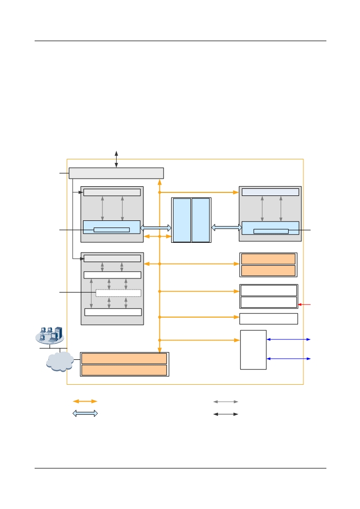
Figure 4-1 and Figure 4-2 show the system architecture of the OptiX OSN 8800 used as an
OTN and an OCS system, respectively.
Figure 4-1 System architecture of the OptiX OSN 8800 (OTN)
To line fiber
L0
Optical-layer board
WDM-side optical module
Client-side optical module
Cross-
Cross-
connect
connect
board
board
Signal processing module
(active)
(standy)
Signal processing module
L1
ODUk
ODUk
L1
Line board
Tributary board
WDM-side optical module
Clock board (active)
Clock board (standby)
Signal processing module
Power (active)
L2
L2 switching module
-48 V/-60 V DC
Power (standby)
Client-side optical module
Fans
NMS
OTU board
External alarm
Auxiliary
interface
External clock/
System control and communication
board
external time
DCN
board (active)
System control and communication
board (standby)
Backplane
Control and communication bus & Clock bus
Electrical signal
Electrical cross-connect bus(ODUk)
Optical-layer service
27
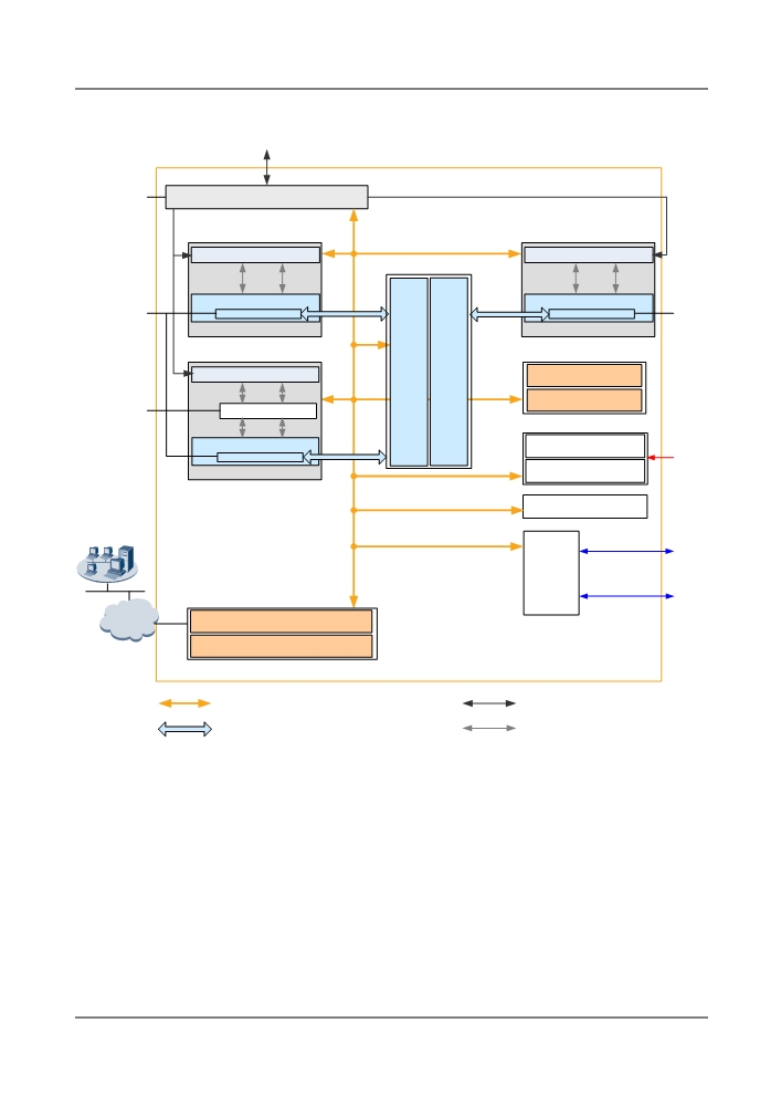
Figure 4-2 System architecture of the OptiX OSN 8800 (OCS)
To line fiber
L0
Optical-layer board
Inteface processing module
Inteface processing module
Signal processing module
Signal processing module
L1
VCx
VCx
L1
Line board
Line board
Cross-
Cross-
connect
connect
board
board
Inteface processing module
Clock board (active)
(active)
(standy)
Clock board (standby)
L2
L2 switching module
、
Signal processing module
-48 V/-60 V DC
Power (active)
VCx
EoS board
Power (standby)
Fans
NMS
External alarm
Auxiliary
interface
External clock/
board
external time
System control and communication
DCN
board (active)
System control and communication
board (standby)
Backplane
Control and communication bus & Clock bus
Optical-layer service
Electrical cross-connect bus
Electrical signal
Functions of modules are as follows:
l Optical-layer boards are classified into optical multiplexer and demultiplexer boards,
optical add/drop multiplexing (OADM) boards, optical amplifier (OA) boards, optical
supervisory channel (OSC) boards, optical spectrum analysis boards, optical variable
attenuator boards, and optical power and dispersion equalization boards. These boards are
intended to process optical-layer services, for example, to cross-connect wavelengths at
the optical layer.
l Electrical-layer boards such as OTU, tributary, and line boards are used to process
electrical-layer signals, and perform conversion between optical and electrical signals. The
OptiX OSN 8800 uses a tributary-line-separate architecture, and a centralized cross-
connect unit to flexibly groom electrical-layer signals at different granularities.
28
l For OptiX OSN 8800, EoO, EoW, Ethernet over SDH (EoS) boards have the L2 processing
capabilities, and they can add, strip, and exchange VLAN tags, learn MAC addresses, and
forward packets.
l As the control center of the entire system, the system control and communication (SCC)
board cooperates with the network management system (NMS) to manage boards in the
system and to implement inter-subrack communication.
l The clock board provides system clock signals and frame header signals to each service
board, and synchronizes the local system time with the upstream system time, achieving
clock and time synchronization.
l The power supply and fan systems with a redundancy protection design ensure highly-
reliable equipment operation.
l The auxiliary interface board provides functional ports such as clock/time input/output
ports, management serial port, alarm output and cascading ports, and alarm input/output
ports.
l Inter-board communication and service cross-connections, clock synchronization, and
power supplies are implemented using the backplane buses. Backplane buses include
control and communication buses, clock buses, and power buses.
4.2 Hardware Architecture
4.2.1 Cabinet
In typical configuration, the OptiX OSN 8800 T32 is installed in N63B cabinet. The OptiX OSN
8800 T64 is installed in N66B cabinet. In typical configuration, the OptiX OSN 8800 T32 and
the OptiX OSN 8800 T16 are installed in N63B cabinet. The OptiX OSN 8800 T64 is installed
in N66B cabinet.
The OptiX OSN 8800 T32 has subracks as the basic working units. The subrack of the OptiX
OSN 8800 T32 has independent power supply and can be installed in N63B cabinet, or N66B
cabinet.
The OptiX OSN 8800 T64 has subracks as the basic working units. The subrack of the OptiX
OSN 8800 T64 has independent power supply and can be installed in N66B cabinet.
4.2.1.1 N63B Cabinet Structure
The N63B is an ETSI middle-column cabinet with 300 mm depth, complying with the ETS
300-119 standard.
The following subracks can be installed on the N63B cabinet: OptiX OSN 8800 T32, OptiX
OSN and OptiX OSN 6800.
The N63B cabinet consists of the rack (main frame), open-close type front door, rear panel fixed
by screws, and side panels at the left and right sides.
Cabinet doors and side panels can be disassembled. The front door and side panels have
grounding points. Keys to the front door of all N63B cabinets are the same.
Figure 4-3 shows the appearance of the N63B cabinet.
29
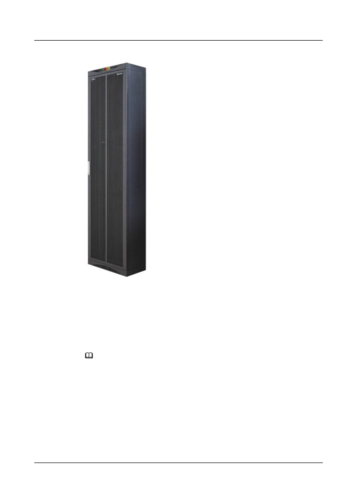
Figure 4-3 N63B cabinet appearance
4.2.1.2 Configuration of the Integrated N63B Cabinet
Typical configuration of the N63B cabinet involves settings of the following items: the subrack
type, the number of subracks, DCM and CRPC frames, and the PDU model.
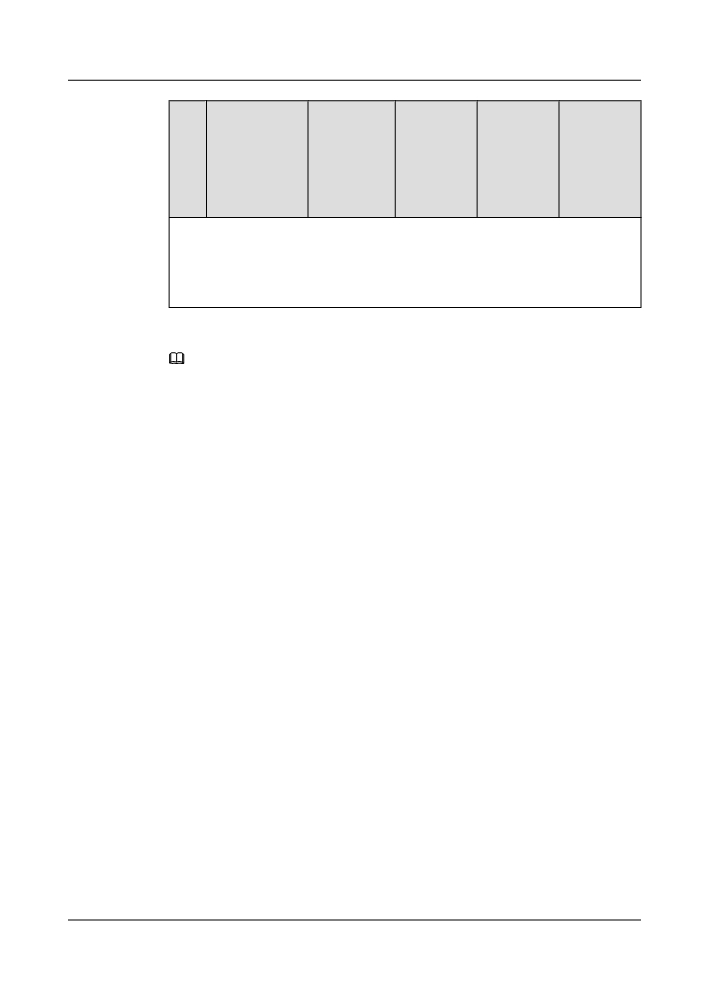
Table 4-1 lists the typical configurations of the N63B cabinet.
NOTE
There are two types of ETSI 300 mm rear-column cabinets: T63B and N63B. These two types of cabinets
differ in color and door. You can perform an expansion installation on the T63B cabinet based on the typical
configurations of the N63B cabinet.
30
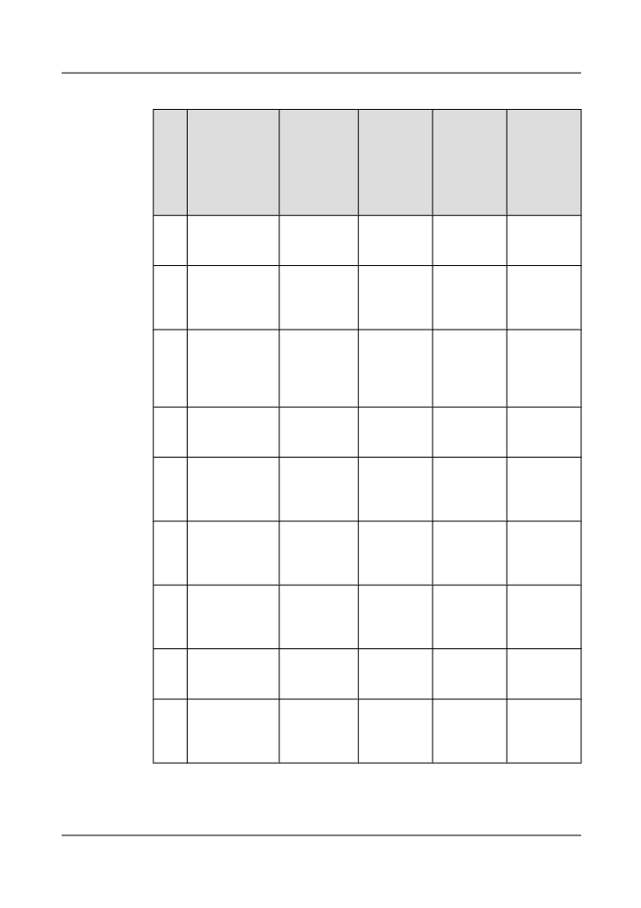
Table 4-1 Typical configurations of the N63B cabinet
Typ
Number of
PDU Model
Circuit
Maximum
Power
ical
Subracks and
Breaker a
Power
Consumpti
Con
Frames
Consumpti
on for the
figu
on of
Typical
rati
Integrated
Configurati
on
Equipment
on
b
1
2 x OptiX OSN
TN16
Eight 63 A
5400 W
< 4000 W
8800 T32 + 1 x
circuit
DCM frame
breakers
2
1 x OptiX OSN
TN16
Four 63 A and
5400 W
< 4000 W
8800 T32 + 2 x
four 32 A
OptiX OSN 6800
circuit
+ 2 x DCM frame
breakers
3
1 x OptiX OSN
TN16
Eight 63 A
5000 W
< 4000 W
8800 T32 + 2 x
circuit
OptiX OSN 8800
breakers
T16 + 1 x DCM
frame
4
4 x OptiX OSN
TN16
Eight 63 A
5000 W
< 4000 W
8800 T16 + 1 x
circuit
DCM frame
breakers
5
3 x OptiX OSN
TN16
Six 63 A and
5000 W
< 4000 W
8800 T16 +1 x
two 32 A
OptiX OSN 6800
circuit
+ 2 x DCM frame
breakers
6
2 x OptiX OSN
TN16
Four 63 A and
5000 W
< 4000 W
8800 T16 + 2 x
four 32 A
OptiX OSN 6800
circuit
+ 2 x DCM frame
breakers
7
1 x OptiX OSN
TN16
Two 63 A and
5000 W
< 4000 W
8800 T16 + 3 x
six 32 A
OptiX OSN 6800
circuit
+ 2 x DCM frame
breakers
8
4 x OptiX OSN
TN11
Four 63 A
4800 W
< 4000 W
6800 + 1 x DCM
circuit
frame
breakers
9
3 x OptiX OSN
TN11
Four 63 A
4800 W
< 4000 W
6800 + 2 x CRPC
circuit
frame + 3 x DCM
breakers
frame
31
Typ
Number of
PDU Model
Circuit
Maximum
Power
ical
Subracks and
Breaker a
Power
Consumpti
Con
Frames
Consumpti
on for the
figu
on of
Typical
rati
Integrated
Configurati
on
Equipment
on
b
a: This column lists the number of circuit breakers required on the PDF.
b: The maximum power consumption of the integrated equipment refers to the maximum
power consumption of the cabinet or the maximum heat dissipation capacity of the integrated
equipment. The power consumption of the integrated equipment can not exceed the maximum
power consumption.
NOTE
In the case of transmission equipment, power consumption is generally transformed into heat consumption.
Hence, heat consumption (BTU/h) and power consumption (W) can be converted to each other in the
formula: Heat consumption (BTU/h) = Power consumption (W) / 0.2931 (Wh).
Power consumption for the typical configuration refers to the average power consumption of the device in
normal scenarios. The maximum power consumption refers to the maximum power consumption of the
device under extreme conditions.
4.2.1.3 N66B Cabinet Structure
The N66B is an ETSI middle-column cabinet with 600 mm depth, complying with the ETS
300-119 standard.
The following subracks can be installed on the N66B cabinet: OptiX OSN 8800 T64, OptiX
OSN 8800 T32, OptiX OSN , and OptiX OSN 6800.
The N66B cabinet consists of the rack (main frame), open-close type front and rear doors, and
side panels at the left and right sides.
Cabinet doors and side panels can be disassembled. The front door and side panels have
grounding points. Keys to the front and rear doors of all N63B cabinets are the same.
Figure 4-4 shows the appearance of the N66B cabinet.
32
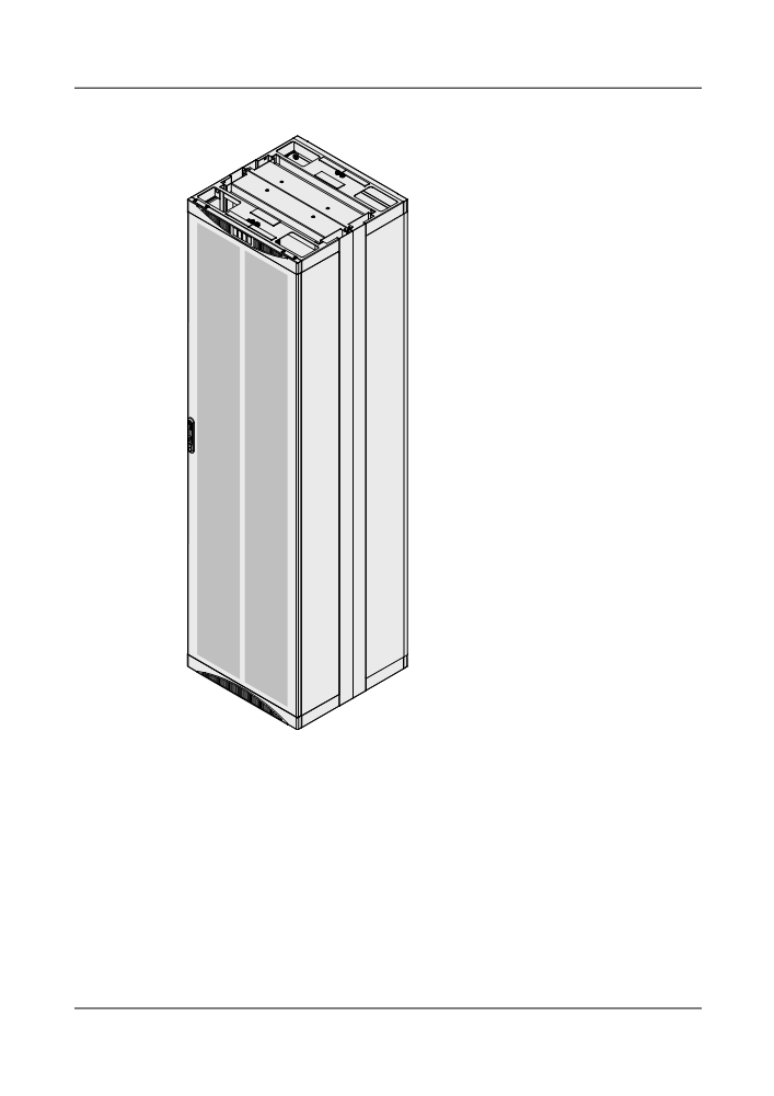
Figure 4-4 N66B cabinet appearance
4.2.1.4 Configuration of the Integrated N66B Cabinet
Typical configuration of the N63B cabinet involves settings of the following items: the subrack
type, the number of subracks, DCM and CRPC frames, and the PDU model.
Table 4-2 lists the typical configurations of the N66B cabinet.
33
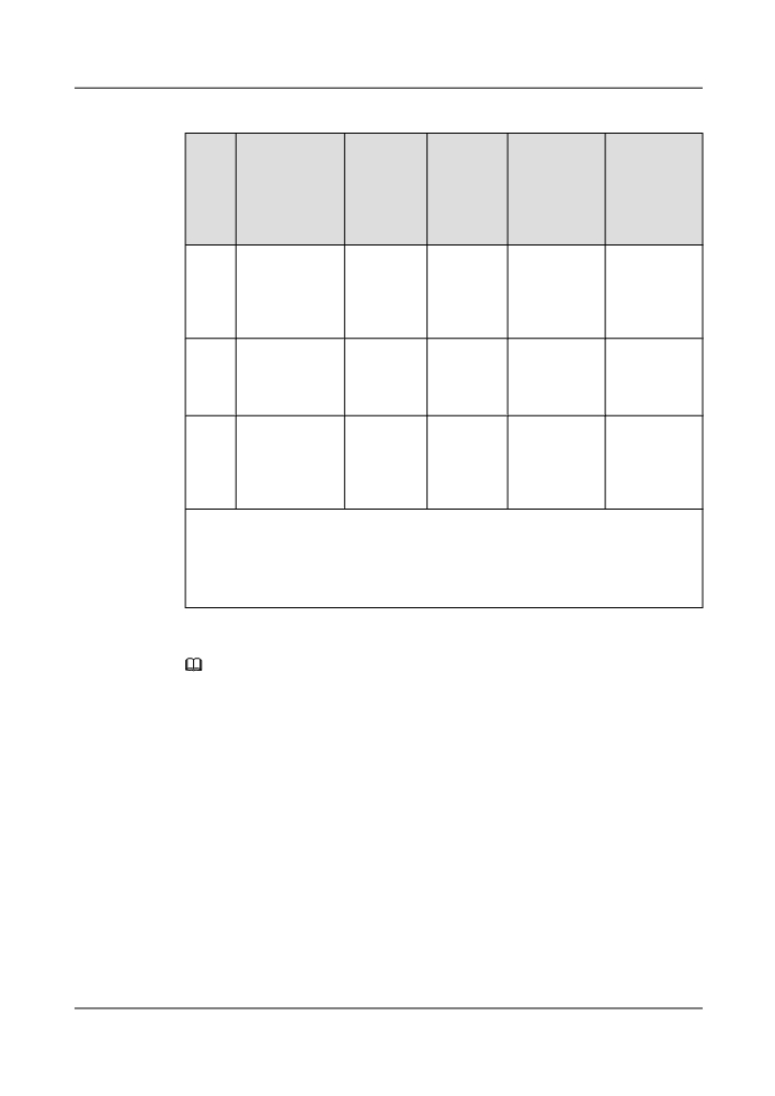
Table 4-2 Typical configurations of the N66B cabinet
Typic
Number of
PDU
Circuit
Maximum
Power
al
Subracks and
Mode
Breaker a
Power
Consumptio
Confi
Frames
Consumptio
n for the
gurat
n of
Typical
ion
Integrated
Configuratio
Equipment b
n
1
1 x OptiX OSN
TN16
Sixteen 63
10800 W
< 6000 W
8800 T64 + 2 x
A circuit
OptiX OSN 8800
breakers
T32 + 2 x DCM
frame
2
1 x OptiX OSN
TN16
Eight 63 A
10800 W
< 6000 W
8800 T64 + 4 x
and eight 32
OptiX OSN 6800
A circuit
+ 4 x DCM frame
breakers
3
1 x OptiX OSN
TN16
Sixteen 63
10000 W
< 6000 W
8800 T64 + 4 x
A circuit
OptiX OSN 8800
breakers
T16 + 2 x DCM
frame
a: This column lists the number of circuit breakers required on the PDF.
b: The maximum power consumption of the integrated equipment refers to the maximum
power consumption of the cabinet or the maximum heat dissipation capacity of the integrated
equipment. The power consumption of the integrated equipment do not exceed the maximum
power consumption.
NOTE
In the case of transmission equipment, power consumption is generally transformed into heat consumption.
Hence, heat consumption (BTU/h) and power consumption (W) can be converted to each other in the
formula: Heat consumption (BTU/h) = Power consumption (W) / 0.2931 (Wh).
Power consumption for the typical configuration refers to the average power consumption of the device in
normal scenarios. The maximum power consumption refers to the maximum power consumption of the
device under extreme conditions.
4.2.1.5 Cabinet Installation Mode
The ETSI 300 mm cabinet supports three installation modes: back-to-back installation, face-to-
face installation, and side-by-side installation. They can be located on cement floors or anti-
static floors. There are two ways of cabling for the cabinets: upward cabling and downward
cabling.
The ETSI 600 mm cabinet supports two installation modes: face-to-face installation, and side-
by-side installation. They can be located on cement floors or anti-static floors. There are two
ways of cabling for the cabinets: upward cabling and downward cabling.
34
4.2.1.6 TN16PDU
The TN16PDU is installed in the upper part of a cabinet to supply power to subracks inside the
cabinet.
NOTE
The TN51PDU and TN16PDU have the same functions but differ in height. The TN51PDU is 133.4 mm
high. When two OptiX OSN 8800 T32 subracks are installed on a cabinet, one more DCM frame can be
configured if the TN16PDU is used, compared with the TN51PDU.
TN51PDU can be substituted by the TN16PDU.This topic describes the TN16PDU.
The TN16PDU consists of two parts: A and B, which backs up each other. Both A and B receive
four -48V/-60V power supplies and output four power supplies for subracks in the cabinet.
Whether short-circuiting copper bars are required is determined by the current of power supplied
by the power supply equipment in the telecommunications room:
l When eight 63 A power supplies are provided, no short-circuiting copper bar is required.
l When four 125 A power supplies are provided, short-circuiting copper bars are required
for dividing one 125 A power supply into two 63 A power supplies.
For more information about short-circuiting copper bars, see Short-Circuiting Copper
Bar.
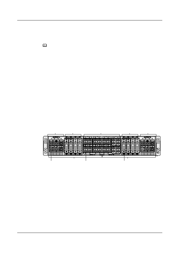
Figure 4-5 shows the front panel of the TN16PDU.
Figure 4-5 Front panel of the TN16PDU
Power supply
Power supply
Power supply
Power supply
Power supply
output area
switch area
input area
switch area
output area
-
-
-
-
-+
-+
-+
-+
+1
+2
+3
+4
1
2
3
4
A
B
1
2
3
1. Output cable terminal block
2. Input cable terminal block
3. Power switch
l Panel dimensions: 535 mm (W) x 100 mm (H)
l Output cable terminal block: Both A and B of the DC PDU have four output cable terminal
blocks for connecting power cables of subracks to supply power for subracks.
l Input cable terminal block: Both A and B of the DC PDU have four input cable terminal
blocks and receive four -48V/-60V DC power supplies, eight -48V/-60V DC power supplies
in total.
l Power switch: Both A and B of the DC PDU have four output power switches to control
power supplies for subracks inside the cabinet and provide overcurrent protection for each
other.
Figure 4-6 shows the internal pin assignments of the TN16PDU.
35
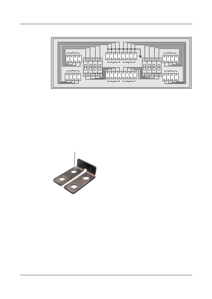
Figure 4-6 TN16PDU internal pin assignments
OUTPUT A
OUTPUT B
-
-
-
-
-
-
-
-
1
2
3
4
1
2
3
4
1
2
3
4
1
2
3
4
+
+
+
+
+
+
+
+
ON
ON
ON
ON
ON
ON
ON
ON
INPUT A
INPUT B
OUTPUT A
OUTPUT B
OFF
OFF
OFF
OFF
OFF
OFF
OFF
OFF
+
+
+
+
+
+
+
+
1
2
3
4
1
2
3
4
1
2
3
4
1
2
3
4
-
-
-
-
-
-
-
-
INPUT A
INPUT B
Short-Circuit Copper Bar
If a power supply is 125 A, both A and B need to receive two power supplies, four power supplies
in total. In this case, short-circuit copper bars are required for both A and B. Figure 4-7 shows
the appearance of the short-circuiting copper bar.
Figure 4-7 Appearance
Copper Plate
4.2.2 OptiX OSN 8800 T64 Subrack
4.2.2.1 Structure
Subracks are the basic working units of the OptiX OSN 8800 T64. Each subrack has independent
power supply.
Figure 4-8 shows the structure of the OptiX OSN 8800 T64 subrack.
Table 4-3 describes the mechanical specifications of the 8800 T64 subrack.
36