Intel 64 and IA-32 Architectures. Software Developer’s Manual (2026) - page 51
TASK MANAGEMENT
15. If CET is enabled, the processor performs following shadow stack actions:
IF shadow stack enabled at current CPL OR indirect branch tracking at current CPL
THEN
IF EFLAGS.VM = 1
THEN #TSS(new-Task-TSS);FI;
FI;
IF shadow stack enabled at current CPL
IF task switch initiated by CALL instruction, JMP instruction, interrupt or exception (* switch stack *)
new_SSP ← Load the 4 byte from offset 104 in the TSS
// Verify new SSP to be legal
IF new_SSP & 0x07 != 0
THEN #TSS(New-Task-TSS); FI;
expected_token_value = SSP;
(* busy - bit 0 - must be clear *)
new_token_value
= SSP | BUSY_BIT (* set the busy bit - bit 0*)
IF shadow_stack_lock_cmpxchg8b(SSP, new_token_value,
expected_token_value) != expected_token_value
THEN #TSS(New-Task-TSS); FI;
SSP = new_SSP
IF pushCsLipSsp = 1 (* call, int, exception from user → user or supv → supv or supv → user *)
Push tempSsCS, tempSsLip, tempSsSSP on shadow stack using 8B pushes1
FI;
FI;
FI;
IF task switch initiated by IRET
IF verifyCsLIP = 1
(* do 64 bit comparisons; CS zero padded to 64 bit; CSBASE+EIP zero padded to 64 bit *)
IF tempSsCS and tempSsLIP do not match CS and CSBASE+EIP
THEN #CP(FAR-RET/IRET); FI;
FI;
IF ShadowStackEnabled(CPL)
THEN
IF (verifyCsLIP == 0) tempSSP = IA32_PL3_SSP;
IF tempSSP & 0x03 != 0 THEN #CP(FAR-RET/IRET) // verify aligned to 4 bytes
IF tempSSP[63:32] != 0 THEN # CP(FAR-RET/IRET)
SSP = tempSSP
FI;
FI;
IF EndbranchEnabled(CPL)
IF task switch initiated by CALL instruction, JMP instruction, interrupt or exception
IF CPL = 3
THEN
IA32_U_CET.TRACKER = WAIT_FOR_ENDBRANCH
1. If any of these pushes leads to an exception or a VM exit, the supervisor shadow-stack token remains busy.
10-12
Vol. 3A

TASK MANAGEMENT
IA32_U_CET.SUPPRESS = 0
ELSE
IA32_S_CET.TRACKER = WAIT_FOR_ENDBRANCH
IA32_S_CET.SUPPRESS = 0
FI;
FI;
FI;
16. Begins executing the new task. (To an exception handler, the first instruction of the new task appears not to
have been executed.)
NOTES
If all checks and saves have been carried out successfully, the processor commits to the task
switch. If an unrecoverable error occurs in steps 1 through 8, the processor does not complete the
task switch and ensures that the processor is returned to its state prior to the execution of the
instruction that initiated the task switch.
If an unrecoverable error occurs in step 9, architectural state may be corrupted, but an attempt will
be made to handle the error in the prior execution environment. If an unrecoverable error occurs
after the commit point (in step 13), the processor completes the task switch (without performing
additional access and segment availability checks) and generates the appropriate exception prior to
beginning execution of the new task.
If exceptions occur after the commit point, the exception handler must finish the task switch itself
before allowing the processor to begin executing the new task. See Chapter 7, “Event 10-Invalid
TSS Exception (#TS),” for more information about the affect of exceptions on a task when they
occur after the commit point of a task switch.
The state of the currently executing task is always saved when a successful task switch occurs. If the task is
resumed, execution starts with the instruction pointed to by the saved EIP value, and the registers are restored to
the values they held when the task was suspended.
When switching tasks, the privilege level of the new task does not inherit its privilege level from the suspended
task. The new task begins executing at the privilege level specified in the CPL field of the CS register, which is
loaded from the TSS. Because tasks are isolated by their separate address spaces and TSSs and because privilege
rules control access to a TSS, software does not need to perform explicit privilege checks on a task switch.
Table 10-1 shows the exception conditions that the processor checks for when switching tasks. It also shows the
exception that is generated for each check if an error is detected and the segment that the error code references.
(The order of the checks in the table is the order used in the P6 family processors. The exact order is model specific
and may be different for other IA-32 processors.) Exception handlers designed to handle these exceptions may be
subject to recursive calls if they attempt to reload the segment selector that generated the exception. The cause of
the exception (or the first of multiple causes) should be fixed before reloading the selector.
Table 10-1. Exception Conditions Checked During a Task Switch
Condition Checked
Exception1
Error Code Reference2
Segment selector for a TSS descriptor references
#GP
New Task’s TSS
the GDT and is within the limits of the table.
#TS (for IRET)
P bit is set in TSS descriptor.
#NP
New Task’s TSS
TSS descriptor is not busy (for task switch initiated by a call, interrupt, or
#GP (for JMP, CALL, INT)
Task’s back-link TSS
exception).
TSS descriptor is not busy (for task switch initiated by an IRET instruction).
#TS (for IRET)
New Task’s TSS
TSS segment limit greater than or equal to 108 (for 32-bit TSS) or 44 (for 16-bit
#TS
New Task’s TSS
TSS).
Vol. 3A
10-13

TASK MANAGEMENT
Table 10-1. Exception Conditions Checked During a Task Switch (Contd.)
Condition Checked
Exception1
Error Code Reference2
TSS segment limit greater than or equal to 108 (for 32-bit TSS) if CR4.CET = 1.3
#TS
New Task’s TSS
If shadow stack enabled and SSP not aligned to 8 bytes (for task switch initiated
#TS
Current Task’s TSS
by an IRET instruction).3
Registers are loaded from the values in the TSS.
LDT segment selector of new task is valid 4.
#TS
New Task’s LDT
If code segment is non-conforming, its DPL should equal its RPL.
#TS
New Code Segment
If code segment is conforming, its DPL should be less than or equal to its RPL.
#TS
New Code Segment
SS segment selector is valid 2.
#TS
New Stack Segment
P bit is set in stack segment descriptor.
#SS
New Stack Segment
Stack segment DPL should equal CPL.
#TS
New stack segment
P bit is set in new task's LDT descriptor.
#TS
New Task’s LDT
CS segment selector is valid 4.
#TS
New Code Segment
P bit is set in code segment descriptor.
#NP
New Code Segment
Stack segment DPL should equal its RPL.
#TS
New Stack Segment
DS, ES, FS, and GS segment selectors are valid 4.
#TS
New Data Segment
DS, ES, FS, and GS segments are readable.
#TS
New Data Segment
P bits are set in descriptors of DS, ES, FS, and GS segments.
#NP
New Data Segment
DS, ES, FS, and GS segment DPL greater than or equal to CPL (unless these are
#TS
New Data Segment
conforming segments).
Shadow Stack Pointer in a task not aligned to 8 bytes (for task switch initiated by
#TS
New Task’s TSS
a call, interrupt, or exception).3
If EFLAGS.VM=1 and shadow stacks are enabled.3
#TS
New Task’s TSS
Supervisor Shadow Stack Token verification failures (for task switch initiated by a
#TS
New Task’s TSS
call, interrupt, jump, or exception):3
- Busy bit already set.
- Address in Shadow stack token does not match SSP value from TSS.
If task switch initiated by IRET, CS and LIP stored on old task shadow stack does
#CP
FAR-RET/IRET
not match CS and LIP of new task.3
If task switch initiated by IRET and SSP of new task loaded from shadow stack of
#CP
FAR-RET/IRET
old task (if new task CPL is < 3) OR the SSP from IA32_PL3_SSP (if new task CPL
= 3) fails the following checks:3
- Not aligned to 4 bytes.
- Is beyond 4G.
NOTES:
1. #NP is segment-not-present exception, #GP is general-protection exception, #TS is invalid-TSS exception, and #SS is stack-fault
exception.
2. The error code contains an index to the segment descriptor referenced in this column.
3. Valid when CET is enabled.
4. A segment selector is valid if it is in a compatible type of table (GDT or LDT), occupies an address within the table's segment limit,
and refers to a compatible type of descriptor (for example, a segment selector in the CS register only is valid when it points to a
code-segment descriptor).
The TS (task switched) flag in the control register CR0 is set every time a task switch occurs. System software uses
the TS flag to coordinate the actions of floating-point unit when generating floating-point exceptions with the rest
of the processor. The TS flag indicates that the context of the floating-point unit may be different from that of the
current task. See Section 2.5, “Control Registers,” for a detailed description of the function and use of the TS flag.
10-14
Vol. 3A
TASK MANAGEMENT
10.4
TASK LINKING
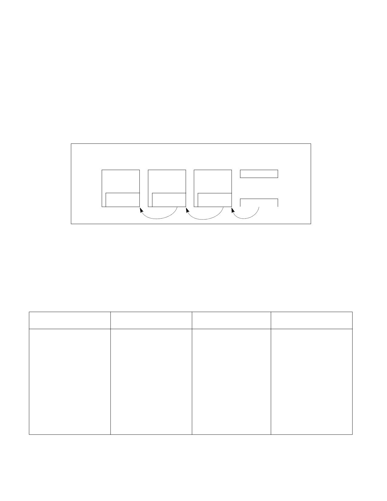
The previous task link field of the TSS (sometimes called the “backlink”) and the NT flag in the EFLAGS register are
used to return execution to the previous task. EFLAGS.NT = 1 indicates that the currently executing task is nested
within the execution of another task.
When a CALL instruction, an interrupt, or an exception causes a task switch: the processor copies the segment
selector for the current TSS to the previous task link field of the TSS for the new task; it then sets EFLAGS.NT = 1.
If software uses an IRET instruction to suspend the new task, the processor checks for EFLAGS.NT = 1; it then
uses the value in the previous task link field to return to the previous task. See Figures 10-8.
When a JMP instruction causes a task switch, the new task is not nested. The previous task link field is not used and
EFLAGS.NT = 0. Use a JMP instruction to dispatch a new task when nesting is not desired.
Top Level
Nested
More Deeply
Currently Executing
Task
Task
Nested Task
Task
TSS
TSS
TSS
EFLAGS
NT=1
NT=0
NT=1
NT=1
Previous
Previous
Previous
Task Link
Task Link
Task Link
Task Register
Figure 10-8. Nested Tasks
Table 10-2 shows the busy flag (in the TSS segment descriptor), the NT flag, the previous task link field, and TS
flag (in control register CR0) during a task switch.
The NT flag may be modified by software executing at any privilege level. It is possible for a program to set the NT
flag and execute an IRET instruction. This might randomly invoke the task specified in the previous link field of the
current task's TSS. To keep such spurious task switches from succeeding, the operating system should initialize the
previous task link field in every TSS that it creates to 0.
Table 10-2. Effect of a Task Switch on Busy Flag, NT Flag, Previous Task Link Field, and TS Flag
Flag or Field
Effect of JMP instruction
Effect of CALL Instruction or
Effect of IRET
Interrupt
Instruction
Busy (B) flag of new task.
Flag is set. Must have been
Flag is set. Must have been
No change. Must have been set.
clear before.
clear before.
Busy flag of old task.
Flag is cleared.
No change. Flag is currently
Flag is cleared.
set.
NT flag of new task.
Set to value from TSS of new
Flag is set.
Set to value from TSS of new
task.
task.
NT flag of old task.
No change.
No change.
Flag is cleared.
Previous task link field of new
No change.
Loaded with selector
No change.
task.
for old task’s TSS.
Previous task link field of old
No change.
No change.
No change.
task.
TS flag in control register CR0.
Flag is set.
Flag is set.
Flag is set.
Vol. 3A
10-15
TASK MANAGEMENT
10.4.1 Use of Busy Flag To Prevent Recursive Task Switching
A TSS allows only one context to be saved for a task; therefore, once a task is called (dispatched), a recursive (or
re-entrant) call to the task would cause the current state of the task to be lost. The busy flag in the TSS segment
descriptor is provided to prevent re-entrant task switching and a subsequent loss of task state information. The
processor manages the busy flag as follows:
1. When dispatching a task, the processor sets the busy flag of the new task.
2. If during a task switch, the current task is placed in a nested chain (the task switch is being generated by a
CALL instruction, an interrupt, or an exception), the busy flag for the current task remains set.
3. When switching to the new task (initiated by a CALL instruction, interrupt, or exception), the processor
generates a general-protection exception (#GP) if the busy flag of the new task is already set. If the task switch
is initiated with an IRET instruction, the exception is not raised because the processor expects the busy flag to
be set.
4. When a task is terminated by a jump to a new task (initiated with a JMP instruction in the task code) or by an
IRET instruction in the task code, the processor clears the busy flag, returning the task to the “not busy” state.
The processor prevents recursive task switching by preventing a task from switching to itself or to any task in a
nested chain of tasks. The chain of nested suspended tasks may grow to any length, due to multiple calls, inter-
rupts, or exceptions. The busy flag prevents a task from being invoked if it is in this chain.
The busy flag may be used in multiprocessor configurations, because the processor follows a LOCK protocol (on the
bus or in the cache) when it sets or clears the busy flag. This lock keeps two processors from invoking the same
task at the same time. See Section 11.1.2.1, “Automatic Locking,” for more information about setting the busy flag
in a multiprocessor applications.
10.4.2 Modifying Task Linkages
In a uniprocessor system, in situations where it is necessary to remove a task from a chain of linked tasks, use the
following procedure to remove the task:
1. Disable interrupts.
2. Change the previous task link field in the TSS of the pre-empting task (the task that suspended the task to be
removed). It is assumed that the pre-empting task is the next task (newer task) in the chain from the task to
be removed. Change the previous task link field to point to the TSS of the next oldest task in the chain or to an
even older task in the chain.
3. Clear the busy (B) flag in the TSS segment descriptor for the task being removed from the chain. If more than
one task is being removed from the chain, the busy flag for each task being remove must be cleared.
4. Enable interrupts.
In a multiprocessing system, additional synchronization and serialization operations must be added to this proce-
dure to ensure that the TSS and its segment descriptor are both locked when the previous task link field is changed
and the busy flag is cleared.
10.5
TASK ADDRESS SPACE
The address space for a task consists of the segments that the task can access. These segments include the code,
data, stack, and system segments referenced in the TSS and any other segments accessed by the task code. The
segments are mapped into the processor’s linear address space, which is in turn mapped into the processor’s phys-
ical address space (either directly or through paging).
The LDT segment field in the TSS can be used to give each task its own LDT. Giving a task its own LDT allows the
task address space to be isolated from other tasks by placing the segment descriptors for all the segments associ-
ated with the task in the task’s LDT.
It also is possible for several tasks to use the same LDT. This is a memory-efficient way to allow specific tasks to
communicate with or control each other, without dropping the protection barriers for the entire system.
10-16
Vol. 3A
TASK MANAGEMENT
Because all tasks have access to the GDT, it also is possible to create shared segments accessed through segment
descriptors in this table.
If paging is enabled, the CR3 register (PDBR) field in the TSS allows each task to have its own set of page tables
for mapping linear addresses to physical addresses. Or, several tasks can share the same set of page tables.
10.5.1 Mapping Tasks to the Linear and Physical Address Spaces
Tasks can be mapped to the linear address space and physical address space in one of two ways:
• One linear-to-physical address space mapping is shared among all tasks. - When paging is not
enabled, this is the only choice. Without paging, all linear addresses map to the same physical addresses. When
paging is enabled, this form of linear-to-physical address space mapping is obtained by using one page
directory for all tasks. The linear address space may exceed the available physical space if demand-paged
virtual memory is supported.
• Each task has its own linear address space that is mapped to the physical address space. - This form
of mapping is accomplished by using a different page directory for each task. Because the PDBR (control
register CR3) is loaded on task switches, each task may have a different page directory.
The linear address spaces of different tasks may map to completely distinct physical addresses. If the entries of
different page directories point to different page tables and the page tables point to different pages of physical
memory, then the tasks do not share physical addresses.
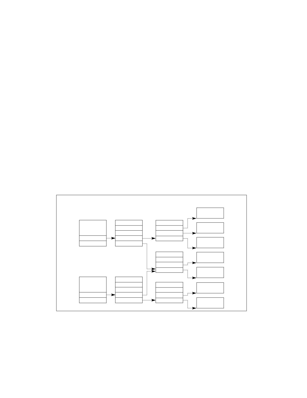
With either method of mapping task linear address spaces, the TSSs for all tasks must lie in a shared area of the
physical space, which is accessible to all tasks. This mapping is required so that the mapping of TSS addresses does
not change while the processor is reading and updating the TSSs during a task switch. The linear address space
mapped by the GDT also should be mapped to a shared area of the physical space; otherwise, the purpose of the
GDT is defeated. Figure 10-9 shows how the linear address spaces of two tasks can overlap in the physical space
by sharing page tables.
TSS
Page Directories
Page Tables
Page Frames
Task A
Task A TSS
Task A
PTE
PTE
PDBR
PDE
PTE
Task A
PDE
Shared PT
Shared
PTE
PTE
Shared
Task B TSS
Task B
PDBR
PDE
PTE
PDE
PTE
Task B
Figure 10-9. Overlapping Linear-to-Physical Mappings
10.5.2 Task Logical Address Space
To allow the sharing of data among tasks, use the following techniques to create shared logical-to-physical
address-space mappings for data segments:
• Through the segment descriptors in the GDT - All tasks must have access to the segment descriptors in
the GDT. If some segment descriptors in the GDT point to segments in the linear-address space that are
Vol. 3A
10-17
TASK MANAGEMENT
mapped into an area of the physical-address space common to all tasks, then all tasks can share the data and
code in those segments.
• Through a shared LDT - Two or more tasks can use the same LDT if the LDT fields in their TSSs point to the
same LDT. If some segment descriptors in a shared LDT point to segments that are mapped to a common area
of the physical address space, the data and code in those segments can be shared among the tasks that share
the LDT. This method of sharing is more selective than sharing through the GDT, because the sharing can be
limited to specific tasks. Other tasks in the system may have different LDTs that do not give them access to the
shared segments.
• Through segment descriptors in distinct LDTs that are mapped to common addresses in linear
address space - If this common area of the linear address space is mapped to the same area of the physical
address space for each task, these segment descriptors permit the tasks to share segments. Such segment
descriptors are commonly called aliases. This method of sharing is even more selective than those listed above,
because, other segment descriptors in the LDTs may point to independent linear addresses which are not
shared.
10.6
16-BIT TASK-STATE SEGMENT (TSS)
The 32-bit IA-32 processors also recognize a 16-bit TSS format like the one used in Intel 286 processors (see
Figure 10-10). This format is supported for compatibility with software written to run on earlier IA-32 processors.
The following information is important to know about the 16-bit TSS.
• Do not use a 16-bit TSS to implement a virtual-8086 task.
• The valid segment limit for a 16-bit TSS is 2CH.
• The 16-bit TSS does not contain a field for the base address of the page directory, which is loaded into control
register CR3. A separate set of page tables for each task is not supported for 16-bit tasks. If a 16-bit task is
dispatched, the page-table structure for the previous task is used.
• The I/O base address is not included in the 16-bit TSS. None of the functions of the I/O map are supported.
• When task state is saved in a 16-bit TSS, the upper 16 bits of the EFLAGS register and the EIP register are lost.
• When the general-purpose registers are loaded or saved from a 16-bit TSS, the upper 16 bits of the registers
are modified and not maintained.
10-18
Vol. 3A

TASK MANAGEMENT
15
0
Task LDT Selector
42
DS Selector
40
SS Selector
38
CS Selector
36
ES Selector
34
DI
32
SI
30
BP
28
SP
26
BX
24
DX
22
CX
20
AX
18
FLAG Word
16
IP (Entry Point)
14
SS2
12
SP2
10
SS1
8
SP1
6
SS0
4
SP0
2
Previous Task Link
0
Figure 10-10. 16-Bit TSS Format
10.7
TASK MANAGEMENT IN 64-BIT MODE
In 64-bit mode, task structure and task state are similar to those in protected mode. However, the task switching
mechanism available in protected mode is not supported in 64-bit mode. Task management and switching must be
performed by software. The processor issues a general-protection exception (#GP) if the following is attempted in
64-bit mode:
• Control transfer to a TSS or a task gate using JMP, CALL, INT n, INT3, INTO, INT1, or interrupt.
• An IRET with EFLAGS.NT (nested task) set to 1.
Although hardware task-switching is not supported in 64-bit mode, a 64-bit task state segment (TSS) must exist.
Figure 10-11 shows the format of a 64-bit TSS. The TSS holds information important to 64-bit mode and that is not
directly related to the task-switch mechanism. This information includes:
• RSPn - The full 64-bit canonical forms of the stack pointers (RSP) for privilege levels 0-2.
• ISTn - The full 64-bit canonical forms of the interrupt stack table (IST) pointers.
• I/O map base address - The 16-bit offset to the I/O permission bit map from the 64-bit TSS base.
The operating system must create at least one 64-bit TSS after activating IA-32e mode. It must execute the LTR
instruction (in 64-bit mode) to load the TR register with a pointer to the 64-bit TSS responsible for both 64-bit-
mode programs and compatibility-mode programs.
Vol. 3A
10-19

TASK MANAGEMENT
31
15
0
I/O Map Base Address
Reserved
100
Reserved
96
Reserved
92
IST7 (upper 32 bits)
88
IST7 (lower 32 bits)
84
IST6 (upper 32 bits)
80
IST6 (lower 32 bits)
76
IST5 (upper 32 bits)
72
IST5 (lower 32 bits)
68
IST4 (upper 32 bits)
64
IST4 (lower 32 bits)
60
IST3 (upper 32 bits)
56
IST3 (lower 32 bits)
52
IST2 (upper 32 bits)
48
IST2 (lower 32 bits)
44
IST1 (upper 32 bits)
40
IST1 (lower 32 bits)
36
Reserved
32
Reserved
28
RSP2 (upper 32 bits)
24
RSP2 (lower 32 bits)
20
RSP1 (upper 32 bits)
16
RSP1 (lower 32 bits)
12
RSP0 (upper 32 bits)
8
RSP0 (lower 32 bits)
4
Reserved
0
Reserved bits. Set to 0.
Figure 10-11. 64-Bit TSS Format
10-20
Vol. 3A
CHAPTER 11
MULTIPLE-PROCESSOR MANAGEMENT
The Intel 64 and IA-32 architectures provide mechanisms for managing and improving the performance of multiple
processors connected to the same system bus. These include:
• Bus locking and/or cache coherency management for performing atomic operations on system memory.
• Serializing instructions.
• An advance programmable interrupt controller (APIC) located on the processor chip (see Chapter 13,
“Advanced Programmable Interrupt Controller (APIC)”). This feature was introduced by the Pentium processor.
• A second-level cache (level 2, L2). For the Pentium 4, Intel Xeon, and P6 family processors, the L2 cache is
included in the processor package and is tightly coupled to the processor. For the Pentium and Intel486
processors, pins are provided to support an external L2 cache.
• A third-level cache (level 3, L3). For Intel Xeon processors, the L3 cache is included in the processor package
and is tightly coupled to the processor.
• Intel Hyper-Threading Technology. This extension to the Intel 64 and IA-32 architectures enables a single
processor core to execute two or more threads concurrently (see Section 11.5, “Intel® Hyper-Threading
Technology and Intel® Multi-Core Technology”).
These mechanisms are particularly useful in symmetric-multiprocessing (SMP) systems. However, they can also be
used when an Intel 64 or IA-32 processor and a special-purpose processor (such as a communications, graphics,
or video processor) share the system bus.
These multiprocessing mechanisms have the following characteristics:
• To maintain system memory coherency - When two or more processors are attempting simultaneously to
access the same address in system memory, some communication mechanism or memory access protocol
must be available to promote data coherency and, in some instances, to allow one processor to temporarily lock
a memory location.
• To maintain cache consistency - When one processor accesses data cached on another processor, it must not
receive incorrect data. If it modifies data, all other processors that access that data must receive the modified
data.
• To allow predictable ordering of writes to memory - In some circumstances, it is important that memory writes
be observed externally in precisely the same order as programmed.
• To distribute interrupt handling among a group of processors - When several processors are operating in a
system in parallel, it is useful to have a centralized mechanism for receiving interrupts and distributing them to
available processors for servicing.
• To increase system performance by exploiting the multi-threaded and multi-process nature of contemporary
operating systems and applications.
The caching mechanism and cache consistency of Intel 64 and IA-32 processors are discussed in Chapter 14. The
APIC architecture is described in Chapter 13. Bus and memory locking, serializing instructions, memory ordering,
and Intel Hyper-Threading Technology are discussed in the following sections.
11.1
LOCKED ATOMIC OPERATIONS
The 32-bit IA-32 processors support locked atomic operations on locations in system memory. These operations
are typically used to manage shared data structures (such as semaphores, segment descriptors, system segments,
or page tables) in which two or more processors may try simultaneously to modify the same field or flag. The
processor uses three interdependent mechanisms for carrying out locked atomic operations:
• Guaranteed atomic operations.
• Bus locking, using the LOCK# signal and the LOCK instruction prefix.
Vol. 3A
11-1
MULTIPLE-PROCESSOR MANAGEMENT
• Cache coherency protocols that ensure that atomic operations can be carried out on cached data structures
(cache lock); this mechanism is present in the Pentium 4, Intel Xeon, and P6 family processors.
These mechanisms are interdependent in the following ways. Certain basic memory transactions (such as reading
or writing a byte in system memory) are always guaranteed to be handled atomically. That is, once started, the
processor guarantees that the operation will be completed before another processor or bus agent is allowed access
to the memory location. The processor also supports bus locking for performing selected memory operations (such
as a read-modify-write operation in a shared area of memory) that typically need to be handled atomically, but are
not automatically handled this way. Because frequently used memory locations are often cached in a processor’s L1
or L2 caches, atomic operations can often be carried out inside a processor’s caches without asserting the bus lock.
Here the processor’s cache coherency protocols ensure that other processors that are caching the same memory
locations are managed properly while atomic operations are performed on cached memory locations.
NOTE
Where there are contested lock accesses, software may need to implement algorithms that ensure
fair access to resources in order to prevent lock starvation. The hardware provides no resource that
guarantees fairness to participating agents. It is the responsibility of software to manage the
fairness of semaphores and exclusive locking functions.
The mechanisms for handling locked atomic operations have evolved with the complexity of IA-32 processors. More
recent IA-32 processors (such as the Pentium 4, Intel Xeon, and P6 family processors) and Intel 64 provide a more
refined locking mechanism than earlier processors. These mechanisms are described in the following sections.
11.1.1 Guaranteed Atomic Operations
The Intel486 processor (and newer processors since) guarantees that the following basic memory operations will
always be carried out atomically:
• Reading or writing a byte.
• Reading or writing a word aligned on a 16-bit boundary.
• Reading or writing a doubleword aligned on a 32-bit boundary.
The Pentium processor (and newer processors since) guarantees that the following additional memory operations
will always be carried out atomically:
• Reading or writing a quadword aligned on a 64-bit boundary.
•
16-bit accesses to uncached memory locations that fit within a 32-bit data bus.
The P6 family processors (and newer processors since) guarantee that the following additional memory operation
will always be carried out atomically:
• Unaligned 16-, 32-, and 64-bit accesses to cached memory that fit within a cache line.
Processors that enumerate support for Intel® AVX (by setting the feature flag CPUID.01H:ECX.AVX[28]) guarantee
that the 16-byte memory operations performed by the following instructions will always be carried out atomically:
• MOVAPD, MOVAPS, and MOVDQA.
• VMOVAPD, VMOVAPS, and VMOVDQA when encoded with VEX.128.
• VMOVAPD, VMOVAPS, VMOVDQA32, and VMOVDQA64 when encoded with EVEX.128 and k0 (masking
disabled).
(Note that these instructions require the linear addresses of their memory operands to be 16-byte aligned.)
Accesses to cacheable memory that are split across cache lines and page boundaries are not guaranteed to be
atomic by the Intel Core 2 Duo, Intel Atom, Intel Core Duo, Pentium M, Pentium 4, Intel Xeon, P6 family, Pentium,
and Intel486 processors. The Intel Core 2 Duo, Intel Atom, Intel Core Duo, Pentium M, Pentium 4, Intel Xeon, and
P6 family processors provide bus control signals that permit external memory subsystems to make split accesses
atomic; however, nonaligned data accesses will seriously impact the performance of the processor and should be
avoided.
Except as noted above, an x87 instruction or an SSE instruction that accesses data larger than a quadword may be
implemented using multiple memory accesses. If such an instruction stores to memory, some of the accesses may
11-2
Vol. 3A
MULTIPLE-PROCESSOR MANAGEMENT
complete (writing to memory) while another causes the operation to fault for architectural reasons (e.g., due an
page-table entry that is marked “not present”). In this case, the effects of the completed accesses may be visible
to software even though the overall instruction caused a fault. If TLB invalidation has been delayed (see Section
5.10.4.4), such page faults may occur even if all accesses are to the same page.
11.1.2 Bus Locking
Intel 64 and IA-32 processors provide a LOCK# signal that is asserted automatically during certain critical memory
operations to lock the system bus or equivalent link. Assertion of this signal is called a bus lock. While this output
signal is asserted, requests from other processors or bus agents for control of the bus are blocked. Software can
specify other occasions when the LOCK semantics are to be followed by prepending the LOCK prefix to an instruc-
tion.
In the case of the Intel386, Intel486, and Pentium processors, explicitly locked instructions will result in the asser-
tion of the LOCK# signal. It is the responsibility of the hardware designer to make the LOCK# signal available in
system hardware to control memory accesses among processors.
For the P6 and more recent processor families, if the memory area being accessed is cached internally in the
processor, the LOCK# signal is generally not asserted; instead, locking is only applied to the processor’s caches
(see Section 11.1.4, “Effects of a LOCK Operation on Internal Processor Caches”). These processors will assert a
bus lock for a locked access in either of the following situations: (1) the access is to multiple cache lines (a split
lock); or (2) the access uses a memory type other than WB (a UC lock)1.
11.1.2.1 Automatic Locking
The operations on which the processor automatically follows the LOCK semantics are as follows:
• When executing an XCHG instruction that references memory.
• When switching to a task, the processor tests and sets the busy flag in the type field of the TSS descriptor. To
ensure that two processors do not switch to the same task simultaneously, the processor follows the LOCK
semantics while testing and setting this flag.
• When loading a segment descriptor, the processor sets the accessed flag in the segment descriptor if the flag is
clear. During this operation, the processor follows the LOCK semantics so that the descriptor will not be
modified by another processor while it is being updated. For this action to be effective, operating-system
procedures that update descriptors should use the following steps:
- Use a locked operation to modify the access-rights byte to indicate that the segment descriptor is not-
present, and specify a value for the type field that indicates that the descriptor is being updated.
- Update the fields of the segment descriptor. (This operation may require several memory accesses;
therefore, locked operations cannot be used.)
- Use a locked operation to modify the access-rights byte to indicate that the segment descriptor is valid and
present.
- The Intel386 processor always updates the accessed flag in the segment descriptor, whether it is clear or
not. The Pentium 4, Intel Xeon, P6 family, Pentium, and Intel486 processors only update this flag if it is not
already set.
• The processor uses locked cycles to set the accessed and dirty flag in paging-structure entries.
• After an interrupt request, an interrupt controller may use the data bus to send the interrupt’s vector to the
processor. The processor follows the LOCK semantics during this time to ensure that no other data appears on
the data bus while the vector is being transmitted.
1. The term “UC lock” is used because the most common situation regards accesses to UC memory. Despite the name, locked accesses
to WC, WP, and WT memory also cause bus locks.
Vol. 3A
11-3
MULTIPLE-PROCESSOR MANAGEMENT
11.1.2.2 Software Controlled Bus Locking
To explicitly force the LOCK semantics, software can use the LOCK prefix with the following instructions when they
are used to modify a memory location. An invalid-opcode exception (#UD) is generated when the LOCK prefix is
used with any other instruction or when no write operation is made to memory (that is, when the destination
operand is in a register).
• The bit test and modify instructions (BTS, BTR, and BTC).
• The exchange instructions (XADD, CMPXCHG, CMPXCHG8B, and CMPXCHG16B).
• The LOCK prefix is automatically assumed for XCHG instruction.
• The following single-operand arithmetic and logical instructions: INC, DEC, NOT, and NEG.
• The following two-operand arithmetic and logical instructions: ADD, ADC, SUB, SBB, AND, OR, and XOR.
A locked instruction is guaranteed to lock only the area of memory defined by the destination operand, but may be
interpreted by the system as a lock for a larger memory area.
Software should access semaphores (shared memory used for signaling between multiple processors) using iden-
tical addresses and operand lengths. For example, if one processor accesses a semaphore using a word access,
other processors should not access the semaphore using a byte access.
NOTE
Do not implement semaphores using the WC memory type. Do not perform non-temporal stores to
a cache line containing a location used to implement a semaphore.
The integrity of a bus lock is not affected by the alignment of the memory field. The LOCK semantics are followed
for as many bus cycles as necessary to update the entire operand. However, it is recommend that locked accesses
be aligned on their natural boundaries for better system performance:
• Any boundary for an 8-bit access (locked or otherwise).
•
16-bit boundary for locked word accesses.
•
32-bit boundary for locked doubleword accesses.
•
64-bit boundary for locked quadword accesses.
Locked operations are atomic with respect to all other memory operations and all externally visible events. Only
instruction fetch and page table accesses can pass locked instructions. Locked instructions can be used to synchro-
nize data written by one processor and read by another processor.
For the P6 family processors, locked operations serialize all outstanding load and store operations (that is, wait for
them to complete). This rule is also true for the Pentium 4 and Intel Xeon processors, with one exception. Load
operations that reference weakly ordered memory types (such as the WC memory type) may not be serialized.
Locked instructions should not be used to ensure that data written can be fetched as instructions.
NOTE
The locked instructions for the current versions of the Pentium 4, Intel Xeon, P6 family, Pentium,
and Intel486 processors allow data written to be fetched as instructions. However, Intel
recommends that developers who require the use of self-modifying code use a different synchro-
nizing mechanism, described in the following sections.
11.1.2.3 Features to Disable Bus Locks
Because bus locks may adversely affect performance in certain situations, processors may support two features
that system software can use to disable bus locking. These are called split-lock disable and UC-lock disable.
Support for split-lock disable is enumerated by IA32_CORE_CAPABILITIES[5].
Software enables split-lock disable by setting MSR_MEMORY_CTRL[29]. When this bit is set, a locked access to
multiple cache lines causes a bus-lock violation that causes an alignment-check exception (#AC).1 The locked
access does not occur.
11-4
Vol. 3A
MULTIPLE-PROCESSOR MANAGEMENT
A processor enumerates support for UC-lock disable either by setting bit4 of the IA32_CORE_CAPABILITIES MSR
(MSR index CFH) or by enumerating CPUID.07H.02H:EDX[6] as 1. The latter architectural form of enumeration
(CPUID) is used beginning with processors based on Sierra Forest microarchitecture; earlier processors may use
the older model-specific form (IA32_CORE_CAPABILITIES).
NOTE
No processor will both set IA32_CORE_CAPABILITIES[4] and enumerate CPUID.07H.02H:EDX[6]
as 1.
If a processor enumerates support for UC-lock disable (in either way), software can enable UC-lock disable by
setting MSR_MEMORY_CTRL[28]. When this bit is set, a locked access using a memory type other than WB causes
a bus-lock violation, leading to a fault. The locked access does not occur. The specific fault that occurs depends on
how UC-lock disable is enumerated:
• If IA32_CORE_CAPABILITIES[4] is read as 1, the UC lock results in a general-protection exception (#GP) with
a zero error code.
• If CPUID.07H.02H:EDX[6] is enumerated as 1, the UC lock results in an #AC with an error code with value 4.1
UC-lock disable does not apply to locked accesses to physical addresses specified in a VMCS. Such accesses include
updates to accessed and dirty flags for EPT and those to posted-interrupt descriptors.
UC-lock disable is not enabled if CR0.CD = 1 or if MSR_PRMRR_BASE_0[2:0] ≠ 6 (WB) when PRMRRs are enabled.
If either of those conditions hold, the processor ignores the value of MSR_MEMORY_CTRL[28].
Note that the #AC(0) due to split-lock disable or alignment check is higher priority than a #GP(0) or #AC(4) due
to UC-lock disable. If both features are enabled, a locked access to multiple cache lines causes #AC(0) regardless
of the memory type(s) being accessed.
While MSR_MEMORY_CTRL is not an architectural MSR, the behavior described above is consistent across
processor models that enumerate the support in IA32_CORE_CAPABILITIES or CPUID.
In addition to these features that disable bus locks, there are features that allow software to detect when a bus lock
has occurred. See Section 20.3.1.6 for information about OS bus-lock detection and Section 28.2 for information
about the VMM bus-lock detection.
11.1.3 Handling Self- and Cross-Modifying Code
The act of a processor writing data into a currently executing code segment with the intent of executing that data
as code is called self-modifying code. IA-32 processors exhibit model-specific behavior when executing self-
modified code, depending upon how far ahead of the current execution pointer the code has been modified.
As processor microarchitectures become more complex and start to speculatively execute code ahead of the retire-
ment point (as in P6 and more recent processor families), the rules regarding which code should execute, pre- or
post-modification, become blurred. To write self-modifying code and ensure that it is compliant with current and
future versions of the IA-32 architectures, use one of the following coding options:
(* OPTION 1 *)
Store modified code (as data) into code segment;
Jump to new code or an intermediate location;
Execute new code;
(* OPTION 2 *)
Store modified code (as data) into code segment;
Execute a serializing instruction; (* For example, CPUID instruction *)
Execute new code;
1. Other alignment-check exceptions occur only if CR0.AM = 1, EFLAGS.AC = 1, and CPL = 3. The alignment-check exceptions resulting
from split-lock disable may occur even if CR0.AM = 0, EFLAGS.AC = 0, or CPL < 3. For these bus-lock violations, the error code is null,
meaning that bits 31:2 of the error code are clear; bit 0 (EXT) may be set normally.
1. Bit 0 (EXT) may be set normally. The error code would have value 5 if the EXT bit is set.
Vol. 3A
11-5
MULTIPLE-PROCESSOR MANAGEMENT
The use of one of these options is not required for programs intended to run on the Pentium or Intel486 processors,
but are recommended to ensure compatibility with the P6 and more recent processor families.
Self-modifying code will execute at a lower level of performance than non-self-modifying or normal code. The
degree of the performance deterioration will depend upon the frequency of modification and specific characteristics
of the code.
The act of one processor writing data into the currently executing code segment of a second processor with the
intent of having the second processor execute that data as code is called cross-modifying code. As with self-
modifying code, IA-32 processors exhibit model-specific behavior when executing cross-modifying code,
depending upon how far ahead of the executing processors current execution pointer the code has been modified.
To write cross-modifying code and ensure that it is compliant with current and future versions of the IA-32 archi-
tecture, the following processor synchronization algorithm must be implemented:
(* Action of Modifying Processor *)
Memory_Flag := 0; (* Set Memory_Flag to value other than 1 *)
Store modified code (as data) into code segment;
Memory_Flag := 1;
(* Action of Executing Processor *)
WHILE (Memory_Flag ≠ 1)
Wait for code to update;
ELIHW;
Execute serializing instruction; (* For example, CPUID instruction *)
Begin executing modified code;
(The use of this option is not required for programs intended to run on the Intel486 processor, but is recommended
to ensure compatibility with the Pentium 4, Intel Xeon, P6 family, and Pentium processors.)
Like self-modifying code, cross-modifying code will execute at a lower level of performance than non-cross-modi-
fying (normal) code, depending upon the frequency of modification and specific characteristics of the code.
The restrictions on self-modifying code and cross-modifying code also apply to the Intel 64 architecture.
11.1.4 Effects of a LOCK Operation on Internal Processor Caches
For the Intel486 and Pentium processors, the LOCK# signal is always asserted on the bus during a LOCK operation,
even if the area of memory being locked is cached in the processor.
For the P6 and more recent processor families, if the area of memory being locked during a LOCK operation is
cached in the processor that is performing the LOCK operation as write-back memory and is completely contained
in a cache line, the processor may not assert the LOCK# signal on the bus. Instead, it will modify the memory loca-
tion internally and allow it’s cache coherency mechanism to ensure that the operation is carried out atomically. This
operation is called “cache locking.” The cache coherency mechanism automatically prevents two or more proces-
sors that have cached the same area of memory from simultaneously modifying data in that area.
11.2
MEMORY ORDERING
The term memory ordering refers to the order in which the processor issues reads (loads) and writes (stores)
through the system bus to system memory. The Intel 64 and IA-32 architectures support several memory-ordering
models depending on the implementation of the architecture. For example, the Intel386 processor enforces
program ordering (generally referred to as strong ordering), where reads and writes are issued on the system
bus in the order they occur in the instruction stream under all circumstances.
To allow performance optimization of instruction execution, the IA-32 architecture allows departures from strong-
ordering model called processor ordering in Pentium 4, Intel Xeon, and P6 family processors. These processor-
ordering variations (called here the memory-ordering model) allow performance enhancing operations such as
allowing reads to go ahead of buffered writes. The goal of any of these variations is to increase instruction execu-
tion speeds, while maintaining memory coherency, even in multiple-processor systems.
11-6
Vol. 3A
MULTIPLE-PROCESSOR MANAGEMENT
Section 11.2.1 and Section 11.2.2 describe the memory-ordering implemented by Intel486, Pentium, Intel Core 2
Duo, Intel Atom, Intel Core Duo, Pentium 4, Intel Xeon, and P6 family processors. Section 11.2.3 gives examples
illustrating the behavior of the memory-ordering model on IA-32 and Intel-64 processors. Section 11.2.4 considers
the special treatment of stores for string operations and Section 11.2.5 discusses how memory-ordering behavior
may be modified through the use of specific instructions.
11.2.1 Memory Ordering in the Intel® Pentium® and Intel486™ Processors
The Pentium and Intel486 processors follow the processor-ordered memory model; however, they operate as
strongly-ordered processors under most circumstances. Reads and writes always appear in programmed order at
the system bus-except for the following situation where processor ordering is exhibited. Read misses are
permitted to go ahead of buffered writes on the system bus when all the buffered writes are cache hits and, there-
fore, are not directed to the same address being accessed by the read miss.
In the case of I/O operations, both reads and writes always appear in programmed order.
Software intended to operate correctly in processor-ordered processors (such as the Pentium 4, Intel Xeon, and P6
family processors) should not depend on the relatively strong ordering of the Pentium or Intel486 processors.
Instead, it should ensure that accesses to shared variables that are intended to control concurrent execution
among processors are explicitly required to obey program ordering through the use of appropriate locking or seri-
alizing operations (see Section 11.2.5, “Strengthening or Weakening the Memory-Ordering Model”).
11.2.2 Memory Ordering in P6 and More Recent Processor Families
The Intel Core 2 Duo, Intel Atom, Intel Core Duo, Pentium 4, and P6 family processors also use a processor-
ordered memory-ordering model that can be further defined as “write ordered with store-buffer forwarding.” This
model can be characterized as follows.
In a single-processor system for memory regions defined as write-back cacheable, the memory-ordering model
respects the following principles (Note the memory-ordering principles for single-processor and multiple-
processor systems are written from the perspective of software executing on the processor, where the term
“processor” refers to a logical processor. For example, a physical processor supporting multiple cores and/or Intel
Hyper-Threading Technology is treated as a multi-processor systems.):
• Reads are not reordered with other reads.
• Writes are not reordered with older reads.
• Writes to memory are not reordered with other writes, with the following exceptions:
- streaming stores (writes) executed with the non-temporal move instructions (MOVNTI, MOVNTQ,
MOVNTDQ, MOVNTPS, and MOVNTPD); and
- string operations (see Section 11.2.4.1).
• No write to memory may be reordered with an execution of the CLFLUSH instruction; a write may be reordered
with an execution of the CLFLUSHOPT instruction that flushes a cache line other than the one being written.1
Executions of the CLFLUSH instruction are not reordered with each other. Executions of CLFLUSHOPT that
access different cache lines may be reordered with each other. An execution of CLFLUSHOPT may be reordered
with an execution of CLFLUSH that accesses a different cache line.
• Reads may be reordered with older writes to different locations but not with older writes to the same location.
• Reads or writes cannot be reordered with I/O instructions, locked instructions, or serializing instructions.
• Reads cannot pass earlier LFENCE and MFENCE instructions.
• Writes and executions of CLFLUSH and CLFLUSHOPT cannot pass earlier LFENCE, SFENCE, and MFENCE
instructions.
• LFENCE instructions cannot pass earlier reads.
• SFENCE instructions cannot pass earlier writes or executions of CLFLUSH and CLFLUSHOPT.
1. Earlier versions of this manual specified that writes to memory may be reordered with executions of the CLFLUSH instruction. No
processors implementing the CLFLUSH instruction allow such reordering.
Vol. 3A
11-7
MULTIPLE-PROCESSOR MANAGEMENT
• MFENCE instructions cannot pass earlier reads, writes, or executions of CLFLUSH and CLFLUSHOPT.
In a multiple-processor system, the following ordering principles apply:
• Individual processors use the same ordering principles as in a single-processor system.
• Writes by a single processor are observed in the same order by all processors.
• Writes from an individual processor are NOT ordered with respect to the writes from other processors.
• Memory ordering obeys causality (memory ordering respects transitive visibility).
• Any two stores are seen in a consistent order by processors other than those performing the stores
• Locked instructions have a total order.
See the example in Figure 11-1. Consider three processors in a system and each processor performs three writes,
one to each of three defined locations (A, B, and C). Individually, the processors perform the writes in the same
program order, but because of bus arbitration and other memory access mechanisms, the order that the three
processors write the individual memory locations can differ each time the respective code sequences are executed
on the processors. The final values in location A, B, and C would possibly vary on each execution of the write
sequence.
The processor-ordering model described in this section is virtually identical to that used by the Pentium and
Intel486 processors. The only enhancements in the Pentium 4, Intel Xeon, and P6 family processors are:
• Added support for speculative reads, while still adhering to the ordering principles above.
• Store-buffer forwarding, when a read passes a write to the same memory location.
• Out of order store from long string store and string move operations (see Section 11.2.4, “Fast-String
Operation and Out-of-Order Stores,” below).
Order of Writes From Individual Processors
Processor #1
Processor #2
Processor #3
Each processor
Write A.1
Write A.2
Write A.3
is guaranteed to
Write B.1
Write B.2
Write B.3
perform writes in
Write C.1
Write C.2
Write C.3
program order.
Example of order of actual writes
from all processors to memory
Writes are in order
Write A.1
with respect to
Write B.1
individual processes.
Write A.2
Writes from all
Write A.3
processors are
Write C.1
not guaranteed
Write B.2
to occur in a
particular order.
Write C.2
Write B.3
Write C.3
Figure 11-1. Example of Write Ordering in Multiple-Processor Systems
NOTE
In P6 processor family, store-buffer forwarding to reads of WC memory from streaming stores to
the same address does not occur due to errata.
11-8
Vol. 3A
MULTIPLE-PROCESSOR MANAGEMENT
11.2.3 Examples Illustrating the Memory-Ordering Principles
This section provides a set of examples that illustrate the behavior of the memory-ordering principles introduced in
Section 11.2.2. They are designed to give software writers an understanding of how memory ordering may affect
the results of different sequences of instructions.
These examples are limited to accesses to memory regions defined as write-back cacheable (WB). (Section
11.2.3.1 describes other limitations on the generality of the examples.) The reader should understand that they
describe only software-visible behavior. A logical processor may reorder two accesses even if one of examples indi-
cates that they may not be reordered. Such an example states only that software cannot detect that such a reor-
dering occurred. Similarly, a logical processor may execute a memory access more than once as long as the
behavior visible to software is consistent with a single execution of the memory access.
11.2.3.1 Assumptions, Terminology, and Notation
As noted above, the examples in this section are limited to accesses to memory regions defined as write-back
cacheable (WB). They apply only to ordinary loads stores and to locked read-modify-write instructions. They do not
necessarily apply to any of the following: out-of-order stores for string instructions (see Section 11.2.4); accesses
with a non-temporal hint; reads from memory by the processor as part of address translation (e.g., page walks);
and updates to segmentation and paging structures by the processor (e.g., to update “accessed” bits).
The principles underlying the examples in this section apply to individual memory accesses and to locked read-
modify-write instructions. The Intel-64 memory-ordering model guarantees that, for each of the following
memory-access instructions, the constituent memory operation appears to execute as a single memory access:
• Instructions that read or write a single byte.
• Instructions that read or write a word (2 bytes) whose address is aligned on a 2 byte boundary.
• Instructions that read or write a doubleword (4 bytes) whose address is aligned on a 4 byte boundary.
• Instructions that read or write a quadword (8 bytes) whose address is aligned on an 8 byte boundary.
Any locked instruction (either the XCHG instruction or another read-modify-write instruction with a LOCK prefix)
appears to execute as an indivisible and uninterruptible sequence of load(s) followed by store(s) regardless of
alignment.
Other instructions may be implemented with multiple memory accesses. From a memory-ordering point of view,
there are no guarantees regarding the relative order in which the constituent memory accesses are made. There is
also no guarantee that the constituent operations of a store are executed in the same order as the constituent
operations of a load.
Section 11.2.3.2 through Section 11.2.3.7 give examples using the MOV instruction. The principles that underlie
these examples apply to load and store accesses in general and to other instructions that load from or store to
memory. Section 11.2.3.8 and Section 11.2.3.9 give examples using the XCHG instruction. The principles that
underlie these examples apply to other locked read-modify-write instructions.
This section uses the term “processor” is to refer to a logical processor. The examples are written using Intel-64
assembly-language syntax and use the following notational conventions:
• Arguments beginning with an “r”, such as r1 or r2 refer to registers (e.g., EAX) visible only to the processor
being considered.
• Memory locations are denoted with x, y, z.
• Stores are written as mov [ _x], val, which implies that val is being stored into the memory location x.
• Loads are written as mov r, [ _x], which implies that the contents of the memory location x are being loaded
into the register r.
As noted earlier, the examples refer only to software visible behavior. When the succeeding sections make state-
ment such as “the two stores are reordered,” the implication is only that “the two stores appear to be reordered
from the point of view of software.”
Vol. 3A
11-9

MULTIPLE-PROCESSOR MANAGEMENT
11.2.3.2 Neither Loads Nor Stores Are Reordered with Like Operations
The Intel-64 memory-ordering model allows neither loads nor stores to be reordered with the same kind of opera-
tion. That is, it ensures that loads are seen in program order and that stores are seen in program order. This is illus-
trated by the following example:
Example 11-1. Stores Are Not Reordered with Other Stores
Processor 0
Processor 1
mov [ _x], 1
mov r1, [ _y]
mov [ _y], 1
mov r2, [ _x]
Initially x = y = 0
r1 = 1 and r2 = 0 is not allowed
The disallowed return values could be exhibited only if processor 0’s two stores are reordered (with the two loads
occurring between them) or if processor 1’s two loads are reordered (with the two stores occurring between them).
If r1 = 1, the store to y occurs before the load from y. Because the Intel-64 memory-ordering model does not allow
stores to be reordered, the earlier store to x occurs before the load from y. Because the Intel-64 memory-ordering
model does not allow loads to be reordered, the store to x also occurs before the later load from x. This r2 = 1.
11.2.3.3 Stores Are Not Reordered With Earlier Loads
The Intel-64 memory-ordering model ensures that a store by a processor may not occur before a previous load by
the same processor. This is illustrated in Example 11-2.
11-10
Vol. 3A

MULTIPLE-PROCESSOR MANAGEMENT
Example 11-2. Stores Are Not Reordered with Older Loads
Processor 0
Processor 1
mov r1, [ _x]
mov r2, [ _y]
mov [ _y], 1
mov [ _x], 1
Initially x = y = 0
r1 = 1 and r2 = 1 is not allowed
Assume r1 = 1.
• Because r1 = 1, processor 1’s store to x occurs before processor 0’s load from x.
• Because the Intel-64 memory-ordering model prevents each store from being reordered with the earlier load
by the same processor, processor 1’s load from y occurs before its store to x.
• Similarly, processor 0’s load from x occurs before its store to y.
• Thus, processor 1’s load from y occurs before processor 0’s store to y, implying r2 = 0.
11.2.3.4 Loads May Be Reordered with Earlier Stores to Different Locations
The Intel-64 memory-ordering model allows a load to be reordered with an earlier store to a different location.
However, loads are not reordered with stores to the same location.
The fact that a load may be reordered with an earlier store to a different location is illustrated by the following
example:
Example 11-3. Loads May be Reordered with Older Stores
Processor 0
Processor 1
mov [ _x], 1
mov [ _y], 1
mov r1, [ _y]
mov r2, [ _x]
Initially x = y = 0
r1 = 0 and r2 = 0 is allowed
At each processor, the load and the store are to different locations and hence may be reordered. Any interleaving
of the operations is thus allowed. One such interleaving has the two loads occurring before the two stores. This
would result in each load returning value 0.
The fact that a load may not be reordered with an earlier store to the same location is illustrated by the following
example:
Example 11-4. Loads Are not Reordered with Older Stores to the Same Location
Processor 0
mov [ _x], 1
mov r1, [ _x]
Initially x = 0
r1 = 0 is not allowed
The Intel-64 memory-ordering model does not allow the load to be reordered with the earlier store because the
accesses are to the same location. Therefore, r1 = 1 must hold.
Vol. 3A
11-11

MULTIPLE-PROCESSOR MANAGEMENT
11.2.3.5 Intra-Processor Forwarding Is Allowed
The memory-ordering model allows concurrent stores by two processors to be seen in different orders by those two
processors; specifically, each processor may perceive its own store occurring before that of the other. This is illus-
trated by the following example:
Example 11-5. Intra-Processor Forwarding is Allowed
Processor 0
Processor 1
mov [ _x], 1
mov [ _y], 1
mov r1, [ _x]
mov r3, [ _y]
mov r2, [ _y]
mov r4, [ _x]
Initially x = y = 0
r2 = 0 and r4 = 0 is allowed
The memory-ordering model imposes no constraints on the order in which the two stores appear to execute by the
two processors. This fact allows processor 0 to see its store before seeing processor 1's, while processor 1 sees its
store before seeing processor 0's. (Each processor is self consistent.) This allows r2 = 0 and r4 = 0.
In practice, the reordering in this example can arise as a result of store-buffer forwarding. While a store is tempo-
rarily held in a processor's store buffer, it can satisfy the processor's own loads but is not visible to (and cannot
satisfy) loads by other processors.
11.2.3.6 Stores Are Transitively Visible
The memory-ordering model ensures transitive visibility of stores; stores that are causally related appear to all
processors to occur in an order consistent with the causality relation. This is illustrated by the following example:
Example 11-6. Stores Are Transitively Visible
Processor 0
Processor 1
Processor 2
mov [ _x], 1
mov r1, [ _x]
mov [ _y], 1
mov r2, [ _y]
mov r3, [_x]
Initially x = y = 0
r1 = 1, r2 = 1, r3 = 0 is not allowed
Assume that r1 = 1 and r2 = 1.
• Because r1 = 1, processor 0’s store occurs before processor 1’s load.
• Because the memory-ordering model prevents a store from being reordered with an earlier load (see Section
11.2.3.3), processor 1’s load occurs before its store. Thus, processor 0’s store causally precedes processor 1’s
store.
• Because processor 0’s store causally precedes processor 1’s store, the memory-ordering model ensures that
processor 0’s store appears to occur before processor 1’s store from the point of view of all processors.
• Because r2 = 1, processor 1’s store occurs before processor 2’s load.
• Because the Intel-64 memory-ordering model prevents loads from being reordered (see Section 11.2.3.2),
processor 2’s load occur in order.
• The above items imply that processor 0’s store to x occurs before processor 2’s load from x. This implies that
r3 = 1.
11-12
Vol. 3A

MULTIPLE-PROCESSOR MANAGEMENT
11.2.3.7 Stores Are Seen in a Consistent Order by Other Processors
As noted in Section 11.2.3.5, the memory-ordering model allows stores by two processors to be seen in different
orders by those two processors. However, any two stores must appear to execute in the same order to all proces-
sors other than those performing the stores. This is illustrated by the following example:
Example 11-7. Stores Are Seen in a Consistent Order by Other Processors
Processor 0
Processor 1
Processor 2
Processor 3
mov [ _x], 1
mov [ _y], 1
mov r1, [ _x]
mov r3, [_y]
mov r2, [ _y]
mov r4, [_x]
Initially x = y =0
r1 = 1, r2 = 0, r3 = 1, r4 = 0 is not allowed
By the principles discussed in Section 11.2.3.2:
• Processor 2’s first and second load cannot be reordered.
• Processor 3’s first and second load cannot be reordered.
• If r1 = 1 and r2 = 0, processor 0’s store appears to precede processor 1’s store with respect to processor 2.
• Similarly, r3 = 1 and r4 = 0 imply that processor 1’s store appears to precede processor 0’s store with respect
to processor 1.
Because the memory-ordering model ensures that any two stores appear to execute in the same order to all
processors (other than those performing the stores), this set of return values is not allowed.
11.2.3.8 Locked Instructions Have a Total Order
The memory-ordering model ensures that all processors agree on a single execution order of all locked instruc-
tions, including those that are larger than 8 bytes or are not naturally aligned. This is illustrated by the following
example:
Example 11-8. Locked Instructions Have a Total Order
Processor 0
Processor 1
Processor 2
Processor 3
xchg [ _x], r1
xchg [ _y], r2
mov r3, [ _x]
mov r5, [_y]
mov r4, [ _y]
mov r6, [_x]
Initially r1 = r2 = 1, x = y = 0
r3 = 1, r4 = 0, r5 = 1, r6 = 0 is not allowed
Processor 2 and processor 3 must agree on the order of the two executions of XCHG. Without loss of generality,
suppose that processor 0’s XCHG occurs first.
• If r5 = 1, processor 1’s XCHG into y occurs before processor 3’s load from y.
• Because the Intel-64 memory-ordering model prevents loads from being reordered (see Section 11.2.3.2),
processor 3’s loads occur in order and, therefore, processor 1’s XCHG occurs before processor 3’s load from x.
• Since processor 0’s XCHG into x occurs before processor 1’s XCHG (by assumption), it occurs before
processor 3’s load from x. Thus, r6 = 1.
A similar argument (referring instead to processor 2’s loads) applies if processor 1’s XCHG occurs before
processor 0’s XCHG.
11.2.3.9 Loads and Stores Are Not Reordered with Locked Instructions
The memory-ordering model prevents loads and stores from being reordered with locked instructions that execute
earlier or later. The examples in this section illustrate only cases in which a locked instruction is executed before a
Vol. 3A
11-13

MULTIPLE-PROCESSOR MANAGEMENT
load or a store. The reader should note that reordering is prevented also if the locked instruction is executed after
a load or a store.
The first example illustrates that loads may not be reordered with earlier locked instructions:
Example 11-9. Loads Are not Reordered with Locks
Processor 0
Processor 1
xchg [ _x], r1
xchg [ _y], r3
mov r2, [ _y]
mov r4, [ _x]
Initially x = y = 0, r1 = r3 = 1
r2 = 0 and r4 = 0 is not allowed
As explained in Section 11.2.3.8, there is a total order of the executions of locked instructions. Without loss of
generality, suppose that processor 0’s XCHG occurs first.
Because the Intel-64 memory-ordering model prevents processor 1’s load from being reordered with its earlier
XCHG, processor 0’s XCHG occurs before processor 1’s load. This implies r4 = 1.
A similar argument (referring instead to processor 2’s accesses) applies if processor 1’s XCHG occurs before
processor 0’s XCHG.
The second example illustrates that a store may not be reordered with an earlier locked instruction:
Example 11-10. Stores Are not Reordered with Locks
Processor 0
Processor 1
xchg [ _x], r1
mov r2, [ _y]
mov [ _y], 1
mov r3, [ _x]
Initially x = y = 0, r1 = 1
r2 = 1 and r3 = 0 is not allowed
Assume r2 = 1.
• Because r2 = 1, processor 0’s store to y occurs before processor 1’s load from y.
• Because the memory-ordering model prevents a store from being reordered with an earlier locked instruction,
processor 0’s XCHG into x occurs before its store to y. Thus, processor 0’s XCHG into x occurs before
processor 1’s load from y.
• Because the memory-ordering model prevents loads from being reordered (see Section 11.2.3.2),
processor 1’s loads occur in order and, therefore, processor 1’s XCHG into x occurs before processor 1’s load
from x. Thus, r3 = 1.
11.2.4 Fast-String Operation and Out-of-Order Stores
Section 7.3.9.3 of Intel® 64 and IA-32 Architectures Software Developer’s Manual, Volume 1, described an optimi-
zation of repeated string operations called fast-string operation.
As explained in that section, the stores produced by fast-string operation may appear to execute out of order or be
repeated. Software dependent upon sequential store ordering should not use string operations for the entire data
structure to be stored. Data and semaphores should be separated. Order-dependent code should write to a discrete
semaphore variable after any string operations to allow correctly ordered data to be seen by all processors.
Atomicity of load and store operations is guaranteed only for native data elements of the string with native data
size, and only if they are included in a single cache line.
Section 11.2.4.1 and Section 11.2.4.2 provide further explain and examples.
11.2.4.1 Memory-Ordering Model for String Operations on Write-Back (WB) Memory
This section deals with the memory-ordering model for string operations on write-back (WB) memory for the Intel
64 architecture.
11-14
Vol. 3A

MULTIPLE-PROCESSOR MANAGEMENT
The memory-ordering model respects the follow principles:
1. Stores within a single string operation may be executed out of order or be repeated in the case of a fast string
operation.
2. Stores from separate string operations (for example, stores from consecutive string operations) do not execute
out of order. All the stores from an earlier string operation will complete before any store from a later string
operation.
3. String operations are not reordered with other store operations.
Fast string operations (e.g., string operations initiated with the MOVS/STOS instructions and the REP prefix) may
be interrupted by exceptions or interrupts. The interrupts are precise but may be delayed - for example, the inter-
ruptions may be taken at cache line boundaries, after every few iterations of the loop, or after operating on every
few bytes. Different implementations may choose different options, or may even choose not to delay interrupt
handling, so software should not rely on the delay. When the interrupt/trap handler is reached, the source/destina-
tion registers point to the next string element to be operated on, while the EIP stored in the stack points to the
string instruction, and the ECX register has the value it held following the last successful iteration. The return from
that trap/interrupt handler should cause the string instruction to be resumed from the point where it was inter-
rupted.
The string operation memory-ordering principles, (item 2 and 3 above) should be interpreted by taking the incor-
ruptibility of fast string operations into account. For example, if a fast string operation gets interrupted after k iter-
ations, then stores performed by the interrupt handler will become visible after the fast string stores from iteration
0 to k, and before the fast string stores from the (k+1)th iteration onward.
Stores within a single string operation may execute out of order (item 1 above) only if fast string operation is
enabled. Fast string operations are enabled/disabled through the IA32_MISC_ENABLE model specific register.
11.2.4.2 Examples Illustrating Memory-Ordering Principles for String Operations
The following examples uses the same notation and convention as described in Section 11.2.3.1.
In Example 11-11, processor 0 does one round of (128 iterations) doubleword string store operation via rep:stosd,
writing the value 1 (value in EAX) into a block of 512 bytes from location _x (kept in ES:EDI) in ascending order.
Since each operation stores a doubleword (4 bytes), the operation is repeated 128 times (value in ECX). The block
of memory initially contained 0. Processor 1 is reading two memory locations that are part of the memory block
being updated by processor 0, i.e, reading locations in the range _x to (_x+511).
Example 11-11. Stores Within a String Operation May be Reordered
Processor 0
Processor 1
rep:stosd [ _x]
mov r1, [ _z]
mov r2, [ _y]
Initially on processor 0: EAX = 1, ECX=128, ES:EDI =_x
Initially [_x] to 511[_x]= 0, _x <= _y < _z < _x+512
r1 = 1 and r2 = 0 is allowed
It is possible for processor 1 to perceive that the repeated string stores in processor 0 are happening out of order.
Assume that fast string operations are enabled on processor 0.
In Example 11-12, processor 0 does two separate rounds of rep stosd operation of 128 doubleword stores, writing
the value 1 (value in EAX) into the first block of 512 bytes from location _x (kept in ES:EDI) in ascending order. It
then writes 1 into a second block of memory from (_x+512) to (_x+1023). All of the memory locations initially
contain 0. The block of memory initially contained 0. Processor 1 performs two load operations from the two blocks
of memory.
Vol. 3A
11-15

MULTIPLE-PROCESSOR MANAGEMENT
Example 11-12. Stores Across String Operations Are not Reordered
Processor 0
Processor 1
rep:stosd [ _x]
mov r1, [ _z]
mov ecx, $128
mov r2, [ _y]
rep:stosd 512[ _x]
Initially on processor 0: EAX = 1, ECX=128, ES:EDI =_x
Initially [_x] to 1023[_x]= 0, _x <= _y < _x+512 < _z < _x+1024
r1 = 1 and r2 = 0 is not allowed
It is not possible in the above example for processor 1 to perceive any of the stores from the later string operation
(to the second 512 block) in processor 0 before seeing the stores from the earlier string operation to the first 512
block.
The above example assumes that writes to the second block (_x+512 to _x+1023) does not get executed while
processor 0’s string operation to the first block has been interrupted. If the string operation to the first block by
processor 0 is interrupted, and a write to the second memory block is executed by the interrupt handler, then that
change in the second memory block will be visible before the string operation to the first memory block resumes.
In Example 11-13, processor 0 does one round of (128 iterations) doubleword string store operation via rep:stosd,
writing the value 1 (value in EAX) into a block of 512 bytes from location _x (kept in ES:EDI) in ascending order. It
then writes to a second memory location outside the memory block of the previous string operation. Processor 1
performs two read operations, the first read is from an address outside the 512-byte block but to be updated by
processor 0, the second ready is from inside the block of memory of string operation.
Example 11-13. String Operations Are not Reordered with later Stores
Processor 0
Processor 1
rep:stosd [ _x]
mov r1, [ _z]
mov [_z], $1
mov r2, [ _y]
Initially on processor 0: EAX = 1, ECX=128, ES:EDI =_x
Initially [_y] = [_z] = 0, [_x] to 511[_x]= 0, _x <= _y < _x+512, _z is a separate memory location
r1 = 1 and r2 = 0 is not allowed
Processor 1 cannot perceive the later store by processor 0 until it sees all the stores from the string operation.
Example 11-13 assumes that processor 0’s store to [_z] is not executed while the string operation has been inter-
rupted. If the string operation is interrupted and the store to [_z] by processor 0 is executed by the interrupt
handler, then changes to [_z] will become visible before the string operation resumes.
Example 11-14 illustrates the visibility principle when a string operation is interrupted.
Example 11-14. Interrupted String Operation
Processor 0
Processor 1
rep:stosd [ _x] // interrupted before es:edi reach _y
mov r1, [ _z]
mov [_z], $1 // interrupt handler
mov r2, [ _y]
Initially on processor 0: EAX = 1, ECX=128, ES:EDI =_x
Initially [_y] = [_z] = 0, [_x] to 511[_x]= 0, _x <= _y < _x+512, _z is a separate memory location
r1 = 1 and r2 = 0 is allowed
11-16
Vol. 3A

MULTIPLE-PROCESSOR MANAGEMENT
In Example 11-14, processor 0 started a string operation to write to a memory block of 512 bytes starting at
address _x. Processor 0 got interrupted after k iterations of store operations. The address _y has not yet been
updated by processor 0 when processor 0 got interrupted. The interrupt handler that took control on processor 0
writes to the address _z. Processor 1 may see the store to _z from the interrupt handler, before seeing the
remaining stores to the 512-byte memory block that are executed when the string operation resumes.
Example 11-15 illustrates the ordering of string operations with earlier stores. No store from a string operation can
be visible before all prior stores are visible.
Example 11-15. String Operations Are not Reordered with Earlier Stores
Processor 0
Processor 1
mov [_z], $1
mov r1, [ _y]
rep:stosd [ _x]
mov r2, [ _z]
Initially on processor 0: EAX = 1, ECX=128, ES:EDI =_x
Initially [_y] = [_z] = 0, [_x] to 511[_x]= 0, _x <= _y < _x+512, _z is a separate memory location
r1 = 1 and r2 = 0 is not allowed
11.2.5 Strengthening or Weakening the Memory-Ordering Model
The Intel 64 and IA-32 architectures provide several mechanisms for strengthening or weakening the memory-
ordering model to handle special programming situations. These mechanisms include:
• The I/O instructions, locked instructions, the LOCK prefix, and serializing instructions force stronger ordering
on the processor.
• The SFENCE instruction (introduced to the IA-32 architecture in the Pentium III processor) and the LFENCE and
MFENCE instructions (introduced in the Pentium 4 processor) provide memory-ordering and serialization
capabilities for specific types of memory operations.
• The memory type range registers (MTRRs) can be used to strengthen or weaken memory ordering for specific
area of physical memory (see Section 14.11, “Memory Type Range Registers (MTRRs)”). MTRRs are available
only in the Pentium 4, Intel Xeon, and P6 family processors.
• The page attribute table (PAT) can be used to strengthen memory ordering for a specific page or group of pages
(see Section 14.12, “Page Attribute Table (PAT)”). The PAT is available only in the Pentium 4, Intel Xeon, and
Pentium III processors.
These mechanisms can be used as follows:
Memory mapped devices and other I/O devices on the bus are often sensitive to the order of writes to their I/O
buffers. I/O instructions can be used to (the IN and OUT instructions) impose strong write ordering on such
accesses as follows. Prior to executing an I/O instruction, the processor waits for all previous instructions in the
program to complete and for all buffered writes to drain to memory. Only instruction fetch and page tables walks
can pass I/O instructions. Execution of subsequent instructions do not begin until the processor determines that
the I/O instruction has been completed.
Synchronization mechanisms in multiple-processor systems may depend upon a strong memory-ordering model.
Here, a program can use a locked instruction such as the XCHG instruction or the LOCK prefix to ensure that a
read-modify-write operation on memory is carried out atomically. Locked instructions typically operate like I/O
instructions in that they wait for all previous memory accesses to complete and for all buffered writes to drain to
memory (see Section 11.1.2, “Bus Locking”). Unlike I/O operations, locked instructions do not wait for all previous
instructions to complete execution.
Program synchronization can also be carried out with serializing instructions (see Section 11.3). These instructions
are typically used at critical procedure or task boundaries to force completion of all previous instructions before a
jump to a new section of code or a context switch occurs. Like the I/O instructions, the processor waits until all
previous instructions have been completed and all buffered writes have been drained to memory before executing
the serializing instruction.
Vol. 3A
11-17
MULTIPLE-PROCESSOR MANAGEMENT
The SFENCE, LFENCE, and MFENCE instructions provide a performance-efficient way of ensuring load and store
memory ordering between routines that produce weakly-ordered results and routines that consume that data. The
functions of these instructions are as follows:
• SFENCE - Serializes all store (write) operations that occurred prior to the SFENCE instruction in the program
instruction stream, but does not affect load operations.
• LFENCE - Serializes all load (read) operations that occurred prior to the LFENCE instruction in the program
instruction stream, but does not affect store operations.1
• MFENCE - Serializes all store and load operations that occurred prior to the MFENCE instruction in the
program instruction stream.
Note that the SFENCE, LFENCE, and MFENCE instructions provide a more efficient method of controlling memory
ordering than the CPUID instruction.
The MTRRs were introduced in the P6 family processors to define the cache characteristics for specified areas of
physical memory. The following are two examples of how memory types set up with MTRRs can be used strengthen
or weaken memory ordering for the Pentium 4, Intel Xeon, and P6 family processors:
• The strong uncached (UC) memory type forces a strong-ordering model on memory accesses. Here, all reads
and writes to the UC memory region appear on the bus and out-of-order or speculative accesses are not
performed. This memory type can be applied to an address range dedicated to memory mapped I/O devices to
force strong memory ordering.
• For areas of memory where weak ordering is acceptable, the write back (WB) memory type can be chosen.
Here, reads can be performed speculatively and writes can be buffered and combined. For this type of memory,
cache locking is performed on atomic (locked) operations that do not split across cache lines, which helps to
reduce the performance penalty associated with the use of the typical synchronization instructions, such as
XCHG, that lock the bus during the entire read-modify-write operation. With the WB memory type, the XCHG
instruction locks the cache instead of the bus if the memory access is contained within a cache line.
The PAT was introduced in the Pentium III processor to enhance the caching characteristics that can be assigned to
pages or groups of pages. The PAT mechanism typically used to strengthen caching characteristics at the page level
with respect to the caching characteristics established by the MTRRs. Table 14-7 shows the interaction of the PAT
with the MTRRs.
Intel recommends that software written to run on Intel Core 2 Duo, Intel Atom, Intel Core Duo, Pentium 4, Intel
Xeon, and P6 family processors assume the processor-ordering model or a weaker memory-ordering model. The
Intel Core 2 Duo, Intel Atom, Intel Core Duo, Pentium 4, Intel Xeon, and P6 family processors do not implement a
strong memory-ordering model, except when using the UC memory type. Despite the fact that Pentium 4, Intel
Xeon, and P6 family processors support processor ordering, Intel does not guarantee that future processors will
support this model. To make software portable to future processors, it is recommended that operating systems
provide critical region and resource control constructs and API’s (application program interfaces) based on I/O,
locking, and/or serializing instructions be used to synchronize access to shared areas of memory in multiple-
processor systems. Also, software should not depend on processor ordering in situations where the system hard-
ware does not support this memory-ordering model.
11.3
SERIALIZING INSTRUCTIONS
The Intel 64 and IA-32 architectures define several serializing instructions. These instructions force the
processor to complete all modifications to flags, registers, and memory by previous instructions and to drain all
buffered writes to memory before the next instruction is fetched and executed. For example, when a MOV to
control register instruction is used to load a new value into control register CR0 to enable protected mode, the
processor must perform a serializing operation before it enters protected mode. This serializing operation ensures
1. Specifically, LFENCE does not execute until all prior instructions have completed locally, and no later instruction begins execution
until LFENCE completes. As a result, an instruction that loads from memory and that precedes an LFENCE receives data from mem-
ory prior to completion of the LFENCE. An LFENCE that follows an instruction that stores to memory might complete before the data
being stored have become globally visible. Instructions following an LFENCE may be fetched from memory before the LFENCE, but
they will not execute until the LFENCE completes.
11-18
Vol. 3A
MULTIPLE-PROCESSOR MANAGEMENT
that all operations that were started while the processor was in real-address mode are completed before the switch
to protected mode is made.
The concept of serializing instructions was introduced into the IA-32 architecture with the Pentium processor to
support parallel instruction execution. Serializing instructions have no meaning for the Intel486 and earlier proces-
sors that do not implement parallel instruction execution.
It is important to note that executing of serializing instructions on P6 and more recent processor families constrain
speculative execution because the results of speculatively executed instructions are discarded. The following
instructions are serializing instructions:
• Privileged serializing instructions - INVD, INVEPT, INVLPG, INVVPID, LGDT, LIDT, LLDT, LTR, MOV (to
control register, with the exception of MOV CR81), MOV (to debug register), WBINVD, and WRMSR2.
• Non-privileged serializing instructions - CPUID, IRET, RSM, and SERIALIZE.
When the processor serializes instruction execution, it ensures that all pending memory transactions are
completed (including writes stored in its store buffer) before it executes the next instruction. Nothing can pass a
serializing instruction and a serializing instruction cannot pass any other instruction (read, write, instruction fetch,
or I/O). For example, CPUID can be executed at any privilege level to serialize instruction execution with no effect
on program flow, except that the EAX, EBX, ECX, and EDX registers are modified.
The following instructions are memory-ordering instructions, not serializing instructions. These drain the data
memory subsystem. They do not serialize the instruction execution stream:3
• Non-privileged memory-ordering instructions - SFENCE, LFENCE, and MFENCE.
The SFENCE, LFENCE, and MFENCE instructions provide more granularity in controlling the serialization of memory
loads and stores (see Section 11.2.5, “Strengthening or Weakening the Memory-Ordering Model”).
The following additional information is worth noting regarding serializing instructions:
• The processor does not write back the contents of modified data in its data cache to external memory when it
serializes instruction execution. Software can force modified data to be written back by executing the WBINVD
instruction, which is a serializing instruction. The amount of time or cycles for WBINVD to complete will vary
due to the size of different cache hierarchies and other factors. As a consequence, the use of the WBINVD
instruction can have an impact on interrupt/event response time.
• When an instruction is executed that enables or disables paging (that is, changes the PG flag in control register
CR0), the instruction should be followed by a jump instruction. The target instruction of the jump instruction is
fetched with the new setting of the PG flag (that is, paging is enabled or disabled), but the jump instruction
itself is fetched with the previous setting. The Pentium 4, Intel Xeon, and P6 family processors do not require
the jump operation following the move to register CR0 (because any use of the MOV instruction in a Pentium 4,
Intel Xeon, or P6 family processor to write to CR0 is completely serializing). However, to maintain backwards
and forward compatibility with code written to run on other IA-32 processors, it is recommended that the jump
operation be performed.
• Whenever an instruction is executed to change the contents of CR3 while paging is enabled, the next
instruction is fetched using the translation tables that correspond to the new value of CR3. Therefore the next
instruction and the sequentially following instructions should have a mapping based upon the new value of
CR3. (Global entries in the TLBs are not invalidated, see Section 5.10.4, “Invalidation of TLBs and Paging-
Structure Caches.”)
• The Pentium processor and more recent processor families use branch-prediction techniques to improve
performance by prefetching the destination of a branch instruction before the branch instruction is executed.
Consequently, instruction execution is not deterministically serialized when a branch instruction is executed.
1. MOV CR8 is not defined architecturally as a serializing instruction.
2. An execution of WRMSR to any non-serializing MSR is not serializing. Non-serializing MSRs include the following: IA32_SPEC_CTRL
MSR (MSR index 48H), IA32_PRED_CMD MSR (MSR index 49H), IA32_TSX_CTRL MSR (MSR index 122H), IA32_TSC_DEADLINE MSR
(MSR index 6E0H), IA32_PKRS MSR (MSR index 6E1H), IA32_HWP_REQUEST MSR (MSR index 774H), or any of the x2APIC MSRs
(MSR indices 802H to 83FH).
3. LFENCE does provide some guarantees on instruction ordering. It does not execute until all prior instructions have completed locally,
and no later instruction begins execution until LFENCE completes.
Vol. 3A
11-19
MULTIPLE-PROCESSOR MANAGEMENT
11.4
MULTIPLE-PROCESSOR (MP) INITIALIZATION
The IA-32 architecture (beginning with the P6 family processors) defines a multiple-processor (MP) initialization
protocol called the Multiprocessor Specification Version 1.4. This specification defines the boot protocol to be used
by IA-32 processors in multiple-processor systems. (Here, multiple processors is defined as two or more proces-
sors.) The MP initialization protocol has the following important features:
• It supports controlled booting of multiple processors without requiring dedicated system hardware.
• It allows hardware to initiate the booting of a system without the need for a dedicated signal or a predefined
boot processor.
• It allows all IA-32 processors to be booted in the same manner, including those supporting Intel Hyper-
Threading Technology.
• The MP initialization protocol also applies to MP systems using Intel 64 processors.
The mechanism for carrying out the MP initialization protocol differs depending on the Intel processor generations.
The following bullets summarizes the evolution of the changes:
• For P6 family or older processors supporting MP operations- The selection of the BSP and APs (see
Section 11.4.1, “BSP and AP Processors”) is handled through arbitration on the APIC bus, using BIPI and FIPI
messages. These processor generations have CPUID signatures of (family=06H, extended_model=0,
model<=0DH), or family <06H. See Section 11.11.1, “Overview of the MP Initialization Process for P6 Family
Processors,” for a complete discussion of MP initialization for P6 family processors.
• Early generations of IA processors with family 0FH - The selection of the BSP and APs (see Section
11.4.1, “BSP and AP Processors”) is handled through arbitration on the system bus, using BIPI and FIPI
messages (see Section 11.4.3, “MP Initialization Protocol Algorithm for MP Systems”). These processor
generations have CPUID signatures of family=0FH, model=0H, stepping<=09H.
• Later generations of IA processors with family 0FH, and IA processors with system bus - The
selection of the BSP and APs is handled through a special system bus cycle, without using BIPI and FIPI
message arbitration (see Section 11.4.3, “MP Initialization Protocol Algorithm for MP Systems”). These
processor generations have CPUID signatures of family=0FH with (model=0H, stepping>=0AH) or (model >0,
all steppings); or family=06H, extended_model=0, model>=0EH.
• All other modern IA processor generations supporting MP operations- The selection of the BSP and
APs in the system is handled by platform-specific arrangement of the combination of hardware, BIOS, and/or
configuration input options. The basis of the selection mechanism is similar to those of the Later generations of
family 0FH and other Intel processor using system bus (see Section 11.4.3, “MP Initialization Protocol
Algorithm for MP Systems”). These processor generations have CPUID signatures of family=06H, extended_-
model>0.
The family, model, and stepping ID for a processor is returned in the EAX register by CPUID.01H.
11.4.1 BSP and AP Processors
The MP initialization protocol defines two classes of processors: the bootstrap processor (BSP) and the application
processors (APs). Following a power-up or RESET of an MP system, system hardware dynamically selects one of the
processors on the system bus as the BSP. The remaining processors are designated as APs.
As part of the BSP selection mechanism, the BSP flag is set in the IA32_APIC_BASE MSR (see Figure 13-5) of the
BSP, indicating that it is the BSP. This flag is cleared for all other processors.
The BSP executes the BIOS’s boot-strap code to configure the APIC environment, sets up system-wide data struc-
tures, and starts and initializes the APs. When the BSP and APs are initialized, the BSP then begins executing the
operating-system initialization code.
Following a power-up or reset, the APs complete a minimal self-configuration, then wait for a startup signal (a SIPI
message) from the BSP processor. Upon receiving a SIPI message, an AP executes the BIOS AP configuration code,
which ends with the AP being placed in halt state.
For Intel 64 and IA-32 processors supporting Intel Hyper-Threading Technology, the MP initialization protocol treats
each of the logical processors on the system bus or coherent link domain as a separate processor (with a unique
11-20
Vol. 3A
MULTIPLE-PROCESSOR MANAGEMENT
APIC ID). During boot-up, one of the logical processors is selected as the BSP and the remainder of the logical
processors are designated as APs.
11.4.2 MP Initialization Protocol Requirements and Restrictions
The MP initialization protocol imposes the following requirements and restrictions on the system:
• The MP protocol is executed only after a power-up or RESET. If the MP protocol has completed and a BSP is
chosen, subsequent INITs (either to a specific processor or system wide) do not cause the MP protocol to be
repeated. Instead, each logical processor examines its BSP flag (in the IA32_APIC_BASE MSR) to determine
whether it should execute the BIOS boot-strap code (if it is the BSP) or enter a wait-for-SIPI state (if it is an
AP).
• All devices in the system that are capable of delivering interrupts to the processors must be inhibited from
doing so for the duration of the MP initialization protocol. The time during which interrupts must be inhibited
includes the window between when the BSP issues an INIT-SIPI-SIPI sequence to an AP and when the AP
responds to the last SIPI in the sequence.
11.4.3 MP Initialization Protocol Algorithm for MP Systems
Following a power-up or RESET of an MP system, the processors in the system execute the MP initialization protocol
algorithm to initialize each of the logical processors on the system bus or coherent link domain. In the course of
executing this algorithm, the following boot-up and initialization operations are carried out:
1.
Each logical processor is assigned a unique APIC ID, based on system topology. The unique ID is a 32-bit value
if the processor supports CPUID.0BH, otherwise the unique ID is an 8-bit value. (see Section 11.4.5, “Identi-
fying Logical Processors in an MP System”).
2.
Each logical processor is assigned a unique arbitration priority based on its APIC ID.
3.
Each logical processor executes its internal BIST simultaneously with the other logical processors in the
system.
4.
Upon completion of the BIST, the logical processors use a hardware-defined selection mechanism to select the
BSP and the APs from the available logical processors on the system bus. The BSP selection mechanism differs
depending on the family, model, and stepping IDs of the processors, as follows:
- Later generations of IA processors within family 0FH (see Section 11.4), IA processors with system bus
(family=06H, extended_model=0, model>=0EH), or all other modern Intel processors (family=06H,
extended_model>0):
• The logical processors begin monitoring the BNR# signal, which is toggling. When the BNR# pin stops
toggling, each processor attempts to issue a NOP special cycle on the system bus.
• The logical processor with the highest arbitration priority succeeds in issuing a NOP special cycle and is
nominated the BSP. This processor sets the BSP flag in its IA32_APIC_BASE MSR, then fetches and
begins executing BIOS boot-strap code, beginning at the reset vector (physical address FFFF FFF0H).
• The remaining logical processors (that failed in issuing a NOP special cycle) are designated as APs. They
leave their BSP flags in the clear state and enter a “wait-for-SIPI state.”
- Early generations of IA processors within family 0FH (family=0FH, model=0H, stepping<=09H), P6 family
or older processors supporting MP operations (family=06H, extended_model=0, model<=0DH; or family
<06H):
• Each processor broadcasts a BIPI to “all including self.” The first processor that broadcasts a BIPI (and
thus receives its own BIPI vector), selects itself as the BSP and sets the BSP flag in its IA32_APIC_BASE
MSR. (See Section 11.11.1, “Overview of the MP Initialization Process for P6 Family Processors,” for a
description of the BIPI, FIPI, and SIPI messages.)
• The remainder of the processors (which were not selected as the BSP) are designated as APs. They
leave their BSP flags in the clear state and enter a “wait-for-SIPI state.”
• The newly established BSP broadcasts an FIPI message to “all including self,” which the BSP and APs
treat as an end of MP initialization signal. Only the processor with its BSP flag set responds to the FIPI
Vol. 3A
11-21
MULTIPLE-PROCESSOR MANAGEMENT
message. It responds by fetching and executing the BIOS boot-strap code, beginning at the reset vector
(physical address FFFF FFF0H).
5. As part of the boot-strap code, the BSP creates an ACPI table and/or an MP table and adds its initial APIC ID to
these tables as appropriate.
6. At the end of the boot-strap procedure, the BSP sets a processor counter to 1, then broadcasts a SIPI message
to all the APs in the system. Here, the SIPI message contains a vector to the BIOS AP initialization code (at
000VV000H, where VV is the vector contained in the SIPI message).
7. The first action of the AP initialization code is to set up a race (among the APs) to a BIOS initialization
semaphore. The first AP to the semaphore begins executing the initialization code. (See Section 11.4.4, “MP
Initialization Example,” for semaphore implementation details.) As part of the AP initialization procedure, the
AP adds its APIC ID number to the ACPI and/or MP tables as appropriate and increments the processor counter
by 1. At the completion of the initialization procedure, the AP executes a CLI instruction and halts itself.
8. When each of the APs has gained access to the semaphore and executed the AP initialization code, the BSP
establishes a count for the number of processors connected to the system bus, completes executing the BIOS
boot-strap code, and then begins executing operating-system boot-strap and start-up code.
9. While the BSP is executing operating-system boot-strap and start-up code, the APs remain in the halted state.
In this state they will respond only to INITs, NMIs, and SMIs. They will also respond to snoops and to assertions
of the STPCLK# pin.
The following section gives an example (with code) of the MP initialization protocol for of multiple processors oper-
ating in an MP configuration.
Chapter 2, “Model-Specific Registers (MSRs)‚” in the Intel® 64 and IA-32 Architectures Software Developer’s
Manual, Volume 4, describes how to program the LINT[0:1] pins of the processor’s local APICs after an MP config-
uration has been completed.
11.4.4 MP Initialization Example
The following example illustrates the use of the MP initialization protocol used to initialize processors in an MP
system after the BSP and APs have been established. The code runs on Intel 64 or IA-32 processors that use a
protocol. This includes P6 Family processors, Pentium 4 processors, Intel Core Duo, Intel Core 2 Duo and Intel Xeon
processors.
The following constants and data definitions are used in the accompanying
code examples. They are based on the addresses of the APIC registers defined in Table 13-1.
ICR_LOW
EQU 0FEE00300H
SVR
EQU 0FEE000F0H
APIC_ID
EQU 0FEE00020H
LVT3
EQU 0FEE00370H
APIC_ENABLED
EQU 0100H
BOOT_ID
DD ?
COUNT
EQU 00H
VACANT
EQU 00H
11.4.4.1 Typical BSP Initialization Sequence
After the BSP and APs have been selected (by means of a hardware protocol, see Section 11.4.3, “MP Initialization
Protocol Algorithm for MP Systems”), the BSP begins executing BIOS boot-strap code (POST) at the normal IA-32
architecture starting address (FFFF FFF0H). The boot-strap code typically performs the following operations:
1. Initializes memory.
2. Loads the microcode update into the processor.
3. Initializes the MTRRs.
4. Enables the caches.
11-22
Vol. 3A
MULTIPLE-PROCESSOR MANAGEMENT
5. Executes the CPUID instruction with a value of 0H in the EAX register, then reads the EBX, ECX, and EDX
registers to determine if the BSP is “GenuineIntel.”
6. Executes the CPUID instruction with a value of 1H in the EAX register, then saves the values in the EAX, ECX,
and EDX registers in a system configuration space in RAM for use later.
7. Loads start-up code for the AP to execute into a 4-KByte page in the lower 1 MByte of memory.
8. Switches to protected mode and ensures that the APIC address space is mapped to the strong uncacheable
(UC) memory type.
9. Determine the BSP’s APIC ID from the local APIC ID register (default is 0), the code snippet below is an
example that applies to logical processors in a system whose local APIC units operate in xAPIC mode that APIC
registers are accessed using memory mapped interface:
MOV ESI, APIC_ID; Address of local APIC ID register
MOV EAX, [ESI];
AND EAX, 0FF000000H; Zero out all other bits except APIC ID
MOV BOOT_ID, EAX; Save in memory
Saves the APIC ID in the ACPI and/or MP tables and optionally in the system configuration space in RAM.
10. Converts the base address of the 4-KByte page for the AP’s bootup code into 8-bit vector. The 8-bit vector
defines the address of a 4-KByte page in the real-address mode address space (1-MByte space). For example,
a vector of 0BDH specifies a start-up memory address of 000BD000H.
11. Enables the local APIC by setting bit 8 of the APIC spurious vector register (SVR).
MOV ESI, SVR; Address of SVR
MOV EAX, [ESI];
OR EAX, APIC_ENABLED; Set bit 8 to enable (0 on reset)
MOV [ESI], EAX;
12. Sets up the LVT error handling entry by establishing an 8-bit vector for the APIC error handler.
MOV ESI, LVT3;
MOV EAX, [ESI];
AND EAX, FFFFFF00H; Clear out previous vector.
OR EAX, 000000xxH; xx is the 8-bit vector the APIC error handler.
MOV [ESI], EAX;
13. Initializes the Lock Semaphore variable VACANT to 00H. The APs use this semaphore to determine the order in
which they execute BIOS AP initialization code.
14. Performs the following operation to set up the BSP to detect the presence of APs in the system and the number
of processors (within a finite duration, minimally 100 milliseconds):
- Sets the value of the COUNT variable to 1.
- In the AP BIOS initialization code, the AP will increment the COUNT variable to indicate its presence. The
finite duration while waiting for the COUNT to be updated can be accomplished with a timer. When the timer
expires, the BSP checks the value of the COUNT variable. If the timer expires and the COUNT variable has
not been incremented, no APs are present or some error has occurred.
15. Broadcasts an INIT-SIPI-SIPI IPI sequence to the APs to wake them up and initialize them. Alternatively,
following a power-up or RESET, since all APs are already in the “wait-for-SIPI state,” the BSP can broadcast just
a single SIPI IPI to the APs to wake them up and initialize them. If software knows how many logical processors
it expects to wake up, it may choose to poll the COUNT variable. If the expected processors show up before the
100 millisecond timer expires, the timer can be canceled and skip to step 16.
The left-hand-side of the procedure illustrated in Table 11-1 provides an algorithm when the expected
processor count is unknown. The right-hand-side of Table 11-1 can be used when the expected processor count
is known.
Vol. 3A
11-23

MULTIPLE-PROCESSOR MANAGEMENT
Table 11-1. Broadcast INIT-SIPI-SIPI Sequence and Choice of Timeouts
INIT-SIPI-SIPI when the expected processor count is unknown
INIT-SIPI-SIPI when the expected processor count is known
MOV ESI, ICR_LOW; Load address of ICR low dword into ESI.
MOV ESI, ICR_LOW; Load address of ICR low dword into ESI.
MOV EAX, 000C4500H; Load ICR encoding for broadcast INIT IPI
MOV EAX, 000C4500H; Load ICR encoding for broadcast INIT IPI
; to all APs into EAX.
; to all APs into EAX.
MOV [ESI], EAX; Broadcast INIT IPI to all APs
MOV [ESI], EAX; Broadcast INIT IPI to all APs
; 10-millisecond delay loop.
; 10-millisecond delay loop.
MOV EAX, 000C46XXH; Load ICR encoding for broadcast SIPI IP
MOV EAX, 000C46XXH; Load ICR encoding for broadcast SIPI IP
; to all APs into EAX, where xx is the vector computed in step 10.
; to all APs into EAX, where xx is the vector computed in step 10.
MOV [ESI], EAX; Broadcast SIPI IPI to all APs
MOV [ESI], EAX; Broadcast SIPI IPI to all APs
; 200-microsecond delay loop
; 200 microsecond delay loop with check to see if COUNT has
MOV [ESI], EAX; Broadcast second SIPI IPI to all APs
; reached the expected processor count. If COUNT reaches
;Waits for the timer interrupt until the timer expires
; expected processor count, cancel timer and go to step 16.
MOV [ESI], EAX; Broadcast second SIPI IPI to all APs
; Wait for the timer interrupt polling COUNT. If COUNT reaches
; expected processor count, cancel timer and go to step 16.
; If timer expires, go to step 16.
16. Reads and evaluates the COUNT variable and establishes a processor count.
17. If necessary, reconfigures the APIC and continues with the remaining system diagnostics as appropriate.
11.4.4.2 Typical AP Initialization Sequence
When an AP receives the SIPI, it begins executing BIOS AP initialization code at the vector encoded in the SIPI. The
AP initialization code typically performs the following operations:
1. Waits on the BIOS initialization Lock Semaphore. When control of the semaphore is attained, initialization
continues.
2. Loads the microcode update into the processor.
3. Initializes the MTRRs (using the same mapping that was used for the BSP).
4. Enables the cache.
5. Executes the CPUID instruction with a value of 0H in the EAX register, then reads the EBX, ECX, and EDX
registers to determine if the AP is “GenuineIntel.”
6. Executes the CPUID instruction with a value of 1H in the EAX register, then saves the values in the EAX, ECX,
and EDX registers in a system configuration space in RAM for use later.
7. Switches to protected mode and ensures that the APIC address space is mapped to the strong uncacheable
(UC) memory type.
8. Determines the AP’s APIC ID from the local APIC ID register, and adds it to the MP and ACPI tables and
optionally to the system configuration space in RAM.
9. Initializes and configures the local APIC by setting bit 8 in the SVR register and setting up the LVT3 (error LVT)
for error handling (as described in steps 9 and 10 in Section 11.4.4.1, “Typical BSP Initialization Sequence”).
10. Configures the APs SMI execution environment. (Each AP and the BSP must have a different SMBASE address.)
11. Increments the COUNT variable by 1.
12. Releases the semaphore.
13. Executes one of the following:
11-24
Vol. 3A
MULTIPLE-PROCESSOR MANAGEMENT
- the CLI and HLT instructions (if MONITOR/MWAIT is not supported), or
- the CLI, MONITOR, and MWAIT sequence to enter a deep C-state.
14. Waits for an INIT IPI.
11.4.5 Identifying Logical Processors in an MP System
After the BIOS has completed the MP initialization protocol, each logical processor can be uniquely identified by its
local APIC ID. Software can access these APIC IDs in either of the following ways:
• Read APIC ID for a local APIC - Code running on a logical processor can read APIC ID in one of two ways
depending on the local APIC unit is operating in x2APIC mode or in xAPIC mode:
- If the local APIC unit supports x2APIC and is operating in x2APIC mode, 32-bit APIC ID can be read by
executing a RDMSR instruction to read the processor’s x2APIC ID register. This method is equivalent to
executing CPUID.0BH described below.
- If the local APIC unit is operating in xAPIC mode, 8-bit APIC ID can be read by executing a MOV instruction
to read the processor’s local APIC ID register (see Section 13.4.6, “Local APIC ID”). This is the ID to use for
directing physical destination mode interrupts to the processor.
• Read ACPI or MP table - As part of the MP initialization protocol, the BIOS creates an ACPI table and an MP
table. These tables are defined in the Multiprocessor Specification Version 1.4 and provide software with a list
of the processors in the system and their local APIC IDs. The format of the ACPI table is derived from the ACPI
specification, which is an industry standard power management and platform configuration specification for MP
systems.
• Read Initial APIC ID (If the processor does not support CPUID.0BH) - An APIC ID is assigned to a logical
processor during power up. This is the initial APIC ID reported by CPUID.01H:EBX[31:24] and may be different
from the current value read from the local APIC. The initial APIC ID can be used to determine the topological
relationship between logical processors for multi-processor systems that do not support CPUID.0BH.
Bits in the 8-bit initial APIC ID can be interpreted using several bit masks. Each bit mask can be used to extract
an identifier to represent a hierarchical domain of the multi-threading resource topology in an MP system (See
Section 11.9.1, “Hierarchical Mapping of Shared Resources”). The initial APIC ID may consist of up to four bit-
fields. In a non-clustered MP system, the field consists of up to three bit fields.
• Read 32-bit APIC ID from CPUID.0BH (If the processor supports CPUID.0BH) - A unique APIC ID is
assigned to a logical processor during power up. This APIC ID is reported by CPUID.0BH:EDX[31:0] as a 32-bit
value. Use the 32-bit APIC ID and CPUID.0BH to determine the topological relationship between logical
processors if the processor supports CPUID.0BH.
Bits in the 32-bit x2APIC ID can be extracted into sub-fields using CPUID.0BH parameters. (See Section 11.9.1,
“Hierarchical Mapping of Shared Resources”).
Figure 11-2 shows two examples of APIC ID bit fields in earlier single-core processors. In single-core Intel Xeon
processors, the APIC ID assigned to a logical processor during power-up and initialization is 8 bits. Bits 2:1 form a
2-bit physical package identifier (which can also be thought of as a socket identifier). In systems that configure
physical processors in clusters, bits 4:3 form a 2-bit cluster ID. Bit 0 is used in the Intel Xeon processor MP to iden-
tify the two logical processors within the package (see Section 11.9.3, “Hierarchical ID of Logical Processors in an
MP System”). For Intel Xeon processors that do not support Intel Hyper-Threading Technology, bit 0 is always set
to 0; for Intel Xeon processors supporting Intel Hyper-Threading Technology, bit 0 performs the same function as
it does for Intel Xeon processor MP.
For more recent multi-core processors, see Section 11.9.1, “Hierarchical Mapping of Shared Resources,” for a
complete description of the topological relationships between logical processors and bit field locations within an
initial APIC ID across Intel 64 and IA-32 processor families.
Note the number of bit fields and the width of bit-fields are dependent on processor and platform hardware capa-
bilities. Software should determine these at runtime. When initial APIC IDs are assigned to logical processors, the
value of APIC ID assigned to a logical processor will respect the bit-field boundaries corresponding core, physical
package, etc. Additional examples of the bit fields in the initial APIC ID of multi-threading capable systems are
shown in Section 11.9.
Vol. 3A
11-25

MULTIPLE-PROCESSOR MANAGEMENT
APIC ID Format for Intel Xeon Processors that
do not Support Intel Hyper-Threading Technology
7
5
4
3
2
1
0
Reserved
0
Cluster
Processor ID
APIC ID Format for P6 Family Processors
7
4
3
2
1
0
Reserved
Cluster
Processor ID
Figure 11-2. Interpretation of APIC ID in Early MP Systems
For P6 family processors, the APIC ID that is assigned to a processor during power-up and initialization is 4 bits
(see Figure 11-2). Here, bits 0 and 1 form a 2-bit processor (or socket) identifier and bits 2 and 3 form a 2-bit
cluster ID.
11.5
INTEL® HYPER-THREADING TECHNOLOGY AND INTEL® MULTI-CORE
TECHNOLOGY
Intel Hyper-Threading Technology and Intel multi-core technology are extensions to Intel 64 and IA-32 architec-
tures that enable a single physical processor to execute two or more separate code streams (called threads)
concurrently. In Intel Hyper-Threading Technology, a single processor core provides two logical processors that
share execution resources (see Section 11.7, “Intel® Hyper-Threading Technology Architecture”). In Intel multi-
core technology, a physical processor package provides two or more processor cores. Both configurations require
chipsets and a BIOS that support the technologies.
Software should not rely on processor names to determine whether a processor supports Intel Hyper-Threading
Technology or Intel multi-core technology. Use the CPUID instruction to determine processor capability (see
Section 11.6.2, “Initializing Multi-Core Processors”).
11.6
DETECTING HARDWARE MULTI-THREADING SUPPORT AND TOPOLOGY
Use the CPUID instruction to detect the presence of hardware multi-threading support in a physical processor.
Hardware multi-threading can support several varieties of multigrade and/or Intel Hyper-Threading Technology.
CPUID instruction provides several sets of parameter information to aid software enumerating topology informa-
tion. The relevant topology enumeration parameters provided by CPUID include:
• Hardware Multi-Threading feature flag (CPUID.01H:EDX[28] =1) - Indicates when set that the
physical package is capable of supporting Intel Hyper-Threading Technology and/or multiple cores.
• Processor topology enumeration parameters for 8-bit APIC ID:
- Addressable IDs for Logical processors in the same Package (CPUID.01H:EBX[23:16]) -
Indicates the maximum number of addressable ID for logical processors in a physical package. Within a
physical package, there may be addressable IDs that are not occupied by any logical processors. This
parameter does not represents the hardware capability of the physical processor.1
11-26
Vol. 3A
MULTIPLE-PROCESSOR MANAGEMENT
• Addressable IDs for processor cores in the same Package1 (CPUID.04H.00H2:EAX[31:26] + 1 = Y)
- Indicates the maximum number of addressable IDs attributable to processor cores (Y) in the physical
package.
• Extended Processor Topology Enumeration parameters for 32-bit APIC ID: Intel 64 processors
supporting CPUID.0BH will assign unique APIC IDs to each logical processor in the system. CPUID.0BH reports
the 32-bit APIC ID and provide topology enumeration parameters. See CPUID instruction reference pages in
Intel® 64 and IA-32 Architectures Software Developer’s Manual, Volume 2A.
The CPUID feature flag may indicate support for hardware multi-threading when only one logical processor avail-
able in the package. In this case, the decimal value represented by bits 16 through 23 in the EBX register will have
a value of 1.
Software should note that the number of logical processors enabled by system software may be less than the value
of “Addressable IDs for Logical processors”. Similarly, the number of cores enabled by system software may be less
than the value of “Addressable IDs for processor cores”.
Software can detect the availability of the CPUID extended topology enumeration leaf (0BH) by performing two
steps:
• Check maximum input value for basic CPUID information by using CPUID.00H. If CPUID.00H:EAX is greater
than or equal or 11 (0BH), then proceed to next step,
• Check CPUID.0BH.00H:EBX is non-zero.
If both of the above conditions are true, extended topology enumeration leaf is available. Note the presence of
CPUID.0BH in a processor does not guarantee support that the local APIC supports x2APIC. If CPUID.0BH.00H:EBX
returns zero and maximum input value for basic CPUID information is greater than 0BH, then CPUID.0BH leaf is not
supported on that processor.
11.6.1 Initializing Processors Supporting Intel® Hyper-Threading Technology
The initialization process for an MP system that contains processors supporting Intel Hyper-Threading Technology
is the same as for conventional MP systems (see Section 11.4, “Multiple-Processor (MP) Initialization”). One logical
processor in the system is selected as the BSP and other processors (or logical processors) are designated as APs.
The initialization process is identical to that described in Section 11.4.3, “MP Initialization Protocol Algorithm for MP
Systems,” and Section 11.4.4, “MP Initialization Example.”
During initialization, each logical processor is assigned an APIC ID that is stored in the local APIC ID register for
each logical processor. If two or more processors supporting Intel Hyper-Threading Technology are present, each
logical processor on the system bus is assigned a unique ID (see Section 11.9.3, “Hierarchical ID of Logical Proces-
sors in an MP System”). Once logical processors have APIC IDs, software communicates with them by sending APIC
IPI messages.
11.6.2 Initializing Multi-Core Processors
The initialization process for an MP system that contains multi-core Intel 64 or IA-32 processors is the same as for
conventional MP systems (see Section 11.4, “Multiple-Processor (MP) Initialization”). A logical processor in one
core is selected as the BSP; other logical processors are designated as APs.
During initialization, each logical processor is assigned an APIC ID. Once logical processors have APIC IDs, soft-
ware may communicate with them by sending APIC IPI messages.
1. Operating system and BIOS may implement features that reduce the number of logical processors available in a platform to applica-
tions at runtime to less than the number of physical packages times the number of hardware-capable logical processors per pack-
age.
1. Software must check CPUID for its support of leaf 4 when implementing support for multi-core. If CPUID.04H is not available at run-
time, software should handle the situation as if there is only one core per package.
2. Maximum number of cores in the physical package must be queried by executing CPUID with EAX=4 and a valid ECX input value.
Valid ECX input values start from 0.
Vol. 3A
11-27
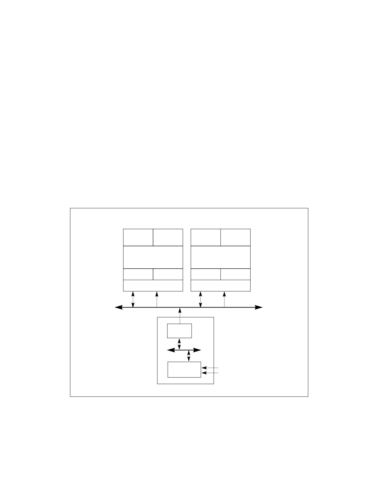
MULTIPLE-PROCESSOR MANAGEMENT
11.6.3 Executing Multiple Threads on an Intel® 64 or IA-32 Processor Supporting Hardware
Multi-Threading
Upon completing the operating system boot-up procedure, the bootstrap processor (BSP) executes operating
system code. Other logical processors are placed in the halt state. To execute a code stream (thread) on a halted
logical processor, the operating system issues an interprocessor interrupt (IPI) addressed to the halted logical
processor. In response to the IPI, the processor wakes up and begins executing the code identified by the vector
received as part of the IPI.
To manage execution of multiple threads on logical processors, an operating system can use conventional
symmetric multiprocessing (SMP) techniques. For example, the operating-system can use a time-slice or load
balancing mechanism to periodically interrupt each of the active logical processors. Upon interrupting a logical
processor, the operating system checks its run queue for a thread waiting to be executed and dispatches the thread
to the interrupted logical processor.
11.6.4 Handling Interrupts on an IA-32 Processor Supporting Hardware Multi-Threading
Interrupts are handled on processors supporting Intel Hyper-Threading Technology as they are on conventional MP
systems. External interrupts are received by the I/O APIC, which distributes them as interrupt messages to specific
logical processors (see Figure 11-3).
Logical processors can also send IPIs to other logical processors by writing to the ICR register of its local APIC (see
Section 13.6, “Issuing Interprocessor Interrupts”). This also applies to dual-core processors.
Intel Processor with Intel
Intel Processor with Intel
Hyper-Threading Technology
Hyper-Threading Technology
Logical
Logical
Logical
Logical
Processor 0
Processor 1
Processor 0
Processor 1
Processor Core
Processor Core
Local APIC
Local APIC
Local APIC
Local APIC
Bus Interface
Bus Interface
Interrupt
Interrupt
IPIs
IPIs
Messages
Messages
Interrupt Messages
Bridge
PCI
I/O APIC
External
Interrupts
System Chipset
Figure 11-3. Local APICs and I/O APIC in MP System Supporting Intel HT Technology
11.7
INTEL® HYPER-THREADING TECHNOLOGY ARCHITECTURE
Figure 11-4 shows a generalized view of an Intel processor supporting Intel Hyper-Threading Technology, using the
original Intel Xeon processor MP as an example. This implementation of the Intel Hyper-Threading Technology
11-28
Vol. 3A
MULTIPLE-PROCESSOR MANAGEMENT
consists of two logical processors (each represented by a separate architectural state) which share the processor’s
execution engine and the bus interface. Each logical processor also has its own advanced programmable interrupt
controller (APIC).
Logical
Logical
Processor 0
Processor 1
Architectural
Architectural
State
State
Execution Engine
Local
APIC
Local APIC
Bus Interface
System Bus
Figure 11-4. IA-32 Processor with Two Logical Processors Supporting Intel HT Technology
11.7.1 State of the Logical Processors
The following features are part of the architectural state of logical processors within Intel 64 or IA-32 processors
supporting Intel Hyper-Threading Technology. The features can be subdivided into three groups:
• Duplicated for each logical processor
• Shared by logical processors in a physical processor
• Shared or duplicated, depending on the implementation
The following features are duplicated for each logical processor:
• General purpose registers (EAX, EBX, ECX, EDX, ESI, EDI, ESP, and EBP)
• Segment registers (CS, DS, SS, ES, FS, and GS)
• EFLAGS and EIP registers. Note that the CS and EIP/RIP registers for each logical processor point to the
instruction stream for the thread being executed by the logical processor.
• x87 FPU registers (ST0 through ST7, status word, control word, tag word, data operand pointer, and instruction
pointer)
• MMX registers (MM0 through MM7)
• XMM registers (XMM0 through XMM7) and the MXCSR register
• Control registers and system table pointer registers (GDTR, LDTR, IDTR, task register)
• Debug registers (DR0, DR1, DR2, DR3, DR6, DR7) and the debug control MSRs
• Machine check global status (IA32_MCG_STATUS) and machine check capability (IA32_MCG_CAP) MSRs
• Thermal clock modulation and ACPI Power management control MSRs
• Time stamp counter MSRs
• Most of the other MSR registers, including the page attribute table (PAT). See the exceptions below.
• Local APIC registers.
• Additional general purpose registers (R8-R15), XMM registers (XMM8-XMM15), control register, IA32_EFER on
Intel 64 processors.
The following features are shared by logical processors:
Vol. 3A
11-29
MULTIPLE-PROCESSOR MANAGEMENT
• Memory type range registers (MTRRs)
Whether the following features are shared or duplicated is implementation-specific:
• IA32_MISC_ENABLE MSR (MSR address 1A0H)
• Machine check architecture (MCA) MSRs (except for the IA32_MCG_STATUS and IA32_MCG_CAP MSRs)
• Performance monitoring control and counter MSRs
11.7.2 APIC Functionality
When a processor supporting Intel Hyper-Threading Technology support is initialized, each logical processor is
assigned a local APIC ID (see Table 13-1). The local APIC ID serves as an ID for the logical processor and is stored
in the logical processor’s APIC ID register. If two or more processors supporting Intel Hyper-Threading Technology
are present in a dual processor (DP) or MP system, each logical processor on the system bus is assigned a unique
local APIC ID (see Section 11.9.3, “Hierarchical ID of Logical Processors in an MP System”).
Software communicates with local processors using the APIC’s interprocessor interrupt (IPI) messaging facility.
Setup and programming for APICs is identical in processors that support and do not support Intel Hyper-Threading
Technology. See Chapter 13, “Advanced Programmable Interrupt Controller (APIC),” for a detailed discussion.
11.7.3 Memory Type Range Registers (MTRR)
MTRRs in a processor supporting Intel Hyper-Threading Technology are shared by logical processors. When one
logical processor updates the setting of the MTRRs, settings are automatically shared with the other logical proces-
sors in the same physical package.
The architectures require that all MP systems based on Intel 64 and IA-32 processors (this includes logical proces-
sors) must use an identical MTRR memory map. This gives software a consistent view of memory, independent of
the processor on which it is running. See Section 14.11, “Memory Type Range Registers (MTRRs),” for information
on setting up MTRRs.
11.7.4 Page Attribute Table (PAT)
Each logical processor has its own PAT MSR (IA32_PAT). However, as described in Section 14.12, “Page Attribute
Table (PAT),” the PAT MSR settings must be the same for all processors in a system, including the logical proces-
sors.
11.7.5 Machine Check Architecture
In the Intel HT Technology context as implemented by processors based on Intel NetBurst® microarchitecture, all
of the machine check architecture (MCA) MSRs (except for the IA32_MCG_STATUS and IA32_MCG_CAP MSRs) are
duplicated for each logical processor. This permits logical processors to initialize, configure, query, and handle
machine-check exceptions simultaneously within the same physical processor. The design is compatible with
machine check exception handlers that follow the guidelines given in Chapter 18, “Machine-Check Architecture.”
The IA32_MCG_STATUS MSR is duplicated for each logical processor so that its machine check in progress bit field
(MCIP) can be used to detect recursion on the part of MCA handlers. In addition, the MSR allows each logical
processor to determine that a machine-check exception is in progress independent of the actions of another logical
processor in the same physical package.
Because the logical processors within a physical package are tightly coupled with respect to shared hardware
resources, both logical processors are notified of machine check errors that occur within a given physical processor.
If machine-check exceptions are enabled when a fatal error is reported, all the logical processors within a physical
package are dispatched to the machine-check exception handler. If machine-check exceptions are disabled, the
logical processors enter the shutdown state and assert the IERR# signal.
When enabling machine-check exceptions, the MCE flag in control register CR4 should be set for each logical
processor.
11-30
Vol. 3A
MULTIPLE-PROCESSOR MANAGEMENT
On Intel Atom family processors that support Intel Hyper-Threading Technology, the MCA facilities are shared
between all logical processors on the same processor core.
11.7.6 Debug Registers and Extensions
Each logical processor has its own set of debug registers (DR0, DR1, DR2, DR3, DR6, DR7) and its own debug
control MSR. These can be set to control and record debug information for each logical processor independently.
Each logical processor also has its own last branch records (LBR) stack.
11.7.7 Performance Monitoring Counters
Performance counters and their companion control MSRs are shared between the logical processors within a
processor core for processors based on Intel NetBurst microarchitecture. As a result, software must manage the
use of these resources. The performance counter interrupts, events, and precise event monitoring support can be
set up and allocated on a per thread (per logical processor) basis.
See Section 22.6.4, “Performance Monitoring and Intel® Hyper-Threading Technology in Processors Based on Intel
NetBurst® Microarchitecture,” for a discussion of performance monitoring in the Intel Xeon processor MP.
In Intel Atom processor family that support Intel Hyper-Threading Technology, the performance counters (general-
purpose and fixed-function counters) and their companion control MSRs are duplicated for each logical processor.
11.7.8 IA32_MISC_ENABLE MSR
The IA32_MISC_ENABLE MSR (MSR address 1A0H) is generally shared between the logical processors in a
processor core supporting Intel Hyper-Threading Technology. However, some bit fields within IA32_MISC_ENABLE
MSR may be duplicated per logical processor. The partition of shared or duplicated bit fields within IA32_MISC_EN-
ABLE is implementation dependent. Software should program duplicated fields carefully on all logical processors in
the system to ensure consistent behavior.
11.7.9 Memory Ordering
The logical processors in an Intel 64 or IA-32 processor supporting Intel Hyper-Threading Technology obey the
same rules for memory ordering as Intel 64 or IA-32 processors without Intel HT Technology (see Section 11.2,
“Memory Ordering”). Each logical processor uses a processor-ordered memory model that can be further defined
as “write-ordered with store buffer forwarding.” All mechanisms for strengthening or weakening the memory-
ordering model to handle special programming situations apply to each logical processor.
11.7.10 Serializing Instructions
As a general rule, when a logical processor in a processor supporting Intel Hyper-Threading Technology executes a
serializing instruction, only that logical processor is affected by the operation. An exception to this rule is the
execution of the WBINVD, INVD, and WRMSR instructions; and the MOV CR instruction when the state of the CD
flag in control register CR0 is modified. Here, both logical processors are serialized.
11.7.11 Microcode Update Resources
In an Intel processor supporting Intel Hyper-Threading Technology, the microcode update facilities are shared
between the logical processors; either logical processor can initiate an update. Each logical processor has its own
BIOS signature MSR (IA32_BIOS_SIGN_ID at MSR address 8BH). When a logical processor performs an update for
the physical processor, the IA32_BIOS_SIGN_ID MSRs for resident logical processors are updated with identical
information. If logical processors initiate an update simultaneously, the processor core provides the necessary
synchronization needed to ensure that only one update is performed at a time.
Vol. 3A
11-31
MULTIPLE-PROCESSOR MANAGEMENT
NOTE
Some processors (prior to the introduction of Intel 64 Architecture and based on Intel NetBurst
microarchitecture) do not support simultaneous loading of microcode update to the sibling logical
processors in the same core. All other processors support logical processors initiating an update
simultaneously. Intel recommends a common approach that the microcode loader use the
sequential technique described in Section 12.11.6.3.
11.7.12 Self Modifying Code
Intel processors supporting Intel Hyper-Threading Technology support self-modifying code, where data writes
modify instructions cached or currently in flight. They also support cross-modifying code, where on an MP system
writes generated by one processor modify instructions cached or currently in flight on another. See Section 11.1.3,
“Handling Self- and Cross-Modifying Code,” for a description of the requirements for self- and cross-modifying code
in an IA-32 processor.
11.7.13 Implementation-Specific Intel® HT Technology Facilities
The following non-architectural facilities are implementation-specific in IA-32 processors supporting Intel Hyper-
Threading Technology:
• Caches.
• Translation lookaside buffers (TLBs).
• Thermal monitoring facilities.
The Intel Xeon processor MP implementation is described in the following sections.
11.7.13.1 Processor Caches
For processors supporting Intel Hyper-Threading Technology, the caches are shared. Any cache manipulation
instruction that is executed on one logical processor has a global effect on the cache hierarchy of the physical
processor. Note the following:
• WBINVD instruction - The entire cache hierarchy is invalidated after modified data is written back to
memory. All logical processors are stopped from executing until after the write-back and invalidate operation is
completed. A special bus cycle is sent to all caching agents. The amount of time or cycles for WBINVD to
complete will vary due to the size of different cache hierarchies and other factors. As a consequence, the use of
the WBINVD instruction can have an impact on interrupt/event response time.
• INVD instruction - The entire cache hierarchy is invalidated without writing back modified data to memory.
All logical processors are stopped from executing until after the invalidate operation is completed. A special bus
cycle is sent to all caching agents.
• CLFLUSH and CLFLUSHOPT instructions - The specified cache line is invalidated from the cache hierarchy
after any modified data is written back to memory and a bus cycle is sent to all caching agents, regardless of
which logical processor caused the cache line to be filled.
• CD flag in control register CR0 - Each logical processor has its own CR0 control register, and thus its own
CD flag in CR0. The CD flags for the two logical processors are ORed together, such that when any logical
processor sets its CD flag, the entire cache is nominally disabled.
11.7.13.2 Processor Translation Lookaside Buffers (TLBs)
In processors supporting Intel Hyper-Threading Technology, data cache TLBs are shared. The instruction cache TLB
may be duplicated or shared in each logical processor, depending on implementation specifics of different processor
families.
Entries in the TLBs are tagged with an ID that indicates the logical processor that initiated the translation. This tag
applies even for translations that are marked global using the page-global feature for memory paging. See Section
5.10, “Caching Translation Information,” for information about global translations.
11-32
Vol. 3A
MULTIPLE-PROCESSOR MANAGEMENT
When a logical processor performs a TLB invalidation operation, only the TLB entries that are tagged for that logical
processor are guaranteed to be flushed. This protocol applies to all TLB invalidation operations, including writes to
control registers CR3 and CR4 and uses of the INVLPG instruction.
11.7.13.3 Thermal Monitor
In a processor that supports Intel Hyper-Threading Technology, logical processors share the catastrophic shutdown
detector and the automatic thermal monitoring mechanism (see Section 17.8, “Thermal Monitoring and Protec-
tion”). Sharing results in the following behavior:
• If the processor’s core temperature rises above the preset catastrophic shutdown temperature, the processor
core halts execution, which causes both logical processors to stop execution.
• When the processor’s core temperature rises above the preset automatic thermal monitor trip temperature,
the frequency of the processor core is automatically modulated, which effects the execution speed of both
logical processors.
For software controlled clock modulation, each logical processor has its own IA32_CLOCK_MODULATION MSR,
allowing clock modulation to be enabled or disabled on a logical processor basis. Typically, if software controlled
clock modulation is going to be used, the feature must be enabled for all the logical processors within a physical
processor and the modulation duty cycle must be set to the same value for each logical processor. If the duty cycle
values differ between the logical processors, the processor clock will be modulated at the highest duty cycle
selected.
11.7.13.4 External Signal Compatibility
This section describes the constraints on external signals received through the pins of a processor supporting Intel
Hyper-Threading Technology and how these signals are shared between its logical processors.
• STPCLK# - A single STPCLK# pin is provided on the physical package of the Intel Xeon processor MP. External
control logic uses this pin for power management within the system. When the STPCLK# signal is asserted, the
processor core transitions to the stop-grant state, where instruction execution is halted but the processor core
continues to respond to snoop transactions. Regardless of whether the logical processors are active or halted
when the STPCLK# signal is asserted, execution is stopped on both logical processors and neither will respond
to interrupts.
In MP systems, the STPCLK# pins on all physical processors are generally tied together. As a result this signal
affects all the logical processors within the system simultaneously.
• LINT0 and LINT1 pins - A processor supporting Intel Hyper-Threading Technology has only one set of LINT0
and LINT1 pins, which are shared between the logical processors. When one of these pins is asserted, both
logical processors respond unless the pin has been masked in the APIC local vector tables for one or both of the
logical processors.
Typically in MP systems, the LINT0 and LINT1 pins are not used to deliver interrupts to the logical processors.
Instead all interrupts are delivered to the local processors through the I/O APIC.
• A20M# pin - On an IA-32 processor, the A20M# pin is typically provided for compatibility with the Intel 286
processor. Asserting this pin causes bit 20 of the physical address to be masked (forced to zero) for all external
bus memory accesses. Processors supporting Intel Hyper-Threading Technology provide one A20M# pin, which
affects the operation of both logical processors within the physical processor.
The functionality of A20M# is used primarily by older operating systems and not used by modern operating
systems. On newer Intel 64 processors, A20M# may be absent.
11.8
MULTI-CORE ARCHITECTURE
This section describes the architecture of Intel 64 and IA-32 processors supporting dual-core and quad-core tech-
nology. The discussion is applicable to the Intel Pentium processor Extreme Edition, Pentium D, Intel Core Duo,
Intel Core 2 Duo, Dual-core Intel Xeon processor, Intel Core 2 Quad processors, and quad-core Intel Xeon proces-
sors. Features vary across different microarchitectures and are detectable using CPUID.
Vol. 3A
11-33
MULTIPLE-PROCESSOR MANAGEMENT
In general, each processor core has dedicated microarchitectural resources identical to a single-processor imple-
mentation of the underlying microarchitecture without hardware multi-threading capability. Each logical processor
in a dual-core processor (whether supporting Intel Hyper-Threading Technology or not) has its own APIC function-
ality, PAT, machine check architecture, debug registers and extensions. Each logical processor handles serialization
instructions or self-modifying code on its own. Memory order is handled the same way as in Intel Hyper-Threading
Technology.
The topology of the cache hierarchy (with respect to whether a given cache level is shared by one or more
processor cores or by all logical processors in the physical package) depends on the processor implementation.
Software must use the deterministic cache parameter leaf of CPUID instruction to discover the cache-sharing
topology between the logical processors in a multi-threading environment.
11.8.1 Logical Processor Support
The topological composition of processor cores and logical processors in a multi-core processor can be discovered
using CPUID. Within each processor core, one or more logical processors may be available.
System software must follow the requirement MP initialization sequences (see Section 11.4, “Multiple-Processor
(MP) Initialization”) to recognize and enable logical processors. At runtime, software can enumerate those logical
processors enabled by system software to identify the topological relationships between these logical processors.
(See Section 11.9.5, “Identifying Topological Relationships in an MP System”).
11.8.2 Memory Type Range Registers (MTRR)
MTRR is shared between two logical processors sharing a processor core if the physical processor supports Intel
Hyper-Threading Technology. MTRR is not shared between logical processors located in different cores or different
physical packages.
The Intel 64 and IA-32 architectures require that all logical processors in an MP system use an identical MTRR
memory map. This gives software a consistent view of memory, independent of the processor on which it is
running.
See Section 14.11, “Memory Type Range Registers (MTRRs).”
11.8.3 Performance Monitoring Counters
Performance counters and their companion control MSRs are shared between two logical processors sharing a
processor core if the processor core supports Intel Hyper-Threading Technology and is based on Intel NetBurst
microarchitecture. They are not shared between logical processors in different cores or different physical packages.
As a result, software must manage the use of these resources, based on the topology of performance monitoring
resources. Performance counter interrupts, events, and precise event monitoring support can be set up and allo-
cated on a per thread (per logical processor) basis.
See Section 22.6.4, “Performance Monitoring and Intel® Hyper-Threading Technology in Processors Based on Intel
NetBurst® Microarchitecture.”
11.8.4 IA32_MISC_ENABLE MSR
Some bit fields in IA32_MISC_ENABLE MSR (MSR address 1A0H) may be shared between two logical processors
sharing a processor core, or may be shared between different cores in a physical processor. See Chapter 2, “Model-
Specific Registers (MSRs)‚” in the Intel® 64 and IA-32 Architectures Software Developer’s Manual, Volume 4.
11.8.5 Microcode Update Resources
Microcode update facilities are shared between two logical processors sharing a processor core if the physical
package supports Intel Hyper-Threading Technology. They are not shared between logical processors in different
11-34
Vol. 3A
MULTIPLE-PROCESSOR MANAGEMENT
cores or different physical packages. Either logical processor that has access to the microcode update facility can
initiate an update.
Each logical processor has its own BIOS signature MSR (IA32_BIOS_SIGN_ID at MSR address 8BH). When a logical
processor performs an update for the physical processor, the IA32_BIOS_SIGN_ID MSRs for resident logical
processors are updated with identical information.
All microcode update steps during processor initialization should use the same update data on all cores in all phys-
ical packages of the same stepping. Any subsequent microcode update must apply consistent update data to all
cores in all physical packages of the same stepping. If the processor detects an attempt to load an older microcode
update when a newer microcode update had previously been loaded, it may reject the older update to stay with the
newer update.
NOTE
Some processors (prior to the introduction of Intel 64 Architecture and based on Intel NetBurst
microarchitecture) do not support simultaneous loading of microcode update to the sibling logical
processors in the same core. All other processors support logical processors initiating an update
simultaneously. Intel recommends a common approach that the microcode loader use the
sequential technique described in Section 12.11.6.3.
11.9
PROGRAMMING CONSIDERATIONS FOR HARDWARE MULTI-THREADING
CAPABLE PROCESSORS
In a multi-threading environment, there may be certain hardware resources that are physically shared at some
level of the hardware topology. In the multi-processor systems, typically bus and memory sub-systems are physi-
cally shared between multiple sockets. Within a hardware multi-threading capable processors, certain resources
are provided for each processor core, while other resources may be provided for each logical processors (see
Section 11.7, “Intel® Hyper-Threading Technology Architecture,” and Section 11.8, “Multi-Core Architecture”).
From a software programming perspective, control transfer of processor operation is managed at the granularity of
logical processor (operating systems dispatch a runnable task by allocating an available logical processor on the
platform). To manage the topology of shared resources in a multi-threading environment, it may be useful for soft-
ware to understand and manage resources that are shared by more than one logical processors.
11.9.1 Hierarchical Mapping of Shared Resources
The APIC_ID value associated with each logical processor in a multi-processor system is unique (see Section 11.6,
“Detecting Hardware Multi-Threading Support and Topology”). This 8-bit or 32-bit value can be decomposed into
sub-fields, where each sub-field corresponds a hierarchical domain of the topological mapping of hardware
resources.
The decomposition of an APIC_ID may consist of several sub fields representing the topology within a physical
processor package, the higher-order bits of an APIC ID may also be used by cluster vendors to represent the
topology of cluster nodes of each coherent multiprocessor systems:
• Cluster - Some multi-threading environments consists of multiple clusters of multi-processor systems. The
CLUSTER_ID sub-field is usually supported by vendor firmware to distinguish different clusters. For non-
clustered systems, CLUSTER_ID is usually 0 and system topology is reduced.
• Package - A physical processor package mates with a socket. A package may contain one or more software
visible die. The PACKAGE_ID sub-field distinguishes different physical packages within a cluster.
• Die - A software-visible chip inside a package. The DIE_ID sub-field distinguishes different die within a
package. If there are no software visible die, the width of this bit field is 0.
• DieGrp - A group of die that share certain resources.
• Tile - A set of cores that share certain resources. The TILE_ID sub-field distinguishes different tiles. If there
are no software visible tiles, the width of this bit field is 0.
Vol. 3A
11-35

MULTIPLE-PROCESSOR MANAGEMENT
• Module - A set of cores that share certain resources. The MODULE_ID sub-field distinguishes different
modules. If there are no software visible modules, the width of this bit field is 0.
• Core - Processor cores may be contained within modules, within tiles, on software-visible die, or appear
directly at the package domain. The CORE_ID sub-field distinguishes processor cores. For a single-core
processor, the width of this bit field is 0.
• Logical Processor - A processor core provides one or more logical processors sharing execution resources.
The LOGICAL_PROCESSOR_ID sub-field distinguishes logical processors in a core. The width of this bit field is
non-zero if a processor core provides more than one logical processors.
The LOGICAL_PROCESSOR_ID and CORE_ID sub-fields are bit-wise contiguous in the APIC_ID field (see
Figure 11-5).
X
0
Reserved
CLUSTER_ID
PACKAGE_ID
DIE_ID
TILE_ID
MODULE_ID
CORE_ID
LOGICAL_PROCESSOR_ID
X=31 if x2APIC is supported, otherwise X= 7
Figure 11-5. Generalized Seven-Domain Interpretation of the APIC ID
If the processor supports CPUID.0BH and CPUID.1FH, the 32-bit APIC ID can represent cluster plus several
domains of topology within the physical processor package. The exact number of hierarchical domains within a
physical processor package must be enumerated through CPUID.0BH and CPUID.1FH. Common processor families
may employ a topology similar to that represented by the 8-bit Initial APIC ID. In general, CPUID.0BH and
CPUID.1FH can support a topology enumeration algorithm that decompose a 32-bit APIC ID into more than four
sub-fields (see Figure 11-6).
NOTE
CPUID.0BH and CPUID.1FH can have differences in the number of domain types reported
(CPUID.1FH defines additional domain types). If the processor supports CPUID.1FH, usage of this
leaf is preferred over CPUID.0BH. CPUID.0BH is available for legacy compatibility going forward.
The width of each sub-field depends on hardware and software configurations. Field widths can be determined at
runtime using the algorithm discussed below (Example 11-16 through Example 11-21).
Figure 11-6 depicts the relationships of three of the hierarchical sub-fields in a hypothetical MP system. The value
of valid APIC_IDs need not be contiguous across package boundary or core boundaries.
11-36
Vol. 3A

MULTIPLE-PROCESSOR MANAGEMENT
PACKAGE
31
0
Q
R
CORE
Reserved
LOGICAL
PROCESSOR
CLUSTER_ID
PACKAGE_ID
Q_ID
R_ID
CORE_ID
Physical Processor Topology
LOGICAL_PROCESSOR_ID
32-bit APIC ID Composition
Figure 11-6. Conceptual Six-Domain Topology and 32-bit APIC ID Composition
11.9.2 Hierarchical Mapping of CPUID Extended Topology Leaf
CPUID.0BH and CPUID.1FH provide enumeration parameters for software to identify each hierarchy of the
processor topology in a deterministic manner. Each hierarchical domain of the topology starting from the Logical
Processor domain is represented numerically by a sub-leaf index within the CPUID 0BH leaf and 1FH leaf. Each
domain of the topology is mapped to a sub-field in the APIC ID, following the general relationship depicted in
Figure 11-6. This mechanism allows software to query the exact number of domains within a physical processor
package and the bit-width of each sub-field of x2APIC ID directly. For example,
• Starting from sub-leaf index 0 and incrementing the input ECX, N, until the output ECX[15:8] returned by
either CPUID.0BH.N or CPUID.1FH.N returns an invalid “domain type” encoding. The number of domains within
the physical processor package is “N” (excluding PACKAGE). Using Figure 11-6 as an example, ECX[15:8]
returned by either CPUID.0BH.04H or CPUID.1FH.04H will report 00H, indicating sub leaf 04H is invalid. This is
also depicted by a pseudo code example:
Example 11-16. Number of Domains Below the Physical Processor Package
Word NumberOfDomainsBelowPackage = 0;
DWord Subleaf = 0;
EAX = 0BH or 1FH; // query each sub leaf of CPUID.0BH or 1FH; CPUID.1FH is preferred over CPUID.0BH if available.
ECX = Subleaf;
CPUID;
while (EBX != 0) // Enumerate until EBX reports 0
{
if (EAX[4:0] != 0)
// A Shift Value of 0 indicates this domain does not exist.
// (Such as no SMT_ID, which is required entry at sub-leaf 0.)
{
NumberOfDomainsBelowPackage++;
}
Subleaf++;
EAX = 0BH or 1FH;
ECX = Subleaf;
CPUID;
}
// NumberOfDomainsBelowPackage contains the absolute number of domains that exist below package.
Vol. 3A
11-37
MULTIPLE-PROCESSOR MANAGEMENT
N = Subleaf;
// Sub-leaf supplies the number of entries CPUID will return.
• Sub-leaf index 0 (ECX = 0 as input) provides enumeration parameters to extract the LOGICAL_PROCESSOR_ID
sub-field of x2APIC ID. If EAX[4:0] returned by either CPUID.0BH.00H or CPUID.1FH.00H reports a value (a
right-shift count) that allow software to extract part of x2APIC ID to distinguish the next higher topological
entities above the LOGICAL_PROCESSOR_ID domain. This value also corresponds to the bit-width of the sub-
field of x2APIC ID corresponding the hierarchical domain with sub-leaf index 0.
• For each subsequent higher sub-leaf index m, EAX[4:0] returned by either CPUID.0BH.m or CPUID.1FH.m
reports the right-shift count that will allow software to extract part of x2APIC ID to distinguish higher-domain
topological entities. This means the right-shift value at of sub-leaf m, corresponds to the least significant
(m+1) sub-fields of the 32-bit x2APIC ID.
Example 11-17. BitWidth Determination of x2APIC ID Sub-fields
For m = 0, m < N, m ++;
{cumulative_width[m] = CPUID.0BH.m:EAX[4:0] or CPUID.1FH.m:EAX[4:0]; }
BitWidth[0] = cumulative_width[0];
For m = 1, m < N, m ++;
BitWidth[m] = cumulative_width[m] - cumulative_width[m-1];
NOTE
CPUID.1FH is a preferred superset to CPUID.0BH. CPUID.1FH defines additional domain types, and
it must be parsed by an algorithm that can handle the addition of future domain types.
Previously, only the following encoding of hierarchical domain types were defined: 0 (invalid), 1 (logical processor),
and 2 (core). With the additional hierarchical domain types available (see Section 11.9.1, “Hierarchical Mapping of
Shared Resources,” and Figure 11-5, “Generalized Seven-Domain Interpretation of the APIC ID” ) software must
not assume any “domain type” encoding value to be related to any sub-leaf index, except sub-leaf 0.
Example 11-18. Support Routines for Identifying Package, Die, Core, and Logical Processors from 32-bit x2APIC ID
a.
Derive the extraction bitmask for logical processors in a processor core and associated mask offset for different
cores.
//
// This example shows how to enumerate CPU topology domain types (domain types may or may not be known/supported by the
software)
//
// Below is the list of sample domain types used in the example.
// Refer to the CPUID.1FH definition for the actual domain type numbers: “V2 Extended Topology Enumeration Leaf (Initial EAX Value
= 1FH, ECX ≥ 0)”.
//
// LOGICAL PROCESSOR
// CORE
// MODULE
// TILE
// DIE
// PACKAGE
//
// The example shows how to identify and derive the extraction bitmask for the domains with identify type
LOGICAL_PROCESSOR_ID/CORE_ID/DIE_ID/PACKAGE_ID
//
int DeriveLogical_Processor_Mask_Offsets (void)
{
11-38
Vol. 3A
MULTIPLE-PROCESSOR MANAGEMENT
IF (!HWMTSupported()) return -1;
execute cpuid with EAX = 0BH or 1FH, ECX = 0;
IF (returned domain type encoding in EXC[15:8] does not match LOGICAL_PROCESSOR_ID) return -1;
Mask_Logical_Processor_shift = EAX[4:0];
//# bits shift right of APIC ID to distinguish different cores, note this can be a shift
// of zero if there is only one logical processor per core.
Logical Processor Mask =~( (-1) << Mask_Logical_Processor_shift);
//shift left to derive extraction bitmask for
// LOGICAL_PROCESSOR_ID
return 0;
}
b.
Derive the extraction bitmask for processor cores in a physical processor package and associated mask offset for
different packages.
int DeriveCore_Mask_Offsets (void)
{
IF (!HWMTSupported()) return -1;
execute cpuid with EAX = 0BH or 1FH, ECX = 0;
WHILE ( ECX[15:8] ) {
//domain type encoding is valid
Mask_last_known_shift = EAX[4:0]
IF (returned domain type encoding in ECX[15:8] matches CORE) {
Mask_Core_shift = EAX[4:0];
}
ELSE IF (returned domain type encoding in ECX[15:8] matches DIE {
Mask_Die_shift = EAX[4:0];
}
//
// Keep enumerating. Check if the next domain is the desired domain and if not, keep enumerating until you reach a known
// domain or the invalid domain (“0” domain type). If there are more domains between DIE and PACKAGE, the unknown
// domains will be ignored and treated as an extension of the last known domain (i.e., DIE in this case).
//
ECX++;
execute cpuid with EAX = 0BH or 1FH;
}
COREPlusLogical_Processor_MASK = ~( (-1) << Mask_Core_shift);
DIEPlusCORE_MASK = ~( (-1) << Mask_Die_shift);
//
// Treat domains between DIE and physical package as an extension of DIE for software choosing not to implement or recognize
// these unknown domains.
//
CORE_MASK = COREPlusLogical_Processor_MASK ^ Logical Processor Mask;
DIE_MASK = DIEPlusCORE_MASK ^ COREPlusLogical_Processor_MASK;
PACKAGE_MASK = (-1) << Mask_last_known_shift;
return -1;
}
Vol. 3A
11-39
MULTIPLE-PROCESSOR MANAGEMENT
11.9.3 Hierarchical ID of Logical Processors in an MP System
For Intel 64 and IA-32 processors, system hardware establishes an 8-bit initial APIC ID (or 32-bit APIC ID if the
processor supports CPUID.0BH) that is unique for each logical processor following power-up or RESET (see Section
11.6.1). Each logical processor on the system is allocated an initial APIC ID. BIOS may implement features that tell
the OS to support less than the total number of logical processors on the system bus. Those logical processors that
are not available to applications at runtime are halted during the OS boot process. As a result, the number valid
local APIC_IDs that can be queried by affinitizing-current-thread-context (See Example 11-23) is limited to the
number of logical processors enabled at runtime by the OS boot process.
Table 11-2 shows an example of the 8-bit APIC IDs that are initially reported for logical processors in a system with
four Intel Xeon MP processors that support Intel Hyper-Threading Technology (a total of 8 logical processors, each
physical package has two processor cores and supports Intel Hyper-Threading Technology). Of the two logical
processors within a Intel Xeon processor MP, logical processor 0 is designated the primary logical processor and
logical processor 1 as the secondary logical processor.
LOGICAL_PROCESSOR_ID
CORE_ID
T0
T1
T0
T1
T0
T1
T0
T1
PACKAGE_ID
Core 0
Core 1
Core 0
Core 1
Package 0
Package 1
Figure 11-7. Topological Relationships Between Hierarchical IDs in a Hypothetical MP Platform
Table 11-2. Initial APIC IDs for the Logical Processors in a System that has Four Intel Xeon MP Processors
Supporting Intel Hyper-Threading Technology1
Initial APIC ID
PACKAGE_ID
CORE_ID
LOGICAL_PROCESSOR_ID
0H
0H
0H
0H
1H
0H
0H
1H
2H
1H
0H
0H
3H
1H
0H
1H
4H
2H
0H
0H
5H
2H
0H
1H
6H
3H
0H
0H
7H
3H
0H
1H
NOTE:
1. Because information on the number of processor cores in a physical package was not available in early single-core processors sup-
porting Intel Hyper-Threading Technology, the CORE_ID can be treated as 0.
Table 11-3 shows the initial APIC IDs for a hypothetical situation with a dual processor system. Each physical
package providing two processor cores, and each processor core also supporting Intel Hyper-Threading Tech-
nology.
11-40
Vol. 3A
MULTIPLE-PROCESSOR MANAGEMENT
Table 11-3. Initial APIC IDs for the Logical Processors in a System that has Two Physical Processors Supporting
Dual-Core and Intel Hyper-Threading Technology
Initial APIC ID
PACKAGE_ID
CORE_ID
LOGICAL_PROCESSOR_ID
0H
0H
0H
0H
1H
0H
0H
1H
2H
0H
1H
0H
3H
0H
1H
1H
4H
1H
0H
0H
5H
1H
0H
1H
6H
1H
1H
0H
7H
1H
1H
1H
11.9.3.1 Hierarchical ID of Logical Processors with x2APIC ID
Table 11-4 shows an example of possible x2APIC ID assignments for a dual processor system that support x2APIC.
Each physical package providing four processor cores, and each processor core also supporting Intel Hyper-
Threading Technology. Note that the x2APIC ID need not be contiguous in the system.
Table 11-4. Example of Possible x2APIC ID Assignment in a System that has Two Physical Processors Supporting
x2APIC and Intel Hyper-Threading Technology
x2APIC ID
PACKAGE_ID
CORE_ID
LOGICAL_PROCESSOR_ID
0H
0H
0H
0H
1H
0H
0H
1H
2H
0H
1H
0H
3H
0H
1H
1H
4H
0H
2H
0H
5H
0H
2H
1H
6H
0H
3H
0H
7H
0H
3H
1H
10H
1H
0H
0H
11H
1H
0H
1H
12H
1H
1H
0H
13H
1H
1H
1H
14H
1H
2H
0H
15H
1H
2H
1H
16H
1H
3H
0H
17H
1H
3H
1H
Vol. 3A
11-41
MULTIPLE-PROCESSOR MANAGEMENT
11.9.4 Algorithm for Three-Domain Mappings of APIC_ID
Software can gather the initial APIC_IDs for each logical processor supported by the operating system at runtime1
and extract identifiers corresponding to the three domains of sharing topology (package, core, and logical
processor). The three-domain algorithms below focus on a non-clustered MP system for simplicity. They do not
assume APIC IDs are contiguous or that all logical processors on the platform are enabled.
Intel supports multi-threading systems where all physical processors report identical values in CPUID.0BH,
CPUID.01H:EBX[23:16], CPUID.04H2:EAX[31:26], and CPUID.04H3:EAX[25:14]. The algorithms below assume
the target system has symmetry across physical package boundaries with respect to the number of logical proces-
sors per package, number of cores per package, and cache topology within a package.
Software can choose to assume three-domain hierarchy if it was developed to understand only three domains.
However, software implementation needs to ensure it does not break if it runs on systems that have more domains
in the hierarchy even if it does not recognize them.
The extraction algorithm (for three-domain mappings from an APIC ID) uses the general procedure depicted in
Example 11-19, and is supplemented by more detailed descriptions on the derivation of topology enumeration
parameters for extraction bit masks:
1.
Detect hardware multi-threading support in the processor.
2.
Derive a set of bit masks that can extract the sub ID of each hierarchical domain of the topology. The algorithm
to derive extraction bit masks for LOGICAL_PROCESSOR_ID/CORE_ID/PACKAGE_ID differs based on APIC ID
is 32-bit (see step 3 below) or 8-bit (see step 4 below).
3.
If the processor supports CPUID.0BH, each APIC ID contains a 32-bit value, the topology enumeration
parameters needed to derive three-domain extraction bit masks are:
a. Query the right-shift value for the LOGICAL_PROCESSOR_ID domain of the topology using CPUID.0BH with
ECX = 0H as input. The number of bits to shift-right on x2APIC ID (EAX[4:0]) can distinguish different
higher-domain entities above logical processor in the same physical package. This is also the width of the
bit mask to extract the LOGICAL_PROCESSOR_ID. The shift value may be 0 and enumerate no logical
processor bit mask to create. A platform where cores only have one logical processor are not required to
enumerate a separate bit layout for logical processor, and the lowest bits may only identify the core (where
core and logical processor are then synonymous).
b. Enumerate until the desired domain is found (i.e., processor cores). Determine if the next domain is the
expected domain. If the next domain is not known to the software, keep enumerating until the next known
or the last domain. Software should use the previous domain before this to represent the last previously
known domain (i.e., processor cores). If the software does not recognize or implement certain hierarchical
domains, it should assume these unknown domains as an extension of the last known domain.
c. Query CPUID.0BH for the amount of bit shift to distinguish next higher-domain entities (e.g., physical
processor packages) in the system. This describes an explicit three-domain-topology situation for
commonly available processors. Consult Example 11-17 to adapt to situations beyond a three-domain
topology of a physical processor. The width of the extraction bit mask can be used to derive the cumulative
extraction bitmask to extract the sub IDs of logical processors (including different processor cores) in the
same physical package. The extraction bit mask to distinguish merely different processor cores can be
derived by xor’ing the logical processor extraction bit mask from the cumulative extraction bit mask.
d. Query the 32-bit x2APIC ID for the logical processor where the current thread is executing.
e. Derive the extraction bit masks corresponding to LOGICAL_PROCESSOR_ID, CORE_ID, and PACKAGE_ID,
starting from LOGICAL_PROCESSOR_ID.
f. Apply each extraction bit mask to the 32-bit x2APIC ID to extract sub-field IDs.
1.
As noted in Section 11.6 and Section 11.9.3, the number of logical processors supported by the OS at runtime may be less than the
total number logical processors available in the platform hardware.
2.
Maximum number of addressable ID for processor cores in a physical processor is obtained by executing CPUID with EAX = 4 and a
valid ECX index. The ECX index starts at 0.
3.
Maximum number addressable ID for processor cores sharing the target cache level is obtained by executing CPUID with EAX = 4
and the ECX index corresponding to the target cache level.
11-42
Vol. 3A
MULTIPLE-PROCESSOR MANAGEMENT
4. If the processor does not support CPUID.0BH, each initial APIC ID contains an 8-bit value, the topology
enumeration parameters needed to derive extraction bit masks are:
a. Query the size of address space for sub IDs that can accommodate logical processors in a physical
processor package. This size parameters (CPUID.01H:EBX[23:16]) can be used to derive the width of an
extraction bitmask to enumerate the sub IDs of different logical processors in the same physical package.
b. Query the size of address space for sub IDs that can accommodate processor cores in a physical processor
package. This size parameters can be used to derive the width of an extraction bitmask to enumerate the
sub IDs of processor cores in the same physical package.
c. Query the 8-bit initial APIC ID for the logical processor where the current thread is executing.
d. Derive the extraction bit masks using respective address sizes corresponding to LOGICAL_PROCESSOR_ID,
CORE_ID, and PACKAGE_ID, starting from LOGICAL_PROCESSOR_ID.
e. Apply each extraction bit mask to the 8-bit initial APIC ID to extract sub-field IDs.
Example 11-19. Support Routines for Detecting Hardware Multi-Threading and Identifying the Relationships Between
Package, Core, and Logical Processors
1.
Detect support for Hardware Multi-Threading Support in a processor.
// Returns a non-zero value if CPUID reports the presence of hardware multi-threading
// support in the physical package where the current logical processor is located.
// This does not guarantee BIOS or OS will enable all logical processors in the physical
// package and make them available to applications.
// Returns zero if hardware multi-threading is not present.
#define HWMT_BIT 10000000H
unsigned int HWMTSupported(void)
{
// ensure cpuid instruction is supported
execute cpuid with eax = 0 to get vendor string
execute cpuid with eax = 1 to get feature flag and signature
// Check to see if this a Genuine Intel Processor
if (vendor string EQ GenuineIntel) {
return (feature_flag_edx & HWMT_BIT); // bit 28
}
return 0;
}
Example 11-20. Support Routines for Identifying Package, Core, and Logical Processors from 32-bit x2APIC ID
a.
Derive the extraction bitmask for logical processors in a processor core and associated mask offset for different
cores.
int DeriveLogical_Processor_Mask_Offsets (void)
{
if (!HWMTSupported()) return -1;
execute cpuid with eax = 11, ECX = 0;
If (returned domain type encoding in ECX[15:8] does not match logical processor) return -1;
Mask_Logical_Processor_shift = EAX[4:0];
// # bits shift right of APIC ID to distinguish different cores, note this can be a shift
// of zero if there is only one logical processor per core.
Logical Processor Mask = ~( (-1) << Mask_Logical_Processor_shift); // shift left to derive extraction bitmask for
// LOGICAL_PROCESSOR_ID
Vol. 3A
11-43
MULTIPLE-PROCESSOR MANAGEMENT
return 0;
}
b.
Derive the extraction bitmask for processor cores in a physical processor package and associated mask offset for
different packages.
int DeriveCore_Mask_Offsets (void)
{
if (!HWMTSupported()) return -1;
execute cpuid with eax = 11, ECX = 0;
while ( ECX[15:8] ) {
// domain type encoding is valid
Mask_Core_shift = EAX[4:0];
// needed to distinguish different physical packages
ECX ++;
execute cpuid with eax = 11;
}
COREPlusLogical_Processor_MASK = ~( (-1) << Mask_Core_shift);
// treat domains between core and physical package as a core for software choosing not to implement or recognize
// these unknown domains
CORE_MASK = COREPlusLogical_Processor_MASK ^ Logical Processor Mask;
PACKAGE_MASK = (-1) << Mask_Core_shift;
return -1;
}
c.
Query the x2APIC ID of a logical processor.
APIC_IDs for each logical processor.
unsigned char Getx2APIC_ID (void)
{
unsigned reg_edx = 0;
execute cpuid with eax = 11, ECX = 0
store returned value of edx
return (unsigned) (reg_edx) ;
}
Example 11-21. Support Routines for Identifying Package, Core, and Logical Processors from 8-bit Initial APIC ID
a.
Find the size of address space for logical processors in a physical processor package.
#define NUM_LOGICAL_BITS 00FF0000H
// Use the mask above and CPUID.01H:EBX[23:16] to obtain the max number of addressable IDs
// for logical processors in a physical package,
//Returns the size of address space of logical processors in a physical processor package;
// Software should not assume the value to be a power of 2.
unsigned char MaxLPIDsPerPackage(void)
{
if (!HWMTSupported()) return 1;
execute cpuid with eax = 1
store returned value of ebx
return (unsigned char) ((reg_ebx & NUM_LOGICAL_BITS) >> 16);
}
11-44
Vol. 3A
MULTIPLE-PROCESSOR MANAGEMENT
b.
Find the size of address space for processor cores in a physical processor package.
// Returns the max number of addressable IDs for processor cores in a physical processor package;
// Software should not assume cpuid reports this value to be a power of 2.
unsigned MaxCoreIDsPerPackage(void)
{
if (!HWMTSupported()) return (unsigned char) 1;
if cpuid supports leaf number 4
{ // we can retrieve multi-core topology info using leaf 4
execute cpuid with eax = 4, ecx = 0
store returned value of eax
return (unsigned) ((reg_eax >> 26) +1);
}
else // must be a single-core processor
return 1;
}
c.
Query the initial APIC ID of a logical processor.
#define INITIAL_APIC_ID_BITS FF000000H // CPUID.01H:EBX[31:24] initial APIC ID
// Returns the 8-bit unique initial APIC ID for the processor running the code.
// Software can use OS services to affinitize the current thread to each logical processor
// available under the OS to gather the initial APIC_IDs for each logical processor.
unsigned GetInitAPIC_ID (void)
{
unsigned int reg_ebx = 0;
execute cpuid with eax = 1
store returned value of ebx
return (unsigned) ((reg_ebx & INITIAL_APIC_ID_BITS) >> 24;
}
d.
Find the width of an extraction bitmask from the maximum count of the bit-field (address size).
// Returns the mask bit width of a bit field from the maximum count that bit field can represent.
// This algorithm does not assume ‘address size’ to have a value equal to power of 2.
// Address size for LOGICAL_PROCESSOR_ID can be calculated from MaxLPIDsPerPackage()/MaxCoreIDsPerPackage()
// Then use the routine below to derive the corresponding width of logical processor extraction bitmask
// Address size for CORE_ID is MaxCoreIDsPerPackage(),
// Derive the bitwidth for CORE extraction mask similarly
unsigned FindMaskWidth(Unsigned Max_Count)
{unsigned int mask_width, cnt = Max_Count;
__asm {
mov eax, cnt
mov ecx, 0
mov mask_width, ecx
dec eax
bsr cx, ax
jz next
inc cx
mov mask_width, ecx
next:
mov eax, mask_width
Vol. 3A
11-45
MULTIPLE-PROCESSOR MANAGEMENT
}
return mask_width;
}
e.
Extract a sub ID from an 8-bit full ID, using address size of the sub ID and shift count.
// The routine below can extract LOGICAL_PROCESSOR_ID, CORE_ID, and PACKAGE_ID respectively from the init APIC_ID
// To extract LOGICAL_PROCESSOR_ID, MaxSubIDvalue is set to the address size of LOGICAL_PROCESSOR_ID, Shift_Count = 0
// To extract CORE_ID, MaxSubIDvalue is the address size of CORE_ID, Shift_Count is width of logical processor extraction bitmask.
// Returns the value of the sub ID, this is not a zero-based value
Unsigned char GetSubID(unsigned char Full_ID, unsigned char MaxSubIDvalue, unsigned char Shift_Count)
{
MaskWidth = FindMaskWidth(MaxSubIDValue);
MaskBits = ((uchar) (FFH << Shift_Count)) ^ ((uchar) (FFH << Shift_Count + MaskWidth)) ;
SubID = Full_ID & MaskBits;
Return SubID;
}
Software must not assume local APIC_ID values in an MP system are consecutive. Non-consecutive local APIC_IDs
may be the result of hardware configurations or debug features implemented in the BIOS or OS.
An identifier for each hierarchical domain can be extracted from an 8-bit APIC_ID using the support routines illus-
trated in Example 11-21. The appropriate bit mask and shift value to construct the appropriate bit mask for each
domain must be determined dynamically at runtime.
11.9.5 Identifying Topological Relationships in an MP System
To detect the number of physical packages, processor cores, or other topological relationships in a MP system, the
following procedures are recommended:
• Extract the three-domain identifiers from the APIC ID of each logical processor enabled by system software.
The sequence is as follows (see the pseudo code shown in Example 11-22 and support routines shown in
Example 11-19):
• The extraction start from the right-most bit field, corresponding to LOGICAL_PROCESSOR_ID, the
innermost hierarchy in a three-domain topology (See Figure 11-7). For the right-most bit field, the shift
value of the working mask is zero. The width of the bit field is determined dynamically using the
maximum number of logical processor per core, which can be derived from information provided from
CPUID.
• To extract the next bit-field, the shift value of the working mask is determined from the width of the bit
mask of the previous step. The width of the bit field is determined dynamically using the maximum
number of cores per package.
• To extract the remaining bit-field, the shift value of the working mask is determined from the maximum
number of logical processor per package. So the remaining bits in the APIC ID (excluding those bits
already extracted in the two previous steps) are extracted as the third identifier. This applies to a non-
clustered MP system, or if there is no need to distinguish between PACKAGE_ID and CLUSTER_ID.
If there is need to distinguish between PACKAGE_ID and CLUSTER_ID, PACKAGE_ID can be extracted
using an algorithm similar to the extraction of CORE_ID, assuming the number of physical packages in
each node of a clustered system is symmetric.
• Assemble the three-domain identifiers of LOGICAL_PROCESSOR_ID, CORE_ID, PACKAGE_IDs into arrays for
each enabled logical processor. This is shown in Example 11-23a.
• To detect the number of physical packages: use PACKAGE_ID to identify those logical processors that reside in
the same physical package. This is shown in Example 11-23b. This example also depicts a technique to
construct a mask to represent the logical processors that reside in the same package.
11-46
Vol. 3A
MULTIPLE-PROCESSOR MANAGEMENT
• To detect the number of processor cores: use CORE_ID to identify those logical processors that reside in the
same core. This is shown in Example 11-23. This example also depicts a technique to construct a mask to
represent the logical processors that reside in the same core.
In Example 11-22, the numerical ID value can be obtained from the value extracted with the mask by shifting it
right by shift count. Algorithms below do not shift the value. The assumption is that the SubID values can be
compared for equivalence without the need to shift.
Example 11-22. Pseudo Code Depicting Three-Domain Extraction Algorithm
For Each local_APIC_ID{
// Calculate Logical Processor Mask, the bit mask pattern to extract LOGICAL_PROCESSOR_ID,
// Logical Processor Mask is determined using topology enumertaion parameters
// from CPUID.0BH (Example 11-20);
// otherwise, Logical Processor Mask is determined using CPUID.01H and leaf 04H (Example 11-21).
// This algorithm assumes there is symmetry across core boundary, i.e., each core within a
// package has the same number of logical processors
// LOGICAL_PROCESSOR_ID always starts from bit 0, corresponding to the right-most bit-field
LOGICAL_PROCESSOR_ID = APIC_ID & Logical Processor Mask;
// Extract CORE_ID:
// Core Mask is determined in Example 11-20 or Example 11-21
CORE_ID = (APIC_ID & Core Mask);
// Extract PACKAGE_ID:
// Assume single cluster.
// Shift out the mask width for maximum logical processors per package
// Package Mask is determined in Example 11-20 or Example 11-21
PACKAGE_ID = (APIC_ID & Package Mask) ;
}
Example 11-23. Compute the Number of Packages, Cores, and Processor Relationships in a MP System
a) Assemble lists of PACKAGE_ID, CORE_ID, and LOGICAL_PROCESSOR_ID of each enabled logical processors
// The BIOS and/or OS may limit the number of logical processors available to applications after system boot.
// The below algorithm will compute topology for the processors visible to the thread that is computing it.
// Extract the 3-domains of IDs on every processor.
// SystemAffinity is a bitmask of all the processors started by the OS. Use OS specific APIs to obtain it.
// ThreadAffinityMask is used to affinitize the topology enumeration thread to each processor using OS specific APIs.
// Allocate per processor arrays to store the Package_ID, Core_ID, and LOGICAL_PROCESSOR_ID for every started processor.
ThreadAffinityMask = 1;
ProcessorNum = 0;
while (ThreadAffinityMask ≠ 0 && ThreadAffinityMask <= SystemAffinity) {
// Check to make sure we can utilize this processor first.
if (ThreadAffinityMask & SystemAffinity){
Set thread to run on the processor specified in ThreadAffinityMask
Wait if necessary and ensure thread is running on specified processor
APIC_ID = GetAPIC_ID(); // 32 bit ID in Example 11-20 or 8-bit ID in Example 11-21
Extract the Package_ID, Core_ID, and LOGICAL_PROCESSOR_ID as explained in three domain extraction
algorithm of Example 11-22
PackageID[ProcessorNUM] = PACKAGE_ID;
CoreID[ProcessorNum] = CORE_ID;
Vol. 3A
11-47
MULTIPLE-PROCESSOR MANAGEMENT
LOGICAL_PROCESSOR_ID[ProcessorNum] = LOGICAL_PROCESSOR_ID;
ProcessorNum++;
}
ThreadAffinityMask <<= 1;
}
NumStartedLPs = ProcessorNum;
b) Using the list of PACKAGE_ID to count the number of physical packages in a MP system and construct, for each package, a multi-bit
mask corresponding to those logical processors residing in the same package.
// Compute the number of packages by counting the number of processors with unique PACKAGE_IDs in the PackageID array.
// Compute the mask of processors in each package.
// PackageIDBucket is an array of unique PACKAGE_ID values. Allocate an array of NumStartedLPs count of entries in this array.
// PackageProcessorMask is a corresponding array of the bit mask of processors belonging to the same package, these are
// processors with the same PACKAGE_ID.
// The algorithm below assumes there is symmetry across package boundary if more than one socket is populated in an MP
//system.
// Bucket Package IDs and compute processor mask for every package.
PackageNum = 1;
PackageIDBucket[0] = PackageID[0];
ProcessorMask = 1;
PackageProcessorMask[0] = ProcessorMask;
For (ProcessorNum = 1; ProcessorNum < NumStartedLPs; ProcessorNum++) {
ProcessorMask << = 1;
For (i=0; i < PackageNum; i++) {
// we may be comparing bit-fields of logical processors residing in different
// packages, the code below assume package symmetry
If (PackageID[ProcessorNum] = PackageIDBucket[i]) {
PackageProcessorMask[i] |= ProcessorMask;
Break; // found in existing bucket, skip to next iteration
}
}
if (i =PackageNum) {
//PACKAGE_ID did not match any bucket, start new bucket
PackageIDBucket[i] = PackageID[ProcessorNum];
PackageProcessorMask[i] = ProcessorMask;
PackageNum++;
}
}
// PackageNum has the number of Packages started in OS
// PackageProcessorMask[] array has the processor set of each package
c) Using the list of CORE_ID to count the number of cores in a MP system and construct, for each core, a multi-bit mask corresponding
to those logical processors residing in the same core.
Processors in the same core can be determined by bucketing the processors with the same PACKAGE_ID and CORE_ID. Note that code
below can BIT OR the values of PACKGE and CORE ID because they have not been shifted right.
The algorithm below assumes there is symmetry across package boundary if more than one socket is populated in an MP system.
//Bucketing PACKAGE and CORE IDs and computing processor mask for every core
CoreNum = 1;
CoreIDBucket[0] = PackageID[0] | CoreID[0];
ProcessorMask = 1;
11-48
Vol. 3A
MULTIPLE-PROCESSOR MANAGEMENT
CoreProcessorMask[0] = ProcessorMask;
For (ProcessorNum = 1; ProcessorNum < NumStartedLPs; ProcessorNum++) {
ProcessorMask << = 1;
For (i=0; i < CoreNum; i++) {
// we may be comparing bit-fields of logical processors residing in different
// packages, the code below assume package symmetry
If ((PackageID[ProcessorNum] | CoreID[ProcessorNum]) = CoreIDBucket[i]) {
CoreProcessorMask[i] |= ProcessorMask;
Break; // found in existing bucket, skip to next iteration
}
}
if (i = CoreNum) {
//Did not match any bucket, start new bucket
CoreIDBucket[i] = PackageID[ProcessorNum] | CoreID[ProcessorNum];
CoreProcessorMask[i] = ProcessorMask;
CoreNum++;
}
}
// CoreNum has the number of cores started in the OS
// CoreProcessorMask[] array has the processor set of each core
Other processor relationships such as processor mask of sibling cores can be computed from set operations of the
PackageProcessorMask[] and CoreProcessorMask[].
The algorithm shown above can be adapted to work with earlier generations of single-core IA-32 processors that
support Intel Hyper-Threading Technology and in situations that the deterministic cache parameter leaf is not
supported (provided CPUID supports initial APIC ID). A reference code example is available (see Intel® 64 Archi-
tecture Processor Topology Enumeration Technical Paper).
11.10 MANAGEMENT OF IDLE AND BLOCKED CONDITIONS
When a logical processor in an MP system (including multi-core processor or processors supporting Intel Hyper-
Threading Technology) is idle (no work to do) or blocked (on a lock or semaphore), additional management of the
core execution engine resource can be accomplished by using the HLT (halt), PAUSE, or the MONITOR/MWAIT
instructions.
11.10.1 HLT Instruction
The HLT instruction stops the execution of the logical processor on which it is executed and places it in a halted
state until further notice (see the description of the HLT instruction in Chapter 3 of the Intel® 64 and IA-32 Archi-
tectures Software Developer’s Manual, Volume 2A). When a logical processor is halted, active logical processors
continue to have full access to the shared resources within the physical package. Here shared resources that were
being used by the halted logical processor become available to active logical processors, allowing them to execute
at greater efficiency. When the halted logical processor resumes execution, shared resources are again shared
among all active logical processors. (See Section 11.10.6.3, “Halt Idle Logical Processors,” for more information
about using the HLT instruction with processors supporting Intel Hyper-Threading Technology.)
11.10.2 PAUSE Instruction
The PAUSE instruction can improves the performance of processors supporting Intel Hyper-Threading Technology
when executing “spin-wait loops” and other routines where one thread is accessing a shared lock or semaphore in
a tight polling loop. When executing a spin-wait loop, the processor can suffer a severe performance penalty when
exiting the loop because it detects a possible memory order violation and flushes the core processor’s pipeline. The
PAUSE instruction provides a hint to the processor that the code sequence is a spin-wait loop. The processor uses
Vol. 3A
11-49
MULTIPLE-PROCESSOR MANAGEMENT
this hint to avoid the memory order violation and prevent the pipeline flush. In addition, the PAUSE instruction de-
pipelines the spin-wait loop to prevent it from consuming execution resources excessively and consume power
needlessly. (See Section 11.10.6.1, “Use the PAUSE Instruction in Spin-Wait Loops,” for more information about
using the PAUSE instruction with IA-32 processors supporting Intel Hyper-Threading Technology.)
11.10.3 Detecting Support MONITOR/MWAIT Instruction
Streaming SIMD Extensions 3 introduced two instructions (MONITOR and MWAIT) to help multithreaded software
improve thread synchronization. In the initial implementation, MONITOR and MWAIT are available to software at
ring 0. The instructions are conditionally available at levels greater than 0. Use the following steps to detect the
availability of MONITOR and MWAIT:
• Use CPUID to query the MONITOR bit (CPUID.01H:ECX[3] = 1).
• If CPUID indicates support, execute MONITOR inside a TRY/EXCEPT exception handler and trap for an
exception. If an exception occurs, MONITOR and MWAIT are not supported at a privilege level greater than 0.
See Example 11-24.
Example 11-24. Verifying MONITOR/MWAIT Support
boolean MONITOR_MWAIT_works = TRUE;
try {
_asm {
xor ecx, ecx
xor edx, edx
mov eax, MemArea
monitor
}
// Use monitor
} except (UNWIND) {
// if we get here, MONITOR/MWAIT is not supported
MONITOR_MWAIT_works = FALSE;
}
11.10.4 MONITOR/MWAIT Instruction
Operating systems usually implement idle loops to handle thread synchronization. In a typical idle-loop scenario,
there could be several “busy loops” and they would use a set of memory locations. An impacted processor waits in
a loop and poll a memory location to determine if there is available work to execute. The posting of work is typically
a write to memory (the work-queue of the waiting processor). The time for initiating a work request and getting it
scheduled is on the order of a few bus cycles.
From a resource sharing perspective (logical processors sharing execution resources), use of the HLT instruction in
an OS idle loop is desirable but has implications. Executing the HLT instruction on a idle logical processor puts the
targeted processor in a non-execution state. This requires another processor (when posting work for the halted
logical processor) to wake up the halted processor using an inter-processor interrupt. The posting and servicing of
such an interrupt introduces a delay in the servicing of new work requests.
In a shared memory configuration, exits from busy loops usually occur because of a state change applicable to a
specific memory location; such a change tends to be triggered by writes to the memory location by another agent
(typically a processor).
MONITOR/MWAIT complement the use of HLT and PAUSE to allow for efficient partitioning and un-partitioning of
shared resources among logical processors sharing physical resources. MONITOR sets up an effective address
range that is monitored for write-to-memory activities; MWAIT places the processor in an optimized state (this may
vary between different implementations) until a write to the monitored address range occurs.
In the initial implementation of MONITOR and MWAIT, they are available at CPL = 0 only.
11-50
Vol. 3A
MULTIPLE-PROCESSOR MANAGEMENT
Both instructions rely on the state of the processor’s monitor hardware. The monitor hardware can be either armed
(by executing the MONITOR instruction) or triggered (due to a variety of events, including a store to the monitored
memory region). If upon execution of MWAIT, monitor hardware is in a triggered state: MWAIT behaves as a NOP
and execution continues at the next instruction in the execution stream. The state of monitor hardware is not archi-
tecturally visible except through the behavior of MWAIT.
Multiple events other than a write to the triggering address range can cause a processor that executed MWAIT to
wake up. These include events that would lead to voluntary or involuntary context switches, such as:
• External interrupts, including NMI, SMI, INIT, BINIT, MCERR, A20M#
• Faults, Aborts (including Machine Check)
• Architectural TLB invalidations including writes to CR0, CR3, CR4, and certain MSR writes; execution of LMSW
(occurring prior to issuing MWAIT but after setting the monitor)
• Voluntary transitions due to fast system call and far calls (occurring prior to issuing MWAIT but after setting the
monitor)
Power management related events (such as Thermal Monitor 2 or chipset driven STPCLK# assertion) will not cause
the monitor event pending flag to be cleared. Faults will not cause the monitor event pending flag to be cleared.
Software should not allow for voluntary context switches in between MONITOR/MWAIT in the instruction flow. Note
that execution of MWAIT does not re-arm the monitor hardware. This means that MONITOR/MWAIT need to be
executed in a loop. Also note that exits from the MWAIT state could be due to a condition other than a write to the
triggering address; software should explicitly check the triggering data location to determine if the write occurred.
Software should also check the value of the triggering address following the execution of the monitor instruction
(and prior to the execution of the MWAIT instruction). This check is to identify any writes to the triggering address
that occurred during the course of MONITOR execution.
The address range provided to the MONITOR instruction must be of write-back caching type. Only write-back
memory type stores to the monitored address range will trigger the monitor hardware. If the address range is not
in memory of write-back type, the address monitor hardware may not be set up properly or the monitor hardware
may not be armed. Software is also responsible for ensuring that
• Writes that are not intended to cause the exit of a busy loop do not write to a location within the address region
being monitored by the monitor hardware,
• Writes intended to cause the exit of a busy loop are written to locations within the monitored address region.
Not doing so will lead to more false wakeups (an exit from the MWAIT state not due to a write to the intended data
location). These have negative performance implications. It might be necessary for software to use padding to
prevent false wakeups. CPUID provides a mechanism for determining the size data locations for monitoring as well
as a mechanism for determining the size of a the pad.
11.10.5 Monitor/Mwait Address Range Determination
To use the MONITOR/MWAIT instructions, software should know the length of the region monitored by the
MONITOR/MWAIT instructions and the size of the coherence line size for cache-snoop traffic in a multiprocessor
system. This information can be queried using CPUID.05H). You will need the smallest and largest monitor line
size:
• To avoid missed wake-ups: make sure that the data structure used to monitor writes fits within the smallest
monitor line-size. Otherwise, the processor may not wake up after a write intended to trigger an exit from
MWAIT.
• To avoid false wake-ups; use the largest monitor line size to pad the data structure used to monitor writes.
Software must make sure that beyond the data structure, no unrelated data variable exists in the triggering
area for MWAIT. A pad may be needed to avoid this situation.
These above two values bear no relationship to cache line size in the system and software should not make any
assumptions to that effect. Within a single-cluster system, the two parameters should default to be the same (the
size of the monitor triggering area is the same as the system coherence line size).
Based on the monitor line sizes returned by the CPUID, the OS should dynamically allocate structures with appro-
priate padding. If static data structures must be used by an OS, attempt to adapt the data structure and use a
Vol. 3A
11-51
MULTIPLE-PROCESSOR MANAGEMENT
dynamically allocated data buffer for thread synchronization. When the latter technique is not possible, consider
not using MONITOR/MWAIT when using static data structures.
To set up the data structure correctly for MONITOR/MWAIT on multi-clustered systems: interaction between
processors, chipsets, and the BIOS is required (system coherence line size may depend on the chipset used in the
system; the size could be different from the processor’s monitor triggering area). The BIOS is responsible to set the
correct value for system coherence line size using the IA32_MONITOR_FILTER_LINE_SIZE MSR. Depending on the
relative magnitude of the size of the monitor triggering area versus the value written into the IA32_MONITOR_FIL-
TER_LINE_SIZE MSR, the smaller of the parameters will be reported as the Smallest Monitor Line Size. The larger
of the parameters will be reported as the Largest Monitor Line Size.
11.10.6 Required Operating System Support
This section describes changes that must be made to an operating system to run on processors supporting Intel
Hyper-Threading Technology. It also describes optimizations that can help an operating system make more effi-
cient use of the logical processors sharing execution resources. The required changes and suggested optimizations
are representative of the types of modifications that appear in Windows* XP and Linux* kernel 2.4.0 operating
systems for Intel processors supporting Intel Hyper-Threading Technology. Additional optimizations for processors
supporting Intel Hyper-Threading Technology are described in the Intel® 64 and IA-32 Architectures Optimization
Reference Manual.
11.10.6.1 Use the PAUSE Instruction in Spin-Wait Loops
Intel recommends that a PAUSE instruction be placed in all spin-wait loops that run on Intel processors supporting
Intel Hyper-Threading Technology and multi-core processors.
Software routines that use spin-wait loops include multiprocessor synchronization primitives (spin-locks, sema-
phores, and mutex variables) and idle loops. Such routines keep the processor core busy executing a load-compare-
branch loop while a thread waits for a resource to become available. Including a PAUSE instruction in such a loop
greatly improves efficiency (see Section 11.10.2, “PAUSE Instruction”). The following routine gives an example of a
spin-wait loop that uses a PAUSE instruction:
Spin_Lock:
CMP lockvar, 0
;Check if lock is free
JE Get_Lock
PAUSE
;Short delay
JMP Spin_Lock
Get_Lock:
MOV EAX, 1
XCHG EAX, lockvar ;Try to get lock
CMP EAX, 0
;Test if successful
JNE Spin_Lock
Critical_Section:
<critical section code>
MOV lockvar, 0
Continue:
The spin-wait loop above uses a “test, test-and-set” technique for determining the availability of the synchroniza-
tion variable. This technique is recommended when writing spin-wait loops.
In IA-32 processor generations earlier than the Pentium 4 processor, the PAUSE instruction is treated as a NOP
instruction.
11.10.6.2 Potential Usage of MONITOR/MWAIT in C0 Idle Loops
An operating system may implement different handlers for different idle states. A typical OS idle loop on an ACPI-
compatible OS is shown in Example 11-25:
11-52
Vol. 3A
MULTIPLE-PROCESSOR MANAGEMENT
Example 11-25. A Typical OS Idle Loop
// WorkQueue is a memory location indicating there is a thread
// ready to run. A non-zero value for WorkQueue is assumed to
// indicate the presence of work to be scheduled on the processor.
// The idle loop is entered with interrupts disabled.
WHILE (1) {
IF (WorkQueue) THEN {
// Schedule work at WorkQueue.
}
ELSE {
// No work to do - wait in appropriate C-state handler depending
// on Idle time accumulated
IF (IdleTime >= IdleTimeThreshhold) THEN {
// Call appropriate C1, C2, C3 state handler, C1 handler
// shown below
}
}
}
// C1 handler uses a Halt instruction
VOID C1Handler()
{
STI
HLT
}
The MONITOR and MWAIT instructions may be considered for use in the C0 idle state loops, if MONITOR and MWAIT are supported.
Example 11-26. An OS Idle Loop with MONITOR/MWAIT in the C0 Idle Loop
// WorkQueue is a memory location indicating there is a thread
// ready to run. A non-zero value for WorkQueue is assumed to
// indicate the presence of work to be scheduled on the processor.
// The following example assumes that the necessary padding has been
// added surrounding WorkQueue to eliminate false wakeups
// The idle loop is entered with interrupts disabled.
WHILE (1) {
IF (WorkQueue) THEN {
// Schedule work at WorkQueue.
}
ELSE {
// No work to do - wait in appropriate C-state handler depending
// on Idle time accumulated.
IF (IdleTime >= IdleTimeThreshhold) THEN {
// Call appropriate C1, C2, C3 state handler, C1
// handler shown below
MONITOR WorkQueue
// Setup of eax with WorkQueue
// LinearAddress,
// ECX, EDX = 0
IF (WorkQueue = 0) THEN {
MWAIT
}
}
}
Vol. 3A
11-53
MULTIPLE-PROCESSOR MANAGEMENT
}
// C1 handler uses a Halt instruction.
VOID C1Handler()
{
STI
HLT
}
11.10.6.3 Halt Idle Logical Processors
If one of two logical processors is idle or in a spin-wait loop of long duration, explicitly halt that processor by means
of a HLT instruction.
In an MP system, operating systems can place idle processors into a loop that continuously checks the run queue
for runnable software tasks. Logical processors that execute idle loops consume a significant amount of core’s
execution resources that might otherwise be used by the other logical processors in the physical package. For this
reason, halting idle logical processors optimizes the performance.1 If all logical processors within a physical
package are halted, the processor will enter a power-saving state.
11.10.6.4 Potential Usage of MONITOR/MWAIT in C1 Idle Loops
An operating system may also consider replacing HLT with MONITOR/MWAIT in its C1 idle loop. An example is
shown in Example 11-27:
Example 11-27. An OS Idle Loop with MONITOR/MWAIT in the C1 Idle Loop
// WorkQueue is a memory location indicating there is a thread
// ready to run. A non-zero value for WorkQueue is assumed to
// indicate the presence of work to be scheduled on the processor.
// The following example assumes that the necessary padding has been
// added surrounding WorkQueue to eliminate false wakeups
// The idle loop is entered with interrupts disabled.
WHILE (1) {
IF (WorkQueue) THEN {
// Schedule work at WorkQueue
}
ELSE {
// No work to do - wait in appropriate C-state handler depending
// on Idle time accumulated
IF (IdleTime >= IdleTimeThreshhold) THEN {
// Call appropriate C1, C2, C3 state handler, C1
// handler shown below
}
}
}
VOID C1Handler()
{
MONITOR WorkQueue
// Setup of eax with WorkQueue LinearAddress,
// ECX, EDX = 0
IF (WorkQueue = 0) THEN {
STI
1. Excessive transitions into and out of the HALT state could also incur performance penalties. Operating systems should evaluate the
performance trade-offs for their operating system.
11-54
Vol. 3A
MULTIPLE-PROCESSOR MANAGEMENT
MWAIT
// EAX, ECX = 0
}
}
11.10.6.5 Guidelines for Scheduling Threads on Logical Processors Sharing Execution Resources
Because the logical processors, the order in which threads are dispatched to logical processors for execution can
affect the overall efficiency of a system. The following guidelines are recommended for scheduling threads for
execution.
• Dispatch threads to one logical processor per processor core before dispatching threads to the other logical
processor sharing execution resources in the same processor core.
• In an MP system with two or more physical packages, distribute threads out over all the physical processors,
rather than concentrate them in one or two physical processors.
• Use processor affinity to assign a thread to a specific processor core or package, depending on the cache-
sharing topology. The practice increases the chance that the processor’s caches will contain some of the
thread’s code and data when it is dispatched for execution after being suspended.
11.10.6.6 Eliminate Execution-Based Timing Loops
Intel discourages the use of timing loops that depend on a processor’s execution speed to measure time. There are
several reasons:
• Timing loops cause problems when they are calibrated on a IA-32 processor running at one frequency and then
executed on a processor running at another frequency.
• Routines for calibrating execution-based timing loops produce unpredictable results when run on an IA-32
processor supporting Intel Hyper-Threading Technology. This is due to the sharing of execution resources
between the logical processors within a physical package.
To avoid the problems described, timing loop routines must use a timing mechanism for the loop that does not
depend on the execution speed of the logical processors in the system. The following sources are generally avail-
able:
• A high resolution system timer (for example, an Intel 8254).
• A high resolution timer within the processor (such as, the local APIC timer or the time-stamp counter).
For additional information, see the Intel® 64 and IA-32 Architectures Optimization Reference Manual.
11.10.6.7 Place Locks and Semaphores in Aligned, 128-Byte Blocks of Memory
When software uses locks or semaphores to synchronize processes, threads, or other code sections; Intel recom-
mends that only one lock or semaphore be present within a cache line (or 128 byte sector, if 128-byte sector is
supported). In processors based on Intel NetBurst microarchitecture (which support 128-byte sector consisting of
two cache lines), following this recommendation means that each lock or semaphore should be contained in a 128-
byte block of memory that begins on a 128-byte boundary. The practice minimizes the bus traffic required to
service locks.
11.11 MP INITIALIZATION FOR P6 FAMILY PROCESSORS
This section describes the MP initialization process for systems that use multiple P6 family processors. This process
uses the MP initialization protocol that was introduced with the Pentium Pro processor (see Section 11.4, “Multiple-
Processor (MP) Initialization”). For P6 family processors, this protocol is typically used to boot 2 or 4 processors
that reside on single system bus; however, it can support from 2 to 15 processors in a multi-clustered system when
the APIC buses are tied together. Larger systems are not supported.
Vol. 3A
11-55

MULTIPLE-PROCESSOR MANAGEMENT
11.11.1 Overview of the MP Initialization Process for P6 Family Processors
During the execution of the MP initialization protocol, one processor is selected as the bootstrap processor (BSP)
and the remaining processors are designated as application processors (APs), see Section 11.4.1, “BSP and AP
Processors.” Thereafter, the BSP manages the initialization of itself and the APs. This initialization includes
executing BIOS initialization code and operating-system initialization code.
The MP protocol imposes the following requirements and restrictions on the system:
• An APIC clock (APICLK) must be provided.
• The MP protocol will be executed only after a power-up or RESET. If the MP protocol has been completed and a
BSP has been chosen, subsequent INITs (either to a specific processor or system wide) do not cause the MP
protocol to be repeated. Instead, each processor examines its BSP flag (in the APIC_BASE MSR) to determine
whether it should execute the BIOS boot-strap code (if it is the BSP) or enter a wait-for-SIPI state (if it is an
AP).
• All devices in the system that are capable of delivering interrupts to the processors must be inhibited from
doing so for the duration of the MP initialization protocol. The time during which interrupts must be inhibited
includes the window between when the BSP issues an INIT-SIPI-SIPI sequence to an AP and when the AP
responds to the last SIPI in the sequence.
The following special-purpose interprocessor interrupts (IPIs) are used during the boot phase of the MP initializa-
tion protocol. These IPIs are broadcast on the APIC bus.
• Boot IPI (BIPI)-Initiates the arbitration mechanism that selects a BSP from the group of processors on the
system bus and designates the remainder of the processors as APs. Each processor on the system bus
broadcasts a BIPI to all the processors following a power-up or RESET.
• Final Boot IPI (FIPI)-Initiates the BIOS initialization procedure for the BSP. This IPI is broadcast to all the
processors on the system bus, but only the BSP responds to it. The BSP responds by beginning execution of the
BIOS initialization code at the reset vector.
• Startup IPI (SIPI)-Initiates the initialization procedure for an AP. The SIPI message contains a vector to the AP
initialization code in the BIOS.
Table 11-5 describes the various fields of the boot phase IPIs.
Table 11-5. Boot Phase IPI Message Format
Destination
Destination
Trigger
Destination
Delivery
Vector
Type
Field
Shorthand
Mode
Level
Mode
Mode
(Hex)
BIPI
Not used
All including self
Edge
Deassert
Don’t Care
Fixed
40 to 4E*
(000)
FIPI
Not used
All including self
Edge
Deassert
Don’t Care
Fixed
10
(000)
SIPI
Used
All excluding self
Edge
Assert
Physical
StartUp
00 to FF
(110)
NOTE:
* For all P6 family processors.
For BIPI messages, the lower 4 bits of the vector field contain the APIC ID of the processor issuing the message and
the upper 4 bits contain the “generation ID” of the message. All P6 family processor will have a generation ID of 4H.
BIPIs will therefore use vector values ranging from 40H to 4EH (4FH can not be used because FH is not a valid APIC
ID).
11.11.2 MP Initialization Protocol Algorithm
Following a power-up or RESET of a system, the P6 family processors in the system execute the MP initialization
protocol algorithm to initialize each of the processors on the system bus. In the course of executing this algorithm,
the following boot-up and initialization operations are carried out:
11-56
Vol. 3A
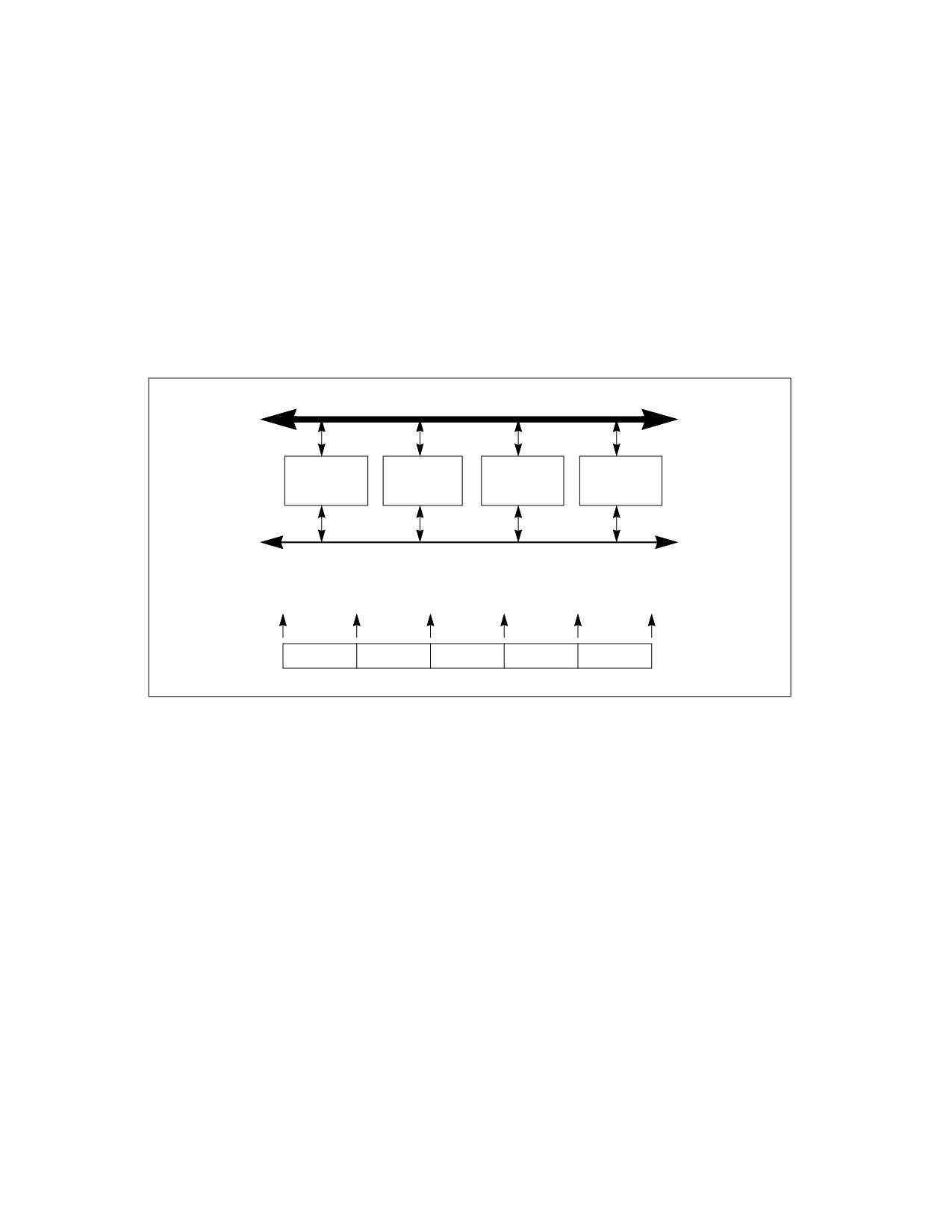
MULTIPLE-PROCESSOR MANAGEMENT
1. Each processor on the system bus is assigned a unique APIC ID, based on system topology (see Section 11.4.5,
“Identifying Logical Processors in an MP System”). This ID is written into the local APIC ID register for each
processor.
2. Each processor executes its internal BIST simultaneously with the other processors on the system bus. Upon
completion of the BIST (at T0), each processor broadcasts a BIPI to “all including self” (see Figure 11-8).
3. APIC arbitration hardware causes all the APICs to respond to the BIPIs one at a time (at T1, T2, T3, and T4).
4. When the first BIPI is received (at time T1), each APIC compares the four least significant bits of the BIPI’s
vector field with its APIC ID. If the vector and APIC ID match, the processor selects itself as the BSP by setting
the BSP flag in its IA32_APIC_BASE MSR. If the vector and APIC ID do not match, the processor selects itself
as an AP by entering the “wait for SIPI” state. (Note that in Figure 11-8, the BIPI from processor 1 is the first
BIPI to be handled, so processor 1 becomes the BSP.)
5. The newly established BSP broadcasts an FIPI message to “all including self.” The FIPI is guaranteed to be
handled only after the completion of the BIPIs that were issued by the non-BSP processors.
System (CPU) Bus
Pentium III
Pentium III
Pentium III
Pentium III
Processor 0
Processor 1
Processor 2
Processor 3
APIC Bus
Processor 1
Becomes BSP
T0
T1
T2
T3
T4
T5
BIPI.1
BIPI.0
BIPI.3
BIPI.2
FIPI
Serial Bus Activity
Figure 11-8. MP System With Multiple Pentium III Processors
6. After the BSP has been established, the outstanding BIPIs are received one at a time (at T2, T3, and T4) and
ignored by all processors.
7. When the FIPI is finally received (at T5), only the BSP responds to it. It responds by fetching and executing
BIOS boot-strap code, beginning at the reset vector (physical address FFFF FFF0H).
8. As part of the boot-strap code, the BSP creates an ACPI table and an MP table and adds its initial APIC ID to
these tables as appropriate.
9. At the end of the boot-strap procedure, the BSP broadcasts a SIPI message to all the APs in the system. Here,
the SIPI message contains a vector to the BIOS AP initialization code (at 000V V000H, where VV is the vector
contained in the SIPI message).
10. All APs respond to the SIPI message by racing to a BIOS initialization semaphore. The first one to the
semaphore begins executing the initialization code. (See MP init code for semaphore implementation details.)
As part of the AP initialization procedure, the AP adds its APIC ID number to the ACPI and MP tables as appro-
priate. At the completion of the initialization procedure, the AP executes a CLI instruction (to clear the IF flag in
the EFLAGS register) and halts itself.
11. When each of the APs has gained access to the semaphore and executed the AP initialization code and all
written their APIC IDs into the appropriate places in the ACPI and MP tables, the BSP establishes a count for the
number of processors connected to the system bus, completes executing the BIOS boot-strap code, and then
begins executing operating-system boot-strap and start-up code.
Vol. 3A
11-57
MULTIPLE-PROCESSOR MANAGEMENT
12. While the BSP is executing operating-system boot-strap and start-up code, the APs remain in the halted state.
In this state they will respond only to INITs, NMIs, and SMIs. They will also respond to snoops and to assertions
of the STPCLK# pin.
See Section 11.4.4, “MP Initialization Example,” for an annotated example the use of the MP protocol to boot IA-32
processors in an MP. This code should run on any IA-32 processor that used the MP protocol.
11.11.2.1 Error Detection and Handling During the MP Initialization Protocol
Errors may occur on the APIC bus during the MP initialization phase. These errors may be transient or permanent
and can be caused by a variety of failure mechanisms (for example, broken traces, soft errors during bus usage,
etc.). All serial bus related errors will result in an APIC checksum or acceptance error.
The MP initialization protocol makes the following assumptions regarding errors that occur during initialization:
• If errors are detected on the APIC bus during execution of the MP initialization protocol, the processors that
detect the errors are shut down.
• The MP initialization protocol will be executed by processors even if they fail their BIST sequences.
11-58
Vol. 3A
CHAPTER 12
PROCESSOR MANAGEMENT AND INITIALIZATION
This chapter describes the facilities provided for managing processor wide functions and for initializing the
processor. The subjects covered include: processor initialization, x87 FPU initialization, processor configuration,
feature determination, mode switching, the MSRs (in the Pentium, P6 family, Pentium 4, and Intel Xeon proces-
sors), and the MTRRs (in the P6 family, Pentium 4, and Intel Xeon processors).
12.1
INITIALIZATION OVERVIEW
Following power-up or an assertion of the RESET# pin, each processor on the system bus performs a hardware
initialization of the processor (known as a hardware reset) and an optional built-in self-test (BIST). A hardware
reset sets each processor’s registers to a known state and places the processor in real-address mode. It also inval-
idates the internal caches, translation lookaside buffers (TLBs) and the branch target buffer (BTB). At this point,
the action taken depends on the processor family:
• Pentium 4 processors (CPUID DisplayFamily 0FH) - All the processors on the system bus (including a
single processor in a uniprocessor system) execute the multiple processor (MP) initialization protocol. The
processor that is selected through this protocol as the bootstrap processor (BSP) then immediately starts
executing software-initialization code in the current code segment beginning at the offset in the EIP register.
The application (non-BSP) processors (APs) go into a Wait For Startup IPI (SIPI) state while the BSP is
executing initialization code. See Section 11.4, “Multiple-Processor (MP) Initialization,” for more details. Note
that in a uniprocessor system, the single Pentium 4 or Intel Xeon processor automatically becomes the BSP.
• IA-32 and Intel 64 processors (CPUID DisplayFamily 06H) - The action taken is the same as for the
Pentium 4 processors (as described in the previous paragraph).
• Pentium processors - In either a single- or dual- processor system, a single Pentium processor is always
pre-designated as the primary processor. Following a reset, the primary processor behaves as follows in both
single- and dual-processor systems. Using the dual-processor (DP) ready initialization protocol, the primary
processor immediately starts executing software-initialization code in the current code segment beginning at
the offset in the EIP register. The secondary processor (if there is one) goes into a halt state.
• Intel486 processor - The primary processor (or single processor in a uniprocessor system) immediately
starts executing software-initialization code in the current code segment beginning at the offset in the EIP
register. (The Intel486 does not automatically execute a DP or MP initialization protocol to determine which
processor is the primary processor.)
The software-initialization code performs all system-specific initialization of the BSP or primary processor and the
system logic.
At this point, for MP (or DP) systems, the BSP (or primary) processor wakes up each AP (or secondary) processor
to enable those processors to execute self-configuration code.
When all processors are initialized, configured, and synchronized, the BSP or primary processor begins executing
an initial operating-system or executive task.
The x87 FPU is also initialized to a known state during hardware reset. x87 FPU software initialization code can then
be executed to perform operations such as setting the precision of the x87 FPU and the exception masks. No special
initialization of the x87 FPU is required to switch operating modes.
Asserting the INIT# pin on the processor invokes a similar response to a hardware reset. The major difference is
that during an INIT, the internal caches, MSRs, MTRRs, and x87 FPU state are left unchanged (although, the TLBs
and BTB are invalidated as with a hardware reset). An INIT provides a method for switching from protected to real-
address mode while maintaining the contents of the internal caches.
Vol. 3A
12-1
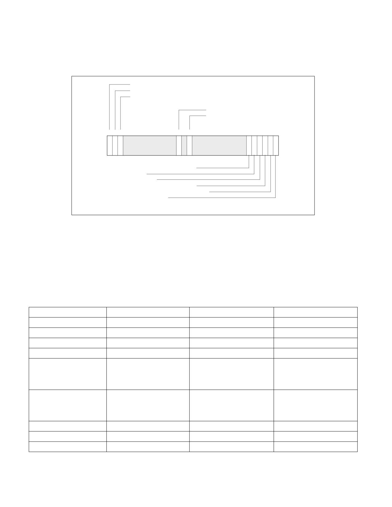
PROCESSOR MANAGEMENT AND INITIALIZATION
12.1.1 Processor State After Reset
Following power-up, The state of control register CR0 is 60000010H (see Figure 12-1). This places the processor is
in real-address mode with paging disabled.
Paging disabled: 0
Caching disabled: 1
Not write-through disabled: 1
Alignment check disabled: 0
Write-protect disabled: 0
31
30 29 28
19
18 17
16 15
6
5
4
3
2
1
0
P
C
N
A
W
N
T
E
M
P
Reserved
Reserved
1
G
D
W
M
P
E
S
M
P
E
External x87 FPU error reporting: 0
(Not used): 1
No task switch: 0
x87 FPU instructions not trapped: 0
WAIT/FWAIT instructions not trapped: 0
Real-address mode: 0
Figure 12-1. Contents of CR0 Register after Reset
The state of the flags and other registers following power-up for the Pentium 4, Pentium Pro, and Pentium proces-
sors are shown in Section 25.39, “Initial State of Pentium, Pentium Pro and Pentium 4 Processors,” of the Intel® 64
and IA-32 Architectures Software Developer’s Manual, Volume 3B.
Table 12-1 shows processor states of IA-32 and Intel 64 processors with CPUID DisplayFamily signature of 06H at
the following events: power-up, RESET, and INIT. In a few cases, the behavior of some registers behave slightly
different across warm RESET, the variant cases are marked in Table 12-1 and described in more detail in Table
12-2.
Table 12-1. IA-32 and Intel® 64 Processor States Following Power-up, Reset, or INIT
Register
Power up
Reset
INIT
EFLAGS1
00000002H
00000002H
00000002H
EIP
0000FFF0H
0000FFF0H
0000FFF0H
CR0
60000010H2
60000010H2
60000010H2
CR2, CR3, CR4
00000000H
00000000H
00000000H
CS
Selector = F000H
Selector = F000H
Selector = F000H
Base = FFFF0000H
Base = FFFF0000H
Base = FFFF0000H
Limit = FFFFH
Limit = FFFFH
Limit = FFFFH
AR = Present, R/W, Accessed
AR = Present, R/W, Accessed
AR = Present, R/W, Accessed
SS, DS, ES, FS, GS
Selector = 0000H
Selector = 0000H
Selector = 0000H
Base = 00000000H
Base = 00000000H
Base = 00000000H
Limit = FFFFH
Limit = FFFFH
Limit = FFFFH
AR = Present, R/W, Accessed
AR = Present, R/W, Accessed
AR = Present, R/W, Accessed
EDX
000n06xxH3
000n06xxH3
000n06xxH3
EAX
04
04
04
EBX, ECX, ESI, EDI, EBP, ESP
00000000H
00000000H
00000000H
12-2
Vol. 3A
PROCESSOR MANAGEMENT AND INITIALIZATION
Table 12-1. IA-32 and Intel® 64 Processor States Following Power-up, Reset, or INIT (Contd.)
Register
Power up
Reset
INIT
ST0 through ST75
+0.0
+0.0
FINIT/FNINIT: Unchanged
x87 FPU Control Word5
0040H
0040H
FINIT/FNINIT: 037FH
x87 FPU Status Word5
0000H
0000H
FINIT/FNINIT: 0000H
x87 FPU Tag Word5
5555H
5555H
FINIT/FNINIT: FFFFH
x87 FPU Data Operand and
0000H
0000H
FINIT/FNINIT: 0000H
CS Seg. Selectors5
x87 FPU Data Operand and
00000000H
00000000H
FINIT/FNINIT: 00000000H
Inst. Pointers5
MM0 through MM75
0000000000000000H
0000000000000000H
INIT or FINIT/FNINIT: Unchanged
XMM0 through XMM7
0H
0H
Unchanged
MXCSR
1F80H
1F80H
Unchanged
GDTR, IDTR
Base = 00000000H
Base = 00000000H
Base = 00000000H
Limit = FFFFH
Limit = FFFFH
Limit = FFFFH
AR = Present, R/W
AR = Present, R/W
AR = Present, R/W
LDTR, Task Register
Selector = 0000H
Selector = 0000H
Selector = 0000H
Base = 00000000H
Base = 00000000H
Base = 00000000H
Limit = FFFFH
Limit = FFFFH
Limit = FFFFH
AR = Present, R/W
AR = Present, R/W
AR = Present, R/W
DR0, DR1, DR2, DR3
00000000H
00000000H
00000000H
DR6
FFFF0FF0H
FFFF0FF0H
FFFF0FF0H
DR7
00000400H
00000400H
00000400H
R8-R15
0000000000000000H
0000000000000000H
0000000000000000H
XMM8-XMM15
0H
0H
Unchanged
XCR0
1H
1H
Unchanged
IA32_XSS
0H
0H
Unchanged
YMM_H[255:128]
0H
0H
Unchanged
BNDCFGU
0H
0H
0H
BND0-BND3
0H
0H
0H
IA32_BNDCFGS
0H
0H
0H
OPMASK
0H
0H
Unchanged
ZMM_H[511:256]
0H
0H
Unchanged
ZMMHi16[511:0]
0H
0H
Unchanged
PKRU
0H
0H
Unchanged
Intel Processor Trace MSRs
0H
0HW
Unchanged
Time-Stamp Counter
0H
0HW
Unchanged
IA32_TSC_AUX
0H
0H
Unchanged
IA32_TSC_ADJUST
0H
0H
Unchanged
IA32_TSC_DEADLINE
0H
0H
Unchanged
IA32_SYSENTER_CS/ESP/EIP
0H
0H
Unchanged
IA32_EFER
0000000000000000H
0000000000000000H
0000000000000000H
IA32_STAR/LSTAR
0H
0H
Unchanged
Vol. 3A
12-3