Intel 64 and IA-32 Architectures. Software Developer’s Manual (2026) - page 52
PROCESSOR MANAGEMENT AND INITIALIZATION
Table 12-1. IA-32 and Intel® 64 Processor States Following Power-up, Reset, or INIT (Contd.)
Register
Power up
Reset
INIT
IA32_FS_BASE/GS_BASE
0H
0H
0H
IA32_PMCx,
0H
0H
Unchanged
IA32_PERFEVTSELx
IA32_PERF_GLOBAL_CTRL
Sets bits n-1:0 and clears the
Sets bits n-1:0 and clears the
Unchanged
upper bits.7
upper bits.7
IA32_FIXED_CTRx,
0H
0H
Unchanged
IA32_FIXED_CTR_CTRL
Data and Code Cache, TLBs
Invalid6
Invalid6
Unchanged
Fixed MTRRs
Disabled
Disabled
Unchanged
Variable MTRRs
Disabled
Disabled
Unchanged
Machine-Check Banks
Undefined
UndefinedW
Unchanged
Last Branch Record Stack
0
0W
Unchanged
APIC
Enabled
Enabled
Unchanged
X2APIC
Disabled
Disabled
Unchanged
IA32_DEBUG_INTERFACE
0
0W
Unchanged
NOTES:
1. The 10 most-significant bits of the EFLAGS register are undefined following a reset. Software should not depend on the states of
any of these bits.
2. The CD and NW flags are unchanged, bit 4 is set to 1, all other bits are cleared.
3. Where “n” is the Extended Model Value for the respective processor, and “xx” = don’t care.
4. If Built-In Self-Test (BIST) is invoked on power up or reset, EAX is 0 only if all tests passed. (BIST cannot be invoked during an INIT.)
5. The state of the x87 FPU and MMX registers is not changed by the execution of an INIT.
6. Internal caches are invalid after power-up and RESET, but left unchanged with an INIT.
7. Where “n” is the number of general-purpose counters available in the processor. See Chapter 22, “Performance Monitoring,” for addi-
tional details.
W: Warm RESET behavior differs from power-on RESET with details listed in Table 12-2.
Table 12-2. Variance of RESET Values in Selected Intel Architecture Processors
State
XREF
Value
Feature Flag or DisplayFamily_DisplayModel Signatures
Time-Stamp Counter
Warm RESET
Unmodified across warm
06_2DH, 06_3EH
Reset
Machine-Check Banks
Warm RESET
IA32_MCi_Status banks are
06_2DH, 06_3EH, 06_3FH, 06_4FH, 06_56H
unmodified across warm
Reset
Last Branch Record Stack
Warm RESET
LBR stack MSRs are
06_1AH, 06_1CH, DisplayFamiy= 06 and DisplayModel >1DH
unmodified across warm
Reset
Intel Processor Trace
Warm RESET
Clears
If CPUID.14H.00H:EBX[2] = 1
MSRs
IA32_RTIT_CTL.TraceEn,
the rest of MSRs are
unmodified
IA32_DEBUG_INTERFACE
Warm RESET
Unmodified across warm
If CPUID.01H:ECX[11] = 1
Reset
12-4
Vol. 3A

PROCESSOR MANAGEMENT AND INITIALIZATION
12.1.2 Processor Built-In Self-Test (BIST)
Hardware may request that the BIST be performed at power-up. The EAX register is cleared (0H) if the processor
passes the BIST. A nonzero value in the EAX register after the BIST indicates that a processor fault was detected.
If the BIST is not requested, the contents of the EAX register after a hardware reset is 0H.
The overhead for performing a BIST varies between processor families. For example, the BIST takes approximately
30 million processor clock periods to execute on the Pentium 4 processor. This clock count is model-specific; Intel
reserves the right to change the number of periods for any Intel 64 or IA-32 processor, without notification.
12.1.3 Model and Stepping Information
Following a hardware reset, the EDX register contains component identification and revision information (see
Figure 12-2). For example, the model, family, and processor type returned for the first processor in the Intel
Pentium 4 family is as follows: model (0000B), family (1111B), and processor type (00B).
31
28 27
20 19
1615
14 13
12 11
8 7
43
0
Extended
Extended
Stepping
EDX
Family
Model
Family
Model
ID
Processor Type
Family (1111B for the Pentium 4 Processor Family)
Model (Beginning with 0000B)
Reserved
Figure 12-2. Version Information in the EDX Register after Reset
The stepping ID field contains a unique identifier for the processor’s stepping ID or revision level. The extended
family and extended model fields were added to the IA-32 architecture in the Pentium 4 processors.
12.1.4 First Instruction Executed
The first instruction that is fetched and executed following a hardware reset is located at physical address
FFFFFFF0H. This address is 16 bytes below the processor’s uppermost physical address. The EPROM containing the
software-initialization code must be located at this address.
The address FFFFFFF0H is beyond the 1-MByte addressable range of the processor while in real-address mode. The
processor is initialized to this starting address as follows. The CS register has two parts: the visible segment
selector part and the hidden base address part. In real-address mode, the base address is normally formed by
shifting the 16-bit segment selector value 4 bits to the left to produce a 20-bit base address. However, during a
hardware reset, the segment selector in the CS register is loaded with F000H and the base address is loaded with
FFFF0000H. The starting address is thus formed by adding the base address to the value in the EIP register (that
is, FFFF0000 + FFF0H = FFFFFFF0H).
The first time the CS register is loaded with a new value after a hardware reset, the processor will follow the normal
rule for address translation in real-address mode (that is, [CS base address = CS segment selector * 16]). To
ensure that the base address in the CS register remains unchanged until the EPROM based software-initialization
code is completed, the code must not contain a far jump or far call or allow an interrupt to occur (which would
cause the CS selector value to be changed).
12.2
X87 FPU INITIALIZATION
Software-initialization code can determine the whether the processor contains an x87 FPU by using the CPUID
instruction. The code must then initialize the x87 FPU and set flags in control register CR0 to reflect the state of the
x87 FPU environment.
Vol. 3A
12-5

PROCESSOR MANAGEMENT AND INITIALIZATION
A hardware reset places the x87 FPU in the state shown in Table 12-1. This state is different from the state the x87
FPU is placed in following the execution of an FINIT or FNINIT instruction (also shown in Table 12-1). If the x87 FPU
is to be used, the software-initialization code should execute an FINIT/FNINIT instruction following a hardware
reset. These instructions, tag all data registers as empty, clear all the exception masks, set the TOP-of-stack value
to 0, and select the default rounding and precision controls setting (round to nearest and 64-bit precision).
If the processor is reset by asserting the INIT# pin, the x87 FPU state is not changed.
12.2.1 Configuring the x87 FPU Environment
Initialization code must load the appropriate values into the MP, EM, and NE flags of control register CR0. These bits
are cleared on hardware reset of the processor. Figure 12-3 shows the suggested settings for these flags,
depending on the IA-32 processor being initialized. Initialization code can test for the type of processor present
before setting or clearing these flags.
Table 12-3. Recommended Settings of EM and MP Flags on IA-32 Processors
EM
MP
NE
IA-32 processor
1
0
1
Intel486™ SX, Intel386™ DX, and Intel386™ SX processors only, without the presence of a math
coprocessor.
0
1
1 or 0*
Pentium 4, Intel Xeon, P6 family, Pentium, Intel486™ DX, and Intel 487 SX processors, and
Intel386 DX and Intel386 SX processors when a companion math coprocessor is present.
0
1
1 or 0*
More recent Intel 64 or IA-32 processors
NOTE:
* The setting of the NE flag depends on the operating system being used.
The EM flag determines whether floating-point instructions are executed by the x87 FPU (EM is cleared) or a
device-not-available exception (#NM) is generated for all floating-point instructions so that an exception handler
can emulate the floating-point operation (EM = 1). Ordinarily, the EM flag is cleared when an x87 FPU or math
coprocessor is present and set if they are not present. If the EM flag is set and no x87 FPU, math coprocessor, or
floating-point emulator is present, the processor will hang when a floating-point instruction is executed.
The MP flag determines whether WAIT/FWAIT instructions react to the setting of the TS flag. If the MP flag is clear,
WAIT/FWAIT instructions ignore the setting of the TS flag; if the MP flag is set, they will generate a device-not-
available exception (#NM) if the TS flag is set. Generally, the MP flag should be set for processors with an inte-
grated x87 FPU and clear for processors without an integrated x87 FPU and without a math coprocessor present.
However, an operating system can choose to save the floating-point context at every context switch, in which case
there would be no need to set the MP bit.
Table 2-2 shows the actions taken for floating-point and WAIT/FWAIT instructions based on the settings of the EM,
MP, and TS flags.
The NE flag determines whether unmasked floating-point exceptions are handled by generating a floating-point
error exception internally (NE is set, native mode) or through an external interrupt (NE is cleared). In systems
where an external interrupt controller is used to invoke numeric exception handlers (such as MS-DOS-based
systems), the NE bit should be cleared.
12.2.2 Setting the Processor for x87 FPU Software Emulation
Setting the EM flag causes the processor to generate a device-not-available exception (#NM) and trap to a software
exception handler whenever it encounters a floating-point instruction. (Table 12-3 shows when it is appropriate to
use this flag.) Setting this flag has two functions:
• It allows x87 FPU code to run on an IA-32 processor that has neither an integrated x87 FPU nor is connected to
an external math coprocessor, by using a floating-point emulator.
• It allows floating-point code to be executed using a special or nonstandard floating-point emulator, selected for
a particular application, regardless of whether an x87 FPU or math coprocessor is present.
12-6
Vol. 3A

PROCESSOR MANAGEMENT AND INITIALIZATION
To emulate floating-point instructions, the EM, MP, and NE flag in control register CR0 should be set as shown in
Table 12-4.
Table 12-4. Software Emulation Settings of EM, MP, and NE Flags
CR0 Bit
Value
EM
1
MP
0
NE
1
Regardless of the value of the EM bit, the Intel486 SX processor generates a device-not-available exception (#NM)
upon encountering any floating-point instruction.
12.3
CACHE ENABLING
IA-32 processors (beginning with the Intel486 processor) and Intel 64 processors contain internal instruction and
data caches. These caches are enabled by clearing the CD and NW flags in control register CR0. (They are set
during a hardware reset.) Because all internal cache lines are invalid following reset initialization, it is not neces-
sary to invalidate the cache before enabling caching. Any external caches may require initialization and invalidation
using a system-specific initialization and invalidation code sequence.
Depending on the hardware and operating system or executive requirements, additional configuration of the
processor’s caching facilities will probably be required. Beginning with the Intel486 processor, page-level caching
can be controlled with the PCD and PWT flags in page-directory and page-table entries. Beginning with the P6
family processors, the memory type range registers (MTRRs) control the caching characteristics of the regions of
physical memory. (For the Intel486 and Pentium processors, external hardware can be used to control the caching
characteristics of regions of physical memory.) See Chapter 14, “Memory Cache Control,” for detailed information
on configuration of the caching facilities in the Pentium 4, Intel Xeon, and P6 family processors and system
memory.
12.4
MODEL-SPECIFIC REGISTERS (MSRS)
Most IA-32 processors (starting from Pentium processors) and Intel 64 processors contain a model-specific regis-
ters (MSRs). A given MSR may not be supported across all families and models for Intel 64 and IA-32 processors.
Some MSRs are designated as architectural to simplify software programming; a feature introduced by an architec-
tural MSR is expected to be supported in future processors. Non-architectural MSRs are not guaranteed to be
supported or to have the same functions on future processors.
MSRs that provide control for a number of hardware and software-related features, include:
• Performance-monitoring counters (see Chapter 22, “Performance Monitoring”).
• Debug extensions (see Chapter 20, “Debug, Branch Profile, TSC, and Intel® Resource Director Technology
(Intel® RDT) Features”).
• Machine-check exception capability and its accompanying machine-check architecture (see Chapter 18,
“Machine-Check Architecture”).
• MTRRs (see Section 14.11, “Memory Type Range Registers (MTRRs)”).
• Thermal and power management.
• Instruction-specific support (for example: SYSENTER, SYSEXIT, SWAPGS, etc.).
• Processor feature/mode support (for example: IA32_EFER, IA32_FEATURE_CONTROL).
The MSRs can be read and written to using the RDMSR and WRMSR instructions, respectively.
When performing software initialization of an IA-32 or Intel 64 processor, many of the MSRs will need to be initial-
ized to set up things like performance-monitoring events, run-time machine checks, and memory types for phys-
ical memory.
Vol. 3A
12-7
PROCESSOR MANAGEMENT AND INITIALIZATION
Lists of available performance-monitoring events can be found at: https://perfmon-events.intel.com/ , and lists of
available MSRs are given in Chapter 2, “Model-Specific Registers (MSRs)‚” in the Intel® 64 and IA-32 Architectures
Software Developer’s Manual, Volume 4. The references earlier in this section show where the functions of the
various groups of MSRs are described in this manual.
12.5
MEMORY TYPE RANGE REGISTERS (MTRRS)
Memory type range registers (MTRRs) were introduced into the IA-32 architecture with the Pentium Pro processor.
They allow the type of caching (or no caching) to be specified in system memory for selected physical address
ranges. They allow memory accesses to be optimized for various types of memory such as RAM, ROM, frame buffer
memory, and memory-mapped I/O devices.
In general, initializing the MTRRs is normally handled by the software initialization code or BIOS and is not an oper-
ating system or executive function. At the very least, all the MTRRs must be cleared to 0, which selects the
uncached (UC) memory type. See Section 14.11, “Memory Type Range Registers (MTRRs),” for detailed informa-
tion on the MTRRs.
12.6
INITIALIZING SSE/SSE2/SSE3/SSSE3 EXTENSIONS
For processors that contain SSE/SSE2/SSE3/SSSE3 extensions, steps must be taken when initializing the
processor to allow execution of these instructions.
1. Check the CPUID feature flags for the presence of the SSE/SSE2/SSE3/SSSE3 extensions (respectively: EDX
bits 25 and 26, ECX bit 0 and 9) and support for the FXSAVE and FXRSTOR instructions (EDX bit 24). Also check
for support for the CLFLUSH instruction (EDX bit 19). The CPUID feature flags are loaded in the EDX and ECX
registers when the CPUID instruction is executed with a 1 in the EAX register.
2. Set the OSFXSR flag (bit 9 in control register CR4) to indicate that the operating system supports saving and
restoring the SSE/SSE2/SSE3/SSSE3 execution environment (XMM and MXCSR registers) with the FXSAVE and
FXRSTOR instructions, respectively. See Section 2.5, “Control Registers,” for a description of the OSFXSR flag.
3. Set the OSXMMEXCPT flag (bit 10 in control register CR4) to indicate that the operating system supports the
handling of SSE/SSE2/SSE3 SIMD floating-point exceptions (#XM). See Section 2.5, “Control Registers,” for a
description of the OSXMMEXCPT flag.
4. Set the mask bits and flags in the MXCSR register according to the mode of operation desired for
SSE/SSE2/SSE3 SIMD floating-point instructions. See “MXCSR Control and Status Register” in Chapter 10,
“Programming with Intel® Streaming SIMD Extensions (Intel® SSE),” of the Intel® 64 and IA-32 Architectures
Software Developer’s Manual, Volume 1, for a detailed description of the bits and flags in the MXCSR register.
12.7
SOFTWARE INITIALIZATION FOR REAL-ADDRESS MODE OPERATION
Following a hardware reset (either through a power-up or the assertion of the RESET# pin) the processor is placed
in real-address mode and begins executing software initialization code from physical address FFFFFFF0H. Software
initialization code must first set up the necessary data structures for handling basic system functions, such as a
real-mode IDT for handling interrupts and exceptions. If the processor is to remain in real-address mode, software
must then load additional operating-system or executive code modules and data structures to allow reliable execu-
tion of application programs in real-address mode.
If the processor is going to operate in protected mode, software must load the necessary data structures to operate
in protected mode and then switch to protected mode. The protected-mode data structures that must be loaded
are described in Section 12.8, “Software Initialization for Protected-Mode Operation.”
12.7.1 Real-Address Mode IDT
In real-address mode, the only system data structure that must be loaded into memory is the IDT (also called the
“interrupt vector table”). By default, the address of the base of the IDT is physical address 0H. This address can be
12-8
Vol. 3A
PROCESSOR MANAGEMENT AND INITIALIZATION
changed by using the LIDT instruction to change the base address value in the IDTR. Software initialization code
needs to load interrupt- and exception-handler pointers into the IDT before interrupts can be enabled.
The actual interrupt- and exception-handler code can be contained either in EPROM or RAM; however, the code
must be located within the 1-MByte addressable range of the processor in real-address mode. If the handler code
is to be stored in RAM, it must be loaded along with the IDT.
12.7.2 NMI Interrupt Handling
The NMI interrupt is always enabled (except when multiple NMIs are nested). If the IDT and the NMI interrupt
handler need to be loaded into RAM, there will be a period of time following hardware reset when an NMI interrupt
cannot be handled. During this time, hardware must provide a mechanism to prevent an NMI interrupt from halting
code execution until the IDT and the necessary NMI handler software is loaded. Here are two examples of how
NMIs can be handled during the initial states of processor initialization:
• A simple IDT and NMI interrupt handler can be provided in EPROM. This allows an NMI interrupt to be handled
immediately after reset initialization.
• The system hardware can provide a mechanism to enable and disable NMIs by passing the NMI# signal through
an AND gate controlled by a flag in an I/O port. Hardware can clear the flag when the processor is reset, and
software can set the flag when it is ready to handle NMI interrupts.
12.8
SOFTWARE INITIALIZATION FOR PROTECTED-MODE OPERATION
The processor is placed in real-address mode following a hardware reset. At this point in the initialization process,
some basic data structures and code modules must be loaded into physical memory to support further initialization
of the processor, as described in Section 12.7, “Software Initialization for Real-Address Mode Operation.” Before
the processor can be switched to protected mode, the software initialization code must load a minimum number of
protected mode data structures and code modules into memory to support reliable operation of the processor in
protected mode. These data structures include the following:
• A IDT.
• A GDT.
• A TSS.
• (Optional) An LDT.
• If paging is to be used, at least one page directory and one page table.
• A code segment that contains the code to be executed when the processor switches to protected mode.
• One or more code modules that contain the necessary interrupt and exception handlers.
Software initialization code must also initialize the following system registers before the processor can be switched
to protected mode:
• The GDTR.
• (Optional.) The IDTR. This register can also be initialized immediately after switching to protected mode, prior
to enabling interrupts.
• Control registers CR1 through CR4.
• (Pentium 4, Intel Xeon, and P6 family processors only.) The memory type range registers (MTRRs).
With these data structures, code modules, and system registers initialized, the processor can be switched to
protected mode by loading control register CR0 with a value that sets the PE flag (bit 0).
12.8.1 Protected-Mode System Data Structures
The contents of the protected-mode system data structures loaded into memory during software initialization,
depend largely on the type of memory management the protected-mode operating-system or executive is going to
support: flat, flat with paging, segmented, or segmented with paging.
Vol. 3A
12-9
PROCESSOR MANAGEMENT AND INITIALIZATION
To implement a flat memory model without paging, software initialization code must at a minimum load a GDT with
one code and one data-segment descriptor. A null descriptor in the first GDT entry is also required. The stack can
be placed in a normal read/write data segment, so no dedicated descriptor for the stack is required. A flat memory
model with paging also requires a page directory and at least one page table (unless all pages are 4 MBytes in
which case only a page directory is required). See Section 12.8.3, “Initializing Paging.”
Before the GDT can be used, the base address and limit for the GDT must be loaded into the GDTR register using
an LGDT instruction.
A multi-segmented model may require additional segments for the operating system, as well as segments and
LDTs for each application program. LDTs require segment descriptors in the GDT. Some operating systems allocate
new segments and LDTs as they are needed. This provides maximum flexibility for handling a dynamic program-
ming environment. However, many operating systems use a single LDT for all tasks, allocating GDT entries in
advance. An embedded system, such as a process controller, might pre-allocate a fixed number of segments and
LDTs for a fixed number of application programs. This would be a simple and efficient way to structure the software
environment of a real-time system.
12.8.2 Initializing Protected-Mode Exceptions and Interrupts
Software initialization code must at a minimum load a protected-mode IDT with gate descriptor for each exception
vector that the processor can generate. If interrupt or trap gates are used, the gate descriptors can all point to the
same code segment, which contains the necessary exception handlers. If task gates are used, one TSS and accom-
panying code, data, and task segments are required for each exception handler called with a task gate.
If hardware allows interrupts to be generated, gate descriptors must be provided in the IDT for one or more inter-
rupt handlers.
Before the IDT can be used, the base address and limit for the IDT must be loaded into the IDTR register using an
LIDT instruction. This operation is typically carried out immediately after switching to protected mode.
12.8.3 Initializing Paging
Paging is controlled by the PG flag in control register CR0. When this flag is clear (its state following a hardware
reset), the paging mechanism is turned off; when it is set, paging is enabled. Before setting the PG flag, the
following data structures and registers must be initialized:
• Software must load at least one page directory and one page table into physical memory. The page table can
be eliminated if the page directory contains a directory entry pointing to itself (here, the page directory and
page table reside in the same page), or if only 4-MByte pages are used.
• Control register CR3 (also called the PDBR register) is loaded with the physical base address of the page
directory.
• (Optional) Software may provide one set of code and data descriptors in the GDT or in an LDT for supervisor
mode and another set for user mode.
With this paging initialization complete, paging is enabled and the processor is switched to protected mode at the
same time by loading control register CR0 with an image in which the PG and PE flags are set. (Paging cannot be
enabled before the processor is switched to protected mode.)
12.8.4 Initializing Multitasking
If the multitasking mechanism is not going to be used and changes between privilege levels are not allowed, it is
not necessary load a TSS into memory or to initialize the task register.
If the multitasking mechanism is going to be used and/or changes between privilege levels are allowed, software
initialization code must load at least one TSS and an accompanying TSS descriptor. (A TSS is required to change
privilege levels because pointers to the privileged-level 0, 1, and 2 stack segments and the stack pointers for these
stacks are obtained from the TSS.) TSS descriptors must not be marked as busy when they are created; they
should be marked busy by the processor only as a side-effect of performing a task switch. As with descriptors for
LDTs, TSS descriptors reside in the GDT.
12-10
Vol. 3A
PROCESSOR MANAGEMENT AND INITIALIZATION
After the processor has switched to protected mode, the LTR instruction can be used to load a segment selector for
a TSS descriptor into the task register. This instruction marks the TSS descriptor as busy, but does not perform a
task switch. The processor can, however, use the TSS to locate pointers to privilege-level 0, 1, and 2 stacks. The
segment selector for the TSS must be loaded before software performs its first task switch in protected mode,
because a task switch copies the current task state into the TSS.
After the LTR instruction has been executed, further operations on the task register are performed by task
switching. As with other segments and LDTs, TSSs and TSS descriptors can be either pre-allocated or allocated as
needed.
12.8.5 Initializing IA-32e Mode
On Intel 64 processors, the IA32_EFER MSR is cleared on system reset. The operating system must be in protected
mode with paging enabled before attempting to initialize IA-32e mode. IA-32e mode operation also requires phys-
ical-address extensions with four or five levels of enhanced paging structures (see Section 5.5, “4-Level Paging and
5-Level Paging”).
Operating systems should follow this sequence to initialize IA-32e mode:
1. Starting from protected mode, disable paging by setting CR0.PG = 0. Use the MOV CR0 instruction to disable
paging (the instruction must be located in an identity-mapped page).
2. Enable physical-address extensions (PAE) by setting CR4.PAE = 1. Failure to enable PAE will result in a #GP
fault when an attempt is made to initialize IA-32e mode.
3. Load CR3 with the physical base address of the Level 4 page map table (PML4) or Level 5 page map table
(PML5).
4. Enable IA-32e mode by setting IA32_EFER.LME = 1.
5. Enable paging by setting CR0.PG = 1. This causes the processor to set the IA32_EFER.LMA bit to 1. The MOV
CR0 instruction that enables paging and the following instructions must be located in an identity-mapped page
(until such time that a branch to non-identity mapped pages can be effected).
64-bit mode paging structures must be located in the first 4 GBytes of physical-address space prior to activating
IA-32e mode. This is necessary because the MOV CR3 instruction used to initialize the page-directory base must be
executed in legacy mode prior to activating IA-32e mode (setting CR0.PG = 1 to enable paging). Because MOV CR3
is executed in protected mode, only the lower 32 bits of the register are written, limiting the table location to the
low 4 GBytes of memory. Software can relocate the page tables anywhere in physical memory after IA-32e mode
is activated.
The processor performs 64-bit mode consistency checks whenever software attempts to modify any of the enable
bits directly involved in activating IA-32e mode (IA32_EFER.LME, CR0.PG, and CR4.PAE). It will generate a general
protection fault (#GP) if consistency checks fail. 64-bit mode consistency checks ensure that the processor does
not enter an undefined mode or state with unpredictable behavior.
64-bit mode consistency checks fail in the following circumstances:
• An attempt is made to enable or disable IA-32e mode while paging is enabled.
• IA-32e mode is enabled and an attempt is made to enable paging prior to enabling physical-address extensions
(PAE).
• IA-32e mode is active and an attempt is made to disable physical-address extensions (PAE).
• If the current CS has the L-bit set on an attempt to activate IA-32e mode.
• If the TR contains a 16-bit TSS on an attempt to activate IA-32e mode.
12.8.5.1 IA-32e Mode System Data Structures
After activating IA-32e mode, the system-descriptor-table registers (GDTR, LDTR, IDTR, TR) continue to reference
legacy protected-mode descriptor tables. Tables referenced by the descriptors all reside in the lower 4 GBytes of
linear-address space. After activating IA-32e mode, 64-bit operating-systems should use the LGDT, LLDT, LIDT,
and LTR instructions to load the system-descriptor-table registers with references to 64-bit descriptor tables.
Vol. 3A
12-11
PROCESSOR MANAGEMENT AND INITIALIZATION
12.8.5.2 IA-32e Mode Interrupts and Exceptions
Software must not allow exceptions or interrupts to occur between the time IA-32e mode is activated and the
update of the interrupt-descriptor-table register (IDTR) that establishes references to a 64-bit interrupt-descriptor
table (IDT). This is because the IDT remains in legacy form immediately after IA-32e mode is activated.
If an interrupt or exception occurs prior to updating the IDTR, a legacy 32-bit interrupt gate will be referenced and
interpreted as a 64-bit interrupt gate with unpredictable results. External interrupts can be disabled by using the
CLI instruction.
Non-maskable interrupts (NMI) must be disabled using external hardware.
12.8.5.3
64-bit Mode and Compatibility Mode Operation
IA-32e mode uses two code segment-descriptor bits (CS.L and CS.D, see Figure 3-8) to control the operating modes
after IA-32e mode is initialized. If CS.L = 1 and CS.D = 0, the processor is running in 64-bit mode. With this
encoding, the default operand size is 32 bits and default address size is 64 bits. Using instruction prefixes, operand
size can be changed to 64 bits or 16 bits; address size can be changed to 32 bits.
When IA-32e mode is active and CS.L = 0, the processor operates in compatibility mode. In this mode, CS.D
controls default operand and address sizes exactly as it does in the IA-32 architecture. Setting CS.D = 1 specifies
default operand and address size as 32 bits. Clearing CS.D to 0 specifies default operand and address size as 16
bits (the CS.L = 1, CS.D = 1 bit combination is reserved).
Compatibility mode execution is selected on a code-segment basis. This mode allows legacy applications to coexist
with 64-bit applications running in 64-bit mode. An operating system running in IA-32e mode can execute existing
16-bit and 32-bit applications by clearing their code-segment descriptor’s CS.L bit to 0.
In compatibility mode, the following system-level mechanisms continue to operate using the IA-32e-mode archi-
tectural semantics:
• Linear-to-physical address translation uses the 64-bit mode extended page-translation mechanism.
• Interrupts and exceptions are handled using the 64-bit mode mechanisms.
• System calls (calls through call gates and SYSENTER/SYSEXIT) are handled using the IA-32e mode
mechanisms.
12.8.5.4 Switching Out of IA-32e Mode Operation
To return from IA-32e mode to paged-protected mode operation operating systems must use the following
sequence:
1. Switch to compatibility mode.
2. Deactivate IA-32e mode by clearing CR0.PG = 0. This causes the processor to set IA32_EFER.LMA = 0. The
MOV CR0 instruction used to disable paging and subsequent instructions must be located in an identity-mapped
page.
3. Load CR3 with the physical base address of the legacy page-table-directory base address.
4. Disable IA-32e mode by setting IA32_EFER.LME = 0.
5. Enable legacy paged-protected mode by setting CR0.PG = 1
6. A branch instruction must follow the MOV CR0 that enables paging. Both the MOV CR0 and the branch
instruction must be located in an identity-mapped page.
Registers only available in 64-bit mode (R8-R15 and XMM8-XMM15) are preserved across transitions from 64-bit
mode into compatibility mode then back into 64-bit mode. However, values of R8-R15 and XMM8-XMM15 are unde-
fined after transitions from 64-bit mode through compatibility mode to legacy or real mode and then back through
compatibility mode to 64-bit mode.
12-12
Vol. 3A
PROCESSOR MANAGEMENT AND INITIALIZATION
12.9
MODE SWITCHING
To use the processor in protected mode after hardware or software reset, a mode switch must be performed from
real-address mode. Once in protected mode, software generally does not need to return to real-address mode. To
run software written to run in real-address mode (8086 mode), it is generally more convenient to run the software
in virtual-8086 mode, than to switch back to real-address mode.
12.9.1 Switching to Protected Mode
Before switching to protected mode from real mode, a minimum set of system data structures and code modules
must be loaded into memory, as described in Section 12.8, “Software Initialization for Protected-Mode Operation.”
Once these tables are created, software initialization code can switch into protected mode.
Protected mode is entered by executing a MOV CR0 instruction that sets the PE flag in the CR0 register. (In the
same instruction, the PG flag in register CR0 can be set to enable paging.) Execution in protected mode begins with
a CPL of 0.
Intel 64 and IA-32 processors have slightly different requirements for switching to protected mode. To ensure
upwards and downwards code compatibility with Intel 64 and IA-32 processors, we recommend that you follow
these steps:
1. Disable interrupts. A CLI instruction disables maskable hardware interrupts. NMI interrupts can be disabled
with external circuitry. (Software must guarantee that no exceptions or interrupts are generated during the
mode switching operation.)
2. Execute the LGDT instruction to load the GDTR register with the base address of the GDT.
3. Execute a MOV CR0 instruction that sets the PE flag (and optionally the PG flag) in control register CR0.
4. Immediately following the MOV CR0 instruction, execute a far JMP or far CALL instruction. (This operation is
typically a far jump or call to the next instruction in the instruction stream.)
5. The JMP or CALL instruction immediately after the MOV CR0 instruction changes the flow of execution and
serializes the processor.
6. If paging is enabled, the code for the MOV CR0 instruction and the JMP or CALL instruction must come from a
page that is identity mapped (that is, the linear address before the jump is the same as the physical address
after paging and protected mode is enabled). The target instruction for the JMP or CALL instruction does not
need to be identity mapped.
7. If a local descriptor table is going to be used, execute the LLDT instruction to load the segment selector for the
LDT in the LDTR register.
8. Execute the LTR instruction to load the task register with a segment selector to the initial protected-mode task
or to a writable area of memory that can be used to store TSS information on a task switch.
9. After entering protected mode, the segment registers continue to hold the contents they had in real-address
mode. The JMP or CALL instruction in step 4 resets the CS register. Perform one of the following operations to
update the contents of the remaining segment registers.
- Reload segment registers DS, SS, ES, FS, and GS. If the ES, FS, and/or GS registers are not going to be
used, load them with a null selector.
- Perform a JMP or CALL instruction to a new task, which automatically resets the values of the segment
registers and branches to a new code segment.
10. Execute the LIDT instruction to load the IDTR register with the address and limit of the protected-mode IDT.
11. Execute the STI instruction to enable maskable hardware interrupts and perform the necessary hardware
operation to enable NMI interrupts.
Random failures can occur if other instructions exist between steps 3 and 4 above. Failures will be readily seen in
some situations, such as when instructions that reference memory are inserted between steps 3 and 4 while in
system management mode.
Vol. 3A
12-13
PROCESSOR MANAGEMENT AND INITIALIZATION
12.9.2 Switching Back to Real-Address Mode
The processor switches from protected mode back to real-address mode if software clears the PE bit in the CR0
register with a MOV CR0 instruction. A procedure that re-enters real-address mode should perform the following
steps:
1.
Disable interrupts. A CLI instruction disables maskable hardware interrupts. NMI interrupts can be disabled
with external circuitry.
2.
If paging is enabled, perform the following operations:
- Transfer program control to linear addresses that are identity mapped to physical addresses (that is, linear
addresses equal physical addresses).
- Ensure that the GDT and IDT are in identity mapped pages.
- Clear the PG bit in the CR0 register.
- Move 0H into the CR3 register to flush the TLB.
3.
Transfer program control to a readable segment that has a limit of 64 KBytes (FFFFH). This operation loads the
CS register with the segment limit required in real-address mode.
4.
Load segment registers SS, DS, ES, FS, and GS with a selector for a descriptor containing the following values,
which are appropriate for real-address mode:
- Limit = 64 KBytes (0FFFFH)
- Byte granular (G = 0)
- Expand up (E = 0)
- Writable (W = 1)
- Present (P = 1)
- Base = any value
The segment registers must be loaded with non-null segment selectors or the segment registers will be
unusable in real-address mode. Note that if the segment registers are not reloaded, execution continues using
the descriptor attributes loaded during protected mode.
5.
Execute an LIDT instruction to point to a real-address mode interrupt table that is within the 1-MByte real-
address mode address range.
6.
Clear the PE flag in the CR0 register to switch to real-address mode.
7.
Execute a far JMP instruction to jump to a real-address mode program. This operation flushes the instruction
queue and loads the appropriate base-address value in the CS register.
8.
Load the SS, DS, ES, FS, and GS registers as needed by the real-address mode code. If any of the registers are
not going to be used in real-address mode, write 0s to them.
9.
Execute the STI instruction to enable maskable hardware interrupts and perform the necessary hardware
operation to enable NMI interrupts.
NOTE
All the code that is executed in steps 1 through 9 must be in a single page and the linear addresses
in that page must be identity mapped to physical addresses.
12.10 INITIALIZATION AND MODE SWITCHING EXAMPLE
This section provides an initialization and mode switching example that can be incorporated into an application.
This code was originally written to initialize the Intel386 processor, but it will execute successfully on the Pentium
4, Intel Xeon, P6 family, Pentium, and Intel486 processors. The code in this example is intended to reside in EPROM
and to run following a hardware reset of the processor. The function of the code is to do the following:
• Establish a basic real-address mode operating environment.
12-14
Vol. 3A
PROCESSOR MANAGEMENT AND INITIALIZATION
• Load the necessary protected-mode system data structures into RAM.
• Load the system registers with the necessary pointers to the data structures and the appropriate flag settings
for protected-mode operation.
• Switch the processor to protected mode.
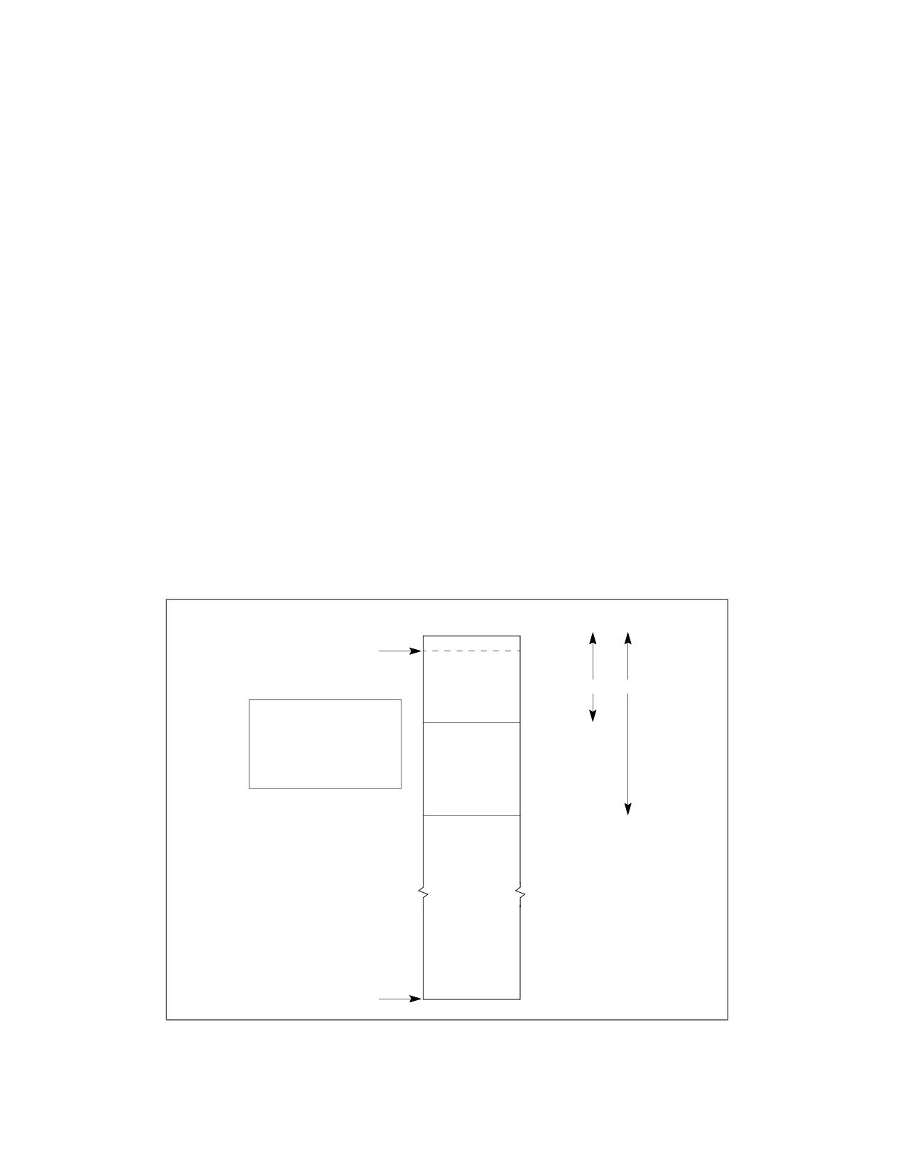
Figure 12-3 shows the physical memory layout for the processor following a hardware reset and the starting point
of this example. The EPROM that contains the initialization code resides at the upper end of the processor’s physical
memory address range, starting at address FFFFFFFFH and going down from there. The address of the first instruc-
tion to be executed is at FFFFFFF0H, the default starting address for the processor following a hardware reset.
The main steps carried out in this example are summarized in Table 12-5. The source listing for the example (with
the filename STARTUP.ASM) is given in Example 12-1. The line numbers given in Table 12-5 refer to the source
listing.
The following are some additional notes concerning this example:
• When the processor is switched into protected mode, the original code segment base-address value of
FFFF0000H (located in the hidden part of the CS register) is retained and execution continues from the current
offset in the EIP register. The processor will thus continue to execute code in the EPROM until a far jump or call
is made to a new code segment, at which time, the base address in the CS register will be changed.
• Maskable hardware interrupts are disabled after a hardware reset and should remain disabled until the
necessary interrupt handlers have been installed. The NMI interrupt is not disabled following a reset. The NMI#
pin must thus be inhibited from being asserted until an NMI handler has been loaded and made available to the
processor.
• The use of a temporary GDT allows simple transfer of tables from the EPROM to anywhere in the RAM area. A
GDT entry is constructed with its base pointing to address 0 and a limit of 4 GBytes. When the DS and ES
registers are loaded with this descriptor, the temporary GDT is no longer needed and can be replaced by the
application GDT.
• This code loads one TSS and no LDTs. If more TSSs exist in the application, they must be loaded into RAM. If
there are LDTs they may be loaded as well.
After Reset
FFFF FFFFH
[CS.BASE+EIP]
FFFF FFF0H
64K EPROM
EIP = 0000 FFF0H
CS.BASE = FFFF 0000H
FFFF 0000H
DS.BASE = 0H
ES.BASE = 0H
SS.BASE = 0H
ESP = 0H
[SP, DS, SS, ES]
0
Figure 12-3. Processor State After Reset
Vol. 3A
12-15

PROCESSOR MANAGEMENT AND INITIALIZATION
Table 12-5. Main Initialization Steps in STARTUP.ASM Source Listing
STARTUP.ASM Line
Description
Numbers
From
To
157
157
Jump (short) to the entry code in the EPROM
162
169
Construct a temporary GDT in RAM with one entry:
0 - null
1 - R/W data segment, base = 0, limit = 4 GBytes
171
172
Load the GDTR to point to the temporary GDT
174
177
Load CR0 with PE flag set to switch to protected mode
179
181
Jump near to clear real mode instruction queue
184
186
Load DS, ES registers with GDT[1] descriptor, so both point to the entire physical memory space
188
195
Perform specific board initialization that is imposed by the new protected mode
196
218
Copy the application's GDT from ROM into RAM
220
238
Copy the application's IDT from ROM into RAM
241
243
Load application's GDTR
244
245
Load application's IDTR
247
261
Copy the application's TSS from ROM into RAM
263
267
Update TSS descriptor and other aliases in GDT (GDT alias or IDT alias)
277
277
Load the task register (without task switch) using LTR instruction
282
286
Load SS, ESP with the value found in the application's TSS
287
287
Push EFLAGS value found in the application's TSS
288
288
Push CS value found in the application's TSS
289
289
Push EIP value found in the application's TSS
290
293
Load DS, ES with the value found in the application's TSS
296
296
Perform IRET; pop the above values and enter the application code
12.10.1 Assembler Usage
In this example, the Intel assembler ASM386 and build tools BLD386 are used to assemble and build the initializa-
tion code module. The following assumptions are used when using the Intel ASM386 and BLD386 tools.
• The ASM386 will generate the right operand size opcodes according to the code-segment attribute. The
attribute is assigned either by the ASM386 invocation controls or in the code-segment definition.
• If a code segment that is going to run in real-address mode is defined, it must be set to a USE 16 attribute. If
a 32-bit operand is used in an instruction in this code segment (for example, MOV EAX, EBX), the assembler
automatically generates an operand prefix for the instruction that forces the processor to execute a 32-bit
operation, even though its default code-segment attribute is 16-bit.
• Intel's ASM386 assembler allows specific use of the 16- or 32-bit instructions, for example, LGDTW, LGDTD,
IRETD. If the generic instruction LGDT is used, the default- segment attribute will be used to generate the right
opcode.
12.10.2 STARTUP.ASM Listing
Example 12-1 provides high-level sample code designed to move the processor into protected mode. This listing
does not include any opcode and offset information.
12-16
Vol. 3A
PROCESSOR MANAGEMENT AND INITIALIZATION
Example 12-1. STARTUP.ASM
MS-DOS* 5.0(045-N) 386(TM) MACRO ASSEMBLER STARTUP
09:44:51 08/19/92 PAGE 1
MS-DOS 5.0(045-N) 386(TM) MACRO ASSEMBLER V4.0, ASSEMBLY OF MODULE STARTUP
OBJECT MODULE PLACED IN startup.obj
ASSEMBLER INVOKED BY: f:\386tools\ASM386.EXE startup.a58 pw (132 )
LINE
SOURCE
1
NAME
STARTUP
2
3
;;;;;;;;;;;;;;;;;;;;;;;;;;;;;;;;;;;;;;;;;;;;
4
;
5
;
ASSUMPTIONS:
6
;
7
;
1. The bottom 64K of memory is ram, and can be used for
8
;
scratch space by this module.
9
;
10
;
2. The system has sufficient free usable ram to copy the
11
;
initial GDT, IDT, and TSS
12
;
13
;;;;;;;;;;;;;;;;;;;;;;;;;;;;;;;;;;;;;;;;;;;;;;;;;;;;;;;;;;;;;;
14
15
; configuration data - must match with build definition
16
17
CS_BASE
EQU
0FFFF0000H
18
19
; CS_BASE is the linear address of the segment STARTUP_CODE
20
; - this is specified in the build language file
21
22
RAM_START
EQU
400H
23
24
; RAM_START is the start of free, usable ram in the linear
25
; memory space.
The GDT, IDT, and initial TSS will be
26
; copied above this space, and a small data segment will be
27
; discarded at this linear address.
The 32-bit word at
28
; RAM_START will contain the linear address of the first
29
; free byte above the copied tables - this may be useful if
30
; a memory manager is used.
31
32
TSS_INDEX
EQU
10
33
34
; TSS_INDEX is the index of the TSS of the first task to
35
; run after startup
36
37
38
;;;;;;;;;;;;;;;;;;;;;;;;;;;;;;;;;;;;;;;;;;;;;;;;;;;;;;;;;;;;
39
40
; ------------------------- STRUCTURES and EQU ---------------
41
; structures for system data
42
43
; TSS structure
44
TASK_STATE STRUC
45
link
DW ?
Vol. 3A
12-17
PROCESSOR MANAGEMENT AND INITIALIZATION
46
link_h
DW ?
47
ESP0
DD ?
48
SS0
DW ?
49
SS0_h
DW ?
50
ESP1
DD ?
51
SS1
DW ?
52
SS1_h
DW ?
53
ESP2
DD ?
54
SS2
DW ?
55
SS2_h
DW ?
56
CR3_reg
DD ?
57
EIP_reg
DD ?
58
EFLAGS_regDD ?
59
EAX_reg DD ?
60
ECX_reg DD ?
61
EDX_reg DD ?
62
EBX_reg DD ?
63
ESP_reg DD ?
64
EBP_reg DD ?
65
ESI_reg DD ?
66
EDI_reg DD ?
67
ES_reg
DW ?
68
ES_h
DW ?
69
CS_reg
DW ?
70
CS_h
DW ?
71
SS_reg
DW ?
72
SS_h
DW ?
73
DS_reg
DW ?
74
DS_h
DW ?
75
FS_reg
DW ?
76
FS_h
DW ?
77
GS_reg
DW ?
78
GS_h
DW ?
79
LDT_reg
DW ?
80
LDT_h
DW ?
81
TRAP_reg DW ?
82
IO_map_baseDW ?
83 TASK_STATE ENDS
84
85
; basic structure of a descriptor
86
DESC
STRUC
87
lim_0_15 DW ?
88
bas_0_15 DW ?
89
bas_16_23DB ?
90
access
DB ?
91
gran
DB ?
92
bas_24_31DB ?
93 DESC
ENDS
94
95
; structure for use with LGDT and LIDT instructions
96
TABLE_REG
STRUC
97
table_limDW ?
98
table_linearDD ?
99 TABLE_REG
ENDS
12-18
Vol. 3A
PROCESSOR MANAGEMENT AND INITIALIZATION
100
101
; offset of GDT and IDT descriptors in builder generated GDT
102
GDT_DESC_OFF
EQU 1*SIZE(DESC)
103
IDT_DESC_OFF
EQU 2*SIZE(DESC)
104
105
; equates for building temporary GDT in RAM
106
LINEAR_SEL
EQU
1*SIZE (DESC)
107
LINEAR_PROTO_LO
EQU
00000FFFFH
; LINEAR_ALIAS
108
LINEAR_PROTO_HI
EQU
000CF9200H
109
110
; Protection Enable Bit in CR0
111
PE_BIT EQU 1B
112
113
; ------------------------------------------------------------
114
115
; ------------------------- DATA SEGMENT----------------------
116
117
; Initially, this data segment starts at linear 0, according
118
; to the processor’s power-up state.
119
120
STARTUP_DATA
SEGMENT RW
121
122
free_mem_linear_base
LABEL
DWORD
123
TEMP_GDT
LABEL
BYTE
; must be first in segment
124
TEMP_GDT_NULL_DESC
DESC
<>
125
TEMP_GDT_LINEAR_DESC DESC
<>
126
127
; scratch areas for LGDT and LIDT instructions
128
TEMP_GDT_SCRATCH TABLE_REG
<>
129
APP_GDT_RAM
TABLE_REG
<>
130
APP_IDT_RAM
TABLE_REG
<>
131
; align end_data
132
fill
DW
?
133
134
; last thing in this segment - should be on a dword boundary
135
end_data
LABEL
BYTE
136
137
STARTUP_DATA
ENDS
138
; ------------------------------------------------------------
139
140
141
; ------------------------- CODE SEGMENT----------------------
142
STARTUP_CODE SEGMENT ER PUBLIC USE16
143
144
; filled in by builder
145
PUBLIC GDT_EPROM
146
GDT_EPROM
TABLE_REG
<>
147
148
; filled in by builder
149
PUBLIC IDT_EPROM
150
IDT_EPROM
TABLE_REG
<>
151
152
; entry point into startup code - the bootstrap will vector
153
; here with a near JMP generated by the builder.
This
Vol. 3A
12-19
PROCESSOR MANAGEMENT AND INITIALIZATION
154
; label must be in the top 64K of linear memory.
155
156
PUBLIC STARTUP
157
STARTUP:
158
159
; DS,ES address the bottom 64K of flat linear memory
160
ASSUME DS:STARTUP_DATA, ES:STARTUP_DATA
161
; See Figure 12-4
162
; load GDTR with temporary GDT
163
LEA
EBX,TEMP_GDT
; build the TEMP_GDT in low ram,
164
MOV
DWORD PTR [EBX],0
; where we can address
165
MOV
DWORD PTR [EBX]+4,0
166
MOV
DWORD PTR [EBX]+8, LINEAR_PROTO_LO
167
MOV
DWORD PTR [EBX]+12, LINEAR_PROTO_HI
168
MOV
TEMP_GDT_scratch.table_linear,EBX
169
MOV
TEMP_GDT_scratch.table_lim,15
170
171
DB 66H; execute a 32 bit LGDT
172
LGDT
TEMP_GDT_scratch
173
174
; enter protected mode
175
MOV
EBX,CR0
176
OR
EBX,PE_BIT
177
MOV
CR0,EBX
178
179
; clear prefetch queue
180
JMP
CLEAR_LABEL
181
CLEAR_LABEL:
182
183
; make DS and ES address 4G of linear memory
184
MOV
CX,LINEAR_SEL
185
MOV
DS,CX
186
MOV
ES,CX
187
188
; do board specific initialization
189
;
190
;
191
;
192
;
193
194
195
; See Figure 12-5
196
; copy EPROM GDT to ram at:
197
;
RAM_START + size (STARTUP_DATA)
198
MOV
EAX,RAM_START
199
ADD
EAX,OFFSET (end_data)
200
MOV
EBX,RAM_START
201
MOV
ECX, CS_BASE
202
ADD
ECX, OFFSET (GDT_EPROM)
203
MOV
ESI, [ECX].table_linear
204
MOV
EDI,EAX
205
MOVZX
ECX, [ECX].table_lim
206
MOV
APP_GDT_ram[EBX].table_lim,CX
12-20
Vol. 3A
PROCESSOR MANAGEMENT AND INITIALIZATION
207
INC
ECX
208
MOV
EDX,EAX
209
MOV
APP_GDT_ram[EBX].table_linear,EAX
210
ADD
EAX,ECX
211
REP MOVS
BYTE PTR ES:[EDI],BYTE PTR DS:[ESI]
212
213
; fixup GDT base in descriptor
214
MOV
ECX,EDX
215
MOV
[EDX].bas_0_15+GDT_DESC_OFF,CX
216
ROR
ECX,16
217
MOV
[EDX].bas_16_23+GDT_DESC_OFF,CL
218
MOV
[EDX].bas_24_31+GDT_DESC_OFF,CH
219
220
; copy EPROM IDT to ram at:
221
; RAM_START+size(STARTUP_DATA)+SIZE (EPROM GDT)
222
MOV
ECX, CS_BASE
223
ADD
ECX, OFFSET (IDT_EPROM)
224
MOV
ESI, [ECX].table_linear
225
MOV
EDI,EAX
226
MOVZX
ECX, [ECX].table_lim
227
MOV
APP_IDT_ram[EBX].table_lim,CX
228
INC
ECX
229
MOV
APP_IDT_ram[EBX].table_linear,EAX
230
MOV
EBX,EAX
231
ADD
EAX,ECX
232
REP MOVS
BYTE PTR ES:[EDI],BYTE PTR DS:[ESI]
233
234
; fixup IDT pointer in GDT
235
MOV
[EDX].bas_0_15+IDT_DESC_OFF,BX
236
ROR
EBX,16
237
MOV
[EDX].bas_16_23+IDT_DESC_OFF,BL
238
MOV
[EDX].bas_24_31+IDT_DESC_OFF,BH
239
240
; load GDTR and IDTR
241
MOV
EBX,RAM_START
242
DB
66H
; execute a 32 bit LGDT
243
LGDT
APP_GDT_ram[EBX]
244
DB
66H
; execute a 32 bit LIDT
245
LIDT
APP_IDT_ram[EBX]
246
247
; move the TSS
248
MOV
EDI,EAX
249
MOV
EBX,TSS_INDEX*SIZE(DESC)
250
MOV
ECX,GDT_DESC_OFF ;build linear address for TSS
251
MOV
GS,CX
252
MOV
DH,GS:[EBX].bas_24_31
253
MOV
DL,GS:[EBX].bas_16_23
254
ROL
EDX,16
255
MOV
DX,GS:[EBX].bas_0_15
256
MOV
ESI,EDX
257
LSL
ECX,EBX
258
INC
ECX
259
MOV
EDX,EAX
260
ADD
EAX,ECX
Vol. 3A
12-21
PROCESSOR MANAGEMENT AND INITIALIZATION
261
REP MOVS
BYTE PTR ES:[EDI],BYTE PTR DS:[ESI]
262
263
; fixup TSS pointer
264
MOV
GS:[EBX].bas_0_15,DX
265
ROL
EDX,16
266
MOV
GS:[EBX].bas_24_31,DH
267
MOV
GS:[EBX].bas_16_23,DL
268
ROL
EDX,16
269
;save start of free ram at linear location RAMSTART
270
MOV
free_mem_linear_base+RAM_START,EAX
271
272
;assume no LDT used in the initial task
- if necessary,
273
;code to move the LDT could be added, and should resemble
274
;that used to move the TSS
275
276
; load task register
277
LTR
BX
; No task switch, only descriptor loading
278
; See Figure 12-6
279
; load minimal set of registers necessary to simulate task
280
; switch
281
282
283
MOV
AX,[EDX].SS_reg
; start loading registers
284
MOV
EDI,[EDX].ESP_reg
285
MOV
SS,AX
286
MOV
ESP,EDI
; stack now valid
287
PUSH
DWORD PTR [EDX].EFLAGS_reg
288
PUSH
DWORD PTR [EDX].CS_reg
289
PUSH
DWORD PTR [EDX].EIP_reg
290
MOV
AX,[EDX].DS_reg
291
MOV
BX,[EDX].ES_reg
292
MOV
DS,AX
; DS and ES no longer linear memory
293
MOV
ES,BX
294
295
; simulate far jump to initial task
296
IRETD
297
298 STARTUP_CODE ENDS
*** WARNING #377 IN 298, (PASS 2) SEGMENT CONTAINS PRIVILEGED INSTRUCTION(S)
299
300 END STARTUP, DS:STARTUP_DATA, SS:STARTUP_DATA
301
302
ASSEMBLY COMPLETE,
1 WARNING,
NO ERRORS.
12-22
Vol. 3A
PROCESSOR MANAGEMENT AND INITIALIZATION
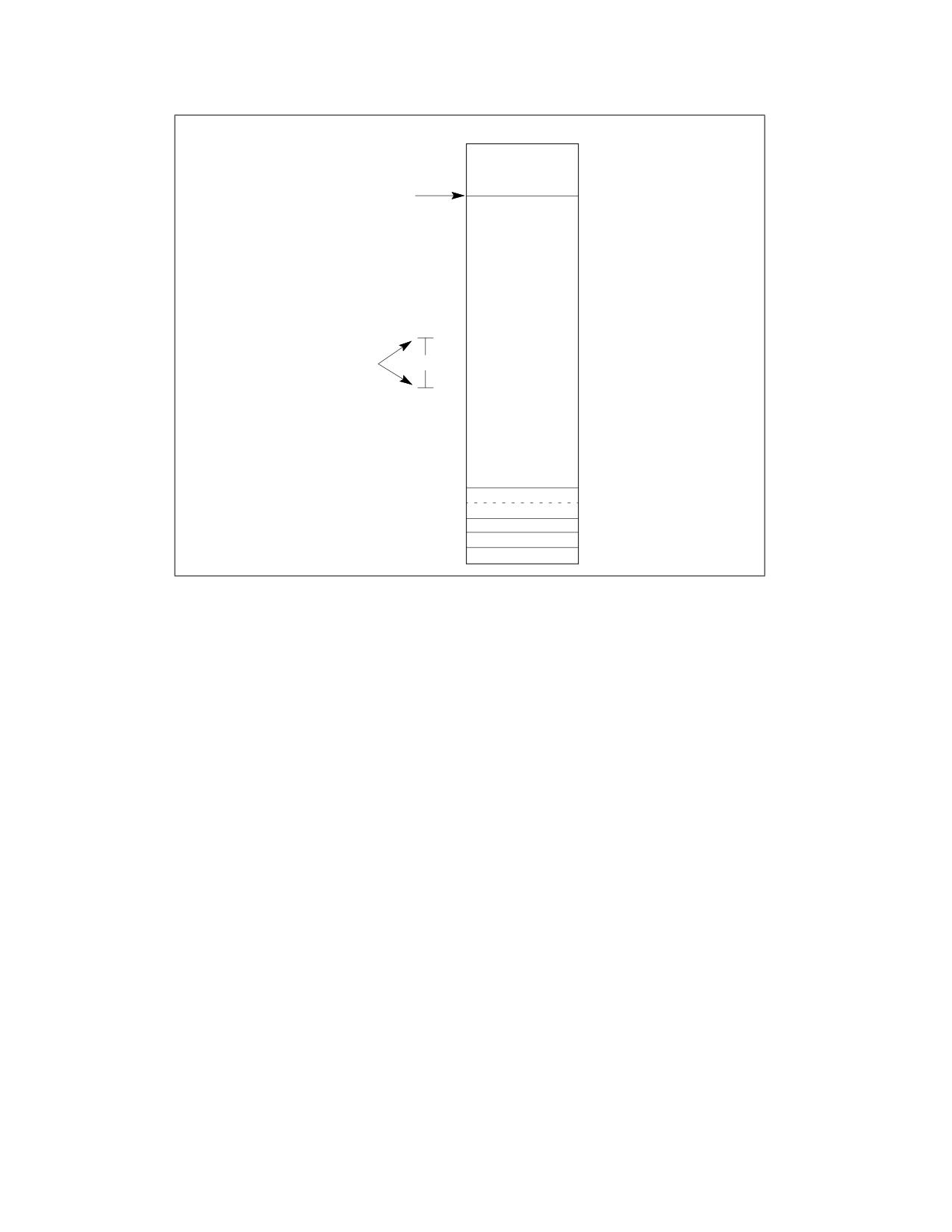
FFFF FFFFH
START: [CS.BASE+EIP]
FFFF 0000H
• Jump near start
• Construct TEMP_GDT
• LGDT
• Move to protected mode
DS, ES = GDT[1]
4 GB
Base
Limit
GDT_SCRATCH
GDT [1]
Base=0, Limit=4G
GDT [0]
0
TEMP_GDT
Figure 12-4. Constructing Temporary GDT and Switching to Protected Mode (Lines 162-172 of List File)
Vol. 3A
12-23
PROCESSOR MANAGEMENT AND INITIALIZATION
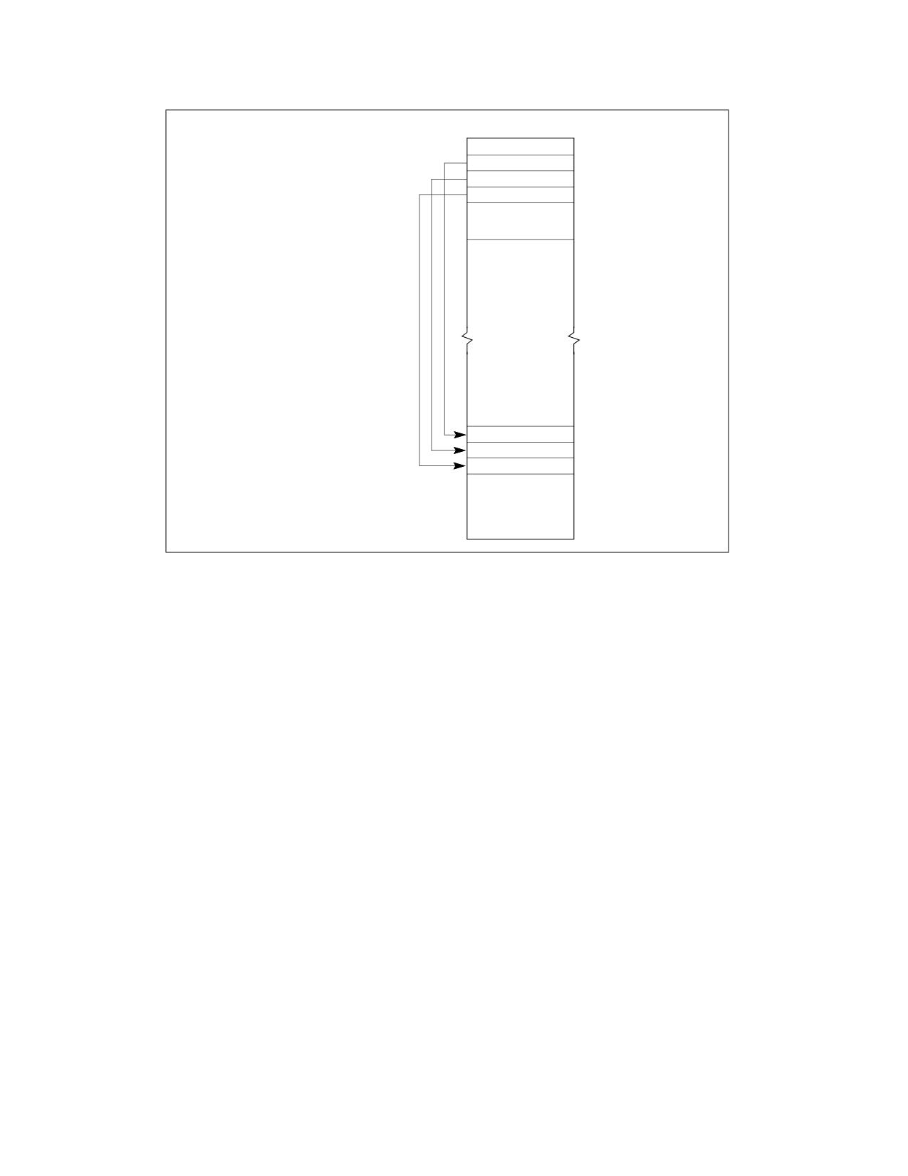
FFFF FFFFH
TSS
IDT
GDT
• Move the GDT, IDT, TSS
from ROM to RAM
• Fix Aliases
• LTR
TSS RAM
IDT RAM
GDT RAM
RAM_START
0
Figure 12-5. Moving the GDT, IDT, and TSS from ROM to RAM (Lines 196-261 of List File)
12-24
Vol. 3A
PROCESSOR MANAGEMENT AND INITIALIZATION
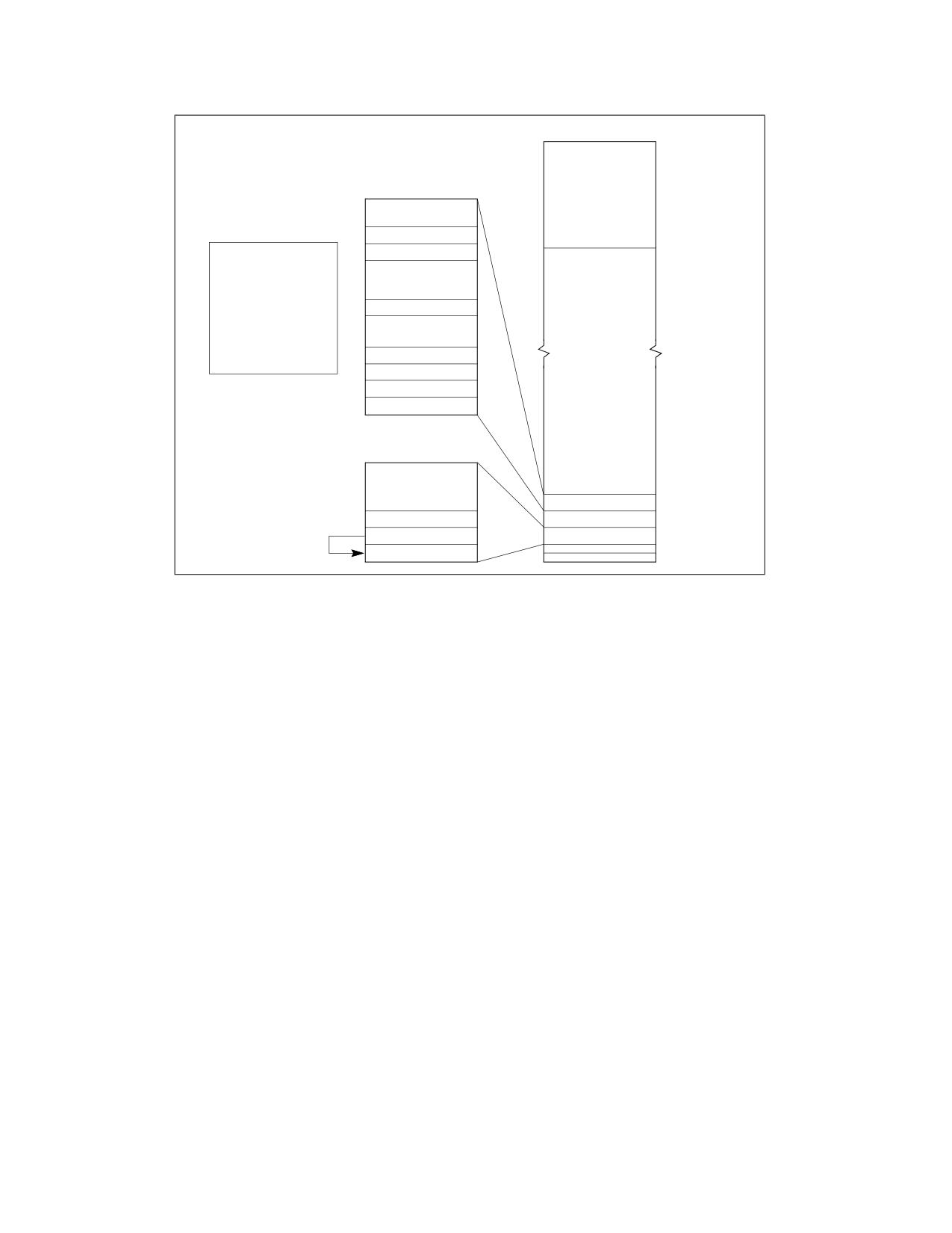
•
•
EIP
EFLAGS
SS = TSS.SS
ESP = TSS.ESP
•
•
PUSH TSS.EFLAG
•
PUSH TSS.CS
ESP
PUSH TSS.EIP
ES = TSS.ES
•
DS = TSS.DS
IRET
ES
CS
SS
DS
GDT
TSS RAM
IDT Alias
IDT RAM
GDT Alias
GDT RAM
RAM_START
0
Figure 12-6. Task Switching (Lines 282-296 of List File)
12.10.3 MAIN.ASM Source Code
The file MAIN.ASM shown in Example 12-2 defines the data and stack segments for this application and can be
substituted with the main module task written in a high-level language that is invoked by the IRET instruction
executed by STARTUP.ASM.
Example 12-2. MAIN.ASM
NAME
main_module
data
SEGMENT RW
dw 1000 dup(?)
DATA
ENDS
stack stackseg 800
CODE SEGMENT ER use32 PUBLIC
main_start:
nop
nop
nop
CODE ENDS
END main_start, ds:data, ss:stack
12.10.4 Supporting Files
The batch file shown in Example 12-3 can be used to assemble the source code files STARTUP.ASM and MAIN.ASM
and build the final application.
Vol. 3A
12-25
PROCESSOR MANAGEMENT AND INITIALIZATION
Example 12-3. Batch File to Assemble and Build the Application
ASM386 STARTUP.ASM
ASM386 MAIN.ASM
BLD386 STARTUP.OBJ, MAIN.OBJ buildfile(EPROM.BLD) bootstrap(STARTUP) Bootload
BLD386 performs several operations in this example:
It allocates physical memory location to segments and tables.
It generates tables using the build file and the input files.
It links object files and resolves references.
It generates a boot-loadable file to be programmed into the EPROM.
Example 12-4 shows the build file used as an input to BLD386 to perform the above functions.
Example 12-4. Build File
INIT_BLD_EXAMPLE;
SEGMENT
*SEGMENTS(DPL = 0)
,
startup.startup_code(BASE = 0FFFF0000H)
;
TASK
BOOT_TASK(OBJECT = startup, INITIAL,DPL = 0,
NOT INTENABLED)
,
PROTECTED_MODE_TASK(OBJECT = main_module,DPL = 0,
NOT INTENABLED)
;
TABLE
GDT (
LOCATION = GDT_EPROM
,
ENTRY = (
10:
PROTECTED_MODE_TASK
,
startup.startup_code
,
startup.startup_data
,
main_module.data
,
main_module.code
,
main_module.stack
)
),
IDT (
LOCATION = IDT_EPROM
);
MEMORY
(
RESERVE = (0..3FFFH
-- Area for the GDT, IDT, TSS copied from ROM
,
60000H..0FFFEFFFFH)
,
RANGE = (ROM_AREA = ROM (0FFFF0000H..0FFFFFFFFH))
-- Eprom size 64K
,
RANGE = (RAM_AREA = RAM (4000H..05FFFFH))
12-26
Vol. 3A

PROCESSOR MANAGEMENT AND INITIALIZATION
);
END
Table 12-6 shows the relationship of each build item with an ASM source file.
Table 12-6. Relationship Between BLD Item and ASM Source File
Item
ASM386 and Startup.A58
BLD386 Controls
Effect
and BLD file
Bootstrap
public startup
bootstrap
Near jump at 0FFFFFFF0H to
startup:
start(startup)
start.
GDT location
public GDT_EPROM
TABLE
The location of the GDT will be
GDT_EPROM TABLE_REG <>
GDT(location = GDT_EPROM)
programmed into the
GDT_EPROM location.
IDT location
public IDT_EPROM
TABLE
The location of the IDT will be
IDT_EPROM TABLE_REG <>
IDT(location = IDT_EPROM
programmed into the
IDT_EPROM location.
RAM start
RAM_START equ 400H
memory (reserve = (0..3FFFH))
RAM_START is used as the ram
destination for moving the
tables. It must be excluded from
the application's segment area.
Location of the
TSS_INDEX EQU 10
TABLE GDT(
Put the descriptor of the
application TSS in
ENTRY = (10: PROTECTED_MODE_
application TSS in GDT entry 10.
the GDT
TASK))
EPROM size and
size and location of the initialization
SEGMENT startup.code (base =
Initialization code size must be
location
code
0FFFF0000H) ...memory (RANGE(
less than 64K and resides at
ROM_AREA = ROM(x..y))
upper most 64K of the 4-GByte
memory space.
12.11 MICROCODE UPDATE FACILITIES
The P6 family and later processors have the capability to correct errata by loading an Intel-supplied data block into
the processor. The data block is called a microcode update. This section describes the mechanisms the BIOS needs
to provide in order to use this feature during system initialization. It also describes a specification that permits the
incorporation of future updates into a system BIOS.
Intel considers the release of a microcode update for a silicon revision to be the equivalent of a processor stepping
and completes a full-stepping level validation for releases of microcode updates.
A microcode update is used to correct errata in the processor. The BIOS, which has an update loader, is responsible
for loading the update on processors during system initialization (Figure 12-7). There are two steps to this process:
the first is to incorporate the necessary update data blocks into the BIOS; the second is to load update data blocks
into the processor.
Vol. 3A
12-27

PROCESSOR MANAGEMENT AND INITIALIZATION
Update
Loader
Update
New Update
CPU
Blocks
BIOS
Figure 12-7. Applying Microcode Updates
12.11.1 Microcode Update
A microcode update consists of an Intel-supplied binary that contains a descriptive header and data. No executable
code resides within the update. Each microcode update is tailored for a specific list of processor signatures. A
mismatch of the processor’s signature with the signature contained in the update will result in a failure to load. A
processor signature includes the extended family, extended model, type, family, model, and stepping of the
processor (starting with processor family 0fH, model 03H, a given microcode update may be associated with one of
multiple processor signatures; see Section 12.11.2 for details).
Microcode updates are composed of a multi-byte header, followed by encrypted data and then by an optional
extended signature table. Table 12-7 provides a definition of the fields; Table 12-8 shows the format of an update.
The header is 48 bytes. The first 4 bytes of the header contain the header version. The update header and its
reserved fields are interpreted by software based upon the header version. An encoding scheme guards against
tampering and provides a means for determining the authenticity of any given update. For microcode updates with
a data size field equal to 00000000H, the size of the microcode update is 2048 bytes. The first 48 bytes contain the
microcode update header. The remaining 2000 bytes contain encrypted data.
For microcode updates with a data size not equal to 00000000H, the total size field specifies the size of the micro-
code update. The first 48 bytes contain the microcode update header. The second part of the microcode update is
the encrypted data. The data size field of the microcode update header specifies the encrypted data size, its value
must be a multiple of the size of DWORD. The total size field of the microcode update header specifies the
encrypted data size plus the header size; its value must be in multiples of 1024 bytes (1 KBytes). The optional
extended signature table if implemented follows the encrypted data, and its size is calculated by (Total Size - (Data
Size + 48)).
NOTE
The optional extended signature table is supported starting with processor family 0FH, model 03H.
Table 12-7. Microcode Update Field Definitions
Field Name
Offset (bytes)
Length
Description
(bytes)
Header Version
0
4
Version number of the update header.
Update Revision
4
4
Unique version number for the update, the basis for the update
signature provided by the processor to indicate the current update
functioning within the processor. Used by the BIOS to authenticate
the update and verify that the processor loads successfully. The
value in this field cannot be used for processor stepping identification
alone. This is a signed 32-bit number.
Date
8
4
Date of the update creation in binary format: mmddyyyy (e.g.,
07/18/98 is 07181998H).
12-28
Vol. 3A

PROCESSOR MANAGEMENT AND INITIALIZATION
Table 12-7. Microcode Update Field Definitions (Contd.)
Field Name
Offset (bytes)
Length
Description
(bytes)
Processor Signature
12
4
Extended family, extended model, type, family, model, and stepping
of processor that requires this particular update revision (e.g.,
00000650H). Each microcode update is designed specifically for a
given extended family, extended model, type, family, model, and
stepping of the processor.
Software should use the processor signature field in conjunction with
the CPUID instruction to determine whether or not an update is
appropriate to load on a processor. The information encoded within
this field exactly corresponds to the bit representations returned by
the CPUID instruction.
Checksum
16
4
Checksum of Update Data and Header. Used to verify the integrity of
the update header and data. Checksum is correct when the
summation of all the DWORDs (including the extended Processor
Signature Table) that comprise the microcode update result in
00000000H.
Loader Revision
20
4
Version number of the loader program needed to correctly load this
update. The initial version is 00000001H.
Processor Flags
24
4
Platform type information is encoded in the lower 8 bits of this 4-
byte field. Each bit represents a particular platform type for a given
CPUID. Software should use the processor flags field in conjunction
with the platform Id bits in MSR (17H) to determine whether or not
an update is appropriate to load on a processor. Multiple bits may be
set representing support for multiple platform IDs.
Data Size
28
4
Specifies the size of the encrypted data in bytes, and must be a
multiple of DWORDs. If this value is 00000000H, then the microcode
update encrypted data is 2000 bytes (or 500 DWORDs).
Total Size
32
4
Specifies the total size of the microcode update in bytes. It is the
summation of the header size, the encrypted data size and the size of
the optional extended signature table. This value is always a multiple
of 1024.
Reserved
36
12
Reserved fields for future expansion.
Update Data
48
Data Size or
Update data.
2000
Extended Signature
Data Size + 48
4
Specifies the number of extended signature structures (Processor
Count
Signature[n], processor flags[n] and checksum[n]) that exist in this
microcode update.
Extended Checksum
Data Size + 52
4
Checksum of update extended processor signature table. Used to
verify the integrity of the extended processor signature table.
Checksum is correct when the summation of the DWORDs that
comprise the extended processor signature table results in
00000000H.
Reserved
Data Size + 56
12
Reserved fields.
Vol. 3A
12-29

PROCESSOR MANAGEMENT AND INITIALIZATION
Table 12-7. Microcode Update Field Definitions (Contd.)
Field Name
Offset (bytes)
Length
Description
(bytes)
Processor Signature[n]
Data Size + 68 +
4
Extended family, extended model, type, family, model, and stepping
(n * 12)
of processor that requires this particular update revision (e.g.,
00000650H). Each microcode update is designed specifically for a
given extended family, extended model, type, family, model, and
stepping of the processor.
Software should use the processor signature field in conjunction with
the CPUID instruction to determine whether or not an update is
appropriate to load on a processor. The information encoded within
this field exactly corresponds to the bit representations returned by
the CPUID instruction.
Processor Flags[n]
Data Size + 72 +
4
Platform type information is encoded in the lower 8 bits of this 4-
(n * 12)
byte field. Each bit represents a particular platform type for a given
CPUID. Software should use the processor flags field in conjunction
with the platform Id bits in MSR (17H) to determine whether or not
an update is appropriate to load on a processor. Multiple bits may be
set representing support for multiple platform IDs.
Checksum[n]
Data Size + 76 +
4
Used by utility software to decompose a microcode update into
(n * 12)
multiple microcode updates where each of the new updates is
constructed without the optional Extended Processor Signature
Table.
To calculate the Checksum, substitute the Primary Processor
Signature entry and the Processor Flags entry with the
corresponding Extended Patch entry. Delete the Extended Processor
Signature Table entries. The Checksum is correct when the
summation of all DWORDs that comprise the created Extended
Processor Patch results in 00000000H.
Table 12-8. Microcode Update Format
31
24
16
8
0
Bytes
Header Version
0
Update Revision
4
Month: 8
Day: 8
Year: 16
8
Processor Signature (CPUID)
12
Checksum
16
Loader Revision
20
Processor Flags
24
Reserved (24 bits)
Data Size
28
Total Size
32
Reserved (12 Bytes)
36
12-30
Vol. 3A

PROCESSOR MANAGEMENT AND INITIALIZATION
Table 12-8. Microcode Update Format (Contd.)
31
24
16
8
0
Bytes
Update Data (Data Size bytes, or 2000 Bytes if Data Size = 00000000H)
48
Extended Signature Count ‘n’
Data Size +
48
Extended Processor Signature Table Checksum
Data Size +
52
Reserved (12 Bytes)
Data Size +
56
Processor Signature[n]
Data Size +
68 +
(n * 12)
Processor Flags[n]
Data Size +
72 +
(n * 12)
Checksum[n]
Data Size +
76 +
(n * 12)
12.11.2 Optional Extended Signature Table
The extended signature table is a structure that may be appended to the end of the encrypted data when the
encrypted data only supports a single processor signature (optional case). The extended signature table will always
be present when the encrypted data supports multiple processor steppings and/or models (required case).
The extended signature table consists of a 20-byte extended signature header structure, which contains the
extended signature count, the extended processor signature table checksum, and 12 reserved bytes (Table 12-9).
Following the extended signature header structure, the extended signature table contains 0-to-n extended
processor signature structures.
Each processor signature structure consist of the processor signature, processor flags, and a checksum
(Table 12-10).
The extended signature count in the extended signature header structure indicates the number of processor signa-
ture structures that exist in the extended signature table.
The extended processor signature table checksum is a checksum of all DWORDs that comprise the extended signa-
ture table. That includes the extended signature count, extended processor signature table checksum, 12 reserved
bytes and the n processor signature structures. A valid extended signature table exists when the result of a
DWORD checksum is 00000000H.
Table 12-9. Extended Processor Signature Table Header Structure
Extended Signature Count ‘n’
Data Size + 48
Extended Processor Signature Table Checksum
Data Size + 52
Reserved (12 Bytes)
Data Size + 56
Table 12-10. Processor Signature Structure
Processor Signature[n]
Data Size + 68 + (n * 12)
Processor Flags[n]
Data Size + 72 + (n * 12)
Checksum[n]
Data Size + 76 + (n * 12)
Vol. 3A
12-31
PROCESSOR MANAGEMENT AND INITIALIZATION
12.11.3 Processor Identification
Each microcode update is designed to for a specific processor or set of processors. To determine the correct micro-
code update to load, software must ensure that one of the processor signatures embedded in the microcode update
matches the 32-bit processor signature returned by the CPUID instruction when executed by the target processor
with EAX = 1. Attempting to load a microcode update that does not match a processor signature embedded in the
microcode update with the processor signature returned by CPUID will cause the BIOS to reject the update.
Example 12-5 shows how to check for a valid processor signature match between the processor and microcode
update.
Example 12-5. Pseudo Code to Validate the Processor Signature
ProcessorSignature ← CPUID.01H:EAX
If (Update.HeaderVersion = 00000001h)
{
// first check the ProcessorSignature field
If (ProcessorSignature = Update.ProcessorSignature)
Success
// if extended signature is present
Else If (Update.TotalSize > (Update.DataSize + 48))
{
//
// Assume the Data Size has been used to calculate the
// location of Update.ProcessorSignature[0].
//
For (N ← 0; ((N < Update.ExtendedSignatureCount) AND
(ProcessorSignature ≠ Update.ProcessorSignature[N])); N++);
// if the loops ended when the iteration count is
// less than the number of processor signatures in
// the table, we have a match
If (N < Update.ExtendedSignatureCount)
Success
Else
Fail
}
Else
Fail
Else
Fail
12.11.4 Platform Identification
In addition to verifying the processor signature, the intended processor platform type must be determined to prop-
erly target the microcode update. The intended processor platform type is determined by reading the IA32_PLAT-
FORM_ID register, (MSR 17H). This 64-bit register must be read using the RDMSR instruction.
The three platform ID bits, when read as a binary coded decimal (BCD) number, indicate the bit position in the
microcode update header’s processor flags field associated with the installed processor. The processor flags in the
48-byte header and the processor flags field associated with the extended processor signature structures may have
multiple bits set. Each set bit represents a different platform ID that the update supports.
Register Name:
IA32_PLATFORM_ID
MSR Address:
017H
12-32
Vol. 3A

PROCESSOR MANAGEMENT AND INITIALIZATION
Access:
Read Only
IA32_PLATFORM_ID is a 64-bit register accessed only when referenced as a Qword through a RDMSR instruction.
Table 12-11. Processor Flags
Bit
Descriptions
63:53
Reserved
52:50
Platform Id Bits (RO). The field gives information concerning the intended platform for the processor. See also Table
12-8.
52
51
50
0
0
0
Processor Flag 0
0
0
1
Processor Flag 1
0
1
0
Processor Flag 2
0
1
1
Processor Flag 3
1
0
0
Processor Flag 4
1
0
1
Processor Flag 5
1
1
0
Processor Flag 6
1
1
1
Processor Flag 7
49:0
Reserved
To validate the platform information, software may implement an algorithm similar to the algorithms in
Example 12-6.
Example 12-6. Pseudo Code Example of Processor Flags Test
Flag ← 1 << IA32_PLATFORM_ID[52:50]
If (Update.HeaderVersion = 00000001h)
{
If (Update.ProcessorFlags & Flag)
{
Load Update
}
Else
{
//
// Assume the Data Size has been used to calculate the
// location of Update.ProcessorSignature[N] and a match
// on Update.ProcessorSignature[N] has already succeeded
//
If (Update.ProcessorFlags[n] & Flag)
{
Load Update
}
}
}
12.11.5 Microcode Update Checksum
Each microcode update contains a DWORD checksum located in the update header. It is software’s responsibility to
ensure that a microcode update is not corrupt. To check for a corrupt microcode update, software must perform a
Vol. 3A
12-33
PROCESSOR MANAGEMENT AND INITIALIZATION
unsigned DWORD (32-bit) checksum of the microcode update. Even though some fields are signed, the checksum
procedure treats all DWORDs as unsigned. Microcode updates with a header version equal to 00000001H must sum
all DWORDs that comprise the microcode update. A valid checksum check will yield a value of 00000000H. Any
other value indicates the microcode update is corrupt and should not be loaded.
The checksum algorithm shown by the pseudo code in Example 12-7 treats the microcode update as an array of
unsigned DWORDs. If the data size DWORD field at byte offset 32 equals 00000000H, the size of the encrypted
data is 2000 bytes, resulting in 500 DWORDs. Otherwise the microcode update size in DWORDs = (Total Size / 4),
where the total size is a multiple of 1024 bytes (1 KBytes).
Example 12-7. Pseudo Code Example of Checksum Test
N ← 512
If (Update.DataSize ≠ 00000000H)
N ← Update.TotalSize / 4
ChkSum ← 0
For (I ← 0; I < N; I++)
{
ChkSum ← ChkSum + MicrocodeUpdate[I]
}
If (ChkSum = 00000000H)
Success
Else
Fail
12.11.6 Microcode Update Loader
This section describes an update loader used to load an update into a P6 family or later processors. It also discusses
the requirements placed on the BIOS to ensure proper loading. The update loader described contains the minimal
instructions needed to load an update. The specific instruction sequence that is required to load an update is
dependent upon the loader revision field contained within the update header. This revision is expected to change
infrequently (potentially, only when new processor models are introduced).
Example 12-8 below represents the update loader with a loader revision of 00000001H. Note that the microcode
update must be aligned on a 16-byte boundary and the size of the microcode update must be 1-KByte granular.
Example 12-8. Assembly Code Example of Simple Microcode Update Loader
mov
ecx,79h
; MSR to write in ECX
xor
eax,eax
; clear EAX
xor
ebx,ebx
; clear EBX
mov
ax,cs
; Segment of microcode update
shl
eax,4
mov
bx,offset Update
; Offset of microcode update
add
eax,ebx
; Linear Address of Update in EAX
add
eax,48d
; Offset of the Update Data within the Update
xor
edx,edx
; Zero in EDX
WRMSR
; microcode update trigger
The loader shown in Example 12-8 assumes that update is the address of a microcode update (header and data)
embedded within the code segment of the BIOS. It also assumes that the processor is operating in real mode. The
data may reside anywhere in memory, aligned on a 16-byte boundary, that is accessible by the processor within its
current operating mode.
Before the BIOS executes the microcode update trigger (WRMSR) instruction, the following must be true:
12-34
Vol. 3A
PROCESSOR MANAGEMENT AND INITIALIZATION
• In 64-bit mode, EAX contains the lower 32-bits of the microcode update linear address. In protected mode, EAX
contains the full 32-bit linear address of the microcode update.
• In 64-bit mode, EDX contains the upper 32-bits of the microcode update linear address. In protected mode,
EDX equals zero.
• ECX contains 79H (address of IA32_BIOS_UPDT_TRIG).
Other requirements are:
• The addresses for the microcode update data must be in canonical form.
• If paging is enabled, the microcode update data must map that data as present.
• The microcode update data must start at a 16-byte aligned linear address.
12.11.6.1 Hard Resets in Update Loading
The effects of a loaded update are cleared from the processor upon a hard reset. Therefore, each time a hard reset
is asserted during the BIOS POST, the update must be reloaded on all processors that observed the reset. The
effects of a loaded update are, however, maintained across a processor INIT. There are no side effects caused by
loading an update into a processor multiple times.
12.11.6.2 Update in a Multiprocessor System
A multiprocessor (MP) system requires loading each processor with update data appropriate for its CPUID and plat-
form ID bits. The BIOS is responsible for ensuring that this requirement is met and that the loader is located in a
module executed by all processors in the system. If a system design permits multiple steppings of Pentium 4, Intel
Xeon, and P6 family processors to exist concurrently; then the BIOS must verify individual processors against the
update header information to ensure appropriate loading. Given these considerations, it is most practical to load
the update during MP initialization.
12.11.6.3 Update in a System Supporting Intel Hyper-Threading Technology
Intel Hyper-Threading Technology has implications on the loading of the microcode update. The update must be
loaded for each core in a physical processor. Thus, for a processor supporting Intel Hyper-Threading Technology,
only one logical processor per core is required to load the microcode update. Each individual logical processor can
independently load the update. However, MP initialization must provide some mechanism (e.g., a software sema-
phore) to force serialization of microcode update loads and to prevent simultaneous load attempts to the same
core.
12.11.6.4 Update in a System Supporting Dual-Core Technology
Dual-core technology has implications on the loading of the microcode update. The microcode update facility is not
shared between processor cores in the same physical package. The update must be loaded for each core in a phys-
ical processor.
If processor core supports Intel Hyper-Threading Technology, the guideline described in Section 12.11.6.3 also
applies.
12.11.6.5 Update Loader Enhancements
The update loader presented in Section 12.11.6, “Microcode Update Loader,” is a minimal implementation that can
be enhanced to provide additional functionality. Potential enhancements are described below:
• BIOS can incorporate multiple updates to support multiple steppings of the Pentium 4, Intel Xeon, and P6
family processors. This feature provides for operating in a mixed stepping environment on an MP system and
enables a user to upgrade to a later version of the processor. In this case, modify the loader to check the CPUID
and platform ID bits of the processor that it is running on against the available headers before loading a
particular update. The number of updates is only limited by available BIOS space.
• A loader can load the update and test the processor to determine if the update was loaded correctly. See
Section 12.11.7, “Update Signature and Verification.”
Vol. 3A
12-35
PROCESSOR MANAGEMENT AND INITIALIZATION
• A loader can verify the integrity of the update data by performing a checksum on the double words of the
update summing to zero. See Section 12.11.5, “Microcode Update Checksum.”
• A loader can provide power-on messages indicating successful loading of an update.
12.11.7 Update Signature and Verification
The P6 family and later processors provide capabilities to verify the authenticity of a particular update and to iden-
tify the current update revision. This section describes the model-specific extensions of processors that support
this feature. The update verification method below assumes that the BIOS will only verify an update that is more
recent than the revision currently loaded in the processor.
CPUID returns a value in a model specific register in addition to its usual register return values. The semantics of
CPUID cause it to deposit an update ID value in the 64-bit model-specific register at address 08BH
(IA32_BIOS_SIGN_ID). If no update is present in the processor, the value in the MSR remains unmodified. The
BIOS must pre-load a zero into the MSR before executing CPUID. If a read of the MSR at 8BH still returns zero after
executing CPUID, this indicates that no update is present.
The update ID value returned in the EDX register after RDMSR executes indicates the revision of the update loaded
in the processor. This value, in combination with the CPUID value returned in the EAX register, uniquely identifies a
particular update. The signature ID can be directly compared with the update revision field in a microcode update
header for verification of a correct load. No consecutive updates released for a given stepping of a processor may
share the same signature. The processor signature returned by CPUID differentiates updates for different step-
pings.
12.11.7.1 Determining the Signature
An update that is successfully loaded into the processor provides a signature that matches the update revision of
the currently functioning revision. This signature is available any time after the actual update has been loaded.
Requesting the signature does not have a negative impact upon a loaded update.
The procedure for determining this signature shown in Example 12-9.
Example 12-9. Assembly Code to Retrieve the Update Revision
MOV
ECX, 08BH
;IA32_BIOS_SIGN_ID
XOR
EAX, EAX
;clear EAX
XOR
EDX, EDX
;clear EDX
WRMSR
;Load 0 to MSR at 8BH
MOV
EAX, 1
cpuid
MOV
ECX, 08BH
;IA32_BIOS_SIGN_ID
rdmsr
;Read Model Specific Register
If there is an update active in the processor, its revision is returned in the EDX register after the RDMSR instruction
executes.
IA32_BIOS_SIGN_ID
Microcode Update Signature Register
MSR Address:
08BH Accessed as a Qword
Default Value:
XXXX XXXX XXXX XXXXh
Access:
Read/Write
The IA32_BIOS_SIGN_ID register is used to report the microcode update signature when CPUID executes. The
signature is returned in the upper DWORD (Table 12-12).
12-36
Vol. 3A

PROCESSOR MANAGEMENT AND INITIALIZATION
Table 12-12. Microcode Update Signature
Bit
Description
63:32
Microcode update signature. This field contains the signature of the currently loaded microcode update when read following
the execution of the CPUID.(EAX=01H). It is required that this register field be pre-loaded with zero prior to executing the
CPUID, function 1. If the field remains equal to zero, then there is no microcode update loaded. Another non-zero value will
be the signature.
31:0
Reserved.
12.11.7.2 Authenticating the Update
An update may be authenticated by the BIOS using the signature primitive, described above, and the algorithm in
Example 12-10.
Example 12-10. Pseudo Code to Authenticate the Update
Z ← Obtain Update Revision from the Update Header to be authenticated;
X ← Obtain Current Update Signature from MSR 8BH;
If (Z > X)
{
Load Update that is to be authenticated;
Y ← Obtain New Signature from MSR 8BH;
If (Z = Y)
Success
Else
Fail
}
Else
Fail
Example 12-10 requires that the BIOS only authenticate updates that contain a numerically larger revision than
the currently loaded revision, where Current Signature (X) < New Update Revision (Z). A processor with no loaded
update is considered to have a revision equal to zero.
This authentication procedure relies upon the decoding provided by the processor to verify an update from a poten-
tially hostile source. As an example, this mechanism in conjunction with other safeguards provides security for
dynamically incorporating field updates into the BIOS.
12.11.8 Optional Processor Microcode Update Specifications
This section describes an interface that an OEM-BIOS may provide to its client system software to manage
processor microcode updates. System software may choose to build its own facility to manage microcode updates
(e.g., similar to the facility described in Section 12.11.6) or rely on a facility provided by the BIOS to perform
microcode updates.
For this update facility, regardless of the actual implementation, the BIOS is responsible for ensuring the validity
and the integrity of the information provided by the caller, including authenticating the proposed update before
incorporating it into non-volatile storage.
Sections 12.11.8.1-12.11.8.9 describes a legacy extension (Function 0D042H) to the real mode INT 15H service.
INT 15H 0D042H function is one of several alternatives that a BIOS may choose to implement microcode update
facility and offer to its client application (e.g., an OS).
Alternatively, BIOS can choose a more modern microcode update facility based on platform-specific capabilities,
including the Capsule Update mechanism from the UEFI specification (www.uefi.org). In this discussion, the appli-
cation is referred to as the calling program or caller.
Vol. 3A
12-37
PROCESSOR MANAGEMENT AND INITIALIZATION
The real mode INT15 call specification described here is an Intel extension to an OEM BIOS. This extension allows
an application to read and modify the contents of the microcode update data in NVRAM. The update loader, which
is part of the system BIOS, cannot be updated by the interface. All of the functions defined in the specification must
be implemented for a system to be considered compliant with the specification. The INT15 functions are accessible
only from real mode.
12.11.8.1 Responsibilities of the BIOS
If a BIOS passes the presence test (INT 15H, AX = 0D042H, BL = 0H), it must implement all of the sub-functions
defined in the INT 15H, AX = 0D042H specification. There are no optional functions. BIOS must load the appropriate
update for each processor during system initialization.
A Header Version of an update block containing the value 0FFFFFFFFH indicates that the update block is unused and
available for storing a new update.
The BIOS is responsible for providing a region of non-volatile storage (NVRAM) for each potential processor step-
ping within a system. This storage unit consists of one or more update blocks. An update block is a contiguous
2048-byte block of memory. The BIOS for a single processor system need only provide update blocks to store one
microcode update. If the BIOS for a multiple processor system is intended to support mixed processor steppings,
then the BIOS needs to provide enough update blocks to store each unique microcode update or for each processor
socket on the OEM’s system board.
The BIOS is responsible for managing the NVRAM update blocks. This includes garbage collection, such as
removing microcode updates that exist in NVRAM for which a corresponding processor does not exist in the system.
This specification only provides the mechanism for ensuring security, the uniqueness of an entry, and that stale
entries are not loaded. The actual update block management is implementation specific on a per-BIOS basis.
As an example, the BIOS may use update blocks sequentially in ascending order with CPU signatures sorted versus
the first available block. In addition, garbage collection may be implemented as a setup option to clear all NVRAM
slots or as BIOS code that searches and eliminates unused entries during boot.
NOTES
For IA-32 processors starting with family 0FH and model 03H and Intel 64 processors, the
microcode update may be as large as 16 KBytes. Thus, BIOS must allocate 8 update blocks for each
microcode update. In a MP system, a common microcode update may be sufficient for each socket
in the system.
For IA-32 processors earlier than family 0FH and model 03H, the microcode update is 2 KBytes. An
MP-capable BIOS that supports multiple steppings must allocate a block for each socket in the
system.
A single-processor BIOS that supports variable-sized microcode update and fixed-sized microcode
update must allocate one 16-KByte region and a second region of at least 2 KBytes.
The following algorithm (Example 12-11) describes the steps performed during BIOS initialization used to load the
updates into the processor(s). The algorithm assumes:
• The BIOS ensures that no update contained within NVRAM has a header version or loader version that does not
match one currently supported by the BIOS.
• The update contains a correct checksum.
• The BIOS ensures that (at most) one update exists for each processor stepping.
• Older update revisions are not allowed to overwrite more recent ones.
These requirements are checked by the BIOS during the execution of the write update function of this interface.
The BIOS sequentially scans through all of the update blocks in NVRAM starting with index 0. The BIOS scans until
it finds an update where the processor fields in the header match the processor signature (extended family,
extended model, type, family, model, and stepping) as well as the platform bits of the current processor.
Example 12-11. Pseudo Code, Checks Required Prior to Loading an Update
For each processor in the system
{
12-38
Vol. 3A
PROCESSOR MANAGEMENT AND INITIALIZATION
Determine the Processor Signature via CPUID.01H;
Determine the Platform Bits ← 1 << IA32_PLATFORM_ID[52:50];
For (I ← UpdateBlock 0, I < NumOfBlocks; I++)
{
If (Update.Header_Version = 00000001H)
{
If ((Update.ProcessorSignature = Processor Signature) &&
(Update.ProcessorFlags & Platform Bits))
{
Load Update.UpdateData into the Processor;
Verify update was correctly loaded into the processor
Go on to next processor
Break;
}
Else If (Update.TotalSize > (Update.DataSize + 48))
{
N ← 0
While (N < Update.ExtendedSignatureCount)
{
If ((Update.ProcessorSignature[N] =
Processor Signature) &&
(Update.ProcessorFlags[N] & Platform Bits))
{
Load Update.UpdateData into the Processor;
Verify update correctly loaded into the processor
Go on to next processor
Break;
}
N ← N + 1
}
I ← I + (Update.TotalSize / 2048)
If ((Update.TotalSize MOD 2048) = 0)
I ← I + 1
}
}
}
}
NOTES
The platform Id bits in IA32_PLATFORM_ID are encoded as a three-bit binary coded decimal field.
The platform bits in the microcode update header are individually bit encoded. The algorithm must
do a translation from one format to the other prior to doing a check.
When performing the INT 15H, 0D042H functions, the BIOS must assume that the caller has no knowledge of plat-
form specific requirements. It is the responsibility of BIOS calls to manage all chipset and platform specific prereq-
uisites for managing the NVRAM device. When writing the update data using the Write Update sub-function, the
BIOS must maintain implementation specific data requirements (such as the update of NVRAM checksum). The
BIOS should also attempt to verify the success of write operations on the storage device used to record the update.
12.11.8.2 Responsibilities of the Calling Program
This section of the document lists the responsibilities of a calling program using the interface specifications to load
microcode update(s) into BIOS NVRAM.
• The calling program should call the INT 15H, 0D042H functions from a pure real mode program and should be
executing on a system that is running in pure real mode.
Vol. 3A
12-39
PROCESSOR MANAGEMENT AND INITIALIZATION
• The caller should issue the presence test function (sub function 0) and verify the signature and return codes of
that function.
• It is important that the calling program provides the required scratch RAM buffers for the BIOS and the proper
stack size as specified in the interface definition.
• The calling program should read any update data that already exists in the BIOS in order to make decisions
about the appropriateness of loading the update. The BIOS must refuse to overwrite a newer update with an
older version. The update header contains information about version and processor specifics for the calling
program to make an intelligent decision about loading.
• There can be no ambiguous updates. The BIOS must refuse to allow multiple updates for the same CPU to exist
at the same time; it also must refuse to load updates for processors that don’t exist on the system.
• The calling application should implement a verify function that is run after the update write function success-
fully completes. This function reads back the update and verifies that the BIOS returned an image identical to
the one that was written.
Example 12-12 represents a calling program.
Example 12-12. INT 15 DO42 Calling Program Pseudo-code
//
// We must be in real mode
//
If the system is not in Real mode exit
//
// Detect presence of Genuine Intel processor(s) that can be updated
// using(CPUID)
//
If no Intel processors exist that can be updated exit
//
// Detect the presence of the Intel microcode update extensions
//
If the BIOS fails the PresenceTestexit
//
// If the APIC is enabled, see if any other processors are out there
//
Read IA32_APICBASE
If APIC enabled
{
Send Broadcast Message to all processors except self via APIC
Have all processors execute CPUID, record the Processor Signature
(i.e.,Extended Family, Extended Model, Type, Family, Model, Stepping)
Have all processors read IA32_PLATFORM_ID[52:50], record Platform
Id Bits
If current processor cannot be updated
exit
}
//
// Determine the number of unique update blocks needed for this system
//
NumBlocks = 0
For each processor
{
If ((this is a unique processor stepping) AND
(we have a unique update in the database for this processor))
{
Checksum the update from the database;
If Checksum fails
exit
12-40
Vol. 3A
PROCESSOR MANAGEMENT AND INITIALIZATION
NumBlocks ← NumBlocks + size of microcode update / 2048
}
}
//
// Do we have enough update slots for all CPUs?
//
If there are more blocks required to support the unique processor steppings than update blocks
provided by the BIOS exit
//
// Do we need any update blocks at all? If not, we are done
//
If (NumBlocks = 0)
exit
//
// Record updates for processors in NVRAM.
//
For (I=0; I<NumBlocks; I++)
{
//
// Load each Update
//
Issue the WriteUpdate function
If (STORAGE_FULL) returned
{
Display Error -- BIOS is not managing NVRAM appropriately
exit
}
If (INVALID_REVISION) returned
{
Display Message: More recent update already loaded in NVRAM for
this stepping
continue
}
If any other error returned
{
Display Diagnostic
exit
}
//
// Verify the update was loaded correctly
//
Issue the ReadUpdate function
If an error occurred
{
Display Diagnostic
exit
}
//
// Compare the Update read to that written
//
If (Update read ≠ Update written)
{
Display Diagnostic
Vol. 3A
12-41

PROCESSOR MANAGEMENT AND INITIALIZATION
exit
}
I ← I + (size of microcode update / 2048)
}
//
// Enable Update Loading, and inform user
//
Issue the Update Control function with Task = Enable.
12.11.8.3 Microcode Update Functions
Table 12-13 defines the processor microcode update functions that implementations of INT 15H 0D042H must
support.
Table 12-13. Microcode Update Functions
Microcode Update Function
Function
Description
Required/Optional
Number
Presence test
00H
Returns information about the supported functions.
Required
Write update data
01H
Writes one of the update data areas (slots).
Required
Update control
02H
Globally controls the loading of updates.
Required
Read update data
03H
Reads one of the update data areas (slots).
Required
12.11.8.4 INT 15H-based Interface
If an OEM-BIOS is implementing INT 15H 0D042H interface and offer to its client, the BIOS should allow additional
microcode updates to be added to system flash.
The program that calls this interface is responsible for providing three 64-kilobyte RAM areas for BIOS use during
calls to the read and write functions. These RAM scratch pads can be used by the BIOS for any purpose, but only
for the duration of the function call. The calling routine places real mode segments pointing to the RAM blocks in
the CX, DX, and SI registers. Calls to functions in this interface must be made with a minimum of 32 kilobytes of
stack available to the BIOS.
In general, each function returns with CF cleared and AH contains the returned status. The general return codes
and other constant definitions are listed in Section 12.11.8.9, “Return Codes.”
The OEM error field (AL) is provided for the OEM to return additional error information specific to the platform. If
the BIOS provides no additional information about the error, OEM error must be set to SUCCESS. The OEM error
field is undefined if AH contains either SUCCESS (00H) or NOT_IMPLEMENTED (86H). In all other cases, it must be
set with either SUCCESS or a value meaningful to the OEM.
The following sections describe functions provided by the INT15H-based interface.
12.11.8.5 Function 00H-Presence Test
This function verifies that the BIOS has implemented required microcode update functions. Table 12-14 lists the
parameters and return codes for the function.
Table 12-14. Parameters for the Presence Test
Input
AX
Function Code
0D042H
BL
Sub-function
00H - Presence test
Output
CF
Carry Flag
Carry Set - Failure - AH contains status
Carry Clear - All return values valid
12-42
Vol. 3A

PROCESSOR MANAGEMENT AND INITIALIZATION
Table 12-14. Parameters for the Presence Test (Contd.)
Input
AH
Return Code
AL
OEM Error
Additional OEM information.
EBX
Signature Part 1
'INTE' - Part one of the signature
ECX
Signature Part 2
'LPEP'- Part two of the signature
EDX
Loader Version
Version number of the microcode update loader
SI
Update Count
Number of 2048 update blocks in NVRAM the BIOS allocated to storing
microcode updates
Return Codes (see Table 12-19 for code definitions
SUCCESS
The function completed successfully.
NOT_IMPLEMENTED
The function is not implemented.
In order to assure that the BIOS function is present, the caller must verify the carry flag, the return code, and the
64-bit signature. The update count reflects the number of 2048-byte blocks available for storage within one non-
volatile RAM.
The loader version number refers to the revision of the update loader program that is included in the system BIOS
image.
12.11.8.6 Function 01H-Write Microcode Update Data
This function integrates a new microcode update into the BIOS storage device. Table 12-15 lists the parameters
and return codes for the function.
Table 12-15. Parameters for the Write Update Data Function
Input
AX
Function Code
0D042H
BL
Sub-function
01H - Write update
ES:DI
Update Address
Real Mode pointer to the Intel Update structure. This buffer is 2048 bytes in
length if the processor supports only fixed-size microcode update or...
Real Mode pointer to the Intel Update structure. This buffer is 64 KBytes in
length if the processor supports a variable-size microcode update.
CX
Scratch Pad1
Real mode segment address of 64 KBytes of RAM block
DX
Scratch Pad2
Real mode segment address of 64 KBytes of RAM block
SI
Scratch Pad3
Real mode segment address of 64 KBytes of RAM block
SS:SP
Stack pointer
32 KBytes of stack minimum
Output
CF
Carry Flag
Carry Set - Failure - AH Contains status
Carry Clear - All return values valid
AH
Return Code
Status of the call
AL
OEM Error
Additional OEM information
Return Codes (see Table 12-19 for code definitions
SUCCESS
The function completed successfully.
NOT_IMPLEMENTED
The function is not implemented.
Vol. 3A
12-43

PROCESSOR MANAGEMENT AND INITIALIZATION
Table 12-15. Parameters for the Write Update Data Function (Contd.)
Input
WRITE_FAILURE
A failure occurred because of the inability to write the storage device.
ERASE_FAILURE
A failure occurred because of the inability to erase the storage device.
READ_FAILURE
A failure occurred because of the inability to read the storage device.
STORAGE_FULL
The BIOS non-volatile storage area is unable to accommodate the update
because all available update blocks are filled with updates that are needed for
processors in the system.
CPU_NOT_PRESENT
The processor stepping does not currently exist in the system.
INVALID_HEADER
The update header contains a header or loader version that is not recognized by
the BIOS.
INVALID_HEADER_CS
The update does not checksum correctly.
SECURITY_FAILURE
The processor rejected the update.
INVALID_REVISION
The same or more recent revision of the update exists in the storage device.
Description
The BIOS is responsible for selecting an appropriate update block in the non-volatile storage for storing the new
update. This BIOS is also responsible for ensuring the integrity of the information provided by the caller, including
authenticating the proposed update before incorporating it into storage.
Before writing the update block into NVRAM, the BIOS should ensure that the update structure meets the following
criteria in the following order:
1. The update header version should be equal to an update header version recognized by the BIOS.
2. The update loader version in the update header should be equal to the update loader version contained within
the BIOS image.
3. The update block must checksum. This checksum is computed as a 32-bit summation of all double words in the
structure, including the header, data, and processor signature table.
The BIOS selects update block(s) in non-volatile storage for storing the candidate update. The BIOS can select any
available update block as long as it guarantees that only a single update exists for any given processor stepping in
non-volatile storage. If the update block selected already contains an update, the following additional criteria apply
to overwrite it:
• The processor signature in the proposed update must be equal to the processor signature in the header of the
current update in NVRAM (Processor Signature + platform ID bits).
• The update revision in the proposed update should be greater than the update revision in the header of the
current update in NVRAM.
If no unused update blocks are available and the above criteria are not met, the BIOS can overwrite update
block(s) for a processor stepping that is no longer present in the system. This can be done by scanning the update
blocks and comparing the processor steppings, identified in the MP Specification table, to the processor steppings
that currently exist in the system.
Finally, before storing the proposed update in NVRAM, the BIOS must verify the authenticity of the update via the
mechanism described in Section 12.11.6, “Microcode Update Loader.” This includes loading the update into the
current processor, executing the CPUID instruction, reading MSR 08Bh, and comparing a calculated value with the
update revision in the proposed update header for equality.
When performing the write update function, the BIOS must record the entire update, including the header, the
update data, and the extended processor signature table (if applicable). When writing an update, the original
contents may be overwritten, assuming the above criteria have been met. It is the responsibility of the BIOS to
ensure that more recent updates are not overwritten through the use of this BIOS call, and that only a single
update exists within the NVRAM for any processor stepping and platform ID.
Figure 12-8 and Figure 12-9 show the process the BIOS follows to choose an update block and ensure the integrity
of the data when it stores the new microcode update.
12-44
Vol. 3A
PROCESSOR MANAGEMENT AND INITIALIZATION
Vol. 3A
12-45
PROCESSOR MANAGEMENT AND INITIALIZATION
Write Microcode Update
Does Update Match A
Return
No
CPU_NOT_PRESENT
CPU in The System
Yes
Valid Update
Return
No
Header Version?
INVALID_HEADER
Yes
Return
Loader Revision Match
No
INVALID_HEADER
BIOS’s Loader?
Yes
Does Update
Return
Checksum Correctly?
No
INVALID_HEADER_CS
1
Figure 12-8. Microcode Update Write Operation Flow [1]
12-46
Vol. 3A
PROCESSOR MANAGEMENT AND INITIALIZATION
1
Replacement
Update Matching CPU
Space Available in
No
No
policy implemented?
Already In NVRAM?
NVRAM?
Yes
Yes
No
Yes
Update Revision Newer
Return
Return
No
Than NVRAM Update?
INVALID_REVISION
STORAGE_FULL
Yes
Update Pass
Return
Authenticity Test?
SECURITY_FAILURE
Yes
Update NMRAM Record
Return
SUCCESS
Figure 12-9. Microcode Update Write Operation Flow [2]
12.11.8.7 Function 02H-Microcode Update Control
This function enables loading of binary updates into the processor. Table 12-16 lists the parameters and return
codes for the function.
Vol. 3A
12-47

PROCESSOR MANAGEMENT AND INITIALIZATION
Table 12-16. Parameters for the Control Update Sub-function
Input
AX
Function Code
0D042H
BL
Sub-function
02H - Control update
BH
Task
See the description below.
CX
Scratch Pad1
Real mode segment of 64 KBytes of RAM block
DX
Scratch Pad2
Real mode segment of 64 KBytes of RAM block
SI
Scratch Pad3
Real mode segment of 64 KBytes of RAM block
SS:SP
Stack pointer
32 kilobytes of stack minimum
Output
CF
Carry Flag
Carry Set - Failure - AH contains status
Carry Clear - All return values valid.
AH
Return Code
Status of the call
AL
OEM Error
Additional OEM Information.
BL
Update Status
Either enable or disable indicator
Return Codes (see Table 12-19 for code definitions)
SUCCESS
Function completed successfully.
READ_FAILURE
A failure occurred because of the inability to read the storage device.
This control is provided on a global basis for all updates and processors. The caller can determine the current status
of update loading (enabled or disabled) without changing the state. The function does not allow the caller to disable
loading of binary updates, as this poses a security risk.
The caller specifies the requested operation by placing one of the values from Table 12-17 in the BH register. After
successfully completing this function, the BL register contains either the enable or the disable designator. Note that
if the function fails, the update status return value is undefined.
Table 12-17. Mnemonic Values
Mnemonic
Value
Meaning
Enable
1
Enable the Update loading at initialization time.
Query
2
Determine the current state of the update control without changing its status.
The READ_FAILURE error code returned by this function has meaning only if the control function is implemented in
the BIOS NVRAM. The state of this feature (enabled/disabled) can also be implemented using CMOS RAM bits
where READ failure errors cannot occur.
12.11.8.8 Function 03H-Read Microcode Update Data
This function reads a currently installed microcode update from the BIOS storage into a caller-provided RAM buffer.
Table 12-18 lists the parameters and return codes.
Table 12-18. Parameters for the Read Microcode Update Data Function
Input
AX
Function Code
0D042H
BL
Sub-function
03H - Read Update
ES:DI
Buffer Address
Real Mode pointer to the Intel Update structure that
will be written with the binary data
12-48
Vol. 3A

PROCESSOR MANAGEMENT AND INITIALIZATION
Table 12-18. Parameters for the Read Microcode Update Data Function (Contd.)
ECX
Scratch Pad1
Real Mode Segment address of 64 KBytes of RAM
Block (lower 16 bits)
ECX
Scratch Pad2
Real Mode Segment address of 64 KBytes of RAM
Block (upper 16 bits)
DX
Scratch Pad3
Real Mode Segment address of 64 KBytes of RAM
Block
SS:SP
Stack pointer
32 KBytes of Stack Minimum
SI
Update Number
This is the index number of the update block to be
read. This value is zero based and must be less than
the update count returned from the presence test
function.
Output
CF
Carry Flag
Carry Set
- Failure - AH contains Status
Carry Clear - All return values are
valid.
AH
Return Code
Status of the Call
AL
OEM Error
Additional OEM Information
Return Codes (see Table 12-19 for code definitions)
SUCCESS
The function completed successfully.
READ_FAILURE
There was a failure because of the inability to read the
storage device.
UPDATE_NUM_INVALID
Update number exceeds the maximum number of
update blocks implemented by the BIOS.
NOT_EMPTY
The specified update block is a subsequent block in use
to store a valid microcode update that spans multiple
blocks.
The specified block is not a header block and is not
empty.
The read function enables the caller to read any microcode update data that already exists in a BIOS and make
decisions about the addition of new updates. As a result of a successful call, the BIOS copies the microcode update
into the location pointed to by ES:DI, with the contents of all Update block(s) that are used to store the specified
microcode update.
If the specified block is not a header block, but does contain valid data from a microcode update that spans multiple
update blocks, then the BIOS must return Failure with the NOT_EMPTY error code in AH.
An update block is considered unused and available for storing a new update if its Header Version contains the
value 0FFFFFFFFH after return from this function call. The actual implementation of NVRAM storage management
is not specified here and is BIOS dependent. As an example, the actual data value used to represent an empty
block by the BIOS may be zero, rather than 0FFFFFFFFH. The BIOS is responsible for translating this information
into the header provided by this function.
12.11.8.9 Return Codes
After the call has been made, the return codes listed in Table 12-19 are available in the AH register.
Vol. 3A
12-49

PROCESSOR MANAGEMENT AND INITIALIZATION
Table 12-19. Return Code Definitions
Return Code
Value
Description
SUCCESS
00H
The function completed successfully.
NOT_IMPLEMENTED
86H
The function is not implemented.
ERASE_FAILURE
90H
A failure because of the inability to erase the storage device.
WRITE_FAILURE
91H
A failure because of the inability to write the storage device.
READ_FAILURE
92H
A failure because of the inability to read the storage device.
STORAGE_FULL
93H
The BIOS non-volatile storage area is unable to accommodate the update
because all available update blocks are filled with updates that are needed
for processors in the system.
CPU_NOT_PRESENT
94H
The processor stepping does not currently exist in the system.
INVALID_HEADER
95H
The update header contains a header or loader version that is not
recognized by the BIOS.
INVALID_HEADER_CS
96H
The update does not checksum correctly.
SECURITY_FAILURE
97H
The update was rejected by the processor.
INVALID_REVISION
98H
The same or more recent revision of the update exists in the storage device.
UPDATE_NUM_INVALID
99H
The update number exceeds the maximum number of update blocks
implemented by the BIOS.
NOT_EMPTY
9AH
The specified update block is a subsequent block in use to store a valid
microcode update that spans multiple blocks.
The specified block is not a header block and is not empty.
12-50
Vol. 3A
CHAPTER 13
ADVANCED PROGRAMMABLE INTERRUPT CONTROLLER (APIC)
The Advanced Programmable Interrupt Controller (APIC), referred to in the following sections as the local APIC,
was introduced into the IA-32 processors with the Pentium processor (see Section 25.27, “Advanced Program-
mable Interrupt Controller (APIC)”) and is included in the P6 family, Pentium 4, Intel Xeon processors, and other
more recent Intel 64 and IA-32 processor families (see Section 13.4.2, “Presence of the Local APIC”). The local
APIC performs two primary functions for the processor:
• It receives interrupts from the processor’s interrupt pins, from internal sources and from an external I/O APIC
(or other external interrupt controller). It sends these to the processor core for handling.
• In multiple processor (MP) systems, it sends and receives interprocessor interrupt (IPI) messages to and from
other logical processors on the system bus. IPI messages can be used to distribute interrupts among the
processors in the system or to execute system wide functions (such as, booting up processors or distributing
work among a group of processors).
The external I/O APIC is part of Intel’s system chipset. Its primary function is to receive external interrupt events
from the system and its associated I/O devices and relay them to the local APIC as interrupt messages. In MP
systems, the I/O APIC also provides a mechanism for distributing external interrupts to the local APICs of selected
processors or groups of processors on the system bus.
This chapter provides a description of the local APIC and its programming interface. It also provides an overview of
the interface between the local APIC and the I/O APIC. Contact Intel for detailed information about the I/O APIC.
When a local APIC has sent an interrupt to its processor core for handling, the processor uses the interrupt and
exception handling mechanism described in Chapter 7, “Interrupt and Exception Handling.” See Section 7.1, “Inter-
rupt and Exception Overview,” for an introduction to interrupt and exception handling.
13.1
LOCAL AND I/O APIC OVERVIEW
Each local APIC consists of a set of APIC registers (see Table 13-1) and associated hardware that control the
delivery of interrupts to the processor core and the generation of IPI messages. The APIC registers are memory
mapped and can be read and written to using the MOV instruction.
Local APICs can receive interrupts from the following sources:
• Locally connected I/O devices - These interrupts originate as an edge or level asserted by an I/O device
that is connected directly to the processor’s local interrupt pins (LINT0 and LINT1). The I/O devices may also
be connected to an 8259-type interrupt controller that is in turn connected to the processor through one of the
local interrupt pins.
• Externally connected I/O devices - These interrupts originate as an edge or level asserted by an I/O
device that is connected to the interrupt input pins of an I/O APIC. Interrupts are sent as I/O interrupt
messages from the I/O APIC to one or more of the processors in the system.
• Inter-processor interrupts (IPIs) - An Intel 64 or IA-32 processor can use the IPI mechanism to interrupt
another processor or group of processors on the system bus. IPIs are used for software self-interrupts,
interrupt forwarding, or preemptive scheduling.
• APIC timer generated interrupts - The local APIC timer can be programmed to send a local interrupt to its
associated processor when a programmed count is reached (see Section 13.5.4, “APIC Timer”).
• Performance monitoring counter interrupts - P6 family, Pentium 4, and Intel Xeon processors provide the
ability to send an interrupt to its associated processor when a performance-monitoring counter overflows (see
Section 22.6.3.5.8, “Generating an Interrupt on Overflow”).
• Thermal Sensor interrupts - Pentium 4 and Intel Xeon processors provide the ability to send an interrupt to
themselves when the internal thermal sensor has been tripped (see Section 17.8.2, “Thermal Monitor”).
• APIC internal error interrupts - When an error condition is recognized within the local APIC (such as an
attempt to access an unimplemented register), the APIC can be programmed to send an interrupt to its
associated processor (see Section 13.5.3, “Error Handling”).
Vol. 3A
13-1
ADVANCED PROGRAMMABLE INTERRUPT CONTROLLER (APIC)
Of these interrupt sources: the processor’s LINT0 and LINT1 pins, the APIC timer, the performance-monitoring
counters, the thermal sensor, and the internal APIC error detector are referred to as local interrupt sources.
Upon receiving a signal from a local interrupt source, the local APIC delivers the interrupt to the processor core
using an interrupt delivery protocol that has been set up through a group of APIC registers called the local vector
table or LVT (see Section 13.5.1, “Local Vector Table”). A separate entry is provided in the local vector table for
each local interrupt source, which allows a specific interrupt delivery protocol to be set up for each source. For
example, if the LINT1 pin is going to be used as an NMI pin, the LINT1 entry in the local vector table can be set up
to deliver an interrupt with vector number 2 (NMI interrupt) to the processor core.
The local APIC handles interrupts from the other two interrupt sources (externally connected I/O devices and IPIs)
through its IPI message handling facilities.
A processor can generate IPIs by programming the interrupt command register (ICR) in its local APIC (see Section
13.6.1, “Interrupt Command Register (ICR)”). The act of writing to the ICR causes an IPI message to be generated
and issued on the system bus (for Pentium 4 and Intel Xeon processors) or on the APIC bus (for Pentium and P6
family processors). See Section 13.2, “System Bus Vs. APIC Bus.”
IPIs can be sent to other processors in the system or to the originating processor (self-interrupts). When the target
processor receives an IPI message, its local APIC handles the message automatically (using information included
in the message such as vector number and trigger mode). See Section 13.6, “Issuing Interprocessor Interrupts,”
for a detailed explanation of the local APIC’s IPI message delivery and acceptance mechanism.
The local APIC can also receive interrupts from externally connected devices through the I/O APIC (see
Figure 13-1). The I/O APIC is responsible for receiving interrupts generated by system hardware and I/O devices
and forwarding them to the local APIC as interrupt messages.
Pentium 4 and
Pentium and P6
Intel Xeon Processors
Family Processors
Processor Core
Processor Core
Local APIC
Local APIC
Interrupt
Local
Interrupt
Local
Messages
Interrupts
Messages
Interrupts
Interrupt
System Bus
3-Wire APIC Bus
Messages
Bridge
External
I/O APIC
Interrupts
PCI
System Chipset
I/O APIC
External
Interrupts
System Chipset
Figure 13-1. Relationship of Local APIC and I/O APIC In Single-Processor Systems
Individual pins on the I/O APIC can be programmed to generate a specific interrupt vector when asserted. The I/O
APIC also has a “virtual wire mode” that allows it to communicate with a standard 8259A-style external interrupt
controller. Note that the local APIC can be disabled (see Section 13.4.3, “Enabling or Disabling the Local APIC”).
This allows an associated processor core to receive interrupts directly from an 8259A interrupt controller.
Both the local APIC and the I/O APIC are designed to operate in MP systems (see Figures 13-2 and 13-3). Each local
APIC handles interrupts from the I/O APIC, IPIs from processors on the system bus, and self-generated interrupts.
Interrupts can also be delivered to the individual processors through the local interrupt pins; however, this mecha-
nism is commonly not used in MP systems.
13-2
Vol. 3A
ADVANCED PROGRAMMABLE INTERRUPT CONTROLLER (APIC)
Processor #1
Processor #2
Processor #3
Processor #3
CPU
CPU
CPU
CPU
Local APIC
Local APIC
Local APIC
Local APIC
Interrupt
Interrupt
Interrupt
Interrupt
IPIs
IPIs
IPIs
IPIs
Messages
Messages
Messages
Messages
Processor System Bus
Interrupt
Messages
Bridge
PCI
I/O APIC
External
Interrupts
System Chipset
Figure 13-2. Local APICs and I/O APIC When Intel Xeon Processors Are Used in Multiple-Processor Systems
Processor #1
Processor #2
Processor #3
Processor #4
CPU
CPU
CPU
CPU
Local APIC
Local APIC
Local APIC
Local APIC
Interrupt
IPIs
Interrupt
IPIs
Interrupt
IPIs
Interrupt
IPIs
Messages
Messages
Messages
Messages
Interrupt
3-wire APIC Bus
Messages
External
I/O APIC
Interrupts
System Chipset
Figure 13-3. Local APICs and I/O APIC When P6 Family Processors Are Used in Multiple-Processor Systems
The IPI mechanism is typically used in MP systems to send fixed interrupts (interrupts for a specific vector number)
and special-purpose interrupts to processors on the system bus. For example, a local APIC can use an IPI to
forward a fixed interrupt to another processor for servicing. Special-purpose IPIs (including NMI, INIT, SMI, and
SIPI IPIs) allow one or more processors on the system bus to perform system-wide boot-up and control functions.
The following sections focus on the local APIC and its implementation in the Pentium 4, Intel Xeon, and P6 family
processors. In these sections, the terms “local APIC” and “I/O APIC” refer to local and I/O APICs used with the P6
family processors and to local and I/O xAPICs used with the Pentium 4 and Intel Xeon processors (see Section
13.3, “The Intel® 82489DX External APIC, the APIC, the xAPIC, and the X2APIC”).
13.2
SYSTEM BUS VS. APIC BUS
For the P6 family and Pentium processors, the I/O APIC and local APICs communicate through the 3-wire inter-
APIC bus (see Figure 13-3). Local APICs also use the APIC bus to send and receive IPIs. The APIC bus and its
messages are invisible to software and are not classed as architectural.
Vol. 3A
13-3
ADVANCED PROGRAMMABLE INTERRUPT CONTROLLER (APIC)
Beginning with the Pentium 4 and Intel Xeon processors, the I/O APIC and local APICs (using the xAPIC architec-
ture) communicate through the system bus (see Figure 13-2). The I/O APIC sends interrupt requests to the
processors on the system bus through bridge hardware that is part of the Intel chipset. The bridge hardware gener-
ates the interrupt messages that go to the local APICs. IPIs between local APICs are transmitted directly on the
system bus.
13.3
THE INTEL® 82489DX EXTERNAL APIC, THE APIC, THE XAPIC, AND THE
X2APIC
The local APIC in the P6 family and Pentium processors is an architectural subset of the Intel® 82489DX external
APIC. See Section 25.27.1, “Software Visible Differences Between the Local APIC and the 82489DX.”
The APIC architecture used in the Pentium 4 and Intel Xeon processors (called the xAPIC architecture) is an exten-
sion of the APIC architecture found in the P6 family processors. The primary difference between the APIC and
xAPIC architectures is that with the xAPIC architecture, the local APICs and the I/O APIC communicate through the
system bus. With the APIC architecture, they communication through the APIC bus (see Section 13.2, “System Bus
Vs. APIC Bus”). Also, some APIC architectural features have been extended and/or modified in the xAPIC architec-
ture. These extensions and modifications are described in Section 13.4 through Section 13.10.
The basic operating mode of the xAPIC is xAPIC mode. The x2APIC architecture is an extension of the xAPIC
architecture, primarily to increase processor addressability. The x2APIC architecture provides backward compati-
bility to the xAPIC architecture and forward extendability for future Intel platform innovations. These extensions
and modifications are supported by a new mode of execution (x2APIC mode) are detailed in Section 13.12.
13.4
LOCAL APIC
The following sections describe the architecture of the local APIC and how to detect it, identify it, and determine its
status. Descriptions of how to program the local APIC are given in Section 13.5.1, “Local Vector Table,” and Section
13.6.1, “Interrupt Command Register (ICR).”
13.4.1 The Local APIC Block Diagram
Figure 13-4 gives a functional block diagram for the local APIC. Software interacts with the local APIC by reading
and writing its registers. APIC registers are memory-mapped to a 4-KByte region of the processor’s physical
address space with an initial starting address of FEE00000H. For correct APIC operation, this address space must
be mapped to an area of memory that has been designated as strong uncacheable (UC). See Section 14.3,
“Methods of Caching Available.”
In MP system configurations, the APIC registers for Intel 64 or IA-32 processors on the system bus are initially
mapped to the same 4-KByte region of the physical address space. Software has the option of changing initial
mapping to a different 4-KByte region for all the local APICs or of mapping the APIC registers for each local APIC to
its own 4-KByte region. Section 13.4.5, “Relocating the Local APIC Registers,” describes how to relocate the base
address for APIC registers.
On processors supporting x2APIC architecture (indicated by CPUID.01H:ECX[21] = 1), the local APIC supports
operation both in xAPIC mode and (if enabled by software) in x2APIC mode. x2APIC mode provides extended
processor addressability (see Section 13.12).
NOTE
For P6 family, Pentium 4, and Intel Xeon processors, the APIC handles all memory accesses to
addresses within the 4-KByte APIC register space internally and no external bus cycles are
produced. For the Pentium processors with an on-chip APIC, bus cycles are produced for accesses
to the APIC register space. Thus, for software intended to run on Pentium processors, system
software should explicitly not map the APIC register space to regular system memory. Doing so can
result in an invalid opcode exception (#UD) being generated or unpredictable execution.
13-4
Vol. 3A
ADVANCED PROGRAMMABLE INTERRUPT CONTROLLER (APIC)
Version Register
EOI Register
Timer
Task Priority Register
Current Count
Register
INTA
From
Initial Count
Processor Priority
CPU
Register
Register
Core
Divide Configuration
Register
INTR To
Prioritizer
Local Vector Table
CPU
EXTINT
Core
Timer
In-Service Register (ISR)
Local
LINT0/1
Interrupt Request Register (IRR)
Interrupts 0,1
Perf. Mon.
Performance
Trigger Mode Register (TMR)
(Internal
Monitoring Counters1/
Interrupt)
Intel Processor Trace
Vec[3:0]
Register
Thermal
& TMR Bit
Select
Sensor
Thermal Sensor2
(Internal
Arb. ID
Vecter
Interrupt)
Error
Register4
Decode
Error Status
Register
Local
Acceptance
Interrupts
Logic
Dest. Mode
& Vector
APIC ID
To
Register
Protocol
CPU
Logical Destination
Translation Logic
INIT
Core
Register
NMI
SMI
Destination Format
Register
Interrupt Command
Register (ICR)
Spurious Vector Register
Processor System Bus3
1. Introduced in P6 family processors.
2. Introduced in the Pentium 4 and Intel Xeon processors.
3. Three-wire APIC bus in P6 family and Pentium processors.
4. Not implemented in Pentium 4 and Intel Xeon processors.
Figure 13-4. Local APIC Structure
Table 13-1 shows how the APIC registers are mapped into the 4-KByte APIC register space. Registers are 32 bits,
64 bits, or 256 bits in width; all are aligned on 128-bit boundaries. All 32-bit registers should be accessed using
128-bit aligned 32-bit loads or stores. Some processors may support loads and stores of less than 32 bits to some
of the APIC registers. This is model specific behavior and is not guaranteed to work on all processors. Any
FP/MMX/SSE access to an APIC register, or any access that touches bytes 4 through 15 of an APIC register may
cause undefined behavior and must not be executed. This undefined behavior could include hangs, incorrect results
or unexpected exceptions, including machine checks, and may vary between implementations. Wider registers
(64-bit or 256-bit) must be accessed using multiple 32-bit loads or stores, with all accesses being 128-bit aligned.
The local APIC registers listed in Table 13-1 are not MSRs. The only MSR associated with the programming of the
local APIC is the IA32_APIC_BASE MSR (see Section 13.4.3, “Enabling or Disabling the Local APIC”).
NOTE
In processors based on Nehalem1 microarchitecture, the Local APIC ID Register is no longer
Read/Write; it is Read Only.
Vol. 3A
13-5

ADVANCED PROGRAMMABLE INTERRUPT CONTROLLER (APIC)
Table 13-1. Local APIC Register Address Map
Address
Register Name
Software Read/Write
FEE0 0000H
Reserved
FEE0 0010H
Reserved
FEE0 0020H
Local APIC ID Register
Read/Write.
FEE0 0030H
Local APIC Version Register
Read Only.
FEE0 0040H
Reserved
FEE0 0050H
Reserved
FEE0 0060H
Reserved
FEE0 0070H
Reserved
FEE0 0080H
Task Priority Register (TPR)
Read/Write.
FEE0 0090H
Arbitration Priority Register1 (APR)
Read Only.
FEE0 00A0H
Processor Priority Register (PPR)
Read Only.
FEE0 00B0H
EOI Register
Write Only.
FEE0 00C0H
Remote Read Register1 (RRD)
Read Only
FEE0 00D0H
Logical Destination Register
Read/Write.
FEE0 00E0H
Destination Format Register
Read/Write (see Section
13.6.2.2).
FEE0 00F0H
Spurious Interrupt Vector Register
Read/Write (see Section 13.9.
FEE0 0100H
In-Service Register (ISR); bits 31:0
Read Only.
FEE0 0110H
In-Service Register (ISR); bits 63:32
Read Only.
FEE0 0120H
In-Service Register (ISR); bits 95:64
Read Only.
FEE0 0130H
In-Service Register (ISR); bits 127:96
Read Only.
FEE0 0140H
In-Service Register (ISR); bits 159:128
Read Only.
FEE0 0150H
In-Service Register (ISR); bits 191:160
Read Only.
FEE0 0160H
In-Service Register (ISR); bits 223:192
Read Only.
FEE0 0170H
In-Service Register (ISR); bits 255:224
Read Only.
FEE0 0180H
Trigger Mode Register (TMR); bits 31:0
Read Only.
FEE0 0190H
Trigger Mode Register (TMR); bits 63:32
Read Only.
FEE0 01A0H
Trigger Mode Register (TMR); bits 95:64
Read Only.
FEE0 01B0H
Trigger Mode Register (TMR); bits 127:96
Read Only.
FEE0 01C0H
Trigger Mode Register (TMR); bits 159:128
Read Only.
FEE0 01D0H
Trigger Mode Register (TMR); bits 191:160
Read Only.
FEE0 01E0H
Trigger Mode Register (TMR); bits 223:192
Read Only.
FEE0 01F0H
Trigger Mode Register (TMR); bits 255:224
Read Only.
FEE0 0200H
Interrupt Request Register (IRR); bits 31:0
Read Only.
FEE0 0210H
Interrupt Request Register (IRR); bits 63:32
Read Only.
FEE0 0220H
Interrupt Request Register (IRR); bits 95:64
Read Only.
1. See Table 2-1, “CPUID Signature Values of DisplayFamily_DisplayModel,” on page 1, and Section 2.8, “MSRs In Processors Based on
Nehalem Microarchitecture,” of the Intel® 64 and IA-32 Architectures Software Developer’s Manual, Volume 4, to determine which
processors are based on Nehalem microarchitecture.
13-6
Vol. 3A

ADVANCED PROGRAMMABLE INTERRUPT CONTROLLER (APIC)
Table 13-1. Local APIC Register Address Map (Contd.)
Address
Register Name
Software Read/Write
FEE0 0230H
Interrupt Request Register (IRR); bits 127:96
Read Only.
FEE0 0240H
Interrupt Request Register (IRR); bits 159:128
Read Only.
FEE0 0250H
Interrupt Request Register (IRR); bits 191:160
Read Only.
FEE0 0260H
Interrupt Request Register (IRR); bits 223:192
Read Only.
FEE0 0270H
Interrupt Request Register (IRR); bits 255:224
Read Only.
FEE0 0280H
Error Status Register
Write/Read; see Section
13.5.3.
FEE0 0290H through
Reserved
FEE0 02E0H
FEE0 02F0H
LVT Corrected Machine Check Interrupt (CMCI) Register
Read/Write.
FEE0 0300H
Interrupt Command Register (ICR); bits 0-31
Read/Write.
FEE0 0310H
Interrupt Command Register (ICR); bits 32-63
Read/Write.
FEE0 0320H
LVT Timer Register
Read/Write.
FEE0 0330H
LVT Thermal Sensor Register2
Read/Write.
FEE0 0340H
LVT Performance Monitoring Counters Register3
Read/Write.
FEE0 0350H
LVT LINT0 Register
Read/Write.
FEE0 0360H
LVT LINT1 Register
Read/Write.
FEE0 0370H
LVT Error Register
Read/Write.
FEE0 0380H
Initial Count Register (for Timer)
Read/Write.
FEE0 0390H
Current Count Register (for Timer)
Read Only.
FEE0 03A0H through
Reserved
FEE0 03D0H
FEE0 03E0H
Divide Configuration Register (for Timer)
Read/Write.
FEE0 03F0H
Reserved
NOTES:
1. Not supported in the Pentium 4 and Intel Xeon processors. The Illegal Register Access bit (7) of the ESR will not be set when writ-
ing to these registers.
2. Introduced in the Pentium 4 and Intel Xeon processors. This APIC register and its associated function are implementation depen-
dent and may not be present in future IA-32 or Intel 64 processors.
3. Introduced in the Pentium Pro processor. This APIC register and its associated function are implementation dependent and may not
be present in future IA-32 or Intel 64 processors.
13.4.2 Presence of the Local APIC
Beginning with the P6 family processors, the presence or absence of an on-chip local APIC can be detected using
the CPUID instruction. When the CPUID instruction is executed with a source operand of 1 in the EAX register, bit 9
of the CPUID feature flags returned in the EDX register indicates the presence (set) or absence (clear) of a local
APIC.
13.4.3 Enabling or Disabling the Local APIC
The local APIC can be enabled or disabled in either of two ways:
1. Using the APIC global enable/disable flag in the IA32_APIC_BASE MSR (MSR address 1BH; see Figure 13-5):
Vol. 3A
13-7
ADVANCED PROGRAMMABLE INTERRUPT CONTROLLER (APIC)
- When IA32_APIC_BASE[11] is 0, the processor is functionally equivalent to an IA-32 processor without an
on-chip APIC. The CPUID feature flag for the APIC (see Section 13.4.2, “Presence of the Local APIC”) is also
set to 0.
- When IA32_APIC_BASE[11] is set to 0, processor APICs based on the 3-wire APIC bus cannot be generally
re-enabled until a system hardware reset. The 3-wire bus loses track of arbitration that would be necessary
for complete re-enabling. Certain APIC functionality can be enabled (for example: performance and
thermal monitoring interrupt generation).
- For processors that use Front Side Bus (FSB) delivery of interrupts, software may disable or enable the
APIC by setting and resetting IA32_APIC_BASE[11]. A hardware reset is not required to re-start APIC
functionality, if software guarantees no interrupt will be sent to the APIC as IA32_APIC_BASE[11] is
cleared.
- When IA32_APIC_BASE[11] is set to 0, prior initialization to the APIC may be lost and the APIC may return
to the state described in Section 13.4.7.1, “Local APIC State After Power-Up or Reset.”
2. Using the APIC software enable/disable flag in the spurious-interrupt vector register (see Figure 13-23):
- If IA32_APIC_BASE[11] is 1, software can temporarily disable a local APIC at any time by clearing the APIC
software enable/disable flag in the spurious-interrupt vector register (see Figure 13-23). The state of the
local APIC when in this software-disabled state is described in Section 13.4.7.2, “Local APIC State After It
Has Been Software Disabled.”
- When the local APIC is in the software-disabled state, it can be re-enabled at any time by setting the APIC
software enable/disable flag to 1.
For the Pentium processor, the APICEN pin (which is shared with the PICD1 pin) is used during power-up or reset
to disable the local APIC.
Note that each entry in the LVT has a mask bit that can be used to inhibit interrupts from being delivered to the
processor from selected local interrupt sources (the LINT0 and LINT1 pins, the APIC timer, the performance-moni-
toring counters, Intel® Processor Trace, the thermal sensor, and/or the internal APIC error detector).
13.4.4 Local APIC Status and Location
The status and location of the local APIC are contained in the IA32_APIC_BASE MSR (see Figure 13-5). MSR bit
functions are described below:
• BSP flag, bit 8 ⎯ Indicates if the processor is the bootstrap processor (BSP). See Section 11.4, “Multiple-
Processor (MP) Initialization.” Following a power-up or reset, this flag is set to 1 for the processor selected as
the BSP and set to 0 for the remaining processors (APs).
• APIC Global Enable flag, bit 11 ⎯ Enables or disables the local APIC (see Section 13.4.3, “Enabling or
Disabling the Local APIC”). This flag is available in the Pentium 4, Intel Xeon, and P6 family processors. It is not
guaranteed to be available or available at the same location in future Intel 64 or IA-32 processors.
• APIC Base field, bits MAXAPICADDR-1:12 ⎯ Specifies the base address of the APIC registers.1 This value
is extended by 12 bits at the low end to form the base address. This automatically aligns the address on a 4-
KByte boundary. Following a power-up or reset, the field is set to FEE0 0000H.
• Bits 7:0, bits 10:9, and bits 63:MAXAPICADDR in the IA32_APIC_BASE MSR are reserved.
1. MAXAPICADDR is normally CPUID.80000008H:EAX[7:0] for processors that support CPUID.80000008H and 36 otherwise. If
IA32_TME_ACTIVATE[39:36] > 0 (indicating that SEAM-private KeyIDs have been configured), MAXAPICADDR is reduced by the
value of IA32_TME_ACTIVATE[35:32] (the KeyID bits in the address must be 0).
13-8
Vol. 3A

ADVANCED PROGRAMMABLE INTERRUPT CONTROLLER (APIC)
63
MAXAPICADDR
12 11109
8
7
0
Reserved
APIC Base
APIC Base-Base physical address
APIC global enable/disable
BSP-Processor is BSP
Reserved
Figure 13-5. IA32_APIC_BASE MSR (APIC_BASE_MSR in P6 Family)
13.4.5 Relocating the Local APIC Registers
The Pentium 4, Intel Xeon, and P6 family processors permit the starting address of the APIC registers to be relo-
cated from FEE00000H to another physical address by modifying the value in the base address field of the
IA32_APIC_BASE MSR. This extension of the APIC architecture is provided to help resolve conflicts with memory
maps of existing systems and to allow individual processors in an MP system to map their APIC registers to
different locations in physical memory.
13.4.6 Local APIC ID
At power up, system hardware assigns a unique APIC ID to each local APIC on the system bus (for Pentium 4 and
Intel Xeon processors) or on the APIC bus (for P6 family and Pentium processors). The hardware assigned APIC ID
is based on system topology and includes encoding for socket position and cluster information (see Figure 11-2
and Section 11.9.1, “Hierarchical Mapping of Shared Resources”).
In MP systems, the local APIC ID is also used as a processor ID by the BIOS and the operating system. Some
processors permit software to modify the APIC ID. However, the ability of software to modify the APIC ID is
processor model specific. Because of this, operating system software should avoid writing to the local APIC ID
register. The value returned by bits 31-24 of the EBX register (when the CPUID instruction is executed with a
source operand value of 1 in the EAX register) is always the Initial APIC ID (determined by the platform initializa-
tion). This is true even if software has changed the value in the Local APIC ID register.
The processor receives the hardware assigned APIC ID (or Initial APIC ID) by sampling pins A11# and A12# and
pins BR0# through BR3# (for the Pentium 4, Intel Xeon, and P6 family processors) and pins BE0# through BE3#
(for the Pentium processor). The APIC ID latched from these pins is stored in the APIC ID field of the local APIC ID
register (see Figure 13-6), and is used as the Initial APIC ID for the processor.
P6 family and Pentium processors
xAPIC Mode
31
27
24
0
Address: 0FEE0 0020H
Value after reset: 0000 0000H
APIC ID
Reserved
Pentium 4 processors, Xeon processors, and later processors
31
24
0
APIC ID
Reserved
x2APIC Mode
31
0
MSR Address: 802H
x2APIC ID
Figure 13-6. Local APIC ID Register
Vol. 3A
13-9
ADVANCED PROGRAMMABLE INTERRUPT CONTROLLER (APIC)
For the P6 family and Pentium processors, the local APIC ID field in the local APIC ID register is 4 bits. Encodings
0H through EH can be used to uniquely identify 15 different processors connected to the APIC bus. For the Pentium
4 and Intel Xeon processors, the xAPIC specification extends the local APIC ID field to 8 bits. These can be used to
identify up to 255 processors in the system.
13.4.7 Local APIC State
The following sections describe the state of the local APIC and its registers following a power-up or reset, after the
local APIC has been software disabled, following an INIT reset, and following an INIT-deassert message.
x2APIC will introduce 32-bit ID; see Section 13.12.
13.4.7.1 Local APIC State After Power-Up or Reset
Following a power-up or reset of the processor, the state of local APIC and its registers are as follows:
• The following registers are reset to all 0s.
• IRR, ISR, TMR, ICR, LDR, and TPR.
• Timer initial count and timer current count registers.
• Divide configuration register.
• The DFR register is reset to all 1s.
• The LVT register is reset to 0s except for the mask bits; these are set to 1s.
• The local APIC version register is not affected.
• The local APIC ID register is set to a unique APIC ID. (Pentium and P6 family processors only). The Arb ID
register is set to the value in the APIC ID register.
• The spurious-interrupt vector register is initialized to 000000FFH. By setting bit 8 to 0, software disables the
local APIC.
• If the processor is the only processor in the system or it is the BSP in an MP system (see Section 11.4.1, “BSP
and AP Processors”); the local APIC will respond normally to INIT and NMI messages, to INIT# signals and to
STPCLK# signals. If the processor is in an MP system and has been designated as an AP; the local APIC will
respond the same as for the BSP. In addition, it will respond to SIPI messages. For P6 family processors only,
an AP will not respond to a STPCLK# signal.
13.4.7.2 Local APIC State After It Has Been Software Disabled
When the APIC software enable/disable flag in the spurious interrupt vector register has been explicitly cleared (as
opposed to being cleared during a power up or reset), the local APIC is temporarily disabled (see Section 13.4.3,
“Enabling or Disabling the Local APIC”). The operation and response of a local APIC while in this software-disabled
state is as follows:
• The local APIC will respond normally to INIT, NMI, SMI, and SIPI messages.
• Pending interrupts in the IRR and ISR registers are held and require masking or handling by the CPU.
• The local APIC can still issue IPIs. It is software’s responsibility to avoid issuing IPIs through the IPI mechanism
and the ICR register if sending interrupts through this mechanism is not desired.
• The reception of any interrupt or transmission of any IPIs that are in progress when the local APIC is disabled
are completed before the local APIC enters the software-disabled state.
• The mask bits for all the LVT entries are set. Attempts to reset these bits will be ignored.
• (For Pentium and P6 family processors) The local APIC continues to listen to all bus messages in order to keep
its arbitration ID synchronized with the rest of the system.
13.4.7.3 Local APIC State After an INIT Reset (“Wait-for-SIPI” State)
An INIT reset of the processor can be initiated in either of two ways:
13-10
Vol. 3A

ADVANCED PROGRAMMABLE INTERRUPT CONTROLLER (APIC)
• By asserting the processor’s INIT# pin.
• By sending the processor an INIT IPI (an IPI with the delivery mode set to INIT).
Upon receiving an INIT through either of these mechanisms, the processor responds by beginning the initialization
process of the processor core and the local APIC. The state of the local APIC following an INIT reset is the same as
it is after a power-up or hardware reset, except that the APIC ID and arbitration ID registers are not affected. This
state is also referred to at the “wait-for-SIPI” state (see also: Section 11.4.2, “MP Initialization Protocol Require-
ments and Restrictions”).
13.4.7.4 Local APIC State After It Receives an INIT-Deassert IPI
Only the Pentium and P6 family processors support the INIT-deassert IPI. An INIT-deassert IPI has no affect on the
state of the APIC, other than to reload the arbitration ID register with the value in the APIC ID register.
13.4.8 Local APIC Version Register
The local APIC contains a hardwired version register. Software can use this register to identify the APIC version
(see Figure 13-7). In addition, the register specifies the number of entries in the local vector table (LVT) for a
specific implementation.
The fields in the local APIC version register are as follows:
Version
The version numbers of the local APIC:
0XH
82489DX discrete APIC.
10H - 15H
Integrated APIC.
Other values reserved.
Max LVT Entry
Shows the number of LVT entries minus 1. For the Pentium 4 and Intel Xeon processors (which
have 6 LVT entries), the value returned in the Max LVT field is 5; for the P6 family processors
(which have 5 LVT entries), the value returned is 4; for the Pentium processor (which has 4 LVT
entries), the value returned is 3. For processors based on the Nehalem microarchitecture
(which has 7 LVT entries) and onward, the value returned is 6.
Suppress EOI-broadcasts
Indicates whether software can inhibit the broadcast of EOI message by setting bit 12 of the
Spurious Interrupt Vector Register; see Section 13.8.5 and Section 13.9.
31
25 24
23
16
15
8
7
0
Reserved
Max LVT Entry
Reserved
Version
Support for EOI-broadcast suppression
Value after reset: 0BNN 00VVH
V = Version, N = # of LVT entries minus 1,
B = 1 if EOI-broadcast suppression supported
Address: FEE0 0030H
Figure 13-7. Local APIC Version Register
13.5
HANDLING LOCAL INTERRUPTS
The following sections describe facilities that are provided in the local APIC for handling local interrupts. These
include: the processor’s LINT0 and LINT1 pins, the APIC timer, the performance-monitoring counters, Intel
Processor Trace, the thermal sensor, and the internal APIC error detector. Local interrupt handling facilities include:
the LVT, the error status register (ESR), the divide configuration register (DCR), and the initial count and current
count registers.
Vol. 3A
13-11
ADVANCED PROGRAMMABLE INTERRUPT CONTROLLER (APIC)
13.5.1 Local Vector Table
The local vector table (LVT) allows software to specify the manner in which the local interrupts are delivered to the
processor core. It consists of the following 32-bit APIC registers (see Figure 13-8), one for each local interrupt:
• LVT CMCI Register (FEE0 02F0H) - Specifies interrupt delivery when an overflow condition of corrected
machine check error count reaching a threshold value occurred in a machine check bank supporting CMCI (see
Section 18.5.1, “CMCI Local APIC Interface”).
• LVT Timer Register (FEE0 0320H) - Specifies interrupt delivery when the APIC timer signals an interrupt
(see Section 13.5.4, “APIC Timer”).
• LVT Thermal Monitor Register (FEE0 0330H) - Specifies interrupt delivery when the thermal sensor
generates an interrupt (see Section 17.8.2, “Thermal Monitor”). This LVT entry is implementation specific, not
architectural. If implemented, it will always be at base address FEE0 0330H.
• LVT Performance Counter Register (FEE0 0340H) - Specifies interrupt delivery when a performance
counter generates an interrupt on overflow (see Section 22.6.3.5.8, “Generating an Interrupt on Overflow”) or
when Intel PT signals a ToPA PMI (see Section 36.2.7.2). This LVT entry is implementation specific, not archi-
tectural. If implemented, it is not guaranteed to be at base address FEE0 0340H.
• LVT LINT0 Register (FEE0 0350H) - Specifies interrupt delivery when an interrupt is signaled at the LINT0
pin.
• LVT LINT1 Register (FEE0 0360H) - Specifies interrupt delivery when an interrupt is signaled at the LINT1
pin.
• LVT Error Register (FEE0 0370H) - Specifies interrupt delivery when the APIC detects an internal error
(see Section 13.5.3, “Error Handling”).
The LVT performance counter register and its associated interrupt were introduced in the P6 processors and are
also present in the Pentium 4 and Intel Xeon processors. The LVT thermal monitor register and its associated inter-
rupt were introduced in the Pentium 4 and Intel Xeon processors. The LVT CMCI register and its associated inter-
rupt were introduced in the Intel Xeon 5500 processors.
As shown in Figure 13-8, some of these fields and flags are not available (and reserved) for some entries.
13-12
Vol. 3A
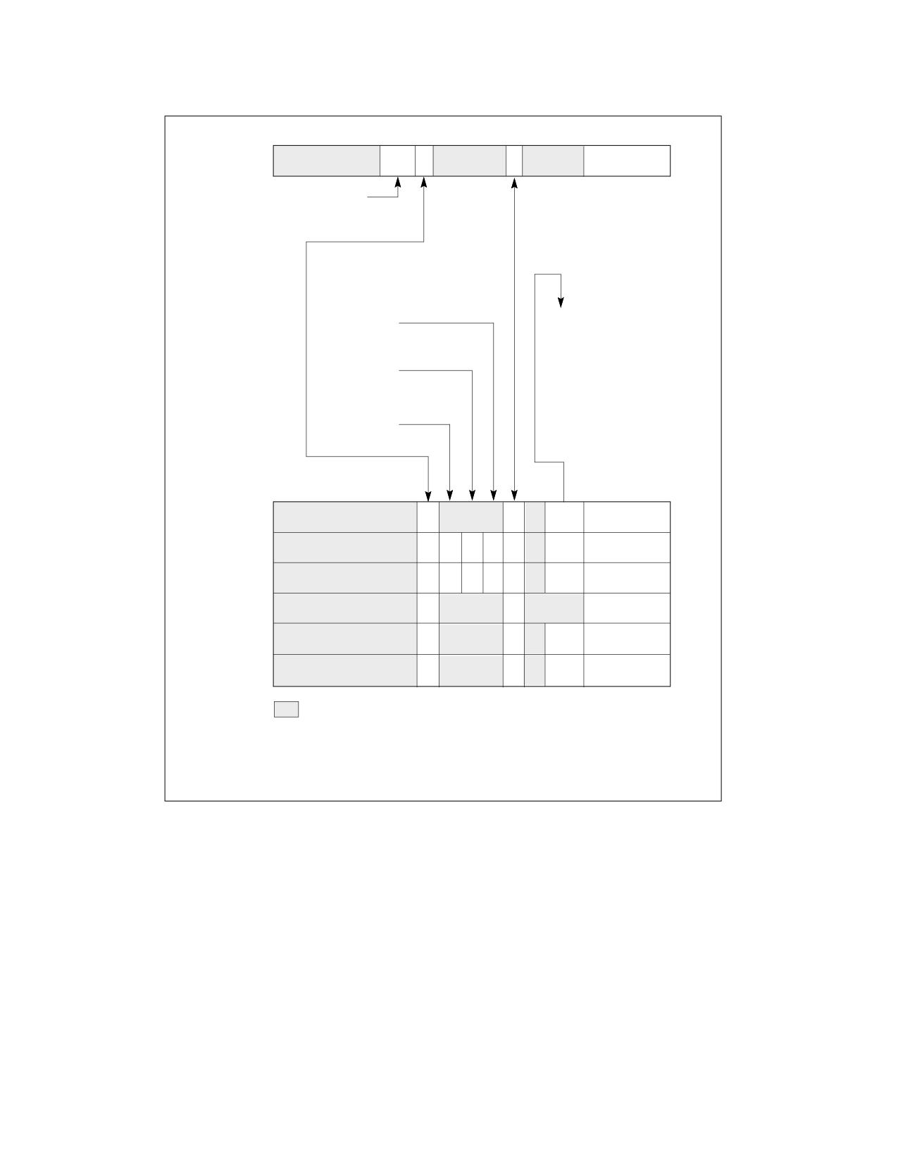
ADVANCED PROGRAMMABLE INTERRUPT CONTROLLER (APIC)
31
19
18 17
16 15
13
12
11
8
7
0
Timer
Vector
Address: FEE0 0320H
Timer Mode
Value after Reset: 0001 0000H
00: One-shot
01: Periodic
Delivery Status
10: TSC-Deadline
0: Idle
1: Send Pending
Mask†
0: Not Masked
1: Masked
Interrupt Input
Delivery Mode
Pin Polarity
000: Fixed
010: SMI
100: NMI
Remote
111: ExtlNT
IRR
101: INIT
All other combinations
are reserved
Trigger Mode
0: Edge
1: Level
31
17
11
10
8
7
0
CMCI
Vector
LINT0
Vector
LINT1
Vector
Error
Vector
Performance
Vector
Mon. Counters
Thermal
Vector
Sensor
16
15
14
13
12
Address: FEE0 02F0H
Reserved
Address: FEE0 0350H
Address: FEE0 0360H
Address: FEE0 0370H
† (Pentium 4 and Intel Xeon processors.) When a
Address: FEE0 0340H
performance monitoring counters interrupt is generated,
Address: FEE0 0330H
the mask bit for its associated LVT entry is set.
Value After Reset: 0001 0000H
Figure 13-8. Local Vector Table (LVT)
The setup information that can be specified in the registers of the LVT table is as follows:
Vector
Interrupt vector number.
Delivery Mode
Specifies the type of interrupt to be sent to the processor. Some delivery modes will only
operate as intended when used in conjunction with a specific trigger mode. The allowable
delivery modes are as follows:
000 (Fixed)
Delivers the interrupt specified in the vector field.
010 (SMI)
Delivers an SMI interrupt to the processor core through the processor’s lo-
cal SMI signal path. When using this delivery mode, the vector field should
be set to 00H for future compatibility.
Vol. 3A
13-13
ADVANCED PROGRAMMABLE INTERRUPT CONTROLLER (APIC)
100 (NMI)
Delivers an NMI interrupt to the processor. The vector information is ig-
nored.
101 (INIT)
Delivers an INIT request to the processor core, which causes the processor
to perform an INIT. When using this delivery mode, the vector field should
be set to 00H for future compatibility. Not supported for the LVT CMCI reg-
ister, the LVT thermal monitor register, or the LVT performance counter
register.
110
Reserved; not supported for any LVT register.
111 (ExtINT) Causes the processor to respond to the interrupt as if the interrupt origi-
nated in an externally connected (8259A-compatible) interrupt controller.
A special INTA bus cycle corresponding to ExtINT, is routed to the external
controller. The external controller is expected to supply the vector informa-
tion. The APIC architecture supports only one ExtINT source in a system,
usually contained in the compatibility bridge. Only one processor in the
system should have an LVT entry configured to use the ExtINT delivery
mode. Not supported for the LVT CMCI register, the LVT thermal monitor
register, or the LVT performance counter register.
Delivery Status (Read Only)
Indicates the interrupt delivery status, as follows:
0 (Idle)
There is currently no activity for this interrupt source, or the previous in-
terrupt from this source was delivered to the processor core and accepted.
1 (Send Pending)
Indicates that an interrupt from this source has been delivered to the pro-
cessor core but has not yet been accepted (see Section 13.5.5, “Local In-
terrupt Acceptance”).
Interrupt Input Pin Polarity
Specifies the polarity of the corresponding interrupt pin: (0) active high or (1) active low.
Remote IRR Flag (Read Only)
For fixed mode, level-triggered interrupts; this flag is set when the local APIC accepts the
interrupt for servicing and is reset when an EOI command is received from the processor. The
meaning of this flag is undefined for edge-triggered interrupts and other delivery modes.
Trigger Mode
Selects the trigger mode for the local LINT0 and LINT1 pins: (0) edge sensitive and (1) level
sensitive. This flag is only used when the delivery mode is Fixed. When the delivery mode is
NMI, SMI, or INIT, the trigger mode is always edge sensitive. When the delivery mode is
ExtINT, the trigger mode is always level sensitive. The timer and error interrupts are always
treated as edge sensitive.
If the local APIC is not used in conjunction with an I/O APIC and fixed delivery mode is
selected; the Pentium 4, Intel Xeon, and P6 family processors will always use level-sensitive
triggering, regardless if edge-sensitive triggering is selected.
Software should always set the trigger mode in the LVT LINT1 register to 0 (edge sensitive).
Level-sensitive interrupts are not supported for LINT1.
Mask
Interrupt mask: (0) enables reception of the interrupt and (1) inhibits reception of the inter-
rupt. When the local APIC handles a performance-monitoring counters interrupt, it automati-
cally sets the mask flag in the LVT performance counter register. This flag is set to 1 on reset.
It can be cleared only by software.
Timer Mode
Bits 18:17 selects the timer mode (see Section 13.5.4):
(00b) one-shot mode using a count-down value,
(01b) periodic mode reloading a count-down value,
(10b) TSC-Deadline mode using absolute target value in IA32_TSC_DEADLINE MSR (see
Section 13.5.4.1),
(11b) is reserved.
13-14
Vol. 3A

ADVANCED PROGRAMMABLE INTERRUPT CONTROLLER (APIC)
13.5.2 Valid Interrupt Vectors
The Intel 64 and IA-32 architectures define 256 vector numbers, ranging from 0 through 255 (see Section 7.2,
“Exception and Interrupt Vectors”). Local and I/O APICs support 240 of these vectors (in the range of 16 to 255)
as valid interrupts.
When an interrupt vector in the range of 0 to 15 is sent or received through the local APIC, the APIC indicates an
illegal vector in its Error Status Register (see Section 13.5.3, “Error Handling”). The Intel 64 and IA-32 architec-
tures reserve vectors 16 through 31 for predefined interrupts, exceptions, and Intel-reserved encodings (see Table
7-1). However, the local APIC does not treat vectors in this range as illegal.
When an illegal vector value (0 to 15) is written to an LVT entry and the delivery mode is Fixed (bits 8-11 equal 0),
the APIC may signal an illegal vector error, without regard to whether the mask bit is set or whether an interrupt is
actually seen on the input.
13.5.3 Error Handling
The local APIC records errors detected during interrupt handling in the error status register (ESR). The format of
the ESR is given in Figure 13-9; it contains the following flags:
31
8
7
6
5 4
3 2
1
0
Reserved
Illegal Register Address1
Received Illegal Vector
Send Illegal Vector
Redirectable IPI2
Receive Accept Error3
Send Accept Error3
Receive Checksum Error3
Send Checksum Error3
Address: FEE0 0280H
Value after reset: 0H
NOTES:
1. Used only by Intel Core, Pentium 4, Intel Xeon, and P6 family
processors; reserved on the Pentium processor.
2. Used only by some Intel Core and Intel Xeon processors;
reserved on other processors.
3. Used only by the P6 family and Pentium processors;
reserved on Intel Core, Pentium 4 and Intel Xeon processors.
Figure 13-9. Error Status Register (ESR)
•
Bit 0: Send Checksum Error.
Set when the local APIC detects a checksum error for a message that it sent on the APIC bus. Used only on P6
family and Pentium processors.
•
Bit 1: Receive Checksum Error.
Set when the local APIC detects a checksum error for a message that it received on the APIC bus. Used only on
P6 family and Pentium processors.
•
Bit 2: Send Accept Error.
Set when the local APIC detects that a message it sent was not accepted by any APIC on the APIC bus. Used
only on P6 family and Pentium processors.
•
Bit 3: Receive Accept Error.
Set when the local APIC detects that the message it received was not accepted by any APIC on the APIC bus,
including itself. Used only on P6 family and Pentium processors.
Vol. 3A
13-15
ADVANCED PROGRAMMABLE INTERRUPT CONTROLLER (APIC)
• Bit 4: Redirectable IPI.
Set when the local APIC detects an attempt to send an IPI with the lowest-priority delivery mode and the local
APIC does not support the sending of such IPIs. This bit is used on some Intel Core and Intel Xeon processors.
As noted in Section 13.6.2, the ability of a processor to send a lowest-priority IPI is model-specific and should
be avoided.
• Bit 5: Send Illegal Vector.
Set when the local APIC detects an illegal vector (one in the range 0 to 15) in the message that it is sending.
This occurs as the result of a write to the ICR (in both xAPIC and x2APIC modes) or to SELF IPI register (x2APIC
mode only) with an illegal vector.
If the local APIC does not support the sending of lowest-priority IPIs and software writes the ICR to send a
lowest-priority IPI with an illegal vector, the local APIC sets only the “redirectable IPI” error bit. The interrupt is
not processed and hence the “Send Illegal Vector” bit is not set in the ESR.
• Bit 6: Receive Illegal Vector.
Set when the local APIC detects an illegal vector (one in the range 0 to 15) in an interrupt message it receives
or in an interrupt generated locally from the local vector table or via a self IPI. Such interrupts are not delivered
to the processor; the local APIC will never set an IRR bit in the range 0 to 15.
• Bit 7: Illegal Register Address
Set when the local APIC is in xAPIC mode and software attempts to access a register that is reserved in the
processor's local-APIC register-address space; see Table 10-1. (The local-APIC register-address space
comprises the 4 KBytes at the physical address specified in the IA32_APIC_BASE MSR.) Used only on Intel
Core, Intel Atom, Pentium 4, Intel Xeon, and P6 family processors.
In x2APIC mode, software accesses the APIC registers using the RDMSR and WRMSR instructions. Use of one
of these instructions to access a reserved register cause a general-protection exception (see Section
10.12.1.3). They do not set the “Illegal Register Access” bit in the ESR.
The ESR is a write/read register. Before attempt to read from the ESR, software should first write to it. (The value
written does not affect the values read subsequently; only zero may be written in x2APIC mode.) This write clears
any previously logged errors and updates the ESR with any errors detected since the last write to the ESR. This
write also rearms the APIC error interrupt triggering mechanism.
The LVT Error Register (see Section 13.5.1) allows specification of the vector of the interrupt to be delivered to the
processor core when APIC error is detected. The register also provides a means of masking an APIC-error interrupt.
This masking only prevents delivery of APIC-error interrupts; the APIC continues to record errors in the ESR.
13.5.4 APIC Timer
The local APIC unit contains a 32-bit programmable timer that is available to software to time events or operations.
This timer is set up by programming four registers: the divide configuration register (see Figure 13-10), the initial-
count and current-count registers (see Figure 13-11), and the LVT timer register (see Figure 13-8).
If CPUID.06H:EAX.ALWAYS_RUNNING_APIC_TIMER[2] = 1, the processor’s APIC timer runs at a constant rate
regardless of P-state transitions and it continues to run at the same rate in deep C-states.
If CPUID.06H:EAX.ALWAYS_RUNNING_APIC_TIMER[2] = 0 or if CPUID 06H is not supported, the APIC timer may
temporarily stop while the processor is in deep C-states or during transitions caused by Enhanced Intel Speed-
Step® Technology.
The APIC timer frequency will be the processor’s bus clock or core crystal clock frequency (when TSC/core crystal
clock ratio is enumerated in CPUID.15H) divided by the value specified in the divide configuration register.
The timer can be configured through the timer LVT entry for one-shot or periodic operation. In one-shot mode, the
timer is started by programming its initial-count register. The initial count value is then copied into the current-
count register and count-down begins. After the timer reaches zero, a timer interrupt is generated and the timer
remains at its 0 value until reprogrammed.
In periodic mode, the timer is started by writing to the initial-count register (as in one-shot mode), and the value
written is copied into the current-count register, which counts down. The current-count register is automatically
reloaded from the initial-count register when the count reaches 0 and a timer interrupt is generated, and the count-
13-16
Vol. 3A

ADVANCED PROGRAMMABLE INTERRUPT CONTROLLER (APIC)
31
4
3
2
1
0
Reserved
0
Address: FEE0 03E0H
Divide Value (bits 0, 1, and 3)
Value after reset: 0H
000: Divide by 2
001: Divide by 4
010: Divide by 8
011: Divide by 16
100: Divide by 32
101: Divide by 64
110: Divide by 128
111: Divide by 1
Figure 13-10. Divide Configuration Register
31
0
Initial Count
Current Count
Address: Initial Count
FEE0 0380H
Current Count FEE0 0390H
Value after reset: 0H
Figure 13-11. Initial Count and Current Count Registers
down is repeated. If during the count-down process the initial-count register is set, counting will restart, using the
new initial-count value. The initial-count register is a read-write register; the current-count register is read only.
A write of 0 to the initial-count register effectively stops the local APIC timer, in both one-shot and periodic mode.
The LVT timer register determines the vector number that is delivered to the processor with the timer interrupt that
is generated when the timer count reaches zero. The mask flag in the LVT timer register can be used to mask the
timer interrupt.
NOTE
Changing the mode of the APIC timer (from one-shot to periodic or vice versa) by writing to the
timer LVT entry does not start the timer. To start the timer, it is necessary to write to the initial-
count register as described above.
13.5.4.1 TSC-Deadline Mode
The mode of operation of the local-APIC timer is determined by the LVT Timer Register. Specifically:
• If CPUID.01H:ECX.TSC_DEADLINE[24] = 0, the mode is determined by bit 17 of the register.
• If CPUID.01H:ECX.TSC_DEADLINE[24] = 1, the mode is determined by bits 18:17. See Figure 13-8. (If
CPUID.01H:ECX.TSC_DEADLINE[24] = 0, bit 18 of the register is reserved.)
The supported timer modes are given in Table 13-2. The three modes of the local APIC timer are mutually exclu-
sive.
Vol. 3A
13-17

ADVANCED PROGRAMMABLE INTERRUPT CONTROLLER (APIC)
Table 13-2. Local APIC Timer Modes
LVT Bits [18:17]
Timer Mode
00b
One-shot mode, program count-down value in an initial-count register. See Section 13.5.4
01b
Periodic mode, program interval value in an initial-count register. See Section 13.5.4
10b
TSC-Deadline mode, program target value in IA32_TSC_DEADLINE MSR.
11b
Reserved
TSC-deadline mode allows software to use the local APIC timer to signal an interrupt at an absolute time. In TSC-
deadline mode, writes to the initial-count register are ignored; and current-count register always reads 0. Instead,
timer behavior is controlled using the IA32_TSC_DEADLINE MSR.
The IA32_TSC_DEADLINE MSR (MSR address 6E0H) is a per-logical processor MSR that specifies the time at which
a timer interrupt should occur. Writing a non-zero 64-bit value into IA32_TSC_DEADLINE arms the timer. An inter-
rupt is generated when the logical processor’s time-stamp counter equals or exceeds the target value in the
IA32_TSC_DEADLINE MSR.1 When the timer generates an interrupt, it disarms itself and clears the
IA32_TSC_DEADLINE MSR. Thus, each write to the IA32_TSC_DEADLINE MSR generates at most one timer inter-
rupt.
In TSC-deadline mode, writing 0 to the IA32_TSC_DEADLINE MSR disarms the local-APIC timer. Transitioning
between TSC-deadline mode and other timer modes also disarms the timer.
The hardware reset value of the IA32_TSC_DEADLINE MSR is 0. In other timer modes (LVT bit 18 = 0), the
IA32_TSC_DEADLINE MSR reads zero and writes are ignored.
Software can configure the TSC-deadline timer to deliver a single interrupt using the following algorithm:
1. Detect support for TSC-deadline mode by verifying CPUID.01H:ECX[24] = 1.
2. Select the TSC-deadline mode by programming bits 18:17 of the LVT Timer register with 10b.
3. Program the IA32_TSC_DEADLINE MSR with the target TSC value at which the timer interrupt is desired. This
causes the processor to arm the timer.
4. The processor generates a timer interrupt when the value of time-stamp counter is greater than or equal to that
of IA32_TSC_DEADLINE. It then disarms the timer and clear the IA32_TSC_DEADLINE MSR. (Both the time-
stamp counter and the IA32_TSC_DEADLINE MSR are 64-bit unsigned integers.)
5. Software can re-arm the timer by repeating step 3.
The following are usage guidelines for TSC-deadline mode:
• Writes to the IA32_TSC_DEADLINE MSR are not serialized. Therefore, system software should not use WRMSR
to the IA32_TSC_DEADLINE MSR as a serializing instruction. Read and write accesses to the
IA32_TSC_DEADLINE and other MSR registers will occur in program order.
• Software can disarm the timer at any time by writing 0 to the IA32_TSC_DEADLINE MSR.
• If timer is armed, software can change the deadline (forward or backward) by writing a new value to the
IA32_TSC_DEADLINE MSR.
• If software disarms the timer or postpones the deadline, race conditions may result in delivery of a timer
interrupt associated with the original deadline. If the deadline has been postponed, software can identify such
interrupts by reading the time-stamp counter and comparing its value to the new deadline.1
• In xAPIC mode (in which the local-APIC registers are memory-mapped), software must order the memory-
mapped write to the LVT entry that enables TSC-deadline mode and any subsequent WRMSR to the
IA32_TSC_DEADLINE MSR. Software can assure proper ordering by executing the MFENCE instruction after the
memory-mapped write and before any WRMSR. (In x2APIC mode, the WRMSR instruction is used to write to
the LVT entry. The processor ensures the ordering of this write and any subsequent WRMSR to the deadline; no
fencing is required.)
1. If the logical processor is in VMX non-root operation, a read of the time-stamp counter (using either RDMSR, RDTSC, or RDTSCP) may
not return the actual value of the time-stamp counter; see Chapter 28 of the Intel® 64 and IA-32 Architectures Software Devel-
oper’s Manual, Volume 3C. It is the responsibility of software operating in VMX root operation to coordinate the virtualization of the
time-stamp counter and the IA32_TSC_DEADLINE MSR.
13-18
Vol. 3A
ADVANCED PROGRAMMABLE INTERRUPT CONTROLLER (APIC)
13.5.5 Local Interrupt Acceptance
When a local interrupt is sent to the processor core, it is subject to the acceptance criteria specified in the interrupt
acceptance flow chart in Figure 13-17. If the interrupt is accepted, it is logged into the IRR register and handled by
the processor according to its priority (see Section 13.8.4, “Interrupt Acceptance for Fixed Interrupts”). If the
interrupt is not accepted, it is sent back to the local APIC and retried.
13.6
ISSUING INTERPROCESSOR INTERRUPTS
The following sections describe the local APIC facilities that are provided for issuing interprocessor interrupts (IPIs)
from software. The primary local APIC facility for issuing IPIs is the interrupt command register (ICR). The ICR can
be used for the following functions:
• To send an interrupt to another processor.
• To allow a processor to forward an interrupt that it received but did not service to another processor for
servicing.
• To direct the processor to interrupt itself (perform a self interrupt).
• To deliver special IPIs, such as the start-up IPI (SIPI) message, to other processors.
Interrupts generated with this facility are delivered to the other processors in the system through the system bus
(for Pentium 4 and Intel Xeon processors) or the APIC bus (for P6 family and Pentium processors). The ability for a
processor to send a lowest priority IPI is model specific and should be avoided by BIOS and operating system soft-
ware.
13.6.1 Interrupt Command Register (ICR)
The interrupt command register (ICR) is a 64-bit1 local APIC register (see Figure 13-12) that allows software
running on the processor to specify and send interprocessor interrupts (IPIs) to other processors in the system.
1. In XAPIC mode the ICR is addressed as two 32-bit registers, ICR_LOW (FFE0 0300H) and ICR_HIGH (FFE0 0310H). In x2APIC mode,
the ICR uses MSR 830H.
Vol. 3A
13-19

ADVANCED PROGRAMMABLE INTERRUPT CONTROLLER (APIC)
63
56
55
32
Destination Field
Reserved
31
2019181716 1514 1312 1110
8
7
0
Reserved
Vector
Destination Shorthand
Delivery Mode
00: No Shorthand
000: Fixed
01: Self
001: Lowest Priority1
10: All Including Self
010: SMI
11: All Excluding Self
011: Reserved
100: NMI
101: INIT
110: Start Up
Reserved
111: Reserved
Destination Mode
0: Physical
1: Logical
Delivery Status
0: Idle
1: Send Pending
Level
Address: FEE0 0300H (0 - 31)
0 = De-assert
FEE0 0310H (32 - 63)
1 = Assert
Value after Reset: 0H
Trigger Mode
0: Edge
1: Level
NOTE:
1. The ability of a processor to send Lowest Priority IPI is model specific.
Figure 13-12. Interrupt Command Register (ICR)
To send an IPI, software must set up the ICR to indicate the type of IPI message to be sent and the destination
processor or processors. (All fields of the ICR are read-write by software with the exception of the delivery status
field, which is read-only.) The act of writing to the low doubleword of the ICR causes the IPI to be sent.
The ICR consists of the following fields.
Vector
The vector number of the interrupt being sent.
Delivery Mode
Specifies the type of IPI to be sent. This field is also know as the IPI message type field.
000 (Fixed)
Delivers the interrupt specified in the vector field to the target processor or
processors.
001 (Lowest Priority)
Same as fixed mode, except that the interrupt is delivered to the processor
executing at the lowest priority among the set of processors specified in
the destination field. The ability for a processor to send a lowest priority
IPI is model specific and should be avoided by BIOS and operating system
software.
010 (SMI)
Delivers an SMI interrupt to the target processor or processors. The vector
field must be programmed to 00H for future compatibility.
011 (Reserved)
100 (NMI)
Delivers an NMI interrupt to the target processor or processors. The vector
information is ignored.
13-20
Vol. 3A
ADVANCED PROGRAMMABLE INTERRUPT CONTROLLER (APIC)
101 (INIT)
Delivers an INIT request to the target processor or processors, which
causes them to perform an INIT. As a result of this IPI message, all the tar-
get processors perform an INIT. The vector field must be programmed to
00H for future compatibility.
101 (INIT Level De-assert)
(Not supported in the Pentium 4 and Intel Xeon processors.) Sends a syn-
chronization message to all the local APICs in the system to set their arbi-
tration IDs (stored in their Arb ID registers) to the values of their APIC IDs
(see Section 13.7, “System and APIC Bus Arbitration”). For this delivery
mode, the level flag must be set to 0 and trigger mode flag to 1. This IPI is
sent to all processors, regardless of the value in the destination field or the
destination shorthand field; however, software should specify the “all in-
cluding self” shorthand.
110 (Start-Up)
Sends a special “start-up” IPI (called a SIPI) to the target processor or
processors. The vector typically points to a start-up routine that is part of
the BIOS boot-strap code (see Section 11.4, “Multiple-Processor (MP) Ini-
tialization”). IPIs sent with this delivery mode are not automatically retried
if the source APIC is unable to deliver it. It is up to the software to deter-
mine if the SIPI was not successfully delivered and to reissue the SIPI if
necessary.
Destination Mode Selects either physical (0) or logical (1) destination mode (see Section 13.6.2, “Determining
IPI Destination”).
Delivery Status (Read Only)
Indicates the IPI delivery status, as follows:
0 (Idle)
Indicates that this local APIC has completed sending any previous IPIs.
1 (Send Pending)
Indicates that this local APIC has not completed sending the last IPI.
Level
For the INIT level de-assert delivery mode this flag must be set to 0; for all other delivery
modes it must be set to 1. (This flag has no meaning in Pentium 4 and Intel Xeon processors,
and will always be issued as a 1.)
Trigger Mode
Selects the trigger mode when using the INIT level de-assert delivery mode: edge (0) or level
(1). It is ignored for all other delivery modes. (This flag has no meaning in Pentium 4 and Intel
Xeon processors, and will always be issued as a 0.)
Destination Shorthand
Indicates whether a shorthand notation is used to specify the destination of the interrupt and,
if so, which shorthand is used. Destination shorthands are used in place of the 8-bit destina-
tion field, and can be sent by software using a single write to the low doubleword of the ICR.
Shorthands are defined for the following cases: software self interrupt, IPIs to all processors
in the system including the sender, IPIs to all processors in the system excluding the sender.
00: (No Shorthand)
The destination is specified in the destination field.
01: (Self)
The issuing APIC is the one and only destination of the IPI. This destination
shorthand allows software to interrupt the processor on which it is execut-
ing. An APIC implementation is free to deliver the self-interrupt message
internally or to issue the message to the bus and “snoop” it as with any
other IPI message.
10: (All Including Self)
The IPI is sent to all processors in the system including the processor send-
ing the IPI. The APIC will broadcast an IPI message with the destination
field set to FH for Pentium and P6 family processors and to FFH for Pentium
4 and Intel Xeon processors.
11: (All Excluding Self)
The IPI is sent to all processors in a system with the exception of the pro-
Vol. 3A
13-21