Intel 64 and IA-32 Architectures. Software Developer’s Manual (2026) - page 50

INTERRUPT AND EXCEPTION HANDLING
A segment or page fault may be encountered while prefetching instructions; however, this behavior is outside the
domain of Table 7-5. Any further faults generated while the processor is attempting to transfer control to the
appropriate fault handler could still lead to a double-fault sequence.
Table 7-5. Conditions for Generating a Double Fault
Second Exception
First Exception
Benign
Contributory
Page Fault
Benign
Handle Exceptions Serially
Handle Exceptions Serially
Handle Exceptions Serially
Contributory
Handle Exceptions Serially
Generate a Double Fault
Handle Exceptions Serially
Page Fault
Handle Exceptions Serially
Generate a Double Fault
Generate a Double Fault
Double Fault
Handle Exceptions Serially
Enter Shutdown Mode
Enter Shutdown Mode
If another contributory or page fault exception occurs while attempting to call the double-fault handler, the
processor enters shutdown mode. This mode is similar to the state following execution of an HLT instruction. In this
mode, the processor stops executing instructions until an NMI interrupt, SMI interrupt, hardware reset, or INIT# is
received. The processor generates a special bus cycle to indicate that it has entered shutdown mode. Software
designers may need to be aware of the response of hardware when it goes into shutdown mode. For example,
hardware may turn on an indicator light on the front panel, generate an NMI interrupt to record diagnostic informa-
tion, invoke reset initialization, generate an INIT initialization, or generate an SMI. If any events are pending
during shutdown, they will be handled after an wake event from shutdown is processed (for example, A20M# inter-
rupts).
If a shutdown occurs while the processor is executing an NMI interrupt handler, then only a hardware reset can
restart the processor. Likewise, if the shutdown occurs while executing in SMM, a hardware reset must be used to
restart the processor.
Exception Error Code
Zero. The processor always pushes an error code of 0 onto the stack of the double-fault handler.
Event Data
Not currently defined (zero until defined).
Saved Instruction Pointer
The saved contents of CS and EIP registers are undefined.
Program State Change
A program-state following a double-fault exception is undefined. The program or task cannot be resumed or
restarted. The only available action of the double-fault exception handler is to collect all possible context informa-
tion for use in diagnostics and then close the application and/or shut down or reset the processor.
If the double fault occurs when any portion of the exception handling machine state is corrupted, the handler
cannot be invoked and the processor must be reset.
Vol. 3A
7-37
INTERRUPT AND EXCEPTION HANDLING
Event 9-Coprocessor Segment Overrun
Exception Class
Abort. (Intel reserved; do not use. Recent IA-32 processors do not generate this
exception.)
Description
Indicates that an Intel386 CPU-based systems with an Intel 387 math coprocessor detected a page or segment
violation while transferring the middle portion of an Intel 387 math coprocessor operand. The P6 family, Pentium,
and Intel486 processors do not generate this exception; instead, this condition is detected with a general protec-
tion exception (#GP), interrupt 13.
Exception Error Code
None.
Event Data
Not applicable.
Saved Instruction Pointer
The saved contents of CS and EIP registers point to the instruction that generated the exception.
Program State Change
A program-state following a coprocessor segment overrun exception is undefined. The program or task cannot be
resumed or restarted. The only available action of the exception handler is to save the instruction pointer and reini-
tialize the x87 FPU using the FNINIT instruction.
7-38
Vol. 3A

INTERRUPT AND EXCEPTION HANDLING
Event 10-Invalid TSS Exception (#TS)
Exception Class
Fault.
Description
Indicates that there was an error related to a TSS. Such an error might be detected during a task switch or during
the execution of instructions that use information from a TSS. Table 7-6 shows the conditions that cause an invalid
TSS exception to be generated.
Table 7-6. Invalid TSS Conditions
Error Code Index
Invalid Condition
TSS segment selector index
The TSS segment limit is less than 67H for 32-bit TSS or less than 2CH for 16-bit TSS.
TSS segment selector index
During an IRET task switch, the TI flag in the TSS segment selector indicates the LDT.
TSS segment selector index
During an IRET task switch, the TSS segment selector exceeds descriptor table limit.
TSS segment selector index
During an IRET task switch, the busy flag in the TSS descriptor indicates an inactive task.
TSS segment selector index
During a task switch, an attempt to access data in a TSS results in a limit violation or
canonical fault.
TSS segment selector index
During an IRET task switch, the backlink is a NULL selector.
TSS segment selector index
During an IRET task switch, the backlink points to a descriptor which is not a busy TSS.
TSS segment selector index
The new TSS descriptor is beyond the GDT limit.
TSS segment selector index
The new TSS selector is null on an attempt to lock the new TSS.
TSS segment selector index
The new TSS selector has the TI bit set on an attempt to lock the new TSS.
TSS segment selector index
The new TSS descriptor is not an available TSS descriptor on an attempt to lock the new
TSS.
LDT segment selector index
LDT not valid or not present.
Stack segment selector index
The stack segment selector exceeds descriptor table limit.
Stack segment selector index
The stack segment selector is NULL.
Stack segment selector index
The stack segment descriptor is a non-data segment.
Stack segment selector index
The stack segment is not writable.
Stack segment selector index
The stack segment DPL ? CPL.
Stack segment selector index
The stack segment selector RPL ? CPL.
Code segment selector index
The code segment selector exceeds descriptor table limit.
Code segment selector index
The code segment selector is NULL.
Code segment selector index
The code segment descriptor is not a code segment type.
Code segment selector index
The nonconforming code segment DPL ? CPL.
Code segment selector index
The conforming code segment DPL is greater than CPL.
Data segment selector index
The data segment selector exceeds the descriptor table limit.
Data segment selector index
The data segment descriptor is not a readable code or data type.
Data segment selector index
The data segment descriptor is a nonconforming code type and RPL > DPL.
Data segment selector index
The data segment descriptor is a nonconforming code type and CPL > DPL.
TSS segment selector index
The TSS segment descriptor/upper descriptor is beyond the GDT segment limit.
TSS segment selector index
The TSS segment descriptor is not an available TSS type.
TSS segment selector index
The TSS segment descriptor is an available 286 TSS type in IA-32e mode.
Vol. 3A
7-39

INTERRUPT AND EXCEPTION HANDLING
Table 7-6. Invalid TSS Conditions (Contd.)
Error Code Index
Invalid Condition
TSS segment selector index
The TSS segment upper descriptor is not the correct type.
TSS segment selector index
The TSS segment descriptor contains a non-canonical base.
This exception can generated either in the context of the original task or in the context of the new task (see Section
10.3, “Task Switching”). Until the processor has completely verified the presence of the new TSS, the exception is
generated in the context of the original task. Once the existence of the new TSS is verified, the task switch is
considered complete. Any invalid-TSS conditions detected after this point are handled in the context of the new
task. (A task switch is considered complete when the task register is loaded with the segment selector for the new
TSS and, if the switch is due to a procedure call or interrupt, the previous task link field of the new TSS references
the old TSS.)
The invalid-TSS handler must be a task called using a task gate. Handling this exception inside the faulting TSS
context is not recommended because the processor state may not be consistent.
Exception Error Code
An error code containing the segment selector index for the segment descriptor that caused the violation is pushed
onto the stack of the exception handler. If the EXT flag is set, it indicates that the exception was caused by an event
external to the currently running program (for example, if an external interrupt handler using a task gate
attempted a task switch to an invalid TSS).
Event Data
Not currently defined (zero until defined).
Saved Instruction Pointer
If the exception condition was detected before the task switch was carried out, the saved contents of CS and EIP
registers point to the instruction that invoked the task switch. If the exception condition was detected after the task
switch was carried out, the saved contents of CS and EIP registers point to the first instruction of the new task.
Program State Change
The ability of the invalid-TSS handler to recover from the fault depends on the error condition than causes the fault.
See Section 10.3, “Task Switching,” for more information on the task switch process and the possible recovery
actions that can be taken.
If an invalid TSS exception occurs during a task switch, it can occur before or after the commit-to-new-task point.
If it occurs before the commit point, no program state change occurs. If it occurs after the commit point (when the
segment descriptor information for the new segment selectors have been loaded in the segment registers), the
processor will load all the state information from the new TSS before it generates the exception. During a task
switch, the processor first loads all the segment registers with segment selectors from the TSS, then checks their
contents for validity. If an invalid TSS exception is discovered, the remaining segment registers are loaded but not
checked for validity and therefore may not be usable for referencing memory. The invalid TSS handler should not
rely on being able to use the segment selectors found in the CS, SS, DS, ES, FS, and GS registers without causing
another exception. The exception handler should load all segment registers before trying to resume the new task;
otherwise, general-protection exceptions (#GP) may result later under conditions that make diagnosis more diffi-
cult. The Intel recommended way of dealing situation is to use a task for the invalid TSS exception handler. The task
switch back to the interrupted task from the invalid-TSS exception-handler task will then cause the processor to
check the registers as it loads them from the TSS.
7-40
Vol. 3A
INTERRUPT AND EXCEPTION HANDLING
Event 11-Segment Not Present (#NP)
Exception Class
Fault.
Description
Indicates that the present flag of a segment or gate descriptor is clear. The processor can generate this exception
during any of the following operations:
• While attempting to load CS, DS, ES, FS, or GS registers. [Detection of a not-present segment while loading the
SS register causes a stack fault exception (#SS) to be generated.] This situation can occur while performing a
task switch.
• While attempting to load the LDTR using an LLDT instruction. Detection of a not-present LDT while loading the
LDTR during a task switch operation causes an invalid-TSS exception (#TS) to be generated.
• When executing the LTR instruction and the TSS is marked not present.
• While attempting to use a gate descriptor or TSS that is marked segment-not-present, but is otherwise valid.
An operating system typically uses the segment-not-present exception to implement virtual memory at the
segment level. If the exception handler loads the segment and returns, the interrupted program or task resumes
execution.
A not-present indication in a gate descriptor, however, does not indicate that a segment is not present (because
gates do not correspond to segments). The operating system may use the present flag for gate descriptors to
trigger exceptions of special significance to the operating system.
A contributory exception or page fault that subsequently referenced a not-present segment would cause a double
fault (#DF) to be generated instead of #NP.
Exception Error Code
An error code containing the segment selector index for the segment descriptor that caused the violation is pushed
onto the stack of the exception handler. If the EXT flag is set, it indicates that the exception resulted from either:
• an external event (NMI or INTR) that caused an interrupt, which subsequently referenced a not-present
segment
• a benign exception that subsequently referenced a not-present segment
The IDT flag is set if the error code refers to an IDT entry. This occurs when the IDT entry for an interrupt being
serviced references a not-present gate. Such an event could be generated by an INT instruction or a hardware
interrupt.
Event Data
Not currently defined (zero until defined).
Saved Instruction Pointer
The saved contents of CS and EIP registers normally point to the instruction that generated the exception. If the
exception occurred while loading segment descriptors for the segment selectors in a new TSS, the CS and EIP
registers point to the first instruction in the new task. If the exception occurred while accessing a gate descriptor,
the CS and EIP registers point to the instruction that invoked the access (for example a CALL instruction that refer-
ences a call gate).
Program State Change
If the segment-not-present exception occurs as the result of loading a register (CS, DS, SS, ES, FS, GS, or LDTR),
a program-state change does accompany the exception because the register is not loaded. Recovery from this
exception is possible by simply loading the missing segment into memory and setting the present flag in the
segment descriptor.
Vol. 3A
7-41
INTERRUPT AND EXCEPTION HANDLING
If the segment-not-present exception occurs while accessing a gate descriptor, a program-state change does not
accompany the exception. Recovery from this exception is possible merely by setting the present flag in the gate
descriptor.
If a segment-not-present exception occurs during a task switch, it can occur before or after the commit-to-new-
task point (see Section 10.3, “Task Switching”). If it occurs before the commit point, no program state change
occurs. If it occurs after the commit point, the processor will load all the state information from the new TSS
(without performing any additional limit, present, or type checks) before it generates the exception. The segment-
not-present exception handler should not rely on being able to use the segment selectors found in the CS, SS, DS,
ES, FS, and GS registers without causing another exception. (See the Program State Change description for “Event
10-Invalid TSS Exception (#TS)” in this chapter for additional information on how to handle this situation.)
7-42
Vol. 3A
INTERRUPT AND EXCEPTION HANDLING
Event 12-Stack Fault Exception (#SS)
Exception Class
Fault.
Description
Indicates that one of the following stack related conditions was detected:
• A limit violation is detected during an operation that refers to the SS register. Operations that can cause a limit
violation include stack-oriented instructions such as POP, PUSH, CALL, RET, IRET, ENTER, and LEAVE, as well as
other memory references which implicitly or explicitly use the SS register (for example, MOV AX, [BP+6] or
MOV AX, SS:[EAX+6]). The ENTER instruction generates this exception when there is not enough stack space
for allocating local variables.
• A not-present stack segment is detected when attempting to load the SS register. This violation can occur
during the execution of a task switch, a CALL instruction to a different privilege level, a return to a different
privilege level, an LSS instruction, or a MOV or POP instruction to the SS register.
• A canonical violation is detected in 64-bit mode during an operation that reference memory using the stack
pointer register containing a non-canonical memory address.
Recovery from this fault is possible by either extending the limit of the stack segment (in the case of a limit viola-
tion) or loading the missing stack segment into memory (in the case of a not-present violation.
In the case of a canonical violation that was caused intentionally by software, recovery is possible by loading the
correct canonical value into RSP. Otherwise, a canonical violation of the address in RSP likely reflects some register
corruption in the software.
Exception Error Code
If the exception is caused by a not-present stack segment or by overflow of the new stack during an inter-privilege-
level call, the error code contains a segment selector for the segment that caused the exception. Here, the excep-
tion handler can test the present flag in the segment descriptor pointed to by the segment selector to determine
the cause of the exception. For a normal limit violation (on a stack segment already in use) the error code is set to
0.
Event Data
Not currently defined (zero until defined).
Saved Instruction Pointer
The saved contents of CS and EIP registers generally point to the instruction that generated the exception.
However, when the exception results from attempting to load a not-present stack segment during a task switch,
the CS and EIP registers point to the first instruction of the new task.
Program State Change
A program-state change does not generally accompany a stack-fault exception, because the instruction that gener-
ated the fault is not executed. Here, the instruction can be restarted after the exception handler has corrected the
stack fault condition.
If a stack fault occurs during a task switch, it occurs after the commit-to-new-task point (see Section 10.3, “Task
Switching”). Here, the processor loads all the state information from the new TSS (without performing any addi-
tional limit, present, or type checks) before it generates the exception. The stack fault handler should thus not rely
on being able to use the segment selectors found in the CS, SS, DS, ES, FS, and GS registers without causing
another exception. The exception handler should check all segment registers before trying to resume the new
task; otherwise, general protection faults may result later under conditions that are more difficult to diagnose.
(See the Program State Change description for “Event 10-Invalid TSS Exception (#TS)” in this chapter for addi-
tional information on how to handle this situation.)
Vol. 3A
7-43
INTERRUPT AND EXCEPTION HANDLING
Event 13-General Protection Exception (#GP)
Exception Class
Fault.
Description
Indicates that the processor detected one of a class of protection violations called “general-protection violations.”
The conditions that cause this exception to be generated comprise all the protection violations that do not cause
other exceptions to be generated (such as, invalid-TSS, segment-not-present, stack-fault, or page-fault excep-
tions). The following conditions cause general-protection exceptions to be generated:
•
Exceeding the segment limit when accessing the CS, DS, ES, FS, or GS segments.
•
Exceeding the segment limit when referencing a descriptor table (except during a task switch or a stack
switch).
•
Transferring execution to a segment that is not executable.
•
Writing to a code segment or a read-only data segment.
•
Reading from an execute-only code segment.
•
Loading the SS register with a segment selector for a read-only segment (unless the selector comes from a TSS
during a task switch, in which case an invalid-TSS exception occurs).
•
Loading the SS, DS, ES, FS, or GS register with a segment selector for a system segment.
•
Loading the DS, ES, FS, or GS register with a segment selector for an execute-only code segment.
•
Loading the SS register with the segment selector of an executable segment or a null segment selector.
•
Loading the CS register with a segment selector for a data segment or a null segment selector.
•
Accessing memory using the DS, ES, FS, or GS register when it contains a null segment selector.
•
Switching to a busy task during a call or jump to a TSS.
•
Using a segment selector on a non-IRET task switch that points to a TSS descriptor in the current LDT. TSS
descriptors can only reside in the GDT. This condition causes a #TS exception during an IRET task switch.
•
Violating any of the privilege rules described in Chapter 6, “Protection.”
•
Exceeding the instruction length limit of 15 bytes (this only can occur when redundant prefixes are placed
before an instruction).
•
Loading the CR0 register with a set PG flag (paging enabled) and a clear PE flag (protection disabled).
•
Loading the CR0 register with a set NW flag and a clear CD flag.
•
Referencing an entry in the IDT (following an interrupt or exception) that is not an interrupt, trap, or task gate.
•
Attempting to access an interrupt or exception handler through an interrupt or trap gate from virtual-8086
mode when the handler’s code segment DPL is greater than 0.
•
Attempting to write a 1 into a reserved bit of CR4.
•
Attempting to execute a privileged instruction when the CPL is not equal to 0 (see Section 6.9, “Privileged
Instructions,” for a list of privileged instructions).
•
Attempting to execute SGDT, SIDT, SLDT, SMSW, or STR when CR4.UMIP = 1 and the CPL is not equal to 0.
•
Writing to a reserved bit in an MSR.
•
Accessing a gate that contains a null segment selector.
•
Executing the INT n instruction when the CPL is greater than the DPL of the referenced interrupt, trap, or task
gate.
•
The segment selector in a call, interrupt, or trap gate does not point to a code segment.
•
The segment selector operand in the LLDT instruction is a local type (TI flag is set) or does not point to a
segment descriptor of the LDT type.
•
The segment selector operand in the LTR instruction is local or points to a TSS that is not available.
•
The target code-segment selector for a call, jump, or return is null.
7-44
Vol. 3A
INTERRUPT AND EXCEPTION HANDLING
• If the PAE and/or PSE flag in control register CR4 is set and the processor detects any reserved bits in a page-
directory-pointer-table entry set to 1. These bits are checked during a write to control registers CR0, CR3, or
CR4 that causes a reloading of the page-directory-pointer-table entry.
• Attempting to write a non-zero value into the reserved bits of the MXCSR register.
• Executing an SSE/SSE2/SSE3 instruction that attempts to access a 128-bit memory location that is not aligned
on a 16-byte boundary when the instruction requires 16-byte alignment. This condition also applies to the
stack segment.
A program or task can be restarted following any general-protection exception. If the exception occurs while
attempting to call an interrupt handler, the interrupted program can be restartable, but the interrupt may be lost.
Exception Error Code
The processor pushes an error code onto the exception handler's stack. If the fault condition was detected while
loading a segment descriptor, the error code contains a segment selector to or IDT vector number for the
descriptor; otherwise, the error code is 0. The source of the selector in an error code may be any of the following:
• An operand of the instruction.
• A selector from a gate which is the operand of the instruction.
• A selector from a TSS involved in a task switch.
• IDT vector number.
Event Data
Not currently defined (zero until defined).
Saved Instruction Pointer
The saved contents of CS and EIP registers point to the instruction that generated the exception.
Program State Change
In general, a program-state change does not accompany a general-protection exception, because the invalid
instruction or operation is not executed. An exception handler can be designed to correct all of the conditions that
cause general-protection exceptions and restart the program or task without any loss of program continuity.
If a general-protection exception occurs during a task switch, it can occur before or after the commit-to-new-task
point (see Section 10.3, “Task Switching”). If it occurs before the commit point, no program state change occurs.
If it occurs after the commit point, the processor will load all the state information from the new TSS (without
performing any additional limit, present, or type checks) before it generates the exception. The general-protection
exception handler should thus not rely on being able to use the segment selectors found in the CS, SS, DS, ES, FS,
and GS registers without causing another exception. (See the Program State Change description for “Event
10-Invalid TSS Exception (#TS)” in this chapter for additional information on how to handle this situation.)
General Protection Exception in 64-bit Mode
The following conditions cause general-protection exceptions in 64-bit mode:
• If the memory address is in a non-canonical form.
• If a segment descriptor memory address is in non-canonical form.
• If the target offset in a destination operand of a call or jmp is in a non-canonical form.
• If a code segment or 64-bit call gate overlaps non-canonical space.
• If the code segment descriptor pointed to by the selector in the 64-bit gate doesn't have the L-bit set and the
D-bit clear.
• If the EFLAGS.NT bit is set in IRET.
• If the stack segment selector of IRET is null when going back to compatibility mode.
• If the stack segment selector of IRET is null going back to CPL3 and 64-bit mode.
Vol. 3A
7-45
INTERRUPT AND EXCEPTION HANDLING
• If a null stack segment selector RPL of IRET is not equal to CPL going back to non-CPL3 and 64-bit mode.
• If the proposed new code segment descriptor of IRET has both the D-bit and the L-bit set.
• If the segment descriptor pointed to by the segment selector in the destination operand is a code segment and
it has both the D-bit and the L-bit set.
• If the segment descriptor from a 64-bit call gate is in non-canonical space.
• If the DPL from a 64-bit call-gate is less than the CPL or than the RPL of the 64-bit call-gate.
• If the type field of the upper 64 bits of a 64-bit call gate is not 0.
• If an attempt is made to load a null selector in the SS register in compatibility mode.
• If an attempt is made to load null selector in the SS register in CPL3 and 64-bit mode.
• If an attempt is made to load a null selector in the SS register in non-CPL3 and 64-bit mode where RPL is not
equal to CPL.
• If an attempt is made to clear CR0.PG while IA-32e mode is enabled.
• If an attempt is made to set a reserved bit in CR3, CR4 or CR8.
7-46
Vol. 3A
INTERRUPT AND EXCEPTION HANDLING
Event 14-Page-Fault Exception (#PF)
Exception Class
Fault.
Description
Indicates that, with paging enabled (the PG flag in the CR0 register is set), the processor detected one of the
following conditions while using the page-translation mechanism to translate a linear address to a physical
address:
• The P (present) flag in a page-directory or page-table entry needed for the address translation is clear,
indicating that a page table or the page containing the operand is not present in physical memory.
• The procedure does not have sufficient privilege to access the indicated page (that is, a procedure running in
user mode attempts to access a supervisor-mode page). If the SMAP flag is set in CR4, a page fault may also
be triggered by code running in supervisor mode that tries to access data at a user-mode address. If either the
PKE flag or the PKS flag is set in CR4, the protection-key rights registers may cause page faults on data
accesses to linear addresses with certain protection keys.
• Code running in user mode attempts to write to a read-only page. If the WP flag is set in CR0, the page fault
will also be triggered by code running in supervisor mode that tries to write to a read-only page.
• An instruction fetch to a linear address that translates to a physical address in a memory page with the
execute-disable bit set (for information about the execute-disable bit, see Chapter 5, “Paging”). If the SMEP
flag is set in CR4, a page fault will also be triggered by code running in supervisor mode that tries to fetch an
instruction from a user-mode address.
• One or more reserved bits in paging-structure entry are set to 1. See description below of RSVD error code flag.
• A shadow-stack access is made to a page that is not a shadow-stack page. See Section 18.2, “Shadow Stacks,”
in the Intel® 64 and IA-32 Architectures Software Developer’s Manual, Volume 1, and Section 5.6, “Access
Rights.”
• An enclave access violates one of the specified access-control requirements. See Section 38.3, “Access-control
Requirements,” and Section 38.20, “Enclave Page Cache Map (EPCM),” in Chapter 38, “Enclave Access Control
and Data Structures.” In this case, the exception is called an SGX-induced page fault. The processor uses the
error code (below) to distinguish SGX-induced page faults from ordinary page faults.
The exception handler can recover from page-not-present conditions and restart the program or task without any
loss of program continuity. It can also restart the program or task after a privilege violation, but the problem that
caused the privilege violation may be uncorrectable.
See also: Section 5.7, “Page-Fault Exceptions.”
Exception Error Code
Yes (special format). The processor provides the page-fault handler with two items of information to aid in diag-
nosing the exception and recovering from it:
• An error code on the stack. The error code for a page fault has a format different from that for other exceptions
(see Figure 7-11). The processor establishes the bits in the error code as follows:
- P flag (bit 0).
This flag is 0 if there is no translation for the linear address because the P flag was 0 in one of the paging-
structure entries used to translate that address.
- W/R (bit 1).
If the access causing the page-fault exception was a write, this flag is 1; otherwise, it is 0. This flag
describes the access causing the page-fault exception, not the access rights specified by paging.
- U/S (bit 2).
If a user-mode access caused the page-fault exception, this flag is 1; it is 0 if a supervisor-mode access did
so. This flag describes the access causing the page-fault exception, not the access rights specified by
paging.
Vol. 3A
7-47
INTERRUPT AND EXCEPTION HANDLING
- RSVD flag (bit 3).
This flag is 1 if there is no translation for the linear address because a reserved bit was set in one of the
paging-structure entries used to translate that address.
- I/D flag (bit 4).
This flag is 1 if the access causing the page-fault exception was an instruction fetch. This flag describes the
access causing the page-fault exception, not the access rights specified by paging.
- PK flag (bit 5).
This flag is 1 if the access causing the page-fault exception was a data access to a linear address with a
protection key for which the protection-key rights registers disallow access.
- SS (bit 6).
If the access causing the page-fault exception was a shadow-stack access (including shadow-stack
accesses in enclave mode), this flag is 1; otherwise, it is 0. This flag describes the access causing the page-
fault exception, not the access rights specified by paging.
- HLAT (bit 7).
This flag is 1 if there is no translation for the linear address using HLAT paging because, in one of the
paging-structure entries used to translate that address, either the P flag was 0 or a reserved bit was set. An
error code will set this flag only if it clears bit 0 or sets bit 3. This flag will not be set by a page fault resulting
from a violation of access rights, nor for one encountered during ordinary paging, including the case in
which there has been a restart of HLAT paging.
- SGX flag (bit 15).
This flag is 1 if the exception is unrelated to paging and resulted from violation of SGX-specific access-
control requirements. Because such a violation can occur only if there is no ordinary page fault, this flag is
set only if the P flag (bit 0) is 1 and the RSVD flag (bit 3) and the PK flag (bit 5) are both 0.
See Section 5.6, “Access Rights,” and Section 5.7, “Page-Fault Exceptions,” for more information about page-
fault exceptions and the error codes that they produce.
7-48
Vol. 3A

INTERRUPT AND EXCEPTION HANDLING
31
15
7
6
5
4
3
2
1
0
Reserved
Reserved
0 The fault was caused by a non-present page.
P
1 The fault was caused by a page-level protection violation.
W/R
0
The access causing the fault was a read.
1
The access causing the fault was a write.
U/S
0
A supervisor-mode access caused the fault.
1 A user-mode access caused the fault.
0 The fault was not caused by reserved bit violation.
RSVD
1
The fault was caused by a reserved bit set to 1 in some
paging-structure entry.
I/D
0 The fault was not caused by an instruction fetch.
1 The fault was caused by an instruction fetch.
PK
0 The fault was not caused by protection keys.
1 There was a protection-key violation.
SS
0 The fault was not caused by a shadow-stack access.
1 The fault was caused by a shadow-stack access.
HLAT
0 The fault occurred during ordinary paging or due to access rights.
1 The fault occurred during HLAT paging.
SGX
0 The fault is not related to SGX.
1 The fault resulted from violation of SGX-specific access-control
requirements.
Figure 7-11. Page-Fault Error Code
• The contents of the CR2 register. The processor loads the CR2 register with the linear address that generated
the exception. If linear-address masking had been in effect (Section 4.4), the address recorded reflects the
result of that masking and does not contain any masked metadata. If the page-fault exception occurred during
execution of an instruction in enclave mode (and not during delivery of an event incident to enclave mode), bits
11:0 of the address are cleared.
The page-fault handler can use this address to locate the corresponding paging-structure entries. Another page
fault can potentially occur during execution of the page-fault handler; the handler should save the contents of
the CR2 register before a second page fault can occur.1 If a page fault is caused by a page-level protection
violation, the accessed flags in paging-structure entries may be set when the fault occurs (behavior is model-
specific and not architecturally defined).
Event Data
FRED event delivery of a page fault saves the faulting linear address (this is the same value that the #PF loads into
CR2).2
1. Processors update CR2 whenever a page fault is detected. If a second page fault occurs while an earlier page fault is being deliv-
ered, the faulting linear address of the second fault will overwrite the contents of CR2 (replacing the previous address). These
updates to CR2 occur even if the page fault results in a double fault or occurs during the delivery of a double fault.
2. If the #PF occurred during execution of an instruction in enclave mode (but not during delivery of an event incident to enclave
mode), bits 11:0 of the event data are cleared.
Vol. 3A
7-49
INTERRUPT AND EXCEPTION HANDLING
Saved Instruction Pointer
The saved contents of CS and EIP registers generally point to the instruction that generated the exception. If the
page-fault exception occurred during a task switch, the CS and EIP registers may point to the first instruction of the
new task (as described in the following “Program State Change” section).
Program State Change
A program-state change does not normally accompany a page-fault exception, because the instruction that causes
the exception to be generated is not executed. After the page-fault exception handler has corrected the violation
(for example, loaded the missing page into memory), execution of the program or task can be resumed.
When a page-fault exception is generated during a task switch, the program-state may change, as follows. During
a task switch, a page-fault exception can occur during any of following operations:
• While writing the state of the original task into the TSS of that task.
• While reading the GDT to locate the TSS descriptor of the new task.
• While reading the TSS of the new task.
• While reading segment descriptors associated with segment selectors from the new task.
• While reading the LDT of the new task to verify the segment registers stored in the new TSS.
In the last two cases the exception occurs in the context of the new task. The instruction pointer refers to the first
instruction of the new task, not to the instruction which caused the task switch (or the last instruction to be
executed, in the case of an interrupt). If the design of the operating system permits page faults to occur during
task-switches, the page-fault handler should be called through a task gate.
If a page fault occurs during a task switch, the processor will load all the state information from the new TSS
(without performing any additional limit, present, or type checks) before it generates the exception. The page-fault
handler should thus not rely on being able to use the segment selectors found in the CS, SS, DS, ES, FS, and GS
registers without causing another exception. (See the Program State Change description for “Event 10-Invalid
TSS Exception (#TS)” in this chapter for additional information on how to handle this situation.)
Additional Exception-Handling Information
Special care should be taken to ensure that an exception that occurs during an explicit stack switch does not cause
the processor to use an invalid stack pointer (SS:ESP). Software written for 16-bit IA-32 processors often use a
pair of instructions to change to a new stack, for example:
MOV SS, AX
MOV SP, StackTop
When executing this code on one of the 32-bit IA-32 processors, it is possible to get a page fault, general-protec-
tion fault (#GP), or alignment check fault (#AC) after the segment selector has been loaded into the SS register
but before the ESP register has been loaded. At this point, the two parts of the stack pointer (SS and ESP) are
inconsistent. The new stack segment is being used with the old stack pointer.
The processor does not use the inconsistent stack pointer if the exception handler switches to a well defined stack
(that is, the handler is a task or a more privileged procedure). However, if the exception handler is called at the
same privilege level and from the same task, the processor will attempt to use the inconsistent stack pointer.
In systems that handle page-fault, general-protection, or alignment check exceptions within the faulting task (with
trap or interrupt gates), software executing at the same privilege level as the exception handler should initialize a
new stack by using the LSS instruction rather than a pair of MOV instructions, as described earlier in this note.
When the exception handler is running at privilege level 0 (the normal case), the problem is limited to procedures
or tasks that run at privilege level 0, typically the kernel of the operating system.
7-50
Vol. 3A
INTERRUPT AND EXCEPTION HANDLING
Event 16-x87 FPU Floating-Point Error (#MF)
Exception Class
Fault.
Description
Indicates that the x87 FPU has detected a floating-point error. The NE flag in the register CR0 must be set for an
interrupt 16 (floating-point error exception) to be generated. (See Section 2.5, “Control Registers,” for a detailed
description of the NE flag.)
NOTE
SIMD floating-point exceptions (#XM) are signaled through interrupt 19.
While executing x87 FPU instructions, the x87 FPU detects and reports six types of floating-point error conditions:
• Invalid operation (#I)
- Stack overflow or underflow (#IS)
- Invalid arithmetic operation (#IA)
• Divide-by-zero (#Z)
• Denormalized operand (#D)
• Numeric overflow (#O)
• Numeric underflow (#U)
• Inexact result (precision) (#P)
Each of these error conditions represents an x87 FPU exception type, and for each of exception type, the x87 FPU
provides a flag in the x87 FPU status register and a mask bit in the x87 FPU control register. If the x87 FPU detects
a floating-point error and the mask bit for the exception type is set, the x87 FPU handles the exception automati-
cally by generating a predefined (default) response and continuing program execution. The default responses have
been designed to provide a reasonable result for most floating-point applications.
If the mask for the exception is clear and the NE flag in register CR0 is set, the x87 FPU does the following:
1. Sets the necessary flag in the FPU status register.
2. Waits until the next “waiting” x87 FPU instruction or WAIT/FWAIT instruction is encountered in the program’s
instruction stream.
3. Generates an internal error signal that cause the processor to generate a floating-point exception (#MF).
Prior to executing a waiting x87 FPU instruction or the WAIT/FWAIT instruction, the x87 FPU checks for pending
x87 FPU floating-point exceptions (as described in step 2 above). Pending x87 FPU floating-point exceptions are
ignored for “non-waiting” x87 FPU instructions, which include the FNINIT, FNCLEX, FNSTSW, FNSTSW AX, FNSTCW,
FNSTENV, and FNSAVE instructions. Pending x87 FPU exceptions are also ignored when executing the state
management instructions FXSAVE and FXRSTOR.
All of the x87 FPU floating-point error conditions can be recovered from. The x87 FPU floating-point-error exception
handler can determine the error condition that caused the exception from the settings of the flags in the x87 FPU
status word. See “Software Exception Handling” in Chapter 8 of the Intel® 64 and IA-32 Architectures Software
Developer’s Manual, Volume 1, for more information on handling x87 FPU floating-point exceptions.
Exception Error Code
None. The x87 FPU provides its own error information.
Event Data
Not currently defined (zero until defined).
Vol. 3A
7-51
INTERRUPT AND EXCEPTION HANDLING
Saved Instruction Pointer
The saved contents of CS and EIP registers point to the floating-point or WAIT/FWAIT instruction that was about to
be executed when the floating-point-error exception was generated. This is not the faulting instruction in which the
error condition was detected. The address of the faulting instruction is contained in the x87 FPU instruction pointer
register. See Section 8.1.8, “x87 FPU Instruction and Data (Operand) Pointers,” in Chapter 8 of the Intel® 64 and
IA-32 Architectures Software Developer’s Manual, Volume 1, for more information about information the FPU saves
for use in handling floating-point-error exceptions.
Program State Change
A program-state change generally accompanies an x87 FPU floating-point exception because the handling of the
exception is delayed until the next waiting x87 FPU floating-point or WAIT/FWAIT instruction following the faulting
instruction. The x87 FPU, however, saves sufficient information about the error condition to allow recovery from the
error and re-execution of the faulting instruction if needed.
In situations where non- x87 FPU floating-point instructions depend on the results of an x87 FPU floating-point
instruction, a WAIT or FWAIT instruction can be inserted in front of a dependent instruction to force a pending x87
FPU floating-point exception to be handled before the dependent instruction is executed. See “x87 FPU Exception
Synchronization” in Chapter 8 of the Intel® 64 and IA-32 Architectures Software Developer’s Manual, Volume 1, for
more information about synchronization of x87 floating-point-error exceptions.
7-52
Vol. 3A

INTERRUPT AND EXCEPTION HANDLING
Event 17-Alignment Check Exception (#AC)
Exception Class
Fault.
Description
There are two causes of alignment-check exceptions: alignment violations and bus-lock violations.
Alignment Violations
An alignment violation occurs when the processor detects an unaligned memory operand when alignment
checking was enabled. Alignment checks are only carried out in data (or stack) accesses (not in code fetches or
system segment accesses). An example of an alignment violation is a word stored at an odd byte address, or a
doubleword stored at an address that is not an integer multiple of 4. Table 7-7 lists the alignment requirements
various data types recognized by the processor.
Table 7-7. Alignment Requirements by Data Type
Data Type
Address Must Be Divisible By
Word
2
Doubleword
4
Single precision floating-point (32-bits)
4
Double precision floating-point (64-bits)
8
Double extended precision floating-point (80-bits)
8
Quadword
8
Double quadword
16
Segment Selector
2
32-bit Far Pointer
2
48-bit Far Pointer
4
32-bit Pointer
4
GDTR, IDTR, LDTR, or Task Register Contents
4
FSTENV/FLDENV Save Area
4 or 2, depending on operand size
FSAVE/FRSTOR Save Area
4 or 2, depending on operand size
Bit String
2 or 4 depending on the operand-size attribute.
Note that an alignment violation occurs only for data types that must be aligned on word, doubleword, and quad-
word boundaries. A general-protection exception (#GP) is generated 128-bit data types that are not aligned on a
16-byte boundary.
To enable alignment checking, the following conditions must be true:
• AM flag in CR0 register is set.
• AC flag in the EFLAGS register is set.
• The CPL is 3 (including virtual-8086 mode).
Alignment violations are generated only when operating at privilege level 3 (user mode). Memory references that
default to privilege level 0, such as segment descriptor loads, do not generate alignment violations, even when
caused by a memory reference made from privilege level 3.
Storing the contents of the GDTR, IDTR, LDTR, or task register in memory while at privilege level 3 can generate
an alignment violation. Although application programs do not normally store these registers, the fault can be
avoided by aligning the information stored on an even word-address.
The FXSAVE/XSAVE and FXRSTOR/XRSTOR instructions save and restore a 512-byte data structure, the first byte
of which must be aligned on a 16-byte boundary. If alignment violations are enabled when executing these instruc-
Vol. 3A
7-53
INTERRUPT AND EXCEPTION HANDLING
tions (and CPL is 3), a misaligned memory operand can cause either an alignment violation or a general-protection
exception (#GP) depending on the processor implementation (see “FXSAVE-Save x87 FPU, MMX, SSE, and SSE2
State” and “FXRSTOR-Restore x87 FPU, MMX, SSE, and SSE2 State” in Chapter 3 of the Intel® 64 and IA-32 Archi-
tectures Software Developer’s Manual, Volume 2A; see “XSAVE-Save Processor Extended States” and
“XRSTOR-Restore Processor Extended States” in Chapter 6 of the Intel® 64 and IA-32 Architectures Software
Developer’s Manual, Volume 2D).
The MOVDQU, MOVUPS, and MOVUPD instructions perform 128-bit unaligned loads or stores. The LDDQU instruc-
tions loads 128-bit unaligned data. They do not generate general-protection exceptions (#GP) when operands are
not aligned on a 16-byte boundary. If alignment checking is enabled, alignment violations may or may not be
generated depending on processor implementation when data addresses are not aligned on an 8-byte boundary.
FSAVE and FRSTOR instructions can generate unaligned references, which can cause alignment violations. These
instructions are rarely needed by application programs.
Bus-Lock Violations
Some processors include features that disable bus locks. Section 11.1.2.3 provides details. When these features
are enabled, occurrence of a bus lock causes a bus-lock violation, leading to a fault. In some cases, the fault is
delivered as an alignment-check exception (#AC). The following are the cases in which bus-lock violation leads to
an #AC:
• Split-lock disable is enabled (because MSR_MEMORY_CTRL[29] = 1) and locked access to multiple cache lines
occurs (a split lock).
• Bus-lock disabled is enabled (because MSR_MEMORY_CTRL[28] = 1), CPUID.07H.02H:EDX[6] is enumerated
as 1 (indicating support for the architectural form of bus-lock disable), and a locked access using a memory
type other than WB occurs (a UC lock).1
Exception Error Code
Yes. For alignment violations and bus-lock violations due to split locks, the error code is null, meaning that bits 31:2
of the error code are clear. For bus-lock violations due to UC locks, the error code has value 4, meaning that bit 2
is set.
In either case, bit 0 (EXT) is set if the violation is recognized during delivery of an event other than a software inter-
rupt. (See Section 7.13, “Error Code” and “INT n/INTO/INT3/INT1-Call to Interrupt Procedure” in Chapter 3 of the
Intel® 64 and IA-32 Architectures Software Developer’s Manual, Volume 2A.) In such cases, the actual error code
delivered will have value 1 or value 5.
Event Data
Not currently defined (zero until defined).
Saved Instruction Pointer
The saved contents of CS and EIP registers point to the instruction that generated the exception.
Program State Change
A program-state change does not accompany an alignment-check fault, because the instruction is not executed.
1. If CPUID.07H.02H:EDX[6] is enumerated as 0, the processor may support an older model-specific form of bus-lock disable. That form
generates a general-protection exception (#GP) and not an alignment-check exception.
7-54
Vol. 3A
INTERRUPT AND EXCEPTION HANDLING
Event 18-Machine-Check Exception (#MC)
Exception Class
Abort.
Description
Indicates that the processor detected an internal machine error or a bus error, or that an external agent detected
a bus error. The machine-check exception is model-specific, available on the Pentium and later generations of
processors. The implementation of the machine-check exception is different between different processor families,
and these implementations may not be compatible with future Intel 64 or IA-32 processors. (Use the CPUID
instruction to determine whether this feature is present.)
Bus errors detected by external agents are signaled to the processor on dedicated pins: the BINIT# and MCERR#
pins on the Pentium 4, Intel Xeon, and P6 family processors and the BUSCHK# pin on the Pentium processor. When
one of these pins is enabled, asserting the pin causes error information to be loaded into machine-check registers
and a machine-check exception is generated.
The machine-check exception and machine-check architecture are discussed in detail in Chapter 18, “Machine-
Check Architecture.” Also, see the data books for the individual processors for processor-specific hardware infor-
mation.
Exception Error Code
None. Error information is provided by machine-check MSRs.
Event Data
Not currently defined (zero until defined).
Saved Instruction Pointer
For the Pentium 4 and Intel Xeon processors, the saved contents of extended machine-check state registers are
directly associated with the error that caused the machine-check exception to be generated (see Section 18.3.1.2,
“IA32_MCG_STATUS MSR,” and Section 18.3.2.6, “IA32_MCG Extended Machine Check State MSRs”).
For the P6 family processors, if the EIPV flag in the MCG_STATUS MSR is set, the saved contents of CS and EIP
registers are directly associated with the error that caused the machine-check exception to be generated; if the
flag is clear, the saved instruction pointer may not be associated with the error (see Section 18.3.1.2, “IA32_MC-
G_STATUS MSR”).
For the Pentium processor, contents of the CS and EIP registers may not be associated with the error.
Program State Change
The machine-check mechanism is enabled by setting the MCE flag in control register CR4.
For the Pentium 4, Intel Xeon, P6 family, and Pentium processors, a program-state change always accompanies a
machine-check exception, and an abort class exception is generated. For abort exceptions, information about the
exception can be collected from the machine-check MSRs, but the program cannot generally be restarted.
If the machine-check mechanism is not enabled (the MCE flag in control register CR4 is clear), a machine-check
exception causes the processor to enter the shutdown state.
Vol. 3A
7-55
INTERRUPT AND EXCEPTION HANDLING
Event 19-SIMD Floating-Point Exception (#XM)
Exception Class
Fault.
Description
Indicates the processor has detected an SSE/SSE2/SSE3 SIMD floating-point exception. The appropriate status
flag in the MXCSR register must be set and the particular exception unmasked for this interrupt to be generated.
There are six classes of numeric exception conditions that can occur while executing an SSE/ SSE2/SSE3 SIMD
floating-point instruction:
• Invalid operation (#I)
• Divide-by-zero (#Z)
• Denormal operand (#D)
• Numeric overflow (#O)
• Numeric underflow (#U)
• Inexact result (Precision) (#P)
The invalid operation, divide-by-zero, and denormal-operand exceptions are pre-computation exceptions; that is,
they are detected before any arithmetic operation occurs. The numeric underflow, numeric overflow, and inexact
result exceptions are post-computational exceptions.
See “SIMD Floating-Point Exceptions” in Chapter 11 of the Intel® 64 and IA-32 Architectures Software Developer’s
Manual, Volume 1, for additional information about the SIMD floating-point exception classes.
When a SIMD floating-point exception occurs, the processor does either of the following things:
• It handles the exception automatically by producing the most reasonable result and allowing program
execution to continue undisturbed. This is the response to masked exceptions.
• It generates a SIMD floating-point exception, which in turn invokes a software exception handler. This is the
response to unmasked exceptions.
Each of the six SIMD floating-point exception conditions has a corresponding flag bit and mask bit in the MXCSR
register. If an exception is masked (the corresponding mask bit in the MXCSR register is set), the processor takes
an appropriate automatic default action and continues with the computation. If the exception is unmasked (the
corresponding mask bit is clear) and the operating system supports SIMD floating-point exceptions (the OSXM-
MEXCPT flag in control register CR4 is set), a software exception handler is invoked through a SIMD floating-point
exception. If the exception is unmasked and the OSXMMEXCPT bit is clear (indicating that the operating system
does not support unmasked SIMD floating-point exceptions), an invalid opcode exception (#UD) is signaled instead
of a SIMD floating-point exception.
Note that because SIMD floating-point exceptions are precise and occur immediately, the situation does not arise
where an x87 FPU instruction, a WAIT/FWAIT instruction, or another SSE/SSE2/SSE3 instruction will catch a
pending unmasked SIMD floating-point exception.
In situations where a SIMD floating-point exception occurred while the SIMD floating-point exceptions were
masked (causing the corresponding exception flag to be set) and the SIMD floating-point exception was subse-
quently unmasked, then no exception is generated when the exception is unmasked.
When SSE/SSE2/SSE3 SIMD floating-point instructions operate on packed operands (made up of two or four sub-
operands), multiple SIMD floating-point exception conditions may be detected. If no more than one exception
condition is detected for one or more sets of sub-operands, the exception flags are set for each exception condition
detected. For example, an invalid exception detected for one sub-operand will not prevent the reporting of a divide-
by-zero exception for another sub-operand. However, when two or more exceptions conditions are generated for
one sub-operand, only one exception condition is reported, according to the precedences shown in Table 7-8. This
exception precedence sometimes results in the higher priority exception condition being reported and the lower
priority exception conditions being ignored.
7-56
Vol. 3A

INTERRUPT AND EXCEPTION HANDLING
Table 7-8. SIMD Floating-Point Exceptions Priority
Priority
Description
1 (Highest)
Invalid operation exception due to SNaN operand (or any NaN operand for maximum, minimum, or certain compare and
convert operations).
2
QNaN operand1.
3
Any other invalid operation exception not mentioned above or a divide-by-zero exception2.
4
Denormal operand exception2.
5
Numeric overflow and underflow exceptions possibly in conjunction with the inexact result exception2.
6 (Lowest)
Inexact result exception.
NOTES:
1. Though a QNaN this is not an exception, the handling of a QNaN operand has precedence over lower priority exceptions. For exam-
ple, a QNaN divided by zero results in a QNaN, not a divide-by-zero- exception.
2. If masked, then instruction execution continues, and a lower priority exception can occur as well.
Exception Error Code
None.
Event Data
Not currently defined (zero until defined).
Saved Instruction Pointer
The saved contents of CS and EIP registers point to the SSE/SSE2/SSE3 instruction that was executed when the
SIMD floating-point exception was generated. This is the faulting instruction in which the error condition was
detected.
Program State Change
A program-state change does not accompany a SIMD floating-point exception because the handling of the excep-
tion is immediate unless the particular exception is masked. The available state information is often sufficient to
allow recovery from the error and re-execution of the faulting instruction if needed.
Vol. 3A
7-57
INTERRUPT AND EXCEPTION HANDLING
Event 20-Virtualization Exception (#VE)
Exception Class
Fault.
Description
Indicates that the processor detected an EPT violation in VMX non-root operation. Not all EPT violations cause virtu-
alization exceptions. See Section 28.5.8.2 for details.
The exception handler can recover from EPT violations and restart the program or task without any loss of program
continuity. In some cases, however, the problem that caused the EPT violation may be uncorrectable.
Exception Error Code
None.
Event Data
Not currently defined (zero until defined).
Saved Instruction Pointer
The saved contents of CS and EIP registers generally point to the instruction that generated the exception.
Program State Change
A program-state change does not normally accompany a virtualization exception, because the instruction that
causes the exception to be generated is not executed. After the virtualization exception handler has corrected the
violation (for example, by executing the EPTP-switching VM function), execution of the program or task can be
resumed.
Additional Exception-Handling Information
The processor saves information about virtualization exceptions in the virtualization-exception information area.
See Section 28.5.8.2 for details.
7-58
Vol. 3A

INTERRUPT AND EXCEPTION HANDLING
Event 21-Control Protection Exception (#CP)
Exception Class
Fault.
Description
Indicates a control flow transfer attempt violated the control flow enforcement technology constraints.
Exception Error Code
Yes (special format). The processor provides the control protection exception handler with following information
through the error code on the stack.
31
15 14
0
ENCL
CPEC
Reserved
Figure 7-12. Exception Error Code Information
• Bit 14:0 - CPEC
- 1 - NEAR-RET: Indicates the #CP was caused by a near RET instruction.
- 2 - FAR-RET/IRET: Indicates the #CP was caused by a FAR RET or IRET instruction.
- 3 - ENDBRANCH: indicates the #CP was due to missing ENDBRANCH at target of an indirect call or jump
instruction.
- 4 - RSTORSSP: Indicates the #CP was caused by a shadow-stack-restore token check failure in the
RSTORSSP instruction.
- 5- SETSSBSY: Indicates #CP was caused by a supervisor shadow stack token check failure in the SETSSBSY
instruction.
• Bit 15 (ENCL) of the error code, if set to 1, indicates the #CP occurred during enclave execution.
Event Data
Not currently defined (zero until defined).
Saved Instruction Pointer
The saved contents of the CS and EIP registers generally point to the instruction that generated the exception.
Program State Change
A program-state change does not normally accompany a control protection exception, because the instruction that
causes the exception to be generated is not executed.
When a control protection exception is generated during a task switch, the program-state may change as follows.
During a task switch, a control protection exception can occur during any of following operations:
Vol. 3A
7-59
INTERRUPT AND EXCEPTION HANDLING
• If task switch is initiated by IRET, CS and LIP stored on old task shadow stack do not match CS and LIP of new
task (where LIP is the linear address of the return address).
• If task switch is initiated by IRET and SSP of new task loaded from shadow stack of old task (if new task CPL is
< 3), OR the SSP from IA32_PL3_SSP (if new task CPL = 3) is not aligned to 4 bytes or is a value beyond 4GB.
In these cases the exception occurs in the context of the new task. The instruction pointer refers to the first instruc-
tion of the new task, not to the instruction which caused the task switch (or the last instruction to be executed, in
the case of an interrupt). If the design of the operating system permits control protection faults to occur during
task-switches, the control protection fault handler should be called through a task gate.
7-60
Vol. 3A
INTERRUPT AND EXCEPTION HANDLING
Events 32 to 255-User Defined Interrupts
Exception Class
Not applicable.
Description
Indicates that the processor did one of the following things:
• Executed an INT n instruction where the instruction operand is one of the vector numbers from 32 through 255.
• Responded to an interrupt request at the INTR pin or from the local APIC when the interrupt vector number
associated with the request is from 32 through 255.
Exception Error Code
Not applicable.
Event Data
Not currently defined (zero until defined).
Saved Instruction Pointer
The saved contents of CS and EIP registers point to the instruction that follows the INT n instruction or instruction
following the instruction on which the INTR signal occurred.
Program State Change
A program-state change does not accompany interrupts generated by the INT n instruction or the INTR signal. The
INT n instruction generates the interrupt within the instruction stream. When the processor receives an INTR
signal, it commits all state changes for all previous instructions before it responds to the interrupt; so, program
execution can resume upon returning from the interrupt handler.
Vol. 3A
7-61
INTERRUPT AND EXCEPTION HANDLING
7-62
Vol. 3A
CHAPTER 8
FLEXIBLE RETURN AND EVENT DELIVERY (FRED)
This chapter describes the architecture of flexible return and event delivery (FRED).
The FRED architecture defines new transitions for invoking and returning from event handlers. These transitions
are FRED event delivery and, for returning from events, two FRED return instructions.
FRED event delivery can change the current privilege level (CPL) from 3 to 0, but it is used also to deliver events
that occur while CPL = 0. One FRED instruction (ERETU) effects a return that changes the CPL from 0 to 3, while
the other (ERETS) returns while leaving the CPL at 0. Collectively, FRED event delivery and the FRED return instruc-
tions are FRED transitions.
The following is the organization of this chapter:
• Section 8.1 gives an overview of the FRED architecture.
• Section 8.2 gives details on enumeration and configuration of the FRED architecture, including the new state
defined for it.
• Section 8.3 explains FRED event delivery.
• Section 8.4 presents the FRED return instructions.
• Section 8.5 describes how enabling FRED transitions changes the operation of existing instructions (including
those use for system call and return).
8.1
OVERVIEW OF THE FRED ARCHITECTURE
The following items summarize the principle elements of the FRED architecture:
• FRED event delivery. Any event that would normally cause IDT event delivery (e.g., an interrupt or
exception) instead establishes the new context with a process that does not use existing data structures such
as the IDT. The SYSCALL and SYSENTER instructions also use FRED event delivery in place of their existing
operation.
• FRED return instructions. Two return instructions, ERETS and ERETU, effect returns from event handling.
ERETS (event return to supervisor) is used to return from events incident to CPL 0 and does not change CPL;
ERETU (event return to user) returns to software operating with CPL 3.
• GS segment management. FRED transitions that change the CPL (FRED event delivery and ERETU) update
the GS base address in a manner similar to the SWAPGS instruction. In addition, the LKGS instruction allows
system software to manage the GS segment more flexibly.
When FRED transitions are enabled, they are the only transitions that change the CPL. Since FRED event delivery
is always to CPL 0 and ERETU returns only to CPL 3, it is not possible for CPL to be 1 or 2 while FRED transitions are
enabled. Enabling FRED transitions also prevents entry to compatibility mode with CPL 0.
The FRED architecture is defined for use by a 64-bit operating system. Except where noted, FRED event delivery
and the FRED instructions (ERETS, ERETU, and LKGS) apply only in IA-32e mode (IA32_EFER.LMA = 1) and not in
legacy protected mode (or real-address mode). The processor state defined by the FRED architecture is accessible
with MSR-access instructions (e.g., RDMSR, WRMSR) regardless of mode.
The FRED architecture includes the concept of a stack level. The current stack level (CSL) is a value in the range
0-3 that a logical processor tracks when CPL = 0. FRED event delivery determines the stack level associated with
the event being delivered and, if it is greater than the CSL (or if CPL had been 3), loads the stack pointer (RSP) from
the FRED RSP MSR associated with the event’s stack level. (If supervisor shadow stacks are enabled, the stack
level applies also to the shadow-stack pointer, SSP, which would be loaded from a FRED SSP MSR.) The FRED
return instruction ERETS restores the old stack level. (Details of the MSRs are given in Section 8.2.3.)
The existing shadow-stack architecture includes a token-management mechanism to ensure shadow-stack integ-
rity when switching shadow stacks. This mechanism uses locked read-modify-write operations. FRED transitions do
not use this token-management mechanism and instead protect shadow-stack integrity by having the FRED return
instructions check values in the FRED SSP MSRs.
Vol. 3A
8-1
FLEXIBLE RETURN AND EVENT DELIVERY (FRED)
NOTE
Because FRED transitions do not use the shadow-stack token-management mechanism, FRED
event delivery can never cause a fault or a VM exit after setting the busy bit in a shadow-stack
token (unlike IDT event delivery). For that reason, an OS that enables FRED transitions need not
consult CPUID.07H.1H:EDX.CET_SSS[18] before enabling supervisor shadow stacks.
8.2
ENUMERATION, ENABLING, AND CONFIGURATION
This section describes the enumeration, enabling, and configuration mechanisms for the FRED architecture.
8.2.1
Enumeration
The FRED architecture includes two related but independent elements: FRED transitions and the LKGS instruction
for management of the GS segment register. Because 64-bit operating systems may benefit from the LKGS instruc-
tion without using FRED, the two elements are enumerated independently.
CPUID.07H.01H:EAX.FRED[17] is a feature flag that enumerates support for the FRED transitions. It also enumer-
ates support for the architectural state (MSRs) defined by FRED.
CPUID.07H.01H:EAX.LKGS[18] is a feature flag that enumerates support for the LKGS instruction.
Any Intel® processor that enumerates support for FRED transitions will also enumerate support for LKGS.
8.2.2
Enabling in CR4
Software enables FRED transitions by setting CR4.FRED[32]. Specifically, setting CR4.FRED enables FRED event
delivery (Section 8.3) as well as the FRED return instructions (Section 8.4), although those instructions can be
used only in 64-bit mode (when CS.L = 1).
Execution of the MOV to CR4 instruction outside 64-bit mode clears CR4[63:32]. For that reason, software must
first enter 64-bit mode before using MOV to CR4 to set CR4.FRED. The architecture ensures that CR4.FRED can be
1 only if the logical processor is in IA-32e mode (if IA32_EFER.LMA = 1):
• As just noted, MOV to CR4 can set CR4.FRED only in IA-32e mode.
• Software can leave IA-32e mode only by executing MOV to CR0 to clear CR0.PG, and this can be done only in
compatibility mode while CPL = 0. (Attempts to clear CR0.PG in 64-bit mode will fault.)
• If CR4.FRED = 1, it is impossible to enter compatibility mode while CPL = 0 (see Section 8.5.2).
• RSM and VMX transitions cannot enter a state in which CR4.FRED = 1 outside IA-32e mode.
The value of CR4.FRED does not affect the accessibility of the FRED MSRs (Section 8.2.3) by MSR-access instruc-
tions (e.g., RDMSR, WRMSR), nor does it effect the operation of the LKGS instruction (Section 8.6).
Enabling FRED transitions changes the behavior of various existing instructions. See Section 8.5.
8.2.3
New MSRs for Configuration of FRED Transitions
FRED transitions are controlled by the following MSRs:
• IA32_FRED_CONFIG (MSR index 1D4H). This MSR is organized as follows:
- Bits 1:0 of this MSR contain the current stack level (CSL). This 2-bit value is manipulated and used by
FRED event delivery (Section 8.3) and the FRED return instructions (Section 8.4).
- Software can modify the CSL with MSR-write instructions (e.g., WRMSR), but this is not an expected usage.
It is recommended that, when using such an instruction to update IA32_FRED_CONFIG, software always
write the existing CSL into bits 1:0 of the MSR (unless it specifically desires to change the CSL).
- Bit 2 is reserved.
8-2
Vol. 3A
FLEXIBLE RETURN AND EVENT DELIVERY (FRED)
- Bit 3 indicates, if set, that, if FRED event delivery is not changing stacks, it should decrement the shadow-
stack pointer (SSP) by 8.
- Bits 5:4 are reserved.
- Bits 8:6 identify the amount (measured in 64-byte cache lines) by which FRED event delivery decrements
the regular stack pointer (RSP) when not changing stacks.
- Bits 10:9 identify the stack level that is used for maskable interrupts that occur while CPL = 0. See Section
8.3.1.2.
- Bit 11 is reserved.
- Bits 63:12 contain the upper bits of the linear address of a page in memory containing event handlers.
FRED event delivery will load RIP to refer to an entry point on this page. See Section 8.3.1.1.
A write to this MSR (e.g., using WRMSR) causes a general-protection exception (#GP) if its operand sets any
reserved bits or if it is not CPU canonical.
•
IA32_FRED_RSP0, IA32_FRED_RSP1, IA32_FRED_RSP2, and IA32_FRED_RSP3 (MSR indices 1CCH-1CFH).
These are the FRED RSP MSRs.
If FRED event delivery causes a change of the CPL (from 3 to 0) or a change to the CSL, it loads RSP from the
FRED RSP MSR corresponding to the new stack level. See Section 8.3.1.2.
A write to any of these MSRs (e.g., using WRMSR) causes a general-protection exception (#GP) if its source
operand is not 64-byte aligned (bits 5:0 are not all zero) or if it is not CPU canonical.
NOTE
The numbers 0-3 in the MSR names refer to the corresponding stack level and not to privilege
level.
•
IA32_FRED_STKLVLS (MSR index 1D0H). This MSR is interpreted as an array of 32 2-bit values, one for each
vector in the range 0-31. For an exception with vector v (or for a non-maskable interrupt, which has vector v =
2) that occurs CPL = 0, FRED event delivery ensures that the new stack level is at least the value of
IA32_FRED_STKLVLS[2v+1:2v]. See Section 8.3.1.2.
•
IA32_FRED_SSP1, IA32_FRED_SSP2, and IA32_FRED_SSP3 (MSR indices 1D1H-1D3H). Together with the
existing MSR IA32_PL0_SSP (MSR index 6A4H), these are the FRED SSP MSRs. References in this document
to “IA32_FRED_SSP0” are to the IA32_PL0_SSP MSR.
If supervisor shadow stacks are enabled and FRED event delivery causes a change of the CPL (from 3 to 0) or
a change to the CSL, it loads SSP from the FRED SSP MSR corresponding to the new stack level. See Section
8.3.1.2.
The address in each of IA32_FRED_SSPi (1 ≤ i ≤ 3) must be 8-byte aligned, so bits 2:0 are reserved.
(IA32_PL0_SSP - also called IA32_FRED_SSP0 - is allowed to be 4-byte aligned, so only bits 1:0 are
reserved.)
A write to any of these MSRs (e.g., using WRMSR) will cause a general-protection exception (#GP) if its source
operand sets any reserved bits or if it is not CPU canonical. (The same is already true for executions of
XRSTORS and MSR-write instructions that would load IA32_PL0_SSP.)
NOTES
As with the FRED RSP MSRs, the numbers 0-3 in the MSR names refer to the corresponding stack
level and not to privilege level.
The FRED SSP MSRs are supported by any processor that enumerates
CPUID.07H.01H:EAX.FRED[17] as 1. If such a processor does not support CET, FRED transitions
will not use the MSRs (because shadow stacks are not enabled), but the MSRs would still be
accessible using MSR-access instructions (e.g., RDMSR, WRMSR).
The RESET state of each of the new MSRs is zero. INIT does not change the value of the FRED MSRs.
Vol. 3A
8-3
FLEXIBLE RETURN AND EVENT DELIVERY (FRED)
8.2.4
FRED Use of Existing MSRs
In addition to the MSRs identified in Section 8.2.3, FRED transitions use the MSRs specified in the following items:
• IA32_STAR.
- Use without FRED: this MSR is used by the existing operation of SYSCALL and SYSRET.
- FRED use: FRED event delivery loads the CS and SS selectors with values derived from IA32_STAR[47:32]
(see Section 8.3.3). ERETU uses the value of IA32_STAR[63:48] to determine how to load the CS and SS
registers (see Section 8.4.2.1).
It is expected that operating systems will set IA32_STAR[33:32] to 00B and IA32_STAR[49:48] to 11B.
• IA32_KERNEL_GS_BASE.
- Use without FRED: the SWAPGS instruction exchanges the value of this MSR with the base address of the
GS segment register.
- FRED use: executions of ERETU perform this same swapping operation, as does FRED event delivery of
events that occur while CPL = 3.
• IA32_PL0_SSP.
- Use without FRED: the shadow-stack feature of control-flow enforcement technology (CET) typically loads
SSP from this MSR when the CPL changes to 0.
- FRED use: FRED transitions use this MSR as IA32_FRED_SSP0 (Section 8.2.3).
8.3
FRED EVENT DELIVERY
When FRED transitions are enabled (CR4.FRED = 1), IDT event delivery of exceptions and interrupts is replaced
with FRED event delivery. In addition, the existing operation of SYSCALL and SYSENTER is also replaced with
FRED event delivery.
These changes do not affect the processor’s handling of exceptions and interrupts prior to event delivery. For
example, any determination that an event causes a VM exit or is converted into a double fault occurs normally.
Similarly, page faults and debug exceptions update CR2 and DR6, respectively, in the normal way.
The principal functionality of FRED event delivery is to establish a new context, that of the event handler at CPL 0,
while saving the old context for a subsequent return. Some parts of the new context have fixed values, while others
depend on the old context, the nature of the event being delivered, and software configuration. Section 8.3.1
describes how FRED event delivery determines and establishes the new context. Section 8.3.2 specifies how FRED
event delivery saves elements of the old context on the stack (and, when enabled, the shadow stack). Section
8.3.3 then describes how additional state is updated. Section 8.3.4 gives details about faults encountered during
FRED event delivery.
Section 8.3.5 presents the detailed flow of the operation of FRED event delivery.
8.3.1
Determining and Establishing the New Context
The context of an event handler invoked by FRED event delivery includes the CS and SS segment registers, the
instruction pointer (RIP), the flags register (RFLAGS), the stack pointer (RSP), and the base address of the GS
segment (GS.base). The context also includes the shadow-stack pointer (SSP) if supervisor shadow stacks are
enabled.
FRED event delivery establishes this context by loading these registers appropriately. It determines the values to
be loaded into RIP, RSP, GS.base, and SSP based on the old context, the nature of the event being delivered, and
software configuration. RFLAGS, CS, and SS are loaded with fixed values.
8.3.1.1
Determining the New RIP Value
FRED event delivery uses two entry points, depending on the CPL at the time the event occurred. This allows an
event handler to identify the appropriate return instruction (ERETU or ERETS).
8-4
Vol. 3A
FLEXIBLE RETURN AND EVENT DELIVERY (FRED)
Specifically, the new RIP value that FRED event delivery establishes is IA32_FRED_CONFIG & ~FFFH for events
that occur while CPL
= 3 and (IA32_FRED_CONFIG & ~FFFH) + 256 for events that occur while CPL = 0.
If the new RIP value is not paging canonical, FRED event delivery causes a general-protection fault (#GP).1
8.3.1.2
Determining the New Values for Stack Level, RSP, and SSP
FRED transitions support four different stacks for use while CPL = 0. A logical processor identifies the stack
currently in use with a 2-bit value called the current stack level (CSL).
FRED event delivery first determines the event’s stack level and then uses that to determine whether the CSL
should change. An event’s stack level is based on the CPL, the nature and type of the event, the event’s vector (for
some event types), and MSRs configured by system software:
• If the event occurred while CPL = 3, was not a nested exception encountered during event delivery, and was
not a double fault (#DF), the event’s stack level is 0.
• If the event occurred while CPL = 0, was a nested exception encountered during event delivery, or was a #DF,
the following items apply:
- If the event is a maskable interrupt, the event’s stack level is IA32_FRED_CONFIG[10:9].
- If the event is an exception or a non-maskable interrupt (NMI), the event’s stack level is
IA32_FRED_STKLVLS[2v+1:2v], where v is the event’s vector (in the range 0-31).2
- The stack level of all other events is 0.3
If the event occurred while CPL = 3, the new stack level is the event’s stack level; otherwise, the new stack level is
the maximum of the CSL and the event’s stack level. (This implies that the CSL is always 0 following FRED event
delivery of an event that occurred while CPL = 3, unless the event was a nested exception or a #DF.)
After determining the new stack level, FRED event delivery identifies the new RSP value as follows:
• If either the CPL or the CSL is changing, the new RSP value will be that of the FRED RSP MSR corresponding to
the new stack level.
• Otherwise, the new RSP value will be the current RSP value decremented by IA32_FRED_CONFIG & 1C0H (the
multiple of 64 in bits 8:6 of that MSR) and then aligned to a 64-byte boundary (by clearing RSP[5:0]).
If supervisor shadow stacks are enabled, the following items explain how the new SSP value is determined:
• If either the CPL or the CSL is changing, the new SSP value will be that of the FRED SSP MSR corresponding to
the new stack level. If that new SSP value is not 8-byte aligned, FRED event delivery causes a general-
protection fault (#GP).4
• Otherwise, the new SSP value will be the current SSP value decremented by IA32_FRED_CONFIG & 8 (setting
bit 3 of that MSR indicates that SSP should be decremented by 8).
8.3.1.3
Establishing the New Context
After determining the details of the new context, FRED event delivery loads registers to establish that context.
For events that occur while CPL = 3, FRED event delivery updates the CS, SS, and GS segments as well as the
IA32_KERNEL_GS_BASE MSR:
• CS:
- The selector is set to IA32_STAR[47:32] AND FFFCH (this forces CS.RPL to 0).
1. If this #GP does not cause a VM exit, FRED event delivery of the #GP will cause a second #GP, which will be converted to a double
fault (#DF). If the #DF does not cause a VM exit, FRED event delivery of the #DF will cause a third #GP, resulting in a triple fault,
which will either cause a VM exit or take the logical processor to shutdown.
2. Exceptions include the events generated by the INT1, INT3, and INTO instructions, but not those generated by the INT n instruction
(for any value of n).
3. The other events are those generated by the instructions INT n (for any value of n), SYSCALL, and SYSENTER.
4. The value of each of IA32_FRED_SSPi (1 ≤ i ≤ 3) is always 8-byte aligned, so the check specified above is necessary only if SSP is
being loaded from the IA32_PL0_SSP MSR (IA32_FRED_SSP0).
Vol. 3A
8-5
FLEXIBLE RETURN AND EVENT DELIVERY (FRED)
- The base address is set to 0. The limit is set to FFFFFH and the G bit is set to 1.
- The type is set to 11 (execute/read accessed code) and the S bit is set to 1.
- The DPL is set to 0, the P and L bits are each set to 1, and the D bit is set to 0.
- CS is made usable regardless of the value of the selector.
• SS:
- The selector is set to the new value of the CS selector (above) plus 8 (thus, SS.RPL is also 0).
- The base address is set to 0. The limit is set to FFFFFH and the G bit is set to 1.
- The type is set to 3 (read/write accessed data) and the S bit is set to 1.
- The DPL is set to 0, and the P and B bits are each set to 1.
- SS is made usable regardless of the value of the selector.
• GS: FRED event delivery swaps the value of the GS base address and that of the IA32_KERNEL_GS_BASE MSR.
(Note that the above updates occur without any access to the GDT or an LDT.)
For events that occur while CPL = 0, FRED event delivery does not modify CS, SS, or GS.
After updating the segment registers, FRED event delivery loads RIP, RSP, and CSL with the values determined in
Section 8.3.1.1 and Section 8.3.1.2. If supervisor shadow stacks are enabled, SSP is loaded with the value deter-
mined in Section 8.3.1.2. RFLAGS is loaded with the value 2 (all bits clear except position 1, which has no function
but is always set).
If FRED event delivery incurs a nested exception or VM exit after this point, the processor restores the values that
were in these registers before FRED event delivery commenced and only then delivers the nested exception or VM
exit.
8.3.2
Saving Information About the Event and the Old Context
Like IDT event delivery, FRED event delivery saves information about the old context on the stack of the event
handler. This information includes the previous context saved in much the same format as that following IDT event
delivery, additional information about the event being delivered, and auxiliary information that will guide a subse-
quent return instruction.
If supervisor shadow stacks are enabled, FRED event delivery also saves information on the event handler’s
shadow stack.
Since FRED event delivery results in CPL = 0, the memory accesses used to store information on the stacks are
performed with supervisor privilege. Any of these memory accesses may result in nested exception. The nested
exception (or a double fault to which it may be converted) would then be delivered with FRED event delivery.
8.3.2.1
Saving Information on the Regular Stack
The format of the stack frame is illustrated in Figure 8-1 and detailed in the following items.
8-6
Vol. 3A
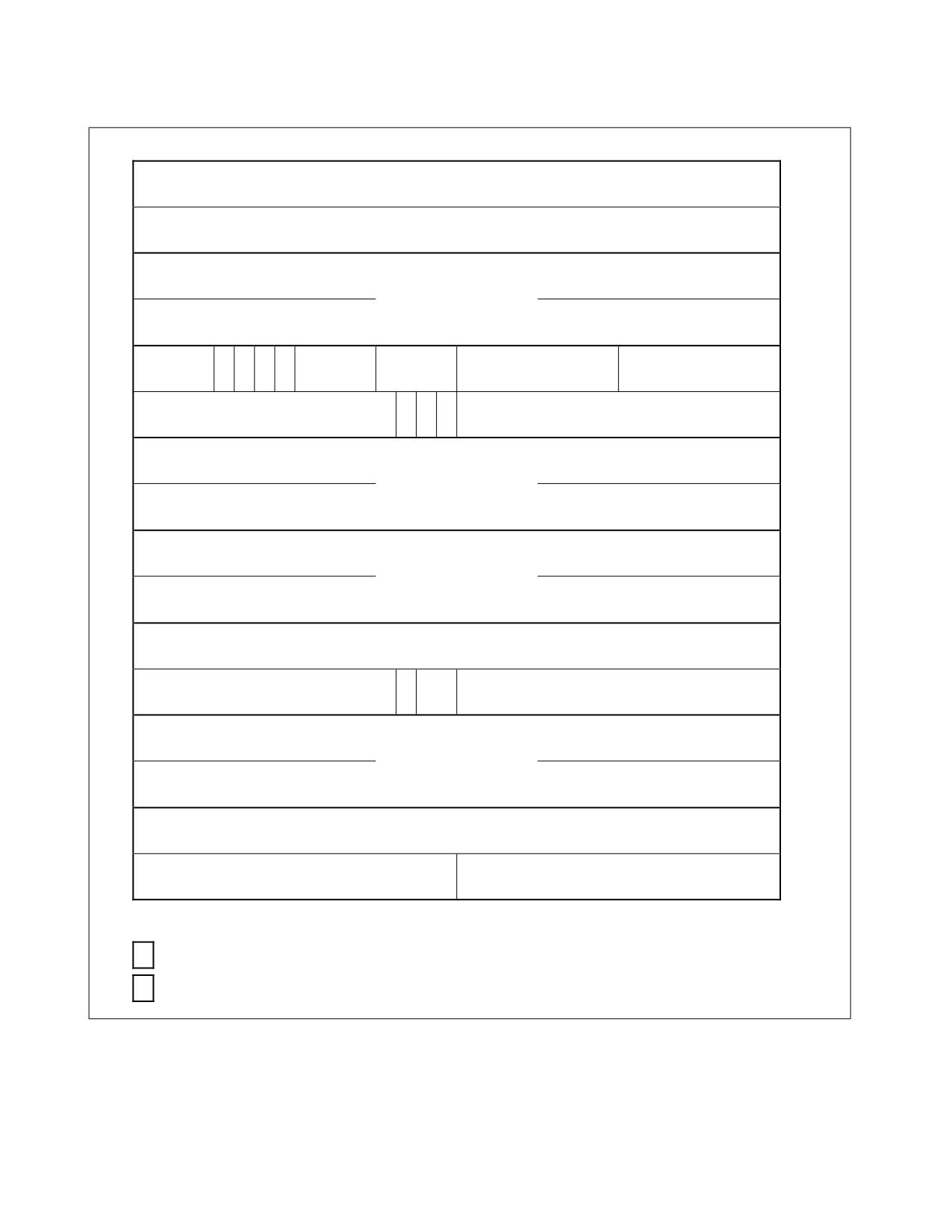
FLEXIBLE RETURN AND EVENT DELIVERY (FRED)
31 30 29 28 27 26
25 24 23 22 21 20
19 18 17 16 15 14 13 12 11 10
9
8
7
6
5
4
3
2
1
0
0
0
0
0
0
0
0
0
0
0
0
0
0
0
0
0
0
0
0
0
0
0
0
0
0
0
0
0
0
0
0
0
60
0
0
0
0
0
0
0
0
0
0
0
0
0
0
0
0
0
0
0
0
0
0
0
0
0
0
0
0
0
0
0
0
56
52
Event data
48
N
E
Instr Len
0
S
L
N
0
0
0
0
Type
0
0
0
0
0
0
0
0
Vector
44
T
C
N
S
S
0
0
0
0
0
0
0
0
0
0
0
0
0
M
Y
T
SS selector
40
I
S
B
36
RSP
32
28
RFLAGS
24
0
0
0
0
0
0
0
0
0
0
0
0
0
0
0
0
0
0
0
0
0
0
0
0
0
0
0
0
0
0
0
0
20
W
0
0
0
0
0
0
0
0
0
0
0
0
0
F
SL
CS selector
16
E
12
RIP
8
0
0
0
0
0
0
0
0
0
0
0
0
0
0
0
0
0
0
0
0
0
0
0
0
0
0
0
0
0
0
0
0
4
0
0
0
0
0
0
0
0
0
0
0
0
0
0
0
0
Error code
0
31 30 29 28 27 26
25 24 23 22 21 20
19 18 17 16 15 14 13 12 11 10
9
8
7
6
5
4
3
2
1
0
0
Not currently defined
X
Identical to legacy event frame
Figure 8-1. Flexible Return and Event Delivery Stack
• The first 8 bytes pushed (bytes 63:56 of the 64-byte stack frame) are not currently defined and will be zero
until they are.
Vol. 3A
8-7
FLEXIBLE RETURN AND EVENT DELIVERY (FRED)
•
The next 8 bytes pushed (bytes 55:48) contain event data and are defined as follows:
- If the event being delivered is a page fault (#PF), the event data is the faulting linear address (this is the
same value that the #PF loads into CR2).1
- If the event being delivered is a debug exception (#DB), the event data identifies the nature of the debug
exception:
• Bits 3:0 are B3-B0. When set, each of these bits indicates that the corresponding breakpoint condition
was met (and may be set even if its corresponding enabling bit in DR7 is not set).
• Bits 10:4 are not currently defined and will be zero until they are.
• Bit 11 is BLD. When set, this bit indicates that the cause of the debug exception was acquisition of a bus
lock (because IA32_DEBUGCTL[2] = 1).
• Bit 12 is not currently defined and will be zero until it is.
• Bit 13 is BD. When set, this bit indicates that the cause of the debug exception was “debug register
access detected.”
• Bit 14 is BS. When set, this bit indicates that the cause of the debug exception was the execution of a
single instruction (because execution of that instruction commenced with RFLAGS.TF = 1).2
• Bit 15 is not currently defined and will be zero until it is.
• Bit 16 is RTM. When set, this bit indicates that a debug exception (#DB) or a breakpoint exception
(#BP) occurred inside an RTM region while advanced debugging of RTM transactional regions was
enabled.
• Bits 63:17 are not currently defined and will be zero until they are.
The event data is not exactly the same as that which will be in DR6 following delivery of the #DB. The
polarity of bit 11 and bit 16 is inverted in DR6; in addition, delivery of #DB may leave unmodified in DR6
some bits in positions that are clear in the event data and that were already set in DR6.
- If the event being delivered is a device-not-available exception (#NM) caused by extended feature disable,
the event data indicates the cause of the exception and is the same as that loaded into the IA32_XFD_ERR
MSR. If the #NM was not caused by extended feature disable, the event data is zero.
- If the event being delivered is an NMI, the event data depends on whether the processor supports NMI-
source reporting:
• If the processor supports NMI-source reporting, the event data contains the source information about
the NMIs being delivered (see Section 7.7.3, “NMI-Source Reporting”).
• If the processor does not support NMI-source reporting, the event data is zero.
A processor supports NMI-source reporting if CPUID.07H.01H:EAX.NMI_SRC[20] is enumerated as 1.
- For any other events, the event data is not currently defined and will be zero until defined.
•
The next 40 bytes pushed (bytes 47:8) are the return state and have generally the same format as that used
by IDT event delivery. That format stores the 16-bit selectors for CS and SS in 64-bit fields. FRED event delivery
augments those selector values with additional information saved in the upper 48 bits of those fields.
The following items detail the format of the return state on the stack from bottom (highest address) to top:
- The augmented SS of the previous context, 64 bits formatted as follows:
• Bits 15:0 contain the SS selector.
• Bit 16 is set to 1 for FRED event delivery of a hardware exception if interrupt blocking by STI (STB) was
in effect at the time the exception occurred3 and is otherwise cleared to 0.4
1.
If the #PF occurred during execution of an instruction in enclave mode (but not during delivery of an event incident to enclave
mode), bits 11:0 of the event data are cleared.
2.
If in addition IA32_DEBUGCTL.BTF was 1 when the instruction commenced, a debug exception occurs only if the instruction was a
taken branch.
3.
Execution of STI with RFLAGS.IF = 0 blocks interrupts on the instruction boundary following its execution.
8-8
Vol. 3A
FLEXIBLE RETURN AND EVENT DELIVERY (FRED)
•
Bit 17 is set to 1 for FRED event delivery of SYSCALL, SYSENTER, or INT n (SYS) and is otherwise
cleared to 0.
•
Bit 18 is set to 1 if the event being delivered is a non-maskable interrupt (NMI) and is otherwise cleared
to 0.
•
Bits 31:19 are not currently defined and will be zero until they are.
•
Bits 63:32 contain event information. This provides software with additional information about the
event. The FRED return instructions ignore these bits. The event information is formatted as follows:
- Bits 39:32 contain the event’s vector. The vector depends on the type of event:
• For an external interrupt, the vector is provided by the local APIC.
• For a non-maskable interrupt (NMI), the vector is 2.
• For a hardware exception, the vector is determined by the exception.
• For a software interrupt (INT n), the vector comes from the instruction’s opcode (value n).
• For a software exception, the vector is determined by the instruction opcode: INT1 has vector 1;
INT3 has vector 3; INTO has vector 4.
• For SYSCALL and SYSENTER (which use FRED event delivery but not IDT event delivery), vectors
1 and 2 are used, respectively.
- Bits 47:40 are not currently defined and will be zero until they are.
- Bit 51:48 encode the event type as follows: 0 = external interrupt; 2 = non-maskable interrupt; 3 =
hardware exception (e.g., page fault); 4 = software interrupt (INT n); 5 = privileged software
exception (INT1); 6 = software exception (INT3 or INTO); and 7 = other event (used for SYSCALL
and SYSENTER). Other values are not used.1
- Bits 55:52 are not currently defined and will be zero until they are.
- Bit 56 is set to 1 to indicate that the event was incident to enclave execution (ENC). Specifically, it is
set if the event occurred while the logical processor was in enclave mode or was an exception
encountered during delivery of such an event. Otherwise, the bit is cleared to 0.
- Bit 57 (L) is set to 1 if the logical processor had been in 64-bit mode when the event occurred. (A
value of 0 indicates an event incident to compatibility mode.)
- Bit 58 is set to 1 if the event is nested exception (NST) encountered during FRED event delivery of
another event. This bit is not set if the event is double fault (#DF).
- Bit 59 is not currently defined and will be zero until it is.
- Bits 63:60 contain the length of the instruction causing the event if the event type is software
interrupt (INT n), privileged software exception (INT1), software exception (INT3 or INTO), or other
event (when used for SYSCALL or SYSENTER). For other event types, these bits are cleared to zero.
- RSP of the previous context (64 bits).
- RFLAGS of the previous context (64 bits).
Bit 16 of the RFLAGS field (corresponding to the RF bit) is saved as 1 when delivering events that do the
same for IDT event delivery. These are faults other than instruction breakpoints as well as any traps or
interrupts delivered following partial execution of an instruction (e.g., between iterations of a REP-prefixed
string instruction). Delivery of other events save in bit 16 the value that RFLAGS.RF had at the time the
event occurred.
- The augmented CS of the previous context. The FRED return instructions use the 64 bits of this field. It is
formatted as follows:
• Bits 15:0 contain the CS selector.
4.
Delivery of SYSCALL, SYSENTER, INT1, INT3, or INT n (for any value of n) will always clear this bit, as will delivery of any exception
encountered during event delivery for one of those instructions.
1.
The event types used by FRED event delivery are the same as those already defined for VMX transitions. For SYSCALL or
SYSENTER, FRED event delivery reports event type 7 (other event).
Vol. 3A
8-9
FLEXIBLE RETURN AND EVENT DELIVERY (FRED)
• Bits 17:16:
- For delivery of events that occur while CPL = 0, these bits report the stack level (SL) at the time the
event occurred.
- For delivery of events that occur while CPL = 3, these bits are cleared to 0.
• Bit 18 is set to 1 if the event occurred while CPL = 0 and the indirect branch tracker was in the
WAIT_FOR_ENDBRANCH (WFE) state. Specifically, the bit is set if and only if the following are all true:
CPL = 0; CR4.CET = 1; IA32_S_CET.ENDBR_EN = 1; and IA32_S_CET.TRACKER = 1.
The following items document the implications of how bit 18 is saved based on the existing operation of
indirect branch tracking (providing details regarding delivery of specific events occurring while CPL =
0):
- Delivery of an event occurring at an instruction boundary saves bit 18 with the setting of the tracker
at that instruction boundary:
• For an event that takes priority over a missing-ENDBRANCH #CP exceptions, this value may be 0
or 1, depending on the state of the tracker. These events include certain machine-check
exceptions, trap-class debug exceptions, non-maskable interrupts, external interrupts, debug
exceptions due to instruction breakpoints, and faults from fetching the next instruction. They
may also include faults from decoding the next instruction.
• For a missing-ENDBRANCH #CP exception, this value is 1.
• For a fault from decoding the next instruction that is prioritized below missing-ENDBRANCH #CP
exceptions, this value is 0.
- Delivery of INT1 or INT3 saves bit 18 with the tracker’s setting at the time INT1 or INT3 was fetched.
(Decode of these instructions does not clear the tracker.)
- Delivery of INT n (for any value of n), SYSCALL, or SYSENTER will save bit 18 with value 0.
- Delivery of an exception encountered during FRED event delivery (including that for INT1, INT3, INT
n, SYSCALL, or SYSENTER) will save bit 18 with the value that would have been saved by delivery of
the original event.
- Delivery of an exception encountered during execution of any instruction other than INT1 or INT3
will save bit 18 with value 0.
• Bits 63:19 are not currently defined and will be zero until they are.
- RIP of the previous context (64 bits).
If the event type is software interrupt (INT n), privileged software exception (INT1), software exception
(INT3 or INTO), or other event (when used for SYSCALL or SYSENTER); the RIP value saved references the
instruction after the one that caused the event being delivered. (If delivery of such an event encounters an
exception, the RIP value saved by delivery of the exception will instead reference the instruction that
caused the original event.)
• The last 8 bytes pushed (bytes 7:0) contain error code (defined only for certain exceptions; zero if none is
defined) in bits 15:0. Bits 63:16 are not currently defined and will be zero until they are.
8.3.2.2
Saving Information on the Shadow Stack
If supervisor shadow stacks are enabled and the event being delivered occurred while CPL = 0, FRED event delivery
saves information on the new shadow stack. The following items provide details:
• FRED event delivery writes four bytes of zeroes to the linear address SSP - 4 and then clears SSP[2:0]. This has
the following effect:
- If the value of SSP had not been 8-byte aligned (it is necessarily 4-byte aligned), 4 bytes of zeroes are
stored (as padding) and subsequent shadow-stack pushes will immediately follow those 4 bytes of zeroes.
- If the value of SSP had been 8-byte aligned, 4 bytes of zeroes are stored but will be overwritten by
subsequent shadow-stack pushes.
• FRED event delivery then pushes the following values on the new shadow stack:
8-10
Vol. 3A
FLEXIBLE RETURN AND EVENT DELIVERY (FRED)
- The same 64-bit augmented CS that was pushed on the regular stack (see Section 8.3.2.1), including any
bits defined in positions 63:16.
- The old linear instruction pointer.
- The old SSP on the shadow stack.
Each of these values is pushed in a separate 8-byte field on the shadow stack.
The write of zeroes and the pushes are all performed as shadow-stack accesses; because FRED event delivery
results in CPL = 0, they are performed with supervisor privilege.
8.3.3
Loading Additional State
After saving the old context and other information, FRED event delivery completes operation by loading additional
registers and updating other processor state.
If the event occurred while CPL = 3 and user shadow stacks are enabled, the IA32_PL3_SSP MSR is loaded with the
old value of SSP. The value loaded into the MSR is adjusted so that bits 63:N get the value of bit N-1, where N is
the processor’s maximum linear-address width.
If supervisor indirect branch tracking is enabled, the IA32_S_CET MSR is updated to set the TRACKER value to
IDLE and to clear the SUPPRESS bit to 0. There is no reason for the instruction referenced by the new RIP value to
be ENDBR64.
A debug trap (single-step trap or data or I/O breakpoint) may be pending at the time another event is delivered.
FRED event delivery drops any debug traps that were pending at the time the original event occurred, regardless
of the event being delivered. In particular, any pending data or I/O breakpoints (or single-step traps) are no longer
pending after INT n, INT3, INTO, SYSCALL, or SYSENTER is delivered using FRED event delivery.
Data breakpoints detected during FRED event delivery might not be dropped and may be pending after completion
of FRED event delivery. A single-step trap will never be pending following FRED event delivery (even if INT n, INT1,
INT3, INTO, SYSCALL, or SYSENTER is executed while RFLAGS.TF = 1).
8.3.4
Faults During FRED Event Delivery
The earlier sections identify situations in which faults may occur during FRED event delivery. In addition, a memory
access will cause a fault if it uses a non-canonical address or encounters a LASS violation1 (#SS for an access to
the regular stack; #GP for the shadow stack); or if it causes a page fault (#PF).
An exception encountered during FRED event delivery will be converted to a double fault (#DF) following the same
principles under which this is done for IDT event delivery. As with IDT event delivery, the error code for the #DF is
always zero.
For a #GP or #SS encountered during FRED event delivery that is not converted to #DF, the error code will be 0 if
the event that was being delivered had type software interrupt (INT n), software exception (INT3 or INTO), or
other event (SYSCALL and SYSENTER); it will be 1 for event types external interrupt, non-maskable interrupt,
hardware exception, or privileged software exception (INT1). (This aligns with the existing specification of the EXT
bit in such error codes.)
For a #PF encountered during FRED event delivery that is not converted to #DF, the error code is defined exactly
as it is for IDT event delivery.
If FRED event delivery causes a fault, any changes to register state are undone before delivering the fault.
8.3.5
Detailed Operation of FRED Event Delivery
The section presents detailed pseudocode for the operation of FRED event delivery. It does not include details of
how event information is formatted or how event data is determined. These details are in Section 8.3.2.1.
1. Since FRED event delivery clears both CPL and RFLAGS.AC, a LASS violation will occur if CR4.LASS = CR4.SMAP = 1 and a memory
access uses a linear address that clears bit 63.
Vol. 3A
8-11
FLEXIBLE RETURN AND EVENT DELIVERY (FRED)
// HOLD OLD STATE IN TEMPORARIES
oldRIP := RIP;
oldCS := CS;
// oldCS is 8 bytes; the upper 6 bytes are defined below
oldCPL := CPL;
// the same as oldCS[1:0]
oldRFLAGS := RFLAGS;
oldSS := SS;
// oldSS is 8 bytes; upper 6 bytes are zero
oldRSP := RSP;
IF CPL = 3
THEN oldCSL := 0;
ELSE oldCSL := CSL;
FI;
oldGSB := GS.base;
oldSSP := SSP;
// used only when shadow stacks are enabled
// ERETS and ERETU will restore the oldRFLAGS to RFLAGS
// Before saving, event delivery updates oldRFLAGS to set RF when appropriate
IF the event being delivered is a fault other than an instruction breakpoint OR
the event being delivered is a trap or interrupt following partial execution of an instruction
(e.g., between iterations of a REP-prefixed string instruction)
THEN oldRFLAGS[16] := 1;
FI;
// Update bits above CS selector to hold additional information
// ERETS and ERETU will use these
oldCS[17:16] := oldCSL;
IF CPL = 3
THEN oldCS[18] := 0;
ELSE
// See Section 8.3.2.1 for details of how oldCS[18] is determined
oldCS[18] = CR4.CET AND IA32_S_CET.ENDBR_EN AND IA32_S_CET.TRACKER;
FI;
// Update bits above SS selector to hold additional information
IF STI blocking was in effect when the event occurred
THEN oldSS[16] := 1;
FI;
IF event being delivered is either SYSCALL, SYSENTER, or INT n
THEN oldSS[17] := 1;
FI;
IF event being delivered is an NMI
// includes VM-entry injection of NMI
THEN oldSS[18] := 1;
FI;
// ERETS and ERETU will ignore the event information
oldSS[63:32] := event information as defined in Section 8.3.2.1;
// DETERMINE NEW CONTEXT
// determine new RIP
IF oldCPL = 3
THEN newRIP := IA32_FRED_CONFIG & ~FFFH;
ELSE newRIP := IA32_FRED_CONFIG & ~FFFH + 256;
FI;
IF newRIP is not paging canonical
THEN #GP(0);
// will lead eventually to shutdown or VM exit
FI;
// determine event’s stack level and the new stack level for event handler
IF oldCPL = 3 AND event is not an exception nested on event delivery AND event is not #DF
THEN eventSL := 0;
ELSE
8-12
Vol. 3A
FLEXIBLE RETURN AND EVENT DELIVERY (FRED)
IF event type is external interrupt
// oldCPL must be 0
THEN eventSL := IA32_FRED_CONFIG[10:9];
ELSIF event type is hardware exception, software exception, privileged software exception, or NMI
// v = event vector (0-31); includes INT1, INT3, INTO
THEN eventSL := IA32_FRED_STKLVLS[2v+1:2v];
ELSE
// SYSCALL, SYSENTER, INT n with CPL = 0; do not change CSL
eventSL := 0;
FI;
FI;
newCSL := MAX{eventSL, oldCSL};
// determine new RSP
IF oldCPL = 3 OR newCSL > oldCSL
THEN newRSP := IA32_FRED_RSPi, where i = newCSL;
ELSE
// decrement RSP as specified and align to 64 bytes
newRSP := (RSP - (IA32_FRED_CONFIG & 1C0H)) & ~3FH;
FI;
// determine new RFLAGS; clear all bits except position 1
newRFLAGS := 2;
// if needed, determine new SSP
IF CR4.CET = 1 AND IA32_S_CET.SH_STK_EN = 1
THEN
IF oldCPL = 3 OR newCSL > oldCSL
THEN
newSSP := IA32_FRED_SSPi, where i = newCSL;
IF newSSP[2] = 1
// check for 8-byte alignment
THEN #GP(0);
FI;
ELSE
// decrement SSP if specified
newSSP := SSP - (IA32_FRED_CONFIG & 8);
FI;
FI;
// ESTABLISH NEW CONTEXT - OLD STATE WILL BE RESTORED IF THERE IS A SUBSEQUENT EXCEPTION
// update segment registers if event occurred while CPL = 3
IF oldCPL = 3
THEN
// set CS to standard values used by a 64-bit operating system
CS.selector := IA32_STAR[47:32] & FFFCH;
CS.base := 0;
CS.limit := FFFFFH;
CS.type := 11;
CS.S := 1;
CS.DPL := 0;
CS.P := 1;
CS.L := 1;
CS.D := 0;
CS.G := 1;
CS.unusable := 0;
// set SS to standard values used by a 64-bit operating system
SS.selector := CS.selector + 8;
SS.base := 0;
SS.limit := FFFFFH;
SS.type := 3;
SS.S := 1;
Vol. 3A
8-13
FLEXIBLE RETURN AND EVENT DELIVERY (FRED)
SS.DPL := 0;
SS.P := 1;
SS.B := 1;
SS.G := 1;
SS.unusable := 0;
// swap in supervisor GS base address
GS.base := IA32_KERNEL_GS_BASE;
IA32_KERNEL_GS_BASE := oldGSB;
FI;
// update registers defining context
RIP := newRIP;
RFLAGS := newRFLAGS;
RSP := newRSP;
CSL := newCSL;
// reflected in IA32_FRED_CONFIG[1:0]
// Update SSP if supervisor shadow stacks enabled
IF CR4.CET = 1 AND IA32_S_CET.SH_STK_EN = 1
THEN SSP := newSSP;
FI;
// SAVE STATE ON STACKS
// Save return state on new regular stack; memory accesses here have supervisor privilege
push8B 00000000_00000000H;
// First 8 bytes pushed are all zero
push8B event data as defined in Section 8.3.2.1;
push8B oldSS;
push8B oldRSP;
push8B oldRFLAGS;
push8B oldCS;
push8B oldRIP;
push8B errorcode;
// If supervisor shadow stacks enabled and old CPL was 0, save data on new shadow stack
IF CR4.CET = 1 AND IA32_S_CET.SH_STK_EN = 1 AND oldCPL = 0
THEN
store 4 bytes of zeroes to address SSP - 4;// shadow-stack access
SSP := SSP & ~7;
// aligns SSP to 8B boundary
pushSS_8B oldCS;
// full 64-bit field
pushSS_8B oldRIP;
pushSS_8B oldSSP;
FI;
// UPDATE ADDITIONAL STATE
// update additional CET state as needed (SSP was updated earlier)
IF CR4.CET = 1
THEN
IF oldCPL = 3 AND IA32_U_CET.SH_STK_EN = 1
THEN
// adjust so bits 63:N get the value of bit N-1
// N = processor’s maximum linear-address width
IA32_PL3_SSP := LA_adjust(oldSSP);
FI;
IF IA32_S_CET.ENDBR_EN = 1
THEN IA32_S_CET[11:10] := 00b;
// IDLE with SUPPRESS = 0
FI;
FI;
// update event-related state
clear any debug traps that were pending prior to FRED event delivery;
CPL := 0;
8-14
Vol. 3A
FLEXIBLE RETURN AND EVENT DELIVERY (FRED)
8.4
FRED RETURN INSTRUCTIONS
FRED defines two instructions for returning from events delivered by FRED event delivery:
• ERETS (Section 8.4.1) is used to return from events that occur while CPL = 0; it does not modify CS, SS, or
GS.
• ERETU (Section 8.4.2) is used to return from events that occur while CPL = 3; it loads CS and SS based on the
stack image and also updates the GS base address.
Neither instruction takes explicit operands. These instructions can be executed only if FRED transitions are enabled
and only if CPL = 0; in addition, ERETU can be executed only if CSL = 0.
NOTE
The following sections indicate situations in which one of the instructions may cause a control-
protection exception (#CP). These exceptions will use the value 2 for an error code, indicating that
the #CP was caused by a return instruction other than near RET.
8.4.1
ERETS (Event Return to Supervisor)
ERETS returns from an event handler without changing the CPL, establishing the return state that was in effect
before FRED event delivery. Because it stays within the supervisor context, ERETS does not modify the segment
registers CS, SS, or GS. Execution of ERETS causes an invalid-opcode exception (#UD) if FRED transitions are not
enabled or if CPL > 0.
ERETS begins by reading and checking the return state from the stack (Section 8.4.1.1). If supervisor shadow
stacks are enabled, it then checks the shadow stack to confirm the validity of this control-flow transfer (Section
8.4.1.2). Finally, ERETS establishes the return state by loading the appropriate registers (Section 8.4.1.3).
See “ERETS-Event Return to Supervisor” in Chapter 3 of Volume 2 in the Intel® 64 and IA-32 Architectures Soft-
ware Developer’s Manual for the detailed flow of the operation of ERETS.
8.4.1.1
Loading and Checking the Return State
ERETS operates on the stack frame created by FRED event delivery (Section 8.3.2.1), principally to restore the
state saved in that stack frame (the return state).
When FRED event delivery completes, the return state is located at offset 8 from the RSP value. (RSP references
an 8-byte field containing the event’s error code.) For this reason, ERETS begins by adding 8 to RSP so that it can
access the return state directly.
After adding 8 to RSP, ERETS pops from the regular stack (referenced by RSP) the return state that was saved by
FRED event delivery. The state is checked and held by the processor to update register state when the instruction
completes. The following items detail the state fields that are popped, from top (lowest address) to bottom
(highest address), specifying the checks that are performed:
• The RIP of the return state (64 bits).
This field must be paging canonical; otherwise, a #GP with a zero error code occurs.
• The augmented CS for the return state (64 bits).
ERETS does not use bits 15:0 to load CS, but it does ensure that the value of these bits equals that of the
current CS selector; otherwise, a #GP occurs.
Bit 18 of this field determines whether ERETS updates the state of the indirect branch tracker.
ERETS will establish the new stack level as the minimum of the CSL and the value of bits 17:16 of this field.
Bits 63:19 of this field must be zero; otherwise, a #GP occurs.
• The RFLAGS of the return state (64 bits).
Bit 1 of this field must be 1; bit 3, bit 5, bit 15, bit 17 (VM), and bits 63:22 of the field must be zero; otherwise,
a #GP occurs.
• The RSP of the return state (64 bits). This field is not checked.
Vol. 3A
8-15
FLEXIBLE RETURN AND EVENT DELIVERY (FRED)
• The augmented SS of the return state (64 bits).
ERETS does not use bits 15:0 to load SS, but it does ensure that the value of these bits equals that of the
current SS selector; otherwise, a #GP occurs.
Bits 18:16 of this field determine how ERETS manages certain events. See Section 8.4.1.3.
Bits 31:19 of this field must be zero; otherwise, a #GP occurs. ERETS ignores bits 63:32 of this field (the event
information).
8.4.1.2
Checking the Shadow Stack
If supervisor shadow stacks are enabled, ERETS pops and checks values from the shadow stack (referenced by
SSP) that were saved by FRED event delivery. The following items detail the state that is popped from top (lowest
address) to bottom (highest address), specifying the checks that are performed:
• The SSP of the return state (64 bits).
This value must be 4-byte aligned (bits 1:0 must be zero); otherwise, a control-protection exception (#CP)
occurs.
This value must be CPU canonical; otherwise, a #GP occurs with a zero error code. (This #GP has priority below
the #CP exceptions specified in the following items.)
• The linear instruction pointer of the return state (64 bits).
This value must equal the RIP of the return context that was popped from the regular stack; otherwise, a #CP
occurs.
• The augmented CS for the return state (64 bits).
This value must equal the code-segment value that was popped from the regular stack; otherwise, a #CP
occurs.
If supervisor shadow stacks are enabled and the new stack level is less than the CSL, ERETS compares the value of
SSP (after popping the above fields) and the value of the FRED SSP MSR for the CSL (not the new stack level). (For
example, if ERETS is executing with CSL = 2 and is returning to stack level 1, the comparison is with
IA32_FRED_SSP2.) If the values are not equal, a #CP occurs.
8.4.1.3
Establishing the Return State
After the stack operations described in Section 8.4.1.1 and Section 8.4.1.2, ERETS then loads RIP, RFLAGS, RSP,
and CSL with the values that were popped earlier from the regular stack. If supervisor shadow stacks are enabled,
SSP is loaded with the value that was popped earlier from the shadow stack.
Additional steps are performed based on the value of the popped fields for CS and SS:
• If bit 18 of the CS field is 1 and ERETS will complete with indirect branch tracking enabled and not suppressed,
the indirect branch tracker will be in the WAIT_FOR_ENDBRANCH state upon completion of ERETS.1
• If bit 16 of the SS field is 1, bit 9 of the RFLAGS field (corresponding to RFLAGS.IF) is 1, and there was no
blocking by STI prior to ERETS, blocking by STI is in effect upon completion of ERETS.
• If bit 17 of the SS field is 1 and ERETS will result in RFLAGS.TF = 1, a single-step trap will be pending upon
completion of ERETS.2
• If bit 18 of the SS field is 1, ERETS unblocks NMIs.
1. ERETS will complete with indirect branch tracking enabled and not suppressed if CR4.CET = 1, IA32_S_CET.ENDBR_EN = 1, and
IA32_S_CET.SUPPRESS = 0. If ERETS puts the indirect branch tracker in the WAIT_FOR_ENDBRANCH state, it will result in
IA32_S_CET.TRACKER = 1.
2. If ERETS begins execution with RFLAGS.TF = 1, there will always be a single-step debug exception pending after ERETS, regardless
of the values on the stack for RFLAGS.TF and CS.
8-16
Vol. 3A
FLEXIBLE RETURN AND EVENT DELIVERY (FRED)
8.4.2
ERETU (Event Return to User)
ERETU returns from an event handler while changing the CPL to 3, establishing the return context that was in
effect before FRED event delivery. The change of context includes updates to the segment registers CS, SS, or GS.
Execution of ERETU causes an invalid-opcode exception (#UD) if FRED transitions are not enabled or if CPL > 0,
and a general-protection exception (#GP) if CSL > 0.
ERETU begins by reading and checking the return state from the stack (Section 8.4.2.1). If supervisor shadow
stacks are enabled, it then checks the validity of the old and new shadow-stack pointers (Section 8.4.2.2). Finally,
ERETU establishes the return state by loading the appropriate registers (Section 8.4.2.3).
See “ERETU-Event Return to User” in Chapter 3 of Volume 2 in the Intel® 64 and IA-32 Architectures Software
Developer’s Manual for the detailed flow of the operation of ERETU.
8.4.2.1
Loading and Checking the Return State
ERETU operates on the stack frame created by FRED event delivery (Section 8.3.2.1), principally to restore the
state saved in that stack frame (the return state).
When FRED event delivery completes, the return state is located at offset 8 from the RSP value. (RSP references
an 8-byte field containing the event’s error code.) For this reason, ERETU begins by adding 8 to RSP so that it can
access the return state directly.
After adding 8 to RSP, ERETU first pops from the regular stack (referenced by RSP) the return state that was saved
by FRED event delivery. The state is checked and held by the processor to update register state when the instruc-
tion completes. The following items detail the state fields that are popped, from top (lowest address) to bottom
(highest address), specifying the checks that are performed:
• The RIP of the return state (64 bits).
This field is checked once the new CS configuration is determined (see below).
• The augmented CS of the return state (64 bits).
Bits 15:0 contain the new CS selector itself. ERETU ensures that the value of bits 1:0 is 3; otherwise, a #GP
occurs.
Bits 63:16 of this field must be zero; otherwise, a #GP occurs.
• The RFLAGS of the return state (64 bits).
Bit 1 of this field must be 1; bit 3, bit 5, bits 13:12 (IOPL), bit 15, bit 17 (VM), and bits 63:22 of the field must
be zero; otherwise, a #GP occurs.
NOTE
Checking IOPL ensures that, when FRED transitions are enabled, IOPL is always 0 when CPL = 3.
• The RSP of the return state (64 bits). This field is not checked.
• The augmented SS of the return state (64 bits).
Bits 15:0 contain the new SS selector itself. ERETU ensures that the value of bits 1:0 is 3; otherwise, a #GP
occurs.
Bit 17 and bit 18 of this field determine how ERETU manages certain events. See Section 8.4.2.3.
Bits 31:19 of this field must be zero; otherwise, a #GP occurs. ERETU ignores bit 16 of this field, as well as bits
63:32 (the event information).
After popping these fields, ERETU determines the configuration of the CS and SS segment registers for the return
state according to one of these three cases:
1. If the selector popped for CS is IA32_STAR[63:48] + 16 and the selector popped for SS is
IA32_STAR[63:48] + 8, ERETU establishes CS and SS in a standard configuration for CPL 3 in 64-bit mode:
- CS:
• The selector is set to the selector popped for CS.
• The base address is set to 0. The limit is set to FFFFFH and the G bit is set to 1.
Vol. 3A
8-17
FLEXIBLE RETURN AND EVENT DELIVERY (FRED)
• The type is set to 11 (execute/read accessed code) and the S bit is set to 1.
• The DPL is set to 3, the P and L bits are each set to 1, and the D bit is set to 0.
• CS is made usable regardless of the value of the selector.
- SS:
• The selector is set to the selector popped for SS.
• The base address is set to 0. The limit is set to FFFFFH and the G bit is set to 1.
• The type is set to 3 (read/write accessed data) and the S bit is set to 1.
• The DPL is set to 3, and the P and B bits are each set to 1.
• SS is made usable regardless of the value of the selector.
2. If the selector popped for CS is IA32_STAR[63:48] and the selector popped for SS is IA32_STAR[63:48] + 8,
ERETU will establish CS and SS in a standard configuration for CPL s3 in compatibility mode:
- CS:
• The selector is set to the selector popped for CS.
• The base address is set to 0. The limit is set to FFFFFH and the G bit is set to 1.
• The type is set to 11 (execute/read accessed code) and the S bit is set to 1.
• The DPL is set to 3, the P and D bits are set to 1, and the L bit is set to 0.
• CS is made usable regardless of the value of the selector.
- SS:
• The selector is set to the selector popped for SS.
• The base address is set to 0. The limit is set to FFFFFH and the G bit is set to 1.
• The type is set to 3 (read/write accessed data) and the S bit is set to 1.
• The DPL is set to 3, and the P and B bits are each set to 1.
• SS is made usable regardless of the value of the selector.
3. Otherwise, the selectors popped for CS and SS are used to load descriptors from the GDT or an LDT as would
be done by an execution of IRET. These descriptor loads may cause ERETU to fault as would occur with IRET.
The RIP of the return state is then checked, depending on the mode to which ERETU is returning:
• If ERETU is returning to 64-bit mode (either case #1 above, or case #3, where the descriptor loaded for CS sets
the L bit), a #GP with a zero error code occurs if the return RIP is not paging canonical.
• If ERETU is returning to compatibility mode (either case #2 above, or case #3, where the descriptor loaded for
CS clears the L bit), the upper 32 bits of the return RIP are cleared. Following this, a #GP with a zero error code
occurs if the truncated RIP value exceeds the new CS segment limit (taking into account that segment’s G bit).
(Such a #GP will never occur for case #2, as it establishes a limit of FFFFFFFFH.)
8.4.2.2
Checking the Shadow-Stack Pointers
If user shadow stacks are enabled, the SSP of the return state is the value of the IA32_PL3_SSP MSR. If the return
is to compatibility mode, a #GP occurs if IA32_PL3_SSP[63:32] are not all zero.
If supervisor shadow stacks are enabled, ERETU compares the current (supervisor) SSP value and the value of the
IA32_FRED_SSP0 MSR. If the values are not equal, a #CP occurs.
NOTE
Execution of ERETU does not access any shadow stack.
8-18
Vol. 3A
FLEXIBLE RETURN AND EVENT DELIVERY (FRED)
8.4.2.3
Establishing the Return State
After the stack operations described earlier, ERETU loads RIP, RFLAGS, RSP, CS, and SS with the values identified
in Section 8.4.2.1. If the return is to compatibility mode, the upper 32 bits of each of RIP and RSP are cleared to
zero. If user shadow stacks are enabled, SSP is loaded with the value for the return state as identified in Section
8.4.2.2 (from the IA32_PL3_SSP MSR).
ERETU swaps the value of the GS base address and that of the IA32_KERNEL_GS_BASE MSR.
Additional steps are performed based on the value of the popped SS field:
• If bit 17 of the field is 1 and ERETU would result in RFLAGS.TF = 1, a single-step trap will be pending upon
completion of ERETU.1
• If bit 18 of the field (above the selector) is 1, ERETU unblocks NMIs.
NOTE
Unlike IRET, ERETU does not make any of DS, ES, FS, or GS null if it is found to have DPL < 3. It is
expected that a FRED-enabled operating system will return to CPL 3 (in compatibility mode) only
when those segments all have DPL = 3.
8.4.2.4
Interactions Between ERETU and Other Instructions
ERETU provides the same instruction-ordering guarantees as SYSRET. Specifically, instructions following an execu-
tion of ERETU may be fetched from memory before earlier instructions complete execution, but they will not
execute (even speculatively) until all instructions prior to the ERETU have completed execution. (The later instruc-
tions may execute before data stored by the earlier instructions have become globally visible.)
Execution of the UMWAIT instruction will not wait (will not enter an implementation-dependent optimized state) if
ERETU was executed before UMWAIT and after the most recent execution of the UMONITOR instruction.
8.5
FRED AND EXISTING INSTRUCTIONS
The Intel® 64 architecture defines numerous instructions that change the CPL. This section considers those
instructions (and others) and describes how enabling FRED transitions affects either their operation or their usage.
(Recall that FRED transitions are enabled if CR4.FRED = 1.)
• Section 8.5.1 identifies instructions that cannot be executed when FRED transitions are enabled.
• Section 8.5.2 considers far CALL, far JMP, far RET, and IRET. Enabling FRED transitions modifies the operation
of these instructions. A FRED-enabled operating system cannot use them to change the CPL or to enter
compatibility mode while CPL = 0.
• Section 8.5.3 discusses software interrupts and related instructions (INT n, INT3, INTO, and INT1). When FRED
transitions are enabled, these instructions use FRED event delivery.
• Section 8.5.4 describes changes to the instructions SYSCALL and SYSENTER. When FRED transitions are
enabled, these instructions also use FRED event delivery.
• Section 8.5.5 discusses interactions with the GETSEC instructions that enter or exit authenticated code
execution mode.
8.5.1
Disallowed Instructions
When FRED transitions are enabled, execution of any of the following instructions causes an invalid-opcode excep-
tion (#UD): CLRSSBSY, SETSSBSY, SWAPGS, SYSEXIT, and SYSRET.
1. If ERETU began execution with RFLAGS.TF = 1, there will always be a single-step debug exception pending after ERETU, regardless
of the values on the stack for RFLAGS.TF and CS.
Vol. 3A
8-19
FLEXIBLE RETURN AND EVENT DELIVERY (FRED)
NOTE
CLRSSBSY, SETSSBSY, and SWAPGS account for anomalous situations that do not exist with FRED.
In addition, CLRSSBSY and SETSSBSY operate on supervisor shadow-stack tokens, which are not
used when FRED transitions are enabled.
8.5.2
Far CALL, IRET, Far JMP, and Far RET
Enabling FRED transitions disables the ability of certain existing instructions to change the CPL or to effect certain
other mode changes.
The far CALL instruction provides a mechanism by which user software can change to more privilege. The IRET and
far RET instructions allow returns to the calling context, and this can change the CPL. The operation of these
instructions (as well as that of far JMP) is modified when FRED transitions are enabled.
Far CALL can change CPL only if it references a call gate in the GDT or an LDT. (Far JMP can also reference a call
gate, but an execution that does so cannot change the CPL.) When FRED transitions are enabled, any execution of
far CALL or far JMP that references a call gate causes a general-protection exception (#GP). (The call-gate
descriptor will not be modified.) The exception’s error code will include the selector that referenced the call gate.
This exception has the same priority as that of existing checks on the type of the target descriptor.
An execution of IRET or far RET changes the CPL if the RPL value of selector referencing the target code segment is
greater than the CPL. When FRED transitions are enabled, such an execution causes #GP. (The code-segment
descriptor will be accessed but not modified.) The exception’s error code will include the selector that referenced
the code segment. This exception has the same priority as that of the existing check that the RPL cannot be less
than the CPL.
These restrictions imply that, when they are enabled, FRED transitions are the only ways to change the CPL and
that it is impossible to change the CPL to 1 or to 2.
In addition, enabling FRED transitions disables the ability of software to enter compatibility mode while CPL = 0. An
execution of far CALL, IRET, far JMP, or far RET causes a transition to compatibility mode if it loads CS from a code-
segment descriptor in which the L bit is 0. (The L bit is bit 53 of the 64-bit descriptor.) When FRED transitions are
enabled, such an execution with CPL = 0 causes #GP. The exception’s error code will include the selector that refer-
enced the code segment. This exception has the same priority as that of existing checks on the type of the target
descriptor.
NOTE
The restrictions described in this section do not prevent use of far CALL, IRET, far JMP, or far RET to
enter compatibility mode when the instruction is executed with CPL = 3 and does not reference a
call gate. They can be used with CPL = 0 only if their execution does not change the CPL and stays
in 64-bit mode.
8.5.3
Software Interrupts and Related Instructions
The Intel 64 architecture supports the following instructions that unprivileged software can use to invoke the oper-
ating system using the IDT:
• INT n (opcode CD followed by an immediate byte). There are 256 such software-interrupt instructions, one for
each value n of the immediate byte (0-255).
• INT3 (opcode CC). This instruction generates a breakpoint exception (#BP) as a trap.
• INTO (opcode CE). If RFLAGS.OF = 1, this instruction generates an overflow exception (#OF) as a trap. If
RFLAGS.OF = 0, this instruction does not generate an exception and control passes to the next instruction.
Executing INTO in 64-bit mode causes an invalid-opcode exception (#UD), but the instruction can be used to
generate #OF in compatibility mode.
• INT1 (opcode F1). This instruction generates a debug exception (#DB) as a trap. Hardware vendors may use
INT1 for hardware debug.
8-20
Vol. 3A
FLEXIBLE RETURN AND EVENT DELIVERY (FRED)
When FRED transitions are enabled, an execution of any of these instructions (except for INTO if RFLAGS.OF = 0)
results in FRED event delivery. Section 8.3.2.1 describes how the resulting FRED event delivery saves event infor-
mation for these instructions (including the length of the instruction).
NOTE
IDT event delivery of INT n, INT3, and INTO checks the DPL field of the IDT gate and generates a
general-protection exception (#GP) if it is less than the CPL. (Delivery of INT1 does not do this.)
FRED event delivery does not use the IDT and thus does not perform this check. The event handlers
of a FRED-enabled operating system should check the event type and vector to identify situations
that would have resulted in a fault with IDT event delivery.
8.5.4
SYSCALL and SYSENTER
The Intel 64 architecture supports two instructions that unprivileged software can use to invoke the operating
system without using the IDT: SYSCALL and SYSENTER.
When FRED transitions are enabled, the operation of SYSCALL is modified to use FRED event delivery (Section 8.3)
in place of its existing operation. A FRED-enabled operating system should use ERETU (Section 8.4.2) instead of
SYSRET to return after handling a system call invoked by an execution of SYSCALL with CPL = 3. (Recall that any
execution of SYSRET causes #UD when FRED transitions are enabled. A FRED-enabled operating system will
normally use ERETU to return from any event that occurred when CPL = 3.)
(Since the SYSRET instruction always changes the CPL to 3, use of SYSCALL has previously been effectively limited
to CPL 3. When SYSCALL uses FRED event delivery, that instruction can be used effectively when CPL = 0. If this is
done, a FRED-enabled operating system would naturally return with ERETS.)
The operation of SYSENTER is also modified to use FRED event delivery when FRED transitions are enabled. A
FRED-enabled operating system should use ERETU instead of SYSEXIT to return after handling a system call
invoked by an execution of SYSENTER with CPL = 3. (Recall that any execution of SYSEXIT causes #UD when FRED
transitions are enabled.)
(Since the SYSEXIT instruction always changes the CPL to 3, use of SYSENTER has previously been effectively
limited to CPL 3. When SYSENTER uses FRED event delivery, that instruction can be used effectively when CPL = 0.
If this is done, a FRED-enabled operating system would naturally return with ERETS.)
8.5.5
GETSEC and Authenticated-Code Execution Mode
Software can invoke an authenticated-code module that operates in authenticated-code execution mode using the
ENTERACCS and SENTER functions of the GETSEC instruction. The authenticated-code module leaves authenti-
cated-code execution mode by executing the GETSEC function EXITAC.
After an authenticated-code module is invoked, events should not be delivered using FRED event delivery using a
configuration that was established before entry to authenticated-code execution mode. Processors ensure that by
disabling FRED transitions when entering authenticated-code execution mode. A subsequent execution of
GETSEC[EXITAC] will re-enable FRED transitions if they had been enabled earlier.
To support this functionality, processors that support FRED transitions implement the features described in the
remainder of this section.
A four-byte field called Cr4High is defined at offset 92 in the header of an authenticated-code module (ACM). This
field is used by entry to and exit from authenticated-code execution mode.
Execution of either GETSEC[ENTERACCS] or GETSEC[SENTER] saves the current value of CR4[63:32] into the
Cr4High field in the ACM header and then clears CR4.FRED to 0. This ensures that FRED event delivery will not be
used in authenticated-code execution mode until the ACM has had the opportunity to configure and enable FRED.
If the logical processor entered authenticated-code execution mode using GETSEC[ENTERACCS], execution of
GETSEC[EXITAC] reads the Cr4High field in the ACM header. If bit 0 of the Cr4High field in the ACM header (corre-
sponding to CR4.FRED) is 1, a general-protection fault (#GP) occurs if GETSEC[EXITAC] is executed (and would
thus end) outside IA-32e mode (IA32_EFER.LMA = 0). Otherwise, GETSEC[EXITAC] loads CR4.FRED with the value
Vol. 3A
8-21
FLEXIBLE RETURN AND EVENT DELIVERY (FRED)
of that bit. (If the logical processor entered authenticated-code execution mode in some other manner,
GETSEC[EXITAC] does not read the Cr4High field in the ACM header and does not modify CR4.)
8.6
LKGS: SUPPORT FOR MANAGING GS
64-bit operating systems and their applications use the GS segment for thread-local storage (TLS). Because the
operating system and applications use the TLS at different addresses, they use different base addresses for that
segment.
FRED transitions ensure that an operating system can always operate with its own GS base address:
• For events that occur while CPL = 3, FRED event delivery swaps the GS base address with the
IA32_KERNEL_GS_BASE MSR.
• ERETU (the FRED transition that returns to CPL 3) also swaps the GS base address with the
IA32_KERNEL_GS_BASE MSR.
An operating system can modify the GS base address of a user thread (e.g., as part of a context switch) by
updating the IA32_KERNEL_GS_BASE MSR. However, the MOV GS instruction does not allow an operating system
to modify other attributes of the GS segment without compromising its ability always to operate with its own GS
base address. This is because that instruction updates the GS base address as well as those attributes.
The FRED architecture addresses this deficiency with the LKGS instruction (abbreviating “load into
IA32_KERNEL_GS_BASE”). LKGS behaves like the MOV to GS instruction except that it loads the base address into
the IA32_KERNEL_GS_BASE MSR instead of the GS segment’s descriptor cache.
Support for LKGS is enumerated with the feature flag CPUID.07H.01H:EAX.LKGS[18].
8-22
Vol. 3A
CHAPTER 9
USER INTERRUPTS
9.1
INTRODUCTION
This chapter provides details of an architectural feature called user interrupts.
This feature defines user interrupts as new events in the architecture. User interrupts are delivered to software
operating in 64-bit mode with CPL = 3 without any change to segmentation state. An individual user interrupt is
identified by a 6-bit user-interrupt vector, which is pushed on the stack as part of user-interrupt delivery. The
UIRET (user-interrupt return) instruction reverses user-interrupt delivery.
System software configures the user-interrupt architecture with MSRs. An operating system (OS) may update the
content of some of these MSRs when switching between OS-managed threads.
One of these MSRs references a data structure called the user posted-interrupt descriptor (UPID). User inter-
rupts for an OS-managed thread can be posted in the UPID associated with that thread. Such user interrupts will
be delivered after receipt of an ordinary interrupt (identified in the UPID) called a user-interrupt notification.1
System software can define operations to post user interrupts and to send user-interrupt notifications. In addition,
the user-interrupt feature defines the SENDUIPI instruction, by which application software can send interprocessor
user interrupts (user IPIs). An execution of SENDUIPI posts a user interrupt in a UPID and may send a user-inter-
rupt notification.
(Platforms may include mechanisms to process external interrupts as either ordinary interrupts or user interrupts.
Those processed as user interrupts would be posted in UPIDs and may result in user-interrupt notifications.
Specifics of such mechanisms are outside of the scope of this manual.)
Section 9.2 explains how a processor enumerates support for user interrupts and how they are enabled by system
software. Section 9.3 identifies the new processor state defined for user interrupts. Section 9.4 explains how a
processor identifies and delivers user interrupts. Section 9.5 describes how a processor identifies and processes
user-interrupt notifications. Section 9.6 enumerates new instructions that support management of user interrupts.
Section 9.8 defines new support for user inter-processor interrupts (user IPIs).
9.2
ENUMERATION AND ENABLING
Software enables user interrupts by setting bit 25 (UINTR) in control register CR4. Setting CR4.UINTR enables
user-interrupt delivery (Section 9.4.2), user-interrupt notification identification (Section 9.5.1), and the user-inter-
rupt instructions (Section 9.6). It does not affect the accessibility of the user-interrupt MSRs (Section 9.3) by
RDMSR, WRMSR or the XSAVE feature set.
Processor support for user interrupts is enumerated by CPUID.07H.00H:EDX[5]. If this bit is set, software can set
CR4.UINTR to 1 and can access the user-interrupt MSRs using RDMSR and WRMSR (see Section 9.3).
The user-interrupt feature is XSAVE-managed (see Section 13.5). This implies that aspects of the feature are
enumerated as part of enumeration of the XSAVE feature set. See Section 13.5.11 in the Intel® 64 and IA-32 Archi-
tectures Software Developer’s Manual, Volume 1, for details.
9.3
USER-INTERRUPT STATE AND USER-INTERRUPT MSRS
The user-interrupt architecture defines the following new state. Some of this state can be accessed via the RDMSR
and WRMSR instructions (through new user-interrupt MSRs detailed in Section 9.3.2) and some can be accessed
using instructions described in Section 9.6.
1. For clarity, this chapter uses the term ordinary interrupts to refer to those events in the existing interrupt architecture, which are
typically delivered to system software operating with CPL = 0.
Vol. 3A
9-1
USER INTERRUPTS
9.3.1
User-Interrupt State
The following are the elements of the user-interrupt state (listed here independent of how they are accessed):
•
UIRR: user-interrupt request register.
This value includes one bit for each of the 64 user-interrupt vectors. If UIRR[i] = 1, a user interrupt with
vector i is requesting service. The notation UIRRV is used to refer to the position of the most significant bit
set in UIRR; if UIRR = 0, UIRRV = 0.
•
UIF: user-interrupt flag.
If UIF = 0, user-interrupt delivery is blocked; if UIF = 1, user interrupts may be delivered. User-interrupt
delivery clears UIF, and the new UIRET instruction sets it. Section 9.6 defines other instructions for accessing
UIF and Section 9.7 describes an enhancement that allows UIRET to maintain UIF as 0.
•
UIHANDLER: user-interrupt handler.
This is the linear address of the user-interrupt handler. User-interrupt delivery loads this address into RIP.
•
UISTACKADJUST: user-interrupt stack adjustment.
This value controls adjustment to the stack pointer (RSP) prior to user-interrupt delivery. It can be configured
to load RSP with an alternate stack pointer or configured to prevent user-interrupt delivery from overwriting
data above the current stack top.
The value UISTACKADJUST must be canonical. If bit 0 is 1, user-interrupt delivery loads RSP with UISTACK-
ADJUST; otherwise, it subtracts UISTACKADJUST from RSP. Either way, user-interrupt delivery then aligns
RSP to a 16-byte boundary. See Section 9.4.2 for details.
•
UINV: user-interrupt notification vector.
This is the vector of the ordinary interrupts that are treated as user-interrupt notifications (Section 9.5.1).
When the logical processor receives user-interrupt notification, it processes the user interrupts in the user
posted-interrupt descriptor (UPID) referenced by UPIDADDR (see below and Section 9.5.2).
•
UPIDADDR: user posted-interrupt descriptor address.
This is the linear address of the UPID that the logical processor consults upon receiving an ordinary interrupt
with vector UINV.
•
UITTADDR: user-interrupt target table address.
This is the linear address of user-interrupt target table (UITT), which the logical processor consults when
software executes the SENDUIPI instruction (see Section 9.8).
•
UITTSZ: user-interrupt target table size.
This value is the highest index of a valid entry in the UITT (see Section 9.8).
9.3.2
User-Interrupt MSRs
Some of the state elements identified in Section 9.3.1 can be accessed as user-interrupt MSRs using the RDMSR
and WRMSR instructions:
• IA32_UINTR_RR MSR (MSR address 985H). This MSR is an interface to UIRR (64 bits).
Following a WRMSR to this MSR, the logical processor recognizes a pending user interrupt if and only if some bit
is set in the MSR.
• IA32_UINTR_HANDLER MSR (MSR address 986H). This MSR is an interface to the UIHANDLER address. This is
a linear address that must be canonical relative to the maximum linear-address width supported by the
processor.1 WRMSR to this MSR causes a general-protection fault (#GP) if its source operand does not meet
this requirement.
• IA32_UINTR_STACKADJUST MSR (MSR address 987H). This MSR is an interface to the UISTACKADJUST value.
This value includes a linear address that must be canonical relative to the maximum linear-address width
supported by the processor. WRMSR to this MSR causes a #GP if its source operand does not meet this
requirement.
1. CPUID.80000008H:EAX[15:8] enumerates the maximum linear-address width supported by the processor.
9-2
Vol. 3A
USER INTERRUPTS
Bit 0 of this MSR corresponds to UISTACKADJUST[0], which controls how user-interrupt delivery updates the
stack pointer. WRMSR may set it to either 0 or 1.
• IA32_UINTR_MISC MSR (MSR address 988H). This MSR is an interface to the UITTSZ and UINV values. The
MSR has the following format:
- Bits 31:0 are UITTSZ.
- Bits 39:32 are UINV.
- Bits 63:40 are reserved. WRMSR causes a #GP if it would set any of those bits (if
EDX[31:8] ≠ 000000H).
Because this MSR will share an 8-byte portion of the XSAVE area with UIF (see Section 13.5.11 of Intel® 64
and IA-32 Architectures Software Developer’s Manual, Volume 1), bit 63 of the MSR will never be used and
will always be reserved.
• IA32_UINTR_PD MSR (MSR address 989H). This MSR is an interface to the UPIDADDR address. This is a linear
address that must be canonical relative to the maximum linear-address width supported by the processor.
WRMSR to this MSR causes a #GP if its source operand does not meet this requirement.
Bits 5:0 of this MSR are reserved. WRMSR causes a #GP if it would set any of those bits (if
EAX[5:0] ≠ 000000b).
• IA32_UINTR_TT MSR (MSR address 98AH). This MSR is an interface to the UITTADDR address (in addition, bit
0 enables SENDUIPI).
Bit 63:4 of this MSR holds the current value of UITTADDR. This a linear address that must be canonical relative
to the maximum linear-address width supported by the processor. WRMSR to this MSR causes a #GP if its
source operand does not meet this requirement.
Bits 3:1 of this MSR are reserved. WRMSR causes a #GP if it would set any of those bits (if EAX[3:1] ≠ 000b).
Bit 0 of this MSR determines whether the SENDUIPI instruction is enabled. WRMSR may set it to either 0 or 1.
9.4
EVALUATION AND DELIVERY OF USER INTERRUPTS
A processor determines whether there is a user interrupt to deliver based on UIRR. Section 9.4.1 describes this
recognition of pending user interrupts. Once a logical processor has recognized a pending user interrupt, it will
deliver it on a subsequent instruction boundary by causing a control-flow change asynchronous to software execu-
tion. Section 9.4.2 details this process of user-interrupt delivery.
9.4.1
User-Interrupt Recognition
There is a user interrupt pending whenever UIRR ≠ 0.
Any instruction or operation that modifies UIRR updates the logical processor’s recognition of a pending user inter-
rupt. The following instructions and operations may do this:
• WRMSR to the IA32_UINTR_RR MSR (Section 9.3).
• XRSTORS of the user-interrupt state component.
• User-interrupt delivery (Section 9.4.2).
• User-interrupt notification processing (Section 9.5.2).
• VMX transitions that load the IA32_UINTR_RR MSR.
Each of these instructions or operations results in recognition of a pending user interrupt if it completes with
UIRR ≠ 0; if it completes with UIRR = 0, no pending user interrupt is recognized.
Once recognized, a pending user interrupt may be delivered to software; see Section 9.4.2.
9.4.2
User-Interrupt Delivery
If CR4.UINTR = 1 and a user interrupt has been recognized (see Section 9.4.1), it will be delivered at an instruction
boundary when the following conditions all hold: (1) UIF = 1; (2) there is no blocking by MOV SS or by POP SS1;
Vol. 3A
9-3
USER INTERRUPTS
(3) CPL = 3; (4) IA32_EFER.LMA = CS.L = 1 (the logical processor is in 64-bit mode); and (5) software is not
executing inside an enclave.
User-interrupt delivery has priority just below that of ordinary interrupts. It wakes a logical processor from the
states entered using the TPAUSE and UMWAIT instructions1; it does not wake a logical processor in the shutdown
state or in the wait-for-SIPI state.
User-interrupt delivery does not change CPL (it occurs entirely with CPL = 3). The following pseudocode details the
behavior of user-interrupt delivery:
IF UIHANDLER is not canonical in current paging mode
THEN #GP(0);
FI;
holdRSP := RSP;
IF UISTACKADJUST[0] = 1
THEN RSP := UISTACKADJUST;
ELSE RSP := RSP - UISTACKADJUST;
FI;
RSP := RSP & ~FH;
// force the stack to be 16-byte aligned
Push holdRSP;
Push RFLAGS;
Push RIP;
Push UIRRV;
// 64-bit push; upper 58 bits pushed as 0
IF shadow stack is enabled for CPL = 3
THEN ShadowStackPush RIP;
FI;
IF end-branch is enabled for CPL = 3
THEN IA32_U_CET.TRACKER := WAIT_FOR_ENDBRANCH;
FI;
UIRR[Vector] := 0;
IF UIRR = 0
THEN cease recognition of any pending user interrupt;
FI;
UIF := 0;
RFLAGS.TF := 0;
RFLAGS.RF := 0;
RIP := UIHANDLER;
If UISTACKADJUST[0] = 0, user-interrupt delivery decrements RSP by UISTACKADJUST; otherwise, it loads RSP
with UISTACKADJUST. In either case, user-interrupt delivery aligns RSP to a 16-byte boundary by clearing
RSP[3:0].
User-interrupt delivery that occurs during transactional execution causes transactional execution to abort and a
transition to a non-transactional execution. The transactional abort loads EAX as it would had it been due to an
ordinary interrupt. User-interrupt delivery occurs after the transactional abort.
The stack accesses performed by user-interrupt delivery may incur faults (page faults, or stack faults due to canon-
icality violations). Before such a fault is delivered, RSP is restored to its original value (memory locations above the
top of the stack may have been written). If such a fault produces an error code that uses the EXT bit, that bit will
be cleared to 0.
1. Execution of the STI instruction does not block delivery of user interrupts for one instruction as it does ordinary interrupts. If a user
interrupt is delivered immediately following execution of a STI instruction, ordinary interrupts are not blocked after delivery of the
user interrupt.
1. User-interrupt delivery occurs only if CPL = 3. Since the HLT and MWAIT instructions can be executed only if CPL = 0, a user inter-
rupt can never be delivered when a logical processor is an activity state that was entered using one of those instructions.
9-4
Vol. 3A

USER INTERRUPTS
If a fault occurs during user-interrupt delivery, UIRR is not updated and UIF is not cleared and, as a result, the
logical processor continues to recognize that a user interrupt is pending, and user-interrupt delivery will normally
recur after the fault is handled.
If the shadow-stack feature of control-flow enforcement technology (CET) is enabled for CPL = 3, user-interrupt
delivery pushes the return instruction pointer on the shadow stack. If indirect-branch-tracking feature of CET is
enabled, user-interrupt delivery transitions the indirect branch tracker to the WAIT_FOR_ENDBRANCH state; an
ENDBR64 instruction is expected as first instruction of the user-interrupt handler.
User-interrupt delivery can be tracked by Architectural Last Branch Records (LBRs), Intel® Processor Trace (Intel®
PT), and Performance Monitoring. For both Intel PT and LBRs, user-interrupt delivery is recorded in precisely the
same manner as ordinary interrupt delivery. Hence for LBRs, user interrupts fall into the OTHER_BRANCH category,
which implies that IA32_LBR_CTL.OTHER_BRANCH[bit 22] must be set to record user-interrupt delivery, and that
the IA32_LBR_x_INFO.BR_TYPE field will indicate OTHER_BRANCH for any recorded user interrupt. For Intel PT,
control flow tracing must be enabled by setting IA32_RTIT_CTL.BranchEn[bit 13].
User-interrupt delivery will also increment performance counters for which counting
BR_INST_RETIRED.FAR_BRANCH is enabled. Some implementations may have dedicated events for counting
user-interrupt delivery; see processor-specific event lists at https://github.com/intel/perfmon.
9.5
USER-INTERRUPT NOTIFICATION IDENTIFICATION AND PROCESSING
User-interrupt posting is the process by which a platform agent (or software operating on a CPU) records user
interrupts in a user posted-interrupt descriptor (UPID) in memory. The platform agent (or software) may send
an ordinary interrupt (called a user-interrupt notification) to the logical processor on which the target of the
user interrupt is operating.
Table 9-1 gives the format of a UPID.
Table 9-1. Format of User Posted-Interrupt Descriptor - UPID
Bit Position(s)
Name
Description
Outstanding notifi-
If this bit is set, there is a notification outstanding for one or more user interrupts in
0
cation
PIR.
If this bit is set, agents (including SENDUIPI) should not send notifications when
1
Suppress notification
posting user interrupts in this descriptor.
User-interrupt notification processing ignores these bits; must be zero for
15:2
Reserved
SENDUIPI.
23:16
Notification vector
Used by agents sending user-interrupt notifications (including SENDUIPI).
User-interrupt notification processing ignores these bits; must be zero for
31:24
Reserved
SENDUIPI.
Target physical APIC ID - used by SENDUIPI.
63:32
Notification destination
In xAPIC mode, bits 47:40 are the 8-bit APIC ID.
In x2APIC mode, the entire field forms the 32-bit APIC ID.
Posted-interrupt
One bit for each user-interrupt vector. There is a user-interrupt request for a vector
127:64
requests (PIR)
if the corresponding bit is 1.
The notation PIR (posted-interrupt requests) refers to the 64 posted-interrupt requests in a UPID.
If an ordinary interrupt arrives while CR4.UINTR = IA32_EFER.LMA = 1, the logical processor determines whether
the interrupt is a user-interrupt notification. This process is called user-interrupt notification identification
and is described in Section 9.5.1.
Once a logical processor has identified a user-interrupt notification, it copies user interrupts in the UPID’s PIR into
UIRR. This process is called user-interrupt notification processing and is described in Section 9.5.2.
A logical processor is not interruptible during either user-interrupt notification identification or user-interrupt noti-
fication processing or between those operations (when they occur in succession).
Vol. 3A
9-5
USER INTERRUPTS
9.5.1
User-Interrupt Notification Identification
If CR4.UINTR = IA32_EFER.LMA = 1, a logical processor performs user-interrupt notification identification when it
receives an ordinary interrupt. The following algorithm describes the response by the processor to an ordinary
maskable interrupt when CR4.UINTR = IA32_EFER.LMA = 11:
1. The local APIC is acknowledged; this provides the processor core with an interrupt vector, V.
2. If V = UINV, the logical processor continues to the next step. Otherwise, an interrupt with vector V is delivered
normally; the remainder of this algorithm does not apply and user-interrupt notification processing does not
occur.
3. The processor writes zero to the EOI register in the local APIC; this dismisses the interrupt with vector V = UINV
from the local APIC.
User-interrupt notification identification involves acknowledgment of the local APIC and thus occurs only when
ordinary interrupts are not masked.
If user-interrupt notification identification completes step #3, the logical processor then performs user-interrupt
notification processing as described in Section 9.5.2.
An ordinary interrupt that occurs during transactional execution causes the transactional execution to abort and
transition to a non-transactional execution. This occurs before user-interrupt notification identification.
An ordinary interrupt that occurs while software is executing inside an enclave causes an asynchronous enclave
exit (AEX). This AEX occurs before user-interrupt notification identification.
9.5.2
User-Interrupt Notification Processing
Once a logical processor has identified a user-interrupt notification, it performs user-interrupt notification
processing using the UPID at the linear address in the IA32_UINTR_PD MSR.
The following algorithm describes user-interrupt notification processing:
1. The logical processor clears the outstanding-notification bit (bit 0) in the UPID. This is done atomically so as to
leave the remainder of the descriptor unmodified.
2. The logical processor reads PIR (bits 127:64 of the UPID) into a temporary register and writes all zeros to PIR.
This is done atomically so as to ensure that each bit cleared in PIR is set in the temporary register.
3. If any bit is set in the temporary register, the logical processor sets in UIRR each bit corresponding to a bit set
in the temporary register (e.g., with a logical OR) and recognizes a pending user interrupt (if it has not already
done so).
The logical processor performs the steps above in an uninterruptible manner. Steps #1 and #2 may be combined
into a single atomic step. If step #3 leads to recognition of a user interrupt, the processor may deliver that user
interrupt on the following instruction boundary (see Section 9.4.2).
Although user-interrupt notification processing may occur at any privilege level, all of the memory accesses in
steps #1 and #2 are performed with supervisor privilege.
Step #1 and step #2 each access the UPID using a linear address and may therefore incur faults (page faults, or
general-protection faults due to canonicality violations). If such a fault produces an error code that uses the EXT
bit, that bit will be set to 1.
If a fault occurs during user-interrupt notification processing, updates to architectural state performed by the
earlier user-interrupt notification identification (Section 9.5.1) remain committed and are not undone; if such a
fault occurs at step #2 (if it is not performed atomically with step #1), any update to architectural state performed
by step #1 also remains committed. System software is advised to prevent such faults (e.g., by ensuring that no
page fault occurs and that the linear address in the IA32_UINTR_PD MSR is canonical with respect to the paging
mode in use).
1. If the interrupt arrives between iterations of a REP-prefixed string instruction, the processor first updates state as follows: RIP is
loaded to reference the string instruction; RCX, RSI, and RDI are updated as appropriate to reflect the iterations completed; and
RFLAGS.RF is set to 1.
9-6
Vol. 3A
USER INTERRUPTS
If the user-interrupt notification identification that precedes user-interrupt notification processing occurred due to
an ordinary interrupt that arrived while the logical processor was in the HLT state, the logical processor returns to
the HLT state following user-interrupt notification processing.
9.6
USER-INTERRUPT INSTRUCTIONS
The user-interrupt feature defines instructions for control-flow transfer and access to new state. UIRET is an
instruction to effect a return from a user-interrupt handler. CLUI, STUI, and TESTUI allow software to access UIF.
SENDUIPI sends a user IPI. See Intel® 64 and IA-32 Architectures Software Developer’s Manual, Volumes 2A, 2B,
2C, & 2D for details on the instructions’ operation.
The following items provide high-level overviews of the instructions:
• UIRET pops from the stack the state saved by user-interrupt delivery (see Section 9.4.2) and loads those
values into the corresponding registers (software should pop the user-interrupt vector from the stack before
executing UIRET). Because RIP is one of those registers, UIRET effect a return to the that point from which the
user interrupt was delivered.
• CLUI clears UIF.
• STUI sets UIF.
• TESTUI copies UIF to RFLAGS.CF.
• SENDUIPI is discussed in Section 9.8.
9.7
FLEXIBLE UPDATES OF UIF BY UIRET
There may be software usages that seek to return from the handling of a user interrupt while maintaining UIF as 0.
This section describes an enhancement to UIRET that allows that.
This enhancement is supported if CPUID.07H.01H:EDX.UIRET_UIF[17] is enumerated as 1.
If the enhancement is supported, UIRET loads UIF with the value of the bit at position 1 in the RFLAGS image on
the stack. (If the enhancement is not supported, UIRET ignores that bit in the RFLAGS image and always sets UIF
to 1.)
The value of RFLAGS[1] is fixed as 1. All operations that save RFLAGS to memory save bit 1 as set; all operations
that load RFLAGS leave bit 1 set.
This implies that user-interrupt delivery always saves on the stack an RFLAGS value that sets bit 1. If software does
not modify this stack value, UIRET will set UIF to 1, even with the enhancement. Thus, the enhancement should
not affect the operation of existing software, as long as that software does not modify the stack value saved for
RFLAGS[1].
If a user-interrupt handler seek to return from the handling of a user interrupt while maintaining UIF as 0, it should
modify the RFLAGS image on the stack to clear bit 1. Subsequent execution of UIRET will load UIF with 0, as long
as the enhancement is supported.
Note that UIRET never modifies RFLAGS[1] (always leaving it with value 1) regardless of the stack value and
regardless of whether enhancement is supported.
See Intel® 64 and IA-32 Architectures Software Developer’s Manual, Volumes 2A, 2B, 2C, & 2D for details on the
operation of the UIRET instruction.
9.8
USER IPIS
The SENDUIPI instruction sends a user interprocessor interrupt (IPI). The instruction uses a data structure called
the user-interrupt target table (UITT). This table is located at the linear address UITTADDR and it comprises
UITTSZ+1 16-byte entries (the values UITTADDR and UITTSZ are defined in Section 9.3.1). SENDUIPI uses the
UITT entry (UITTE) indexed by the instruction’s register operand. Each UITTE has the following format:
• Bit 0: V, a valid bit.
Vol. 3A
9-7
USER INTERRUPTS
• Bits 7:1 are reserved and must be 0.
• Bits 15:8: UV, the user-interrupt vector (in the range 0-63, so bits 15:14 must be 0).
• Bits 63:16 are reserved.
• Bits 127:64: UPIDADDR, the linear address of a UPID (64-byte aligned, so bits 69:64 must be 0).
SENDUIPI sends a user interrupt by posting a user interrupt with vector V in the UPID referenced by UPIDADDR and
then sending, as an ordinary IPI, any notification interrupt specified in that UPID. Details appear in Intel® 64 and
IA-32 Architectures Software Developer’s Manual, Volumes 2A, 2B, 2C, & 2D.
9-8
Vol. 3A
CHAPTER 10
TASK MANAGEMENT
This chapter describes the IA-32 architecture’s task management facilities. These facilities are only available when
the processor is running in protected mode.
This chapter focuses on 32-bit tasks and the 32-bit TSS structure. For information on 16-bit tasks and the 16-bit
TSS structure, see Section 10.6, “16-Bit Task-State Segment (TSS).” For information specific to task management
in 64-bit mode, see Section 10.7, “Task Management in 64-bit Mode.”
10.1
TASK MANAGEMENT OVERVIEW
A task is a unit of work that a processor can dispatch, execute, and suspend. It can be used to execute a program,
a task or process, an operating-system service utility, an interrupt or exception handler, or a kernel or executive
utility.
The IA-32 architecture provides a mechanism for saving the state of a task, for dispatching tasks for execution, and
for switching from one task to another. When operating in protected mode, all processor execution takes place from
within a task. Even simple systems must define at least one task. More complex systems can use the processor’s
task management facilities to support multitasking applications.
10.1.1 Task Structure
A task is made up of two parts: a task execution space and a task-state segment (TSS). The task execution space
consists of a code segment, a stack segment, and one or more data segments (see Figure 10-1). If an operating
system or executive uses the processor’s privilege-level protection mechanism, the task execution space also
provides a separate stack for each privilege level.
The TSS specifies the segments that make up the task execution space and provides a storage place for task state
information. In multitasking systems, the TSS also provides a mechanism for linking tasks.
A task is identified by the segment selector for its TSS. When a task is loaded into the processor for execution, the
segment selector, base address, limit, and segment descriptor attributes for the TSS are loaded into the task
register (see Section 2.4.4, “Task Register (TR)”).
If paging is implemented for the task, the base address of the page directory used by the task is loaded into control
register CR3.
Vol. 3A
10-1
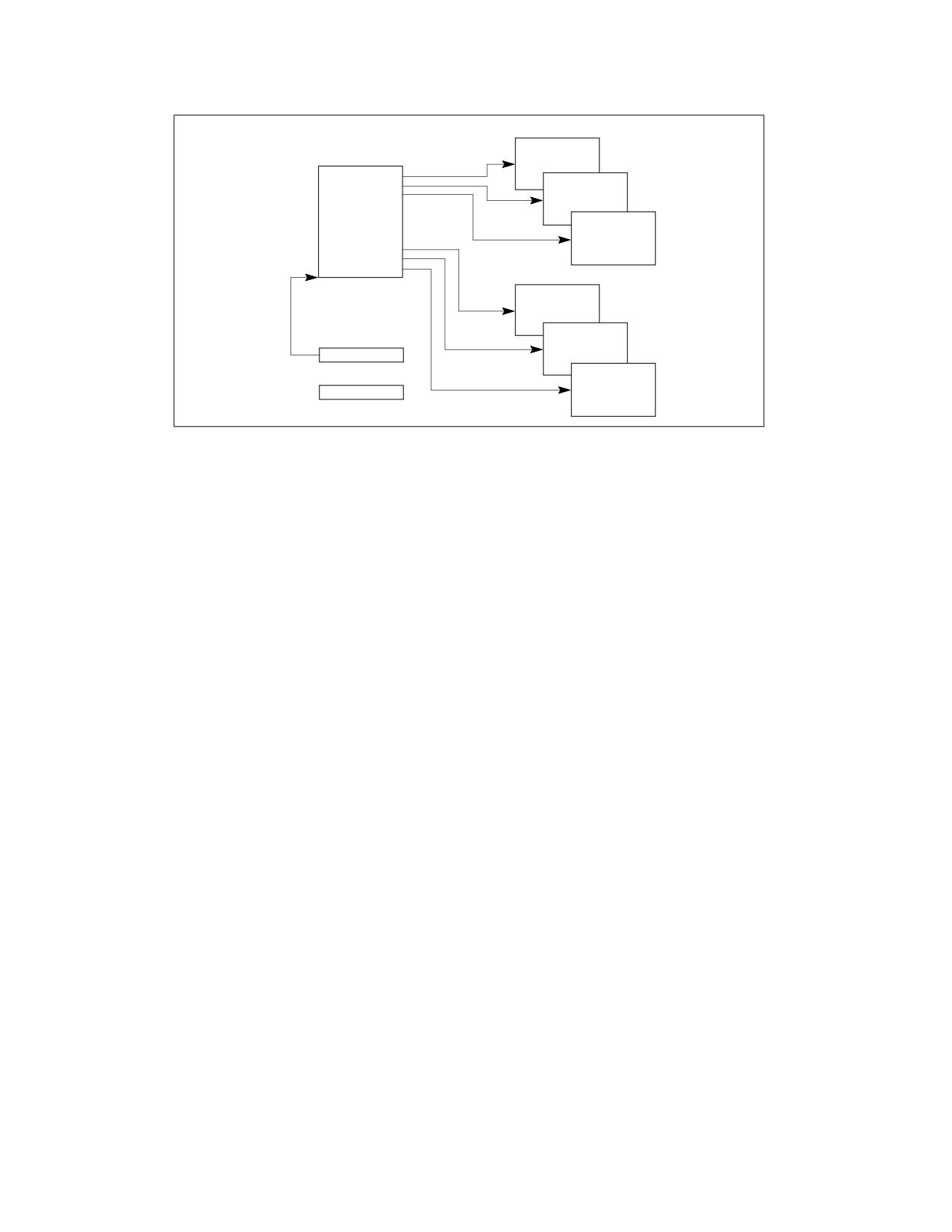
TASK MANAGEMENT
Code
Segment
Task-State
Data
Segment
Segment
(TSS)
Stack
Segment
(Current Priv.
Level)
Stack Seg.
Priv. Level 0
Stack Seg.
Priv. Level 1
Task Register
Stack
Segment
(Priv. Level 2)
CR3
Figure 10-1. Structure of a Task
10.1.2 Task State
The following items define the state of the currently executing task:
• The task’s current execution space, defined by the segment selectors in the segment registers (CS, DS, SS, ES,
FS, and GS).
• The state of the general-purpose registers.
• The state of the EFLAGS register.
• The state of the EIP register.
• The state of control register CR3.
• The state of the task register.
• The state of the LDTR register.
• The I/O map base address and I/O map (contained in the TSS).
• Stack pointers to the privilege 0, 1, and 2 stacks (contained in the TSS).
• Link to previously executed task (contained in the TSS).
• The state of the shadow stack pointer (SSP).
Prior to dispatching a task, all of these items are contained in the task’s TSS, except the state of the task register.
Also, the complete contents of the LDTR register are not contained in the TSS, only the segment selector for the
LDT.
10.1.3 Executing a Task
Software or the processor can dispatch a task for execution in one of the following ways:
• A explicit call to a task with the CALL instruction.
• A explicit jump to a task with the JMP instruction.
• An implicit call (by the processor) to an interrupt-handler task.
• An implicit call to an exception-handler task.
• A return (initiated with an IRET instruction) when the NT flag in the EFLAGS register is set.
All of these methods for dispatching a task identify the task to be dispatched with a segment selector that points to
a task gate or the TSS for the task. When dispatching a task with a CALL or JMP instruction, the selector in the
instruction may select the TSS directly or a task gate that holds the selector for the TSS. When dispatching a task
10-2
Vol. 3A
TASK MANAGEMENT
to handle an interrupt or exception, the IDT entry for the interrupt or exception must contain a task gate that holds
the selector for the interrupt- or exception-handler TSS.
When a task is dispatched for execution, a task switch occurs between the currently running task and the
dispatched task. During a task switch, the execution environment of the currently executing task (called the task’s
state or context) is saved in its TSS and execution of the task is suspended. The context for the dispatched task is
then loaded into the processor and execution of that task begins with the instruction pointed to by the newly loaded
EIP register. If the task has not been run since the system was last initialized, the EIP will point to the first instruc-
tion of the task’s code; otherwise, it will point to the next instruction after the last instruction that the task
executed when it was last active.
If the currently executing task (the calling task) called the task being dispatched (the called task), the TSS
segment selector for the calling task is stored in the TSS of the called task to provide a link back to the calling task.
For all IA-32 processors, tasks are not recursive. A task cannot call or jump to itself.
Interrupts and exceptions can be handled with a task switch to a handler task. Here, the processor performs a task
switch to handle the interrupt or exception and automatically switches back to the interrupted task upon returning
from the interrupt-handler task or exception-handler task. This mechanism can also handle interrupts that occur
during interrupt tasks.
As part of a task switch, the processor can also switch to another LDT, allowing each task to have a different logical-
to-physical address mapping for LDT-based segments. The page-directory base register (CR3) also is reloaded on a
task switch, allowing each task to have its own set of page tables. These protection facilities help isolate tasks and
prevent them from interfering with one another.
If protection mechanisms are not used, the processor provides no protection between tasks. This is true even with
operating systems that use multiple privilege levels for protection. A task running at privilege level 3 that uses the
same LDT and page tables as other privilege-level-3 tasks can access code and corrupt data and the stack of other
tasks.
Use of task management facilities for handling multitasking applications is optional. Multitasking can be handled in
software, with each software defined task executed in the context of a single IA-32 architecture task.
If shadow stack is enabled, then the SSP of the task is located at the 4 bytes at offset 104 in the 32-bit TSS and is
used by the processor to establish the SSP when a task switch occurs from a task associated with this TSS. Note
that the processor does not write the SSP of the task initiating the task switch to the TSS of that task, and instead
the SSP of the previous task is pushed onto the shadow stack of the new task.
10.2
TASK MANAGEMENT DATA STRUCTURES
The processor defines five data structures for handling task-related activities:
• Task-state segment (TSS).
• Task-gate descriptor.
• TSS descriptor.
• Task register.
• NT flag in the EFLAGS register.
When operating in protected mode, a TSS and TSS descriptor must be created for at least one task, and the
segment selector for the TSS must be loaded into the task register (using the LTR instruction).
10.2.1 Task-State Segment (TSS)
The processor state information needed to restore a task is saved in a system segment called the task-state
segment (TSS). Figure 10-2 shows the format of a TSS for tasks designed for 32-bit CPUs. The fields of a TSS are
divided into two main categories: dynamic fields and static fields.
For information about 16-bit Intel 286 processor task structures, see Section 10.6, “16-Bit Task-State Segment
(TSS).” For information about 64-bit mode task structures, see Section 10.7, “Task Management in 64-bit Mode.”
Vol. 3A
10-3

TASK MANAGEMENT
31
15
0
SSP
104
I/
O Map Base Address
Reserved
T
100
Reserved
LDT Segment Selector
96
Reserved
GS
92
Reserved
FS
88
Reserved
DS
84
Reserved
SS
80
Reserved
CS
76
Reserved
ES
72
EDI
68
ESI
64
EBP
60
ESP
56
EBX
52
EDX
48
ECX
44
EAX
40
EFLAGS
36
EIP
32
CR3 (PDBR)
28
Reserved
SS2
24
ESP2
20
Reserved
SS1
16
ESP1
12
Reserved
SS0
8
ESP0
4
Reserved
Previous Task Link
0
Reserved bits. Set to 0.
Figure 10-2. 32-Bit Task-State Segment (TSS)
The processor updates dynamic fields when a task is suspended during a task switch. The following are dynamic
fields:
• General-purpose register fields - State of the EAX, ECX, EDX, EBX, ESP, EBP, ESI, and EDI registers prior
to the task switch.
• Segment selector fields - Segment selectors stored in the ES, CS, SS, DS, FS, and GS registers prior to the
task switch.
10-4
Vol. 3A
TASK MANAGEMENT
• EFLAGS register field - State of the EFLAGS register prior to the task switch.
• EIP (instruction pointer) field - State of the EIP register prior to the task switch.
• Previous task link field - Contains the segment selector for the TSS of the previous task (updated on a task
switch that was initiated by a call, interrupt, or exception). This field (which is sometimes called the back link
field) permits a task switch back to the previous task by using the IRET instruction.
The processor reads the static fields, but does not normally change them. These fields are set up when a task is
created. The following are static fields:
• LDT segment selector field - Contains the segment selector for the task's LDT.
• CR3 control register field - Contains the base physical address of the page directory to be used by the task.
Control register CR3 is also known as the page-directory base register (PDBR).
• Privilege level-0, -1, and -2 stack pointer fields - These stack pointers consist of a logical address made
up of the segment selector for the stack segment (SS0, SS1, and SS2) and an offset into the stack (ESP0,
ESP1, and ESP2). Note that the values in these fields are static for a particular task; whereas, the SS and ESP
values will change if stack switching occurs within the task.
• T (debug trap) flag (byte 100, bit 0) - When set, the T flag causes the processor to raise a debug exception
when a task switch to this task occurs (see Section 20.3.1.5, “Task-Switch Exception Condition”).
• I/O map base address field - Contains a 16-bit offset from the base of the TSS to the I/O permission bit
map and interrupt redirection bitmap. When present, these maps are stored in the TSS at higher addresses.
The I/O map base address points to the beginning of the I/O permission bit map and the end of the interrupt
redirection bit map. See Chapter 20, “Input/Output,” in the Intel® 64 and IA-32 Architectures Software
Developer’s Manual, Volume 1, for more information about the I/O permission bit map. See Section 23.3,
“Interrupt and Exception Handling in Virtual-8086 Mode,” for a detailed description of the interrupt redirection
bit map.
• Shadow Stack Pointer (SSP) - Contains task's shadow stack pointer. The shadow stack of the task should
have a supervisor shadow stack token at the address pointed to by the task SSP (offset 104). This token will be
verified and made busy when switching to that shadow stack using a CALL/JMP instruction, and made free
when switching out of that task using an IRET instruction.
If paging is used:
• Pages corresponding to the previous task’s TSS, the current task’s TSS, and the descriptor table entries for
each all should be marked as read/write.
• Task switches are carried out faster if the pages containing these structures are present in memory before the
task switch is initiated.
10.2.2 TSS Descriptor
The TSS, like all other segments, is defined by a segment descriptor. Figure 10-3 shows the format of a TSS
descriptor. TSS descriptors may only be placed in the GDT; they cannot be placed in an LDT or the IDT.
An attempt to access a TSS using a segment selector with its TI flag set (which indicates the current LDT) causes
a general-protection exception (#GP) to be generated during CALLs and JMPs; it causes an invalid TSS exception
(#TS) during IRETs. A general-protection exception is also generated if an attempt is made to load a segment
selector for a TSS into a segment register.
The busy flag (B) in the type field indicates whether the task is busy. A busy task is currently running or suspended.
A type field with a value of 1001B indicates an inactive task; a value of 1011B indicates a busy task. Tasks are not
recursive. The processor uses the busy flag to detect an attempt to call a task whose execution has been inter-
rupted. To ensure that there is only one busy flag is associated with a task, each TSS should have only one TSS
descriptor that points to it.
Vol. 3A
10-5

TASK MANAGEMENT
TSS Descriptor
31
24 23 22 2120 19
16 15 14 13 12 11
8
7
0
A
D
Type
Base 31:24
G
0
0
V
Limit
P
P
Base 23:16
4
19:16
L
L
0
1
0
B
1
31
16 15
0
Base Address 15:00
Segment Limit 15:00
0
AVL
Available for use by system software
B
Busy flag
BASE
Segment Base Address
DPL
Descriptor Privilege Level
G
Granularity
LIMIT
Segment Limit
P
Segment Present
TYPE
Segment Type
Figure 10-3. TSS Descriptor
The base, limit, and DPL fields and the granularity and present flags have functions similar to their use in data-
segment descriptors (see Section 3.4.5, “Segment Descriptors”). When the G flag is 0 in a TSS descriptor for a 32-
bit TSS, the limit field must have a value equal to or greater than 67H, one byte less than the minimum size of a
TSS. Attempting to switch to a task whose TSS descriptor has a limit less than 67H generates an invalid-TSS excep-
tion (#TS). A larger limit is required if an I/O permission bit map is included or if the operating system stores addi-
tional data. The processor does not check for a limit greater than 67H on a task switch; however, it does check
when accessing the I/O permission bit map or interrupt redirection bit map.
Any program or procedure with access to a TSS descriptor (that is, whose CPL is numerically equal to or less than
the DPL of the TSS descriptor) can dispatch the task with a call or a jump.
In most systems, the DPLs of TSS descriptors are set to values less than 3, so that only privileged software can
perform task switching. However, in multitasking applications, DPLs for some TSS descriptors may be set to 3 to
allow task switching at the application (or user) privilege level.
10.2.3 TSS Descriptor in 64-bit mode
In 64-bit mode, task switching is not supported, but TSS descriptors still exist. The format of a 64-bit TSS is
described in Section 10.7.
In 64-bit mode, the TSS descriptor is expanded to 16 bytes (see Figure 10-4). This expansion also applies to an
LDT descriptor in 64-bit mode. Table 3-2 provides the encoding information for the segment type field.
10-6
Vol. 3A
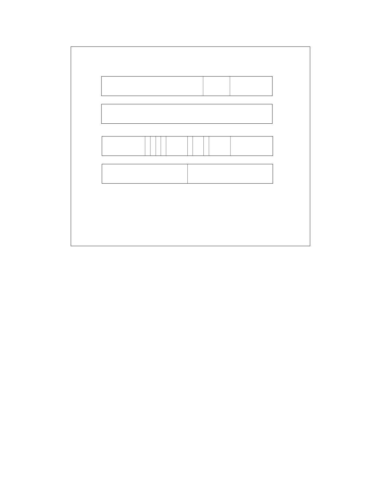
TASK MANAGEMENT
TSS (or LDT) Descriptor
31
13 12
8
7
0
Reserved
0
Reserved
12
31
0
Base Address 63:32
8
31
24 23 22 2120 19
16 15 14 13 12 11
8
7
0
A
D
Type
Base 31:24
G
0
0
V
Limit
P
P
Base 23:16
4
19:16
L
L
0
31
16 15
0
Base Address 15:00
Segment Limit 15:00
0
AVL
Available for use by system software
B
Busy flag
BASE
Segment Base Address
DPL
Descriptor Privilege Level
G
Granularity
LIMIT
Segment Limit
P
Segment Present
TYPE
Segment Type
Figure 10-4. Format of TSS and LDT Descriptors in 64-bit Mode
10.2.4 Task Register
The task register holds the 16-bit segment selector and the entire segment descriptor (32-bit base address (64 bits
in IA-32e mode), 16-bit segment limit, and descriptor attributes) for the TSS of the current task (see Figure 2-6).
This information is copied from the TSS descriptor in the GDT for the current task. Figure 10-5 shows the path the
processor uses to access the TSS (using the information in the task register).
The task register has a visible part (that can be read and changed by software) and an invisible part (maintained
by the processor and is inaccessible by software). The segment selector in the visible portion points to a TSS
descriptor in the GDT. The processor uses the invisible portion of the task register to cache the segment descriptor
for the TSS. Caching these values in a register makes execution of the task more efficient. The LTR (load task
register) and STR (store task register) instructions load and read the visible portion of the task register:
The LTR instruction loads a segment selector (source operand) into the task register that points to a TSS descriptor
in the GDT. It then loads the invisible portion of the task register with information from the TSS descriptor. LTR is a
privileged instruction that may be executed only when the CPL is 0. It’s used during system initialization to put an
initial value in the task register. Afterwards, the contents of the task register are changed implicitly when a task
switch occurs.
The STR (store task register) instruction stores the visible portion of the task register in a general-purpose register
or memory. This instruction can be executed by code running at any privilege level in order to identify the currently
running task. However, it is normally used only by operating system software. (If CR4.UMIP = 1, STR can be
executed only when CPL = 0.)
On power up or reset of the processor, segment selector and base address are set to the default value of 0; the limit
is set to FFFFH.
Vol. 3A
10-7
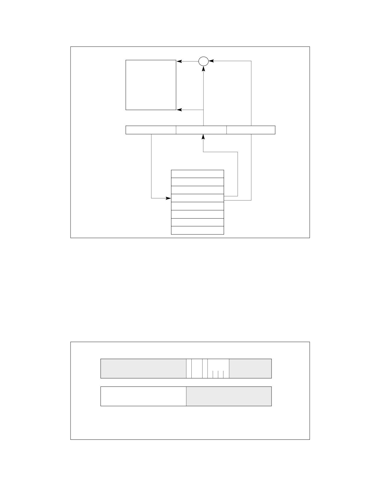
TASK MANAGEMENT
TSS
+
Visible Part
Invisible Part
Task
Selector
Base Address
Segment Limit
Register
GDT
TSS Descriptor
0
Figure 10-5. Task Register
10.2.5 Task-Gate Descriptor
A task-gate descriptor provides an indirect, protected reference to a task (see Figure 10-6). It can be placed in the
GDT, an LDT, or the IDT. The TSS segment selector field in a task-gate descriptor points to a TSS descriptor in the
GDT. The RPL in this segment selector is not used.
The DPL of a task-gate descriptor controls access to the TSS descriptor during a task switch. When a program or
procedure makes a call or jump to a task through a task gate, the CPL and the RPL field of the gate selector pointing
to the task gate must be less than or equal to the DPL of the task-gate descriptor. Note that when a task gate is
used, the DPL of the destination TSS descriptor is not used.
31
16 15 14 13 12 11
8
7
0
D
Type
Reserved
P
P
Reserved
4
L
0
0
1
0
1
31
16 15
0
TSS Segment Selector
Reserved
0
DPL
Descriptor Privilege Level
P
Segment Present
TYPE
Segment Type
Figure 10-6. Task-Gate Descriptor
10-8
Vol. 3A
TASK MANAGEMENT
A task can be accessed either through a task-gate descriptor or a TSS descriptor. Both of these structures satisfy
the following needs:
• Need for a task to have only one busy flag - Because the busy flag for a task is stored in the TSS
descriptor, each task should have only one TSS descriptor. There may, however, be several task gates that
reference the same TSS descriptor.
• Need to provide selective access to tasks - Task gates fill this need, because they can reside in an LDT
and can have a DPL that is different from the TSS descriptor's DPL. A program or procedure that does not have
sufficient privilege to access the TSS descriptor for a task in the GDT (which usually has a DPL of 0) may be
allowed access to the task through a task gate with a higher DPL. Task gates give the operating system greater
latitude for limiting access to specific tasks.
• Need for an interrupt or exception to be handled by an independent task - Task gates may also reside
in the IDT, which allows interrupts and exceptions to be handled by handler tasks. When an interrupt or
exception vector points to a task gate, the processor switches to the specified task.
Figure 10-7 illustrates how a task gate in an LDT, a task gate in the GDT, and a task gate in the IDT can all point to
the same task.
LDT
GDT
TSS
Task Gate
Task Gate
TSS Descriptor
IDT
Task Gate
Figure 10-7. Task Gates Referencing the Same Task
10.3
TASK SWITCHING
The processor transfers execution to another task in one of four cases:
• The current program, task, or procedure executes a JMP or CALL instruction to a TSS descriptor in the GDT.
• The current program, task, or procedure executes a JMP or CALL instruction to a task-gate descriptor in the
GDT or the current LDT.
Vol. 3A
10-9
TASK MANAGEMENT
• An interrupt or exception vector points to a task-gate descriptor in the IDT.
• The current task executes an IRET when the NT flag in the EFLAGS register is set.
JMP, CALL, and IRET instructions, as well as interrupts and exceptions, are all mechanisms for redirecting a
program. The referencing of a TSS descriptor or a task gate (when calling or jumping to a task) or the state of the
NT flag (when executing an IRET instruction) determines whether a task switch occurs.
The processor performs the following operations when switching to a new task:
1.
Obtains the TSS segment selector for the new task as the operand of the JMP or CALL instruction, from a task
gate, or from the previous task link field (for a task switch initiated with an IRET instruction).
2.
Checks that the current (old) task is allowed to switch to the new task. Data-access privilege rules apply to JMP
and CALL instructions. The CPL of the current (old) task and the RPL of the segment selector for the new task
must be less than or equal to the DPL of the TSS descriptor or task gate being referenced. Exceptions,
interrupts (except for those identified in the next sentence), and the IRET and INT1 instructions are permitted
to switch tasks regardless of the DPL of the destination task-gate or TSS descriptor. For interrupts generated by
the INT n, INT3, and INTO instructions, the DPL is checked and a general-protection exception (#GP) results if
it is less than the CPL.1
3.
Checks that the TSS descriptor of the new task is marked present and has a valid limit (greater than or equal
to 67H). If the task switch was initiated by IRET and shadow stacks are enabled at the current CPL, then the
SSP must be aligned to 8 bytes, else a #TS(current task TSS) fault is generated. If CR4.CET is 1, then the TSS
must be a 32 bit TSS and the limit of the new task’s TSS must be greater than or equal to 107 bytes, else a
#TS(new task TSS) fault is generated.
4.
Checks that the new task is available (call, jump, exception, or interrupt) or busy (IRET return).
5.
Checks that the current (old) TSS, new TSS, and all segment descriptors used in the task switch are paged into
system memory.
6.
Saves the state of the current (old) task in the current task’s TSS. The processor finds the base address of the
current TSS in the task register and then copies the states of the following registers into the current TSS: all the
general-purpose registers, segment selectors from the segment registers, the temporarily saved image of the
EFLAGS register, and the instruction pointer register (EIP).
7.
Loads the task register with the segment selector and descriptor for the new task's TSS.
8.
If CET is enabled, the processor performs following shadow stack actions:
Read CS of new task from new task TSS
Read EFLAGS of new task from new task TSS
IF EFLAGS.VM = 1
THEN
new task CPL = 3;
ELSE
new task CPL = CS.RPL;
FI;
pushCsLipSsp = 0
IF task switch was initiated by CALL instruction, exception or interrupt
IF shadow stack enabled at current CPL
IF new task CPL < CPL and current task CPL = 3
THEN
IA32_PL3_SSP = SSP (* user → supervisor *)
ELSE
pushCsLipSsp = 1 (* no privilege change; supv → supv; supv → user *) tempSSP = SSP
1.
The INT1 has opcode F1; the INT n instruction with n=1 has opcode CD 01.
10-10
Vol. 3A
TASK MANAGEMENT
tempSsLIP =CSBASE + EIP
tempSsCS = CS
FI;
FI;
FI;
verifyCsLIP = 0
IF task switch was initiated by IRET
IF shadow stacks enabled at current CPL
IF (CPL of new Task = CPL of current Task) OR
(CPL of new Task < 3 AND CPL of current Task < 3) OR
(CPL or new Task < 3 AND CPL of current task = 3)
(* no privilege change or supervisor → supervisor or user → supervisor IRET *)
tempSsCS = shadow_stack_load 8 bytes from SSP+16;
tempSsLIP = shadow_stack_load 8 bytes from SSP+8;
tempSSP = shadow_stack_load 8 bytes from SSP;
SSP = SSP + 24;
verifyCsLIP = 1
FI;
// Clear busy flag on current shadow stack
IF ( SSP & 0x07 == 0 )
(* SSP must be aligned to 8B *)
THEN
expected_token_value = (SSP & ~0x07) | BUSY_BIT; (* busy - bit 0 - must be set*)
new_token_value
= SSP
(* clear the busy bit *)
shadow_stack_lock_cmpxchg8b(SSP, new_token_value, expected_token_value)
FI;
SSP = 0
FI;
FI;
9.
The TSS state is loaded into the processor. This includes the LDTR register, the PDBR (control register CR3), the
EFLAGS register, the EIP register, the general-purpose registers, and the segment selectors. A fault during the
load of this state may corrupt architectural state. (If paging is not enabled, a PDBR value is read from the new
task's TSS, but it is not loaded into CR3.)
10. If the task switch was initiated with a JMP or IRET instruction, the processor clears the busy (B) flag in the
current (old) task’s TSS descriptor; if initiated with a CALL instruction, an exception, or an interrupt: the busy
(B) flag is left set. (See Table 10-2.)
11. If the task switch was initiated with an IRET instruction, the processor clears the NT flag in a temporarily saved
image of the EFLAGS register; if initiated with a CALL or JMP instruction, an exception, or an interrupt, the NT
flag is left unchanged in the saved EFLAGS image.
12. If the task switch was initiated with a CALL instruction, an exception, or an interrupt, the processor will set the
NT flag in the EFLAGS loaded from the new task. If initiated with an IRET instruction or JMP instruction, the NT
flag will reflect the state of NT in the EFLAGS loaded from the new task (see Table 10-2).
13. If the task switch was initiated with a CALL instruction, JMP instruction, an exception, or an interrupt, the
processor sets the busy (B) flag in the new task’s TSS descriptor; if initiated with an IRET instruction, the busy
(B) flag is left set.
14. The descriptors associated with the segment selectors are loaded and qualified. Any errors associated with this
loading and qualification occur in the context of the new task and may corrupt architectural state.
Vol. 3A
10-11