Intel 64 and IA-32 Architectures. Software Developer’s Manual (2026) - page 49
CHAPTER 6
PROTECTION
In protected mode, the Intel 64 and IA-32 architectures provide a protection mechanism that operates at both the
segment level and the page level. This protection mechanism provides the ability to limit access to certain
segments or pages based on privilege levels (four privilege levels for segments and two privilege levels for pages).
For example, critical operating-system code and data can be protected by placing them in more privileged
segments than those that contain applications code. The processor’s protection mechanism will then prevent appli-
cation code from accessing the operating-system code and data in any but a controlled, defined manner.
Segment and page protection can be used at all stages of software development to assist in localizing and detecting
design problems and bugs. It can also be incorporated into end-products to offer added robustness to operating
systems, utilities software, and applications software.
When the protection mechanism is used, each memory reference is checked to verify that it satisfies various
protection checks. All checks are made before the memory cycle is started; any violation results in an exception.
Because checks are performed in parallel with address translation, there is no performance penalty. The protection
checks that are performed fall into the following categories:
• Limit checks.
• Type checks.
• Privilege level checks.
• Restriction of addressable domain.
• Restriction of procedure entry-points.
• Restriction of instruction set.
All protection violation results in an exception being generated. See Chapter 7, “Interrupt and Exception Handling,”
for an explanation of the exception mechanism. This chapter describes the protection mechanism and the viola-
tions which lead to exceptions.
The following sections describe the protection mechanism available in protected mode. See Chapter 23, “8086
Emulation,” for information on protection in real-address and virtual-8086 mode.
6.1
ENABLING AND DISABLING SEGMENT AND PAGE PROTECTION
Setting the PE flag in register CR0 causes the processor to switch to protected mode, which in turn enables the
segment-protection mechanism. Once in protected mode, there is no control bit for turning the protection mecha-
nism on or off. The part of the segment-protection mechanism that is based on privilege levels can essentially be
disabled while still in protected mode by assigning a privilege level of 0 (most privileged) to all segment selectors
and segment descriptors. This action disables the privilege level protection barriers between segments, but other
protection checks such as limit checking and type checking are still carried out.
Page-level protection is automatically enabled when paging is enabled (by setting the PG flag in register CR0). Here
again there is no mode bit for turning off page-level protection once paging is enabled. However, page-level protec-
tion can be disabled by performing the following operations:
• Clear the WP flag in control register CR0.
• Set the read/write (R/W) and user/supervisor (U/S) flags for each page-directory and page-table entry.
This action makes each page a writable, user page, which in effect disables page-level protection.
Vol. 3A
6-1
PROTECTION
6.2
FIELDS AND FLAGS USED FOR SEGMENT-LEVEL AND PAGE-LEVEL
PROTECTION
The processor’s protection mechanism uses the following fields and flags in the system data structures to control
access to segments and pages:
• Descriptor type (S) flag - (Bit 12 in the second doubleword of a segment descriptor.) Determines if the
segment descriptor is for a system segment or a code or data segment.
• Type field - (Bits 8 through 11 in the second doubleword of a segment descriptor.) Determines the type of
code, data, or system segment.
• Limit field - (Bits 0 through 15 of the first doubleword and bits 16 through 19 of the second doubleword of a
segment descriptor.) Determines the size of the segment, along with the G flag and E flag (for data segments).
• G flag - (Bit 23 in the second doubleword of a segment descriptor.) Determines the size of the segment, along
with the limit field and E flag (for data segments).
• E flag - (Bit 10 in the second doubleword of a data-segment descriptor.) Determines the size of the segment,
along with the limit field and G flag.
• Descriptor privilege level (DPL) field - (Bits 13 and 14 in the second doubleword of a segment descriptor.)
Determines the privilege level of the segment.
• Requested privilege level (RPL) field - (Bits 0 and 1 of any segment selector.) Specifies the requested
privilege level of a segment selector.
• Current privilege level (CPL) field - (Bits 0 and 1 of the CS segment register.) Indicates the privilege level
of the currently executing program or procedure. The term current privilege level (CPL) refers to the setting of
this field.
• User/supervisor (U/S) flag - (Bit 2 of paging-structure entries.) Determines the type of page: user or
supervisor.
• Read/write (R/W) flag - (Bit 1 of paging-structure entries.) Determines the type of access allowed to a
page: read-only or read/write.
• Execute-disable (XD) flag - (Bit 63 of certain paging-structure entries.) Determines the type of access
allowed to a page: executable or not-executable.
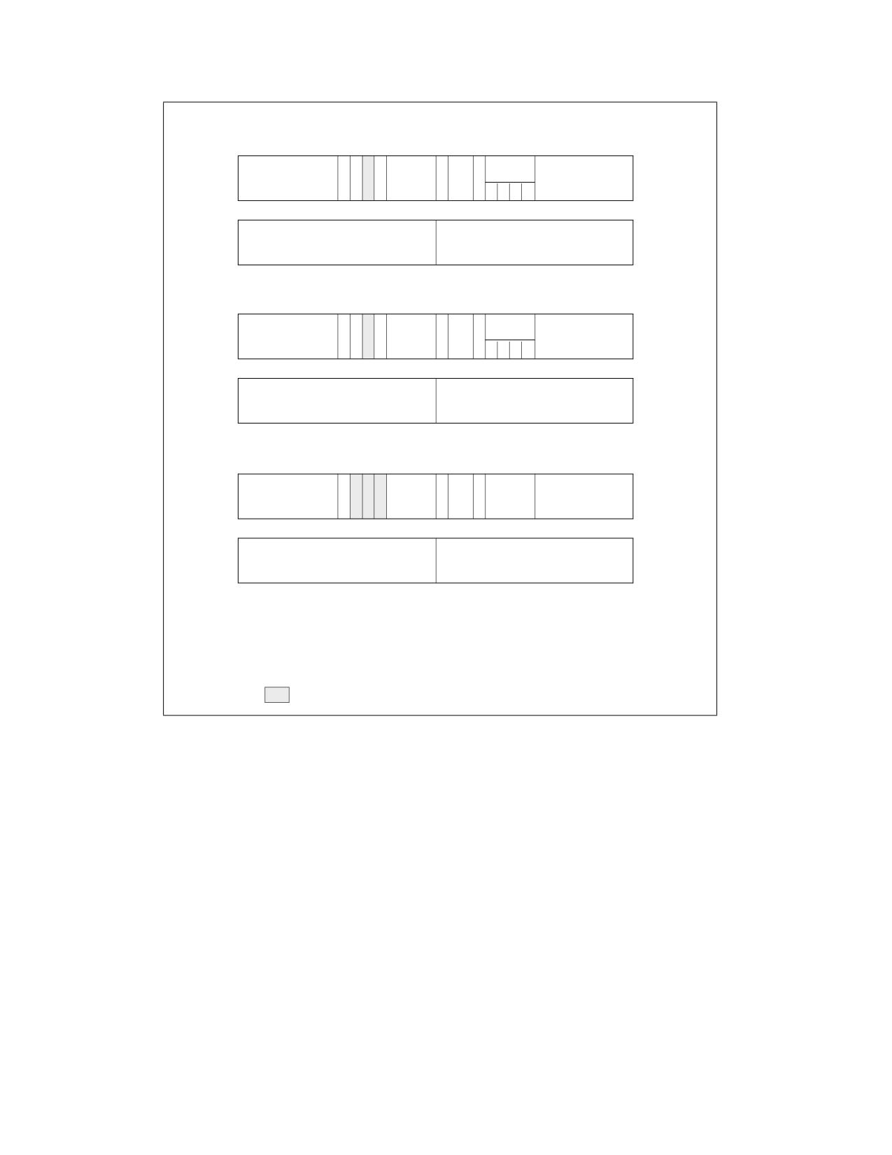
Figure 6-1 shows the location of the various fields and flags in the data-, code-, and system-segment descriptors;
Figure 3-6 shows the location of the RPL (or CPL) field in a segment selector (or the CS register); and Chapter 5
identifies the locations of the U/S, R/W, and XD flags in the paging-structure entries.
6-2
Vol. 3A
PROTECTION
Data-Segment Descriptor
31
24 23 22 2120 19
16 15 14 13 12 11
8
7
0
A
D
Type
Limit
Base 31:24
G
B
0
V
P
P
Base 23:16
4
19:16
L
L
1
0
E
W
A
31
16 15
0
Base Address 15:00
Segment Limit 15:00
0
Code-Segment Descriptor
31
24 23 22 2120 19
16 15 14 13 12 11
8
7
0
A
D
Type
Base 31:24
G
D
0
V
Limit
P
P
Base 23:16
4
19:16
L
L
1
1
C
R
A
31
16 15
0
Base Address 15:00
Segment Limit 15:00
0
System-Segment Descriptor
31
24 23 22 2120 19
16 15 14 13 12 11
8
7
0
D
Limit
Base 31:24
G
0
P
P
0
Type
Base 23:16
4
19:16
L
31
16 15
0
Base Address 15:00
Segment Limit 15:00
0
A
Accessed
E
Expansion Direction
AVL Available to Sys. Programmers
G
Granularity
B
Big
R
Readable
C
Conforming
LIMIT
Segment Limit
D
Default
W
Writable
DPL
Descriptor Privilege Level
P
Present
Reserved
Figure 6-1. Descriptor Fields Used for Protection
Many different styles of protection schemes can be implemented with these fields and flags. When the operating
system creates a descriptor, it places values in these fields and flags in keeping with the particular protection style
chosen for an operating system or executive. Application programs do not generally access or modify these fields
and flags.
The following sections describe how the processor uses these fields and flags to perform the various categories of
checks described in the introduction to this chapter.
6.2.1
Code-Segment Descriptor in 64-bit Mode
Code segments continue to exist in 64-bit mode even though, for address calculations, the segment base is treated
as zero. Some code-segment (CS) descriptor content (the base address and limit fields) is ignored; the remaining
fields function normally (except for the readable bit in the type field).
Code segment descriptors and selectors are needed in IA-32e mode to establish the processor’s operating mode
and execution privilege-level. The usage is as follows:
Vol. 3A
6-3

PROTECTION
• IA-32e mode uses a previously unused bit in the CS descriptor. Bit 53 is defined as the 64-bit (L) flag and is
used to select between 64-bit mode and compatibility mode when IA-32e mode is active (IA32_EFER.LMA = 1).
See Figure 6-2.
- If CS.L = 0 and IA-32e mode is active, the processor is running in compatibility mode. In this case, CS.D
selects the default size for data and addresses. If CS.D = 0, the default data and address size is 16 bits. If
CS.D = 1, the default data and address size is 32 bits.
- If CS.L = 1 and IA-32e mode is active, the only valid setting is CS.D = 0. This setting indicates a default
operand size of 32 bits and a default address size of 64 bits. The CS.L = 1 and CS.D = 1 bit combination is
reserved for future use and a #GP fault will be generated on an attempt to use a code segment with these
bits set in IA-32e mode.
• In IA-32e mode, the CS descriptor’s DPL is used for execution privilege checks (as in legacy 32-bit mode).
Code-Segment Descriptor
31
24 23 22 2120 19
16 15 14 13 12 11
8
7
0
A
D
Type
G
D
L
V
P
P
4
L
L
1
1
C
R
A
31
0
0
A
Accessed
AVL Available to Sys. Programmer’s
G
Granularity
C
Conforming
R
Readable
D
Default
P
Present
DPL
Descriptor Privilege Level
L
64-Bit Flag
Figure 6-2. Descriptor Fields with Flags used in IA-32e Mode
6.3
LIMIT CHECKING
The limit field of a segment descriptor prevents programs or procedures from addressing memory locations outside
the segment. The effective value of the limit depends on the setting of the G (granularity) flag (see Figure 6-1). For
data segments, the limit also depends on the E (expansion direction) flag and the B (default stack pointer size
and/or upper bound) flag. The E flag is one of the bits in the type field when the segment descriptor is for a data-
segment type.
When the G flag is clear (byte granularity), the effective limit is the value of the 20-bit limit field in the segment
descriptor. Here, the limit ranges from 0 to FFFFFH (1 MByte). When the G flag is set (4-KByte page granularity),
the processor scales the value in the limit field by a factor of 212 (4 KBytes). In this case, the effective limit ranges
from FFFH (4 KBytes) to FFFFFFFFH (4 GBytes). Note that when scaling is used (G flag is set), the lower 12 bits of
a segment offset (address) are not checked against the limit; for example, note that if the segment limit is 0,
offsets 0 through FFFH are still valid.
For all types of segments except expand-down data segments, the effective limit is the last address that is allowed
to be accessed in the segment, which is one less than the size, in bytes, of the segment. The processor causes a
general-protection exception (or, if the segment is SS, a stack-fault exception) any time an attempt is made to
access the following addresses in a segment:
• A byte at an offset greater than the effective limit
• A word at an offset greater than the (effective-limit - 1)
• A doubleword at an offset greater than the (effective-limit - 3)
• A quadword at an offset greater than the (effective-limit - 7)
6-4
Vol. 3A
PROTECTION
• A double quadword at an offset greater than the (effective limit - 15)
When the effective limit is FFFFFFFFH (4 GBytes), these accesses may or may not cause the indicated exceptions.
Behavior is implementation-specific and may vary from one execution to another.
For expand-down data segments, the segment limit has the same function but is interpreted differently. Here, the
effective limit specifies the last address that is not allowed to be accessed within the segment; the range of valid
offsets is from (effective-limit + 1) to FFFFFFFFH if the B flag is set and from (effective-limit + 1) to FFFFH if the B
flag is clear. An expand-down segment has maximum size when the segment limit is 0.
Limit checking catches programming errors such as runaway code, runaway subscripts, and invalid pointer calcu-
lations. These errors are detected when they occur, so identification of the cause is easier. Without limit checking,
these errors could overwrite code or data in another segment.
In addition to checking segment limits, the processor also checks descriptor table limits. The GDTR and IDTR regis-
ters contain 16-bit limit values that the processor uses to prevent programs from selecting a segment descriptors
outside the respective descriptor tables. The LDTR and task registers contain 32-bit segment limit value (read from
the segment descriptors for the current LDT and TSS, respectively). The processor uses these segment limits to
prevent accesses beyond the bounds of the current LDT and TSS. See Section 3.5.1, “Segment Descriptor Tables,”
for more information on the GDT and LDT limit fields; see Section 7.10, “Interrupt Descriptor Table (IDT),” for more
information on the IDT limit field; and see Section 10.2.4, “Task Register,” for more information on the TSS
segment limit field.
6.3.1
Limit Checking in 64-bit Mode
In 64-bit mode, the processor does not perform runtime limit checking on code or data segments. However, the
processor does check descriptor-table limits.
6.4
TYPE CHECKING
Segment descriptors contain type information in two places:
• The S (descriptor type) flag.
• The type field.
The processor uses this information to detect programming errors that result in an attempt to use a segment or
gate in an incorrect or unintended manner.
The S flag indicates whether a descriptor is a system type or a code or data type. The type field provides 4 addi-
tional bits for use in defining various types of code, data, and system descriptors. Table 3-1 shows the encoding of
the type field for code and data descriptors; Table 3-2 shows the encoding of the field for system descriptors.
The processor examines type information at various times while operating on segment selectors and segment
descriptors. The following list gives examples of typical operations where type checking is performed (this list is not
exhaustive):
• When a segment selector is loaded into a segment register - Certain segment registers can contain only
certain descriptor types, for example:
- The CS register only can be loaded with a selector for a code segment.
- Segment selectors for code segments that are not readable or for system segments cannot be loaded into
data-segment registers (DS, ES, FS, and GS).
- Only segment selectors of writable data segments can be loaded into the SS register.
• When a segment selector is loaded into the LDTR or task register - For example:
- The LDTR can only be loaded with a selector for an LDT.
- The task register can only be loaded with a segment selector for a TSS.
• When instructions access segments whose descriptors are already loaded into segment registers -
Certain segments can be used by instructions only in certain predefined ways, for example:
- No instruction may write into an executable segment.
Vol. 3A
6-5
PROTECTION
- No instruction may write into a data segment if it is not writable.
- No instruction may read an executable segment unless the readable flag is set.
•
When an instruction operand contains a segment selector - Certain instructions can access segments
or gates of only a particular type, for example:
- A far CALL or far JMP instruction can only access a segment descriptor for a conforming code segment,
nonconforming code segment, call gate, task gate, or TSS.
- The LLDT instruction must reference a segment descriptor for an LDT.
- The LTR instruction must reference a segment descriptor for a TSS.
- The LAR instruction must reference a segment or gate descriptor for an LDT, TSS, call gate, task gate, code
segment, or data segment.
- The LSL instruction must reference a segment descriptor for a LDT, TSS, code segment, or data segment.
- IDT entries must be interrupt, trap, or task gates.
•
During certain internal operations - For example:
- On a far call or far jump (executed with a far CALL or far JMP instruction), the processor determines the
type of control transfer to be carried out (call or jump to another code segment, a call or jump through a
gate, or a task switch) by checking the type field in the segment (or gate) descriptor pointed to by the
segment (or gate) selector given as an operand in the CALL or JMP instruction. If the descriptor type is for
a code segment or call gate, a call or jump to another code segment is indicated; if the descriptor type is for
a TSS or task gate, a task switch is indicated.
- On a call or jump through a call gate (or on an interrupt- or exception-handler call through a trap or
interrupt gate), the processor automatically checks that the segment descriptor being pointed to by the
gate is for a code segment.
- On a call or jump to a new task through a task gate (or on an interrupt- or exception-handler call to a new
task through a task gate), the processor automatically checks that the segment descriptor being pointed to
by the task gate is for a TSS.
- On a call or jump to a new task by a direct reference to a TSS, the processor automatically checks that the
segment descriptor being pointed to by the CALL or JMP instruction is for a TSS.
- On return from a nested task (initiated by an IRET instruction), the processor checks that the previous task
link field in the current TSS points to a TSS.
6.4.1
Null Segment Selector Checking
Attempting to load a null segment selector (see Section 3.4.2, “Segment Selectors”) into the CS or SS segment
register generates a general-protection exception (#GP). A null segment selector can be loaded into the DS, ES,
FS, or GS register, but any attempt to access a segment through one of these registers when it is loaded with a null
segment selector results in a #GP exception being generated. Loading unused data-segment registers with a null
segment selector is a useful method of detecting accesses to unused segment registers and/or preventing
unwanted accesses to data segments.
6.4.1.1
NULL Segment Checking in 64-bit Mode
In 64-bit mode, the processor does not perform runtime checking on NULL segment selectors. The processor does
not cause a #GP fault when an attempt is made to access memory where the referenced segment register has a
NULL segment selector.
6.5
PRIVILEGE LEVELS
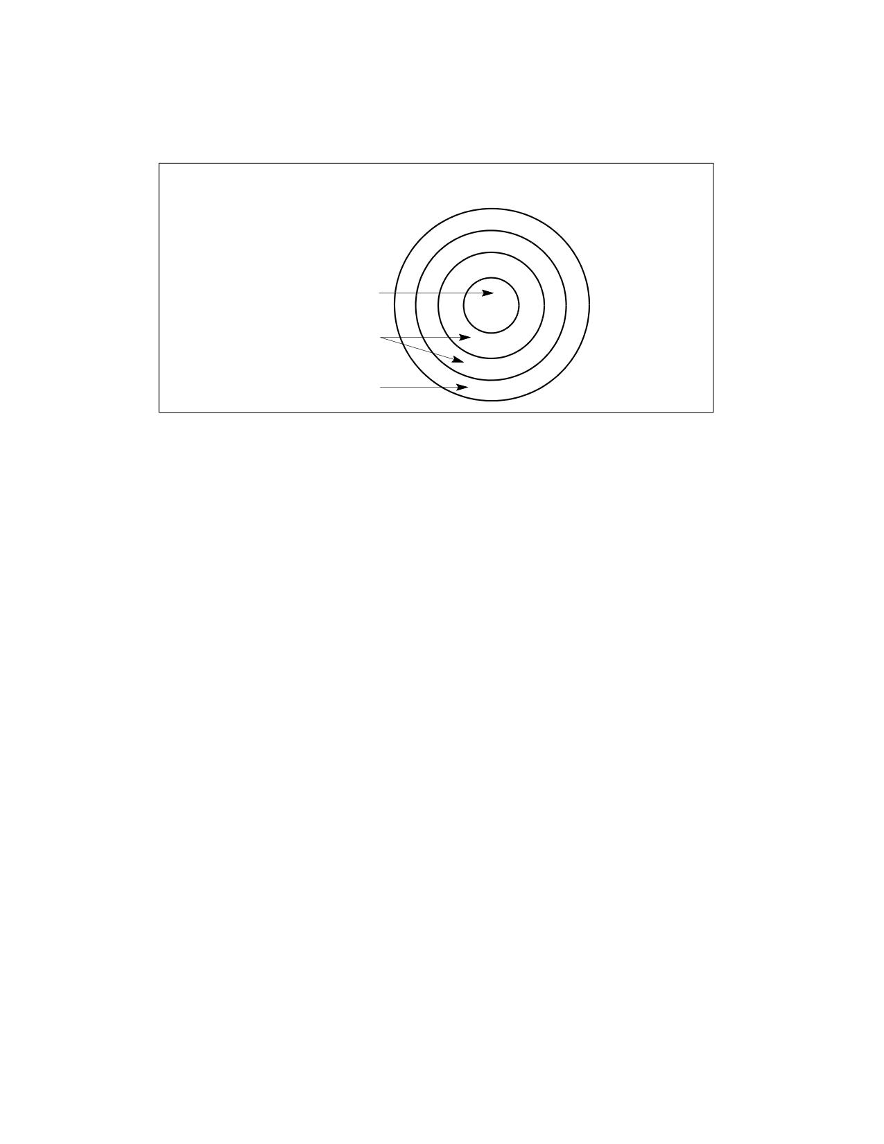
The processor’s segment-protection mechanism recognizes 4 privilege levels, numbered from 0 to 3. The greater
numbers mean lesser privileges. Figure 6-3 shows how these levels of privilege can be interpreted as rings of
protection.
6-6
Vol. 3A
PROTECTION
The center (reserved for the most privileged code, data, and stacks) is used for the segments containing the critical
software, usually the kernel of an operating system. Outer rings are used for less critical software. (Systems that
use only 2 of the 4 possible privilege levels should use levels 0 and 3.)
Protection Rings
Operating
System
Kernel
Level 0
Operating System
Services
Level 1
Level 2
Applications
Level 3
Figure 6-3. Protection Rings
The processor uses privilege levels to prevent a program or task operating at a lesser privilege level from accessing
a segment with a greater privilege, except under controlled situations. When the processor detects a privilege level
violation, it generates a general-protection exception (#GP).
To carry out privilege-level checks between code segments and data segments, the processor recognizes the
following three types of privilege levels:
• Current privilege level (CPL) - The CPL is the privilege level of the currently executing program or task. It
is stored in bits 0 and 1 of the CS and SS segment registers. Normally, the CPL is equal to the privilege level of
the code segment from which instructions are being fetched. The processor changes the CPL when program
control is transferred to a code segment with a different privilege level. The CPL is treated slightly differently
when accessing conforming code segments. Conforming code segments can be accessed from any privilege
level that is equal to or numerically greater (less privileged) than the DPL of the conforming code segment.
Also, the CPL is not changed when the processor accesses a conforming code segment that has a different
privilege level than the CPL.
• Descriptor privilege level (DPL) - The DPL is the privilege level of a segment or gate. It is stored in the DPL
field of the segment or gate descriptor for the segment or gate. When the currently executing code segment
attempts to access a segment or gate, the DPL of the segment or gate is compared to the CPL and RPL of the
segment or gate selector (as described later in this section). The DPL is interpreted differently, depending on
the type of segment or gate being accessed:
- Data segment - The DPL indicates the numerically highest privilege level that a program or task can have
to be allowed to access the segment. For example, if the DPL of a data segment is 1, only programs running
at a CPL of 0 or 1 can access the segment.
- Nonconforming code segment (without using a call gate) - The DPL indicates the privilege level that
a program or task must be at to access the segment. For example, if the DPL of a nonconforming code
segment is 0, only programs running at a CPL of 0 can access the segment.
- Call gate - The DPL indicates the numerically highest privilege level that the currently executing program
or task can be at and still be able to access the call gate. (This is the same access rule as for a data
segment.)
- Conforming code segment and nonconforming code segment accessed through a call gate - The
DPL indicates the numerically lowest privilege level that a program or task can have to be allowed to access
the segment. For example, if the DPL of a conforming code segment is 2, programs running at a CPL of 0 or
1 cannot access the segment.
Vol. 3A
6-7
PROTECTION
- TSS - The DPL indicates the numerically highest privilege level that the currently executing program or
task can be at and still be able to access the TSS. (This is the same access rule as for a data segment.)
• Requested privilege level (RPL) - The RPL is an override privilege level that is assigned to segment
selectors. It is stored in bits 0 and 1 of the segment selector. The processor checks the RPL along with the CPL
to determine if access to a segment is allowed. Even if the program or task requesting access to a segment has
sufficient privilege to access the segment, access is denied if the RPL is not of sufficient privilege level. That is,
if the RPL of a segment selector is numerically greater than the CPL, the RPL overrides the CPL, and vice versa.
The RPL can be used to ensure that privileged code does not access a segment on behalf of an application
program unless the program itself has access privileges for that segment. See Section 6.10.4, “Checking Caller
Access Privileges (ARPL Instruction),” for a detailed description of the purpose and typical use of the RPL.
Privilege levels are checked when the segment selector of a segment descriptor is loaded into a segment register.
The checks used for data access differ from those used for transfers of program control among code segments;
therefore, the two kinds of accesses are considered separately in the following sections.
6.6
PRIVILEGE LEVEL CHECKING WHEN ACCESSING DATA SEGMENTS
To access operands in a data segment, the segment selector for the data segment must be loaded into the data-
segment registers (DS, ES, FS, or GS) or into the stack-segment register (SS). (Segment registers can be loaded
with the MOV, POP, LDS, LES, LFS, LGS, and LSS instructions.) Before the processor loads a segment selector into
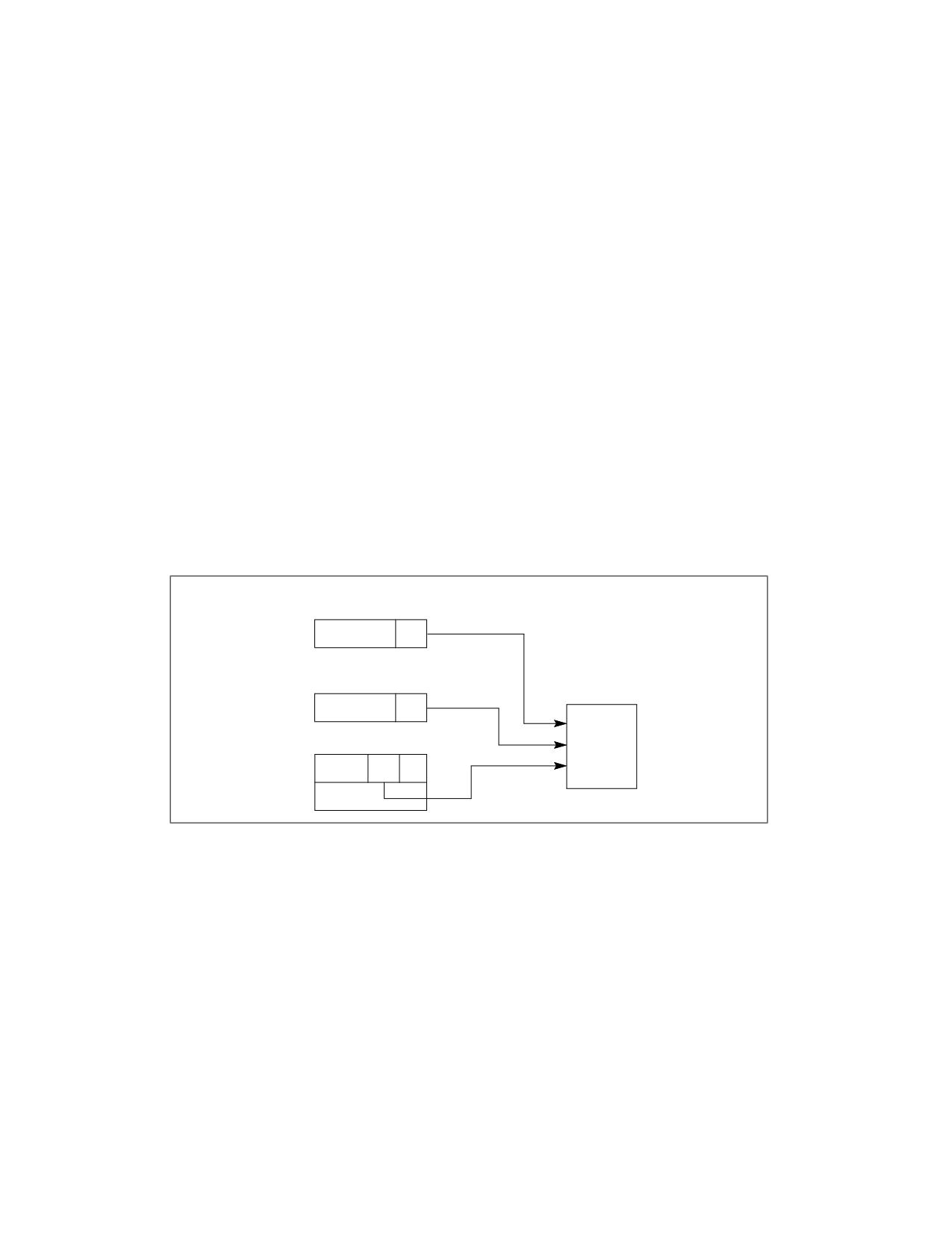
a segment register, it performs a privilege check (see Figure 6-4) by comparing the privilege levels of the currently
running program or task (the CPL), the RPL of the segment selector, and the DPL of the segment’s segment
descriptor. The processor loads the segment selector into the segment register if the DPL is numerically greater
than or equal to both the CPL and the RPL. Otherwise, a general-protection fault is generated and the segment
register is not loaded.
CS Register
CPL
Segment Selector
For Data Segment
RPL
Privilege
Data-Segment Descriptor
Check
DPL
Figure 6-4. Privilege Check for Data Access
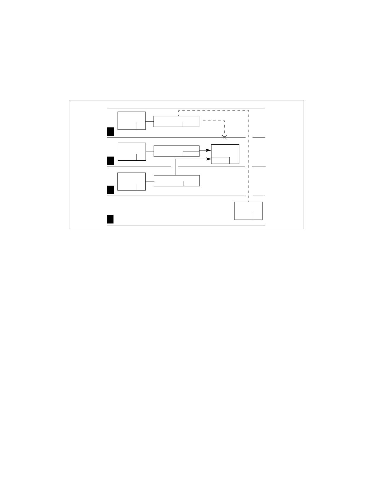
Figure 6-5 shows four procedures (located in codes segments A, B, C, and D), each running at different privilege
levels and each attempting to access the same data segment.
1. The procedure in code segment A is able to access data segment E using segment selector E1, because the CPL
of code segment A and the RPL of segment selector E1 are equal to the DPL of data segment E.
2. The procedure in code segment B is able to access data segment E using segment selector E2, because the CPL
of code segment B and the RPL of segment selector E2 are both numerically lower than (more privileged) than
the DPL of data segment E. A code segment B procedure can also access data segment E using segment
selector E1.
3. The procedure in code segment C is not able to access data segment E using segment selector E3 (dotted line),
because the CPL of code segment C and the RPL of segment selector E3 are both numerically greater than (less
privileged) than the DPL of data segment E. Even if a code segment C procedure were to use segment selector
6-8
Vol. 3A
PROTECTION
E1 or E2, such that the RPL would be acceptable, it still could not access data segment E because its CPL is not
privileged enough.
4. The procedure in code segment D should be able to access data segment E because code segment D’s CPL is
numerically less than the DPL of data segment E. However, the RPL of segment selector E3 (which the code
segment D procedure is using to access data segment E) is numerically greater than the DPL of data segment
E, so access is not allowed. If the code segment D procedure were to use segment selector E1 or E2 to access
the data segment, access would be allowed.
Code
Segment C
Segment Sel. E3
RPL=3
CPL=3
3
Lowest Privilege
Code
Segment Sel. E1
Data
Segment A
RPL=2
Segment E
CPL=2
2
DPL=2
Code
Segment Sel. E2
Segment B
RPL=1
CPL=1
1
Code
Segment D
CPL=0
Highest Privilege
0
Figure 6-5. Examples of Accessing Data Segments From Various Privilege Levels
As demonstrated in the previous examples, the addressable domain of a program or task varies as its CPL changes.
When the CPL is 0, data segments at all privilege levels are accessible; when the CPL is 1, only data segments at
privilege levels 1 through 3 are accessible; when the CPL is 3, only data segments at privilege level 3 are acces-
sible.
The RPL of a segment selector can always override the addressable domain of a program or task. When properly
used, RPLs can prevent problems caused by accidental (or intensional) use of segment selectors for privileged data
segments by less privileged programs or procedures.
It is important to note that the RPL of a segment selector for a data segment is under software control. For
example, an application program running at a CPL of 3 can set the RPL for a data- segment selector to 0. With the
RPL set to 0, only the CPL checks, not the RPL checks, will provide protection against deliberate, direct attempts to
violate privilege-level security for the data segment. To prevent these types of privilege-level-check violations, a
program or procedure can check access privileges whenever it receives a data-segment selector from another
procedure (see Section 6.10.4, “Checking Caller Access Privileges (ARPL Instruction)”).
6.6.1
Accessing Data in Code Segments
In some instances it may be desirable to access data structures that are contained in a code segment. The
following methods of accessing data in code segments are possible:
• Load a data-segment register with a segment selector for a nonconforming, readable, code segment.
• Load a data-segment register with a segment selector for a conforming, readable, code segment.
• Use a code-segment override prefix (CS) to read a readable, code segment whose selector is already loaded in
the CS register.
The same rules for accessing data segments apply to method 1. Method 2 is always valid because the privilege
level of a conforming code segment is effectively the same as the CPL, regardless of its DPL. Method 3 is always
valid because the DPL of the code segment selected by the CS register is the same as the CPL.
Vol. 3A
6-9
PROTECTION
6.7
PRIVILEGE LEVEL CHECKING WHEN LOADING THE SS REGISTER
Privilege level checking also occurs when the SS register is loaded with the segment selector for a stack segment.
Here all privilege levels related to the stack segment must match the CPL; that is, the CPL, the RPL of the stack-
segment selector, and the DPL of the stack-segment descriptor must be the same. If the RPL and DPL are not equal
to the CPL, a general-protection exception (#GP) is generated.
6.8
PRIVILEGE LEVEL CHECKING WHEN TRANSFERRING PROGRAM CONTROL
BETWEEN CODE SEGMENTS
To transfer program control from one code segment to another, the segment selector for the destination code
segment must be loaded into the code-segment register (CS). As part of this loading process, the processor exam-
ines the segment descriptor for the destination code segment and performs various limit, type, and privilege
checks. If these checks are successful, the CS register is loaded, program control is transferred to the new code
segment, and program execution begins at the instruction pointed to by the EIP register.
Program control transfers are carried out with the JMP, CALL, RET, SYSENTER, SYSEXIT, SYSCALL, SYSRET, INT n,
and IRET instructions, as well as by the exception and interrupt mechanisms. Exceptions, interrupts, and the IRET
instruction are special cases discussed in Chapter 7, “Interrupt and Exception Handling.” This chapter discusses
only the JMP, CALL, RET, SYSENTER, SYSEXIT, SYSCALL, and SYSRET instructions.
A JMP or CALL instruction can reference another code segment in any of four ways:
• The target operand contains the segment selector for the target code segment.
• The target operand points to a call-gate descriptor, which contains the segment selector for the target code
segment.
• The target operand points to a TSS, which contains the segment selector for the target code segment.
• The target operand points to a task gate, which points to a TSS, which in turn contains the segment selector for
the target code segment.
The following sections describe first two types of references. See Section 10.3, “Task Switching,” for information on
transferring program control through a task gate and/or TSS.
The SYSENTER and SYSEXIT instructions are special instructions for making fast calls to and returns from operating
system or executive procedures. These instructions are discussed in Section 6.8.7, “Performing Fast Calls to
System Procedures with the SYSENTER and SYSEXIT Instructions.”
The SYCALL and SYSRET instructions are special instructions for making fast calls to and returns from operating
system or executive procedures in 64-bit mode. These instructions are discussed in Section 6.8.8, “Fast System
Calls in 64-Bit Mode.”
6.8.1
Direct Calls or Jumps to Code Segments
The near forms of the JMP, CALL, and RET instructions transfer program control within the current code segment,
so privilege-level checks are not performed. The far forms of the JMP, CALL, and RET instructions transfer control
to other code segments, so the processor does perform privilege-level checks.
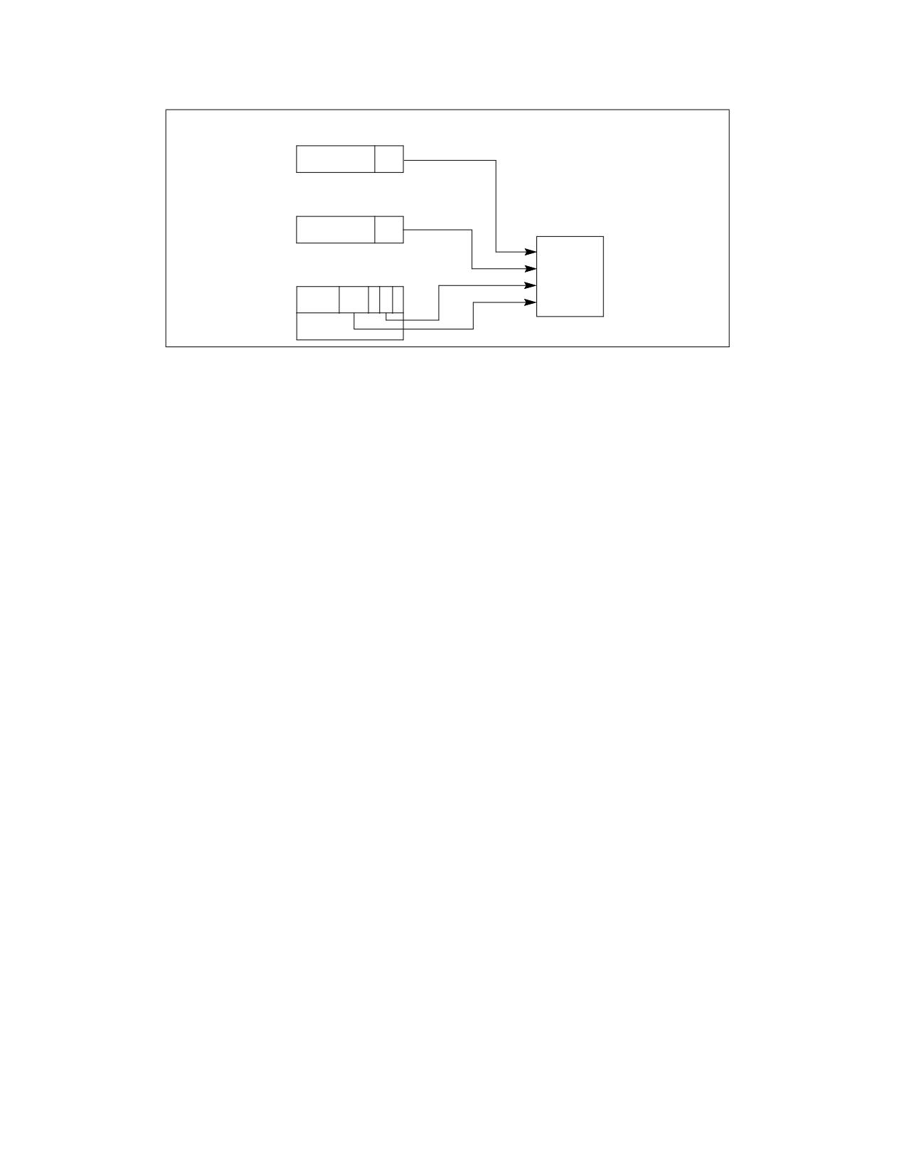
When transferring program control to another code segment without going through a call gate, the processor
examines four kinds of privilege level and type information (see Figure 6-6):
• The CPL. (Here, the CPL is the privilege level of the calling code segment; that is, the code segment that
contains the procedure that is making the call or jump.)
6-10
Vol. 3A
PROTECTION
CS Register
CPL
Segment Selector
For Code Segment
RPL
Destination Code
Privilege
Segment Descriptor
Check
DPL
C
Figure 6-6. Privilege Check for Control Transfer Without Using a Gate
• The DPL of the segment descriptor for the destination code segment that contains the called procedure.
• The RPL of the segment selector of the destination code segment.
• The conforming (C) flag in the segment descriptor for the destination code segment, which determines whether
the segment is a conforming (C flag is set) or nonconforming (C flag is clear) code segment. See Section
3.4.5.1, “Code- and Data-Segment Descriptor Types,” for more information about this flag.
The rules that the processor uses to check the CPL, RPL, and DPL depends on the setting of the C flag, as described
in the following sections.
6.8.1.1
Accessing Nonconforming Code Segments
When accessing nonconforming code segments, the CPL of the calling procedure must be equal to the DPL of the
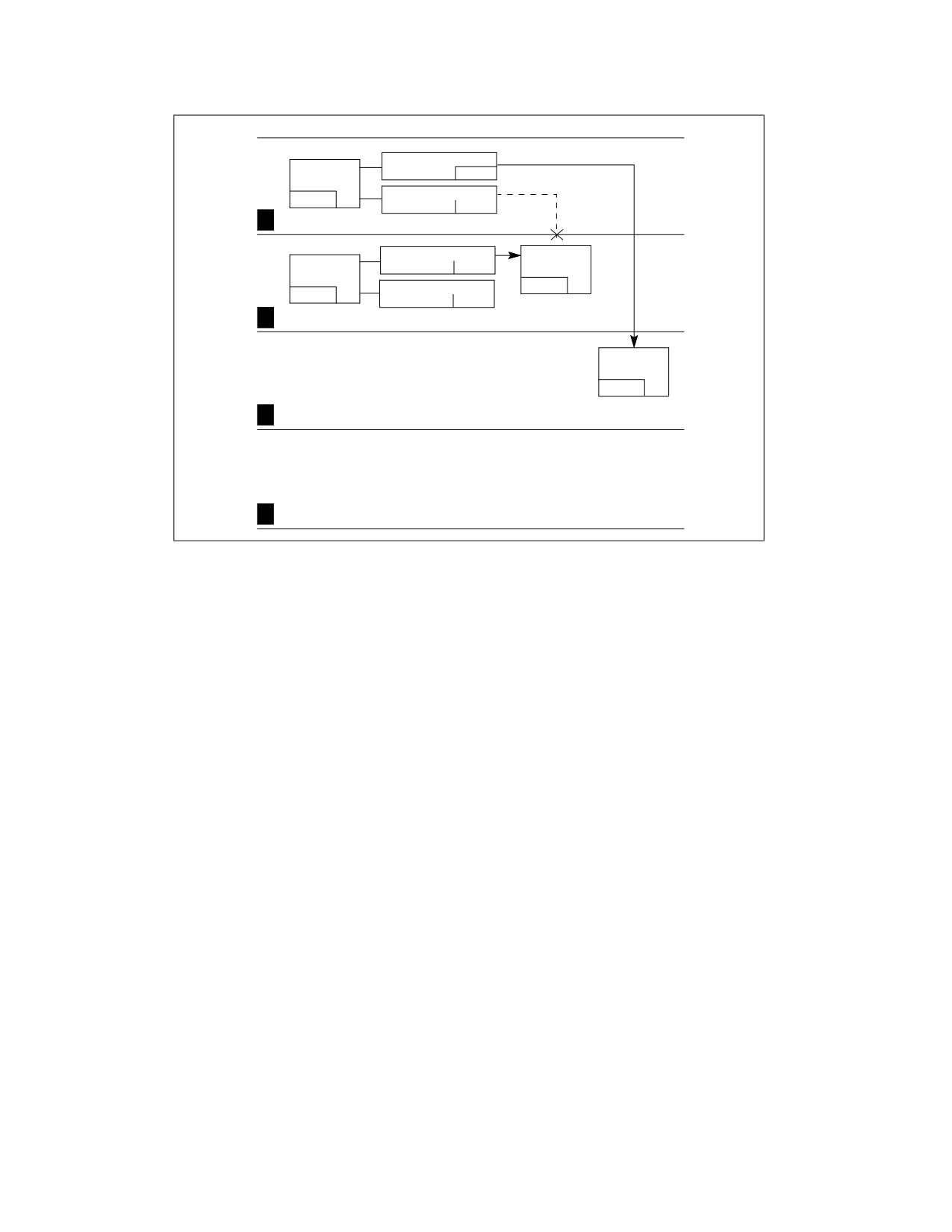
destination code segment; otherwise, the processor generates a general-protection exception (#GP). For example
in Figure 6-7:
• Code segment C is a nonconforming code segment. A procedure in code segment A can call a procedure in code
segment C (using segment selector C1) because they are at the same privilege level (CPL of code segment A is
equal to the DPL of code segment C).
• A procedure in code segment B cannot call a procedure in code segment C (using segment selector C2 or C1)
because the two code segments are at different privilege levels.
Vol. 3A
6-11
PROTECTION
Segment Sel. D2
Code
RPL=3
Segment B
Segment Sel. C2
CPL=3
RPL=3
3
Lowest Privilege
Segment Sel. C1
Code
Code
RPL=2
Segment C
Segment A
Segment Sel. D1
DPL=2
CPL=2
RPL=2
Nonconforming
Code Segment
2
Code
Segment D
DPL=1
Conforming
1
Code Segment
Highest Privilege
0
Figure 6-7. Examples of Accessing Conforming and Nonconforming Code Segments From Various Privilege Levels
The RPL of the segment selector that points to a nonconforming code segment has a limited effect on the privilege
check. The RPL must be numerically less than or equal to the CPL of the calling procedure for a successful control
transfer to occur. So, in the example in Figure 6-7, the RPLs of segment selectors C1 and C2 could legally be set to
0, 1, or 2, but not to 3.
When the segment selector of a nonconforming code segment is loaded into the CS register, the privilege level field
is not changed; that is, it remains at the CPL (which is the privilege level of the calling procedure). This is true, even
if the RPL of the segment selector is different from the CPL.
6.8.1.2
Accessing Conforming Code Segments
When accessing conforming code segments, the CPL of the calling procedure may be numerically equal to or
greater than (less privileged) the DPL of the destination code segment; the processor generates a general-protec-
tion exception (#GP) only if the CPL is less than the DPL. (The segment selector RPL for the destination code
segment is not checked if the segment is a conforming code segment.)
In the example in Figure 6-7, code segment D is a conforming code segment. Therefore, calling procedures in both
code segment A and B can access code segment D (using either segment selector D1 or D2, respectively), because
they both have CPLs that are greater than or equal to the DPL of the conforming code segment. For conforming
code segments, the DPL represents the numerically lowest privilege level that a calling procedure may
be at to successfully make a call to the code segment.
(Note that segments selectors D1 and D2 are identical except for their respective RPLs. But since RPLs are not
checked when accessing conforming code segments, the two segment selectors are essentially interchangeable.)
When program control is transferred to a conforming code segment, the CPL does not change, even if the DPL of
the destination code segment is less than the CPL. This situation is the only one where the CPL may be different
from the DPL of the current code segment. Also, since the CPL does not change, no stack switch occurs.
Conforming segments are used for code modules such as math libraries and exception handlers, which support
applications but do not require access to protected system facilities. These modules are part of the operating
system or executive software, but they can be executed at numerically higher privilege levels (less privileged
levels). Keeping the CPL at the level of a calling code segment when switching to a conforming code segment
6-12
Vol. 3A

PROTECTION
prevents an application program from accessing nonconforming code segments while at the privilege level (DPL) of
a conforming code segment and thus prevents it from accessing more privileged data.
Most code segments are nonconforming. For these segments, program control can be transferred only to code
segments at the same level of privilege, unless the transfer is carried out through a call gate, as described in the
following sections.
6.8.2
Gate Descriptors
To provide controlled access to code segments with different privilege levels, the processor provides special set of
descriptors called gate descriptors. There are four kinds of gate descriptors:
• Call gates
• Trap gates
• Interrupt gates
• Task gates
Task gates are used for task switching and are discussed in Chapter 10, “Task Management.” Trap and interrupt
gates are special kinds of call gates used for calling exception and interrupt handlers. The are described in Chapter
7, “Interrupt and Exception Handling.” This chapter is concerned only with call gates.
6.8.3
Call Gates
Call gates facilitate controlled transfers of program control between different privilege levels. They are typically
used only in operating systems or executives that use the privilege-level protection mechanism. Call gates are also
useful for transferring program control between 16-bit and 32-bit code segments, as described in Section 24.4,
“Transferring Control Among Mixed-Size Code Segments.”
Figure 6-8 shows the format of a call-gate descriptor. A call-gate descriptor may reside in the GDT or in an LDT, but
not in the interrupt descriptor table (IDT). It performs six functions:
• It specifies the code segment to be accessed.
• It defines an entry point for a procedure in the specified code segment.
• It specifies the privilege level required for a caller trying to access the procedure.
31
16 15 14 13 12 11
8
7
6
5
4
0
D
Type
Param.
Offset in Segment 31:16
P
P
0
0
0
4
Count
L
0
1
1
0
0
31
16 15
0
Segment Selector
Offset in Segment 15:00
0
DPL
Descriptor Privilege Level
P
Gate Valid
Figure 6-8. Call-Gate Descriptor
• If a stack switch occurs, it specifies the number of optional parameters to be copied between stacks.
• It defines the size of values to be pushed onto the target stack: 16-bit gates force 16-bit pushes and 32-bit
gates force 32-bit pushes.
• It specifies whether the call-gate descriptor is valid.
The segment selector field in a call gate specifies the code segment to be accessed. The offset field specifies the
entry point in the code segment. This entry point is generally to the first instruction of a specific procedure. The DPL
field indicates the privilege level of the call gate, which in turn is the privilege level required to access the selected
Vol. 3A
6-13

PROTECTION
procedure through the gate. The P flag indicates whether the call-gate descriptor is valid. (The presence of the code
segment to which the gate points is indicated by the P flag in the code segment’s descriptor.) The parameter count
field indicates the number of parameters to copy from the calling procedures stack to the new stack if a stack
switch occurs (see Section 6.8.5, “Stack Switching”). The parameter count specifies the number of words for 16-
bit call gates and doublewords for 32-bit call gates.
Note that the P flag in a gate descriptor is normally always set to 1. If it is set to 0, a not present (#NP) exception
is generated when a program attempts to access the descriptor. The operating system can use the P flag for special
purposes. For example, it could be used to track the number of times the gate is used. Here, the P flag is initially
set to 0 causing a trap to the not-present exception handler. The exception handler then increments a counter and
sets the P flag to 1, so that on returning from the handler, the gate descriptor will be valid.
6.8.3.1
IA-32e Mode Call Gates
Call-gate descriptors in 32-bit mode provide a 32-bit offset for the instruction pointer (EIP); 64-bit extensions
double the size of 32-bit mode call gates in order to store 64-bit instruction pointers (RIP). See Figure 6-9:
• The first eight bytes (bytes 7:0) of a 64-bit mode call gate are similar but not identical to legacy 32-bit mode
call gates. The parameter-copy-count field has been removed.
• Bytes 11:8 hold the upper 32 bits of the target-segment offset in canonical form. A general-protection
exception (#GP) is generated if software attempts to use a call gate with a target offset that is not in canonical
form.
•
16-byte descriptors may reside in the same descriptor table with 16-bit and 32-bit descriptors. A type field,
used for consistency checking, is defined in bits 12:8 of the 64-bit descriptor’s highest dword (cleared to zero).
A general-protection exception (#GP) results if an attempt is made to access the upper half of a 64-bit mode
descriptor as a 32-bit mode descriptor.
31
13 12 11 10 9 8 7
0
Type
Reserved
Reserved
12
0
0
0
0
0
31
0
Offset in Segment 63:31
8
31
16 15 14 13 12 11
8
7
0
D
Type
Offset in Segment 31:16
P
P
0
4
L
0
1
1
0
0
31
16 15
0
Segment Selector
Offset in Segment 15:00
0
DPL
Descriptor Privilege Level
P
Gate Valid
Figure 6-9. Call-Gate Descriptor in IA-32e Mode
• Target code segments referenced by a 64-bit call gate must be 64-bit code segments (CS.L = 1, CS.D = 0). If
not, the reference generates a general-protection exception, #GP (CS selector).
• Only 64-bit mode call gates can be referenced in IA-32e mode (64-bit mode and compatibility mode). The
legacy 32-bit mode call gate type (0CH) is redefined in IA-32e mode as a 64-bit call-gate type; no 32-bit call-
gate type exists in IA-32e mode.
6-14
Vol. 3A
PROTECTION
• If a far call references a 16-bit call gate type (04H) in IA-32e mode, a general-protection exception (#GP) is
generated.
When a call references a 64-bit mode call gate, actions taken are identical to those taken in 32-bit mode, with the
following exceptions:
• Stack pushes are made in eight-byte increments.
• A 64-bit RIP is pushed onto the stack.
• Parameter copying is not performed.
Use a matching far-return instruction size for correct operation (returns from 64-bit calls must be performed with
a 64-bit operand-size return to process the stack correctly).
Call gates cannot be used when FRED transitions are enabled. An execution of CALL or JMP that accesses a call gate
when FRED transitions are enabled will cause a general-protection exception (#GP).
6.8.4
Accessing a Code Segment Through a Call Gate
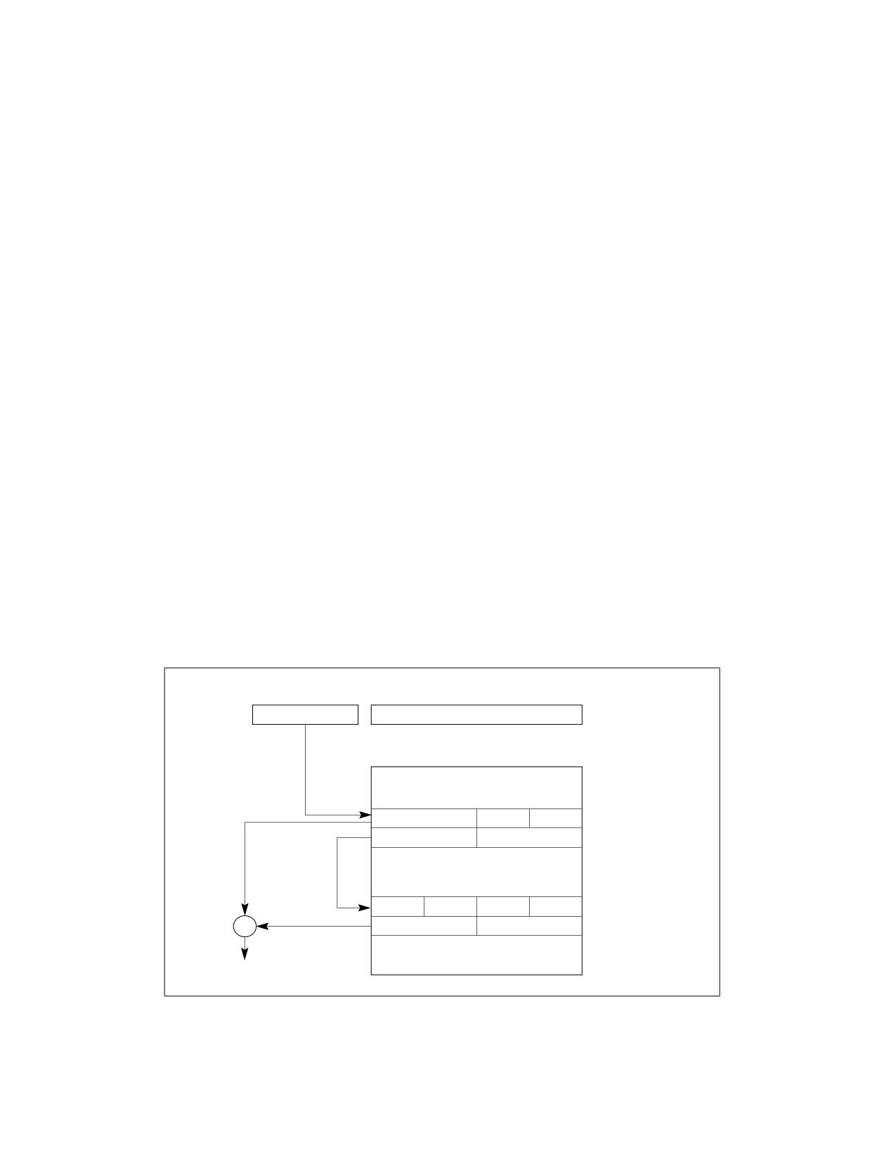
To access a call gate, a far pointer to the gate is provided as a target operand in a CALL or JMP instruction. The
segment selector from this pointer identifies the call gate (see Figure 6-10); the offset from the pointer is required,
but not used or checked by the processor. (The offset can be set to any value.)
When the processor has accessed the call gate, it uses the segment selector from the call gate to locate the
segment descriptor for the destination code segment. (This segment descriptor can be in the GDT or the LDT.) It
then combines the base address from the code-segment descriptor with the offset from the call gate to form the
linear address of the procedure entry point in the code segment.
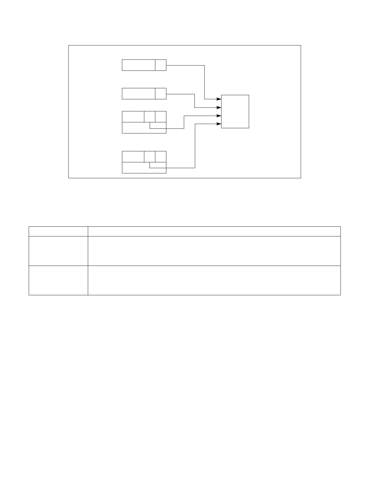
As shown in Figure 6-11, four different privilege levels are used to check the validity of a program control transfer
through a call gate:
• The CPL (current privilege level).
• The RPL (requestor privilege level) of the call gate’s selector.
• The DPL (descriptor privilege level) of the call gate descriptor.
• The DPL of the segment descriptor of the destination code segment.
The C flag (conforming) in the segment descriptor for the destination code segment is also checked.
Far Pointer to Call Gate
Segment Selector
Offset
Required but not used by processor
Descriptor Table
Offset
Call-Gate
Segment Selector
Offset
Descriptor
Base
Base
Code-Segment
Descriptor
Base
+
Procedure
Entry Point
Figure 6-10. Call-Gate Mechanism
Vol. 3A
6-15
PROTECTION
CS Register
CPL
Call-Gate Selector
RPL
Call Gate (Descriptor)
Privilege
Check
DPL
Destination Code-
Segment Descriptor
DPL
Figure 6-11. Privilege Check for Control Transfer with Call Gate
The privilege checking rules are different depending on whether the control transfer was initiated with a CALL or a
JMP instruction, as shown in Table 6-1.
Table 6-1. Privilege Check Rules for Call Gates
Instruction
Privilege Check Rules
CALL
CPL ≤ call gate DPL; RPL ≤ call gate DPL
Destination conforming code segment DPL ≤ CPL
Destination nonconforming code segment DPL ≤ CPL
JMP
CPL ≤ call gate DPL; RPL ≤ call gate DPL
Destination conforming code segment DPL ≤ CPL
Destination nonconforming code segment DPL = CPL
The DPL field of the call-gate descriptor specifies the numerically highest privilege level from which a calling proce-
dure can access the call gate; that is, to access a call gate, the CPL of a calling procedure must be equal to or less
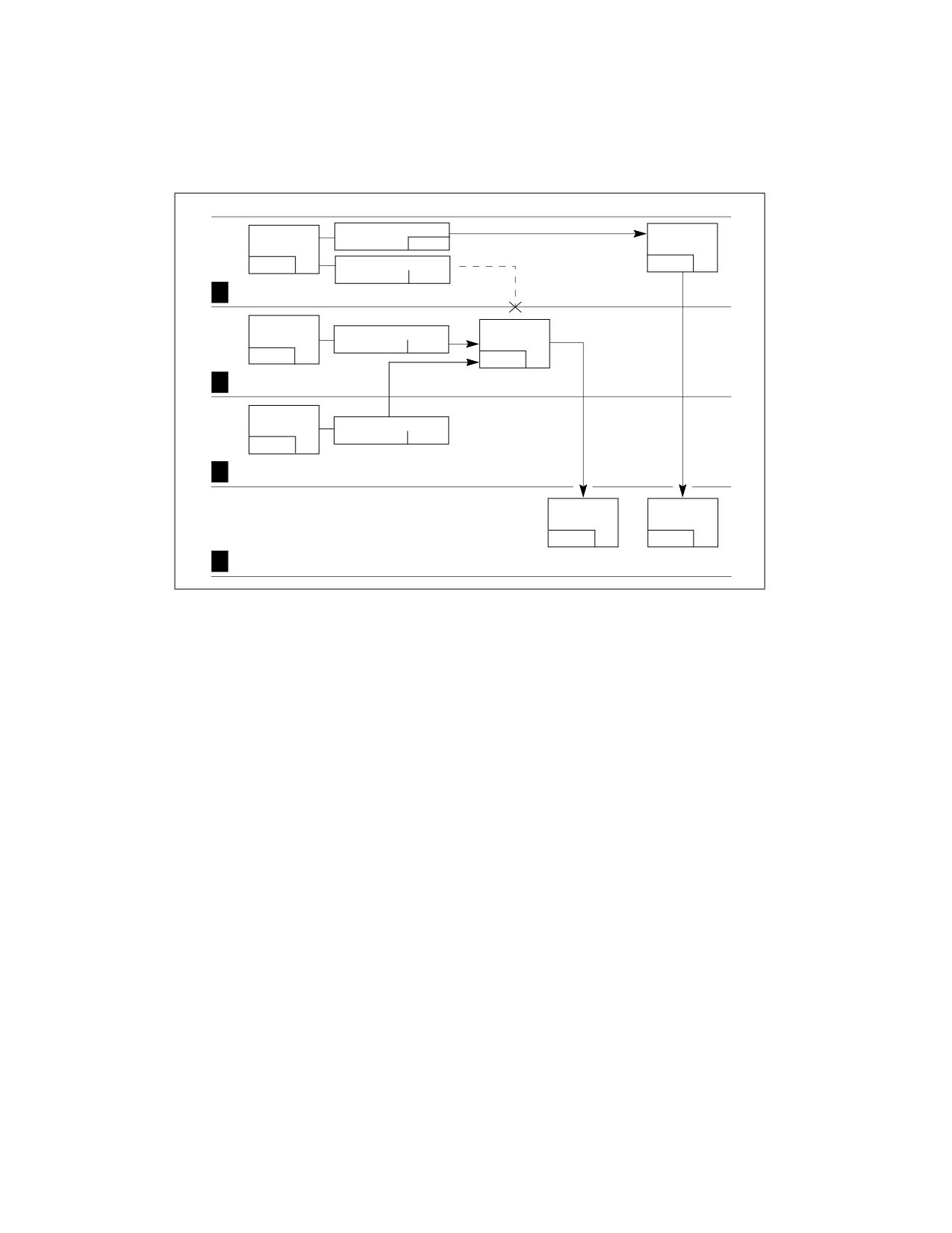
than the DPL of the call gate. For example, in Figure 6-15, call gate A has a DPL of 3. So calling procedures at all
CPLs (0 through 3) can access this call gate, which includes calling procedures in code segments A, B, and C. Call
gate B has a DPL of 2, so only calling procedures at a CPL or 0, 1, or 2 can access call gate B, which includes calling
procedures in code segments B and C. The dotted line shows that a calling procedure in code segment A cannot
access call gate B.
The RPL of the segment selector to a call gate must satisfy the same test as the CPL of the calling procedure; that
is, the RPL must be less than or equal to the DPL of the call gate. In the example in Figure 6-15, a calling procedure
in code segment C can access call gate B using gate selector B2 or B1, but it could not use gate selector B3 to
access call gate B.
If the privilege checks between the calling procedure and call gate are successful, the processor then checks the
DPL of the code-segment descriptor against the CPL of the calling procedure. Here, the privilege check rules vary
between CALL and JMP instructions. Only CALL instructions can use call gates to transfer program control to more
privileged (numerically lower privilege level) nonconforming code segments; that is, to nonconforming code
segments with a DPL less than the CPL. A JMP instruction can use a call gate only to transfer program control to a
nonconforming code segment with a DPL equal to the CPL. CALL and JMP instruction can both transfer program
control to a more privileged conforming code segment; that is, to a conforming code segment with a DPL less than
or equal to the CPL.
6-16
Vol. 3A
PROTECTION
If a call is made to a more privileged (numerically lower privilege level) nonconforming destination code segment,
the CPL is lowered to the DPL of the destination code segment and a stack switch occurs (see Section 6.8.5, “Stack
Switching”). If a call or jump is made to a more privileged conforming destination code segment, the CPL is not
changed and no stack switch occurs.
Code
Gate Selector A
Call
Segment A
RPL=3
Gate A
CPL=3
Gate Selector B3
DPL=3
RPL=3
Lowest Privilege
3
Code
Call
Segment B
Gate Selector B1
Gate B
RPL=2
CPL=2
DPL=2
2
Code
Segment C
Gate Selector B2
RPL=1
CPL=1
No Stack
Stack Switch
1
Switch Occurs
Occurs
Code
Code
Segment D
Segment E
DPL=0
DPL=0
Conforming
Nonconforming
0
Highest Privilege
Code Segment
Code Segment
Figure 6-12. Example of Accessing Call Gates At Various Privilege Levels
Call gates allow a single code segment to have procedures that can be accessed at different privilege levels. For
example, an operating system located in a code segment may have some services which are intended to be used
by both the operating system and application software (such as procedures for handling character I/O). Call gates
for these procedures can be set up that allow access at all privilege levels (0 through 3). More privileged call gates
(with DPLs of 0 or 1) can then be set up for other operating system services that are intended to be used only by
the operating system (such as procedures that initialize device drivers).
6.8.5
Stack Switching
Whenever a call gate is used to transfer program control to a more privileged nonconforming code segment (that
is, when the DPL of the nonconforming destination code segment is less than the CPL), the processor automatically
switches to the stack for the destination code segment’s privilege level. This stack switching is carried out to
prevent more privileged procedures from crashing due to insufficient stack space. It also prevents less privileged
procedures from interfering (by accident or intent) with more privileged procedures through a shared stack.
Each task must define up to 4 stacks: one for applications code (running at privilege level 3) and one for each of
the privilege levels 2, 1, and 0 that are used. (If only two privilege levels are used [3 and 0], then only two stacks
must be defined.) Each of these stacks is located in a separate segment and is identified with a segment selector
and an offset into the stack segment (a stack pointer).
The segment selector and stack pointer for the privilege level 3 stack is located in the SS and ESP registers, respec-
tively, when privilege-level-3 code is being executed and is automatically stored on the called procedure’s stack
when a stack switch occurs.
Pointers to the privilege level 0, 1, and 2 stacks are stored in the TSS for the currently running task (see
Figure 10-2). Each of these pointers consists of a segment selector and a stack pointer (loaded into the ESP
register). These initial pointers are strictly read-only values. The processor does not change them while the task is
running. They are used only to create new stacks when calls are made to more privileged levels (numerically lower
Vol. 3A
6-17
PROTECTION
privilege levels). These stacks are disposed of when a return is made from the called procedure. The next time the
procedure is called, a new stack is created using the initial stack pointer. (The TSS does not specify a stack for priv-
ilege level 3 because the processor does not allow a transfer of program control from a procedure running at a CPL
of 0, 1, or 2 to a procedure running at a CPL of 3, except on a return.)
The operating system is responsible for creating stacks and stack-segment descriptors for all the privilege levels to
be used and for loading initial pointers for these stacks into the TSS. Each stack must be read/write accessible (as
specified in the type field of its segment descriptor) and must contain enough space (as specified in the limit field)
to hold the following items:
• The contents of the SS, ESP, CS, and EIP registers for the calling procedure.
• The parameters and temporary variables required by the called procedure.
• The EFLAGS register and error code, when implicit calls are made to an exception or interrupt handler.
The stack will need to require enough space to contain many frames of these items, because procedures often call
other procedures, and an operating system may support nesting of multiple interrupts. Each stack should be large
enough to allow for the worst case nesting scenario at its privilege level.
(If the operating system does not use the processor’s multitasking mechanism, it still must create at least one TSS
for this stack-related purpose.)
When a procedure call through a call gate results in a change in privilege level, the processor performs the following
steps to switch stacks and begin execution of the called procedure at a new privilege level:
1. Uses the DPL of the destination code segment (the new CPL) to select a pointer to the new stack (segment
selector and stack pointer) from the TSS.
2. Reads the segment selector and stack pointer for the stack to be switched to from the current TSS. Any limit
violations detected while reading the stack-segment selector, stack pointer, or stack-segment descriptor cause
an invalid TSS (#TS) exception to be generated.
3. Checks the stack-segment descriptor for the proper privileges and type and generates an invalid TSS (#TS)
exception if violations are detected.
4. Temporarily saves the current values of the SS and ESP registers.
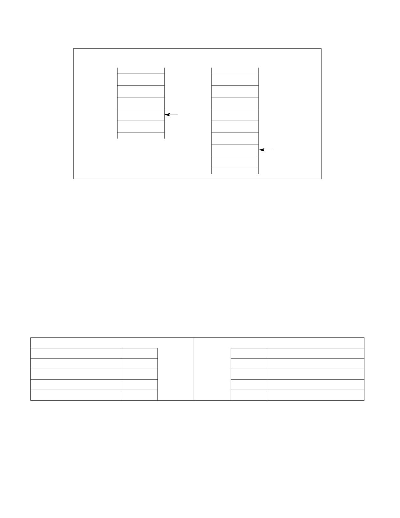
5. Loads the segment selector and stack pointer for the new stack in the SS and ESP registers.
6. Pushes the temporarily saved values for the SS and ESP registers (for the calling procedure) onto the new stack
(see Figure 6-13).
7. Copies the number of parameter specified in the parameter count field of the call gate from the calling
procedure’s stack to the new stack. If the count is 0, no parameters are copied.
8. Pushes the return instruction pointer (the current contents of the CS and EIP registers) onto the new stack.
9. Loads the segment selector for the new code segment and the new instruction pointer from the call gate into
the CS and EIP registers, respectively, and begins execution of the called procedure.
See the description of the CALL instruction in Chapter 3, “Instruction Set Reference, A-L‚”, in the Intel® 64 and
IA-32 Architectures Software Developer’s Manual, Volume 2A, for a detailed description of the privilege level
checks and other protection checks that the processor performs on a far call through a call gate.
6-18
Vol. 3A
PROTECTION
Calling Procedure’s Stack
Called Procedure’s Stack
Calling SS
Parameter 1
Calling ESP
Parameter 2
Parameter 1
Parameter 3
ESP
Parameter 2
Parameter 3
Calling CS
Calling EIP
ESP
Figure 6-13. Stack Switching During an Interprivilege-Level Call
The parameter count field in a call gate specifies the number of data items (up to 31) that the processor should
copy from the calling procedure’s stack to the stack of the called procedure. If more than 31 data items need to be
passed to the called procedure, one of the parameters can be a pointer to a data structure, or the saved contents
of the SS and ESP registers may be used to access parameters in the old stack space. The size of the data items
passed to the called procedure depends on the call gate size, as described in Section 6.8.3, “Call Gates.”
6.8.5.1
Stack Switching in 64-bit Mode
Although protection-check rules for call gates are unchanged from 32-bit mode, stack-switch changes in 64-bit
mode are different.
When stacks are switched as part of a 64-bit mode privilege-level change through a call gate, a new SS (stack
segment) descriptor is not loaded; 64-bit mode only loads an inner-level RSP from the TSS. The new SS is forced
to NULL and the SS selector’s RPL field is forced to the new CPL. The new SS is set to NULL in order to handle
nested far transfers (far CALL, INTn, interrupts, and exceptions). The old SS and RSP are saved on the new stack.
On a subsequent far RET, the old SS is popped from the stack and loaded into the SS register. See Table 6-2.
Table 6-2. 64-Bit-Mode Stack Layout After Far CALL with CPL Change
32-bit Mode
IA-32e mode
Old SS Selector
+12
+24
Old SS Selector
Old ESP
+8
+16
Old RSP
CS Selector
+4
+8
Old CS Selector
EIP
0
ESP
RSP
0
RIP
< 4 Bytes >
< 8 Bytes >
In 64-bit mode, stack operations resulting from a privilege-level-changing far call or far return are eight-bytes wide
and change the RSP by eight. The mode does not support the automatic parameter-copy feature found in 32-bit
mode. The call-gate count field is ignored. Software can access the old stack, if necessary, by referencing the old
stack-segment selector and stack pointer saved on the new process stack.
In 64-bit mode, far RET is allowed to load a NULL SS under certain conditions. If the target mode is 64-bit mode
and the target CPL ≠ 3, IRET allows SS to be loaded with a NULL selector. If the called procedure itself is inter-
rupted, the NULL SS is pushed on the stack frame. On the subsequent far RET, the NULL SS on the stack acts as a
flag to tell the processor not to load a new SS descriptor.
Vol. 3A
6-19
PROTECTION
6.8.6
Returning from a Called Procedure
The RET instruction can be used to perform a near return, a far return at the same privilege level, and a far return
to a different privilege level. This instruction is intended to execute returns from procedures that were called with
a CALL instruction. It does not support returns from a JMP instruction, because the JMP instruction does not save a
return instruction pointer on the stack.
A near return only transfers program control within the current code segment; therefore, the processor performs
only a limit check. When the processor pops the return instruction pointer from the stack into the EIP register, it
checks that the pointer does not exceed the limit of the current code segment.
On a far return at the same privilege level, the processor pops both a segment selector for the code segment being
returned to and a return instruction pointer from the stack. Under normal conditions, these pointers should be
valid, because they were pushed on the stack by the CALL instruction. However, the processor performs privilege
checks to detect situations where the current procedure might have altered the pointer or failed to maintain the
stack properly.
A far return that requires a privilege-level change is only allowed when returning to a less privileged level (that is,
the DPL of the return code segment is numerically greater than the CPL). The processor uses the RPL field from the
CS register value saved for the calling procedure (see Figure 6-13) to determine if a return to a numerically higher
privilege level is required. If the RPL is numerically greater (less privileged) than the CPL, a return across privilege
levels occurs.
The processor performs the following steps when performing a far return to a calling procedure (see Figures 6-2
and 6-4 in the Intel® 64 and IA-32 Architectures Software Developer’s Manual, Volume 1, for an illustration of the
stack contents prior to and after a return):
1. Checks the RPL field of the saved CS register value to determine if a privilege level change is required on the
return.
2. Loads the CS and EIP registers with the values on the called procedure’s stack. (Type and privilege level checks
are performed on the code-segment descriptor and RPL of the code- segment selector.)
3. (If the RET instruction includes a parameter count operand and the return requires a privilege level change.)
Adds the parameter count (in bytes obtained from the RET instruction) to the current ESP register value (after
popping the CS and EIP values), to step past the parameters on the called procedure’s stack. The resulting
value in the ESP register points to the saved SS and ESP values for the calling procedure’s stack. (Note that the
byte count in the RET instruction must be chosen to match the parameter count in the call gate that the calling
procedure referenced when it made the original call multiplied by the size of the parameters.)
4. (If the return requires a privilege level change.) Loads the SS and ESP registers with the saved SS and ESP
values and switches back to the calling procedure’s stack. The SS and ESP values for the called procedure’s
stack are discarded. Any limit violations detected while loading the stack-segment selector or stack pointer
cause a general-protection exception (#GP) to be generated. The new stack-segment descriptor is also checked
for type and privilege violations.
5. (If the RET instruction includes a parameter count operand.) Adds the parameter count (in bytes obtained from
the RET instruction) to the current ESP register value, to step past the parameters on the calling procedure’s
stack. The resulting ESP value is not checked against the limit of the stack segment. If the ESP value is beyond
the limit, that fact is not recognized until the next stack operation.
6. (If the return requires a privilege level change.) Checks the contents of the DS, ES, FS, and GS segment
registers. If any of these registers refer to segments whose DPL is less than the new CPL (excluding conforming
code segments), the segment register is loaded with a null segment selector.
See the description of the RET instruction in Chapter 4 of the Intel® 64 and IA-32 Architectures Software Devel-
oper’s Manual, Volume 2B, for a detailed description of the privilege level checks and other protection checks that
the processor performs on a far return.
6.8.7
Performing Fast Calls to System Procedures with the SYSENTER and SYSEXIT
Instructions
The SYSENTER and SYSEXIT instructions were introduced into the IA-32 architecture in the Pentium II processors
for the purpose of providing a fast (low overhead) mechanism for calling operating system or executive procedures.
6-20
Vol. 3A
PROTECTION
SYSENTER is intended for use by user code running at privilege level 3 to access operating system or executive
procedures running at privilege level 0. SYSEXIT is intended for use by privilege level 0 operating system or exec-
utive procedures for fast returns to privilege level 3 user code. SYSENTER can be executed from privilege levels 3,
2, 1, or 0; SYSEXIT can only be executed from privilege level 0.
The SYSENTER and SYSEXIT instructions are companion instructions, but they do not constitute a call/return pair.
This is because SYSENTER does not save any state information for use by SYSEXIT on a return.
The target instruction and stack pointer for these instructions are not specified through instruction operands.
Instead, they are specified through parameters entered in MSRs and general-purpose registers.
For SYSENTER, target fields are generated using the following sources:
• Target code segment - Reads this from IA32_SYSENTER_CS.
• Target instruction - Reads this from IA32_SYSENTER_EIP.
• Stack segment - Computed by adding 8 to the value in IA32_SYSENTER_CS.
• Stack pointer - Reads this from the IA32_SYSENTER_ESP.
For SYSEXIT, target fields are generated using the following sources:
• Target code segment - Computed by adding 16 to the value in the IA32_SYSENTER_CS.
• Target instruction - Reads this from EDX.
• Stack segment - Computed by adding 24 to the value in IA32_SYSENTER_CS.
• Stack pointer - Reads this from ECX.
The SYSENTER and SYSEXIT instructions perform “fast” calls and returns because they force the processor into a
predefined privilege level 0 state when SYSENTER is executed and into a predefined privilege level 3 state when
SYSEXIT is executed. By forcing predefined and consistent processor states, the number of privilege checks ordi-
narily required to perform a far call to another privilege levels are greatly reduced. Also, by predefining the target
context state in MSRs and general-purpose registers eliminates all memory accesses except when fetching the
target code.
Any additional state that needs to be saved to allow a return to the calling procedure must be saved explicitly by
the calling procedure or be predefined through programming conventions.
6.8.7.1
SYSENTER and SYSEXIT Instructions in IA-32e Mode
For Intel 64 processors, the SYSENTER and SYSEXIT instructions are enhanced to allow fast system calls from user
code running at privilege level 3 (in compatibility mode or 64-bit mode) to 64-bit executive procedures running at
privilege level 0. IA32_SYSENTER_EIP MSR and IA32_SYSENTER_ESP MSR are expanded to hold 64-bit addresses.
If IA-32e mode is inactive, only the lower 32-bit addresses stored in these MSRs are used. The WRMSR instruction
ensures that the addresses stored in these MSRs are canonical. Note that, in 64-bit mode, IA32_SYSENTER_CS
must not contain a NULL selector.
When SYSENTER transfers control, the following fields are generated and bits set:
• Target code segment - Reads non-NULL selector from IA32_SYSENTER_CS.
• New CS attributes - CS base = 0, CS limit = FFFFFFFFH.
• Target instruction - Reads 64-bit canonical address from IA32_SYSENTER_EIP.
• Stack segment - Computed by adding 8 to the value from IA32_SYSENTER_CS.
• Stack pointer - Reads 64-bit canonical address from IA32_SYSENTER_ESP.
• New SS attributes - SS base = 0, SS limit = FFFFFFFFH.
When the SYSEXIT instruction transfers control to 64-bit mode user code using REX.W, the following fields are
generated and bits set:
• Target code segment - Computed by adding 32 to the value in IA32_SYSENTER_CS.
• New CS attributes - L-bit = 1 (go to 64-bit mode).
• Target instruction - Reads 64-bit canonical address in RDX.
• Stack segment - Computed by adding 40 to the value of IA32_SYSENTER_CS.
Vol. 3A
6-21
PROTECTION
• Stack pointer - Update RSP using 64-bit canonical address in RCX.
When SYSEXIT transfers control to compatibility mode user code when the operand size attribute is 32 bits, the
following fields are generated and bits set:
• Target code segment - Computed by adding 16 to the value in IA32_SYSENTER_CS.
• New CS attributes - L-bit = 0 (go to compatibility mode).
• Target instruction - Fetch the target instruction from 32-bit address in EDX.
• Stack segment - Computed by adding 24 to the value in IA32_SYSENTER_CS.
• Stack pointer - Update ESP from 32-bit address in ECX.
6.8.8
Fast System Calls in 64-Bit Mode
The SYSCALL and SYSRET instructions are designed for operating systems that use a flat memory model (segmen-
tation is not used). The instructions, along with SYSENTER and SYSEXIT, are suited for IA-32e mode operation.
SYSCALL and SYSRET, however, are not supported in compatibility mode (or in protected mode). Use CPUID to
check if SYSCALL and SYSRET are available (CPUID.80000001H:EDX[11] = 1).
SYSCALL is intended for use by user code running at privilege level 3 to access operating system or executive
procedures running at privilege level 0. SYSRET is intended for use by privilege level 0 operating system or execu-
tive procedures for fast returns to privilege level 3 user code.
Stack pointers for SYSCALL/SYSRET are not specified through model specific registers. The clearing of bits in
RFLAGS is programmable rather than fixed. SYSCALL/SYSRET save and restore the RFLAGS register.
For SYSCALL, the processor saves RFLAGS into R11 and the RIP of the next instruction into RCX; it then gets the
privilege-level 0 target code segment, instruction pointer, stack segment, and flags as follows:
• Target code segment - Reads a non-NULL selector from IA32_STAR[47:32].
• Target instruction pointer - Reads a 64-bit address from IA32_LSTAR. (The WRMSR instruction ensures
that the value of the IA32_LSTAR MSR is canonical.)
• Stack segment - Computed by adding 8 to the value in IA32_STAR[47:32].
• Flags - The processor sets RFLAGS to the logical-AND of its current value with the complement of the value in
the IA32_FMASK MSR.
When SYSRET transfers control to 64-bit mode user code using REX.W, the processor gets the privilege level 3
target code segment, instruction pointer, stack segment, and flags as follows:
• Target code segment - Reads a non-NULL selector from IA32_STAR[63:48] + 16.
• Target instruction pointer - Copies the value in RCX into RIP.
• Stack segment - IA32_STAR[63:48] + 8.
• EFLAGS - Loaded from R11.
When SYSRET transfers control to 32-bit mode user code using a 32-bit operand size, the processor gets the priv-
ilege level 3 target code segment, instruction pointer, stack segment, and flags as follows:
• Target code segment - Reads a non-NULL selector from IA32_STAR[63:48].
• Target instruction pointer - Copies the value in ECX into EIP.
• Stack segment - IA32_STAR[63:48] + 8.
• EFLAGS - Loaded from R11.
It is the responsibility of the OS to ensure the descriptors in the GDT/LDT correspond to the selectors loaded by
SYSCALL/SYSRET (consistent with the base, limit, and attribute values forced by the instructions).
See Figure 6-14 for the layout of IA32_STAR, IA32_LSTAR, and IA32_FMASK.
6-22
Vol. 3A

PROTECTION
63
32 31
0
Reserved
SYSCALL EFLAGS Mask
IA32_FMASK
63
0
Target RIP for 64-bit Mode Calling Program
IA32_LSTAR
63
48 47
32 31
0
SYSRET CS and SS
SYSCALL CS and SS
Reserved
IA32_STAR
Figure 6-14. MSRs Used by SYSCALL and SYSRET
The SYSCALL instruction does not save the stack pointer, and the SYSRET instruction does not restore it. It is likely
that the OS system-call handler will change the stack pointer from the user stack to the OS stack. If so, it is the
responsibility of software first to save the user stack pointer. This might be done by user code, prior to executing
SYSCALL, or by the OS system-call handler after SYSCALL.
Because the SYSRET instruction does not modify the stack pointer, it is necessary for software to switch back to the
user stack. The OS may load the user stack pointer (if it was saved after SYSCALL) before executing SYSRET; alter-
natively, user code may load the stack pointer (if it was saved before SYSCALL) after receiving control from
SYSRET.
If the OS loads the stack pointer before executing SYSRET, it must ensure that the handler of any interrupt or
exception delivered between restoring the stack pointer and successful execution of SYSRET is not invoked with the
user stack. It can do so using approaches such as the following:
• External interrupts. The OS can prevent an external interrupt from being delivered by clearing EFLAGS.IF
before loading the user stack pointer.
• Nonmaskable interrupts (NMIs). The OS can ensure that the NMI handler is invoked with the correct stack by
using the interrupt stack table (IST) mechanism for gate 2 (NMI) in the IDT (see Section 7.14.5, “Interrupt
Stack Table”).
• General-protection exceptions (#GP). The SYSRET instruction generates #GP(0) if the value of RCX is not
canonical. The OS can address this possibility using one or more of the following approaches:
- Confirming that the value of RCX is canonical before executing SYSRET.
- Using paging to ensure that the SYSCALL instruction will never save a non-canonical value into RCX.
- Using the IST mechanism for gate 13 (#GP) in the IDT.
When FRED transitions are enabled, SYSCALL and SYSENTER are implemented using FRED event delivery. SYSRET
and SYSEXIT are not used; instead, ERETU (or ERETS) are used to return. See Chapter 8, “Flexible Return and
Event Delivery (FRED).”
6.9
PRIVILEGED INSTRUCTIONS
Some of the system instructions (called “privileged instructions”) are protected from use by application programs.
The privileged instructions control system functions (such as the loading of system registers). They can be
Vol. 3A
6-23
PROTECTION
executed only when the CPL is 0 (most privileged). If one of these instructions is executed when the CPL is not 0,
a general-protection exception (#GP) is generated. The following system instructions are privileged instructions:
• LGDT - Load GDT register.
• LLDT - Load LDT register.
• LTR - Load task register.
• LIDT - Load IDT register.
• MOV (control registers) - Load and store control registers.
• LMSW - Load machine status word.
• CLTS - Clear task-switched flag in register CR0.
• MOV (debug registers) - Load and store debug registers.
• INVD - Invalidate cache, without writeback.
• WBINVD - Invalidate cache, with writeback.
• INVLPG -Invalidate TLB entry.
• HLT- Halt processor.
• RDMSR, RDMSRLIST- Read Model-Specific Registers.
• WRMSR, WRMSRLIST, WRMSRNS -Write Model-Specific Registers.
• RDPMC - Read Performance-Monitoring Counter.
• RDTSC - Read Time-Stamp Counter.
• ERETS - Event return to supervisor
• ERETU - Event return to user
• LKGS - Load kernel GS base
Some of the privileged instructions are available only in the more recent families of Intel 64 and IA-32 processors
(see Section 25.13, “New Instructions In the Pentium and Later IA-32 Processors”).
The PCE and TSD flags in register CR4 (bits 4 and 2, respectively) enable the RDPMC and RDTSC instructions,
respectively, to be executed at any CPL.
6.10
POINTER VALIDATION
When operating in protected mode, the processor validates all pointers to enforce protection between segments
and maintain isolation between privilege levels. Pointer validation consists of the following checks:
1. Checking access rights to determine if the segment type is compatible with its use.
2. Checking read/write rights.
3. Checking if the pointer offset exceeds the segment limit.
4. Checking if the supplier of the pointer is allowed to access the segment.
5. Checking the offset alignment.
The processor automatically performs first, second, and third checks during instruction execution. Software must
explicitly request the fourth check by issuing an ARPL instruction. The fifth check (offset alignment) is performed
automatically at privilege level 3 if alignment checking is turned on. Offset alignment does not affect isolation of
privilege levels.
6.10.1 Checking Access Rights (LAR Instruction)
When the processor accesses a segment using a far pointer, it performs an access rights check on the segment
descriptor pointed to by the far pointer. This check is performed to determine if type and privilege level (DPL) of the
segment descriptor are compatible with the operation to be performed. For example, when making a far call in
protected mode, the segment-descriptor type must be for a conforming or nonconforming code segment, a call
6-24
Vol. 3A
PROTECTION
gate, a task gate, or a TSS. Then, if the call is to a nonconforming code segment, the DPL of the code segment must
be equal to the CPL, and the RPL of the code segment’s segment selector must be less than or equal to the DPL. If
type or privilege level are found to be incompatible, the appropriate exception is generated.
To prevent type incompatibility exceptions from being generated, software can check the access rights of a
segment descriptor using the LAR (load access rights) instruction. The LAR instruction specifies the segment
selector for the segment descriptor whose access rights are to be checked and a destination register. The instruc-
tion then performs the following operations:
1. Check that the segment selector is not null.
2. Checks that the segment selector points to a segment descriptor that is within the descriptor table limit (GDT
or LDT).
3. Checks that the segment descriptor is a code, data, LDT, call gate, task gate, or TSS segment-descriptor type.
4. If the segment is not a conforming code segment, checks if the segment descriptor is visible at the CPL (that
is, if the CPL and the RPL of the segment selector are less than or equal to the DPL).
5. If the privilege level and type checks pass, loads the second doubleword of the segment descriptor into the
destination register (masked by the value 00FXFF00H, where X indicates that the corresponding 4 bits are
undefined) and sets the ZF flag in the EFLAGS register. If the segment selector is not visible at the current
privilege level or is an invalid type for the LAR instruction, the instruction does not modify the destination
register and clears the ZF flag.
Once loaded in the destination register, software can perform additional checks on the access rights information.
6.10.2 Checking Read/Write Rights (VERR and VERW Instructions)
When the processor accesses any code or data segment it checks the read/write privileges assigned to the
segment to verify that the intended read or write operation is allowed. Software can check read/write rights using
the VERR (verify for reading) and VERW (verify for writing) instructions. Both these instructions specify the
segment selector for the segment being checked. The instructions then perform the following operations:
1. Check that the segment selector is not null.
2. Checks that the segment selector points to a segment descriptor that is within the descriptor table limit (GDT
or LDT).
3. Checks that the segment descriptor is a code or data-segment descriptor type.
4. If the segment is not a conforming code segment, checks if the segment descriptor is visible at the CPL (that
is, if the CPL and the RPL of the segment selector are less than or equal to the DPL).
5. Checks that the segment is readable (for the VERR instruction) or writable (for the VERW) instruction.
The VERR instruction sets the ZF flag in the EFLAGS register if the segment is visible at the CPL and readable; the
VERW sets the ZF flag if the segment is visible and writable. (Code segments are never writable.) The ZF flag is
cleared if any of these checks fail.
6.10.3 Checking That the Pointer Offset Is Within Limits (LSL Instruction)
When the processor accesses any segment it performs a limit check to ensure that the offset is within the limit of
the segment. Software can perform this limit check using the LSL (load segment limit) instruction. Like the LAR
instruction, the LSL instruction specifies the segment selector for the segment descriptor whose limit is to be
checked and a destination register. The instruction then performs the following operations:
1. Check that the segment selector is not null.
2. Checks that the segment selector points to a segment descriptor that is within the descriptor table limit (GDT
or LDT).
3. Checks that the segment descriptor is a code, data, LDT, or TSS segment-descriptor type.
4. If the segment is not a conforming code segment, checks if the segment descriptor is visible at the CPL (that
is, if the CPL and the RPL of the segment selector less than or equal to the DPL).
Vol. 3A
6-25
PROTECTION
5. If the privilege level and type checks pass, loads the unscrambled limit (the limit scaled according to the setting
of the G flag in the segment descriptor) into the destination register and sets the ZF flag in the EFLAGS register.
If the segment selector is not visible at the current privilege level or is an invalid type for the LSL instruction,
the instruction does not modify the destination register and clears the ZF flag.
Once loaded in the destination register, software can compare the segment limit with the offset of a pointer.
6.10.4 Checking Caller Access Privileges (ARPL Instruction)
The requestor’s privilege level (RPL) field of a segment selector is intended to carry the privilege level of a calling
procedure (the calling procedure’s CPL) to a called procedure. The called procedure then uses the RPL to determine
if access to a segment is allowed. The RPL is said to “weaken” the privilege level of the called procedure to that of
the RPL.
Operating-system procedures typically use the RPL to prevent less privileged application programs from accessing
data located in more privileged segments. When an operating-system procedure (the called procedure) receives a
segment selector from an application program (the calling procedure), it sets the segment selector’s RPL to the
privilege level of the calling procedure. Then, when the operating system uses the segment selector to access its
associated segment, the processor performs privilege checks using the calling procedure’s privilege level (stored in
the RPL) rather than the numerically lower privilege level (the CPL) of the operating-system procedure. The RPL
thus ensures that the operating system does not access a segment on behalf of an application program unless that
program itself has access to the segment.
Figure 6-15 shows an example of how the processor uses the RPL field. In this example, an application program
(located in code segment A) possesses a segment selector (segment selector D1) that points to a privileged data
structure (that is, a data structure located in a data segment D at privilege level 0).
The application program cannot access data segment D, because it does not have sufficient privilege, but the oper-
ating system (located in code segment C) can. So, in an attempt to access data segment D, the application
program executes a call to the operating system and passes segment selector D1 to the operating system as a
parameter on the stack. Before passing the segment selector, the (well behaved) application program sets the RPL
of the segment selector to its current privilege level (which in this example is 3). If the operating system attempts
to access data segment D using segment selector D1, the processor compares the CPL (which is now 0 following
the call), the RPL of segment selector D1, and the DPL of data segment D (which is 0). Since the RPL is greater than
the DPL, access to data segment D is denied. The processor’s protection mechanism thus protects data segment D
from access by the operating system, because application program’s privilege level (represented by the RPL of
segment selector B) is greater than the DPL of data segment D.
6-26
Vol. 3A
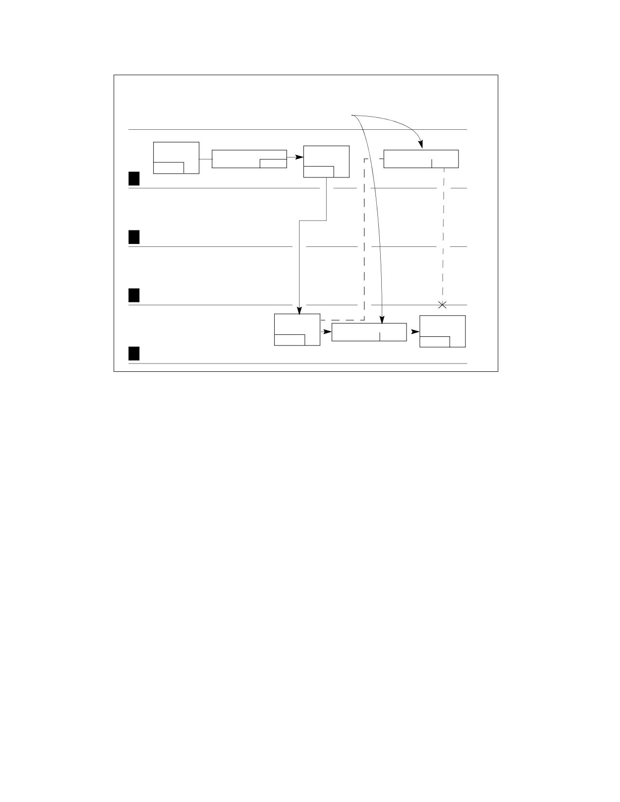
PROTECTION
Passed as a
parameter on
the stack.
Application Program
Code
Call
Segment A
Gate Selector B
Segment Sel. D1
Gate B
RPL=3
RPL=3
CPL=3
DPL=3
Lowest Privilege
3
2
Access
not
allowed
1
Code
Data
Operating
Segment C
Segment Sel. D2 Segment D
System
RPL=0
DPL=0
DPL=0
Access
0
Highest Privilege
allowed
Figure 6-15. Use of RPL to Weaken Privilege Level of Called Procedure
Now assume that instead of setting the RPL of the segment selector to 3, the application program sets the RPL to
0 (segment selector D2). The operating system can now access data segment D, because its CPL and the RPL of
segment selector D2 are both equal to the DPL of data segment D.
Because the application program is able to change the RPL of a segment selector to any value, it can potentially use
a procedure operating at a numerically lower privilege level to access a protected data structure. This ability to
lower the RPL of a segment selector breaches the processor’s protection mechanism.
Because a called procedure cannot rely on the calling procedure to set the RPL correctly, operating-system proce-
dures (executing at numerically lower privilege-levels) that receive segment selectors from numerically higher
privilege-level procedures need to test the RPL of the segment selector to determine if it is at the appropriate level.
The ARPL (adjust requested privilege level) instruction is provided for this purpose. This instruction adjusts the RPL
of one segment selector to match that of another segment selector.
The example in Figure 6-15 demonstrates how the ARPL instruction is intended to be used. When the operating-
system receives segment selector D2 from the application program, it uses the ARPL instruction to compare the
RPL of the segment selector with the privilege level of the application program (represented by the code-segment
selector pushed onto the stack). If the RPL is less than application program’s privilege level, the ARPL instruction
changes the RPL of the segment selector to match the privilege level of the application program (segment selector
D1). Using this instruction thus prevents a procedure running at a numerically higher privilege level from
accessing numerically lower privilege-level (more privileged) segments by lowering the RPL of a segment selector.
Note that the privilege level of the application program can be determined by reading the RPL field of the segment
selector for the application-program’s code segment. This segment selector is stored on the stack as part of the call
to the operating system. The operating system can copy the segment selector from the stack into a register for
use as an operand for the ARPL instruction.
Vol. 3A
6-27
PROTECTION
6.10.5 Checking Alignment
When the CPL is 3, alignment of memory references can be checked by setting the AM flag in the CR0 register and
the AC flag in the EFLAGS register. Unaligned memory references generate alignment exceptions (#AC). The
processor does not generate alignment exceptions when operating at privilege level 0, 1, or 2. See Table 7-7 for a
description of the alignment requirements when alignment checking is enabled.
6.11
PAGE-LEVEL PROTECTION
Page-level protection can be used alone or applied to segments. When page-level protection is used with the flat
memory model, it allows supervisor code and data (the operating system or executive) to be protected from user
code and data (application programs). It also allows pages containing code to be write protected. When the
segment- and page-level protection are combined, page-level read/write protection allows more protection granu-
larity within segments.
With page-level protection (as with segment-level protection) each memory reference is checked to verify that
protection checks are satisfied. All checks are made before the memory cycle is started, and any violation prevents
the cycle from starting and results in a page-fault exception being generated. Because checks are performed in
parallel with address translation, there is no performance penalty.
The processor performs two page-level protection checks:
• Restriction of addressable domain (supervisor and user modes).
• Page type (read only or read/write).
Violations of either of these checks results in a page-fault exception being generated. See Chapter 7, “Event
14-Page-Fault Exception (#PF),” for an explanation of the page-fault exception mechanism. This chapter
describes the protection violations which lead to page-fault exceptions.
6.11.1 Page-Protection Flags
Protection information for pages is contained in two flags in a paging-structure entry (see Chapter 5): the
read/write flag (bit 1) and the user/supervisor flag (bit 2). The protection checks use the flags in all paging struc-
tures.
6.11.2 Restricting Addressable Domain
The page-level protection mechanism allows restricting access to pages based on two privilege levels:
• Supervisor mode (U/S flag is 0)-(Most privileged) For the operating system or executive, other system
software (such as device drivers), and protected system data (such as page tables).
• User mode (U/S flag is 1)-(Least privileged) For application code and data.
The segment privilege levels map to the page privilege levels as follows. If the processor is currently operating at
a CPL of 0, 1, or 2, it is in supervisor mode; if it is operating at a CPL of 3, it is in user mode. When the processor is
in supervisor mode, it can access all pages; when in user mode, it can access only user-level pages. (Note that the
WP flag in control register CR0 modifies the supervisor permissions, as described in Section 6.11.3, “Page Type.”)
Note that to use the page-level protection mechanism, code and data segments must be set up for at least two
segment-based privilege levels: level 0 for supervisor code and data segments and level 3 for user code and data
segments. (In this model, the stacks are placed in the data segments.) To minimize the use of segments, a flat
memory model can be used (see Section 3.2.1, “Basic Flat Model”).
Here, the user and supervisor code and data segments all begin at address zero in the linear address space and
overlay each other. With this arrangement, operating-system code (running at the supervisor level) and application
code (running at the user level) can execute as if there are no segments. Protection between operating-system and
application code and data is provided by the processor’s page-level protection mechanism.
6-28
Vol. 3A
PROTECTION
6.11.3 Page Type
The page-level protection mechanism recognizes two page types:
• Read-only access (R/W flag is 0).
• Read/write access (R/W flag is 1).
When the processor is in supervisor mode and the WP flag in register CR0 is clear (its state following reset initial-
ization), all pages are both readable and writable (write-protection is ignored). When the processor is in user
mode, it can write only to user-mode pages that are read/write accessible. User-mode pages which are read/write
or read-only are readable; supervisor-mode pages are neither readable nor writable from user mode. A page-fault
exception is generated on any attempt to violate the protection rules.
Starting with the P6 family, Intel processors allow user-mode pages to be write-protected against supervisor-mode
access. Setting CR0.WP = 1 enables supervisor-mode sensitivity to write protected pages. If CR0.WP = 1, read-
only pages are not writable from any privilege level. This supervisor write-protect feature is useful for imple-
menting a “copy-on-write” strategy used by some operating systems, such as UNIX*, for task creation (also called
forking or spawning). When a new task is created, it is possible to copy the entire address space of the parent task.
This gives the child task a complete, duplicate set of the parent's segments and pages. An alternative copy-on-
write strategy saves memory space and time by mapping the child's segments and pages to the same segments
and pages used by the parent task. A private copy of a page gets created only when one of the tasks writes to the
page. By using the WP flag and marking the shared pages as read-only, the supervisor can detect an attempt to
write to a page, and can copy the page at that time.
6.11.4 Combining Protection of Both Levels of Page Tables
For any one page, the protection attributes of its page-directory entry (first-level page table) may differ from those
of its page-table entry (second-level page table). The processor checks the protection for a page in both its page-
directory and the page-table entries. Table 6-3 shows the protection provided by the possible combinations of
protection attributes when the WP flag is clear.
6.11.5 Overrides to Page Protection
The following types of memory accesses are checked as if they are privilege-level 0 accesses, regardless of the CPL
at which the processor is currently operating:
• Access to segment descriptors in the GDT, LDT, or IDT.
• Access to an inner-privilege-level stack during an inter-privilege-level call or a call to in exception or interrupt
handler, when a change of privilege level occurs.
6.12
COMBINING PAGE AND SEGMENT PROTECTION
When paging is enabled, the processor evaluates segment protection first, then evaluates page protection. If the
processor detects a protection violation at either the segment level or the page level, the memory access is not
carried out and an exception is generated. If an exception is generated by segmentation, no paging exception is
generated.
Page-level protections cannot be used to override segment-level protection. For example, a code segment is by
definition not writable. If a code segment is paged, setting the R/W flag for the pages to read-write does not make
the pages writable. Attempts to write into the pages will be blocked by segment-level protection checks.
Page-level protection can be used to enhance segment-level protection. For example, if a large read-write data
segment is paged, the page-protection mechanism can be used to write-protect individual pages.
Table 6-3. Combined Page-Directory and Page-Table Protection
Page-Directory Entry
Page-Table Entry
Combined Effect
Privilege
Access Type
Privilege
Access Type
Privilege
Access Type
Vol. 3A
6-29

PROTECTION
Table 6-3. Combined Page-Directory and Page-Table Protection
User
Read-Only
User
Read-Only
User
Read-Only
User
Read-Only
User
Read-Write
User
Read-Only
User
Read-Write
User
Read-Only
User
Read-Only
User
Read-Write
User
Read-Write
User
Read/Write
User
Read-Only
Supervisor
Read-Only
Supervisor
Read/Write*
User
Read-Only
Supervisor
Read-Write
Supervisor
Read/Write*
User
Read-Write
Supervisor
Read-Only
Supervisor
Read/Write*
User
Read-Write
Supervisor
Read-Write
Supervisor
Read/Write
Supervisor
Read-Only
User
Read-Only
Supervisor
Read/Write*
Supervisor
Read-Only
User
Read-Write
Supervisor
Read/Write*
Supervisor
Read-Write
User
Read-Only
Supervisor
Read/Write*
Supervisor
Read-Write
User
Read-Write
Supervisor
Read/Write
Supervisor
Read-Only
Supervisor
Read-Only
Supervisor
Read/Write*
Supervisor
Read-Only
Supervisor
Read-Write
Supervisor
Read/Write*
Supervisor
Read-Write
Supervisor
Read-Only
Supervisor
Read/Write*
Supervisor
Read-Write
Supervisor
Read-Write
Supervisor
Read/Write
NOTE:
* If CR0.WP = 1, access type is determined by the R/W flags of the page-directory and page-table entries. IF CR0.WP = 0, supervisor
privilege permits read-write access.
6.13
PAGE-LEVEL PROTECTION AND EXECUTE-DISABLE BIT
In addition to page-level protection offered by the U/S and R/W flags, paging structures used with PAE paging, 4-
level paging,1 and 5-level paging provide the execute-disable bit (see Chapter 5, “Paging”). This bit offers addi-
tional protection for data pages.
An Intel 64 or IA-32 processor with the execute-disable bit capability can prevent data pages from being used by
malicious software to execute code. This capability is provided in:
•
32-bit protected mode with PAE enabled.
• IA-32e mode.
While the execute-disable bit capability does not introduce new instructions, it does require operating systems to
use a PAE-enabled environment and establish a page-granular protection policy for memory pages.
If the execute-disable bit of a memory page is set, that page can be used only as data. An attempt to execute code
from a memory page with the execute-disable bit set causes a page-fault exception.
The execute-disable capability is not supported with 32-bit paging. Existing page-level protection mechanisms (see
Section 6.11, “Page-Level Protection”) continue to apply to memory pages independent of the execute-disable
setting.
6.13.1 Detecting and Enabling the Execute-Disable Capability
Software can detect the presence of the execute-disable capability using the CPUID instruction.
CPUID.80000001H:EDX.NX[20] = 1 indicates the capability is available.
1. Earlier versions of this manual used the term “IA-32e paging” to identify 4-level paging.
6-30
Vol. 3A

PROTECTION
If the capability is available, software can enable it by setting IA32_EFER.NXE[bit 11] to 1. IA32_EFER is available
if CPUID.80000001H:EDX[20 or 29] = 1.
If the execute-disable capability is not available, a write to set IA32_EFER.NXE produces a #GP exception. See
Table 6-4.
Table 6-4. Extended Feature Enable MSR (IA32_EFER)
63:12
11
10
9
8
7:1
0
Reserved
Execute-disable bit
IA-32e mode
Reserved
IA-32e mode
Reserved
SysCall enable (SCE)
enable (NXE)
active (LMA)
enable (LME)
6.13.2 Execute-Disable Page Protection
The execute-disable bit in the paging structures enhances page protection for data pages. Instructions cannot be
fetched from a memory page if IA32_EFER.NXE = 1 and the execute-disable bit is set in any of the paging-struc-
ture entries used to map the page. Table 6-5 lists the valid usage of a page in relation to the value of execute-
disable bit (bit 63) of the corresponding entry in each level of the paging structures. Execute-disable protection can
be activated using the execute-disable bit at any level of the paging structure, irrespective of the corresponding
entry in other levels. When execute-disable protection is not activated, the page can be used as code or data.
Vol. 3A
6-31

PROTECTION
Table 6-5. Page Level Protection Matrix with Execute-Disable Bit Capability with 4-Level Paging
Execute Disable Bit Value (Bit 63)
Valid Usage
PML4
PDP
PDE
PTE
Bit 63 = 1
*
*
*
Data
*
Bit 63 = 1
*
*
Data
*
*
Bit 63 = 1
*
Data
*
*
*
Bit 63 = 1
Data
Bit 63 = 0
Bit 63 = 0
Bit 63 = 0
Bit 63 = 0
Data/Code
NOTES:
* Value not checked.
In legacy PAE-enabled mode, Table 6-6 and Table 6-7 show the effect of setting the execute-disable bit for code and
data pages.
Table 6-6. 4-KByte Page Level Protection Matrix with Execute-Disable Bit Capability with PAE Paging
Execute Disable Bit Value (Bit 63)
Valid Usage
PDE
PTE
Bit 63 = 1
*
Data
*
Bit 63 = 1
Data
Bit 63 = 0
Bit 63 = 0
Data/Code
NOTE:
* Value not checked.
Table 6-7. 2-MByte Page Level Protection with Execute-Disable Bit Capability with PAE Paging
Execute Disable Bit Value (Bit 63)
Valid Usage
PDE
Bit 63 = 1
Data
Bit 63 = 0
Data/Code
6.13.3 Reserved Bit Checking
The processor enforces reserved bit checking in paging data structure entries. The bits being checked varies with
paging mode and may vary with the size of physical address space.
Table 6-8 shows the reserved bits that are checked when the execute disable bit capability is enabled (CR4.PAE = 1
and IA32_EFER.NXE = 1). Table 6-8 and Table 6-9 show the following paging modes:
• Non-PAE 4-KByte paging: 4-KByte-page only paging (CR4.PAE = 0, CR4.PSE = 0).
• PSE36: 4-KByte and 4-MByte pages (CR4.PAE = 0, CR4.PSE = 1).
• PAE: 4-KByte and 2-MByte pages (CR4.PAE = 1).
6-32
Vol. 3A

PROTECTION
Table 6-8. Page Level Protection Matrix with Execute-Disable Bit Capability Enabled
Mode
Paging Mode
Check Bits
32-bit
4-KByte paging (non-PAE)
No reserved bits checked
PSE36 - PDE, 4-MByte page
Bit 21
PSE36 - PDE, 4-KByte page
No reserved bits checked
PSE36 - PTE
No reserved bits checked
PAE - PDP table entry
Bits 63:MAXPHYADDR, 8:5, and 2:1
PAE - PDE, 2-MByte page
Bits 62:MAXPHYADDR and 20:13
PAE - PDE, 4-KByte page
Bits 62:MAXPHYADDR
PAE - PTE
Bits 62:MAXPHYADDR
64-bit
PML5E
Bits 51:MAXPHYADDR
PML4E
Bits 51:MAXPHYADDR
PDPTE
Bits 51:MAXPHYADDR
PDE, 2-MByte page
Bits 51:MAXPHYADDR and 20:13
PDE, 4-KByte page
Bits 51:MAXPHYADDR
PTE
Bits 51:MAXPHYADDR
The reserved bit checking depends on the physical-address width supported by the processor. This width is denoted
MAXPHYADDR and is enumerated in CPUID.80000008H:EAX[7:0].1
If execute disable bit capability is not enabled or not available, reserved bit checking in 64-bit mode includes bit 63
and additional bits. This and reserved bit checking for legacy 32-bit paging modes are shown in Table 6-9.
Table 6-9. Reserved Bit Checking with Execute-Disable Bit Capability Not Enabled
Mode
Paging Mode
Check Bits
32-bit
KByte paging (non-PAE)
No reserved bits checked
PSE36 - PDE, 4-MByte page
Bit 21
PSE36 - PDE, 4-KByte page
No reserved bits checked
PSE36 - PTE
No reserved bits checked
PAE - PDP table entry
Bits 63:MAXPHYADDR, 8:5, and 2:1
PAE - PDE, 2-MByte page
Bits 63:MAXPHYADDR and 20:13
PAE - PDE, 4-KByte page
Bits 63:MAXPHYADDR
PAE - PTE
Bits 63:MAXPHYADDR
64-bit
PML5E
Bit 63, bits 51:MAXPHYADDR
PML4E
Bit 63, bits 51:MAXPHYADDR
PDPTE
Bit 63, bits 51:MAXPHYADDR
PDE, 2-MByte page
Bit 63, bits 51:MAXPHYADDR and 20:13
PDE, 4-KByte page
Bit 63, bits 51:MAXPHYADDR
PTE
Bit 63, bits 51:MAXPHYADDR
1. If IA32_TME_ACTIVATE[0] = 1 (indicating that TME has been configured), MAXPHYADDR is reduced by the value of IA32_TME_ACTI-
VATE[39:36] when a logical processor is outside secure arbitration mode (SEAM; see Chapter 35); the value is not reduced in SEAM.
Vol. 3A
6-33
PROTECTION
6.13.4 Exception Handling
When execute disable bit capability is enabled (IA32_EFER.NXE = 1), conditions for a page fault to occur include
the same conditions that apply to an Intel 64 or IA-32 processor without execute disable bit capability plus the
following new condition: an instruction fetch to a linear address that translates to physical address in a memory
page that has the execute-disable bit set.
An Execute Disable Bit page fault can occur at all privilege levels. It can occur on any instruction fetch, including
(but not limited to): near branches, far branches, CALL/RET/INT/IRET execution, sequential instruction fetches,
and task switches. The execute-disable bit in the page translation mechanism is checked only when:
• IA32_EFER.NXE = 1.
• The instruction translation look-aside buffer (ITLB) is loaded with a page that is not already present in the ITLB.
6-34
Vol. 3A
CHAPTER 7
INTERRUPT AND EXCEPTION HANDLING
This chapter describes the interrupt and exception-handling mechanism when operating in protected mode on an
Intel 64 or IA-32 processor. Most of the information provided here also applies to interrupt and exception mecha-
nisms used in real-address, virtual-8086 mode, and 64-bit mode.
Chapter 23, “8086 Emulation,” describes information specific to interrupt and exception mechanisms in real-
address and virtual-8086 mode. Section 7.14, “Exception and Interrupt Handling in 64-bit Mode,” describes infor-
mation specific to interrupt and exception mechanisms in IA-32e mode and 64-bit sub-mode.
7.1
INTERRUPT AND EXCEPTION OVERVIEW
Interrupts and exceptions are events that indicate that a condition exists somewhere in the system, the processor,
or within the currently executing program or task that requires the attention of a processor. They typically result in
a forced transfer of execution from the currently running program or task to a special software routine or task
called an interrupt handler or an exception handler. The action taken by a processor in response to an interrupt or
exception is referred to as servicing or handling the interrupt or exception.
Interrupts occur at random times during the execution of a program, in response to signals from hardware. System
hardware uses interrupts to handle events external to the processor, such as requests to service peripheral devices.
Software can also generate interrupts by executing the INT n instruction.
Exceptions occur when the processor detects an error condition while executing an instruction, such as division by
zero. The processor detects a variety of error conditions including protection violations, page faults, and internal
machine faults. The machine-check architecture of the Pentium 4, Intel Xeon, P6 family, and Pentium processors
also permits a machine-check exception to be generated when internal hardware errors and bus errors are
detected.
When an interrupt is received or an exception is detected, the currently running procedure or task is suspended
while the processor executes an interrupt or exception handler. When execution of the handler is complete, the
processor resumes execution of the interrupted procedure or task. The resumption of the interrupted procedure or
task happens without loss of program continuity, unless recovery from an exception was not possible or an inter-
rupt caused the currently running program to be terminated.
This chapter describes the processor’s interrupt and exception-handling mechanism, when operating in protected
mode. A description of the exceptions and the conditions that cause them to be generated is given at the end of this
chapter.
7.2
EXCEPTION AND INTERRUPT VECTORS
To aid in handling exceptions and interrupts, each architecturally defined exception and each interrupt condition
requiring special handling by the processor is assigned a unique identification number, called a vector number. The
processor uses the vector number assigned to an exception or interrupt as an index into the interrupt descriptor
table (IDT). The table provides the entry point to an exception or interrupt handler (see Section 7.10, “Interrupt
Descriptor Table (IDT)”). When FRED transitions are enabled, the vector number does not reference the IDT but is
instead saved on the stack by FRED event delivery; see Chapter 8, “Flexible Return and Event Delivery (FRED).”
The allowable range for vector numbers is 0 to 255. Vector numbers in the range 0 through 31 are reserved by the
Intel 64 and IA-32 architectures for architecture-defined exceptions and interrupts. Not all of the vector numbers
in this range have a currently defined function. The unassigned vector numbers in this range are reserved. Do not
use the reserved vector numbers.
Vector numbers in the range 32 to 255 are designated as user-defined interrupts and are not reserved by the Intel
64 and IA-32 architecture. These interrupts are generally assigned to external I/O devices to enable those devices
to send interrupts to the processor through one of the external hardware interrupt mechanisms (see Section 7.3,
“Sources of Interrupts”).
Vol. 3A
7-1

INTERRUPT AND EXCEPTION HANDLING
Table 7-1 shows vector number assignments for architecturally defined exceptions and for the NMI interrupt. This
table gives the exception type (see Section 7.5, “Exception Classifications”) and indicates whether an error code is
saved on the stack for the exception. The source of each predefined exception and the NMI interrupt is also given.
7.3
SOURCES OF INTERRUPTS
The processor receives interrupts from two sources:
• External (hardware generated) interrupts.
• Software-generated interrupts.
7.3.1
External Interrupts
External interrupts are received through pins on the processor or through the local APIC. The primary interrupt pins
on Pentium 4, Intel Xeon, P6 family, and Pentium processors are the LINT[1:0] pins, which are connected to the
local APIC (see Chapter 13, “Advanced Programmable Interrupt Controller (APIC)”). When the local APIC is
enabled, the LINT[1:0] pins can be programmed through the APIC’s local vector table (LVT) to be associated with
any of the processor’s exception or interrupt vectors.
When the local APIC is global/hardware disabled, these pins are configured as INTR and NMI pins, respectively.
Asserting the INTR pin signals the processor that an external interrupt has occurred. The processor reads from the
system bus the interrupt vector number provided by an external interrupt controller, such as an 8259A (see Section
7.2, “Exception and Interrupt Vectors”). Asserting the NMI pin signals a non-maskable interrupt (NMI), which is
assigned to interrupt vector 2.
Table 7-1. Protected-Mode Exceptions and Interrupts
Vector
Mnemonic
Description
Type
Error
Source
Code
0
#DE
Divide Error
Fault
No
DIV and IDIV instructions.
1
#DB
Debug Exception
Fault/ Trap
No
Instruction, data, and I/O breakpoints;
single-step; and others.
2
-
NMI Interrupt
Interrupt
No
Nonmaskable external interrupt.
3
#BP
Breakpoint
Trap
No
INT3 instruction.
4
#OF
Overflow
Trap
No
INTO instruction.
5
#BR
BOUND Range Exceeded
Fault
No
BOUND instruction.
6
#UD
Invalid Opcode (Undefined Opcode)
Fault
No
UD instruction or reserved opcode.
7
#NM
Device Not Available (No Math
Fault
No
Floating-point or WAIT/FWAIT instruction.
Coprocessor)
8
#DF
Double Fault
Abort
Yes
Any instruction that can generate an
(zero)
exception, an NMI, or an INTR.
9
Coprocessor Segment Overrun
Fault
No
Floating-point instruction.1
(reserved)
10
#TS
Invalid TSS
Fault
Yes
Task switch or TSS access.
11
#NP
Segment Not Present
Fault
Yes
Loading segment registers or accessing
system segments.
12
#SS
Stack-Segment Fault
Fault
Yes
Stack operations and SS register loads.
13
#GP
General Protection
Fault
Yes
Any memory reference and other
protection checks.
14
#PF
Page Fault
Fault
Yes
Any memory reference.
7-2
Vol. 3A

INTERRUPT AND EXCEPTION HANDLING
Table 7-1. Protected-Mode Exceptions and Interrupts (Contd.)
Vector
Mnemonic
Description
Type
Error
Source
Code
15
-
(Intel reserved. Do not use.)
No
16
#MF
x87 FPU Floating-Point Error (Math
Fault
No
x87 FPU floating-point or WAIT/FWAIT
Fault)
instruction.
17
#AC
Alignment Check
Fault
Yes
Any data reference in memory.2
18
#MC
Machine Check
Abort
No
Error codes (if any) and source are model
dependent.3
19
#XM
SIMD Floating-Point Exception
Fault
No
SSE/SSE2/SSE3 floating-point
instructions4
20
#VE
Virtualization Exception
Fault
No
EPT violations5
21
#CP
Control Protection Exception
Fault
Yes
RET, IRET, RSTORSSP, and SETSSBSY
instructions can generate this exception.
When CET indirect branch tracking is
enabled, this exception can be generated
due to a missing ENDBRANCH instruction
at target of an indirect call or jump.
22-31
-
Intel reserved. Do not use.
32-255
-
User Defined (Non-reserved)
Interrupt
External interrupt or INT n instruction.
Interrupts
NOTES:
1. Processors after the Intel386 processor do not generate this exception.
2. This exception was introduced in the Intel486 processor.
3. This exception was introduced in the Pentium processor and enhanced in the P6 family processors.
4. This exception was introduced in the Pentium III processor.
5. This exception can occur only on processors that support the 1-setting of the “EPT-violation #VE” VM-execution control.
The processor’s local APIC is normally connected to a system-based I/O APIC. Here, external interrupts received at
the I/O APIC’s pins can be directed to the local APIC through the system bus (Pentium 4, Intel Core Duo, Intel Core
2, Intel Atom, and Intel Xeon processors) or the APIC serial bus (P6 family and Pentium processors). The I/O APIC
determines the vector number of the interrupt and sends this number to the local APIC. When a system contains
multiple processors, processors can also send interrupts to one another by means of the system bus (Pentium 4,
Intel Core Duo, Intel Core 2, Intel Atom, and Intel Xeon processors) or the APIC serial bus (P6 family and Pentium
processors).
The LINT[1:0] pins are not available on the Intel486 processor and earlier Pentium processors that do not contain
an on-chip local APIC. These processors have dedicated NMI and INTR pins. With these processors, external inter-
rupts are typically generated by a system-based interrupt controller (8259A), with the interrupts being signaled
through the INTR pin.
Note that several other pins on the processor can cause a processor interrupt to occur. However, these interrupts
are not handled by the interrupt and exception mechanism described in this chapter. These pins include the
RESET#, FLUSH#, STPCLK#, SMI#, R/S#, and INIT# pins. Whether they are included on a particular processor is
implementation dependent. Pin functions are described in the data books for the individual processors. The SMI#
pin is described in Chapter 34, “System Management Mode.”
7.3.2
Maskable Hardware Interrupts
Any external interrupt that is delivered to the processor by means of the INTR pin or through the local APIC is called
a maskable hardware interrupt. Maskable hardware interrupts that can be delivered through the INTR pin include
all IA-32 architecture defined interrupt vectors from 0 through 255; those that can be delivered through the local
APIC include interrupt vectors 16 through 255.
Vol. 3A
7-3
INTERRUPT AND EXCEPTION HANDLING
The IF flag in the EFLAGS register permits all maskable hardware interrupts to be masked as a group (see Section
7.8.1, “Masking Maskable Hardware Interrupts”). Note that when interrupts 0 through 15 are delivered through the
local APIC, the APIC indicates the receipt of an illegal vector.
7.3.3
Software-Generated Interrupts
The INT n instruction permits interrupt-like events to be generated from within software by supplying an interrupt
vector number as an operand. For example, execution of the INT 35 instruction delivers an event with vector 35.
With IDT event delivery, these events appear like ordinary interrupts; thus, execution of INT 35 would invoke the
interrupt handler for interrupt 35. These events differ from true interrupts in that they are not masked by the IF
flag in the EFLAGS register and execution of INT 2 does not activate the processor’s NMI-handling hardware.
FRED event delivery of these events identifies them with event type 4, distinguishing them from maskable inter-
rupts (event type 0) and NMIs (event type 2).
Software-generated interrupts differ from software-generated exceptions, which are described in Section 7.4.2.
7.4
SOURCES OF EXCEPTIONS
The processor receives exceptions from three sources:
• Processor-detected program-error exceptions.
• Software-generated exceptions.
• Machine-check exceptions.
7.4.1
Program-Error Exceptions
The processor generates one or more exceptions when it detects program errors during the execution in an appli-
cation program or the operating system or executive. Intel 64 and IA-32 architectures define a vector number for
each processor-detectable exception. Exceptions are classified as faults, traps, and aborts (see Section 7.5,
“Exception Classifications”).
7.4.2
Software-Generated Exceptions
The INTO, INT1, INT3, and BOUND instructions permit exceptions to be generated in software. These instructions
allow checks for exception conditions to be performed at points in the instruction stream. For example, INT3 causes
a breakpoint exception to be generated.
7.4.3
Machine-Check Exceptions
The P6 family and Pentium processors provide both internal and external machine-check mechanisms for checking
the operation of the internal chip hardware and bus transactions. These mechanisms are implementation depen-
dent. When a machine-check error is detected, the processor signals a machine-check exception (vector 18) and
returns an error code.
See “Event 7-Device Not Available Exception (#NM)” and Chapter 18, “Machine-Check Architecture,” for more
information about the machine-check mechanism.
7.5
EXCEPTION CLASSIFICATIONS
Exceptions are classified as faults, traps, or aborts depending on the way they are reported and whether the
instruction that caused the exception can be restarted without loss of program or task continuity.
7-4
Vol. 3A
INTERRUPT AND EXCEPTION HANDLING
• Faults - A fault is an exception that can generally be corrected and that, once corrected, allows the program
to be restarted with no loss of continuity. When a fault is reported, the processor restores the machine state to
the state prior to the beginning of execution of the faulting instruction. The return address (saved contents of
the CS and EIP registers) for the fault handler points to the faulting instruction, rather than to the instruction
following the faulting instruction.
• Traps - A trap is an exception that is reported immediately following the execution of the trapping instruction.
Traps allow execution of a program or task to be continued without loss of program continuity. The return
address for the trap handler points to the instruction to be executed after the trapping instruction.
• Aborts - An abort is an exception that does not always report the precise location of the instruction causing
the exception and does not allow a restart of the program or task that caused the exception. Aborts are used to
report severe errors, such as hardware errors and inconsistent or illegal values in system tables.
NOTE
One exception subset normally reported as a fault is not restartable. Such exceptions result in loss
of some processor state. For example, executing a POPAD instruction where the stack frame
crosses over the end of the stack segment causes a fault to be reported. In this situation, the
exception handler sees that the instruction pointer (CS:EIP) has been restored as if the POPAD
instruction had not been executed. However, internal processor state (the general-purpose
registers) will have been modified. Such cases are considered programming errors. An application
causing this class of exceptions should be terminated by the operating system.
7.6
PROGRAM OR TASK RESTART
To allow the restarting of program or task following the handling of an exception or an interrupt, all exceptions
(except aborts) are guaranteed to report exceptions on an instruction boundary. All interrupts are guaranteed to be
taken on an instruction boundary.
For fault-class exceptions, the return instruction pointer (saved when the processor generates an exception) points
to the faulting instruction. So, when a program or task is restarted following the handling of a fault, the faulting
instruction is restarted (re-executed). Restarting the faulting instruction is commonly used to handle exceptions
that are generated when access to an operand is blocked. The most common example of this type of fault is a page-
fault exception (#PF) that occurs when a program or task references an operand located on a page that is not in
memory. When a page-fault exception occurs, the exception handler can load the page into memory and resume
execution of the program or task by restarting the faulting instruction. To ensure that the restart is handled trans-
parently to the currently executing program or task, the processor saves the necessary registers and stack pointers
to allow a restart to the state prior to the execution of the faulting instruction.
For trap-class exceptions, the return instruction pointer points to the instruction following the trapping instruction.
If a trap is detected during an instruction which transfers execution, the return instruction pointer reflects the
transfer. For example, if a trap is detected while executing a JMP instruction, the return instruction pointer points
to the destination of the JMP instruction, not to the next address past the JMP instruction. All trap exceptions allow
program or task restart with no loss of continuity. For example, the overflow exception is a trap exception. Here,
the return instruction pointer points to the instruction following the INTO instruction that tested EFLAGS.OF (over-
flow) flag. The trap handler for this exception resolves the overflow condition. Upon return from the trap handler,
program or task execution continues at the instruction following the INTO instruction.
The abort-class exceptions do not support reliable restarting of the program or task. Abort handlers are designed
to collect diagnostic information about the state of the processor when the abort exception occurred and then shut
down the application and system as gracefully as possible.
Interrupts rigorously support restarting of interrupted programs and tasks without loss of continuity. The return
instruction pointer saved for an interrupt points to the next instruction to be executed at the instruction boundary
where the processor took the interrupt. If the instruction just executed has a repeat prefix, the interrupt is taken
at the end of the current iteration with the registers set to execute the next iteration.
The ability of a P6 family processor to speculatively execute instructions does not affect the taking of interrupts by
the processor. Interrupts are taken at instruction boundaries located during the retirement phase of instruction
execution; so they are always taken in the “in-order” instruction stream. See Chapter 2, “Intel® 64 and IA-32
Vol. 3A
7-5
INTERRUPT AND EXCEPTION HANDLING
Architectures,” in the Intel® 64 and IA-32 Architectures Software Developer’s Manual, Volume 1, for more informa-
tion about the P6 family processors’ microarchitecture and its support for out-of-order instruction execution.
Note that the Pentium processor and earlier IA-32 processors also perform varying amounts of prefetching and
preliminary decoding. With these processors as well, exceptions and interrupts are not signaled until actual “in-
order” execution of the instructions. For a given code sample, the signaling of exceptions occurs uniformly when
the code is executed on any family of IA-32 processors (except where new exceptions or new opcodes have been
defined).
7.7
NONMASKABLE INTERRUPT (NMI)
The nonmaskable interrupt (NMI) can be generated in the following ways:
• External hardware asserts the NMI pin.
• The logical processor’s local APIC receives an interrupt message with a delivery mode NMI.
• Software uses a local APIC to send an interprocessor interrupt with delivery mode NMI.
An NMI is not masked by the IF flag in the EFLAGS register.
7.7.1
NMI Delivery
A logical processor receiving a NMI handles it by delivering an event with vector 2. With IDT event delivery, this
delivery uses descriptor 2 in the IDT; FRED event delivery identifies the event in the stack frame with event type
NMI and vector 2.
It is possible to issue a maskable hardware interrupt (through the INTR pin) to vector 2 to invoke the NMI interrupt
handler; however, this interrupt will not truly be an NMI interrupt (FRED event delivery will use the event type
“external interrupt” instead of “NMI”). A true NMI interrupt that activates the processor’s NMI-handling hardware
can only be delivered through one of the mechanisms listed above.
7.7.2
NMI Blocking
When handling an NMI, the processor invokes certain hardware conditions to ensure that no other NMIs will be
delivered until the NMI handler has completed executing. This is called NMI blocking.
Once NMI blocking is established, the processor blocks delivery of subsequent NMIs until the next execution of the
IRET instruction. This blocking of NMIs prevents nested execution of the NMI handler. (With IDT event delivery, it
is recommended that the NMI interrupt handler be accessed through an interrupt gate to disable maskable hard-
ware interrupts.)
An execution of the IRET instruction unblocks NMIs even if the instruction causes a fault. For example, if the IRET
instruction executes with EFLAGS.VM = 1 and IOPL of less than 3, a general-protection exception is generated (see
Section 23.2.7, “Sensitive Instructions”). In such a case, NMIs are unmasked before the exception handler is
invoked.
The treatment of NMI blocking is enhanced when FRED transitions are enabled. It is still the case that the processor
will block NMIs before delivering an NMI, and an execution of IRET will unblock NMIs. In addition, FRED event
delivery sets a bit in the stack frame when delivering an NMI. The subsequent return instruction (ERETS or ERETU)
uses that bit to determine whether to unblock NMIs. See Chapter 8, “Flexible Return and Event Delivery (FRED).”
Note that the processor blocks NMIs before it commences to deliver the NMI. If NMI delivery encounters a nested
exception, NMIs will be blocked before that exception is delivered. FRED event delivery of that exception will not set
the NMI bit in the stack frame, so a subsequent return instruction will not unblock NMIs. For this reason, software
should ensure that FRED event delivery of an NMI does not encounter a nested fault.
7-6
Vol. 3A
INTERRUPT AND EXCEPTION HANDLING
7.7.3
NMI-Source Reporting
Like ordinary interrupts, NMIs that result from platform interrupt messages (or registers in the local APIC) include
an 8-bit vector. However, IDT event delivery ignores this vector and instead always uses vector 2 to deliver an NMI,
selecting descriptor 2 from the IDT.
As explained in Section 8.3.2, FRED event delivery also uses vector 2 for NMIs. (It also distinguishes NMIs from
other events using the event type.) Processors that support FRED may also support a related feature called NMI-
source reporting. With NMI-source reporting, FRED event delivery reports information about the sources of NMIs
based on the vectors in NMI interrupt messages (or in the local APIC). When NMI-source reporting is available,
software can program different NMI sources to use different vectors, allowing software to identify the source of an
NMI when it is delivered.
Support for NMI-source reporting is enumerated with the feature flag CPUID.07H.01H:EAX.NMI_SRC[20].
When NMI-source reporting is supported, each logical processor maintains a 16-bit NMI-source bitmap. The bitmap
is zero on reset. When a logical processor receives an NMI, it updates the NMI-source bitmap as follows:
• If the NMI has a vector (as specified in an interrupt message or APIC register) in the range 0-15, the processor
sets the bit corresponding to the vector.
• If the NMI has no vector, or if its vector is not in the range 0-15, the logical processor sets bit 0.
A logical processor may receive multiple NMIs before the first is delivered. When this happens, the NMIs are
coalesced and only one is delivered to software. In this case, NMI-source reporting will set multiple bits in the NMI-
source bitmap (assuming the NMIs did not all have the same vector).
When a logical processor handles an NMI, it records internally the value of the NMI-source bitmap and then clears
it.
• If the NMI is delivered with FRED event delivery, the NMI-source information (the recorded value of the NMI-
source bitmap) is saved on the stack as event data (see Section 8.3.2).
• IDT event delivery does not report the NMI-source bitmap to software, even if the processor supports NMI-
source reporting.
Note that the processor records and clears the NMI-source bitmap before it commences to deliver the NMI. If NMI
delivery encounters a nested exception, the recorded NMI-source information is lost.
7.8
ENABLING AND DISABLING INTERRUPTS
The processor inhibits the generation of some interrupts, depending on the state of the processor and of the IF and
RF flags in the EFLAGS register, as described in the following sections.
7.8.1
Masking Maskable Hardware Interrupts
The IF flag can disable the servicing of maskable hardware interrupts received on the processor’s INTR pin or
through the local APIC (see Section 7.3.2, “Maskable Hardware Interrupts”). When the IF flag is clear, the
processor inhibits interrupts delivered to the INTR pin or through the local APIC from generating an internal inter-
rupt request; when the IF flag is set, interrupts delivered to the INTR or through the local APIC pin are processed
as normal external interrupts.
The IF flag does not affect non-maskable interrupts (NMIs) delivered to the NMI pin or delivery mode NMI
messages delivered through the local APIC, nor does it affect processor generated exceptions. As with the other
flags in the EFLAGS register, the processor clears the IF flag in response to a hardware reset.
The fact that the group of maskable hardware interrupts includes the reserved interrupt and exception vectors 0
through 32 can potentially cause confusion. Architecturally, when the IF flag is set, an interrupt for any of the
vectors from 0 through 32 can be delivered to the processor through the INTR pin and any of the vectors from 16
through 32 can be delivered through the local APIC. The processor will then generate an interrupt and call the
interrupt or exception handler pointed to by the vector number. So for example, it is possible to invoke the page-
fault handler through the INTR pin (by means of vector 14); however, this is not a true page-fault exception. It is
an interrupt. As with the INT n instruction (see Section 7.4.2, “Software-Generated Exceptions”), when an inter-
Vol. 3A
7-7
INTERRUPT AND EXCEPTION HANDLING
rupt is generated through the INTR pin to an exception vector, the processor does not push an error code on the
stack, so the exception handler may not operate correctly.
The IF flag can be set or cleared with the STI (set interrupt-enable flag) and CLI (clear interrupt-enable flag)
instructions, respectively. These instructions may be executed only if the CPL is equal to or less than the IOPL. A
general-protection exception (#GP) is generated if they are executed when the CPL is greater than the IOPL.1 If
IF = 0, maskable hardware interrupts remain inhibited on the instruction boundary following an execution of STI.2
The inhibition ends after delivery of another event (e.g., exception) or the execution of the next instruction.
The IF flag is also affected by the following operations:
• The PUSHF instruction stores all flags on the stack, where they can be examined and modified. The POPF
instruction can be used to load the modified flags back into the EFLAGS register.
• Task switches and the POPF, IRET, ERETS, and ERETU instructions load the EFLAGS register; therefore, they
can be used to modify the setting of the IF flag.
• When an interrupt is handled through an interrupt gate, the IF flag is automatically cleared, which disables
maskable hardware interrupts. (If an interrupt is handled through a trap gate, the IF flag is not cleared.) FRED
event delivery of any event clears the IF flag.
See the descriptions of the CLI, STI, PUSHF, POPF, IRET, ERETS, and ERETU instructions in Chapter 3, “Instruction
Set Reference, A-L,” in the Intel® 64 and IA-32 Architectures Software Developer’s Manual, Volume 2A, and
Chapter 4, “Instruction Set Reference, M-U,” in the Intel® 64 and IA-32 Architectures Software Developer’s
Manual, Volume 2B, for a detailed description of the operations these instructions are allowed to perform on the IF
flag.
7.8.2
Masking Instruction Breakpoints
The RF (resume) flag in the EFLAGS register controls the response of the processor to instruction-breakpoint condi-
tions (see the description of the RF flag in Section 2.3, “System Flags and Fields in the EFLAGS Register”).
When set, it prevents an instruction breakpoint from generating a debug exception (#DB); when clear, instruction
breakpoints will generate debug exceptions. The primary function of the RF flag is to prevent the processor from
going into a debug exception loop on an instruction-breakpoint. See Section 20.3.1.1, “Instruction-Breakpoint
Exception Condition,” for more information on the use of this flag.
As noted in Section 7.8.3, execution of the MOV or POP instruction to load the SS register suppresses any instruc-
tion breakpoint on the next instruction (just as if EFLAGS.RF were 1).
7.8.3
Masking Exceptions and Interrupts When Switching Stacks
To switch to a different stack segment, software often uses a pair of instructions, for example:
MOV SS, AX
MOV ESP, StackTop
(Software might also use the POP instruction to load SS and ESP.)
If an interrupt or exception occurs after the new SS segment descriptor has been loaded but before the ESP register
has been loaded, these two parts of the logical address into the stack space are inconsistent for the duration of the
interrupt or exception handler (assuming that delivery of the interrupt or exception does not itself load a new stack
pointer).
To account for this situation, the processor prevents certain events from being delivered after execution of a MOV
to SS instruction or a POP to SS instruction. The following items provide details:
• Any instruction breakpoint on the next instruction is suppressed (as if EFLAGS.RF were 1).
1. The effect of the IOPL on these instructions is modified slightly when the virtual mode extension is enabled by setting the VME flag
in control register CR4: see Section 23.3, “Interrupt and Exception Handling in Virtual-8086 Mode.” Behavior is also impacted by the
PVI flag: see Section 23.4, “Protected-Mode Virtual Interrupts.”
2. Nonmaskable interrupts and system-management interrupts may also be inhibited on the instruction boundary following such an
execution of STI.
7-8
Vol. 3A

INTERRUPT AND EXCEPTION HANDLING
• Any data breakpoint on the MOV to SS instruction or POP to SS instruction is inhibited until the instruction
boundary following the next instruction.
• Any single-step trap that would be delivered following the MOV to SS instruction or POP to SS instruction
(because EFLAGS.TF is 1) is suppressed.
• The suppression and inhibition ends after delivery of an exception or the execution of the next instruction.
• If a sequence of consecutive instructions each loads the SS register (using MOV or POP), only the first is
guaranteed to inhibit or suppress events in this way.
Intel recommends that software use the LSS instruction to load the SS register and ESP together. The problem
identified earlier does not apply to LSS, and the LSS instruction does not inhibit events as detailed above.
7.9
PRIORITIZATION OF CONCURRENT EVENTS
If more than one event is pending at an instruction boundary (between execution of instructions), the processor
services them in a predictable order. Table 7-2 shows the priority among classes of event sources.
Table 7-2. Priority Among Concurrent Events
Priority
Description
1 (Highest)
Hardware Reset and Machine Checks
- RESET
- Machine Check (#MC)
2
Trap on Task Switch
- T flag in TSS is set (#DB)
3
External Hardware Interventions
- FLUSH
- STOPCLK
- SMI
- INIT
4
Traps on the Previous Instruction
- Trap-class Debug Exceptions (#DB due to TF flag set or data/I-O breakpoint)
5
Nonmaskable Interrupts (NMI) 1
6
Maskable Hardware Interrupts 1
7
Fault-class Debug Exceptions (#DB due to instruction breakpoint)
8
Faults from Fetching Next Instruction
- Code-Segment Limit Violation (#GP)
- Code Page Fault (#PF)
9 (Lowest)
Faults from Decoding the Next Instruction
- Control protection exception due to missing ENDBRANCH at target of an indirect call or jump (#CP)
- Instruction length > 15 bytes (#GP)
- Invalid Opcode (#UD)
- Coprocessor Not Available (#NM)
NOTE
1. The Intel® 486 processor and earlier processors group nonmaskable and maskable interrupts in the same priority class.
The processor first services a pending event from the class which has the highest priority, transferring execution to
the first instruction of the handler. Lower priority exceptions are discarded; lower priority interrupts are held
pending. Discarded exceptions may be re-generated when the event handler returns execution to the point in the
program or task where the original event occurred. While the priority among the classes listed in Table 7-2 is
Vol. 3A
7-9
INTERRUPT AND EXCEPTION HANDLING
consistent across processor implementations, the priority of events within a class is implementation-dependent
and may vary from processor to processor.
Table 7-2 specifies the prioritization of events that may be pending at an instruction boundary. It does not specify
the prioritization of faults that arise during instruction execution or event delivery (these include #BR, #TS, #NP,
#SS, #GP, #PF, #AC, #MF, #XM, #VE, or #CP). It also does not apply to the events generated by the “Call to Inter-
rupt Procedure” instructions (INT n, INTO, INT3, and INT1), as these events are integral to the execution of those
instructions and do not occur between instructions.
7.10
INTERRUPT DESCRIPTOR TABLE (IDT)
NOTE
FRED event delivery is an alternative to use of the IDT. The material in this section does not apply
when FRED transitions are enabled. See Chapter 8, “Flexible Return and Event Delivery (FRED),” for
more information about FRED transitions.
The interrupt descriptor table (IDT) associates each exception or interrupt vector with a gate descriptor for the
procedure or task used to service the associated exception or interrupt. Like the GDT and LDTs, the IDT is an array
of 8-byte descriptors (in protected mode). Unlike the GDT, the first entry of the IDT may contain a descriptor. To
form an index into the IDT, the processor scales the exception or interrupt vector by eight (the number of bytes in
a gate descriptor). Because there are only 256 interrupt or exception vectors, the IDT need not contain more than
256 descriptors. It can contain fewer than 256 descriptors, because descriptors are required only for the interrupt
and exception vectors that may occur. All empty descriptor slots in the IDT should have the present flag for the
descriptor set to 0.
The base addresses of the IDT should be aligned on an 8-byte boundary to maximize performance of cache line fills.
The limit value is expressed in bytes and is added to the base address to get the address of the last valid byte. A
limit value of 0 results in exactly 1 valid byte. Because IDT entries are always eight bytes long, the limit should
always be one less than an integral multiple of eight (that is, 8N - 1).
The IDT may reside anywhere in the linear address space. As shown in Figure 7-1, the processor locates the IDT
using the IDTR register. This register holds both a 32-bit base address and 16-bit limit for the IDT.
The LIDT (load IDT register) and SIDT (store IDT register) instructions load and store the contents of the IDTR
register, respectively. The LIDT instruction loads the IDTR register with the base address and limit held in a memory
operand. This instruction can be executed only when the CPL is 0. It normally is used by the initialization code of an
operating system when creating an IDT. An operating system also may use it to change from one IDT to another.
The SIDT instruction copies the base and limit value stored in IDTR to memory. This instruction can be executed at
any privilege level.
If a vector references a descriptor beyond the limit of the IDT, a general-protection exception (#GP) is generated.
NOTE
Because interrupts are delivered to the processor core only once, an incorrectly configured IDT
could result in incomplete interrupt handling and/or the blocking of interrupt delivery.
IA-32 architecture rules need to be followed for setting up IDTR base/limit/access fields and each
field in the gate descriptors. The same apply for the Intel 64 architecture. This includes implicit
referencing of the destination code segment through the GDT or LDT and accessing the stack.
7-10
Vol. 3A
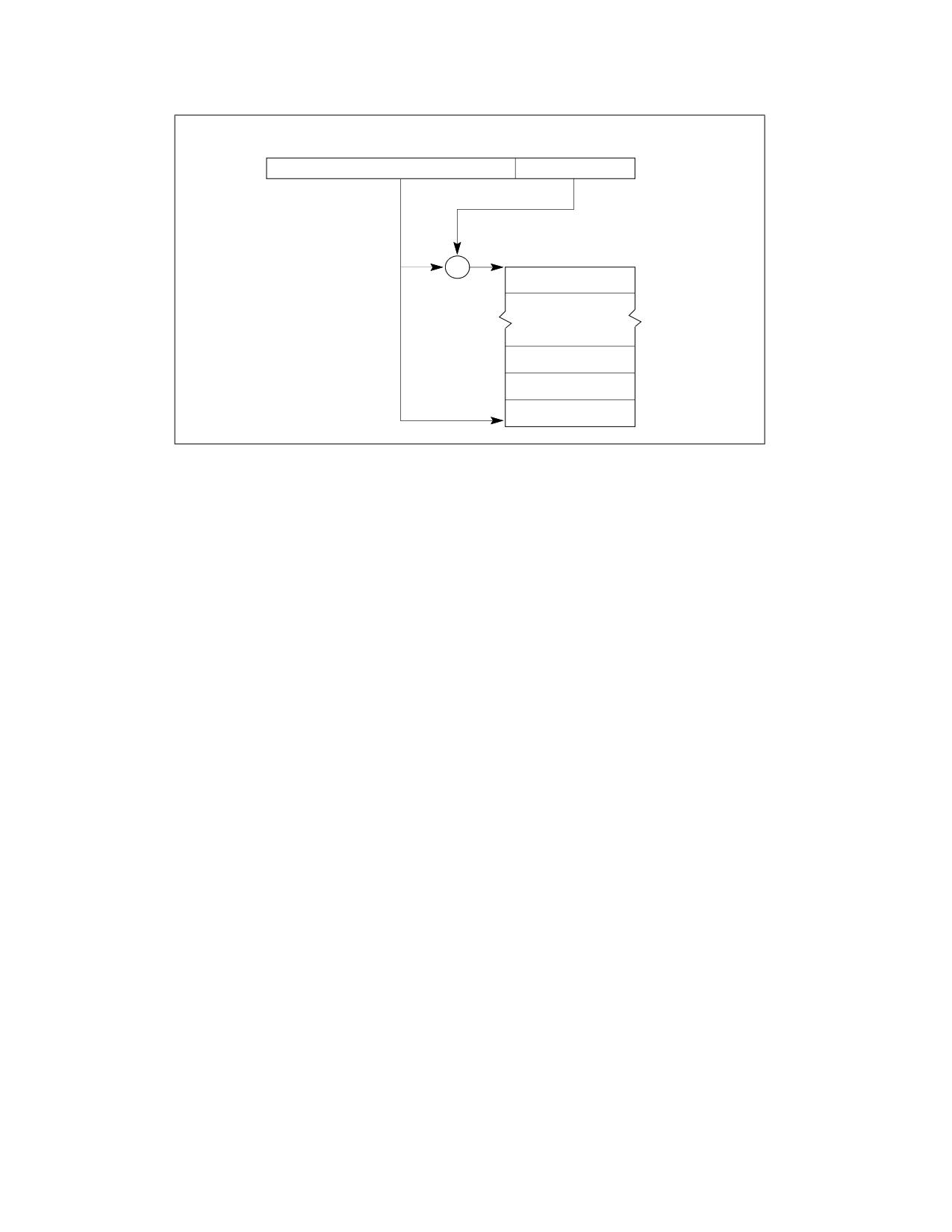
INTERRUPT AND EXCEPTION HANDLING
IDTR Register
47
16 15
0
IDT Base
Address
IDT Limit
Interrupt
Descriptor Table (IDT)
+
Gate for
Interrupt #n
(n-1)∗8
Gate for
Interrupt #3
16
Gate for
Interrupt #2
8
Gate for
Interrupt #1
0
31
0
Figure 7-1. Relationship of the IDTR and IDT
7.11
IDT DESCRIPTORS
NOTE
FRED event delivery does not use IDT descriptors. The material in this section does not apply when
FRED transitions are enabled. See Chapter 8, “Flexible Return and Event Delivery (FRED),” for more
information about FRED transitions.
The IDT may contain any of three kinds of gate descriptors:
• Task-gate descriptor
• Interrupt-gate descriptor
• Trap-gate descriptor
Figure 7-2 shows the formats for the task-gate, interrupt-gate, and trap-gate descriptors. The format of a task
gate used in an IDT is the same as that of a task gate used in the GDT or an LDT (see Section 10.2.5, “Task-Gate
Descriptor”). The task gate contains the segment selector for a TSS for an exception and/or interrupt handler task.
Interrupt and trap gates are very similar to call gates (see Section 6.8.3, “Call Gates”). They contain a far pointer
(segment selector and offset) that the processor uses to transfer program execution to a handler procedure in an
exception- or interrupt-handler code segment. These gates differ in the way the processor handles the IF flag in the
EFLAGS register (see Section 7.12.1.3, “Flag Usage By Exception- or Interrupt-Handler Procedure”).
Vol. 3A
7-11
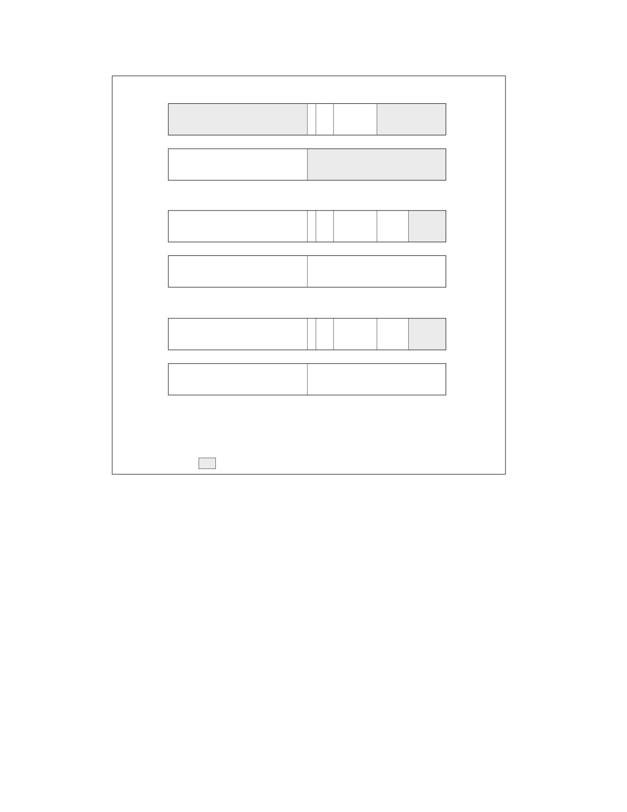
INTERRUPT AND EXCEPTION HANDLING
Task Gate
31
16 15 14 13 12
8
7
0
D
P
P
0
0
1
0
1
4
L
31
16 15
0
TSS Segment Selector
0
Interrupt Gate
31
16 15 14 13 12
8
7
5
4
0
D
Offset 31..16
P
P
0
D 1
1
0
0
0
0
4
L
31
16 15
0
Segment Selector
Offset 15..0
0
Trap Gate
31
16 15 14 13 12
8
7
5
4
0
D
Offset 31..16
P
P
0
D 1
1
1
0
0
0
4
L
31
16 15
0
Segment Selector
Offset 15..0
0
DPL
Descriptor Privilege Level
Offset
Offset to procedure entry point
P
Segment Present flag
Selector
Segment Selector for destination code segment
D
Size of gate: 1 = 32 bits; 0 = 16 bits
Reserved
Figure 7-2. IDT Gate Descriptors
7.12
EXCEPTION AND INTERRUPT HANDLING
NOTE
This section focuses on event handling based on IDT event delivery and on return using the IRET
instruction. FRED transitions are alternatives to these mechanisms. In general, the material in this
section does not apply when FRED transitions are enabled. See Chapter 8, “Flexible Return and
Event Delivery (FRED),” for more information about FRED transitions.
The processor handles calls to exception- and interrupt-handlers similar to the way it handles calls with a CALL
instruction to a procedure or a task. When responding to an exception or interrupt, the processor uses the excep-
tion or interrupt vector as an index to a descriptor in the IDT. If the index points to an interrupt gate or trap gate,
the processor calls the exception or interrupt handler in a manner similar to a CALL to a call gate (see Section 6.8.2,
“Gate Descriptors,” through Section 6.8.6, “Returning from a Called Procedure”). If index points to a task gate, the
processor executes a task switch to the exception- or interrupt-handler task in a manner similar to a CALL to a task
gate (see Section 10.3, “Task Switching”).
7-12
Vol. 3A
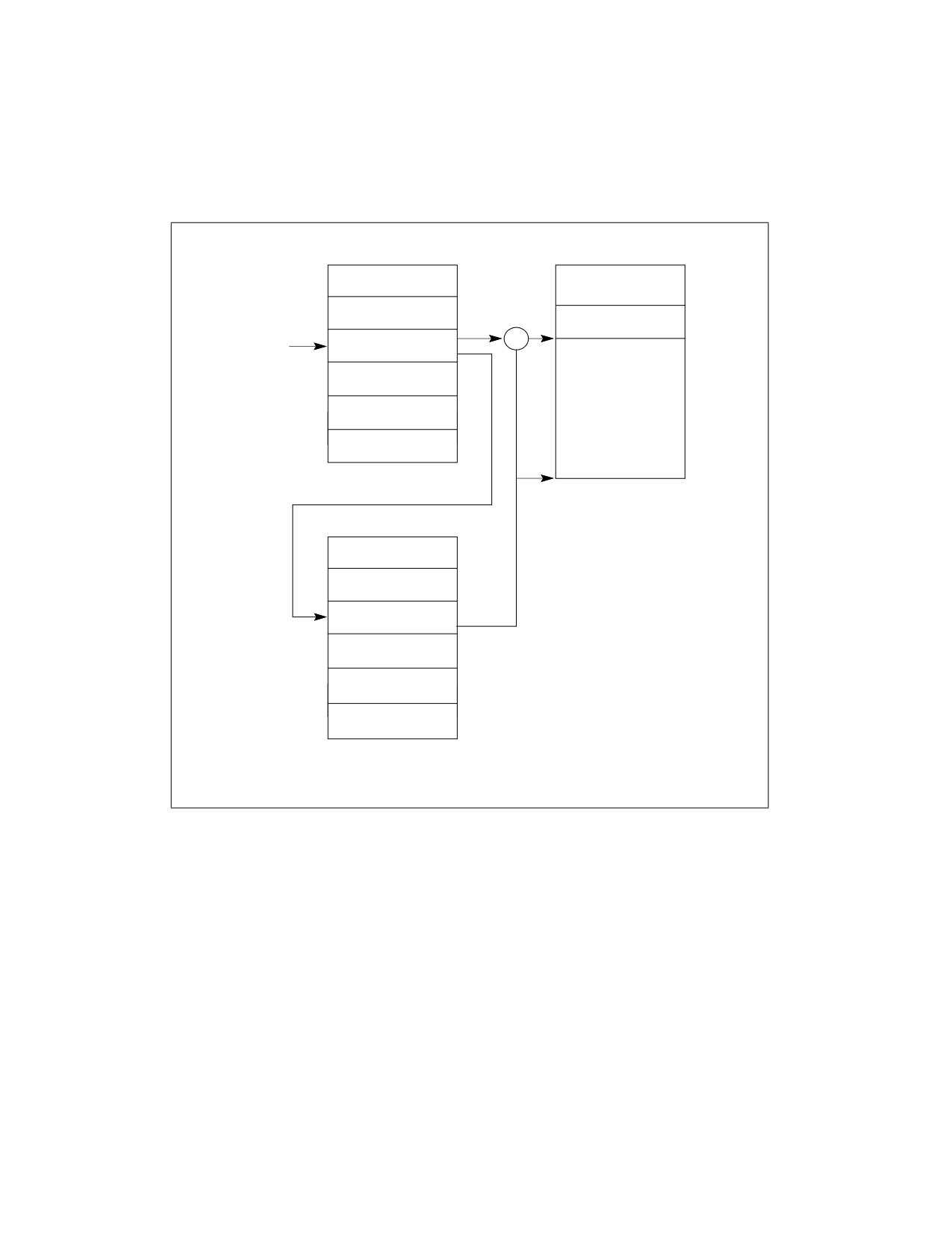
INTERRUPT AND EXCEPTION HANDLING
7.12.1 Exception- or Interrupt-Handler Procedures
An interrupt gate or trap gate references an exception- or interrupt-handler procedure that runs in the context of
the currently executing task (see Figure 7-3). The segment selector for the gate points to a segment descriptor for
an executable code segment in either the GDT or the current LDT. The offset field of the gate descriptor points to
the beginning of the exception- or interrupt-handling procedure.
Destination
IDT
Code Segment
Interrupt
Offset
Procedure
Interrupt
Interrupt or
+
Vector
Trap Gate
Segment Selector
GDT or LDT
Base
Address
Segment
Descriptor
Figure 7-3. Interrupt Procedure Call
Vol. 3A
7-13
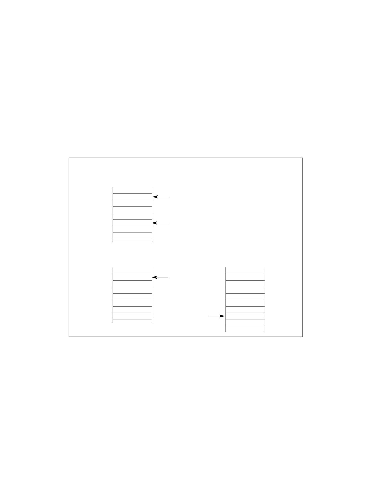
INTERRUPT AND EXCEPTION HANDLING
When the processor performs a call to the exception- or interrupt-handler procedure:
•
If the handler procedure is going to be executed at a numerically lower privilege level, a stack switch occurs.
When the stack switch occurs:
a. The segment selector and stack pointer for the stack to be used by the handler are obtained from the TSS
for the currently executing task. On this new stack, the processor pushes the stack segment selector and
stack pointer of the interrupted procedure.
b. The processor then saves the current state of the EFLAGS, CS, and EIP registers on the new stack (see
Figure 7-4).
c. If an exception causes an error code to be saved, it is pushed on the new stack after the EIP value.
•
If the handler procedure is going to be executed at the same privilege level as the interrupted procedure:
a. The processor saves the current state of the EFLAGS, CS, and EIP registers on the current stack (see Figure
7-4).
b. If an exception causes an error code to be saved, it is pushed on the current stack after the EIP value.
Stack Usage with No
Privilege-Level Change
Interrupted Procedure’s
and Handler’s Stack
ESP Before
EFLAGS
Transfer to Handler
CS
EIP
Error Code
ESP After
Transfer to Handler
Stack Usage with
Privilege-Level Change
Interrupted Procedure’s
Handler’s Stack
Stack
ESP Before
Transfer to Handler
SS
ESP
EFLAGS
CS
EIP
ESP After
Error Code
Transfer to Handler
Figure 7-4. Stack Usage on Transfers to Interrupt and Exception-Handling Routines
To return from an exception- or interrupt-handler procedure, the handler must use the IRET (or IRETD) instruction.
The IRET instruction is similar to the RET instruction except that it restores the saved flags into the EFLAGS
register. The IOPL field of the EFLAGS register is restored only if the CPL is 0. The IF flag is changed only if the CPL
is less than or equal to the IOPL. See Chapter 3, “Instruction Set Reference, A-L,” of the Intel® 64 and IA-32 Archi-
tectures Software Developer’s Manual, Volume 2A, for a description of the complete operation performed by the
IRET instruction.
If a stack switch occurred when calling the handler procedure, the IRET instruction switches back to the interrupted
procedure’s stack on the return.
7-14
Vol. 3A
INTERRUPT AND EXCEPTION HANDLING
7.12.1.1 Shadow Stack Usage on Transfers to Interrupt and Exception Handling Routines
When the processor performs a call to the exception- or interrupt-handler procedure:
• If the handler procedure is going to be execute at a numerically lower privilege level, a shadow stack switch
occurs. When the shadow stack switch occurs:
a. On a transfer from privilege level 3, if shadow stacks are enabled at privilege level 3 then the SSP is saved
to the IA32_PL3_SSP MSR.
b. If shadow stacks are enabled at the privilege level where the handler will execute then the shadow stack for
the handler is obtained from one of the following MSRs based on the privilege level at which the handler
executes.
• IA32_PL2_SSP if handler executes at privilege level 2.
• IA32_PL1_SSP if handler executes at privilege level 1.
• IA32_PL0_SSP if handler executes at privilege level 0.
c. The SSP obtained is then verified to ensure it points to a valid supervisory shadow stack that is not
currently active by verifying a supervisor shadow stack token at the address pointed to by the SSP. The
operations performed to verify and acquire the supervisor shadow stack token by making it busy are as
described in Section 18.2.3 of the Intel® 64 and IA-32 Architectures Software Developer’s Manual, Volume
1.
d. On this new shadow stack, the processor pushes the CS, LIP (CS.base + EIP), and SSP of the interrupted
procedure if the interrupted procedure was executing at privilege level less than 3; see Figure 7-5.1
• If the handler procedure is going to be executed at the same privilege level as the interrupted procedure and
shadow stacks are enabled at current privilege level:
a. The processor saves the current state of the CS, LIP (CS.base + EIP), and SSP registers on the current
shadow stack; see Figure 7-5.
1. If any of these pushes leads to an exception or a VM exit, the supervisor shadow-stack token remains busy.
Vol. 3A
7-15
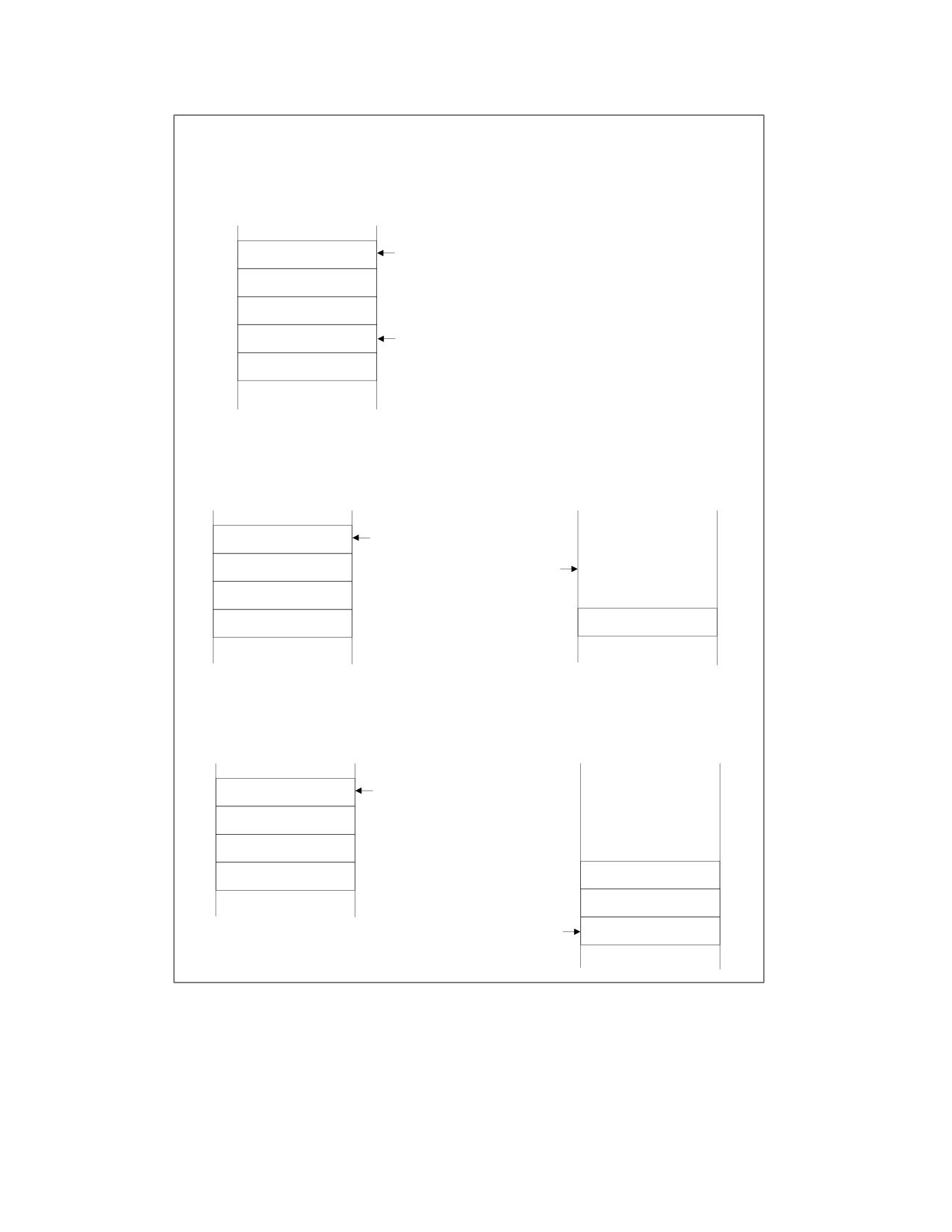
INTERRUPT AND EXCEPTION HANDLING
Shadow Stack Usage with
No Privilege-Level Change
Interrupted Procedure’s
and Handler’s Shadow Stack
SSP Before
Transfer to Handler
CS
LIP
SSP
SSP After
Transfer to Handler
Shadow Stack Usage with Privilege-
Level Change from Level 3
Interrupted Procedure’s
Handler’s Shadow Stack
Shadow Stack
SSP Before
Transfer to Handler
Supervisor
Shadow Stack
SSP After
Token
Transfer to Handler
Shadow Stack Usage with Privilege-
Level Change from Level 2 or 1
Interrupted Procedure’s
Handler’s Shadow Stack
Shadow Stack
SSP Before
Transfer to Handler
Supervisor
Shadow Stack
Token
CS
LIP
SSP After
SSP
Transfer to Handler
Figure 7-5. Shadow Stack Usage on Transfers to Interrupt and Exception-Handling Routines
To return from an exception- or interrupt-handler procedure, the handler must use the IRET (or IRETD) instruction.
When executing a return from an interrupt or exception handler from the same privilege level as the interrupted
procedure, the processor performs these actions to enforce return address protection:
• Restores the CS and EIP registers to their values prior to the interrupt or exception.
7-16
Vol. 3A
INTERRUPT AND EXCEPTION HANDLING
If shadow stack is enabled:
- Compares the values on shadow stack at address SSP+8 (the LIP) and SSP+16 (the CS) to the CS and
(CS.base + EIP) popped from the stack and causes a control protection exception (#CP(FAR-RET/IRET)) if
they do not match.
- Pops the top-of-stack value (the SSP prior to the interrupt or exception) from shadow stack into SSP
register.
When executing a return from an interrupt or exception handler from a different privilege level than the interrupted
procedure, the processor performs the actions below.
• If shadow stack is enabled at current privilege level:
- If SSP is not aligned to 8 bytes then causes a control protection exception (#CP(FAR-RET/IRET)).
- If privilege level of the procedure being returned to is less than 3 (returning to supervisor mode):
• Compares the values on shadow stack at address SSP+8 (the LIP) and SSP+16 (the CS) to the CS and
(CS.base + EIP) popped from the stack and causes a control protection exception (#CP(FAR-
RET/IRET)) if they do not match.
• Temporarily saves the top-of-stack value (the SSP of the procedure being returned to) internally.
- If a busy supervisor shadow stack token is present at address SSP+24, then marks the token free using
operations described in section Section 18.2.3 of the Intel® 64 and IA-32 Architectures Software
Developer’s Manual, Volume 1.
- If the privilege level of the procedure being returned to is less than 3 (returning to supervisor mode),
restores the SSP register from the internally saved value.
- If the privilege level of the procedure being returned to is 3 (returning to user mode) and shadow stack is
enabled at privilege level 3, then restores the SSP register with value of IA32_PL3_SSP MSR.
7.12.1.2 Protection of Exception- and Interrupt-Handler Procedures
The privilege-level protection for exception- and interrupt-handler procedures is similar to that used for ordinary
procedure calls when called through a call gate (see Section 6.8.4, “Accessing a Code Segment Through a Call
Gate”). The processor does not permit transfer of execution to an exception- or interrupt-handler procedure in a
less privileged code segment (numerically greater privilege level) than the CPL.
An attempt to violate this rule results in a general-protection exception (#GP). The protection mechanism for
exception- and interrupt-handler procedures is different in the following ways:
• Because interrupt and exception vectors have no RPL, the RPL is not checked on implicit calls to exception and
interrupt handlers.
• The processor checks the DPL of the interrupt or trap gate only if an exception or interrupt is generated with an
INT n, INT3, or INTO instruction.1 Here, the CPL must be less than or equal to the DPL of the gate. This
restriction prevents application programs or procedures running at privilege level 3 from using a software
interrupt to access critical exception handlers, such as the page-fault handler, providing that those handlers are
placed in more privileged code segments (numerically lower privilege level). For hardware-generated
interrupts and processor-detected exceptions, the processor ignores the DPL of interrupt and trap gates.
Because exceptions and interrupts generally do not occur at predictable times, these privilege rules effectively
impose restrictions on the privilege levels at which exception and interrupt- handling procedures can run. Either of
the following techniques can be used to avoid privilege-level violations.
• The exception or interrupt handler can be placed in a conforming code segment. This technique can be used for
handlers that only need to access data available on the stack (for example, divide error exceptions). If the
handler needs data from a data segment, the data segment needs to be accessible from privilege level 3, which
would make it unprotected.
• The handler can be placed in a nonconforming code segment with privilege level 0. This handler would always
run, regardless of the CPL that the interrupted program or task is running at.
1. This check is not performed by execution of the INT1 instruction (opcode F1); it would be performed by execution of INT 1 (opcode
CD 01).
Vol. 3A
7-17
INTERRUPT AND EXCEPTION HANDLING
7.12.1.3 Flag Usage By Exception- or Interrupt-Handler Procedure
When accessing an exception or interrupt handler through either an interrupt gate or a trap gate, the processor
clears the TF flag in the EFLAGS register after it saves the contents of the EFLAGS register on the stack. (On calls
to exception and interrupt handlers, the processor also clears the VM, RF, and NT flags in the EFLAGS register, after
they are saved on the stack.) Clearing the TF flag prevents instruction tracing from affecting interrupt response and
ensures that no single-step exception will be delivered after delivery to the handler. A subsequent IRET instruction
restores the TF (and VM, RF, and NT) flags to the values in the saved contents of the EFLAGS register on the stack.
The only difference between an interrupt gate and a trap gate is the way the processor handles the IF flag in the
EFLAGS register. When accessing an exception- or interrupt-handling procedure through an interrupt gate, the
processor clears the IF flag to prevent other interrupts from interfering with the current interrupt handler. A subse-
quent IRET instruction restores the IF flag to its value in the saved contents of the EFLAGS register on the stack.
Accessing a handler procedure through a trap gate does not affect the IF flag.
7.12.2 Interrupt Tasks
When an exception or interrupt handler is accessed through a task gate in the IDT, a task switch results. Handling
an exception or interrupt with a separate task offers several advantages:
• The entire context of the interrupted program or task is saved automatically.
• A new TSS permits the handler to use a new privilege level 0 stack when handling the exception or interrupt. If
an exception or interrupt occurs when the current privilege level 0 stack is corrupted, accessing the handler
through a task gate can prevent a system crash by providing the handler with a new privilege level 0 stack.
• The handler can be further isolated from other tasks by giving it a separate address space. This is done by
giving it a separate LDT.
The disadvantage of handling an interrupt with a separate task is that the amount of machine state that must be
saved on a task switch makes it slower than using an interrupt gate, resulting in increased interrupt latency.
A task gate in the IDT references a TSS descriptor in the GDT (see Figure 7-6). A switch to the handler task is
handled in the same manner as an ordinary task switch (see Section 10.3, “Task Switching”). The link back to the
interrupted task is stored in the previous task link field of the handler task’s TSS. If an exception caused an error
code to be generated, this error code is copied to the stack of the new task.
When exception- or interrupt-handler tasks are used in an operating system, there are actually two mechanisms
that can be used to dispatch tasks: the software scheduler (part of the operating system) and the hardware sched-
uler (part of the processor's interrupt mechanism). The software scheduler needs to accommodate interrupt tasks
that may be dispatched when interrupts are enabled.
7-18
Vol. 3A
INTERRUPT AND EXCEPTION HANDLING
NOTE
Because IA-32 architecture tasks are not re-entrant, an interrupt-handler task must disable
interrupts between the time it completes handling the interrupt and the time it executes the IRET
instruction. This action prevents another interrupt from occurring while the interrupt task’s TSS is
still marked busy, which would cause a general-protection (#GP) exception.
TSS for Interrupt-
IDT
Handling Task
Interrupt
Task Gate
Vector
TSS Selector
TSS
Base
Address
GDT
TSS Descriptor
Figure 7-6. Interrupt Task Switch
7.13
ERROR CODE
When an exception condition is related to a specific segment selector or IDT vector, the processor pushes an error
code onto the stack of the exception handler (whether it is a procedure or task). The error code has the format
shown in Figure 7-7. The error code resembles a segment selector; however, instead of a TI flag and RPL field, the
error code contains 3 flags:
EXT
External event (bit 0) - When set, indicates that the exception occurred during delivery of an
event external to the program, such as an interrupt or an earlier exception.1 The bit is cleared if the
exception occurred during delivery of a software interrupt (INT n, INT3, or INTO).
IDT
Descriptor location (bit 1) - When set, indicates that the index portion of the error code refers
to a gate descriptor in the IDT; when clear, indicates that the index refers to a descriptor in the GDT
or the current LDT. The processor does not set this bit when FRED transitions are enabled.
TI
GDT/LDT (bit 2) - Only used when the IDT flag is clear. When set, the TI flag indicates that the
index portion of the error code refers to a segment or gate descriptor in the LDT; when clear, it indi-
cates that the index refers to a descriptor in the current GDT.
1. The bit is also set if the exception occurred during delivery of INT1.
Vol. 3A
7-19

INTERRUPT AND EXCEPTION HANDLING
31
3
2
1
0
I
E
T
Reserved
Segment Selector Index
I
D
X
T
T
Figure 7-7. Error Code
The segment selector index field provides an index into the IDT, GDT, or current LDT to the segment or gate
selector being referenced by the error code. In some cases the error code is null (all bits are clear except possibly
EXT). A null error code indicates that the error was not caused by a reference to a specific segment or that a null
segment selector was referenced in an operation.
The format of the error code is different for page-fault exceptions (#PF). See the “Event 14-Page-Fault Exception
(#PF)” section in this chapter.
The format of the error code is different for control protection exceptions (#CP). See the “Event 21-Control
Protection Exception (#CP)” section in this chapter.
The error code is pushed on the stack as a doubleword or word (depending on the default interrupt, trap, or task
gate size). To keep the stack aligned for doubleword pushes, the upper half of the error code is reserved. Note that
the error code is not popped when the IRET instruction is executed to return from an exception handler, so the
handler must remove the error code before executing a return.
Error codes are not pushed on the stack for exceptions that are generated externally (with the INTR or LINT[1:0]
pins) or the INT n instruction, even if an error code is normally produced for those exceptions.
7.14
EXCEPTION AND INTERRUPT HANDLING IN 64-BIT MODE
NOTE
This section focuses on event handling based on IDT event delivery and on return using the IRET
instruction. FRED transitions are alternatives to these mechanisms. In general, the material in this
section does not apply when FRED transitions are enabled. See Chapter 8, “Flexible Return and
Event Delivery (FRED),” for more information about FRED transitions.
In 64-bit mode, interrupt and exception handling is similar to what has been described for non-64-bit modes. The
following are the exceptions:
• All interrupt handlers pointed by the IDT are in 64-bit code (this does not apply to the SMI handler).
• The size of interrupt-stack pushes is fixed at 64 bits; and the processor uses 8-byte, zero extended stores.
• The stack pointer (SS:RSP) is pushed unconditionally on interrupts. In legacy modes, this push is conditional
and based on a change in current privilege level (CPL).
• The new SS is set to NULL if there is a change in CPL.
• IRET behavior changes.
• There is a new interrupt stack-switch mechanism and a new interrupt shadow stack-switch mechanism.
• The alignment of interrupt stack frame is different.
7.14.1
64-Bit Mode IDT
Interrupt and trap gates are 16 bytes in length to provide a 64-bit offset for the instruction pointer (RIP). The 64-
bit RIP referenced by interrupt-gate descriptors allows an interrupt service routine to be located anywhere in the
linear-address space. See Figure 7-8.
7-20
Vol. 3A

INTERRUPT AND EXCEPTION HANDLING
Interrupt/Trap Gate
31
0
Reserved
12
31
0
Offset 63..32
8
31
16 15 14 13 12
11
8
7
5
4
2
0
D
Offset 31..16
P
P
0
TYPE
0
0
0
0
0
IST
4
L
31
16 15
0
Segment Selector
Offset 15..0
0
DPL
Descriptor Privilege Level
Offset
Offset to procedure entry point
P
Segment Present flag
Selector
Segment Selector for destination code segment
IST
Interrupt Stack Table
Figure 7-8. 64-Bit IDT Gate Descriptors
In 64-bit mode, the IDT index is formed by scaling the interrupt vector by 16. The first eight bytes (bytes 7:0) of a
64-bit mode interrupt gate are similar but not identical to legacy 32-bit interrupt gates. The type field (bits 11:8 in
bytes 7:4) is described in Table 3-2. The Interrupt Stack Table (IST) field (bits 4:0 in bytes 7:4) is used by the stack
switching mechanisms described in Section 7.14.5, “Interrupt Stack Table.” Bytes 11:8 hold the upper 32 bits of
the target RIP (interrupt segment offset) in canonical form. A general-protection exception (#GP) is generated if
software attempts to reference an interrupt gate with a target RIP that is not in canonical form.
The target code segment referenced by the interrupt gate must be a 64-bit code segment (CS.L = 1, CS.D = 0). If
the target is not a 64-bit code segment, a general-protection exception (#GP) is generated with the IDT vector
number reported as the error code.
Only 64-bit interrupt and trap gates can be referenced in IA-32e mode (64-bit mode and compatibility mode).
Legacy 32-bit interrupt or trap gate types (0EH or 0FH) are redefined in IA-32e mode as 64-bit interrupt and trap
gate types. No 32-bit interrupt or trap gate type exists in IA-32e mode. If a reference is made to a 16-bit interrupt
or trap gate (06H or 07H), a general-protection exception (#GP(0)) is generated.
7.14.2
64-Bit Mode Stack Frame
In legacy mode, the size of an IDT entry (16 bits or 32 bits) determines the size of interrupt-stack-frame pushes.
SS:ESP is pushed only on a CPL change. In 64-bit mode, the size of interrupt stack-frame pushes is fixed at eight
bytes. This is because only 64-bit mode gates can be referenced. 64-bit mode also pushes SS:RSP unconditionally,
rather than only on a CPL change.
When shadow stacks are enabled at the interrupt handler’s privilege level and the interrupted procedure was not
executing at a privilege level 3, then the processor pushes the CS:LIP:SSP of the interrupted procedure on the
shadow stack of the interrupt handler (where LIP is the linear address of the return address).
Aside from error codes, pushing SS:RSP unconditionally presents operating systems with a consistent interrupt-
stackframe size across all interrupts. Interrupt service-routine entry points that handle interrupts generated by the
INTn instruction or external INTR# signal can push an additional error code place-holder to maintain consistency.
In legacy mode, the stack pointer may be at any alignment when an interrupt or exception causes a stack frame to
be pushed. This causes the stack frame and succeeding pushes done by an interrupt handler to be at arbitrary
alignments. In IA-32e mode, the RSP is aligned to a 16-byte boundary before pushing the stack frame. The stack
frame itself is aligned on a 16-byte boundary when the interrupt handler is called. The processor can arbitrarily
realign the new RSP on interrupts because the previous (possibly unaligned) RSP is unconditionally saved on the
newly aligned stack. The previous RSP will be automatically restored by a subsequent IRET.
Vol. 3A
7-21
INTERRUPT AND EXCEPTION HANDLING
Aligning the stack permits exception and interrupt frames to be aligned on a 16-byte boundary before interrupts
are re-enabled. This allows the stack to be formatted for optimal storage of 16-byte XMM registers, which enables
the interrupt handler to use faster 16-byte aligned loads and stores (MOVAPS rather than MOVUPS) to save and
restore XMM registers.
Although the RSP alignment is always performed when LMA = 1, it is only of consequence for the kernel-mode case
where there is no stack switch or IST used. For a stack switch or IST, the OS would have presumably put suitably
aligned RSP values in the TSS.
7.14.3 IRET in IA-32e Mode
In IA-32e mode, IRET executes with an 8-byte operand size. There is nothing that forces this requirement. The
stack is formatted in such a way that for actions where IRET is required, the 8-byte IRET operand size works
correctly.
Because interrupt stack-frame pushes are always eight bytes in IA-32e mode, an IRET must pop eight byte items
off the stack. This is accomplished by preceding the IRET with a 64-bit operand-size prefix. The size of the pop is
determined by the address size of the instruction. The SS/ESP/RSP size adjustment is determined by the stack size.
IRET pops SS:RSP unconditionally off the interrupt stack frame only when it is executed in 64-bit mode. In compat-
ibility mode, IRET pops SS:RSP off the stack only if there is a CPL change. This allows legacy applications to execute
properly in compatibility mode when using the IRET instruction. 64-bit interrupt service routines that exit with an
IRET unconditionally pop SS:RSP off of the interrupt stack frame, even if the target code segment is running in 64-
bit mode or at CPL = 0. This is because the original interrupt always pushes SS:RSP.
When shadow stacks are enabled and the target privilege level is not 3, the CS:LIP from the shadow stack frame is
compared to the return linear address formed by CS:EIP from the stack. If they do not match then the processor
caused a control protection exception (#CP(FAR-RET/IRET)), else the processor pops the SSP of the interrupted
procedure from the shadow stack. If the target privilege level is 3 and shadow stacks are enabled at privilege level
3, then the SSP for the interrupted procedure is restored from the IA32_PL3_SSP MSR.
In IA-32e mode, IRET is allowed to load a NULL SS under certain conditions. If the target mode is 64-bit mode and
the target CPL ? 3, IRET allows SS to be loaded with a NULL selector. As part of the stack switch mechanism, an
interrupt or exception sets the new SS to NULL, instead of fetching a new SS selector from the TSS and loading the
corresponding descriptor from the GDT or LDT. The new SS selector is set to NULL in order to properly handle
returns from subsequent nested far transfers. If the called procedure itself is interrupted, the NULL SS is pushed on
the stack frame. On the subsequent IRET, the NULL SS on the stack acts as a flag to tell the processor not to load
a new SS descriptor.
7.14.4 Stack Switching in IA-32e Mode
The IA-32 architecture provides a mechanism to automatically switch stack frames in response to an interrupt. The
64-bit extensions of Intel 64 architecture implement a modified version of the legacy stack-switching mechanism
and an alternative stack-switching mechanism called the interrupt stack table (IST).
In IA-32 modes, the legacy IA-32 stack-switch mechanism is unchanged. In IA-32e mode, the legacy stack-switch
mechanism is modified. When stacks are switched as part of a 64-bit mode privilege-level change (resulting from
an interrupt), a new SS descriptor is not loaded. IA-32e mode loads only an inner-level RSP from the TSS. The new
SS selector is forced to NULL and the SS selector’s RPL field is set to the new CPL. The new SS is set to NULL in
order to handle nested far transfers (far CALL, INT, interrupts, and exceptions). The old SS and RSP are saved on
the new stack (Figure 7-9). On the subsequent IRET, the old SS is popped from the stack and loaded into the SS
register.
In summary, a stack switch in IA-32e mode works like the legacy stack switch, except that a new SS selector is not
loaded from the TSS. Instead, the new SS is forced to NULL.
7-22
Vol. 3A
INTERRUPT AND EXCEPTION HANDLING
Legacy Mode
Stack Usage with
IA-32e Mode
Privilege-Level Change
Handler’s Stack
Handler’s Stack
+20
SS
SS
+40
+16
ESP
RSP
+32
+12
EFLAGS
RFLAGS
+24
+8
+16
CS
CS
+4
EIP
RIP
+8
0
Error Code
Stack Pointer After
Error Code
0
Transfer to Handler
Figure 7-9. IA-32e Mode Stack Usage After Privilege Level Change
7.14.5 Interrupt Stack Table
In IA-32e mode, a new interrupt stack table (IST) mechanism is available as an alternative to the modified legacy
stack-switching mechanism described above. This mechanism unconditionally switches stacks when it is enabled.
It can be enabled on an individual interrupt-vector basis using a field in the IDT entry. This means that some inter-
rupt vectors can use the modified legacy mechanism and others can use the IST mechanism.
The IST mechanism is only available in IA-32e mode. It is part of the 64-bit mode TSS. The motivation for the IST
mechanism is to provide a method for specific interrupts (such as NMI, double-fault, and machine-check) to always
execute on a known good stack. In legacy mode, interrupts can use the task-switch mechanism to set up a known-
good stack by accessing the interrupt service routine through a task gate located in the IDT. However, the legacy
task-switch mechanism is not supported in IA-32e mode.
The IST mechanism provides up to seven IST pointers in the TSS. The pointers are referenced by an interrupt-gate
descriptor in the interrupt-descriptor table (IDT); see Figure 7-8. The gate descriptor contains a 3-bit IST index
field that provides an offset into the IST section of the TSS. Using the IST mechanism, the processor loads the
value pointed by an IST pointer into the RSP.
When an interrupt occurs, the new SS selector is forced to NULL and the SS selector’s RPL field is set to the new
CPL. The old SS, RSP, RFLAGS, CS, and RIP are pushed onto the new stack. Interrupt processing then proceeds as
normal. If the IST index is zero, the modified legacy stack-switching mechanism described above is used.
To support this stack-switching mechanism with shadow stacks enabled, the processor provides an MSR, IA32_IN-
TERRUPT_SSP_TABLE_ADDR, to program the linear address of a table of seven shadow stack pointers that are
selected using the IST index from the gate descriptor. To switch to a shadow stack selected from the interrupt
shadow stack table pointed to by the IA32_INTERRUPT_SSP_TABLE_ADDR, the processor requires that the
shadow stack addresses programmed into this table point to a supervisor shadow stack token; see Figure 7-10.
Vol. 3A
7-23
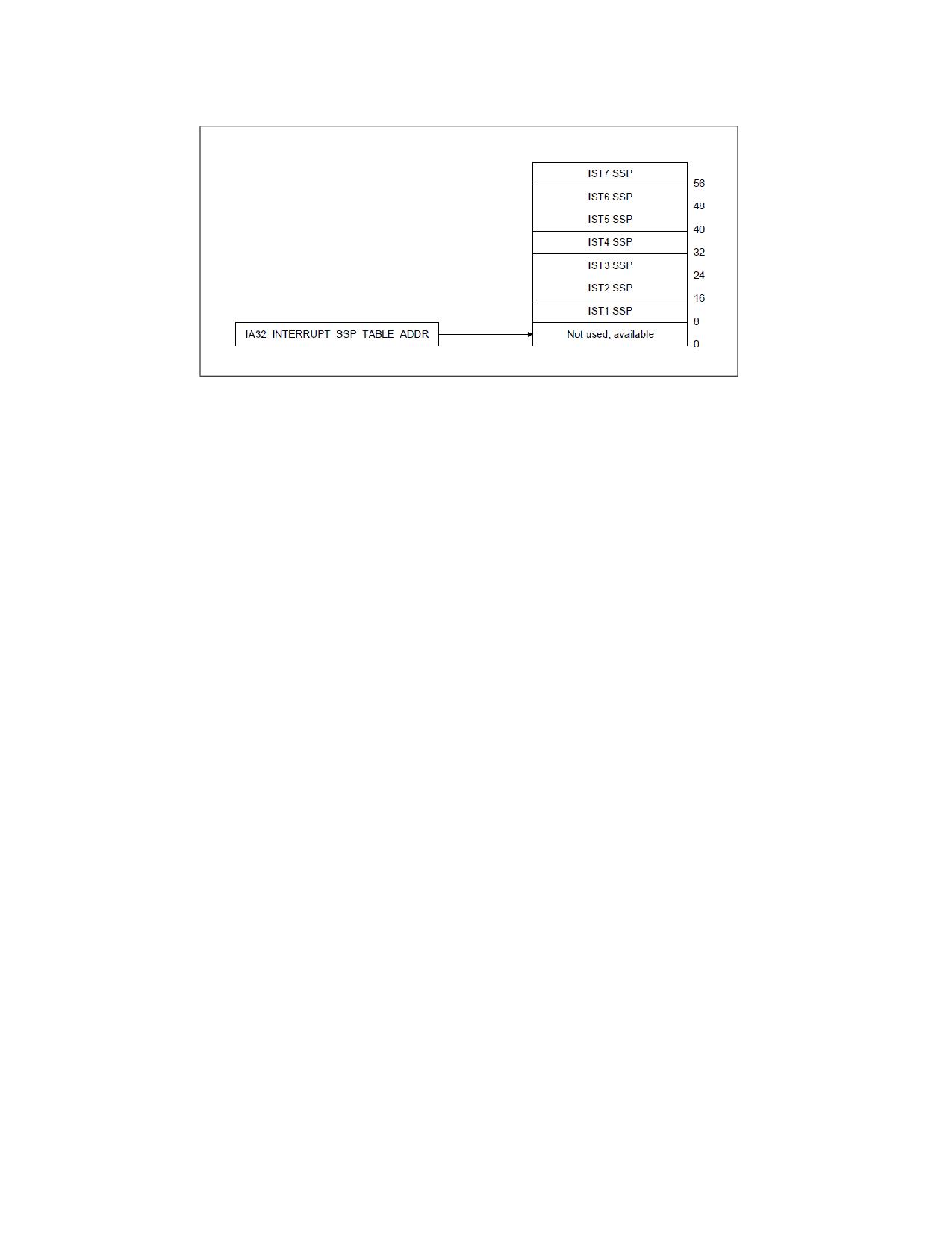
INTERRUPT AND EXCEPTION HANDLING
Figure 7-10. Interrupt Shadow Stack Table
7.15
EXCEPTION AND INTERRUPT REFERENCE
The following sections describe conditions which generate exceptions and interrupts. They are arranged in the
order of vector numbers. The information contained in these sections are as follows:
• Exception Class - Indicates whether the exception class is a fault, trap, or abort type. Some exceptions can
be either a fault or trap type, depending on when the error condition is detected. (This section is not applicable
to interrupts.)
• Description - Gives a general description of the purpose of the exception or interrupt type. It also describes
how the processor handles the exception or interrupt.
• Exception Error Code - Indicates whether an error code is saved for the exception. If one is saved, the
contents of the error code are described. (This section is not applicable to interrupts.)
• Event Data - In addition to the error code, FRED event delivery provides 64 bits of additional information for
certain events
• Saved Instruction Pointer - Describes which instruction the saved (or return) instruction pointer points to.
It also indicates whether the pointer can be used to restart a faulting instruction.
• Program State Change - Describes the effects of the exception or interrupt on the state of the currently
running program or task and the possibilities of restarting the program or task without loss of continuity.
7-24
Vol. 3A
INTERRUPT AND EXCEPTION HANDLING
Event 0-Divide Error Exception (#DE)
Exception Class
Fault.
Description
Indicates the divisor operand for a DIV or IDIV instruction is 0 or that the result cannot be represented in the
number of bits specified for the destination operand.
Exception Error Code
None.
Event Data
Not currently defined (zero until defined).
Saved Instruction Pointer
Saved contents of CS and EIP registers point to the instruction that generated the exception.
Program State Change
A program-state change does not accompany the divide error, because the exception occurs before the faulting
instruction is executed.
Vol. 3A
7-25

INTERRUPT AND EXCEPTION HANDLING
Event 1-Debug Exception (#DB)
Exception Class
Trap or Fault. The exception handler can distinguish between traps or faults by exam-
ining the contents of DR6 and the other debug registers.
Description
Indicates that one or more of several debug-exception conditions has been detected. Whether the exception is a
fault or a trap depends on the condition (see Table 7-3). See Chapter 20, “Debug, Branch Profile, TSC, and Intel®
Resource Director Technology (Intel® RDT) Features,” for detailed information about the debug exceptions.
Table 7-3. Debug Exception Conditions and Corresponding Exception Classes
Exception Condition
Exception Class
Instruction fetch breakpoint
Fault
Data read or write breakpoint
Trap
I/O read or write breakpoint
Trap
General detect condition (in conjunction with in-circuit emulation)
Fault
Single-step
Trap
Task-switch
Trap
Execution of INT11
Trap
NOTES:
1. Hardware vendors may use the INT1 instruction for hardware debug. For that reason, Intel recommends software vendors instead
use the INT3 instruction for software breakpoints.
Exception Error Code
None. An exception handler can examine the debug registers (or, with FRED event delivery, the event data; see
below) to determine which condition caused the exception.
Event Data
FRED event delivery of a debug exception saves information that identifies the nature of the debug exception:
• Bits 3:0 are B3-B0. When set, each of these bits indicates that the corresponding breakpoint condition was met
(and may be set even if its corresponding enabling bit in DR7 is not set).
• Bits 10:4 are not currently defined and will be zero until they are.
• Bit 11 is BLD. When set, this bit indicates that the cause of the debug exception was acquisition of a bus lock
(because IA32_DEBUGCTL[2] = 1).
• Bit 12 is not currently defined and will be zero until it is.
• Bit 13 is BD. When set, this bit indicates that the cause of the debug exception was “debug register access
detected.”
• Bit 14 is BS. When set, this bit indicates that the cause of the debug exception was the execution of a single
instruction (because execution of that instruction commenced with RFLAGS.TF = 1).1
• Bit 15 is not currently defined and will be zero until it is.
• Bit 16 is RTM. When set, this bit indicates that a debug exception (#DB) or a breakpoint exception (#BP)
occurred inside an RTM region while advanced debugging of RTM transactional regions was enabled.
• Bits 63:17 are not currently defined and will be zero until they are.
1. If in addition IA32_DEBUGCTL.BTF was 1 when the instruction commenced, a debug exception occurs only if the instruction was a
taken branch.
7-26
Vol. 3A
INTERRUPT AND EXCEPTION HANDLING
The event data is not exactly the same as that which will be in DR6 following delivery of the #DB. The polarity of
bit 11 and bit 16 is inverted in DR6; in addition, delivery of #DB may leave unmodified in DR6 some bits in positions
that are clear in the event data and that were already set in DR6.
Saved Instruction Pointer
Fault - Saved contents of CS and EIP registers point to the instruction that generated the exception.
Trap - Saved contents of CS and EIP registers point to the instruction following the instruction that generated the
exception.
Program State Change
Fault - A program-state change does not accompany the debug exception, because the exception occurs before
the faulting instruction is executed. The program can resume normal execution upon returning from the debug
exception handler.
Trap - A program-state change does accompany the debug exception, because the instruction or task switch being
executed is allowed to complete before the exception is generated. However, the new state of the program is not
corrupted and execution of the program can continue reliably.
The following items detail the treatment of debug exceptions on the instruction boundary following execution of the
MOV or the POP instruction that loads the SS register:
• If EFLAGS.TF is 1, no single-step trap is generated.
• If the instruction encounters a data breakpoint, the resulting debug exception is delivered after completion of
the instruction after the MOV or POP. This occurs even if the next instruction is INT n, INT3, or INTO.
• Any instruction breakpoint on the instruction after the MOV or POP is suppressed (as if EFLAGS.RF were 1).
Any debug exception inside an RTM region causes a transactional abort and, by default, redirects control flow to the
fallback instruction address. If advanced debugging of RTM transactional regions has been enabled, any transac-
tional abort due to a debug exception instead causes execution to roll back to just before the XBEGIN instruction
and then delivers a #DB. See Section 17.3.7, “RTM-Enabled Debugger Support,” of Intel® 64 and IA-32 Architec-
tures Software Developer’s Manual, Volume 1.
Vol. 3A
7-27
INTERRUPT AND EXCEPTION HANDLING
Event 2-NMI Interrupt
Exception Class
Not applicable.
Description
The nonmaskable interrupt (NMI) is generated externally by asserting the processor’s NMI pin or through an NMI
request set by the I/O APIC to the local APIC. This interrupt causes the NMI interrupt handler to be called.
Exception Error Code
Not applicable.
Event Data
FRED event delivery of an NMI saves information that depends on whether the processor supports NMI-source
reporting:
• If the processor supports NMI-source reporting, the event data contains the source information about the NMIs
being delivered (see Section 7.7.3).
• If the processor does not support NMI-source reporting, the event data is zero.
A processor supports NMI-source reporting if CPUID.07H.01H:EAX.NMI_SRC[20] is enumerated as 1.
Saved Instruction Pointer
The processor always takes an NMI interrupt on an instruction boundary. The saved contents of CS and EIP regis-
ters point to the next instruction to be executed at the point the interrupt is taken. See Section 7.5, “Exception
Classifications,” for more information about when the processor takes NMI interrupts.
Program State Change
The instruction executing when an NMI interrupt is received is completed before the NMI is generated. A program
or task can thus be restarted upon returning from an interrupt handler without loss of continuity, provided the
interrupt handler saves the state of the processor before handling the interrupt and restores the processor’s state
prior to a return.
7-28
Vol. 3A
INTERRUPT AND EXCEPTION HANDLING
Event 3-Breakpoint Exception (#BP)
Exception Class
Trap.
Description
Indicates that a breakpoint instruction (INT3, opcode CC) was executed, causing a breakpoint trap to be gener-
ated. Typically, a debugger sets a breakpoint by replacing the first opcode byte of an instruction with the opcode
for the INT3 instruction. (The INT3 instruction is one byte long, which makes it easy to replace an opcode in a code
segment in RAM with the breakpoint opcode.) The operating system or a debugging tool can use a data segment
mapped to the same physical address space as the code segment to place an INT3 instruction in places where it is
desired to call the debugger.
With the P6 family, Pentium, Intel486, and Intel386 processors, it is more convenient to set breakpoints with the
debug registers. (See Section 20.3.2, “Breakpoint Exception (#BP)-Interrupt Vector 3,” for information about the
breakpoint exception.) If more breakpoints are needed beyond what the debug registers allow, the INT3 instruc-
tion can be used.
Any breakpoint exception inside an RTM region causes a transactional abort and, by default, redirects control flow
to the fallback instruction address. If advanced debugging of RTM transactional regions has been enabled, any
transactional abort due to a break exception instead causes execution to roll back to just before the XBEGIN
instruction and then delivers a debug exception (#DB) - not a breakpoint exception. See Section 17.3.7, “RTM-
Enabled Debugger Support,” of Intel® 64 and IA-32 Architectures Software Developer’s Manual, Volume 1.
A breakpoint exception can also be generated by executing the INT n instruction with an operand of 3. The action
of this instruction (INT 3) is slightly different than that of the INT3 instruction (see “INT n/INTO/INT3/INT1-Call
to Interrupt Procedure” in Chapter 3 of the Intel® 64 and IA-32 Architectures Software Developer’s Manual,
Volume 2A).
Exception Error Code
None.
Event Data
Not currently defined (zero until defined).
Saved Instruction Pointer
Saved contents of CS and EIP registers point to the instruction following the INT3 instruction.
Program State Change
Even though the EIP points to the instruction following the breakpoint instruction, the state of the program is
essentially unchanged because the INT3 instruction does not affect any register or memory locations. The
debugger can thus resume the suspended program by replacing the INT3 instruction that caused the breakpoint
with the original opcode and decrementing the saved contents of the EIP register. Upon returning from the
debugger, program execution resumes with the replaced instruction.
Vol. 3A
7-29
INTERRUPT AND EXCEPTION HANDLING
Event 4-Overflow Exception (#OF)
Exception Class
Trap.
Description
Indicates that an overflow trap occurred when an INTO instruction was executed. The INTO instruction checks the
state of the OF flag in the EFLAGS register. If the OF flag is set, an overflow trap is generated.
Some arithmetic instructions (such as the ADD and SUB) perform both signed and unsigned arithmetic. These
instructions set the OF and CF flags in the EFLAGS register to indicate signed overflow and unsigned overflow,
respectively. When performing arithmetic on signed operands, the OF flag can be tested directly or the INTO
instruction can be used. The benefit of using the INTO instruction is that if the overflow exception is detected, an
exception handler can be called automatically to handle the overflow condition.
Exception Error Code
None.
Event Data
Not currently defined (zero until defined).
Saved Instruction Pointer
The saved contents of CS and EIP registers point to the instruction following the INTO instruction.
Program State Change
Even though the EIP points to the instruction following the INTO instruction, the state of the program is essentially
unchanged because the INTO instruction does not affect any register or memory locations. The program can thus
resume normal execution upon returning from the overflow exception handler.
7-30
Vol. 3A
INTERRUPT AND EXCEPTION HANDLING
Event 5-BOUND Range Exceeded Exception (#BR)
Exception Class
Fault.
Description
Indicates that a BOUND-range-exceeded fault occurred when a BOUND instruction was executed. The BOUND
instruction checks that a signed array index is within the upper and lower bounds of an array located in memory. If
the array index is not within the bounds of the array, a BOUND-range-exceeded fault is generated.
Exception Error Code
None.
Event Data
Not currently defined (zero until defined).
Saved Instruction Pointer
The saved contents of CS and EIP registers point to the BOUND instruction that generated the exception.
Program State Change
A program-state change does not accompany the bounds-check fault, because the operands for the BOUND
instruction are not modified. Returning from the BOUND-range-exceeded exception handler causes the BOUND
instruction to be restarted.
Vol. 3A
7-31
INTERRUPT AND EXCEPTION HANDLING
Event 6-Invalid Opcode Exception (#UD)
Exception Class
Fault.
Description
Indicates that the processor did one of the following things:
• Attempted to execute an invalid or reserved opcode.
• Attempted to execute an instruction with an operand type that is invalid for its accompanying opcode; for
example, the source operand for a LES instruction is not a memory location.
• Attempted to execute an MMX or SSE/SSE2/SSE3 instruction on an Intel 64 or IA-32 processor that does not
support the MMX technology or SSE/SSE2/SSE3/SSSE3 extensions, respectively. CPUID feature flags MMX (bit
23), SSE (bit 25), SSE2 (bit 26), SSE3 (ECX, bit 0), SSSE3 (ECX, bit 9) indicate support for these extensions.
• Attempted to execute an MMX instruction or SSE/SSE2/SSE3/SSSE3 SIMD instruction (with the exception of
the MOVNTI, PAUSE, PREFETCHh, SFENCE, LFENCE, MFENCE, CLFLUSH, MONITOR, and MWAIT instructions)
when the EM flag in control register CR0 is set (1).
• Attempted to execute an SSE/SE2/SSE3/SSSE3 instruction when the OSFXSR bit in control register CR4 is clear
(0). Note this does not include the following SSE/SSE2/SSE3 instructions: MASKMOVQ, MOVNTQ, MOVNTI,
PREFETCHh, SFENCE, LFENCE, MFENCE, and CLFLUSH; or the 64-bit versions of the PAVGB, PAVGW, PEXTRW,
PINSRW, PMAXSW, PMAXUB, PMINSW, PMINUB, PMOVMSKB, PMULHUW, PSADBW, PSHUFW, PADDQ, PSUBQ,
PALIGNR, PABSB, PABSD, PABSW, PHADDD, PHADDSW, PHADDW, PHSUBD, PHSUBSW, PHSUBW,
PMADDUBSM, PMULHRSW, PSHUFB, PSIGNB, PSIGND, and PSIGNW.
• Attempted to execute an SSE/SSE2/SSE3/SSSE3 instruction on an Intel 64 or IA-32 processor that caused a
SIMD floating-point exception when the OSXMMEXCPT bit in control register CR4 is clear (0).
• Executed a UD0, UD1, UD2, or UDB instruction. Note that even though it is the execution of the UD0, UD1,
UD2, or UDB instruction that causes the invalid opcode exception, the saved instruction pointer will reference
the UD0, UD1, UD2, or UDB instruction.
• Detected a LOCK prefix that precedes an instruction that may not be locked or one that may be locked but the
destination operand is not a memory location.
• Attempted to execute an LLDT, SLDT, LTR, STR, LSL, LAR, VERR, VERW, or ARPL instruction while in real-
address or virtual-8086 mode.
• Attempted to execute the RSM instruction when not in SMM mode.
In Intel 64 and IA-32 processors that implement out-of-order execution microarchitectures, this exception is not
generated until an attempt is made to retire the result of executing an invalid instruction; that is, decoding and
speculatively attempting to execute an invalid opcode does not generate this exception. Likewise, in the Pentium
processor and earlier IA-32 processors, this exception is not generated as the result of prefetching and preliminary
decoding of an invalid instruction. (See Section 7.5, “Exception Classifications,” for general rules for taking of inter-
rupts and exceptions.)
The opcodes D6 and F1 are undefined opcodes reserved by the Intel 64 and IA-32 architectures. These opcodes,
even though undefined, do not generate an invalid opcode exception.
Exception Error Code
None.
Event Data
Not currently defined (zero until defined).
Saved Instruction Pointer
The saved contents of CS and EIP registers point to the instruction that generated the exception.
7-32
Vol. 3A
INTERRUPT AND EXCEPTION HANDLING
Program State Change
A program-state change does not accompany an invalid-opcode fault, because the invalid instruction is not
executed.
Vol. 3A
7-33
INTERRUPT AND EXCEPTION HANDLING
Event 7-Device Not Available Exception (#NM)
Exception Class
Fault.
Description
Indicates one of the following things:
The device-not-available exception is generated by any one of the following conditions:
• The processor executed an x87 FPU floating-point instruction while the EM flag in control register CR0 was set
(1). See the paragraph below for the special case of the WAIT/FWAIT instruction.
• The processor executed a WAIT/FWAIT instruction while the MP and TS flags of register CR0 were set,
regardless of the setting of the EM flag.
• The processor executed an x87 FPU, MMX, or SSE/SSE2/SSE3 instruction (with the exception of MOVNTI,
PAUSE, PREFETCHh, SFENCE, LFENCE, MFENCE, and CLFLUSH) while the TS flag in control register CR0 was set
and the EM flag is clear.
• The processor executed an instruction that would access an XSAVE-managed state component and the bit in
the IA32_XFD MSR corresponding to that component is set. See Section 13.14, “Extended Feature Disable
(XFD),” in IA-32 Intel® Architecture Software Developer’s Manual, Volume 1 for details.
The EM flag is set when the processor does not have an internal x87 FPU floating-point unit. A device-not-available
exception is then generated each time an x87 FPU floating-point instruction is encountered, allowing an exception
handler to call floating-point instruction emulation routines.
The TS flag indicates that a context switch (task switch) has occurred since the last time an x87 floating-point,
MMX, or SSE/SSE2/SSE3 instruction was executed; but that the context of the x87 FPU, XMM, and MXCSR registers
were not saved. When the TS flag is set and the EM flag is clear, the processor generates a device-not-available
exception each time an x87 floating-point, MMX, or SSE/SSE2/SSE3 instruction is encountered (with the exception
of the instructions listed above). The exception handler can then save the context of the x87 FPU, XMM, and MXCSR
registers before it executes the instruction. See Section 2.5, “Control Registers,” for more information about the TS
flag.
The MP flag in control register CR0 is used along with the TS flag to determine if WAIT or FWAIT instructions should
generate a device-not-available exception. It extends the function of the TS flag to the WAIT and FWAIT instruc-
tions, giving the exception handler an opportunity to save the context of the x87 FPU before the WAIT or FWAIT
instruction is executed. The MP flag is provided primarily for use with the Intel 286 and Intel386 DX processors. For
programs running on the Pentium 4, Intel Xeon, P6 family, Pentium, or Intel486 DX processors, or the Intel 487 SX
coprocessors, the MP flag should always be set; for programs running on the Intel486 SX processor, the MP flag
should be clear.
Exception Error Code
None.
If the #NM is due to XFD, the processor loads the IA32_XFD_ERR MSR to identify the disabled state component(s).
Specifically, the MSR is loaded with the logical AND of the IA32_XFD MSR and the bitmap corresponding to the state
component(s) required by the faulting instruction. Device-not-available exceptions that are not due to XFD do not
modify the IA32_XFD_ERR MSR.
Event Data
FRED event delivery of an #NM caused by XFD saves information that indicates the cause of the exception and is
the same as that loaded into the IA32_XFD_ERR MSR (above). For an #NM not caused by XFD, the event data is
zero.
Saved Instruction Pointer
The saved contents of CS and EIP registers point to the floating-point instruction or the WAIT/FWAIT instruction
that generated the exception.
7-34
Vol. 3A
INTERRUPT AND EXCEPTION HANDLING
Program State Change
A program-state change does not accompany a device-not-available fault, because the instruction that generated
the exception is not executed.
If the EM flag is set, the exception handler can then read the floating-point instruction pointed to by the EIP and
call the appropriate emulation routine.
If the MP and TS flags are set or the TS flag alone is set, the exception handler can save the context of the x87 FPU,
clear the TS flag, and continue execution at the interrupted floating-point or WAIT/FWAIT instruction.
Vol. 3A
7-35

INTERRUPT AND EXCEPTION HANDLING
Event 8-Double Fault Exception (#DF)
Exception Class
Abort.
Description
Indicates that the processor detected a second exception while calling an exception handler for a prior exception.
Normally, when the processor detects another exception while trying to call an exception handler, the two excep-
tions can be handled serially. If, however, the processor cannot handle them serially, it signals the double-fault
exception. To determine when two faults need to be signalled as a double fault, the processor divides the excep-
tions into three classes: benign exceptions, contributory exceptions, and page faults (see Table 7-4).
Table 7-4. Interrupt and Exception Classes
Class
Vector Number
Description
Benign Exceptions and Interrupts
1
Debug
2
NMI Interrupt
3
Breakpoint
4
Overflow
5
BOUND Range Exceeded
6
Invalid Opcode
7
Device Not Available
9
Coprocessor Segment Overrun
16
Floating-Point Error
17
Alignment Check
18
Machine Check
19
SIMD floating-point
All
INT n
All
INTR
Contributory Exceptions
0
Divide Error
10
Invalid TSS
11
Segment Not Present
12
Stack Fault
13
General Protection
21
Control Protection
Page Faults
14
Page Fault
20
Virtualization Exception
Table 7-5 shows the various combinations of exception classes that cause a double fault to be generated. A double-
fault exception falls in the abort class of exceptions. The program or task cannot be restarted or resumed. The
double-fault handler can be used to collect diagnostic information about the state of the machine and/or, when
possible, to shut the application and/or system down gracefully or restart the system.
7-36
Vol. 3A