Intel 64 and IA-32 Architectures. Software Developer’s Manual (2026) - page 30

TDPBSSD/TDPBSUD/TDPBUSD/TDPBUUD-Dot Product of Signed/Unsigned Bytes with Dword
Accumulation
Opcode/
Op/
64/32 bit
CPUID Feature
Description
Instruction
En
Mode
Flag
Support
VEX.128.F2.0F38.W0 5E 11:rrr:bbb
A
V/N.E.
AMX_INT8
Matrix multiply signed byte elements from tmm2
TDPBSSD tmm1, tmm2, tmm3
by signed byte elements from tmm3 and
accumulate the dword elements in tmm1.
VEX.128.F3.0F38.W0 5E 11:rrr:bbb
A
V/N.E.
AMX_INT8
Matrix multiply signed byte elements from tmm2
TDPBSUD tmm1, tmm2, tmm3
by unsigned byte elements from tmm3 and
accumulate the dword elements in tmm1.
VEX.128.66.0F38.W0 5E 11:rrr:bbb
A
V/N.E.
AMX_INT8
Matrix multiply unsigned byte elements from
TDPBUSD tmm1, tmm2, tmm3
tmm2 by signed byte elements from tmm3 and
accumulate the dword elements in tmm1.
VEX.128.NP.0F38.W0 5E 11:rrr:bbb
A
V/N.E.
AMX_INT8
Matrix multiply unsigned byte elements from
TDPBUUD tmm1, tmm2, tmm3
tmm2 by unsigned byte elements from tmm3
and accumulate the dword elements in tmm1.
Instruction Operand Encoding
Op/En
Tuple
Operand 1
Operand 2
Operand 3
Operand 4
A
N/A
ModRM:reg (r, w)
ModRM:r/m (r)
VEX.vvvv (r)
N/A
Description
For each possible combination of (row of tmm2, column of tmm3), the instruction performs a set of SIMD dot-prod-
ucts on all corresponding four byte elements, one from tmm2 and one from tmm3, adds the results of those dot-
products, and then accumulates the result into the corresponding row and column of tmm1. Each dword in input
tiles tmm2 and tmm3 is interpreted as four byte elements. These may be signed or unsigned. Each letter in the
two-letter pattern SU, US, SS, UU indicates the signed/unsigned nature of the values in tmm2 and tmm3, respec-
tively.
Any attempt to execute the TDPBSSD/TDPBSUD/TDPBUSD/TDPBUUD instructions inside an Intel TSX transaction
will result in a transaction abort.
Operation
define DPBD(c,x,y):// arguments are dwords
if *x operand is signed*:
extend_src1 := SIGN_EXTEND
else:
extend_src1 := ZERO_EXTEND
if *y operand is signed*:
extend_src2 := SIGN_EXTEND
else:
extend_src2 := ZERO_EXTEND
p0dword := extend_src1(x.byte[0]) * extend_src2(y.byte[0])
p1dword := extend_src1(x.byte[1]) * extend_src2(y.byte[1])
p2dword := extend_src1(x.byte[2]) * extend_src2(y.byte[2])
p3dword := extend_src1(x.byte[3]) * extend_src2(y.byte[3])
c := c + p0dword + p1dword + p2dword + p3dword
TDPBSSD/TDPBSUD/TDPBUSD/TDPBUUD-Dot Product of Signed/Unsigned Bytes with Dword Accumulation
Vol. 2B
4-716
TDPBSSD, TDPBSUD, TDPBUSD, TDPBUUD tsrcdest, tsrc1, tsrc2 (Register Only Version)
// C = m x n (tsrcdest), A = m x k (tsrc1), B = k x n (tsrc2)
tsrc1_elements_per_row := tsrc1.colsb / 4
tsrc2_elements_per_row := tsrc2.colsb / 4
tsrcdest_elements_per_row := tsrcdest.colsb / 4
for m in 0 ... tsrcdest.rows-1:
tmp := tsrcdest.row[m]
for k in 0 ... tsrc1_elements_per_row-1:
for n in 0 ... tsrcdest_elements_per_row-1:
DPBD( tmp.dword[n], tsrc1.row[m].dword[k], tsrc2.row[k].dword[n] )
write_row_and_zero(tsrcdest, m, tmp, tsrcdest.colsb)
zero_upper_rows(tsrcdest, tsrcdest.rows)
zero_tilecfg_start()
Intel C/C++ Compiler Intrinsic Equivalent
TDPBSSD void _tile_dpbssd(__tile dst, __tile src1, __tile src2);
TDPBSUD void _tile_dpbsud(__tile dst, __tile src1, __tile src2);
TDPBUSD void _tile_dpbusd(__tile dst, __tile src1, __tile src2);
TDPBUUD void _tile_dpbuud(__tile dst, __tile src1, __tile src2);
Flags Affected
None.
Exceptions
AMX-E4; see Section 2.10, “Intel® AMX Instruction Exception Classes,” for details.
TDPBSSD/TDPBSUD/TDPBUSD/TDPBUUD-Dot Product of Signed/Unsigned Bytes with Dword Accumulation
Vol. 2B
4-717

TDPFP16PS-Dot Product of FP16 Tiles Accumulated into Packed Single Precision Tile
Opcode/
Op/
64/32
CPUID Feature
Description
Instruction
En
bit Mode
Flag
Support
VEX.128.F2.0F38.W0 5C 11:rrr:bbb
A
V/N.E.
AMX_FP16
Matrix multiply FP16 elements from tmm2 and
TDPFP16PS tmm1, tmm2, tmm3
tmm3, and accumulate the packed single precision
elements in tmm1.
Instruction Operand Encoding
Op/En
Tuple
Operand 1
Operand 2
Operand 3
Operand 4
A
N/A
ModRM:reg (r, w)
ModRM:r/m (r)
VEX.vvvv (r)
N/A
Description
This instruction performs a set of SIMD dot-products of two FP16 elements and accumulates the results into a
packed single precision tile. Each dword element in input tiles tmm2 and tmm3 is interpreted as a FP16 pair. For
each possible combination of (row of tmm2, column of tmm3), the instruction performs a set of SIMD dot-products
on all corresponding FP16 pairs (one pair from tmm2 and one pair from tmm3), adds the results of those dot-prod-
ucts, and then accumulates the result into the corresponding row and column of tmm1.
“Round to nearest even” rounding mode is used when doing each accumulation of the Fused Multiply-Add (FMA).
Output FP32 denormals are always flushed to zero. Input FP16 denormals are always handled and not treated as
zero.
MXCSR is not consulted nor updated.
Any attempt to execute the TDPFP16PS instruction inside an Intel TSX transaction will result in a transaction abort.
Operation
TDPFP16PS tsrcdest, tsrc1, tsrc2
// C = m x n (tsrcdest), A = m x k (tsrc1), B = k x n (tsrc2)
# src1 and src2 elements are pairs of fp16
elements_src1 := tsrc1.colsb / 4
elements_src2 := tsrc2.colsb / 4
elements_dest := tsrcdest.colsb / 4
elements_temp := tsrcdest.colsb / 2 // Count is in fp16 prior to horizontal
for m in 0 ... tsrcdest.rows-1:
temp1[ 0 ... elements_temp-1 ] := 0
for k in 0 ... elements_src1-1:
for n in 0 ... elements_dest-1:
// For this operation:
// Handle FP16 denorms. Not forcing input FP16 denorms to 0.
// FP32 FMA with DAZ=FTZ=1, RNE rounding.
// MXCSR is neither consulted nor updated.
// No exceptions raised or denoted.
temp1.fp32[2*n+0] += cvt_fp16_to_fp32(tsrc1.row[m].fp16[2*k+0]) *cvt_fp16_to_fp32(tsrc2.row[k].fp16[2*n+0])
temp1.fp32[2*n+1] += cvt_fp16_to_fp32(tsrc1.row[m].fp16[2*k+1]) *cvt_fp16_to_fp32(tsrc2.row[k].fp16[2*n+1])
for n in 0 ... elements_dest-1:
// DAZ=FTZ=1, RNE rounding.
// MXCSR is neither consulted nor updated.
TDPFP16PS-Dot Product of FP16 Tiles Accumulated into Packed Single Precision Tile
Vol. 2B
4-718
// No exceptions raised or denoted.
tmpf32 := temp1.fp32[2*n] + temp1.fp32[2*n+1]
srcdest.row[m].fp32[n] := srcdest.row[m].fp32[n] + tmpf32
write_row_and_zero(tsrcdest, m, tmp, tsrcdest.colsb)
zero_upper_rows(tsrcdest, tsrcdest.rows)
zero_tileconfig_start()
Flags Affected
None.
Exceptions
AMX-E4; see Section 2.10, “Intel® AMX Instruction Exception Classes,” for details.
TDPFP16PS-Dot Product of FP16 Tiles Accumulated into Packed Single Precision Tile
Vol. 2B
4-719

TEST-Logical Compare
Opcode
Instruction
Op/
64-Bit
Compat/
Description
En
Mode
Leg Mode
A8 ib
TEST AL, imm8
I
Valid
Valid
AND imm8 with AL; set SF, ZF, PF according to result.
A9 iw
TEST AX, imm16
I
Valid
Valid
AND imm16 with AX; set SF, ZF, PF according to result.
A9 id
TEST EAX, imm32
I
Valid
Valid
AND imm32 with EAX; set SF, ZF, PF according to
result.
REX.W + A9 id
TEST RAX, imm32
I
Valid
N.E.
AND imm32 sign-extended to 64-bits with RAX; set SF,
ZF, PF according to result.
F6 /0 ib
TEST r/m81, imm8
MI
Valid
Valid
AND imm8 with r/m8; set SF, ZF, PF according to result.
F7 /0 iw
TEST r/m16, imm16
MI
Valid
Valid
AND imm16 with r/m16; set SF, ZF, PF according to
result.
F7 /0 id
TEST r/m32, imm32
MI
Valid
Valid
AND imm32 with r/m32; set SF, ZF, PF according to
result.
REX.W + F7 /0 id
TEST r/m64, imm32
MI
Valid
N.E.
AND imm32 sign-extended to 64-bits with r/m64; set
SF, ZF, PF according to result.
84 /r
TEST r/m81, r81
MR
Valid
Valid
AND r8 with r/m8; set SF, ZF, PF according to result.
85 /r
TEST r/m16, r16
MR
Valid
Valid
AND r16 with r/m16; set SF, ZF, PF according to result.
85 /r
TEST r/m32, r32
MR
Valid
Valid
AND r32 with r/m32; set SF, ZF, PF according to result.
REX.W + 85 /r
TEST r/m64, r64
MR
Valid
N.E.
AND r64 with r/m64; set SF, ZF, PF according to result.
NOTES:
1. With a REX prefix in 64-bit mode, attempts to access AH, BH, CH, or DH will instead access SPL, DIL, BPL, or SIL, respectively.
Instruction Operand Encoding
Op/En
Operand 1
Operand 2
Operand 3
Operand 4
I
AL/AX/EAX/RAX
imm8/16/32
N/A
N/A
MI
ModRM:r/m (r)
imm8/16/32
N/A
N/A
MR
ModRM:r/m (r)
ModRM:reg (r)
N/A
N/A
Description
Computes the bit-wise logical AND of first operand (source 1 operand) and the second operand (source 2 operand)
and sets the SF, ZF, and PF status flags according to the result. The result is then discarded.
In 64-bit mode, using a REX prefix in the form of REX.R permits access to additional registers (R8-R15). Using a
REX prefix in the form of REX.W promotes operation to 64 bits. See the summary chart at the beginning of this
section for encoding data and limits.
Operation
TEMP := SRC1 AND SRC2;
SF := MSB(TEMP);
IF TEMP = 0
THEN ZF := 1;
ELSE ZF := 0;
FI:
PF := BitwiseXNOR(TEMP[0:7]);
CF := 0;
OF := 0;
TEST-Logical Compare
Vol. 2B
4-720
(* AF is undefined *)
Flags Affected
The OF and CF flags are set to 0. The SF, ZF, and PF flags are set according to the result (see the “Operation”
section above). The state of the AF flag is undefined.
Protected Mode Exceptions
#GP(0)
If a memory operand effective address is outside the CS, DS, ES, FS, or GS segment limit.
If the DS, ES, FS, or GS register contains a NULL segment selector.
#SS(0)
If a memory operand effective address is outside the SS segment limit.
#PF(fault-code)
If a page fault occurs.
#AC(0)
If alignment checking is enabled and an unaligned memory reference is made while the
current privilege level is 3.
#UD
If the LOCK prefix is used.
Real-Address Mode Exceptions
#GP
If a memory operand effective address is outside the CS, DS, ES, FS, or GS segment limit.
#SS
If a memory operand effective address is outside the SS segment limit.
#UD
If the LOCK prefix is used.
Virtual-8086 Mode Exceptions
#GP(0)
If a memory operand effective address is outside the CS, DS, ES, FS, or GS segment limit.
#SS(0)
If a memory operand effective address is outside the SS segment limit.
#PF(fault-code)
If a page fault occurs.
#AC(0)
If alignment checking is enabled and an unaligned memory reference is made.
#UD
If the LOCK prefix is used.
Compatibility Mode Exceptions
Same exceptions as in protected mode.
64-Bit Mode Exceptions
#SS(0)
If a memory address referencing the SS segment is in a non-canonical form.
#GP(0)
If the memory address is in a non-canonical form.
#PF(fault-code)
If a page fault occurs.
#AC(0)
If alignment checking is enabled and an unaligned memory reference is made while the
current privilege level is 3.
#UD
If the LOCK prefix is used.
TEST-Logical Compare
Vol. 2B
4-721

TESTUI-Determine User Interrupt Flag
Opcode/
Op/
64/32 bit
CPUID Feature
Description
Instruction
En
Mode
Flag
Support
F3 0F 01 ED
ZO
V/I
UINTR
Copies the current value of UIF into EFLAGS.CF.
TESTUI
Instruction Operand Encoding
Op/En
Tuple
Operand 1
Operand 2
Operand 3
Operand 4
ZO
N/A
N/A
N/A
N/A
N/A
TESTUI copies the current value of the user interrupt flag (UIF) into EFLAGS.CF. This instruction can be executed
regardless of CPL.
TESTUI may be executed normally inside a transactional region.
Operation
CF := UIF;
ZF := AF := OF := PF := SF := 0;
Flags Affected
The ZF, OF, AF, PF, SF flags are cleared and the CF flags to the value of the user interrupt flag.
Protected Mode Exceptions
#UD
The TESTUI instruction is not recognized in protected mode.
Real-Address Mode Exceptions
#UD
The TESTUI instruction is not recognized in real-address mode.
Virtual-8086 Mode Exceptions
#UD
The TESTUI instruction is not recognized in virtual-8086 mode.
Compatibility Mode Exceptions
#UD
The TESTUI instruction is not recognized in compatibility mode.
64-Bit Mode Exceptions
#UD
If the LOCK prefix is used.
If executed inside an enclave.
If CR4.UINTR = 0.
If CPUID.07H.00H:EDX.UINTR[5] = 0.
TESTUI-Determine User Interrupt Flag
Vol. 2B
4-722

TILELOADD/TILELOADDT1-Load Tile
Opcode/
Op/
64/32 bit
CPUID Feature
Description
Instruction
En
Mode
Flag
Support
VEX.128.F2.0F38.W0 4B !(11):rrr:100
A
V/N.E.
AMX_TILE
Load data into tmm1 as specified by information
TILELOADD tmm1, sibmem
in sibmem.
VEX.128.66.0F38.W0 4B !(11):rrr:100
A
V/N.E.
AMX_TILE
Load data into tmm1 as specified by information
TILELOADDT1 tmm1, sibmem
in sibmem with hint to optimize data caching.
Instruction Operand Encoding
Op/En
Tuple
Operand 1
Operand 2
Operand 3
Operand 4
A
N/A
ModRM:reg (w)
ModRM:r/m (r)
N/A
N/A
Description
This instruction is required to use SIB addressing. The index register serves as a stride indicator. If the SIB
encoding omits an index register, the value zero is assumed for the content of the index register.
This instruction loads a tile destination with rows and columns as specified by the tile configuration. The “T1”
version provides a hint to the implementation that the data would be reused but does not need to be resident in the
nearest cache levels.
The TILECFG.start_row in the TILECFG data should be initialized to '0' in order to load the entire tile and is set to
zero on successful completion of the TILELOADD instruction. TILELOADD is a restartable instruction and the
TILECFG.start_row will be non-zero when restartable events occur during the instruction execution.
Only memory operands are supported and they can only be accessed using a SIB addressing mode, similar to the
V[P]GATHER*/V[P]SCATTER* instructions.
Any attempt to execute the TILELOADD/TILELOADDT1 instructions inside an Intel TSX transaction will result in a
transaction abort.
Operation
TILELOADD[,T1] tdest, tsib
start := tilecfg.start_row
zero_upper_rows(tdest,start)
membegin := tsib.base + displacement
// if no index register in the SIB encoding, the value zero is used.
stride := tsib.index << tsib.scale
nbytes := tdest.colsb
while start < tdest.rows:
memptr := membegin + start * stride
write_row_and_zero(tdest, start, read_memory(memptr, nbytes), nbytes)
start := start + 1
zero_tilecfg_start()
// In the case of a memory fault in the middle of an instruction, the tilecfg.start_row := start
Intel C/C++ Compiler Intrinsic Equivalent
TILELOADD void _tile_loadd(__tile dst, const void *base, int stride);
TILELOADDT1 void _tile_stream_loadd(__tile dst, const void *base, int stride);
TILELOADD/TILELOADDT1-Load Tile
Vol. 2B
4-723
Flags Affected
None.
Exceptions
AMX-E3; see Section 2.10, “Intel® AMX Instruction Exception Classes,” for details.
TILELOADD/TILELOADDT1-Load Tile
Vol. 2B
4-724

TILERELEASE-Release Tile
Opcode/
Op/
64/32 bit
CPUID Feature
Description
Instruction
En
Mode
Flag
Support
VEX.128.NP.0F38.W0 49 C0
A
V/N.E.
AMX_TILE
Initialize TILECFG and TILEDATA.
TILERELEASE
Instruction Operand Encoding
Op/En
Tuple
Operand 1
Operand 2
Operand 3
Operand 4
A
N/A
N/A
N/A
N/A
N/A
Description
This instruction returns TILECFG and TILEDATA to the INIT state.
Any attempt to execute the TILERELEASE instruction inside an Intel TSX transaction will result in a transaction
abort.
Operation
zero_all_tile_data()
tilecfg := 0// equivalent to 64B of zeros
TILES_CONFIGURED := 0
Intel C/C++ Compiler Intrinsic Equivalent
TILERELEASE void _tile_release(void);
Flags Affected
None.
Exceptions
AMX-E6; see Section 2.10, “Intel® AMX Instruction Exception Classes,” for details.
TILERELEASE-Release Tile
Vol. 2B
4-725

TILESTORED-Store Tile
Opcode/
Op/
64/32 bit
CPUID Feature
Description
Instruction
En
Mode
Flag
Support
VEX.128.F3.0F38.W0 4B !(11):rrr:100
A
V/N.E.
AMX_TILE
Store a tile in sibmem as specified in tmm1.
TILESTORED sibmem, tmm1
Instruction Operand Encoding
Op/En
Tuple
Operand 1
Operand 2
Operand 3
Operand 4
A
N/A
ModRM:r/m (w)
ModRM:reg (r)
N/A
N/A
Description
This instruction is required to use SIB addressing. The index register serves as a stride indicator. If the SIB
encoding omits an index register, the value zero is assumed for the content of the index register.
This instruction stores a tile source of rows and columns as specified by the tile configuration.
The TILECFG.start_row in the TILECFG data should be initialized to '0' in order to store the entire tile and are set to
zero on successful completion of the TILESTORED instruction. TILESTORED is a restartable instruction and the
TILECFG.start_row will be non-zero when restartable events occur during the instruction execution.
Only memory operands are supported and they can only be accessed using a SIB addressing mode, similar to the
V[P]GATHER*/V[P]SCATTER* instructions.
Any attempt to execute the TILESTORED instruction inside an Intel TSX transaction will result in a transaction
abort.
Operation
TILESTORED tsib, tsrc
start := tilecfg.start_row
membegin := tsib.base + displacement
// if no index register in the SIB encoding, the value zero is used.
stride := tsib.index << tsib.scale
while start < tdest.rows:
memptr := membegin + start * stride
write_memory(memptr, tsrc.colsb, tsrc.row[start])
start := start + 1
zero_tilecfg_start()
// In the case of a memory fault in the middle of an instruction, the tilecfg.start_row := start
Intel C/C++ Compiler Intrinsic Equivalent
TILESTORED void _tile_stored(__tile src, void *base, int stride);
Flags Affected
None.
Exceptions
AMX-E3; see Section 2.10, “Intel® AMX Instruction Exception Classes,” for details.
TILESTORED-Store Tile
Vol. 2B
4-726

TILEZERO-Zero Tile
Opcode/
Op/
64/32 bit
CPUID Feature
Description
Instruction
En
Mode
Flag
Support
VEX.128.F2.0F38.W0 49 11:rrr:000
A
V/N.E.
AMX_TILE
Zero the destination tile.
TILEZERO tmm1
Instruction Operand Encoding
Op/En
Tuple
Operand 1
Operand 2
Operand 3
Operand 4
A
N/A
ModRM:reg (w)
N/A
N/A
N/A
Description
This instruction zeroes the destination tile.
Any attempt to execute the TILEZERO instruction inside an Intel TSX transaction will result in a transaction abort.
Operation
TILEZERO tdest
nbytes := palette_table[palette_id].bytes_per_row
for i in 0 ... palette_table[palette_id].max_rows-1:
for j in 0 ... nbytes-1:
tdest.row[i].byte[j] := 0
zero_tilecfg_start()
Intel C/C++ Compiler Intrinsic Equivalent
TILEZERO void _tile_zero(__tile dst);
Flags Affected
None.
Exceptions
AMX-E5; see Section 2.10, “Intel® AMX Instruction Exception Classes,” for details.
TILEZERO-Zero Tile
Vol. 2B
4-727

TPAUSE-Timed PAUSE
Opcode /
Op/
64/32 bit
CPUID
Description
Instruction
En
Mode
Feature
Support
Flag
66 0F AE /6
A
V/V
WAITPKG
Directs the processor to enter an implementation-dependent
optimized state until the TSC reaches the value in EDX:EAX.
TPAUSE r32, <edx>, <eax>
Instruction Operand Encoding1
Op/En
Tuple
Operand 1
Operand 2
Operand 3
Operand 4
A
N/A
ModRM:r/m (r)
N/A
N/A
N/A
Description
TPAUSE instructs the processor to enter an implementation-dependent optimized state. There are two such opti-
mized states to choose from: light-weight power/performance optimized state, and improved power/performance
optimized state. The selection between the two is governed by the explicit input register bit[0] source operand.
TPAUSE is available when CPUID.07H.00H:ECX.WAITPKG[5] is enumerated as 1. TPAUSE may be executed at any
privilege level. This instruction’s operation is the same in non-64-bit modes and in 64-bit mode.
Unlike PAUSE, the TPAUSE instruction will not cause an abort when used inside a transactional region, described in
the chapter Chapter 16, “Programming with Intel® AVX10,” of the Intel® 64 and IA-32 Architectures Software
Developer’s Manual, Volume 1.
The input register contains information such as the preferred optimized state the processor should enter as
described in the following table. Bits other than bit 0 are reserved and will result in #GP if non-zero.
Table 4-23. TPAUSE Input Register Bit Definitions
Bit Value
State Name
Wakeup Time
Power Savings
Other Benefits
bit[0] = 0
C0.2
Slower
Larger
Improves performance of the other SMT thread(s)
on the same core.
bit[0] = 1
C0.1
Faster
Smaller
N/A
bits[31:1]
N/A
N/A
N/A
Reserved
The instruction execution wakes up when the time-stamp counter reaches or exceeds the implicit EDX:EAX 64-bit
input value.
Prior to executing the TPAUSE instruction, an operating system may specify the maximum delay it allows the
processor to suspend its operation. It can do so by writing TSC-quanta value to the following 32-bit MSR
(IA32_UMWAIT_CONTROL at MSR index E1H):
• IA32_UMWAIT_CONTROL[31:2] - Determines the maximum time in TSC-quanta that the processor can reside
in either C0.1 or C0.2. A zero value indicates no maximum time. The maximum time value is a 32-bit value
where the upper 30 bits come from this field and the lower two bits are zero.
• IA32_UMWAIT_CONTROL[1] - Reserved.
• IA32_UMWAIT_CONTROL[0] - C0.2 is not allowed by the OS. Value of “1” means all C0.2 requests revert to
C0.1.
If the processor that executed a TPAUSE instruction wakes due to the expiration of the operating system time-limit,
the instructions sets RFLAGS.CF; otherwise, that flag is cleared.
The following additional events cause the processor to exit the implementation-dependent optimized state: a store
to the read-set range within the transactional region, an NMI or SMI, a debug exception, a machine check excep-
tion, the BINIT# signal, the INIT# signal, and the RESET# signal.
1. The Mod field of the ModR/M byte must have value 11B.
TPAUSE-Timed PAUSE
Vol. 2B
4-728
Other implementation-dependent events may cause the processor to exit the implementation-dependent opti-
mized state proceeding to the instruction following TPAUSE. In addition, an external interrupt causes the processor
to exit the implementation-dependent optimized state regardless of whether maskable-interrupts are inhibited
(EFLAGS.IF =0). It should be noted that if maskable-interrupts are inhibited execution will proceed to the instruc-
tion following TPAUSE.
Operation
os_deadline := TSC+(IA32_UMWAIT_CONTROL[31:2]<<2)
instr_deadline := UINT64(EDX:EAX)
IF os_deadline < instr_deadline:
deadline := os_deadline
using_os_deadline := 1
ELSE:
deadline := instr_deadline
using_os_deadline := 0
WHILE TSC < deadline:
implementation_dependent_optimized_state(Source register, deadline, IA32_UMWAIT_CONTROL[0])
IF using_os_deadline AND TSC ≥ deadline:
RFLAGS.CF := 1
ELSE:
RFLAGS.CF := 0
RFLAGS.AF,PF,SF,ZF,OF := 0
Intel C/C++ Compiler Intrinsic Equivalent
TPAUSE uint8_t _tpause(uint32_t control, uint64_t counter);
Numeric Exceptions
None.
Exceptions (All Operating Modes)
#GP(0)
If src[31:1] != 0.
If CR4.TSD = 1 and CPL != 0.
#UD
If CPUID.07H.00H:ECX.WAITPKG[5]=0.
TPAUSE-Timed PAUSE
Vol. 2B
4-729

TZCNT-Count the Number of Trailing Zero Bits
Opcode/
Op/
64/32-
CPUID
Description
Instruction
En
bit
Feature
Mode
Flag
F3 0F BC /r
A
V/V
BMI1
Count the number of trailing zero bits in r/m16, return result in r16.
TZCNT r16, r/m16
F3 0F BC /r
A
V/V
BMI1
Count the number of trailing zero bits in r/m32, return result in r32.
TZCNT r32, r/m32
F3 REX.W 0F BC /r
A
V/N.E.
BMI1
Count the number of trailing zero bits in r/m64, return result in r64.
TZCNT r64, r/m64
Instruction Operand Encoding
Op/En
Operand 1
Operand 2
Operand 3
Operand 4
A
ModRM:reg (w)
ModRM:r/m (r)
N/A
N/A
Description
TZCNT counts the number of trailing least significant zero bits in source operand (second operand) and returns the
result in the destination operand (first operand). TZCNT is an extension of the BSF instruction. The key difference
between the TZCNT and BSF instructions is that when the source operand is zero, TZCNT outputs the operand size
to the destination operand, whereas BSF leaves the destination operand unmodified.
On processors that do not support TZCNT, the instruction byte encoding is executed as BSF.
Operation
temp := 0
DEST := 0
DO WHILE ( (temp < OperandSize) and (SRC[ temp] = 0) )
temp := temp +1
DEST := DEST+ 1
OD
IF DEST = OperandSize
CF := 1
ELSE
CF := 0
FI
IF DEST = 0
ZF := 1
ELSE
ZF := 0
FI
Flags Affected
ZF is set to 1 in case of zero output (least significant bit of the source is set), and to 0 otherwise, CF is set to 1 if
the input was zero and cleared otherwise. OF, SF, PF, and AF flags are undefined.
Intel C/C++ Compiler Intrinsic Equivalent
TZCNT unsigned __int32 _tzcnt_u32(unsigned __int32 src);
TZCNT unsigned __int64 _tzcnt_u64(unsigned __int64 src);
TZCNT-Count the Number of Trailing Zero Bits
Vol. 2B
4-730
Protected Mode Exceptions
#GP(0)
For an illegal memory operand effective address in the CS, DS, ES, FS or GS segments.
If the DS, ES, FS, or GS register is used to access memory and it contains a null segment
selector.
#SS(0)
For an illegal address in the SS segment.
#PF (fault-code)
For a page fault.
#AC(0)
If alignment checking is enabled and an unaligned memory reference is made while the
current privilege level is 3.
#UD
If LOCK prefix is used.
Real-Address Mode Exceptions
#GP(0)
If any part of the operand lies outside of the effective address space from 0 to 0FFFFH.
#SS(0)
For an illegal address in the SS segment.
#UD
If LOCK prefix is used.
Virtual 8086 Mode Exceptions
#GP(0)
If any part of the operand lies outside of the effective address space from 0 to 0FFFFH.
#SS(0)
For an illegal address in the SS segment.
#PF (fault-code)
For a page fault.
#AC(0)
If alignment checking is enabled and an unaligned memory reference is made while the
current privilege level is 3.
#UD
If LOCK prefix is used.
Compatibility Mode Exceptions
Same exceptions as in Protected Mode.
64-Bit Mode Exceptions
#GP(0)
If the memory address is in a non-canonical form.
#SS(0)
If a memory address referencing the SS segment is in a non-canonical form.
#PF (fault-code)
For a page fault.
#AC(0)
If alignment checking is enabled and an unaligned memory reference is made while the
current privilege level is 3.
#UD
If LOCK prefix is used.
TZCNT-Count the Number of Trailing Zero Bits
Vol. 2B
4-731

UCOMISD-Unordered Compare Scalar Double Precision Floating-Point Values and Set EFLAGS
Opcode/
Op /
64/32 bit
CPUID Feature
Description
Instruction
En
Mode
Flag
Support
66 0F 2E /r
A
V/V
SSE2
Compare low double precision floating-point values in
UCOMISD xmm1, xmm2/m64
xmm1 and xmm2/mem64 and set the EFLAGS flags
accordingly.
VEX.LIG.66.0F.WIG 2E /r
A
V/V
AVX
Compare low double precision floating-point values in
VUCOMISD xmm1, xmm2/m64
xmm1 and xmm2/mem64 and set the EFLAGS flags
accordingly.
EVEX.LLIG.66.0F.W1 2E /r
B
V/V
AVX512F
Compare low double precision floating-point values in
VUCOMISD xmm1, xmm2/m64{sae}
OR AVX10.1
xmm1 and xmm2/m64 and set the EFLAGS flags
accordingly.
Instruction Operand Encoding
Op/En
Tuple Type
Operand 1
Operand 2
Operand 3
Operand 4
A
N/A
ModRM:reg (r)
ModRM:r/m (r)
N/A
N/A
B
Tuple1 Scalar
ModRM:reg (w)
ModRM:r/m (r)
N/A
N/A
Description
Performs an unordered compare of the double precision floating-point values in the low quadwords of operand 1
(first operand) and operand 2 (second operand), and sets the ZF, PF, and CF flags in the EFLAGS register according
to the result (unordered, greater than, less than, or equal). The OF, SF, and AF flags in the EFLAGS register are set
to 0. The unordered result is returned if either source operand is a NaN (QNaN or SNaN).
Operand 1 is an XMM register; operand 2 can be an XMM register or a 64 bit memory
location.
The UCOMISD instruction differs from the COMISD instruction in that it signals a SIMD floating-point invalid oper-
ation exception (#I) only when a source operand is an SNaN. The COMISD instruction signals an invalid operation
exception only if a source operand is either an SNaN or a QNaN.
The EFLAGS register is not updated if an unmasked SIMD floating-point exception is generated.
Note: VEX.vvvv and EVEX.vvvv are reserved and must be 1111b, otherwise instructions will #UD.
Software should ensure VCOMISD is encoded with VEX.L=0. Encoding VCOMISD with VEX.L=1 may encounter
unpredictable behavior across different processor generations.
Operation
(V)UCOMISD (All Versions)
RESULT := UnorderedCompare(DEST[63:0] <> SRC[63:0]) {
(* Set EFLAGS *) CASE (RESULT) OF
UNORDERED: ZF,PF,CF := 111;
GREATER_THAN: ZF,PF,CF := 000;
LESS_THAN: ZF,PF,CF := 001;
EQUAL: ZF,PF,CF := 100;
ESAC;
OF, AF, SF := 0; }
UCOMISD-Unordered Compare Scalar Double Precision Floating-Point Values and Set EFLAGS
Vol. 2B
4-732
Intel C/C++ Compiler Intrinsic Equivalent
VUCOMISD int _mm_comi_round_sd(__m128d a, __m128d b, int imm, int sae);
UCOMISD int _mm_ucomieq_sd(__m128d a, __m128d b)
UCOMISD int _mm_ucomilt_sd(__m128d a, __m128d b)
UCOMISD int _mm_ucomile_sd(__m128d a, __m128d b)
UCOMISD int _mm_ucomigt_sd(__m128d a, __m128d b)
UCOMISD int _mm_ucomige_sd(__m128d a, __m128d b)
UCOMISD int _mm_ucomineq_sd(__m128d a, __m128d b)
SIMD Floating-Point Exceptions
Invalid (if SNaN operands), Denormal.
Other Exceptions
VEX-encoded instructions, see Table 2-20, “Type 3 Class Exception Conditions,” additionally:
#UD
If VEX.vvvv != 1111B.
EVEX-encoded instructions, see Table 2-50, “Type E3NF Class Exception Conditions.”
UCOMISD-Unordered Compare Scalar Double Precision Floating-Point Values and Set EFLAGS
Vol. 2B
4-733

UCOMISS-Unordered Compare Scalar Single Precision Floating-Point Values and Set EFLAGS
Opcode/
Op /
64/32 bit
CPUID Feature
Description
Instruction
En
Mode
Flag
Support
NP 0F 2E /r
A
V/V
SSE
Compare low single precision floating-point values in
UCOMISS xmm1, xmm2/m32
xmm1 and xmm2/mem32 and set the EFLAGS flags
accordingly.
VEX.LIG.0F.WIG 2E /r
A
V/V
AVX
Compare low single precision floating-point values in
VUCOMISS xmm1, xmm2/m32
xmm1 and xmm2/mem32 and set the EFLAGS flags
accordingly.
EVEX.LLIG.0F.W0 2E /r
B
V/V
AVX512F
Compare low single precision floating-point values in
VUCOMISS xmm1, xmm2/m32{sae}
OR AVX10.1
xmm1 and xmm2/mem32 and set the EFLAGS flags
accordingly.
Instruction Operand Encoding
Op/En
Tuple Type
Operand 1
Operand 2
Operand 3
Operand 4
A
N/A
ModRM:reg (r)
ModRM:r/m (r)
N/A
N/A
B
Tuple1 Scalar
ModRM:reg (w)
ModRM:r/m (r)
N/A
N/A
Description
Compares the single precision floating-point values in the low doublewords of operand 1 (first operand) and
operand 2 (second operand), and sets the ZF, PF, and CF flags in the EFLAGS register according to the result (unor-
dered, greater than, less than, or equal). The OF, SF, and AF flags in the EFLAGS register are set to 0. The unor-
dered result is returned if either source operand is a NaN (QNaN or SNaN).
Operand 1 is an XMM register; operand 2 can be an XMM register or a 32 bit memory location.
The UCOMISS instruction differs from the COMISS instruction in that it signals a SIMD floating-point invalid opera-
tion exception (#I) only if a source operand is an SNaN. The COMISS instruction signals an invalid operation excep-
tion when a source operand is either a QNaN or SNaN.
The EFLAGS register is not updated if an unmasked SIMD floating-point exception is generated.
Note: VEX.vvvv and EVEX.vvvv are reserved and must be 1111b, otherwise instructions will #UD.
Software should ensure VCOMISS is encoded with VEX.L=0. Encoding VCOMISS with VEX.L=1 may encounter
unpredictable behavior across different processor generations.
Operation
(V)UCOMISS (All Versions)
RESULT := UnorderedCompare(DEST[31:0] <> SRC[31:0]) {
(* Set EFLAGS *) CASE (RESULT) OF
UNORDERED: ZF,PF,CF := 111;
GREATER_THAN: ZF,PF,CF := 000;
LESS_THAN: ZF,PF,CF := 001;
EQUAL: ZF,PF,CF := 100;
ESAC;
OF, AF, SF := 0; }
Intel C/C++ Compiler Intrinsic Equivalent
VUCOMISS int _mm_comi_round_ss(__m128 a, __m128 b, int imm, int sae);
UCOMISS
int _mm_ucomieq_ss(__m128 a, __m128 b);
UCOMISS
int _mm_ucomilt_ss(__m128 a, __m128 b);
UCOMISS
int _mm_ucomile_ss(__m128 a, __m128 b);
UCOMISS-Unordered Compare Scalar Single Precision Floating-Point Values and Set EFLAGS
Vol. 2B
4-734
UCOMISS
int _mm_ucomigt_ss(__m128 a, __m128 b);
UCOMISS
int _mm_ucomige_ss(__m128 a, __m128 b);
UCOMISS
int _mm_ucomineq_ss(__m128 a, __m128 b);
SIMD Floating-Point Exceptions
Invalid (if SNaN Operands), Denormal.
Other Exceptions
VEX-encoded instructions, see Table 2-20, “Type 3 Class Exception Conditions,” additionally:
#UD
If VEX.vvvv != 1111B.
EVEX-encoded instructions, see Table 2-50, “Type E3NF Class Exception Conditions.”
UCOMISS-Unordered Compare Scalar Single Precision Floating-Point Values and Set EFLAGS
Vol. 2B
4-735

UD-Undefined Instruction
Opcode
Instruction
Op/
64-Bit
Compat/
Description
En
Mode
Leg Mode
0F FF /r
UD01 r32, r/m32
RM
Valid
Valid
Raise invalid opcode exception.
0F B9 /r
UD1 r32, r/m32
RM
Valid
Valid
Raise invalid opcode exception.
0F 0B
UD2
ZO
Valid
Valid
Raise invalid opcode exception.
D6
UDB
Z0
Valid
N.E.
Raise invalid opcode exception.
NOTES:
1. Some processors decode the UD0 instruction without a ModR/M byte. As a result, those processors would deliver an invalid-opcode
exception instead of a fault on instruction fetch when the instruction with a ModR/M byte (and any implied bytes) would cross a page
or segment boundary.
Instruction Operand Encoding
Op/En
Operand 1
Operand 2
Operand 3
Operand 4
ZO
N/A
N/A
N/A
N/A
RM
ModRM:reg (r)
ModRM:r/m (r)
N/A
N/A
Description
Generates an invalid opcode exception. This instruction is provided for software testing to explicitly generate an
invalid opcode exception. The opcodes for this instruction are reserved for this purpose.
Other than raising the invalid opcode exception, this instruction has no effect on processor state or memory.
Even though it is the execution of the UD instruction that causes the invalid opcode exception, the instruction
pointer saved by delivery of the exception references the UD instruction (and not the following instruction).
This instruction’s operation is the same in non-64-bit modes and 64-bit mode.
Operation
#UD (* Generates invalid opcode exception *);
Flags Affected
None.
Exceptions (All Operating Modes)
#UD
Raises an invalid opcode exception in all operating modes. (UDB does so only in 64-bit mode.)
UD-Undefined Instruction
Vol. 2B
4-736

UIRET-User-Interrupt Return
Opcode/
Op/
64/32 bit
CPUID Feature
Description
Instruction
En
Mode
Flag
Support
F3 0F 01 EC
ZO
V/I
UINTR
Return from handling a user interrupt.
UIRET
Instruction Operand Encoding
Op/En
Tuple
Operand 1
Operand 2
Operand 3
Operand 4
ZO
N/A
N/A
N/A
N/A
N/A
Description
UIRET returns from the handling of a user interrupt. It can be executed regardless of CPL.
Execution of UIRET inside a transactional region causes a transactional abort; the abort loads EAX as it would have
had it been due to an execution of IRET.
UIRET can be tracked by Architectural Last Branch Records (LBRs), Intel Processor Trace (Intel PT), and Perfor-
mance Monitoring. For both Intel PT and LBRs, UIRET is recorded in precisely the same manner as IRET. Hence for
LBRs, UIRETs fall into the OTHER_BRANCH category, which implies that IA32_LBR_CTL.OTHER_BRANCH[bit 22]
must be set to record user-interrupt delivery, and that the IA32_LBR_x_INFO.BR_TYPE field will indicate
OTHER_BRANCH for any recorded user interrupt. For Intel PT, control flow tracing must be enabled by setting
IA32_RTIT_CTL.BranchEn[bit 13].
UIRET will also increment performance counters for which counting BR_INST_RETIRED.FAR_BRANCH is enabled.
Operation
Pop tempRIP;
Pop tempRFLAGS; // see below for how this is used to load RFLAGS
Pop tempRSP;
IF tempRIP is not canonical in current paging mode
THEN #GP(0);
FI;
IF ShadowStackEnabled(CPL)
THEN
PopShadowStack SSRIP;
IF SSRIP ≠ tempRIP
THEN #CP (FAR-RET/IRET);
FI;
FI;
RIP := tempRIP;
// update in RFLAGS only CF, PF, AF, ZF, SF, TF, DF, OF, NT, RF, AC, and ID
RFLAGS := (RFLAGS & ~254DD5H) | (tempRFLAGS & 254DD5H);
RSP := tempRSP;
IF CPUID.07H.01H:EDX.UIRET_UIF[17] = 1
THEN UIF := tempRFLAGS[1];
ELSE UIF := 1;
FI;
Clear any cache-line monitoring established by MONITOR or UMONITOR;
Flags Affected
See the Operation section.
UIRET-User-Interrupt Return
Vol. 2B
4-737
Protected Mode Exceptions
#UD
The UIRET instruction is not recognized in protected mode.
Real-Address Mode Exceptions
#UD
The UIRET instruction is not recognized in real-address mode.
Virtual-8086 Mode Exceptions
#UD
The UIRET instruction is not recognized in virtual-8086 mode.
Compatibility Mode Exceptions
#UD
The UIRET instruction is not recognized in compatibility mode.
64-Bit Mode Exceptions
#GP(0)
If the return instruction pointer is non-canonical.
#SS(0)
If an attempt to pop a value off the stack causes a non-canonical address to be referenced.
#PF(fault-code)
If a page fault occurs.
#AC(0)
If alignment checking is enabled and an unaligned memory reference is made while the
current privilege level is 3.
#CP
If return instruction pointer from stack and shadow stack do not match.
#UD
If the LOCK prefix is used.
If executed inside an enclave.
If CR4.UINTR = 0.
If CPUID.07H.00H:EDX.UINTR[5] = 0.
UIRET-User-Interrupt Return
Vol. 2B
4-738

UMONITOR-User Level Set Up Monitor Address
Opcode /
Op/
64/32 bit
CPUID
Description
Instruction
En
Mode
Feature
Support
Flag
F3 0F AE /6
A
V/V
WAITPKG
Sets up a linear address range to be monitored by
hardware and activates the monitor. The address range
UMONITOR r16/r32/r64
should be a write-back memory caching type. The
address is contained in r16/r32/r64.
Instruction Operand Encoding1
Op/En
Tuple
Operand 1
Operand 2
Operand 3
Operand 4
A
N/A
ModRM:r/m (r)
N/A
N/A
N/A
Description
The UMONITOR instruction arms address monitoring hardware using an address specified in the source register
(the address range that the monitoring hardware checks for store operations can be determined by using the
CPUID.05H). A store to an address within the specified address range triggers the monitoring hardware. The state
of monitor hardware is used by UMWAIT.
The content of the source register is an effective address. By default, the DS segment is used to create a linear
address that is monitored. Segment overrides can be used. The address range must use memory of the write-back
type. Only write-back memory is guaranteed to correctly trigger the monitoring hardware. Additional information
on determining what address range to use in order to prevent false wake-ups is described in Chapter 11, “Multiple-
Processor Management‚” of the Intel® 64 and IA-32 Architectures Software Developer’s Manual, Volume 3A.
The UMONITOR instruction is ordered as a load operation with respect to other memory transactions. The instruc-
tion is subject to the permission checking and faults associated with a byte load. Like a load, UMONITOR sets the
A-bit but not the D-bit in page tables.
UMONITOR and UMWAIT are available when CPUID.07H.00H:ECX.WAITPKG[5] is enumerated as 1. UMONITOR
and UMWAIT may be executed at any privilege level. Except for the width of the source register, the instruction’s
operation is the same in non-64-bit modes and in 64-bit mode.
UMONITOR does not interoperate with the legacy MWAIT instruction. If UMONITOR was executed prior to
executing MWAIT and following the most recent execution of the legacy MONITOR instruction, MWAIT will not enter
an optimized state. Execution will continue to the instruction following MWAIT.
The UMONITOR instruction causes a transactional abort when used inside a transactional region.
The width of the source register (16b, 32b or 64b) is determined by the effective addressing width, which is
affected in the standard way by the machine mode settings and 67 prefix.
Operation
UMONITOR sets up an address range for the monitor hardware using the content of source register as an effective
address and puts the monitor hardware in armed state. A store to the specified address range will trigger the
monitor hardware.
Intel C/C++ Compiler Intrinsic Equivalent
UMONITOR void _umonitor(void *address);
Numeric Exceptions
None.
1. The Mod field of the ModR/M byte must have value 11B.
UMONITOR-User Level Set Up Monitor Address
Vol. 2B
4-739
Protected Mode Exceptions
#GP(0)
If the specified segment is not SS and the source register is outside the specified segment
limit.
If the specified segment register contains a NULL segment selector.
#SS(0)
If the specified segment is SS and the source register is outside the SS segment limit.
#PF(fault-code)
For a page fault.
#UD
If CPUID.07H.00H:ECX.WAITPKG[5]=0.
If the LOCK prefix is used.
Real Address Mode Exceptions
#GP
If the specified segment is not SS and the source register is outside of the effective address
space from 0 to FFFFH.
#SS
If the specified segment is SS and the source register is outside of the effective address space
from 0 to FFFFH.
#UD
If CPUID.07H.00H:ECX.WAITPKG[5] =0.
If the LOCK prefix is used.
Virtual 8086 Mode Exceptions
Same exceptions as in real address mode; additionally:
#PF(fault-code)
For a page fault.
Compatibility Mode Exceptions
Same exceptions as in protected mode.
64-Bit Mode Exceptions
#GP(0)
If the specified segment is not SS and the linear address is in non-canonical form.
#SS(0)
If the specified segment is SS and the source register is in non-canonical form.
#PF(fault-code)
For a page fault.
#UD
If CPUID.07H.00H:ECX.WAITPKG[5] =0.
If the LOCK prefix is used.
UMONITOR-User Level Set Up Monitor Address
Vol. 2B
4-740

UMWAIT-User Level Monitor Wait
Opcode /
Op/
64/32 bit
CPUID
Description
Instruction
En
Mode
Feature
Support
Flag
F2 0F AE /6
A
V/V
WAITPKG
A hint that allows the processor to stop instruction
execution and enter an implementation-dependent
UMWAIT r32, <edx>, <eax>
optimized state until occurrence of a class of events.
Instruction Operand Encoding1
Op/En
Tuple
Operand 1
Operand 2
Operand 3
Operand 4
A
N/A
ModRM:r/m (r)
N/A
N/A
N/A
Description
UMWAIT instructs the processor to enter an implementation-dependent optimized state while monitoring a range
of addresses. The optimized state may be either a light-weight power/performance optimized state or an improved
power/performance optimized state. The selection between the two states is governed by the explicit input register
bit[0] source operand.
UMWAIT is available when CPUID.07H.00H:ECX.WAITPKG[5] is enumerated as 1. UMWAIT may be executed at
any privilege level. This instruction’s operation is the same in non-64-bit modes and in 64-bit mode.
The input register contains information such as the preferred optimized state the processor should enter as
described in the following table. Bits other than bit 0 are reserved and will result in #GP if nonzero.
Table 4-24. UMWAIT Input Register Bit Definitions
Bit Value
State Name
Wakeup Time
Power Savings
Other Benefits
bit[0] = 0
C0.2
Slower
Larger
Improves performance of the other SMT thread(s) on the same core.
bit[0] = 1
C0.1
Faster
Smaller
N/A
bits[31:1]
N/A
N/A
N/A
Reserved
The instruction wakes up when the time-stamp counter reaches or exceeds the implicit EDX:EAX 64-bit input value
(if the monitoring hardware did not trigger beforehand).
Prior to executing the UMWAIT instruction, an operating system may specify the maximum delay it allows the
processor to suspend its operation. It can do so by writing TSC-quanta value to the following 32bit MSR (IA32_UM-
WAIT_CONTROL at MSR index E1H):
• IA32_UMWAIT_CONTROL[31:2] - Determines the maximum time in TSC-quanta that the processor can reside
in either C0.1 or C0.2. A zero value indicates no maximum time. The maximum time value is a 32-bit value
where the upper 30 bits come from this field and the lower two bits are zero.
• IA32_UMWAIT_CONTROL[1] - Reserved.
• IA32_UMWAIT_CONTROL[0] - C0.2 is not allowed by the OS. Value of “1” means all C0.2 requests revert to
C0.1.
If the processor that executed a UMWAIT instruction wakes due to the expiration of the operating system time-
limit, the instructions sets RFLAGS.CF; otherwise, that flag is cleared.
The UMWAIT instruction causes a transactional abort when used inside a transactional region.
The UMWAIT instruction operates with the UMONITOR instruction. The two instructions allow the definition of an
address at which to wait (UMONITOR) and an implementation-dependent optimized operation to perform while
waiting (UMWAIT). The execution of UMWAIT is a hint to the processor that it can enter an implementation-depen-
dent-optimized state while waiting for an event or a store operation to the address range armed by UMONITOR.
The UMWAIT instruction will not wait (will not enter an implementation-dependent optimized state) if any of the
1. The Mod field of the ModR/M byte must have value 11B.
UMWAIT-User Level Monitor Wait
Vol. 2B
4-741
following instructions were executed before UMWAIT and after the most recent execution of UMONITOR: IRET,
MONITOR, SYSEXIT, SYSRET, and far RET (the last if it is changing CPL).
The following additional events cause the processor to exit the implementation-dependent optimized state: a store
to the address range armed by the UMONITOR instruction, an NMI or SMI, a debug exception, a machine check
exception, the BINIT# signal, the INIT# signal, and the RESET# signal. Other implementation-dependent events
may also cause the processor to exit the implementation-dependent optimized state.
In addition, an external interrupt causes the processor to exit the implementation-dependent optimized state
regardless of whether maskable-interrupts are inhibited (EFLAGS.IF =0).
Following exit from the implementation-dependent-optimized state, control passes to the instruction after the
UMWAIT instruction. A pending interrupt that is not masked (including an NMI or an SMI) may be delivered before
execution of that instruction.
Unlike the HLT instruction, the UMWAIT instruction does not restart at the UMWAIT instruction following the
handling of an SMI.
If the preceding UMONITOR instruction did not successfully arm an address range or if UMONITOR was not
executed prior to executing UMWAIT and following the most recent execution of the legacy MONITOR instruction
(UMWAIT does not interoperate with MONITOR), then the processor will not enter an optimized state. Execution
will continue to the instruction following UMWAIT.
A store to the address range armed by the UMONITOR instruction will cause the processor to exit UMWAIT if either
the store was originated by other processor agents or the store was originated by a non-processor agent.
Operation
os_deadline := TSC+(IA32_UMWAIT_CONTROL[31:2]<<2)
instr_deadline := UINT64(EDX:EAX)
IF os_deadline < instr_deadline:
deadline := os_deadline
using_os_deadline := 1
ELSE:
deadline := instr_deadline
using_os_deadline := 0
WHILE monitor hardware armed AND TSC < deadline:
implementation_dependent_optimized_state(Source register, deadline, IA32_UMWAIT_CONTROL[0] )
IF using_os_deadline AND TSC ≥ deadline:
RFLAGS.CF := 1
ELSE:
RFLAGS.CF := 0
RFLAGS.AF,PF,SF,ZF,OF := 0
Intel C/C++ Compiler Intrinsic Equivalent
UMWAIT uint8_t _umwait(uint32_t control, uint64_t counter);
Numeric Exceptions
None.
Exceptions (All Operating Modes)
#GP(0)
If src[31:1] != 0.
If CR4.TSD = 1 and CPL != 0.
#UD
If CPUID.07H.00H:ECX.WAITPKG[5] = 0.
UMWAIT-User Level Monitor Wait
Vol. 2B
4-742

UNPCKHPD-Unpack and Interleave High Packed Double Precision Floating-Point Values
Opcode/
Op /
64/32 bit
CPUID Feature
Description
Instruction
En
Mode
Flag
Support
66 0F 15 /r
A
V/V
SSE2
Unpacks and Interleaves double precision floating-
UNPCKHPD xmm1, xmm2/m128
point values from high quadwords of xmm1 and
xmm2/m128.
VEX.128.66.0F.WIG 15 /r
B
V/V
AVX
Unpacks and Interleaves double precision floating-
VUNPCKHPD xmm1,xmm2,
point values from high quadwords of xmm2 and
xmm3/m128
xmm3/m128.
VEX.256.66.0F.WIG 15 /r
B
V/V
AVX
Unpacks and Interleaves double precision floating-
VUNPCKHPD ymm1,ymm2,
point values from high quadwords of ymm2 and
ymm3/m256
ymm3/m256.
EVEX.128.66.0F.W1 15 /r
C
V/V
(AVX512VL AND
Unpacks and Interleaves double precision floating-
VUNPCKHPD xmm1 {k1}{z}, xmm2,
AVX512F) OR
point values from high quadwords of xmm2 and
xmm3/m128/m64bcst
AVX10.1
xmm3/m128/m64bcst subject to writemask k1.
EVEX.256.66.0F.W1 15 /r
C
V/V
(AVX512VL AND
Unpacks and Interleaves double precision floating-
VUNPCKHPD ymm1 {k1}{z}, ymm2,
AVX512F) OR
point values from high quadwords of ymm2 and
ymm3/m256/m64bcst
AVX10.1
ymm3/m256/m64bcst subject to writemask k1.
EVEX.512.66.0F.W1 15 /r
C
V/V
AVX512F
Unpacks and Interleaves double precision floating-
VUNPCKHPD zmm1 {k1}{z}, zmm2,
OR AVX10.1
point values from high quadwords of zmm2 and
zmm3/m512/m64bcst
zmm3/m512/m64bcst subject to writemask k1.
Instruction Operand Encoding
Op/En
Tuple Type
Operand 1
Operand 2
Operand 3
Operand 4
A
N/A
ModRM:reg (r, w)
ModRM:r/m (r)
N/A
N/A
B
N/A
ModRM:reg (w)
VEX.vvvv (r)
ModRM:r/m (r)
N/A
C
Full
ModRM:reg (w)
EVEX.vvvv (r)
ModRM:r/m (r)
N/A
Description
Performs an interleaved unpack of the high double precision floating-point values from the first source operand and
the second source operand. See Figure 4-15 in the Intel® 64 and IA-32 Architectures Software Developer’s
Manual, Volume 2B.
128-bit Legacy SSE version: The second source can be an XMM register or an 128-bit memory location. The desti-
nation is not distinct from the first source XMM register and the upper bits (MAXVL-1:128) of the corresponding
ZMM register destination are unmodified. When unpacking from a memory operand, an implementation may fetch
only the appropriate 64 bits; however, alignment to 16-byte boundary and normal segment checking will still be
enforced.
VEX.128 encoded version: The first source operand is a XMM register. The second source operand can be a XMM
register or a 128-bit memory location. The destination operand is a XMM register. The upper bits (MAXVL-1:128) of
the corresponding ZMM register destination are zeroed.
VEX.256 encoded version: The first source operand is a YMM register. The second source operand can be a YMM
register or a 256-bit memory location. The destination operand is a YMM register.
EVEX.512 encoded version: The first source operand is a ZMM register. The second source operand is a ZMM
register, a 512-bit memory location, or a 512-bit vector broadcasted from a 64-bit memory location. The destina-
tion operand is a ZMM register, conditionally updated using writemask k1.
EVEX.256 encoded version: The first source operand is a YMM register. The second source operand is a YMM
register, a 256-bit memory location, or a 256-bit vector broadcasted from a 64-bit memory location. The destina-
tion operand is a YMM register, conditionally updated using writemask k1.
UNPCKHPD-Unpack and Interleave High Packed Double Precision Floating-Point Values
Vol. 2B
4-743
EVEX.128 encoded version: The first source operand is a XMM register. The second source operand is a XMM
register, a 128-bit memory location, or a 128-bit vector broadcasted from a 64-bit memory location. The destina-
tion operand is a XMM register, conditionally updated using writemask k1.
Operation
VUNPCKHPD (EVEX Encoded Versions When SRC2 is a Register)
(KL, VL) = (2, 128), (4, 256), (8, 512)
IF VL >= 128
TMP_DEST[63:0] := SRC1[127:64]
TMP_DEST[127:64] := SRC2[127:64]
FI;
IF VL >= 256
TMP_DEST[191:128] := SRC1[255:192]
TMP_DEST[255:192] := SRC2[255:192]
FI;
IF VL >= 512
TMP_DEST[319:256] := SRC1[383:320]
TMP_DEST[383:320] := SRC2[383:320]
TMP_DEST[447:384] := SRC1[511:448]
TMP_DEST[511:448] := SRC2[511:448]
FI;
FOR j := 0 TO KL-1
i := j * 64
IF k1[j] OR *no writemask*
THEN DEST[i+63:i] := TMP_DEST[i+63:i]
ELSE
IF *merging-masking*
; merging-masking
THEN *DEST[i+63:i] remains unchanged*
ELSE *zeroing-masking*
; zeroing-masking
DEST[i+63:i] := 0
FI
FI;
ENDFOR
DEST[MAXVL-1:VL] := 0
UNPCKHPD-Unpack and Interleave High Packed Double Precision Floating-Point Values
Vol. 2B
4-744
VUNPCKHPD (EVEX Encoded Version When SRC2 is Memory)
(KL, VL) = (2, 128), (4, 256), (8, 512)
FOR j := 0 TO KL-1
i := j * 64
IF (EVEX.b = 1)
THEN TMP_SRC2[i+63:i] := SRC2[63:0]
ELSE TMP_SRC2[i+63:i] := SRC2[i+63:i]
FI;
ENDFOR;
IF VL >= 128
TMP_DEST[63:0] := SRC1[127:64]
TMP_DEST[127:64] := TMP_SRC2[127:64]
FI;
IF VL >= 256
TMP_DEST[191:128] := SRC1[255:192]
TMP_DEST[255:192] := TMP_SRC2[255:192]
FI;
IF VL >= 512
TMP_DEST[319:256] := SRC1[383:320]
TMP_DEST[383:320] := TMP_SRC2[383:320]
TMP_DEST[447:384] := SRC1[511:448]
TMP_DEST[511:448] := TMP_SRC2[511:448]
FI;
FOR j := 0 TO KL-1
i := j * 64
IF k1[j] OR *no writemask*
THEN DEST[i+63:i] := TMP_DEST[i+63:i]
ELSE
IF *merging-masking*
; merging-masking
THEN *DEST[i+63:i] remains unchanged*
ELSE *zeroing-masking*
; zeroing-masking
DEST[i+63:i] := 0
FI
FI;
ENDFOR
DEST[MAXVL-1:VL] := 0
VUNPCKHPD (VEX.256 Encoded Version)
DEST[63:0] := SRC1[127:64]
DEST[127:64] := SRC2[127:64]
DEST[191:128] := SRC1[255:192]
DEST[255:192] := SRC2[255:192]
DEST[MAXVL-1:256] := 0
VUNPCKHPD (VEX.128 Encoded Version)
DEST[63:0] := SRC1[127:64]
DEST[127:64] := SRC2[127:64]
DEST[MAXVL-1:128] := 0
UNPCKHPD (128-bit Legacy SSE Version)
DEST[63:0] := SRC1[127:64]
DEST[127:64] := SRC2[127:64]
DEST[MAXVL-1:128] (Unmodified)
UNPCKHPD-Unpack and Interleave High Packed Double Precision Floating-Point Values
Vol. 2B
4-745
Intel C/C++ Compiler Intrinsic Equivalent
VUNPCKHPD __m512d _mm512_unpackhi_pd( __m512d a, __m512d b);
VUNPCKHPD __m512d _mm512_mask_unpackhi_pd(__m512d s, __mmask8 k, __m512d a, __m512d b);
VUNPCKHPD __m512d _mm512_maskz_unpackhi_pd(__mmask8 k, __m512d a, __m512d b);
VUNPCKHPD __m256d _mm256_unpackhi_pd(__m256d a, __m256d b)
VUNPCKHPD __m256d _mm256_mask_unpackhi_pd(__m256d s, __mmask8 k, __m256d a, __m256d b);
VUNPCKHPD __m256d _mm256_maskz_unpackhi_pd(__mmask8 k, __m256d a, __m256d b);
UNPCKHPD __m128d _mm_unpackhi_pd(__m128d a, __m128d b)
VUNPCKHPD __m128d _mm_mask_unpackhi_pd(__m128d s, __mmask8 k, __m128d a, __m128d b);
VUNPCKHPD __m128d _mm_maskz_unpackhi_pd(__mmask8 k, __m128d a, __m128d b);
SIMD Floating-Point Exceptions
None.
Other Exceptions
Non-EVEX-encoded instructions, see Table 2-21, “Type 4 Class Exception Conditions.”
EVEX-encoded instructions, see Table 2-52, “Type E4NF Class Exception Conditions.”
UNPCKHPD-Unpack and Interleave High Packed Double Precision Floating-Point Values
Vol. 2B
4-746

UNPCKHPS-Unpack and Interleave High Packed Single Precision Floating-Point Values
Opcode/
Op /
64/32 bit
CPUID Feature
Description
Instruction
En
Mode
Flag
Support
NP 0F 15 /r
A
V/V
SSE
Unpacks and Interleaves single precision floating-point
UNPCKHPS xmm1, xmm2/m128
values from high quadwords of xmm1 and xmm2/m128.
VEX.128.0F.WIG 15 /r
B
V/V
AVX
Unpacks and Interleaves single precision floating-point
VUNPCKHPS xmm1, xmm2,
values from high quadwords of xmm2 and xmm3/m128.
xmm3/m128
VEX.256.0F.WIG 15 /r
B
V/V
AVX
Unpacks and Interleaves single precision floating-point
VUNPCKHPS ymm1, ymm2,
values from high quadwords of ymm2 and ymm3/m256.
ymm3/m256
EVEX.128.0F.W0 15 /r
C
V/V
(AVX512VL AND
Unpacks and Interleaves single precision floating-point
VUNPCKHPS xmm1 {k1}{z}, xmm2,
AVX512F) OR
values from high quadwords of xmm2 and
xmm3/m128/m32bcst
AVX10.1
xmm3/m128/m32bcst and write result to xmm1
subject to writemask k1.
EVEX.256.0F.W0 15 /r
C
V/V
(AVX512VL AND
Unpacks and Interleaves single precision floating-point
VUNPCKHPS ymm1 {k1}{z}, ymm2,
AVX512F) OR
values from high quadwords of ymm2 and
ymm3/m256/m32bcst
AVX10.1
ymm3/m256/m32bcst and write result to ymm1
subject to writemask k1.
EVEX.512.0F.W0 15 /r
C
V/V
AVX512F
Unpacks and Interleaves single precision floating-point
VUNPCKHPS zmm1 {k1}{z}, zmm2,
OR AVX10.1
values from high quadwords of zmm2 and
zmm3/m512/m32bcst
zmm3/m512/m32bcst and write result to zmm1 subject
to writemask k1.
Instruction Operand Encoding
Op/En
Tuple Type
Operand 1
Operand 2
Operand 3
Operand 4
A
N/A
ModRM:reg (r, w)
ModRM:r/m (r)
N/A
N/A
B
N/A
ModRM:reg (w)
VEX.vvvv (r)
ModRM:r/m (r)
N/A
C
Full
ModRM:reg (w)
EVEX.vvvv (r)
ModRM:r/m (r)
N/A
Description
Performs an interleaved unpack of the high single precision floating-point values from the first source operand and
the second source operand.
128-bit Legacy SSE version: The second source can be an XMM register or an 128-bit memory location. The desti-
nation is not distinct from the first source XMM register and the upper bits (MAXVL-1:128) of the corresponding
ZMM register destination are unmodified. When unpacking from a memory operand, an implementation may fetch
only the appropriate 64 bits; however, alignment to 16-byte boundary and normal segment checking will still be
enforced.
VEX.128 encoded version: The first source operand is a XMM register. The second source operand can be a XMM
register or a 128-bit memory location. The destination operand is a XMM register. The upper bits (MAXVL-1:128) of
the corresponding ZMM register destination are zeroed.
VEX.256 encoded version: The second source operand is an YMM register or an 256-bit memory location. The first
source operand and destination operands are YMM registers.
UNPCKHPS-Unpack and Interleave High Packed Single Precision Floating-Point Values
Vol. 2B
4-747
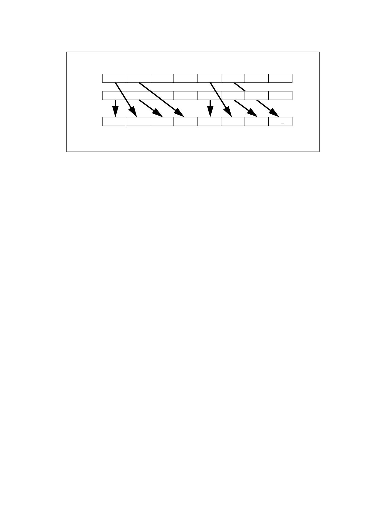
SRC1
X7
X6
X5
X4
X3
X2
X1
X0
SRC2
Y7
Y6
Y5
Y4
Y3
Y2
Y1
Y0
DEST
Y7
X7
Y6
X6
Y3
X3
Y2
X2
Figure 4-27. VUNPCKHPS Operation
EVEX.512 encoded version: The first source operand is a ZMM register. The second source operand is a ZMM
register, a 512-bit memory location, or a 512-bit vector broadcasted from a 32-bit memory location. The destina-
tion operand is a ZMM register, conditionally updated using writemask k1.
EVEX.256 encoded version: The first source operand is a YMM register. The second source operand is a YMM
register, a 256-bit memory location, or a 256-bit vector broadcasted from a 32-bit memory location. The destina-
tion operand is a YMM register, conditionally updated using writemask k1.
EVEX.128 encoded version: The first source operand is a XMM register. The second source operand is a XMM
register, a 128-bit memory location, or a 128-bit vector broadcasted from a 32-bit memory location. The destina-
tion operand is a XMM register, conditionally updated using writemask k1.
Operation
VUNPCKHPS (EVEX Encoded Version When SRC2 is a Register)
(KL, VL) = (4, 128), (8, 256), (16, 512)
IF VL >= 128
TMP_DEST[31:0] := SRC1[95:64]
TMP_DEST[63:32] := SRC2[95:64]
TMP_DEST[95:64] := SRC1[127:96]
TMP_DEST[127:96] := SRC2[127:96]
FI;
IF VL >= 256
TMP_DEST[159:128] := SRC1[223:192]
TMP_DEST[191:160] := SRC2[223:192]
TMP_DEST[223:192] := SRC1[255:224]
TMP_DEST[255:224] := SRC2[255:224]
FI;
IF VL >= 512
TMP_DEST[287:256] := SRC1[351:320]
TMP_DEST[319:288] := SRC2[351:320]
TMP_DEST[351:320] := SRC1[383:352]
TMP_DEST[383:352] := SRC2[383:352]
TMP_DEST[415:384] := SRC1[479:448]
TMP_DEST[447:416] := SRC2[479:448]
TMP_DEST[479:448] := SRC1[511:480]
TMP_DEST[511:480] := SRC2[511:480]
FI;
UNPCKHPS-Unpack and Interleave High Packed Single Precision Floating-Point Values
Vol. 2B
4-748
FOR j := 0 TO KL-1
i := j * 32
IF k1[j] OR *no writemask*
THEN DEST[i+31:i] := TMP_DEST[i+31:i]
ELSE
IF *merging-masking*
; merging-masking
THEN *DEST[i+31:i] remains unchanged*
ELSE *zeroing-masking*
; zeroing-masking
DEST[i+31:i] := 0
FI
FI;
ENDFOR
DEST[MAXVL-1:VL] := 0
VUNPCKHPS (EVEX Encoded Version When SRC2 is Memory)
(KL, VL) = (4, 128), (8, 256), (16, 512)
FOR j := 0 TO KL-1
i := j * 32
IF (EVEX.b = 1)
THEN TMP_SRC2[i+31:i] := SRC2[31:0]
ELSE TMP_SRC2[i+31:i] := SRC2[i+31:i]
FI;
ENDFOR;
IF VL >= 128
TMP_DEST[31:0] := SRC1[95:64]
TMP_DEST[63:32] := TMP_SRC2[95:64]
TMP_DEST[95:64] := SRC1[127:96]
TMP_DEST[127:96] := TMP_SRC2[127:96]
FI;
IF VL >= 256
TMP_DEST[159:128] := SRC1[223:192]
TMP_DEST[191:160] := TMP_SRC2[223:192]
TMP_DEST[223:192] := SRC1[255:224]
TMP_DEST[255:224] := TMP_SRC2[255:224]
FI;
IF VL >= 512
TMP_DEST[287:256] := SRC1[351:320]
TMP_DEST[319:288] := TMP_SRC2[351:320]
TMP_DEST[351:320] := SRC1[383:352]
TMP_DEST[383:352] := TMP_SRC2[383:352]
TMP_DEST[415:384] := SRC1[479:448]
TMP_DEST[447:416] := TMP_SRC2[479:448]
TMP_DEST[479:448] := SRC1[511:480]
TMP_DEST[511:480] := TMP_SRC2[511:480]
FI;
FOR j := 0 TO KL-1
i := j * 32
IF k1[j] OR *no writemask*
THEN DEST[i+31:i] := TMP_DEST[i+31:i]
ELSE
IF *merging-masking*
; merging-masking
THEN *DEST[i+31:i] remains unchanged*
ELSE *zeroing-masking*
; zeroing-masking
DEST[i+31:i] := 0
UNPCKHPS-Unpack and Interleave High Packed Single Precision Floating-Point Values
Vol. 2B
4-749
FI;
FI;
ENDFOR
DEST[MAXVL-1:VL] := 0
VUNPCKHPS (VEX.256 Encoded Version)
DEST[31:0] := SRC1[95:64]
DEST[63:32] := SRC2[95:64]
DEST[95:64] := SRC1[127:96]
DEST[127:96] := SRC2[127:96]
DEST[159:128] := SRC1[223:192]
DEST[191:160] := SRC2[223:192]
DEST[223:192] := SRC1[255:224]
DEST[255:224] := SRC2[255:224]
DEST[MAXVL-1:256] := 0
VUNPCKHPS (VEX.128 Encoded Version)
DEST[31:0] := SRC1[95:64]
DEST[63:32] := SRC2[95:64]
DEST[95:64] := SRC1[127:96]
DEST[127:96] := SRC2[127:96]
DEST[MAXVL-1:128] := 0
UNPCKHPS (128-bit Legacy SSE Version)
DEST[31:0] := SRC1[95:64]
DEST[63:32] := SRC2[95:64]
DEST[95:64] := SRC1[127:96]
DEST[127:96] := SRC2[127:96]
DEST[MAXVL-1:128] (Unmodified)
Intel C/C++ Compiler Intrinsic Equivalent
VUNPCKHPS __m512 _mm512_unpackhi_ps( __m512 a, __m512 b);
VUNPCKHPS __m512 _mm512_mask_unpackhi_ps(__m512 s, __mmask16 k, __m512 a, __m512 b);
VUNPCKHPS __m512 _mm512_maskz_unpackhi_ps(__mmask16 k, __m512 a, __m512 b);
VUNPCKHPS __m256 _mm256_unpackhi_ps (__m256 a, __m256 b);
VUNPCKHPS __m256 _mm256_mask_unpackhi_ps(__m256 s, __mmask8 k, __m256 a, __m256 b);
VUNPCKHPS __m256 _mm256_maskz_unpackhi_ps(__mmask8 k, __m256 a, __m256 b);
UNPCKHPS __m128 _mm_unpackhi_ps (__m128 a, __m128 b);
VUNPCKHPS __m128 _mm_mask_unpackhi_ps(__m128 s, __mmask8 k, __m128 a, __m128 b);
VUNPCKHPS __m128 _mm_maskz_unpackhi_ps(__mmask8 k, __m128 a, __m128 b);
SIMD Floating-Point Exceptions
None.
Other Exceptions
Non-EVEX-encoded instructions, see Table 2-21, “Type 4 Class Exception Conditions.”
EVEX-encoded instructions, see Table 2-52, “Type E4NF Class Exception Conditions.”
UNPCKHPS-Unpack and Interleave High Packed Single Precision Floating-Point Values
Vol. 2B
4-750

UNPCKLPD-Unpack and Interleave Low Packed Double Precision Floating-Point Values
Opcode/
Op /
64/32 bit
CPUID Feature
Description
Instruction
En
Mode
Flag
Support
66 0F 14 /r
A
V/V
SSE2
Unpacks and Interleaves double precision floating-point
UNPCKLPD xmm1, xmm2/m128
values from low quadwords of xmm1 and xmm2/m128.
VEX.128.66.0F.WIG 14 /r
B
V/V
AVX
Unpacks and Interleaves double precision floating-point
VUNPCKLPD xmm1,xmm2,
values from low quadwords of xmm2 and xmm3/m128.
xmm3/m128
VEX.256.66.0F.WIG 14 /r
B
V/V
AVX
Unpacks and Interleaves double precision floating-point
VUNPCKLPD ymm1,ymm2,
values from low quadwords of ymm2 and ymm3/m256.
ymm3/m256
EVEX.128.66.0F.W1 14 /r
C
V/V
(AVX512VL AND
Unpacks and Interleaves double precision floating-point
VUNPCKLPD xmm1 {k1}{z}, xmm2,
AVX512F) OR
values from low quadwords of xmm2 and
xmm3/m128/m64bcst
AVX10.1
xmm3/m128/m64bcst subject to write mask k1.
EVEX.256.66.0F.W1 14 /r
C
V/V
(AVX512VL AND
Unpacks and Interleaves double precision floating-point
VUNPCKLPD ymm1 {k1}{z}, ymm2,
AVX512F) OR
values from low quadwords of ymm2 and
ymm3/m256/m64bcst
AVX10.1
ymm3/m256/m64bcst subject to write mask k1.
EVEX.512.66.0F.W1 14 /r
C
V/V
AVX512F
Unpacks and Interleaves double precision floating-point
VUNPCKLPD zmm1 {k1}{z}, zmm2,
OR AVX10.1
values from low quadwords of zmm2 and
zmm3/m512/m64bcst
zmm3/m512/m64bcst subject to write mask k1.
Instruction Operand Encoding
Op/En
Tuple Type
Operand 1
Operand 2
Operand 3
Operand 4
A
N/A
ModRM:reg (r, w)
ModRM:r/m (r)
N/A
N/A
B
N/A
ModRM:reg (w)
VEX.vvvv (r)
ModRM:r/m (r)
N/A
C
Full
ModRM:reg (w)
EVEX.vvvv (r)
ModRM:r/m (r)
N/A
Description
Performs an interleaved unpack of the low double precision floating-point values from the first source operand and
the second source operand.
128-bit Legacy SSE version: The second source can be an XMM register or an 128-bit memory location. The desti-
nation is not distinct from the first source XMM register and the upper bits (MAXVL-1:128) of the corresponding
ZMM register destination are unmodified. When unpacking from a memory operand, an implementation may fetch
only the appropriate 64 bits; however, alignment to 16-byte boundary and normal segment checking will still be
enforced.
VEX.128 encoded version: The first source operand is a XMM register. The second source operand can be a XMM
register or a 128-bit memory location. The destination operand is a XMM register. The upper bits (MAXVL-1:128) of
the corresponding ZMM register destination are zeroed.
VEX.256 encoded version: The first source operand is a YMM register. The second source operand can be a YMM
register or a 256-bit memory location. The destination operand is a YMM register.
EVEX.512 encoded version: The first source operand is a ZMM register. The second source operand is a ZMM
register, a 512-bit memory location, or a 512-bit vector broadcasted from a 64-bit memory location. The destina-
tion operand is a ZMM register, conditionally updated using writemask k1.
EVEX.256 encoded version: The first source operand is a YMM register. The second source operand is a YMM
register, a 256-bit memory location, or a 256-bit vector broadcasted from a 64-bit memory location. The destina-
tion operand is a YMM register, conditionally updated using writemask k1.
EVEX.128 encoded version: The first source operand is an XMM register. The second source operand is a XMM
register, a 128-bit memory location, or a 128-bit vector broadcasted from a 64-bit memory location. The destina-
tion operand is a XMM register, conditionally updated using writemask k1.
UNPCKLPD-Unpack and Interleave Low Packed Double Precision Floating-Point Values
Vol. 2B
4-751
Operation
VUNPCKLPD (EVEX Encoded Versions When SRC2 is a Register)
(KL, VL) = (2, 128), (4, 256), (8, 512)
IF VL >= 128
TMP_DEST[63:0] := SRC1[63:0]
TMP_DEST[127:64] := SRC2[63:0]
FI;
IF VL >= 256
TMP_DEST[191:128] := SRC1[191:128]
TMP_DEST[255:192] := SRC2[191:128]
FI;
IF VL >= 512
TMP_DEST[319:256] := SRC1[319:256]
TMP_DEST[383:320] := SRC2[319:256]
TMP_DEST[447:384] := SRC1[447:384]
TMP_DEST[511:448] := SRC2[447:384]
FI;
FOR j := 0 TO KL-1
i := j * 64
IF k1[j] OR *no writemask*
THEN DEST[i+63:i] := TMP_DEST[i+63:i]
ELSE
IF *merging-masking*
; merging-masking
THEN *DEST[i+63:i] remains unchanged*
ELSE *zeroing-masking*
; zeroing-masking
DEST[i+63:i] := 0
FI
FI;
ENDFOR
DEST[MAXVL-1:VL] := 0
UNPCKLPD-Unpack and Interleave Low Packed Double Precision Floating-Point Values
Vol. 2B
4-752
VUNPCKLPD (EVEX Encoded Version When SRC2 is Memory)
(KL, VL) = (2, 128), (4, 256), (8, 512)
FOR j := 0 TO KL-1
i := j * 64
IF (EVEX.b = 1)
THEN TMP_SRC2[i+63:i] := SRC2[63:0]
ELSE TMP_SRC2[i+63:i] := SRC2[i+63:i]
FI;
ENDFOR;
IF VL >= 128
TMP_DEST[63:0] := SRC1[63:0]
TMP_DEST[127:64] := TMP_SRC2[63:0]
FI;
IF VL >= 256
TMP_DEST[191:128] := SRC1[191:128]
TMP_DEST[255:192] := TMP_SRC2[191:128]
FI;
IF VL >= 512
TMP_DEST[319:256] := SRC1[319:256]
TMP_DEST[383:320] := TMP_SRC2[319:256]
TMP_DEST[447:384] := SRC1[447:384]
TMP_DEST[511:448] := TMP_SRC2[447:384]
FI;
FOR j := 0 TO KL-1
i := j * 64
IF k1[j] OR *no writemask*
THEN DEST[i+63:i] := TMP_DEST[i+63:i]
ELSE
IF *merging-masking*
; merging-masking
THEN *DEST[i+63:i] remains unchanged*
ELSE *zeroing-masking*
; zeroing-masking
DEST[i+63:i] := 0
FI
FI;
ENDFOR
DEST[MAXVL-1:VL] := 0
VUNPCKLPD (VEX.256 Encoded Version)
DEST[63:0] := SRC1[63:0]
DEST[127:64] := SRC2[63:0]
DEST[191:128] := SRC1[191:128]
DEST[255:192] := SRC2[191:128]
DEST[MAXVL-1:256] := 0
VUNPCKLPD (VEX.128 Encoded Version)
DEST[63:0] := SRC1[63:0]
DEST[127:64] := SRC2[63:0]
DEST[MAXVL-1:128] := 0
UNPCKLPD (128-bit Legacy SSE Version)
DEST[63:0] := SRC1[63:0]
DEST[127:64] := SRC2[63:0]
DEST[MAXVL-1:128] (Unmodified)
UNPCKLPD-Unpack and Interleave Low Packed Double Precision Floating-Point Values
Vol. 2B
4-753
Intel C/C++ Compiler Intrinsic Equivalent
VUNPCKLPD __m512d _mm512_unpacklo_pd( __m512d a, __m512d b);
VUNPCKLPD __m512d _mm512_mask_unpacklo_pd(__m512d s, __mmask8 k, __m512d a, __m512d b);
VUNPCKLPD __m512d _mm512_maskz_unpacklo_pd(__mmask8 k, __m512d a, __m512d b);
VUNPCKLPD __m256d _mm256_unpacklo_pd(__m256d a, __m256d b)
VUNPCKLPD __m256d _mm256_mask_unpacklo_pd(__m256d s, __mmask8 k, __m256d a, __m256d b);
VUNPCKLPD __m256d _mm256_maskz_unpacklo_pd(__mmask8 k, __m256d a, __m256d b);
UNPCKLPD __m128d _mm_unpacklo_pd(__m128d a, __m128d b)
VUNPCKLPD __m128d _mm_mask_unpacklo_pd(__m128d s, __mmask8 k, __m128d a, __m128d b);
VUNPCKLPD __m128d _mm_maskz_unpacklo_pd(__mmask8 k, __m128d a, __m128d b);
SIMD Floating-Point Exceptions
None.
Other Exceptions
Non-EVEX-encoded instructions, see Table 2-21, “Type 4 Class Exception Conditions.”
EVEX-encoded instructions, see Table 2-52, “Type E4NF Class Exception Conditions.”
UNPCKLPD-Unpack and Interleave Low Packed Double Precision Floating-Point Values
Vol. 2B
4-754

UNPCKLPS-Unpack and Interleave Low Packed Single Precision Floating-Point Values
Opcode/
Op /
64/32 bit
CPUID Feature
Description
Instruction
En
Mode
Flag
Support
NP 0F 14 /r
A
V/V
SSE
Unpacks and Interleaves single precision floating-point
UNPCKLPS xmm1, xmm2/m128
values from low quadwords of xmm1 and xmm2/m128.
VEX.128.0F.WIG 14 /r
B
V/V
AVX
Unpacks and Interleaves single precision floating-point
VUNPCKLPS xmm1,xmm2,
values from low quadwords of xmm2 and xmm3/m128.
xmm3/m128
VEX.256.0F.WIG 14 /r
B
V/V
AVX
Unpacks and Interleaves single precision floating-point
VUNPCKLPS
values from low quadwords of ymm2 and ymm3/m256.
ymm1,ymm2,ymm3/m256
EVEX.128.0F.W0 14 /r
C
V/V
(AVX512VL AND
Unpacks and Interleaves single precision floating-point
VUNPCKLPS xmm1 {k1}{z}, xmm2,
AVX512F) OR
values from low quadwords of xmm2 and xmm3/mem
xmm3/m128/m32bcst
AVX10.1
and write result to xmm1 subject to write mask k1.
EVEX.256.0F.W0 14 /r
C
V/V
(AVX512VL AND
Unpacks and Interleaves single precision floating-point
VUNPCKLPS ymm1 {k1}{z}, ymm2,
AVX512F) OR
values from low quadwords of ymm2 and ymm3/mem
ymm3/m256/m32bcst
AVX10.1
and write result to ymm1 subject to write mask k1.
EVEX.512.0F.W0 14 /r
C
V/V
AVX512F
Unpacks and Interleaves single precision floating-point
VUNPCKLPS zmm1 {k1}{z}, zmm2,
OR AVX10.1
values from low quadwords of zmm2 and
zmm3/m512/m32bcst
zmm3/m512/m32bcst and write result to zmm1
subject to write mask k1.
Instruction Operand Encoding
Op/En
Tuple Type
Operand 1
Operand 2
Operand 3
Operand 4
A
N/A
ModRM:reg (r, w)
ModRM:r/m (r)
N/A
N/A
B
N/A
ModRM:reg (w)
VEX.vvvv (r)
ModRM:r/m (r)
N/A
C
Full
ModRM:reg (w)
EVEX.vvvv (r)
ModRM:r/m (r)
N/A
Description
Performs an interleaved unpack of the low single precision floating-point values from the first source operand and
the second source operand.
128-bit Legacy SSE version: The second source can be an XMM register or an 128-bit memory location. The desti-
nation is not distinct from the first source XMM register and the upper bits (MAXVL-1:128) of the corresponding
ZMM register destination are unmodified. When unpacking from a memory operand, an implementation may fetch
only the appropriate 64 bits; however, alignment to 16-byte boundary and normal segment checking will still be
enforced.
VEX.128 encoded version: The first source operand is a XMM register. The second source operand can be a XMM
register or a 128-bit memory location. The destination operand is a XMM register. The upper bits (MAXVL-1:128) of
the corresponding ZMM register destination are zeroed.
VEX.256 encoded version: The first source operand is a YMM register. The second source operand can be a YMM
register or a 256-bit memory location. The destination operand is a YMM register.
UNPCKLPS-Unpack and Interleave Low Packed Single Precision Floating-Point Values
Vol. 2B
4-755
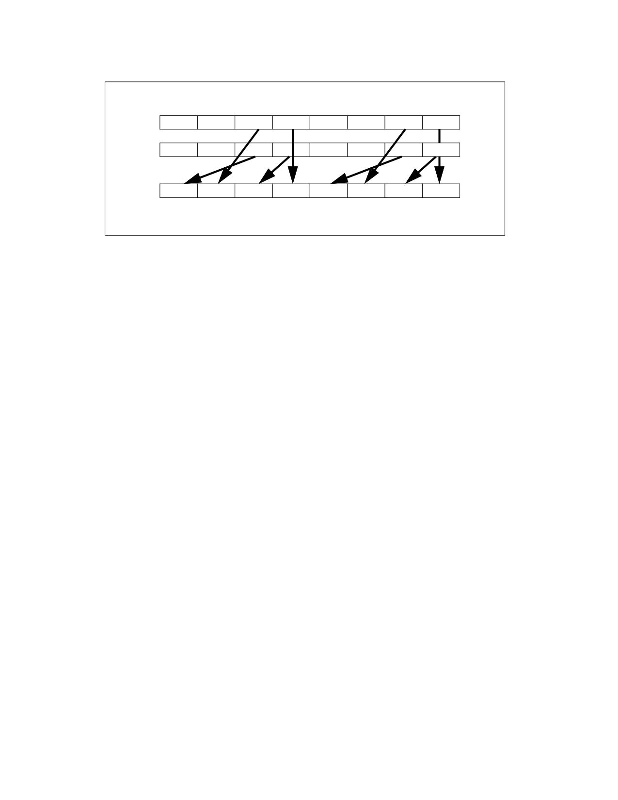
SRC1
X7
X6
X5
X4
X3
X2
X1
X0
SRC2
Y7
Y6
Y5
Y
4
Y3
Y2
Y1
Y0
DEST
Y5
X5
Y4
X4
Y1
X1
Y0
X0
Figure 4-28. VUNPCKLPS Operation
EVEX.512 encoded version: The first source operand is a ZMM register. The second source operand is a ZMM
register, a 512-bit memory location, or a 512-bit vector broadcasted from a 32-bit memory location. The destina-
tion operand is a ZMM register, conditionally updated using writemask k1.
EVEX.256 encoded version: The first source operand is a YMM register. The second source operand is a YMM
register, a 256-bit memory location, or a 256-bit vector broadcasted from a 32-bit memory location. The destina-
tion operand is a YMM register, conditionally updated using writemask k1.
EVEX.128 encoded version: The first source operand is an XMM register. The second source operand is a XMM
register, a 128-bit memory location, or a 128-bit vector broadcasted from a 32-bit memory location. The destina-
tion operand is a XMM register, conditionally updated using writemask k1.
Operation
VUNPCKLPS (EVEX Encoded Version When SRC2 is a ZMM Register)
(KL, VL) = (4, 128), (8, 256), (16, 512)
IF VL >= 128
TMP_DEST[31:0] := SRC1[31:0]
TMP_DEST[63:32] := SRC2[31:0]
TMP_DEST[95:64] := SRC1[63:32]
TMP_DEST[127:96] := SRC2[63:32]
FI;
IF VL >= 256
TMP_DEST[159:128] := SRC1[159:128]
TMP_DEST[191:160] := SRC2[159:128]
TMP_DEST[223:192] := SRC1[191:160]
TMP_DEST[255:224] := SRC2[191:160]
FI;
IF VL >= 512
TMP_DEST[287:256] := SRC1[287:256]
TMP_DEST[319:288] := SRC2[287:256]
TMP_DEST[351:320] := SRC1[319:288]
TMP_DEST[383:352] := SRC2[319:288]
TMP_DEST[415:384] := SRC1[415:384]
TMP_DEST[447:416] := SRC2[415:384]
TMP_DEST[479:448] := SRC1[447:416]
TMP_DEST[511:480] := SRC2[447:416]
FI;
FOR j := 0 TO KL-1
UNPCKLPS-Unpack and Interleave Low Packed Single Precision Floating-Point Values
Vol. 2B
4-756
i := j * 32
IF k1[j] OR *no writemask*
THEN DEST[i+31:i] := TMP_DEST[i+31:i]
ELSE
IF *merging-masking*
; merging-masking
THEN *DEST[i+31:i] remains unchanged*
ELSE *zeroing-masking*
; zeroing-masking
DEST[i+31:i] := 0
FI
FI;
ENDFOR
DEST[MAXVL-1:VL] := 0
VUNPCKLPS (EVEX Encoded Version When SRC2 is Memory)
(KL, VL) = (4, 128), (8, 256), (16, 512)
FOR j := 0 TO KL-1
i := j * 31
IF (EVEX.b = 1)
THEN TMP_SRC2[i+31:i] := SRC2[31:0]
ELSE TMP_SRC2[i+31:i] := SRC2[i+31:i]
FI;
ENDFOR;
IF VL >= 128
TMP_DEST[31:0] := SRC1[31:0]
TMP_DEST[63:32] := TMP_SRC2[31:0]
TMP_DEST[95:64] := SRC1[63:32]
TMP_DEST[127:96] := TMP_SRC2[63:32]
FI;
IF VL >= 256
TMP_DEST[159:128] := SRC1[159:128]
TMP_DEST[191:160] := TMP_SRC2[159:128]
TMP_DEST[223:192] := SRC1[191:160]
TMP_DEST[255:224] := TMP_SRC2[191:160]
FI;
IF VL >= 512
TMP_DEST[287:256] := SRC1[287:256]
TMP_DEST[319:288] := TMP_SRC2[287:256]
TMP_DEST[351:320] := SRC1[319:288]
TMP_DEST[383:352] := TMP_SRC2[319:288]
TMP_DEST[415:384] := SRC1[415:384]
TMP_DEST[447:416] := TMP_SRC2[415:384]
TMP_DEST[479:448] := SRC1[447:416]
TMP_DEST[511:480] := TMP_SRC2[447:416]
FI;
FOR j := 0 TO KL-1
i := j * 32
IF k1[j] OR *no writemask*
THEN DEST[i+31:i] := TMP_DEST[i+31:i]
ELSE
IF *merging-masking*
; merging-masking
THEN *DEST[i+31:i] remains unchanged*
ELSE *zeroing-masking*
; zeroing-masking
DEST[i+31:i] := 0
FI
UNPCKLPS-Unpack and Interleave Low Packed Single Precision Floating-Point Values
Vol. 2B
4-757
FI;
ENDFOR
DEST[MAXVL-1:VL] := 0
UNPCKLPS (VEX.256 Encoded Version)
DEST[31:0] := SRC1[31:0]
DEST[63:32] := SRC2[31:0]
DEST[95:64] := SRC1[63:32]
DEST[127:96] := SRC2[63:32]
DEST[159:128] := SRC1[159:128]
DEST[191:160] := SRC2[159:128]
DEST[223:192] := SRC1[191:160]
DEST[255:224] := SRC2[191:160]
DEST[MAXVL-1:256] := 0
VUNPCKLPS (VEX.128 Encoded Version)
DEST[31:0] := SRC1[31:0]
DEST[63:32] := SRC2[31:0]
DEST[95:64] := SRC1[63:32]
DEST[127:96] := SRC2[63:32]
DEST[MAXVL-1:128] := 0
UNPCKLPS (128-bit Legacy SSE Version)
DEST[31:0] := SRC1[31:0]
DEST[63:32] := SRC2[31:0]
DEST[95:64] := SRC1[63:32]
DEST[127:96] := SRC2[63:32]
DEST[MAXVL-1:128] (Unmodified)
Intel C/C++ Compiler Intrinsic Equivalent
VUNPCKLPS __m512 _mm512_unpacklo_ps(__m512 a, __m512 b);
VUNPCKLPS __m512 _mm512_mask_unpacklo_ps(__m512 s, __mmask16 k, __m512 a, __m512 b);
VUNPCKLPS __m512 _mm512_maskz_unpacklo_ps(__mmask16 k, __m512 a, __m512 b);
VUNPCKLPS __m256 _mm256_unpacklo_ps (__m256 a, __m256 b);
VUNPCKLPS __m256 _mm256_mask_unpacklo_ps(__m256 s, __mmask8 k, __m256 a, __m256 b);
VUNPCKLPS __m256 _mm256_maskz_unpacklo_ps(__mmask8 k, __m256 a, __m256 b);
UNPCKLPS __m128 _mm_unpacklo_ps (__m128 a, __m128 b);
VUNPCKLPS __m128 _mm_mask_unpacklo_ps(__m128 s, __mmask8 k, __m128 a, __m128 b);
VUNPCKLPS __m128 _mm_maskz_unpacklo_ps(__mmask8 k, __m128 a, __m128 b);
SIMD Floating-Point Exceptions
None.
Other Exceptions
Non-EVEX-encoded instructions, see Table 2-21, “Type 4 Class Exception Conditions.”
EVEX-encoded instructions, see Table 2-52, “Type E4NF Class Exception Conditions.”
UNPCKLPS-Unpack and Interleave Low Packed Single Precision Floating-Point Values
Vol. 2B
4-758

URDMSR-User Read from Model-Specific Register
Opcode /
Op/
64/32 bit
CPUID
Description
Instruction
En
Mode
Feature
Support
Flag
F2 0F 38 F8 11:rrr:bbb
MR
V/N.E.
USER_MSR
Load into register bbb the value of the MSR with
address in rrr.
URDMSR r64, r64
VEX.128.F2.MAP7:W0.F8 11:000:bbb
MI
V/N.E.
USER_MSR
Load into register bbb the value of the MSR with
address in the 32-bit immediate.
URDMSR r64, imm32
Instruction Operand Encoding
Op/En
Operand 1
Operand 2
Operand 3
Operand 4
MR
ModRM:r/m (r)
ModRM:reg (r)
N/A
N/A
MI
ModRM:r/m (r)
imm32
N/A
N/A
Description
URDMSR reads the contents of a 64-bit MSR specified in operand 2 into operand 1. Operand 1 is a general-purpose
register, while operand 2 may be either a general-purpose register or an immediate. URDMSR reads the indicated
MSR in the same manner as RDMSR.
MSRs readable by RDMSR with CPL = 0 can be read by URDMSR at any privilege level but under OS control. The OS
controls what MSRs can be read by the URDMSR and UWRMSR instructions with a 4-KByte user-MSR bitmap
located at an aligned linear address in the IA32_USER_MSR_CTL MSR (address 1CH). The URDMSR instruction is
enabled only if bit 0 of this MSR is 1.
The low 2 KBytes of the bitmap control URDMSR (they compose the URDMSR bitmap); these 2 KBytes include one
bit for each MSR address in the range 0H-3FFFH. URDMSR may read an MSR only if the bit corresponding to the
MSR has value 1; otherwise (or if the MSR address is outside that range) URDMSR causes a general-protection
exception (#GP).
The URDMSR accesses to these bitmaps are implicit supervisor-mode accesses, which means they use supervisor
privilege regardless of CPL.
Operation
DEST := MSR[SRC]
Flags Affected
None.
Protected Mode Exceptions
#UD
The URDMSR instruction is not recognized outside 64-bit mode.
Real-Address Mode Exceptions
#UD
The URDMSR instruction is not recognized outside 64-bit mode.
Virtual-8086 Mode Exceptions
#UD
The URDMSR instruction is not recognized outside 64-bit mode.
Compatibility Mode Exceptions
#UD
The URDMSR instruction is not recognized outside 64-bit mode.
64-Bit Mode Exceptions
#GP(0)
If MSR_address[63:14] is not all zero.
URDMSR-User Read from Model-Specific Register
Vol. 2B
4-759
If the MSR address is in the range 0-3FFH and bit n in the URDMSR bitmap is 0, where n is the
MSR address.
If RDMSR from the specified MSR would result in a #GP(0) exception due to the MSR not being
accessible.
#UD
If the LOCK prefix is used.
If CPUID.07H.01H:EDX.USER_MSR[15] = 0.
If IA32_USER_MSR_CTL.ENABLE = 0.
URDMSR-User Read from Model-Specific Register
Vol. 2B
4-760

UWRMSR-User Write to Model-Specific Register
Opcode /
Op/
64/32 bit
CPUID
Description
Instruction
En
Mode
Feature
Support
Flag
F3 0F 38 F8 11:rrr:bbb
RM
V/N.E.
USER_MSR
Write the value of register bbb to the MSR with
address in rrr.
UWRMSR r64, r64
VEX.128.F3.MAP7:W0.F8 11:000:bbb
IM
V/N.E.
USER_MSR
Write the value of register bbb to the MSR specified in
the 32-bit immediate.
UWRMSR imm32, r64
Instruction Operand Encoding
Op/En
Operand 1
Operand 2
Operand 3
Operand 4
RM
ModRM:reg (r, w)
ModRM:r/m (r)
N/A
N/A
IM
imm32
ModRM:r/m (r)
N/A
N/A
Description
UWRMSR writes the contents of operand 2 into the 64-bit MSR specified in operand 1. Operand 2 is a general-
purpose register, while operand 1 may be either a general-purpose register or an immediate. UWRMSR writes the
indicated MSR in the same manner as WRMSR, but it is limited to a specific set of MSRs. Currently, the only such
MSR is the IA32_UARCH_MISC_CTL MSR (address 1B01H).
The indicated MSRs can be written by UWRMSR at any privilege level but under OS control. The OS controls what
MSRs can be read by the URDMSR and UWRMSR instructions with a 4-KByte user-MSR bitmap located at an
aligned linear address in the IA32_USER_MSR_CTL MSR (address 1CH). The UWRMSR instruction is enabled only
if bit 0 of this MSR is 1.
The high 2 KBytes of the bitmap control UWRMSR (they compose the UWRMSR bitmap); these 2 KBytes include
one bit for each MSR address in the range 0H-3FFFH. UWRMSR may write to an MSR only if the bit corresponding
to the MSR has value 1; otherwise (or if the MSR address is outside that range) UWRMSR causes a general-protec-
tion exception (#GP).
UWRMSR accesses to these bitmaps are implicit supervisor-mode accesses, which means they use supervisor priv-
ilege regardless of CPL. UWRMSR behaves like WRMSRNS and is not defined as a serializing instruction (see
“Serializing Instructions” in Chapter 11 of the Intel® 64 and IA-32 Architectures Software Developer's Manual,
Volume 3A). Refer to the WRMSRNS instruction for a thorough explanation of what this implies.
Operation
MSR[DEST] := SRC
Flags Affected
None.
Protected Mode Exceptions
#UD
The UWRMSR instruction is not recognized outside 64-bit mode.
Real-Address Mode Exceptions
#UD
The UWRMSR instruction is not recognized outside 64-bit mode.
Virtual-8086 Mode Exceptions
#UD
The UWRMSR instruction is not recognized outside 64-bit mode.
Compatibility Mode Exceptions
#UD
The UWRMSR instruction is not recognized outside 64-bit mode.
UWRMSR-User Write to Model-Specific Register
Vol. 2B
4-761
64-Bit Mode Exceptions
#GP(0)
If MSR_address[63:14] is not all zero.
If the MSR address is in the range 0-3FFH and bit n in UWRMSR bitmap is 0, where n is the
MSR address.
If an MSR other than IA32_UARCH_MISC_CTL is specified.
If WRMSR to the specified MSR would result in a #GP(0) exception due to the MSR not being
accessible or attempting to set bits that are reserved.
#UD
If the LOCK prefix is used.
If CPUID.07H.01H:EDX.USER_MSR[15] = 0.
If IA32_USER_MSR_CTL.ENABLE = 0.
UWRMSR-User Write to Model-Specific Register
Vol. 2B
4-762
CHAPTER 5
INSTRUCTION SET REFERENCE, V
5.1
TERNARY BIT VECTOR LOGIC TABLE
VPTERNLOGD/VPTERNLOGQ instructions operate on dword/qword elements and take three bit vectors of the
respective input data elements to form a set of 32/64 indices, where each 3-bit value provides an index into an 8-
bit lookup table represented by the imm8 byte of the instruction. The 256 possible values of the imm8 byte is
constructed as a 16x16 boolean logic table. The 16 rows of the table uses the lower 4 bits of imm8 as row index.
The 16 columns are referenced by imm8[7:4]. The 16 columns of the table are present in two halves, with 8
columns shown in Table 5-1 for the column index value between 0:7, followed by Table 5-2 showing the 8 columns
corresponding to column index 8:15. This section presents the two-halves of the 256-entry table using a short-
hand notation representing simple or compound boolean logic expressions with three input bit source data.
The three input bit source data will be denoted with the capital letters: A, B, C; where A represents a bit from the
first source operand (also the destination operand), B and C represent a bit from the 2nd and 3rd source operands.
Each map entry takes the form of a logic expression consisting of one of more component expressions. Each
component expression consists of either a unary or binary boolean operator and associated operands. Each binary
boolean operator is expressed in lowercase letters, and operands concatenated after the logic operator. The unary
operator ‘not’ is expressed using ‘!’. Additionally, the conditional expression “A?B:C” expresses a result returning B
if A is set, returning C otherwise.
A binary boolean operator is followed by two operands, e.g., andAB. For a compound binary expression that contain
commutative components and comprising the same logic operator, the 2nd logic operator is omitted and three
operands can be concatenated in sequence, e.g., andABC. When the 2nd operand of the first binary boolean
expression comes from the result of another boolean expression, the 2nd boolean expression is concatenated after
the uppercase operand of the first logic expression, e.g., norBnandAC. When the result is independent of an
operand, that operand is omitted in the logic expression, e.g., zeros or norCB.
The 3-input expression “majorABC” returns 0 if two or more input bits are 0, returns 1 if two or more input bits are
1. The 3-input expression “minorABC” returns 1 if two or more input bits are 0, returns 0 if two or more input bits
are 1.
The building-block bit logic functions used in Table 5-1 and Table 5-2 include:
• Constants: TRUE (1), FALSE (0);
• Unary function: Not (!);
• Binary functions: and, nand, or, nor, xor, xnor;
• Conditional function: Select (?:);
• Tertiary functions: major, minor.
Vol. 2C
5-1

INSTRUCTION SET REFERENCE, V
:
Table 5-1. Lower 8 columns of the 16x16 Map of VPTERNLOG Boolean Logic Operations
Imm
[7:4]
[3:0]
0H
1H
2H
3H
4H
5H
6H
7H
00H
FALSE
andAnorBC
norBnandAC
andA!B
norCnandBA
andA!C
andAxorBC
andAnandBC
01H
norABC
norCB
norBxorAC
A?!B:norBC
norCxorBA
A?!C:norBC
A?xorBC:norB
A?nandBC:no
C
rBC
02H
andCnorBA
norBxnorAC
andC!B
norBnorAC
C?norBA:and
C?norBA:A
C?!B:andBA
C?!B:A
BA
03H
norBA
norBandAC
C?!B:norBA
!B
C?norBA:xnor
A?!C:!B
A?xorBC:!B
A?nandBC:!B
BA
04H
andBnorAC
norCxnorBA
B?norAC:and
B?norAC:A
andB!C
norCnorBA
B?!C:andAC
B?!C:A
AC
05H
norCA
norCandBA
B?norAC:xnor
A?!B:!C
B?!C:norAC
!C
A?xorBC:!C
A?nandBC:!C
AC
06H
norAxnorBC
A?norBC:xorB
B?norAC:C
xorBorAC
C?norBA:B
xorCorBA
xorCB
B?!C:orAC
C
07H
norAandBC
minorABC
C?!B:!A
nandBorAC
B?!C:!A
nandCorBA
A?xorBC:nan
nandCB
dBC
08H
norAnandBC
A?norBC:and
andCxorBA
A?!B:andBC
andBxorAC
A?!C:andBC
A?xorBC:and
xorAandBC
BC
BC
09H
norAxorBC
A?norBC:xnor
C?xorBA:norB
A?!B:xnorBC
B?xorAC:norA
A?!C:xnorBC
xnorABC
A?nandBC:xn
BC
A
C
orBC
0AH
andC!A
A?norBC:C
andCnandBA
A?!B:C
C?!A:andBA
xorCA
xorCandBA
A?nandBC:C
0BH
C?!A:norBA
C?!A:!B
C?nandBA:no
C?nandBA:!B
B?xorAC:!A
B?xorAC:nan
C?nandBA:xn
nandBxnorAC
rBA
dAC
orBA
0CH
andB!A
A?norBC:B
B?!A:andAC
xorBA
andBnandAC
A?!C:B
xorBandAC
A?nandBC:B
0DH
B?!A:norAC
B?!A:!C
B?!A:xnorAC
C?xorBA:nan
B?nandAC:no
B?nandAC:!C
B?nandAC:xn
nandCxnorBA
dBA
rAC
orAC
0EH
norAnorBC
xorAorBC
B?!A:C
A?!B:orBC
C?!A:B
A?!C:orBC
B?nandAC:C
A?nandBC:or
BC
0FH
!A
nandAorBC
C?nandBA:!A
nandBA
B?nandAC:!A
nandCA
nandAxnorBC
nandABC
Table 5-2 shows the half of 256-entry map corresponding to column index values 8:15.
Vol. 2C
5-2

INSTRUCTION SET REFERENCE, V
:
Table 5-2. Upper 8 columns of the 16x16 Map of VPTERNLOG Boolean Logic Operations
Imm
[7:4]
[3:0]
08H
09H
0AH
0BH
0CH
0DH
0EH
0FH
00H
andABC
andAxnorBC
andCA
B?andAC:A
andBA
C?andBA:A
andAorBC
A
01H
A?andBC:nor
B?andAC:!C
A?C:norBC
C?A:!B
A?B:norBC
B?A:!C
xnorAorBC
orAnorBC
BC
02H
andCxnorBA
B?andAC:xor
B?andAC:C
B?andAC:orA
C?xnorBA:an
B?A:xorAC
B?A:C
B?A:orAC
AC
C
dBA
03H
A?andBC:!B
xnorBandAC
A?C:!B
nandBnandA
xnorBA
B?A:nandAC
A?orBC:!B
orA!B
C
04H
andBxnorAC
C?andBA:xor
B?xnorAC:an
B?xnorAC:A
C?andBA:B
C?andBA:orB
C?A:B
C?A:orBA
BA
dAC
A
05H
A?andBC:!C
xnorCandBA
xnorCA
C?A:nandBA
A?B:!C
nandCnandB
A?orBC:!C
orA!C
A
06H
A?andBC:xor
xorABC
A?C:xorBC
B?xnorAC:orA
A?B:xorBC
C?xnorBA:orB
A?orBC:xorBC
orAxorBC
BC
C
A
07H
xnorAandBC
A?xnorBC:na
A?C:nandBC
nandBxorAC
A?B:nandBC
nandCxorBA
A?orBCnandB
orAnandBC
ndBC
C
08H
andCB
A?xnorBC:an
andCorAB
B?C:A
andBorAC
C?B:A
majorABC
orAandBC
dBC
09H
B?C:norAC
xnorCB
xnorCorBA
C?orBA:!B
xnorBorAC
B?orAC:!C
A?orBC:xnorB
orAxnorBC
C
0AH
A?andBC:C
A?xnorBC:C
C
B?C:orAC
A?B:C
B?orAC:xorAC
orCandBA
orCA
0BH
B?C:!A
B?C:nandAC
orCnorBA
orC!B
B?orAC:!A
B?orAC:nand
orCxnorBA
nandBnorAC
AC
0CH
A?andBC:B
A?xnorBC:B
A?C:B
C?orBA:xorBA
B
C?B:orBA
orBandAC
orBA
0DH
C?B!A
C?B:nandBA
C?orBA:!A
C?orBA:nand
orBnorAC
orB!C
orBxnorAC
nandCnorBA
BA
0EH
A?andBC:orB
A?xnorBC:orB
A?C:orBC
orCxorBA
A?B:orBC
orBxorAC
orCB
orABC
C
C
0FH
nandAnandB
nandAxorBC
orC!A
orCnandBA
orB!A
orBnandAC
nandAnorBC
TRUE
C
Table 5-1 and Table 5-2 translate each of the possible value of the imm8 byte to a Boolean expression. These tables
can also be used by software to translate Boolean expressions to numerical constants to form the imm8 value
needed to construct the VPTERNLOG syntax. There is a unique set of three byte constants (F0H, CCH, AAH) that
can be used for this purpose as input operands in conjunction with the Boolean expressions defined in those tables.
The reverse mapping can be expressed as:
Result_imm8 = Table_Lookup_Entry(0F0H, 0CCH, 0AAH)
Table_Lookup_Entry is the Boolean expression defined in Table 5-1 and Table 5-2.
5.2
INSTRUCTIONS (V)
Chapter 5 continues an alphabetical discussion of Intel® 64 and IA-32 instructions (V). See also: Chapter 3,
“Instruction Set Reference, A-L,” in the Intel® 64 and IA-32 Architectures Software Developer’s Manual, Volume
Vol. 2C
5-3
INSTRUCTION SET REFERENCE, V
2A; Chapter 5, “Instruction Set Reference, V‚” in the Intel® 64 and IA-32 Architectures Software Developer’s
Manual, Volume 2B; and Chapter 5, “Instruction Set Reference, V,” in the Intel® 64 and IA-32 Architectures Soft-
ware Developer’s Manual, Volume 2D.
Vol. 2C
5-4

VADDPH-Add Packed FP16 Values
Opcode/
Op/
64/32
CPUID Feature
Description
Instruction
En
Bit Mode
Flag
Support
EVEX.128.NP.MAP5.W0 58 /r
A
V/V
(AVX512_FP16
Add packed FP16 value from
VADDPH xmm1{k1}{z}, xmm2,
AND AVX512VL)
xmm3/m128/m16bcst to xmm2, and store result
xmm3/m128/m16bcst
OR AVX10.1
in xmm1 subject to writemask k1.
EVEX.256.NP.MAP5.W0 58 /r
A
V/V
(AVX512_FP16
Add packed FP16 value from
VADDPH ymm1{k1}{z}, ymm2,
AND AVX512VL)
ymm3/m256/m16bcst to ymm2, and store result
ymm3/m256/m16bcst
OR AVX10.1
in ymm1 subject to writemask k1.
EVEX.512.NP.MAP5.W0 58 /r
A
V/V
AVX512_FP16
Add packed FP16 value from
VADDPH zmm1{k1}{z}, zmm2,
OR AVX10.1
zmm3/m512/m16bcst to zmm2, and store result
zmm3/m512/m16bcst {er}
in zmm1 subject to writemask k1.
Instruction Operand Encoding
Op/En
Tuple
Operand 1
Operand 2
Operand 3
Operand 4
A
Full
ModRM:reg (w)
VEX.vvvv (r)
ModRM:r/m (r)
N/A
Description
This instruction adds packed FP16 values from source operands and stores the packed FP16 result in the destina-
tion operand. The destination elements are updated according to the writemask.
Operation
VADDPH (EVEX Encoded Versions) When SRC2 Operand is a Register
VL = 128, 256 or 512
KL := VL/16
IF (VL = 512) AND (EVEX.b = 1):
SET_RM(EVEX.RC)
ELSE
SET_RM(MXCSR.RC)
FOR j := 0 TO KL-1:
IF k1[j] OR *no writemask*:
DEST.fp16[j] := SRC1.fp16[j] + SRC2.fp16[j]
ELSEIF *zeroing*:
DEST.fp16[j] := 0
// else dest.fp16[j] remains unchanged
DEST[MAXVL-1:VL] := 0
VADDPH-Add Packed FP16 Values
Vol. 2C
5-1
VADDPH (EVEX Encoded Versions) When SRC2 Operand is a Memory Source
VL = 128, 256 or 512
KL := VL/16
FOR j := 0 TO KL-1:
IF k1[j] OR *no writemask*:
IF EVEX.b = 1:
DEST.fp16[j] := SRC1.fp16[j] + SRC2.fp16[0]
ELSE:
DEST.fp16[j] := SRC1.fp16[j] + SRC2.fp16[j]
ELSE IF *zeroing*:
DEST.fp16[j] := 0
// else dest.fp16[j] remains unchanged
DEST[MAXVL-1:VL] := 0
Intel C/C++ Compiler Intrinsic Equivalent
VADDPH __m128h _mm_add_ph (__m128h a, __m128h b);
VADDPH __m128h _mm_mask_add_ph (__m128h src, __mmask8 k, __m128h a, __m128h b);
VADDPH __m128h _mm_maskz_add_ph (__mmask8 k, __m128h a, __m128h b);
VADDPH __m256h _mm256_add_ph (__m256h a, __m256h b);
VADDPH __m256h _mm256_mask_add_ph (__m256h src, __mmask16 k, __m256h a, __m256h b);
VADDPH __m256h _mm256_maskz_add_ph (__mmask16 k, __m256h a, __m256h b);
VADDPH __m512h _mm512_add_ph (__m512h a, __m512h b);
VADDPH __m512h _mm512_add_ph (__m512h a, __m512h b);
VADDPH __m512h _mm512_mask_add_ph (__m512h src, __mmask32 k, __m512h a, __m512h b);
VADDPH __m512h _mm512_maskz_add_ph (__mmask32 k, __m512h a, __m512h b);
VADDPH __m512h _mm512_add_round_ph (__m512h a, __m512h b, int rounding);
VADDPH __m512h _mm512_mask_add_round_ph (__m512h src, __mmask32 k, __m512h a, __m512h b, int rounding);
VADDPH __m512h _mm512_maskz_add_round_ph (__mmask32 k, __m512h a, __m512h b, int rounding);
SIMD Floating-Point Exceptions
Invalid, Underflow, Overflow, Precision, Denormal.
Other Exceptions
EVEX-encoded instructions, see Table 2-48, “Type E2 Class Exception Conditions.”
VADDPH-Add Packed FP16 Values
Vol. 2C
5-2

VADDSH-Add Scalar FP16 Values
Opcode/
Op/
64/32
CPUID Feature
Description
Instruction
En
Bit Mode
Flag
Support
EVEX.LLIG.F3.MAP5.W0 58 /r
A
V/V
AVX512_FP16
Add the low FP16 value from xmm3/m16 to
VADDSH xmm1{k1}{z}, xmm2,
OR AVX10.1
xmm2, and store the result in xmm1 subject to
xmm3/m16 {er}
writemask k1. Bits 127:16 of xmm2 are copied
to xmm1[127:16].
Instruction Operand Encoding
Op/En
Tuple
Operand 1
Operand 2
Operand 3
Operand 4
A
Scalar
ModRM:reg (w)
VEX.vvvv (r)
ModRM:r/m (r)
N/A
Description
This instruction adds the low FP16 value from the source operands and stores the FP16 result in the destination
operand.
Bits 127:16 of the destination operand are copied from the corresponding bits of the first source operand. Bits
MAXVL-1:128 of the destination operand are zeroed. The low FP16 element of the destination is updated according
to the writemask.
Operation
VADDSH (EVEX Encoded Versions)
IF EVEX.b = 1 and SRC2 is a register:
SET_RM(EVEX.RC)
ELSE
SET_RM(MXCSR.RC)
IF k1[0] OR *no writemask*:
DEST.fp16[0] := SRC1.fp16[0] + SRC2.fp16[0]
ELSEIF *zeroing*:
DEST.fp16[0] := 0
// else dest.fp16[0] remains unchanged
DEST[127:16] := SRC1[127:16]
DEST[MAXVL-1:128] := 0
Intel C/C++ Compiler Intrinsic Equivalent
VADDSH __m128h _mm_add_round_sh (__m128h a, __m128h b, int rounding);
VADDSH
___m128h _mm_mask_add_round_sh (__m128h src, __mmask8 k, __m128h a, __m128h b, int rounding);
VADDSH
___m128h _mm_maskz_add_round_sh (__mmask8 k, __m128h a, __m128h b, int rounding);
VADDSH
___m128h _mm_add_sh (__m128h a, __m128h b);
VADDSH
___m128h _mm_mask_add_sh (__m128h src, __mmask8 k, __m128h a, __m128h b);
VADDSH
___m128h _mm_maskz_add_sh (__mmask8 k, __m128h a, __m128h b);
SIMD Floating-Point Exceptions
Invalid, Underflow, Overflow, Precision, Denormal.
Other Exceptions
EVEX-encoded instructions, see Table 2-49, “Type E3 Class Exception Conditions.”
VADDSH-Add Scalar FP16 Values
Vol. 2C
5-3

VALIGND/VALIGNQ-Align Doubleword/Quadword Vectors
Opcode/
Op /
64/32
CPUID Feature
Description
Instruction
En
Bit Mode
Flag
Support
EVEX.128.66.0F3A.W0 03 /r ib
A
V/V
(AVX512VL AND
Shift right and merge vectors xmm2 and
VALIGND xmm1 {k1}{z}, xmm2,
AVX512F) OR
xmm3/m128/m32bcst with double-word granularity
xmm3/m128/m32bcst, imm8
AVX10.1
using imm8 as number of elements to shift, and store
the final result in xmm1, under writemask.
EVEX.128.66.0F3A.W1 03 /r ib
A
V/V
(AVX512VL AND
Shift right and merge vectors xmm2 and
VALIGNQ xmm1 {k1}{z}, xmm2,
AVX512F) OR
xmm3/m128/m64bcst with quad-word granularity
xmm3/m128/m64bcst, imm8
AVX10.1
using imm8 as number of elements to shift, and store
the final result in xmm1, under writemask.
EVEX.256.66.0F3A.W0 03 /r ib
A
V/V
(AVX512VL AND
Shift right and merge vectors ymm2 and
VALIGND ymm1 {k1}{z}, ymm2,
AVX512F) OR
ymm3/m256/m32bcst with double-word granularity
ymm3/m256/m32bcst, imm8
AVX10.1
using imm8 as number of elements to shift, and store
the final result in ymm1, under writemask.
EVEX.256.66.0F3A.W1 03 /r ib
A
V/V
(AVX512VL AND
Shift right and merge vectors ymm2 and
VALIGNQ ymm1 {k1}{z}, ymm2,
AVX512F) OR
ymm3/m256/m64bcst with quad-word granularity
ymm3/m256/m64bcst, imm8
AVX10.1
using imm8 as number of elements to shift, and store
the final result in ymm1, under writemask.
EVEX.512.66.0F3A.W0 03 /r ib
A
V/V
AVX512F
Shift right and merge vectors zmm2 and
VALIGND zmm1 {k1}{z}, zmm2,
OR AVX10.1
zmm3/m512/m32bcst with double-word granularity
zmm3/m512/m32bcst, imm8
using imm8 as number of elements to shift, and store
the final result in zmm1, under writemask.
EVEX.512.66.0F3A.W1 03 /r ib
A
V/V
AVX512F
Shift right and merge vectors zmm2 and
VALIGNQ zmm1 {k1}{z}, zmm2,
OR AVX10.1
zmm3/m512/m64bcst with quad-word granularity
zmm3/m512/m64bcst, imm8
using imm8 as number of elements to shift, and store
the final result in zmm1, under writemask.
Instruction Operand Encoding
Op/En
Tuple Type
Operand 1
Operand 2
Operand 3
Operand 4
A
Full
ModRM:reg (w)
EVEX.vvvv (r)
ModRM:r/m (r)
N/A
Description
Concatenates and shifts right doubleword/quadword elements of the first source operand (the second operand)
and the second source operand (the third operand) into a 1024/512/256-bit intermediate vector. The low
512/256/128-bit of the intermediate vector is written to the destination operand (the first operand) using the
writemask k1. The destination and first source operands are ZMM/YMM/XMM registers. The second source operand
can be a ZMM/YMM/XMM register, a 512/256/128-bit memory location or a 512/256/128-bit vector broadcasted
from a 32/64-bit memory location.
This instruction is writemasked, so only those elements with the corresponding bit set in vector mask register k1
are computed and stored into zmm1. Elements in zmm1 with the corresponding bit clear in k1 retain their previous
values (merging-masking) or are set to 0 (zeroing-masking).
VALIGND/VALIGNQ-Align Doubleword/Quadword Vectors
Vol. 2C
5-4
Operation
VALIGND (EVEX Encoded Versions)
(KL, VL) = (4, 128), (8, 256), (16, 512)
IF (SRC2 *is memory*) (AND EVEX.b = 1)
THEN
FOR j := 0 TO KL-1
i := j * 32
src[i+31:i] := SRC2[31:0]
ENDFOR;
ELSE src := SRC2
FI
; Concatenate sources
tmp[VL-1:0] := src[VL-1:0]
tmp[2VL-1:VL] := SRC1[VL-1:0]
; Shift right doubleword elements
IF VL = 128
THEN SHIFT = imm8[1:0]
ELSE
IF VL = 256
THEN SHIFT = imm8[2:0]
ELSE SHIFT = imm8[3:0]
FI
FI;
tmp[2VL-1:0] := tmp[2VL-1:0] >> (32*SHIFT)
; Apply writemask
FOR j := 0 TO KL-1
i := j * 32
IF k1[j] OR *no writemask*
THEN DEST[i+31:i] := tmp[i+31:i]
ELSE
IF *merging-masking*
; merging-masking
THEN *DEST[i+31:i] remains unchanged*
ELSE
; zeroing-masking
DEST[i+31:i] := 0
FI
FI;
ENDFOR;
DEST[MAXVL-1:VL] := 0
VALIGNQ (EVEX Encoded Versions)
(KL, VL) = (2, 128), (4, 256),(8, 512)
IF (SRC2 *is memory*) (AND EVEX.b = 1)
THEN
FOR j := 0 TO KL-1
i := j * 64
src[i+63:i] := SRC2[63:0]
ENDFOR;
ELSE src := SRC2
FI
; Concatenate sources
tmp[VL-1:0] := src[VL-1:0]
tmp[2VL-1:VL] := SRC1[VL-1:0]
; Shift right quadword elements
VALIGND/VALIGNQ-Align Doubleword/Quadword Vectors
Vol. 2C
5-5
IF VL = 128
THEN SHIFT = imm8[0]
ELSE
IF VL = 256
THEN SHIFT = imm8[1:0]
ELSE SHIFT = imm8[2:0]
FI
FI;
tmp[2VL-1:0] := tmp[2VL-1:0] >> (64*SHIFT)
; Apply writemask
FOR j := 0 TO KL-1
i := j * 64
IF k1[j] OR *no writemask*
THEN DEST[i+63:i] := tmp[i+63:i]
ELSE
IF *merging-masking*
; merging-masking
THEN *DEST[i+63:i] remains unchanged*
ELSE
; zeroing-masking
DEST[i+63:i] := 0
FI
FI;
ENDFOR;
DEST[MAXVL-1:VL] := 0
Intel C/C++ Compiler Intrinsic Equivalent
VALIGND __m512i _mm512_alignr_epi32( __m512i a, __m512i b, int cnt);
VALIGND __m512i _mm512_mask_alignr_epi32(__m512i s, __mmask16 k, __m512i a, __m512i b, int cnt);
VALIGND __m512i _mm512_maskz_alignr_epi32( __mmask16 k, __m512i a, __m512i b, int cnt);
VALIGND __m256i _mm256_mask_alignr_epi32(__m256i s, __mmask8 k, __m256i a, __m256i b, int cnt);
VALIGND __m256i _mm256_maskz_alignr_epi32( __mmask8 k, __m256i a, __m256i b, int cnt);
VALIGND __m128i _mm_mask_alignr_epi32(__m128i s, __mmask8 k, __m128i a, __m128i b, int cnt);
VALIGND __m128i _mm_maskz_alignr_epi32( __mmask8 k, __m128i a, __m128i b, int cnt);
VALIGNQ __m512i _mm512_alignr_epi64( __m512i a, __m512i b, int cnt);
VALIGNQ __m512i _mm512_mask_alignr_epi64(__m512i s, __mmask8 k, __m512i a, __m512i b, int cnt);
VALIGNQ __m512i _mm512_maskz_alignr_epi64( __mmask8 k, __m512i a, __m512i b, int cnt);
VALIGNQ __m256i _mm256_mask_alignr_epi64(__m256i s, __mmask8 k, __m256i a, __m256i b, int cnt);
VALIGNQ __m256i _mm256_maskz_alignr_epi64( __mmask8 k, __m256i a, __m256i b, int cnt);
VALIGNQ __m128i _mm_mask_alignr_epi64(__m128i s, __mmask8 k, __m128i a, __m128i b, int cnt);
VALIGNQ __m128i _mm_maskz_alignr_epi64( __mmask8 k, __m128i a, __m128i b, int cnt);
Exceptions
See Table 2-52, “Type E4NF Class Exception Conditions.”
VALIGND/VALIGNQ-Align Doubleword/Quadword Vectors
Vol. 2C
5-6

VBCSTNEBF162PS-Load BF16 Element and Convert to FP32 Element With Broadcast
Opcode/
Op/
64/32
CPUID Feature
Description
Instruction
En
bit Mode
Flag
Support
VEX.128.F3.0F38.W0 B1
A
V/V
AVX_NE_
Load one BF16 floating-point element from
!(11):rrr:bbb
CONVERT
m16, convert to FP32 and store result in
xmm1.
VBCSTNEBF162PS xmm1, m16
VEX.256.F3.0F38.W0 B1
A
V/V
AVX_NE_
Load one BF16 floating-point element from
!(11):rrr:bbb
CONVERT
m16, convert to FP32 and store result in
ymm1.
VBCSTNEBF162PS ymm1, m16
Instruction Operand Encoding
Op/En
Tuple Type
Operand 1
Operand 2
Operand 3
Operand 4
A
N/A
ModRM:reg (w)
ModRM:r/m (r)
N/A
N/A
Description
This instruction loads one BF16 element from memory, converts it to FP32, and broadcasts it to a SIMD register.
This instruction does not generate floating-point exceptions and does not consult or update MXCSR.
Since any BF16 number can be represented in FP32, the conversion result is exact and no rounding is needed.
Operation
VBCSTNEBF162PS dest, src (VEX encoded version)
VL = (128, 256)
KL = VL/32
FOR i in range(0, KL):
tmp.dword[i].word[0] = src.word[0] // reads 16b from memory
FOR i in range(0, KL):
dest.dword[i] = make_fp32(TMP.dword[i].word[0])
DEST[MAXVL-1:VL] := 0
Flags Affected
None.
Intel C/C++ Compiler Intrinsic Equivalent
VBCSTNEBF162PS __m128 _mm_bcstnebf16_ps (const __bf16* __A);
VBCSTNEBF162PS __m256 _mm256_bcstnebf16_ps (const __bf16* __A);
SIMD Floating-Point Exceptions
None.
Other Exceptions
See Table 2-22, “Type 5 Class Exception Conditions.”
VBCSTNEBF162PS-Load BF16 Element and Convert to FP32 Element With Broadcast
Vol. 2C
5-7

VBCSTNESH2PS-Load FP16 Element and Convert to FP32 Element with Broadcast
Opcode/
Op/
64/32
CPUID Feature
Description
Instruction
En
bit Mode
Flag
Support
VEX.128.66.0F38.W0 B1 !(11):rrr:bbb
A
V/V
AVX_NE_
Load one FP16 element from m16, convert
CONVERT
to FP32, and store result in xmm1.
VBCSTNESH2PS xmm1, m16
VEX.256.66.0F38.W0 B1 !(11):rrr:bbb
A
V/V
AVX_NE_
Load one FP16 element from m16, convert
CONVERT
to FP32, and store result in ymm1.
VBCSTNESH2PS ymm1, m16
Instruction Operand Encoding
Op/En
Tuple Type
Operand 1
Operand 2
Operand 3
Operand 4
A
N/A
ModRM:reg (w)
ModRM:r/m (r)
N/A
N/A
Description
This instruction loads one FP16 element from memory, converts it to FP32, and broadcasts it to a SIMD register.
This instruction does not generate floating-point exceptions and does not consult or update MXCSR.
Input FP16 denormals are converted to normal FP32 numbers and not treated as zero. Since any FP16 number can
be represented in FP32, the conversion result is exact and no rounding is needed.
Operation
VBCSTNESH2PS dest, src (VEX encoded version)
VL = (128, 256)
KL = VL/32
FOR i in range(0, KL):
tmp.dword[i].word[0] = src.word[0] // read 16b from memory
FOR i in range(0, KL):
dest.dword[i] = convert_fp16_to_fp32(tmp.dword[i].word[0]) //SAE
DEST[MAXVL-1:VL] := 0
Flags Affected
None.
Intel C/C++ Compiler Intrinsic Equivalent
VBCSTNESH2PS __m128 _mm_bcstnesh_ps (const _Float16* __A);
VBCSTNESH2PS __m256 _mm256_bcstnesh_ps (const _Float16* __A);
SIMD Floating-Point Exceptions
None.
Other Exceptions
See Table 2-22, “Type 5 Class Exception Conditions.”
VBCSTNESH2PS-Load FP16 Element and Convert to FP32 Element with Broadcast
Vol. 2C
5-8

VBLENDMPD/VBLENDMPS-Blend Float64/Float32 Vectors Using an OpMask Control
Opcode/
Op /
64/32
CPUID Feature
Description
Instruction
En
Bit Mode
Flag
Support
EVEX.128.66.0F38.W1 65 /r
A
V/V
(AVX512VL AND
Blend double precision vector xmm2 and double
VBLENDMPD xmm1 {k1}{z},
AVX512F) OR
precision vector xmm3/m128/m64bcst and store the
xmm2, xmm3/m128/m64bcst
AVX10.1
result in xmm1, under control mask.
EVEX.256.66.0F38.W1 65 /r
A
V/V
(AVX512VL AND
Blend double precision vector ymm2 and double
VBLENDMPD ymm1 {k1}{z},
AVX512F) OR
precision vector ymm3/m256/m64bcst and store the
ymm2, ymm3/m256/m64bcst
AVX10.1
result in ymm1, under control mask.
EVEX.512.66.0F38.W1 65 /r
A
V/V
AVX512F
Blend double precision vector zmm2 and double
VBLENDMPD zmm1 {k1}{z},
OR AVX10.1
precision vector zmm3/m512/m64bcst and store the
zmm2, zmm3/m512/m64bcst
result in zmm1, under control mask.
EVEX.128.66.0F38.W0 65 /r
A
V/V
(AVX512VL AND
Blend single precision vector xmm2 and single
VBLENDMPS xmm1 {k1}{z},
AVX512F) OR
precision vector xmm3/m128/m32bcst and store the
xmm2, xmm3/m128/m32bcst
AVX10.1
result in xmm1, under control mask.
EVEX.256.66.0F38.W0 65 /r
A
V/V
(AVX512VL AND
Blend single precision vector ymm2 and single
VBLENDMPS ymm1 {k1}{z},
AVX512F) OR
precision vector ymm3/m256/m32bcst and store the
ymm2, ymm3/m256/m32bcst
AVX10.1
result in ymm1, under control mask.
EVEX.512.66.0F38.W0 65 /r
A
V/V
AVX512F
Blend single precision vector zmm2 and single
VBLENDMPS zmm1 {k1}{z},
OR AVX10.1
precision vector zmm3/m512/m32bcst using k1 as
zmm2, zmm3/m512/m32bcst
select control and store the result in zmm1.
Instruction Operand Encoding
Op/En
Tuple Type
Operand 1
Operand 2
Operand 3
Operand 4
A
Full
ModRM:reg (w)
EVEX.vvvv (r)
ModRM:r/m (r)
N/A
Description
Performs an element-by-element blending between float64/float32 elements in the first source operand (the
second operand) with the elements in the second source operand (the third operand) using an opmask register as
select control. The blended result is written to the destination register.
The destination and first source operands are ZMM/YMM/XMM registers. The second source operand can be a
ZMM/YMM/XMM register, a 512/256/128-bit memory location or a 512/256/128-bit vector broadcasted from a 64-
bit memory location.
The opmask register is not used as a writemask for this instruction. Instead, the mask is used as an element
selector: every element of the destination is conditionally selected between first source or second source using the
value of the related mask bit (0 for first source operand, 1 for second source operand).
If EVEX.z is set, the elements with corresponding mask bit value of 0 in the destination operand are zeroed.
VBLENDMPD/VBLENDMPS-Blend Float64/Float32 Vectors Using an OpMask Control
Vol. 2C
5-9
Operation
VBLENDMPD (EVEX Encoded Versions)
(KL, VL) = (2, 128), (4, 256), (8, 512)
FOR j := 0 TO KL-1
i := j * 64
IF k1[j] OR *no controlmask*
THEN
IF (EVEX.b = 1) AND (SRC2 *is memory*)
THEN
DEST[i+63:i] := SRC2[63:0]
ELSE
DEST[i+63:i] := SRC2[i+63:i]
FI;
ELSE
IF *merging-masking*
; merging-masking
THEN DEST[i+63:i] := SRC1[i+63:i]
ELSE
; zeroing-masking
DEST[i+63:i] := 0
FI;
FI;
ENDFOR
DEST[MAXVL-1:VL] := 0
VBLENDMPS (EVEX Encoded Versions)
(KL, VL) = (4, 128), (8, 256), (16, 512)
FOR j := 0 TO KL-1
i := j * 32
IF k1[j] OR *no controlmask*
THEN
IF (EVEX.b = 1) AND (SRC2 *is memory*)
THEN
DEST[i+31:i] := SRC2[31:0]
ELSE
DEST[i+31:i] := SRC2[i+31:i]
FI;
ELSE
IF *merging-masking*
; merging-masking
THEN DEST[i+31:i] := SRC1[i+31:i]
ELSE
; zeroing-masking
DEST[i+31:i] := 0
FI;
FI;
ENDFOR
DEST[MAXVL-1:VL] := 0
Intel C/C++ Compiler Intrinsic Equivalent
VBLENDMPD __m512d _mm512_mask_blend_pd(__mmask8 k, __m512d a, __m512d b);
VBLENDMPD __m256d _mm256_mask_blend_pd(__mmask8 k, __m256d a, __m256d b);
VBLENDMPD __m128d _mm_mask_blend_pd(__mmask8 k, __m128d a, __m128d b);
VBLENDMPS __m512 _mm512_mask_blend_ps(__mmask16 k, __m512 a, __m512 b);
VBLENDMPS __m256 _mm256_mask_blend_ps(__mmask8 k, __m256 a, __m256 b);
VBLENDMPS __m128 _mm_mask_blend_ps(__mmask8 k, __m128 a, __m128 b);
VBLENDMPD/VBLENDMPS-Blend Float64/Float32 Vectors Using an OpMask Control
Vol. 2C
5-10
SIMD Floating-Point Exceptions
None.
Other Exceptions
See Table 2-51, “Type E4 Class Exception Conditions.”
VBLENDMPD/VBLENDMPS-Blend Float64/Float32 Vectors Using an OpMask Control
Vol. 2C
5-11

VBROADCAST-Load with Broadcast Floating-Point Data
Opcode/
Op /
64/32
CPUID Feature
Description
Instruction
En
Bit Mode
Flag
Support
VEX.128.66.0F38.W0 18 /r
A
V/V
AVX
Broadcast single precision floating-point
VBROADCASTSS xmm1, m32
element in mem to four locations in xmm1.
VEX.256.66.0F38.W0 18 /r
A
V/V
AVX
Broadcast single precision floating-point
VBROADCASTSS ymm1, m32
element in mem to eight locations in ymm1.
VEX.256.66.0F38.W0 19 /r
A
V/V
AVX
Broadcast double precision floating-point
VBROADCASTSD ymm1, m64
element in mem to four locations in ymm1.
VEX.256.66.0F38.W0 1A /r
A
V/V
AVX
Broadcast 128 bits of floating-point data in
VBROADCASTF128 ymm1, m128
mem to low and high 128-bits in ymm1.
VEX.128.66.0F38.W0 18/r
A
V/V
AVX2
Broadcast the low single precision floating-point
element in the source operand to four locations
VBROADCASTSS xmm1, xmm2
in xmm1.
VEX.256.66.0F38.W0 18 /r
A
V/V
AVX2
Broadcast low single precision floating-point
element in the source operand to eight
VBROADCASTSS ymm1, xmm2
locations in ymm1.
VEX.256.66.0F38.W0 19 /r
A
V/V
AVX2
Broadcast low double precision floating-point
element in the source operand to four locations
VBROADCASTSD ymm1, xmm2
in ymm1.
EVEX.256.66.0F38.W1 19 /r
B
V/V
(AVX512VL AND
Broadcast low double precision floating-point
VBROADCASTSD ymm1 {k1}{z},
AVX512F) OR
element in xmm2/m64 to four locations in
xmm2/m64
AVX10.1
ymm1 using writemask k1.
EVEX.512.66.0F38.W1 19 /r
B
V/V
AVX512F
Broadcast low double precision floating-point
VBROADCASTSD zmm1 {k1}{z},
OR AVX10.1
element in xmm2/m64 to eight locations in
xmm2/m64
zmm1 using writemask k1.
EVEX.256.66.0F38.W0 19 /r
C
V/V
(AVX512VL AND
Broadcast two single precision floating-point
VBROADCASTF32X2 ymm1 {k1}{z},
AVX512DQ) OR
elements in xmm2/m64 to locations in ymm1
xmm2/m64
AVX10.1
using writemask k1.
EVEX.512.66.0F38.W0 19 /r
C
V/V
AVX512DQ
Broadcast two single precision floating-point
VBROADCASTF32X2 zmm1 {k1}{z},
OR AVX10.1
elements in xmm2/m64 to locations in zmm1
xmm2/m64
using writemask k1.
EVEX.128.66.0F38.W0 18 /r
B
V/V
(AVX512VL AND
Broadcast low single precision floating-point
VBROADCASTSS xmm1 {k1}{z},
AVX512F) OR
element in xmm2/m32 to all locations in xmm1
xmm2/m32
AVX10.1
using writemask k1.
EVEX.256.66.0F38.W0 18 /r
B
V/V
(AVX512VL AND
Broadcast low single precision floating-point
VBROADCASTSS ymm1 {k1}{z},
AVX512F) OR
element in xmm2/m32 to all locations in ymm1
xmm2/m32
AVX10.1
using writemask k1.
EVEX.512.66.0F38.W0 18 /r
B
V/V
AVX512F
Broadcast low single precision floating-point
VBROADCASTSS zmm1 {k1}{z},
OR AVX10.1
element in xmm2/m32 to all locations in zmm1
xmm2/m32
using writemask k1.
EVEX.256.66.0F38.W0 1A /r
D
V/V
(AVX512VL AND
Broadcast 128 bits of 4 single precision
VBROADCASTF32X4 ymm1 {k1}{z},
AVX512F) OR
floating-point data in mem to locations in ymm1
m128
AVX10.1
using writemask k1.
EVEX.512.66.0F38.W0 1A /r
D
V/V
AVX512F
Broadcast 128 bits of 4 single precision
VBROADCASTF32X4 zmm1 {k1}{z},
OR AVX10.1
floating-point data in mem to locations in zmm1
m128
using writemask k1.
EVEX.256.66.0F38.W1 1A /r
C
V/V
(AVX512VL AND
Broadcast 128 bits of 2 double precision
VBROADCASTF64X2 ymm1 {k1}{z},
AVX512DQ) OR
floating-point data in mem to locations in ymm1
m128
AVX10.1
using writemask k1.
VBROADCAST-Load with Broadcast Floating-Point Data
Vol. 2C
5-12
Opcode/
Op /
64/32
CPUID Feature
Description
Instruction
En
Bit Mode
Flag
Support
EVEX.512.66.0F38.W1 1A /r
C
V/V
AVX512DQ
Broadcast 128 bits of 2 double precision
VBROADCASTF64X2 zmm1 {k1}{z},
OR AVX10.1
floating-point data in mem to locations in zmm1
m128
using writemask k1.
EVEX.512.66.0F38.W0 1B /r
E
V/V
AVX512DQ
Broadcast 256 bits of 8 single precision
VBROADCASTF32X8 zmm1 {k1}{z},
OR AVX10.1
floating-point data in mem to locations in zmm1
m256
using writemask k1.
EVEX.512.66.0F38.W1 1B /r
D
V/V
AVX512F
Broadcast 256 bits of 4 double precision
VBROADCASTF64X4 zmm1 {k1}{z},
OR AVX10.1
floating-point data in mem to locations in zmm1
m256
using writemask k1.
Instruction Operand Encoding
Op/En
Tuple Type
Operand 1
Operand 2
Operand 3
Operand 4
A
N/A
ModRM:reg (w)
ModRM:r/m (r)
N/A
N/A
B
Tuple1 Scalar
ModRM:reg (w)
ModRM:r/m (r)
N/A
N/A
C
Tuple2
ModRM:reg (w)
ModRM:r/m (r)
N/A
N/A
D
Tuple4
ModRM:reg (w)
ModRM:r/m (r)
N/A
N/A
E
Tuple8
ModRM:reg (w)
ModRM:r/m (r)
N/A
N/A
Description
VBROADCASTSD/VBROADCASTSS/VBROADCASTF128 load floating-point values as one tuple from the source
operand (second operand) in memory and broadcast to all elements of the destination operand (first operand).
VEX256-encoded versions: The destination operand is a YMM register. The source operand is either a 32-bit, 64-
bit, or 128-bit memory location. Register source encodings are reserved and will #UD. Bits (MAXVL-1:256) of the
destination register are zeroed.
EVEX-encoded versions: The destination operand is a ZMM/YMM/XMM register and updated according to the write-
mask k1. The source operand is either a 32-bit, 64-bit memory location or the low doubleword/quadword element
of an XMM register.
VBROADCASTF32X2/VBROADCASTF32X4/VBROADCASTF64X2/VBROADCASTF32X8/VBROADCASTF64X4 load
floating-point values as tuples from the source operand (the second operand) in memory or register and broadcast
to all elements of the destination operand (the first operand). The destination operand is a YMM/ZMM register
updated according to the writemask k1. The source operand is either a register or 64-bit/128-bit/256-bit memory
location.
VBROADCASTSD and VBROADCASTF128,F32x4 and F64x2 are only supported as 256-bit and 512-bit wide
versions and up. VBROADCASTSS is supported in 128-bit, 256-bit and 512-bit wide versions. F32x8 and F64x4 are
only supported as 512-bit wide versions.
VBROADCASTF32X2/VBROADCASTF32X4/VBROADCASTF32X8 have 32-bit granularity. VBROADCASTF64X2 and
VBROADCASTF64X4 have 64-bit granularity.
Note: VEX.vvvv and EVEX.vvvv are reserved and must be 1111b otherwise instructions will #UD.
If VBROADCASTSD or VBROADCASTF128 is encoded with VEX.L= 0, an attempt to execute the instruction encoded
with VEX.L= 0 will cause an #UD exception.
VBROADCAST-Load with Broadcast Floating-Point Data
Vol. 2C
5-13
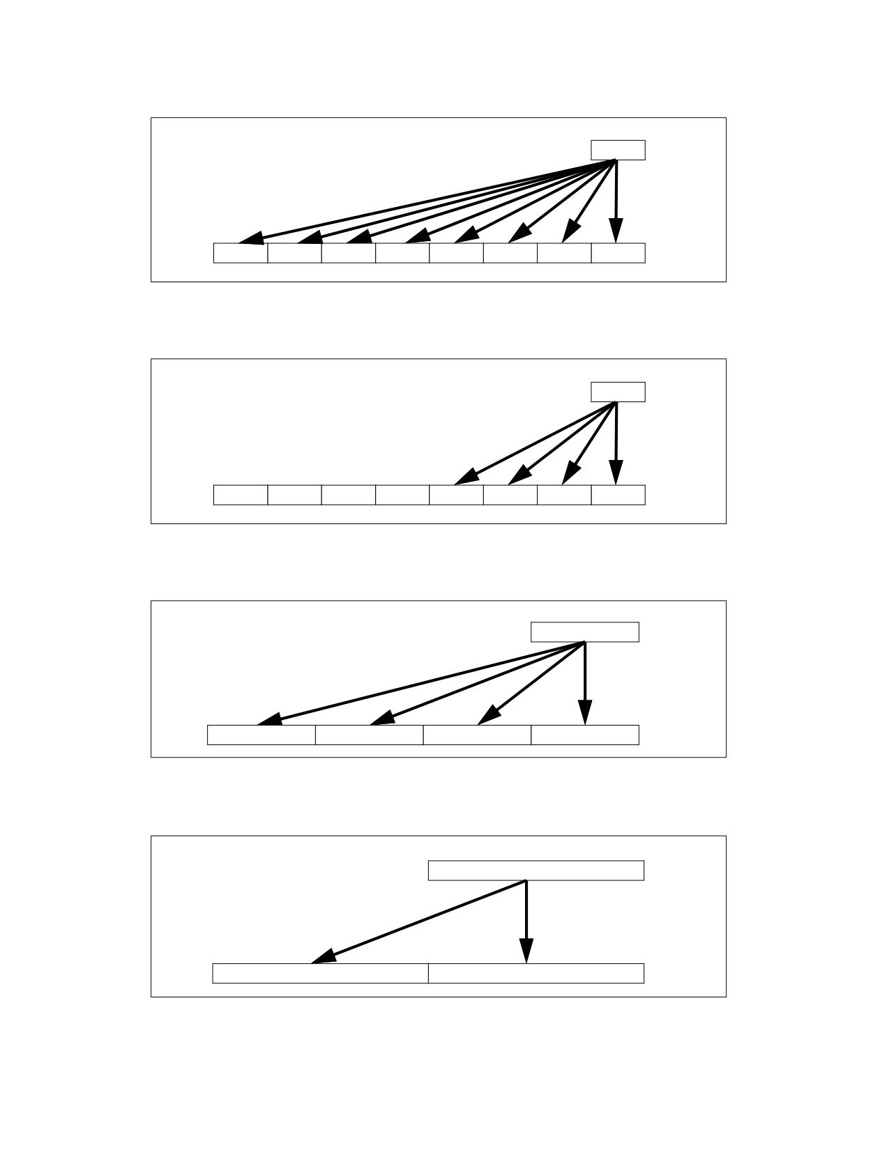
m32
X0
DEST
X0
X0
X0
X0
X0
X0
X0
X0
Figure 5-1. VBROADCASTSS Operation (VEX.256 encoded version)
m32
X0
DEST
0
0
0
0
X0
X0
X0
X0
Figure 5-2. VBROADCASTSS Operation (VEX.128-bit version)
m64
X0
DEST
X0
X0
X0
X0
Figure 5-3. VBROADCASTSD Operation (VEX.256-bit version)
m128
X0
DEST
X0
X0
Figure 5-4. VBROADCASTF128 Operation (VEX.256-bit version)
VBROADCAST-Load with Broadcast Floating-Point Data
Vol. 2C
5-14
m256
X0
DEST
X0
X0
Figure 5-5. VBROADCASTF64X4 Operation (512-bit version with writemask all 1s)
Operation
VBROADCASTSS (128-bit Version VEX and Legacy)
temp := SRC[31:0]
DEST[31:0] := temp
DEST[63:32] := temp
DEST[95:64] := temp
DEST[127:96] := temp
DEST[MAXVL-1:128] := 0
VBROADCASTSS (VEX.256 Encoded Version)
temp := SRC[31:0]
DEST[31:0] := temp
DEST[63:32] := temp
DEST[95:64] := temp
DEST[127:96] := temp
DEST[159:128] := temp
DEST[191:160] := temp
DEST[223:192] := temp
DEST[255:224] := temp
DEST[MAXVL-1:256] := 0
VBROADCASTSS (EVEX Encoded Versions)
(KL, VL) (4, 128), (8, 256),= (16, 512)
FOR j := 0 TO KL-1
i := j * 32
IF k1[j] OR *no writemask*
THEN DEST[i+31:i] := SRC[31:0]
ELSE
IF *merging-masking*
; merging-masking
THEN *DEST[i+31:i] remains unchanged*
ELSE
; zeroing-masking
DEST[i+31:i] := 0
FI
FI;
ENDFOR
DEST[MAXVL-1:VL] := 0
VBROADCAST-Load with Broadcast Floating-Point Data
Vol. 2C
5-15
VBROADCASTSD (VEX.256 Encoded Version)
temp := SRC[63:0]
DEST[63:0] := temp
DEST[127:64] := temp
DEST[191:128] := temp
DEST[255:192] := temp
DEST[MAXVL-1:256] := 0
VBROADCASTSD (EVEX Encoded Versions)
(KL, VL) = (4, 256), (8, 512)
FOR j := 0 TO KL-1
i := j * 64
IF k1[j] OR *no writemask*
THEN DEST[i+63:i] := SRC[63:0]
ELSE
IF *merging-masking*
; merging-masking
THEN *DEST[i+63:i] remains unchanged*
ELSE
; zeroing-masking
DEST[i+63:i] := 0
FI
FI;
ENDFOR
DEST[MAXVL-1:VL] := 0
VBROADCASTF32x2 (EVEX Encoded Versions)
(KL, VL) = (8, 256), (16, 512)
FOR j := 0 TO KL-1
i := j * 32
n := (j mod 2) * 32
IF k1[j] OR *no writemask*
THEN DEST[i+31:i] := SRC[n+31:n]
ELSE
IF *merging-masking*
; merging-masking
THEN *DEST[i+31:i] remains unchanged*
ELSE
; zeroing-masking
DEST[i+31:i] := 0
FI
FI;
ENDFOR
DEST[MAXVL-1:VL] := 0
VBROADCASTF128 (VEX.256 Encoded Version)
temp := SRC[127:0]
DEST[127:0] := temp
DEST[255:128] := temp
DEST[MAXVL-1:256] := 0
VBROADCAST-Load with Broadcast Floating-Point Data
Vol. 2C
5-16
VBROADCASTF32X4 (EVEX Encoded Versions)
(KL, VL) = (8, 256), (16, 512)
FOR j := 0 TO KL-1
i := j* 32
n := (j modulo 4) * 32
IF k1[j] OR *no writemask*
THEN DEST[i+31:i] := SRC[n+31:n]
ELSE
IF *merging-masking*
; merging-masking
THEN *DEST[i+31:i] remains unchanged*
ELSE
; zeroing-masking
DEST[i+31:i] := 0
FI
FI;
ENDFOR
DEST[MAXVL-1:VL] := 0
VBROADCASTF64X2 (EVEX Encoded Versions)
(KL, VL) = (4, 256), (8, 512)
FOR j := 0 TO KL-1
i := j * 64
n := (j modulo 2) * 64
IF k1[j] OR *no writemask*
THEN DEST[i+63:i] := SRC[n+63:n]
ELSE
IF *merging-masking*
; merging-masking
THEN *DEST[i+63:i] remains unchanged*
ELSE
; zeroing-masking
DEST[i+63:i] = 0
FI
FI;
ENDFOR;
VBROADCASTF32X8 (EVEX.U1.512 Encoded Version)
FOR j := 0 TO 15
i := j * 32
n := (j modulo 8) * 32
IF k1[j] OR *no writemask*
THEN DEST[i+31:i] := SRC[n+31:n]
ELSE
IF *merging-masking*
; merging-masking
THEN *DEST[i+31:i] remains unchanged*
ELSE
; zeroing-masking
DEST[i+31:i] := 0
FI
FI;
ENDFOR
DEST[MAXVL-1:VL] := 0
VBROADCAST-Load with Broadcast Floating-Point Data
Vol. 2C
5-17