Intel 64 and IA-32 Architectures. Software Developer’s Manual (2026) - page 28
ELSE (* StackAddressSize = 64 *)
RSP := RSP + SRC;
FI;
FI;
FI;
tempESP := Pop();
tempSS := Pop(); (* 32-bit pop, high-order 16 bits discarded, segment descriptor loaded *)
ELSE
IF OperandSize = 16
THEN
EIP := Pop();
EIP := EIP AND 0000FFFFH;
CS := Pop(); (* 16-bit pop; segment descriptor loaded *)
CS(RPL) := ReturnCodeSegmentSelector(RPL);
IF instruction has immediate operand
THEN (* Release parameters from called procedure’s stack *)
IF StackAddressSize = 32
THEN
ESP := ESP + SRC;
ELSE
IF StackAddressSize = 16
THEN
SP := SP + SRC;
ELSE (* StackAddressSize = 64 *)
RSP := RSP + SRC;
FI;
FI;
FI;
tempESP := Pop();
tempSS := Pop(); (* 16-bit pop; segment descriptor loaded *)
ELSE (* OperandSize = 64 *)
RIP := Pop();
CS := Pop(); (* 64-bit pop; high-order 48 bits discarded; seg. descriptor loaded *)
CS(RPL) := ReturnCodeSegmentSelector(RPL);
IF instruction has immediate operand
THEN (* Release parameters from called procedure’s stack *)
RSP := RSP + SRC;
FI;
tempESP := Pop();
tempSS := Pop(); (* 64-bit pop; high-order 48 bits discarded; seg. desc. loaded *)
FI;
FI;
IF ShadowStackEnabled(CPL)
(* check if 8 byte aligned *)
IF SSP AND 0x7 != 0
THEN #CP(FAR-RET/IRET); FI;
IF ReturnCodeSegmentSelector(RPL) !=3
THEN
tempSsCS = shadow_stack_load 8 bytes from SSP+16;
tempSsLIP = shadow_stack_load 8 bytes from SSP+8;
tempSSP = shadow_stack_load 8 bytes from SSP;
SSP = SSP + 24;
(* Do 64 bit compare to detect bits beyond 15 being set *)
RET-Return From Procedure
Vol. 2B
4-578
tempCS = CS; (* zero padded to 64 bit *)
IF tempCS != tempSsCS
THEN #CP(FAR-RET/IRET); FI;
(* Do 64 bit compare; pad CSBASE+RIP with 0 for 32 bit LIP *)
IF CSBASE + RIP != tempSsLIP
THEN #CP(FAR-RET/IRET); FI;
(* check if 4 byte aligned *)
IF tempSSP AND 0x3 != 0
THEN #CP(FAR-RET/IRET); FI;
FI;
FI;
tempOldCPL = CPL;
CPL := ReturnCodeSegmentSelector(RPL);
ESP := tempESP;
SS := tempSS;
tempOldSSP = SSP;
IF ShadowStackEnabled(CPL)
IF CPL = 3
THEN tempSSP := IA32_PL3_SSP; FI;
IF (CS.L = 0 AND tempSSP[63:32] != 0) OR
(CS.L = 1 AND tempSSP is not canonical relative to the current paging mode)
THEN #GP(0); FI;
SSP := tempSSP
FI;
(* Now past all faulting points; safe to free the token. The token free is done using the old SSP
* and using a supervisor override as old CPL was a supervisor privilege level *)
IF ShadowStackEnabled(tempOldCPL)
expected_token_value = tempOldSSP | BUSY_BIT
(* busy bit - bit position 0 - must be set *)
new_token_value = tempOldSSP
(* clear the busy bit *)
shadow_stack_lock_cmpxchg8b(tempOldSSP, new_token_value, expected_token_value)
FI;
FOR each of segment register (ES, FS, GS, and DS)
DO
IF segment register points to data or non-conforming code segment
and CPL > segment descriptor DPL; (* DPL in hidden part of segment register *)
THEN SegmentSelector := 0; (* SegmentSelector invalid *)
FI;
OD;
IF instruction has immediate operand
THEN (* Release parameters from calling procedure’s stack *)
IF StackAddressSize = 32
THEN
ESP := ESP + SRC;
ELSE
IF StackAddressSize = 16
THEN
SP := SP + SRC;
ELSE (* StackAddressSize = 64 *)
RSP := RSP + SRC;
FI;
FI;
FI;
RET-Return From Procedure
Vol. 2B
4-579
Flags Affected
None.
Protected Mode Exceptions
#GP(0)
If the return code or stack segment selector is NULL.
If the return instruction pointer is not within the return code segment limit.
If returning to 32-bit or compatibility mode and the previous SSP from shadow stack (when
returning to CPL <3) or from IA32_PL3_SSP (returning to CPL 3) is beyond 4GB.
#GP(selector)
If the RPL of the return code segment selector is less then the CPL.
If the return code or stack segment selector index is not within its descriptor table limits.
If the return code segment descriptor does not indicate a code segment.
If the return code segment is non-conforming and the segment selector’s DPL is not equal to
the RPL of the code segment’s segment selector
If the return code segment is conforming and the segment selector’s DPL greater than the RPL
of the code segment’s segment selector
If the stack segment is not a writable data segment.
If the stack segment selector RPL is not equal to the RPL of the return code segment selector.
If the stack segment descriptor DPL is not equal to the RPL of the return code segment
selector.
#SS(0)
If the top bytes of stack are not within stack limits.
If the return stack segment is not present.
#NP(selector)
If the return code segment is not present.
#PF(fault-code)
If a page fault occurs.
#AC(0)
If an unaligned memory access occurs when the CPL is 3 and alignment checking is enabled.
#CP(Far-RET/IRET) If the previous SSP from shadow stack (when returning to CPL <3) or from IA32_PL3_SSP
(returning to CPL 3) is not 4 byte aligned.
If return instruction pointer from stack and shadow stack do not match.
Real-Address Mode Exceptions
#GP
If the return instruction pointer is not within the return code segment limit
#SS
If the top bytes of stack are not within stack limits.
Virtual-8086 Mode Exceptions
#GP(0)
If the return instruction pointer is not within the return code segment limit
#SS(0)
If the top bytes of stack are not within stack limits.
#PF(fault-code)
If a page fault occurs.
#AC(0)
If an unaligned memory access occurs when alignment checking is enabled.
Compatibility Mode Exceptions
Same as 64-bit mode exceptions.
RET-Return From Procedure
Vol. 2B
4-580
64-Bit Mode Exceptions
#GP(0)
If the return instruction pointer is non-canonical.
If the return instruction pointer is not within the return code segment limit.
If the stack segment selector is NULL going back to compatibility mode.
If the stack segment selector is NULL going back to CPL3 64-bit mode.
If a NULL stack segment selector RPL is not equal to CPL going back to non-CPL3 64-bit mode.
If the return code segment selector is NULL.
If returning to 32-bit or compatibility mode and the previous SSP from shadow stack (when
returning to CPL <3) or from IA32_PL3_SSP (returning to CPL 3) is beyond 4GB.
#GP(selector)
If the proposed segment descriptor for a code segment does not indicate it is a code segment.
If the proposed new code segment descriptor has both the D-bit and L-bit set.
If the DPL for a nonconforming-code segment is not equal to the RPL of the code segment
selector.
If CPL is greater than the RPL of the code segment selector.
If FRED transitions are enabled and CPL is less than the RPL of the code segment selector.
If FRED transitions are enabled and CPL = 0 and far RET would enter compatibility mode.
If the DPL of a conforming-code segment is greater than the return code segment selector
RPL.
If a segment selector index is outside its descriptor table limits.
If a segment descriptor memory address is non-canonical.
If the stack segment is not a writable data segment.
If the stack segment descriptor DPL is not equal to the RPL of the return code segment
selector.
If the stack segment selector RPL is not equal to the RPL of the return code segment selector.
#SS(0)
If an attempt to pop a value off the stack violates the SS limit.
If an attempt to pop a value off the stack causes a non-canonical address to be referenced.
#NP(selector)
If the return code or stack segment is not present.
#PF(fault-code)
If a page fault occurs.
#AC(0)
If alignment checking is enabled and an unaligned memory reference is made while the
current privilege level is 3.
#CP(Far-RET/IRET) If the previous SSP from shadow stack (when returning to CPL <3) or from IA32_PL3_SSP
(returning to CPL 3) is not 4 byte aligned.
If return instruction pointer from stack and shadow stack do not match.
RET-Return From Procedure
Vol. 2B
4-581

RORX - Rotate Right Logical Without Affecting Flags
Opcode/
Op/
64/32-
CPUID
Description
Instruction
En
bit
Feature
Mode
Flag
VEX.LZ.F2.0F3A.W0 F0 /r ib
RMI
V/V
BMI2
Rotate 32-bit r/m32 right imm8 times and load into r32 without
RORX r32, r/m32, imm8
affecting arithmetic flags.
VEX.LZ.F2.0F3A.W1 F0 /r ib
RMI
V/N.E.
BMI2
Rotate 64-bit r/m64 right imm8 times and load into r64 without
RORX r64, r/m64, imm8
affecting arithmetic flags.
Instruction Operand Encoding
Op/En
Operand 1
Operand 2
Operand 3
Operand 4
RMI
ModRM:reg (w)
ModRM:r/m (r)
imm8
N/A
Description
Rotates the bits of source operand right by the count value specified in imm8 without affecting arithmetic flags. The
result is written to the destination operand.
This instruction is not supported in real mode and virtual-8086 mode. The operand size is always 32 bits if not in
64-bit mode. In 64-bit mode operand size 64 requires VEX.W1. VEX.W1 is ignored in non-64-bit modes. An
attempt to execute this instruction with VEX.L not equal to 0 will cause #UD.
Operation
IF (OperandSize = 32)
y := imm8 AND 1FH;
DEST := (SRC >> y) | (SRC << (32-y));
ELSEIF (OperandSize = 64)
y := imm8 AND 3FH;
DEST := (SRC >> y) | (SRC << (64-y));
FI;
Flags Affected
None.
Intel C/C++ Compiler Intrinsic Equivalent
Auto-generated from high-level language.
SIMD Floating-Point Exceptions
None.
Other Exceptions
See Table 2-29, “Type 13 Class Exception Conditions.”
RORX - Rotate Right Logical Without Affecting Flags
Vol. 2B
4-582

ROUNDPD-Round Packed Double Precision Floating-Point Values
Opcode*/
Op/
64/32 bit
CPUID
Description
Instruction
En
Mode
Feature
Support
Flag
66 0F 3A 09 /r ib
RMI
V/V
SSE4_1
Round packed double precision floating-point
ROUNDPD xmm1, xmm2/m128, imm8
values in xmm2/m128 and place the result in
xmm1. The rounding mode is determined by
imm8.
VEX.128.66.0F3A.WIG 09 /r ib
RMI
V/V
AVX
Round packed double precision floating-point
VROUNDPD xmm1, xmm2/m128, imm8
values in xmm2/m128 and place the result in
xmm1. The rounding mode is determined by
imm8.
VEX.256.66.0F3A.WIG 09 /r ib
RMI
V/V
AVX
Round packed double precision floating-point
VROUNDPD ymm1, ymm2/m256, imm8
values in ymm2/m256 and place the result in
ymm1. The rounding mode is determined by
imm8.
Instruction Operand Encoding
Op/En
Operand 1
Operand 2
Operand 3
Operand 4
RMI
ModRM:reg (w)
ModRM:r/m (r)
imm8
N/A
Description
Round the 2 double precision floating-point values in the source operand (second operand) using the rounding
mode specified in the immediate operand (third operand) and place the results in the destination operand (first
operand). The rounding process rounds each input floating-point value to an integer value and returns the integer
result as a double precision floating-point value.
The immediate operand specifies control fields for the rounding operation, three bit fields are defined and shown in
Figure 4-24. Bit 3 of the immediate byte controls processor behavior for a precision exception, bit 2 selects the
source of rounding mode control. Bits 1:0 specify a non-sticky rounding-mode value (Table 4-21 lists the encoded
values for rounding-mode field).
The Precision Floating-Point Exception is signaled according to the immediate operand. If any source operand is an
SNaN then it will be converted to a QNaN. If DAZ is set to ‘1 then denormals will be converted to zero before
rounding.
128-bit Legacy SSE version: The second source can be an XMM register or 128-bit memory location. The destina-
tion is not distinct from the first source XMM register and the upper bits (MAXVL-1:128) of the corresponding YMM
register destination are unmodified.
VEX.128 encoded version: the source operand second source operand or a 128-bit memory location. The destina-
tion operand is an XMM register. The upper bits (MAXVL-1:128) of the corresponding YMM register destination are
zeroed.
VEX.256 encoded version: The source operand is a YMM register or a 256-bit memory location. The destination
operand is a YMM register.
Note: In VEX-encoded versions, VEX.vvvv is reserved and must be 1111b, otherwise instructions will #UD.
ROUNDPD-Round Packed Double Precision Floating-Point Values
Vol. 2B
4-583
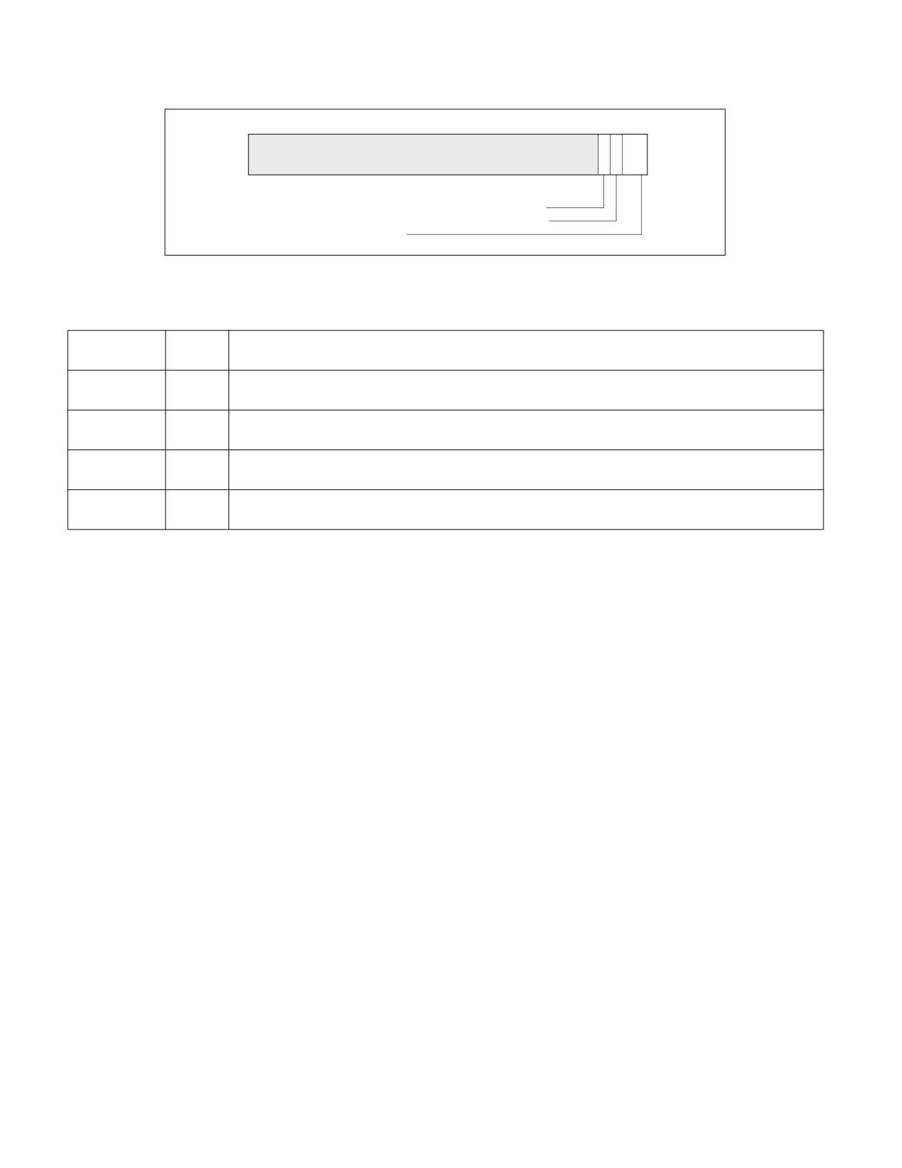
8
3 2 1 0
Reserved
P - Precision Mask (SPE); 0: normal, 1: inexact
RS - Rounding select; 1: MXCSR.RC, 0: Imm8.RC
RC - Rounding mode
Figure 4-24. Bit Control Fields of Immediate Byte for ROUNDxx Instruction
Table 4-21. Rounding Modes and Encoding of Rounding Control (RC) Field
Rounding
RC Field
Description
Mode
Setting
Round to
00B
Rounded result is the closest to the infinitely precise result. If two values are equally close, the result is
nearest (even)
the even value (i.e., the integer value with the least-significant bit of zero).
Round down
01B
Rounded result is closest to but no greater than the infinitely precise result.
(toward -∞)
Round up
10B
Rounded result is closest to but no less than the infinitely precise result.
(toward +∞)
Round toward
11B
Rounded result is closest to but no greater in absolute value than the infinitely precise result.
zero (Truncate)
Operation
IF (imm[2] = ‘1)
THEN
// rounding mode is determined by MXCSR.RC
DEST[63:0] := ConvertDPFPToInteger_M(SRC[63:0]);
DEST[127:64] := ConvertDPFPToInteger_M(SRC[127:64]);
ELSE
// rounding mode is determined by IMM8.RC
DEST[63:0] := ConvertDPFPToInteger_Imm(SRC[63:0]);
DEST[127:64] := ConvertDPFPToInteger_Imm(SRC[127:64]);
FI
ROUNDPD (128-bit Legacy SSE Version)
DEST[63:0] := RoundToInteger(SRC[63:0]], ROUND_CONTROL)
DEST[127:64] := RoundToInteger(SRC[127:64]], ROUND_CONTROL)
DEST[MAXVL-1:128] (Unmodified)
VROUNDPD (VEX.128 Encoded Version)
DEST[63:0] := RoundToInteger(SRC[63:0]], ROUND_CONTROL)
DEST[127:64] := RoundToInteger(SRC[127:64]], ROUND_CONTROL)
DEST[MAXVL-1:128] := 0
VROUNDPD (VEX.256 Encoded Version)
DEST[63:0] := RoundToInteger(SRC[63:0], ROUND_CONTROL)
DEST[127:64] := RoundToInteger(SRC[127:64]], ROUND_CONTROL)
DEST[191:128] := RoundToInteger(SRC[191:128]], ROUND_CONTROL)
DEST[255:192] := RoundToInteger(SRC[255:192] ], ROUND_CONTROL)
ROUNDPD-Round Packed Double Precision Floating-Point Values
Vol. 2B
4-584
Intel C/C++ Compiler Intrinsic Equivalent
__m128 _mm_round_pd(__m128d s1, int iRoundMode);
__m128 _mm_floor_pd(__m128d s1);
__m128 _mm_ceil_pd(__m128d s1)
__m256 _mm256_round_pd(__m256d s1, int iRoundMode);
__m256 _mm256_floor_pd(__m256d s1);
__m256 _mm256_ceil_pd(__m256d s1)
SIMD Floating-Point Exceptions
Invalid (signaled only if SRC = SNaN).
Precision (signaled only if imm[3] = ‘0; if imm[3] = ‘1, then the Precision Mask in the MXCSR is ignored and preci-
sion exception is not signaled.)
Note that Denormal is not signaled by ROUNDPD.
Other Exceptions
See Table 2-19, “Type 2 Class Exception Conditions,” additionally:
#UD
If VEX.vvvv ≠ 1111B.
ROUNDPD-Round Packed Double Precision Floating-Point Values
Vol. 2B
4-585
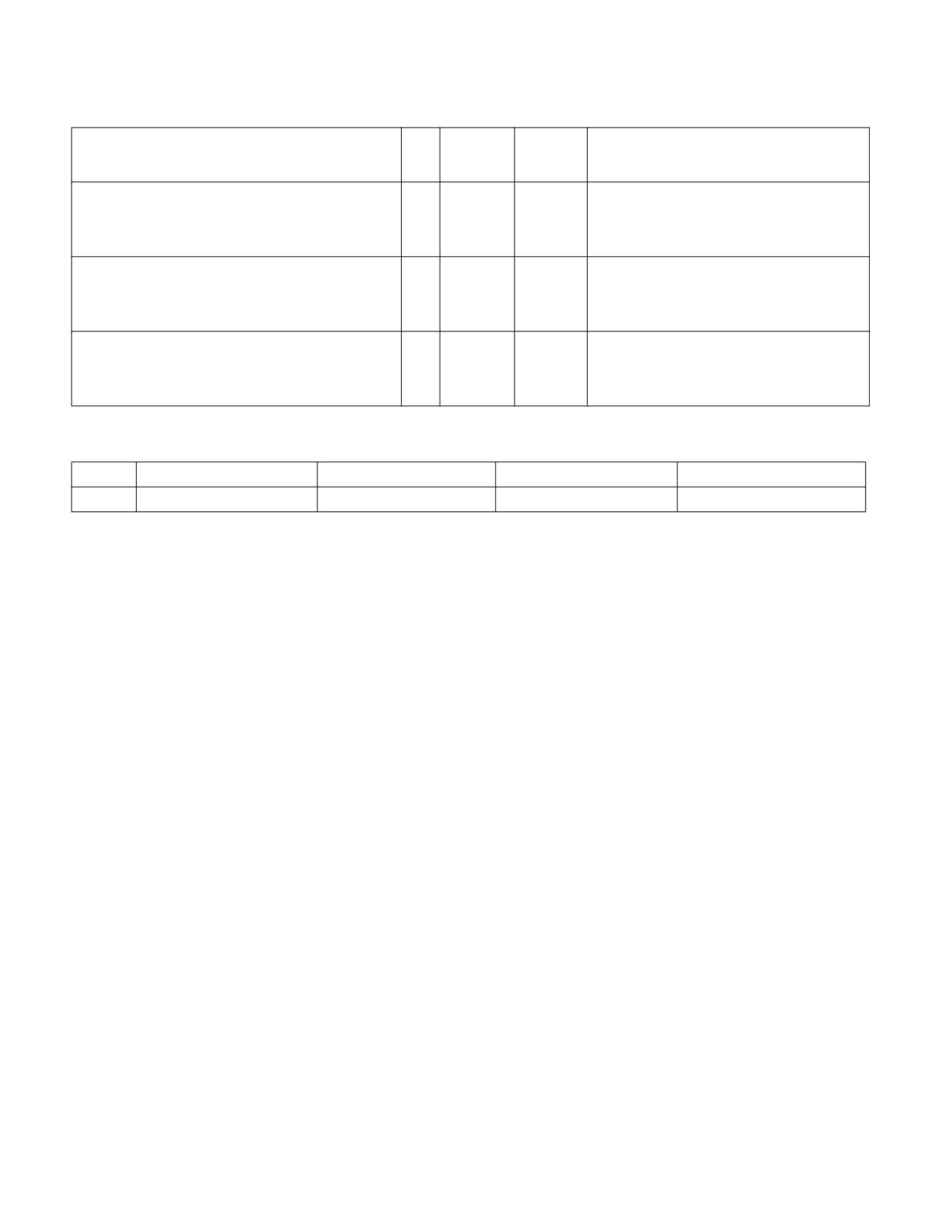
ROUNDPS-Round Packed Single Precision Floating-Point Values
Opcode*/
Op/
64/32 bit
CPUID
Description
Instruction
En
Mode
Feature
Support
Flag
66 0F 3A 08
RMI
V/V
SSE4_1
Round packed single precision floating-point
/r ib
values in xmm2/m128 and place the result in
ROUNDPS xmm1, xmm2/m128, imm8
xmm1. The rounding mode is determined by
imm8.
VEX.128.66.0F3A.WIG 08 /r ib
RMI
V/V
AVX
Round packed single precision floating-point
VROUNDPS xmm1, xmm2/m128, imm8
values in xmm2/m128 and place the result in
xmm1. The rounding mode is determined by
imm8.
VEX.256.66.0F3A.WIG 08 /r ib
RMI
V/V
AVX
Round packed single precision floating-point
VROUNDPS ymm1, ymm2/m256, imm8
values in ymm2/m256 and place the result in
ymm1. The rounding mode is determined by
imm8.
Instruction Operand Encoding
Op/En
Operand 1
Operand 2
Operand 3
Operand 4
RMI
ModRM:reg (w)
ModRM:r/m (r)
imm8
N/A
Description
Round the 4 single precision floating-point values in the source operand (second operand) using the rounding mode
specified in the immediate operand (third operand) and place the results in the destination operand (first operand).
The rounding process rounds each input floating-point value to an integer value and returns the integer result as a
single precision floating-point value.
The immediate operand specifies control fields for the rounding operation, three bit fields are defined and shown in
Figure 4-24. Bit 3 of the immediate byte controls processor behavior for a precision exception, bit 2 selects the
source of rounding mode control. Bits 1:0 specify a non-sticky rounding-mode value (Table 4-21 lists the encoded
values for rounding-mode field).
The Precision Floating-Point Exception is signaled according to the immediate operand. If any source operand is an
SNaN then it will be converted to a QNaN. If DAZ is set to ‘1 then denormals will be converted to zero before
rounding.
128-bit Legacy SSE version: The second source can be an XMM register or 128-bit memory location. The destina-
tion is not distinct from the first source XMM register and the upper bits (MAXVL-1:128) of the corresponding YMM
register destination are unmodified.
VEX.128 encoded version: the source operand second source operand or a 128-bit memory location. The destina-
tion operand is an XMM register. The upper bits (MAXVL-1:128) of the corresponding YMM register destination are
zeroed.
VEX.256 encoded version: The source operand is a YMM register or a 256-bit memory location. The destination
operand is a YMM register.
Note: In VEX-encoded versions, VEX.vvvv is reserved and must be 1111b otherwise instructions will #UD.
Operation
IF (imm[2] = ‘1)
THEN
// rounding mode is determined by MXCSR.RC
DEST[31:0] := ConvertSPFPToInteger_M(SRC[31:0]);
DEST[63:32] := ConvertSPFPToInteger_M(SRC[63:32]);
DEST[95:64] := ConvertSPFPToInteger_M(SRC[95:64]);
DEST[127:96] := ConvertSPFPToInteger_M(SRC[127:96]);
ELSE
// rounding mode is determined by IMM8.RC
ROUNDPS-Round Packed Single Precision Floating-Point Values
Vol. 2B
4-586
DEST[31:0] := ConvertSPFPToInteger_Imm(SRC[31:0]);
DEST[63:32] := ConvertSPFPToInteger_Imm(SRC[63:32]);
DEST[95:64] := ConvertSPFPToInteger_Imm(SRC[95:64]);
DEST[127:96] := ConvertSPFPToInteger_Imm(SRC[127:96]);
FI;
ROUNDPS(128-bit Legacy SSE Version)
DEST[31:0] := RoundToInteger(SRC[31:0], ROUND_CONTROL)
DEST[63:32] := RoundToInteger(SRC[63:32], ROUND_CONTROL)
DEST[95:64] := RoundToInteger(SRC[95:64]], ROUND_CONTROL)
DEST[127:96] := RoundToInteger(SRC[127:96]], ROUND_CONTROL)
DEST[MAXVL-1:128] (Unmodified)
VROUNDPS (VEX.128 Encoded Version)
DEST[31:0] := RoundToInteger(SRC[31:0], ROUND_CONTROL)
DEST[63:32] := RoundToInteger(SRC[63:32], ROUND_CONTROL)
DEST[95:64] := RoundToInteger(SRC[95:64]], ROUND_CONTROL)
DEST[127:96] := RoundToInteger(SRC[127:96]], ROUND_CONTROL)
DEST[MAXVL-1:128] := 0
VROUNDPS (VEX.256 Encoded Version)
DEST[31:0] := RoundToInteger(SRC[31:0], ROUND_CONTROL)
DEST[63:32] := RoundToInteger(SRC[63:32], ROUND_CONTROL)
DEST[95:64] := RoundToInteger(SRC[95:64]], ROUND_CONTROL)
DEST[127:96] := RoundToInteger(SRC[127:96]], ROUND_CONTROL)
DEST[159:128] := RoundToInteger(SRC[159:128]], ROUND_CONTROL)
DEST[191:160] := RoundToInteger(SRC[191:160]], ROUND_CONTROL)
DEST[223:192] := RoundToInteger(SRC[223:192] ], ROUND_CONTROL)
DEST[255:224] := RoundToInteger(SRC[255:224] ], ROUND_CONTROL)
Intel C/C++ Compiler Intrinsic Equivalent
__m128 _mm_round_ps(__m128 s1, int iRoundMode);
__m128 _mm_floor_ps(__m128 s1);
__m128 _mm_ceil_ps(__m128 s1)
__m256 _mm256_round_ps(__m256 s1, int iRoundMode);
__m256 _mm256_floor_ps(__m256 s1);
__m256 _mm256_ceil_ps(__m256 s1)
SIMD Floating-Point Exceptions
Invalid (signaled only if SRC = SNaN).
Precision (signaled only if imm[3] = ‘0; if imm[3] = ‘1, then the Precision Mask in the MXCSR is ignored and preci-
sion exception is not signaled.)
Note that Denormal is not signaled by ROUNDPS.
Other Exceptions
See Table 2-19, “Type 2 Class Exception Conditions,” additionally:
#UD
If VEX.vvvv ≠ 1111B.
ROUNDPS-Round Packed Single Precision Floating-Point Values
Vol. 2B
4-587
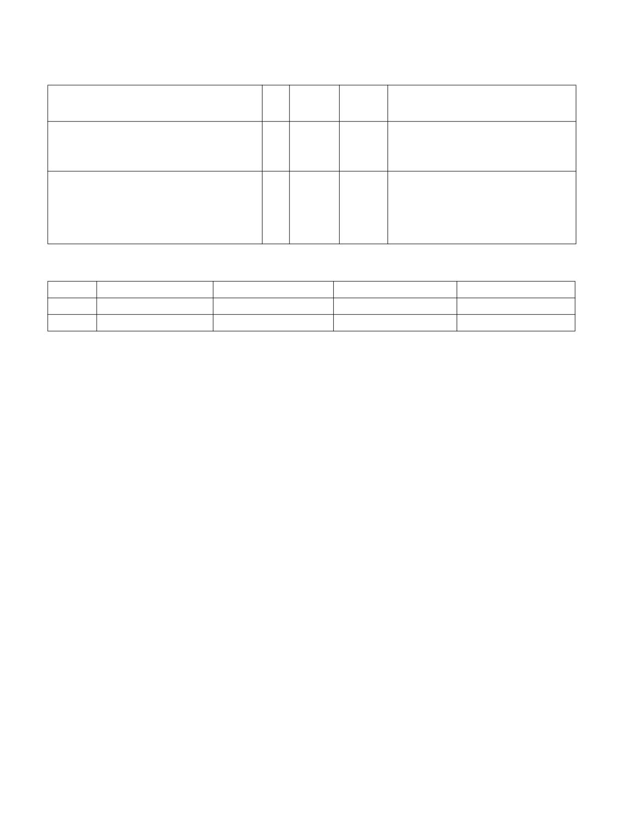
ROUNDSD-Round Scalar Double Precision Floating-Point Values
Opcode*/
Op/
64/32 bit
CPUID
Description
Instruction
En
Mode
Feature
Support
Flag
66 0F 3A 0B /r ib
RMI
V/V
SSE4_1
Round the low packed double precision
ROUNDSD xmm1, xmm2/m64, imm8
floating-point value in xmm2/m64 and place
the result in xmm1. The rounding mode is
determined by imm8.
VEX.LIG.66.0F3A.WIG 0B /r ib
RVMI
V/V
AVX
Round the low packed double precision
VROUNDSD xmm1, xmm2, xmm3/m64, imm8
floating-point value in xmm3/m64 and place
the result in xmm1. The rounding mode is
determined by imm8. Upper packed double
precision floating-point value (bits[127:64])
from xmm2 is copied to xmm1[127:64].
Instruction Operand Encoding
Op/En
Operand 1
Operand 2
Operand 3
Operand 4
RMI
ModRM:reg (w)
ModRM:r/m (r)
imm8
N/A
RVMI
ModRM:reg (w)
VEX.vvvv (r)
ModRM:r/m (r)
imm8
Description
Round the double precision floating-point value in the lower qword of the source operand (second operand) using
the rounding mode specified in the immediate operand (third operand) and place the result in the destination
operand (first operand). The rounding process rounds a double precision floating-point input to an integer value
and returns the integer result as a double precision floating-point value in the lowest position. The upper double
precision floating-point value in the destination is retained.
The immediate operand specifies control fields for the rounding operation, three bit fields are defined and shown in
Figure 4-24. Bit 3 of the immediate byte controls processor behavior for a precision exception, bit 2 selects the
source of rounding mode control. Bits 1:0 specify a non-sticky rounding-mode value (Table 4-21 lists the encoded
values for rounding-mode field).
The Precision Floating-Point Exception is signaled according to the immediate operand. If any source operand is an
SNaN then it will be converted to a QNaN. If DAZ is set to ‘1 then denormals will be converted to zero before
rounding.
128-bit Legacy SSE version: The first source operand and the destination operand are the same. Bits (MAXVL-
1:64) of the corresponding YMM destination register remain unchanged.
VEX.128 encoded version: Bits (MAXVL-1:128) of the destination YMM register are zeroed.
Operation
IF (imm[2] = ‘1)
THEN
// rounding mode is determined by MXCSR.RC
DEST[63:0] := ConvertDPFPToInteger_M(SRC[63:0]);
ELSE
// rounding mode is determined by IMM8.RC
DEST[63:0] := ConvertDPFPToInteger_Imm(SRC[63:0]);
FI;
DEST[127:63] remains unchanged ;
ROUNDSD (128-bit Legacy SSE Version)
DEST[63:0] := RoundToInteger(SRC[63:0], ROUND_CONTROL)
DEST[MAXVL-1:64] (Unmodified)
ROUNDSD-Round Scalar Double Precision Floating-Point Values
Vol. 2B
4-588
VROUNDSD (VEX.128 Encoded Version)
DEST[63:0] := RoundToInteger(SRC2[63:0], ROUND_CONTROL)
DEST[127:64] := SRC1[127:64]
DEST[MAXVL-1:128] := 0
Intel C/C++ Compiler Intrinsic Equivalent
ROUNDSD __m128d mm_round_sd(__m128d dst, __m128d s1, int iRoundMode);
ROUNDSD __m128d mm_floor_sd(__m128d dst, __m128d s1);
ROUNDSD __m128d mm_ceil_sd(__m128d dst, __m128d s1);
SIMD Floating-Point Exceptions
Invalid (signaled only if SRC = SNaN).
Precision (signaled only if imm[3] = ‘0; if imm[3] = ‘1, then the Precision Mask in the MXCSR is ignored and preci-
sion exception is not signaled.)
Note that Denormal is not signaled by ROUNDSD.
Other Exceptions
See Table 2-20, “Type 3 Class Exception Conditions.”
ROUNDSD-Round Scalar Double Precision Floating-Point Values
Vol. 2B
4-589
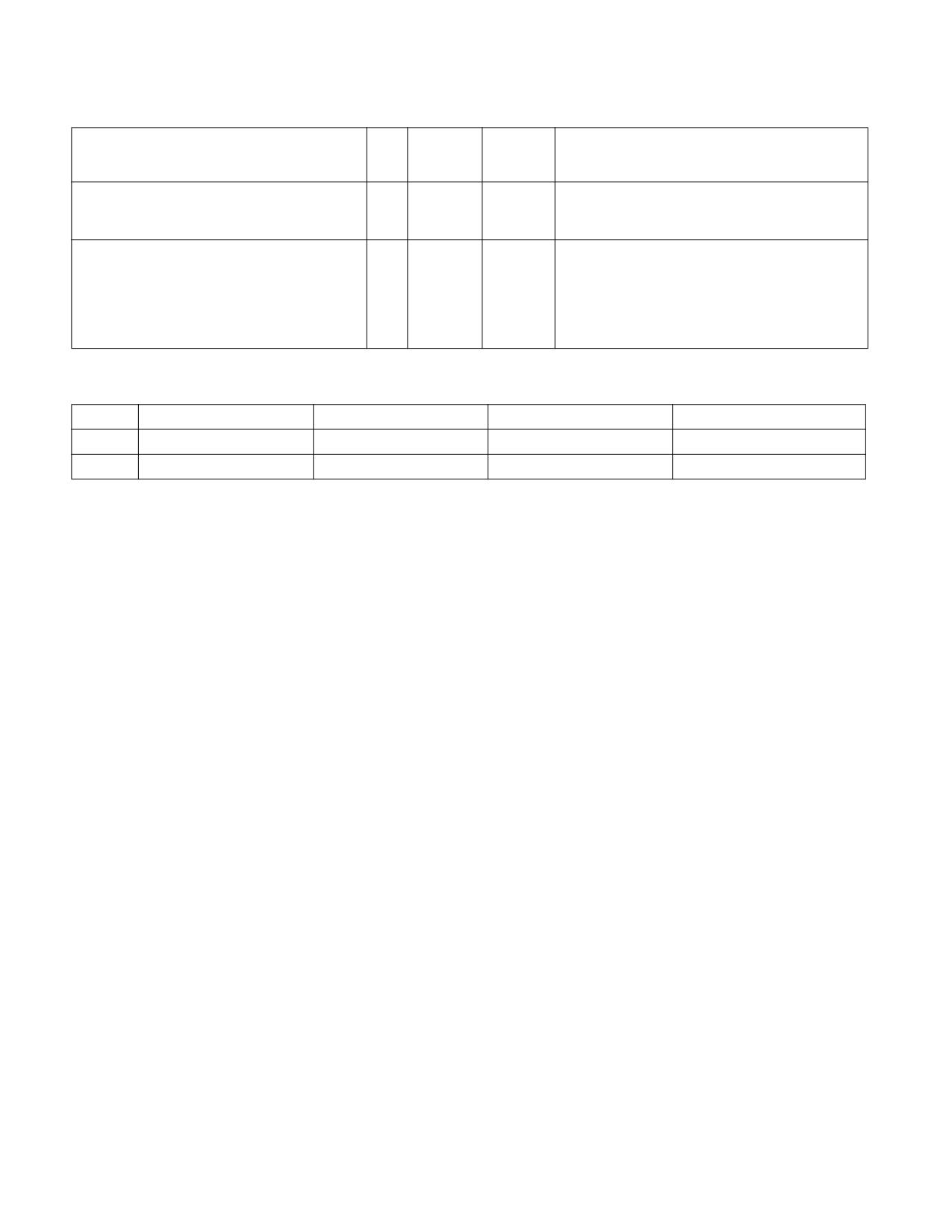
ROUNDSS-Round Scalar Single Precision Floating-Point Values
Opcode*/
Op/
64/32 bit
CPUID
Description
Instruction
En
Mode
Feature
Support
Flag
66 0F 3A 0A /r ib
RMI
V/V
SSE4_1
Round the low packed single precision floating-
ROUNDSS xmm1, xmm2/m32, imm8
point value in xmm2/m32 and place the result in
xmm1. The rounding mode is determined by imm8.
VEX.LIG.66.0F3A.WIG 0A /r ib
RVMI
V/V
AVX
Round the low packed single precision floating-
VROUNDSS xmm1, xmm2, xmm3/m32, imm8
point value in xmm3/m32 and place the result in
xmm1. The rounding mode is determined by imm8.
Also, upper packed single precision floating-point
values (bits[127:32]) from xmm2 are copied to
xmm1[127:32].
Instruction Operand Encoding
Op/En
Operand 1
Operand 2
Operand 3
Operand 4
RMI
ModRM:reg (w)
ModRM:r/m (r)
imm8
N/A
RVMI
ModRM:reg (w)
VEX.vvvv (r)
ModRM:r/m (r)
imm8
Description
Round the single precision floating-point value in the lowest dword of the source operand (second operand) using
the rounding mode specified in the immediate operand (third operand) and place the result in the destination
operand (first operand). The rounding process rounds a single precision floating-point input to an integer value and
returns the result as a single precision floating-point value in the lowest position. The upper three single precision
floating-point values in the destination are retained.
The immediate operand specifies control fields for the rounding operation, three bit fields are defined and shown in
Figure 4-24. Bit 3 of the immediate byte controls processor behavior for a precision exception, bit 2 selects the
source of rounding mode control. Bits 1:0 specify a non-sticky rounding-mode value (Table 4-21 lists the encoded
values for rounding-mode field).
The Precision Floating-Point Exception is signaled according to the immediate operand. If any source operand is an
SNaN then it will be converted to a QNaN. If DAZ is set to ‘1 then denormals will be converted to zero before
rounding.
128-bit Legacy SSE version: The first source operand and the destination operand are the same. Bits (MAXVL-
1:32) of the corresponding YMM destination register remain unchanged.
VEX.128 encoded version: Bits (MAXVL-1:128) of the destination YMM register are zeroed.
Operation
IF (imm[2] = ‘1)
THEN
// rounding mode is determined by MXCSR.RC
DEST[31:0] := ConvertSPFPToInteger_M(SRC[31:0]);
ELSE
// rounding mode is determined by IMM8.RC
DEST[31:0] := ConvertSPFPToInteger_Imm(SRC[31:0]);
FI;
DEST[127:32] remains unchanged ;
ROUNDSS (128-bit Legacy SSE Version)
DEST[31:0] := RoundToInteger(SRC[31:0], ROUND_CONTROL)
DEST[MAXVL-1:32] (Unmodified)
ROUNDSS-Round Scalar Single Precision Floating-Point Values
Vol. 2B
4-590
VROUNDSS (VEX.128 Encoded Version)
DEST[31:0] := RoundToInteger(SRC2[31:0], ROUND_CONTROL)
DEST[127:32] := SRC1[127:32]
DEST[MAXVL-1:128] := 0
Intel C/C++ Compiler Intrinsic Equivalent
ROUNDSS __m128 mm_round_ss(__m128 dst, __m128 s1, int iRoundMode);
ROUNDSS __m128 mm_floor_ss(__m128 dst, __m128 s1);
ROUNDSS __m128 mm_ceil_ss(__m128 dst, __m128 s1);
SIMD Floating-Point Exceptions
Invalid (signaled only if SRC = SNaN).
Precision (signaled only if imm[3] = ‘0; if imm[3] = ‘1, then the Precision Mask in the MXCSR is ignored and preci-
sion exception is not signaled.)
Note that Denormal is not signaled by ROUNDSS.
Other Exceptions
See Table 2-20, “Type 3 Class Exception Conditions.”
ROUNDSS-Round Scalar Single Precision Floating-Point Values
Vol. 2B
4-591
RSM-Resume From System Management Mode
Opcode*
Instruction
Op/
64-Bit
Compat/
Description
En
Mode
Leg Mode
0F AA
RSM
ZO
Valid
Valid
Resume operation of interrupted program.
Instruction Operand Encoding
Op/En
Operand 1
Operand 2
Operand 3
Operand 4
ZO
N/A
N/A
N/A
N/A
Description
Returns program control from system management mode (SMM) to the application program or operating-system
procedure that was interrupted when the processor received an SMM interrupt. The processor’s state is restored
from the dump created upon entering SMM. If the processor detects invalid state information during state resto-
ration, it enters the shutdown state. The following invalid information can cause a shutdown:
• Any reserved bit of CR4 is set to 1.
• Any illegal combination of bits in CR0, such as (PG=1 and PE=0) or (NW=1 and CD=0).
• (Intel Pentium and Intel486™ processors only.) The value stored in the state dump base field is not a 32-KByte
aligned address.
The contents of the model-specific registers are not affected by a return from SMM.
The SMM state map used by RSM supports resuming processor context for non-64-bit modes and 64-bit mode.
See Chapter 34, “System Management Mode,” in the Intel® 64 and IA-32 Architectures Software Developer’s
Manual, Volume 3C, for more information about SMM and the behavior of the RSM instruction.
Operation
ReturnFromSMM;
IF (IA-32e mode supported) or (CPUID DisplayFamily_DisplayModel = 06H_0CH )
THEN
ProcessorState := Restore(SMMDump(IA-32e SMM STATE MAP));
Else
ProcessorState := Restore(SMMDump(Non-32-Bit-Mode SMM STATE MAP));
FI
Flags Affected
All.
Protected Mode Exceptions
#UD
If an attempt is made to execute this instruction when the processor is not in SMM.
If the LOCK prefix is used.
#GP(0)
If CPL > 0 and IA32_CORE_CAPABILITIES.RSM_IN_CPL0_ONLY[bit 3] = 1.
Real-Address Mode Exceptions
#UD
If an attempt is made to execute this instruction when the processor is not in SMM.
If the LOCK prefix is used.
Virtual-8086 Mode Exceptions
#UD
If an attempt is made to execute this instruction when the processor is not in SMM.
If the LOCK prefix is used.
RSM-Resume From System Management Mode
Vol. 2B
4-592
#GP(0)
If IA32_CORE_CAPABILITIES.RSM_IN_CPL0_ONLY[bit 3] = 1.
Compatibility Mode Exceptions
Same exceptions as in protected mode.
64-Bit Mode Exceptions
Same exceptions as in protected mode.
RSM-Resume From System Management Mode
Vol. 2B
4-593

RSQRTPS-Compute Reciprocals of Square Roots of Packed Single Precision Floating-Point
Values
Opcode*/
Op/
64/32 bit
CPUID
Description
Instruction
En
Mode
Feature
Support
Flag
NP 0F 52 /r
RM
V/V
SSE
Computes the approximate reciprocals of the square
roots of the packed single precision floating-point
RSQRTPS xmm1, xmm2/m128
values in xmm2/m128 and stores the results in
xmm1.
VEX.128.0F.WIG 52 /r
RM
V/V
AVX
Computes the approximate reciprocals of the square
roots of packed single precision values in xmm2/mem
VRSQRTPS xmm1, xmm2/m128
and stores the results in xmm1.
VEX.256.0F.WIG 52 /r
RM
V/V
AVX
Computes the approximate reciprocals of the square
roots of packed single precision values in ymm2/mem
VRSQRTPS ymm1, ymm2/m256
and stores the results in ymm1.
Instruction Operand Encoding
Op/En
Operand 1
Operand 2
Operand 3
Operand 4
RM
ModRM:reg (w)
ModRM:r/m (r)
N/A
N/A
Description
Performs a SIMD computation of the approximate reciprocals of the square roots of the four packed single precision
floating-point values in the source operand (second operand) and stores the packed single precision floating-point
results in the destination operand. The source operand can be an XMM register or a 128-bit memory location. The
destination operand is an XMM register. See Figure 10-5 in the Intel® 64 and IA-32 Architectures Software Devel-
oper’s Manual, Volume 1, for an illustration of a SIMD single precision floating-point operation.
The relative error for this approximation is:
|Relative Error| ≤ 1.5 ∗ 2-12
The RSQRTPS instruction is not affected by the rounding control bits in the MXCSR register. When a source value is
a 0.0, an ∞ of the sign of the source value is returned. A denormal source value is treated as a 0.0 (of the same
sign). When a source value is a negative value (other than -0.0), a floating-point indefinite is returned. When a
source value is an SNaN or QNaN, the SNaN is converted to a QNaN or the source QNaN is returned.
In 64-bit mode, using a REX prefix in the form of REX.R permits this instruction to access additional registers
(XMM8-XMM15).
128-bit Legacy SSE version: The second source can be an XMM register or an 128-bit memory location. The desti-
nation is not distinct from the first source XMM register and the upper bits (MAXVL-1:128) of the corresponding
YMM register destination are unmodified.
VEX.128 encoded version: the first source operand is an XMM register or 128-bit memory location. The destination
operand is an XMM register. The upper bits (MAXVL-1:128) of the corresponding YMM register destination are
zeroed.
VEX.256 encoded version: The first source operand is a YMM register. The second source operand can be a YMM
register or a 256-bit memory location. The destination operand is a YMM register.
Note: In VEX-encoded versions, VEX.vvvv is reserved and must be 1111b, otherwise instructions will #UD.
RSQRTPS-Compute Reciprocals of Square Roots of Packed Single Precision Floating-Point Values
Vol. 2B
4-594
Operation
RSQRTPS (128-bit Legacy SSE Version)
DEST[31:0] := APPROXIMATE(1/SQRT(SRC[31:0]))
DEST[63:32] := APPROXIMATE(1/SQRT(SRC1[63:32]))
DEST[95:64] := APPROXIMATE(1/SQRT(SRC1[95:64]))
DEST[127:96] := APPROXIMATE(1/SQRT(SRC2[127:96]))
DEST[MAXVL-1:128] (Unmodified)
VRSQRTPS (VEX.128 Encoded Version)
DEST[31:0] := APPROXIMATE(1/SQRT(SRC[31:0]))
DEST[63:32] := APPROXIMATE(1/SQRT(SRC1[63:32]))
DEST[95:64] := APPROXIMATE(1/SQRT(SRC1[95:64]))
DEST[127:96] := APPROXIMATE(1/SQRT(SRC2[127:96]))
DEST[MAXVL-1:128] := 0
VRSQRTPS (VEX.256 Encoded Version)
DEST[31:0] := APPROXIMATE(1/SQRT(SRC[31:0]))
DEST[63:32] := APPROXIMATE(1/SQRT(SRC1[63:32]))
DEST[95:64] := APPROXIMATE(1/SQRT(SRC1[95:64]))
DEST[127:96] := APPROXIMATE(1/SQRT(SRC2[127:96]))
DEST[159:128] := APPROXIMATE(1/SQRT(SRC2[159:128]))
DEST[191:160] := APPROXIMATE(1/SQRT(SRC2[191:160]))
DEST[223:192] := APPROXIMATE(1/SQRT(SRC2[223:192]))
DEST[255:224] := APPROXIMATE(1/SQRT(SRC2[255:224]))
Intel C/C++ Compiler Intrinsic Equivalent
RSQRTPS __m128 _mm_rsqrt_ps(__m128 a)
RSQRTPS __m256 _mm256_rsqrt_ps (__m256 a);
SIMD Floating-Point Exceptions
None.
Other Exceptions
See Table 2-21, “Type 4 Class Exception Conditions,” additionally:
#UD
If VEX.vvvv ≠ 1111B.
RSQRTPS-Compute Reciprocals of Square Roots of Packed Single Precision Floating-Point Values
Vol. 2B
4-595

RSQRTSS-Compute Reciprocal of Square Root of Scalar Single Precision Floating-Point Value
Opcode*/
Op/
64/32 bit
CPUID
Description
Instruction
En
Mode
Feature
Support
Flag
F3 0F 52 /r
RM
V/V
SSE
Computes the approximate reciprocal of the square
root of the low single precision floating-point value in
RSQRTSS xmm1, xmm2/m32
xmm2/m32 and stores the results in xmm1.
VEX.LIG.F3.0F.WIG 52 /r
RVM
V/V
AVX
Computes the approximate reciprocal of the square
VRSQRTSS xmm1, xmm2, xmm3/m32
root of the low single precision floating-point value in
xmm3/m32 and stores the results in xmm1. Also,
upper single precision floating-point values
(bits[127:32]) from xmm2 are copied to
xmm1[127:32].
Instruction Operand Encoding
Op/En
Operand 1
Operand 2
Operand 3
Operand 4
RM
ModRM:reg (w)
ModRM:r/m (r)
N/A
N/A
RVM
ModRM:reg (w)
VEX.vvvv (r)
ModRM:r/m (r)
N/A
Description
Computes an approximate reciprocal of the square root of the low single precision floating-point value in the source
operand (second operand) stores the single precision floating-point result in the destination operand. The source
operand can be an XMM register or a 32-bit memory location. The destination operand is an XMM register. The
three high-order doublewords of the destination operand remain unchanged. See Figure 10-6 in the Intel® 64 and
IA-32 Architectures Software Developer’s Manual, Volume 1, for an illustration of a scalar single precision floating-
point operation.
The relative error for this approximation is:
|Relative Error| ≤ 1.5 ∗ 2-12
The RSQRTSS instruction is not affected by the rounding control bits in the MXCSR register. When a source value is
a 0.0, an ∞ of the sign of the source value is returned. A denormal source value is treated as a 0.0 (of the same
sign). When a source value is a negative value (other than -0.0), a floating-point indefinite is returned. When a
source value is an SNaN or QNaN, the SNaN is converted to a QNaN or the source QNaN is returned.
In 64-bit mode, using a REX prefix in the form of REX.R permits this instruction to access additional registers
(XMM8-XMM15).
128-bit Legacy SSE version: The first source operand and the destination operand are the same. Bits (MAXVL-
1:32) of the corresponding YMM destination register remain unchanged.
VEX.128 encoded version: Bits (MAXVL-1:128) of the destination YMM register are zeroed.
Operation
RSQRTSS (128-bit Legacy SSE Version)
DEST[31:0] := APPROXIMATE(1/SQRT(SRC2[31:0]))
DEST[MAXVL-1:32] (Unmodified)
VRSQRTSS (VEX.128 Encoded Version)
DEST[31:0] := APPROXIMATE(1/SQRT(SRC2[31:0]))
DEST[127:32] := SRC1[127:32]
DEST[MAXVL-1:128] := 0
RSQRTSS-Compute Reciprocal of Square Root of Scalar Single Precision Floating-Point Value
Vol. 2B
4-596
Intel C/C++ Compiler Intrinsic Equivalent
RSQRTSS __m128 _mm_rsqrt_ss(__m128 a)
SIMD Floating-Point Exceptions
None.
Other Exceptions
See Table 2-22, “Type 5 Class Exception Conditions.”
RSQRTSS-Compute Reciprocal of Square Root of Scalar Single Precision Floating-Point Value
Vol. 2B
4-597

RSTORSSP-Restore Saved Shadow Stack Pointer
Opcode/
Op/
64/32 bit
CPUID
Description
Instruction
En
Mode
Feature
Support
Flag
F3 0F 01 /5 (mod!=11, /5, memory only)
M
V/V
CET_SS
Restore SSP.
RSTORSSP m64
Instruction Operand Encoding
Op/En
Operand 1
Operand 2
Operand 3
Operand 4
M
ModRM:r/m (r, w)
N/A
N/A
N/A
Description
Restores SSP from the shadow-stack-restore token pointed to by m64. If the SSP restore was successful then the
instruction replaces the shadow-stack-restore token with a previous-ssp token. The instruction sets the CF flag to
indicate whether the SSP address recorded in the shadow-stack-restore token that was processed was 4 byte
aligned, i.e., whether an alignment hole was created when the restore-shadow-stack token was pushed on this
shadow stack.
Following RSTORSSP if a restore-shadow-stack token needs to be saved on the previous shadow stack, use the
SAVEPREVSSP instruction.
If pushing a restore-shadow-stack token on the previous shadow stack is not required, the previous-ssp token can
be popped using the INCSSPQ instruction. If the CF flag was set to indicate presence of an alignment hole, an addi-
tional INCSSPD instruction is needed to advance the SSP past the alignment hole.
Operation
IF CPL = 3
IF (CR4.CET & IA32_U_CET.SH_STK_EN) = 0
THEN #UD; FI;
ELSE
IF (CR4.CET & IA32_S_CET.SH_STK_EN) = 0
THEN #UD; FI;
FI;
SSP_LA = Linear_Address(mem operand)
IF SSP_LA not aligned to 8 bytes
THEN #GP(0); FI;
previous_ssp_token = SSP | (IA32_EFER.LMA AND CS.L) | 0x02
Start Atomic Execution
restore_ssp_token = Locked shadow_stack_load 8 bytes from SSP_LA
fault = 0
IF ((restore_ssp_token & 0x03) != (IA32_EFER.LMA & CS.L))
THEN fault = 1; FI;
(* If L flag in token does not match IA32_EFER.LMA & CS.L or bit 1 is not 0 *)
IF ((IA32_EFER.LMA AND CS.L) = 0 AND restore_ssp_token[63:32] != 0)
THEN fault = 1; FI;
(* If compatibility/legacy mode and SSP to be restored not below 4G *)
TMP = restore_ssp_token & ~0x01
TMP = (TMP - 8)
TMP = TMP & ~0x07
IF TMP != SSP_LA
RSTORSSP-Restore Saved Shadow Stack Pointer
Vol. 2B
4-598
THEN fault = 1; FI;
(* If address in token does not match the requested top of stack *)
TMP = (fault == 0) ? previous_ssp_token : restore_ssp_token
shadow_stack_store 8 bytes of TMP to SSP_LA and release lock
End Atomic Execution
IF fault == 1
THEN #CP(RSTORSSP); FI;
SSP = SSP_LA
// Set the CF if the SSP in the restore token was 4 byte aligned, i.e., there is an alignment hole
RFLAGS.CF = (restore_ssp_token & 0x04) ? 1 : 0;
RFLAGS.ZF,PF,AF,OF,SF := 0;
Flags Affected
CF is set to indicate if the shadow stack pointer in the restore token was 4 byte aligned, else it is cleared. ZF, PF, AF,
OF, and SF are cleared.
C/C++ Compiler Intrinsic Equivalent
RSTORSSP void _rstorssp(void *);
Protected Mode Exceptions
#UD
If the LOCK prefix is used.
If CR4.CET = 0.
IF CPL = 3 and IA32_U_CET.SH_STK_EN = 0.
IF CPL < 3 and IA32_S_CET.SH_STK_EN = 0.
#GP(0)
If linear address of memory operand not 8 byte aligned.
If a memory operand effective address is outside the CS, DS, ES, FS, or GS segment limit.
If destination is located in a non-writeable segment.
If the DS, ES, FS, or GS register is used to access memory and it contains a NULL segment
selector.
#SS(0)
If a memory operand effective address is outside the SS segment limit.
#CP(rstorssp)
If L bit in token does not match (IA32_EFER.LMA & CS.L).
If address in token does not match linear address of memory operand.
If in 32-bit or compatibility mode and the address in token is not below 4G.
#PF(fault-code)
If a page fault occurs.
Real-Address Mode Exceptions
#UD
The RSTORSSP instruction is not recognized in real-address mode.
Virtual-8086 Mode Exceptions
#UD
The RSTORSSP instruction is not recognized in virtual-8086 mode.
Compatibility Mode Exceptions
Same as protected mode exceptions.
RSTORSSP-Restore Saved Shadow Stack Pointer
Vol. 2B
4-599
64-Bit Mode Exceptions
#UD
If the LOCK prefix is used.
If CR4.CET = 0.
If CPL = 3 and IA32_U_CET.SH_STK_EN = 0.
If CPL < 3 and IA32_S_CET.SH_STK_EN = 0.
#GP(0)
If linear address of memory operand not 8 byte aligned.
If a memory address is in a non-canonical form.
#SS(0)
If a memory address referencing the SS segment is in a non-canonical form.
#CP(rstorssp)
If L bit in token does not match (IA32_EFER.LMA & CS.L).
If address in token does not match linear address of memory operand.
#PF(fault-code)
If a page fault occurs.
RSTORSSP-Restore Saved Shadow Stack Pointer
Vol. 2B
4-600

SAHF-Store AH Into Flags
Opcode
Instruction
Op/
64-Bit
Compat/
Description
En
Mode
Leg Mode
9E
SAHF
ZO
Valid1
Valid
Loads SF, ZF, AF, PF, and CF from AH into the EFLAGS
register.
NOTES:
1. Invalid if CPUID.80000001H:ECX.LAHF_SAHF_64 is enumerated as 0.
Instruction Operand Encoding
Op/En
Operand 1
Operand 2
Operand 3
Operand 4
ZO
N/A
N/A
N/A
N/A
Description
Loads the SF, ZF, AF, PF, and CF flags of the EFLAGS register with values from the corresponding bits in the AH
register (bits 7, 6, 4, 2, and 0, respectively). Bits 1, 3, and 5 of register AH are ignored; the corresponding reserved
bits (1, 3, and 5) in the EFLAGS register remain as shown in the “Operation” section below.
This instruction executes as described above in compatibility mode and legacy mode. It is valid in 64-bit mode only
if CPUID.80000001H:ECX.LAHF_SAHF_64[0] = 1.
Operation
IF IA-64 Mode
THEN
IF CPUID.80000001H:ECX[0] = 1;
THEN
RFLAGS(SF:ZF:0:AF:0:PF:1:CF) := AH;
ELSE
#UD;
FI
ELSE
EFLAGS(SF:ZF:0:AF:0:PF:1:CF) := AH;
FI;
Flags Affected
The SF, ZF, AF, PF, and CF flags are loaded with values from the AH register. Bits 1, 3, and 5 of the EFLAGS register
are unaffected, with the values remaining 1, 0, and 0, respectively.
Protected Mode Exceptions
None.
Real-Address Mode Exceptions
None.
Virtual-8086 Mode Exceptions
None.
Compatibility Mode Exceptions
None.
SAHF-Store AH Into Flags
Vol. 2B
4-601
64-Bit Mode Exceptions
#UD
If CPUID.80000001H:ECX.LAHF_SAHF_64[0] = 0.
If the LOCK prefix is used.
SAHF-Store AH Into Flags
Vol. 2B
4-602
SAL/SAR/SHL/SHR-Shift
Opcode1
Instruction
Op/
64-Bit
Compat/
Description
En
Mode
Leg Mode
D0 /4
SAL r/m82, 1
M1
Valid
Valid
Multiply r/m8 by 2, once.
D2 /4
SAL r/m82, CL
MC
Valid
Valid
Multiply r/m8 by 2, CL times.
C0 /4 ib
SAL r/m82, imm8
MI
Valid
Valid
Multiply r/m8 by 2, imm8 times.
D1 /4
SAL r/m16, 1
M1
Valid
Valid
Multiply r/m16 by 2, once.
D3 /4
SAL r/m16, CL
MC
Valid
Valid
Multiply r/m16 by 2, CL times.
C1 /4 ib
SAL r/m16, imm8
MI
Valid
Valid
Multiply r/m16 by 2, imm8 times.
D1 /4
SAL r/m32, 1
M1
Valid
Valid
Multiply r/m32 by 2, once.
REX.W + D1 /4
SAL r/m64, 1
M1
Valid
N.E.
Multiply r/m64 by 2, once.
D3 /4
SAL r/m32, CL
MC
Valid
Valid
Multiply r/m32 by 2, CL times.
REX.W + D3 /4
SAL r/m64, CL
MC
Valid
N.E.
Multiply r/m64 by 2, CL times.
C1 /4 ib
SAL r/m32, imm8
MI
Valid
Valid
Multiply r/m32 by 2, imm8 times.
REX.W + C1 /4 ib
SAL r/m64, imm8
MI
Valid
N.E.
Multiply r/m64 by 2, imm8 times.
D0 /7
SAR r/m82, 1
M1
Valid
Valid
Signed divide3 r/m8 by 2, once.
D2 /7
SAR r/m82, CL
MC
Valid
Valid
Signed divide3 r/m8 by 2, CL times.
C0 /7 ib
SAR r/m82, imm8
MI
Valid
Valid
Signed divide3 r/m8 by 2, imm8 times.
D1 /7
SAR r/m16,1
M1
Valid
Valid
Signed divide3 r/m16 by 2, once.
D3 /7
SAR r/m16, CL
MC
Valid
Valid
Signed divide3 r/m16 by 2, CL times.
C1 /7 ib
SAR r/m16, imm8
MI
Valid
Valid
Signed divide3 r/m16 by 2, imm8 times.
D1 /7
SAR r/m32, 1
M1
Valid
Valid
Signed divide3 r/m32 by 2, once.
REX.W + D1 /7
SAR r/m64, 1
M1
Valid
N.E.
Signed divide3 r/m64 by 2, once.
D3 /7
SAR r/m32, CL
MC
Valid
Valid
Signed divide3 r/m32 by 2, CL times.
REX.W + D3 /7
SAR r/m64, CL
MC
Valid
N.E.
Signed divide3 r/m64 by 2, CL times.
C1 /7 ib
SAR r/m32, imm8
MI
Valid
Valid
Signed divide3 r/m32 by 2, imm8 times.
REX.W + C1 /7 ib
SAR r/m64, imm8
MI
Valid
N.E.
Signed divide3 r/m64 by 2, imm8 times
D0 /4
SHL r/m82, 1
M1
Valid
Valid
Multiply r/m8 by 2, once.
D2 /4
SHL r/m82, CL
MC
Valid
Valid
Multiply r/m8 by 2, CL times.
C0 /4 ib
SHL r/m82, imm8
MI
Valid
Valid
Multiply r/m8 by 2, imm8 times.
D1 /4
SHL r/m16,1
M1
Valid
Valid
Multiply r/m16 by 2, once.
D3 /4
SHL r/m16, CL
MC
Valid
Valid
Multiply r/m16 by 2, CL times.
C1 /4 ib
SHL r/m16, imm8
MI
Valid
Valid
Multiply r/m16 by 2, imm8 times.
D1 /4
SHL r/m32,1
M1
Valid
Valid
Multiply r/m32 by 2, once.
REX.W + D1 /4
SHL r/m64,1
M1
Valid
N.E.
Multiply r/m64 by 2, once.
D3 /4
SHL r/m32, CL
MC
Valid
Valid
Multiply r/m32 by 2, CL times.
REX.W + D3 /4
SHL r/m64, CL
MC
Valid
N.E.
Multiply r/m64 by 2, CL times.
C1 /4 ib
SHL r/m32, imm8
MI
Valid
Valid
Multiply r/m32 by 2, imm8 times.
REX.W + C1 /4 ib
SHL r/m64, imm8
MI
Valid
N.E.
Multiply r/m64 by 2, imm8 times.
D0 /5
SHR r/m82,1
M1
Valid
Valid
Unsigned divide r/m8 by 2, once.
D2 /5
SHR r/m82, CL
MC
Valid
Valid
Unsigned divide r/m8 by 2, CL times.
C0 /5 ib
SHR r/m82, imm8
MI
Valid
Valid
Unsigned divide r/m8 by 2, imm8 times.
D1 /5
SHR r/m16, 1
M1
Valid
Valid
Unsigned divide r/m16 by 2, once.
SAL/SAR/SHL/SHR-Shift
Vol. 2B
4-603

Opcode1
Instruction
Op/
64-Bit
Compat/
Description
En
Mode
Leg Mode
D3 /5
SHR r/m16, CL
MC
Valid
Valid
Unsigned divide r/m16 by 2, CL times
C1 /5 ib
SHR r/m16, imm8
MI
Valid
Valid
Unsigned divide r/m16 by 2, imm8 times.
D1 /5
SHR r/m32, 1
M1
Valid
Valid
Unsigned divide r/m32 by 2, once.
REX.W + D1 /5
SHR r/m64, 1
M1
Valid
N.E.
Unsigned divide r/m64 by 2, once.
D3 /5
SHR r/m32, CL
MC
Valid
Valid
Unsigned divide r/m32 by 2, CL times.
REX.W + D3 /5
SHR r/m64, CL
MC
Valid
N.E.
Unsigned divide r/m64 by 2, CL times.
C1 /5 ib
SHR r/m32, imm8
MI
Valid
Valid
Unsigned divide r/m32 by 2, imm8 times.
REX.W + C1 /5 ib
SHR r/m64, imm8
MI
Valid
N.E.
Unsigned divide r/m64 by 2, imm8 times.
NOTES:
1. See the IA-32 Architecture Compatibility section below.
2. With a REX prefix in 64-bit mode, attempts to access AH, BH, CH, or DH will instead access SPL, DIL, BPL, or SIL, respectively.
3. Not the same form of division as IDIV; rounding is toward negative infinity.
Instruction Operand Encoding
Op/En
Operand 1
Operand 2
Operand 3
Operand 4
M1
ModRM:r/m (r, w)
1
N/A
N/A
MC
ModRM:r/m (r, w)
CL
N/A
N/A
MI
ModRM:r/m (r, w)
imm8
N/A
N/A
Description
Shifts the bits in the first operand (destination operand) to the left or right by the number of bits specified in the
second operand (count operand). Bits shifted beyond the destination operand boundary are first shifted into the CF
flag, then discarded. At the end of the shift operation, the CF flag contains the last bit shifted out of the destination
operand.
The destination operand can be a register or a memory location. The count operand can be an immediate value or
the CL register. The count is masked to 5 bits (or 6 bits with a 64-bit operand). The count range is limited to 0 to
31 (or 63 with a 64-bit operand). A special opcode encoding is provided for a count of 1.
The shift arithmetic left (SAL) and shift logical left (SHL) instructions perform the same operation; they shift the
bits in the destination operand to the left (toward more significant bit locations). For each shift count, the most
significant bit of the destination operand is shifted into the CF flag, and the least significant bit is cleared (see
Figure 7-7 in the Intel® 64 and IA-32 Architectures Software Developer’s Manual, Volume 1).
The shift arithmetic right (SAR) and shift logical right (SHR) instructions shift the bits of the destination operand to
the right (toward less significant bit locations). For each shift count, the least significant bit of the destination
operand is shifted into the CF flag, and the most significant bit is either set or cleared depending on the instruction
type. The SHR instruction clears the most significant bit (see Figure 7-8 in the Intel® 64 and IA-32 Architectures
Software Developer’s Manual, Volume 1); the SAR instruction sets or clears the most significant bit to correspond
to the sign (most significant bit) of the original value in the destination operand. In effect, the SAR instruction fills
the empty bit position’s shifted value with the sign of the unshifted value (see Figure 7-9 in the Intel® 64 and IA-32
Architectures Software Developer’s Manual, Volume 1).
The SAR and SHR instructions can be used to perform signed or unsigned division, respectively, of the destination
operand by powers of 2. For example, using the SAR instruction to shift a signed integer 1 bit to the right divides
the value by 2.
Using the SAR instruction to perform a division operation does not produce the same result as the IDIV instruction.
The quotient from the IDIV instruction is rounded toward zero, whereas the “quotient” of the SAR instruction is
rounded toward negative infinity. This difference is apparent only for negative numbers. For example, when the
IDIV instruction is used to divide -9 by 4, the result is -2 with a remainder of -1. If the SAR instruction is used to
SAL/SAR/SHL/SHR-Shift
Vol. 2B
4-604
shift -9 right by two bits, the result is -3 and the “remainder” is +3; however, the SAR instruction stores only the
most significant bit of the remainder (in the CF flag).
The OF flag is affected only on 1-bit shifts. For left shifts, the OF flag is set to 0 if the most-significant bit of the
result is the same as the CF flag (that is, the top two bits of the original operand were the same); otherwise, it is
set to 1. For the SAR instruction, the OF flag is cleared for all 1-bit shifts. For the SHR instruction, the OF flag is set
to the most-significant bit of the original operand.
In 64-bit mode, the instruction’s default operation size is 32 bits and the mask width for CL is 5 bits. Using a REX
prefix in the form of REX.R permits access to additional registers (R8-R15). Using a REX prefix in the form of REX.W
promotes operation to 64-bits and sets the mask width for CL to 6 bits. See the summary chart at the beginning of
this section for encoding data and limits.
IA-32 Architecture Compatibility
The 8086 does not mask the shift count. However, all other IA-32 processors (starting with the Intel 286 processor)
do mask the shift count to 5 bits, resulting in a maximum count of 31. This masking is done in all operating modes
(including the virtual-8086 mode) to reduce the maximum execution time of the instructions.
Operation
IF OperandSize = 64
THEN
countMASK := 3FH;
ELSE
countMASK := 1FH;
FI
tempCOUNT := (COUNT AND countMASK);
origDEST := DEST;
tempDEST := DEST;
WHILE (tempCOUNT ≠ 0)
DO
IF instruction is SAL or SHL
THEN
CF := MSB(tempDEST);
ELSE (* Instruction is SAR or SHR *)
CF := LSB(tempDEST);
FI;
IF instruction is SAL or SHL
THEN
tempDEST := tempDEST ∗ 2;
ELSE
IF instruction is SAR
THEN
tempDEST := tempDEST / 2; (* Signed divide, rounding toward negative infinity *)
ELSE (* Instruction is SHR *)
tempDEST := tempDEST / 2 ; (* Unsigned divide *)
FI;
FI;
tempCOUNT := tempCOUNT - 1;
OD;
(* Determine overflow for the various instructions *)
IF (COUNT and countMASK) = 1
THEN
IF instruction is SAL or SHL
SAL/SAR/SHL/SHR-Shift
Vol. 2B
4-605
THEN
OF := MSB(tempDEST) XOR CF;
ELSE
IF instruction is SAR
THEN
OF := 0;
ELSE (* Instruction is SHR *)
OF := MSB(origDEST);
FI;
FI;
ELSE IF (COUNT AND countMASK) = 0
THEN
All flags unchanged;
ELSE (* COUNT not 1 or 0 *)
OF := undefined;
FI;
FI;
DEST := tempDEST;
Flags Affected
The CF flag contains the value of the last bit shifted out of the destination operand; it is undefined for SHL and SHR
instructions where the count is greater than or equal to the size (in bits) of the destination operand. The OF flag is
affected only for 1-bit shifts (see “Description” above); otherwise, it is undefined. The SF, ZF, and PF flags are set
according to the result. If the count is 0, the flags are not affected. For a non-zero count, the AF flag is undefined.
Protected Mode Exceptions
#GP(0)
If the destination is located in a non-writable segment.
If a memory operand effective address is outside the CS, DS, ES, FS, or GS segment limit.
If the DS, ES, FS, or GS register contains a NULL segment selector.
#SS(0)
If a memory operand effective address is outside the SS segment limit.
#PF(fault-code)
If a page fault occurs.
#AC(0)
If alignment checking is enabled and an unaligned memory reference is made while the
current privilege level is 3.
#UD
If the LOCK prefix is used.
Real-Address Mode Exceptions
#GP
If a memory operand effective address is outside the CS, DS, ES, FS, or GS segment limit.
#SS
If a memory operand effective address is outside the SS segment limit.
#UD
If the LOCK prefix is used.
Virtual-8086 Mode Exceptions
#GP(0)
If a memory operand effective address is outside the CS, DS, ES, FS, or GS segment limit.
#SS(0)
If a memory operand effective address is outside the SS segment limit.
#PF(fault-code)
If a page fault occurs.
#AC(0)
If alignment checking is enabled and an unaligned memory reference is made.
#UD
If the LOCK prefix is used.
Compatibility Mode Exceptions
Same exceptions as in protected mode.
SAL/SAR/SHL/SHR-Shift
Vol. 2B
4-606
64-Bit Mode Exceptions
#SS(0)
If a memory address referencing the SS segment is in a non-canonical form.
#GP(0)
If the memory address is in a non-canonical form.
#PF(fault-code)
If a page fault occurs.
#AC(0)
If alignment checking is enabled and an unaligned memory reference is made while the
current privilege level is 3.
#UD
If the LOCK prefix is used.
SAL/SAR/SHL/SHR-Shift
Vol. 2B
4-607
SARX/SHLX/SHRX-Shift Without Affecting Flags
Opcode/
Op/
64/32-
CPUID
Description
Instruction
En
bit Mode
Feature
Flag
VEX.LZ.F3.0F38.W0 F7 /r
RMV
V/V
BMI2
Shift r/m32 arithmetically right with count specified in r32b and
SARX r32a, r/m32, r32b
load into r32a.
VEX.LZ.66.0F38.W0 F7 /r
RMV
V/V
BMI2
Shift r/m32 logically left with count specified in r32b and load into
SHLX r32a, r/m32, r32b
r32a.
VEX.LZ.F2.0F38.W0 F7 /r
RMV
V/V
BMI2
Shift r/m32 logically right with count specified in r32b and load into
SHRX r32a, r/m32, r32b
r32a.
VEX.LZ.F3.0F38.W1 F7 /r
RMV
V/N.E.
BMI2
Shift r/m64 arithmetically right with count specified in r64b and
SARX r64a, r/m64, r64b
load into r64a.
VEX.LZ.66.0F38.W1 F7 /r
RMV
V/N.E.
BMI2
Shift r/m64 logically left with count specified in r64b and load into
SHLX r64a, r/m64, r64b
r64a.
VEX.LZ.F2.0F38.W1 F7 /r
RMV
V/N.E.
BMI2
Shift r/m64 logically right with count specified in r64b and load into
SHRX r64a, r/m64, r64b
r64a.
Instruction Operand Encoding
Op/En
Operand 1
Operand 2
Operand 3
Operand 4
RMV
ModRM:reg (w)
ModRM:r/m (r)
VEX.vvvv (r)
N/A
Description
Shifts the bits of the first source operand (the second operand) to the left or right by a COUNT value specified in the
second source operand (the third operand). The result is written to the destination operand (the first operand).
The shift arithmetic right (SARX) and shift logical right (SHRX) instructions shift the bits of the destination operand
to the right (toward less significant bit locations), SARX keeps and propagates the most significant bit (sign bit)
while shifting.
The logical shift left (SHLX) shifts the bits of the destination operand to the left (toward more significant bit loca-
tions).
This instruction is not supported in real mode and virtual-8086 mode. The operand size is always 32 bits if not in
64-bit mode. In 64-bit mode operand size 64 requires VEX.W1. VEX.W1 is ignored in non-64-bit modes. An
attempt to execute this instruction with VEX.L not equal to 0 will cause #UD.
If the value specified in the first source operand exceeds OperandSize -1, the COUNT value is masked.
SARX,SHRX, and SHLX instructions do not update flags.
Operation
TEMP := SRC1;
IF VEX.W1 and CS.L = 1
THEN
countMASK := 3FH;
ELSE
countMASK := 1FH;
FI
COUNT := SRC2 AND countMASK;
DO WHILE (COUNT ≠ 0)
IF instruction is SHLX
THEN
TEMP := TEMP *2;
SARX/SHLX/SHRX-Shift Without Affecting Flags
Vol. 2B
4-608
ELSE IF instruction is SHRX
THEN
TEMP := TEMP /2; //unsigned divide
ELSE
// SARX
TEMP := TEMP /2; // signed divide, round toward negative infinity
FI;
COUNT := COUNT - 1;
OD
DEST := TEMP;
Flags Affected
None.
Intel C/C++ Compiler Intrinsic Equivalent
Auto-generated from high-level language.
SIMD Floating-Point Exceptions
None.
Other Exceptions
See Table 2-29, “Type 13 Class Exception Conditions.”
SARX/SHLX/SHRX-Shift Without Affecting Flags
Vol. 2B
4-609
SAVEPREVSSP-Save Previous Shadow Stack Pointer
Opcode/
Op/
64/32 bit
CPUID
Description
Instruction
En
Mode
Feature
Support
Flag
F3 0F 01 EA
ZO
V/V
CET_SS
Save a restore-shadow-stack token on previous shadow stack.
SAVEPREVSSP
Instruction Operand Encoding
Op/En
Operand 1
Operand 2
Operand 3
Operand 4
ZO
N/A
N/A
N/A
N/A
Description
Push a restore-shadow-stack token on the previous shadow stack at the next 8 byte aligned boundary. The
previous SSP is obtained from the previous-ssp token at the top of the current shadow stack.
Operation
IF CPL = 3
IF (CR4.CET & IA32_U_CET.SH_STK_EN) = 0
THEN #UD; FI;
ELSE
IF (CR4.CET & IA32_S_CET.SH_STK_EN) = 0
THEN #UD; FI;
FI;
IF SSP not aligned to 8 bytes
THEN #GP(0); FI;
(* Pop the “previous-ssp” token from current shadow stack *)
previous_ssp_token = ShadowStackPop8B(SSP)
(* If the CF flag indicates there was a alignment hole on current shadow stack then pop that alignment hole *)
(* Note that the alignment hole must be zero and can be present only when in legacy/compatibility mode *)
IF RFLAGS.CF == 1 AND (IA32_EFER.LMA AND CS.L)
#GP(0)
FI;
IF RFLAGS.CF == 1
must_be_zero = ShadowStackPop4B(SSP)
IF must_be_zero != 0 THEN #GP(0)
FI;
(* Previous SSP token must have the bit 1 set *)
IF ((previous_ssp_token & 0x02) == 0)
THEN #GP(0); (* bit 1 was 0 *)
IF ((IA32_EFER.LMA AND CS.L) = 0 AND previous_ssp_token [63:32] != 0)
THEN #GP(0); FI; (* If compatibility/legacy mode and SSP not in 4G *)
(* Save Prev SSP from previous_ssp_token to the old shadow stack at next 8 byte aligned address *)
old_SSP = previous_ssp_token & ~0x03
temp := (old_SSP | (IA32_EFER.LMA & CS.L));
Shadow_stack_store 4 bytes of 0 to (old_SSP - 4)
old_SSP := old_SSP & ~0x07;
SAVEPREVSSP-Save Previous Shadow Stack Pointer
Vol. 2B
4-610
Shadow_stack_store 8 bytes of temp to (old_SSP - 8)
Flags Affected
None.
C/C++ Compiler Intrinsic Equivalent
SAVEPREVSSP void _saveprevssp(void);
Protected Mode Exceptions
#UD
If the LOCK prefix is used.
If CR4.CET = 0.
IF CPL = 3 and IA32_U_CET.SH_STK_EN = 0.
IF CPL < 3 and IA32_S_CET.SH_STK_EN = 0.
#GP(0)
If SSP not 8 byte aligned.
If alignment hole on shadow stack is not 0.
If bit 1 of the previous-ssp token is not set to 1.
If in 32-bit/compatibility mode and SSP recorded in previous-ssp token is beyond 4G.
#PF(fault-code)
If a page fault occurs.
Real-Address Mode Exceptions
#UD
The SAVEPREVSSP instruction is not recognized in real-address mode.
Virtual-8086 Mode Exceptions
#UD
The SAVEPREVSSP instruction is not recognized in virtual-8086 mode.
Compatibility Mode Exceptions
Same as protected mode exceptions.
64-Bit Mode Exceptions
#UD
If the LOCK prefix is used.
If CR4.CET = 0.
If CPL = 3 and IA32_U_CET.SH_STK_EN = 0.
If CPL < 3 and IA32_S_CET.SH_STK_EN = 0.
#GP(0)
If SSP not 8 byte aligned.
If carry flag is set.
If bit 1 of the previous-ssp token is not set to 1.
#PF(fault-code)
If a page fault occurs.
SAVEPREVSSP-Save Previous Shadow Stack Pointer
Vol. 2B
4-611
SBB-Integer Subtraction With Borrow
Opcode
Instruction
Op/
64-Bit
Compat/
Description
En
Mode
Leg Mode
1C ib
SBB AL, imm8
I
Valid
Valid
Subtract with borrow imm8 from AL.
1D iw
SBB AX, imm16
I
Valid
Valid
Subtract with borrow imm16 from AX.
1D id
SBB EAX, imm32
I
Valid
Valid
Subtract with borrow imm32 from EAX.
REX.W + 1D id
SBB RAX, imm32
I
Valid
N.E.
Subtract with borrow sign-extended imm.32
to 64-bits from RAX.
80 /3 ib
SBB r/m81, imm8
MI
Valid
Valid
Subtract with borrow imm8 from r/m8.
81 /3 iw
SBB r/m16, imm16
MI
Valid
Valid
Subtract with borrow imm16 from r/m16.
81 /3 id
SBB r/m32, imm32
MI
Valid
Valid
Subtract with borrow imm32 from r/m32.
REX.W + 81 /3 id
SBB r/m64, imm32
MI
Valid
N.E.
Subtract with borrow sign-extended imm32 to
64-bits from r/m64.
83 /3 ib
SBB r/m16, imm8
MI
Valid
Valid
Subtract with borrow sign-extended imm8
from r/m16.
83 /3 ib
SBB r/m32, imm8
MI
Valid
Valid
Subtract with borrow sign-extended imm8
from r/m32.
REX.W + 83 /3 ib
SBB r/m64, imm8
MI
Valid
N.E.
Subtract with borrow sign-extended imm8
from r/m64.
18 /r
SBB r/m81, r81
MR
Valid
Valid
Subtract with borrow r8 from r/m8.
19 /r
SBB r/m16, r16
MR
Valid
Valid
Subtract with borrow r16 from r/m16.
19 /r
SBB r/m32, r32
MR
Valid
Valid
Subtract with borrow r32 from r/m32.
REX.W + 19 /r
SBB r/m64, r64
MR
Valid
N.E.
Subtract with borrow r64 from r/m64.
1A /r
SBB r81, r/m81
RM
Valid
Valid
Subtract with borrow r/m8 from r8.
1B /r
SBB r16, r/m16
RM
Valid
Valid
Subtract with borrow r/m16 from r16.
1B /r
SBB r32, r/m32
RM
Valid
Valid
Subtract with borrow r/m32 from r32.
REX.W + 1B /r
SBB r64, r/m64
RM
Valid
N.E.
Subtract with borrow r/m64 from r64.
NOTES:
1. With a REX prefix in 64-bit mode, attempts to access AH, BH, CH, or DH will instead access SPL, DIL, BPL, or SIL, respectively.
Instruction Operand Encoding
Op/En
Operand 1
Operand 2
Operand 3
Operand 4
I
AL/AX/EAX/RAX
imm8/16/32
N/A
N/A
MI
ModRM:r/m (w)
imm8/16/32
N/A
N/A
MR
ModRM:r/m (w)
ModRM:reg (r)
N/A
N/A
RM
ModRM:reg (w)
ModRM:r/m (r)
N/A
N/A
Description
Adds the source operand (second operand) and the carry (CF) flag, and subtracts the result from the destination
operand (first operand). The result of the subtraction is stored in the destination operand. The destination operand
can be a register or a memory location; the source operand can be an immediate, a register, or a memory location.
(However, two memory operands cannot be used in one instruction.) The state of the CF flag represents a borrow
from a previous subtraction.
When an immediate value is used as an operand, it is sign-extended to the length of the destination operand
format.
SBB-Integer Subtraction With Borrow
Vol. 2B
4-612
The SBB instruction does not distinguish between signed or unsigned operands. Instead, the processor evaluates
the result for both data types and sets the OF and CF flags to indicate a borrow in the signed or unsigned result,
respectively. The SF flag indicates the sign of the signed result.
The SBB instruction is usually executed as part of a multibyte or multiword subtraction in which a SUB instruction
is followed by a SBB instruction.
This instruction can be used with a LOCK prefix to allow the instruction to be executed atomically.
In 64-bit mode, the instruction’s default operation size is 32 bits. Using a REX prefix in the form of REX.R permits
access to additional registers (R8-R15). Using a REX prefix in the form of REX.W promotes operation to 64 bits. See
the summary chart at the beginning of this section for encoding data and limits.
Operation
DEST := (DEST - (SRC + CF));
Intel C/C++ Compiler Intrinsic Equivalent
SBB extern unsigned char _subborrow_u8(unsigned char c_in, unsigned char src1, unsigned char src2, unsigned char *diff_out);
SBB extern unsigned char _subborrow_u16(unsigned char c_in, unsigned short src1, unsigned short src2, unsigned short *diff_out);
SBB extern unsigned char _subborrow_u32(unsigned char c_in, unsigned int src1, unsigned char int, unsigned int *diff_out);
SBB extern unsigned char _subborrow_u64(unsigned char c_in, unsigned __int64 src1, unsigned __int64 src2, unsigned __int64
*diff_out);
Flags Affected
The OF, SF, ZF, AF, PF, and CF flags are set according to the result.
Protected Mode Exceptions
#GP(0)
If the destination is located in a non-writable segment.
If a memory operand effective address is outside the CS, DS, ES, FS, or GS segment limit.
If the DS, ES, FS, or GS register contains a NULL segment selector.
#SS(0)
If a memory operand effective address is outside the SS segment limit.
#PF(fault-code)
If a page fault occurs.
#AC(0)
If alignment checking is enabled and an unaligned memory reference is made while the
current privilege level is 3.
#UD
If the LOCK prefix is used but the destination is not a memory operand.
Real-Address Mode Exceptions
#GP
If a memory operand effective address is outside the CS, DS, ES, FS, or GS segment limit.
#SS
If a memory operand effective address is outside the SS segment limit.
#UD
If the LOCK prefix is used but the destination is not a memory operand.
Virtual-8086 Mode Exceptions
#GP(0)
If a memory operand effective address is outside the CS, DS, ES, FS, or GS segment limit.
#SS(0)
If a memory operand effective address is outside the SS segment limit.
#PF(fault-code)
If a page fault occurs.
#AC(0)
If alignment checking is enabled and an unaligned memory reference is made.
#UD
If the LOCK prefix is used but the destination is not a memory operand.
Compatibility Mode Exceptions
Same exceptions as in protected mode.
SBB-Integer Subtraction With Borrow
Vol. 2B
4-613
64-Bit Mode Exceptions
#SS(0)
If a memory address referencing the SS segment is in a non-canonical form.
#GP(0)
If the memory address is in a non-canonical form.
#PF(fault-code)
If a page fault occurs.
#AC(0)
If alignment checking is enabled and an unaligned memory reference is made while the
current privilege level is 3.
#UD
If the LOCK prefix is used but the destination is not a memory operand.
SBB-Integer Subtraction With Borrow
Vol. 2B
4-614

SCAS/SCASB/SCASW/SCASD-Scan String
Opcode
Instruction
Op/
64-Bit
Compat/
Description
En
Mode
Leg Mode
AE
SCAS m8
ZO
Valid
Valid
Compare AL with byte at ES:(E)DI or RDI, then set
status flags.1
AF
SCAS m16
ZO
Valid
Valid
Compare AX with word at ES:(E)DI or RDI, then set
status flags.1
AF
SCAS m32
ZO
Valid
Valid
Compare EAX with doubleword at ES(E)DI or RDI then
set status flags.1
REX.W + AF
SCAS m64
ZO
Valid
N.E.
Compare RAX with quadword at RDI or EDI then set
status flags.
AE
SCASB
ZO
Valid
Valid
Compare AL with byte at ES:(E)DI or RDI then set
status flags.1
AF
SCASW
ZO
Valid
Valid
Compare AX with word at ES:(E)DI or RDI then set
status flags.1
AF
SCASD
ZO
Valid
Valid
Compare EAX with doubleword at ES:(E)DI or RDI
then set status flags.1
REX.W + AF
SCASQ
ZO
Valid
N.E.
Compare RAX with quadword at RDI or EDI then set
status flags.
NOTES:
1. In 64-bit mode, only 64-bit (RDI) and 32-bit (EDI) address sizes are supported. In non-64-bit mode, only 32-bit (EDI) and 16-bit (DI)
address sizes are supported.
Instruction Operand Encoding
Op/En
Operand 1
Operand 2
Operand 3
Operand 4
ZO
N/A
N/A
N/A
N/A
Description
In non-64-bit modes and in default 64-bit mode: this instruction compares a byte, word, doubleword or quadword
specified using a memory operand with the value in AL, AX, or EAX. It then sets status flags in EFLAGS recording
the results. The memory operand address is read from ES:(E)DI register (depending on the address-size attribute
of the instruction and the current operational mode). Note that ES cannot be overridden with a segment override
prefix.
At the assembly-code level, two forms of this instruction are allowed. The explicit-operand form and the no-oper-
ands form. The explicit-operand form (specified using the SCAS mnemonic) allows a memory operand to be spec-
ified explicitly. The memory operand must be a symbol that indicates the size and location of the operand value.
The register operand is then automatically selected to match the size of the memory operand (AL register for byte
comparisons, AX for word comparisons, EAX for doubleword comparisons). The explicit-operand form is provided
to allow documentation. Note that the documentation provided by this form can be misleading. That is, the
memory operand symbol must specify the correct type (size) of the operand (byte, word, or doubleword) but it
does not have to specify the correct location. The location is always specified by ES:(E)DI.
The no-operands form of the instruction uses a short form of SCAS. Again, ES:(E)DI is assumed to be the memory
operand and AL, AX, or EAX is assumed to be the register operand. The size of operands is selected by the
mnemonic: SCASB (byte comparison), SCASW (word comparison), or SCASD (doubleword comparison).
After the comparison, the (E)DI register is incremented or decremented automatically according to the setting of
the DF flag in the EFLAGS register. If the DF flag is 0, the (E)DI register is incremented; if the DF flag is 1, the (E)DI
register is decremented. The register is incremented or decremented by 1 for byte operations, by 2 for word oper-
ations, and by 4 for doubleword operations.
SCAS/SCASB/SCASW/SCASD-Scan String
Vol. 2B
4-615
SCAS, SCASB, SCASW, SCASD, and SCASQ can be preceded by the REPE prefix or the REPNE prefix for block
comparisons of ECX bytes, words, doublewords, or quadwords. Often, however, these instructions will be used in a
LOOP construct that takes some action based on the setting of status flags. See “REPE/REPZ-Repeat String Oper-
ation While Zero (Prefix)” and “REPNE/REPNZ-Repeat String Operation While Not Zero (Prefix)” in this chapter for
a description of the REPE and REPNE prefixes.
In 64-bit mode, the instruction’s default address size is 64-bits, 32-bit address size is supported using the prefix
67H. Using a REX prefix in the form of REX.W promotes operation on doubleword operand to 64 bits. The 64-bit no-
operand mnemonic is SCASQ. Address of the memory operand is specified in either RDI or EDI, and
AL/AX/EAX/RAX may be used as the register operand. After a comparison, the destination register is incremented
or decremented by the current operand size (depending on the value of the DF flag). See the summary chart at the
beginning of this section for encoding data and limits.
Operation
Non-64-bit Mode:
IF (Byte comparison)
THEN
temp := AL - SRC;
SetStatusFlags(temp);
THEN IF DF = 0
THEN (E)DI := (E)DI + 1;
ELSE (E)DI := (E)DI - 1; FI;
ELSE IF (Word comparison)
THEN
temp := AX - SRC;
SetStatusFlags(temp);
IF DF = 0
THEN (E)DI := (E)DI + 2;
ELSE (E)DI := (E)DI - 2; FI;
FI;
ELSE IF (Doubleword comparison)
THEN
temp := EAX - SRC;
SetStatusFlags(temp);
IF DF = 0
THEN (E)DI := (E)DI + 4;
ELSE (E)DI := (E)DI - 4; FI;
FI;
FI;
64-bit Mode:
IF (Byte comparison)
THEN
temp := AL - SRC;
SetStatusFlags(temp);
THEN IF DF = 0
THEN (R|E)DI := (R|E)DI + 1;
ELSE (R|E)DI := (R|E)DI - 1; FI;
ELSE IF (Word comparison)
THEN
temp := AX - SRC;
SetStatusFlags(temp);
IF DF = 0
THEN (R|E)DI := (R|E)DI + 2;
ELSE (R|E)DI := (R|E)DI - 2; FI;
SCAS/SCASB/SCASW/SCASD-Scan String
Vol. 2B
4-616
FI;
ELSE IF (Doubleword comparison)
THEN
temp := EAX - SRC;
SetStatusFlags(temp);
IF DF = 0
THEN (R|E)DI := (R|E)DI + 4;
ELSE (R|E)DI := (R|E)DI - 4; FI;
FI;
ELSE IF (Quadword comparison using REX.W )
THEN
temp := RAX - SRC;
SetStatusFlags(temp);
IF DF = 0
THEN (R|E)DI := (R|E)DI + 8;
ELSE (R|E)DI := (R|E)DI - 8;
FI;
FI;
FI;
Flags Affected
The OF, SF, ZF, AF, PF, and CF flags are set according to the temporary result of the comparison.
Protected Mode Exceptions
#GP(0)
If a memory operand effective address is outside the limit of the ES segment.
If the ES register contains a NULL segment selector.
If an illegal memory operand effective address in the ES segment is given.
#PF(fault-code)
If a page fault occurs.
#AC(0)
If alignment checking is enabled and an unaligned memory reference is made while the
current privilege level is 3.
#UD
If the LOCK prefix is used.
Real-Address Mode Exceptions
#GP
If a memory operand effective address is outside the CS, DS, ES, FS, or GS segment limit.
#SS
If a memory operand effective address is outside the SS segment limit.
#UD
If the LOCK prefix is used.
Virtual-8086 Mode Exceptions
#GP(0)
If a memory operand effective address is outside the CS, DS, ES, FS, or GS segment limit.
#SS(0)
If a memory operand effective address is outside the SS segment limit.
#PF(fault-code)
If a page fault occurs.
#AC(0)
If alignment checking is enabled and an unaligned memory reference is made.
#UD
If the LOCK prefix is used.
Compatibility Mode Exceptions
Same exceptions as in protected mode.
SCAS/SCASB/SCASW/SCASD-Scan String
Vol. 2B
4-617
64-Bit Mode Exceptions
#GP(0)
If the memory address is in a non-canonical form.
#PF(fault-code)
If a page fault occurs.
#AC(0)
If alignment checking is enabled and an unaligned memory reference is made while the
current privilege level is 3.
#UD
If the LOCK prefix is used.
SCAS/SCASB/SCASW/SCASD-Scan String
Vol. 2B
4-618

SENDUIPI-Send User Interprocessor Interrupt
Opcode/
Op/
64/32 bit
CPUID Feature
Description
Instruction
En
Mode
Flag
Support
F3 0F C7 /6
A
V/I
UINTR
Send interprocessor user interrupt.
SENDUIPI reg
Instruction Operand Encoding
Op/En
Tuple
Operand 1
Operand 2
Operand 3
Operand 4
A
N/A
ModRM:reg (r)
N/A
N/A
N/A
Description
The SENDUIPI instruction sends the user interprocessor interrupt (IPI) indicated by its register operand. (The
operand always has 64 bits; operand-size overrides such as the prefix 66 are ignored.)
SENDUIPI uses a data structure called the user-interrupt target table (UITT). This table is located at the linear
address UITTADDR (in the IA32_UINTR_TT MSR); it comprises UITTSZ+1 16-byte entries, where UITTSZ =
IA32_UINT_MISC[31:0]. SENDUIPI uses the UITT entry (UITTE) indexed by the instruction's register operand.
Each UITTE has the following format:
• Bit 0: V, a valid bit.
• Bits 7:1 are reserved and must be 0.
• Bits 15:8: UV, the user-interrupt vector (in the range 0-63, so bits 15:14 must be 0).
• Bits 63:16 are reserved.
• Bits 127:64: UPIDADDR, the linear address of a user posted-interrupt descriptor (UPID). (UPIDADDR is 64-
byte aligned, so bits 69:64 of each UITTE must be 0.)
Each UPID has the following format (fields and bits not referenced are reserved):
• Bit 0 (ON) indicates an outstanding notification. If this bit is set, there is a notification outstanding for one or
more user interrupts in PIR.
• Bit 1 (SN) indicates that notifications should be suppressed. If this bit is set, agents (including SENDUIPI)
should not send notifications when posting user interrupts in this descriptor.
• Bits 23:16 (NV) contain the notification vector. This is used by agents sending user-interrupt notifications
(including SENDUIPI).
• Bits 63:32 (NDST) contain the notification destination. This is the target physical APIC ID (in xAPIC mode,
bits 47:40 are the 8-bit APIC ID; in x2APIC mode, the entire field forms the 32-bit APIC ID).
• Bits 127:64 (PIF) contain posted-interrupt requests. There is one bit for each user-interrupt vector. There is a
user-interrupt request for a vector if the corresponding bit is 1.
Although SENDUIPI may be executed at any privilege level, all of the instruction’s memory accesses (to a UITTE
and a UPID) are performed with supervisor privilege.
SENDUIPI sends a user interrupt by posting a user interrupt with vector V in the UPID referenced by UPIDADDR
and then sending, as an ordinary IPI, any notification interrupt specified in that UPID.
Operation
IF reg > UITTSZ;
THEN #GP(0);
FI;
read tempUITTE from 16 bytes at UITTADDR+ (reg « 4);
IF tempUITTE.V = 0 or tempUITTE sets any reserved bit
THEN #GP(0);
FI;
SENDUIPI-Send User Interprocessor Interrupt
Vol. 2B
4-619
read tempUPID from 16 bytes at tempUITTE.UPIDADDR;// under lock
IF tempUPID sets any reserved bits or bits that must be zero
THEN #GP(0); // release lock
FI;
tempUPID.PIR[tempUITTE.UV] := 1;
IF tempUPID.SN = tempUPID.ON = 0
THEN
tempUPID.ON := 1;
sendNotify := 1;
ELSE sendNotify := 0;
FI;
write tempUPID to 16 bytes at tempUITTE.UPIDADDR;// release lock
IF sendNotify = 1
THEN
IF local APIC is in x2APIC mode
THEN send ordinary IPI with vector tempUPID.NV
to 32-bit physical APIC ID tempUPID.NDST;
ELSE send ordinary IPI with vector tempUPID.NV
to 8-bit physical APIC ID tempUPID.NDST[15:8];
FI;
FI;
Flags Affected
None.
Protected Mode Exceptions
#UD
The SENDUIPI instruction is not recognized in protected mode.
Real-Address Mode Exceptions
#UD
The SENDUIPI instruction is not recognized in real-address mode.
Virtual-8086 Mode Exceptions
#UD
The SENDUIPI instruction is not recognized in virtual-8086 mode.
Compatibility Mode Exceptions
#UD
The SENDUIPI instruction is not recognized in compatibility mode.
64-Bit Mode Exceptions
#UD
If the LOCK prefix is used.
If executed inside an enclave.
If CR4.UINTR = 0.
If IA32_UINTR_TT[0] = 0.
If CPUID.07H.00H:EDX.UINTR[5] = 0.
#PF
If a page fault occurs.
#GP
If the value of the register operand exceeds UITTSZ.
If the selected UITTE is not valid or sets any reserved bits.
If the selected UPID sets any reserved bits.
If there is an attempt to access memory using a linear address that is not canonical relative to
the current paging mode.
SENDUIPI-Send User Interprocessor Interrupt
Vol. 2B
4-620

SERIALIZE-Serialize Instruction Execution
Opcode/
Op/
64/32 bit
CPUID Feature
Description
Instruction
En
Mode
Flag
Support
NP 0F 01 E8
ZO
V/V
SERIALIZE
Serialize instruction fetch and execution.
SERIALIZE
Instruction Operand Encoding
Op/En
Tuple
Operand 1
Operand 2
Operand 3
Operand 4
ZO
N/A
N/A
N/A
N/A
N/A
Description
Serializes instruction execution. Before the next instruction is fetched and executed, the SERIALIZE instruction
ensures that all modifications to flags, registers, and memory by previous instructions are completed, draining all
buffered writes to memory. This instruction is also a serializing instruction as defined in the section “Serializing
Instructions” in Chapter 11 of the Intel® 64 and IA-32 Architectures Software Developer’s Manual, Volume 3A.
SERIALIZE does not modify registers, arithmetic flags, or memory.
Operation
Wait_On_Fetch_And_Execution_Of_Next_Instruction_Until(preceding_instructions_complete_and_preceding_stores_globally_visible);
Intel C/C++ Compiler Intrinsic Equivalent
SERIALIZE void _serialize(void);
SIMD Floating-Point Exceptions
None.
Other Exceptions
#UD
If the LOCK prefix is used.
If CPUID.07H.00H:EDX.SERIALIZE[14] = 0.
SERIALIZE-Serialize Instruction Execution
Vol. 2B
4-621

SETcc-Set Byte on Condition
Opcode
Instruction
Op/
64-Bit
Compat/
Description
En
Mode
Leg Mode
0F 97
SETA r/m81
M
Valid
Valid
Set byte if above (CF=0 and ZF=0).
0F 93
SETAE r/m81
M
Valid
Valid
Set byte if above or equal (CF=0).
0F 92
SETB r/m81
M
Valid
Valid
Set byte if below (CF=1).
0F 96
SETBE r/m81
M
Valid
Valid
Set byte if below or equal (CF=1 or ZF=1).
0F 92
SETC r/m81
M
Valid
Valid
Set byte if carry (CF=1).
0F 94
SETE r/m81
M
Valid
Valid
Set byte if equal (ZF=1).
0F 9F
SETG r/m81
M
Valid
Valid
Set byte if greater (ZF=0 and SF=OF).
0F 9D
SETGE r/m81
M
Valid
Valid
Set byte if greater or equal (SF=OF).
0F 9C
SETL r/m81
M
Valid
Valid
Set byte if less (SF≠ OF).
0F 9E
SETLE r/m81
M
Valid
Valid
Set byte if less or equal (ZF=1 or SF≠ OF).
0F 96
SETNA r/m81
M
Valid
Valid
Set byte if not above (CF=1 or ZF=1).
0F 92
SETNAE r/m81
M
Valid
Valid
Set byte if not above or equal (CF=1).
0F 93
SETNB r/m81
M
Valid
Valid
Set byte if not below (CF=0).
0F 97
SETNBE r/m81
M
Valid
Valid
Set byte if not below or equal (CF=0 and ZF=0).
0F 93
SETNC r/m81
M
Valid
Valid
Set byte if not carry (CF=0).
0F 95
SETNE r/m81
M
Valid
Valid
Set byte if not equal (ZF=0).
0F 9E
SETNG r/m81
M
Valid
Valid
Set byte if not greater (ZF=1 or SF≠ OF)
0F 9C
SETNGE r/m81
M
Valid
Valid
Set byte if not greater or equal (SF≠ OF).
0F 9D
SETNL r/m81
M
Valid
Valid
Set byte if not less (SF=OF).
0F 9F
SETNLE r/m81
M
Valid
Valid
Set byte if not less or equal (ZF=0 and SF=OF).
0F 91
SETNO r/m81
M
Valid
Valid
Set byte if not overflow (OF=0).
0F 9B
SETNP r/m81
M
Valid
Valid
Set byte if not parity (PF=0).
0F 99
SETNS r/m81
M
Valid
Valid
Set byte if not sign (SF=0).
0F 95
SETNZ r/m81
M
Valid
Valid
Set byte if not zero (ZF=0).
0F 90
SETO r/m81
M
Valid
Valid
Set byte if overflow (OF=1)
0F 9A
SETP r/m81
M
Valid
Valid
Set byte if parity (PF=1).
0F 9A
SETPE r/m81
M
Valid
Valid
Set byte if parity even (PF=1).
0F 9B
SETPO r/m81
M
Valid
Valid
Set byte if parity odd (PF=0).
0F 98
SETS r/m81
M
Valid
Valid
Set byte if sign (SF=1).
0F 94
SETZ r/m81
M
Valid
Valid
Set byte if zero (ZF=1).
NOTES:
1. With a REX prefix in 64-bit mode, attempts to access AH, BH, CH, or DH will instead access SPL, DIL, BPL, or SIL, respectively.
SETcc-Set Byte on Condition
Vol. 2B
4-622

Instruction Operand Encoding
Op/En
Operand 1
Operand 2
Operand 3
Operand 4
M
ModRM:r/m (w)
N/A
N/A
N/A
Description
Sets the destination operand to 0 or 1 depending on the settings of the status flags (CF, SF, OF, ZF, and PF) in the
EFLAGS register. The destination operand points to a byte register or a byte in memory. The condition code suffix
(cc) indicates the condition being tested for.
The terms “above” and “below” are associated with the CF flag and refer to the relationship between two unsigned
integer values. The terms “greater” and “less” are associated with the SF and OF flags and refer to the relationship
between two signed integer values.
Many of the SETcc instruction opcodes have alternate mnemonics. For example, SETG (set byte if greater) and
SETNLE (set if not less or equal) have the same opcode and test for the same condition: ZF equals 0 and SF equals
OF. These alternate mnemonics are provided to make code more intelligible. Appendix B, “EFLAGS Condition
Codes,” in the Intel® 64 and IA-32 Architectures Software Developer’s Manual, Volume 1, shows the alternate
mnemonics for various test conditions.
Some languages represent a logical one as an integer with all bits set. This representation can be obtained by
choosing the logically opposite condition for the SETcc instruction, then decrementing the result. For example, to
test for overflow, use the SETNO instruction, then decrement the result.
The reg field of the ModR/M byte is not used for the SETCC instruction and those opcode bits are ignored by the
processor.
In IA-64 mode, the operand size is fixed at 8 bits. Use of REX prefix enable uniform addressing to additional byte
registers. Otherwise, this instruction’s operation is the same as in legacy mode and compatibility mode.
Operation
IF condition
THEN DEST := 1;
ELSE DEST := 0;
FI;
Flags Affected
None.
Protected Mode Exceptions
#GP(0)
If the destination is located in a non-writable segment.
If a memory operand effective address is outside the CS, DS, ES, FS, or GS segment limit.
If the DS, ES, FS, or GS register contains a NULL segment selector.
#SS(0)
If a memory operand effective address is outside the SS segment limit.
#PF(fault-code)
If a page fault occurs.
#UD
If the LOCK prefix is used.
Real-Address Mode Exceptions
#GP
If a memory operand effective address is outside the CS, DS, ES, FS, or GS segment limit.
#SS
If a memory operand effective address is outside the SS segment limit.
#UD
If the LOCK prefix is used.
Virtual-8086 Mode Exceptions
#GP(0)
If a memory operand effective address is outside the CS, DS, ES, FS, or GS segment limit.
#SS(0)
If a memory operand effective address is outside the SS segment limit.
SETcc-Set Byte on Condition
Vol. 2B
4-623
#PF(fault-code)
If a page fault occurs.
#UD
If the LOCK prefix is used.
Compatibility Mode Exceptions
Same exceptions as in protected mode.
64-Bit Mode Exceptions
#SS(0)
If a memory address referencing the SS segment is in a non-canonical form.
#GP(0)
If the memory address is in a non-canonical form.
#PF(fault-code)
If a page fault occurs.
#UD
If the LOCK prefix is used.
SETcc-Set Byte on Condition
Vol. 2B
4-624

SETSSBSY-Mark Shadow Stack Busy
Opcode/
Op/
64/32 bit
CPUID
Description
Instruction
En
Mode
Feature Flag
Support
F3 0F 01 E8
ZO
V/V
CET_SS
Set busy flag in supervisor shadow stack token reference by
SETSSBSY
IA32_PL0_SSP.
Instruction Operand Encoding
Op/En
Operand 1
Operand 2
Operand 3
Operand 4
ZO
N/A
N/A
N/A
N/A
Description
The SETSSBSY instruction verifies the presence of a non-busy supervisor shadow stack token at the address in the
IA32_PL0_SSP MSR and marks it busy. Following successful execution of the instruction, the SSP is set to the value
of the IA32_PL0_SSP MSR.
This instruction cannot be executed when FRED transitions are enabled. FRED transitions do not use supervisor
shadow stack tokens.
Operation
IF CR4.CET = 0 OR CR4.FRED = 1
THEN #UD; FI;
IF IA32_S_CET.SH_STK_EN = 0
THEN #UD; FI;
IF CPL > 0
THEN GP(0); FI;
SSP_LA = IA32_PL0_SSP
If SSP_LA not aligned to 8 bytes
THEN #GP(0); FI;
expected_token_value = SSP_LA
(* busy bit must not be set *)
new_token_value
= SSP_LA | BUSY_BIT
(* set busy bit; bit position 0 *)
IF shadow_stack_lock_cmpxchg8B(SSP_LA, new_token_value, expected_token_value) != expected_token_value
THEN #CP(SETSSBSY); FI;
SSP = SSP_LA
Flags Affected
None.
C/C++ Compiler Intrinsic Equivalent
SETSSBSYvoid _setssbsy(void);
Protected Mode Exceptions
#UD
If the LOCK prefix is used.
If CR4.CET = 0.
IF IA32_S_CET.SH_STK_EN = 0.
#GP(0)
If IA32_PL0_SSP not aligned to 8 bytes.
If CPL is not 0.
SETSSBSY-Mark Shadow Stack Busy
Vol. 2B
4-625
#CP(setssbsy)
If busy bit in token is set.
If the address in token is not below 4 GBytes.
#PF(fault-code)
If a page fault occurs.
Real-Address Mode Exceptions
#UD
The SETSSBSY instruction is not recognized in real-address mode.
Virtual-8086 Mode Exceptions
#UD
The SETSSBSY instruction is not recognized in virtual-8086 mode.
Compatibility Mode Exceptions
#UD
If the LOCK prefix is used.
If CR4.CET = 0.
IF IA32_S_CET.SH_STK_EN = 0.
If CR4.FRED = 1.
#GP(0)
If IA32_PL0_SSP not aligned to 8 bytes.
If CPL is not 0.
#CP(setssbsy)
If busy bit in token is set.
If the address in token is not below 4 GBytes.
#PF(fault-code)
If a page fault occurs.
64-Bit Mode Exceptions
Same as compatibility mode exceptions (except there is no check on the token address).
SETSSBSY-Mark Shadow Stack Busy
Vol. 2B
4-626

SFENCE-Store Fence
Opcode*
Instruction
Op/
64-Bit
Compat/
Description
En
Mode
Leg Mode
NP 0F AE F8
SFENCE
ZO
Valid
Valid
Serializes store operations.
Instruction Operand Encoding
Op/En
Operand 1
Operand 2
Operand 3
Operand 4
ZO
N/A
N/A
N/A
N/A
Description
Orders processor execution relative to all memory stores prior to the SFENCE instruction. The processor ensures
that every store prior to SFENCE is globally visible before any store after SFENCE becomes globally visible. The
SFENCE instruction is ordered with respect to memory stores, other SFENCE instructions, MFENCE instructions,
and any serializing instructions (such as the CPUID instruction). It is not ordered with respect to memory loads or
the LFENCE instruction.
Weakly ordered memory types can be used to achieve higher processor performance through such techniques as
out-of-order issue, write-combining, and write-collapsing. The degree to which a consumer of data recognizes or
knows that the data is weakly ordered varies among applications and may be unknown to the producer of this data.
The SFENCE instruction provides a performance-efficient way of ensuring store ordering between routines that
produce weakly-ordered results and routines that consume this data.
This instruction’s operation is the same in non-64-bit modes and 64-bit mode.
Specification of the instruction's opcode above indicates a ModR/M byte of F8. For this instruction, the processor
ignores the r/m field of the ModR/M byte. Thus, SFENCE is encoded by any opcode of the form 0F AE Fx, where x
is in the range 8-F.
Operation
Wait_On_Following_Stores_Until(preceding_stores_globally_visible);
Intel C/C++ Compiler Intrinsic Equivalent
void _mm_sfence(void)
Exceptions (All Operating Modes)
#UD
If CPUID.01H:EDX.SSE[25] = 0.
If the LOCK prefix is used.
SFENCE-Store Fence
Vol. 2B
4-627

SGDT-Store Global Descriptor Table Register
Opcode1
Instruction
Op/
64-Bit
Compat/
Description
En
Mode
Leg Mode
0F 01 /0
SGDT m
M
Valid
Valid
Store GDTR to m.
NOTES:
1. See the IA-32 Architecture Compatibility section below.
Instruction Operand Encoding
Op/En
Operand 1
Operand 2
Operand 3
Operand 4
M
ModRM:r/m (w)
N/A
N/A
N/A
Description
Stores the content of the global descriptor table register (GDTR) in the destination operand. The destination
operand specifies a memory location.
In legacy or compatibility mode, the destination operand is a 6-byte memory location. If the operand-size attribute
is 16 or 32 bits, the 16-bit limit field of the register is stored in the low 2 bytes of the memory location and the 32-
bit base address is stored in the high 4 bytes.
In 64-bit mode, the operand size is fixed at 8+2 bytes. The instruction stores an 8-byte base and a 2-byte limit.
SGDT is useful only by operating-system software. However, it can be used in application programs without causing
an exception to be generated if CR4.UMIP = 0. See “LGDT/LIDT-Load Global/Interrupt Descriptor Table Register”
in Chapter 3, Intel® 64 and IA-32 Architectures Software Developer’s Manual, Volume 2A, for information on
loading the GDTR and IDTR.
IA-32 Architecture Compatibility
The 16-bit form of the SGDT is compatible with the Intel 286 processor if the upper 8 bits are not referenced. The
Intel 286 processor fills these bits with 1s; processor generations later than the Intel 286 processor fill these bits
with 0s.
Operation
IF instruction is SGDT
IF OperandSize =16 or OperandSize = 32 (* Legacy or Compatibility Mode *)
THEN
DEST[0:15] := GDTR(Limit);
DEST[16:47] := GDTR(Base); (* Full 32-bit base address stored *)
FI;
ELSE (* 64-bit Mode *)
DEST[0:15] := GDTR(Limit);
DEST[16:79] := GDTR(Base); (* Full 64-bit base address stored *)
FI;
FI;
Flags Affected
None.
SGDT-Store Global Descriptor Table Register
Vol. 2B
4-628
Protected Mode Exceptions
#UD
If the LOCK prefix is used.
#GP(0)
If the destination is located in a non-writable segment.
If a memory operand effective address is outside the CS, DS, ES, FS, or GS segment limit.
If the DS, ES, FS, or GS register is used to access memory and it contains a NULL segment
selector.
If CR4.UMIP = 1 and CPL > 0.
#SS(0)
If a memory operand effective address is outside the SS segment limit.
#PF(fault-code)
If a page fault occurs.
#AC(0)
If alignment checking is enabled and an unaligned memory reference is made while CPL = 3.
Real-Address Mode Exceptions
#UD
If the LOCK prefix is used.
#GP
If a memory operand effective address is outside the CS, DS, ES, FS, or GS segment limit.
#SS
If a memory operand effective address is outside the SS segment limit.
Virtual-8086 Mode Exceptions
#UD
If the LOCK prefix is used.
#GP(0)
If a memory operand effective address is outside the CS, DS, ES, FS, or GS segment limit.
If CR4.UMIP = 1.
#SS(0)
If a memory operand effective address is outside the SS segment limit.
#PF(fault-code)
If a page fault occurs.
#AC(0)
If alignment checking is enabled and an unaligned memory reference is made.
Compatibility Mode Exceptions
Same exceptions as in protected mode.
64-Bit Mode Exceptions
#SS(0)
If a memory address referencing the SS segment is in a non-canonical form.
#UD
If the LOCK prefix is used.
#GP(0)
If the memory address is in a non-canonical form.
If CR4.UMIP = 1 and CPL > 0.
#PF(fault-code)
If a page fault occurs.
#AC(0)
If alignment checking is enabled and an unaligned memory reference is made while CPL = 3.
SGDT-Store Global Descriptor Table Register
Vol. 2B
4-629

SHA1MSG1-Perform an Intermediate Calculation for the Next Four SHA1 Message Dwords
Opcode/
Op/En
64/32 bit
CPUID
Description
Instruction
Mode
Feature
Support
Flag
NP 0F 38 C9 /r
RM
V/V
SHA
Performs an intermediate calculation for the next four SHA1 mes-
SHA1MSG1 xmm1,
sage dwords using previous message dwords from xmm1 and
xmm2/m128
xmm2/m128, storing the result in xmm1.
Instruction Operand Encoding
Op/En
Operand 1
Operand 2
Operand 3
RM
ModRM:reg (r, w)
ModRM:r/m (r)
N/A
Description
The SHA1MSG1 instruction is one of two SHA1 message scheduling instructions. The instruction performs an inter-
mediate calculation for the next four SHA1 message dwords.
Operation
SHA1MSG1
W0 := SRC1[127:96] ;
W1 := SRC1[95:64] ;
W2 := SRC1[63: 32] ;
W3 := SRC1[31: 0] ;
W4 := SRC2[127:96] ;
W5 := SRC2[95:64] ;
DEST[127:96] := W2 XOR W0;
DEST[95:64] := W3 XOR W1;
DEST[63:32] := W4 XOR W2;
DEST[31:0] := W5 XOR W3;
Intel C/C++ Compiler Intrinsic Equivalent
SHA1MSG1 __m128i _mm_sha1msg1_epu32(__m128i, __m128i);
Flags Affected
None.
SIMD Floating-Point Exceptions
None.
Other Exceptions
See Table 2-21, “Type 4 Class Exception Conditions.”
SHA1MSG1-Perform an Intermediate Calculation for the Next Four SHA1 Message Dwords
Vol. 2B
4-630

SHA1MSG2-Perform a Final Calculation for the Next Four SHA1 Message Dwords
Opcode/
Op/En
64/32 bit
CPUID
Description
Instruction
Mode
Feature
Support
Flag
NP 0F 38 CA /r
RM
V/V
SHA
Performs the final calculation for the next four SHA1 message
SHA1MSG2 xmm1,
dwords using intermediate results from xmm1 and the previous
xmm2/m128
message dwords from xmm2/m128, storing the result in xmm1.
Instruction Operand Encoding
Op/En
Operand 1
Operand 2
Operand 3
RM
ModRM:reg (r, w)
ModRM:r/m (r)
N/A
Description
The SHA1MSG2 instruction is one of two SHA1 message scheduling instructions. The instruction performs the final
calculation to derive the next four SHA1 message dwords.
Operation
SHA1MSG2
W13 := SRC2[95:64] ;
W14 := SRC2[63: 32] ;
W15 := SRC2[31: 0] ;
W16 := (SRC1[127:96] XOR W13 ) ROL 1;
W17 := (SRC1[95:64] XOR W14) ROL 1;
W18 := (SRC1[63: 32] XOR W15) ROL 1;
W19 := (SRC1[31: 0] XOR W16) ROL 1;
DEST[127:96] := W16;
DEST[95:64] := W17;
DEST[63:32] := W18;
DEST[31:0] := W19;
Intel C/C++ Compiler Intrinsic Equivalent
SHA1MSG2 __m128i _mm_sha1msg2_epu32(__m128i, __m128i);
Flags Affected
None.
SIMD Floating-Point Exceptions
None.
Other Exceptions
See Table 2-21, “Type 4 Class Exception Conditions.”
SHA1MSG2-Perform a Final Calculation for the Next Four SHA1 Message Dwords
Vol. 2B
4-631

SHA1NEXTE-Calculate SHA1 State Variable E After Four Rounds
Opcode/
Op/En
64/32 bit
CPUID
Description
Instruction
Mode
Feature
Support
Flag
NP 0F 38 C8 /r
RM
V/V
SHA
Calculates SHA1 state variable E after four rounds of operation
SHA1NEXTE xmm1,
from the current SHA1 state variable A in xmm1. The calculated
xmm2/m128
value of the SHA1 state variable E is added to the scheduled
dwords in xmm2/m128, and stored with some of the scheduled
dwords in xmm1.
Instruction Operand Encoding
Op/En
Operand 1
Operand 2
Operand 3
RM
ModRM:reg (r, w)
ModRM:r/m (r)
N/A
Description
The SHA1NEXTE calculates the SHA1 state variable E after four rounds of operation from the current SHA1 state
variable A in the destination operand. The calculated value of the SHA1 state variable E is added to the source
operand, which contains the scheduled dwords.
Operation
SHA1NEXTE
TMP := (SRC1[127:96] ROL 30);
DEST[127:96] := SRC2[127:96] + TMP;
DEST[95:64] := SRC2[95:64];
DEST[63:32] := SRC2[63:32];
DEST[31:0] := SRC2[31:0];
Intel C/C++ Compiler Intrinsic Equivalent
SHA1NEXTE __m128i _mm_sha1nexte_epu32(__m128i, __m128i);
Flags Affected
None.
SIMD Floating-Point Exceptions
None.
Other Exceptions
See Table 2-21, “Type 4 Class Exception Conditions.”
SHA1NEXTE-Calculate SHA1 State Variable E After Four Rounds
Vol. 2B
4-632
SHA1RNDS4-Perform Four Rounds of SHA1 Operation
Opcode/
Op/En
64/32 bit
CPUID
Description
Instruction
Mode
Feature
Support
Flag
NP 0F 3A CC /r ib
RMI
V/V
SHA
Performs four rounds of SHA1 operation operating on SHA1 state
SHA1RNDS4 xmm1,
(A,B,C,D) from xmm1, with a pre-computed sum of the next 4 round
xmm2/m128, imm8
message dwords and state variable E from xmm2/m128. The
immediate byte controls logic functions and round constants.
Instruction Operand Encoding
Op/En
Operand 1
Operand 2
Operand 3
RMI
ModRM:reg (r, w)
ModRM:r/m (r)
imm8
Description
The SHA1RNDS4 instruction performs four rounds of SHA1 operation using an initial SHA1 state (A,B,C,D) from the
first operand (which is a source operand and the destination operand) and some pre-computed sum of the next 4
round message dwords, and state variable E from the second operand (a source operand). The updated SHA1 state
(A,B,C,D) after four rounds of processing is stored in the destination operand.
Operation
SHA1RNDS4
The function f() and Constant K are dependent on the value of the immediate.
IF ( imm8[1:0] = 0 )
THEN f() := f0(), K := K0;
ELSE IF ( imm8[1:0] = 1 )
THEN f() := f1(), K := K1;
ELSE IF ( imm8[1:0] = 2 )
THEN f() := f2(), K := K2;
ELSE IF ( imm8[1:0] = 3 )
THEN f() := f3(), K := K3;
FI;
A := SRC1[127:96];
B := SRC1[95:64];
C := SRC1[63:32];
D := SRC1[31:0];
W0E := SRC2[127:96];
W1 := SRC2[95:64];
W2 := SRC2[63:32];
W3 := SRC2[31:0];
Round i = 0 operation:
A_1 := f (B, C, D) + (A ROL 5) +W0E +K;
B_1 := A;
C_1 := B ROL 30;
D_1 := C;
E_1 := D;
FOR i = 1 to 3
A_(i +1) := f (B_i, C_i, D_i) + (A_i ROL 5) +Wi+ E_i +K;
SHA1RNDS4-Perform Four Rounds of SHA1 Operation
Vol. 2B
4-633
B_(i +1) := A_i;
C_(i +1) := B_i ROL 30;
D_(i +1) := C_i;
E_(i +1) := D_i;
ENDFOR
DEST[127:96] := A_4;
DEST[95:64] := B_4;
DEST[63:32] := C_4;
DEST[31:0] := D_4;
Intel C/C++ Compiler Intrinsic Equivalent
SHA1RNDS4 __m128i _mm_sha1rnds4_epu32(__m128i, __m128i, const int);
Flags Affected
None.
SIMD Floating-Point Exceptions
None.
Other Exceptions
See Table 2-21, “Type 4 Class Exception Conditions.”
SHA1RNDS4-Perform Four Rounds of SHA1 Operation
Vol. 2B
4-634

SHA256MSG1-Perform an Intermediate Calculation for the Next Four SHA256 Message
Dwords
Opcode/
Op/En
64/32 bit
CPUID
Description
Instruction
Mode
Feature
Support
Flag
NP 0F 38 CC /r
RM
V/V
SHA
Performs an intermediate calculation for the next four SHA256
SHA256MSG1 xmm1,
message dwords using previous message dwords from xmm1 and
xmm2/m128
xmm2/m128, storing the result in xmm1.
Instruction Operand Encoding
Op/En
Operand 1
Operand 2
Operand 3
RM
ModRM:reg (r, w)
ModRM:r/m (r)
N/A
Description
The SHA256MSG1 instruction is one of two SHA256 message scheduling instructions. The instruction performs an
intermediate calculation for the next four SHA256 message dwords.
Operation
SHA256MSG1
W4 := SRC2[31: 0] ;
W3 := SRC1[127:96] ;
W2 := SRC1[95:64] ;
W1 := SRC1[63: 32] ;
W0 := SRC1[31: 0] ;
DEST[127:96] := W3 + σ0( W4);
DEST[95:64] := W2 + σ0( W3);
DEST[63:32] := W1 + σ0( W2);
DEST[31:0] := W0 + σ0( W1);
Intel C/C++ Compiler Intrinsic Equivalent
SHA256MSG1 __m128i _mm_sha256msg1_epu32(__m128i, __m128i);
Flags Affected
None.
SIMD Floating-Point Exceptions
None.
Other Exceptions
See Table 2-21, “Type 4 Class Exception Conditions.”
SHA256MSG1-Perform an Intermediate Calculation for the Next Four SHA256 Message Dwords
Vol. 2B
4-635

SHA256MSG2-Perform a Final Calculation for the Next Four SHA256 Message Dwords
Opcode/
Op/En
64/32 bit
CPUID
Description
Instruction
Mode
Feature
Support
Flag
NP 0F 38 CD /r
RM
V/V
SHA
Performs the final calculation for the next four SHA256 message
SHA256MSG2 xmm1,
dwords using previous message dwords from xmm1 and
xmm2/m128
xmm2/m128, storing the result in xmm1.
Instruction Operand Encoding
Op/En
Operand 1
Operand 2
Operand 3
RM
ModRM:reg (r, w)
ModRM:r/m (r)
N/A
Description
The SHA256MSG2 instruction is one of two SHA2 message scheduling instructions. The instruction performs the
final calculation for the next four SHA256 message dwords.
Operation
SHA256MSG2
W14 := SRC2[95:64] ;
W15 := SRC2[127:96] ;
W16 := SRC1[31: 0] + σ1( W14) ;
W17 := SRC1[63: 32] + σ1( W15) ;
W18 := SRC1[95: 64] + σ1( W16) ;
W19 := SRC1[127: 96] + σ1( W17) ;
DEST[127:96] := W19 ;
DEST[95:64] := W18 ;
DEST[63:32] := W17 ;
DEST[31:0] := W16;
Intel C/C++ Compiler Intrinsic Equivalent
SHA256MSG2 __m128i _mm_sha256msg2_epu32(__m128i, __m128i);
Flags Affected
None.
SIMD Floating-Point Exceptions
None.
Other Exceptions
See Table 2-21, “Type 4 Class Exception Conditions.”
SHA256MSG2-Perform a Final Calculation for the Next Four SHA256 Message Dwords
Vol. 2B
4-636

SHA256RNDS2-Perform Two Rounds of SHA256 Operation
Opcode/
Op/En
64/32 bit
CPUID
Description
Instruction
Mode
Feature
Support
Flag
NP 0F 38 CB /r
RMI
V/V
SHA
Perform 2 rounds of SHA256 operation using an initial SHA256
SHA256RNDS2 xmm1,
state (C,D,G,H) from xmm1, an initial SHA256 state (A,B,E,F) from
xmm2/m128, <XMM0>
xmm2/m128, and a pre-computed sum of the next 2 round mes-
sage dwords and the corresponding round constants from the
implicit operand XMM0, storing the updated SHA256 state
(A,B,E,F) result in xmm1.
Instruction Operand Encoding
Op/En
Operand 1
Operand 2
Operand 3
RMI
ModRM:reg (r, w)
ModRM:r/m (r)
Implicit XMM0 (r)
Description
The SHA256RNDS2 instruction performs 2 rounds of SHA256 operation using an initial SHA256 state (C,D,G,H)
from the first operand, an initial SHA256 state (A,B,E,F) from the second operand, and a pre-computed sum of the
next 2 round message dwords and the corresponding round constants from the implicit operand xmm0. Note that
only the two lower dwords of XMM0 are used by the instruction.
The updated SHA256 state (A,B,E,F) is written to the first operand, and the second operand can be used as the
updated state (C,D,G,H) in later rounds.
Operation
SHA256RNDS2
A_0 := SRC2[127:96];
B_0 := SRC2[95:64];
C_0 := SRC1[127:96];
D_0 := SRC1[95:64];
E_0 := SRC2[63:32];
F_0 := SRC2[31:0];
G_0 := SRC1[63:32];
H_0 := SRC1[31:0];
WK0 := XMM0[31: 0];
WK1 := XMM0[63: 32];
FOR i = 0 to 1
A_(i +1) := Ch (E_i, F_i, G_i) +Σ1( E_i) +WKi+ H_i + Maj(A_i , B_i, C_i) +Σ0( A_i);
B_(i +1) := A_i;
C_(i +1) := B_i ;
D_(i +1) := C_i;
E_(i +1) := Ch (E_i, F_i, G_i) +Σ1( E_i) +WKi+ H_i + D_i;
F_(i +1) := E_i ;
G_(i +1) := F_i;
H_(i +1) := G_i;
ENDFOR
DEST[127:96] := A_2;
DEST[95:64] := B_2;
DEST[63:32] := E_2;
DEST[31:0] := F_2;
SHA256RNDS2-Perform Two Rounds of SHA256 Operation
Vol. 2B
4-637
Intel C/C++ Compiler Intrinsic Equivalent
SHA256RNDS2 __m128i _mm_sha256rnds2_epu32(__m128i, __m128i, __m128i);
Flags Affected
None.
SIMD Floating-Point Exceptions
None.
Other Exceptions
See Table 2-21, “Type 4 Class Exception Conditions.”
SHA256RNDS2-Perform Two Rounds of SHA256 Operation
Vol. 2B
4-638
SHLD-Double Precision Shift Left
Opcode*
Instruction
Op/
64-Bit
Compat/
Description
En
Mode
Leg Mode
0F A4 /r ib
SHLD r/m16, r16, imm8
MRI
Valid
Valid
Shift r/m16 to left imm8 places while shifting
bits from r16 in from the right.
0F A5 /r
SHLD r/m16, r16, CL
MRC
Valid
Valid
Shift r/m16 to left CL places while shifting bits
from r16 in from the right.
0F A4 /r ib
SHLD r/m32, r32, imm8
MRI
Valid
Valid
Shift r/m32 to left imm8 places while shifting
bits from r32 in from the right.
REX.W + 0F A4 /r ib
SHLD r/m64, r64, imm8
MRI
Valid
N.E.
Shift r/m64 to left imm8 places while shifting
bits from r64 in from the right.
0F A5 /r
SHLD r/m32, r32, CL
MRC
Valid
Valid
Shift r/m32 to left CL places while shifting bits
from r32 in from the right.
REX.W + 0F A5 /r
SHLD r/m64, r64, CL
MRC
Valid
N.E.
Shift r/m64 to left CL places while shifting bits
from r64 in from the right.
Instruction Operand Encoding
Op/En
Operand 1
Operand 2
Operand 3
Operand 4
MRI
ModRM:r/m (w)
ModRM:reg (r)
imm8
N/A
MRC
ModRM:r/m (w)
ModRM:reg (r)
CL
N/A
Description
The SHLD instruction is used for multi-precision shifts of 64 bits or more.
The instruction shifts the first operand (destination operand) to the left the number of bits specified by the third
operand (count operand). The second operand (source operand) provides bits to shift in from the right (starting
with bit 0 of the destination operand).
The destination operand can be a register or a memory location; the source operand is a register. The count
operand is an unsigned integer that can be stored in an immediate byte or in the CL register. If the count operand
is CL, the shift count is the logical AND of CL and a count mask. In non-64-bit modes and default 64-bit mode; only
bits 0 through 4 of the count are used. This masks the count to a value between 0 and 31. If a count is greater than
the operand size, the result is undefined.
If the count is 1 or greater, the CF flag is filled with the last bit shifted out of the destination operand. For a 1-bit
shift, the OF flag is set if a sign change occurred; otherwise, it is cleared. If the count operand is 0, flags are not
affected.
In 64-bit mode, the instruction’s default operation size is 32 bits. Using a REX prefix in the form of REX.R permits
access to additional registers (R8-R15). Using a REX prefix in the form of REX.W promotes operation to 64 bits
(upgrading the count mask to 6 bits). See the summary chart at the beginning of this section for encoding data and
limits.
Operation
IF (In 64-Bit Mode and REX.W = 1)
THEN COUNT := COUNT MOD 64;
ELSE COUNT := COUNT MOD 32;
FI
SIZE := OperandSize;
tempDEST := DEST;
IF COUNT > SIZE
THEN (* Bad parameters *)
tempDEST is undefined;
SHLD-Double Precision Shift Left
Vol. 2B
4-639
CF, OF, SF, ZF, AF, PF are undefined;
ELSE IF COUNT > 0 (* Perform the shift *)
CF := BIT[tempDEST, SIZE - COUNT];
(* Last bit shifted out on exit *)
FOR i := SIZE - 1 DOWN TO COUNT
DO
Bit(tempDEST, i) := Bit(tempDEST, i - COUNT);
OD;
FOR i := COUNT - 1 DOWN TO 0
DO
BIT[tempDEST, i] := BIT[SRC, i - COUNT + SIZE];
OD;
FI;
DEST := tempDEST;
Flags Affected
If the count is 1 or greater, the CF flag is filled with the last bit shifted out of the destination operand and the SF,
ZF, and PF flags are set according to the value of the result. For a 1-bit shift, the OF flag is set if a sign change
occurred; otherwise, it is cleared. For shifts greater than 1 bit, the OF flag is undefined. If a shift occurs, the AF flag
is undefined. If the count operand is 0, the flags are not affected. If the count is greater than the operand size, the
flags are undefined.
Protected Mode Exceptions
#GP(0)
If the destination is located in a non-writable segment.
If a memory operand effective address is outside the CS, DS, ES, FS, or GS segment limit.
If the DS, ES, FS, or GS register contains a NULL segment selector.
#SS(0)
If a memory operand effective address is outside the SS segment limit.
#PF(fault-code)
If a page fault occurs.
#AC(0)
If alignment checking is enabled and an unaligned memory reference is made while the
current privilege level is 3.
#UD
If the LOCK prefix is used.
Real-Address Mode Exceptions
#GP
If a memory operand effective address is outside the CS, DS, ES, FS, or GS segment limit.
#SS
If a memory operand effective address is outside the SS segment limit.
#UD
If the LOCK prefix is used.
Virtual-8086 Mode Exceptions
#GP(0)
If a memory operand effective address is outside the CS, DS, ES, FS, or GS segment limit.
#SS(0)
If a memory operand effective address is outside the SS segment limit.
#PF(fault-code)
If a page fault occurs.
#AC(0)
If alignment checking is enabled and an unaligned memory reference is made.
#UD
If the LOCK prefix is used.
Compatibility Mode Exceptions
Same exceptions as in protected mode.
64-Bit Mode Exceptions
#SS(0)
If a memory address referencing the SS segment is in a non-canonical form.
#GP(0)
If the memory address is in a non-canonical form.
SHLD-Double Precision Shift Left
Vol. 2B
4-640
#PF(fault-code)
If a page fault occurs.
#AC(0)
If alignment checking is enabled and an unaligned memory reference is made while the
current privilege level is 3.
#UD
If the LOCK prefix is used.
SHLD-Double Precision Shift Left
Vol. 2B
4-641
SHRD-Double Precision Shift Right
Opcode*
Instruction
Op/
64-Bit
Compat/
Description
En
Mode
Leg Mode
0F AC /r ib
SHRD r/m16, r16, imm8
MRI
Valid
Valid
Shift r/m16 to right imm8 places while
shifting bits from r16 in from the left.
0F AD /r
SHRD r/m16, r16, CL
MRC
Valid
Valid
Shift r/m16 to right CL places while shifting
bits from r16 in from the left.
0F AC /r ib
SHRD r/m32, r32, imm8
MRI
Valid
Valid
Shift r/m32 to right imm8 places while
shifting bits from r32 in from the left.
REX.W + 0F AC /r ib
SHRD r/m64, r64, imm8
MRI
Valid
N.E.
Shift r/m64 to right imm8 places while
shifting bits from r64 in from the left.
0F AD /r
SHRD r/m32, r32, CL
MRC
Valid
Valid
Shift r/m32 to right CL places while shifting
bits from r32 in from the left.
REX.W + 0F AD /r
SHRD r/m64, r64, CL
MRC
Valid
N.E.
Shift r/m64 to right CL places while shifting
bits from r64 in from the left.
Instruction Operand Encoding
Op/En
Operand 1
Operand 2
Operand 3
Operand 4
MRI
ModRM:r/m (w)
ModRM:reg (r)
imm8
N/A
MRC
ModRM:r/m (w)
ModRM:reg (r)
CL
N/A
Description
The SHRD instruction is useful for multi-precision shifts of 64 bits or more.
The instruction shifts the first operand (destination operand) to the right the number of bits specified by the third
operand (count operand). The second operand (source operand) provides bits to shift in from the left (starting with
the most significant bit of the destination operand).
The destination operand can be a register or a memory location; the source operand is a register. The count
operand is an unsigned integer that can be stored in an immediate byte or the CL register. If the count operand is
CL, the shift count is the logical AND of CL and a count mask. In non-64-bit modes and default 64-bit mode, the
width of the count mask is 5 bits. Only bits 0 through 4 of the count register are used (masking the count to a value
between 0 and 31). If the count is greater than the operand size, the result is undefined.
If the count is 1 or greater, the CF flag is filled with the last bit shifted out of the destination operand. For a 1-bit
shift, the OF flag is set if a sign change occurred; otherwise, it is cleared. If the count operand is 0, flags are not
affected.
In 64-bit mode, the instruction’s default operation size is 32 bits. Using a REX prefix in the form of REX.R permits
access to additional registers (R8-R15). Using a REX prefix in the form of REX.W promotes operation to 64 bits
(upgrading the count mask to 6 bits). See the summary chart at the beginning of this section for encoding data and
limits.
Operation
IF (In 64-Bit Mode and REX.W = 1)
THEN COUNT := COUNT MOD 64;
ELSE COUNT := COUNT MOD 32;
FI
SIZE := OperandSize;
tempDEST := DEST;
IF COUNT > SIZE
THEN (* Bad parameters *)
tempDEST is undefined;
SHRD-Double Precision Shift Right
Vol. 2B
4-642
CF, OF, SF, ZF, AF, PF are undefined;
ELSE IF COUNT >0 (* Perform the shift *)
CF := BIT[tempDEST, COUNT - 1]; (* Last bit shifted out on exit *)
FOR i := 0 TO SIZE - 1 - COUNT
DO
BIT[tempDEST, i] := BIT[tempDEST, i + COUNT];
OD;
FOR i := SIZE - COUNT TO SIZE - 1
DO
BIT[tempDEST, i] := BIT[SRC, i + COUNT - SIZE];
OD;
FI;
DEST := tempDEST;
Flags Affected
If the count is 1 or greater, the CF flag is filled with the last bit shifted out of the destination operand and the SF,
ZF, and PF flags are set according to the value of the result. For a 1-bit shift, the OF flag is set if a sign change
occurred; otherwise, it is cleared. For shifts greater than 1 bit, the OF flag is undefined. If a shift occurs, the AF flag
is undefined. If the count operand is 0, the flags are not affected. If the count is greater than the operand size, the
flags are undefined.
Protected Mode Exceptions
#GP(0)
If the destination is located in a non-writable segment.
If a memory operand effective address is outside the CS, DS, ES, FS, or GS segment limit.
If the DS, ES, FS, or GS register contains a NULL segment selector.
#SS(0)
If a memory operand effective address is outside the SS segment limit.
#PF(fault-code)
If a page fault occurs.
#AC(0)
If alignment checking is enabled and an unaligned memory reference is made while the
current privilege level is 3.
#UD
If the LOCK prefix is used.
Real-Address Mode Exceptions
#GP
If a memory operand effective address is outside the CS, DS, ES, FS, or GS segment limit.
#SS
If a memory operand effective address is outside the SS segment limit.
#UD
If the LOCK prefix is used.
Virtual-8086 Mode Exceptions
#GP(0)
If a memory operand effective address is outside the CS, DS, ES, FS, or GS segment limit.
#SS(0)
If a memory operand effective address is outside the SS segment limit.
#PF(fault-code)
If a page fault occurs.
#AC(0)
If alignment checking is enabled and an unaligned memory reference is made.
#UD
If the LOCK prefix is used.
Compatibility Mode Exceptions
Same exceptions as in protected mode.
64-Bit Mode Exceptions
#SS(0)
If a memory address referencing the SS segment is in a non-canonical form.
#GP(0)
If the memory address is in a non-canonical form.
#PF(fault-code)
If a page fault occurs.
SHRD-Double Precision Shift Right
Vol. 2B
4-643
#AC(0)
If alignment checking is enabled and an unaligned memory reference is made while the
current privilege level is 3.
#UD
If the LOCK prefix is used.
SHRD-Double Precision Shift Right
Vol. 2B
4-644
SHUFPD-Packed Interleave Shuffle of Pairs of Double Precision Floating-Point Values
Opcode/
Op /
64/32 bit
CPUID Feature
Description
Instruction
En
Mode
Flag
Support
66 0F C6 /r ib
A
V/V
SSE2
Shuffle two pairs of double precision floating-point
SHUFPD xmm1, xmm2/m128, imm8
values from xmm1 and xmm2/m128 using imm8 to
select from each pair, interleaved result is stored in
xmm1.
VEX.128.66.0F.WIG C6 /r ib
B
V/V
AVX
Shuffle two pairs of double precision floating-point
VSHUFPD xmm1, xmm2,
values from xmm2 and xmm3/m128 using imm8 to
xmm3/m128, imm8
select from each pair, interleaved result is stored in
xmm1.
VEX.256.66.0F.WIG C6 /r ib
B
V/V
AVX
Shuffle four pairs of double precision floating-point
VSHUFPD ymm1, ymm2,
values from ymm2 and ymm3/m256 using imm8 to
ymm3/m256, imm8
select from each pair, interleaved result is stored in
xmm1.
EVEX.128.66.0F.W1 C6 /r ib
C
V/V
(AVX512VL AND
Shuffle two pairs of double precision floating-point
VSHUFPD xmm1{k1}{z}, xmm2,
AVX512F) OR
values from xmm2 and xmm3/m128/m64bcst using
xmm3/m128/m64bcst, imm8
AVX10.1
imm8 to select from each pair. store interleaved
results in xmm1 subject to writemask k1.
EVEX.256.66.0F.W1 C6 /r ib
C
V/V
(AVX512VL AND
Shuffle four pairs of double precision floating-point
VSHUFPD ymm1{k1}{z}, ymm2,
AVX512F) OR
values from ymm2 and ymm3/m256/m64bcst using
ymm3/m256/m64bcst, imm8
AVX10.1
imm8 to select from each pair. store interleaved
results in ymm1 subject to writemask k1.
EVEX.512.66.0F.W1 C6 /r ib
C
V/V
AVX512F
Shuffle eight pairs of double precision floating-point
VSHUFPD zmm1{k1}{z}, zmm2,
OR AVX10.1
values from zmm2 and zmm3/m512/m64bcst using
zmm3/m512/m64bcst, imm8
imm8 to select from each pair. store interleaved
results in zmm1 subject to writemask k1.
Instruction Operand Encoding
Op/En
Tuple Type
Operand 1
Operand 2
Operand 3
Operand 4
A
N/A
ModRM:reg (r, w)
ModRM:r/m (r)
imm8
N/A
B
N/A
ModRM:reg (w)
VEX.vvvv (r)
ModRM:r/m (r)
imm8
C
Full
ModRM:reg (w)
EVEX.vvvv (r)
ModRM:r/m (r)
imm8
Description
Selects a double precision floating-point value of an input pair using a bit control and move to a designated element
of the destination operand. The low-to-high order of double precision element of the destination operand is inter-
leaved between the first source operand and the second source operand at the granularity of input pair of 128 bits.
Each bit in the imm8 byte, starting from bit 0, is the select control of the corresponding element of the destination
to received the shuffled result of an input pair.
EVEX encoded versions: The first source operand is a ZMM/YMM/XMM register. The second source operand can be
a ZMM/YMM/XMM register, a 512/256/128-bit memory location or a 512/256/128-bit vector broadcasted from a
64-bit memory location The destination operand is a ZMM/YMM/XMM register updated according to the writemask.
The select controls are the lower 8/4/2 bits of the imm8 byte.
VEX.256 encoded version: The first source operand is a YMM register. The second source operand can be a YMM
register or a 256-bit memory location. The destination operand is a YMM register. The select controls are the bit 3:0
of the imm8 byte, imm8[7:4) are ignored.
VEX.128 encoded version: The first source operand is a XMM register. The second source operand can be a XMM
register or a 128-bit memory location. The destination operand is a XMM register. The upper bits (MAXVL-1:128) of
SHUFPD-Packed Interleave Shuffle of Pairs of Double Precision Floating-Point Values
Vol. 2B
4-645