Intel 64 and IA-32 Architectures. Software Developer’s Manual (2026) - page 29
the corresponding ZMM register destination are zeroed. The select controls are the bit 1:0 of the imm8 byte,
imm8[7:2) are ignored.
128-bit Legacy SSE version: The second source can be an XMM register or an 128-bit memory location. The desti-
nation operand and the first source operand is the same and is an XMM register. The upper bits (MAXVL-1:128) of
the corresponding ZMM register destination are unmodified. The select controls are the bit 1:0 of the imm8 byte,
imm8[7:2) are ignored.
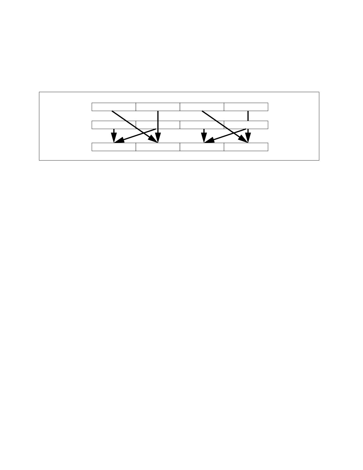
SRC1
X3
X2
X1
X0
SRC2
Y3
Y2
Y1
Y0
DEST
Y2 or Y3
X2 or X3
Y0 or Y1
X0 or X1
Figure 4-25. 256-bit VSHUFPD Operation of Four Pairs of Double Precision Floating-Point Values
Operation
VSHUFPD (EVEX Encoded Versions When SRC2 is a Vector Register)
(KL, VL) = (2, 128), (4, 256), (8, 512)
IF IMM0[0] = 0
THEN TMP_DEST[63:0] := SRC1[63:0]
ELSE TMP_DEST[63:0] := SRC1[127:64] FI;
IF IMM0[1] = 0
THEN TMP_DEST[127:64] := SRC2[63:0]
ELSE TMP_DEST[127:64] := SRC2[127:64] FI;
IF VL >= 256
IF IMM0[2] = 0
THEN TMP_DEST[191:128] := SRC1[191:128]
ELSE TMP_DEST[191:128] := SRC1[255:192] FI;
IF IMM0[3] = 0
THEN TMP_DEST[255:192] := SRC2[191:128]
ELSE TMP_DEST[255:192] := SRC2[255:192] FI;
FI;
IF VL >= 512
IF IMM0[4] = 0
THEN TMP_DEST[319:256] := SRC1[319:256]
ELSE TMP_DEST[319:256] := SRC1[383:320] FI;
IF IMM0[5] = 0
THEN TMP_DEST[383:320] := SRC2[319:256]
ELSE TMP_DEST[383:320] := SRC2[383:320] FI;
IF IMM0[6] = 0
THEN TMP_DEST[447:384] := SRC1[447:384]
ELSE TMP_DEST[447:384] := SRC1[511:448] FI;
IF IMM0[7] = 0
THEN TMP_DEST[511:448] := SRC2[447:384]
ELSE TMP_DEST[511:448] := SRC2[511:448] FI;
FI;
FOR j := 0 TO KL-1
i := j * 64
SHUFPD-Packed Interleave Shuffle of Pairs of Double Precision Floating-Point Values
Vol. 2B
4-646
IF k1[j] OR *no writemask*
THEN DEST[i+63:i] := TMP_DEST[i+63:i]
ELSE
IF *merging-masking*
; merging-masking
THEN *DEST[i+63:i] remains unchanged*
ELSE *zeroing-masking*
; zeroing-masking
DEST[i+63:i] := 0
FI
FI;
ENDFOR
DEST[MAXVL-1:VL] := 0
VSHUFPD (EVEX Encoded Versions When SRC2 is Memory)
(KL, VL) = (2, 128), (4, 256), (8, 512)
FOR j := 0 TO KL-1
i := j * 64
IF (EVEX.b = 1)
THEN TMP_SRC2[i+63:i] := SRC2[63:0]
ELSE TMP_SRC2[i+63:i] := SRC2[i+63:i]
FI;
ENDFOR;
IF IMM0[0] = 0
THEN TMP_DEST[63:0] := SRC1[63:0]
ELSE TMP_DEST[63:0] := SRC1[127:64] FI;
IF IMM0[1] = 0
THEN TMP_DEST[127:64] := TMP_SRC2[63:0]
ELSE TMP_DEST[127:64] := TMP_SRC2[127:64] FI;
IF VL >= 256
IF IMM0[2] = 0
THEN TMP_DEST[191:128] := SRC1[191:128]
ELSE TMP_DEST[191:128] := SRC1[255:192] FI;
IF IMM0[3] = 0
THEN TMP_DEST[255:192] := TMP_SRC2[191:128]
ELSE TMP_DEST[255:192] := TMP_SRC2[255:192] FI;
FI;
IF VL >= 512
IF IMM0[4] = 0
THEN TMP_DEST[319:256] := SRC1[319:256]
ELSE TMP_DEST[319:256] := SRC1[383:320] FI;
IF IMM0[5] = 0
THEN TMP_DEST[383:320] := TMP_SRC2[319:256]
ELSE TMP_DEST[383:320] := TMP_SRC2[383:320] FI;
IF IMM0[6] = 0
THEN TMP_DEST[447:384] := SRC1[447:384]
ELSE TMP_DEST[447:384] := SRC1[511:448] FI;
IF IMM0[7] = 0
THEN TMP_DEST[511:448] := TMP_SRC2[447:384]
ELSE TMP_DEST[511:448] := TMP_SRC2[511:448] FI;
FI;
FOR j := 0 TO KL-1
i := j * 64
IF k1[j] OR *no writemask*
THEN DEST[i+63:i] := TMP_DEST[i+63:i]
SHUFPD-Packed Interleave Shuffle of Pairs of Double Precision Floating-Point Values
Vol. 2B
4-647
ELSE
IF *merging-masking*
; merging-masking
THEN *DEST[i+63:i] remains unchanged*
ELSE *zeroing-masking*
; zeroing-masking
DEST[i+63:i] := 0
FI
FI;
ENDFOR
DEST[MAXVL-1:VL] := 0
VSHUFPD (VEX.256 Encoded Version)
IF IMM0[0] = 0
THEN DEST[63:0] := SRC1[63:0]
ELSE DEST[63:0] := SRC1[127:64] FI;
IF IMM0[1] = 0
THEN DEST[127:64] := SRC2[63:0]
ELSE DEST[127:64] := SRC2[127:64] FI;
IF IMM0[2] = 0
THEN DEST[191:128] := SRC1[191:128]
ELSE DEST[191:128] := SRC1[255:192] FI;
IF IMM0[3] = 0
THEN DEST[255:192] := SRC2[191:128]
ELSE DEST[255:192] := SRC2[255:192] FI;
DEST[MAXVL-1:256] (Unmodified)
VSHUFPD (VEX.128 Encoded Version)
IF IMM0[0] = 0
THEN DEST[63:0] := SRC1[63:0]
ELSE DEST[63:0] := SRC1[127:64] FI;
IF IMM0[1] = 0
THEN DEST[127:64] := SRC2[63:0]
ELSE DEST[127:64] := SRC2[127:64] FI;
DEST[MAXVL-1:128] := 0
VSHUFPD (128-bit Legacy SSE Version)
IF IMM0[0] = 0
THEN DEST[63:0] := SRC1[63:0]
ELSE DEST[63:0] := SRC1[127:64] FI;
IF IMM0[1] = 0
THEN DEST[127:64] := SRC2[63:0]
ELSE DEST[127:64] := SRC2[127:64] FI;
DEST[MAXVL-1:128] (Unmodified)
SHUFPD-Packed Interleave Shuffle of Pairs of Double Precision Floating-Point Values
Vol. 2B
4-648
Intel C/C++ Compiler Intrinsic Equivalent
VSHUFPD __m512d _mm512_shuffle_pd(__m512d a, __m512d b, int imm);
VSHUFPD __m512d _mm512_mask_shuffle_pd(__m512d s, __mmask8 k, __m512d a, __m512d b, int imm);
VSHUFPD __m512d _mm512_maskz_shuffle_pd( __mmask8 k, __m512d a, __m512d b, int imm);
VSHUFPD __m256d _mm256_shuffle_pd (__m256d a, __m256d b, const int select);
VSHUFPD __m256d _mm256_mask_shuffle_pd(__m256d s, __mmask8 k, __m256d a, __m256d b, int imm);
VSHUFPD __m256d _mm256_maskz_shuffle_pd( __mmask8 k, __m256d a, __m256d b, int imm);
SHUFPD __m128d _mm_shuffle_pd (__m128d a, __m128d b, const int select);
VSHUFPD __m128d _mm_mask_shuffle_pd(__m128d s, __mmask8 k, __m128d a, __m128d b, int imm);
VSHUFPD __m128d _mm_maskz_shuffle_pd( __mmask8 k, __m128d a, __m128d b, int imm);
SIMD Floating-Point Exceptions
None.
Other Exceptions
Non-EVEX-encoded instruction, see Table 2-21, “Type 4 Class Exception Conditions.”
EVEX-encoded instruction, see Table 2-52, “Type E4NF Class Exception Conditions.”
SHUFPD-Packed Interleave Shuffle of Pairs of Double Precision Floating-Point Values
Vol. 2B
4-649

SHUFPS-Packed Interleave Shuffle of Quadruplets of Single Precision Floating-Point Values
Opcode/
Op /
64/32 bit
CPUID Feature
Description
Instruction
En
Mode
Flag
Support
NP 0F C6 /r ib
A
V/V
SSE
Select from quadruplet of single precision floating-
SHUFPS xmm1, xmm3/m128, imm8
point values in xmm1 and xmm2/m128 using
imm8, interleaved result pairs are stored in xmm1.
VEX.128.0F.WIG C6 /r ib
B
V/V
AVX
Select from quadruplet of single precision floating-
VSHUFPS xmm1, xmm2, xmm3/m128,
point values in xmm1 and xmm2/m128 using
imm8
imm8, interleaved result pairs are stored in xmm1.
VEX.256.0F.WIG C6 /r ib
B
V/V
AVX
Select from quadruplet of single precision floating-
VSHUFPS ymm1, ymm2, ymm3/m256,
point values in ymm2 and ymm3/m256 using
imm8
imm8, interleaved result pairs are stored in ymm1.
EVEX.128.0F.W0 C6 /r ib
C
V/V
(AVX512VL AND
Select from quadruplet of single precision floating-
VSHUFPS xmm1{k1}{z}, xmm2,
AVX512F) OR
point values in xmm1 and xmm2/m128 using
xmm3/m128/m32bcst, imm8
AVX10.1
imm8, interleaved result pairs are stored in xmm1,
subject to writemask k1.
EVEX.256.0F.W0 C6 /r ib
C
V/V
(AVX512VL AND
Select from quadruplet of single precision floating-
VSHUFPS ymm1{k1}{z}, ymm2,
AVX512F) OR
point values in ymm2 and ymm3/m256 using
ymm3/m256/m32bcst, imm8
AVX10.1
imm8, interleaved result pairs are stored in ymm1,
subject to writemask k1.
EVEX.512.0F.W0 C6 /r ib
C
V/V
AVX512F
Select from quadruplet of single precision floating-
VSHUFPS zmm1{k1}{z}, zmm2,
OR AVX10.1
point values in zmm2 and zmm3/m512 using imm8,
zmm3/m512/m32bcst, imm8
interleaved result pairs are stored in zmm1, subject
to writemask k1.
Instruction Operand Encoding
Op/En
Tuple Type
Operand 1
Operand 2
Operand 3
Operand 4
A
N/A
ModRM:reg (r, w)
ModRM:r/m (r)
imm8
N/A
B
N/A
ModRM:reg (w)
VEX.vvvv (r)
ModRM:r/m (r)
imm8
C
Full
ModRM:reg (w)
EVEX.vvvv (r)
ModRM:r/m (r)
imm8
Description
Selects a single precision floating-point value of an input quadruplet using a two-bit control and move to a desig-
nated element of the destination operand. Each 64-bit element-pair of a 128-bit lane of the destination operand is
interleaved between the corresponding lane of the first source operand and the second source operand at the gran-
ularity 128 bits. Each two bits in the imm8 byte, starting from bit 0, is the select control of the corresponding
element of a 128-bit lane of the destination to received the shuffled result of an input quadruplet. The two lower
elements of a 128-bit lane in the destination receives shuffle results from the quadruple of the first source operand.
The next two elements of the destination receives shuffle results from the quadruple of the second source operand.
EVEX encoded versions: The first source operand is a ZMM/YMM/XMM register. The second source operand can be
a ZMM/YMM/XMM register, a 512/256/128-bit memory location or a 512/256/128-bit vector broadcasted from a
32-bit memory location. The destination operand is a ZMM/YMM/XMM register updated according to the writemask.
imm8[7:0] provides 4 select controls for each applicable 128-bit lane of the destination.
VEX.256 encoded version: The first source operand is a YMM register. The second source operand can be a YMM
register or a 256-bit memory location. The destination operand is a YMM register. Imm8[7:0] provides 4 select
controls for the high and low 128-bit of the destination.
VEX.128 encoded version: The first source operand is a XMM register. The second source operand can be a XMM
register or a 128-bit memory location. The destination operand is a XMM register. The upper bits (MAXVL-1:128) of
the corresponding ZMM register destination are zeroed. Imm8[7:0] provides 4 select controls for each element of
the destination.
SHUFPS-Packed Interleave Shuffle of Quadruplets of Single Precision Floating-Point Values
Vol. 2B
4-650
128-bit Legacy SSE version: The source can be an XMM register or an 128-bit memory location. The destination is
not distinct from the first source XMM register and the upper bits (MAXVL-1:128) of the corresponding ZMM
register destination are unmodified. Imm8[7:0] provides 4 select controls for each element of the destination.
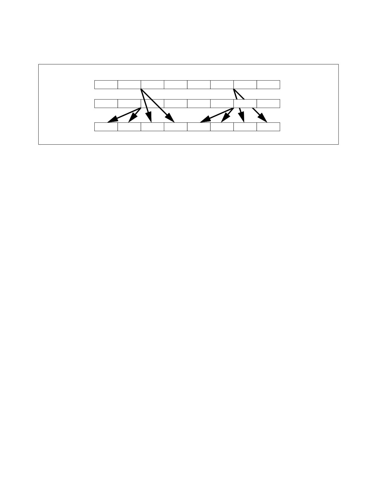
SRC1
X7
X6
X5
X4
X3
X2
X1
X0
SRC2
Y7
Y6
Y5
Y4
Y3
Y2
Y1
Y0
DEST
Y7 .. Y4
Y7 .. Y4
X7 .. X4
X7 .. X4
Y3 ..Y0
Y3 ..Y0
X3 .. X0
X3 .. X0
Figure 4-26. 256-bit VSHUFPS Operation of Selection from Input Quadruplet and Pair-wise Interleaved Result
Operation
Select4(SRC, control) {
CASE (control[1:0]) OF
0: TMP := SRC[31:0];
1: TMP := SRC[63:32];
2: TMP := SRC[95:64];
3: TMP := SRC[127:96];
ESAC;
RETURN TMP
}
VPSHUFPS (EVEX Encoded Versions When SRC2 is a Vector Register)
(KL, VL) = (4, 128), (8, 256), (16, 512)
TMP_DEST[31:0] := Select4(SRC1[127:0], imm8[1:0]);
TMP_DEST[63:32] := Select4(SRC1[127:0], imm8[3:2]);
TMP_DEST[95:64] := Select4(SRC2[127:0], imm8[5:4]);
TMP_DEST[127:96] := Select4(SRC2[127:0], imm8[7:6]);
IF VL >= 256
TMP_DEST[159:128] := Select4(SRC1[255:128], imm8[1:0]);
TMP_DEST[191:160] := Select4(SRC1[255:128], imm8[3:2]);
TMP_DEST[223:192] := Select4(SRC2[255:128], imm8[5:4]);
TMP_DEST[255:224] := Select4(SRC2[255:128], imm8[7:6]);
FI;
IF VL >= 512
TMP_DEST[287:256] := Select4(SRC1[383:256], imm8[1:0]);
TMP_DEST[319:288] := Select4(SRC1[383:256], imm8[3:2]);
TMP_DEST[351:320] := Select4(SRC2[383:256], imm8[5:4]);
TMP_DEST[383:352] := Select4(SRC2[383:256], imm8[7:6]);
TMP_DEST[415:384] := Select4(SRC1[511:384], imm8[1:0]);
TMP_DEST[447:416] := Select4(SRC1[511:384], imm8[3:2]);
TMP_DEST[479:448] := Select4(SRC2[511:384], imm8[5:4]);
TMP_DEST[511:480] := Select4(SRC2[511:384], imm8[7:6]);
FI;
FOR j := 0 TO KL-1
i := j * 32
IF k1[j] OR *no writemask*
SHUFPS-Packed Interleave Shuffle of Quadruplets of Single Precision Floating-Point Values
Vol. 2B
4-651
THEN DEST[i+31:i] := TMP_DEST[i+31:i]
ELSE
IF *merging-masking*
; merging-masking
THEN *DEST[i+31:i] remains unchanged*
ELSE *zeroing-masking*
; zeroing-masking
DEST[i+31:i] := 0
FI
FI;
ENDFOR
DEST[MAXVL-1:VL] := 0
VPSHUFPS (EVEX Encoded Versions When SRC2 is Memory)
(KL, VL) = (4, 128), (8, 256), (16, 512)
FOR j := 0 TO KL-1
i := j * 32
IF (EVEX.b = 1)
THEN TMP_SRC2[i+31:i] := SRC2[31:0]
ELSE TMP_SRC2[i+31:i] := SRC2[i+31:i]
FI;
ENDFOR;
TMP_DEST[31:0] := Select4(SRC1[127:0], imm8[1:0]);
TMP_DEST[63:32] := Select4(SRC1[127:0], imm8[3:2]);
TMP_DEST[95:64] := Select4(TMP_SRC2[127:0], imm8[5:4]);
TMP_DEST[127:96] := Select4(TMP_SRC2[127:0], imm8[7:6]);
IF VL >= 256
TMP_DEST[159:128] := Select4(SRC1[255:128], imm8[1:0]);
TMP_DEST[191:160] := Select4(SRC1[255:128], imm8[3:2]);
TMP_DEST[223:192] := Select4(TMP_SRC2[255:128], imm8[5:4]);
TMP_DEST[255:224] := Select4(TMP_SRC2[255:128], imm8[7:6]);
FI;
IF VL >= 512
TMP_DEST[287:256] := Select4(SRC1[383:256], imm8[1:0]);
TMP_DEST[319:288] := Select4(SRC1[383:256], imm8[3:2]);
TMP_DEST[351:320] := Select4(TMP_SRC2[383:256], imm8[5:4]);
TMP_DEST[383:352] := Select4(TMP_SRC2[383:256], imm8[7:6]);
TMP_DEST[415:384] := Select4(SRC1[511:384], imm8[1:0]);
TMP_DEST[447:416] := Select4(SRC1[511:384], imm8[3:2]);
TMP_DEST[479:448] := Select4(TMP_SRC2[511:384], imm8[5:4]);
TMP_DEST[511:480] := Select4(TMP_SRC2[511:384], imm8[7:6]);
FI;
FOR j := 0 TO KL-1
i := j * 32
IF k1[j] OR *no writemask*
THEN DEST[i+31:i] := TMP_DEST[i+31:i]
ELSE
IF *merging-masking*
; merging-masking
THEN *DEST[i+31:i] remains unchanged*
ELSE *zeroing-masking*
; zeroing-masking
DEST[i+31:i] := 0
FI
FI;
ENDFOR
DEST[MAXVL-1:VL] := 0
SHUFPS-Packed Interleave Shuffle of Quadruplets of Single Precision Floating-Point Values
Vol. 2B
4-652
VSHUFPS (VEX.256 Encoded Version)
DEST[31:0] := Select4(SRC1[127:0], imm8[1:0]);
DEST[63:32] := Select4(SRC1[127:0], imm8[3:2]);
DEST[95:64] := Select4(SRC2[127:0], imm8[5:4]);
DEST[127:96] := Select4(SRC2[127:0], imm8[7:6]);
DEST[159:128] := Select4(SRC1[255:128], imm8[1:0]);
DEST[191:160] := Select4(SRC1[255:128], imm8[3:2]);
DEST[223:192] := Select4(SRC2[255:128], imm8[5:4]);
DEST[255:224] := Select4(SRC2[255:128], imm8[7:6]);
DEST[MAXVL-1:256] := 0
VSHUFPS (VEX.128 Encoded Version)
DEST[31:0] := Select4(SRC1[127:0], imm8[1:0]);
DEST[63:32] := Select4(SRC1[127:0], imm8[3:2]);
DEST[95:64] := Select4(SRC2[127:0], imm8[5:4]);
DEST[127:96] := Select4(SRC2[127:0], imm8[7:6]);
DEST[MAXVL-1:128] := 0
SHUFPS (128-bit Legacy SSE Version)
DEST[31:0] := Select4(SRC1[127:0], imm8[1:0]);
DEST[63:32] := Select4(SRC1[127:0], imm8[3:2]);
DEST[95:64] := Select4(SRC2[127:0], imm8[5:4]);
DEST[127:96] := Select4(SRC2[127:0], imm8[7:6]);
DEST[MAXVL-1:128] (Unmodified)
Intel C/C++ Compiler Intrinsic Equivalent
VSHUFPS __m512 _mm512_shuffle_ps(__m512 a, __m512 b, int imm);
VSHUFPS __m512 _mm512_mask_shuffle_ps(__m512 s, __mmask16 k, __m512 a, __m512 b, int imm);
VSHUFPS __m512 _mm512_maskz_shuffle_ps(__mmask16 k, __m512 a, __m512 b, int imm);
VSHUFPS __m256 _mm256_shuffle_ps (__m256 a, __m256 b, const int select);
VSHUFPS __m256 _mm256_mask_shuffle_ps(__m256 s, __mmask8 k, __m256 a, __m256 b, int imm);
VSHUFPS __m256 _mm256_maskz_shuffle_ps(__mmask8 k, __m256 a, __m256 b, int imm);
SHUFPS __m128 _mm_shuffle_ps (__m128 a, __m128 b, const int select);
VSHUFPS __m128 _mm_mask_shuffle_ps(__m128 s, __mmask8 k, __m128 a, __m128 b, int imm);
VSHUFPS __m128 _mm_maskz_shuffle_ps(__mmask8 k, __m128 a, __m128 b, int imm);
SIMD Floating-Point Exceptions
None.
Other Exceptions
Non-EVEX-encoded instruction, see Table 2-21, “Type 4 Class Exception Conditions.”
EVEX-encoded instruction, see Table 2-52, “Type E4NF Class Exception Conditions.”
SHUFPS-Packed Interleave Shuffle of Quadruplets of Single Precision Floating-Point Values
Vol. 2B
4-653

SIDT-Store Interrupt Descriptor Table Register
Opcode1
Instruction
Op/
64-Bit
Compat/
Description
En
Mode
Leg Mode
0F 01 /1
SIDT m
M
Valid
Valid
Store IDTR to m.
NOTES:
1. See the IA-32 Architecture Compatibility section below.
Instruction Operand Encoding
Op/En
Operand 1
Operand 2
Operand 3
Operand 4
M
ModRM:r/m (w)
N/A
N/A
N/A
Description
Stores the content the interrupt descriptor table register (IDTR) in the destination operand. The destination
operand specifies a 6-byte memory location.
In non-64-bit modes, the 16-bit limit field of the register is stored in the low 2 bytes of the memory location and
the 32-bit base address is stored in the high 4 bytes.
In 64-bit mode, the operand size fixed at 8+2 bytes. The instruction stores 8-byte base and 2-byte limit values.
SIDT is only useful in operating-system software; however, it can be used in application programs without causing
an exception to be generated if CR4.UMIP = 0. See “LGDT/LIDT-Load Global/Interrupt Descriptor Table Register”
in Chapter 3, Intel® 64 and IA-32 Architectures Software Developer’s Manual, Volume 2A, for information on
loading the GDTR and IDTR.
IA-32 Architecture Compatibility
The 16-bit form of SIDT is compatible with the Intel 286 processor if the upper 8 bits are not referenced. The Intel
286 processor fills these bits with 1s; processor generations later than the Intel 286 processor fill these bits with
0s.
Operation
IF instruction is SIDT
THEN
IF OperandSize =16 or OperandSize = 32 (* Legacy or Compatibility Mode *)
THEN
DEST[0:15] := IDTR(Limit);
DEST[16:47] := IDTR(Base); FI; (* Full 32-bit base address stored *)
ELSE (* 64-bit Mode *)
DEST[0:15] := IDTR(Limit);
DEST[16:79] := IDTR(Base); (* Full 64-bit base address stored *)
FI;
FI;
Flags Affected
None.
SIDT-Store Interrupt Descriptor Table Register
Vol. 2B
4-654
Protected Mode Exceptions
#GP(0)
If the destination is located in a non-writable segment.
If a memory operand effective address is outside the CS, DS, ES, FS, or GS segment limit.
If the DS, ES, FS, or GS register is used to access memory and it contains a NULL segment
selector.
If CR4.UMIP = 1 and CPL > 0.
#SS(0)
If a memory operand effective address is outside the SS segment limit.
#PF(fault-code)
If a page fault occurs.
#AC(0)
If alignment checking is enabled and an unaligned memory reference is made while CPL = 3.
#UD
If the LOCK prefix is used.
Real-Address Mode Exceptions
#GP
If a memory operand effective address is outside the CS, DS, ES, FS, or GS segment limit.
#SS
If a memory operand effective address is outside the SS segment limit.
#UD
If the LOCK prefix is used.
Virtual-8086 Mode Exceptions
#GP(0)
If a memory operand effective address is outside the CS, DS, ES, FS, or GS segment limit.
If CR4.UMIP = 1.
#SS(0)
If a memory operand effective address is outside the SS segment limit.
#PF(fault-code)
If a page fault occurs.
#AC(0)
If alignment checking is enabled and an unaligned memory reference is made.
#UD
If the LOCK prefix is used.
Compatibility Mode Exceptions
Same exceptions as in protected mode.
64-Bit Mode Exceptions
#SS(0)
If a memory address referencing the SS segment is in a non-canonical form.
#UD
If the LOCK prefix is used.
#GP(0)
If the memory address is in a non-canonical form.
If CR4.UMIP = 1 and CPL > 0.
#PF(fault-code)
If a page fault occurs.
#AC(0)
If alignment checking is enabled and an unaligned memory reference is made while CPL = 3.
SIDT-Store Interrupt Descriptor Table Register
Vol. 2B
4-655

SLDT-Store Local Descriptor Table Register
Opcode*
Instruction
Op/
64-Bit
Compat/
Description
En
Mode
Leg Mode
0F 00 /0
SLDT r/m16
M
Valid
Valid
Stores segment selector from LDTR in r/m16.
Instruction Operand Encoding
Op/En
Operand 1
Operand 2
Operand 3
Operand 4
M
ModRM:r/m (w)
N/A
N/A
N/A
Description
Stores the segment selector from the local descriptor table register (LDTR) in the destination operand. The desti-
nation operand can be a general-purpose register or a memory location. The segment selector stored with this
instruction points to the segment descriptor (located in the GDT) for the current LDT. This instruction can only be
executed in protected mode.
Outside IA-32e mode, when the destination operand is a 32-bit register, the 16-bit segment selector is copied into
the low-order 16 bits of the register. The high-order 16 bits of the register are cleared for the Pentium 4, Intel Xeon,
and P6 family processors. They are undefined for Pentium, Intel486, and Intel386 processors. When the destina-
tion operand is a memory location, the segment selector is written to memory as a 16-bit quantity, regardless of
the operand size.
In compatibility mode, when the destination operand is a 32-bit register, the 16-bit segment selector is copied into
the low-order 16 bits of the register. The high-order 16 bits of the register are cleared. When the destination
operand is a memory location, the segment selector is written to memory as a 16-bit quantity, regardless of the
operand size.
In 64-bit mode, using a REX prefix in the form of REX.R permits access to additional registers (R8-R15). The
behavior of SLDT with a 64-bit register is to zero-extend the 16-bit selector and store it in the register. If the desti-
nation is memory and operand size is 64, SLDT will write the 16-bit selector to memory as a 16-bit quantity,
regardless of the operand size.
Operation
DEST := LDTR(SegmentSelector);
Flags Affected
None.
Protected Mode Exceptions
#GP(0)
If the destination is located in a non-writable segment.
If a memory operand effective address is outside the CS, DS, ES, FS, or GS segment limit.
If the DS, ES, FS, or GS register is used to access memory and it contains a NULL segment
selector.
If CR4.UMIP = 1 and CPL > 0.
#SS(0)
If a memory operand effective address is outside the SS segment limit.
#PF(fault-code)
If a page fault occurs.
#AC(0)
If alignment checking is enabled and an unaligned memory reference is made while CPL = 3.
#UD
If the LOCK prefix is used.
Real-Address Mode Exceptions
#UD
The SLDT instruction is not recognized in real-address mode.
SLDT-Store Local Descriptor Table Register
Vol. 2B
4-656
Virtual-8086 Mode Exceptions
#UD
The SLDT instruction is not recognized in virtual-8086 mode.
Compatibility Mode Exceptions
Same exceptions as in protected mode.
64-Bit Mode Exceptions
#SS(0)
If a memory address referencing the SS segment is in a non-canonical form.
#GP(0)
If the memory address is in a non-canonical form.
If CR4.UMIP = 1 and CPL > 0.
#PF(fault-code)
If a page fault occurs.
#AC(0)
If alignment checking is enabled and an unaligned memory reference is made while CPL = 3.
#UD
If the LOCK prefix is used.
SLDT-Store Local Descriptor Table Register
Vol. 2B
4-657

SMSW-Store Machine Status Word
Opcode*
Instruction
Op/
64-Bit
Compat/
Description
En
Mode
Leg Mode
0F 01 /4
SMSW r/m16
M
Valid
Valid
Store machine status word to r/m16.
0F 01 /4
SMSW r32/m16
M
Valid
Valid
Store machine status word in low-order 16
bits of r32/m16; high-order 16 bits of r32 are
undefined.
REX.W + 0F 01 /4
SMSW r64/m16
M
Valid
Valid
Store machine status word in low-order 16
bits of r64/m16; high-order 16 bits of r32 are
undefined.
Instruction Operand Encoding
Op/En
Operand 1
Operand 2
Operand 3
Operand 4
M
ModRM:r/m (w)
N/A
N/A
N/A
Description
Stores the machine status word (bits 0 through 15 of control register CR0) into the destination operand. The desti-
nation operand can be a general-purpose register or a memory location.
In non-64-bit modes, when the destination operand is a 32-bit register, the low-order 16 bits of register CR0 are
copied into the low-order 16 bits of the register and the high-order 16 bits are undefined. When the destination
operand is a memory location, the low-order 16 bits of register CR0 are written to memory as a 16-bit quantity,
regardless of the operand size.
In 64-bit mode, the behavior of the SMSW instruction is defined by the following examples:
• SMSW r16 operand size 16, store CR0[15:0] in r16
• SMSW r32 operand size 32, zero-extend CR0[31:0], and store in r32
• SMSW r64 operand size 64, zero-extend CR0[63:0], and store in r64
• SMSW m16 operand size 16, store CR0[15:0] in m16
• SMSW m16 operand size 32, store CR0[15:0] in m16 (not m32)
• SMSW m16 operands size 64, store CR0[15:0] in m16 (not m64)
SMSW is only useful in operating-system software. However, it is not a privileged instruction and can be used in
application programs if CR4.UMIP = 0. It is provided for compatibility with the Intel 286 processor. Programs and
procedures intended to run on IA-32 and Intel 64 processors beginning with the Intel386 processors should use the
MOV CR instruction to load the machine status word.
See “Changes to Instruction Behavior in VMX Non-Root Operation” in Chapter 27 of the Intel® 64 and IA-32 Archi-
tectures Software Developer’s Manual, Volume 3C, for more information about the behavior of this instruction in
VMX non-root operation.
Operation
DEST := CR0[15:0];
(* Machine status word *)
Flags Affected
None.
SMSW-Store Machine Status Word
Vol. 2B
4-658
Protected Mode Exceptions
#GP(0)
If the destination is located in a non-writable segment.
If a memory operand effective address is outside the CS, DS, ES, FS, or GS segment limit.
If the DS, ES, FS, or GS register is used to access memory and it contains a NULL segment
selector.
If CR4.UMIP = 1 and CPL > 0.
#SS(0)
If a memory operand effective address is outside the SS segment limit.
#PF(fault-code)
If a page fault occurs.
#AC(0)
If alignment checking is enabled and an unaligned memory reference is made while CPL = 3.
#UD
If the LOCK prefix is used.
Real-Address Mode Exceptions
#GP
If a memory operand effective address is outside the CS, DS, ES, FS, or GS segment limit.
#SS(0)
If a memory operand effective address is outside the SS segment limit.
#UD
If the LOCK prefix is used.
Virtual-8086 Mode Exceptions
#GP(0)
If a memory operand effective address is outside the CS, DS, ES, FS, or GS segment limit.
If CR4.UMIP = 1.
#SS(0)
If a memory operand effective address is outside the SS segment limit.
#PF(fault-code)
If a page fault occurs.
#AC(0)
If alignment checking is enabled and an unaligned memory reference is made.
#UD
If the LOCK prefix is used.
Compatibility Mode Exceptions
Same exceptions as in protected mode.
64-Bit Mode Exceptions
#SS(0)
If a memory address referencing the SS segment is in a non-canonical form.
#GP(0)
If the memory address is in a non-canonical form.
If CR4.UMIP = 1 and CPL > 0.
#PF(fault-code)
If a page fault occurs.
#AC(0)
If alignment checking is enabled and an unaligned memory reference is made while CPL = 3.
#UD
If the LOCK prefix is used.
SMSW-Store Machine Status Word
Vol. 2B
4-659

SQRTPD-Square Root of Double Precision Floating-Point Values
Opcode/
Op /
64/32 bit
CPUID Feature
Description
Instruction
En
Mode
Flag
Support
66 0F 51 /r
A
V/V
SSE2
Computes Square Roots of the packed double precision
SQRTPD xmm1, xmm2/m128
floating-point values in xmm2/m128 and stores the
result in xmm1.
VEX.128.66.0F.WIG 51 /r
A
V/V
AVX
Computes Square Roots of the packed double precision
VSQRTPD xmm1, xmm2/m128
floating-point values in xmm2/m128 and stores the
result in xmm1.
VEX.256.66.0F.WIG 51 /r
A
V/V
AVX
Computes Square Roots of the packed double precision
VSQRTPD ymm1, ymm2/m256
floating-point values in ymm2/m256 and stores the
result in ymm1.
EVEX.128.66.0F.W1 51 /r
B
V/V
(AVX512VL AND
Computes Square Roots of the packed double precision
VSQRTPD xmm1 {k1}{z},
AVX512F) OR
floating-point values in xmm2/m128/m64bcst and
xmm2/m128/m64bcst
AVX10.1
stores the result in xmm1 subject to writemask k1.
EVEX.256.66.0F.W1 51 /r
B
V/V
(AVX512VL AND
Computes Square Roots of the packed double precision
VSQRTPD ymm1 {k1}{z},
AVX512F) OR
floating-point values in ymm2/m256/m64bcst and
ymm2/m256/m64bcst
AVX10.1
stores the result in ymm1 subject to writemask k1.
EVEX.512.66.0F.W1 51 /r
B
V/V
AVX512F OR
Computes Square Roots of the packed double precision
VSQRTPD zmm1 {k1}{z},
AVX10.1
floating-point values in zmm2/m512/m64bcst and
zmm2/m512/m64bcst{er}
stores the result in zmm1 subject to writemask k1.
Instruction Operand Encoding
Op/En
Tuple Type
Operand 1
Operand 2
Operand 3
Operand 4
A
N/A
ModRM:reg (w)
ModRM:r/m (r)
N/A
N/A
B
Full
ModRM:reg (w)
ModRM:r/m (r)
N/A
N/A
Description
Performs a SIMD computation of the square roots of the two, four or eight packed double precision floating-point
values in the source operand (the second operand) stores the packed double precision floating-point results in the
destination operand (the first operand).
EVEX encoded versions: The source operand is a ZMM/YMM/XMM register, a 512/256/128-bit memory location, or
a 512/256/128-bit vector broadcasted from a 64-bit memory location. The destination operand is a
ZMM/YMM/XMM register updated according to the writemask.
VEX.256 encoded version: The source operand is a YMM register or a 256-bit memory location. The destination
operand is a YMM register. The upper bits (MAXVL-1:256) of the corresponding ZMM register destination are
zeroed.
VEX.128 encoded version: the source operand second source operand or a 128-bit memory location. The destina-
tion operand is an XMM register. The upper bits (MAXVL-1:128) of the corresponding ZMM register destination are
zeroed.
128-bit Legacy SSE version: The second source can be an XMM register or 128-bit memory location. The destina-
tion is not distinct from the first source XMM register and the upper bits (MAXVL-1:128) of the corresponding ZMM
register destination are unmodified.
Note: VEX.vvvv and EVEX.vvvv are reserved and must be 1111b otherwise instructions will #UD.
SQRTPD-Square Root of Double Precision Floating-Point Values
Vol. 2B
4-660
Operation
VSQRTPD (EVEX Encoded Versions)
(KL, VL) = (2, 128), (4, 256), (8, 512)
IF (VL = 512) AND (EVEX.b = 1) AND (SRC *is register*)
THEN
SET_ROUNDING_MODE_FOR_THIS_INSTRUCTION(EVEX.RC);
ELSE
SET_ROUNDING_MODE_FOR_THIS_INSTRUCTION(MXCSR.RC);
FI;
FOR j := 0 TO KL-1
i := j * 64
IF k1[j] OR *no writemask* THEN
IF (EVEX.b = 1) AND (SRC *is memory*)
THEN DEST[i+63:i] := SQRT(SRC[63:0])
ELSE DEST[i+63:i] := SQRT(SRC[i+63:i])
FI;
ELSE
IF *merging-masking*
; merging-masking
THEN *DEST[i+63:i] remains unchanged*
ELSE
; zeroing-masking
DEST[i+63:i] := 0
FI
FI;
ENDFOR
DEST[MAXVL-1:VL] := 0
VSQRTPD (VEX.256 Encoded Version)
DEST[63:0] := SQRT(SRC[63:0])
DEST[127:64] := SQRT(SRC[127:64])
DEST[191:128] := SQRT(SRC[191:128])
DEST[255:192] := SQRT(SRC[255:192])
DEST[MAXVL-1:256] := 0
VSQRTPD (VEX.128 Encoded Version)
DEST[63:0] := SQRT(SRC[63:0])
DEST[127:64] := SQRT(SRC[127:64])
DEST[MAXVL-1:128] := 0
SQRTPD (128-bit Legacy SSE Version)
DEST[63:0] := SQRT(SRC[63:0])
DEST[127:64] := SQRT(SRC[127:64])
DEST[MAXVL-1:128] (Unmodified)
Intel C/C++ Compiler Intrinsic Equivalent
VSQRTPD __m512d _mm512_sqrt_round_pd(__m512d a, int r);
VSQRTPD __m512d _mm512_mask_sqrt_round_pd(__m512d s, __mmask8 k, __m512d a, int r);
VSQRTPD __m512d _mm512_maskz_sqrt_round_pd( __mmask8 k, __m512d a, int r);
VSQRTPD __m256d _mm256_sqrt_pd (__m256d a);
VSQRTPD __m256d _mm256_mask_sqrt_pd(__m256d s, __mmask8 k, __m256d a, int r);
VSQRTPD __m256d _mm256_maskz_sqrt_pd( __mmask8 k, __m256d a, int r);
SQRTPD __m128d _mm_sqrt_pd (__m128d a);
VSQRTPD __m128d _mm_mask_sqrt_pd(__m128d s, __mmask8 k, __m128d a, int r);
VSQRTPD __m128d _mm_maskz_sqrt_pd( __mmask8 k, __m128d a, int r);
SQRTPD-Square Root of Double Precision Floating-Point Values
Vol. 2B
4-661
SIMD Floating-Point Exceptions
Invalid, Precision, Denormal.
Other Exceptions
Non-EVEX-encoded instruction, see Table 2-19, “Type 2 Class Exception Conditions,” additionally:
#UD
If VEX.vvvv != 1111B.
EVEX-encoded instruction, see Table 2-48, “Type E2 Class Exception Conditions,” additionally:
#UD
If EVEX.vvvv != 1111B.
SQRTPD-Square Root of Double Precision Floating-Point Values
Vol. 2B
4-662

SQRTPS-Square Root of Single Precision Floating-Point Values
Opcode/
Op /
64/32 bit
CPUID Feature
Description
Instruction
En
Mode
Flag
Support
NP 0F 51 /r
A
V/V
SSE
Computes Square Roots of the packed single precision
SQRTPS xmm1, xmm2/m128
floating-point values in xmm2/m128 and stores the result
in xmm1.
VEX.128.0F.WIG 51 /r
A
V/V
AVX
Computes Square Roots of the packed single precision
VSQRTPS xmm1, xmm2/m128
floating-point values in xmm2/m128 and stores the result
in xmm1.
VEX.256.0F.WIG 51/r
A
V/V
AVX
Computes Square Roots of the packed single precision
VSQRTPS ymm1, ymm2/m256
floating-point values in ymm2/m256 and stores the result
in ymm1.
EVEX.128.0F.W0 51 /r
B
V/V
(AVX512VL AND
Computes Square Roots of the packed single precision
VSQRTPS xmm1 {k1}{z},
AVX512F) OR
floating-point values in xmm2/m128/m32bcst and stores
xmm2/m128/m32bcst
AVX10.1
the result in xmm1 subject to writemask k1.
EVEX.256.0F.W0 51 /r
B
V/V
(AVX512VL AND
Computes Square Roots of the packed single precision
VSQRTPS ymm1 {k1}{z},
AVX512F) OR
floating-point values in ymm2/m256/m32bcst and stores
ymm2/m256/m32bcst
AVX10.1
the result in ymm1 subject to writemask k1.
EVEX.512.0F.W0 51/r
B
V/V
AVX512F
Computes Square Roots of the packed single precision
VSQRTPS zmm1 {k1}{z},
OR AVX10.1
floating-point values in zmm2/m512/m32bcst and stores
zmm2/m512/m32bcst{er}
the result in zmm1 subject to writemask k1.
Instruction Operand Encoding
Op/En
Tuple Type
Operand 1
Operand 2
Operand 3
Operand 4
A
N/A
ModRM:reg (w)
ModRM:r/m (r)
N/A
N/A
B
Full
ModRM:reg (w)
ModRM:r/m (r)
N/A
N/A
Description
Performs a SIMD computation of the square roots of the four, eight or sixteen packed single precision floating-point
values in the source operand (second operand) stores the packed single precision floating-point results in the desti-
nation operand.
EVEX.512 encoded versions: The source operand is a ZMM/YMM/XMM register, a 512/256/128-bit memory location
or a 512/256/128-bit vector broadcasted from a 32-bit memory location. The destination operand is a
ZMM/YMM/XMM register updated according to the writemask.
VEX.256 encoded version: The source operand is a YMM register or a 256-bit memory location. The destination
operand is a YMM register. The upper bits (MAXVL-1:256) of the corresponding ZMM register destination are
zeroed.
VEX.128 encoded version: the source operand second source operand or a 128-bit memory location. The destina-
tion operand is an XMM register. The upper bits (MAXVL-1:128) of the corresponding ZMM register destination are
zeroed.
128-bit Legacy SSE version: The second source can be an XMM register or 128-bit memory location. The destina-
tion is not distinct from the first source XMM register and the upper bits (MAXVL-1:128) of the corresponding ZMM
register destination are unmodified.
Note: VEX.vvvv and EVEX.vvvv are reserved and must be 1111b otherwise instructions will #UD.
SQRTPS-Square Root of Single Precision Floating-Point Values
Vol. 2B
4-663
Operation
VSQRTPS (EVEX Encoded Versions)
(KL, VL) = (4, 128), (8, 256), (16, 512)
IF (VL = 512) AND (EVEX.b = 1) AND (SRC *is register*)
THEN
SET_ROUNDING_MODE_FOR_THIS_INSTRUCTION(EVEX.RC);
ELSE
SET_ROUNDING_MODE_FOR_THIS_INSTRUCTION(MXCSR.RC);
FI;
FOR j := 0 TO KL-1
i := j * 32
IF k1[j] OR *no writemask* THEN
IF (EVEX.b = 1) AND (SRC *is memory*)
THEN DEST[i+31:i] := SQRT(SRC[31:0])
ELSE DEST[i+31:i] := SQRT(SRC[i+31:i])
FI;
ELSE
IF *merging-masking*
; merging-masking
THEN *DEST[i+31:i] remains unchanged*
ELSE
; zeroing-masking
DEST[i+31:i] := 0
FI
FI;
ENDFOR
DEST[MAXVL-1:VL] := 0
VSQRTPS (VEX.256 Encoded Version)
DEST[31:0] := SQRT(SRC[31:0])
DEST[63:32] := SQRT(SRC[63:32])
DEST[95:64] := SQRT(SRC[95:64])
DEST[127:96] := SQRT(SRC[127:96])
DEST[159:128] := SQRT(SRC[159:128])
DEST[191:160] := SQRT(SRC[191:160])
DEST[223:192] := SQRT(SRC[223:192])
DEST[255:224] := SQRT(SRC[255:224])
VSQRTPS (VEX.128 Encoded Version)
DEST[31:0] := SQRT(SRC[31:0])
DEST[63:32] := SQRT(SRC[63:32])
DEST[95:64] := SQRT(SRC[95:64])
DEST[127:96] := SQRT(SRC[127:96])
DEST[MAXVL-1:128] := 0
SQRTPS (128-bit Legacy SSE Version)
DEST[31:0] := SQRT(SRC[31:0])
DEST[63:32] := SQRT(SRC[63:32])
DEST[95:64] := SQRT(SRC[95:64])
DEST[127:96] := SQRT(SRC[127:96])
DEST[MAXVL-1:128] (Unmodified)
SQRTPS-Square Root of Single Precision Floating-Point Values
Vol. 2B
4-664
Intel C/C++ Compiler Intrinsic Equivalent
VSQRTPS __m512 _mm512_sqrt_round_ps(__m512 a, int r);
VSQRTPS __m512 _mm512_mask_sqrt_round_ps(__m512 s, __mmask16 k, __m512 a, int r);
VSQRTPS __m512 _mm512_maskz_sqrt_round_ps( __mmask16 k, __m512 a, int r);
VSQRTPS __m256 _mm256_sqrt_ps (__m256 a);
VSQRTPS __m256 _mm256_mask_sqrt_ps(__m256 s, __mmask8 k, __m256 a, int r);
VSQRTPS __m256 _mm256_maskz_sqrt_ps( __mmask8 k, __m256 a, int r);
SQRTPS __m128 _mm_sqrt_ps (__m128 a);
VSQRTPS __m128 _mm_mask_sqrt_ps(__m128 s, __mmask8 k, __m128 a, int r);
VSQRTPS __m128 _mm_maskz_sqrt_ps( __mmask8 k, __m128 a, int r);
SIMD Floating-Point Exceptions
Invalid, Precision, Denormal.
Other Exceptions
Non-EVEX-encoded instruction, see Table 2-19, “Type 2 Class Exception Conditions,” additionally:
#UD
If VEX.vvvv != 1111B.
EVEX-encoded instruction, see Table 2-48, “Type E2 Class Exception Conditions,” additionally:
#UD
If EVEX.vvvv != 1111B.
SQRTPS-Square Root of Single Precision Floating-Point Values
Vol. 2B
4-665

SQRTSD-Compute Square Root of Scalar Double Precision Floating-Point Value
Opcode/
Op /
64/32 bit
CPUID
Description
Instruction
En
Mode
Feature Flag
Support
F2 0F 51/r
A
V/V
SSE2
Computes square root of the low double precision floating-
SQRTSD xmm1,xmm2/m64
point value in xmm2/m64 and stores the results in xmm1.
VEX.LIG.F2.0F.WIG 51/r
B
V/V
AVX
Computes square root of the low double precision floating-
VSQRTSD xmm1,xmm2, xmm3/m64
point value in xmm3/m64 and stores the results in xmm1.
Also, upper double precision floating-point value
(bits[127:64]) from xmm2 is copied to xmm1[127:64].
EVEX.LLIG.F2.0F.W1 51/r
C
V/V
AVX512F
Computes square root of the low double precision floating-
VSQRTSD xmm1 {k1}{z}, xmm2,
OR AVX10.1
point value in xmm3/m64 and stores the results in xmm1
xmm3/m64{er}
under writemask k1. Also, upper double precision floating-
point value (bits[127:64]) from xmm2 is copied to
xmm1[127:64].
Instruction Operand Encoding
Op/En
Tuple Type
Operand 1
Operand 2
Operand 3
Operand 4
A
N/A
ModRM:reg (w)
ModRM:r/m (r)
N/A
N/A
B
N/A
ModRM:reg (w)
VEX.vvvv (r)
ModRM:r/m (r)
N/A
C
Tuple1 Scalar
ModRM:reg (w)
EVEX.vvvv (r)
ModRM:r/m (r)
N/A
Description
Computes the square root of the low double precision floating-point value in the second source operand and stores
the double precision floating-point result in the destination operand. The second source operand can be an XMM
register or a 64-bit memory location. The first source and destination operands are XMM registers.
128-bit Legacy SSE version: The first source operand and the destination operand are the same. The quadword at
bits 127:64 of the destination operand remains unchanged. Bits (MAXVL-1:64) of the corresponding destination
register remain unchanged.
VEX.128 and EVEX encoded versions: Bits 127:64 of the destination operand are copied from the corresponding
bits of the first source operand. Bits (MAXVL-1:128) of the destination register are zeroed.
EVEX encoded version: The low quadword element of the destination operand is updated according to the write-
mask.
Software should ensure VSQRTSD is encoded with VEX.L=0. Encoding VSQRTSD with VEX.L=1 may encounter
unpredictable behavior across different processor generations.
SQRTSD-Compute Square Root of Scalar Double Precision Floating-Point Value
Vol. 2B
4-666
Operation
VSQRTSD (EVEX Encoded Version)
IF (EVEX.b = 1) AND (SRC2 *is register*)
THEN
SET_ROUNDING_MODE_FOR_THIS_INSTRUCTION(EVEX.RC);
ELSE
SET_ROUNDING_MODE_FOR_THIS_INSTRUCTION(MXCSR.RC);
FI;
IF k1[0] or *no writemask*
THEN
DEST[63:0] := SQRT(SRC2[63:0])
ELSE
IF *merging-masking*
; merging-masking
THEN *DEST[63:0] remains unchanged*
ELSE
; zeroing-masking
THEN DEST[63:0] := 0
FI;
FI;
DEST[127:64] := SRC1[127:64]
DEST[MAXVL-1:128] := 0
VSQRTSD (VEX.128 Encoded Version)
DEST[63:0] := SQRT(SRC2[63:0])
DEST[127:64] := SRC1[127:64]
DEST[MAXVL-1:128] := 0
SQRTSD (128-bit Legacy SSE Version)
DEST[63:0] := SQRT(SRC[63:0])
DEST[MAXVL-1:64] (Unmodified)
Intel C/C++ Compiler Intrinsic Equivalent
VSQRTSD __m128d _mm_sqrt_round_sd(__m128d a, __m128d b, int r);
VSQRTSD __m128d _mm_mask_sqrt_round_sd(__m128d s, __mmask8 k, __m128d a, __m128d b, int r);
VSQRTSD __m128d _mm_maskz_sqrt_round_sd(__mmask8 k, __m128d a, __m128d b, int r);
SQRTSD __m128d _mm_sqrt_sd (__m128d a, __m128d b)
SIMD Floating-Point Exceptions
Invalid, Precision, Denormal.
Other Exceptions
Non-EVEX-encoded instruction, see Table 2-20, “Type 3 Class Exception Conditions.”
EVEX-encoded instruction, see Table 2-49, “Type E3 Class Exception Conditions.”
SQRTSD-Compute Square Root of Scalar Double Precision Floating-Point Value
Vol. 2B
4-667

SQRTSS-Compute Square Root of Scalar Single Precision Value
Opcode/
Op /
64/32 bit
CPUID Feature
Description
Instruction
En
Mode
Flag
Support
F3 0F 51 /r
A
V/V
SSE
Computes square root of the low single precision floating-
SQRTSS xmm1, xmm2/m32
point value in xmm2/m32 and stores the results in xmm1.
VEX.LIG.F3.0F.WIG 51 /r
B
V/V
AVX
Computes square root of the low single precision floating-
VSQRTSS xmm1, xmm2,
point value in xmm3/m32 and stores the results in xmm1.
xmm3/m32
Also, upper single precision floating-point values
(bits[127:32]) from xmm2 are copied to xmm1[127:32].
EVEX.LLIG.F3.0F.W0 51 /r
C
V/V
AVX512F
Computes square root of the low single precision floating-
VSQRTSS xmm1 {k1}{z}, xmm2,
OR AVX10.1
point value in xmm3/m32 and stores the results in xmm1
xmm3/m32{er}
under writemask k1. Also, upper single precision floating-
point values (bits[127:32]) from xmm2 are copied to
xmm1[127:32].
Instruction Operand Encoding
Op/En
Tuple Type
Operand 1
Operand 2
Operand 3
Operand 4
A
N/A
ModRM:reg (w)
ModRM:r/m (r)
N/A
N/A
B
N/A
ModRM:reg (w)
VEX.vvvv (r)
ModRM:r/m (r)
N/A
C
Tuple1 Scalar
ModRM:reg (w)
EVEX.vvvv (r)
ModRM:r/m (r)
N/A
Description
Computes the square root of the low single precision floating-point value in the second source operand and stores
the single precision floating-point result in the destination operand. The second source operand can be an XMM
register or a 32-bit memory location. The first source and destination operands is an XMM register.
128-bit Legacy SSE version: The first source operand and the destination operand are the same. Bits (MAXVL-
1:32) of the corresponding YMM destination register remain unchanged.
VEX.128 and EVEX encoded versions: Bits 127:32 of the destination operand are copied from the corresponding
bits of the first source operand. Bits (MAXVL-1:128) of the destination ZMM register are zeroed.
EVEX encoded version: The low doubleword element of the destination operand is updated according to the write-
mask.
Software should ensure VSQRTSS is encoded with VEX.L=0. Encoding VSQRTSS with VEX.L=1 may encounter
unpredictable behavior across different processor generations.
SQRTSS-Compute Square Root of Scalar Single Precision Value
Vol. 2B
4-668
Operation
VSQRTSS (EVEX Encoded Version)
IF (EVEX.b = 1) AND (SRC2 *is register*)
THEN
SET_ROUNDING_MODE_FOR_THIS_INSTRUCTION(EVEX.RC);
ELSE
SET_ROUNDING_MODE_FOR_THIS_INSTRUCTION(MXCSR.RC);
FI;
IF k1[0] or *no writemask*
THEN
DEST[31:0] := SQRT(SRC2[31:0])
ELSE
IF *merging-masking*
; merging-masking
THEN *DEST[31:0] remains unchanged*
ELSE
; zeroing-masking
DEST[31:0] := 0
FI;
FI;
DEST[127:32] := SRC1[127:32]
DEST[MAXVL-1:128] := 0
VSQRTSS (VEX.128 Encoded Version)
DEST[31:0] := SQRT(SRC2[31:0])
DEST[127:32] := SRC1[127:32]
DEST[MAXVL-1:128] := 0
SQRTSS (128-bit Legacy SSE Version)
DEST[31:0] := SQRT(SRC2[31:0])
DEST[MAXVL-1:32] (Unmodified)
Intel C/C++ Compiler Intrinsic Equivalent
VSQRTSS __m128 _mm_sqrt_round_ss(__m128 a, __m128 b, int r);
VSQRTSS __m128 _mm_mask_sqrt_round_ss(__m128 s, __mmask8 k, __m128 a, __m128 b, int r);
VSQRTSS __m128 _mm_maskz_sqrt_round_ss( __mmask8 k, __m128 a, __m128 b, int r);
SQRTSS __m128 _mm_sqrt_ss(__m128 a)
SIMD Floating-Point Exceptions
Invalid, Precision, Denormal.
Other Exceptions
Non-EVEX-encoded instruction, see Table 2-20, “Type 3 Class Exception Conditions.”
EVEX-encoded instruction, see Table 2-49, “Type E3 Class Exception Conditions.”
SQRTSS-Compute Square Root of Scalar Single Precision Value
Vol. 2B
4-669

STAC-Set AC Flag in EFLAGS Register
Opcode/
Op /
64/32 bit
CPUID
Description
Instruction
En
Mode
Feature
Support
Flag
NP 0F 01 CB
ZO
V/V
SMAP
Set the AC flag in the EFLAGS register.
STAC
Instruction Operand Encoding
Op/En
Operand 1
Operand 2
Operand 3
Operand 4
ZO
N/A
N/A
N/A
N/A
Description
Sets the AC flag bit in EFLAGS register. This may enable alignment checking of user-mode data accesses. This
allows explicit supervisor-mode data accesses to user-mode pages even if the SMAP bit is set in the CR4 register.
This instruction's operation is the same in non-64-bit modes and 64-bit mode. Attempts to execute STAC when
CPL > 0 cause #UD.
Operation
EFLAGS.AC := 1;
Flags Affected
AC set. Other flags are unaffected.
Protected Mode Exceptions
#UD
If the LOCK prefix is used.
If the CPL > 0.
If CPUID.07H.00H:EBX.SMAP[20] = 0.
Real-Address Mode Exceptions
#UD
If the LOCK prefix is used.
If CPUID.07H.00H:EBX.SMAP[20] = 0.
Virtual-8086 Mode Exceptions
#UD
The STAC instruction is not recognized in virtual-8086 mode.
Compatibility Mode Exceptions
#UD
If the LOCK prefix is used.
If the CPL > 0.
If CPUID.07H.00H:EBX.SMAP[20] = 0.
64-Bit Mode Exceptions
#UD
If the LOCK prefix is used.
If the CPL > 0.
If CPUID.07H.00H:EBX.SMAP[20] = 0.
STAC-Set AC Flag in EFLAGS Register
Vol. 2B
4-670

STC-Set Carry Flag
Opcode
Instruction
Op/
64-Bit
Compat/
Description
En
Mode
Leg Mode
F9
STC
ZO
Valid
Valid
Set CF flag.
Instruction Operand Encoding
Op/En
Operand 1
Operand 2
Operand 3
Operand 4
ZO
N/A
N/A
N/A
N/A
Description
Sets the CF flag in the EFLAGS register. Operation is the same in all modes.
Operation
CF := 1;
Flags Affected
The CF flag is set. The OF, ZF, SF, AF, and PF flags are unaffected.
Exceptions (All Operating Modes)
#UD
If the LOCK prefix is used.
STC-Set Carry Flag
Vol. 2B
4-671

STD-Set Direction Flag
Opcode
Instruction
Op/
64-bit
Compat/
Description
En
Mode
Leg Mode
FD
STD
ZO
Valid
Valid
Set DF flag.
Instruction Operand Encoding
Op/En
Operand 1
Operand 2
Operand 3
Operand 4
ZO
N/A
N/A
N/A
N/A
Description
Sets the DF flag in the EFLAGS register. When the DF flag is set to 1, string operations decrement the index regis-
ters (ESI and/or EDI). Operation is the same in all modes.
Operation
DF := 1;
Flags Affected
The DF flag is set. The CF, OF, ZF, SF, AF, and PF flags are unaffected.
Exceptions (All Operating Modes)
#UD
If the LOCK prefix is used.
STD-Set Direction Flag
Vol. 2B
4-672
STI-Set Interrupt Flag
Opcode
Instruction
Op/
64-Bit
Compat/
Description
En
Mode
Leg Mode
FB
STI
ZO
Valid
Valid
Set interrupt flag; external, maskable
interrupts enabled at the end of the next
instruction.
Instruction Operand Encoding
Op/En
Operand 1
Operand 2
Operand 3
Operand 4
ZO
N/A
N/A
N/A
N/A
Description
In most cases, STI sets the interrupt flag (IF) in the EFLAGS register. This allows the processor to respond to
maskable hardware interrupts.
If IF = 0, maskable hardware interrupts remain inhibited on the instruction boundary following an execution of STI.
(The delayed effect of this instruction is provided to allow interrupts to be enabled just before returning from a
procedure or subroutine. For instance, if an STI instruction is followed by an RET instruction, the RET instruction is
allowed to execute before external interrupts are recognized. No interrupts can be recognized if an execution of CLI
immediately follow such an execution of STI.) The inhibition ends after delivery of another event (e.g., exception)
or the execution of the next instruction.
The IF flag and the STI and CLI instructions do not prohibit the generation of exceptions and nonmaskable inter-
rupts (NMIs). However, NMIs (and system-management interrupts) may be inhibited on the instruction boundary
following an execution of STI that begins with IF = 0.
Operation is different in two modes defined as follows:
• PVI mode (protected-mode virtual interrupts): CR0.PE = 1, EFLAGS.VM = 0, CPL = 3, and CR4.PVI = 1;
• VME mode (virtual-8086 mode extensions): CR0.PE = 1, EFLAGS.VM = 1, and CR4.VME = 1.
If IOPL < 3, EFLAGS.VIP = 1, and either VME mode or PVI mode is active, STI sets the VIF flag in the EFLAGS
register, leaving IF unaffected.
Table 4-22 indicates the action of the STI instruction depending on the processor operating mode, IOPL, CPL, and
EFLAGS.VIP.
Table 4-22. Decision Table for STI Results
Mode
IOPL
EFLAGS.VIP
STI Result
Real-address
X1
X
IF = 1
≥ CPL
X
IF = 1
Protected, not PVI2
< CPL
X
#GP fault
3
X
IF = 1
Protected, PVI3
0
VIF = 1
0-2
1
#GP fault
3
X
IF = 1
Virtual-8086, not VME3
0-2
X
#GP fault
3
X
IF = 1
Virtual-8086, VME3
0
VIF = 1
0-2
1
#GP fault
NOTES:
1. X = This setting has no effect on instruction operation.
STI-Set Interrupt Flag
Vol. 2B
4-673
2. For this table, “protected mode” applies whenever CR0.PE = 1 and EFLAGS.VM = 0; it includes compatibility mode and 64-bit mode.
3. PVI mode and virtual-8086 mode each imply CPL = 3.
Operation
IF CR0.PE = 0 (* Executing in real-address mode *)
THEN IF := 1; (* Set Interrupt Flag *)
ELSE
IF IOPL ≥ CPL (* CPL = 3 if EFLAGS.VM = 1 *)
THEN IF := 1; (* Set Interrupt Flag *)
ELSE
IF VME mode OR PVI mode
THEN
IF EFLAGS.VIP = 0
THEN VIF := 1; (* Set Virtual Interrupt Flag *)
ELSE #GP(0);
FI;
ELSE #GP(0);
FI;
FI;
FI;
Flags Affected
Either the IF flag or the VIF flag is set to 1. Other flags are unaffected.
Protected Mode Exceptions
#GP(0)
If CPL is greater than IOPL and PVI mode is not active.
If CPL is greater than IOPL and EFLAGS.VIP = 1.
#UD
If the LOCK prefix is used.
Real-Address Mode Exceptions
#UD
If the LOCK prefix is used.
Virtual-8086 Mode Exceptions
#GP(0)
If IOPL is less than 3 and VME mode is not active.
If IOPL is less than 3 and EFLAGS.VIP = 1.
#UD
If the LOCK prefix is used.
Compatibility Mode Exceptions
Same exceptions as in protected mode.
64-Bit Mode Exceptions
Same exceptions as in protected mode.
STI-Set Interrupt Flag
Vol. 2B
4-674
STMXCSR-Store MXCSR Register State
Opcode*/
Op/
64/32 bit
CPUID
Description
Instruction
En
Mode
Feature
Support
Flag
NP 0F AE /3
M
V/V
SSE
Store contents of MXCSR register to m32.
STMXCSR m32
VEX.LZ.0F.WIG AE /3
M
V/V
AVX
Store contents of MXCSR register to m32.
VSTMXCSR m32
Instruction Operand Encoding
Op/En
Operand 1
Operand 2
Operand 3
Operand 4
M
ModRM:r/m (w)
N/A
N/A
N/A
Description
Stores the contents of the MXCSR control and status register to the destination operand. The destination operand
is a 32-bit memory location. The reserved bits in the MXCSR register are stored as 0s.
This instruction’s operation is the same in non-64-bit modes and 64-bit mode.
VEX.L must be 0, otherwise instructions will #UD.
Note: In VEX-encoded versions, VEX.vvvv is reserved and must be 1111b, otherwise instructions will #UD.
Operation
m32 := MXCSR;
Intel C/C++ Compiler Intrinsic Equivalent
_mm_getcsr(void)
SIMD Floating-Point Exceptions
None.
Other Exceptions
See Table 2-22, “Type 5 Class Exception Conditions,” additionally:
#UD
If VEX.L= 1,
If VEX.vvvv ≠ 1111B.
STMXCSR-Store MXCSR Register State
Vol. 2B
4-675
STOS/STOSB/STOSW/STOSD/STOSQ-Store String
Opcode
Instruction
Op/
64-Bit
Compat/
Description
En
Mode
Leg Mode
AA
STOS m8
ZO
Valid
Valid
For legacy mode, store AL at address ES:(E)DI; For 64-
bit mode store AL at address RDI or EDI.
AB
STOS m16
ZO
Valid
Valid
For legacy mode, store AX at address ES:(E)DI; For 64-
bit mode store AX at address RDI or EDI.
AB
STOS m32
ZO
Valid
Valid
For legacy mode, store EAX at address ES:(E)DI; For
64-bit mode store EAX at address RDI or EDI.
REX.W + AB
STOS m64
ZO
Valid
N.E.
Store RAX at address RDI or EDI.
AA
STOSB
ZO
Valid
Valid
For legacy mode, store AL at address ES:(E)DI; For 64-
bit mode store AL at address RDI or EDI.
AB
STOSW
ZO
Valid
Valid
For legacy mode, store AX at address ES:(E)DI; For 64-
bit mode store AX at address RDI or EDI.
AB
STOSD
ZO
Valid
Valid
For legacy mode, store EAX at address ES:(E)DI; For
64-bit mode store EAX at address RDI or EDI.
REX.W + AB
STOSQ
ZO
Valid
N.E.
Store RAX at address RDI or EDI.
Instruction Operand Encoding
Op/En
Operand 1
Operand 2
Operand 3
Operand 4
ZO
N/A
N/A
N/A
N/A
Description
In non-64-bit and default 64-bit mode; stores a byte, word, or doubleword from the AL, AX, or EAX register
(respectively) into the destination operand. The destination operand is a memory location, the address of which is
read from either the ES:EDI or ES:DI register (depending on the address-size attribute of the instruction and the
mode of operation). The ES segment cannot be overridden with a segment override prefix.
At the assembly-code level, two forms of the instruction are allowed: the “explicit-operands” form and the “no-
operands” form. The explicit-operands form (specified with the STOS mnemonic) allows the destination operand to
be specified explicitly. Here, the destination operand should be a symbol that indicates the size and location of the
destination value. The source operand is then automatically selected to match the size of the destination operand
(the AL register for byte operands, AX for word operands, EAX for doubleword operands). The explicit-operands
form is provided to allow documentation; however, note that the documentation provided by this form can be
misleading. That is, the destination operand symbol must specify the correct type (size) of the operand (byte,
word, or doubleword), but it does not have to specify the correct location. The location is always specified by the
ES:(E)DI register. These must be loaded correctly before the store string instruction is executed.
The no-operands form provides “short forms” of the byte, word, doubleword, and quadword versions of the STOS
instructions. Here also ES:(E)DI is assumed to be the destination operand and AL, AX, or EAX is assumed to be the
source operand. The size of the destination and source operands is selected by the mnemonic: STOSB (byte read
from register AL), STOSW (word from AX), STOSD (doubleword from EAX).
After the byte, word, or doubleword is transferred from the register to the memory location, the (E)DI register is
incremented or decremented according to the setting of the DF flag in the EFLAGS register. If the DF flag is 0, the
register is incremented; if the DF flag is 1, the register is decremented (the register is incremented or decremented
by 1 for byte operations, by 2 for word operations, by 4 for doubleword operations).
NOTE
To improve performance, more recent processors support modifications to the processor’s
operation during the string store operations initiated with STOS and STOSB. See Section 7.3.9.3 in
the Intel® 64 and IA-32 Architectures Software Developer’s Manual, Volume 1, for additional
information on fast-string operation.
STOS/STOSB/STOSW/STOSD/STOSQ-Store String
Vol. 2B
4-676
In 64-bit mode, the default address size is 64 bits, 32-bit address size is supported using the prefix 67H. Using a
REX prefix in the form of REX.W promotes operation on doubleword operand to 64 bits. The promoted no-operand
mnemonic is STOSQ. STOSQ (and its explicit operands variant) store a quadword from the RAX register into the
destination addressed by RDI or EDI. See the summary chart at the beginning of this section for encoding data and
limits.
The STOS, STOSB, STOSW, STOSD, STOSQ instructions can be preceded by the REP prefix for block stores of ECX
bytes, words, or doublewords. More often, however, these instructions are used within a LOOP construct because
data needs to be moved into the AL, AX, or EAX register before it can be stored. See “REP-Repeat String Operation
(Prefix)” in this chapter for a description of the REP prefix.
Operation
Non-64-bit Mode:
IF (Byte store)
THEN
DEST := AL;
THEN IF DF = 0
THEN (E)DI := (E)DI + 1;
ELSE (E)DI := (E)DI - 1;
FI;
ELSE IF (Word store)
THEN
DEST := AX;
THEN IF DF = 0
THEN (E)DI := (E)DI + 2;
ELSE (E)DI := (E)DI - 2;
FI;
FI;
ELSE IF (Doubleword store)
THEN
DEST := EAX;
THEN IF DF = 0
THEN (E)DI := (E)DI + 4;
ELSE (E)DI := (E)DI - 4;
FI;
FI;
FI;
64-bit Mode:
IF (Byte store)
THEN
DEST := AL;
THEN IF DF = 0
THEN (R|E)DI := (R|E)DI + 1;
ELSE (R|E)DI := (R|E)DI - 1;
FI;
ELSE IF (Word store)
THEN
DEST := AX;
THEN IF DF = 0
THEN (R|E)DI := (R|E)DI + 2;
ELSE (R|E)DI := (R|E)DI - 2;
FI;
FI;
ELSE IF (Doubleword store)
STOS/STOSB/STOSW/STOSD/STOSQ-Store String
Vol. 2B
4-677
THEN
DEST := EAX;
THEN IF DF = 0
THEN (R|E)DI := (R|E)DI + 4;
ELSE (R|E)DI := (R|E)DI - 4;
FI;
FI;
ELSE IF (Quadword store using REX.W )
THEN
DEST := RAX;
THEN IF DF = 0
THEN (R|E)DI := (R|E)DI + 8;
ELSE (R|E)DI := (R|E)DI - 8;
FI;
FI;
FI;
Flags Affected
None.
Protected Mode Exceptions
#GP(0)
If the destination is located in a non-writable segment.
If a memory operand effective address is outside the limit of the ES segment.
If the ES register contains a NULL segment selector.
#PF(fault-code)
If a page fault occurs.
#AC(0)
If alignment checking is enabled and an unaligned memory reference is made while the
current privilege level is 3.
#UD
If the LOCK prefix is used.
Real-Address Mode Exceptions
#GP
If a memory operand effective address is outside the ES segment limit.
#UD
If the LOCK prefix is used.
Virtual-8086 Mode Exceptions
#GP(0)
If a memory operand effective address is outside the ES segment limit.
#PF(fault-code)
If a page fault occurs.
#AC(0)
If alignment checking is enabled and an unaligned memory reference is made.
#UD
If the LOCK prefix is used.
Compatibility Mode Exceptions
Same exceptions as in protected mode.
64-Bit Mode Exceptions
#GP(0)
If the memory address is in a non-canonical form.
#PF(fault-code)
If a page fault occurs.
#AC(0)
If alignment checking is enabled and an unaligned memory reference is made while the
current privilege level is 3.
#UD
If the LOCK prefix is used.
STOS/STOSB/STOSW/STOSD/STOSQ-Store String
Vol. 2B
4-678
STR-Store Task Register
Opcode
Instruction
Op/
64-Bit
Compat/
Description
En
Mode
Leg Mode
0F 00 /1
STR r/m16
M
Valid
Valid
Stores segment selector from TR in r/m16.
Instruction Operand Encoding
Op/En
Operand 1
Operand 2
Operand 3
Operand 4
M
ModRM:r/m (w)
N/A
N/A
N/A
Description
Stores the segment selector from the task register (TR) in the destination operand. The destination operand can be
a general-purpose register or a memory location. The segment selector stored with this instruction points to the
task state segment (TSS) for the currently running task.
When the destination operand is a 32-bit register, the 16-bit segment selector is copied into the lower 16 bits of the
register and the upper 16 bits of the register are cleared. When the destination operand is a memory location, the
segment selector is written to memory as a 16-bit quantity, regardless of operand size.
In 64-bit mode, operation is the same. The size of the memory operand is fixed at 16 bits. In register stores, the
2-byte TR is zero extended if stored to a 64-bit register.
The STR instruction is useful only in operating-system software. It can only be executed in protected mode.
Operation
DEST := TR(SegmentSelector);
Flags Affected
None.
Protected Mode Exceptions
#GP(0)
If the destination is a memory operand that is located in a non-writable segment or if the
effective address is outside the CS, DS, ES, FS, or GS segment limit.
If the DS, ES, FS, or GS register is used to access memory and it contains a NULL segment
selector.
If CR4.UMIP = 1 and CPL > 0.
#SS(0)
If a memory operand effective address is outside the SS segment limit.
#PF(fault-code)
If a page fault occurs.
#AC(0)
If alignment checking is enabled and an unaligned memory reference is made while the
current privilege level is 3.
#UD
If the LOCK prefix is used.
Real-Address Mode Exceptions
#UD
The STR instruction is not recognized in real-address mode.
Virtual-8086 Mode Exceptions
#UD
The STR instruction is not recognized in virtual-8086 mode.
Compatibility Mode Exceptions
Same exceptions as in protected mode.
STR-Store Task Register
Vol. 2B
4-679
64-Bit Mode Exceptions
#GP(0)
If the memory address is in a non-canonical form.
If CR4.UMIP = 1 and CPL > 0.
#SS(0)
If the stack address is in a non-canonical form.
#PF(fault-code)
If a page fault occurs.
#AC(0)
If alignment checking is enabled and an unaligned memory reference is made while the
current privilege level is 3.
#UD
If the LOCK prefix is used.
STR-Store Task Register
Vol. 2B
4-680
STTILECFG-Store Tile Configuration
Opcode/
Op/
64/32 bit
CPUID Feature
Description
Instruction
En
Mode
Flag
Support
VEX.128.66.0F38.W0 49 !(11):000:bbb
A
V/N.E.
AMX_TILE
Store tile configuration in m512.
STTILECFG m512
Instruction Operand Encoding
Op/En
Tuple
Operand 1
Operand 2
Operand 3
Operand 4
A
N/A
ModRM:r/m (w)
N/A
N/A
N/A
Description
The STTILECFG instruction takes a pointer to a 64-byte memory location (described in Table 3-56 in the “LDTI-
LECFG-Load Tile Configuration” entry) that will, after successful execution of this instruction, contain the descrip-
tion of the tiles that were configured. In order to configure tiles, the AMX_TILE bit in CPUID must be set and the
operating system has to have enabled the tiles architecture.
If the tiles are not configured, then STTILECFG stores 64B of zeros to the indicated memory location.
Any attempt to execute the STTILECFG instruction inside an Intel TSX transaction will result in a transaction abort.
Operation
STTILECFG mem
if TILES_CONFIGURED == 0:
//write 64 bytes of zeros at mem pointer
buf[0..63] := 0
write_memory(mem, 64, buf)
else:
buf.byte[0] := tilecfg.palette_id
buf.byte[1] := tilecfg.start_row
buf.byte[2..15] := 0
p := 16
for n in 0 ... palette_table[tilecfg.palette_id].max_names-1:
buf.word[p/2] := tilecfg.t[n].colsb
p := p + 2
if p < 47:
buf.byte[p..47] := 0
p := 48
for n in 0 ... palette_table[tilecfg.palette_id].max_names-1:
buf.byte[p++] := tilecfg.t[n].rows
if p < 63:
buf.byte[p..63] := 0
write_memory(mem, 64, buf)
Intel C/C++ Compiler Intrinsic Equivalent
STTILECFGvoid _tile_storeconfig(void *);
Flags Affected
None.
STTILECFG-Store Tile Configuration
Vol. 2B
4-681
Exceptions
AMX-E2; see Section 2.10, “Intel® AMX Instruction Exception Classes,” for details.
STTILECFG-Store Tile Configuration
Vol. 2B
4-682
STUI-Set User Interrupt Flag
Opcode/
Op/
64/32 bit
CPUID Feature
Description
Instruction
En
Mode
Flag
Support
F3 0F 01 EF
ZO
V/I
UINTR
Set user interrupt flag.
STUI
Instruction Operand Encoding
Op/En
Tuple
Operand 1
Operand 2
Operand 3
Operand 4
ZO
N/A
N/A
N/A
N/A
N/A
Description
STUI sets the user interrupt flag (UIF). Its effect takes place immediately; a user interrupt may be delivered on the
instruction boundary following STUI. (This is in contrast with STI, whose effect is delayed by one instruction).
An execution of STUI inside a transactional region causes a transactional abort; the abort loads EAX as it would
have had it been due to an execution of STI.
Operation
UIF := 1;
Flags Affected
None.
Protected Mode Exceptions
#UD
The STUI instruction is not recognized in protected mode.
Real-Address Mode Exceptions
#UD
The STUI instruction is not recognized in real-address mode.
Virtual-8086 Mode Exceptions
#UD
The STUI instruction is not recognized in virtual-8086 mode.
Compatibility Mode Exceptions
#UD
The STUI instruction is not recognized in compatibility mode.
64-Bit Mode Exceptions
#UD
If the LOCK prefix is used.
If executed inside an enclave.
If CR4.UINTR = 0.
If CPUID.07H.00H:EDX.UINTR[5] = 0.
STUI-Set User Interrupt Flag
Vol. 2B
4-683

SUB-Subtract
Opcode
Instruction
Op/
64-Bit
Compat/
Description
En
Mode
Leg Mode
2C ib
SUB AL, imm8
I
Valid
Valid
Subtract imm8 from AL.
2D iw
SUB AX, imm16
I
Valid
Valid
Subtract imm16 from AX.
2D id
SUB EAX, imm32
I
Valid
Valid
Subtract imm32 from EAX.
REX.W + 2D id
SUB RAX, imm32
I
Valid
N.E.
Subtract imm32 sign-extended to 64-bits
from RAX.
80 /5 ib
SUB r/m81, imm8
MI
Valid
Valid
Subtract imm8 from r/m8.
81 /5 iw
SUB r/m16, imm16
MI
Valid
Valid
Subtract imm16 from r/m16.
81 /5 id
SUB r/m32, imm32
MI
Valid
Valid
Subtract imm32 from r/m32.
REX.W + 81 /5 id
SUB r/m64, imm32
MI
Valid
N.E.
Subtract imm32 sign-extended to 64-bits
from r/m64.
83 /5 ib
SUB r/m16, imm8
MI
Valid
Valid
Subtract sign-extended imm8 from r/m16.
83 /5 ib
SUB r/m32, imm8
MI
Valid
Valid
Subtract sign-extended imm8 from r/m32.
REX.W + 83 /5 ib
SUB r/m64, imm8
MI
Valid
N.E.
Subtract sign-extended imm8 from r/m64.
28 /r
SUB r/m81, r81
MR
Valid
Valid
Subtract r8 from r/m8.
29 /r
SUB r/m16, r16
MR
Valid
Valid
Subtract r16 from r/m16.
29 /r
SUB r/m32, r32
MR
Valid
Valid
Subtract r32 from r/m32.
REX.W + 29 /r
SUB r/m64, r64
MR
Valid
N.E.
Subtract r64 from r/m64.
2A /r
SUB r81, r/m81
RM
Valid
Valid
Subtract r/m8 from r8.
2B /r
SUB r16, r/m16
RM
Valid
Valid
Subtract r/m16 from r16.
2B /r
SUB r32, r/m32
RM
Valid
Valid
Subtract r/m32 from r32.
REX.W + 2B /r
SUB r64, r/m64
RM
Valid
N.E.
Subtract r/m64 from r64.
NOTES:
1. With a REX prefix in 64-bit mode, attempts to access AH, BH, CH, or DH will instead access SPL, DIL, BPL, or SIL, respectively.
Instruction Operand Encoding
Op/En
Operand 1
Operand 2
Operand 3
Operand 4
I
AL/AX/EAX/RAX
imm8/16/32
N/A
N/A
MI
ModRM:r/m (r, w)
imm8/16/32
N/A
N/A
MR
ModRM:r/m (r, w)
ModRM:reg (r)
N/A
N/A
RM
ModRM:reg (r, w)
ModRM:r/m (r)
N/A
N/A
Description
Subtracts the second operand (source operand) from the first operand (destination operand) and stores the result
in the destination operand. The destination operand can be a register or a memory location; the source operand
can be an immediate, register, or memory location. (However, two memory operands cannot be used in one
instruction.) When an immediate value is used as an operand, it is sign-extended to the length of the destination
operand format.
The SUB instruction performs integer subtraction. It evaluates the result for both signed and unsigned integer
operands and sets the OF and CF flags to indicate an overflow in the signed or unsigned result, respectively. The SF
flag indicates the sign of the signed result.
SUB-Subtract
Vol. 2B
4-684
In 64-bit mode, the instruction’s default operation size is 32 bits. Using a REX prefix in the form of REX.R permits
access to additional registers (R8-R15). Using a REX prefix in the form of REX.W promotes operation to 64 bits. See
the summary chart at the beginning of this section for encoding data and limits.
This instruction can be used with a LOCK prefix to allow the instruction to be executed atomically.
Operation
DEST := (DEST - SRC);
Flags Affected
The OF, SF, ZF, AF, PF, and CF flags are set according to the result.
Protected Mode Exceptions
#GP(0)
If the destination is located in a non-writable segment.
If a memory operand effective address is outside the CS, DS, ES, FS, or GS segment limit.
If the DS, ES, FS, or GS register contains a NULL segment selector.
#SS(0)
If a memory operand effective address is outside the SS segment limit.
#PF(fault-code)
If a page fault occurs.
#AC(0)
If alignment checking is enabled and an unaligned memory reference is made while the
current privilege level is 3.
#UD
If the LOCK prefix is used but the destination is not a memory operand.
Real-Address Mode Exceptions
#GP
If a memory operand effective address is outside the CS, DS, ES, FS, or GS segment limit.
#SS
If a memory operand effective address is outside the SS segment limit.
#UD
If the LOCK prefix is used but the destination is not a memory operand.
Virtual-8086 Mode Exceptions
#GP(0)
If a memory operand effective address is outside the CS, DS, ES, FS, or GS segment limit.
#SS(0)
If a memory operand effective address is outside the SS segment limit.
#PF(fault-code)
If a page fault occurs.
#AC(0)
If alignment checking is enabled and an unaligned memory reference is made.
#UD
If the LOCK prefix is used but the destination is not a memory operand.
Compatibility Mode Exceptions
Same exceptions as in protected mode.
64-Bit Mode Exceptions
#SS(0)
If a memory address referencing the SS segment is in a non-canonical form.
#GP(0)
If the memory address is in a non-canonical form.
#PF(fault-code)
If a page fault occurs.
#AC(0)
If alignment checking is enabled and an unaligned memory reference is made while the
current privilege level is 3.
#UD
If the LOCK prefix is used but the destination is not a memory operand.
SUB-Subtract
Vol. 2B
4-685

SUBPD-Subtract Packed Double Precision Floating-Point Values
Opcode/
Op/E
64/32 bit
CPUID Feature
Description
Instruction
n
Mode
Flag
Support
66 0F 5C /r
A
V/V
SSE2
Subtract packed double precision floating-point values
SUBPD xmm1, xmm2/m128
in xmm2/mem from xmm1 and store result in xmm1.
VEX.128.66.0F.WIG 5C /r
B
V/V
AVX
Subtract packed double precision floating-point values
VSUBPD xmm1,xmm2, xmm3/m128
in xmm3/mem from xmm2 and store result in xmm1.
VEX.256.66.0F.WIG 5C /r
B
V/V
AVX
Subtract packed double precision floating-point values
VSUBPD ymm1, ymm2, ymm3/m256
in ymm3/mem from ymm2 and store result in ymm1.
EVEX.128.66.0F.W1 5C /r
C
V/V
(AVX512VL AND
Subtract packed double precision floating-point values
VSUBPD xmm1 {k1}{z}, xmm2,
AVX512F) OR
from xmm3/m128/m64bcst to xmm2 and store result
xmm3/m128/m64bcst
AVX10.1
in xmm1 with writemask k1.
EVEX.256.66.0F.W1 5C /r
C
V/V
(AVX512VL AND
Subtract packed double precision floating-point values
VSUBPD ymm1 {k1}{z}, ymm2,
AVX512F) OR
from ymm3/m256/m64bcst to ymm2 and store result
ymm3/m256/m64bcst
AVX10.1
in ymm1 with writemask k1.
EVEX.512.66.0F.W1 5C /r
C
V/V
AVX512F
Subtract packed double precision floating-point values
VSUBPD zmm1 {k1}{z}, zmm2,
OR AVX10.1
from zmm3/m512/m64bcst to zmm2 and store result
zmm3/m512/m64bcst{er}
in zmm1 with writemask k1.
Instruction Operand Encoding
Op/En
Tuple Type
Operand 1
Operand 2
Operand 3
Operand 4
A
N/A
ModRM:reg (r, w)
ModRM:r/m (r)
N/A
N/A
B
N/A
ModRM:reg (w)
VEX.vvvv (r)
ModRM:r/m (r)
N/A
C
Full
ModRM:reg (w)
EVEX.vvvv (r)
ModRM:r/m (r)
N/A
Description
Performs a SIMD subtract of the two, four or eight packed double precision floating-point values of the second
Source operand from the first Source operand, and stores the packed double precision floating-point results in the
destination operand.
VEX.128 and EVEX.128 encoded versions: The second source operand is an XMM register or an 128-bit memory
location. The first source operand and destination operands are XMM registers. Bits (MAXVL-1:128) of the corre-
sponding destination register are zeroed.
VEX.256 and EVEX.256 encoded versions: The second source operand is an YMM register or an 256-bit memory
location. The first source operand and destination operands are YMM registers. Bits (MAXVL-1:256) of the corre-
sponding destination register are zeroed.
EVEX.512 encoded version: The second source operand is a ZMM register, a 512-bit memory location or a 512-bit
vector broadcasted from a 64-bit memory location. The first source operand and destination operands are ZMM
registers. The destination operand is conditionally updated according to the writemask.
128-bit Legacy SSE version: The second source can be an XMM register or an 128-bit memory location. The desti-
nation is not distinct from the first source XMM register and the upper Bits (MAXVL-1:128) of the corresponding
register destination are unmodified.
SUBPD-Subtract Packed Double Precision Floating-Point Values
Vol. 2B
4-686
Operation
VSUBPD (EVEX Encoded Versions When SRC2 Operand is a Vector Register)
(KL, VL) = (2, 128), (4, 256), (8, 512)
IF (VL = 512) AND (EVEX.b = 1)
THEN
SET_ROUNDING_MODE_FOR_THIS_INSTRUCTION(EVEX.RC);
ELSE
SET_ROUNDING_MODE_FOR_THIS_INSTRUCTION(MXCSR.RC);
FI;
FOR j := 0 TO KL-1
i := j * 64
IF k1[j] OR *no writemask*
THEN DEST[i+63:i] := SRC1[i+63:i] - SRC2[i+63:i]
ELSE
IF *merging-masking*
; merging-masking
THEN *DEST[63:0] remains unchanged*
ELSE
; zeroing-masking
DEST[63:0] := 0
FI;
FI;
ENDFOR
DEST[MAXVL-1:VL] := 0
VSUBPD (EVEX Encoded Versions When SRC2 Operand is a Memory Source)
(KL, VL) = (2, 128), (4, 256), (8, 512)
FOR j := 0 TO KL-1
i := j * 64
IF k1[j] OR *no writemask* THEN
IF (EVEX.b = 1)
THEN DEST[i+63:i] := SRC1[i+63:i] - SRC2[63:0];
ELSE
EST[i+63:i] := SRC1[i+63:i] - SRC2[i+63:i];
FI;
ELSE
IF *merging-masking*
; merging-masking
THEN *DEST[63:0] remains unchanged*
ELSE
; zeroing-masking
DEST[63:0] := 0
FI;
FI;
ENDFOR
DEST[MAXVL-1:VL] := 0
VSUBPD (VEX.256 Encoded Version)
DEST[63:0] := SRC1[63:0] - SRC2[63:0]
DEST[127:64] := SRC1[127:64] - SRC2[127:64]
DEST[191:128] := SRC1[191:128] - SRC2[191:128]
DEST[255:192] := SRC1[255:192] - SRC2[255:192]
DEST[MAXVL-1:256] := 0
SUBPD-Subtract Packed Double Precision Floating-Point Values
Vol. 2B
4-687
VSUBPD (VEX.128 Encoded Version)
DEST[63:0] := SRC1[63:0] - SRC2[63:0]
DEST[127:64] := SRC1[127:64] - SRC2[127:64]
DEST[MAXVL-1:128] := 0
SUBPD (128-bit Legacy SSE Version)
DEST[63:0] := DEST[63:0] - SRC[63:0]
DEST[127:64] := DEST[127:64] - SRC[127:64]
DEST[MAXVL-1:128] (Unmodified)
Intel C/C++ Compiler Intrinsic Equivalent
VSUBPD __m512d _mm512_sub_pd (__m512d a, __m512d b);
VSUBPD __m512d _mm512_mask_sub_pd (__m512d s, __mmask8 k, __m512d a, __m512d b);
VSUBPD __m512d _mm512_maskz_sub_pd (__mmask8 k, __m512d a, __m512d b);
VSUBPD __m512d _mm512_sub_round_pd (__m512d a, __m512d b, int);
VSUBPD __m512d _mm512_mask_sub_round_pd (__m512d s, __mmask8 k, __m512d a, __m512d b, int);
VSUBPD __m512d _mm512_maskz_sub_round_pd (__mmask8 k, __m512d a, __m512d b, int);
VSUBPD __m256d _mm256_sub_pd (__m256d a, __m256d b);
VSUBPD __m256d _mm256_mask_sub_pd (__m256d s, __mmask8 k, __m256d a, __m256d b);
VSUBPD __m256d _mm256_maskz_sub_pd (__mmask8 k, __m256d a, __m256d b);
SUBPD __m128d _mm_sub_pd (__m128d a, __m128d b);
VSUBPD __m128d _mm_mask_sub_pd (__m128d s, __mmask8 k, __m128d a, __m128d b);
VSUBPD __m128d _mm_maskz_sub_pd (__mmask8 k, __m128d a, __m128d b);
SIMD Floating-Point Exceptions
Overflow, Underflow, Invalid, Precision, Denormal.
Other Exceptions
VEX-encoded instructions, see Table 2-19, “Type 2 Class Exception Conditions.”
EVEX-encoded instructions, see Table 2-48, “Type E2 Class Exception Conditions.”
SUBPD-Subtract Packed Double Precision Floating-Point Values
Vol. 2B
4-688

SUBPS-Subtract Packed Single Precision Floating-Point Values
Opcode/
Op/E
64/32 bit
CPUID Feature
Description
Instruction
n
Mode
Flag
Support
NP 0F 5C /r
A
V/V
SSE
Subtract packed single precision floating-point values
SUBPS xmm1, xmm2/m128
in xmm2/mem from xmm1 and store result in xmm1.
VEX.128.0F.WIG 5C /r
B
V/V
AVX
Subtract packed single precision floating-point values
VSUBPS xmm1,xmm2, xmm3/m128
in xmm3/mem from xmm2 and stores result in xmm1.
VEX.256.0F.WIG 5C /r
B
V/V
AVX
Subtract packed single precision floating-point values
VSUBPS ymm1, ymm2, ymm3/m256
in ymm3/mem from ymm2 and stores result in ymm1.
EVEX.128.0F.W0 5C /r
C
V/V
(AVX512VL AND
Subtract packed single precision floating-point values
VSUBPS xmm1 {k1}{z}, xmm2,
AVX512F) OR
from xmm3/m128/m32bcst to xmm2 and stores
xmm3/m128/m32bcst
AVX10.1
result in xmm1 with writemask k1.
EVEX.256.0F.W0 5C /r
C
V/V
(AVX512VL AND
Subtract packed single precision floating-point values
VSUBPS ymm1 {k1}{z}, ymm2,
AVX512F) OR
from ymm3/m256/m32bcst to ymm2 and stores
ymm3/m256/m32bcst
AVX10.1
result in ymm1 with writemask k1.
EVEX.512.0F.W0 5C /r
C
V/V
AVX512F
Subtract packed single precision floating-point values
VSUBPS zmm1 {k1}{z}, zmm2,
OR AVX10.1
in zmm3/m512/m32bcst from zmm2 and stores result
zmm3/m512/m32bcst{er}
in zmm1 with writemask k1.
Instruction Operand Encoding
Op/En
Tuple Type
Operand 1
Operand 2
Operand 3
Operand 4
A
N/A
ModRM:reg (r, w)
ModRM:r/m (r)
N/A
N/A
B
N/A
ModRM:reg (w)
VEX.vvvv (r)
ModRM:r/m (r)
N/A
C
Full
ModRM:reg (w)
EVEX.vvvv (r)
ModRM:r/m (r)
N/A
Description
Performs a SIMD subtract of the packed single precision floating-point values in the second Source operand from
the First Source operand, and stores the packed single precision floating-point results in the destination operand.
VEX.128 and EVEX.128 encoded versions: The second source operand is an XMM register or an 128-bit memory
location. The first source operand and destination operands are XMM registers. Bits (MAXVL-1:128) of the corre-
sponding destination register are zeroed.
VEX.256 and EVEX.256 encoded versions: The second source operand is an YMM register or an 256-bit memory
location. The first source operand and destination operands are YMM registers. Bits (MAXVL-1:256) of the corre-
sponding destination register are zeroed.
EVEX.512 encoded version: The second source operand is a ZMM register, a 512-bit memory location or a 512-bit
vector broadcasted from a 32-bit memory location. The first source operand and destination operands are ZMM
registers. The destination operand is conditionally updated according to the writemask.
128-bit Legacy SSE version: The second source can be an XMM register or an 128-bit memory location. The desti-
nation is not distinct from the first source XMM register and the upper Bits (MAXVL-1:128) of the corresponding
register destination are unmodified.
SUBPS-Subtract Packed Single Precision Floating-Point Values
Vol. 2B
4-689
Operation
VSUBPS (EVEX Encoded Versions When SRC2 Operand is a Vector Register)
(KL, VL) = (4, 128), (8, 256), (16, 512)
IF (VL = 512) AND (EVEX.b = 1)
THEN
SET_ROUNDING_MODE_FOR_THIS_INSTRUCTION(EVEX.RC);
ELSE
SET_ROUNDING_MODE_FOR_THIS_INSTRUCTION(MXCSR.RC);
FI;
FOR j := 0 TO KL-1
i := j * 32
IF k1[j] OR *no writemask*
THEN DEST[i+31:i] := SRC1[i+31:i] - SRC2[i+31:i]
ELSE
IF *merging-masking*
; merging-masking
THEN *DEST[31:0] remains unchanged*
ELSE
; zeroing-masking
DEST[31:0] := 0
FI;
FI;
ENDFOR;
DEST[MAXVL-1:VL] := 0
VSUBPS (EVEX Encoded Versions When SRC2 Operand is a Memory Source)
(KL, VL) = (4, 128), (8, 256), (16, 512)
FOR j := 0 TO KL-1
i := j * 32
IF k1[j] OR *no writemask* THEN
IF (EVEX.b = 1)
THEN DEST[i+31:i] := SRC1[i+31:i] - SRC2[31:0];
ELSE
DEST[i+31:i] := SRC1[i+31:i] - SRC2[i+31:i];
FI;
ELSE
IF *merging-masking*
; merging-masking
THEN *DEST[31:0] remains unchanged*
ELSE
; zeroing-masking
DEST[31:0] := 0
FI;
FI;
ENDFOR;
DEST[MAXVL-1:VL] := 0
VSUBPS (VEX.256 Encoded Version)
DEST[31:0] := SRC1[31:0] - SRC2[31:0]
DEST[63:32] := SRC1[63:32] - SRC2[63:32]
DEST[95:64] := SRC1[95:64] - SRC2[95:64]
DEST[127:96] := SRC1[127:96] - SRC2[127:96]
DEST[159:128] := SRC1[159:128] - SRC2[159:128]
DEST[191:160] := SRC1[191:160] - SRC2[191:160]
DEST[223:192] := SRC1[223:192] - SRC2[223:192]
DEST[255:224] := SRC1[255:224] - SRC2[255:224].
DEST[MAXVL-1:256] := 0
SUBPS-Subtract Packed Single Precision Floating-Point Values
Vol. 2B
4-690
VSUBPS (VEX.128 Encoded Version)
DEST[31:0] := SRC1[31:0] - SRC2[31:0]
DEST[63:32] := SRC1[63:32] - SRC2[63:32]
DEST[95:64] := SRC1[95:64] - SRC2[95:64]
DEST[127:96] := SRC1[127:96] - SRC2[127:96]
DEST[MAXVL-1:128] := 0
SUBPS (128-bit Legacy SSE Version)
DEST[31:0] := SRC1[31:0] - SRC2[31:0]
DEST[63:32] := SRC1[63:32] - SRC2[63:32]
DEST[95:64] := SRC1[95:64] - SRC2[95:64]
DEST[127:96] := SRC1[127:96] - SRC2[127:96]
DEST[MAXVL-1:128] (Unmodified)
Intel C/C++ Compiler Intrinsic Equivalent
VSUBPS __m512 _mm512_sub_ps (__m512 a, __m512 b);
VSUBPS __m512 _mm512_mask_sub_ps (__m512 s, __mmask16 k, __m512 a, __m512 b);
VSUBPS __m512 _mm512_maskz_sub_ps (__mmask16 k, __m512 a, __m512 b);
VSUBPS __m512 _mm512_sub_round_ps (__m512 a, __m512 b, int);
VSUBPS __m512 _mm512_mask_sub_round_ps (__m512 s, __mmask16 k, __m512 a, __m512 b, int);
VSUBPS __m512 _mm512_maskz_sub_round_ps (__mmask16 k, __m512 a, __m512 b, int);
VSUBPS __m256 _mm256_sub_ps (__m256 a, __m256 b);
VSUBPS __m256 _mm256_mask_sub_ps (__m256 s, __mmask8 k, __m256 a, __m256 b);
VSUBPS __m256 _mm256_maskz_sub_ps (__mmask16 k, __m256 a, __m256 b);
SUBPS __m128 _mm_sub_ps (__m128 a, __m128 b);
VSUBPS __m128 _mm_mask_sub_ps (__m128 s, __mmask8 k, __m128 a, __m128 b);
VSUBPS __m128 _mm_maskz_sub_ps (__mmask16 k, __m128 a, __m128 b);
SIMD Floating-Point Exceptions
Overflow, Underflow, Invalid, Precision, Denormal.
Other Exceptions
VEX-encoded instructions, see Table 2-19, “Type 2 Class Exception Conditions.”
EVEX-encoded instructions, see Table 2-48, “Type E2 Class Exception Conditions.”
SUBPS-Subtract Packed Single Precision Floating-Point Values
Vol. 2B
4-691
SUBSD-Subtract Scalar Double Precision Floating-Point Value
Opcode/
Op /
64/32 bit
CPUID
Description
Instruction
En
Mode
Feature Flag
Support
F2 0F 5C /r
A
V/V
SSE2
Subtract the low double precision floating-point value in
SUBSD xmm1, xmm2/m64
xmm2/m64 from xmm1 and store the result in xmm1.
VEX.LIG.F2.0F.WIG 5C /r
B
V/V
AVX
Subtract the low double precision floating-point value in
VSUBSD xmm1,xmm2, xmm3/m64
xmm3/m64 from xmm2 and store the result in xmm1.
EVEX.LLIG.F2.0F.W1 5C /r
C
V/V
AVX512F
Subtract the low double precision floating-point value in
VSUBSD xmm1 {k1}{z}, xmm2,
OR AVX10.1
xmm3/m64 from xmm2 and store the result in xmm1
xmm3/m64{er}
under writemask k1.
Instruction Operand Encoding
Op/En
Tuple Type
Operand 1
Operand 2
Operand 3
Operand 4
A
N/A
ModRM:reg (r, w)
ModRM:r/m (r)
N/A
N/A
B
N/A
ModRM:reg (w)
VEX.vvvv (r)
ModRM:r/m (r)
N/A
C
Tuple1 Scalar
ModRM:reg (w)
EVEX.vvvv (r)
ModRM:r/m (r)
N/A
Description
Subtract the low double precision floating-point value in the second source operand from the first source operand
and stores the double precision floating-point result in the low quadword of the destination operand.
The second source operand can be an XMM register or a 64-bit memory location. The first source and destination
operands are XMM registers.
128-bit Legacy SSE version: The destination and first source operand are the same. Bits (MAXVL-1:64) of the
corresponding destination register remain unchanged.
VEX.128 and EVEX encoded versions: Bits (127:64) of the XMM register destination are copied from corresponding
bits in the first source operand. Bits (MAXVL-1:128) of the destination register are zeroed.
EVEX encoded version: The low quadword element of the destination operand is updated according to the write-
mask.
Software should ensure VSUBSD is encoded with VEX.L=0. Encoding VSUBSD with VEX.L=1 may encounter unpre-
dictable behavior across different processor generations.
SUBSD-Subtract Scalar Double Precision Floating-Point Value
Vol. 2B
4-692
Operation
VSUBSD (EVEX Encoded Version)
IF (SRC2 *is register*) AND (EVEX.b = 1)
THEN
SET_ROUNDING_MODE_FOR_THIS_INSTRUCTION(EVEX.RC);
ELSE
SET_ROUNDING_MODE_FOR_THIS_INSTRUCTION(MXCSR.RC);
FI;
IF k1[0] or *no writemask*
THEN
DEST[63:0] := SRC1[63:0] - SRC2[63:0]
ELSE
IF *merging-masking*
; merging-masking
THEN *DEST[63:0] remains unchanged*
ELSE
; zeroing-masking
THEN DEST[63:0] := 0
FI;
FI;
DEST[127:64] := SRC1[127:64]
DEST[MAXVL-1:128] := 0
VSUBSD (VEX.128 Encoded Version)
DEST[63:0] := SRC1[63:0] - SRC2[63:0]
DEST[127:64] := SRC1[127:64]
DEST[MAXVL-1:128] := 0
SUBSD (128-bit Legacy SSE Version)
DEST[63:0] := DEST[63:0] - SRC[63:0]
DEST[MAXVL-1:64] (Unmodified)
Intel C/C++ Compiler Intrinsic Equivalent
VSUBSD __m128d _mm_mask_sub_sd (__m128d s, __mmask8 k, __m128d a, __m128d b);
VSUBSD __m128d _mm_maskz_sub_sd (__mmask8 k, __m128d a, __m128d b);
VSUBSD __m128d _mm_sub_round_sd (__m128d a, __m128d b, int);
VSUBSD __m128d _mm_mask_sub_round_sd (__m128d s, __mmask8 k, __m128d a, __m128d b, int);
VSUBSD __m128d _mm_maskz_sub_round_sd (__mmask8 k, __m128d a, __m128d b, int);
SUBSD __m128d _mm_sub_sd (__m128d a, __m128d b);
SIMD Floating-Point Exceptions
Overflow, Underflow, Invalid, Precision, Denormal.
Other Exceptions
VEX-encoded instructions, see Table 2-20, “Type 3 Class Exception Conditions.”
EVEX-encoded instructions, see Table 2-49, “Type E3 Class Exception Conditions.”
SUBSD-Subtract Scalar Double Precision Floating-Point Value
Vol. 2B
4-693
SUBSS-Subtract Scalar Single Precision Floating-Point Value
Opcode/
Op /
64/32 bit
CPUID Feature
Description
Instruction
En
Mode
Flag
Support
F3 0F 5C /r
A
V/V
SSE
Subtract the low single precision floating-point value in
SUBSS xmm1, xmm2/m32
xmm2/m32 from xmm1 and store the result in xmm1.
VEX.LIG.F3.0F.WIG 5C /r
B
V/V
AVX
Subtract the low single precision floating-point value in
VSUBSS xmm1,xmm2, xmm3/m32
xmm3/m32 from xmm2 and store the result in xmm1.
EVEX.LLIG.F3.0F.W0 5C /r
C
V/V
AVX512F
Subtract the low single precision floating-point value in
VSUBSS xmm1 {k1}{z}, xmm2,
OR AVX10.1
xmm3/m32 from xmm2 and store the result in xmm1
xmm3/m32{er}
under writemask k1.
Instruction Operand Encoding
Op/En
Tuple Type
Operand 1
Operand 2
Operand 3
Operand 4
A
N/A
ModRM:reg (r, w)
ModRM:r/m (r)
N/A
N/A
B
N/A
ModRM:reg (w)
VEX.vvvv (r)
ModRM:r/m (r)
N/A
C
Tuple1 Scalar
ModRM:reg (w)
EVEX.vvvv (r)
ModRM:r/m (r)
N/A
Description
Subtract the low single precision floating-point value from the second source operand and the first source operand
and store the double precision floating-point result in the low doubleword of the destination operand.
The second source operand can be an XMM register or a 32-bit memory location. The first source and destination
operands are XMM registers.
128-bit Legacy SSE version: The destination and first source operand are the same. Bits (MAXVL-1:32) of the
corresponding destination register remain unchanged.
VEX.128 and EVEX encoded versions: Bits (127:32) of the XMM register destination are copied from corresponding
bits in the first source operand. Bits (MAXVL-1:128) of the destination register are zeroed.
EVEX encoded version: The low doubleword element of the destination operand is updated according to the write-
mask.
Software should ensure VSUBSS is encoded with VEX.L=0. Encoding VSUBSD with VEX.L=1 may encounter unpre-
dictable behavior across different processor generations.
SUBSS-Subtract Scalar Single Precision Floating-Point Value
Vol. 2B
4-694
Operation
VSUBSS (EVEX Encoded Version)
IF (SRC2 *is register*) AND (EVEX.b = 1)
THEN
SET_ROUNDING_MODE_FOR_THIS_INSTRUCTION(EVEX.RC);
ELSE
SET_ROUNDING_MODE_FOR_THIS_INSTRUCTION(MXCSR.RC);
FI;
IF k1[0] or *no writemask*
THEN
DEST[31:0] := SRC1[31:0] - SRC2[31:0]
ELSE
IF *merging-masking*
; merging-masking
THEN *DEST[31:0] remains unchanged*
ELSE
; zeroing-masking
THEN DEST[31:0] := 0
FI;
FI;
DEST[127:32] := SRC1[127:32]
DEST[MAXVL-1:128] := 0
VSUBSS (VEX.128 Encoded Version)
DEST[31:0] := SRC1[31:0] - SRC2[31:0]
DEST[127:32] := SRC1[127:32]
DEST[MAXVL-1:128] := 0
SUBSS (128-bit Legacy SSE Version)
DEST[31:0] := DEST[31:0] - SRC[31:0]
DEST[MAXVL-1:32] (Unmodified)
Intel C/C++ Compiler Intrinsic Equivalent
VSUBSS __m128 _mm_mask_sub_ss (__m128 s, __mmask8 k, __m128 a, __m128 b);
VSUBSS __m128 _mm_maskz_sub_ss (__mmask8 k, __m128 a, __m128 b);
VSUBSS __m128 _mm_sub_round_ss (__m128 a, __m128 b, int);
VSUBSS __m128 _mm_mask_sub_round_ss (__m128 s, __mmask8 k, __m128 a, __m128 b, int);
VSUBSS __m128 _mm_maskz_sub_round_ss (__mmask8 k, __m128 a, __m128 b, int);
SUBSS __m128 _mm_sub_ss (__m128 a, __m128 b);
SIMD Floating-Point Exceptions
Overflow, Underflow, Invalid, Precision, Denormal.
Other Exceptions
VEX-encoded instructions, see Table 2-20, “Type 3 Class Exception Conditions.”
EVEX-encoded instructions, see Table 2-49, “Type E3 Class Exception Conditions.”
SUBSS-Subtract Scalar Single Precision Floating-Point Value
Vol. 2B
4-695

SWAPGS-Swap GS Base Register
Opcode
Instruction
Op/
64-Bit
Compat/
Description
En
Mode
Leg Mode
0F 01 F8
SWAPGS
ZO
Valid
Invalid
Exchanges the current GS base register value with
the IA32_KERNEL_GS_BASE MSR.
Instruction Operand Encoding
Op/En
Operand 1
Operand 2
Operand 3
Operand 4
ZO
N/A
N/A
N/A
N/A
Description
SWAPGS exchanges the current GS base register value with the IA32_KERNEL_GS_BASE MSR (MSR address
C0000102H). The SWAPGS instruction is a privileged instruction intended for use by system software.
When using SYSCALL to implement system calls, there is no kernel stack at the OS entry point. Neither is there a
straightforward method to obtain a pointer to kernel structures from which the kernel stack pointer could be read.
Thus, the kernel cannot save general purpose registers or reference memory.
By design, SWAPGS does not require any general purpose registers or memory operands. No registers need to be
saved before using the instruction. SWAPGS exchanges the CPL 0 data pointer from the IA32_KERNEL_GS_BASE
MSR with the GS base register. The kernel can then use the GS prefix on normal memory references to access
kernel data structures. Similarly, when the OS kernel is entered using an interrupt or exception (where the kernel
stack is already set up), SWAPGS can be used to quickly get a pointer to the kernel data structures.
The IA32_KERNEL_GS_BASE MSR itself is only accessible using RDMSR/WRMSR instructions. Those instructions
are only accessible at privilege level 0. The WRMSR instruction ensures that the IA32_KERNEL_GS_BASE MSR
contains a canonical address.
The instruction cannot be executed when FRED transitions are enabled. FRED transitions perform the same swap
when changing the CPL.
Operation
IF CS.L ≠ 1 (* Not in 64-Bit Mode *) OR CR4.FRED = 1
THEN
#UD; FI;
IF CPL ≠ 0
THEN #GP(0); FI;
tmp := GS.base;
GS.base := IA32_KERNEL_GS_BASE;
IA32_KERNEL_GS_BASE := tmp;
Flags Affected
None.
Protected Mode Exceptions
#UD
The SWAPGS instruction is not recognized in protected mode.
Real-Address Mode Exceptions
#UD
The SWAPGS instruction is not recognized in real-address mode.
Virtual-8086 Mode Exceptions
#UD
The SWAPGS instruction is not recognized in virtual-8086 mode.
SWAPGS-Swap GS Base Register
Vol. 2B
4-696
Compatibility Mode Exceptions
#UD
The SWAPGS instruction is not recognized in compatibility mode.
64-Bit Mode Exceptions
#GP(0)
If CPL ≠ 0.
#UD
If the LOCK prefix is used.
If CR4.FRED = 1.
SWAPGS-Swap GS Base Register
Vol. 2B
4-697

SYSCALL-Fast System Call
Opcode
Instruction
Op/
64-Bit
Compat/
Description
En
Mode
Leg Mode
0F 05
SYSCALL
ZO
Valid
Invalid
Fast call to privilege level 0 system procedures.
Instruction Operand Encoding
Op/En
Operand 1
Operand 2
Operand 3
Operand 4
ZO
N/A
N/A
N/A
N/A
Description
SYSCALL invokes an OS system-call handler at privilege level 0. Its operation depends on whether FRED transitions
are enabled.
Operation When FRED Transitions Are Not Enabled
When FRED transitions are not enabled, SYSCALL invokes the OS handler by loading RIP from the IA32_LSTAR MSR
(after saving the address of the instruction following SYSCALL into RCX). (MSR writes ensure that the
IA32_LSTAR MSR always contain a canonical address.) The OS handler returns using the SYSRET instruction.
SYSCALL also saves RFLAGS into R11 and then masks RFLAGS using the IA32_FMASK MSR (MSR address
C0000084H); specifically, the processor clears in RFLAGS every bit corresponding to a bit that is set in the
IA32_FMASK MSR.
SYSCALL loads the CS and SS selectors with values derived from bits 47:32 of the IA32_STAR MSR. However, the
CS and SS descriptor caches are not loaded from the descriptors (in GDT or LDT) referenced by those selectors.
Instead, the descriptor caches are loaded with fixed values. See the Operation section for details. It is the respon-
sibility of OS software to ensure that the descriptors (in GDT or LDT) referenced by those selector values corre-
spond to the fixed values loaded into the descriptor caches; the SYSCALL instruction does not ensure this
correspondence.
The SYSCALL instruction does not save the stack pointer (RSP). If the OS system-call handler will change the stack
pointer, it is the responsibility of software to save the previous value of the stack pointer. This might be done prior
to executing SYSCALL, with software restoring the stack pointer with the instruction following SYSCALL (which will
be executed after SYSRET). Alternatively, the OS system-call handler may save the stack pointer and restore it
before executing SYSRET.
When shadow stacks are enabled at a privilege level where the SYSCALL instruction is invoked, the SSP is saved to
the IA32_PL3_SSP MSR. If shadow stacks are enabled at privilege level 0, the SSP is loaded with 0. Refer to
Chapter 6, “Procedure Calls, Interrupts, and Exceptions‚” and Chapter 18, “Control-flow Enforcement Technology
(CET)‚” in the Intel® 64 and IA-32 Architectures Software Developer’s Manual, Volume 1, for additional CET details.
When FRED Transitions are Enabled
When FRED transitions are enabled, SYSCALL invokes the OS handler by performing FRED event delivery. See
Section 8.3, “FRED Event Delivery,” in the Intel® 64 and IA-32 Architectures Software Developer’s Manual, Volume
3. The event is delivered using event type 7 and vector 1. With FRED transitions, the OS handler uses the ERETU
instruction to return to calling code operating at CPL 3.
Instruction ordering. Instructions following a SYSCALL may be fetched from memory before earlier instructions
complete execution, but they will not execute (even speculatively) until all instructions prior to the SYSCALL have
completed execution (the later instructions may execute before data stored by the earlier instructions have
become globally visible).
Operation
IF IA32_EFER.LMA = 0 OR CS.L = 0
(* SYSCALL can be used only in 64-bit mode *)
THEN #UD;
ELSE IF CR4.FRED = 0
SYSCALL-Fast System Call
Vol. 2B
4-698
THEN
IF IA32_EFER.SCE = 0
THEN #UD;
ELSE
RCX := RIP;
(* Will contain address of next instruction *)
RIP := IA32_LSTAR;
R11 := RFLAGS;
RFLAGS := RFLAGS AND NOT(IA32_FMASK);
CS.Selector := IA32_STAR[47:32] AND FFFCH
(* Operating system provides CS; RPL forced to 0 *)
(* Set rest of CS to a fixed value *)
CS.Base := 0;
(* Flat segment *)
CS.Limit := FFFFFH;
(* With 4-KByte granularity, implies a 4-GByte limit *)
CS.Type := 11;
(* Execute/read code, accessed *)
CS.S := 1;
CS.DPL := 0;
CS.P := 1;
CS.L := 1;
(* Entry is to 64-bit mode *)
CS.D := 0;
(* Required if CS.L = 1 *)
CS.G := 1;
(* 4-KByte granularity *)
IF ShadowStackEnabled(CPL)
THEN (* adjust so bits 63:N get the value of bit N-1, where N is the CPU’s maximum linear-address width *)
IA32_PL3_SSP := LA_adjust(SSP);
(* With shadow stacks enabled the system call is supported from Ring 3 to Ring 0 *)
(* OS supporting Ring 0 to Ring 0 system calls or Ring 1/2 to ring 0 system call *)
(* Must preserve the contents of IA32_PL3_SSP to avoid losing ring 3 state *)
FI;
CPL := 0;
IF ShadowStackEnabled(CPL)
SSP := 0;
FI;
IF EndbranchEnabled(CPL)
IA32_S_CET.TRACKER = WAIT_FOR_ENDBRANCH
IA32_S_CET.SUPPRESS = 0
FI;
SS.Selector := IA32_STAR[47:32] + 8;
(* SS just above CS *)
(* Set rest of SS to a fixed value *)
SS.Base := 0;
(* Flat segment *)
SS.Limit := FFFFFH;
(* With 4-KByte granularity, implies a 4-GByte limit *)
SS.Type := 3;
(* Read/write data, accessed *)
SS.S := 1;
SS.DPL := 0;
SS.P := 1;
SS.B := 1;
(* 32-bit stack segment *)
SS.G := 1;
(* 4-KByte granularity *)
FI;
ELSE (* CR4.FRED = 1 *)
FRED event delivery of SYSCALL;
(* save instruction length on stack *)
FI;
SYSCALL-Fast System Call
Vol. 2B
4-699
Flags Affected
All.
Protected Mode Exceptions
#UD
The SYSCALL instruction is not recognized in protected mode.
Real-Address Mode Exceptions
#UD
The SYSCALL instruction is not recognized in real-address mode.
Virtual-8086 Mode Exceptions
#UD
The SYSCALL instruction is not recognized in virtual-8086 mode.
Compatibility Mode Exceptions
#UD
The SYSCALL instruction is not recognized in compatibility mode.
64-Bit Mode Exceptions
#UD
If IA32_EFER.SCE = 0.
If the LOCK prefix is used.
#GP(0)
If FRED event delivery of SYSCALL would load RIP with a non-canonical address.
If FRED event delivery of SYSCALL would load SSP with an address that is not 8-byte aligned.
If a shadow-stack access performed by FRED event delivery of SYSCALL uses a non-canonical
address or causes a LASS violation.
#SS(0)
If an ordinary stack access performed by FRED event delivery of SYSCALL uses a non-canon-
ical address or causes a LASS violation.
#PF
If a memory access performed by FRED event delivery of SYSCALL causes a page fault.
SYSCALL-Fast System Call
Vol. 2B
4-700

SYSENTER-Fast System Call
Opcode
Instruction
Op/
64-Bit
Compat/
Description
En
Mode
Leg Mode
0F 34
SYSENTER
ZO
Valid
Valid
Fast call to privilege level 0 system procedures.
Instruction Operand Encoding
Op/En
Operand 1
Operand 2
Operand 3
Operand 4
ZO
N/A
N/A
N/A
N/A
Description
SYSENTER invokes an OS system-call handler at privilege level 0. Its operation depends on whether FRED transi-
tions are enabled.
Operation When FRED Transitions Are Not Enabled
When FRED transitions are not enabled, SYSENTER is a companion instruction to SYSEXIT. SYSENTER is optimized
to provide the maximum performance for system calls from user code running at privilege level 3 to operating
system or executive procedures running at privilege level 0.
When executed in IA-32e mode, the SYSENTER instruction transitions the logical processor to 64-bit mode; other-
wise, the logical processor remains in protected mode.
Prior to executing the SYSENTER instruction, software must specify the privilege level 0 code segment and code
entry point, and the privilege level 0 stack segment and stack pointer by writing values to the following MSRs:
• IA32_SYSENTER_CS (MSR address 174H) - The lower 16 bits of this MSR are the segment selector for the
privilege level 0 code segment. This value is also used to determine the segment selector of the privilege level
0 stack segment (see the Operation section). This value cannot indicate a null selector.
• IA32_SYSENTER_EIP (MSR address 176H) - The value of this MSR is loaded into RIP (thus, this value
references the first instruction of the selected operating procedure or routine). In protected mode, only
bits 31:0 are loaded.
• IA32_SYSENTER_ESP (MSR address 175H) - The value of this MSR is loaded into RSP (thus, this value
contains the stack pointer for the privilege level 0 stack). This value cannot represent a non-canonical address.
In protected mode, only bits 31:0 are loaded.
MSR writes ensure that the IA32_SYSENTER_EIP and IA32_SYSENTER_ESP MSRs always contain canonical
addresses.
While SYSENTER loads the CS and SS selectors with values derived from the IA32_SYSENTER_CS MSR, the CS and
SS descriptor caches are not loaded from the descriptors (in GDT or LDT) referenced by those selectors. Instead,
the descriptor caches are loaded with fixed values. See the Operation section for details. It is the responsibility of
OS software to ensure that the descriptors (in GDT or LDT) referenced by those selector values correspond to the
fixed values loaded into the descriptor caches; the SYSENTER instruction does not ensure this correspondence.
The SYSENTER instruction cannot be invoked from real-address mode.
The SYSENTER and SYSEXIT instructions are companion instructions, but they do not constitute a call/return pair.
When executing a SYSENTER instruction, the processor does not save state information for the user code (e.g., the
instruction pointer), and neither the SYSENTER nor the SYSEXIT instruction supports passing parameters on the
stack.
To use the SYSENTER and SYSEXIT instructions as companion instructions for transitions between privilege level 3
code and privilege level 0 operating system procedures, the following conventions must be followed:
• The segment descriptors for the privilege level 0 code and stack segments and for the privilege level 3 code and
stack segments must be contiguous in a descriptor table. This convention allows the processor to compute the
segment selectors from the value entered in the SYSENTER_CS_MSR MSR.
• The fast system call “stub” routines executed by user code (typically in shared libraries or DLLs) must save the
required return IP and processor state information if a return to the calling procedure is required. Likewise, the
SYSENTER-Fast System Call
Vol. 2B
4-701
operating system or executive procedures called with SYSENTER instructions must have access to and use this
saved return and state information when returning to the user code.
The SYSENTER and SYSEXIT instructions were introduced into the IA-32 architecture in the Pentium II processor.
The availability of these instructions on a processor is indicated with the SYSENTER/SYSEXIT present (SEP) feature
flag returned to the EDX register by the CPUID instruction. An operating system that qualifies the SEP flag must
also qualify the processor family and model to ensure that the SYSENTER/SYSEXIT instructions are actually
present. For example:
IF CPUID SEP bit is set
THEN IF (Family = 6) and (Model < 3) and (Stepping < 3)
THEN
SYSENTER/SYSEXIT_Not_Supported; FI;
ELSE
SYSENTER/SYSEXIT_Supported; FI;
FI;
When the CPUID instruction is executed on the Pentium Pro processor (model 1), the processor returns a the SEP
flag as set, but does not support the SYSENTER/SYSEXIT instructions.
When shadow stacks are enabled at privilege level where SYSENTER instruction is invoked, the SSP is saved to the
IA32_PL3_SSP MSR. If shadow stacks are enabled at privilege level 0, the SSP is loaded with 0. Refer to Chapter
6, “Procedure Calls, Interrupts, and Exceptions‚” and Chapter 18, “Control-flow Enforcement Technology (CET)‚” in
the Intel® 64 and IA-32 Architectures Software Developer’s Manual, Volume 1, for additional CET details.
When FRED Transitions are Enabled
When FRED transitions are enabled, SYSENTER invokes the OS handler by performing FRED event delivery. See
Section 8.3, “FRED Event Delivery,” in Intel® 64 and IA-32 Architectures Software Developer’s Manual, Volume 3.
The event is delivered using event type 7 and vector 2. With FRED transitions, the OS handler uses the ERETU
instruction to return to calling code operating at CPL 3.
Instruction ordering. Instructions following a SYSENTER may be fetched from memory before earlier instructions
complete execution, but they will not execute (even speculatively) until all instructions prior to the SYSENTER have
completed execution (the later instructions may execute before data stored by the earlier instructions have
become globally visible).
Operation
IF CR0.PE = 0 OR (CR4.FRED = 0 AND IA32_SYSENTER_CS[15:2] = 0)
THEN #GP(0); FI;
IF CR4.FRED = 0
THEN
RFLAGS.VM := 0;
(* Ensures protected mode execution *)
RFLAGS.IF := 0;
(* Mask interrupts *)
IF in IA-32e mode
THEN
RSP := IA32_SYSENTER_ESP;
RIP := IA32_SYSENTER_EIP;
ELSE
ESP := IA32_SYSENTER_ESP[31:0];
EIP := IA32_SYSENTER_EIP[31:0];
FI;
CS.Selector := IA32_SYSENTER_CS[15:0] AND FFFCH;
(* Operating system provides CS; RPL forced to 0 *)
(* Set rest of CS to a fixed value *)
CS.Base := 0;
(* Flat segment *)
CS.Limit := FFFFFH;
(* With 4-KByte granularity, implies a 4-GByte limit *)
CS.Type := 11;
(* Execute/read code, accessed *)
SYSENTER-Fast System Call
Vol. 2B
4-702
CS.S := 1;
CS.DPL := 0;
CS.P := 1;
IF in IA-32e mode
THEN
CS.L := 1;
(* Entry is to 64-bit mode *)
CS.D := 0;
(* Required if CS.L = 1 *)
ELSE
CS.L := 0;
CS.D := 1;
(* 32-bit code segment*)
FI;
CS.G := 1;
(* 4-KByte granularity *)
IF ShadowStackEnabled(CPL)
THEN
IF IA32_EFER.LMA = 0
THEN IA32_PL3_SSP := SSP;
ELSE (* adjust so bits 63:N get the value of bit N-1, where N is the CPU’s maximum linear-address width *)
IA32_PL3_SSP := LA_adjust(SSP);
FI;
FI;
CPL := 0;
IF ShadowStackEnabled(CPL)
SSP := 0;
FI;
IF EndbranchEnabled(CPL)
IA32_S_CET.TRACKER = WAIT_FOR_ENDBRANCH
IA32_S_CET.SUPPRESS = 0
FI;
SS.Selector := CS.Selector + 8;
(* SS just above CS *)
(* Set rest of SS to a fixed value *)
SS.Base := 0;
(* Flat segment *)
SS.Limit := FFFFFH;
(* With 4-KByte granularity, implies a 4-GByte limit *)
SS.Type := 3;
(* Read/write data, accessed *)
SS.S := 1;
SS.DPL := 0;
SS.P := 1;
SS.B := 1;
(* 32-bit stack segment*)
SS.G := 1;
(* 4-KByte granularity *)
ELSE (* CR4.FRED = 1 *)
FRED event delivery of SYSENTER;
(* save instruction length on stack *)
FI;
Flags Affected
VM, IF (see Operation above).
Protected Mode Exceptions
#GP(0)
If IA32_SYSENTER_CS[15:2] = 0.
#UD
If the LOCK prefix is used.
SYSENTER-Fast System Call
Vol. 2B
4-703
Real-Address Mode Exceptions
#GP
The SYSENTER instruction is not recognized in real-address mode.
#UD
If the LOCK prefix is used.
Virtual-8086 Mode Exceptions
Same exceptions as in protected mode.
Compatibility Mode Exceptions
#UD
If the LOCK prefix is used.
#GP(0)
If CR4.FRED = 0 and IA32_SYSENTER_CS[15:2] = 0.
If FRED event delivery of SYSENTER would load RIP with a non-canonical address.
If FRED event delivery of SYSENTER would load SSP with an address that is not 8-byte aligned.
If a shadow-stack access performed by FRED event delivery of SYSENTER uses a non-canon-
ical address or causes a LASS violation.
#SS(0)
If an ordinary stack access performed by FRED event delivery of SYSENTER uses a non-canon-
ical address or causes a LASS violation.
#PF
If a memory access performed by FRED event delivery of SYSENTER causes a page fault.
64-Bit Mode Exceptions
Same exceptions as in compatibility mode.
SYSENTER-Fast System Call
Vol. 2B
4-704

SYSEXIT-Fast Return from Fast System Call
Opcode
Instruction
Op/
64-Bit
Compat/
Description
En
Mode
Leg Mode
0F 35
SYSEXIT
ZO
Valid
Valid
Fast return to privilege level 3 user code.
REX.W + 0F 35
SYSEXIT
ZO
Valid
Valid
Fast return to 64-bit mode privilege level 3 user code.
Instruction Operand Encoding
Op/En
Operand 1
Operand 2
Operand 3
Operand 4
ZO
N/A
N/A
N/A
N/A
Description
Executes a fast return to privilege level 3 user code. SYSEXIT is a companion instruction to the SYSENTER instruc-
tion. The instruction is optimized to provide the maximum performance for returns from system procedures
executing at protections levels 0 to user procedures executing at protection level 3. It must be executed from code
executing at privilege level 0.
With a 64-bit operand size, SYSEXIT remains in 64-bit mode; otherwise, it either enters compatibility mode (if the
logical processor is in IA-32e mode) or remains in protected mode (if it is not).
Prior to executing SYSEXIT, software must specify the privilege level 3 code segment and code entry point, and the
privilege level 3 stack segment and stack pointer by writing values into the following MSR and general-purpose
registers:
• IA32_SYSENTER_CS (MSR address 174H) - Contains a 32-bit value that is used to determine the segment
selectors for the privilege level 3 code and stack segments (see the Operation section)
• RDX - The canonical address in this register is loaded into RIP (thus, this value references the first instruction
to be executed in the user code). If the return is not to 64-bit mode, only bits 31:0 are loaded.
• RCX - The canonical address in this register is loaded into RSP (thus, this value contains the stack pointer for
the privilege level 3 stack). If the return is not to 64-bit mode, only bits 31:0 are loaded.
The IA32_SYSENTER_CS MSR can be read from and written to using RDMSR and WRMSR.
While SYSEXIT loads the CS and SS selectors with values derived from the IA32_SYSENTER_CS MSR, the CS and
SS descriptor caches are not loaded from the descriptors (in GDT or LDT) referenced by those selectors. Instead,
the descriptor caches are loaded with fixed values. See the Operation section for details. It is the responsibility of
OS software to ensure that the descriptors (in GDT or LDT) referenced by those selector values correspond to the
fixed values loaded into the descriptor caches; the SYSEXIT instruction does not ensure this correspondence.
The SYSEXIT instruction can be invoked from all operating modes except real-address mode and virtual-8086
mode.
The SYSENTER and SYSEXIT instructions were introduced into the IA-32 architecture in the Pentium II processor.
The availability of these instructions on a processor is indicated with the SYSENTER/SYSEXIT present (SEP) feature
flag returned to the EDX register by the CPUID instruction. An operating system that qualifies the SEP flag must
also qualify the processor family and model to ensure that the SYSENTER/SYSEXIT instructions are actually
present. For example:
IF CPUID SEP bit is set
THEN IF (Family = 6) and (Model < 3) and (Stepping < 3)
THEN
SYSENTER/SYSEXIT_Not_Supported; FI;
ELSE
SYSENTER/SYSEXIT_Supported; FI;
FI;
When the CPUID instruction is executed on the Pentium Pro processor (model 1), the processor returns a the SEP
flag as set, but does not support the SYSENTER/SYSEXIT instructions.
SYSEXIT-Fast Return from Fast System Call
Vol. 2B
4-705
When shadow stacks are enabled at privilege level 3 the instruction loads SSP with value from IA32_PL3_SSP MSR.
Refer to Chapter 7, “Interrupt and Exception Handling‚” and Chapter 18, “Control-flow Enforcement Technology
(CET)‚” in the Intel® 64 and IA-32 Architectures Software Developer’s Manual, Volume 1, for additional CET details.
The instruction cannot be executed when FRED transitions are enabled. An operating system that has enabled
FRED transitions should use ERETU instead.
Instruction ordering. Instructions following a SYSEXIT may be fetched from memory before earlier instructions
complete execution, but they will not execute (even speculatively) until all instructions prior to the SYSEXIT have
completed execution (the later instructions may execute before data stored by the earlier instructions have
become globally visible).
Operation
IF CR4.FRED = 1
THEN #UD; FI;
IF IA32_SYSENTER_CS[15:2] = 0 OR CR0.PE = 0 OR CPL ≠ 0 THEN #GP(0); FI;
IF operand size is 64-bit
THEN
(* Return to 64-bit mode *)
RSP := RCX;
RIP := RDX;
ELSE
(* Return to protected mode or compatibility mode *)
RSP := ECX;
RIP := EDX;
FI;
IF operand size is 64-bit
(* Operating system provides CS; RPL forced to 3 *)
THEN CS.Selector := IA32_SYSENTER_CS[15:0] + 32;
ELSE CS.Selector := IA32_SYSENTER_CS[15:0] + 16;
FI;
CS.Selector := CS.Selector OR 3;
(* RPL forced to 3 *)
(* Set rest of CS to a fixed value *)
CS.Base := 0;
(* Flat segment *)
CS.Limit := FFFFFH;
(* With 4-KByte granularity, implies a 4-GByte limit *)
CS.Type := 11;
(* Execute/read code, accessed *)
CS.S := 1;
CS.DPL := 3;
CS.P := 1;
IF operand size is 64-bit
THEN
(* return to 64-bit mode *)
CS.L := 1;
(* 64-bit code segment *)
CS.D := 0;
(* Required if CS.L = 1 *)
ELSE
(* return to protected mode or compatibility mode *)
CS.L := 0;
CS.D := 1;
(* 32-bit code segment*)
FI;
CS.G := 1;
(* 4-KByte granularity *)
CPL := 3;
IF ShadowStackEnabled(CPL)
THEN SSP := IA32_PL3_SSP;
FI;
SS.Selector := CS.Selector + 8;
(* SS just above CS *)
(* Set rest of SS to a fixed value *)
SS.Base := 0;
(* Flat segment *)
SS.Limit := FFFFFH;
(* With 4-KByte granularity, implies a 4-GByte limit *)
SYSEXIT-Fast Return from Fast System Call
Vol. 2B
4-706
SS.Type := 3;
(* Read/write data, accessed *)
SS.S := 1;
SS.DPL := 3;
SS.P := 1;
SS.B := 1;
(* 32-bit stack segment*)
SS.G := 1;
(* 4-KByte granularity *)
Flags Affected
None.
Protected Mode Exceptions
#GP(0)
If IA32_SYSENTER_CS[15:2] = 0.
If CPL ≠ 0.
#UD
If the LOCK prefix is used.
Real-Address Mode Exceptions
#GP
The SYSEXIT instruction is not recognized in real-address mode.
#UD
If the LOCK prefix is used.
Virtual-8086 Mode Exceptions
#GP(0)
The SYSEXIT instruction is not recognized in virtual-8086 mode.
Compatibility Mode Exceptions
#GP(0)
If IA32_SYSENTER_CS[15:2] = 0.
If CPL ≠ 0.
#UD
If the LOCK prefix is used.
If CR4.FRED = 1.
64-Bit Mode Exceptions
#GP(0)
If IA32_SYSENTER_CS = 0.
If CPL ≠ 0.
If RCX or RDX contains a non-canonical address.
#UD
If the LOCK prefix is used.
If CR4.FRED = 1.
SYSEXIT-Fast Return from Fast System Call
Vol. 2B
4-707

SYSRET-Return From Fast System Call
Opcode
Instruction
Op/
64-Bit
Compat/
Description
En
Mode
Leg Mode
0F 07
SYSRET
ZO
Valid
Invalid
Return to compatibility mode from fast
system call.
REX.W + 0F 07
SYSRET
ZO
Valid
Invalid
Return to 64-bit mode from fast system call.
Instruction Operand Encoding
Op/En
Operand 1
Operand 2
Operand 3
Operand 4
ZO
N/A
N/A
N/A
N/A
Description
SYSRET is a companion instruction to the SYSCALL instruction. It returns from an OS system-call handler to user
code at privilege level 3. It does so by loading RIP from RCX and loading RFLAGS from R11.1 With a 64-bit operand
size, SYSRET remains in 64-bit mode; otherwise, it enters compatibility mode and only the low 32 bits of the regis-
ters are loaded.
SYSRET loads the CS and SS selectors with values derived from bits 63:48 of the IA32_STAR MSR. However, the
CS and SS descriptor caches are not loaded from the descriptors (in GDT or LDT) referenced by those selectors.
Instead, the descriptor caches are loaded with fixed values. See the Operation section for details. It is the respon-
sibility of OS software to ensure that the descriptors (in GDT or LDT) referenced by those selector values corre-
spond to the fixed values loaded into the descriptor caches; the SYSRET instruction does not ensure this
correspondence.
The SYSRET instruction does not modify the stack pointer (ESP or RSP). For that reason, it is necessary for soft-
ware to switch to the user stack. The OS may load the user stack pointer (if it was saved after SYSCALL) before
executing SYSRET; alternatively, user code may load the stack pointer (if it was saved before SYSCALL) after
receiving control from SYSRET.
If the OS loads the stack pointer before executing SYSRET, it must ensure that the handler of any interrupt or
exception delivered between restoring the stack pointer and successful execution of SYSRET is not invoked with the
user stack. It can do so using approaches such as the following:
• External interrupts. The OS can prevent an external interrupt from being delivered by clearing EFLAGS.IF
before loading the user stack pointer.
• Nonmaskable interrupts (NMIs). The OS can ensure that the NMI handler is invoked with the correct stack by
using the interrupt stack table (IST) mechanism for gate 2 (NMI) in the IDT (see Section 7.14.5, “Interrupt
Stack Table,” in Intel® 64 and IA-32 Architectures Software Developer’s Manual, Volume 3A).
• General-protection exceptions (#GP). The SYSRET instruction generates #GP(0) if the value of RCX is not
canonical. The OS can address this possibility using one or more of the following approaches:
- Confirming that the value of RCX is canonical before executing SYSRET.
- Using paging to ensure that the SYSCALL instruction will never save a non-canonical value into RCX.
- Using the IST mechanism for gate 13 (#GP) in the IDT.
When shadow stacks are enabled at privilege level 3 the instruction loads SSP with value from IA32_PL3_SSP MSR.
Refer to Chapter 6, “Procedure Calls, Interrupts, and Exceptions‚” and Chapter 18, “Control-flow Enforcement
Technology (CET)‚” in the Intel® 64 and IA-32 Architectures Software Developer’s Manual, Volume 1, for additional
CET details.
The instruction cannot be executed when FRED transitions are enabled. An operating system that has enabled
FRED transitions should use ERETU instead.
1. Regardless of the value of R11, the RF and VM flags are always 0 in RFLAGS after execution of SYSRET. In addition, all reserved bits
in RFLAGS retain the fixed values.
SYSRET-Return From Fast System Call
Vol. 2B
4-708
Instruction ordering. Instructions following a SYSRET may be fetched from memory before earlier instructions
complete execution, but they will not execute (even speculatively) until all instructions prior to the SYSRET have
completed execution (the later instructions may execute before data stored by the earlier instructions have
become globally visible).
Operation
IF (CS.L ≠ 1 ) or (IA32_EFER.LMA ≠ 1) or (IA32_EFER.SCE ≠ 1) or (CR4.FRED = 1)
(* Not in 64-Bit Mode or SYSCALL/SYSRET not enabled in IA32_EFER or FRED enabled *)
THEN #UD; FI;
IF (CPL ≠ 0) THEN #GP(0); FI;
IF (operand size is 64-bit)
THEN (* Return to 64-Bit Mode *)
IF (RCX is not canonical) THEN #GP(0);
RIP := RCX;
ELSE (* Return to Compatibility Mode *)
RIP := ECX;
FI;
RFLAGS := (R11 & 3C7FD7H) | 2;
(* Clear RF, VM, reserved bits; set bit 1 *)
IF (operand size is 64-bit)
THEN CS.Selector := IA32_STAR[63:48]+16;
ELSE CS.Selector := IA32_STAR[63:48];
FI;
CS.Selector := CS.Selector OR 3;
(* RPL forced to 3 *)
(* Set rest of CS to a fixed value *)
CS.Base := 0;
(* Flat segment *)
CS.Limit := FFFFFH;
(* With 4-KByte granularity, implies a 4-GByte limit *)
CS.Type := 11;
(* Execute/read code, accessed *)
CS.S := 1;
CS.DPL := 3;
CS.P := 1;
IF (operand size is 64-bit)
THEN (* Return to 64-Bit Mode *)
CS.L := 1;
(* 64-bit code segment *)
CS.D := 0;
(* Required if CS.L = 1 *)
ELSE (* Return to Compatibility Mode *)
CS.L := 0;
(* Compatibility mode *)
CS.D := 1;
(* 32-bit code segment *)
FI;
CS.G := 1;
(* 4-KByte granularity *)
CPL := 3;
IF ShadowStackEnabled(CPL)
SSP := IA32_PL3_SSP;
FI;
SS.Selector := (IA32_STAR[63:48]+8) OR 3;
(* RPL forced to 3 *)
(* Set rest of SS to a fixed value *)
SS.Base := 0;
(* Flat segment *)
SS.Limit := FFFFFH;
(* With 4-KByte granularity, implies a 4-GByte limit *)
SS.Type := 3;
(* Read/write data, accessed *)
SS.S := 1;
SS.DPL := 3;
SS.P := 1;
SS.B := 1;
(* 32-bit stack segment*)
SS.G := 1;
(* 4-KByte granularity *)
SYSRET-Return From Fast System Call
Vol. 2B
4-709
Flags Affected
All.
Protected Mode Exceptions
#UD
The SYSRET instruction is not recognized in protected mode.
Real-Address Mode Exceptions
#UD
The SYSRET instruction is not recognized in real-address mode.
Virtual-8086 Mode Exceptions
#UD
The SYSRET instruction is not recognized in virtual-8086 mode.
Compatibility Mode Exceptions
#UD
The SYSRET instruction is not recognized in compatibility mode.
64-Bit Mode Exceptions
#UD
If IA32_EFER.SCE = 0.
If the LOCK prefix is used.
If CR4.FRED = 1.
#GP(0)
If CPL ≠ 0.
If the return is to 64-bit mode and RCX contains a non-canonical address.
SYSRET-Return From Fast System Call
Vol. 2B
4-710

TCMMIMFP16PS/TCMMRLFP16PS-Matrix Multiplication of Complex Tiles Accumulated into
Packed Single Precision Tile
Opcode/
Op/
64/32
CPUID Feature
Description
Instruction
En
bit Mode
Flag
Support
VEX.128.66.0F38.W0 6C 11:rrr:bbb
A
V/N.E.
AMX_COMPLEX
Matrix multiply complex elements from tmm2 and
TCMMIMFP16PS tmm1, tmm2, tmm3
tmm3, and accumulate the imaginary part into
single precision elements in tmm1.
VEX.128.NP.0F38.W0 6C 11:rrr:bbb
A
V/N.E.
AMX_COMPLEX
Matrix multiply complex elements from tmm2 and
TCMMRLFP16PS tmm1, tmm2,
tmm3, and accumulate the real part into single
tmm3
precision elements in tmm1.
Instruction Operand Encoding
Op/En
Tuple
Operand 1
Operand 2
Operand 3
Operand 4
A
N/A
ModRM:reg (r, w)
ModRM:r/m (r)
VEX.vvvv (r)
N/A
Description
These instructions perform matrix multiplication of two tiles containing complex elements and accumulate the
results into a packed single precision tile. Each dword element in input tiles tmm2 and tmm3 is interpreted as a
complex number with FP16 real part and FP16 imaginary part.
TCMMRLFP16PS calculates the real part of the result. For each possible combination of (row of tmm2, column of
tmm3), the instruction performs a set of multiplication and accumulations on all corresponding complex numbers
(one from tmm2 and one from tmm3). The real part of the tmm2 element is multiplied with the real part of the
corresponding tmm3 element, and the negated imaginary part of the tmm2 element is multiplied with the imagi-
nary part of the corresponding tmm3 elements. The two accumulated results are added, and then accumulated
into the corresponding row and column of tmm1.
TCMMIMFP16PS calculates the imaginary part of the result. For each possible combination of (row of tmm2, column
of tmm3), the instruction performs a set of multiplication and accumulations on all corresponding complex
numbers (one from tmm2 and one from tmm3). The imaginary part of the tmm2 element is multiplied with the real
part of the corresponding tmm3 element, and the real part of the tmm2 element is multiplied with the imaginary
part of the corresponding tmm3 elements. The two accumulated results are added, and then accumulated into the
corresponding row and column of tmm1.
“Round to nearest even” rounding mode is used when doing each accumulation of the FMA. Output denormals are
always flushed to zero but FP16 input denormals are not treated as zero.
MXCSR is not consulted nor updated.
Any attempt to execute these instructions inside an Intel TSX transaction will result in a transaction abort.
Operation
TCMMIMFP16PS tsrcdest, tsrc1, tsrc2
// C = m x n (tsrcdest), A = m x k (tsrc1), B = k x n (tsrc2)
# src1 and src2 elements are pairs of fp16
elements_src1 := tsrc1.colsb / 4
elements_dest := tsrcdest.colsb / 4
elements_temp := tsrcdest.colsb / 2 // Count is in fp16 prior to horizontal
for m in 0 ... tsrcdest.rows-1:
temp1[ 0 ... elements_temp-1] := 0
for k in 0 ... elements_src1-1:
for n in 0 ... elements_dest-1:
TCMMIMFP16PS/TCMMRLFP16PS-Matrix Multiplication of Complex Tiles Accumulated into Packed Single Precision Tile
Vol. 2B
4-711
s1e = cvt_fp16_to_fp32(tsrc1.row[m].fp16[2*k+0])
// real
s2e = cvt_fp16_to_fp32(tsrc2.row[k].fp16[2*n+0])
// real
s1o = cvt_fp16_to_fp32(tsrc1.row[m].fp16[2*k+1])
// imaginary
s2o = cvt_fp16_to_fp32(tsrc2.row[k].fp16[2*n+1])
// imaginary
// FP32 FMA with DAZ=FTZ=1, RNE rounding.
// MXCSR is neither consulted nor updated.
// No exceptions raised or denoted.
temp1.fp32[2*n+0] = fma32(temp1.fp32[2*n+0], s1o, s2e, daz=1, ftz=1, sae=1, rc=RNE)
temp1.fp32[2*n+1] = fma32(temp1.fp32[2*n+1], s1e, s2o, daz=1, ftz=1, sae=1, rc=RNE)
for n in 0 ... elements_dest-1:
// DAZ=FTZ=1, RNE rounding.
// MXCSR is neither consulted nor updated.
// No exceptions raised or denoted.
tmpf32 := temp1.fp32[2*n] + temp1.fp32[2*n+1]
srcdest.row[m].fp32[n] := srcdest.row[m].fp32[n] + tmpf32
write_row_and_zero(tsrcdest, m, tmp, tsrcdest.colsb)
zero_upper_rows(tsrcdest, tsrcdest.rows)
zero_tileconfig_start()
TCMMRLFP16PS tsrcdest, tsrc1, tsrc2
// C = m x n (tsrcdest), A = m x k (tsrc1), B = k x n (tsrc2)
# src1 and src2 elements are pairs of fp16
elements_src1 := tsrc1.colsb / 4
elements_dest := tsrcdest.colsb / 4
elements_temp := tsrcdest.colsb / 2 // Count is in fp16 prior to horizontal
for m in 0 ... tsrcdest.rows-1:
temp1[ 0 ... elements_temp-1 ] := 0
for k in 0 ... elements_src1-1:
for n in 0 ... elements_dest-1:
s1e = cvt_fp16_to_fp32(tsrc1.row[m].fp16[2*k+0])
// real
s2e = cvt_fp16_to_fp32(tsrc2.row[k].fp16[2*n+0])
// real
s1o = cvt_fp16_to_fp32(-tsrc1.row[m].fp16[2*k+1])
// imaginary: “-” is for imaginary*imaginary
s2o = cvt_fp16_to_fp32(tsrc2.row[k].fp16[2*n+1])
// imaginary
// FP32 FMA with DAZ=FTZ=1, RNE rounding.
// MXCSR is neither consulted nor updated.
// No exceptions raised or denoted.
temp1.fp32[2*n+0] = fma32(temp1.fp32[2*n+0], s1e, s2e, daz=1, ftz=1, sae=1, rc=RNE)
// real
temp1.fp32[2*n+1] = fma32(temp1.fp32[2*n+1], s1o, s2o, daz=1, ftz=1, sae=1, rc=RNE)
// imaginary
for n in 0 ... elements_dest-1:
// DAZ=FTZ=1, RNE rounding.
// MXCSR is neither consulted nor updated.
// No exceptions raised or denoted.
tmpf32 := temp1.fp32[2*n] + temp1.fp32[2*n+1]
TCMMIMFP16PS/TCMMRLFP16PS-Matrix Multiplication of Complex Tiles Accumulated into Packed Single Precision Tile
Vol. 2B
4-712
srcdest.row[m].fp32[n] := srcdest.row[m].fp32[n] + tmpf32
write_row_and_zero(tsrcdest, m, tmp, tsrcdest.colsb)
zero_upper_rows(tsrcdest, tsrcdest.rows)
zero_tileconfig_start()
Flags Affected
None.
Exceptions
AMX-E4; see Section 2.10, “Intel® AMX Instruction Exception Classes,” for details.
TCMMIMFP16PS/TCMMRLFP16PS-Matrix Multiplication of Complex Tiles Accumulated into Packed Single Precision Tile
Vol. 2B
4-713

TDPBF16PS-Dot Product of BF16 Tiles Accumulated into Packed Single Precision Tile
Opcode/
Op/
64/32 bit
CPUID Feature
Description
Instruction
En
Mode
Flag
Support
VEX.128.F3.0F38.W0 5C 11:rrr:bbb
A
V/N.E.
AMX_BF16
Matrix multiply BF16 elements from tmm2 and
TDPBF16PS tmm1, tmm2, tmm3
tmm3, and accumulate the packed single
precision elements in tmm1.
Instruction Operand Encoding
Op/En
Tuple
Operand 1
Operand 2
Operand 3
Operand 4
A
N/A
ModRM:reg (r, w)
ModRM:r/m (r)
VEX.vvvv (r)
N/A
Description
This instruction performs a set of SIMD dot-products of two BF16 elements and accumulates the results into a
packed single precision tile. Each dword element in input tiles tmm2 and tmm3 is interpreted as a BF16 pair. For
each possible combination of (row of tmm2, column of tmm3), the instruction performs a set of SIMD dot-products
on all corresponding BF16 pairs (one pair from tmm2 and one pair from tmm3), adds the results of those dot-prod-
ucts, and then accumulates the result into the corresponding row and column of tmm1.
“Round to nearest even” rounding mode is used when doing each accumulation of the FMA. Output denormals are
always flushed to zero and input denormals are always treated as zero. MXCSR is not consulted nor updated.
Any attempt to execute the TDPBF16PS instruction inside a TSX transaction will result in a transaction abort.
Operation
define make_fp32(x):
// The x parameter is bfloat16. Pack it in to upper 16b of a dword.
// The bit pattern is a legal fp32 value. Return that bit pattern.
dword: = 0
dword[31:16] := x
return dword
TDPBF16PS tsrcdest, tsrc1, tsrc2
// C = m x n (tsrcdest), A = m x k (tsrc1), B = k x n (tsrc2)
# src1 and src2 elements are pairs of bfloat16
elements_src1 := tsrc1.colsb / 4
elements_src2 := tsrc2.colsb / 4
elements_dest := tsrcdest.colsb / 4
elements_temp := tsrcdest.colsb / 2
// Count is in bfloat16 prior to horizontal
for m in 0 ... tsrcdest.rows-1:
temp1[ 0 ... elements_temp-1 ] := 0
for k in 0 ... elements_src1-1:
for n in 0 ... elements_dest-1:
// FP32 FMA with DAZ=FTZ=1, RNE rounding.
// MXCSR is neither consulted nor updated.
// No exceptions raised or denoted.
temp1.fp32[2*n+0] += make_fp32(tsrc1.row[m].bfloat16[2*k+0]) * make_fp32(tsrc2.row[k].bfloat16[2*n+0])
temp1.fp32[2*n+1] += make_fp32(tsrc1.row[m].bfloat16[2*k+1]) * make_fp32(tsrc2.row[k].bfloat16[2*n+1])
TDPBF16PS-Dot Product of BF16 Tiles Accumulated into Packed Single Precision Tile
Vol. 2B
4-714
for n in 0 ... elements_dest-1:
// DAZ=FTZ=1, RNE rounding.
// MXCSR is neither consulted nor updated.
// No exceptions raised or denoted.
tmpf32 := temp1.fp32[2*n] + temp1.fp32[2*n+1]
tsrcdest.row[m].fp32[n] := tsrcdest.row[m].fp32[n] + tmpf32
write_row_and_zero(tsrcdest, m, tmp, tsrcdest.colsb)
zero_upper_rows(tsrcdest, tsrcdest.rows)
zero_tilecfg_start()
Intel C/C++ Compiler Intrinsic Equivalent
TDPBF16PS void _tile_dpbf16ps(__tile dst, __tile src1, __tile src2);
Flags Affected
None.
Exceptions
AMX-E4; see Section 2.10, “Intel® AMX Instruction Exception Classes,” for details.
TDPBF16PS-Dot Product of BF16 Tiles Accumulated into Packed Single Precision Tile
Vol. 2B
4-715