Intel 64 and IA-32 Architectures. Software Developer’s Manual (2026) - page 27
VPUNPCKHBW (EVEX Encoded Versions)
(KL, VL) = (16, 128), (32, 256), (64, 512)
IF VL = 128
TMP_DEST[VL-1:0] := INTERLEAVE_HIGH_BYTES(SRC1[VL-1:0], SRC2[VL-1:0])
FI;
IF VL = 256
TMP_DEST[VL-1:0] := INTERLEAVE_HIGH_BYTES_256b(SRC1[VL-1:0], SRC2[VL-1:0])
FI;
IF VL = 512
TMP_DEST[VL-1:0] := INTERLEAVE_HIGH_BYTES_512b(SRC1[VL-1:0], SRC2[VL-1:0])
FI;
FOR j := 0 TO KL-1
i := j * 8
IF k1[j] OR *no writemask*
THEN DEST[i+7:i] := TMP_DEST[i+7:i]
ELSE
IF *merging-masking*
; merging-masking
THEN *DEST[i+7:i] remains unchanged*
ELSE *zeroing-masking*
; zeroing-masking
DEST[i+7:i] := 0
FI
FI;
ENDFOR
DEST[MAXVL-1:VL] := 0
PUNPCKHWD (128-bit Legacy SSE Version)
DEST[127:0] := INTERLEAVE_HIGH_WORDS(DEST, SRC)
DEST[255:127] (Unmodified)
VPUNPCKHWD (VEX.128 Encoded Version)
DEST[127:0] := INTERLEAVE_HIGH_WORDS(SRC1, SRC2)
DEST[MAXVL-1:127] := 0
VPUNPCKHWD (VEX.256 Encoded Version)
DEST[255:0] := INTERLEAVE_HIGH_WORDS_256b(SRC1, SRC2)
DEST[MAXVL-1:256] := 0
VPUNPCKHWD (EVEX Encoded Versions)
(KL, VL) = (8, 128), (16, 256), (32, 512)
IF VL = 128
TMP_DEST[VL-1:0] := INTERLEAVE_HIGH_WORDS(SRC1[VL-1:0], SRC2[VL-1:0])
FI;
IF VL = 256
TMP_DEST[VL-1:0] := INTERLEAVE_HIGH_WORDS_256b(SRC1[VL-1:0], SRC2[VL-1:0])
FI;
IF VL = 512
TMP_DEST[VL-1:0] := INTERLEAVE_HIGH_WORDS_512b(SRC1[VL-1:0], SRC2[VL-1:0])
FI;
FOR j := 0 TO KL-1
i := j * 16
IF k1[j] OR *no writemask*
PUNPCKHBW/PUNPCKHWD/PUNPCKHDQ/PUNPCKHQDQ- Unpack High Data
Vol. 2B
4-508
THEN DEST[i+15:i] := TMP_DEST[i+15:i]
ELSE
IF *merging-masking*
; merging-masking
THEN *DEST[i+15:i] remains unchanged*
ELSE *zeroing-masking*
; zeroing-masking
DEST[i+15:i] := 0
FI
FI;
ENDFOR
DEST[MAXVL-1:VL] := 0
PUNPCKHDQ (128-bit Legacy SSE Version)
DEST[127:0] := INTERLEAVE_HIGH_DWORDS(DEST, SRC)
DEST[255:127] (Unmodified)
VPUNPCKHDQ (VEX.128 Encoded Version)
DEST[127:0] := INTERLEAVE_HIGH_DWORDS(SRC1, SRC2)
DEST[MAXVL-1:127] := 0
VPUNPCKHDQ (VEX.256 Encoded Version)
DEST[255:0] := INTERLEAVE_HIGH_DWORDS_256b(SRC1, SRC2)
DEST[MAXVL-1:256] := 0
VPUNPCKHDQ (EVEX.512 Encoded Version)
(KL, VL) = (4, 128), (8, 256), (16, 512)
FOR j := 0 TO KL-1
i := j * 32
IF (EVEX.b = 1) AND (SRC2 *is memory*)
THEN TMP_SRC2[i+31:i] := SRC2[31:0]
ELSE TMP_SRC2[i+31:i] := SRC2[i+31:i]
FI;
ENDFOR;
IF VL = 128
TMP_DEST[VL-1:0] := INTERLEAVE_HIGH_DWORDS(SRC1[VL-1:0], TMP_SRC2[VL-1:0])
FI;
IF VL = 256
TMP_DEST[VL-1:0] := INTERLEAVE_HIGH_DWORDS_256b(SRC1[VL-1:0], TMP_SRC2[VL-1:0])
FI;
IF VL = 512
TMP_DEST[VL-1:0] := INTERLEAVE_HIGH_DWORDS_512b(SRC1[VL-1:0], TMP_SRC2[VL-1:0])
FI;
FOR j := 0 TO KL-1
i := j * 32
IF k1[j] OR *no writemask*
THEN DEST[i+31:i] := TMP_DEST[i+31:i]
ELSE
IF *merging-masking*
; merging-masking
THEN *DEST[i+31:i] remains unchanged*
ELSE *zeroing-masking*
; zeroing-masking
DEST[i+31:i] := 0
FI
FI;
ENDFOR
PUNPCKHBW/PUNPCKHWD/PUNPCKHDQ/PUNPCKHQDQ- Unpack High Data
Vol. 2B
4-509
DEST[MAXVL-1:VL] := 0
PUNPCKHQDQ (128-bit Legacy SSE Version)
DEST[127:0] := INTERLEAVE_HIGH_QWORDS(DEST, SRC)
DEST[MAXVL-1:128] (Unmodified)
VPUNPCKHQDQ (VEX.128 Encoded Version)
DEST[127:0] := INTERLEAVE_HIGH_QWORDS(SRC1, SRC2)
DEST[MAXVL-1:128] := 0
VPUNPCKHQDQ (VEX.256 Encoded Version)
DEST[255:0] := INTERLEAVE_HIGH_QWORDS_256b(SRC1, SRC2)
DEST[MAXVL-1:256] := 0
VPUNPCKHQDQ (EVEX Encoded Versions)
(KL, VL) = (2, 128), (4, 256), (8, 512)
FOR j := 0 TO KL-1
i := j * 64
IF (EVEX.b = 1) AND (SRC2 *is memory*)
THEN TMP_SRC2[i+63:i] := SRC2[63:0]
ELSE TMP_SRC2[i+63:i] := SRC2[i+63:i]
FI;
ENDFOR;
IF VL = 128
TMP_DEST[VL-1:0] := INTERLEAVE_HIGH_QWORDS(SRC1[VL-1:0], TMP_SRC2[VL-1:0])
FI;
IF VL = 256
TMP_DEST[VL-1:0] := INTERLEAVE_HIGH_QWORDS_256b(SRC1[VL-1:0], TMP_SRC2[VL-1:0])
FI;
IF VL = 512
TMP_DEST[VL-1:0] := INTERLEAVE_HIGH_QWORDS_512b(SRC1[VL-1:0], TMP_SRC2[VL-1:0])
FI;
FOR j := 0 TO KL-1
i := j * 64
IF k1[j] OR *no writemask*
THEN DEST[i+63:i] := TMP_DEST[i+63:i]
ELSE
IF *merging-masking*
; merging-masking
THEN *DEST[i+63:i] remains unchanged*
ELSE *zeroing-masking*
; zeroing-masking
DEST[i+63:i] := 0
FI
FI;
ENDFOR
DEST[MAXVL-1:VL] := 0
Intel C/C++ Compiler Intrinsic Equivalents
VPUNPCKHBW __m512i _mm512_unpackhi_epi8(__m512i a, __m512i b);
VPUNPCKHBW __m512i _mm512_mask_unpackhi_epi8(__m512i s, __mmask64 k, __m512i a, __m512i b);
VPUNPCKHBW __m512i _mm512_maskz_unpackhi_epi8( __mmask64 k, __m512i a, __m512i b);
VPUNPCKHBW __m256i _mm256_mask_unpackhi_epi8(__m256i s, __mmask32 k, __m256i a, __m256i b);
VPUNPCKHBW __m256i _mm256_maskz_unpackhi_epi8( __mmask32 k, __m256i a, __m256i b);
PUNPCKHBW/PUNPCKHWD/PUNPCKHDQ/PUNPCKHQDQ- Unpack High Data
Vol. 2B
4-510
VPUNPCKHBW __m128i _mm_mask_unpackhi_epi8(v s, __mmask16 k, __m128i a, __m128i b);
VPUNPCKHBW __m128i _mm_maskz_unpackhi_epi8( __mmask16 k, __m128i a, __m128i b);
VPUNPCKHWD __m512i _mm512_unpackhi_epi16(__m512i a, __m512i b);
VPUNPCKHWD __m512i _mm512_mask_unpackhi_epi16(__m512i s, __mmask32 k, __m512i a, __m512i b);
VPUNPCKHWD __m512i _mm512_maskz_unpackhi_epi16( __mmask32 k, __m512i a, __m512i b);
VPUNPCKHWD __m256i _mm256_mask_unpackhi_epi16(__m256i s, __mmask16 k, __m256i a, __m256i b);
VPUNPCKHWD __m256i _mm256_maskz_unpackhi_epi16( __mmask16 k, __m256i a, __m256i b);
VPUNPCKHWD __m128i _mm_mask_unpackhi_epi16(v s, __mmask8 k, __m128i a, __m128i b);
VPUNPCKHWD __m128i _mm_maskz_unpackhi_epi16( __mmask8 k, __m128i a, __m128i b);
VPUNPCKHDQ __m512i _mm512_unpackhi_epi32(__m512i a, __m512i b);
VPUNPCKHDQ __m512i _mm512_mask_unpackhi_epi32(__m512i s, __mmask16 k, __m512i a, __m512i b);
VPUNPCKHDQ __m512i _mm512_maskz_unpackhi_epi32( __mmask16 k, __m512i a, __m512i b);
VPUNPCKHDQ __m256i _mm256_mask_unpackhi_epi32(__m512i s, __mmask8 k, __m512i a, __m512i b);
VPUNPCKHDQ __m256i _mm256_maskz_unpackhi_epi32( __mmask8 k, __m512i a, __m512i b);
VPUNPCKHDQ __m128i _mm_mask_unpackhi_epi32(__m512i s, __mmask8 k, __m512i a, __m512i b);
VPUNPCKHDQ __m128i _mm_maskz_unpackhi_epi32( __mmask8 k, __m512i a, __m512i b);
VPUNPCKHQDQ __m512i _mm512_unpackhi_epi64(__m512i a, __m512i b);
VPUNPCKHQDQ __m512i _mm512_mask_unpackhi_epi64(__m512i s, __mmask8 k, __m512i a, __m512i b);
VPUNPCKHQDQ __m512i _mm512_maskz_unpackhi_epi64( __mmask8 k, __m512i a, __m512i b);
VPUNPCKHQDQ __m256i _mm256_mask_unpackhi_epi64(__m512i s, __mmask8 k, __m512i a, __m512i b);
VPUNPCKHQDQ __m256i _mm256_maskz_unpackhi_epi64( __mmask8 k, __m512i a, __m512i b);
VPUNPCKHQDQ __m128i _mm_mask_unpackhi_epi64(__m512i s, __mmask8 k, __m512i a, __m512i b);
VPUNPCKHQDQ __m128i _mm_maskz_unpackhi_epi64( __mmask8 k, __m512i a, __m512i b);
PUNPCKHBW __m64 _mm_unpackhi_pi8(__m64 m1, __m64 m2)
(V)PUNPCKHBW __m128i _mm_unpackhi_epi8(__m128i m1, __m128i m2)
VPUNPCKHBW __m256i _mm256_unpackhi_epi8(__m256i m1, __m256i m2)
PUNPCKHWD __m64 _mm_unpackhi_pi16(__m64 m1,__m64 m2)
(V)PUNPCKHWD __m128i _mm_unpackhi_epi16(__m128i m1,__m128i m2)
VPUNPCKHWD __m256i _mm256_unpackhi_epi16(__m256i m1,__m256i m2)
PUNPCKHDQ __m64 _mm_unpackhi_pi32(__m64 m1, __m64 m2)
(V)PUNPCKHDQ __m128i _mm_unpackhi_epi32(__m128i m1, __m128i m2)
VPUNPCKHDQ __m256i _mm256_unpackhi_epi32(__m256i m1, __m256i m2)
(V)PUNPCKHQDQ __m128i _mm_unpackhi_epi64 ( __m128i a, __m128i b)
VPUNPCKHQDQ __m256i _mm256_unpackhi_epi64 ( __m256i a, __m256i b)
Flags Affected
None.
Numeric Exceptions
None.
Other Exceptions
Non-EVEX-encoded instruction, see Table 2-21, “Type 4 Class Exception Conditions.”
EVEX-encoded VPUNPCKHQDQ/QDQ, see Table 2-52, “Type E4NF Class Exception Conditions.”
EVEX-encoded VPUNPCKHBW/WD, see Exceptions Type E4NF.nb in Table 2-52, “Type E4NF Class Exception Condi-
tions.”
PUNPCKHBW/PUNPCKHWD/PUNPCKHDQ/PUNPCKHQDQ- Unpack High Data
Vol. 2B
4-511

PUNPCKLBW/PUNPCKLWD/PUNPCKLDQ/PUNPCKLQDQ-Unpack Low Data
Opcode/
Op/
64/32 bit
CPUID Feature
Description
Instruction
En
Mode
Flag
Support
NP 0F 60 /r1
A
V/V
MMX
Interleave low-order bytes from mm and
mm/m32 into mm.
PUNPCKLBW mm, mm/m32
66 0F 60 /r
A
V/V
SSE2
Interleave low-order bytes from xmm1 and
xmm2/m128 into xmm1.
PUNPCKLBW xmm1, xmm2/m128
NP 0F 61 /r1
A
V/V
MMX
Interleave low-order words from mm and
mm/m32 into mm.
PUNPCKLWD mm, mm/m32
66 0F 61 /r
A
V/V
SSE2
Interleave low-order words from xmm1 and
xmm2/m128 into xmm1.
PUNPCKLWD xmm1, xmm2/m128
NP 0F 62 /r1
A
V/V
MMX
Interleave low-order doublewords from mm
and mm/m32 into mm.
PUNPCKLDQ mm, mm/m32
66 0F 62 /r
A
V/V
SSE2
Interleave low-order doublewords from xmm1
and xmm2/m128 into xmm1.
PUNPCKLDQ xmm1, xmm2/m128
66 0F 6C /r
A
V/V
SSE2
Interleave low-order quadword from xmm1
and xmm2/m128 into xmm1 register.
PUNPCKLQDQ xmm1, xmm2/m128
VEX.128.66.0F.WIG 60/r
B
V/V
AVX
Interleave low-order bytes from xmm2 and
xmm3/m128 into xmm1.
VPUNPCKLBW xmm1,xmm2, xmm3/m128
VEX.128.66.0F.WIG 61/r
B
V/V
AVX
Interleave low-order words from xmm2 and
xmm3/m128 into xmm1.
VPUNPCKLWD xmm1,xmm2, xmm3/m128
VEX.128.66.0F.WIG 62/r
B
V/V
AVX
Interleave low-order doublewords from xmm2
and xmm3/m128 into xmm1.
VPUNPCKLDQ xmm1, xmm2, xmm3/m128
VEX.128.66.0F.WIG 6C/r
B
V/V
AVX
Interleave low-order quadword from xmm2
and xmm3/m128 into xmm1 register.
VPUNPCKLQDQ xmm1, xmm2, xmm3/m128
VEX.256.66.0F.WIG 60 /r
B
V/V
AVX2
Interleave low-order bytes from ymm2 and
ymm3/m256 into ymm1 register.
VPUNPCKLBW ymm1, ymm2, ymm3/m256
VEX.256.66.0F.WIG 61 /r
B
V/V
AVX2
Interleave low-order words from ymm2 and
ymm3/m256 into ymm1 register.
VPUNPCKLWD ymm1, ymm2, ymm3/m256
VEX.256.66.0F.WIG 62 /r
B
V/V
AVX2
Interleave low-order doublewords from ymm2
and ymm3/m256 into ymm1 register.
VPUNPCKLDQ ymm1, ymm2, ymm3/m256
VEX.256.66.0F.WIG 6C /r
B
V/V
AVX2
Interleave low-order quadword from ymm2
and ymm3/m256 into ymm1 register.
VPUNPCKLQDQ ymm1, ymm2, ymm3/m256
EVEX.128.66.0F.WIG 60 /r
C
V/V
(AVX512VL AND
Interleave low-order bytes from xmm2 and
VPUNPCKLBW xmm1 {k1}{z}, xmm2,
AVX512BW) OR
xmm3/m128 into xmm1 register subject to
xmm3/m128
AVX10.1
write mask k1.
EVEX.128.66.0F.WIG 61 /r
C
V/V
(AVX512VL AND
Interleave low-order words from xmm2 and
VPUNPCKLWD xmm1 {k1}{z}, xmm2,
AVX512BW) OR
xmm3/m128 into xmm1 register subject to
xmm3/m128
AVX10.1
write mask k1.
EVEX.128.66.0F.W0 62 /r
D
V/V
(AVX512VL AND
Interleave low-order doublewords from xmm2
VPUNPCKLDQ xmm1 {k1}{z}, xmm2,
AVX512F) OR
and xmm3/m128/m32bcst into xmm1
xmm3/m128/m32bcst
AVX10.1
register subject to write mask k1.
EVEX.128.66.0F.W1 6C /r
D
V/V
(AVX512VL AND
Interleave low-order quadword from zmm2
VPUNPCKLQDQ xmm1 {k1}{z}, xmm2,
AVX512F) OR
and zmm3/m512/m64bcst into zmm1
xmm3/m128/m64bcst
AVX10.1
register subject to write mask k1.
PUNPCKLBW/PUNPCKLWD/PUNPCKLDQ/PUNPCKLQDQ-Unpack Low Data
Vol. 2B
4-512
Opcode/
Op/
64/32 bit
CPUID Feature
Description
Instruction
En
Mode
Flag
Support
EVEX.256.66.0F.WIG 60 /r
C
V/V
(AVX512VL AND
Interleave low-order bytes from ymm2 and
VPUNPCKLBW ymm1 {k1}{z}, ymm2,
AVX512BW) OR
ymm3/m256 into ymm1 register subject to
ymm3/m256
AVX10.1
write mask k1.
EVEX.256.66.0F.WIG 61 /r
C
V/V
(AVX512VL AND
Interleave low-order words from ymm2 and
VPUNPCKLWD ymm1 {k1}{z}, ymm2,
AVX512BW) OR
ymm3/m256 into ymm1 register subject to
ymm3/m256
AVX10.1
write mask k1.
EVEX.256.66.0F.W0 62 /r
D
V/V
(AVX512VL AND
Interleave low-order doublewords from ymm2
VPUNPCKLDQ ymm1 {k1}{z}, ymm2,
AVX512F) OR
and ymm3/m256/m32bcst into ymm1
ymm3/m256/m32bcst
AVX10.1
register subject to write mask k1.
EVEX.256.66.0F.W1 6C /r
D
V/V
(AVX512VL AND
Interleave low-order quadword from ymm2
VPUNPCKLQDQ ymm1 {k1}{z}, ymm2,
AVX512F) OR
and ymm3/m256/m64bcst into ymm1
ymm3/m256/m64bcst
AVX10.1
register subject to write mask k1.
EVEX.512.66.0F.WIG 60/r
C
V/V
AVX512BW
Interleave low-order bytes from zmm2 and
VPUNPCKLBW zmm1 {k1}{z}, zmm2,
OR AVX10.1
zmm3/m512 into zmm1 register subject to
zmm3/m512
write mask k1.
EVEX.512.66.0F.WIG 61/r
C
V/V
AVX512BW
Interleave low-order words from zmm2 and
VPUNPCKLWD zmm1 {k1}{z}, zmm2,
OR AVX10.1
zmm3/m512 into zmm1 register subject to
zmm3/m512
write mask k1.
EVEX.512.66.0F.W0 62 /r
D
V/V
AVX512F
Interleave low-order doublewords from zmm2
VPUNPCKLDQ zmm1 {k1}{z}, zmm2,
OR AVX10.1
and zmm3/m512/m32bcst into zmm1
zmm3/m512/m32bcst
register subject to write mask k1.
EVEX.512.66.0F.W1 6C /r
D
V/V
AVX512F
Interleave low-order quadword from zmm2
VPUNPCKLQDQ zmm1 {k1}{z}, zmm2,
OR AVX10.1
and zmm3/m512/m64bcst into zmm1
zmm3/m512/m64bcst
register subject to write mask k1.
NOTES:
1. See note in Section 2.5, “Intel® AVX and Intel® SSE Instruction Exception Classification,” in the Intel® 64 and IA-32 Architectures Soft-
ware Developer’s Manual, Volume 2A, and Section 25.25.3, “Exception Conditions of Legacy SIMD Instructions Operating on MMX
Registers,” in the Intel® 64 and IA-32 Architectures Software Developer’s Manual, Volume 3B.
Instruction Operand Encoding
Op/En
Tuple Type
Operand 1
Operand 2
Operand 3
Operand 4
A
N/A
ModRM:reg (r, w)
ModRM:r/m (r)
N/A
N/A
B
N/A
ModRM:reg (w)
VEX.vvvv (r)
ModRM:r/m (r)
N/A
C
Full Mem
ModRM:reg (w)
EVEX.vvvv (r)
ModRM:r/m (r)
N/A
D
Full
ModRM:reg (w)
EVEX.vvvv (r)
ModRM:r/m (r)
N/A
Description
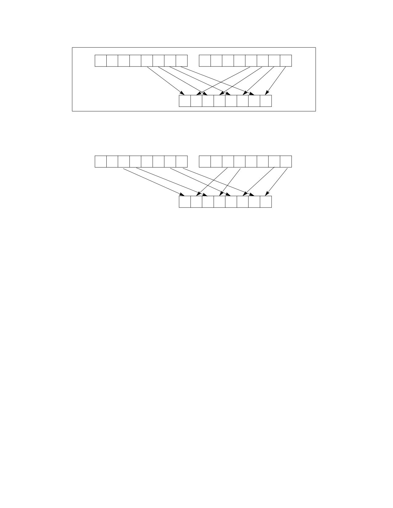
Unpacks and interleaves the low-order data elements (bytes, words, doublewords, and quadwords) of the destina-
tion operand (first operand) and source operand (second operand) into the destination operand. (Figure 4-22
shows the unpack operation for bytes in 64-bit operands.). The high-order data elements are ignored.
PUNPCKLBW/PUNPCKLWD/PUNPCKLDQ/PUNPCKLQDQ-Unpack Low Data
Vol. 2B
4-513
SRC
Y7
Y6
Y5
Y4
Y3
Y2
Y1
Y0
X7
X6
X5
X4
X3
X2
X1
X0
DEST
DEST
Y3
X3
Y2
X2
Y1
X1
Y0
X0
Figure 4-22. PUNPCKLBW Instruction Operation Using 64-bit Operands
255
31
0
255
31
0
SRC
Y7
Y6
Y5
Y4
Y3
Y2
Y1
Y0
X7
X6
X5
X4
X3
X2
X1
X0
255
0
DEST
Y5
X5
Y4
X4
Y1
X1
Y0
X0
Figure 4-23. 256-bit VPUNPCKLDQ Instruction Operation
When the source data comes from a 128-bit memory operand, an implementation may fetch only the appropriate
64 bits; however, alignment to a 16-byte boundary and normal segment checking will still be enforced.
The (V)PUNPCKLBW instruction interleaves the low-order bytes of the source and destination operands, the
(V)PUNPCKLWD instruction interleaves the low-order words of the source and destination operands, the (V)PUNP-
CKLDQ instruction interleaves the low-order doubleword (or doublewords) of the source and destination operands,
and the (V)PUNPCKLQDQ instruction interleaves the low-order quadwords of the source and destination operands.
These instructions can be used to convert bytes to words, words to doublewords, doublewords to quadwords, and
quadwords to double quadwords, respectively, by placing all 0s in the source operand. Here, if the source operand
contains all 0s, the result (stored in the destination operand) contains zero extensions of the high-order data
elements from the original value in the destination operand. For example, with the (V)PUNPCKLBW instruction the
high-order bytes are zero extended (that is, unpacked into unsigned word integers), and with the (V)PUNPCKLWD
instruction, the high-order words are zero extended (unpacked into unsigned doubleword integers).
In 64-bit mode and not encoded with VEX/EVEX, using a REX prefix in the form of REX.R permits this instruction to
access additional registers (XMM8-XMM15).
Legacy SSE versions 64-bit operand: The source operand can be an MMX technology register or a 32-bit memory
location. The destination operand is an MMX technology register.
128-bit Legacy SSE versions: The second source operand is an XMM register or a 128-bit memory location. The
first source operand and destination operands are XMM registers. Bits (MAXVL-1:128) of the corresponding YMM
destination register remain unchanged.
VEX.128 encoded versions: The second source operand is an XMM register or a 128-bit memory location. The first
source operand and destination operands are XMM registers. Bits (MAXVL-1:128) of the destination YMM register
are zeroed.
VEX.256 encoded version: The second source operand is an YMM register or an 256-bit memory location. The first
source operand and destination operands are YMM registers. Bits (MAXVL-1:256) of the corresponding ZMM
register are zeroed.
EVEX encoded VPUNPCKLDQ/QDQ: The second source operand is a ZMM/YMM/XMM register, a 512/256/128-bit
memory location or a 512/256/128-bit vector broadcasted from a 32/64-bit memory location. The first source
PUNPCKLBW/PUNPCKLWD/PUNPCKLDQ/PUNPCKLQDQ-Unpack Low Data
Vol. 2B
4-514
operand and destination operands are ZMM/YMM/XMM registers. The destination is conditionally updated with
writemask k1.
EVEX encoded VPUNPCKLWD/BW: The second source operand is a ZMM/YMM/XMM register, a 512/256/128-bit
memory location. The first source operand and destination operands are ZMM/YMM/XMM registers. The destination
is conditionally updated with writemask k1.
Operation
PUNPCKLBW Instruction With 64-bit Operands:
DEST[63:56] := SRC[31:24];
DEST[55:48] := DEST[31:24];
DEST[47:40] := SRC[23:16];
DEST[39:32] := DEST[23:16];
DEST[31:24] := SRC[15:8];
DEST[23:16] := DEST[15:8];
DEST[15:8] := SRC[7:0];
DEST[7:0] := DEST[7:0];
PUNPCKLWD Instruction With 64-bit Operands:
DEST[63:48] := SRC[31:16];
DEST[47:32] := DEST[31:16];
DEST[31:16] := SRC[15:0];
DEST[15:0] := DEST[15:0];
PUNPCKLDQ Instruction With 64-bit Operands:
DEST[63:32] := SRC[31:0];
DEST[31:0] := DEST[31:0];
INTERLEAVE_BYTES_512b (SRC1, SRC2)
TMP_DEST[255:0] := INTERLEAVE_BYTES_256b(SRC1[255:0], SRC[255:0])
TMP_DEST[511:256] := INTERLEAVE_BYTES_256b(SRC1[511:256], SRC[511:256])
INTERLEAVE_BYTES_256b (SRC1, SRC2)
DEST[7:0] := SRC1[7:0]
DEST[15:8] := SRC2[7:0]
DEST[23:16] := SRC1[15:8]
DEST[31:24] := SRC2[15:8]
DEST[39:32] := SRC1[23:16]
DEST[47:40] := SRC2[23:16]
DEST[55:48] := SRC1[31:24]
DEST[63:56] := SRC2[31:24]
DEST[71:64] := SRC1[39:32]
DEST[79:72] := SRC2[39:32]
DEST[87:80] := SRC1[47:40]
DEST[95:88] := SRC2[47:40]
DEST[103:96] := SRC1[55:48]
DEST[111:104] := SRC2[55:48]
DEST[119:112] := SRC1[63:56]
DEST[127:120] := SRC2[63:56]
DEST[135:128] := SRC1[135:128]
DEST[143:136] := SRC2[135:128]
DEST[151:144] := SRC1[143:136]
DEST[159:152] := SRC2[143:136]
DEST[167:160] := SRC1[151:144]
DEST[175:168] := SRC2[151:144]
PUNPCKLBW/PUNPCKLWD/PUNPCKLDQ/PUNPCKLQDQ-Unpack Low Data
Vol. 2B
4-515
DEST[183:176] := SRC1[159:152]
DEST[191:184] := SRC2[159:152]
DEST[199:192] := SRC1[167:160]
DEST[207:200] := SRC2[167:160]
DEST[215:208] := SRC1[175:168]
DEST[223:216] := SRC2[175:168]
DEST[231:224] := SRC1[183:176]
DEST[239:232] := SRC2[183:176]
DEST[247:240] := SRC1[191:184]
DEST[255:248] := SRC2[191:184]
INTERLEAVE_BYTES (SRC1, SRC2)
DEST[7:0] := SRC1[7:0]
DEST[15:8] := SRC2[7:0]
DEST[23:16] := SRC1[15:8]
DEST[31:24] := SRC2[15:8]
DEST[39:32] := SRC1[23:16]
DEST[47:40] := SRC2[23:16]
DEST[55:48] := SRC1[31:24]
DEST[63:56] := SRC2[31:24]
DEST[71:64] := SRC1[39:32]
DEST[79:72] := SRC2[39:32]
DEST[87:80] := SRC1[47:40]
DEST[95:88] := SRC2[47:40]
DEST[103:96] := SRC1[55:48]
DEST[111:104] := SRC2[55:48]
DEST[119:112] := SRC1[63:56]
DEST[127:120] := SRC2[63:56]
INTERLEAVE_WORDS_512b (SRC1, SRC2)
TMP_DEST[255:0] := INTERLEAVE_WORDS_256b(SRC1[255:0], SRC[255:0])
TMP_DEST[511:256] := INTERLEAVE_WORDS_256b(SRC1[511:256], SRC[511:256])
INTERLEAVE_WORDS_256b(SRC1, SRC2)
DEST[15:0] := SRC1[15:0]
DEST[31:16] := SRC2[15:0]
DEST[47:32] := SRC1[31:16]
DEST[63:48] := SRC2[31:16]
DEST[79:64] := SRC1[47:32]
DEST[95:80] := SRC2[47:32]
DEST[111:96] := SRC1[63:48]
DEST[127:112] := SRC2[63:48]
DEST[143:128] := SRC1[143:128]
DEST[159:144] := SRC2[143:128]
DEST[175:160] := SRC1[159:144]
DEST[191:176] := SRC2[159:144]
DEST[207:192] := SRC1[175:160]
DEST[223:208] := SRC2[175:160]
DEST[239:224] := SRC1[191:176]
DEST[255:240] := SRC2[191:176]
INTERLEAVE_WORDS (SRC1, SRC2)
DEST[15:0] := SRC1[15:0]
DEST[31:16] := SRC2[15:0]
PUNPCKLBW/PUNPCKLWD/PUNPCKLDQ/PUNPCKLQDQ-Unpack Low Data
Vol. 2B
4-516
DEST[47:32] := SRC1[31:16]
DEST[63:48] := SRC2[31:16]
DEST[79:64] := SRC1[47:32]
DEST[95:80] := SRC2[47:32]
DEST[111:96] := SRC1[63:48]
DEST[127:112] := SRC2[63:48]
INTERLEAVE_DWORDS_512b (SRC1, SRC2)
TMP_DEST[255:0] := INTERLEAVE_DWORDS_256b(SRC1[255:0], SRC2[255:0])
TMP_DEST[511:256] := INTERLEAVE_DWORDS_256b(SRC1[511:256], SRC2[511:256])
INTERLEAVE_DWORDS_256b(SRC1, SRC2)
DEST[31:0] := SRC1[31:0]
DEST[63:32] := SRC2[31:0]
DEST[95:64] := SRC1[63:32]
DEST[127:96] := SRC2[63:32]
DEST[159:128] := SRC1[159:128]
DEST[191:160] := SRC2[159:128]
DEST[223:192] := SRC1[191:160]
DEST[255:224] := SRC2[191:160]
INTERLEAVE_DWORDS(SRC1, SRC2)
DEST[31:0] := SRC1[31:0]
DEST[63:32] := SRC2[31:0]
DEST[95:64] := SRC1[63:32]
DEST[127:96] := SRC2[63:32]
INTERLEAVE_QWORDS_512b (SRC1, SRC2)
TMP_DEST[255:0] := INTERLEAVE_QWORDS_256b(SRC1[255:0], SRC2[255:0])
TMP_DEST[511:256] := INTERLEAVE_QWORDS_256b(SRC1[511:256], SRC2[511:256])
INTERLEAVE_QWORDS_256b(SRC1, SRC2)
DEST[63:0] := SRC1[63:0]
DEST[127:64] := SRC2[63:0]
DEST[191:128] := SRC1[191:128]
DEST[255:192] := SRC2[191:128]
INTERLEAVE_QWORDS(SRC1, SRC2)
DEST[63:0] := SRC1[63:0]
DEST[127:64] := SRC2[63:0]
PUNPCKLBW
DEST[127:0] := INTERLEAVE_BYTES(DEST, SRC)
DEST[255:127] (Unmodified)
VPUNPCKLBW (VEX.128 Encoded Instruction)
DEST[127:0] := INTERLEAVE_BYTES(SRC1, SRC2)
DEST[MAXVL-1:127] := 0
VPUNPCKLBW (VEX.256 Encoded Instruction)
DEST[255:0] := INTERLEAVE_BYTES_256b(SRC1, SRC2)
DEST[MAXVL-1:256] := 0
PUNPCKLBW/PUNPCKLWD/PUNPCKLDQ/PUNPCKLQDQ-Unpack Low Data
Vol. 2B
4-517
VPUNPCKLBW (EVEX.512 Encoded Instruction)
(KL, VL) = (16, 128), (32, 256), (64, 512)
IF VL = 128
TMP_DEST[VL-1:0] := INTERLEAVE_BYTES(SRC1[VL-1:0], SRC2[VL-1:0])
FI;
IF VL = 256
TMP_DEST[VL-1:0] := INTERLEAVE_BYTES_256b(SRC1[VL-1:0], SRC2[VL-1:0])
FI;
IF VL = 512
TMP_DEST[VL-1:0] := INTERLEAVE_BYTES_512b(SRC1[VL-1:0], SRC2[VL-1:0])
FI;
FOR j := 0 TO KL-1
i := j * 8
IF k1[j] OR *no writemask*
THEN DEST[i+7:i] := TMP_DEST[i+7:i]
ELSE
IF *merging-masking*
; merging-masking
THEN *DEST[i+7:i] remains unchanged*
ELSE *zeroing-masking*
; zeroing-masking
DEST[i+7:i] := 0
FI
FI;
ENDFOR
DEST[MAXVL-1:VL] := 0
DEST[511:0] := INTERLEAVE_BYTES_512b(SRC1, SRC2)
PUNPCKLWD
DEST[127:0] := INTERLEAVE_WORDS(DEST, SRC)
DEST[255:127] (Unmodified)
VPUNPCKLWD (VEX.128 Encoded Instruction)
DEST[127:0] := INTERLEAVE_WORDS(SRC1, SRC2)
DEST[MAXVL-1:127] := 0
VPUNPCKLWD (VEX.256 Encoded Instruction)
DEST[255:0] := INTERLEAVE_WORDS_256b(SRC1, SRC2)
DEST[MAXVL-1:256] := 0
VPUNPCKLWD (EVEX.512 Encoded Instruction)
(KL, VL) = (8, 128), (16, 256), (32, 512)
IF VL = 128
TMP_DEST[VL-1:0] := INTERLEAVE_WORDS(SRC1[VL-1:0], SRC2[VL-1:0])
FI;
IF VL = 256
TMP_DEST[VL-1:0] := INTERLEAVE_WORDS_256b(SRC1[VL-1:0], SRC2[VL-1:0])
FI;
IF VL = 512
TMP_DEST[VL-1:0] := INTERLEAVE_WORDS_512b(SRC1[VL-1:0], SRC2[VL-1:0])
FI;
FOR j := 0 TO KL-1
i := j * 16
IF k1[j] OR *no writemask*
PUNPCKLBW/PUNPCKLWD/PUNPCKLDQ/PUNPCKLQDQ-Unpack Low Data
Vol. 2B
4-518
THEN DEST[i+15:i] := TMP_DEST[i+15:i]
ELSE
IF *merging-masking*
; merging-masking
THEN *DEST[i+15:i] remains unchanged*
ELSE *zeroing-masking*
; zeroing-masking
DEST[i+15:i] := 0
FI
FI;
ENDFOR
DEST[MAXVL-1:VL] := 0
DEST[511:0] := INTERLEAVE_WORDS_512b(SRC1, SRC2)
PUNPCKLDQ
DEST[127:0] := INTERLEAVE_DWORDS(DEST, SRC)
DEST[MAXVL-1:128] (Unmodified)
VPUNPCKLDQ (VEX.128 Encoded Instruction)
DEST[127:0] := INTERLEAVE_DWORDS(SRC1, SRC2)
DEST[MAXVL-1:128] := 0
VPUNPCKLDQ (VEX.256 Encoded Instruction)
DEST[255:0] := INTERLEAVE_DWORDS_256b(SRC1, SRC2)
DEST[MAXVL-1:256] := 0
VPUNPCKLDQ (EVEX Encoded Instructions)
(KL, VL) = (4, 128), (8, 256), (16, 512)
FOR j := 0 TO KL-1
i := j * 32
IF (EVEX.b = 1) AND (SRC2 *is memory*)
THEN TMP_SRC2[i+31:i] := SRC2[31:0]
ELSE TMP_SRC2[i+31:i] := SRC2[i+31:i]
FI;
ENDFOR;
IF VL = 128
TMP_DEST[VL-1:0] := INTERLEAVE_DWORDS(SRC1[VL-1:0], TMP_SRC2[VL-1:0])
FI;
IF VL = 256
TMP_DEST[VL-1:0] := INTERLEAVE_DWORDS_256b(SRC1[VL-1:0], TMP_SRC2[VL-1:0])
FI;
IF VL = 512
TMP_DEST[VL-1:0] := INTERLEAVE_DWORDS_512b(SRC1[VL-1:0], TMP_SRC2[VL-1:0])
FI;
FOR j := 0 TO KL-1
i := j * 32
IF k1[j] OR *no writemask*
THEN DEST[i+31:i] := TMP_DEST[i+31:i]
ELSE
IF *merging-masking*
; merging-masking
THEN *DEST[i+31:i] remains unchanged*
ELSE *zeroing-masking*
; zeroing-masking
DEST[i+31:i] := 0
FI
FI;
PUNPCKLBW/PUNPCKLWD/PUNPCKLDQ/PUNPCKLQDQ-Unpack Low Data
Vol. 2B
4-519
ENDFOR
DEST511:0] := INTERLEAVE_DWORDS_512b(SRC1, SRC2)
DEST[MAXVL-1:VL] := 0
PUNPCKLQDQ
DEST[127:0] := INTERLEAVE_QWORDS(DEST, SRC)
DEST[MAXVL-1:128] (Unmodified)
VPUNPCKLQDQ (VEX.128 Encoded Instruction)
DEST[127:0] := INTERLEAVE_QWORDS(SRC1, SRC2)
DEST[MAXVL-1:128] := 0
VPUNPCKLQDQ (VEX.256 Encoded Instruction)
DEST[255:0] := INTERLEAVE_QWORDS_256b(SRC1, SRC2)
DEST[MAXVL-1:256] := 0
VPUNPCKLQDQ (EVEX Encoded Instructions)
(KL, VL) = (2, 128), (4, 256), (8, 512)
FOR j := 0 TO KL-1
i := j * 64
IF (EVEX.b = 1) AND (SRC2 *is memory*)
THEN TMP_SRC2[i+63:i] := SRC2[63:0]
ELSE TMP_SRC2[i+63:i] := SRC2[i+63:i]
FI;
ENDFOR;
IF VL = 128
TMP_DEST[VL-1:0] := INTERLEAVE_QWORDS(SRC1[VL-1:0], TMP_SRC2[VL-1:0])
FI;
IF VL = 256
TMP_DEST[VL-1:0] := INTERLEAVE_QWORDS_256b(SRC1[VL-1:0], TMP_SRC2[VL-1:0])
FI;
IF VL = 512
TMP_DEST[VL-1:0] := INTERLEAVE_QWORDS_512b(SRC1[VL-1:0], TMP_SRC2[VL-1:0])
FI;
FOR j := 0 TO KL-1
i := j * 64
IF k1[j] OR *no writemask*
THEN DEST[i+63:i] := TMP_DEST[i+63:i]
ELSE
IF *merging-masking*
; merging-masking
THEN *DEST[i+63:i] remains unchanged*
ELSE *zeroing-masking*
; zeroing-masking
DEST[i+63:i] := 0
FI
FI;
ENDFOR
DEST[MAXVL-1:VL] := 0
Intel C/C++ Compiler Intrinsic Equivalents
VPUNPCKLBW __m512i _mm512_unpacklo_epi8(__m512i a, __m512i b);
VPUNPCKLBW __m512i _mm512_mask_unpacklo_epi8(__m512i s, __mmask64 k, __m512i a, __m512i b);
VPUNPCKLBW __m512i _mm512_maskz_unpacklo_epi8( __mmask64 k, __m512i a, __m512i b);
PUNPCKLBW/PUNPCKLWD/PUNPCKLDQ/PUNPCKLQDQ-Unpack Low Data
Vol. 2B
4-520
VPUNPCKLBW __m256i _mm256_mask_unpacklo_epi8(__m256i s, __mmask32 k, __m256i a, __m256i b);
VPUNPCKLBW __m256i _mm256_maskz_unpacklo_epi8( __mmask32 k, __m256i a, __m256i b);
VPUNPCKLBW __m128i _mm_mask_unpacklo_epi8(v s, __mmask16 k, __m128i a, __m128i b);
VPUNPCKLBW __m128i _mm_maskz_unpacklo_epi8( __mmask16 k, __m128i a, __m128i b);
VPUNPCKLWD __m512i _mm512_unpacklo_epi16(__m512i a, __m512i b);
VPUNPCKLWD __m512i _mm512_mask_unpacklo_epi16(__m512i s, __mmask32 k, __m512i a, __m512i b);
VPUNPCKLWD __m512i _mm512_maskz_unpacklo_epi16( __mmask32 k, __m512i a, __m512i b);
VPUNPCKLWD __m256i _mm256_mask_unpacklo_epi16(__m256i s, __mmask16 k, __m256i a, __m256i b);
VPUNPCKLWD __m256i _mm256_maskz_unpacklo_epi16( __mmask16 k, __m256i a, __m256i b);
VPUNPCKLWD __m128i _mm_mask_unpacklo_epi16(v s, __mmask8 k, __m128i a, __m128i b);
VPUNPCKLWD __m128i _mm_maskz_unpacklo_epi16( __mmask8 k, __m128i a, __m128i b);
VPUNPCKLDQ __m512i _mm512_unpacklo_epi32(__m512i a, __m512i b);
VPUNPCKLDQ __m512i _mm512_mask_unpacklo_epi32(__m512i s, __mmask16 k, __m512i a, __m512i b);
VPUNPCKLDQ __m512i _mm512_maskz_unpacklo_epi32( __mmask16 k, __m512i a, __m512i b);
VPUNPCKLDQ __m256i _mm256_mask_unpacklo_epi32(__m256i s, __mmask8 k, __m256i a, __m256i b);
VPUNPCKLDQ __m256i _mm256_maskz_unpacklo_epi32( __mmask8 k, __m256i a, __m256i b);
VPUNPCKLDQ __m128i _mm_mask_unpacklo_epi32(v s, __mmask8 k, __m128i a, __m128i b);
VPUNPCKLDQ __m128i _mm_maskz_unpacklo_epi32( __mmask8 k, __m128i a, __m128i b);
VPUNPCKLQDQ __m512i _mm512_unpacklo_epi64(__m512i a, __m512i b);
VPUNPCKLQDQ __m512i _mm512_mask_unpacklo_epi64(__m512i s, __mmask8 k, __m512i a, __m512i b);
VPUNPCKLQDQ __m512i _mm512_maskz_unpacklo_epi64( __mmask8 k, __m512i a, __m512i b);
VPUNPCKLQDQ __m256i _mm256_mask_unpacklo_epi64(__m256i s, __mmask8 k, __m256i a, __m256i b);
VPUNPCKLQDQ __m256i _mm256_maskz_unpacklo_epi64( __mmask8 k, __m256i a, __m256i b);
VPUNPCKLQDQ __m128i _mm_mask_unpacklo_epi64(__m128i s, __mmask8 k, __m128i a, __m128i b);
VPUNPCKLQDQ __m128i _mm_maskz_unpacklo_epi64( __mmask8 k, __m128i a, __m128i b);
PUNPCKLBW __m64 _mm_unpacklo_pi8 (__m64 m1, __m64 m2)
(V)PUNPCKLBW __m128i _mm_unpacklo_epi8 (__m128i m1, __m128i m2)
VPUNPCKLBW __m256i _mm256_unpacklo_epi8 (__m256i m1, __m256i m2)
PUNPCKLWD __m64 _mm_unpacklo_pi16 (__m64 m1, __m64 m2)
(V)PUNPCKLWD __m128i _mm_unpacklo_epi16 (__m128i m1, __m128i m2)
VPUNPCKLWD __m256i _mm256_unpacklo_epi16 (__m256i m1, __m256i m2)
PUNPCKLDQ __m64 _mm_unpacklo_pi32 (__m64 m1, __m64 m2)
(V)PUNPCKLDQ __m128i _mm_unpacklo_epi32 (__m128i m1, __m128i m2)
VPUNPCKLDQ __m256i _mm256_unpacklo_epi32 (__m256i m1, __m256i m2)
(V)PUNPCKLQDQ __m128i _mm_unpacklo_epi64 (__m128i m1, __m128i m2)
VPUNPCKLQDQ __m256i _mm256_unpacklo_epi64 (__m256i m1, __m256i m2)
Flags Affected
None.
Numeric Exceptions
None.
Other Exceptions
Non-EVEX-encoded instruction, see Table 2-21, “Type 4 Class Exception Conditions.”
EVEX-encoded VPUNPCKLDQ/QDQ, see Table 2-52, “Type E4NF Class Exception Conditions.”
EVEX-encoded VPUNPCKLBW/WD, see Exceptions Type E4NF.nb in Table 2-52, “Type E4NF Class Exception Condi-
tions.”
PUNPCKLBW/PUNPCKLWD/PUNPCKLDQ/PUNPCKLQDQ-Unpack Low Data
Vol. 2B
4-521
PUSH-Push Word, Doubleword, or Quadword Onto the Stack
Opcode1
Instruction
Op/
64-Bit
Compat/
Description
En
Mode
Leg Mode
FF /6
PUSH r/m16
M
Valid
Valid
Push r/m16.
FF /6
PUSH r/m32
M
N.E.
Valid
Push r/m32.
FF /6
PUSH r/m64
M
Valid
N.E.
Push r/m64.
50+rw
PUSH r16
O
Valid
Valid
Push r16.
50+rd
PUSH r32
O
N.E.
Valid
Push r32.
50+rd
PUSH r64
O
Valid
N.E.
Push r64.
6A ib
PUSH imm8
I
Valid
Valid
Push imm8.
68 iw
PUSH imm16
I
Valid
Valid
Push imm16.
68 id
PUSH imm32
I
Valid
Valid
Push imm32.
0E
PUSH CS
ZO
Invalid
Valid
Push CS.
16
PUSH SS
ZO
Invalid
Valid
Push SS.
1E
PUSH DS
ZO
Invalid
Valid
Push DS.
06
PUSH ES
ZO
Invalid
Valid
Push ES.
0F A0
PUSH FS
ZO
Valid
Valid
Push FS.
0F A8
PUSH GS
ZO
Valid
Valid
Push GS.
NOTES:
1. See the IA-32 Architecture Compatibility section below.
Instruction Operand Encoding
Op/En
Operand 1
Operand 2
Operand 3
Operand 4
M
ModRM:r/m (r)
N/A
N/A
N/A
O
opcode + rd (r)
N/A
N/A
N/A
I
imm8/16/32
N/A
N/A
N/A
ZO
N/A
N/A
N/A
N/A
Description
Decrements the stack pointer and then stores the source operand on the top of the stack. Address and operand
sizes are determined and used as follows:
• Address size. The D flag in the current code-segment descriptor determines the default address size; it may be
overridden by an instruction prefix (67H).
The address size is used only when referencing a source operand in memory.
• Operand size. The D flag in the current code-segment descriptor determines the default operand size; it may
be overridden by instruction prefixes (66H or REX.W).
The operand size (16, 32, or 64 bits) determines the amount by which the stack pointer is decremented (2, 4
or 8).
If the source operand is an immediate of size less than the operand size, a sign-extended value is pushed on
the stack. If the source operand is a segment register (16 bits) and the operand size is 64-bits, a zero-
extended value is pushed on the stack; if the operand size is 32-bits, either a zero-extended value is pushed
on the stack or the segment selector is written on the stack using a 16-bit move. For the last case, all recent
Intel Core and Intel Atom processors perform a 16-bit move, leaving the upper portion of the stack location
unmodified.
PUSH-Push Word, Doubleword, or Quadword Onto the Stack
Vol. 2B
4-522
• Stack-address size. Outside of 64-bit mode, the B flag in the current stack-segment descriptor determines the
size of the stack pointer (16 or 32 bits); in 64-bit mode, the size of the stack pointer is always 64 bits.
The stack-address size determines the width of the stack pointer when writing to the stack in memory and
when decrementing the stack pointer. (As stated above, the amount by which the stack pointer is
decremented is determined by the operand size.)
If the operand size is less than the stack-address size, the PUSH instruction may result in a misaligned stack
pointer (a stack pointer that is not aligned on a doubleword or quadword boundary).
The PUSH ESP instruction pushes the value of the ESP register as it existed before the instruction was executed. If
a PUSH instruction uses a memory operand in which the ESP register is used for computing the operand address,
the address of the operand is computed before the ESP register is decremented.
If the ESP or SP register is 1 when the PUSH instruction is executed in real-address mode, a stack-fault exception
(#SS) is generated (because the limit of the stack segment is violated). Its delivery encounters a second stack-
fault exception (for the same reason), causing generation of a double-fault exception (#DF). Delivery of the
double-fault exception encounters a third stack-fault exception, and the logical processor enters shutdown mode.
See the discussion of the double-fault exception in Chapter 7 of the Intel® 64 and IA-32 Architectures Software
Developer’s Manual, Volume 3A.
IA-32 Architecture Compatibility
For IA-32 processors from the Intel 286 on, the PUSH ESP instruction pushes the value of the ESP register as it
existed before the instruction was executed. (This is also true for Intel 64 architecture, real-address and virtual-
8086 modes of IA-32 architecture.) For the Intel® 8086 processor, the PUSH SP instruction pushes the new value
of the SP register (that is the value after it has been decremented by 2).
Operation
(* See Description section for possible sign-extension or zero-extension of source operand and for *)
(* a case in which the size of the memory store may be smaller than the instruction’s operand size *)
IF StackAddrSize = 64
THEN
IF OperandSize = 64
THEN
RSP := RSP - 8;
Memory[SS:RSP] := SRC;
(* push quadword *)
ELSE IF OperandSize = 32
THEN
RSP := RSP - 4;
Memory[SS:RSP] := SRC;
(* push dword *)
ELSE (* OperandSize = 16 *)
RSP := RSP - 2;
Memory[SS:RSP] := SRC;
(* push word *)
FI;
ELSE IF StackAddrSize = 32
THEN
IF OperandSize = 64
THEN
ESP := ESP - 8;
Memory[SS:ESP] := SRC;
(* push quadword *)
ELSE IF OperandSize = 32
THEN
ESP := ESP - 4;
Memory[SS:ESP] := SRC;
(* push dword *)
ELSE (* OperandSize = 16 *)
ESP := ESP - 2;
Memory[SS:ESP] := SRC;
(* push word *)
PUSH-Push Word, Doubleword, or Quadword Onto the Stack
Vol. 2B
4-523
FI;
ELSE (* StackAddrSize = 16 *)
IF OperandSize = 32
THEN
SP := SP - 4;
Memory[SS:SP] := SRC;
(* push dword *)
ELSE (* OperandSize = 16 *)
SP := SP - 2;
Memory[SS:SP] := SRC;
(* push word *)
FI;
FI;
Flags Affected
None.
Protected Mode Exceptions
#GP(0)
If a memory operand effective address is outside the CS, DS, ES, FS, or GS segment limit.
If the DS, ES, FS, or GS register is used to access memory and it contains a NULL segment
selector.
#SS(0)
If a memory operand effective address is outside the SS segment limit.
#PF(fault-code)
If a page fault occurs.
#AC(0)
If alignment checking is enabled and an unaligned memory reference is made while the
current privilege level is 3.
#UD
If the LOCK prefix is used.
Real-Address Mode Exceptions
#GP
If a memory operand effective address is outside the CS, DS, ES, FS, or GS segment limit.
#SS
If a memory operand effective address is outside the SS segment limit.
If the new value of the SP or ESP register is outside the stack segment limit.
#UD
If the LOCK prefix is used.
Virtual-8086 Mode Exceptions
#GP(0)
If a memory operand effective address is outside the CS, DS, ES, FS, or GS segment limit.
#SS(0)
If a memory operand effective address is outside the SS segment limit.
#PF(fault-code)
If a page fault occurs.
#AC(0)
If alignment checking is enabled and an unaligned memory reference is made.
#UD
If the LOCK prefix is used.
Compatibility Mode Exceptions
Same exceptions as in protected mode.
64-Bit Mode Exceptions
#GP(0)
If the memory address is in a non-canonical form.
#SS(0)
If the stack address is in a non-canonical form.
#PF(fault-code)
If a page fault occurs.
#AC(0)
If alignment checking is enabled and an unaligned memory reference is made while the
current privilege level is 3.
#UD
If the LOCK prefix is used.
If the PUSH is of CS, SS, DS, or ES.
PUSH-Push Word, Doubleword, or Quadword Onto the Stack
Vol. 2B
4-524
PUSH-Push Word, Doubleword, or Quadword Onto the Stack
Vol. 2B
4-525
PUSHA/PUSHAD-Push All General-Purpose Registers
Opcode
Instruction
Op/
64-Bit
Compat/
Description
En
Mode
Leg Mode
60
PUSHA
ZO
Invalid
Valid
Push AX, CX, DX, BX, original SP, BP, SI, and DI.
60
PUSHAD
ZO
Invalid
Valid
Push EAX, ECX, EDX, EBX, original ESP, EBP,
ESI, and EDI.
Instruction Operand Encoding
Op/En
Operand 1
Operand 2
Operand 3
Operand 4
ZO
N/A
N/A
N/A
N/A
Description
Pushes the contents of the general-purpose registers onto the stack. The registers are stored on the stack in the
following order: EAX, ECX, EDX, EBX, ESP (original value), EBP, ESI, and EDI (if the current operand-size attribute
is 32) and AX, CX, DX, BX, SP (original value), BP, SI, and DI (if the operand-size attribute is 16). These instruc-
tions perform the reverse operation of the POPA/POPAD instructions. The value pushed for the ESP or SP register
is its value before prior to pushing the first register (see the “Operation” section below).
The PUSHA (push all) and PUSHAD (push all double) mnemonics reference the same opcode. The PUSHA instruc-
tion is intended for use when the operand-size attribute is 16 and the PUSHAD instruction for when the operand-
size attribute is 32. Some assemblers may force the operand size to 16 when PUSHA is used and to 32 when
PUSHAD is used. Others may treat these mnemonics as synonyms (PUSHA/PUSHAD) and use the current setting
of the operand-size attribute to determine the size of values to be pushed from the stack, regardless of the
mnemonic used.
In the real-address mode, if the ESP or SP register is 1, 3, or 5 when PUSHA/PUSHAD executes: an #SS exception
is generated but not delivered (the stack error reported prevents #SS delivery). Next, the processor generates a
#DF exception and enters a shutdown state as described in the #DF discussion in Chapter 7 of the Intel® 64 and
IA-32 Architectures Software Developer’s Manual, Volume 3A.
This instruction executes as described in compatibility mode and legacy mode. It is not valid in 64-bit mode.
Operation
IF 64-bit Mode
THEN #UD
FI;
IF OperandSize = 32 (* PUSHAD instruction *)
THEN
Temp := (ESP);
Push(EAX);
Push(ECX);
Push(EDX);
Push(EBX);
Push(Temp);
Push(EBP);
Push(ESI);
Push(EDI);
ELSE (* OperandSize = 16, PUSHA instruction *)
Temp := (SP);
Push(AX);
Push(CX);
Push(DX);
Push(BX);
Push(Temp);
PUSHA/PUSHAD-Push All General-Purpose Registers
Vol. 2B
4-526
Push(BP);
Push(SI);
Push(DI);
FI;
Flags Affected
None.
Protected Mode Exceptions
#SS(0)
If the starting or ending stack address is outside the stack segment limit.
#PF(fault-code)
If a page fault occurs.
#AC(0)
If an unaligned memory reference is made while the current privilege level is 3 and alignment
checking is enabled.
#UD
If the LOCK prefix is used.
Real-Address Mode Exceptions
#GP
If the ESP or SP register contains 7, 9, 11, 13, or 15.
#UD
If the LOCK prefix is used.
Virtual-8086 Mode Exceptions
#GP(0)
If the ESP or SP register contains 7, 9, 11, 13, or 15.
#PF(fault-code)
If a page fault occurs.
#AC(0)
If an unaligned memory reference is made while alignment checking is enabled.
#UD
If the LOCK prefix is used.
Compatibility Mode Exceptions
Same exceptions as in protected mode.
64-Bit Mode Exceptions
#UD
If in 64-bit mode.
PUSHA/PUSHAD-Push All General-Purpose Registers
Vol. 2B
4-527
PUSHF/PUSHFD/PUSHFQ-Push EFLAGS Register Onto the Stack
Opcode
Instruction
Op/
64-Bit
Compat/
Description
En
Mode
Leg Mode
9C
PUSHF
ZO
Valid
Valid
Push lower 16 bits of EFLAGS.
9C
PUSHFD
ZO
N.E.
Valid
Push EFLAGS.
9C
PUSHFQ
ZO
Valid
N.E.
Push RFLAGS.
Instruction Operand Encoding
Op/En
Operand 1
Operand 2
Operand 3
Operand 4
ZO
N/A
N/A
N/A
N/A
Description
Decrements the stack pointer by 4 (if the current operand-size attribute is 32) and pushes the entire contents of
the EFLAGS register onto the stack, or decrements the stack pointer by 2 (if the operand-size attribute is 16) and
pushes the lower 16 bits of the EFLAGS register (that is, the FLAGS register) onto the stack. These instructions
reverse the operation of the POPF/POPFD instructions.
When copying the entire EFLAGS register to the stack, the VM and RF flags (bits 16 and 17) are not copied; instead,
the values for these flags are cleared in the EFLAGS image stored on the stack. See Chapter 3 of the Intel® 64 and
IA-32 Architectures Software Developer’s Manual, Volume 1, for more information about the EFLAGS register.
The PUSHF (push flags) and PUSHFD (push flags double) mnemonics reference the same opcode. The PUSHF
instruction is intended for use when the operand-size attribute is 16 and the PUSHFD instruction for when the
operand-size attribute is 32. Some assemblers may force the operand size to 16 when PUSHF is used and to 32
when PUSHFD is used. Others may treat these mnemonics as synonyms (PUSHF/PUSHFD) and use the current
setting of the operand-size attribute to determine the size of values to be pushed from the stack, regardless of the
mnemonic used.
In 64-bit mode, the instruction’s default operation is to decrement the stack pointer (RSP) by 8 and pushes
RFLAGS on the stack. 16-bit operation is supported using the operand size override prefix 66H. 32-bit operand size
cannot be encoded in this mode. When copying RFLAGS to the stack, the VM and RF flags (bits 16 and 17) are not
copied; instead, values for these flags are cleared in the RFLAGS image stored on the stack.
When operating in virtual-8086 mode (EFLAGS.VM = 1) without the virtual-8086 mode extensions (CR4.VME = 0),
the PUSHF/PUSHFD instructions can be used only if IOPL = 3; otherwise, a general-protection exception (#GP)
occurs. If the virtual-8086 mode extensions are enabled (CR4.VME = 1), PUSHF (but not PUSHFD) can be executed
in virtual-8086 mode with IOPL < 3.
(The protected-mode virtual-interrupt feature - enabled by setting CR4.PVI - affects the CLI and STI instructions
in the same manner as the virtual-8086 mode extensions. PUSHF, however, is not affected by CR4.PVI.)
In the real-address mode, if the ESP or SP register is 1 when PUSHF/PUSHFD instruction executes: an #SS excep-
tion is generated but not delivered (the stack error reported prevents #SS delivery). Next, the processor generates
a #DF exception and enters a shutdown state as described in the #DF discussion in Chapter 7 of the Intel® 64 and
IA-32 Architectures Software Developer’s Manual, Volume 3A.
Operation
IF (PE = 0) or (PE = 1 and ((VM = 0) or (VM = 1 and IOPL = 3)))
(* Real-Address Mode, Protected mode, or Virtual-8086 mode with IOPL equal to 3 *)
THEN
IF OperandSize = 32
THEN
push (EFLAGS AND 00FCFFFFH);
(* VM and RF bits are cleared in image stored on the stack *)
ELSE
push (EFLAGS); (* Lower 16 bits only *)
PUSHF/PUSHFD/PUSHFQ-Push EFLAGS Register Onto the Stack
Vol. 2B
4-528
FI;
ELSE IF 64-bit MODE (* In 64-bit Mode *)
IF OperandSize = 64
THEN
push (RFLAGS AND 00000000_00FCFFFFH);
(* VM and RF bits are cleared in image stored on the stack; *)
ELSE
push (EFLAGS); (* Lower 16 bits only *)
FI;
ELSE (* In Virtual-8086 Mode with IOPL less than 3 *)
IF (CR4.VME = 0) OR (OperandSize = 32)
THEN #GP(0); (* Trap to virtual-8086 monitor *)
ELSE
tempFLAGS = EFLAGS[15:0];
tempFLAGS[9] = tempFLAGS[19];
(* VIF replaces IF *)
tempFlags[13:12] = 3; (* IOPL is set to 3 in image stored on the stack *)
push (tempFLAGS);
FI;
FI;
Flags Affected
None.
Protected Mode Exceptions
#SS(0)
If the new value of the ESP register is outside the stack segment boundary.
#PF(fault-code)
If a page fault occurs.
#AC(0)
If an unaligned memory reference is made while CPL = 3 and alignment checking is enabled.
#UD
If the LOCK prefix is used.
Real-Address Mode Exceptions
#UD
If the LOCK prefix is used.
Virtual-8086 Mode Exceptions
#GP(0)
If the I/O privilege level is less than 3.
#PF(fault-code)
If a page fault occurs.
#AC(0)
If an unaligned memory reference is made while alignment checking is enabled.
#UD
If the LOCK prefix is used.
Compatibility Mode Exceptions
Same exceptions as in protected mode.
64-Bit Mode Exceptions
#SS(0)
If the stack address is in a non-canonical form.
#PF(fault-code)
If a page fault occurs.
#AC(0)
If an unaligned memory reference is made while CPL = 3 and alignment checking is enabled.
#UD
If the LOCK prefix is used.
PUSHF/PUSHFD/PUSHFQ-Push EFLAGS Register Onto the Stack
Vol. 2B
4-529
PXOR-Logical Exclusive OR
Opcode/
Op/
64/32 bit
CPUID Feature
Description
Instruction
En
Mode
Flag
Support
NP 0F EF /r1
A
V/V
MMX
Bitwise XOR of mm/m64 and mm.
PXOR mm, mm/m64
66 0F EF /r
A
V/V
SSE2
Bitwise XOR of xmm2/m128 and xmm1.
PXOR xmm1, xmm2/m128
VEX.128.66.0F.WIG EF /r
B
V/V
AVX
Bitwise XOR of xmm3/m128 and xmm2.
VPXOR xmm1, xmm2, xmm3/m128
VEX.256.66.0F.WIG EF /r
B
V/V
AVX2
Bitwise XOR of ymm3/m256 and ymm2.
VPXOR ymm1, ymm2, ymm3/m256
EVEX.128.66.0F.W0 EF /r
C
V/V
(AVX512VL AND
Bitwise XOR of packed doubleword integers in
VPXORD xmm1 {k1}{z}, xmm2,
AVX512F) OR
xmm2 and xmm3/m128 using writemask k1.
xmm3/m128/m32bcst
AVX10.1
EVEX.256.66.0F.W0 EF /r
C
V/V
(AVX512VL AND
Bitwise XOR of packed doubleword integers in
VPXORD ymm1 {k1}{z}, ymm2,
AVX512F) OR
ymm2 and ymm3/m256 using writemask k1.
ymm3/m256/m32bcst
AVX10.1
EVEX.512.66.0F.W0 EF /r
C
V/V
AVX512F
Bitwise XOR of packed doubleword integers in
VPXORD zmm1 {k1}{z}, zmm2,
OR AVX10.1
zmm2 and zmm3/m512/m32bcst using
zmm3/m512/m32bcst
writemask k1.
EVEX.128.66.0F.W1 EF /r
C
V/V
(AVX512VL AND
Bitwise XOR of packed quadword integers in
VPXORQ xmm1 {k1}{z}, xmm2,
AVX512F) OR
xmm2 and xmm3/m128 using writemask k1.
xmm3/m128/m64bcst
AVX10.1
EVEX.256.66.0F.W1 EF /r
C
V/V
(AVX512VL AND
Bitwise XOR of packed quadword integers in
VPXORQ ymm1 {k1}{z}, ymm2,
AVX512F) OR
ymm2 and ymm3/m256 using writemask k1.
ymm3/m256/m64bcst
AVX10.1
EVEX.512.66.0F.W1 EF /r
C
V/V
AVX512F
Bitwise XOR of packed quadword integers in
VPXORQ zmm1 {k1}{z}, zmm2,
OR AVX10.1
zmm2 and zmm3/m512/m64bcst using
zmm3/m512/m64bcst
writemask k1.
NOTES:
1. See note in Section 2.5, “Intel® AVX and Intel® SSE Instruction Exception Classification,” in the Intel® 64 and IA-32 Architectures Soft-
ware Developer’s Manual, Volume 2A, and Section 25.25.3, “Exception Conditions of Legacy SIMD Instructions Operating on MMX
Registers,” in the Intel® 64 and IA-32 Architectures Software Developer’s Manual, Volume 3B.
Instruction Operand Encoding
Op/En
Tuple Type
Operand 1
Operand 2
Operand 3
Operand 4
A
N/A
ModRM:reg (r, w)
ModRM:r/m (r)
N/A
N/A
B
N/A
ModRM:reg (w)
VEX.vvvv (r)
ModRM:r/m (r)
N/A
C
Full
ModRM:reg (w)
EVEX.vvvv (r)
ModRM:r/m (r)
N/A
Description
Performs a bitwise logical exclusive-OR (XOR) operation on the source operand (second operand) and the destina-
tion operand (first operand) and stores the result in the destination operand. Each bit of the result is 1 if the corre-
sponding bits of the two operands are different; each bit is 0 if the corresponding bits of the operands are the
same.
In 64-bit mode and not encoded with VEX/EVEX, using a REX prefix in the form of REX.R permits this instruction to
access additional registers (XMM8-XMM15).
PXOR-Logical Exclusive OR
Vol. 2B
4-530
Legacy SSE instructions 64-bit operand: The source operand can be an MMX technology register or a 64-bit
memory location. The destination operand is an MMX technology register.
128-bit Legacy SSE version: The second source operand is an XMM register or a 128-bit memory location. The first
source operand and destination operands are XMM registers. Bits (MAXVL-1:128) of the corresponding YMM desti-
nation register remain unchanged.
VEX.128 encoded version: The second source operand is an XMM register or a 128-bit memory location. The first
source operand and destination operands are XMM registers. Bits (MAXVL-1:128) of the destination YMM register
are zeroed.
VEX.256 encoded version: The first source operand is a YMM register. The second source operand is a YMM register
or a 256-bit memory location. The destination operand is a YMM register. The upper bits (MAXVL-1:256) of the
corresponding register destination are zeroed.
EVEX encoded versions: The first source operand is a ZMM/YMM/XMM register. The second source operand can be
a ZMM/YMM/XMM register, a 512/256/128-bit memory location or a 512/256/128-bit vector broadcasted from a
32/64-bit memory location. The destination operand is a ZMM/YMM/XMM register conditionally updated with write-
mask k1.
Operation
PXOR (64-bit Operand)
DEST := DEST XOR SRC
PXOR (128-bit Legacy SSE Version)
DEST := DEST XOR SRC
DEST[MAXVL-1:128] (Unmodified)
VPXOR (VEX.128 Encoded Version)
DEST := SRC1 XOR SRC2
DEST[MAXVL-1:128] := 0
VPXOR (VEX.256 Encoded Version)
DEST := SRC1 XOR SRC2
DEST[MAXVL-1:256] := 0
VPXORD (EVEX Encoded Versions)
(KL, VL) = (4, 128), (8, 256), (16, 512)
FOR j := 0 TO KL-1
i := j * 32
IF k1[j] OR *no writemask* THEN
IF (EVEX.b = 1) AND (SRC2 *is memory*)
THEN DEST[i+31:i] := SRC1[i+31:i] BITWISE XOR SRC2[31:0]
ELSE DEST[i+31:i] := SRC1[i+31:i] BITWISE XOR SRC2[i+31:i]
FI;
ELSE
IF *merging-masking*
; merging-masking
THEN *DEST[31:0] remains unchanged*
ELSE
; zeroing-masking
DEST[31:0] := 0
FI;
FI;
ENDFOR;
DEST[MAXVL-1:VL] := 0
PXOR-Logical Exclusive OR
Vol. 2B
4-531
VPXORQ (EVEX Encoded Versions)
(KL, VL) = (2, 128), (4, 256), (8, 512)
FOR j := 0 TO KL-1
i := j * 64
IF k1[j] OR *no writemask* THEN
IF (EVEX.b = 1) AND (SRC2 *is memory*)
THEN DEST[i+63:i] := SRC1[i+63:i] BITWISE XOR SRC2[63:0]
ELSE DEST[i+63:i] := SRC1[i+63:i] BITWISE XOR SRC2[i+63:i]
FI;
ELSE
IF *merging-masking*
; merging-masking
THEN *DEST[63:0] remains unchanged*
ELSE
; zeroing-masking
DEST[63:0] := 0
FI;
FI;
ENDFOR;
DEST[MAXVL-1:VL] := 0
Intel C/C++ Compiler Intrinsic Equivalent
VPXORD __m512i _mm512_xor_epi32(__m512i a, __m512i b)
VPXORD __m512i _mm512_mask_xor_epi32(__m512i s, __mmask16 m, __m512i a, __m512i b)
VPXORD __m512i _mm512_maskz_xor_epi32( __mmask16 m, __m512i a, __m512i b)
VPXORD __m256i _mm256_xor_epi32(__m256i a, __m256i b)
VPXORD __m256i _mm256_mask_xor_epi32(__m256i s, __mmask8 m, __m256i a, __m256i b)
VPXORD __m256i _mm256_maskz_xor_epi32( __mmask8 m, __m256i a, __m256i b)
VPXORD __m128i _mm_xor_epi32(__m128i a, __m128i b)
VPXORD __m128i _mm_mask_xor_epi32(__m128i s, __mmask8 m, __m128i a, __m128i b)
VPXORD __m128i _mm_maskz_xor_epi32( __mmask16 m, __m128i a, __m128i b)
VPXORQ __m512i _mm512_xor_epi64( __m512i a, __m512i b);
VPXORQ __m512i _mm512_mask_xor_epi64(__m512i s, __mmask8 m, __m512i a, __m512i b);
VPXORQ __m512i _mm512_maskz_xor_epi64(__mmask8 m, __m512i a, __m512i b);
VPXORQ __m256i _mm256_xor_epi64( __m256i a, __m256i b);
VPXORQ __m256i _mm256_mask_xor_epi64(__m256i s, __mmask8 m, __m256i a, __m256i b);
VPXORQ __m256i _mm256_maskz_xor_epi64(__mmask8 m, __m256i a, __m256i b);
VPXORQ __m128i _mm_xor_epi64( __m128i a, __m128i b);
VPXORQ __m128i _mm_mask_xor_epi64(__m128i s, __mmask8 m, __m128i a, __m128i b);
VPXORQ __m128i _mm_maskz_xor_epi64(__mmask8 m, __m128i a, __m128i b);
PXOR:__m64 _mm_xor_si64 (__m64 m1, __m64 m2)
(V)PXOR:__m128i _mm_xor_si128 ( __m128i a, __m128i b)
VPXOR:__m256i _mm256_xor_si256 ( __m256i a, __m256i b)
Flags Affected
None.
Numeric Exceptions
None.
Other Exceptions
Non-EVEX-encoded instruction, see Table 2-21, “Type 4 Class Exception Conditions.”
EVEX-encoded instruction, see Table 2-51, “Type E4 Class Exception Conditions.”
PXOR-Logical Exclusive OR
Vol. 2B
4-532

RCL/RCR/ROL/ROR-Rotate
Opcode1
Instruction
Op/
64-Bit
Compat/
Description
En
Mode
Leg Mode
D0 /2
RCL r/m82, 1
M1
Valid
Valid
Rotate 9 bits (CF, r/m8) left once.
D2 /2
RCL r/m82, CL
MC
Valid
Valid
Rotate 9 bits (CF, r/m8) left CL times.
C0 /2 ib
RCL r/m82, imm8
MI
Valid
Valid
Rotate 9 bits (CF, r/m8) left imm8 times.
D1 /2
RCL r/m16, 1
M1
Valid
Valid
Rotate 17 bits (CF, r/m16) left once.
D3 /2
RCL r/m16, CL
MC
Valid
Valid
Rotate 17 bits (CF, r/m16) left CL times.
C1 /2 ib
RCL r/m16, imm8
MI
Valid
Valid
Rotate 17 bits (CF, r/m16) left imm8 times.
D1 /2
RCL r/m32, 1
M1
Valid
Valid
Rotate 33 bits (CF, r/m32) left once.
REX.W + D1 /2
RCL r/m64, 1
M1
Valid
N.E.
Rotate 65 bits (CF, r/m64) left once. Uses a 6
bit count.
D3 /2
RCL r/m32, CL
MC
Valid
Valid
Rotate 33 bits (CF, r/m32) left CL times.
REX.W + D3 /2
RCL r/m64, CL
MC
Valid
N.E.
Rotate 65 bits (CF, r/m64) left CL times. Uses a
6 bit count.
C1 /2 ib
RCL r/m32, imm8
MI
Valid
Valid
Rotate 33 bits (CF, r/m32) left imm8 times.
REX.W + C1 /2 ib
RCL r/m64, imm8
MI
Valid
N.E.
Rotate 65 bits (CF, r/m64) left imm8 times.
Uses a 6 bit count.
D0 /3
RCR r/m82, 1
M1
Valid
Valid
Rotate 9 bits (CF, r/m8) right once.
D2 /3
RCR r/m82, CL
MC
Valid
Valid
Rotate 9 bits (CF, r/m8) right CL times.
C0 /3 ib
RCR r/m82, imm8
MI
Valid
Valid
Rotate 9 bits (CF, r/m8) right imm8 times.
D1 /3
RCR r/m16, 1
M1
Valid
Valid
Rotate 17 bits (CF, r/m16) right once.
D3 /3
RCR r/m16, CL
MC
Valid
Valid
Rotate 17 bits (CF, r/m16) right CL times.
C1 /3 ib
RCR r/m16, imm8
MI
Valid
Valid
Rotate 17 bits (CF, r/m16) right imm8 times.
D1 /3
RCR r/m32, 1
M1
Valid
Valid
Rotate 33 bits (CF, r/m32) right once. Uses a 6
bit count.
REX.W + D1 /3
RCR r/m64, 1
M1
Valid
N.E.
Rotate 65 bits (CF, r/m64) right once. Uses a 6
bit count.
D3 /3
RCR r/m32, CL
MC
Valid
Valid
Rotate 33 bits (CF, r/m32) right CL times.
REX.W + D3 /3
RCR r/m64, CL
MC
Valid
N.E.
Rotate 65 bits (CF, r/m64) right CL times. Uses
a 6 bit count.
C1 /3 ib
RCR r/m32, imm8
MI
Valid
Valid
Rotate 33 bits (CF, r/m32) right imm8 times.
REX.W + C1 /3 ib
RCR r/m64, imm8
MI
Valid
N.E.
Rotate 65 bits (CF, r/m64) right imm8 times.
Uses a 6 bit count.
D0 /0
ROL r/m8,2 1
M1
Valid
Valid
Rotate 8 bits r/m8 left once.
D2 /0
ROL r/m82, CL
MC
Valid
Valid
Rotate 8 bits r/m8 left CL times.
C0 /0 ib
ROL r/m82, imm8
MI
Valid
Valid
Rotate 8 bits r/m8 left imm8 times.
D1 /0
ROL r/m16, 1
M1
Valid
Valid
Rotate 16 bits r/m16 left once.
D3 /0
ROL r/m16, CL
MC
Valid
Valid
Rotate 16 bits r/m16 left CL times.
C1 /0 ib
ROL r/m16, imm8
MI
Valid
Valid
Rotate 16 bits r/m16 left imm8 times.
D1 /0
ROL r/m32, 1
M1
Valid
Valid
Rotate 32 bits r/m32 left once.
REX.W + D1 /0
ROL r/m64, 1
M1
Valid
N.E.
Rotate 64 bits r/m64 left once. Uses a 6 bit
count.
D3 /0
ROL r/m32, CL
MC
Valid
Valid
Rotate 32 bits r/m32 left CL times.
RCL/RCR/ROL/ROR-Rotate
Vol. 2B
4-533

Opcode1
Instruction
Op/
64-Bit
Compat/
Description
En
Mode
Leg Mode
REX.W + D3 /0
ROL r/m64, CL
MC
Valid
N.E.
Rotate 64 bits r/m64 left CL times. Uses a 6
bit count.
C1 /0 ib
ROL r/m32, imm8
MI
Valid
Valid
Rotate 32 bits r/m32 left imm8 times.
REX.W + C1 /0 ib
ROL r/m64, imm8
MI
Valid
N.E.
Rotate 64 bits r/m64 left imm8 times. Uses a
6 bit count.
D0 /1
ROR r/m82, 1
M1
Valid
Valid
Rotate 8 bits r/m8 right once.
D2 /1
ROR r/m82, CL
MC
Valid
Valid
Rotate 8 bits r/m8 right CL times.
C0 /1 ib
ROR r/m82, imm8
MI
Valid
Valid
Rotate 8 bits r/m16 right imm8 times.
D1 /1
ROR r/m16, 1
M1
Valid
Valid
Rotate 16 bits r/m16 right once.
D3 /1
ROR r/m16, CL
MC
Valid
Valid
Rotate 16 bits r/m16 right CL times.
C1 /1 ib
ROR r/m16, imm8
MI
Valid
Valid
Rotate 16 bits r/m16 right imm8 times.
D1 /1
ROR r/m32, 1
M1
Valid
Valid
Rotate 32 bits r/m32 right once.
REX.W + D1 /1
ROR r/m64, 1
M1
Valid
N.E.
Rotate 64 bits r/m64 right once. Uses a 6 bit
count.
D3 /1
ROR r/m32, CL
MC
Valid
Valid
Rotate 32 bits r/m32 right CL times.
REX.W + D3 /1
ROR r/m64, CL
MC
Valid
N.E.
Rotate 64 bits r/m64 right CL times. Uses a 6
bit count.
C1 /1 ib
ROR r/m32, imm8
MI
Valid
Valid
Rotate 32 bits r/m32 right imm8 times.
REX.W + C1 /1 ib
ROR r/m64, imm8
MI
Valid
N.E.
Rotate 64 bits r/m64 right imm8 times. Uses a
6 bit count.
NOTES:
1. See the IA-32 Architecture Compatibility section below.
2. With a REX prefix in 64-bit mode, attempts to access AH, BH, CH, or DH will instead access SPL, DIL, BPL, or SIL, respectively.
Instruction Operand Encoding
Op/En
Operand 1
Operand 2
Operand 3
Operand 4
M1
ModRM:r/m (w)
1
N/A
N/A
MC
ModRM:r/m (w)
CL
N/A
N/A
MI
ModRM:r/m (w)
imm8
N/A
N/A
Description
Shifts (rotates) the bits of the first operand (destination operand) the number of bit positions specified in the
second operand (count operand) and stores the result in the destination operand. The destination operand can be
a register or a memory location; the count operand is an unsigned integer that can be an immediate or a value in
the CL register. The count is masked to 5 bits (or 6 bits if in 64-bit mode and REX.W = 1).
The rotate left (ROL) and rotate through carry left (RCL) instructions shift all the bits toward more-significant bit
positions, except for the most-significant bit, which is rotated to the least-significant bit location. The rotate right
(ROR) and rotate through carry right (RCR) instructions shift all the bits toward less significant bit positions, except
for the least-significant bit, which is rotated to the most-significant bit location.
The RCL and RCR instructions include the CF flag in the rotation. The RCL instruction shifts the CF flag into the
least-significant bit and shifts the most-significant bit into the CF flag. The RCR instruction shifts the CF flag into the
most-significant bit and shifts the least-significant bit into the CF flag. For the ROL and ROR instructions, the orig-
inal value of the CF flag is not a part of the result, but the CF flag receives a copy of the bit that was shifted from
one end to the other.
RCL/RCR/ROL/ROR-Rotate
Vol. 2B
4-534
The OF flag is defined only for the 1-bit rotates; it is undefined in all other cases (except RCL and RCR instructions
only: a zero-bit rotate does nothing, that is affects no flags). For left rotates, the OF flag is set to the exclusive OR
of the CF bit (after the rotate) and the most-significant bit of the result. For right rotates, the OF flag is set to the
exclusive OR of the two most-significant bits of the result.
In 64-bit mode, using a REX prefix in the form of REX.R permits access to additional registers (R8-R15). Use of
REX.W promotes the first operand to 64 bits and causes the count operand to become a 6-bit counter.
IA-32 Architecture Compatibility
The 8086 does not mask the rotation count. However, all other IA-32 processors (starting with the Intel 286
processor) do mask the rotation count to 5 bits, resulting in a maximum count of 31. This masking is done in all
operating modes (including the virtual-8086 mode) to reduce the maximum execution time of the instructions.
Operation
(* RCL and RCR Instructions *)
SIZE := OperandSize;
CASE (determine count) OF
SIZE := 8:
tempCOUNT := (COUNT AND 1FH) MOD 9;
SIZE := 16:
tempCOUNT := (COUNT AND 1FH) MOD 17;
SIZE := 32:
tempCOUNT := COUNT AND 1FH;
SIZE := 64:
tempCOUNT := COUNT AND 3FH;
ESAC;
IF OperandSize = 64
THEN COUNTMASK = 3FH;
ELSE COUNTMASK = 1FH;
FI;
(* RCL Instruction Operation *)
tempDEST := DEST;
WHILE (tempCOUNT ≠ 0)
DO
tempCF := MSB(tempDEST);
tempDEST := (tempDEST ∗ 2) + CF;
CF := tempCF;
tempCOUNT := tempCOUNT - 1;
OD;
ELIHW;
IF (COUNT & COUNTMASK) = 1
THEN OF := MSB(tempDEST) XOR CF;
ELSE OF is undefined;
FI;
DEST := tempDEST;
RCL/RCR/ROL/ROR-Rotate
Vol. 2B
4-535
(* RCR Instruction Operation *)
tempDEST := DEST;
IF (COUNT & COUNTMASK) = 1
THEN OF := MSB(tempDEST) XOR CF;
ELSE OF is undefined;
FI;
WHILE (tempCOUNT ≠ 0)
DO
tempCF := LSB(SRC);
tempDEST := (tempDEST / 2) + (CF * 2SIZE);
CF := tempCF;
tempCOUNT := tempCOUNT - 1;
OD;
DEST := tempDEST;
(* ROL Instruction Operation *)
tempCOUNT := (COUNT & COUNTMASK) MOD SIZE
tempDEST := DEST;
WHILE (tempCOUNT ≠ 0)
DO
tempCF := MSB(tempDEST);
tempDEST := (tempDEST ∗ 2) + tempCF;
tempCOUNT := tempCOUNT - 1;
OD;
ELIHW;
IF (COUNT & COUNTMASK) ≠ 0
THEN CF := LSB(tempDEST);
FI;
IF (COUNT & COUNTMASK) = 1
THEN OF := MSB(tempDEST) XOR CF;
ELSE OF is undefined;
FI;
DEST := tempDEST;
(* ROR Instruction Operation *)
tempCOUNT := (COUNT & COUNTMASK) MOD SIZE
tempDEST := DEST;
WHILE (tempCOUNT ≠ 0)
DO
tempCF := LSB(SRC);
tempDEST := (tempDEST / 2) + (tempCF ∗ 2SIZE);
tempCOUNT := tempCOUNT - 1;
OD;
ELIHW;
IF (COUNT & COUNTMASK) ≠ 0
THEN CF := MSB(tempDEST);
FI;
IF (COUNT & COUNTMASK) = 1
THEN OF := MSB(tempDEST) XOR MSB - 1(tempDEST);
ELSE OF is undefined;
FI;
DEST := tempDEST;
RCL/RCR/ROL/ROR-Rotate
Vol. 2B
4-536
Flags Affected
For RCL and RCR instructions, a zero-bit rotate does nothing, i.e., affects no flags. For ROL and ROR instructions,
if the masked count is 0, the flags are not affected. If the masked count is 1, then the OF flag is affected, otherwise
(masked count is greater than 1) the OF flag is undefined.
For all instructions, the CF flag is affected when the masked count is non-zero. The SF, ZF, AF, and PF flags are
always unaffected.
Protected Mode Exceptions
#GP(0)
If the source operand is located in a non-writable segment.
If a memory operand effective address is outside the CS, DS, ES, FS, or GS segment limit.
If the DS, ES, FS, or GS register contains a NULL segment selector.
#SS(0)
If a memory operand effective address is outside the SS segment limit.
#PF(fault-code)
If a page fault occurs.
#AC(0)
If alignment checking is enabled and an unaligned memory reference is made while the
current privilege level is 3.
#UD
If the LOCK prefix is used.
Real-Address Mode Exceptions
#GP
If a memory operand effective address is outside the CS, DS, ES, FS, or GS segment limit.
#SS
If a memory operand effective address is outside the SS segment limit.
#UD
If the LOCK prefix is used.
Virtual-8086 Mode Exceptions
#GP(0)
If a memory operand effective address is outside the CS, DS, ES, FS, or GS segment limit.
#SS(0)
If a memory operand effective address is outside the SS segment limit.
#PF(fault-code)
If a page fault occurs.
#AC(0)
If alignment checking is enabled and an unaligned memory reference is made.
#UD
If the LOCK prefix is used.
Compatibility Mode Exceptions
Same exceptions as in protected mode.
64-Bit Mode Exceptions
#SS(0)
If a memory address referencing the SS segment is in a non-canonical form.
#GP(0)
If the source operand is located in a nonwritable segment.
If the memory address is in a non-canonical form.
#PF(fault-code)
If a page fault occurs.
#AC(0)
If alignment checking is enabled and an unaligned memory reference is made while the
current privilege level is 3.
#UD
If the LOCK prefix is used.
RCL/RCR/ROL/ROR-Rotate
Vol. 2B
4-537
RCPPS-Compute Reciprocals of Packed Single Precision Floating-Point Values
Opcode*/
Op/
64/32 bit
CPUID
Description
Instruction
En
Mode
Feature
Support
Flag
NP 0F 53 /r
RM
V/V
SSE
Computes the approximate reciprocals of the
packed single precision floating-point values in
RCPPS xmm1, xmm2/m128
xmm2/m128 and stores the results in xmm1.
VEX.128.0F.WIG 53 /r
RM
V/V
AVX
Computes the approximate reciprocals of
packed single precision values in xmm2/mem
VRCPPS xmm1, xmm2/m128
and stores the results in xmm1.
VEX.256.0F.WIG 53 /r
RM
V/V
AVX
Computes the approximate reciprocals of
packed single precision values in ymm2/mem
VRCPPS ymm1, ymm2/m256
and stores the results in ymm1.
Instruction Operand Encoding
Op/En
Operand 1
Operand 2
Operand 3
Operand 4
RM
ModRM:reg (w)
ModRM:r/m (r)
N/A
N/A
Description
Performs a SIMD computation of the approximate reciprocals of the four packed single precision floating-point
values in the source operand (second operand) stores the packed single precision floating-point results in the desti-
nation operand. The source operand can be an XMM register or a 128-bit memory location. The destination
operand is an XMM register. See Figure 10-5 in the Intel® 64 and IA-32 Architectures Software Developer’s Manual,
Volume 1, for an illustration of a SIMD single precision floating-point operation.
The relative error for this approximation is:
|Relative Error| ≤ 1.5 ∗ 2-12
The RCPPS instruction is not affected by the rounding control bits in the MXCSR register. When a source value is a
0.0, an ∞ of the sign of the source value is returned. A denormal source value is treated as a 0.0 (of the same sign).
Tiny results (see Section 4.9.1.5, “Numeric Underflow Exception (#U)” in Intel® 64 and IA-32 Architectures Soft-
ware Developer’s Manual, Volume 1) are always flushed to 0.0, with the sign of the operand. (Input values greater
than or equal to |1.11111111110100000000000B∗2125| are guaranteed to not produce tiny results; input values
less than or equal to |1.00000000000110000000001B*2126| are guaranteed to produce tiny results, which are in
turn flushed to 0.0; and input values in between this range may or may not produce tiny results, depending on the
implementation.) When a source value is an SNaN or QNaN, the SNaN is converted to a QNaN or the source QNaN
is returned.
In 64-bit mode, using a REX prefix in the form of REX.R permits this instruction to access additional registers
(XMM8-XMM15).
128-bit Legacy SSE version: The second source can be an XMM register or an 128-bit memory location. The desti-
nation is not distinct from the first source XMM register and the upper bits (MAXVL-1:128) of the corresponding
YMM register destination are unmodified.
VEX.128 encoded version: the first source operand is an XMM register or 128-bit memory location. The destination
operand is an XMM register. The upper bits (MAXVL-1:128) of the corresponding YMM register destination are
zeroed.
VEX.256 encoded version: The first source operand is a YMM register. The second source operand can be a YMM
register or a 256-bit memory location. The destination operand is a YMM register.
Note: In VEX-encoded versions, VEX.vvvv is reserved and must be 1111b, otherwise instructions will #UD.
RCPPS-Compute Reciprocals of Packed Single Precision Floating-Point Values
Vol. 2B
4-538
Operation
RCPPS (128-bit Legacy SSE Version)
DEST[31:0] := APPROXIMATE(1/SRC[31:0])
DEST[63:32] := APPROXIMATE(1/SRC[63:32])
DEST[95:64] := APPROXIMATE(1/SRC[95:64])
DEST[127:96] := APPROXIMATE(1/SRC[127:96])
DEST[MAXVL-1:128] (Unmodified)
VRCPPS (VEX.128 Encoded Version)
DEST[31:0] := APPROXIMATE(1/SRC[31:0])
DEST[63:32] := APPROXIMATE(1/SRC[63:32])
DEST[95:64] := APPROXIMATE(1/SRC[95:64])
DEST[127:96] := APPROXIMATE(1/SRC[127:96])
DEST[MAXVL-1:128] := 0
VRCPPS (VEX.256 Encoded Version)
DEST[31:0] := APPROXIMATE(1/SRC[31:0])
DEST[63:32] := APPROXIMATE(1/SRC[63:32])
DEST[95:64] := APPROXIMATE(1/SRC[95:64])
DEST[127:96] := APPROXIMATE(1/SRC[127:96])
DEST[159:128] := APPROXIMATE(1/SRC[159:128])
DEST[191:160] := APPROXIMATE(1/SRC[191:160])
DEST[223:192] := APPROXIMATE(1/SRC[223:192])
DEST[255:224] := APPROXIMATE(1/SRC[255:224])
Intel C/C++ Compiler Intrinsic Equivalent
RCCPS __m128 _mm_rcp_ps(__m128 a)
RCPPS __m256 _mm256_rcp_ps (__m256 a);
SIMD Floating-Point Exceptions
None.
Other Exceptions
See Table 2-21, “Type 4 Class Exception Conditions,” additionally:
#UD
If VEX.vvvv ≠ 1111B.
RCPPS-Compute Reciprocals of Packed Single Precision Floating-Point Values
Vol. 2B
4-539
RCPSS-Compute Reciprocal of Scalar Single Precision Floating-Point Values
Opcode*/
Op/
64/32 bit
CPUID
Description
Instruction
En
Mode
Feature
Support
Flag
F3 0F 53 /r
RM
V/V
SSE
Computes the approximate reciprocal of the scalar single
precision floating-point value in xmm2/m32 and stores
RCPSS xmm1, xmm2/m32
the result in xmm1.
VEX.LIG.F3.0F.WIG 53 /r
RVM
V/V
AVX
Computes the approximate reciprocal of the scalar single
precision floating-point value in xmm3/m32 and stores
VRCPSS xmm1, xmm2, xmm3/m32
the result in xmm1. Also, upper single precision floating-
point values (bits[127:32]) from xmm2 are copied to
xmm1[127:32].
Instruction Operand Encoding
Op/En
Operand 1
Operand 2
Operand 3
Operand 4
RM
ModRM:reg (w)
ModRM:r/m (r)
N/A
N/A
RVM
ModRM:reg (w)
VEX.vvvv (r)
ModRM:r/m (r)
N/A
Description
Computes of an approximate reciprocal of the low single precision floating-point value in the source operand
(second operand) and stores the single precision floating-point result in the destination operand. The source
operand can be an XMM register or a 32-bit memory location. The destination operand is an XMM register. The
three high-order doublewords of the destination operand remain unchanged. See Figure 10-6 in the Intel® 64 and
IA-32 Architectures Software Developer’s Manual, Volume 1, for an illustration of a scalar single precision floating-
point operation.
The relative error for this approximation is:
|Relative Error| ≤ 1.5 ∗ 2-12
The RCPSS instruction is not affected by the rounding control bits in the MXCSR register. When a source value is a
0.0, an ∞ of the sign of the source value is returned. A denormal source value is treated as a 0.0 (of the same sign).
Tiny results (see Section 4.9.1.5, “Numeric Underflow Exception (#U)” in Intel® 64 and IA-32 Architectures Soft-
ware Developer’s Manual, Volume 1) are always flushed to 0.0, with the sign of the operand. (Input values greater
than or equal to |1.11111111110100000000000B∗2125| are guaranteed to not produce tiny results; input values
less than or equal to |1.00000000000110000000001B*2126| are guaranteed to produce tiny results, which are in
turn flushed to 0.0; and input values in between this range may or may not produce tiny results, depending on the
implementation.) When a source value is an SNaN or QNaN, the SNaN is converted to a QNaN or the source QNaN
is returned.
In 64-bit mode, using a REX prefix in the form of REX.R permits this instruction to access additional registers
(XMM8-XMM15).
128-bit Legacy SSE version: The first source operand and the destination operand are the same. Bits (MAXVL-
1:32) of the corresponding YMM destination register remain unchanged.
VEX.128 encoded version: Bits (MAXVL-1:128) of the destination YMM register are zeroed.
Operation
RCPSS (128-bit Legacy SSE Version)
DEST[31:0] := APPROXIMATE(1/SRC[31:0])
DEST[MAXVL-1:32] (Unmodified)
RCPSS-Compute Reciprocal of Scalar Single Precision Floating-Point Values
Vol. 2B
4-540
VRCPSS (VEX.128 Encoded Version)
DEST[31:0] := APPROXIMATE(1/SRC2[31:0])
DEST[127:32] := SRC1[127:32]
DEST[MAXVL-1:128] := 0
Intel C/C++ Compiler Intrinsic Equivalent
RCPSS __m128 _mm_rcp_ss(__m128 a)
SIMD Floating-Point Exceptions
None.
Other Exceptions
See Table 2-22, “Type 5 Class Exception Conditions.”
RCPSS-Compute Reciprocal of Scalar Single Precision Floating-Point Values
Vol. 2B
4-541
RDFSBASE/RDGSBASE-Read FS/GS Segment Base
Opcode/
Op/
64/32-
CPUID Fea-
Description
Instruction
En
bit
ture Flag
Mode
F3 0F AE /0
M
V/I
FSGSBASE
Load the 32-bit destination register with the FS
RDFSBASE r32
base address.
F3 REX.W 0F AE /0
M
V/I
FSGSBASE
Load the 64-bit destination register with the FS
RDFSBASE r64
base address.
F3 0F AE /1
M
V/I
FSGSBASE
Load the 32-bit destination register with the GS
RDGSBASE r32
base address.
F3 REX.W 0F AE /1
M
V/I
FSGSBASE
Load the 64-bit destination register with the GS
RDGSBASE r64
base address.
Instruction Operand Encoding
Op/En
Operand 1
Operand 2
Operand 3
Operand 4
M
ModRM:r/m (w)
N/A
N/A
N/A
Description
Loads the general-purpose register indicated by the ModR/M:r/m field with the FS or GS segment base address.
The destination operand may be either a 32-bit or a 64-bit general-purpose register. The REX.W prefix indicates the
operand size is 64 bits. If no REX.W prefix is used, the operand size is 32 bits; the upper 32 bits of the source base
address (for FS or GS) are ignored and upper 32 bits of the destination register are cleared.
This instruction is supported only in 64-bit mode.
Operation
DEST := FS/GS segment base address;
Flags Affected
None.
C/C++ Compiler Intrinsic Equivalent
RDFSBASE unsigned int _readfsbase_u32(void );
RDFSBASE unsigned __int64 _readfsbase_u64(void );
RDGSBASE unsigned int _readgsbase_u32(void );
RDGSBASE unsigned __int64 _readgsbase_u64(void );
Protected Mode Exceptions
#UD
The RDFSBASE and RDGSBASE instructions are not recognized in protected mode.
Real-Address Mode Exceptions
#UD
The RDFSBASE and RDGSBASE instructions are not recognized in real-address mode.
Virtual-8086 Mode Exceptions
#UD
The RDFSBASE and RDGSBASE instructions are not recognized in virtual-8086 mode.
Compatibility Mode Exceptions
#UD
The RDFSBASE and RDGSBASE instructions are not recognized in compatibility mode.
RDFSBASE/RDGSBASE-Read FS/GS Segment Base
Vol. 2B
4-542
64-Bit Mode Exceptions
#UD
If the LOCK prefix is used.
If CR4.FSGSBASE[bit 16] = 0.
If CPUID.07H.00H:EBX.FSGSBASE[0] = 0.
RDFSBASE/RDGSBASE-Read FS/GS Segment Base
Vol. 2B
4-543
RDMSR-Read From Model Specific Register
Opcode1/
Op/
64/32 Bit
CPUID
Description
Instruction
En
Mode
Feature Flag
Support
0F 32
ZO
Valid
Read MSR specified by ECX into EDX:EAX.
RDMSR
VEX.128.F2.MAP7:W0.F6 11:000:bbb
MI
V/N.E.
MSR_IMM
Load into register bbb the value of the MSR
with address in the 32-bit immediate.
RDMSR r64, imm32
NOTES:
1. See the IA-32 Architecture Compatibility section below.
Instruction Operand Encoding
Op/En
Operand 1
Operand 2
Operand 3
Operand 4
ZO
N/A
N/A
N/A
N/A
MI
ModRM:r/m (r)
imm32
N/A
N/A
Description
Reads the contents of a 64-bit model specific register (MSR). RDMSR has an implicit form and an immediate
form.
The implicit form reads the contents of a 64-bit model specific register (MSR) specified in the ECX register into
registers EDX:EAX. (On processors that support the Intel 64 architecture, the high-order 32 bits of RCX are
ignored.) The EDX register is loaded with the high-order 32 bits of the MSR and the EAX register is loaded with the
low-order 32 bits. (On processors that support the Intel 64 architecture, the high-order 32 bits of each of RAX and
RDX are cleared.) If fewer than 64 bits are implemented in the MSR being read, the values returned to EDX:EAX in
unimplemented bit locations are undefined.
The immediate form reads the contents of the MSR specified by operand 2 into operand 1. Operand 2 is an imme-
diate, while operand 1 is a general-purpose register. The immediate form can be used only in 64-bit mode; other-
wise, a invalid-opcode exception (#UD) will be generated. The immediate form may provide better performance
than the implicit form.
This instruction must be executed at privilege level 0 or in real-address mode; otherwise, a general protection
exception #GP(0) will be generated. Specifying a reserved or unimplemented MSR address in ECX will also cause a
general protection exception.
The MSRs control functions for testability, execution tracing, performance-monitoring, and machine check errors.
Chapter 2, “Model-Specific Registers (MSRs)” of the Intel® 64 and IA-32 Architectures Software Developer’s
Manual, Volume 4, lists all the MSRs that can be read with this instruction and their addresses. Note that each
processor family has its own set of MSRs.
The CPUID instruction should be used to determine whether MSRs are supported (CPUID.01H:EDX[5] = 1) before
using this instruction. The immediate form is supported only in CPUID.07H.01H:ECX.MSR_IMM[5] = 1.
IA-32 Architecture Compatibility
The MSRs and the ability to read them with the RDMSR instruction were introduced into the IA-32 Architecture with
the Pentium processor. Execution of this instruction by an IA-32 processor earlier than the Pentium processor
results in an invalid opcode exception #UD.
Operation
IF implicit form
THEN
EDX:EAX := MSR[ECX];
RDMSR-Read From Model Specific Register
Vol. 2B
4-544
ELSE (* immediate form *)
DEST := MSR[SRC];
FI;
Flags Affected
None.
Protected Mode Exceptions
#GP(0)
If the current privilege level is not 0.
If the value in ECX specifies a reserved or unimplemented MSR address.
#UD
If the LOCK prefix is used.
If the immediate form is used.
Real-Address Mode Exceptions
#GP
If the value in ECX specifies a reserved or unimplemented MSR address.
#UD
If the LOCK prefix is used.
If the immediate form is used.
Virtual-8086 Mode Exceptions
#GP(0)
The RDMSR instruction is not recognized in virtual-8086 mode.
Compatibility Mode Exceptions
Same exceptions as in protected mode.
64-Bit Mode Exceptions
#GP(0)
If the current privilege level is not 0.
If the value in ECX specifies a reserved or unimplemented MSR address.
#UD
If the LOCK prefix is used.
If the immediate form is used and CPUID.07H.01H:ECX.MSR_IMM[5] = 0.
RDMSR-Read From Model Specific Register
Vol. 2B
4-545
RDMSRLIST-Read List of Model Specific Registers
Opcode /
Op/
64/32 bit
CPUID Feature Flag
Description
Instruction
En
Mode
Support
F2 0F 01 C6
ZO
V/N.E.
MSRLIST
Read the requested list of MSRs, and store
the read values to memory.
RDMSRLIST
Instruction Operand Encoding
Op/En
Operand 1
Operand 2
Operand 3
Operand 4
ZO
N/A
N/A
N/A
N/A
Description
This instruction reads a software-provided list of up to 64 MSRs and stores their values in memory.
RDMSRLIST takes three implied input operands:
• RSI: Linear address of a table of MSR addresses (8 bytes per address)1.
• RDI: Linear address of a table into which MSR data is stored (8 bytes per MSR).
• RCX: 64-bit bitmask of valid bits for the MSRs. Bit 0 is the valid bit for entry 0 in each table, etc.
For each RCX bit [n] from 0 to 63, if RCX[n] is 1, RDMSRLIST will read the MSR specified at entry [n] in the RSI-
based table and write it out to memory at the entry [n] in the RDI-based table.
This implies a maximum of 64 MSRs that can be processed by this instruction. The processor will clear RCX[n] after
it finishes handling that MSR. Similar to repeated string operations, RDMSRLIST supports partial completion for
interrupts, exceptions, and traps. In these situations, the RIP register saved will point to the RDMSRLIST instruc-
tion while the RCX register will have cleared bits corresponding to all completed iterations.
This instruction must be executed at privilege level 0; otherwise, a general protection exception #GP(0) is gener-
ated. This instruction performs MSR-specific checks in the same manner as RDMSR.
Although RDMSRLIST accesses the entries in the two tables in order, the actual reads of the MSRs may be
performed out of order: for table entries m < n, the processor may read the MSR for entry n before reading the
MSR for entry m. (This may be true also for a sequence of executions of RDMSR.) Ordering is guaranteed if the
address of the IA32_BARRIER MSR (2FH) appears in the table of MSR addresses. Specifically, if IA32_BARRIER
appears at entry m, then the MSR read for any entry n with n > m will not occur until (1) all instructions prior to
RDMSRLIST have completed locally; and (2) MSRs have been read for all table entries before entry m.
The processor is allowed (but not required) to “load ahead” in the list. For example, it may cause a page fault for
an access to a table entry after the nth, despite the processor having read only n MSRs.2
Operation
DO WHILE RCX != 0
MSR_index := position of least significant bit set in RCX;
Load MSR_address_table_entry from 8 bytes at the linear address RSI + (MSR_index * 8);
IF MSR_address_table_entry[63:32] != 0 THEN #GP(0); FI;
MSR_address := MSR_address_table_entry[31:0];
IF RDMSR of the MSR with address MSR_address would #GP THEN #GP(0); FI;
Store the value of the MSR with address MSR_address into 8 bytes at the linear address RDI + (MSR_index * 8);
RCX[MSR_index] := 0;
Allow delivery of any pending interrupts or traps;
OD;
1. Since MSR addresses are only 32-bits wide, bits 63:32 of each MSR address table entry is reserved.
2. For example, the processor may take a page fault due to a linear address for the 10th entry in the MSR address table despite only
having completed the MSR reads up to entry 5.
RDMSRLIST-Read List of Model Specific Registers
Vol. 2A
3-546
Flags Affected
None.
Protected Mode Exceptions
#UD
The RDMSRLIST instruction is not recognized in protected mode.
Real-Address Mode Exceptions
#UD
The RDMSRLIST instruction is not recognized in real-address mode.
Virtual-8086 Mode Exceptions
#UD
The RDMSRLIST instruction is not recognized in virtual-8086 mode.
Compatibility Mode Exceptions
#UD
The RDMSRLIST instruction is not recognized in compatibility mode.
64-Bit Mode Exceptions
#GP(0)
If the current privilege level is not 0.
If RSI [2:0] ≠ 0, RDI [2:0] ≠ 0, or bits 63:32 of an MSR-address table entry are not all zero.
If an execution of RDMSR from a specified MSR would generate a general protection exception
#GP(0).
If the memory address is in a non-canonical form.
#PF(fault-code)
If a page fault occurs.
#UD
If the LOCK prefix is used.
If CPUID.07H.01H:EAX.MSRLIST[27] = 0.
RDMSRLIST-Read List of Model Specific Registers
Vol. 2A
3-547
RDPID-Read Processor ID
Opcode/
Op/
64/32-
CPUID
Description
Instruction
En
bit
Feature Flag
Mode
F3 0F C7 /7
R
N.E./V
RDPID
Read IA32_TSC_AUX into r32.
RDPID r32
F3 0F C7 /7
R
V/N.E.
RDPID
Read IA32_TSC_AUX into r64.
RDPID r64
Instruction Operand Encoding1
Op/En
Operand 1
Operand 2
Operand 3
Operand 4
R
ModRM:r/m (w)
N/A
N/A
N/A
Description
Reads the value of the IA32_TSC_AUX MSR (address C0000103H) into the destination register. The value of CS.D
and operand-size prefixes (66H and REX.W) do not affect the behavior of the RDPID instruction.
Operation
DEST := IA32_TSC_AUX
Flags Affected
None.
Protected Mode Exceptions
#UD
If the LOCK prefix is used.
If CPUID.07H.00H:ECX.RDPID[22] = 0.
Real-Address Mode Exceptions
Same exceptions as in protected mode.
Virtual-8086 Mode Exceptions
Same exceptions as in protected mode.
Compatibility Mode Exceptions
Same exceptions as in protected mode.
64-Bit Mode Exceptions
Same exceptions as in protected mode.
1.ModRM.MOD = 011B required
RDPID-Read Processor ID
Vol. 2B
4-548
RDPKRU-Read Protection Key Rights for User Pages
Opcode*
Instruction
Op/
64/32bit
CPUID
Description
En
Mode
Feature
Support
Flag
NP 0F 01 EE
RDPKRU
ZO
V/V
OSPKE
Reads PKRU into EAX.
Instruction Operand Encoding
Op/En
Operand 1
Operand 2
Operand 3
Operand 4
ZO
N/A
N/A
N/A
N/A
Description
Reads the value of PKRU into EAX and clears EDX. ECX must be 0 when RDPKRU is executed; otherwise, a general-
protection exception (#GP) occurs.
RDPKRU can be executed only if CR4.PKE = 1; otherwise, an invalid-opcode exception (#UD) occurs. Software can
discover the value of CR4.PKE by examining CPUID.07H.00H:ECX.OSPKE[4].
On processors that support the Intel 64 Architecture, the high-order 32-bits of RCX are ignored and the high-order
32-bits of RDX and RAX are cleared.
Operation
IF (ECX = 0)
THEN
EAX := PKRU;
EDX := 0;
ELSE #GP(0);
FI;
Flags Affected
None.
C/C++ Compiler Intrinsic Equivalent
RDPKRU uint32_t _rdpkru_u32(void);
Protected Mode Exceptions
#GP(0)
If ECX ≠ 0.
#UD
If the LOCK prefix is used.
If CR4.PKE = 0.
Real-Address Mode Exceptions
Same exceptions as in protected mode.
Virtual-8086 Mode Exceptions
Same exceptions as in protected mode.
Compatibility Mode Exceptions
Same exceptions as in protected mode.
RDPKRU-Read Protection Key Rights for User Pages
Vol. 2B
4-549
64-Bit Mode Exceptions
Same exceptions as in protected mode.
RDPKRU-Read Protection Key Rights for User Pages
Vol. 2B
4-550
RDPMC-Read Performance-Monitoring Counters
Opcode*
Instruction
Op/
64-Bit
Compat/
Description
En
Mode
Leg Mode
0F 33
RDPMC
ZO
Valid
Valid
Read performance-monitoring counter
specified by ECX into EDX:EAX.
Instruction Operand Encoding
Op/En
Operand 1
Operand 2
Operand 3
Operand 4
ZO
N/A
N/A
N/A
N/A
Description
Reads the contents of the performance monitoring counter (PMC) specified in ECX register into registers EDX:EAX.
(On processors that support the Intel 64 architecture, the high-order 32 bits of RCX are ignored.) The EDX register
is loaded with the high-order 32 bits of the PMC and the EAX register is loaded with the low-order 32 bits. (On
processors that support the Intel 64 architecture, the high-order 32 bits of each of RAX and RDX are cleared.) If
fewer than 64 bits are implemented in the PMC being read, unimplemented bits returned to EDX:EAX will have
value zero.
The width of PMCs on processors supporting architectural performance monitoring (CPUID.0AH:EAX[7:0] ≠ 0) are
reported by CPUID.0AH:EAX[23:16]. On processors that do not support architectural performance monitoring
(CPUID.0AH:EAX[7:0]=0), the width of general-purpose performance PMCs is 40 bits, while the widths of special-
purpose PMCs are implementation specific.
Use of ECX to specify a PMC depends on whether the processor supports architectural performance monitoring:
• If the processor does not support architectural performance monitoring (CPUID.0AH:EAX[7:0]=0), ECX[30:0]
specifies the index of the PMC to be read. Setting ECX[31] selects “fast” read mode if supported. In this mode,
RDPMC returns bits 31:0 of the PMC in EAX while clearing EDX to zero.
• If the processor does support architectural performance monitoring (CPUID.0AH:EAX[7:0] ≠ 0), ECX[31:16]
specifies type of PMC while ECX[15:0] specifies the index of the PMC to be read within that type. The following
PMC types are currently defined:
- General-purpose counters use type 0. To read IA32_PMCx, one of the following must hold for the index x:
• It is less than the value enumerated by CPUID.0AH:EAX[15:8]; or
• It is at most 31 and the value enumerated by CPUID.23H.01H:EAX[x] is 1.
- Fixed-function counters use type 4000H. To read IA32_FIXED_CTRx, one of the following must hold for the
index x:
• It is less than the value enumerated by CPUID.0AH:EDX[4:0];
• It is at most 31 and the value enumerated by CPUID.0AH:ECX[x] is 1; or
• It is at most 31 and the value enumerated by CPUID.23H.01H:EBX[x] is 1.
- Performance metrics use type 2000H. This type can be used only if IA32_PERF_CAPABILITIES.PERF_MET-
RICS_AVAILABLE[bit 15]=1. For this type, the index in ECX[15:0] is implementation specific.
Specifying an unsupported PMC encoding will cause a general protection exception #GP(0). For PMC details see
Chapter 21, “Last Branch Records,” in the Intel® 64 and IA-32 Architectures Software Developer’s Manual, Volume
3B.
When in protected or virtual 8086 mode, the Performance-monitoring Counters Enabled (PCE) flag in register
CR4 restricts the use of the RDPMC instruction. When the PCE flag is set, the RDPMC instruction can be executed
at any privilege level; when the flag is clear, the instruction can only be executed at privilege level 0. (When in real-
address mode, the RDPMC instruction is always enabled.) The PMCs can also be read with the RDMSR instruction,
when executing at privilege level 0.
Processors that support performance metrics may also support clearing them on read if the
IA32_PERF_CAPABILITIES.RDPMC_METRICS_CLEAR[bit 19] is set. Since the IA32_PERF_CAPABILITIES MSR
RDPMC-Read Performance-Monitoring Counters
Vol. 2B
4-551
enumerates non-architectural PMU features, software should check DisplayFamily and DisplayModel to confirm
that the processor supports the functionality described in the next paragraph.
When the IA32_FIXED_CTR_CTRL.METRICS_CLEAR_EN[bit 14] is set, an RDPMC instruction for PERF_METRICS
(that is, when ECX=0x2000'0000) clears PERF_METRICS-related resources as well as fixed-function performance
monitoring counter 3 after the read is performed. When METRICS_CLEAR_EN is clear, the RDPMC instruction only
reads PERF_METRICS.
The RDPMC instruction is not a serializing instruction; that is, it does not imply that all the events caused by the
preceding instructions have been completed or that events caused by subsequent instructions have not begun. If
an exact event count is desired, software must insert a serializing instruction (such as the CPUID instruction)
before and/or after the RDPMC instruction.
Performing back-to-back fast reads are not guaranteed to be monotonic. To guarantee monotonicity on back-to-
back reads, a serializing instruction must be placed between the two RDPMC instructions.
The RDPMC instruction can execute in 16-bit addressing mode or virtual-8086 mode; however, the full contents of
the ECX register are used to select the PMC, and the event count is stored in the full EAX and EDX registers. The
RDPMC instruction was introduced into the IA-32 Architecture in the Pentium Pro processor and the Pentium
processor with MMX technology. The earlier Pentium processors have PMCs, but they must be read with the RDMSR
instruction.
Operation
MSCB = Most Significant Counter Bit (* Model-specific *)
IF (((CR4.PCE = 1) or (CPL = 0) or (CR0.PE = 0)) and (ECX indicates a supported counter))
THEN
EAX := counter[31:0];
EDX := ZeroExtend(counter[MSCB:32]);
ELSE (* ECX is not valid or CR4.PCE is 0 and CPL is 1, 2, or 3 and CR0.PE is 1 *)
#GP(0);
FI;
Flags Affected
None.
Protected Mode Exceptions
#GP(0)
If the current privilege level is not 0 and the PCE flag in the CR4 register is clear.
If an invalid performance counter index is specified.
#UD
If the LOCK prefix is used.
Real-Address Mode Exceptions
#GP
If an invalid performance counter index is specified.
#UD
If the LOCK prefix is used.
Virtual-8086 Mode Exceptions
#GP(0)
If the PCE flag in the CR4 register is clear.
If an invalid performance counter index is specified.
#UD
If the LOCK prefix is used.
Compatibility Mode Exceptions
Same exceptions as in protected mode.
RDPMC-Read Performance-Monitoring Counters
Vol. 2B
4-552
64-Bit Mode Exceptions
#GP(0)
If the current privilege level is not 0 and the PCE flag in the CR4 register is clear.
If an invalid performance counter index is specified.
#UD
If the LOCK prefix is used.
RDPMC-Read Performance-Monitoring Counters
Vol. 2B
4-553
RDRAND-Read Random Number
Opcode*/
Op/
64/32 bit
CPUID
Description
Instruction
En
Mode
Feature
Support
Flag
NFx 0F C7 /6
M
V/V
RDRAND
Read a 16-bit random number and store in the destination
register.
RDRAND r16
NFx 0F C7 /6
M
V/V
RDRAND
Read a 32-bit random number and store in the destination
register.
RDRAND r32
NFx REX.W + 0F C7 /6
M
V/I
RDRAND
Read a 64-bit random number and store in the destination
register.
RDRAND r64
Instruction Operand Encoding
Op/En
Operand 1
Operand 2
Operand 3
Operand 4
M
ModRM:r/m (w)
N/A
N/A
N/A
Description
Loads a hardware generated random value and store it in the destination register. The size of the random value is
determined by the destination register size and operating mode. The Carry Flag indicates whether a random value
is available at the time the instruction is executed. CF=1 indicates that the data in the destination is valid. Other-
wise CF=0 and the data in the destination operand will be returned as zeros for the specified width. All other flags
are forced to 0 in either situation. Software must check the state of CF=1 for determining if a valid random value
has been returned, otherwise it is expected to loop and retry execution of RDRAND (see Intel® 64 and IA-32 Archi-
tectures Software Developer’s Manual, Volume 1, Section 7.3.17, “Random Number Generator Instructions”).
This instruction is available at all privilege levels.
In 64-bit mode, the instruction's default operand size is 32 bits. Using a REX prefix in the form of REX.B permits
access to additional registers (R8-R15). Using a REX prefix in the form of REX.W promotes operation to 64 bit oper-
ands. See the summary chart at the beginning of this section for encoding data and limits.
Operation
IF HW_RND_GEN.ready = 1
THEN
CASE of
operand size is 64: DEST[63:0] := HW_RND_GEN.data;
operand size is 32: DEST[31:0] := HW_RND_GEN.data;
operand size is 16: DEST[15:0] := HW_RND_GEN.data;
ESAC
CF := 1;
ELSE
CASE of
operand size is 64: DEST[63:0] := 0;
operand size is 32: DEST[31:0] := 0;
operand size is 16: DEST[15:0] := 0;
ESAC
CF := 0;
FI
OF, SF, ZF, AF, PF := 0;
Flags Affected
The CF flag is set according to the result (see the “Operation” section above). The OF, SF, ZF, AF, and PF flags are
set to 0.
RDRAND-Read Random Number
Vol. 2B
4-554
Intel C/C++ Compiler Intrinsic Equivalent
RDRAND int _rdrand16_step( unsigned short * );
RDRAND int _rdrand32_step( unsigned int * );
RDRAND int _rdrand64_step( unsigned __int64 *);
Protected Mode Exceptions
#UD
If the LOCK prefix is used.
If CPUID.01H:ECX.RDRAND[30] = 0.
Real-Address Mode Exceptions
Same exceptions as in protected mode.
Virtual-8086 Mode Exceptions
Same exceptions as in protected mode.
Compatibility Mode Exceptions
Same exceptions as in protected mode.
64-Bit Mode Exceptions
Same exceptions as in protected mode.
RDRAND-Read Random Number
Vol. 2B
4-555
RDSEED-Read Random SEED
Opcode/
Op/
64/32 bit
CPUID
Description
Instruction
En
Mode
Feature Flag
Support
NFx 0F C7 /7
M
V/V
RDSEED
Read a 16-bit NIST SP800-90B & C compliant random value and
RDSEED r16
store in the destination register.
NFx 0F C7 /7
M
V/V
RDSEED
Read a 32-bit NIST SP800-90B & C compliant random value and
RDSEED r32
store in the destination register.
NFx REX.W + 0F C7 /7
M
V/I
RDSEED
Read a 64-bit NIST SP800-90B & C compliant random value and
RDSEED r64
store in the destination register.
Instruction Operand Encoding
Op/En
Operand 1
Operand 2
Operand 3
Operand 4
M
ModRM:r/m (w)
N/A
N/A
N/A
Description
Loads a hardware generated random value and store it in the destination register. The random value is generated
from an Enhanced NRBG (Non Deterministic Random Bit Generator) that is compliant to NIST SP800-90B and NIST
SP800-90C in the XOR construction mode. The size of the random value is determined by the destination register
size and operating mode. The Carry Flag indicates whether a random value is available at the time the instruction
is executed. CF=1 indicates that the data in the destination is valid. Otherwise CF=0 and the data in the destination
operand will be returned as zeros for the specified width. All other flags are forced to 0 in either situation. Software
must check the state of CF=1 for determining if a valid random seed value has been returned, otherwise it is
expected to loop and retry execution of RDSEED (see Section 1.2).
The RDSEED instruction is available at all privilege levels. The RDSEED instruction executes normally either inside
or outside a transaction region.
In 64-bit mode, the instruction's default operand size is 32 bits. Using a REX prefix in the form of REX.B permits
access to additional registers (R8-R15). Using a REX prefix in the form of REX.W promotes operation to 64 bit oper-
ands. See the summary chart at the beginning of this section for encoding data and limits.
Operation
IF HW_NRND_GEN.ready = 1
THEN
CASE of
operand size is 64: DEST[63:0] := HW_NRND_GEN.data;
operand size is 32: DEST[31:0] := HW_NRND_GEN.data;
operand size is 16: DEST[15:0] := HW_NRND_GEN.data;
ESAC;
CF := 1;
ELSE
CASE of
operand size is 64: DEST[63:0] := 0;
operand size is 32: DEST[31:0] := 0;
operand size is 16: DEST[15:0] := 0;
ESAC;
CF := 0;
FI;
OF, SF, ZF, AF, PF := 0;
RDSEED-Read Random SEED
Vol. 2B
4-556
Flags Affected
The CF flag is set according to the result (see the “Operation” section above). The OF, SF, ZF, AF, and PF flags are
set to 0.
C/C++ Compiler Intrinsic Equivalent
RDSEED int _rdseed16_step( unsigned short * );
RDSEED int _rdseed32_step( unsigned int * );
RDSEED int _rdseed64_step( unsigned __int64 *);
Protected Mode Exceptions
#UD
If the LOCK prefix is used.
If CPUID.07H.00H:EBX.RDSEED[18] = 0.
Real-Address Mode Exceptions
#UD
If the LOCK prefix is used.
If CPUID.07H.00H:EBX.RDSEED[18] = 0.
Virtual-8086 Mode Exceptions
#UD
If the LOCK prefix is used.
If CPUID.07H.00H:EBX.RDSEED[18] = 0.
Compatibility Mode Exceptions
#UD
If the LOCK prefix is used.
If CPUID.07H.00H:EBX.RDSEED[18] = 0.
64-Bit Mode Exceptions
#UD
If the LOCK prefix is used.
If CPUID.07H.00H:EBX.RDSEED[18] = 0.
RDSEED-Read Random SEED
Vol. 2B
4-557
RDSSPD/RDSSPQ-Read Shadow Stack Pointer
Opcode/
Op/
64/32 bit
CPUID
Description
Instruction
En
Mode
Feature Flag
Support
F3 0F 1E /1 (mod=11)
R
V/V
CET_SS
Copy low 32 bits of shadow stack pointer (SSP) to r32.
RDSSPD r32
F3 REX.W 0F 1E /1 (mod=11)
R
V/N.E.
CET_SS
Copies shadow stack pointer (SSP) to r64.
RDSSPQ r64
Instruction Operand Encoding
Op/En
Operand 1
Operand 2
Operand 3
Operand 4
R
ModRM:r/m (w)
N/A
N/A
N/A
Description
Copies the current shadow stack pointer (SSP) register to the register destination. This opcode is a NOP when CET
shadow stacks are not enabled and on processors that do not support CET.
Operation
IF CPL = 3
IF CR4.CET & IA32_U_CET.SH_STK_EN
IF (operand size is 64 bit)
THEN
Dest := SSP;
ELSE
Dest := SSP[31:0];
FI;
FI;
ELSE
IF CR4.CET & IA32_S_CET.SH_STK_EN
IF (operand size is 64 bit)
THEN
Dest := SSP;
ELSE
Dest := SSP[31:0];
FI;
FI;
FI;
Flags Affected
None.
C/C++ Compiler Intrinsic Equivalent
RDSSPD__int32 _rdsspd_i32(void);
RDSSPQ__int64 _rdsspq_i64(void);
Exceptions (All Operating Modes)
#UD
If the LOCK prefix is used.
RDSSPD/RDSSPQ-Read Shadow Stack Pointer
Vol. 2B
4-558
RDTSCP-Read Time-Stamp Counter and Processor ID
Opcode*
Instruction
Op/
64-Bit
Compat/
Description
En
Mode
Leg Mode
0F 01 F9
RDTSCP
ZO
Valid
Valid
Read 64-bit time-stamp counter and
IA32_TSC_AUX value into EDX:EAX and ECX.
Instruction Operand Encoding
Op/En
Operand 1
Operand 2
Operand 3
Operand 4
ZO
N/A
N/A
N/A
N/A
Description
Reads the current value of the processor’s time-stamp counter (a 64-bit MSR) into the EDX:EAX registers and also
reads the value of the IA32_TSC_AUX MSR (address C0000103H) into the ECX register. The EDX register is loaded
with the high-order 32 bits of the IA32_TSC MSR; the EAX register is loaded with the low-order 32 bits of the
IA32_TSC MSR; and the ECX register is loaded with the low-order 32-bits of IA32_TSC_AUX MSR. On processors
that support the Intel 64 architecture, the high-order 32 bits of each of RAX, RDX, and RCX are cleared.
The processor monotonically increments the time-stamp counter MSR every clock cycle and resets it to 0 whenever
the processor is reset. See “Time-Stamp Counter” in Chapter 20 of the Intel® 64 and IA-32 Architectures Software
Developer’s Manual, Volume 3B, for specific details of the time stamp counter behavior.
The time stamp disable (TSD) flag in register CR4 restricts the use of the RDTSCP instruction as follows. When the
flag is clear, the RDTSCP instruction can be executed at any privilege level; when the flag is set, the instruction can
only be executed at privilege level 0.
The RDTSCP instruction is not a serializing instruction, but it does wait until all previous instructions have executed
and all previous loads are globally visible.1 But it does not wait for previous stores to be globally visible, and subse-
quent instructions may begin execution before the read operation is performed. The following items may guide
software seeking to order executions of RDTSCP:
• If software requires RDTSCP to be executed only after all previous stores are globally visible, it can execute
MFENCE immediately before RDTSCP.
• If software requires RDTSCP to be executed prior to execution of any subsequent instruction (including any
memory accesses), it can execute LFENCE immediately after RDTSCP.
See “Changes to Instruction Behavior in VMX Non-Root Operation” in Chapter 27 of the Intel® 64 and IA-32 Archi-
tectures Software Developer’s Manual, Volume 3C, for more information about the behavior of this instruction in
VMX non-root operation.
Operation
IF (CR4.TSD = 0) or (CPL = 0) or (CR0.PE = 0)
THEN
EDX:EAX := TimeStampCounter;
ECX := IA32_TSC_AUX[31:0];
ELSE (* CR4.TSD = 1 and (CPL = 1, 2, or 3) and CR0.PE = 1 *)
#GP(0);
FI;
Flags Affected
None.
1. A load is considered to become globally visible when the value to be loaded is determined.
RDTSCP-Read Time-Stamp Counter and Processor ID
Vol. 2B
4-561
Protected Mode Exceptions
#GP(0)
If the TSD flag in register CR4 is set and the CPL is greater than 0.
#UD
If the LOCK prefix is used.
If CPUID.80000001H:EDX.RDTSCP[27] = 0.
Real-Address Mode Exceptions
#UD
If the LOCK prefix is used.
If CPUID.80000001H:EDX.RDTSCP[27] = 0.
Virtual-8086 Mode Exceptions
#GP(0)
If the TSD flag in register CR4 is set.
#UD
If the LOCK prefix is used.
If CPUID.80000001H:EDX.RDTSCP[27] = 0.
Compatibility Mode Exceptions
Same exceptions as in protected mode.
64-Bit Mode Exceptions
Same exceptions as in protected mode.
RDTSCP-Read Time-Stamp Counter and Processor ID
Vol. 2B
4-562
RDTSC-Read Time-Stamp Counter
Opcode*
Instruction
Op/
64-Bit
Compat/
Description
En
Mode
Leg Mode
0F 31
RDTSC
ZO
Valid
Valid
Read time-stamp counter into EDX:EAX.
Instruction Operand Encoding
Op/En
Operand 1
Operand 2
Operand 3
Operand 4
ZO
N/A
N/A
N/A
N/A
Description
Reads the current value of the processor’s time-stamp counter (a 64-bit MSR) into the EDX:EAX registers. The EDX
register is loaded with the high-order 32 bits of the MSR and the EAX register is loaded with the low-order 32 bits.
(On processors that support the Intel 64 architecture, the high-order 32 bits of each of RAX and RDX are cleared.)
The processor monotonically increments the time-stamp counter MSR every clock cycle and resets it to 0 whenever
the processor is reset. See “Time-Stamp Counter” in Chapter 20 of the Intel® 64 and IA-32 Architectures Software
Developer’s Manual, Volume 3B, for specific details of the time stamp counter behavior.
The time stamp disable (TSD) flag in register CR4 restricts the use of the RDTSC instruction as follows. When the
flag is clear, the RDTSC instruction can be executed at any privilege level; when the flag is set, the instruction can
only be executed at privilege level 0.
The time-stamp counter can also be read with the RDMSR instruction, when executing at privilege level 0.
The RDTSC instruction is not a serializing instruction. It does not necessarily wait until all previous instructions
have been executed before reading the counter. Similarly, subsequent instructions may begin execution before the
read operation is performed. The following items may guide software seeking to order executions of RDTSC:
• If software requires RDTSC to be executed only after all previous instructions have executed and all previous
loads are globally visible,1 it can execute LFENCE immediately before RDTSC.
• If software requires RDTSC to be executed only after all previous instructions have executed and all previous
loads and stores are globally visible, it can execute the sequence MFENCE;LFENCE immediately before RDTSC.
• If software requires RDTSC to be executed prior to execution of any subsequent instruction (including any
memory accesses), it can execute the sequence LFENCE immediately after RDTSC.
This instruction was introduced by the Pentium processor.
See “Changes to Instruction Behavior in VMX Non-Root Operation” in Chapter 27 of the Intel® 64 and IA-32 Archi-
tectures Software Developer’s Manual, Volume 3C, for more information about the behavior of this instruction in
VMX non-root operation.
Operation
IF (CR4.TSD = 0) or (CPL = 0) or (CR0.PE = 0)
THEN EDX:EAX := TimeStampCounter;
ELSE (* CR4.TSD = 1 and (CPL = 1, 2, or 3) and CR0.PE = 1 *)
#GP(0);
FI;
Flags Affected
None.
1. A load is considered to become globally visible when the value to be loaded is determined.
RDTSC-Read Time-Stamp Counter
Vol. 2B
4-559
Protected Mode Exceptions
#GP(0)
If the TSD flag in register CR4 is set and the CPL is greater than 0.
#UD
If the LOCK prefix is used.
Real-Address Mode Exceptions
#UD
If the LOCK prefix is used.
Virtual-8086 Mode Exceptions
#GP(0)
If the TSD flag in register CR4 is set.
#UD
If the LOCK prefix is used.
Compatibility Mode Exceptions
Same exceptions as in protected mode.
64-Bit Mode Exceptions
Same exceptions as in protected mode.
RDTSC-Read Time-Stamp Counter
Vol. 2B
4-560

REP-Repeat String Operation (Prefix)
Opcode
Instruction
Op/
64-Bit
Compat/
Description1
En
Mode
Leg Mode
F3 6C
REP INS m8, DX
ZO
Valid
Valid
Input (count) bytes from port DX to (dest).
F3 6D
REP INS m16, DX
ZO
Valid
Valid
Input (count) words from port DX to (dest).
F3 6D
REP INS m32, DX
ZO
Valid
Valid
Input (count) doublewords from port DX to
(dest).
F3 AC
REP LODS AL
ZO
Valid
Valid
Load (count) bytes from (src) to AL.
F3 AD
REP LODS AX
ZO
Valid
Valid
Load (count) words from (src) to AX.
F3 AD
REP LODS EAX
ZO
Valid
Valid
Load (count) doublewords from (src) to EAX.
F3 REX.W AD
REP LODS RAX
ZO
Valid
N.E.
Load (count) quadwords from (src) to RAX.
F3 A4
REP MOVS m8, m8
ZO
Valid
Valid
Move (count) bytes from (src) to (dest).
F3 A5
REP MOVS m16, m16
ZO
Valid
Valid
Move (count) words from (src) to (dest).
F3 A5
REP MOVS m32, m32
ZO
Valid
Valid
Move (count) doublewords from (src) to (dest).
F3 REX.W A5
REP MOVS m64, m64
ZO
Valid
N.E.
Move (count) quadwords from (src) to (dest).
F3 6E
REP OUTS DX, m8
ZO
Valid
Valid
Output (count) bytes from (src) to port DX.
F3 6F
REP OUTS DX, m16
ZO
Valid
Valid
Output (count) words from (src) to port DX.
F3 6F
REP OUTS DX, m32
ZO
Valid
Valid
Output (count) doublewords from (src) to port
DX.
F3 AA
REP STOS m8
ZO
Valid
Valid
Fill (count) bytes at (dest) with AL.
F3 AB
REP STOS m16
ZO
Valid
Valid
Fill (count) words at (dest) with AX.
F3 AB
REP STOS m32
ZO
Valid
Valid
Fill (count) doublewords at (dest) with EAX.
F3 REX.W AB
REP STOS m64
ZO
Valid
N.E.
Fill (count) quadwords at (dest) with RAX.
NOTES:
1. See Description section for details on (count), (src), and (dest).
Instruction Operand Encoding
Op/En
Operand 1
Operand 2
Operand 3
Operand 4
ZO
N/A
N/A
N/A
N/A
Description
Repeats a string instruction the number of times specified in the count register. The count register is CX, ECX, or
RCX, depending on the instruction’s address size. The REP (repeat) mnemonic is a prefix that can be added to the
INS, OUTS, MOVS, LODS, and STOS instructions.
The REP prefixes apply only to one string instruction at a time. To repeat a block of instructions, use the LOOP
instruction or another looping construct. The REP prefixes causes the associated instruction to be repeated until the
count in register is decremented to 0.
Each of the string instructions uses a source address, a destination address, or both. The source address is DS:SI,
DS:ESI, or DS:RSI, depending on the instruction’s address size; the DS segment may be overridden by an instruc-
tion prefix. The destination address is ES:DI, ES:EDI, or ES:RDI, depending on the instruction's address size; the
ES segment may not be overridden. (Note that, in 64-bit mode, the base addresses of the CS, DS, ES, and SS
segments are treated as zero.)
Similarly, the size of the count register is the instruction’s address size. Thus, the default count register in 64-bit
mode is RCX; REX.W has no effect on the address size and the count register. If 67H is used to override the default
address size, the size of the count register is also overridden.
REP-Repeat String Operation (Prefix)
Vol. 2B
4-563
A repeating string operation can be suspended by an exception or interrupt. When this happens, the state of the
registers is preserved to allow the string operation to be resumed upon a return from the exception or interrupt
handler. The source and destination registers point to the next string elements to be operated on, the EIP register
points to the string instruction, and the ECX register has the value it held following the last successful iteration of
the instruction. This mechanism allows long string operations to proceed without affecting the interrupt response
time of the system.
Use the REP INS and REP OUTS instructions with caution. Not all I/O ports can handle the rate at which these
instructions execute. Note that a REP STOS instruction is the fastest way to initialize a large block of memory.
REP INS may read from the I/O port without writing to the memory location if an exception or VM exit occurs due
to the write (e.g., #PF). If this would be problematic, for example because the I/O port read has side-effects, soft-
ware should ensure the write to the memory location does not cause an exception or VM exit.
Operation
IF AddressSize = 16
THEN
Use CX for CountReg;
Implicit Source/Dest operand for memory use of SI/DI;
ELSE IF AddressSize = 64
THEN Use RCX for CountReg;
Implicit Source/Dest operand for memory use of RSI/RDI;
ELSE
Use ECX for CountReg;
Implicit Source/Dest operand for memory use of ESI/EDI;
FI;
WHILE CountReg ≠ 0
DO
Service pending interrupts (if any);
Execute associated string instruction;
CountReg := (CountReg - 1);
OD;
Flags Affected
None.
Exceptions (All Operating Modes)
Exceptions may be generated by an instruction associated with the prefix.
REP-Repeat String Operation (Prefix)
Vol. 2B
4-564

REPE/REPZ-Repeat String Operation While Zero (Prefix)
Opcode
Instruction
Op/
64-Bit
Compat/
Description1
En
Mode
Leg Mode
F3 A6
REPE CMPS m8, m8
ZO
Valid
Valid
Find nonmatching bytes in (src1) and (src2).
F3 A7
REPE CMPS m16, m16
ZO
Valid
Valid
Find nonmatching words in (src1) and (src2).
F3 A7
REPE CMPS m32, m32
ZO
Valid
Valid
Find nonmatching doublewords in (src1) and
(src2).
F3 REX.W A7
REPE CMPS m64, m64
ZO
Valid
N.E.
Find nonmatching quadwords in (src1) and
(src2).
F3 AE
REPE SCAS m8
ZO
Valid
Valid
Find non-AL byte starting at (src2).
F3 AF
REPE SCAS m16
ZO
Valid
Valid
Find non-AX word starting at (src2).
F3 AF
REPE SCAS m32
ZO
Valid
Valid
Find non-EAX doubleword starting at (src2).
F3 REX.W AF
REPE SCAS m64
ZO
Valid
N.E.
Find non-RAX quadword starting at (src2).
NOTES:
1. See Description section for details on (src1) and (src2).
Instruction Operand Encoding
Op/En
Operand 1
Operand 2
Operand 3
Operand 4
ZO
N/A
N/A
N/A
N/A
Description
Repeats a string instruction the number of times specified in the count register or until the ZF flag is clear. The
count register is CX, ECX, or RCX, depending on the instruction’s address size. The REPE (repeat while equal) and
REPZ (repeat while zero) mnemonics are prefixes that can be added to the CMPS and SCAS instructions. (The REPZ
prefix is a synonymous form of the REPE prefix.)
The REPE/REPZ prefixes apply only to one string instruction at a time. To repeat a block of instructions, use the
LOOP instruction or another looping construct. These repeat prefixes cause the associated instruction to be
repeated until the count in register is decremented to 0.
The REPE/REPZ prefixes check the state of the ZF flag after each iteration and terminate the repeat loop if the ZF
flag is not set. When both termination conditions are tested, the cause of a repeat termination can be determined
either by testing the count register with a JECXZ instruction or by testing the ZF flag (with a JZ, JNZ, or JNE instruc-
tion).
The ZF flag does not require initialization because both the CMPS and SCAS instructions affect the ZF flag according
to the results of the comparisons they make.
Each of the string instructions uses one or two source addresses. The first source address is DS:SI, DS:ESI, or
DS:RSI, depending on the instruction’s address size; the DS segment may be overridden by an instruction prefix.
The second source address is ES:DI, ES:EDI, or ES:RDI, depending on the instruction's address size; the ES
segment may not be overridden. (Note that, in 64-bit mode, the base addresses of the CS, DS, ES, and SS
segments are treated as zero.)
Similarly, the size of the count register is the instruction’s address size. Thus, the default count register in 64-bit
mode is RCX; REX.W has no effect on the address size and the count register. If 67H is used to override the default
address size, the size of the count register is also overridden.
A repeating string operation can be suspended by an exception or interrupt. When this happens, the state of the
registers is preserved to allow the string operation to be resumed upon a return from the exception or interrupt
handler. The source and destination registers point to the next string elements to be operated on, the EIP register
points to the string instruction, and the ECX register has the value it held following the last successful iteration of
the instruction. This mechanism allows long string operations to proceed without affecting the interrupt response
time of the system.
REPE/REPZ-Repeat String Operation While Zero (Prefix)
Vol. 2B
4-565
When a fault occurs during the execution of a CMPS or SCAS instruction that is prefixed with REPE or REPZ, the
EFLAGS value is restored to the state prior to the execution of the instruction. Since the SCAS and CMPS instruc-
tions do not use EFLAGS as an input, the processor can resume the instruction after the page fault handler.
Operation
IF AddressSize = 16
THEN
Use CX for CountReg;
Implicit Source/Dest operand for memory use of SI/DI;
ELSE IF AddressSize = 64
THEN Use RCX for CountReg;
Implicit Source/Dest operand for memory use of RSI/RDI;
ELSE
Use ECX for CountReg;
Implicit Source/Dest operand for memory use of ESI/EDI;
FI;
WHILE CountReg ≠ 0
DO
Service pending interrupts (if any);
Execute associated string instruction;
CountReg := (CountReg - 1);
IF ZF = 0
THEN exit WHILE loop;
FI;
OD;
Flags Affected
None by the prefixes; however, the CMPS and SCAS instructions do set the status flags in the EFLAGS register.
Exceptions (All Operating Modes)
Exceptions may be generated by an instruction associated with the prefix.
REPE/REPZ-Repeat String Operation While Zero (Prefix)
Vol. 2B
4-566

REPNE/REPNZ-Repeat String Operation While Not Zero (Prefix)
Opcode
Instruction
Op/
64-Bit
Compat/
Description1
En
Mode
Leg Mode
F2 A6
REPNE CMPS m8, m8
ZO
Valid
Valid
Find matching bytes in (src1) and (src2).
F2 A7
REPNE CMPS m16, m16
ZO
Valid
Valid
Find matching words in (src1) and (src2).
F2 A7
REPNE CMPS m32, m32
ZO
Valid
Valid
Find matching doublewords in (src1) and
(src2).
F2 REX.W A7
REPNE CMPS m64, m64
ZO
Valid
N.E.
Find matching quadwords in (src1) and (src2).
F2 AE
REPNE SCAS m8
ZO
Valid
Valid
Find AL, starting at (src2).
F2 AF
REPNE SCAS m16
ZO
Valid
Valid
Find AX, starting at (src2).
F2 AF
REPNE SCAS m32
ZO
Valid
Valid
Find EAX, starting at (src2).
F2 REX.W AF
REPNE SCAS m64
ZO
Valid
N.E.
Find RAX, starting at (src2).
NOTES:
1. See Description section for details on (src1) and (src2).
Instruction Operand Encoding
Op/En
Operand 1
Operand 2
Operand 3
Operand 4
ZO
N/A
N/A
N/A
N/A
Description
Repeats a string instruction the number of times specified in the count register or until the ZF flag is set. The count
register is CX, ECX, or RCX, depending on the instruction’s address size. The REPNE (repeat while not equal) and
REPNZ (repeat while not zero) mnemonics are prefixes that can be added to the CMPS and SCAS instructions. (The
REPNZ prefix is a synonymous form of the REPNE prefix.)
The REPNE/REPNZ prefixes apply only to one string instruction at a time. To repeat a block of instructions, use the
LOOP instruction or another looping construct. These repeat prefixes cause the associated instruction to be
repeated until the count in register is decremented to 0.
The REPNE/REPNZ prefixes also check the state of the ZF flag after each iteration and terminate the repeat loop if
the ZF flag is set. When both termination conditions are tested, the cause of a repeat termination can be deter-
mined either by testing the count register with a JECXZ instruction or by testing the ZF flag (with a JZ, JNZ, or JNE
instruction).
The ZF flag does not require initialization because it is checked only after each execution of CMPS and SCAS, and
those instructions update the ZF flag according to the results of the comparisons they make.
Each of the string instructions uses one or two source addresses. The first source address is DS:SI, DS:ESI, or
DS:RSI, depending on the instruction’s address size; the DS segment may be overridden by an instruction prefix.
The second source address is ES:DI, ES:EDI, or ES:RDI, depending on the instruction's address size; the ES
segment may not be overridden. (Note that, in 64-bit mode, the base addresses of the CS, DS, ES, and SS
segments are treated as zero.)
Similarly, the size of the count register is the instruction’s address size. Thus, the default count register in 64-bit
mode is RCX; REX.W has no effect on the address size and the count register. If 67H is used to override the default
address size, the size of the count register is also overridden.
A repeating string operation can be suspended by an exception or interrupt. When this happens, the state of the
registers is preserved to allow the string operation to be resumed upon a return from the exception or interrupt
handler. The source and destination registers point to the next string elements to be operated on, the EIP register
points to the string instruction, and the ECX register has the value it held following the last successful iteration of
the instruction. This mechanism allows long string operations to proceed without affecting the interrupt response
time of the system.
REPNE/REPNZ-Repeat String Operation While Not Zero (Prefix)
Vol. 2B
4-567
When a fault occurs during the execution of a CMPS or SCAS instruction that is prefixed with REPNE or REPNZ, the
EFLAGS value is restored to the state prior to the execution of the instruction. Since the SCAS and CMPS instruc-
tions do not use EFLAGS as an input, the processor can resume the instruction after the page fault handler.
Operation
IF AddressSize = 16
THEN
Use CX for CountReg;
Implicit Source/Dest operand for memory use of SI/DI;
ELSE IF AddressSize = 64
THEN Use RCX for CountReg;
Implicit Source/Dest operand for memory use of RSI/RDI;
ELSE
Use ECX for CountReg;
Implicit Source/Dest operand for memory use of ESI/EDI;
FI;
WHILE CountReg ≠ 0
DO
Service pending interrupts (if any);
Execute associated string instruction;
CountReg := (CountReg - 1);
IF CountReg = 0
THEN exit WHILE loop; FI;
IF ZF = 1
THEN exit WHILE loop; FI;
OD;
Flags Affected
None; however, the CMPS and SCAS instructions do set the status flags in the EFLAGS register.
Exceptions (All Operating Modes)
Exceptions may be generated by an instruction associated with the prefix.
REPNE/REPNZ-Repeat String Operation While Not Zero (Prefix)
Vol. 2B
4-568

RET-Return From Procedure
Opcode*
Instruction
Op/
64-Bit
Compat/
Description
En
Mode
Leg Mode
C3
RET
ZO
Valid
Valid
Near return to calling procedure.
CB
RET
ZO
Valid
Valid
Far return to calling procedure.
C2 iw
RET imm16
I
Valid
Valid
Near return to calling procedure and pop
imm16 bytes from stack.
CA iw
RET imm16
I
Valid
Valid
Far return to calling procedure and pop imm16
bytes from stack.
Instruction Operand Encoding
Op/En
Operand 1
Operand 2
Operand 3
Operand 4
ZO
N/A
N/A
N/A
N/A
I
imm16
N/A
N/A
N/A
Description
Transfers program control to a return address located on the top of the stack. The address is usually placed on the
stack by a CALL instruction, and the return is made to the instruction that follows the CALL instruction.
The optional source operand specifies the number of stack bytes to be released after the return address is popped;
the default is none. This operand can be used to release parameters from the stack that were passed to the called
procedure and are no longer needed. It must be used when the CALL instruction used to switch to a new procedure
uses a call gate with a non-zero word count to access the new procedure. Here, the source operand for the RET
instruction must specify the same number of bytes as is specified in the word count field of the call gate.
The RET instruction can be used to execute three different types of returns:
• Near return - A return to a calling procedure within the current code segment (the segment currently pointed
to by the CS register), sometimes referred to as an intrasegment return.
• Far return - A return to a calling procedure located in a different segment than the current code segment,
sometimes referred to as an intersegment return.
• Inter-privilege-level far return - A far return to a different privilege level than that of the currently
executing program or procedure.
The inter-privilege-level return type can only be executed in protected mode. See the section titled “Calling Proce-
dures Using Call and RET” in Chapter 6 of the Intel® 64 and IA-32 Architectures Software Developer’s Manual,
Volume 1, for detailed information on near, far, and inter-privilege-level returns.
When executing a near return, the processor pops the return instruction pointer (offset) from the top of the stack
into the EIP register and begins program execution at the new instruction pointer. The CS register is unchanged.
When executing a far return, the processor pops the return instruction pointer from the top of the stack into the EIP
register, then pops the segment selector from the top of the stack into the CS register. The processor then begins
program execution in the new code segment at the new instruction pointer.
The mechanics of an inter-privilege-level far return are similar to an intersegment return, except that the
processor examines the privilege levels and access rights of the code and stack segments being returned to deter-
mine if the control transfer is allowed to be made. The DS, ES, FS, and GS segment registers are cleared by the RET
instruction during an inter-privilege-level return if they refer to segments that are not allowed to be accessed at the
new privilege level. Since a stack switch also occurs on an inter-privilege level return, the ESP and SS registers are
loaded from the stack.
If parameters are passed to the called procedure during an inter-privilege level call, the optional source operand
must be used with the RET instruction to release the parameters on the return. Here, the parameters are released
both from the called procedure’s stack and the calling procedure’s stack (that is, the stack being returned to).
In 64-bit mode, the default operation size of this instruction is the stack-address size, i.e., 64 bits. This applies to
near returns, not far returns; the default operation size of far returns is 32 bits.
RET-Return From Procedure
Vol. 2B
4-569
Refer to Chapter 6, “Procedure Calls, Interrupts, and Exceptions‚” and Chapter 18, “Control-flow Enforcement
Technology (CET)‚” in the Intel® 64 and IA-32 Architectures Software Developer’s Manual, Volume 1, for CET
details.
When FRED transitions are enabled, an execution of far RET that would change CPL causes a general-protection
exception, as does an execution of far RET that would enter compatibility mode when CPL is 0.
Instruction ordering. Instructions following a far return may be fetched from memory before earlier instructions
complete execution, but they will not execute (even speculatively) until all instructions prior to the far return have
completed execution (the later instructions may execute before data stored by the earlier instructions have
become globally visible).
Unlike near indirect CALL and near indirect JMP, the processor will not speculatively execute the next sequential
instruction after a near RET unless that instruction is also the target of a jump or is a target in a branch predictor.
Operation
(* Near return *)
IF instruction = near return
THEN;
IF OperandSize = 32
THEN
IF top 4 bytes of stack not within stack limits
THEN #SS(0); FI;
EIP := Pop();
IF ShadowStackEnabled(CPL)
tempSsEIP = ShadowStackPop4B();
IF EIP != TempSsEIP
THEN #CP(NEAR_RET); FI;
FI;
ELSE
IF OperandSize = 64
THEN
IF top 8 bytes of stack not within stack limits
THEN #SS(0); FI;
RIP := Pop();
IF ShadowStackEnabled(CPL)
tempSsEIP = ShadowStackPop8B();
IF RIP != tempSsEIP
THEN #CP(NEAR_RET); FI;
FI;
ELSE (* OperandSize = 16 *)
IF top 2 bytes of stack not within stack limits
THEN #SS(0); FI;
tempEIP := Pop();
tempEIP := tempEIP AND 0000FFFFH;
IF tempEIP not within code segment limits
THEN #GP(0); FI;
EIP := tempEIP;
IF ShadowStackEnabled(CPL)
tempSsEip = ShadowStackPop4B();
IF EIP != tempSsEIP
THEN #CP(NEAR_RET); FI;
FI;
FI;
FI;
IF instruction has immediate operand
RET-Return From Procedure
Vol. 2B
4-570
THEN (* Release parameters from stack *)
IF StackAddressSize = 32
THEN
ESP := ESP + SRC;
ELSE
IF StackAddressSize = 64
THEN
RSP := RSP + SRC;
ELSE (* StackAddressSize = 16 *)
SP := SP + SRC;
FI;
FI;
FI;
FI;
(* Real-address mode or virtual-8086 mode *)
IF ((PE = 0) or (PE = 1 AND VM = 1)) and instruction = far return
THEN
IF OperandSize = 32
THEN
IF top 8 bytes of stack not within stack limits
THEN #SS(0); FI;
EIP := Pop();
CS := Pop(); (* 32-bit pop, high-order 16 bits discarded *)
ELSE (* OperandSize = 16 *)
IF top 4 bytes of stack not within stack limits
THEN #SS(0); FI;
tempEIP := Pop();
tempEIP := tempEIP AND 0000FFFFH;
IF tempEIP not within code segment limits
THEN #GP(0); FI;
EIP := tempEIP;
CS := Pop(); (* 16-bit pop *)
FI;
IF instruction has immediate operand
THEN (* Release parameters from stack *)
SP := SP + (SRC AND FFFFH);
FI;
FI;
(* Protected mode, not virtual-8086 mode *)
IF (PE = 1 and VM = 0 and IA32_EFER.LMA = 0) and instruction = far return
THEN
IF OperandSize = 32
THEN
IF second doubleword on stack is not within stack limits
THEN #SS(0); FI;
ELSE (* OperandSize = 16 *)
IF second word on stack is not within stack limits
THEN #SS(0); FI;
FI;
IF return code segment selector is NULL
THEN #GP(0); FI;
IF return code segment selector addresses descriptor beyond descriptor table limit
RET-Return From Procedure
Vol. 2B
4-571
THEN #GP(selector); FI;
Obtain descriptor to which return code segment selector points from descriptor table;
IF return code segment descriptor is not a code segment
THEN #GP(selector); FI;
IF return code segment selector RPL < CPL
THEN #GP(selector); FI;
IF return code segment descriptor is conforming and return code segment DPL > return code segment selector RPL
THEN #GP(selector); FI;
IF return code segment descriptor is non-conforming and return code segment DPL ≠ return code segment selector RPL
THEN #GP(selector); FI;
IF return code segment descriptor is not present
THEN #NP(selector); FI:
IF return code segment selector RPL > CPL
THEN GOTO RETURN-TO-OUTER-PRIVILEGE-LEVEL;
ELSE GOTO RETURN-TO-SAME-PRIVILEGE-LEVEL;
FI;
FI;
RETURN-TO-SAME-PRIVILEGE-LEVEL:
IF the return instruction pointer is not within the return code segment limit
THEN #GP(0); FI;
IF OperandSize = 32
THEN
EIP := Pop();
CS := Pop(); (* 32-bit pop, high-order 16 bits discarded *)
ELSE (* OperandSize = 16 *)
EIP := Pop();
EIP := EIP AND 0000FFFFH;
CS := Pop(); (* 16-bit pop *)
FI;
IF instruction has immediate operand
THEN (* Release parameters from stack *)
IF StackAddressSize = 32
THEN
ESP := ESP + SRC;
ELSE (* StackAddressSize = 16 *)
SP := SP + SRC;
FI;
FI;
IF ShadowStackEnabled(CPL)
(* SSP must be 8 byte aligned *)
IF SSP AND 0x7 != 0
THEN #CP(FAR-RET/IRET); FI;
tempSsCS = shadow_stack_load 8 bytes from SSP+16;
tempSsLIP = shadow_stack_load 8 bytes from SSP+8;
prevSSP = shadow_stack_load 8 bytes from SSP;
SSP = SSP + 24;
(* do a 64 bit-compare to check if any bits beyond bit 15 are set *)
tempCS = CS; (* zero pad to 64 bit *)
IF tempCS != tempSsCS
THEN #CP(FAR-RET/IRET); FI;
(* do a 64 bit-compare; pad CSBASE+RIP with 0 for 32 bit LIP*)
IF CSBASE + RIP != tempSsLIP
THEN #CP(FAR-RET/IRET); FI;
RET-Return From Procedure
Vol. 2B
4-572
(* prevSSP must be 4 byte aligned *)
IF prevSSP AND 0x3 != 0
THEN #CP(FAR-RET/IRET); FI;
(* In legacy mode SSP must be in low 4GB *)
IF prevSSP[63:32] != 0
THEN #GP(0); FI;
SSP := prevSSP
FI;
RETURN-TO-OUTER-PRIVILEGE-LEVEL:
IF top (16 + SRC) bytes of stack are not within stack limits (OperandSize = 32)
or top (8 + SRC) bytes of stack are not within stack limits (OperandSize = 16)
THEN #SS(0); FI;
Read return segment selector;
IF stack segment selector is NULL
THEN #GP(0); FI;
IF return stack segment selector index is not within its descriptor table limits
THEN #GP(selector); FI;
Read segment descriptor pointed to by return segment selector;
IF stack segment selector RPL ≠ RPL of the return code segment selector
or stack segment is not a writable data segment
or stack segment descriptor DPL ≠ RPL of the return code segment selector
THEN #GP(selector); FI;
IF stack segment not present
THEN #SS(StackSegmentSelector); FI;
IF the return instruction pointer is not within the return code segment limit
THEN #GP(0); FI;
IF OperandSize = 32
THEN
EIP := Pop();
CS := Pop(); (* 32-bit pop, high-order 16 bits discarded; segment descriptor loaded *)
CS(RPL) := ReturnCodeSegmentSelector(RPL);
IF instruction has immediate operand
THEN (* Release parameters from called procedure’s stack *)
IF StackAddressSize = 32
THEN
ESP := ESP + SRC;
ELSE (* StackAddressSize = 16 *)
SP := SP + SRC;
FI;
FI;
tempESP := Pop();
tempSS := Pop(); (* 32-bit pop, high-order 16 bits discarded; seg. descriptor loaded *)
ELSE (* OperandSize = 16 *)
EIP := Pop();
EIP := EIP AND 0000FFFFH;
CS := Pop(); (* 16-bit pop; segment descriptor loaded *)
CS(RPL) := ReturnCodeSegmentSelector(RPL);
IF instruction has immediate operand
THEN (* Release parameters from called procedure’s stack *)
IF StackAddressSize = 32
THEN
ESP := ESP + SRC;
ELSE (* StackAddressSize = 16 *)
RET-Return From Procedure
Vol. 2B
4-573
SP := SP + SRC;
FI;
FI;
tempESP := Pop();
tempSS := Pop(); (* 16-bit pop; segment descriptor loaded *)
FI;
IF ShadowStackEnabled(CPL)
(* check if 8 byte aligned *)
IF SSP AND 0x7 != 0
THEN #CP(FAR-RET/IRET); FI;
IF ReturnCodeSegmentSelector(RPL) !=3
THEN
tempSsCS = shadow_stack_load 8 bytes from SSP+16;
tempSsLIP = shadow_stack_load 8 bytes from SSP+8;
tempSSP = shadow_stack_load 8 bytes from SSP;
SSP = SSP + 24;
(* Do 64 bit compare to detect bits beyond 15 being set *)
tempCS = CS; (* zero extended to 64 bit *)
IF tempCS != tempSsCS
THEN #CP(FAR-RET/IRET); FI;
(* Do 64 bit compare; pad CSBASE+RIP with 0 for 32 bit LA *)
IF CSBASE + RIP != tempSsLIP
THEN #CP(FAR-RET/IRET); FI;
(* check if 4 byte aligned *)
IF tempSSP AND 0x3 != 0
THEN #CP(FAR-RET/IRET); FI;
FI;
FI;
tempOldCPL = CPL;
CPL := ReturnCodeSegmentSelector(RPL);
ESP := tempESP;
SS := tempSS;
tempOldSSP = SSP;
IF ShadowStackEnabled(CPL)
IF CPL = 3
THEN tempSSP := IA32_PL3_SSP; FI;
IF tempSSP[63:32] != 0
THEN #GP(0); FI;
SSP := tempSSP
FI;
(* Now past all faulting points; safe to free the token. The token free is done using the old SSP
* and using a supervisor override as old CPL was a supervisor privilege level *)
IF ShadowStackEnabled(tempOldCPL)
expected_token_value = tempOldSSP | BUSY_BIT (* busy bit - bit position 0 - must be set *)
new_token_value = tempOldSSP
(* clear the busy bit *)
shadow_stack_lock_cmpxchg8b(tempOldSSP, new_token_value, expected_token_value)
FI;
FI;
FOR each SegReg in (ES, FS, GS, and DS)
DO
tempDesc := descriptor cache for SegReg (* hidden part of segment register *)
IF (SegmentSelector == NULL) OR (tempDesc(DPL) < CPL AND tempDesc(Type) is (data or non-conforming code)))
RET-Return From Procedure
Vol. 2B
4-574
THEN (* Segment register invalid *)
SegmentSelector := 0; (*Segment selector becomes null*)
FI;
OD;
IF instruction has immediate operand
THEN (* Release parameters from calling procedure’s stack *)
IF StackAddressSize = 32
THEN
ESP := ESP + SRC;
ELSE (* StackAddressSize = 16 *)
SP := SP + SRC;
FI;
FI;
(* IA-32e Mode *)
IF (PE = 1 and VM = 0 and IA32_EFER.LMA = 1) and instruction = far return
THEN
IF OperandSize = 32
THEN
IF second doubleword on stack is not within stack limits
THEN #SS(0); FI;
IF first or second doubleword on stack is not in canonical space
THEN #SS(0); FI;
ELSE
IF OperandSize = 16
THEN
IF second word on stack is not within stack limits
THEN #SS(0); FI;
IF first or second word on stack is not in canonical space
THEN #SS(0); FI;
ELSE (* OperandSize = 64 *)
IF first or second quadword on stack is not in canonical space
THEN #SS(0); FI;
FI
FI;
IF return code segment selector is NULL
THEN GP(0); FI;
IF return code segment selector addresses descriptor beyond descriptor table limit
THEN GP(selector); FI;
IF return code segment selector addresses descriptor in non-canonical space
THEN GP(selector); FI;
Obtain descriptor to which return code segment selector points from descriptor table;
IF return code segment descriptor is not a code segment
THEN #GP(selector); FI;
IF return code segment descriptor has L-bit = 1 and D-bit = 1
THEN #GP(selector); FI;
IF return code segment selector RPL < CPL or (CR4.FRED = 1 and return code segment selector RPL > CPL)
THEN #GP(selector); FI;
IF return code segment descriptor is conforming and return code segment DPL > return code segment selector RPL
THEN #GP(selector); FI;
IF return code segment descriptor is non-conforming and return code segment DPL ≠ return code segment selector RPL
THEN #GP(selector); FI;
IF CR4.FRED = 1 and CPL = 0 and L-bit is 0 in return code segment descriptor
RET-Return From Procedure
Vol. 2B
4-575
THEN #GP(selector); FI;
IF return code segment descriptor is not present
THEN #NP(selector); FI:
IF return code segment selector RPL > CPL
THEN GOTO IA-32E-MODE-RETURN-TO-OUTER-PRIVILEGE-LEVEL;
ELSE GOTO IA-32E-MODE-RETURN-TO-SAME-PRIVILEGE-LEVEL;
FI;
FI;
IA-32E-MODE-RETURN-TO-SAME-PRIVILEGE-LEVEL:
IF the return instruction pointer is not within the return code segment limit
THEN #GP(0); FI;
IF the return instruction pointer is not within canonical address space
THEN #GP(0); FI;
IF OperandSize = 32
THEN
EIP := Pop();
CS := Pop(); (* 32-bit pop, high-order 16 bits discarded *)
ELSE
IF OperandSize = 16
THEN
EIP := Pop();
EIP := EIP AND 0000FFFFH;
CS := Pop(); (* 16-bit pop *)
ELSE (* OperandSize = 64 *)
RIP := Pop();
CS := Pop(); (* 64-bit pop, high-order 48 bits discarded *)
FI;
FI;
IF instruction has immediate operand
THEN (* Release parameters from stack *)
IF StackAddressSize = 32
THEN
ESP := ESP + SRC;
ELSE
IF StackAddressSize = 16
THEN
SP := SP + SRC;
ELSE (* StackAddressSize = 64 *)
RSP := RSP + SRC;
FI;
FI;
FI;
IF ShadowStackEnabled(CPL)
IF SSP AND 0x7 != 0 (* check if aligned to 8 bytes *)
THEN #CP(FAR-RET/IRET); FI;
tempSsCS = shadow_stack_load 8 bytes from SSP+16;
tempSsLIP = shadow_stack_load 8 bytes from SSP+8;
tempSSP = shadow_stack_load 8 bytes from SSP;
SSP = SSP + 24;
tempCS = CS; (* zero padded to 64 bit *)
IF tempCS != tempSsCS (* 64 bit compare; CS zero padded to 64 bits *)
THEN #CP(FAR-RET/IRET); FI;
IF CSBASE + RIP != tempSsLIP (* 64 bit compare *)
RET-Return From Procedure
Vol. 2B
4-576
THEN #CP(FAR-RET/IRET); FI;
IF tempSSP AND 0x3 != 0 (* check if aligned to 4 bytes *)
THEN #CP(FAR-RET/IRET); FI;
IF (CS.L = 0 AND tempSSP[63:32] != 0) OR
(CS.L = 1 AND tempSSP is not canonical relative to the current paging mode)
THEN #GP(0); FI;
SSP := tempSSP
FI;
IA-32E-MODE-RETURN-TO-OUTER-PRIVILEGE-LEVEL:
IF top (16 + SRC) bytes of stack are not within stack limits (OperandSize = 32)
or top (8 + SRC) bytes of stack are not within stack limits (OperandSize = 16)
THEN #SS(0); FI;
IF top (16 + SRC) bytes of stack are not in canonical address space (OperandSize =32)
or top (8 + SRC) bytes of stack are not in canonical address space (OperandSize = 16)
or top (32 + SRC) bytes of stack are not in canonical address space (OperandSize = 64)
THEN #SS(0); FI;
Read return stack segment selector;
IF stack segment selector is NULL
THEN
IF new CS descriptor L-bit = 0
THEN #GP(selector);
IF stack segment selector RPL = 3
THEN #GP(selector);
FI;
IF return stack segment descriptor is not within descriptor table limits
THEN #GP(selector); FI;
IF return stack segment descriptor is in non-canonical address space
THEN #GP(selector); FI;
Read segment descriptor pointed to by return segment selector;
IF stack segment selector RPL ≠ RPL of the return code segment selector
or stack segment is not a writable data segment
or stack segment descriptor DPL ≠ RPL of the return code segment selector
THEN #GP(selector); FI;
IF stack segment not present
THEN #SS(StackSegmentSelector); FI;
IF the return instruction pointer is not within the return code segment limit
THEN #GP(0); FI:
IF the return instruction pointer is not within canonical address space
THEN #GP(0); FI;
IF OperandSize = 32
THEN
EIP := Pop();
CS := Pop(); (* 32-bit pop, high-order 16 bits discarded, segment descriptor loaded *)
CS(RPL) := ReturnCodeSegmentSelector(RPL);
IF instruction has immediate operand
THEN (* Release parameters from called procedure’s stack *)
IF StackAddressSize = 32
THEN
ESP := ESP + SRC;
ELSE
IF StackAddressSize = 16
THEN
SP := SP + SRC;
RET-Return From Procedure
Vol. 2B
4-577