Intel 64 and IA-32 Architectures. Software Developer’s Manual (2026) - page 3
INSTRUCTION SET SUMMARY
subtracting the second element of the second operand from the first element of the second
operand; and the fourth by subtracting the fourth element of the second operand from the
third element of the second operand.
HADDPD
Performs a double precision addition on contiguous data elements. The first data element
of the result is obtained by adding the first and second elements of the first operand; the
second element by adding the first and second elements of the second operand.
HSUBPD
Performs a double precision subtraction on contiguous data elements. The first data
element of the result is obtained by subtracting the second element of the first operand
from the first element of the first operand; the second element by subtracting the second
element of the second operand from the first element of the second operand.
5.7.5
Intel® SSE3 SIMD Floating-Point LOAD/MOVE/DUPLICATE Instructions
MOVSHDUP
Loads/moves 128 bits; duplicating the second and fourth 32-bit data elements.
MOVSLDUP
Loads/moves 128 bits; duplicating the first and third 32-bit data elements.
MOVDDUP
Loads/moves 64 bits (bits[63:0] if the source is a register) and returns the same 64 bits in
both the lower and upper halves of the 128-bit result register; duplicates the 64 bits from
the source.
5.7.6
Intel® SSE3 Agent Synchronization Instructions
MONITOR
Sets up an address range used to monitor write-back stores.
MWAIT
Enables a logical processor to enter into an optimized state while waiting for a write-back
store to the address range set up by the MONITOR instruction.
5.8
SUPPLEMENTAL STREAMING SIMD EXTENSIONS 3 (SSSE3) INSTRUCTIONS
SSSE3 provide 32 instructions (represented by 14 mnemonics) to accelerate computations on packed integers.
These include:
• Twelve instructions that perform horizontal addition or subtraction operations.
• Six instructions that evaluate absolute values.
• Two instructions that perform multiply and add operations and speed up the evaluation of dot products.
• Two instructions that accelerate packed-integer multiply operations and produce integer values with scaling.
• Two instructions that perform a byte-wise, in-place shuffle according to the second shuffle control operand.
• Six instructions that negate packed integers in the destination operand if the signs of the corresponding
element in the source operand is less than zero.
• Two instructions that align data from the composite of two operands.
SSSE3 instructions can only be executed on Intel 64 and IA-32 processors that support SSSE3 extensions. Support
for these instructions can be detected with the CPUID instruction. See the description of the CPUID instruction in
Chapter 3, “Instruction Set Reference, A-L,” of the Intel® 64 and IA-32 Architectures Software Developer’s Manual,
Volume 2A.
The sections that follow describe each subgroup.
5.8.1
Horizontal Addition/Subtraction
PHADDW
Adds two adjacent, signed 16-bit integers horizontally from the source and destination
operands and packs the signed 16-bit results to the destination operand.
PHADDSW
Adds two adjacent, signed 16-bit integers horizontally from the source and destination
operands and packs the signed, saturated 16-bit results to the destination operand.
Vol. 1
5-25
INSTRUCTION SET SUMMARY
PHADDD
Adds two adjacent, signed 32-bit integers horizontally from the source and destination
operands and packs the signed 32-bit results to the destination operand.
PHSUBW
Performs horizontal subtraction on each adjacent pair of 16-bit signed integers by
subtracting the most significant word from the least significant word of each pair in the
source and destination operands. The signed 16-bit results are packed and written to the
destination operand.
PHSUBSW
Performs horizontal subtraction on each adjacent pair of 16-bit signed integers by
subtracting the most significant word from the least significant word of each pair in the
source and destination operands. The signed, saturated 16-bit results are packed and
written to the destination operand.
PHSUBD
Performs horizontal subtraction on each adjacent pair of 32-bit signed integers by
subtracting the most significant doubleword from the least significant double word of each
pair in the source and destination operands. The signed 32-bit results are packed and
written to the destination operand.
5.8.2
Packed Absolute Values
PABSB
Computes the absolute value of each signed byte data element.
PABSW
Computes the absolute value of each signed 16-bit data element.
PABSD
Computes the absolute value of each signed 32-bit data element.
5.8.3
Multiply and Add Packed Signed and Unsigned Bytes
PMADDUBSW
Multiplies each unsigned byte value with the corresponding signed byte value to produce
an intermediate, 16-bit signed integer. Each adjacent pair of 16-bit signed values are
added horizontally. The signed, saturated 16-bit results are packed to the destination
operand.
5.8.4
Packed Multiply High with Round and Scale
PMULHRSW
Multiplies vertically each signed 16-bit integer from the destination operand with the corre-
sponding signed 16-bit integer of the source operand, producing intermediate, signed 32-
bit integers. Each intermediate 32-bit integer is truncated to the 18 most significant bits.
Rounding is always performed by adding 1 to the least significant bit of the 18-bit interme-
diate result. The final result is obtained by selecting the 16 bits immediately to the right of
the most significant bit of each 18-bit intermediate result and packed to the destination
operand.
5.8.5
Packed Shuffle Bytes
PSHUFB
Permutes each byte in place, according to a shuffle control mask. The least significant
three or four bits of each shuffle control byte of the control mask form the shuffle index.
The shuffle mask is unaffected. If the most significant bit (bit 7) of a shuffle control byte is
set, the constant zero is written in the result byte.
5.8.6
Packed Sign
PSIGNB/W/D
Negates each signed integer element of the destination operand if the sign of the corre-
sponding data element in the source operand is less than zero.
5-26
Vol. 1
INSTRUCTION SET SUMMARY
5.8.7
Packed Align Right
PALIGNR
Source operand is appended after the destination operand forming an intermediate value
of twice the width of an operand. The result is extracted from the intermediate value into
the destination operand by selecting the 128-bit or 64-bit value that are right-aligned to
the byte offset specified by the immediate value.
5.9
INTEL® SSE4 INSTRUCTIONS
Intel Streaming SIMD Extensions 4 (Intel SSE4) introduces 54 new instructions. 47 of the Intel SSE4 instructions
are referred to as Intel SSE4.1 in this document, and 7 new Intel SSE4 instructions are referred to as Intel SSE4.2.
Intel SSE4.1 is targeted to improve the performance of media, imaging, and 3D workloads. Intel SSE4.1 adds
instructions that improve compiler vectorization and significantly increase support for packed dword computation.
The technology also provides a hint that can improve memory throughput when reading from uncacheable WC
memory type.
The 47 Intel SSE4.1 instructions include:
• Two instructions perform packed dword multiplies.
• Two instructions perform floating-point dot products with input/output selects.
• One instruction performs a load with a streaming hint.
• Six instructions simplify packed blending.
• Eight instructions expand support for packed integer MIN/MAX.
• Four instructions support floating-point round with selectable rounding mode and precision exception override.
• Seven instructions improve data insertion and extractions from XMM registers
• Twelve instructions improve packed integer format conversions (sign and zero extensions).
• One instruction improves SAD (sum absolute difference) generation for small block sizes.
• One instruction aids horizontal searching operations.
• One instruction improves masked comparisons.
• One instruction adds qword packed equality comparisons.
• One instruction adds dword packing with unsigned saturation.
The Intel SSE4.2 instructions operating on XMM registers include:
• String and text processing that can take advantage of single-instruction multiple-data programming
techniques.
• A SIMD integer instruction that enhances the capability of the 128-bit integer SIMD capability in SSE4.1.
5.10
INTEL® SSE4.1 INSTRUCTIONS
Intel SSE4.1 instructions can use an XMM register as a source or destination. Programming Intel SSE4.1 is similar
to programming 128-bit Integer SIMD and floating-point SIMD instructions in Intel SSE/SSE2/SSE3/SSSE3. Intel
SSE4.1 does not provide any 64-bit integer SIMD instructions operating on MMX registers. The sections that follow
describe each subgroup.
5.10.1 Dword Multiply Instructions
PMULLD
Returns four lower 32-bits of the 64-bit results of signed 32-bit integer multiplies.
PMULDQ
Returns two 64-bit signed result of signed 32-bit integer multiplies.
Vol. 1
5-27
INSTRUCTION SET SUMMARY
5.10.2 Floating-Point Dot Product Instructions
DPPD
Perform double precision dot product for up to 2 elements and broadcast.
DPPS
Perform single precision dot products for up to 4 elements and broadcast.
5.10.3 Streaming Load Hint Instruction
MOVNTDQA
Provides a non-temporal hint that can cause adjacent 16-byte items within an aligned 64-
byte region (a streaming line) to be fetched and held in a small set of temporary buffers
(“streaming load buffers”). Subsequent streaming loads to other aligned 16-byte items in
the same streaming line may be supplied from the streaming load buffer and can improve
throughput.
5.10.4 Packed Blending Instructions
BLENDPD
Conditionally copies specified double precision floating-point data elements in the source
operand to the corresponding data elements in the destination, using an immediate byte
control.
BLENDPS
Conditionally copies specified single precision floating-point data elements in the source
operand to the corresponding data elements in the destination, using an immediate byte
control.
BLENDVPD
Conditionally copies specified double precision floating-point data elements in the source
operand to the corresponding data elements in the destination, using an implied mask.
BLENDVPS
Conditionally copies specified single precision floating-point data elements in the source
operand to the corresponding data elements in the destination, using an implied mask.
PBLENDVB
Conditionally copies specified byte elements in the source operand to the corresponding
elements in the destination, using an implied mask.
PBLENDW
Conditionally copies specified word elements in the source operand to the corresponding
elements in the destination, using an immediate byte control.
5.10.5 Packed Integer MIN/MAX Instructions
PMINUW
Compare packed unsigned word integers.
PMINUD
Compare packed unsigned dword integers.
PMINSB
Compare packed signed byte integers.
PMINSD
Compare packed signed dword integers.
PMAXUW
Compare packed unsigned word integers.
PMAXUD
Compare packed unsigned dword integers.
PMAXSB
Compare packed signed byte integers.
PMAXSD
Compare packed signed dword integers.
5.10.6 Floating-Point Round Instructions With Selectable Rounding Mode
ROUNDPS
Round packed single precision floating-point values into integer values and return rounded
floating-point values.
ROUNDPD
Round packed double precision floating-point values into integer values and return
rounded floating-point values.
ROUNDSS
Round the low packed single precision floating-point value into an integer value and return
a rounded floating-point value.
ROUNDSD
Round the low packed double precision floating-point value into an integer value and return
a rounded floating-point value.
5-28
Vol. 1
INSTRUCTION SET SUMMARY
5.10.7 Insertion and Extractions from XMM Registers
EXTRACTPS
Extracts a single precision floating-point value from a specified offset in an XMM register
and stores the result to memory or a general-purpose register.
INSERTPS
Inserts a single precision floating-point value from either a 32-bit memory location or
selected from a specified offset in an XMM register to a specified offset in the destination
XMM register. In addition, INSERTPS allows zeroing out selected data elements in the
destination, using a mask.
PINSRB
Insert a byte value from a register or memory into an XMM register.
PINSRD
Insert a dword value from 32-bit register or memory into an XMM register.
PINSRQ
Insert a qword value from 64-bit register or memory into an XMM register.
PEXTRB
Extract a byte from an XMM register and insert the value into a general-purpose register or
memory.
PEXTRW
Extract a word from an XMM register and insert the value into a general-purpose register
or memory.
PEXTRD
Extract a dword from an XMM register and insert the value into a general-purpose register
or memory.
PEXTRQ
Extract a qword from an XMM register and insert the value into a general-purpose register
or memory.
5.10.8 Packed Integer Format Conversions
PMOVSXBW
Sign extend the lower 8-bit integer of each packed word element into packed signed word
integers.
PMOVZXBW
Zero extend the lower 8-bit integer of each packed word element into packed signed word
integers.
PMOVSXBD
Sign extend the lower 8-bit integer of each packed dword element into packed signed
dword integers.
PMOVZXBD
Zero extend the lower 8-bit integer of each packed dword element into packed signed
dword integers.
PMOVSXWD
Sign extend the lower 16-bit integer of each packed dword element into packed signed
dword integers.
PMOVZXWD
Zero extend the lower 16-bit integer of each packed dword element into packed signed
dword integers.
PMOVSXBQ
Sign extend the lower 8-bit integer of each packed qword element into packed signed
qword integers.
PMOVZXBQ
Zero extend the lower 8-bit integer of each packed qword element into packed signed
qword integers.
PMOVSXWQ
Sign extend the lower 16-bit integer of each packed qword element into packed signed
qword integers.
PMOVZXWQ
Zero extend the lower 16-bit integer of each packed qword element into packed signed
qword integers.
PMOVSXDQ
Sign extend the lower 32-bit integer of each packed qword element into packed signed
qword integers.
PMOVZXDQ
Zero extend the lower 32-bit integer of each packed qword element into packed signed
qword integers.
5.10.9 Improved Sums of Absolute Differences (SAD) for 4-Byte Blocks
MPSADBW
Performs eight 4-byte wide Sum of Absolute Differences operations to produce eight word
integers.
Vol. 1
5-29
INSTRUCTION SET SUMMARY
5.10.10 Horizontal Search
PHMINPOSUW
Finds the value and location of the minimum unsigned word from one of 8 horizontally
packed unsigned words. The resulting value and location (offset within the source) are
packed into the low dword of the destination XMM register.
5.10.11 Packed Test
PTEST
Performs a logical AND between the destination with this mask and sets the ZF flag if the
result is zero. The CF flag (zero for TEST) is set if the inverted mask AND’d with the desti-
nation is all zeroes.
5.10.12 Packed Qword Equality Comparisons
PCMPEQQ
128-bit packed qword equality test.
5.10.13 Dword Packing With Unsigned Saturation
PACKUSDW
Packs dword to word with unsigned saturation.
5.11
INTEL® SSE4.2 INSTRUCTION SET
Five of the Intel SSE4.2 instructions operate on XMM register as a source or destination. These include four
text/string processing instructions and one packed quadword compare SIMD instruction. Programming these five
Intel SSE4.2 instructions is similar to programming 128-bit Integer SIMD in Intel SSE2/SSSE3. Intel SSE4.2 does
not provide any 64-bit integer SIMD instructions.
CRC32 operates on general-purpose registers and is summarized in Section 5.1.6. The sections that follow summa-
rize each subgroup.
5.11.1 String and Text Processing Instructions
PCMPESTRI
Packed compare explicit-length strings, return index in ECX/RCX.
PCMPESTRM
Packed compare explicit-length strings, return mask in XMM0.
PCMPISTRI
Packed compare implicit-length strings, return index in ECX/RCX.
PCMPISTRM
Packed compare implicit-length strings, return mask in XMM0.
5.11.2 Packed Comparison SIMD Integer Instruction
PCMPGTQ
Performs logical compare of greater-than on packed integer quadwords.
5.12
INTEL® AES-NI AND PCLMULQDQ
Six Intel® AES-NI instructions operate on XMM registers to provide accelerated primitives for block encryp-
tion/decryption using Advanced Encryption Standard (FIPS-197). The PCLMULQDQ instruction performs carry-less
multiplication for two binary numbers up to 64-bit wide.
AESDEC
Perform an AES decryption round using an 128-bit state and a round key.
AESDECLAST
Perform the last AES decryption round using an 128-bit state and a round key.
AESENC
Perform an AES encryption round using an 128-bit state and a round key.
AESENCLAST
Perform the last AES encryption round using an 128-bit state and a round key.
AESIMC
Perform an inverse mix column transformation primitive.
5-30
Vol. 1
INSTRUCTION SET SUMMARY
AESKEYGENASSIST
Assist the creation of round keys with a key expansion schedule.
PCLMULQDQ
Perform carryless multiplication of two 64-bit numbers.
5.13
INTEL® ADVANCED VECTOR EXTENSIONS (INTEL® AVX)
Intel® Advanced Vector Extensions (AVX) promote legacy 128-bit SIMD instruction sets that operate on the XMM
register set to use a “vector extension” (VEX) prefix and operates on 256-bit vector registers (YMM). Almost all
prior generations of 128-bit SIMD instructions that operate on XMM (but not on MMX registers) are promoted to
support three-operand syntax with VEX-128 encoding.
VEX-prefix encoded Intel AVX instructions support 256-bit and 128-bit floating-point operations by extending the
legacy 128-bit SIMD floating-point instructions to support three-operand syntax.
Additional functional enhancements are also provided with VEX-encoded Intel AVX instructions.
The list of Intel AVX instructions is included in the following tables:
• Table 14-2 lists 256-bit and 128-bit floating-point arithmetic instructions promoted from legacy 128-bit SIMD
instruction sets.
• Table 14-3 lists 256-bit and 128-bit data movement and processing instructions promoted from legacy 128-bit
SIMD instruction sets.
• Table 14-4 lists functional enhancements of 256-bit Intel AVX instructions not available from legacy 128-bit
SIMD instruction sets.
• Table 14-5 lists 128-bit integer and floating-point instructions promoted from legacy 128-bit SIMD instruction
sets.
• Table 14-6 lists functional enhancements of 128-bit Intel AVX instructions not available from legacy 128-bit
SIMD instruction sets.
• Table 14-7 lists 128-bit data movement and processing instructions promoted from legacy instruction sets.
5.14
16-BIT FLOATING-POINT CONVERSION
Conversions between single precision floating-point (32-bit) and half precision floating-point (16-bit) data are
provided by the VCVTPS2PH and VCVTPH2PS instructions, introduced beginning with the third generation of Intel
Core processors based on Ivy Bridge microarchitecture:
VCVTPH2PS
Convert eight/four data elements containing 16-bit floating-point data into eight/four
single precision floating-point data.
VCVTPS2PH
Convert eight/four data elements containing single precision floating-point data into
eight/four 16-bit floating-point data.
Starting with the 4th generation Intel Xeon Scalable Processor Family based on Sapphire Rapids microarchitecture,
Intel® AVX-512 instruction set architecture for FP16 was added, supporting a wide range of general-purpose
numeric operations for 16-bit half precision floating-point values (binary16 in IEEE Standard 754-2019 for
Floating-Point Arithmetic, aka half precision or FP16). Section 5.19 includes a list of these instructions.
5.15
FUSED-MULTIPLY-ADD (FMA)
FMA extensions enhances Intel AVX with high-throughput, arithmetic capabilities covering fused multiply-add,
fused multiply-subtract, fused multiply add/subtract interleave, signed-reversed multiply on fused multiply-add
and multiply-subtract. FMA extensions provide 36 256-bit floating-point instructions to perform computation on
256-bit vectors and additional 128-bit and scalar FMA instructions.
• Table 14-15 lists FMA instruction sets.
Vol. 1
5-31
INSTRUCTION SET SUMMARY
5.16
INTEL® ADVANCED VECTOR EXTENSIONS 2 (INTEL® AVX2)
Intel® AVX2 extends Intel AVX by promoting most of the 128-bit SIMD integer instructions with 256-bit numeric
processing capabilities. Intel AVX2 instructions follow the same programming model as AVX instructions.
In addition, AVX2 provide enhanced functionalities for broadcast/permute operations on data elements, vector
shift instructions with variable-shift count per data element, and instructions to fetch non-contiguous data
elements from memory.
• Table 14-18 lists promoted vector integer instructions in AVX2.
• Table 14-19 lists new instructions in AVX2 that complements AVX.
5.17
INTEL® TRANSACTIONAL SYNCHRONIZATION EXTENSIONS (INTEL® TSX)
XABORT
Abort an RTM transaction execution.
XACQUIRE
Prefix hint to the beginning of an HLE transaction region.
XRELEASE
Prefix hint to the end of an HLE transaction region.
XBEGIN
Transaction begin of an RTM transaction region.
XEND
Transaction end of an RTM transaction region.
XTEST
Test if executing in a transactional region.
XRESLDTRK
Resume tracking load addresses.
XSUSLDTRK
Suspend tracking load addresses.
5.18
INTEL® SHA EXTENSIONS
Intel® SHA extensions provide a set of instructions that target the acceleration of the Secure Hash Algorithm
(SHA), specifically the SHA-1 and SHA-256 variants.
SHA1MSG1
Perform an intermediate calculation for the next four SHA1 message dwords from the
previous message dwords.
SHA1MSG2
Perform the final calculation for the next four SHA1 message dwords from the intermediate
message dwords.
SHA1NEXTE
Calculate SHA1 state E after four rounds.
SHA1RNDS4
Perform four rounds of SHA1 operations.
SHA256MSG1
Perform an intermediate calculation for the next four SHA256 message dwords.
SHA256MSG2
Perform the final calculation for the next four SHA256 message dwords.
SHA256RNDS2
Perform two rounds of SHA256 operations.
5.19
INTEL® ADVANCED VECTOR EXTENSIONS 512 (INTEL® AVX-512)
The Intel® AVX-512 family comprises a collection of 512-bit SIMD instruction sets to accelerate a diverse range of
applications. Intel AVX-512 instructions provide a wide range of functionality that support programming in 512-bit,
256 and 128-bit vector register, plus support for opmask registers and instructions operating on opmask registers.
The collection of 512-bit SIMD instruction sets in Intel AVX-512 include new functionality not available in Intel AVX
and Intel AVX2, and promoted instructions similar to equivalent ones in Intel AVX/Intel AVX2 but with enhance-
ment provided by opmask registers not available to VEX-encoded Intel AVX/Intel AVX2. Some instruction
mnemonics in Intel AVX/Intel AVX2 that are promoted into Intel AVX-512 can be replaced by new instruction
mnemonics that are available only with EVEX encoding, e.g., VBROADCASTF128 into VBROADCASTF32X4. Details
of EVEX instruction encoding are discussed in Section 2.7, “Intel® AVX-512 Encoding,” of the Intel® 64 and IA-32
Architectures Software Developer’s Manual, Volume 2A. Starting with the 4th generation Intel Xeon Scalable
Processor Family, an Intel AVX-512 instruction set architecture for FP16 was added, supporting a wide range of
5-32
Vol. 1
INSTRUCTION SET SUMMARY
general-purpose numeric operations for 16-bit half precision floating-point values, which complements the existing
32-bit and 64-bit floating-point instructions already available in the Intel Xeon processor-based products.
512-bit instruction mnemonics in AVX-512F instructions that are not Intel AVX or AVX2 promotions include:
VALIGND/Q
Perform dword/qword alignment of two concatenated source vectors.
VBLENDMPD/PS
Replace the VBLENDVPD/PS instructions (using opmask as select control).
VCOMPRESSPD/PS
Compress packed DP or SP elements of a vector.
VCVT(T)PD2UDQ
Convert packed DP FP elements of a vector to packed unsigned 32-bit integers.
VCVT(T)PS2UDQ
Convert packed SP FP elements of a vector to packed unsigned 32-bit integers.
VCVTQQ2PD/PS
Convert packed signed 64-bit integers to packed DP/SP FP elements.
VCVT(T)SD2USI
Convert the low DP FP element of a vector to an unsigned integer.
VCVT(T)SS2USI
Convert the low SP FP element of a vector to an unsigned integer.
VCVTUDQ2PD/PS
Convert packed unsigned 32-bit integers to packed DP/SP FP elements.
VCVTUSI2USD/S
Convert an unsigned integer to the low DP/SP FP element and merge to a vector.
VEXPANDPD/PS
Expand packed DP or SP elements of a vector.
VEXTRACTF32X4/64X4 Extract a vector from a full-length vector with 32/64-bit granular update.
VEXTRACTI32X4/64X4 Extract a vector from a full-length vector with 32/64-bit granular update.
VFIXUPIMMPD/PS
Perform fix-up to special values in DP/SP FP vectors.
VFIXUPIMMSD/SS
Perform fix-up to special values of the low DP/SP FP element.
VGETEXPPD/PS
Convert the exponent of DP/SP FP elements of a vector into FP values.
VGETEXPSD/SS
Convert the exponent of the low DP/SP FP element in a vector into FP value.
VGETMANTPD/PS
Convert the mantissa of DP/SP FP elements of a vector into FP values.
VGETMANTSD/SS
Convert the mantissa of the low DP/SP FP element of a vector into FP value.
VINSERTF32X4/64X4
Insert a 128/256-bit vector into a full-length vector with 32/64-bit granular update.
VMOVDQA32/64
VMOVDQA with 32/64-bit granular conditional update.
VMOVDQU32/64
VMOVDQU with 32/64-bit granular conditional update.
VPBLENDMD/Q
Blend dword/qword elements using opmask as select control.
VPBROADCASTD/Q
Broadcast from general-purpose register to vector register.
VPCMPD/UD
Compare packed signed/unsigned dwords using specified primitive.
VPCMPQ/UQ
Compare packed signed/unsigned quadwords using specified primitive.
VPCOMPRESSQ/D
Compress packed 64/32-bit elements of a vector.
VPERMI2D/Q
Full permute of two tables of dword/qword elements overwriting the index vector.
VPERMI2PD/PS
Full permute of two tables of DP/SP elements overwriting the index vector.
VPERMT2D/Q
Full permute of two tables of dword/qword elements overwriting one source table.
VPERMT2PD/PS
Full permute of two tables of DP/SP elements overwriting one source table.
VPEXPANDD/Q
Expand packed dword/qword elements of a vector.
VPMAXSQ
Compute maximum of packed signed 64-bit integer elements.
VPMAXUD/UQ
Compute maximum of packed unsigned 32/64-bit integer elements.
VPMINSQ
Compute minimum of packed signed 64-bit integer elements.
VPMINUD/UQ
Compute minimum of packed unsigned 32/64-bit integer elements.
VPMOV(S|US)QB
Down convert qword elements in a vector to byte elements using truncation (saturation |
unsigned saturation).
VPMOV(S|US)QW
Down convert qword elements in a vector to word elements using truncation (saturation |
unsigned saturation).
VPMOV(S|US)QD
Down convert qword elements in a vector to dword elements using truncation (saturation
| unsigned saturation).
VPMOV(S|US)DB
Down convert dword elements in a vector to byte elements using truncation (saturation |
unsigned saturation).
Vol. 1
5-33
INSTRUCTION SET SUMMARY
VPMOV(S|US)DW
Down convert dword elements in a vector to word elements using truncation (saturation |
unsigned saturation).
VPROLD/Q
Rotate dword/qword element left by a constant shift count with conditional update.
VPROLVD/Q
Rotate dword/qword element left by shift counts specified in a vector with conditional
update.
VPRORD/Q
Rotate dword/qword element right by a constant shift count with conditional update.
VPRORRD/Q
Rotate dword/qword element right by shift counts specified in a vector with conditional
update.
VPSCATTERDD/DQ
Scatter dword/qword elements in a vector to memory using dword indices.
VPSCATTERQD/QQ
Scatter dword/qword elements in a vector to memory using qword indices.
VPSRAQ
Shift qwords right by a constant shift count and shifting in sign bits.
VPSRAVQ
Shift qwords right by shift counts in a vector and shifting in sign bits.
VPTESTNMD/Q
Perform bitwise NAND of dword/qword elements of two vectors and write results to
opmask.
VPTERLOGD/Q
Perform bitwise ternary logic operation of three vectors with 32/64 bit granular conditional
update.
VPTESTMD/Q
Perform bitwise AND of dword/qword elements of two vectors and write results to opmask.
VRCP14PD/PS
Compute approximate reciprocals of packed DP/SP FP elements of a vector.
VRCP14SD/SS
Compute the approximate reciprocal of the low DP/SP FP element of a vector.
VRNDSCALEPD/PS
Round packed DP/SP FP elements of a vector to specified number of fraction bits.
VRNDSCALESD/SS
Round the low DP/SP FP element of a vector to specified number of fraction bits.
VRSQRT14PD/PS
Compute approximate reciprocals of square roots of packed DP/SP FP elements of a vector.
VRSQRT14SD/SS
Compute the approximate reciprocal of square root of the low DP/SP FP element of a
vector.
VSCALEPD/PS
Multiply packed DP/SP FP elements of a vector by powers of two with exponents specified
in a second vector.
VSCALESD/SS
Multiply the low DP/SP FP element of a vector by powers of two with exponent specified in
the corresponding element of a second vector.
VSCATTERDD/DQ
Scatter SP/DP FP elements in a vector to memory using dword indices.
VSCATTERQD/QQ
Scatter SP/DP FP elements in a vector to memory using qword indices.
VSHUFF32X4/64X2
Shuffle 128-bit lanes of a vector with 32/64 bit granular conditional update.
VSHUFI32X4/64X2
Shuffle 128-bit lanes of a vector with 32/64 bit granular conditional update.
512-bit instruction mnemonics in AVX-512DQ that are not Intel AVX or AVX2 promotions include:
VCVT(T)PD2QQ
Convert packed DP FP elements of a vector to packed signed 64-bit integers.
VCVT(T)PD2UQQ
Convert packed DP FP elements of a vector to packed unsigned 64-bit integers.
VCVT(T)PS2QQ
Convert packed SP FP elements of a vector to packed signed 64-bit integers.
VCVT(T)PS2UQQ
Convert packed SP FP elements of a vector to packed unsigned 64-bit integers.
VCVTUQQ2PD/PS
Convert packed unsigned 64-bit integers to packed DP/SP FP elements.
VEXTRACTF64X2
Extract a vector from a full-length vector with 64-bit granular update.
VEXTRACTI64X2
Extract a vector from a full-length vector with 64-bit granular update.
VFPCLASSPD/PS
Test packed DP/SP FP elements in a vector by numeric/special-value category.
VFPCLASSSD/SS
Test the low DP/SP FP element by numeric/special-value category.
VINSERTF64X2
Insert a 128-bit vector into a full-length vector with 64-bit granular update.
VINSERTI64X2
Insert a 128-bit vector into a full-length vector with 64-bit granular update.
VPMOVM2D/Q
Convert opmask register to vector register in 32/64-bit granularity.
VPMOVB2D/Q2M
Convert a vector register in 32/64-bit granularity to an opmask register.
5-34
Vol. 1
INSTRUCTION SET SUMMARY
VPMULLQ
Multiply packed signed 64-bit integer elements of two vectors and store low 64-bit signed
result.
VRANGEPD/PS
Perform RANGE operation on each pair of DP/SP FP elements of two vectors using specified
range primitive in imm8.
VRANGESD/SS
Perform RANGE operation on the pair of low DP/SP FP element of two vectors using speci-
fied range primitive in imm8.
VREDUCEPD/PS
Perform Reduction operation on packed DP/SP FP elements of a vector using specified
reduction primitive in imm8.
VREDUCESD/SS
Perform Reduction operation on the low DP/SP FP element of a vector using specified
reduction primitive in imm8.
512-bit instruction mnemonics in AVX-512BW that are not Intel AVX or AVX2 promotions include:
VDBPSADBW
Double block packed Sum-Absolute-Differences on unsigned bytes.
VMOVDQU8/16
VMOVDQU with 8/16-bit granular conditional update.
VPBLENDMB
Replaces the VPBLENDVB instruction (using opmask as select control).
VPBLENDMW
Blend word elements using opmask as select control.
VPBROADCASTB/W
Broadcast from general-purpose register to vector register.
VPCMPB/UB
Compare packed signed/unsigned bytes using specified primitive.
VPCMPW/UW
Compare packed signed/unsigned words using specified primitive.
VPERMW
Permute packed word elements.
VPERMI2W
Full permute from two tables of word elements overwriting the index vector.
VPMOVM2B/W
Convert opmask register to vector register in 8/16-bit granularity.
VPMOVB2M/W2M
Convert a vector register in 8/16-bit granularity to an opmask register.
VPMOV(S|US)WB
Down convert word elements in a vector to byte elements using truncation (saturation |
unsigned saturation).
VPSLLVW
Shift word elements in a vector left by shift counts in a vector.
VPSRAVW
Shift words right by shift counts in a vector and shifting in sign bits.
VPSRLVW
Shift word elements in a vector right by shift counts in a vector.
VPTESTNMB/W
Perform bitwise NAND of byte/word elements of two vectors and write results to opmask.
VPTESTMB/W
Perform bitwise AND of byte/word elements of two vectors and write results to opmask.
512-bit instruction mnemonics in AVX-512CD that are not Intel AVX or AVX2 promotions include:
VPBROADCASTM
Broadcast from opmask register to vector register.
VPCONFLICTD/Q
Detect conflicts within a vector of packed 32/64-bit integers.
VPLZCNTD/Q
Count the number of leading zero bits of packed dword/qword elements.
Opmask instructions include:
KADDB/W/D/Q
Add two 8/16/32/64-bit opmasks.
KANDB/W/D/Q
Logical AND two 8/16/32/64-bit opmasks.
KANDNB/W/D/Q
Logical AND NOT two 8/16/32/64-bit opmasks.
KMOVB/W/D/Q
Move from or move to opmask register of 8/16/32/64-bit data.
KNOTB/W/D/Q
Bitwise NOT of two 8/16/32/64-bit opmasks.
KORB/W/D/Q
Logical OR two 8/16/32/64-bit opmasks.
KORTESTB/W/D/Q
Update EFLAGS according to the result of bitwise OR of two 8/16/32/64-bit opmasks.
KSHIFTLB/W/D/Q
Shift left 8/16/32/64-bit opmask by specified count.
KSHIFTRB/W/D/Q
Shift right 8/16/32/64-bit opmask by specified count.
KTESTB/W/D/Q
Update EFLAGS according to the result of bitwise TEST of two 8/16/32/64-bit opmasks.
Vol. 1
5-35
INSTRUCTION SET SUMMARY
KUNPCKBW/WD/DQ
Unpack and interleave two 8/16/32-bit opmasks into 16/32/64-bit mask.
KXNORB/W/D/Q
Bitwise logical XNOR of two 8/16/32/64-bit opmasks.
KXORB/W/D/Q
Logical XOR of two 8/16/32/64-bit opmasks.
512-bit instruction mnemonics in AVX-512ER include:
VEXP2PD/PS
Compute approximate base-2 exponential of packed DP/SP FP elements of a vector.
VEXP2SD/SS
Compute approximate base-2 exponential of the low DP/SP FP element of a vector.
VRCP28PD/PS
Compute approximate reciprocals to 28 bits of packed DP/SP FP elements of a vector.
VRCP28SD/SS
Compute the approximate reciprocal to 28 bits of the low DP/SP FP element of a vector.
VRSQRT28PD/PS
Compute approximate reciprocals of square roots to 28 bits of packed DP/SP FP elements
of a vector.
VRSQRT28SD/SS
Compute the approximate reciprocal of square root to 28 bits of the low DP/SP FP element
of a vector.
512-bit instruction mnemonics in AVX-512PF include:
VGATHERPF0DPD/PS Sparse prefetch of packed DP/SP FP vector with T0 hint using dword indices.
VGATHERPF0QPD/PS Sparse prefetch of packed DP/SP FP vector with T0 hint using qword indices.
VGATHERPF1DPD/PS Sparse prefetch of packed DP/SP FP vector with T1 hint using dword indices.
VGATHERPF1QPD/PS Sparse prefetch of packed DP/SP FP vector with T1 hint using qword indices.
VSCATTERPF0DPD/PS Sparse prefetch of packed DP/SP FP vector with T0 hint to write using dword indices.
VSCATTERPF0QPD/PS Sparse prefetch of packed DP/SP FP vector with T0 hint to write using qword indices.
VSCATTERPF1DPD/PS Sparse prefetch of packed DP/SP FP vector with T1 hint to write using dword indices.
VSCATTERPF1QPD/PS Sparse prefetch of packed DP/SP FP vector with T1 hint to write using qword indices.
512-bit instruction mnemonics in AVX512-FP16 include:
VADDPH/SH
Add packed/scalar FP16 values.
VCMPPH/SH
Compare packed/scalar FP16 values.
VCOMISH
Compare scalar ordered FP16 values and set EFLAGS.
VCVTDQ2PH
Convert packed signed doubleword integers to packed FP16 values.
VCVTPD2PH
Convert packed double precision FP values to packed FP16 values.
VCVTPH2DQ/QQ
Convert packed FP16 values to signed doubleword/quadword integers.
VCVTPH2PD
Convert packed FP16 values to FP64 values.
VCVTPH2PS[X]
Convert packed FP16 values to single precision floating-point values.
VCVTPH2QQ
Convert packed FP16 values to signed quadword integer values.
VCVTPH2UDQ/QQ Convert packed FP16 values to unsigned doubleword/quadword integers.
VCVTPH2UW/W
Convert packed FP16 values to unsigned/signed word integers.
VCVTPS2PH[X]
Convert packed single precision floating-point values to packed FP16 values.
VCVTQQ2PH
Convert packed signed quadword integers to packed FP16 values.
VCVTSD2SH
Convert low FP64 value to an FP16 value.
VCVTSH2SD/SS
Convert low FP16 value to an FP64/FP32 value.
VCVTSH2SI/USI
Convert low FP16 value to signed/unsigned integer.
VCVTSI2SH
Convert a signed doubleword/quadword integer to an FP16 value.
VCVTSS2SH
Convert low FP32 value to an FP16 value.
VCVTTPH2DQ/QQ Convert with truncation packed FP16 values to signed doubleword/quadword integers.
VCVTTPH2UDQ/QQ Convert with truncation packed FP16 values to unsigned doubleword/quadword integers.
VCVTTPH2UW/W
Convert packed FP16 values to unsigned/signed word integers.
5-36
Vol. 1
INSTRUCTION SET SUMMARY
VCVTTSH2SI/USI
Convert with truncation low FP16 value to a signed/unsigned integer.
VCVTUDQ2PH
Convert packed unsigned doubleword integers to packed FP16 values.
VCVTUQQ2PH
Convert packed unsigned quadword integers to packed FP16 values.
VCVTUSI2SH
Convert unsigned doubleword integer to an FP16 value.
VCVTUW2PH
Convert packed unsigned word integers to FP16 values.
VCVTW2PH
Convert packed signed word integers to FP16 values.
VDIVPH/SH
Divide packed/scalar FP16 values.
VF[C]MADDCPH
Complex multiply and accumulate FP16 values.
VF[C]MADDCSH
Complex multiply and accumulate scalar FP16 values.
VF[C]MULCPH
Complex multiply FP16 values.
VF[C]MULCSH
Complex multiply scalar FP16 values.
VF[,N]MADD[132,213,231]PH
Fused multiply-add of packed FP16 values.
VF[,N]MADD[132,213,231]SH
Fused multiply-add of scalar FP16 values.
VFMADDSUB[132,213,231]PH
Fused multiply-alternating add/subtract of packed FP16 values.
VFMSUBADD[132,213,231]PH
Fused multiply-alternating subtract/add of packed FP16 values.
VF[,N]MSUB[132,213,231]PH
Fused multiply-subtract of packed FP16 values.
VF[,N]MSUB[132,213,231]SH
Fused multiply-subtract of scalar FP16 values.
VFPCLASSPH/SH
Test types of packed/scalar FP16 values.
VGETEXPPH/SH
Convert exponents of packed/scalar FP16 values to FP16 values.
VGETMANTPH/SH Extract FP16 vector of normalized mantissas from FP16 vector/scalar.
VMAXPH/PS
Return maximum of packed/scalar FP16 values.
VMINPH/PS
Return minimum of packed/scalar FP16 values.
VMOVSH
Move scalar FP16 value.
VMOVW
Move word.
VMULPH/SH
Multiply packed/scalar FP16 values.
VRCPPH/SH
Compute reciprocals of packed/scalar FP16 values.
VREDUCEPH/SH
Perform reduction transformation on packed/scalar FP16 values.
VRNDSCALEPH/SH Round packed/scalar FP16 values to include a given number of fraction bits.
VRSQRTPH/SH
Compute reciprocals of square roots of packed/scalar FP16 values.
VSCALEPH/SH
Scale packed/scalar FP16 values with FP16 values.
VSQRTPH/SH
Compute square root of packed/scalar FP16 values.
VSUBPH/SH
Subtract packed/scalar FP16 values.
VUCOMISH
Unordered compare scalar FP16 values and set EFLAGS.
5.20
SYSTEM INSTRUCTIONS
The following system instructions are used to control those functions of the processor that are provided to support
for operating systems and executives.
CLAC
Clear AC Flag in EFLAGS register.
STAC
Set AC Flag in EFLAGS register.
LGDT
Load global descriptor table (GDT) register.
SGDT
Store global descriptor table (GDT) register.
LLDT
Load local descriptor table (LDT) register.
SLDT
Store local descriptor table (LDT) register.
LTR
Load task register.
STR
Store task register.
Vol. 1
5-37
INSTRUCTION SET SUMMARY
LIDT
Load interrupt descriptor table (IDT) register.
SIDT
Store interrupt descriptor table (IDT) register.
MOV
Load and store control registers.
LMSW
Load machine status word.
SMSW
Store machine status word.
CLTS
Clear the task-switched flag.
ARPL
Adjust requested privilege level.
LAR
Load access rights.
LSL
Load segment limit.
VERR
Verify segment for reading
VERW
Verify segment for writing.
MOV
Load and store debug registers.
INVD
Invalidate cache, no writeback.
WBINVD
Invalidate cache, with writeback.
INVLPG
Invalidate TLB Entry.
INVPCID
Invalidate Process-Context Identifier.
LOCK (prefix)
Perform atomic access to memory (can be applied to a number of general purpose instruc-
tions that provide memory source/destination access).
HLT
Halt processor.
RSM
Return from system management mode (SMM).
RDMSR
Read model-specific register.
WRMSR
Write model-specific register.
RDPMC
Read performance monitoring counters.
RDTSC
Read time stamp counter.
RDTSCP
Read time stamp counter and processor ID.
SYSENTER
Fast System Call, transfers to a flat protected mode kernel at CPL = 0.
SYSEXIT
Fast System Call, transfers to a flat protected mode kernel at CPL = 3.
XSAVE
Save processor extended states to memory.
XSAVEC
Save processor extended states with compaction to memory.
XSAVEOPT
Save processor extended states to memory, optimized.
XSAVES
Save processor supervisor-mode extended states to memory.
XRSTOR
Restore processor extended states from memory.
XRSTORS
Restore processor supervisor-mode extended states from memory.
XGETBV
Reads the state of an extended control register.
XSETBV
Writes the state of an extended control register.
RDFSBASE
Reads from FS base address at any privilege level.
RDGSBASE
Reads from GS base address at any privilege level.
WRFSBASE
Writes to FS base address at any privilege level.
WRGSBASE
Writes to GS base address at any privilege level.
5.21
64-BIT MODE INSTRUCTIONS
The following instructions are introduced in 64-bit mode. This mode is a sub-mode of IA-32e mode.
CDQE
Convert doubleword to quadword.
CMPSQ
Compare string operands.
CMPXCHG16B
Compare RDX:RAX with m128.
5-38
Vol. 1
INSTRUCTION SET SUMMARY
LODSQ
Load qword at address (R)SI into RAX.
MOVSQ
Move qword from address (R)SI to (R)DI.
MOVZX (64-bits)
Move bytes/words to doublewords/quadwords, zero-extension.
STOSQ
Store RAX at address RDI.
SWAPGS
Exchanges current GS base register value with value in MSR address C0000102H.
SYSCALL
Fast call to privilege level 0 system procedures.
SYSRET
Return from fast system call.
5.22
VIRTUAL-MACHINE EXTENSIONS
The behavior of the VMCS-maintenance instructions is summarized below:
VMPTRLD
Takes a single 64-bit source operand in memory. It makes the referenced VMCS active and
current.
VMPTRST
Takes a single 64-bit destination operand that is in memory. Current-VMCS pointer is
stored into the destination operand.
VMCLEAR
Takes a single 64-bit operand in memory. The instruction sets the launch state of the
VMCS referenced by the operand to “clear”, renders that VMCS inactive, and ensures that
data for the VMCS have been written to the VMCS-data area in the referenced VMCS
region.
VMREAD
Reads a component from the VMCS (the encoding of that field is given in a register
operand) and stores it into a destination operand.
VMWRITE
Writes a component to the VMCS (the encoding of that field is given in a register operand)
from a source operand.
The behavior of the VMX management instructions is summarized below:
VMLAUNCH
Launches a virtual machine managed by the VMCS. A VM entry occurs, transferring control
to the VM.
VMRESUME
Resumes a virtual machine managed by the VMCS. A VM entry occurs, transferring control
to the VM.
VMXOFF
Causes the processor to leave VMX operation.
VMXON
Takes a single 64-bit source operand in memory. It causes a logical processor to enter VMX
root operation and to use the memory referenced by the operand to support VMX opera-
tion.
The behavior of the VMX-specific TLB-management instructions is summarized below:
INVEPT
Invalidate cached Extended Page Table (EPT) mappings in the processor to synchronize
address translation in virtual machines with memory-resident EPT pages.
INVVPID
Invalidate cached mappings of address translation based on the Virtual Processor ID
(VPID).
None of the instructions above can be executed in compatibility mode; they generate invalid-opcode exceptions if
executed in compatibility mode.
The behavior of the guest-available instructions is summarized below:
VMCALL
Allows a guest in VMX non-root operation to call the VMM for service. A VM exit occurs,
transferring control to the VMM.
VMFUNC
Allows software in VMX non-root operation to invoke a VM function, which is processor
functionality enabled and configured by software in VMX root operation. No VM exit occurs.
5.23
SAFER MODE EXTENSIONS
The behavior of the GETSEC instruction leaves of the Safer Mode Extensions (SMX) are summarized below:
Vol. 1
5-39
INSTRUCTION SET SUMMARY
GETSEC[CAPABILITIES]Returns the available leaf functions of the GETSEC instruction.
GETSEC[ENTERACCS] Loads an authenticated code chipset module and enters authenticated code execution
mode.
GETSEC[EXITAC]
Exits authenticated code execution mode.
GETSEC[SENTER]
Establishes a Measured Launched Environment (MLE) which has its dynamic root of trust
anchored to a chipset supporting Intel Trusted Execution Technology.
GETSEC[SEXIT]
Exits the MLE.
GETSEC[PARAMETERS] Returns SMX related parameter information.
GETSEC[SMCRTL]
SMX mode control.
GETSEC[WAKEUP]
Wakes up sleeping logical processors inside an MLE.
5.24
INTEL® MEMORY PROTECTION EXTENSIONS
Intel Memory Protection Extensions (Intel MPX) provides a set of instructions to enable software to add robust
bounds checking capability to memory references. Details of Intel MPX are described in Appendix E, “Intel®
Memory Protection Extensions.”
BNDMK
Create a LowerBound and an UpperBound in a register.
BNDCL
Check the address of a memory reference against a LowerBound.
BNDCU
Check the address of a memory reference against an UpperBound in 1’s complement form.
BNDCN
Check the address of a memory reference against an UpperBound not in 1’s complement
form.
BNDMOV
Copy or load from memory of the LowerBound and UpperBound to a register.
BNDMOV
Store to memory of the LowerBound and UpperBound from a register.
BNDLDX
Load bounds using address translation.
BNDSTX
Store bounds using address translation.
5.25
INTEL® SOFTWARE GUARD EXTENSIONS
Intel Software Guard Extensions (Intel SGX) provide two sets of instruction leaf functions to enable application
software to instantiate a protected container, referred to as an enclave. The enclave instructions are organized as
leaf functions under two instruction mnemonics: ENCLS (ring 0) and ENCLU (ring 3). Details of Intel SGX are
described in Chapter 37 through Chapter 43 of the Intel® 64 and IA-32 Architectures Software Developer’s Manual,
Volume 3D.
The first implementation of Intel SGX is also referred to as SGX1, it is introduced with the 6th Generation Intel
Core Processors. The leaf functions supported in SGX1 are shown in Table 5-3.
Table 5-3. Supervisor and User Mode Enclave Instruction Leaf Functions in Long-Form of SGX1
Supervisor Instruction
Description
User Instruction
Description
ENCLS[EADD]
Add a page
ENCLU[EENTER]
Enter an Enclave
ENCLS[EBLOCK]
Block an EPC page
ENCLU[EEXIT]
Exit an Enclave
ENCLS[ECREATE]
Create an enclave
ENCLU[EGETKEY]
Create a cryptographic key
ENCLS[EDBGRD]
Read data by debugger
ENCLU[EREPORT]
Create a cryptographic report
ENCLS[EDBGWR]
Write data by debugger
ENCLU[ERESUME]
Re-enter an Enclave
ENCLS[EEXTEND]
Extend EPC page measurement
ENCLU
Verify a cryptographic report of TDX
[EVERIFYREPORT2]
Trust Domain (TD)
ENCLS[EINIT]
Initialize an enclave
ENCLS[ELDB]
Load an EPC page as blocked
5-40
Vol. 1
INSTRUCTION SET SUMMARY
Table 5-3. Supervisor and User Mode Enclave Instruction Leaf Functions in Long-Form of SGX1
Supervisor Instruction
Description
User Instruction
Description
ENCLS[ELDU]
Load an EPC page as unblocked
ENCLS[EPA]
Add version array
ENCLS[EREMOVE]
Remove a page from EPC
ENCLS[ETRACK]
Activate EBLOCK checks
ENCLS[EWB]
Write back/invalidate an EPC page
ENCLS[EUPDATESVN]
Update CR_CPUSVN
5.26
SHADOW STACK MANAGEMENT INSTRUCTIONS
Shadow stack management instructions allow the program and run-time to perform operations like recovering
from control protection faults, shadow stack switching, etc. The following instructions are provided.
CLRSSBSY
Clear busy bit in a supervisor shadow stack token.
INCSSP
Increment the shadow stack pointer (SSP).
RDSSP
Read shadow stack point (SSP).
RSTORSSP
Restore a shadow stack pointer (SSP).
SAVEPREVSSP
Save previous shadow stack pointer (SSP).
SETSSBSY
Set busy bit in a supervisor shadow stack token.
WRSS
Write to a shadow stack.
WRUSS
Write to a user mode shadow stack.
5.27
CONTROL TRANSFER TERMINATING INSTRUCTIONS
ENDBR32
Terminate an Indirect Branch in 32-bit and Compatibility Mode.
ENDBR64
Terminate an Indirect Branch in 64-bit Mode.
5.28
INTEL® AMX INSTRUCTIONS
LDTILECFG
Load tile configuration.
STTILECFG
Store tile configuration.
TDPBF16PS
Dot product of BF16 tiles accumulated into packed single precision tile.
TDPBSSD
Dot product of signed bytes with dword accumulation.
TDPBSUD
Dot product of signed/unsigned bytes with dword accumulation.
TDPBUSD
Dot product of unsigned/signed bytes with dword accumulation.
TDPBUUD
Dot product of unsigned bytes with dword accumulation.
TILELOADD
Load data into tile.
TILELOADDT1
Load data into tile with hint to optimize data caching.
TILERELEASE
Release tile.
TILESTORED
Store tile.
TILEZERO
Zero tile.
5.29
USER INTERRUPT INSTRUCTIONS
CLUI
Clear user interrupt flag.
Vol. 1
5-41
INSTRUCTION SET SUMMARY
SENDUIPI
Send user interprocessor interrupt.
STUI
Set user interrupt flag.
TESTUI
Determine user interrupt flag.
UIRET
User-interrupt return.
5.30
ENQUEUE STORE INSTRUCTIONS
ENQCMD
Enqueue command.
ENQCMDS
Enqueue command supervisor.
5.31
INTEL® ADVANCED VECTOR EXTENSIONS 10 VERSION 1 INSTRUCTIONS
Intel® Advanced Vector Extensions 10 Version 1 (Intel® AVX10.1) is based on the Intel AVX-512 ISA feature set
and includes all Intel AVX-512 instructions introduced with the Intel® Xeon® 6 P-core processor based on Granite
Rapids microarchitecture. Intel AVX10.1 supports all instruction vector lengths (128, 256, and 512), as well as
scalar and opmask instructions.
For a list of Intel AVX-512 instructions, see Section 5.19, “Intel® Advanced Vector Extensions 512 (Intel® AVX-
512).” Additionally, note that some Intel AVX and Intel AVX2 instructions were promoted to Intel AVX512 and are
also supported. See Section 5.13, “Intel® Advanced Vector Extensions (Intel® AVX),” Section 5.16, “Intel®
Advanced Vector Extensions 2 (Intel® AVX2),” and Chapter 16, “Programming with Intel® AVX10‚” for further
details.
5-42
Vol. 1
CHAPTER 6
PROCEDURE CALLS, INTERRUPTS, AND EXCEPTIONS
This chapter describes the facilities in the Intel 64 and IA-32 architectures for executing calls to procedures or
subroutines. It also describes how interrupts and exceptions are handled from the perspective of an application
programmer.
6.1
PROCEDURE CALL TYPES
The processor supports procedure calls in the following two different ways:
• CALL and RET instructions.
• ENTER and LEAVE instructions, in conjunction with the CALL and RET instructions.
Both of these procedure call mechanisms use the procedure stack, commonly referred to simply as “the stack,” to
save the state of the calling procedure, pass parameters to the called procedure, and store local variables for the
currently executing procedure.
The processor’s facilities for handling interrupts and exceptions are similar to those used by the CALL and RET
instructions.
Processors that support Control-Flow Enforcement Technology (CET) support an additional stack referred to as “the
shadow stack”. The CALL instruction, when shadow stacks are enabled, additionally saves the state of the calling
procedure on the shadow stack; and the RET instruction restores the state of the calling procedure if the state on
the stack and the shadow stack match.
6.2
STACKS
The stack (see Figure 6-1) is a contiguous array of memory locations. It is contained in a segment and identified by
the segment selector in the SS register. When using the flat memory model, the stack can be located anywhere in
the linear address space for the program. A stack can be up to 4 GBytes long, the maximum size of a segment.
Items are placed on the stack using the PUSH instruction and removed from the stack using the POP instruction.
When an item is pushed onto the stack, the processor decrements the ESP register, then writes the item at the new
top of stack. When an item is popped off the stack, the processor reads the item from the top of stack, then incre-
ments the ESP register. In this manner, the stack grows down in memory (towards lesser addresses) when items
are pushed on the stack and shrinks up (towards greater addresses) when the items are popped from the stack.
A program or operating system/executive can set up many stacks. For example, in multitasking systems, each task
can be given its own stack. The number of stacks in a system is limited by the maximum number of segments and
the available physical memory.
When a system sets up many stacks, only one stack-the current stack-is available at a time. The current stack
is the one contained in the segment referenced by the SS register.
Vol. 1
6-1
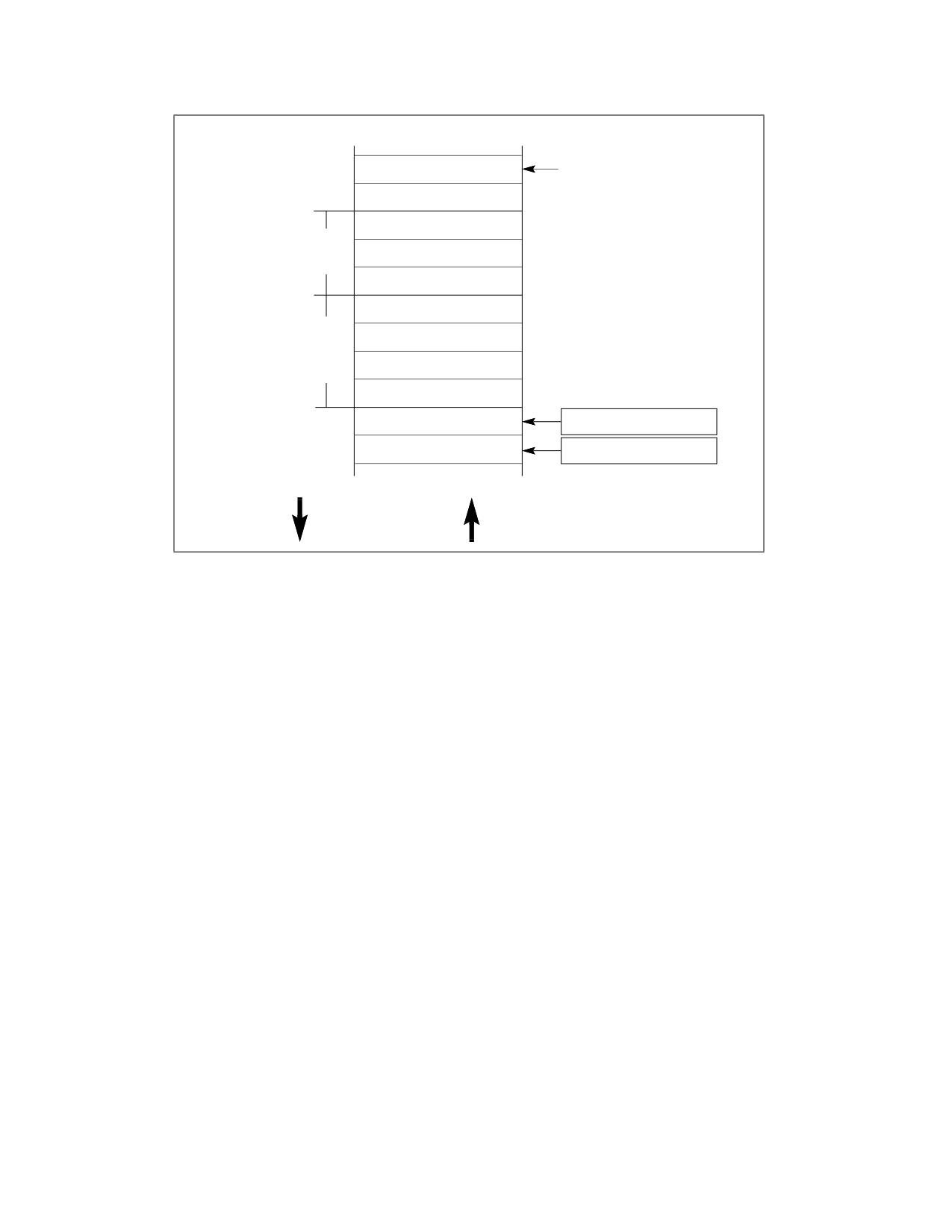
PROCEDURE CALLS, INTERRUPTS, AND EXCEPTIONS
Stack Segment
Bottom of Stack
(Initial ESP Value)
Local Variables
for Calling
The Stack Can Be
Procedure
16 or 32 Bits Wide
Parameters
Passed to
The EBP register is
Called
typically set to point
Procedure
to the return
instruction pointer.
Frame Boundary
Return Instruction
EBP Register
Pointer
ESP Register
Top of Stack
Pushes Move the
Pops Move the
Top Of Stack to
Top Of Stack to
Lower Addresses
Higher Addresses
Figure 6-1. Stack Structure
The processor references the SS register automatically for all stack operations. For example, when the ESP register
is used as a memory address, it automatically points to an address in the current stack. Also, the CALL, RET, PUSH,
POP, ENTER, and LEAVE instructions all perform operations on the current stack.
6.2.1
Setting Up a Stack
To set a stack and establish it as the current stack, the program or operating system/executive must do the
following:
1. Establish a stack segment.
2. Load the segment selector for the stack segment into the SS register using a MOV, POP, or LSS instruction.
3. Load the stack pointer for the stack into the ESP register using a MOV, POP, or LSS instruction. The LSS
instruction can be used to load the SS and ESP registers in one operation.
See “Segment Descriptors” in Chapter 3, “Protected-Mode Memory Management,” of the Intel® 64 and IA-32 Archi-
tectures Software Developer’s Manual, Volume 3A, for information on how to set up a segment descriptor and
segment limits for a stack segment.
6.2.2
Stack Alignment
The stack pointer for a stack segment should be aligned on 16-bit (word) or 32-bit (double-word) boundaries,
depending on the width of the stack segment. The D flag in the segment descriptor for the current code segment
sets the stack-segment width (see “Segment Descriptors” in Chapter 3, “Protected-Mode Memory Management,” of
the Intel® 64 and IA-32 Architectures Software Developer’s Manual, Volume 3A). The PUSH and POP instructions
use the D flag to determine how much to decrement or increment the stack pointer on a push or pop operation,
respectively. When the stack width is 16 bits, the stack pointer is incremented or decremented in 16-bit increments;
when the width is 32 bits, the stack pointer is incremented or decremented in 32-bit increments. Pushing a 16-bit
value onto a 32-bit wide stack can result in stack misaligned (that is, the stack pointer is not aligned on a double-
6-2
Vol. 1
PROCEDURE CALLS, INTERRUPTS, AND EXCEPTIONS
word boundary). One exception to this rule is when the contents of a segment register (a 16-bit segment selector)
are pushed onto a 32-bit wide stack. Here, the processor automatically aligns the stack pointer to the next 32-bit
boundary.
The processor does not check stack pointer alignment. It is the responsibility of the programs, tasks, and system
procedures running on the processor to maintain proper alignment of stack pointers. Misaligning a stack pointer
can cause serious performance degradation and in some instances program failures.
6.2.3
Address-Size Attributes for Stack Accesses
Instructions that use the stack implicitly (such as the PUSH and POP instructions) have two address-size attributes
each of either 16 or 32 bits. This is because they always have the implicit address of the top of the stack, and they
may also have an explicit memory address (for example, PUSH Array1[EBX]). The attribute of the explicit address
is determined by the D flag of the current code segment and the presence or absence of the 67H address-size
prefix.
The address-size attribute of the top of the stack determines whether SP or ESP is used for the stack access. Stack
operations with an address-size attribute of 16 use the 16-bit SP stack pointer register and can use a maximum
stack address of FFFFH; stack operations with an address-size attribute of 32 bits use the 32-bit ESP register and
can use a maximum address of FFFFFFFFH. The default address-size attribute for data segments used as stacks is
controlled by the B flag of the segment’s descriptor. When this flag is clear, the default address-size attribute is 16;
when the flag is set, the address-size attribute is 32.
6.2.4
Procedure Linking Information
The processor provides two pointers for linking of procedures: the stack-frame base pointer and the return instruc-
tion pointer. When used in conjunction with a standard software procedure-call technique, these pointers permit
reliable and coherent linking of procedures.
6.2.4.1
Stack-Frame Base Pointer
The stack is typically divided into frames. Each stack frame can then contain local variables, parameters to be
passed to another procedure, and procedure linking information. The stack-frame base pointer (contained in the
EBP register) identifies a fixed reference point within the stack frame for the called procedure. To use the stack-
frame base pointer, the called procedure typically copies the contents of the ESP register into the EBP register prior
to pushing any local variables on the stack. The stack-frame base pointer then permits easy access to data struc-
tures passed on the stack, to the return instruction pointer, and to local variables added to the stack by the called
procedure.
Like the ESP register, the EBP register automatically points to an address in the current stack segment (that is, the
segment specified by the current contents of the SS register).
6.2.4.2
Return Instruction Pointer
Prior to branching to the first instruction of the called procedure, the CALL instruction pushes the address in the EIP
register onto the current stack. This address is then called the return-instruction pointer and it points to the
instruction where execution of the calling procedure should resume following a return from the called procedure.
Upon returning from a called procedure, the RET instruction pops the return-instruction pointer from the stack back
into the EIP register. Execution of the calling procedure then resumes.
The processor does not keep track of the location of the return-instruction pointer. It is thus up to the programmer
to ensure that stack pointer is pointing to the return-instruction pointer on the stack, prior to issuing a RET instruc-
tion. A common way to reset the stack pointer to the point to the return-instruction pointer is to move the contents
of the EBP register into the ESP register. If the EBP register is loaded with the stack pointer immediately following
a procedure call, it should point to the return instruction pointer on the stack.
The processor does not require that the return instruction pointer point back to the calling procedure. Prior to
executing the RET instruction, the return instruction pointer can be manipulated in software to point to any address
Vol. 1
6-3
PROCEDURE CALLS, INTERRUPTS, AND EXCEPTIONS
in the current code segment (near return) or another code segment (far return). Performing such an operation,
however, should be undertaken very cautiously, using only well defined code entry points.
6.2.5
Stack Behavior in 64-Bit Mode
In 64-bit mode, address calculations that reference SS segments are treated as if the segment base is zero. Fields
(base, limit, and attribute) in segment descriptor registers are ignored. SS DPL is modified such that it is always
equal to CPL. This will be true even if it is the only field in the SS descriptor that is modified.
Registers E(SP), E(IP) and E(BP) are promoted to 64-bits and are re-named RSP, RIP, and RBP respectively. Some
forms of segment load instructions are invalid (for example, LDS, POP ES).
PUSH/POP instructions increment/decrement the stack using a 64-bit width. When the contents of a segment
register is pushed onto 64-bit stack, the pointer is automatically aligned to 64 bits (as with a stack that has a 32-
bit width).
6.3
SHADOW STACKS
A shadow stack is a second stack used exclusively for control transfer operations. This stack is separate from the
procedure stack. The shadow stack is not used to store data, hence is not explicitly writeable by software. Writes
to the shadow stack are restricted to control transfer instructions and shadow stack management instructions.
Shadow stacks can be enabled separately for privilege level 3 (user mode) or privilege levels less than 3 (super-
visor mode).
Shadow stacks are active only in protected mode with paging enabled. Shadow stacks cannot be enabled for a
program executing in virtual 8086 mode.
Processors that support shadow stacks have an architectural register called the shadow stack pointer (SSP) that
points to the current top of the shadow stack. The SSP cannot be directly encoded as a source, destination, or
memory operand in instructions. The width of the shadow stack is 32-bit in 32-bit/compatibility mode, and is 64-
bit in 64-bit mode. The address-size attribute of the shadow stack is likewise 32-bit in 32-bit/compatibility mode,
and 64-bit in 64-bit mode.
The size of the shadow stack pushes and pops for far CALL and call to interrupt/exception handlers is fixed at 64
bits, and the processor uses 8-byte, zero padded stores for these pushes in 32-bit/compatibility modes.
6.4
CALLING PROCEDURES USING CALL AND RET
The CALL instruction allows control transfers to procedures within the current code segment (near call) and in a
different code segment (far call). Near calls usually provide access to local procedures within the currently running
program or task. Far calls are usually used to access operating system procedures or procedures in a different task.
See “CALL-Call Procedure” in Chapter 3, “Instruction Set Reference, A-L,” of the Intel® 64 and IA-32 Architectures
Software Developer’s Manual, Volume 2A, for a detailed description of the CALL instruction.
The RET instruction also allows near and far returns to match the near and far versions of the CALL instruction. In
addition, the RET instruction allows a program to increment the stack pointer on a return to release parameters
from the stack. The number of bytes released from the stack is determined by an optional argument (n) to the RET
instruction. See “RET-Return from Procedure” in Chapter 4, “Instruction Set Reference, M-U,” of the Intel® 64 and
IA-32 Architectures Software Developer’s Manual, Volume 2B, for a detailed description of the RET instruction.
6.4.1
Near CALL and RET Operation
When executing a near call, the processor does the following (see Figure 6-2):
1. Pushes the current value of the EIP register on the stack.
If shadow stack is enabled and the displacement value is not 0, pushes the current value of the EIP register on
the shadow stack.
6-4
Vol. 1
PROCEDURE CALLS, INTERRUPTS, AND EXCEPTIONS
2. Loads the offset of the called procedure in the EIP register.
3. Begins execution of the called procedure.
When executing a near return, the processor performs these actions:
1. Pops the top-of-stack value (the return instruction pointer) into the EIP register.
If shadow stack is enabled, pops the top-of-stack (the return instruction pointer) value from the shadow stack
and if it’s not the same as the return instruction pointer popped from the stack, then the processor causes a
control protection exception with error code NEAR-RET (#CP(NEAR-RET)).
2. If the RET instruction has an optional n argument, increments the stack pointer by the number of bytes
specified with the n operand to release parameters from the stack.
3. Resumes execution of the calling procedure.
6.4.2
Far CALL and RET Operation
When executing a far call, the processor performs these actions (see Figure 6-2):
1. Pushes the current value of the CS register on the stack.
If shadow stack is enabled:
a. Temporarily saves the current value of the SSP register internally and aligns the SSP to the next 8 byte
boundary.
b. Pushes the current value of the CS register on the shadow stack.
c. Pushes the current value of LIP (CS.base + EIP) on the shadow stack.
d. Pushes the internally saved value of the SSP register on the shadow stack.
2. Pushes the current value of the EIP register on the stack.
3. Loads the segment selector of the segment that contains the called procedure in the CS register.
4. Loads the offset of the called procedure in the EIP register.
5. Begins execution of the called procedure.
When executing a far return, the processor does the following:
1. Pops the top-of-stack value (the return instruction pointer) into the EIP register.
2. Pops the top-of-stack value (the segment selector for the code segment being returned to) into the CS register.
If shadow stack is enabled:
a. Causes a control protection exception (#CP(FAR-RET/IRET)) if the SSP is not aligned to 8 bytes.
b. Compares the values on the shadow stack at address SSP+8 (the LIP) and SSP+16 (the CS) to the CS and
(CS.base + EIP) popped from the stack, and causes a control protection exception (#CP(FAR-RET/IRET)) if
they do not match.
c. Pops the top-of-stack value (the SSP of the procedure being returned to) from shadow stack into the SSP
register.
3. If the RET instruction has an optional n argument, increments the stack pointer by the number of bytes
specified with the n operand to release parameters from the stack.
4. Resumes execution of the calling procedure.
Vol. 1
6-5
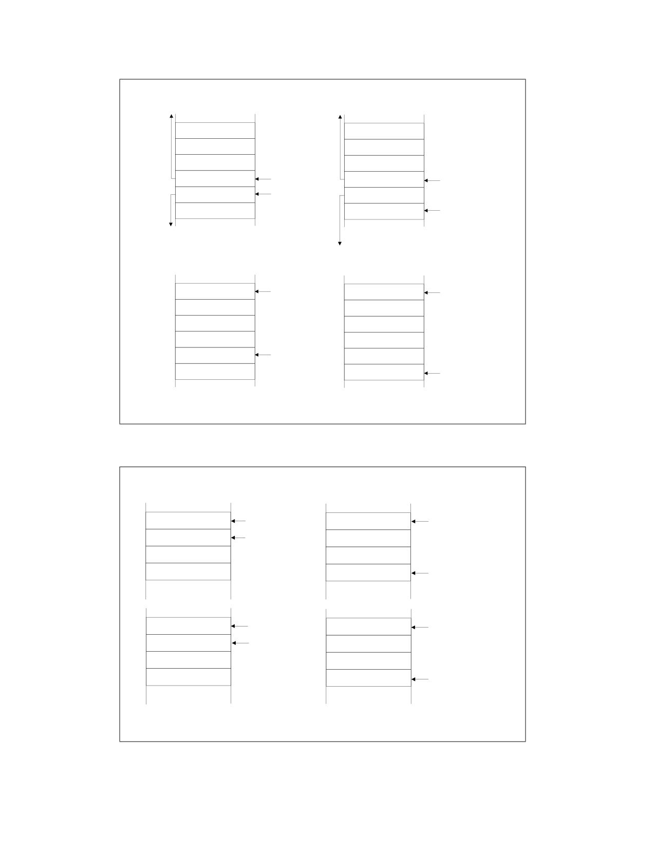
PROCEDURE CALLS, INTERRUPTS, AND EXCEPTIONS
Stack During
Stack During
Near Call
Far Call
Stack
Frame
Param 1
Before
Param 1
Call
Param 2
Param 2
Param 3
ESP Before Call
Param 3
ESP Before Call
Calling EIP
ESP After Call
Calling CS
Stack
Frame
Stack
Calling EIP
ESP After Call
After
Frame
Call
After
Call
Stack During
Stack During
Near Return
Far Return
ESP After Return
ESP After Return
Param 1
Param 1
Param 2
Param 2
Param 3
Param 3
Calling EIP
ESP Before Return
Calling CS
Calling EIP
ESP Before Return
Note: On a near or far return, parameters are released from the stack based
on the optional n operand in the RET n instruction.
Figure 6-2. Stack on Near and Far Calls
Shadow Stack
Shadow Stack
During Near Call
During Far Call
SSP Before Call
SSP Before Call
Calling EIP
SSP After Call
Calling CS
Calling LIP
Calling SSP
SSP After Call
SSP After Return
SSP After Return
Calling EIP
SSP Before Return
Calling CS
Calling LIP
Calling SSP
SSP Before Return
Note: There are no parameters on the shadow stack. RET and RET n operate identically on
the shadow stack.
Figure 6-3. Shadow Stack on Near and Far Calls
6-6
Vol. 1
PROCEDURE CALLS, INTERRUPTS, AND EXCEPTIONS
6.4.3
Parameter Passing
Parameters can be passed between procedures in any of three ways: through general-purpose registers, in an
argument list, or on the stack.
6.4.3.1
Passing Parameters Through the General-Purpose Registers
The processor does not save the state of the general-purpose registers on procedure calls. A calling procedure can
thus pass up to six parameters to the called procedure by copying the parameters into any of these registers
(except the ESP and EBP registers) prior to executing the CALL instruction. The called procedure can likewise pass
parameters back to the calling procedure through general-purpose registers.
6.4.3.2
Passing Parameters on the Stack
To pass a large number of parameters to the called procedure, the parameters can be placed on the stack, in the
stack frame for the calling procedure. Here, it is useful to use the stack-frame base pointer (in the EBP register) to
make a frame boundary for easy access to the parameters.
The stack can also be used to pass parameters back from the called procedure to the calling procedure.
6.4.3.3
Passing Parameters in an Argument List
An alternate method of passing a larger number of parameters (or a data structure) to the called procedure is to
place the parameters in an argument list in one of the data segments in memory. A pointer to the argument list can
then be passed to the called procedure through a general-purpose register or the stack. Parameters can also be
passed back to the calling procedure in this same manner.
6.4.4
Saving Procedure State Information
The processor does not save the contents of the general-purpose registers, segment registers, or the EFLAGS
register on a procedure call. A calling procedure should explicitly save the values in any of the general-purpose
registers that it will need when it resumes execution after a return. These values can be saved on the stack or in
memory in one of the data segments.
The PUSHA and POPA instructions facilitate saving and restoring the contents of the general-purpose registers.
PUSHA pushes the values in all the general-purpose registers on the stack in the following order: EAX, ECX, EDX,
EBX, ESP (the value prior to executing the PUSHA instruction), EBP, ESI, and EDI. The POPA instruction pops all the
register values saved with a PUSHA instruction (except the ESP value) from the stack to their respective registers.
If a called procedure changes the state of any of the segment registers explicitly, it should restore them to their
former values before executing a return to the calling procedure.
If a calling procedure needs to maintain the state of the EFLAGS register, it can save and restore all or part of the
register using the PUSHF/PUSHFD and POPF/POPFD instructions. The PUSHF instruction pushes the lower word of
the EFLAGS register on the stack, while the PUSHFD instruction pushes the entire register. The POPF instruction
pops a word from the stack into the lower word of the EFLAGS register, while the POPFD instruction pops a double
word from the stack into the register.
6.4.5
Calls to Other Privilege Levels
The IA-32 architecture’s protection mechanism recognizes four privilege levels, numbered from 0 to 3, where a
greater number mean less privilege. The reason to use privilege levels is to improve the reliability of operating
systems. For example, Figure 6-4 shows how privilege levels can be interpreted as rings of protection.
Vol. 1
6-7
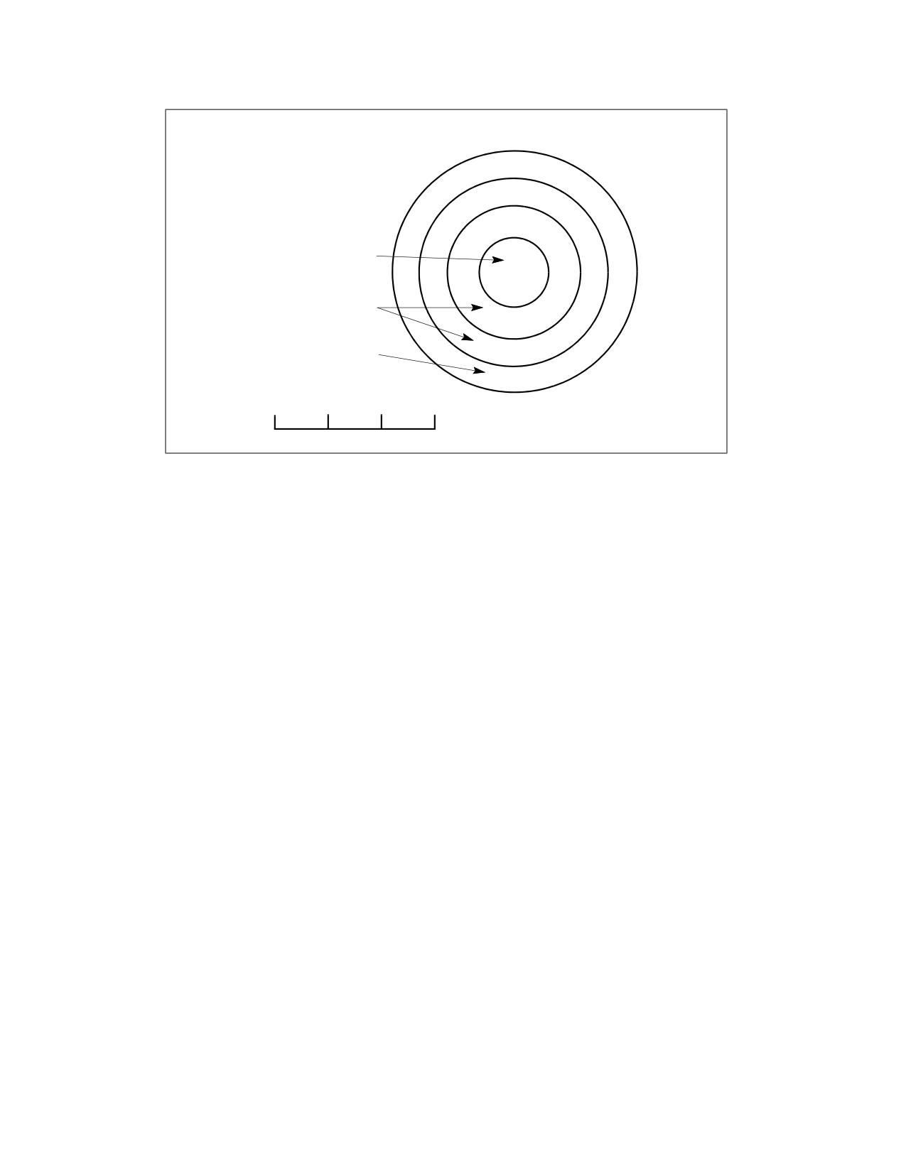
PROCEDURE CALLS, INTERRUPTS, AND EXCEPTIONS
Protection Rings
Operating
System
Kernel
Level 0
Operating System
Services (Device
Drivers, Etc.)
Level 1
Applications
Level 2
Level 3
Highest
Lowest
0
1
2
3
Privilege Levels
Figure 6-4. Protection Rings
In this example, the highest privilege level 0 (at the center of the diagram) is used for segments that contain the
most critical code modules in the system, usually the kernel of an operating system. The outer rings (with progres-
sively lower privileges) are used for segments that contain code modules for less critical software.
Code modules in lower privilege segments can only access modules operating at higher privilege segments by
means of a tightly controlled and protected interface called a gate. Attempts to access higher privilege segments
without going through a protection gate and without having sufficient access rights causes a general-protection
exception (#GP) to be generated.
If an operating system or executive uses this multilevel protection mechanism, a call to a procedure that is in a
more privileged protection level than the calling procedure is handled in a similar manner as a far call (see Section
6.4.2, “Far CALL and RET Operation”). The differences are as follows:
• The segment selector provided in the CALL instruction references a special data structure called a call gate
descriptor. Among other things, the call gate descriptor provides the following:
- Access rights information.
- The segment selector for the code segment of the called procedure.
- An offset into the code segment (that is, the instruction pointer for the called procedure).
• The processor switches to a new stack to execute the called procedure. Each privilege level has its own stack.
The segment selector and stack pointer for the privilege level 3 stack are stored in the SS and ESP registers,
respectively, and are automatically saved when a call to a more privileged level occurs. The segment selectors
and stack pointers for the privilege level 2, 1, and 0 stacks are stored in a system segment called the task state
segment (TSS).
The use of a call gate and the TSS during a stack switch are transparent to the calling procedure, except when a
general-protection exception is raised.
Flexible return and event delivery (FRED) defines new mechanisms for changing privilege levels. See Chapter 8,
“Flexible Return and Event Delivery (FRED)‚” in the Intel® 64 and IA-32 Architectures Software Developer’s
Manual, Volume 3. When FRED transitions are enabled, call gates cannot be used to change privilege level. An
execution of CALL causes a general-protection exception (#GP) if it accesses a call gate. Similarly, an execution of
RET causes a #GP if it would change privilege level. In any of these cases, the fault identifies the relevant selector
in its error code.
6-8
Vol. 1
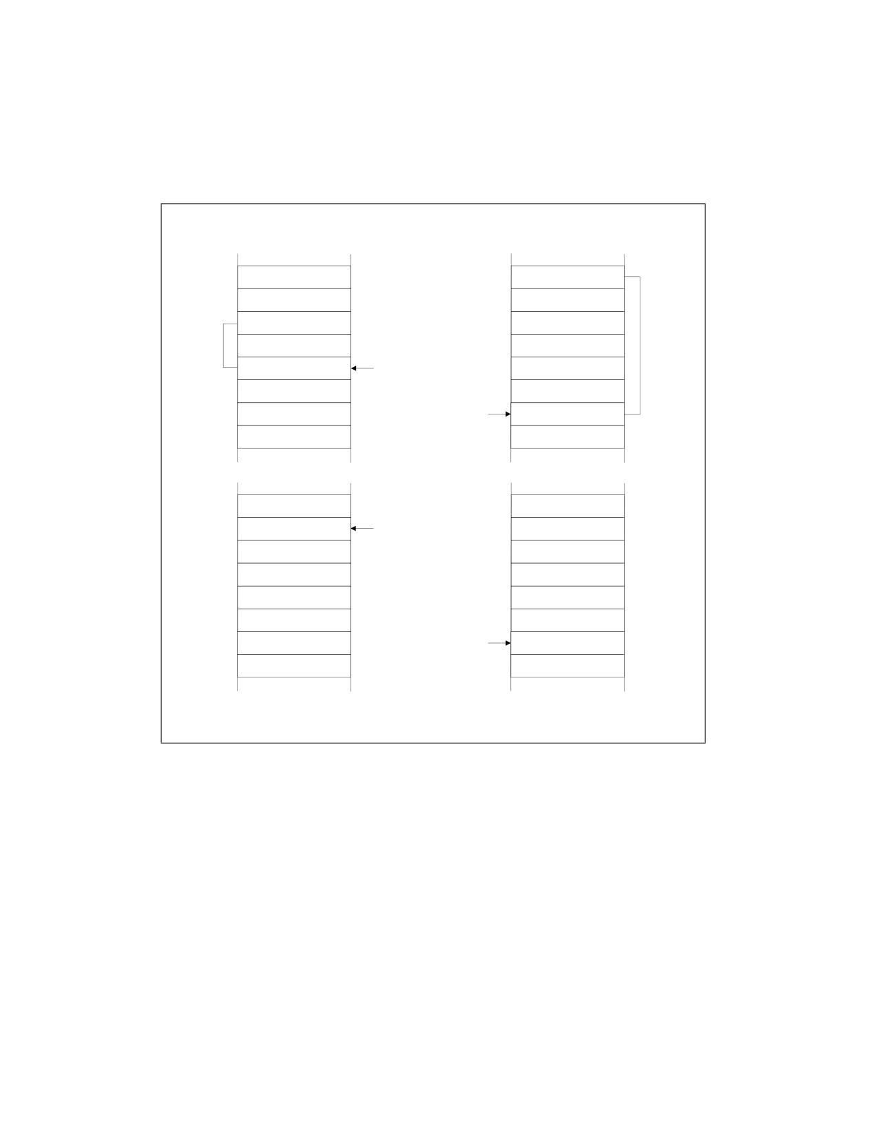
PROCEDURE CALLS, INTERRUPTS, AND EXCEPTIONS
6.4.6
CALL and RET Operation Between Privilege Levels
When making a call to a more privileged protection level, the processor does the following (see Figure 6-5):
1. Performs an access rights check (privilege check).
2. Temporarily saves (internally) the current contents of the SS, ESP, CS, and EIP registers.
Stack for Calling
Stack for Called
Procedure
Procedure
Calling SS
Calling ESP
Param 1
Param 1
Stack
Stack
Frame
Param 2
Param 2
Frame
Before Call
After Call
Param 3
ESP Before Call
Param 3
Calling CS
ESP After Call
Calling EIP
Calling SS
ESP After Return
Calling ESP
Param 1
Param 1
Param 2
Param 2
Param 3
Param 3
Calling CS
ESP
Before Return
Calling EIP
Note: On a return, parameters are released on both stacks based on the optional n
operand in the RET n instruction.
Figure 6-5. Stack Switch on a Call to a Different Privilege Level
Vol. 1
6-9
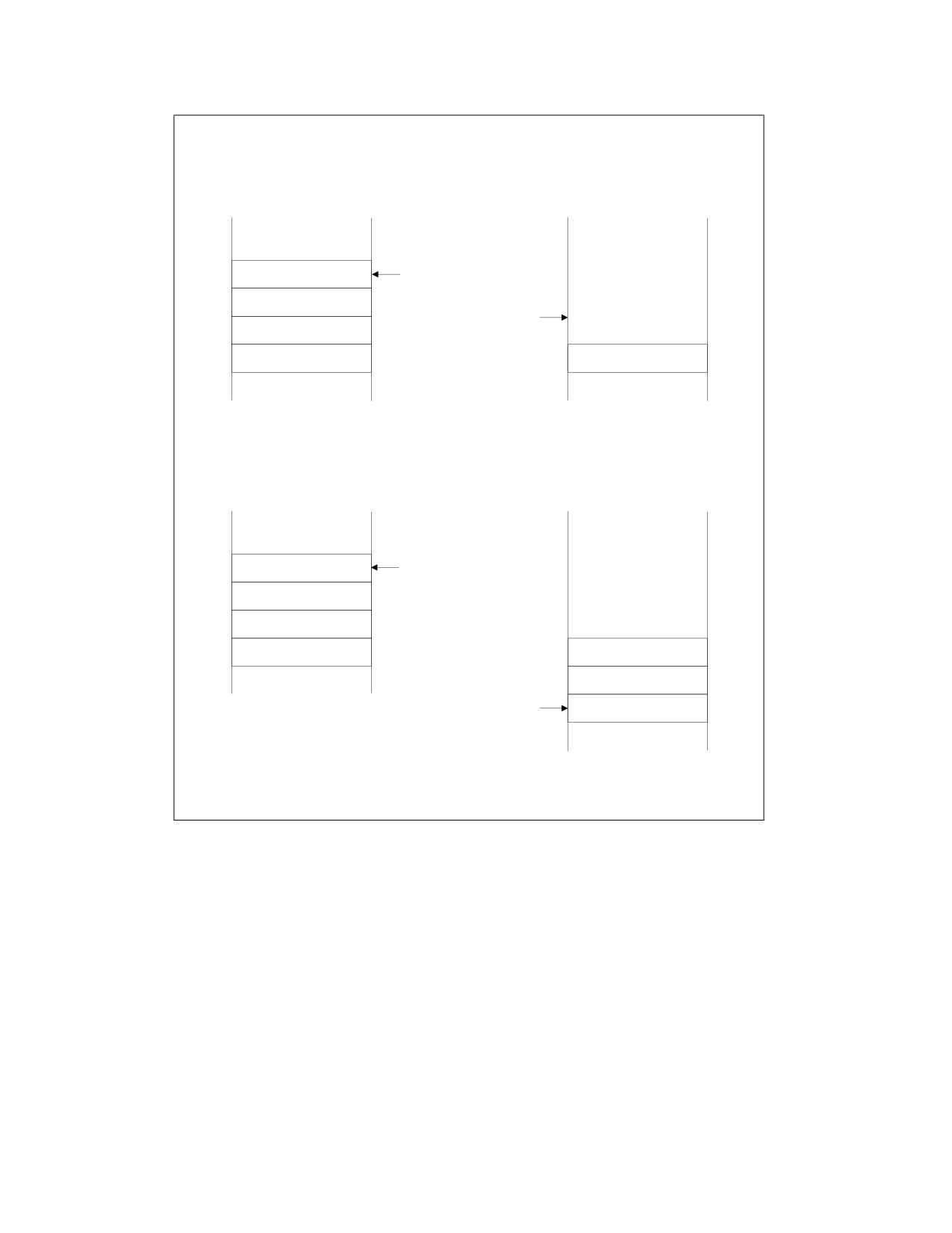
PROCEDURE CALLS, INTERRUPTS, AND EXCEPTIONS
Calling to Procedure at Higher Privilege Level from Privilege Level 3
Shadow Stack for
Handler’s Shadow
Calling Procedure
Stack
SSP Before Call
Supervisor
and After Return
Shadow Stack
Token
SSP After Call and
Before Return
Calling to Procedure at Higher Privilege Level from Privilege Level 2 or 1
Interrupted Procedure’s
Handler’s Shadow
Shadow Stack
Stack
SSP Before Call
Supervisor
and After Return
Shadow Stack
Token
CS
LIP
SSP After Call and
SSP
Before Return
Note: There are no parameters on the shadow stack. RET and RET n operate
identically on the shadow stack.
Figure 6-6. Shadow Stack Switch on a Call to a Different Privilege Level
3. Loads the segment selector and stack pointer for the new stack (that is, the stack for the privilege level being
called) from the TSS into the SS and ESP registers and switches to the new stack.
4. Pushes the temporarily saved SS and ESP values for the calling procedure’s stack onto the new stack.
5. Copies the parameters from the calling procedure’s stack to the new stack. A value in the call gate descriptor
determines how many parameters to copy to the new stack.
6. Pushes the temporarily saved CS and EIP values for the calling procedure to the new stack.
If shadow stack is enabled at the privilege level of the calling procedure, then the processor temporarily saves
the SSP of the calling procedure internally. If the calling procedure is at privilege level 3, the SSP of the calling
procedure is also saved into the IA32_PL3_SSP MSR.
6-10
Vol. 1
PROCEDURE CALLS, INTERRUPTS, AND EXCEPTIONS
If shadow stack is enabled at the privilege level of the called procedure, then the SSP for the called procedure
is obtained from one of the MSRs listed below, depending on the target privilege level. The SSP obtained is then
verified to ensure it points to a valid supervisor shadow stack that is not currently active by verifying a
supervisor shadow stack token at the address pointed to by the SSP. The operations performed to verify and
acquire the supervisor shadow stack token by making it busy are as described in Section 18.2.3 of the Intel®
64 and IA-32 Architectures Software Developer’s Manual, Volume 1.
- IA32_PL2_SSP if transitioning to ring 2.
- IA32_PL1_SSP if transitioning to ring 1.
- IA32_PL0_SSP if transitioning to ring 0.
If shadow stack is enabled at the privilege level of the called procedure and the calling procedure was not at
privilege level 3, then the processor pushes the temporarily saved CS, LIP (CS.base + EIP), and SSP of the
calling procedure to the new shadow stack.1
7. Loads the segment selector for the new code segment and the new instruction pointer from the call gate into
the CS and EIP registers, respectively.
8. Begins execution of the called procedure at the new privilege level.
When executing a return from the privileged procedure, the processor performs these actions:
1. Performs a privilege check.
2. Restores the CS and EIP registers to their values prior to the call.
If shadow stack is enabled at the current privilege level:
- Causes a control protection exception (#CP(FAR-RET/IRET)) if SSP is not aligned to 8 bytes.
- If the privilege level of the procedure being returned to is less than 3 (returning to supervisor mode):
• Compares the values on shadow stack at address SSP+8 (the LIP) and SSP+16 (the CS) to the CS and
(CS.base + EIP) popped from the stack and causes a control protection exception (#CP(FAR-
RET/IRET)) if they do not match.
• Temporarily saves the top-of-stack value (the SSP of the procedure being returned to) internally.
- If a busy supervisor shadow stack token is present at address SSP+24, then marks the token free using
operations described in Section 18.2.3 of the Intel® 64 and IA-32 Architectures Software Developer’s
Manual, Volume 1.
- If the privilege level of the procedure being returned to is less than 3 (returning to supervisor mode), re-
stores the SSP register from the internally saved value.
- If the privilege level of the procedure being returned to is 3 (returning to user mode) and shadow stack is
enabled at privilege level 3, then restores the SSP register with value of IA32_PL3_SSP MSR.
3. If the RET instruction has an optional n argument, increments the stack pointer by the number of bytes
specified with the n operand to release parameters from the stack. If the call gate descriptor specifies that one
or more parameters be copied from one stack to the other, a RET n instruction must be used to release the
parameters from both stacks. Here, the n operand specifies the number of bytes occupied on each stack by the
parameters. On a return, the processor increments ESP by n for each stack to step over (effectively remove)
these parameters from the stacks.
4. Restores the SS and ESP registers to their values prior to the call, which causes a switch back to the stack of
the calling procedure.
5. If the RET instruction has an optional n argument, increments the stack pointer by the number of bytes
specified with the n operand to release parameters from the stack (see explanation in step 3).
6. Resumes execution of the calling procedure.
See Chapter 6, “Protection,” in the Intel® 64 and IA-32 Architectures Software Developer’s Manual, Volume 3A, for
detailed information on calls to privileged levels and the call gate descriptor.
1. If any of these pushes leads to an exception or a VM exit, the supervisor shadow-stack token remains busy.
Vol. 1
6-11
PROCEDURE CALLS, INTERRUPTS, AND EXCEPTIONS
6.4.7
Branch Functions in 64-Bit Mode
The 64-bit extensions expand branching mechanisms to accommodate branches in 64-bit linear-address space.
These are:
• Near-branch semantics are redefined in 64-bit mode.
• In 64-bit mode and compatibility mode, 64-bit call-gate descriptors for far calls are available.
In 64-bit mode, the operand size for all near branches (CALL, RET, JCC, JCXZ, JMP, and LOOP) is forced to 64 bits.
These instructions update the 64-bit RIP without the need for a REX operand-size prefix.
The following aspects of near branches are controlled by the effective operand size:
• Truncation of the size of the instruction pointer.
• Size of a stack pop or push, due to a CALL or RET.
• Size of a stack-pointer increment or decrement, due to a CALL or RET.
• Indirect-branch operand size.
In 64-bit mode, all of the above actions are forced to 64 bits regardless of operand size prefixes (operand size
prefixes are silently ignored). However, the displacement field for relative branches is still limited to 32 bits and the
address size for near branches is not forced in 64-bit mode.
Address sizes affect the size of RCX used for JCXZ and LOOP; they also impact the address calculation for memory
indirect branches. Such addresses are 64 bits by default; but they can be overridden to 32 bits by an address size
prefix.
Software typically uses far branches to change privilege levels. The legacy IA-32 architecture provides the call-gate
mechanism to allow software to branch from one privilege level to another, although call gates can also be used for
branches that do not change privilege levels. When call gates are used, the selector portion of the direct or indirect
pointer references a gate descriptor (the offset in the instruction is ignored). The offset to the destination’s code
segment is taken from the call-gate descriptor.
64-bit mode redefines the type value of a 32-bit call-gate descriptor type to a 64-bit call gate descriptor and
expands the size of the 64-bit descriptor to hold a 64-bit offset. The 64-bit mode call-gate descriptor allows far
branches that reference any location in the supported linear-address space. These call gates also hold the target
code selector (CS), allowing changes to privilege level and default size as a result of the gate transition.
Because immediates are generally specified up to 32 bits, the only way to specify a full 64-bit absolute RIP in 64-
bit mode is with an indirect branch. For this reason, direct far branches are eliminated from the instruction set in
64-bit mode.
64-bit mode also expands the semantics of the SYSENTER and SYSEXIT instructions so that the instructions
operate within a 64-bit memory space. The mode also introduces two new instructions: SYSCALL and SYSRET
(which are valid only in 64-bit mode). For details, see “SYSENTER-Fast System Call,” “SYSEXIT-Fast Return from
Fast System Call,” “SYSCALL-Fast System Call,” and “SYSRET-Return From Fast System Call” in Chapter 4,
“Instruction Set Reference, M-U,” of the Intel® 64 and IA-32 Architectures Software Developer’s Manual, Volume
2B.
6.5
INTERRUPTS AND EXCEPTIONS
The processor provides two mechanisms for interrupting program execution, interrupts, and exceptions:
• An interrupt is an asynchronous event that is typically triggered by an I/O device.
• An exception is a synchronous event that is generated when the processor detects one or more predefined
conditions while executing an instruction. The IA-32 architecture specifies three classes of exceptions: faults,
traps, and aborts.
The processor responds to interrupts and exceptions in essentially the same way. When an interrupt or exception
is signaled, the processor halts execution of the current program or task and switches to a handler procedure that
has been written specifically to handle the interrupt or exception condition. The processor accesses the handler
procedure through an entry in the interrupt descriptor table (IDT) or through FRED event delivery. When the
handler has completed handling the interrupt or exception, program control is returned to the interrupted program
or task.
6-12
Vol. 1

PROCEDURE CALLS, INTERRUPTS, AND EXCEPTIONS
The operating system, executive, and/or device drivers normally handle interrupts and exceptions independently
from application programs or tasks. Application programs can, however, access the interrupt and exception
handlers incorporated in an operating system or executive through assembly-language calls. The remainder of this
section gives a brief overview of the processor’s interrupt and exception handling mechanism. See Chapter 7,
“Interrupt and Exception Handling,” in the Intel® 64 and IA-32 Architectures Software Developer’s Manual, Volume
3A, for a description of this mechanism.
The IA-32 Architecture defines 18 predefined interrupts and exceptions and 224 user defined interrupts, which are
associated with entries in the IDT. Each interrupt and exception in the IDT is identified with a number, called a
vector. Table 6-1 lists the interrupts and exceptions with entries in the IDT and their respective vectors. Vectors 0
through 8, 10 through 14, and 16 through 19 are the predefined interrupts and exceptions; vectors 32 through 255
are for software-defined interrupts, which are for either software interrupts or maskable hardware inter-
rupts.
When FRED transitions are enabled, the processor does not use the IDT. Instead, interrupts and exceptions are
delivered using FRED event delivery. FRED event delivery saves an event’s vector on the stack, along with the
event type (e.g., interrupt or exception). The event type allows software to distinguish interrupts and exceptions
with the same vector.
Note that the processor defines several additional interrupts that do not point to entries in the IDT and are not
delivered using FRED event delivery; the most notable of these interrupts is the SMI interrupt. See Chapter 7,
“Interrupt and Exception Handling,” in the Intel® 64 and IA-32 Architectures Software Developer’s Manual, Volume
3A, for more information about the interrupts and exceptions.
When the processor detects an interrupt or exception, it does one of the following things:
• Executes an implicit call to a handler procedure.
• Executes an implicit call to a handler task.
6.5.1
Call and Return Operation for Interrupt or Exception Handling Procedures
This section describes IDT event delivery, a method for calling OS handlers for interrupts and exceptions. When
FRED transitions are enabled, FRED event delivery is used instead. FRED event delivery is detailed in Section 8.3,
“FRED Event Delivery” in the Intel® 64 and IA-32 Architectures Software Developer’s Manual, Volume 3.
A call to an interrupt or exception handler procedure is similar to a procedure call to another protection level (see
Section 6.4.6, “CALL and RET Operation Between Privilege Levels”). Here, the vector references one of two kinds
of gates in the IDT: an interrupt gate or a trap gate. Interrupt and trap gates are similar to call gates in that they
provide the following information:
• Access rights information
• The segment selector for the code segment that contains the handler procedure
• An offset into the code segment to the first instruction of the handler procedure
The difference between an interrupt gate and a trap gate is as follows. If an interrupt or exception handler is called
through an interrupt gate, the processor clears the interrupt enable (IF) flag in the EFLAGS register to prevent
subsequent interrupts from interfering with the execution of the handler. When a handler is called through a trap
gate, the state of the IF flag is not changed.
Table 6-1. Exceptions and Interrupts
Vector
Mnemonic
Description
Source
0
#DE
Divide Error
DIV and IDIV instructions.
1
#DB
Debug
Any code or data reference.
2
NMI Interrupt
Non-maskable external interrupt.
3
#BP
Breakpoint
INT3 instruction.
4
#OF
Overflow
INTO instruction.
5
#BR
BOUND Range Exceeded
BOUND instruction.
6
#UD
Invalid Opcode (Undefined Opcode)
UD instruction or reserved opcode.
Vol. 1
6-13

PROCEDURE CALLS, INTERRUPTS, AND EXCEPTIONS
Table 6-1. Exceptions and Interrupts (Contd.)
Vector
Mnemonic
Description
Source
7
#NM
Device Not Available (No Math Coprocessor)
Floating-point or WAIT/FWAIT instruction.
8
#DF
Double Fault
Any instruction that can generate an exception, an NMI, or
an INTR.
9
#MF
CoProcessor Segment Overrun (reserved)
Floating-point instruction.1
10
#TS
Invalid TSS
Task switch or TSS access.
11
#NP
Segment Not Present
Loading segment registers or accessing system segments.
12
#SS
Stack Segment Fault
Stack operations and SS register loads.
13
#GP
General Protection
Any memory reference and other protection checks.
14
#PF
Page Fault
Any memory reference.
15
Reserved
16
#MF
Floating-Point Error (Math Fault)
Floating-point or WAIT/FWAIT instruction.
17
#AC
Alignment Check
Any data reference in memory.2
18
#MC
Machine Check
Error codes (if any) and source are model dependent.3
19
#XM
SIMD Floating-Point Exception
SIMD Floating-Point Instruction4
20
#VE
Virtualization Exception
EPT violations5
21
#CP
Control Protection Exception
The RET, IRET, RSTORSSP, and SETSSBSY instructions can
generate this exception. When CET indirect branch tracking
is enabled, this exception can be generated due to a
missing ENDBRANCH instruction at the target of an indirect
call or jump.
22-31
Reserved
32-255
Maskable Interrupts
External interrupt from INTR pin or INT n instruction.
NOTES:
1. IA-32 processors after the Intel386 processor do not generate this exception.
2. This exception was introduced in the Intel486 processor.
3. This exception was introduced in the Pentium processor and enhanced in the P6 family processors.
4. This exception was introduced in the Pentium III processor.
5. This exception can occur only on processors that support the 1-setting of the “EPT-violation #VE” VM-execution control.
If the code segment for the handler procedure has the same privilege level as the currently executing program or
task, the handler procedure uses the current stack; if the handler executes at a more privileged level, the processor
switches to the stack for the handler’s privilege level.
If no stack switch occurs, the processor does the following when calling an interrupt or exception handler (see
Figure 6-7):
1. Pushes the current contents of the EFLAGS, CS, and EIP registers (in that order) on the stack.
If shadow stack is enabled:
a. Temporarily saves the current value of the SSP register internally.
b. Pushes the current value of the CS register on the shadow stack.
c. Pushes the current value of LIP (CS.base + EIP) on the shadow stack.
d. Pushes the temporarily saved SSP value on the shadow stack.
2. Pushes an error code (if appropriate) on the stack.
3. Loads the segment selector for the new code segment and the new instruction pointer (from the interrupt gate
or trap gate) into the CS and EIP registers, respectively.
4. If the call is through an interrupt gate, clears the IF flag in the EFLAGS register.
6-14
Vol. 1
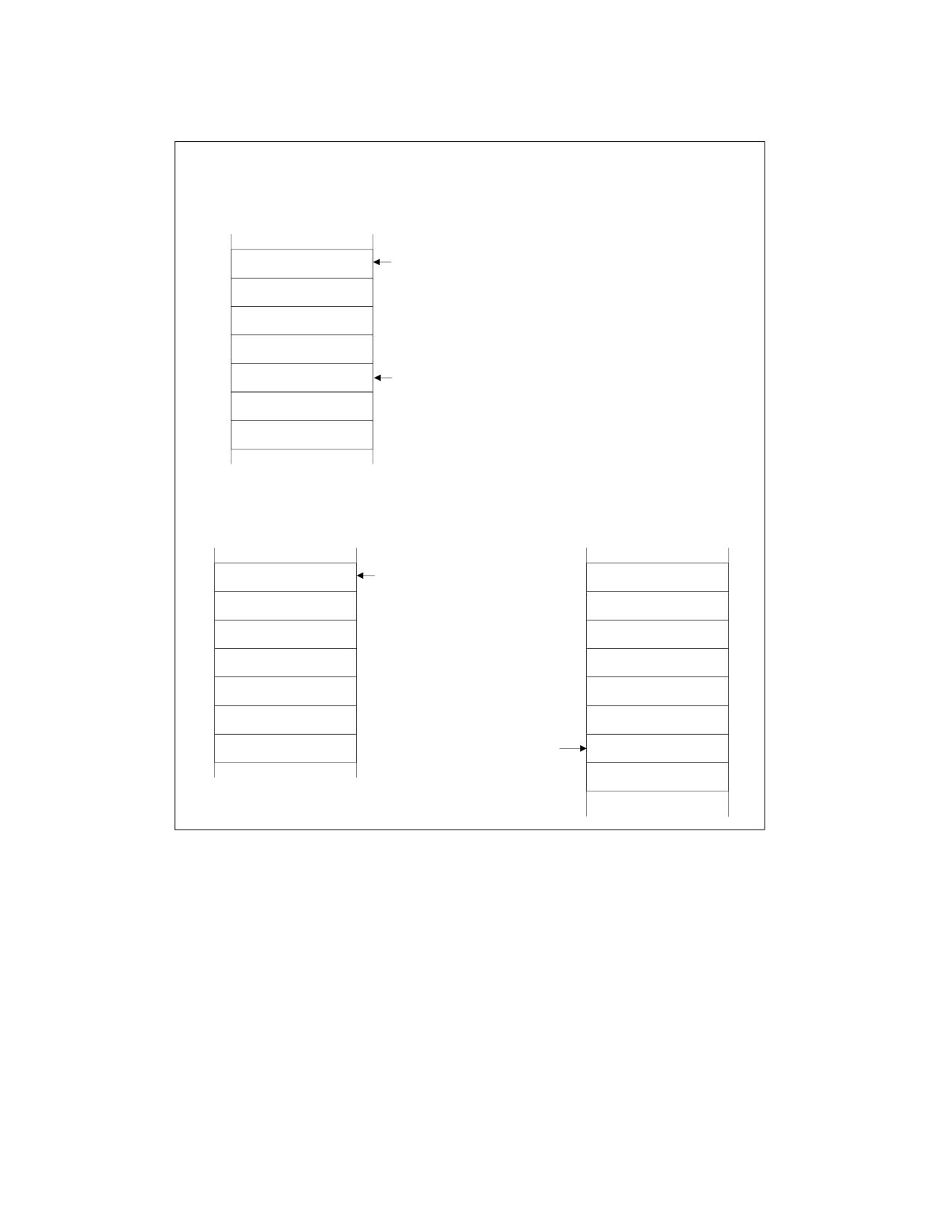
PROCEDURE CALLS, INTERRUPTS, AND EXCEPTIONS
5. Begins execution of the handler procedure.
Stack Usage with No Privilege-Level Change
Interrupted Procedure’s
and Handler’s Stack
ESP Before
Transfer to Handler
EFLAGS
CS
EIP
Error Code
ESP After
Transfer to Handler
Stack Usage with Privilege-Level Change
Interrupted Procedure’s
Handler’s Stack
Stack
ESP Before
Transfer to Handler
SS
ESP
EFLAGS
CS
EIP
ESP After
Error Code
Transfer to Handler
Figure 6-7. Stack Usage on Transfers to Interrupt and Exception Handling Routines
Vol. 1
6-15
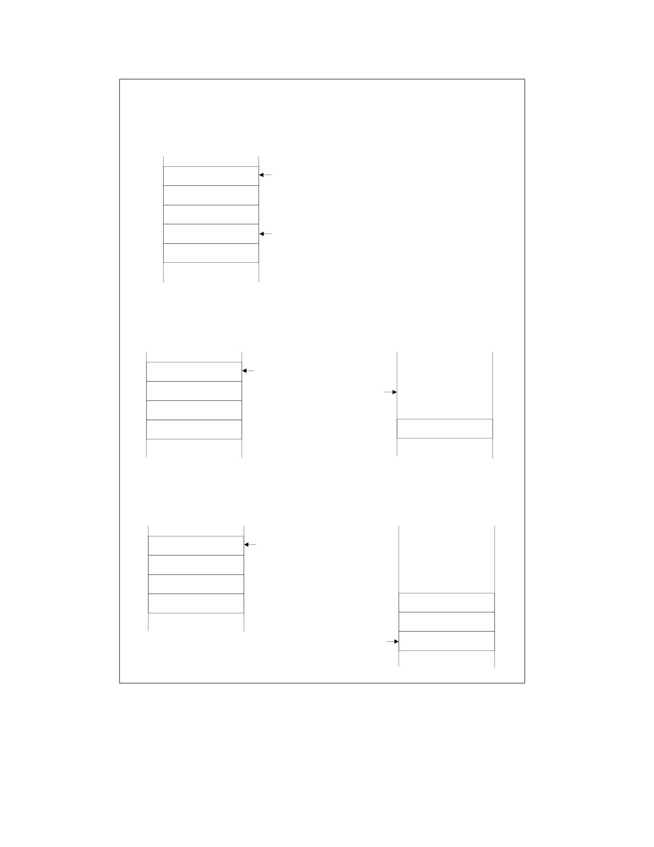
PROCEDURE CALLS, INTERRUPTS, AND EXCEPTIONS
Shadow Stack Usage with No Privilege-Level Change
Interrupted Procedure’s
and Handler’s Shadow Stack
SSP Before
Transfer to Handler
CS
LIP
SSP
SSP After
Transfer to Handler
Shadow Stack Usage with Privilege-Level Change from Level 3
Interrupted Procedure’s
Handler’s Shadow Stack
Shadow Stack
SSP Before
Transfer to Handler
Supervisor
Shadow Stack
SSP After
Token
Transfer to Handler
Shadow Stack Usage with Privilege-Level Change from Level 2 or 1
Interrupted Procedure’s
Handler’s Shadow Stack
Shadow Stack
SSP Before
Transfer to Handler
Supervisor
Shadow Stack
Token
CS
LIP
SSP After
SSP
Transfer to Handler
Figure 6-8. Shadow Stack Usage on Transfers to Interrupt and Exception Handling Routines
6-16
Vol. 1
PROCEDURE CALLS, INTERRUPTS, AND EXCEPTIONS
If a stack switch does occur, the processor does the following:
1. Temporarily saves (internally) the current contents of the SS, ESP, EFLAGS, CS, and EIP registers.
2. Loads the segment selector and stack pointer for the new stack (that is, the stack for the privilege level being
called) from the TSS into the SS and ESP registers and switches to the new stack.
3. Pushes the temporarily saved SS, ESP, EFLAGS, CS, and EIP values for the interrupted procedure’s stack onto
the new stack.
If shadow stack is enabled at the privilege level of the interrupted procedure, then the processor temporarily
saves the SSP of the interrupted procedure internally. If the interrupted procedure is at privilege level 3, the
SSP of the interrupted procedure is also saved into the IA32_PL3_SSP MSR.
If shadow stack is enabled at the privilege level being called, then the SSP for the called privilege level is
obtained from one of the MSRs listed below, depending on the target privilege level. The SSP obtained is then
verified to ensure it points to a valid supervisor shadow stack that is not currently active by verifying a
supervisor shadow stack token at the address pointed to by the SSP. The operations performed to verify and
acquire the supervisor shadow stack token by making it busy are as described in Section 18.2.3 of the Intel®
64 and IA-32 Architectures Software Developer’s Manual, Volume 1.
- IA32_PL2_SSP if transitioning to ring 2.
- IA32_PL1_SSP if transitioning to ring 1.
- IA32_PL0_SSP if transitioning to ring 0.
If shadow stack is enabled at the privilege level being called and the interrupted procedure was not at privilege
level 3, then the processor pushes the temporarily saved CS, LIP (CS.base + EIP), and SSP of the interrupted
procedure to the new shadow stack.1
4. Pushes an error code on the new stack (if appropriate).
5. Loads the segment selector for the new code segment and the new instruction pointer (from the interrupt gate
or trap gate) into the CS and EIP registers, respectively.
6. If the call is through an interrupt gate, clears the IF flag in the EFLAGS register.
7. Begins execution of the handler procedure at the new privilege level.
A return from an interrupt or exception handler is initiated with the IRET instruction. The IRET instruction is similar
to the far RET instruction, except that it also restores the contents of the EFLAGS register for the interrupted proce-
dure. When executing a return from an interrupt or exception handler from the same privilege level as the inter-
rupted procedure, the processor performs these actions:
1. Restores the CS and EIP registers to their values prior to the interrupt or exception.
If shadow stack is enabled:
a. Compares the values on the shadow stack at address SSP+8 (the LIP) and SSP+16 (the CS) to the CS and
(CS.base + EIP) popped from the stack, and causes a control protection exception (#CP(FAR-RET/IRET)) if
they do not match.
b. Pops the top-of-stack value (the SSP prior to the interrupt or exception) from the shadow stack into the SSP
register.
2. Restores the EFLAGS register.
3. Increments the stack pointer appropriately.
4. Resumes execution of the interrupted procedure.
When executing a return from an interrupt or exception handler from a different privilege level than the interrupted
procedure, the processor performs these actions:
1. Performs a privilege check.
2. Restores the CS and EIP registers to their values prior to the interrupt or exception.
3. Restores the EFLAGS register.
1. If any of these pushes leads to an exception or a VM exit, the supervisor shadow-stack token remains busy.
Vol. 1
6-17
PROCEDURE CALLS, INTERRUPTS, AND EXCEPTIONS
If shadow stack is enabled at the current privilege level:
- If SSP is not aligned to 8 bytes, then causes a control protection exception (#CP(FAR-RET/IRET)).
- If the privilege level of the procedure being returned to is less than 3 (returning to supervisor mode):
• Compares the values on the shadow stack at address SSP+8 (the LIP) and SSP+16 (the CS) to the CS
and (CS.base + EIP) popped from the stack, and causes a control protection exception (#CP(FAR-
RET/IRET)) if they do not match.
• Temporarily saves the top-of-stack value (the SSP of the procedure being returned to) internally.
- If a busy supervisor shadow stack token is present at address SSP+24, then marks the token free using
operations described in Section 18.2.3 of the Intel® 64 and IA-32 Architectures Software Developer’s
Manual, Volume 1.
- If the privilege level of the procedure being returned to is less than 3 (returning to supervisor mode),
restores the SSP register from the internally saved value.
- If the privilege level of the procedure being returned to is 3 (returning to user mode) and shadow stack is
enabled at privilege level 3, then restores the SSP register with the value of the IA32_PL3_SSP MSR.
4. Restores the SS and ESP registers to their values prior to the interrupt or exception, resulting in a stack switch
back to the stack of the interrupted procedure.
5. Resumes execution of the interrupted procedure.
6.5.2
Calls to Interrupt or Exception Handler Tasks
Interrupt and exception handler routines can also be executed in a separate task. Here, an interrupt or exception
causes a task switch to a handler task. The handler task is given its own address space and (optionally) can execute
at a higher protection level than application programs or tasks.
The switch to the handler task is accomplished with an implicit task call that references a task gate descriptor.
The task gate provides access to the address space for the handler task. As part of the task switch, the processor
saves complete state information for the interrupted program or task. Upon returning from the handler task, the
state of the interrupted program or task is restored and execution continues. See Chapter 7, “Interrupt and Excep-
tion Handling,” in the Intel® 64 and IA-32 Architectures Software Developer’s Manual, Volume 3A, for more infor-
mation on handling interrupts and exceptions through handler tasks.
6.5.3
Interrupt and Exception Handling in Real-Address Mode
When operating in real-address mode, the processor responds to an interrupt or exception with an implicit far call
to an interrupt or exception handler. The processor uses the interrupt or exception vector as an index into an inter-
rupt table. The interrupt table contains instruction pointers to the interrupt and exception handler procedures.
The processor saves the state of the EFLAGS register, the EIP register, the CS register, and an optional error code
on the stack before switching to the handler procedure.
A return from the interrupt or exception handler is carried out with the IRET instruction.
See Chapter 23, “8086 Emulation,” in the Intel® 64 and IA-32 Architectures Software Developer’s Manual, Volume
3B, for more information on handling interrupts and exceptions in real-address mode.
6.5.4
INT n, INTO, INT3, INT1, and BOUND Instructions
The INT n, INTO, INT3, and BOUND instructions allow a program or task to explicitly call an interrupt or exception
handler. The INT n instruction (opcode CD) uses a vector as an argument, which allows a program to call any inter-
rupt handler.
The INTO instruction (opcode CE) explicitly calls the overflow exception (#OF) handler if the overflow flag (OF) in
the EFLAGS register is set. The OF flag indicates overflow on arithmetic instructions, but it does not automatically
raise an overflow exception. An overflow exception can only be raised explicitly in either of the following ways:
6-18
Vol. 1
PROCEDURE CALLS, INTERRUPTS, AND EXCEPTIONS
• Execute the INTO instruction.
• Test the OF flag and execute the INT n instruction with an argument of 4 (the vector of the overflow exception)
if the flag is set.
Both the methods of dealing with overflow conditions allow a program to test for overflow at specific places in the
instruction stream.
The INT3 instruction (opcode CC) explicitly calls the breakpoint exception (#BP) handler. Similarly, the INT1
instruction (opcode F1) explicitly calls the debug exception (#DB) handler.1
The BOUND instruction explicitly calls the BOUND-range exceeded exception (#BR) handler if an operand is found
to be not within predefined boundaries in memory. This instruction is provided for checking references to arrays
and other data structures. Like the overflow exception, the BOUND-range exceeded exception can only be raised
explicitly with the BOUND instruction or the INT n instruction with an argument of 5 (the vector of the bounds-
check exception). The processor does not implicitly perform bounds checks and raise the BOUND-range exceeded
exception.
6.5.5
Handling Floating-Point Exceptions
When operating on individual or packed floating-point values, the IA-32 architecture supports a set of six floating-
point exceptions. These exceptions can be generated during operations performed by the x87 FPU instructions or
by SSE/SSE2/SSE3 instructions. When an x87 FPU instruction (including the FISTTP instruction in SSE3) generates
one or more of these exceptions, it in turn generates floating-point error exception (#MF); when an
SSE/SSE2/SSE3 instruction generates a floating-point exception, it in turn generates SIMD floating-point excep-
tion (#XM).
See the following sections for further descriptions of the floating-point exceptions, how they are generated, and
how they are handled:
• Section 4.9.1, “Floating-Point Exception Conditions,” and Section 4.9.3, “Typical Actions of a Floating-Point
Exception Handler.”
• Section 8.4, “x87 FPU Floating-Point Exception Handling,” and Section 8.5, “x87 FPU Floating-Point Exception
Conditions.”
• Section 11.5.1, “SIMD Floating-Point Exceptions.”
• Interrupt Behavior.
6.5.6
Interrupt and Exception Behavior in 64-Bit Mode
64-bit extensions expand the legacy IA-32 interrupt-processing and exception-processing mechanism to allow
support for 64-bit operating systems and applications. Changes include:
• All interrupt handlers pointed to by the IDT are 64-bit code (does not apply to the SMI handler).
• The size of interrupt-stack pushes is fixed at 64 bits. The processor uses 8-byte, zero extended stores.
• The stack pointer (SS:RSP) is pushed unconditionally on interrupts. In legacy environments, this push is
conditional and based on a change in current privilege level (CPL).
• The new SS is set to NULL if there is a change in CPL.
• IRET behavior changes.
• There is a new interrupt stack-switch mechanism and a new interrupt shadow stack-switch mechanism.
• The alignment of interrupt stack frame is different.
The above items apply to IDT event delivery. When FRED transitions are enabled, FRED event delivery is used
instead. See Section 8.3, “FRED Event Delivery” in the Intel® 64 and IA-32 Architectures Software Developer’s
Manual, Volume 3.
1. Hardware vendors may use the INT1 instruction for hardware debug. For that reason, Intel recommends software vendors instead
use the INT3 instruction for software breakpoints.
Vol. 1
6-19
PROCEDURE CALLS, INTERRUPTS, AND EXCEPTIONS
6.6
PROCEDURE CALLS FOR BLOCK-STRUCTURED LANGUAGES
The IA-32 architecture supports an alternate method of performing procedure calls with the ENTER (enter proce-
dure) and LEAVE (leave procedure) instructions. These instructions automatically create and release, respectively,
stack frames for called procedures. The stack frames have predefined spaces for local variables and the necessary
pointers to allow coherent returns from called procedures. They also allow scope rules to be implemented so that
procedures can access their own local variables and some number of other variables located in other stack frames.
ENTER and LEAVE offer two benefits:
• They provide machine-language support for implementing block-structured languages, such as C and Pascal.
• They simplify procedure entry and exit in compiler-generated code.
6.6.1
ENTER Instruction
The ENTER instruction creates a stack frame compatible with the scope rules typically used in block-structured
languages. In block-structured languages, the scope of a procedure is the set of variables to which it has access.
The rules for scope vary among languages. They may be based on the nesting of procedures, the division of the
program into separately compiled files, or some other modularization scheme.
ENTER has two operands. The first specifies the number of bytes to be reserved on the stack for dynamic storage
for the procedure being called. Dynamic storage is the memory allocated for variables created when the procedure
is called, also known as automatic variables. The second parameter is the lexical nesting level (from 0 to 31) of the
procedure. The nesting level is the depth of a procedure in a hierarchy of procedure calls. The lexical level is unre-
lated to either the protection privilege level or to the I/O privilege level of the currently running program or task.
ENTER, in the following example, allocates 2 Kbytes of dynamic storage on the stack and sets up pointers to two
previous stack frames in the stack frame for this procedure:
ENTER 2048,3
The lexical nesting level determines the number of stack frame pointers to copy into the new stack frame from the
preceding frame. A stack frame pointer is a doubleword used to access the variables of a procedure. The set of
stack frame pointers used by a procedure to access the variables of other procedures is called the display. The first
doubleword in the display is a pointer to the previous stack frame. This pointer is used by a LEAVE instruction to
undo the effect of an ENTER instruction by discarding the current stack frame.
After the ENTER instruction creates the display for a procedure, it allocates the dynamic local variables for the
procedure by decrementing the contents of the ESP register by the number of bytes specified in the first parameter.
This new value in the ESP register serves as the initial top-of-stack for all PUSH and POP operations within the
procedure.
To allow a procedure to address its display, the ENTER instruction leaves the EBP register pointing to the first
doubleword in the display. Because stacks grow down, this is actually the doubleword with the highest address in
the display. Data manipulation instructions that specify the EBP register as a base register automatically address
locations within the stack segment instead of the data segment.
The ENTER instruction can be used in two ways: nested and non-nested. If the lexical level is 0, the non-nested
form is used. The non-nested form pushes the contents of the EBP register on the stack, copies the contents of the
ESP register into the EBP register, and subtracts the first operand from the contents of the ESP register to allocate
dynamic storage. The non-nested form differs from the nested form in that no stack frame pointers are copied. The
nested form of the ENTER instruction occurs when the second parameter (lexical level) is not zero.
The following pseudo code shows the formal definition of the ENTER instruction. STORAGE is the number of bytes
of dynamic storage to allocate for local variables, and LEVEL is the lexical nesting level.
6-20
Vol. 1

PROCEDURE CALLS, INTERRUPTS, AND EXCEPTIONS
PUSH EBP;
FRAME_PTR := ESP;
IF LEVEL > 0
THEN
DO (LEVEL - 1) times
EBP := EBP - 4;
PUSH Pointer(EBP); (* doubleword pointed to by EBP *)
OD;
PUSH FRAME_PTR;
FI;
EBP := FRAME_PTR;
ESP := ESP - STORAGE;
The main procedure (in which all other procedures are nested) operates at the highest lexical level, level 1. The
first procedure it calls operates at the next deeper lexical level, level 2. A level 2 procedure can access the variables
of the main program, which are at fixed locations specified by the compiler. In the case of level 1, the ENTER
instruction allocates only the requested dynamic storage on the stack because there is no previous display to copy.
A procedure that calls another procedure at a lower lexical level gives the called procedure access to the variables
of the caller. The ENTER instruction provides this access by placing a pointer to the calling procedure's stack frame
in the display.
A procedure that calls another procedure at the same lexical level should not give access to its variables. In this
case, the ENTER instruction copies only that part of the display from the calling procedure which refers to previ-
ously nested procedures operating at higher lexical levels. The new stack frame does not include the pointer for
addressing the calling procedure’s stack frame.
The ENTER instruction treats a re-entrant procedure as a call to a procedure at the same lexical level. In this case,
each succeeding iteration of the re-entrant procedure can address only its own variables and the variables of the
procedures within which it is nested. A re-entrant procedure always can address its own variables; it does not
require pointers to the stack frames of previous iterations.
By copying only the stack frame pointers of procedures at higher lexical levels, the ENTER instruction makes
certain that procedures access only those variables of higher lexical levels, not those at parallel lexical levels (see
Figure 6-9).
Main (Lexical Level 1)
Procedure A (Lexical Level 2)
Procedure B (Lexical Level 3)
Procedure C (Lexical Level 3)
Procedure D (Lexical Level 4)
Figure 6-9. Nested Procedures
Block-structured languages can use the lexical levels defined by ENTER to control access to the variables of nested
procedures. In Figure 6-9, for example, if procedure A calls procedure B which, in turn, calls procedure C, then
procedure C will have access to the variables of the MAIN procedure and procedure A, but not those of procedure
B because they are at the same lexical level. The following definition describes the access to variables for the
nested procedures in Figure 6-9.
1. MAIN has variables at fixed locations.
2. Procedure A can access only the variables of MAIN.
Vol. 1
6-21
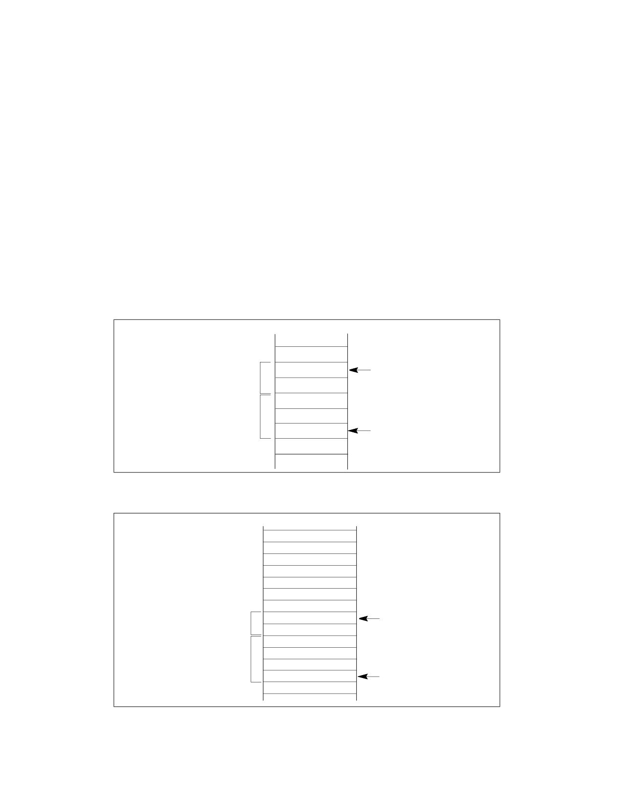
PROCEDURE CALLS, INTERRUPTS, AND EXCEPTIONS
3. Procedure B can access only the variables of procedure A and MAIN. Procedure B cannot access the variables of
procedure C or procedure D.
4. Procedure C can access only the variables of procedure A and MAIN. Procedure C cannot access the variables of
procedure B or procedure D.
5. Procedure D can access the variables of procedure C, procedure A, and MAIN. Procedure D cannot access the
variables of procedure B.
In Figure 6-10, an ENTER instruction at the beginning of the MAIN procedure creates three doublewords of dynamic
storage for MAIN, but copies no pointers from other stack frames. The first doubleword in the display holds a copy
of the last value in the EBP register before the ENTER instruction was executed. The second doubleword holds a
copy of the contents of the EBP register following the ENTER instruction. After the instruction is executed, the EBP
register points to the first doubleword pushed on the stack, and the ESP register points to the last doubleword in
the stack frame.
When MAIN calls procedure A, the ENTER instruction creates a new display (see Figure 6-11). The first doubleword
is the last value held in MAIN's EBP register. The second doubleword is a pointer to MAIN's stack frame which is
copied from the second doubleword in MAIN's display. This happens to be another copy of the last value held in
MAIN’s EBP register. Procedure A can access variables in MAIN because MAIN is at level 1.
Therefore the base address for the dynamic storage used in MAIN is the current address in the EBP register, plus
four bytes to account for the saved contents of MAIN’s EBP register. All dynamic variables for MAIN are at fixed,
positive offsets from this value.
EBP
Old EBP
Display
Main’s EBP
Dynamic
Storage
ESP
Figure 6-10. Stack Frame After Entering the MAIN Procedure
Old EBP
Main’s EBP
Main’s EBP
EBP
Display
Main’s EBP
Procedure A’s EBP
Dynamic
Storage
ESP
Figure 6-11. Stack Frame After Entering Procedure A
6-22
Vol. 1
PROCEDURE CALLS, INTERRUPTS, AND EXCEPTIONS
When procedure A calls procedure B, the ENTER instruction creates a new display (see Figure 6-12). The first
doubleword holds a copy of the last value in procedure A’s EBP register. The second and third doublewords are
copies of the two stack frame pointers in procedure A’s display. Procedure B can access variables in procedure A
and MAIN by using the stack frame pointers in its display.
When procedure B calls procedure C, the ENTER instruction creates a new display for procedure C (see
Figure 6-13). The first doubleword holds a copy of the last value in procedure B’s EBP register. This is used by the
LEAVE instruction to restore procedure B’s stack frame. The second and third doublewords are copies of the two
stack frame pointers in procedure A’s display. If procedure C were at the next deeper lexical level from procedure
B, a fourth doubleword would be copied, which would be the stack frame pointer to procedure B’s local variables.
Note that procedure B and procedure C are at the same level, so procedure C is not intended to access procedure
B’s variables. This does not mean that procedure C is completely isolated from procedure B; procedure C is called
by procedure B, so the pointer to the returning stack frame is a pointer to procedure B’s stack frame. In addition,
procedure B can pass parameters to procedure C either on the stack or through variables global to both procedures
(that is, variables in the scope of both procedures).
Old EBP
Main’s EBP
Main’s EBP
Main’s EBP
Procedure A’s EBP
Procedure A’s EBP
EBP
Main’s EBP
Display
Procedure A’s EBP
Procedure B’s EBP
Dynamic
Storage
ESP
Figure 6-12. Stack Frame After Entering Procedure B
Vol. 1
6-23
PROCEDURE CALLS, INTERRUPTS, AND EXCEPTIONS
Old EBP
Main’s EBP
Main’s EBP
Main’s EBP
Procedure A’s EBP
Procedure A’s EBP
Main’s EBP
Procedure A’s EBP
Procedure B’s EBP
Procedure B’s EBP
EBP
Main’s EBP
Display
Procedure A’s EBP
Procedure C’s EBP
Dynamic
Storage
ESP
Figure 6-13. Stack Frame After Entering Procedure C
6.6.2
LEAVE Instruction
The LEAVE instruction, which does not have any operands, reverses the action of the previous ENTER instruction.
The LEAVE instruction copies the contents of the EBP register into the ESP register to release all stack space allo-
cated to the procedure. Then it restores the old value of the EBP register from the stack. This simultaneously
restores the ESP register to its original value. A subsequent RET instruction then can remove any arguments and
the return address pushed on the stack by the calling program for use by the procedure.
6-24
Vol. 1
CHAPTER 7
PROGRAMMING WITH
GENERAL-PURPOSE INSTRUCTIONS
General-purpose (GP) instructions are a subset of the IA-32 instructions that represent the fundamental instruction
set for the Intel IA-32 processors. These instructions were introduced into the IA-32 architecture with the first IA-
32 processors (the Intel 8086 and 8088). Additional instructions were added to the general-purpose instruction set
in subsequent families of IA-32 processors (the Intel 286, Intel386, Intel486, Pentium, Pentium Pro, and Pentium
II processors).
Intel 64 architecture further extends the capability of most general-purpose instructions so that they are able to
handle 64-bit data in 64-bit mode. A small number of general-purpose instructions (still supported in non-64-bit
modes) are not supported in 64-bit mode.
General-purpose instructions perform basic data movement, memory addressing, arithmetic and logical, program
flow control, input/output, and string operations on a set of integer, pointer, and BCD data types. This chapter
provides an overview of the general-purpose instructions. See the Intel® 64 and IA-32 Architectures Software
Developer’s Manual, Volumes 2A, 2B, 2C, & 2D, for detailed descriptions of individual instructions.
7.1
PROGRAMMING ENVIRONMENT FOR GP INSTRUCTIONS
The programming environment for the general-purpose instructions consists of the set of registers and address
space. The environment includes the following items:
• General-purpose registers - Eight 32-bit general-purpose registers (see Section 3.4.1, “General-Purpose
Registers”) are used in non-64-bit modes to address operands in memory. These registers are referenced by
the names EAX, EBX, ECX, EDX, EBP, ESI EDI, and ESP.
• Segment registers - The six 16-bit segment registers contain segment pointers for use in accessing memory
(see Section 3.4.2, “Segment Registers”). These registers are referenced by the names CS, DS, SS, ES, FS, and
GS.
• EFLAGS register - This 32-bit register (see Section 3.4.3, “EFLAGS Register”) is used to provide status and
control for basic arithmetic, compare, and system operations.
• EIP register - This 32-bit register contains the current instruction pointer (see Section 3.5, “Instruction
Pointer”).
General-purpose instructions operate on the following data types. The width of valid data types is dependent on
processor mode (see Chapter 4):
• Bytes, words, doublewords.
• Signed and unsigned byte, word, doubleword integers.
• Near and far pointers.
• Bit fields.
• BCD integers.
7.2
PROGRAMMING ENVIRONMENT FOR GP INSTRUCTIONS IN 64-BIT MODE
The programming environment for the general-purpose instructions in 64-bit mode is similar to that described in
Section 7.1.
• General-purpose registers - In 64-bit mode, sixteen general-purpose registers available. These include the
eight GPRs described in Section 7.1 and eight new GPRs (R8D-R15D). R8D-R15D are available by using a REX
prefix. All sixteen GPRs can be promoted to 64 bits. The 64-bit registers are referenced as RAX, RBX, RCX, RDX,
RBP, RSI, RDI, RSP, and R8-R15 (see Section 3.4.1.1, “General-Purpose Registers in 64-Bit Mode”). Promotion
to 64-bit operand requires REX prefix encodings.
Vol. 1
7-1
PROGRAMMING WITH GENERAL-PURPOSE INSTRUCTIONS
• Segment registers - In 64-bit mode, segmentation is available but it is set up uniquely (see Section 3.4.2.1,
“Segment Registers in 64-Bit Mode”).
• Flags and Status register - When the processor is running in 64-bit mode, EFLAGS becomes the 64-bit
RFLAGS register (see Section 3.4.3, “EFLAGS Register”).
• Instruction Pointer register - In 64-bit mode, the EIP register becomes the 64-bit RIP register (see Section
3.5.1, “Instruction Pointer in 64-Bit Mode”).
General-purpose instructions operate on the following data types in 64-bit mode. The width of valid data types is
dependent on default operand size, address size, or a prefix that overrides the default size:
• Bytes, words, doublewords, quadwords.
• Signed and unsigned byte, word, doubleword, quadword integers.
• Near and far pointers.
• Bit fields.
See also:
• Chapter 3, “Basic Execution Environment,” for more information about IA-32e modes.
• Chapter 2, “Instruction Format,” in the Intel® 64 and IA-32 Architectures Software Developer’s Manual, Volume
2A, for more detailed information about REX prefixes.
• Intel® 64 and IA-32 Architectures Software Developer’s Manual, Volumes 2A, 2B, 2C, & 2D, for a complete
listing of all instructions. This information documents the behavior of individual instructions in the 64-bit mode
context.
7.3
SUMMARY OF GP INSTRUCTIONS
General purpose instructions are divided into the following subgroups:
• Data transfer.
• Binary arithmetic.
• Decimal arithmetic.
• Logical.
• Shift and rotate.
• Bit and byte.
• Control transfer.
• String.
• I/O.
• Enter and Leave.
• Flag control.
• Segment register.
• Miscellaneous.
Each sub-group of general-purpose instructions is discussed in the context of non-64-bit mode operation first.
Changes in 64-bit mode beyond those affected by the use of the REX prefixes are discussed in separate sub-
sections within each subgroup. For a simple list of general-purpose instructions by subgroup, see Chapter 5.
7.3.1
Data Transfer Instructions
The data transfer instructions move bytes, words, doublewords, or quadwords both between memory and the
processor’s registers and between registers. For the purpose of this discussion, these instructions are divided into
subordinate subgroups that provide for:
• General data movement.
7-2
Vol. 1

PROGRAMMING WITH GENERAL-PURPOSE INSTRUCTIONS
• Exchange.
• Stack manipulation.
• Type conversion.
7.3.1.1
General Data Movement Instructions
Move instructions - The MOV (move) and CMOVcc (conditional move) instructions transfer data between
memory and registers or between registers.
The MOV instruction performs basic load data and store data operations between memory and the processor’s
registers and data movement operations between registers. It handles data transfers along the paths listed in Table
7-1. (See “MOV-Move to/from Control Registers” and “MOV-Move to/from Debug Registers” in Chapter 4,
“Instruction Set Reference, M-U,” of the Intel® 64 and IA-32 Architectures Software Developer’s Manual, Volume
2A, for information on moving data to and from the control and debug registers.)
The MOV instruction cannot move data from one memory location to another or from one segment register to
another segment register. Memory-to-memory moves are performed with the MOVS (string move) instruction (see
Section 7.3.9, “String Operations”).
Conditional move instructions - The CMOVcc instructions are a group of instructions that check the state of the
status flags in the EFLAGS register and perform a move operation if the flags are in a specified state. These instruc-
tions can be used to move a 16-bit or 32-bit value from memory to a general-purpose register or from one general-
purpose register to another. The flag state being tested is specified with a condition code (cc) associated with the
instruction. If the condition is not satisfied, a move is not performed and execution continues with the instruction
following the CMOVcc instruction.
Table 7-1. Move Instruction Operations
Type of Data Movement
Source → Destination
From memory to a register
Memory location → General-purpose register
Memory location → Segment register
From a register to memory
General-purpose register → Memory location
Segment register → Memory location
Between registers
General-purpose register → General-purpose register
General-purpose register → Segment register
Segment register → General-purpose register
General-purpose register → Control register
Control register → General-purpose register
General-purpose register → Debug register
Debug register → General-purpose register
Immediate data to a register
Immediate → General-purpose register
Immediate data to memory
Immediate → Memory location
Table 7-2 shows mnemonics for CMOVcc instructions and the conditions being tested for each instruction. The
condition code mnemonics are appended to the letters “CMOV” to form the mnemonics for CMOVcc instructions.
The instructions listed in Table 7-2 as pairs (for example, CMOVA/CMOVNBE) are alternate names for the same
instruction. The assembler provides these alternate names to make it easier to read program listings.
CMOVcc instructions are useful for optimizing small IF constructions. They also help eliminate branching overhead
for IF statements and the possibility of branch mispredictions by the processor.
These conditional move instructions are supported in the P6 family, Pentium 4, and Intel Xeon processors. Software
can check if CMOVcc instructions are supported by checking the processor’s feature information with the CPUID
instruction.
Vol. 1
7-3

PROGRAMMING WITH GENERAL-PURPOSE INSTRUCTIONS
7.3.1.2
Exchange Instructions
The exchange instructions swap the contents of one or more operands and, in some cases, perform additional oper-
ations such as asserting the LOCK signal or modifying flags in the EFLAGS register.
The XCHG (exchange) instruction swaps the contents of two operands. This instruction takes the place of three
MOV instructions and does not require a temporary location to save the contents of one operand location while the
other is being loaded. When a memory operand is used with the XCHG instruction, the processor’s LOCK signal is
automatically asserted. This instruction is thus useful for implementing semaphores or similar data structures for
process synchronization. See “Bus Locking” in Chapter 11, “Multiple-Processor Management,”of the Intel® 64 and
IA-32 Architectures Software Developer’s Manual, Volume 3A, for more information on bus locking.
The BSWAP (byte swap) instruction reverses the byte order in a 32-bit register operand. Bit positions 0 through 7
are exchanged with 24 through 31, and bit positions 8 through 15 are exchanged with 16 through 23. Executing
this instruction twice in a row leaves the register with the same value as before. The BSWAP instruction is useful for
converting between “big-endian” and “little-endian” data formats. This instruction also speeds execution of decimal
arithmetic. (The XCHG instruction can be used to swap the bytes in a word.)
Table 7-2. Conditional Move Instructions
Instruction Mnemonic
Status Flag States
Condition Description
Unsigned Conditional Moves
CMOVA/CMOVNBE
(CF or ZF) = 0
Above/not below or equal
CMOVAE/CMOVNB
CF = 0
Above or equal/not below
CMOVNC
CF = 0
Not carry
CMOVB/CMOVNAE
CF = 1
Below/not above or equal
CMOVC
CF = 1
Carry
CMOVBE/CMOVNA
(CF or ZF) = 1
Below or equal/not above
CMOVE/CMOVZ
ZF = 1
Equal/zero
CMOVNE/CMOVNZ
ZF = 0
Not equal/not zero
CMOVP/CMOVPE
PF = 1
Parity/parity even
CMOVNP/CMOVPO
PF = 0
Not parity/parity odd
Signed Conditional Moves
CMOVGE/CMOVNL
(SF xor OF) = 0
Greater or equal/not less
CMOVL/CMOVNGE
(SF xor OF) = 1
Less/not greater or equal
CMOVLE/CMOVNG
((SF xor OF) or ZF) = 1
Less or equal/not greater
CMOVO
OF = 1
Overflow
CMOVNO
OF = 0
Not overflow
CMOVS
SF = 1
Sign (negative)
CMOVNS
SF = 0
Not sign (non-negative)
The XADD (exchange and add) instruction swaps two operands and then stores the sum of the two operands in the
destination operand. The status flags in the EFLAGS register indicate the result of the addition. This instruction can
be combined with the LOCK prefix (see “LOCK-Assert LOCK# Signal Prefix” in Chapter 3, “Instruction Set Refer-
ence, A-L,” of the Intel® 64 and IA-32 Architectures Software Developer’s Manual, Volume 2A) in a multiprocessing
system to allow multiple processors to execute one DO loop.
The CMPXCHG (compare and exchange) and CMPXCHG8B (compare and exchange 8 bytes) instructions are used
to synchronize operations in systems that use multiple processors. The CMPXCHG instruction requires three oper-
ands: a source operand in a register, another source operand in the EAX register, and a destination operand. If
the values contained in the destination operand and the EAX register are equal, the destination operand is
replaced with the value of the other source operand (the value not in the EAX register). Otherwise, the original
7-4
Vol. 1
PROGRAMMING WITH GENERAL-PURPOSE INSTRUCTIONS
value of the destination operand is loaded in the EAX register. The status flags in the EFLAGS register reflect the
result that would have been obtained by subtracting the destination operand from the value in the EAX register.
The CMPXCHG instruction is commonly used for testing and modifying semaphores. It checks to see if a semaphore
is free. If the semaphore is free, it is marked allocated; otherwise it gets the ID of the current owner. This is all done
in one uninterruptible operation. In a single-processor system, the CMPXCHG instruction eliminates the need to
switch to protection level 0 (to disable interrupts) before executing multiple instructions to test and modify a sema-
phore.
For multiple processor systems, CMPXCHG can be combined with the LOCK prefix to perform the compare and
exchange operation atomically. (See “Locked Atomic Operations” in Chapter 11, “Multiple-Processor Management,”
of the Intel® 64 and IA-32 Architectures Software Developer’s Manual, Volume 3A, for more information on atomic
operations.)
The CMPXCHG8B instruction also requires three operands: a 64-bit value in EDX:EAX, a 64-bit value in ECX:EBX,
and a destination operand in memory. The instruction compares the 64-bit value in the EDX:EAX registers with the
destination operand. If they are equal, the 64-bit value in the ECX:EBX registers is stored in the destination
operand. If the EDX:EAX registers and the destination are not equal, the destination is loaded in the EDX:EAX
registers. The CMPXCHG8B instruction can be combined with the LOCK prefix to perform the operation atomically.
7.3.1.3
Exchange Instructions in 64-Bit Mode
The CMPXCHG16B instruction is available in 64-bit mode only. It is an extension of the functionality provided by
CMPXCHG8B that operates on 128-bits of data.
7.3.1.4
Stack Manipulation Instructions
The PUSH, POP, PUSHA (push all registers), and POPA (pop all registers) instructions move data to and from the
stack. The PUSH instruction decrements the stack pointer (contained in the ESP register), then copies the source
operand to the top of stack (see Figure 7-1). It operates on memory operands, immediate operands, and register
operands (including segment registers). The PUSH instruction is commonly used to place parameters on the stack
before calling a procedure. It can also be used to reserve space on the stack for temporary variables.
Stack
Before Pushing Doubleword
After Pushing Doubleword
Stack
Growth
31
0
31
0
n
ESP
n - 4
Doubleword V
alue
ESP
n - 8
Figure 7-1. Operation of the PUSH Instruction
The PUSHA instruction saves the contents of the eight general-purpose registers on the stack (see Figure 7-2).
This instruction simplifies procedure calls by reducing the number of instructions required to save the contents of
the general-purpose registers. The registers are pushed on the stack in the following order: EAX, ECX, EDX, EBX,
the initial value of ESP before EAX was pushed, EBP, ESI, and EDI.
Vol. 1
7-5
PROGRAMMING WITH GENERAL-PURPOSE INSTRUCTIONS
Stack
Before Pushing Registers
After Pushing Registers
Stack
31
0
31
0
Growth
n
n - 4
ESP
n - 8
EAX
n - 12
ECX
n - 16
EDX
n - 20
EBX
n - 24
Old ESP
n - 28
EBP
n - 32
ESI
n - 36
EDI
ESP
Figure 7-2. Operation of the PUSHA Instruction
The POP instruction copies the word or doubleword at the current top of stack (indicated by the ESP register) to the
location specified with the destination operand. It then increments the ESP register to point to the new top of stack
(see Figure 7-3). The destination operand may specify a general-purpose register, a segment register, or a memory
location.
Stack
Before Popping Doubleword
After Popping Doubleword
Stack
31
0
31
0
Growth
n
n - 4
ESP
n - 8
Doubleword V
alue
ESP
Figure 7-3. Operation of the POP Instruction
The POPA instruction reverses the effect of the PUSHA instruction. It pops the top eight words or doublewords from
the top of the stack into the general-purpose registers, except for the ESP register (see Figure 7-4). If the operand-
size attribute is 32, the doublewords on the stack are transferred to the registers in the following order: EDI, ESI,
EBP, ignore doubleword, EBX, EDX, ECX, and EAX. The ESP register is restored by the action of popping the stack.
If the operand-size attribute is 16, the words on the stack are transferred to the registers in the following order: DI,
SI, BP, ignore word, BX, DX, CX, and AX.
7-6
Vol. 1
PROGRAMMING WITH GENERAL-PURPOSE INSTRUCTIONS
Stack
Before Popping Registers
After Popping Registers
0
31
0
31
Stack
Growth
n
n - 4
ESP
n - 8
EAX
n - 12
ECX
n - 16
EDX
n - 20
EBX
n - 24
Ignored
n - 28
EBP
n - 32
ESI
n - 36
EDI
ESP
Figure 7-4. Operation of the POPA Instruction
7.3.1.5
Stack Manipulation Instructions in 64-Bit Mode
In 64-bit mode, the stack pointer size is 64 bits and cannot be overridden by an instruction prefix. In implicit stack
references, address-size overrides are ignored. Pushes and pops of 32-bit values on the stack are not possible in
64-bit mode. 16-bit pushes and pops are supported by using the 66H operand-size prefix. PUSHA, PUSHAD, POPA,
and POPAD are not supported.
7.3.1.6
Type Conversion Instructions
The type conversion instructions convert bytes into words, words into doublewords, and doublewords into quad-
words. These instructions are especially useful for converting integers to larger integer formats, because they
perform sign extension (see Figure 7-5).
Two kinds of type conversion instructions are provided: simple conversion and move and convert.
15
0
Before Sign
S
N
N
N
N
N
N
N
N
N
N
N
N
N
N
N
Extension
31
15
0
After Sign
S
S
S
S
S
S
S
S
S
S
S
S
S
S
S
S
S
N
N
N
N
N
N
N
N
N
N
N
N
N
N
N
Extension
Figure 7-5. Sign Extension
Simple conversion - The CBW (convert byte to word), CWDE (convert word to doubleword extended), CWD
(convert word to doubleword), and CDQ (convert doubleword to quadword) instructions perform sign extension to
double the size of the source operand.
The CBW instruction copies the sign (bit 7) of the byte in the AL register into every bit position of the upper byte of
the AX register. The CWDE instruction copies the sign (bit 15) of the word in the AX register into every bit position
of the high word of the EAX register.
The CWD instruction copies the sign (bit 15) of the word in the AX register into every bit position in the DX register.
The CDQ instruction copies the sign (bit 31) of the doubleword in the EAX register into every bit position in the EDX
register. The CWD instruction can be used to produce a doubleword dividend from a word before a word division,
and the CDQ instruction can be used to produce a quadword dividend from a doubleword before doubleword divi-
sion.
Vol. 1
7-7
PROGRAMMING WITH GENERAL-PURPOSE INSTRUCTIONS
Move with sign or zero extension - The MOVSX (move with sign extension) and MOVZX (move with zero
extension) instructions move the source operand into a register then perform the sign extension.
The MOVSX instruction extends an 8-bit value to a 16-bit value or an 8-bit or 16-bit value to a 32-bit value by sign
extending the source operand, as shown in Figure 7-5. The MOVZX instruction extends an 8-bit value to a 16-bit
value or an 8-bit or 16-bit value to a 32-bit value by zero extending the source operand.
7.3.1.7
Type Conversion Instructions in 64-Bit Mode
The MOVSXD instruction operates on 64-bit data. It sign-extends a 32-bit value to 64 bits. This instruction is not
encodable in non-64-bit modes.
7.3.2
Binary Arithmetic Instructions
Binary arithmetic instructions operate on 8-, 16-, and 32-bit numeric data encoded as signed or unsigned binary
integers. The binary arithmetic instructions may also be used in algorithms that operate on decimal (BCD) values.
For the purpose of this discussion, these instructions are divided into subordinate subgroups of instructions that:
• Add and subtract.
• Increment and decrement.
• Compare and change signs.
• Multiply and divide.
7.3.2.1
Addition and Subtraction Instructions
The ADD (add integers), ADC (add integers with carry), SUB (subtract integers), and SBB (subtract integers with
borrow) instructions perform addition and subtraction operations on signed or unsigned integer operands.
The ADD instruction computes the sum of two integer operands.
The ADC instruction computes the sum of two integer operands, plus 1 if the CF flag is set. This instruction is used
to propagate a carry when adding numbers in stages.
The SUB instruction computes the difference of two integer operands.
The SBB instruction computes the difference of two integer operands, minus 1 if the CF flag is set. This instruction
is used to propagate a borrow when subtracting numbers in stages.
7.3.2.2
Increment and Decrement Instructions
The INC (increment) and DEC (decrement) instructions add 1 to or subtract 1 from an unsigned integer operand,
respectively. A primary use of these instructions is for implementing counters.
7.3.2.3
Increment and Decrement Instructions in 64-Bit Mode
The INC and DEC instructions are supported in 64-bit mode. However, some forms of INC and DEC (the register
operand being encoded using register extension field in the MOD R/M byte) are not encodable in 64-bit mode
because the opcodes are treated as REX prefixes.
7.3.2.4
Comparison and Sign Change Instructions
The CMP (compare) instruction computes the difference between two integer operands and updates the OF, SF, ZF,
AF, PF, and CF flags according to the result. The source operands are not modified, nor is the result saved. The CMP
instruction is commonly used in conjunction with a Jcc (jump) or SETcc (byte set on condition) instruction, with the
latter instructions performing an action based on the result of a CMP instruction.
The NEG (negate) instruction subtracts a signed integer operand from zero. The effect of the NEG instruction is to
change the sign of a two's complement operand while keeping its magnitude.
7-8
Vol. 1
PROGRAMMING WITH GENERAL-PURPOSE INSTRUCTIONS
7.3.2.5
Multiplication and Division Instructions
The processor provides two multiply instructions, MUL (unsigned multiply) and IMUL (signed multiply), and two
divide instructions, DIV (unsigned divide) and IDIV (signed divide).
The MUL instruction multiplies two unsigned integer operands. The result is computed to twice the size of the
source operands (for example, if word operands are being multiplied, the result is a doubleword).
The IMUL instruction multiplies two signed integer operands. The result is computed to twice the size of the source
operands; however, in some cases the result is truncated to the size of the source operands (see “IMUL-Signed
Multiply” in Chapter 3, “Instruction Set Reference, A-L,” of the Intel® 64 and IA-32 Architectures Software Devel-
oper’s Manual, Volume 2A).
The DIV instruction divides one unsigned operand by another unsigned operand and returns a quotient and a
remainder.
The IDIV instruction is identical to the DIV instruction, except that IDIV performs a signed division.
7.3.3
Decimal Arithmetic Instructions
Decimal arithmetic can be performed by combining the binary arithmetic instructions ADD, SUB, MUL, and DIV
(discussed in Section 7.3.2, “Binary Arithmetic Instructions”) with the decimal arithmetic instructions. The decimal
arithmetic instructions are provided to carry out the following operations:
• To adjust the results of a previous binary arithmetic operation to produce a valid BCD result.
• To adjust the operands of a subsequent binary arithmetic operation so that the operation will produce a valid
BCD result.
These instructions operate on both packed and unpacked BCD values. For the purpose of this discussion, the
decimal arithmetic instructions are divided into subordinate subgroups of instructions that provide:
• Packed BCD adjustments.
• Unpacked BCD adjustments.
7.3.3.1
Packed BCD Adjustment Instructions
The DAA (decimal adjust after addition) and DAS (decimal adjust after subtraction) instructions adjust the results
of operations performed on packed BCD integers (see Section 4.7, “BCD and Packed BCD Integers”). Adding two
packed BCD values requires two instructions: an ADD instruction followed by a DAA instruction. The ADD instruc-
tion adds (binary addition) the two values and stores the result in the AL register. The DAA instruction then adjusts
the value in the AL register to obtain a valid, 2-digit, packed BCD value and sets the CF flag if a decimal carry
occurred as the result of the addition.
Likewise, subtracting one packed BCD value from another requires a SUB instruction followed by a DAS instruction.
The SUB instruction subtracts (binary subtraction) one BCD value from another and stores the result in the AL
register. The DAS instruction then adjusts the value in the AL register to obtain a valid, 2-digit, packed BCD value
and sets the CF flag if a decimal borrow occurred as the result of the subtraction.
7.3.3.2
Unpacked BCD Adjustment Instructions
The AAA (ASCII adjust after addition), AAS (ASCII adjust after subtraction), AAM (ASCII adjust after multiplica-
tion), and AAD (ASCII adjust before division) instructions adjust the results of arithmetic operations performed
on unpacked BCD values (see Section 4.7, “BCD and Packed BCD Integers”). All these instructions assume that
the value to be adjusted is stored in the AL register or, in one instance, the AL and AH registers.
The AAA instruction adjusts the contents of the AL register following the addition of two unpacked BCD values. It
converts the binary value in the AL register into a decimal value and stores the result in the AL register in unpacked
BCD format (the decimal number is stored in the lower 4 bits of the register and the upper 4 bits are cleared). If a
decimal carry occurred as a result of the addition, the CF flag is set and the contents of the AH register are incre-
mented by 1.
Vol. 1
7-9
PROGRAMMING WITH GENERAL-PURPOSE INSTRUCTIONS
The AAS instruction adjusts the contents of the AL register following the subtraction of two unpacked BCD values.
Here again, a binary value is converted into an unpacked BCD value. If a borrow was required to complete the
decimal subtract, the CF flag is set and the contents of the AH register are decremented by 1.
The AAM instruction adjusts the contents of the AL register following a multiplication of two unpacked BCD values.
It converts the binary value in the AL register into a decimal value and stores the least significant digit of the result
in the AL register (in unpacked BCD format) and the most significant digit, if there is one, in the AH register (also
in unpacked BCD format).
The AAD instruction adjusts a two-digit BCD value so that when the value is divided with the DIV instruction, a valid
unpacked BCD result is obtained. The instruction converts the BCD value in registers AH (most significant digit) and
AL (least significant digit) into a binary value and stores the result in register AL. When the value in AL is divided by
an unpacked BCD value, the quotient and remainder will be automatically encoded in unpacked BCD format.
7.3.4
Decimal Arithmetic Instructions in 64-Bit Mode
Decimal arithmetic instructions are not supported in 64-bit mode, they are either invalid or not encodable.
7.3.5
Logical Instructions
The logical instructions AND, OR, XOR (exclusive or), and NOT perform the standard Boolean operations for which
they are named. The AND, OR, and XOR instructions require two operands; the NOT instruction operates on a
single operand.
7.3.6
Shift and Rotate Instructions
The shift and rotate instructions rearrange the bits within an operand. For the purpose of this discussion, these
instructions are further divided into subordinate subgroups of instructions that:
• Shift bits
• Double-shift bits (move them between operands)
• Rotate bits
7.3.6.1
Shift Instructions
The SAL (shift arithmetic left), SHL (shift logical left), SAR (shift arithmetic right), SHR (shift logical right) instruc-
tions perform an arithmetic or logical shift of the bits in a byte, word, or doubleword.
The SAL and SHL instructions perform the same operation (see Figure 7-6). They shift the source operand left by
from 1 to 31 bit positions. Empty bit positions are cleared. The CF flag is loaded with the last bit shifted out of the
operand.
7-10
Vol. 1
PROGRAMMING WITH GENERAL-PURPOSE INSTRUCTIONS
Initial State
CF
Operand
X
1 0 0 0 1 0 0 0 1 0 0 0 1 0 0 0 1 0 0 0 1 0 0 0 1 0 0 0 1 1 1 1
After 1-bit SHL/SAL Instruction
1
0 0 0 1 0 0 0 1 0 0 0 1 0 0 0 1 0 0 0 1 0 0 0 1 0 0 0 1 1 1 1 0
After 10-bit SHL/SAL Instruction
0
0 0 1 0 0 0 1 0 0 0 1 0 0 0 1 0 0 0 1 1 1 1 0 0 0 0 0 0 0 0 0 0
Figure 7-6. SHL/SAL Instruction Operation
The SHR instruction shifts the source operand right by from 1 to 31 bit positions (see Figure 7-7). As with the
SHL/SAL instruction, the empty bit positions are cleared and the CF flag is loaded with the last bit shifted out of the
operand.
Initial State
Operand
CF
1 0 0 0 1 0 0 0 1 0 0 0 1 0 0 0 1 0 0 0 1 0 0 0 1 0 0 0 1 1 1 1
X
After 1-bit SHR Instruction
0 1 0 0 0 1 0 0 0 1 0 0 0 1 0 0 0 1 0 0 0 1 0 0 0 1 0 0 0 1 1 1
1
After 10-bit SHR Instruction
0 0 0 0 0 0 0 0 0 0 1 0 0 0 1 0 0 0 1 0 0 0 1 0 0 0 1 0 0 0 1 0
0
Figure 7-7. SHR Instruction Operation
The SAR instruction shifts the source operand right by from 1 to 31 bit positions (see Figure 7-8). This instruction
differs from the SHR instruction in that it preserves the sign of the source operand by clearing empty bit positions
if the operand is positive or setting the empty bits if the operand is negative. Again, the CF flag is loaded with the
last bit shifted out of the operand.
The SAR and SHR instructions can also be used to perform division by powers of 2 (see “SAL/SAR/SHL/SHR-Shift
Instructions” in Chapter 4, “Instruction Set Reference, M-U,” of the Intel® 64 and IA-32 Architectures Software
Developer’s Manual, Volume 2B).
Vol. 1
7-11
PROGRAMMING WITH GENERAL-PURPOSE INSTRUCTIONS
Initial State (Positive Operand)
Operand
CF
0 1 0 0 0 1 0 0 0 1 0 0 0 1 0 0 0 1 0 0 0 1 0 0 0 1 0 0 0 1 1 1
X
After 1-bit SAR Instruction
0 0 1 0 0 0 1 0 0 0 1 0 0 0 1 0 0 0 1 0 0 0 1 0 0 0 1 0 0 0 1 1
1
Initial State (Negative Operand)
CF
1 1 0 0 0 1 0 0 0 1 0 0 0 1 0 0 0 1 0 0 0 1 0 0 0 1 0 0 0 1 1 1
X
After 1-bit SAR Instruction
1 1 1 0 0 0 1 0 0 0 1 0 0 0 1 0 0 0 1 0 0 0 1 0 0 0 1 0 0 0 1 1
1
Figure 7-8. SAR Instruction Operation
7.3.6.2
Double-Shift Instructions
The SHLD (shift left double) and SHRD (shift right double) instructions shift a specified number of bits from one
operand to another (see Figure 7-9). They are provided to facilitate operations on unaligned bit strings. They can
also be used to implement a variety of bit string move operations.
SHLD Instruction
31
0
CF
Destination (Memory or Register)
31
0
Source (Register)
SHRD Instruction
31
0
Source (Register)
31
0
Destination (Memory or Register)
CF
Figure 7-9. SHLD and SHRD Instruction Operations
The SHLD instruction shifts the bits in the destination operand to the left and fills the empty bit positions (in the
destination operand) with bits shifted out of the source operand. The destination and source operands must be the
same length (either words or doublewords). The shift count can range from 0 to 31 bits. The result of this shift
operation is stored in the destination operand, and the source operand is not modified. The CF flag is loaded with
the last bit shifted out of the destination operand.
The SHRD instruction operates the same as the SHLD instruction except bits are shifted to the right in the destina-
tion operand, with the empty bit positions filled with bits shifted out of the source operand.
7-12
Vol. 1
PROGRAMMING WITH GENERAL-PURPOSE INSTRUCTIONS
7.3.6.3
Rotate Instructions
The ROL (rotate left), ROR (rotate right), RCL (rotate through carry left) and RCR (rotate through carry right)
instructions rotate the bits in the destination operand out of one end and back through the other end (see
Figure 7-10). Unlike a shift, no bits are lost during a rotation. The rotate count can range from 0 to 31.
ROL Instruction
31
0
CF
Destination (Memory or Register)
ROR Instruction
31
0
Destination (Memory or Register)
CF
RCL Instruction
31
0
CF
Destination (Memory or Register)
RCR Instruction
31
0
Destination (Memory or Register)
CF
Figure 7-10. ROL, ROR, RCL, and RCR Instruction Operations
The ROL instruction rotates the bits in the operand to the left (toward more significant bit locations). The ROR
instruction rotates the operand right (toward less significant bit locations).
The RCL instruction rotates the bits in the operand to the left, through the CF flag. This instruction treats the CF flag
as a one-bit extension on the upper end of the operand. Each bit that exits from the most significant bit location of
the operand moves into the CF flag. At the same time, the bit in the CF flag enters the least significant bit location
of the operand.
The RCR instruction rotates the bits in the operand to the right through the CF flag.
For all the rotate instructions, the CF flag always contains the value of the last bit rotated out of the operand, even
if the instruction does not use the CF flag as an extension of the operand. The value of this flag can then be tested
by a conditional jump instruction (JC or JNC).
7.3.7
Bit and Byte Instructions
These instructions operate on bit or byte strings. For the purpose of this discussion, they are further divided into
subordinate subgroups that:
• Test and modify a single bit.
• Scan a bit string.
• Set a byte given conditions.
• Test operands and report results.
Vol. 1
7-13

PROGRAMMING WITH GENERAL-PURPOSE INSTRUCTIONS
7.3.7.1
Bit Test and Modify Instructions
The bit test and modify instructions (see Table 7-3) operate on a single bit, which can be in an operand. The loca-
tion of the bit is specified as an offset from the least significant bit of the operand. When the processor identifies
the bit to be tested and modified, it first loads the CF flag with the current value of the bit. Then it assigns a new
value to the selected bit, as determined by the modify operation for the instruction.
Table 7-3. Bit Test and Modify Instructions
Instruction
Effect on CF Flag
Effect on Selected Bit
BT (Bit Test)
CF flag ← Selected Bit
No effect
BTS (Bit Test and Set)
CF flag ← Selected Bit
Selected Bit ← 1
BTR (Bit Test and Reset)
CF flag ← Selected Bit
Selected Bit ← 0
BTC (Bit Test and Complement)
CF flag ← Selected Bit
Selected Bit ← NOT (Selected Bit)
7.3.7.2
Bit Scan Instructions
The BSF (bit scan forward) and BSR (bit scan reverse) instructions scan a bit string in a source operand for a set bit
and store the bit index of the first set bit found in a destination register. The bit index is the offset from the least
significant bit (bit 0) in the bit string to the first set bit. The BSF instruction scans the source operand low-to-high
(from bit 0 of the source operand toward the most significant bit); the BSR instruction scans high-to-low (from the
most significant bit toward the least significant bit).
7.3.7.3
Byte Set on Condition Instructions
The SETcc (set byte on condition) instructions set a destination-operand byte to 0 or 1, depending on the state of
selected status flags (CF, OF, SF, ZF, and PF) in the EFLAGS register. The suffix (cc) added to the SET mnemonic
determines the condition being tested for.
For example, the SETO instruction tests for overflow. If the OF flag is set, the destination byte is set to 1; if OF is
clear, the destination byte is cleared to 0. Appendix B, “EFLAGS Condition Codes,” lists the conditions it is possible
to test for with this instruction.
7.3.7.4
Test Instruction
The TEST instruction performs a logical AND of two operands and sets the SF, ZF, and PF flags according to the
results. The flags can then be tested by the conditional jump or loop instructions or the SETcc instructions. The
TEST instruction differs from the AND instruction in that it does not alter either of the operands.
7.3.8
Control Transfer Instructions
The processor provides both conditional and unconditional control transfer instructions to direct the flow of
program execution. Conditional transfers are taken only for specified states of the status flags in the EFLAGS
register. Unconditional control transfers are always executed.
For the purpose of this discussion, these instructions are further divided into subordinate subgroups that process:
• Unconditional transfers.
• Conditional transfers.
• Software interrupts.
7.3.8.1
Unconditional Transfer Instructions
The JMP, CALL, RET, INT, and IRET instructions transfer program control to another location (destination address)
in the instruction stream. The destination can be within the same code segment (near transfer) or in a different
code segment (far transfer).
7-14
Vol. 1
PROGRAMMING WITH GENERAL-PURPOSE INSTRUCTIONS
Jump instruction - The JMP (jump) instruction unconditionally transfers program control to a destination
instruction. The transfer is one-way; that is, a return address is not saved. A destination operand specifies the
address (the instruction pointer) of the destination instruction. The address can be a relative address or an
absolute address.
A relative address is a displacement (offset) with respect to the address in the EIP register. The destination
address (a near pointer) is formed by adding the displacement to the address in the EIP register. The displacement
is specified with a signed integer, allowing jumps either forward or backward in the instruction stream.
An absolute address is a offset from address 0 of a segment. It can be specified in either of the following ways:
• An address in a general-purpose register - This address is treated as a near pointer, which is copied into
the EIP register. Program execution then continues at the new address within the current code segment.
• An address specified using the standard addressing modes of the processor - Here, the address can
be a near pointer or a far pointer. If the address is for a near pointer, the address is translated into an offset and
copied into the EIP register. If the address is for a far pointer, the address is translated into a segment selector
(which is copied into the CS register) and an offset (which is copied into the EIP register).
In protected mode, the JMP instruction also allows jumps to a call gate, a task gate, and a task-state segment.
Call and return instructions - The CALL (call procedure) and RET (return from procedure) instructions allow a
jump from one procedure (or subroutine) to another and a subsequent jump back (return) to the calling procedure.
The CALL instruction transfers program control from the current (or calling) procedure to another procedure (the
called procedure). To allow a subsequent return to the calling procedure, the CALL instruction saves the current
contents of the EIP register on the stack before jumping to the called procedure. The EIP register (prior to trans-
ferring program control) contains the address of the instruction following the CALL instruction. When this address
is pushed on the stack, it is referred to as the return instruction pointer or return address.
The address of the called procedure (the address of the first instruction in the procedure being jumped to) is spec-
ified in a CALL instruction the same way as it is in a JMP instruction (see “Jump instruction” on page 7-15). The
address can be specified as a relative address or an absolute address. If an absolute address is specified, it can be
either a near or a far pointer.
The RET instruction transfers program control from the procedure currently being executed (the called procedure)
back to the procedure that called it (the calling procedure). Transfer of control is accomplished by copying the
return instruction pointer from the stack into the EIP register. Program execution then continues with the instruc-
tion pointed to by the EIP register.
The RET instruction has an optional operand, the value of which is added to the contents of the ESP register as part
of the return operation. This operand allows the stack pointer to be incremented to remove parameters from the
stack that were pushed on the stack by the calling procedure.
See Section 6.4, “Calling Procedures Using CALL and RET,” for more information on the mechanics of making proce-
dure calls with the CALL and RET instructions.
Return from interrupt instruction - When the processor services an interrupt, it performs an implicit call to an
interrupt-handling procedure. The IRET (return from interrupt) instruction returns program control from an inter-
rupt handler to the interrupted procedure (that is, the procedure that was executing when the interrupt occurred).
The IRET instruction performs a similar operation to the RET instruction (see “Call and return instructions” on page
7-15) except that it also restores the EFLAGS register from the stack. The contents of the EFLAGS register are
automatically stored on the stack along with the return instruction pointer when the processor services an inter-
rupt.
7.3.8.2
Conditional Transfer Instructions
The conditional transfer instructions execute jumps or loops that transfer program control to another instruction in
the instruction stream if specified conditions are met. The conditions for control transfer are specified with a set of
condition codes that define various states of the status flags (CF, ZF, OF, PF, and SF) in the EFLAGS register.
Conditional jump instructions - The Jcc (conditional) jump instructions transfer program control to a destina-
tion instruction if the conditions specified with the condition code (cc) associated with the instruction are satisfied
(see Table 7-4). If the condition is not satisfied, execution continues with the instruction following the Jcc instruc-
tion. As with the JMP instruction, the transfer is one-way; that is, a return address is not saved.
Vol. 1
7-15

PROGRAMMING WITH GENERAL-PURPOSE INSTRUCTIONS
Table 7-4. Conditional Jump Instructions
Instruction Mnemonic
Condition (Flag States)
Description
Unsigned Conditional Jumps
JA/JNBE
(CF or ZF) = 0
Above/not below or equal
JAE/JNB
CF = 0
Above or equal/not below
JB/JNAE
CF = 1
Below/not above or equal
JBE/JNA
(CF or ZF) = 1
Below or equal/not above
JC
CF = 1
Carry
JE/JZ
ZF = 1
Equal/zero
JNC
CF = 0
Not carry
JNE/JNZ
ZF = 0
Not equal/not zero
JNP/JPO
PF = 0
Not parity/parity odd
JP/JPE
PF = 1
Parity/parity even
JCXZ
CX = 0
Register CX is zero
JECXZ
ECX = 0
Register ECX is zero
Signed Conditional Jumps
JG/JNLE
((SF xor OF) or ZF) = 0
Greater/not less or equal
JGE/JNL
(SF xor OF) = 0
Greater or equal/not less
JL/JNGE
(SF xor OF) = 1
Less/not greater or equal
JLE/JNG
((SF xor OF) or ZF) = 1
Less or equal/not greater
JNO
OF = 0
Not overflow
JNS
SF = 0
Not sign (non-negative)
JO
OF = 1
Overflow
JS
SF = 1
Sign (negative)
The destination operand specifies a relative address (a signed offset with respect to the address in the EIP register)
that points to an instruction in the current code segment. The Jcc instructions do not support far transfers;
however, far transfers can be accomplished with a combination of a Jcc and a JMP instruction (see “Jcc-Jump if
Condition Is Met” in Chapter 3, “Instruction Set Reference, A-L,” of the Intel® 64 and IA-32 Architectures Software
Developer’s Manual, Volume 2A).
Table 7-4 shows the mnemonics for the Jcc instructions and the conditions being tested for each instruction. The
condition code mnemonics are appended to the letter “J” to form the mnemonic for a Jcc instruction. The instruc-
tions are divided into two groups: unsigned and signed conditional jumps. These groups correspond to the results
of operations performed on unsigned and signed integers respectively. Those instructions listed as pairs (for
example, JA/JNBE) are alternate names for the same instruction. Assemblers provide alternate names to make it
easier to read program listings.
The JCXZ and JECXZ instructions test the CX and ECX registers, respectively, instead of one or more status flags.
See “Jump if zero instructions” on page 7-17 for more information about these instructions.
Loop instructions - The LOOP, LOOPE (loop while equal), LOOPZ (loop while zero), LOOPNE (loop while not
equal), and LOOPNZ (loop while not zero) instructions are conditional jump instructions that use the value of the
ECX register as a count for the number of times to execute a loop. All the loop instructions decrement the count in
the ECX register each time they are executed and terminate a loop when zero is reached. The LOOPE, LOOPZ,
LOOPNE, and LOOPNZ instructions also accept the ZF flag as a condition for terminating the loop before the count
reaches zero.
The LOOP instruction decrements the contents of the ECX register (or the CX register, if the address-size attribute
is 16), then tests the register for the loop-termination condition. If the count in the ECX register is non-zero,
program control is transferred to the instruction address specified by the destination operand. The destination
7-16
Vol. 1
PROGRAMMING WITH GENERAL-PURPOSE INSTRUCTIONS
operand is a relative address (that is, an offset relative to the contents of the EIP register), and it generally points
to the first instruction in the block of code that is to be executed in the loop. When the count in the ECX register
reaches zero, program control is transferred to the instruction immediately following the LOOP instruction,
which terminates the loop. If the count in the ECX register is zero when the LOOP instruction is first executed, the
register is pre-decremented to FFFFFFFFH, causing the loop to be executed 232 times.
The LOOPE and LOOPZ instructions perform the same operation (they are mnemonics for the same instruction).
These instructions operate the same as the LOOP instruction, except that they also test the ZF flag.
If the count in the ECX register is not zero and the ZF flag is set, program control is transferred to the destination
operand. When the count reaches zero or the ZF flag is clear, the loop is terminated by transferring program control
to the instruction immediately following the LOOPE/LOOPZ instruction.
The LOOPNE and LOOPNZ instructions (mnemonics for the same instruction) operate the same as the
LOOPE/LOOPZ instructions, except that they terminate the loop if the ZF flag is set.
Jump if zero instructions - The JECXZ (jump if ECX zero) instruction jumps to the location specified in the desti-
nation operand if the ECX register contains the value zero. This instruction can be used in combination with a loop
instruction (LOOP, LOOPE, LOOPZ, LOOPNE, or LOOPNZ) to test the ECX register prior to beginning a loop. As
described in “Loop instructions” on page 7-16, the loop instructions decrement the contents of the ECX register
before testing for zero. If the value in the ECX register is zero initially, it will be decremented to FFFFFFFFH on the
first loop instruction, causing the loop to be executed 232 times. To prevent this problem, a JECXZ instruction can
be inserted at the beginning of the code block for the loop, causing a jump out of the loop if the ECX register count
is initially zero. When used with repeated string scan and compare instructions, the JECXZ instruction can deter-
mine whether the loop terminated because the count reached zero or because the scan or compare conditions were
satisfied.
The JCXZ (jump if CX is zero) instruction operates the same as the JECXZ instruction when the 16-bit address-size
attribute is used. Here, the CX register is tested for zero.
7.3.8.3
Control Transfer Instructions in 64-Bit Mode
In 64-bit mode, the operand size for all near branches (CALL, RET, JCC, JCXZ, JMP, and LOOP) is forced to 64 bits.
The listed instructions update the 64-bit RIP without need for a REX operand-size prefix.
Near branches in the following operations are forced to 64-bits (regardless of operand size prefixes):
• Truncation of the size of the instruction pointer.
• Size of a stack pop or push, due to CALL or RET.
• Size of a stack-pointer increment or decrement, due to CALL or RET.
• Indirect-branch operand size.
Note that the displacement field for relative branches is still limited to 32 bits and the address size for near
branches is not forced.
Address size determines the register size (CX/ECX/RCX) used for JCXZ and LOOP. It also impacts the address
calculation for memory indirect branches. Addresses size is 64 bits by default, although it can be over-ridden to 32
bits (using a prefix).
7.3.8.4
Software Interrupt Instructions
The INT n (software interrupt), INTO (interrupt on overflow), and BOUND (detect value out of range) instructions
allow a program to explicitly raise a specified interrupt or exception, which in turn causes the handler routine for
the interrupt or exception to be called.
The INT n instruction can raise any of the processor’s interrupts or exceptions by encoding the vector of the inter-
rupt or exception in the instruction. This instruction can be used to support software generated interrupts or to test
the operation of interrupt and exception handlers.
The IRET (return from interrupt) instruction returns program control from an interrupt handler to the interrupted
procedure. The IRET instruction performs a similar operation to the RET instruction.
Vol. 1
7-17
PROGRAMMING WITH GENERAL-PURPOSE INSTRUCTIONS
The CALL (call procedure) and RET (return from procedure) instructions allow a jump from one procedure to
another and a subsequent return to the calling procedure. EFLAGS register contents are automatically stored on
the stack along with the return instruction pointer when the processor services an interrupt.
The INTO instruction raises the overflow exception if the OF flag is set. If the flag is clear, execution continues
without raising the exception. This instruction allows software to access the overflow exception handler explicitly to
check for overflow conditions.
The BOUND instruction compares a signed value against upper and lower bounds, and raises the “BOUND range
exceeded” exception if the value is less than the lower bound or greater than the upper bound. This instruction is
useful for operations such as checking an array index to make sure it falls within the range defined for the array.
7.3.8.5
Software Interrupt Instructions in 64-Bit Mode and Compatibility Mode
In 64-bit mode, the stack size is 8 bytes wide. IRET must pop 8-byte items off the stack. SS:RSP pops uncondition-
ally. BOUND is not supported.
In compatibility mode, SS:RSP is popped only if the CPL changes.
7.3.9
String Operations
The GP instructions includes a set of string instructions that are designed to access large data structures; these
are introduced in Section 7.3.9.1. Section 7.3.9.2 describes how REP prefixes can be used with these instructions
to perform more complex repeated string operations. Certain processors optimize repeated string operations
with fast-string operation, as described in Section 7.3.9.3. Section 7.3.9.4 explains how string operations can be
used in 64-bit mode.
7.3.9.1
String Instructions
The MOVS (Move String), CMPS (Compare string), SCAS (Scan string), LODS (Load string), and STOS (Store
string) instructions permit large data structures, such as alphanumeric character strings, to be moved and exam-
ined in memory. These instructions operate on individual elements in a string, which can be a byte, word, or
doubleword. The string elements to be operated on are identified with the ESI (source string element) and EDI
(destination string element) registers. Both of these registers contain absolute addresses (offsets into a segment)
that point to a string element.
By default, the ESI register addresses the segment identified with the DS segment register. A segment-override
prefix allows the ESI register to be associated with the CS, SS, ES, FS, or GS segment register. The EDI register
addresses the segment identified with the ES segment register; no segment override is allowed for the EDI register.
The use of two different segment registers in the string instructions permits operations to be performed on strings
located in different segments. Or by associating the ESI register with the ES segment register, both the source and
destination strings can be located in the same segment. (This latter condition can also be achieved by loading the
DS and ES segment registers with the same segment selector and allowing the ESI register to default to the DS
register.)
The MOVS instruction moves the string element addressed by the ESI register to the location addressed by the EDI
register. The assembler recognizes three “short forms” of this instruction, which specify the size of the string to be
moved: MOVSB (move byte string), MOVSW (move word string), and MOVSD (move doubleword string).
The CMPS instruction subtracts the destination string element from the source string element and updates the
status flags (CF, ZF, OF, SF, PF, and AF) in the EFLAGS register according to the results. Neither string element is
written back to memory. The assembler recognizes three “short forms” of the CMPS instruction: CMPSB (compare
byte strings), CMPSW (compare word strings), and CMPSD (compare doubleword strings).
The SCAS instruction subtracts the destination string element from the contents of the EAX, AX, or AL register
(depending on operand length) and updates the status flags according to the results. The string element and
register contents are not modified. The following “short forms” of the SCAS instruction specify the operand length:
SCASB (scan byte string), SCASW (scan word string), and SCASD (scan doubleword string).
The LODS instruction loads the source string element identified by the ESI register into the EAX register (for a
doubleword string), the AX register (for a word string), or the AL register (for a byte string). The “short forms” for
7-18
Vol. 1
PROGRAMMING WITH GENERAL-PURPOSE INSTRUCTIONS
this instruction are LODSB (load byte string), LODSW (load word string), and LODSD (load doubleword string). This
instruction is usually used in a loop, where other instructions process each element of the string after they are
loaded into the target register.
The STOS instruction stores the source string element from the EAX (doubleword string), AX (word string), or AL
(byte string) register into the memory location identified with the EDI register. The “short forms” for this instruction
are STOSB (store byte string), STOSW (store word string), and STOSD (store doubleword string). This instruction
is also normally used in a loop. Here a string is commonly loaded into the register with a LODS instruction, oper-
ated on by other instructions, and then stored again in memory with a STOS instruction.
The I/O instructions (see Section 7.3.10, “I/O Instructions”) also perform operations on strings in memory.
7.3.9.2
Repeated String Operations
Each of the string instructions described in Section 7.3.9.1 perform one iteration of a string operation. To operate
on strings longer than a doubleword, the string instructions can be combined with a repeat prefix (REP) to create a
repeating instruction or be placed in a loop.
When used in string instructions, the ESI and EDI registers are automatically incremented or decremented after
each iteration of an instruction to point to the next element (byte, word, or doubleword) in the string. String oper-
ations can thus begin at higher addresses and work toward lower ones, or they can begin at lower addresses and
work toward higher ones. The DF flag in the EFLAGS register controls whether the registers are incremented (DF =
0) or decremented (DF = 1). The STD and CLD instructions set and clear this flag, respectively.
The following repeat prefixes can be used in conjunction with a count in the ECX register to cause a string instruc-
tion to repeat:
• REP - Repeat while the ECX register not zero.
• REPE/REPZ - Repeat while the ECX register not zero and the ZF flag is set.
• REPNE/REPNZ - Repeat while the ECX register not zero and the ZF flag is clear.
When a string instruction has a repeat prefix, the operation executes until one of the termination conditions spec-
ified by the prefix is satisfied. The REPE/REPZ and REPNE/REPNZ prefixes are used only with the CMPS and SCAS
instructions. Also, note that a REP STOS instruction is the fastest way to initialize a large block of memory.
7.3.9.3
Fast-String Operation
To improve performance, more recent processors support modifications to the processor’s operation during the
string store operations initiated with the MOVS, MOVSB, STOS, and STOSB instructions. This optimized operation,
called fast-string operation, is used when the execution of one of those instructions meets certain initial condi-
tions (see below). Instructions using fast-string operation effectively operate on the string in groups that may
include multiple elements of the native data size (byte, word, doubleword, or quadword). With fast-string opera-
tion, the processor recognizes interrupts and data breakpoints only on boundaries between these groups. Fast-
string operation is used only if the source and destination addresses both use either the WB or WC memory types.
The initial conditions for fast-string operation are implementation-specific and may vary with the native string size.
Examples of parameters that may impact the use of fast-string operation include the following:
• The alignment indicated in the EDI and ESI alignment registers.
• The address order of the string operation.
• The value of the initial operation counter (ECX).
• The difference between the source and destination addresses.
NOTE
Initial conditions for fast-string operation in future Intel 64 or IA-32 processor families may differ
from above. The Intel® 64 and IA-32 Architectures Optimization Reference Manual may contain
model-specific information.
Vol. 1
7-19
PROGRAMMING WITH GENERAL-PURPOSE INSTRUCTIONS
Software can disable fast-string operation by clearing the fast-string-enable bit (bit 0) of IA32_MISC_ENABLE MSR.
However, Intel recommends that system software always enable fast-string operation.
When fast-string operation is enabled (because IA32_MISC_ENABLE[0] = 1), some processors may further
enhance the operation of the REP MOVSB and REP STOSB instructions. A processor supports these enhancements
if CPUID.07H.00H:EBX[9] is 1. The Intel® 64 and IA-32 Architectures Optimization Reference Manual may include
model-specific recommendations for use of these enhancements.
The stores produced by fast-string operation may appear to execute out of order or be repeated. Software depen-
dent upon sequential store ordering should not use string operations for the entire data structure to be stored. Data
and semaphores should be separated. Order-dependent code should write to a discrete semaphore variable after
any string operations to allow correctly ordered data to be seen by all processors. Atomicity of load and store oper-
ations is guaranteed only for native data elements of the string with native data size, and only if they are included
in a single cache line. See Section 11.2.4, “Fast-String Operation and Out-of-Order Stores,” of the Intel® 64 and
IA-32 Architectures Software Developer’s Manual, Volume 3A.
7.3.9.4
String Operations in 64-Bit Mode
The behavior of MOVS (Move String), CMPS (Compare string), SCAS (Scan string), LODS (Load string), and STOS
(Store string) instructions in 64-bit mode is similar to their behavior in non-64-bit modes, with the following differ-
ences:
• The source operand is specified by RSI or DS:ESI, depending on the address size attribute of the operation.
• The destination operand is specified by RDI or DS:EDI, depending on the address size attribute of the
operation.
• Operation on 64-bit data is supported by using the REX.W prefix.
When using REP prefixes for string operations in 64-bit mode, the repeat count is specified by RCX or ECX
(depending on the address size attribute of the operation). The default address size is 64 bits.
7.3.10 I/O Instructions
The IN (input from port to register), INS (input from port to string), OUT (output from register to port), and OUTS
(output string to port) instructions move data between the processor’s I/O ports and either a register or memory.
The register I/O instructions (IN and OUT) move data between an I/O port and the EAX register (32-bit I/O), the
AX register (16-bit I/O), or the AL (8-bit I/O) register. The I/O port being read or written to is specified with an
immediate operand or an address in the DX register.
The block I/O instructions (INS and OUTS) instructions move blocks of data (strings) between an I/O port and
memory. These instructions operate similar to the string instructions (see Section 7.3.9, “String Operations”). The
ESI and EDI registers are used to specify string elements in memory and the repeat prefix (REP) is used to repeat
the instructions to implement block moves. The assembler recognizes the following alternate mnemonics for these
instructions: INSB (input byte), INSW (input word), and INSD (input doubleword), and OUTSB (output byte),
OUTSW (output word), and OUTSD (output doubleword).
The INS and OUTS instructions use an address in the DX register to specify the I/O port to be read or written to.
7.3.11 I/O Instructions in 64-Bit Mode
For I/O instructions to and from memory, the differences in 64-bit mode are:
• The source operand is specified by RSI or DS:ESI, depending on the address size attribute of the operation.
• The destination operand is specified by RDI or DS:EDI, depending on the address size attribute of the
operation.
• Operation on 64-bit data is not encodable and REX prefixes are silently ignored.
7-20
Vol. 1
PROGRAMMING WITH GENERAL-PURPOSE INSTRUCTIONS
7.3.12 Enter and Leave Instructions
The ENTER and LEAVE instructions provide machine-language support for procedure calls in block-structured
languages, such as C and Pascal. These instructions and the call and return mechanism that they support are
described in detail in Section 6.6, “Procedure Calls for Block-Structured Languages.”
7.3.13 Flag Control (EFLAG) Instructions
The Flag Control (EFLAG) instructions allow the state of selected flags in the EFLAGS register to be read or modi-
fied. For the purpose of this discussion, these instructions are further divided into subordinate subgroups of
instructions that manipulate:
• Carry and direction flags.
• The EFLAGS register.
• Interrupt flags.
7.3.13.1 Carry and Direction Flag Instructions
The STC (set carry flag), CLC (clear carry flag), and CMC (complement carry flag) instructions allow the CF flag in
the EFLAGS register to be modified directly. They are typically used to initialize the CF flag to a known state before
an instruction that uses the flag in an operation is executed. They are also used in conjunction with the rotate-with-
carry instructions (RCL and RCR).
The STD (set direction flag) and CLD (clear direction flag) instructions allow the DF flag in the EFLAGS register to
be modified directly. The DF flag determines the direction in which index registers ESI and EDI are stepped when
executing string processing instructions. If the DF flag is clear, the index registers are incremented after each iter-
ation of a string instruction; if the DF flag is set, the registers are decremented.
7.3.13.2 EFLAGS Transfer Instructions
The EFLAGS transfer instructions allow groups of flags in the EFLAGS register to be copied to a register or memory
or be loaded from a register or memory.
The LAHF (load AH from flags) and SAHF (store AH into flags) instructions operate on five of the EFLAGS status
flags (SF, ZF, AF, PF, and CF). The LAHF instruction copies the status flags to bits 7, 6, 4, 2, and 0 of the AH register,
respectively. The contents of the remaining bits in the register (bits 5, 3, and 1) are unaffected, and the contents
of the EFLAGS register remain unchanged. The SAHF instruction copies bits 7, 6, 4, 2, and 0 from the AH register
into the SF, ZF, AF, PF, and CF flags, respectively in the EFLAGS register.
The PUSHF (push flags), PUSHFD (push flags double), POPF (pop flags), and POPFD (pop flags double) instructions
copy the flags in the EFLAGS register to and from the stack. The PUSHF instruction pushes the lower word of the
EFLAGS register onto the stack (see Figure 7-11). The PUSHFD instruction pushes the entire EFLAGS register onto
the stack (with the RF and VM flags read as clear).
PUSHFD/POPFD
PUSHF/POPF
31 30 29 28 27 26 25 24 23 22 21 20 19 18 17 16
15 14 13 12 11 10 9
8
7
6
5
4
3
2
1
0
I
V
V
I
A
V
R
N
O
O
D
I
T
S
Z
A
P
C
0
0
0
0
0
0
0
0
0
0
I
I
0
0
0
1
D
C
M
F
T
P
F
F
F
F
F
F
F
F
F
P
F
L
Figure 7-11. Flags Affected by the PUSHF, POPF, PUSHFD, and POPFD Instructions
The POPF instruction pops a word from the stack into the EFLAGS register. Only bits 11, 10, 8, 7, 6, 4, 2, and 0 of
the EFLAGS register are affected with all uses of this instruction. If the current privilege level (CPL) of the current
Vol. 1
7-21
PROGRAMMING WITH GENERAL-PURPOSE INSTRUCTIONS
code segment is 0 (most privileged), the IOPL bits (bits 13 and 12) also are affected. If the I/O privilege level
(IOPL) is greater than or equal to the CPL, numerically, the IF flag (bit 9) also is affected.
The POPFD instruction pops a doubleword into the EFLAGS register. This instruction can change the state of the AC
bit (bit 18) and the ID bit (bit 21), as well as the bits affected by a POPF instruction. The restrictions for changing
the IOPL bits and the IF flag that were given for the POPF instruction also apply to the POPFD instruction.
7.3.13.3 Interrupt Flag Instructions
The STI (set interrupt flag) and CLI (clear interrupt flag) instructions allow the interrupt IF flag in the EFLAGS
register to be modified directly. The IF flag controls the servicing of hardware-generated interrupts (those received
at the processor’s INTR pin). If the IF flag is set, the processor services hardware interrupts; if the IF flag is clear,
hardware interrupts are masked.
The ability to execute these instructions depends on the operating mode of the processor and the current privilege
level (CPL) of the program or task attempting to execute these instructions.
7.3.14 Flag Control (RFLAG) Instructions in 64-Bit Mode
In 64-bit mode, the LAHF and SAHF instructions are supported if CPUID.80000001H:ECX.LAHF_SAHF_64[0] = 1.
PUSHF and POPF behave the same in 64-bit mode as in non-64-bit mode. PUSHFD always pushes 64-bit RFLAGS
onto the stack (with the RF and VM flags read as clear). POPFD always pops a 64-bit value from the top of the stack
and loads the lower 32 bits into RFLAGS. It then zero extends the upper bits of RFLAGS.
7.3.15 Segment Register Instructions
The processor provides a variety of instructions that address the segment registers of the processor directly. These
instructions are only used when an operating system or executive is using the segmented or the real-address mode
memory model.
For the purpose of this discussion, these instructions are divided into subordinate subgroups of instructions that
allow:
• Segment-register load and store.
• Far control transfers.
• Software interrupt calls.
• Handling of far pointers.
7.3.15.1 Segment-Register Load and Store Instructions
The MOV instruction (introduced in Section 7.3.1.1, “General Data Movement Instructions”) and the PUSH and POP
instructions (introduced in Section 7.3.1.4, “Stack Manipulation Instructions”) can transfer 16-bit segment selec-
tors to and from segment registers (DS, ES, FS, GS, and SS). The transfers are always made to or from a segment
register and a general-purpose register or memory. Transfers between segment registers are not supported.
The POP and MOV instructions cannot place a value in the CS register. Only the far control-transfer versions of the
JMP, CALL, and RET instructions (see Section 7.3.15.2, “Far Control Transfer Instructions”) affect the CS register
directly.
7.3.15.2 Far Control Transfer Instructions
The JMP and CALL instructions (see Section 7.3.8, “Control Transfer Instructions”) both accept a far pointer as a
destination to transfer program control to a segment other than the segment currently being pointed to by the CS
register. When a far call is made with the CALL instruction, the current values of the EIP and CS registers are both
pushed on the stack.
The RET instruction (see “Call and return instructions” on page 7-15) can be used to execute a far return. Here,
program control is transferred from a code segment that contains a called procedure back to the code segment that
7-22
Vol. 1
PROGRAMMING WITH GENERAL-PURPOSE INSTRUCTIONS
contained the calling procedure. The RET instruction restores the values of the CS and EIP registers for the calling
procedure from the stack.
7.3.15.3 Software Interrupt Instructions
The software interrupt instructions INT, INTO, and IRET (see Section 7.3.8.4, “Software Interrupt Instructions”)
can also call and return from interrupt and exception handler procedures that are located in a code segment other
than the current code segment. With these instructions, however, the switching of code segments is handled trans-
parently from the application program.
7.3.15.4 Load Far Pointer Instructions
The load far pointer instructions LDS (load far pointer using DS), LES (load far pointer using ES), LFS (load far
pointer using FS), LGS (load far pointer using GS), and LSS (load far pointer using SS) load a far pointer from
memory into a segment register and a general-purpose general register. The segment selector part of the far
pointer is loaded into the selected segment register and the offset is loaded into the selected general-purpose
register.
7.3.16 Miscellaneous Instructions
The following instructions perform operations that are of interest to applications programmers. For the purpose of
this discussion, these instructions are further divided into subordinate subgroups of instructions that provide for:
• Address computations.
• Table lookup.
• Processor identification.
• NOP and undefined instruction entry.
7.3.16.1 Address Computation Instruction
The LEA (load effective address) instruction computes the effective address in memory (offset within a segment)
of a source operand and places it in a general-purpose register. This instruction can interpret any of the processor’s
addressing modes and can perform any indexing or scaling that may be needed. It is especially useful for initial-
izing the ESI or EDI registers before the execution of string instructions or for initializing the EBX register before an
XLAT instruction.
7.3.16.2 Table Lookup Instructions
The XLAT and XLATB (table lookup) instructions replace the contents of the AL register with a byte read from a
translation table in memory. The initial value in the AL register is interpreted as an unsigned index into the trans-
lation table. This index is added to the contents of the EBX register (which contains the base address of the table)
to calculate the address of the table entry. These instructions are used for applications such as converting character
codes from one alphabet into another (for example, an ASCII code could be used to look up its EBCDIC equivalent
in a table).
7.3.16.3 Processor Identification Instruction
The CPUID (processor identification) instruction returns information about the processor on which the instruction
is executed.
7.3.16.4 No-Operation and Undefined Instructions
The NOP (no operation) instruction increments the EIP register to point at the next instruction, but affects nothing
else.
Vol. 1
7-23
PROGRAMMING WITH GENERAL-PURPOSE INSTRUCTIONS
The UD (undefined) instruction generates an invalid opcode exception. Intel reserves the opcode for this instruction
for this function. The instruction is provided to allow software to test an invalid opcode exception handler.
7.3.17 Random Number Generator Instructions
The instructions for generating random numbers to comply with NIST SP800-90A, SP800-90B, and SP800-90C
standards are described in this section.
7.3.17.1 RDRAND
The RDRAND instruction returns a random number. All Intel processors that support the RDRAND instruction indi-
cate the availability of the RDRAND instruction via reporting CPUID.01H:ECX.RDRAND[30] = 1.
RDRAND returns random numbers that are supplied by a cryptographically secure, deterministic random bit gener-
ator DRBG. The DRBG is designed to meet the NIST SP 800-90A standard. The DRBG is re-seeded frequently from
an on-chip non-deterministic entropy source to guarantee data returned by RDRAND is statistically uniform, non-
periodic and non-deterministic.
In order for the hardware design to meet its security goals, the random number generator continuously tests itself
and the random data it is generating. Runtime failures in the random number generator circuitry or statistically
anomalous data occurring by chance will be detected by the self test hardware and flag the resulting data as being
bad. In such extremely rare cases, the RDRAND instruction will return no data instead of bad data.
Under heavy load, with multiple cores executing RDRAND in parallel, it is possible, though unlikely, for the demand
of random numbers by software processes/threads to exceed the rate at which the random number generator
hardware can supply them. This will lead to the RDRAND instruction returning no data transitorily. The RDRAND
instruction indicates the occurrence of this rare situation by clearing the CF flag.
The RDRAND instruction returns with the carry flag set (CF = 1) to indicate valid data is returned. It is recom-
mended that software using the RDRAND instruction to get random numbers retry for a limited number of itera-
tions while RDRAND returns CF = 0 and complete when valid data is returned, indicated with CF = 1. This will deal
with transitory underflows. A retry limit should be employed to prevent a hard failure in the RNG (expected to be
extremely rare) leading to a busy loop in software.
The intrinsic primitive for RDRAND is defined to address software’s need for the common cases (CF = 1) and the
rare situations (CF = 0). The intrinsic primitive returns a value that reflects the value of the carry flag returned by
the underlying RDRAND instruction. The example below illustrates the recommended usage of an RDRAND intrinsic
in a utility function, a loop to fetch a 64 bit random value with a retry count limit of 10. A C implementation might
be written as follows:
----------------------------------------------------------------------------------------
#define SUCCESS 1
#define RETRY_LIMIT_EXCEEDED 0
#define RETRY_LIMIT 10
int get_random_64(unsigned __int 64 * arand)
{int i ;
for (i = 0; i < RETRY_LIMIT; i ++) {
if(_rdrand64_step(arand) ) return SUCCESS;
}
return RETRY_LIMIT_EXCEEDED;
}
-------------------------------------------------------------------------------
7.3.17.2 RDSEED
The RDSEED instruction returns a random number. All Intel processors that support the RDSEED instruction indi-
cate the availability of the RDSEED instruction via reporting CPUID.07H.00H:EBX.RDSEED[18] = 1.
7-24
Vol. 1
PROGRAMMING WITH GENERAL-PURPOSE INSTRUCTIONS
RDSEED returns random numbers that are supplied by a cryptographically secure, enhanced non-deterministic
random bit generator (Enhanced NRBG). The NRBG is designed to meet the NIST SP 800-90B and NIST SP800-90C
standards.
In order for the hardware design to meet its security goals, the random number generator continuously tests itself
and the random data it is generating. Runtime failures in the random number generator circuitry or statistically
anomalous data occurring by chance will be detected by the self test hardware and flag the resulting data as being
bad. In such extremely rare cases, the RDSEED instruction will return no data instead of bad data.
Under heavy load, with multiple cores executing RDSEED in parallel, it is possible for the demand of random
numbers by software processes/threads to exceed the rate at which the random number generator hardware can
supply them. This will lead to the RDSEED instruction returning no data transitorily. The RDSEED instruction indi-
cates the occurrence of this situation by clearing the CF flag.
The RDSEED instruction returns with the carry flag set (CF = 1) to indicate valid data is returned. It is recom-
mended that software using the RDSEED instruction to get random numbers retry for a limited number of iterations
while RDSEED returns CF = 0 and complete when valid data is returned, indicated with CF = 1. This will deal with
transitory underflows. A retry limit should be employed to prevent a hard failure in the NRBG (expected to be
extremely rare) leading to a busy loop in software.
The intrinsic primitive for RDSEED is defined to address software’s need for the common cases (CF = 1) and the
rare situations (CF = 0). The intrinsic primitive returns a value that reflects the value of the carry flag returned by
the underlying RDSEED instruction.
Vol. 1
7-25
PROGRAMMING WITH GENERAL-PURPOSE INSTRUCTIONS
7-26
Vol. 1
CHAPTER 8
PROGRAMMING WITH THE X87 FPU
The x87 Floating-Point Unit (FPU) provides high-performance floating-point processing capabilities for use in
graphics processing, scientific, engineering, and business applications. It supports the floating-point, integer, and
packed BCD integer data types and the floating-point processing algorithms and exception handling architecture
defined in the IEEE Standard 754 for Floating-Point Arithmetic.
This chapter describes the x87 FPU execution environment and instruction set. It also provides exception handling
information that is specific to the x87 FPU. Refer to the following chapters or sections of chapters for additional
information about x87 FPU instructions and floating-point operations:
• The Intel® 64 and IA-32 Architectures Software Developer’s Manual, Volumes 2A, 2B, 2C, & 2D, provides
detailed descriptions of x87 FPU instructions.
• Section 4.2.2, “Floating-Point Data Types,” Section 4.2.1.2, “Signed Integers,” and Section 4.7, “BCD and
Packed BCD Integers,” describe the floating-point, integer, and BCD data types.
• Section 4.9, “Overview of Floating-Point Exceptions,” Section 4.9.1, “Floating-Point Exception Conditions,” and
Section 4.9.2, “Floating-Point Exception Priority,” give an overview of the floating-point exceptions that the x87
FPU can detect and report.
8.1
X87 FPU EXECUTION ENVIRONMENT
The x87 FPU represents a separate execution environment within the IA-32 architecture (see Figure 8-1). This
execution environment consists of eight data registers (called the x87 FPU data registers) and the following
special-purpose registers:
• Status register.
• Control register.
• Tag word register.
• Last instruction pointer register.
• Last data (operand) pointer register.
• Opcode register.
These registers are described in the following sections.
The x87 FPU executes instructions from the processor’s normal instruction stream. The state of the x87 FPU is inde-
pendent from the state of the basic execution environment and from the state of SSE/SSE2/SSE3 extensions.
However, the x87 FPU and Intel MMX technology share state because the MMX registers are aliased to the x87 FPU
data registers. Therefore, when writing code that uses x87 FPU and MMX instructions, the programmer must
explicitly manage the x87 FPU and MMX state (see Section 9.5, “Compatibility with x87 FPU Architecture”).
8.1.1
x87 FPU in 64-Bit Mode and Compatibility Mode
In compatibility mode and 64-bit mode, x87 FPU instructions function like they do in protected mode. Memory
operands are specified using the ModR/M, SIB encoding that is described in Section 3.7.5, “Specifying an Offset.”
8.1.2
x87 FPU Data Registers
The x87 FPU data registers (shown in Figure 8-1) consist of eight 80-bit registers. Values are stored in these regis-
ters in the double extended precision floating-point format shown in Figure 4-3. When floating-point, integer, or
packed BCD integer values are loaded from memory into any of the x87 FPU data registers, the values are auto-
matically converted into double extended precision floating-point format (if they are not already in that format).
When computation results are subsequently transferred back into memory from any of the x87 FPU registers, the
Vol. 1
8-1
PROGRAMMING WITH THE X87 FPU
results can be left in the double extended precision floating-point format or converted back into a shorter floating-
point format, an integer format, or the packed BCD integer format. (See Section 8.2, “x87 FPU Data Types,” for a
description of the data types operated on by the x87 FPU.)
Data Registers
Sign
79
78
64 63
0
R7
Exponent
Significand
R6
R5
R4
R3
R2
R1
R0
15
0
47
0
Control
Last Instruction Pointer (FCS:FIP)
Register
Status
Last Data (Operand) Pointer (FDS:FDP)
Register
Tag
10
0
Register
Opcode
Figure 8-1. x87 FPU Execution Environment
The x87 FPU instructions treat the eight x87 FPU data registers as a register stack (see Figure 8-2). All addressing of
the data registers is relative to the register on the top of the stack. The register number of the current top-of-stack
register is stored in the TOP (stack TOP) field in the x87 FPU status word. Load operations decrement TOP by one
and load a value into the new top-of-stack register, and store operations store the value from the current TOP
register in memory and then increment TOP by one. (For the x87 FPU, a load operation is equivalent to a push and
a store operation is equivalent to a pop.) Note that load and store operations are also available that do not push and
pop the stack.
FPU Data Register Stack
7
6
Growth
5
ST(2)
Stack
4
ST(1)
Top
3
ST(0)
011B
2
1
0
Figure 8-2. x87 FPU Data Register Stack
If a load operation is performed when TOP is at 0, register wraparound occurs and the new value of TOP is set to 7.
The floating-point stack-overflow exception indicates when wraparound might cause an unsaved value to be over-
written (see Section 8.5.1.1, “Stack Overflow or Underflow Exception (#IS)”).
Many floating-point instructions have several addressing modes that permit the programmer to implicitly operate
on the top of the stack, or to explicitly operate on specific registers relative to the TOP. Assemblers support these
8-2
Vol. 1