SINUMERIK 840D sl. Service - Configuring Commissioning. Manual (2011-2020) - page 111
3 General Operating Sequences
07/2008
3.1 Installation and start-up with SinuCom NC
3.1 Installation and start-up with SinuCom NC
Interactive installation and start-up
SinuCom NC allows you to install and start up the SINUMERIK 840D sl/ 840Di sl/
840D/ 840Di/ 810D controls interactively.
Creating a project
When you perform installation with the tool SinuCom NC
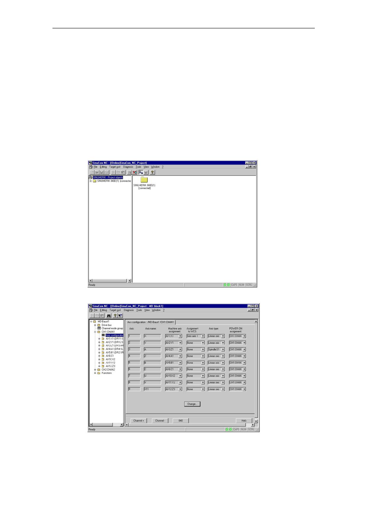
1. a "project" is created (application window)
2. a project tree is generated (project window)
3. in which you can configure functions (parameterization window)
Fig. 3-1
Initial display SinuCOM NC (application window)
Fig. 3-2
Project tree with parameterization window
© Siemens AG 2008 All Rights Reserved
3-28
SINUMERIK 840D sl/840Di sl/ 840D/840Di/810D SinuCom (INC) - 07/2008
07/2008
3 General Operating Sequences
3.2 Help functions
Projects
Projects are created and managed in the application window.
Project tree
The branches of the project tree are the functions to be parameterized, the
arrangement corresponds to the installation sequence (which must be kept).
Parameterization window
Data is entered in the parameterization window. The online help is available for any
queries.
Important
!
When you start SinuCom, not only SinuCom NC but also the HMI basic system
applications MMC 101/102 master control, data cache, MMCEnv, AccVar, and
arcdrv are displayed in the task bar or task manager.
These basic system applications are automatically closed when you close down
SinuCom NC and must not be closed manually, as otherwise SinuCom NC will no
longer function correctly.
3.2 Help functions
To ensure that all information that might be required is available during installation
and start-up, the installation /service tool SinuCom NC provides the following online
Help:
• Context-sensitive Help dialog box
• Context-sensitive Help SW functions (DOCONCD)
• Machine data Help
• Alarm Help
• The Operating Manual SinuCom Installation/Service Tools in German and
English as PDF (part of the Online Help)
Context-sensitive help dialog box
The context help is called up by clicking on the help icon in the tool bar with the
mouse
and then clicking into the dialog box or on the control element.
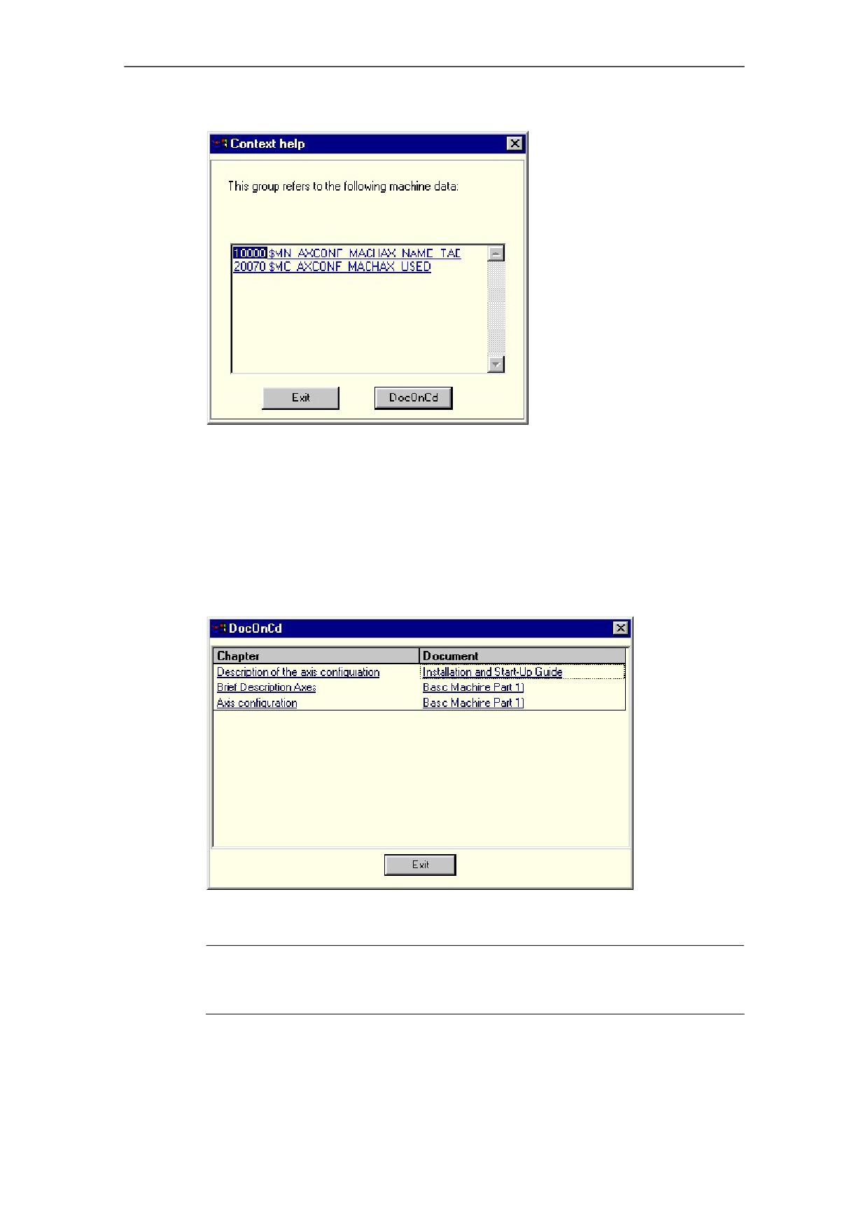
For each dialog box or control element a Help screen listing the associated
machine data is opened.
If you select a control element (e. g. text field), only the machine data used by that
control element appear.
If you click into the backg75round of the dialog box, all the machine data used in the
dialog box appear.
© Siemens AG 2008 All Rights Reserved
SINUMERIK 840D sl/840Di sl/ 840D/840Di/810D SinuCom (INC) - 07/2008
3-29
3 General Operating Sequences
07/2008
3.2 Help functions
Fig. 3-3
Machine data Help
Context-sensitive Help from software functions
Requirements:
The CD "DOCONCD" has been inserted into your CD drive and installed.
Call:
The context-sensitive Help for software functions is called up from the context-
sensitive Help window by clicking on the "DOCONCD" button.
If several Help topics are output, you can select them individually:
Fig. 3-4
Context-sensitive Help Software functions: Several Help topics
Note
If DOCONCD is not installed the button "DocOnCD" does not appear.
© Siemens AG 2008 All Rights Reserved
3-30
SINUMERIK 840D sl/840Di sl/ 840D/840Di/810D SinuCom (INC) - 07/2008
07/2008
3 General Operating Sequences
3.2 Help functions
Machine data Help
The context help is called up by clicking on the help icon in the tool bar with the
mouse
and then clicking into the dialog box or on the control element.
For each dialog box or control element a Help screen listing the associated
machine data is opened. The machine data are sorted numerically in ascending
order and displayed as a link. By clicking on one of these links you open the
associated machine data Help.
The Help dialog remains open until you click on the "Close" button or select
another dialog (you can select several Help texts).
Alarm Help
Call
If alarms occur while you are performing installation and start-up interactively, you
can start the alarm Help by clicking on the info symbol
with the mouse in the
alarm line and then clicking on the alarm.
The Help for the alarm in question is opened.
The Help dialog remains open until you click on the "Close" button or select
another dialog (you can select several Help texts).
Operating manual SinuCom
The operating manual “SinuCom Installation/Service tool” is part of the online Help.
Folder: "SinuCom NC" → "840dincd" (german) und "840dince" (english)
© Siemens AG 2008 All Rights Reserved
SINUMERIK 840D sl/840Di sl/ 840D/840Di/810D SinuCom (INC) - 07/2008
3-31
3 General Operating Sequences
07/2008
3.3 Using the keyboard
3.3 Using the keyboard
You can call up the following functions using key combinations:
Table 3-1 Calling up functions with key combinations
Key combinations
Meaning
"F1"
Context-sensitive Help dialog box, call up machine
data Help
"<Strg> + F"
Open Find dialog box (in expert list only)
"F3"
Find next (in expert list only)
"<Strg> + Pos1":
Jump to the beginning of the table (in expert list only)
"<Strg> + End":
Jump to the end of the table (in expert list only)
">" or "<"
Incremental increase or decrease of value (in expert
list only)
"<Strg> + E"
Switches between expert list and dialog box view
© Siemens AG 2008 All Rights Reserved
3-32
SINUMERIK 840D sl/840Di sl/ 840D/840Di/810D SinuCom (INC) - 07/2008
07/2008
4 SinuCom NC: Functions
4.1 Document Scope and Supported Systems
4
4 SinuCom NC: Functions
4.1 Document Scope and Supported Systems
4-34
4.1.1 Scope of this Manual
4-34
4.1.2 Supported Systems and NCK Versions
4-34
4.1.3 Supported Languages
4-34
4.2 What's New in SinuCom NC 7.50
4-35
4.3 Main Menu
4-35
4.5 Toolbar Buttons
4-36
4.6 Alarm Messages
4-36
4.7 Machine Data ("MD")
4-37
4.7.1 Viewing and Configuring MD
4-37
4.7.2 Machine Data Project Tree
4-39
4.7.3 Service Data
4-41
4.8 Archiving
4-42
4.8 SinuCom NC Trace
4-43
4.9.1 Overview: How Trace is Used
4-44
4.9.2 Sessions and Their Content
4-49
4.9.3 Reference Waveforms
4-52
4.9.4 Toolbars and Menus
4-54
4.9.5 Context Menus
4-68
4.8.6 Dialogs
4-73
4.8.7 Trace Symbol Import Wizard (TSIW)
4-88
4.8.8 Trace Setup Wizard (TSW)
4-94
4.9 Safety Integrated Acceptance Test Wizard
4-99
4.10.1Example:
4-99
4.10.2Common Screen Contents
4-101
4.10.3Custom Templates
4-104
© Siemens AG 2008 All Rights Reserved
SINUMERIK 840D sl/840Di sl/ 840D/840Di/810D SinuCom (INC) - 07/2008
4-33
4 SinuCom NC: Functions
07/2008
4.1 Document Scope and Supported Systems
4.1 Document Scope and Supported Systems
4.1.1
Scope of this Manual
This SinuCom NC of the manual supports SinuCom 07.50. For other SinuComs of
the software, please consult the corresponding manual.
4.1.2
Supported Systems and NCK Versions
SinuCom supports the following SINUMERIK controls:
•
840D sl
•
840D
•
840Di
•
810D
SinuCom can be combined with NCU 710/ 720/ 730, SW 1.3 (or later) and 810D/
840D controllere, SW 6.x (or later)
An appropriate warning is output if the machine data server from SinuCom is
started on older NCK versions. Furthermore, SinuCom outputs various error
messages when operated on older NCK versions because these versions are not
fully supported.
SinuCom NC runs under HMI Advanced resp. HMI Base SW 7.5 (or later).
SinuCom NC only runs on Windows XP.
SinuCom NC Resource Displays requires NCU SW 6.4 or newer. No alarm will
occur on older versions. The feature will simply not be there.
SinuCom NC Trace supports full Trace of IPO servo and PLC signals for NCU
SW 6.4 (06.04.15.00 or newer versions).
SinuCom NC SI Acceptance Test is supported for NCU SW 6.4 (06.04.15.00 or
newer versions).
4.1.3
Supported Languages
SinuCom supports the same standard languages as Sinumerik.The language
setting can be accessed by clicking "Tools" on the main menu.
The new language settings is enabled with the next launch of the application.
© Siemens AG 2008 All Rights Reserved
4-34
SINUMERIK 840D sl/840Di sl/ 840D/840Di/810D SinuCom (INC) - 07/2008
07/2008
4 SinuCom NC: Functions
4.2 What's New in SinuCom NC 7.50
4.2 What's New in SinuCom NC 7.50
• Not any news
4.3 Main Menu
The SinuCom NC main menu is, for the most part, self-explanatory. Rather than
listing the functions here that it provides, it is suggested that the user view the
selections directly in the product. Non-obvious selections will be addressed in
context elsewhere in this manual.
Note
Some menu choices might be permanently grayed out. These menu choices will
be used in the future to support features such as Offline SinuCom.
© Siemens AG 2008 All Rights Reserved
SINUMERIK 840D sl/840Di sl/ 840D/840Di/810D SinuCom (INC) - 07/2008
4-35
4 SinuCom NC: Functions
07/2008
4.4 Toolbar Buttons
4.4 Toolbar Buttons
Find in
This button displays a dialog that allows the operator to
search for variable names by character string. The variables
can be filtered to display subsets such as "All Data", "General
Data ONLY", "Axis Data ONLY", "Channel Data ONLY", and
"Drive Data ONLY".
Info
If the Machine Data is being displayed (either in Dialog View
or in the Expert List), this button displays the Machine Data
version. If not in a Machine Data display, the SinuCom NC
version is displayed.
Help (context
This button is available if context-sensitive help is available.
sensitive)
Clicking the button and then clicking a dialog or control
element opens a Help window. If a control element is
selected (e. g., a text field), only the machine data used by
that control element appear. If the backg75round of a dialog
box is clicked, all the machine data used in the dialog box
appear.
Open
This button open the connection to the NCU.
Connection
Close
This button closes the connection to the NCU.
Connection
Online Project
This button places the project online and displays a check
mark next to "Online Project" in the drop-down menu.
4.5 Alarm Messages
When an alarm occurs, the alarm display area appears near the top of the screen.
The most recent alarm appears in the alarm text window, which is a drop-down list
that expands to display the most recent alarms. If an alarm can be selected its
selection can be followed by a click on the information button. This provides
detailed alarm information in the form of a PDF file (definitions, reactions, remedy,
and program continuation data). The "Alarm Log" button provides chronological
alarm data. The "Alarm Remedy" button can be used to guide the user through the
process of eliminating the alarm.
© Siemens AG 2008 All Rights Reserved
4-36
SINUMERIK 840D sl/840Di sl/ 840D/840Di/810D SinuCom (INC) - 07/2008
07/2008
4 SinuCom NC: Functions
4.6 Machine Data ("MD")
4.6 Machine Data ("MD")
4.6.1
Viewing and Configuring MD
Machine data can be viewed in either the Dialog Display (default) or the Expert
List. The Dialog Display provides better navigation and grouping of data points
(valuable for the novice) while the Expert List provides more data per screen. The
user can toggle between these two display types with "Ctrl - E", or from the "View"
menu.
The MD Server is started from the project tree (left side of screen) with a machine
data block. To do this:
• Select "Open Online Project" from either its toolbar button or from "Target Syst."
in the main menu.
• Expand the Sinumerik folder, click on "MD Block", then double-click on the "MD-
Block 1" icon.
• Click on any element shown under MD-Block 1 in the tree to display or change
that element's configuration.
Note
The units displayed depend on the system of units selected.
Note
Variables that have a white backg75round can be changed. Those that have a gray
backg75round are read-only.
The Dialog Display
When a folder is selected, the first level dialog is displayed. When a dialog within
the folder is selected, the data associated with that dialog is read out of the NC.
When the buttons "Channel +" or "Channel -" (or "Axis +", Axis -", etc.) are clicked,
the dialog with the data of the next/previous channel is selected. After an NCK
reset (warm restart) the project tree and the dialog display are regenerated. When
the dialog is exited, the displayed status data is written to the NC.
Note
On single-channel systems the structure view does not contain any channel
folders. The axis-specific dialogs are then located directly below the control
folder.
© Siemens AG 2008 All Rights Reserved
SINUMERIK 840D sl/840Di sl/ 840D/840Di/810D SinuCom (INC) - 07/2008
4-37
4 SinuCom NC: Functions
07/2008
4.6 Machine Data ("MD")
The Expert List
Prior to SinuCom NC 7.3, the Expert List was not configurable. It simply showed all
data for the General, Channel, Axis or Drives areas. Starting with SinuCom NC 7.3,
all available custom expert lists are offered as well. (A custom expert list is a small
subset of data items that are relevant to a particular task, such as Safety Integrated
configuration.)
Note
At this time, a custom expert list cannot be edited or created from SinuCom NC.
This must be done elsewhere.
Reference:
Operating Manual, HMI Advanced
All configuration that can be performed with the Dialog Display View can also be
performed using the Expert List. The difference is in presentation. The tabular
structure of the Expert List offers the experienced user a considerable amount of
flexibility without the guiding presence of the Dialog View.
Right-clicking anywhere on the grid section of the Expert List brings up a context-
sensitive menu of tools for working with the list, as follows:
• Find (may not work on custom expert lists)
• Find next
• Bit Editor *
• Display options
• Plaintext
* The Bit Editor is used to change values that are bit-oriented (i. e., those with the
suffix "H", such as "3EABH" or "0H"). The Bit Editor can also be invoked by double-
clicking the desired MD item, or just by pressing "5" on the keypad.
To assist in searching, four separate Expert List MD ranges can be can be
accessed from the project tree:
• General MDs
• Channel-specific MDs
• Axis-specific MDs
• Drive MDs.
The following key combinations can be used to find and position within the Expert
List:
Tabelle 4-1 Key combinations ti find and position within The Expert List
F1
Opens the Help for the selected machine data
Ctrl - F
Opens the "Find" dialog box
F3
Find next
Ctrl - Home
Jumps to the beginning of the table
Ctrl - End
Jumps to the end of the table
© Siemens AG 2008 All Rights Reserved
4-38
SINUMERIK 840D sl/840Di sl/ 840D/840Di/810D SinuCom (INC) - 07/2008
07/2008
4 SinuCom NC: Functions
4.6 Machine Data ("MD")
Note
Any Machine Data item can be located in the Expert List via the "Find" dialog
using either its MD number or its description. (This "Find" dialog can be invoked
by pressing “Ctrl” - “F” from the Expert menu.).
The "<" and ">" keys can be used to make 10% increases and decreases in the
values.
The color and font of the title, values, table, and status bar can be accessed by
selecting "Tools" from the main menu, then "Settings", then "Expert List". The
settings take effect immediately and are not lost when the system is restarted.
Changing and Activating MD
Effecting a modification in a machine data item is a two-step process:
• change the item
• activate the item
To change a Machine data item:
• (Display Dialog View only) If a "Change" button is available, press it to begin the
change.
• Place the cursor in the field, or select a drop-down menu.
• Key in or select the desired data.
• (Expert List only) press "Enter" to complete the change.
To activate most changes, the specific action described in the toolbar must be
executed (e. g., NCK Reset). Other changes immediately activate.
4.6.2
Machine Data Project Tree
Options
Supplementary condition: This option is only valid for 840D sl und 840Di sl.
This dialog allows installation of purchased control options, and the associated
upgrade of the license key. User guidance for obtaining a license key via the
Internet is also available here.
A detailed description is included in the following documentation:
Literature: SINUMERIK 840Di sl Manual, Chapter: License management
Trace Setup Wizard
See the section "Trace Setup Wizard" for more information.
© Siemens AG 2008 All Rights Reserved
SINUMERIK 840D sl/840Di sl/ 840D/840Di/810D SinuCom (INC) - 07/2008
4-39
4 SinuCom NC: Functions
07/2008
4.6 Machine Data ("MD")
Drive Bus Configuration
This dialog allows configuration of the drives on the machine.
Channel Mode Group Assignment
This dialog allows channels to be assigned to a given mode group, or to no mode
group.
Axis Data
This extensive dialog allows configuration of the overall complement of machine
axes as well as a wide variety of attributes for the individual axes on the machine. It
is important to note that the drives for the axes are also setup in this area.
Axis Couplings (Functions)
This dialog allows the configuration of coupled axes. It is only visible when one of
the following control options is set:
• Gantry Axes
• Master-Slave Coupling
• Synchronous Spindle
Measure (Functions)
This dialog is used to set the electrical polarity of each connected sensor (probe).
Protection Zones (Functions)
The Protection Zones dialog is used in setting the number of files for machine- and
channel-related protection zones.
Resource Displays (Functions)
There are four categories of Resource Displays. They can be accessed from the
Functions folder in the Machine Data Project Tree:
• Clock Rates
• Memory
• DRAM
• SRAM
Since these resources are MD variables, they can be viewed and changed as
described in the section: "Machine Data".
Detailed descriptions and rationale for modification of specific Resource Display
parameters is beyond the scope of this manual. For additional information, contact
Siemens Support.
© Siemens AG 2008 All Rights Reserved
4-40
SINUMERIK 840D sl/840Di sl/ 840D/840Di/810D SinuCom (INC) - 07/2008
07/2008
4 SinuCom NC: Functions
4.6 Machine Data ("MD")
Clock Rates
The cycle times and burden on the NCU are displayed so the user can estimate the
system basic clock rate and the interpolator clock factor.
Data is displayed for Clock Rates of all channels and for individual Channel Clock
Rates. If individual Channel Clock Rates are selected, a drop-down list is
displayed to select the channel. See the actual display for the specific parameters.
Field updates are started and stopped via the "Start" and "Stop" buttons.
Memory
This function allows, to allocate the total user memory space for the following two
types of RAM:
• Static (SRAM) - data needing to be retained (e. g., configuration data).
• Dynamic (DRAM) - data not needing to be retained (e. g., current axis position).
DRAM and SRAM
These functions allow a piecewise allocation of memory as described by the
Resource Display screens provided. (See the specific screen for the actual
variables that can be configured.) These memory areas are set to reasonable
default subsections during a general NCK reset. To use the user memory
optimally, these areas can be adapted by the user by changing the relevant
machine data items. This memory configuration comes into effect after an NCK
reset.
4.6.3
Service Data
The Service Data Display is opened by clicking "Diagnose" in the main menu, then
"Service Data". The Service Overview page gives an indication of the overall health
of the axes and drives on the machine. The "Axis" display shows the actual and
setpoint values for key axis and drive parameters.
Beginning with SinuCom NC, a PROFIBUS Diagnostics screen has been added to
this area. This screen can show up to three PROFIBUS network types, and can
assist in the evaluation of the status of each network
© Siemens AG 2008 All Rights Reserved
SINUMERIK 840D sl/840Di sl/ 840D/840Di/810D SinuCom (INC) - 07/2008
4-41
4 SinuCom NC: Functions
07/2008
4.7 Archiving
4.7 Archiving
An archive is a backup of configuration data. The default path for archiving files is
the same as that of HMI Advanced.
An archive:
• can be manually commanded through the SinuCom NC File menu. (This is
recommended prior to making configuration changes to allow recovery from
errors.)
• can be required by the system when a change has been made to the NCK that
requires memory reorganization. The message "NCK Reset Required" is
presented, and an archive is performed during the subsequent reset.
For similar machines, a standard archive can be read in immediately after the
installation and first startup of SinuCom NC.
Creating an archive
1. Click "File" → "Archive", then "Create...". The "Create archive" dialog appears.
2. Select one of the following archive choices:
- Data management
- File system
- NC card
3.
(840D powerline only) Using the "radio" buttons, select whether the file should
be of type:
- "Series Startup" (binary)
- "Upgrade" (ASCII)
4. Using the "radio" buttons, select the archive content, which can include any of
the following:
• NC (with or without compensation)
• PLC
• MMC data
• Compile cycles
• Drive data
5. Click the "Next>" button.
6. At the prompt, enter the desired name and path of the .arc file.
7. Click the "Finish" button to complete the operation.
© Siemens AG 2008 All Rights Reserved
4-42
SINUMERIK 840D sl/840Di sl/ 840D/840Di/810D SinuCom (INC) - 07/2008
07/2008
4 SinuCom NC: Functions
4.8 SinuCom NC Trace
Reading In an Archive
1. Click "File" → "Archive", then "Read In...". The "Read in archive" dialog
appears.
2. Select one of the following archive choices:
• Data management
• File system
• NC card
3. Click the "Next>" button.
4. At the prompt, enter a file name.
5. Click the "Finish" button to complete the operation.
4.8 SinuCom NC Trace
Note
SinuCom NC Trace uses several unique terms. To better understand the
descriptions in this section, please review the Appendix entitled "Abbreviations
and Definitions - SinuCom NC Trace".
Definition and Use
SinuCom NC Trace (also simply called "Trace" in this document) is a SinuCom
NC facility that can dynamically record data from the NC, drives, PLC, or HMI.
Once recorded, this data can be graphically displayed in a form similar to that of an
oscilloscope or logic analyzer, printed, or saved to a file. Saved files can be loaded
into Trace for viewing at a later time, even on a different machine.
Trace can be used to assist machine manufacturers, end users and Siemens
service personnel in activities such as:
• Trouble-shooting and debugging
• Machine performance analysis, benchmarking and tuning
• Process performance analysis, benchmarking and tuning
Compatibility with Siemens Software
NCU 05.03 or NCU 06.03 (basic functionality).
NCU 06.04 or later (extended functionality).
Note
The level of available Trace functionality is automatically determined when the
NCU SinuCom NC is detected at startup.
© Siemens AG 2008 All Rights Reserved
SINUMERIK 840D sl/840Di sl/ 840D/840Di/810D SinuCom (INC) - 07/2008
4-43
4 SinuCom NC: Functions
07/2008
4.8 SinuCom NC Trace
Compatibility with Microsoft Windows®
Trace is a Microsoft Windows® application. It runs on a standard Windows-PC
platform under Windows® XP (SP1 or SP2).
Common Windows® controls such as scroll bars, toolbars, tabbed dialogs, etc., are
used. A mouse or other pointing device is required for selecting, dragging, etc.
Trace’s Relationship to SinuCom NC
Trace can be started from SinuCom NC by selecting the Trace menu item from the
"Diagnosis" menu. If a Trace session is already active in the NCK when this menu
item is selected, SinuCom NC switches to the active Trace session.
Trace runs as a separate executable (.exe file) in its own application window. This
means that Trace has its own set of menus that do not integrate into the menus of
SinuCom NC. These Trace-specific menus are described in the section "Toolbars
and Menus".
4.8.1
Overview: How Trace is Used
Typically, Trace is used to record data (signals) shortly before or after an event. To
do this, the following sequence can be executed:
1. Specify what signals to record.
2. Specify when to start and stop recording (can involve the definition of a trigger
condition).
Note
A mode of operation called “endless collection” can be enabled by simply not
specifying a stop condition. (I. e., the recording process continues until it is
stopped manually.) This mode operates like a strip chart recorder. Instead of
printing on paper, however, when the data storage area becomes full, the oldest
data is discarded to make room for the newest. (I. e., the data is stored in a
“circular buffer”.)
3. Start the recording process by arming the trigger.
4. The "Awaiting Stop" message is displayed until data collection stops.
Note
If it is desirable to view waveforms as the data as it is collected, the user can set
"Keep Data on NCK" off.
© Siemens AG 2008 All Rights Reserved
4-44
SINUMERIK 840D sl/840Di sl/ 840D/840Di/810D SinuCom (INC) - 07/2008
07/2008
4 SinuCom NC: Functions
4.8 SinuCom NC Trace
5. View the resulting waveform(s).
6. Manipulate the waveform(s) as desired to examine details (e. g., zoom, scroll,
etc.).
7. Optionally, print the waveform(s) or save to a file.
Note
Siemens or the machine builder can supply setup files that are pre-configured for
certain tasks such as troubleshooting or performance analysis.
Hands-On Example
The easiest way to learn about Trace is to actually use it. This section illustrates
the basic use of the tool in step-by-step fashion.
1. Activate SinuCom NC.
2. Click "Diagnosis" in the SinuCom NC main menu.
3. Click "Trace" in the Diagnosis menu. The Trace initial screen will appear.
Note
A yellow (or red) message banner (in this case containing "No Waveforms") is
displayed at the top of the graph window. This box can optionally appear
whenever a graph window is displayed. It can contain such messages as:
• "No Waveforms" - No waveforms have been defined ("added") for display.
• "No Waveforms Shown" - All defined waveforms have had their "Show"
checkbox unchecked, see Figure 4-2.
• "Awaiting Stop" - Recording is in process, and the checkbox "Keep data on
NCU until stopped" has been checked (default setting), see Figure 4-5.
• "Trace Data has been Lost. Total Segments (x)" - Where "(x)" is the
number of segments lost. (See "Hide Dropouts / Show Dropouts" for
additional information on lost data.)
4. Right-click anywhere in the graph window to bring up the "Graph Window
Context Menu".
5. Click the "Add Waveform..." menu item. The "Add Waveform" screen will
appear.
© Siemens AG 2008 All Rights Reserved
SINUMERIK 840D sl/840Di sl/ 840D/840Di/810D SinuCom (INC) - 07/2008
4-45
4 SinuCom NC: Functions
07/2008
4.8 SinuCom NC Trace
6. In the field labeled "Containing:", type "actime". On the right of the screen, three
candidates that have this character string in their names are presented.
7. Click the name "acTime" (top selection) to highlight the line it is on.
8. Click the "Add" button. The signal is now ready to be recorded.
9. Click the "Close" button. A graph window will appear without a waveform but
with axis labels and a tab for the new waveform.
10.Click the "Start Trace" icon (
). The "Trace Status" will change from
"Stopped", to "Ready", to "Recording". Data recording is now in process.
11.After a short period of time, click the "Stop Trace" icon (
). The waveform
representing the collected data will be drawn.
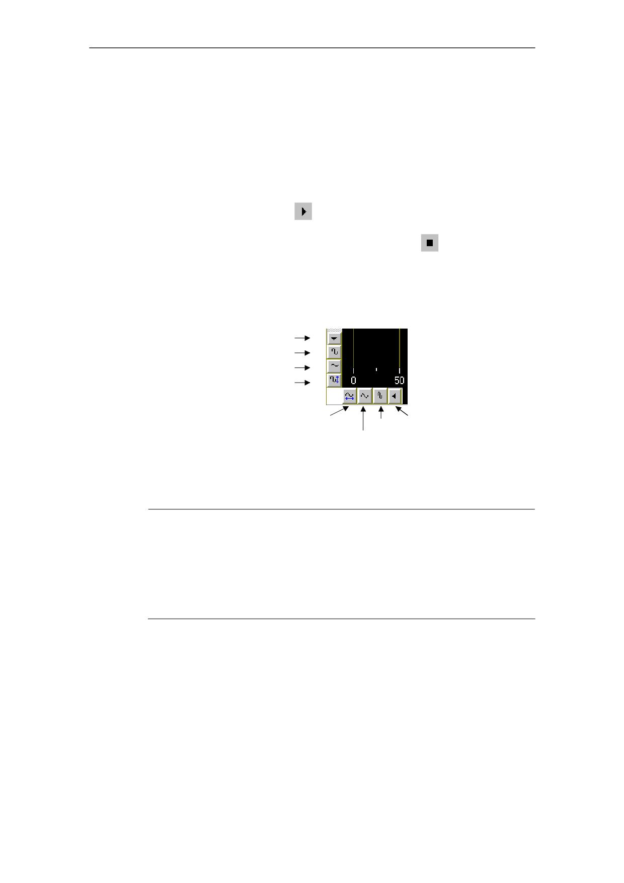
12.The figure below is an enlargement of the lower left corner of the display. Click
the "Fit Height to Window" and "Fit Time to Window" icons to show the entire
waveform at its maximum size.
Scroll down
Compress Y
Expand Y
Fit Height to
Window
Scroll Left
Fit Time to
Compress X
Window
Expand X
Figure 4-1 Scale and Scroll Icons
The entire waveform is now shown at its maximum size. The plot is either a
diagonal line or a sawtooth.
Note
The scale of the observed waveform will vary because of the data limit, sampling
rates and amplification that had previously been set. Y axis scaling will vary
depending upon when "Start Trace" and "Stop Trace" are clicked. Also, the
variable "acTime" is a continuously running clock that can roll over to zero. It also
restarts at the beginning of each block. This might cause the waveform to appear
as a sawtooth.
The above example is intended to be an introduction to the Trace function. Review
of the remainder of the material in this section, and further work with Trace, will
allow discovery of a variety of additional capabilities.
© Siemens AG 2008 All Rights Reserved
4-46
SINUMERIK 840D sl/840Di sl/ 840D/840Di/810D SinuCom (INC) - 07/2008
07/2008
4 SinuCom NC: Functions
4.8 SinuCom NC Trace
Passwords
Certain functions of Trace require use of a password:
• Variable Selection - Some variables are available for selection only at
approved password levels. If the appropriate password has not been entered,
certain variables will not be displayed, and thus cannot be recorded.
• Functions - Some functions are available only at approved password levels.
(e. g., selecting signals by address rather than by name).
• Sessions - The creator of a session can make the session read-only or
password-accessible. (E. g., a session intended for troubleshooting might be
executable by an operator, but its setup can be modified only by a technician.).
Recording Basics: Data and Events
There are two main aspects of recording:
• The Data aspect (i. e., what to record, sometimes called the “signal”)
• The Event aspect (i. e., when to record, on a per-point basis)
The Data aspect can be selected as subsets of the following main types of data:
• All NC variables (axis data, drive data, channel data, etc.)
• Some PLC data
The data is usually selected by name, but can also be selected by address. (See
the section: "Dialogs", "Dialog: Setup Waveforms"). Note that some types of data
require further qualification of the signal. (E. g. "axis data" must also have the
specific axis defined.)
Note
“Event-Only” is a special case in which no data is recorded. Only the occurrence
of the event is recorded.
© Siemens AG 2008 All Rights Reserved
SINUMERIK 840D sl/840Di sl/ 840D/840Di/810D SinuCom (INC) - 07/2008
4-47
4 SinuCom NC: Functions
07/2008
4.8 SinuCom NC Trace
The Event aspect requires that an "Event" be selected for each waveform.The
following list shows three examples of these Events:
Events - Partial List
Interpolation Cycle (IPO Cycle)
IPO interpolation cycle 11
Prot File Begin
start logging
Block Begin S1
block start, w/o intermediate blocks,
(all program levels) (preprocessing)
A drop-down menu of all Events is made available when the Event field for the
session's first waveform is selected. The selected Event for the first waveform will
either be a "preprocessing" or a "non-preprecessing" Event. Within a given
session, all Events must be either preprocessing or non-preprocessing. To ensure
this continuity, the system will present only the appropriate Events (preprocessing
or non-preprocessing) for subsequent waveforms.
1
Events designated as “cyclic” occur repetitively at a constant rate. Waveforms for data re-
corded on non-cyclic events have special features and different behaviors as described else-
where in this manual.
© Siemens AG 2008 All Rights Reserved
4-48
SINUMERIK 840D sl/840Di sl/ 840D/840Di/810D SinuCom (INC) - 07/2008
07/2008
4 SinuCom NC: Functions
4.8 SinuCom NC Trace
4.8.2
Sessions and Their Content
Sessions
A Trace Session is an environment constructed for the purpose of collecting data.
This data can be used to display one or more waveforms in a configurable manner.
The setup (configuration) and the "trace status" (e. g. stopped, recording, no
waveform, etc.) are attributes of a session. (I. e., at any given time, a session has a
single setup and a single status, independent of other sessions.)
More than one session can exist simultaneously. Any or all existing sessions can
be operated, and can record independently. A new session can be created at any
time (assuming memory, disk space, resources in the NCK, etc., are available).
For example, one session can be recording a set of signals while the second
session is waiting for a trigger condition.
When the recording process is manually started or stopped (i. e., by clicking the
"start trace" button,
, or the "stop trace" button,
, on the toolbar ), only the
active session is affected. (The active session is the session that is currently
displayed.) Likewise, when a setup is changed, only the active session is affected.
Typically, a session is created by clicking "New Session..." in the file menu. In a
future release, a session will also be able to be created by instructions in the NC
part program (also called “batch mode”). Session data will be recorded and viewed
the same way regardless of which method was used to create it.
See also in the section: "Toolbars and Menus", "Open Sessions…" and "Close
Sessions…", for file maintenance information, including information on Preserved
Sessions.
Graph Windows
A graph window is the area of the screen where the acquired data is displayed as
one or more waveforms. More than one graph window can be displayed, but
waveforms in all graph windows must be drawn from the same set of recorded data
(within a session). Multiple waveforms can be combined and overlaid in each graph
window.
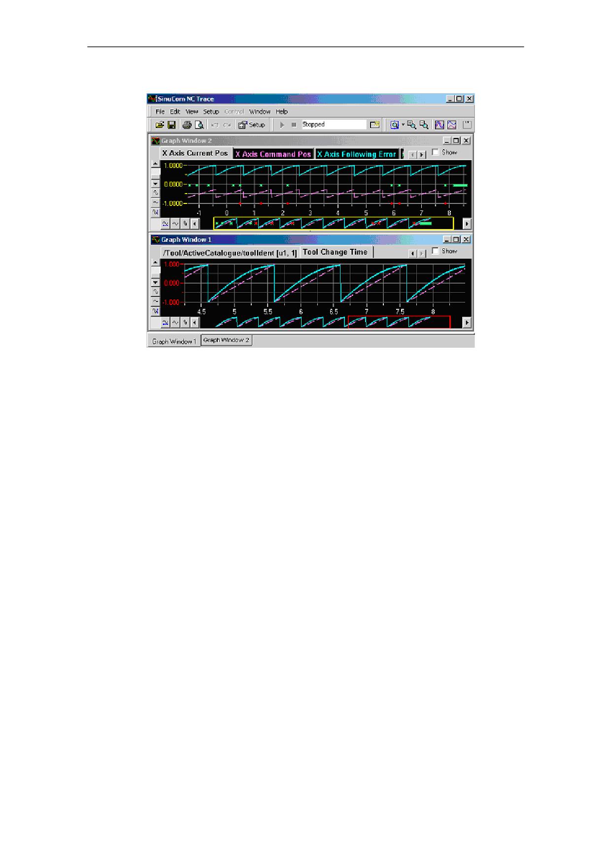
Example: Below, shows relationships among four recorded waveforms. Waveforms
1, 2 and 4 are displayed in the upper graph window while waveforms 2 and 3 are
displayed in the lower graph window. (Note that a 5th waveform exists but has not
been selected for display.) Each graph window can be maximized, minimized, tiled
or cascaded according to the normal conventions of Microsoft Windows®.
© Siemens AG 2008 All Rights Reserved
SINUMERIK 840D sl/840Di sl/ 840D/840Di/810D SinuCom (INC) - 07/2008
4-49
4 SinuCom NC: Functions
07/2008
4.8 SinuCom NC Trace
Bild 4-2
Multiple Graph Windows (tiled horizontally)
Each graph window can have a user-defined title. All settings described in this
section are independent for each graph window. Each graph window can be
manipulated in the following ways:
• The focus of the graph window determines which of the displayed waveforms
is ready for manipulation. The focus can be changed from one waveform to
another by clicking the associated colored tab, or by clicking the waveform
itself. The colored tab can be configured to show either the waveform number,
or the waveform description/name (as in "Graph Window 1" in Figure 4-2.,
above). The waveform that has focus is indicated in the colored tabs by a
change in coloration..
• Focus can be applied to more than one waveform at a time by holding down
the CTL key when clicking another waveform or tab. This feature is useful for
performing the same manipulation on multiple waveforms at once for
operations such as drag, resize, show/hide, remove, and cut/copy/paste. When
two waveforms have focus, tick marks and Y labels will appear for both
waveforms at the same time. When more than two waveforms have focus, tick
marks and Y labels will appear for only the last two waveforms selected.
• A show/hide checkbox is used to “show” or “hide” the waveform that has focus.
When the box is checked, the waveform that has focus is made visible and its
tab is shown in color; when the box is not checked, the waveform that has
focus is made invisible and its tab is gray.
© Siemens AG 2008 All Rights Reserved
4-50
SINUMERIK 840D sl/840Di sl/ 840D/840Di/810D SinuCom (INC) - 07/2008
07/2008
4 SinuCom NC: Functions
4.8 SinuCom NC Trace
Note
More than one waveform can have focus at the same time. If this is the case, the
paragraph above applies to all waveforms that have focus.
• X and Y Axis labels are the numbers displayed next to the ticks marks.They
pertain to the waveform that has focus.These labels change automatically with
panning, zooming or change of scale. Numeric resolution (number of decimal
places) can also be selected.
• The vertical scroll bars can be clicked or dragged to scroll the off-screen
portions of the graph window into view (i. e., according to the normal
conventions of MicroSoft Windows®). The specifics of scrolling and scaling are
as follows:
• The horizontal scroll bar is shown as a miniature image of the entire waveform,
(see Figure 4-2) This bar can be moved or dragged just like a standard
Windows® scroll bar. Additionally, a rectangle is superimposed onto a portion
of the bar which corresponds to the portion of the waveform that is being
displayed. This rectangle can be stretched to change the horizontal scaling.
• Along the vertical and horizontal scroll bars, there are buttons to incrementally
stretch or shrink the scaling of the axes. Alternately, the vertical and horizontal
axes can be dragged to stretch or shrink the scaling. Also, the "Fit Height to
Window" and "Fit Time to Window" buttons can be used to force the entire
waveform into view. (See figure "Scale and Scroll Icons").
• After selecting "Zoom X and Y" from the View menu, a portion of the waveform
can be "boxed" (i. e., left mouse button down, then drag, then left mouse button
up) in order to zoom to that section (See the section: "Toolbars and Menus",
"Menus: View", for details pertaining to the zoom function).
Other aspects of the graph window can be configured, such as graph style, grid
lines, scaling style, etc. (See "Dialog: Setup Display“ for details).
© Siemens AG 2008 All Rights Reserved
SINUMERIK 840D sl/840Di sl/ 840D/840Di/810D SinuCom (INC) - 07/2008
4-51
4 SinuCom NC: Functions
07/2008
4.8 SinuCom NC Trace
4.8.3
Reference Waveforms
An understanding of the following terms will be beneficial in understanding this
section:
Waveform - Any single graphical plot of a series of recorded data points.
Standard Waveform - A waveform that is updated with new data when the
"Record" button is clicked.
Reference Waveform - A static waveform that is created from an existing
waveform (i. e., from either a standard or reference waveform). This waveform type
is NOT updated with new data when the "Record" button is clicked.
Copy (a waveform) -The process of selecting a waveform and placing a duplicate
on the Windows® clipboard. Such a waveform can subsequently be pasted into a
SinuCom NC Trace Session.
Insert (a waveform) - The process of placing a duplicate of a waveform from one
session into another session.
Load (a waveform) - A waveform characterization process that is executed during
the opening of a session file. Waveforms can be loaded as either standard
waveforms or reference waveforms.
A reference waveform can be displayed alongside freshly recorded data, (e. g., to
be used as a baseline reference or for comparison to a known data signature).
Reference waveforms have many of the characteristics of standard waveforms,
and can be manipulated similarly; however, they differ in the following important
ways:
• They have an "R" prefix before their numeric designation to distinquish them
from standard waveforms. They are also drawn with a dashed line.
• Their data and display remains unchanged when a new recording session
begins. (I. e., their data is not updated during a recording session.)
• They can be repositioned horizontally (e. g., to synchronize them with
waveforms recorded at a different time.)
• They can be created from an existing waveform that has recorded data, either
by "copying" a waveform in the current session or by "inserting" a waveform as
reference from another file.
© Siemens AG 2008 All Rights Reserved
4-52
SINUMERIK 840D sl/840Di sl/ 840D/840Di/810D SinuCom (INC) - 07/2008
07/2008
4 SinuCom NC: Functions
4.8 SinuCom NC Trace
Creating Reference Waveforms
There are three ways to create a reference waveform:
1. By "Copy Waveform / Paste Waveform as Reference". (Note that copy from
session-to-session is supported).
2. When opening a session file, by designating one or more waveforms as
reference (via checkbox).
3. When "Inserting" (i. e., "appending") an existing session file, by designating one
or more waveforms as reference (via checkbox).
Note
Any waveform that had been previously saved without data can only be loaded as
a standard waveform.
Note
Edits to waveforms can result in one or more waveforms that consist of individual
signals with and without collected data (e. g., non-cyclic signals with the "Same
Y" Plot Y option). If an edit creates a waveform with incomplete data, all recorded
data for that waveform will be discarded.
Manual Alignment of Reference Waveforms ("Dragging")
A reference waveform can be dragged horizontally to visually synchronize it with
data captured at a different time. This dragging applies to the display of that
waveform in all windows.
Note
When either a reference or standard waveform is hovered over, a directional
arrow cursor will be displayed that shows the direction(s) in which dragging is
allowed. If no dragging is allowed, a padlock cursor is displayed.
Horizontal dragging is enabled only if none of the following conditions are true:
• A zoom tool is selected. (Waveform can be dragged again after the zoom
operation is completed.)
• A trace is being recorded.
• An annotation is being dragged.
© Siemens AG 2008 All Rights Reserved
SINUMERIK 840D sl/840Di sl/ 840D/840Di/810D SinuCom (INC) - 07/2008
4-53
4 SinuCom NC: Functions
07/2008
4.8 SinuCom NC Trace
Dragging Facts:
When a reference waveform is dragged, it "tears off" from its original position (i. e.,
a faded dotted original waveform is left behind).
Both a numeric absolute position and a delta position are displayed in real time in
the graph window during the dragging process.
The original waveform and the position data are removed from the display when
the mouse button is released.
While the mouse button is still depressed, the dragging operation can be
terminated with the "Escape" key. Similarly, an "Undo" operation after release of
the mouse button will undo the drag. Either operation restores both the pre-drag
waveform position and the window pan position.
All reference waveforms in the same scale group are dragged together.
If multiple waveforms are selected, they are dragged together if they are all
reference waveforms.
4.8.4
Toolbars and Menus
Functions of Trace are accessed through dialogs (covered later in this manual),
toolbars, and menus.
(See also section: "Context Menus".)
Toolbars
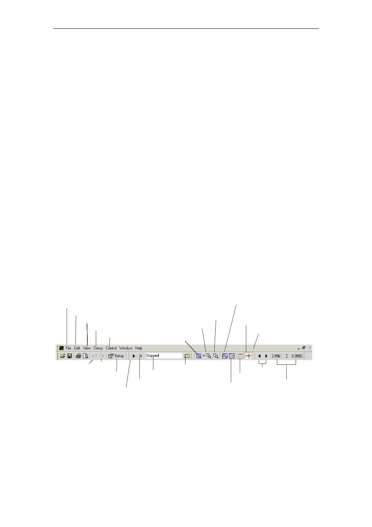
The Trace Main (Entry) Menu and its toolbars are shown in Figure 4-2 below. Items
found in common MicroSoft Windows® toolbars are shown but are not described
here. Annotated items are specific to Trace.
File Menu
Fit All: Overlaid
Edit Menu
Zoom Out
View Menü
Difference Cursor
Zoom In
Setup Menü
Measurement Cursor
Control Menu
Zoom X and Y in a Box
Undo Redo
Clear screen
Cursor Control
Setup Button
Trace status
Annotations
Trace stop Button
Cursor Position
Fit All: Separated
Trace start Button
Figure 4-3
Trace Main (Entry) Menu and Toolbars
© Siemens AG 2008 All Rights Reserved
4-54
SINUMERIK 840D sl/840Di sl/ 840D/840Di/810D SinuCom (INC) - 07/2008
07/2008
4 SinuCom NC: Functions
4.8 SinuCom NC Trace
Menu: File
The File “menu” provides access to the following functions:
• session management
• data export
• print management
The following selections are available from the menu:
New Session…
Selection of this item creates a new session. A dialog
containing a suggested session name is presented (e. g.,
“Session 1”), but any session name can be applied.
Selection of this item automatically creates a new graph
window for the new session.
Open Session…
Selection of this item calls up a sub-menu that allows
retreival of a session either "From Preserved Sessions
List" or "From Session File". (See the two descriptions with
these titles directly below.)
Note
When a session is retreived, it becomes the active session.
(I. e., it replaces any currently-displayed session.)
From Preserved Session List…
Selection of this item opens the Preserved Sessions dialog.
This dialog presents a list of sessions that are currently
preserved in the NCU. Any entry in the list can be selected,
making it the active session.
From Session File…
Selection of this item allows a saved session file to be
opened using the standard MicroSoft Windows® "Open"
dialog. Selection of a specific file calls up the "Select
Session Contents to Load" dialog. Via checkbox, this dialog
allows the loading of the following:
• Setup Waveforms, Collection and Triggers
• Setup Display
• All Waveform Data
If signal data is loaded, it is immediately displayed just as if it
had been freshly recorded.
© Siemens AG 2008 All Rights Reserved
SINUMERIK 840D sl/840Di sl/ 840D/840Di/810D SinuCom (INC) - 07/2008
4-55
4 SinuCom NC: Functions
07/2008
4.8 SinuCom NC Trace
Note
Siemens or the OEM can provide pre-configured session
files for common tasks. If this is the case, only the session
file needs to be loaded to obtain the desired setup.
A new session can also be created with this information.
This would allow the previously active session to reside in its
window rather than over-writing it. After this waveform data
is loaded, it is presented in the graph window(s) as the
active session, just as if the session had not been
interrupted; however, its data will be lost the next time
recording is started.
Open Session...
When opening from a Session File, only the data associated
(continued)
with a waveform could be suppressed. Decide via
checkbox:
1. whether or not to load each waveform.
2. whether to load each waveform as reference or
standard.
Close Session…
Selection of this item closes the active (current) session and
calls up a dialog that provides the option of either discarding
or preserving the session and its recorded data. If "Preserve
Session" is selected, the session will be maintained in the
NCU even if the Trace application is exited and even if the
NCU is shut down. The preserved session maintains:
• the NCU resources
• the entire setup
• the recorded signal data (if any).
At some later time, Trace can be reconnected to a
preserved session. (See "Open Session.." for information
about reconnecting to a preserved session.) This
reconnection allows work with the session to resume. If any
signal data was recorded by the NCU while the Trace was
disconnected, the HMI will retrieve that recorded data
immediately upon reconnection to the session.
Save Session…
Selection of this item opens the "Save Session" dialog.
Either "Save Session to File" or "Preserve Session on NCU"
(or both) must be checked in order to perform a save. The
"Advanced >>" button can be pressed to allow checkbox
selection of a only a subset of the waveforms and
parameters to be saved. If the Advanced window is not
used, all setup parameters and the waveforms will be saved
to the file.
© Siemens AG 2008 All Rights Reserved
4-56
SINUMERIK 840D sl/840Di sl/ 840D/840Di/810D SinuCom (INC) - 07/2008
07/2008
4 SinuCom NC: Functions
4.8 SinuCom NC Trace
A path is initially suggested (e. g., "f:\user\"). A filename
must be specified. Optionally, a new path can precede the
filename. If this is done, the suggested path disappears. In
subsequent saves, the new path becomes the suggested
path.
At some later time, the sequence "File...Open
Session...From Session File" can be used to reload the file.
Note
A saved session file that includes waveform data can be
used later to load reference waveforms, See the section:
"Sessions and Their Content", "Reference Waveform", for
information on the use of Reference Waveforms.)
Save Image…
Selection of this item calls up a standard MicroSoft
Windows® “Save As” dialog that allows the image of the
active graph window to be saved to a Windows graphic
metafile or bmp. This graphic metafile contains the graphical
content of the graph window including waveforms, axis
scales, and annotations, but excludes borders, scrollbars,
tabs, etc.
Note
A Windows® metafile is a format that can be resized without
losing detail.
Import Symbols
Selection of this item opens the Trace Symbol Import
Wizard. The function of this tool is self-explanatory. This
wizard allows manually update GUDs and PLC Variables at
any time.
Export
Selection of this item opens the "Export Waveforms" dialog,
Waveforms…
The "Advanced >>" button can be pressed to allow
checkbox selection of a only a subset of the waveforms to
be exported. If the Advanced window is not used, all
waveforms will be saved to the file.
A path is initially suggested (e. g., "f:\user\"). A filename
must be specified. Optionally, a new path can precede the
filename. If this is done, the suggested path disappears. In
subsequent saves, the new path becomes the suggested
path.
Unlike a saved Session, an exported waveform file cannot
be reloaded and re-displayed.
Note
Unlike the XML format of a saved session, an exported
waveform is a numerical representation of the waveforms to
be saved in a comma-delimited (.csv) format. This format
can be easily imported into other applications such as
Microsoft Excel.
© Siemens AG 2008 All Rights Reserved
SINUMERIK 840D sl/840Di sl/ 840D/840Di/810D SinuCom (INC) - 07/2008
4-57
4 SinuCom NC: Functions
07/2008
4.8 SinuCom NC Trace
Print Preview
Selection of this item displays a preview of the impending
printout in standard MicroSoft Windows® Print Preview
format.
Print…
Selection of this item opens the Print dialog.
(Note that toggling "Page Setup >>" alternately compresses,
then expands the lower portion of the screen.).
This print dialog has functionality similar to that of many
MicroSoft® products, but also has the following two
capabilities:
• Print Range - The following two choices are provided:
-
Full Range
Prints the full recording, on multiple pages if
required.
-
Current view only
Prints only the content currently in view.
• Image Size - The following three choices are provided:
-
Actual Size
The size of the display will be reproduced in print,
pixel-for-pixel at 100% of its size. One screen of
data will be produced per page. If the screen is
larger than the page (X and/or Y), a portion of the
printout will be cut off.
-
Full Page ("preserve aspect ratio" checked)
The displayed size ratio of X to Y is preserved. The
on-screen waveform will be enlarged to either the
full horizontal or full vertical dimension of the page
(whichever is reached first).
-
Full Page ("preserve aspect ratio" not checked)
Both the X and Y dimension of the on-screen
waveform will be enlarged to the size of the page
without regard to the displayed size ratio of X to Y.
Significant distortion is expected unless the aspect
ratio of the display is close to the aspect ratio of the
page.
• Print Color Scheme - The following three choices are
provided:
-
Black and white printer scheme
-
Color printer schemeo
-
Same as display
© Siemens AG 2008 All Rights Reserved
4-58
SINUMERIK 840D sl/840Di sl/ 840D/840Di/810D SinuCom (INC) - 07/2008
07/2008
4 SinuCom NC: Functions
4.8 SinuCom NC Trace
Note
Any printout will contain the graphical content of the graph
window (waveforms, axis scales, and annotations), but
borders, scrollbars, tabs, etc. will be excluded. The
displayed scaling of the graphs will be reflected in the
printout.
Exit Trace
Selection of this item exits the Trace facility.
Menu: Edit
The following “Edit” Menu functions are available for text editing:
Undo
Selection of this item will perform an Undo (revert) on the last
action (if possible). Possible actions for undo include scaling
and zooming of graph windows, and various changes to
setup parameters. Undo will not be available for actions that
involve the actual recording of data or clearing of recorded
data.
Redo
Each redo restores an undo operation until the state prior to
first undo operation is achieved.
Note
If an undo-redo operation is performed on a setup parameter
while the Setup dialog is visible, the dialog is automatically
switched to the page that contains the changed parameter.
© Siemens AG 2008 All Rights Reserved
SINUMERIK 840D sl/840Di sl/ 840D/840Di/810D SinuCom (INC) - 07/2008
4-59
4 SinuCom NC: Functions
07/2008
4.8 SinuCom NC Trace
The following Edit Menu functions are available for waveform editing:
Cut Waveform
Removes the waveform from the session and moves it -- and
its data -- onto the Windows® clipboard.
Copy Waveform Leaves the waveform in the session and moves a copy of it --
and its data -- onto the Windows® clipboard.
Paste Waveform
Pastes the waveform on the Windows® clipboard into the
as Standard
session as a Standard Waveform at the end of the waveform
order. It can subsequently be dragged to another position in
the order.
Note
Standard waveforms, if pasted in the same session, are
always pasted with data. To prevent invalid mixes of data, a
waveform pasted into a different session will be pasted
without data.
Application Hint:
Multiple copies of a Standard Waveform can be pasted into
the same session, and can subsequently be given a different
bit field specification. Each will be redrawn according to its
specific bit field.
Paste Waveform
Pastes the waveform on the Windows® clipboard into the
as Reference
session as a Reference Waveform at the end of the
waveform order. It can subsequently be dragged to another
position in the order. Standard waveforms are pasted with
data.
Note
Reference Waveforms are always pasted with data. If a
waveform has no data it must be pasted as a Standard
Waveform.
© Siemens AG 2008 All Rights Reserved
4-60
SINUMERIK 840D sl/840Di sl/ 840D/840Di/810D SinuCom (INC) - 07/2008
07/2008
4 SinuCom NC: Functions
4.8 SinuCom NC Trace
Scale Grouping
Note
Scale Grouping and Multiple Selection are similar (e. g.,
whenever any one waveform is compressed or expanded, all
associated waveforms are compressed or expanded), but
they have two major differences:
1. Scale Grouping is more permanent. (I. e.,
waveforms in a Scale Group stay together until
explicitly split apart; waveforms under Multiple
Selection stay together only until another selection is
2.
All waveforms in a Scale Group have the same Y
axis scaling.
To perform a multiple selection:
1.
Click on any waveform (or its tab) to select it.
2.
Ctrl-click any other waveform (or its tab) to add it to
the selection.
3.
Repeat step 2 to add additional waveforms.
To perform a scale grouping:
1.
Perform a multiple selection, as described directly
above.
2.
Select "Scale Grouping" from the Edit drop-down
menu.
Scale Grouping
Selection of Scale Grouping opens a submenu with three
(cont.)
choices, as described below. A table of scenarios is shown
for each. For these tables, the following rules apply:
•
Group names "A" and "B" designate existing groups.
•
Group name "C" designates a resulting group.
•
"0" indicates an independent (ungrouped) waveform.
•
A BOLD "A", "B" or "C" is a selected waveform.
Note
If possible, existing group names are preserved.
• Group
This choice is available if two or more waveforms are
selected. Selection brings up the "Scale Group
Properties" dialog, in which the group (i. e., all selected
waveforms) can be given a unique name. Radio buttons
allow the waveforms to share the "same Y scale" and
optionally the "same Y position".
© Siemens AG 2008 All Rights Reserved
SINUMERIK 840D sl/840Di sl/ 840D/840Di/810D SinuCom (INC) - 07/2008
4-61
4 SinuCom NC: Functions
07/2008
4.8 SinuCom NC Trace
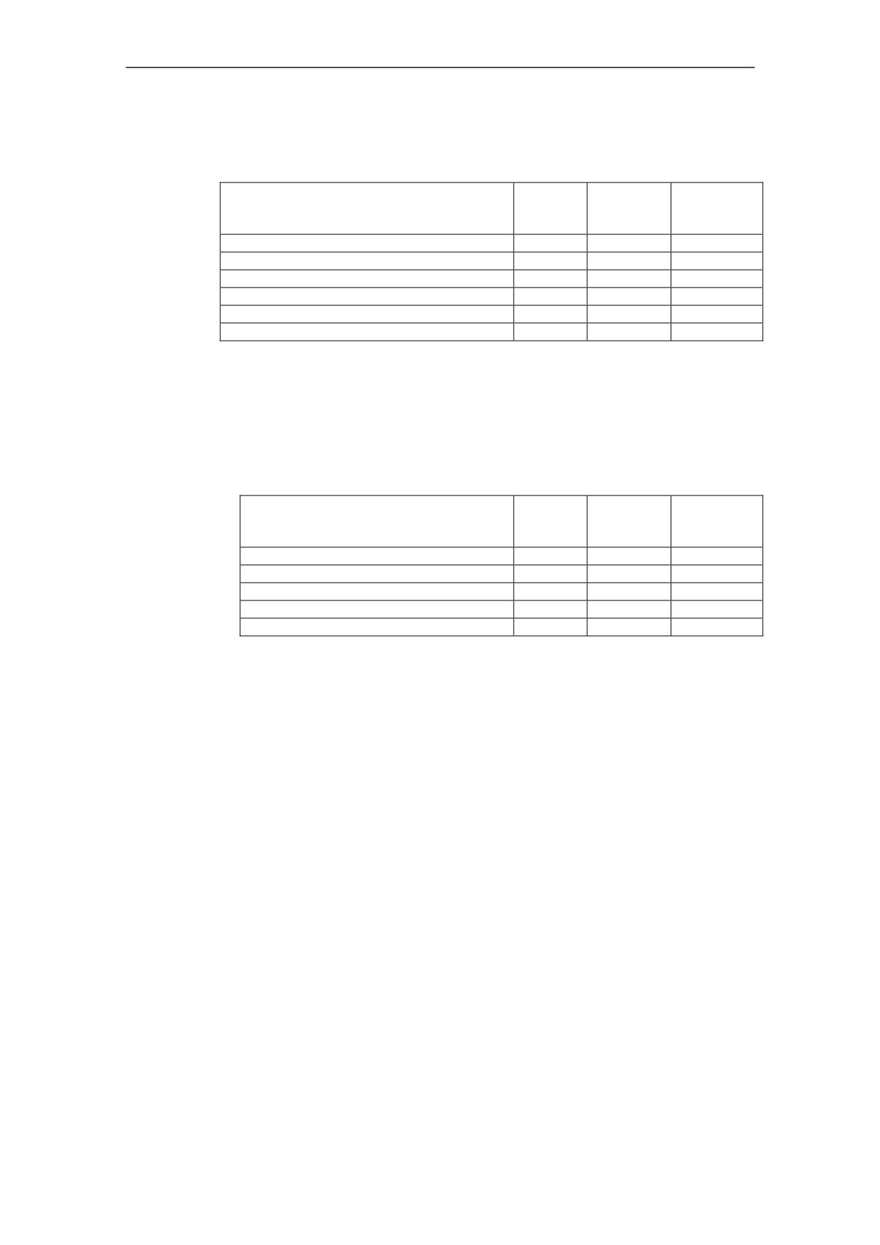
The following table describes grouping behavior:
"Group" Scenarios
Menu
Initial
Resulting
State
Conditio
Effect
n
One waveform selected
grayed
AAABB
no effect
Selection spans groups
normal
AAABB
AACC0
Subset of group selected
normal
AAA
AA0
Subset of large group selected
normal
AAAA
AACC
Selection contains ungrouped waveforms
normal
AA0000
AAAA00
Entire group selected
normal
AAAA
no effect
Scale Grouping
• Ungroup
(cont.)
This choice is available if the selection contains at least
one waveform that belongs to a group. Selection will
either cause a simple group to "ungroup", or will cause
one of the other resulting effects as described in the
following table:
"Ungroup" Scenarios
Menu
Initial
Resulting
State
Conditio
Effect
n
Subset Selected
normal
AAAABB
00AABB
Selection spans groups
grayed
AAABB
no effect
Set minus one element
normal
AAA
000
Entire set selected
normal
AAA
000
Selection includes unselected
normal
AAA0
AA00
Scale Grouping
• Select Entire Group
(cont.)
This choice is available when a selection contains one or
more waveforms from a single group, and no others. It is
useful for:
-
seeing the full complement of signals for a given
group.
-
adding a waveform to a group. To do so:
Right-click on a waveform in the target group
Click on "Scale Grouping".
Click on "Select Entire Group".
<ctrl> click the waveform to be added.
Click on "Scale Grouping".
Click on "Group" to add the waveform to the group.
-
performing an operation on an entire group (i. e.,
making sure a group is completely disbanded.)
© Siemens AG 2008 All Rights Reserved
4-62
SINUMERIK 840D sl/840Di sl/ 840D/840Di/810D SinuCom (INC) - 07/2008
07/2008
4 SinuCom NC: Functions
4.8 SinuCom NC Trace
The following scenarios apply:
"Select Entire Group" Scenarios
Menu
Initial
Resulting
State
Condition
Effect
One item selected
normal
AAABB
AAABB
Selection spans groups
grayed
AAABB
no effect
Subset of group selected
normal
AAA
AAA
Subset of large group selected
normal
AAAA
AAAA
Selection spans unselected items
grayed
AA00
no effect
Menu "View"
The View menu allows waveforms to be enlarged, reduced, repositioned, and
labeled.
The following selections are available from the menu:
Show Custom
Selection of this item returns the scaling and position of all
View
waveforms to a previously-established state called the
"Custom View". If no Custom View has been set, the initial
view is used.
Note
Establishing a Scale Grouping overrides a Custom View.
Set Custom View Selection of this item establishes the current view as the
Custom View.
Control Scale >
Selection of this item allows manipulation of vertical and time
scaling through a submenu consisting of the following
choices:
Set Vertical Scale Selection of this item invokes a dialog that allows
numeric min and max vertical scale values to be set
for the active waveform(s). (This is especially useful
if the Y values of two or more waveforms are to be
visually compared.)
Lock Vertical
Prohibits the vertical dragging of the selscted
Drag
waveform(s).
Unlock Vertical
Enables the vertical dragging of the selected
Drag
waveform(s).
Set Time Scale
Selection of this item invokes a dialog which allows
numeric min and max horizontal scale values to be
set (all waveforms).
Lock All Vertical
Prohibits the vertical dragging of all waveforms.
Drag
Unlock All
Enables the vertical dragging of all waveforms.
Vertical Drag
© Siemens AG 2008 All Rights Reserved
SINUMERIK 840D sl/840Di sl/ 840D/840Di/810D SinuCom (INC) - 07/2008
4-63
4 SinuCom NC: Functions
07/2008
4.8 SinuCom NC Trace
Zoom >
Selection of this item allows zooming through a submenu
consisting of the following choices:
Zoom X and Y
Selection of this item allows an area of the display
to be magnified in both the X and Y direction. A
portion of the waveform can be dragged over (i. e.,
left mouse button down, then drag, then left mouse
button up) in order to zoom to that section. The
proportion of X-to-Y is dictated by the proportion of
the zoom box.
Zoom X only
Selection of this item is the same as Zoom X and
Y, but only the X dimension is zoomed.
Zoom Y only
Selection of this item is the same as Zoom X and
Y, but only the Y dimension is zoomed.
MODAL ZOOM:
The three zoom capabilities directly above involve
dragging the mouse. Their capability can be
enhanced by MODAL ZOOM. This mode can be
locked on by double-clicking the zoom button on the
toolbar. While in modal zoom, the selected area can
be zoomed repeatedly by dragging, without having
to click the zoom button again. Modal zoom is
unlocked by clicking the zoom button again, or by
clicking anywhere in the graph window without
dragging.
Zoom In
Selection of this item causes the display to be
enlarged by a preset amount. The center of the
display is maintained.
Zoom Out
Selection of this item causes the display to be
reduced in size by a preset amount. The center of
the display is maintained.
Fit All: Overlaid
Selection of this item fits all waveforms to maximum
size. Since all waveforms occupy the full extent of
the vertical screen, they are "overlaid" with each
other.
Fit All: Separated
Selection of this item divides the screen into
partitions, one partition for each visible waveform
(or scale group if any waveforms are grouped).
Each waveform is displayed to its maximum vertical
size within its partition.
© Siemens AG 2008 All Rights Reserved
4-64
SINUMERIK 840D sl/840Di sl/ 840D/840Di/810D SinuCom (INC) - 07/2008
07/2008
4 SinuCom NC: Functions
4.8 SinuCom NC Trace
Annotations
Repetitive selection of this item toggles the
annotations on and off for all displayed waveforms.
Note
Annotations are color-coded waveform names. The
names are derived from the Waveforms Setup. If a
Description has been supplied in the Waveforms
Setup, it is the annotation. Otherwise, the
Waveform Name is the annotation.
Note
Both the annotation and its arrow can be dragged to
a new position on the screen. The arrowhead
remains stationary when the annotation is dragged;
the arrow remains parallel to its original orientation
when the arrow is dragged.
Difference
Repetitive selection of this item turns the difference
cursors, and their associated dialog display, on and
off. (see a description of "Difference Cursors".)
Measurement
Repetitive selection of this item toggles the display
of the measurement cursors as well as their
control/display features on the measurement
toolbar, see the section: "Dialogs", "Measurement
Cursor", for information on the use of the
Measurement Cursor.)
Show All
Selection of this item causes all waveforms to be
Waveforms
visible.
Hide All
Selection of this item causes all waveforms to be
Waveforms
hidden.
Hide Dropouts /
Selection of this items turns the visible state of all
Show Droputs
dropout indicators on and off. (A dropout indicator is
a pair of vertical lines that shows when a dropout
begins and ends.
Note
A dropout indicator is a pair of vertical lines that
shows where a dropout begins and ends. (A
dropout is a portion of a waveform for which the
signal data is not available.)
Note
Dropouts can occur for a number of reasons, but
the most common reason is that Trace could not
process the signal data as fast as it was being
accumulated at the signal source.
© Siemens AG 2008 All Rights Reserved
SINUMERIK 840D sl/840Di sl/ 840D/840Di/810D SinuCom (INC) - 07/2008
4-65
4 SinuCom NC: Functions
07/2008
4.8 SinuCom NC Trace
Toolbars
This menu item allows the display of individual
toolbars to be turned on and off (e. g. the Control
toolbar).
Menu "Insert"
The following selections are available from the menu:
Add Waveform... Directs focus to the "Add Waveform" dialog.
Waveforms
Allows the introduction of an additional waveform
into the correct session either from a file or from
another session.
Menu "Setup"
The Setup menu provides access to the Setup dialog. Each menu item allows
quick access to a particular page of the Setup dialog. Alternately, the Setup toolbar
button calls up the Setup dialog to the page last used. The following selections are
available from the menu:
Waveforms…
This menu item opens the Setup dialog with the Waveforms
page selected.
(See the section: "Dialogs", "Dialog: Setup Waveforms").
Collection…
This menu item opens the Setup dialog with the Collections
page selected
(See the section: "Dialogs", "Dialog: Setup Collection").
Trigger…
This menu item opens the Setup dialog with the Trigger page
selected.
(See the section: "Dialogs", "Dialog: Setup Trigger").
Sample Rates
This menu item opens the Setup dialog with the Sample
Rates page selected,
(See the section: "Dialogs", "Dialog: Setup Trigger").
Display…
This menu item opens the Setup dialog with the Display page
selected,
(See the section: "Dialogs", "Dialog: Setup Display").
© Siemens AG 2008 All Rights Reserved
4-66
SINUMERIK 840D sl/840Di sl/ 840D/840Di/810D SinuCom (INC) - 07/2008
07/2008
4 SinuCom NC: Functions
4.8 SinuCom NC Trace
Menu "Control"
The Control menu allows the recording process to be started and stopped, and the
screen to be cleared. The trace status window indicates one of the following states
• Stopped
• Waiting for trigger
• Recording
The following selections are available from the menu:
Start
Selection of this item makes Trace ‘active’, and initiates
monitoring for the trigger condition. If no trigger condition has
been defined, recording begins immediately upon Start. If the
setup parameter Auto-start at power-on is set True,
monitoring for the trigger condition starts automatically at
power-on.
Stop
Selection of this item makes Trace ‘inactive’, and stops
recording or stops waiting for the trigger condition. This
action is not needed if recording stops automatically because
the recording duration is satisfied.
Clear
Selection of this item clears the current graph window of any
waveforms.
Menu "Window"
The Window menu provides features comparable to its MicroSoft Windows®
counterpart. In addition to windows arrangement and control, it allows multiple
graph windows to be created and manipulated. All graph windows draw from the
same acquired data, but each window can be manipulated independently.
The following selections are available from the menu:
New Window
Selection of this item creates a new graph window. The new
window becomes the new active session. Waveforms in the
new window are a copy of the old window. This allows
manipulation in the new active window without change in the
old. When more than one window is present, tabs appear
below the windows to allow for quick selection with the
mouse.
Note
Multiple windows allow convenient waveform comparison.
They also can relieve clutter by grouping sets of relevant
waveforms and eliminating irrelevant ones.
© Siemens AG 2008 All Rights Reserved
SINUMERIK 840D sl/840Di sl/ 840D/840Di/810D SinuCom (INC) - 07/2008
4-67
4 SinuCom NC: Functions
07/2008
4.8 SinuCom NC Trace
Cascade
Selection of this item arranges all windows in an overlapped
fashion.
Tile Horizontally Selection of this item arranges all windows in non-overlapped
horizontal tiles.
Tile Vertically
Selection of this item arranges all windows in non-overlapped
vertical tiles.
Graph Window n This menu item selects a particular graph window for viewing.
This menu item is repeated for each available graph window.
4.8.5
Context Menus
A context menu is a pop-up menu that appears when the right mouse button is
clicked over a specific area or type of item. It appears at the click point and is
context-specific (i. e., the items in the menu will vary depending on the area
clicked.) Context menu items are often the same items found on normal menus,
but they provide an alternate way to quickly access functions that apply to the area
that was clicked.
Context Menu: Graph Window
This context menu appears when any empty space in the graph window is right-
clicked (i. e., where there is no waveform).
Add Waveform
This menu item opens the Add Waveform dialog (identical to
the "Dialog: Setup Display")
Setup
This menu item cascades to a sub-menu that is identical to
that found under "Menu: Setup".
New Session
This menu item is identical to the one of the same name
found under "Menu: File".
Cut Waveform
This menu item is identical to the one of the same name
found under "Menu: Edit".
Copy Waveform This menu item is identical to the one of the same name
found under "Menu: Edit".
© Siemens AG 2008 All Rights Reserved
4-68
SINUMERIK 840D sl/840Di sl/ 840D/840Di/810D SinuCom (INC) - 07/2008
07/2008
4 SinuCom NC: Functions
4.8 SinuCom NC Trace
Paste Waveform
This menu item is identical to the one of the same name
as Standard
found under "Menu: Edit".
Paste Waveform
This menu item is identical to the one of the same name
as Reference
found under "Menu: Edit".
Edit Graph
This menu item opens the Graph Window Colors dialog
Window Colors
(identical to the dialog accessed by the "Colors" button in the
Setup Display Dialog.
Show All
This menu item is identical to the one of the same name
Waveforms
found under "Menu: View".
Hide All
This menu item is identical to the one of the same name
Waveforms
found under "Menu: View".
Hide Dropouts
This menu item is identical to the one of the same name
found under "Menu: View".
Show Custom
This menu item is identical to the one of the same name
View
found under "Menu: View".
Set Custom View
This menu item is identical to the one of the same name
found under "Menu: View".
Control All
This menu item cascades to a sub-menu with the following
Scales
selections:
Set Time Scale
Lock All Vertical Drag
Unlock All Vertical Drag
Fit Time to Window
Descriptions for these choices can be found under "Menu:
View".
Zoom
This menu item cascades to a sub-menu with the items under
"Menu: View" used for zooming and scaling.
Annotations
This menu item is identical to the one of the same name
found on the "Menu: View".
© Siemens AG 2008 All Rights Reserved
SINUMERIK 840D sl/840Di sl/ 840D/840Di/810D SinuCom (INC) - 07/2008
4-69
4 SinuCom NC: Functions
07/2008
4.8 SinuCom NC Trace
Context Menu: Waveform
This context menu appears when a waveform or waveform tab is right-clicked.
Add Waveform
This menu item opens the Add Waveform dialog (identical to
the "Dialog: Setup Waveforms").
Edit Waveform
This menu item opens the Edit Waveform dialog (identical to
the dialog accessed by the "Edit" button in the "Dialog: Setup
Waveforms").
Remove
This menu removes the selected waveform(s) (identical to the
Waveform
dialog accessed by the "Remove" button in the "Dialog:
Setup Waveforms").
Cut Waveform
This menu item is identical to the one of the same name
found under "Menu: Edit".
Copy Waveform
This menu item is identical to the one of the same name
found under "Menu: Edit".
Paste Waveform
This menu item is identical to the one of the same name
as Standard
found under "Menu: Edit".
Paste Waveform
This menu item is identical to the one of the same name
as Reference
found under "Menu: Edit".
Edit Style
This menu item opens the Waveform Style dialog (identical to
the dialog accessed by the "Edit" button in the "Dialog: Setup
Waveforms").
Edit Description
This menu item moves the cursor to the waveform's tab,
allowing immediate editing of the waveform description.
Show Waveform
This menu item causes the waveform to be visible (identical
to checking the "Show" checkbox shown in Figure 4-2).
Hide Waveform
This menu item causes the waveform to be hidden (identical
to unchecking the "Show" checkbox shown in Figure 4-2
(tiled horizontally)).
Control Vertical
Selection of this item allows manipulation of vertical scaling
Scale >
through a submenu consisting of the following choices:
(formerly
"Resize
Waveform)
© Siemens AG 2008 All Rights Reserved
4-70
SINUMERIK 840D sl/840Di sl/ 840D/840Di/810D SinuCom (INC) - 07/2008
07/2008
4 SinuCom NC: Functions
4.8 SinuCom NC Trace
Set Vertical
This menu item is identical to the one of the same
Scale
name found under "Menu: Edit".
Lock Vertical
This menu item is identical to the one of the same
Drag
name found under "Menu: Edit".
Unlock Vertical
This menu item is identical to the one of the same
Drag
name found under "Menu: Edit".
Fit Height to
This menu item performs a function identical to the
Window
"Fit Height to Window" icon found in Figure 4-1.
Scale Grouping This menu item is identical to the one of the same name
found under "Menu: Edit".
Waveform Tabs This menu item cascades to a sub-menu with the following
selections:
Show Text
Show Numbers
Show Both
These choices are duplicates of the ones found in the
"Dialog: Setup Display".
Annotations
This menu item is identical to the one of the same name
found under "Menu: View".
© Siemens AG 2008 All Rights Reserved
SINUMERIK 840D sl/840Di sl/ 840D/840Di/810D SinuCom (INC) - 07/2008
4-71
4 SinuCom NC: Functions
07/2008
4.8 SinuCom NC Trace
Context Menu: Setup Waveform Dialog
This context menu appears when the Setup Waveform Dialog is right-clicked.
Add Waveform This menu item opens the Add Waveform dialog (identical to
the "Dialog: Setup Waveforms").
Edit Waveform
This menu item cascades to a sub-menu with the following
selections:
Edit Style (identical to "Edit Style")
Edit Description (identical to "Edit Description").
Edit Signal Specification (identical to "Edit Wave
form").
Edit Bitmask (opens the Bit Editor Dialog [identical to
the dialog accessed by the "Bit" button in the Edit
Waveform Dialog. See also "Bit Mask").
Remove
This menu removes the selected waveform (identical to the
Waveform
dialog accessed by the "Remove" button in the "Dialog:
Setup Display").
Cut Waveform
This menu item is identical to the one of the same name
found under "Menu: Edit".
Copy Waveform This menu item is identical to the one of the same name
found under "Menu: Edit".
Paste Waveform
This menu item is identical to the one of the same name
as Standard
found under "Menu: Edit".
Paste Waveform
This menu item is identical to the one of the same name
as Reference
found under "Menu: Edit".
Event Data Display
More than one data item can be recorded on the same event. If this occurs, a
single marker (point) will be visible, but others may be hidden directly below it. To
see all of the data represented by the single marker, the mouse pointer can be
moved (hovered) over the plot marker. After a brief delay, a window will temporarily
appear near the marker (until the mouse is moved again). This window displays the
name of the event, followed by the name or description and value of each data
item recorded on that event.
If the mouse is clicked on the event marker, this window remains displayed on the
screen if the mouse is moved or clicked elsewhere. The Close button dismisses
this window.
© Siemens AG 2008 All Rights Reserved
4-72
SINUMERIK 840D sl/840Di sl/ 840D/840Di/810D SinuCom (INC) - 07/2008
07/2008
4 SinuCom NC: Functions
4.8 SinuCom NC Trace
4.8.6
Dialogs
Most Trace dialogs pertain to the presentation of waveforms. They are called Setup
Dialogs (described below).
Dialogs are interactive displays. They are called dialogs because have three major
functions. Each one:
1. displays a category of information.
2. allows the modification of this information.
3. feeds back the effects of the updated information.
Setup Dialogs
As stated above, Setup Dialogs control the presentation of the waveforms. They
are used to identify what data to record and when to record it. When either the
Setup Menu or Setup Button is clicked (as shown in Figure 4-3), the Setup Dialogs
are presented as the following group of tabbed pages:
• Waveforms
• Collection
• Trigger
• Sample Rates
• Display
Dialog: Setup Waveforms
This dialog facilitates the preparation for waveform recording, including the
selection of signals to be recorded. It presents a table of all signals that are
currently selected. As much as possible, only choices that result in a valid
configuration are presented. The designed configuration is cross-checked and
validated against system resources. This may result in error messages that will
describe which part of the setup is invalid.
Note
Settings that affect recording can be changed only when recording is not in
progress.
Note
In addition to the functionality described below, the Cut/Copy/Paste functions will
also operate in this dialog. If a field other than the "#" (number) field is selected,
the Cut/Copy/Paste functions operate only on the value in that field. If the "#"
(number) field is selected, the Cut/Copy/Paste functions operate on the entire
waveform record. This is an effective way, for example, to duplicate one or more
waveform entries, or to copy one or more waveforms to another session.
See also "Context Menus: Setup Waveform Dialog"
© Siemens AG 2008 All Rights Reserved
SINUMERIK 840D sl/840Di sl/ 840D/840Di/810D SinuCom (INC) - 07/2008
4-73
4 SinuCom NC: Functions
07/2008
4.8 SinuCom NC Trace
In the table below, each entry is read-write unless otherwise specified, and has the
following attributes:
# (number)
(Read-only) This field contains the waveform’s reference
number. This number is automatically assigned, and is used
elsewhere to reference the signal or its waveform. When a
signal is removed from the list, the subsequent signals are
renumbered to remove the gap.
Note
The number field can be dragged up or down to a new table
row. This action moves all the signal attributes connected to
that number field to the new row, and then renumbers the
signals.
Style
Double-clicking on an entry in the Style field displays the
"Waveform Style" window. This window facilitates the
configuration of the following attributes, each of which are
further described below:
• Line Style
• Line Width
• Marker Style
• Waveform Color
• Axis Display
• Plot Y Option
The selected attributes are previewed on the displayed
waveform prior to acceptance.
Style (continued) Dropping down the Line Style menu allows the following
characteristics for lines connecting the data points:
• Line None
• Line Solid
• Line Dash
• Line Dash Dot
• Line Dash Dot Dot
• Line Dot
• Line StepXY
• Line Step YX
Note
"Line Solid" is the default for cyclic events. "Line None" is the
default for non-cyclic events.
Line Widths between 1 and 5 inclusive can be selected
using the up-down arrows shown.
Markers can optionally be plotted on the waveform at the
data points. Several Marker Styles are available in the drop-
down menu (asterisk, diamond, cross, etc.) See the actual
menu within Trace for current content.
© Siemens AG 2008 All Rights Reserved
4-74
SINUMERIK 840D sl/840Di sl/ 840D/840Di/810D SinuCom (INC) - 07/2008
07/2008
4 SinuCom NC: Functions
4.8 SinuCom NC Trace
Clicking the "Select" button next to Waveform Color displays
a standard Color Selection dialog. The desired waveform
color can be defined by simple selection, or custom colors
can be defined using the associated button.
Axis numbering and labels can be positioned to the Left,
Right, Both, or None using the Axis Display drop-down
menu.
The Plot Y Option is active only for non-cyclic events
(primarily because it usually does not make sense to use the
value of a non-cyclic event for its own Y coordinate). This
option has three possible selections:
• Source Y:/<description> - The non-cyclic occurrences
will superimpose onto the waveform identified by
<description>. I. e., the value of <description> is used as
the Y coordinate.)
• Snap Y - The non-cyclic occurrences will "snap" (i. e.,
superimpose themselves) onto the waveform that has
focus.
• Same Y for Each - The non-cyclic occurrences will plot
at Y=0.00 (i. e., in a straight horizontal line).
Event
This item specifies the occurrence at which the signal data is
to be recorded. The event for each signal is selected in the
Add Signal dialog, see "Dialog: Add Waveform" for details.
Event Channel
This optional field identifies the Sinumerik channel in which a
specific event is to occur. The field is blank for events that are
not channel-specific. (See the appropriate Sinumerik
documentation for the definition of the term "channel".)
Description
This comment field is available for general description. It is
used to annotate the waveform. It can be overwritten as
desired. When a signal is first selected, its signal description
appears in this field (if it has been defined by the machine
builder). If there is no signal description, the signal name
appears, and is appended with a channel/axis/drive index (if it
exists).
© Siemens AG 2008 All Rights Reserved
SINUMERIK 840D sl/840Di sl/ 840D/840Di/810D SinuCom (INC) - 07/2008
4-75
4 SinuCom NC: Functions
07/2008
4.8 SinuCom NC Trace
Bit Mask
If the signal is an integer, this field can be used to specify an
optional Bit Mask. The signal value is AND’ed with this Bit
Mask before it is displayed. After masking, all the selected
bits are squeezed to the right so that the bit/bits appear as if
they start at bit 0 (e. g. if all but bit 7 were masked, the
resulting integer would have a value of either 0 or 1, not 0 or
128; if all but bits 7 and 0 were masked, the resulting integer
would have a value of either 0, 1, 2 or 3 [not 0, 1, 128 or
129).
Units
(Read-only) This field describes the signal's units (e. g.
mm/min).
Decimal Places
This setting determines the number of digits to the right of the
decimal point that will be displayed on the axis labels.
Note
This selection also affects the number of decimal places
shown in the hover display.
Scale Grouping
If there is a text string in this field, it synchronizes the
described waveform with all other waveforms having the
same text string. This collection of waveforms is called a
“Scale Group”. If this field is empty there is no
synchronization of scaling.
Example:
Assume this text string is “AxisPos” for waveforms 2 and 3.
Whenever the scaling of either is changed, the scaling for the
other is changed as well. If either is stretched or shrunk, the
other stretches or shrinks to match.
Signal
This field contains the identification of the signal in proprietary
Specification
Sinumerik format.
Signal ID
This field specifies the Machine Data number of the signal if
one exists. (See the appropriate Sinumerik documentation
for a definition of "Machine Data number".)
© Siemens AG 2008 All Rights Reserved
4-76
SINUMERIK 840D sl/840Di sl/ 840D/840Di/810D SinuCom (INC) - 07/2008
07/2008
4 SinuCom NC: Functions
4.8 SinuCom NC Trace
In addition to the fields described above, this dialog also includes the following
buttons:
Add
This button calls up the Add Waveform dialog. This dialog
allows the addition of an item to the list of waveforms to be
recorded. (See "Dialog: Add Waveform" for more
information.)
Edit
This button allows editing of the selected item. It brings up
the same dialog as the Add button.
Remove
This button removes the selected item from the list.
Dialog: Add Waveform
The Add Waveform dialog appears when the Add button on the Waveforms page
of the Setup dialog is pressed. See Figure4-4) In this dialog, the event, name and
other characteristics of a signal are selected. The Add button can then be clicked to
add that signal to the list of items to be recorded.
There are five tabs across the top of the dialog. They allow the various methods of
selection described in the next few pages. The following item is common to the
screens associated with the first four tabs:
Event
This setting specifies when to record, on a per-point basis.
(See the section: "Overview: How Trace is Used", "List of
Events".)
Description
The content of this box defaults to the "Name" of the selected
waveform in the list of names below it.
Provide a new name, e. g. a descriptive phrase for the
waveform. When "Add" is clicked, the description follows the
entry to the "Setup: Waveforms" dialog.
If a new waveform is added, the makeup of the session is changed. To ensure that
settings always match data, and unless there are no waveforms displayed, the
"Keep Data" dialog appears before access to the Add Waveforms dialog is allowed.
This provides the opportunity to either save the session as it currently exists, or
discard it.
After the choice is made, new waveforms can be added as described in the
following sections.
© Siemens AG 2008 All Rights Reserved
SINUMERIK 840D sl/840Di sl/ 840D/840Di/810D SinuCom (INC) - 07/2008
4-77
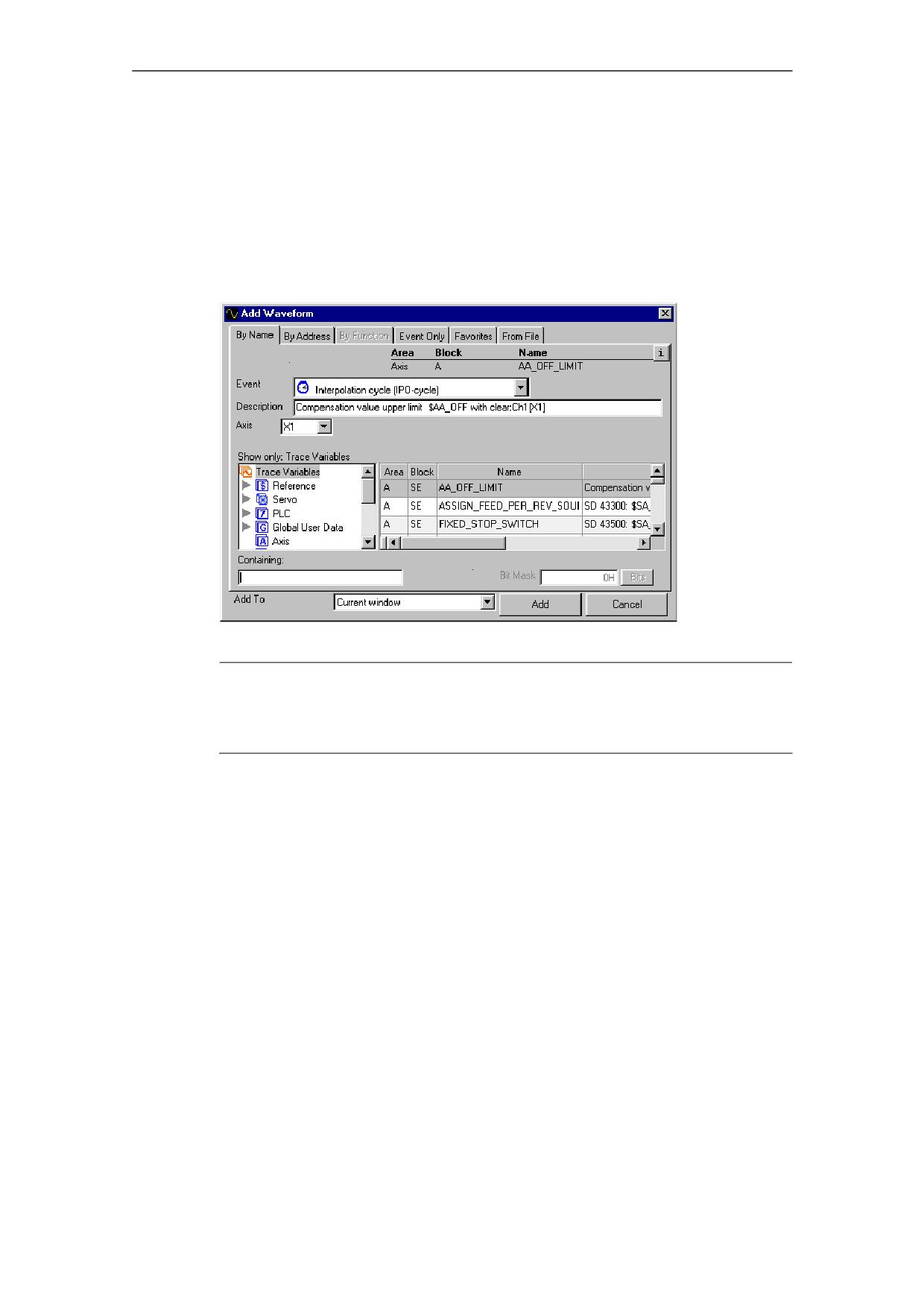
4 SinuCom NC: Functions
07/2008
4.8 SinuCom NC Trace
Add Waveform by Name
The "By Name" dialog (shown in Figure 4-4) is the first of five dialogs that is
accessible under Add Signal, and thus appears upon entry into this area. As its
name states, it is used to select the signal "by name". The list on the right side of
the dialog displays a list of names, ID’s, and descriptions. (Descriptions are
typically supplied by the machine builder.) The list can be sorted by any column by
clicking on its heading. The list is filtered based on the password currently in effect.
Figure 4-4 Add Waveform By Name
Note
If the PLC or Global User Data (GUD) categories display no entries, run the
TSIW, as described in the section: "Trace Symbol Import Wizard (TSIW)".
Show Only
This box provides a means to filter the list of names.
Selections in this area cause the list to show either "All
Variables", or to show only one category of variables (i. e.,
Axis, Channel, NCK, etc.; A:, B:, C:, etc.). Selecting one
category shortens the list to make it easier to find a specific
name. The content of each category is described on screen,
in the dialog.
Containing
This box acts as an additional filter, showing only variable
names or IDs that contain the entered text. Even if only part
of a name is entered, the list will be reduced to aid in finding
a specific name.
Note
An orange "X" will appear in the containing field to indicate
that the list is being filtered.
© Siemens AG 2008 All Rights Reserved
4-78
SINUMERIK 840D sl/840Di sl/ 840D/840Di/810D SinuCom (INC) - 07/2008
07/2008
4 SinuCom NC: Functions
4.8 SinuCom NC Trace
Bit Mask
If the variable is an integer, this field can be used to specify
an optional Bit Mask. The signal value is AND’ed with this Bit
Mask before it is displayed. After masking, all the selected
bits are squeezed to the right so that the bit/bits appear to
start at bit 0 (e. g. if all but bit 7 were masked, the resulting
integer would have a value of either 0 or 1, not 0 or 128; if all
but bits 7 and 0 were masked, the resulting integer would
have a value of either 0, 1, 2 or 3 [not 0, 1, 128 or 129).
"Add To"
Select with a drop-down list the window in which any new
waveform appears.
Based on the name selected, other "qualifiers" may be needed to identify it as a
unique entity. Fields designed to assist in this identification will appear in the upper
right of the dialog as needed (in this example shown as "Tool Area", "Point Tool
Off", and "TN". For instance, in Figure 4-4, above, the "Tool Area" field has a drop-
down menu (not shown) that offers a list of tool areas from which to select.
Often the selection from drop-down menu is self-explanatory, such as the case of
the "Tool Area" field described above. Occasionally, however, the selection of a
name will cause a field labeled "See DocOnCD" to appear. In these cases, the
information required is very specific to the variable (e. g., the selection of an array
index or an override). The detailed information needed to correctly select the entry
can be found in DocOnCD under the name being configured.
Add Waveform by Address
The "By Address" tab (shown Figure 4-4) represents the second of five dialogs that
is accessible under Add Signal. Rather than selecting by name, the signal can be
identified by a PLC address or a BTSS path specification.
Note
Access to this page is password-restricted.
There are two tabs on the "By Address" screen. "PLC Address" is the first tab, and
is thus the default dialog when the "By Address" option is selected. Entries in the
following fields are required to identify a specific address:
Memory Range One of the following memory areas must be selected:
1. Input area
2. Output area
3. Bit memory area
4. Data block
Offset
The specified offset is added to the starting address of the
Memory Range.The resultant sum is the address of the
selected variable.
© Siemens AG 2008 All Rights Reserved
SINUMERIK 840D sl/840Di sl/ 840D/840Di/810D SinuCom (INC) - 07/2008
4-79
4 SinuCom NC: Functions
07/2008
4.8 SinuCom NC Trace
Data Type
One of the following data types must be selected:
1. Character
2. Byte
3. Boolean
4. Integer
5. Word
6. Double Integer
7. Double Word
8. Real
The memory location which is identified by the Memory
Range and Offset will be interpreted as the identified Data
Type.
Waveforms can also be identified by "BTSS Address". BTSS is an addressing
scheme that is proprietary to Sinumerik. A high level of proficiency is required to
use this method to identify signals. Information on the structure of BTSS addresses
can be found elsewhere in Sinumerik documentation.
Add Waveform by Function
Add Signal by Function will be implemented in a future release. It is not available at
this time.
Add Waveform - "Event Only"
Signals can be added by "Event-Only". This is the special case where no data is
recorded. (I. e., only the occurrence of the event is recorded.) Identification of the
Event is all that is required to effect this type of recording. The choices in the drop-
down menu are the same as the items in the section: "Overview: How Trace is
Used", "List of Events".
Add Waveform - Favorites
When this tab is clicked, a list of the most recently used Event / Data combinations
will be displayed for selection. A maximum of 20 signals are retained in the list.
Unless marked as a "favorite", the oldest signal is dropped when a new signal is
added.
The following buttons are provided:
Add to Favorites
This button marks the highlighted signal with "***" in the
"Favorite" column. The entry will then be kept in the list even
if it has not been used recently.
Remove
This button removes the highlighted entry from the Recently
Used List.
© Siemens AG 2008 All Rights Reserved
4-80
SINUMERIK 840D sl/840Di sl/ 840D/840Di/810D SinuCom (INC) - 07/2008
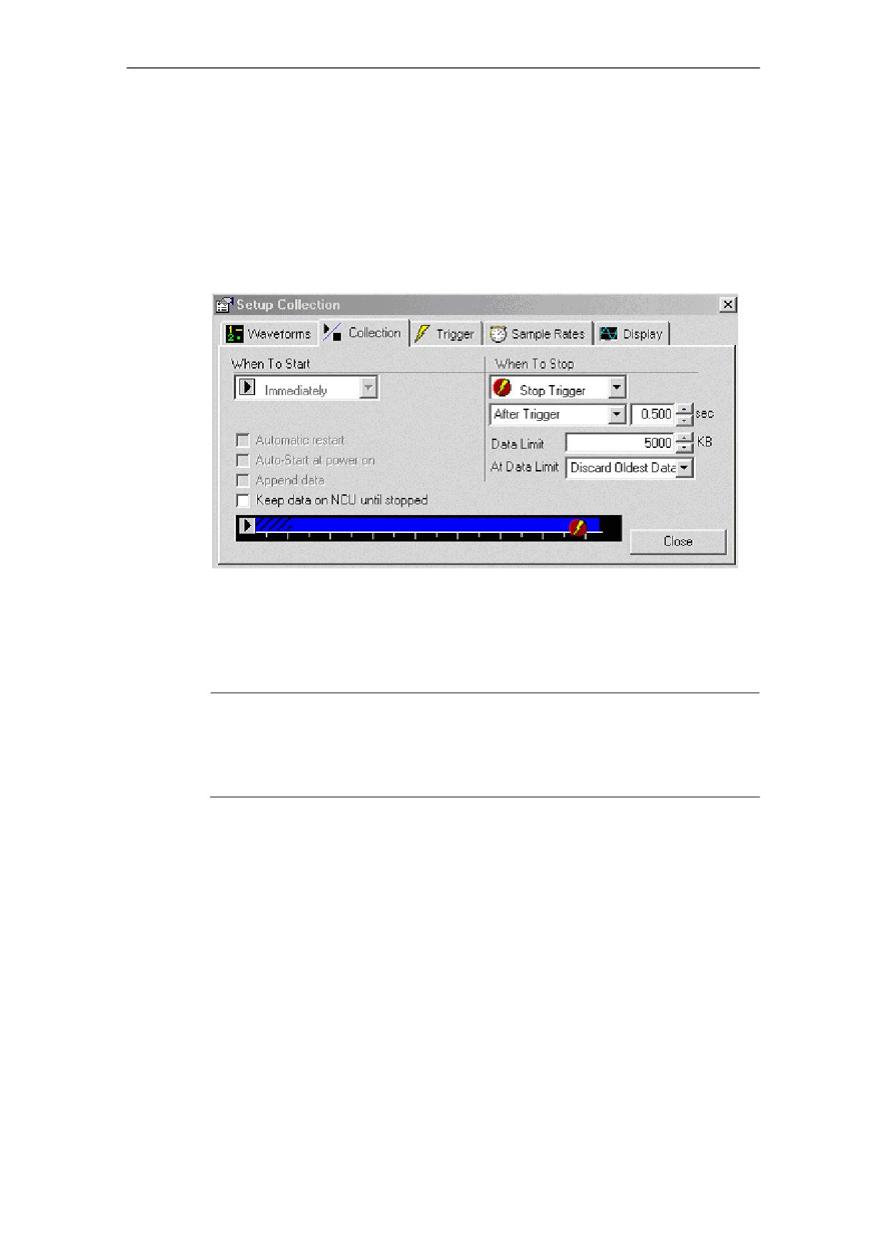
07/2008
4 SinuCom NC: Functions
4.8 SinuCom NC Trace
Add Waveform - From File
This tab, displays an "Insert from File" dialog that allows selection of specific
waveforms from a session file. These new waveforms can be brought in either as
standard waveforms, or as reference waveforms if they have data associated with
them.
Dialog: Setup Collection
Figure 4-5 Dialog: Setup Collection
The settings described in this section specify when collection (recording) is to start
and when it is to stop. As these settings are changed, a graphic image (i. e., the
bar across the window near the bottom) dynamically changes to illustrate how
these settings affect the collection process.
Note
Depending on the capabilities of the SinuCom NC of Trace that is installed
(driven by the SinuCom NC of NCK software), some of these choices may not be
available and therefore will be hidden or disabled.
"When to Start" Collection (left side of screen, Figure 4-5)
There are two choices in the drop-down menu for this feature, as shown directly
below:
Immediately
This choice specifies that recording should start immediately
when the start button is pressed (i. e. don’t wait for any start
trigger condition).
Start Trigger
This choice specifies that recording should start only if the
start trigger condition has been satisfied. If so, the next
setting specifies exactly when the recording starts, relative to
the trigger:
• At Trigger - start recording exactly at the time of the
trigger
© Siemens AG 2008 All Rights Reserved
SINUMERIK 840D sl/840Di sl/ 840D/840Di/810D SinuCom (INC) - 07/2008
4-81
4 SinuCom NC: Functions
07/2008
4.8 SinuCom NC Trace
• Before Trigger - start recording at the specified time
before the trigger occurs (pre-trigger)
• After Trigger - start recording at the specified time after
the trigger occurs (post-trigger)
Specifics of the trigger condition are defined on the Setup
Trigger page.
The following Funktions will be implemented in a future release.
Additionally, there are three checkboxes available to further define when collection
should start:
Automatic
A check in this box will cause the trigger to re-arm each time
restart
the recording stops. This immediately places Trace back into
the 'active' state, waiting for another trigger. After each
trigger, the new waveforms are displayed as the new data is
collected.
Note
This selection is not valid for Endless Recording
(see Figure 4-7).
Auto-Start at
A check in this box activates Trace at power on. In addition to
power on
automatically being ready for a defined trigger, this feature
also allows for the recording of data that occurs during the
power-on sequence).
Note
Triggers function the same during the power-on sequence as
they do at any other time.
Append data
A check in this box causes new data (evoked by a new
occurrence of the trigger) to be appended to old data. If the
box is not checked, the new data replaces the old data.
Note
If appended, the data will not represent a continuous
timeframe. There will be time gaps within it.
Note
This setting is useful in combination with the trigger setting
“Automatic restart“.
Note
This selection is not valid for Endless recording
(see Figure 4-7).
Keep data on
A check in this box will cause Trace to keep recorded data on
NCU until
the NCU until recording is stopped (i. e., to defer offloading
stopped
the data to the Trace HMI). If this box is not checked, Trace
will offload recorded data from the NCU to the Trace HMI as
soon as possible, even while recording is in progress.
© Siemens AG 2008 All Rights Reserved
4-82
SINUMERIK 840D sl/840Di sl/ 840D/840Di/810D SinuCom (INC) - 07/2008
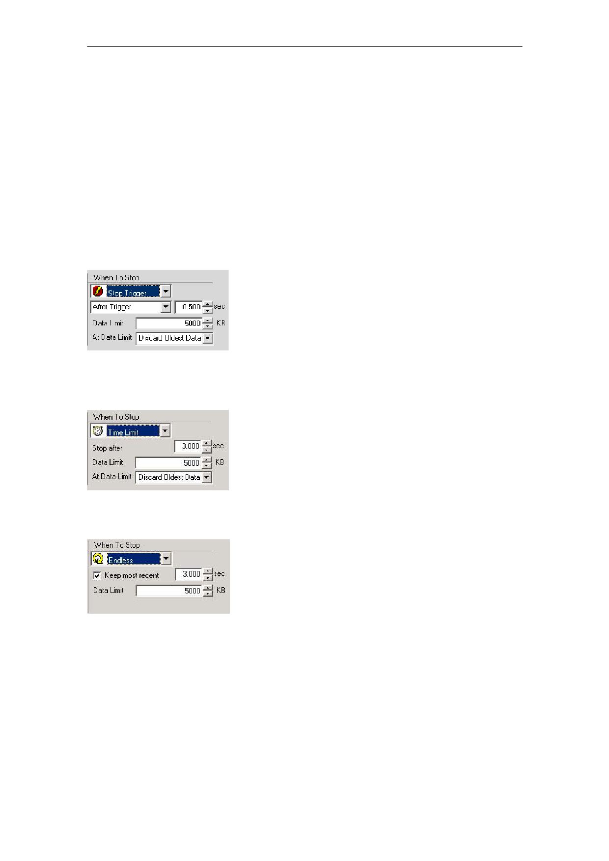
07/2008
4 SinuCom NC: Functions
4.8 SinuCom NC Trace
Note
If this box is checked, the "Data Limit" value (see next page)
applies to storage on the NCU. If this box is not checked, the
"Data Limit" value applies to storage on the “Trace HMI”.
"When to Stop" Collection (right side of screen, Figure 4-5)
The upper drop-down menu has three choices. This area of the screen changes
based on the choice, so a figure is provided for each, as shown directly below:
Stop Trigger
This choice specifies that termination of the recording is
controlled by a predetermined Stop Trigger. The second
drop-down menu can place a time qualifier on the Stop
Trigger, as follows:
• At Trigger - Recording stops exactly at the
occurrence of the Stop Trigger.
• After Trigger - Recording stops at the specified time
after the trigger occurs (post-trigger).
Figure 4-6
Stop Trigger
Time Limit
This choice specifies that the recording will occur only for the
time period specified in the "Stop After" field.
A Data Limit can also be set. If the Data Limit is reached, one
of the two choices from the "At Data Limit" drop-down menu
prevails, as follows:
• Discard Oldest Data
• Stop Collecting
Figure 4-7
Time Limit
Endless
This choice specifies that the recording continues until the
recording is manually stopped. A circular buffer is used to
store the recorded data, so only the most recent data will be
available for display. (i. e., the oldest data may be lost.). The
size of the circular buffer is specified in the "Data Limit" field.
A check in the "Keep most recent" checkbox will cause only
the specified number of seconds of data to be retained.
Additionally, the data is limited by the Data Limit amount. No
Figure 4-8
Endless
check in this box will cause data collection to be limited only
by the Data Limit amount.
© Siemens AG 2008 All Rights Reserved
SINUMERIK 840D sl/840Di sl/ 840D/840Di/810D SinuCom (INC) - 07/2008
4-83
4 SinuCom NC: Functions
07/2008
4.8 SinuCom NC Trace
Dialog: Setup Trigger
The settings described in this section define the characteristics of the trigger. If the
use of triggers is specified on the Setup Collection page, there is either a stop
trigger, a start trigger or both. These triggers apply to all recording within a given
session. If no triggers are specified on the Setup Collection page, this Setup
Trigger page is not used (and is not available).
Start Trigger/
This pair of buttons can optionally be present. Two conditions
Stop Trigger
are possible:
• Buttons present - Both a start and a stop trigger
have been specified. Selection is mutually exclusive.
On-screen data switches with the selection.
• Buttons not present - Either a start or a stop trigger
has been specified. The data applies to the specified
trigger.
Note
As described above, if there are no triggers, the window in
(see Figure 4-8) above will not appear.
Trigger
This setting specifies which signal will be used in the makeup
Waveform
of the trigger. The following selections are available:
• No trigger (i. e., field is left blank).
• Names of waveforms already defined for collection
(can be accessed via drop-down menu).
Trigger Mode
This setting specifies the type of test to be performed on the
trigger waveform. The following selections are available:
• Rising edge1 - Recording begins or ends when the
trigger transitions from lower to higher than the trigger
level.
• Falling edge1 - Recording begins or ends when the
trigger transitions from higher to lower than the trigger
level.
• Equals - Recording begins when the trigger is equal
to the trigger level.
• Not equal to -Recording begins when the trigger is
not equal to the trigger level.
• Greater than or equal - Recording begins when the
trigger is greater than or equal to the trigger level.
• Less than or equal - Recording begins when the
trigger is less than or equal to the trigger level.
• Value changed1 - Recording begins when the trigger
changes from what it was at the start of recording.
1 These functions will not appear if the installed NCK
SinuCom NC does not support them.
© Siemens AG 2008 All Rights Reserved
4-84
SINUMERIK 840D sl/840Di sl/ 840D/840Di/810D SinuCom (INC) - 07/2008
07/2008
4 SinuCom NC: Functions
4.8 SinuCom NC Trace
Trigger Level
This setting specifies the trigger waveform threshold that is
tested by the Trigger Mode.
Dialog: Setup Sample Rates
Some events are cyclic in nature. (see the section: "Overview: How Trace is Used",
"List of Events"). They appear in the "Setup Sample Rates" dialog. This dialog
allows a multiplier, or "skip count", to be applied to each of these events to reduce
their associated sampling rates (or, stated another way, increase their intervals).
The multipliers must be positive whole numbers.
Note
Sometimes after a session file is loaded, the sample rate parameters specified in
the newly-loaded session file cannot be realized with the current Basic Interval of
the NCU. In this case, a text message in red letters will appear on the "Setup
Sample Rates" dialog to indicate that the sample rates have been adjusted to
numbers that can be realized. In this condition, a button on the dialog can be
selected to acknowledge this adjustment and dismiss the warning message.
Dialog: Setup Display
This dialog allows the visual characteristics of the waveform display to be
configured.
Note
The effects of the changes are immediately reflected in the waveform display.
Note
Unlike other tabbed pages of the Setup dialog, these settings (except "Colors...")
apply to each graph window independent of other graph windows.
© Siemens AG 2008 All Rights Reserved
SINUMERIK 840D sl/840Di sl/ 840D/840Di/810D SinuCom (INC) - 07/2008
4-85
4 SinuCom NC: Functions
07/2008
4.8 SinuCom NC Trace
Rename/Select
This setting selects the graph window to which the display
Graph
settings are applied. The Graph Window name can also be
modified from this dialog.
Note
This field is not visible if only one Graph Window is present.
Waveform Tabs
This setting specifies the markings on the waveform tabs.
The choices are:
1. Show Text - The complete text description / name of the
waveform.
2. Show Numbers - The number of the waveform.
3. Show Both.
Note
It may be preferable to show the text name if there are only a
few signals; conversely, to reduce clutter, it may be
preferable to show only the number if there are many signals.
Colors…
This button calls up "Graph Window Colors" dialog. Through
its use, the colors of the following components of the graph
window may be changed:
• Background color.
• Grid lines color (major and minor).
• Axis labels color.
To change the color of one of these items, click the "Select"
button adjacent to it. A standard color selection dialog will
appear. The desired waveform color can be defined by
simple selection, or custom colors can be defined using the
associated button.
Scaling (both X
These settings determine the type of scaling for the graphs'
and Y Axes)
axes. The choices are:
• Linear scaling
• Logarithmic scaling
Note
Logarithmic scaling is not allowed for the X axis if Graph
Style is “Y vs. Time”.
Grid Lines (both
A check in one or both of these boxes determines if either the
X and Y Axes)
horizontal grid lines, vertical grid lines, or both, are visible.
© Siemens AG 2008 All Rights Reserved
4-86
SINUMERIK 840D sl/840Di sl/ 840D/840Di/810D SinuCom (INC) - 07/2008
07/2008
4 SinuCom NC: Functions
4.8 SinuCom NC Trace
Measurement Cursor
Accurate values of sampled data points can be determined through the use of the
Measurement Cursor. This cursor can be added or removed from the waveform
display either through the View Menu (as described in the section: "Toolbars and
Menus", "Menu: View") or through its icon (Figure 4-3). The numeric readout on the
toolbar reflects the X and Y positions of the selected sample point on the active
waveform. The cursor can be dragged to a desired sample point, or can be
incrementally moved from point to point using the arrows on the Measurement
Cursor toolbar.
Difference Cursors
The difference cursors are a pair of cursors that provides a function similar to the
Measurement Cursor. But instead of just one position, these are two cursors that
show two X and two Y positions, as well as the difference between them. The
position and difference information is displayed in a dialog that is visible whenever
the Difference Cursors are turned on.
The cursors can be attached to the same waveform or to different waveforms. The
waveform association is made within the dialog by first expanding the dialog with
the button and then choosing the waveforms from a dropdown list of waveform
descriptions.
© Siemens AG 2008 All Rights Reserved
SINUMERIK 840D sl/840Di sl/ 840D/840Di/810D SinuCom (INC) - 07/2008
4-87
4 SinuCom NC: Functions
07/2008
4.8 SinuCom NC Trace
4.8.7
Trace Symbol Import Wizard (TSIW)
Note
GUD and OEM PLC symbols are not available to SinuCom NC Trace until the
TSIW is run. SinuCom NC Trace adds selected symbols to the database when
this wizard finishes. These symbols are also automatically imported on any
subsequent installations of SinuCom NC Trace. As with any subsequent use of
the TSIW, this update of symbols can take several minutes.
Previous releases of SinuCom NC Trace use a static symbols database (i. e., the
set of variables that can be plotted). This database simply shipped with the system.
The TSIW offers the ability to update this database at any time with a variety of
symbol types from the machine environment. This data does not have to be
coincident with an NCK release, but instead might be part of a PLC release, or be
provided by an OEM installation. Such data includes:
Global User Data (GUD): Symbols specified by multiple providers. Categories
include:
• System GUDs - Provided by Siemens.
• OEM GUDs - Provided by a machine manufacturer.
• User GUDs - Provided for a part program or specific factory floor application.
• GUD 4 - 9: Available for special purposes.
PLC VDI Symbols - Names of PLC data created by Siemens and shipped with a
SinuCom NC of the PLC software.
Note
A set of PLC VDI symbols ships with SinuCom NC. A special procedure
must be performed to update these. (See "How to Make Symbols Available for
Import"
PLC OEM Symbols - Names of PLC data created for a particular machine
application by a machine manufacturer.
Note
Local User Data (LUD) and Program User Data (PUD) are temporary variables
created by a part program or a subprogram. The NCK creates this data at the
request of a part program and removes it when the program terminates. The
TSIW does not address this type of data.
© Siemens AG 2008 All Rights Reserved
4-88
SINUMERIK 840D sl/840Di sl/ 840D/840Di/810D SinuCom (INC) - 07/2008
07/2008
4 SinuCom NC: Functions
4.8 SinuCom NC Trace
How To Make Symbols Available for Import
Before using the TSIW, certain types of symbols must be staged for import, as
described below:
GUDs: Nothing needs to be done for these symbols. The machine environment
either has them available or it doesn’t.
PLC Symbols (OEM or VDI): This 2-step procedure must be performed only once,
prior to first use of SIMATIC Manager. It installs the SIMATIC Manager toolbox. If
this procedure has already been performed, please skip to the next appropriate
section.
Note
If the toolbox installer has been downloaded, start the downloaded file. (It may be
called 07010100.exe). This creates a folder that contains the setup.exe program.
1. Using the PG/PC, call up PLC Toolbox Setup.
2. Under "Programs to be installed":
• click "PLC Basic Program for <control> Vv.w", and
• click "SINUMERIK Add-on for STEP 7 Vx.y".
3. Click “Next>”, then continue with the procedure directly below.
Exporting the PLC Input/Output/Bit Memory Symbols from SIMATIC:
1. From the Windows® desktop, launch the SIMATIC Manager by selecting
"Start", "Programs", "SIMATIC", then "SIMATIC Manager"
2. Press "Cancel" to dismiss the "New Project Wizard".
3. From the SIMATIC Manager's File menu, select "Open..."
4. When the "Open Project" dialog appears, select the "Libraries" tab
5. From the list, select "gp8x0d“. A list of objects will appear in the window on the
right.
6. Double-click the object named "Symbols“.
7. From the window that appears select "Export“ from the Symbol Table menu.
8. From the dialog that appears, select a folder (recommended folder:
c:\siemens\sinumerik\symbols: [default for SIMATIC symbols export]).
9. Provide a filename
10.Click "Save".
11.Proceed to one of the two following procedures on the next two pages.
© Siemens AG 2008 All Rights Reserved
SINUMERIK 840D sl/840Di sl/ 840D/840Di/810D SinuCom (INC) - 07/2008
4-89
4 SinuCom NC: Functions
07/2008
4.8 SinuCom NC Trace
Updating PLC VDI Symbols: Avoid this procedure unless you have installed the
810D sl/ 840D(i) Toolbox (SinuCom NC 07.01 and newer). This procedure will take
several minutes in the TSIW, and several minutes of additional time in SinuCom
NC Trace after the TSIW completes. After performing the procedure for PLC
Symbols on the previous page, these symbols can be prepared for export from the
machine environment via the following procedure:
Caution
!
The two procedures on the preceding page must have been performed or this
procedure will fail.
1. From the Windows® desktop, launch the SIMATIC Manager by selecting
"Start", "Programs", "SIMATIC", then "SIMATIC Manager".
2. From the SIMATIC Manager's File menu, select "Open...".
3. When the "Open Project" dialog appears, select the "Libraries" tab.
4. Select the library named "gp8x0d64" (or other desired library SinuCom NC [ex:
gp8x0d71]), then press "OK". A new dialog with a project tree on the left will
appear.
5. From the project tree, select "Sources".
6. Right-click the object named "nst_udtb". (This is the object that contains the
PLC VDI symbols.)
7. From the context menu that appears, select "Export Source...".
8. Select the c:\siemens\sinumerik\symbols folder in which to save nst_udtb.AWL
(English) or nst_udt.AWL (German). Note this location, since the TSIW will be
set up to search here for the PLC VDI symbols.
9. Click "Save". The PLC VDI Symbols are now ready for import.
Updating PLC OEM Symbols: After performing the procedure for PLC Symbols
on the previous page, these symbols can be prepared for export from the machine
environment via the following procedure:
Caution
!
The two procedures on the preceding page must have been performed or this
procedure will fail.
© Siemens AG 2008 All Rights Reserved
4-90
SINUMERIK 840D sl/840Di sl/ 840D/840Di/810D SinuCom (INC) - 07/2008
07/2008
4 SinuCom NC: Functions
4.8 SinuCom NC Trace
1. From the Windows® desktop, launch the SIMATIC Manager by selecting
"Start", "Programs", "SIMATIC", then "SIMATIC Manager".
2. In the SIMATIC Manager application, select "File", "Open", and then select the
desired PLC project.
3. Double-click the compiled logic block for which you wish to export Trace
symbols.
4. From the LAD editor ("LAD, FBD - Programming S7 Blocks.") select "File",
"Generate Source" from the File menu. The new dialog will appear.
5. In the "Object Name" box, key in the name of the source file that will contain the
desired PLC OEM symbols, then press "OK".
6. The "Generate source <object>" dialog will appear.
7. Highlight the blocks in the "Blocks Not Selected" window that contain the
symbols to be imported, then use the right arrow to move these blocks to the
"Blocks Selected" window. Make sure the "Symbolic" option is selected.
8. Activate the SIMATIC Manager (click on it).
9. From the project tree, select "Sources".
10.Right-Click the new Source file in the list.
11.From the menu that appears, select "Export Source...".
12.Select the c:\siemens\sinumerik\symbols folder.
13.Click "Save". The PLC OEM Symbols are now ready for import.
Importing the Symbols
Once symbols are prepared for import (as described above) the Trace Symbol
Import Wizard can be invoked from SinuCom NC through the following procedure:
1. If SinuCom NC Trace is not already running, start Trace from SinuCom NC (as
described in "A Hands-On Example").
2. Select "File" from the main menu.
3. Select "Import Symbols...". The Overview screen will appear, indicating if any
symbols now exist in the NC that have not yet been imported into SinuCom NC.
4. Select “Next>”. The user is then asked if a Custom or an Express Import is to be
performed.
5. Select "Express Import".
© Siemens AG 2008 All Rights Reserved
SINUMERIK 840D sl/840Di sl/ 840D/840Di/810D SinuCom (INC) - 07/2008
4-91
4 SinuCom NC: Functions
07/2008
4.8 SinuCom NC Trace
6. For PLC symbols, the "Include PLC Symbols" check is made available by typing
the name of the PLC folder (only if the symbols are located in a folder othere
than the default). Typing an invalid folder or one with no symbols invalidates
the "Include PLC Symbols check box.
7. Click Finish
8. When the procedure completes the wizard disappears. The new symbols are
now available for use in SinuCom NC Trace.
Express versus Custom Import
Note
An Express Import is recommended to reduce the complexity of this procedure.
Express Import: Prepares the wizard to accept all default selections, and to import
PLC symbols from the specified folder. TSIW will disable the "Include PLC
symbols" checkbox if the folder specification is incorrect or the folder does not
contain the required symbol files (reference "How to Make Symbols Available for
Import"). The "Browse" button can be used to correct the folder specification.
Clicking the "Finish" button proceeds directly to the Summary screen and starts the
import process. However if there is nothing for the Wizard to do, only the Cancel
button will be available.
Custom Import: Allows to decide whether to import GUDs and which kind of PLC
symbols to import. This is only recommended for users who need a greater degree
of control over what symbols are added into the database. Clicking the “Next>”
button advances the dialog to Global User Data.
The following screens apply only to the "Custom" selection:
• Global User Data
• PLC Variables
Global User Data
If there are GUDs available for import, this selection on the left of the screen is
active. Selecting it yields a list of any GUDs available for import (if any). (Note that
the wizard will display only GUD categories with defined GUDs. For example when
there are no GUDs in a category, the category is skipped) Each GUD displayed
might have available GUDs for "Channel", "General", both or neither.
© Siemens AG 2008 All Rights Reserved
4-92
SINUMERIK 840D sl/840Di sl/ 840D/840Di/810D SinuCom (INC) - 07/2008
07/2008
4 SinuCom NC: Functions
4.8 SinuCom NC Trace
PLC Variables
Note
Typically PLC VDI symbols are already installed. The mention of PLC VDI
symbols only applies when a SinuCom NC update is required.
If there are either PLC VDI or PLC OEM variables available for import, the "PLC
Variables" selection on the left of the screen is active. Import of these two variable
types is identical. Thus, they are loaded at the same time with the same tool.
In addition to allows user to select a pertinent folder or project file (first two
buttons), the following selections it allows to specify the types of symbols to be
imported:
Note
The following choices appear on the "General" tab:
• Import I, Q, M symbols
• Import User DB symbols
When you prepare VDI Symbols for upgrade, the "Advanced" tab becomes
available. Using this tab requires prior selection of Import I, Q, M symbols.
Clicking the "Advanced" tab reveals the following additional choice:
• Import PLC-NC Interface (VDI) symbols.
After the choices above have been made, any new PLC variables available for
import are displayed.
Summary Screen
Prior to exiting the TSIW, the Summary Screen confirms the choice of symbols for
import, and displays progress as it creates the database files to be used by
SinuCom NC Trace. When importing activities complete, the TSIW dismisses itself.
© Siemens AG 2008 All Rights Reserved
SINUMERIK 840D sl/840Di sl/ 840D/840Di/810D SinuCom (INC) - 07/2008
4-93
4 SinuCom NC: Functions
07/2008
4.8 SinuCom NC Trace
4.8.8
Trace Setup Wizard (TSW)
SINUMERIK 840D Trace must be properly configured to support SinuCom NC
Trace and the SI Acceptance Test.
The TSW provides two choices for configuration:
• EXPRESS (to minimize the required steps, yet still provide a typical
configuration).
• CUSTOM (for experts, who wish to fine tune the configuration).
If a message box suggesting use of the TSW appears at startup, an unsuitable
configuration is present. The TSW must be run in this case.
Note
A startup check is performed by SinuCom NC Trace (Trace) and SI Acceptance
Test for minimum Trace resources. A message box appears if this test fails. If
this occurs, use the Trace Setup Wizard (TSW) to configure the Trace
applications that you want to run. After successfully running the TSW, SinuCom
NC Trace applications will start up without interruption.
To start the TSW from the SinuCom NC opening screen:
1.
Select "Open Online Project" from its toolbar button or the "Target Syst."
menu.
2.
Expand the Sinumerik folder and double-click on the machine data block
(e. g., "MD-block 1").
Ensure that the "Display Dialog" (not the Expert List) is active.
3.
Click on "Trace Setup Wizard" in the project tree.
Overview Dialog
The Overview Dialog is the opening screen for the TSW. It describes the current
state of the system’s Trace Server and NCK configuration according to the
selected trace applications. This shows whether the currently configured trace
applications are consistent with the current NCK configuration and NCK SinuCom
NC.
The Overview displays the connected NCK’s name, SinuCom NC number, and
current SRAM and DRAM utilization.
The Overview also shows the status of each configured application. A green check
mark (
) icon indicates that the current configuration supports the running of this
application. A red "X" means that this application cannot run with the current
configuration.
Along with the red "X", a “Results” button appears. Pressing this button describes
why the application won’t run with the current configuration.
© Siemens AG 2008 All Rights Reserved
4-94
SINUMERIK 840D sl/840Di sl/ 840D/840Di/810D SinuCom (INC) - 07/2008
07/2008
4 SinuCom NC: Functions
4.8 SinuCom NC Trace
Setup Method Dialog
Note
Express Setup is recommended to reduce the complexity of this procedure.
Express: Prepares the wizard to accept all default selections. Clicking the "Finish"
button proceeds directly to the Summary screen and starts the setup process.
However, if the Wizard finds nothing to do, only the Cancel button will be available.
Custom: Allows users to decide whether to provide specific values for resource
allocations. This is only recommended for users who want a greater degree of
control over the settings for individual trace application. Clicking the “Next>” button
proceeds to the applications list.
The following screens are available only in Custom Setup mode:
• Trace Applications List.
• SinuCom NC Trace
• Generic Trace Client
• Advanced Features
Trace Applications List
Note
Warning text indicates if an earlier NCK SinuCom NC will not allow the SI
Acceptance Test to run.
The Trace Applications List provides information to balance the available trace
resources among the SinuCom NC applications. Therefore, it is best not to click
"Yes" for an application unless you have a known need to run it.
There is also a choice between sharing slots or configuring multiple slots. Each
allocated slot corresponds to a resource that hosts a trace recording session. SI
Acceptance Test uses only one recording session, but SinuCom NC trace can use
more than one recording session. SinuCom NC Trace can start a recording
session and switch to another. Simultaneous use of multiple trace recording
sessions is an advanced feature.
Slot allocation selections are:
• One shared slot for all applications. (This is only choice for earlier NCK
SinuCom NCs.)
• Multiple slots to be shared for all applications.
Note
A configuration page is provided for Trace and Generic applications. Generic
applications are optional and are not available in most cases.
© Siemens AG 2008 All Rights Reserved
SINUMERIK 840D sl/840Di sl/ 840D/840Di/810D SinuCom (INC) - 07/2008
4-95