SINUMERIK 840D sl. Service - Configuring Commissioning. Manual (2011-2020) - page 112
4 SinuCom NC: Functions
07/2008
4.8 SinuCom NC Trace
Note
A configuration page is not presented for the SI Acceptance Test because its
requirements are fixed.
Common General Configuration Items
These items are available for fine tuning SinuCom NC Trace and Generic
applications. Please avoid changing these values unless you need to customize
your settings. The Summary section can be skipped if performing an "Express
Setup“.
• Maximum simultaneous sessions: Total user slots required by this
application. Slots should be used sparingly to avoid impairing other control
functions.
• Maximum standard unique data lists: (memory) Total standard events.
Each combination of a different standard event and NCK data item
requires one list. Reference: MD 18371,
MM_PROTOC_NUM_ETPD_STD_LST.
• Highest standard event ID: (memory) highest event number used.
Normally all standard events should be included. Reference: MD 28302,
MM_PROTOC_NUM_ETP_STD_TYP.
• Maximum OEM unique data lists: (memory) Total OEM events. Each
combination of a different OEM event and NCK data item requires one list.
Reference MD 18372, MM_PROTOC_NUM_ETPD_OEM_LST.
• Highest OEM event ID: (memory) Highest NCK OEM event number.
Reference: MD 28301, MM_PROTOC_NUM_ETP_STD_TYP.
• Maximum simultaneous servo signals: (memory) Total servo data items
per session. Reference: MD 18373, MM_PROTOC_NUM_SERVO_DATA.
Common Advanced Configuration Items
• Amount of data stored in the NCU SRAM/DRAM log file: Maximum file size
for the NCK log file. Data loss occurs when the logged data exceeds this
size prior to being offloaded to the HMI. Corresponds with TraceSrv.ini key
nckFileSize. Note deferred offloading overrides this size with the value
specified for a Trace.
• Amount of data stored in the HMI hard drive log file: Maximum size for the
log file offloaded to the HMI’s hard drive. If the session’s total amount of
data logged exceeds this size (without a client consuming the data), data
loss occurs. Corresponds with TraceSrv.ini key "HmiFileCapacity". Note If
a session disables deferred offloading, the size in the session overrides
this.
• Amount of data cached to the HMI RAM Frame: Maximum data memory
for logging that is cached for quick client access on the HMI. This
allocation uses the OS virtual memory pool, and thereby affects other
applications running on the CPU. Corresponds with TraceSrv.ini key
"HmiFrameCapacity".
© Siemens AG 2008 All Rights Reserved
4-96
SINUMERIK 840D sl/840Di sl/ 840D/840Di/810D SinuCom (INC) - 07/2008
07/2008
4 SinuCom NC: Functions
4.8 SinuCom NC Trace
• Size of the NCK Trace Logging Buffer: Size of the FIFO buffer on the NCK
that spools captured data to the NCK Log File. Determines the memory
resource allocation on the NCK. Decreasing the size can cause data loss.
Reference: MD 18374, MM_PROTOC_FILE_BUFFER_SIZE.
• Type of NCK Memory used for log data file: Selects SRAM or DRAM for
the NCK Trace log file. Reference: MD 11295, PROTOC_FILE_MEM.
SinuCom NC Trace
SinuCom NC Trace has requirements that vary with each session. A minimal
resource allocation is provided by default
Generic Trace Client
The Generic Trace Client does not appear in most installations. If it does appear,
there are a few unique configuration details:
• Application Name: Text string user name displayed for generic trace
application.
• Generic Trace Client Name: Text string representing the key used to
identify the application in the TraceSrv.ini file.
Advanced Features
The Trace Setup Wizard advanced features page provides entries for expert
configuration of Trace services. Some items represent resources that are shared
by multiple applications. For these items, the current values and the required
values are displayed. The user can override the required values or accept the
calculated value.
• Amount of data storage in the NCU SRAM/DRAM Log: Maximum file size
for the NCK log file. Data loss occurs when the logged data exceeds this
size prior to being offloaded to the HMI. Corresponds with TraceSrv.ini key
nckFileSize. Note deferred offloading replaces this size with the value
specified for a Trace.
• Amount of data stored in the HMI hard drive log file: Maximum size for the
log file offloaded to the HMI’s hard drive. If the session’s total amount of
data logged exceeds this size (without a client consuming the data), data
loss occurs. Corresponds with TraceSrv.ini key HmiFileCapacity.
• Amount of data cached to the HMI RAM Frame: Maximum data memory
for logging that is cached for quick client access on the HMI. This
allocation uses the OS virtual memory pool, and thereby affects other
applications running on the CPU. Corresponds with TraceSrv.ini key
HmiFrameCapacity.
• Required User Slots: The number of NCK Trace user slots required to
support the currently configured applications. If the slot range is not
correctly specified a session may not be hosted by the NCK because of
slot limitations.
• Lowest valid trace user slot: This is the lowest user slot that can be
reserved by the Trace Server for use. Corresponds with TraceSrv.ini key
LowestUserSlot.
© Siemens AG 2008 All Rights Reserved
SINUMERIK 840D sl/840Di sl/ 840D/840Di/810D SinuCom (INC) - 07/2008
4-97
4 SinuCom NC: Functions
07/2008
4.8 SinuCom NC Trace
Note 1
This item, in conjunction with the highest user slot, determines the valid range of
NCK Trace user slots available for use by the Trace Server and its client
applications.
Note 2
User slots 1,2, and 3 are reserved for use by Siemens applications.
• Highest valid trace user slot: Highest user slot that can be reserved for
use. Corresponds with TraceSrv.ini key HighestUserSlot.
• Trace Server stays alive when no client exists: Prevents the Trace Server
from shutting down when no client applications are running. Corresponds
with TraceSrv.ini key KeepTraceSrvAlive.
Note
If the Trace Server is kept running, only system shutdown will terminate the
server. This may present problems if other HMI Base servers are terminated.
• Maintain NCU Trace diagnostic file: Causes the Trace Server to create and
maintain an NCK Trace Diagnostic file on the NCK. The file:
SIEMPROTOKSTATUS.MPF is maintained in the MPF directory. The
diagnostic file records configuration and memory utilization data that can
be used for problem diagnosis. Corresponds with TraceSrv.ini key
RetainTraceDiagnosticFile.
Note Feature, not currently supported.
Summary Screen
The Trace Setup Wizard transitions to the summary page when the user presses
the “Finish” Button. The summary page indicates progress through the
configuration list with an arrow that appears next to each completed item. The
process suspends if an NCK reset or NCK memory archive is required. Continue
the process by pressing the "Execute..." button on the SinuComNC tool bar.
When setup activities complete, the TSW returns to the Overview Dialog.
© Siemens AG 2008 All Rights Reserved
4-98
SINUMERIK 840D sl/840Di sl/ 840D/840Di/810D SinuCom (INC) - 07/2008
07/2008
4 SinuCom NC: Functions
4.9 Safety Integrated Acceptance Test Wizard
4.9 Safety Integrated Acceptance Test Wizard
Background and Definitions
EC Machine Directive requires the original equipment manufacturer (OEM) to:
• run acceptance testing on safety-relevant functions and machine parts.
• generate an "Acceptance Test Certificate" showing the test results.
The Safety Integrated Acceptance Test Wizard ("SI Wizard") is a "front end"
designed to accomplish the above tasks. It eases the work of the OEM by:
• Providing a standard way of adding the needed safety measures through the
use of a user interface which has the look and feel of other components within
SinuCom NC.
• Minimizing the number of steps involved in performing a given test.
• Integrating/automating the test instructions, test actions, collection of data and
generation of the Acceptance Test Certificate in "wizard format".
• Allowing the user to determine pass/fail status of each test (i. e., the decision-
making process is not automated).
• Making the test results easy to view, clear and repeat as desired.
Compatibility with Siemens Software
SinuCom NC - Must be version 06.03.10 or later in power line.
SinuCom NC - Must be version 07.02.01 or later in solution line.
NCK - Must be version 06.04.15 or later.
Acceptance Test Certificate
The Acceptance Test Certificate is generated in the same language that has been
selected as the SinuCom NC UI language. It is produced as a file in Rich Text
Format (RTF). RTF is a standard format compatible with many text editors,
including MicroSoft Word®.
4.9.1
Example:
1. Activate SinuCom NC.
2. Click "Diagnosis" in the SinuCom NC main menu.
3. Click "SI Acceptance Test" in the Diagnosis menu. The "Introduction/ Overview"
Screen will appear.
© Siemens AG 2008 All Rights Reserved
SINUMERIK 840D sl/840Di sl/ 840D/840Di/810D SinuCom (INC) - 07/2008
4-99
4 SinuCom NC: Functions
07/2008
4.9 Safety Integrated Acceptance Test Wizard
4. Key in representative data in the fields on the right side of the screen. Entries
made here describe the test environment, and will ultimately appear on the
Acceptance Test Certificate. Field descriptions are as follows:
•
Machine designation - The machine name (e. g., "Polaris 9000").
•
Machine type - The kind of machine (e. g., knee mill).
•
Serial number - The unique serialized number assigned to the machine
by the OEM.
•
Manufacturer - The machine maker, or OEM.
•
PLC SinuCom NC manufacturer - The manufacturer of the PLC.
•
Ultimate customer - The end-user of the machine.
•
Name of tester - The person running the test.
•
Series machine startup - Check if the machine is part of a production
run of similar machines.
•
"Safe programmable logic" - automatical setting, whether SPL existent
or inexistent.
5. Click "Functional Relationships" in the List of Tests on the left side of the
screen. The "Summary Functional Relationships" screen will appear.
Note
"Functional Relationships" was chosen for this example because it is a basic
type of test. It simply allows manual entry of any test, and the results of the
test.
6. Click the "Begin This Test" button. The "Results New Test" screen will appear.
7. Note that a "New Test" has been added to the List of Tests under "Functional
Relationships".
8. Click the "Continue Test" button. The "Results New Test" screen is now
updated to allow tester to perform any test that is desired. The tester can
manually name the test, and and can document the Test Trigger Condition and
Result in the fields provided. The name given to the test now appears in the List
of Tests.
9. Select "Click here if functional test valid". The test is now marked as "passed
(green check). In any other case, a red cross is displayed.
10.Click the "Finish" button near the bottom of the screen. The "Finished" screen
will appear.
11.Click the "Generate Certificate" button. Because the test suite for this example
is not complete, a prompt asking if a partial certificate will appear.
12.Click "Yes". A "Save" dialog box will appear.
13.Key in a path and filename and click the "Save" button.
© Siemens AG 2008 All Rights Reserved
4-100
SINUMERIK 840D sl/840Di sl/ 840D/840Di/810D SinuCom (INC) - 07/2008
07/2008
4 SinuCom NC: Functions
4.9 Safety Integrated Acceptance Test Wizard
4.9.2
Common Screen Contents
All SI Wizard screens consist of two major display regions:
• A Selection/Status Pane (i. e., the List of Tests on the left)
• A Dialog Pane (i. e., the area on the right).
The following features are found at the top of each screen:
• The Test Title
• The screen type
• A prompt below the Test Title
The "Next Page", "Previous Page" and "Finish" buttons appear at the bottom left.
They are useful for navigating within and among tests.
Buttons for Cancel and Help appear at the bottom right.
Note
The Cancel button terminates the wizard, but may request further confirmation
before termination is allowed.
The Selection/Status Pane
The Selection/Status pane (left side of initial screen) has two main functions:
• Display of status information pertaining to individual tests and the overall
acceptance test.
• Navigation between test steps and between test results.
Initially, this list contains one entry per test step with a final entry, “Finished”, used
primarily for status.
Tests are displayed under the appropriate test step as they are invoked. They
appear in one of three states:
• Enabled Tests - Tests that are appropriate for the machine type and must be
run.
• Disabled Tests - Tests that are inappropriate for the machine type and
feature content and cannot be run. (I. e., tests that require Safe Programmable
Logic are unavailable if that feature is not present.)
• Deselected Tests - Tests that have been specified as not applicable for the
current machine configuration by the user. Tests are deselected by navigating
to the individual test and then deselecting the test by checking a checkbox on
the test summary screen.
As tests are performed, the list is modified to show the status of individual tests.
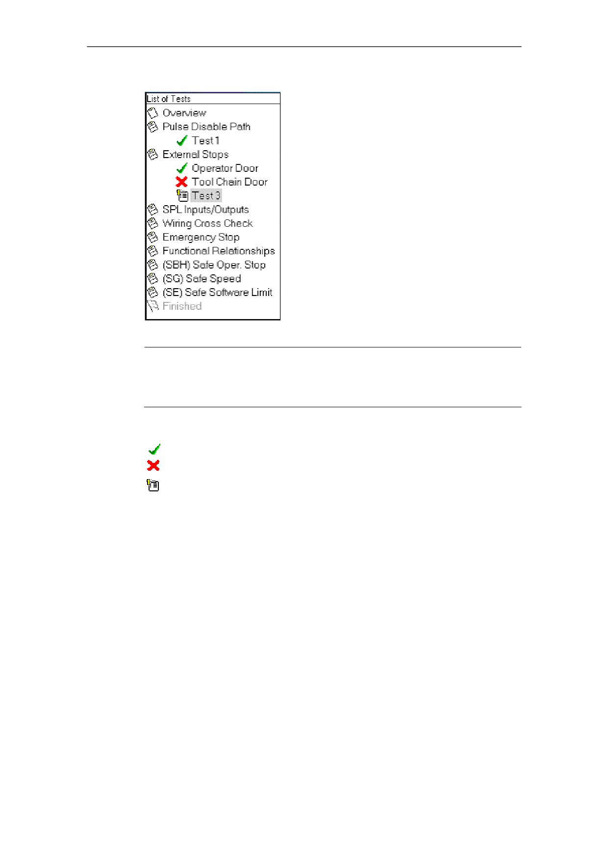
Figure 4-9, below, is an example of the results of four tests:
• “Test1” (passed, "Pulse Disable Path" step).
• “Operator Door” (passed, "External Stops" step).
• “Tool Chain Door” (failed, "External Stops" step).
• Test 3 (Test is currenty being run)
© Siemens AG 2008 All Rights Reserved
SINUMERIK 840D sl/840Di sl/ 840D/840Di/810D SinuCom (INC) - 07/2008
4-101
4 SinuCom NC: Functions
07/2008
4.9 Safety Integrated Acceptance Test Wizard
Figure 4-9 Status Display with Test Results
Note
Status of a given test is displayed as an indented entry that appears beneath the
corresponding test step.
The status of each test is indicated by one of the following icons:
Test has been run and has passed.
Test has been run and has failed.
Test is currenty being run. (I. e., test is incomplete).
The tester can take action on the test results by right clicking anywhere within the
Selection/Status display. A window appears that offers the following choices:
• Load Test Results... (allows previously-recorded test results to be retrieved
from a file).
• Save Test Results... (allows current test results to be stored in a file).
• Reset All Tests (erases all current test results).
The last entry in the List of Tests is labeled “Finished”. Initially, this entry is
disabled (greyed) and is enabled upon completion of at least one iteration of each
of the tests (regardless of pass/fail status).
© Siemens AG 2008 All Rights Reserved
4-102
SINUMERIK 840D sl/840Di sl/ 840D/840Di/810D SinuCom (INC) - 07/2008
07/2008
4 SinuCom NC: Functions
4.9 Safety Integrated Acceptance Test Wizard
Dialog Pane
The Dialog Pane (right side of initial screen) contains interactive information that is
specific to the test that has been selected in the Selection/Status Pane.
Since most tests have similar operational steps (i. e., setup, induce the failure, and
verify the results) each of the dialogs has generally the same operational model.
Each test is typically represented by three screen types:
• Test Summary Screen - Describes the purpose, procedure, and any warnings
associated with the test. Pressing the "Begin This Test" button advances the
dialog to the "Running Test Screen".
• Running Test Screen - Provides a step-by-step series of prompts such as:
- Establish initial conditions (e. g., select the appropriate axis)
- Start the test (will also auto-start the data collection)
- Terminate data collection
- Select data to be saved
- Restore initial conditions (usually a prompt for the operator to restore the
machine)
Each step of each step has colored a number box with the following color:
Green box - indicates a completed step. The user cannot progress to next step
without completing the current step.
Yellow box - indicates the current step. The prompt that appears in the display
area at the top of the dialog applies to this step.
Gray box - indicates an upcoming step.
• Test Results Screen - This screen:
-
Allows manual entry of the pass/fail status of the test.
-
Allows entry of observations for test results, if required. (Prompting that
includes the captured data from the Running Test screen may occur.).
-
Provides a “Repeat This Test” button at end of test, if appropriate.
-
Provides a “Delete Test Results” button at end of test, if appropriate.
Note
If "Repeat This Test" is selected, results from the current test are NOT discarded.
(Test data is discarded only when "Delete This Test" is selected.) Repeating is
appropriate when the same test is run multiple times with different commissioning
(e. g., tests performed on multiple I/O points or axes.).
© Siemens AG 2008 All Rights Reserved
SINUMERIK 840D sl/840Di sl/ 840D/840Di/810D SinuCom (INC) - 07/2008
4-103
4 SinuCom NC: Functions
07/2008
4.9 Safety Integrated Acceptance Test Wizard
Alarm Display (only in connection with templates)
The table format allows each alarm to be saved via checkbox. Three types of
collected alarms are available via tab selection:
Tabelle 4-1:
Alarms
Description
"Collected" Alarms
All alarms that were detected during the running of the
tests.
"Unexpected" Alarms
Collected alarms specified in the template as "MustNotOccur".
"Missing" alarms
Alarms specified in the template as "MustOccur", but did not
occur.
"Unexpected" alarms are always shown in both the list of "Collected Alarms" (in
red), and in the list of "Unexpected Alarms".
Repeat Same Test
Through the "Repeat Same Test" button on the Results page, the user can now
create a new test with the same commissioning settings as the prior test.
Note
This button does not appear when operating with a template since new tests are
not allowed when a template is active.
4.9.3
Custom Templates
Custom templates (also known simply as "templates") - they exist in the form of an
XML file.
These custom templates are typically created by expert users and can be adapted
to specific machines.
The set of tests that a template executes can be made up of any of the test types
currently supported by the CT Editor (CTEditor.exe) supplied. In addition, the user
can enter his/her own instruction texts. Also, the axes to be tested and the
sequence of steps can be selected. Tests for functions which are not provided on
the machine are not defined in these templates or included in the test procedure.
The test to be performed has thus been reduced to the basics through:
• Custom instruction texts which can be adapted to the specific machine.
• Acceptance testing which can then be performed, even by the novice.
© Siemens AG 2008 All Rights Reserved
4-104
SINUMERIK 840D sl/840Di sl/ 840D/840Di/810D SinuCom (INC) - 07/2008
07/2008
4 SinuCom NC: Functions
4.9 Safety Integrated Acceptance Test Wizard
Facts About Custom Templates
• When a template is active, the system displays only the tests in the tree view
which are defined in the template.
• A template test cannot be deleted (and cannot be removed from the results list)
as long as the template is active. When a template test is reset, it returns to its
"Not Tested" state.
• The user cannot create any new tests while a template is active.
• A test which has not yet been performed is marked in the tree view by a blue
exclamation mark.
• When a template is active, the entries made (e. g. descriptions or instructions)
cannot be modified.
• Templates are language-specific. To switch languages, a new template must be
selected.
• Running a template is much the same as running a normal test, except that the
system prompts for data entry are skipped. (This was already done when the
custom template was created.)
• You need not make any inputs (axis selection, input of text) while a template is
active. The user is required only to enter the pass/fail status of the test.
Customized Test Prompts
To provide more meaningful instruction, texts supplied by the template file replace
default text in the user interface. If a text is not supplied, the default text is used.
The following texts can be overridden:
• Summary Page Procedure
- This replaces the text that appears under the
"Procedure" portion of the Test Summary. All
other texts remain as their default setting.
• Test Step Specific Prompt
- This replaces the instructional text at the right
of the test step indicator.
• Data Collection Dialog
- Appears on the Data Collection Dialog. It
Prompt
instructs the user to initiate the test condition.
© Siemens AG 2008 All Rights Reserved
SINUMERIK 840D sl/840Di sl/ 840D/840Di/810D SinuCom (INC) - 07/2008
4-105
4 SinuCom NC: Functions
07/2008
4.9 Safety Integrated Acceptance Test Wizard
Loading a Custom Template
There are two mechanisms for loading a template:
• The "Load Template..." button on the "Template Info..." page.
• The "Load Template..." menu item in the context menu of the SI Wizard
"Selection/Status" page.
Selection of either choice presents a Windows® "File Open" dialog with a filter set
to show template (i. e., .xml) files.
Note
If there are results present when the user attempts to load a template, a message
box is displayed that indicates that the results will be lost if the template is loaded.
The load operation can be either canceled or completed.
Unloading a Custom Template
There are two mechanisms for unloading a template:
•
The "Unload Template" button on the "Template Info..." page.
•
The "Unload Template" menu item in the context menu of the SI Wizard
"Selection/Status" page.
Unloading a template causes the following to occur:
•
All tests in the template with the state "Not Tested" are removed.
•
All tests in the template with the state "Passed" or "Failed" are retained
(including the contents of the "Overview" page).
•
The contents of the "Template Info" page are changed to show that a
template is not active.
•
The template indicator at the top of the SI Wizard "Selection/Status" pane
is removed.
•
All test prompts are reverted to the default prompts.
Creating and Modifying Templates
Templates can be created by:
•
Saving the results of a standard SI Wizard test as a template.
•
Modifying an existing template, then saving it in as new XML file.
•
Starting from scratch using the "CT Editor". (See "The Custom Template
("CT") Editor")
Saving Results as a Template
A template can be exported from the SI Wizard as a custom template file by using
the "Export" selection in the File Menu. The exported file contains the information
for each test result, including all test commissioning data (e. g., axis selections,
direction, etc.), and all test documentation data (e. g., trigger condition, tested
circuit, etc.). The exported file will not contain any prompt information.
For tests with alarm data, the collected alarms will be exported as "Must Occur"
alarm entries. Exported alarm data is provided as a convenience to the user;
however, it is not intended to be a complete solution, but rather a starting point for
the created template.
© Siemens AG 2008 All Rights Reserved
4-106
SINUMERIK 840D sl/840Di sl/ 840D/840Di/810D SinuCom (INC) - 07/2008
07/2008
4 SinuCom NC: Functions
4.9 Safety Integrated Acceptance Test Wizard
Note
This capability is not intended to fully allow a template to be created from an
existing set of test results, but rather is intended as an aid in the conSinuCom NC
of existing results to a template file.
The Custom Template ("CT") Editor
Note
Use of the CT Editor requires that SinuCom NC 06.04 or later be installed, but not
necessarily running.
To start the CT Editor:
1.
On the Windows® Desktop, open the "SinuComNc" folder.
2.
Drag the CT Editor shortcut to the Windows® Desktop.
3.
Double-click on the CT Editor icon.
When the editor is launched, the "Template Information" page appears.
Menus:
There are four sub-menus in the main menu:
• the File Menu
• the Action Menu
• the Settings Menu
• the Help Menu
The File Menu allows:
• Creation of a new template
• Opening an existing template
• Saving a Template
• Exiting the editor
The Action Menu allows the adding or removal of tests.
Right-clicking on any test type in the tree view yields a pop-up menu identical to the
Action Menu.
© Siemens AG 2008 All Rights Reserved
SINUMERIK 840D sl/840Di sl/ 840D/840Di/810D SinuCom (INC) - 07/2008
4-107
4 SinuCom NC: Functions
07/2008
4.9 Safety Integrated Acceptance Test Wizard
Alarm Control:
The following tests have alarms:
• Pulse Disable Path
• SPL Inputs/Outputs
• Safe Operating Stops (SBH
• Safely Reduced Speed (SG)
• Safe Software Limit Switch (SE)
Whenever one of these test types is added, three vertical boxes appear on the
right side of the screen, each with "Add Alarm" and "Remove Alarm" buttons.
These features allow the population of alarms in the following three categories:
• Must Not Occur
• Must Occur
• Filtered (i. e., unimportant alarms to be excluded from the tests)
It is an error to include:
• the same alarm in both the "Must Occur" and "Must Not Occur" lists.
• "Must Occur" or "Must Not Occur" in the "Filtered" list.
Limit Checking of Test Results
The user can supply test-specific limit values against which test results can be
checked. Limits and actual values are displayed on the Results page. If the limit is
violated, the data is displayed in red.
Saving the Template
After configuration of the Custom Template is completed, the editor creates the
.XML template. The "Save" function allows preservation of the template in a
fashion similar to other Windows® applications.
XML Structure of the Custom Template
Note
Direct modification of XML code is not recommended. However, it can be
performed by expert users if necessary. This manual does not address the details
of XML code modification.
© Siemens AG 2008 All Rights Reserved
4-108
SINUMERIK 840D sl/840Di sl/ 840D/840Di/810D SinuCom (INC) - 07/2008
07/2008
5 SinuCom FFS: Functions
5.1 Operation
5
5 SinuCom FFS: Functions
5.1 Operation
5-110
5.2 Display of the NC image
5-110
5.3 Displaying/editing the FFS image
5-110
5.4 Writing/Reading an NC image to NC card
5-111
© Siemens AG 2008 All Rights Reserved
SINUMERIK 840D sl/840Di sl/ 840D/840Di/810D SinuCom (INC) - 07/2008
5-109
5 SinuCom FFS: Functions
07/2008
5.1 Operation
5.1 Operation
Start the SinuCom FFS program on your PC/PG, for example, via "Start" →
"Programs" → "SinuCom" → "SinuComFFS".
5.2 Display of the NC image
In the basic display the modules of the NC image are displayed with
• name
• version
• date
• size
• checksum
Properties
With menu items "View” → “Properties" you can display
• the contents of the serial number file or
• the PCM version with which the image was generated.
5.3 Displaying/editing the FFS image
Irrespective of the SINUMERIK system software (NC), SinuCom FFS can
• read
• change
• rewrite
• reformat the FFS range of the NC card
• create new directories
• copy and insert a file in the directories and subdirectories (via the clipboard).
You can call up the various functions of the program from the menu bar or directly
from the user interface using the buttons.
Displaying the FFS
If the contents of the FFS image are not displayed in the right-hand window, the
FFS image must be formatted with "Edit” → “Format":
In the "formattng window", you specify the
• start address
• size
• file name
© Siemens AG 2008 All Rights Reserved
5-110
SINUMERIK 840D sl/840Di sl/ 840D/840Di/810D SinuCom (INC) - 07/2008
07/2008
5 SinuCom FFS: Functions
5.4 Writing/Reading an NC image to NC card
Processing the FFS
Once the FFS image is formatted, the menu items for creating files and directories
are enabled.
Exporting the FFS
You can export (transfer) a formatted FFS image by selecting menu items "File” →
“Export": In the dialog box "Export to" you can specify the target and target
directory to which the FFS image is to be exported.
Importing the FFS
To import the FFS image, select it in the left-hand window and start the function
"File” → "Import": In the dialog box "Import from" you can specify the target and
target directory to which the FFS image is to be imported.
In this case, the image does not have to contain an FFS. If one does exist, it is
overwritten.
5.4 Writing/Reading an NC image to NC card
The system software (NC) can be
• completely overwritten,
• duplicated,
• read out, and
• stored as a file
The version of the NC system of the inserted card is displayed when it is read out.
Storage capacity of the NC card
In order avoid storage capacity problems, you can specify the storage capacity of
the NC card used under "View” → "Options” → "Card size".
Note
You can duplicate entire NC cards (NC + FFS).
© Siemens AG 2008 All Rights Reserved
SINUMERIK 840D sl/840Di sl/ 840D/840Di/810D SinuCom (INC) - 07/2008
5-111
5 SinuCom FFS: Functions
07/2008
5.4 Writing/Reading an NC image to NC card
© Siemens AG 2008 All Rights Reserved
5-112
SINUMERIK 840D sl/840Di sl/ 840D/840Di/810D SinuCom (INC) - 07/2008
07/2008
6 SinuCom CFS: Functions
6.1 Operation
6
6 SinuCom CFS: Functions
6.1 Operation
6-114
6.1.1 Create projekt
6-114
6.1.2 Set up project views
6-116
6.1.3 Generate image
6-117
6.1.4 Read in / out image on the CompactFlash Card
6-117
6.1.5 Select language
6-118
© Siemens AG 2008 All Rights Reserved
SINUMERIK 840D sl/840Di sl/ 840D/840Di/810D SinuCom (INC) - 07/2008
6-113
6 SinuCom CFS: Functions
07/2008
6.1 Operation
6.1 Operation
6.1.1 Create projekt
1. Start the SinuCom CFS program on your PC/PG, for example, via "Start" →
"Programs" → "SinuCom" → "SinuComCFS".
2. Click the file menu to select "File" → "New" to create a new project. A dialog
window entitled "New project" is displayed with the following input fields:
Project name:
Name of the new project.
Project path:
Name of the path for the project and data to be stored.
SinuCom CFS suggests a default path.
You can also define another storage location. For this,
click on "...". The "Change project path" dialog window
is opened.
In the Explorer displayed, select a folder resp. create a
new one via the button "Create new folder".
MBR or boot
Enter an absolute path name for a file comprising a
loader:
Master Boot Record (MBR) or a boot loader.
The boot loader included is stored in the SinuCom CFS
installation directory.
Click on "...".
In the Explorer displayed, select the file
"bootloader.img".
Click on "Open" to enter the file and path into the input
field.
If no boot loader is specified, you can define another
boot loader (if included in the import file) by importing
the system data.
Standard User ID:
User ID which is assigned when data are entered in the
project or created and no ID information is available.
User ID "102" (protection level 1, manufacturer) is set
by default.
Standard Group ID:
User group ID which is assigned when data are
entered in the project or created and no ID information
is available. User ID "102" (protection level 1,
manufacturer) is set by default.
© Siemens AG 2008 All Rights Reserved
6-114
SINUMERIK 840D sl/840Di sl/ 840D/840Di/810D SinuCom (INC) - 07/2008
07/2008
6 SinuCom CFS: Functions
6.1 Operation
UMask:
Enter the negated mask for standard access rights
required when creating directories and files. The mask
is set to 022 (octal writing) by default.
The mask is negated and rounded via the access right
0777 (full access).
Enter the rights to be removed upon creation (octal
writing).
4 = read authorization
2 = write authorization
1 = execute authorization
The first digit (0) indicates that this is an octal digit and
has no meaning.
The second digit designates the user rights.
The third digit designates the group rights
The fourth digit designates further rights.
3. Click on "OK" to create the new project "Name.cfg".
4. Click the file menu to select "Edit" → "Import" to install the system software (file
"*.tar") in the project. An Explorer view shows the folder structure.
5. Navigate to the directory comprising the system software. In the Linux
environment, the system software is called "*.tgz". On a Windows PC, the
extension is changed into "*.tar".
6. Click on "OK".
If the system software package comprises a boot loader file, the following
message is output: "A boot loader file was found during the import ! Do you wish
to use this file as project boot loader ?".
7. Click on "Yes" to use the file of the software package.
Click on "No" to use the boot loader stated in the dialog window "New project".
The project is created and the folders are displayed in a structured form in the
Explorer view.
8. Click the file menu to select "File" → "Save" to store your project.
Open project
1. Click the file menu to select "File" → "Open".
2. Select the project via the Explorer view, file type "SinuCom CFS Project (*.cfp)".
3. Select "Open" to edit the project.
© Siemens AG 2008 All Rights Reserved
SINUMERIK 840D sl/840Di sl/ 840D/840Di/810D SinuCom (INC) - 07/2008
6-115
6 SinuCom CFS: Functions
07/2008
6.1 Operation
Edit project
The menu "Edit" offers the following commands for project processing:
• Select "Cut" to delete marked data from the project and transfer them to
the clipboard.
• Select "Copy" to copy marked data from the project to the clipboard.
• Select "Paste" to insert marked data from the clipboard into the project.
• Select "Delete" to delete marked data from the project.
• Select "Rename" to rename marked data in the project.
• Select "Properties" to display the name, type, location and current access
rights of marked data.
• Select "Import" to import data from “*.tar.gz“ archives into the project.
6.1.2 Set up project views
The menu "Window" allows to display several views of one or several projects.
The following options are available:
• Select "New window" to open another window showing the same contents
as the active window. This allows to display different views of the same
project. If you change the contents in an open window, these modifications
are also made in all windows comprising the same project. When you open
a new window, this becomes the active window and is displayed on top.
• Select "Cascade" to display all open windows one upon the other.
• Select "Tile" to display all open windows adjacently.
• Select "Arrange icons" to arrange the icons of the minimized windows in
the lower area of the main window. If an open window is located in the
lower area, some or all icons may be hidden since they are located
underneath the project window.
• Following the commands, SinuCom CFS displays a list of currently open
project windows. The active window is marked with a checkmark. To
activate a window, select a project from the list.
© Siemens AG 2008 All Rights Reserved
6-116
SINUMERIK 840D sl/840Di sl/ 840D/840Di/810D SinuCom (INC) - 07/2008
07/2008
6 SinuCom CFS: Functions
6.1 Operation
6.1.3 Generate image
To create an image of your Linux Ext3 project, proceed as follows:
1. Click the file menu to select "File" → "Generate image...". The dialog window
"Save as..." opens.
2. Enter a file name for the image.
3. Press "Save".
If there is already a file *.img", the system issues a safety prompt asking you
whether you wish to replace the existing file.
Select "Yes", to overwrite the existing file. Or press “Abort” and assign a new
file name. Press "Save" again to start image generation.
4. You can monitor the generation process in the dialog window "Generate image
...". As soon as the generation process has been completed, the result is
displayed as follows: Directory creation, file creation, user ID, group ID and
access right settings !
At the end, you will be informed whether the process has been terminated
correctly. While the generation process is running, you cannot select this field
(read authorization only). You can mark and save information via Copy/Paste.
5. Press "OK" to terminate this process.
6.1.4 Read in / out image on the CompactFlash Card
Specify additional programs
Additional programs have to be specified to write image files from SinuCom CFS
onto a CompactFlash Card resp. read out CompactFlash Card image files from
SinuCom CFS.
1. Click the file menu to select "View" → "Option". The dialog window "Options"
"General" tab is opened.
2. Place the cursor in the input field "write program:", enter a program (together
with the relevant parameters) to be called when writing an image file from
SinuCom CFS onto a CompactFlash Card.
If you click on "..." next to the input field, you can select the program via the
Explorer. Complete the parameters. As a wildcard for the object from SinuCom
CFS, enter "%1" where applicable, followed by the CompactFlash Card target
drive, e.g. "G:".
Example:
C:\Siemens\Sinumerik\SinuComCFS\installdisk.exe --verbose --blocksize 512k
"%1" G
© Siemens AG 2008 All Rights Reserved
SINUMERIK 840D sl/840Di sl/ 840D/840Di/810D SinuCom (INC) - 07/2008
6-117
6 SinuCom CFS: Functions
07/2008
6.1 Operation
3. Place the cursor in the input field "read program:" enter a program (together
with the relevant parameters) to be called when reading a SinuCom CFS image
file from the CompactFlash Card.
If you click on "..." next to the input field, you can select the program via the
Explorer. Complete the parameters. As a wildcard for the object from SinuCom
CFS, enter "%1" where applicable, followed by the CompactFlash Card source
drive, e.g. "G:".
Example:
C:\Siemens\Sinumerik\SinuComCFS\installdisk.exe --verbose --blocksize 512k -
-extract "%1" G:
Read in / out image on the CompactFlash Card
After setting the write program, select the icon
in the toolbar to write the
specified file from SinuCom CFS onto the CompactFlash Card.
After setting the read program, select the icon
in the toolbar to read the
specified file from the CompactFlash Card into the SinuCom CFS.
6.1.5 Select language
1. Click the file menu to select "View" → "Options". The dialog window "Options" is
opened.
2. Select the "Languages" tab.
3. Select the language in which you wish to display the SinuCom CFS.
Select German or English.
4. Click on "OK".
Note
Restart the program to activate the language setting.
© Siemens AG 2008 All Rights Reserved
6-118
SINUMERIK 840D sl/840Di sl/ 840D/840Di/810D SinuCom (INC) - 07/2008
07/2008
7 SinuCom ARC: Functions
7.1 Operation
7
7 SinuCom ARC: Functions
7.1 Operation
7-120
7.2 Displaying the contents of the archive
7-120
7.3 Editing the archive contents
7-120
7.4 Creating an archive
7-122
© Siemens AG 2008 All Rights Reserved
SINUMERIK 840D sl/840Di sl/ 840D/840Di/810D SinuCom (INC) - 07/2008
7-119
7 SinuCom ARC: Functions
07/2008
7.1 Operation
7.1 Operation
Start the SinuCom FFS program on your PC/PG, for example, via "Start" →
"Programs" → "SinuCom" → "SinuComFFS".
You can call up the various functions of the program from the menu bar or directly
from the user interface using the buttons.
Help is available for all actions that can be called up via the "Help" menu.
7.2 Displaying the contents of the archive
As soon as an archive has been loaded, the files contained in the archive appear in
the basic display together with the
• name
• size
7.3 Editing the archive contents
Processing the ARC
With SinuCom ARC you can
• create new directories and files
• change directories and files
• copy and insert files/directories into the directories and subdirectories (via the
clipboard), and
• delete files/directories
You can call up the various functions of the program from the menu bar or directly
from the user interface using the buttons.
Saving the ARC
When the files of the archive file are complete, the archive file must be saved.
Exporting the ARC
You can export (transfer) an archive file by selecting menu items "File” → "Export”
The dialog box "Export to" shows the target directory to which the archive file is
exported.
The same hierarchy is reproduced and the data are placed in the same hierarchy
structure.
At the same time the system automatically generates a standard import
"description file" (see below).
Importing the ARC
The ARC file is imported by selecting it in the window and then starting the function
"File" → "Import": The target and "description file" containing the import instruction
is displayed in the dialog box "Import from".
© Siemens AG 2008 All Rights Reserved
7-120
SINUMERIK 840D sl/840Di sl/ 840D/840Di/810D SinuCom (INC) - 07/2008
07/2008
7 SinuCom ARC: Functions
7.3 Editing the archive contents
Description file
For all ARC import actions, whether to an empty or existing archive, a description
file containing the individual instructions for the import action must be specified.
Each line of the file is read in and interpreted.
Comments are either separated from the instruction itself by a ";" or stand alone in
a line preceded by a ";" at the beginning of the line. The following commands are
possible:
"$$ROOT$$ = path name":
Path name: Absolute path within the file system of the operating system.
Specifies the path from which all relative paths in the following instructions are
located. This instruction can occur several times within a single file.
"Path_nameOS = Path_nameArchive":
This instruction ensures that the content of Path_nameOS becomes the content of
Path_nameArchive. Path_nameArchive is always an absolute path within the
archive hierarchy in every instruction. Path_nameOS can be either a relative or
absolute path.
If Path_nameOS is a directory, Path_nameArchive is always interpreted as such,
and the files and subdirectories of Path_nameOS are added to Path_nameArchive.
The system attempts to create Path_nameArchive if it does not exist. If
Path_nameOS is a file, Path_nameArchive must also assume a file name.
The content of file Path_nameOS becomes the content of the file
Path_nameArchive. If Pathname_Archive already exists, you are asked whether
you want to overwrite the content. If the file does not yet exist, the program tries to
create the file.
Path_nameOS > Path_nameArchive":
With this instruction, Path_nameOS is placed in directory Path_nameArchive.
Path_nameArchive is then always an absolute path to a directory in the archive. If it
does not exist, the program tries to create it. Path_nameOS can be either a relative
or absolute path. If Path_nameOS is a directory, the directory and all the data it
contains (files and subdirectories) are placed in Pathname_Archive. If
Pathname_OS is a file, it is entered in Pathname_Archive under the same name. If
this file already exists, you are asked whether it should be overwritten.
© Siemens AG 2008 All Rights Reserved
SINUMERIK 840D sl/840Di sl/ 840D/840Di/810D SinuCom (INC) - 07/2008
7-121
7 SinuCom ARC: Functions
07/2008
7.4 Creating an archive
7.4 Creating an archive
Select "File" → "New" to create a new empty archive into which you can put
files/directories.
Saving the ARC
Once the files of the archive file are complete the archive file must be stored in
Advanced format.
© Siemens AG 2008 All Rights Reserved
7-122
SINUMERIK 840D sl/840Di sl/ 840D/840Di/810D SinuCom (INC) - 07/2008
07/2008
8 SinuCom PCIN: Functions
8.1 Operation
8
8 SinuCom PCIN: Functions
8.1 Operation
8-124
8.2 Functions
8-124
8.3 File WINPCIN.ini
8-125
© Siemens AG 2008 All Rights Reserved
SINUMERIK 840D sl/840Di sl/ 840D/840Di/810D SinuCom (INC) - 07/2008
8-123
8 SinuCom PCIN: Functions
07/2008
8.1 Operation
8.1 Operation
Start the SinuCom PCIN program on your PC/PG, for example, via "Start" →
"Programs" → "SinuCom" → "SinuComPCIN".
8.2 Functions
Configuring the RS-232 interface (softkey RS-232 Config)
You can set the RS-232 interface according to your individual needs and the
requirements of the connected device, softkey RS-232 Config (or F1) . When you
press the softkey, the selection image showing the various parameters is
displayed. You now select one of the four settings with one of the assigned keys.
(softkeys shift F1 to shift F4).
Flow control
The flow control controls the serial communication (data transmission) between
transmitter and receiver. Both a hardware and a software procedure exist:
• XON and XOFF software procedure (handshaking) for flow control with serial
data transmission. The receiver signals to the transmitter whether the data can
be received (XON) or not (XOFF).
• DTR / DSR and RTS / CTS: Hardware procedure (handshaking) for flow control
with serial data transmission.
Note
Wherever possible, hardware handshaking should be used as this is much
quicker.
Transmission with error detection and correction
With SinuCom PCIN you can activate the protocol Transmission with error
detection and correction (ZMODEM):
• High degree of error detection
• If transmission fails, it is resumed again precisely at the point at which it was
interrupted.
• Adapts the size of the transmitted blocks to the transmission conditions.
If an error occurs during transmission, transmission is not aborted. The protocol
attempts to resume data transmission from the point of interruption. This happens
automatically. After five failed attempts transmission is then aborted.
Note
You can only activate transmission with error detection and correction with
hardware handshaking RTS/CTS.
© Siemens AG 2008 All Rights Reserved
8-124
SINUMERIK 840D sl/840Di sl/ 840D/840Di/810D SinuCom (INC) - 07/2008
07/2008
8 SinuCom PCIN: Functions
8.3 File WINPCIN.ini
Sending/receiving data (SEND DATA/RECEIVE DATA)
You send data with SEND DATA (or F3) and receive data with RECEIVE DATA (or
F2). In both procedures, you enter the source and target file name after triggering
the procedure from a menu. You can cancel transmission with ABORT Transfer (or
F4).
Editing data (Edit single archive file)
Select a SINUMERIK archive file. A list of the files in this archive file is displayed.
Double-click the selected file to transfer it to the editor where you can continue to
work on it. Only individual files can be returned to the control.
Saving individual files from directories (Split archive)
All the files of the selected archive are stored as individual files as of this directory.
Querying the RS-232 status window (Show RS-232 status)
A status line with the status signals of the RS-232 interface is displayed here. (Red
→ no transmission possible // Green → transmission possible) For an explanation
of the signals see PIN functions under Interconnection diagrams.
8.3 File WINPCIN.ini
The tool SinuCom PCIN can also be parameterized by experts in the WINPCIN.ini
file:
The four possible settings enabled by pressing a key can be found in file
WINPCIN.INI under User to USER3 or RS232_INI to RS232_INI3.
[User] ; or [User1];[User2];[User3]
Both paths for upload and download can be preset.
Upload path=c:\winpcin\updata
Download path=c:\winpcin\downdata
If a different path is selected for uploading or downloading during a SinuCom PCIN
"session", it remains valid for the duration of the program.
Background=c:\v24\winpcin\myBild.jpg
Here you can load your own logo image as a backg76round.
[RS232_INI] or [RS232_INI1] [RS232_INI2] [RS232_INI3]
Softkey=USER
Here you will find the softkey text.
Bildschirm_aktiv=1
(Screen active) displays the file content in a window, only for transmitting data
EOF=0 ; 0 = deactivated 1=activated
Data transfer is stopped as soon as the EOF character is received, or during
transmission the EOF character (03h) is additionally sent.
© Siemens AG 2008 All Rights Reserved
SINUMERIK 840D sl/840Di sl/ 840D/840Di/810D SinuCom (INC) - 07/2008
8-125
8 SinuCom PCIN: Functions
07/2008
8.3 File WINPCIN.ini
PortNumber=1
Settings=19200,N,8,1
This is where the serial interface is parameterized.
The sequence is baudrate, parity , databit , stopbit
Possible settings for baudrate : 300, 1200, 2400, 4800, 9600, 19200, 38400,
57600, 115200
Possible settings for parity : n=None;e=Even;o=Odd;m=Mark;s=Space
Possible settings for number of data bits : 5 to 8
Possible settings for number of stop bits : 1, 1.5, 2
Handshaking=2
This is where the transmission control is set.
0=none No control -> in certain circumstances characters might be lost
1=rtscts Control through two hardware lines
2=xon/xoff Control through software together with two characters which can be
transmitted to stop and continue transmission.
Timeout=5
Transmission is aborted after the set time.
Protocol=5
The data transmission protocol is set here
Possible settings are PROTOCOL_ASCII = 0 or transmission with error detection
and correction = 5
The internal sizes of the input buffer or output buffer are set with the two variables
InBufferSize= 1536‚ default value
OutBufferSize= 2048‚ default value
Under the heading
[COMMON] you will find the interface parameterization to be activated directly after
power up
DEFAULT=0 ; corresponds to USER or RS232_INI
© Siemens AG 2008 All Rights Reserved
8-126
SINUMERIK 840D sl/840Di sl/ 840D/840Di/810D SinuCom (INC) - 07/2008
07/2008
A Appendix
A
A Appendix
A.1 Abbreviations
ASCII
American Standard Code for Information Interchange: Amerikanische Code-
Norm für den Informationsaustausch
ATW
SinuCom NC SI Acceptance Test Wizard (a.k.a. "SI Wizard")
BTSS
Operator panel interface ("BedienTafelSchnittStelle")
DB
Data Block
GUD
Global User Data
HMI
Human Machine Interface
IPO
Interpolation Task
LUD
Local User Data
MD, or MaDa Machine Data
MDI
Manual Data Interface
NC
Numerical Control
NCDDE
SINUMERIK HMI Base's MPI Communications Server (Numerical Control
Dynamic Data Exchange)
NCK
Numerical Control Kernel
NCU
Numerical Control Unit (i.e., the real-time hardware)
NCW
NC Connect Wizard, tool for connecting the NCK, PLC, and drives
OEM
Original Equipment Manufacturer
PLC
Programmable Logic Controller
PUD
Program User Data (a.k.a. Program Global Variables)
SBH
Test of Safe Operating Stop (SI)
© Siemens AG 2008 All Rights Reserved
SINUMERIK 840D sl/840Di sl/ 840D/840Di/810D SinuCom (INC) - 07/2008
A-127
A Appendix
07/2008
SE
Test of Safe Software Limit Switch (SI)
SG
Test of Safely Reduced Speed (SI)
SI
Safety Integrated
SPL
Safe Programmable Logic (SI)
SRAM
Static Random Access Memory
SYNACT
Motion Synchronous Action
© Siemens AG 2008 All Rights Reserved
A-128
SINUMERIK 840D sl/840Di sl/ 840D/840Di/810D SinuCom (INC) - 07/2008
07/2008
A Appendix
A.2 Definitions
Acceptance Test
The certifying document that is the product of running the SI
Certificate
Acceptance Test.
Acceptance Test Wizard
Same as "SI Acceptance Test".
Archive
A backup of data (e.g., of SinuCom NC configuration data).
Bit Mask
A signed or unsigned integer (byte, word or dword) used to select
only certain bits of information from a target integer.
Copy (a waveform)
The process of selecting a waveform and placing a duplicate on
the Windows® clipboard. Such a waveform can subsequently be
pasted into a SinuCom NC Trace Session. See also "Insert" and
"Load".
Custom Template
An SI Acceptance Test XML file that contains all the information
necessary to run its preconfigured set of Acceptance Tests.
Same as "Customizing Template", or "Template". See also
"Template Test".
Data
A general term for stored values of any variable.
Data Manager
A facility within SinuCom NC Trace that collects and caches data
from the Trace Server and formats that data for display via
TraceGraph.
Event
Event - 1) For a given waveform, the occurrence of a state
change which results in the recording of one point of data. See
also "List of Events". 2) The point at which sampling occurs.
General NCK Reset
Same as "NCK Reset - General".
Global User Data (GUD)
A database of variables that is accessible by all part programs.
Often contains data specified by multiple providers such as:
1. System GUDs (provided by Siemens).
2. OEM GUDs (provided by a machine manufacturer).
3. User GUDs (provided for a part program or specific factory
floor application).
4. GUD 4 through GUD 9 (special purpose).
Graph
Same as "Waveform".
Graph window
The area of the screen where acquired data is displayed as one
or more waveforms.
© Siemens AG 2008 All Rights Reserved
SINUMERIK 840D sl/840Di sl/ 840D/840Di/810D SinuCom (INC) - 07/2008
A-129
A Appendix
07/2008
Event
1. For a given waveform, the occurrence of a state change
which results in the recording of one point of data.
2. The point in time when sampling occurs.
Event Channel
The Sinumerik channel in which a specific event occurs. (See
the appropriate Sinumerik documentation for a definition of the
term "channel".)
Event-only Signal
A special recording case in which no data is recorded. (I.e., only
the time of the event is recorded.)
Expert List
A modifiable spreadsheet of configuration data that should only
be modified by an expert.
Insert
The process of placing a duplicate of a waveform from one
session into another session. See also "Copy" and "Load".
IPO Trace
Same as "NCK Trace".
Live Waveform
A waveform that is updated with new data when the "Record"
button is clicked.
Load (a waveform)
A waveform characterization process that is executed during the
opening of a session file. Waveforms can be loaded as either
"Standard Waveforms" or "Reference Waveforms". See also
"Copy" and "Insert".
Local User Data (LUD)
Variables which are valid only in the part program or subroutine
in which they were defined.
LUD
See "Local User Data".
Metadata
1. Characteristics of data existing elsewhere in the machine
environment, including type, units, description, access rights,
storage location, array length, etc.
2. Literally, "data about data".
NCK Reset
A re-initialization of the NCK Data that causes modified machine
data to take effect. (confirmation required)
NCK Reset - General
A re-initialization of the NCK Data that deletes all data in the
battery-backed memory (SRAM) and loads standard machine
data (confirmation required to initiate; all user settings will be
lost).
NCK Trace (a.k.a. IPO
The NCK's data logging facility. A software module in the NCK
Trace)
that collects information for the Trace Server (see below). The
information is raw trace data that is in a format not usable by
SinuCom NC Trace.
© Siemens AG 2008 All Rights Reserved
A-130
SINUMERIK 840D sl/840Di sl/ 840D/840Di/810D SinuCom (INC) - 07/2008
07/2008
A Appendix
PLC Symbols
The names used for accessing PLC Variables, including:
1. PLC VDI Symbols (names of PLC data created by Siemens
and shipped with a version of the PLC software).
2. PLC OEM Symbols (metadata created for a particular
machine application by a machine manufacturer).
PLC Variables
The variables (either PLC or VDI) that represent the state of a
SIMATIC PLC.
Plot
Same as "Waveform".
Program User Data (PUD)
Local User Data, defined in the main part program, that have
(a.k.a. Program Global
been "globalized" by a setting in the machine data. Note that
Variables)
PUD may be written and read on all subroutine levels.
Qualifier
An extension of the description of a signal that is required to
resolve that signal to a unique entity.
Reference Waveform
A static waveform that is created from an existing waveform
(standard or reference). This waveform type is NOT updated
with new data when the record button is clicked.
A Reference Waveform has many of the characteristis of a
Standard Waveform, but differes in the following important ways:
Its data and display remains unchanged when a new recording
session begins. (I.e., its data is not updated during a recording
session.)
It can be repositioned horizontally (e.g., to synchronize it with
waveforms recorded at a different time.)
It can be created from an existing waveform that has recorded
data, either by "copying" a waveform in the current session or by
"inserting" a waveform as reference from another file.
See also "Waveform" and "Standard Waveform".
Requirements, User
See "User Requirements".
© Siemens AG 2008 All Rights Reserved
SINUMERIK 840D sl/840Di sl/ 840D/840Di/810D SinuCom (INC) - 07/2008
A-131
A Appendix
07/2008
Safe Operating Stop
A SinuCom NC SI Acceptance Test type which tests the ability of
a machine axis to stop safely.
Safe Software Limit
A SinuCom NC SI Acceptance Test type which tests the software
Switch
travel limits of a machine axis.
Safely Reduced Speed
A SinuCom NC SI Acceptance Test type which tests the ability of
a machine axis to safely reduce speed.
Session
An environment constructed for the purpose of collecting data.
This DATA can be used to display one or more waveforms in a
configurable manner.
SI Acceptance Test
A function in SinuCom NC which facilitates testing of safety-
relevant machine functions and documentation of same, as
required by EC Machine Directive EN954-1 (Control Category 3).
SI Wizard
Same as "SI Acceptance Test".
Signal
A variable that can be recorded by Trace, or can be used as one
of the elements of a trigger.
Signal Data
Same as "Data".
Signal Description
Text providing information about a signal (can be overridden by
the user).
Signal ID
The unique numeric identifier (MD number) of a waveform (in the
context of the SinuCom NC Trace "Setup: Waveforms" dialog).
Signal Name
The name of a waveform.
Signal Specification
Technical description of the signal as it is understood by the
Sinumerik NCK or PLC...may be an address, a BTSS link item, a
variable name, a Sinumerik reference, or other syntax.
SinuCom NC
The configuration tool for commissioning of the Siemens
SINUMERIK line of controls.
SinuCom NC Trace
A facility that records and plots dynamic information from the NC,
drives, PLC, and/or HMI. Also known as “Trace HMI” and “Trace
UI”. The SinuCom NC Trace application that runs when the user
selects "Diagnostics-->Trace" from SinuCom NC. See also
"trace" (lower case "t").
Standard Waveform
A waveform that is updated with new data when the record button
is clicked. See also "Waveform" and "Reference Waveform".
© Siemens AG 2008 All Rights Reserved
A-132
SINUMERIK 840D sl/840Di sl/ 840D/840Di/810D SinuCom (INC) - 07/2008
07/2008
A Appendix
Start Trigger
A trigger that initiates the recording of a waveform.
Stop Trigger
A trigger that terminates the recording of a waveform.
Symbol
A name for a piece of data in memory. With respect to Trace,
these can be GUDs or or PLC variables, and have the following
common characteristics:
1. PLC VDI and NCK BTSS symbols are synchronous with a
release.
2. New symbols are added asynchronously to an NCK release.
3. New symbols are added asynchronously to a PLC release.
4. Users of Trace may be called upon to import these symbols.
Symbol File
A file containing information correlating names with memory
addresses. (Other metadata may also be present, depending on
the source of the file.)
System Resources
The resources that the NCK can provide. (E.g., if the NCK allows
only one slot, only one Trace Application can run at a time.) Note
also that User Requirements can exceed System Resources.
See also "User Requirements".
Template
Same as "Custom Template".
Template Test
An installed test that is the result of loading a "SinuCom NC SI
Acceptance Test" custom template. See also "Custom
Template".
Trace
Same as "SinuCom NC Trace".
(upper case "T")
trace
A generic term that applies to a graphical presentation of data,
(lower case "t")
whether it is on a SINUMERIK control or elsewhere.
Trace Checker
A utility service used to verify that adequate resources exist and
are properly configured when a user attempts to run a SinuCom
NC Trace application.
Trace Graph
The graphical presentation facility of SinuCom NC Trace.
Trace Server
1. A facility within SINUMERIK that collects and caches data from
NCK Trace and formats that data for it clients (e.g., SinuCom NC
Trace, and SI Acceptance Test [through Trace UI Core]). Note
that the caching of data is done asynchronously to the running of
Trace. Additionally, the Trace Server transforms the data from a
Trace Session XML file into a setup for a Trace Session.
© Siemens AG 2008 All Rights Reserved
SINUMERIK 840D sl/840Di sl/ 840D/840Di/810D SinuCom (INC) - 07/2008
A-133
A Appendix
07/2008
Trace Session
Same as "Session".
Trace Setup Wizard
A six-screen user interface that allows easier configuration of
Trace Server and NCK IPO Trace features.
Trace Data
Any data that is gathered that describes a waveform.
Trace HMI
Same as "SinuCom NCTrace".
Trace UI
Same as "SinuCom NCTrace".
Trace UI Core
The trace facility with the Trace front end (i.e., SinuCom NC
Trace's UI) stripped off, which provides the services necessary to
display plots. Additionally, Trace UI Core is the repository for the
display data pipeline between the Data Manager and
TraceGraph. Trace UI Core can operate in the SINUMERIK
environment where a mouse or other pointing device is not
available.
Trace XML
The storage format for the data.
Trigger
1. The occurrence of a state change that initiates or terminates
the recording of a series of data points.
2. The satisfaction of the trigger level, according to the trigger
mode, by the trigger waveform.
Trigger Event
A specific entry in the list of events entitled "Trigger Event".
Trigger Level
The value a trigger must achieve for the trigger event to occur.
(NOTE: Units for the selected trigger level are pre-defined in the
database.)
Trigger Mode
Either an arithmetic operator (e.g., "equals“, "greater“) or a
characteristic of the trigger (e.g., "rising edge“).
Waveform
A single graphical plot of a series of recorded data points that is
associated with a signal at an event (synonymous with "Plot",
"Graph" and "Trace").
Waveform Data
The complete set of data points, collected at the occurrences of
the event, required to describe a given waveform (data plus the
event). Recorded data representing the behavior, and thus the
waveform, of any variable.
© Siemens AG 2008 All Rights Reserved
A-134
SINUMERIK 840D sl/840Di sl/ 840D/840Di/810D SinuCom (INC) - 07/2008