SINUMERIK 840D sl. Service - Configuring Commissioning. Manual (2011-2020) - page 109
Tips for personnel changing over from another system
7.2 Migrating projects
4.
Add from the hardware catalog the devices that belong to your migrated user program and
make the settings as in the STEP 7 V5.x project.
Note
Set the module addresses correctly before copying the tag table
If you copy the migrated tag table (see step 6) into the newly created NCU before you
correctly set the module addresses in the device properties, the "Tags in module" dialog is
displayed.
Do not click "Rewire tags with the new module address" in the dialog.
Otherwise, the tags are assigned incorrectly to the tag table and you must correct it
manually or recopy the tag table.
See also: Rewiring variables in the module (Page 112)
5.
In the project tree, delete the "Main [OB1]" block under "CNC_x > PLC_x > program blocks".
6.
Copy the migrated data from the not specified SIMATIC CPU into the newly created
SINUMERIK NCU:
- Copy the migrated blocks to the "Program blocks" folder of the newly created device.
- Copy the migrated tag tables to the newly created device.
- Copy the migrated PLC data types (UDT) to the "PLC data types" folder of the newly
created device.
- Copy the migrated technology objects (TO) to the "Technology objects" folder of the
newly created device.
7.
Upgrade the PLC basic program by means of the master copies folder "840D sl PLC Basic
Program (upgrade)".
See: Upgrading the PLC basic program (Page 104)
8.
Interconnect the devices and re-establish the connections.
See: Configuring of connections (Page 121)
9.
Compile all the program blocks. If errors or warnings are issued during the compilation, help
is available in Section Troubleshooting (Page 107).
10.Check the migration log in the project tree under "Shared data > Logs" and systematically
work through the notes contained in the migration log.
Section "Troubleshooting (Page 107)" also provides help for frequently asked questions
concerning migrated SINUMERIK projects.
Result
The program blocks and symbols of the PLC have been migrated and assigned to the new
project in the TIA Portal.
If errors or warnings are issued during the migration, help is available in Section
Troubleshooting (Page 107).
The PLC data types (UDT) contained in the SINUMERIK basic program for STEP 7 V5.x are
transferred during the migration. The data blocks of the PLC basic program in the TIA Portal
(e.g. axis DBs), however, do not use them. (See: Using user-defined data types (UDT)
(Page 123))
SINUMERIK 840D sl STEP 7 Toolbox V16
102
Getting Started, 12/2019, 6FC5397-1GP40-0BA1
Tips for personnel changing over from another system
7.2 Migrating projects
You can now familiarize yourself with the TIA Portal when migrating from STEP 7 V5.x. Section
"Comparison of functionality (Page 114)", for example, is interesting for migration. It contains
information about the functionality and handling compared with STEP 7 V5.x.
7.2.4
Migrating software and hardware configurations
The general procedure for the migration with focus on the special considerations during the
migration of a SINUMERIK project follows.
General information about migration is contained under Migrating STEP 7 projects (S7-300,
S7-400) (help for the TIA Portal) or in the system manual STEP 7 Professional (https://
support.industry.siemens.com/cs/products?search=STEP
%207%20Professional&dtp=Manual) in the section on "Migrating projects".
Requirement
● The project to be migrated is upgraded to SINUMERIK 840D sl Toolbox 4.5 SP2 or higher
for STEP 7 V5.5 SP4 or higher.
● The project to be migrated contains only those modules supported in the TIA Portal.
Use the Readiness Check Tool to check whether the used modules are supported.
Alternative modules will be displayed if modules are not supported in the TIA Portal.
● FC1007, FC1008 and FC1010 are not contained in the project.
FC1007, FC1008 and FC1010 are no longer part of the basic program and cannot be
migrated. If these functions are contained in your user program, delete them and the
associated calls.
● The STEP 7 project to be migrated is consistent and can be executed.
If your project cannot be executed, you must correct it in STEP 7 V5.x before you migrate
it. You can check the consistency with SIMATIC Manager and restore by compiling the
blocks.
● All option packages used to create the project in STEP 7 V5.x are installed and licensed
(e.g. the option package for SCL).
Procedure overview
Ste
Description
p
1
Preparations of the starting project
● To keep the reworking effort low, you can adapt the project prior to the migration (Page 98).
● If STEP 7 V5.x and the TIA Portal are not installed on the same PG/PC or the starting project is an integrated project,
you must convert the starting project to a migration file using the migration tool.
See: Migration tool (help for the TIA Portal)
2
Migrating the project
You can import the complete project (hardware configuration, program blocks, PLC symbols) by activating the "Include
hardware configuration" checkbox.
See: Migration of projects with the TIA Portal (help for the TIA Portal)
SINUMERIK 840D sl STEP 7 Toolbox V16
Getting Started, 12/2019, 6FC5397-1GP40-0BA1
103
Tips for personnel changing over from another system
7.2 Migrating projects
Ste
Description
p
3
Upgrading the PLC basic program (Page 104)
If errors or warnings are issued during the compilation, help is available in Section Troubleshooting (Page 107).
4
Checking the migration log
● A migration log is created for each migration. It contains notes for changed project components. You can fetch the
log in the project tree under "Shared data > Logs" or from the project history. After completion of the migration, the
migration log is displayed in the TIA Portal. Check the log after completion of the migration.
● If the migration failed, an XML file is created as log under "\Logs" in the project directory. You can open it with any
XML editor and view the causes for the failed migration.
5
Post-editing a migrated project
Because the configurations of the starting project are not always fully compatible with the TIA Portal, all configurations
are not necessarily transferred identically in the migrated project. Consequently, systematically work through the notes
contained in the migration log.
The "Problem solution (Page 107)" section contains help for frequently asked questions concerning migrated SINU-
MERIK projects.
Result
The project has been migrated to the TIA Portal.
You can now familiarize yourself with the TIA Portal when migrating from STEP 7 V5.x. Section
"Comparison of functionality (Page 114)", for example, is interesting for migration. It contains
information about the functionality and handling compared with STEP 7 V5.x.
See also
Using copy templates (Page 73)
7.2.5
Upgrading the PLC basic program
If you upgraded the firmware of an NCU or carried out a project migration, you should then also
upgrade the PLC basic program to the current version.
However, it is essential that you check beforehand whether you would inadvertently overwrite
your own blocks (see requirement).
Requirement
● Block number ranges of the SINUMERIK PLC basic program in the project are not occupied
by blocks of other creators or you have checked which blocks of other creators are located
in the SINUMERIK number range.
SINUMERIK 840D sl STEP 7 Toolbox V16
104
Getting Started, 12/2019, 6FC5397-1GP40-0BA1
Tips for personnel changing over from another system
7.2 Migrating projects
Procedure
To upgrade the PLC basic program, proceed as follows:
1.
Switch to the "Libraries" task card and open the PLC basic program that matches the
firmware version of the inserted NCU:
- SINUMERIK 840D sl PLC basic program V4.5.x.x
- SINUMERIK 840D sl PLC basic program V4.7.x.x
- SINUMERIK 840D sl PLC basic program V4.8.x.x
See also: Using copy templates (Page 73), Opening the PLC basic program system library
(Page 72)
2.
Open the folder "Master copies > 840D sl PLC Basic Program (upgrade)"
3.
Depending on the block number assignment in your project, select one of the following
options:
Assignment of the PLC
Possible procedure
GP No. range
Through blocks of other
Overwriting specific PLC basic program blocks
creators
1. Open the lower-level master copies folders and select only those
PLC basic program blocks that you use in your project.
or
- To select successive objects, click on the first object, press and
hold the Shift key and then click on the last object.
Exclusively through PLC
- To select non-successive objects, press and hold the Ctrl key
basic program blocks
and click on the objects one-by-one.
2. Drag and drop the selected blocks into your "Program blocks"
folder, e.g. under "CNC_1 > PLC_1 > Program blocks".
Exclusively through PLC
Overwriting the PLC basic program including folder structure as a whole
basic program blocks
Drag and drop the entire master copies folder "840D sl PLC BP" into
your "Program blocks" folder, e.g. under "CNC_1 > PLC_1 > Program
blocks".
The blocks are copied to your project. A check is made for duplicate block names and the
"Conflicts during copying" dialog is displayed.
Note
Copy further required blocks separately (e.g. DB2 variant "ExtendAlMsg=True")
If you are using PLC basic program blocks that are not contained in the master copies folder
"840D sl Basic Program > 840D sl PLC BP", you must copy them separately:
● DB2 variant "ExtendAlMsg=True" from the master copies folder
"ALMSG_DB_ExtendAlMsg"
● Different external STL sources from the master copies folder "External source files"
See: Using copy templates (Page 73)Create blocks from external sources (Page 80)
4.
Select the option "Replace existing objects and move to this location" and confirm with "OK".
5.
In the project tree, right-click "Program blocks" and select the "Software (compile all blocks)"
command in the "Compile" shortcut menu.
SINUMERIK 840D sl STEP 7 Toolbox V16
Getting Started, 12/2019, 6FC5397-1GP40-0BA1
105
Tips for personnel changing over from another system
7.2 Migrating projects
Result
The PLC basic program has been upgraded and is currently compiled.
Now you can check the copied blocks and, if applicable, manually delete the PLC basic
program blocks that you do not require (e.g. unused axis DB, channel DB, FB or FC).
If you have unused blocks in your project, some tasks take unnecessarily long, e.g. the loading
or the creation and import of SINUMERIK archives.
See also
Adding the PLC basic program (Page 76)
7.2.6
More information
The Siemens Industry Online Support and the online help of the TIA Portal contain general
information about the migration of STEP 7 V5.x projects. It normally also applies to the
migration of SINUMERIK projects.
Documentation in the TIA Portal online help
● Migrating projects in a TIA Portal project
● Migrating STEP 7 projects
● Special considerations for the migration (S7-300, S7-400)
● Migration of program blocks (S7-300, S7-400)
FAQs in Siemens Industry Online Support
● Overview of the most important documents and links to the TIA Portal (http://
support.automation.siemens.com/WW/view/en/65601780)
● Webinar for the migration topic (http://support.automation.siemens.com/WW/view/en/
57425491)
● Requirements for migrating a STEP 7 V5.x project (http://support.automation.siemens.com/
WW/view/en/62100731)
● List with devices and modules supported in the TIA Portal (http://
support.automation.siemens.com/WW/view/en/50029532)
● Migration of a SCL program (http://support.automation.siemens.com/WW/view/en/
59784005)
● Comparison of the standard blocks and instructions in STEP 7 (TIA Portal) and STEP 7 V5.x
● Differences for the keyboard operation (http://support.automation.siemens.com/WW/
view/en/48697265) (key combinations)
SINUMERIK 840D sl STEP 7 Toolbox V16
106
Getting Started, 12/2019, 6FC5397-1GP40-0BA1
Tips for personnel changing over from another system
7.3 Troubleshooting
7.3
Troubleshooting
7.3.1
Overview
This section provides help for frequently asked questions regarding migrated projects.
The following messages in the TIA Portal are discussed:
● "Objects with ambiguous addresses exist in the program"
See: Duplicate block addresses (Page 107)
● "Avoid absolute accesses on the local data stack" and "Access to x with non-unique
address"
See: Automatically assigned absolute access (Page 108)
● "The data type of the actual parameter x does not match the data type y of the formal
parameter"
See: Incompatible data types (Page 109)
● "Implicit conversion from data type x to data type y not possible"
See: LAD/FDB/SCL: Data type conversion with MOVE instruction (Page 109)
● "The called block DB20 in network x does not exist"
See: PLC machine data in DB20 (Page 127)
● "The settings for the system diagnostics are invalid. Please check the settings"
See: Configuration and activation of the Web server (Page 111)
● "The module address has been changed. How should the assigned variables be handled?"
See: Rewiring variables in the module (Page 112)
7.3.2
Duplicate block addresses
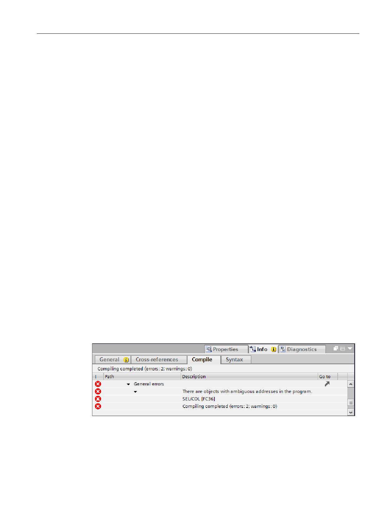
If multiple blocks are present with the same addresses or numbers in the "Program blocks"
folder (or a subordinate folder), an error will be displayed in the "Info > Compile" inspector
window during the compilation process.
Figure 7-2
Error: "Objects with ambiguous addresses exist in the program"
SINUMERIK 840D sl STEP 7 Toolbox V16
Getting Started, 12/2019, 6FC5397-1GP40-0BA1
107
Tips for personnel changing over from another system
7.3 Troubleshooting
Troubleshooting
If duplicate block numbers exist, proceed as follows:
● If this involves one of the blocks of the basic program that you do not require (e.g. unused
axis DB, channel DB, FB or FC), you can delete it.
● If a user block has the same block number as a required basic program block, you must
change the number of the user block. (You cannot change the addresses of required basic
program blocks.)
● If after the migration an additional system block with a previously used address is added
automatically, you can change the number of the automatically generated block.
System blocks are not stored directly in the "Program blocks" folder, but rather in a
subfolder, e.g. "CNC_1 > PLC_1 > Program blocks > System blocks > Program resources
> SEL [FC36]".
If the "Number" property field cannot be edited, you can delete the block and recompile
program blocks. During the compilation process of the calling block, the deleted block will
be recreated with a free block address.
You can view information about the calling structure of the blocks by right-clicking a block
and selecting the "Call structure" command.
7.3.3
Automatically assigned absolute access
Because blocks are tested more exactly in the TIA Portal than in STEP 7 V5.x, in some cases,
after the migration, a consistent and executable LAD/FDB block can be represented only in
STL. For the automatic conversion of such a block in STL, further errors or warnings may be
displayed in the TIA Portal.
To avoid such messages, check your user program preferably prior to migration for flags
without symbol and data type. If this is not possible, you can proceed as described below.
Troubleshooting
To rectify the problems, add new entries for address accesses in the block editor and assign a
symbolic name to the associated address:
● Warning "Avoid absolute accesses on the local data stack"
If you use temporary results in a LAD/FDB block, after the migration in STL, they are
absolute accesses to the local data stack.
Figure 7-3
Alarm: Absolute access to the local data stack
Declare symbolic variables in the Var_Temp area of the block and use them in the program.
● Error "Access to x with an ambiguous address"
An attempt is made to access a non-declared address area x of a symbolically declared
variable.
Declare for the subarea x a symbolic name and use it in the program.
SINUMERIK 840D sl STEP 7 Toolbox V16
108
Getting Started, 12/2019, 6FC5397-1GP40-0BA1
Tips for personnel changing over from another system
7.3 Troubleshooting
7.3.4
Incompatible data types
After the migration of a project to the TIA Portal, type conflicts can result, because during the
migration, a symbol and a data type are assigned to each used absolute address of a flag.
Examples:
● In the STEP 7 V5.x project, flags were used for intermediate results for which no data type
(and no symbol) was defined.
● In the STEP 7 V5.x project, a flag word for which no data type was defined was used for the
block call.
If an incorrect data type is assigned for the migration, the error message shown below is
displayed during the compilation:
● "The data type of the actual parameter x does not match the data type y of the formal
parameter"
To correct the data type, switch in the block editor to the named parameter with incorrect data
type (e.g. "Word") and specify the correct data type instead. Alternatively, you can use the
"Rewire variable" (Page 112) dialog.
See also:
Migration help for STEP 7 in Section "General notes for the migration of program blocks"
(programs with absolute addressing).
7.3.5
LAD/FDB/SCL: Data type conversion with MOVE instruction
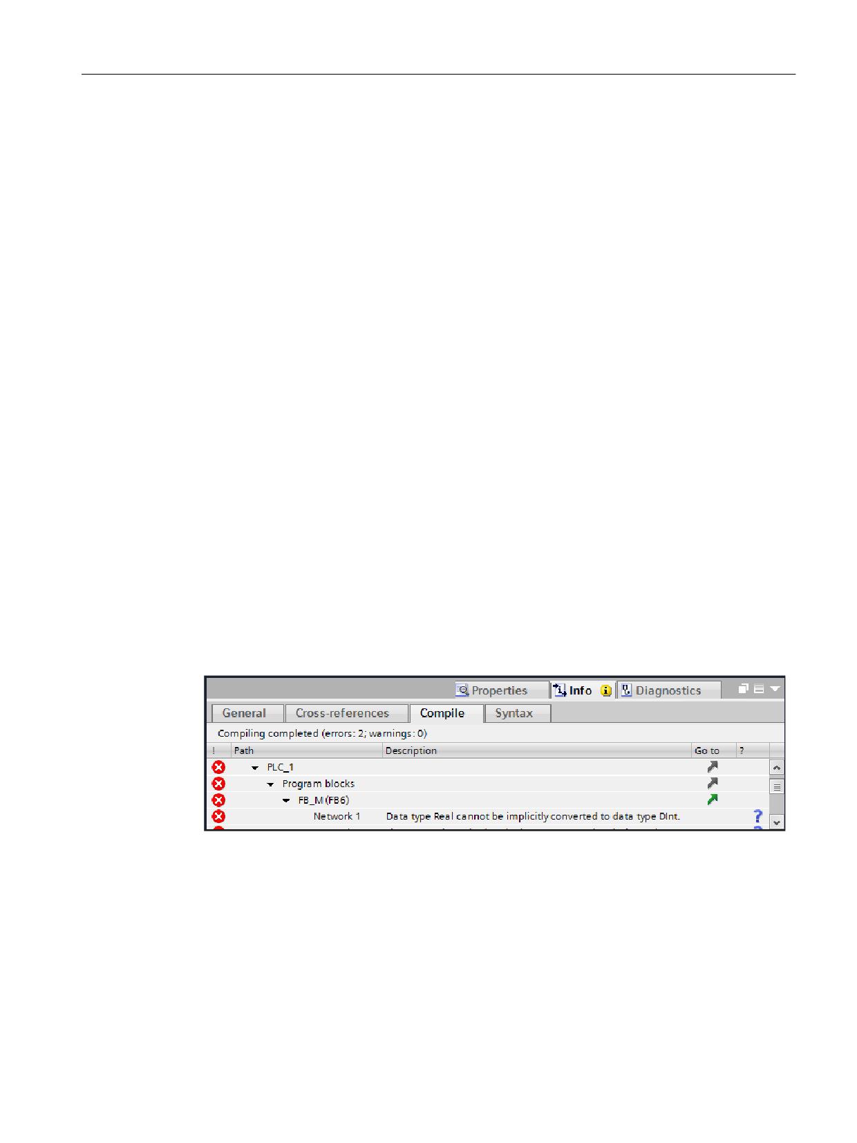
If you use a MOVE instruction in a STEP 7 V5.x block, for example, to transport data types from
axis/channel DBs to user DBs and implicitly convert the data type (e.g. "Real > DInt" or "Real
> Word"), warnings or error messages may be displayed in the TIA Portal after the migration.
Figure 7-4
Implicit conversion of data type error
Troubleshooting
● If you use such a MOVE instruction but have not copied the axis/channel DBs to the
"Program blocks" folder, the data type cannot be checked (absolute access). Warnings are
displayed because of access made to blocks not present in the project.
You can still compile and load the configuration; the required axis/channel DBs are then
generated by the runtime on the NCU. However, you can then not address symbolically
those axis/channel DBs not present in the project.
SINUMERIK 840D sl STEP 7 Toolbox V16
Getting Started, 12/2019, 6FC5397-1GP40-0BA1
109
Tips for personnel changing over from another system
7.3 Troubleshooting
● If you use such a MOVE instruction, have already copied the axis/channel DBs present in
the "Program blocks" folder and compiled the project, all absolute addressings are
automatically converted into symbolic addressings. This cannot be undone.
Because, in this case, the data type information is present in the TIA Portal and the above
mentioned implicit data type conversions are not permitted, errors will be issued during the
compilation.
To rectify the errors, you must convert the data type using two MOVE instructions. For
example, for the REAL > DInt conversion, create a new variable of the DWord type, add a
second MOVE instruction and convert using "REAL > DWord > DInt".
7.3.6
Inconsistency of the data blocks for a different runtime version
If the basic program blocks used in the TIA Portal belong to an older runtime version than that
of the actual hardware, inconsistencies can occur between the blocks in the project and on the
controller:
If a data block (e.g. axis DB) loaded onto the NCU from an older version is smaller than required
by the runtime in the newer version, it will be deleted at runtime and replaced with a so-called
CPU data block of the appropriate length. In the TIA Portal, an inconsistency is then detected
and displayed in online mode. The monitoring of the current values is not possible in online
mode.
In this case, you have the following options:
● Despite the inconsistency, you can continue working with the different block versions, but
not symbolically address the additional functions of the new block. The PLC program,
however, still functions because blocks of newer versions only append but not move signals.
● In the TIA Portal, you can add the appropriate Global DB to the runtime version of the NCU,
explicitly delete the CPU DB on the PLC and reload the Global DB into the NCU. (A CPU DB
cannot be overwritten by a global DB.)
● You can upload the new block from the NCU into the TIA Portal. This corrects the
inconsistency, but also deletes the symbolic information of this data block. If the PLC
program was addressed symbolically, errors will be issued during the compilation.
See also the information system, "PLC programming > Create user program >
Programming fundamentals > Blocks in the user program > CPU data blocks" section.
7.3.7
Renaming blocks
You cannot rename blocks used by know-how protected blocks if the password is not known or
the know-how protection cannot be revoked for any other reasons.
If your user program contains blocks with non-revokable know-how protection that call other
blocks of the basic program, they are affected.
SINUMERIK 840D sl STEP 7 Toolbox V16
110
Getting Started, 12/2019, 6FC5397-1GP40-0BA1
Tips for personnel changing over from another system
7.3 Troubleshooting
The following blocks are affected within the SINUMERIK basic program:
● GP_PAR [DB7]
● FC12 [FC12]
● RUN_UP [FB1]: Renaming possible, complete compilation with the "Software (compile
blocks completely)" command required.
7.3.8
Configuration and activation of the Web server
Overview
The Web server can be used to monitor the PLC via the Internet or the company-internal
Intranet. Evaluations and diagnostics can therefore be performed remotely.
Connect the PG/PC to the PROFINET interface X150 and make the network settings on the PG/
PC so that the subnet address configured for X150 is accessible. The Web server cannot be
accessed via X120/X130/X127.
You can configure the Web server of the PLC in the same way in the TIA Portal as in STEP 7
V5.x. See also: Commissioning Manual, SINUMERIK 840D sl Commissioning CNC: NCK, PLC.
After activation of the Web server, the "Activate system diagnostics" dialog is called. If you
confirm this dialog with "Yes", the following settings are made in the properties of the PLC:
"System diagnostics > General > Activate system diagnostics for this PLC".
Note
Troubleshooting for double block assignment
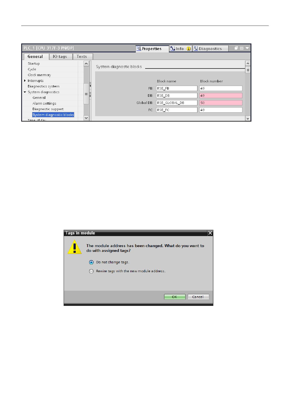
The system diagnostics requires system diagnostic blocks that by default occupy the same
address area as the blocks of the PLC basic program (FB49, DB49, FC49, DB50).
If you activate the system diagnostics for a SINUMERIK project, an error message with the
prompt to adapt the settings of the system diagnostics will be issued for the next compilation.
In this case, switch to the properties of the system diagnostic blocks by double-clicking the error
message and change the block numbers.
SINUMERIK 840D sl STEP 7 Toolbox V16
Getting Started, 12/2019, 6FC5397-1GP40-0BA1
111
Tips for personnel changing over from another system
7.3 Troubleshooting
Figure 7-5
Default block numbers of the system diagnostics blocks are already assigned
Further information
● Information on the configuration of the PLC Web server on the NCU can be found in the
Commissioning Manual, SINUMERIK 840D sl Commissioning CNC: NCK, PLC.
● General information on the Web server can be found in the information system of the TIA
Portal, keyword "Web server".
7.3.9
Rewiring variables in the module
If a module address is assigned to a variable, and you change the address of this module, a
dialog will be displayed indicating whether the address of the variable also needs to be changed
(rewired).
Figure 7-6
"Variables in the module" dialog
Migration: Set the module addresses correctly before copying the variables table
If you have migrated a project without hardware configuration and copy the migrated variable
table to the newly created NCU before you have set the module addresses in the device
properties, you are not permitted to rewire the variables.
SINUMERIK 840D sl STEP 7 Toolbox V16
112
Getting Started, 12/2019, 6FC5397-1GP40-0BA1
Tips for personnel changing over from another system
7.3 Troubleshooting
Otherwise, the inputs in the function blocks of the basic program are assigned incorrectly and
the program is no longer executable. You must correct it manually or copy the variable table
again.
After completion of the migration including the adapted module addresses and the migrated
variable table, you can use this dialog in order to transfer a planned change to module
addresses automatically to the variable table.
SINUMERIK 840D sl STEP 7 Toolbox V16
Getting Started, 12/2019, 6FC5397-1GP40-0BA1
113

Tips for personnel changing over from another system
7.4 Comparison of functionality
7.4
Comparison of functionality
7.4.1
Overview
The SINUMERIK TIA Portal Toolbox offers a number of functional changes. Some functions
differ from the functions that you know from migrating SINUMERIK Add-on for STEP 7 V5.x.
This section provides an overview of the new functionality and compares functions of the TIA
Portal with functions from STEP 7 V5.x.
Function
SINUMERIK 840D sl Toolbox
SINUMERIK TIA Portal Toolbox
for STEP 7 V5.x
Adding the SINU-
Extended functionality and changed handling
MERIK PLC basic
The SINUMERIK Toolbox for STEP 7 V5.x
The TIA Portal Toolbox contains various copy templates
program
contains a library with the PLC basic pro-
with basic program blocks for each firmware version.
gram for this specific firmware version.
Some data blocks are not contained in this
The copy templates also contain data blocks of the axes/
library, but rather they are created at runtime
spindles and DB2 alarms that differ from the toolbox for
on the controller (e.g. axis DB).
STEP 7 V5.x.
Although this permits a simple symbolic addressing of
the blocks,
you should add only those blocks that you require in your
program.
See: User-defined data types from the basic program
(Page 125)
Defining user-de-
Changed handling
fined data types
In STEP 7 V5.x you can create user-defined
In the TIA Portal you can create used-defined structured
(UDT)
data types (UDT) and store them in the
data types (UDT) in the special "PLC data types" folder.
"Blocks" folder.
See: Using user-defined data types (UDT) (Page 123)
The user data blocks from the basic program
The user data blocks from the basic program are not
(e.g. axis DB) provided by SIEMENS are al-
based on UDT, but rather they are global DBs.
so based on UDT. Symbolic names have
These data blocks are supplied as copy templates and
been declared for these UDTs in the symbol
can be added to the project so they can be addressed
table without the associated blocks (CPU
symbolically.
DBs) being contained in the project.
User-defined data types from the basic program
(Page 125)
Addressing ele-
Changed handling
ments symbolically
In STEP 7 V5.x, you could address operands
In the TIA Portal, however, symbolic addressing has pri-
(I/O signals, flags, counters, times, DBs,
ority which increases the readability of the program and
FBs) either absolutely or symbolically, al-
so simplifies error correction.
though absolute addressing had priority as
default.
In STEP 7 V5.x, you could assign a symbol
In the TIA Portal, there is no symbol table and all used
to operands (I/O signals, flags, counters,
objects have a symbolic name.
times, DBs, FBs) using the symbol table
See: Changing the operand priority (absolute/symbolic)
without the operand itself needing to be con-
(Page 127)
tained in the project.
SINUMERIK 840D sl STEP 7 Toolbox V16
114
Getting Started, 12/2019, 6FC5397-1GP40-0BA1
Tips for personnel changing over from another system
7.4 Comparison of functionality
Function
SINUMERIK 840D sl Toolbox
SINUMERIK TIA Portal Toolbox
for STEP 7 V5.x
Generating and
Simple operation
loading PLC sym-
The "PLC Symbol Generator" external tool
You can export the PLC symbols directly via the TIA
bols
can be used to export PLC symbols for SIN-
Portal.
UMERIK Operate.
See: Exporting PLC symbols (PLC Symbol Generator)
(Page 115)
Organizing objects
Extended functionality
into libraries
You can organize parts of your program into
Libraries in the TIA Portal can contain additional hard-
libraries so, for example, they can be added
ware components.
to other programs.
See: New library functions (Page 116)
Configuring con-
Simple operation
nections
In STEP 7 V5.x, you open NetPro in order to
In the TIA Portal, you can edit connections in the net view
edit connections.
under "Connections".
See: Configuring of connections (Page 121)
Creating SINU-
Extended functionality
MERIK archives
In STEP 7 V5.x, you can create SINUMERIK
In addition to the SINUMERIK PLC archives known from
PLC hardware upgrade archives and PLC
STEP 7 V5.x, you can now create PLC reload archives in
commissioning archives to obtain precom-
which a selection of program blocks is saved.
piled data for use with SINUMERIK Operate.
See Handling SINUMERIK archives (Page 122)
Symbolic access to
Changed handling
PLC machine data In STEP 7 V5.x, you can use absolute ad-
In the TIA Portal, you can symbolically directly access
dressing to access elements of the DB20 (in-
block elements of the DB20 and so access the PLC ma-
terface for PLC machine data). You can use
chine data when you add and declare the DB20 in the
the symbol table to symbolically address the
project.
DB20.
See: PLC machine data in DB20 (Page 127)
The DB20 is created at runtime on the con-
troller.
See also
Safety Integrated and Safety Integrated plus (Page 117)
Working in the project view and the portal view (Page 118)
Displaying program blocks in the tabular overview (Page 119)
7.4.2
Exporting PLC symbols (PLC Symbol Generator)
Comparison of functionality
When the SINUMERIK Toolbox is used for STEP 7 V5.x, you could prepare defined symbols
for SINUMERIK Operate in the Engineering System by using the external "PLC Symbol
Generator" tool.
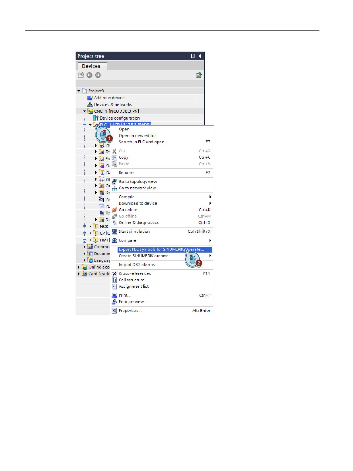
In the TIA Portal, this functionality is fully integrated in the software and can be called from the
menu bar or the shortcut menu (see Section "Generating and loading PLC symbols (Page 89)").
SINUMERIK 840D sl STEP 7 Toolbox V16
Getting Started, 12/2019, 6FC5397-1GP40-0BA1
115
Tips for personnel changing over from another system
7.4 Comparison of functionality
Figure 7-7
Exporting PLC symbols using the shortcut menu
7.4.3
New library functions
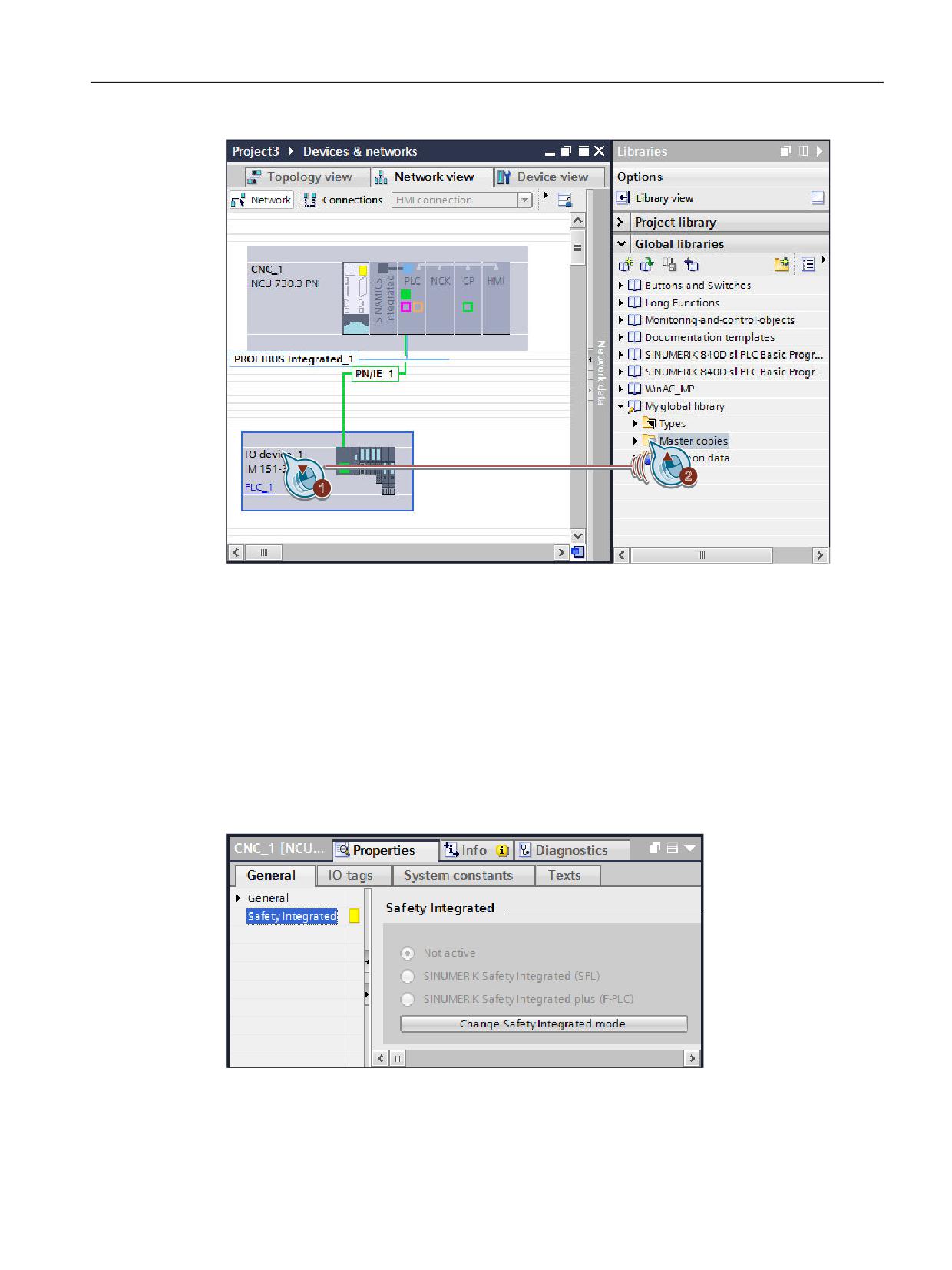
Unlike STEP 7 V5.x libraries, TIA Portal libraries can also contain hardware, including the
device configuration or inserted modules.
This allows you to copy preconfigured components and configured hardware components with
drag-and-drop to a global library in order to add them together with the made settings later to
another project.
SINUMERIK 840D sl STEP 7 Toolbox V16
116
Getting Started, 12/2019, 6FC5397-1GP40-0BA1
Tips for personnel changing over from another system
7.4 Comparison of functionality
Figure 7-8
Copying hardware with drag-and-drop to a library
Further information for handling libraries in the TIA Portal can be found in the information
system under the keyword "Library > Fundamentals".
7.4.4
Safety Integrated and Safety Integrated plus
The F-configuration tool allowed you to use the SINUMERIK Safety Integrated (SPL) safety
functions with the SINUMERIK 840D sl Toolbox for STEP 7 V5.x.
Two different Safety Integrated modes are available in the TIA Portal (from NCU Version 4.8),
whereby Safety Integrated is deactivated as default setting:
Figure 7-9
NCU Safety Integrated settings are "not active" by default.
SINUMERIK 840D sl STEP 7 Toolbox V16
Getting Started, 12/2019, 6FC5397-1GP40-0BA1
117

Tips for personnel changing over from another system
7.4 Comparison of functionality
The NCU always supports both Safety Integrated modes, although they must be licensed and
configured differently. Whether Safety Integrated should be used and its preferred mode
depends on the associated automation task.
Consequently, you must decide for a Safety Integrated mode directly after adding the NCU and
activate its mode manually in the NCU properties.
The activation at the start of the configuring execution sequence allows the system to assign
some safety-relevant parameters automatically (e.g. PROFIsafe addresses).
If you do not select the correct Safety Integrated mode already at the start, you may get error
messages during the compilation and must set these safety-relevant parameters manually
afterwards.
7.4.5
Working in the project view and the portal view
Views in the TIA Portal
The TIA Portal provides various views for the automation project between which you can switch
at any time:
● Project view
The project view shows all components of the project as well as all associated work areas
and editors.
Working in the project view is similar to working as you know from STEP 7 V5.x.
● Portal view
Although the portal view provides a task-oriented overview and configuration options for
many important components, such as CPUs, HMI devices or drives,
not all configuring options are available (e.g. configure I/O peripherals). If required, an
automatic switch to the project view for the selected task is made.
SINUMERIK 840D sl STEP 7 Toolbox V16
118
Getting Started, 12/2019, 6FC5397-1GP40-0BA1
Tips for personnel changing over from another system
7.4 Comparison of functionality
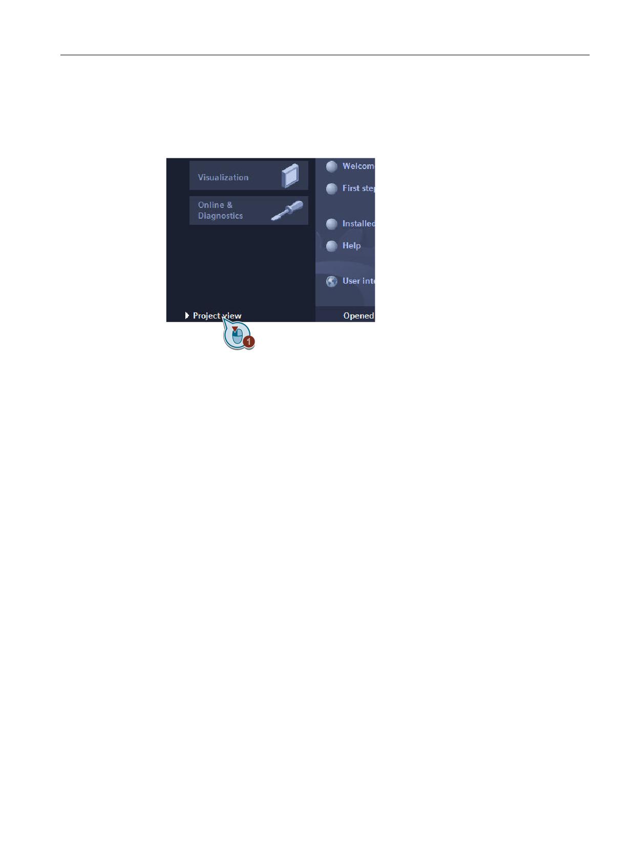
Switching between views
The portal view is displayed during the first start of the TIA Portal or as default setting.
● The associated "Project view" or "Portal view" link in the lower left-hand area can be used
to switch the views at any time.
● You can change the settings (via "General > General > Start view") to specify the view to be
used to start the TIA Portal.
7.4.6
Displaying program blocks in the tabular overview
In STEP 7 V5.x, the list of the program blocks was not displayed in the project tree, but rather
as an overview in the work area. The program blocks could be sorted in this overview, e.g.
according to addresses or symbolic names.
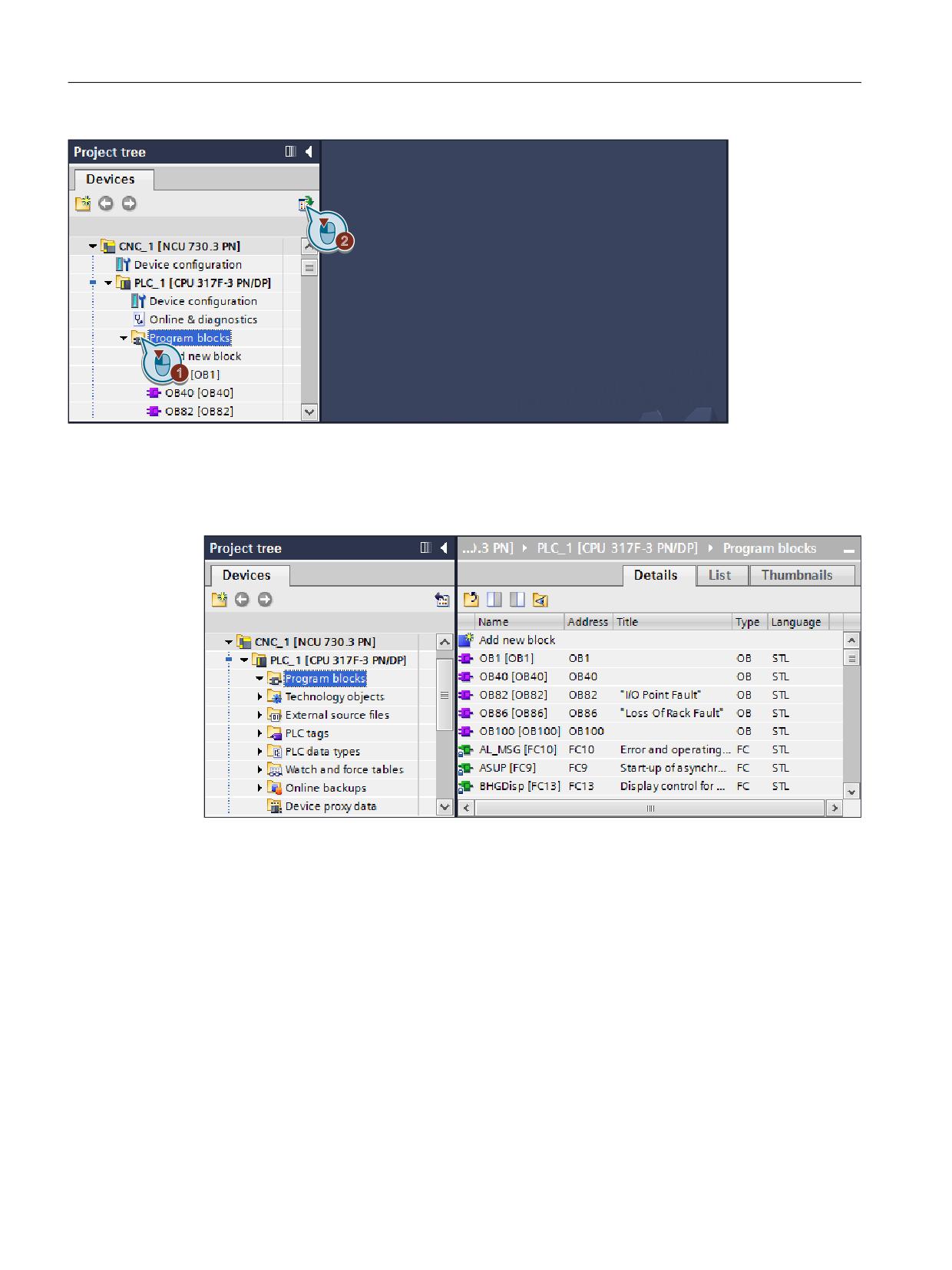
In the TIA Portal, you can display the individual program blocks already in the project tree by
expanding the "Program blocks" folder. The sorting, however, cannot be set in the project tree,
but rather the blocks are always sorted according to type and name.
You can, however, maximize the project tree view in order to display the content of the
"Program blocks" folder in the work area.
SINUMERIK 840D sl STEP 7 Toolbox V16
Getting Started, 12/2019, 6FC5397-1GP40-0BA1
119
Tips for personnel changing over from another system
7.4 Comparison of functionality
Figure 7-10
Maximizing the project tree
You can then display the program blocks as symbols, list or details. In the details view, you can
sort the program blocks according to any column, e.g. according to the address or
programming language.
Figure 7-11
Maximized project tree
Further information
● You can find details on the maximized overview in the TIA Portal online help under
"Overview window".
● A table with all blocks of the PLC basic program and the associated block addresses, PLC
symbols, etc. (e.g. for printing) is available under Tabular listing of blocks (Online Help).
SINUMERIK 840D sl STEP 7 Toolbox V16
120
Getting Started, 12/2019, 6FC5397-1GP40-0BA1
Tips for personnel changing over from another system
7.4 Comparison of functionality
7.4.7
Configuring of connections
Comparison of functionality
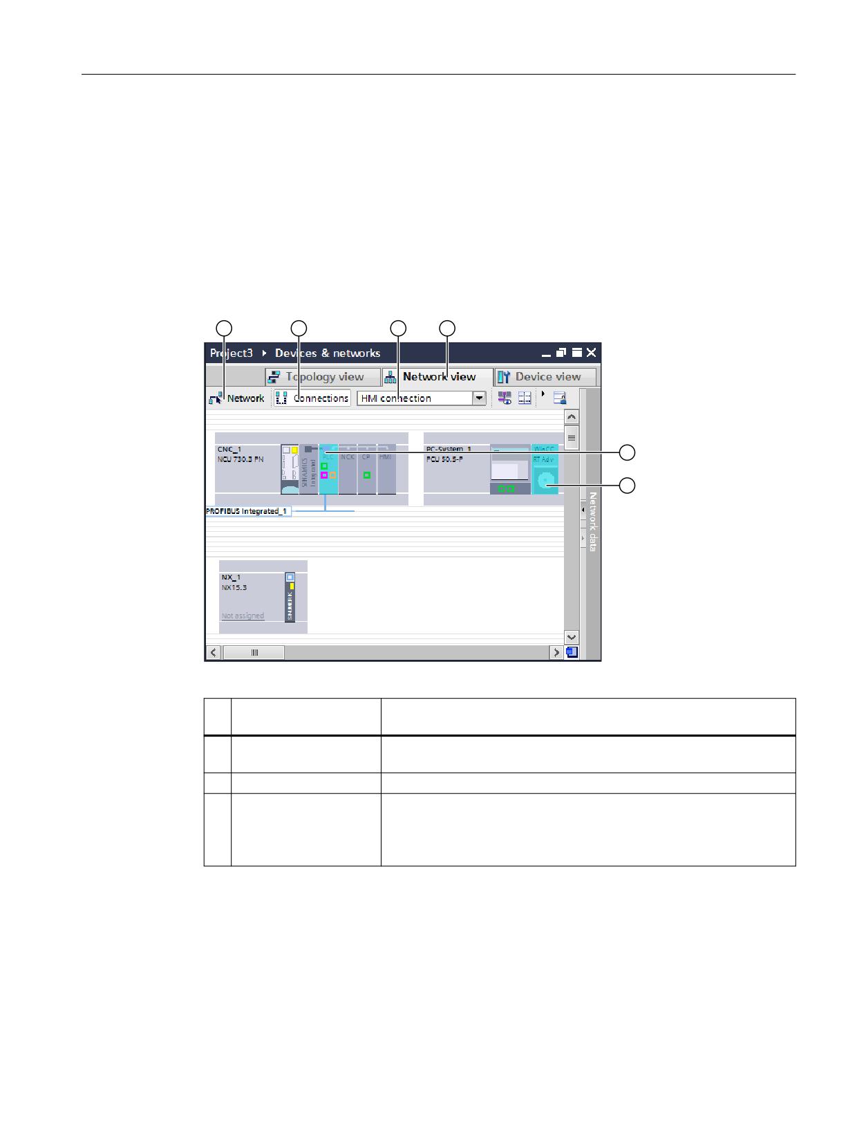
In STEP 7 V5.x, you can create connections in NetPro, e.g. for the configuring of
interconnected plants. In the TIA Portal, make these settings in the net view.
You can switch the net view by clicking "Interconnect" or "Connections" in the toolbar. In the
"Connections" dropdown list, you can select a connection type directly and then use drag-and-
drop in the work area to create connections between devices.
Figure 7-12
Net view with active "Connections" functionality
No
Function
Purpose
1.
Networking
Functionality within the net view with which you can interconnect devi-
ces and configure nets.
2
Connections
Functionality within the net view with which you can create connections.
3
Dropdown list for select-
Depending on the operational purpose or device type, select in the
ing the connection type
dropdown list the connection type to be created.
The associated possible communications partners are then color-high-
lighted.
SINUMERIK 840D sl STEP 7 Toolbox V16
Getting Started, 12/2019, 6FC5397-1GP40-0BA1
121
Tips for personnel changing over from another system
7.4 Comparison of functionality
No
Function
Purpose
4
Net view tab
The "Net view" tab in the "Devices & nets" editor provides two function-
alities: "interconnect" and "connections".
If you switch to the net view, the "interconnect" functionality is initially
active.
5
Color-highlighting of
If you activate the "connections" functionality in the net view, all possible
possible communication
communications partners that match the selected connection type are
partners
highlighted.
The following can be used as communications partner:
● Controller (e.g. PLC of the SINUMERIK NCU)
● PC applications (e.g. WinCC RT Advanced of the PCU 50.5)
Further information
General information on connections in the net view can be found in the online help of the TIA
Portal, keyword "Communication via connections".
7.4.8
Handling SINUMERIK archives
Comparison of functionality
Unlike STEP 7 V5.x, data blocks for axes/spindles are now already contained in the project and
also saved in the SINUMERIK PLC archive.
You can also create additional so-called PLC reload archives in the TIA Portal with which you
can save a selection of program blocks.
Restrictions
The F-blocks used for the Safety Integrated plus (F-PLC) mode cannot be stored in PLC reload
archives, because a mutual dependency between F-blocks and the associated hardware
configuration with failsafe components exists. Instead, you can save F-blocks together with
other blocks and hardware data in a PLC commissioning archive.
Time required for creating and importing archives
If the creation or import takes longer than usual, you may have saved data blocks of non-
activated axes/spindles in the archive. In this case, delete the superfluous data blocks in the
"Program blocks" folder and recreate the archive.
SINUMERIK 840D sl STEP 7 Toolbox V16
122
Getting Started, 12/2019, 6FC5397-1GP40-0BA1
Tips for personnel changing over from another system
7.4 Comparison of functionality
Further information
● Information about the general handling of copy templates in libraries can be found at Using
copy templates (Page 73).
● The detailed procedure and an overview of the data for SINUMERIK PLC archives
contained in the TIA Portal are available under Creation of SINUMERIK-PLC archives
(online help).
7.4.9
Using user-defined data types (UDT)
Overview
Many programs require user-defined data types that can be edited by various program
locations, e.g.
● UDT31: Axis/spindle signals for data blocks Axis1 [DB31]...Axis31 [DB61]
● UDT2: Alarms/messages for data block ALMSG_DB [DB2]
In the PLC basic program of the TIA Portal, the user-defined data types from the basic program
(axes/spindles, channels, mode groups, alarms/messages, tool management, PLC/HMI, MCP/
HHU) are not based on user-defined data types. Instead, these data blocks are contained in the
basic program as global data blocks that define their elements appropriately for each block.
This allows them to be directly addressed symbolically. See User-defined data types from the
basic program (Page 125).
Comparison of functionality
In STEP 7 V5.x, you can define your data types and store these directly in your "S7 program >
Blocks" folder in which the data blocks and other program blocks are also stored.
In the TIA Portal, you can also declare your own structured PLC data types (UDT), use them in
data blocks and address these elements symbolically. These PLC data types, however, are
located in a separate folder ("CNC_1 > PLC_1 > PLC data types"). You can also create the
UDTs from an external source (STL).
SINUMERIK 840D sl STEP 7 Toolbox V16
Getting Started, 12/2019, 6FC5397-1GP40-0BA1
123
Tips for personnel changing over from another system
7.4 Comparison of functionality
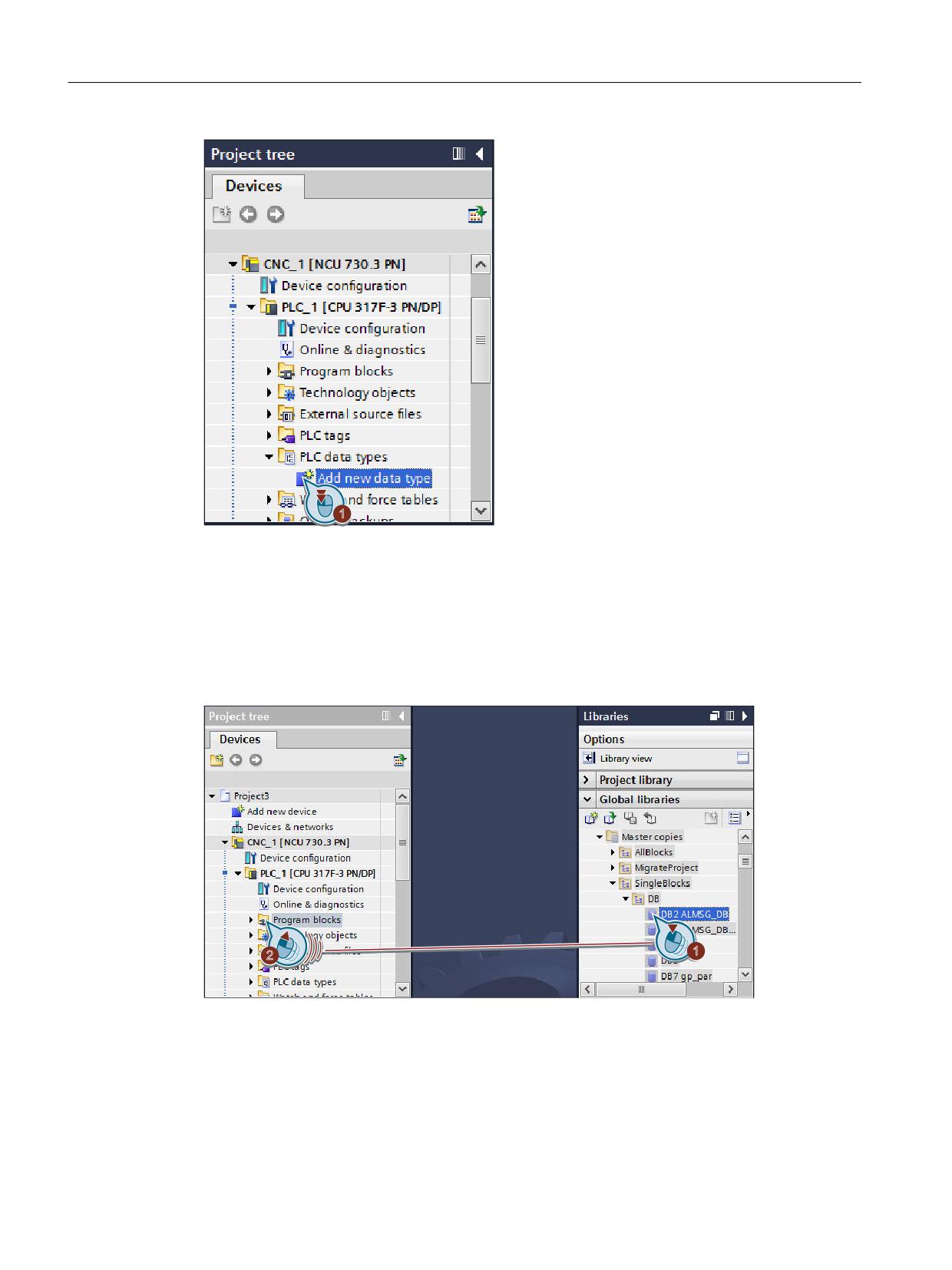
In STEP 7 V5.x, data blocks defined by SIEMENS are also based on UDT (data blocks of axes/
spindles, channels, mode groups, alarms/messages, tool management, PLC/HMI, MCP/HHU).
Unlike STEP 7 V5.x, in the basic program in the TIA Portal, these data blocks are not based on
UDTs, but rather are global DBs that define their elements in each DB. As previously,
SIEMENS specifies the structure and the symbology. Consequently, you can copy these data
blocks without further dependencies of UDTs in a single step from the system library into the
"Program blocks" folder.
Figure 7-13
Copying blocks from a copy template
SINUMERIK 840D sl STEP 7 Toolbox V16
124
Getting Started, 12/2019, 6FC5397-1GP40-0BA1
Tips for personnel changing over from another system
7.4 Comparison of functionality
Further information
● An overview of the differences between STEP 7 V5.x and the TIA Portal as well as
information about the procedure are contained in the Service & Support portal Programming
user-defined data types in the TIA Portal (http://support.automation.siemens.com/WW/
view/en/51339156).
● Information about the concept and the procedure for PLC data types are contained in the
information system under the keyword "Data type, PLC data type".
● Information about symbolic programming with UDTs is contained in Section "Symbolic
programming of the user program with interface DB" of the Base Functions (FB1) Function
Manual.
7.4.10
User-defined data types from the basic program
Comparison of functionality
Unlike the SINUMERIK Toolbox for STEP 7 V5.x, the user data blocks from the basic program
in the Engineering System are supplied for the TIA Portal Toolbox:
● Axes/spindles: Axis1 [DB31]…Axis31 [DB61]
● Channels: Chan1 [DB21]…Chan10 [DB30]
● PLC / mode group signals: Mode group [DB11]
● DB2 alarms from the PLC (alarm numbers 500000 to 799999): ALMSG_DB [DB2] or
ALMSG_DB_ExtendAlMsg [DB2]
● Tool management DB74 [DB74]
● PLC/HMI signals: MMC [DB19]
● MCP / HHU (SDB210): DB77 [DB77]
They were not contained in the SINUMERIK basic program for STEP 7 V5.x, but rather were
created on the NCU only at runtime. You could address them symbolically only with an
appropriate symbol table.
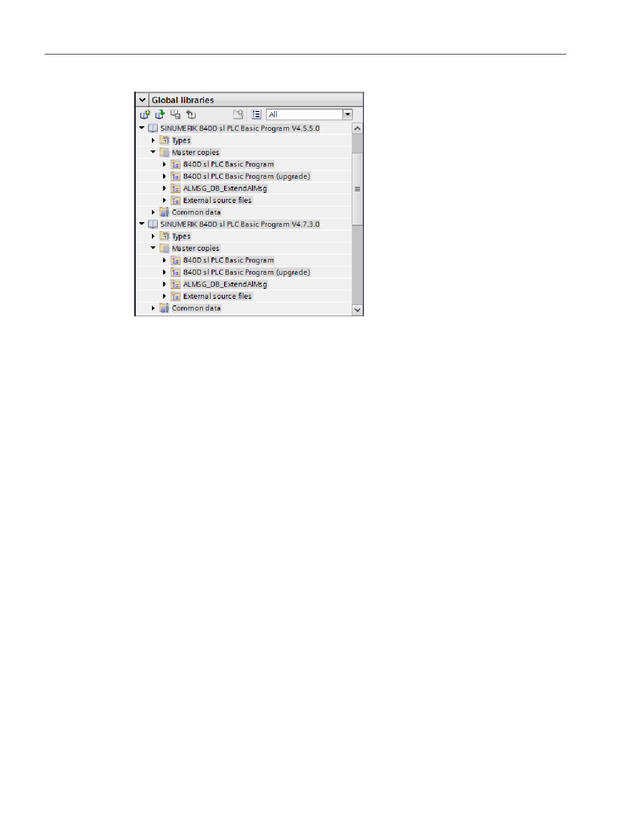
In the TIA Portal, these blocks are provided as copy templates in the system library appropriate
for your NCU version:
SINUMERIK 840D sl STEP 7 Toolbox V16
Getting Started, 12/2019, 6FC5397-1GP40-0BA1
125
Tips for personnel changing over from another system
7.4 Comparison of functionality
Figure 7-14
"Copy templates" folder in the "Libraries" task card
If you copy them in your project to the "Program blocks" folder, you can also address them
symbolically like other blocks. Unlike STEP 7 V5.x, access is no longer made to user-defined
data types (UDT), but rather the data structure is defined in the data blocks themselves.
Because of this different handling of the data blocks, you must augment a project migrated from
STEP 7 V5.x subsequently with the data blocks, e.g. by means of the "840D sl PLC Basic
Program (upgrade)" copy template. Otherwise, access in the user program is made to non-
existent data blocks and warnings or errors will be issued during the compilation. (Symbolic
access to the elements of a data block is not possible if the data block is not contained in the
project.)
You should ensure that only the required axis/channel DBs are stored in the "Program blocks"
folder:
● The copy template "840D sl PLC Basic Program (upgrade)" contains all of the know-how-
protected blocks that you require for the maximum configuration (31 axes, 10 channels).
● If your machine is using fewer axes or channels, you can either copy only the required
blocks or you can delete the blocks that are not required in the project tree after copying.
If you have data blocks for non-activated channels or axes/spindles in the project, the
procedure for compiling, loading and creating/importing of archives is delayed.
You can also create your own global libraries as copy templates in which, for example, you save
only the blocks required for a specific configuration.
Further information
● You will find further information about the data blocks in the copy templates in Sections
"Using copy templates (Page 73)" and "Overview (Page 71)".
● A functionality comparison of the symbolic addressing in STEP 7 V5.x and the TIA Portal is
available under Changing the operand priority (absolute/symbolic) (Page 127).
● Information about creating your own libraries as copy templates can be found in the
information system of the TIA Portal, keyword "Library".
SINUMERIK 840D sl STEP 7 Toolbox V16
126
Getting Started, 12/2019, 6FC5397-1GP40-0BA1
Tips for personnel changing over from another system
7.4 Comparison of functionality
7.4.11
PLC machine data in DB20
The DB20 provides the interface for PLC machine data and is not contained in either
STEP 7 V5.x or in the TIA Portal part of the PLC basic program.
In STEP 7 V5.x, you can use absolute addressing to access elements of the DB20 (interface
for PLC machine data). You can use the symbol table to symbolically address the DB20.
In the TIA Portal, you can symbolically directly access block elements of the DB20 and so
access the PLC machine data when you add and declare the DB20 in the project.
Basic procedure
Add this data block in the "Program blocks" folder so that you can access this data symbolically
in the TIA Portal. The declaration for DB20 in the project must match the specified values in the
machine data for SINUMERIK Operate (MD14504, MD14506, MD14508).
If you do not create the DB20 in the TIA Portal, it will be created on the NCU at runtime. In this
case, you cannot access symbolically the elements of the DB20, and warnings will be issued
during the compilation because the block is not found in the project.
Further information
Information about the declaration of the DB20 is contained in the following documentation:
● SINUMERIK 840D sl / 828D Function Manual Basic Functions, Section "PLC machine data"
● SINUMERIK 840D sl List Manual, SINAMICS S120 Lists, Book 2, Section "PLC machine
data (DB20)"
7.4.12
Changing the operand priority (absolute/symbolic)
7.4.12.1
Effects of the symbolic addressing
In STEP 7 V5.x, you could address operands (I/O signals, flags, counters, times, DBs, FBs)
either absolutely or symbolically, although absolute addressing had priority as default. In the
TIA Portal, however, symbolic addressing has priority which increases the readability of the
program and so simplifies error correction.
In STEP 7 V5.x, you could assign a symbol to operands (I/O signals, flags, counters, times,
DBs, FBs) using the symbol table without the operand itself needing to be contained in the
project. In the TIA Portal, there is no symbol table and all used objects have a symbolic name.
SINUMERIK 840D sl STEP 7 Toolbox V16
Getting Started, 12/2019, 6FC5397-1GP40-0BA1
127
Tips for personnel changing over from another system
7.4 Comparison of functionality
This change of the operand priority in the PLC program can, however, require changes in your
migrated user program. Similarly, persons making the migration may need to make themselves
familiar with the changed handling of certain functionalities:
● Data type for PLC variables
If you define PLC variables in the TIA Portal, you must specify the associated data type. This
is tested more restrictively in the TIA Portal than in STEP 7 V5.x. In particular, after the
migration, corrections must be made to the user program.
See also:
- Incompatible data types (Page 109)
- LAD/FDB/SCL: Data type conversion with MOVE instruction (Page 109)
● Declarations only with symbolic addressing
Each data type (e.g. UDT or blocks) has a symbolic name. You must use the symbolic
addressing for the declaration of instances.
See also:
- Declaration of multi-instances (GET [FB2], PUT [FB3]) (Page 128)
- Declaration of static local data in the block interface (Page 131)
● Variables adaptation when changing the module address (Page 112)
7.4.12.2
Declaration of multi-instances
Both in STEP 7 V5.x and in the TIA Portal you can add function blocks as multi-instances using
the FB2.
In the TIA Portal, you do not address the block using its address "FB2", but rather symbolically
using its "GET" name.
Because GET, however, is also the name of an instruction for S7 communication, you must
take care when programming that the correct block is addressed:
● When you enter "GET" (with quotes), the FB2 of the SINUMERIK basic program is
addressed.
● When you enter GET (without quotes), the instruction is used for S7 communication.
SINUMERIK 840D sl STEP 7 Toolbox V16
128
Getting Started, 12/2019, 6FC5397-1GP40-0BA1
Tips for personnel changing over from another system
7.4 Comparison of functionality
Procedure
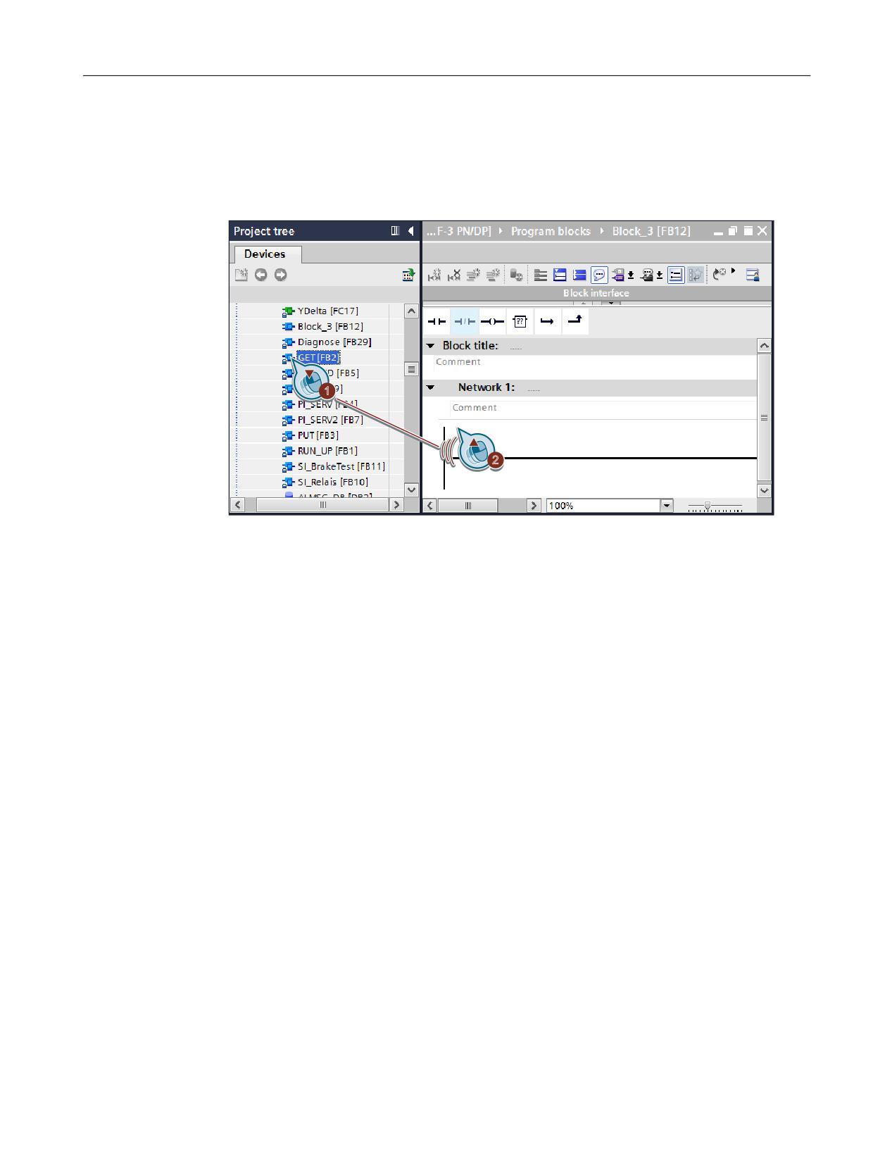
To correctly address the SINUMERIK "GET [FB2]" block rather than the S7 communications
instruction GET for programming, use one of the following methods:
● Addressing a block with drag-and-drop
You can drag-and-drop the "GET [FB2]" block from the project tree into a network of your
block. The "Call options" dialog is then displayed in which you can configure the associated
instance data block.
● Enter the "GET" block name directly (note the quotes)
If you enter the block completely (e.g. in an STL source, in an empty box or as data type in
the block interface), ensure that you write the name within quotes.
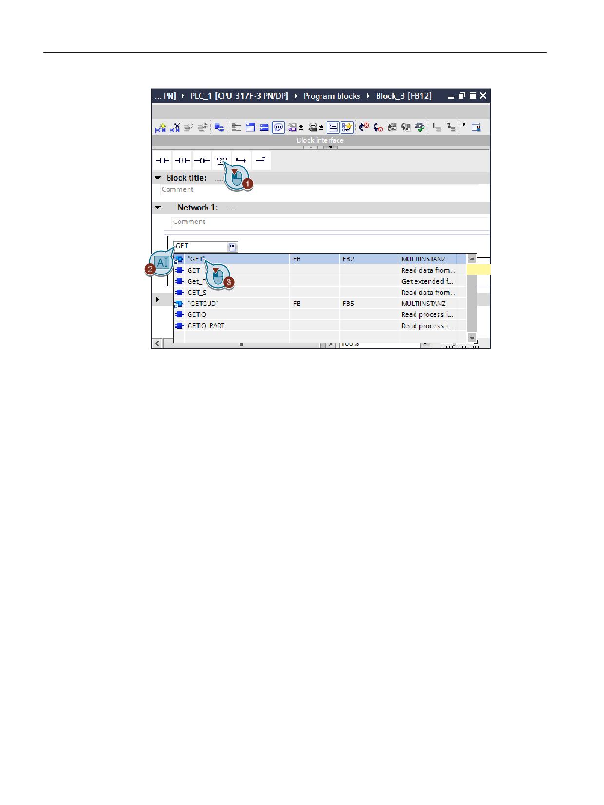
● Enter the GET block name and select "GET" in the auto-complete list
SINUMERIK 840D sl STEP 7 Toolbox V16
Getting Started, 12/2019, 6FC5397-1GP40-0BA1
129
Tips for personnel changing over from another system
7.4 Comparison of functionality
If you enter the block name itself (e.g. in an empty box or as data type in the block interface),
you can select the FB2 from the auto-complete list.
Further information
For further information, refer to the TIA Portal online help:
● Fundamentals of instances
● Fundamentals for block properties
● Overview of the block properties
SINUMERIK 840D sl STEP 7 Toolbox V16
130
Getting Started, 12/2019, 6FC5397-1GP40-0BA1
Tips for personnel changing over from another system
7.4 Comparison of functionality
7.4.12.3
Declaration of static local data in the block interface
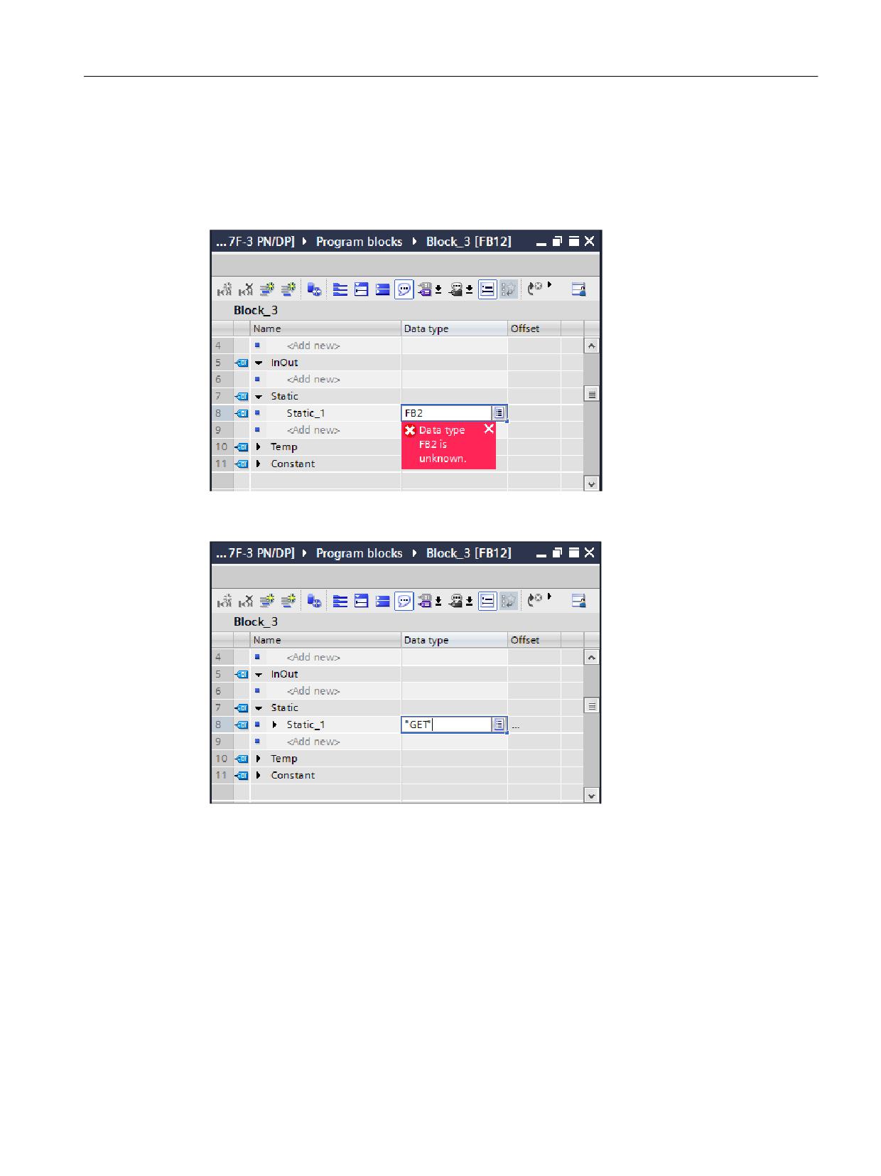
If, when programming blocks in the block interface, you declare static local data ("Static"
section) and want to specify a block as "data type" in order to declare an instance, unlike STEP
7 V5.x, you cannot address absolutely.
Instead, simply enter the symbolic name of the block (e.g. "GET" or "PUT").
In this case, use quotes explicitly to avoid inadvertently addressing an instruction with a similar
name. (See also Declaration of multi-instances (Page 128))
SINUMERIK 840D sl STEP 7 Toolbox V16
Getting Started, 12/2019, 6FC5397-1GP40-0BA1
131
uidelines / basic
Preface_______________
system requirements
1
Introduction__________
2
Safety information______
MOTION CONTROL
3
design and installation
EMC installation guidelines / basic
system requirements
Configuration Manual
Valid for
- MICROMASTER
- SIMOCRANE
- SIMODRIVE
- SIMOREG
- SIMOTICS
- SIMOTION
- SIMOVERT MASTERDRIVES
- SINAMICS
- SINUMERIK
(PH1), 01/2012
6FC5297-0AD30-0BP3
Table of contents
Preface
3
1
Introduction
11
2
Safety information
13
3
Information on planning, design and installation
15
3.1
Planning
15
3.2
Application environments for drive systems
15
3.3
EMC-zone concept
16
3.4
Openings in the housing, e.g. ventilation openings
18
3.5
Equipotential bonding
18
3.5.1
Equipotential bonding within a control cabinet
19
3.5.2
Equipotential bonding between several cabinet elements
20
3.5.3
Equipotential bonding inside the machine/plant
20
3.5.4
Equipotential bonding of components to moving parts/slides
22
3.6
Cables
22
3.6.1
General
22
3.6.2
Shielded cables
23
3.6.2.1
Plug connections for shielded cables
24
3.6.3
Cables in the power line
25
3.6.3.1
Bundling, parallel connection of cables
25
3.6.3.2
The motor cable shield connection at the motor modules
25
3.6.3.3
Shield connection of the motor cable to the motor terminal box
26
3.6.3.4
Shield connection for cables with connector
26
3.6.3.5
Protective conductor in the motor cables (green/yellow)
26
3.6.3.6
The last meter to the motor
26
3.6.3.7
DC-link connection, braking resistor
26
3.6.3.8
Cable lengths in the power line
26
3.6.4
Brake cables
27
3.6.5
Encoder cables
27
3.6.5.1
Encoder cables with plug connectors
27
3.6.5.2
DRIVE-CLiQ encoder connections
27
3.6.5.3
Cable lengths for encoders
27
3.6.6
DRIVE-CLiQ connections
27
3.6.7
Field bus
28
3.6.7.1
PROFIBUS, PROFINET
28
3.6.8
Analog signals
29
3.6.9
Examples of shield connections
29
3.7
Laying cables on cable racks/routes at the plant
29
3.8
Connection to the line supply
31
3.8.1
Drive line filter, cabinet line filter
31
3.8.2
Drive line filter arrangement, line reactor, drive group
32
EMC installation guidelines / basic system requirements
Configuration Manual, (PH1), 01/2012, 6FC5297-0AD30-0BP3
9
Table of contents
3.9
Miscellaneous
33
3.9.1
Wiring of coils
33
3.9.2
Bearing currents
33
EMC installation guidelines / basic system requirements
10
Configuration Manual, (PH1), 01/2012, 6FC5297-0AD30-0BP3
Introduction
1
EMC (electromagnetic compatibility) means that the devices function satisfactorily without
interfering with other devices and without being disrupted by other devices. This is true when
the emitted interference (emission level) and the interference immunity are matched with
each other.
EMC emitted interference and interference immunity are regulated worldwide by standards,
guidelines or laws.
In order to comply with the regulated limit values and to ensure the function, the measures
described below must be observed as minimum.
In the case of devices that are supplied ready to use, it normally suffices to install and
operate them in accordance with the manufacturer's documentation in order to observe the
EMC limit values and to achieve a satisfactory function.
Drive systems, however, are usually supplied in the form of components, such as line filters,
line reactors, converters, motors and cables. The fast switching of the power semiconductors
are major sources of interference to drive systems. In order to observe the EMC limit values
and to achieve a satisfactory function, the specifications of the manufacturer documentation
must be observed for the assembly and installation.
We strongly recommend that all components originate from the same manufacturer and are
combined in accordance with the catalog or configuration guidelines because they have
been tested in example constructions. If, however, the user combines components from
different manufacturers, the user is solely responsible for the observance of the EMC limit
values and the function of the plant.
Provided the following information is observed for the design of the components to form a
system, it can be assumed that the EMC limit values are met and a satisfactory function
achieved.
It is essential to follow the safety instructions given in the device-specific technical user
documentation under all circumstances.
The binding document for configuring the respective device types is always the device-
specific technical user documentation.
Certificates, declarations of conformity, test certificates, such as CE, UL, Safety Integrated,
etc., are valid only when the components described in the associated catalogs and
configuration guides are used, and installed in accordance with the configuring guidelines
and used properly. In other cases, such documents must be prepared again by the vendor of
these products.
EMC installation guidelines / basic system requirements
Configuration Manual, (PH1), 01/2012, 6FC5297-0AD30-0BP3
11
Introduction
)DFWRU\ QHWZRUN ,QGXVWULDO (WKHUQHW
6,180(5,. RSHUDWRU SDQHOV
6,180(5,.
+7
3&8
3ODQW QHWZRUN
,QGXVWULDO (WKHUQHW
352),%86 , 2V
'5,9( &/L4
6,0$7,&
(7
SUR
6,180(5,.
1;
6,1$0,&6
6,1$0,&6
' VO
6
6
/LQH ILOWHU
/LQH UHDFWRU
0DLQ VSLQGOH
)HHG
/LQH ILOWHU /LQH UHDFWRU
)HHG PRWRUV
PRWRU
PRWRU
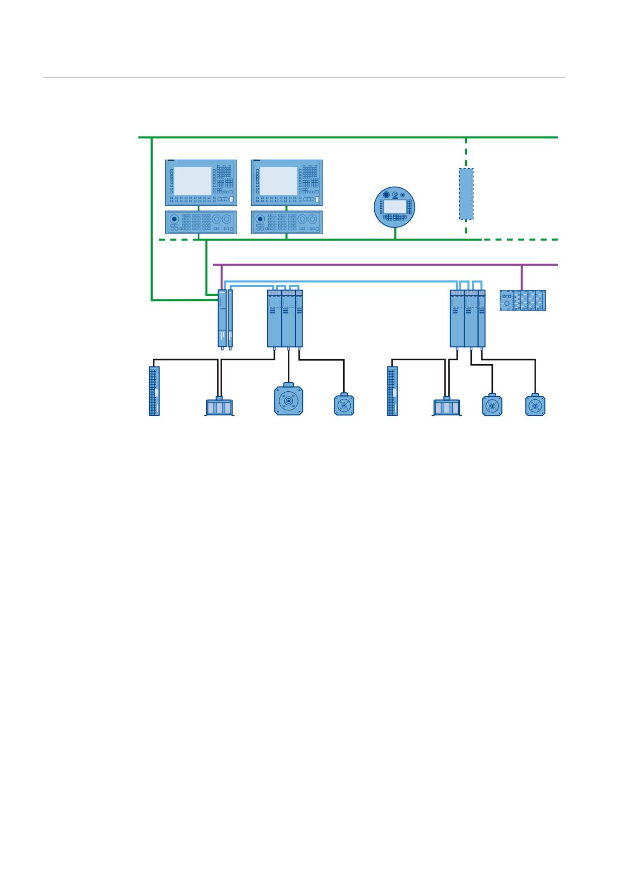
Figure 1-1
Example of an equipment item (schematic)
EMC installation guidelines / basic system requirements
12
Configuration Manual, (PH1), 01/2012, 6FC5297-0AD30-0BP3
Safety information
2
CAUTION
The laying of cables on ventilation grilles is not permitted. This would considerably impede
the heat dissipation of the devices, in particular for narrow modules. Moreover, the resulting
high exhaust air temperatures can damage the cable insulation.
Power cables must be routed to the component connections so that the air supply is not
obstructed more than necessary. To achieve this, the cables should preferably be laid
vertical.
EMC installation guidelines / basic system requirements
Configuration Manual, (PH1), 01/2012, 6FC5297-0AD30-0BP3
13
Information on planning, design and installation
3
This documentation contains general information and examples for the EMC-compliant
design of controller and drive components in the control cabinet.
This installation guideline covers the best possible electromagnetic compatibility for the
design of controller and drive components and informs about points that must be considered
for the proper design of the drive system.
If these rules are not observed, malfunctions or faults in other devices and consequently
potential failure must be expected.
Note
Cables in machines and control cabinets are subject to high requirements, such as bending
strength in ground cables, highly dynamic movements of motors, resistance to cutting oils
and EMC properties. For this reason, only those cables that have been released for these
applications, e.g. MOTION-CONNECT cables, must be used. Especially for machines with
functional safety, the use of such cables is necessary.
3.1
Planning
The achieving of the EMC at a plant, machine or control cabinet requires careful planning.
The requirements result from:
● EMC requirements appropriate for the environment, see Application environments for
drive systems (Page 15)
● EMC zone concept, see EMC-zone concept (Page 16)
● Equipotential bonding, see Equipotential bonding (Page 18)
3.2
Application environments for drive systems
The permitted emission level is at a low level in the first environment (residential). For this
reason, devices for use in the first environment must have a low noise emission, but require
only a relatively small interference immunity.
The permitted emission level is at a high level in the second environment (industrial area).
Devices for use in the second environment may have a relatively high emitted interference,
but also require a high level of interference immunity.
EMC installation guidelines / basic system requirements
Configuration Manual, (PH1), 01/2012, 6FC5297-0AD30-0BP3
15

Information on planning, design and installation
3.3 EMC-zone concept
Table 3- 1
Environments and categories in accordance with EMC product standard IEC 61800-3
Variable-speed PDS drive system
Environment
1. Environment
2. Environment
(residential and commercial areas)
(industrial area)
(public grid)
(industrial network decoupled with an
isolating transformer)
Category
C11)
C22)
C33)
C44)
Voltage, current
< 1,000 V
≥ 1,000 V
or
≥ 400 A
Line system
TN, TT
TN, TT, IT
Expert
No request
Installation and commissioning must be performed by
authorized personnel.
1) No products are on offer for category C1.
2) Drive systems installed by qualified personnel can be used in the first environment category C2 in
accordance with EMC product standard IEC 61800-3.
3) The drive systems described in this document with the associated filters in accordance with EMC
product standard IEC 61800-3 can be used in the second environment category C3.
4) To ensure the EMC in the category C4, it is necessary that the plant manufacturer and the plant
operators agree an EMC plan that specifies individual, plant-specific measures. If prescribed by
the product description, drive systems can also be used in non-grounded systems (IT systems) in
accordance with EMC product standard IEC 61800-3.
3.3
EMC-zone concept
Interference suppression measures within the plant or the control cabinet are easiest to
implement and most cost-effectively by installing interference sources and sinks physically
separated from each other. This separation must already be taken into consideration during
the planning.
First, it must be decided for each used device whether it is a potential interference source or
sink.
● Typical interference sources are, for example, frequency converters, braking modules*,
switched-mode power supplies, coils for contactors.
● Typical interference sinks are, for example, automation devices, encoders and sensors
as well as their evaluation electronics.
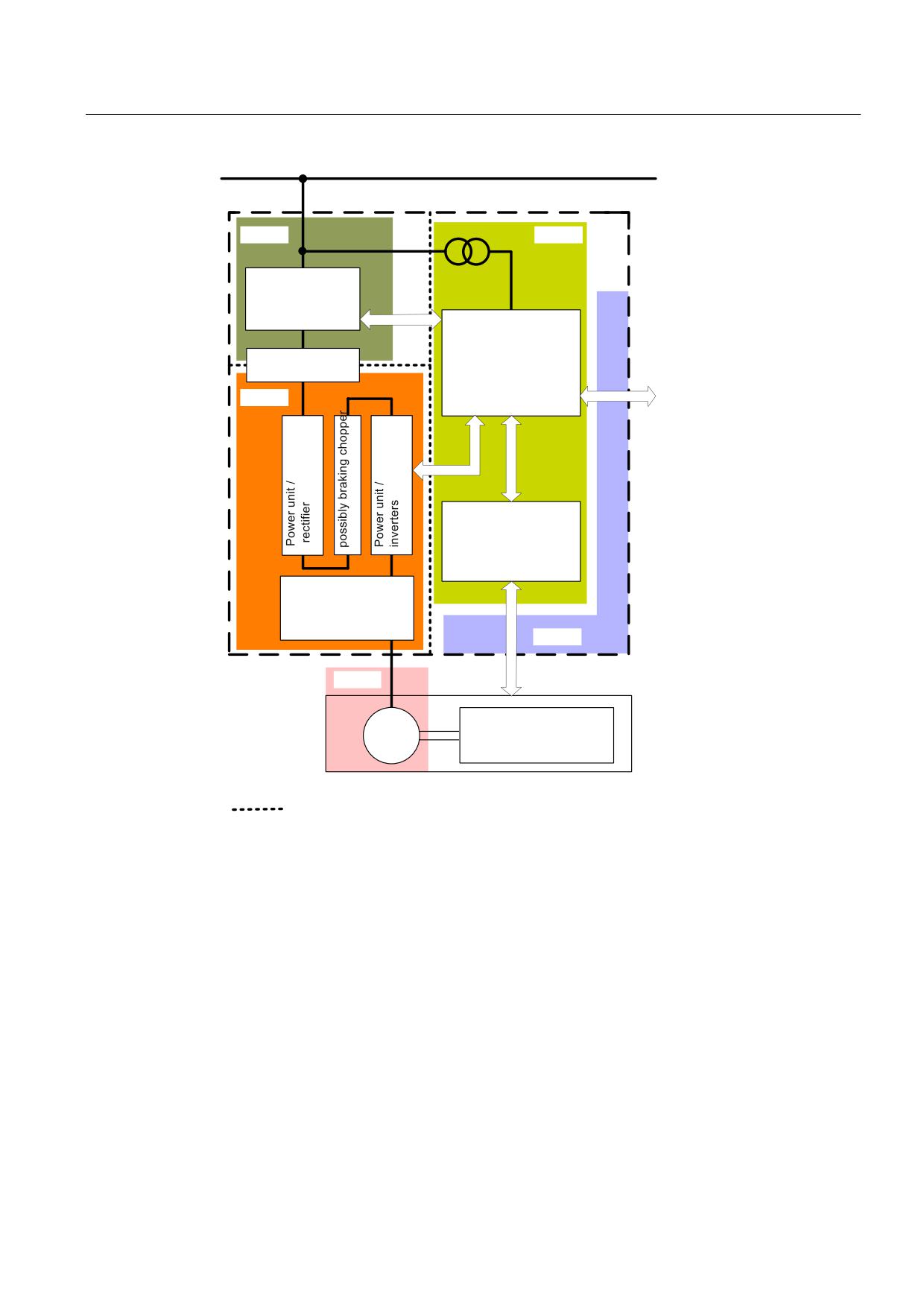
● The entire area of the plant or the control cabinet is then divided into EMC zones and the
devices assigned to the zones. The following example explains the zone concept in
greater detail.
* Depending on the device series, terms such as braking chopper, pulsed resistor module or
similar are also in use.
EMC installation guidelines / basic system requirements
16
Configuration Manual, (PH1), 01/2012, 6FC5297-0AD30-0BP3
Information on planning, design and installation
3.3 EMC-zone concept
/LQH VXSSO\
&RQWURO FDELQHW
=RQH $
=RQH &
6XSSO\ V\VWHP
FRQQHFWLRQ
)XVHV
6ZLWFKHV
&RQWDFWRUV
&RQWUROOHU
&RQWURO 8QLW &8
3RVVLEO\ VDIHW\ UHOD\
/LQH ILOWHU
3RVVLEO\ 6,0$7,&
/LQH UHDFWRU
=RQH %
6HQVRU HTXLSPHQW
7HPSHUDWXUH VHQVLQJ
3RVLWLRQ HYDOXDWLRQ
3UHVVXUH VHQVLQJ
0RWRU FRQQHFWLRQ
6ZLWFKHV
5HDFWRUV
)LOWHUV
=RQH '
=RQH (
0DFKLQH
0
0HFKDQLFDO V\VWHP
a
*URXQGHG PHWDO SDUWLWLRQ
Zone A System connection
The limit values for the conducted interference emission and interference immunity must be
observed
Zone B Power electronics
Interference sources: Converters consisting of rectifiers, possibly braking choppers,
inverters and possibly motor-side reactors and filters
Zone C Controller and sensors
Interference sinks: Sensitive open-loop and closed-loop control electronics and sensors
Zone D Signal interfaces for the I/O
The limit values for the interference immunity must be observed
Zone E Motor and motor cable
Interference sources
Figure 3-1
Classification of the control cabinet or the drive system into EMC zones
EMC installation guidelines / basic system requirements
Configuration Manual, (PH1), 01/2012, 6FC5297-0AD30-0BP3
17
Information on planning, design and installation
3.4 Openings in the housing, e.g. ventilation openings
Specific requirements regarding the interference emission and the interference immunity
apply within each zone. The zones must be decoupled electromagnetically. This decoupling
can, for example, be achieved with large physical separations (approx. 20 cm). Better and
space-saving is decoupling using separate metal enclosures or large metal partitions.
Cables of different zones must be separated and must not be laid in shared cable harnesses
or cable ducts. Where necessary, filters and/or coupler blocks must be deployed at the zone
interfaces. Coupler blocks with electrical isolation can effectively prevent the interference
propagation between the zones.
All communication and signal cables that exit the control cabinet must be shielded.
Additional isolation amplifiers must be used for longer analog signal cables.
3.4
Openings in the housing, e.g. ventilation openings
Ventilation holes, inspection windows, operator controls, etc., impair the shielding effect of
the control cabinet. Each opening half the size of the wavelength λ of the interference
frequency acts as an antenna and radiates electromagnetic fields. In practice, the slit lengths
should be less than λ/20. The following openings have proven themselves:
● In the first environment, openings with a maximum diameter of 30 mm
● In the second environment, openings with a maximum diameter of 100 mm
Openings with a diameter larger than 100 mm must be covered with a metal hood. It must
have a good metallic-conducting contact with the cabinet panel.
3.5
Equipotential bonding
To ensure the problem-free interaction of the components in a complex system, a good
equipotential bonding is necessary that acts effectively for technical frequencies and high
frequencies in the area above 10 MHz.
To achieve this, all metallic parts must have a large surface-area contact with each other and
so form an equipotential area.
This also prevents shields applied on both sides from being damaged or burnt due to high
equalizing currents or components from being subjected to interference, damaged or
destroyed because of an excessive voltage difference.
Signal cables to stations outside this equipotential area must be equipped with electrically-
isolating coupling blocks.
EMC installation guidelines / basic system requirements
18
Configuration Manual, (PH1), 01/2012, 6FC5297-0AD30-0BP3
Information on planning, design and installation
3.5 Equipotential bonding
3.5.1
Equipotential bonding within a control cabinet
The equipotential bonding within a control-cabinet is achieved by connecting all metallic
parts to one another at as many positions as possible over a large area, such as control-
cabinet panels or stays. Cabinet doors should be connected to the stays or side panels with
the shortest-possible copper ribbons at least at the top and bottom. The housing of the
devices and components installed in the cabinet element (e.g. converters, line filters, control
units, terminal modules, sensor modules, etc.) must be connected with each other using a
good-conducting (galvanized) mounting plate over a large surface area.
This mounting plate must have a large surface area electrically-conductive connection with
the cabinet frame, PE or shield buses of the cabinet element.
Painted control-cabinet panels, mounting plates or mounting equipment with a small
mounting footprint do not fully satisfy this requirement. If painted control-cabinet panels or
mounting plates need to be used, an adequately-good contact must be ensured. To do this,
the cable glands must be freed of paint during the installation or contact washers used.
Corrosion protection is necessary, e.g. painting after installation.
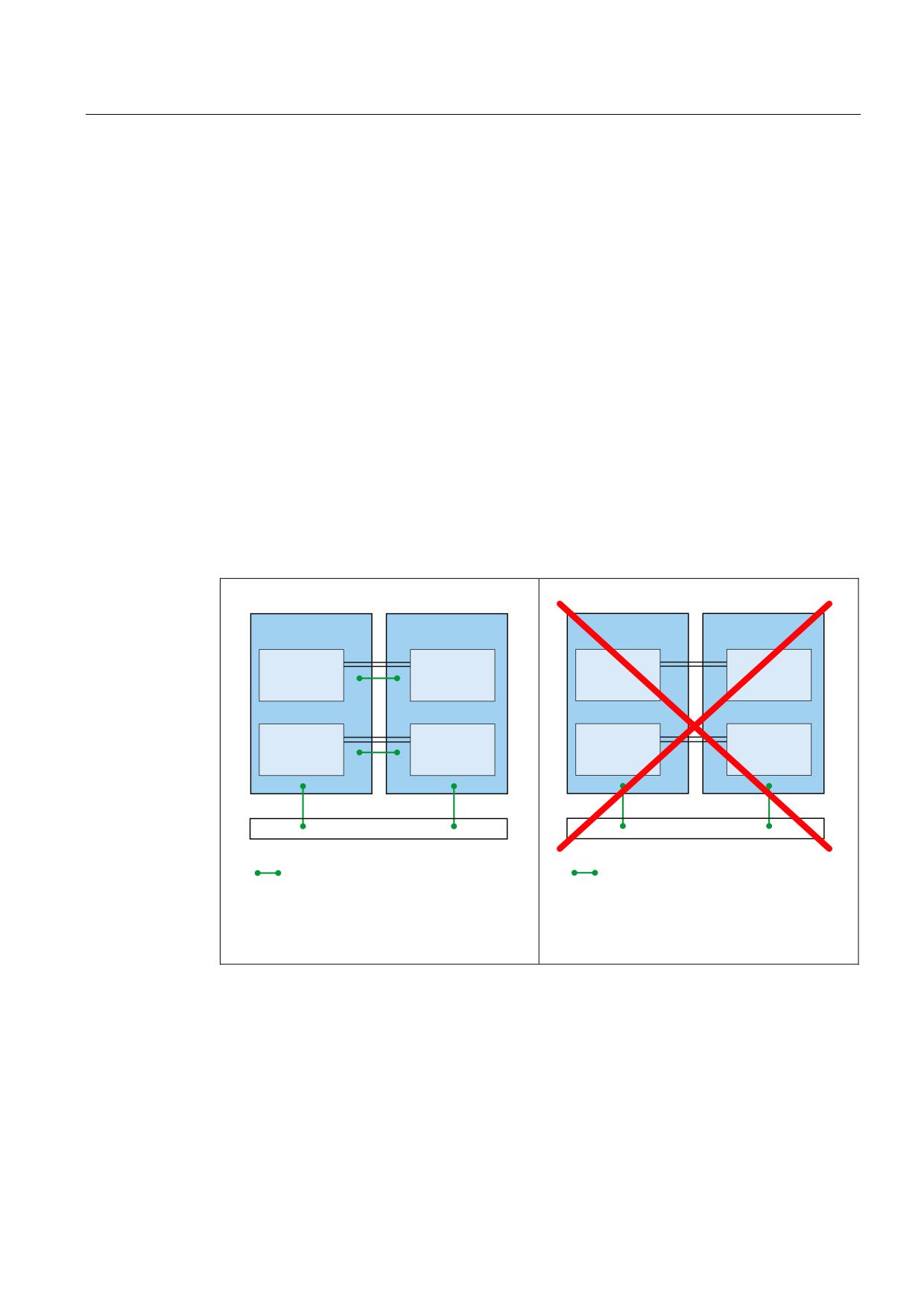
If several mounting plates are connected with each other using cables or ribbon wires, the
connection must be made close to the signal or power cable (minimization of the enclosed
area).
0RXQWLQJ SODWH
0RXQWLQJ SODWH
0RXQWLQJ SODWH
0RXQWLQJ SODWH
'HYLFH
'HYLFH
'HYLFH
'HYLFH
'HYLFH
'HYLFH
'HYLFH
'HYLFH
3( EDU
3( EDU
3URWHFWLYH HTXLSRWHQWLDO ERQGLQJ
3URWHFWLYH HTXLSRWHQWLDO ERQGLQJ
Example for the optimum connection of mounting
Example for an unfavorable connection of
plates
mounting plates
The larger surface area of ribbon connections makes them more favorable than round
connections with regard to EMC.
EMC installation guidelines / basic system requirements
Configuration Manual, (PH1), 01/2012, 6FC5297-0AD30-0BP3
19
Information on planning, design and installation
3.5 Equipotential bonding
Figure 3-2
Example for the connection with braided-copper ribbon
3.5.2
Equipotential bonding between several cabinet elements
The equipotential bonding between several cabinet elements for larger cabinet units is made
with an interconnecting PE bar that passes through all these cabinet elements. In addition,
the frames of the individual cabinet elements are screwed together several times with good
conductivity ensured through the use of contact washers. If very long rows of cabinets are
installed back-to-back, the two PE bars must be connected with each as often as possible
(recommended value: ten screw connections per cabinet element).
3.5.3
Equipotential bonding inside the machine/plant
The equipotential bonding within the machine/plant for technical frequencies is made by
connecting all the electrical and mechanical drive components (transformer, control cabinet,
motor, gear unit and driven machine) to the grounding system. These connections are made
with standard, heavy-duty PE conductors. For high frequencies, the equipotential bonding is
made using the shields of the motor cables to all components of the drive train (motor, gear
unit and driven machine).
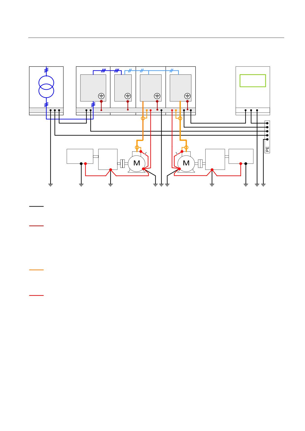
The following diagram illustrates all grounding and high-frequency equipotential bonding
measures using the example of a typical high-power installation comprising several
SINAMICS S120 Cabinet Modules.
Note
Compared with the shown rod grounding, the mesh grounding provides better results.
EMC installation guidelines / basic system requirements
20
Configuration Manual, (PH1), 01/2012, 6FC5297-0AD30-0BP3
Information on planning, design and installation
3.5 Equipotential bonding
7UDQVIRUPHU
6,1$0,&6
&RQWUROOHU
/LQH
/LQH
0RWRU
0RWRU
6,0$7,&
&RQQHFWLRQ
0RGXOH
0RGXOH
0RGXOH
0RGXOH
/&0
[/0
0R0R
0R0R
> @
> @
> @
> @
3(
3(
3(
> @
> @
> @
> @
> @
0DLQ HTXLSRWHQWLDO ERQGLQJ
LQ WKH FRQWURO URRP
> @
> @
'ULYHQ
*HDU
*HDU
'ULYHQ
PDFKLQH
XQLW
XQLW
PDFKLQH
> @
> @
> @
> @
> @
> @
> @
> @
> @
> @
> @
> @
> @
5RG JURXQGLQJ
The ground connections shown black form the conventional grounding system for the drive
[0]
components. They are made with standard, heavy-duty PE conductors without special high-frequency
properties and ensure low-frequency equipotential bonding as well as protection against injury.
The connections shown dark red inside the control cabinets provide good conductivity for high-
[1]
frequency protection between the metal housings of the integrated converter components and the PE
bar and EMC shield bus of the cabinet. These internal connections can be established over the
greatest possible surface area using the metallic construction of the cabinet unit, whereby the contact
surfaces must be bare metal and have a minimum cross-section of several cm2 at each contact point.
Alternatively, these connections can be established by means of short, finely-stranded, braided copper
wires with a large cross-section (> 95 mm2).
The shields of the motor cables shown in orange provide the high-frequency equipotential bonding
[2]
between the inverters or motor modules and the motor terminal boxes. The finely stranded, braided
copper cables shown in red can be routed in parallel with these when cables with poor high-frequency
properties are used or in installations with inferior grounding systems.
The connections shown in red provide a good-conducting high-frequency connection for the motor
[3], [4], [5]
terminal box or the gear unit and the driven machine bond to the motor housing.
Figure 3-3
Grounding and high-frequency equipotential-bonding measures for equipotential bonding in the drive system
via ground
EMC installation guidelines / basic system requirements
Configuration Manual, (PH1), 01/2012, 6FC5297-0AD30-0BP3
21
Information on planning, design and installation
3.6 Cables
3.5.4
Equipotential bonding of components to moving parts/slides
When components are mounted on moving parts/slides, an additional equipotential-bonding
conductor (at least 10 mm2) should, if possible, be laid in parallel and near the cable
(bundled). This equipotential-bonding conductor must be connected as close as possible to
the component on the slide and directly at the PE connection for the associated module on
the cabinet.
Note
The cables must be suitable for trailing.
3.6
Cables
3.6.1
General
Power and signal cables, even shielded, must always be routed separately. For this purpose,
it is practical to arrange the various cables according to cable groups. Cables belonging to a
group can be combined in a bundle. The various cable groups must be routed with the
necessary clearance between them. A minimum clearance of 20 cm has proven itself in
practice. As an alternative, shielding plates with the appropriate contacts at several locations
can be used between the cable bundles.
In order to reduce crosstalk, all cables must be laid as close as possible to the (grounded)
structural parts connected to the cabinet ground. These are, for example, mounting plates or
frame parts of the cabinet.
In order to minimize the antenna effect, all cables should be kept as short as possible.
Although signal and power cables may cross each other (if absolutely necessary), they must
never be routed close to each other over longer distances.
Signal cables must be routed with a minimum clearance of 20 cm from strong magnetic
fields (motors, transformers). Alternatively, shield plates with the appropriate contacts at
several locations along their length can be used to provide the appropriate clearance.
CAUTION
Cables for the 24 V supply should be treated just like signal cables. Adequate bending
radiuses of the signal and power cables must be ensured.
EMC installation guidelines / basic system requirements
22
Configuration Manual, (PH1), 01/2012, 6FC5297-0AD30-0BP3
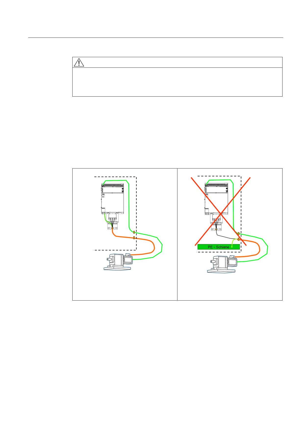
Information on planning, design and installation
3.6 Cables
WARNING
Capacitive coupling causes charging. To discharge these charges, at least one end of the
unused conductors for unshielded and shielded cables and their shields must be placed on
a grounded housing potential. Non-compliance may cause potentially fatal touch voltages
to develop at non-grounded insulated conductors and shielding.
3.6.2
Shielded cables
To achieve the smallest possible transfer resistances in the high-frequency area, cable
shields must always be connected at both ends with the largest possible surface area, if
possible using spring-loaded elements that enclose the shield.
The shield must be uninterrupted.
An example of a good uninterrupted cable routing
An example of an impermissible interrupted cable
from the motor to the motor module
routing from the motor to the motor module
If a break in the cable cannot be avoided, a bridging of the shields such as that shown in the
figure below must be provided.
EMC installation guidelines / basic system requirements
Configuration Manual, (PH1), 01/2012, 6FC5297-0AD30-0BP3
23
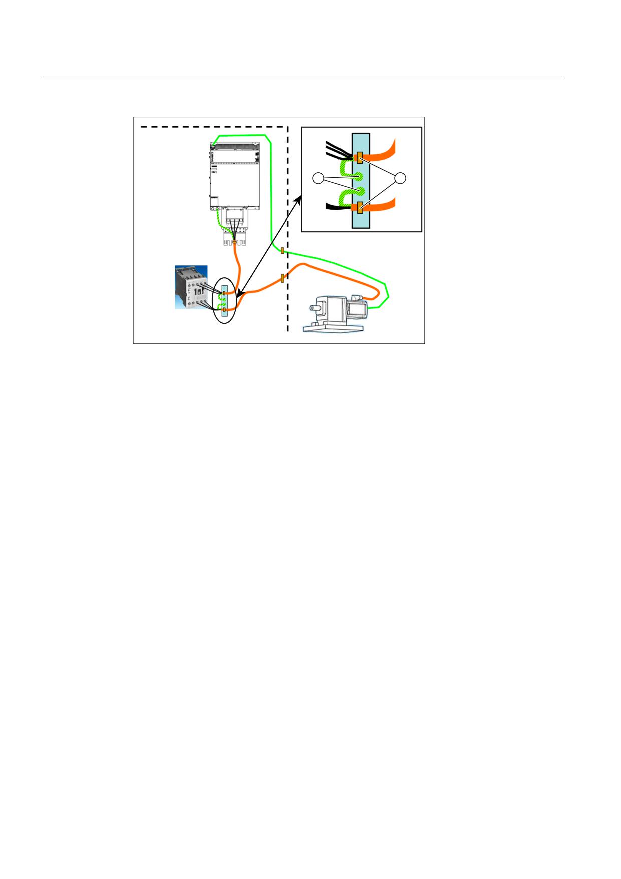
Information on planning, design and installation
3.6 Cables
①
Protective conductor
②
Shield connection
Figure 3-4
Example of good shield bridging with braided-copper ribbon
Braided shields should be favored. Foil shields should be avoided because their current-
carrying capacity is smaller and so the shields can be damaged.
Shield connections may not also serve as strain relief. The strain relief must be implemented
separately so that the shield connection is free from tensile forces.
As an alternative to the shielding inside control cabinets, measures are permitted that
achieve similar results as shielding, such as routing behind mounting plates or in metal cable
channels, suitable clearances, etc.
3.6.2.1
Plug connections for shielded cables
If cable shields are connected via connector enclosures, continuous metallic contact in the
connector must be ensured. Metalized plastic is not suitable in plants with converters for
providing sufficient contact over the plant service life because the metallic coating will be
abraded by vibrations or eroded by the shield current. If such connectors or connectors with
an unknown internal design are used, the shield must also be connected close to the
connector; see Figure 3-7 Examples of good types of shield connection (Page 29).
EMC installation guidelines / basic system requirements
24
Configuration Manual, (PH1), 01/2012, 6FC5297-0AD30-0BP3
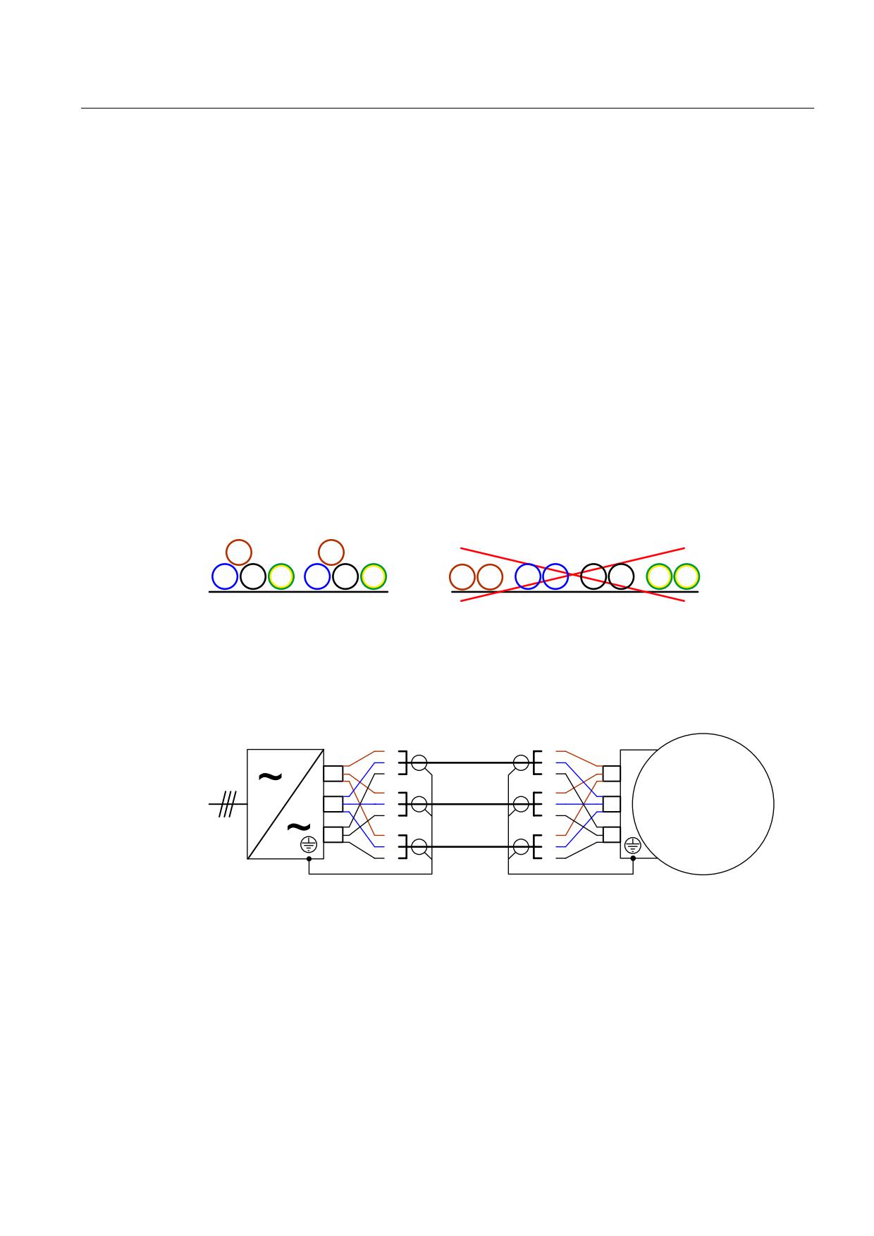
Information on planning, design and installation
3.6 Cables
3.6.3
Cables in the power line
Power cables in converter systems, in particular motor cables, are some of the largest
generators of interference signals. For this reason, all cables from the output of the drive line
filter must be laid twisted/bundled and shielded without interruption to the motor. Experience
has shown that short connections under 1 m within the control cabinet can be laid
twisted/bundled without shield, e.g. the connection filter to the reactor, reactor to the infeed
DC-link connections. The information from Section Drive line filter arrangement, line reactor,
drive group (Page 32) must also be observed.
3.6.3.1
Bundling, parallel connection of cables
For the routing of three-phase systems using single-core cables (e.g. unshielded power
supply cables), the three phases L1, L2 and L3 must be bundled symmetrically and so
minimize the magnetic leakage fields. This is true even when high currents mean several
parallel single-core cables must be laid for each phase of a three-phase system. The
following diagram shows an example of this using a three-phase system with two parallel
single-core cables per phase:
&RUUHFW EXQGOLQJ
,QFRUUHFW EXQGOLQJ
/
/
/
/
3(
/
/
3(
/
/
/
/
/
/
3(
3(
Figure 3-5
Bundling of cables
When more than one motor cable is routed in parallel, note that each individual motor cable
must contain all three conductors of the three-phase system. This helps to minimize the
magnetic leakage fields and thus also the magnetic interference of other loads.
/
/
/
/
0
/
/
Figure 3-6
Example of three motor cables routed in parallel
3.6.3.2
The motor cable shield connection at the motor modules
The provided shield connections must be used at the motor modules for built-in units. If this
cannot be done due to space limitations, the shield must be connected to the mounting plate
as close as possible to the motor modules. The shield is connected to the central grounding
bar for cabinet units.
EMC installation guidelines / basic system requirements
Configuration Manual, (PH1), 01/2012, 6FC5297-0AD30-0BP3
25
Information on planning, design and installation
3.6 Cables
3.6.3.3
Shield connection of the motor cable to the motor terminal box
To ensure a large-area shield connection, cable glands with EMC inserts must be used on
the terminal box, e.g. PG glands. If space requirements mean this is not possible, the shield
must be connected as close as possible to the motor housing; see for example Figure 3-7
Examples of good types of shield connection (Page 29).
3.6.3.4
Shield connection for cables with connector
The shield must be connected in the connector at the motor and converter side as described
by the connector manufacturer.
3.6.3.5
Protective conductor in the motor cables (green/yellow)
The protective conductor included in the motor cables must be connected directly to the
motor module at the PE connection for the cabinet for built-in units. For cabinet units, the
connection is made to the central grounding bar. The protective conductor must be
connected at the provided PE connection in the connector or in the terminal box at the
motor.
3.6.3.6
The last meter to the motor
The position of the connector means the required distances of 20 cm between the motor and
encoder cable cannot always be observed on the motor.
Experience has shown that a bundling of motor and encoder cables for mechanical reasons
is possible for the last meter to the motor.
3.6.3.7
DC-link connection, braking resistor
If the DC link is further connected to other groups, an equalizing conductor with the two
cables must be provided. This must be connected to the motor modules at the provided
connections. The three cables must be twisted or be bundled. For lengths exceeding approx.
1 m, a shield instead of the equipotential conductor should be provided. This must be
connected at both ends at the provided connections or, for lack of space, at the mounting
plates near the drive groups.
The same requirements apply to the cable for the braking resistor.
3.6.3.8
Cable lengths in the power line
If the permissible total cable length is exceeded, the increased shield currents can cause
additional losses in the line filter, the line reactor, the infeed module and motor modules or
saturation in the line filter, which then become ineffective. This leads to an overheating of the
components and thus failures or a reduction of the service life. Information about maximum
permissible cable lengths is contained in the device-specific technical user documentation.
EMC installation guidelines / basic system requirements
26
Configuration Manual, (PH1), 01/2012, 6FC5297-0AD30-0BP3
Information on planning, design and installation
3.6 Cables
3.6.4
Brake cables
Cables for brakes must be shielded. If the brake cables are combined with the motor cables
in a common cable, the twisted motor cores with the protective conductor must be routed in
a common shield and the twisted brake cores in another separate shield.
The same requirements apply to the shield connection as for the motor cables. See Section
The motor cable shield connection at the motor modules (Page 25).
Note
Wiring; see Section Wiring of coils (Page 33).
3.6.5
Encoder cables
Encoders and encoder cables are some of the most sensitive parts of the equipment. In this
case, faulty signals, for example in machine tools, can cause surface flaws or sporadic errors
of the machine. For double-shielded encoder cables, whereas the outer shield must be
connected at both ends, the inner shield is connected at only one side to the drive group.
3.6.5.1
Encoder cables with plug connectors
The shield is usually connected at the connector. When particularly high requirements apply,
such as an environment with very high EMC levels, another connection close to the
connector is recommended.
3.6.5.2
DRIVE-CLiQ encoder connections
The shield contacting of the DRIVE-CLiQ encoder cables is made at the connector.
3.6.5.3
Cable lengths for encoders
Maximum cable lengths appropriate for the encoder must be observed. Details can be taken
from the device-specific technical user documentation.
3.6.6
DRIVE-CLiQ connections
The shield contacting of the DRIVE-CLiQ connections between the components of the drive
group is made at the connectors.
The different connector types (integrated 24 V supply) means the use of commercially
available Ethernet cables is not permitted.
EMC installation guidelines / basic system requirements
Configuration Manual, (PH1), 01/2012, 6FC5297-0AD30-0BP3
27
Information on planning, design and installation
3.6 Cables
The maximum total cable length for DRIVE-CLiQ is 100 m.
Note
Depending on the used cable type, the cable lengths may be shorter.
3.6.7
Field bus
Field buses must be particularly resistant to faults. To achieve this robustness, the following
points according to the manufacturer's instructions of the connected bus components must
be observed:
● Sufficient distance from the power cables
● Shield connection to the bus components
● Shield connection at the control cabinet input
● Equipotential bonding
3.6.7.1
PROFIBUS, PROFINET
● The minimum distance between PROFIBUS or PROFINET cables to power cables is 20
cm.
● The shield connection to the PROFIBUS or PROFINET components is implemented at
the plug connector. If the component is not mounted on a metal mounting plate, an
additional equipotential bonding conductor with 4 mm2 cross-section must be laid for the
protective equipotential bonding.
● The shield connection at the control cabinet inlet is necessary in order to comply with the
immission limit values must be observed in the first environment. The shield connection is
recommended for operation in the second environment.
● For PROFIBUS or PROFINET connections between different buildings or parts of
buildings, an equipotential bonding must be laid parallel to the PROFIBUS or PROFINET
cable.
The following minimum cross-sections according to IEC 60364-5-54 are required:
- Copper: 6 mm2
- Aluminum: 16 mm2
- Steel: 50 mm2
For further information, see under
orwort.html)
EMC installation guidelines / basic system requirements
28
Configuration Manual, (PH1), 01/2012, 6FC5297-0AD30-0BP3
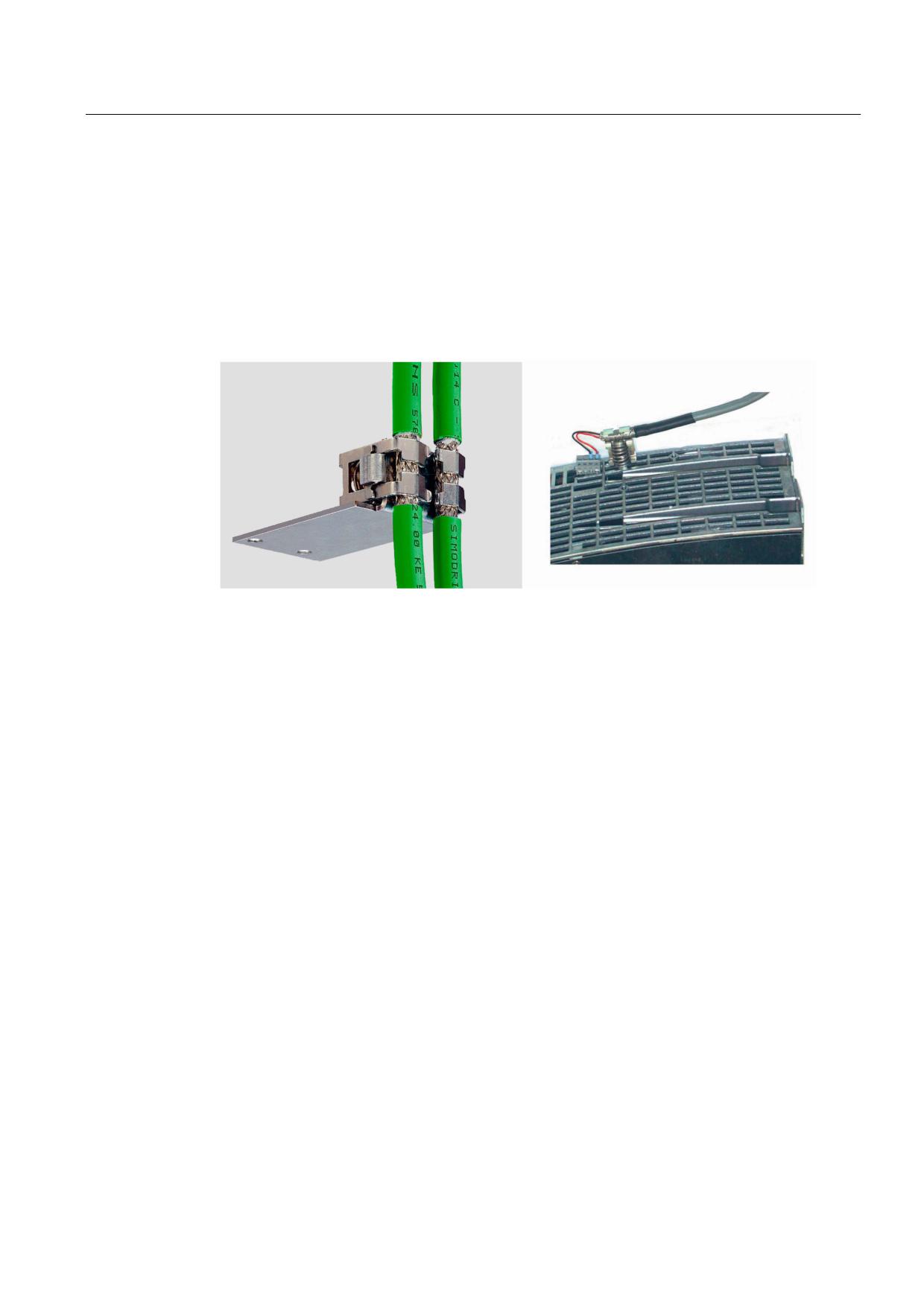
Information on planning, design and installation
3.7 Laying cables on cable racks/routes at the plant
3.6.8
Analog signals
The shields of cables for analog signals must be connected on both sides, see Figure 3-7
Examples of good types of shield connection (Page 29). A good equipotential bonding
between output and input is required.
3.6.9
Examples of shield connections
Figure 3-7
Examples of good types of shield connection
3.7
Laying cables on cable racks/routes at the plant
If cables cannot be routed directly from the control cabinet to the machine, they must be laid
on cable racks/routes. In this case, all cable shields should also be connected at the cable
entry of the control cabinet in order to comply with the immission limit values in the first
environment. The shield connection is recommended for operation in the second
environment.
The same requirements for the distance and shielding as described in Section General
(Page 22) apply to the cable routing. The following figure shows a laying example.
EMC installation guidelines / basic system requirements
Configuration Manual, (PH1), 01/2012, 6FC5297-0AD30-0BP3
29
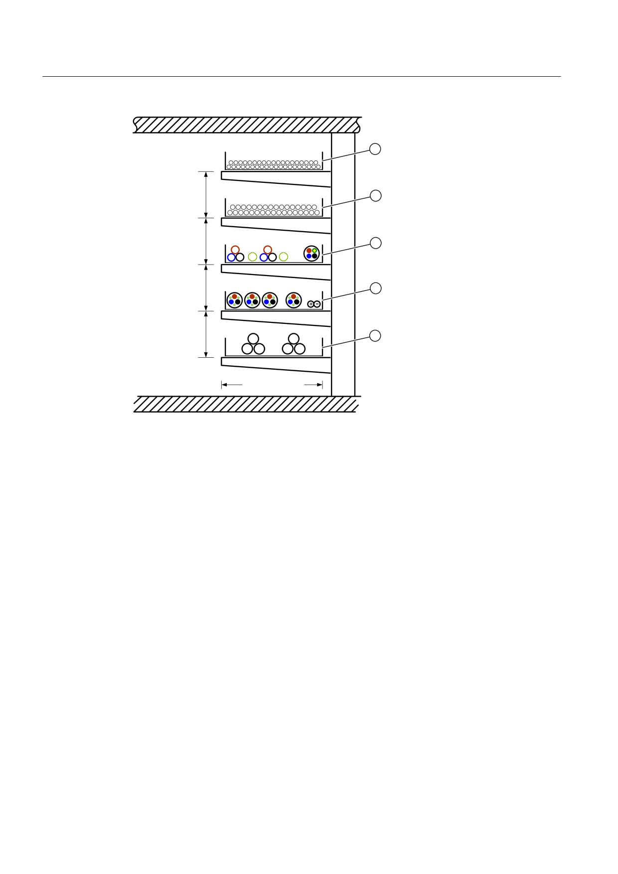
Information on planning, design and installation
3.7 Laying cables on cable racks/routes at the plant
FP
FP
FP
FP
/
/
/
/
3(
/
/
3(
FP
FP
FP
FP
/
/
/
/
/
/
FP
FP
①
Signal, data, bus and single-core cables with U < 60 V
②
Signal cables and single cables with U = 60 V to 10 V
③
Power cables with low interference level
(e.g. unshielded power supply cables with U > 230 V. ..1 kV)
④
Power cables with a high noise level
(e.g. motor cables and cables between the braking unit and the braking resistor) with U > 230
V. ..1 kV
⑤
Medium-voltage cables with U > 1 kV
Figure 3-8
Cable installation
The cable racks/routes must be included in the equipotential bonding. In order to also
achieve an effect in the high-frequency range, large surface area mechanical connections
must be made to the cabinet and to the motor casing. The individual rack parts must also
have a large surface area connection with each other.
For further information, see under
EMC installation guidelines / basic system requirements
30
Configuration Manual, (PH1), 01/2012, 6FC5297-0AD30-0BP3
Information on planning, design and installation
3.8 Connection to the line supply
3.8
Connection to the line supply
Equipment with converters also have low-frequency negative effects on the line supply that
can be suppressed not at all or only to a very limited extent by the line filters. Such limited
suppression can make itself apparent as flickering lights, overheating or even other defective
devices, etc.
To prevent this, the connection conditions, such as the short-circuit power of the line supply
and loop impedance, stated in the technical user documentation must be observed.
3.8.1
Drive line filter, cabinet line filter
The drive line filter that belongs to the converter system is tailored exclusively to the
converter system and should only be used for this. For other consumers, a commercially
available line filter should be installed as close as possible behind the main switch and fuse
protection at the cabinet entry. Further consumers are supplied via this line filter.
To prevent the filter becoming ineffective because of over-coupling, the filtered cables must
be laid with unfiltered cables in accordance with Section Drive line filter arrangement, line
reactor, drive group (Page 32).
Filters must be installed as close as possible to the cable entry of the control cabinet with a
large contact area. Exceptions are special drive filters that should be installed as close as
possible to the drive group or filters integrated in devices, such as for SITOP power supplies.
A large contact surface must be ensured during installation.
Incoming cables and filters to filter outgoing cables must always be installed separately.
For examples, see Figure Good laying with distance (Page 32) and Figure Good laying with
shield plate (Page 32).
Filtered and unfiltered cables must never be laid together.
EMC installation guidelines / basic system requirements
Configuration Manual, (PH1), 01/2012, 6FC5297-0AD30-0BP3
31
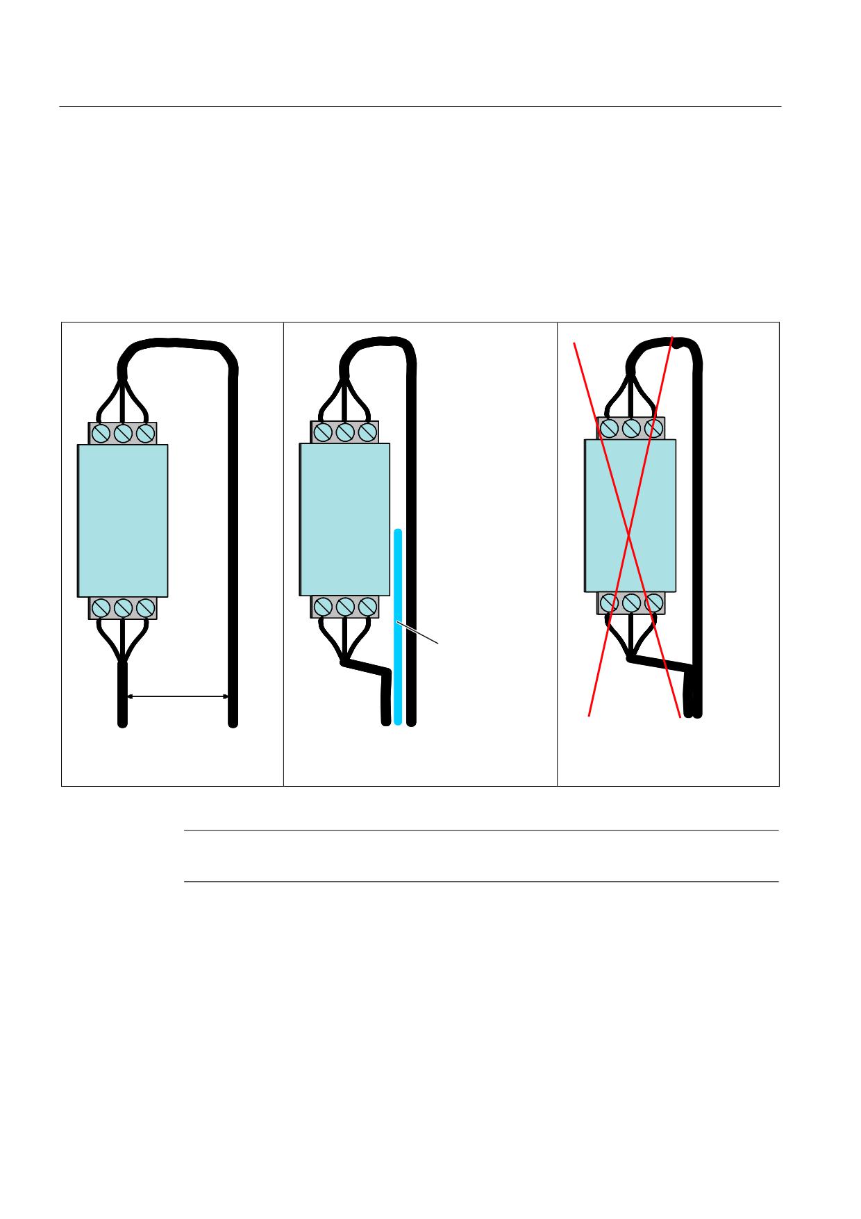
Information on planning, design and installation
3.8 Connection to the line supply
3.8.2
Drive line filter arrangement, line reactor, drive group
Branching to the drive is made behind the main switch and the fuse protection but before the
line filter. The housings of drive line filters and the infeed of the drive group must be
connected together with low resistance for high-frequency interference currents. For this
purpose, the components must be mounted close together on a common conducting
(galvanized) mounting plate on which they must have a large-area, permanent conductive
connection. The line reactor must be installed close to the filter and infeed.
2XWSXW
2XWSXW
2XWSXW
)LOWHU
)LOWHU
)LOWHU
,QSXW
,QSXW
,QSXW
6KLHOG SODWH
8QVKLHOGHG
!
FP
Good laying with distance
Good laying with shield plate
Impermissible laying
It is recommended that the power cables are laid shielded starting at the control cabinet inlet.
Note
Reactors and filters can also be combined, for example, as an AIM
EMC installation guidelines / basic system requirements
32
Configuration Manual, (PH1), 01/2012, 6FC5297-0AD30-0BP3
Information on planning, design and installation
3.9 Miscellaneous
3.9
Miscellaneous
3.9.1
Wiring of coils
When
● mechanical switch contacts are used for switching,
● unconnected PLC outputs are used for switching,
to avoid switching overvoltages, all connected actuators, contactor coils, solenoid valves,
holding brakes, etc., should be connected using surge-suppression devices (e.g. RC
elements, varistors), if possible, directly at the interference source.
NOTICE
Increased run times can occur for circuits with free-wheeling diodes.
3.9.2
Bearing currents
For converter operation, the motor voltages are generated by pulse-width modulation. The
steep edges generate parasitic currents in the motor because of the winding capacitance.
Some of these currents can flow through the motor bearings and so damage them. This can
reduce the bearing service life.
Up to and including axis height 100, a good stator grounding by means of an EMC-compliant
installation in accordance with the figure (see Figure 3-3 Grounding and high-frequency
equipotential-bonding measures for equipotential bonding in the drive system via ground
(Page 21)) must be provided over the shields of the cables [ 2] or an insulated coupling to
ensure that the bearing currents are kept sufficiently small.
Above axis shaft height 100, an additional good high-frequency equipotential bonding to the
driven machine and from the motor terminal box to the motor housing as shown in the figure
(see Figure 3-3 Grounding and high-frequency equipotential-bonding measures for
equipotential bonding in the drive system via ground (Page 21)) via the cables [ 5] is required
and possibly an insulated bearing at the non-drive end.
du/dt or sine-wave filters can also be used at the converter output instead of an insulated
bearing in the motor, provided this is permitted.
EMC installation guidelines / basic system requirements
Configuration Manual, (PH1), 01/2012, 6FC5297-0AD30-0BP3
33
Preface
Fundamental safety
1
instructions
2
Introduction
SINUMERIK
Ctrl-E Analysis
3
SINUMERIK 840D sl / 828D
Ctrl-Energy
4
Ctrl-E Profiles
Reactive power
5
compensation
System Manual
6
Flux reduction
User know-how
7
A
Appendix
Valid for
Control system
SINUMERIK 840D sl / 840DE sl / 828D
Software
Version
CNC Software
4.7 SP2
10/2015
6FC5397-0EP40-5BA3
Preface
SINUMERIK documentation
SINUMERIK documentation
The SINUMERIK documentation is organized in the following categories:
● General documentation
● User documentation
● Manufacturer/service documentation
Additional information
You can find information on the following topics at www.siemens.com/motioncontrol/docu:
● Ordering documentation/overview of documentation
● Additional links to download documents
● Using documentation online (find and search in manuals/information)
Please send any questions about the technical documentation (e.g. suggestions for
improvement, corrections) to the following address:
docu.motioncontrol@siemens.com
My Documentation Manager (MDM)
Under the following link you will find information to individually compile OEM-specific machine
documentation based on the Siemens content:
Training
For information about the range of training courses, refer under:
SITRAIN - Siemens training for products, systems and solutions in automation technology
SinuTrain - training software for SINUMERIK
FAQs
You can find Frequently Asked Questions in the Service&Support pages under Product
Ctrl-Energy
System Manual, 10/2015, 6FC5397-0EP40-5BA3
3
Preface
SINUMERIK
You can find information on SINUMERIK under the following link:
Hotline and Internet address
Technical Support
You will find telephone numbers for other countries for technical support in the Internet under
EC Declaration of Conformity
The EC Declaration of Conformity for the EMC Directive can be found on the Internet at:
Ctrl-Energy
4
System Manual, 10/2015, 6FC5397-0EP40-5BA3
Table of contents
Preface
3
1
Fundamental safety instructions
7
1.1
General safety instructions
7
1.2
Industrial security
7
2
Introduction
9
3
Ctrl-E Analysis
11
3.1
SENTRON PAC3200/4200
12
3.1.1
Hardware
12
3.1.2
Commissioning the Power Monitoring Device
13
3.1.3
Commissioning the PAC PROFIBUS expansion module (840D sl)
14
3.1.4
Commissioning the expansion module PAC PROFINET (828D)
15
3.2
Commissioning the PLC for SENTRON PAC
15
3.2.1
SINUMERIK 840D sl
15
3.2.1.1
Commissioning the PLC with PROFIBUS
15
3.2.1.2
Commissioning the PLC with PROFINET
19
3.2.2
SINUMERIK 828D
22
3.3
Commissioning the PLC for Ctrl-E Analysis
23
3.3.1
Configuring the energy consumption display for SINUMERIK 840D sl
23
3.3.1.1
PLC user program for SINUMERIK 840D sl programming
27
3.3.2
Configuring the display of energy consumption for SINUMERIK 828D
29
3.3.2.1
Programming the PLC user program for SINUMERIK 828D
33
3.4
Commissioning the HMI for Ctrl-E Analysis
37
3.4.1
Changing display texts of the auxiliary systems
37
3.5
Long time measurement
38
3.6
Power display in the status line of the "Machine" operating area
38
4
Ctrl-E Profiles
39
4.1
Commissioning the PLC for Ctrl-E Profiles
39
4.1.1
Overview
39
4.1.2
Automatic state machine PLC functions
40
4.1.3
Checking the energy-saving states
42
4.1.4
PLC user program
43
4.1.5
Interface signals 840D sl
44
4.1.5.1
Signals for controlling energy-saving profiles
44
4.1.5.2
Signals for parameterization
45
4.1.6
Interface signals 828D
46
4.1.6.1
Signals for controlling energy-saving profiles
46
4.1.6.2
Signals for parameterization
47
4.2
Creating and editing energy-saving profiles
48
Ctrl-Energy
System Manual, 10/2015, 6FC5397-0EP40-5BA3
5
Table of contents
5
Reactive power compensation
53
6
Flux reduction
55
7
User know-how
57
7.1
Commissioning user screen forms
57
A
Appendix
59
A.1
Overview
59
Index
61
Ctrl-Energy
6
System Manual, 10/2015, 6FC5397-0EP40-5BA3
Fundamental safety instructions
1
1.1
General safety instructions
WARNING
Risk of death if the safety instructions and remaining risks are not carefully observed
If the safety instructions and residual risks are not observed in the associated hardware
documentation, accidents involving severe injuries or death can occur.
● Observe the safety instructions given in the hardware documentation.
● Consider the residual risks for the risk evaluation.
WARNING
Danger to life or malfunctions of the machine as a result of incorrect or changed
parameterization
As a result of incorrect or changed parameterization, machines can malfunction, which in turn
can lead to injuries or death.
● Protect the parameterization (parameter assignments) against unauthorized access.
● Respond to possible malfunctions by applying suitable measures (e.g. EMERGENCY
STOP or EMERGENCY OFF).
1.2
Industrial security
Note
Industrial security
Siemens provides products and solutions with industrial security functions that support the
secure operation of plants, solutions, machines, equipment and/or networks. They are
important components in a holistic industrial security concept. With this in mind, Siemens’
products and solutions undergo continuous development. Siemens recommends strongly that
you regularly check for product updates.
For the secure operation of Siemens products and solutions, it is necessary to take suitable
preventive action (e.g. cell protection concept) and integrate each component into a holistic,
state-of-the-art industrial security concept. Third-party products that may be in use should also
be considered. For more information about industrial security, visit this address (http://
To stay informed about product updates as they occur, sign up for a product-specific
Ctrl-Energy
System Manual, 10/2015, 6FC5397-0EP40-5BA3
7
Fundamental safety instructions
1.2 Industrial security
WARNING
Danger as a result of unsafe operating states resulting from software manipulation
Software manipulation (e.g. by viruses, Trojan horses, malware, worms) can cause unsafe
operating states to develop in your installation which can result in death, severe injuries and/
or material damage.
● Keep the software up to date.
You will find relevant information and newsletters at this address (http://
support.automation.siemens.com).
● Incorporate the automation and drive components into a holistic, state-of-the-art industrial
security concept for the installation or machine.
You will find further information at this address (http://www.siemens.com/
industrialsecurity).
● Make sure that you include all installed products into the holistic industrial security concept.
Ctrl-Energy
8
System Manual, 10/2015, 6FC5397-0EP40-5BA3
Introduction
2
The topics of energy efficiency and energy saving are also playing an increasingly important
role in the machine tool environment.
With SINUMERIK Ctrl-Energy, Siemens is offering an extensive range of components,
functions, software tools and services to increase the efficiency of machine tools.
Ctrl-Energy
You will find an overview of the complete range of functions under the following link:
Acquisition, evaluation, and control of energy consumption
The functions Ctrl-E Analysis to acquire and evaluate the energy consumption of the machine
and Ctrl-E Profiles, to control energy-saving states of the machine are available in SINUMERIK
Operate. Additional energy-saving functions or user know-how on this topic can be added in
this area of SINUMERIK Operate.
Ctrl-Energy
System Manual, 10/2015, 6FC5397-0EP40-5BA3
9
Ctrl-E Analysis
3
In order to sensitize users to the topic of energy efficiency, the power and energy data of the
machine are first acquired.
Acquiring and evaluating energy consumption
A control system with SINUMERIK Operate without a connected measuring instrument
determines the power directly from the drives and displays this.
Additional consumption-relevant data can be retrieved and displayed at the control using the
additional SENTRON PAC Power Monitoring Device.
Depending on where the SENTRON PAC measuring transducer is installed, you have the
possibility of either measuring the power of the whole machine or only a specific load.
With an integrated measuring function, the energy consumption during a measuring period
can be acquired for all drives together with an additional measuring location - and the electrical
power drawn for a selected load can be recorded with respect to time.
Display of energy consumption
● The user can see a graphic of the current power consumption in the first status line of the
"Machine" operating area.
● Additionally, in the Ctrl-Energy initial display the user is shown the consumption in the form
of colored bars, which indicate the current power and the results of today's and yesterday's
long time measurement.
Maximum measuring time
The maximum measuring time for energy between start and stop as well as for an NC part
program is, as a result of the trace recording, 922 seconds (00:15:22).
Ctrl-Energy
System Manual, 10/2015, 6FC5397-0EP40-5BA3
11
Ctrl-E Analysis
3.1 SENTRON PAC3200/4200
3.1
SENTRON PAC3200/4200
3.1.1
Hardware
Hardware components
You require the following hardware in order to be able to use all of the "Ctrl-Energy" functions:
●
SENTRON PAC3200 (Firmware ≥ V2.2.0)
●
SENTRON PAC4200 (Firmware ≥ V1.4.0)
●
SENTRON PAC - accessories
Lowvoltage_LV10-1_complete_German_2011.pdf
- Power Monitoring Device (page 11/27 ff)
- Current transformer (Page 11/39)
●
The expansion modules must be temporarily removed in order to upgrade the firmware
using powerconfig.
●
Protection/fusing of the supply and measuring voltages according to Configuration Manual
●
Expansion module PAC PROFINET; order number 7KM 9300-0AE01-0AA0
●
Expansion module PAC PROFIBUS; order number 7KM 9300-0AB01-0AA0
●
PC software powerconfig (≥ V2.2)
●
Current transformer depending on
- the connection type at the SENTRON PAC
- Accuracy requirements
- Currents
DANGER
Open current transformer circuits result in electric shock and arcing
If not observed, will cause death, serious injury or considerable property damage.
Only measure the current using external current transformers. DO NOT protect the
circuits using a fuse. Do not open the secondary circuit of the current transformer under
load. Short circuit the secondary current terminals of the current transformer before
removing this device. The safety information for the current transformers used must
be carefully followed.
Selection example
Catalog, Siemens LV 1/Accessories and spare parts:
Ctrl-Energy
12
System Manual, 10/2015, 6FC5397-0EP40-5BA3
Ctrl-E Analysis
3.1 SENTRON PAC3200/4200
For a three-phase measurement according to connection type 3P4W (four conductors,
unbalanced load, without voltage transformers, with three current transformers), accuracy
class 1, primary rated current 100 A, secondary rated current 1A, three window-type
transformers are recommended (4NC5117-0CC20).
Note
When measuring the complete machine, it is recommended that the current is sensed directly
after the main switch. For the voltage tap, please observe the usual protection/fusing.
References
Information on the installation, configuration and operation of the Power Monitoring Device
and the expansion module can be found in the following references:
● SENTRON PAC3200 Power Monitoring Device Manual
(Document order number A5E01168664A-05)
● SENTRON PAC4200 Power Monitoring Device System Manual
(Document order number A5E02316180A-03)
● PAC PROFIBUS DP, SWITCHED ETHERNET PROFINET Expansion Module Manual
(document order number A5E01168846A-06)
3.1.2
Commissioning the Power Monitoring Device
A detailed description of commissioning of the SENTRON PAC Power Monitoring Device is
provided in the corresponding manuals.
Preconditions
● The device has been installed.
● The optional expansion modules have been installed.
● The device has been connected in accordance with the possible connection methods.
● The battery has been inserted into the battery compartment (only for the SENTRON
PAC4200).
General procedure when commissioning the device
● Connected the supply voltage
● Parameterizing SENTRON PAC
● Connect the measuring voltage
● Connect the current to be measured
● Check the displayed measured values
● Check the polarity and phase assignment of the measuring transducer
Ctrl-Energy
System Manual, 10/2015, 6FC5397-0EP40-5BA3
13