SINUMERIK 840D sl. Service - Configuring Commissioning. Manual (2011-2020) - page 107
Importing user alarms
9.4 Enable project languages
9.4
Enable project languages
If a multilingual project is created, all project languages, the editing language and reference
language must be specified in the settings under "Languages and Resources".
These settings should be made at an early stage because, for example, when copying or
inserting multilingual objects, only those languages defined as project languages are included.
If a project language is disabled, all text and graphic objects previously created in this language
are deleted from the current project.
Procedure
1. Double click "Project languages" below "Languages & Resources" in the project navigation.
All selectable project languages are displayed in the working area.
2. Activate the check boxes of all languages and language variants that are to be available as
project languages.
3. Specify the reference and editing languages in the relevant drop-down lists.
SINUMERIK 840D sl STEP 7 Toolbox V16
Configuration Manual, 12/2019, 6FC5397-0GP40-0BA1
169
Importing user alarms
9.5 Importing SINUMERIK PLC alarm texts
9.5
Importing SINUMERIK PLC alarm texts
Note
System-specific differences
Importing and saving alarm texts can differ in the TIA Portal depending on the specific system.
Note the corresponding subsection applicable for the system being used,
e.g. SINUMERIK 840D sl.
Requirement
● A SINUMERIK controller or a device proxy (PLC 300) is inserted.
● The languages in which the TS files are available are activated as project languages
(Page 169) in the TIA Portal.
If you would like to assign a TS file that is to be imported to several language variants, enable
all of the desired language variants.
● The TS files of the corresponding language are available on the configuration computer.
Note
Check TS files
Before importing, it should be ensured that all TS files have been fully translated and match
each other, this means that the same number of alarms are imported and the same alarm
numbers are used for each of the various languages.
SINUMERIK 840D sl STEP 7 Toolbox V16
170
Configuration Manual, 12/2019, 6FC5397-0GP40-0BA1
Importing user alarms
9.5 Importing SINUMERIK PLC alarm texts
Procedure
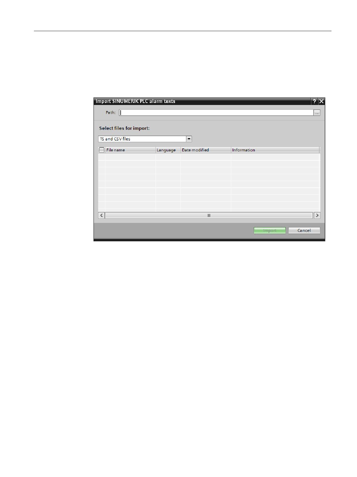
To import SINUMERIK user alarm texts into the TIA Portal, proceed as follows:
1. In the Project tree, right-click the controller or the device proxy, then select "Import
SINUMERIK PLC alarm texts" in the shortcut menu.
The "Import SINUMERIK PLC alarm texts" dialog opens.
2. Enter the path in which you have saved the user alarm files.
3. Select the file formats which you would like to import in the "File type" drop-down list.
- TS and CSV files
- TS files: Importing DB2 alarm texts that were copied directly from the controller.
- CSV file: Importing of DB2 alarm texts that were converted beforehand into the CSV
format, for example with AMM /P2P.
4. Check the checkboxes of the desired files individually or activate the higher-level
checkboxes to import all of the displayed files.
5. Confirm the selection with "Import".
Result
The SINUMERIK user alarm texts have been imported.
Only the alarm texts of the alarm numbers 5xx.xxx … 9xx.xxx relevant in the TIA Portal are
taken into account here.
Note that the imported texts are only visible in the TIA Portal if one of the languages is selected
as the editing language for which the texts were imported.
If the SINUMERIK PLC alarm texts are re-imported, the texts in the TIA Portal are deleted or
overwritten.
SINUMERIK 840D sl STEP 7 Toolbox V16
Configuration Manual, 12/2019, 6FC5397-0GP40-0BA1
171
Importing user alarms
9.5 Importing SINUMERIK PLC alarm texts
See also
Exporting TS files from SINUMERIK Operate (Page 166)
SINUMERIK 840D sl STEP 7 Toolbox V16
172
Configuration Manual, 12/2019, 6FC5397-0GP40-0BA1
Safety configuration
10
10.1
Introduction
The integrated safety functions of SINUMERIK Safety Integrated are used in the machine tools
sector. In the TIA Portal, you can select one of two Safety Integrated modes in conjunction with
the SINUMERIK Toolbox:
● Safety Integrated (SPL) (general) (Page 189)
● Safety Integrated plus (F-PLC) (general) (Page 202)
Because the Safety Integrated modes must be licensed (Page 186) and configured differently,
Safety Integrated is not active as default setting. You should activate the desired Safety
Integrated mode directly at the start of the configuring work so that the system can assign the
affected parameters automatically where possible.
The following sample configuring sequences serve as an aid for the configuring and provide an
overview of this chapter content.
● Configuring Safety Integrated (SPL) (handling overview) (Page 189)
● Configuring Safety Integrated plus (F-PLC) (handling overview) (Page 203)
You can, however, make most settings for Safety Integrated in TIA Portal in any order. If you
already have experience with configuring SINUMERIK Safety Integrated, you can orient
yourself on the overview of the Safety Integrated relevant parameters (Page 179).
SINUMERIK 840D sl STEP 7 Toolbox V16
Configuration Manual, 12/2019, 6FC5397-0GP40-0BA1
173
Safety configuration
10.2 Representation of safety-related resources in the TIA Portal
10.2
Representation of safety-related resources in the TIA Portal
Overview
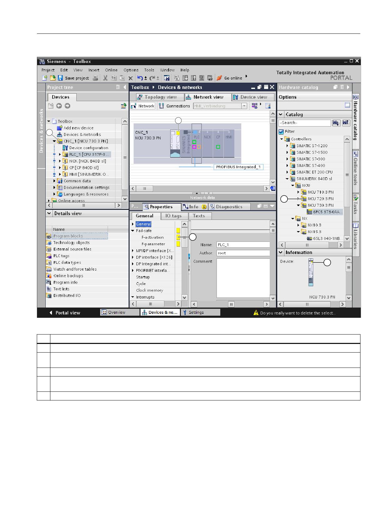
Yellow markings identify all safety-related resources in the views of the TIA Portal:
● Network view, device view, topology view
● Project tree
● Hardware catalog
● Inspector window
This also applies to the SINUMERIK components:
● NCU
Because the PLC and SINAMICS Integrated Safety subcomponents support integrated
functions, the higher-level NCU is marked as safety-oriented resource.
● Integrated PLC
● Integrated SINAMICS Integrated
● NX
SINUMERIK 840D sl STEP 7 Toolbox V16
174
Configuration Manual, 12/2019, 6FC5397-0GP40-0BA1
Safety configuration
10.2 Representation of safety-related resources in the TIA Portal
2
1
Figure 10-1
Marking of safety-related resources in the TIA Portal
No.
Description
1
The project tree shows which components of your project are F-components.
2
In the network view, device view or topology view, the Safety Integrated marking is on the NCU, representative for the integrated
components. External devices, e.g. NX, may have their own Safety Integrated marking.
3
Safety-related settings are marked in the "Properties" inspector window.
4
Folders and the devices themselves are marked in the hardware catalog. You can therefore see whether SINUMERIK Safety Integrated
is supported before inserting the device.
5
Fail-safe devices are also marked in the information area of the hardware catalog.
EMERGENCY STOP button symbol when using Safety Integrated plus (F-PLC)
If you activate the "Safety Integrated plus (F-PLC)" mode and therefore use PROFIsafe
telegrams, all devices with fail-safe modules (PROFIsafe telegrams) have an EMERGENCY
STOP button symbol in the network and topology view:
SINUMERIK 840D sl STEP 7 Toolbox V16
Configuration Manual, 12/2019, 6FC5397-0GP40-0BA1
175
Safety configuration
10.2 Representation of safety-related resources in the TIA Portal
Figure 10-2
NCU with EMERGENCY STOP button symbol
SINUMERIK 840D sl STEP 7 Toolbox V16
176
Configuration Manual, 12/2019, 6FC5397-0GP40-0BA1
Safety configuration
10.3 Changing the Safety Integrated mode
10.3
Changing the Safety Integrated mode
Procedure
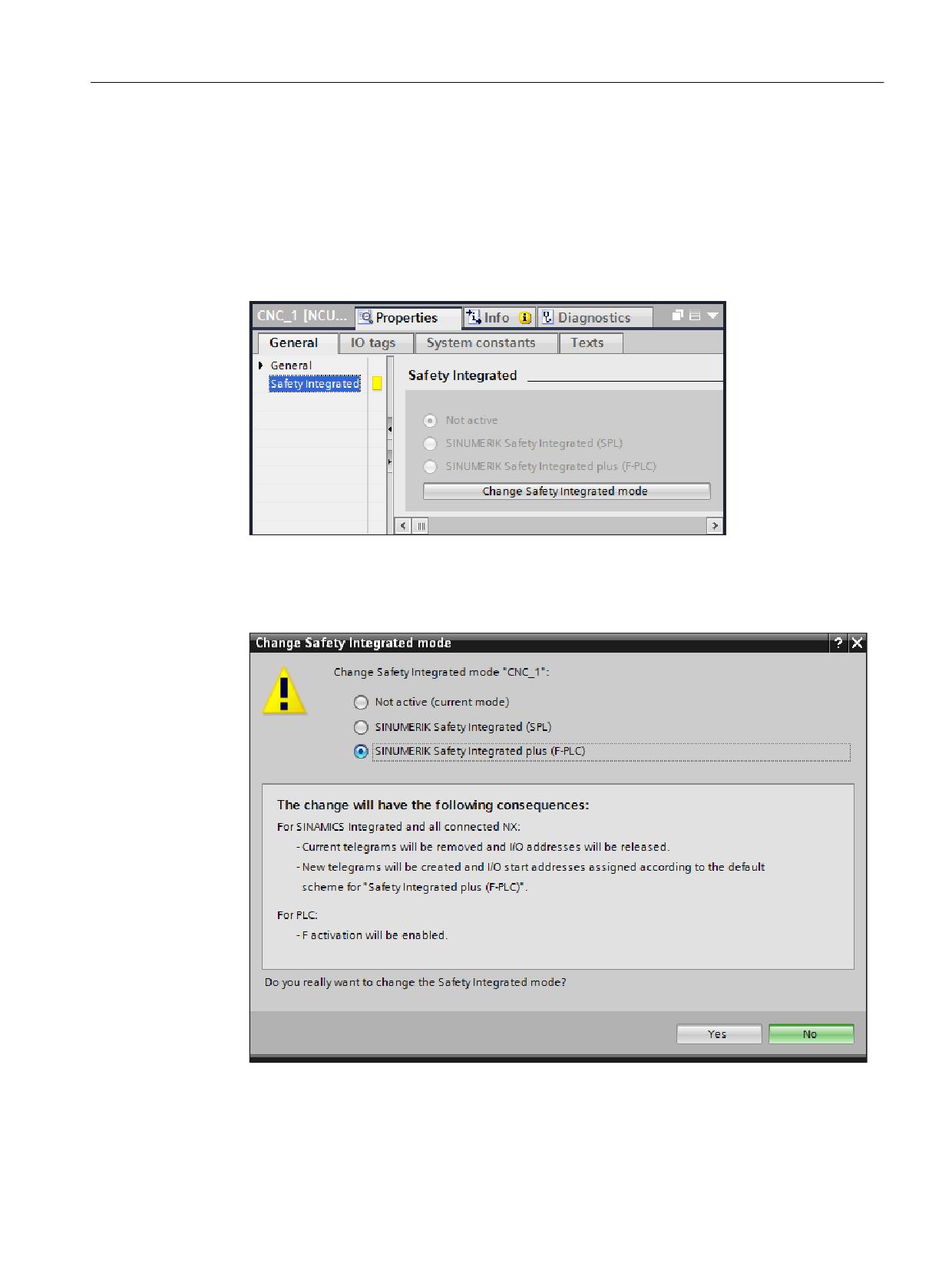
To change the Safety Integrated mode, proceed as follows:
1. Click the NCU in the network or device view and select the "Safety Integrated" entry in the
"Properties" inspector window at "General".
Figure 10-3
Properties inspector window - Safety Integrated when using NCU V4.8
2. Click the "Change Safety Integrated mode" button.
The "Change Safety Integrated mode" dialog opens. If you select an option, the effects of
the mode change are performed here.
Figure 10-4
"Change Safety Integrated mode" dialog when using NCU V4.8
3. Select the required Safety Integrated mode and confirm the reconfiguration with "Yes".
SINUMERIK 840D sl STEP 7 Toolbox V16
Configuration Manual, 12/2019, 6FC5397-0GP40-0BA1
177
Safety configuration
10.3 Changing the Safety Integrated mode
Result
The Safety Integrated mode has been changed. The precise effects depend on the selected
mode and can be seen in the "Change Safety Integrated mode" dialog (step 2).
If you are using the Safety Integrated (SPL) mode, configure next the PROFIsafe addresses
(peripherals (Page 194) or drives (Page 198)).
If problems occur during the changeover, you can find further information in the "Info" inspector
window at "General".
Note
Effects on telegram configuration
The Safety Integrated mode affects the telegram configuration because, in the Safety
Integrated plus (F-PLC) mode, different telegrams are used than in the inactivated Safety
Integrated or the Safety Integrated (SPL) modes.
Telegrams that are added or changed are kept, however, as long as they are compatible with
the newly selected Safety Integrated mode.
Make sure, if applicable, that any modifications are still present following the change of mode
in the telegram configuration.
As long as you have not saved the project, you can completely undo the change of the Safety
Integrated mode by clicking "Undo" in the toolbar.
Further information
General information on the Safety Integrated modes can be found in the following sections:
● Safety Integrated (SPL) (Page 189)
● Safety Integrated plus (F-PLC) (Page 202)
Note also the following documents with information on Safety Integrated:
● Function Manual, SINUMERIK Safety Integrated
● Function Manual, SINUMERIK Safety Integrated plus
● SIMATIC Safety Integrated System Manual
SINUMERIK 840D sl STEP 7 Toolbox V16
178
Configuration Manual, 12/2019, 6FC5397-0GP40-0BA1
Safety configuration
10.4 Parameterization of relevant properties
10.4
Parameterization of relevant properties
The Safety Integrated modes of the NCU control the safety behavior of the NCU together with
the integrated subcomponents, such as the PLC, SINAMICS Integrated and possibly
connected NX modules. Depending on the used mode and communications standard
(PROFINET or PROFIBUS), you must configure further relevant properties and F-parameters
for various modules. Sample configuring sequences can be found in Sections Configuring
Safety Integrated (SPL) (Page 189) and Configuring Safety Integrated plus (F-PLC)
(Page 202).
You can, however, also parameterize the appropriate properties in a different order.
Overview
The following table shows in which device properties and in which section you find a specific
configuration-relevant setting:
Note that not all parameters are relevant in both Safety Integrated modes. In addition, some
parameters are displayed only in a specific Safety Integrated mode for the SINAMICS
Integrated and NX components and the associated telegrams.
Table 10-1
Configuration-relevant properties
Setting
Can be found at
Further information
Safety Integrated mode (op-
NCU > Safety Integrated
● This chapter, "NCU properties"
erating mode)
section.
● Changing the Safety
Integrated mode (Page 177)
● Safety Integrated mode (SPL)
● Safety Integrated plus mode (F-
PLC)
Basis for PROFIsafe ad-
PLC > Fail-safe > F-parameters
● Information system, keyword
dresses
"Basis for PROFIsafe
addresses".
F-source address
PLC > Fail-safe > F-source ad-
● Configuration of the
(F_Source_Add)
dresses
PROFIsafe addresses
(only for Safety Integrated mode
(peripherals)
(SPL))
● Configuration of the
PROFIsafe addresses (drives)
(for a GSD module, also under
● Information system, keyword
"Module > PROFIsafe")
"Special considerations when
configuring the F-system"
F-destination address
Module/submodule > F-parame-
● Information system, keyword
(F_Dest_Add)
ters
"Special considerations when
configuring the F-system"
DIL switching setting
Module/submodule > F-parame-
● Configuring Safety Integrated
ters
plus (F-PLC) (handling
overview)
● Configuring Safety Integrated
(SPL) (handling overview)
SINUMERIK 840D sl STEP 7 Toolbox V16
Configuration Manual, 12/2019, 6FC5397-0GP40-0BA1
179
Safety configuration
10.4 Parameterization of relevant properties
Setting
Can be found at
Further information
Default F-monitoring time for
Interface > F-parameters
● Information system, keyword
F-peripherals of this interface
"Monitoring and response
times"
F-monitoring time
Module/submodule > F-parame-
● Information system, keyword
ters
"Configuring the F-peripherals"
● Information system, keyword
"Monitoring and response
times"
I/O address
Module/submodule > I/O address-
● Information system, keyword
es
"Addressing modules (S7-300,
S7-400)"
Size of the PLC process im-
PLC > Cycle
● Information system, keyword
age
"Settings for the cycle behavior
(S7-300, S7-400)"
● Information system, keyword
"S7-300 memory areas"
Name of an I/O system node
Device / header module > General
● Information system, keyword
"Assign device name and IP
address"
IP address of an I/O system
Device / header module > PROFI-
● Information system, keyword
node
NET interface > Ethernet address-
"Assign device name and IP
es
address"
NCU properties
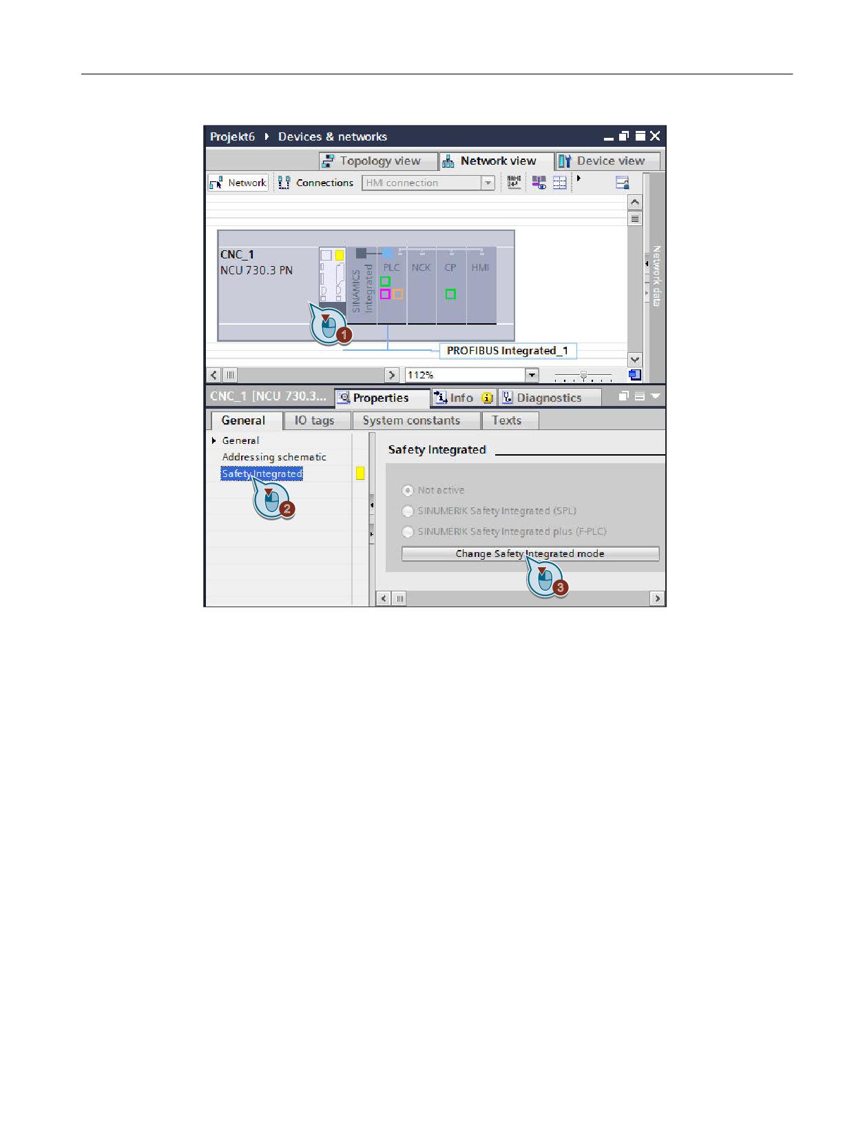
The Safety Integrated mode of the NCU affects not only the configuration of the integrated PLC,
but rather also that of the integrated drives.
SINAMICS Integrated and NX modules always use automatically the same Safety Integrated
mode as the associated NCU.
Therefore, set this mode in the NCU properties and not in the PLC properties:
SINUMERIK 840D sl STEP 7 Toolbox V16
180
Configuration Manual, 12/2019, 6FC5397-0GP40-0BA1
Safety configuration
10.4 Parameterization of relevant properties
Figure 10-5
Changing the Safety Integrated mode
With the activation of a Safety Integrated mode, the F-capability of the PLC is set appropriate
for the Safety Integrated mode of the NCU.
SINUMERIK 840D sl STEP 7 Toolbox V16
Configuration Manual, 12/2019, 6FC5397-0GP40-0BA1
181
Safety configuration
10.4 Parameterization of relevant properties
PLC properties
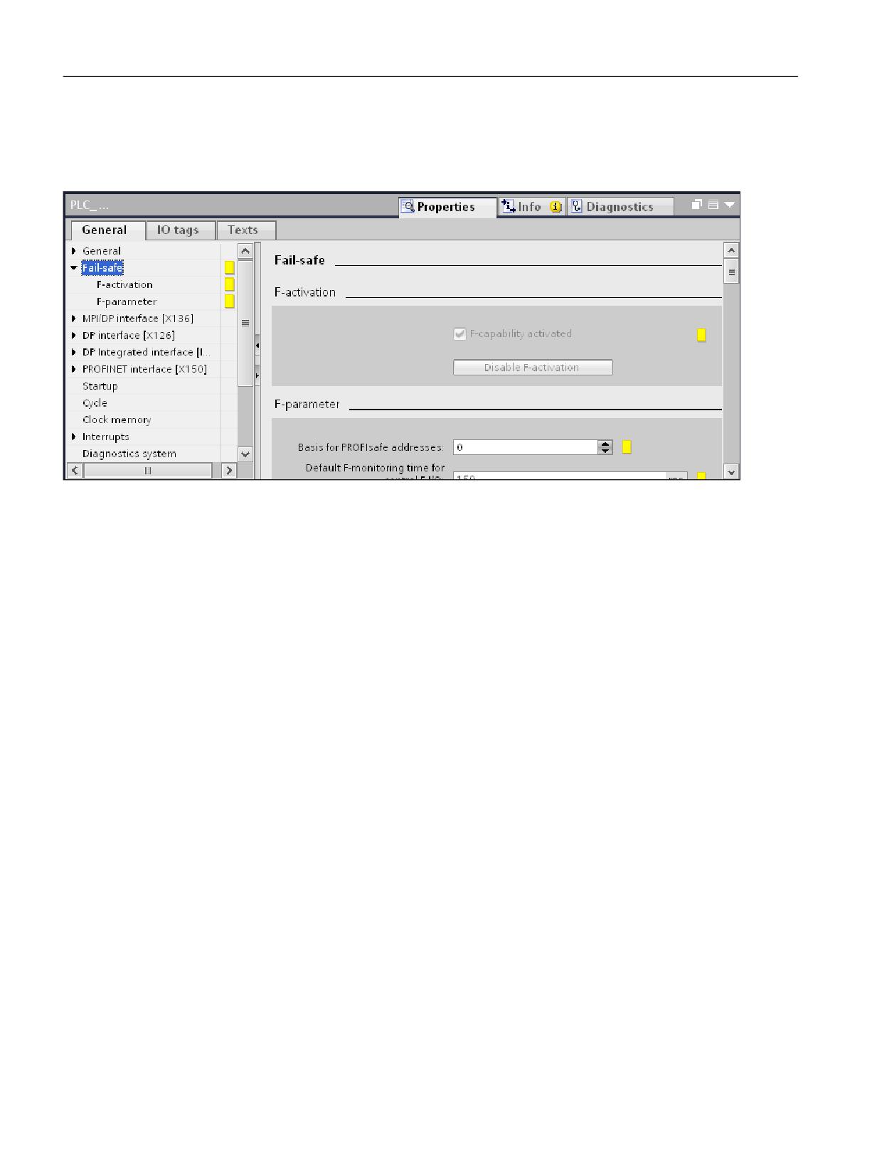
Safety Integrated settings are available in the PLC properties if the NCU uses a safety mode.
Figure 10-6
Fail-safety in the PLC properties - the "F-activation" section is inactive (grayed-out) because the F-activation is
controlled via the selection of the Safety Integrated mode in the NCU properties.
Loading the changed Safety Integrated mode into the hardware
If the actual hardware has been operated in Safety Integrated plus (F-PLC) mode and you now
want to load a configured hardware configuration with changed Safety Integrated mode, you
must perform a general reset of the PLC prior to the loading.
Further information
General information on the Safety Integrated modes can be found in the following sections:
● Safety Integrated (SPL)
● Safety Integrated (F-PLC)
Note also the following documents with information on Safety Integrated:
● Function Manual, SINUMERIK Safety Integrated
● Function Manual, SINUMERIK Safety Integrated plus
SINUMERIK 840D sl STEP 7 Toolbox V16
182
Configuration Manual, 12/2019, 6FC5397-0GP40-0BA1
Safety configuration
10.5 Availability of I/O addresses at the mode change
10.5
Availability of I/O addresses at the mode change
If the default I/O addresses for communication with the drive are already assigned when
changing the Safety Integrated mode, you must configure the telegrams and I/O addresses.
Note
Undoing changes
As long as the project has not been saved, you can undo the change of the Safety Integrated
mode together with the changed drive telegram and address settings. Click "Undo" in the
toolbar.
SINUMERIK 840D sl STEP 7 Toolbox V16
Configuration Manual, 12/2019, 6FC5397-0GP40-0BA1
183
Safety configuration
10.5 Availability of I/O addresses at the mode change
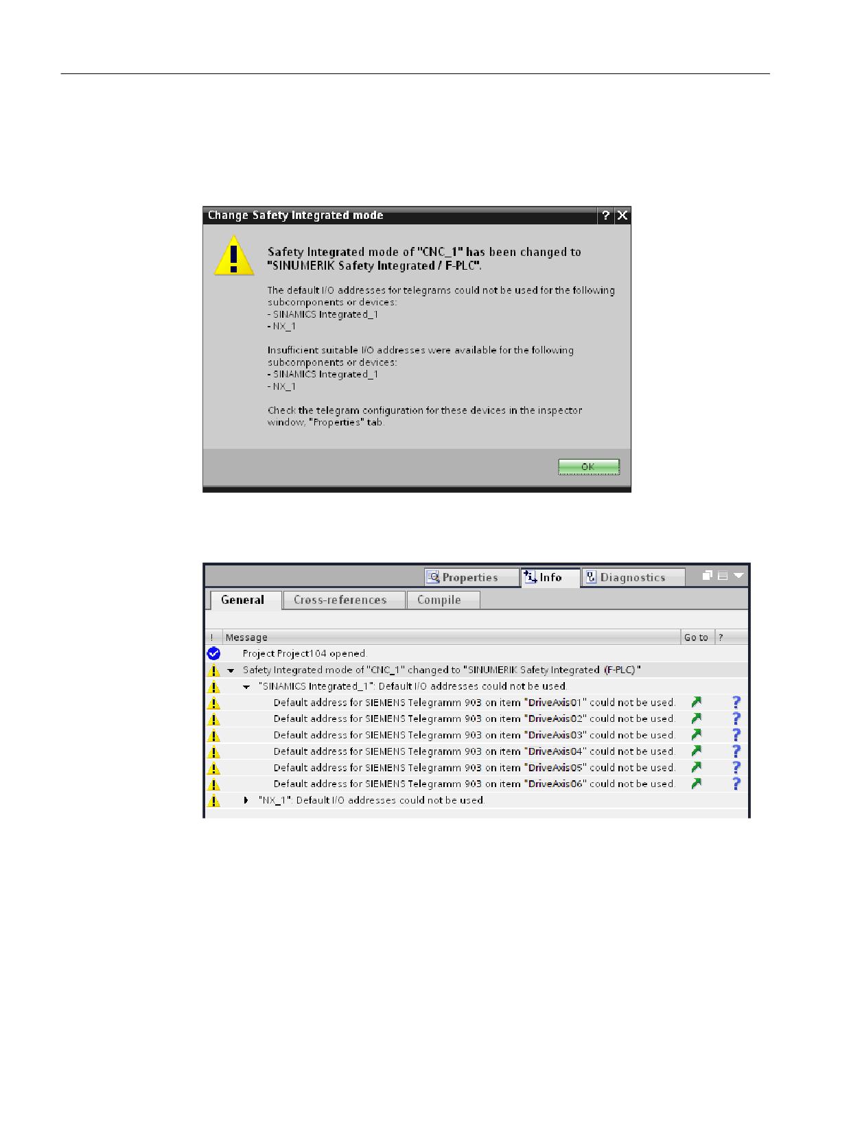
Refer to the "Change Safety Integrated mode" dialog or the "Info" inspector window to see
which I/O addresses are effected.
● The "Change Safety Integrated mode" dialog shows the components for which the default
I/O addresses are assigned.
Figure 10-7
"Change Safety Integrated mode" dialog: Default I/O addresses are not available
● The "Info" inspector window shows which default I/O addresses were already assigned for
each individual telegram.
Figure 10-8
You can click the symbol in the "Go to" column in the "Info > General" inspector window
to display the relevant I/O address.
● You can also display an overview of the telegram settings by clicking "Address overview" in
the PLC properties.
SINUMERIK 840D sl STEP 7 Toolbox V16
184
Configuration Manual, 12/2019, 6FC5397-0GP40-0BA1
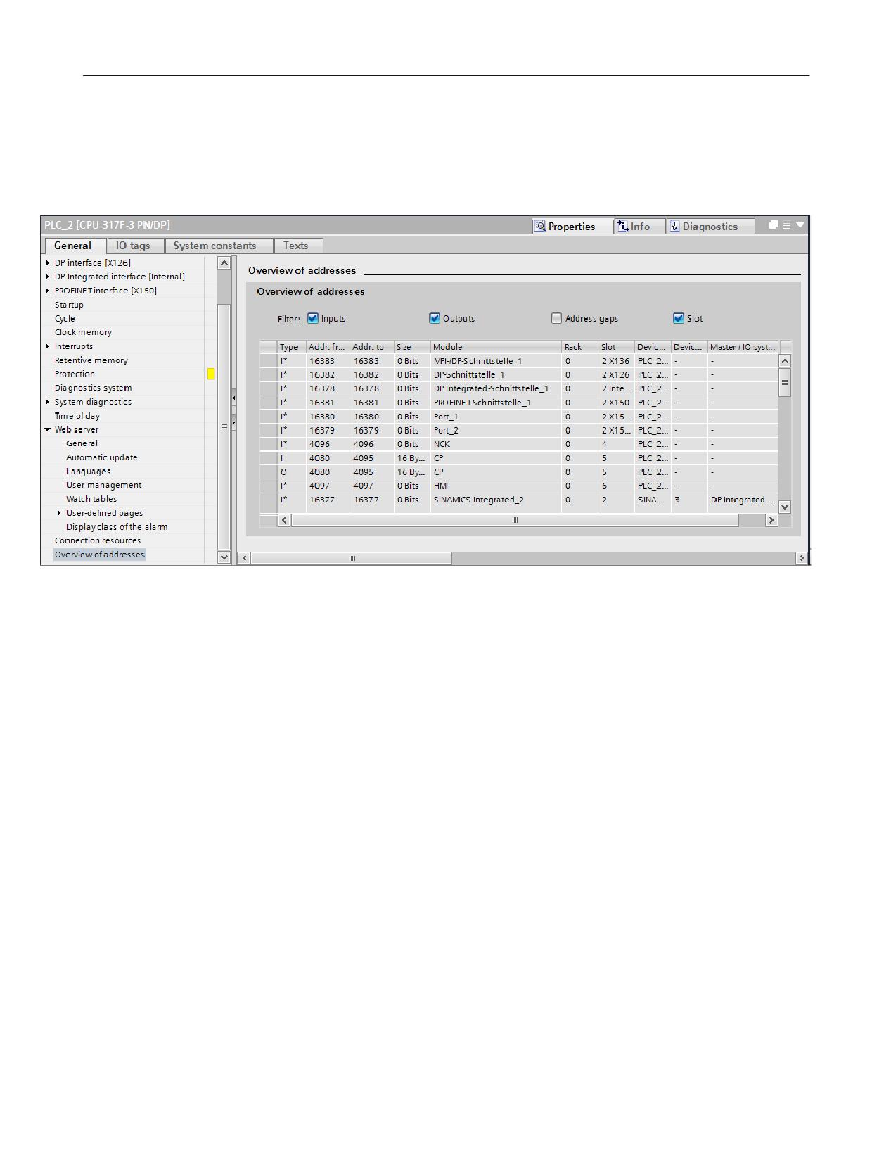
Safety configuration
10.5 Availability of I/O addresses at the mode change
Figure 10-9
Address overview in the "Properties" inspector window of the PLC
Further information
Detailed information on aligning and configuring I/O addresses can be found in
Section Configuring telegrams and drive units (Page 115).
SINUMERIK 840D sl STEP 7 Toolbox V16
Configuration Manual, 12/2019, 6FC5397-0GP40-0BA1
185

Safety configuration
10.6 Licensing
10.6
Licensing
10.6.1
Overview
The integrated safety functions of SINUMERIK Safety Integrated are used in the machine tools
sector. They are integrated with two channels in the NC, the drive and the internal PLC, and are
used to monitor speed, standstill and position. Such monitoring is necessary if the danger zone
of the machines and systems is not blocked off.
During operation, the integrated safety functions provide effective operator protection as well
as protection of tools, materials and machines.
In the TIA Portal, you can select one of three modes in conjunction with the SINUMERIK:
Mode
Requirement
SINUMERIK Safety Inte-
-
grated not active
Safety Integrated (SPL)
● No additional license is required in the TIA Portal: SIMATIC STEP 7
Safety without license corresponds to the F-configuration tool from
STEP 7 V5.x)
● Appropriate software option for SPL
Safety Integrated plus (F-
● NCU V4.8 or newer
PLC)
● Appropriate software option for F-PLC
Refer to Section Changing the Safety Integrated mode for a description of how to set the Safety
Integrated mode.
10.6.2
Software options for Safety Integrated (SPL)
To configure SINUMERIK Safety Integrated (SPL), SIMATIC STEP 7 Safety Advanced (TIA
Portal) without license suffices. (SIMATIC STEP 7 Safety Advanced without license
corresponds to the F-configuration tool from STEP 7 V5.x)
To use the configuring in SINUMERIK Operate, you require the appropriate software options:
Table 10-2
Software options for use of Safety Integrated (SPL)
Software option
Purpose
SI Basic
Activate SPL
Contains a license for one axis/spindle, up to four SPL I/O
SI Comfort
Activate SPL
Contains a license for one axis/spindle, up to 64 SPL I/O
SI High Feature
Activate SPL
Contains a license for one axis/spindle, up to 192 SPL I/O
SI Axis/Spindle
Additional license for one axis/spindle, multiple licensing in order to be able to use
further axes/spindles.
SINUMERIK 840D sl STEP 7 Toolbox V16
186
Configuration Manual, 12/2019, 6FC5397-0GP40-0BA1
Safety configuration
10.6 Licensing
Software option
Purpose
SI Axis/Spindle
Additional license for 15 axes/spindles, multiple licensing in order to be able to use
package
further axes/spindles.
SI-Connect
Make more than three FSEND and three FRECV connections available.
Depending on the functionality used, you must license the appropriate software options and set
in the machine data:
● MD19120 $MN_NUM_SAFE_AXES: Number of SI axes/spindles
● MD19122 $MN_NUM_SPL_IO: Number of SPL I/Os
1 = 4 SPL I/O or SI-Basic software option
2 = 64 SPL I/O or SI-Comfort software option
3 = 192 SPL I/O or SI-High Feature software option
● MD19510 $MN_SAFE_FUNCTION_MASK: Number of FSEND and FRECV connections
SI-Connect software option: Bit 0 = 1
See also:
● SINUMERIK 840D sl Basic Software and Operating Software Commissioning Manual,
Section SINUMERIK Operate (IM9).
● Function Manual, SINUMERIK Safety Integrated
10.6.3
Software options for Safety Integrated plus (F-PLC)
For the use of Safety Integrated plus (F-PLC), you require the appropriate software options for
the RT function:
Table 10-3
Software options for the use of Safety Integrated plus (F-PLC)
Software option
Purpose
SINUMERIK Safe-
Activate the F-PLC in SINUMERIK 840D sl in order to process the fail-safe sensors
ty Integrated plus
and actuators in an F-program.
/SI logic
SINUMERIK Safe-
Use the motion control functions of the SINAMICS Integrated in the SINUMERIK
ty Integrated plus
Safety Integrated plus (F-PLC) mode.
/SI axis/spindle
License for one axis/spindle, multiple licensing in order to be able to use further
axes/spindles.
SINUMERIK Safe-
Use the motion control functions of the SINAMICS Integrated in the SINUMERIK
ty Integrated plus
Safety Integrated plus (F-PLC) mode.
/SI multi-axis pack-
License for any number of axes/spindles.
age
Depending on the functions used, you must license the appropriate software options and set in
the machine data:
● MD19500 $MN_SAFE_PLC_LOGIC: Safety Integrated plus /SI-Logic basic option
● MD19121 $MN_NUM_DRIVEBASED_SAFE_AXES: Number of axes/spindles in Safety
Integrated plus (F-PLC) mode
SINUMERIK 840D sl STEP 7 Toolbox V16
Configuration Manual, 12/2019, 6FC5397-0GP40-0BA1
187
Safety configuration
10.6 Licensing
See also:
SINUMERIK 840D sl Basic Software and Operating Software Commissioning Manual, Section
SINUMERIK Operate (IM9)
Function Manual, SINUMERIK Safety Integrated plus
SINUMERIK 840D sl STEP 7 Toolbox V16
188
Configuration Manual, 12/2019, 6FC5397-0GP40-0BA1
Safety configuration
10.7 Configuring Safety Integrated (SPL)
10.7
Configuring Safety Integrated (SPL)
10.7.1
Introduction
With the aid of safe programmable logic (SPL), safety-related sensors and actuators can be
directly connected to the control's I/O and evaluated by means of software without external
evaluation units.
In order to check that the NCK SPL and PLC SPL are functioning, the system program
organizes a cyclic data cross-check between the PLC and the NCK.
6*(
6*$
1&. 63/
'LUHFW FRQQHFWLRQ RI PD[
'LUHFW FRQQHFWLRQ RI PD[
VDIHW\ UHODWHG VHQVRUV
VDIHW\ UHODWHG DFWXDWRUV
5HVXOW DQG GDWD FURVV
H J PRGH VZLWFK OLJKW
H J SURWHFWLYH GRRU LQWHUORFN
FKHFN
EDUULHUV (0(5*(1&< 6723
PRWRU EUDNHV
3/& 63/
6*(
6*$
Figure 10-10
SPL - data cross-check
The Safety Integrated (SPL) mode is supported by all NCU versions available in the TIA Portal.
The Safety Integrated (SPL) mode has the following characteristics:
● SINAMICS Integrated or connected NX use the SINUMERIK "SI Motion Monitoring"
telegrams, not the PROFIsafe telegrams.
● The user program is programmed like a standard user program in the editors for STL, FBD
or LAD. Each safety-related program must be created in two programming languages in
order to allow the data cross-check (PLC SPL and NCK SPL).
● During the programming, the SGE/SGA of the data block SPL [DB18] is used that you
assign on the NCU (e.g. via SINUMERIK Operate) to the I/O addresses of the field devices.
See: Function Manual, SINUMERIK Safety Integrated
10.7.2
Configuring the F-peripherals
During the configuring of F-peripherals with Safety Integrated (SPL), you can orient yourself on
the following handling overview with sample configuring sequence. This serves, however, only
as an introduction to the configuring and programming of SINUMERIK Safety Integrated (SPL).
Therefore, observe the following documentation prior to configuring Safety Integrated (SPL):
● Function Manual, SINUMERIK Safety Integrated
SINUMERIK 840D sl STEP 7 Toolbox V16
Configuration Manual, 12/2019, 6FC5397-0GP40-0BA1
189
Safety configuration
10.7 Configuring Safety Integrated (SPL)
WARNING
Depending on the application area, the SINUMERIK NCU, being a part of plants and systems,
requires the observance of special standards and regulations. Observe the appropriate safety
and accident prevention regulations, e.g. IEC 60204-1 (general requirements placed on the
safety of machines).
This sample handling overview serves only as an introduction to the configuring and
programming of STEP 7 Safety Advanced with SINUMERIK. It cannot always be used for
effective regular operation. Before you do this, ensure that you reference the current version
of the SINUMERIK Safety Integrated Function Manual. The warnings and other notes
contained in that manual must be observed, even when they are not repeated in this
document!
The non-observance of these regulations can lead to severe injuries and damage to machines
and equipment.
Requirement
● The devices to be configured have been inserted
(at least one NCU and one peripheral device)
● The "Safety Integrated (SPL)" mode is activated in the NCU properties.
See: Changing the Safety Integrated mode (Page 177)
Note
Activating Safety Integrated mode at the start of the configuring work
If you activate the Safety Integrated mode first at the end of the configuring work, it is
possible that all parameters are no longer assigned automatically by the system and you
must match these values.
Consequently, activate the desired Safety Integrated mode directly after inserting the NCU.
● The required modules, submodules and telegrams are inserted on the peripheral device.
● The devices are interconnected with each other using the desired interfaces (PROFINET or
PROFIBUS).
You can also connect devices to the interfaces of both types (PROFINET and PROFIBUS)
and operate in the Safety Integrated (SPL) mode.
Procedure overview
Step
Description
1
Configuring the basis for PROFIsafe addresses
See also: TIA Portal online help, keyword "Basis for PROFIsafe addresses".
2
Configure the input modules. (Page 191)
3
Configure the output modules. (Page 194)
SINUMERIK 840D sl STEP 7 Toolbox V16
190
Configuration Manual, 12/2019, 6FC5397-0GP40-0BA1
Safety configuration
10.7 Configuring Safety Integrated (SPL)
Step
Description
4
If necessary, set the F-monitoring time manually:
● You can configure the parameterization of the F-monitoring time for all devices on a specific interface in the
interface settings under "F-parameters > Default F-monitoring time for F-peripherals of this interface".
● You can configure each F-module individually under "F-parameters" in the settings of the associated module.
A valid current safety telegram must be received from the F-CPU within the F-monitoring time. Otherwise, the F-
module enters the safe state.
The F-monitoring time should be sufficiently long so that telegram delays are tolerated, but sufficiently short so that
the process can respond as fast as possible in a fault situation and run without impairments. The Excel file for the
response time calculation provides help with the time determination.
See also: SIMATIC Safety Help, keyword "Monitoring and response times"
5
Enter the PROFIsafe addresses in the NCU MD. (Page 194)
6
Assign the F-destination addresses. The procedure depends on the associated device:
● For devices with DIP switches, set the DIP switches on the F-modules to set the PROFIsafe destination
addresses as configured in the TIA Portal.
● For the ET200SP fail-safe modules, assign the F-destination address.
Further information and information for other devices is available in the documentation for your device and from the
manufacturer.
To use the configuring in SINUMERIK Operate, you require the appropriate software options.
10.7.3
Parameterizing F-input modules
The F-modules and F-submodules to be configured must be selected individually in order to
make the desired settings in the "Properties" inspector window. You can select the modules
and submodules in the device view or device overview (in the case of GSD-based devices, only
in the device overview).
You can set the I/O addresses in the properties of the F-modules and F-submodules. These I/
O addresses must lie within the process image of the PLC. (default setting: 1024 bytes; can be
configured under "Cycle" in the PLC properties).
You can select F-modules and F-submodules in the device view or device overview of the rack.
Procedure
To configure the inserted F-input modules, select them successively and make the settings
individually for each module in the inspector window. Proceed as follows:
1. In the device view, select the rack and open the device overview.
2. In the device overview, select on the rack one of the modules to be configured.
3. In the "Properties > General" inspector window, select the "I/O addresses" entry.
4. Select the "OB1-PA" in the "Process image" dropdown list in each of the "Input addresses"
and "Output addresses" sections.
SINUMERIK 840D sl STEP 7 Toolbox V16
Configuration Manual, 12/2019, 6FC5397-0GP40-0BA1
191
Safety configuration
10.7 Configuring Safety Integrated (SPL)
5. Enter the desired address in the associated "Start address" text field. Note the following:
- The I/O addresses must lie within the process image of the PLC (default setting: 1024
bytes; can be configured under "Cycle" in the PLC properties).
- Do not use any I/O addresses that are used for some other purpose, e.g. by the machine
control panel.
6. In the "Properties > General" inspector window, select the "DI parameters" entry.
The properties will be displayed. Safety-relevant settings are marked yellow.
7. Make the required settings, e.g.
Setting
Purpose
Encoder power supply
Select the type of the encoder power supply:
● Internal: VS1, VS2 are used; the short-circuit test is
active
● Internal: VS1, VS2 are not used; the short-circuit test is
inactive
Encoder evaluation
Select the encoder evaluation:
● 1oo2 (2v2) evaluation: Dual-channel activation 2v2
● 1oo1 (1v1) evaluation: Single-channel activation 1v1
Type of encoder connection
Select between equivalent or non-equivalent encoder inter-
connection.
Discrepancy time
Specify the discrepancy time in ms.
Reintegration after discrepancy error
Select whether Test 0 signal is required.
(Test 0 signal, for example, is required for the EMERGEN-
CY STOP button)
10.7.4
Configuring drives with F-functions
During the configuring of drives Safety Integrated, you can orient yourself on the following
handling overview with sample configuring sequence. This serves, however, only as an
introduction to the configuring and programming of SINUMERIK Safety Integrated (SPL).
Therefore, observe the following documentation prior to configuring Safety Integrated (SPL):
● Function Manual, SINUMERIK Safety Integrated
SINUMERIK 840D sl STEP 7 Toolbox V16
192
Configuration Manual, 12/2019, 6FC5397-0GP40-0BA1
Safety configuration
10.7 Configuring Safety Integrated (SPL)
WARNING
Depending on the application area, the SINUMERIK NCU, being a part of plants and systems,
requires the observance of special standards and regulations. Observe the appropriate safety
and accident prevention regulations, e.g. IEC 60204-1 (general requirements placed on the
safety of machines).
This sample handling overview serves only as an introduction to the configuring and
programming of STEP 7 Safety Advanced with SINUMERIK. It cannot always be used for
effective regular operation. Before you do this, ensure that you reference the current version
of the SINUMERIK Safety Integrated Function Manual. The warnings and other notes
contained in that manual must be observed, even when they are not repeated in this
document!
The non-observance of these regulations can lead to severe injuries and damage to machines
and equipment.
Requirement
● The devices to be configured have been inserted
(at least one NCU and one drive device)
● The "Safety Integrated (SPL)" mode is activated in the NCU properties.
See: Changing the Safety Integrated mode (Page 177)
Note
Activating Safety Integrated mode at the start of the configuring work
If you activate the Safety Integrated mode first at the end of the configuring work, it is
possible that all parameters are no longer assigned automatically by the system and you
must match these values.
Consequently, activate the desired Safety Integrated mode directly after inserting the NCU.
● The required modules, submodules and telegrams are inserted on the drive device.
● The devices are interconnected with each other using the desired interfaces (PROFINET or
PROFIBUS).
You can also connect devices to the interfaces of both types (PROFINET and PROFIBUS)
and operate in the Safety Integrated (SPL) mode.
Procedure overview
Step
Description
1
Configuring the basis for PROFIsafe addresses
See also TIA Portal online help, keyword "Basis for PROFIsafe addresses".
2
Configure the PROFIsafe telegrams. (Page 200)
3
Enter the PROFIsafe addresses in the NCU MD. (Page 198)
4
During the commissioning of the drive, enter the PROFIsafe addresses as hexadecimal value in p9610 and p9810.
Further information is available in the documentation for your device and from the manufacturer.
SINUMERIK 840D sl STEP 7 Toolbox V16
Configuration Manual, 12/2019, 6FC5397-0GP40-0BA1
193
Safety configuration
10.7 Configuring Safety Integrated (SPL)
To use the configuring in SINUMERIK Operate, you require the appropriate software options.
10.7.5
Parameterizing F-output modules
Procedure
To configure the inserted F-output modules, select them successively and make the settings
individually for each module in the inspector window. Proceed as follows:
1. In the device view, select the rack and open the device overview.
2. In the device overview, select on the rack one of the modules to be configured.
3. In the "Properties" inspector window, select the "I/O address" entry.
4. Enter the desired address in the "Input addresses > Start address" field. Note the following:
- The I/O addresses must lie within the process image of the PLC (default setting: 1024
bytes; can be configured under "Cycle" in the PLC properties).
- Do not use any I/O addresses that are used for some other purpose, e.g. by the machine
control panel.
5. In the "Properties" inspector window, select the "DO parameters" entry.
The properties will be displayed. Safety-relevant settings are marked yellow.
6. Make the required settings, e.g.
- Enter the desired value (in ms) under "Read-back time". This time should be set to at
least 200 ms for large capacitive or inductive loads.
- "Diagnosis: Wire breakage" should be activated
10.7.6
Configuration of the PROFIsafe addresses (peripherals)
The PROFIsafe addresses (F-source address, F-destination address) are used to uniquely
identify the source and the destination.
Note
Problem solution for the 27220, 27221 alarms (Safety Integrated (SPL))
● Alarm 27220: "PROFIsafe: Number of NCK-F modules (6) <> number of S7-F modules (0)"
● Alarm 27221: "PROFIsafe: NCK-F module MD $MN_PROFISAFE_IN_ADDRESS[0]
unknown or "PROFIsafe: NCK-F module MD $MN_PROFISAFE_OUT_ADDRESS[0]
unknown"
Even if you reuse the existing machine data settings (e.g. using an existing SINUMERIK
archive), you can change the PROFIsafe addresses. In this case, alarms 27220 and 27221 are
displayed in SINUMERIK Operate.
You must also modify or augment the details in MD10385, as described here.
SINUMERIK 840D sl STEP 7 Toolbox V16
194
Configuration Manual, 12/2019, 6FC5397-0GP40-0BA1
Safety configuration
10.7 Configuring Safety Integrated (SPL)
Rules for configuring F-source addresses
When Safety Integrated (SPL) is used, you must enter the associated F-source addresses in
the MD10385[0..2]. A maximum of three different F-source addresses are permitted throughout
the system.
You can view the assigned F-source addresses in the PLC properties under "Fail-safe > F-
source addresses".
The assignment methods of the F-source address in the TIA Portal depend on the used F-
peripherals, not on the controller or the used Safety Integrated mode:
● F-peripherals based on the device description file:
The configured F-source address can be set in the properties of the module under
"PROFIsafe > F_Source_Add".
● F-peripherals for PROFIsafe address type 1 (e.g. F-module ET 200S)
The F-source address has the constant value "1".
(The unique identification is made using the set F-destination address.)
● F-peripherals for PROFIsafe address type 2 (e.g. F-module ET200SP)
The unique identification is made using the F-source address and F-destination address
The "Basis for PROFIsafe addresses" parameter differs in its effect from STEP 7 V5.x. This
parameter is not used in the TIA Portal to influence the F-source address for fail-safe I/O of the
PROFIsafe address type 1 (e.g. ET200S).
Requirement
● The software options for Safety Integrated (SPL) are licensed and enabled in the associated
machine data.
● A maximum of three different F-source addresses are used in the configuration.
You can view the used F-source addresses in the PLC properties under "Fail-safe > F-
parameters". If more than three different F-source addresses are used, you must
standardize the F-source addresses because a maximum of 3 different F-source addresses
can be entered in the MD10385.
● The current configuration is compiled and loaded into the PLC.
● The MD10385, MD10386, MD10387, MD10388 and MD10389 machine data items are not
yet filled.
● No red LED illuminates on the F-peripherals.
If a red LED illuminates, check and correct the DIP switch setting or the F-source address,
e.g. using online diagnosis.
SINUMERIK 840D sl STEP 7 Toolbox V16
Configuration Manual, 12/2019, 6FC5397-0GP40-0BA1
195
Safety configuration
10.7 Configuring Safety Integrated (SPL)
Procedure
To enter the PROFIsafe addresses in the NCK machine data, proceed as follows:
1. In the TIA Portal, open the properties of the associated object:
- Click the PLC and switch in the "Properties" inspector window to "Fail-safe > F-source
addresses".
A tabular view with the used F-source addresses and the associated values for
MD10385 is displayed.
- Click the DI/DO modules and switch to "Module > F-parameters > F-destination address"
in the "Properties" inspector window.
2. In SINUMERIK Operate, call the general machine data and enter the values:
Machine data
Value to be entered
Property in the TIA Por-
tal
MD10385[0..2]
F-source addresses
PLC > Fail-safe > F-
source addresses
$MN_PROFISAFE_MASTER_ADDRESS
Notation: <Identifier for PROFIsafe (5000)><F source
address as hexadecimal number>
For example, enter "5000001" for F-source address 1.
MD10386[0..47]
F-destination addresses of the F-DI modules
Module > F-parame-
ters > F-destination ad-
$MN_PROFISAFE_IN_ADDRESS
dress
Format: 0s 0x aaaa
s: Bus segment (5 = DP connection on the PLC side)
x : Sub-slot address
Range of values: 0...2
x = 0 addresses the F net data signals 1...32
x = 1 addresses the F net data signals 33...64
x = 2 addresses the F net data signals 65...96
aaaa: Hexadecimal PROFIsafe address of the F mod-
ule
Example:
For example, enter "50000C8" for F-destination ad-
dress 200.
MD10387[0..47]
F-destination addresses of the F-DO modules
Module > F-parame-
ters > F-destination ad-
$MN_PROFISAFE_OUT_ADDRESS
dress
Format: See above (MD10386)
Example:
For example, enter "50000C7" for F-destination ad-
dress 199.
SINUMERIK 840D sl STEP 7 Toolbox V16
196
Configuration Manual, 12/2019, 6FC5397-0GP40-0BA1
Safety configuration
10.7 Configuring Safety Integrated (SPL)
Machine data
Value to be entered
Property in the TIA Por-
tal
MD10388[0..47]
Inputs of the F-DI modules
-
$MN_PROFISAFE_IN_ASSIGN
For example, enter "1004" when INSE/INSEP 1 to 4 is
used.
MD10389[0..47]
Outputs of the F-DO modules
-
$MN_PROFISAFE_OUT_ASSIGN
For example, enter "1004" when OUTSE/OUTSEP 1 to
4 is used.
MD10098
Factor for PROFIsafe cycle
-
$MN_PROFISAFE_IPO_TIME_RATIO
The PROFIsafe cycle is displayed in MD10099 and is
constructed as follows:
MD10098 (factor for PROFIsafe clock cycle) x
MD10071 (IPO clock cycle)
The value should lie between 16 ms and 24 ms.
The sequence and the index entered for the PROFIsafe addresses is irrelevant.
3. Restart the NCK.
4. Check the enabled input bytes in DBB 138 "Profisafe input bytes". One bit must be set for
each byte.
5. Check the enabled output bytes in DBB 140 "Profisafe output bytes". One bit must be set for
each byte.
Further information
● Detailed information about the SINUMERIK Safety Integrated safety concept and for
MD10385 can be found in the "SINUMERIK Safety Integrated" Function Manual.
● Information about individual machine data items is contained in the online help for
SINUMERIK Operate and in the "SINUMERIK 840D sl detailed description of the machine
data" Lists Manual.
● Information on the parameterization of machine data in SINUMERIK Operate can be found
in the SINUMERIK 840D sl Basic Software and Operating Software Commissioning Manual
in Section SINUMERIK Operate (IM9).
SINUMERIK 840D sl STEP 7 Toolbox V16
Configuration Manual, 12/2019, 6FC5397-0GP40-0BA1
197
Safety configuration
10.7 Configuring Safety Integrated (SPL)
10.7.7
Configuration of the PROFIsafe addresses (drives)
The PROFIsafe addresses (F-source address, F-destination address) are used to uniquely
identify the source and the destination.
Note
Problem solution for the 27220, 27221 alarms (Safety Integrated (SPL))
● Alarm 27220: "PROFIsafe: Number of NCK-F modules (6) <> number of S7-F modules (0)"
● Alarm 27221: "PROFIsafe: NCK-F module MD $MN_PROFISAFE_IN_ADDRESS[0]
unknown or "PROFIsafe: NCK-F module MD $MN_PROFISAFE_OUT_ADDRESS[0]
unknown"
Even if you reuse the existing machine data settings (e.g. using an existing SINUMERIK
archive), you can change the PROFIsafe addresses. In this case, alarms 27220 and 27221 are
displayed in SINUMERIK Operate.
You must also modify or augment the details in MD10385, as described here.
Rules for configuring F-source addresses
When Safety Integrated (SPL) is used, you must enter the associated F-source addresses in
the MD10385[0..2]. A maximum of three different F-source addresses are permitted throughout
the system.
You can view the assigned F-source addresses in the PLC properties under "Fail-safe > F-
source addresses".
The assignment method of the F-source address in the TIA Portal depends on the used device
type:
● Drive device based on the device description file:
The configured F-source address can be set in the properties of the telegram under
"PROFIsafe > F_Source_Add".
See also: SIMATIC Safety Help, keyword "Recommendation for allocating PROFIsafe
addresses"
Requirement
● The software options for Safety Integrated (SPL) are licensed and enabled in the associated
machine data.
● A maximum of three different F-source addresses are used in the configuration.
You can view the used F-source addresses in the PLC properties under "Fail-safe > F-
parameters". If more than three different F-source addresses are used, you must
standardize the F-source addresses because a maximum of three different F-source
addresses can be entered in the MD1385.
● The current configuration is compiled and loaded into the PLC.
● The MD10385, MD10386, MD10387, MD10388 and MD10389 machine data items are not
yet filled.
SINUMERIK 840D sl STEP 7 Toolbox V16
198
Configuration Manual, 12/2019, 6FC5397-0GP40-0BA1
Safety configuration
10.7 Configuring Safety Integrated (SPL)
Procedure
To enter the PROFIsafe addresses in the NCK machine data, proceed as follows:
1. In the TIA Portal, open the properties of the associated object:
- Click the PLC and switch in the "Properties" inspector window to "Fail-safe > F-source
addresses".
A tabular view with the used F-source addresses and the associated values for
MD10385 is displayed.
- In the device overview of the drive device, select the telegram and switch in the
"Properties" inspector window to "PROFIsafe > F_Source_Add".
2. In SINUMERIK Operate, call the general machine data and enter the values:
Machine data
Value to be entered
Property in the TIA Por-
tal
MD10385[0..2]
F-source addresses
PLC > Fail-safe > F-
source addresses
$MN_PROFISAFE_MASTER_ADDRESS
Notation: <Identifier for PROFIsafe (5000)><F source
address as hexadecimal number>
Telegram > PROFI-
safe > F_Source_Add
For example, enter "5000001" for F-source address 1.
MD10386[0..47]
F-destination addresses of the F-DI modules
Telegram > PROFI-
safe > F_Dest_Add
$MN_PROFISAFE_IN_ADDRESS
Format: 0s 0x aaaa
s: Bus segment (5 = DP connection on the PLC side)
x : Sub-slot address
Range of values: 0...2
x = 0 addresses the F net data signals 1...32
x = 1 addresses the F net data signals 33...64
x = 2 addresses the F net data signals 65...96
aaaa: Hexadecimal PROFIsafe address of the F module
Example:
For example, enter "50000C8" for F-destination ad-
dress 200.
MD10387[0..47]
F-destination addresses of the F-DO modules
Telegram > PROFI-
safe > F_Dest_Add
$MN_PROFISAFE_OUT_ADDRESS
Format: See above (MD10386)
Example:
For example, enter "50000C7" for F-destination ad-
dress 199.
MD10388[0..47]
Inputs of the F-DI modules
-
$MN_PROFISAFE_IN_ASSIGN
For example, enter "1004" when INSE/INSEP 1 to 4 is
used.
SINUMERIK 840D sl STEP 7 Toolbox V16
Configuration Manual, 12/2019, 6FC5397-0GP40-0BA1
199
Safety configuration
10.7 Configuring Safety Integrated (SPL)
Machine data
Value to be entered
Property in the TIA Por-
tal
MD10389[0..47]
Outputs of the F-DO modules
-
$MN_PROFISAFE_OUT_ASSIGN
For example, enter "1004" when OUTSE/OUTSEP 1 to
4 is used.
MD10098
Factor for PROFIsafe cycle
-
$MN_PROFISAFE_IPO_TIME_RATIO
The PROFIsafe cycle is displayed in MD10099 and is
constructed as follows:
MD10098 (factor for PROFIsafe clock cycle) x
MD10071 (IPO clock cycle)
The value should lie between 16 ms and 24 ms.
The sequence and the index entered for the PROFIsafe addresses is irrelevant.
3.
Restart the NCK.
4.
Check the enabled input bytes in DBB 138 "Profisafe input bytes". One bit must be set for
each byte.
5.
Check the enabled output bytes in DBB 140 "Profisafe output bytes". One bit must be set for
each byte.
Further information
●
Detailed information about the SINUMERIK Safety Integrated safety concept and for
MD10385 can be found in the "SINUMERIK Safety Integrated" Function Manual.
●
Information about individual machine data items is contained in the online help for
SINUMERIK Operate and in the "SINUMERIK 840D sl detailed description of the machine
data" Lists Manual.
●
Information on the parameterization of machine data in SINUMERIK Operate can be found
in the SINUMERIK 840D sl Basic Software and Operating Software Commissioning Manual
in Section SINUMERIK Operate (IM9).
10.7.8
Parameterizing PROFIsafe telegrams
The modules and submodules to be configured must be selected individually in order to make
the desired settings in the "Properties" inspector window. You can select the modules and
submodules in the device view or device overview (in the case of GSD-based devices, only in
the device overview).
You can set the I/O addresses in the properties of the telegrams. These I/O addresses must lie
within the process image of the PLC. (Default setting: 1024 bytes; can be configured under
"Cycle" in the PLC properties.)
You can select telegrams in the device view or device overview of the rack.
SINUMERIK 840D sl STEP 7 Toolbox V16
200
Configuration Manual, 12/2019, 6FC5397-0GP40-0BA1
Safety configuration
10.7 Configuring Safety Integrated (SPL)
Procedure
To configure the inserted input modules, select them successively and make the settings
individually for each telegram in the inspector window. Proceed as follows:
1. In the device overview of the drive device, select one of the telegrams to be configured.
2. In the "Properties > General" inspector window, select the "I/O addresses" entry.
3. Select the "OB1-PA" in the "Process image" dropdown list in each of the "Input addresses"
and "Output addresses" sections.
4. Enter the desired address in the associated "Start address" text field. Note the following:
- The I/O addresses must lie within the process image of the PLC (OB1-PA).
- Do not use any I/O addresses that are used for some other purpose, e.g. by the machine
control panel.
SINUMERIK 840D sl STEP 7 Toolbox V16
Configuration Manual, 12/2019, 6FC5397-0GP40-0BA1
201
Safety configuration
10.8 Configuring Safety Integrated plus (F-PLC)
10.8
Configuring Safety Integrated plus (F-PLC)
10.8.1
Introduction
New safety functions are available with the Safety Integrated plus (F-PLC) mode.
The following safety functions are used in the SINUMERIK Integrated plus (F-PLC) mode:
● Use of PROFIsafe telegrams for SINAMICS Integrated or connected NX modules
● Programming of F-blocks with F-logic via the editors for F-FBD or F-LAD
● Handling of configurations and the F-library in the same way as with SIMATIC F-CPUs
● Configuration via the Safety Administration Editor (see below)
Safety Administration Editor
In the SINUMERIK Safety Integrated plus (F-PLC) mode, the "Safety Administration Editor" is
also available in the project tree.
It supports the following tasks:
● Display of the safety program status
● Display of the F-collective signature
● Display of the safety mode status
● Creation/organization of F-runtime groups
● Display of information on the F-blocks
● Definition/change of the access protection
● Definition/change of the general settings for the safety program
The Safety Administration Editor is divided into the following sections:
● General
● F-runtime groups
SINUMERIK 840D sl STEP 7 Toolbox V16
202
Configuration Manual, 12/2019, 6FC5397-0GP40-0BA1
Safety configuration
10.8 Configuring Safety Integrated plus (F-PLC)
● F-blocks
● Access protection
● Settings
F-libraries
You can not only store F-blocks in global libraries and project libraries as master copies, but
also use them as already tested and approved safety functions.
However, you must observe additional conditions, which are described in the following help
functions:
Help on SIMATIC Safety, Section "Acceptance of the system"
TIA Portal online help, Section "Libraries"
Reserved block numbers for SINUMERIK Safety Integrated plus (F-PLC)
An F-runtime group is created when you activate Safety Integrated plus (F-PLC) mode. An
associated F-FB, F-FC and F-DB is created in the reserved number range for F-runtime groups:
Reserved number range for F-runtime groups
● F-FB 1010..1019
● F-FC 1010..1019
● F-DB 1010..1019
Further reserved number range for F-runtime groups
● F-FB: 3999..7999
● F-FC: 3999..7999
● F-DB: 8000..16000
See also: Assignment overview (Page 66)Creating a second F-runtime group for Safety
Integrated plus (F-PLC) (Page 205)
Further information
Detailed information on the Safety Administration Editor can be found in the Programming and
Operating Manual SIMATIC Safety - Configuring and Programming, or in the section with the
same name in the TIA Portal online help.
10.8.2
Configuring Safety Integrated plus (F-PLC)
The following basic procedure only roughly lists the project planning steps that are performed
in TIA Portal and specific to SINUMERIK. Commissioning is described in detail in the following
documentation:
● SINUMERIK Safety Integrated plus Commissioning Manual
The SINUMERIK Safety Integrated plus documentation only serves to clarify the special
features in contrast to a S7-300 CPU and are only meant to be an introduction to configuring
and programming SIMATIC Safety for SINUMERIK.
SINUMERIK 840D sl STEP 7 Toolbox V16
Configuration Manual, 12/2019, 6FC5397-0GP40-0BA1
203
Safety configuration
10.8 Configuring Safety Integrated plus (F-PLC)
Therefore, observe the following documentation prior to configuring Safety Integrated plus (F-
PLC):
● SIMATIC Safety - Configuring and Programming
● SIMATIC Safety - Getting Started
Note
Validity and scope of the information about SIMATIC STEP 7 Safety
This handling overview provided as example only serves as an introduction to configuring and
programming of SIMATIC Safety for SINUMERIK in the TIA Portal. It cannot always be used for
effective regular operation.
The following documentation is the main source of all information regarding functional safety
relating to configuring and programming in the TIA Portal:
● SIMATIC Safety
This also applies in the case of discrepancies between this manual and the SIMATIC STEP 7
Safety manual.
The warnings and other notes contained in that manual must be observed, even when they are
not repeated in this document!
WARNING
Danger to life if the safety instructions and residual risks are not observed
If the safety instructions and residual risks in the associated software and hardware
documentation are not observed, accidents involving severe injuries or death can occur - and
machines and equipment could be damaged.
● Observe the safety instructions given in the documentation on SINUMERIK Safety
Integrated plus, SIMATIC Safety and SINAMICS S120 Safety.
● Observe the safety instructions provided in the hardware documentation.
● When evaluating the risks, take into account residual risks.
Note
Compliance with applicable standards and regulations
Depending on the application area, the SINUMERIK NCU, being a part of plants and systems,
requires the observance of special standards and regulations. It is absolutely crucial that you
observe the appropriate safety and accident prevention regulations, e.g. IEC 60204-1 (general
requirements placed on the safety of machines).
Requirement
● A project is created in the TIA Portal and an NCU added.
SINUMERIK 840D sl STEP 7 Toolbox V16
204
Configuration Manual, 12/2019, 6FC5397-0GP40-0BA1
Safety configuration
10.8 Configuring Safety Integrated plus (F-PLC)
Basic procedure
● Activate the SINUMERIK Safety Integrated plus (F-PLC) mode in the NCU properties
(Page 177).
● With the activation of the F-capability of the NCU, among other things, an F-execution group
is created and telegrams are inserted for PROFIsafe and SIC/SCC.
● Add the desired components (e.g. peripheral device, drive device, NX module, etc.).
● In the network view, interconnect the peripheral device or drive device with the PROFINET
interface X150 of the NCU.
● Check the PROFIsafe addresses. (Page 209)
● If necessary, set the F-monitoring time manually.
● Assign the F-destination addresses. The procedure depends on the associated device.
Information on the commissioning steps to be carried out in SINUMERIK Operate and on
acceptance can be found in the SINUMERIK Safety Integrated plus Commissioning Manual.
See also
Programming and operating manual "SIMATIC Safety - Configuring and Programming" (https://
support.industry.siemens.com/cs/products?search=SIMATIC
%20Safety&dtp=Manual&pnid=24471)
10.8.3
Creating a second F-runtime group for Safety Integrated plus (F-PLC)
An F-runtime group is automatically created when you activate Safety Integrated plus (F-PLC)
mode. The "Program blocks" folder contains the created F-blocks of the F-runtime group:
CYC_INT5 [OB35], Main-Safety [FB1010] and Main-Safety_DB [DB1010].
The procedure how you can create a second F-runtime group is described below, e.g. to
organize fast-running safety-oriented program sections in a dedicated F-runtime group.
Characteristic SINUMERIK-specific features are described in particular. Detailed information
can be found in the SIMATIC Safety help, Chapter "Defining F-runtime groups".
Procedure
To create a second F-runtime group, proceed as follows:
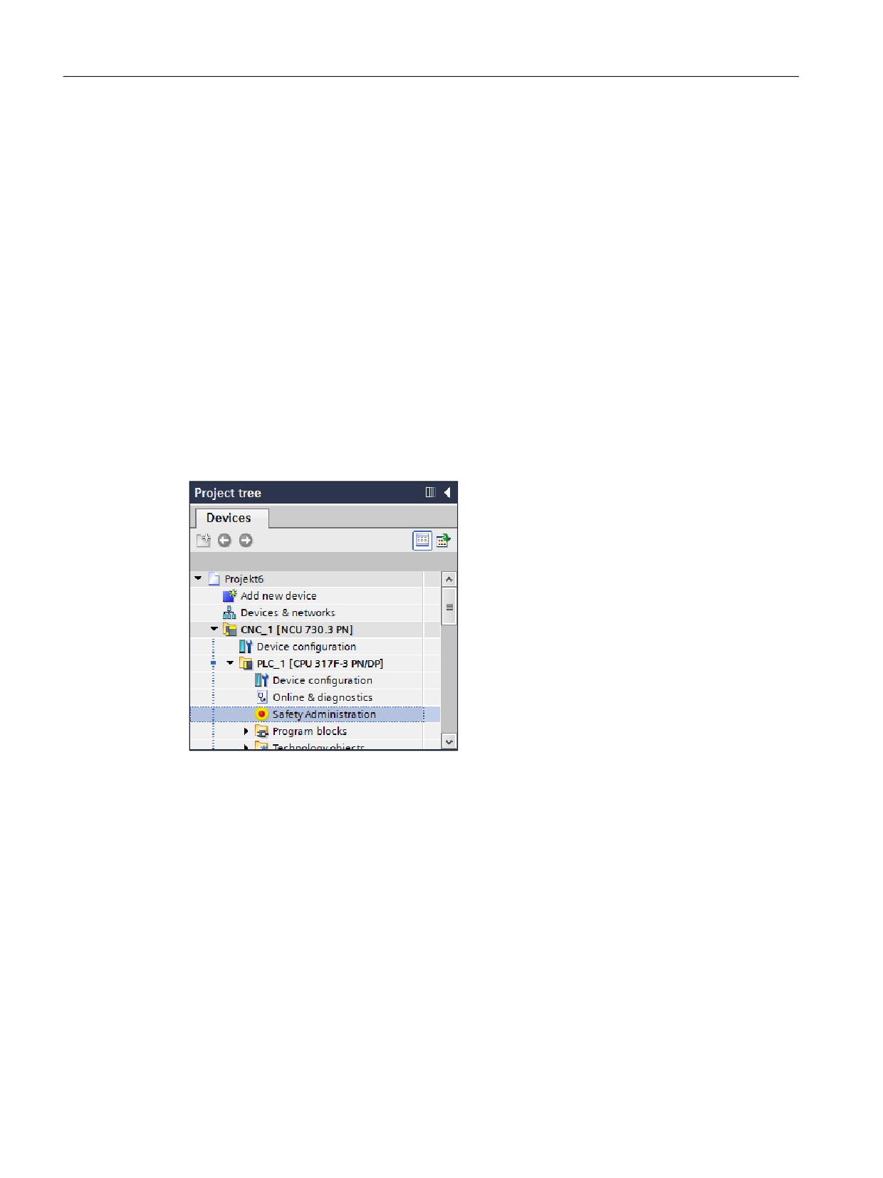
1. In the project tree, double-click the command "Safety administration", e.g. under "CNC_1 >
PLC_1".
2. In the Safety Administration Editor, select the "F-runtime group" entry in the sector tree.
SINUMERIK 840D sl STEP 7 Toolbox V16
Configuration Manual, 12/2019, 6FC5397-0GP40-0BA1
205
Safety configuration
10.8 Configuring Safety Integrated plus (F-PLC)
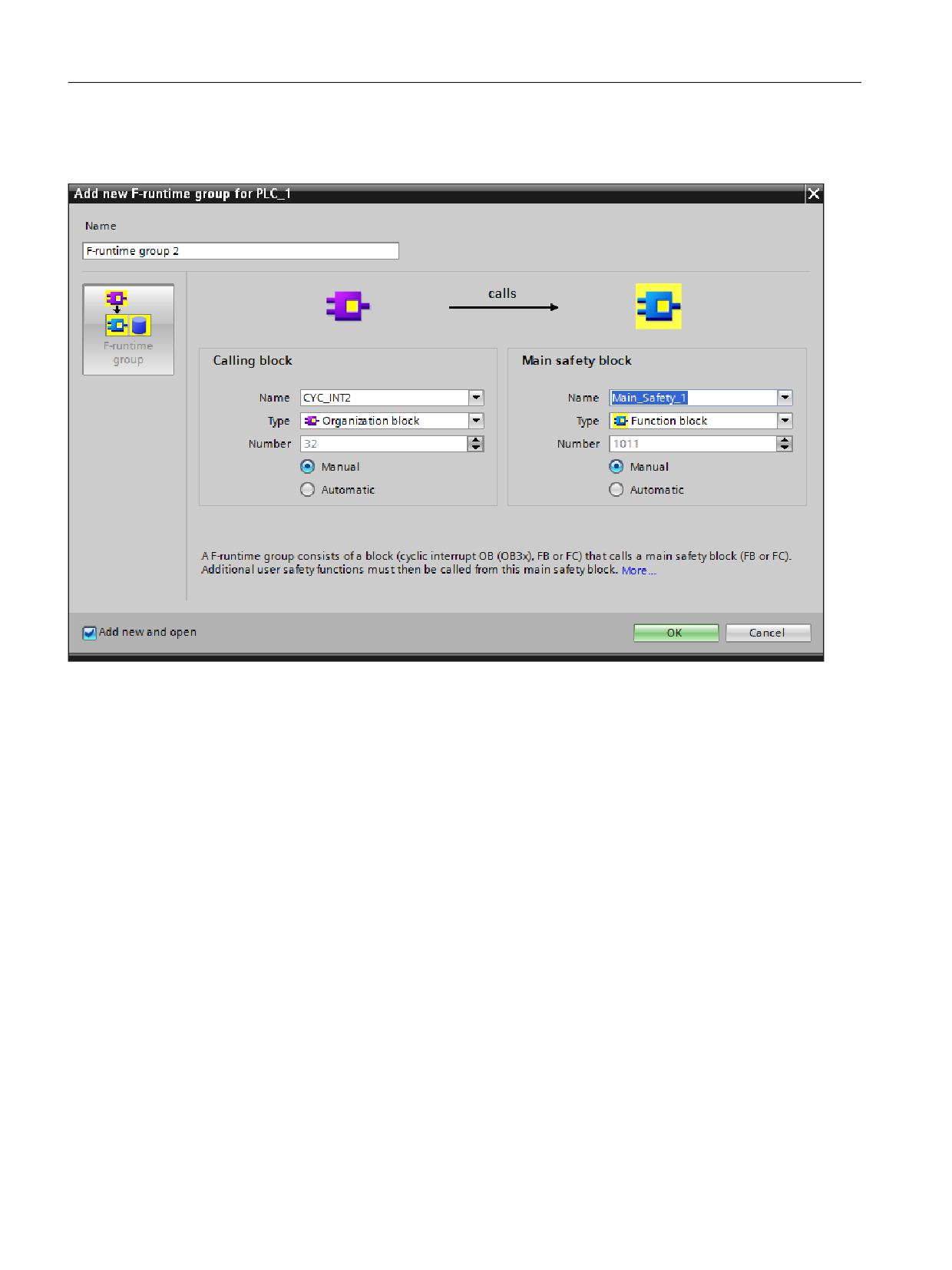
3. Click "Create new F-runtime group".
The "Add new F-runtime group for PLC_1" dialog opens.
Figure 10-11
"Add new F-runtime group for PLC_1" dialog
4. Adjust the settings:
- In the "Calling block" section, you select the desired block, e.g. the organization block
with the number 32 [OB32].
(You can then adapt the cyclical execution time of the calling block in the properties of
the PLC under "Alarms > Watchdog interrupts".)
- In the "Main safety block" section, enter a free block number reserved for Safety
Integrated in the "Number" text field: 1010..1019.
SINUMERIK 840D sl STEP 7 Toolbox V16
206
Configuration Manual, 12/2019, 6FC5397-0GP40-0BA1
Safety configuration
10.8 Configuring Safety Integrated plus (F-PLC)
5. Confirm the entries with "OK".
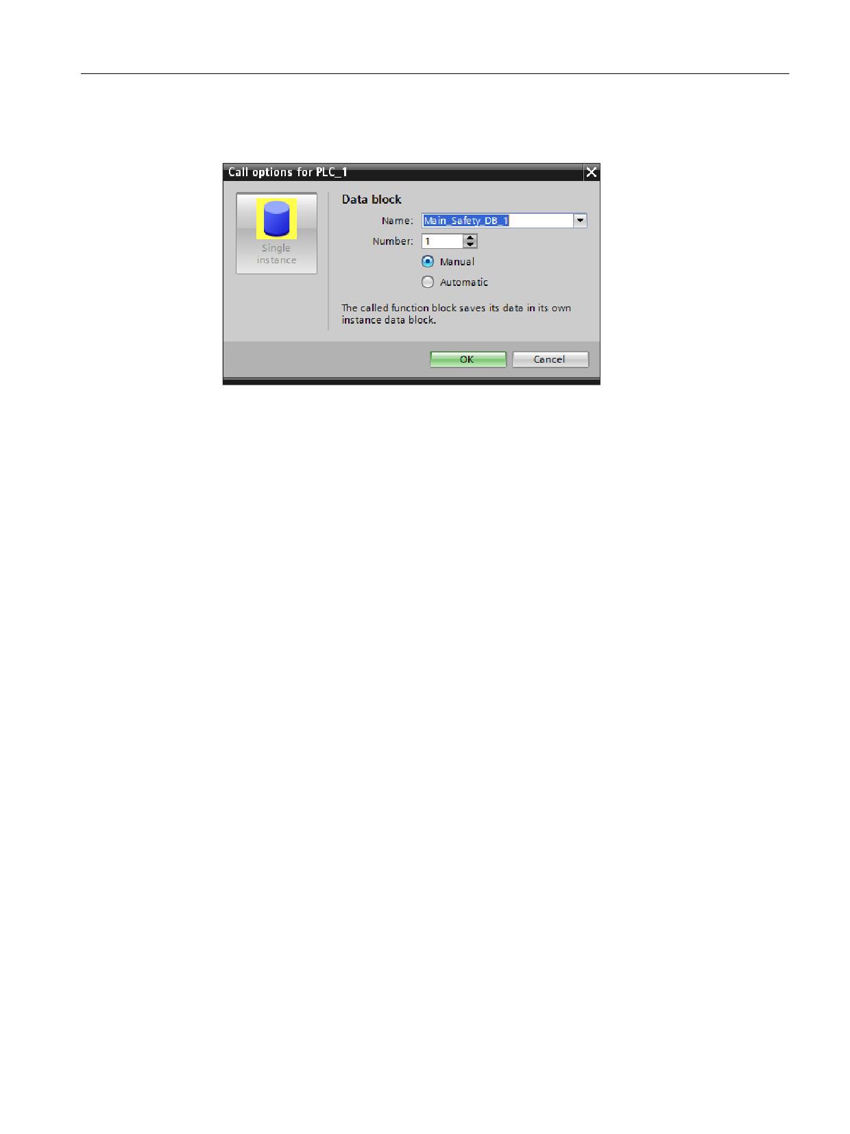
The "Call options for PLC" dialog opens.
Figure 10-12
"Call options for PLC_1" dialog
6. In the "Number" text field, enter a free block number reserved for Safety Integrated:
1010..1019.
7. Confirm the creation of the data block with "OK".
8. Right-click the NCU in the project navigation and select the "Compile > Hardware and
software (only changes)" command.
The configuration will be compiled. This may create further program blocks and F-constants
that are useful for programming.
Result
The F-runtime group has been created in the "Program blocks" folder. The Safety
Administration Editor provides an overview of all available F-blocks.
Further information
● Information about the reserved number range can be found under Introduction (Page 202).
● Information on block assignments can be found in the SINUMERIK 840D sl Function
Manual Basic Functions.
10.8.4
Configuring PROFIsafe
The safety functions can be controlled via PROFIBUS DP using the PROFIsafe profile.
Telegrams are available for the data exchange with the higher-level controller which enable the
triggering of the safety functions in the converter by the controller as well as the feedback of the
status of the safety functions from the converter to the controller.
SINUMERIK 840D sl STEP 7 Toolbox V16
Configuration Manual, 12/2019, 6FC5397-0GP40-0BA1
207
Safety configuration
10.8 Configuring Safety Integrated plus (F-PLC)
PROFIsafe address type for SINAMICS Integrated and NX
SINAMICS Integrated, as integrated subcomponent of the NCU as well as of NX modules are
considered as F-I/O of PROFIsafe address type 1 in the TIA Portal. (This address type is also
valid for other SINAMICS drives.)
For the I/Os of PROFIsafe address type 1, the uniqueness of the PROFIsafe address is only
ensured by the F-destination address (F_DEST_ADD). The F-source address has no effect on
the uniqueness of the PROFIsafe address.
The F-destination address must therefore be unique throughout the network and CPU (see
SIMATIC Safety Help, keyword "Rules for address assignment").
Configuration of safety telegrams
Safety telegrams can be configured in the properties of SINAMICS Integrated or NX under
"Cyclic data traffic".
Safety-relevant parameters, such as the fields for PROFIsafe addresses, are displayed if a
PROFIsafe telegram was added:
● The telegram configuration of SINAMICS Integrated or NX modules is automatically
adapted when you activate the Safety Integrated plus (F-PLC) mode. PROFIsafe telegrams
are added here.
● For additionally connected drive units, add a PROFIsafe telegram in the device overview.
Unique PROFIsafe addresses
For safe operation, you must check whether the used PROFIsafe addresses are unique before
starting the communication.
The uniqueness of the PROFIsafe address is only ensured by the fail-safe destination address.
The PROFIsafe address must be unique throughout the network and the CPU.
You can configure the fail-safe destination address under "Cyclic data exchange" in the
properties of the PROFIsafe telegrams (Safety actual value or Safety setpoint value).
WARNING
Unique PROFIsafe addresses
You must ensure the unique assignment of the PROFIsafe address throughout the network
and the CPU.
● The fail-safe I/O of PROFIsafe address type 1 is addressed clearly by its fail-safe
destination address.
● The fail-safe destination address of the fail-safe I/O (drive units in this case) must be
unique for the entire fail-safe I/O throughout the network and the CPU (system-wide). The
fail-safe I/O of PROFIsafe address type 2, e.g. modules of the ET 200SP type, must also
be taken into account.
● Note also the corresponding documentation in the TIA Portal online help in Section
"SIMATIC Safety - Configuration and programming".
(SIN001)
SINUMERIK 840D sl STEP 7 Toolbox V16
208
Configuration Manual, 12/2019, 6FC5397-0GP40-0BA1
Safety configuration
10.8 Configuring Safety Integrated plus (F-PLC)
Acceptance of the system
Information on the acceptance of a safety configuration with controller can be found in the TIA
Portal information system under "Acceptance of the system".
Note
Error-free hardware and software transmission
Error-free HW and SW transmission is the prerequisite for the creation of the safety printout for
acceptance purposes. Only then is it assured that all consistency checks have been performed
and therefore the safety printout created for a consistent project.
10.8.5
Checking the PROFIsafe address
Unique PROFIsafe address
To ensure safe communication, unique PROFIsafe addresses are required throughout the
CPU and the network.
For this reason, it is also necessary that you check the settings of the PROFIsafe addresses
carefully.
WARNING
Unique PROFIsafe addresses
You must ensure the unique assignment of the PROFIsafe address throughout the network
and the CPU.
● The fail-safe I/O of PROFIsafe address type 1 is addressed clearly by its fail-safe
destination address.
● The fail-safe destination address of the fail-safe I/O (drive units in this case) must be
unique for the entire fail-safe I/O throughout the network and the CPU (system-wide). The
fail-safe I/O of PROFIsafe address type 2, e.g. modules of the ET 200SP type, must also
be taken into account.
● Note also the corresponding documentation in the TIA Portal online help in the section
"SIMATIC Safety - Configuration and programming".
(SIN001)
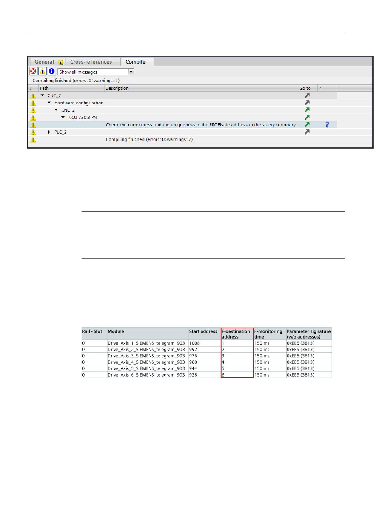
During compilation of the safety program, a warning indicates the importance of unique
PROFIsafe addresses:
SINUMERIK 840D sl STEP 7 Toolbox V16
Configuration Manual, 12/2019, 6FC5397-0GP40-0BA1
209
Safety configuration
10.8 Configuring Safety Integrated plus (F-PLC)
Creating and checking the safety printout of the PLC
Create the safety printout by right-clicking on "Safety administration" and selecting "Print" in the
shortcut menu.
All the relevant data is listed in the safety printout.
Note
Error-free hardware and software transmission
Error-free HW and SW transmission is the prerequisite for the creation of the safety printout for
acceptance purposes. Only then is it assured that all consistency checks have been performed
and therefore the safety printout created for a consistent project.
Example of a safety printout
Here is an example of an NCU 730.3 PN with SINAMICS Integrated standard configuration (6
drive objects).
In the SINAMICS Integrated overview table, the PROFIsafe addresses of the individual drive
objects are listed under "F-destination address".
Figure 10-13
PROFIsafe address in the safety printout
In the tables below, further details on the PROFIsafe telegrams of the individual drive objects
are listed.
Checking the PROFIsafe address in the safety printout
● Compare the PROFIsafe address with the value of the drive parameter p9610 in
SINUMERIK Operate.
● Compare this PROFIsafe address with the values of all other nodes and ensure uniqueness.
SINUMERIK 840D sl STEP 7 Toolbox V16
210
Configuration Manual, 12/2019, 6FC5397-0GP40-0BA1
Safety configuration
10.8 Configuring Safety Integrated plus (F-PLC)
Further information
● Information on the configuration of drives with PROFIsafe via SINUMERIK Operate can be
found in the SINUMERIK Safety Integrated plus Commissioning Manual.
● Further information on the unambiguousness of PROFIsafe addresses can be found in the
Programming and Operating Manual, SIMATIC Safety - Configuring and Programming, or
in the section with the same name in the information system of the TIA Portal, particularly in
chapter "PROFIsafe addresses for F-I/Os of PROFIsafe address type 1".
SINUMERIK 840D sl STEP 7 Toolbox V16
Configuration Manual, 12/2019, 6FC5397-0GP40-0BA1
211
Preface
Fundamental safety
1
instructions
2
Introduction
SINUMERIK
Product features
3
SINUMERIK 840D sl
SINUMERIK 840D sl STEP 7
4
Getting Started
Toolbox V16
Configuring the hardware
5
Getting Started
6
Creating a PLC program
Tips for personnel changing
7
over from another system
Valid for
SINUMERIK V4.93
TIA Portal V16
12/2019
6FC5397-1GP40-0BA1
Preface
SINUMERIK documentation
The SINUMERIK documentation is organized in the following categories:
● General documentation
● User documentation
● Manufacturer and service documentation
This documentation belongs to the manufacturer and service documentation category.
Additional information
You can find information at www.siemens.com/motioncontrol/docu for the following topics:
● Ordering documentation / overview of documentation
● Additional links to download documents
● Using documentation online (find and search in manuals/information)
Please send any questions about the technical documentation (e.g. suggestions for
improvement, corrections) to the following address:
docu.motioncontrol@siemens.com
My Documentation Manager (MDM)
Under the following link you will find information to individually compile OEM-specific machine
documentation based on the Siemens content:
Training
You can find information about the range of training courses under the following links:
SITRAIN - training courses from Siemens for products, systems and solutions in automation
technology
SinuTrain - training software for SINUMERIK
FAQs
You can find Frequently Asked Questions in the Service&Support pages under Product
SINUMERIK 840D sl STEP 7 Toolbox V16
Getting Started, 12/2019, 6FC5397-1GP40-0BA1
3
Preface
SINUMERIK
You can find information on SINUMERIK under the following link:
Technical Support
Country-specific telephone numbers for technical support are provided on the Internet at the
area.
If you have any technical questions, use the online form in the "Support Request" area.
Target group
This document is intended for first-time users wanting to familiarize themselves with the
product.
Benefits
Getting Started provides information to the newcomer and brings about a sense of
achievement to the first-time user in a very short time. First-time users learn the basic functions
of the product or system and how to perform the essential activities and operations themselves.
Standard scope
This documentation only describes the functionality of the standard scope. Additions or
revisions made by the machine manufacturer are documented by the machine manufacturer.
Other functions not described in this documentation might be executable in the control. This
does not, however, represent an obligation to supply such functions with a new control or when
servicing.
For the sake of simplicity, this documentation does not contain all detailed information about all
types of the product and cannot cover every conceivable case of installation, operation, or
maintenance.
Note regarding the General Data Protection Regulation
Siemens observes standard data protection principles, in particular the principle of privacy by
design. That means that
this product does not process / store any personal data, only technical functional data (e.g. time
stamps). If a user links this data with other data (e.g. a shift schedule) or stores personal data
on the same storage medium (e.g. hard drive) and thus establishes a link to a person or
persons, then the user is responsible for ensuring compliance with the relevant data protection
regulations.
SINUMERIK 840D sl STEP 7 Toolbox V16
4
Getting Started, 12/2019, 6FC5397-1GP40-0BA1
Table of contents
Preface
3
1
Fundamental safety instructions
11
1.1
General safety instructions
11
1.2
Equipment damage due to electric fields or electrostatic discharge
15
1.3
Warranty and liability for application examples
16
1.4
Industrial security
17
1.5
Residual risks of power drive systems
19
2
Introduction
21
2.1
Classification in the documentation landscape
21
2.2
Organization of the Getting Started
22
2.3
Views in the TIA Portal
24
2.4
Structure of SINUMERIK NCU
28
3
Product features
31
4
Getting Started
33
4.1
Installing the SINUMERIK toolbox
33
4.2
Starting the TIA Portal
34
4.3
Creating a sample project
35
5
Configuring the hardware
37
5.1
Configuration example
37
5.2
Insert NCU
38
5.3
Insert NX module
40
5.4
Inserting an ADI4 module
45
5.5
Inserting SINUMERIK I/O via the general station description (GSD) file
48
5.5.1
Installing general station description files for SINUMERIK I/O
49
5.5.2
Inserting the SINUMERIK I/O module PP72/48
51
5.5.3
Inserting SINUMERIK MCP/MPP
53
5.6
Configuring network interfaces
56
5.6.1
Introduction
56
5.6.2
Configuring an Ethernet Interface
56
5.6.3
Configuring PROFINET
57
5.6.4
Configuring PROFIBUS DP
58
5.6.5
Configure Integrated PROFIBUS (DP Integrated)
59
5.7
Configuration of telegrams and I/O addresses
61
5.8
Setting up the communication
62
SINUMERIK 840D sl STEP 7 Toolbox V16
Getting Started, 12/2019, 6FC5397-1GP40-0BA1
7
Table of contents
5.9
Loading and closing the hardware configuration in the PLC
65
6
Creating a PLC program
71
6.1
Overview
71
6.2
Adding the PLC basic program
72
6.2.1
Opening the PLC basic program system library
72
6.2.2
Using copy templates
73
6.2.3
Adding the PLC basic program
76
6.2.4
Create blocks from external sources
80
6.2.5
Correcting OB1
81
6.3
Edit blocks
83
6.4
Configuring Ethernet machine control panels in the PLC program
84
6.5
Loading the PLC program to the PLC
87
6.6
Exporting PLC symbols for SINUMERIK Operate
89
6.6.1
Overview
89
6.6.2
Exporting PLC symbols
90
6.6.3
Importing PLC symbols
93
6.7
Completing the first commissioning of the PLC
95
7
Tips for personnel changing over from another system
97
7.1
Overview for the migration
97
7.2
Migrating projects
98
7.2.1
Overview
98
7.2.2
Preparing a STEP 7 V5.x project for the migration
98
7.2.3
Migrating program blocks and symbols
100
7.2.4
Migrating software and hardware configurations
103
7.2.5
Upgrading the PLC basic program
104
7.2.6
More information
106
7.3
Troubleshooting
107
7.3.1
Overview
107
7.3.2
Duplicate block addresses
107
7.3.3
Automatically assigned absolute access
108
7.3.4
Incompatible data types
109
7.3.5
LAD/FDB/SCL: Data type conversion with MOVE instruction
109
7.3.6
Inconsistency of the data blocks for a different runtime version
110
7.3.7
Renaming blocks
110
7.3.8
Configuration and activation of the Web server
111
7.3.9
Rewiring variables in the module
112
7.4
Comparison of functionality
114
7.4.1
Overview
114
7.4.2
Exporting PLC symbols (PLC Symbol Generator)
115
7.4.3
New library functions
116
7.4.4
Safety Integrated and Safety Integrated plus
117
7.4.5
Working in the project view and the portal view
118
7.4.6
Displaying program blocks in the tabular overview
119
7.4.7
Configuring of connections
121
7.4.8
Handling SINUMERIK archives
122
SINUMERIK 840D sl STEP 7 Toolbox V16
8
Getting Started, 12/2019, 6FC5397-1GP40-0BA1
Table of contents
7.4.9
Using user-defined data types (UDT)
123
7.4.10
User-defined data types from the basic program
125
7.4.11
PLC machine data in DB20
127
7.4.12
Changing the operand priority (absolute/symbolic)
127
7.4.12.1
Effects of the symbolic addressing
127
7.4.12.2
Declaration of multi-instances
128
7.4.12.3
Declaration of static local data in the block interface
131
Index
133
SINUMERIK 840D sl STEP 7 Toolbox V16
Getting Started, 12/2019, 6FC5397-1GP40-0BA1
9
Fundamental safety instructions
1
1.1
General safety instructions
WARNING
Electric shock and danger to life due to other energy sources
Touching live components can result in death or severe injury.
● Only work on electrical devices when you are qualified for this job.
● Always observe the country-specific safety rules.
Generally, the following six steps apply when establishing safety:
1. Prepare for disconnection. Notify all those who will be affected by the procedure.
2. Isolate the drive system from the power supply and take measures to prevent it being
switched back on again.
3. Wait until the discharge time specified on the warning labels has elapsed.
4. Check that there is no voltage between any of the power connections, and between any of
the power connections and the protective conductor connection.
5. Check whether the existing auxiliary supply circuits are de-energized.
6. Ensure that the motors cannot move.
7. Identify all other dangerous energy sources, e.g. compressed air, hydraulic systems, or
water. Switch the energy sources to a safe state.
8. Check that the correct drive system is completely locked.
After you have completed the work, restore the operational readiness in the inverse sequence.
WARNING
Electric shock due to connection to an unsuitable power supply
When equipment is connected to an unsuitable power supply, exposed components may
carry a hazardous voltage. Contact with hazardous voltage can result in severe injury or death.
● Only use power supplies that provide SELV (Safety Extra Low Voltage) or PELV-
(Protective Extra Low Voltage) output voltages for all connections and terminals of the
electronics modules.
SINUMERIK 840D sl STEP 7 Toolbox V16
Getting Started, 12/2019, 6FC5397-1GP40-0BA1
11
Fundamental safety instructions
1.1 General safety instructions
WARNING
Electric shock due to equipment damage
Improper handling may cause damage to equipment. For damaged devices, hazardous
voltages can be present at the enclosure or at exposed components; if touched, this can result
in death or severe injury.
● Ensure compliance with the limit values specified in the technical data during transport,
storage and operation.
● Do not use any damaged devices.
WARNING
Electric shock due to unconnected cable shields
Hazardous touch voltages can occur through capacitive cross-coupling due to unconnected
cable shields.
● As a minimum, connect cable shields and the cores of cables that are not used at one end
at the grounded housing potential.
WARNING
Electric shock if there is no ground connection
For missing or incorrectly implemented protective conductor connection for devices with
protection class I, high voltages can be present at open, exposed parts, which when touched,
can result in death or severe injury.
● Ground the device in compliance with the applicable regulations.
WARNING
Spread of fire from built-in devices
In the event of fire outbreak, the enclosures of built-in devices cannot prevent the escape of
fire and smoke. This can result in serious personal injury or property damage.
● Install built-in units in a suitable metal cabinet in such a way that personnel are protected
against fire and smoke, or take other appropriate measures to protect personnel.
● Ensure that smoke can only escape via controlled and monitored paths.
SINUMERIK 840D sl STEP 7 Toolbox V16
12
Getting Started, 12/2019, 6FC5397-1GP40-0BA1
Fundamental safety instructions
1.1 General safety instructions
WARNING
Unexpected movement of machines caused by radio devices or mobile phones
When radio devices or mobile phones with a transmission power > 1 W are used in the
immediate vicinity of components, they may cause the equipment to malfunction.
Malfunctions may impair the functional safety of machines and can therefore put people in
danger or lead to property damage.
● If you come closer than around 2 m to such components, switch off any radios or mobile
phones.
● Use the "SIEMENS Industry Online Support app" only on equipment that has already been
switched off.
WARNING
Fire due to inadequate ventilation clearances
Inadequate ventilation clearances can cause overheating of components with subsequent fire
and smoke. This can cause severe injury or even death. This can also result in increased
downtime and reduced service lives for devices/systems.
● Ensure compliance with the specified minimum clearance as ventilation clearance for the
respective component.
NOTICE
Overheating due to inadmissible mounting position
The device may overheat and therefore be damaged if mounted in an inadmissible position.
● Only operate the device in admissible mounting positions.
WARNING
Unexpected movement of machines caused by inactive safety functions
Inactive or non-adapted safety functions can trigger unexpected machine movements that
may result in serious injury or death.
● Observe the information in the appropriate product documentation before commissioning.
● Carry out a safety inspection for functions relevant to safety on the entire system, including
all safety-related components.
● Ensure that the safety functions used in your drives and automation tasks are adjusted and
activated through appropriate parameterizing.
● Perform a function test.
● Only put your plant into live operation once you have guaranteed that the functions relevant
to safety are running correctly.
SINUMERIK 840D sl STEP 7 Toolbox V16
Getting Started, 12/2019, 6FC5397-1GP40-0BA1
13
Fundamental safety instructions
1.1 General safety instructions
Note
Important safety notices for Safety Integrated functions
If you want to use Safety Integrated functions, you must observe the safety notices in the Safety
Integrated manuals.
WARNING
Malfunctions of the machine as a result of incorrect or changed parameter settings
As a result of incorrect or changed parameterization, machines can malfunction, which in turn
can lead to injuries or death.
● Protect the parameterization against unauthorized access.
● Handle possible malfunctions by taking suitable measures, e.g. emergency stop or
emergency off.
SINUMERIK 840D sl STEP 7 Toolbox V16
14
Getting Started, 12/2019, 6FC5397-1GP40-0BA1
Fundamental safety instructions
1.2 Equipment damage due to electric fields or electrostatic discharge
1.2
Equipment damage due to electric fields or electrostatic discharge
Electrostatic sensitive devices (ESD) are individual components, integrated circuits, modules
or devices that may be damaged by either electric fields or electrostatic discharge.
NOTICE
Equipment damage due to electric fields or electrostatic discharge
Electric fields or electrostatic discharge can cause malfunctions through damaged individual
components, integrated circuits, modules or devices.
● Only pack, store, transport and send electronic components, modules or devices in their
original packaging or in other suitable materials, e.g conductive foam rubber of aluminum
foil.
● Only touch components, modules and devices when you are grounded by one of the
following methods:
- Wearing an ESD wrist strap
- Wearing ESD shoes or ESD grounding straps in ESD areas with conductive flooring
● Only place electronic components, modules or devices on conductive surfaces (table with
ESD surface, conductive ESD foam, ESD packaging, ESD transport container).
SINUMERIK 840D sl STEP 7 Toolbox V16
Getting Started, 12/2019, 6FC5397-1GP40-0BA1
15
Fundamental safety instructions
1.3 Warranty and liability for application examples
1.3
Warranty and liability for application examples
Application examples are not binding and do not claim to be complete regarding configuration,
equipment or any eventuality which may arise. Application examples do not represent specific
customer solutions, but are only intended to provide support for typical tasks.
As the user you yourself are responsible for ensuring that the products described are operated
correctly. Application examples do not relieve you of your responsibility for safe handling when
using, installing, operating and maintaining the equipment.
SINUMERIK 840D sl STEP 7 Toolbox V16
16
Getting Started, 12/2019, 6FC5397-1GP40-0BA1
Fundamental safety instructions
1.4 Industrial security
1.4
Industrial security
Note
Industrial security
Siemens provides products and solutions with industrial security functions that support the
secure operation of plants, systems, machines and networks.
In order to protect plants, systems, machines and networks against cyber threats, it is
necessary to implement - and continuously maintain - a holistic, state-of-the-art industrial
security concept. Products and solutions from Siemens constitute one element of such a
concept.
Customers are responsible for preventing unauthorized access to their plants, systems,
machines and networks. Such systems, machines and components should only be connected
to an enterprise network or the Internet if and to the extent such a connection is necessary and
only when appropriate security measures (e.g. using firewalls and/or network segmentation)
are in place.
For additional information on industrial security measures that can be implemented, please
visit:
Siemens’ products and solutions undergo continuous development to make them more secure.
Siemens strongly recommends that product updates are applied as soon as they become
available, and that only the latest product versions are used. Use of product versions that are
no longer supported, and failure to apply the latest updates may increase customer’s exposure
to cyber threats.
To stay informed about product updates, subscribe to the Siemens Industrial Security RSS
Feed at:
Further information is provided on the Internet:
Industrial Security Configuration Manual (https://support.industry.siemens.com/cs/ww/en/
view/108862708)
SINUMERIK 840D sl STEP 7 Toolbox V16
Getting Started, 12/2019, 6FC5397-1GP40-0BA1
17
Fundamental safety instructions
1.4 Industrial security
WARNING
Unsafe operating states resulting from software manipulation
Software manipulations, e.g. viruses, Trojans, or worms, can cause unsafe operating states
in your system that may lead to death, serious injury, and property damage.
● Keep the software up to date.
● Incorporate the automation and drive components into a holistic, state-of-the-art industrial
security concept for the installation or machine.
● Make sure that you include all installed products into the holistic industrial security concept.
● Protect files stored on exchangeable storage media from malicious software by with
suitable protection measures, e.g. virus scanners.
● On completion of commissioning, check all security-related settings.
● Protect the drive against unauthorized changes by activating the "Know-how protection"
converter function.
SINUMERIK 840D sl STEP 7 Toolbox V16
18
Getting Started, 12/2019, 6FC5397-1GP40-0BA1
Fundamental safety instructions
1.5 Residual risks of power drive systems
1.5
Residual risks of power drive systems
When assessing the machine- or system-related risk in accordance with the respective local
regulations (e.g., EC Machinery Directive), the machine manufacturer or system installer must
take into account the following residual risks emanating from the control and drive components
of a drive system:
1.
Unintentional movements of driven machine or system components during commissioning,
operation, maintenance, and repairs caused by, for example,
- Hardware and/or software errors in the sensors, control system, actuators, and cables
and connections
- Response times of the control system and of the drive
- Operation and/or environmental conditions outside the specification
- Condensation/conductive contamination
- Parameterization, programming, cabling, and installation errors
- Use of wireless devices/mobile phones in the immediate vicinity of electronic
components
- External influences/damage
- X-ray, ionizing radiation and cosmic radiation
2.
Unusually high temperatures, including open flames, as well as emissions of light, noise,
particles, gases, etc., can occur inside and outside the components under fault conditions
caused by, for example:
- Component failure
- Software errors
- Operation and/or environmental conditions outside the specification
- External influences/damage
3.
Hazardous shock voltages caused by, for example:
- Component failure
- Influence during electrostatic charging
- Induction of voltages in moving motors
- Operation and/or environmental conditions outside the specification
- Condensation/conductive contamination
- External influences/damage
4.
Electrical, magnetic and electromagnetic fields generated in operation that can pose a risk
to people with a pacemaker, implants or metal replacement joints, etc., if they are too close
5.
Release of environmental pollutants or emissions as a result of improper operation of the
system and/or failure to dispose of components safely and correctly
6.
Influence of network-connected communication systems, e.g. ripple-control transmitters or
data communication via the network
For more information about the residual risks of the drive system components, see the relevant
sections in the technical user documentation.
SINUMERIK 840D sl STEP 7 Toolbox V16
Getting Started, 12/2019, 6FC5397-1GP40-0BA1
19
Fundamental safety instructions
1.5 Residual risks of power drive systems
SINUMERIK 840D sl STEP 7 Toolbox V16
20
Getting Started, 12/2019, 6FC5397-1GP40-0BA1
Introduction
2
2.1
Classification in the documentation landscape
This Getting Started publication is aimed at those who are new to the field of SINUMERIK PLC
programming and configuration, as well as those who are migrating and have previously
worked with the SINUMERIK add-on for STEP 7 V5.x.
For this purpose, the SINUMERIK-specific configuration of the PLC is performed in the TIA
Portal on the basis of a simple example. Also in this Getting Started, you will find tips for
beginners, including a comparison of functions and descriptions of project migration.
If you are new to this field of SINUMERIK NC and drive commissioning (using SINUMERIK
Operate), we recommend the following additional documentation:
● Commissioning Manual, CNC Commissioning: NC, PLC, Drive
This manual describes the basics of the complete commissioning, in other words all those
commissioning steps that you must perform with SINUMERIK Operate outside the TIA
Portal.
To extend your knowledge and for reference, you can use the following documentation:
● SINUMERIK STEP 7 Toolbox V15.1 Update 1 Configuration Manual
This manual describes all functionalities of the SINUMERIK STEP 7 Toolbox, including for
example, PROFINET IO IRT, Safety or NC variables. It does not, however, contain any
configuration example or any information on migration or changing over.
● Online help of the TIA Portal
The online help of the TIA Portal contains the documentation of all installed TIA Portal
software, including the SINUMERIK STEP 7 Toolbox.
● Function Manual, SINUMERIK 840D sl Basic Functions
This documentation contains the detailed description of the SINUMERIK PLC basic
program.
Note
SINUMERIK documentation in the SIEMENS Industry Online Support (SIOS)
Current documentation on SINUMERIK can be found in the SIOS:
SINUMERIK CNC automation system (http://support.automation.siemens.com/WW/view/en/
10805517/133300)
SINUMERIK 840D sl STEP 7 Toolbox V16
Getting Started, 12/2019, 6FC5397-1GP40-0BA1
21
Introduction
2.2 Organization of the Getting Started
2.2
Organization of the Getting Started
Structure of Getting Started
Getting Started is subdivided into the following sections:
● Getting started
● Configuring the hardware
● Creating a PLC program
● Optional: Tips for those changing over from another system and information on project
migration
A detailed list of the individual configuration steps can be found in the following table. You can
use the links to navigate directly to the required task.
Step
Task
Implementation
1.
Installing the SINUMERIK toolbox
● Installing the SINUMERIK toolbox (Page 33)
and creating a project (Page 33)
● Starting the TIA Portal (Page 34)
● Creating a sample project (Page 35)
2
Inserting and configuring SINU-
● Insert NCU (Page 38)
MERIK hardware (Page 37)
● Insert NX module (Page 40)
● Inserting an ADI4 module (Page 45)
● Inserting SINUMERIK I/O via the general station
description (GSD) file (Page 48)
● Configuring network interfaces (Page 56)
● Configuration of telegrams and IO addresses
(Page 61)
● Setting up the communication (Page 62)
● Loading and closing the hardware configuration in
the PLC (Page 65)
3
Programming SINUMERIK PLC
● Overview of the PLC program (Page 71)
(Page 71)
● Adding the PLC basic program (Page 72)
● Edit blocks (Page 83)
● Configuring Ethernet machine control panels in
the PLC program (Page 84)
● Loading the PLC program to the PLC (Page 87)
● Creating PLC symbols for SINUMERIK Operate
● Completing the first commissioning of the PLC
(Page 95)
SINUMERIK 840D sl STEP 7 Toolbox V16
22
Getting Started, 12/2019, 6FC5397-1GP40-0BA1
Introduction
2.2 Organization of the Getting Started
Also in this documentation, you will find tips for those switching from SINUMERIK Toolbox for
STEP 7 V5.x, including a comparison of functions and descriptions of project migration.
Step
Task
Implementation
Optional
Project migration (Page 97)
● Comparison of functionality
● Migrating projects
● Troubleshooting
SINUMERIK 840D sl STEP 7 Toolbox V16
Getting Started, 12/2019, 6FC5397-1GP40-0BA1
23
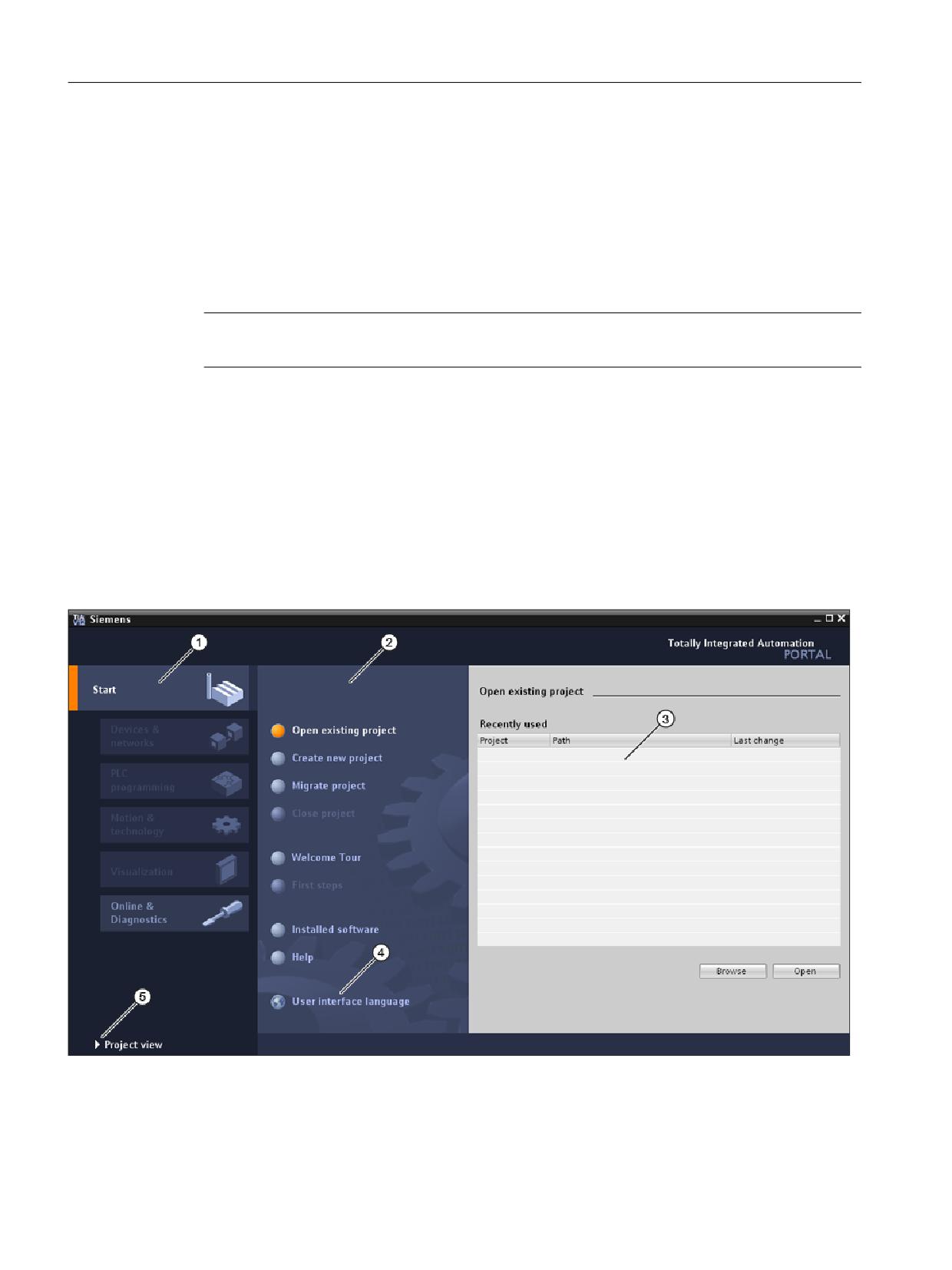
Introduction
2.3 Views in the TIA Portal
2.3
Views in the TIA Portal
Introduction
Two different views available for a differentiated introduction to the TIA Portal: The portal view
and the project view.
Below you will find an explanation of the portal view and project view functions.
Note
Please refer to the Online Help of the TIA Portal for further information on this topic.
The portal view
The portal view provides an overview of all configuration steps and enables a task-based start
to your automation solution.
The individual portals ("Start", "Devices & Networks", "PLC programming", "Visualization",
"Online & Diagnostics", etc.) show all required steps to solve an automation task clearly
structured. Here, you can quickly decide what you want to do and start the tool required for it.
The following figure shows the layout of the portal view:
SINUMERIK 840D sl STEP 7 Toolbox V16
24
Getting Started, 12/2019, 6FC5397-1GP40-0BA1
Introduction
2.3 Views in the TIA Portal
①
Portals for the various tasks:
The portals provide the basic functions for the individual task areas. The portals that are
provided in the portal view depend on the products that have been installed.
②
Actions for the selected portal:
Here, you will find the actions available to you in the portal you have selected. You can open
context-sensitive help in every portal.
③
Selection window for the selected action:
The selection window is available in all portals. The content of the window adapts to your
current selection.
④
Select user interface language.
⑤
Change to project view.
The project view
The project view is a hierarchically structured view of all components in a project. The project
view enables quick and intuitive access to all objects in the project, the relevant work areas and
editors. Using the available editors, you can create and edit all the objects required in the
project.
The various work windows show you all the corresponding data for the selected objects.
The following figure shows the layout of the project view:
SINUMERIK 840D sl STEP 7 Toolbox V16
Getting Started, 12/2019, 6FC5397-1GP40-0BA1
25
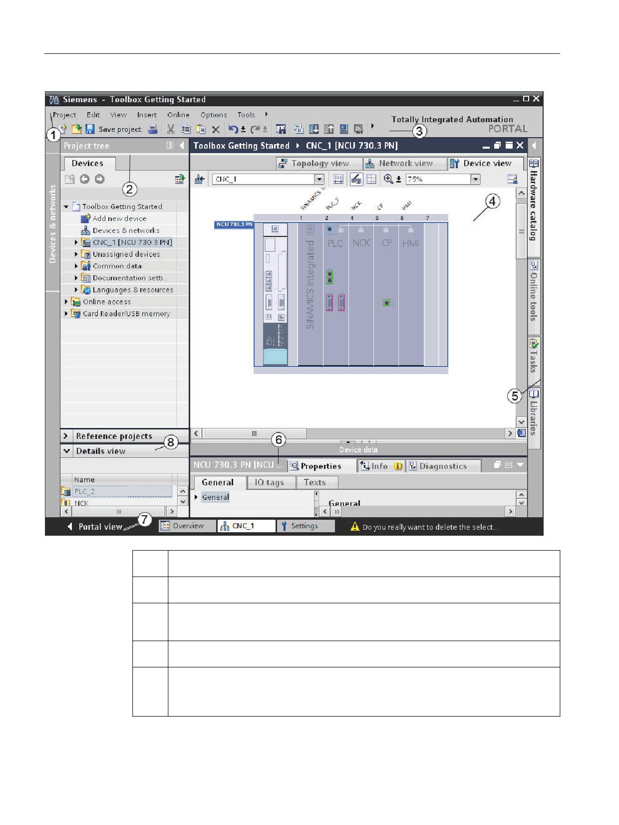
Introduction
2.3 Views in the TIA Portal
①
Menu bar:
The menu bar contains all the commands that you require for your work.
②
Project tree:
The project tree provides access to all components and project data.
③
Toolbar:
The toolbar provides you with buttons for commands you will use frequently. This setup gives
you faster access to these commands compared to the menus in the menu bar.
④
Work area:
The objects that you can open for editing purposes are displayed in the work area.
⑤
Task cards:
Depending on the object being edited or that has been selected, task cards are available. You
can find the task cards in a bar at the right-hand edge of the screen. You can collapse and
reopen them at any time.
SINUMERIK 840D sl STEP 7 Toolbox V16
26
Getting Started, 12/2019, 6FC5397-1GP40-0BA1
Introduction
2.3 Views in the TIA Portal
⑥
Inspector window:
The inspector window displays additional information on a selected object or on executed
actions.
⑦
Portal view:
Changing to the portal view
⑧
Detailed view:
The detailed view shows specific content of a selected object. This might include text lists or
tags.
Note
Adjusting the working area in the TIA Portal
To increase the visible surface of the work area, you can temporarily hide other areas of the TIA
Portal, e.g. the individual task cards, the project tree or the inspector window.
To do this, click "Minimize" in the title bar of the associated area or disable the appropriate
option checkbox in the "View" menu.
You can use the same commands to redisplay the minimized areas at any time.
SINUMERIK 840D sl STEP 7 Toolbox V16
Getting Started, 12/2019, 6FC5397-1GP40-0BA1
27
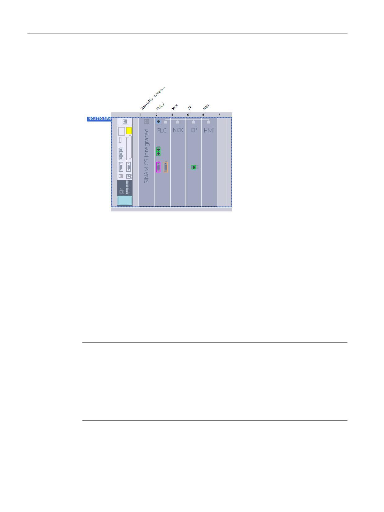
Introduction
2.4 Structure of SINUMERIK NCU
2.4
Structure of SINUMERIK NCU
The structure of the NCU will be explained as introduction to obtain a better understanding.
Subcomponents of the NCU
A SINUMERIK NCU comprises the following integrated subcomponents:
● PLC
● NCK
● CP
● HMI (SINUMERIK Operate)
● SINAMICS Integrated (DRIVE)
These subcomponents are always a fixed component of an NCU and can only be handled in
combination with the NCU. Subcomponents cannot be individually pasted, copied or moved in
the project or across projects (e.g. in libraries).
Note
Copying and pasting the NCU or the DP master system
You can copy and insert NCUs within a project. For this purpose, switch to the network view or
to the topology view of the project view.
The DP master system (PROFIBUS Integrated) cannot be individually copied, pasted or
deleted. It is considered as an integral part of the NCU.
If you copy an NCU, all integrated subcomponents are also copied, e.g. SINAMICS Integrated
or PROFIBUS Integrated.
SINUMERIK 840D sl STEP 7 Toolbox V16
28
Getting Started, 12/2019, 6FC5397-1GP40-0BA1
Introduction
2.4 Structure of SINUMERIK NCU
Additional connectable components
Optionally, the following components can be connected to the NCU:
● NX10.3 and NX15.3 modules
These components are not inserted automatically when inserting an NCU, but must be
integrated manually (Page 40).
SINUMERIK 840D sl STEP 7 Toolbox V16
Getting Started, 12/2019, 6FC5397-1GP40-0BA1
29