SINUMERIK 840D sl. Service - Configuring Commissioning. Manual (2011-2020) - page 106
Configuring networks
5.5 Configuring PROFINET IO with IRT
5.5.3
Isochronous-capable modules identification
Whether a module supports isochronous mode can be determined in the hardware catalog in
the following manner:
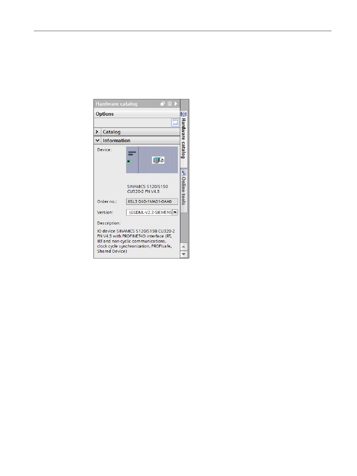
● When you select a device in the hardware catalog, you can see from the description in the
"Information" section whether this device supports isochronous mode or IRT.
Figure 5-1
Description of a device in the hardware catalog
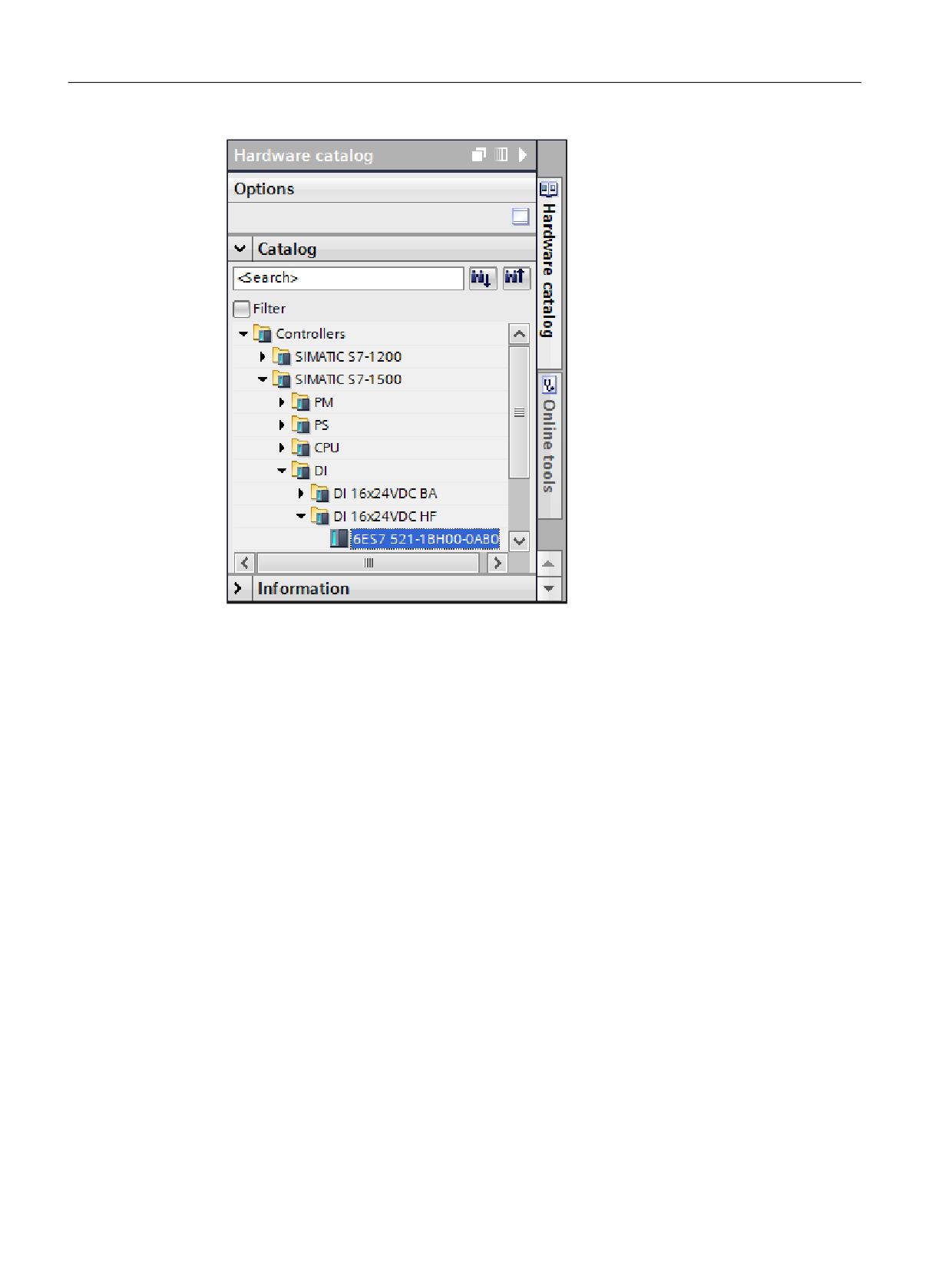
● All peripheral modules that have the "HF" name suffix can be operated isochronously (e.g.
DI 16x 24 VDC HF - 6ES7 521-1BH00).
SINUMERIK 840D sl STEP 7 Toolbox V16
Configuration Manual, 12/2019, 6FC5397-0GP40-0BA1
99
Configuring networks
5.5 Configuring PROFINET IO with IRT
Figure 5-2
Hardware catalog - "HF" (High Feature) name suffix
● The "Information" section does not explicitly list whether drive telegrams (e.g. SIEMENS
telegram 136) support isochronous mode. The compiler will issue an error message if you
use an isochronous telegram without activating isochronous mode for the associated
header module.
● A listing of isochronous-conform PROFINET controllers and PROFINET devices is
contained in the Service & Support portal:
- Which IO controllers and IO devices support the IRT [...] functions and isochronous
- Which SIMATIC S7 components and which drives support isochronous mode? (http://
support.automation.siemens.com/WW/view/en/14747677)
The associated hardware documentation specifies whether a PROFIBUS controller or
device is isochronous-conform.
SINUMERIK 840D sl STEP 7 Toolbox V16
100
Configuration Manual, 12/2019, 6FC5397-0GP40-0BA1
Configuring networks
5.5 Configuring PROFINET IO with IRT
Note
Differences for devices based on device description files (DDF)
A description of the functionality is also contained in the "Information" section for DDF devices.
The following differences, however, exist for the configuring:
● GSD devices are not contained in the same folder as standard devices in the hardware
catalog. The SINAMICS S120/S150 CU320-2, for example, are not found under "Field
devices", but rather under "Further field devices > PROFINET IO > Drives > Siemens AG >
SINAMICS".
● To insert modules or submodules for a GSD device, you must use the device overview
rather than the device view.
5.5.4
Configuring isochronous NC-controlled drives
The procedure for configuring isochronous NC-controlled drives is described below.
If, instead, you want to operate drives isochronously via the PLC, proceed as for a CPU S7-300.
(Use the OB61 as isochronous alarm OB or the TPA1 as process image, and do not enter the
drive addresses in the machine data.)
If, rather than NC-controlled drives, you want to configure I/O used by NC isochronously,
proceed as described in the associated section (Page 102).
Requirement
● The devices to be configured have been inserted (at least one NCU and one PROFINET IO
IRT-conform device).
● The isochronous-conform modules and submodules to be configured have been inserted in
the PROFINET IO IRT-conform device.
See also: Isochronous-capable modules identification (Page 99)
● The PROFINET IO IRT-conform devices are interconnected to the NCU with X150.
Note
Concurrent operation of devices with and without clock synchronization
When you configure devices that do not participate on the IRT communication, observe
the rules for sync domains for PROFINET IO IRT (Page 110).
Procedure overview
Step
Description
1
Configuring the NCU (Page 103)
2
Configuring PROFINET IO IRT devices (Page 104)
3
Configuring IO modules or drive telegrams (Page 106)
SINUMERIK 840D sl STEP 7 Toolbox V16
Configuration Manual, 12/2019, 6FC5397-0GP40-0BA1
101
Configuring networks
5.5 Configuring PROFINET IO with IRT
Step
Description
4
Configuring sync domains (Page 110)
5
Compile the configuration and load into the actual hardware (Page 39)
The compiler issues error messages if you use different values for bus cycles. In this case, match the values
(Page 111).
6
Assigning drive addresses to the NCU machine data (Page 112)
Note
Reusing configured drives or devices in other projects
You can copy preconfigured and configured drives or devices with drag-and-drop into a global
library. In this manner, you can insert them later together with the made settings into another
project and so save configuration effort.
Further information on handling libraries in the TIA Portal can be found in the online help under
"Library > Fundamentals".
Further information
Further information on the configuration of IRT can be found in the TIA Portal online help under
"Configuring IRT communication".
5.5.5
Configuring I/O used by NC isochronously
The procedure for configuring isochronous NC I/O is described below.
If, instead, you want to operate I/O isochronously via the PLC, proceed as for a CPU S7-300.
(Use the OB61 as isochronous alarm OB or the TPA1 as process image, and do not enter the
I/O addresses in the machine data.)
If, rather than non-NC I/O, you want to configure NC drives isochronously, proceed as
described in the associated section (Page 101).
Requirement
● The devices to be configured have been inserted (at least one NCU and one PROFINET IO
IRT-conform device).
● The modules to be configured have been inserted in the PROFINET IO IRT-conform device.
See also Isochronous-capable modules identification (Page 99)
● The PROFINET IO IRT-conform devices are interconnected to the NCU with X150.
Note
Concurrent operation of devices with and without clock synchronization
When you configure devices that do not participate on the IRT communication, observe
the rules for sync domains for PROFINET IO IRT (Page 110).
SINUMERIK 840D sl STEP 7 Toolbox V16
102
Configuration Manual, 12/2019, 6FC5397-0GP40-0BA1
Configuring networks
5.5 Configuring PROFINET IO with IRT
Procedure overview
Step
Description
1
Configuring the NCU (Page 103)
2
Configuring PROFINET IO IRT devices (Page 104)
3
Configuring IO modules or drive telegrams (Page 106)
4
Configuring the input delay for digital input modules (Page 109)
5
Configuring sync domains (Page 110)
6
Compile the configuration and load into the actual hardware (Page 39)
The compiler issues error messages if you use different values for bus cycles. In this case, match the values
(Page 111).
7
Assigning I/O addresses to the NCU machine data (Page 113)
Note
Reusing configured drives or devices in other projects
You can copy preconfigured and configured drives or devices with drag-and-drop into a global
library. In this manner, you can insert them later together with the made settings into another
project and so save configuration effort.
Further information for handling libraries in the TIA Portal can be found in the information
system under the keyword "Library > Fundamentals".
Further information
Further information on the configuration of IRT can be found in the information system of the
TIA Portal at "Configuring IRT communication".
5.5.6
Configuring the NCU
When you operate drives or IO isochronously using NC, make the following SINUMERIK-
specific settings.
If, however, you operate the drives or I/O via the PLC, make the settings as for an S7-300-CPU.
(See online help, keyword "Isochronous mode, configure".)
Requirement
● The devices to be configured have been inserted (at least one NCU and one PROFINET IO
IRT-conform device).
● The isochronous-conform modules and submodules to be configured have been inserted in
the PROFINET IO IRT-conform device.
See also: Isochronous-capable modules identification (Page 99)
● The PROFINET IO IRT-conform devices are interconnected to the NCU with X150.
SINUMERIK 840D sl STEP 7 Toolbox V16
Configuration Manual, 12/2019, 6FC5397-0GP40-0BA1
103
Configuring networks
5.5 Configuring PROFINET IO with IRT
Note
Concurrent operation of devices with and without clock synchronization
When you configure devices that do not participate on the IRT communication, observe
the rules for sync domains for PROFINET IO IRT (Page 110).
Procedure
To configure the NC of the NCU to use isochronous mode, proceed as follows:
1. Select the PLC of the NCU.
2. Select the "Alarms > Isochronous alarms > NCK" entry in the "Properties > General"
inspector window.
3. In the "Distributed I/O" dropdown list, select the PROFINET IO system with which you have
interconnected the PROFINET IO IRT devices (e.g. "PROFINET IO system (100)").
Note
Changing the name and number of the PROFINET IO system
You can specify the name and number of the PROFINET IO system in the settings of the IO
system (bus system on X150). You find the setting under "General" provided IO system is
highlighted in the network view.
If, however, the sync domain or nothing is highlighted, the setting is not available.
To highlight the IO system, position the mouse cursor over the IO system in the network view
and activate the appropriate option box in the displayed tooltip.
4. In the "Application cycle (ms)" dropdown list, select the value that you defined as send clock
of the sync domain and the DP cycle of SINAMICS Integrated, e.g. 2000.
5. Enter "2" in the "TPA" (subprocess image) text field. The setting must match the "process
image" setting on the IO modules.
5.5.7
Configuring PROFINET IO IRT devices
Requirement
● The devices to be configured have been inserted (at least one NCU and one PROFINET IO
IRT-conform device).
● The isochronous-conform modules and submodules to be configured have been inserted in
the PROFINET IO IRT-conform device.
See also Isochronous-capable modules identification (Page 99)
● The PROFINET IO IRT-conform devices are interconnected to the NCU with X150.
● The NCU is configured.
See also Configuring the NCU (Page 103)
SINUMERIK 840D sl STEP 7 Toolbox V16
104
Configuration Manual, 12/2019, 6FC5397-0GP40-0BA1
Configuring networks
5.5 Configuring PROFINET IO with IRT
Procedure
To configure devices for isochronous operation, proceed as follows:
1. Switch to the device view of the PROFINET IO IRT device and select it.
2. Select in the "Properties > General" inspector window under "PROFINET interface >
Extended options" the port (e.g. Port [X1 P1]).
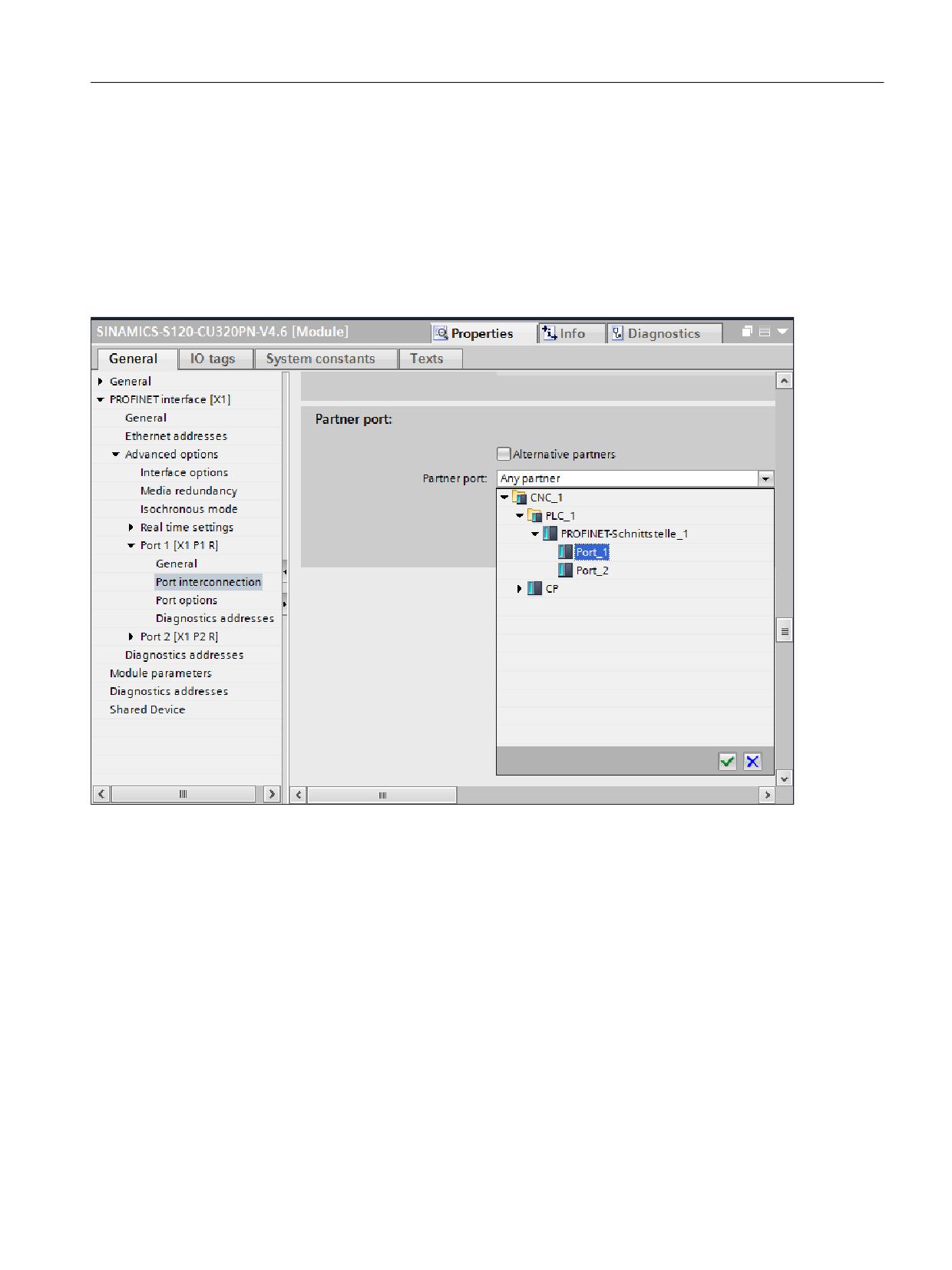
3. Select a specific port on the PLC in the "Partner port" dropdown list in the "Port
interconnection" section: "Port_1" (X150 P1) or "Port_2" (X150 P2).
Figure 5-3
Example port interconnection
The selected port of the device is interconnected with the appropriate port of the PLC.
(Alternatively, you can make the port interconnection between devices graphically in the
topology view.)
4. In the "Cable length" dropdown list, enter the length of the actual cable in order to minimize
the signal run time.
5. Switch in the sector tree of the inspector window to the "PROFINET interface > Extended
options > Isochronous mode" entry.
6. Activate the "Isochronous operation" checkbox.
The isochronous operation of the device is activated and concurrently the synchronization
role of the device set to "sync slave" and the RT class set to "IRT" in the sync domain.
SINUMERIK 840D sl STEP 7 Toolbox V16
Configuration Manual, 12/2019, 6FC5397-0GP40-0BA1
105
Configuring networks
5.5 Configuring PROFINET IO with IRT
7. In the "Ti/To values" dropdown list, select "From the OB".
This causes the value to be taken automatically from the setting of the isochronous alarm
OB "NCK".
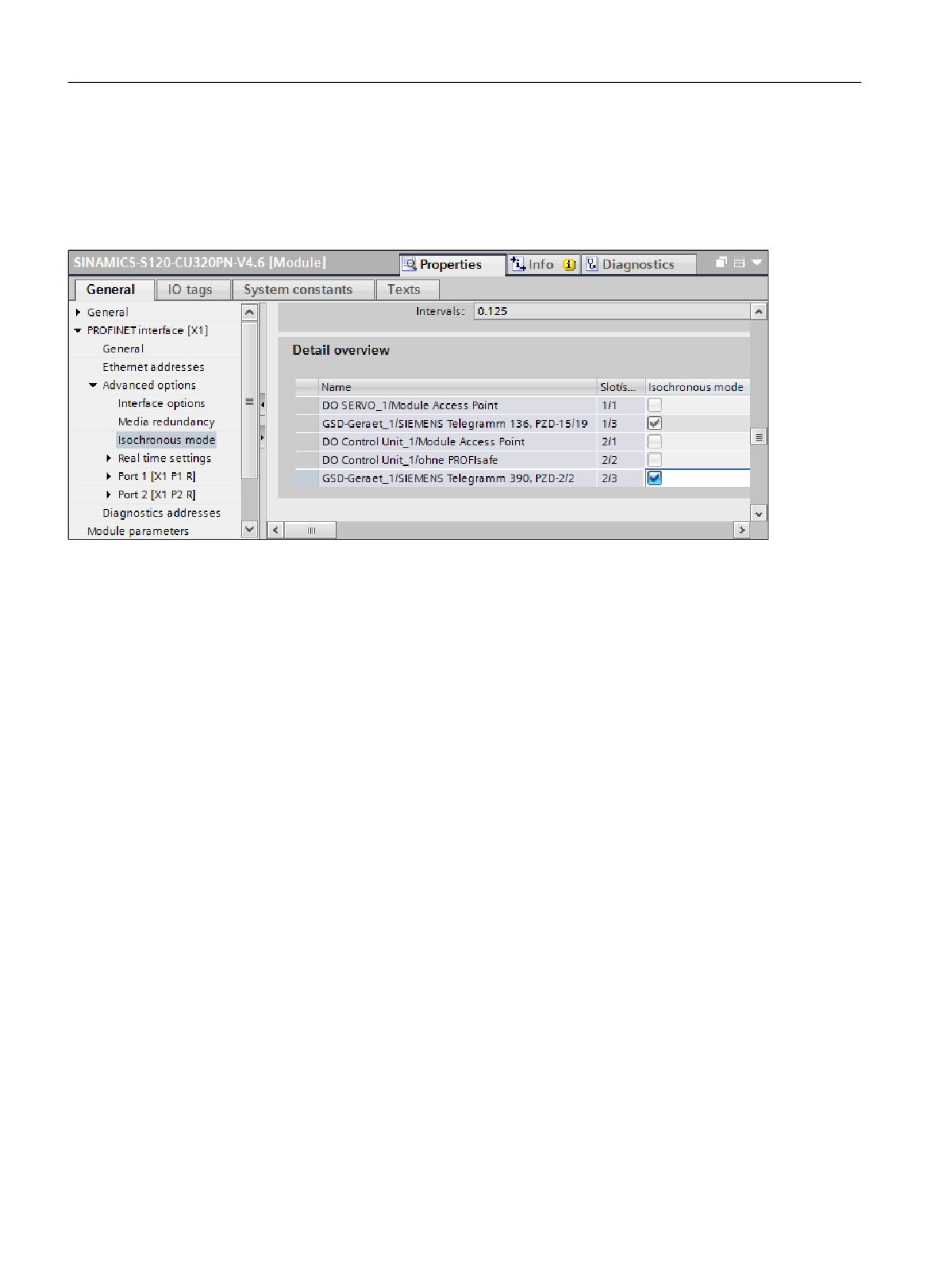
8. Activate the isochronous mode individually for the desired modules of the device in the
"Detail overview" table.
Figure 5-4
Settings for the isochronous mode using the example of a SINAMICS S120/S150 CU320-2
5.5.8
Configuring IO modules or drive telegrams
The isochronous-conform modules (e.g. input/output modules, DO or telegrams) to be
configured must be selected individually in order to make the desired settings in the
"Properties" inspector window. You can select these modules in the device view or device
overview (in the case of GSD-based devices, only in the device overview).
Requirement
● The devices to be configured have been inserted (at least one NCU and one PROFINET IO
IRT-conform device).
● The isochronous-conform modules and submodules to be configured have been inserted in
the PROFINET IO IRT-conform device.
See also Isochronous-capable modules identification (Page 99)
● The PROFINET IO IRT-conform devices are interconnected to the NCU with X150.
● The NCU is configured.
See also Configuring the NCU (Page 103)
● The device or the rack is configured.
See also Configuring PROFINET IO IRT devices (Page 104)
SINUMERIK 840D sl STEP 7 Toolbox V16
106
Configuration Manual, 12/2019, 6FC5397-0GP40-0BA1
Configuring networks
5.5 Configuring PROFINET IO with IRT
Procedure
To configure the inserted IO modules, select them successively and make the settings
individually for each module in the inspector window. Proceed as follows:
1. In the device view, select the rack and open the device overview.
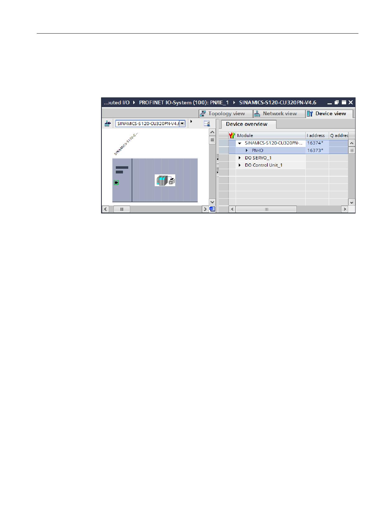
Figure 5-5
Device overview example of a GSD drive device with modules
2. In the device overview, select on the rack of the PROFINET unit one of the inserted modules
to be configured.
SINUMERIK 840D sl STEP 7 Toolbox V16
Configuration Manual, 12/2019, 6FC5397-0GP40-0BA1
107
Configuring networks
5.5 Configuring PROFINET IO with IRT
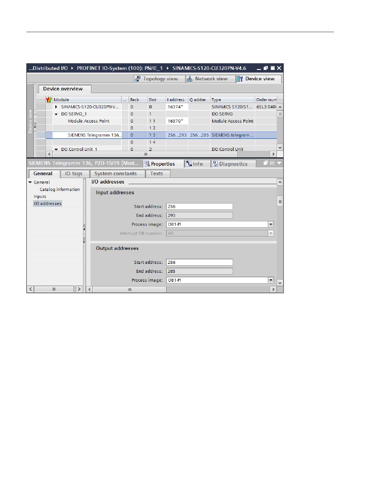
3. In the "Properties > General" inspector window, select the "I/O addresses" entry.
Figure 5-6
Settings for I/O addresses
SINUMERIK 840D sl STEP 7 Toolbox V16
108
Configuration Manual, 12/2019, 6FC5397-0GP40-0BA1
Configuring networks
5.5 Configuring PROFINET IO with IRT
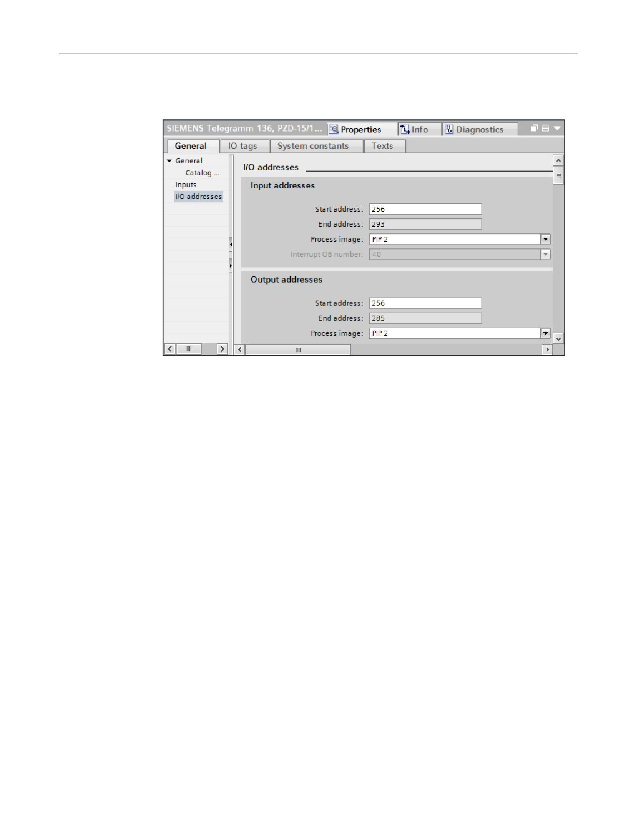
4. Select the TPA2" as "Process image" in each of the "Input addresses" and "Output
addresses" sections.
Figure 5-7
TPA2 process image setting using a telegram 136 as example
5. Enter the desired address in the associated "Start address" text field. Note the following:
- The I/O addresses must lie within the process image of the PLC (default setting: 1024
bytes; can be configured under "Cycle" in the PLC properties).
- Do not use any I/O addresses that are used for some other purpose, e.g. by the machine
control panel.
- The I/O addresses must match the setting in the NC (SINUMERIK Operate).
The machine data in which this is entered depends on whether drives or I/Os are to be
configured:
Assigning drive addresses to the NCU machine data (Page 112)
Assigning I/O addresses to the NCU machine data (Page 113)
5.5.9
Configuring the input delay for digital input modules
If you configure isochronous NC IO, you must correctly set the "input delay" value on the used
digital input modules. A small input delay shortens the response time, although a larger input
delay can possibly suppress longer interference pulses.
● You find the setting for the input delay for a selected digital input module under "Inputs" in
the "Properties" inspector window.
Configure the input delay appropriate for the send clock of the sync domain. The send clock of
the sync domain cannot be set smaller than the input delay of the digital input modules. The
default setting of the input delay is 3 ms.
SINUMERIK 840D sl STEP 7 Toolbox V16
Configuration Manual, 12/2019, 6FC5397-0GP40-0BA1
109
Configuring networks
5.5 Configuring PROFINET IO with IRT
5.5.10
Configuring sync domains
All PROFINET devices that participate on the IRT communication are synchronized to a
common clock. The devices must belong to a sync domain. Just one device has the role of the
sync master (clock generator) in a sync domain; all other devices have the role of a sync slave.
For SINUMERIK, the PROFINET IO controller serves as sync master in the PLC.
Rules
● The configured PROFINET topology must match the actual wiring of the hardware.
● PROFINET devices that do not participate on the IRT communication, namely not
synchronized, are also not part of a sync domain.
● Devices that do not belong to the sync domain may not be contained in the PROFINET
topology between a node of a sync domain and its sync master.
How to remove or add nodes from or to a sync domain is described under "Specifying nodes
of a sync domain" in the TIA Portal online help.
Procedure
To configure the sync domain in the properties of the PROFINET IO system, proceed as follows:
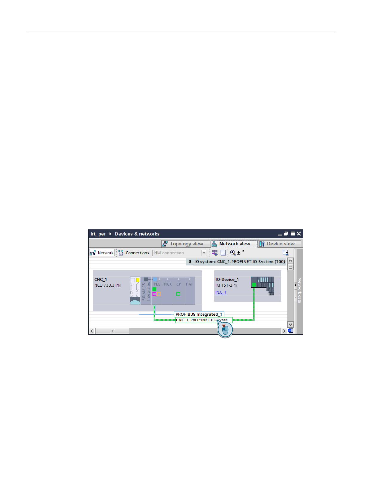
1. In the network view, select the PROFINET IO system.
Figure 5-8
Selecting the PROFINET IO system
2. Select the "PROFINET > Domain management > Sync-Domain_1" entry in the "Properties
> General" inspector window.
SINUMERIK 840D sl STEP 7 Toolbox V16
110
Configuration Manual, 12/2019, 6FC5397-0GP40-0BA1
Configuring networks
5.5 Configuring PROFINET IO with IRT
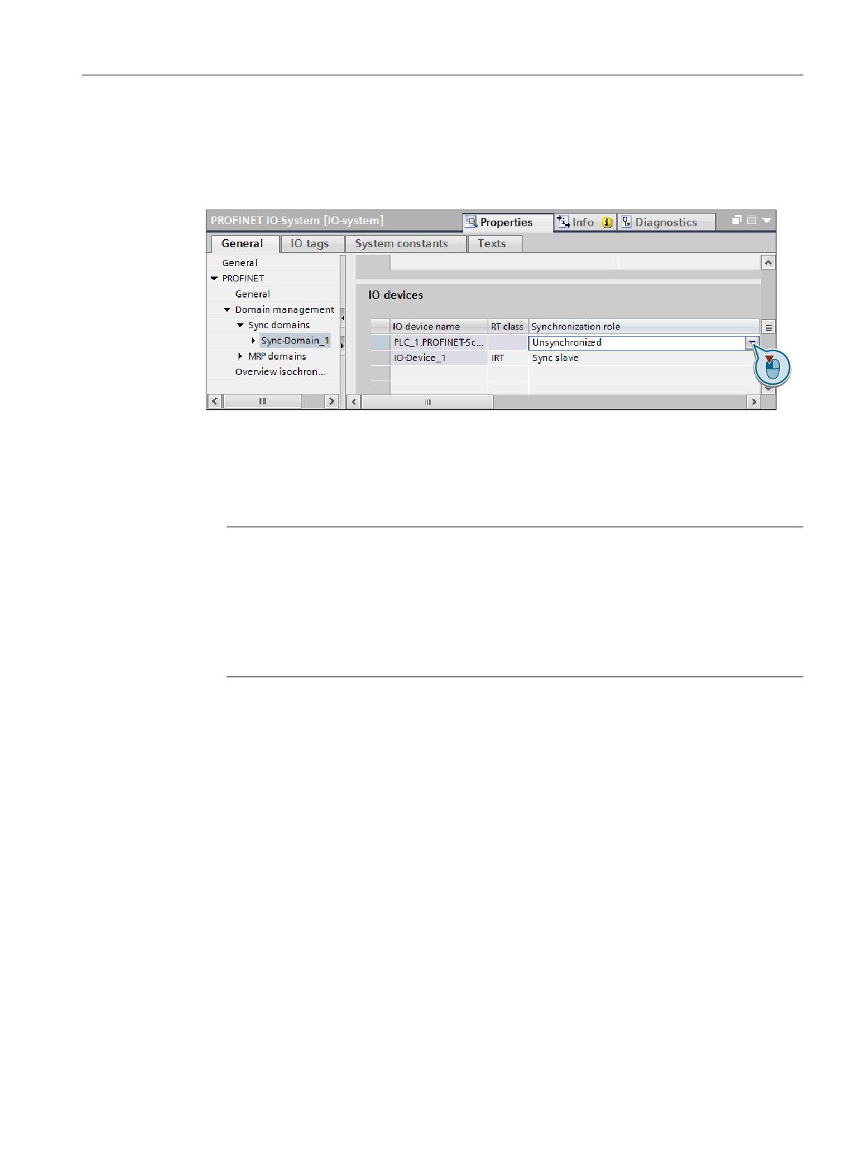
3. In the "IO devices" table, define the synchronization roles and RT classes of all devices of
the sync domain:
- Define the role of the PLC by opening the dropdown list in the "Synchronization role"
column and selecting "Sync master".
Figure 5-9
Selecting the sync master
- Check whether the synchronization role is set to "Sync slave" for all desired devices.
See also: Configuring PROFINET IO IRT devices (Page 104)
4. In the "Sync-Domain_1" section, enter a value in the "send clock" dropdown list appropriate
for the "Equidistant DP cycle" setting.
Note
The send clock of the sync domain and the DP cycle for SINAMICS Integrated must match!
If you have not set the same values for these settings, an error message will be issued when
the configuration is compiled. In this case, match the values and compile the project again.
The "Equidistance DP cycle" setting is contained under "Equidistance" in the properties of
the PROFIBUS Integrated subsystem. (default setting: 2 ms; minimum value: Version-
dependent)
5.5.11
Match values between PROFINET IO and PROFIBUS Integrated
In case you have used different values, an error message will be issued in the "Info > Compile"
inspector window during the compilation.
The following values must agree:
Isochronous mode values:
● "PLC > Alarms > Isochronous alarms > NCK > Application cycle"
● "PROFINET IO system > Domain management > Sync domains > Sync-Domain_1 > Send
clock"
● "PROFIBUS Integrated_1 > Equidistance > DP cycle > Equidistant DP cycle"
SINUMERIK 840D sl STEP 7 Toolbox V16
Configuration Manual, 12/2019, 6FC5397-0GP40-0BA1
111
Configuring networks
5.5 Configuring PROFINET IO with IRT
Ti/To values:
● "PROFIBUS Integrated_1 > Equidistance > Ti/To values of the PROFIBUS"
● "I/O device > PROFINET interface [x1] > Extended options > Isochronous mode"
Match the values and compile the project again.
5.5.12
Assigning drive addresses to the NCU machine data
Procedure
To enter configured addresses in the machine data in the TIA Portal, proceed as follows:
1. Check in the TIA Portal which addresses you have assigned to the drives (see Configuring
IO modules or drive telegrams (Page 106)).
2. Transfer the addresses to the machine data (e.g. via SINUMERIK Operate).
See Adapting I/O start addresses (Page 134).
Further information
● General information concerning this machine data is available in Chapter A4 of the
SINUMERIK 840D sl Supplementary Functions Manual: Digital and analog NCK I/Os for
SINUMERIK 840D sl.
● Specific information on the individual machine data can be found in the online help of
SINUMERIK Operate.
SINUMERIK 840D sl STEP 7 Toolbox V16
112
Configuration Manual, 12/2019, 6FC5397-0GP40-0BA1

Configuring networks
5.5 Configuring PROFINET IO with IRT
5.5.13
Assigning I/O addresses to the NCU machine data
Procedure
To enter addresses which have been configured in the TIA Portal in the machine data, proceed
as follows:
1. Check in the TIA Portal which addresses you have assigned to the I/O modules
(see Configuring IO modules or drive telegrams (Page 106)).
2. Transfer the addresses to the following machine data (e.g. via SINUMERIK Operate):
MD
Identifier
Description
Concerns the mod-
ule type
105
$MN_DPIO_LOGIC_AD-
Logical slot address of the PROFIBUS/
Input module
00
DRESS_IN
PROFINET I/O
105
$MN_DPIO_RANGE_LENG
Length of the PROFIBUS/PROFINET I/
Input module
01
TH_IN
O range
105
$MN_DPIO_LOGIC_AD-
Logical slot address of the PROFIBUS/
Output module
10
DRESS_OUT
PROFINET I/O
105
$MN_DPIO_RANGE_LENG
Length of the PROFIBUS/PROFINET I/
Output module
11
TH_OUT
O range
Use machine data with the same index in order to enter the address and the associated
address length of a module. Use, for example, for the address of an input module,
MD10500[1] and for the address length of the same module MD10501[1].
Example
The following example compares the configuration in the TIA Portal and the compared values
in the machine data:
Table 5-1
Configuring in the TIA Portal with five IO modules
Module
Address
2AI U HS
1020…1023
2AO U HS
1020…1023
4DI 24 VDC HF
1016.0…1016.3
4DI 24 VDC HF
1018.0…1018.7
8DO 24 VDC / 0.5 A HF
1018.0…1018.7
SINUMERIK 840D sl STEP 7 Toolbox V16
Configuration Manual, 12/2019, 6FC5397-0GP40-0BA1
113
Configuring networks
5.5 Configuring PROFINET IO with IRT
Assignment of the IO modules to the NCK machine data
MD10500 $MN_DPIO_LOGIC_ADDRESS_IN[0]=1016
MD10500 $MN_DPIO_LOGIC_ADDRESS_IN[1]=1018
MD10500 $MN_DPIO_LOGIC_ADDRESS_IN[2]=1020
MD10501 $MN_DPIO_RANGE_LENGTH_IN[0]=1
MD10501 $MN_DPIO_RANGE_LENGTH_IN[1]=1
MD10501 $MN_DPIO_RANGE_LENGTH_IN[2]=4
MD10510 $MN_DPIO_LOGIC_ADDRESS_OUT[0]=1018
MD10510 $MN_DPIO_LOGIC_ADDRESS_OUT[1]=1020
MD10511 $MN_DPIO_RANGE_LENGTH_OUT[0]=1
MD10511 $MN_DPIO_RANGE_LENGTH_OUT[1]=4
Further information
● General information concerning this machine data is available in Chapter A4 of the
SINUMERIK 840D sl Supplementary Functions Manual: Digital and analog NCK I/Os for
SINUMERIK 840D sl.
● Specific information on the individual machine data can be found in the online help of
SINUMERIK Operate.
SINUMERIK 840D sl STEP 7 Toolbox V16
114
Configuration Manual, 12/2019, 6FC5397-0GP40-0BA1
Configuring telegrams and drive units
6
6.1
Overview
The drive communication of a SINUMERIK NCU takes place via the SINAMICS Integrated
subcomponent and, if applicable, via additional connected NX modules. The scope of
functionality of the SINAMICS Integrated (or of an NX module) includes the functionality of a
SINAMICS S120 of the corresponding firmware version:
NCU firmware
SINAMICS firmware used
V4.5
V4.5
V4.7
V4.7
V4.8
V4.9
V4.91
V5.2
V4.92
You can find detailed information about drive communication, e.g. function charts, in the
SINAMICS S120 List Manual for the corresponding SINAMICS version (https://
support.industry.siemens.com/cs/document/109739998/).
The standard telegram configuration of a SINUMERIK NCU (Page 116) is redundantly preset
in the TIA Portal and in the machine data and usually does not have to be modified.
Alternatively, you can switch over to a user-defined telegram configuration (Page 121).
You can also use various standard functionalities of STEP 7 (TIA Portal) in combination with
telegrams, e.g.:
● In the properties of the PLC, you can see a complete overview of the assigned I/O
addresses (Page 117).
● In the PLC tag editor, you can define telegram I/O addresses as PLC tags to access them
symbolically in the PLC program.
See: TIA Portal online help; keyword "Declaring PLC tags"
SINUMERIK 840D sl STEP 7 Toolbox V16
Configuration Manual, 12/2019, 6FC5397-0GP40-0BA1
115
Configuring telegrams and drive units
6.2 Standard telegram configuration
6.2
Standard telegram configuration
The standard telegram configuration of a SINUMERIK NCU can have different versions. This
depends on the safety mode and I/O addressing schematic used:
● Depending on the safety mode used, different telegram types are used for safety-relevant
communication. Telegram types for standard communication do not differ.
● The optimized I/O addressing scheme (Page 118) provides a larger coherent address area
for other purposes and therefore uses different telegram I/O addresses (except for
PROFIsafe telegrams).
A telegram configuration with an optimized I/O addressing scheme is considered the
standard telegram configuration in this sense, but nevertheless requires additional
adaptations of the machine data (via SINUMERIK Operate) (Page 143).
See also
Viewing I/O addresses in the TIA Portal (Page 117)
Calling the telegram configuration (Page 122)
PROFIsafe/PROFIdrive telegrams for Safety Integrated plus (F-PLC) (Page 139)
Matching user-specific adaptations (Page 144)
SINUMERIK 840D sl STEP 7 Toolbox V16
116
Configuration Manual, 12/2019, 6FC5397-0GP40-0BA1
Configuring telegrams and drive units
6.3 Viewing I/O addresses in the TIA Portal
6.3
Viewing I/O addresses in the TIA Portal
Requirement
● An NCU has been inserted
● The project view is active
Procedure
To display a complete overview of the assigned I/O addresses, proceed as follows:
1. Click the PLC subcomponent on the NCU.
2. Click "Properties > General" in the inspector window and then click "Address overview" in
the sector tree.
Result
The Address overview is displayed:
You can view all I/O addresses in the address overview and filter them with the checkboxes to
display Inputs, Outputs, Address gaps and Slots.
Note
I/O addresses cannot be changed in the address overview
If you want to change I/O addresses assigned in the TIA Portal, e.g. because insufficient
suitable address space is available, you must switch to the properties of the peer (e.g.
SINAMICS Integrated). There are several ways of switching to these properties:
● To jump directly to the configuration of a specific I/O address, right-click the appropriate line
in the Address overview and then select "Go to..." in the shortcut menu.
● Alternatively, click the appropriate component (SINAMICS Integrated or NX) for example in
the network view, then switch to "Properties > General > Telegram configuration" in the
inspector window.
Further information
Commissioning Manual, CNC Commissioning: NC, PLC, Drive, Section Communication
between NC and drive.
SINUMERIK 840D sl STEP 7 Toolbox V16
Configuration Manual, 12/2019, 6FC5397-0GP40-0BA1
117
Configuring telegrams and drive units
6.4 Changing the addressing schematic
6.4
Changing the addressing schematic
The selected addressing schematic determines the principle according to which the I/O
addresses of the telegrams are assigned by drive objects and influences the address range that
is available for other purposes.
This addressing schematic is thus valid for the SINAMICS Integrated of the NCU as well as all
NX modules. The addressing schematic is also assigned to NX modules that were connected
retrospectively.
You can choose between two different I/O addressing schematics:
● Standard I/O addressing schematic
- Addressing schematic as familiar from SINUMERIK Toolbox for STEP 7 V5.x
- The available address range for diagnostic addresses or additional peripherals is divided
up and available at the start and at the end of the overall address range.
- The I/O addresses of the telegrams are assigned in the middle of the address range and
correspond to the presetting in the machine data.
● I/O addressing schematic optimized for I/O address extension
- Larger, coherent address range for diagnostic addresses or additional peripherals at the
start of the overall address range.
- The telegram I/O addresses are assigned in descending order from the end of the overall
address range and must be entered in the machine data (Page 143).
SINUMERIK 840D sl STEP 7 Toolbox V16
118
Configuration Manual, 12/2019, 6FC5397-0GP40-0BA1
Configuring telegrams and drive units
6.4 Changing the addressing schematic
Procedure
In order to change the schematic for the assignment of telegram I/O addresses of SINAMICS
Integrated (and of all connected NX modules), proceed as follows:
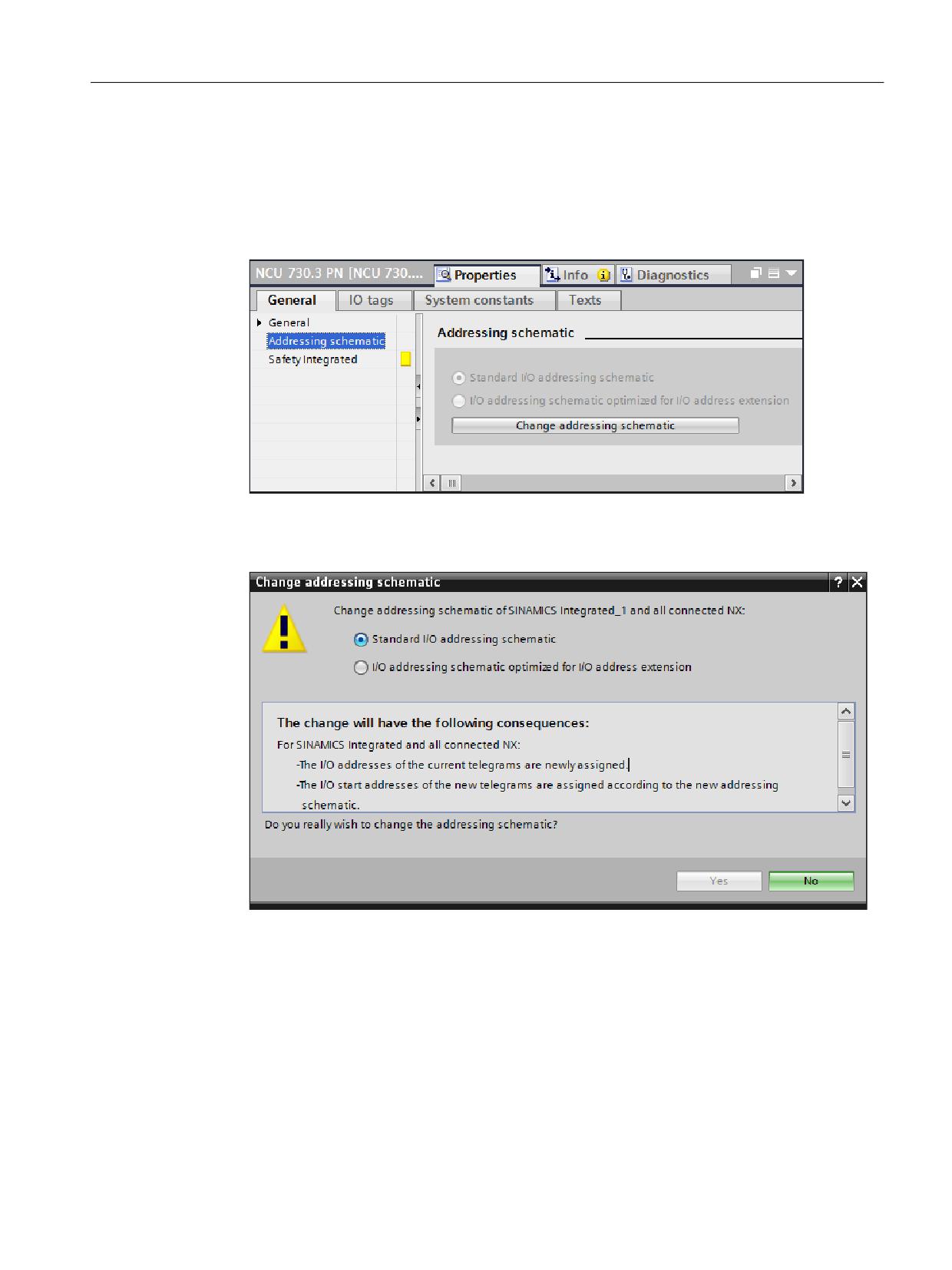
1. Click the NCU in the network or device view and select the "Addressing schematic" entry in
the "Properties" inspector window under "General".
2. Click the "Change addressing schematic" button.
The "Change I/O addressing schematic" dialog opens. If you select an option, the effects of
the change are listed here.
3. Select the required I/O addressing schematic and confirm the reconfiguration with "Yes".
Result
The I/O addressing schematic was changed.
If you use the optimized I/O addressing schematic, you must additionally enter the I/O
addresses in the machine data (Page 143) e.g. via SINUMERIK Operate.
If problems occur during the changeover, you can find further information in the "Info" inspector
window at "General".
SINUMERIK 840D sl STEP 7 Toolbox V16
Configuration Manual, 12/2019, 6FC5397-0GP40-0BA1
119
Configuring telegrams and drive units
6.5 Resetting telegrams
6.5
Resetting telegrams
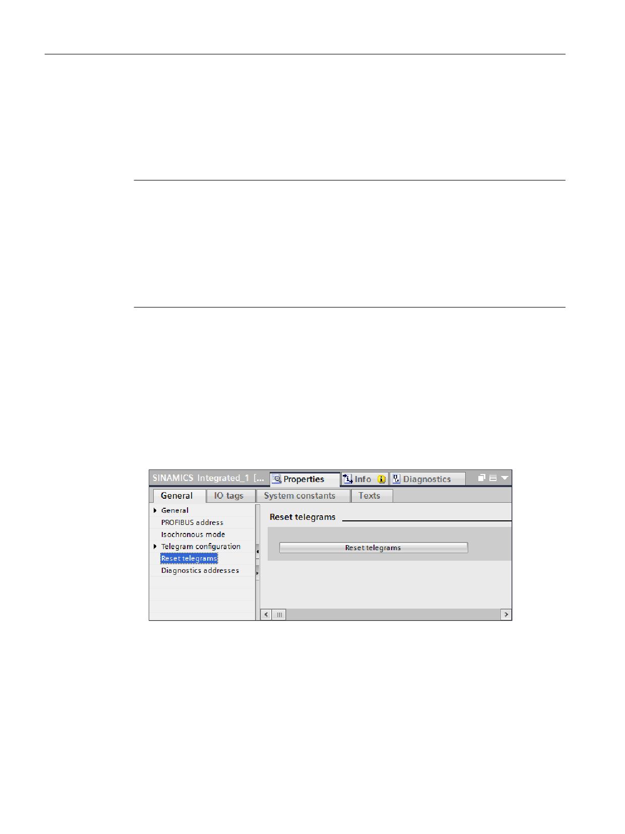
With the command "Reset telegrams" in the properties of SINAMICS Integrated (or an NX
module), you can reset the telegram configuration of a device in the TIA Portal to the standard
telegram configuration (Page 116).
When doing this, all telegrams in this device are deleted.
Note
Settings that deviate from the standard telegram configuration (e.g. additional telegrams) are
deleted
If you reset the telegram configuration, settings that have been added retrospectively or user-
specific settings are lost (e.g. added drive objects, telegrams, or changed I/O addresses).
After resetting you can, of course, customize (Page 121) the telegram configuration again.
As long as the project has not been saved, you can undo the resetting of the telegrams together
with the changed settings: Click "Undo" in the toolbar.
Procedure
In order to reset the telegram configuration of SINAMICS Integrated or an NX module, proceed
as follows:
1. Select the device in the device view:
- To reset the telegrams of SINAMICS Integrated, select SINAMICS Integrated.
- To reset the telegrams of an NX, select the NX.
2. In the inspector window, click "Reset telegrams" under "Properties > General".
3. Click the "Reset telegrams" button and confirm the confirmation message with "Yes".
Result
The existing telegrams were deleted and the standard telegram configuration (Page 116)
inserted.
As many drive objects (including appropriately configured telegrams) were automatically
inserted as are supported by the corresponding SINAMICS Integrated or the NX module drives.
SINUMERIK 840D sl STEP 7 Toolbox V16
120
Configuration Manual, 12/2019, 6FC5397-0GP40-0BA1
Configuring telegrams and drive units
6.6 Displaying or adapting the telegram configuration
6.6
Displaying or adapting the telegram configuration
6.6.1
Overview
You can call (Page 122) the telegram configuration in the properties of the specific device
(SINAMICS Integrated or NX), and when required adapt to address the specific user
requirements.
Features of a user-defined telegram configuration
A telegram configuration which differs from a standard telegram configuration (Page 116) due
to adaptations of any kind is called a user-defined telegram configuration:
● Adapting the configured number of drives (Page 129)
● Other changes in the overview for telegram configuration (Page 122) or in the properties for
the send telegram (actual value) (Page 123) or receive telegram (setpoint value)
(Page 126):
- Adding or removing telegrams
- Adding telegram extensions
- Changing I/O start addresses
- Changing the telegram types used
Special issues to observe when configuring
If you wish to use a user-defined telegram configuration, you must ensure that the user-defined
adaptations are consistent at two positions:
● TIA Portal project
● Machine data (via SINUMERIK Operate)
The user-defined telegram configuration is kept if you upgrade the firmware version of an NCU,
or you replace either the NCU or the NX in the TIA Portal.
Reset to the standard telegram configuration
You can reset the telegram configuration in the TIA Portal back to the standard telegram
configuration in the properties of the individual devices.
A telegram configuration is only reset for the device involved, and must be separately carried
out at the SINAMICS Integrated and connected NX modules.
A reset in the TIA Portal does not affect the machine data (in SINUMERIK Operate).
See also
Resetting telegrams (Page 120)
SINUMERIK 840D sl STEP 7 Toolbox V16
Configuration Manual, 12/2019, 6FC5397-0GP40-0BA1
121
Configuring telegrams and drive units
6.6 Displaying or adapting the telegram configuration
6.6.2
Calling the telegram configuration
The telegram configuration is part of the device properties (SINAMICS Integrated or NX).
Procedure
Proceed as follows to display an overview of all configured telegrams:
1. Select the device in the device view:
- To display the telegram configuration of the SINAMICS Integrated of an NCU, select
SINAMICS Integrated.
- To display the telegram configuration of an NX, select the NX.
2. In the inspector window, click "Telegram configuration" under "Properties > General".
Result
An overview of all of the telegrams configured on the device is displayed.
● Structure of the "Telegram configuration" dialog (Page 122)
When you click on one of the lower-level elements (e.g. "Send (actual value)"), you switch to the
complete properties of the drive object or telegram.
● Changing the properties of receive telegrams (setpoint) (Page 126)
● Changing the properties of send telegrams (actual value) (Page 123)
See also
Adapting the number of drives (Page 129)
6.6.3
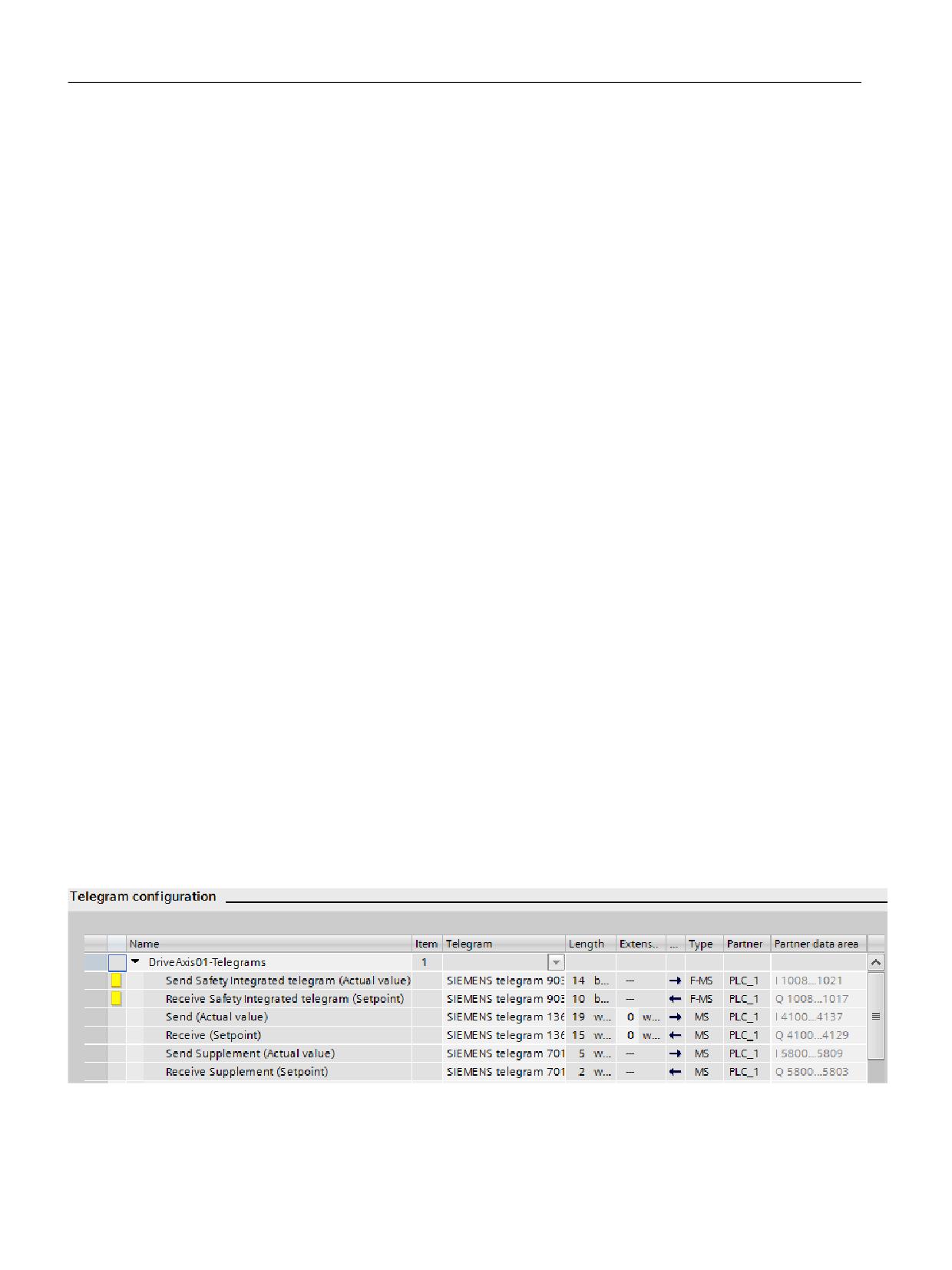
Structure of the "Telegram configuration" dialog
You can find an overview of all of the telegrams that are configured for the SINAMICS
Integrated or an NX in the properties of the corresponding device under "Telegram
configuration".
Figure 6-1
Telegram configuration based on the example of Drive_Axis_1 of a SINUMERIK 840D sl with Safety Integrated
plus and standard I/O addressing scheme
SINUMERIK 840D sl STEP 7 Toolbox V16
122
Configuration Manual, 12/2019, 6FC5397-0GP40-0BA1
Configuring telegrams and drive units
6.6 Displaying or adapting the telegram configuration
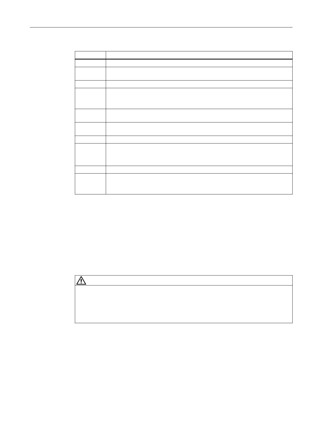
Column
Description
If applicable, yellow marking for identifying safety-oriented resources (Page 174).
Name
Name of the drive object or telegram channel. Display of communication direction (send/
receive) and, if applicable, purpose, actual value/setpoint value.
Element
Positioning the element in the telegram configuration.
Telegram
Display or setting of the telegram type used. The standard setting (Page 116) depends
on the NCU/NX device version and the Safety Integrated mode (Page 177) that is set.
The selectable telegram types depend on the purpose of the telegram (Page 130).
Length
Length of the telegram in bytes or words. The telegram length depends on the telegram
type used.
Extension
Display of the extension of the relevant telegram in words or setting, if supported by the
telegram type.
Direction
Communication direction (setpoint/actual value direction)
Type
Type of communication:
MS = Master-slave communication for PROFIBUS DP
F-MS = PROFIsafe-specific master-slave communication
Partner
Name of the PLC assigned as communication partner.
Partner data
I/O address range of the communication partner (PLC).
area
The Partner data area of a telegram (one each for actual value and setpoint) results from
the I/O start address and the telegram length in bytes (1 word = 2 bytes).
6.6.4
Changing the properties of send telegrams (actual value)
In the telegram properties "Send (actual value)" or "Send safety telegram (actual value)", all
configurable properties of the corresponding object are displayed.
You can edit the parameters for the actual values of the communication between the drive and
the controller. The communication direction is from the drive to the partner.
The settings relevant for PROFIsafe are marked in yellow and are only displayed if SINUMERIK
Safety Integrated plus is active and a PROFIsafe telegram has been selected.
WARNING
Checking the PROFIsafe telegrams
The setting of the PROFIsafe telegrams under "Telegram configuration" is not password-
protected. If you are working with PROFIsafe telegrams, re-check the setting of the
PROFIsafe telegrams over the course of the safety acceptance inspection to be sure that the
selected PROFIsafe telegram corresponds to the requirements of your application.
SINUMERIK 840D sl STEP 7 Toolbox V16
Configuration Manual, 12/2019, 6FC5397-0GP40-0BA1
123
Configuring telegrams and drive units
6.6 Displaying or adapting the telegram configuration
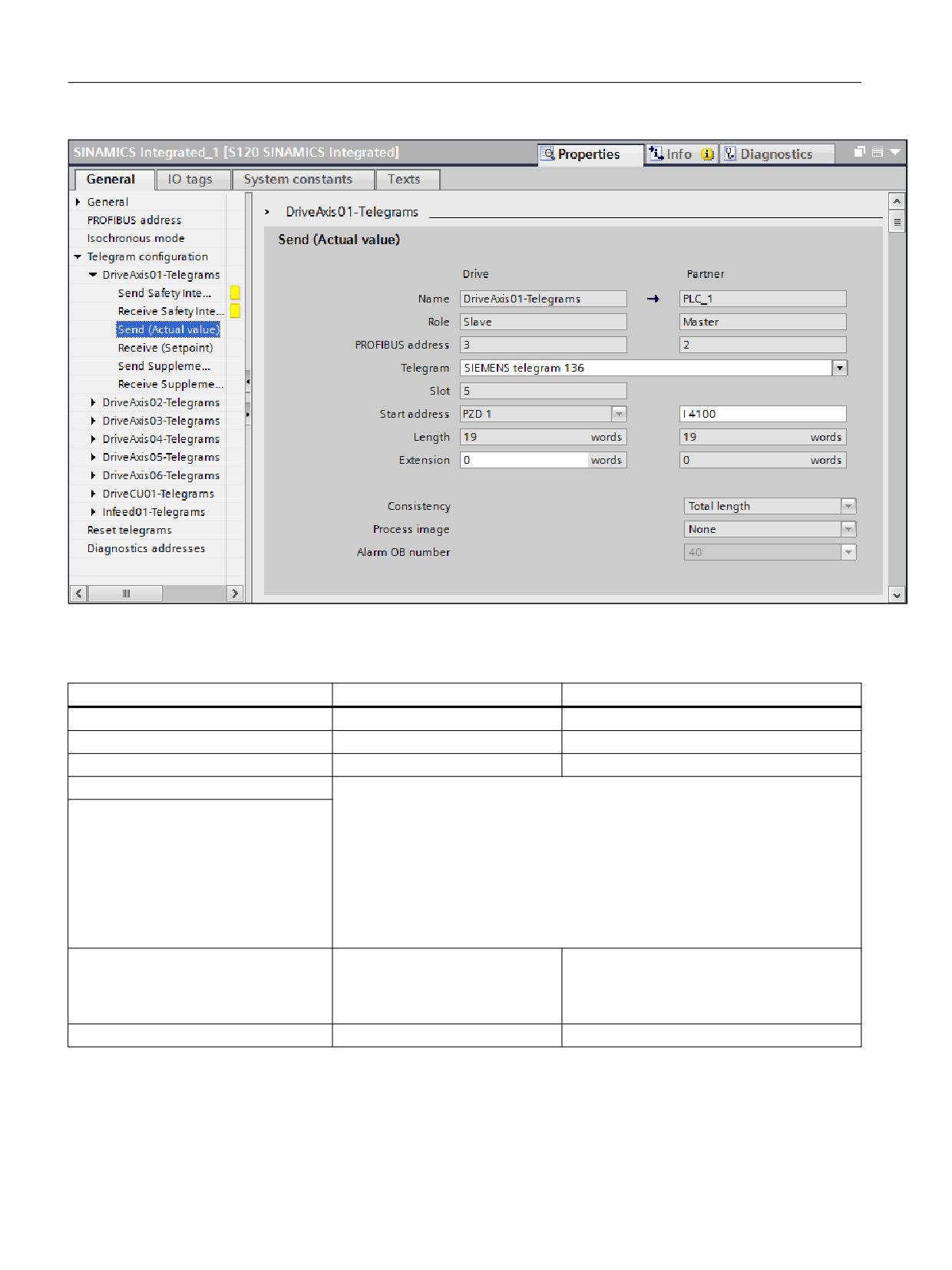
Figure 6-2
Telegram properties - Send (actual value) based on the example of SIEMENS telegram 136
Table 6-1
Parameters of the properties "Send (actual value)" or "Send safety telegram (actual value)"
Parameter
Drive
Control system
Name
Name of the drive in the project
Name of the assigned PLC.
Role
Slave
Master
PROFIBUS address
PROFIBUS address of the slave
PROFIBUS address of the master
Telegram
Display or setting of the telegram type used. The standard setting (Page 116)
depends on the NCU/NX device version and the Safety Integrated mode
Telegram (PROFIsafe)
(Page 177) that is set. The selectable telegram types depend on the purpose of the
telegram.
● Telegrams for PROFIdrive communication (Page 130)
● PROFIsafe telegrams (Page 131)
● Additional PROFIdrive telegrams for Safety Integrated plus (F-PLC) (Page 132)
● Additional PROFIdrive telegrams for Safety Integrated (SPL) (Page 131)
F address
PROFIsafe address of the destina-
PROFIsafe address of the source
tion (F_Dest_Add). The address is
(F_Source_Add). The address is used for
(only PROFIsafe)
used for clear identification of the
clear identification of the source.
destination.
Slot
Slot in the device
-
SINUMERIK 840D sl STEP 7 Toolbox V16
124
Configuration Manual, 12/2019, 6FC5397-0GP40-0BA1

Configuring telegrams and drive units
6.6 Displaying or adapting the telegram configuration
Parameter
Drive
Control system
Start address
Display of the process data word
Currently set start address for the configured
(PZD)
module. You can accept or change the ad-
dress.
If you change the start address for an actual
value, the start address is also adapted for the
setpoint.
Only PROFIsafe: The start address is part of
the F-I/O DB-name of this telegram. If you
change the start address, the F-I/O DB-num-
ber will also be changed.
Length
Length of the telegram in bytes or words. The telegram length depends on the
telegram type used.
Extension
Display of the extension of the relevant telegram in words or setting, if supported by
the telegram type.
Consistency
The use of various consistency areas is useful to optimize the performance of an
S7-CPU. Consistency areas that are longer than two words must be edited with
system functions. You can use the effective Load/Transfer commands for consis-
tency areas up to two words.
Total length:
The consistency applies for all data of this slot. This default entry should usually be
sufficient.
Unit:
The consistency applies for one process data word.
You must configure at least a "2" word "Total length" for the transfer of a double
word.
Process image
Display of the process image (partition), which is used to consistently transfer the
data.
Interrupt OB number
Specification of the interrupt OB number for the output of diagnostic information.
Manual assignment of the F-Watchdog
If this option is activated, you have the capability of assigning the F-monitoring time
time
manually. Otherwise the F-monitoring time will be assigned according to the global
parameterization at the interface (DP interface > F-parameters).
(only PROFIsafe)
F-monitoring time
Monitoring time in the fail-safe DP standard slave/IO standard device/PA field de-
vice.
(only PROFIsafe)
A valid, current safety telegram must arrive from the F-CPU within the monitoring
time. This ensures that failures and errors are detected and the appropriate reac-
tions triggered to keep the safety system in a safe state or to transfer it to a safe
state.
Manual assignment of the F-I/O DB
If this option is activated, you have the capability of assigning the F-I/O DB-number
number
manually. Otherwise it is assigned by the F system.
(only PROFIsafe)
SINUMERIK 840D sl STEP 7 Toolbox V16
Configuration Manual, 12/2019, 6FC5397-0GP40-0BA1
125
Configuring telegrams and drive units
6.6 Displaying or adapting the telegram configuration
Parameter
Drive
Control system
F-I/O DB number
Here you assign a number for the F-I/O DB.
(only PROFIsafe)
The adjustable value range depends upon the value range for DBs set in the Safety
Administration Editor (area "Settings > Assign numbers for F-system blocks"), or is
automatically managed by the F-system.
F-I/O DB name
The name of the F-I/O DB is displayed here.
(only PROFIsafe)
The start address is part of the F-I/O DB-name of this telegram. If you change the
start address, the F-I/O DB-number will also be changed.
The F-I/O DBs are located at the following point in the project navigation: "Con-
troller (e.g. CNC_1 > PLC 1) > Program blocks > System blocks > STEP 7 Safety
> F-I/O DBs"
6.6.5
Changing the properties of receive telegrams (setpoint)
In the telegram properties "Receive (setpoint)" or "Receive safety telegram (setpoint)", all
configurable properties of the corresponding object are displayed.
You can edit the parameters for the setpoints of the communication between the drive and the
controller. The communication direction is from the partner to the drive.
The settings relevant for PROFIsafe are marked in yellow and are only displayed if SINUMERIK
Safety Integrated plus is active and a PROFIsafe telegram has been selected.
WARNING
Checking the PROFIsafe telegrams
The setting of the PROFIsafe telegrams under "Telegram configuration" is not password-
protected. If you are working with PROFIsafe telegrams, re-check the setting of the
PROFIsafe telegrams over the course of the safety acceptance inspection to be sure that the
selected PROFIsafe telegram corresponds to the requirements of your application.
SINUMERIK 840D sl STEP 7 Toolbox V16
126
Configuration Manual, 12/2019, 6FC5397-0GP40-0BA1
Configuring telegrams and drive units
6.6 Displaying or adapting the telegram configuration
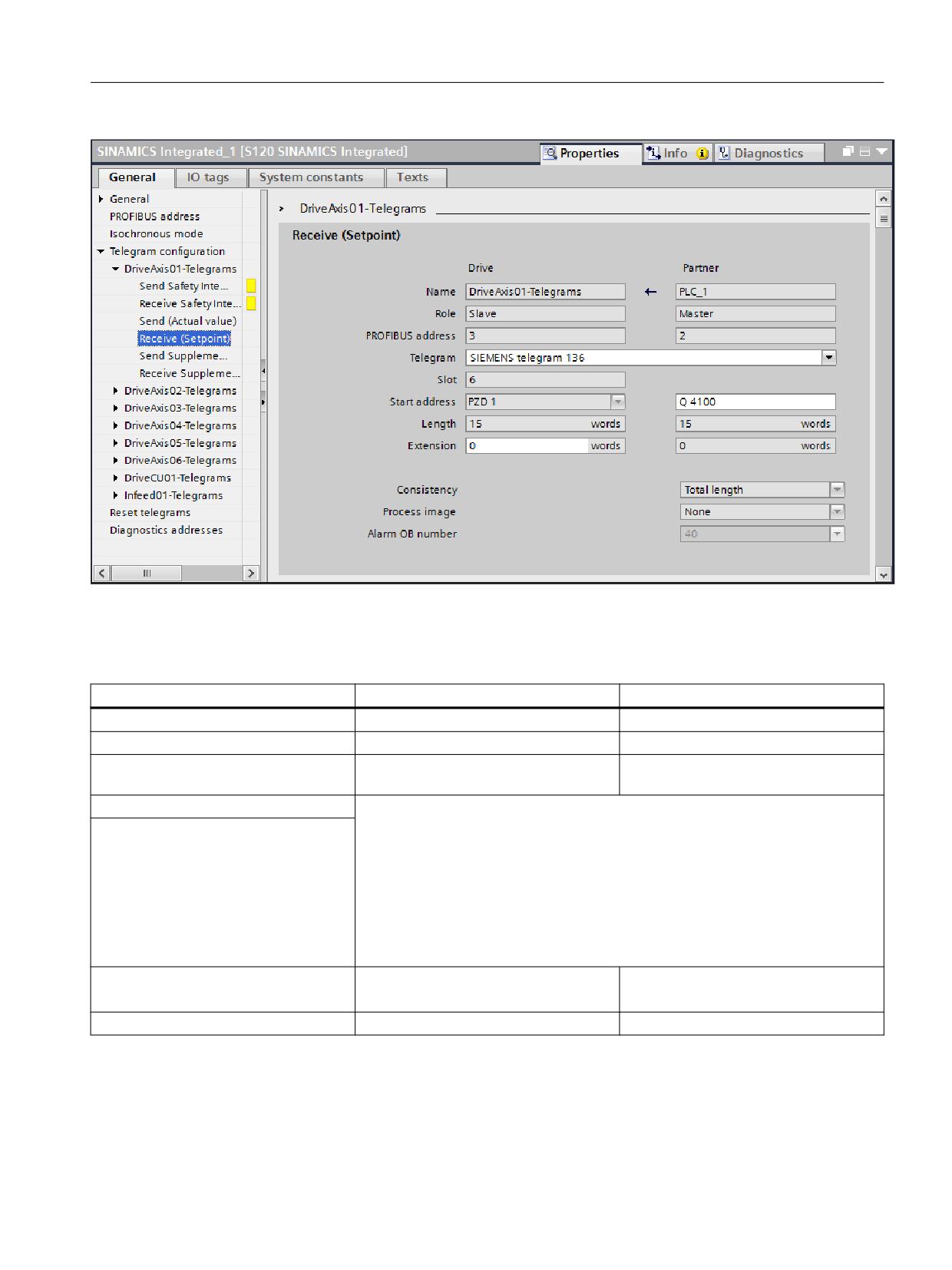
Figure 6-3
Telegram properties - Receive (setpoint value) based on the example of SIEMENS telegram 136
Table 6-2
Parameters of the properties "Receive (setpoint value)" or "Receive safety telegram (setpoint value)"
Parameter
Drive
Control system
Name
Name of the drive in the project
Name of the assigned PLC.
Role
Slave
Master
PROFIBUS address
PROFIBUS address of the slave
PROFIBUS address of the master (can-
not be changed).
Telegram
Display or setting of the telegram type used. The standard setting (Page 116)
depends on the NCU/NX device version and the Safety Integrated mode
Telegram (PROFIsafe)
(Page 177) that is set. The selectable telegram types depend on the purpose of the
telegram.
● Telegrams for PROFIdrive communication (Page 130)
● PROFIsafe telegrams (Page 131)
● Additional PROFIdrive telegrams for Safety Integrated plus (F-PLC) (Page 132)
● Additional PROFIdrive telegrams for Safety Integrated (SPL) (Page 131)
F address
PROFIsafe address of the destination
PROFIsafe address of the source
(F_Dest_Add)
(F_Source_Add)
(only PROFIsafe)
Slot
Slot in the device
-
SINUMERIK 840D sl STEP 7 Toolbox V16
Configuration Manual, 12/2019, 6FC5397-0GP40-0BA1
127

Configuring telegrams and drive units
6.6 Displaying or adapting the telegram configuration
Parameter
Drive
Control system
Start address
Display of the process data word (PZD)
The currently set start address for the
configured module that you can accept
or change.
If you change the start address for a set-
point value, the start address is also
adapted for the actual value.
Only PROFIsafe: The start address is
part of the F-I/O DB-name of this tele-
gram. If you change the start address,
the F-I/O DB-number will also be
changed.
Length
Length of the telegram in bytes or words. The telegram length depends on the
telegram type used.
Extension
Display of the extension of the relevant telegram in words or setting, if supported by
the telegram type.
Consistency
The use of various consistency areas is useful to optimize the performance of an
S7-CPU. Consistency areas that are longer than two words must be edited with
system functions. You can use the effective Load/Transfer commands for consis-
tency areas up to two words.
Total length:
The consistency applies for all data of this slot. This default entry should usually be
sufficient.
Unit:
The consistency applies for one process data word.
You must configure at least a "2" word "Total length" for the transfer of a double
word.
Process image
Display of the process image (partition), which is used to consistently transfer the
data.
Interrupt OB number
Specification of the interrupt OB number for the output of diagnostic information.
Manual assignment of the F-Watchdog
If this option is activated, you have the capability of assigning the F-monitoring time
time
manually. Otherwise the F-monitoring time will be assigned according to the global
parameterization at the interface (DP interface > F-parameters).
(only PROFIsafe)
F-monitoring time
Monitoring time in the fail-safe DP standard slave/IO standard device/PA field de-
vice.
(only PROFIsafe)
A valid, current safety telegram must arrive from the F-CPU within the monitoring
time. This ensures that failures and errors are detected and the appropriate reac-
tions triggered to keep the safety system in a safe state or to transfer it to a safe
state.
Manual assignment of the F-I/O DB
If this option is activated, you have the capability of assigning the F-I/O DB-number
number
manually. Otherwise it is assigned by the F system.
(only PROFIsafe)
SINUMERIK 840D sl STEP 7 Toolbox V16
128
Configuration Manual, 12/2019, 6FC5397-0GP40-0BA1
Configuring telegrams and drive units
6.6 Displaying or adapting the telegram configuration
Parameter
Drive
Control system
F-I/O DB number
Here you assign a number for the F-I/O DB.
(only PROFIsafe)
The adjustable value range depends upon the value range for DBs set in the Safety
Administration Editor (area "Settings > Assign numbers for F-system blocks"), or is
automatically managed by the F-system.
F-I/O DB name
The name of the F-I/O DB is displayed here.
(only PROFIsafe)
The start address is part of the F-I/O DB-name of this telegram. If you change the
start address, the F-I/O DB-number will also be changed.
The F-I/O DBs are located at the following point in the project navigation: "Con-
troller (e.g. CNC_1 > PLC 1) > Program blocks > System blocks > STEP 7 Safety
> F-I/O DBs"
6.6.6
Adapting the number of drives
When an NCU or NX module is inserted, the appropriate number of drive objects (incl.
appropriate configured telegrams) that the associated NCU or NX module supports are
inserted automatically. These standard settings correspond to the standard settings in the NCK
(e.g. configurable via SINUMERIK Operate).
Even if you use fewer than the maximum number of drives of an appropriate NCU or NX
module, you do not need to make any changes here.
If, however, for specific reasons, you make adaptations, you must make them both in the TIA
Portal for the PLC and for the NCK (e.g. via SINUMERIK Operate).
Information concerning the commissioning of SINUMERIK Operate is contained in the Base
Software and Operating Software Commissioning Manual.
Procedure
Proceed as follows to adapt the number of drives:
1. Select the device in the device view:
- To configure the drive objects of the SINAMICS Integrated of an NCU, select SINAMICS
Integrated.
- To configure the drive objects of an NX, select the NX.
2. In the inspector window, click "Telegram configuration" under "Properties > General".
3. You can delete and add drive objects or add individual telegrams under "Telegram
configuration".
- To delete a drive object, right-click the drive object and select "Delete" in the shortcut
menu.
- To add a drive object, click the "<Add new drive object>" command in the "Name"
column.
- To add a user-defined telegram, click the "<Add new telegram>" command in the "Name"
column of the associated drive object.
SINUMERIK 840D sl STEP 7 Toolbox V16
Configuration Manual, 12/2019, 6FC5397-0GP40-0BA1
129

Configuring telegrams and drive units
6.7 Available telegram types
6.7
Available telegram types
6.7.1
Telegrams for the transfer of standard data (PROFIdrive)
The standard telegram configuration (Page 116) of a SINUMERIK NCU uses the following
telegram types for PROFIdrive communication (standard data):
Table 6-3
Telegrams for PROFIdrive communication
Compatible
Designation
Purpose
drive objects
DriveAxis-
SIEMENS telegram 136
Manufacturer-specific telegram.
XY (in SI-
Permits the use of the following data:
NAMICS In-
● Dynamic Servo Control (DSC)
tegrated)
● Torque feedforward control
DO SERVO
(in ext. drive
●
2 position encoders (encoder 1 and encoder 2)
unit)
●
4 trace signals
Process image: PIP NCK
Isochronous mode: Activated
DriveCU01
SIEMENS telegram 390
Manufacturer-specific telegram for PROFIdrive communication.
(in SINAM-
Permits the use of the following data:
ICS Integra-
● Access to onboard I/O of the CU
ted)
● Use of the control and status word of the CU (CU_STW, CU_ZSW)
DO Control
Unit (in ext.
This telegram is used by NX modules for PROFIdrive communication.
drive unit)
Process image: PIP NCK
Isochronous mode: Activated
SIEMENS telegram 391
Manufacturer-specific telegram for PROFIdrive communication.
Permits the use of the following data:
● Access to onboard I/O of the CU
● Use of the control and status word of the CU (CU_STW, CU_ZSW)
● Central measuring probe evaluation of up to 2 probes
This telegram is used by the NCU for PROFIdrive communication between NC
and DRIVE.
Process image: PIP NCK
Isochronous mode: Activated
Infeed01 (in
SIEMENS telegram 370
Manufacturer-specific telegram for communication of the infeed (Infeed / Active
SINAMICS
Infeed (A_INF)).
Integrated)
Process image: Automatic update
DO infeed
Isochronous mode: cannot be set
(in ext. drive
unit)
For the purpose of implementing a user-defined telegram configuration (Page 121), you can
also configure other telegram types for transferring standard data.
SINUMERIK 840D sl STEP 7 Toolbox V16
130
Configuration Manual, 12/2019, 6FC5397-0GP40-0BA1
Configuring telegrams and drive units
6.7 Available telegram types
Further information
You will find a brief description of all configurable telegram types in the TIA Portal in the tooltip
for the telegram. Detailed information can be found in the respective function block diagrams
in the SINAMICS S120/S150 List Manual (https://support.industry.siemens.com/cs/document/
109739998/).
Telegram
Function diagram
1…9
2415
20…83
2416
102…116
2419
118…166
2420
220…371
2421
390…396
2422
6.7.2
Telegrams in SINUMERIK Safety Integrated (SPL) mode
The standard telegram configuration (Page 116) of a SINUMERIK NCU with Safety Integrated
plus (SPL) uses the "SI Motion Monitoring" telegram for safety-oriented communication. This
telegram is also available with inactive safety mode in the configuration, but is then not used.
Table 6-4
Telegrams for SINUMERIK Safety Integrated (SPL)
Profile
Designation
Purpose
PROFIdrive
SI Motion Monitoring
Safety-related communication (SPL) in SINUMERIK Safety
Integrated (SPL) mode.
See also
SINAMICS S120/S150 List Manual (https://support.industry.siemens.com/cs/document/
109739998/)
6.7.3
Telegrams for PROFIsafe communication
The standard telegram configuration (Page 116) of a SINUMERIK NCU with Safety Integrated
plus (F-PLC) uses the following telegram types for PROFIsafe communication:
SINUMERIK 840D sl STEP 7 Toolbox V16
Configuration Manual, 12/2019, 6FC5397-0GP40-0BA1
131

Configuring telegrams and drive units
6.7 Available telegram types
Table 6-5
Telegrams for controlling via PROFIdrive/PROFIsafe
Compatible drive objects
Designation
Purpose
DriveAxisXY (in SINAM-
SIEMENS telegram 902
Extended manufacturer-specific telegram with 32-bit position
ICS Integrated)
value.
DO SERVO (in ext. drive
Process image: none
unit)
Isochronous mode: cannot be set
SIEMENS telegram 903
Extended manufacturer-specific telegram with 32-bit Safe
Cam (S_ZSW_CAM1).
Default setting for internal NC drives.
Process image: none
Isochronous mode: cannot be set
For the purpose of implementing a user-defined telegram configuration (Page 121), you can
also configure other telegram types for PROFIsafe communication.
Further information
You will find a brief description of all configurable telegram types in the TIA Portal in the tooltip
for the telegram. Detailed information can be found in the respective function block diagrams
in the SINAMICS S120/S150 List Manual (https://support.industry.siemens.com/cs/document/
109739998/).
Telegram
Function diagram
30…31
2915
901…903
2916
6.7.4
Telegrams for SIC/SCC communication
The standard telegram configuration (Page 116) of a SINUMERIK NCU with Safety Integrated
plus (F-PLC) uses the following telegram types for SIC/SCC communication:
Table 6-6
Telegrams for controlling via SIC/SCC (PROFIdrive)
Compatible drive objects
Designation
Purpose
DriveAxisXY (in SINAM-
SIEMENS telegram 701
Manufacturer-specific telegram for SIC/SCC communication.
ICS Integrated)
With SINUMERIK, SIC/SCC communication only takes place
DO SERVO (in ext. drive
via telegram 701.
unit)
Process image: PIP NCK
Isochronous mode: Activated
For the purpose of implementing a user-defined telegram configuration (Page 121), you can
also configure telegram 700.
Further information
You will find a brief description of all configurable telegram types in the TIA Portal in the tooltip
for the telegram. Detailed information can be found in the respective function block diagrams
SINUMERIK 840D sl STEP 7 Toolbox V16
132
Configuration Manual, 12/2019, 6FC5397-0GP40-0BA1
Configuring telegrams and drive units
6.7 Available telegram types
in the SINAMICS S120/S150 List Manual (https://support.industry.siemens.com/cs/document/
109739998/).
Telegram
Function diagram
700…701
2423
SINUMERIK 840D sl STEP 7 Toolbox V16
Configuration Manual, 12/2019, 6FC5397-0GP40-0BA1
133

Configuring telegrams and drive units
6.8 Adapting I/O start addresses
6.8
Adapting I/O start addresses
6.8.1
Introduction
Telegram configuration and I/O addressing schematics
The I/O addresses of the NX and SINAMICS Integrated components for communication
between the NCU and the drive are entered in the TIA Portal and in the machine data of the
NCU.
In order that the I/O addresses match in the TIA Portal and in the machine data of the NCU, they
are identical by default and correspond to the standard I/O addressing schematic.
If you use the expanded I/O addressing schematic or have made user-specific adjustments to
the telegram configuration, you must synchronize these I/O addresses between TIA Portal and
machine data.
Telegrams used by default
● Which telegrams are used by default depends on the SINUMERIK Safety Integrated mode.
● Which I/O start addresses are assigned to the telegrams by default depends on the I/O
addressing schematic used.
● The Partner data area of a telegram (one each for actual value and setpoint) results from the
I/O start address and the telegram length in bytes (1 WORD = 2 bytes). The telegram length
depends on the telegram type used.
Table 6-7
Telegrams used by default in the safety modes
Designation
Partner data area
Used in mode
Actual val-
Setpoint
ue
SIEMENS Telegramm 136
19 Words
15 Words
These telegrams transfer standard data
and are used in all safety modes:
SIEMENS Telegramm 390
2 Words
2 Words
● Inactive safety functionality
SIEMENS Telegramm 391
7 Words
3 Words
● Safety Integrated (SPL)
SIEMENS Telegramm 370
1 Words
1 Words
● Safety Integrated plus (F-PLC)
SI Motion Monitoring
12 Words
12 Words
● Safety Integrated (SPL)
Comment: This telegram is also available
with inactive safety mode in the telegram
configuration, but is then not used.
SIEMENS Telegramm 903
14 Bytes
14 Bytes
● Safety Integrated plus (F-PLC)
SIEMENS Telegramm 701
5 Words
2 Words
● Safety Integrated plus (F-PLC)
SINUMERIK 840D sl STEP 7 Toolbox V16
134
Configuration Manual, 12/2019, 6FC5397-0GP40-0BA1

Configuring telegrams and drive units
6.8 Adapting I/O start addresses
machine data to be configured
You must adapt the following machine data if you do not use the default I/O addressing
schematic:
● MD10393 $MN_SAFE_DRIVE_LOGIC_ADDRESS
● MD13050 $MN_DRIVE_LOGIC_ADDRESS
Specific information on the individual machine data can be found in the online help of
SINUMERIK Operate.
The following tables show the machine data (MD) of the NCU in which a specific I/O start
address is entered.
See also
Viewing I/O addresses in the TIA Portal (Page 117)
Calling the telegram configuration (Page 122)
PROFIsafe/PROFIdrive telegrams for Safety Integrated plus (F-PLC) (Page 139)
Matching user-specific adaptations (Page 144)
6.8.2
PROFIdrive telegrams for standard data
Table 6-8
SINAMICS Integrated: I/O addresses of PROFIdrive telegrams
Drive
Telegram type
I/O address
Machine data
Standard addressing
Optimized addressing
schematic
schematic
Drive_Axis_1
SIEMENS telegram 136
4100
15700
13050[0]
Drive_Axis_2
SIEMENS telegram 136
4140
15620
13050[1]
Drive_Axis_3
SIEMENS telegram 136
4180
15540
13050[2]
Drive_Axis_4
SIEMENS telegram 136
4220
15460
13050[3]
Drive_Axis_5
SIEMENS telegram 136
4260
15380
13050[4]
Drive_Axis_6
SIEMENS telegram 136
4300
15300
13050[5]
Drive_CU_1
SIEMENS telegram 391
6500
15780
Infeed_1
SIEMENS telegram 370
6514
15830
Table 6-9
NX on DRIVE-CLiQ socket X105; DP address 15: I/O addresses of PROFIdrive telegrams
Drive
Telegram type
I/O address
Machine data
Standard addressing
Optimized addressing
schematic
schematic
Drive_Axis_1
SIEMENS telegram 136
4340
15150
13050[6]
Drive_Axis_2
SIEMENS telegram 136
4380
15070
13050[7]
Drive_Axis_3
SIEMENS telegram 136
4420
14990
13050[8]
Drive_Axis_4
SIEMENS telegram 136
4460
14910
13050[9]
Drive_Axis_5
SIEMENS telegram 136
4500
14830
13050[10]
SINUMERIK 840D sl STEP 7 Toolbox V16
Configuration Manual, 12/2019, 6FC5397-0GP40-0BA1
135

Configuring telegrams and drive units
6.8 Adapting I/O start addresses
Drive
Telegram type
I/O address
Machine data
Standard addressing
Optimized addressing
schematic
schematic
Drive_Axis_6
SIEMENS telegram 136
4540
14750
13050[11]
Drive_CU_1
SIEMENS telegram 390
6530
15230
Infeed_1
SIEMENS telegram 370
6534
15280
Table 6-10
NX on DRIVE-CLiQ socket X104; DP address 14: I/O addresses of PROFIdrive telegrams
Drive
Telegram type
I/O address
Machine data
Standard addressing
Optimized addressing
schematic
schematic
Drive_Axis_1
SIEMENS telegram 136
4580
14600
13050[12]
Drive_Axis_2
SIEMENS telegram 136
4620
14520
13050[13]
Drive_Axis_3
SIEMENS telegram 136
4660
14440
13050[14]
Drive_Axis_4
SIEMENS telegram 136
4700
14360
13050[15]
Drive_Axis_5
SIEMENS telegram 136
4740
14280
13050[16]
Drive_Axis_6
SIEMENS telegram 136
4780
14200
13050[17]
Drive_CU_1
SIEMENS telegram 390
6560
14680
Infeed_1
SIEMENS telegram 370
6554
14730
Table 6-11
NX on DRIVE-CLiQ socket X103; DP address 13: I/O addresses of PROFIdrive telegrams
Drive
Telegram type
I/O address
Machine data
Standard addressing
Optimized addressing
schematic
schematic
Drive_Axis_1
SIEMENS telegram 136
4820
14050
13050[18]
Drive_Axis_2
SIEMENS telegram 136
4860
13970
13050[19]
Drive_Axis_3
SIEMENS telegram 136
4900
13890
13050[20]
Drive_Axis_4
SIEMENS telegram 136
4940
13810
13050[21]
Drive_Axis_5
SIEMENS telegram 136
4980
13730
13050[22]
Drive_Axis_6
SIEMENS telegram 136
5020
13650
13050[23]
Drive_CU_1
SIEMENS telegram 390
6590
14130
Infeed_1
SIEMENS telegram 370
6574
14180
Table 6-12
NX on DRIVE-CLiQ socket X102; DP address 12: I/O addresses of PROFIdrive telegrams
Drive
Telegram type
I/O address
Machine data
Standard addressing
Optimized addressing
schematic
schematic
Drive_Axis_1
SIEMENS telegram 136
5060
13500
13050[24]
Drive_Axis_2
SIEMENS telegram 136
5100
13420
13050[25]
Drive_Axis_3
SIEMENS telegram 136
5140
13340
13050[26]
Drive_Axis_4
SIEMENS telegram 136
5180
13260
13050[27]
Drive_Axis_5
SIEMENS telegram 136
5220
13180
13050[28]
Drive_Axis_6
SIEMENS telegram 136
5260
13100
13050[29]
SINUMERIK 840D sl STEP 7 Toolbox V16
136
Configuration Manual, 12/2019, 6FC5397-0GP40-0BA1

Configuring telegrams and drive units
6.8 Adapting I/O start addresses
Drive
Telegram type
I/O address
Machine data
Standard addressing
Optimized addressing
schematic
schematic
Drive_CU_1
SIEMENS telegram 390
6620
13580
Infeed_1
SIEMENS telegram 370
6594
13630
Table 6-13
NX on DRIVE-CLiQ socket X101; DP address 11: I/O addresses of PROFIdrive telegrams
Drive
Telegram type
I/O address
Machine data
Standard addressing
Optimized addressing
schematic
schematic
Drive_Axis_1
SIEMENS telegram 136
5300
12950
13050[30]
Drive_Axis_2
SIEMENS telegram 136
5340
12870
13050[31]
Drive_Axis_3
SIEMENS telegram 136
5380
12790
13050[32]
Drive_Axis_4
SIEMENS telegram 136
5420
12710
13050[33]
Drive_Axis_5
SIEMENS telegram 136
5460
12630
13050[34]
Drive_Axis_6
SIEMENS telegram 136
5500
12550
13050[35]
Drive_CU_1
SIEMENS telegram 390
6650
13030
Infeed_1
SIEMENS telegram 370
6614
13080
Table 6-14
NX on DRIVE-CLiQ socket X100; DP address 10: I/O addresses of PROFIdrive telegrams
Drive
Telegram type
I/O address
Machine data
Standard addressing
Optimized addressing
schematic
schematic
Drive_Axis_1
SIEMENS telegram 136
5540
12400
13050[36]
Drive_Axis_2
SIEMENS telegram 136
5580
12320
13050[37]
Drive_Axis_3
SIEMENS telegram 136
5620
12240
13050[38]
Drive_Axis_4
SIEMENS telegram 136
5660
12160
13050[39]
Drive_Axis_5
SIEMENS telegram 136
5700
12080
13050[40]
Drive_Axis_6
SIEMENS telegram 136
5740
12000
13050[41]
Drive_CU_1
SIEMENS telegram 390
6680
12480
Infeed_1
SIEMENS telegram 370
6634
12530
6.8.3
PROFIdrive telegrams for Safety Integrated (SPL)
Table 6-15
SINAMICS Integrated: I/O addresses of telegram SI Motion Monitoring
Drive
Telegram type
I/O address
Machine data
Standard addressing sche-
Optimized address-
matic
ing schematic
Drive_Axis_1
SI Motion Monitoring
6700
15756
10393[0]
Drive_Axis_2
SI Motion Monitoring
6724
15676
10393[1]
Drive_Axis_3
SI Motion Monitoring
6748
15596
10393[2]
Drive_Axis_4
SI Motion Monitoring
6772
15516
10393[3]
SINUMERIK 840D sl STEP 7 Toolbox V16
Configuration Manual, 12/2019, 6FC5397-0GP40-0BA1
137

Configuring telegrams and drive units
6.8 Adapting I/O start addresses
Drive
Telegram type
I/O address
Machine data
Standard addressing sche-
Optimized address-
matic
ing schematic
Drive_Axis_5
SI Motion Monitoring
6796
15436
10393[4]
Drive_Axis_6
SI Motion Monitoring
6820
15356
10393[5]
Table 6-16
NX on DRIVE-CLiQ socket X105; DP address 15: I/O addresses of telegram SI Motion Monitoring
Drive
Telegram type
I/O address
Machine data
Standard addressing sche-
Optimized address-
matic
ing schematic
Drive_Axis_1
SI Motion Monitoring
6844
15206
10393[6]
Drive_Axis_2
SI Motion Monitoring
6868
15126
10393[7]
Drive_Axis_3
SI Motion Monitoring
6892
15046
10393[8]
Drive_Axis_4
SI Motion Monitoring
6916
14966
10393[9]
Drive_Axis_5
SI Motion Monitoring
6940
14886
10393[10]
Drive_Axis_6
SI Motion Monitoring
6964
14806
10393[11]
Table 6-17
NX on DRIVE-CLiQ socket X104; DP address 14: I/O addresses of telegram SI Motion Monitoring
Drive
Telegram type
I/O address
Machine data
Standard addressing sche-
Optimized address-
matic
ing schematic
Drive_Axis_1
SI Motion Monitoring
6988
14656
10393[12]
Drive_Axis_2
SI Motion Monitoring
7012
14576
10393[13]
Drive_Axis_3
SI Motion Monitoring
7036
14496
10393[14]
Drive_Axis_4
SI Motion Monitoring
7060
14416
10393[15]
Drive_Axis_5
SI Motion Monitoring
7084
14336
10393[16]
Drive_Axis_6
SI Motion Monitoring
7108
14256
10393[17]
Table 6-18
NX on DRIVE-CLiQ socket X103; DP address 13: I/O addresses of telegram SI Motion Monitoring
Drive
Telegram type
I/O address
Machine data
Standard addressing sche-
Optimized address-
matic
ing schematic
Drive_Axis_1
SI Motion Monitoring
7132
14106
10393[18]
Drive_Axis_2
SI Motion Monitoring
7156
14026
10393[19]
Drive_Axis_3
SI Motion Monitoring
7180
13946
10393[20]
Drive_Axis_4
SI Motion Monitoring
7204
13866
10393[21]
Drive_Axis_5
SI Motion Monitoring
7228
13786
10393[22]
Drive_Axis_6
SI Motion Monitoring
7252
13706
10393[23]
SINUMERIK 840D sl STEP 7 Toolbox V16
138
Configuration Manual, 12/2019, 6FC5397-0GP40-0BA1

Configuring telegrams and drive units
6.8 Adapting I/O start addresses
Table 6-19
NX on DRIVE-CLiQ socket X102; DP address 12: I/O addresses of telegram SI Motion Monitoring
Drive
Telegram type
I/O address
Machine data
Standard addressing sche-
Optimized address-
matic
ing schematic
Drive_Axis_1
SI Motion Monitoring
7276
13556
10393[24]
Drive_Axis_2
SI Motion Monitoring
7300
13476
10393[25]
Drive_Axis_3
SI Motion Monitoring
7324
13396
10393[26]
Drive_Axis_4
SI Motion Monitoring
7348
13316
10393[27]
Drive_Axis_5
SI Motion Monitoring
7372
13236
10393[28]
Drive_Axis_6
SI Motion Monitoring
7396
13156
10393[29]
Table 6-20
NX on DRIVE-CLiQ socket X101; DP address 11: I/O addresses of telegram SI Motion Monitoring
Drive
Telegram type
I/O address
Machine data
Standard addressing sche-
Optimized address-
matic
ing schematic
Drive_Axis_1
SI Motion Monitoring
7420
13006
10393[30]
Drive_Axis_2
SI Motion Monitoring
7444
12926
10393[31]
Drive_Axis_3
SI Motion Monitoring
7468
12846
10393[32]
Drive_Axis_4
SI Motion Monitoring
7492
12766
10393[33]
Drive_Axis_5
SI Motion Monitoring
7516
12686
10393[34]
Drive_Axis_6
SI Motion Monitoring
7540
12606
10393[35]
Table 6-21
NX on DRIVE-CLiQ socket X100; DP address 10: I/O addresses of telegram SI Motion Monitoring
Drive
Telegram type
I/O address
Machine data
Standard addressing sche-
Optimized address-
matic
ing schematic
Drive_Axis_1
SI Motion Monitoring
7564
12456
10393[36]
Drive_Axis_2
SI Motion Monitoring
7588
12376
10393[37]
Drive_Axis_3
SI Motion Monitoring
7612
12296
10393[38]
Drive_Axis_4
SI Motion Monitoring
7636
12216
10393[39]
Drive_Axis_5
SI Motion Monitoring
7660
12136
10393[40]
Drive_Axis_6
SI Motion Monitoring
7684
12056
10393[41]
6.8.4
PROFIsafe/PROFIdrive telegrams for Safety Integrated plus (F-PLC)
Table 6-22
SINAMICS Integrated: I/O addresses of PROFIsafe/PROFIdrive telegrams
Drive
Telegram type
I/O start address
Machine data
Standard addressing
Optimized address-
schematic
ing schematic
Drive_Axis_1
SIEMENS telegram 701
5800
15756
13374[0]
SIEMENS telegram 903
1008
13372[0]
SINUMERIK 840D sl STEP 7 Toolbox V16
Configuration Manual, 12/2019, 6FC5397-0GP40-0BA1
139
Configuring telegrams and drive units
6.8 Adapting I/O start addresses
Drive
Telegram type
I/O start address
Machine data
Standard addressing
Optimized address-
schematic
ing schematic
Drive_Axis_2
SIEMENS telegram 701
5816
15676
13374[1]
SIEMENS telegram 903
992
13372[1]
Drive_Axis_3
SIEMENS telegram 701
5832
15596
13374[2]
SIEMENS telegram 903
976
13372[2]
Drive_Axis_4
SIEMENS telegram 701
5848
15516
13374[3]
SIEMENS telegram 903
960
13372[3]
Drive_Axis_5
SIEMENS telegram 701
5864
15436
13374[4]
SIEMENS telegram 903
944
13372[4]
Drive_Axis_6
SIEMENS telegram 701
5880
15356
13374[5]
SIEMENS telegram 903
928
13372[5]
Table 6-23
NX on DRIVE-CLiQ socket X105; DP address 15: I/O addresses of PROFIsafe/PROFIdrive telegrams
Drive
Telegram type
I/O start address
Machine data
Standard addressing
Optimized address-
schematic
ing schematic
Drive_Axis_1
SIEMENS telegram 701
5896
15206
13374[6]
SIEMENS telegram 903
912
13372[6]
Drive_Axis_2
SIEMENS telegram 701
5912
15126
13374[7]
SIEMENS telegram 903
896
13372[7]
Drive_Axis_3
SIEMENS telegram 701
5928
15046
13374[8]
SIEMENS telegram 903
880
13372[8]
Drive_Axis_4
SIEMENS telegram 701
5944
14966
13374[9]
SIEMENS telegram 903
864
13372[9]
Drive_Axis_5
SIEMENS telegram 701
5960
14886
13374[10]
SIEMENS telegram 903
848
13372[10]
Drive_Axis_6
SIEMENS telegram 701
5976
14806
13374[11]
SIEMENS telegram 903
832
13372[11]
Table 6-24
NX on DRIVE-CLiQ socket X104; DP address 14: I/O addresses of PROFIsafe/PROFIdrive telegrams
Drive
Telegram type
I/O start address
Machine data
Standard addressing
Optimized address-
schematic
ing schematic
Drive_Axis_1
SIEMENS telegram 701
5992
14656
13374[12]
SIEMENS telegram 903
816
13372[12]
Drive_Axis_2
SIEMENS telegram 701
6008
14576
13374[13]
SIEMENS telegram 903
800
13372[13]
Drive_Axis_3
SIEMENS telegram 701
6024
14496
13374[14]
SIEMENS telegram 903
784
13372[14]
Drive_Axis_4
SIEMENS telegram 701
6040
14416
13374[15]
SIEMENS telegram 903
768
13372[15]
SINUMERIK 840D sl STEP 7 Toolbox V16
140
Configuration Manual, 12/2019, 6FC5397-0GP40-0BA1

Configuring telegrams and drive units
6.8 Adapting I/O start addresses
Drive
Telegram type
I/O start address
Machine data
Standard addressing
Optimized address-
schematic
ing schematic
Drive_Axis_5
SIEMENS telegram 701
6056
14336
13374[16]
SIEMENS telegram 903
752
13372[16]
Drive_Axis_6
SIEMENS telegram 701
6072
14256
13374[17]
SIEMENS telegram 903
736
13372[17]
Table 6-25
NX on DRIVE-CLiQ socket X103; DP address 13: I/O addresses of PROFIsafe/PROFIdrive telegrams
Drive
Telegram type
I/O start address
Machine data
Standard addressing
Optimized address-
schematic
ing schematic
Drive_Axis_1
SIEMENS telegram 701
6088
14106
13374[18]
SIEMENS telegram 903
720
13372[18]
Drive_Axis_2
SIEMENS telegram 701
6104
14026
13374[19]
SIEMENS telegram 903
704
13372[19]
Drive_Axis_3
SIEMENS telegram 701
6120
13946
13374[20]
SIEMENS telegram 903
688
13372[20]
Drive_Axis_4
SIEMENS telegram 701
6136
13866
13374[21]
SIEMENS telegram 903
672
13372[21]
Drive_Axis_5
SIEMENS telegram 701
6152
13786
13374[22]
SIEMENS telegram 903
656
13372[22]
Drive_Axis_6
SIEMENS telegram 701
6168
13706
13374[23]
SIEMENS telegram 903
640
13372[23]
Table 6-26
NX on DRIVE-CLiQ socket X102; DP address 12: I/O addresses of PROFIsafe/PROFIdrive telegrams
Drive
Telegram type
I/O start address
Machine data
Standard addressing
Optimized address-
schematic
ing schematic
Drive_Axis_1
SIEMENS telegram 701
6184
13556
13374[24]
SIEMENS telegram 903
624
13372[24]
Drive_Axis_2
SIEMENS telegram 701
6200
13476
13374[25]
SIEMENS telegram 903
608
13372[25]
Drive_Axis_3
SIEMENS telegram 701
6216
13396
13374[26]
SIEMENS telegram 903
592
13372[26]
Drive_Axis_4
SIEMENS telegram 701
6232
13316
13374[27]
SIEMENS telegram 903
576
13372[27]
Drive_Axis_5
SIEMENS telegram 701
6248
13236
13374[28]
SIEMENS telegram 903
560
13372[28]
Drive_Axis_6
SIEMENS telegram 701
6264
13156
13374[29]
SIEMENS telegram 903
544
13372[29]
SINUMERIK 840D sl STEP 7 Toolbox V16
Configuration Manual, 12/2019, 6FC5397-0GP40-0BA1
141

Configuring telegrams and drive units
6.8 Adapting I/O start addresses
Table 6-27
NX on DRIVE-CLiQ socket X101; DP address 11: I/O addresses of PROFIsafe/PROFIdrive telegrams
Drive
Telegram type
I/O start address
Machine data
Standard addressing
Optimized address-
schematic
ing schematic
Drive_Axis_1
SIEMENS telegram 701
6280
13006
13374[30]
SIEMENS telegram 903
528
13372[30]
Drive_Axis_2
SIEMENS telegram 701
6296
12926
13374[31]
SIEMENS telegram 903
512
13372[31]
Drive_Axis_3
SIEMENS telegram 701
6312
12846
13374[32]
SIEMENS telegram 903
496
13372[32]
Drive_Axis_4
SIEMENS telegram 701
6328
12766
13374[33]
SIEMENS telegram 903
480
13372[33]
Drive_Axis_5
SIEMENS telegram 701
6344
12686
13374[34]
SIEMENS telegram 903
464
13372[34]
Drive_Axis_6
SIEMENS telegram 701
6360
12606
13374[35]
SIEMENS telegram 903
448
13372[35]
Table 6-28
NX on DRIVE-CLiQ socket X100; DP address 10: I/O addresses of PROFIsafe/PROFIdrive telegrams
Drive
Telegram type
I/O start address
Machine data
Standard addressing
Optimized address-
schematic
ing schematic
Drive_Axis_1
SIEMENS telegram 701
6376
12456
13374[36]
SIEMENS telegram 903
432
13372[36]
Drive_Axis_2
SIEMENS telegram 701
6392
12376
13374[37]
SIEMENS telegram 903
416
13372[37]
Drive_Axis_3
SIEMENS telegram 701
6408
12296
13374[38]
SIEMENS telegram 903
400
13372[38]
Drive_Axis_4
SIEMENS telegram 701
6424
12216
13374[39]
SIEMENS telegram 903
384
13372[39]
Drive_Axis_5
SIEMENS telegram 701
6440
12136
13374[40]
SIEMENS telegram 903
368
13372[40]
Drive_Axis_6
SIEMENS telegram 701
6456
12056
13374[41]
SIEMENS telegram 903
352
13372[41]
SINUMERIK 840D sl STEP 7 Toolbox V16
142
Configuration Manual, 12/2019, 6FC5397-0GP40-0BA1
Configuring telegrams and drive units
6.9 Deviations from the standard I/O addressing schematic
6.9
Deviations from the standard I/O addressing schematic
6.9.1
Overview
Use of user-specific adaptations of an addressing schematic
In some cases when configuring in the TIA Portal, the preset default I/O addresses for the
communication with the drive have already been assigned, e.g.:
● If you added telegrams that are not part of the default telegram configuration.
● If you have subsequently changed the size of the process image.
● If you have subsequently changed the Safety Integrated mode.
● If you have subsequently added NX modules.
A message is then displayed in the TIA Portal, indicating that you must check the telegram
configuration. The actual procedure depends on whether suitable alternative I/O addresses
could be assigned:
● Suitable alternative I/O addresses have been assigned in the TIA Portal that do not match
the standard I/O addresses in the machine data of the NCU. In this case, the I/O addresses
in the TIA Portal must be aligned with the I/O addresses in the machine data of the NCU
(Page 144).
● There are not enough suitable I/O addresses available in the TIA Portal. In this case, you
must release suitable I/O addresses in the TIA Portal, re-assign them and then align them
with the I/O addresses in the machine data of the NCU. See: Availability of suitable I/O
addresses (Page 146).
If you do not want to make these settings at this time, and have not saved the project, you can
undo the changes: Click "Undo" in the toolbar.
See also
Matching I/O addresses for use of the optimized I/O addressing schematic (Page 143)
Changing the addressing schematic (Page 118)
6.9.2
Matching of deviating I/O addresses
6.9.2.1
Matching I/O addresses for use of the optimized I/O addressing schematic
If you use the optimized I/O addressing schematic, you must activate it in TIA Portal and you
must enter the I/O addresses in the machine data, e.g. via SINUMERIK Operate.
SINUMERIK 840D sl STEP 7 Toolbox V16
Configuration Manual, 12/2019, 6FC5397-0GP40-0BA1
143
Configuring telegrams and drive units
6.9 Deviations from the standard I/O addressing schematic
Requirement
● I/O addressing schematic optimized for I/O address extension has been selected.
See also: Changing the addressing schematic (Page 118)
● No user-specific adaptations to I/O addresses exist.
If you have made user-specific adaptations, refer to Chapter Matching user-specific
adaptations (Page 144).
Procedure
To enter the I/O addresses of the optimized addressing schematic in the machine data,
proceed as follows:
1. Call or print out the tabular overview for the addressing schematic:
- Adapting I/O start addresses (Page 134)
2. In SINUMERIK Operate, enter the I/O addresses of all related drives into the corresponding
machine datum (MD).
For how to change to the machine data in SINUMERIK Operate, refer to the Commissioning
Manual, "CNC Commissioning: NCK, PLC, Drive for TIA", Section "Communication
between NC and drive".
6.9.2.2
Matching user-specific adaptations
Default I/O addresses are preset in the machine data of the NCU during the first commissioning
that match the default I/O addresses in the TIA Portal.
If these default I/O addresses were already assigned during a configuration change (e.g.
change of the Safety Integrated mode), proceed as follows:
Step
Description
1
Check which I/O addresses in the TIA Portal differ from the standard I/O addressing schematic. There are several
ways to find differing I/O addresses:
● Check the messages in the inspector window, "Info > General" (Page 145)
● Check the address overview in the PLC properties (Page 146)
2
Check in which machine data (MD) of the NCU the differing I/O address is entered. To do this, use the tabular
overview (Page 134) corresponding to the Safety Integrated mode.
3
Enter the differing I/O addresses in the associated machine data (MD) in SINUMERIK Operate.
For how to change to the machine data in SINUMERIK Operate, refer to the Commissioning Manual, "CNC Com-
missioning: NCK, PLC, Drive for TIA", Section "Communication between NC and drive".
SINUMERIK 840D sl STEP 7 Toolbox V16
144
Configuration Manual, 12/2019, 6FC5397-0GP40-0BA1
Configuring telegrams and drive units
6.9 Deviations from the standard I/O addressing schematic
6.9.3
Viewing messages in the info area
If, after a configuration change, e.g. deviations from the default scheme, the I/O addresses
cause conflicts, this information can be viewed in the message log until the TIA Portal is
restarted. This message log is displayed in various inspector windows depending on the
message type:
● For example, messages displayed when the device configuration is changed are listed
under "Info > General".
● Some conflicts are checked only during the compilation. Such messages are not displayed
under "Info > General", but rather under "Info > Compile".
Check these messages in order to be able to align the I/O address entries in the TIA Portal with
the NCU machine data.
The most recent message is always displayed in the status bar of the TIA Portal (lower right).
This shows at any time whether conflicts have occurred.
The message log is deleted when the TIA Portal is closed or restarted. Therefore rectify or note
any conflicts before exiting the TIA Portal. If this is not possible, you can discard the changes
that caused the conflicts or display the information in some other way (e.g. in the address
overview (Page 117)) before exiting.
Requirement
The default I/O addresses were already assigned at a configuration change (or during the
compilation) so that alternative valid I/O addresses were assigned.
SINUMERIK 840D sl STEP 7 Toolbox V16
Configuration Manual, 12/2019, 6FC5397-0GP40-0BA1
145
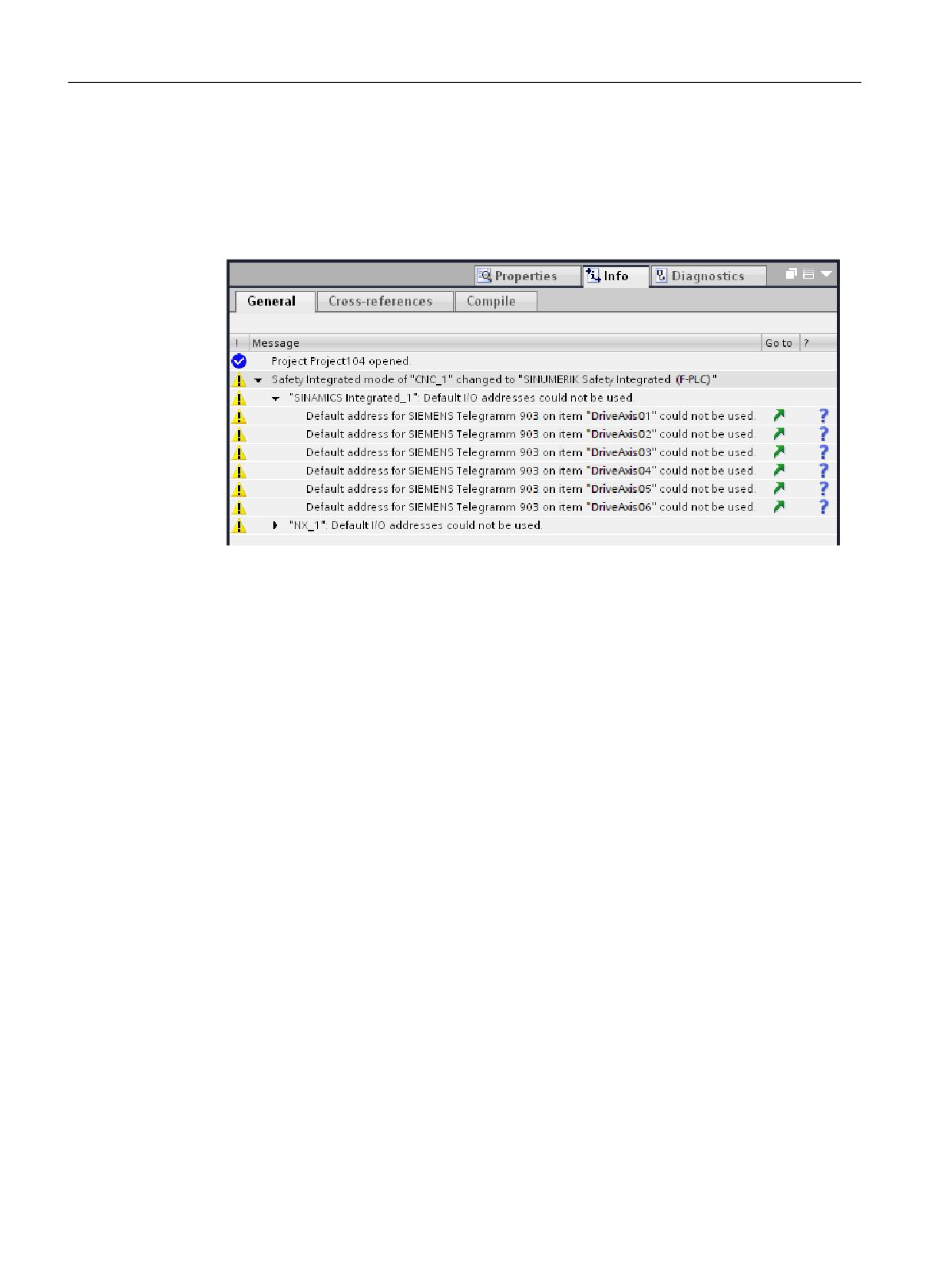
Configuring telegrams and drive units
6.9 Deviations from the standard I/O addressing schematic
Procedure
To directly view after a configuration change (or after the compile) which I/O addresses differ
from the standard schema, proceed as follows:
1. Click "General" or "Compile" in the "Info" inspector window.
The message log is displayed.
Figure 6-4
The "Info > General" inspector window shows which default I/O addresses were already
assigned for each individual telegram.
The inspector window has the following options:
- All components and telegrams that differ from the default scheme are listed in the
"Message" column.
- To switch directly to the detail view of the respective component or I/O address, click the
symbol in the "Go to" column.
- To call the associated help entry in the information system of the TIA Portal, click the
symbol in the "?" column.
2. Note the required information.
6.9.4
Availability of suitable I/O addresses
If the message is displayed that insufficient suitable I/O addresses are available, you must
release suitable I/O addresses.
SINUMERIK 840D sl STEP 7 Toolbox V16
146
Configuration Manual, 12/2019, 6FC5397-0GP40-0BA1
Configuring telegrams and drive units
6.9 Deviations from the standard I/O addressing schematic
Basic procedure
Release suitable I/O addresses
Check whether you can release suitable address space with one of the following procedures:
● If the associated addresses are PROFIsafe addresses, zoom the process image of the OB1
in the PLC properties under "Cycle".
● Check which device is occupying the required address range. You may be able to assign a
different address space to this device in order to release the required I/O addresses.
● Release address space directly by removing empty space that is not required between
different I/O addresses and adapting the I/O addresses of the relevant device.
Assign suitable I/O addresses
You must then assign suitable I/O addresses to the relevant devices in the TIA Portal.
Devices without suitable I/O addresses are displayed as follows:
● Select the appropriate component (SINAMICS Integrated or NX), then click "Telegram
configuration" in the "Properties" inspector window.
Cells with unsuitable I/O addresses are highlighted in red.
● If a message showing which I/O addresses were not available has already been displayed,
you can view these in the "Info" inspector window at "General".
Align the I/O addresses with the machine data of the NCU
Finally, enter the assignment of the I/O address different to the default scheme in the machine
data of the NCU. Refer to Adapting I/O start addresses (Page 134) to find the machine data in
which you must align the corresponding I/O address.
See also:
● Online help of SINUMERIK Operate
● Commissioning Manual, "Commissioning CNC: NCK, PLC, Drive", Section Communication
between NC and drive
SINUMERIK 840D sl STEP 7 Toolbox V16
Configuration Manual, 12/2019, 6FC5397-0GP40-0BA1
147
Configuring telegrams and drive units
6.9 Deviations from the standard I/O addressing schematic
SINUMERIK 840D sl STEP 7 Toolbox V16
148
Configuration Manual, 12/2019, 6FC5397-0GP40-0BA1
Configuring I/O
7
7.1
Inserting ADI4 module (840 sl)
Procedure
In order to insert an ADI4 module into the project via the hardware catalog, proceed as
follows:
1. In the hardware catalog, navigate to the folder "Distributed I/O > Drive Interfaces > ADI4"
and select the ADI4 module.
2. Use drag-and-drop to move the ADI4 module from the hardware catalog and place it in the
network view.
SINUMERIK 840D sl STEP 7 Toolbox V16
Configuration Manual, 12/2019, 6FC5397-0GP40-0BA1
149
Configuring I/O
7.1 Inserting ADI4 module (840 sl)
3. To connect the module to the master system, click "Not assigned" and select the DP
interface.
4. Click the "PROFIBUS_1" bus system and at "General > Network settings" in the "Properties"
tab in the inspector window, change the "Transmission rate" entry from 1.5 Mbit/s to 12 Mbit/
s. The ADI4 module can only be operated with 12 Mbit/s.
Reference
You can find additional information on the precise parameter assignment of the ADI4 module
in the "ADI4 - analog drive interface for four axes" manual.
SINUMERIK 840D sl STEP 7 Toolbox V16
150
Configuration Manual, 12/2019, 6FC5397-0GP40-0BA1
Configuring I/O
7.1 Inserting ADI4 module (840 sl)
Result
The ADI4 module has been created as new device and connected to the NCU.
SINUMERIK 840D sl STEP 7 Toolbox V16
Configuration Manual, 12/2019, 6FC5397-0GP40-0BA1
151
Configuring I/O
7.2 Installing general station description files for SINUMERIK I/O
7.2
Installing general station description files for SINUMERIK I/O
Requirement
The current version of the general station description (GSD/GSDML) files to be installed is
stored on your PG/PC.
Note
General station description files on the Service&Support pages
You can find the current versions of the general station description files in the Siemens Industry
Online Support:
SINUMERIK I/O: GSD/GSDML files (SIOS) (http://support.automation.siemens.com/WW/
view/en/62332440)
Procedure
To install SINUMERIK I/O via general station description files, proceed as follows:
1. In the "Options" menu, select the command "Manage general station description files
(GSD)".
2. In the "Manage general station description files" dialog, select the folder that contains the
GSD/GSDML files.
The device description files saved in the source path are listed.
3. Select the checkboxes of the files that you want to install.
4. Confirm your entry with "Install".
SINUMERIK 840D sl STEP 7 Toolbox V16
152
Configuration Manual, 12/2019, 6FC5397-0GP40-0BA1
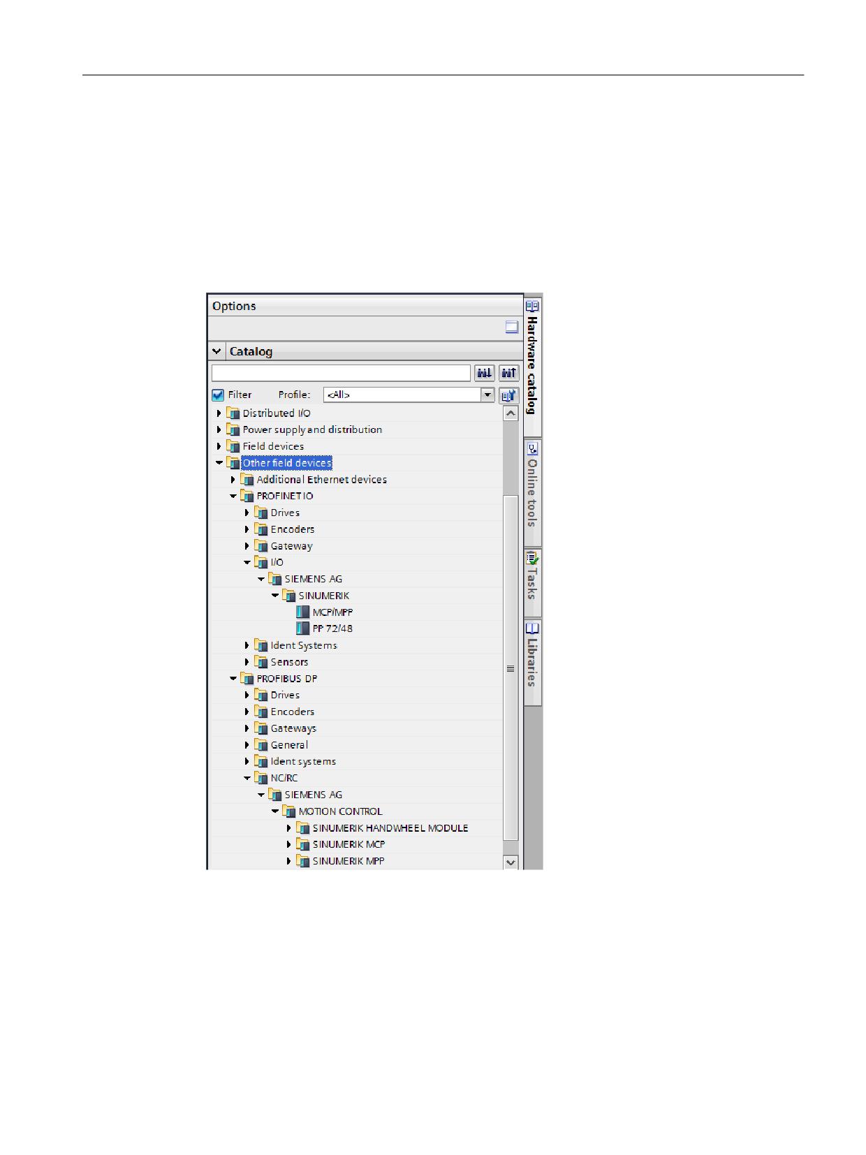
Configuring I/O
7.2 Installing general station description files for SINUMERIK I/O
Result
The general station description files are installed, and then the SINUMERIK I/O in the hardware
catalog displayed in the appropriate folders:
● SINUMERIK I/O for PROFINET IO: "Further field devices > PROFINET IO > I/O > SIEMENS
AG > SINUMERIK"
● SINUMERIK I/O for PROFIBUS DP: "Further field devices > PROFIBUS DP > NC/RC >
SIEMENS AG > MOTION CONTROL"
Figure 7-1
Installed SINUMERIK I/O in the hardware catalog
SINUMERIK 840D sl STEP 7 Toolbox V16
Configuration Manual, 12/2019, 6FC5397-0GP40-0BA1
153
Configuring I/O
7.3 Inserting the SINUMERIK I/O module PP72/48
7.3
Inserting the SINUMERIK I/O module PP72/48
Requirement
● The respective PROFIBUS GSD file or PROFINET GSDML file is installed.
See: Installing general station description files for SINUMERIK I/O (Page 152)
● The network view is active.
SINUMERIK 840D sl STEP 7 Toolbox V16
154
Configuration Manual, 12/2019, 6FC5397-0GP40-0BA1
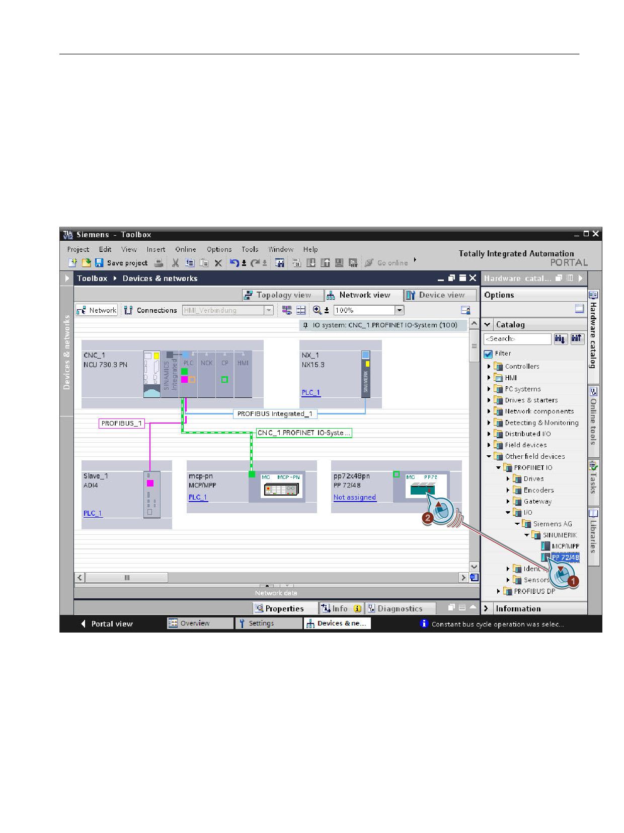
Configuring I/O
7.3 Inserting the SINUMERIK I/O module PP72/48
Procedure
Proceed as follows to insert a PP72/48 I/O module:
1. In the hardware catalog, navigate to the respective device:
- PP72/48 (PROFIBUS): "Further field devices > PROFIBUS DP > NC/RC > SIEMENS
AG > MOTION CONTROL"
- PP72/48 (PROFINET): "Further field devices > PROFINET IO > I/O > SIEMENS AG >
SINUMERIK > PP72/48"
2. Use drag-and-drop to move the PP72/48 from the hardware catalog to the network view.
3. Interconnect the inserted SINUMERIK I/O with the NCU.
See TIA Portal online help, search term "Interconnect devices in the network view"
SINUMERIK 840D sl STEP 7 Toolbox V16
Configuration Manual, 12/2019, 6FC5397-0GP40-0BA1
155
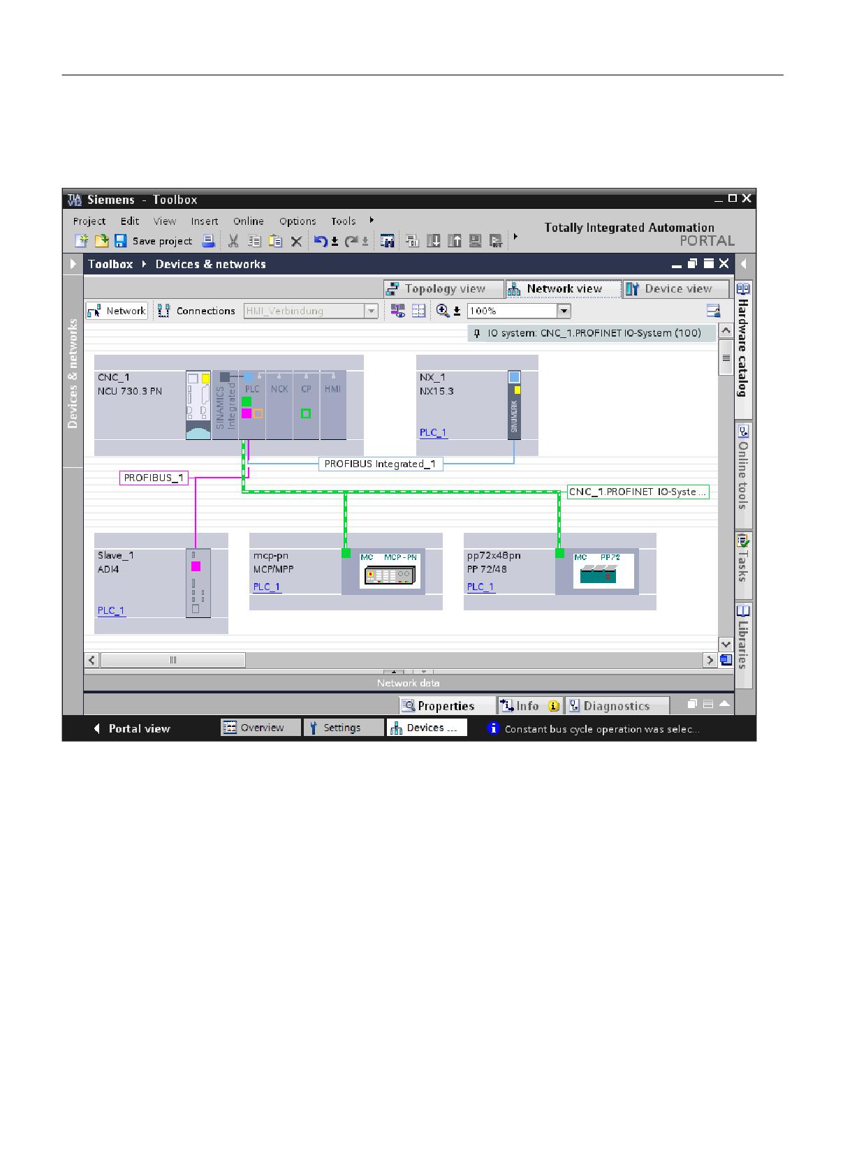
Configuring I/O
7.3 Inserting the SINUMERIK I/O module PP72/48
Result
The SINUMERIK I/O modules were created as new devices and connected to the NCU.
Additional information
You can find general information about the device in the SINUMERIK I/O module PP72/48D
2/2A PN manual
SINUMERIK 840D sl STEP 7 Toolbox V16
156
Configuration Manual, 12/2019, 6FC5397-0GP40-0BA1
Configuring I/O
7.4 Inserting SINUMERIK MCP/MPP
7.4
Inserting SINUMERIK MCP/MPP
Requirement
● The respective PROFIBUS GSD file or PROFINET GSDML file is installed.
See: Installing general station description files for SINUMERIK I/O (Page 152)
● The network view is active.
Procedure
Proceed as follows to insert a SINUMERIK MCP/MPP:
1. In the hardware catalog, navigate to the respective device:
- MCP/MPP (PROFIBUS): "Further field devices > PROFIBUS DP > NC/RC > SIEMENS
AG > MOTION CONTROL"
- MCP/MPP (PROFINET): "Further field devices > PROFINET IO > I/O > SIEMENS AG >
SINUMERIK"
2. Use drag-and-drop to move the corresponding MCP/MPP from the hardware catalog to the
network view.
3. Interconnect the inserted SINUMERIK I/O with the NCU.
See TIA Portal online help, search term "Interconnect devices in the network view"
SINUMERIK 840D sl STEP 7 Toolbox V16
Configuration Manual, 12/2019, 6FC5397-0GP40-0BA1
157
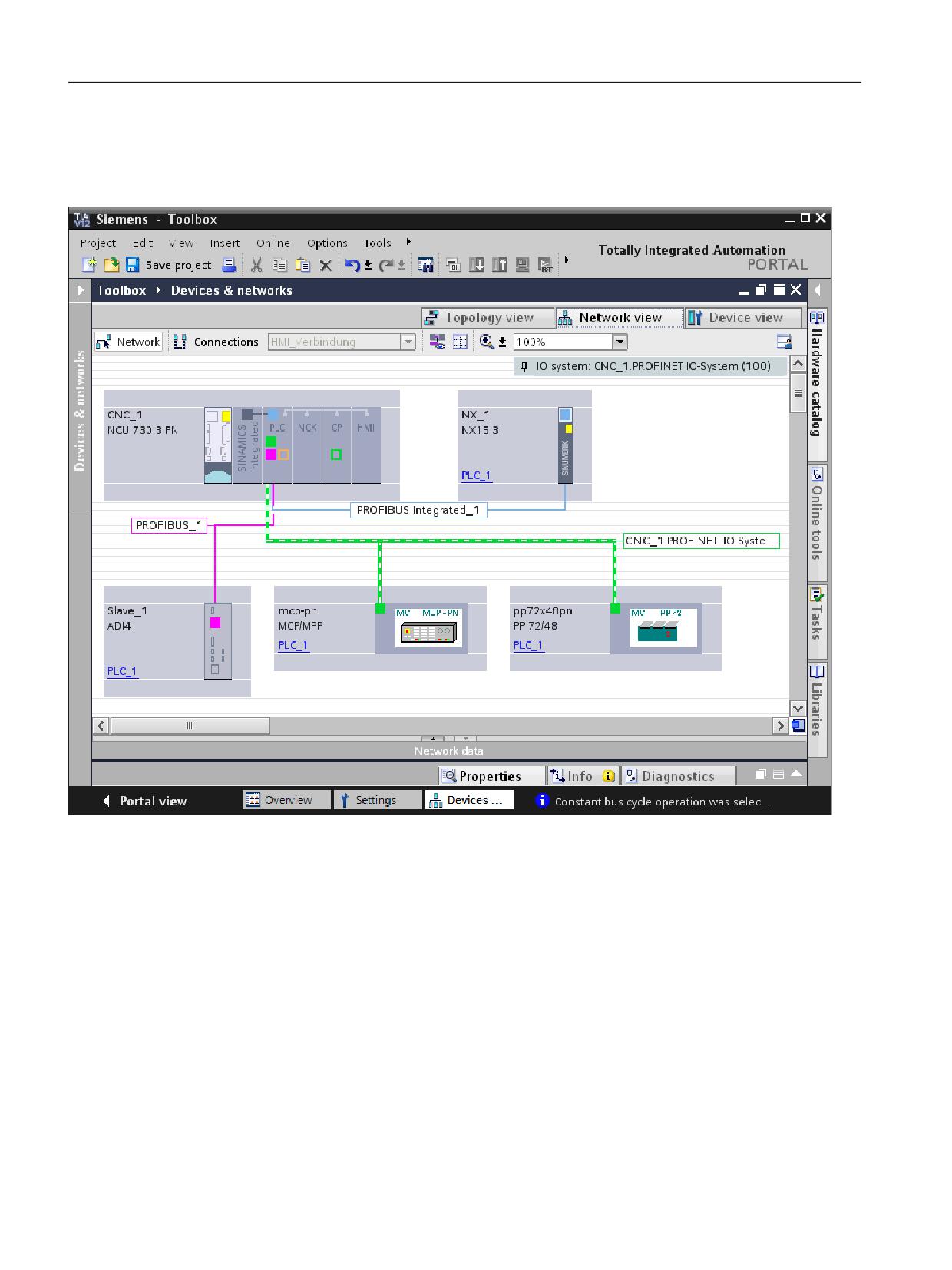
Configuring I/O
7.4 Inserting SINUMERIK MCP/MPP
Result
The SINUMERIK MCP/MPP has been created as new device and connected to the NCU.
Additional information
General information on the device can be found in the respective manual.
SINUMERIK 840D sl STEP 7 Toolbox V16
158
Configuration Manual, 12/2019, 6FC5397-0GP40-0BA1
Tag selection with NC VAR selector
8
8.1
NC VAR selector
Introduction
The external tool "NC VAR Selector" obtains addresses of the required NC tags and processes
them for access in the PLC program (PUT [FB3] and GET [FB2]).
● In the NC VAR Selector, you can select the required NC and drive tag addresses and save
them as ASCII file (*.STL) (Page 160).
● In the TIA Portal, you can import this STL file (Page 162), use it to create data blocks and
so make program access to the tags.
Further information
● A detailed description for the NC VAR Selector is contained in the P3 section of the
SINUMERIK 840D sl Basic Functions Manual: PLC basic program for SINUMERIK 840D sl.
● The block descriptions and other information about the PLC basic program are contained in
the P3 section of the SINUMERIK 840D sl Basic Functions Manual. Basic PLC program.
SINUMERIK 840D sl STEP 7 Toolbox V16
Configuration Manual, 12/2019, 6FC5397-0GP40-0BA1
159
Tag selection with NC VAR selector
8.2 Selecting tags and saving as STL file
8.2
Selecting tags and saving as STL file
Requirement
● The "NC-VAR-Selector" program is installed.
The program is installed automatically when installing the SINUMERIK Toolbox if you have
selected the program during installation.
Procedure
To select the NC tags to be configured and save them as an STL file, proceed as follows:
1. In the Start menu, click on "All Programs > NC Tag Selector 32 Bit > NCVar Selector".
NC-VAR Selector opens.
2. Select the firmware version of the configured NCU in the "Software version" drop-down list.
3. Select "New" from the "Project" menu.
4. Add all of the necessary tags from the "NcData" and "Sinamics" tag lists into your project list
in the bottom section. The following options are available:
- You can sort the tags in ascending or descending order by column captions.
- The command "Find, Filter" gives you various filter criteria.
- If you double-click on a tag name, a configuration dialog with a help entry for this tag is
displayed.
- To add a tag to your project list, double-click on the tag name, adapt the values "Area
No.", "Row" and "Column" if applicable and confirm with "OK".
SINUMERIK 840D sl STEP 7 Toolbox V16
160
Configuration Manual, 12/2019, 6FC5397-0GP40-0BA1
Tag selection with NC VAR selector
8.2 Selecting tags and saving as STL file
5. Save your project data (*.var).
6. In the "Code" menu, click on "Generate", select a save location for your NC tag file (*.stl) and
confirm with "Save".
Result
The selected tag addresses were saved in an STL file, which you can use in the TIA Portal.
SINUMERIK 840D sl STEP 7 Toolbox V16
Configuration Manual, 12/2019, 6FC5397-0GP40-0BA1
161
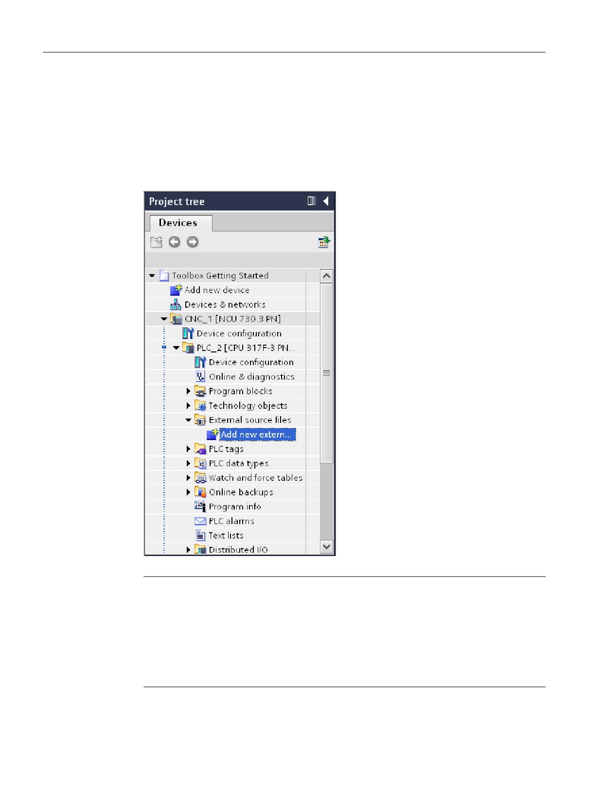
Tag selection with NC VAR selector
8.3 Adding a tag file (STL) in the TIA Portal
8.3
Adding a tag file (STL) in the TIA Portal
Procedure
To add the STL file with the selected tags in the TIA Portal as an external source, proceed as
follows:
1. In the project tree, select "CNC > PLC > External source files > Add new external file".
Note
Displaying external sources (e.g. STL files) using an external editor
The internal editor of the TIA Portal does not display external sources.
If you add and open an external source in the TIA Portal, the file will be opened with the
application linked with the associated file type (e.g. STL) in Windows (e.g. Microsoft Editor).
In order to be able to open external sources directly from the TIA Portal with any external
editor, define this once in Windows.
2. Then generate the data block via the shortcut menu "Generate blocks from source".
SINUMERIK 840D sl STEP 7 Toolbox V16
162
Configuration Manual, 12/2019, 6FC5397-0GP40-0BA1
Tag selection with NC VAR selector
8.3 Adding a tag file (STL) in the TIA Portal
Result
You can now address the selected variables in your PLC program and use the PUT [FB3] and
GET [FB2] blocks to write and read the variables.
SINUMERIK 840D sl STEP 7 Toolbox V16
Configuration Manual, 12/2019, 6FC5397-0GP40-0BA1
163
Tag selection with NC VAR selector
8.3 Adding a tag file (STL) in the TIA Portal
SINUMERIK 840D sl STEP 7 Toolbox V16
164
Configuration Manual, 12/2019, 6FC5397-0GP40-0BA1
Importing user alarms
9
9.1
Overview
The procedure overview below describes how to copy the SINUMERIK user alarm files directly
from an NCU and import them into TIA Portal.
Alternatively, the import of alarm files in CSV format is also supported. This can, for example,
be created if you manage your language-dependent text files with SINUMERIK Integrate
Access My Machine /P2P.
Requirement
● The user alarms are available in SINUMERIK Operate (or AMM/P2P).
● A SINUMERIK NCU or device proxy (PLC 300) is inserted in the TIA Portal project.
Procedure overview
To use SINUMERIK user alarms in the TIA Portal, proceed as follows:
Ste
Description
p
1
Make the user alarm files available in the required languages. You can copy the files via the SINUMERIK Operate user
interface, for example to a USB flash drive (Page 166).
2
Check whether all languages or language variants in which you want to import SINUMERIK user alarms are enabled
as project languages in the TIA Portal.
● To check which exported alarm files correspond to which project languages in the TIA Portal, refer to
Section Language assignment in language-dependent texts (Page 167).
● How to activate the project languages is described in Section Enable project languages (Page 169).
3
Import the SINUMERIK user alarms into the TIA Portal (Page 170).
SINUMERIK 840D sl STEP 7 Toolbox V16
Configuration Manual, 12/2019, 6FC5397-0GP40-0BA1
165
Importing user alarms
9.2 Exporting TS files from SINUMERIK Operate
9.2
Exporting TS files from SINUMERIK Operate
This section describes how the DB2 alarm texts are exported from the user interface of
SINUMERIK Operate.
If you have installed SINUMERIK Operate on a Siemens PC system, you can alternatively copy
the files via the Windows Explorer.
Requirement
● A USB flash drive is inserted into a PC system with SINUMERIK Operate.
● In SINUMERIK Operate, the USB port is activated under "Commissioning > HMI > Log.
Drive"
● Access rights of access level 3 (user) are available in SINUMERIK Operate.
Procedure
To copy TS files from SINUMERIK Operate, proceed as follows:
1. In SINUMERIK Operate select the screen "Commissioning > System data" - and in the
folder structure, navigate in the "HMI data/Texts/Manufacturer/" directory.
2. Select the required TS files and actuate the "Copy" softkey.
3. Select the directory structure of your USB flash drive and press the "Paste" softkey.
Result
The DB2 alarm texts were copied from SINUMERIK Operate as TS files.
You can then subsequently import these files into the TIA Portal.
SINUMERIK 840D sl STEP 7 Toolbox V16
166
Configuration Manual, 12/2019, 6FC5397-0GP40-0BA1
Importing user alarms
9.3 Language assignment in language-dependent texts
9.3
Language assignment in language-dependent texts
Language ID in the file name of language-dependent texts
Language-dependent texts are saved in TS files in SINUMERIK Operate. There is a separate
file for each language which is assigned via the language ID in the file name.
● <Name><LanguageID>.ts
● E. g.: oem_alarms_plc_eng.ts
Assignment of the DB2 alarm texts to project languages
In the TIA Portal (in contrast to SINUMERIK Operate), language variants of different countries
are regarded as separate project languages, this means that there are separate entries for e.g.
English (Great Britain), English (Ireland) and English (USA). If you import an alarm file into the
TIA Portal, this will be assigned to all of the relevant activated project languages (or language
variants), depending on the language ID in the file name. For example, if you have activated the
project languages "English (USA)" and "English (Great Britain)" and imported an
oem_alarms_plc_eng.ts file, these alarm texts are mapped to the two project languages.
Availability of languages in SINUMERIK Operate
SINUMERIK Operate has 6 languages (standard languages) installed in the factory state. If you
need additional languages, you can order them separately:
● DVD "Language extension": 6FC5860-0YC40-0YA8
● Software option "Additional languages": 6FC5800-0AN00-0YB0
Storing the active language in the NC block [DB10]
The language that is presently active in SINUMERIK Operate is saved in communication block
NC [DB10] in address DB10.DBB96 as value.
Table 9-1
Language IDs of language-dependent texts and language values in the block NC [DB10]
Value in DB10.DBB96
Language in SINUMERIK Operate
Language code
Default language
1
German
deu
x
2
French
fra
x
3
English
eng
x
4
Spanish
esp
x
6
Italian
ita
x
7
Dutch
nld
8
Simplified Chinese
chs
x
9
Swedish
sve
18
Hungarian
hun
19
Finnish
fin
28
Czech
csy
50
Portuguese
ptb
53
Polish
plk
55
Danish
dan
SINUMERIK 840D sl STEP 7 Toolbox V16
Configuration Manual, 12/2019, 6FC5397-0GP40-0BA1
167
Importing user alarms
9.3 Language assignment in language-dependent texts
Value in DB10.DBB96
Language in SINUMERIK Operate
Language code
Default language
57
Russian
rus
68
Slovakian
sky
69
Slovenian
slv
72
Rumanian
rom
80
Traditional Chinese
cht
85
Korean
kor
87
Japanese
jap
89
Turkish
trk
122
Indonesian
ind
212
Thai
tha
230
Malay
msl
SINUMERIK 840D sl STEP 7 Toolbox V16
168
Configuration Manual, 12/2019, 6FC5397-0GP40-0BA1