SINUMERIK 840D sl. Service - Configuring Commissioning. Manual (2011-2020) - page 104
List of system variables
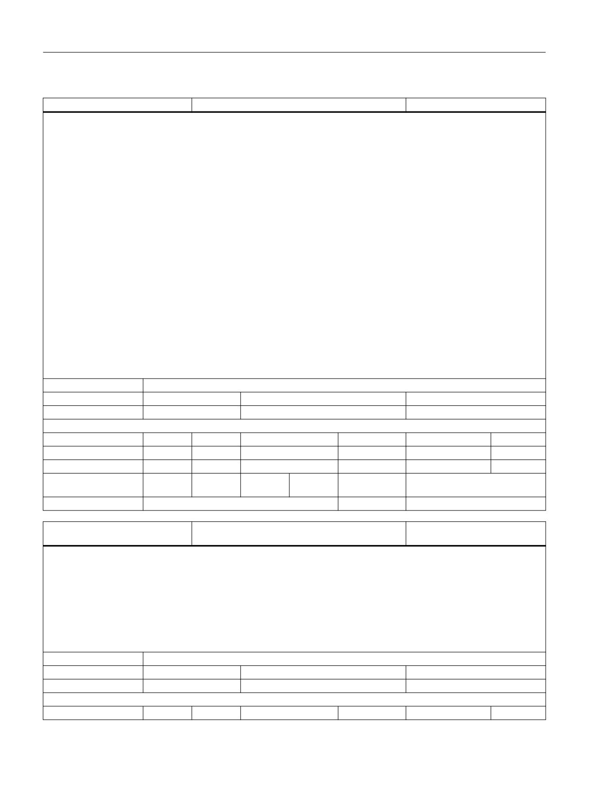
3.26 User-specific system variables
SYG_S6 [n]
Synact String parameters for GUD6 block
STRING
Unit
Init value
Min
Max
-
""
Read/Write properties:
TP
SA
TP/SA safety
NC-Variable
Safety
OEM-CC
Read:
X
X
7
X
7
X
Write:
X
X
7
X
7
X
Axis entry:
Overlap chan-
channel-specific
nel:
Scan mode:
Program sensitive
Link:
No restrictions
SYG_R7 [n]
Synact Real parameters for GUD7 block
DOUBLE
Description:
SYG_R7[n] Synact Real parameters in GUD7 block.
A protection level can be assigned to the parameters with REDEF.
In order to create the parameters, at least seven
GUD blocks must be activated with MD $MN_MM_NUM_GUD_MODULES.
Index 1:
The max. number of SynactGUD Real is defined by the machine data ($MN_MM_NUM_SYNACT_GUD_REAL[6])
Unit
Init value
Min
Max
-
0.0
-1.8E+308
1.8E+308
Read/Write properties:
TP
SA
TP/SA safety
NC-Variable
Safety
OEM-CC
Read:
X
X
7
X
7
X
Write:
X
X
7
X
7
X
Axis entry:
Overlap chan-
channel-specific
nel:
Scan mode:
Program sensitive
Link:
No restrictions
SYG_I7 [n]
Synact Integer parameters for GUD7 block
INT
Description:
SYG_I7[n] Synact Integer parameters in GUD7 block.
A protection level can be assigned to the parameters with REDEF.
In order to create the parameters, at least seven
GUD blocks must be activated with MD $MN_MM_NUM_GUD_MODULES.
Index 1:
The max. number of SynactGUD Integer is defined by the machine data ($MN_MM_NUM_SYNACT_GUD_INT[6])
Unit
Init value
Min
Max
-
0
-2147483648
2147483647
Read/Write properties:
TP
SA
TP/SA safety
NC-Variable
Safety
OEM-CC
Read:
X
X
7
X
7
X
Write:
X
X
7
X
7
X
Axis entry:
Overlap chan-
channel-specific
nel:
Scan mode:
Program sensitive
Link:
No restrictions
System variables
List Manual, 10/2020, 6FC5397-6AP40-6BA4
817
List of system variables
3.26 User-specific system variables
SYG_B7 [n]
Synact Boolean parameters for GUD7 block
BOOL
Description:
SYG_B7[n] Synact Boolean parameters in GUD7 block.
A protection level can be assigned to the parameters with REDEF.
In order to create the parameters, at least seven
GUD blocks must be activated with MD $MN_MM_NUM_GUD_MODULES.
Index 1:
The max. number of SynactGUD Boolean is defined by the machine data ($MN_MM_NUM_SYN-
ACT_GUD_BOOL[6])
Unit
Init value
Min
Max
-
FALSE
FALSE
TRUE
Read/Write properties:
TP
SA
TP/SA safety
NC-Variable
Safety
OEM-CC
Read:
X
X
7
X
7
X
Write:
X
X
7
X
7
X
Axis entry:
Overlap chan-
channel-specific
nel:
Scan mode:
Program sensitive
Link:
No restrictions
SYG_A7 [n]
Synact Axis parameters for GUD7 block
AXIS
Description:
SYG_A7[n] Synact Axis parameters in GUD7 block.
A protection level can be assigned to the parameters with REDEF.
In order to create the parameters, at least seven
GUD blocks must be activated with MD $MN_MM_NUM_GUD_MODULES.
Index 1:
The max. number of SynactGUD Axis is defined by the machine data ($MN_MM_NUM_SYNACT_GUD_AXIS[6])
Unit
Init value
Min
Max
-
NOAXISNUM
Read/Write properties:
TP
SA
TP/SA safety
NC-Variable
Safety
OEM-CC
Read:
X
X
7
X
7
X
Write:
X
X
7
X
7
X
Axis entry:
Overlap chan-
channel-specific
nel:
Scan mode:
Program sensitive
Link:
No restrictions
SYG_C7 [n]
Synact Char parameters for GUD7 block
CHAR
Description:
SYG_C7[n] Synact Char parameters in GUD7 block.
A protection level can be assigned to the parameters with REDEF.
In order to create the parameters, at least seven
GUD blocks must be activated with MD $MN_MM_NUM_GUD_MODULES.
Index 1:
The max. number of SynactGUD Char is defined by the machine data ($MN_MM_NUM_SYNACT_GUD_CHAR[6])
Unit
Init value
Min
Max
-
0
0
CHAR_MAX
Read/Write properties:
TP
SA
TP/SA safety
NC-Variable
Safety
OEM-CC
Read:
X
X
7
X
7
X
System variables
818
List Manual, 10/2020, 6FC5397-6AP40-6BA4
List of system variables
3.26 User-specific system variables
SYG_C7 [n]
Synact Char parameters for GUD7 block
CHAR
Write:
X
X
7
X
7
X
Axis entry:
Overlap chan-
channel-specific
nel:
Scan mode:
Program sensitive
Link:
No restrictions
SYG_S7 [n]
Synact String parameters for GUD7 block
STRING
Description:
SYG_S7[n] Synact parameter string in GUD7 block. The maximum string length has been limited to 31 characters.
A protection level can be assigned to the parameters with REDEF.
In order to create the parameters, at least seven
GUD blocks must be activated with MD $MN_MM_NUM_GUD_MODULES.
Index 1:
The max. number of SynactGUD String is defined by the machine data ($MN_MM_NUM_SYNACT_GUD_STRING[6])
Index 3:
31 characters and end-of-string character
Unit
Init value
Min
Max
-
""
Read/Write properties:
TP
SA
TP/SA safety
NC-Variable
Safety
OEM-CC
Read:
X
X
7
X
7
X
Write:
X
X
7
X
7
X
Axis entry:
Overlap chan-
channel-specific
nel:
Scan mode:
Program sensitive
Link:
No restrictions
SYG_R8 [n]
Synact Real parameters for GUD8 block
DOUBLE
Description:
SYG_R8[n] Synact Real parameters in GUD8 block.
A protection level can be assigned to the parameters with REDEF.
In order to create the parameters, at least eight
GUD blocks must be activated with MD $MN_MM_NUM_GUD_MODULES.
Index 1:
The max. number of SynactGUD Real is defined by the machine data ($MN_MM_NUM_SYNACT_GUD_REAL[7])
Unit
Init value
Min
Max
-
0.0
-1.8E+308
1.8E+308
Read/Write properties:
TP
SA
TP/SA safety
NC-Variable
Safety
OEM-CC
Read:
X
X
7
X
7
X
Write:
X
X
7
X
7
X
Axis entry:
Overlap chan-
channel-specific
nel:
Scan mode:
Program sensitive
Link:
No restrictions
SYG_I8 [n]
Synact Integer parameters for GUD8 block
INT
Description:
SYG_I8[n] Synact Integer parameters in GUD8 block.
A protection level can be assigned to the parameters with REDEF.
In order to create the parameters, at least eight
GUD blocks must be activated with MD $MN_MM_NUM_GUD_MODULES.
Index 1:
The max. number of SynactGUD Integer is defined by the machine data ($MN_MM_NUM_SYNACT_GUD_INT[7])
System variables
List Manual, 10/2020, 6FC5397-6AP40-6BA4
819
List of system variables
3.26 User-specific system variables
SYG_I8 [n]
Synact Integer parameters for GUD8 block
INT
Unit
Init value
Min
Max
-
0
-2147483648
2147483647
Read/Write properties:
TP
SA
TP/SA safety
NC-Variable
Safety
OEM-CC
Read:
X
X
7
X
7
X
Write:
X
X
7
X
7
X
Axis entry:
Overlap chan-
channel-specific
nel:
Scan mode:
Program sensitive
Link:
No restrictions
SYG_B8 [n]
Synact Boolean parameters for GUD8 block
BOOL
Description:
SYG_B8[n] Synact Boolean parameters in GUD8 block.
A protection level can be assigned to the parameters with REDEF.
In order to create the parameters, at least eight
GUD blocks must be activated with MD $MN_MM_NUM_GUD_MODULES.
Index 1:
The max. number of SynactGUD Integer is defined by the machine data ($MN_MM_NUM_SYNACT_GUD_BOOL[7])
Unit
Init value
Min
Max
-
FALSE
FALSE
TRUE
Read/Write properties:
TP
SA
TP/SA safety
NC-Variable
Safety
OEM-CC
Read:
X
X
7
X
7
X
Write:
X
X
7
X
7
X
Axis entry:
Overlap chan-
channel-specific
nel:
Scan mode:
Program sensitive
Link:
No restrictions
SYG_A8 [n]
Synact Axis parameters for GUD8 block
AXIS
Description:
SYG_A8[n] Synact Axis parameters in GUD8 block.
A protection level can be assigned to the parameters with REDEF.
In order to create the parameters, at least eight
GUD blocks must be activated with MD $MN_MM_NUM_GUD_MODULES.
Index 1:
The max. number of SynactGUD Axis is defined by the machine data ($MN_MM_NUM_SYNACT_GUD_AXIS[7])
Unit
Init value
Min
Max
-
NOAXISNUM
Read/Write properties:
TP
SA
TP/SA safety
NC-Variable
Safety
OEM-CC
Read:
X
X
7
X
7
X
Write:
X
X
7
X
7
X
Axis entry:
Overlap chan-
channel-specific
nel:
Scan mode:
Program sensitive
Link:
No restrictions
System variables
820
List Manual, 10/2020, 6FC5397-6AP40-6BA4
List of system variables
3.26 User-specific system variables
SYG_C8 [n]
Synact Char parameters for GUD8 block
CHAR
Description:
SYG_C8[n] Synact Char parameters in GUD8 block.
A protection level can be assigned to the parameters with REDEF.
In order to create the parameters, at least eight
GUD blocks must be activated with MD $MN_MM_NUM_GUD_MODULES.
Index 1:
The max. number of SynactGUD Char is defined by the machine data ($MN_MM_NUM_SYNACT_GUD_CHAR[7])
Unit
Init value
Min
Max
-
0
0
CHAR_MAX
Read/Write properties:
TP
SA
TP/SA safety
NC-Variable
Safety
OEM-CC
Read:
X
X
7
X
7
X
Write:
X
X
7
X
7
X
Axis entry:
Overlap chan-
channel-specific
nel:
Scan mode:
Program sensitive
Link:
No restrictions
SYG_S8 [n]
Synact String parameters for GUD8 block
STRING
Description:
SYG_S8[n] Synact parameter string in GUD8 block. The maximum string length has been limited to 31 characters.
A protection level can be assigned to the parameters with REDEF.
In order to create the parameters, at least eight
GUD blocks must be activated with MD $MN_MM_NUM_GUD_MODULES.
Index 1:
The max. number of SynactGUD String is defined by the machine data ($MN_MM_NUM_SYNACT_GUD_STRING[7])
Index 3:
31 characters and end-of-string character
Unit
Init value
Min
Max
-
""
Read/Write properties:
TP
SA
TP/SA safety
NC-Variable
Safety
OEM-CC
Read:
X
X
7
X
7
X
Write:
X
X
7
X
7
X
Axis entry:
Overlap chan-
channel-specific
nel:
Scan mode:
Program sensitive
Link:
No restrictions
SYG_R9 [n]
Synact Real parameters for GUD9 block
DOUBLE
Description:
SYG_R9[n] Synact Real parameters in GUD9 block.
A protection level can be assigned to the parameters with REDEF.
In order to create the parameters, at least nine
GUD blocks must be activated with MD $MN_MM_NUM_GUD_MODULES.
Index 1:
The max. number of SynactGUD Real is defined by the machine data ($MN_MM_NUM_SYNACT_GUD_REAL[8])
Unit
Init value
Min
Max
-
0.0
-1.8E+308
1.8E+308
Read/Write properties:
TP
SA
TP/SA safety
NC-Variable
Safety
OEM-CC
Read:
X
X
7
X
7
X
System variables
List Manual, 10/2020, 6FC5397-6AP40-6BA4
821
List of system variables
3.26 User-specific system variables
SYG_R9 [n]
Synact Real parameters for GUD9 block
DOUBLE
Write:
X
X
7
X
7
X
Axis entry:
Overlap chan-
channel-specific
nel:
Scan mode:
Program sensitive
Link:
No restrictions
SYG_I9 [n]
Synact Integer parameters for GUD9 block
INT
Description:
SYG_I9[n] Synact Integer parameters in GUD9 block.
A protection level can be assigned to the parameters with REDEF.
In order to create the parameters, at least nine
GUD blocks must be activated with MD $MN_MM_NUM_GUD_MODULES.
Index 1:
The max. number of SynactGUD Integer is defined by the machine data ($MN_MM_NUM_SYNACT_GUD_INT[8])
Unit
Init value
Min
Max
-
0
-2147483648
2147483647
Read/Write properties:
TP
SA
TP/SA safety
NC-Variable
Safety
OEM-CC
Read:
X
X
7
X
7
X
Write:
X
X
7
X
7
X
Axis entry:
Overlap chan-
channel-specific
nel:
Scan mode:
Program sensitive
Link:
No restrictions
SYG_B9 [n]
Synact Boolean parameters for GUD9 block
BOOL
Description:
SYG_B9[n] Synact Boolean parameters in GUD9 block.
A protection level can be assigned to the parameters with REDEF.
In order to create the parameters, at least nine
GUD blocks must be activated with MD $MN_MM_NUM_GUD_MODULES.
Index 1:
The max. number of SynactGUD Boolean is defined by the machine data ($MN_MM_NUM_SYN-
ACT_GUD_BOOL[8])
Unit
Init value
Min
Max
-
FALSE
FALSE
TRUE
Read/Write properties:
TP
SA
TP/SA safety
NC-Variable
Safety
OEM-CC
Read:
X
X
7
X
7
X
Write:
X
X
7
X
7
X
Axis entry:
Overlap chan-
channel-specific
nel:
Scan mode:
Program sensitive
Link:
No restrictions
SYG_A9 [n]
Synact Axis parameters for GUD9 block
AXIS
Description:
SYG_A9[n] Synact Axis parameters in GUD9 block.
A protection level can be assigned to the parameters with REDEF.
In order to create the parameters, at least nine
GUD blocks must be activated with MD $MN_MM_NUM_GUD_MODULES.
Index 1:
The max. number of SynactGUD Axis is defined by the machine data ($MN_MM_NUM_SYNACT_GUD_AXIS[8])
System variables
822
List Manual, 10/2020, 6FC5397-6AP40-6BA4
List of system variables
3.26 User-specific system variables
SYG_A9 [n]
Synact Axis parameters for GUD9 block
AXIS
Unit
Init value
Min
Max
-
NOAXISNUM
Read/Write properties:
TP
SA
TP/SA safety
NC-Variable
Safety
OEM-CC
Read:
X
X
7
X
7
X
Write:
X
X
7
X
7
X
Axis entry:
Overlap chan-
channel-specific
nel:
Scan mode:
Program sensitive
Link:
No restrictions
SYG_C9 [n]
Synact Char parameters for GUD9 block
CHAR
Description:
SYG_C9[n] Synact Char parameters in GUD9 block.
A protection level can be assigned to the parameters with REDEF.
In order to create the parameters, at least nine
GUD blocks must be activated with MD $MN_MM_NUM_GUD_MODULES.
Index 1:
The max. number of SynactGUD Char is defined by the machine data ($MN_MM_NUM_SYNACT_GUD_CHAR[8])
Unit
Init value
Min
Max
-
0
0
CHAR_MAX
Read/Write properties:
TP
SA
TP/SA safety
NC-Variable
Safety
OEM-CC
Read:
X
X
7
X
7
X
Write:
X
X
7
X
7
X
Axis entry:
Overlap chan-
channel-specific
nel:
Scan mode:
Program sensitive
Link:
No restrictions
SYG_S9 [n]
Synact String parameters for GUD9 block
STRING
Description:
SYG_S9[n] Synact parameter string in GUD9 block. The maximum string length has been limited to 31 characters.
A protection level can be assigned to the parameters with REDEF.
In order to create the parameters, at least nine
GUD blocks must be activated with MD $MN_MM_NUM_GUD_MODULES.
Index 1:
The max. number of SynactGUD String is defined by the machine data ($MN_MM_NUM_SYNACT_GUD_STRING[8])
Index 3:
31 characters and end-of-string character
Unit
Init value
Min
Max
-
""
Read/Write properties:
TP
SA
TP/SA safety
NC-Variable
Safety
OEM-CC
Read:
X
X
7
X
7
X
Write:
X
X
7
X
7
X
Axis entry:
Overlap chan-
channel-specific
nel:
Scan mode:
Program sensitive
Link:
No restrictions
System variables
List Manual, 10/2020, 6FC5397-6AP40-6BA4
823
List of system variables
3.26 User-specific system variables
SYG_RS [n]
Synact Real parameters for SGUD block
DOUBLE
Description:
SYG_RS[n] Synchronization Real parameters in SGUD block.
A protection level can be assigned to the parameters with REDEF.
In order to create the parameters, at least one
GUD block must be activated with MD $MN_MM_NUM_GUD_MODULES.
Index 1:
The max. number of SynactGUD Real is defined by the machine data ($MN_MM_NUM_SYNACT_GUD_REAL[0])
Unit
Init value
Min
Max
-
0.0
-1.8E+308
1.8E+308
Read/Write properties:
TP
SA
TP/SA safety
NC-Variable
Safety
OEM-CC
Read:
X
X
7
X
7
X
Write:
X
X
7
X
7
X
Axis entry:
Overlap chan-
channel-specific
nel:
Scan mode:
Program sensitive
Link:
No restrictions
SYG_IS [n]
Synact Integer parameters for SGUD block
INT
Description:
SYG_IS[n] Synact Integer parameters in SGUD block.
A protection level can be assigned to the parameters with REDEF.
In order to create the parameters, at least one
GUD block must be activated with MD $MN_MM_NUM_GUD_MODULES.
Index 1:
The max. number of SynactGUD Integer is defined by the machine data ($MN_MM_NUM_SYNACT_GUD_INT[0])
Unit
Init value
Min
Max
-
0
-2147483648
2147483647
Read/Write properties:
TP
SA
TP/SA safety
NC-Variable
Safety
OEM-CC
Read:
X
X
7
X
7
X
Write:
X
X
7
X
7
X
Axis entry:
Overlap chan-
channel-specific
nel:
Scan mode:
Program sensitive
Link:
No restrictions
SYG_BS [n]
Synact Boolean parameters for SGUD block
BOOL
Description:
SYG_BS[n] Synact Boolean parameters in SGUD block.
A protection level can be assigned to the parameters with REDEF.
In order to create the parameters, at least one
GUD block must be activated with MD $MN_MM_NUM_GUD_MODULES.
Index 1:
The max. number of SynactGUD Boolean is defined by the machine data ($MN_MM_NUM_SYN-
ACT_GUD_BOOL[0])
Unit
Init value
Min
Max
-
FALSE
FALSE
TRUE
Read/Write properties:
TP
SA
TP/SA safety
NC-Variable
Safety
OEM-CC
Read:
X
X
7
X
7
X
System variables
824
List Manual, 10/2020, 6FC5397-6AP40-6BA4
List of system variables
3.26 User-specific system variables
SYG_BS [n]
Synact Boolean parameters for SGUD block
BOOL
Write:
X
X
7
X
7
X
Axis entry:
Overlap chan-
channel-specific
nel:
Scan mode:
Program sensitive
Link:
No restrictions
SYG_AS [n]
Synact axis parameters for SGUD block
AXIS
Description:
SYG_AS[n] Synchronization axis parameters in SGUD block.
A protection level can be assigned to the parameters with REDEF.
In order to create the parameters, at least one
GUD block must be activated with MD $MN_MM_NUM_GUD_MODULES.
Index 1:
The max. number of SynactGUD Axis is defined by the machine data ($MN_MM_NUM_SYNACT_GUD_AXIS[0])
Unit
Init value
Min
Max
-
NOAXISNUM
Read/Write properties:
TP
SA
TP/SA safety
NC-Variable
Safety
OEM-CC
Read:
X
X
7
X
7
X
Write:
X
X
7
X
7
X
Axis entry:
Overlap chan-
channel-specific
nel:
Scan mode:
Program sensitive
Link:
No restrictions
SYG_CS [n]
Synact char parameters for SGUD block
CHAR
Description:
SYG_CS[n] Synchronization Char parameters in SGUD block.
A protection level can be assigned to the parameters with REDEF.
In order to create the parameters, at least one
GUD block must be activated with MD $MN_MM_NUM_GUD_MODULES.
Index 1:
The max. number of SynactGUD Char is defined by the machine data ($MN_MM_NUM_SYNACT_GUD_CHAR[0])
Unit
Init value
Min
Max
-
0
0
CHAR_MAX
Read/Write properties:
TP
SA
TP/SA safety
NC-Variable
Safety
OEM-CC
Read:
X
X
7
X
7
X
Write:
X
X
7
X
7
X
Axis entry:
Overlap chan-
channel-specific
nel:
Scan mode:
Program sensitive
Link:
No restrictions
SYG_SS [n]
Synact string parameters for SGUD block
STRING
Description:
SYG_SS[n] Synchronized action parameter string in SGUD block. The maximum string length has been limited to 31 characters.
A protection level can be assigned to the parameters with REDEF.
In order to create the parameters, at least one
GUD block must be activated with MD $MN_MM_NUM_GUD_MODULES.
Index 1:
The max. number of SynactGUD String is defined by the machine data ($MN_MM_NUM_SYNACT_GUD_STRING[0])
Index 3:
31 characters and end-of-string character
System variables
List Manual, 10/2020, 6FC5397-6AP40-6BA4
825
List of system variables
3.27 Kinematic chain
SYG_SS [n]
Synact string parameters for SGUD block
STRING
Unit
Init value
Min
Max
-
""
Read/Write properties:
TP
SA
TP/SA safety
NC-Variable
Safety
OEM-CC
Read:
X
X
7
X
7
X
Write:
X
X
7
X
7
X
Axis entry:
Overlap chan-
channel-specific
nel:
Scan mode:
Program sensitive
Link:
No restrictions
3.27
Kinematic chain
$NK_NAME [n]
Name of chain element
STRING
Description:
Name of the nth element of a kinematic chain. The maximum possible number of chain elements is set in MD $MN_MM_MAX-
NUM_KIN_CHAIN_ELEMENTS.
Index 1:
The maximum number of kinematic chains is set by the MD $MN_MM_MAXNUM_KIN_CHAIN_ELEM.
Index 3:
Max. string length
Unit
Init value
Min
Max
-
""
Read/Write properties:
TP
SA
TP/SA safety
NC-Variable
Safety
OEM-CC
Read:
X
-
7
X
7
X
Write:
X
-
1
X
7
X
Axis entry:
Overlap chan-
channel-specific
nel:
Scan mode:
Not classified
Link:
No restrictions
$NK_NEXT [n]
Name of next chain element
STRING
Description:
Name of the next chain element. This means that, in contrast to the system variable $NK_PARALLEL, the subchain referenced by $NK_NEXT
branches off at the end of the current chain element.
An empty string "" means the end of the chain.
Index 1:
The maximum number of kinematic chains is set by the MD $MN_MM_MAXNUM_KIN_CHAIN_ELEM.
Index 3:
Max. string length
Unit
Init value
Min
Max
-
""
Read/Write properties:
TP
SA
TP/SA safety
NC-Variable
Safety
OEM-CC
Read:
X
-
7
X
7
X
Write:
X
-
1
X
7
X
Axis entry:
Overlap chan-
channel-specific
nel:
Scan mode:
Not classified
Link:
No restrictions
System variables
826
List Manual, 10/2020, 6FC5397-6AP40-6BA4
List of system variables
3.27 Kinematic chain
$NK_PARALLEL [n]
Name of a parallel chain element
STRING
Description:
Name of a chain element that branches off in parallel to the current chain element. This means that, in contrast to the system variable
$NK_NEXT, the subchain referenced by $NK_PARALLEL branches off at the start of the current chain element.
An empty string "" means that a parallel chain element is not present.
Index 1:
The maximum number of kinematic chains is set by the MD $MN_MM_MAXNUM_KIN_CHAIN_ELEM.
Index 3:
Max. string length
Unit
Init value
Min
Max
-
""
Read/Write properties:
TP
SA
TP/SA safety
NC-Variable
Safety
OEM-CC
Read:
X
-
7
X
7
X
Write:
X
-
1
X
7
X
Axis entry:
Overlap chan-
channel-specific
nel:
Scan mode:
Not classified
Link:
No restrictions
$NK_TYPE [n]
Type of chain link
STRING
Description:
Type of chain link
The following types are permitted (No distinction is made between upper and lower case letters):
"OFFSET"
"AXIS_LIN"
"AXIS_LIN_VIRT"
"AXIS_ROT"
"AXIS_ROT_VIRT"
"ROT_CONST"
"SWITCH"
Index 1:
The maximum number of kinematic chains is set by the MD $MN_MM_MAXNUM_KIN_CHAIN_ELEM.
Index 3:
Max. string length
Unit
Init value
Min
Max
-
""
Read/Write properties:
TP
SA
TP/SA safety
NC-Variable
Safety
OEM-CC
Read:
X
-
7
X
7
X
Write:
X
-
1
X
7
X
Axis entry:
Overlap chan-
channel-specific
nel:
Scan mode:
Not classified
Link:
No restrictions
$NK_OFF_DIR [n,3]
Offset or directional vector
DOUBLE
Description:
Describes the 3 components of the offset vector of a constant chain link or the direction of the axis of a variable chain link.
If the vector describes a direction, the value of the vector must not equal 0. Otherwise not relevant.
Index 1:
The maximum number of kinematic chains is set by the MD $MN_MM_MAXNUM_KIN_CHAIN_ELEM.
Index 2:
Index of the 3 components (0 <= i <= 2).
Unit
Init value
Min
Max
System variables
List Manual, 10/2020, 6FC5397-6AP40-6BA4
827
List of system variables
3.27 Kinematic chain
$NK_OFF_DIR [n,3]
Offset or directional vector
DOUBLE
mm
0.0
-1.8E+308
1.8E+308
Read/Write properties:
TP
SA
TP/SA safety
NC-Variable
Safety
OEM-CC
Read:
X
-
7
X
7
X
Write:
X
-
1
X
7
X
Axis entry:
Overlap chan-
channel-specific
nel:
Scan mode:
Not classified
Link:
No restrictions
$NK_AXIS [n]
Axis name, frame name
STRING
Description:
Name of axis or frame.
The content of this component is not evaluated for the element types "OFFSET" and "ROT_CONST" ($NK_TYPE). For all other element types, it
must be ensured that a corresponding element (axis, frame) with the specified name exists. No distinction is made between upper and lower
case letters.
Index 1:
The maximum number of kinematic chains is set by the MD $MN_MM_MAXNUM_KIN_CHAIN_ELEM.
Index 3:
Max. string length
Unit
Init value
Min
Max
-
""
Read/Write properties:
TP
SA
TP/SA safety
NC-Variable
Safety
OEM-CC
Read:
X
-
7
X
7
X
Write:
X
-
1
X
7
X
Axis entry:
Overlap chan-
channel-specific
nel:
Scan mode:
Not classified
Link:
No restrictions
$NK_A_OFF [n]
Axis offset
DOUBLE
Description:
Is relevant only if the chain link describes an axis. In this case, this element indicates the position of the axis in the zero point.
In the case of linear axes, this value is redundant as it can also be replaced by a changed offset of the previous link.
Index 1:
The maximum number of kinematic chains is set by the MD $MN_MM_MAXNUM_KIN_CHAIN_ELEM.
Unit
Init value
Min
Max
mm
0.0
-1.8E+308
1.8E+308
Read/Write properties:
TP
SA
TP/SA safety
NC-Variable
Safety
OEM-CC
Read:
X
-
7
X
7
X
Write:
X
-
1
X
7
X
Axis entry:
Overlap chan-
channel-specific
nel:
Scan mode:
Not classified
Link:
No restrictions
$NK_SWITCH_INDEX [n]
Switch index
INT
Description:
Index of a switch in a kinematic chain.
This system variable is only evaluated for "SWITCH" type chain elements.
Index 1:
The maximum number of kinematic chains is set by the MD $MN_MM_MAXNUM_KIN_CHAIN_ELEM.
Unit
Init value
Min
Max
System variables
828
List Manual, 10/2020, 6FC5397-6AP40-6BA4
List of system variables
3.28 Orientation transformation
$NK_SWITCH_INDEX [n]
Switch index
INT
-
-1
-1
MAXNUM_KIN_CHAIN_SWITCHES - 1
Read/Write properties:
TP
SA
TP/SA safety
NC-Variable
Safety
OEM-CC
Read:
X
-
7
X
7
X
Write:
X
-
1
X
7
X
Axis entry:
Overlap chan-
channel-specific
nel:
Scan mode:
Not classified
Link:
No restrictions
$NK_SWITCH_POS [n]
Switch position
INT
Description:
Indicates at which position of a switch in the kinematic chain, a connection is established between the input of the element and the output
$NK_NEXT.
This system variable is only evaluated for "SWITCH" type chain elements.
Index 1:
The maximum number of kinematic chains is set by the MD $MN_MM_MAXNUM_KIN_CHAIN_ELEM.
Unit
Init value
Min
Max
-
0
0
2147483647
Read/Write properties:
TP
SA
TP/SA safety
NC-Variable
Safety
OEM-CC
Read:
X
-
7
X
7
X
Write:
X
-
1
X
7
X
Axis entry:
Overlap chan-
channel-specific
nel:
Scan mode:
Not classified
Link:
No restrictions
$NK_SWITCH [n]
Switch control
INT
Description:
Position of a switch in a kinematic chain.
Index 1:
The maximum number of switches in kinematic chains is set using MD MAXNUM_KIN_CHAIN_SWITCHES
Unit
Init value
Min
Max
mm
-1
-1
2147483647
Read/Write properties:
TP
SA
TP/SA safety
NC-Variable
Safety
OEM-CC
Read:
X
-
7
X
7
X
Write:
X
-
7
X
7
X
Axis entry:
Overlap chan-
channel-specific
nel:
Scan mode:
Not classified
Link:
No restrictions
3.28
Orientation transformation
$NT_NAME [n]
Name of the transformation data set
STRING
Description:
Name of the transformation data set n.
Index 1:
The maximum number of transformation datasets is set by the MD $MN_MM_NUM_KIN_TRAFOS.
System variables
List Manual, 10/2020, 6FC5397-6AP40-6BA4
829
List of system variables
3.28 Orientation transformation
$NT_NAME [n]
Name of the transformation data set
STRING
Index 3:
Max. string length
Unit
Init value
Min
Max
-
""
Read/Write properties:
TP
SA
TP/SA safety
NC-Variable
Safety
OEM-CC
Read:
X
-
7
X
7
-
Write:
X
-
1
X
7
-
Axis entry:
Overlap chan-
channel-specific
nel:
Scan mode:
Not classified
Link:
No restrictions
$NT_TRAFO_TYPE [n]
Transformation type
STRING
Description:
The same type of transformation applies as for the transformation data set.
Only certain reserved key words are permitted for the content of this system data.
The valid key words are currently:
- TRAORI
for dynamic orientation transformations
- TRAORI_STAT for static orientation transformations
- TRAANG_K
for transformations without orientation axes. The geometry axes need not be at right angles to each other (inclined axis
transformation).
- TRANSMIT_K
for polar transformations
- TRAFO_OEM
for OEM transformations that are implemented in a CC, but without orientation axes.
- TRAFO_OEM_ORI for OEM transformations that are implemented in a CC with orientation axes.
-
Index 1:
The maximum number of transformation datasets is set by the MD $MN_MM_NUM_KIN_TRAFOS.
Index 3:
Max. string length
Unit
Init value
Min
Max
-
""
Read/Write properties:
TP
SA
TP/SA safety
NC-Variable
Safety
OEM-CC
Read:
X
-
7
X
7
-
Write:
X
-
1
X
7
-
Axis entry:
Overlap chan-
channel-specific
nel:
Scan mode:
Not classified
Link:
No restrictions
$NT_T_CHAIN_LAST_ELEM [n]
Last elem. of the kin. chain to the tool
STRING
Description:
Name of an element in the kinematic description of the machine. This chain element indicates the last link of a kinematic chain. It defines the
point of the transformation at which the tool starts.
Index 1:
The maximum number of transformation datasets is set by the MD $MN_MM_NUM_KIN_TRAFOS.
Index 3:
Max. string length
Unit
Init value
Min
Max
-
""
Read/Write properties:
TP
SA
TP/SA safety
NC-Variable
Safety
OEM-CC
Read:
X
-
7
X
7
-
System variables
830
List Manual, 10/2020, 6FC5397-6AP40-6BA4
List of system variables
3.28 Orientation transformation
$NT_T_CHAIN_LAST_ELEM [n]
Last elem. of the kin. chain to the tool
STRING
Write:
X
-
1
X
7
-
Axis entry:
Overlap chan-
channel-specific
nel:
Scan mode:
Not classified
Link:
No restrictions
$NT_P_CHAIN_LAST_ELEM [n]
Last element of the kin. chain to the workpiece
STRING
Description:
>Name of an element in the kinematic description of the machine. This chain element indicates the last link in a kinematic chain. It defines the
workpiece zero.
Index 1:
The maximum number of transformation datasets is set by the MD $MN_MM_NUM_KIN_TRAFOS.
Index 3:
Max. string length
Unit
Init value
Min
Max
-
""
Read/Write properties:
TP
SA
TP/SA safety
NC-Variable
Safety
OEM-CC
Read:
X
-
7
X
7
-
Write:
X
-
1
X
7
-
Axis entry:
Overlap chan-
channel-specific
nel:
Scan mode:
Not classified
Link:
No restrictions
$NT_T_REF_ELEM [n]
Reference point for tool length calculation
STRING
Description:
This system variable refers to the reference point for the tool length calculation (tool reference point). The tool reference point is the starting
point of the described kinematic element.
The tool reference point defines the point in the kinematic chain, where tool wear components can be included, their orientation can be rotated
in comparison with basic length components, see the description of the G codes in Group 56 (inclusion of the tool wear).
If the system variable is not empty, it must contain the name of a chain element, which is the core element of the current chain to the tool.
Index 1:
The maximum number of transformation datasets is set by the MD $MN_MM_NUM_KIN_TRAFOS.
Index 3:
Max. string length
Unit
Init value
Min
Max
-
""
Read/Write properties:
TP
SA
TP/SA safety
NC-Variable
Safety
OEM-CC
Read:
X
-
7
X
7
-
Write:
X
-
1
X
7
-
Axis entry:
Overlap chan-
channel-specific
nel:
Scan mode:
Not classified
Link:
No restrictions
System variables
List Manual, 10/2020, 6FC5397-6AP40-6BA4
831
List of system variables
3.28 Orientation transformation
$NT_GEO_AX_NAME [n,GEODIM,32]
Names of the linear axes
STRING
Description:
This system data refers to a maximum of 3 machine axes. It contains the names of the chain links ($NK_NAME), which define the axes, which
must execute the compensation motions, which result from a kinematic transformation. These axes can be both linear axes (e.g. for all
orientation transformations) and rotary axes (e.g. the rotary axis for TRANSMIT).
The sequence of these axes defines the assignment of the geometrical axes to the channel axes in accordance with the machine data
$MC_AXCONF_GEO_AX_ASSIGN_TAB.
Example: The system data $NT_GEO_AX_NAME[n,1] refers to a chain link which contains the rotary machine axis C1. In the current channel,
C1 would be the 7th axis. In the case of an active transformation, this entry has the same meaning as the entry $MC_AXCONF_GEOAX_AS-
SIGN_TAB[1] = 7 for a deactivated transformation.
Index 1:
The maximum number of transformation datasets is set by the MD $MN_MM_NUM_KIN_TRAFOS.
Index 2:
Index of the linear axis
Index 3:
Max. string length
Unit
Init value
Min
Max
-
""
Read/Write properties:
TP
SA
TP/SA safety
NC-Variable
Safety
OEM-CC
Read:
X
-
7
X
7
-
Write:
X
-
1
X
7
-
Axis entry:
Overlap chan-
channel-specific
nel:
Scan mode:
Not classified
Link:
No restrictions
$NT_ROT_AX_NAME [n,ORIDIM,32]
Names of the rotary axes
STRING
Description:
This system data refers to a maximum of 3 axes used for setting the orientation. It contains the names of the chain links ($NK_NAME), which
define the machine axes (rotary axes), which must execute the orientation motions, which result from a kinematic transformation.
The sequence in which the maximum of three rotary axes are contained in this system data is insignificant for machine kinematics, as this is
derived from the structure of the kinematic chains. It does, however, define the sequence which also refers to rotary axes (e.g. the Hirth
parameters) and the access to the rotary axes.
Index 1:
The maximum number of transformation datasets is set by the MD $MN_MM_NUM_KIN_TRAFOS.
Index 2:
Index of the rotary axis
Index 3:
Max. string length
Unit
Init value
Min
Max
-
""
Read/Write properties:
TP
SA
TP/SA safety
NC-Variable
Safety
OEM-CC
Read:
X
-
7
X
7
-
Write:
X
-
1
X
7
-
Axis entry:
Overlap chan-
channel-specific
nel:
Scan mode:
Not classified
Link:
No restrictions
$NT_ROT_AX_POS [n,3]
Position of a manual rotary axis
DOUBLE
Description:
This system variable is of significance only if the rotary axis, which refers to ($NT_ROT_AX_NAME), is a manual rotary axis. In this case, the rotary
axis position is the result of the total of these system variables and the system variables $NK_A_OFF and $NK_A_OFF_FINE of the affected
kinematic chain element.
Index 1:
The maximum number of transformation datasets is set by the MD $MN_MM_NUM_KIN_TRAFOS.
System variables
832
List Manual, 10/2020, 6FC5397-6AP40-6BA4
List of system variables
3.28 Orientation transformation
$NT_ROT_AX_POS [n,3]
Position of a manual rotary axis
DOUBLE
Index 2:
Index of the position component
Unit
Init value
Min
Max
mm
0.0
-1.8E+308
1.8E+308
Read/Write properties:
TP
SA
TP/SA safety
NC-Variable
Safety
OEM-CC
Read:
X
-
7
X
7
-
Write:
X
-
1
X
7
-
Axis entry:
Overlap chan-
channel-specific
nel:
Scan mode:
Not classified
Link:
No restrictions
$NT_HIRTH_OFF [n,ORIDIM]
Offset of the Hirth tooth system
DOUBLE
Description:
Offset of the Hirth tooth system.
A Hirth tooth system is activated for a rotary axis if the associated system data $NT_HIRT_INC[n, i] does not contain a value of 0.
At a specified setpoint position PHIset of a rotary axis, the currently set angle results in
PHIact = $NT_HIRTH_OFF[n, i] + k * $NT_HIRTH_INC
whereby k is an integer and is selected in such a way that the difference between PHIact and PHIset is minimized.
Index 1:
The maximum number of transformation datasets is set by the MD $MN_MM_NUM_KIN_TRAFOS.
Index 2:
Index of the rotary axis
Unit
Init value
Min
Max
deg.
0.0
-1.8E+308
1.8E+308
Read/Write properties:
TP
SA
TP/SA safety
NC-Variable
Safety
OEM-CC
Read:
X
-
7
X
7
-
Write:
X
-
1
X
7
-
Axis entry:
Overlap chan-
channel-specific
nel:
Scan mode:
Not classified
Link:
No restrictions
$NT_HIRTH_INC [n,ORIDIM]
Increment of the Hirth tooth system
DOUBLE
Description:
Increment of the Hirth tooth system.
A Hirth tooth system is activated for a rotary axis if this system data does not contain a value of 0.
At a specified setpoint position PHIset of a rotary axis, the currently set angle results in
PHIact = $NT_HIRTH_OFF[n, i] + k * $NT_HIRTH_INC
whereby k is an integer and is selected in such a way that the difference between PHIact and PHIset is minimized.
Index 1:
The maximum number of transformation datasets is set by the MD $MN_MM_NUM_KIN_TRAFOS.
Index 2:
Index of the rotary axis
Unit
Init value
Min
Max
deg.
0.0
0.0
1.8E+308
Read/Write properties:
TP
SA
TP/SA safety
NC-Variable
Safety
OEM-CC
Read:
X
-
7
X
7
-
Write:
X
-
1
X
7
-
System variables
List Manual, 10/2020, 6FC5397-6AP40-6BA4
833
List of system variables
3.28 Orientation transformation
$NT_HIRTH_INC [n,ORIDIM]
Increment of the Hirth tooth system
DOUBLE
Axis entry:
Overlap chan-
channel-specific
nel:
Scan mode:
Not classified
Link:
No restrictions
$NT_ROT_AX_MIN [n,ORIDIM]
Minimum position of a rotary axis
DOUBLE
Description:
This system variable is evaluated only if $NT_ROT_AX_MIN[n, i] and $NT_ROT_AX_MAX[n,i] are not set to zero.
In this case, it indicates the minimum permitted position of the rotary axis, which is referred to with $NT_ROT_AX_NAME[n, i].
Index 1:
The maximum number of transformation datasets is set by the MD $MN_MM_NUM_KIN_TRAFOS.
Index 2:
Index of the rotary axis
Unit
Init value
Min
Max
deg.
0.0
-1.8E+308
1.8E+308
Read/Write properties:
TP
SA
TP/SA safety
NC-Variable
Safety
OEM-CC
Read:
X
-
7
X
7
-
Write:
X
-
1
X
7
-
Axis entry:
Overlap chan-
channel-specific
nel:
Scan mode:
Not classified
Link:
No restrictions
$NT_ROT_AX_MAX [n,ORIDIM]
Maximum position of a rotary axis
DOUBLE
Description:
Maximum position of a rotary axis.
This system variable is evaluated only if $NT_ROT_AX_MIN[n, i] and $NT_ROT_AX_MAX[n,i] are not set to zero.
In this case, it indicates the maximum permitted position of the rotary axis, which is referred to with $NT_ROT_AX_NAME[n, i].
Index 1:
The maximum number of transformation datasets is set by the MD $MN_MM_NUM_KIN_TRAFOS.
Index 2:
Index of the rotary axis
Unit
Init value
Min
Max
deg.
0.0
-1.8E+308
1.8E+308
Read/Write properties:
TP
SA
TP/SA safety
NC-Variable
Safety
OEM-CC
Read:
X
-
7
X
7
-
Write:
X
-
1
X
7
-
Axis entry:
Overlap chan-
channel-specific
nel:
Scan mode:
Not classified
Link:
No restrictions
$NT_BASE_ORIENT [n,GEODIM]
Vector of the tool base orientation for orientation trans-
DOUBLE
formations
Description:
Indicates the vector of the tool orientation in the general orientation transformation.
The vector becomes effective only if the tool orientation is not indicated when the transformation is called up or read from a programmed tool.
The vector can equal any amount, but this must not be equal to zero.
Index 1:
The maximum number of transformation datasets is set by the MD $MN_MM_NUM_KIN_TRAFOS.
Index 2:
Index of the vector component
Unit
Init value
Min
Max
-
0.0
-1.8E+308
1.8E+308
System variables
834
List Manual, 10/2020, 6FC5397-6AP40-6BA4
List of system variables
3.28 Orientation transformation
$NT_BASE_ORIENT [n,GEODIM]
Vector of the tool base orientation for orientation trans-
DOUBLE
formations
Read/Write properties:
TP
SA
TP/SA safety
NC-Variable
Safety
OEM-CC
Read:
X
-
7
X
7
-
Write:
X
-
1
X
7
-
Axis entry:
Overlap chan-
channel-specific
nel:
Scan mode:
Not classified
Link:
No restrictions
$NT_BASE_ORIENT_NORMAL [n,GEO-
Norm. vector for orientation transformers with 3 orien-
DOUBLE
DIM]
tation degs. of freedom
Description:
Indicates a vector that is perpendicular to the tool orientation ($NT_BASE_ORIENT) in the case of orientation transformations with 3 degrees
of freedom.
The vector becomes effective only if the tool orientation is not indicated when the transformation is called up or read from a programmed tool.
The vector can equal any amount, but this must not be equal to zero.
If $NT_BASE_ORIENT_NORMAL and $NT_BASE_ORIENT are neither orthogonal nor parallel, the two vectors are orthogonalized by modifying
the normal vector. The normal vector is now in the plane, which is defined by both vectors and rotated in such a way that the two vectors are
positioned orthogonally.
The two named vectors must not be parallel.
Index 1:
The maximum number of transformation datasets is set by the MD $MN_MM_NUM_KIN_TRAFOS.
Index 2:
Index of the vector component
Unit
Init value
Min
Max
-
0.0
-1.8E+308
1.8E+308
Read/Write properties:
TP
SA
TP/SA safety
NC-Variable
Safety
OEM-CC
Read:
X
-
7
X
7
-
Write:
X
-
1
X
7
-
Axis entry:
Overlap chan-
channel-specific
nel:
Scan mode:
Not classified
Link:
No restrictions
$NT_POLE_LIMIT [n]
End angle toler. with interpol. through pole for 5/6-axis
DOUBLE
transf.
Description:
This MD designates an end angle tolerance for the fifth axis of the first 5-axis transformation with the following properties:
With the interpolation through the pole point, only the 2nd rotary axis moves, the 2nd rotary axis retains its starting position. If a motion is
programmed that does not run exactly through the pole point but is to run near the pole within the area given by MD: TRAFO5_NON_POLE_LIM-
IT then there is a deviation from the defined path, as the interpolation runs exactly through the pole point. This results in a deviation in the
position of the end point of the fourth axis (the polar axis) from the programmed value.
This MD defines the angle by which the polar axis may deviate from the programmed value with 5-axis transformation when switching from
the programmed interpolation to the interpolation through the pole point.
An error message (alarm 14112) is output if there is a greater deviation and the interpolation is not executed.
Not relevant:
If the "5-Axis Transformation" option is not installed.
Also irrelevant with programming in the machine coordinate system ORIMKS.
Related to:
MD: TRAFO5_NON_POLE_LIMIT_n
Index 1:
The maximum number of transformation datasets is set by the MD $MN_MM_NUM_KIN_TRAFOS.
System variables
List Manual, 10/2020, 6FC5397-6AP40-6BA4
835
List of system variables
3.28 Orientation transformation
$NT_POLE_LIMIT [n]
End angle toler. with interpol. through pole for 5/6-axis
DOUBLE
transf.
Unit
Init value
Min
Max
deg.
2.0
0.0
45.0
Read/Write properties:
TP
SA
TP/SA safety
NC-Variable
Safety
OEM-CC
Read:
X
-
7
X
7
-
Write:
X
-
1
X
7
-
Axis entry:
Overlap chan-
channel-specific
nel:
Scan mode:
Not classified
Link:
No restrictions
$NT_POLE_TOL [n]
End angle tolerance for pole interpolation
DOUBLE
Description:
End angle tolerance for interpolation through the pole for the 1st 5/6-axis transformation.
This MD is evaluated only by the generic 5/6-axis
transformation.
If the end orientation lies within the pole cone and within the tolerance cone specified by means of this MD, the pole axis does not
move and retains its start position. The other
rotary axis, however, moves to the programmed angle.
This results in a deviation of the end orientation
from the programmed orientation.
The maximum active value of this MD is the value of MD TRAFO5_POLE_LIMIT_1, which is used to define the pole cone.
Index 1:
The maximum number of transformation datasets is set by the MD $MN_MM_NUM_KIN_TRAFOS.
Unit
Init value
Min
Max
deg.
0.0
0.0
45.0
Read/Write properties:
TP
SA
TP/SA safety
NC-Variable
Safety
OEM-CC
Read:
X
-
7
X
7
-
Write:
X
-
1
X
7
-
Axis entry:
Overlap chan-
channel-specific
nel:
Scan mode:
Not classified
Link:
No restrictions
$NT_ROT_OFFSET_FROM_FRAME [n]
Transfer rotary axis offset from the work offset when
INT
selecting the transformer
Description:
For orientation transformations:
If the content of this data is not equal to zero, the programmable offset for orientation axes is automatically accepted from the work offset active
for the orientation axes on switch-on of an orientation transformation.
For Transmit:
0: Axial offset of the rotary axis is not considered.
1: Axial offset of the rotary axis is considered.
2: Axial offset of the rotary axis is considered until SZS.
SZS frames include transformed rotations around the rotary axis.
Index 1:
The maximum number of transformation datasets is set by the MD $MN_MM_NUM_KIN_TRAFOS.
Unit
Init value
Min
Max
-
false
0
2
Read/Write properties:
System variables
836
List Manual, 10/2020, 6FC5397-6AP40-6BA4
List of system variables
3.28 Orientation transformation
$NT_ROT_OFFSET_FROM_FRAME [n]
Transfer rotary axis offset from the work offset when
INT
selecting the transformer
TP
SA
TP/SA safety
NC-Variable
Safety
OEM-CC
Read:
X
-
7
X
7
-
Write:
X
-
1
X
7
-
Axis entry:
Overlap chan-
channel-specific
nel:
Scan mode:
Not classified
Link:
No restrictions
$NT_IGNORE_TOOL_ORIENT [n]
Read out tool orientation from $NT_BASE_ORIENT
BOOL
Description:
Each tool has a defined tool orientation, which is normally used in the case of orientation programming to form the basis of calculating motions
or the end points of the orientation axes. If this system data is set, the $NT_BASE_ORIENT / $NT_BASE_ORIENT_NORMAL orientation contained
in the system data is used in place of the tool orientation, even in the case of an active tool.
Index 1:
The maximum number of transformation datasets is set by the MD $MN_MM_NUM_KIN_TRAFOS.
Unit
Init value
Min
Max
-
false
FALSE
TRUE
Read/Write properties:
TP
SA
TP/SA safety
NC-Variable
Safety
OEM-CC
Read:
X
-
7
X
7
-
Write:
X
-
1
X
7
-
Axis entry:
Overlap chan-
channel-specific
nel:
Scan mode:
Not classified
Link:
No restrictions
$NT_TRAFO_INCLUDES_TOOL [n]
Tool handling with active transformation
BOOL
Description:
This system variable indicates whether the tool for an active transformation is handled internally or externally.
It is only evaluated for certain transformations.
The prerequisite for an evaluation is that the orientation of the tool in relation to the basic coordinate system cannot be modified by the
transformation. In the case of standard transformations, this condition is only met for the "inclined axis transformation".
If this system variable is set, the basic coordinate system (BCS) refers to the tool reference point even in the case of an active transformation,
in all other cases it refers to the tool center point (TCP).
The operation of protection zones and working area limitations varies accordingly.
Index 1:
The maximum number of transformation datasets is set by the MD $MN_MM_NUM_KIN_TRAFOS.
Unit
Init value
Min
Max
-
TRUE
FALSE
TRUE
Read/Write properties:
TP
SA
TP/SA safety
NC-Variable
Safety
OEM-CC
Read:
X
-
7
X
7
-
Write:
X
-
1
X
7
-
Axis entry:
Overlap chan-
channel-specific
nel:
Scan mode:
Not classified
Link:
No restrictions
System variables
List Manual, 10/2020, 6FC5397-6AP40-6BA4
837
List of system variables
3.28 Orientation transformation
$NT_AUX_POS [n,3]
Auxiliary position
DOUBLE
Description:
This system variable contains a position vector for use by measuring cycles.
It does not have any meaning within NCK.
Index 1:
The maximum number of transformation datasets is set by the MD $MN_MM_NUM_KIN_TRAFOS.
Index 2:
Index of the position component
Unit
Init value
Min
Max
mm
0.0
-1.8E+308
1.8E+308
Read/Write properties:
TP
SA
TP/SA safety
NC-Variable
Safety
OEM-CC
Read:
X
-
7
X
7
-
Write:
X
-
1
X
7
-
Axis entry:
Overlap chan-
channel-specific
nel:
Scan mode:
Not classified
Link:
No restrictions
$NT_IDENT [n,3]
Identifier
INT
Description:
This system variable contain a numerical ID for identifying a transformation data set for use by measuring cycles.
They do not have any meaning within NCK.
Index 1:
The maximum number of transformation datasets is set by the MD $MN_MM_NUM_KIN_TRAFOS.
Index 2:
Index of the variable $NT_IDENT
Unit
Init value
Min
Max
-
0
-2147483648
2147483647
Read/Write properties:
TP
SA
TP/SA safety
NC-Variable
Safety
OEM-CC
Read:
X
-
7
X
7
-
Write:
X
-
1
X
7
-
Axis entry:
Overlap chan-
channel-specific
nel:
Scan mode:
Not classified
Link:
No restrictions
$NT_CORR_ELEM_T [n,4,32]
Names of correction elements
STRING
Description:
With this system data, a maximum of 4 constant chain elements ($NK_NAME) are referred to in the part chain. These are intended to include
offset/correction values (linear offsets), determined in the measuring cycles, for example. (Initially) it is only of significance for orientation
transformation.
In the kinematic chain, an orientation axis must always be located between two of these elements. This means that only for 6-axis transfor-
mations, where all 3 orientation axes are defined in the tool chain, all 4 chain elements can also be occupied, while e.g. for 5-axis transfor-
mations, this system data may only include a maximum of three entries.
The complete kinematic chain from the machine zero (reference point of the kinematic chain) up to the workpiece zero is subdivided into a
maximum of 4 sections by the orientation axes. In each of these sections, they can only be a maximum of one correction element. The
correction element with index n must be located in the nth section (example: $NT_CORR_ELEM_T[k, 1] must refer to a chain element between
the first and second orientation axis in the part chain)
Index 1:
The maximum number of transformation datasets is set by the MD $MN_MM_NUM_KIN_TRAFOS.
Index 2:
Position in the kinematic tool chain
Index 3:
Max. string length
Unit
Init value
Min
Max
-
""
System variables
838
List Manual, 10/2020, 6FC5397-6AP40-6BA4
List of system variables
3.28 Orientation transformation
$NT_CORR_ELEM_T [n,4,32]
Names of correction elements
STRING
Read/Write properties:
TP
SA
TP/SA safety
NC-Variable
Safety
OEM-CC
Read:
X
-
7
X
7
-
Write:
X
-
1
X
7
-
Axis entry:
Overlap chan-
channel-specific
nel:
Scan mode:
Not classified
Link:
No restrictions
$NT_CORR_ELEM_P [n,4,32]
Names of correction elements
STRING
Description:
With this system data, a maximum of 4 constant chain elements ($NK_NAME) are referred to in the part chain. These are intended to include
offset/correction values (linear offsets), determined in the measuring cycles, for example. (Initially) it is only of significance for orientation
transformation.
In the kinematic chain, an orientation axis must always be located between two of these elements. This means that only for 6-axis transfor-
mations, where all 3 orientation axes are defined in the tool chain, all 4 chain elements can also be occupied, while e.g. for 5-axis transfor-
mations, this system data may only include a maximum of three entries.
The complete kinematic chain from the machine zero (reference point of the kinematic chain) up to the workpiece zero is subdivided into a
maximum of 4 sections by the orientation axes. In each of these sections, they can only be a maximum of one correction element. The
correction element with index n must be located in the nth section (example: $NT_CORR_ELEM_P[k, 1] must refer to a chain element between
the first and second orientation axis in the part chain).
Index 1:
The maximum number of transformation datasets is set by the MD $MN_MM_NUM_KIN_TRAFOS.
Index 2:
Position in the kinematic part chain
Index 3:
Max. string length
Unit
Init value
Min
Max
-
""
Read/Write properties:
TP
SA
TP/SA safety
NC-Variable
Safety
OEM-CC
Read:
X
-
7
X
7
-
Write:
X
-
1
X
7
-
Axis entry:
Overlap chan-
channel-specific
nel:
Scan mode:
Not classified
Link:
No restrictions
System variables
List Manual, 10/2020, 6FC5397-6AP40-6BA4
839
List of system variables
3.28 Orientation transformation
$NT_CNTRL [n]
Bit-coded control word
INT
Description:
This data is a bit-coded control word, which can be used to influence the response in specific situations.
The individual bits have the following meanings:
Bit 0:
Not assigned
Bits 1 - 3 (H2 - H8):
The orientation axis, to which the bit is assigned (bit 1: first orientation axis, bit 2: second orientation axis, bit 3: third orientation axis) is
interpreted as a speed-controlled spindle.
Presently, only cases are supported, where either the first or third orientation axis is parameterized as a spindle (turning on milling machines
or 5-axis milling on machines where the third orientation axis is not operated with position control).
Bits 4 - 6 (H10 - H40):
The orientation axis, which is assigned to the bit (bit 4: first orientation axis, bit 5: second orientation axis, bit 6: third orientation axis) is Hirth
gearing. For the Hirth gearing, only machine data $MA_INDEX_AX_NUMERATOR, $MA_INDEX_AX_DENOMINATOR and $MA_INDEX_AX_OFF-
SET are evaluated.
The content of machine data $MA_HIRTH_IS_ACTIVE is not evaluated, i.e. the axis does not have to be parameterized as a real Hirth axis.
If the axis is parameterized as a modulo axis, machine data $MA_INDEX_AX_NUMERATOR is replaced by machine data $MA_MODU-
LO_RANGE. The distances of the permissible axis positions are then obtained from $MA_MODULO_RANGE / $MA_INDEX_AX_DENOMINATOR.
Machine data $MA_INDEX_AX_OFFSET is also evaluated for modulo axes.
Bits 7 - 8 (H80 - H100):
If these bits are set, additional constant chain elements are automatically inserted internally, if required, at the start points of the part chains
(bit7: part chain: bit 8: tool chain), which establish a connection from the start of the chain to the machine zero ("Close chain").
Bit 9 - 10 (H200-H400):
The scope of functions of Transmit and Tracyl transformations are specified more precisely with these bits (with/without central offset axis),
see programming guide.
Bit 11 (H800):
If this bit is set, the direction of rotation of the polar axis is inverted for Transmit and Tracyl. This corresponds to machine data MD24810
$MC_TRACYL_ROT_SIGN_IS_PLUS_n or MD24910 $MC_TRANSMIT_ROT_SIGN_IS_PLUS_n with conventionally parameterized Transmit and
Tracyl transformations.
Bits 12 - 15: Reserved for OEM transformations. These bits can have different meanings with the different OEM transformations.
Bit
12
: A standard pole handling, that relates only to the orientation, is activated for an OEM orientation transformation.
Bit 16 - 18 (H10000 - H40000)
These bits contain a 3 bit number, which may have values between 0 and 5. For Transmit and Tracyl transformations, the number indicates
how the channel axes entered in $NT_ROT_AX_NAME[n, 1], $NT_GEO_AX_NAME[n. 0] and $NT_GEO_AX_NAME[n. 2] are assigned to the
geometry axes. It thus replaces machine data MD24120 $MC_TRAFO_GEO_AX_ASSIGN_TAB_n[0..2] for conventionally parameterized trans-
formations.
The assignment is shown in the following table. It is assumed that the geometry axis identifiers are defined in the usual order (X, Y, Z).
Numerical value Order of geometry axes
0
X Y Z
1
Z X Y
2
Y Z X
3
Z Y X
4
X Z Y
5
Y X Z
Bit 19 - 20 (H80000-H100000):
If bit 19 is set, the last kinematic chain element that defines the tool reference point must be a rotary axis or a constant rotation. The direction
vector of the rotary axis then defines the Z direction of the tool coordinate system. The rotation around the tool Z axis defined in this way derives
from the corresponding definition for the local coordinate system of an axis in kinematic chains, see /R1/. If the system variable $NK_A_OFF of
this chain element contains a value unequal to zero, the tool coordinate system is also rotated around the coordinate axis by this angle.
If bit 20 is also set, the sign of the Z direction of the axis is inverted to determine the tool coordinate system.
Bit 21 - 31:
System variables
840
List Manual, 10/2020, 6FC5397-6AP40-6BA4
List of system variables
3.28 Orientation transformation
$NT_CNTRL [n]
Bit-coded control word
INT
Not assigned
Index 1:
The maximum number of transformation datasets is set by the MD $MN_MM_NUM_KIN_TRAFOS.
Unit
Init value
Min
Max
-
0
-2147483648
2147483647
Read/Write properties:
TP
SA
TP/SA safety
NC-Variable
Safety
OEM-CC
Read:
X
-
7
X
7
-
Write:
X
-
1
X
7
-
Axis entry:
Overlap chan-
channel-specific
nel:
Scan mode:
Not classified
Link:
No restrictions
$NT_CLOSE_CHAIN_P [n]
Point to close the part chain.
STRING
Description:
This system data refers to an element of the kinematic chain, whose end point is used as reference point for "closing" the part chain.
When closing the kinematic chain, at the start point, such an offset element is inserted so that for the zero position of all axes, the specified
reference point coincides with the start point of the chain.
If the system data is empty, then the reference point is the end point of the chain.
Index 1:
The maximum number of transformation datasets is set by the MD $MN_MM_NUM_KIN_TRAFOS.
Index 3:
Max. string length
Unit
Init value
Min
Max
-
""
Read/Write properties:
TP
SA
TP/SA safety
NC-Variable
Safety
OEM-CC
Read:
X
-
7
X
7
-
Write:
X
-
1
X
7
-
Axis entry:
Overlap chan-
channel-specific
nel:
Scan mode:
Not classified
Link:
No restrictions
$NT_CLOSE_CHAIN_T [n]
Point to close the tool chain.
STRING
Description:
This system data refers to an element of the kinematic chain, whose end point is used as reference point for "closing" the part chain.
When closing the kinematic chain, at the start point, such an offset element is inserted so that for the zero position of all axes, the specified
reference point coincides with the start point of the chain.
If the system data is empty, then the reference point is the end point of the chain.
Index 1:
The maximum number of transformation datasets is set by the MD $MN_MM_NUM_KIN_TRAFOS.
Index 3:
Max. string length
Unit
Init value
Min
Max
-
""
Read/Write properties:
TP
SA
TP/SA safety
NC-Variable
Safety
OEM-CC
Read:
X
-
7
X
7
-
Write:
X
-
1
X
7
-
Axis entry:
Overlap chan-
channel-specific
nel:
Scan mode:
Not classified
Link:
No restrictions
System variables
List Manual, 10/2020, 6FC5397-6AP40-6BA4
841
List of system variables
3.28 Orientation transformation
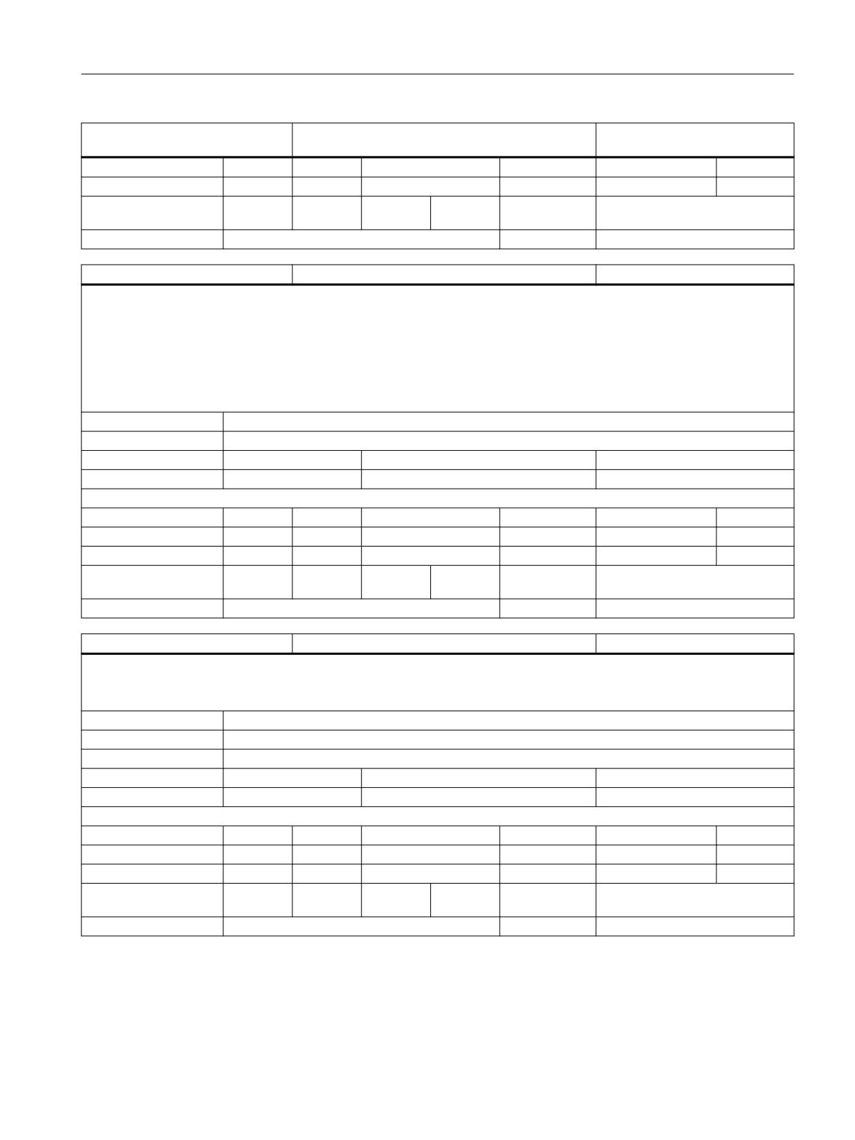
$NT_TRAFO_INDEX [n]
Index for transformation call with conventional syntax
INT
Description:
A transformation defined by kinematic chains can also be activated by conventional language commands, such as TRAORI(<n>) or TRANS-
MIT(<n>), instead of the call TRAFOON(<Name>), if a value not equal to zero is entered in this system data.
The content of the system variable is decimal-coded. The decimal places have the following meanings:
Units digit: Defines the transformation type for which the conventional transformation call is to be diverted to a transformation defined by
kinematic chains. The following assignments apply:
1: TRAORI
2: TRANSMIT
3: TRACYL
4: TRAANG
5: TRACON
Tens and hundreds digits: Transformer number (double digit)
Thousands and ten thousands digits: Number of the channel in which the conventional transformation call is to be diverted to a transformation
defined by kinematic chains. The entry 0 is equivalent to the entry 1. This means that the definition automatically applies to the first channel
if the channel number is not explicitly defined.
For a transformation defined by kinematic chains to be called by a conventional language command, the three lowest-value decimal places of
this system data must not equal zero. The orientation transformation indicated by the index 1 is also activated for compatibility reasons with
the conventional call syntax with TRAORI(0), TRAORI() or TRAORI but not with TRAORI(1). The same applies to the other transformation types
(TRANSMIT, TRACYL, TRAANG and TRACON).
Example: The call TRANSMIT(3) in the fifth channel is diverted to a transformation defined by kinematic chains that contains the entry 5032
in the system data $NT_TRAFO_INDEX.
Whether the called transformation is of a type compatible with the transformation type of the original call is not checked.
Index 1:
The maximum number of transformation datasets is set by the MD $MN_MM_NUM_KIN_TRAFOS.
Unit
Init value
Min
Max
-
0
-2147483648
2147483647
Read/Write properties:
TP
SA
TP/SA safety
NC-Variable
Safety
OEM-CC
Read:
X
-
7
X
7
-
Write:
X
-
1
X
7
-
Axis entry:
Overlap chan-
channel-specific
nel:
Scan mode:
Not classified
Link:
No restrictions
$NT_POLE_SIDE_FIX [n]
Restriction of working area in front of/behind pole with
INT
TRANSMIT
Description:
Restriction of working area in front of/behind pole or no restriction, i.e. traversal through the pole.
The assigned values have the following meanings:
0: No restriction of the working area. Traversal through the pole is allowed.
1: Working area of linear axis for positions >=0,
(if tool length compensation parallel to linear axis = 0)
2: Working area of linear axis for positions <=0,
(if tool length compensation parallel to linear axis = 0)
Index 1:
The maximum number of transformation datasets is set by the MD $MN_MM_NUM_KIN_TRAFOS.
Unit
Init value
Min
Max
-
0
0
2
Read/Write properties:
TP
SA
TP/SA safety
NC-Variable
Safety
OEM-CC
System variables
842
List Manual, 10/2020, 6FC5397-6AP40-6BA4
List of system variables
3.28 Orientation transformation
$NT_POLE_SIDE_FIX [n]
Restriction of working area in front of/behind pole with
INT
TRANSMIT
Read:
X
-
7
X
7
-
Write:
X
-
1
X
7
-
Axis entry:
Overlap chan-
channel-specific
nel:
Scan mode:
Not classified
Link:
No restrictions
$NT_ROT_AX_CNT [n,2]
Number of rotary axes in the part or tool chain
INT
Description:
This system variable can contain the number of relevant rotary axes of a transformation in the part chain (index 0) or tool chain (index 1).
It is used to support the parameterization of a transformation with kinematic chains via the user interface.
If the contents of both components are -1 (initialization value), their content is not evaluated.
If the content of at least one component is not equal to zero, the contents of both components must be the same as the number of relevant
rotary axes found by the analysis of the kinematic chains.
Relevant rotary axes in this sense are those rotary axes defined in the $NT_ROT_AX_Name system variable.
Index 1:
The maximum number of transformation datasets is set by the MD $MN_MM_NUM_KIN_TRAFOS.
Index 2:
Index of the $NT_ROT_AX_CNT variable
Unit
Init value
Min
Max
-
-1
-1
3
Read/Write properties:
TP
SA
TP/SA safety
NC-Variable
Safety
OEM-CC
Read:
X
-
7
X
7
-
Write:
X
-
1
X
7
-
Axis entry:
Overlap chan-
channel-specific
nel:
Scan mode:
Not classified
Link:
No restrictions
$NT_TRACON_CHAIN [n,4,32]
Name of the partial transformation
STRING
Description:
This system variable is only relevant for transformation type $NT_TRAFO_TYPE[] = "TRACON_K". Consequently,
the names of the partial transformations are given in the order that the transformation from BCS to MCS is to be evaluated.
Index 1:
The maximum number of transformation datasets is set by the MD $MN_MM_NUM_KIN_TRAFOS.
Index 2:
The maximum number of transformations in a transformation chain
Index 3:
Max. string length
Unit
Init value
Min
Max
-
""
Read/Write properties:
TP
SA
TP/SA safety
NC-Variable
Safety
OEM-CC
Read:
X
-
7
X
7
-
Write:
X
-
1
-
0
-
Axis entry:
Overlap chan-
channel-specific
nel:
Scan mode:
Not classified
Link:
No restrictions
System variables
List Manual, 10/2020, 6FC5397-6AP40-6BA4
843
List of system variables
3.28 Orientation transformation
$NT_OEM_PAR_I [n,MAX_OEMTRA-
Parameter for OEM transformation
INT
FO_PAR_I]
Description:
This integer parameter is evaluated by OEM transformations. The meaning of the individual parameter values depends on the respective OEM
transformation.
The details are described in the documentation of the particular OEM transformation.
Index 1:
The maximum number of transformation datasets is set by the MD $MN_MM_NUM_KIN_TRAFOS.
Index 2:
Index of the variable $NT_OEM_PAR_I
Unit
Init value
Min
Max
-
0
-2147483648
2147483647
Read/Write properties:
TP
SA
TP/SA safety
NC-Variable
Safety
OEM-CC
Read:
X
-
7
X
7
-
Write:
X
-
1
X
7
-
Axis entry:
Overlap chan-
channel-specific
nel:
Scan mode:
Not classified
Link:
No restrictions
$NT_OEM_PAR_D [n,MAX_OEMTRA-
Parameter for OEM transformation
DOUBLE
FO_PAR_D]
Description:
This real parameter is evaluated by OEM transformations. The meaning of the individual parameter values depends on the respective OEM
transformation.
The details are described in the documentation of the particular OEM transformation.
Index 1:
The maximum number of transformation datasets is set by the MD $MN_MM_NUM_KIN_TRAFOS.
Index 2:
Index of the variable $NT_OEM_PAR_D
Unit
Init value
Min
Max
-
0.0
-1.8E+308
1.8E+308
Read/Write properties:
TP
SA
TP/SA safety
NC-Variable
Safety
OEM-CC
Read:
X
-
7
X
7
-
Write:
X
-
1
X
7
-
Axis entry:
Overlap chan-
channel-specific
nel:
Scan mode:
Not classified
Link:
No restrictions
$NT_OEM_PAR_S [n,MAX_OEMTRA-
Parameter for OEM transformation
STRING
FO_PAR_S,32]
Description:
This string parameter is evaluated by OEM transformations. The meaning of the individual parameter values depends on the respective OEM
transformation.
The details are described in the documentation of the particular OEM transformation.
Index 1:
The maximum number of transformation datasets is set by the MD $MN_MM_NUM_KIN_TRAFOS.
Index 2:
Index of the variable $NT_OEM_PAR_S
Index 3:
Max. string length
Unit
Init value
Min
Max
-
""
Read/Write properties:
System variables
844
List Manual, 10/2020, 6FC5397-6AP40-6BA4
List of system variables
3.28 Orientation transformation
$NT_OEM_PAR_S [n,MAX_OEMTRA-
Parameter for OEM transformation
STRING
FO_PAR_S,32]
TP
SA
TP/SA safety
NC-Variable
Safety
OEM-CC
Read:
X
-
7
X
7
-
Write:
X
-
1
X
7
-
Axis entry:
Overlap chan-
channel-specific
nel:
Scan mode:
Not classified
Link:
No restrictions
$NT_BASE_TOOL_COMP [n]
Compensation of the tool axes for TRANSMIT or TRACYL
INT
with frames.
Description:
Components of the BaseTool can be compensated via the transformation frame with this bit-coded system variable, so that there is no change
in the WCS component on transformation selection.
Bit0: MD24920 $NT_BASE_TOOL[n,0] is compensated via $P_TRAFRAME.
Bit1: MD24920 $NT_BASE_TOOL[n,1] is compensated via $P_TRAFRAME.
Bit2: MD24920 $NT_BASE_TOOL[n,2] is compensated via $P_TRAFRAME.
This function is only available if the system frame $P_TRAFRAME has been configured by bit 6 of MD28082 $MC_MM_SYSTEM_FRAME_MASK.
Index 1:
The maximum number of transformation datasets is set by the MD $MN_MM_NUM_KIN_TRAFOS.
Unit
Init value
Min
Max
-
0
0
7
Read/Write properties:
TP
SA
TP/SA safety
NC-Variable
Safety
OEM-CC
Read:
X
-
7
X
7
-
Write:
X
-
1
X
7
-
Axis entry:
Overlap chan-
channel-specific
nel:
Scan mode:
Not classified
Link:
No restrictions
$NT_T_CHAIN_FIRST_ELEM [n]
First element of the kinematic chain to the tool
STRING
Description:
Name of an element in the kinematic description of the machine. The first link of a kinematic chain that leads to the tool is identified by this
chain element. If this variable is not defined, the ROOT element of the chain is used for this purpose.
Index 1:
The maximum number of transformation datasets is set by the MD $MN_MM_NUM_KIN_TRAFOS.
Index 3:
Max. string length
Unit
Init value
Min
Max
-
""
Read/Write properties:
TP
SA
TP/SA safety
NC-Variable
Safety
OEM-CC
Read:
X
-
7
X
7
-
Write:
X
-
1
X
7
-
Axis entry:
Overlap chan-
channel-specific
nel:
Scan mode:
Not classified
Link:
No restrictions
System variables
List Manual, 10/2020, 6FC5397-6AP40-6BA4
845
List of system variables
3.28 Orientation transformation
$NT_P_CHAIN_FIRST_ELEM [n]
First element of the kinematic chain to the workpiece
STRING
Description:
>Name of an element in the kinematic description of the machine. The first link of a kinematic chain that leads to the workpiece zero is
identified by this chain element. If this variable is not defined, the ROOT element of the chain is used for this purpose.
Index 1:
The maximum number of transformation datasets is set by the MD $MN_MM_NUM_KIN_TRAFOS.
Index 3:
Max. string length
Unit
Init value
Min
Max
-
""
Read/Write properties:
TP
SA
TP/SA safety
NC-Variable
Safety
OEM-CC
Read:
X
-
7
X
7
-
Write:
X
-
1
X
7
-
Axis entry:
Overlap chan-
channel-specific
nel:
Scan mode:
Not classified
Link:
No restrictions
$NT_BASE_TOOL [n,GEODIM]
Vector of base tool for TRANSMIT or TRACYL.
DOUBLE
Description:
Indicates a base offset of the tool zero for the active transformation. The offset is specified for the geometry axes valid for the active transfor-
mation. The base offset is included with and without selection of the tool length compensation. Programmed length corrections have an
additive effect with respect to the base tool.
The index i takes the values 0, 1, 2 for the 1st to 3rd geometry axes.
This system variable is currently only used with TRANSMIT and TRACYL.
Index 1:
The maximum number of transformation datasets is set by the MD $MN_MM_NUM_KIN_TRAFOS.
Index 2:
Index of the vector component
Unit
Init value
Min
Max
mm
0.0
-1.8E+308
1.8E+308
Read/Write properties:
TP
SA
TP/SA safety
NC-Variable
Safety
OEM-CC
Read:
X
-
7
X
7
-
Write:
X
-
1
X
7
-
Axis entry:
Overlap chan-
channel-specific
nel:
Scan mode:
Not classified
Link:
No restrictions
$NT_ROT_AX_OFFSET [n,ORIDIM]
Position offset of a/the rotary axis for the active trans-
DOUBLE
formation
Description:
This machine data indicates the angular offset of the rotary axis
1/2/3 (TRAORI) or the rotary axis 1 (TRACYL,TRANSMIT) in degrees for the active transformation of a channel.
Index 1:
The maximum number of transformation datasets is set by the MD $MN_MM_NUM_KIN_TRAFOS.
Index 2:
Rotary axis index (maximum MD_MAXNUM_ROT_AXES_IN_ORI_TRAFO)
Unit
Init value
Min
Max
deg.
0.0
-1.8E+308
1.8E+308
Read/Write properties:
TP
SA
TP/SA safety
NC-Variable
Safety
OEM-CC
Read:
X
-
7
X
7
-
Write:
X
-
1
X
7
-
System variables
846
List Manual, 10/2020, 6FC5397-6AP40-6BA4
List of system variables
3.29 Protection area elements
$NT_ROT_AX_OFFSET [n,ORIDIM]
Position offset of a/the rotary axis for the active trans-
DOUBLE
formation
Axis entry:
Overlap chan-
channel-specific
nel:
Scan mode:
Not classified
Link:
No restrictions
$NT_POLE_TOL_FACTOR [n]
Factor for calculating the end angle tolerance with pole
DOUBLE
interpolation from OTOL
Description:
Factor for calculating the end angle tolerance with pole interpolation from OTOL for 5/6-axis transformation.
This NT is only evaluated by the generic 5/6-axis transformation.
The assigned values have the following meaning:
0: compatible behavior with previous software behavior. The end angle tolerance with pole interpolation is defined via $NT_POLE_TOL
>0: The end angle tolerance with pole interpolation is calculated internally as $NT_POLE_TOL_FACTOR * OTOL.
Index 1:
The maximum number of transformation datasets is set by the MD $MN_MM_NUM_KIN_TRAFOS.
Unit
Init value
Min
Max
-
0.0
0
1.8E+308
Read/Write properties:
TP
SA
TP/SA safety
NC-Variable
Safety
OEM-CC
Read:
X
-
7
X
7
-
Write:
X
-
1
X
7
-
Axis entry:
Overlap chan-
channel-specific
nel:
Scan mode:
Not classified
Link:
No restrictions
3.29
Protection area elements
$NP_PROT_NAME [n]
Name of protection area
STRING
Description:
Name of protection area n.
Index 1:
The maximum number of protection areas is set by the MD $MN_MM_MAXNUM_3D_PROT_AREAS.
Index 3:
Max. string length
Unit
Init value
Min
Max
-
""
Read/Write properties:
TP
SA
TP/SA safety
NC-Variable
Safety
OEM-CC
Read:
X
-
7
X
7
X
Write:
X
-
1
X
7
X
Axis entry:
Overlap chan-
channel-specific
nel:
Scan mode:
Not classified
Link:
No restrictions
$NP_CHAIN_ELEM [n]
Assignment to a kinematic chain element
STRING
Description:
This system variable states which kinematic chain element ($NK_NAME[..]) is assigned to the current protection area.
Index 1:
The maximum number of protection areas is set by the MD $MN_MM_MAXNUM_3D_PROT_AREAS.
System variables
List Manual, 10/2020, 6FC5397-6AP40-6BA4
847
List of system variables
3.29 Protection area elements
$NP_CHAIN_ELEM [n]
Assignment to a kinematic chain element
STRING
Index 3:
Max. string length
Unit
Init value
Min
Max
-
""
Read/Write properties:
TP
SA
TP/SA safety
NC-Variable
Safety
OEM-CC
Read:
X
-
7
X
7
X
Write:
X
-
1
X
7
X
Axis entry:
Overlap chan-
channel-specific
nel:
Scan mode:
Not classified
Link:
No restrictions
$NP_PROT_TYPE [n]
Type of protection area
STRING
Description:
Type of protection area. The following values are permitted:
"MACHINE"
"TOOL"
"WORKPIECE"
"FIXTURE"
Index 1:
The maximum number of protection areas is set by the MD $MN_MM_MAXNUM_3D_PROT_AREAS.
Index 3:
Max. string length
Unit
Init value
Min
Max
-
""
Read/Write properties:
TP
SA
TP/SA safety
NC-Variable
Safety
OEM-CC
Read:
X
-
7
X
7
X
Write:
X
-
1
X
7
X
Axis entry:
Overlap chan-
channel-specific
nel:
Scan mode:
Not classified
Link:
No restrictions
$NP_1ST_PROT [n]
Name of first element of a protection area
STRING
Description:
Name of first element of a protection area.
Index 1:
The maximum number of protection areas is set by the MD $MN_MM_MAXNUM_3D_PROT_AREAS.
Index 3:
Max. string length
Unit
Init value
Min
Max
-
""
Read/Write properties:
TP
SA
TP/SA safety
NC-Variable
Safety
OEM-CC
Read:
X
-
7
X
7
X
Write:
X
-
1
X
7
X
Axis entry:
Overlap chan-
channel-specific
nel:
Scan mode:
Not classified
Link:
No restrictions
System variables
848
List Manual, 10/2020, 6FC5397-6AP40-6BA4
List of system variables
3.29 Protection area elements
$NP_PROT_COLOR [n]
Color of the protection area.
INT
Description:
Data for visualizing a protection area element.
The 3 low-value bytes contain the color information in RGB format, the highest byte contains the information for the alpha channel (trans-
parency).
This data is only active for a protection area element that is part of the protection area for which this data is defined if a separate color parameter
has not been defined for it (see system data $NP_COLOR), this means that the color definition for a protection area element has priority over
the color definition of a protection area.
The default value is 0 (black, transparent).
Index 1:
The maximum number of protection areas is set by the MD $MN_MM_MAXNUM_3D_PROT_AREAS.
Unit
Init value
Min
Max
-
0
0
2147483647
Read/Write properties:
TP
SA
TP/SA safety
NC-Variable
Safety
OEM-CC
Read:
X
-
7
X
7
X
Write:
X
-
1
X
7
X
Axis entry:
Overlap chan-
channel-specific
nel:
Scan mode:
Not classified
Link:
No restrictions
$NP_PROT_D_LEVEL [n]
Detailing level of a protection area
INT
Description:
Data for visualizing a protection area.
This data contains an integer value which defines when the relevant protection area is to be displayed in the successive generations of the
display.
This data is only active for a protection area element that is part of the protection area for which this data is defined if a separate D-level
parameter has not been defined for it (see system data $NP_D_LEVEL), this means that the D-level definition for a protection area element has
priority over the D-level definition of a protection area.
The default value is 0.
Index 1:
The maximum number of protection areas is set by the MD $MN_MM_MAXNUM_3D_PROT_AREAS.
Unit
Init value
Min
Max
-
0
0
2147483647
Read/Write properties:
TP
SA
TP/SA safety
NC-Variable
Safety
OEM-CC
Read:
X
-
7
X
7
X
Write:
X
-
1
X
7
X
Axis entry:
Overlap chan-
channel-specific
nel:
Scan mode:
Not classified
Link:
No restrictions
$NP_BIT_NO [n]
No. of interface bit for switchover activated / preactiva-
INT
ted
Description:
64 bits are defined in the PLC interface through which protection areas can be activated once they have been preactivated with the command
PROTA(1(,.,.,.)). The entry indicates which bit has been assigned to this protection area. The default value is -1, i.e. no interface bit has been
assigned to this protection area.
Index 1:
The maximum number of protection areas is set by the MD $MN_MM_MAXNUM_3D_PROT_AREAS.
Unit
Init value
Min
Max
-
-1
-1
63
System variables
List Manual, 10/2020, 6FC5397-6AP40-6BA4
849
List of system variables
3.29 Protection area elements
$NP_BIT_NO [n]
No. of interface bit for switchover activated / preactiva-
INT
ted
Read/Write properties:
TP
SA
TP/SA safety
NC-Variable
Safety
OEM-CC
Read:
X
-
7
X
7
X
Write:
X
-
1
X
7
X
Axis entry:
Overlap chan-
channel-specific
nel:
Scan mode:
Not classified
Link:
No restrictions
$NP_INIT_STAT [n]
Default activation status of a protection area
UCHAR
Description:
Activation status of the protection area at first selection without indication of an activation status.
This status is activated for defined protection areas also during runup of the control.
The permitted values are:
Activated ('A' or 'a'),
Inactivated ('I' or 'i'),
Preactivated ('P' or 'p').
Default value is 'I'.
Index 1:
The maximum number of protection areas is set by the MD $MN_MM_MAXNUM_3D_PROT_AREAS.
Unit
Init value
Min
Max
-
'I'
0
255
Read/Write properties:
TP
SA
TP/SA safety
NC-Variable
Safety
OEM-CC
Read:
X
-
7
X
7
X
Write:
X
-
1
X
7
X
Axis entry:
Overlap chan-
channel-specific
nel:
Scan mode:
Not classified
Link:
No restrictions
$NP_INDEX [n,3]
Index for tool identifier
INT
Description:
This component is evaluated only if $NP_PROT_TYPE[n] contains an automatically generated protection area named ("TOOL").
The indices then define the exact type of the automatically generated protection area.
Index 1:
The maximum number of protection areas is set by the MD $MN_MM_MAXNUM_3D_PROT_AREAS.
Index 2:
Number of the index (0 <= i <= 2)
Unit
Init value
Min
Max
-
0
-2147483648
2147483647
Read/Write properties:
TP
SA
TP/SA safety
NC-Variable
Safety
OEM-CC
Read:
X
-
7
X
7
X
Write:
X
-
1
X
7
X
Axis entry:
Overlap chan-
channel-specific
nel:
Scan mode:
Not classified
Link:
No restrictions
System variables
850
List Manual, 10/2020, 6FC5397-6AP40-6BA4
List of system variables
3.29 Protection area elements
$NP_NAME [n]
Name of protection zone element
STRING
Description:
Name of protection zone element.
Index 1:
The maximum number of items in protection areas is set by the MD $MN_MM_MAXNUM_3D_PROT_AREA_ELEM.
Index 3:
Max. string length
Unit
Init value
Min
Max
-
""
Read/Write properties:
TP
SA
TP/SA safety
NC-Variable
Safety
OEM-CC
Read:
X
-
7
X
7
X
Write:
X
-
1
X
7
X
Axis entry:
Overlap chan-
channel-specific
nel:
Scan mode:
Not classified
Link:
No restrictions
$NP_NEXT [n]
Name of next protection zone element
STRING
Description:
Name of next protection zone element.
Index 1:
The maximum number of items in protection areas is set by the MD $MN_MM_MAXNUM_3D_PROT_AREA_ELEM.
Index 3:
Max. string length
Unit
Init value
Min
Max
-
""
Read/Write properties:
TP
SA
TP/SA safety
NC-Variable
Safety
OEM-CC
Read:
X
-
7
X
7
X
Write:
X
-
1
X
7
X
Axis entry:
Overlap chan-
channel-specific
nel:
Scan mode:
Not classified
Link:
No restrictions
$NP_NEXTP [n]
Name of the next parallel protection area element
STRING
Description:
Name of another protection area element ("parallel" to $NP_NEXT) that follows the current protection area element.
Index 1:
The maximum number of items in protection areas is set by the MD $MN_MM_MAXNUM_3D_PROT_AREA_ELEM.
Index 3:
Max. string length
Unit
Init value
Min
Max
-
""
Read/Write properties:
TP
SA
TP/SA safety
NC-Variable
Safety
OEM-CC
Read:
X
-
7
X
7
X
Write:
X
-
1
X
7
X
Axis entry:
Overlap chan-
channel-specific
nel:
Scan mode:
Not classified
Link:
No restrictions
System variables
List Manual, 10/2020, 6FC5397-6AP40-6BA4
851
List of system variables
3.29 Protection area elements
$NP_ADD [n]
Name of an additive protection zone
STRING
Description:
Name of protection element to be added to the current protection zone.
Index 1:
The maximum number of items in protection areas is set by the MD $MN_MM_MAXNUM_3D_PROT_AREA_ELEM.
Index 3:
Max. string length
Unit
Init value
Min
Max
-
""
Read/Write properties:
TP
SA
TP/SA safety
NC-Variable
Safety
OEM-CC
Read:
X
-
7
X
7
X
Write:
X
-
1
X
7
X
Axis entry:
Overlap chan-
channel-specific
nel:
Scan mode:
Not classified
Link:
No restrictions
$NP_COLOR [n]
Color of the protection area element.
INT
Description:
Data for visualizing a protection area element.
For the coding, see the system variable $NP_PROT_COLOR.
If the content of this data is 0, then the color is not defined. In this case, the protection area element is given the color defined for the protection
area in which it is contained.
The default value is 0 (color not defined).
Index 1:
The maximum number of protection areas is set by the MD $MN_MM_MAXNUM_3D_PROT_AREAS.
Unit
Init value
Min
Max
-
0
0
2147483647
Read/Write properties:
TP
SA
TP/SA safety
NC-Variable
Safety
OEM-CC
Read:
X
-
7
X
7
X
Write:
X
-
1
X
7
X
Axis entry:
Overlap chan-
channel-specific
nel:
Scan mode:
Not classified
Link:
No restrictions
$NP_D_LEVEL [n]
Detailing level of a protection area element
INT
Description:
Data for visualizing a protection area element.
If the content of this data is 0, then the detailing level is not defined. In this case, the protection area element is given the detailing level
defined for the protection area in which it is contained.
The default value is 0.
Index 1:
The maximum number of protection areas is set by the MD $MN_MM_MAXNUM_3D_PROT_AREAS.
Unit
Init value
Min
Max
-
0
0
2147483647
Read/Write properties:
TP
SA
TP/SA safety
NC-Variable
Safety
OEM-CC
Read:
X
-
7
X
7
X
Write:
X
-
1
X
7
X
System variables
852
List Manual, 10/2020, 6FC5397-6AP40-6BA4
List of system variables
3.29 Protection area elements
$NP_D_LEVEL [n]
Detailing level of a protection area element
INT
Axis entry:
Overlap chan-
channel-specific
nel:
Scan mode:
Not classified
Link:
No restrictions
$NP_USAGE [n]
Intended use of the protection area.
UCHAR
Description:
This system variable defines whether the protection area element is to be visualized ('V'), is to be included in the protection area monitoring
('C'), or both ('A').
No distinction is made between upper and lower case letters.
The default value is 'A'.
Index 1:
The maximum number of protection areas is set by the MD $MN_MM_MAXNUM_3D_PROT_AREAS.
Unit
Init value
Min
Max
-
'A'
0
255
Read/Write properties:
TP
SA
TP/SA safety
NC-Variable
Safety
OEM-CC
Read:
X
-
7
X
7
X
Write:
X
-
1
X
7
X
Axis entry:
Overlap chan-
channel-specific
nel:
Scan mode:
Not classified
Link:
No restrictions
$NP_TYPE [n]
Type of protection area element
STRING
Description:
Type of protection area element. The following types are possible:
FRAME: An element of this type does not contain a body, it only defines a frame, which is active for the subsequent protection area definitions.
1. BOX (L, W, H): Axis-parallel cuboid, symmetrically arranged around the zero point, with the dimensions L in the X direction, W in the Y
direction and H in the Z direction, i.e. the corners of the cuboid are located at (+/-L/2, +/-W/2, +/-H/2).
2. SPHERE (R): Sphere centered in the zero point with radius R.
3. CYLINDER (H, R): Cylinder with radius R and height H, longitudinal axis parallel to Z axis. The center point of the cylinder lies at the zero point,
i.e. the two limiting circular areas are parallel to the X-Y plane and are located at +/-H/2.
4. FILE: Grid of triangular areas in STL format.
Index 1:
The maximum number of items in protection areas is set by the MD $MN_MM_MAXNUM_3D_PROT_AREA_ELEM.
Index 3:
Max. string length
Unit
Init value
Min
Max
-
""
Read/Write properties:
TP
SA
TP/SA safety
NC-Variable
Safety
OEM-CC
Read:
X
-
7
X
7
X
Write:
X
-
1
X
7
X
Axis entry:
Overlap chan-
channel-specific
nel:
Scan mode:
Not classified
Link:
No restrictions
$NP_FILENAME [n]
File name of a protection area element of the type "FILE"
STRING
Description:
This parameter is evaluated only if the protection area element is the type "File" ($NP_TYPE[..] = "FILE"). In which case, it defines the name of the
file containing the description of the protection area element.
Index 1:
The maximum number of items in protection areas is set by the MD $MN_MM_MAXNUM_3D_PROT_AREA_ELEM.
System variables
List Manual, 10/2020, 6FC5397-6AP40-6BA4
853
List of system variables
3.29 Protection area elements
$NP_FILENAME [n]
File name of a protection area element of the type "FILE"
STRING
Index 3:
Max. string length
Unit
Init value
Min
Max
-
""
Read/Write properties:
TP
SA
TP/SA safety
NC-Variable
Safety
OEM-CC
Read:
X
-
7
X
7
X
Write:
X
-
1
X
7
X
Axis entry:
Overlap chan-
channel-specific
nel:
Scan mode:
Not classified
Link:
No restrictions
$NP_PARA [n,3]
Parameters for describing the type
DOUBLE
Description:
Parameters for describing the protection area element. A maximum of 3 parameters are required for the types described under $NP_TYPE.
Index 1:
The maximum number of items in protection areas is set by the MD $MN_MM_MAXNUM_3D_PROT_AREA_ELEM.
Index 2:
The maximum number of parameters is 3.
Unit
Init value
Min
Max
mm
0.0
-1.8E+308
1.8E+308
Read/Write properties:
TP
SA
TP/SA safety
NC-Variable
Safety
OEM-CC
Read:
X
-
7
X
7
X
Write:
X
-
1
X
7
X
Axis entry:
Overlap chan-
channel-specific
nel:
Scan mode:
Not classified
Link:
No restrictions
$NP_OFF [n,GEODIM]
Offset component
DOUBLE
Description:
Component i (0<=i<=2) of the offset vector of protection zone element n.
Index 1:
The maximum number of items in protection areas is set by the MD $MN_MM_MAXNUM_3D_PROT_AREA_ELEM.
Index 2:
The 2nd index i designates the coordinate axis (0 <= i <= 2).
Unit
Init value
Min
Max
mm
0.0
-1.8E+308
1.8E+308
Read/Write properties:
TP
SA
TP/SA safety
NC-Variable
Safety
OEM-CC
Read:
X
-
7
X
7
X
Write:
X
-
1
X
7
X
Axis entry:
Overlap chan-
channel-specific
nel:
Scan mode:
Not classified
Link:
No restrictions
$NP_DIR [n,GEODIM]
Direction of rotary axis
DOUBLE
Description:
Components of the rotary axis for a coordinate rotation of the protection area element n.
Index 1:
The maximum number of items in protection areas is set by the MD $MN_MM_MAXNUM_3D_PROT_AREA_ELEM.
Index 2:
The 2nd index designates the vector component i (0 <= i <= 2).
Unit
Init value
Min
Max
System variables
854
List Manual, 10/2020, 6FC5397-6AP40-6BA4
List of system variables
3.29 Protection area elements
$NP_DIR [n,GEODIM]
Direction of rotary axis
DOUBLE
-
0.0
-1.8E+308
1.8E+308
Read/Write properties:
TP
SA
TP/SA safety
NC-Variable
Safety
OEM-CC
Read:
X
-
7
X
7
X
Write:
X
-
1
X
7
X
Axis entry:
Overlap chan-
channel-specific
nel:
Scan mode:
Not classified
Link:
No restrictions
$NP_ANG [n]
Angle of a coordinate rotation in the protection area
DOUBLE
element n.
Description:
Angle (in degrees) of a coordinate rotation in protection area element n
Index 1:
The maximum number of items in protection areas is set by the MD $MN_MM_MAXNUM_3D_PROT_AREA_ELEM.
Unit
Init value
Min
Max
deg.
0.0
-1.8E+308
1.8E+308
Read/Write properties:
TP
SA
TP/SA safety
NC-Variable
Safety
OEM-CC
Read:
X
-
7
X
7
X
Write:
X
-
1
X
7
X
Axis entry:
Overlap chan-
channel-specific
nel:
Scan mode:
Not classified
Link:
No restrictions
$NP_COLL_PAIR [n,2,32]
Protection area pairs
STRING
Description:
Contains the names of two protection areas that can be monitored to prevent them colliding with each other.
Index 1:
The maximum number of protection area pairs is derived from the MD $MN_MM_MAXNUM_3D_PROT_AREAS.
Index 2:
The two protection areas form a pair which can be monitored for collision
Index 3:
Max. string length
Unit
Init value
Min
Max
-
""
Read/Write properties:
TP
SA
TP/SA safety
NC-Variable
Safety
OEM-CC
Read:
X
-
7
X
7
X
Write:
X
-
1
X
7
X
Axis entry:
Overlap chan-
channel-specific
nel:
Scan mode:
Not classified
Link:
No restrictions
$NP_SAFETY_DIST [n]
Safety distance of a pair of protection areas
DOUBLE
Description:
Safety distance of a pair of protection areas. If the content of this data is 0.0, the global safety distance contained in $MN_COLLISION_SAFE-
TY_DIST is effective.
Index 1:
The maximum number of protection area pairs is derived from the MD $MN_MM_MAXNUM_3D_PROT_AREAS.
Unit
Init value
Min
Max
mm
0.0
0.0
FLT_MAX
Read/Write properties:
System variables
List Manual, 10/2020, 6FC5397-6AP40-6BA4
855
List of system variables
3.30 Coordinate system-specific working area limitation
$NP_SAFETY_DIST [n]
Safety distance of a pair of protection areas
DOUBLE
TP
SA
TP/SA safety
NC-Variable
Safety
OEM-CC
Read:
X
-
7
X
7
X
Write:
X
-
1
X
7
X
Axis entry:
Overlap chan-
channel-specific
nel:
Scan mode:
Not classified
Link:
No restrictions
3.30
Coordinate system-specific working area limitation
$P_WORKAREA_CS_COORD_SYSTEM
Coordinate system to which the working area limitation
INT
[n]
applies
Description:
Coordinate system in which the group is to apply.
The following values apply:
Working area limitation in the WCS
Working area limitation in the SZS
Index 1:
Group of the coordinate system-specific working area limitation -1. The maximum value is determined by the MD
$MC_MM_NUM_WORKAREA_CS_GROUPS.
Unit
Init value
Min
Max
-
0
-2147483648
2147483647
Read/Write properties:
TP
SA
TP/SA safety
NC-Variable
Safety
OEM-CC
Read:
X
-
7
X
7
-
Write:
X
-
7
X
7
-
Axis entry:
Overlap chan-
channel-specific
nel:
Scan mode:
Not classified
Link:
No restrictions
$P_WORKAREA_CS_PLUS_ENABLE
Coordinate system-specific working area limitation plus
BOOL
[n,m]
valid
Description:
TRUE: The coordinate system-specific working area limitation in the plus direction is valid for the stated axis of the stated group. (See
$P_WORKAREA_CS_LIMIT_PLUS[ groupNo-1, ax])
Index 1:
Group of the coordinate system-specific working area limitation -1. The maximum value is determined by the MD
$MC_MM_NUM_WORKAREA_CS_GROUPS.
Index 2:
Axis name of the working area limitation. Any axis names known in the channel are permitted as axis name.
Unit
Init value
Min
Max
-
FALSE
FALSE
TRUE
Read/Write properties:
TP
SA
TP/SA safety
NC-Variable
Safety
OEM-CC
Read:
X
-
7
X
7
-
Write:
X
-
7
X
7
-
Axis entry:
GEO
CHAN
MACH
Overlap chan-
channel-specific
nel:
Scan mode:
Not classified
Link:
No restrictions
System variables
856
List Manual, 10/2020, 6FC5397-6AP40-6BA4
List of system variables
3.30 Coordinate system-specific working area limitation
$P_WORKAREA_CS_MINUS_ENABLE
Coordinate system-specific working area limitation mi-
BOOL
[n,m]
nus valid
Description:
TRUE: The coordinate system-specific working area limitation in the minus direction is valid for the stated axis of the stated group. (See
$P_WORKAREA_CS_LIMIT_MINUS[ groupNo-1, ax])
Index 1:
Group of the coordinate system-specific working area limitation -1. The maximum value is determined by the MD
$MC_MM_NUM_WORKAREA_CS_GROUPS.
Index 2:
Axis name of the working area limitation. Any axis names known in the channel are permitted as axis name.
Unit
Init value
Min
Max
-
FALSE
FALSE
TRUE
Read/Write properties:
TP
SA
TP/SA safety
NC-Variable
Safety
OEM-CC
Read:
X
-
7
X
7
-
Write:
X
-
7
X
7
-
Axis entry:
GEO
CHAN
MACH
Overlap chan-
channel-specific
nel:
Scan mode:
Not classified
Link:
No restrictions
$P_WORKAREA_CS_LIMIT_PLUS [n,m]
Coordinate system-specific working area limitation pos-
DOUBLE
itive
Description:
The coordinate system-specific working area limitation in the plus direction for the stated axis of the stated group. This value is evaluated only
if $P_WORKAREA_CS_PLUS_ENABLE[ groupNo-1, ax] = TRUE.
Index 1:
Group of the coordinate system-specific working area limitation -1. The maximum value is determined by the MD
$MC_MM_NUM_WORKAREA_CS_GROUPS.
Index 2:
Axis name of the working area limitation. Any axis names known in the channel are permitted as axis name.
Unit
Init value
Min
Max
Linear / angular position
0.0
-1.8E+308
1.8E+308
Read/Write properties:
TP
SA
TP/SA safety
NC-Variable
Safety
OEM-CC
Read:
X
-
7
X
7
-
Write:
X
-
7
X
7
-
Axis entry:
GEO
CHAN
MACH
Overlap chan-
channel-specific
nel:
Scan mode:
Not classified
Link:
No restrictions
$P_WORKAREA_CS_LIMIT_MINUS
Coordinate system-specific working area limitation neg-
DOUBLE
[n,m]
ative
Description:
The coordinate system-specific working area limitation in the minus direction for the stated axis of the stated group. This value is evaluated only
if $P_WORKAREA_CS_MINUS_ENABLE[ groupNo-1, ax] = TRUE.
Index 1:
Group of the coordinate system-specific working area limitation -1. The maximum value is determined by the MD
$MC_MM_NUM_WORKAREA_CS_GROUPS.
Index 2:
Axis name of the working area limitation. Any axis names known in the channel are permitted as axis name.
Unit
Init value
Min
Max
Linear / angular position
0.0
-1.8E+308
1.8E+308
Read/Write properties:
TP
SA
TP/SA safety
NC-Variable
Safety
OEM-CC
Read:
X
-
7
X
7
-
System variables
List Manual, 10/2020, 6FC5397-6AP40-6BA4
857
List of system variables
3.31 Tool data ISO dialect milling
$P_WORKAREA_CS_LIMIT_MINUS
Coordinate system-specific working area limitation neg-
DOUBLE
[n,m]
ative
Write:
X
-
7
X
7
-
Axis entry:
GEO
CHAN
MACH
Overlap chan-
channel-specific
nel:
Scan mode:
Not classified
Link:
No restrictions
3.31
Tool data ISO dialect milling
$TC_ISO_H [n]
ISO2 tool length offset
DOUBLE
Description:
$TC_ISO_H[n]
Correction value memory for the geometry of the tool length compensation in ISO2 mode.
Is available only if ISO2 mode is active.
Index 1:
n: Compensation number of the ISO tool compensation parameter
Unit
Init value
Min
Max
mm
0.0
-1.8E+308
1.8E+308
Read/Write properties:
TP
SA
TP/SA safety
NC-Variable
Safety
OEM-CC
Read:
X
-
7
X
7
-
Write:
X
-
7
X
7
-
Axis entry:
Overlap chan-
channel-specific
nel:
Scan mode:
Not classified
Link:
No restrictions
$TC_ISO_HW [n]
ISO2 tool length wear
DOUBLE
Description:
$TC_ISO_HW[n]
Correction value memory for the wear of the tool length compensation in ISO2 mode.
Is available only if ISO2 mode is active.
Index 1:
n: Compensation number of the ISO tool compensation parameter
Unit
Init value
Min
Max
mm
0.0
-1.8E+308
1.8E+308
Read/Write properties:
TP
SA
TP/SA safety
NC-Variable
Safety
OEM-CC
Read:
X
-
7
X
7
-
Write:
X
-
7
X
7
-
Axis entry:
Overlap chan-
channel-specific
nel:
Scan mode:
Not classified
Link:
No restrictions
System variables
858
List Manual, 10/2020, 6FC5397-6AP40-6BA4
List of system variables
3.32 Tool data ISO dialect turning
$TC_ISO_D [n]
ISO2 tool radius offset
DOUBLE
Description:
$TC_ISO_D[n]
Correction value memory for the geometry of the tool radius in ISO2 mode.
Is available only if ISO2 mode is active.
Index 1:
n: Compensation number of the ISO tool compensation parameter
Unit
Init value
Min
Max
mm
0.0
-1.8E+308
1.8E+308
Read/Write properties:
TP
SA
TP/SA safety
NC-Variable
Safety
OEM-CC
Read:
X
-
7
X
7
-
Write:
X
-
7
X
7
-
Axis entry:
Overlap chan-
channel-specific
nel:
Scan mode:
Not classified
Link:
No restrictions
$TC_ISO_DW [n]
ISO2 tool radius wear
DOUBLE
Description:
$TC_ISO_DW[n]
Correction value memory for the wear of the tool radius in ISO2 mode.
Is available only if ISO2 mode is active.
Index 1:
n: Compensation number of the ISO tool compensation parameter
Unit
Init value
Min
Max
mm
0.0
-1.8E+308
1.8E+308
Read/Write properties:
TP
SA
TP/SA safety
NC-Variable
Safety
OEM-CC
Read:
X
-
7
X
7
-
Write:
X
-
7
X
7
-
Axis entry:
Overlap chan-
channel-specific
nel:
Scan mode:
Not classified
Link:
No restrictions
3.32
Tool data ISO dialect turning
$TC_ISO_L1 [n]
ISO3 tool length 1 offset
DOUBLE
Description:
$TC_ISO_L1[n]
Correction value memory for the geometry of tool length 1 in ISO3 mode.
Is available only if ISO3 mode is active.
Index 1:
n: Compensation number of the ISO tool compensation parameter
Unit
Init value
Min
Max
mm
0.0
-1.8E+308
1.8E+308
Read/Write properties:
TP
SA
TP/SA safety
NC-Variable
Safety
OEM-CC
Read:
X
-
7
X
7
-
System variables
List Manual, 10/2020, 6FC5397-6AP40-6BA4
859
List of system variables
3.32 Tool data ISO dialect turning
$TC_ISO_L1 [n]
ISO3 tool length 1 offset
DOUBLE
Write:
X
-
7
X
7
-
Axis entry:
Overlap chan-
channel-specific
nel:
Scan mode:
Not classified
Link:
No restrictions
$TC_ISO_L1W [n]
ISO3 tool length 1 wear
DOUBLE
Description:
$TC_ISO_L1W[n]
Correction value memory for the wear of tool length 1 in ISO3 mode.
Is available only if ISO3 mode is active.
Index 1:
n: Compensation number of the ISO tool compensation parameter
Unit
Init value
Min
Max
mm
0.0
-1.8E+308
1.8E+308
Read/Write properties:
TP
SA
TP/SA safety
NC-Variable
Safety
OEM-CC
Read:
X
-
7
X
7
-
Write:
X
-
7
X
7
-
Axis entry:
Overlap chan-
channel-specific
nel:
Scan mode:
Not classified
Link:
No restrictions
$TC_ISO_L2 [n]
ISO3 tool length 2 offset
DOUBLE
Description:
$TC_ISO_L2[n]
Correction value memory for the geometry of tool length 2 in ISO3 mode.
Is available only if ISO3 mode is active.
Index 1:
n: Compensation number of the ISO tool compensation parameter
Unit
Init value
Min
Max
mm
0.0
-1.8E+308
1.8E+308
Read/Write properties:
TP
SA
TP/SA safety
NC-Variable
Safety
OEM-CC
Read:
X
-
7
X
7
-
Write:
X
-
7
X
7
-
Axis entry:
Overlap chan-
channel-specific
nel:
Scan mode:
Not classified
Link:
No restrictions
$TC_ISO_L2W [n]
ISO3 tool length 2 wear
DOUBLE
Description:
$TC_ISO_L2W[n]
Correction value memory for the wear of tool length 2 in ISO3 mode.
Is available only if ISO3 mode is active.
Index 1:
n: Compensation number of the ISO tool compensation parameter
Unit
Init value
Min
Max
mm
0.0
-1.8E+308
1.8E+308
Read/Write properties:
TP
SA
TP/SA safety
NC-Variable
Safety
OEM-CC
System variables
860
List Manual, 10/2020, 6FC5397-6AP40-6BA4
List of system variables
3.32 Tool data ISO dialect turning
$TC_ISO_L2W [n]
ISO3 tool length 2 wear
DOUBLE
Read:
X
-
7
X
7
-
Write:
X
-
7
X
7
-
Axis entry:
Overlap chan-
channel-specific
nel:
Scan mode:
Not classified
Link:
No restrictions
$TC_ISO_L3 [n]
ISO3 tool length 3 offset
DOUBLE
Description:
$TC_ISO_L3[n]
Correction value memory for the geometry of tool length 3 in ISO3 mode.
Is available only if ISO3 mode is active.
Index 1:
n: Compensation number of the ISO tool compensation parameter
Unit
Init value
Min
Max
mm
0.0
-1.8E+308
1.8E+308
Read/Write properties:
TP
SA
TP/SA safety
NC-Variable
Safety
OEM-CC
Read:
X
-
7
X
7
-
Write:
X
-
7
X
7
-
Axis entry:
Overlap chan-
channel-specific
nel:
Scan mode:
Not classified
Link:
No restrictions
$TC_ISO_L3W [n]
ISO3 tool length 3 wear
DOUBLE
Description:
$TC_ISO_L3W[n]
Correction value memory for the wear of tool length 3 in ISO3 mode.
Is available only if ISO3 mode is active.
Index 1:
n: Compensation number of the ISO tool compensation parameter
Unit
Init value
Min
Max
mm
0.0
-1.8E+308
1.8E+308
Read/Write properties:
TP
SA
TP/SA safety
NC-Variable
Safety
OEM-CC
Read:
X
-
7
X
7
-
Write:
X
-
7
X
7
-
Axis entry:
Overlap chan-
channel-specific
nel:
Scan mode:
Not classified
Link:
No restrictions
$TC_ISO_R [n]
ISO3 tool radius compensation
DOUBLE
Description:
$TC_ISO_R[n]
Correction value memory for the geometry of the tool radius in ISO3 mode.
Is available only if ISO3 mode is active.
Index 1:
n: Compensation number of the ISO tool compensation parameter
Unit
Init value
Min
Max
mm
0.0
-1.8E+308
1.8E+308
Read/Write properties:
System variables
List Manual, 10/2020, 6FC5397-6AP40-6BA4
861
List of system variables
3.32 Tool data ISO dialect turning
$TC_ISO_R [n]
ISO3 tool radius compensation
DOUBLE
TP
SA
TP/SA safety
NC-Variable
Safety
OEM-CC
Read:
X
-
7
X
7
-
Write:
X
-
7
X
7
-
Axis entry:
Overlap chan-
channel-specific
nel:
Scan mode:
Not classified
Link:
No restrictions
$TC_ISO_RW [n]
ISO3 tool radius wear
DOUBLE
Description:
$TC_ISO_RW[n]
Correction value memory for the wear of the tool radius in ISO3 mode.
Is available only if ISO3 mode is active.
Index 1:
n: Compensation number of the ISO tool compensation parameter
Unit
Init value
Min
Max
mm
0.0
-1.8E+308
1.8E+308
Read/Write properties:
TP
SA
TP/SA safety
NC-Variable
Safety
OEM-CC
Read:
X
-
7
X
7
-
Write:
X
-
7
X
7
-
Axis entry:
Overlap chan-
channel-specific
nel:
Scan mode:
Not classified
Link:
No restrictions
$TC_ISO_Q [n]
ISO3 cutting edge position
INT
Description:
$TC_ISO_Q[n]
Cutting edge position in ISO3 mode.
Is available only if ISO3 mode is active.
Index 1:
n: Compensation number of the ISO tool compensation parameter
Unit
Init value
Min
Max
-
0
-2147483648
2147483647
Read/Write properties:
TP
SA
TP/SA safety
NC-Variable
Safety
OEM-CC
Read:
X
-
7
X
7
-
Write:
X
-
7
X
7
-
Axis entry:
Overlap chan-
channel-specific
nel:
Scan mode:
Not classified
Link:
No restrictions
System variables
862
List Manual, 10/2020, 6FC5397-6AP40-6BA4
Preface
Fundamental safety
1
instructions
2
Product information
SINUMERIK
Configuring the NCU
3
SINUMERIK 840D sl
SINUMERIK 840D sl STEP 7
4
Programming the PLC
Toolbox V16
Configuring networks
5
Configuration Manual
Configuring telegrams and
6
drive units
Configuring I/O
7
Tag selection with NC VAR
8
selector
Importing user alarms
9
10
Safety configuration
Printout of the Online Help
12/2019
6FC5397-0GP40-0BA1
Table of contents
Preface
3
1
Fundamental safety instructions
11
1.1
General safety instructions
11
1.2
Equipment damage due to electric fields or electrostatic discharge
15
1.3
Warranty and liability for application examples
16
1.4
Industrial security
17
1.5
Residual risks of power drive systems
19
2
Product information
21
2.1
Validity of the description
21
2.2
Product features
22
2.3
Installation notes
23
2.4
Limitations for use
24
3
Configuring the NCU
25
3.1
SINUMERIK NCU
25
3.1.1
Structure of SINUMERIK NCU
25
3.1.2
Insert NCU
26
3.2
Insert NX module
28
3.3
Replacing a device or upgrading firmware
33
3.3.1
Replacing the NCU
33
3.3.2
Replacing an NX
33
3.3.3
Basic procedure
34
3.4
Establish the communication connection
37
3.5
Load hardware configuration into the PLC
39
3.6
Creating SINUMERIK PLC archives
44
3.6.1
Creating a SINUMERIK PLC archive
44
3.6.2
Available SINUMERIK archive types
47
3.6.3
External tools for SINUMERIK archives
48
3.6.4
Creating a PLC hardware upgrade archive
48
3.6.5
Creating a PLC commissioning archive
50
3.6.6
Creating a PLC reload archive
52
4
Programming the PLC
55
4.1
General information about the PLC program
55
4.1.1
Introduction
55
4.1.2
Execution structure
55
4.1.3
Using copy templates
58
4.1.4
Block listing as table
61
SINUMERIK 840D sl STEP 7 Toolbox V16
Configuration Manual, 12/2019, 6FC5397-0GP40-0BA1
7
Table of contents
4.1.5
Blocks with user-specific adaptations
65
4.1.6
Assignment overview
66
4.1.7
Generating blocks at runtime on the NCU
67
4.2
Opening the PLC basic program system library
69
4.3
Adding the PLC basic program
70
4.4
Conflicts when copying blocks
74
4.5
Correcting OB1
76
4.6
Upgrading the PLC basic program
77
4.7
Copying blocks from one project into another
79
4.8
Use and handling of groups
82
4.9
Create blocks from external sources
84
4.10
Exporting PLC symbols for SINUMERIK Operate
85
4.10.1
Creating and loading PLC symbols
85
4.10.2
Exporting PLC symbols
86
4.10.3
Importing PLC symbols
89
4.11
Edit blocks
91
5
Configuring networks
93
5.1
Configuring an Ethernet Interface
93
5.2
Configuring PROFIBUS DP
94
5.3
Configuring Integrated PROFIBUS (DP Integrated)
95
5.4
Configuring PROFINET
96
5.5
Configuring PROFINET IO with IRT
97
5.5.1
Overview
97
5.5.2
Rules and requirements
97
5.5.3
Isochronous-capable modules identification
99
5.5.4
Configuring isochronous NC-controlled drives
101
5.5.5
Configuring I/O used by NC isochronously
102
5.5.6
Configuring the NCU
103
5.5.7
Configuring PROFINET IO IRT devices
104
5.5.8
Configuring IO modules or drive telegrams
106
5.5.9
Configuring the input delay for digital input modules
109
5.5.10
Configuring sync domains
110
5.5.11
Match values between PROFINET IO and PROFIBUS Integrated
111
5.5.12
Assigning drive addresses to the NCU machine data
112
5.5.13
Assigning I/O addresses to the NCU machine data
113
6
Configuring telegrams and drive units
115
6.1
Overview
115
6.2
Standard telegram configuration
116
6.3
Viewing I/O addresses in the TIA Portal
117
6.4
Changing the addressing schematic
118
6.5
Resetting telegrams
120
SINUMERIK 840D sl STEP 7 Toolbox V16
8
Configuration Manual, 12/2019, 6FC5397-0GP40-0BA1
Table of contents
6.6
Displaying or adapting the telegram configuration
121
6.6.1
Overview
121
6.6.2
Calling the telegram configuration
122
6.6.3
Structure of the "Telegram configuration" dialog
122
6.6.4
Changing the properties of send telegrams (actual value)
123
6.6.5
Changing the properties of receive telegrams (setpoint)
126
6.6.6
Adapting the number of drives
129
6.7
Available telegram types
130
6.7.1
Telegrams for the transfer of standard data (PROFIdrive)
130
6.7.2
Telegrams in SINUMERIK Safety Integrated (SPL) mode
131
6.7.3
Telegrams for PROFIsafe communication
131
6.7.4
Telegrams for SIC/SCC communication
132
6.8
Adapting I/O start addresses
134
6.8.1
Introduction
134
6.8.2
PROFIdrive telegrams for standard data
135
6.8.3
PROFIdrive telegrams for Safety Integrated (SPL)
137
6.8.4
PROFIsafe/PROFIdrive telegrams for Safety Integrated plus (F-PLC)
139
6.9
Deviations from the standard I/O addressing schematic
143
6.9.1
Overview
143
6.9.2
Matching of deviating I/O addresses
143
6.9.2.1
Matching I/O addresses for use of the optimized I/O addressing schematic
143
6.9.2.2
Matching user-specific adaptations
144
6.9.3
Viewing messages in the info area
145
6.9.4
Availability of suitable I/O addresses
146
7
Configuring I/O
149
7.1
Inserting ADI4 module (840 sl)
149
7.2
Installing general station description files for SINUMERIK I/O
152
7.3
Inserting the SINUMERIK I/O module PP72/48
154
7.4
Inserting SINUMERIK MCP/MPP
157
8
Tag selection with NC VAR selector
159
8.1
NC VAR selector
159
8.2
Selecting tags and saving as STL file
160
8.3
Adding a tag file (STL) in the TIA Portal
162
9
Importing user alarms
165
9.1
Overview
165
9.2
Exporting TS files from SINUMERIK Operate
166
9.3
Language assignment in language-dependent texts
167
9.4
Enable project languages
169
9.5
Importing SINUMERIK PLC alarm texts
170
10
Safety configuration
173
10.1
Introduction
173
SINUMERIK 840D sl STEP 7 Toolbox V16
Configuration Manual, 12/2019, 6FC5397-0GP40-0BA1
9
Table of contents
10.2
Representation of safety-related resources in the TIA Portal
174
10.3
Changing the Safety Integrated mode
177
10.4
Parameterization of relevant properties
179
10.5
Availability of I/O addresses at the mode change
183
10.6
Licensing
186
10.6.1
Overview
186
10.6.2
Software options for Safety Integrated (SPL)
186
10.6.3
Software options for Safety Integrated plus (F-PLC)
187
10.7
Configuring Safety Integrated (SPL)
189
10.7.1
Introduction
189
10.7.2
Configuring the F-peripherals
189
10.7.3
Parameterizing F-input modules
191
10.7.4
Configuring drives with F-functions
192
10.7.5
Parameterizing F-output modules
194
10.7.6
Configuration of the PROFIsafe addresses (peripherals)
194
10.7.7
Configuration of the PROFIsafe addresses (drives)
198
10.7.8
Parameterizing PROFIsafe telegrams
200
10.8
Configuring Safety Integrated plus (F-PLC)
202
10.8.1
Introduction
202
10.8.2
Configuring Safety Integrated plus (F-PLC)
203
10.8.3
Creating a second F-runtime group for Safety Integrated plus (F-PLC)
205
10.8.4
Configuring PROFIsafe
207
10.8.5
Checking the PROFIsafe address
209
Index
213
SINUMERIK 840D sl STEP 7 Toolbox V16
10
Configuration Manual, 12/2019, 6FC5397-0GP40-0BA1
Fundamental safety instructions
1
1.1
General safety instructions
WARNING
Electric shock and danger to life due to other energy sources
Touching live components can result in death or severe injury.
● Only work on electrical devices when you are qualified for this job.
● Always observe the country-specific safety rules.
Generally, the following six steps apply when establishing safety:
1. Prepare for disconnection. Notify all those who will be affected by the procedure.
2. Isolate the drive system from the power supply and take measures to prevent it being
switched back on again.
3. Wait until the discharge time specified on the warning labels has elapsed.
4. Check that there is no voltage between any of the power connections, and between any of
the power connections and the protective conductor connection.
5. Check whether the existing auxiliary supply circuits are de-energized.
6. Ensure that the motors cannot move.
7. Identify all other dangerous energy sources, e.g. compressed air, hydraulic systems, or
water. Switch the energy sources to a safe state.
8. Check that the correct drive system is completely locked.
After you have completed the work, restore the operational readiness in the inverse sequence.
WARNING
Electric shock due to connection to an unsuitable power supply
When equipment is connected to an unsuitable power supply, exposed components may
carry a hazardous voltage. Contact with hazardous voltage can result in severe injury or death.
● Only use power supplies that provide SELV (Safety Extra Low Voltage) or PELV-
(Protective Extra Low Voltage) output voltages for all connections and terminals of the
electronics modules.
SINUMERIK 840D sl STEP 7 Toolbox V16
Configuration Manual, 12/2019, 6FC5397-0GP40-0BA1
11
Fundamental safety instructions
1.1 General safety instructions
WARNING
Electric shock due to equipment damage
Improper handling may cause damage to equipment. For damaged devices, hazardous
voltages can be present at the enclosure or at exposed components; if touched, this can result
in death or severe injury.
● Ensure compliance with the limit values specified in the technical data during transport,
storage and operation.
● Do not use any damaged devices.
WARNING
Electric shock due to unconnected cable shields
Hazardous touch voltages can occur through capacitive cross-coupling due to unconnected
cable shields.
● As a minimum, connect cable shields and the cores of cables that are not used at one end
at the grounded housing potential.
WARNING
Electric shock if there is no ground connection
For missing or incorrectly implemented protective conductor connection for devices with
protection class I, high voltages can be present at open, exposed parts, which when touched,
can result in death or severe injury.
● Ground the device in compliance with the applicable regulations.
WARNING
Spread of fire from built-in devices
In the event of fire outbreak, the enclosures of built-in devices cannot prevent the escape of
fire and smoke. This can result in serious personal injury or property damage.
● Install built-in units in a suitable metal cabinet in such a way that personnel are protected
against fire and smoke, or take other appropriate measures to protect personnel.
● Ensure that smoke can only escape via controlled and monitored paths.
SINUMERIK 840D sl STEP 7 Toolbox V16
12
Configuration Manual, 12/2019, 6FC5397-0GP40-0BA1
Fundamental safety instructions
1.1 General safety instructions
WARNING
Unexpected movement of machines caused by radio devices or mobile phones
When radio devices or mobile phones with a transmission power > 1 W are used in the
immediate vicinity of components, they may cause the equipment to malfunction.
Malfunctions may impair the functional safety of machines and can therefore put people in
danger or lead to property damage.
● If you come closer than around 2 m to such components, switch off any radios or mobile
phones.
● Use the "SIEMENS Industry Online Support app" only on equipment that has already been
switched off.
WARNING
Fire due to inadequate ventilation clearances
Inadequate ventilation clearances can cause overheating of components with subsequent fire
and smoke. This can cause severe injury or even death. This can also result in increased
downtime and reduced service lives for devices/systems.
● Ensure compliance with the specified minimum clearance as ventilation clearance for the
respective component.
NOTICE
Overheating due to inadmissible mounting position
The device may overheat and therefore be damaged if mounted in an inadmissible position.
● Only operate the device in admissible mounting positions.
WARNING
Unexpected movement of machines caused by inactive safety functions
Inactive or non-adapted safety functions can trigger unexpected machine movements that
may result in serious injury or death.
● Observe the information in the appropriate product documentation before commissioning.
● Carry out a safety inspection for functions relevant to safety on the entire system, including
all safety-related components.
● Ensure that the safety functions used in your drives and automation tasks are adjusted and
activated through appropriate parameterizing.
● Perform a function test.
● Only put your plant into live operation once you have guaranteed that the functions relevant
to safety are running correctly.
SINUMERIK 840D sl STEP 7 Toolbox V16
Configuration Manual, 12/2019, 6FC5397-0GP40-0BA1
13
Fundamental safety instructions
1.1 General safety instructions
Note
Important safety notices for Safety Integrated functions
If you want to use Safety Integrated functions, you must observe the safety notices in the Safety
Integrated manuals.
WARNING
Malfunctions of the machine as a result of incorrect or changed parameter settings
As a result of incorrect or changed parameterization, machines can malfunction, which in turn
can lead to injuries or death.
● Protect the parameterization against unauthorized access.
● Handle possible malfunctions by taking suitable measures, e.g. emergency stop or
emergency off.
SINUMERIK 840D sl STEP 7 Toolbox V16
14
Configuration Manual, 12/2019, 6FC5397-0GP40-0BA1
Fundamental safety instructions
1.2 Equipment damage due to electric fields or electrostatic discharge
1.2
Equipment damage due to electric fields or electrostatic discharge
Electrostatic sensitive devices (ESD) are individual components, integrated circuits, modules
or devices that may be damaged by either electric fields or electrostatic discharge.
NOTICE
Equipment damage due to electric fields or electrostatic discharge
Electric fields or electrostatic discharge can cause malfunctions through damaged individual
components, integrated circuits, modules or devices.
● Only pack, store, transport and send electronic components, modules or devices in their
original packaging or in other suitable materials, e.g conductive foam rubber of aluminum
foil.
● Only touch components, modules and devices when you are grounded by one of the
following methods:
- Wearing an ESD wrist strap
- Wearing ESD shoes or ESD grounding straps in ESD areas with conductive flooring
● Only place electronic components, modules or devices on conductive surfaces (table with
ESD surface, conductive ESD foam, ESD packaging, ESD transport container).
SINUMERIK 840D sl STEP 7 Toolbox V16
Configuration Manual, 12/2019, 6FC5397-0GP40-0BA1
15
Fundamental safety instructions
1.3 Warranty and liability for application examples
1.3
Warranty and liability for application examples
Application examples are not binding and do not claim to be complete regarding configuration,
equipment or any eventuality which may arise. Application examples do not represent specific
customer solutions, but are only intended to provide support for typical tasks.
As the user you yourself are responsible for ensuring that the products described are operated
correctly. Application examples do not relieve you of your responsibility for safe handling when
using, installing, operating and maintaining the equipment.
SINUMERIK 840D sl STEP 7 Toolbox V16
16
Configuration Manual, 12/2019, 6FC5397-0GP40-0BA1
Fundamental safety instructions
1.4 Industrial security
1.4
Industrial security
Note
Industrial security
Siemens provides products and solutions with industrial security functions that support the
secure operation of plants, systems, machines and networks.
In order to protect plants, systems, machines and networks against cyber threats, it is
necessary to implement - and continuously maintain - a holistic, state-of-the-art industrial
security concept. Products and solutions from Siemens constitute one element of such a
concept.
Customers are responsible for preventing unauthorized access to their plants, systems,
machines and networks. Such systems, machines and components should only be connected
to an enterprise network or the Internet if and to the extent such a connection is necessary and
only when appropriate security measures (e.g. using firewalls and/or network segmentation)
are in place.
For additional information on industrial security measures that can be implemented, please
visit:
Siemens’ products and solutions undergo continuous development to make them more secure.
Siemens strongly recommends that product updates are applied as soon as they become
available, and that only the latest product versions are used. Use of product versions that are
no longer supported, and failure to apply the latest updates may increase customer’s exposure
to cyber threats.
To stay informed about product updates, subscribe to the Siemens Industrial Security RSS
Feed at:
Further information is provided on the Internet:
Industrial Security Configuration Manual (https://support.industry.siemens.com/cs/ww/en/
view/108862708)
SINUMERIK 840D sl STEP 7 Toolbox V16
Configuration Manual, 12/2019, 6FC5397-0GP40-0BA1
17
Fundamental safety instructions
1.4 Industrial security
WARNING
Unsafe operating states resulting from software manipulation
Software manipulations, e.g. viruses, Trojans, or worms, can cause unsafe operating states
in your system that may lead to death, serious injury, and property damage.
● Keep the software up to date.
● Incorporate the automation and drive components into a holistic, state-of-the-art industrial
security concept for the installation or machine.
● Make sure that you include all installed products into the holistic industrial security concept.
● Protect files stored on exchangeable storage media from malicious software by with
suitable protection measures, e.g. virus scanners.
● On completion of commissioning, check all security-related settings.
● Protect the drive against unauthorized changes by activating the "Know-how protection"
converter function.
SINUMERIK 840D sl STEP 7 Toolbox V16
18
Configuration Manual, 12/2019, 6FC5397-0GP40-0BA1
Fundamental safety instructions
1.5 Residual risks of power drive systems
1.5
Residual risks of power drive systems
When assessing the machine- or system-related risk in accordance with the respective local
regulations (e.g., EC Machinery Directive), the machine manufacturer or system installer must
take into account the following residual risks emanating from the control and drive components
of a drive system:
1.
Unintentional movements of driven machine or system components during commissioning,
operation, maintenance, and repairs caused by, for example,
- Hardware and/or software errors in the sensors, control system, actuators, and cables
and connections
- Response times of the control system and of the drive
- Operation and/or environmental conditions outside the specification
- Condensation/conductive contamination
- Parameterization, programming, cabling, and installation errors
- Use of wireless devices/mobile phones in the immediate vicinity of electronic
components
- External influences/damage
- X-ray, ionizing radiation and cosmic radiation
2.
Unusually high temperatures, including open flames, as well as emissions of light, noise,
particles, gases, etc., can occur inside and outside the components under fault conditions
caused by, for example:
- Component failure
- Software errors
- Operation and/or environmental conditions outside the specification
- External influences/damage
3.
Hazardous shock voltages caused by, for example:
- Component failure
- Influence during electrostatic charging
- Induction of voltages in moving motors
- Operation and/or environmental conditions outside the specification
- Condensation/conductive contamination
- External influences/damage
4.
Electrical, magnetic and electromagnetic fields generated in operation that can pose a risk
to people with a pacemaker, implants or metal replacement joints, etc., if they are too close
5.
Release of environmental pollutants or emissions as a result of improper operation of the
system and/or failure to dispose of components safely and correctly
6.
Influence of network-connected communication systems, e.g. ripple-control transmitters or
data communication via the network
For more information about the residual risks of the drive system components, see the relevant
sections in the technical user documentation.
SINUMERIK 840D sl STEP 7 Toolbox V16
Configuration Manual, 12/2019, 6FC5397-0GP40-0BA1
19
Product information
2
2.1
Validity of the description
These notes take precedence over statements in other documents.
Please read the notes carefully since important information for installation and use of the
software is included for you.
Notes that were no longer able to be taken into account in the online help can be found under
Limitations for use (Page 24).
SINUMERIK 840D sl STEP 7 Toolbox V16
Configuration Manual, 12/2019, 6FC5397-0GP40-0BA1
21
Product information
2.2 Product features
2.2
Product features
SINUMERIK 840D sl STEP 7 Toolbox V16 is an option package for SIMATIC STEP 7
Professional V16 (TIA Portal) with additional setup.
Functional scope
SINUMERIK 840D sl STEP 7 Toolbox V16 contains the following tools and functions:
●
Supplementation of the hardware catalog with the following modules of the SINUMERIK
840D sl (as of firmware V4.5 SP2 or higher):
- NCU 710.3
- NCU 720.3
- NCU 730.3
- NX10.3
- NX15.3
●
Supplement of the hardware catalog to include the ADI4 module
●
SINUMERIK PLC basic program
The SINUMERIK 840D sl STEP 7 Toolbox automatically installs the PLC basic program as
the "SINUMERIK 840D sl PLC Basic Program" system library. Matching the firmware
versions of the modules, there are different versions of the PLC basic program:
- SINUMERIK 840D sl PLC basic program V4.5.x.x
- SINUMERIK 840D sl PLC basic program V4.7.x.x
- SINUMERIK 840D sl PLC basic program V4.8.x.x
- SINUMERIK 840D sl PLC Basic Program V4.9.1.x
- SINUMERIK 840D sl PLC Basic Program V4.9.2.x
- SINUMERIK 840D sl PLC Basic Program V4.9.3.x
●
Export of PLC symbols for SINUMERIK Operate
●
Importing SINUMERIK user alarm texts
●
Creating SINUMERIK PLC archives
●
Support of PROFINET IO IRT for NCK
●
Support of SINUMERIK Safety Integrated and Safety Integrated plus
●
NC VAR selector (external tool)
SINUMERIK 840D sl STEP 7 Toolbox V16
22
Configuration Manual, 12/2019, 6FC5397-0GP40-0BA1
Product information
2.3 Installation notes
2.3
Installation notes
Software requirements
SINUMERIK 840D sl STEP 7 Toolbox V16 is a TIA Portal options package which requires
installation of the following products:
● SIMATIC STEP 7 Professional V16
Hardware requirements and other system requirements
All of the hardware and system requirements of SIMATIC STEP 7 Professional apply.
You can find the system requirements of STEP 7 Professional in the following documentation:
● STEP 7 Professional System Manual (https://support.industry.siemens.com/cs/products?
search=STEP%207%20Professional&dtp=Manual)
● TIA Portal online help, search term "System requirements STEP 7 Professional"
Installation
Before installing, exit all of the applications (e.g. TIA Portal) and execute the "Start.exe" setup
file in the master directory of the product DVD.
Uninstallation
Via the installation wizard of the TIA Portal, you can uninstall the software, which is entered in
the Windows dialog "Uninstall or change program":
"Control Panel > Programs > Uninstall Program > Siemens Totally Integrated Automation
Portal"
Note
The NC VAR selector must be uninstalled separately.
SINUMERIK 840D sl STEP 7 Toolbox V16
Configuration Manual, 12/2019, 6FC5397-0GP40-0BA1
23
Product information
2.4 Limitations for use
2.4
Limitations for use
According to the state of the art, it can admittedly not be excluded - given the complexity of the
software products - that sporadic functional restrictions can occur under the greatly differing
system and application conditions.
In this context, please observe the current boundary conditions, functional restrictions and
workarounds on the Internet:
Boundary conditions in Siemens Industry Online Support (https://
support.industry.siemens.com/cs/document/109751810)
SINUMERIK 840D sl STEP 7 Toolbox V16
24
Configuration Manual, 12/2019, 6FC5397-0GP40-0BA1
Configuring the NCU
3
3.1
SINUMERIK NCU
3.1.1
Structure of SINUMERIK NCU
Subcomponents of the NCU
A SINUMERIK NCU comprises the following integrated subcomponents:
● PLC
● NCK
● CP
● HMI (SINUMERIK Operate)
● SINAMICS Integrated (DRIVE)
These subcomponents are always a fixed component of an NCU and can only be handled in
combination with the NCU. Subcomponents cannot be individually pasted, copied or moved in
the project or across projects (e.g. in libraries).
Note
Copying and pasting the NCU or the DP master system
You can copy and insert NCUs within a project. For this purpose, switch to the network view or
to the topology view of the project view.
The DP master system (PROFIBUS Integrated) cannot be individually copied, pasted or
deleted. It is considered as an integral part of the NCU.
If you copy an NCU, all integrated subcomponents are also copied, e.g. SINAMICS Integrated
or PROFIBUS Integrated.
Additional connectable components
Optionally, the following components can be connected to the NCU:
● NX10.3 and NX15.3 modules
These components are not inserted automatically when inserting an NCU, but must be
integrated manually (Page 28).
SINUMERIK 840D sl STEP 7 Toolbox V16
Configuration Manual, 12/2019, 6FC5397-0GP40-0BA1
25
Configuring the NCU
3.1 SINUMERIK NCU
3.1.2
Insert NCU
Requirement
● A project is open in the TIA Portal.
Procedure
To insert a SINUMERIK NCU in the project view, proceed as follows:
1. Click "Add new device" in the project tree.
2. Click the "Controllers" button.
3. In the folder structure under "Controllers", expand the corresponding SINUMERIK device
family (e.g. SINUMERIK 840D sl) and required NCU and select these.
Figure 3-1
Selected NCU using the SINUMERIK 840D sl NCU 730.3 PN V4.8 as an example
SINUMERIK 840D sl STEP 7 Toolbox V16
26
Configuration Manual, 12/2019, 6FC5397-0GP40-0BA1
Configuring the NCU
3.1 SINUMERIK NCU
4. Select the firmware version that matches the envisaged firmware version of the real NCU in
the "Version" drop-down list.
5. Confirm your selection with "OK".
Result
The SINUMERIK NCU is created as new device.
See also
Replacing a device or upgrading firmware (Page 33)
SINUMERIK 840D sl STEP 7 Toolbox V16
Configuration Manual, 12/2019, 6FC5397-0GP40-0BA1
27
Configuring the NCU
3.2 Insert NX module
3.2
Insert NX module
Procedure
In order to insert an NX module into the project via the hardware catalog, proceed as follows:
1. In the network view, navigate in the hardware catalog to the folder "Controller > SINUMERIK
840D sl > NX" and select, for example, NX15.3 .
2. You can select the firmware version of the NX module at "Information" in the hardware
catalog. This must match the firmware version of the NCU. Firmware versions of the
configured hardware and the real hardware must match.
SINUMERIK 840D sl STEP 7 Toolbox V16
28
Configuration Manual, 12/2019, 6FC5397-0GP40-0BA1
Configuring the NCU
3.2 Insert NX module
3. Use drag-and-drop to move the NX module from the hardware catalog to the network view.
SINUMERIK 840D sl STEP 7 Toolbox V16
Configuration Manual, 12/2019, 6FC5397-0GP40-0BA1
29
Configuring the NCU
3.2 Insert NX module
4. To connect the NX module with a master system, click "Not assigned" and select the master
system.
Note
Connection to DP Integrated
Note that the NX modules can only be connected to the DP Integrated of a SINUMERIK
NCU, and not to external PROFIBUS interfaces!
The NX is connected with the NCU and the "Wiring between control and NX" dialog opens.
5. In the "Wiring between control and NX" dialog, select the DP address of the NX in the master
system that matches your real wiring. The DP addresses of the NX modules are
permanently assigned to the DRIVE-CLiQ sockets of the NCU.
DP address of the NX in the master system
DRIVE-CLiQ socket on the NCU
10
X100
11
X101
12
X102
13
X103
14
X104
15
X105
SINUMERIK 840D sl STEP 7 Toolbox V16
30
Configuration Manual, 12/2019, 6FC5397-0GP40-0BA1