SINUMERIK 840D sl. Service - Configuring Commissioning. Manual (2011-2020) - page 108
Product features
3
SINUMERIK 840D sl STEP 7 Toolbox V16 is an option package for SIMATIC STEP 7
Professional V16 (TIA Portal) with additional setup.
Functional scope
SINUMERIK 840D sl STEP 7 Toolbox V16 contains the following tools and functions:
●
Supplementation of the hardware catalog with the following modules of the SINUMERIK
840D sl (as of firmware V4.5 SP2 or higher):
- NCU 710.3
- NCU 720.3
- NCU 730.3
- NX10.3
- NX15.3
●
Supplement of the hardware catalog to include the ADI4 module
●
SINUMERIK PLC basic program
The SINUMERIK 840D sl STEP 7 Toolbox automatically installs the PLC basic program as
the "SINUMERIK 840D sl PLC Basic Program" system library. Matching the firmware
versions of the modules, there are different versions of the PLC basic program:
- SINUMERIK 840D sl PLC basic program V4.5.x.x
- SINUMERIK 840D sl PLC basic program V4.7.x.x
- SINUMERIK 840D sl PLC basic program V4.8.x.x
- SINUMERIK 840D sl PLC Basic Program V4.9.1.x
- SINUMERIK 840D sl PLC Basic Program V4.9.2.x
- SINUMERIK 840D sl PLC Basic Program V4.9.3.x
●
Export of PLC symbols for SINUMERIK Operate
●
Importing SINUMERIK user alarm texts
●
Creating SINUMERIK PLC archives
●
Support of PROFINET IO IRT for NCK
●
Support of SINUMERIK Safety Integrated and Safety Integrated plus
●
NC VAR selector (external tool)
SINUMERIK 840D sl STEP 7 Toolbox V16
Getting Started, 12/2019, 6FC5397-1GP40-0BA1
31
Getting Started
4
4.1
Installing the SINUMERIK toolbox
Software requirements
SINUMERIK 840D sl STEP 7 Toolbox V16 is a TIA Portal options package which requires
installation of the following products:
● SIMATIC STEP 7 Professional V16
Hardware requirements and other system requirements
All of the hardware and system requirements of SIMATIC STEP 7 Professional apply.
You can find the system requirements of STEP 7 Professional in the following documentation:
● STEP 7 Professional System Manual (https://support.industry.siemens.com/cs/products?
search=STEP%207%20Professional&dtp=Manual)
● TIA Portal online help, search term "System requirements STEP 7 Professional"
Installation
Before installing, exit all of the applications (e.g. TIA Portal) and execute the "Start.exe" setup
file in the master directory of the product DVD.
Uninstallation
Via the installation wizard of the TIA Portal, you can uninstall the software, which is entered in
the Windows dialog "Uninstall or change program":
"Control Panel > Programs > Uninstall Program > Siemens Totally Integrated Automation
Portal"
Note
The NC VAR selector must be uninstalled separately.
SINUMERIK 840D sl STEP 7 Toolbox V16
Getting Started, 12/2019, 6FC5397-1GP40-0BA1
33
Getting Started
4.2 Starting the TIA Portal
4.2
Starting the TIA Portal
Procedure
1. Start the TIA Portal by double-clicking the link to the Windows desktop or from the Start
menu under "All Programs > Siemens Automation > TIA Portal V16".
Result
The TIA Portal opens. The functions of the SINUMERIK 840D sl STEP 7 are now available in
the TIA Portal.
SINUMERIK 840D sl STEP 7 Toolbox V16
34
Getting Started, 12/2019, 6FC5397-1GP40-0BA1
Getting Started
4.3 Creating a sample project
4.3
Creating a sample project
Introduction
You create a new project in the following. Within a project, all of the automation tasks required,
for example the hardware configuration and the PLC programming, are performed.
Precondition
● The TIA Portal has been started (Page 34).
Procedure
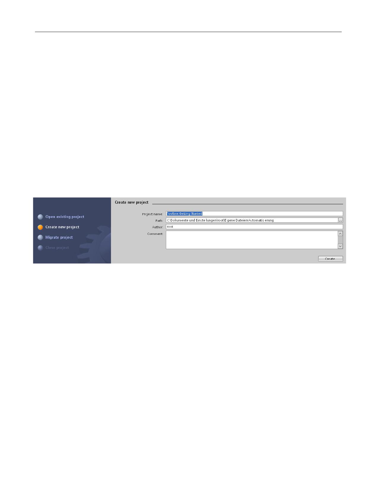
1. Click "Create new project" in the portal view.
2. Assign a project name and select the storage location of the project (path).
3. Click "Create".
Result
A new, empty project has been created.
SINUMERIK 840D sl STEP 7 Toolbox V16
Getting Started, 12/2019, 6FC5397-1GP40-0BA1
35
Getting Started
4.3 Creating a sample project
SINUMERIK 840D sl STEP 7 Toolbox V16
36
Getting Started, 12/2019, 6FC5397-1GP40-0BA1
Configuring the hardware
5
5.1
Configuration example
Introduction
The TIA Portal with the SINUMERIK Toolbox option package offers many options for
configuring the hardware. To better understand the individual functions, this Getting Started is
based on a specific configuration example. The following is an overview of this configuration
example with all components and interfaces.
Configuration overview
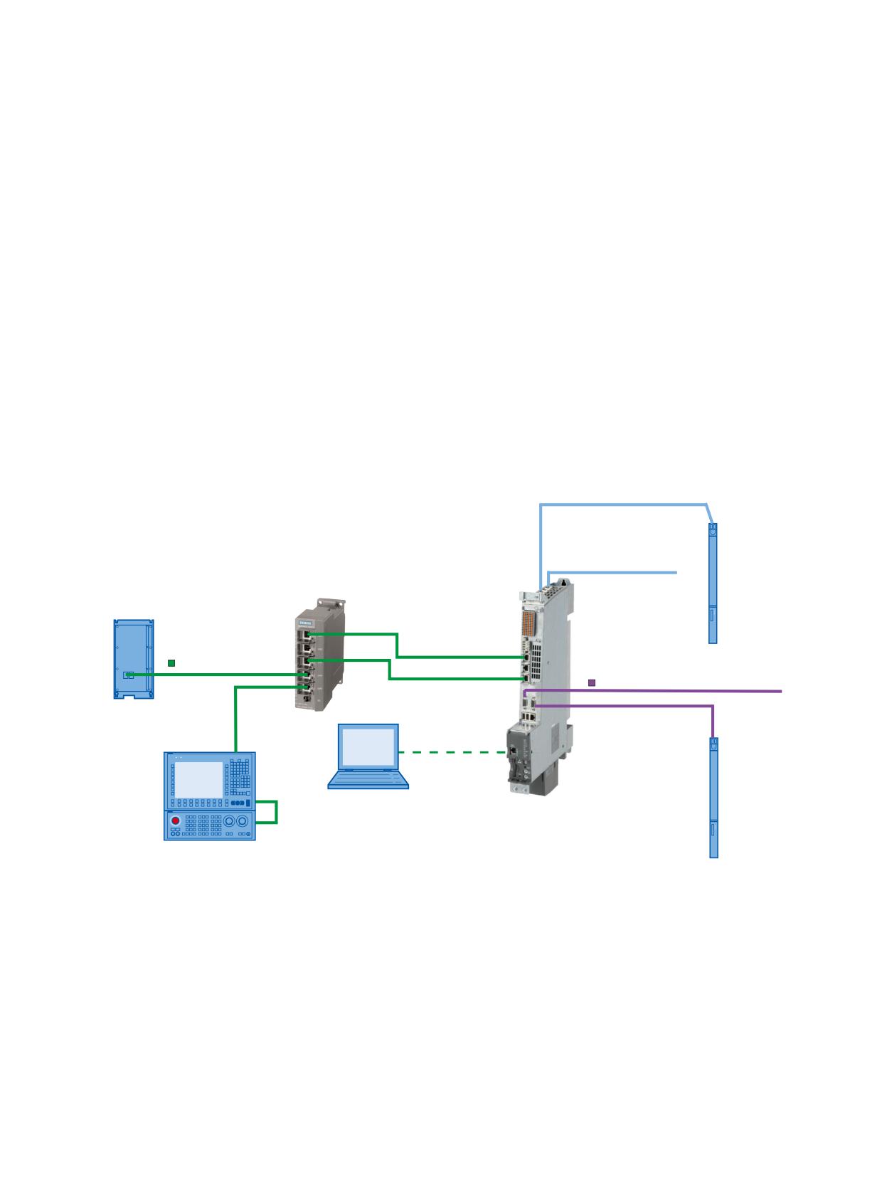
As an example, the following configuration of a SINUMERIK 840D sl is to be configured using
the TIA Portal:
NX15.3
DRIVE-CLiQ connection to
the drives
6,180(5,. 33
6&$/$1&( VZLWFK
;
' 31 SHULSKHUDO
, 2 PRGXOH
SINUMERIK
NCU 730.3 PN
;
PROFINET I/O
;
PROFIBUS I/O
;
;
Interface
module
ADI4
3* 3&
6,180(5,.
0&3
31
SINUMERIK operator panel front with TCU
In this sample configuration, drives are not connected to the control and therefore do not need
to be configured. If you have connected drives to your control system, you must configure them
outside of the TIA Portal. You can find a detailed explanation in the ""Commissioning CNC:
NCK, PLC, drive".
SINUMERIK 840D sl STEP 7 Toolbox V16
Getting Started, 12/2019, 6FC5397-1GP40-0BA1
37
Configuring the hardware
5.2 Insert NCU
5.2
Insert NCU
Introduction
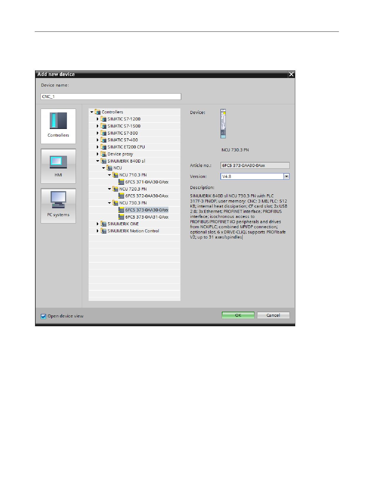
In the following, you insert the "NCU 730.3 PN" into the sample project. The NCU module
(Numeric Control Unit) is the CPU of the SINUMERIK 840D sl. It takes over all the CNC, PLC
and communication tasks.
Requirement
● A project is open in the TIA Portal.
Procedure
To insert a SINUMERIK NCU in the project view, proceed as follows:
1. Click "Add new device" in the project tree.
2. Click the "Controllers" button.
SINUMERIK 840D sl STEP 7 Toolbox V16
38
Getting Started, 12/2019, 6FC5397-1GP40-0BA1
Configuring the hardware
5.2 Insert NCU
3. In the folder structure under "Controllers", expand the corresponding SINUMERIK device
family (e.g. SINUMERIK 840D sl) and required NCU and select these.
Figure 5-1
Selected NCU using the SINUMERIK 840D sl NCU 730.3 PN V4.8 as an example
4. Select the firmware version that matches the envisaged firmware version of the real NCU in
the "Version" drop-down list.
5. Confirm your selection with "OK".
Result
The SINUMERIK NCU is created as new device.
SINUMERIK 840D sl STEP 7 Toolbox V16
Getting Started, 12/2019, 6FC5397-1GP40-0BA1
39
Configuring the hardware
5.3 Insert NX module
5.3
Insert NX module
Introduction
In the next step, you insert the NX module into the configuration. You can use this module to
increase the number of controlled axes connected to an NX module. Each NX10.3 can control
up to 3 additional axes and each NX15.3 can control up to 6 additional axes.
Procedure
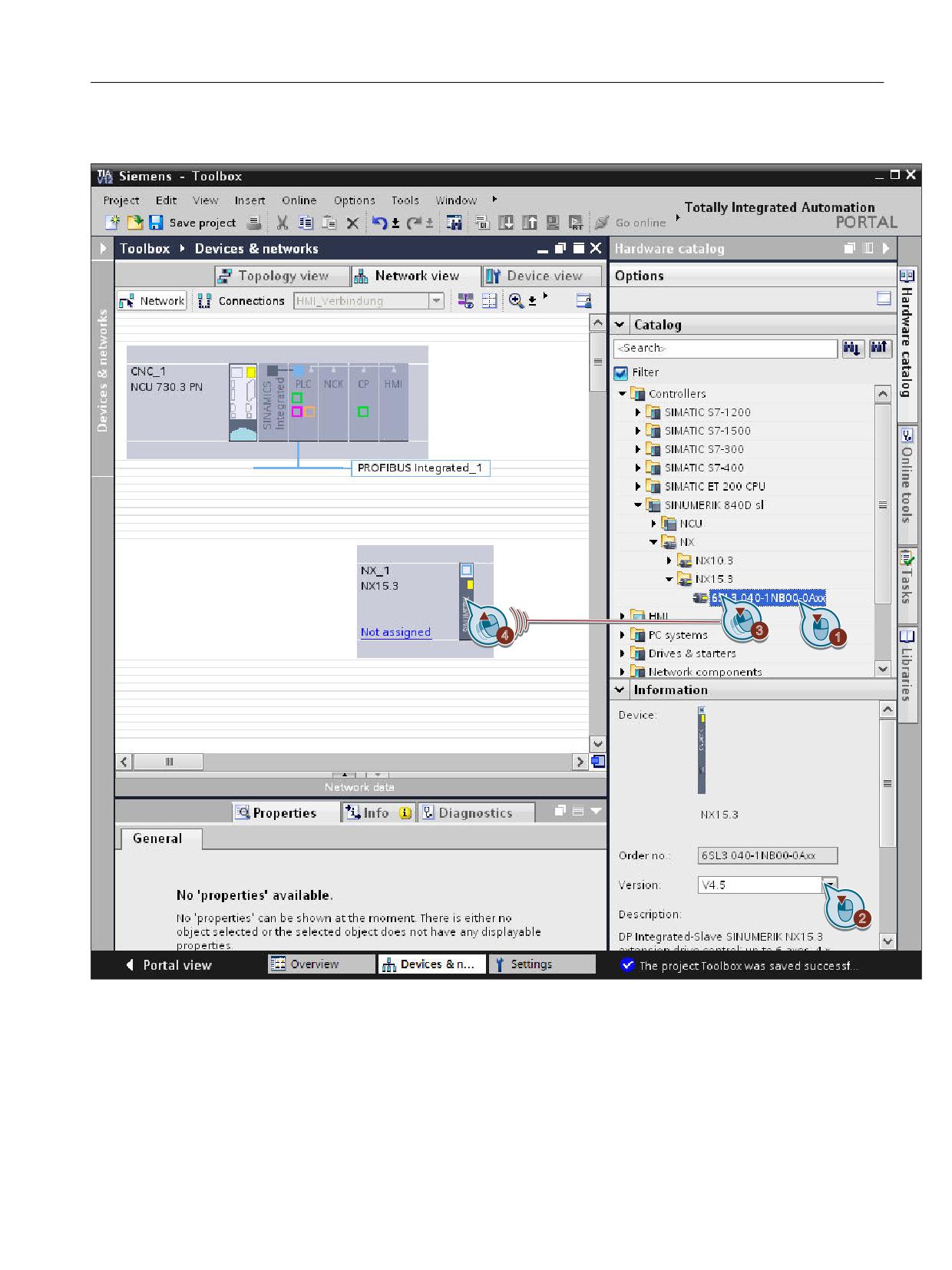
In order to insert an NX module into the project via the hardware catalog, proceed as follows:
1. In the network view, navigate in the hardware catalog to the folder "Controller > SINUMERIK
840D sl > NX" and select, for example, NX15.3 .
2. You can select the firmware version of the NX module at "Information" in the hardware
catalog. This must match the firmware version of the NCU. Firmware versions of the
configured hardware and the real hardware must match.
SINUMERIK 840D sl STEP 7 Toolbox V16
40
Getting Started, 12/2019, 6FC5397-1GP40-0BA1
Configuring the hardware
5.3 Insert NX module
3. Use drag-and-drop to move the NX module from the hardware catalog to the network view.
SINUMERIK 840D sl STEP 7 Toolbox V16
Getting Started, 12/2019, 6FC5397-1GP40-0BA1
41
Configuring the hardware
5.3 Insert NX module
4. To connect the NX module with a master system, click "Not assigned" and select the master
system.
Note
Connection to DP Integrated
Note that the NX modules can only be connected to the DP Integrated of a SINUMERIK
NCU, and not to external PROFIBUS interfaces!
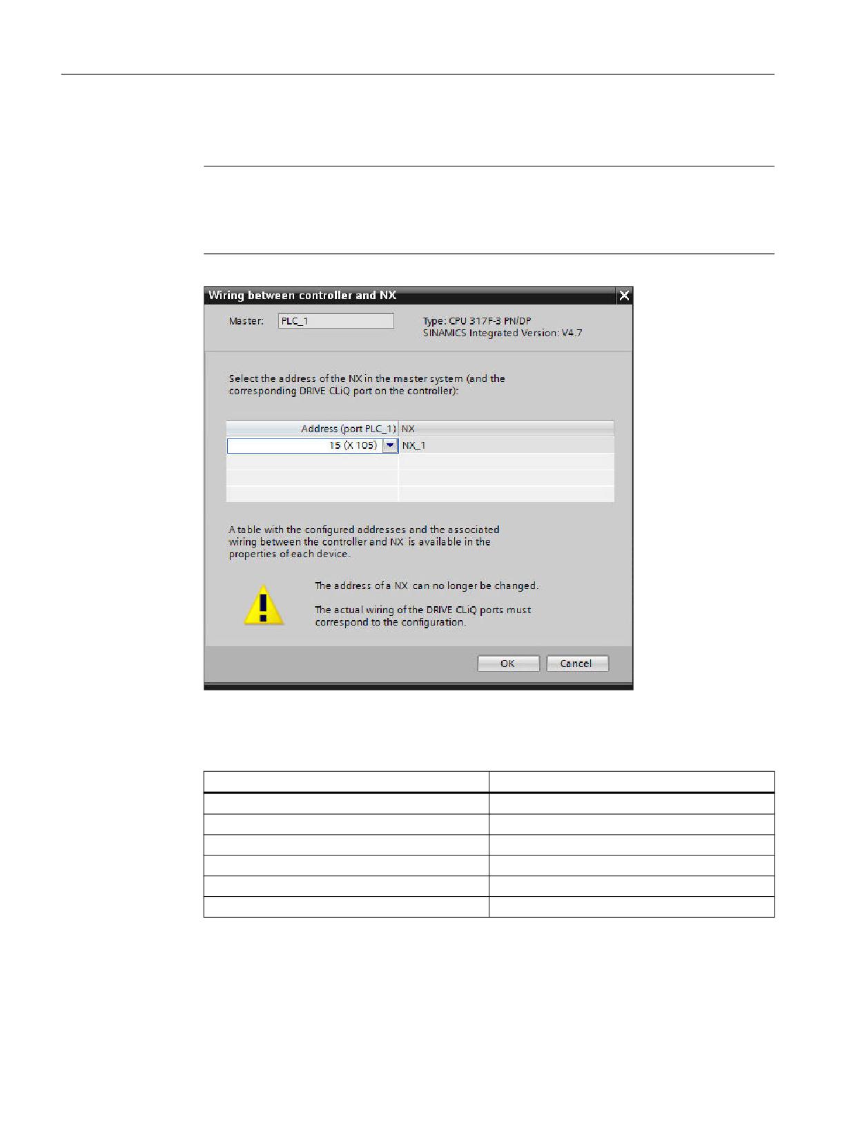
The NX is connected with the NCU and the "Wiring between control and NX" dialog opens.
5. In the "Wiring between control and NX" dialog, select the DP address of the NX in the master
system that matches your real wiring. The DP addresses of the NX modules are
permanently assigned to the DRIVE-CLiQ sockets of the NCU.
DP address of the NX in the master system
DRIVE-CLiQ socket on the NCU
10
X100
11
X101
12
X102
13
X103
14
X104
15
X105
SINUMERIK 840D sl STEP 7 Toolbox V16
42
Getting Started, 12/2019, 6FC5397-1GP40-0BA1
Configuring the hardware
5.3 Insert NX module
Note
This setting cannot be undone
Please note that once set, the DP address of an NX cannot be subsequently changed. The
NX modules must be connected to the DRIVE-CLiQ socket of the NCU in the real wiring that
corresponds to the permanently assigned DP address.
If you have incorrectly set the DP address of an NX, delete this NX from the project and add
a new one.
The DP address of the NX module is specified in accordance with your setting and the
appropriate I/O addresses of the telegrams are set automatically.
Note
Default I/O addresses of the telegrams
Depending on the set DP address, the appropriate I/O addresses of the telegrams are set
automatically.
Change this setting only when the I/O addresses of your telegrams differ from the default
setting!
You can also find information on the wiring between NCU and NX in the properties of the DP
Integrated interface on the NCU and NX under "PROFIBUS address".
SINUMERIK 840D sl STEP 7 Toolbox V16
Getting Started, 12/2019, 6FC5397-1GP40-0BA1
43
Configuring the hardware
5.3 Insert NX module
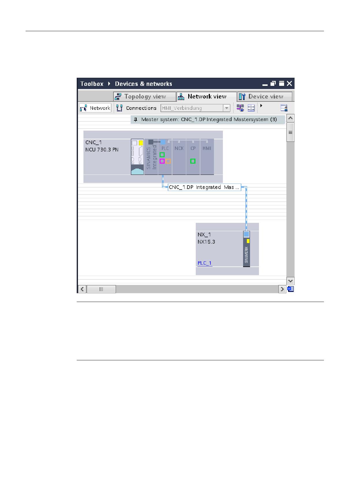
Result
The NX module has been inserted into the project and connected to an NCU.
Note
Handling the NX
● If NX modules were connected with the NCU and the NCU is subsequently deleted, the NX
modules are kept in the project as unconnected slave modules. They can be subsequently
assigned to another NCU. The parameter settings of the NX modules are retained.
● If the DP address of the NX is specified, then the I/O addresses matching the default setting
on the NCK side are entered.
SINUMERIK 840D sl STEP 7 Toolbox V16
44
Getting Started, 12/2019, 6FC5397-1GP40-0BA1
Configuring the hardware
5.4 Inserting an ADI4 module
5.4
Inserting an ADI4 module
Introduction
In the next step, insert the ADI4 module into the configuration and connect it with the MPI/DP
interface (X126).
An ADI4 module (Analog Drive Interface for 4 axes) is an interface module suitable for
operating up to four drives with an analog setpoint interface and TTL/SSI encoders on an
equidistant PROFIBUS DP.
SINUMERIK 840D sl STEP 7 Toolbox V16
Getting Started, 12/2019, 6FC5397-1GP40-0BA1
45
Configuring the hardware
5.4 Inserting an ADI4 module
Procedure
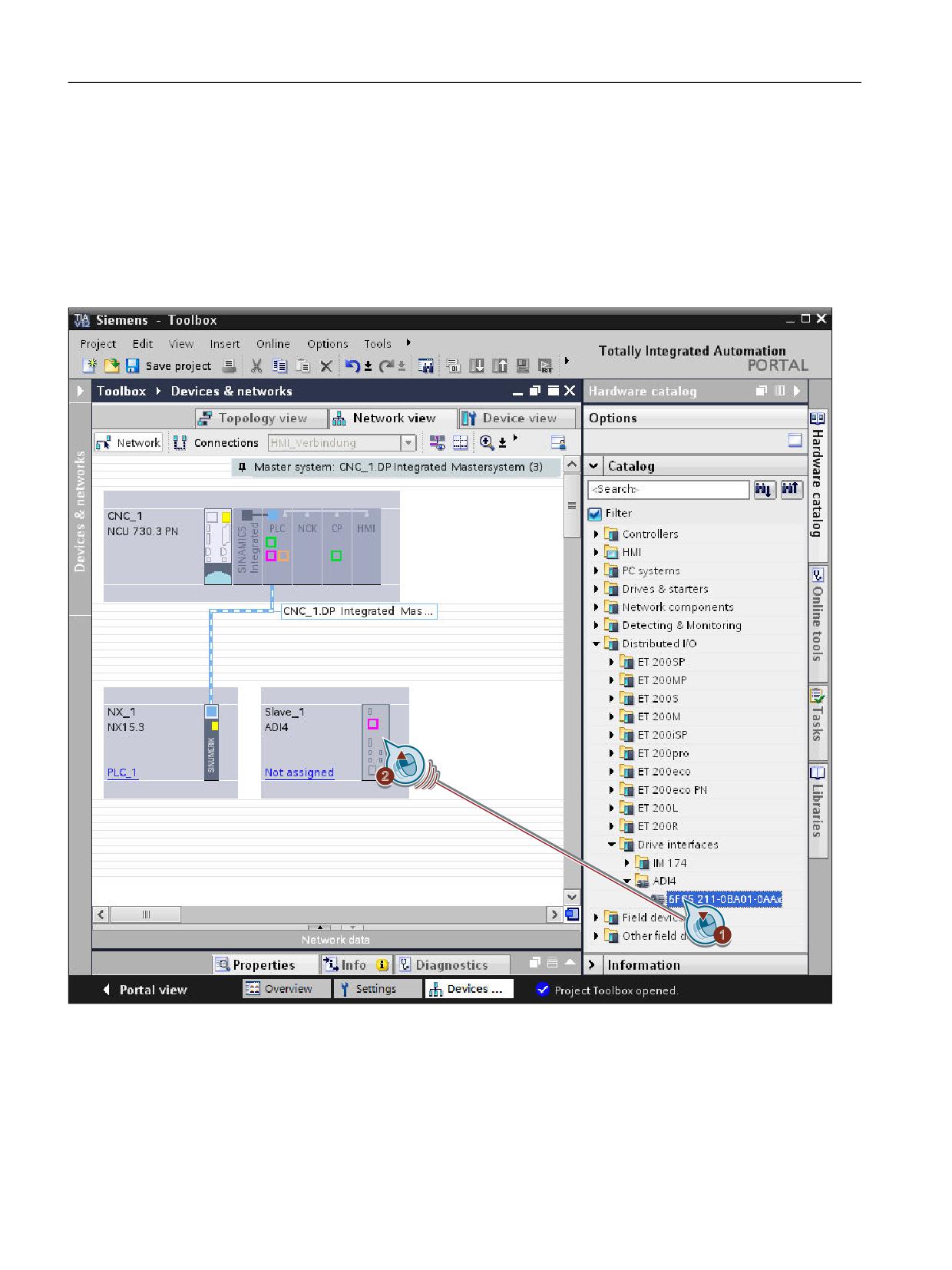
In order to insert an ADI4 module into the project via the hardware catalog, proceed as
follows:
1. In the hardware catalog, navigate to the folder "Distributed I/O > Drive Interfaces > ADI4"
and select the ADI4 module.
2. Use drag-and-drop to move the ADI4 module from the hardware catalog and place it in the
network view.
3. To connect the module to the master system, click "Not assigned" and select the DP
interface.
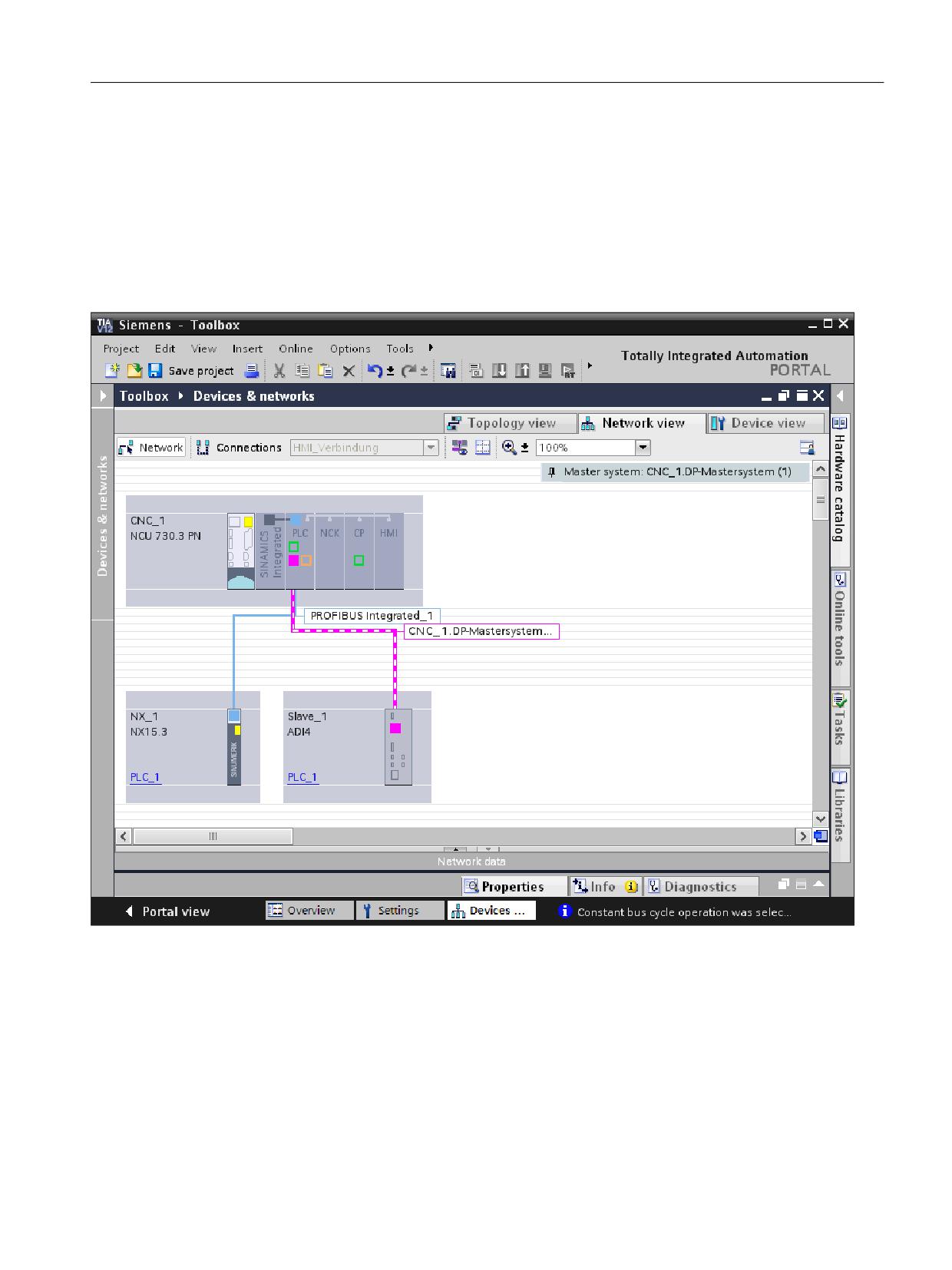
4. Click the "PROFIBUS_1" bus system and at "General > Network settings" in the "Properties"
tab in the inspector window, change the "Transmission rate" entry from 1.5 Mbit/s to 12 Mbit/
s. The ADI4 module can only be operated with 12 Mbit/s.
SINUMERIK 840D sl STEP 7 Toolbox V16
46
Getting Started, 12/2019, 6FC5397-1GP40-0BA1
Configuring the hardware
5.4 Inserting an ADI4 module
Reference
You can find additional information on the precise parameter assignment of the ADI4 module
in the "ADI4 - analog drive interface for four axes" manual.
Result
The ADI4 module has been created as new device and connected to the NCU.
SINUMERIK 840D sl STEP 7 Toolbox V16
Getting Started, 12/2019, 6FC5397-1GP40-0BA1
47
Configuring the hardware
5.5 Inserting SINUMERIK I/O via the general station description (GSD) file
5.5
Inserting SINUMERIK I/O via the general station description (GSD) file
Introduction
If you want to configure a SINUMERIK I/O that is not available in the hardware catalog, you
must first install the general station description file provided by the manufacturer. SINUMERIK
I/O installed using general station description files are displayed in the hardware catalog, and
can then be selected and configured.
PROFIBUS/PROFINET I/O differences
The general station description file describes all the properties of a PROFIBUS DP slave or a
PROFINET IO device.
● PROFIBUS DP slaves are described in GSD files
● PROFINET IO devices are described in GSDML files
The installation procedure does not differ.
Available SINUMERIK I/O
You can integrate the following SINUMERIK I/O via a GSD/GSDML file into the hardware
catalog at a later point in time:
● SINUMERIK PP 72/48D PN peripheral (I/O) module
● SINUMERIK machine control panel MCP
● SINUMERIK machine pushbutton panel MPP
● SINUMERIK handwheel connection module
Getting Started configuration example
In our configuration example, the following PROFINET I/O should be included using a GSDML
file:
● SINUMERIK MCP 310 PN machine control panel
● SINUMERIK PP 72/48D PN peripheral (I/O) module
SINUMERIK 840D sl STEP 7 Toolbox V16
48
Getting Started, 12/2019, 6FC5397-1GP40-0BA1
Configuring the hardware
5.5 Inserting SINUMERIK I/O via the general station description (GSD) file
5.5.1
Installing general station description files for SINUMERIK I/O
Requirement
The current version of the general station description (GSD/GSDML) files to be installed is
stored on your PG/PC.
Note
General station description files on the Service&Support pages
You can find the current versions of the general station description files in the Siemens Industry
Online Support:
SINUMERIK I/O: GSD/GSDML files (http://support.automation.siemens.com/WW/view/en/
62332440)
Procedure
To install SINUMERIK I/O via general station description files, proceed as follows:
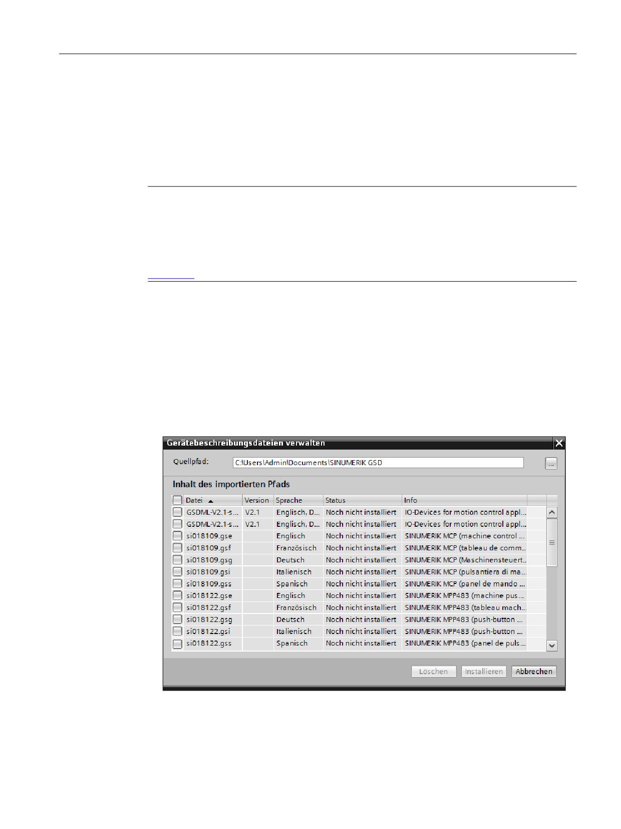
1. In the "Options" menu, select the command "Manage general station description files
(GSD)".
2. In the "Manage general station description files" dialog, select the folder that contains the
GSD/GSDML files.
The device description files saved in the source path are listed.
3. Select the checkboxes of the files that you want to install.
4. Confirm your entry with "Install".
SINUMERIK 840D sl STEP 7 Toolbox V16
Getting Started, 12/2019, 6FC5397-1GP40-0BA1
49
Configuring the hardware
5.5 Inserting SINUMERIK I/O via the general station description (GSD) file
Result
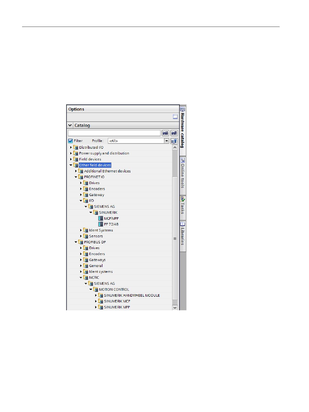
The general station description files are installed, and then the SINUMERIK I/O in the hardware
catalog displayed in the appropriate folders:
● SINUMERIK I/O for PROFINET IO: "Further field devices > PROFINET IO > I/O > SIEMENS
AG > SINUMERIK"
● SINUMERIK I/O for PROFIBUS DP: "Further field devices > PROFIBUS DP > NC/RC >
SIEMENS AG > MOTION CONTROL"
Figure 5-2
Installed SINUMERIK I/O in the hardware catalog
SINUMERIK 840D sl STEP 7 Toolbox V16
50
Getting Started, 12/2019, 6FC5397-1GP40-0BA1
Configuring the hardware
5.5 Inserting SINUMERIK I/O via the general station description (GSD) file
5.5.2
Inserting the SINUMERIK I/O module PP72/48
Requirement
● The respective PROFIBUS GSD file or PROFINET GSDML file is installed.
See: Installing general station description files for SINUMERIK I/O (Page 49)
● The network view is active.
SINUMERIK 840D sl STEP 7 Toolbox V16
Getting Started, 12/2019, 6FC5397-1GP40-0BA1
51
Configuring the hardware
5.5 Inserting SINUMERIK I/O via the general station description (GSD) file
Procedure
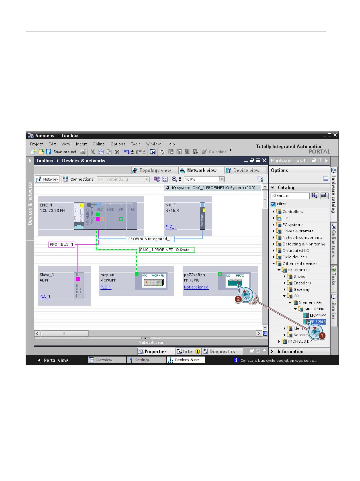
Proceed as follows to insert a PP72/48 I/O module:
1. In the hardware catalog, navigate to the respective device:
- PP72/48 (PROFIBUS): "Further field devices > PROFIBUS DP > NC/RC > SIEMENS
AG > MOTION CONTROL"
- PP72/48 (PROFINET): "Further field devices > PROFINET IO > I/O > SIEMENS AG >
SINUMERIK > PP72/48"
2. Use drag-and-drop to move the PP72/48 from the hardware catalog to the network view.
3. Interconnect the inserted SINUMERIK I/O with the NCU.
See TIA Portal online help, search term "Interconnect devices in the network view"
SINUMERIK 840D sl STEP 7 Toolbox V16
52
Getting Started, 12/2019, 6FC5397-1GP40-0BA1
Configuring the hardware
5.5 Inserting SINUMERIK I/O via the general station description (GSD) file
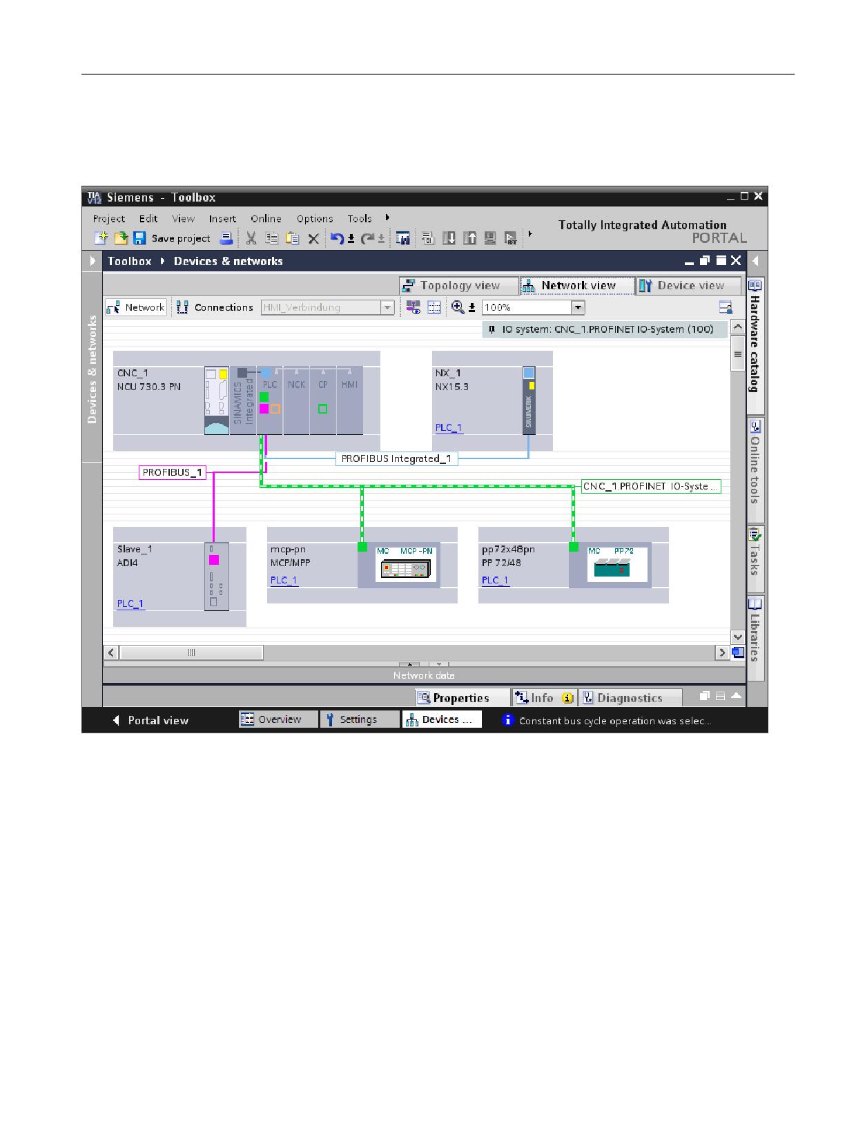
Result
The SINUMERIK I/O modules were created as new devices and connected to the NCU.
Additional information
You can find general information about the device in the SINUMERIK I/O module PP72/48D
2/2A PN manual
5.5.3
Inserting SINUMERIK MCP/MPP
Requirement
● The respective PROFIBUS GSD file or PROFINET GSDML file is installed.
See: Installing general station description files for SINUMERIK I/O (Page 49)
● The network view is active.
SINUMERIK 840D sl STEP 7 Toolbox V16
Getting Started, 12/2019, 6FC5397-1GP40-0BA1
53
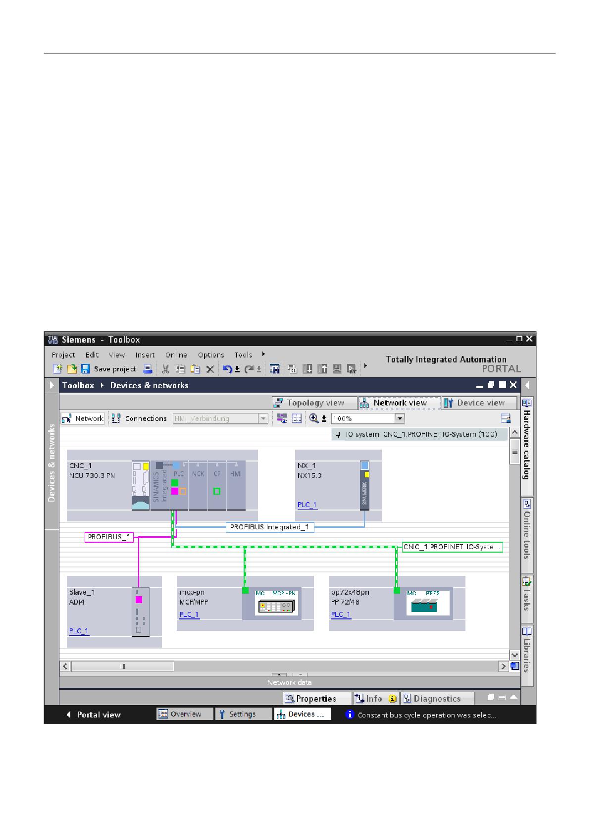
Configuring the hardware
5.5 Inserting SINUMERIK I/O via the general station description (GSD) file
Procedure
Proceed as follows to insert a SINUMERIK MCP/MPP:
1. In the hardware catalog, navigate to the respective device:
- MCP/MPP (PROFIBUS): "Further field devices > PROFIBUS DP > NC/RC > SIEMENS
AG > MOTION CONTROL"
- MCP/MPP (PROFINET): "Further field devices > PROFINET IO > I/O > SIEMENS AG >
SINUMERIK"
2. Use drag-and-drop to move the corresponding MCP/MPP from the hardware catalog to the
network view.
3. Interconnect the inserted SINUMERIK I/O with the NCU.
See TIA Portal online help, search term "Interconnect devices in the network view"
Result
The SINUMERIK MCP/MPP has been created as new device and connected to the NCU.
SINUMERIK 840D sl STEP 7 Toolbox V16
54
Getting Started, 12/2019, 6FC5397-1GP40-0BA1
Configuring the hardware
5.5 Inserting SINUMERIK I/O via the general station description (GSD) file
Additional information
General information on the device can be found in the respective manual.
SINUMERIK 840D sl STEP 7 Toolbox V16
Getting Started, 12/2019, 6FC5397-1GP40-0BA1
55
Configuring the hardware
5.6 Configuring network interfaces
5.6
Configuring network interfaces
5.6.1
Introduction
You must now configure or check the network interfaces. In our example configuration, they are
the following interfaces:
Interface
Communications
Connected component
X127
Ethernet
PG/PC
X120
Ethernet
Machine Control Panel
X150
PROFINET IO
I/O module
X126
PROFIBUS DP
ADI4 module
X105
DRIVE-CLiQ
NX module
5.6.2
Configuring an Ethernet Interface
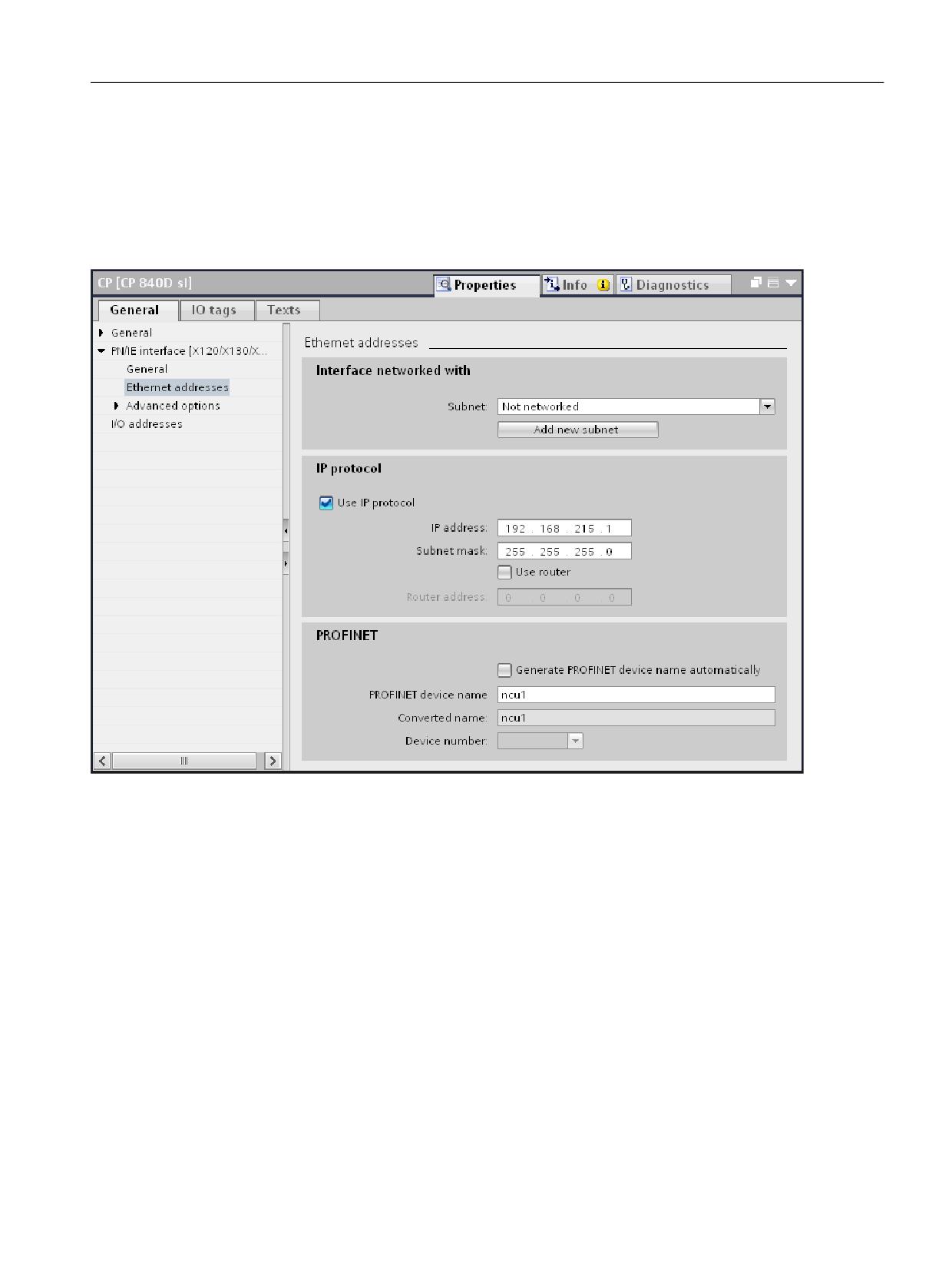
For the initial commissioning with a PG/PC, it is necessary to configure an Ethernet interface.
In our example, this involves the interface to the X127 socket.
SINUMERIK 840D sl STEP 7 Toolbox V16
56
Getting Started, 12/2019, 6FC5397-1GP40-0BA1
Configuring the hardware
5.6 Configuring network interfaces
Procedure
In order to set the Ethernet interface, proceed as follows:
1. In the network view, click the CP in the basic rack of the NCU.
2. Under the "Properties" tab in the inspector window, select the "PN/IE interface > Ethernet
addresses" entry.
3. Set the IP address matching your real configuration. If the PG/PC is connected to X127, the
following IP address applies:
Hardware factory setting on the NCU for socket X127
IP address: 192.168.215.1
Subnet mask: 255.255.255.0
5.6.3
Configuring PROFINET
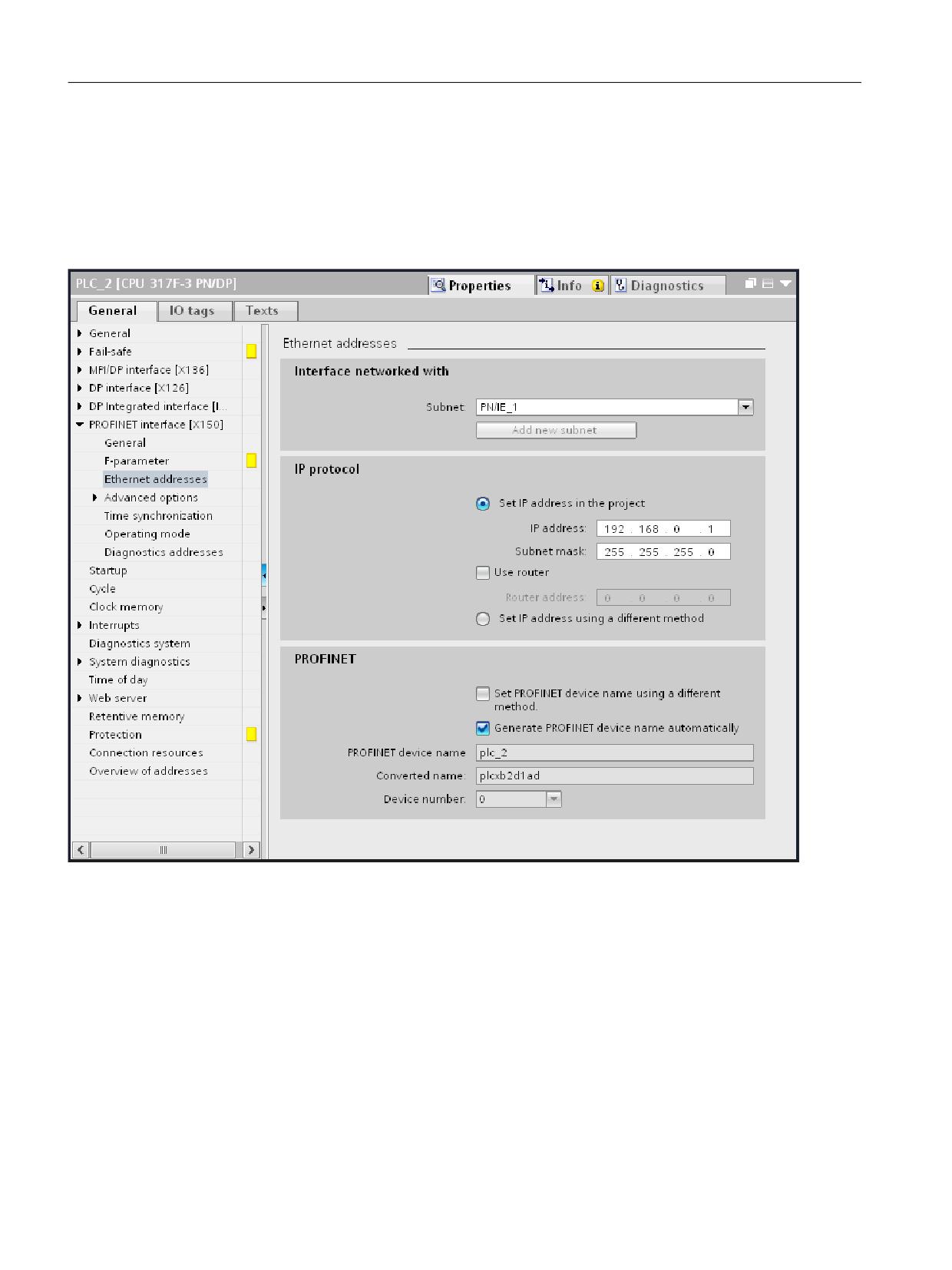
In our configuration example, the SINUMERIK I/O module PP 72/48D PN is connected to the
NCU via PROFINET. You configure the properties of the PROFINET interface for socket X150
as follows:
SINUMERIK 840D sl STEP 7 Toolbox V16
Getting Started, 12/2019, 6FC5397-1GP40-0BA1
57
Configuring the hardware
5.6 Configuring network interfaces
Procedure
In order to set the PROFINET interface, proceed as follows:
1. In the network view, click the PLC in the basic rack of the NCU.
2. Under the "Properties" tab in the inspector window, select the "PROFINET interface >
Ethernet addresses" entry.
3. Check under "IP protocol" whether the correct IP address is set ("192.168.0.1" in the
example).
5.6.4
Configuring PROFIBUS DP
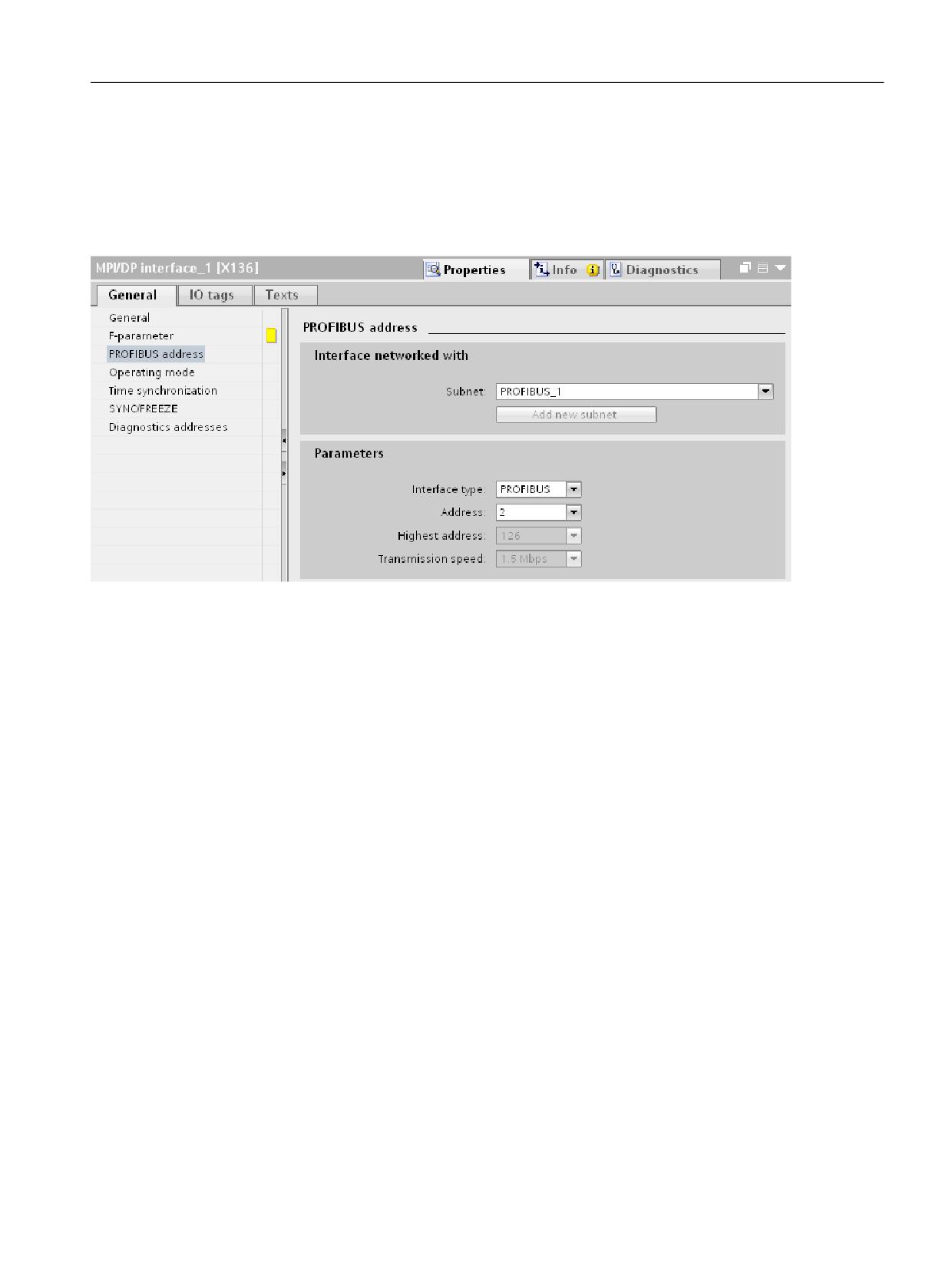
In our example, the ADI4 module is connected to the NCU via PROFIBUS DP. You configure
the properties of the PROFIBUS DP interface for socket X126 as follows:
Procedure
SINUMERIK 840D sl STEP 7 Toolbox V16
58
Getting Started, 12/2019, 6FC5397-1GP40-0BA1
Configuring the hardware
5.6 Configuring network interfaces
Configuring the PROFIBUS DP address on the PLC
1. In the network view, click the PLC in the basic rack of the NCU.
2. In the "Properties" tab, in the inspector window, select the entry "DP Interface > PROFIBUS
address".
The settings of the PROFIBUS address are displayed.
3. In the Parameters area, set the DP address of the interface on the PLC under "Address".
This is transferred from the configuration to the PLC during the load action.
Configuring the PROFIBUS DP address for the ADI4 module
1. In the network view, click the "DP" interface of the ADI4.
2. In the inspector window "Properties", select the entry "PROFIBUS address".
3. Under "Address" set the DP address that matches the hardware. The configured address
must match the hardware address. It is not accepted automatically.
Information about setting the DP address on the hardware is contained in the "ADI4 - Analog
drive interface for 4 axes" Device Manual.
Checking the transmission speed of the ADI4
Although you can view the "Transmission speed" parameter in the DP interface properties, you
must select the bus system to change it:
1. Click the bus system.
2. In the "Properties" inspector window, check under "Network settings" the "Transmission
speed" entry. The ADI4 module can be operated only with the transmission speed 12 Mbit/
s.
5.6.5
Configure Integrated PROFIBUS (DP Integrated)
The PROFIBUS addresses at the DP Integrated were already defined when wiring the NX, and
cannot be subsequently changed (see Insert NX module (Page 40)).
SINUMERIK 840D sl STEP 7 Toolbox V16
Getting Started, 12/2019, 6FC5397-1GP40-0BA1
59
Configuring the hardware
5.6 Configuring network interfaces
Procedure
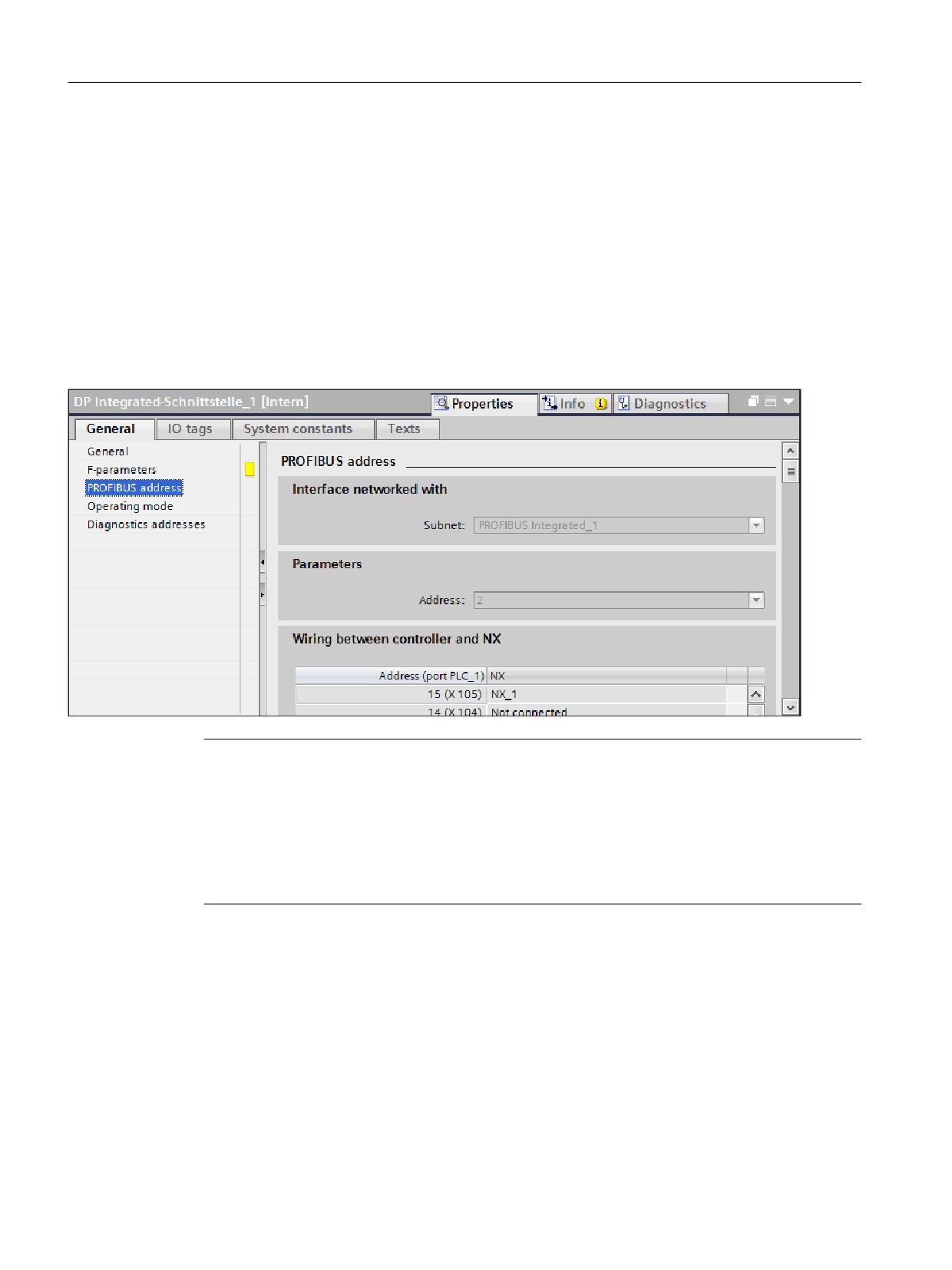
To check the PROFIBUS addresses, proceed as follows:
1. In the network view, click the DP Integrated interface of the PLC or select the interface in the
device overview.
2. In the "Properties" tab, in the inspector window, select the entry "PROFIBUS address".
Result
The DRIVE-CLiQ sockets of the real hardware are displayed to which the NX modules must be
connected.
Note
Cycle clock settings
You can only make the cycle clock settings on the PROFIBUS Integrated subnet and not
directly on the interface: For the selected subnet, you find the cycle clock settings under
"Equidistance" in the inspector window.
Observe the rules for setting the clock cycle at the field buses (see Commissioning Manual,
"Commissioning CNC: NCK, PLC, drive").
SINUMERIK 840D sl STEP 7 Toolbox V16
60
Getting Started, 12/2019, 6FC5397-1GP40-0BA1
Configuring the hardware
5.7 Configuration of telegrams and I/O addresses
5.7
Configuration of telegrams and I/O addresses
The I/O addresses and telegram types of the NX and SINAMICS Integrated components are
used for the communication between NCU and drive.
The telegrams and I/O addresses are already correctly preset and typically do not require any
configuration because the default settings in the TIA Portal correspond to the default settings
in the machine data of the NCU.
If you want to adapt the telegram configuration following creation of the Getting Started
configuration example, you will find further information in the TIA Portal information (menu
"Help > Show help"), keyword "Telegram configuration".
SINUMERIK 840D sl STEP 7 Toolbox V16
Getting Started, 12/2019, 6FC5397-1GP40-0BA1
61
Configuring the hardware
5.8 Setting up the communication
5.8
Setting up the communication
Introduction
To be able to load the configuration to the PLC, a communication connection (Ethernet) must
be established between the PG/PC and the PLC.
In our configuration example, connect the PG with X127 via Ethernet.
Note
Use the DHCP client
Make sure that the PG/PC at X127 is set to "DHCP Client" and the IP address can be assigned
by the NCU.
SINUMERIK 840D sl STEP 7 Toolbox V16
62
Getting Started, 12/2019, 6FC5397-1GP40-0BA1
Configuring the hardware
5.8 Setting up the communication
Procedure
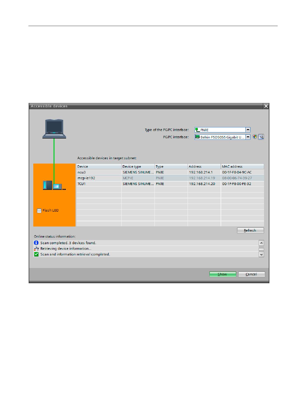
To establish a communication connection between two devices, proceed as follows:
1. In the "Online" menu, select the "Accessible devices" command.
2. In the drop-down lists "Type of PG/PC interface" and "PG/PC interface", search for the
interface used.
If no devices are accessible at an interface, the connecting line between the PG/PC and the
device is interrupted. If devices are accessible, the connecting line is shown and the devices
accessible at the selected interface of the PG/PC are displayed in a list.
SINUMERIK 840D sl STEP 7 Toolbox V16
Getting Started, 12/2019, 6FC5397-1GP40-0BA1
63
Configuring the hardware
5.8 Setting up the communication
3. If you have connected a new device in the meantime, click the "Refresh" button to refresh
the list of accessible devices.
4. Using "Display", transfer to the project navigator the device that has been found in the
"Online accesses" folder.
The subfolder of the interface to which the selected device is connected is selected in the
project tree.
Note
Several identical devices
If several identical devices can be accessed from the PG, by clicking on the "Flash LED"
button you can then display which device corresponds to the entry in the list of accessible
devices.
SINUMERIK 840D sl STEP 7 Toolbox V16
64
Getting Started, 12/2019, 6FC5397-1GP40-0BA1
Configuring the hardware
5.9 Loading and closing the hardware configuration in the PLC
5.9
Loading and closing the hardware configuration in the PLC
Introduction
The project must be stored and compiled before the system data is created for the PLC and the
complete configuration can be closed.
Requirement
● The hardware configuration is compiled.
● A communication connection exists between the PG/PC (TIA Portal) and the NCU.
Note
Loading configurations to simulated environments
If you want to use the configuration in a simulated environment, you must activate the
simulation capability in the project properties before you load the configuration into the
simulated environment or compile the hardware/software.
Note
General reset before loading into a PLC with Safety Integrated plus (F-PLC)
If the actual hardware has been operated in Safety Integrated plus (F-PLC) mode and you now
want to load a configured hardware configuration with changed Safety Integrated mode, you
must perform a general reset of the PLC prior to the loading.
SINUMERIK 840D sl STEP 7 Toolbox V16
Getting Started, 12/2019, 6FC5397-1GP40-0BA1
65
Configuring the hardware
5.9 Loading and closing the hardware configuration in the PLC
Procedure
Proceed as follows to load the configured hardware configuration into the NCU:
1. In the project navigation, right-click the device name, e.g. "CNC_1", and select the
"Hardware configuration" command in the "Download to device" shortcut menu.
Note
Scope of the data to be downloaded
Alternatively, you can select one of the other commands to start downloading additional
data to the NCU in this step.
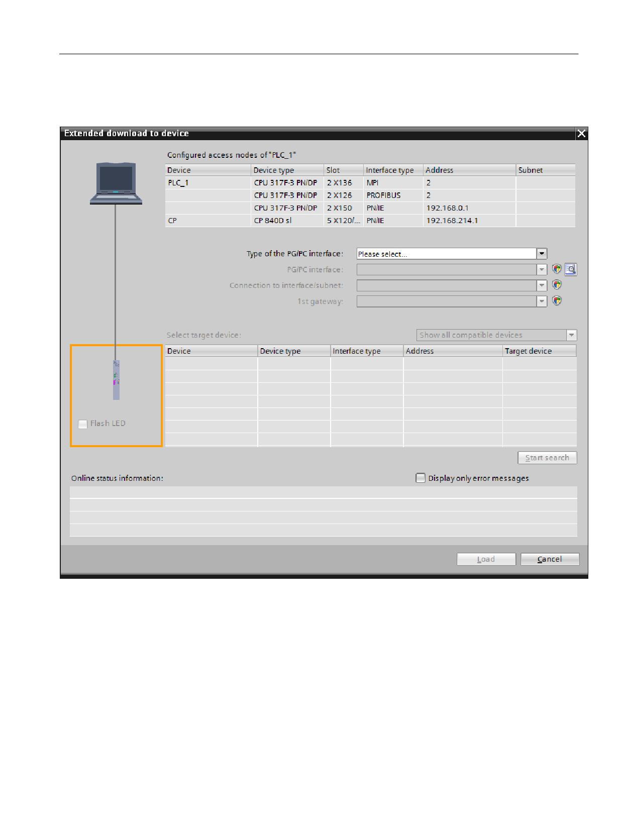
See TIA Portal help, keyword "General information on download".
The "Extended download" dialog opens.
SINUMERIK 840D sl STEP 7 Toolbox V16
66
Getting Started, 12/2019, 6FC5397-1GP40-0BA1
Configuring the hardware
5.9 Loading and closing the hardware configuration in the PLC
Figure 5-3
Dialog using the PLC of a SINUMERIK 840D sl as an example
2. Make the following settings in the "Extended download" dialog:
- PG/PC interface: Network card used, e.g. "Intel[R] Ethernet Connection I217-V"
- Connection with interface/subnet: Specific interface on the NCU or "Try all interfaces"
3. Click on "Start search" and then select the found PLC from "Compatible nodes in the target
subnet". Alternatively, you can specify an IP address directly in the "Compatible nodes in the
target subnet" list in the "Address" column.
SINUMERIK 840D sl STEP 7 Toolbox V16
Getting Started, 12/2019, 6FC5397-1GP40-0BA1
67
Configuring the hardware
5.9 Loading and closing the hardware configuration in the PLC
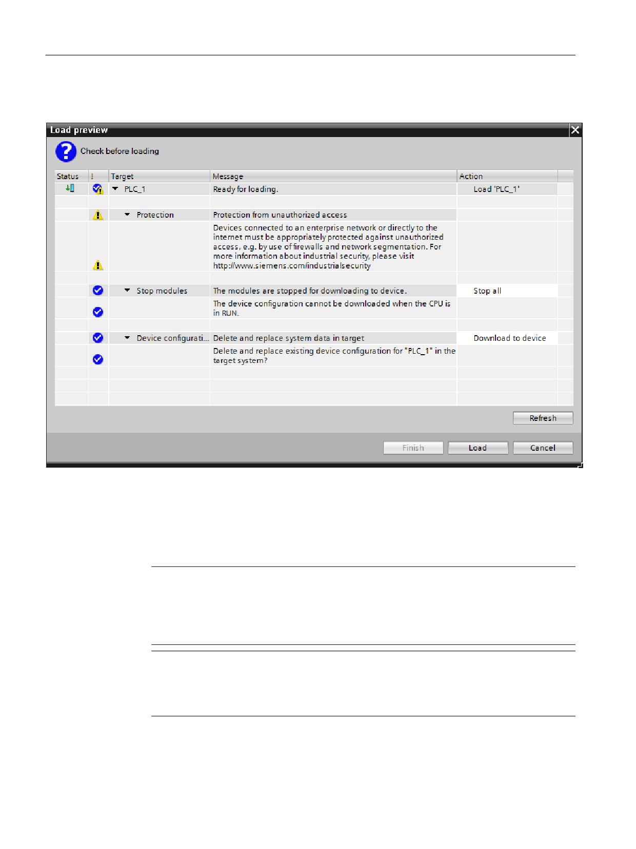
4. Confirm the download with "Load".
The "Download preview" dialog opens.
Figure 5-4
"Download preview" dialog
Note
Consistency check
Before the loading, the consistency of the download is checked. This means that a check is
made as to whether the parameterized hardware of the TIA Portal project matches the
hardware that has been actually installed.
Note
Adapt the IP address?
If the IP address of your PG/PC is located in a different subnet than the PLC, a dialog box
is displayed as to whether the IP address in the PG/PC should be adapted.
5. In the "Download preview" dialog, check the settings and click "Load" to confirm the input.
SINUMERIK 840D sl STEP 7 Toolbox V16
68
Getting Started, 12/2019, 6FC5397-1GP40-0BA1
Configuring the hardware
5.9 Loading and closing the hardware configuration in the PLC
Result
The PLC is stopped and the hardware configuring is loaded into the PLC. The "Results of the
loading action" dialog opens and displays the status of the loading action. The dialog restarts
the PLC after completion, provided the "Start" checkbox has not been deactivated.
SINUMERIK 840D sl STEP 7 Toolbox V16
Getting Started, 12/2019, 6FC5397-1GP40-0BA1
69
Configuring the hardware
5.9 Loading and closing the hardware configuration in the PLC
SINUMERIK 840D sl STEP 7 Toolbox V16
70
Getting Started, 12/2019, 6FC5397-1GP40-0BA1
Creating a PLC program
6
6.1
Overview
The PLC program is constructed modularly. It comprises the two parts:
● PLC basic program
The PLC basic program organizes the exchange of signals and data between the PLC user
program and the NCK, HMI, and machine control panel components.
Use the appropriate PLC basic program depending on the firmware version of an NCU.
- SINUMERIK 840D sl PLC basic program V4.5.x.x
- SINUMERIK 840D sl PLC basic program V4.7.x.x
- SINUMERIK 840D sl PLC basic program V4.8.x.x
- SINUMERIK 840D sl PLC Basic Program V4.9.2.x
● PLC user program
The PLC user program is the user-specific part of the PLC program by which the PLC basic
program has been augmented or extended.
Further information
General information about the PLC basic program is available in the online help of the TIA
Portal under the following keywords:
● Execution structure
● Block listing as table
● Assignment overview
● Generating blocks at runtime on the NCU
SINUMERIK 840D sl STEP 7 Toolbox V16
Getting Started, 12/2019, 6FC5397-1GP40-0BA1
71
Creating a PLC program
6.2 Adding the PLC basic program
6.2
Adding the PLC basic program
6.2.1
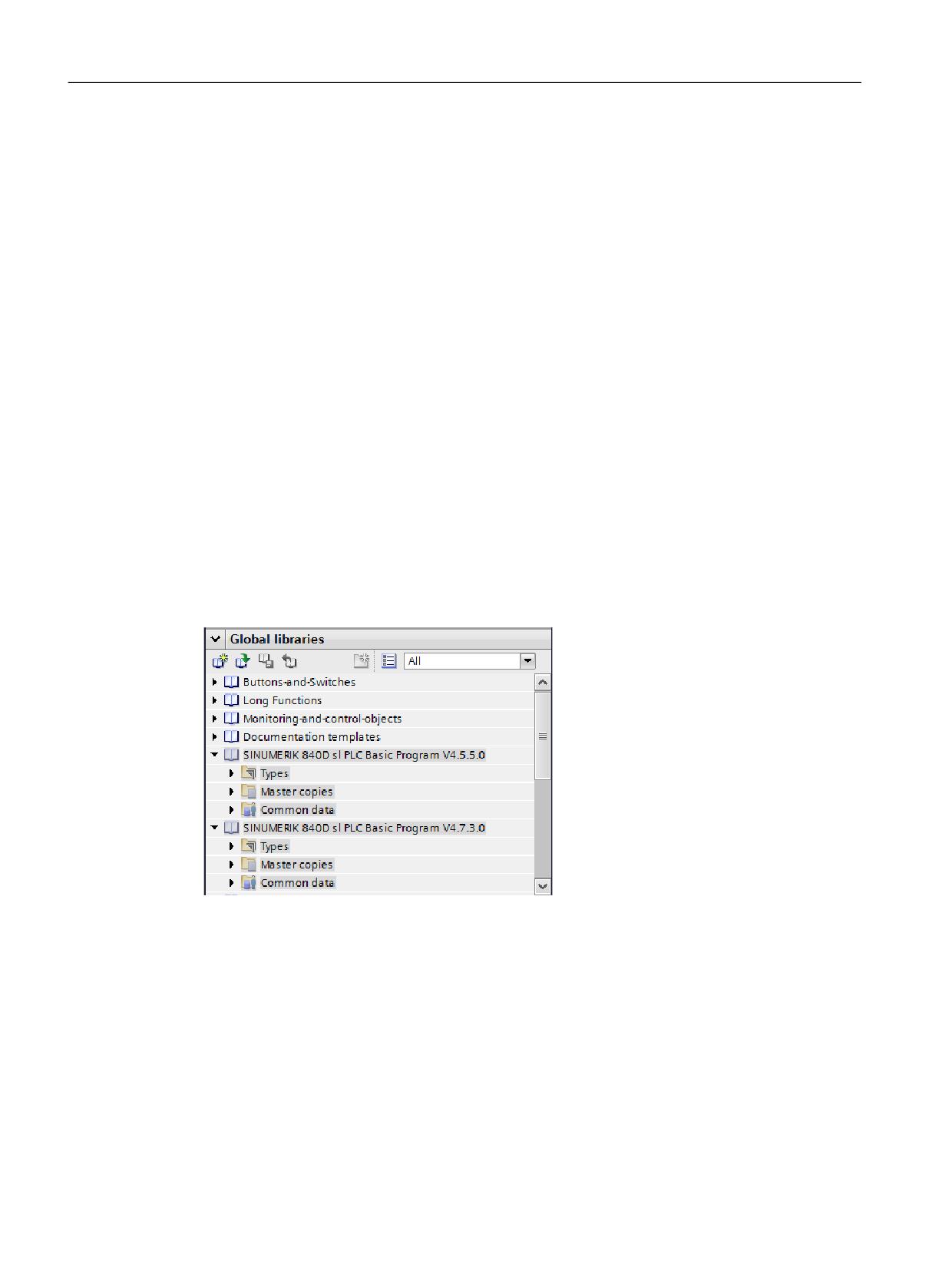
Opening the PLC basic program system library
Procedure
Proceed as follows to open and display the system library of the PLC basic program:
1. Switch to the "Libraries" task card.
2. Select the PLC basic program that matches the firmware version of the inserted NCU:
- SINUMERIK 840D sl PLC basic program V4.5.x.x
- SINUMERIK 840D sl PLC basic program V4.7.x.x
- SINUMERIK 840D sl PLC basic program V4.8.x.x
- SINUMERIK 840D sl PLC Basic Program V4.9.2.x
Result
The system library of the PLC basic program has been opened. Information on handling can be
found under Using copy templates (Page 73) and Adding the PLC basic program (Page 76).
Further information
The block descriptions and other information about the PLC basic program are contained in the
P3 section of the SINUMERIK 840D sl Basic Functions Manual. PLC basic program.
SINUMERIK 840D sl STEP 7 Toolbox V16
72
Getting Started, 12/2019, 6FC5397-1GP40-0BA1
Creating a PLC program
6.2 Adding the PLC basic program
6.2.2
Using copy templates
Introduction
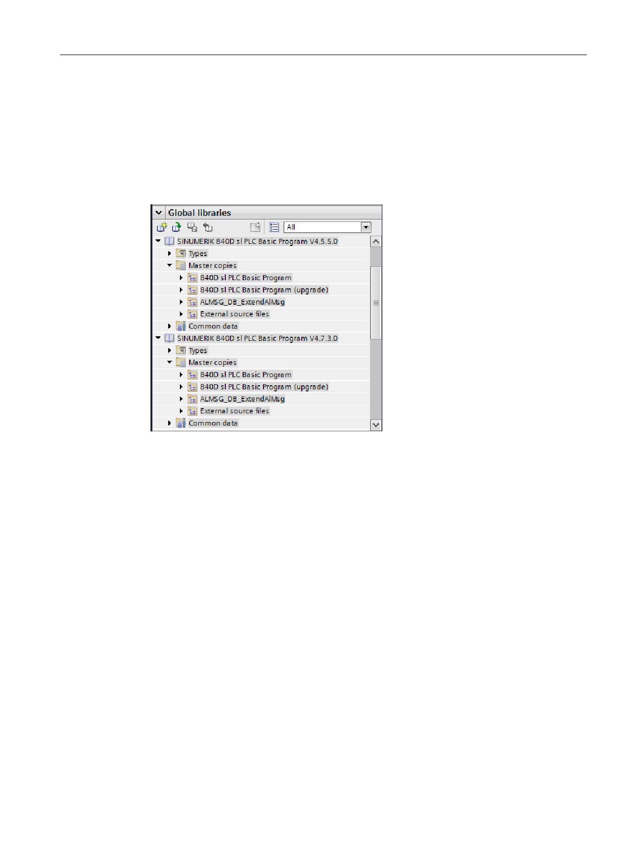
The "Global libraries" folder of the "Libraries" TaskCard contains the system library of the
SINUMERIK PLC program for your device version: "SINUMERIK 840D sl PLC basic program
V4.x.x.x".
Figure 6-1
Master copies of the SINUMERIK PLC program
Under the "Master copies" folder there are four subfolders with different contents. You can copy
the contents of these subfolders in their entirety or you can copy the individual objects as
needed.
● Using the Ctrl or shift key, you can select several objects of the same type and then copy
them.
● If you copy a master copies folder in its entirety (e.g. "840D sl PLC BP"), the folder structure
is imported, i.e. new groups (subfolders) are created in your "Program blocks" folder.
SINUMERIK 840D sl STEP 7 Toolbox V16
Getting Started, 12/2019, 6FC5397-1GP40-0BA1
73
Creating a PLC program
6.2 Adding the PLC basic program
Table 6-1
Use and content of the master copies of the PLC basic program
Folder
Purpose
Contents
840D sl PLC Ba-
This master copy is intended
The master copy contains all the blocks that you require for the maximum
sic Program
to create a completely new
configuration (31 axes, 10 channels).
project.
Use of axis/channel DB
If your machine is using fewer axes or channels, you can either copy only
the required blocks or you can delete the blocks that are not required in the
project tree after copying.
If you have blocks in your project that are not required, this increases,
for example, the time required for the loading or export of the PLC symbols.
Use of ALMSG_DB [DB2]
This master copy contains ALMSG_DB [DB2] in the variant Exten-
dAlMsg=False.
The used DB2 variant must match in the startup for parameterization of the
RUN_UP [FB1] in OB100 [OB100] (parameter ExtendAlMsg).
840D sl PLC Ba-
This master copy is used to
This master copy contains all the know-how-protected blocks that you re-
sic Program
upgrade blocks after the firm-
quire for the maximum configuration (31 axes, 10 channels).
(upgrade)
ware version of an NCU is up-
Blocks to be changed by the user are not included (no organization blocks
dated, i.e. if you have carried
and not FC12 [FC12], Diagnose [FB29], DB4 [DB4], DB5 [DB5]).
out a device replacement or
Use of axis/channel DB
a migration (Page 97).
If your machine is using fewer axes or channels, you can either copy only
the required blocks or you can delete the blocks that are not required in the
project tree after copying.
If you have blocks in your project that are not required, this increases,
for example, the time required for the loading or export of the PLC symbols.
Use of ALMSG_DB [DB2]
This master copy contains ALMSG_DB [DB2] in the variant Exten-
dAlMsg=False.
The used DB2 variant must match in the startup for parameterization of the
RUN_UP [FB1] in OB100 [OB100] (parameter ExtendAlMsg).
SINUMERIK 840D sl STEP 7 Toolbox V16
74
Getting Started, 12/2019, 6FC5397-1GP40-0BA1
Creating a PLC program
6.2 Adding the PLC basic program
Folder
Purpose
Contents
ALMSG_DB_Ex
You need this master copy if
This master copy contains ALMSG_DB [DB2] in the variant Exten-
tendAlMsg
you use the PLC alarm exten-
dAlMsg=True (PLC alarm extension via AL_MSG [FC10]).
sion via AL_MSG [FC10] (Ex-
The used DB2 variant must match in the startup for parameterization of the
tendAlMsg=True).
RUN_UP [FB1] in OB100 [OB100] (parameter ExtendAlMsg).
Otherwise you use the DB2
variant "Exten-
dAlMsg=False", which is con-
tained in the two above-
named master copies folders.
External source
Contains master copies for
Contains the following master copies, from which you can generate the
files
different external sources
blocks named below:
(STL).
● bhg_db_awl
You can copy these sources
- strdat [DB<xy>]
into the folder "External sour-
● diagnose.awl
ces", e.g. under "CNC_1 >
PLC_1 > External sources".
- FB29 [FB29]
You edit objects in the "Exter-
- DB80 [DB80]
nal sources" folder using an
- DB81 [DB81]
external text editor, e.g. Mi-
crosoft Editor.
- FC99 [FC99]
See also: Create blocks from
● gpob840d.awl
external sources (Page 80)
- OB1 [OB1]
- OB100 [OB100]
- OB40 [OB40]
- OB82 [OB82]
- OB86 [OB86]
● mdeclist.awl
- DB75 [DB75]
SINUMERIK 840D sl STEP 7 Toolbox V16
Getting Started, 12/2019, 6FC5397-1GP40-0BA1
75
Creating a PLC program
6.2 Adding the PLC basic program
Note
Selecting the appropriate master copy for ALMSG_DB [DB2]
There are 2 different variants of the block ALMSG_DB [DB2]. The used DB2 variant
(ALMSG_DB [DB2]) must match in the startup for parameterization of the RUN_UP [FB1] in
OB100 [OB100] (parameter ExtendAlMsg).
● DB2 variant "ExtendAlMsg=False"
This variant is contained in the master copies folders "840D sl PLC Basic Program" and
"840D sl PLC Basic Program (upgrade)".
If you use the previous procedure (default value of the parameter ExtendAlMsg in RUN_UP
[FB1]), you do not need to explicitly copy the "ALMSG_DB_ExtendAlMsg" master copy.
● DB2 variant "ExtendAlMsg=True"
This variant is exclusively contained in the separate master copies folder
"ALMSG_DB_ExtendAlMsg".
If you use the extension of the PLC alarms via AL_MSG [FC10], you must use the right
master copy, i.e. copy it separately into your "Program blocks" folder.
Further information about the extension of the PLC alarms via AL_MSG [FC10] is available
under the keyword "ExtendAlMsg" in the Basic Functions Manual, in particular, in the
"Extensions of the PLC alarms via block FC 10" section.
Further information
● General information on handling libraries in the TIA Portal can be found in the TIA Portal
online help, Section "Using libraries".
● The block descriptions and other information about the PLC basic program is contained in
the SINUMERIK 840D sl Basic Functions Manual in the P3: Basic PLC program section.
See also
Classification in the documentation landscape (Page 21)
6.2.3
Adding the PLC basic program
You can copy blocks of the PLC basic program from the respective system library. The "840D
sl PLC Basic Program" folder that it contains is meant for creating a completely new project.
You can copy the PLC basic program blocks in their entirety or individually.
Requirement
● A SINUMERIK 840D sl NCU is inserted.
● In the project, there are no blocks from other creators in the range of numbers of the PLC
basic program.
SINUMERIK 840D sl STEP 7 Toolbox V16
76
Getting Started, 12/2019, 6FC5397-1GP40-0BA1
Creating a PLC program
6.2 Adding the PLC basic program
Procedure
To copy program blocks of the basic program from a master copy to the program blocks folder
of the project tree, proceed as follows:
1. Switch to the "Libraries" task card and open the PLC basic program that matches the
firmware version of the inserted NCU:
- SINUMERIK 840D sl PLC basic program V4.5.x.x
- SINUMERIK 840D sl PLC basic program V4.7.x.x
- SINUMERIK 840D sl PLC basic program V4.8.x.x
- SINUMERIK 840D sl PLC Basic Program V4.9.2.x
See also: Opening the PLC basic program system library (Page 72), Using copy templates
(Page 73)
2. Open the folder "Master copies > 840D sl PLC Basic Program"
SINUMERIK 840D sl STEP 7 Toolbox V16
Getting Started, 12/2019, 6FC5397-1GP40-0BA1
77
Creating a PLC program
6.2 Adding the PLC basic program
3. You have several options for copying the PLC basic program blocks to your project:
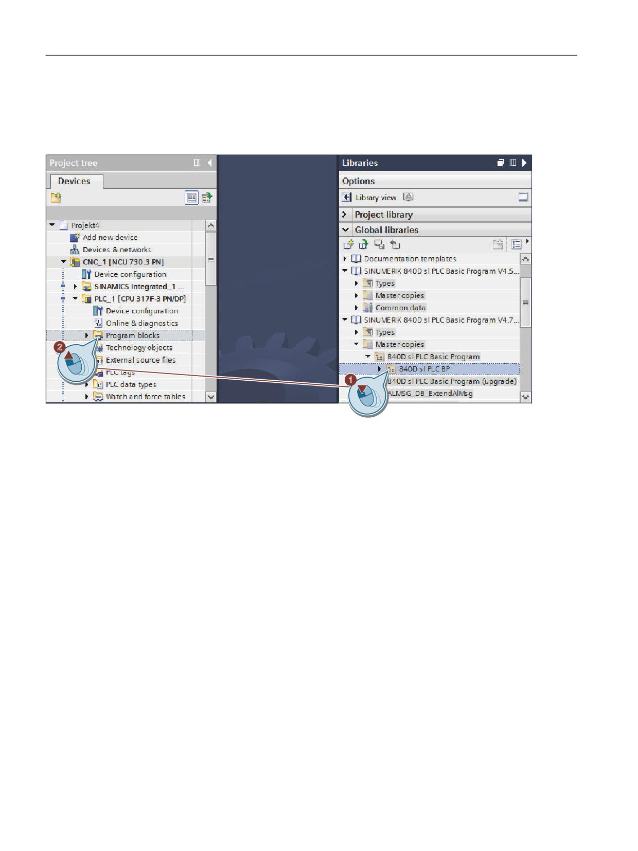
- Copying the PLC basic program including folder structure as a whole
Drag and drop the master copies folder "840D sl PLC BP" into the folder Program blocks,
e.g. under "CNC_1 > PLC_1 > Program blocks".
SINUMERIK 840D sl STEP 7 Toolbox V16
78
Getting Started, 12/2019, 6FC5397-1GP40-0BA1
Creating a PLC program
6.2 Adding the PLC basic program
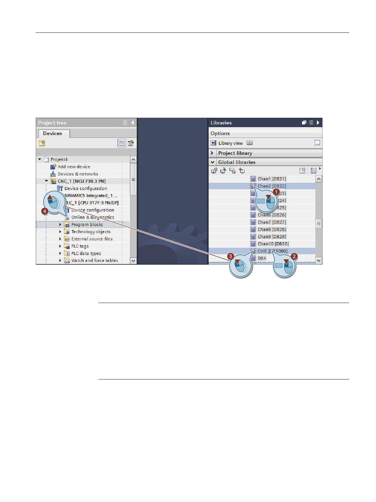
– Copying specific PLC basic program blocks
Open the master copies folder and, if applicable, other lower-level folders and manually
define the blocks which you would like to copy by selecting them and then dragging and
dropping them into the program blocks folder.
To select successive objects, click on the first object, press and hold the Shift key and
then click on the last object.
To select non-successive objects, press and hold the Ctrl key and click on the objects
one-by-one.
Strg
Strg
The blocks are copied to your project. If applicable, the "Conflicts during copying" dialog is
displayed.
Note
Copy further required blocks separately (e.g. DB2 variant "ExtendAlMsg=True")
If you are using PLC basic program blocks that are not contained in the master copies folder
"840D sl Basic Program > 840D sl PLC BP", you must copy them separately:
● DB2 variant "ExtendAlMsg=True" from the master copies folder
"ALMSG_DB_ExtendAlMsg"
● Different external STL sources from the master copies folder "External source files"
See: Create blocks from external sources (Page 80), Using copy templates (Page 73)
4. In the project tree, right-click "Program blocks" and select the "Software (compile all blocks)"
command in the "Compile" shortcut menu.
SINUMERIK 840D sl STEP 7 Toolbox V16
Getting Started, 12/2019, 6FC5397-1GP40-0BA1
79
Creating a PLC program
6.2 Adding the PLC basic program
Result
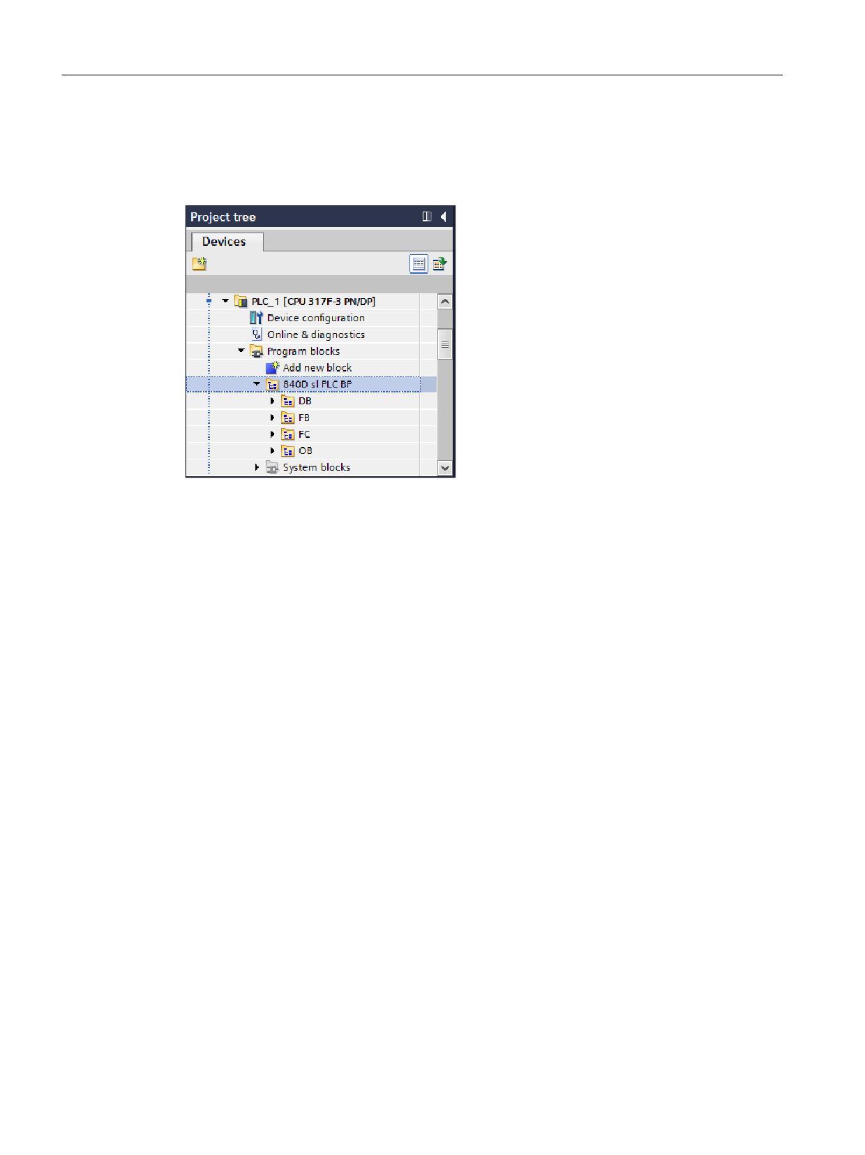
The blocks of the SINUMERIK PLC basic program have been copied to your project. Any
copied folder structure has been imported.
Figure 6-2
Program blocks folder
Now you can check the copied blocks and, if applicable, manually delete the PLC basic
program blocks that you do not require (e.g. unused axis DB, channel DB, FB or FC).
If you have unused blocks in your project, some tasks take unnecessarily long, e.g. the loading
or the creation and import of SINUMERIK archives.
6.2.4
Create blocks from external sources
You do not manage external source files (e.g. *.STL or *.SCL) in TIA Portal in the "Program
blocks" folder, but in the "External sources" folder, e.g. under "CNC_1 > PLC_1 > External
sources". You can then generate blocks from the sources maintained there. These are saved
in the "Program blocks" folder.
You do not edit the files in the "External sources" folder using a TIA Portal editor, but with any
external editor, which you define under Windows.
SINUMERIK 840D sl STEP 7 Toolbox V16
80
Getting Started, 12/2019, 6FC5397-1GP40-0BA1
Creating a PLC program
6.2 Adding the PLC basic program
Requirement
● An external source is available in STL or SCL format.
● The mnemonic set in the TIA Portal corresponds to the setting used in the external source.
These settings are found in the menu bar of the TIA Portal as follows: "Extras > Settings >
General > General settings > Mnemonic".
Note
Use of German mnemonics in external source files of the PLC basic program
The mnemonic setting "German" is required in all external source files contained in the copy
templates of the PLC basic program. This affects the files "bhg_db_awl", "diagnose.awl",
"gpob840d.awl" and "mdeclist.awl".
The process fails if the setting does not correspond to the setting of the source file when the
block is generated.
Procedure
1. In the project tree, select the "Add new external file" command in the "CNC_1 > PLC_1 >
External sources" folder.
2. Select the external file (*.STL or *.SCL) that you want to add in the "Open" dialog.
The external file is copied to the "External sources" folder in the project tree.
Note
Displaying external sources (e.g. STL files) using an external editor
The internal editor of the TIA Portal does not display external sources.
If you add and open an external source in the TIA Portal, the file will be opened with the
application linked with the associated file type (e.g. STL) in Windows (e.g. Microsoft Editor).
See also: TIA Portal online help, search term "Using external source files"
3. Right-click the external source, then select the "Generate blocks from source" command in
the shortcut menu.
Result
You have successfully generated blocks from an external source.
Further information about external sources of the PLC basic program system library can be
found in the SINUMERIK 840D sl Basic Functions Manual.
6.2.5
Correcting OB1
When inserting the blocks from a master copy of the library, the existing organization block OB1
is duplicated because it has a different name in the library than in the newly created PLC.
● Block in project tree: Main [OB1] or the name of your migrated block.
● Block in library: OB1 [OB1]
SINUMERIK 840D sl STEP 7 Toolbox V16
Getting Started, 12/2019, 6FC5397-1GP40-0BA1
81
Creating a PLC program
6.2 Adding the PLC basic program
When the project is compiled, a message is displayed that there may only be one object of the
type "OB1".
Procedure
To identify the not required version of the OB1 and to rectify the problem, proceed as follows:
1. Delete one of the duplicated OB1 blocks in the "program blocks" folder:
- If the "program blocks" folder prior to the insertion contained only the empty Main [OB1]
standard block, you can delete it.
- If you have already programmed your own instructions in the OB1, this block normally
already contains the call for the basic program and you can delete the newly added "OB1
[OB1]" block.
SINUMERIK 840D sl STEP 7 Toolbox V16
82
Getting Started, 12/2019, 6FC5397-1GP40-0BA1
Creating a PLC program
6.3 Edit blocks
6.3
Edit blocks
The individual blocks in the PLC basic program can be processed as follows in the TIA Portal:
Procedure
1. Select the block that you would like to edit (e.g. OB100 [OB100]) in the project tree under
"CNC_1 > PLC_1 > Program blocks".
2. Open the block by double-clicking it.
Note
Change the programming language
You can change the programming language under the "Properties" tab in the inspector
window, under "General > Language". The following can be selected:
● LAD
● FBD
● STL
Further information
How you can specifically change and expand a user program is described in the documentation
of SIMATIC STEP 7 as well as in the higher-level online help of the TIA Portal.
SINUMERIK 840D sl STEP 7 Toolbox V16
Getting Started, 12/2019, 6FC5397-1GP40-0BA1
83
Creating a PLC program
6.4 Configuring Ethernet machine control panels in the PLC program
6.4
Configuring Ethernet machine control panels in the PLC program
The PLC basic program automatically transfers the machine control panel signals (MCP
signals) and the addresses of the MCP in the hardware configuration if the configuration is set
up as laid out below.
SINUMERIK 840D sl STEP 7 Toolbox V16
84
Getting Started, 12/2019, 6FC5397-1GP40-0BA1
Creating a PLC program
6.4 Configuring Ethernet machine control panels in the PLC program
Procedure
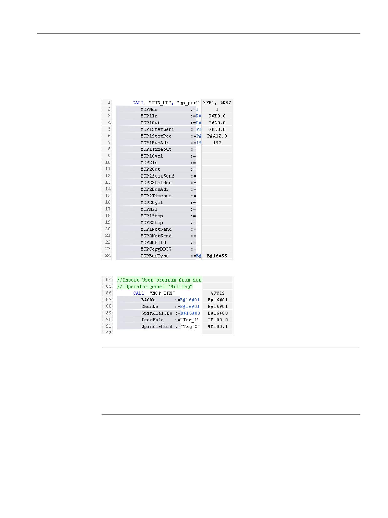
1. In the project tree, under "CNC_1 > PLC_1 > Program blocks" open the "OB100" with a
double-click.
2. Set the following parameters:
3. Open the OB1 and insert the following user program:
Note
Hardware address must correspond to the software address
Make sure that the address of the MCP on the hardware corresponds to the configured
address of the MCP in the TIA Portal. (Parameter MCPxBusAdr; see also Function Manual,
SINUMERIK 840D sl Basic Functions)
In our example, you must set the address at the hardware (at the DIP switch of the device)
to 192.
Result
You have completed the configuration of the PLC basic program.
SINUMERIK 840D sl STEP 7 Toolbox V16
Getting Started, 12/2019, 6FC5397-1GP40-0BA1
85
Creating a PLC program
6.4 Configuring Ethernet machine control panels in the PLC program
Further information
Information on the addressing of the machine control panel can be found in Function Manual,
SINUMERIK 840D sl Basic Functions, Section MCP interface in the PLC.
SINUMERIK 840D sl STEP 7 Toolbox V16
86
Getting Started, 12/2019, 6FC5397-1GP40-0BA1
Creating a PLC program
6.5 Loading the PLC program to the PLC
6.5
Loading the PLC program to the PLC
Introduction
For loading the configured PLC project, the following preconditions must be fulfilled:
Precondition
● Typically, between the PG/PC and the PLC, there is an Ethernet network connection; this
is also the case in our particular example (see Setting up the communication (Page 62)).
● The configuration to be loaded corresponds to the actual station configuration.
● In the previous Chapter Loading and closing the hardware configuration in the PLC
(Page 65) you loaded the hardware configuration to the module.
● The NCU is active:
- NCK is in cyclic mode.
- PLC in RUN or STOP mode.
Procedure
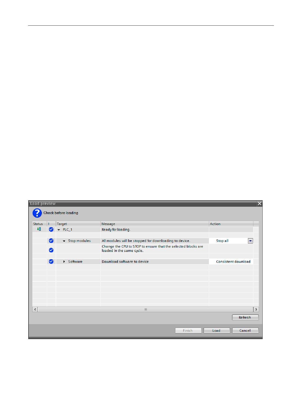
1. In the project tree, right-click "CNC_1 > PLC_1" and select "Load to device > Software
(changes only)" in the context menu.
The "Load preview" dialog opens.
2. In the "Download preview" dialog, check the settings and click "Load" to confirm the input.
SINUMERIK 840D sl STEP 7 Toolbox V16
Getting Started, 12/2019, 6FC5397-1GP40-0BA1
87
Creating a PLC program
6.5 Loading the PLC program to the PLC
Result
The PLC is stopped and the PLC program is loaded into the PLC. The "Results of the loading
action" dialog opens and displays the status of the loading action. The dialog restarts the PLC
after completion provided the "Start" checkbox has not been disabled.
SINUMERIK 840D sl STEP 7 Toolbox V16
88
Getting Started, 12/2019, 6FC5397-1GP40-0BA1
Creating a PLC program
6.6 Exporting PLC symbols for SINUMERIK Operate
6.6
Exporting PLC symbols for SINUMERIK Operate
6.6.1
Overview
You can make PLC symbols defined in the TIA Portal available for SINUMERIK Operate in able
to use them for various functions there. You must export the symbols of the associated PLC in
the TIA Portal and then import into SINUMERIK Operate.
Note
Deleting unwanted blocks before exporting PLC symbols
If you have saved unwanted blocks in your project, this lengthens the time required for
exporting and importing PLC symbols.
Consequently, delete unwanted blocks that you copied previously from the basic program
library prior to the export.
See: Using copy templates (Page 73)
Requirement
● The software has been compiled completely.
● The associated languages are activated as project languages in the TIA Portal.
See: Information system, "Activate project languages" section
Note
Comments only in German or English
Because SINUMERIK Operate can manage only German and English comments, you can
export only German and English comments from the TIA Portal.
● The PLC symbols to be exported are valid.
Note
Only valid PLC symbols are exported
The following PLC symbols are not taken into account during the export:
● PLC symbols of know-how-protected blocks
● PLC symbols of F-blocks
● Internal PLC symbols
● Invalid/faulty PLC symbols
SINUMERIK 840D sl STEP 7 Toolbox V16
Getting Started, 12/2019, 6FC5397-1GP40-0BA1
89
Creating a PLC program
6.6 Exporting PLC symbols for SINUMERIK Operate
Procedure overview
Table 6-2
Example procedure for creating and loading PLC symbols
Step
Description
1
If necessary, check or edit symbols in the TIA Portal
● You can change the symbolic names of blocks by right-clicking the block and selecting
"Rename" from the shortcut menu.
● You can change symbols of the individual elements in the block editor.
● PLC variables for Flags, Times, Input, Output, Timer and Counter can be changed in the
associated table field (e.g. under "CNC_1 > PLC 1 > PLC variables > Display all variables")
2
Exporting PLC symbols with the TIA Portal (Page 90)
3
If necessary, make export files available on the NCU or PCU, e.g. using a USB FlashDrive
4
Importing PLC symbols in SINUMERIK Operate (Page 93)
6.6.2
Exporting PLC symbols
Note
Deleting unwanted blocks before exporting PLC symbols
If you have saved unwanted blocks in your project, this lengthens the time required for
exporting and importing PLC symbols.
Consequently, delete unwanted blocks that you copied previously from the basic program
library prior to the export.
See: Using copy templates (Page 73)
SINUMERIK 840D sl STEP 7 Toolbox V16
90
Getting Started, 12/2019, 6FC5397-1GP40-0BA1
Creating a PLC program
6.6 Exporting PLC symbols for SINUMERIK Operate
Requirement
● The software has been compiled completely.
● The associated languages are activated as project languages in the TIA Portal.
See: Information system, "Activate project languages" section
Note
Comments only in German or English
Because SINUMERIK Operate can manage only German and English comments, you can
export only German and English comments from the TIA Portal.
● The PLC symbols to be exported are valid.
Note
Only valid PLC symbols are exported
The following PLC symbols are not taken into account during the export:
● PLC symbols of know-how-protected blocks
● PLC symbols of F-blocks
● Internal PLC symbols
● Invalid/faulty PLC symbols
SINUMERIK 840D sl STEP 7 Toolbox V16
Getting Started, 12/2019, 6FC5397-1GP40-0BA1
91
Creating a PLC program
6.6 Exporting PLC symbols for SINUMERIK Operate
Procedure
To export PLC symbols for SINUMERIK Operate, proceed as follows:
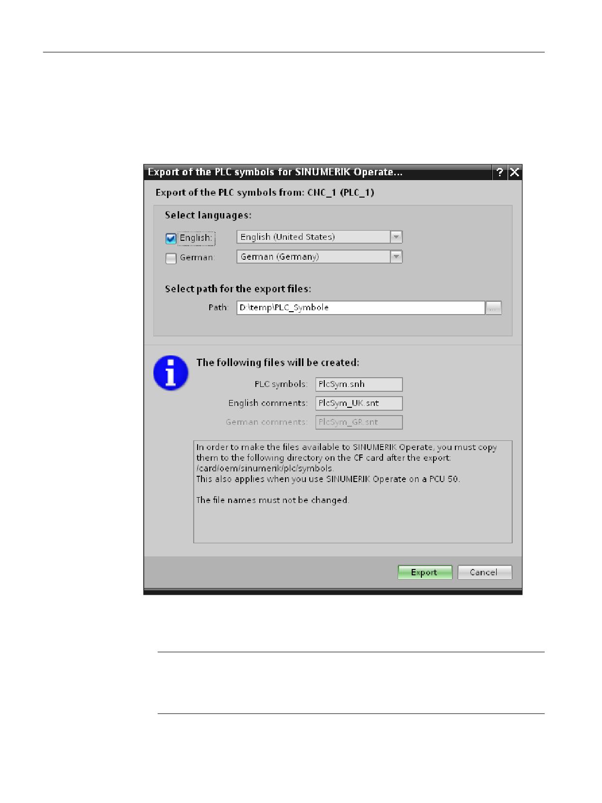
1. In the project tree, right-click on the PLC or NCU and select the "Export PLC symbols for
SINUMERIK Operate " in the shortcut menu.
The "Export PLC symbols for SINUMERIK Operate" dialog opens.
2. Enter the settings:
- Select the languages whose PLC symbols you want to export. Only those languages that
you previously selected under "Project languages" are actively displayed.
Note
Comments only in German or English
Because SINUMERIK Operate can manage only German and English comments, you
can export only German and English comments from the TIA Portal.
SINUMERIK 840D sl STEP 7 Toolbox V16
92
Getting Started, 12/2019, 6FC5397-1GP40-0BA1
Creating a PLC program
6.6 Exporting PLC symbols for SINUMERIK Operate
- Select the storage location in which the exported PLC symbols are to be saved. Use, for
example, a USB FlashDrive to subsequently copy the files to the NCU.
3. Click "Export" to start the export operation.
Result
The PLC symbols will be copied to the chosen storage location. The "PlcSym.snh" file is
created. Depending on your settings, the files are also created with German or English
comments: "PlcSym_GR.snt" and "PlcSym_UK.snt".
Note
Notation
The notation (upper and lower case) of the file names created by the program is mandatory and
must not be changed.
6.6.3
Importing PLC symbols
Requirement
● The symbol export files are available on the NCU or PCU, e.g. using a USB FlashDrive
Note
Notation
The notation (upper and lower case) of the file names created by the program is mandatory
and must not be changed.
● The current PLC symbols in SINUMERIK Operate have been saved
Note
Saving or deleting old symbol tables
Note that already existing files are overwritten during the export if you confirm that this
should be done. Furthermore, it can lead to inconsistencies if not all files are exported.
We recommend that the old files are backed up or deleted before a new export, or the files
are exported to an empty directory.
Procedure
To use PLC symbols exported from the TIA Portal in SINUMERIK Operate, proceed as follows:
1. Copy the symbol export files in the following directory on the CF card of the NCU or PCU:
/oem/sinumerik/plc/symbols
2. Restart SINUMERIK Operate.
SINUMERIK 840D sl STEP 7 Toolbox V16
Getting Started, 12/2019, 6FC5397-1GP40-0BA1
93
Creating a PLC program
6.6 Exporting PLC symbols for SINUMERIK Operate
3. After the startup, confirm the "Diagnosis", ">>" and "NC/PLC variables" horizontal softkeys.
4. Select the "Insert variables" softkey.
The imported symbols are displayed in the "NC/PLC variables" table and can be imported.
Further information
Detailed information on how you can load the PLC symbols to the control system are contained
in the SINUMERIK 840D sl Universal Operator Manual under the "Loading PLC symbols"
keyword.
SINUMERIK 840D sl STEP 7 Toolbox V16
94
Getting Started, 12/2019, 6FC5397-1GP40-0BA1
Creating a PLC program
6.7 Completing the first commissioning of the PLC
6.7
Completing the first commissioning of the PLC
Perform a reset (warm restart) of the NCK to synchronize the PLC and NCK.
Procedure
To perform a reset (warm start), proceed as follows:
1. On the operator panel, press the <MENU SELECT> key and select the "Commissioning"
menu.
2. Press the "Reset..." softkey.
3. Acknowledge the "Do you want to trigger a reset (warm restart) for the NCK and the entire
drive system (all drive units)?" prompt with the "Yes" softkey.
Result
● The "RUN" LED illuminates green continuously.
● Status display shows a "6" with a flashing point. This means that the PLC and NCK are in
cyclic operation.
You have now completed the initial commissioning of the PLC.
This means that you have successfully completed the main part of Getting Started.
Additional chapter and references
If you require information about the migration of your STEP 7 project into the TIA Portal, you can
find this in Section Tips for personnel changing over from another system (Page 97).
If you now wish to continue and complete commissioning your system together with the
SINAMICS drives, you can find this information in the "Commissioning CNC: NCK, PLC, drive
for TIA" Commissioning Manual, Chapter "Commissioning NC-controlled drives".
SINUMERIK 840D sl STEP 7 Toolbox V16
Getting Started, 12/2019, 6FC5397-1GP40-0BA1
95
Creating a PLC program
6.7 Completing the first commissioning of the PLC
SINUMERIK 840D sl STEP 7 Toolbox V16
96
Getting Started, 12/2019, 6FC5397-1GP40-0BA1
Tips for personnel changing over from another system
7
7.1
Overview for the migration
If you have worked previously with the SINUMERIK Toolbox for STEP 7 V5.x and as migrating
party are already familiar with the commissioning and configuration of the SINUMERIK 840D sl,
these sections contain more advanced information about the project migration, functionality
and operation of the TIA Portal:
● The migration of program blocks or complete projects is described in the "Migrating
projects" section (Page 98).
● The "Problem solution (Page 107)" section contains help for frequent questions concerning
migrated SINUMERIK projects.
● The "Comparison of functionality (Page 114)" section contains information about the
functionality and operation in comparison to STEP 7 V5.x. In this way, you can familiarize
yourself with the TIA Portal when migrating from STEP 7 V5.x.
Note
Validity of the description
These descriptions concern the special considerations for the migration of projects that were
created with SINUMERIK Toolbox for STEP 7 V5.5 SP4 or higher. The migration notes and
descriptions for STEP 7 (TIA Portal) also apply.
If you want to migrate components that require further option packages, the migration notes of
the associated documentation also apply.
A selection of general migration descriptions and notes are available under "Further
information" (Page 106).
SINUMERIK 840D sl STEP 7 Toolbox V16
Getting Started, 12/2019, 6FC5397-1GP40-0BA1
97
Tips for personnel changing over from another system
7.2 Migrating projects
7.2
Migrating projects
7.2.1
Overview
Basic information on the content of this description
Validity of the description
These descriptions concern the special considerations for the migration of projects that were
created with SINUMERIK Toolbox for STEP 7 V5.5 SP4 or higher. The migration notes and
descriptions for STEP 7 (TIA Portal) also apply.
If you want to migrate components that require further option packages, the migration notes of
the associated documentation also apply.
A selection of general migration descriptions and notes are available under "Further
information" (Page 106).
Conventions
The term "SINUMERIK project" is used in this description to represent a project created with
SINUMERIK Toolbox for STEP 7 V5.5 SP4 or higher.
Overview
To check whether the modules of your project are supported, use the Readiness Check Tool
If modules are not supported in the TIA Portal, alternative modules will be suggested in the
Readiness Check Tool.
Depending on how many of the modules are supported in the TIA Portal, either migrate the
complete project or only program blocks and symbols:
● You can migrate the complete project (Page 103).
● You can migrate only program blocks and symbols, and recreate the hardware configuration
in the TIA Portal (Page 100).
To keep the reworking effort low, you can adapt the project prior to the migration (Page 98).
7.2.2
Preparing a STEP 7 V5.x project for the migration
You can migrate a consistent and executable STEP 7 as of V5.4 project directly to the
TIA Portal. To keep the reworking effort for the migrated project low, you can prepare the project
for the migration.
Section Troubleshooting (Page 107) also provides help for frequently asked questions
concerning migrated projects.
SINUMERIK 840D sl STEP 7 Toolbox V16
98
Getting Started, 12/2019, 6FC5397-1GP40-0BA1
Tips for personnel changing over from another system
7.2 Migrating projects
Basic procedure
●
Creating user data blocks from the PLC basic program in the project
User data blocks from the PLC basic program (e.g. axis DB) (Page 125) in the TIA Portal are
not based on UDTs, but rather stored as dedicated data blocks in the project.
- You can create the used data blocks prior to the migration in STEP 7 V5.x in the "Blocks"
folder:
Select in the properties of the newly created block under "Name and type > DB of type"
the associated UDT (e.g. "UDT31"). Use the same symbolic name as in the TIA Portal
system library (see Section "Tabular block listing (Page 71)").
During the migration, the blocks are then transferred automatically to the "Program
blocks" folder.
- Alternatively, you can copy the required data blocks after the migration from the master
copies folder "840D sl PLC Basic Program (upgrade) (Page 73)".
See also:
- User-defined data types from the basic program (Page 125)
- Using user-defined data types (UDT) (Page 123)
- Using copy templates (Page 73)
●
Checking the user program for flags without symbol and data type
During the migration, a symbol and a data type are assigned automatically to each used
absolute address (e.g. flags, I/O addresses).
- If you use absolute addresses in your STEP 7 V5.x project for intermediate results for
which no symbol or data type is declared ("temporary flag"), type conflicts can occur after
the migration.
Therefore, preferably augment this information in your STEP 7 V5.x project prior to the
migration.
- In particular, problems occur after the migration when you use in your program
temporary global flags without defined data type (global "temporary flags") in which
different data types are stored.
Correct your program and use instead local data with defined data type and symbol.
●
Testing for implicit type conversions
In the TIA Portal, each used absolute address is assigned a symbol and so a unique data
type.
- If the use of an absolute address differs from the declaration of the data type, an implicit
data type conversion can cause problems.
In this case, change the affected implicit type conversions with incompatible operands to
explicit type conversions.
- If in your user program you save data of different types in the same address area, then
possibly neither an implicit nor an explicit data type conversion can be performed.
The elimination of such a problem differs depending on the concrete situation.
See also:
- LAD/FDB/SCL: Data type conversion with MOVE instruction (Page 109)
- Data type conversion (S7-300, S7-400) (help for STEP 7)
SINUMERIK 840D sl STEP 7 Toolbox V16
Getting Started, 12/2019, 6FC5397-1GP40-0BA1
99
Tips for personnel changing over from another system
7.2 Migrating projects
7.2.3
Migrating program blocks and symbols
You can migrate PLC program blocks and symbols from an NCU of a STEP 7 project of Version
5.4 SP5 (or higher) to the TIA Portal.
To keep the reworking effort low, you can adapt the project prior to the migration (Page 98).
If you also want to migrate the hardware configuration, orient yourself on the corresponding
handling overview "Migrating software and hardware configurations (Page 103)".
Requirement
● The project to be migrated is upgraded to SINUMERIK 840D sl Toolbox 4.5 SP2 or higher
for STEP 7 V5.5 SP4 or higher.
● FC1007, FC1008 and FC1010 are not contained in the project.
FC1007, FC1008 and FC1010 are no longer part of the basic program and cannot be
migrated. If these functions are contained in your user program, delete them and the
associated calls.
● The STEP 7 project to be migrated is consistent and can be executed.
If your project cannot be executed, you must correct it in STEP 7 V5.x before you migrate
it. You can check the consistency with SIMATIC Manager and restore by compiling the
blocks.
● Both STEP 7 V5.5 SP4 (or higher) and the TIA Portal are installed on the PG/PC, or the
project has been converted to AM 15 format with the migration tool.
See Migration tool (help for the TIA Portal).
● All option packages used to create the project in STEP 7 V5.x are installed and licensed
(e.g. the option package for SCL).
Specific information concerning the migration of other option packages is contained in the
associated documentation.
SINUMERIK 840D sl STEP 7 Toolbox V16
100
Getting Started, 12/2019, 6FC5397-1GP40-0BA1
Tips for personnel changing over from another system
7.2 Migrating projects
Procedure
To migrate program blocks and icons of a SINUMERIK project into the TIA Portal, proceed as
follows:
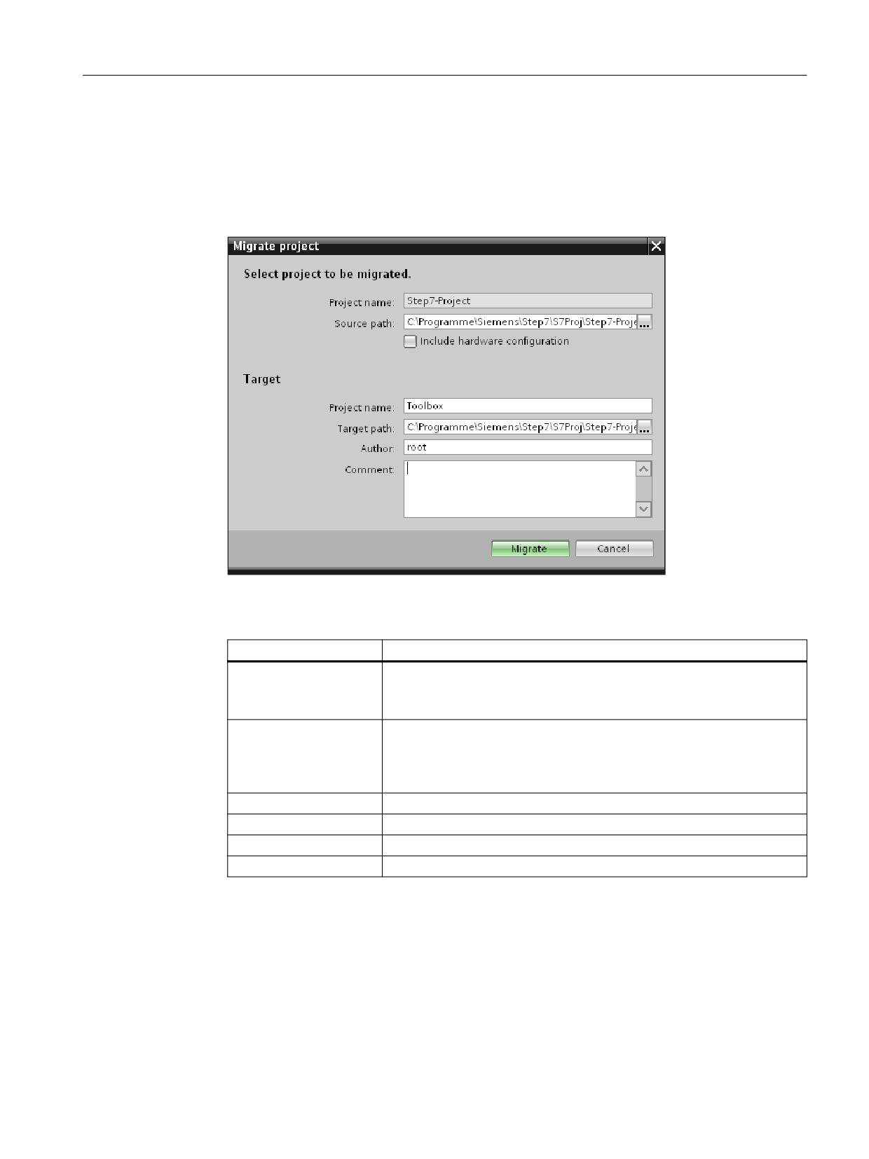
1. In the "Project" menu, select the "Migrate project" command.
The "Migrate project" dialog opens
Figure 7-1
Migrate project dialog
2. Make the following settings:
Setting
Purpose
Source path
Path of the original project that is to be migrated.
Select a project in the format of the initial project (*.s7p) or a project
processed with the migration tool (*.am15).
Close hardware configu-
Keep the "Include hardware configuration" checkbox deactivated.
ration
If you also want to migrate the hardware configuration, orient yourself on
the corresponding handling overview "Migrating software and hardware
configurations (Page 103)".
Target > Project name
Input of the project name for the newly created project.
Target path
Input of the path on which the new project file is to be created.
Author
Name of the author or a person responsible for the project.
Comment
Input of a comment for the migration.
3. Click "Migrate" to confirm the details.
A not specified SIMATIC CPU that contains your migrated program blocks is added to the
project tree. You cannot replace this CPU with a SINUMERIK NCU, but rather you must add
it new.
SINUMERIK 840D sl STEP 7 Toolbox V16
Getting Started, 12/2019, 6FC5397-1GP40-0BA1
101