SINUMERIK 840D sl. Service - Configuring Commissioning. Manual (2011-2020) - page 90
Commissioning and configuring
7.5 Configuring NC and drive-specific safety settings
Precondition
● The commissioning of the (non-safety-relevant) standard drive functions must have been
completed.
● The configuration (hardware and software) has been loaded to the NCU (Page 236).
● Transferring the Safety Integrated mode from the configuration has been completed
(Page 237).
Procedure
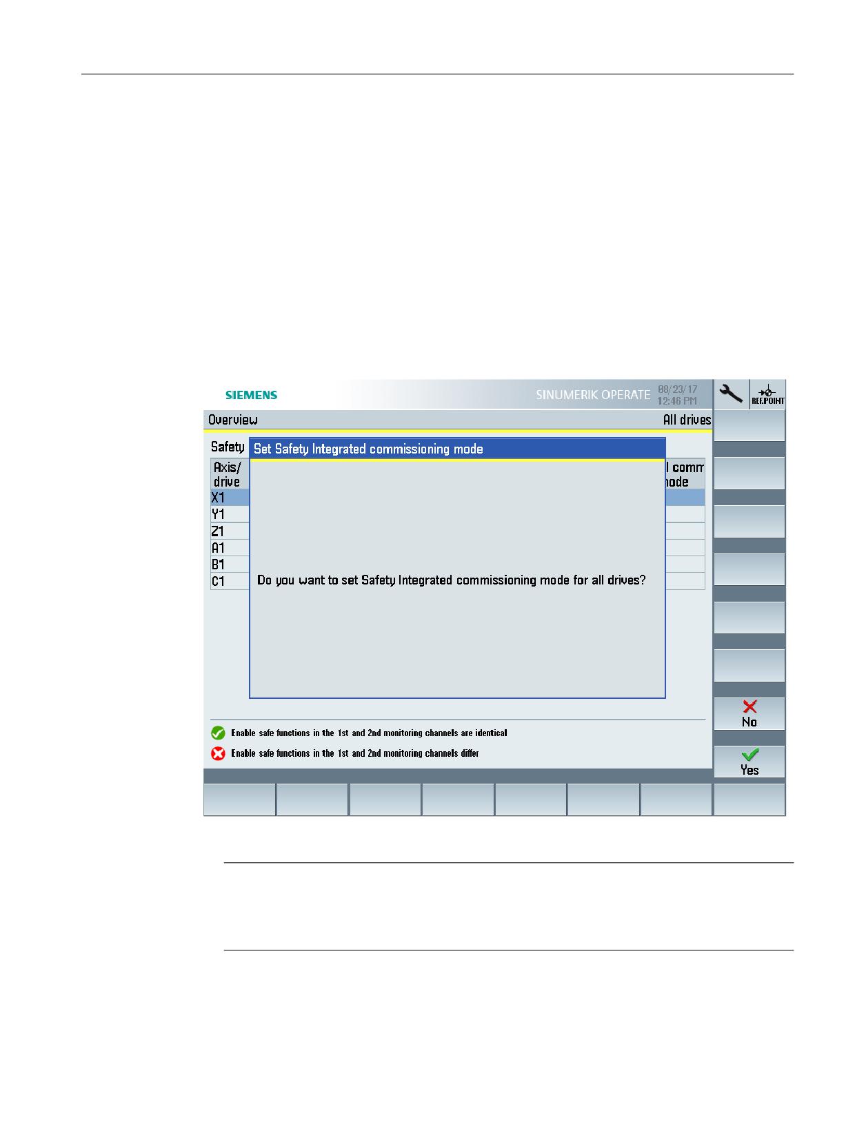
Proceed as follows to activate the Safety Integrated commissioning mode for all drives:
1. In SINUMERIK Operate, go to "MENU SELECT > Commissioning > Menu forward key >
Safety".
Figure 7-10
Activating the Safety Integrated commissioning mode for individual drives
Note
Activating the Safety Integrated commissioning mode for individual drives
To activate the mode for an individual drive only, instead, switch to "MENU SELECT >
Commissioning > Menu forward key > Safety > Settings > Options".
2. Select the softkey "Set SI Commissioning", then "Activate/deactivate drive commissioning"
and confirm with "Yes".
Safety Integrated plus
Commissioning Manual, 12/2019, 6FC5397-1FP40-6BA3
241
Commissioning and configuring
7.5 Configuring NC and drive-specific safety settings
7.5.4
Selecting the safety functional scope
Before you parameterize the various safety functions of the drive, make the following basic
settings for the corresponding drives:
● Scope of the safety functions used (Basic or Extended)
● Control (PROFIsafe, terminals, without selection)
● Use of a safety-relevant encoder
You must make these settings one after the other for each drive where you wish to use the drive-
integrated safety functions.
Precondition
● The commissioning of the (non-safety-relevant) standard drive functions must have been
completed.
● The configuration (hardware and software) has been loaded to the NCU (Page 236).
● Transferring the Safety Integrated mode from the configuration has been completed
(Page 237).
● The safety commissioning mode is activated for the drive to be configured (Page 240).
Procedure
Proceed as follows to set the safety functional scope for a drive:
1. In SINUMERIK Operate, switch to the safety settings of the drive via "MENU SELECT >
Commissioning > Menu forward key > Safety > Settings > Options".
2. Switch to the corresponding drive, e.g. using softkey "Select a drive".
3. Under "Select safety function" select the functional scope:
- Basic Functions via onboard terminals
- Basic Functions via PROFIsafe
- Basic Functions via PROFIsafe and onboard terminals
- Extended Functions via PROFIsafe
- Extended Functions via PROFIsafe and Basic Functions via onboard terminals
- Extended Functions without selection
- Extended Functions without selection and Basic Functions via onboard terminals
Safety Integrated plus
242
Commissioning Manual, 12/2019, 6FC5397-1FP40-6BA3
Commissioning and configuring
7.5 Configuring NC and drive-specific safety settings
4. Make additional settings, when using the extended functional scope:
- Safety with encoder and acceleration monitoring (SAM)
- Safety without encoder with braking ramp (SBR) - can only be set for induction motors
- Safety without encoder with acceleration monitoring (SAMR) - can only be set for
induction motors
See also: Supported axis types (Page 34), Overview of safety functions integrated in the
drive (Page 25), Control options (Page 197)
5. Press softkey "OK".
Note
When the selected safety function is saved, the enable signal for referencing via SIC/SCC
(p9501.27) is automatically set via SINUMERIK Operate.
7.5.5
Parameterizing the setpoint speed limiting
During the runtime, the setpoint speed limiting of the drive (p9533) is evaluated with the
selected evaluation factor of the NC, and issued to the interpolator as setpoint limit.
Precondition
● The safety functional scope of the drive has been selected. (Page 242)
Safety Integrated plus
Commissioning Manual, 12/2019, 6FC5397-1FP40-6BA3
243
Commissioning and configuring
7.5 Configuring NC and drive-specific safety settings
Procedure
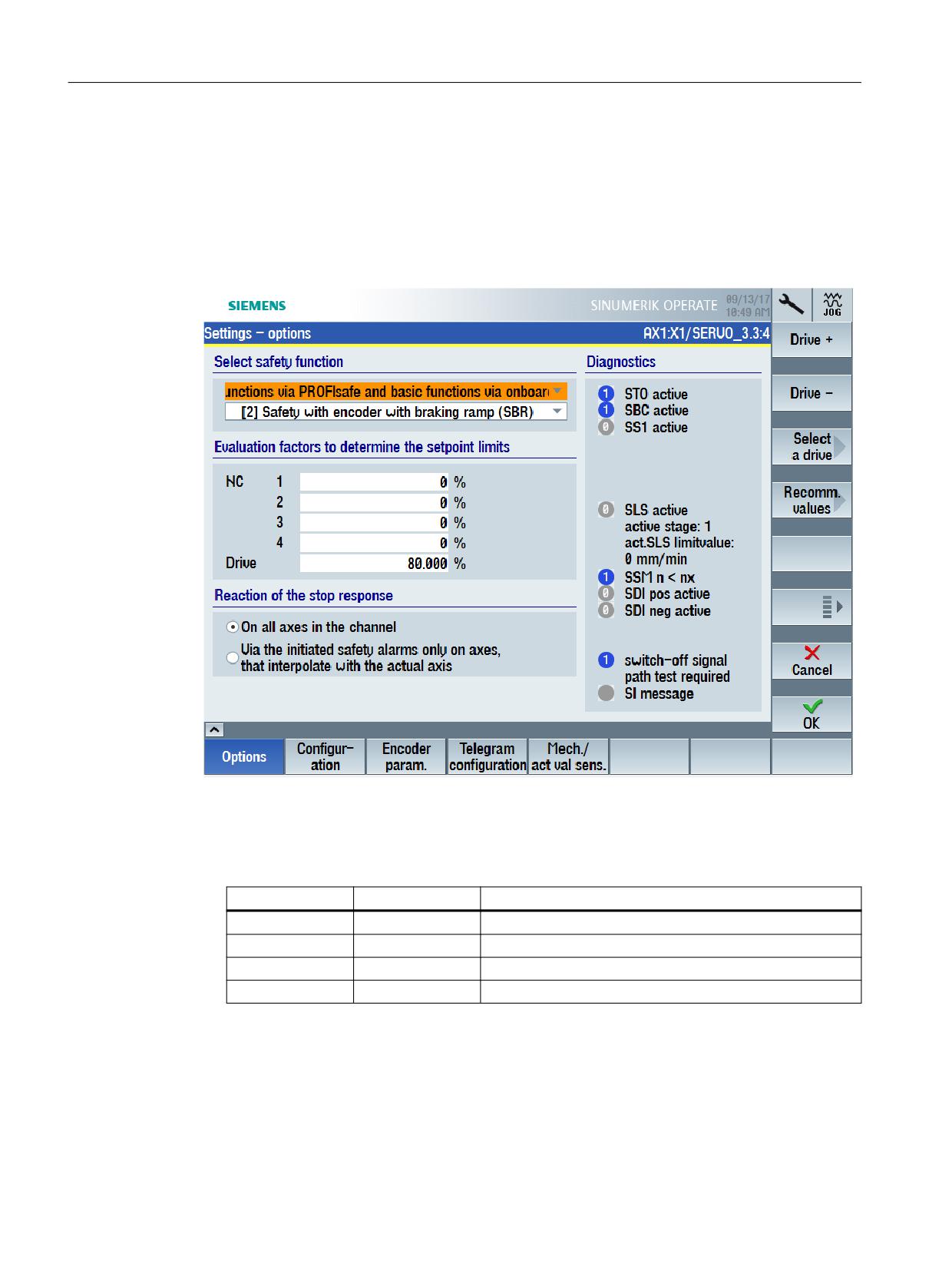
Proceed as follows, to parameterize the evaluation factors of the NC to define the setpoint limits:
1. In SINUMERIK Operate, switch to the safety settings of the drive via "MENU SELECT >
Commissioning > Menu forward key > Safety > Settings > Options".
2. Switch to the corresponding drive, e.g. using softkey "Select a drive".
The parameterization is displayed for the selected drive.
3. Parameterize 4 evaluation factors for defining the setpoint limits
MD36933 $MA_SAFE_DES_VELO_LIMIT includes 4 values (indices 0…3). Using the axis-
specific PLC user interface, in the PLC program you can select which of these values is
active (DBX34.0…DBX34.1 in axis1 [DB31]…axis31[DB61]).
Bit 0
Bit 1
active setpoint limiting factor
= 0
= 0
SAFE_DES_VELO_LIMIT[0]
= 1
= 0
SAFE_DES_VELO_LIMIT[1]
= 1
= 1
SAFE_DES_VELO_LIMIT[2]
= 1
= 1
SAFE_DES_VELO_LIMIT[3]
Select the active setpoint limiting factor using DBX34.0..DBX34.1 in axis1 [DB31]…axis31[DB61]
4. Enter the 4 required evaluation factors.
To optimally set this MD, it is possible that several changes must be made in order to take
into account the dynamic response of the drives.
You can use 80% as recommended value, for example.
Safety Integrated plus
244
Commissioning Manual, 12/2019, 6FC5397-1FP40-6BA3
Commissioning and configuring
7.5 Configuring NC and drive-specific safety settings
Result
The evaluation factors of the NC were parameterized, and are active after an operator panel
reset.
During the runtime, the setpoint speed limiting of the drive (p9533) is evaluated with the
selected (in the PLC user program) evaluation factor of the NC, and issued to the interpolator
as setpoint limit.
The value in MD36933[0] becomes active if a specific value is not selected in the PLC user
program.
7.5.6
Parameterizing reaction of the stop response
If a stop response is initiated, then this has effects on all of the other axes in the channel. The
effect on the other axes in the channel can be influenced using MD36964
$MA_SAFE_IPO_STOP_GROUP. This allows, for example, the pulses of the spindle to be
safely cancelled. This means that the spindle can be manually rotated and the axes can still be
safely monitored while it is moving.
Safety Integrated plus
Commissioning Manual, 12/2019, 6FC5397-1FP40-6BA3
245
Commissioning and configuring
7.5 Configuring NC and drive-specific safety settings
Procedure
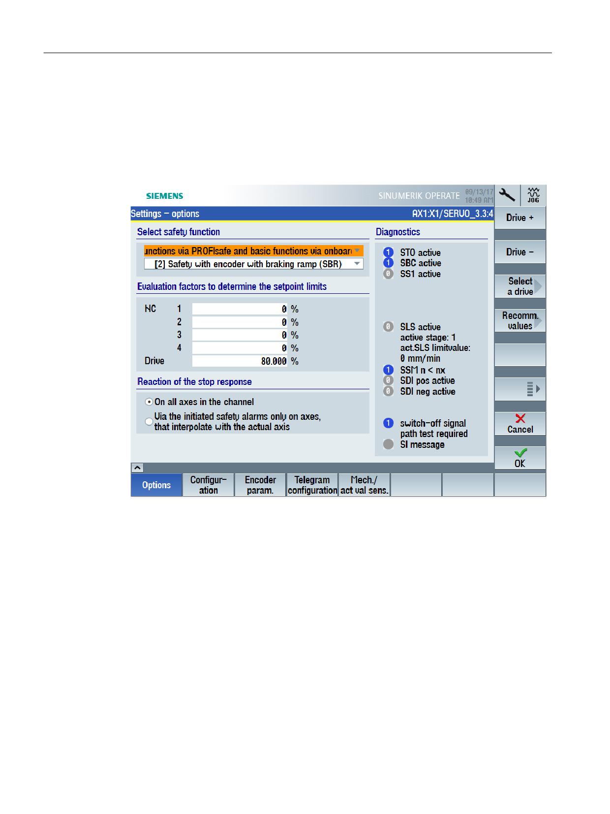
Proceed as follows to assign parameters for the reaction of the stop response:
1. In SINUMERIK Operate, go to the safety settings of the drive via "MENU SELECT >
Commissioning > Menu forward key > Safety > Settings > Options".
2. Go to the corresponding drive, for example, using the "Select drive" softkey.
The parameter assignment is displayed for the selected drive.
3. Select one of the following options as desirable reaction to the stop response:
- On all axes in the channel
- Via the triggered safety alarms only on axes that interpolate with the current axis.
The reaction to the stop response is saved in MD36964 $MA_SAFE_IPO_STOP_GROUP.
7.5.7
Parameterizing an encoder
Precondition
● The SI commissioning mode (Page 240) is active for the drive to be configured.
● The drive is configured for operation with an encoder.
Safety Integrated plus
246
Commissioning Manual, 12/2019, 6FC5397-1FP40-6BA3
Commissioning and configuring
7.5 Configuring NC and drive-specific safety settings
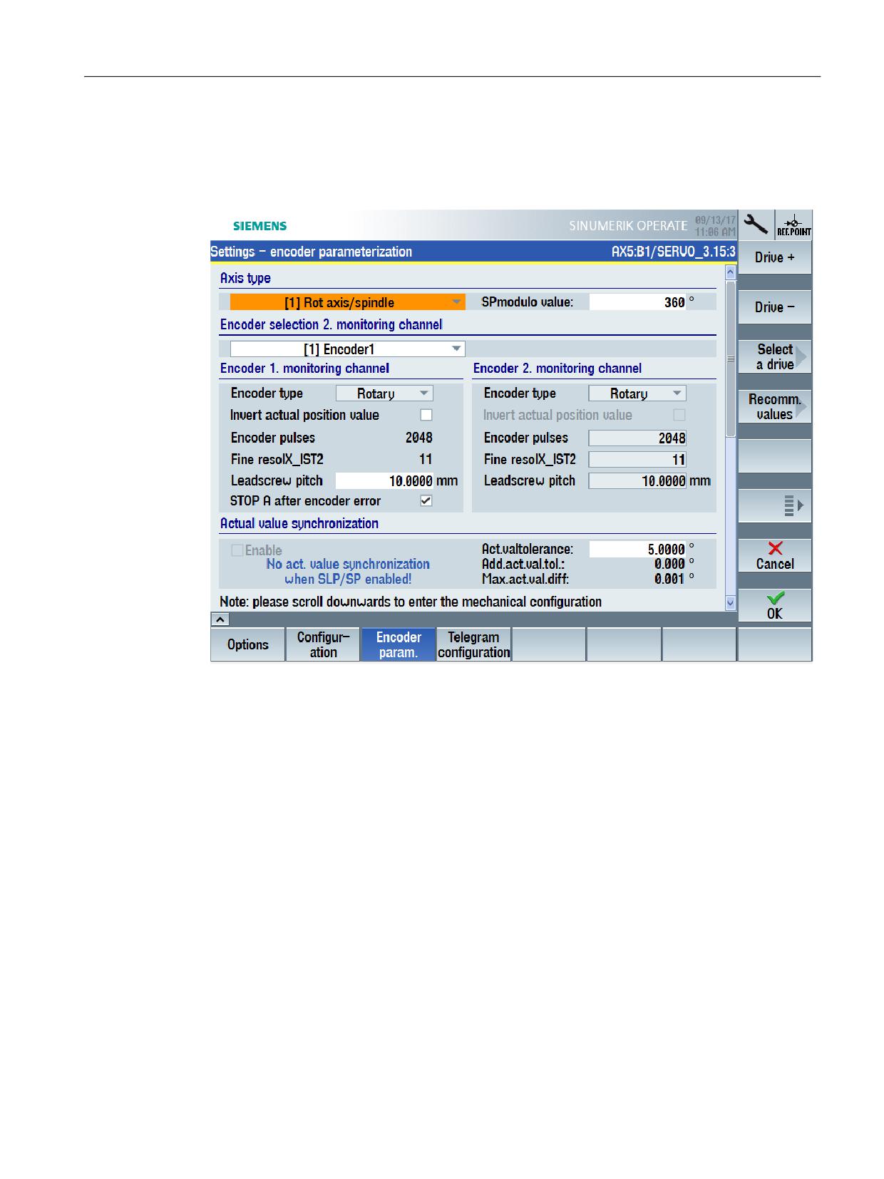
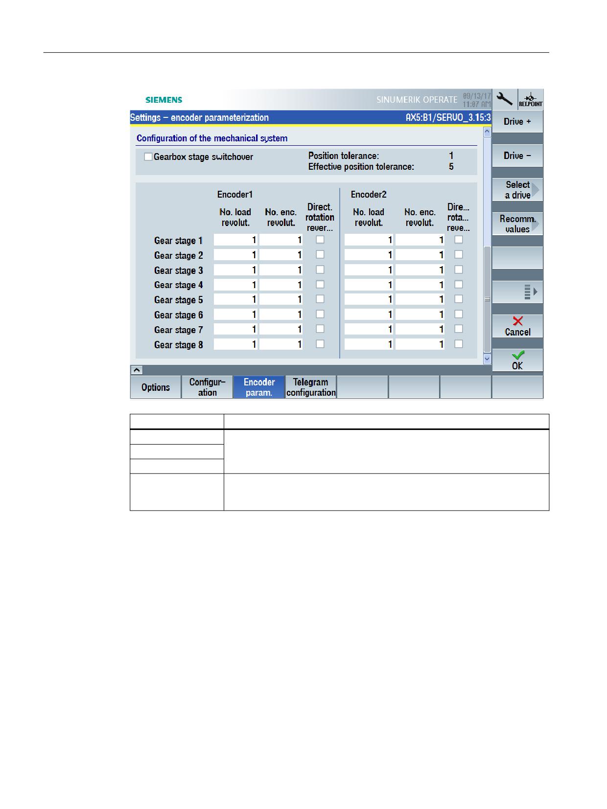
Call the "Encoder parameterization" startup screen form
MENU SELECT > Commissioning > Menu forward key > Safety > Settings > Encoder
parameterization
Safety Integrated plus
Commissioning Manual, 12/2019, 6FC5397-1FP40-6BA3
247
Commissioning and configuring
7.5 Configuring NC and drive-specific safety settings
Softkey
Purpose
Drive +
The settings are specific to a certain drive. Switch to the corresponding drive
using the appropriate softkey before configuring.
Drive -
Select a drive
Recommended val-
You can automatically assign defaults to the encoder settings of the specific
ues
drive using the "Recommended values" softkey. Check the individual suggested
values.
Safety Integrated plus
248
Commissioning Manual, 12/2019, 6FC5397-1FP40-6BA3

Commissioning and configuring
7.5 Configuring NC and drive-specific safety settings
Making the settings
Table 7-1
Parameterizing an encoder (setting - encoder parameterization)
Setting
Meaning
Axis type
Sets the axis type (linear axis or rotary axis/spindle).
SP modulo value
Sets the modulo value in degrees for rotary axes for the "Safe position"
function.
This modulo value is taken into account for safe referencing and for the
transfer of the safe position via PROFIsafe when absolute position is en-
abled. The value should be set so that it lies precisely at 2^n revolutions,
so that when the range that can be represented overflows (+/-2048), then
the position actual value does not exhibit a step (jump).
The modulo function is deactivated for a value = 0.
Encoder selection 2nd
Selects a configured encoder as the encoder that is used by the second
monitoring channel
channel (control, Motor Module) for safe motion monitoring.
Table 7-2
Encoder-monitoring channel (settings - encoder parameterization)
Setting
Meaning
Encoder type
Sets the motor encoder as either rotary or linear encoder.
Invert position actual value
Activates/deactivates the inversion of the position actual value (sign
change).
Encoder pulses
Displays the number of encoder pulses per revolution for rotary encoders.
Fine resolution X_IST2
Displays the fine resolution for G1_XIST1 in bits.
Leadscrew pitch
Sets the ratio between the encoder and load in mm/revolutions for a linear
axis with rotary encoder.
Table 7-3
Actual value synchronization (settings - encoder parameterization)
Setting
Meaning
Enable
Enables/inhibits actual value synchronization.
It is not permissible to enable actual value synchronization and SLP/SP for
the same drive.
Actual value tolerance
Sets the tolerance for the crosswise comparison of the actual position
between the two monitoring channels.
Additional actual value tol-
Displays the maximum additional difference between the load-side actual
erance
position value on the Control Unit and the load-side actual position value
on the second channel, which can occur due to the delay of the actual
value acquisition in the EnDat 2.2 converter.
Maximum actual value tol-
Displays the maximum difference between the load-side position actual
erance
value on the Control Unit and the load-side position actual value on the
second channel.
Safety Integrated plus
Commissioning Manual, 12/2019, 6FC5397-1FP40-6BA3
249
Commissioning and configuring
7.5 Configuring NC and drive-specific safety settings
Table 7-4
Mechanical configuration (settings - encoder parameterization)
Setting
Gearbox stage switchover
Enables/inhibits safety-relevant gearbox stage switchover.
When enabled, you can parameterize up to 8 ratios, and switchover the
active gearbox stage via PROFIsafe.
Position tolerance
Sets the factor to increase the tolerance for the crosswise data comparison
of the actual position between the two monitoring channels while the gear-
box stage is being switched over.
This factor is active when actual value synchronization is both activated as
well as also deactivated.
It is obtained, depending on the following tolerance:
● Actual value synchronization activated: p9549 * position tolerance
● Actual value synchronization deactivated: Actual value tolerance * po-
sition tolerance
Active position tolerance
Displays the active position tolerance. (product from the position tolerance
and actual value tolerance or velocity tolerance)
Number of load revolutions
Sets the denominator for the gearbox between the encoder and load.
Number of encoder revolu-
Sets the numerator for the gearbox between the encoder and load.
tions
Direction reversal
Activates/deactivates the direction of reversal for the gearbox.
7.5.8
Configuring encoderless operation
Precondition
● The SI commissioning mode (Page 240) is active for the drive to be configured.
● The drive is configured for operation without an encoder.
Safety Integrated plus
250
Commissioning Manual, 12/2019, 6FC5397-1FP40-6BA3
Commissioning and configuring
7.5 Configuring NC and drive-specific safety settings
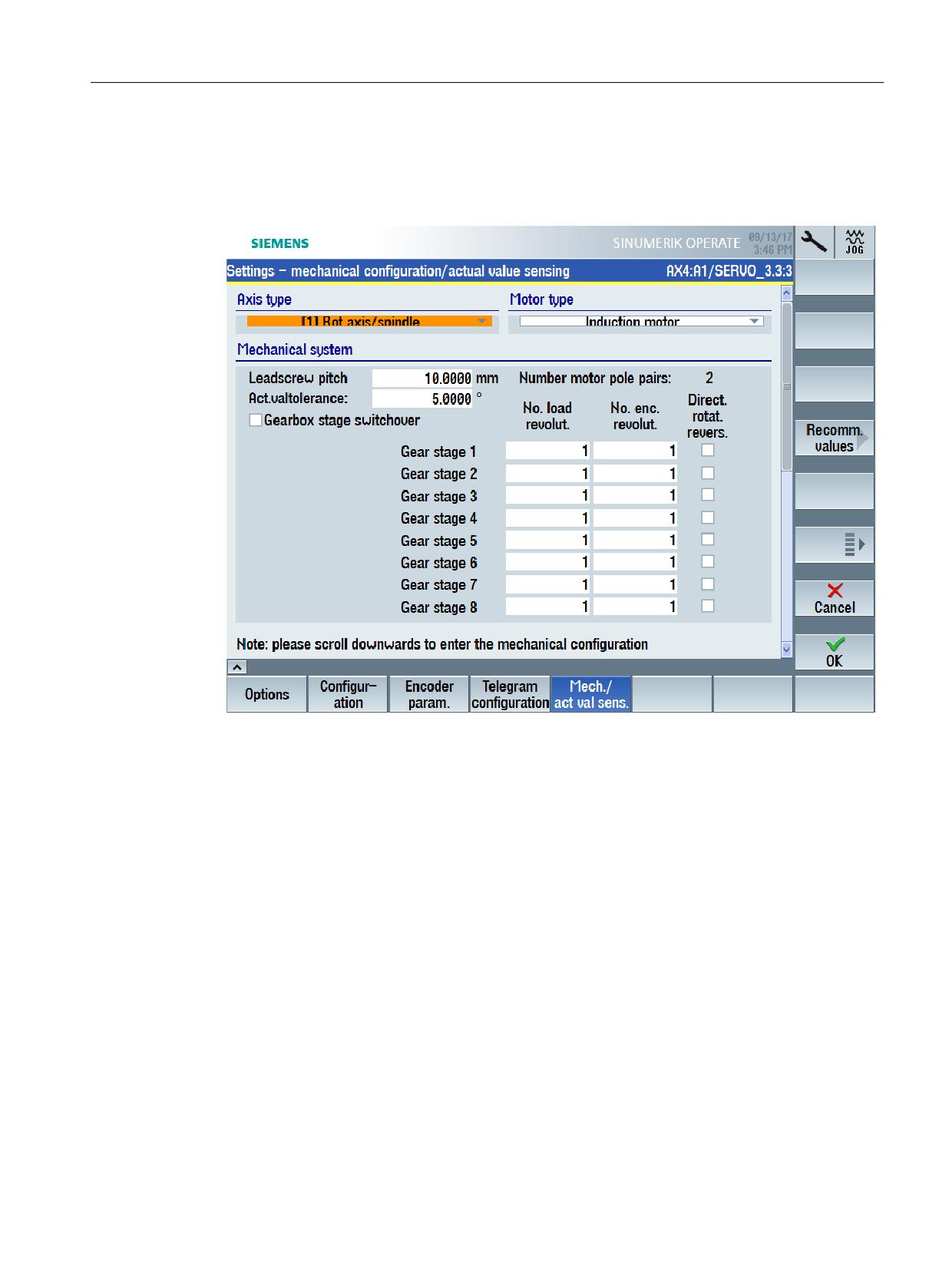
Call the startup screen form "Configuration mechanical/actual value sensing"
MENU SELECT > Commissioning > Menu forward key > Safety > Settings > Mechanical /actual
value sensing
Safety Integrated plus
Commissioning Manual, 12/2019, 6FC5397-1FP40-6BA3
251
Commissioning and configuring
7.5 Configuring NC and drive-specific safety settings
Softkey
Purpose
Drive +
The settings are specific to a certain drive. Switch to the corresponding drive
using the appropriate softkey before configuring.
Drive -
Select a drive
Recommended val-
Using softkey "Recommended values", you can automatically preassign the
ues
values of the particular startup screen form. Check the individual suggested
values.
Adapting settings
Table 7-5
(Settings - mechanical configuration/actual value sensing)
Setting
Meaning
Leadscrew pitch
Sets the ratio between the encoder and load in mm/revolutions for a linear
axis with rotary encoder.
Actual value tolerance
Sets the tolerance for the crosswise comparison of the actual position
between the two monitoring channels.
The tolerance must be set higher (e.g. 12 degrees rotary and 1 mm linear)
for encoderless motion monitoring functions.
Safety Integrated plus
252
Commissioning Manual, 12/2019, 6FC5397-1FP40-6BA3

Commissioning and configuring
7.5 Configuring NC and drive-specific safety settings
Table 7-6
Gearbox stages switchover (Settings - mechanical configuration/actual value sensing)
Setting
Meaning
Gearbox stage switchover
Enables/inhibits safety-relevant gearbox stage switchover.
When enabled, you can parameterize up to 8 ratios, and switchover the
active gearbox stage via PROFIsafe.
Number of load revolutions
Sets the denominator for the gearbox between the motor and load. The
active gearbox stage can be switched over via PROFIsafe.
Number of encoder revolu-
Sets the denominator for the gearbox between the motor and load. The
tions
active gearbox stage can be switched over via PROFIsafe.
For encoderless monitoring functions, the numerator of the gear ratio must
be multiplied by the number of pole pairs (see below).
Example:
Gearbox ratio 1:4, number of pole pairs = 2
Number of load revolutions = 1, number of encoder revolutions = 8 (4 x 2)
Direction reversal
Activates/deactivates the direction of reversal for the gearbox.
Motor pole pair number
Displays the number of motor pole pairs.
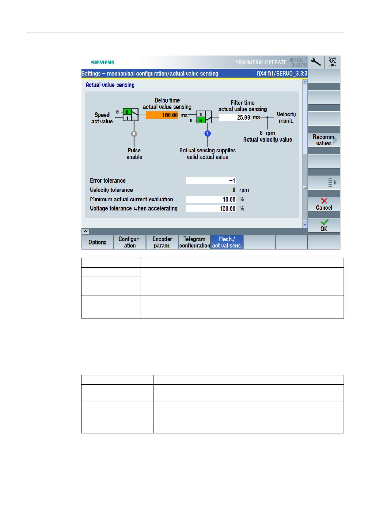
Table 7-7
Actual value sensing (Settings - mechanical configuration/actual value sensing)
Setting
Meaning
Delay time actual value
Sets the delay time for evaluating the encoderless actual value sensing
sensing
after the pulses have been enabled.
The value should be greater than or equal to the magnetization time of the
motor (p0346).
The set time is internally rounded off to an integer multiple of the monitoring
clock cycle.
Caution: The safety functions are not fully effective until this time has
elapsed.
Notice: Reducing this value can have a negative impact on the actual value
acquisition and plausibility check - and result in safety message C01711
with message value 1041 or 1042.
Dependencies: C01711
Filter time actual value
Sets the filter time for the actual value smoothing for actual value acquis-
sensing
ition without encoder.
Notice: A higher filter time results in a longer response time.
The smoothing is realized using a 1st order lowpass filter.
For a minimum value, the filter is deactivated.
The set time is internally rounded off to an integer multiple of the monitoring
clock cycle.
Pulse enable
Display: Enable power
Actual value sensing sup-
Display: Actual value sensing supplies valid actual value
plies valid actual value
Actual speed value
Displays actual speed values for motion monitoring on the Control Unit.
Index [0] = load side actual speed value on the Control Unit
Safety Integrated plus
Commissioning Manual, 12/2019, 6FC5397-1FP40-6BA3
253
Commissioning and configuring
7.5 Configuring NC and drive-specific safety settings
Setting
Meaning
Fault tolerance
Setting of the plausibility monitoring tolerance for the current and the volt-
age angle.
A higher value makes the drive more stable when it is reversing at low
speeds - or when the load changes abruptly in the field-weakening range.
An increase brings advantages when the current or voltage at the motor
becomes small.
Increasing the value results in a longer evaluation delay - and to a higher
speed tolerance (see below).
Notice: Reducing this value can have a negative impact on the actual value
acquisition and the plausibility check.
For synchronous motors, the value must be set to 4.
For value = -1:
- for synchronous motors, the calculation automatically uses a value of 4
- for induction motors, the calculation automatically uses a value of 0 (if the
code number of the power unit p0201[0] is < 14000, otherwise a value of
2 is used).
Dependencies: F01681, C01711
Speed tolerance
Displays the actual speed deviation for encoderless actual value acquisi-
tion.
This value is calculated when setting the error tolerance (see above).
Safety Integrated plus
254
Commissioning Manual, 12/2019, 6FC5397-1FP40-6BA3
Commissioning and configuring
7.5 Configuring NC and drive-specific safety settings
Setting
Meaning
Minimum actual current
Sets the minimum current for encoderless actual value acquisition referred
evaluation
to 1 A (i.e. 1 % = 10 mA).
● The value must be increased if C01711 is output with message value
1042.
● The value must be decreased if C01711 is output with message value
1041.
For synchronous motors, the following condition must be satisfied:
|p0305 x p9783| >= minimum current actual value acquisition x 1.2
Recommendation: If necessary, to determine the correct value, the mini-
mum motor current must be measured.
Notice: An excessive reduction of this percentage value can result in a
safety message and in an inaccurate actual value.
Dependencies: r9785, C01711
Acceleration voltage toler-
Sets the acceleration limit to filter discontinuities in the speed/velocity. The
ance
filter is deactivated when setting the maximum value.
An increase in this percentage value means that velocity peaks can occur
when accelerating, which do not reflect the real velocity characteristic.
A decrease in this value dampens velocity peaks when accelerating.
● The value must be increased if message C01711 is output with the
value 1043.
● The value must be decreased if acceleration has resulted in an exces-
sive safety actual velocity.
Recommendation: This parameter setting depends on the motor and
closed-loop control, and must be redetermined for each configuration.
To do this, a measurement must be made while the actual value is chang-
ing (step function/jump), and the limit should be set so low in r9785[0] via
p9589 that it is not exceeded more than four times per second by the value
set in r9785[1]. At this point in time, the actual value correction filter inter-
venes. The step is no longer so drastic.
Dependencies: r9784, C01711
See also
Selecting the safety functional scope (Page 242)
7.5.9
Configuring telegrams
Precondition
● The SI commissioning mode (Page 240) is active for the drive to be configured.
● Extended Functions or Basic Functions via PROFIsafe are set (Page 242) for the drive to be
configured.
Safety Integrated plus
Commissioning Manual, 12/2019, 6FC5397-1FP40-6BA3
255
Commissioning and configuring
7.5 Configuring NC and drive-specific safety settings
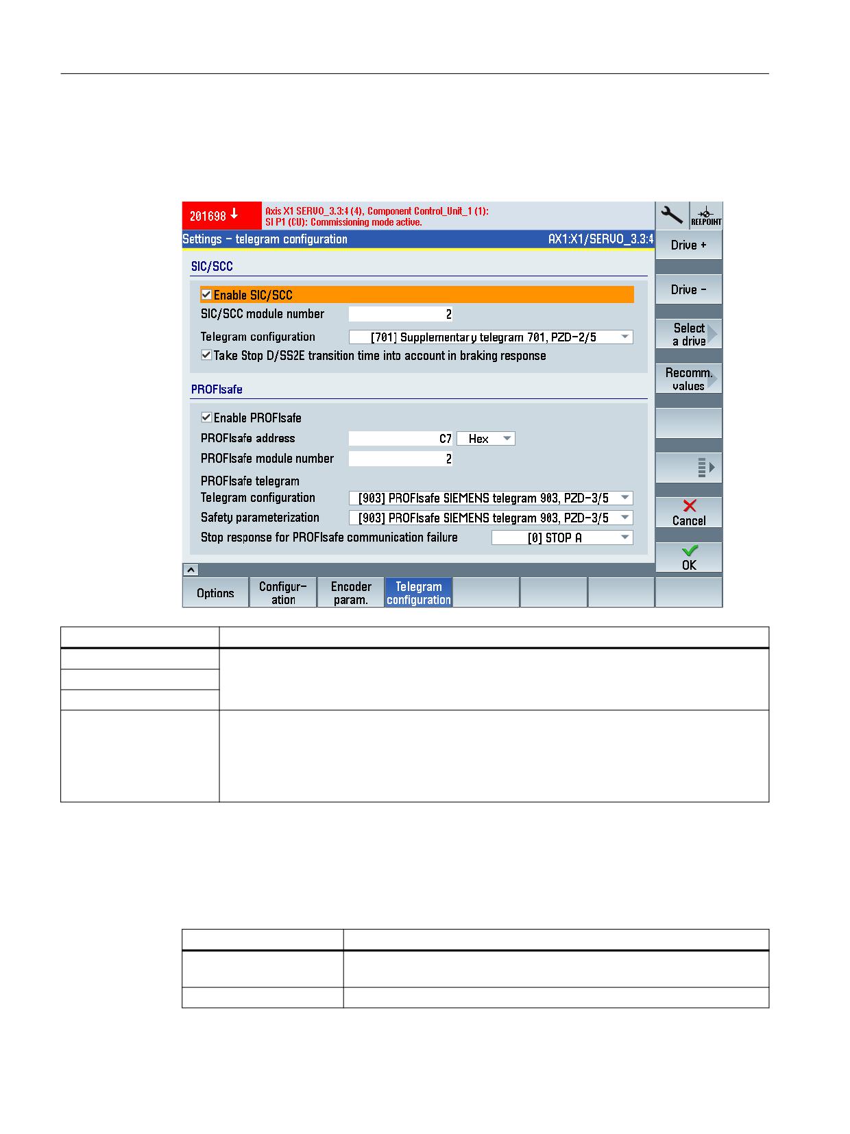
Call up "Telegram configuration" commissioning screen
MENU SELECT > Commissioning > Menu forward key > Safety > Settings > Telegram
configuration
Softkey
Purpose
Drive +
The settings are specific to a certain drive. Switch to the corresponding drive using the appro-
priate softkey before configuring.
Drive -
Select a drive
Recommended values
Using softkey "Recommended values", you can automatically preassign the values of the par-
ticular startup screen form.
For example, in the startup screen form "Telegram configuration", the telegram types from the
configuration belong to the settings that can be assigned as default.
Check the individual suggested values.
Making the settings
Table 7-8
SIC/SCC telegram settings (Settings - telegram configuration)
Setting
Meaning
Enable SIC/SCC
Enables/inhibits the evaluation of the Safety Info Channel / Safety Control
Channel (SCC/SIC).
SIC/SCC module number
Sets the SIC/SCC module number.
Safety Integrated plus
256
Commissioning Manual, 12/2019, 6FC5397-1FP40-6BA3

Commissioning and configuring
7.5 Configuring NC and drive-specific safety settings
Setting
Meaning
Telegram configuration
Sets the telegram type for the Safety Info Channel (SIC)/Safety Control
Channel (SCC)
Takes into account the
Activates the adaptation of the braking ramp for stop D/SS2E
stop D/SS2E transition
time in the braking re-
sponse
Table 7-9
PROFIsafe telegram settings (Settings - telegram configuration)
Setting
Meaning
Enable PROFIsafe
Enables/inhibits PROFIsafe communication between F-PLC and drive
PROFIsafe address
Sets the PROFIsafe address for the Control Unit.
PROFIsafe module num-
Sets the PROFIsafe module number.
ber
Telegram configuration
Sets the PROFIsafe telegram type.
Safety parameter assign-
Sets the PROFIsafe telegram type for the Control Unit.
ment
Safety Integrated plus
Commissioning Manual, 12/2019, 6FC5397-1FP40-6BA3
257

Commissioning and configuring
7.6 Configuring safety functions integrated in the drive
7.6
Configuring safety functions integrated in the drive
7.6.1
Overview
SINUMERIK Operate screen forms and settings to commission the various safety functions are
described in this chapter.
Basic procedure
Call the appropriate startup screen forms in SINUMERIK Operate and configure the safety
functions for the individual drives.
Table 7-10
Startup screen forms and function descriptions
Startup screen form
Detailed function description
STO/SS1 Basic (Page 259)
Safe Torque Off (Page 91) / Safe Stop 1 (Page 80)
STO Extended (Page 260)
Safe Torque Off (Page 91)
SBC (Page 262)
Safe Brake Control (Page 97)
SS1 Extended (Page 263)
Safe Stop 1 (Page 84)
SS2/SOS (Page 265)
Safe Stop 2 (Page 104) / Safe Operating Stop (Page 114)
SLS (Page 271)
Safely-Limited Speed (Page 117)
SSM (Page 274)
Safe Speed Monitor (Page 131)
SAM (Page 267)
Safe Acceleration Monitor (Page 137)
SBR (Page 270)
Safe Brake Ramp (Page 139)
SDI (Page 276)
Safe Direction (Page 142)
SLP/SP (Page 278)
Safely-Limited Position (Page 150) / Safe Position (Page 155)
SBT (Page 281)
Safe Brake Test (Page 160)
SCA (Page 284)
Safe Cam (Page 172)
You can find additional information on the function sequence of parameterization in the
Function Description.
In many cases, using the "Recommended values" softkey, you can automatically preassign the
values of the particular startup screen form.
Safety Integrated plus
258
Commissioning Manual, 12/2019, 6FC5397-1FP40-6BA3
Commissioning and configuring
7.6 Configuring safety functions integrated in the drive
Alternative to the commissioning screen forms, you can switch to "Parameter list", where all of
the parameters are listed in tabular form that are relevant for the particular safety function.
7.6.2
STO/SS1 Basic
Precondition
● The SI commissioning mode (Page 240) is active for the drive to be configured.
● One of the basis functions (Page 242) is is selected.
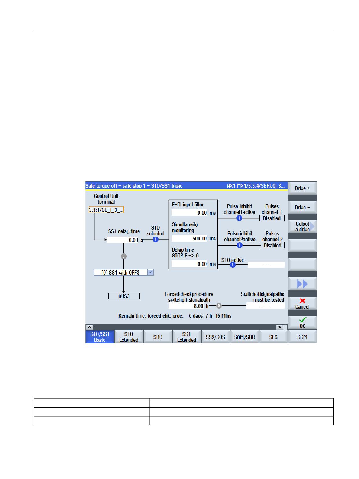
Displaying the "Safe torque off - STO/SS1 Basic" commissioning screen
MENU SELECT > Commissioning > Menu forward key > Safety > Functions > STO/SS1 Basic
Figure 7-11
Safe Torque Off - Safe Stop 1 - STO/SS1 Basic
Status information
For the following parameters, the status symbols indicate the actual state (blue = active; gray
= inactive):
Status
Meaning
STO selected (r9772.0)
"STO selected in the drive" setting
No text (brake reaction) (r9773.2)
Setting "SS1 Delay time active in the drive"
Safety Integrated plus
Commissioning Manual, 12/2019, 6FC5397-1FP40-6BA3
259

Commissioning and configuring
7.6 Configuring safety functions integrated in the drive
Status
Meaning
Pulse inhibit channel 1 active (r9772.1)
Setting "STO or safe pulse cancellation active on the CU"
Pulse inhibit channel 2 active (r9872.1)
Setting "STO on Motor Module active"
STO active (r9773.1)
Setting "STO active in the drive"
Switch-off signal paths must be tested
Setting "Switch-off signal paths must be tested"
(r9773.31)
Settings
Setting
Meaning
Control Unit terminal (p9620[0])
Sets the signal source for the STO, SBC and SS1 functions of the Control
Unit.
This is only relevant if a basic function via terminal is set in the options.
Otherwise, the input field is deactivated.
SS1 delay time (p9652)
Sets the delay time of the pulse cancellation in seconds for the function "Safe
Stop 1" (SS1) on the Control Unit to brake along the OFF3 down ramp
(p1135).
Braking response for SS1 (p9653)
Select a predefined braking response below the input field "SS1 delay time".
Parameter p9653 is preassigned depending on the selected braking re-
sponse.
F-DI input filter (p9651)
Setting the debounce time in ms for the failsafe digital inputs to control STO/
SBC/SS1.
Simultaneity monitoring (p9650)
Sets the discrepancy time in ms for the switchover of the safety-relevant
inputs (SGE) on the Control Unit.
Delay time STOP F -> STOP A (p9658)
Sets the transition time from STOP F to STOP A in ms on the Control Unit.
Forced checking procedure of the switch-off
Sets the time interval in hours for carrying out the forced checking procedure
signal paths (p9659)
and testing the switch-off signal paths.
Switch-off signal paths must be tested
To evaluate whether the switch-off signal paths must be tested, the status of
(r9773.31)
r9773.31 “Switch-off signal path must be tested" can be interconnected with
a parameter via the BICO editor.
7.6.3
STO Extended
Precondition
● The SI commissioning mode (Page 240) is active for the drive to be configured.
● The drive is configured for operation with an encoder and Extended Functions.
Safety Integrated plus
260
Commissioning Manual, 12/2019, 6FC5397-1FP40-6BA3
Commissioning and configuring
7.6 Configuring safety functions integrated in the drive
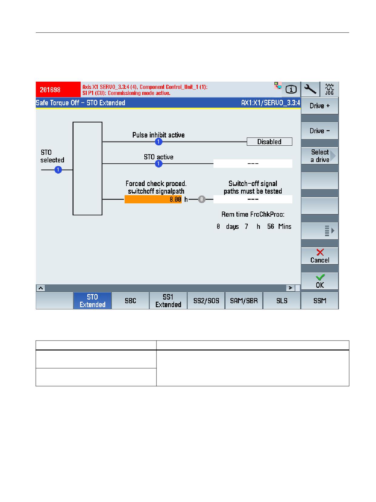
Display commissioning screen "Safe torque off - STO Extended"
MENU SELECT > Commissioning > Menu forward key > Safety > Functions > STO Extended
Status information
Status
Meaning
STO active
Safety Integrated status of the drive (Control Unit and MM).
r9773.1
Test stop required
r9773.31
Safety Integrated plus
Commissioning Manual, 12/2019, 6FC5397-1FP40-6BA3
261
Commissioning and configuring
7.6 Configuring safety functions integrated in the drive
Settings
Setting
Meaning
Forced checking procedure of the switch-off
Sets the time interval for performing the forced checking procedure and
signal paths
testing the safety switch-off signal paths. Within the parameterized time,
STO must have been deselected at least once. The monitoring time is reset
p9659
at every STO deselection.
7.6.4
SBC
Precondition
● The SI commissioning mode (Page 240) is active for the drive to be configured.
● At least one safety monitoring function is enabled for the drive.
● A motor holding brake has been configured for the drive.
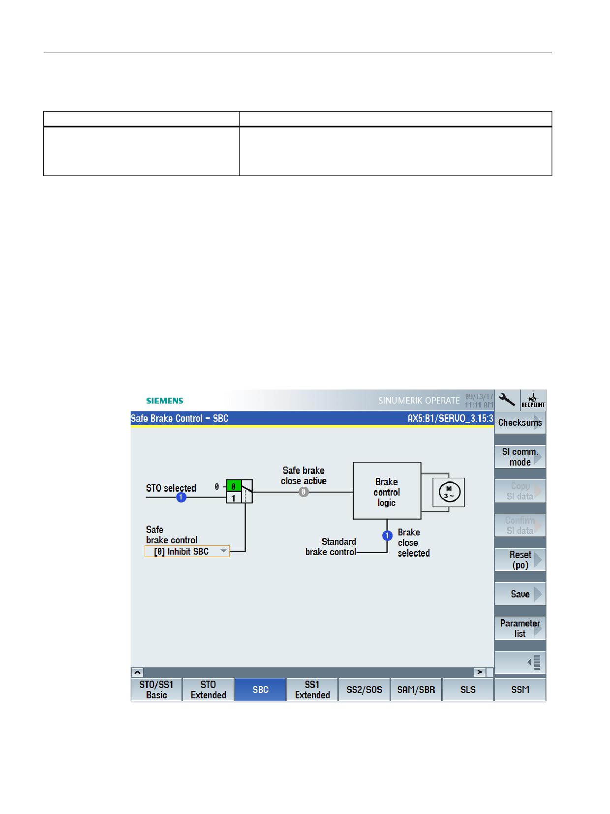
Display "Safe brake control - SBC" commissioning screen
MENU SELECT > Commissioning > Menu forward key > Safety > Functions > SBC
Safety Integrated plus
262
Commissioning Manual, 12/2019, 6FC5397-1FP40-6BA3
Commissioning and configuring
7.6 Configuring safety functions integrated in the drive
Status information
Status
Meaning
STO selected
Display and BICO output for the status of Safety Integrated on the drive
(Control Unit + Motor Module):
r9773.0
STO selected in the drive
Switching element
See "Safe brake control" setting
Safe brake close active
Display and BICO output for the status of Safety Integrated on the drive
(Control Unit + Motor Module):
r9773.4
SBC requested
Close brake selected
Display and BICO output for the status word of the sequence control:
r0899.13
Command, close holding brake
Settings
Setting
Meaning
Safe brake control
Sets the enable signal for the "Safe brake control" (SBC) function on the
Control Unit.
p9602
●
[0] Inhibit SBC
●
[1] Enable SBC
7.6.5
SS1 Extended
Precondition
● The SI commissioning mode (Page 240) is active for the drive to be configured.
● The drive is configured for operation with an encoder and Extended Functions.
Safety Integrated plus
Commissioning Manual, 12/2019, 6FC5397-1FP40-6BA3
263
Commissioning and configuring
7.6 Configuring safety functions integrated in the drive
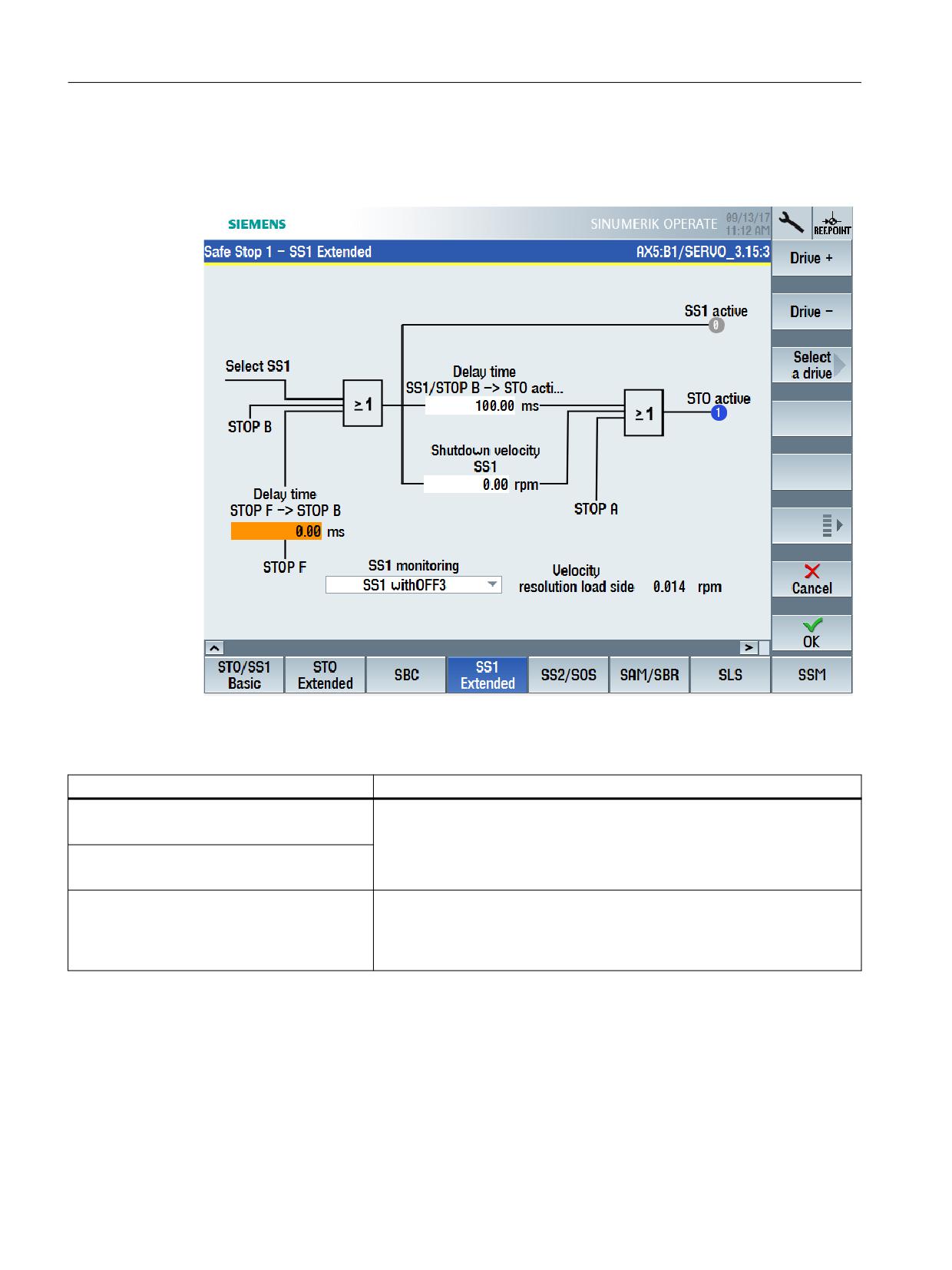
Display "Safe Stop 1 - SS1 Extended" commissioning screen
MENU SELECT > Commissioning > Menu forward key > Safety > Functions > SS1 Extended
Status information
Status
Meaning
SS1 active
Status signals for the safety motion monitoring functions integrated in the
drive on monitoring channel 1.
r9722.1
STO active
r9722.0
Velocity resolution
Displays the safe velocity resolution (load side). Velocity limits that are
specified - or parameter changes for velocities below this threshold - have no
Load side
effect.
r9732[0]
Safety Integrated plus
264
Commissioning Manual, 12/2019, 6FC5397-1FP40-6BA3
Commissioning and configuring
7.6 Configuring safety functions integrated in the drive
Settings
Setting
Meaning
Delay time STOP F -> STOP B
Sets the transition time from STOP F to STOP B
p9555
The set time is internally rounded off to an integer multiple of the monitoring
clock cycle.
SS1 monitoring
Selects the stop response, which is initiated when selecting function SS1 or
activating a STOP B.
p9507.3=0
● SS1 with OFF3
SS1 with OFF3 braking response integrated in the drive
● SS1E external stop
Stop to be externally initiated. Braking monitoring (SBR, SAM) is deac-
tivated.
Delay time, SS1/STOP B -> STO active
Sets the delay time for STOP A to STOP B.
p9556
The set time is internally rounded off to an integer multiple of the monitoring
clock cycle.
Shutdown speed SS1
Sets the shutdown velocity for activating STO. "Standstill" is assumed below
this velocity, and for STOP B / SS1, an STO is selected.
p9560
In the case of encoderless motion monitoring functions, this parameter must
be > 0 (10 is recommended).
(only for SS1 with OFF3)
Note: The shutdown velocity has no effect for a value = 0.
7.6.6
SS2/SOS
Precondition
● The SI commissioning mode (Page 240) is active for the drive to be configured.
● The drive is configured for operation with an encoder and Extended Functions.
Safety Integrated plus
Commissioning Manual, 12/2019, 6FC5397-1FP40-6BA3
265
Commissioning and configuring
7.6 Configuring safety functions integrated in the drive
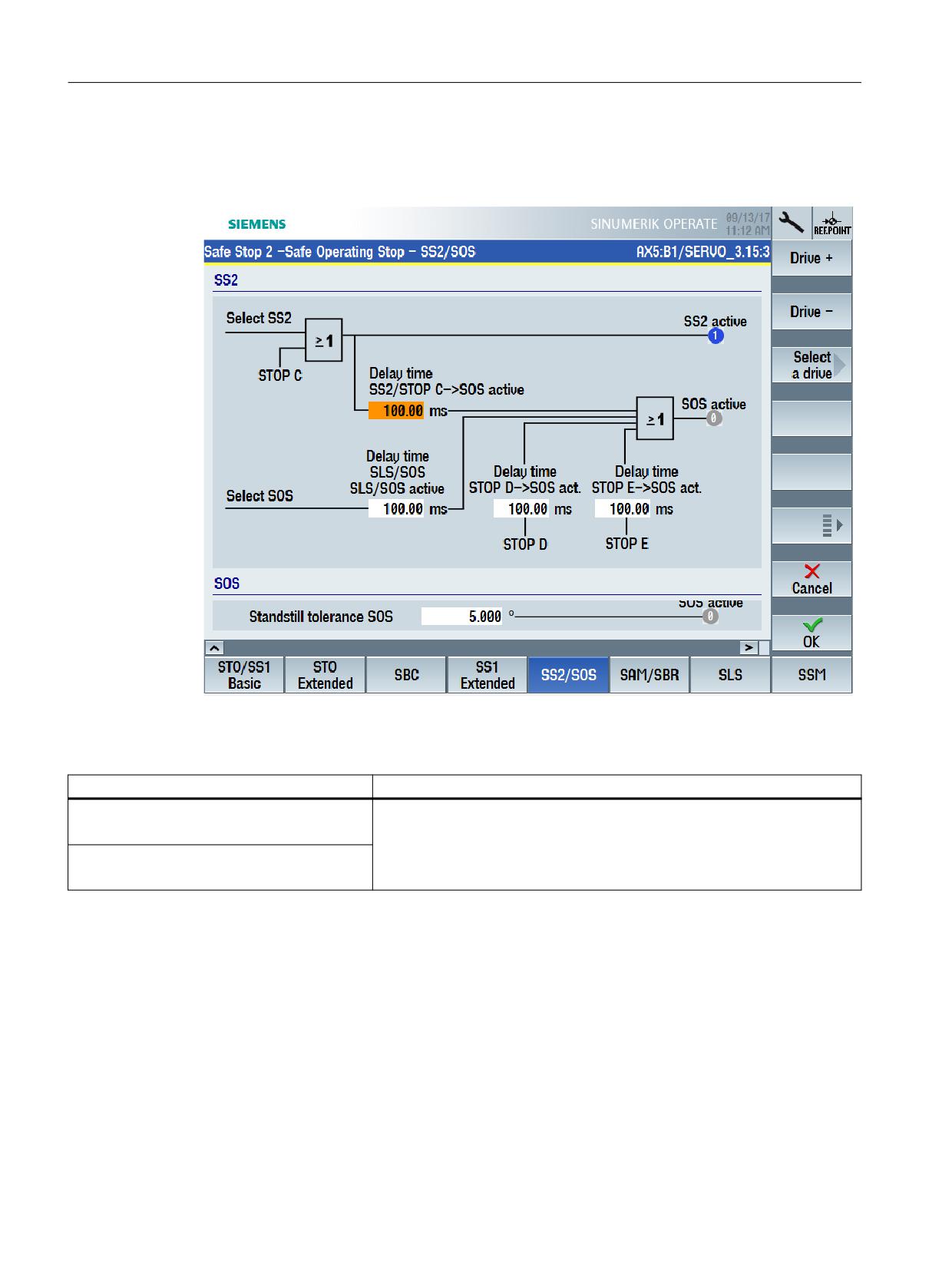
Display "Safe Stop 2 - Safe Operating Stop - SS2/SOS" commissioning screen
MENU SELECT > Commissioning > Menu forward key > Safety > Functions > SS2/SOS
Status information
Status
Meaning
SS2 active
Status signals for the safety motion monitoring functions integrated in the
drive on monitoring channel 1.
r9722.2
SOS active
r9722.3
Safety Integrated plus
266
Commissioning Manual, 12/2019, 6FC5397-1FP40-6BA3
Commissioning and configuring
7.6 Configuring safety functions integrated in the drive
Settings
Setting
Meaning
Delay time for SS2/STOP C -> SOS active
Sets the transition time from STOP C to "Safe Operating Stop" (SOS).
p9552
Delay time, SLS/SOS - SLS/SOS active
Sets the delay time for the SLS changeover and for the activation of SOS for
the functions "Safely-Limited Speed"(SLS) and "Safe operating stop" (SOS).
p9551
When transitioning from a higher to a lower Safely-Limited Speed stage and
when activating a Safe Operating Stop (SOS), the "old" speed stage remains
active for this delay time. A delay is also occurred when activating SLS from
the "SOS and SLS inactive" state - and when activating SOS from the "SOS
inactive" state.
Delay time, STOP D -> SOS active
Sets the transition time from STOP D to "Safe Operating Stop" (SOS)
p9553
Delay time, STOP E -> SOS active
Sets the transition time from STOP E to "Safe Operating Stop" (SOS)
p9554
Standstill tolerance SOS
Sets the tolerance for the "Safe operating stop" function (SOS).
p9530
7.6.7
SAM
Precondition
● The SI commissioning mode (Page 240) is active for the drive to be configured.
● The drive is configured for operation with an encoder and Extended Functions.
Safety Integrated plus
Commissioning Manual, 12/2019, 6FC5397-1FP40-6BA3
267
Commissioning and configuring
7.6 Configuring safety functions integrated in the drive
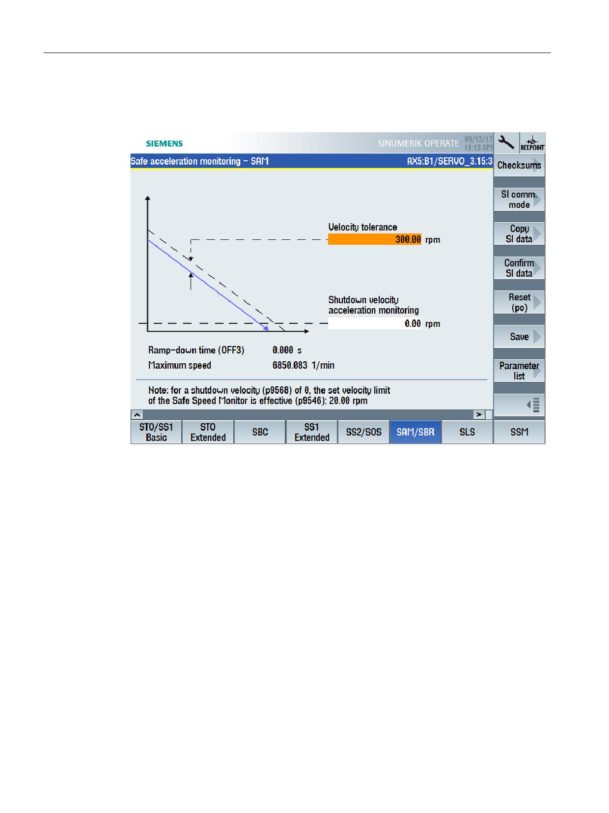
Display "Safe Acceleration Monitoring - SAM" commissioning screen
MENU SELECT > Commissioning > Menu forward key > Safety > Functions > SAM/SBR
Safety Integrated plus
268
Commissioning Manual, 12/2019, 6FC5397-1FP40-6BA3
Commissioning and configuring
7.6 Configuring safety functions integrated in the drive
Settings
Setting
Meaning
Velocity tolerance
p9548
During the down ramp, the converter continually adds the speed tolerance to
the actual speed. The converter reduces the monitoring threshold until the
"Shutdown speed" has been reached.
● If the speed temporarily increases, the monitoring threshold remains at
the last value.
● If the drive accelerates by the velocity tolerance, then SAM identifies this,
and a STOP A is initiated.
Calculation
● The following applies when parameterizing the SAM tolerance:
- The maximum speed increase after SS1 or SS2 is triggered results
from the effective acceleration (a) and the duration of the acceleration
phase.
- The duration of the acceleration phase is equivalent to one monitor-
ing clock cycle (delay from detecting an SS1/SS2 until nset = 0):
● Calculating the velocity tolerance:
Actual speed for SAM = acceleration × acceleration duration
The following setting rule is obtained:
- For linear axes:
SAM tolerance [mm/min] = a [m/s2] x MC [s] x 1000 [mm/m] x 60 [s/
min]
- For rotary axes:
SAM tolerance [rpm] = a [rev/s2] x MC [s] x 60 [s/min]
● Recommendation
The SAM tolerance value entered should be approx. 20 % higher than
the calculated value.
● With the tolerance, the "overshoot", which is automatically obtained
when reaching standstill when braking along the OFF3 ramp, must be
tolerated. However, it cannot be calculated as to just how high this is.
Shutdown speed acceleration monitoring
Sets the speed limit for the "SAM" and "SBR" functions.
p9568
SAM is deactivated once the set velocity limit has been fallen below. SBR is
deactivated if the safe braking ramp falls below the set speed limit.
Ramp-down time (OFF3)
Sets the ramp down time from the maximum velocity or maximum speed to
standstill for the OFF3 command.
p1135[0]
This time can be exceeded if the maximum the DC link voltage is reached.
Maximum velocity or maximum speed
Sets the highest possible velocity or speed.
(linear axis or rotary axis/spindle)
p1082[0]
Safety Integrated plus
Commissioning Manual, 12/2019, 6FC5397-1FP40-6BA3
269
Commissioning and configuring
7.6 Configuring safety functions integrated in the drive
7.6.8
SBR
Precondition
● The SI commissioning mode (Page 240) is active for the drive to be configured.
● The drive is configured for operation without an encoder and Extended Functions.
● Safety function SS1 with stop response OFF3 is configured for the drive.
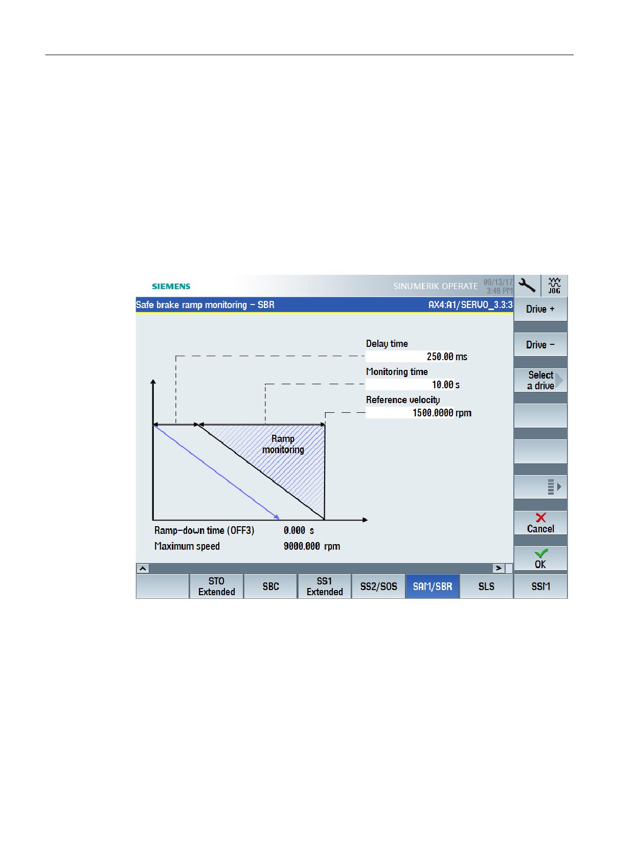
Displaying the "Safe brake ramp - SBR" startup screen form
MENU SELECT > Commissioning > Menu forward key > Safety > Functions > SBR
Safety Integrated plus
270
Commissioning Manual, 12/2019, 6FC5397-1FP40-6BA3
Commissioning and configuring
7.6 Configuring safety functions integrated in the drive
Settings
Setting
Meaning
Delay time
Set the delay time for monitoring the braking ramp.
p9582
Time that lapses after initiating SS1, selecting SLS or SLS level changeover
and the start of brake ramp monitoring.
The delay time has a minimum value of 2 safety monitoring clock cycles. (if
the parameterized delay time is less than 2 safety monitoring clock cycles,
then internally, a delay time of 2x monitoring clock cycles is used.)
Monitoring time
Sets the monitoring time to determine the braking ramp.
p9583
The gradient of the braking ramp depends on the reference velocity (refer-
ence value) and the monitoring time.
Reference velocity
Sets the reference value to determine the braking ramp.
p9581
The gradient of the braking ramp depends on the reference velocity (refer-
ence value) and the monitoring time.
Ramp-down time (OFF3)
Sets the ramp down time from the maximum velocity or maximum speed to
standstill for the OFF3 command.
p1135[0]
This time can be exceeded if the maximum the DC link voltage is reached.
Maximum velocity or maximum speed
Sets the highest possible velocity or speed.
(linear axis or rotary axis/spindle)
p1082[0]
7.6.9
SLS
Precondition
● The SI commissioning mode (Page 240) is active for the drive to be configured.
● The drive is configured for operation with an encoder and Extended Functions.
Note
Transmitting process data for SLS in SIEMENS telegram 903
PROFIsafe telegram 903 - set as default setting for SINUMERIK - is optimized for the use of
SCA (Safe Cam), and only includes restricted process data for SLS. On the other hand,
SIEMENS telegram 902 includes all of the process data for SLS.
Safety Integrated plus
Commissioning Manual, 12/2019, 6FC5397-1FP40-6BA3
271
Commissioning and configuring
7.6 Configuring safety functions integrated in the drive
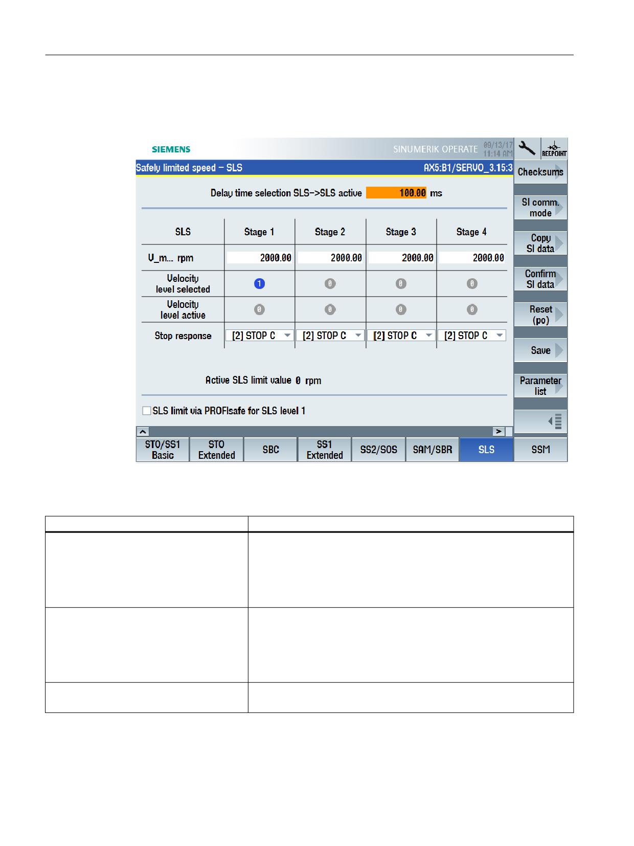
Display "Safely Limited Speed - SLS" commissioning screen
MENU SELECT > Commissioning > Menu forward key > Safety > Functions > SLS
Status information
Status
Meaning
Velocity level selected
Indicates which parameterized velocity level is currently selected.
Level 1: r9720.9=0 and r9720.10=0
Level 2: r9720.9=1 and r9720.10=0
Level 3: r9720.9=0 and r9720.10=1
Level 4: r9720.9=1 and r9720.10=1
Velocity level active
If one of the velocity levels is currently active, then this is displayed in the
corresponding column.
Level 1: r9722.9=0 and r9722.10=0
Level 2: r9722.9=1 and r9722.10=0
Level 3: r9722.9=0 and r9722.10=1
Level 4: r9722.9=1 and r9722.10=1
Active SLS limit value
Displays the load-side velocity actual value of the CU.
r9714.0
The display is updated in the safety monitoring cycle clock.
Safety Integrated plus
272
Commissioning Manual, 12/2019, 6FC5397-1FP40-6BA3
Commissioning and configuring
7.6 Configuring safety functions integrated in the drive
Settings
Setting
Meaning
Delay time when selecting SLS -> SLS active
Sets the delay time for SLS switchover.
p9551
This delay time is active in the following cases:
● Selecting SLS:
Monitoring only becomes active after the configurable delay time has
elapsed. Within this time, the actual velocity must be below the (selected)
limit.
● This delay time is also incurred when activating SLS from the "SOS and
SLS in active" state.
● Reducing the 1st limit value via PROFIsafe - or switching over to a lower
maximum velocity level:
The actual velocity of the drive must have dropped below the new limit
within the delay time. The existing limit remains active during the delay
time. The lower limit value becomes active after the delay time has ex-
pired.
The delay time is not active in the following cases:
● Deselecting SLS
● Switching over to a higher limit value:
The higher limit value immediately becomes active.
In operation, the parameterized delay time cannot be changed. If you require
various delay times in your application, then you must realize this using a
time-delayed transfer of the SLS limit value using the F-PLC.
Maximum velocity (V_max) level 1
Up to 4 parameterizable SLS velocity limit values must be specified based on
the results of the risk analysis. Also when SLS is activated, these limit values
p9531[0]
can be toggled between.
Maximum velocity (V_max) level 2
Depending on the particular situation, when switching over the "Delay time,
p9531[1]
selecting SLS -> SLS active" is active (see above).
Maximum velocity (V_max) level 3
Switchover between these 4 values
p9531[2]
The value of a selected maximum velocity level 1 is transferred via PROFI-
Maximum velocity (V_max) level 4
safe if check box "SLS limit via PROFIsafe for SLS level 1" is active.
p9531[3]
Safety Integrated plus
Commissioning Manual, 12/2019, 6FC5397-1FP40-6BA3
273
Commissioning and configuring
7.6 Configuring safety functions integrated in the drive
Setting
Meaning
Stop response level 1
Sets the specific stop response for the appropriate maximum velocity level:
p9563[0]
● STOP A
Stop response level 2
● STOP B
p9563[1]
● STOP C
Stop response level 3
● STOP D
p9563[2]
● STOP E
Stop response level 4
● STOP A with delayed STO when the bus fails
p9563[3]
● STOP B with delayed STO when the bus fails
● STOP C with delayed STO when the bus fails
● STOP D with delayed STO when the bus fails
● STOP E with delayed STO when the bus fails
Using the settings without delayed STO, when the bus fails, protection for
persons can be implemented - with delayed STO, when the bus fails, pro-
tection for machinery can be implemented.
Here, in a wider sense, bus failure should be understood as a communica-
tion error relating to the signals that are used to control the safety functions
(e.g. via PROFIsafe).
SLS limit value via PROFIsafe for SLS level 1
Setting to transfer the maximum velocity level 1 via PROFIsafe.
The transfer of maximum velocity level 1 via PROFIsafe can also be used to
parameterize (fixed) maximum velocity levels 2, 3 and 4.
When activated, the value is transferred using PROFIsafe in control
word S_SLS_LIMIT_A (Page 362), assuming that level 1 is currently selec-
ted. S_SLS_LIMIT_A has the value range 1 ... 32767; where the following
applies:
●
32767 ≙ 100 % of the 1st SLS level
● The actually monitored limit value is calculated as follows:
SLS limit value = (S_SLS_LIMIT_A/32767) × "maximum velocity level 1"
If an incorrect SLS limit value is transferred, then the converter responds with
the parameterized "Stop response level 1".
7.6.10
SSM
Precondition
● The SI commissioning mode (Page 240) is active for the drive to be configured.
● The drive is configured for operation with Extended Functions.
Safety Integrated plus
274
Commissioning Manual, 12/2019, 6FC5397-1FP40-6BA3
Commissioning and configuring
7.6 Configuring safety functions integrated in the drive
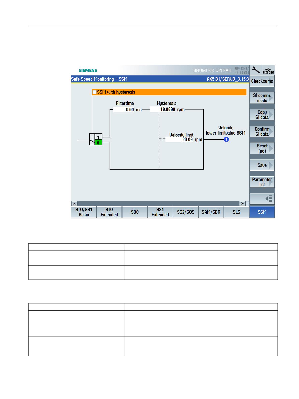
Display "Safe Speed Monitoring - SSM" commissioning screen
MENU SELECT > Commissioning > Menu forward key > Safety > Functions > SSM
Status information
Status
Meaning
Switching element (SSM with hysteresis)
Indicates whether the "Hysteresis" and "Filter time" functions are active.
p9501.16
Speed below SSM limit value
Indicates whether the current velocity is below the parameterized velocity
limit.
r9722.15
Settings
Setting
Meaning
SSM with hysteresis
Activates the "Hysteresis" and "Filter time" functions for SSM.
p9501.16
If the "SSM with hysteresis" function is enabled, the SSM function is evalu-
ated as an active monitoring function, and after a STOP F, also results in a
subsequent STOP B / STOP A response.
Filter time
Sets a filter time (PT1 filter) to smooth the output signal for SSM.
p9545
As filtering characteristic, for output signal SSM, a time-delayed SSM feed-
back signal occurs for the axes.
Safety Integrated plus
Commissioning Manual, 12/2019, 6FC5397-1FP40-6BA3
275
Commissioning and configuring
7.6 Configuring safety functions integrated in the drive
Setting
Meaning
Hysteresis
Parameterizing hysteresis for SSM
p9547
In this way, a more stable SSM signal characteristic can be achieved at
velocities close to the "Velocity limit" (monitoring threshold).
The velocity (or speed) determined by both channels may differ as a maxi-
mum by the difference between "Velocity/speed limit" and "Hysteresis". Oth-
erwise, it would be theoretically possible that for SSM one channel returns a
HIGH signal and the other a LOW signal.
Take into account the following rule when parameterizing:
● Hysteresis p9547 ≤ 0.75 · velocity limit p9546
If actual value synchronization is enabled (Settings - encoder parameteriza-
tion (Page 246)), then you must also comply with the following rule:
● "SI Motion slip velocity tolerance" (p9549) ≤ hysteresis
Velocity limit
Sets the velocity limit for the SSM feedback signal to detect standstill (n < nx).
p9546
If the velocity limit is fallen below, then the signal "Safe Speed Monitor feed-
back signal active" (SGA n < n_x) is set.
The abbreviation SGA n < nx stands for the safety function required for
determining an output signal when a parameterizable velocity limit has been
undershot.
This value is also active for safety function SAM as "Shutdown velocity ac-
celeration monitoring" - assuming that this shutdown velocity is parameter-
ized with "0". In this case, the effects of Safe Acceleration Monitoring are
therefore restricted if a relatively high SSM velocity limit is set when using the
SS1 and SS2 stop functions.
Feedback signal SSM active for pulse inhibit
Sets the response during pulse cancellation in encoderless operation.
(only in encoderless operation)
For Safe Speed Monitor without encoder, after pulse suppression the drive
is unable to determine the current velocity. 2 responses can be selected for
p9509.0
this operating state:
● The status signal (SSM feedback signal) indicates "0" (factory setting).
● The status signal (SSM feedback signal) is frozen. "Safe Torque Off"
(STO) is selected internally.
See also: Signal characteristic for setting "Feedback signal SSM for pulse
inhibit " (Page 134)
7.6.11
SDI
Precondition
● The SI commissioning mode (Page 240) is active for the drive to be configured.
● The drive is configured for operation with Extended Functions.
Safety Integrated plus
276
Commissioning Manual, 12/2019, 6FC5397-1FP40-6BA3
Commissioning and configuring
7.6 Configuring safety functions integrated in the drive
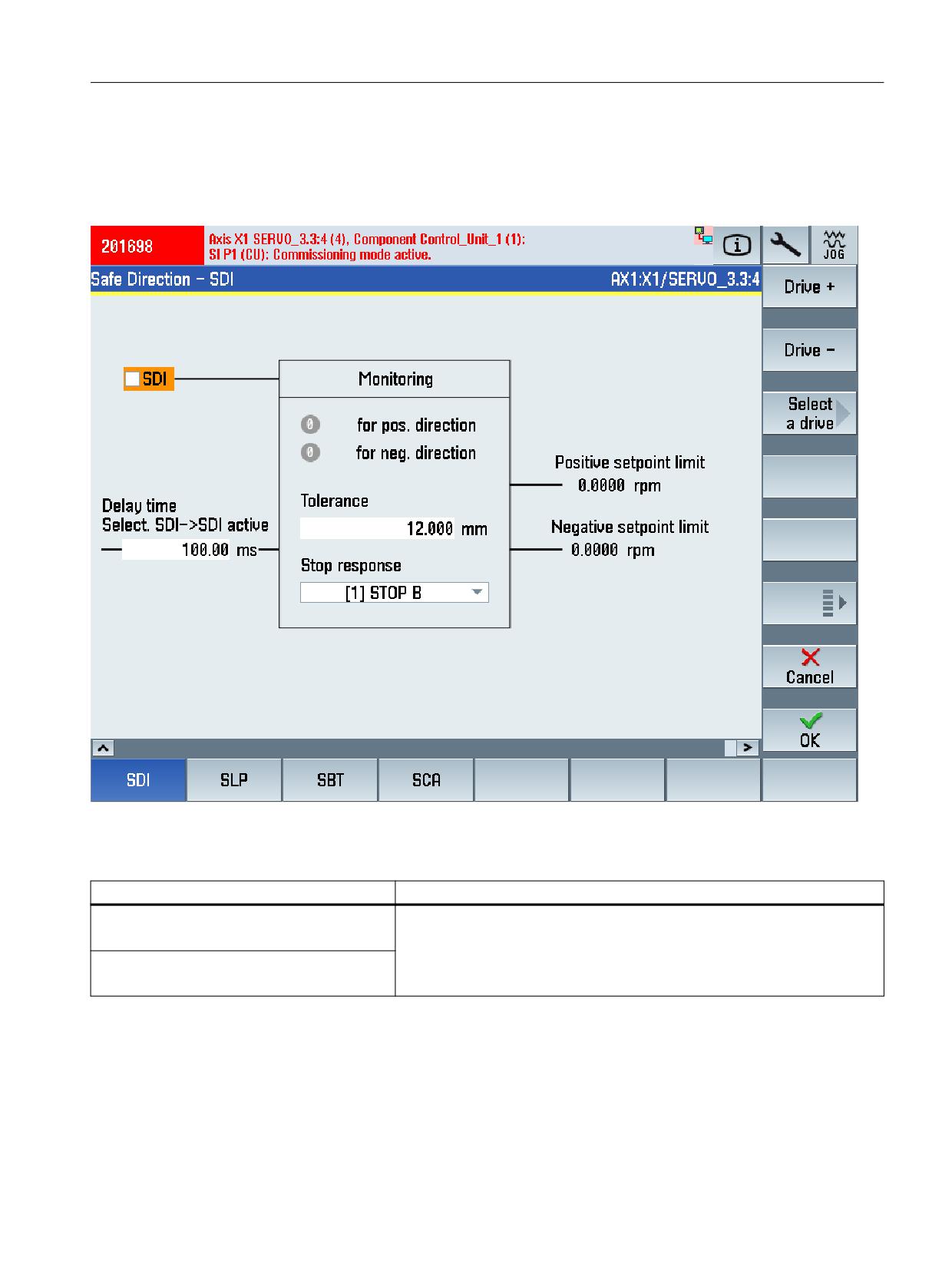
Display "Safe Direction - SDI" commissioning screen
MENU SELECT > Commissioning > Menu forward key > Safety > Functions > Menu forward
key > SDI
Status information
Status
Meaning
for positive direction
Status signals for the safety motion monitoring functions integrated in the
drive on monitoring channel 1.
r9722.12
for negative direction
r9722.13
Safety Integrated plus
Commissioning Manual, 12/2019, 6FC5397-1FP40-6BA3
277

Commissioning and configuring
7.6 Configuring safety functions integrated in the drive
Settings
Setting
Meaning
SDI
Activating/deactivating (enable) SDI.
p9501.17
Delay time, selection SDI -> SDI active
Sets the delay time.
p9565
After selecting function SDI, motion in the monitored direction is permissible,
as a maximum for this time. Therefore, this time can be used to brake active
motion.
Tolerance
Sets the tolerance.
p9564
This motion is still permissible in the monitored direction before safety mes-
sage C01716 is initiated.
Stop response
Sets the stop response. This setting applies to both directions of motion.
p9566
●
[0] STOP A
●
[1] STOP B
●
[2] STOP C
●
[3] STOP D
●
[4] STOP E
●
[10] STOP A with delayed stop response when the bus fails
●
[11] STOP B with delayed stop response when the bus fails
●
[12] STOP C with delayed stop response when the bus fails
●
[13] STOP D with delayed stop response when the bus fails
●
[14] STOP E with delayed stop response when the bus fails
In encoderless operation, only settings "[0] STOP A" and "[1] STOP B" can
be selected.
Feedback signal SDI active for pulse inhibit
Activates/deactivates SDI during pulse cancellation in encoderless opera-
tion.
p9509.8
(only in encoderless operation)
7.6.12
SLP/SP
Precondition
● The SI commissioning mode (Page 240) is active for the drive to be configured.
● The drive is configured for operation with an encoder and Extended Functions.
● Telegram 902 (using SLP/SP) or telegram 903 (using only SLP) is set
● Actual value synchronization is not enabled (p9501.3 != 0).
Safety Integrated plus
278
Commissioning Manual, 12/2019, 6FC5397-1FP40-6BA3
Commissioning and configuring
7.6 Configuring safety functions integrated in the drive
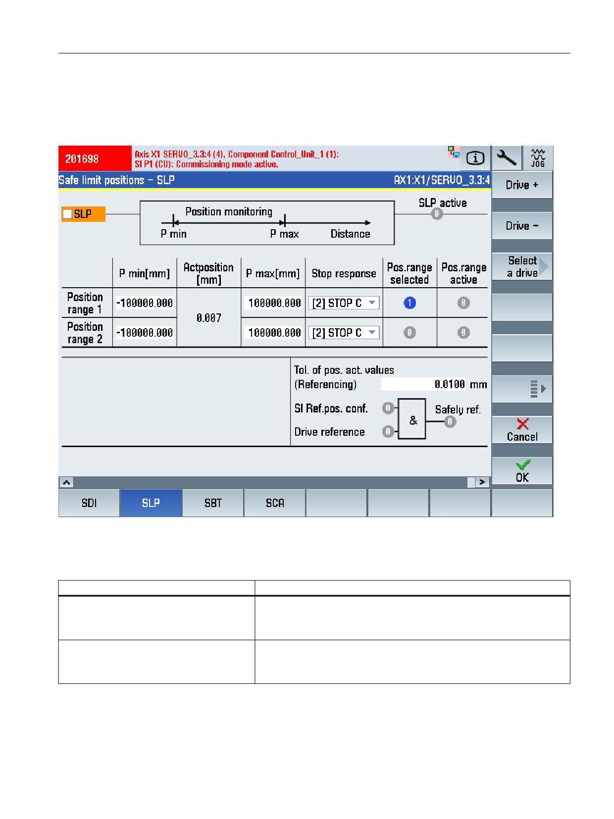
Display "Safe Limit Positions - Safe Position - SLP/SP" commissioning screen
MENU SELECT > Commissioning > Menu forward key > Safety > Functions > Menu forward
key > SLP/SP
Figure 7-12
Example of the "SLP" commissioning screen, that is, with telegram 903 being set
Status information
Status
Meaning
Positioning range selected
Displays whether positioning range 1 or 2 is currently selected.
Range 1: r9720.19=0 & r9720.6=0
Range 2: r9720.19=1 & r9720.6=0
Positioning range active
Displays whether positioning range 1 or 2 is currently active.
Range 1: r9722.19=0 & r9722.6=1
Range 2: r9722.19=1 & r9722.6=1
Safety Integrated plus
Commissioning Manual, 12/2019, 6FC5397-1FP40-6BA3
279

Commissioning and configuring
7.6 Configuring safety functions integrated in the drive
Status
Meaning
Actual position value
Displays the actual load-side actual value via PROFIsafe.
r9708[4]
(only PROFIsafe)
Safety-relevant position valid
Status signals for the safety motion monitoring functions integrated in the
drive on monitoring channel 1.
r9722.22
SP valid
Safety reference position confirmed
Displays the internal status of the user agreement
r9727
Drive reference.
Display: Position referenced
r9723.17
Safely ref.
Display: SP valid
r9722.23
Settings
Setting
Meaning
SLP
Enable/inhibit SLP.
p9501.1
P min [mm]
Sets the lower and upper limit values for position range 1 or 2 of the SLP
function.
Range 1: p9535[0]
For the setting, these limit values apply:
Range 2: p9535[1]
● P max > P min
P min [mm]
Range 1: p9534[0]
● The limit values must lie in the valid traversing range (-737280 …
737280).
Range 2: p9534[1]
See also: C01715
Stop response
Sets the stop response for position range 1 or 2 of the SLP function.
Range 1: p9562[0]
●
[0] STOP A
Range 2: p9562[1]
●
[1] STOP B
●
[2] STOP C
●
[3] STOP D
●
[4] STOP E
●
[10] STOP A with delayed stop response when the bus fails
●
[11] STOP B with delayed stop response when the bus fails
●
[12] STOP C with delayed stop response when the bus fails
●
[13] STOP D with delayed stop response when the bus fails
●
[14] STOP E with delayed stop response when the bus fails
Safe position
Enables/inhibits the transfer of the safe position via PROFIsafe
p9501.25
(only for telegram 902)
(only for PROFIsafe)
Safety Integrated plus
280
Commissioning Manual, 12/2019, 6FC5397-1FP40-6BA3
Commissioning and configuring
7.6 Configuring safety functions integrated in the drive
Setting
Meaning
Safe absolute position
Enables/inhibits the safe absolute position.
p9501.27
(only for telegram 902)
(only for PROFIsafe)
SP scaling
Sets the scaling factor to transfer the safe position via PROFIsafe in the 16-
bit format. The parameter is only active when PROFIsafe telegram 901 is
p9574
selected, see S_XIST16: Current actual position value (16 bits) (Page 363).
(only for telegram 902)
Scaling is realized by dividing the 32-bit position actual value r9713[0] with
(only for PROFIsafe)
this scaling factor. If, during operation, a position actual value is determined
that cannot be scaled, then this results in message C0711 with value 7001
- as well as STOP F.
Tolerance of the position actual values (refer-
Sets the tolerance for checking the actual values.
encing)
For an incremental encoder, the actual values are checked after referencing,
p9544
for an absolute encoder, when switching on.
(only for telegram 902)
7.6.13
SBT
Precondition
● The SI commissioning mode (Page 240) is active for the drive to be configured.
● The drive is configured for operation with Extended Functions.
Safety Integrated plus
Commissioning Manual, 12/2019, 6FC5397-1FP40-6BA3
281
Commissioning and configuring
7.6 Configuring safety functions integrated in the drive
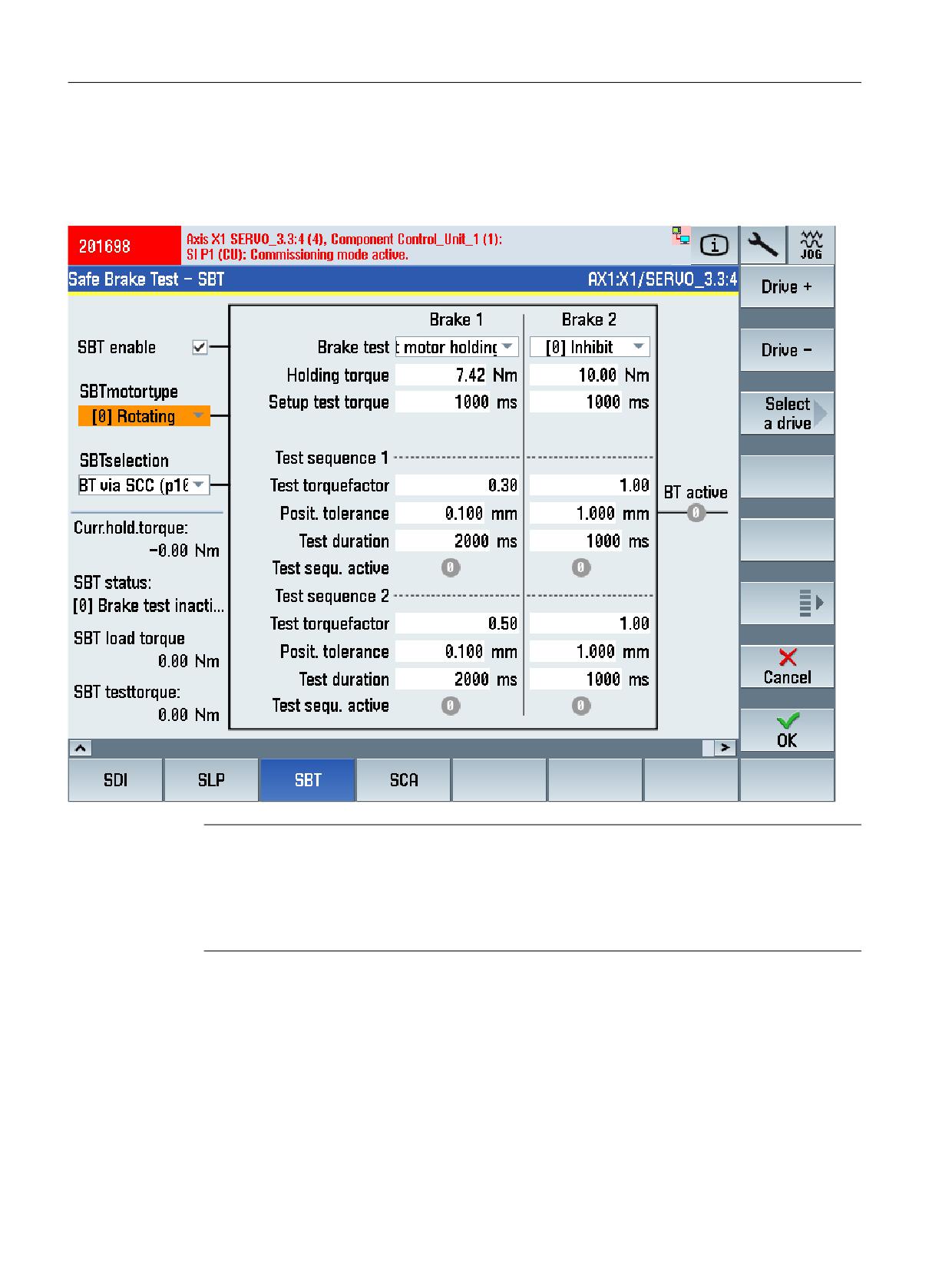
Display "Safe Brake Test - SBT" commissioning screen
MENU SELECT > Commissioning > Menu forward key > Safety > Functions > Menu forward
key > SBT
Note
Additional commissioning support
The following SINUMERIK Operate screen forms are available to commission SBT:
● "Graphic" softkey: Displays a torque-time diagram or a force-time diagram
● "Trace" softkey: Starts a drive trace session with various options.
Safety Integrated plus
282
Commissioning Manual, 12/2019, 6FC5397-1FP40-6BA3

Commissioning and configuring
7.6 Configuring safety functions integrated in the drive
Status information
Status
Meaning
Actual holding torque or force
Displays the torque actual value or force actual value (unsmoothed).
r0080
SBT state
Displays the current status of the Safe Brake Test.
r10242
SBT load torque or force
Displays the load torque or the load force for the Safe Brake Test. This load
torque or this load force is available at the drive when initializing the brake
r10241
test. The displayed value is kept until the brake test is deselected.
SBT test torque or force
Displays the maximum test force or the maximum test torque available on
the motor side. The displayed value remains until the start of the next test
r10240
sequence.
Settings
Setting
Meaning
SBT enable
Enables/inhibits SBT.
p10201.0
SBT motor type
Selects the motor type for the Safe Brake Test.
p10204
●
0: Rotary
●
1: Linear
SBT selection
Selects the control type
p10203
●
0: SBT via SCC (p10235)
●
1: SBT via BICO (p10230)
●
2: SBT for test stop selection (p9705/p10250.8)
For integrated drives (CU_I, CU_NX), only "SBT via SCC" is permissible.
Brake test
Selects the brakes to be tested.
Brake 1: p10202[0]
●
0: Inhibit
Brake 2: p10202[1]
●
1: Test motor holding brake
●
2: Test external brake
It is not possible to test two motor holding brakes.
Actual holding torque or force
Sets the effective holding torque or holding force of the brakes to be tested
on the motor side.
Brake 1: p10209[0]
Brake 2: p10209[1]
Establish the test torque or test force
Sets the time during which the test torque or the test force is ramped up
against the closed brake. After the Safe Brake Test, the test torque or the test
Brake 1: p10208[0]
force is ramped-down again.
Brake 2: p10208[1]
Test torque factor or test force factor
Sets the factor for the test torque or the test force of test sequence 1 or 2 for
the Safe Brake Test. The factor is referred to the brake holding torque or the
Test sequence 1, brake 1: p10210[0]
brake holding force (see above, p10209).
Test sequence 1, brake 2: p10210[1]
Test sequence 2, brake 1: p10220[0]
Test sequence 2, brake 2: p10220[1]
Safety Integrated plus
Commissioning Manual, 12/2019, 6FC5397-1FP40-6BA3
283
Commissioning and configuring
7.6 Configuring safety functions integrated in the drive
Setting
Meaning
Position tolerance
Sets the tolerated position deviation for test sequence 1 or 2 for the Safe
Brake Test.
Test sequence 1, brake 1: p10212[0]
Test sequence 1, brake 2: p10212[1]
Test sequence 2, brake 1: p10222[0]
Test sequence 2, brake 2: p10222[1]
Test duration
Sets the test duration for test sequence 1 or 2 for the Safe Brake Test. The
test torque or the test force is applied to the closed brake for this time.
Test sequence 1, brake 1: p10211[0]
Test sequence 1, brake 2: p10211[1]
Test sequence 2, brake 1: p10221[0]
Test sequence 2, brake 2: p10221[1]
Note
Using MD36968.2 to select the parameter assignment behavior at the end of SBT
You can parameterize the positioning behavior after the brake test via the expert list using
MD36968.2 $MA_SAFE_BRAKETEST_CONTROL, bit 2:
●
0: Positioning at the actual axis position
To conclude the brake test, the actual axis position for the next path motion is used.
(MD36968 $MA_SAFE_BRAKETEST_CONTROL bit 2 = 0). This results in motion to the
last programmed axis position on the path.
●
1: Positioning to the last programmed axis position
Acceptance of the actual axis position is not carried out. After the axis has been pressed
against the brake, the closed-loop position controller withdraws the axis to the last
programmed position.
Vertical axes can thus be prevented from sagging as a result of a repeated brake test. It is
also possible to briefly exceed the software limit switch while pressing against the brake
without initiating an alarm.
7.6.14
SCA
Precondition
● The SI commissioning mode (Page 240) is active for the drive to be configured.
● The drive is configured for operation with an encoder and Extended Functions.
Safety Integrated plus
284
Commissioning Manual, 12/2019, 6FC5397-1FP40-6BA3
Commissioning and configuring
7.6 Configuring safety functions integrated in the drive
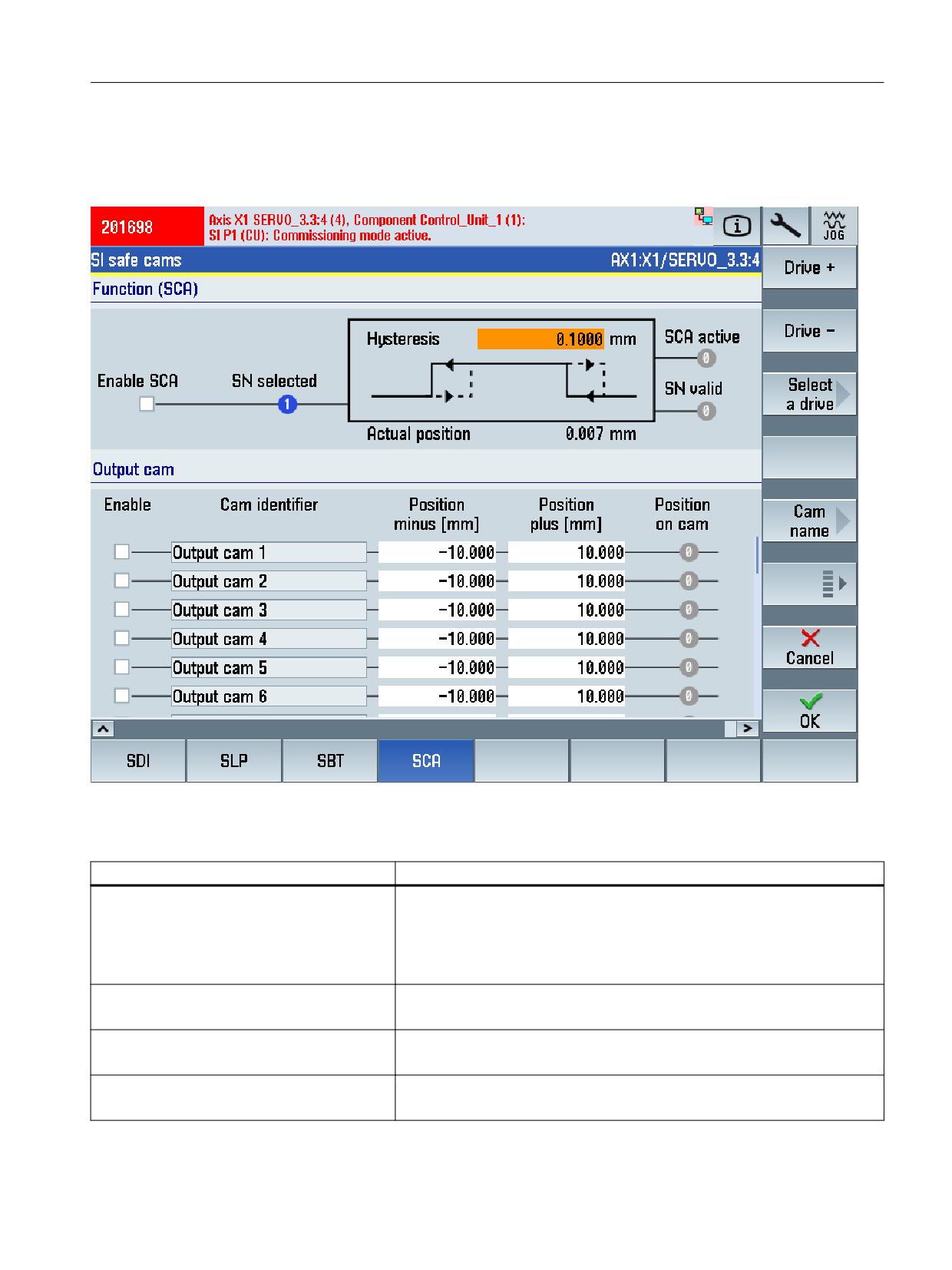
Display "SI Safe Cams" commissioning screen
MENU SELECT > Commissioning > Menu forward key > Safety > Functions > SCA
Settings
Setting
Meaning
Modulo value SP
Sets the modulo value in degrees for rotary axes for the "Safe position"
function.
p9505
This modulo value is taken into account for safe referencing and for the
transfer of the safe position via PROFIsafe when absolute position is ena-
bled.
SCA function
Inhibits or enables the SCA function throughout.
Hysteresis
Specifies the hysteresis value.
<Inhibit or enable>
Inhibits/enable individual Safe Cams of the SCA function.
9503.0 ... 29
Safety Integrated plus
Commissioning Manual, 12/2019, 6FC5397-1FP40-6BA3
285
Commissioning and configuring
7.6 Configuring safety functions integrated in the drive
Setting
Meaning
<Cam identifier>
Displays the cam identifier. Default setting, "Cam 1" … "Cam 30".
The cam identifiers are defined in the associated TS files depending on the
language, and can be freely defined by copying and adapting the files:
● Template for the TS file: /card/siemens/sinumerik/hmi/template/lng/
oem_scam_names_deu.ts
● Archive path for user-defined TS file: /card/oem/sinumerik/hmi/lng/
oem_scam_names_<Sprachkennung>.ts
Minus cams position
Sets the minus cam position in ° or mm.
p9537[0...29]
Plus cam position
Sets the plus cam position in ° or mm.
p9536[0...29]
7.6.15
SS2E
Precondition
● The Safety Integrated commissioning mode (Page 240) is active for the drive to be
configured.
● The drive is configured for operation with an encoder and Extended Functions.
Safety Integrated plus
286
Commissioning Manual, 12/2019, 6FC5397-1FP40-6BA3
Commissioning and configuring
7.6 Configuring safety functions integrated in the drive
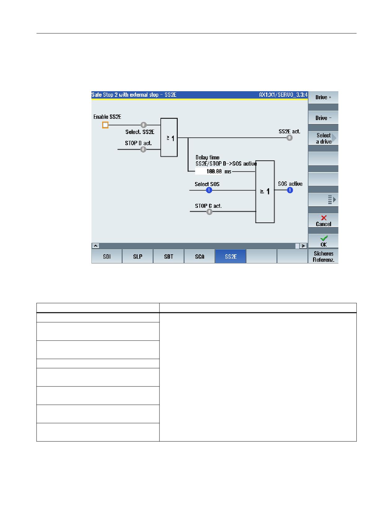
Display commissioning screen "Safe Stop 2 with external stop - SS2E"
MENU SELECT > Commissioning > Menu forward key > Safety > Functions > Menu forward
key > SS2E
Figure 7-13
Safe Stop 2 with external stop - SS2E
Status information
Status
Meaning
Status control signals:
Status - control and status signals for the safety motion monitoring functions
integrated in the drive on monitoring channel 1.
Select SS2E
r9720.28
Select SOS
r9720.3
Status signals:
SS2E active
r9722.28
SOS active
r9722.3
STOP C active
r9721.13
STOP D active
r9721.14
Safety Integrated plus
Commissioning Manual, 12/2019, 6FC5397-1FP40-6BA3
287
Commissioning and configuring
7.6 Configuring safety functions integrated in the drive
Settings
Setting
Meaning
Enable SS2E
SS2E enable is activated via the parameter.
p9501.18
Delay time, STOP D -> SOS active
Sets the transition time from STOP D to "Safe Operating Stop" (SOS) in ms.
p9553
7.6.16
SS2ESR
Precondition
● The Safety Integrated commissioning mode (Page 240) is active for the drive to be
configured.
● The drive is configured for operation with an encoder and Extended Functions.
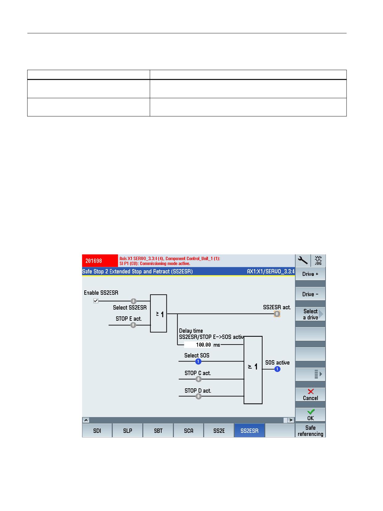
Display commissioning screen "Safe Stop 2 Extended Stop and Retract (SS2ESR)"
MENU SELECT > Commissioning > Menu forward key > Safety > Functions > Menu forward
key > SS2ESR
Figure 7-14
Safe Stop2 Extended Stop and Retract (SS2ESR)
Safety Integrated plus
288
Commissioning Manual, 12/2019, 6FC5397-1FP40-6BA3

Commissioning and configuring
7.6 Configuring safety functions integrated in the drive
Status information
Status
Meaning
Status control signals:
Status - control and status signals for the safety motion monitoring functions
integrated in the drive on monitoring channel 1.
Select SS2ESR
r9720.29
Select SOS
r9720.3
Status signals:
SS2ESR active
r9722.27
STOP E active
r9721.15
STOP C active
r9721.13
STOP D active
r9721.14
SOS active
r9722.3
Settings
Setting
Meaning
Enable SS2ESR
SS2ESR enable is activated via the parameter.
p9501.04
Delay time SS2ESR/STOP E -> SOS active
Sets the transition time from STOP D to "Safe Operating Stop" (SOS) in ms.
p9554
7.6.17
Safe referencing
Precondition
● The Safety Integrated commissioning mode (Page 240) is active for the drive to be
configured.
● Access rights of access level 2 (service) are available in SINUMERIK Commissioning.
● The drive is configured for operation with an encoder and Extended Functions.
Safety Integrated plus
Commissioning Manual, 12/2019, 6FC5397-1FP40-6BA3
289
Commissioning and configuring
7.6 Configuring safety functions integrated in the drive
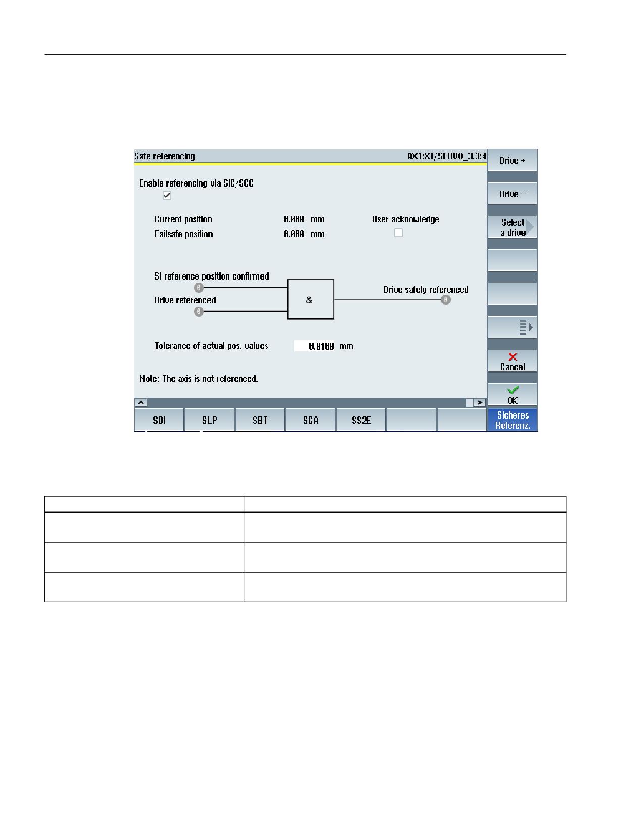
Display "Safe referencing" commissioning screen
MENU SELECT > Commissioning > Menu forward key > Safety > Functions > Menu forward
key > Safe referencing
Figure 7-15
Safe referencing
Status information
Status
Meaning
Safety reference position confirmed
Displays the internal status of the user agreement
r9727
Drive reference.
Display: Position referenced
r9723.17
Safely ref.
Display: Safely referenced
r9722.23
Safety Integrated plus
290
Commissioning Manual, 12/2019, 6FC5397-1FP40-6BA3
Commissioning and configuring
7.6 Configuring safety functions integrated in the drive
Settings
Setting
Meaning
Enable referencing via SCC
Sets the enable signals for the safety-related motion monitoring functions.
p9501.27
SI Motion, user agreement, select/deselect
User agreement Safe Position
p9726
(is only displayed if functions with Safe Position evaluation are activated)
Tolerance of the position actual values (refer-
Sets the tolerance for checking the actual values.
encing)
For an incremental encoder, the actual values are checked after referencing,
p9544
for an absolute encoder, when switching on.
7.6.18
Further safety functions
In addition to the described safety functions that are configured using commissioning screens,
the following drive-integrated safety functions can be configured in the expert list, that is, by
directly entering the parameters:
● SS2e - SS2 with external stop (Page 107)
● Homing via SIC/SCC (Page 179)
● Cancellation of the stop transition times
● Automatic SLS (Page 117)/SOS (Page 114) deselection when STO active
Safety Integrated plus
Commissioning Manual, 12/2019, 6FC5397-1FP40-6BA3
291
Commissioning and configuring
7.7 Finalizing commissioning
7.7
Finalizing commissioning
7.7.1
Confirming settings
After parameterization, the Safety Integrated commissioning mode must be deactivated and
the actual checksums must be transferred into the reference checksums.
Precondition
● The NC and drive-specific settings have been correctly configured for all safety-relevant
drives and for all F-I/O devices.
● The safety functions integrated in the drive are configured.
● The safety commissioning mode is activated (Page 240).
Procedure
Proceed as follows to confirm the drive-specific safety settings that have been made:
1. In SINUMERIK Operate, switch to "MENU SELECT > Commissioning > Menu forward key
> Safety".
2. Using the menu forward key, switch to the 2nd Level of the vertical softkey bar.
3. Press softkey "Copy SI data" and confirm with "OK".
The safety settings are copied from the 1st into the 2nd monitoring channel.
4. Press softkey "Confirm SI data" and confirm with "OK".
5. Press softkey "Save all drive objects" and confirm with "OK".
Safety Integrated plus
292
Commissioning Manual, 12/2019, 6FC5397-1FP40-6BA3
Commissioning and configuring
7.7 Finalizing commissioning
7.7.2
Assigning a Safety Integrated password
In SINUMERIK Operate, commissioning data is generally stored in various access levels. You
protect the safety-related drive parameterization additionally with the Safety Integrated
password. This password is stored in the drive data so that it can be changed only by authorized
persons who know the password.
Note
The SINAMICS safety password must be used for SINUMERIK Safety Integrated
The assigning of the Safety Integrated password using the SINUMERIK operate screen is
supported as of V4.8 SP2 HF1.
Alternatively, assign the password as follows via the expert list as in SINAMICS Safety
Integrated:
● p0010 = 95 Commissioning mode
● p9761 = enter "Old safety password". Default setting for p9761 = 0.
● p9762 = enter "new password".
● p9763 = confirm "new password"
● p0977 = 1; "Copy from RAM to ROM"
The new and confirmed safety password is valid immediately.
Procedure
To assign the Safety Integrated password for all axes/drives, proceed as follows:
1. IN SINUMERIK Operate, go to "MENU SELECT > Commissioning > Menu forward key >
Safety".
2. Press softkey "SI password".
3. Select the check box for the all "axes/drives".
4. Assign a password and confirm by clicking on "OK".
Safety Integrated plus
Commissioning Manual, 12/2019, 6FC5397-1FP40-6BA3
293
Commissioning and configuring
7.8 Series commissioning
7.8
Series commissioning
7.8.1
General information about series commissioning
A project that has been loaded and commissioned, can be loaded to another NCU, keeping the
safety parameterization. However, observe the following information:
● Different component checksums as a result of series commissioning with Safety Integrated
functionality (Page 339)
● Safety message for series commissioning with third-party motor (Page 294)
For series commissioning, for each NCU, you must carry out an acceptance test (Page 331).
7.8.2
Series commissioning with third-party motor
If you are using third-party motors with absolute encoders, then safety message/signal can
block commissioning.
Possible cause:
A different serial number of the absolute encoder is saved on the memory card other that in the
Control Unit that is to be commissioned.
Remedy:
Correct the serial number of the absolute encoder (e.g. with SINUMERIK Operate) before you
acknowledge the safety messages. Then continue with commissioning.
Safety Integrated plus
294
Commissioning Manual, 12/2019, 6FC5397-1FP40-6BA3
Diagnostics
8
If you are looking for a description of the diagnostic functionality, then in this Chapter you can
find a Diagnostics guide (Page 296) and descriptions relating to the safety diagnostic
functionality (Page 300) with SINUMERIK Operate.
These diagnostic functions are possible in the following software depending on the particular
component:
Table 8-1
Diagnostic functionality depending on the components
Component
SINUMERIK Operate
TIA Portal
F-PLC
Operating area "Diagnostics"
See the help for SIMATIC Safe-
ty
F-I/O
Operating area "Diagnostics"
See the help for SIMATIC Safe-
ty
Safety program
-
See the help for SIMATIC Safe-
(F-program)
ty
Checksums
Master checksums and SI-
Signatures of F-I/O, the safety
NAMICS checksums in operat-
program and checksums of the
ing area "Diagnostics"
F-PLC.
See the help for SIMATIC Safe-
ty
Status of safety-relevant drives
Operating area "Diagnostics"
-
Telegram diagnostics
Operating area "Diagnostics"
-
SCA diagnostics
Operating area "Diagnostics"
-
Status and diagnostic information
Operating area "Startup"
-
about specific safety functions
(without activating the commis-
sioning mode)
You will also find general descriptions and backg65round information about diagnostics using
SINUMERIK Operate in this chapter:
● General information about displaying and evaluating diagnostic information (Page 313)
● Checksums (Page 314)
● Stop responses (Page 317)
● Using the fault buffer and safety message buffer (Page 324)
● Acknowledgment (Page 327)
Information about replacing components (software or hardware components) is provided in a
separate chapter (Page 333).
Safety Integrated plus
Commissioning Manual, 12/2019, 6FC5397-1FP40-6BA3
295
Diagnostics
8.1 Diagnostics guide
8.1
Diagnostics guide
Table 8-2
Steps for evaluating diagnostic capabilities
Step
Procedure
Reference
1
Evaluate LEDs on the hardware (F-CPU, F-I/O):
Equipment Manual SINUMERIK
840D sl NCU 7x0.3
● SF, DP, DP/MPI and PN-LEDs of the F-CPU flash for a communication
error at the PROFIBUS DP/PROFINET IO, per channel;
Manuals for the F-I/O
SF-LED is lit, if OB 85 and OB 121 are programmed, for a programming
error (e.g. instance DB not loaded)
● STOP LED on the F-CPU: illuminates when the F-CPU is in STOP mode
● Fault LEDs on the F-I/O: e.g. SF-LED (group error LED) on if any fault
occurs in the individual F-I/O
2
Evaluate diagnostic buffer of the modules:
Help on STEP 7 and manuals for
the F-CPU and F-I/O
You read the diagnostic buffer of a module (F-CPU, F-I/O, CP) in its online
and diagnostic view in the "Diagnostic buffer" group under the "Online & Di-
agnostics" folder.
3
Evaluate stacks of the F-CPU:
Help on STEP 7
when the F-CPU is in STOP mode, read the following successively:
● Block stack: Check whether STOP mode of the F-CPU was triggered by
an F-block of the safety program
● Interruption stack
● Local data stack
4
Evaluate diagnostic tag of the F-I/O DB using testing and commissioning
F-I/O access (Page 70) or help re-
functions, by means of an operator control and monitoring system, or in the
lating to SIMATIC Safety
standard user program:
Evaluate the DIAG tag in the F-I/O DB
5
Evaluate diagnostic outputs of the instance DBs of instructions using testing
Operations (Page 58) or help relat-
and commissioning functions, using an operator control and monitoring sys-
ing to SIMATIC Safety
tem, or in the standard user program:
● For MUTING, EV1oo2DI, TWO_H_EN, MUT_P, ESTOP1, FDBBACK,
SFDOOR, evaluate in the assigned instance:
- Output DIAG
● Evaluate the following for SENDDP or RCVDP in the assigned instance
DB:
- Output RET_DPRD/RET_DPWR
- Output DIAG
● Evaluate the following for SENDS7 or RCVS7 in the assigned instance
DB:
- Output STAT_RCV
- Output STAT_SND
- Output DIAG
Safety Integrated plus
296
Commissioning Manual, 12/2019, 6FC5397-1FP40-6BA3
Diagnostics
8.1 Diagnostics guide
Tip on RET_DPRD/RET_DPWR
The diagnostic information of the RET_DPRD/RET_DPWR parameters correspond to the
diagnostic information of the RETVAL parameter of the "DPRD_DAT" and "DPWR_DAT"
instructions. You can find the description in the help on STEP 7 for the "DPRD_DAT" and
"DPWR_DAT" instructions.
Tip: STAT_RCV and STAT_SND
The diagnostic information of the parameter STAT_RCV corresponds to the diagnostic
information of the parameter STATUS of the instruction "URCV". The diagnostic information of
the parameter STAT_SND corresponds to the diagnostic information of the parameter
STATUS of the instruction "USEND". You can find the description in the help on STEP 7 for the
instruction "UCRV" or "USEND" .
Safety Integrated plus
Commissioning Manual, 12/2019, 6FC5397-1FP40-6BA3
297
Diagnostics
8.2 System alarms and diagnostic screens for F-PLC and F-I/O.
8.2
System alarms and diagnostic screens for F-PLC and F-I/O.
The diagnosis of faults of F-I/O or F-PLC is supported in SINUMERIK Operate via specific
system alarms (number ranges 4300XX and 43100X) as well as own diagnostics screens
(Page 300).
To use this functionality, the configuration must be properly completed and loaded:
● The configured NCU must have firmware version ≥V4.8 and Safety Integrated plus (F-PLC)
must be activated.
● Hardware and software must be consistently compiled and loaded.
With such a correct configuration, SI_DiagDB [DB1009] is automatically generated during the
compilation and transferred to the NCU during loading.
Details on internal processing of the F-PLC / F-I/O system alarms
The system alarms for the diagnostics of the F-PLC and F-I/O are formed based on the status
information of the safety program and collected and processed by the basic PLC program.
Information required for processing is stored in the SI_DiagDB [DB1009] (for example, design
of the safety program and assignment of the F-I/O DBs and F-global DBs). SI_DiagDB
[DB1009] is automatically generated during compilation and transferred to the NCU during
loading, if Safety Integrated plus (F-PLC) is activated and the NCU device version is correctly
configured (≥V4.8). The association between the SI_DiagDB [DB1009] and the safety program
is secured by a checksum (see also Alarm 430000).
Depending on this status information, the corresponding system alarms are triggered and
displayed in SINUMERIK Operate.
Meaning of the "F-PLC/F-I/O system alarms
Note
No simultaneous display of different system alarms with the same alarm number.
If the same error occurs for multiple modules, the respective system alarms are not displayed
at the same time but instead successively. This means that the alarm for the next module is only
displayed if the error has been corrected and/or the first module has been reintegrated.
Table 8-3
General
Meaning
Alarm No.
F-diagnostics: PLC project is inconsistent
430000
The F-diagnostics is not possible because the PLC project is inconsistent (safety program
and SI_DiagDB [DB1009] do not match) or the configured firmware version is not suppor-
ted. The configured NCU firmware version (TIA Portal) must be at least V4.8.
Compile and re-load hardware and software consistently.
Safety Integrated plus
298
Commissioning Manual, 12/2019, 6FC5397-1FP40-6BA3
Diagnostics
8.2 System alarms and diagnostic screens for F-PLC and F-I/O.
Table 8-4
F-PLC system alarms
Meaning
Alarm No.
Safety mode disabled
431001
The safety mode of the F-PLC has been disabled by the user, fault control measures are
partly deactivated.
Safety mode is reactivated at the next startup of the PLC.
Error detected by fail-safe system
431003
A serious problem was detected in safety mode (group signal); STEP 7 is required for exact
analysis.
Carrying out diagnostics on the diagnostics buffer of the CPU using STEP 7.
Table 8-5
F-I/O system alarms
Meaning
Alarm No.
F-module %1: Timeout detected by F-I/O
430001
The F-I/O has detected a timeout in the PROFIsafe communication.
Correct the displayed cause of the error and, if necessary, reintegrate the module.
F-module %1: Channel fault detected by F-I/O
430002
The F-I/O has detected a channel fault.
Correct the displayed cause of the error and, if necessary, reintegrate the module.
F-module %1: CRC error / sequence number error detected by F-I/O
430003
The F-I/O has detected a CRC error / sequence number error.
Correct the displayed cause of the error and, if necessary, reintegrate the module.
F-module %1: Timeout detected by F-system
430005
The F-system has detected a timeout.
Correct the displayed cause of the error and, if necessary, reintegrate the module.
F-module %1: Sequence number error detected by F-system
430006
The F-system has detected a sequence number error.
Correct the displayed cause of the error and, if necessary, reintegrate the module.
F-module %1: CRC error detected by F-system
430007
The F-system has detected a CRC error.
Correct the displayed cause of the error and, if necessary, reintegrate the module.
F-module %1: Reintegration necessary
430010
The F-module is passivated and has to be reintegrated for further use.
Reintegrate the F-module using the ACK_REI signal.
Safety Integrated plus
Commissioning Manual, 12/2019, 6FC5397-1FP40-6BA3
299
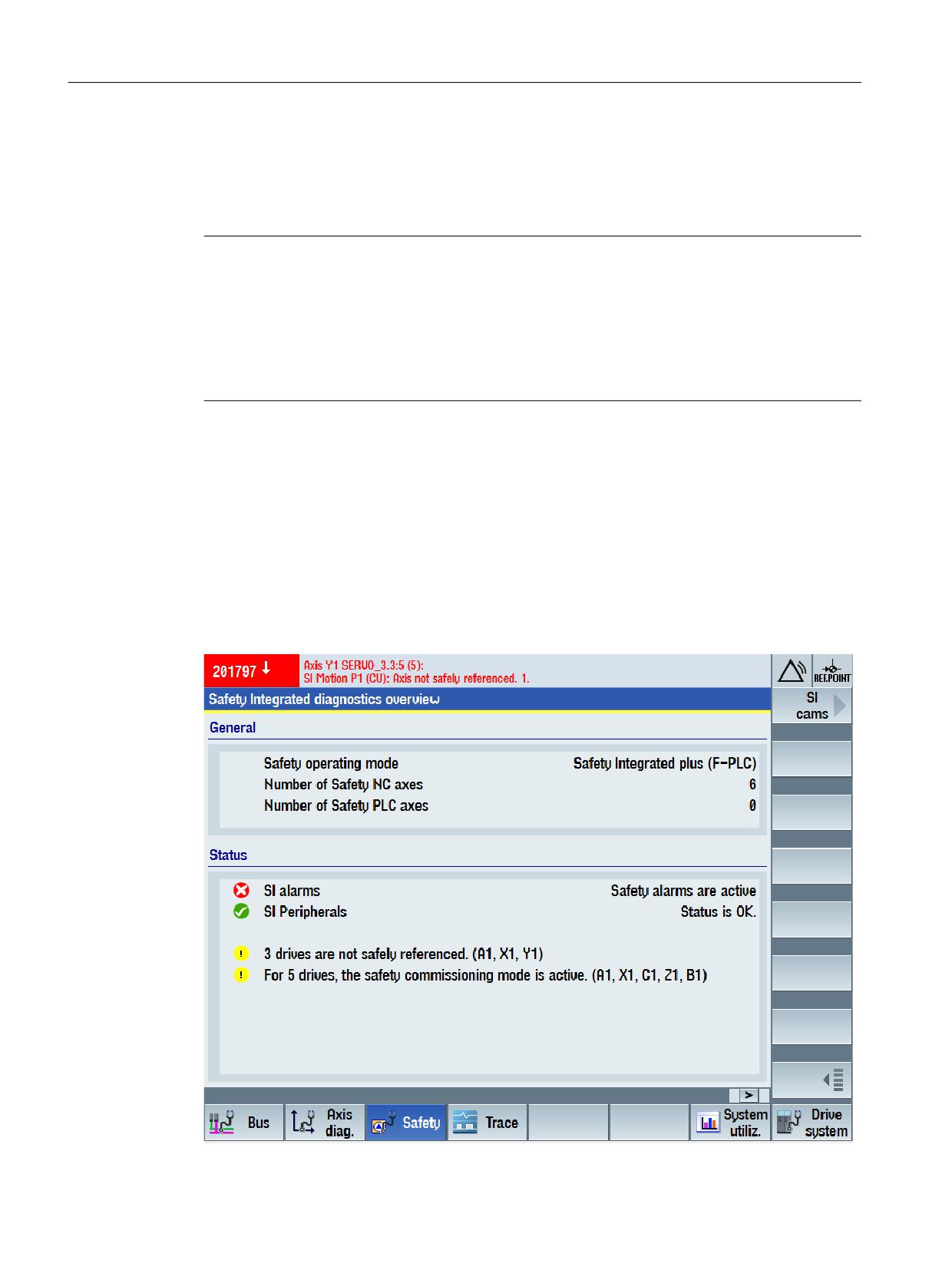
Diagnostics
8.3 Diagnostic functions in SINUMERIK Operate
8.3
Diagnostic functions in SINUMERIK Operate
You can find the SI-diagnostics overview and more specific diagnostic screens under "MENU
SELECT > Diagnostics > Menu forward key > Safety".
Note
A properly completed and loaded configuration is a requirement for diagnostics functionality.
● The configured NCU must have firmware version ≥V4.8 and Safety Integrated plus (F-PLC)
must be activated.
● Hardware and software must be consistently compiled and loaded.
With such a correct configuration, SI_DiagDB [DB1009] is automatically generated during the
compilation and transferred to the NCU during loading.
8.3.1
Safety Integrated diagnostics overview
The diagnostics overview includes general information about the operating mode used, the
number and type of axes used - as well as status information about the pending alarms and safe
referencing (homing).
Call
MENU SELECT > Diagnostics > Menu forward key > Safety
Safety Integrated plus
300
Commissioning Manual, 12/2019, 6FC5397-1FP40-6BA3
Diagnostics
8.3 Diagnostic functions in SINUMERIK Operate
Figure 8-1
Safety Integrated diagnostics overview
This screen is simultaneously used as entry to the following diagnostic screens:
● SI drives (Page 301)
● SI telegrams (Page 304)
● SI checksum (Page 306)
● SI alarms (Page 308)
● SI Safe Cams (Page 309) (via menu forward key)
● SI integrated F-PLC (Page 310)
● SI I/O (Page 311)
8.3.2
SI drives status
The configured safety-relevant status and diagnostic information of the selected drive are
displayed in the "SI drive status" diagnostic screen.
Functions, which are not configured for the selected drive, are not displayed on the screen.
Call
MENU SELECT > Diagnostics > Menu forward key > Safety > SI drives
The diagnostic screen "SI drive status" is available for basic functions and for extended
functions.
Call "SI drive status - Basic functions"
MENU SELECT > Diagnostics > Menu forward key > Safety > SI drives > Basic functions
Safety Integrated plus
Commissioning Manual, 12/2019, 6FC5397-1FP40-6BA3
301
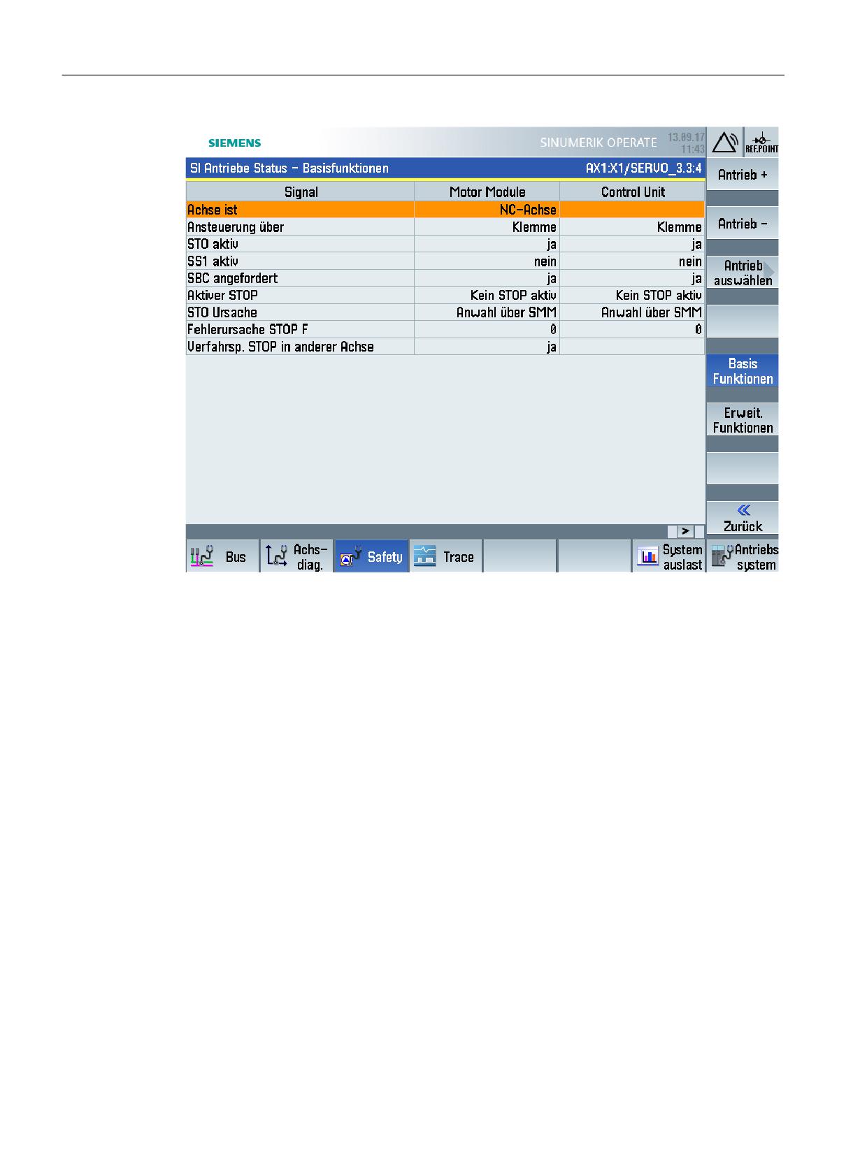
Diagnostics
8.3 Diagnostic functions in SINUMERIK Operate
Figure 8-2
Diagnostic screen "SI drive status - Basic functions" (sample screenshot)
Call "SI drive status - Extended functions"
MENU SELECT > Diagnostics > Menu forward key > Safety > SI drives > Extended Functions
Safety Integrated plus
302
Commissioning Manual, 12/2019, 6FC5397-1FP40-6BA3
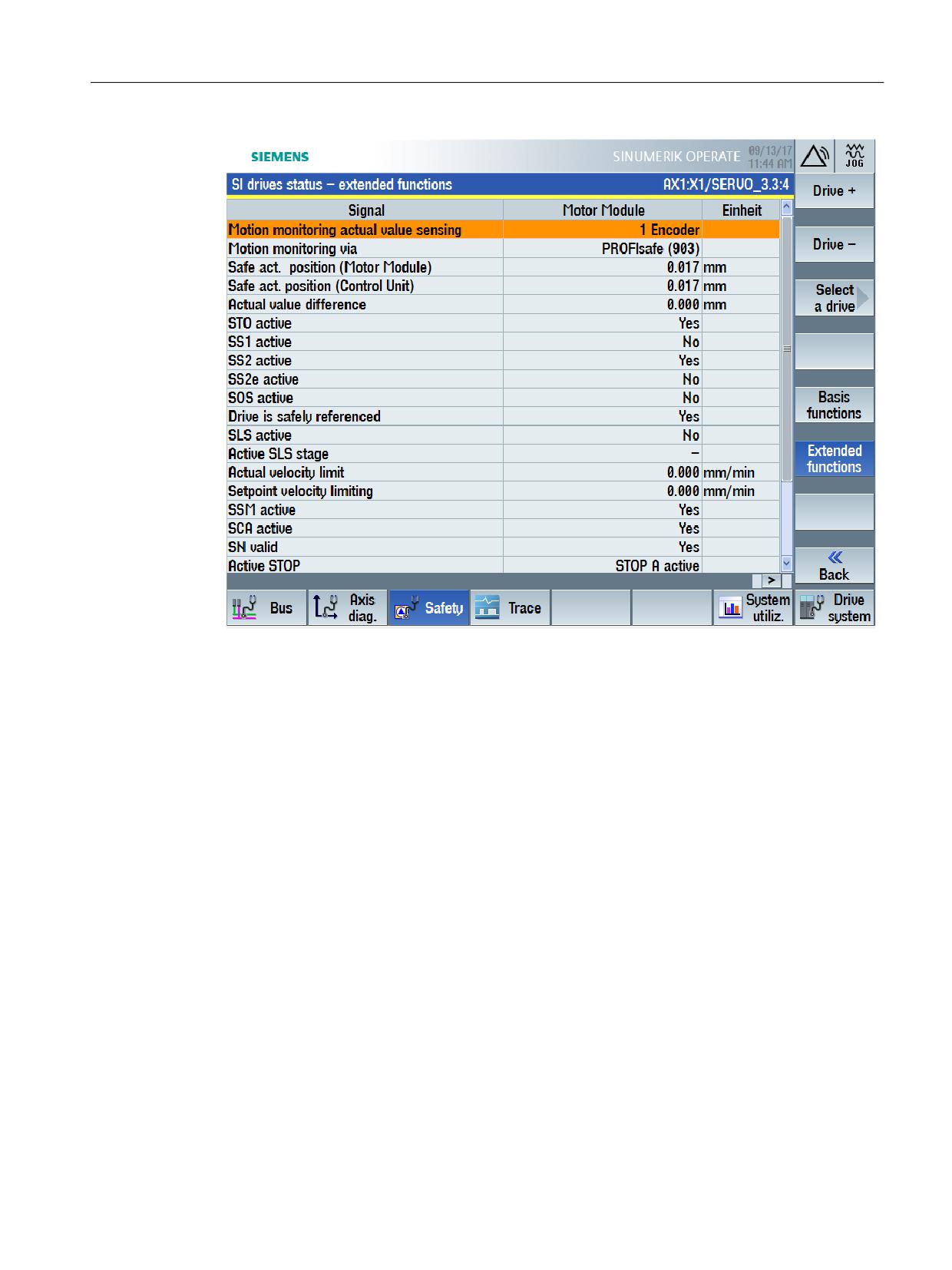
Diagnostics
8.3 Diagnostic functions in SINUMERIK Operate
Figure 8-3
"SI drive status - Extended functions" diagnostic screen (sample screenshot)
8.3.3
SI telegrams overview
The telegram types for PROFIsafe and SIC/SCC for the respective drives/axes are displayed
in the "SI telegrams overview" diagnostic screen.
Call
MENU SELECT > Diagnostics > Menu forward key > Safety > SI telegrams
Safety Integrated plus
Commissioning Manual, 12/2019, 6FC5397-1FP40-6BA3
303
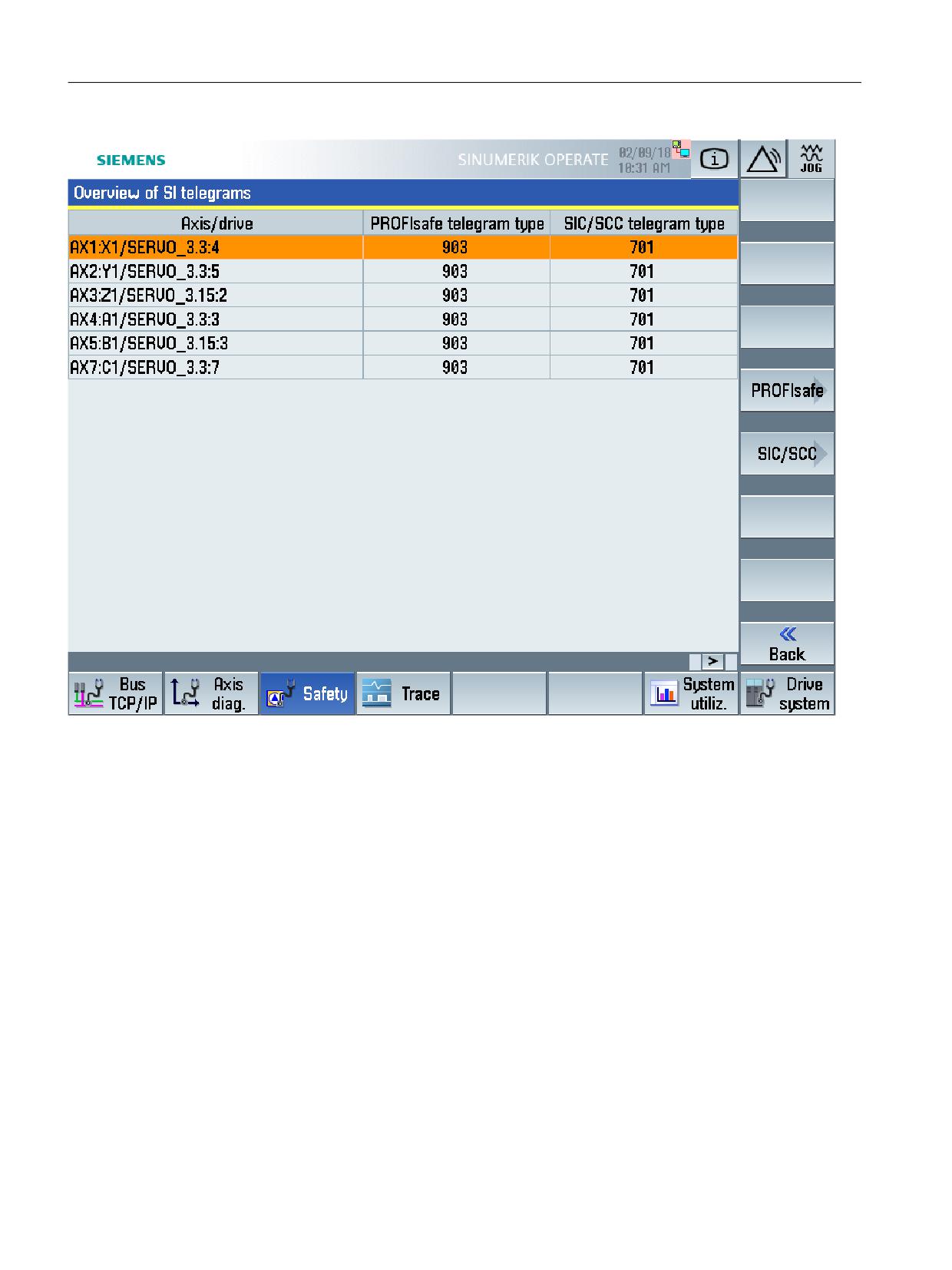
Diagnostics
8.3 Diagnostic functions in SINUMERIK Operate
Figure 8-4
"SI telegrams overview" diagnostic screen
This screen is simultaneously used as entry to the following diagnostic screens:
● SI telegrams PROFIsafe (Page 304)
● PROFIdrive SI telegrams (Page 305)
Additional information
● You will find general information on safety-relevant telegrams in Chapter Controlling safety
functions integrated in the drive (Page 197).
8.3.4
SI telegrams PROFIsafe
The meanings and statuses of the individual bits in the control word and status word are shown
in the "PROFIsafe SI telegrams" diagnostic screen. You can switch between the following
views:
● Status word
● Status word cam (Note: only when the cam function is enabled in SINAMICS)
Safety Integrated plus
304
Commissioning Manual, 12/2019, 6FC5397-1FP40-6BA3
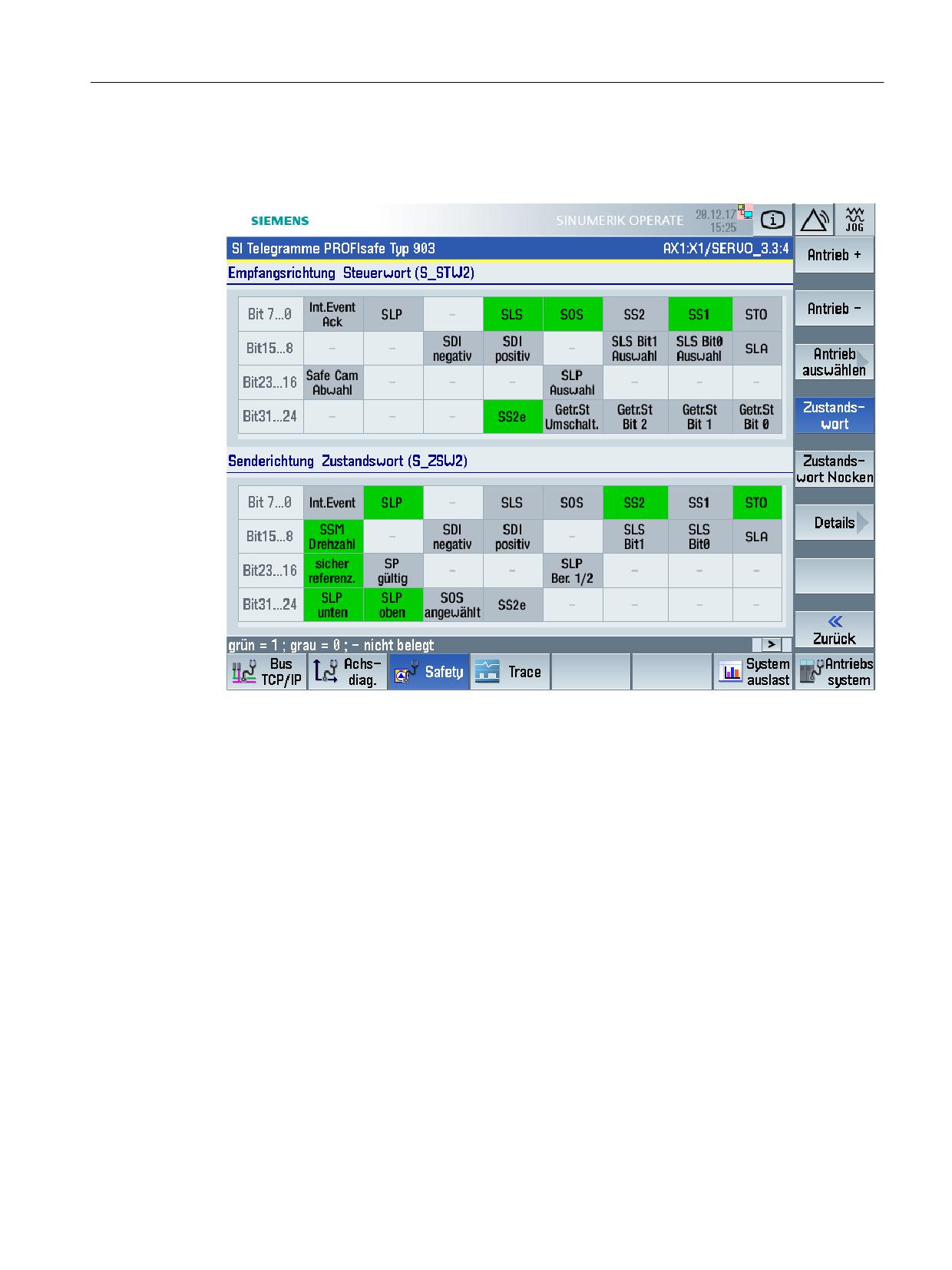
Diagnostics
8.3 Diagnostic functions in SINUMERIK Operate
Call
MENU SELECT > Diagnostics > Menu forward key > Safety > SI telegrams > PROFIsafe
Figure 8-5
"PROFIsafe SI telegrams" diagnostic screen
The view of all user data of the control word and status word is displayed using the "Details"
softkey.
Additional information
● You can obtain general information about PROFIsafe telegrams in Chapter Controlling via
PROFIsafe (Page 201).
8.3.5
PROFIdrive SI telegrams
The meanings and statuses of the individual bits in the control word and status word are shown
in the "PROFIdrive SI telegrams" diagnostic screen.
Call
MENU SELECT > Diagnostics > Menu forward key > Safety > SI telegrams > SIC/SCC
Safety Integrated plus
Commissioning Manual, 12/2019, 6FC5397-1FP40-6BA3
305
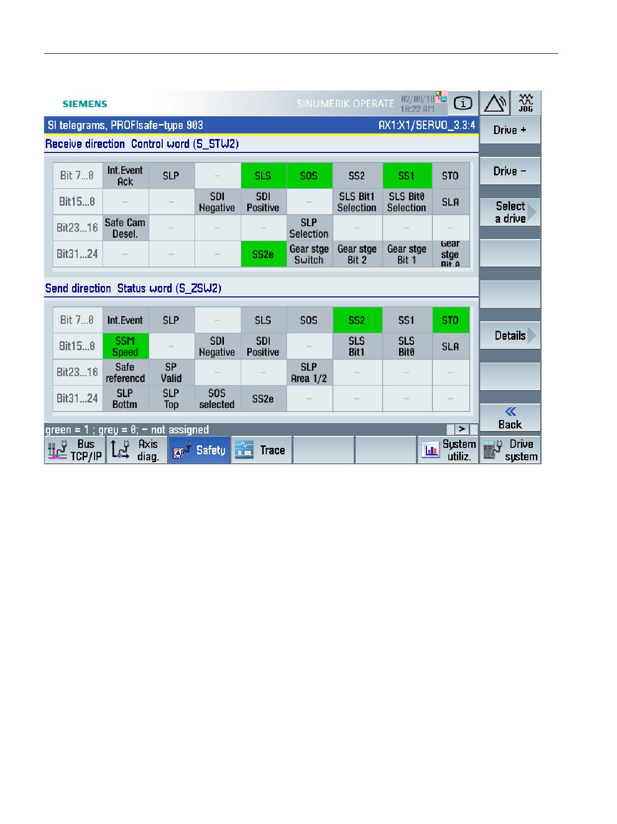
Diagnostics
8.3 Diagnostic functions in SINUMERIK Operate
Figure 8-6
"SI telegrams PROFIdrive" diagnostic screen
The view of all user data of the control word and status word is displayed using the "Details"
softkey.
Additional information
● You can obtain general information about SIC/SCC telegrams in Chapter Safety Info
Channel and Safety Control Channel (SIC/SCC) (Page 205).
8.3.6
SI checksums
In the "SI checksums overview" diagnostic screen, all of the safety reference and actual
checksums are displayed for the axes and drives. Status symbols are used to flag differences
between reference and actual checksums
Calling checksums
MENU SELECT > Diagnostics > Menu forward key > Safety > SI checksum
Safety Integrated plus
306
Commissioning Manual, 12/2019, 6FC5397-1FP40-6BA3
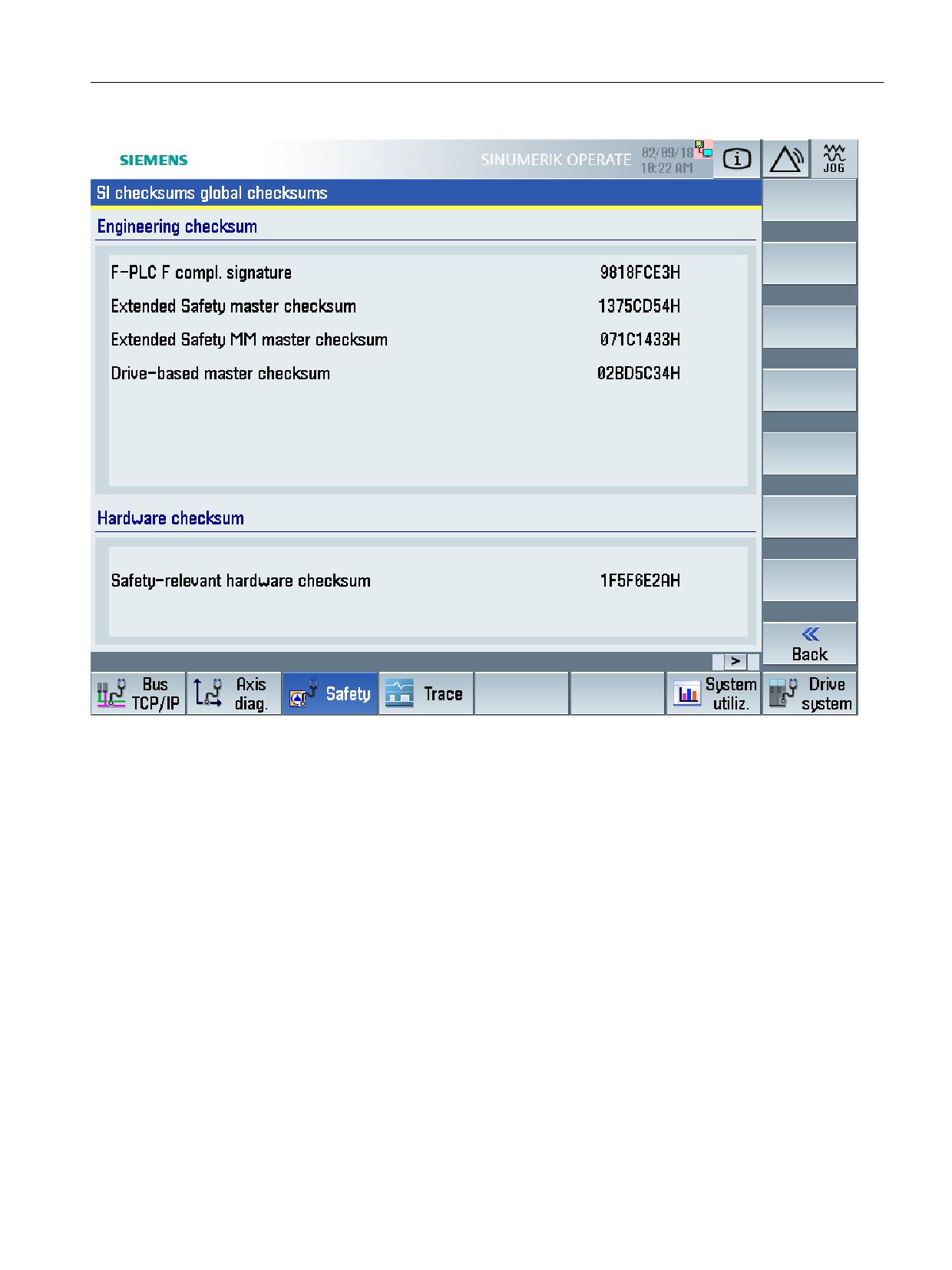
Diagnostics
8.3 Diagnostic functions in SINUMERIK Operate
Figure 8-7
"SI checksums overview" diagnostics screen
Higher-level actual checksums that are calculated from the master checksums (Page 314) are
displayed in the "SI checksums global checksums" diagnostic screen. If you call the diagnostics
screen, then the calculation of the global checksums is started - and after completion, these
actual checksums, along with the calculation date, are displayed.
Calling global checksums
MENU SELECT > Diagnostics > Menu forward key > Safety > SI checksum > Global
checksums
Safety Integrated plus
Commissioning Manual, 12/2019, 6FC5397-1FP40-6BA3
307
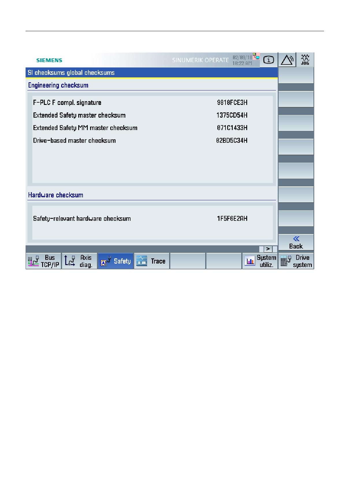
Diagnostics
8.3 Diagnostic functions in SINUMERIK Operate
Figure 8-8
"SI checksums global checksums" diagnostic screen
If, based on these global checksums, you identify some changes in the safety configuration,
then you can switch from diagnostics screen "Global checksums" to the individual axis/drive
checksums in order to identify specific differences.
8.3.7
SI alarms
Active safety-relevant alarms are displayed in diagnostics screen "SI-alarms".
Call
MENU SELECT > Diagnostics > Menu forward key > Safety > SI alarms
Safety Integrated plus
308
Commissioning Manual, 12/2019, 6FC5397-1FP40-6BA3
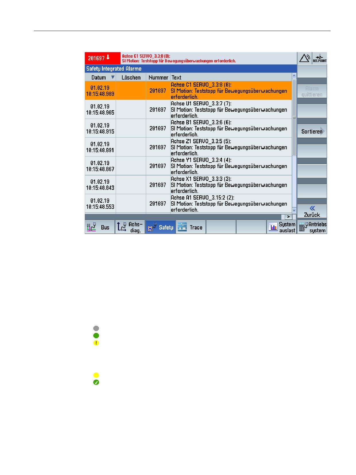
Diagnostics
8.3 Diagnostic functions in SINUMERIK Operate
Figure 8-9
"Safety Integrated alarms" diagnostic screen
8.3.8
SI Safe Cams
In the "SI safe cams" diagnostic screen, the following information about the "Safe Cam (SCA)
safety function" of the selected drive is displayed:
● Status of the function (SCA)
For the selected drive, indicates whether the "Safe Cam" (SCA) safety function has been
selected, is active and is valid. The actual position is also displayed (actual value on the load
side on the CU).
Inactive
Active
Invalid. Safe referencing was not carried out.
● Status of the enabled cams
For each configured and enabled cam, displays the identifier, the minus and plus positions
- as well as the validity of the cam position.
Cam position is reached and the cam is invalid.
Cam position is reached and the cam is valid. Safe referencing was carried out.
Call
MENU SELECT > Diagnostics > Menu forward key > Safety > Menu forward key >SI cams
Safety Integrated plus
Commissioning Manual, 12/2019, 6FC5397-1FP40-6BA3
309
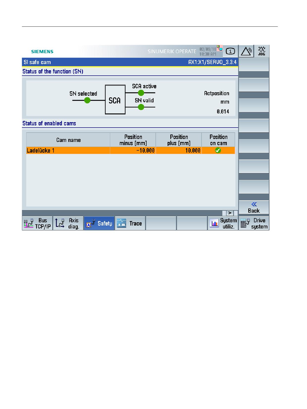
Diagnostics
8.3 Diagnostic functions in SINUMERIK Operate
Figure 8-10
"SI safe cams" diagnostics screen
8.3.9
SI integrated F-PLC
The configured safety-related status and diagnostic information of the integrated F-PLC of the
SINUMERIK NCU is displayed in the "SI Integrated F-PLC" diagnostic screen.
Call
MENU SELECT > Diagnostics > Menu forward key > Safety > SI Integrated F-PLC
Safety Integrated plus
310
Commissioning Manual, 12/2019, 6FC5397-1FP40-6BA3