SINUMERIK 840D sl. Service - Configuring Commissioning. Manual (2011-2020) - page 89
Safety functions integrated in the drive
5.15 SCA
Defining the output cam positions
● You define the output cam positions to be monitored using the parameters p9536[x] and
p9537[x] (where x = 0 ... 29).
Note that the defined output cams must have a certain minimum length: p9536[x] -
p9537[x] ≥ p9540 + p9542
If you violate this rule, the drive will output the message F01686 ("SI Motion: Output cam
position parameterization not permissible").
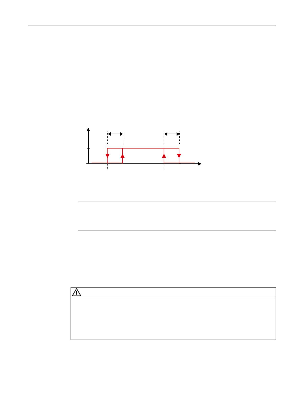
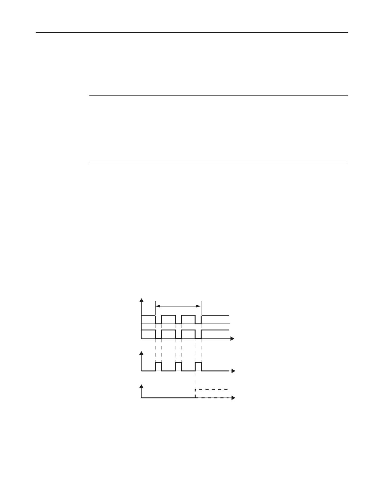
● Owing to variations in the cycle and signal propagation times, the output cam signals of the
two monitoring channels do not switch simultaneously and not precisely at the same
position. For this reason, enter a tolerance band for all output cam types via parameter
p9540. Within this tolerance band, the monitoring channels can have different signal states
for the same output cam:
U
6&$ WROHUDQFH
6&$ WROHUDQFH
S
S
[
S
>[@
S
>[@
3RVLWLRQ
3RVLWLRQ
0LQXV FDP
3OXV FDP
Figure 5-27
Parameterize output cam and tolerance
Note
The smallest possible tolerance band should be selected for the SCA function
(<5 ... 10 mm). It makes sense to parameterize the output cam tolerance to be greater than
or equal to the actual value tolerance.
● Reference the axis using the "Safe referencing (Page 179)" function.
Enable SCA
● You enable the SCA function with p9501.28 = 1.
● You enable each output cam individually with p9503.x = 1 (where x = 0 ... 29).
WARNING
Unexpected speed of the machine component as the axis was not referenced (homed)
The enabled cam signals are immediately output after POWER ON. However, the output is
only safety-related after safety-related referencing (safety-related homing) People can be put
into a dangerous situation or material damage can result if the axis is not referenced in a
safety-related way.
● Reference the axis using the "Safe referencing (Page 179)" function.
Safety Integrated plus
Commissioning Manual, 12/2019, 6FC5397-1FP40-6BA3
173
Safety functions integrated in the drive
5.15 SCA
Select SCA
Select the SCA function using the PROFIsafe control word S_STW2.23. For SCA, you must
use telegram 903, in which control word S_STW2 and status word S_ZSW_CAM1 are available
for SCA.
Cam synchronization
For transmission of the output cam status word via PROFIsafe to the F host, the output cam
signals of the two monitoring channels are synchronized. Monitoring is also performed as to
whether a different output cam signal from the second channel is plausible. If the drive detects
an error, it outputs the message C01711 with the fault value 1014.
As the position tolerance for monitoring the output cam positions, the tolerance for the cross-
check of the actual position between the two monitoring channels in p9542 ("Actual value
comparison tolerance") is used.
Transmission via PROFIsafe
After SCA has been parameterized and selected, the monitoring results are transmitted in
status word S_ZSW_CAM1 (see Chapter "S_ZSW_CAM1 (Page 364)").
5.15.1.1
Function diagrams and parameters
Function diagrams (see SINAMICS S120/S150 List Manual)
●
2826
SCA (Safe Cam)
●
2844
S_ZSW_CAM1 Safety status word Safe Cam 1
Overview of important parameters (see SINAMICS S120/S150 List Manual)
● p9501
SI Motion enable safety functions (Control Unit)
● p9503
SI Motion SCA (SN) enable (Control Unit)
● p9505
SI Motion SP modulo value (Control Unit)
● p9536[0...29]
SI Motion SCA (SN) plus cam position (Control Unit)
● p9537[0...29]
SI Motion SCA (SN) minus cam position (Control Unit)
● p9540
SI Motion SCA (SN) tolerance (Control Unit)
● p9542
SI Motion actual value comparison tolerance (crosswise) (Control Unit)
● r9703.0...31
CO/BO: SI Motion SCA status signal (Control Unit)
● r9708[0...5]
SI Motion diagnostics safe position
● r9720.23
CO/BO: SI Motion drive-integrated control signals:
Deselect SCA
● r9727
SI Motion user agreement inside the drive
● r9771.22
SI shared functions: SCA supported
Safety Integrated plus
174
Commissioning Manual, 12/2019, 6FC5397-1FP40-6BA3
Safety functions integrated in the drive
5.16 SLA
5.16
SLA
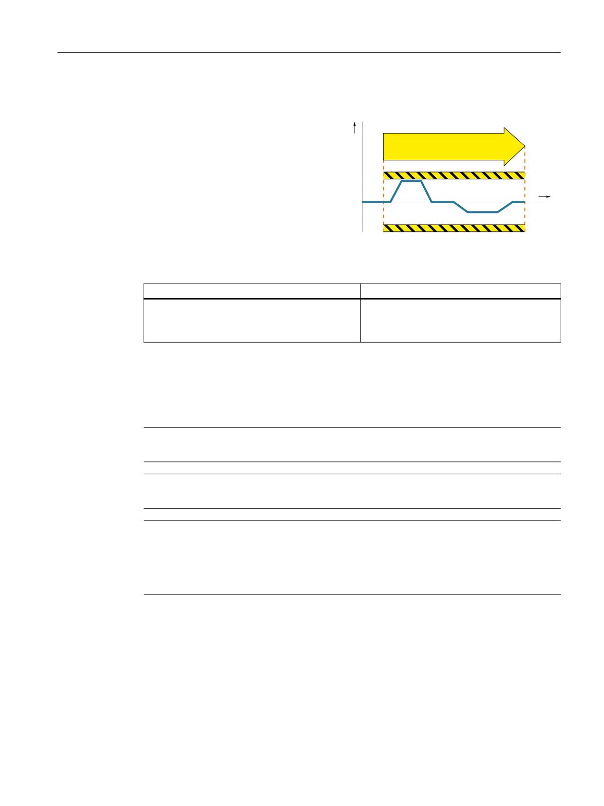
Definition according to EN 61800-5-2:
a
"The SLA function prevents the motor from
SLA
exceeding the defined acceleration limit."
t
Examples of how the function can be used
Example
Possible solution
In the setup mode, it is not permissible that the drive
● Select SLA in the converter via PROFIsafe.
exceeds the permissible acceleration.
● The converter limits and monitors the accel-
eration of the machine.
Function "Safely-Limited Acceleration" (SLA) monitors that the motor does not violate the
defined acceleration limit (e.g. in the setup mode). SLA detects early on whether the speed is
increasing at an inadmissible rate (the drive accelerates uncontrollably) and initiates the stop
response.
SLA is effective when accelerating, however, not when braking.
Note
Safety function "Safely-Limited Acceleration" (SLA) can only be used with an encoder.
Note
Safety function "Safely-Limited Acceleration" (SLA) can only be used for 1-encoder systems.
Note
Configuration only possible in the parameter list
Contrary to other Safety Integrated Functions, there is no configuration screen form for SLA in
the SINUMERIK ONE Commissioning Tool. Therefore, parameterize this function in the
parameter list.
Enabling SLA
● You enable the SLA function with p9501.20 = 1.
Selecting SLA
Select the SLA function using the PROFIsafe control word S_STW1.8 or S_STW2.8. Which
control word you use depends on the PROFIsafe telegram that you configured.
Safety Integrated plus
Commissioning Manual, 12/2019, 6FC5397-1FP40-6BA3
175
Safety functions integrated in the drive
5.16 SLA
Once selected, the SLA function becomes immediately active without any delay.
You can use telegrams 30, 31, 901, 902 and 903 for SLA. These telegrams contain the control
words S_STW1.8 and S_STW2.8 and status words S_ZSW1.8 and S_ZSW2.8 for SLA.
Acceleration limit
● You define the acceleration limit to be monitored using parameter p9578. This limit value is
applicable for both the positive and negative directions of rotation.
● When setting p9578, the following rule must be complied with:
- p9578 ≥ 10 · r9790[1]
● The possible acceleration resolution is shown by the drive in r9790:
- r9790[0] = resolution, coarse
- r9790[1] = resolution, fine
The actual accuracy of the acceleration detection depends on the type of actual value
acquisition, the gear ratios as well as the quality of the encoder being used.
● The drive indicates the velocity limit corresponding to the actual acceleration in r9714[3].
● r9789 allows the finer resolution acceleration monitoring to be diagnosed. Index 0 indicates
the actual acceleration determined. Index 1 and 2 indicate the current limit values of the SLA
monitoring.
Filter time
If the determination of the acceleration leads to very noisy signals, the drive cannot reasonably
monitor the acceleration.
Remedy
● In this case, increase the "SLA filter time" (p9576).
Note that SLA reacts with a delay when you increase the filter time.
Stop response
If the SLA subsequently detects violation of the acceleration limit, the drive initiates the stop
response configured using p9579.
5.16.1
Details and parameterization
5.16.1.1
Function diagrams and parameters
Function diagrams (see SINAMICS S120/S150 List Manual)
●
2838
SLA (Safely-Limited Acceleration)
Safety Integrated plus
176
Commissioning Manual, 12/2019, 6FC5397-1FP40-6BA3
Safety functions integrated in the drive
5.16 SLA
Overview of important parameters (see SINAMICS S120/S150 List Manual)
● p9501
SI Motion enable safety functions (Control Unit)
● p9576
SI Motion SLA filter time (CU)
● p9578
SI Motion SLA acceleration limit (CU)
● p9579
SI Motion SLA stop response (Control Unit)
● r9714[3]
CO: SI Motion diagnostics velocity: Actual SLA velocity limit on the Control
Unit
● r9719.17
CO/BO: SI Motion control signals 2: Deselect SLA
● r9720.8
CO/BO: SI Motion drive-integrated control signals: Deselect SLA
● r9721.11
CO/BO: SI Motion status signals (Control Unit): SLA active
● r9722.8
CO/BO: SI Motion drive-integrated status signals (Control Unit): SLA active
● r9789
CO: SI Motion SLA acceleration acceleration diagnostics
● r9790
SI Motion acceleration resolution
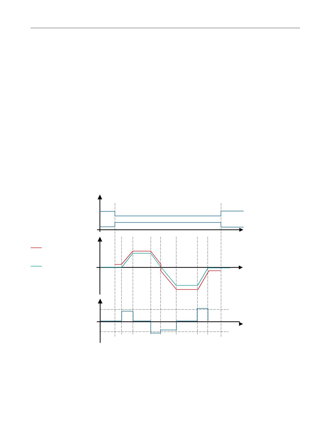
Principle of operation
The following diagram shows the principle of operation of SLA:
352),VDIH DQG GLDJQRVWLFV
6HOHFW 6/$
'HVHOHFW 6/$
6B67:
RU U
'HVHOHFW 6/$
6B=6:
RU U
6/$ DFWLYH
W
6SHHG
!
!
!
!
!
$FFHOHUDWLQJ
&XUUHQW VSHHG OLPLW 6/$
!
%UDNLQJ
6SHHG
W
$FFHOHUDWLRQ
S
ದS
Figure 5-28
Safely-Limited Acceleration (SLA): Principle
Safety Integrated plus
Commissioning Manual, 12/2019, 6FC5397-1FP40-6BA3
177
Safety functions integrated in the drive
5.16 SLA
5.16.1.2
Transmission via PROFIsafe or SIC
Transmission via PROFIsafe
Once SLA has been parameterized and selected, the monitoring results are transmitted in
status words S_ZSW1.8 or S_ZSW2.8.
Note
Response to bus failure
If p9580 ≠ 0 and SLA is active, in the event of a communication failure, the parameterized ESR
reaction only occurs if a STOP with delayed pulse suppression when the bus fails has been
parameterized as the SLA response (p9579 ≥ 10).
Transfer via SIC
Once SLA has been parameterized and selected, the monitoring results are also transmitted in
SIC in status word S_ZSW1B.8. You will find this status word in telegrams 700 and 701.
Safety Integrated plus
178
Commissioning Manual, 12/2019, 6FC5397-1FP40-6BA3
Safety functions integrated in the drive
5.17 Safe referencing
5.17
Safe referencing
The "safe referencing" function allows a safe absolute position to be defined. This safe position
is used for the following functions:
● SLP (Page 150)
● SP (Page 155)
● SCA (Page 172)
General description
Referencing to an absolute position is performed by the motion control of the NC. The
functionality SIC/SCC is used for this.
For SINUMERIK Safety Integrated, the current absolute NC actual position (also in motion) is
transferred to the drive as the "reference position" for the safe actual value system. This
process is carried out on the system side for each referencing of the NC actual position system.
This requires the enabling of SIC/SCC and the "Reference via SCC" function (p9501.27). The
"safely referenced" state is reached when user agreement has been set.
Referencing methods
SINAMICS distinguishes between 2 types of referencing:
● Initial referencing
For initial safe referencing, or in the event of a fault during a subsequent referencing, the
following steps are necessary:
- Perform referencing by the NC
- Setting user agreement
● Subsequent referencing
Subsequent referencing involves referencing with a safety-relevant history (i.e. with an
internally buffered user agreement) after a POWER ON or after deselecting "parking axis".
- After the drive has been referenced, Safety Integrated automatically performs a
plausibility check.
- If the deviation between the current absolute position and the previous position saved by
Safety Integrated is within the tolerance of p9544, then the drive goes into the "safely
referenced" state.
5.17.1
User agreement
Description
With a user agreement, an appropriately authorized person confirms that the currently
displayed SI actual position of an axis corresponds to the actual position at the machine.
You can check this by traversing the axis to a known position (e.g. a visual mark) or adjusting/
calibrating the axis and then comparing the SI actual position with the "user agreement" screen.
Safety Integrated plus
Commissioning Manual, 12/2019, 6FC5397-1FP40-6BA3
179
Safety functions integrated in the drive
5.17 Safe referencing
An axis/spindle with integrated safety functions can have the following status:
● User agreement = yes, or
● User agreement = no
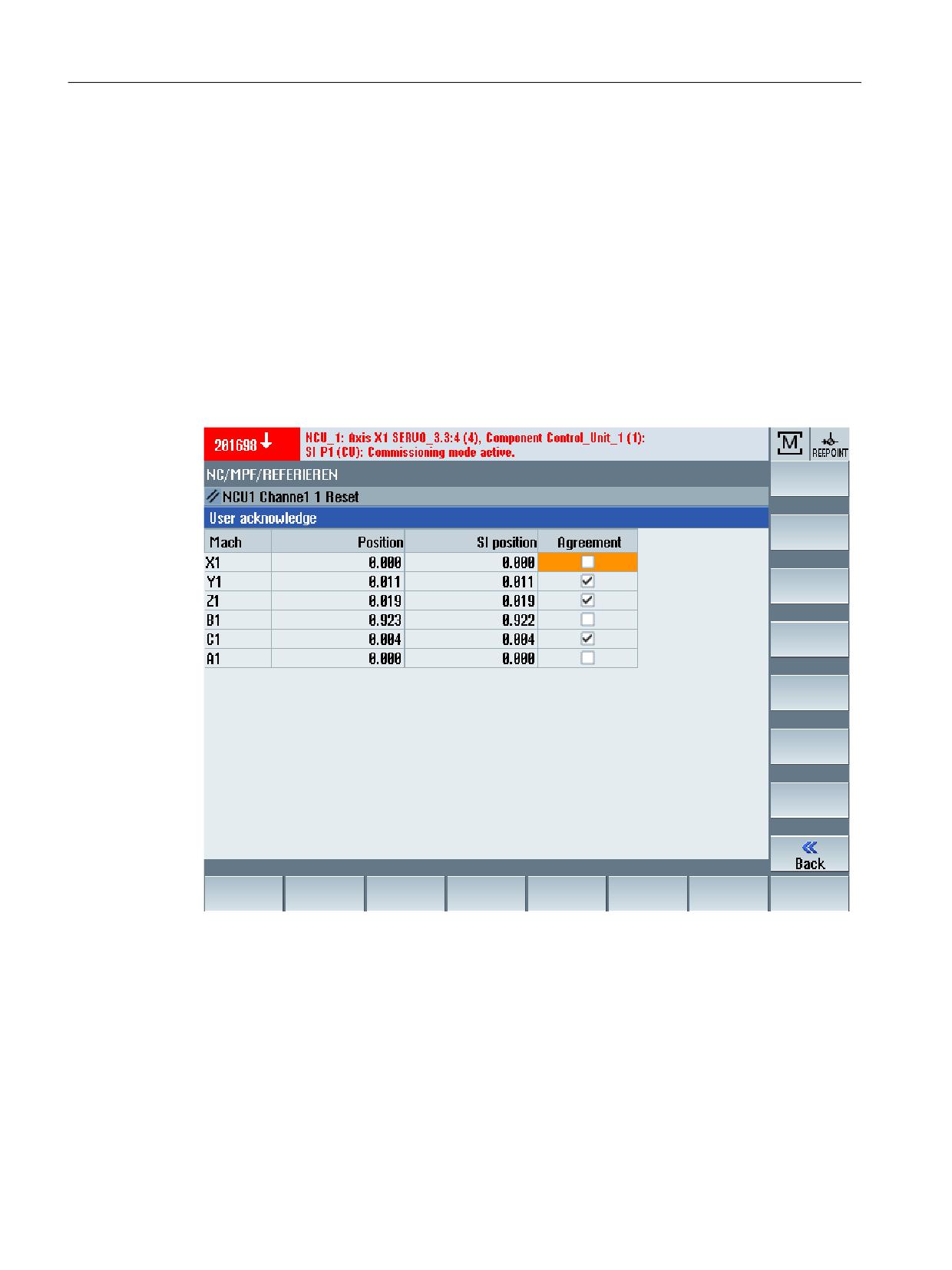
All safety axes that require user agreement to be set are listed in the HMI display "user
agreement".
The following data are displayed:
● Machine axis name
● Position
● SI position
● User agreement
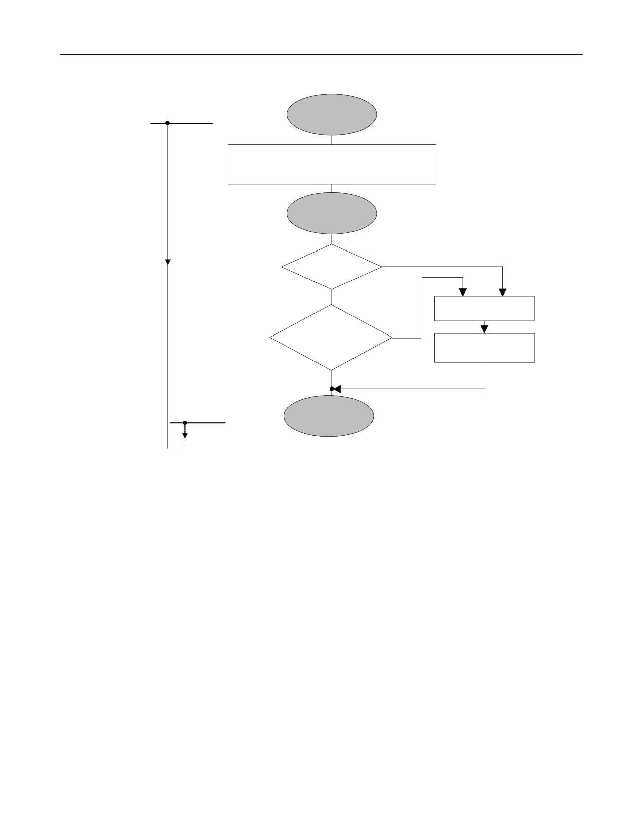
Figure 5-29
User agreement
The user agreement can only be set by an authorized user.
User agreement can be canceled in the following ways:
● By the user
● By selecting a function (e.g. a new gear stage)
● By a fault state (e.g. user acceptance inconsistency in the monitoring channels)
When user agreement is canceled, the "safely referenced" state is always reset.
Safety Integrated plus
180
Commissioning Manual, 12/2019, 6FC5397-1FP40-6BA3
Safety functions integrated in the drive
5.17 Safe referencing
626 6/6 LV VDIH
$[LV VWDWXV LV GLVSOD\HG E\ WKH LQWHUIDFH
IURP WKLV D[LV
VLJQDO
$[LV QRW UHIHUHQFHG
VWDWXV RQZDUG
5HIHUHQFH SRLQW UHDFKHG
$[LV VWDWXV
(41 5HDG WKH DEVROXWH YDOXH IURP WKH HQFRGHU
(51 5HIHUHQFH SRLQW DSSURDFK
,QWHUIDFH VLJQDO
$[LV UHIHUHQFHG
5HIHUHQFH SRLQW UHDFKHG
$[LV VWDWXV
8VHU
1R
DJUHHPHQW
<HV
8VHU FKHFNV WKH SRVLWLRQ
&KHFN QRW
2.
&KHFN DFWXDO SRVLWLRQ
VDYHG VWDQGVWLOO
8VHU DJUHHPHQW
SRVLWLRQ
6RIWNH\
&KHFN 2.
6/3 63 6&$ LV VDIH
IURP WKLV D[LV VWDWXV
VDIHO\ UHIHUHQFHG
$[LV VWDWXV
VDIHO\ UHIHUHQFHG
Figure 5-30
Axis states when referencing
Interlocking the user agreement
Before a user agreement can be issued, the interlock must first be canceled:
● Keyswitch: In position 3 → User agreement can be issued
After user agreement has been issued, you must reactivate the interlock (e.g. keyswitch
position 3 must be left and the key withdrawn).
5.17.2
Function diagrams and parameters
Function diagrams (see SINAMICS S120/S150 List Manual)
●
2821
SI Extended Functions - Safe referencing
Safety Integrated plus
Commissioning Manual, 12/2019, 6FC5397-1FP40-6BA3
181
Safety functions integrated in the drive
5.17 Safe referencing
Overview of important parameters (see SINAMICS S120/S150 List Manual)
● p9572
SI Motion reference position (Control Unit)
● p9573
Accept SI Motion reference position (Control Unit)
● r9708[0...5]
SI Motion diagnostics safe position
● r9713[0...5]
CO: SI Motion diagnostics actual position value load side
● r9722.0...31
CO/BO: SI Motion drive integrated status signals (Control Unit)
● r9723.0...17
CO/BO: SI Motion diagnostics signals integrated in the drive
● p9726
SI motion, user agreement, select/deselect
● p9740
SI motion, user agreement, select/deselect MM
Safety Integrated plus
182
Commissioning Manual, 12/2019, 6FC5397-1FP40-6BA3
Safety functions integrated in the drive
5.18 Safe actual value acquisition
5.18
Safe actual value acquisition
Supported encoder systems
The following encoder systems can in principle be used for safety-relevant speed/position
acquisition:
● Single-encoder systems
or
●
2-encoder systems
Note
Rules for connecting an encoder
Note when connecting an encoder the valid rules: See SINAMICS S120 Drive Functions
Function Manual.
Single-encoder system
In a single-encoder system, only the motor encoder is used to safely acquire the drive actual
values. This motor encoder must be appropriately suitable (see encoder types). The actual
values are generated in a safety-relevant fashion either directly in the encoder or in the Sensor
Module and are transferred to the Control Unit via DRIVE-CLiQ.
For motors without a DRIVE-CLiQ interface, the connection is made using additional Sensor
Modules.
Even if the drive is operating in the closed-loop torque controlled mode, motion monitoring
functions may be selected as long as it is guaranteed that the encoder signals can be evaluated.
Note
No "Safe Acceleration Monitoring" for encoder faults in a 1-encoder system
For an encoder fault in a 1-encoder system, the "Safe Acceleration Monitoring" function
(p9506 = 3) is not active.
A stop response of category 0 or 1 (EN 60204-1) can be set with parameter p9516.4.
Safety Integrated plus
Commissioning Manual, 12/2019, 6FC5397-1FP40-6BA3
183
Safety functions integrated in the drive
5.18 Safe actual value acquisition
Special feature in the case of linear motors
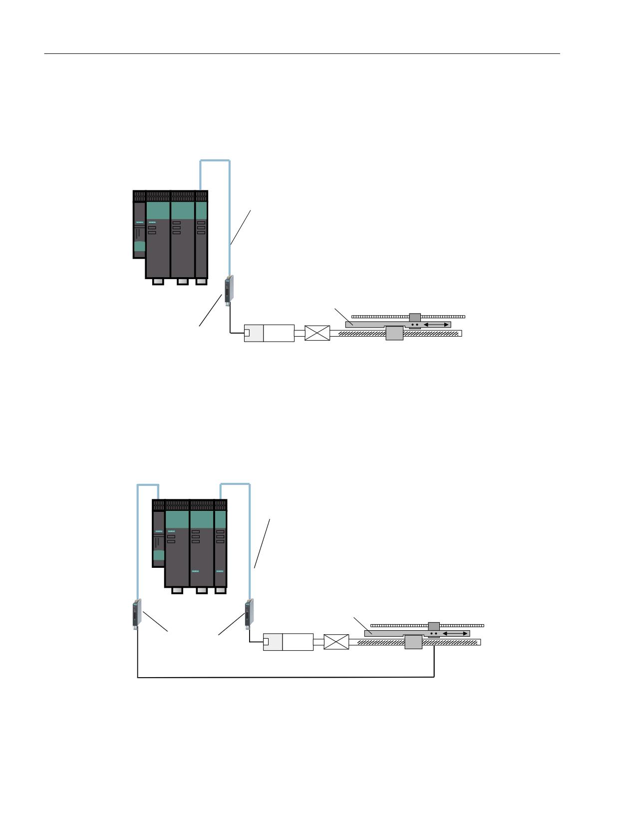
The motor encoder (linear scale) of linear motors also acts as load measuring system. Only one
measuring system is required for this reason. The system is connected by means of a Sensor
Module or directly via DRIVE-CLiQ.
( (QFRGHU
'5,9( &/L4
0 0RWRU
0DFKLQH WDEOH
/LQHDU VFDOH
6HQVRU 0RGXOH
(
0
QRW DSSOLFDEOH IRU PRWRU ZLWK
%DFNODVK
'5,9( &/L4 LQWHUIDFH
Figure 5-31
Example of a single-encoder system
2-encoder system
The failsafe actual values for a drive are provided by 2 separate encoders. The actual values
are transferred to the Control Unit via DRIVE-CLiQ.
For motors without a DRIVE-CLiQ interface, the connection is made using additional Sensor
Modules (see encoder types).
( (QFRGHU
'5,9( &/L4
0 0RWRU
0DFKLQH WDEOH
/LQHDU VFDOH
(
6HQVRU 0RGXOH
(
0
QRW DSSOLFDEOH IRU PRWRU ZLWK
%DFNODVK
'5,9( &/L4 LQWHUIDFH
Figure 5-32
Example of a 2-encoder system on a linear axis via a ball screw
Safety Integrated plus
184
Commissioning Manual, 12/2019, 6FC5397-1FP40-6BA3
Safety functions integrated in the drive
5.18 Safe actual value acquisition
( (QFRGHU
0 0RWRU
'5,9( &/L4
(
0
6HQVRU 0RGXOH
QRW DSSOLFDEOH IRU PRWRU ZLWK
'5,9( &/L4 LQWHUIDFH
(
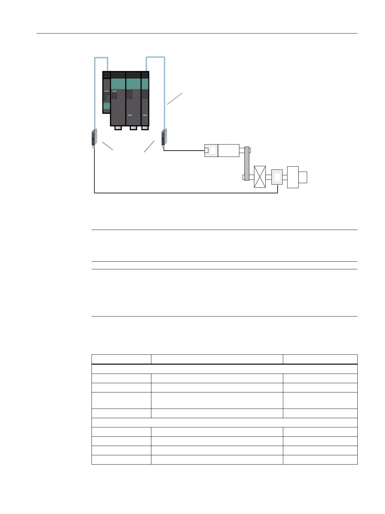
Figure 5-33
Example of a 2-encoder system on a rotary axis
When parameterizing a 2-encoder system with Safety Integrated, you must align parameters
p9315 to p9329 with parameters r0401 to r0474.
Note
Assignment of the encoder parameters
Parameters p95xx are assigned to the 1st encoder; parameters p93xx to the 2nd encoder.
Note
Transfer of the values from the encoder commissioning
To accept the values from the parameters filled during the encoder commissioning to the safety
parameterization, set parameter p9700 = 46 (2E hex). This copy function is only possible if you
are connected online with the drive unit.
Table 5-4
Encoder parameters and corresponding safety parameters for 2-encoder systems
Safety parameters
Designation
Encoder parameters
p9315/p9515 SI Motion coarse position value configuration
p9315.0/p9515.0
Up-counter
r0474[x].0
p9315.1/p9515.1
Encoder CRC, least significant byte first
r0474[x].1
p9315.2/p9515.2
Redundant coarse position value, most significant
r0474[x].2
bit left-justified
p9315.16/p9515.16
DRIVE-CLiQ encoder
p0404[x].10
p9316/p9516 SI Motion encoder configuration, safety functions
p9316.0/p9516.0
Motor encoder, rotary/linear
p0404[x].0
p9316.1/p9516.1
Actual position value, sign change
p0410[x]
p9317/p9517
SI Motion linear scale grid division
p0407
p9318/p9518
SI Motion encoder pulses per revolution
p0408
Safety Integrated plus
Commissioning Manual, 12/2019, 6FC5397-1FP40-6BA3
185

Safety functions integrated in the drive
5.18 Safe actual value acquisition
Safety parameters
Designation
Encoder parameters
p9319/p9519
SI Motion fine resolution G1_XIST1
p0418
p9320/p9520
SI Motion leadscrew pitch
Encoder parameterizing
screen form
p9321/p9521
SI Motion gearbox encoder
Encoder parameterizing
screen form
p9322/p9522
SI Motion gearbox encoder
Encoder parameterizing
screen form
p9323/p9523
Redundant coarse position value valid bits
r0470
p9324/p9524
Redundant coarse position value fine resolution
r0471
bits
p9325/p9525
Redundant coarse position value relevant bits
r0472
p9326/p9526
SI Motion encoder assignment
Encoder parameterizing
screen form
p9328/p9528
SI Motion Sensor Module node identifier
p9329/p9529
Gx_XIST1 coarse position safety most significant
p0415 = r0470 - r0471
bit
Encoder types for single and 2-encoder systems
Incremental encoders or absolute encoders can be used for safe acquisition of the position
values on a drive.
The absolute position values can be transferred via the serial EnDat interface or an SSI
interface to the controller. However, these are not evaluated by the safety functions.
In systems with encoders with SINAMICS Safety Integrated (single and 2-encoder systems),
the following encoders are permitted for safe actual value acquisition:
● Encoders with sin/cos 1 Vpp signals
- Single and 2-encoder systems
- Connected to the SINAMICS SME20/25, SME120/125 and SMC20 Sensor Modules
- The encoders must contain purely analog signal processing and creation. This is
necessary to be able to prevent the A/B track signals with valid levels from becoming
static ("freezing").
● HTL/TTL encoders
- Can only be used for 2-encoder systems. In this case, one encoder must be an HTL/TTL
encoder. The other encoder can be a sin/cos encoder or an HTL/TTL encoder.
- Connected to an SMC30 Sensor Module Cabinet or to SINAMICS HLA or
SINAMICS S120 Combi.
- An HTL/TTL encoder connected to SINAMICS HLA or SINAMICS S120 Combi must not
be operated as first encoder.
- Note the lowest possible velocity resolution (r9732[1]) for an HTL/TTL encoder system.
Safety Integrated plus
186
Commissioning Manual, 12/2019, 6FC5397-1FP40-6BA3
Safety functions integrated in the drive
5.18 Safe actual value acquisition
Note
Encoders with integrated DRIVE-CLiQ interface
These encoders must be certified at least according to IEC 61800-5-2 (SIL2) or ISO 13849-1
(Performance Level d / Category 3).
A fault mode effect analysis (FMEA) for securing the encoder on the motor shaft or on the linear
drive must be performed. The result must be that the risk of the encoder mounting loosening is
defined as a fault that can be ruled out (see DIN EN 61800-5-2, 2008, Table D.16 ). The
encoder would no longer correctly map the motion if its mounting were to become loose.
It should be noted that the machine manufacturer has sole responsibility for the fulfillment of the
above-described requirements. Information on the internal realization of the encoder must
come from the encoder manufacturer. The FMEA must be created by the machine
manufacturer.
Siemens motors with and without DRIVE-CLiQ connection, which can be used for Safety
Integrated Functions, are listed under:
For these motors, the encoder mounting on the motor shaft can be considered to be safety
relevant, and faults associated with an encoder becoming loose ruled out.
Note
Basic absolute encoders with EnDat interface and additional sin/cos tracks
Basic absolute encoders (e.g. EQI) that offer an EnDat interface with additional sin/cos tracks,
but operate according to an inductive measuring principle internally, are not permitted for
SINAMICS Safety Integrated.
Note
Encoder types for SINAMICS HLA
The following encoder types are permissible for SINAMICS HLA:
● Single-encoder systems
- DRIVE-CLiQ encoder with safety capability
- sin/cos encoder connected via SME20/25, SME120/125 or SMC20 (1Vpp, pure analog
signal processing)
●
2-encoder systems
- Encoders with DRIVE-CLiQ connection
- sin/cos encoder connected via SME20/25, SME120/125 or SMC20 (1Vpp, pure analog
signal processing)
- HTL/TTL encoder connected via SMC30 (not in connection with SINUMERIK)
- TTL encoder connected via the onboard interface of the HLA module (not in connection
with SINUMERIK)
Safety Integrated plus
Commissioning Manual, 12/2019, 6FC5397-1FP40-6BA3
187
Safety functions integrated in the drive
5.18 Safe actual value acquisition
Actual value synchronization
6DIH SRVLWLRQ DFWXDO YDOXH
$FWXDO SRVLWLRQ YDOXH
ORDG VLGH
(QFRGHU
$FWXDO SRVLWLRQ YDOXH
(QFRGHU
'HYLDWLRQ EHWZHHQ
SRVLWLRQ DFWXDO YDOXHV QRW
KLJKHU WKDQ VOLS
SHU &'& F\FOH S
U
W
&'& F\FOH U
1)
This deviation cannot be larger than the position difference that can occur at maximum slip
(p9549) during a cross-check cycle (r9724).
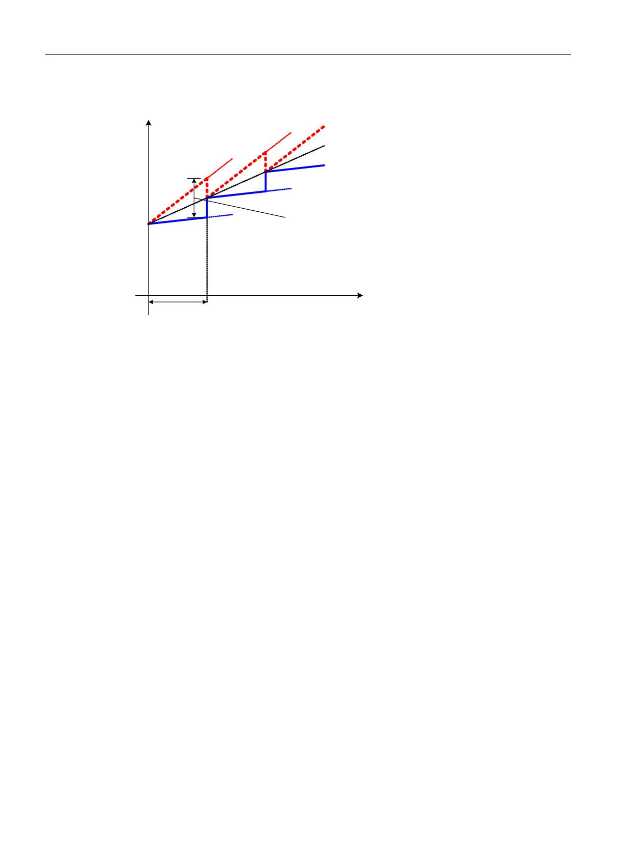
Figure 5-34
Example diagram of actual value synchronization
The mean value of the actual values of both channels is calculated cyclically after actual value
synchronization (p9301.3 = 1) has been activated, for example, for systems or machines with
slip. The maximum slip defined in p9549 is monitored in the cross-check cycle (r9724). If "actual
value synchronization" is not enabled, the value parameterized in p9542 is used as tolerance
value for the crosswise comparison.
Safe motion monitoring
The properties of the actual value acquisition determine not only the encoders used, but also
the values for safe motion monitoring that can be achieved in the best case.
● Safe maximum speed (r9730)
The maximum speed (load side) that is permissible due to the acquisition of actual values
for safe motion monitoring functions is indicated in r9730. This parameter shows up to which
load velocity the safety-relevant encoder actual values (redundant coarse encoder position)
can still be correctly sensed as a result of the particular encoder parameterization.
The actual value acquisition clock (p9511) determines the frequency at which the actual
values are acquired. The longer the clock cycle, the higher the "safe maximum velocity." On
the other hand, a longer actual value acquisition clock cycle places a greater load on the
Control Unit. You must consider this when setting the optimum for your particular
application.
● Safe positioning accuracy (r9731)
This positioning accuracy can be achieved in the best case by acquiring the actual values.
If a 2-encoder system is used, the accuracy of the poorer encoder is indicated based on the
number of encoder pulses.
Safety Integrated plus
188
Commissioning Manual, 12/2019, 6FC5397-1FP40-6BA3
Safety functions integrated in the drive
5.18 Safe actual value acquisition
5.18.1
Overview of important parameters
Overview of important parameters - with encoder system (see SINAMICS S120/S150 List Manual)
● p9501.3
SI Motion enable safety functions (Control Unit),
enable actual value synchronization
● p9502
SI Motion axis type (Control Unit)
● p9511
SI Motion actual value acquisition clock (Control Unit)
● p9515
SI Motion encoder coarse position value configuration (Control Unit)
● p9516
SI Motion encoder configuration safety functions (Control Unit)
● p9517
SI Motion linear encoder grid division (Control Unit)
● p9518
SI Motion encoder pulses per revolution (Control Unit)
● p9519
SI Motion fine resolution G1_XIST1 (Control Unit)
● p9520
SI Motion leadscrew pitch (Control Unit)
● p9521[0...7]
SI Motion gearbox encoder (motor)/load denominator (Control Unit)
● p9522[0...7]
SI Motion gearbox encoder (motor)/load numerator (Control Unit)
● p9523
SI Motion redundant coarse position value valid bits (Control Unit)
● p9524
SI Motion redundant coarse position value, fine resolution (Control Unit)
● p9525
SI Motion redundant coarse position relevant bits (Control Unit)
● p9526
SI Motion encoder assignment second channel
● p9542
SI Motion actual value comparison tolerance (crosswise) (Control Unit)
● p9549
SI Motion slip velocity tolerance (Control Unit)
● p9700
SI Motion copy function
● r9713[0...5]
SI Motion diagnostics actual position value load side
● r9714[0...2]
SI Motion diagnostics velocity
● r9724
SI Motion, cross-check cycle
● r9730
SI Motion safe maximum speed
● r9731
SI Motion safe positioning accuracy
● r9732[0...1]
SI Motion velocity resolution
Overview of important parameters - without encoder system
● p9585
SI Motion actual value acquisition without encoder fault tolerance (CU)
● p9586
SI Motion actual value acquisition without encoder delay time (CU)
● p9587
SI Motion actual value acquisition without encoder filter time (CU)
● p9588
SI Motion actual value acquisition without encoder minimum current (CU)
● p9589
SI Motion actual value acquisition without encoder acceleration limit (CU)
● p9700
SI Motion copy function
● r9732[0...1]
SI Motion velocity resolution
Safety Integrated plus
Commissioning Manual, 12/2019, 6FC5397-1FP40-6BA3
189
Safety functions integrated in the drive
5.19 Safe gearbox stage switchover
5.19
Safe gearbox stage switchover
"Safe gearbox switchover" allows you to switch between 8 gearbox ratios in operation.
Switchover between gearbox ratios is only possible via PROFIBUS (p9601.3 = 1).
Parameterization
Before you can use "Safe gearbox switchover", you must parameterize the following values:
● Gear ratios
You can set up to 8 different gearbox ratios using parameter p9521 (denominator) and
p9522 (numerator).
● Direction reversal
Using parameter p9539, you can set as to whether a direction of rotation reversal is involved
for the particular gearbox.
● Position tolerance
As a result of the motion that can possibly occur when switching over the gearbox, it may be
necessary to increase the tolerance threshold for the duration of the switchover operation.
Using parameter p9539, you set how the tolerance is calculated when switching over the
gearbox:
- Without actual value synchronization: p9542 × p9543
- With actual value synchronization: p9549 × p9543
Selection
Proceed as follows to enable the "Safe gearbox switchover" function:
1. Set p9501.26 = 1
- If control via PROFIsafe is not parameterized, then the converter outputs fault F01681
with the appropriate fault value.
- If you activate the "Safe gearbox switchover" function on a converter, which does not
support the function, then the converter outputs fault F01682 with fault value 39.
2. Switch off the drive unit and then on again (POWER ON).
Safety Integrated plus
190
Commissioning Manual, 12/2019, 6FC5397-1FP40-6BA3
Safety functions integrated in the drive
5.19 Safe gearbox stage switchover
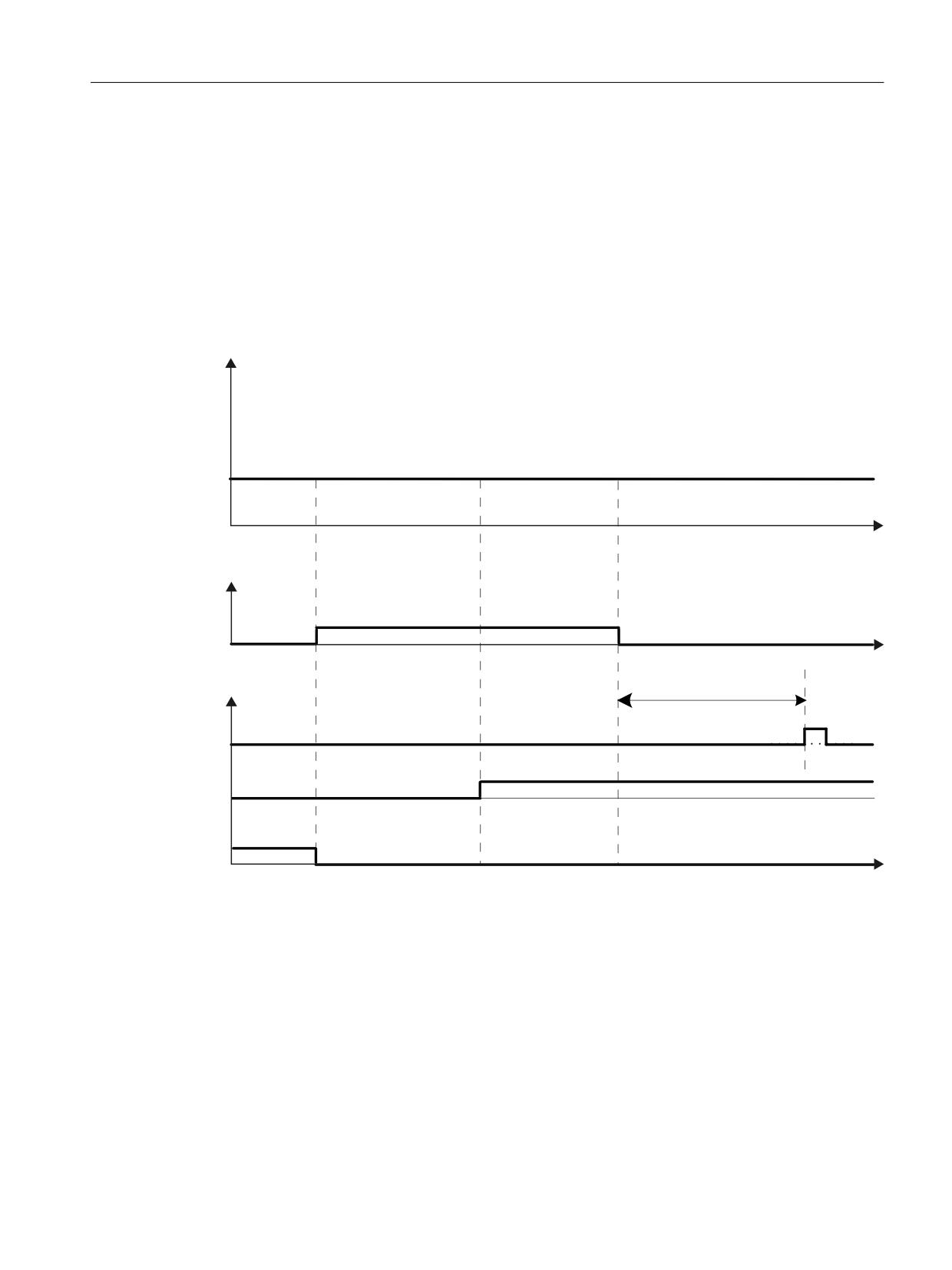
Gearbox switchover without increased position tolerance
In order to switch over the gearbox stage, where no increased tolerance is required for the
crosswise comparison of the actual positions, proceed as follows:
● Set the new gearbox stage using bits 0 to 2 in byte 3 of S_STW2.
● The actual values are then synchronized once automatically. This synchronization is used
to compensate any possible difference that occurs between the position actual values of the
two monitoring channels as a result of the switchover operation.
● The new gearbox stage is then active.
3RVLWLRQ WROHUDQFH
,QFUHDVHG
6WDQGDUG
W
352),VDIH 6B67:
*HDUER[ VWDJH FKDQJH
E\WH ELW
W
6DIHW\ 0RWLRQ 0RQLWRULQJ
0D[LPXP U
6LQJOH
DFWXDO YDOXH
V\QFKURQL]DWLRQ
&RQYHUVLRQ WR WKH
ORDG VLGH ZLWK QHZ
JHDUER[ IDFWRUV
6DIHO\
UHIHUHQFHG
W
Figure 5-35
Gearbox switchover from stage "0" to "1" without increased position tolerance
Safety Integrated plus
Commissioning Manual, 12/2019, 6FC5397-1FP40-6BA3
191
Safety functions integrated in the drive
5.19 Safe gearbox stage switchover
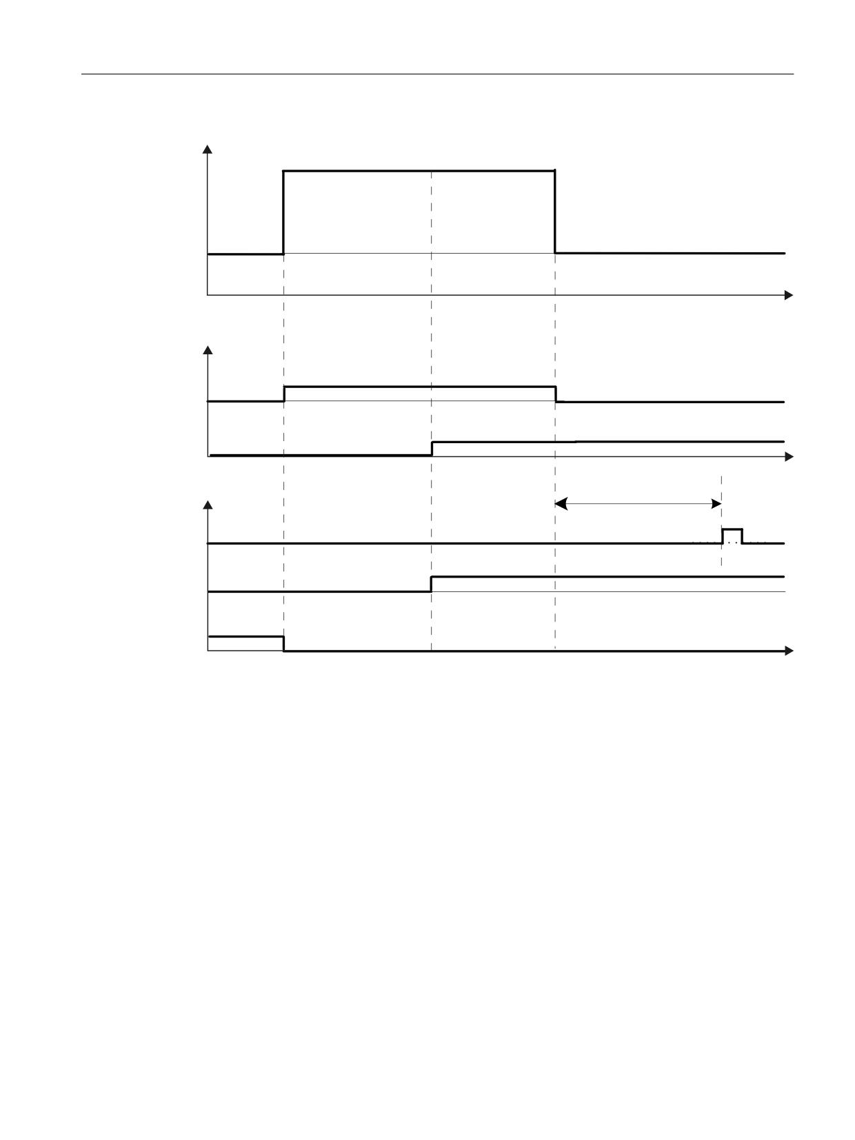
Gearbox switchover with increased position tolerance
In order to switch over the gearbox stage, where increased tolerance is required for the
crosswise comparison of the actual positions, proceed as follows:
Note
Maximum duration of the increased position tolerance
It is not permissible that the increased position tolerance is set for longer than 2 min. If this time
is exceeded, then the converter outputs alarm C01711 with fault value 1015 (≙ STOP F).
● Set the increased position tolerance using bit 3 (= 1) in byte 3 of S_STW2.
● Set the new gearbox stage using bits 0 to 2 in byte 3 of S_STW2.
● Set the position tolerance back to the normal value using bit 3 (= 0) in byte 3 of S_STW2.
● The actual values are then synchronized once automatically. This synchronization is used
to compensate any possible difference that occurs between the position actual values of the
two monitoring channels as a result of the switchover operation.
● The new gearbox stage is then active.
Safety Integrated plus
192
Commissioning Manual, 12/2019, 6FC5397-1FP40-6BA3
Safety functions integrated in the drive
5.19 Safe gearbox stage switchover
3RVLWLRQ WROHUDQFH
,QFUHDVHG
6WDQGDUG
W
352),VDIH 6B67:
*HDUER[ VWDJH FKDQJH
E\WH ELW
*HDUER[ VWDJH
E\WH ELW
W
6DIHW\ 0RWLRQ 0RQLWRULQJ
0D[LPXP U
6LQJOH
DFWXDO YDOXH
V\QFKURQL]DWLRQ
&RQYHUVLRQ WR WKH
ORDG VLGH ZLWK QHZ
JHDUER[ IDFWRUV
6DIHO\
UHIHUHQFHG
W
Figure 5-36
Gearbox switchover with increased position tolerance
Diagnostics
The selected gearbox stage is displayed for diagnostic purposes in parameter r9720, bits 24 to
26.
The selected gearbox stage is displayed for diagnostic purposes in parameter r9720, bit 27.
"Safe gearbox switchover" and referencing
The gearbox stage switchover means that the reference position and the user agreement are
lost. This means that after a gearbox switchover, initial referencing is required, in order to return
to the "safely referenced" state (see Chapter Safe referencing (Page 179)).
Safety Integrated plus
Commissioning Manual, 12/2019, 6FC5397-1FP40-6BA3
193
Safety functions integrated in the drive
5.19 Safe gearbox stage switchover
5.19.1
Overview of important parameters
● p9501.26
SI Motion enable safety functions (Control Unit): Enable reliable gearbox
switchover
● p9521[0...7]
SI Motion gearbox encoder (motor)/load denominator (Control Unit)
● p9522[0...7]
SI Motion gearbox encoder (motor)/load numerator (Control Unit)
● p9539[0...7]
SI Motion gearbox direction of rotation reversal (Control Unit)
● p9542
SI Motion actual value comparison tolerance (crosswise) (Control Unit)
● p9543
SI Motion gearbox switching position tolerance factor (CU)
● p9549
SI Motion slip velocity tolerance (Control Unit)
● r9720.0...27
CO/BO: SI Motion drive-integrated control signals
Safety Integrated plus
194
Commissioning Manual, 12/2019, 6FC5397-1FP40-6BA3
Safety functions integrated in the drive
5.20 Forced checking procedure
5.20
Forced checking procedure
The functions and switch-off signal paths must be tested at least once within a defined period
to establish whether they are working properly in order to meet the requirements of EN ISO
13849-1 and IEC 61508 in terms of timely error detection.
The maximum permissible interval for a test stop/forced checking procedure for Basic and
Extended Functions is 8760 hours; i.e. the forced checking procedure must be performed at
least once per year.
This functionality must be implemented by initiating a test stop/forced checking procedure
either in the cyclic manual mode or as part of an automated process.
The test stop cycle is monitored. On expiration of the parameterized timer (also after POWER
ON / warm restart), the alarm A01697: "SI Motion: Test of motion monitoring required" is
generated and a status bit is set which can be transferred to an output or to a PZD bit via BICO.
This alarm does not affect machine operation.
5.20.1
Examples for when the forced checking procedure is carried out
When the appropriate safety devices are implemented (e.g. protective doors), it can be
assumed that running machinery will not pose any risk to personnel. For this reason, an alarm
is only output to inform the user that a forced checking procedure run is due and to request that
this be carried out at the next available opportunity.
Examples of when to carry out forced checking procedure:
● When the drives are at a standstill after the system has been switched on (POWER ON).
● Before the protective door is opened.
● At defined intervals (e.g. every eight hours).
● In automatic mode (time and event dependent).
5.20.2
Options and control
Note
Requirements
STO is triggered when a test stop is carried out for the Safety functions. It is not permissible that
STO is selected before selecting the test stop.
When blocksize Power Modules are used, the test stop must be triggered under controlled
standstill conditions (speed setpoint setting 0, current is flowing through the motor).
Safety Integrated plus
Commissioning Manual, 12/2019, 6FC5397-1FP40-6BA3
195
Safety functions integrated in the drive
5.20 Forced checking procedure
The forced checking procedure (test stop) can be triggered at any time by an application. The
parameter assignment and control are performed as follows:
● Controlled via SCC (integrated drives, external drives), programmed in the application
You can perform the test stop via SCC, programmed in the application itself. The following
parameters are relevant:
- p9559 SI Motion Forced checking procedure timer (Control Unit)
- p9705 BI: SI Motion Test stop signal source
- r9723.0 CO/BO: SI Motion diagnostics signals integrated in the drive
See: Safety Info Channel and Safety Control Channel (SIC/SCC) (Page 205)
If the test stop is executed as described, the action does not require a POWER ON. The
acknowledgment is set by canceling the test stop request.
Safety Integrated plus
196
Commissioning Manual, 12/2019, 6FC5397-1FP40-6BA3
Controlling safety functions integrated in the drive
6
6.1
Control possibilities
The following options are available for controlling safety functions integrated in the drive:
Table 6-1
Controlling the Safety Integrated Functions
Scope
Basic Functions
Extended Functions
Control type
Telegrams to control process data via PROFIsafe and
Yes
Yes
SIC/SCC (PROFIdrive)
See:
● Overview of telegram/process data (Page 198)
● Controlling via PROFIsafe (Page 201)
● SIC/SCC (Page 205)
Controlling via terminals (on the Control Unit and on the
Yes
No
Motor/Power Module)
See: Control signals via terminals on the NCU and motor/
power module (Page 207)
Note
Term "Control Unit" in this documentation
In the Safety Integrated plus environment and in this documentation the term "Control Unit"
designates the SINUMERIK NCU.
Safety Integrated plus
Commissioning Manual, 12/2019, 6FC5397-1FP40-6BA3
197
Controlling safety functions integrated in the drive
6.2 Overview of telegrams
6.2
Overview of telegrams
You can use the following safety-oriented telegrams.
● PROFIsafe telegram 30
PROFIsafe standard telegram
● PROFIsafe telegram 31
Extended PROFIsafe standard telegram
● SIEMENS telegram 901
Extended manufacturer-specific telegram with 16-bit position value.
● SIEMENS telegram 902
Extended manufacturer-specific telegram with 32-bit position value.
● SIEMENS telegram 903
Extended manufacturer-specific telegram with 32-bit Safe Cam (S_ZSW_CAM1). Default
setting for internal NC drives.
● SIEMENS telegram 701
Manufacturer-specific telegram for SIC/SCC communication. With SINUMERIK, SIC/SCC
communication only takes place via telegram 701.
The following overview shows which process data is transferred in which telegram types.
Safety Integrated plus
198
Commissioning Manual, 12/2019, 6FC5397-1FP40-6BA3
Controlling safety functions integrated in the drive
6.3 Overview: Process data in telegrams
6.3
Overview: Process data in telegrams
Table 6-2
Process data from PROFIsafe telegrams
Telegram
903
902
901
31
30
Process data
Safety control word 1
-
-
-
-
PZD1
S_STW1 (Page 353)
Safety status word 1
-
-
-
-
PZD1
S_ZSW1 (Page 355)
Safety control word 2
PZD1…2
PZD1…2
PZD1…2
PZD1…2
-
S_STW2 (Page 357)
Safety status word 2
PZD1…2
PZD1…2
PZD1…2
PZD1…2
-
S_ZSW2 (Page 359)
SLS limit value input
PZD3
PZD3
PZD3
-
-
S_SLS_LIMIT_A (Page 362)
Active SLS limit value
PZD5
PZD3
PZD3
-
-
S_SLS_LIMIT_A_ACTIVE
(Page 362)
Counter for the safety cycle
-
PZD4
PZD4
-
-
S_CYCLE_COUNT (Page 363)
Actual position value (16 bits)
-
-
PZD5
-
-
S_XIST16 (Page 363)
Actual position value (32 bits)
-
PZD5…6
-
-
-
S_XIST32 (Page 363)
Safe Cam status word
PZD3…4
-
-
-
-
S_ZSW_CAM1 (Page 364)
Table 6-3
Process data from SIEMENS telegram 701 (SIC/SCC)
Telegram
701
Process data
Safety Control Channel control word 1
PZD1
S_STW1B (Page 366)
SI Motion Safety Info Channel status word
PZD1
S_ZSW1B (Page 366)
Safety Info Channel status word 2
PZD2
S_ZSW2B (Page 367)
Safety Control Channel control word 3
PZD2
S_STW3B (Page 368)
SLS setpoint speed limiting (32 bit)
PZD3…4
S_V_LIMIT_B (Page 369)
Safety Info Channel status word 3
PZD5
S_ZSW3B (Page 368)
Safety Integrated plus
Commissioning Manual, 12/2019, 6FC5397-1FP40-6BA3
199
Controlling safety functions integrated in the drive
6.3 Overview: Process data in telegrams
See also
S_ZSW3B: Safety Info Channel status word 3 (Page 368)
Safety Integrated plus
200
Commissioning Manual, 12/2019, 6FC5397-1FP40-6BA3

Controlling safety functions integrated in the drive
6.4 Controlling via PROFIsafe
6.4
Controlling via PROFIsafe
6.4.1
Enabling PROFIsafe control
Control via PROFIsafe is available for both Safety Integrated Basic Functions and Safety
Integrated Extended Functions, and must be enabled in p9601
Table 6-4
Parameter to enable the PROFIsafe control
Parameters
Name
Setting
Meaning
p9601
SI enable functions
0008 hex
Basic Functions are enabled via PROFIsafe (permissible for r9771.6 = 1).
integrated in the
0009 hex
Basic Functions are enabled via PROFIsafe and onboard terminals (per-
drive (Control Unit) /
missible for r9771.6 = 1).
SI enable fct CU
000C hex
Extended Functions are enabled via PROFIsafe (permissible for r9771.4 =
1).
000D hex
Extended Functions are enabled via PROFIsafe - and Basic Functions via
onboard terminals (permissible for r9771.4 = 1).
p9601.0 = 1
Enable STO (SH) via terminals (CU)
Comment: Safety Integrated Basic Functions via PROFIsafe and via ter-
minals
Control of the Basic Functions via terminals on the Control Unit and on the
Motor/Power Module (parameters p9601.0 = 1) may be enabled in parallel.
In order to be able to select SS1, an SS1 delay time p9652 > 0 must be
configured. With PROFIsafe, both SS1 and STO can be selected. Only
SS1 is available for control via terminal.
STO takes priority over SS1, i.e. STO becomes active if SS1 and STO are
simultaneously selected.
r9771
SI common func-
r9771.4 = 1
Extended Functions, PROFIsafe supported
tions (Control Unit) /
r9771.6 = 1
Basic Functions, PROFIsafe supported
SI common fct CU
6.4.2
Selecting the PROFIsafe telegram
You can use telegrams 903, 902, 901, 31 or 30 for PROFIsafe communication via PROFIBUS
and PROFINET. SIEMENS telegram 903 is the default setting for internal NC drives.
Safety Integrated plus
Commissioning Manual, 12/2019, 6FC5397-1FP40-6BA3
201

Controlling safety functions integrated in the drive
6.4 Controlling via PROFIsafe
You make the settings for the F-PLC (F-host) in the TIA Portal; the settings for the individual
drives (F-slaves or F-devices), in SINUMERIK Operate (p60022, p9611, p9811).
Table 6-5
Parameter to select the PROFIsafe telegram
Parameter/name
Setting
Meaning
p60022 PROFIsafe telegram selection / Ps
903
● PROFIsafe SIEMENS telegram 903
telegr_sel
● Extended manufacturer-specific telegram with 32-bit
Safe Cam
● Default setting for internal NC drives
p9611 SI PROFIsafe telegram selection (Con-
● Structure of telegram 903 (Page 348)
trol Unit) / SI Ps telegr CU
902
● PROFIsafe SIEMENS telegram 902, PZD-3/6
● Extended PROFIsafe telegram with 32-bit position value
● Structure of telegram 902 (Page 349)
p9811 SI PROFIsafe telegram selection (Mo-
tor Module) / SI Ps telegram MM
901
● PROFIsafe SIEMENS telegram 901, PZD-3/5
● Extended PROFIsafe telegram with 16-bit position value
● Structure of telegram 901 (Page 349)
31
● PROFIsafe standard telegram 31, PZD-2/2
● Extended standard PROFIsafe telegram
● Structure of telegram 31 (Page 350)
30
● PROFIsafe standard telegram 30, PZD-1/1
● Standard PROFIsafe telegram
● Structure of telegram 30 (Page 350)
The PROFIsafe telegram received at the Control Unit is indicated in r9768, and the PROFIsafe
telegram to be sent, in parameter r9769.
Note
Timing between the switching operations
Message F01611 with fault value 1000 indicates that the switching operations occur too
frequently.
● STO is being permanently initiated via PROFIsafe (also as subsequent response).
Within the time 5 × p9650, there must be at least two switching operations via PROFIsafe with
a minimum time between them of p9650.
6.4.3
ESR response in the event of a communication error
The response of the SINAMICS S drive in the case of a communication error when the
"Extended stop and retract (ESR)" function module is simultaneously enabled is described in
the following.
Safety Integrated plus
202
Commissioning Manual, 12/2019, 6FC5397-1FP40-6BA3
Controlling safety functions integrated in the drive
6.4 Controlling via PROFIsafe
Requirement
● The Safety Integrated Extended Functions are controlled via PROFIsafe
● The function module "Extended stop and retract" is activated and enabled
Communication failure
Under communication failure in this context, we understand one of the following possibilities:
● Interruption/fault of the PROFIBUS or PROFINET connection for control via PROFIsafe
● STOP response of the F-PLC
Drive response
In the event of a communication failure, SINAMICS S makes a distinction between the following
responses:
● If p9580 ≠ 0 and ESR has been enabled, in the event of a communication failure, the
parameterized ESR response is realized.
● If p9580 ≠ 0 and SLS is active, in the event of communication failure, the parameterized ESR
reaction is only realized if, as SLS response, a STOP with delayed pulse cancellation when
the bus fails has been parameterized (p9563[0...3] ≥ 10).
● If p9580 ≠ 0 and SDI is active, in the event of communication failure, the parameterized ESR
reaction is only realized if, as SDI response, a STOP with delayed pulse cancellation when
the bus fails has been parameterized (p9566[0...3] ≥ 10).
● If p9580 ≠ 0 and SLP is active, in the event of communication failure, the parameterized ESR
reaction is only realized if, as SLP response, a STOP with delayed pulse cancellation when
the bus fails has been parameterized (p9562[0...1] ≥ 10).
Note
Maximum response time for interruption in communication
When a safety-relevant communication is interrupted, Safety Integrated only permits a
response time (p9580) of max. 800 ms. The drive changes into the "fail safe state" once this
time expires. In this case, S_STW1/2 is assumed to be 0. This means that all safety functions
are selected. STO has in this case the highest priority, i.e. the pulses are safely canceled.
6.4.4
Parameters and function diagrams
Function diagrams (see SINAMICS S120/S150 List Manual)
●
2840
Extended Functions - SI Motion drive-integrated control signals/status
signals
●
2858
SI Extended Functions - control via PROFIsafe (p9601.2 = p9601.3 = 1)
Safety Integrated plus
Commissioning Manual, 12/2019, 6FC5397-1FP40-6BA3
203
Controlling safety functions integrated in the drive
6.4 Controlling via PROFIsafe
Overview of important parameters (see SINAMICS S120/S150 List Manual)
● p9563[0...3]
SI Motion SLS (SG)-specific stop response (Control Unit)
● p9566
SI Motion SDI stop response (Control Unit)
● p9580
SI Motion STO delay bus failure (Control Unit)
● p9601
SI enable functions integrated in the drive (Control Unit)
● p9610
SI PROFIsafe address (Control Unit)
● p9611
SI PROFIsafe telegram selection (Control Unit)
● p60022
Selecting a PROFIsafe telegram
Safety Integrated plus
204
Commissioning Manual, 12/2019, 6FC5397-1FP40-6BA3
Controlling safety functions integrated in the drive
6.5 Safety Info Channel and Safety Control Channel (SIC/SCC)
6.5
Safety Info Channel and Safety Control Channel (SIC/SCC)
6.5.1
Introduction
In the Safety Integrated plus (F-PLC) mode, status and control signals of the drive-based
motion monitoring functions are connected to the PLC and NC:
● Via the Safety Control Channel (SCC), control signals are sent from the PLC and NC to the
drive (e.g. to start the "Safe Brake Test (SBT)" diagnostic function in the drive - and to
influence it).
● Via the Safety Info Channel (SIC), status signals of the drive are sent to the PLC (e.g. for the
brake test).
● For a STOP response of the drive, status signals are transferred to the NC as well as to the
PLC. The motion control in the NC automatically responds to the drive STOP response by
no longer issuing additional setpoints for the path, for example. As a consequence, alarms
to be acknowledged are avoided, such as "Contour monitoring" or "Positioning monitoring".
You can parameterize SIC/SCC as follows, and access the signals:
● You activate SIC/SCC while commissioning the drive in SINUMERIK Operate.
● The SIC/SCC signals are mapped in the PLC user interface, and can therefore be accessed
via axis DBs.
See: PLC user interface (DB3x) (Page 206), Interface signals: Axis/spindle signals
(Page 370)
Note
SIC and SCC must always be jointly configured and/or parameterized.
6.5.2
Safety Info Channel (SIC)
Status information of the Safety Integrated functionality of the drive (S_ZSW1B, S_ZSW2B,
S_ZSW3B and S_V_LIMIT_B) can be transferred to the F-PLC and NC using the Safety Info
Channel (SIC).
6.5.3
Safety Control Channel (SCC)
Control information (S_STW1B and S_STW3B) can be transferred from the F-PLC and the NC
to the safety functions of the drive using the Safety Control Channel (SCC).
6.5.4
SIC/SCC communication using telegram 701
SIC/SCC communication can always be transferred using the predefined PROFIdrive
telegrams 700 or 701. However, for SINUMERIK only telegram 701 (Page 348)is used.
Safety Integrated plus
Commissioning Manual, 12/2019, 6FC5397-1FP40-6BA3
205
Controlling safety functions integrated in the drive
6.5 Safety Info Channel and Safety Control Channel (SIC/SCC)
If another telegram is configured for SIC/SCC, then cyclic SIC/SCC communication is inhibited,
and Alarm 27811 is output.
6.5.5
PLC user interface (DB3x)
In the Safety Integrated plus (F-PLC) mode, additional axis-specific data from the axis DB
(axis 1 [DB31] ... axis 31 [DB61]) are relevant, which are mapped from the SIC/SCC.
Additional information
● You can find the significance of the individual axis DB signals and the precise addresses
at Interface signals: Axis/spindle signals (Page 370).
● See also: SBT: Connection to NC and PLC programs (Page 161)
6.5.6
Overview of important parameters
● r9733[0...2]
CO: SI Motion setpoint speed limit effective
● r9734.0...15
CO/BO: SI Safety Info Channel status word S_ZSW1B
● r9743.4...15
CO/BO: SI Safety Info Channel status word S_ZSW2B
● r10231
SI Motion SBT control word diagnostics
● r10234.0...15
CO/BO: SI Safety Info Channel status word S_ZSW3B
● p10235
CI: SI Safety Control Channel control word S_STW3B
● p10250
CI: SI Safety Control Channel control word S_STW1B
● r10251.8...12
CO/BO: SI Safety Control Channel control word S_STW1B diagnostics
● p60122
IF1 PROFIdrive SIC/SCC telegram selection
Safety Integrated plus
206
Commissioning Manual, 12/2019, 6FC5397-1FP40-6BA3
Controlling safety functions integrated in the drive
6.6 Control signals via terminals on the NCU and motor/power module
6.6
Control signals via terminals on the NCU and motor/power module
6.6.1
Features
● Control via terminals is only available for Basic Functions.
● Dual-channel structure via 2 digital inputs (Control Unit/power unit)
● In order to prevent nuisance trips as a result of signal disturbances or non-symmetrical test
signals, the signals can be debounced at the terminals of the connected components
(pushbuttons, switches etc.).
You can specify these debounce times in the following parameters:
- p9651 SI STO/SBC/SS1 debounce time (Control Unit) / SI STO t_debou CU
- p9851 SI STO/SBC/SS1 debounce time (Motor Module) / SI STO t_debou MM
● Different terminal blocks depending on the format.
● Automatic ANDing of up to 8 digital inputs (p9620[0...7]) on the Control Unit with parallel
configuration of power units in the chassis format is not supported.
The various SINUMERIK components and SINAMICS power unit formats have different
terminal designations for the inputs used for the safety functions. These are shown in the
following table.
Table 6-6
Inputs for safety functions
Component
1st switch-off signal path
2nd switch-off signal path (EP terminals)
(p9620[0])
NCU
Selected using BICO inter-
connection (BI: p9620[0]):
Digital input DI 0…7
NX module
Selected using BICO inter-
connection (BI: p9620[0]):
Digital input DI 0…3
Single Motor Module Book-
X122.1
6/X132.1…6DI
EP terminals X21.3 and X21.4
size/Booksize Compact
0...7/16/17/20/21
(on the Motor Module)
Single Motor Module/
X122.1
6/X132.1…6DI
EP terminals X41.1 and X41.2
Power Module Chassis
0...7/16/17/20/21
Double Motor Module Book-
X122.1
6/X132.1…6DI
EP terminals on the Motor Module:
size/Booksize Compact
0...7/16/17/20/21
X21.3 and X21.4 (motor connection X1)
X22.3 and X22.4 (motor connection X2)
Power Module Blocksize
X122.1
6/X132.1…6DI
X210.3 and X210.4 (on the CUA31/
with CUA31/CUA32
0...7/16/17/20/21
CUA32)
Control Unit CU320-2
X122.1
6/X132.1…6DI
0...7/16/17/20/21
For further information about the terminals, see the Equipment Manuals.
Safety Integrated plus
Commissioning Manual, 12/2019, 6FC5397-1FP40-6BA3
207
Controlling safety functions integrated in the drive
6.6 Control signals via terminals on the NCU and motor/power module
6.6.2
Terminals for STO, SS1 (time-controlled), SBC
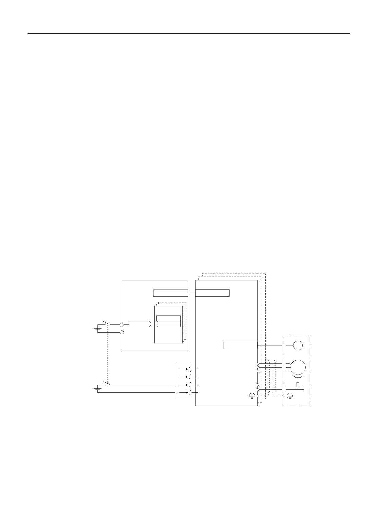
Safety functions STO, SS1 (time-controlled) and SBC are selected/deselected separately for
each drive using 2 terminals.
Basic procedure
The functions are separately selected/deselected for each drive using two terminals.
● Switch-off signal path, Control Unit:
- Input terminal for Safe Torque Off (STO):
Selected using BICO interconnection (BI: p9620[0]).
- Possible signal sources:
NCU: Digital input DI 0…7
NX modules: Digital input DI 0…3
● Motor Module switch-off signal path:
The input terminal is the "EP" terminal ("Enable Pulses").
The EP terminal is periodically interrogated with a sampling time, which is rounded off to an
integer multiple of the current controller cycle; however, it is a minimum of 1 ms. (Example: ti
= 400 µs, tEP => 3x, ti = 1.2 ms)
Both terminals must be energized within the tolerance time p9650/p9850 (Page 210),
otherwise a fault is output.
Example: Terminals for STO
1&8 [
0RWRU 0RGXOH
'5,9( &/L4
'5,9( &/L4
%O
1&8 [
', [
S
U
[
0
'5,9( &/L4
*
0RQLWRULQJ FKDQQHO
&RQWURO 8QLW
[
[
8
0
9
7HPS
a
:
0RQLWRULQJ FKDQQHO
7HPS
0RWRU 0RGXOH
(3
9
%5
(3 0
%5
Figure 6-1
Example: Terminals for STO for an NCU7x0 and a Motor Module, booksize format
Safety Integrated plus
208
Commissioning Manual, 12/2019, 6FC5397-1FP40-6BA3
Controlling safety functions integrated in the drive
6.6 Control signals via terminals on the NCU and motor/power module
6.6.3
Grouping drives
To ensure that the safety function for several drives can be initiated simultaneously, you must
group the terminals for the corresponding drives.
Note
Response of the "STO" safety function when grouping
If a fault in a drive results in a "Safe Torque Off" (STO), this does not automatically mean that
the other drives in the same group also switch to "Safe Torque Off" (STO).
Basic procedure
Proceed as follows to group the corresponding drives:
1. Switch-off signal path, Control Unit
Group by appropriately interconnecting the binector input to the common input terminal for
the drives belonging to a group.
2. Motor Module switch-off signal path
Group by appropriately connecting terminal "EP" for the individual Motor Modules belonging
to a group.
Note
Parameterization of the grouping
The grouping must be set the same in both monitoring channels.
The assignment is checked during the test for the switch-off signal paths. The operator selects
the STO safety function for each group. The check is drive-specific.
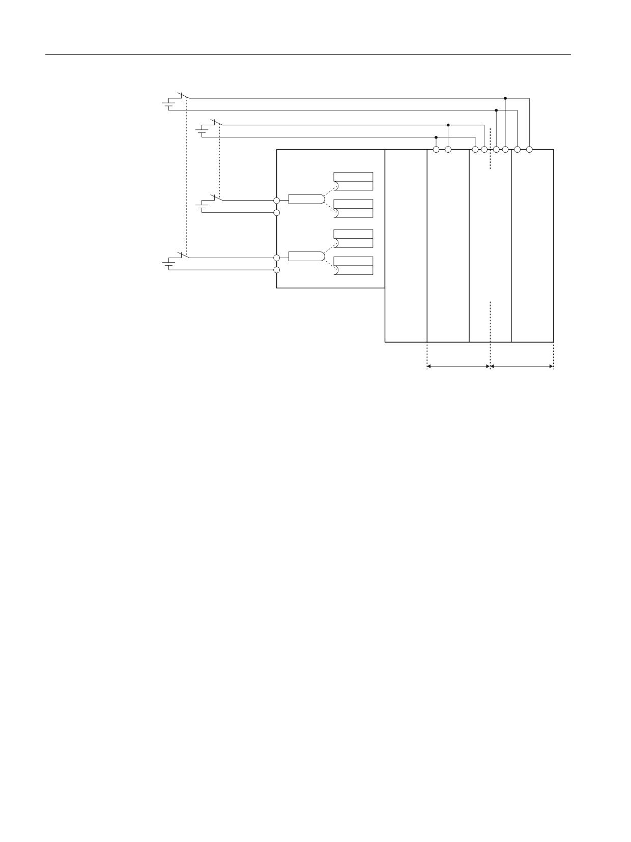
Example: Terminal groups
It must be possible to select/deselect safety function STO separately for group 1 (drives 1 and
2) and group 2 (drives 3 and 4).
For this purpose, the same grouping for STO must be realized both for the Control Unit and the
Motor Modules.
Safety Integrated plus
Commissioning Manual, 12/2019, 6FC5397-1FP40-6BA3
209
Controlling safety functions integrated in the drive
6.6 Control signals via terminals on the NCU and motor/power module
6HOHFWLQJ GH
VHOHFWLQJ
1&8 [
0
(3
0
0
0 (3
6HOHFWLQJ GH
*URXS
'ULYH
(3
(3
VHOHFWLQJ
S
*URXS
'O
'ULYH
/LQH
6LQJOH
'RXEOH
6LQJOH
U
S
0RGXOHV
0RWRU
0RWRU
0RWRU
0
0RGXOHV
0RGXOHV
0RGXOHV
'ULYH
S
'O
;
'ULYH
U
S
0
'ULYH
'ULYH
'ULYH
*URXS
*URXS
Figure 6-2
Example: Grouping the terminals for Motor Modules, booksize format
6.6.4
Simultaneity and tolerance time of the two monitoring channels
The "Safe Torque Off" (STO) safety function must be selected/deselected simultaneously in
both monitoring channels using the input terminals, and is only effective for the associated
drive.
●
1 signal: Deselecting the function
●
0 signal: Selecting the function
Parameterization of the tolerance time
Even when simultaneously selecting/deselecting, a certain time delay cannot be avoided, e.g.
as a result of mechanical switching operations. Therefore, in the following parameters, define
the tolerance times, within which selection/deselection in both monitoring channels is
considered to be simultaneously valid.
● p9650 SI SGE switchover tolerance time (Control Unit)
● p9850 SI SGE switchover tolerance time (Motor Module)
In order to avoid that faults are incorrectly initiated, at these inputs the tolerance time must
always be set shorter than the shortest time between two switching events (ON/OFF, OFF/ON).
Safety Integrated plus
210
Commissioning Manual, 12/2019, 6FC5397-1FP40-6BA3
Controlling safety functions integrated in the drive
6.6 Control signals via terminals on the NCU and motor/power module
Fault F01611
If the "Safe Torque Off" function is not selected/deselected within the tolerance time, this is
detected by the cross-comparison, and fault F01611 (STOP F) is output. In this case, the pulses
have already been canceled as a result of the selection of "Safe Torque Off" on one channel.
Note
Timing between the switching operations
Message F01611 with fault value 1000 indicates that the switching operations occur too
frequently.
● STO is being permanently initiated via PROFIsafe (also as subsequent response).
Within the time 5 × p9650, there must be at least two switching operations via PROFIsafe with
a minimum time between them of p9650.
Additional notes regarding setting the discrepancy time are included in the "SINAMICS S120/
S150 List Manual" for the C01770 and F01611 safety messages.
6.6.5
Bit pattern test
Bit pattern test of failsafe outputs
The converter normally responds immediately to signal changes in its failsafe inputs. This is not
desired in the following case: Several control modules test their failsafe outputs using bit
pattern tests (on/off tests), in order to identify faults due to either short-circuit or cross-circuit
faults. When you interconnect a failsafe input of the converter with a failsafe output of a control
module, the converter responds to these test signals.
,QSXW VLJQDOV
%LW SDWWHUQ WHVW
) ',
W
6DIHW\ IXQFWLRQ
$FWLYH
,QDFWLYH
W
)DXOW )
W
Figure 6-3
Converter response to a bit pattern test
Safety Integrated plus
Commissioning Manual, 12/2019, 6FC5397-1FP40-6BA3
211
Controlling safety functions integrated in the drive
6.6 Control signals via terminals on the NCU and motor/power module
Note
Debounce time for unwanted triggering of Safety Integrated Functions
If the test pulses cause an unwanted triggering of the Safety Integrated Functions, these test
pulses can be suppressed with the aid of the F-DI input filter (p9651). To do this, a value must
be entered in p9651 that is greater than the duration of a test pulse.
Overview of important parameters (see SINAMICS S120/S150 List Manual)
● p9651
SI STO/SBC/SS1 debounce time (Control Unit)
Safety Integrated plus
212
Commissioning Manual, 12/2019, 6FC5397-1FP40-6BA3
Commissioning and configuring
7
7.1
Handling overview
Safety Integrated plus is partially commissioned in the TIA Portal - and partially in SINUMERIK
Operate. Commissioning can be roughly subdivided into the following steps:
● Configuring safety-relevant components (Page 214)
● Generating a safety program (Page 223)
● Loading the configuration (Page 236)
● Configuring NC and drive-specific safety settings (Page 239)
● Configuring safety functions integrated in the drive (Page 258)
● Finalizing commissioning (Page 292)
Detailed action overviews can found in the linked sections.
Safety Integrated plus
Commissioning Manual, 12/2019, 6FC5397-1FP40-6BA3
213
Commissioning and configuring
7.2 Configuring safety-relevant components
7.2
Configuring safety-relevant components
7.2.1
Handling overview for configuring
The following handling overview (as example) and the associated descriptions illustrate the
features when configuring Safety Integrated plus (F-PLC) with a SINUMERIK NCU compared
to a CPU S7-300. Consequently, the overview serves only as an introduction to the configuring
and programming of STEP 7 Safety Advanced with SINUMERIK.
Precondition
● The following TIA Portal software is installed and licensed:
- SIMATIC STEP 7 Professional
- SINUMERIK 840D sl STEP 7 Toolbox
- SIMATIC STEP 7 Safety Advanced
● The non-safety-relevant components have been configured.
● The NCU (firmware version ≥ 4.8) is inserted.
● SINUMERIK PLC basic program and standard PLC user program exist in a project.
● The devices are networked with one another using the specified interfaces (PROFINET or
PROFIBUS).
You can also connect devices at the interfaces of both types (PROFINET and PROFIBUS)
- and then operate them in the Safety Integrated plus mode (F-PLC).
Example handling overview
Step
Description
1
Activating Safety Integrated plus (Page 214)
2
Configuring additional safety-related components (Page 216)
3
Loading the configuration into the controller (Page 216)
4
Allocating and assigning a PROFINET device name (Page 217)
5
Assigning F-destination addresses, address type 1 (Page 219) or Assigning F-destination ad-
dresses, address type 2 (Page 219)
6
Checking the PROFIsafe address (Page 221)
After completing the configuration, generate the safety program of the F-PLC (Page 223).
7.2.2
Activating Safety Integrated plus
Precondition
● The "SIMATIC STEP 7 Safety Advanced" option package has been installed.
Safety Integrated plus
214
Commissioning Manual, 12/2019, 6FC5397-1FP40-6BA3
Commissioning and configuring
7.2 Configuring safety-relevant components
Procedure
To change the Safety Integrated mode, proceed as follows:
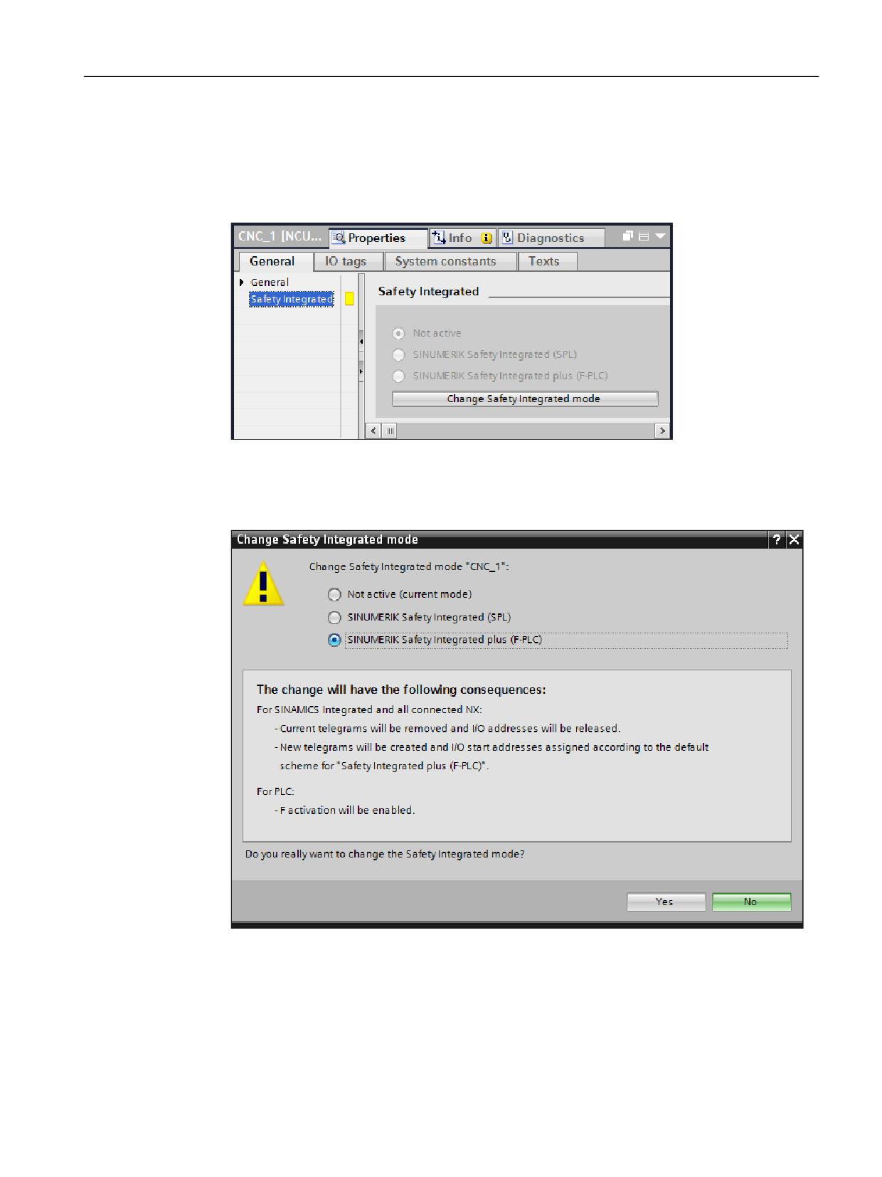
1. Click the NCU in the network or device view and select the "Safety Integrated" entry in the
"Properties" inspector window at "General".
Figure 7-1
Inspection window "Properties" - Safety Integrated
2. Click the "Change Safety Integrated mode" button.
The "Change Safety Integrated mode" dialog opens. If you select an option, the effects of
the mode change are performed here.
Figure 7-2
"Change Safety Integrated mode" dialog
3. Select the required Safety Integrated mode and confirm the reconfiguration with "Yes".
Result
The Safety Integrated mode has been changed.
Safety Integrated plus
Commissioning Manual, 12/2019, 6FC5397-1FP40-6BA3
215
Commissioning and configuring
7.2 Configuring safety-relevant components
If problems occur during the changeover, you can find further information in the "Info" inspector
window at "General".
Note
Effects on telegram configuration
The Safety Integrated mode affects the telegram configuration because, in the Safety
Integrated plus (F-PLC) mode, different telegrams are used than in the inactivated Safety
Integrated or the Safety Integrated modes.
Telegrams that are added or changed are kept, however, as long as they are compatible with
the newly selected Safety Integrated mode.
Make sure, if applicable, that any modifications are still present following the change of mode
in the telegram configuration (Page 255).
7.2.3
Configuring additional safety-related components
Basic procedure
After you have activated Safety Integrated plus, you can insert and configure optional F-I/Os as
well as fail-safe modules/submodules and telegrams.
You can find further information in the documentation for SIMATIC Safety.
7.2.4
Loading the configuration into the controller
If you have changed an existing hardware configuration, then you must first load the actual
configuration to the device. This ensures that the same configuration is set on the PG/PC and
the physical device itself.
Precondition
● The PLC is in the STOP operating state.
Note
Loading/stopping via TIA Portal only applies to PLC
Using the TIA Portal, you can stop and then restart the PLC before the loading. However,
the other subcomponents of the NCU are not stopped or started.
● A network connection exists between the PG/PC and the NCU.
Safety Integrated plus
216
Commissioning Manual, 12/2019, 6FC5397-1FP40-6BA3
Commissioning and configuring
7.2 Configuring safety-relevant components
Procedure
Proceed as follows to load the hardware configuration into the NCU:
1. In the project navigation, right-click on the NCU, and select command "Load to device >
Hardware configuration".
2. Make the following settings in the "Extended load" dialog:
- PG/PC interface: Network card used, e.g. "Intel[R] Ethernet Connection I217-V"
- Connection with interface/subnet: e.g. "Directly at slot '2 X120'
3. Click "Start search".
A search is made for the target devices, and they are displayed in the dialog.
4. Select the appropriate target device, e.g. based on the IP address, and confirm with "Load".
Note
If several F-CPUs can be accessed from a PG/PC via a network (e.g. Industrial Ethernet),
then carefully observe the notes in Manual SIMATIC Safety - Configuring and Programming
%20Safety&dtp=Manual&pnid=24471&lc=en-WW).
5. Check the information in the "Load preview" dialog and confirm with "Load".
6. In dialog "Load results" select whether the PLC should be restarted, and then confirm with
"Complete".
7.2.5
Allocating and assigning a PROFINET device name
Before a PROFINET IO device can be addressed by an I/O controller, it must have a device
name.
The assignment of a device name for a PROFINET IO device can be compared with setting the
PROFIBUS address of a DP slave.
Additional general information about PROFINET device names is provided in the TIA Portal
online help.
Precondition
● The PROFINET IO device can be accessed in the network.
Procedure
In order to assign a device name to a PROFINET IO device, proceed as follows:
1. Enter the required device name in the device properties in the field "Name".
2. Click in the network view, right-click on the device and select command "Assign name".
Safety Integrated plus
Commissioning Manual, 12/2019, 6FC5397-1FP40-6BA3
217
Commissioning and configuring
7.2 Configuring safety-relevant components
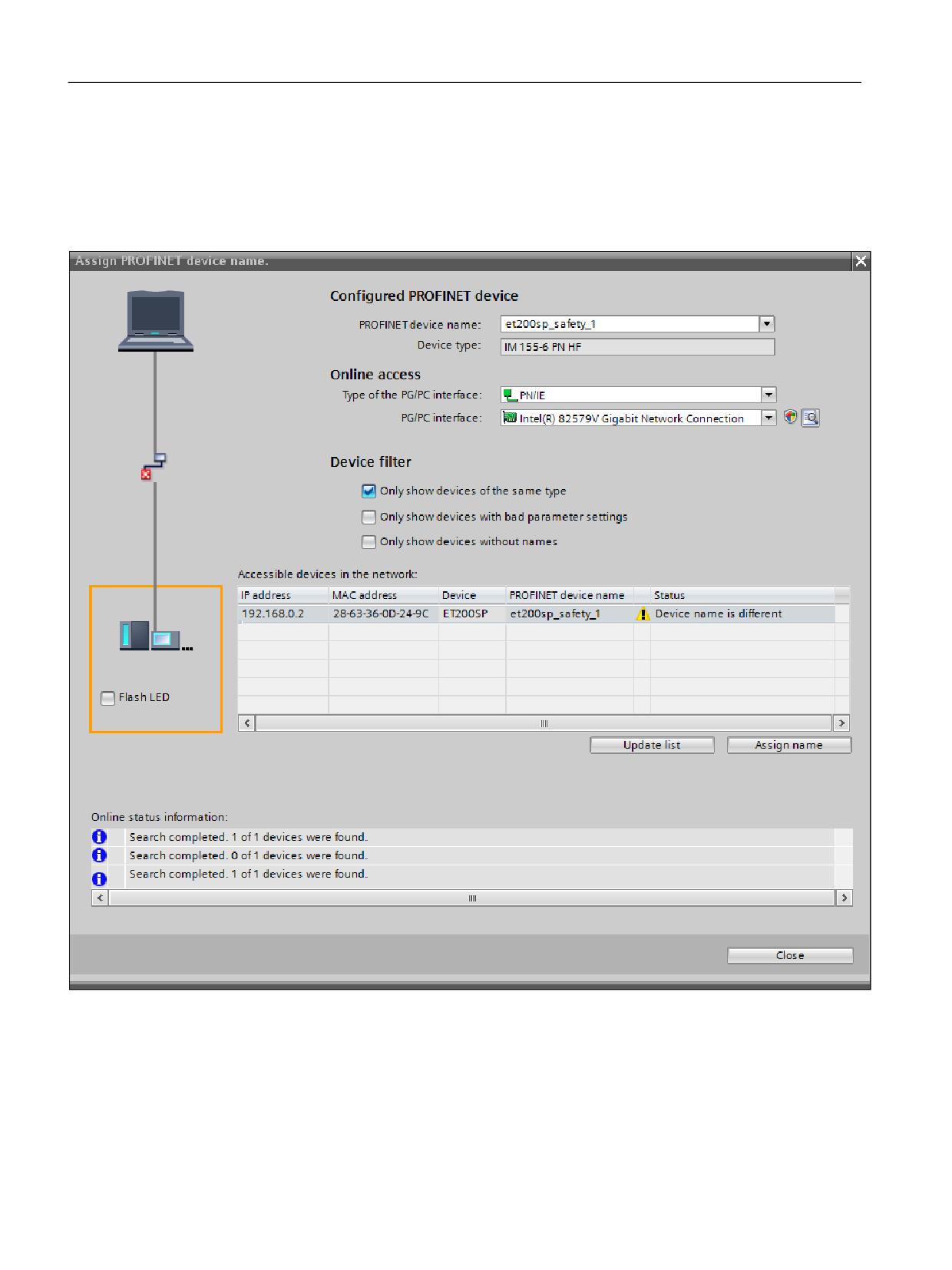
3. Make the following settings in the "Assign PROFINET device name" dialog:
- PG/PC interface type: PN/IE
- PG/PC interface: Network card used, e.g. "Intel(R) 82579V Gigabit Network Connection"
The list of accessible nodes is updated in the dialog.
Figure 7-3
Dialog "Assigning a PROFINET device name"
4. Select the appropriate target device, e.g. based on the device type and IP address, and
confirm with "Name".
Safety Integrated plus
218
Commissioning Manual, 12/2019, 6FC5397-1FP40-6BA3
Commissioning and configuring
7.2 Configuring safety-relevant components
7.2.6
Assigning F-destination addresses, address type 1
The F-destination addresses of the F-I/O of PROFIsafe address type 1 are generally assigned
using the DIL switch on the module. Information on how you can set the F-destination address
for F-I/O using DIL switches is provided in the documentation for the F-I/O.
Unique PROFIsafe addresses
To ensure safe communication, unique PROFIsafe addresses are required throughout the
CPU and the network.
The failsafe I/O of PROFIsafe address type 1 is uniquely addressed by its failsafe destination
address (e.g. using the position of the address switch) (see Chapter "Checking the PROFIsafe
address (Page 221)").
The F-destination address (and therefore also the setting at the address switch) of the F-I/O
must be unique for the entire F-I/O throughout the network and the CPU (system-wide). The F-
I/O of PROFIsafe address type 2 should be taken into account.
See the help for SIMATIC Safety at:
● DIL switch setting
● Special considerations when configuring the F-system
● Recommendation for allocating PROFIsafe addresses
● PROFIsafe addresses for F-I/O of PROFIsafe address type 1
● Configurations supported by the SIMATIC Safety F-safety
● Completeness and correctness of the hardware configuration
7.2.7
Assigning F-destination addresses, address type 2
For the F-I/O of PROFIsafe address type 2, you can adapt the F-destination address in the
module properties - and then use command "Assign F-destination address".
As an alternative to this procedure, you can use the F-IO Connect commissioning software:
SINUMERIK F-IO Connect in SIOS (http://support.industry.siemens.com/cs/document/
109744986/)
Unique PROFIsafe addresses
To ensure safe communication, unique PROFIsafe addresses are required throughout the
CPU and the network.
F-I/O of PROFIsafe address type 2 is uniquely addressed using a combination of F-source
address ("Basis for PROFIsafe addresses of the assigned F-CPU" parameter) and F-
destination address.
The combination of F-source address and F-destination address for each F-I/O must be unique
throughout the network and CPU (system-wide). In addition, the F-destination address must
not be occupied by F-I/O of PROFIsafe address type 1.
To ensure that addresses are unique across F-CPUs for supported configurations, you must
ensure that the parameter "Basis for PROFIsafe addresses" is unique for all F-CPUs in the
Safety Integrated plus
Commissioning Manual, 12/2019, 6FC5397-1FP40-6BA3
219
Commissioning and configuring
7.2 Configuring safety-relevant components
network*. This is achieved by having different settings for the "Basis for PROFIsafe addresses"
parameter of the F-CPUs.
See the help for SIMATIC Safety at:
● Special considerations when configuring the F-system
● Recommendation for allocating PROFIsafe addresses
● PROFIsafe addresses for F-I/O, PROFIsafe address type 2
● Configurations supported by the SIMATIC Safety F-safety
● Completeness and correctness of the hardware configuration
Precondition
● The F-I/O device can be accessed in the network.
● A device name has been assigned to the F-I/O.
● The hardware configuration has been loaded to the device.
Procedure
Proceed as follows, to assign the configured F-destination address to F-I/O, PROFIsafe
address type 2:
1. Click in the network view, right-click on the F-I/O device and click on "Assign F-destination
address".
2. Make the following settings in the "Extended load" dialog:
- PG/PC interface type: PN/IE
- PG/PC interface: Network card used, e.g. "Intel[R] Ethernet Connection I217-V"
- Connection with interface/subnet: Directly at slot '1 X150'
3. Under "Identification" select how you wish to identify the F-modules:
- "By flashing the LEDs"
This is the default setting. During identification, the STATUS LEDs of the F-modules to
be identified flash.
- "Using the serial number"
If you cannot see the F-modules clearly, you can identify them by the serial number of the
interface module.
Note
The displayed serial number may have a year number added to it compared with the
serial number printed on the interface module. The serial numbers are nevertheless
identical.
4. In column "Assign" select all F-modules where you wish to assign an F-destination address.
Safety Integrated plus
220
Commissioning Manual, 12/2019, 6FC5397-1FP40-6BA3
Commissioning and configuring
7.2 Configuring safety-relevant components
5. Click the "Identification" button.
- If you have selected LED flashing for the identification type, then check whether the
status LEDs of that F-module flash green whose F-destination address you wish to
assign.
- If you have selected the serial number for the identification type, compare the displayed
serial number with the serial number of the module.
6. Confirm successfully identified F-modules in the "Confirm" column of the table.
7. Using button "Assign F-destination address" assign the configured F-destination addresses
to the F-modules, and confirm dialog "Acknowledge assignment" (within 60 seconds).
8. Close the dialog.
7.2.8
Checking the PROFIsafe address
To ensure safe communication, unique PROFIsafe addresses are required throughout the
CPU and the network. For this reason, it is also necessary that you check the settings of the
PROFIsafe addresses carefully.
WARNING
Incorrect assignment of the safety functions of an axis
An incorrect assignment of a (valid) F-address results in an incorrect assignment of the safety
functions to the corresponding axis. The system does not identify this incorrect assignment (in
the CPU and in the network). As a consequence, the safety functions can act in a way that was
not intended, which in turn can result in death and serious injury.
● Uniquely address the F-destination address of the F-I/O of PROFIsafe address type 1.
● Ensure that the F-destination address of the F-I/O (the drive units in this case) is unique for
the entire failsafe I/O throughout the network and the CPU (system-wide). When doing this,
also take into account the F-I/O of PROFIsafe address type 2, e.g. modules of the ET
200SP type.
● Note also the corresponding documentation in the TIA Portal online help in the section
"SIMATIC Safety - Configuration and programming".
During compilation of the safety program, a warning indicates the importance of unique
PROFIsafe addresses:
Safety Integrated plus
Commissioning Manual, 12/2019, 6FC5397-1FP40-6BA3
221
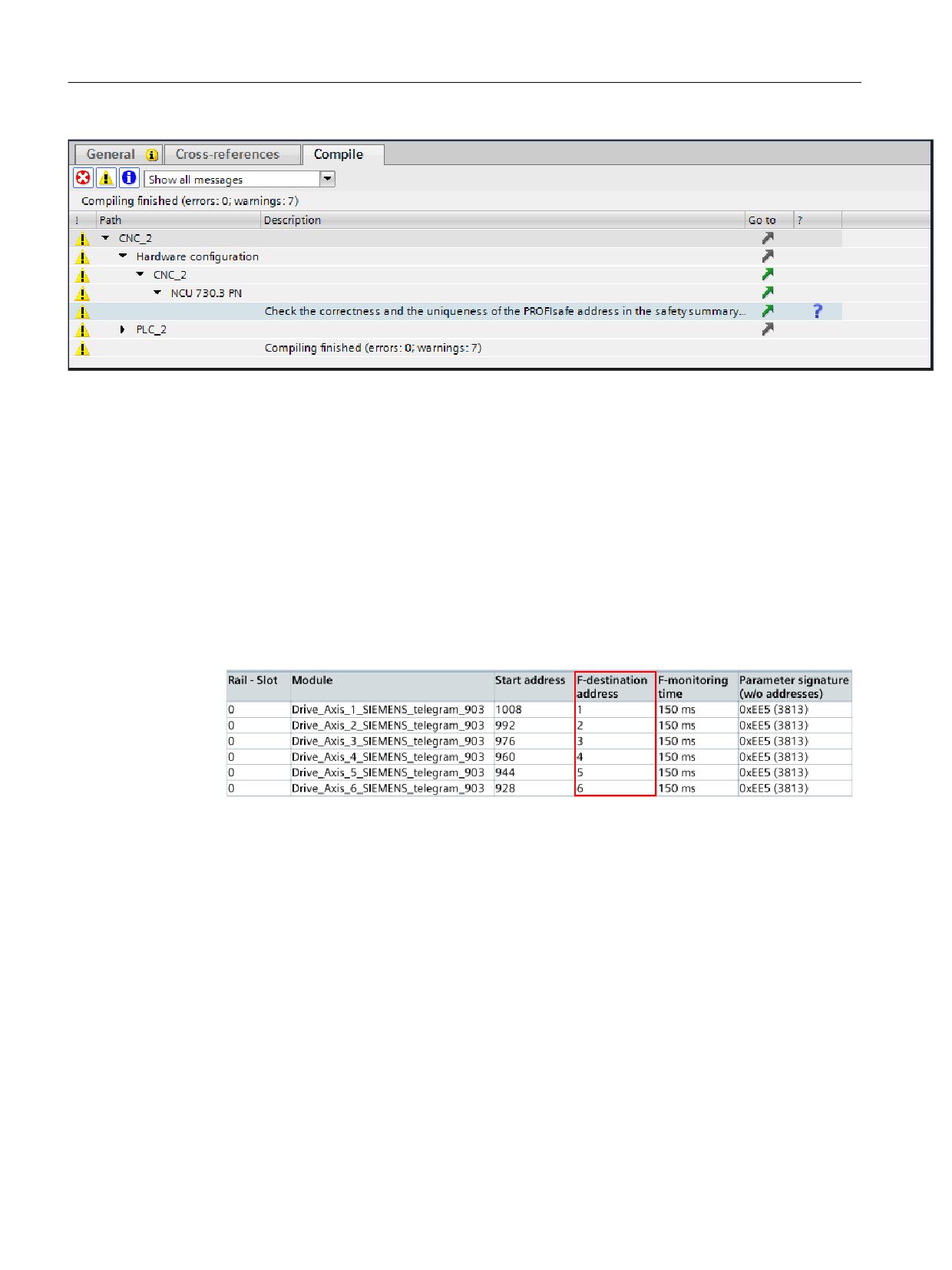
Commissioning and configuring
7.2 Configuring safety-relevant components
Figure 7-4
Warning when compiling the safety program
Precondition
● F-destination addresses have been configured and assigned.
● Hardware and software have been compiled.
Procedure
Proceed as follows to check PROFIsafe addresses:
1. Right-click on "Safety Administration > Print", select a printer or a PDF application and
confirm with "OK".
The safety printout is generated.
Figure 7-5
F-target addresses of SINAMICS Safety Integrated drive objects in the safety printout
(example)
2. Check the PROFIsafe addresses listed in the safety printout:
- Compare the F-target addresses of the drive objects of SINAMICS Safety Integrated and
NX modules with the values of the p9610 drive parameter
- In the safety printout compare the F-destination addresses of the individual modules with
those of all other modules or participants, and ensure that the addresses are unique.
Safety Integrated plus
222
Commissioning Manual, 12/2019, 6FC5397-1FP40-6BA3
Commissioning and configuring
7.3 Generating a safety program
7.3
Generating a safety program
7.3.1
Overview
Precondition
● Safety Integrated plus (F-PLC) is active.
● The F-components have been configured and parameterized.
Example of a handling overview
Step
Description
1
Create receive/send data as PLC tags (Page 223)
2
Adapting the settings of the F-runtime group (optional) (Page 225)
3
Setting up access protection (Page 226)
4
Parameterizing EMERGENCY STOP (Page 227)
5
Implementing user acknowledgment for global reintegration (Page 228)
6
Acknowledging messages related to safety functions integrated in the drive (Page 230)
7
Deselecting safety functions integrated in the drive (Page 233)
8
Initiate a forced checking procedure (test stop) (Page 235)
9
Programming the wiring test (Page 235)
7.3.2
Create receive/send data as PLC tags
In order that you can access the required drive data symbolically in the safety program, in the
TIA Portal create PLC tags with the corresponding drive addresses.
You can create all the PLC tags required before you start programming - or you can always add
your PLC tags if you wish to access new drive data. If you address the drive data with absolute
values instead, tag names are automatically assigned that are subsequently difficult to
comprehend.
You can import or export PLC tags in the XLSX, SDF or XML formats. You can copy PLC tag
tables as copy templates in global libraries.
Procedure
Proceed as follows to create PLC tag tables with the required drive data.
1. In the project navigation, double-click below "PLC tags " on "Add new tag table", e.g.
"CNC_1 > PLC_1 > PLC tags > Add new tag table".
2. Right-click on the new tag table, select "Rename" and assign a name, e.g. "Safety status
data" or "Safety control data".
Safety Integrated plus
Commissioning Manual, 12/2019, 6FC5397-1FP40-6BA3
223
Commissioning and configuring
7.3 Generating a safety program
3. Double-click on the new tag table to open it.
4. In the "Name" column, click on "Add" and enter the tag properties:
Property
Meaning
Name
Enter a meaningful name, e.g. <drive name>-<process data>-<where relevant,
bit identifier>.
Example 1: drive1SpValid
Example 2: drive2SlsLimitA
Data type
Specify with which data type the process data is addressed.
● Bool: S_STW1, S_ZSW1, S_STW2, S_ZSW2, S_ZSW_CAM1
● Int: S_SLS_LIMIT_A, S_SLS_LIMIT_A_ACTIVE, S_CYCLE_COUNT,
S_XIST16
● DInt: S_XIST32
Example 1: Bool
Example 2: Int
Address
In the "Address" column, click on the drop-down list symbol - and enter the
properties:
Address identifier
Status/input data: I
Control/output data: Q
Address
Enter the I/O address to which the specific process data is transferred.
This is obtained from the telegram start address and the PZD range within the
telegram, where the process data starts.
● You can see the start address for a specific drive telegram in the telegram
configuring of SINAMICS Safety Integrated. The standard start addresses
are also listed in Tables (Page 345).
● Refer to the telegram structure (Page 348) to identify in which PZD range (1
PZD = 1 word = 2 byte) within the telegram the required drive data is con-
tained.
Bit number
For data type "Bool" - or if you address a bit - then in addition, specify the bit
number that you take from the process data description (Page 351).
Example 1: %I1010.6
Example 2: %QW996
Comment
Optionally, you can formulate a user-defined note for each tag that is added - or
take this from the manual.
Safety Integrated plus
224
Commissioning Manual, 12/2019, 6FC5397-1FP40-6BA3
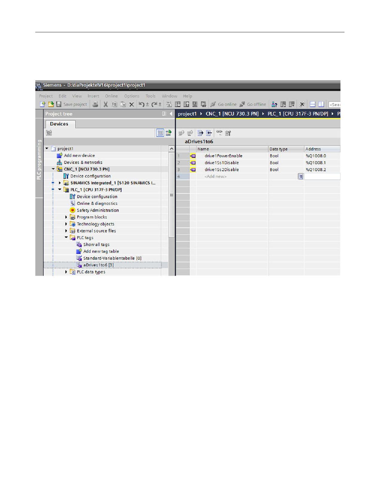
Commissioning and configuring
7.3 Generating a safety program
Result
The PLC tags were added.
Figure 7-6
Example of a user-defined tag table, with the drive addresses required in the programming
7.3.3
Adapting the settings of the F-runtime group (optional)
An F-runtime group is automatically created when you activate the Safety Integrated plus (F-
PLC) mode. The associated F-blocks are provided in folder "Program blocks" - or in the Safety
Administration Editor under "F-blocks":
● CYC_INT5[OB35]
● Main_Safety[FB1010]
● Main_Safety_DB[DB1010]
You can adapt the default settings of the F-runtime group and the associated blocks, as
described here.
Optionally, you can also create a second F-runtime group; for example, to organize safety-
relevant program sections that are executed quickly, in their own dedicated F-runtime group.
Precondition
● Safety Integrated plus (F-PLC) is active.
Safety Integrated plus
Commissioning Manual, 12/2019, 6FC5397-1FP40-6BA3
225
Commissioning and configuring
7.3 Generating a safety program
Procedure
Proceed as follows to view the settings of an F-runtime group - or to adapt them:
1. In the project navigation, double-click below the PLC involved on "Safety Administration",
e.g. "CNC_1 > PLC_1 > Safety Administration".
2. In the Safety Administration Editor switch to "F-runtime group".
3. If necessary, adapt the following settings.
Setting
Purpose
Calling block
Per default setting, CYC_INT5_RTG1[OB35] is set. This block is a
cyclic interrupt OB, which means that within an execution time, the
safety program is called at fixed intervals in time.
In the drop-down list you can define a block other than the calling block:
● If you select an LAD, FBD or STL block, then the call in the block is
automatically updated.
● If you select a block in another programming language, then you
must adapt the call yourself.
Main safety block
Default setting: Main_Safety_RTG1[FB1010]
In the drop-down list you can select a block other than the previously
created F-block.
The following main safety block numbers are intended for SINUMERIK
Safety Integrated plus: 1010..1019.
I-DB for the main safety
Default setting: Main_Safety_RTG1_DB[DB1010]
block
If the main safety block is an FB, then in the drop-down list you can
adapt the associated I-DB.
The following I-DB block numbers are intended for SINUMERIK Safety
Integrated plus: 1010..1019.
Execution time of the call-
If, as executing block, you use a cyclic interrupt OB 3x, then the para-
ing block
meterized execution time is displayed here.
You can change this execution time in the properties of the PLC under
"Alarms > Cyclic interrupts".
Maximum cycle time of the
The F-CPU monitors the F-cycle time in the F-runtime group.
F-runtime group
For "Maximum cycle time of the F-runtime group", select the maximum
time that may elapse between two calls of this F-runtime group.
DB for F-runtime group
If one F-runtime group is to provide tags for evaluation to another F-
communication
runtime group of the safety program, assign a DB for F-runtime group
communication.
Additional information is provided in the help for SIMATIC Safety under
"Safety-related communication between the F-runtime groups".
7.3.4
Setting up access protection
In productive operation, it is absolutely crucial that an F-system is provided with access
protection.
For test purposes, commissioning etc., initially access protection is not required; this means
that you can execute all offline and online actions without access protection, i.e. without a
password prompt.
Safety Integrated plus
226
Commissioning Manual, 12/2019, 6FC5397-1FP40-6BA3
Commissioning and configuring
7.3 Generating a safety program
In the safety mode, when changing the standard user program it is not permissible that access
authorization exists based on the CPU password - as in this case, the safety program can also
be changed. To rule this out, you must configure protection level "Write protection for failsafe
blocks" - and a password for the F-CPU. If only one person is authorized to change both the
standard user program and the safety program, then the protection level "Write protection"or
"Read/write protection" should be configured so that other persons are only given a restricted
or no access to the complete user program (standard and safety program). (S001)
For additional information, refer to the "Access protection" chapter in the SIMATIC Safety -
Configuring and Programming (https://support.industry.siemens.com/cs/products?
search=SIMATIC%20Safety&dtp=Manual&pnid=24471) manual.
Procedure
To set up access protection for productive operation, follow these steps:
1. In the project navigation, double-click below the PLC involved on "Safety Administration",
e.g. "CNC_1 > PLC_1 > Safety Administration".
2. In the Safety Administration Editor switch to "Access protection".
3. Assign passwords for the two access protection types:
- Under "Offline safety program protection", click on "Setup", assign a password and
confirm with OK.
- Under "F-CPU access protection", click the link "Go to the "Protection" area of the F-
CPU".
Select the setting "Write protection for fail-safe blocks" in the called properties and
assign the "Password for write/read access".
4. Load the hardware and software to the device.
Result
Two different access protection types are setup:
● Protection of the safety program
● Protection of the F-CPU
7.3.5
Parameterizing EMERGENCY STOP
The operation "ESTOP1" implements an EMERGENCY STOP shutdown with
acknowledgment for stop Category 0 and 1.
Procedure
Proceed as follows to program an EMERGENCY STOP shutdown:
1. Open the F-block involved.
2. From the task card "Instructions", insert operation "Basic instructions > Safety functions >
ESTOP1".
Safety Integrated plus
Commissioning Manual, 12/2019, 6FC5397-1FP40-6BA3
227
Commissioning and configuring
7.3 Generating a safety program
3. Parameterize the inputs and outputs of the instruction.
Parameters
Declaration
Description
E_STOP
Input
EMERGENCY STOP/EMERGENCY OFF
ACK_NEC
1= acknowledgment required
ACK
1=acknowledgment
TIME_DEL
Delay time
Q
Output
1=enable
Q_DELAY
Enabling of the OFF delay for F-I/O
The enabling signal Q_DELAY is reset to 0 after the delay time has
been set at the TIME_DEL input.
Do not use Q_DELAY for drive components, however, but instead
use the corresponding settings of the relevant drive-integrated safety
function.
ACK_REQ
1= acknowledgment required
DIAG
Non failsafe service information
4. Link the F-DOs for the I/O shutdown or the safety function in the specific drive with the
outputs.
Further information
You can find more information about the instruction in the online help for the instruction or in the
manual for SIMATIC Safety.
7.3.6
Implementing user acknowledgment for global reintegration
If an F-I/O error is detected by the fail-safe system, the affected F-I/O and/or drive components
are passivated.
With the passivation of a failsafe component, for the components involved, substitute values
are provided or are transferred instead of the active process values or output values.
After resolving the cause of the fault, the component involved must be reintegrated, i.e. a
switchover from substitute values to process values or output values.
Safety Integrated plus
228
Commissioning Manual, 12/2019, 6FC5397-1FP40-6BA3
Commissioning and configuring
7.3 Generating a safety program
Depending on the fault type or the component, in which the fault occurs, you can set passivation
and reintegration differently:
Fault type
Passivation
Reintegration
Communication
All channels of the module
After a communication error, user acknowledg-
ment is always required.
F-I/O
dependent on the F-I/O DB parameter:
or Drive
● ACK_NEC=1:
Channel
Depending on F-parameter "Be-
user acknowledgment required
havior after channel fault" of the
● ACK_NEC=0
module:
automatic reintegration
● Passivation of the channel
● Passivation of the complete
module
You implement reintegration after user acknowledgment by interconnecting the signal,
generated by the operator action, with one of the following parameters:
● F-I/O DB parameter "ACK_REI": Reintegration of the corresponding module (all channels)
● Operation "ACK_GL" (parameter "ACK_GLOB"): Reintegration of all modules of a F-
runtime group
Safety Integrated plus
Commissioning Manual, 12/2019, 6FC5397-1FP40-6BA3
229
Commissioning and configuring
7.3 Generating a safety program
Procedure
Proceed as follows to implement a user acknowledgment for global reintegration:
1.
Insert operation "ACK_GL" in that F-runtime group, whose F-I/O should be globally
acknowledged by the user acknowledgment.
2.
In operation "ACK_GL", assign input "ACK_GLOB" to the input of the acknowledgment
button.
3.
If necessary, carry out the optional steps:
Setting
Procedure
Evaluation of the acknowl-
You can evaluate the F-I/O DB tag "ACK_REQ" in the standard user
edgment request
program or on an operation and monitoring system, to interrogate as
to whether a user acknowledgment is required.
● ACK_REQ = 0: No acknowledgment request
● ACK_REQ = 1: Acknowledgment request for reintegration (this is
set by the F-system after the fault has been resolved)
Controlling a signal light or
In the case of a fault, you can control a signal light and/or output
output of a signal
messages/signals in the standard user program, by evaluating the
following:
● F-I/O DB tags:
- QBAD
- QBAD_I_xx/QBAD_O_xx
- DIAG
● Diagnostics buffer of the F-PLC
Automatic or manual reinte-
You can parameterize the F-I/O DB tag "ACK_NEC" if, after an F-I/O/
gration for F-I/O/channel
channel fault, automatic reintegration should take place without user
faults
acknowledgment.
● ACK_NEC = 1 (start value): User acknowledgment required
● ACK_NEC = 0: Automatic reintegration
A user acknowledgment is always required after a communication
error.
Parameterizing tags ACK_NEC = 0 is only permitted, if, from a safety-relevant perspective
automatic reintegration is permissible for the process involved. (S010)
7.3.7
Acknowledging messages related to safety functions integrated in the drive
You program PROFIsafe acknowledgment in the safety program of the F-PLC by setting the
"Internal Event ACK" signal - separately for each drive object - via the PROFIsafe telegram
(S_STW1/S_STW2 bit 7).
Safety messages cannot be acknowledged collectively by the F-PLC, but instead have to be
individually acknowledged for each drive object. A falling edge of the "Internal Event ACK"
signal resets the status "Internal Event" in the particular drive, and thus acknowledges the fault.
Safety Integrated plus
230
Commissioning Manual, 12/2019, 6FC5397-1FP40-6BA3
Commissioning and configuring
7.3 Generating a safety program
In the safety program, logically combine all channel reset signals of channels that contain drive
objects with safety functions, with the "Internal Event ACK" signal for each drive object involved.
WARNING
Unexpected restart for safety-related acknowledgment without MCP reset!
If a STOP response is acknowledged in a safety-related fashion by the machine operator, but
without PROFIdrive RESET acknowledgment, then the part program is not canceled and is
continued with the acknowledgment. When the machine restarts unexpectedly, this can put
people in dangerous situations or cause material damage.
● In the safety program logically combine safe acknowledgment (PROFIsafe IEACK) with a
RESET at the machine control panel (PROFIdrive RESET).
Precondition
● PLC tags for the "Internal Event ACK" signal are added (Page 223) for each drive object.
Safety Integrated plus
Commissioning Manual, 12/2019, 6FC5397-1FP40-6BA3
231
Commissioning and configuring
7.3 Generating a safety program
Procedure
In order to logically combine the reset signal of the machine control panel with the safety-
relevant acknowledgment in the safety program for a channel, proceed as follows:
1. Open the corresponding F-runtime group, e.g. Main_Safety_RTG1[FB1010].
2. Insert a new network, in which you logically combine the signals:
1
2
&KDQ
!
'2!B
$B5HVHW
,17(51$/B
(9(17B$&.
'2!B
,17(51$/B
(9(17B$&.
3
3a
No Instruction/variable
Purpose/procedure
(1)
---| |---NO contact:
The channel reset must be active, i.e. the interface signal in the
"<Channel DB name>".A_Re-
corresponding channel DB must be 1.
set
(2)
---( )--- Assignment
Assign the logic operation result to the corresponding PLC tag,
that you created for the "Internal Event ACK" signal of the ap-
propriate drive.
<PLC tag>
Example:
"drive1InternalEventAck"
(3) Branch
If you are using several safety-relevant drive objects, for each
drive object insert a branch together with the operation (see
3a).
(3a
---( )--- Assignment
Assign the logic operation result to the corresponding PLC tag.
)
<PLC tag>
Example:
"drive2InternalEventAck"
Figure 7-7
Inserting a new network
Result
The channel reset signal of the channel involved was logically combined with the safety-
relevant acknowledgment of faults in the individual drive objects.
Safety Integrated plus
232
Commissioning Manual, 12/2019, 6FC5397-1FP40-6BA3
Commissioning and configuring
7.3 Generating a safety program
7.3.8
Deselecting safety functions integrated in the drive
You deselect safety functions integrated in the drive by accessing the corresponding drive
addresses in the safety program and then set/reset the relevant bits.
Precondition
● PLC tags for the signals required have been added (Page 223).
Safety Integrated plus
Commissioning Manual, 12/2019, 6FC5397-1FP40-6BA3
233
Commissioning and configuring
7.3 Generating a safety program
Procedure
Proceed as follows to select or deselect a safety function integrated in the drive in the safety
program:
1. Open the F-block, e.g. Main_Safety_RTG1 [FB1010].
2. Insert a new network, and in the network, link (logically combine) the signals:
1
2
'HVHOHFWLRQB
'5B 1U !B
6LFKHUKHLWV
6LFKHUKHLWV
IXQNWLRQ!
IXQNWLRQ!
'5B 1U !B
6LFKHUKHLWV
IXQNWLRQ!
3
3a
No Instruction/variable
Purpose/procedure
(1)
---| |---NO contact:
Address the PLC tag "Deselection_<safety function>" or the
"Deselection_<safety func-
drive I/O address, which transfers the associated bit of the safety
tion>"
control word.
Example: "deselectionSs1"
or
Drive I/O address with ZSW
bit
(2)
---( )--- Assignment:
Assign the logic operation result to the safety function in the drive
"DR_<drive num-
involved.
ber>_<safety function>"
Example: "drive1Ss1Disa-
ble"
or
Drive I/O address with STW
bit
(3) Branch
If you deselect the safety function involved for several drives,
insert a branch and operation for each drive (see 3a).
(3a
---( )--- Assignment:
Assign the logic operation result to the safety function in the drive
) "DR_<drive num-
involved.
ber>_<safety function>"
Example: "drive2Ss1Disa-
ble"
or
Drive I/O address with ZSW
bit
Figure 7-8
Inserting a new network
Safety Integrated plus
234
Commissioning Manual, 12/2019, 6FC5397-1FP40-6BA3
Commissioning and configuring
7.3 Generating a safety program
7.3.9
Initiate a forced checking procedure (test stop)
Basic procedure
Functions and switch-off signal paths must be regularly tested using the forced checking
procedure (test stop). The forced checking procedure should be performed each time that the
control system runs up and must, however, be performed at least once a year.
The forced checking procedure is not performed in the safety program but in the standard PLC
program. This means that you insert the affected program code in your PLC user program in
order to trigger the forced check procedure during run-up of the controller.
7.3.10
Programming the wiring test
Basic procedure
You must program a wiring test in order that your F-I/O devices can be correctly addressed. For
the wiring test, use a tag QBAD of the F-I/O DB of the corresponding F-I/O. You can perform
a wiring test jointly for all F-I/O modules of an F-runtime group.
Therefore, configure the F-I/O in such a way that the modules themselves perform the test.
Further information
Further information may be found in the SIMATIC Safety manual.
Safety Integrated plus
Commissioning Manual, 12/2019, 6FC5397-1FP40-6BA3
235
Commissioning and configuring
7.4 Loading the configuration
7.4
Loading the configuration
7.4.1
Loading the configuration to the NCU
Precondition
● There is a network connection between the configuring PG/PC and SINUMERIK 840D sl.
Procedure
Proceed as follows to load the hardware and software configuration into the SINUMERIK 840D
sl:
1. In the project navigation, right-click the NCU and select the "Load to device > Hardware and
software (only changes)" command.
2. Make the following settings in the "Extended load" dialog:
- PG/PC interface: Network card used, e.g. "Intel(R) 82579V Gigabit Network Connection"
- Connection with interface/subnet: "PN/IE_2"
Safety Integrated plus
236
Commissioning Manual, 12/2019, 6FC5397-1FP40-6BA3
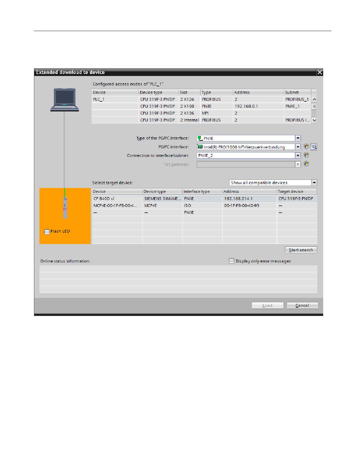
Commissioning and configuring
7.4 Loading the configuration
3. Click "Start search".
A search is made for the target devices, and they are displayed in the dialog.
Figure 7-9
"Extended download" dialog
4. Select the appropriate target device, e.g. based on the IP address, and confirm with "Load".
5. Check the information in the "Load preview" dialog and confirm with "Load".
6. In the "Results of the load procedure" dialog, select whether the PLC should be restarted,
and then confirm with "Complete".
7.4.2
Transferring the safety mode from the configuration
Precondition
● The configuration has been loaded (Page 236).
Safety Integrated plus
Commissioning Manual, 12/2019, 6FC5397-1FP40-6BA3
237
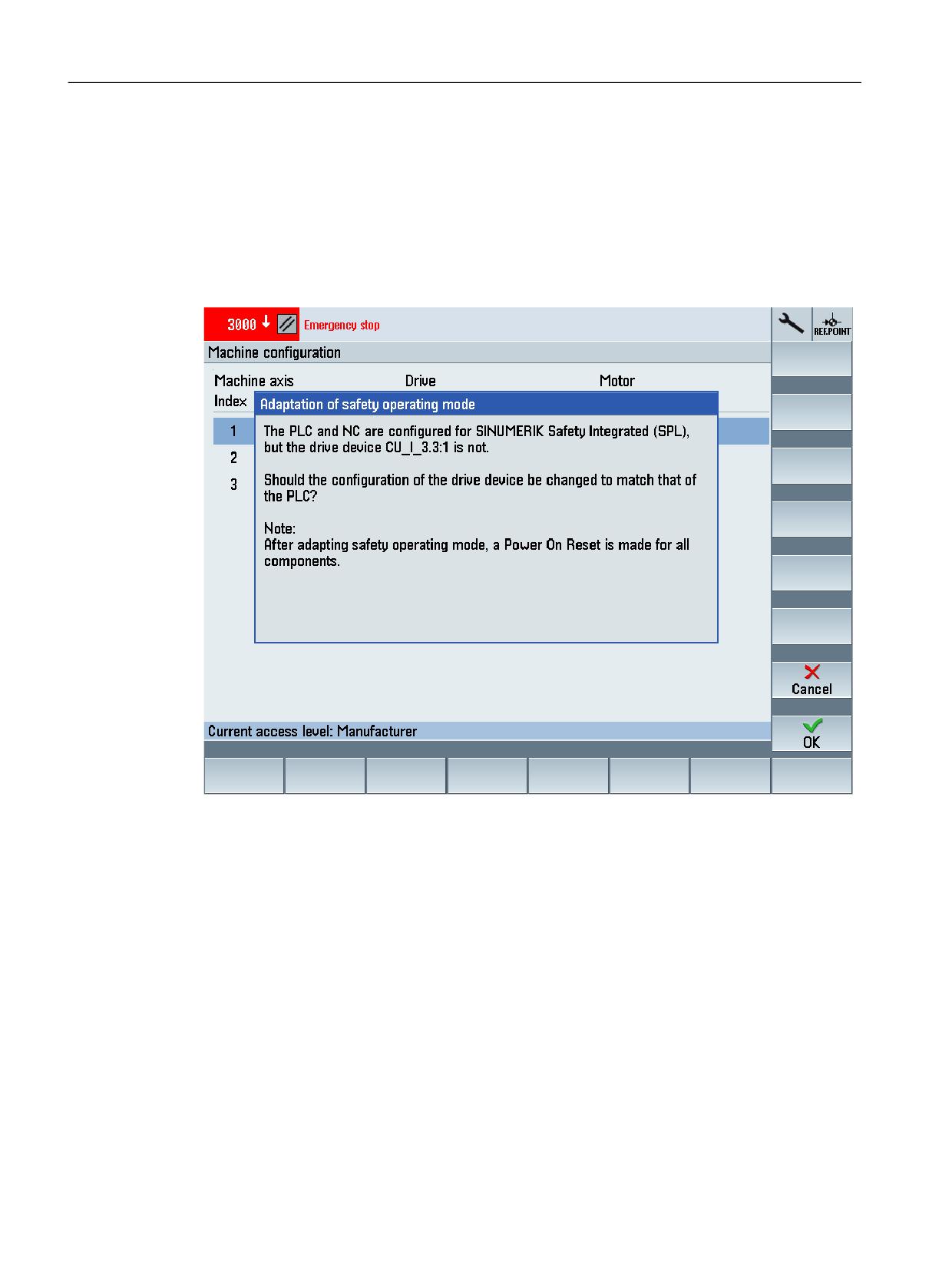
Commissioning and configuring
7.4 Loading the configuration
Procedure
To apply the safety mode in SINUMERIK Operate, proceed as follows:
1. In SINUMERIK Operate, switch to the commissioning area (start-up area) using "MENU
SELECT > Commissioning".
2. Press the "Reset (po)" softkey and confirm with "Yes".
The NCU is restarted, and the "Adaptation of safety operating mode" dialog is then
displayed.
3. Confirm the adaption of the safety mode with "OK".
Safety Integrated plus
238
Commissioning Manual, 12/2019, 6FC5397-1FP40-6BA3
Commissioning and configuring
7.5 Configuring NC and drive-specific safety settings
7.5
Configuring NC and drive-specific safety settings
7.5.1
Overview
Higher-level safety settings are described in this chapter, which you specifically configure for
each drive.
Requirement
● Access rights of access level 2 (service) are available in SINUMERIK Operate.
● The commissioning of the (non-safety-related) default drive functions has been completed.
● The configuration (hardware and software) is loaded in the NCU (Page 236).
● The transfer of the Safety Integrated mode from the configuration has been completed.
(Page 237)
Example handling overview
Step
Description
1
Setting software options (Page 240)
2
Activating the safety commissioning mode (Page 240)
3
Selecting the safety functional scope (Page 242)
4
Parameterizing the setpoint speed limiting (Page 243)
5
Parameterizing reaction of the stop response (Page 245)
6
Parameterizing an encoder (Page 246) or Configuring encoderless operation (Page 250)
7
Configuring telegrams (Page 255)
8
Configuring the message buffer and alarm buffer (Page 325)
Safety Integrated plus
Commissioning Manual, 12/2019, 6FC5397-1FP40-6BA3
239
Commissioning and configuring
7.5 Configuring NC and drive-specific safety settings
7.5.2
Setting software options
Procedure
Proceed as follows to set the software options for Safety Integrated plus:
1. In SINUMERIK Operate switch to licensing via "MENU SELECT > Commissioning > Menu
forward key > Licenses".
2. Press softkey "All options".
3. Set the safety software options required for your particular machine configuration:
Software option
Article No.
Purpose
SINUMERIK 840D sl
6FC5800-0AS60-0YB
Activate the F-PLC in SINUMERIK 840D sl in
0
order to process the failsafe sensors and ac-
Safety Integrated plus
tuators in an F-program.
/SI logic
SINUMERIK 840D sl
6FC5800-0AK00-0YB
Use the motion control functions of the SINAM-
Safety Integrated plus
0
ICS Safety Integrated in the SINUMERIK Safe-
/ SI axis/spindle
ty Integrated plus (F-PLC) mode.
License for 1 axis/spindle, multiple licensing in
order to be able to use additional axes/spin-
dles.
SINUMERIK 840D sl
6FC5800-0AS61-0YB
Use the motion control functions of the SINAM-
Safety Integrated plus
0
ICS Safety Integrated in the SINUMERIK Safe-
/SI multi-axis package
ty Integrated plus (F-PLC) mode.
License for any number of axes/spindles.
Result
The software options were set.
The individual software options to be licensed for the machine can be displayed using softkey
"Missing licenses/options", which you can then order, e.g. through the Siemens Industry Mall.
See also
Licensing axes/spindles and F-PLC (Page 39)
7.5.3
Activating the safety commissioning mode
Changes to the safety-relevant drive parameterization are only possible if the corresponding
drive is in the Safety Integrated commissioning mode. After parameterization, the Safety
Integrated commissioning mode must be deactivated and the actual checksums must be
transferred into the reference checksums.
Safety Integrated plus
240
Commissioning Manual, 12/2019, 6FC5397-1FP40-6BA3