SINUMERIK 840D sl. Service - Configuring Commissioning. Manual (2011-2020) - page 87

Fundamentals
3.6 Hardware components
If motors without a (safety-capable) encoder are being used, not all Safety Integrated Functions
can be used.
Note
Definition: "Without encoder"
When "without encoder" is used in this manual, then this always means that either no encoder
or no safety-capable encoder is being used.
In operation without encoder the actual speed values are calculated from the measured
electrical actual values. Therefore, speed monitoring is also possible during operation without
encoder.
The configuration of the Safety Integrated Functions - and the selection of monitoring with or
without encoder is realized in the commissioning area of SINUMERIK Operate (Page 258).
The safety functions integrated in the drive that are actually supported depends on the drive
components used (drive and axis type, and whether a safety-relevant encoder is used).
Table 3-7
Safety functions in operation with or without encoder
Function
Basic
Extended
HLA
Electric drive
Brief description
With
With-
encod-
out en-
er
coder
STO/SS1 Basic
x
-
x3
x
x1
Safe Torque Off / Safe Stop according to
Stop Category 1 of DIN EN 60204-1.
Safe Torque Off / Safe Stop 1
STO Extended
-
x
x3
x
x1
Safe Torque Off
Safe Torque Off
SBC
x
x
-
x
x1
Safe brake control
Safe Brake Control
SS1 Extended
-
x
x3
x
x1
Safe Stop according to Stop Category 1 of
DIN EN 60204-1.
Safe Stop 1
SOS
-
x
x3
x
-
Safe monitoring of the standstill position
Safe Operating Stop
SS2
-
x
x3
x
-
Safe stopping process in accordance with
stop Category 2
Safe Stop 2
SS2E
-
x
x3
x
x1
SS2 with external stop
SS2 with external stop
SS2ESR
-
x
x3
x
x1
Safe Stop 2 Extended Stop and Retract
Safe Stop 2 Extended Stop and
Retract
SLS
-
x
x3
x
x1
Safely-Limited Speed
Safely-Limited Speed
SSM
-
x
x3
x
x1
Safe Speed Monitoring
Safe Speed Monitor
SAM
-
x
-
x
x1, 2
Safe Acceleration Monitoring
Safe Acceleration Monitor
Safety Integrated plus
Commissioning Manual, 12/2019, 6FC5397-1FP40-6BA3
35

Fundamentals
3.6 Hardware components
Function
Basic
Extended
HLA
Electric drive
Brief description
With
With-
encod-
out en-
er
coder
SBR
-
x
-
x
x1
Safe brake ramp monitoring
Safe Brake Ramp
SDI
-
x
x3
x
x1
Safe motion direction
Safe Direction
SLP/SP
-
x
x3
x
x1
Safely-Limited Position/Safe Position
Safely-Limited Position /
Safe Position
SBT
-
x
-
x
-
Safe Brake Test
Safe Brake Test
SCA
-
x
x
x
-
Safe Cam
Safe Cam
¹ Safety operation without encoder is only supported for spindles equipped with induction
motors, see also Table Supported axis types as a function of the drive type and the use of a
safety-relevant encoder (Page 34).
² Only for the function setting "Safety without encoder with accel_monitoring".
³ Encoderless safety mode with SINAMICS HLA is not supported either for Basic Functions or
for Extended Functions, see also SINAMICS HLA (Page 36).
3.6.4.3
Induction motors and synchronous motors
Approved encoders
Motors with sin/cos encoder and encoder evaluation with DRIVE-CLiQ interface or via Sensor
Module SMC20, SME20/25/120/125.
A list of approved encoders is provided in Siemens Industry Online Support under Entry ID
3.6.4.4
SINAMICS HLA
Safety operation without encoder with HLA is neither supported for Basic nor for Extended
Functions. When operating SINAMICS HLA in a safety mode, you require encoder types that
have been approved for SINAMICS HLA.
Note
Comparison, description of electric ↔ hydraulic drives
In this Safety Integrated plus commissioning manual, Safety Integrated Functions are
described from the perspective of an electric drive. However, these descriptions essentially
also apply in the same way for hydraulic systems. You can find parameters and messages for
the HLA drive object in the SINAMICS S120/S150 List Manual.
Safety Integrated plus
36
Commissioning Manual, 12/2019, 6FC5397-1FP40-6BA3
Fundamentals
3.6 Hardware components
Encoder types supported by SINAMICS HLA
The following encoder types are permissible for SINAMICS HLA:
● Single-encoder systems
- DRIVE-CLiQ encoder with safety capability
- sin/cos encoder connected via SME20/25, SME120/125 or SMC20 (1Vss, pure analog
signal processing)
●
2-encoder systems
- Encoders with DRIVE-CLiQ connection
- sin/cos encoder connected via SME20/25, SME120/125 or SMC20 (1Vss, pure analog
signal processing)
Basic Functions supported by SINAMICS HLA
SINAMICS HLA supports the following Safety Integrated Basic Functions:
● Basic Functions
These functions are part of the standard scope of the drive and can be used without
requiring an additional license. These functions are always available. These functions do
not require an encoder and/or do not place any special requirements on the encoder used.
- Safe Torque Off (STO)
Safe Torque Off is a safety function that prevents the drive from restarting unexpectedly
in accordance with EN- 60204-1. STO prevents the supply of power to the valve, which
can produce a force. It is equivalent to stop Category 0.
- Safe Stop 1 (SS1, time-controlled)
Safe Stop 1 is based on the "Safe Torque Off" function. This means that a Category 1
stop in accordance with EN 60204-1 can be implemented.
These functions are part of the standard scope of the drive and can be used without requiring
an additional license.
Extended Functions supported by SINAMICS HLA
SINAMICS HLA supports the following Safety Integrated Extended Functions:
● Safe Torque Off (STO)
Safe Torque Off is a safety function that prevents the drive from restarting unexpectedly
according to EN- 60204-1.
● Safe Stop 1 (SS1, time and acceleration controlled)
Safe Stop 1 is based on the "Safe Torque Off" function. This means that a Category 1 stop
in accordance with EN 60204-1 can be implemented.
● Safe Operating Stop (SOS)
Safe Operating Stop is used to protect against unintentional movement. The drive is in
closed-loop control mode and is not disconnected from the power supply.
● Safe Stop 2 (SS2)
Safe Stop 2 is used to safely brake the valve with a subsequent transition into the "Safe
Operating Stop" state (SOS). This means that a Category 2 stop in accordance with EN
60204-1 can be implemented.
Safety Integrated plus
Commissioning Manual, 12/2019, 6FC5397-1FP40-6BA3
37
Fundamentals
3.6 Hardware components
● Safe Stop 2 with external stop (SS2E)
The 'Safe Stop 2 with external stop' (SS2E) safety function is used to brake the motor safely.
The drive does not automatically brake the motor, but instead follows the specified speed
setpoint.
● Safe Stop 2 Extended Stop and Retract (SS2ESR)
The "Safe Stop 2 Extended Stop and Retract (SS2ESR)" safety function is used to brake the
motor safely. The drive does not automatically brake the motor, but instead follows the
specified speed setpoint. This can also result in fast retraction motion.
● Safely-Limited Speed (SLS)
Safely-Limited Speed ensures that the drive does not exceed a preset speed limit.
● Safe Speed Monitor (SSM)
Safe Speed Monitor is used for safely identifying when a speed limit is undershot in both
directions of motion, e.g. to identify zero speed. A failsafe output signal is available for
further processing.
● Safe Direction (SDI)
Safe Direction is used to safely monitor the direction of motion.
● Safely-Limited Position (SLP)
Safely-Limited Position ensures that a freely definable traversing range is not left.
● Transferring safe position values (SP)
The "Transfer safe position values (SP)" function enables you to transfer a safe position to
a higher-level control via PROFIsafe.
● Safe Cam (SCA)
Safe electronic cams enable a secure, axis-specific range detection or a work zone /
protection zone delimitation.
These functions require an additional safety license (Page 39).
Safety Integrated plus
38
Commissioning Manual, 12/2019, 6FC5397-1FP40-6BA3
Fundamentals
3.7 Safety components and licensing
3.7
Safety components and licensing
3.7.1
Software components required
To configure Safety Integrated, you also require the licensed STEP 7 Safety Advanced option
package. This option package is integrated in the package "SIMATIC STEP 7 Professional (TIA
Portal) V16".
Engineering system:
● SIMATIC STEP 7 Professional V16
● SIMATIC STEP 7 Safety Advanced V16
● SINUMERIK 840D sl STEP 7 Toolbox V16
CNC software:
● SINUMERIK CNC software V4.93
● SINUMERIK Operate V4.93
3.7.2
Licensing axes/spindles and F-PLC
To use Safety Integrated plus (F-PLC), you require in addition to the license for SIMATIC STEP
7 Safety Advanced (TIA Portal), the appropriate software options for the RT function:
Table 3-8
Software options for the use of Safety Integrated plus (F-PLC)
Software option
Article No.
Purpose
SINUMERIK 840D sl
6FC5800-0AS60-0YB0
Activate the F-PLC in SINUMERIK 840D sl in order
to process the failsafe sensors and actuators in an
Safety Integrated plus
F-program.
/SI logic
SINUMERIK 840D sl
6FC5800-0AK00-0YB0
Use the motion control functions of the SINAMICS
Safety Integrated plus
Safety Integrated in the SINUMERIK Safety Inte-
/ SI axis/spindle
grated plus (F-PLC) mode.
License for one axis/spindle, multiple licensing in
order to be able to use further axes/spindles.
SINUMERIK 840D sl
6FC5800-0AS61-0YB0
Use the motion control functions of the SINAMICS
Safety Integrated plus
Safety Integrated in the SINUMERIK Safety Inte-
/ SI multi-axis package
grated plus (F-PLC) mode.
License for any number of axes/spindles.
Depending on the functions used, you must license the appropriate software options and set in
the machine data:
● MD19500 $MN_SAFE_PLC_LOGIC: Safety Integrated plus /SI-Logic basic option
● MD19121 $MN_NUM_DRIVEBASED_SAFE_AXES: Number of axes/spindles in Safety
Integrated plus (F-PLC) mode
Safety Integrated plus
Commissioning Manual, 12/2019, 6FC5397-1FP40-6BA3
39
Fundamentals
3.7 Safety components and licensing
See also:
Collection of documents SINUMERIK 840D sl Base Software and Operating Software,
Commissioning Manual SINUMERIK Operate (IM9)
Safety Integrated plus
40
Commissioning Manual, 12/2019, 6FC5397-1FP40-6BA3
Fundamentals
3.8 Representation of safety-related resources in the TIA Portal
3.8
Representation of safety-related resources in the TIA Portal
Overview
All safety-relevant resources are marked yellow in the TIA Portal, e.g. in the following views:
● Network view, device view, topology view
● Project tree
● Hardware catalog
● Inspector window or object properties
● Program editor
This also applies to the SINUMERIK components:
● NCU
Because PLC and SINAMICS subcomponents support Safety Integrated Functions, the
higher-level NCU is marked as related resource.
● Integrated PLC
● Integrated SINAMICS Integrated
● NX
Safety Integrated plus
Commissioning Manual, 12/2019, 6FC5397-1FP40-6BA3
41
Fundamentals
3.8 Representation of safety-related resources in the TIA Portal
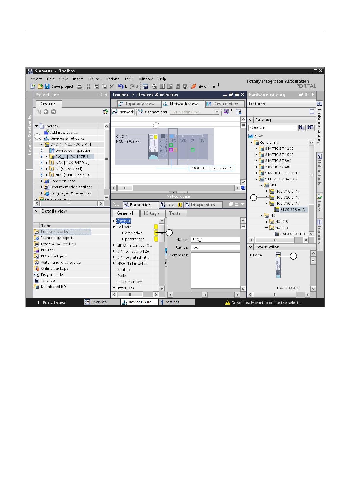
Marking failsafe components in the TIA Portal
2
1
①
The project tree shows which components of your project are F-components.
②
In the network view, device view or topology view, the Safety Integrated marking is on the NCU, representative for
the integrated components. External devices, e.g. NX, may have their own Safety Integrated marking.
③
Safety-related settings are marked in the "Properties" inspector window.
④
Folders and the devices themselves are marked in the hardware catalog. You can therefore see whether SINU-
MERIK Safety Integrated is supported before inserting the device.
⑤
Failsafe devices are also marked in the information area of the hardware catalog.
Figure 3-3
Marking failsafe components in the TIA Portal
Safety Integrated plus
42
Commissioning Manual, 12/2019, 6FC5397-1FP40-6BA3
Fundamentals
3.8 Representation of safety-related resources in the TIA Portal
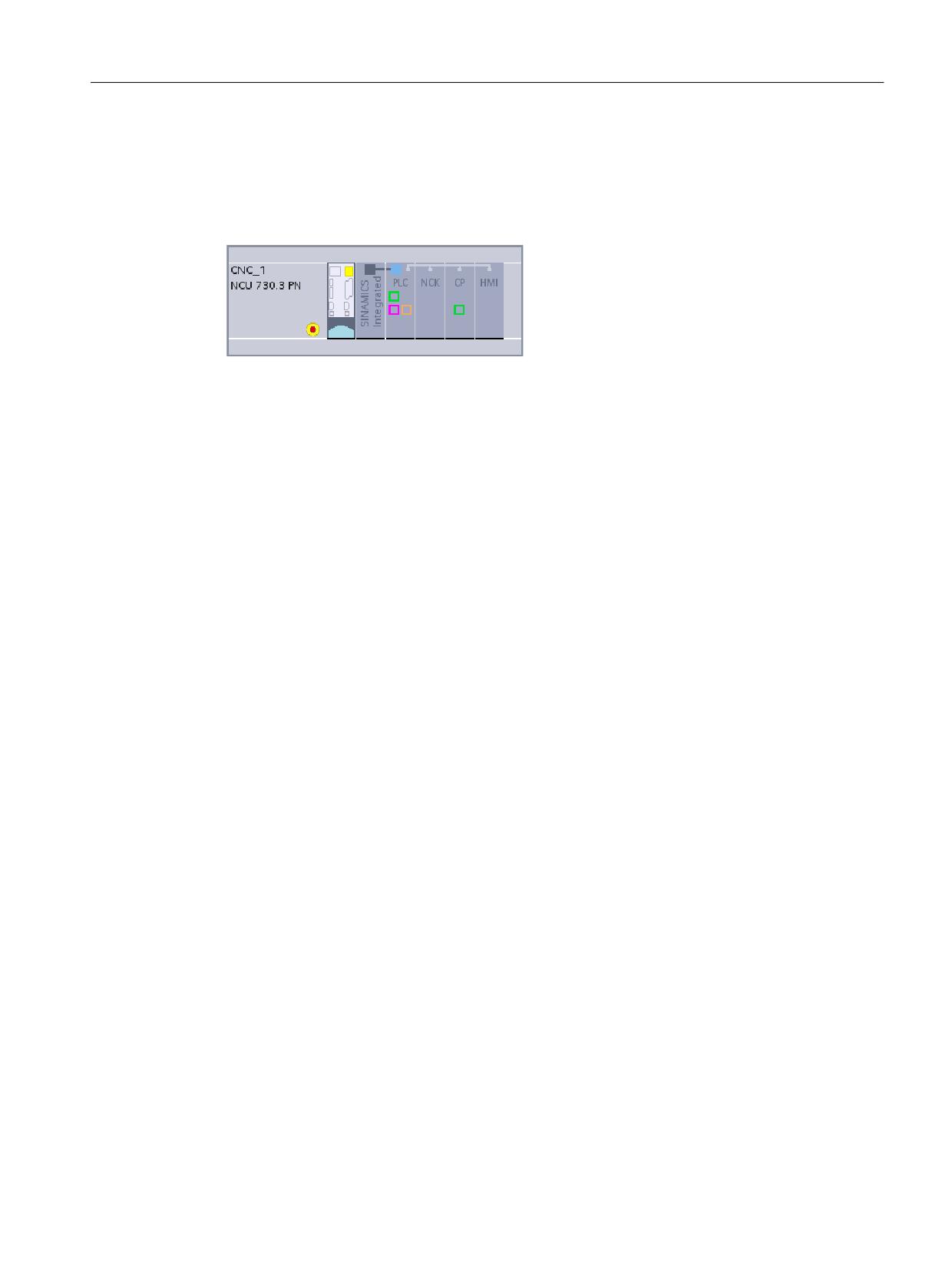
EMERGENCY STOP button symbol when using Safety Integrated plus (F-PLC)
If you activate the "Safety Integrated plus (F-PLC)" mode and therefore use PROFIsafe
telegrams, all devices with failsafe modules (PROFIsafe telegrams) have an EMERGENCY
STOP button symbol in the network and topology view:
Figure 3-4
NCU with EMERGENCY STOP button symbol
Safety Integrated plus
Commissioning Manual, 12/2019, 6FC5397-1FP40-6BA3
43
Fundamentals
3.8 Representation of safety-related resources in the TIA Portal
Safety Integrated plus
44
Commissioning Manual, 12/2019, 6FC5397-1FP40-6BA3
Safety program of the F-PLC
4
4.1
Overview
Information about F-PLC, F-I/O, the safety program and/or SIMATIC safety in this manual
serves as entry-level information only - and describes the special features relating to
SINUMERIK.
Note
Important additional information
For space reasons, the information described in this manual cannot replace a complete
SIMATIC Safety Manual. Therefore, when configuring these safety programs, it is crucial that
you carefully follow the information provided in the TIA Portal help on SIMATIC Safety or in the
"SIMATIC Safety - Configuring and Programming (https://
support.industry.siemens.com/cs/ww/en/view/54110126)" Manual.
Principle of operation of the F-PLC safety functions
The safety functions of the F-PLC are mainly implemented in the software. The safety functions
are executed by the F-system to bring the system into a safe state if a hazardous event takes
place - and maintain it in this safe state. Safety functions are contained mainly in the following
components:
● in the safety-relevant user program (safety program) in the PLC with active F-capability
(F-PLC)
● in the failsafe inputs and outputs (F-I/O)
● in the safety functions integrated in the drive (drive components)
The F-I/O ensure the safe processing of field information (sensors: e.g. EMERGENCY STOP
pushbuttons, light barriers; actuators, e.g. motor controls). They have all of the required
hardware and software components for safe processing, in accordance with the required
Safety Integrity Level. The user only has to program the user safety function. The safety
function for the process can be provided through a user safety function or a fault reaction
function. In the event of an error, if the F-system can no longer execute its actual user safety
function, it executes the fault reaction function; for example, the associated outputs are shut
down, and the F-PLC goes into the STOP mode, if necessary.
Example of user safety function and fault reaction function
In the event of overpressure, the F-system will open a valve (user safety function). For a
hazardous F-PLC fault, all outputs are shutdown (fault response function); the overpressure
valve opens, and also the other actuators go into a safe state. For a non-faulty F-system, only
the valve would be opened.
Safety Integrated plus
Commissioning Manual, 12/2019, 6FC5397-1FP40-6BA3
45
Safety program of the F-PLC
4.1 Overview
Safety program
If you activate (Page 214) Safety Integrated plus in the properties of the NCU, then also the F-
capability of the PLC is activated - and an F-runtime group is created. The F-runtime group,
together with the associated F blocks, is known as the safety program.
You create a safety program in the program editor. You program failsafe FBs and FCs in the
FBD and LAD programming languages with operations from the option package - creating
failsafe DBs.
Safety checks are automatically performed when compiling the safety program, and additional
failsafe blocks are integrated for fault detection and fault response. This ensures that failures
and faults are detected, and the appropriate responses triggered to keep the safety system in
a safe state - or to transition it into a safe state.
In addition to the safety program, a standard user program can also be executed in the F-PLC.
Standard and safety programs can coexist in an F-PLC. This is because the safety-relevant
data of the safety program are protected against being inadvertently influenced by data of the
standard user program.
Data can be exchanged between the safety and standard user program in the F-PLC using bit
memories, data of a standard DB - and by accessing the process image of inputs and outputs.
Safety Integrated plus
46
Commissioning Manual, 12/2019, 6FC5397-1FP40-6BA3
Safety program of the F-PLC
4.2 Structure of the safety program
4.2
Structure of the safety program
Representation of program structure
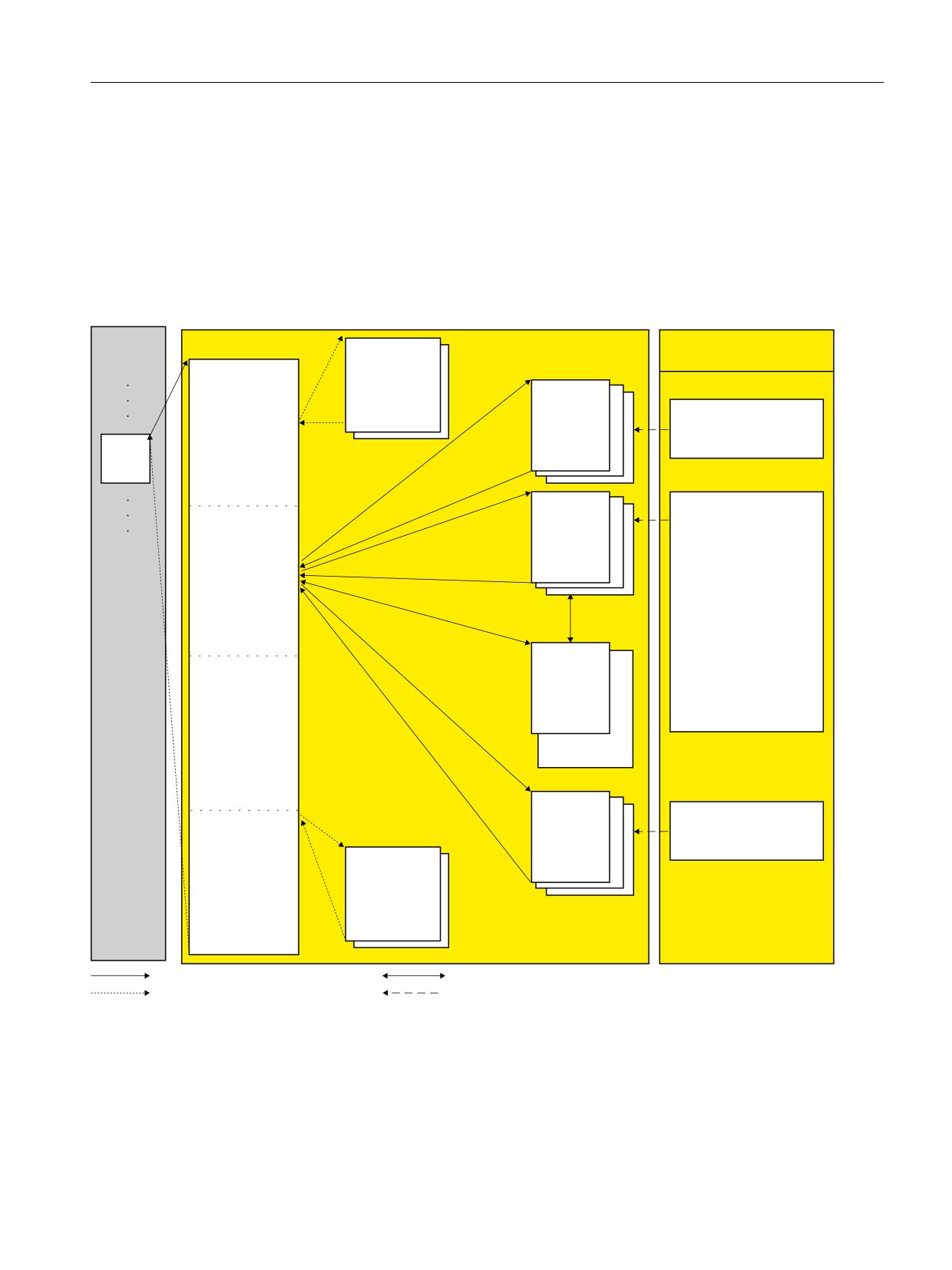
The structure of a safety program (or an F-runtime group) of the PLC of a SINUMERIK 840D
sl (F-PLC S7-300) is schematically shown in the following diagram.
6WDQGDUG XVHU SURJUDP
) UXQWLPH JURXS LQ WKH VDIHW\ SURJUDP
,QVWUXFWLRQV WDVN FDUG
0DLQ VDIHW\ EORFN
) 6%V
,QVWUXFWLRQV
$XWRPDWLF
,QSXWV RI WKH
JHQHUDWHG
5&9'3
) , 2 DUH UHDG
) EORFNV
5&96
LQWR WKH SURFHVV
RSWLRQDO
&RPPXQLFDWLRQ
LPDJH RI WKH
HJ
LQSXWV
2%
) )%
) )& [\
*HQHUDO
(GLWLQJ RI WKH
%LW ORJLF RSHUDWLRQV
) EORFNV FUHDWHG
6DIHW\ IXQFWLRQV
RU DGGHG E\ WKH
7LPHUV
XVHU
&RXQWHUV
&RPSDUDWRU RSHUDWLRQV
0DWK IXQFWLRQV
0RYH
&RQYHUVLRQ RSHUDWLRQV
) '% [\
3URJUDP FRQWURO
:RUG ORJLF RSHUDWLRQ
(GLWLQJ RI
6KLIW DQG URWDWH
DXWRPDWLFDOO\
2SHUDWH
DGGHG ) EORFNV
IDXOW FRQWURO
) ,2
PHDVXUH
'% [\
6(1''3
6(1'6
&RPPXQLFDWLRQ
3URFHVV LPDJH
RSWLRQDO
RI RXWSXWV LV
) 6%V
ZULWWHQ WR
RXWSXWV RI ) , 2
$XWRPDWLF
JHQHUDWHG
) EORFNV
FDOOHG E\ XVHU
ZULWH UHDG
FDOOHG DXWRPDWLFDOO\
IURP ,QVWUXFWLRQV WDVN FDUG
Figure 4-1
Schematic structure of a safety program
Main safety block
The main safety block is the first F-block of the safety program that you program yourself.
During compiling, it is supplemented by additional invisible calls of F-system blocks.
Safety Integrated plus
Commissioning Manual, 12/2019, 6FC5397-1FP40-6BA3
47

Safety program of the F-PLC
4.2 Structure of the safety program
You must assign the main safety block to an F-runtime group (Page 60).
The main safety block is called in an F-CPU S7-300 from any block belonging to the standard
user program. We recommend a call from an OB 3x.
) )% _ ) )&
2%
)% _ )&
) )% _ ) )&
0DLQ VDIHW\ EORFN
Figure 4-2
Calling the main safety block
F-runtime group
To improve handling, a safety program comprises one F-runtime group. An F-runtime group is
a logical arrangement comprising several contiguous F-blocks, which are internally formed by
the F-system.
An F-runtime group is made up of the following components:
● Main safety block (F-FB/F-FC, which you assign to the calling OB)
● F-blocks that you generated yourself - or that you inserted:
- F-blocks from the project library or from global libraries
- Possibly other F-FBs/F-FCs, which you program with FBD/LAD - and that you call from
the main safety block
- Possibly one or several F-DBs
● Automatically added F-blocks:
- F-I/O DBs
- F-system blocks (F-SB)
- Automatically generated F-blocks
Block types and number ranges of the safety program
An F-runtime group is automatically created - together with the associated blocks - when you
activate the Safety Integrated plus (F-PLC) mode.
● Calling block: CYC_INT5_RTG1 [OB35]
● Main safety block: Main_Safety_RTG1 [FB1010]
● I-DB for the main safety block: Main_safety_RTG1_DB [DB1010]
Number range reserved for SINUMERIK
In order to avoid assigning block addresses or numbers twice, the F blocks are automatically
assigned a free number within a certain number range reserved for SINUMERIK. You can also
Safety Integrated plus
48
Commissioning Manual, 12/2019, 6FC5397-1FP40-6BA3
Safety program of the F-PLC
4.2 Structure of the safety program
subsequently change the numbers of F blocks in the block properties. However, only use the
number range that has been reserved:
● Number range reserved for F-FB, F-FC and F-DB of F execution groups
- F-FB 1010..1019
- F-FC 1010..1019
- F-DB 1010..1019
● Additional number range for F blocks (e.g. generated F system blocks)
- F-FB 3999..7999
- F-FC 3999..7999
- F-DB 8000..16000
If you configure F I/O, then automatically an F I/O DB is created within this number range. You
can change the number of an F I/O DB in the properties of the associated F I/O.
Safety Integrated plus
Commissioning Manual, 12/2019, 6FC5397-1FP40-6BA3
49
Safety program of the F-PLC
4.3 Fail-Safe Blocks
4.3
Fail-Safe Blocks
Main safety block
For the integrated PLC of the SINUMERIK 840D sl (PLC 317F-3 PN/DP or PLC 319F-3 PN/
DP), the main safety block is a F-FC or F-FB (with instance DB), which is called by a standard
block (recommendation: OB 35) from the standard user program.
F-FB/F-FC
Both in the main safety block as well as additional F-FBs and F-FCs, you can perform the
following:
● Program the safety program with the instructions available for F-blocks in FBD or LAD
● Call other created F-FBs/F-FCs for structuring the safety program
● Insert F-blocks from the project library or global libraries
F-DB
Optional failsafe data blocks that can be read- and write-accessed within the entire safety
program.
F-I/O DB
An F-I/O DB is automatically generated for each F-I/O when it is configured. You can or you
must access the tags of the F-I/O DB in conjunction with F-I/O accesses.
F-shared DB
The F-shared DB is a failsafe data block that contains all of the shared data of the safety
program and additional information needed by the F-system.
Note
It is not permissible that you add, change or delete blocks in the "System blocks" folder. If this
is not complied with, then this can result in compilation errors or the F-PLC stopping.
Note
You are not permitted to insert F-system blocks from the "System blocks" folder in a main safety
block/F-FB/F-FC.
Additional information
Detailed information about the safety program blocks can be found at Procedure when
specifying an F-runtime group (Page 60).
Safety Integrated plus
50
Commissioning Manual, 12/2019, 6FC5397-1FP40-6BA3
Safety program of the F-PLC
4.4 Safety Administration Editor
4.4
Safety Administration Editor
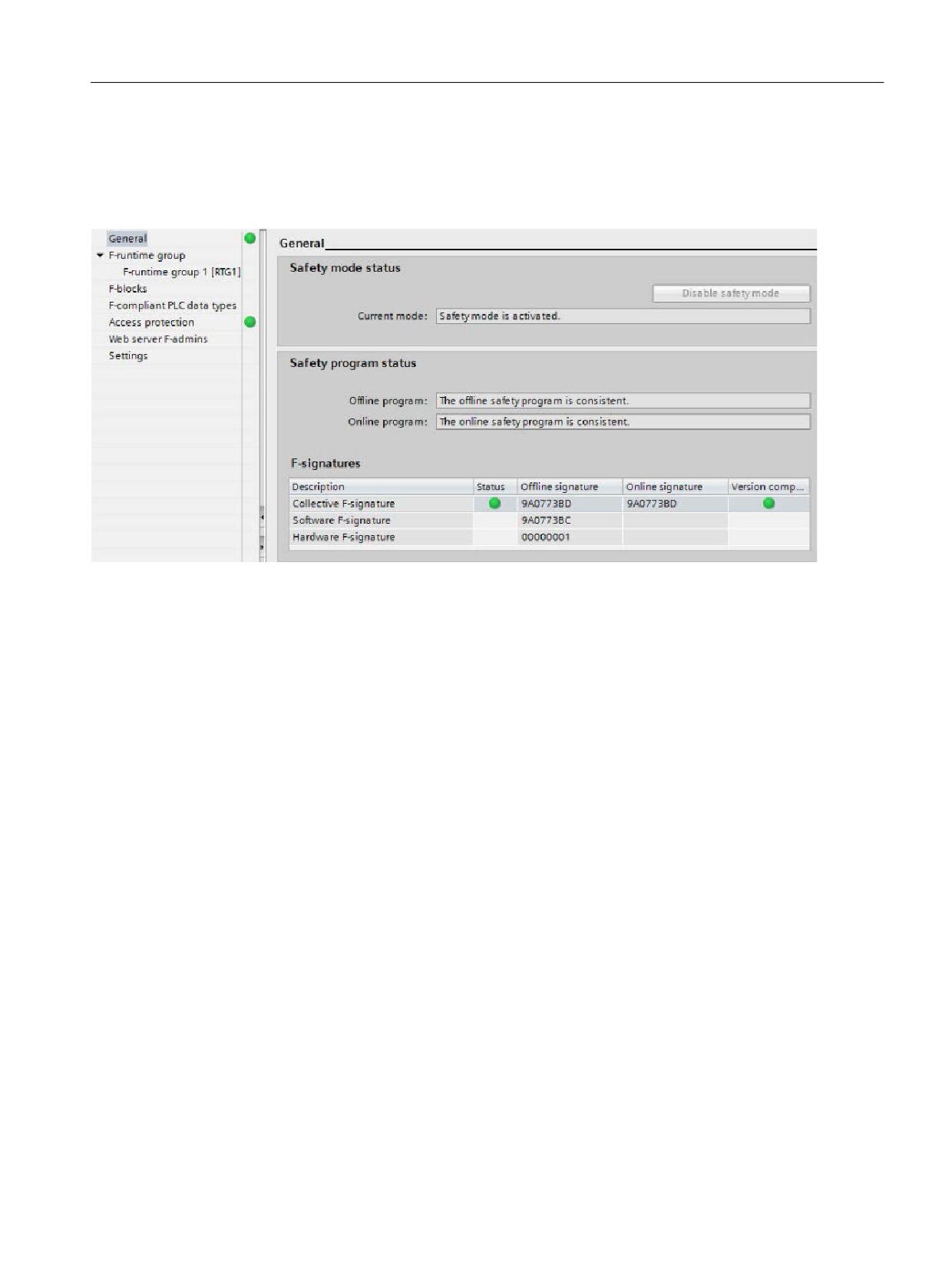
The "Safety Administration Editor" is available in the Safety Integrated plus (F-PLC) mode - in
the project navigation.
Figure 4-3
Safety Administration Editor
The Safety Administration Editor supports you when carrying out the following tasks:
● Display of the safety program status
● Display of the collective signature
● Display of the safety mode status
● Creation/organization of F-runtime groups
● Display of information on the F-blocks
● Definition/change of the access protection
● Definition/change of the general settings for the safety program
The Safety Administration Editor is divided into the following sections:
● General
● F-runtime groups (Page 60)
● F-blocks
● Access protection
● Settings
Further information
Additional information is provided in the help for SIMATIC STEP 7 Safety Advanced in Chapter
"Safety Administration Editor".
Safety Integrated plus
Commissioning Manual, 12/2019, 6FC5397-1FP40-6BA3
51
Safety program of the F-PLC
4.5 Restrictions in the programming languages FBD/LAD
4.5
Restrictions in the programming languages FBD/LAD
LAD and FBD programming languages
Generally, the user program in the F-PLC comprises a standard application program and a
safety program.
The standard user program is created using standard programming languages such as SCL,
STL, LAD, or FBD.
For the safety program, LAD or FBD may be used with certain restrictions in the instructions and
the applicable data types and operand areas.
Supported instructions
The instructions available depend on the F-PLC being used. SINUMERIK 840D sl supports all
F-CPU S7-300 instructions.
Note
Preconnection of enable input EN or evaluation of enable output ENO is not possible.
Supported data types and parameter types
Only the following data types are supported:
● BOOL
● INT
● WORD
● DINT
● DWORD
● TIME
Note
If the result of an operation lies outside the range permissible for the specific data type, then the
F-PLC can go into STOP. The cause of the diagnostic result is entered in the diagnostics buffer
of the F-PLC.
Additional information regarding the cause is available in the online help for the diagnostics
message. You must therefore ensure that the permitted range for the data type is observed
when creating the program or select a matching data type.
Safety Integrated plus
52
Commissioning Manual, 12/2019, 6FC5397-1FP40-6BA3
Safety program of the F-PLC
4.5 Restrictions in the programming languages FBD/LAD
Non-permitted data and parameter types
The following types are not permitted:
● All types not listed in the section "Supported data types and parameters types" (e.g. BYTE,
REAL)
● structured data types (e.g. STRING, ARRAY, STRUCT, PLC data type)
● Parameter types (e.g., BLOCK_FB, BLOCK_DB, ANY)
Supported operand areas
The system memory of an F-PLC is structured in the same operand area as that of a standard
PLC. You can access the operand areas listed in the table below from within the safety program.
Note that you can access data in the safety program only via the declared data type for the tag/
element of an F-compliant PLC data type:
● For the BOOL data type only bit by bit
● For the INT data type only word by word
● For the WORD data type only word by word
● For the DINT data type only double word by double word
● For the DWORD data type, only double word by double word
● For the TIME data type only double word by double word
Example: You can only access input channels, data type BOOL in the process image of the
inputs of F I/O via unit "Input (bit)".
Byte access to eight consecutive input channels of the BOOL data type is not allowed.
For reasons of clarity, you should always access operand areas in a safety program using
symbolic names.
Table 4-1
Supported operand areas
Operand area
Access via units of the fol-
S7 Notation
Description
lowing size:
Process image of the inputs
● Of F-I/O
Input (bit)
I
Only read-only access to input channels of F-
I/O is possible.
Input word
IW
Transfer to IN_OUT parameters of an F-FB or F-
Input double-word
ID
FC is therefore not valid either.
The process image of the inputs of F-I/O is up-
dated before the start of the main safety block.
● Of standard I/O
Input (bit)
I
Input channels of standard I/O can only be ac-
cessed read-only.
Input word
IW
Transfer to IN_OUT parameters of an F-FB or F-
Input double-word
ID
FC is therefore not valid either.
In addition, a process-specific validity check is
required.
See the STEP 7 help for the update times of the
process image of the inputs of standard I/O.
Safety Integrated plus
Commissioning Manual, 12/2019, 6FC5397-1FP40-6BA3
53

Safety program of the F-PLC
4.5 Restrictions in the programming languages FBD/LAD
Operand area
Access via units of the fol-
S7 Notation
Description
lowing size:
Process image of the outputs
● Of F-I/O
Output (bit)
Q
Only write-only access to output channels of F-
I/O is possible.
Output word
QW
Transfer to IN_OUT parameters of an F-FB or F-
Output double-word
QD
FC is therefore not valid either.
In the safety program, the values for the outputs
of the F-I/O are calculated and stored in the
process image of the outputs.
The process image of the outputs for F-I/O is
updated after the end of the main safety block.
● Of standard I/O
Output (bit)
Q
Output channels of standard I/O are write-only
channels.
Output word
QW
Transfer to IN_OUT parameters of an F-FB or F-
Output double-word
QD
FC is therefore not valid either.
In the safety program, the values for the outputs
of the standard I/O are also calculated and stor-
ed in the process image of the outputs, if nee-
ded.
See the STEP 7 help for the update times of the
process image of the outputs of standard I/O.
Bit memory
Bit memory (bit)
M
This area is used for data exchange with the
standard user program.
Memory word
MW
In addition, read access requires a process-
Memory double word
MD
specific validity check.
A particular element of the bit memory can be
either read- or write-accessed in the safety pro-
gram.
Transfer to IN_OUT parameters of an F-FB or F-
FC is therefore not valid either.
Note that it is only permitted to use bit memory
for connecting the standard user program and
the safety program; it must not be used as a
buffer for F-data.
Data blocks
Safety Integrated plus
54
Commissioning Manual, 12/2019, 6FC5397-1FP40-6BA3
Safety program of the F-PLC
4.5 Restrictions in the programming languages FBD/LAD
Operand area
Access via units of the fol-
S7 Notation
Description
lowing size:
● F-DB
Data bit
DBX
Data blocks store information for the program.
They can either be defined as global data
Data word
DBW
blocks such that all F-FBs, F-FCs, or main safe-
Data double word
DBD
ty blocks can access them or assigned to a par-
ticular F-FB or main safety block (instance DB).
A tag of a shared DB can only be accessed from
one F-runtime group, and an instance DB only
from the F-runtime group in which the corre-
sponding F-FB/instruction is called.
● DB
Data bit
DBX
This area is used for data exchange with the
standard user program.
Data word
DBW
In addition, read access requires a process-
Data double word
DBD
specific validity check.
For a tag of a DB, either read access or write
access is possible in the safety program.
Transfer to IN_OUT parameters of an F-FB or F-
FC is therefore not valid either.
Please note that the tags of a DB can only be
used for transferring data between the standard
user program and the safety program; DBs
must not be used as a buffer for F-data.
Non-permitted operand areas
Access via units other than those listed in the table above is not permitted. The same applies
to access to operand areas not listed, in particular:
● Data blocks that were automatically added
Exception: certain tags in the F I/O DB (Page 50) and in the F global DB (Page 50).
● I/O area: Inputs
● I/O area: Outputs
Boolean constants "0" or "FALSE" and "1" or "TRUE" (S7-300, S7-400)
If you require Boolean constants "0" or "FALSE" and "1" or "TRUE" in your safety program to
assign parameters during block calls, you can access the tags "VKE0" and "VKE1" in the F-
shared DB using fully qualified DB access ("F_GLOBDB".VKE0 or "F_GLOBDB".VKE1).
Safety Integrated plus
Commissioning Manual, 12/2019, 6FC5397-1FP40-6BA3
55
Safety program of the F-PLC
4.5 Restrictions in the programming languages FBD/LAD
Operand area of temporary local data: Particularities
Note
Note when using the operand area of temporary local data that the first access of a local data
element in a main safety block/F-FB/F-FC must always be a write access. This initializes the
local data element.
Make sure that the initialization of the local data element is not skipped over by JMP, JMPN. or
RET instructions (branching).
The "local data bit" should be initialized with the Assign ("=") (FBD) or ("--( )") (LAD) instruction.
Assign the local data bit a signal state of "0" or "1" as a Boolean constant.
Local data bits cannot be initialized with the Flip Flop (SR, RS), Set Output (S) or Reset Output
(R) instructions.
If this is not complied with, then the F-PLC can go into STOP. The cause of the diagnostic result
is entered in the diagnostics buffer of the F-PLC. You can find additional information on the
cause in the online help for diagnostic messages.
"Fully qualified DB access"
Access to tags of a data block in an F-FB/F-FC is "fully qualified DB access". This also applies
to initial access to tags of a data block after a jump label.
For F-PLCs S7-300/400, only the first access must be realized as "fully qualified DB access"
Alternatively, you can use the instruction "OPN".
Example of "fully qualified DB access":
Assign a name for the F-DB, e.g. "F_Data_1". Use the names assigned in the declaration of the
F-DB instead of the absolute addresses.
,17
)B'$7$B
9$/8(B$
)B'$7$B
5(68/7
,1
)B'$7$B
9$/8(B%
,1
Figure 4-4
Example with fully qualified access and symbolic names
Safety Integrated plus
56
Commissioning Manual, 12/2019, 6FC5397-1FP40-6BA3
Safety program of the F-PLC
4.5 Restrictions in the programming languages FBD/LAD
Example of "not fully qualified DB access":
1HWZRUN
'%
231
1HWZRUN
,17
'%:
'%;
,1
'%:
,1
Figure 4-5
Example without fully qualified access and symbolic names
Access to instance DBs
Please note that when accessing instance DBs of F-FBs, which are not called in the safety
program, can result in the F-PLC going into STOP.
Additional information is provided in the SIMATIC Safety Programming and Operating Manual.
Safety Integrated plus
Commissioning Manual, 12/2019, 6FC5397-1FP40-6BA3
57
Safety program of the F-PLC
4.6 Instructions for the safety program
4.6
Instructions for the safety program
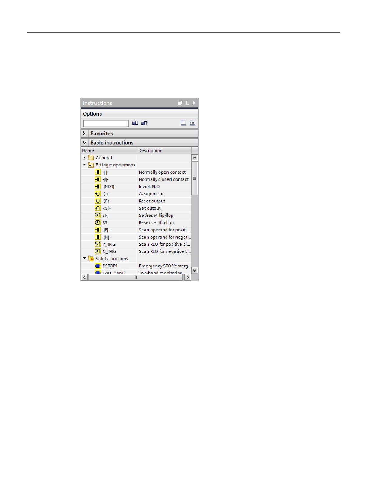
When programming an F block, in task card "Operations" you can find all the operations that
you can use when programming an F block in LAD or FBD with the configured F-PLC. These
operations have a yellow backg63round, as is already the case for as a safety-relevant functions.
Figure 4-6
Task Card "Instructions"
In addition to the known operations, there are special safety functions, e.g. for two-hand
monitoring, discrepancy analysis, muting, E STOP, protective door monitoring and feedback
circuit monitoring.
Additional information
A detailed description of the instructions for the safety program provided in the Programming
and Operating Manual SIMATIC Safety - Configuring and Programming (https://
support.industry.siemens.com/cs/ww/en/view/54110126).
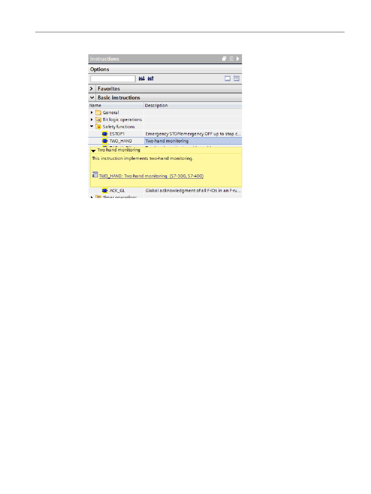
Alternatively, you can call up these descriptions directly in the TIA Portal by moving the tooltip
over a specific operation.
Safety Integrated plus
58
Commissioning Manual, 12/2019, 6FC5397-1FP40-6BA3
Safety program of the F-PLC
4.6 Instructions for the safety program
Figure 4-7
Tooltip of an instruction
Safety Integrated plus
Commissioning Manual, 12/2019, 6FC5397-1FP40-6BA3
59
Safety program of the F-PLC
4.7 F-runtime groups
4.7
F-runtime groups
4.7.1
Rules for F-Runtime Groups of the Safety Program
General rules relating to the safety program
Carefully comply with the following general rules when programming with F-blocks and F-
runtime groups:
● The channels (channel values and value status) of an F-I/O can only be accessed from a
single F-runtime group.
● Tags of the F-I/O DB of an F-I/O can only be accessed from one F-runtime group and only
from that F-runtime group from which the channels or value status of this F-I/O are also
accessed (if access is made).
● Individual tags of F-DBs (except the F-shared DB) can only be used in one F-runtime group
(however, an F-DB can be used in more than one F-runtime group).
● The process image of inputs and outputs of standard I/O, bit memories and tags of the DB
of the standard user program may be accessed, either reading or writing, from several F-
runtime groups. (see also Data exchange between the standard user program and safety
program (Page 74))
You can find additional specific rules at Procedure when specifying an F-runtime group
(Page 60).
Note
You can improve performance by writing sections of the program that are not required for the
safety function in the standard user program.
When distributing your program between a standard user program and safety program, you
should note that you can change the standard user program more simply and load to the F-PLC.
In general, changes in the standard user program do not require an acceptance.
4.7.2
Procedure when specifying an F-runtime group
An F-runtime group comprises a block (cyclic interrupt (OB3x), FB or FC), which calls the main
safety block (FB or FC).
Automatically creating the safety program
An F-runtime group is automatically created when you activate Safety Integrated plus (F-PLC)
mode.
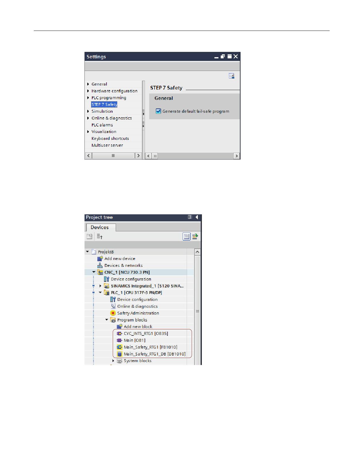
You can adapt this response in the menu under "Options > Settings > STEP 7 Safety".
Safety Integrated plus
60
Commissioning Manual, 12/2019, 6FC5397-1FP40-6BA3
Safety program of the F-PLC
4.7 F-runtime groups
Figure 4-8
Settings for STEP 7 Safety
Archiving the F blocks
The automatically created F-blocks of the F-runtime group are in folder "Program blocks":
CYC_INT5_RTG1 [OB35], Main-Safety_RTG1 [FB1010] and Main-Safety_RTG1_DB
[DB1010].
Figure 4-9
F runtime group blocks in the project navigator
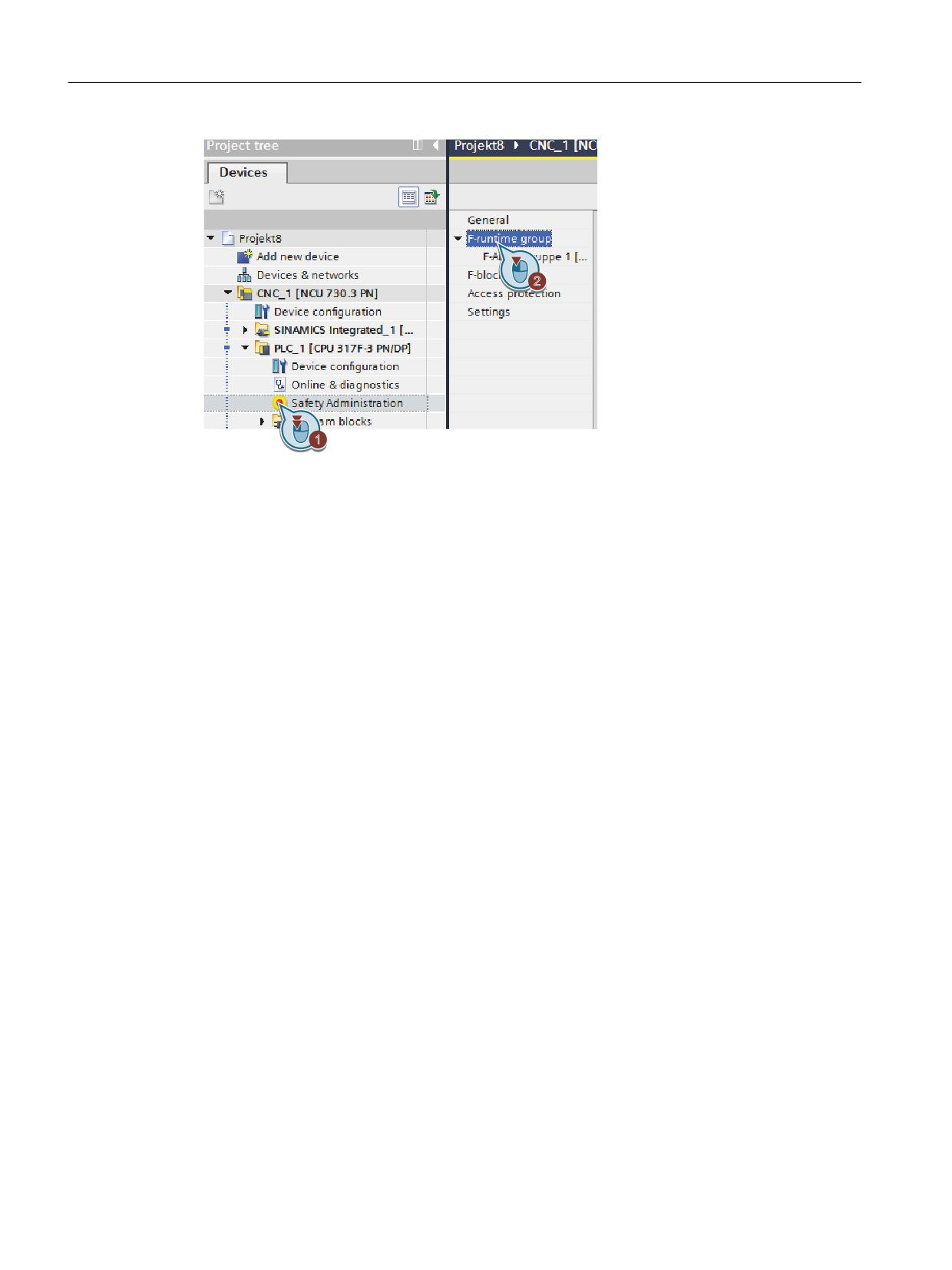
Open the "F runtime group" work cell
If you wish to adapt the automatically created F runtime group or configure F runtime groups,
in the Safety Administration Editor, open the "F runtime group" work cell.
Safety Integrated plus
Commissioning Manual, 12/2019, 6FC5397-1FP40-6BA3
61
Safety program of the F-PLC
4.7 F-runtime groups
Figure 4-10
Displaying the "F runtime group" work cell
Safety Integrated plus
62
Commissioning Manual, 12/2019, 6FC5397-1FP40-6BA3
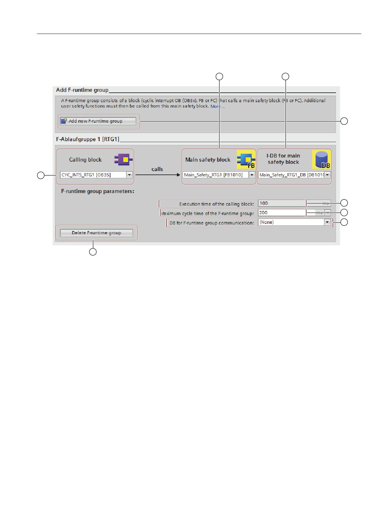
Safety program of the F-PLC
4.7 F-runtime groups
"F runtime group" work cell
①
Calling block
②
Main safety block
③
I-DB for the main safety block
④
Create a new F-runtime group
⑤
Execution time of the calling block
⑥
Maximum cycle time of the F-runtime group
⑦
DB for F-runtime group communication
⑧
Delete F-runtime group
Figure 4-11
Safety Administration Editor, "F runtime group" work cell
Calling block
The default value is "CYC_INT5_RTG1 [OB35]", a cyclic interrupt OB.
The advantage of using cyclic interrupt OBs is that they interrupt the cyclic program execution
in OB 1 of the standard user program at fixed time intervals; that is, the safety program is called
and executed at fixed time intervals in a cyclic interrupt OB.
Programming language
In the drop-down list "Calling block", you can only select blocks that were generated in the
programming languages LAD, FBD or STL.
If you want to call the main safety block in a block that was created in another programming
language, you must program this call itself. The text box is then inactive (grayed out), and you
cannot change the call in the Safety Administration Editor, but only in the calling block.
Safety Integrated plus
Commissioning Manual, 12/2019, 6FC5397-1FP40-6BA3
63
Safety program of the F-PLC
4.7 F-runtime groups
Rules:
● The main safety block may only be called once from a standard block. Calling the block a
multiple number of times can result in the F-PLC going into a STOP.
● To optimally utilize the temporary local data, you must call the F runtime group (the main
safety block) directly in an OB (if at all possible, a cyclic interrupt OB); in this cyclic interrupt
OB you should not declare any additional temporary local data.
● Within a cyclic interrupt OB, the F runtime group should be executed before the standard
user program, i.e. should be located right at the beginning of the OB so that the F runtime
group is always called at fixed intervals in time, independent of how long it takes to process
the standard user program.
This is also the reason that the cyclic interrupt OB should not be interrupted by higher-
priority alarms.
Main safety block
In the "Number" text field, enter a free block number reserved for SINUMERIK Safety
Integrated: 1010..1019.
Rules:
● F-FBs can be used in several F-runtime groups; however, they must be called with different
instance DBs.
● F-FCs can always be called in several F-runtime groups.
I-DB for the main safety block
In the "Number" text field, enter a free block number reserved for SINUMERIK Safety
Integrated: 1010..1019.
Rules:
● Instance DBs may only be accessed from the F-runtime group in which the associated F-FB
is called
Create a new F-runtime group
Using this command, you can create a second F-runtime group; for example, to organize safety-
relevant program sections that are executed quickly, in their own dedicated F-runtime group.
Execution time of the calling block
You can adapt the cyclic execution time of the calling block under "Alarms > Cyclic interrupts"
in the PLC properties.
Maximum cycle time of the F-runtime group
In the the F-runtime group, the F-PLC monitors the F-cycle time For "Maximum cycle time of the
F-runtime group", select the maximum time that can elapse between two calls of this F-runtime
group.
The F-runtime group call interval is monitored for the maximum value; i.e. monitoring is
performed to determine whether the call is executed often enough, but not whether it is
executed too often. Therefore, failsafe times must be implemented using instructions TP, TON
or TOF from the task card "Instructions" and not using a counter (OB calls). (S007)
Safety Integrated plus
64
Commissioning Manual, 12/2019, 6FC5397-1FP40-6BA3
Safety program of the F-PLC
4.7 F-runtime groups
DB for F-runtime group communication
If one F-runtime group is to provide tags for evaluation to another F-runtime group of the safety
program, assign a DB for F-runtime group communication. Select an F-DB for "DB for F-runtime
group communication".
Rules:
● It is only permissible to access an F-communication DB from an F-runtime group.
● A DB for F-runtime group communication may read and write to the F-runtime group, for
which you set up a DB; the "receiving" F-runtime group may only read this F-DB.
● Individual tags of the F-runtime group DB may only be used in their own F-runtime group.
Delete F-runtime group
This command deletes the assignment of the F blocks to an F-runtime group. You may have to
carry out additional steps if you wish to delete your safety program.
4.7.3
F-global DB
Function
The F-shared DB is a fail-safe data block that contains all of the shared data of the safety
program and additional information needed by the F-system. The F-shared DB is automatically
inserted when the hardware configuration is compiled.
Using its name F_GLOBDB, you can evaluate certain data elements of the safety program in
the standard user program.
Reading an F-shared DB in the standard user program
You can read out the following information in the F-shared DB in the standard user program or
on an operator control and monitoring system:
● Operating mode: safety mode or disabled safety mode ("MODE" tag)
● Error information "Error occurred when executing safety program" ("ERROR" tag)
● Collective F-signature ("F_PROG_SIG" tag)
● Compilation date of the safety program ("F_PROG_DAT" tag, DATE_AND_TIME data type)
You use fully qualified access to access these tags (e.g. ""F_GLOBDB".MODE").
Safety Integrated plus
Commissioning Manual, 12/2019, 6FC5397-1FP40-6BA3
65
Safety program of the F-PLC
4.8 Creating F-blocks
4.8
Creating F-blocks
Introduction
In order to create F-FBs, F-FCs, and F-DBs for the safety program, you should follow the same
basic procedure as for standard blocks. In the following, only the deviations from the procedure
for standard blocks are presented.
Creating F-FBs, F-FCs, and F-DBs
You create F-blocks in the same way as for standard blocks. Proceed as follows:
1. Double-click on "Add new block" under "Program blocks" in the project tree.
2. In the dialog that appears, specify the type, name, and language and select the "Create F-
block" check box. (If you do not select the check box, a standard block is created.)
3. After the dialog is confirmed, the F-block is opened in the Program editor.
Note the following
Note the following important instructions:
Note
The main safety block must not contain any parameters, as they cannot be provided with actual
values when the block is called.
Note
It is not permissible to edit the start values in instance DBs of F-FBs online and offline - and this
can result in the F-PLC going into STOP mode.
Note
It is not permitted to access static local data in single instances or multi-instances of other F-
FBs.
Note
Outputs of F-FCs must always be initialized.
If this is not complied with, then the F-PLC can go into STOP. The cause of the diagnostic result
is entered in the diagnostics buffer of the F-PLC. You can find additional information on the
cause in the online help for diagnostic messages.
Note
If you wish to assign an operand from the data area (data block) to a formal parameter of an F-
FC as an actual parameter, you must use fully qualified DB access.
Safety Integrated plus
66
Commissioning Manual, 12/2019, 6FC5397-1FP40-6BA3
Safety program of the F-PLC
4.8 Creating F-blocks
Note
Note that access to the inputs in an F-FB/F-FC is read-only, while access to the outputs is write-
only.
Use an in/out if you wish to have both read and write access.
Note
For greater clarity, assign unique symbolic names to the F-blocks you have created. These
symbolic names appear in the project tree and in the block interface. Symbolic names are
assigned in the same way as for standard blocks.
Copying/pasting F-blocks
You can copy F-FBs, F-FCs, and F-DBs in exactly the same was as blocks of the standard user
program.
Exception:
You must not copy blocks from the folder "Program blocks > System blocks".
Nesting depth for F-FBs and F-FCs
We recommend that you do not exceed a nesting depth of 8 levels.
Safety Integrated plus
Commissioning Manual, 12/2019, 6FC5397-1FP40-6BA3
67
Safety program of the F-PLC
4.9 Using libraries
4.9
Using libraries
Introduction
As with standard blocks, you have the option of storing F-blocks which you wish to reuse as
master copy or types in global libraries or in the project library.
Additional information can be found in the STEP 7 help in "Using libraries".
Reusing F-blocks which have already been tested and accepted
Please note the following when reusing F-blocks which have already been tested and if
applicable also accepted:
● Document the signature and start value signature of the F-block after you have compiled,
tested and possibly accepted the F-block.
● Document the version set for "Instructions (without their own version)" in the Safety
Administration Editor under "Settings"/"System library elements used in safety program".
For documentation purposes, you can create a safety summary of the safety program you
used to create the F-block.
● When re-using the F-block, carefully ensure that the signature and start value signature of
the F-block have not been changed.
For F-blocks with instructions for which a version is indicated in the "Version" column of the
"Instructions" task card, you must also note the following:
● Document the versions of these instructions that were set at the time the F-block was
compiled and on the basis of which the F-block was tested and, if applicable, approved.
You can use the safety summary for documentation purposes.
● When using the F-block again make sure that the documented versions are set for these
instructions in the "Instructions" task card.
● If versions other than the documented versions are set for these instructions, you must
check yourself whether the F-block still works with these versions as intended.
To do so, identify any differences between the versions based on the online help on the
instructions.
You need to have the F-block retested and accepted. Additional information on instruction
versions can be found in the help on STEP 7 in "Basics for instruction versions".
To help you manage F-blocks that you wish to reuse and that have already been tested and if
applicable accepted, we recommend that you save these blocks as types in a global library.
Safety Integrated plus
68
Commissioning Manual, 12/2019, 6FC5397-1FP40-6BA3
Safety program of the F-PLC
4.10 Safety-relevant communication
4.10
Safety-relevant communication
Options for safety-related communication
Safety-related communication
On subnet
Additional hardware
required
I-slave-slave communication
PROFIBUS DP
-
Safety-related CPU-CPU communication:
IO controller-IO controller communica-
PROFINET IO
PN/PN coupler
tion
Master-master communication
PROFIBUS DP
DP/DP coupler
IO controller-I-device communication
PROFINET IO
-
Master-I-slave communication
PROFIBUS DP
-
I-slave-I-slave communication
PROFIBUS DP
-
IO controller-I-slave communication
PROFINET IO and PROFIBUS DP
IE/PB link
Safety-related communication via S7
Industrial Ethernet
-
connections
IO controller-IO controller communica-
PROFINET IO
PN/PN coupler
tion for S7 Distributed Safety
Master-master communication for S7
PROFIBUS DP
DP/DP coupler
Distributed Safety
Safety-related communication to S7 Dis-
Industrial Ethernet
-
tributed Safety or S7 F Systems via S7
connections
Additional information
Additional information and configuration graphics are provided in the help for SIMATIC STEP
7 Safety Advanced in Chapter "Safety-relevant communication".
Safety Integrated plus
Commissioning Manual, 12/2019, 6FC5397-1FP40-6BA3
69
Safety program of the F-PLC
4.11 Access to SI-drives and F-I/O
4.11
Access to SI-drives and F-I/O
Overview
A description is subsequently provided as to how you can access the F-I/O and the safety-
relevant drive telegrams; certain issues are also explained, that you must take into account
when programming this access.
Access via the process image
You access F-I/O and drive telegrams (just the same as standard I/O and standard drive
telegrams) via the process image (PAE and PAA).
Access is only permissible via the data type specified for the particular channel.
Example: You can only access input channels, data type BOOL in the process image of the
inputs of F I/O via unit "Input (bit)" (E x.y). It is not possible to access 16 consecutive input
channels, data type BOOL via unit "Input word" (EW x).
It is not permissible to directly access drive telegrams or F-I/O. Inputs or outputs of the F-I/O or
drive telegrams, which you wish to access, must be activated in the hardware configuration.
The channel value of an F-I/O or a drive telegram may only be accessed from a joint F-runtime
group.
The process image of the inputs is updated at the start of the F-runtime group. The process
image of the outputs is updated at the end of the F-runtime group (see Structure of the safety
program (Page 47)).
The actual communication between F-PLC (process image) and the F-I/O or drive telegram to
update the process image is realized in the backg63round using a special security protocol
according to PROFIsafe.
If, between the F-PLC (S7-300) and the F-I/O, you insert an additional component, which
copies the safety telegram according to PROFIsafe between the F-PLC (S7-300) and the F-I/O
using the user program, then for each change to the user-programmed copy function, you must
carefully test all of the safety functions involved with the copy function. (S049)
Note
As a result of the special safety protocol, F-I/O and drive telegrams occupy a larger area of the
process image than is required by real channels available on the F-I/O or the drive telegram
(channel values and value status).
To find the area of the process image where the channels are stored, refer to the
relevant manuals for the F-I/O. When the process image is accessed in the safety program,
only the channels that are actually present may be accessed.
Note that for certain F-I/O (such as ET 200SP failsafe modules or ET 200MP fail-safe modules),
a "1oo2 evaluation of the sensors" can be specified. To find out which of the channels combined
by the "1oo2 evaluation of the sensors" you can access in the safety program, refer to the
relevant manuals for the F-I/O.
Safety Integrated plus
70
Commissioning Manual, 12/2019, 6FC5397-1FP40-6BA3
Safety program of the F-PLC
4.11 Access to SI-drives and F-I/O
Additional information
Additional information is provided in the help for SIMATIC STEP 7 Safety Advanced in the
following chapters:
● Data transfer from the safety to the standard user program
(Information on updating the process image)
● Safety-relevant I-slave-slave communication - F-I/O access
Also observe the documentation on the relevant F-I/O - as well as on the safety-relevant drive
telegrams.
Safety Integrated plus
Commissioning Manual, 12/2019, 6FC5397-1FP40-6BA3
71
Safety program of the F-PLC
4.12 Programming startup protection
4.12
Programming startup protection
Introduction
Initiating a STOP state, e.g. using PG/PC operator action, mode switch, communication
function or "STP" instruction - as well as maintaining a STOP state - are not safety relevant. This
STOP state can be very simply (also inadvertently) withdrawn, e.g. with an appropriate
operator action at the PG/PC.
When an F-CPU is switched from STOP to RUN mode, the standard user program starts up in
the usual way. When the safety program starts, all FDBs - just the same as for a cold start - are
initialized with values from the load memory. This means that saved error information is lost.
The F-system automatically re-integrates the F-I/O. If your process does not allow such a
startup, you must program a restart/startup protection in the safety program: The output of
process data must be blocked until manually enabled. It is only permissible to issue the enable
signal after process values can be output without incurring any risk, and faults have been
removed. (S031)
Example of restart/startup prevention
In order to implement a restart/startup prevention, it must be possible to detect a startup. To
detect a startup, you declare a tag of data type BOOL with initial value "TRUE" in an F-DB.
Block the output of process data when this tag has the value "1," for example, by passivating
F-I/O using the PASS_ON tag in the F-I/O DB.
To manually enable the output of process data, you reset this tag by means of a user
acknowledgment.
Additional information
Additional information is provided in the help for SIMATIC STEP 7 Safety Advanced in the
following chapters:
● F-I/O DB
● Implementing a user acknowledgment
Safety Integrated plus
72
Commissioning Manual, 12/2019, 6FC5397-1FP40-6BA3
Safety program of the F-PLC
4.13 Implementing a user acknowledgment
4.13
Implementing a user acknowledgment
After communication, channel or F-I/O errors, the send data must be reintegrated.
The existing operations provide the following options:
● Parameter "ACK_REI":
Special acknowledgment for the reintegration for each F-I/O
● Safety function "ACK_GL":
Acknowledgment to simultaneously reintegrate all F-I/O of a F-runtime group
In your safety program you must always provide a user acknowledgment to reintegrate F-I/O.
You can implement the user acknowledgment as follows:
● User acknowledgment using an operation and visualization system
● User acknowledgment using an acknowledgment button at an F-I/O
- Assigning the inputs to the F-CPU of the I-Slaves/I-Devices
- Assigning the inputs to the F-CPU of the DP master / I/O controller
Additional information
● Implementing user acknowledgment for global reintegration (Page 228)
● Additional information and examples are provided in the help for SIMATIC STEP 7 Safety
Advanced under keywords "ACK_REI", "ACK_GL" as well as in Chapter "Implementing a
user acknowledgment".
Safety Integrated plus
Commissioning Manual, 12/2019, 6FC5397-1FP40-6BA3
73

Safety program of the F-PLC
4.14 Data exchange between the standard user program and safety program
4.14
Data exchange between the standard user program and safety
program
4.14.1
Comparison between standard user program and safety program
You have the option of transferring data between the safety program and the standard user
program. Tags can be transferred using DBs, F-DBs and bit memory:
From the standard user program
From the safety program
Read access
Write access
Read access
Write access
Tag from DB
Permitted
Permitted
A tag from the DB can be read-accessed or write-
accessed
Tag from F-DB
Permitted
Not permitted
Permitted
Permitted
Bit memory
Permitted
Permitted
Bit memory can be read-accessed or write-ac-
cessed
You can also access the process image of the standard I/O and F-I/O:
From the standard user program
From the safety program
Read access
Write access
Read access
Write access
Process image
PII
Permitted
Permitted
Permitted
Not permitted
standard I/O
PIQ
Permitted
Permitted
Not permitted
Permitted
Process image
PII
Permitted
Not permitted
Permitted
Not permitted
F-I/O
PIQ
Permitted
Not permitted
Not permitted
Permitted
Decoupling of the safety program from the standard program in case of data transfer
For data exchange between standard user program and safety program, we recommend that
you define special data blocks (transfer blocks) in which the data to be exchanged is stored.
This action allows you to decouple the blocks of the standard and the safety program. The
changes in the standard program do not affect the safety program (and vice versa) provided
these data blocks are not modified.
Safety Integrated plus
74
Commissioning Manual, 12/2019, 6FC5397-1FP40-6BA3
Safety program of the F-PLC
4.14 Data exchange between the standard user program and safety program
4.14.2
Data Transfer from the Safety Program to the Standard User Program
Description
The standard user program can read all data of the safety program, for example using symbolic
(fully qualified) accesses to the following:
● The instance DBs of the F-FBs ("Name of instance DB".Signal_x)
● F-DBs (for example "Name of F_DB".Signal_1)
● The process image of the inputs and process image of the outputs of F-I/O (for example
"Emergency_Stop_Button_1" (I 5.0))
Note
Process image of the inputs and outputs: Access and update
The process image of the inputs of F-I/O is updated not only at the start of the main safety
block, but also by the standard operating system.
To find the standard operating system update times, refer to the Help on STEP 7 under
"Process image of the inputs and output". For F-CPUs that support process image
partitions, also bear in mind the update times when process image partitions are used. For
this reason, when the process image of the inputs of F-I/O is accessed in the standard user
program, it is possible to obtain different values than in the safety program. The differing
values can occur due to:
● Different update times
● Use of failsafe values in the safety program
To obtain the same values in the standard user program as in the safety program, you must
not access the process image of the inputs in the standard program until after execution of
an F-runtime group. In this case, you can also evaluate the QBAD or QBAD_I_xx tag in the
associated F-I/O DB in the standard user program, in order to find out whether the process
image of the inputs is receiving failsafe values (0) or process data. When using process
image partitions, also make sure that the process image is not updated by the standard
operating system or by the UPDAT_PI instruction between execution of an F-runtime group
and evaluation of the process image of the inputs in the standard user program.
Further, you have the option of directly writing safety program data to the standard user
program (see also table of the supported operand areas in: Restrictions in the programming
languages FBD/LAD (Page 52)):
Data block/bit memory
In order to write safety program data directly to the standard user program (e.g., DIAG output
of the SENDDP instruction), you can write to data blocks of the standard user program from the
safety program. However, a written tag must not be read in the safety program itself.
You can also write to bit memory in the safety program. However, written bit memory must not
be read in the safety program itself.
Safety Integrated plus
Commissioning Manual, 12/2019, 6FC5397-1FP40-6BA3
75
Safety program of the F-PLC
4.14 Data exchange between the standard user program and safety program
Process image of the outputs
You can write to the process image of the outputs (PIQ) of standard I/O in the safety program,
for example for display purposes. The PIQ must not be read in the safety program.
4.14.3
Data Transfer from Standard User Program to Safety Program
Description
As a basic principle, only fail-safe data or fail-safe signals from F-I/O and other safety programs
(in other F-CPUs) can be processed in the safety program, as standard tags are unsafe.
If you have to process tags from a standard user program in the safety program, then you can
either evaluate bit memories from the standard user program, tags from a standard DB or the
process image of the inputs (PII) from the standard I/O in the safety program (see also the table
of the supported operand areas in: Restrictions in the programming languages FBD/LAD
(Page 52)).
However, note that structural changes to standard DBs, which are used in the safety program,
can result in inconsistencies of the safety program so that the password is possibly queried as
a consequence. In this case, the F-collective signature after compilation corresponds to the
original one. To avoid this effect, use "Coupling data blocks" between the standard user
program and the safety program.
WARNING
Unexpected machine motion when using non-failsafe data
Bit memories from the standard user program, variables of a standard DB or the process
image of inputs (PAE) of the standard I/O are not failsafe data. Hazardous states can occur in
the machine if you evaluate non-failsafe data in the safety program. This can put people in
dangerous situations or cause material damage.
● Check the standard data in the safety program for plausibility.
● If you use standard data in both F-runtime groups, then separately check the plausibility in
both F-runtime groups.
To facilitate checks, all PLC tags from the standard user program that are evaluated in the
safety program are included in the safety summary.
Bit memory
In order to process tags of the standard user program in the safety program, you can also read
bit memory in the safety program. However, read bit memory must not be written in the safety
program itself.
Data block
In order to process tags of the standard user program in the safety program, you can read tags
from data blocks of the standard user program in the safety program. However, a read tag must
not be written in the safety program itself.
Safety Integrated plus
76
Commissioning Manual, 12/2019, 6FC5397-1FP40-6BA3
Safety program of the F-PLC
4.14 Data exchange between the standard user program and safety program
Process image of the inputs
You can read the process image of the inputs (PII) of standard I/O in the safety program. The
PII must not be written in the safety program.
Examples: Programming validity checks
● Check non-safety relevant tags from the standard user program using operations to
compare whether a permissible upper/lower limit is violated (exceeded/fallen below). You
can then influence your safety function with the result of the comparison.
● With non-safety-related tags from the standard user program, for example, using operations
"S: set output", "R: reset output" or "SR: set/reset flip-flop" only allow the motor to be
switched off, but do NOT allow it to be switched on.
● For switch-on sequences, use the AND logic operation instruction, for example, to logically
combine unsafe tags from the standard user program with switch-on conditions that you
derive from failsafe tags.
If you want to process standard tags in the safety program, please bear in mind that there is not
a sufficiently simple method of checking validity for all unsafe tags.
Reading out variables that can be changed from the standard user program
If, in the safety program, you wish to read variables from the standard user program (bit
memories, variables of a standard DB or PII of the standard I/O), which - during the runtime of
the F-runtime group in which they are being read - can be changed by the standard user
program or an HMI system - for example, because your standard user program is processed
by a higher priority cyclic interrupt - then you must use separate bit memories or variables of
a standard DB.
We recommend that you select the phase offset so that the standard OB is processed
immediately before the F-OB.
You must write variables from the standard user program to these bit memories or variables of
a standard DB before calling the F-runtime group.
You are then permitted to access only this bit memory or these tags of a standard DB in the
safety program.
Also note that the clock memory, which you defined under tab "Properties" when configuring
the F-CPU, can change during the runtime of the F-runtime group. This is because the clock
memory runs asynchronously to the F-CPU cycle.
Note
If this is not complied with, then the F-PLC can go into STOP. The cause of the diagnostic result
is entered in the diagnostics buffer of the F-PLC. You can find additional information on the
cause in the online help for diagnostic messages.
Safety Integrated plus
Commissioning Manual, 12/2019, 6FC5397-1FP40-6BA3
77
Safety program of the F-PLC
4.14 Data exchange between the standard user program and safety program
Safety Integrated plus
78
Commissioning Manual, 12/2019, 6FC5397-1FP40-6BA3
Safety functions integrated in the drive
5
This chapter provides the following information on the individual safety functions integrated in
the drive:
● Basic principle of operation
● Example of how they are used
● Details and parameterization required, for example when commissioning using the
parameter list/parameter view.
A shorter description on how to commission the safety functions using SINUMERIK Operate
screen forms is available at Configuring safety functions integrated in the drive (Page 258).
Note
Difference between Basic Functions and Extended Functions
Basic Functions are designated as such in the chapter headings. Chapters that are not
designated as Basic Functions, refer to Extended Functions.
Note
Different grouping of the SLP, SP and SCA Safety Functions for SINAMICS und SINUMERIK
● SINUMERIK: SLP, SP and SCA = Extended Functions
● SINAMICS: SLP, SP and SCA = Advanced Functions
For reasons of uniformity, these functions are called Extended Functions in the complete
Manual.
Note
Term "Control Unit" in this documentation
In the Safety Integrated plus environment and in this documentation the term "Control Unit"
designates the SINUMERIK NCU.
Safety Integrated plus
Commissioning Manual, 12/2019, 6FC5397-1FP40-6BA3
79
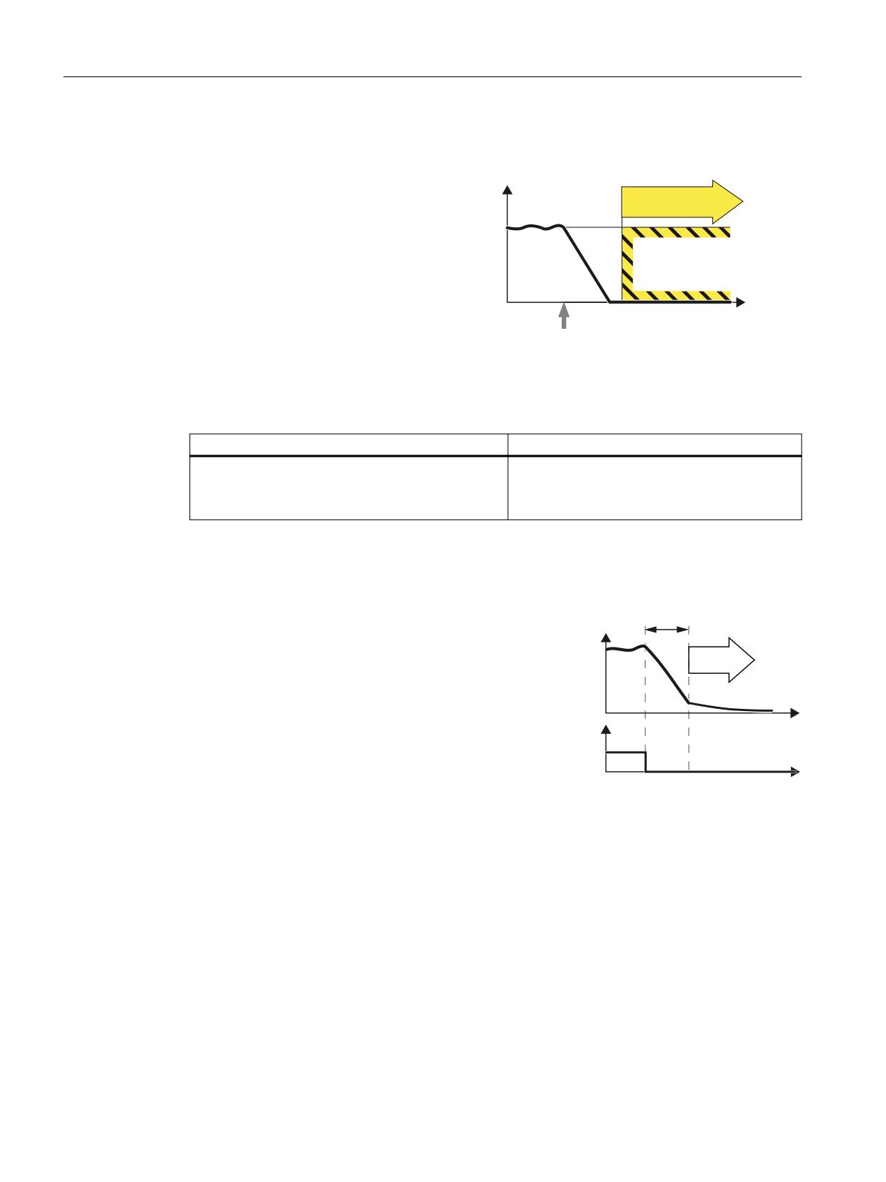
Safety functions integrated in the drive
5.1 SS1 Basic:
5.1
SS1 Basic:
Definition according to EN 61800-5-2:
Y
STO
"The function SS1 brakes the motor and
trips the function STO after a delay time."
W
Select SS1
Example of how the function can be used
Example
Possible solution
A central Emergency Stop button ensures that sev-
● Evaluating an Emergency Stop pushbutton
eral drives are braked as quickly as possible and
in an F-PLC
brought into the STO state.
● Select SS1 via PROFIsafe.
How does SS1 function in detail?
Overview
6DIH 6WRS GHOD\
WLPH
The drive decelerates once "Safe Stop 1" has
6SHHG
been selected, and goes into the "Safe Torque
Off" state once the delay time has expired.
672
W
'HVHOHFW 66
7HUPLQDOV RU
352),VDIH
FRQWURO ZRUG
W
Select SS1
As soon as the converter identifies that SS1 has been selected via a terminal or via the
PROFIsafe safe communication, the following happens:
● If, when selecting SS1, the motor is already switched off, then until the SS1 delay time
expires, there is no response. STO becomes active after the time expires.
● If the motor is switched on when SS1 is selected, the inverter brakes the motor with the
OFF3 ramp-down time. STO is automatically initiated after the delay time has expired.
Safety Integrated plus
80
Commissioning Manual, 12/2019, 6FC5397-1FP40-6BA3
Safety functions integrated in the drive
5.1 SS1 Basic:
5.1.1
Details and parameterization
5.1.1.1
SS1 with OFF3
The "Safe Stop 1" (SS1) function allows the drive to be stopped in accordance with EN 60204-1,
Stop Category 1. The drive decelerates with the OFF3 ramp (p1135) once "Safe Stop 1" is
selected and switches to "Safe Torque Off" once the delay time set in p9652 has elapsed.
Note
Selection via terminals
The selection of the "Safe Stop 1" (time-controlled) function via terminals is parameterized by
setting a delay > 0 in p9652. In this case, the STO function can no longer be selected directly
via terminals, i.e. either STO or SS1 can be selected via terminals.
If the "Safe Stop 1" (time-controlled) function has been selected by parameterizing a delay time
in p9652, STO can no longer be selected directly via terminals.
Functional features of Safe Stop 1
SS1 is enabled by p9652 (delay time) ≠ 0.
● Setting parameter p9652 has the following effect:
- p9652 = 0
SS1 is not enabled. Only STO can be selected via the onboard terminals and PROFIsafe.
- p9652 > 0
SS1 is enabled. Only SS1 can be selected via the onboard terminals; with PROFIsafe,
a selection of SS1 and STO is possible.
● When SS1 is selected, the drive is braked along the OFF3 ramp (p1135) and STO/SBC is
automatically initiated after the delay time has expired (p9652).
After the function has been selected, the delay timer runs down - even if the function is
deselected during this time. In this case, after the delay time has expired, the STO/SBC
function is selected and then again deselected immediately.
Note
Setting the delay time
So that the drive is able to travel down the OFF3 ramp completely and any motor holding
brake present can be applied, before the pulses have been safely deleted, the delay time
should be set as follows:
● Motor holding brake parameterized: Delay time p9652 ≥ p1135 + p1228 + p1217
● Motor holding brake not parameterized: Delay time p9652 ≥ p1135 + p1228
● The setting of parameter p1135 must be oriented towards the actual braking capability
of the drive.
Safety Integrated plus
Commissioning Manual, 12/2019, 6FC5397-1FP40-6BA3
81
Safety functions integrated in the drive
5.1 SS1 Basic:
● The timer (p9652) after whose expiration STO is activated, is implemented with two
channels, although deceleration along the OFF3 ramp is only one channel.
● Effect on "Setpoint speed limit effective" (r9733[0...2]):
For SS1 (≙ STOP B), setpoint 0 is specified in r9733[0...2].
Requirement
● The Basic Functions are enabled via terminals and/or PROFIsafe:
- p9601 = 1, 8 or 9 (hex).
● In order that the drive can brake down to a standstill even when selected through one
channel, the time in p9652 must be shorter than the sum of the parameters for the crosswise
data comparison (p9650 and p9658). Otherwise the drive will coast down after the time
p9650 + p9658 has elapsed.
Status of Safe Stop 1
You can check the status in the SI diagnostics screens via "MENU SELECT > Diagnostics >
Menu forward key > Safety".
5.1.1.2
SS1 with external stop (SS1E)
In drive line-ups (e.g. drives that are mechanically connected via the material), the drive-
independent braking on the respective OFF3 ramp can cause problems. If the SS1E function
is used, the safe delay time (p9652) is started when the function is selected, but no OFF3 is
triggered. The higher-level controller still enters the setpoint.
Note
The function is configurable; however, the brake behavior using SS1E is not supported by the
NC (path stop).
WARNING
Axis motion that is not monitored
During the unmonitored delay time, for "Safe Stop 1 (time-controlled) with external stop", axis
motion is possible that is not monitored. This motion can result in death or severe injury.
● If there is a hazard due to undesirable motion in your application, take measures to counter
it, for example, by using a brake with safe monitoring. For additional information, see
Chapter "SBC (Basic/Extended) (Page 97)".
Safety Integrated plus
82
Commissioning Manual, 12/2019, 6FC5397-1FP40-6BA3
Safety functions integrated in the drive
5.1 SS1 Basic:
Differences between "SS1 with OFF3" and "SS1 with external stop"
"SS1 with OFF3" and "SS1 with external stop" have the following differences:
● In order to activate "Safe Stop 1 with external stop", additionally set p9653 to 1.
● When SS1E is selected, the drive is not braked along the OFF3 ramp, but after the delay
time has expired (p9652), only STO/SBC is automatically initiated.
5.1.1.3
Function diagrams and parameters
Function diagrams (see SINAMICS S120/S150 List Manual)
●
2810
SI Basic Functions - STO (Safe Torque Off), SS1 (Safe Stop 1)
●
2811
SI Basic Functions - STO (Safe Torque Off), safe pulse cancellation
Overview of important parameters (see SINAMICS S120/S150 List Manual)
● p1135[0...n]
OFF3 ramp-down time
● p1217
Motor holding brake closing time
● p1228
Pulse suppression delay time
● p9601
SI enable functions integrated in the drive (Control Unit)
● p9652
SI Safe Stop 1 delay time (Control Unit)
● r9772.0...23
CO/BO: SI Status (Control Unit)
● r9773.0...23
CO/BO: SI Status (Control Unit + Motor Module)
● r9774.0...23
CO/BO: SI Status (group STO)
Only for "Safe Stop 1 (time-controlled) with external stop"
● p9653
SI Safe Stop 1 drive-based braking response
Safety Integrated plus
Commissioning Manual, 12/2019, 6FC5397-1FP40-6BA3
83
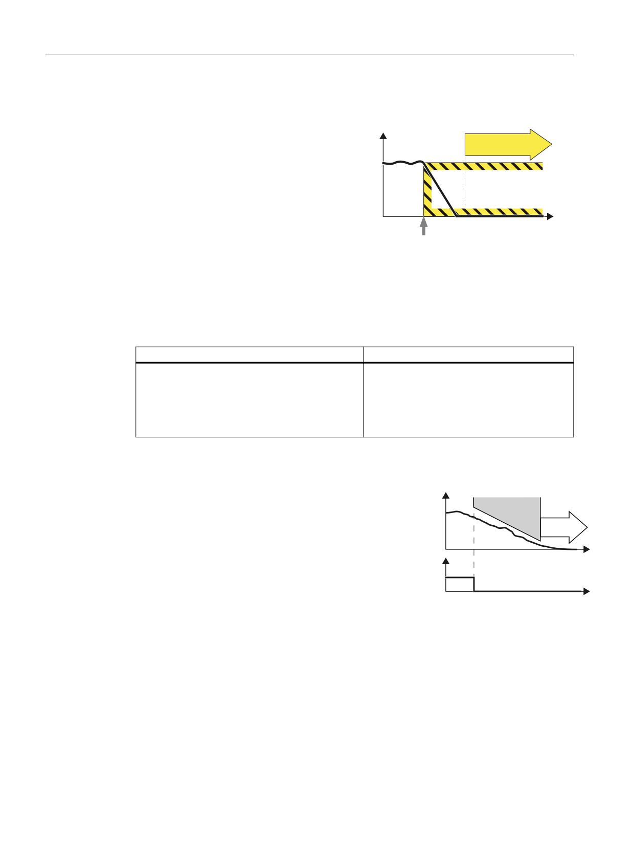
Safety functions integrated in the drive
5.2 SS1
5.2
SS1
Definition according to EN 61800-5-2:
Y
STO
The "SS1" function causes the motor to brake
(this function is integrated in the drive) and ini-
tiates the "Safe Torque Off" (STO) function after
a predefined time interval has elapsed. The fol-
lowing variants are possible:
● SS1-a with acceleration monitoring (SAM)
W
● SS1-r with braking ramp monitoring (SBR)
● Manually set delay time until STO is activa-
Select SS1
ted.
This function corresponds to stop category 1 to
EN 60204-1.
Example of how the function can be used
Example
Possible solution
A central Emergency Stop button ensures that sev-
● Evaluating an Emergency Stop pushbutton
eral drives are braked as quickly as possible and
in an F-PLC
brought into the STO state.
● Select SS1 via PROFIsafe.
● SS1 brakes the drives and then brings them
into the STO state.
How does SS1 function in detail?
Overview
6SHHG
0RQLWRULQJ
Using the SS1 function, the converter brakes
the motor and monitors the absolute speed.
672
If the motor speed is low enough or the delay
time has expired, the converter safely switches
W
66
GHVHOHFWLRQ
off the motor torque using STO .
352),VDIH
FRQWURO ZRUG
W
Select SS1
As soon as the converter identifies that SS1 has been selected via the PROFIsafe safe
communication, the following happens:
● If the motor has already been switched off when selecting SS1 then the converter safely
switches off the motor torque (STO).
● If the motor is switched on when SS1 is selected, the converter brakes the motor with the
AUS3 ramp-down time.
Safety Integrated plus
84
Commissioning Manual, 12/2019, 6FC5397-1FP40-6BA3
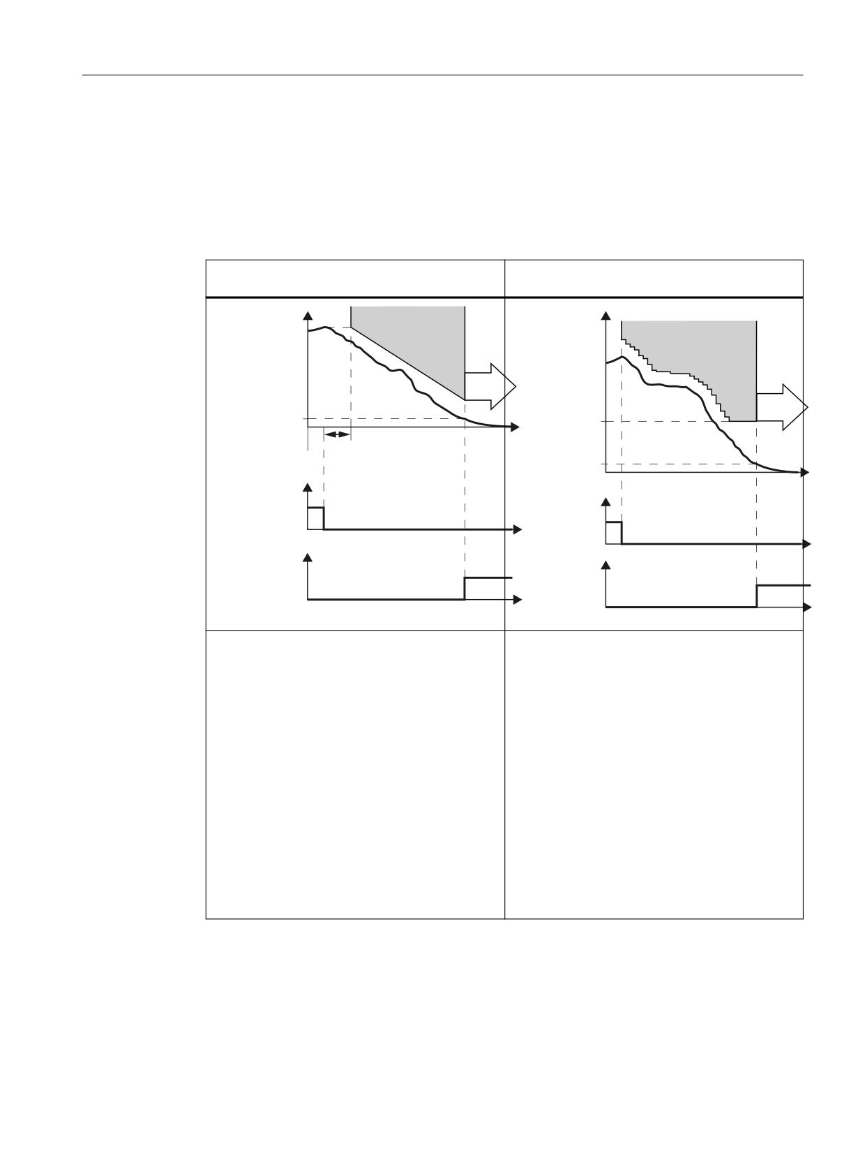
Safety functions integrated in the drive
5.2 SS1
Monitoring modes
● For the Extended Functions with or without encoder, you can choose between 2 different
monitoring modes of the function SS1:
- Safe Brake Ramp (SBR)
- Safe Acceleration Monitor (SAM)
Brake ramp monitoring
Acceleration monitoring
(with or without encoder)
(with or without encoder)
6SHHG
6SHHG
6%5
6$0
6WDQGVWLOO
672
PRQLWRULQJ
6KXWGRZQ
672
YHORFLW\
W
'HOD\ WLPH IRU EUDNH UDPS
6KXWGRZQ
VSHHG 66
66
GHVHOHFWLRQ
W
352),VDIH
66
GHVHOHFWLRQ
FRQWURO ZRUG
352),VDIH
FRQWURO ZRUG
W
672
W
DFWLYH
672 DFWLYH
) '2 RU
) '2 RU
352),VDIH
352),VDIH
VWDWXV ZRUG
W
VWDWXV ZRUG
W
● Using the SBR (Safe Brake Ramp) function,
● The converter monitors the speed of the motor
the converter monitors whether the motor
with the SAM function.
speed decreases.
● The converter prevents the motor from accel-
● The gradient of the SBR function can be set via
erating again by having the monitoring function
the reference velocity and the ramp-down time.
continuously track the speed as it decreases.
The SBR function only starts after the "Delay
● The converter reduces the monitoring thresh-
for braking ramp".
old until the "Shutdown speed" has been
● The SBR function starts with the speed set-
reached.
point, which was present at the instant in time
● The converter safely switches off the motor tor-
that SS1 was selected.
que (STO), if one of the following conditions is
● If the converter detects that the speed has fall-
fulfilled:
en below the speed threshold (standstill moni-
- The speed has fallen below the shutdown
toring), it safely switches off the motor torque
speed SS1.
(STO).
- The maximum time until the torque is
switched off has expired.
Safety Integrated plus
Commissioning Manual, 12/2019, 6FC5397-1FP40-6BA3
85
Safety functions integrated in the drive
5.2 SS1
Note
SS1 with external stop (SS1E)
If you use "SS1 with external stop", neither of the two monitoring functions (SBR, SAM) is
active. For SS1E, the drive must be stopped within the delay time, for example via the PLC
program. STO becomes active after the delay time expires.
5.2.1
Details and parameterization
5.2.1.1
Safe Stop 1 (SS1, time and acceleration controlled)
For function SS1 of the Extended Safety Functions, braking monitoring is included.
● For p9506 = 0, the following applies:
Braking is monitored with the "Safe Acceleration Monitor" function (see Chapter "SAM
(Page 137)").
In this case, we also talk about "SS1 (time and acceleration controlled)".
● For p9506 = 2, the following applies:
Here, also for SS1, the monitoring function "Safe Brake Ramp" is active (see Chapter "SBR
(Page 139)").
In this case, we also talk about "SS1 (speed controlled)".
The "Safe Stop 1" (SS1) function allows the drive to be stopped according to EN 60204-1, Stop
Category 1. The drive brakes with the OFF3 ramp (p1135) once "Safe Stop 1" is selected and
switches to "Safe Torque Off" (STO) once the delay time has elapsed (p9556) or when the
shutdown speed is fallen below (p9560).
Functional features of Safe Stop 1 with encoder
● The delay time starts after the function has been selected. If SS1 is deselected again within
this time, the STO function is selected and deselected immediately again after the delay
time has expired or if the speed drops below the shutdown speed; i.e. the SS1 function is
terminated normally. It cannot be interrupted.
● Selection and monitoring of the acceleration (SAM) or the monitoring function "Safe Brake
Ramp" are implemented in two channels, but braking along the OFF3 ramp is only
implemented in one channel.
● Effect on "Setpoint speed limit effective" (r9733[0...2]):
For SS1 (≙ STOP B), setpoint 0 is specified in r9733[0...2].
Commissioning
The delay time (SS1 time) is set by entering parameter p9556. The wait time until safe pulse
suppression (STO) can be shortened by defining a shutdown speed in p9560.
Safety Integrated plus
86
Commissioning Manual, 12/2019, 6FC5397-1FP40-6BA3
Safety functions integrated in the drive
5.2 SS1
To enable the drive to brake to standstill after selection, the time in p9556 must be selected to
be long enough for the drive to be able to brake along the OFF3 ramp (p1135) from any speed
of the underlying process to below the shutdown speed (p9560).
Note
Setting the delay time
So that the drive is able to travel down the OFF3 ramp completely and any motor holding brake
present can be applied, the delay time should be set as follows:
● Motor holding brake parameterized: Delay time ≥ p1135 + p1228 + p1217
● Motor holding brake not parameterized: Delay time ≥ p1135 + p1228
The shutdown speed defined in p9560 must be set in such a way that coasting down (due to the
subsequent STO function) does not represent any risk for man and machine.
Responses
System fault:
1. STOP F with subsequent STOP B, followed by STOP A
2. Safety message C01711
Status of Safe Stop 1
You can check the status in the SI diagnostics screens via "MENU SELECT > Diagnostics >
Menu forward key > Safety".
5.2.1.2
Safe Stop 1 without encoder
Two encoderless Safe Stop 1 (SS1) monitoring functions can be set with parameter p9506:
● p9506 = 3: Safe monitoring of acceleration (SAM) / delay time
The function is identical to "Safe Stop 1" with encoder (Page 86).
In this case, we also talk about "SS1 (time and acceleration controlled)".
● p9506 = 1: Safe brake ramp monitoring (SBR)
In this case, there is no SS1 delay time active. The transition from SS1 to STO depends
entirely on the speed falling below the shutdown speed (p9560). You will find more
information on the function "Safe Brake Ramp (SBR)" in Chapter "SBR (Page 139)." In this
case, we also talk about "SS1 (speed controlled)".
Safety Integrated plus
Commissioning Manual, 12/2019, 6FC5397-1FP40-6BA3
87
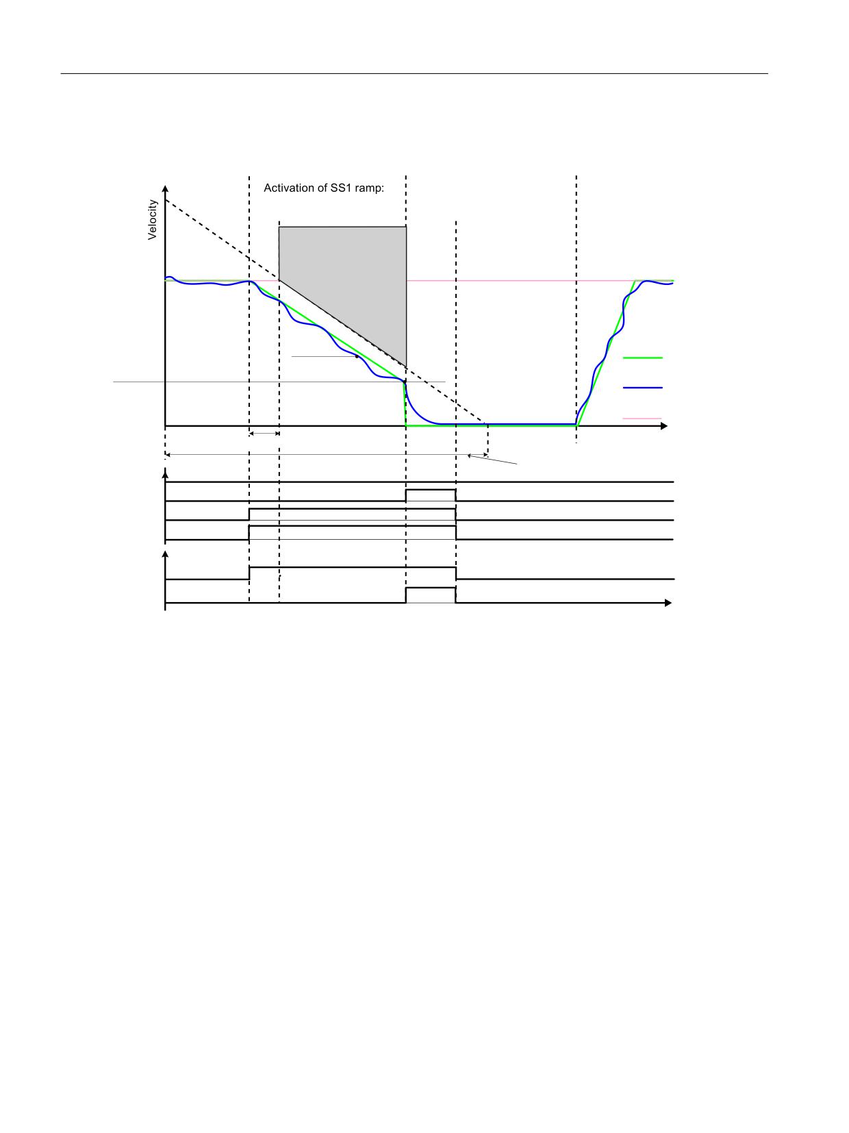
Safety functions integrated in the drive
5.2 SS1
6HOHFWLQJ WKH 66 UDPS
$FWLYDWLRQ RI 672
6WDUW GULYH
8VHU DFWLRQ
8VHU DFWLRQ
8VHU DFWLRQ
6HW 66
VLJQDO
1RQH
6HW 2))
21 VLJQDO
5HIHUHQFH
YHORFLW\
'HVHOHFWLQJ WKH 66 UDPS
8VHU DFWLRQ
8VHU DFWLRQ
1RQH
5HVHW 66
VLJQDO
(QYHORSH
PRQLWRULQJ UDPS
6WDWRU
VSHHG
2)) UDPS
5RWRU
=HUR VSHHG
672
VSHHG
GHWHFWLRQ
6HWSRLQW
VSHHG
W
6%5 GHOD\ WLPH S
'LDJQRVWLFV
0RQLWRULQJ UDPS 'URSRXW WLPH
672 VHOHFWHG
672 DFWLYH
66 VHOHFWHG
66 DFWLYH
352),VDIH
66 DFWLYH
3RZHU UHPRYHG
W
Figure 5-1
Sequence for "Safe Stop 1" without encoder with SBR monitoring (p9506 = 1)
Functional feature of Safe Stop 1 without encoder
● Selection and monitoring of the brake ramp (SBR) or the acceleration (SAM) are
implemented in two channels, however braking at the OFF3 ramp is only through one
channel.
Safety Integrated plus
88
Commissioning Manual, 12/2019, 6FC5397-1FP40-6BA3
Safety functions integrated in the drive
5.2 SS1
5.2.1.3
SS1 (Extended Functions) with external stop
General description
WARNING
Unexpected axis motion when the SS1E function is active
When the SS1E function is active, during the monitored delay time, axis motion that is not
monitored can occur. This can result in death or severe injury.
● Prevent persons from entering the hazardous area around the axis, e.g. by providing
protective doors or other suitable protective equipment.
With external stop, "Safe Stop 1" basically works exactly as described in the previous Chapters
"Safe Stop 1 with encoder (time and acceleration controlled)" and "Safe Stop 1 without encoder
(speed controlled)." Note, however, the following differences:
Differences between "Safe Stop 1 with OFF3" and "SS1 with external stop"
● In order to activate "Safe Stop 1 with external stop", additionally set p9507.3 = 1.
● When SS1 with external stop is selected, the drive is not braked along the OFF3 ramp: You
are responsible in applying suitable measures to brake the drive. After the delay time has
expired (p9556), only STO/SBC are automatically initiated. After the function has been
selected, the delay timer runs down - even if the function is deselected during this time. In
this case, after the delay time has expired, the STO/SBC function is selected and then again
deselected immediately.
● The brake ramp (SBR) and the acceleration (SAM) are not monitored and there is no
standstill detection.
● With this configuration, STO becomes active after the SS1 timer p9556 has expired; this
also applies if SBR has been configured.
● Further information can be found in Section Extended Functions (Page 319).
Constraint
Note
The function is configurable; however, the brake behavior using SS1E is not supported by the
NC (path stop).
See also
SBC (Basic/Extended) (Page 97)
Safety Integrated plus
Commissioning Manual, 12/2019, 6FC5397-1FP40-6BA3
89
Safety functions integrated in the drive
5.2 SS1
5.2.1.4
Function diagrams and parameters
Function diagrams (see SINAMICS S120/S150 List Manual)
●
2819
SI Extended Functions - SS1, SS2, SOS, internal STOP B, C, D, F
Overview of important parameters (see SINAMICS S120/S150 List Manual)
● p1135[0...n]
OFF3 ramp-down time
● p9501
SI Motion enable safety functions (Control Unit)
● p9506
SI Motion function specification (Control Unit)
● p9556
SI Motion STOP A delay time (Control Unit)
● p9560
SI Motion STO shutdown speed (Control Unit)
● r9722.0...15
CO/BO: SI Motion drive-integrated status signals
Only for SS1 (Extended Functions) with external stop
● p9507
SI Motion function configuration (Control Unit)
Safety Integrated plus
90
Commissioning Manual, 12/2019, 6FC5397-1FP40-6BA3
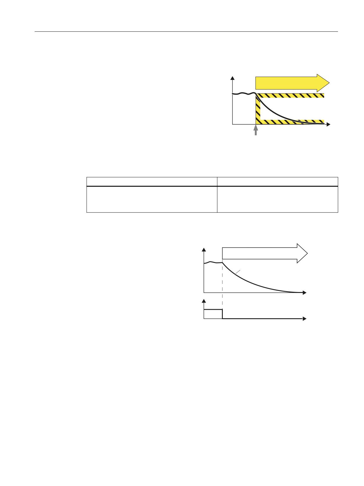
Safety functions integrated in the drive
5.3 STO (Basic/Extended)
5.3
STO (Basic/Extended)
Definition according to EN 61800-5-2:
Y
STO
"The STO function prevents energy from being
supplied to the motor, which can generate a tor-
que."
W
Select STO
Examples of how the function can be used
Example
Possible solution
It is only permissible to open a protective door if the
● Select STO in the converter.
motor torque has been switched off.
● The pulses are suppressed and the motor
coasts to a standstill.
How does STO function in detail?
The converter recogni-
6SHHG
zes the selection of
672
STO via a failsafe input
or via the safe commu-
7KH PRWRU WRUTXH LV
VZLWFKHG RII
nication PROFIsafe.
The converter then
safely switches off the
W
torque of the connected
672 GHVHOHFWLRQ
motor.
352),VDIH FRQWURO
ZRUG
W
5.3.1
Details and parameterization
In conjunction with a machine function or in the event of a fault, the "Safe Torque Off" (STO)
function is used to safely disconnect the torque-generating energy supply to the motor.
A restart is prevented by the two-channel pulse suppression. The switching on inhibited
prevents an automatic restart after deselection of STO.
The two-channel pulse suppression function integrated in the Motor Modules / Power Modules
is the basis for this function.
Safety Integrated plus
Commissioning Manual, 12/2019, 6FC5397-1FP40-6BA3
91
Safety functions integrated in the drive
5.3 STO (Basic/Extended)
Functional features of "Safe Torque Off"
● The function is completely integrated in the drive. It can be selected via terminals or
PROFIsafe from an external source.
● The function is drive-specific, i.e. it is available for each drive and must be individually
commissioned.
● The function must be enabled via parameter.
● When the "Safe Torque Off" function is selected, the following applies:
- The motor cannot be started accidentally.
- The pulse suppression safely disconnects the torque-generating energy supply to the
motor.
- The power unit and motor are not electrically isolated.
● The selection/deselection of the STO function also acknowledges the safety faults when the
Basic Functions are used. The standard acknowledgment mechanism must also be
performed.
● Extended acknowledgment:
The selection/deselection of STO can also acknowledge the safety messages of the
extended safety functions. This means that you must configure the extended message
acknowledgment (p9507.0 = 1).
If in addition to the "Extended Functions", the "Basic Functions via terminals" are also
enabled, in addition to selection/deselection of STO via PROFIsafe (Page 328),
acknowledgement is also possible by selection/deselection of STO via terminals.
● The status of the "Safe Torque Off" function is displayed using parameters (r9772, r9872,
r9773 and r9774).
● Effect on "Setpoint speed limit effective" (r9733[0...2]):
For STO (≙ STOP A), a setpoint of 0 is specified in r9733[0...2].
WARNING
Unexpected machine motion when STO is active
After the energy feed has been disconnected (STO active) the motor can undesirably move
(e.g. the motor can coast down), therefore presenting risk to persons.
● Take suitable measures to prevent undesirable movement, e.g. by using a brake with
safety-relevant monitoring. You can find additional information in Chapter "SBC (Basic/
Extended) (Page 97)".
WARNING
Unexpected motor movement as a result of defective power transistors
Undesirable motor motion1) can occur if 2 power transistor simultaneously become defective
(breakdown of the depletion layer). This can result in accidents leading to death or severe
injury.
● Take suitable measures to prevent undesirable movement, e.g. by using a brake with
safety-relevant monitoring. You can find additional information in Chapter "SBC (Basic/
Extended) (Page 97)".
Safety Integrated plus
92
Commissioning Manual, 12/2019, 6FC5397-1FP40-6BA3
Safety functions integrated in the drive
5.3 STO (Basic/Extended)
1)
The maximum movement can involve:
● Synchronous rotary motors: Max. movement = 180° / no. of pole pairs
● Synchronous linear motors: Max. movement = pole width
Enabling the "Safe Torque Off" function
The "Safe Torque Off" function is enabled via parameter p9601:
● STO for the Safety Integrated Basic Functions:
- p9601 = 1 hex (Basic Functions via onboard terminals)
- p9601 = 8 hex (Basic Functions via PROFIsafe)
- p9601 = 9 hex (Basic Functions via PROFIsafe and onboard terminals)
● STO for the Safety Integrated Extended Functions:
- p9601 = C hex (Extended Functions via PROFIsafe)
- p9601 = D hex (extended functions via PROFIsafe and basic functions via onboard
terminals)
- p9601 = 25 hex (Extended Functions without selection and Basic Functions via onboard
terminals)
Selecting/deselecting "Safe Torque Off"
The following is executed when "Safe Torque Off" is selected:
● Each monitoring channel triggers safe pulse suppression via its switch-off signal path.
● A motor holding brake is closed (if connected and configured).
Deselecting "Safe Torque Off" represents an internal safety acknowledgment. The following is
executed if the cause of the fault has been removed:
● Each monitoring channel cancels safe pulse suppression via its switch-off signal path.
● The Safety requirement "Close motor holding brake" is canceled.
● Any pending STOP F or STOP A commands are canceled (see r9772).
● The messages in the fault memory must also be reset using the general acknowledgment
mechanism.
Note
No message for selection/deselection within the tolerance time (p9650)
If "Safe Torque Off" is selected and deselected through one channel within the tolerance
time p9650, the pulses are suppressed without a message being output.
However, if you want a message to be displayed, then you must reconfigure N01620 as an
alarm or fault using p2118 and p2119.
Restart after the "Safe Torque Off" function has been selected
1. Deselect the function.
2. Set drive enables.
Safety Integrated plus
Commissioning Manual, 12/2019, 6FC5397-1FP40-6BA3
93
Safety functions integrated in the drive
5.3 STO (Basic/Extended)
Status for "Safe Torque Off"
You can check the status in the SI diagnostics screens via "MENU SELECT > Diagnostics >
Menu forward key > Safety".
Internal armature short-circuit with the "Safe Torque Off" function
The function "internal armature short-circuit" can be configured together with the "STO"
function.
The "STO" safety function has the higher priority when simultaneously selected. If the "STO"
function is initiated, then an activated "internal armature short-circuit" is disabled.
Function diagrams (see SINAMICS S120/S150 List Manual)
●
2810
SI Basic Functions - STO (Safe Torque Off), SS1 (Safe Stop 1)
●
2811
SI Basic Functions - STO (Safe Torque Off), safe pulse suppression
Overview of important parameters (see SINAMICS S120/S150 List Manual)
● p9601
SI enable functions integrated in the drive (Control Unit)
● r9720
CO/BO: SI Motion drive-integrated control signals
● r9722
CO/BO: SI Motion drive-integrated status signals
● r9772
CO/BO: SI Status (Control Unit)
● r9773
CO/BO: SI Status (Control Unit + Motor Module)
● r9774
CO/BO: SI Status (group STO)
For the HLA module, Safe Torque Off (STO) corresponds to shutting off a safety-relevant
shutoff valve.
Special features of STO for HLA
● The shutoff valve controls the infeed to the hydraulic circuit. The shutoff valve is controlled
via an F-DO of SINAMICS HLA.
● For Safety Integrated Functions, it is absolutely necessary that a shutoff valve is connected
with the associated feedback signals.
● You configure the feedback signal contacts of the shutoff valve using parameter p9626.
● You can take into account the response times of the feedback signals using parameter
p9625.
Safety Integrated plus
94
Commissioning Manual, 12/2019, 6FC5397-1FP40-6BA3
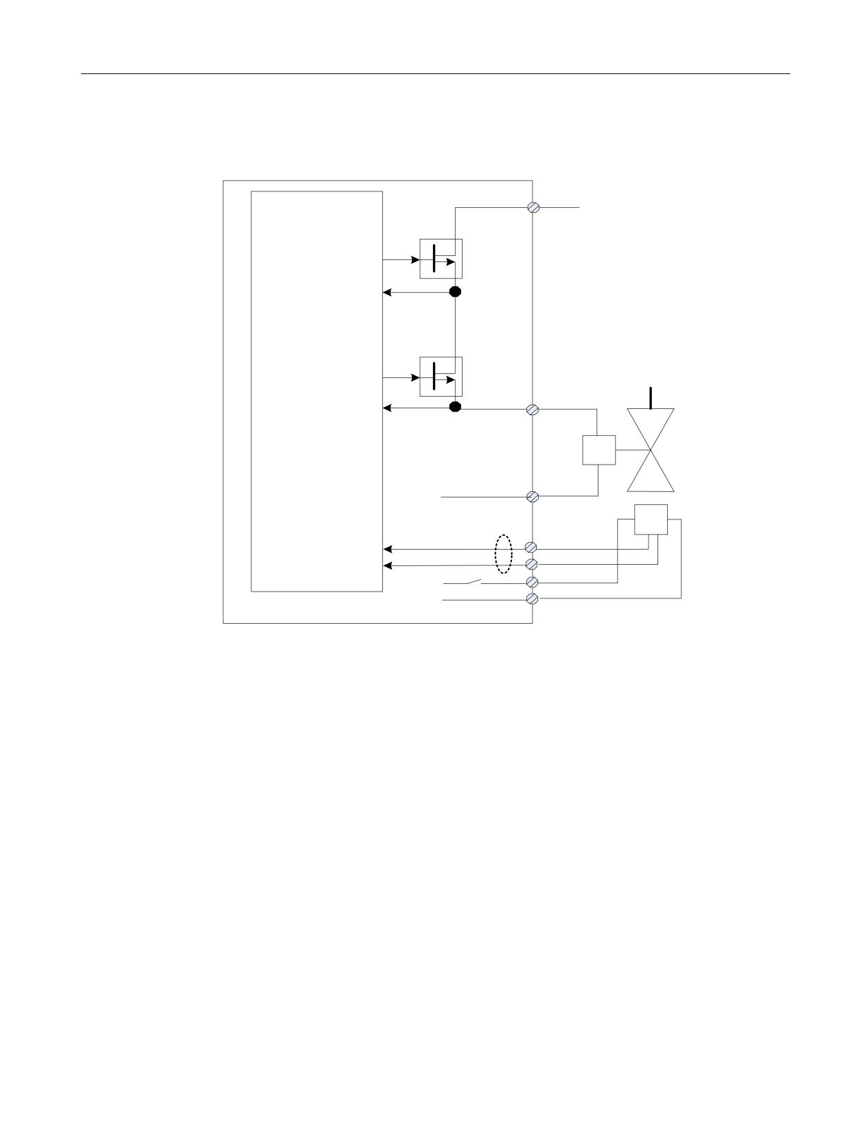
Safety functions integrated in the drive
5.3 STO (Basic/Extended)
● The shutoff valve is safely closed by selecting STO. If the shutoff valve signals a safe state
via the feedback signal(s), the "STO active/Power removed" state is displayed, and is output
at the configured safety-relevant output (PROFIsafe feedback signal telegram).
9 H[W
;
) '2
'LDJ '2
) '2
;
'LDJ '2
&RQ
6KXWRII YDOYH
WURO
;
0
)HHGEDFN
1& FRQWDFW 12
VLJQDOV
;
FRQWDFW
',
',
9
0
Figure 5-2
Interconnecting the shutoff valve (for an axis)
● F-DO is dynamized each time that STO is selected/deselected: "Diag DO+" and "Diag DO-"
are checked when switching F-DO+ and F-DO-.
● It is not necessary to explicitly select a test stop/forced checking procedure.
● If, for test stop/forced checking procedure, a fault occurs, then the converter outputs fault
F01632 or F30632.
Function diagrams (see SINAMICS S120/S150 List Manual)
●
2810
SI Basic Functions - STO (Safe Torque Off), SS1 (Safe Stop 1)
●
2811
SI Basic Functions - STO (Safe Torque Off), safe pulse suppression
Overview of important parameters (see SINAMICS S120/S150 List Manual)
● p9625[0...1]
SI HLA shutoff valve wait time (CU)
● p9626
SI HLA shutoff valve feedback contacts configuration (CU)
● r9773
CO/BO: SI Status (Control Unit + Motor Module)
Safety Integrated plus
Commissioning Manual, 12/2019, 6FC5397-1FP40-6BA3
95
Safety functions integrated in the drive
5.3 STO (Basic/Extended)
● r9774
CO/BO: SI Status (group STO)
● r9780
SI monitoring cycle (Control Unit)
Safety Integrated plus
96
Commissioning Manual, 12/2019, 6FC5397-1FP40-6BA3
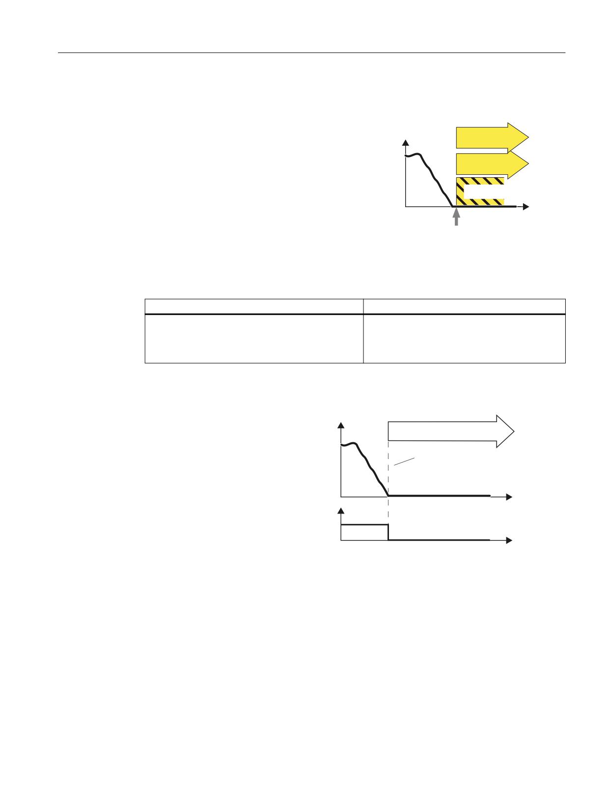
Safety functions integrated in the drive
5.4 SBC (Basic/Extended)
5.4
SBC (Basic/Extended)
Definition according to EN 61800-5-2:
6SHHG
STO
"The SBC function supplies a safe output
signal to control a holding brake."
SBC
W
6HOHFW 672
Safe Brake Control (SBC)
Example of how the function can be used
Example
Possible solution
The safe control of a motor holding brake must be
SBC is (if configured) initiated together with
guaranteed in order to guarantee the motor is at a
STO. The Motor Module / Safe Brake Relay /
standstill.
Safe Brake Adapter then carries out the action
and safely controls the outputs for the brake.
How does SBC function in detail?
The converter recogni-
6SHHG
zes the selection of
672 6%&
STO via a failsafe input
or via the safe commu-
7KH PRWRU WRUTXH LV VZLWFKHG RII
nication PROFIsafe.
6%& FRQWUROV D EUDNH VDIHO\
The converter then
safely switches off the
W
torque of the connected
672 GHVHOHFWLRQ
motor.
352),VDIH FRQWURO
ZRUG
SBC is (if configured) in-
W
itiated together with
STO. The Motor Mod-
ule / Safe Brake Relay /
Safe Brake Adapter
then carries out the ac-
tion and safely controls
the outputs for the
brake.
Safety Integrated plus
Commissioning Manual, 12/2019, 6FC5397-1FP40-6BA3
97
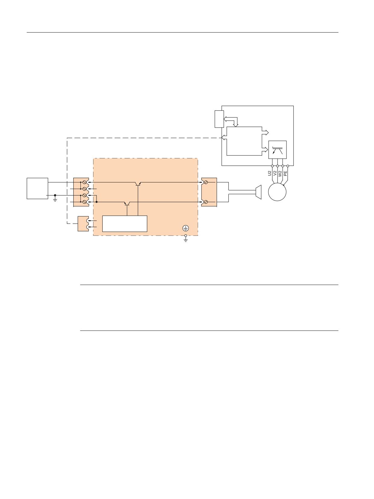
Safety functions integrated in the drive
5.4 SBC (Basic/Extended)
5.4.1
Hardware required
● Safe Brake Relay
The command for releasing or applying the brake is transferred to the Motor Module / Power
Module via DRIVE-CLiQ. The Motor Module / Safe Brake Relay then carries out the action
and appropriately activates the outputs for the brake.
Power Module
PM-IF interface
Cable harness
Safe Brake Relay
+
+
ext.
+
BR+
24 V
M
M
M
3 ~
M
BR-
CTRL
Figure 5-3
Interconnecting the Safe Brake Relay using Blocksize as an example
The brake cannot be directly connected to the Motor Module in the chassis format. The
connection terminals are only designed for 24 VDC with 150 mA; the Safe Brake Adapter is
required for higher currents and voltages.
Note
Additionally required hardware for other formats
A Safe Brake Relay is also required for the "Safe Brake Control" in the blocksize format. A Safe
Brake Adapter is required in the chassis format (starting with order numbers with the
ending ...xxx3). The Safe Brake Adapter is available for a 230 V AC brake control voltage.
Safety Integrated plus
98
Commissioning Manual, 12/2019, 6FC5397-1FP40-6BA3
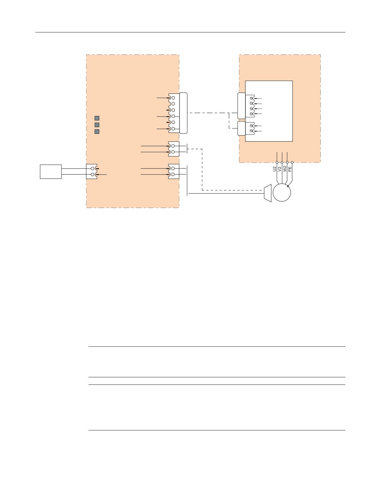
Safety functions integrated in the drive
5.4 SBC (Basic/Extended)
Safe Brake Adapter
Motor Module /
SBA
Power Module
230 V AC
Control Interface
-X11
Module (CIM)
-X46
BR+
1
1
BR output +
BR- 2
Connecting cable
2
BR output -
FB+ 3
3
FB input +
6SL3060-4DX04-0AA0
LEDs
FB-
4
4
FB input -
230 V OK
P24 5
-X42
K1 ON
M
6
2
P24
K2 ON
3
M
-X15
Fast
AUX1
1
de-excitation
AUX2
2
External
supply voltage
-X12
-X14
1
L
SBA_BR_L
1
G_D213_DE_00091b
230 V AC
2
N
SBA_BR_N
2
M
3 ~
Figure 5-4
Interconnecting the Safe Brake Adapter
5.4.2
Details and parameterization
The "Safe Brake Control" function (SBC) is used to safely control holding brakes that function
according to the closed-circuit principle (e.g. motor holding brake).
The opening and closing of the brake is controlled by the Motor Module / Power Module.
Terminals are available for this on the device in booksize format. A Safe Brake Relay is also
required for the "Safe Brake Control" in the blocksize format. With the chassis format (article
numbers ending 3 or higher), a Safe Brake Adapter is required. When the Power Module is
configured automatically, the Safe Brake Relay is detected and the motor holding brake type is
defaulted (p1278 = 0).
Brake activation via the brake connection on the Motor Module / Safe Brake Relay (SBR) / Safe
Brake Adapter (SBA) involves a safe, two-channel method.
Note
No SBC for SINAMICS HLA
SINAMICS HLA does not support Safe Brake Control.
Note
Controlling the brake via a relay for "Safe Brake Control":
If you use the "Safe Brake Control (SBC)" function, the use of relays/contactors can cause
faults in the brake control when brakes are switched. For this reason, this type of control is not
generally enabled.
Safety Integrated plus
Commissioning Manual, 12/2019, 6FC5397-1FP40-6BA3
99
Safety functions integrated in the drive
5.4 SBC (Basic/Extended)
An interrupted cable or a short-circuit in the brake winding is only detected when the state
changes, i.e. when the brake either opens or closes. For devices in the chassis format with
connected Safe Brake Adapter, the connecting cable between the Safe Brake Adapter and the
motor brake is not monitored for an interrupted cable or short-circuit.
WARNING
Undesirable motor motion due to a defective brake
The "Safe Brake Control" function does not detect mechanical defects of the brake. A
defective brake can result in unwanted motor motion, which may result in injury or death.
● Test the brake using the Safety Integrated diagnostics function "Safe Brake Test (SBT)"
(for further information, see Section "Enabling the function (Page 163)").
Functional features of "Safe Brake Control"
● SBC is executed when "Safe Torque Off" (STO) is selected.
● In contrast to conventional brake control, SBC is executed via two channels.
● SBC is executed regardless of the brake control or mode set in p1215. SBC is not
recommended, however, when 1215 = 0 or 3.
● The function must be enabled using parameters.
● When the state changes, electrical faults, such as a short-circuit in the brake winding or wire
breakage can be detected.
Enabling the "Safe Brake Control" function
The "Safe Brake Control" function is enabled via parameter p9602.
The SBC function can be used only together with STO. The selection of SBC alone is not
possible.
Two-channel brake control
Note
Connecting the brake
The brake cannot be directly connected to the Motor Module in chassis format: A Safe Brake
Adapter is also required.
The brake is controlled from the Control Unit. Two signal paths are available for applying the
brake.
Safety Integrated plus
100
Commissioning Manual, 12/2019, 6FC5397-1FP40-6BA3
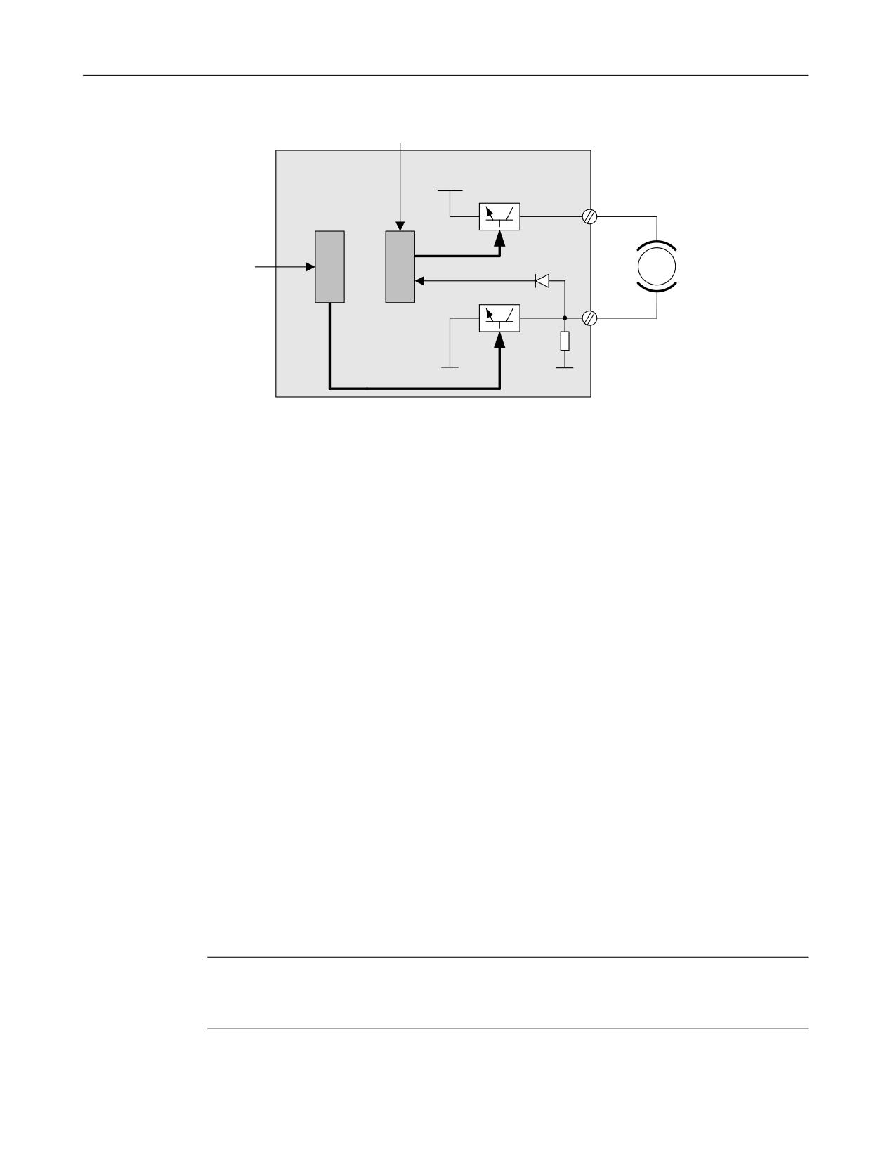
Safety functions integrated in the drive
5.4 SBC (Basic/Extended)
&RQWURO WHUPLQDO
&RQWURO 8QLW 0RWRU
0RGXOH 6DIH %UDNH
3
5HOD\
7%
&ORVHG FLUFXLW EUDNH
%5
&RQWURO
%5
WHUPLQDO
0RWRU
%UDNH GLDJQRVWLFV
7%
%5
0
0
%5
Figure 5-5
Two-channel brake control, blocksize (example)
For the "Safe Brake Control" function, the Motor/Power Module assumes a monitoring function
to ensure that when the Control Unit fails or malfunctions, the brake current is interrupted
therefore closing the brake.
The brake diagnosis can only reliably detect a malfunction in either of the switches (TB+, TB-)
when the status changes, i.e. when the brake is released or applied.
If the Motor Module or Control Unit detects a fault, the brake current is switched off. The brake
then closes and a safe state is reached.
5.4.2.1
SBC for Motor Modules in the chassis format
To be able to set higher power in the brakes of devices of this format, an additional Safe Brake
Adapter (SBA) module is needed. For more information about connecting and wiring the Safe
Brake Adapter, refer to the "SINAMICS G130/G150/S120 Chassis/S120 Cabinet Modules/
S150 Safety Integrated" Function Manual.
Using parameter p9621, you can define via which digital input the relay (NO contacts) feedback
signal of the Safe Brake Adapter is routed to the Control Unit.
To evaluate the feedback signal contacts, you must maintain the wait times caused by the SBA.
Parameter p9622 is pre-assigned with the SBA-relay wait times:
● p9622[0] ≙ wait time, switching on
● p9622[1] ≙ wait time, switching off
Further functionality and the activation of the brake, i.e. reaching the safe status, are in this case
the same as the above described procedure for booksize devices.
Safe Brake Control with power units in a parallel connection
Note
SBC for parallel connection of power units
Safe Brake Control with power units in a parallel connection is available if r9771.14 = 1.
Safety Integrated plus
Commissioning Manual, 12/2019, 6FC5397-1FP40-6BA3
101
Safety functions integrated in the drive
5.4 SBC (Basic/Extended)
If you wish to use SBC with SBA for chassis format power units connected in parallel, then it is
only permissible that you connect precisely one SBA to a power unit in the parallel connection.
The Safe Brake Adapter and therefore the brake are controlled via this power unit.
There are two options for registering this power unit with the system:
● Automatic brake identification when commissioning the system for the first time
- Requirements:
- No Safety Integrated Functions enabled
- p1215 = 0 (no motor holding brake available)
- During the first commissioning, SINAMICS checks at which power unit an SBA is
connected. If precisely one SBA is found, the number of the power unit is entered into
parameter p7015.
If several SBAs are found at the parallel-connected power units, message "F07935
drive: Motor holding brake configuration error" is output.
- For devices in the chassis format, if the SBA feedback signal (SBA_DIAG) is read in via
an input of the power unit, then in addition, this digital input is automatically entered into
parameter p9621.
● Manually defining the power unit
- Enter the component number of the power unit, to which the SBA is connected, into
parameter p7015. If no SBA is connected to the power unit, faults are detected when
controlling the motor holding brake and fault F01630 is output.
- In parameter p9621 (p9621 = BICO interconnection to r9872.3), enter the digital input of
the power unit to which the SBA is connected and via which the SBA feedback signal
(SBA_DIAG) is read in.
Note
Disconnecting the brake cable for service purposes
As long as the brake is permanently released and not actuated, it is possible to briefly
disconnect the brake cable, e.g. for service purposes, and not receive fault messages. In the
case of a fault, message F07935 is only output when the brake is controlled.
5.4.2.2
Function diagrams and parameters
Function diagrams (see SINAMICS S120/S150 List Manual)
●
2814
SI Basic Functions - SBC (Safe Brake Control), SBA (Safe Brake Adapt-
er)
Overview of important parameters (see SINAMICS S120/S150 List Manual)
● p0799
CU inputs/outputs, sampling time
● p1215
Motor holding brake configuration
● p7015
Par_circuit holding brake power unit data set
Safety Integrated plus
102
Commissioning Manual, 12/2019, 6FC5397-1FP40-6BA3