SINUMERIK 840D sl. Service - Configuring Commissioning. Manual (2011-2020) - page 86
Configuring screen objects
9.5 Selecting and editing a part program
9.5
Selecting and editing a part program
In SINUMERIK Integrate Create MyHMI /WinCC, the familiar picture objects from WinCC
flexible for selecting and editing part programs are no longer available (picture objects
"Fileviewer" and "Fileeditor").
Instead, you can now configure the functions for selecting and editing subprograms directly in
SINUMERIK Operate.
Selecting and editing subprograms by the operator
The operator can edit subprograms directly in SINUMERIK Operate by using the "Program
Manager" function:
Using the Program Manager, the user can access programs at any time to run them, edit them,
copy or rename them.
You can find a detailed description in the Operating Manual SINUMERIK 840D sl/828D
Universal in the section "Managing programs" (https://support.industry.siemens.com/cs/
document/109481514/).
Restricting operator access to SINUMERIK Operate
You can also determine the control options available to the user (for example, softkeys) directly
in SINUMERIK Operate:
● For example, you can disable all functions except the Program Manager for the operator.
● You can also disable individual functions within the Program Manager.
To do this, assign the individual softkeys different access levels in SINUMERIK Operate.
You can find a detailed description in the Commissioning Manual SINUMERIK Operate (IM9)
in the section "Access levels for softkeys" (https://support.industry.siemens.com/cs/document/
109481529/).
SINUMERIK Integrate Create MyHMI /WinCC V16
142
Configuration Manual, 12/2019, 6FC5397-8FP40-0BA2
Configuring screen objects
9.6 Screen object Application View
9.6
Screen object Application View
9.6.1
Properties and configuration
The "Application view" screen object permits the positioning of a frameless client area within
WinCC RT Advanced, in which an external application is displayed during runtime. The
application to be integrated must meet the requirements (Page 146) and be tested during
runtime based on the configuration to ensure that it does not lead to any unintended behavior.
Configuration
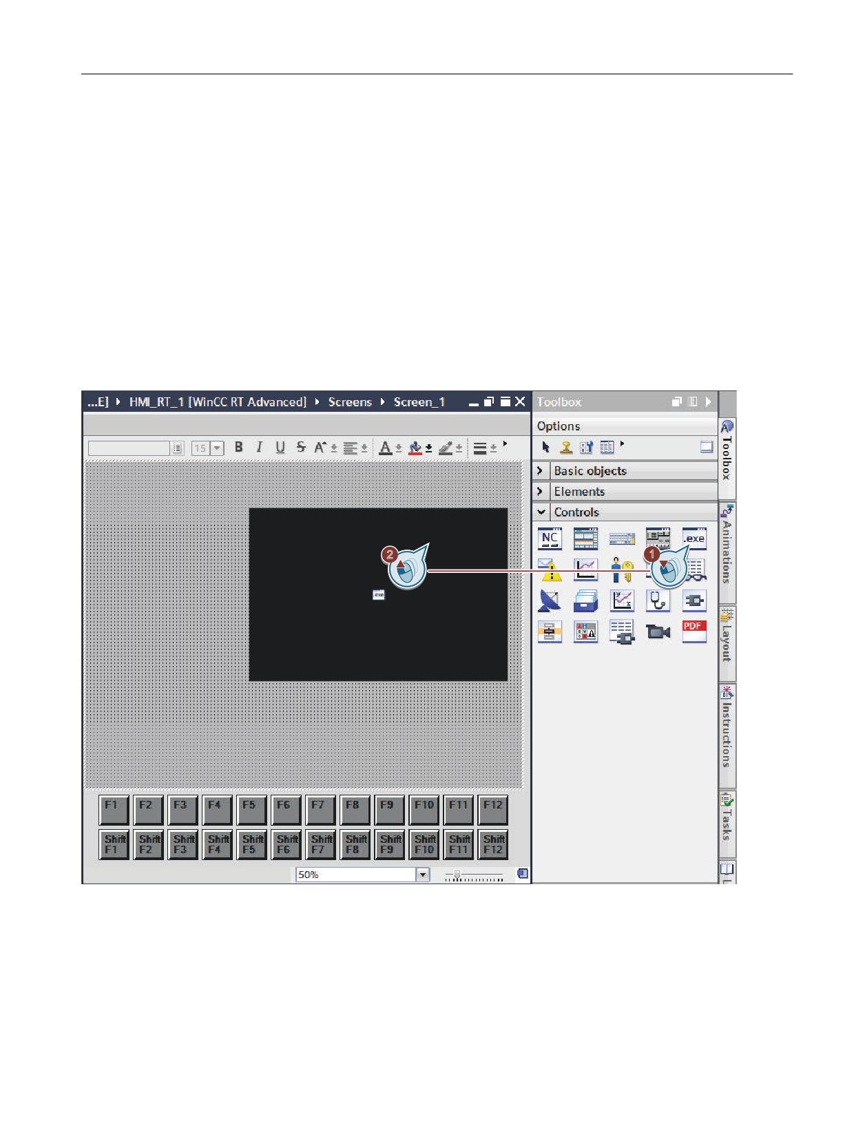
You will find the screen object on the task card "Tools" below "Controls".
Figure 9-6
Inserting a screen object with drag and drop
● You can configure the application view several times within one screen.
● Application views must not overlap. If an "Extend[...]" area is parameterized, it must also be
taken into consideration during positioning.
● Different application views are not allowed to use the same XML description file, although
the same application can be specified in different XML description files.
SINUMERIK Integrate Create MyHMI /WinCC V16
Configuration Manual, 12/2019, 6FC5397-8FP40-0BA2
143
Configuring screen objects
9.6 Screen object Application View
Note
Requirements for display during runtime
To ensure that the application view functions correctly during runtime, certain requirements
must be fulfilled (Page 148).
Properties
If you select a configured application view in the "Screens" editor, you can change the following
properties:
Property
Possible settings
Further information
General >
Specification of the path under which the XML description file is available
during (Page 144) runtime.
External application >
You must store the XML file on the specified path, and you can set further
XML description file
property parameters of the application in the file.
Display >
0 … 32767
Specifies the position of the screen object on the screen in screen coordi-
Position & Size >
nates.
X / Y
You can either enter the coordinates in the input field or move the screen
object around the screen, which will update the coordinates.
See the help for WinCC under "Position object"
Display >
0 … 32767
Specification of the required size of the application view in pixels.
Position & Size >
The application view during runtime is adapted to this size.
Width / Height
Miscellaneous >
Freely definable text
Display or information about the object name
Object > Name
The object name must uniquely identify the object in the project.
See the help for WinCC under "Working with objects"
Miscellaneous >Ob-
Layer of the screen
Display or selection of the layer on which the screen object is located.
ject
Please note that, irrespective of this setting, the NC operate view may be
Layer
displayed (as a borderless object) in front of the other objects if the focus
is on it during runtime.
See the help for WinCC under "Working with layers"
9.6.2
Parameterization of the XML description file
Most settings for integrating the external application are performed in an XML description file.
This file must be stored during runtime using the path that is set in the configuration of the
screen object. The permissible coding is ANSI or UTF-16 (Little Endian).
The setting or the "Path" setting or attribute must always be entered within the XML file, all other
settings are optional.
XML
<?xml version="1.0" encoding="UTF-16"?>
<Application
SINUMERIK Integrate Create MyHMI /WinCC V16
144
Configuration Manual, 12/2019, 6FC5397-8FP40-0BA2
Configuring screen objects
9.6 Screen object Application View
XML
ExtendTop=0
ExtendBottom=0
ExtendRight=0
ExtendLeft=0
DestroyAppAtScreenChange=0
DestroyTimeout=0
Path=""
CommandParam=""
TitlePattern=""
>
</Application>
Table 9-3
Meaning of the settings
Attribute
Setting
ExtendTop=
Specification of an area (in pixels) at the margin of the application, which should not be visible during
runtime and which should be operable. These settings apply to all main windows (top-level windows)
ExtendBottom=
of the application.
ExtendRight=
You can therefore hide the menu bar or title bar of an application, for example, in order to prevent
ExtendLeft=
minimization/maximization, closing or operation of the menu.
If you configure several application views within one screen, you must additionally take into consid-
eration the area parameterized here as a space between the application views.
DestroyAppAtScreen-
Setting that determines whether the application is terminated upon switching screens or is retained
Change=
in the backg63round.
●
=0 (default value)
The application is started the first time that the application view is displayed.
If the application view is hidden or the screen is changed, the application is retained in the
backg63round together with any unsaved data.
"DestroyTimeout" can be set for the purpose of using the Windows API function
"TerminateProcess".
●
=1
The application is started when the application view is initialized.
If the application view is hidden or the screen is switched, the application is terminated (by means
of the Windows API function "TerminateProcess"). Parameterization of "DestroyTimeout" is not
possible.
DestroyTimeout=
Time in seconds (0 … 10) until the application is terminated using the Windows API function "Ter-
minateProcess".
If a time is set here, an attempt is made to close the application using the Windows API function
"WM_CLOSE". During this time, all of the applications that are active in Windows and the desktop
backg63round are visible. When the parameterized time has expired, "TerminateProcess" is executed
if necessary.
In this way, you can terminate the application in a controlled manner and save any data.
This setting is used only if the parameter "DestroyAppAtScreenChange=0" is set, otherwise the
default value of 0 seconds always applies.
SINUMERIK Integrate Create MyHMI /WinCC V16
Configuration Manual, 12/2019, 6FC5397-8FP40-0BA2
145
Configuring screen objects
9.6 Screen object Application View
Attribute
Setting
Path=""
Specification of the absolute path, including file name of the application to be hosted.
If a file name is specified without a path, a search is made in the folder in which the WinCC RT
Advanced is located.
CommandParam=""
Specification of command line parameters for defining start options for the integrated application,
e.g. in order to define a file to be opened by the application.
This value is transferred to the application unchanged.
TitlePattern=""
Setting that determines whether all or only specific windows of the application are displayed in the
application view.
● If the element is empty (default), the setting is deactivated. All windows of the application are
displayed in the application view during runtime.
● If something is entered in the element, only the listed windows are displayed in the application
view during runtime.
The titles of the windows to be hosted are to be listed separated by a vertical line "|".
You can use an asterisk (*) or question mark (?) as a placeholder. An asterisk masks either no
character or any number of characters. A question mark masks precisely one character.
Windows that are not listed are not displayed in the application view. This may affect windows
and dialogs of various types. If the incorrect parameters are set, operation of the application may
be unintentionally restricted or prevented, or windows of other applications may be
unintentionally displayed in the application view.
Since applications can assign different window titles to the same content, depending on various
factors (e.g. Windows settings), the setting "TitlePattern" is only intended for special use cases. The
behavior during runtime must be specifically tested for use.
9.6.3
Demands on external applications
External applications to be integrated in WinCC RT must meet certain criteria to ensure that
they do not lead to errors or unforeseeable behavior.
● Make sure that the application to be integrated does not use any unsupported functions or
properties.
● If you develop a new application, or adapt an application for the integration, in addition, you
should take into account the optimization notes.
Unsupported applications
Applications with the following properties are not supported:
● UWP apps (apps that have been developed for the universal Windows platform (UWP))
This also includes, for example, accessories of Windows 10, such as the calculator app.
● Windows Explorer
● Web browser applications (or web applications)
Use the screen object "HTML Browser" for this purpose instead.
● Applications that do not generate any of their own processes with an identical service life.
(Each time the application is executed, an independent process must be generated that is
not permitted to terminate itself.)
● Applications that can be minimized in the information area of the Windows task bar.
SINUMERIK Integrate Create MyHMI /WinCC V16
146
Configuration Manual, 12/2019, 6FC5397-8FP40-0BA2

Configuring screen objects
9.6 Screen object Application View
● Applications that block or filter mouse or keyboard inputs or demand such inputs exclusively
for themselves.
● Applications that prevent the focus of the operation from being forwarded.
Such applications must not be used in conjunction with the application view.
Optimization of applications to be integrated
If you develop a new application - or adapt an application - to integrate this in WinCC RT, you
should observe the following notes:
Element or property
Instructions to be observed
Main window (top-level window)
The application should only use one single main window (top-level window).
If the application opens several main windows, an option for switching between
them must be available within the application. Switching between different win-
dows using Ctrl + TAB or Alt + TAB can be inhibited by project settings.
Window size or scaling
The application should be infinitely and completely scalable, i.e. when changing
the size of the main window, subordinate elements should be considered (e.g.
additional windows, menus, toolbars).
The size of message dialogs, modal dialogs etc. must match the smallest config-
ured application view.
Window title
If you would like to use the "TitlePattern" setting when configuring the application
view in order to assign different windows to your application, the window title must
be unambiguously named in order for it to be assigned.
Use of standard dialogs or dialog classes
In certain circumstances, the use of standard dialogs can enable the user to exe-
cute unforeseeable actions. For example, a user could execute any applications
(e.g. "Open file" or "Print")
by means of an "Open file" dialog. Actions of this kind cannot be monitored by the
application view or the WinCC RT Advanced.
Standard dialogs can demand a certain minimum size. Check whether this mini-
mum size matches the size of your application or that of the configured application
view.
Opening of files by the application
The active directory of the WinCC RT Advanced is the directory in which the fwc-
file is located. Remember this when opening files without a path specification.
(e.g. configuration files)
Window designs or skins
Rounded corners and/or shadows on the window frame can result in small areas
of the desktop becoming visible and operable. Therefore do not use any designs/
skins of this type.
Controlled termination of the application
The application and any associated processes must require no more than 10
seconds (parameterizable) in which to close in a controlled manner (Windows API
function "WM_CLOSE"). If this waiting time is not set or is exceeded, all associated
processes are terminated by the WinCC RT Advanced using the Windows API
function "TerminateProcess".
It is thus possible that it cannot wait for "Save" dialogs before terminating the
application.
Several instances of the same applica-
If several instances of the same application are to be active at the same time, you
tion
must ensure that no conflicts between process or Windows names occur.
SINUMERIK Integrate Create MyHMI /WinCC V16
Configuration Manual, 12/2019, 6FC5397-8FP40-0BA2
147
Configuring screen objects
9.6 Screen object Application View
9.6.4
Preconditions and required settings
To ensure that a supported (Page 146) external application can be displayed correctly via the
application view of the WinCC RT Advanced during runtime, the following conditions must be
met:
●
The following runtime settings are activated (e.g. under "PC System_1 > HMI_RT_1 >
Runtime settings > General"):
- Full screen mode
- Lock task switching
●
The Windows settings define that menus are opened to the right of the cursor or the hand
symbol.
("Tablet PC settings > Other", setting "Left-handed")
●
Only functions that are compatible with the application view are used with it.
Note
Unsupported WinCC editors and functions
The screen object "Application view" cannot be used in the following editors:
● Faceplates
● Slide-in images
● Pop-up images
● Global screens
The following functions cannot be used in conjunction with the Application view:
● Definition of the TAB sequence
● Use of several screens (e.g. for dividing one image across several monitors or displaying
different screen windows for each monitor)
Note
Use of NC operator display and application display in the same area
If you configure the NC operator display and application display in the same area or
overlapping areas and control the display at runtime using a script, you must proceed as
follows:
● With the screen event "Loaded", you set the "Visibility" of all displays to "false" - with the
exception of the display to be shown. For this, you set the "Visibility" to "true".
● If another display is to be shown, then initially set the "Visibility" of all displays to "false",
and then set the "Visibility" of the new display to be shown to "true".
SINUMERIK Integrate Create MyHMI /WinCC V16
148
Configuration Manual, 12/2019, 6FC5397-8FP40-0BA2
Configuring screen objects
9.6 Screen object Application View
9.6.5
Operation during runtime
In the screen object "Application view", the configured external application is displayed during
runtime and can be operated accordingly.
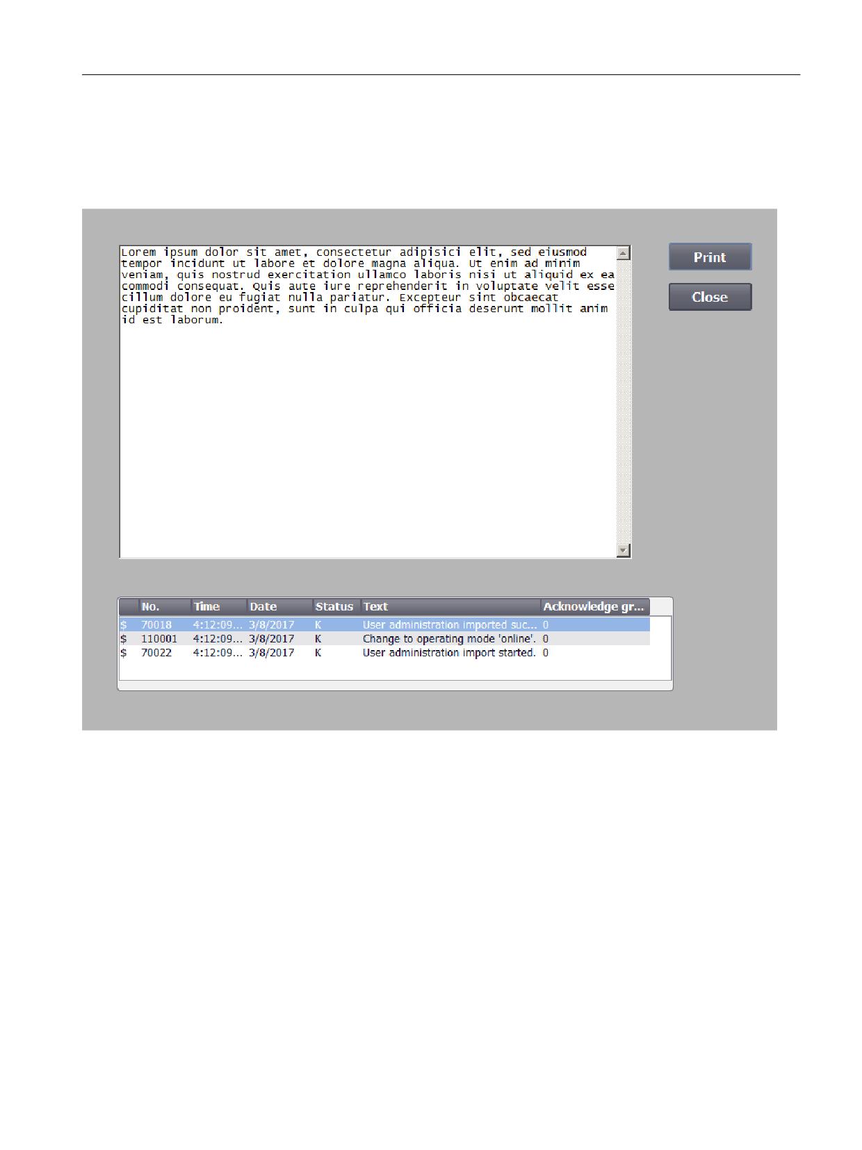
Figure 9-7
Application view at runtime - Example using embedded Windows Editor with hidden title and menu bars
Wherever possible, the window size of the application is automatically adapted to the
application view. Automatic positioning excludes context menus and windows whose change
of position and size are prevented by the application itself.
If problems are detected by the application view, this is indicated in the application view (see
table).
Only the message "No application window available" can intentionally be displayed to the
operator.
● The same application should be used in different application views and is currently being
displayed in another.
● The application has been minimized and can be maximized by the operator by clicking or
tapping on the message.
SINUMERIK Integrate Create MyHMI /WinCC V16
Configuration Manual, 12/2019, 6FC5397-8FP40-0BA2
149

Configuring screen objects
9.6 Screen object Application View
Troubleshooting
Problem
Possible cause
Error message "Application has been closed."
The application has been closed by the user or has crashed.
Error message "XML file is invalid."
XML file is damaged or the XML content or parameterization
is invalid.
Error message "Application could not be started."
The EXE file of the application could not be found or is invalid
or damaged.
The application is used in several application views and the
parameters for "DestroyAppAtScreenChange" (Page 144)
are incorrectly set.
Application view does not display the application or is dis-
The application is used in several application views and the
played in black.
parameters for "DestroyAppAtScreenChange" (Page 144)
are incorrectly set.
Content of the application view is flickering or appears and
disappears in an uncontrolled manner.
The application view displays windows that do not belong to
The runtime parameters (Page 144) are incorrectly set.
the embedded application.
The "TitlePattern" parameter (Page 144) is activated and in-
correctly set.
The application view does not display all (required) windows
The "TitlePattern" parameter (Page 144) is activated and in-
of the application.
correctly set.
The window is minimized.
Error message "No application window available".
The "TitlePattern" parameter (Page 144) is activated and in-
correctly set.
The application is used in several application views and is
currently being displayed in another.
The window is minimized.
Parts of the application are inadvertently cut off or are located
The parameters for "Extend[...]" (Page 144) are incorrectly
outside the application view.
set.
SINUMERIK Integrate Create MyHMI /WinCC V16
150
Configuration Manual, 12/2019, 6FC5397-8FP40-0BA2
Configuring screen objects
9.7 Image object, Fanuc SDF display
9.7
Image object, Fanuc SDF display
9.7.1
Properties and configuration
Screen object "Fanuc SDF display" allows a client area to be located within the WinCC
Runtime, in which, during the runtime, the external "FANUC SDF" application can be displayed.
This means that the HMI of a FANUC control system can be displayed and used within a user-
defined WinCC Runtime.
Configuration
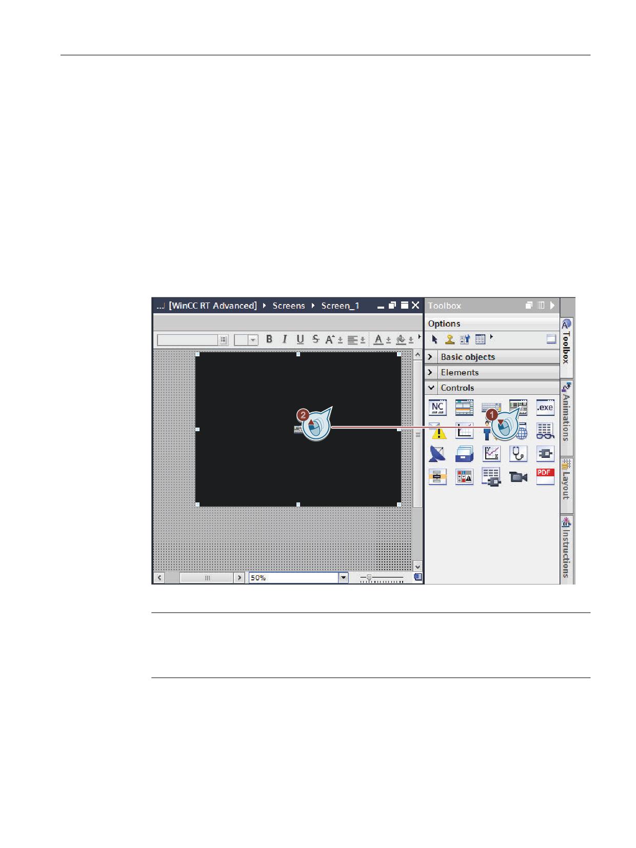
You will find the screen object on the task card "Tools" below "Controls".
Figure 9-8
Insert FANUC SDF view
Note
Requirements for display during runtime
In order to guarantee that the Fanuc SDF view functions correctly during runtime, certain
conditions must be met (Page 152).
SINUMERIK Integrate Create MyHMI /WinCC V16
Configuration Manual, 12/2019, 6FC5397-8FP40-0BA2
151
Configuring screen objects
9.7 Image object, Fanuc SDF display
Properties
If you select a configured Fanuc SDF view in the "Screens" editor, you change the following
properties:
Property
Possible settings
Further information
Display >
0 … 32767
Specifies the position of the screen object on the screen in screen coordi-
Position & Size >
nates.
X / Y
You can either enter the coordinates in the input field or move the screen
object around the screen, which will update the coordinates.
See the help for WinCC under "Position object"
The width and height of the Fanuc SDF view cannot be set here individu-
ally but only jointly in the drop-down list "Resolution".
Display >
●
640 x 480
Selection of the required resolution (width x height) from the drop-down list.
Resolution
●
800 x 600
This resolution must be set identically in FANUC SDF so that this can be
displayed during runtime.
●
1024 x 768
●
1280 x 768
●
1280 x 960
Miscellaneous >
Freely definable text
Display or information about the object name
Object > Name
The object name must uniquely identify the object in the project.
See the help for WinCC under "Working with objects"
Miscellaneous >Ob-
Layer of the screen
Display or selection of the layer on which the screen object is located.
ject
Please note that, irrespective of this setting, the Fanuc SDF display (as a
Layer
borderless object) is possibly shown in front of the other objects, if the
focus is on it during the runtime.
See the help for WinCC under "Working with layers"
9.7.2
Preconditions and required settings
To ensure that FANUC SDF is displayed correctly in WinCC RT Advanced during runtime, the
following criteria must be met:
● The connection to the FANUC CNC/PMC is configured (Page 84).
● FANUC SDF (CNC Screen Display Function) is installed and configured on the PC system.
● The Fanuc SDF display or WinCC Runtime, has exclusive remote access - during the
runtime - to the FANUC control system.
Simultaneously accessing several Fanuc SDF displays, WinCC Runtimes or FANUC SDF
standalone on the same control system is not supported.
SINUMERIK Integrate Create MyHMI /WinCC V16
152
Configuration Manual, 12/2019, 6FC5397-8FP40-0BA2
Configuring screen objects
9.7 Image object, Fanuc SDF display
● The runtime setting "Full screen mode" is activated, e. g. under "PC System_1 > HMI_RT_1
> Runtime settings > General".
● Only functions that are compatible with the FANUC SDF view are used with it.
Note
Unsupported WinCC editors and functions
The screen object "FANUC SDF view" cannot be used in the following editors:
● Faceplates
● Global screens
● Permanent areas
● Slide-in images
The following functions cannot be used in conjunction with the FANUC SDF view:
● Animation
● Events
● Multilingual texts
Note
Automatic display/hide of on-screen keyboards is not supported
For input fields in the FANUC HMI, you can use one of the on-screen keyboards available via
WinCC; this is, however, not automatically displayed/hidden. Therefore, if necessary, configure
a button to display/hide the corresponding on-screen keyboard.
SINUMERIK Integrate Create MyHMI /WinCC V16
Configuration Manual, 12/2019, 6FC5397-8FP40-0BA2
153
Configuring screen objects
9.8 Changing client area screen objects using runtime scripting
9.8
Changing client area screen objects using runtime scripting
The following screen objects differ regarding the options available using runtime scripting. For
example, because the objects within the WinCC runtime only provide client areas for external
applications.
● NC operating display
● Fanuc SDF display
● Application display
● NC keyboard display
For these objects, it can make sense to use runtime scripting, as especially the "Visible" and
"Position" properties of these screen objects can only be set using scripting - and not using
animation.
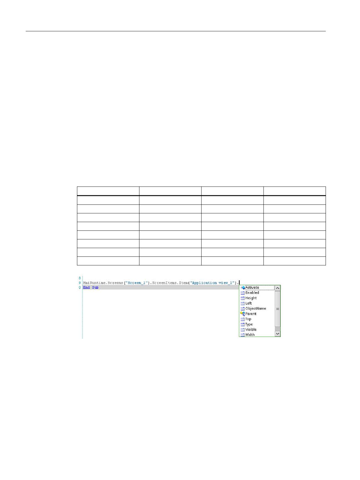
The following properties can be parameterized using runtime scripting:
Table 9-4
Properties that can be changed using runtime scripting
Property
Type
Access
Example
Enabled
Bool
True
Height
Scalar (int)
Read only
480
Left
Scalar (int)
345
Object name
String
Read only
Application_View_1
Top
Scalar (int)
160
Type
String
Read only
HMICameraView
Visible
bool
True
Width
Scalar (int)
Read only
640
Figure 9-9
Adapting the properties of the screen object application display using runtime scripting
SINUMERIK Integrate Create MyHMI /WinCC V16
154
Configuration Manual, 12/2019, 6FC5397-8FP40-0BA2
Using system functions
10
10.1
Configuring SINUMERIK PI services as system functions
10.1.1
Overview
Purpose
In WinCC, you can link events (e.g. "Key pressed") with predefined functions. If an event should
occur during operation, the function triggers a certain action on the HMI device or in the control.
Principle
In general, you can use the functions for the following:
● Establish the configuration on a process-for-process basis (e.g. branch from one screen to
another).
● Control the process (e.g. set control parameters).
● Carry out the system settings online at the HMI device (e.g. changing interface parameters).
As a rule, functions and events are linked to a certain object. For example, a function with event
"Press key" is not triggered by every key, but only by one specific key.
Objects, which can be linked to functions, include:
● Function keys and command buttons
● Fields
● Screens
● Variables
The number of functions offered is, therefore, dependent on the HMI device and on the
situation.
SINUMERIK functions
In addition to the functions available in WinCC, SINUMERIK-specific functions are provided to
support configuration with SINUMERIK Integrate Create MyHMI /WinCC.
These are the following functions:
● Functions for the NC part program view screen object (Page 156)
● Function for the current block display (Page 157)
● Start/stop PLC by means of a function (Page 158)
SINUMERIK Integrate Create MyHMI /WinCC V16
Configuration Manual, 12/2019, 6FC5397-8FP40-0BA2
155
Using system functions
10.1 Configuring SINUMERIK PI services as system functions
Further information
Information about general functions for WinCC can be found in the information system. This
contains not only detailed descriptions, but also Tooltips directly for the individual functions.
10.1.2
Functions for the NC part program view screen object
Introduction
In order also to be able to operate the "NC part program view" screen object externally or,
depending on the functionality, to allocate an appropriate authorization, command buttons can
be hidden in the screen object during configuration. The required functionality can be triggered
via softkeys with various authorization levels.
Procedure
To add a new function, proceed as follows:
1. Open the editor for screens.
2. Select the "NC part program view" screen object.
3. In the inspector window, switch to "Properties > Events".
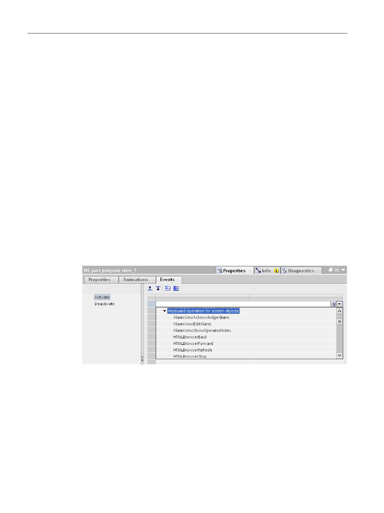
4. To add a new function, select it from the "<Add function>" dropdown list in the "keyboard
operation for screen objects" directory.
Figure 10-1
"Keyboard operation for screen objects" functions
SINUMERIK Integrate Create MyHMI /WinCC V16
156
Configuration Manual, 12/2019, 6FC5397-8FP40-0BA2

Using system functions
10.1 Configuring SINUMERIK PI services as system functions
Functions available for the "NC part program view" screen object
The following functions influence the "NC part program view" screen object:
Table 10-1
Functions for the NC part program screen object
Function
Meaning
ScreenObjectCursorDown
Performs the <down> key function on the the
specified screen object.
ScreenObjectCursorUp
Performs the <up> key function on the the speci-
fied screen object.
ScreenObjectPageDown
Performs the <page down> key function on the the
specified screen object.
ScreenObjectPageUp
Performs the <page up> key function on the the
specified screen object.
PartProgramListDirDown
Navigate and select in the list directory.
PartProgramListDirUp
Navigate and select in the list directory.
PartProgramListRefresh
Update directories in the list box
PartProgramListSelectNCPartProgram
Open the selected part program for editing on the
NC.
10.1.3
Function for the current block display
The PrepareActualNCBlockForDisplay function is used to monitor the execution of the
traversing blocks of an NC traversing program on the HMI device. This function is used to save
the current, previous and next traversing block of an NC part program currently being
processed in a channel from the NC to local variables.
Procedure on the HMI device
● The PrepareActualNCBlockForDisplay function starts when a screen is opened.
● A non-configured NC tag block is activated with the configured cycle.
● On each cyclic reading operation of the NC tag block, the tag block is divided into three parts
and stored in the local tags of the previous, current and subsequent set.
● The local variables can be displayed on the screen as outputs.
SINUMERIK Integrate Create MyHMI /WinCC V16
Configuration Manual, 12/2019, 6FC5397-8FP40-0BA2
157
Using system functions
10.1 Configuring SINUMERIK PI services as system functions
Procedure
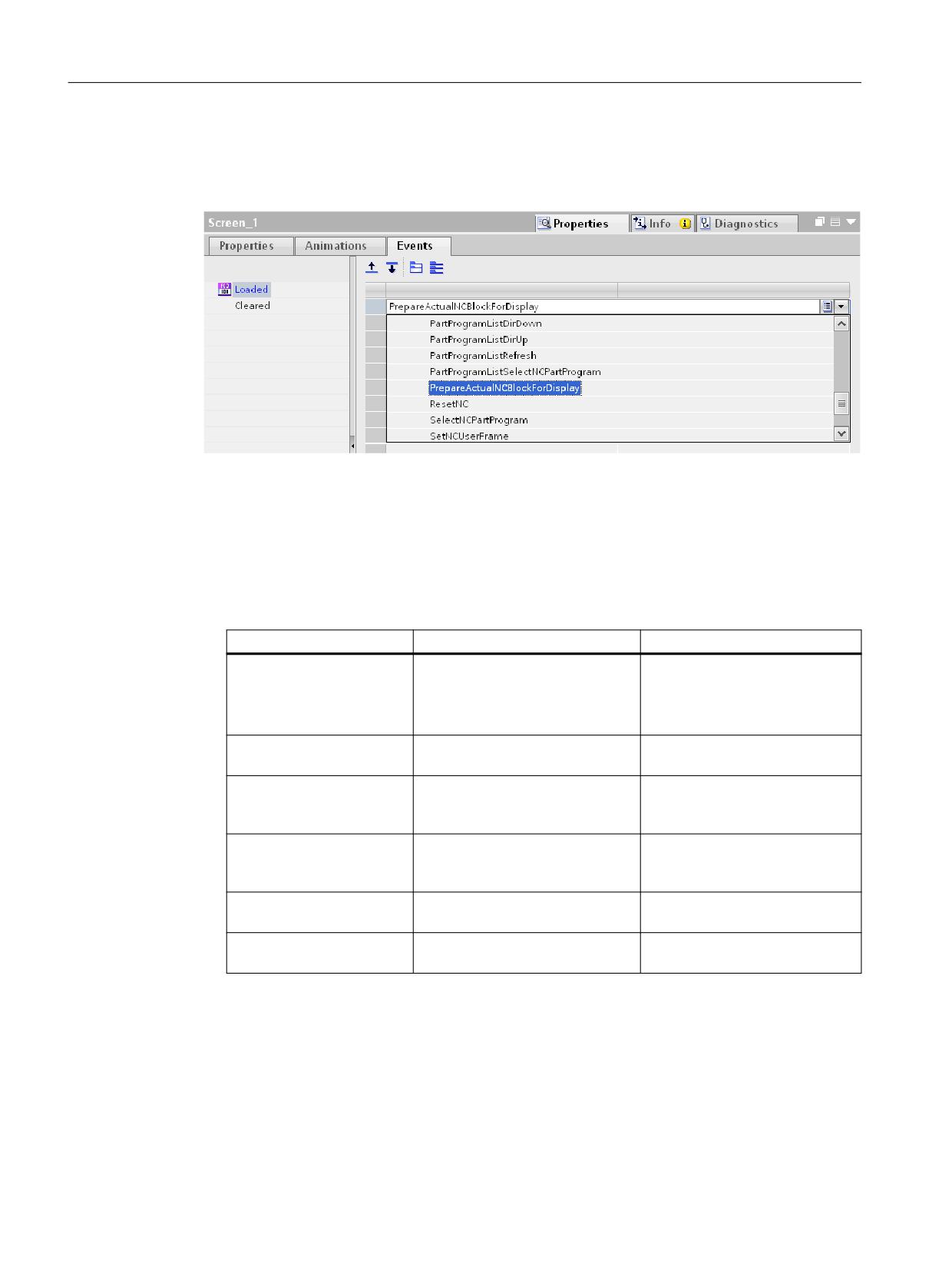
1. Select the function in the screen editor for "Select screen" (the screen is selected) from
"Events > Structured > Add function" in the "SINUMERIK" directory.
Figure 10-2
Current block display
2. Specify three local tags of type String of length 66.
3. Within a screen, create three output fields each with one of these tags.
4. Now configure the PrepareActualNCBlockForDisplay function as the open screen trigger.
5. Then specify the corresponding NC, the channel from which the current block is to be read,
the cycle, and the three local string tags as parameters for this function.
Parameter
Meaning
Data type
Connection
Name of the connection to the NC.
ASCII characters
Can be viewed under: "PC-Sys-
tem_1 > HMI_RT_1 > Connec-
tions".
Channel
Channel from which the program
Constant or variable
is to be read; 1 - max. 10
Cycles (100 ms)
Update time as a multiple of 100
Constant
ms: 1 - 600 (equal to 100 millisec-
onds - 1 minute)
Previous block (output)
Local tag for the traversing block
String tag
that precedes the current travers-
ing block
Current block (output)
Local tag for the current traversing
String tag
block
Next block (output)
Local tag for the traversing block
String tag
that follows the current block
10.1.4
Start/stop PLC by means of a function
You can set a SINUMERIK PLC to RUN or STOP mode by means of a function.
SINUMERIK Integrate Create MyHMI /WinCC V16
158
Configuration Manual, 12/2019, 6FC5397-8FP40-0BA2
Using system functions
10.1 Configuring SINUMERIK PI services as system functions
Requirement
● The connection to the PLC has been configured.
● The screen object that is to receive the start/stop function of the PLC is inserted.
Procedure
To configure a screen object with the function for starting and stopping the SINUMERIK PLC,
proceed as follows:
1. Select the screen object that is to receive the start/stop function of the PLC in the screen
editor.
2. Switch to "Events" in the properties of the screen object and select an event, e.g. "Click".
3. Select the corresponding function under "Settings" in the "Add function" drop-down list:
- SINUMERIK 840D sl (PLC S7-300): SetS7OperatingMode
- SINUMERIK ONE (PLC S7-1500): SetPLCMode
4. Enter the required parameters:
Parameter
Meaning
Connection
Name of the connection to the SINUMERIK PLC.
Operating mode
Operating mode to which the SINUMERIK PLC is to be
set.
(Variable or constant):
0 = RUN
1 = STOP
10.1.5
Executing system functions from WinCC
10.1.5.1
Overview
Requirement
A connection to the NC is established.
See: Configuring connection to the SINUMERIK NC (Page 82)
SINUMERIK Integrate Create MyHMI /WinCC V16
Configuration Manual, 12/2019, 6FC5397-8FP40-0BA2
159
Using system functions
10.1 Configuring SINUMERIK PI services as system functions
Procedure
To add a new function, proceed as follows:
1. Open the editor for screens.
2. In the Inspector window, switch to "Properties > Events".
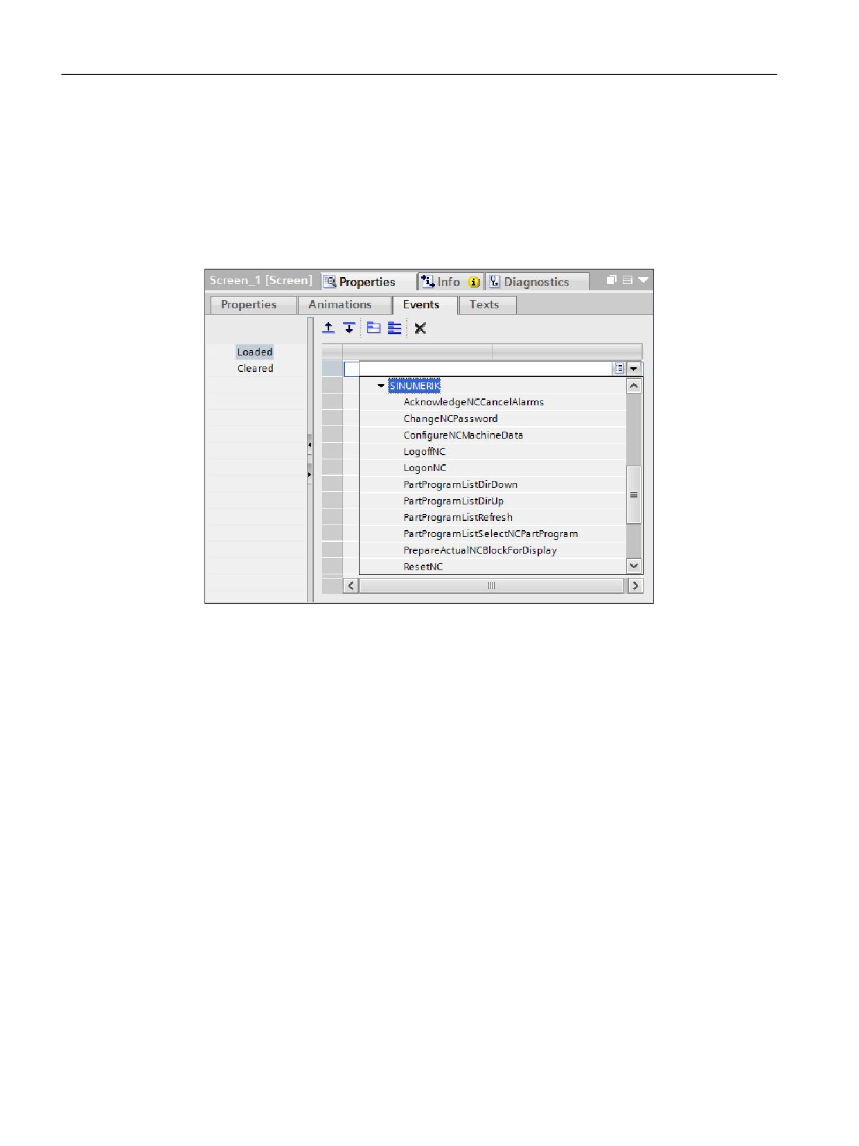
3. To add a new function, select it from the "<Add function>" drop-down list in the
"SINUMERIK" directory.
Figure 10-3
System functions
The following functions are available:
- LogoffNC (Page 160)
- ChangeNCPassword (Page 161)
- LogonNC (Page 161)
- ConfigureNCMachineData (Page 162)
- ResetNC (Page 162)
- AcknowledgeNCCancelAlarms (Page 162)
- SetNCUserFrame (Page 162)
- StartNCPIService (Page 163)
- SelectNCPartProgram (Page 164)
10.1.5.2
LogoffNC
Description
This function clears the NC password. Following this, the keylock switch acts.
SINUMERIK Integrate Create MyHMI /WinCC V16
160
Configuration Manual, 12/2019, 6FC5397-8FP40-0BA2
Using system functions
10.1 Configuring SINUMERIK PI services as system functions
The passwords for the HMI device and the NC are independent of one another.
Parameter
Meaning
Connection
Name of the connection to the NC.
10.1.5.3
ChangeNCPassword
Description
A password is passed to the NC for a password level. The existing password for this password
level is overwritten.
The user must be logged on to the NC with a suitable access level (level).
Procedure on the HMI device
The currently valid NC password is overwritten by the new password.
Parameter
Meaning
Connection
Name of the connection to the NC.
Password
New PLC password (max. 8 characters)
(constant or variable)
Level
NC password level
(constant or variable):
0 = system
1 = manufacturer
2 = service
3 = user
10.1.5.4
LogonNC
Description
A password is passed on to the NC. The passwords for the HMI device and the NC are
independent of one another.
Parameter
Meaning
Connection
Name of the connection to the NC.
Password
The password that authorizes the NC logon (variable or constant)
Procedure on the HMI device
After activating the function, the specified password is used to attempt to log on to the NC.
SINUMERIK Integrate Create MyHMI /WinCC V16
Configuration Manual, 12/2019, 6FC5397-8FP40-0BA2
161
Using system functions
10.1 Configuring SINUMERIK PI services as system functions
10.1.5.5
ConfigureNCMachineData
Description
This function is used to activate all machine data of NEW_CONF classification.
The CLASS parameter permits a more detailed classification. Currently, however, only value 1
is supported.
Parameter
Meaning
Connection
Name of the connection to the NC.
Class
Classification of the machine data being activated (variable or constant): 1 - 3
Procedure on the HMI device
A corresponding PI service is transferred to the NC from the currently valid parameters.
10.1.5.6
ResetNC
Description
This function triggers a restart at the NC.
Parameter
Meaning
Connection
Name of the connection to the NC.
10.1.5.7
AcknowledgeNCCancelAlarms
Description
This function is used to acknowledge all cancel alarms pending for the specified connection in
a single action.
Parameter
Meaning
Connection
Name of the connection to the NC.
10.1.5.8
SetNCUserFrame
Description
The data for zero point offsets is activated for a channel.
On entry, these variables are initially stored in a temporary memory on the NC. The
SetNCUserFrame function completely activates the newly-entered values and can be read
subsequently.
With this system function only one work offset at a time can be activated.
SINUMERIK Integrate Create MyHMI /WinCC V16
162
Configuration Manual, 12/2019, 6FC5397-8FP40-0BA2
Using system functions
10.1 Configuring SINUMERIK PI services as system functions
If several work offsets are set in succession and then the "SetNCUserFrame" system function
is issued, only the parameters of the last set work offset are activated. To activate several work
offsets, you have to set all the parameters of a work offset and then issue the
"SetNCUserFrame" system function. You can only then write the value of the next work offset.
Parameter
Meaning
Connection
Name of the connection to the NC.
Channel
Channel to be activated (constant or variable): 1 - max 10
Procedure on the HMI device
After the HMI device operator has entered the data for the work offsets in the HMI device and
pressed the configured key, the work offset data is accepted for the specified channel.
10.1.5.9
StartNCPIService
Description
This function can be used to transfer any PI service to the NC. This must be described by a
parameter string. This parameter string must include the full command and not merely the
parameters of the PI service.
Parameter
Meaning
Connection
Name of the connection to the NC.
PI parameter string
Specification of the PI service to run
(constant or variable)
Result (output)
When a function is activated, a return value is reported in this pa-
rameter asynchronously after termination.
Procedure on the HMI device
A corresponding PI service is transferred to the NC from the currently valid PI parameter string.
Example
NCK-Reset parameter string
StartNCPIService
("PI_START(/NC,K00,0,_N_IBN_SS)")
Additional information
Descriptions of various PI services can be found in the directory "Documents\Support" on the
product DVD.
SINUMERIK Integrate Create MyHMI /WinCC V16
Configuration Manual, 12/2019, 6FC5397-8FP40-0BA2
163
Using system functions
10.1 Configuring SINUMERIK PI services as system functions
10.1.5.10
SelectNCPartProgram
Description
With the "NC part program view" control you can already implement many functions for part
programs. You can use the "SelectNCPartProgram" function to select all part programs via the
NCU domain services.
For example, this allows you to create special screens for permanently-defined part programs.
These screens can then support a simplified selection process using buttons.
Parameter
Meaning
Connection
Name of the connection to the NC.
Channel
Channel, for which the program is selected: 1 - max. 10
(variable or constant)
Path name
Absolute path details for the program directory
(variable or constant)
Program name
The name of the program or workpiece to be edited (variable or constant)
Note
Together, the path name and program name parameters must indicate the part program path.
Enter only the absolute program or path name.
Path name examples:
● MPF_DIR for main directory
● SPF_DIR for subdirectory
● WKS_DIR for workpiece program directory
Procedure on the HMI device
The specified part program is selected on the NC for editing.
Example
The button "SelectPartProgram" is deactivated in control "NC part program view" with the
following sample code.
VBScript
Sub Button_select_not_visable()
'VBS_Example_ScreenItems
Dim objNCpartprogram
Set objNCpartprogram = HmiRuntime.Screens("Screen_1").ScreenItems("NC part program view_1")
objNCpartprogram.ButtonSelectPartProgramVisible = False
End Sub
The "Keyboard operation for screen objects" function group has not been released for scripts.
SINUMERIK Integrate Create MyHMI /WinCC V16
164
Configuration Manual, 12/2019, 6FC5397-8FP40-0BA2
Using system functions
10.1 Configuring SINUMERIK PI services as system functions
10.1.6
System function calls within a script
Introduction
You can call the SINUMERIK system functions in WinCC even within a VBScript:
● The English function names are used here.
● In the "Connections" editor, you can see the name of your connection to the NC that you
need as parameter in all functions.
● You can find general information on using VBScripts in WinCC in the information system of
the TIA Portal, section "Working with system functions and Runtime scripting (Panels, RT
Advanced, RT Professional)".
Example
VBScript
ResetNC "SinumerikNC"
SinumerikNC here represents the name that was selected for the connection to the NC.
SINUMERIK Integrate Create MyHMI /WinCC V16
Configuration Manual, 12/2019, 6FC5397-8FP40-0BA2
165
Using system functions
10.2 Configuring FANUC system functions
10.2
Configuring FANUC system functions
10.2.1
Configuring function keys by means of system functions
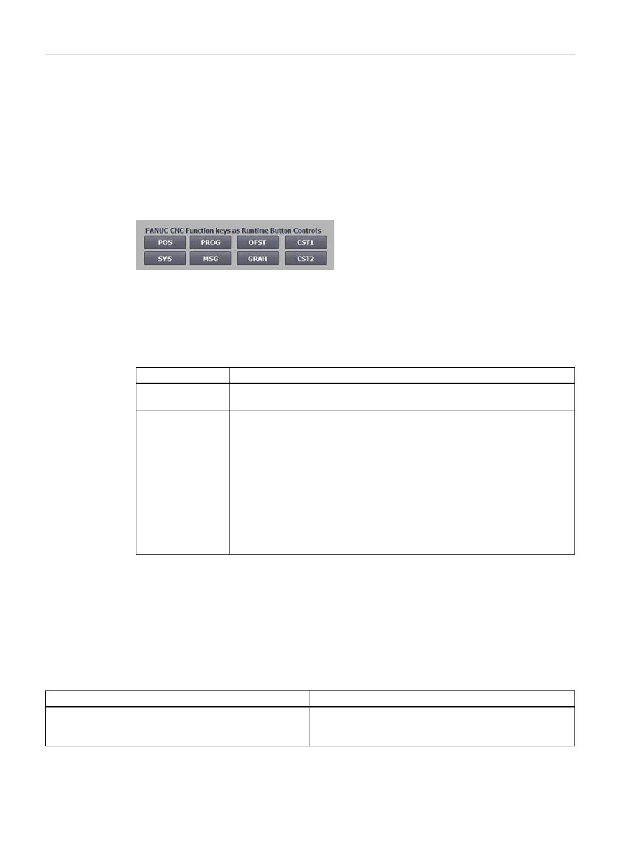
The system function "SwitchFanucCNCScreen" is available in WinCC for the FANUC CNC/
PMC communication driver. This enables you to configure the special FANUC function keys in
WinCC screens, for example as individual command buttons.
Figure 10-4
Function keys as command buttons
Description
With this function, a request is made via the FANUC CNC/PMC connection to switch to a
specific screen of the FANUC CNC/PMC user interface.
Parameters
Meaning
Connection
Name of the connection that has been configured by means of the FANUC CNC/
PMC communication driver.
Screen ID
ID of the FANUC screen to which you wish to switch:
● Position
● Program
● Offset
● System
● Message
● Graph
● Custom
● Custom2
10.2.2
Function when restarting
Description
The "ResetFanucCNC" function externally restarts the FANUC control system. For example,
you can configure this function as event, type "Click" for a button.
Parameter
Meaning
Connection
Name of the connection to the FANUC control system. Only
connections via the "FANUC CNC/PMC" communication driv-
er are permissible.
SINUMERIK Integrate Create MyHMI /WinCC V16
166
Configuration Manual, 12/2019, 6FC5397-8FP40-0BA2
Using system functions
10.2 Configuring FANUC system functions
10.2.3
Function to acknowledge alarms
Description
Function "ClearFanucCNCAlarm" deletes the alarm status of the CNC - or acknowledges the
active alarms. For example, you can configure this function as event, type "Click" for a button.
Parameter
Meaning
Connection
Name of the connection to the FANUC control system. Only
connections via the "FANUC CNC/PMC" communication driv-
er are permissible.
SINUMERIK Integrate Create MyHMI /WinCC V16
Configuration Manual, 12/2019, 6FC5397-8FP40-0BA2
167
Using system functions
10.2 Configuring FANUC system functions
SINUMERIK Integrate Create MyHMI /WinCC V16
168
Configuration Manual, 12/2019, 6FC5397-8FP40-0BA2
Configuring the language settings
11
11.1
Overview
If you configure a multi-language user interface, then you must make the language settings at
different locations:
●
Settings in the TIA Portal at the PG/PC
- Enable project languages (Page 170)
- Configure runtime settings for languages and fonts
Information about language settings, which involve the standard scope of WinCC (TIA
Portal) are in the TIA Portal online help at "Managing languages".
To do this, also use the Table for assigning languages between SINUMERIK Operate and
the TIA Portal (Page 171).
●
Settings for languages in the operating system and on the PC system and PG/PC
See also the TIA Portal online help under "Settings for languages in the operating system".
Note
Adding runtime languages in Windows as keyboard layout
If you use a virtual keyboard (e.g. the NC keyboard display), all of the runtime languages
used on the PC system must be added on the PC system as keyboard layout.
When keyboard layout is added, then the virtual keyboard is automatically adapted
(international ⇔ German) if the language in SINUMERIK Operate or WinCC runtime
changes.
You can find these settings in the Windows Control Panel under "Region and language" or
"Changing keyboards and input methods"
●
Settings for synchronized language switchover of SINUMERIK Operate and WinCC
Runtime
- If you integrate WinCC Runtime as operating area (OEMFrame) in SINUMERIK Operate
then using VB script you can implement a language switchover (Page 173).
- If you use WinCC Runtime as a framework application with NC operate view, you only
have to configure the language settings. During the runtime language switchover is
synchronized for all languages that are configured as runtime languages and installed in
SINUMERIK Operate .
SINUMERIK Integrate Create MyHMI /WinCC V16
Configuration Manual, 12/2019, 6FC5397-8FP40-0BA2
169
Configuring the language settings
11.2 Enable project languages
11.2
Enable project languages
If a multilingual project is created, all project languages, the editing language and reference
language must be specified in the settings under "Languages and Resources".
These settings should be made at an early stage because, for example, when copying or
inserting multilingual objects, only those languages defined as project languages are included.
If a project language is disabled, all text and graphic objects previously created in this language
are deleted from the current project.
Procedure
1. Double click "Project languages" below "Languages & Resources" in the project navigation.
All selectable project languages are displayed in the working area.
2. Activate the check boxes of all languages and language variants that are to be available as
project languages.
3. Specify the reference and editing languages in the relevant drop-down lists.
SINUMERIK Integrate Create MyHMI /WinCC V16
170
Configuration Manual, 12/2019, 6FC5397-8FP40-0BA2
Configuring the language settings
11.3 Language assignment in language-dependent texts
11.3
Language assignment in language-dependent texts
Language ID in the file name of language-dependent texts
Language-dependent texts are saved in TS files in SINUMERIK Operate. There is a separate
file for each language which is assigned via the language ID in the file name.
● <Name><LanguageID>.ts
● E. g.: oem_alarms_plc_eng.ts
Assignment of the DB2 alarm texts to project languages
In the TIA Portal (in contrast to SINUMERIK Operate), language variants of different countries
are regarded as separate project languages, this means that there are separate entries for e.g.
English (Great Britain), English (Ireland) and English (USA). If you import an alarm file into the
TIA Portal, this will be assigned to all of the relevant activated project languages (or language
variants), depending on the language ID in the file name. For example, if you have activated the
project languages "English (USA)" and "English (Great Britain)" and imported an
oem_alarms_plc_eng.ts file, these alarm texts are mapped to the two project languages.
Availability of languages in SINUMERIK Operate
SINUMERIK Operate has 6 languages (standard languages) installed in the factory state. If you
need additional languages, you can order them separately:
● DVD "Language extension": 6FC5860-0YC40-0YA8
● Software option "Additional languages": 6FC5800-0AN00-0YB0
Storing the active language in the NC block [DB10]
The language that is presently active in SINUMERIK Operate is saved in communication block
NC [DB10] in address DB10.DBB96 as value.
Table 11-1
Language IDs of language-dependent texts and language values in the block NC [DB10]
Value in DB10.DBB96
Language in SINUMERIK Operate
Language code
Default language
1
German
deu
x
2
French
fra
x
3
English
eng
x
4
Spanish
esp
x
6
Italian
ita
x
7
Dutch
nld
8
Simplified Chinese
chs
x
9
Swedish
sve
18
Hungarian
hun
19
Finnish
fin
28
Czech
csy
50
Portuguese
ptb
53
Polish
plk
55
Danish
dan
SINUMERIK Integrate Create MyHMI /WinCC V16
Configuration Manual, 12/2019, 6FC5397-8FP40-0BA2
171
Configuring the language settings
11.3 Language assignment in language-dependent texts
Value in DB10.DBB96
Language in SINUMERIK Operate
Language code
Default language
57
Russian
rus
68
Slovakian
sky
69
Slovenian
slv
72
Rumanian
rom
80
Traditional Chinese
cht
85
Korean
kor
87
Japanese
jap
89
Turkish
trk
122
Indonesian
ind
212
Thai
tha
230
Malay
msl
SINUMERIK Integrate Create MyHMI /WinCC V16
172
Configuration Manual, 12/2019, 6FC5397-8FP40-0BA2
Configuring the language settings
11.4 Configuring synchronized language switchover
11.4
Configuring synchronized language switchover
The settings for synchronized language switchover of SINUMERIK Operate and WinCC
Runtime depend on the particular application:
● If you integrate WinCC Runtime as operating area (OEMFrame) in SINUMERIK Operate,
then initially, synchronized language switchover is not activated.
Using a VB function, you can automatically switch over the language of WinCC Runtime if
the language in SINUMERIK Operate is changed.
In your overall concept, please note that during the runtime, the language can only be
switched over synchronized from SINUMERIK Operate and not, for example, from a
configured button in WinCC Runtime.
To configure language selection, create an HMI variable with the address of the PLC data
block DB10.DBB96 (Page 171) in which the active language of SINUMERIK Operate is
stored. You then define a relation between the configured language order and the language
in SINUMERIK Operate using a VB script and have the script be automatically executed
when the value changes.
● If you use WinCC Runtime as a framework application with NC operate view, you only have
to configure the language settings. During the runtime language switchover is synchronized
for all languages that are configured as runtime languages and installed in SINUMERIK
Operate .
Requirement
● A project is created and a PC HMI device is added to the Runtime WinCC RT Advanced.
See Inserting PC system and Runtime (Page 62)
● The connection to the PLC and NC is configured.
See Configuring connections (Page 77).
● The project languages are set.
See Enable project languages (Page 170)
● The sequence of the runtime languages is configured.
See the online help, under keyword "Runtime language".
Procedure
In order to switch over the language of WinCC Runtime depending on the language set in
SINUMERIK Operate proceed as follows:
1. Double-click "Show all variables" in the "PC System_1 > HMI_RT_1 > HMI variables" folder
of the project tree.
2. Create a new HMI variable with the following values:
Column
Value
Name
Freely selectable (in the example, below:
"DB10DBB96")
Variable table
Default variable table
Connection
PLC
Data type
Byte
Address
%DB10.DBB96
SINUMERIK Integrate Create MyHMI /WinCC V16
Configuration Manual, 12/2019, 6FC5397-8FP40-0BA2
173
Configuring the language settings
11.4 Configuring synchronized language switchover
3.
To create a new script, double-click "Add new VB function" in the "PC System_1 >
HMI_RT_1 > Scripts > VB scripts" folder.
4.
In the Inspector window under "Properties > General", select "Sub" as the type and assign
a name (in the example "LangFromOperate").
5.
Write a VB function according to the following scheme:
Sub LangFromOperate()
Select Case SmartTags("DB10DBB96")
' Selected Language in HMI
Operate
Case 1
'German - Germany
SetLanguage 0
' "Order 0" in WinCC project Runtime
settings
Case 3
'English - United Kingdom
SetLanguage 1
' "Order 1" in WinCC project Runtime
settings
Case 2
'French - France
SetLanguage 2
' "Order 2" in WinCC project Runtime
settings
Case 6
'Italian - Italy
SetLanguage 3
' "Order 3" in WinCC project Runtime
settings
Case 4
'Spanish - Spain (Traditional Sort)
SetLanguage 4
' "Order 4" in WinCC project under
Runtime settings
Case 8
'Chinese - People's Republic of China
SetLanguage 5
' "Order 5" in WinCC project under
Runtime settings
Case Else 'Default language f.i. English - United Kingdom
SetLanguage 1
End Select
End Sub
Code
Purpose
Select Case SmartTags ("<HMI variable>")
Evaluate the previously created HMI variable
("DB10DBB96" in the example), which contains
the value of the active language in SINUMERIK
Operate.
Case <n>
Condition that checks the value of the HMI vari-
able.
Value <n> corresponds to the respective lan-
guage value of DB10.DBB96, see table "Lan-
guage values of DB10.DBB96" (Page 171).
SetLanguage <n>
Sets the language to the corresponding value
<n> in Runtime.
Value <n> is the number from the Order column
in "PC System_1 > HMI_RT_1 > Runtime set-
tings > Language & font".
SINUMERIK Integrate Create MyHMI /WinCC V16
174
Configuration Manual, 12/2019, 6FC5397-8FP40-0BA2
Configuring the language settings
11.4 Configuring synchronized language switchover
6. In the project tree, double-click the previously created HMI variable.
7. In the Inspector window under "Properties > Events", click "Value change" in the area
navigation, then click <Add function> and select the previously created VB function
(LangFromOperate in the example).
Result
The language of WinCC Runtime is automatically switched over if the language in SINUMERIK
Operate is changed.
SINUMERIK Integrate Create MyHMI /WinCC V16
Configuration Manual, 12/2019, 6FC5397-8FP40-0BA2
175
Configuring the language settings
11.4 Configuring synchronized language switchover
SINUMERIK Integrate Create MyHMI /WinCC V16
176
Configuration Manual, 12/2019, 6FC5397-8FP40-0BA2
Loading and linking the configuration
12
12.1
Overview
When you have completed the configuration, compile it and load it onto the HMI device.
If you want to integrate the configuration of WinCC RT Advanced into the OEMFrame area of
SINUMERIK Operate, make additional settings in the "SINUMERIK Operate Integration" tool.
Requirement
● The screen resolution is set (Page 66).
● If the header of SINUMERIK Operate is to be displayed at runtime, the screen size is
configured (Page 68).
● The current status of the configuration is completely compiled.
See: See the help for WinCC under "Compile project"
● An HMI device or a folder is available in the network or a data storage medium is available.
You can find information about the network configuration of PCU 50.5 in the Commissioning
Manual PCU Basic Software Windows 7 (IM10).
Procedure overview
Step
Description
1
Transferring the configuration onto the HMI device or via a folder onto the device.
Further information:
● Help for WinCC under "Load project"
● SIOS-FAQ: Transferring the project to the HMI device via storage medium (https://
support.industry.siemens.com/cs/document/109740696/)
2
Integrating WinCC Runtime into the OEMFrame area of SINUMERIK Operate (Page 178).
(only with connection option OEMFrame)
SINUMERIK Integrate Create MyHMI /WinCC V16
Configuration Manual, 12/2019, 6FC5397-8FP40-0BA2
177
Loading and linking the configuration
12.2 Integrating WinCC Runtime into the OEMFrame area of SINUMERIK Operate
12.2
Integrating WinCC Runtime into the OEMFrame area of SINUMERIK
Operate
With the "SINUMERIK Operate Integration" integration tool you can integrate WinCC Runtime
into the OEMFrame area of SINUMERIK Operate. You can make various settings, for example,
you can specify with which SINUMERIK Operate softkey the runtime is called.
Further information
You will find information about the OEMFrame area in the commissioning Manual SINUMERIK
Operate (IM9), Section "SINUMERIK Operate on PC/PCU".
Requirement
● The PC system meets the system requirements (hardware/software) of the OEMFrame
(Page 19) connection option.
● WinCC RT Advanced is installed (Page 35).
● The integration tool is installed (Page 23).
● The configuration file "pdata.fwc" can be accessed from the PC system.
SINUMERIK Integrate Create MyHMI /WinCC V16
178
Configuration Manual, 12/2019, 6FC5397-8FP40-0BA2
Loading and linking the configuration
12.2 Integrating WinCC Runtime into the OEMFrame area of SINUMERIK Operate
Procedure
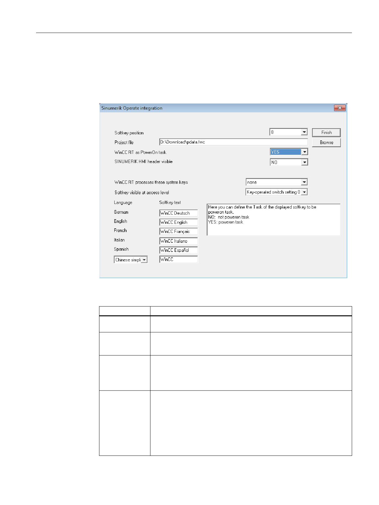
To integrate the Runtime in SINUMERIK Operate, follow these steps:
1. On the PC system, click in the Windows Start menu on "Start > Siemens Automation >
SINUMERIK > Integration Sinumerik Operate English Tool".
The "Integration SINUMERIK Operate" dialog opens.
Figure 12-1
Example of a completed "Integration SINUMERIK Operate" dialog
2. Make the required settings:
Setting
Procedure
Softkey position
The drop-down list shows the currently free, assignable horizontal softkeys.
Select an available softkey (default softkey = 7).
Project file
The TIA Portal configuration file of the WinCC RT Advanced can be entered by
means of the input box. The configuration file is displayed with the "Browse"
button.
WinCC RT as
Here you specify if the WinCC Runtime application covers up SINUMERIK
power up applica-
Operate when it starts up.
tion
● NO: SINUMERIK Operate is not covered.
● YES: SINUMERIK Operate is covered.
SINUMERIK HMI
Here you can define whether the header of SINUMERIK Operate (display of the
header visible
operating area, operating mode, alarms, etc.) is to be visible for the WinCC
application.
● NO: Header is not visible.
● YES: Header is visible.
If YES is entered here, the location of the header on the configuration interface
of each WinCC screen must be kept free for this. See: Configuration of the
screen size (PC systems) (Page 68)
SINUMERIK Integrate Create MyHMI /WinCC V16
Configuration Manual, 12/2019, 6FC5397-8FP40-0BA2
179
Loading and linking the configuration
12.2 Integrating WinCC Runtime into the OEMFrame area of SINUMERIK Operate
Setting
Procedure
These system
Here you can define whether/which keys are to be provided directly to the
keys are only pro-
application. The selected system keys are not processed by SINUMERIK Op-
cessed by WinCC
erate.
RT
● Alarm acknowledgement: ESC is directly assigned to the application
● Channel switching: F11 is directly assigned to the application
Softkey visible as
Use the drop-down menu to specify as of which access level the softkey is
of access level
visible.
Language/softkey
The softkey labeling for the respective language can be entered in the input
text
boxes under softkey text.
3. Confirm the settings with "Exit".
A dialog for the memory prompt is displayed.
- Select "Yes" to save all entries and the dialog box is exited.
- Select "No" and the dialog box is exited without saving the entries.
- Select "Cancel" to cancel the close process and return to the integration tool.
Result
Runtime is integrated according to your settings in SINUMERIK Operate.
You usually need to integrate Runtime in SINUMERIK Operate only once. You only need to
repeat the process if you want to change something in the settings for the integration of
Runtime in SINUMERIK Operate (e.g. the softkey position).
If you change the configuration, although you need to save the latest compiled configuration file
again at the configured location, Runtime does not need to be integrated into SINUMERIK
Operate again.
SINUMERIK Integrate Create MyHMI /WinCC V16
180
Configuration Manual, 12/2019, 6FC5397-8FP40-0BA2

Appendix
13
13.1
SINUMERIK functions, which can be triggered using certain events of
the WinCC RT Advanced
Introduction
The following tables list the functions for the relevant WinCC objects and their associated
events that are used for SINUMERIK with SIMATIC Panels. These functions are indicated by
a crpss in the table.
In the following five tables, these are the WinCC objects
● Tags
● Function keys
● Buttons
● Screen
● Alarms
● OCX
● Script
● Scheduler
SINUMERIK functions, which can be triggered using certain events of the WinCC RT Advanced, part 1
Object
Variables
Softkey
Global
Local
Event
Value
Upper limit ex-
Lower limit
Release
Press
Release
Press
changed
ceeded
fallen below
Functions
SetS7OperatingMode
X
X
X
X
X
X
X
AcknowledgeNCCancelA-
X
X
X
X
X
X
X
larms
LogonNC
X
X
X
X
X
X
X
LogoffNC
X
X
X
X
X
X
X
ChangeNCPassword
X
X
X
X
X
X
X
SetNCUserFrame
X
X
X
X
X
X
X
SelectNCPartProgram
X
X
X
X
X
X
X
PrepareActualNCBlockFor-
Display
StartNCPIService
X
X
X
X
X
X
X
ResetNC
X
X
X
X
X
X
X
SINUMERIK Integrate Create MyHMI /WinCC V16
Configuration Manual, 12/2019, 6FC5397-8FP40-0BA2
181

Appendix
13.1 SINUMERIK functions, which can be triggered using certain events of the WinCC RT Advanced
Object
Variables
Softkey
Global
Local
Event
Value
Upper limit ex-
Lower limit
Release
Press
Release
Press
changed
ceeded
fallen below
Functions
ConfigureNCMachineData
X
X
X
X
X
X
X
ScreenObjectCursorUp
X
X
X
X
ScreenObjectCursorDown
X
X
X
X
ScreenObjectPageUp
X
X
X
X
ScreenObjectPageDown
X
X
X
X
PartProgramListSelectNC-
X
X
X
X
PartProgram
PartProgramListDirUp
X
X
X
X
PartProgramListDirDown
X
X
X
X
PartProgramListRefresh
X
X
X
X
SINUMERIK functions, which can be triggered using certain events of the WinCC RT Advanced, part 2
Object
Command buttons (system key)
Global
Local
Event
Release
Press
Release
Press
Function
SetS7OperatingMode
X
X
X
X
AcknowledgeNCCancelAlarms
X
X
X
X
LogonNC
X
X
X
X
LogoffNC
X
X
X
X
ChangeNCPassword
X
X
X
X
SetNCUserFrame
X
X
X
X
SelectNCPartProgram
X
X
X
X
StartNCPIService
X
X
X
X
ResetNC
X
X
X
X
ConfigureNCMachineData
X
X
X
X
SINUMERIK Integrate Create MyHMI /WinCC V16
182
Configuration Manual, 12/2019, 6FC5397-8FP40-0BA2

Appendix
13.1 SINUMERIK functions, which can be triggered using certain events of the WinCC RT Advanced
SINUMERIK functions, which can be triggered using certain events of the WinCC RT Advanced, part 3
Object
Screen
Messages
Alarm
Event
Events
Built up
Discon-
Activate
Clear
Acknowledge
Edit
Activate
Clear
Edit
nected
Functions
LogonNC
X
X
LogoffNC
X
X
ChangeNCPassword
X
X
SetNCUserFrame
X
X
X
X
X
X
X
X
X
SelectNCPartPro-
X
X
X
X
X
X
X
X
X
gram
PrepareActualNC-
X
BlockForDisplay
StartNCPIService
X
X
X
X
X
X
X
X
X
ResetNC
X
X
X
X
X
X
X
X
X
ConfigureNCMachi-
X
X
X
X
X
X
X
X
X
neData
ScreenObjectCursor-
X
X
Up
ScreenObjectCursor-
X
X
Down
ScreenObjectPage-
X
X
Up
ScreenObjectPage-
X
X
Down
PartProgramListSe-
X
X
lectNCPartProgram
PartProgramListDir-
X
X
Up
PartProgramListDir-
X
X
Down
PartProgramListRe-
X
X
fresh
SINUMERIK functions, which can be triggered using certain events of the WinCC RT Advanced, part 4
Objects
OCX
Script
OCX (ScreenItem)
InScripts
Event
Press, Release, Click,
Activate
Deactivate
Change (or Toggle when
used on a Switch), Switch-
On, SwitchOff
Functions
SetS7OperatingMode
X
X
X
X
AcknowledgeNCCancelAlarms
X
X
X
X
SINUMERIK Integrate Create MyHMI /WinCC V16
Configuration Manual, 12/2019, 6FC5397-8FP40-0BA2
183

Appendix
13.1 SINUMERIK functions, which can be triggered using certain events of the WinCC RT Advanced
Objects
OCX
Script
OCX (ScreenItem)
InScripts
Event
Press, Release, Click,
Activate
Deactivate
Change (or Toggle when
used on a Switch), Switch-
On, SwitchOff
Functions
LogonNC
X
X
X
X
LogoffNC
X
X
X
X
ChangeNCPassword
X
X
X
X
SetNCUserFrame
X
X
X
X
SelectNCPartProgram
X
X
X
X
PrepareActualNCBlockForDisplay
StartNCPIService
X
X
X
X
ResetNC
X
X
X
X
ConfigureNCMachineData
X
X
X
X
ScreenObjectCursorUp
X
X
X
ScreenObjectCursorDown
X
X
X
ScreenObjectPageUp
X
X
X
ScreenObjectPageDown
X
X
X
PartProgramListSelectNCPartProgram
X
X
X
PartProgramListDirUp
X
X
X
PartProgramListDirDown
X
X
X
PartProgramListRefresh
X
X
X
SINUMERIK functions, which can be triggered using certain events of the WinCC RT Advanced, part 5
Object
Scheduler
Event
ExpireTime
ScreenChange
ChangeUser
AlarmOverflowBuffer
StartUp
Shut-
Down
Function
LogoffNC
X
X
SINUMERIK Integrate Create MyHMI /WinCC V16
184
Configuration Manual, 12/2019, 6FC5397-8FP40-0BA2
Preface
Fundamental safety
1
instructions
2
Introduction
SINUMERIK
Fundamentals
3
SINUMERIK 840D sl
Safety Integrated plus
4
Safety program of the F-PLC
Safety functions integrated in
5
the drive
Commissioning Manual
Controlling safety functions
6
integrated in the drive
Commissioning and
7
configuring
8
Diagnostics
Acceptance test with
9
SINUMERIK Operate
Component replacement
10
(software/hardware)
11
Data descriptions
12
System features
Switchover from Safety
Integrated (system-
13
integrated)
Valid for:
CNC Software V4.93
A
SINUMERIK 840D sl STEP 7 Toolbox V16
Appendix
12/2019
6FC5397-1FP40-6BA3
Table of contents
Preface
3
1
Fundamental safety instructions
15
1.1
General safety instructions
15
1.2
Warranty and liability for application examples
16
1.3
Industrial security
17
2
Introduction
19
2.1
Purpose of this documentation
19
2.2
Basic knowledge requirements
21
3
Fundamentals
23
3.1
Introduction
23
3.2
Safety functions of the F-PLC
24
3.3
Safety functions integrated in the drive
25
3.4
Approvals
28
3.5
Safety-relevant processing using NCU components
29
3.6
Hardware components
32
3.6.1
Configuration diagram, SINUMERIK Safety Integrated plus
32
3.6.2
F-I/O for PROFIBUS DP
33
3.6.3
F-I/O for PROFINET IO
33
3.6.4
Drive components
34
3.6.4.1
Interconnecting DRIVE-CLiQ components
34
3.6.4.2
Drive monitoring with or without encoder
34
3.6.4.3
Induction motors and synchronous motors
36
3.6.4.4
SINAMICS HLA
36
3.7
Safety components and licensing
39
3.7.1
Software components required
39
3.7.2
Licensing axes/spindles and F-PLC
39
3.8
Representation of safety-related resources in the TIA Portal
41
4
Safety program of the F-PLC
45
4.1
Overview
45
4.2
Structure of the safety program
47
4.3
Fail-Safe Blocks
50
4.4
Safety Administration Editor
51
4.5
Restrictions in the programming languages FBD/LAD
52
4.6
Instructions for the safety program
58
Safety Integrated plus
Commissioning Manual, 12/2019, 6FC5397-1FP40-6BA3
7
Table of contents
4.7
F-runtime groups
60
4.7.1
Rules for F-Runtime Groups of the Safety Program
60
4.7.2
Procedure when specifying an F-runtime group
60
4.7.3
F-global DB
65
4.8
Creating F-blocks
66
4.9
Using libraries
68
4.10
Safety-relevant communication
69
4.11
Access to SI-drives and F-I/O
70
4.12
Programming startup protection
72
4.13
Implementing a user acknowledgment
73
4.14
Data exchange between the standard user program and safety program
74
4.14.1
Comparison between standard user program and safety program
74
4.14.2
Data Transfer from the Safety Program to the Standard User Program
75
4.14.3
Data Transfer from Standard User Program to Safety Program
76
5
Safety functions integrated in the drive
79
5.1
SS1 Basic:
80
5.1.1
Details and parameterization
81
5.1.1.1
SS1 with OFF3
81
5.1.1.2
SS1 with external stop (SS1E)
82
5.1.1.3
Function diagrams and parameters
83
5.2
SS1
84
5.2.1
Details and parameterization
86
5.2.1.1
Safe Stop 1 (SS1, time and acceleration controlled)
86
5.2.1.2
Safe Stop 1 without encoder
87
5.2.1.3
SS1 (Extended Functions) with external stop
89
5.2.1.4
Function diagrams and parameters
90
5.3
STO (Basic/Extended)
91
5.3.1
Details and parameterization
91
5.4
SBC (Basic/Extended)
97
5.4.1
Hardware required
98
5.4.2
Details and parameterization
99
5.4.2.1
SBC for Motor Modules in the chassis format
101
5.4.2.2
Function diagrams and parameters
102
5.5
SS2
104
5.5.1
Details and parameterization
106
5.5.1.1
SS2 with external stop (SS2E)
107
5.5.1.2
Dynamic response adaptation for SS2E
109
5.5.1.3
Safe Stop 2 Extended Stop and Retract (SS2ESR)
111
5.6
SOS
114
5.6.1
Safe Operating Stop (SOS)
114
5.6.2
Details and parameterization
115
5.6.2.1
Function diagrams and parameters
116
5.7
SLS
117
5.7.1
Details and parameterization
122
Safety Integrated plus
8
Commissioning Manual, 12/2019, 6FC5397-1FP40-6BA3
Table of contents
5.7.1.1
Connection to motion control in the NC
123
5.7.1.2
Safely Limited Speed (SLS)
123
5.7.1.3
Safely Limited Speed without encoder
126
5.7.1.4
Safely-Limited Speed without selection
128
5.7.1.5
Function diagrams and parameters
129
5.7.1.6
EPOS and safety-relevant setpoint velocity limiting
129
5.8
SSM
131
5.8.1
Details and parameterization
131
5.8.1.1
Signal characteristic (with encoder)
133
5.8.1.2
Differences in operation without encoder
133
5.8.1.3
Signal characteristic (without encoder)
134
5.8.1.4
Function diagrams and parameters
135
5.9
SAM
137
5.10
SBR
139
5.10.1
Overview of important parameters
141
5.11
SDI
142
5.11.1
Details and parameterization
144
5.11.1.1
Safe Direction with encoder
144
5.11.1.2
Safe Direction without encoder
145
5.11.1.3
Safe Direction without selection
147
5.11.1.4
Function diagrams and parameters
148
5.12
SLP
150
5.12.1
Safely-Limited Position (SLP)
150
5.12.2
Details and parameterization
150
5.12.2.1
Retraction
153
5.12.2.2
Function diagrams and parameters
154
5.13
SP
155
5.13.1
Details and parameterization
155
5.13.1.1
Function diagrams and parameters
158
5.14
SBT (diagnostic function)
160
5.14.1
Features
160
5.14.2
Connection to NC and PLC programs
161
5.14.3
Details and parameterization
161
5.14.3.1
Requirements
161
5.14.3.2
Handling overview
162
5.14.3.3
Enabling the function
163
5.14.3.4
Selection
166
5.14.3.5
Start of the Safe Brake Test sequence
166
5.14.3.6
Sequence
167
5.14.3.7
Cancellation/deselection and acknowledgment (SBT)
168
5.14.3.8
Communication via SIC/SCC
169
5.14.3.9
Function diagrams and parameters
171
5.15
SCA
172
5.15.1
Details and parameterization
172
5.15.1.1
Function diagrams and parameters
174
5.16
SLA
175
5.16.1
Details and parameterization
176
5.16.1.1
Function diagrams and parameters
176
Safety Integrated plus
Commissioning Manual, 12/2019, 6FC5397-1FP40-6BA3
9
Table of contents
5.16.1.2
Transmission via PROFIsafe or SIC
178
5.17
Safe referencing
179
5.17.1
User agreement
179
5.17.2
Function diagrams and parameters
181
5.18
Safe actual value acquisition
183
5.18.1
Overview of important parameters
189
5.19
Safe gearbox stage switchover
190
5.19.1
Overview of important parameters
194
5.20
Forced checking procedure
195
5.20.1
Examples for when the forced checking procedure is carried out
195
5.20.2
Options and control
195
6
Controlling safety functions integrated in the drive
197
6.1
Control possibilities
197
6.2
Overview of telegrams
198
6.3
Overview: Process data in telegrams
199
6.4
Controlling via PROFIsafe
201
6.4.1
Enabling PROFIsafe control
201
6.4.2
Selecting the PROFIsafe telegram
201
6.4.3
ESR response in the event of a communication error
202
6.4.4
Parameters and function diagrams
203
6.5
Safety Info Channel and Safety Control Channel (SIC/SCC)
205
6.5.1
Introduction
205
6.5.2
Safety Info Channel (SIC)
205
6.5.3
Safety Control Channel (SCC)
205
6.5.4
SIC/SCC communication using telegram 701
205
6.5.5
PLC user interface (DB3x)
206
6.5.6
Overview of important parameters
206
6.6
Control signals via terminals on the NCU and motor/power module
207
6.6.1
Features
207
6.6.2
Terminals for STO, SS1 (time-controlled), SBC
208
6.6.3
Grouping drives
209
6.6.4
Simultaneity and tolerance time of the two monitoring channels
210
6.6.5
Bit pattern test
211
7
Commissioning and configuring
213
7.1
Handling overview
213
7.2
Configuring safety-relevant components
214
7.2.1
Handling overview for configuring
214
7.2.2
Activating Safety Integrated plus
214
7.2.3
Configuring additional safety-related components
216
7.2.4
Loading the configuration into the controller
216
7.2.5
Allocating and assigning a PROFINET device name
217
7.2.6
Assigning F-destination addresses, address type 1
219
7.2.7
Assigning F-destination addresses, address type 2
219
7.2.8
Checking the PROFIsafe address
221
7.3
Generating a safety program
223
Safety Integrated plus
10
Commissioning Manual, 12/2019, 6FC5397-1FP40-6BA3
Table of contents
7.3.1
Overview
223
7.3.2
Create receive/send data as PLC tags
223
7.3.3
Adapting the settings of the F-runtime group (optional)
225
7.3.4
Setting up access protection
226
7.3.5
Parameterizing EMERGENCY STOP
227
7.3.6
Implementing user acknowledgment for global reintegration
228
7.3.7
Acknowledging messages related to safety functions integrated in the drive
230
7.3.8
Deselecting safety functions integrated in the drive
233
7.3.9
Initiate a forced checking procedure (test stop)
235
7.3.10
Programming the wiring test
235
7.4
Loading the configuration
236
7.4.1
Loading the configuration to the NCU
236
7.4.2
Transferring the safety mode from the configuration
237
7.5
Configuring NC and drive-specific safety settings
239
7.5.1
Overview
239
7.5.2
Setting software options
240
7.5.3
Activating the safety commissioning mode
240
7.5.4
Selecting the safety functional scope
242
7.5.5
Parameterizing the setpoint speed limiting
243
7.5.6
Parameterizing reaction of the stop response
245
7.5.7
Parameterizing an encoder
246
7.5.8
Configuring encoderless operation
250
7.5.9
Configuring telegrams
255
7.6
Configuring safety functions integrated in the drive
258
7.6.1
Overview
258
7.6.2
STO/SS1 Basic
259
7.6.3
STO Extended
260
7.6.4
SBC
262
7.6.5
SS1 Extended
263
7.6.6
SS2/SOS
265
7.6.7
SAM
267
7.6.8
SBR
270
7.6.9
SLS
271
7.6.10
SSM
274
7.6.11
SDI
276
7.6.12
SLP/SP
278
7.6.13
SBT
281
7.6.14
SCA
284
7.6.15
SS2E
286
7.6.16
SS2ESR
288
7.6.17
Safe referencing
289
7.6.18
Further safety functions
291
7.7
Finalizing commissioning
292
7.7.1
Confirming settings
292
7.7.2
Assigning a Safety Integrated password
293
7.8
Series commissioning
294
7.8.1
General information about series commissioning
294
7.8.2
Series commissioning with third-party motor
294
Safety Integrated plus
Commissioning Manual, 12/2019, 6FC5397-1FP40-6BA3
11
Table of contents
8
Diagnostics
295
8.1
Diagnostics guide
296
8.2
System alarms and diagnostic screens for F-PLC and F-I/O
298
8.3
Diagnostic functions in SINUMERIK Operate
300
8.3.1
Safety Integrated diagnostics overview
300
8.3.2
SI drives status
301
8.3.3
SI telegrams overview
303
8.3.4
SI telegrams PROFIsafe
304
8.3.5
PROFIdrive SI telegrams
305
8.3.6
SI checksums
306
8.3.7
SI alarms
308
8.3.8
SI Safe Cams
309
8.3.9
SI integrated F-PLC
310
8.3.10
SI I/O
311
8.4
General information about displaying and evaluating diagnostic information
313
8.5
Checksums
314
8.5.1
Calculating the global checksums/master checksums
314
8.5.2
SINAMICS checksums
316
8.6
Stop responses
317
8.6.1
Overview
317
8.6.2
Basic Functions
317
8.6.3
Extended Functions
319
8.6.4
Connection and effects in the NC
321
8.6.5
Priorities
322
8.7
Using the fault buffer and safety message buffer
324
8.8
Configuring the message buffer and alarm buffer
325
8.8.1
Configuring the standard alarm buffer
325
8.8.2
Configuring the safety alarm buffer
325
8.9
Acknowledgment
327
8.9.1
Overview
327
8.9.2
Acknowledgment via PROFIsafe
328
8.9.3
Additional acknowledgment via PROFIdrive RESET
328
8.9.4
Acknowledgment using POWER ON
329
8.9.5
Extended acknowledgment (deselecting STO/SS1)
329
8.9.6
Additional acknowledgment when the safety message buffer is inactive
329
9
Acceptance test with SINUMERIK Operate
331
9.1
Purpose and requirements
331
10
Component replacement (software/hardware)
333
10.1
Safety instructions
333
10.2
Software, F-CPU, F-I/O
334
10.3
Motors, CU (SINAMICS Safety Integrated)
336
10.4
Important parameters - notes regarding component replacement
338
Safety Integrated plus
12
Commissioning Manual, 12/2019, 6FC5397-1FP40-6BA3
Table of contents
10.5
Messages when components are replaced after Safety Integrated has been
commissioned
339
11
Data descriptions
341
11.1
Machine data
341
11.2
NC tags
343
11.2.1
Overview
343
11.3
System variables
344
11.3.1
Overview
344
11.3.2
$VA_STOPSI - actual STOP
344
11.3.3
$A_STOPESI - actual STOP E
344
11.3.4
$VA_SAFE_TYPE - axial Safety Integrated operating mode
344
11.4
Standard telegram start addresses
345
11.4.1
PROFIsafe/PROFIdrive telegrams for Safety Integrated plus (F-PLC)
345
11.5
Telegram structure and data
348
11.5.1
SIEMENS telegram 701
348
11.5.2
SIEMENS telegram 903
348
11.5.3
SIEMENS telegram 902
349
11.5.4
SIEMENS telegram 901
349
11.5.5
PROFIsafe telegram 30
350
11.5.6
PROFIsafe telegram 31
350
11.6
Process data
351
11.6.1
Overview: Process data in telegrams
351
11.6.2
PROFIsafe process data
352
11.6.2.1
S_STW1: Safety control word 1
353
11.6.2.2
S_ZSW1: Safety status word 1
355
11.6.2.3
S_STW2: Safety control word 2
357
11.6.2.4
S_ZSW2: Safety status word 2
359
11.6.2.5
S_SLS_LIMIT_A: SLS limit value input
362
11.6.2.6
S_SLS_LIMIT_A_ACTIVE: Active SLS limit value
362
11.6.2.7
S_CYCLE_COUNT: Counter for the safety cycle
363
11.6.2.8
S_XIST16: Current actual position value (16 bits)
363
11.6.2.9
S_XIST32: Current actual position value (32 bits)
363
11.6.2.10
S_ZSW_CAM1
364
11.6.3
SIC/SCC (PROFIdrive) process data
366
11.6.3.1
S_STW1B: Safety Control Channel control word 1
366
11.6.3.2
S_ZSW1B: SI Motion / Safety Info Channel status word
366
11.6.3.3
S_ZSW2B: Safety Info Channel status word 2
367
11.6.3.4
S_STW3B: Safety Control Channel control word 3
368
11.6.3.5
S_ZSW3B: Safety Info Channel status word 3
368
11.6.3.6
S_V_LIMIT_B: Safety Info Channel setpoint velocity limiting
369
11.7
Interface signals: Axis/spindle signals
370
12
System features
371
12.1
Latest information
371
12.2
Response times
373
12.2.1
Controlling Basic Functions via terminals on the Control Unit and Motor Module
373
12.2.2
Controlling the Basic Functions via PROFIsafe
374
Safety Integrated plus
Commissioning Manual, 12/2019, 6FC5397-1FP40-6BA3
13
Table of contents
12.2.3
Controlling the Extended Functions via PROFIsafe
374
13
Switchover from Safety Integrated (system-integrated)
377
13.1
Overview
377
13.2
Comparison of the safety functions
378
13.2.1
Overview
378
13.2.2
STOP E
379
13.2.3
SG override
380
13.2.4
Safe Cams
381
13.2.5
Parameterizing EMERGENCY STOP
381
13.3
Additional differences when commissioning
383
13.3.1
Overview
383
13.3.2
Commissioning the F-I/O
384
13.3.3
Parameterizing the safety functions
387
13.3.4
Fault response and acknowledgment for F-I/O faults
390
13.3.5
Accessing status/control information
392
13.4
Procedure when switching over between systems
393
A
Appendix
395
A.1
Documentation overview SINUMERIK 840D sl
395
A.2
Abbreviations
396
Index
399
Safety Integrated plus
14
Commissioning Manual, 12/2019, 6FC5397-1FP40-6BA3
Fundamental safety instructions
1
1.1
General safety instructions
WARNING
Danger to life if the safety instructions and residual risks are not observed
If the safety instructions and residual risks in the associated hardware documentation are not
observed, accidents involving severe injuries or death can occur.
● Observe the safety instructions given in the hardware documentation.
● Consider the residual risks for the risk evaluation.
WARNING
Malfunctions of the machine as a result of incorrect or changed parameter settings
As a result of incorrect or changed parameterization, machines can malfunction, which in turn
can lead to injuries or death.
● Protect the parameterization against unauthorized access.
● Handle possible malfunctions by taking suitable measures, e.g. emergency stop or
emergency off.
Safety Integrated plus
Commissioning Manual, 12/2019, 6FC5397-1FP40-6BA3
15
Fundamental safety instructions
1.2 Warranty and liability for application examples
1.2
Warranty and liability for application examples
Application examples are not binding and do not claim to be complete regarding configuration,
equipment or any eventuality which may arise. Application examples do not represent specific
customer solutions, but are only intended to provide support for typical tasks.
As the user you yourself are responsible for ensuring that the products described are operated
correctly. Application examples do not relieve you of your responsibility for safe handling when
using, installing, operating and maintaining the equipment.
Safety Integrated plus
16
Commissioning Manual, 12/2019, 6FC5397-1FP40-6BA3
Fundamental safety instructions
1.3 Industrial security
1.3
Industrial security
Note
Industrial security
Siemens provides products and solutions with industrial security functions that support the
secure operation of plants, systems, machines and networks.
In order to protect plants, systems, machines and networks against cyber threats, it is
necessary to implement - and continuously maintain - a holistic, state-of-the-art industrial
security concept. Products and solutions from Siemens constitute one element of such a
concept.
Customers are responsible for preventing unauthorized access to their plants, systems,
machines and networks. Such systems, machines and components should only be connected
to an enterprise network or the Internet if and to the extent such a connection is necessary and
only when appropriate security measures (e.g. using firewalls and/or network segmentation)
are in place.
For additional information on industrial security measures that can be implemented, please
visit:
Siemens’ products and solutions undergo continuous development to make them more secure.
Siemens strongly recommends that product updates are applied as soon as they become
available, and that only the latest product versions are used. Use of product versions that are
no longer supported, and failure to apply the latest updates may increase customer’s exposure
to cyber threats.
To stay informed about product updates, subscribe to the Siemens Industrial Security RSS
Feed at:
Further information is provided on the Internet:
Industrial Security Configuration Manual (https://support.industry.siemens.com/cs/ww/en/
view/108862708)
Safety Integrated plus
Commissioning Manual, 12/2019, 6FC5397-1FP40-6BA3
17
Fundamental safety instructions
1.3 Industrial security
WARNING
Unsafe operating states resulting from software manipulation
Software manipulations, e.g. viruses, Trojans, or worms, can cause unsafe operating states
in your system that may lead to death, serious injury, and property damage.
● Keep the software up to date.
● Incorporate the automation and drive components into a holistic, state-of-the-art industrial
security concept for the installation or machine.
● Make sure that you include all installed products into the holistic industrial security concept.
● Protect files stored on exchangeable storage media from malicious software by with
suitable protection measures, e.g. virus scanners.
● On completion of commissioning, check all security-related settings.
● Protect the drive against unauthorized changes by activating the "Know-how protection"
converter function.
Safety Integrated plus
18
Commissioning Manual, 12/2019, 6FC5397-1FP40-6BA3
Introduction
2
2.1
Purpose of this documentation
This documentation provides a description of functions and data about the SINUMERIK Safety
Integrated plus (F-PLC) mode - as well as more general information relating to commissioning,
acceptance, maintenance and diagnostics with SINUMERIK Operate and the TIA Portal.
This includes the Safety Integrated Extended Functions and the Safety Integrated Basic
Functions in conjunction with the integrated drives of the NCU or PLC-controlled NC axes - or
external drives, which are assigned to an NC axis.
Drives without NC axis assignment are not taken into account in this documentation.
You can find information about the SINUMERIK Safety Integrated (system-integrated) mode in
separate documentation:
● Function Manual SINUMERIK Safety Integrated (FBSIsl) (http://
support.automation.siemens.com/WW/view/en/28368678/133300)
Information about F-PLC, F-I/O, the safety program and/or SIMATIC Safety in this manual
serves as entry-level information only - and describes the special features relating to
SINUMERIK.
Note
Important additional information
For space reasons, the information described in this manual cannot replace a complete
SIMATIC Safety Manual.
Therefore, when configuring these safety programs, it is crucial that you carefully follow the
information provided in the TIA Portal help on SIMATIC Safety or in manual "SIMATIC Safety
- Configuring and Programming (https://support.industry.siemens.com/cs/ww/en/view/
54110126)".
Safety Integrated plus
Commissioning Manual, 12/2019, 6FC5397-1FP40-6BA3
19
Introduction
2.1 Purpose of this documentation
Note
Validity and scope of the information about SIMATIC STEP 7 Safety
This handling overview provided as example only serves as an introduction to configuring and
programming of SIMATIC STEP 7 Safety with SINUMERIK in the TIA Portal. It cannot always
be used in regular and effective operation.
The following documentation is the main source of all information regarding functional safety
relating to configuring and programming in the TIA portal:
● Programming and operating manual - SIMATIC Safety - Configuring and Programming
This also applies in the case of discrepancies between this manual and the SIMATIC STEP 7
Safety manual.
The warnings and other notes contained in that manual must be observed, even when they are
not repeated in this document!
Note
Carefully comply with the applicable standards and regulations
Depending on the application area, the SINUMERIK NCU, being part of plants and systems,
requires that special standards and regulations are carefully observed. It is absolutely crucial
that you observe the appropriate safety and accident prevention regulations, e.g. IEC 60204-1
(general requirements placed on the safety of machines).
Note
Important additional information
Note also the information in the SINAMICS S120 Safety Integrated Function Manual (https://
support.industry.siemens.com/cs/ww/en/view/109760403).
Note
Information for those switching over from "Safety Integrated (SPL)" to Safety Integrated plus (F-
PLC).
Additional information, which is relevant for users that previously worked with Safety Integrated
(system-integrated) is provided in the index under keyword "Information for people switching
over from a different system".
Safety Integrated plus
20
Commissioning Manual, 12/2019, 6FC5397-1FP40-6BA3
Introduction
2.2 Basic knowledge requirements
2.2
Basic knowledge requirements
General basic knowledge of automation engineering is needed to understand this
documentation. Basic knowledge of the following is also necessary:
● Failsafe automation systems
● S7-300/400 automation systems
● Distributed I/O systems on PROFIBUS DP/PROFINET IO
● Totally Integrated Automation Portal, including:
- Hardware configuration with hardware and network editor
- Programming in the LAD and FBD programming languages using the program editor
- Communication between CPUs
- Configuring and programming failsafe systems with SIMATIC Safety
- Configuring and programming with SINUMERIK hardware and the SINUMERIK PLC
basic program
● Commissioning SINUMERIK 840D sl with SINUMERIK Operate
● Commissioning drives with SINUMERIK Operate
Safety Integrated plus
Commissioning Manual, 12/2019, 6FC5397-1FP40-6BA3
21
Fundamentals
3
3.1
Introduction
Safety solution SINUMERIK Safety Integrated plus (F-PLC) combines various safety functions
in the SINUMERIK 840D sl:
● F-I/O are connected via the F-capable PLC of the SINUMERIK 840D sl
● F-blocks are programmed with F-logic using F-FBD or F-LAD editors
● Configurations and the F-library are handled in the same way as for SIMATIC F-CPUs
● Configuration via the Safety Administration Editor (Page 51)
● Control of the safety functions integrated in the drive (via SINAMICS Safety Integrated)
- Safety Integrated Basic Functions
- Safety Integrated Extended Functions
Safety Integrated plus
Commissioning Manual, 12/2019, 6FC5397-1FP40-6BA3
23
Fundamentals
3.2 Safety functions of the F-PLC
3.2
Safety functions of the F-PLC
The safety functions of the F-PLC are mainly implemented in the software. The safety functions
are executed by the F-system to bring the system into a safe state if a hazardous event takes
place - and to maintain it in this safe state.
These safety functions are mainly included in the following components:
● In the safety-relevant user program (safety program) in the PLC with active F-capability
(F-PLC)
Users only program the users safety function. The safety function for the process itself can
be implemented using a user safety function - or a fault response function. If, in the case of
a fault, the F-system can no longer execute the actual user safety function, then it executes
the fault response function: for example, the associated outputs are shut down, and the
F-PLC goes into the STOP mode, if necessary.
● In the failsafe inputs and outputs (F-I/O)
The F-I/O guarantees the safety-relevant processing of information from the field (sensors:
e.g. EMERGENCY STOP pushbuttons, light barriers; actuators, e.g. motor controls). It has
all of the necessary hardware and software components for safety-relevant processing,
corresponding to the specified safety class.
Safety Integrated plus
24
Commissioning Manual, 12/2019, 6FC5397-1FP40-6BA3

Fundamentals
3.3 Safety functions integrated in the drive
3.3
Safety functions integrated in the drive
SINUMERIK Safety Integrated plus supports, through SINAMICS Integrated (as
subcomponent of the NCU), the SINAMICS Safety Integrated Functions (Page 79). These
safety functions integrated in the drive can communicate with the process via safety-relevant
input/output signals. They can be implemented for each individual axis and spindle.
Differentiation by scope
Based on the scope of the available functions and the licensing required, a distinction is made
between "Basic Functions" and "Extended Functions":
● Safety Integrated Basic Functions are always included as part of the standard scope of the
drive, and can be used without an additional license. These functions do not require an
encoder and/or do not place any special requirements on the encoder used.
● Safety Integrated Extended Functions require an additional license (Page 39). Extended
Functions with encoder require a safety-relevant encoder concept (Page 183).
Differentiation by application
Based on the specific application, safety functions integrated in the drive can be split up into
three main classes:
● Functions for safely stopping the drive, without having to disconnect the power from the line
supply
● Functions for safely monitoring the motion of a drive
● Functions for safely monitoring the position of a drive
Listing of all functions by application
Table 3-1
Functions for safely stopping the drive, without having to disconnect the power from the line supply
Safety Function
Scope
Brief description
Configuration via
Safe Torque Off
Extended
Safe Torque Off is a safety function that prevents the drive from re-
STO Extended
(STO)
starting unexpectedly in accordance with EN- 60204-1. STO prevents
(Page 260)
the supply of power to the motor, which can produce a torque. This is
Basic
STO/SS1 Basic
equivalent to stop Category 0.
(Page 259)
Safe Stop 1 (SS1,
Basic
Safe Stop 1 is based on the "Safe Torque Off" function. This means
time-controlled)
that a Category 1 stop in accordance with EN 60204-1 can be imple-
mented.
Safe Stop 1 (SS1,
Extended
SS1 Extended
time and accelera-
(Page 263)
tion controlled)
Safe Brake Control
Basic
Safe Brake Control is used to safely control a holding brake.1) 2)
SBC (Page 262)
(SBC)
Extended
Safe Brake Test
Extended
The diagnostic function "Safe Brake Test" function (SBT) checks the
SBT (Page 281)
(SBT)
required holding torque of a brake (operating or holding brake). 3)
The "Safe Brake Test" (SBT) diagnostic function is suitable for safety
functions up to Category 2 according to ISO 13849-1.
Safe Stop 2 (SS2)
Extended
Safe Stop 2 is used to safely brake the motor with a subsequent tran-
SS2 (Page 104)
sition into the "Safe Operating Stop" state (SOS). This means that a
Category 2 stop in accordance with EN 60204-1 can be implemented.
Safety Integrated plus
Commissioning Manual, 12/2019, 6FC5397-1FP40-6BA3
25

Fundamentals
3.3 Safety functions integrated in the drive
Safety Function
Scope
Brief description
Configuration via
Safe Stop 2 with ex-
Extended
The 'Safe Stop 2 with external stop' (SS2E) safety function is used to
SS2E (Page 107)
ternal stop (SS2E)
brake the motor safely. The drive does not automatically brake the
motor, but instead follows the specified speed setpoint.
Safe Stop 2 Exten-
Extended
The "Safe Stop 2 Extended Stop and Retract (SS2ESR)" safety func-
SS2ESR
ded Stop and Re-
tion is used to brake the motor safely. The drive does not automatically
(Page 111)
tract (SS2ESR)
brake the motor, but instead follows the specified speed setpoint. This
can also result in fast retraction motion. During the delay time p9554,
the brake ramp (SBR) and the acceleration (SAM) are not monitored,
and there is no standstill detection. SOS becomes active after delay
time p9554 has expired.
Safe Operating
Extended
Safe Operating Stop is used to protect against unintentional move-
SOS (Page 114)
Stop (SOS)
ment. The drive is in closed-loop control mode and is not disconnected
from the power supply.
1)
Note regarding Power/Motor Modules in the chassis format:
For the chassis format, SBC is only supported by Power/Motor Modules with the number 3 or higher at the last position of
the Article number. For this design, a Safe Brake Adapter is also required.
2)
Note regarding Power/Motor Modules in blocksize format:
blocksize Power Modules additionally require a Safe Brake Relay for this function.
3)
The Safe Brake Test is purely a diagnostic function, but for organizational reasons is included in the list of Safety Integrated
Extended Functions.
Table 3-2
Functions for safely monitoring the motion of a drive
Safety Function
Scope
Brief description
Configuration via
Safely-Limited
Extended
Safely-Limited Speed monitors that the drive does not exceed a preset
SLS (Page 271)
Speed (SLS)
speed/velocity limit.
Safely-Limited Ac-
Extended
Safely-Limited Acceleration monitors (the same as SLS) the acceler-
SLA (Page 175)
celeration (SLA)
ation, and intervenes when a limit value is violated.
Safe Speed Moni-
Extended
Safe Speed Monitor is used for safely identifying when a speed limit is
SSM (Page 274)
tor (SSM)
fallen below in both directions of motion, e.g. to identify zero speed. A
failsafe output signal is available for further processing.
Safe Direction
Extended
Safe Direction is used to safely monitor the direction of motion.
SDI (Page 276)
(SDI)
Table 3-3
Functions for safely monitoring the position of a drive
Safety Function
Scope
Brief description
Configuration via
Safely-Limited Po-
Exten-
Safely-Limited Position ensures that a freely definable traversing
SLP/SP (Page 278)
sition (SLP)
ded1)
range is not left.
Transferring safe
Exten-
The "Transfer safe position values (SP)" function enables you to trans-
position values
ded1)
fer a safe position to a higher-level control via PROFIsafe.
(SP)
Safe cams (SCA)
Exten-
Safe electronic cams enable a secure, axis-specific range detection or
SCA (Page 284)
ded1)
a work zone / protection zone delimitation.
1)
For SINAMICS, these Safety Functions are called "Advanced".
Safety Integrated plus
26
Commissioning Manual, 12/2019, 6FC5397-1FP40-6BA3
Fundamentals
3.4 Approvals
3.4
Approvals
The classification of the functional safety always refers to the overall safety system. The
maximum safety requirements that can be achieved for an overall system are obtained from the
lowest achievable safety requirement of the individual safety-relevant components.
The SINUMERIK Safety Integrated plus safety system with the F-PLC and SINAMICS
Integrated safety-relevant components can be used up to the following safety requirements:
● SIL2 - safety class (Safety Integrity Level) according to IEC 61508
● PL d - Performance Level according to DIN EN ISO 13849-1
● Category 3 according to DIN EN ISO 13849-1
In addition, most of the safety functions of the SINAMICS S have been certified by independent
institutes. An up-to-date list of certified components is available on request from your local
Siemens office.
Note
F-system SIMATIC Safety is used to control processes, where a safe state can be immediately
achieved by shutting down.
It is only permissible to use SIMATIC Safety to control processes, where an immediate
shutdown does not represent any risk to persons and the environment.
Additional information
Information about the maximum safety requirements that can be achieved for the individual
safety-relevant components is provided in the relevant documentation.
● Programming and Operating Manual - SIMATIC Safety - Configuring and Programming
● SINAMICS S120 Safety Integrated Function Manual (https://support.industry.siemens.com/
cs/ww/en/view/109760403)
Safety Integrated plus
28
Commissioning Manual, 12/2019, 6FC5397-1FP40-6BA3
Fundamentals
3.5 Safety-relevant processing using NCU components
3.5
Safety-relevant processing using NCU components
In the SINUMERIK Safety Integrated plus (F-PLC) mode, safety-relevant internal and external
signals are processed in the safety-relevant user program (safety program) of the F-PLC:
● F-I/O is connected to the F-PLC, and directly controlled via PROFIsafe.
The safety functions are mainly embedded in the safety program (F-PLC) - and in the
failsafe inputs and outputs (F-I/O).
● Safety functions integrated in the drive are also controlled via PROFIsafe:
The PROFIsafe telegrams (for example, SIEMENS telegram 903) are transferred to the
DP Integrated interface from the PLC to the SINAMICS Safety Integrated (DRIVE) for this
purpose.
Status and control information are transferred using SIC/SCC (Safety Info Channel / Safety
Control Channel) between the integrated subcomponents of the NCU (PLC, NC and
SINAMICS Safety Integrated).
PROFIsafe communication is only possible between F-components. As a consequence, for the
SINUMERIK NCU, PROFIsafe communication is established between the following
components:
● F-PLC as PROFIsafe host
● SINAMICS Safety Integrated (DRIVE) as PROFIsafe slave/device
● F-I/O as PROFIsafe slave/device
Safety Integrated plus
Commissioning Manual, 12/2019, 6FC5397-1FP40-6BA3
29
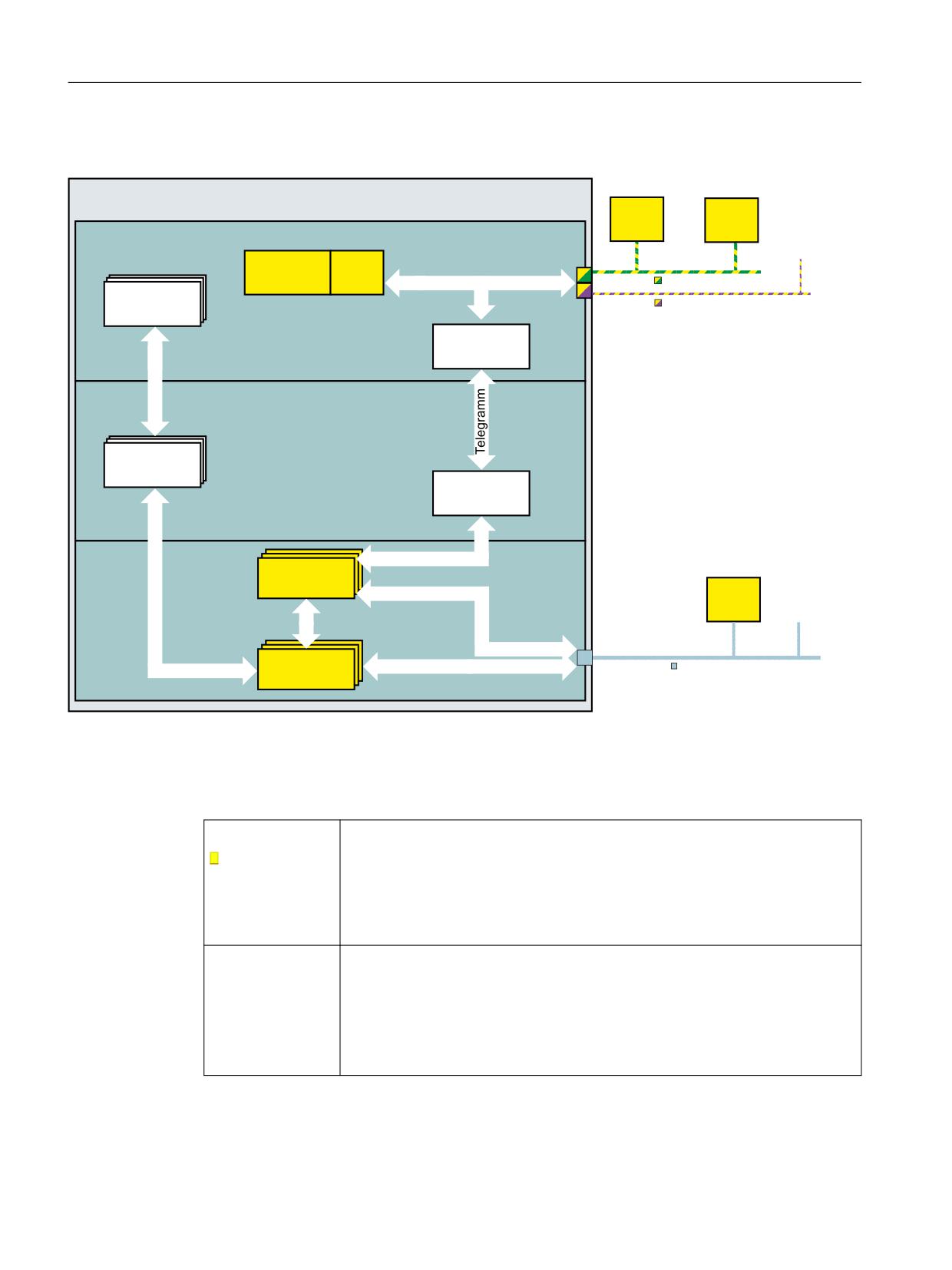
Fundamentals
3.5 Safety-relevant processing using NCU components
Details on internal processing of safety-related communication
1&8
) ',
&8
) '2
,I UHTXLUHG DGGLWLRQDO
) 3/&
GLVWULEXWHG , 2 V\VWHPV
IDLOVDIH '3 VWDQGDUG VODYHV
6DIHW\
3$(
SURJUDP
3$$
352),1(7 352),VDIH
'%
'%
352),%86 352),VDIH
6,& 6&&
7UDQVIHU
352),VDIH
1&.
7UDQVIHU
$;
$;
6,& 6&&
7UDQVIHU
352),VDIH
'5,9(
352),VDIH
$;
$;
00
$;
,I UHTXLUHG DGGLWLRQDO GULYHV
0RQLWRULQJ
'5,9( &/L4
$;
$;
Figure 3-1
Component diagram for processing safety-relevant information and data
Table 3-4
Subcomponents of the NCU
F-PLC
● Processing safety-relevant internal and external signals in the safety-relevant
PROFIsafe host
user program (safety program)
See: Safety program of the F-PLC (Page 45)
● Processing status and control signals (SIC/SCC) via the corresponding axis
DB (axis1 [DB31] ... axis 31 [DB61])
See: PLC user interface (DB3x) (Page 206), SIC/SCC (Page 205)
NC
● Transfers status and control information (SIC/SCC, axis DB) between the F-
PLC and DRIVE
● Transfers PROFIsafe telegrams (safety program, PAE/PAA) between F-PLC
and DRIVE
● Reads-in safety-relevant messages/signals from the message buffers of SI-
NAMICS Safety Integrated into the NC alarm buffer
Safety Integrated plus
30
Commissioning Manual, 12/2019, 6FC5397-1FP40-6BA3
Fundamentals
3.5 Safety-relevant processing using NCU components
HMI
● Displays safety-relevant messages/alarms from the NCK alarm buffer
● Reads out and displays additional safety-relevant diagnostics information di-
rectly from the drive
● Displays a safety delete symbol for active safety messages
See: Diagnostics (Page 295)
DRIVE (SINAMICS
● Safety-relevant motion monitoring of NC-controlled drives (connected at the
Safety Integrated)
DRIVE-CLiQ interface)
PROFIsafe slave
See: Safety functions integrated in the drive (Page 79)
● Executes fault response functions or user safety functions
Table 3-5
I/O and drives
F-I/O
The F-I/O guarantees the safety-relevant processing of information from the
field (sensors: e.g. EMERGENCY STOP pushbuttons, light barriers; actuators,
PROFIsafe slave
e.g. motor controls). The safety function for the process itself can be implemen-
ted using a user safety function - or a fault response function.
See: Safety program of the F-PLC (Page 45), F-I/O for PROFIBUS DP
(Page 33), F-I/O for PROFINET IO (Page 33)
NC-controlled drives
For each individual axis and spindle, safety functions integrated in the drive can
be implemented, which can communicate via safety-relevant input/output sig-
nals with the process.
See: Safety functions integrated in the drive (Page 79), Drive components
(Page 34)
Safety Integrated plus
Commissioning Manual, 12/2019, 6FC5397-1FP40-6BA3
31
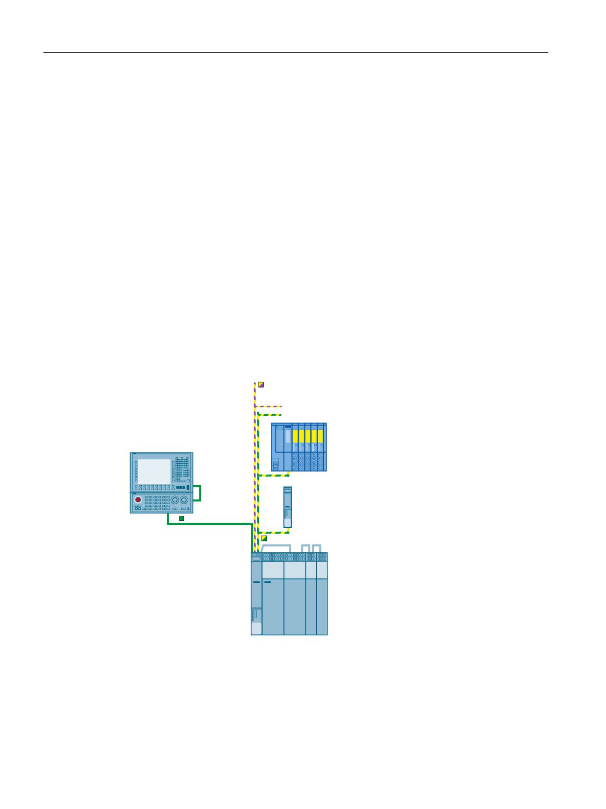
Fundamentals
3.6 Hardware components
3.6
Hardware components
Overview
The SINUMERIK Safety Integrated plus (F-PLC) safety solution places specific requirements
on the hardware components that are used.
Independent of the scope of the Safety Functions used, you can use failsafe SIMATIC and
standard I/O for PROFIBUS DP (Page 33) or PROFINET IO (Page 33) - as known from
SIMATIC Safety.
The drive system that you can use (Page 34) depends on whether a safety-relevant encoder
is used - and which axis type is to be used.
3.6.1
Configuration diagram, SINUMERIK Safety Integrated plus
Hardware components
The following diagram shows an overview of a possible structure with failsafe hardware
components.
PROFIBUS/PROFIsafe
SRVVLEO\ DGGLWLRQDO GLVWULEXWHG , 2
V\VWHPV IDLOVDIH ,2 VWDQGDUG
GHYLFHV '3 VWDQGDUG VODYHV
'LVWULEXWHG , 2
SINUMERIK
Operator panel front with TCU
V\VWHP H J (7
6
&8
ZLWK H[WHUQDO GULYH
Industrial Ethernet
PROFINET/PROFIsafe
SINUMERIK 840D sl
Figure 3-2
Configuration diagram: Hardware structure with SINUMERIK Safety Integrated plus
Safety Integrated plus
32
Commissioning Manual, 12/2019, 6FC5397-1FP40-6BA3
Fundamentals
3.6 Hardware components
3.6.2
F-I/O for PROFIBUS DP
You can use the following failsafe components in SINUMERIK Safety F-systems on
PROFIBUS DP:
● F-CPUs with DP interface
● Failsafe inputs and outputs (F-I/O), such as:
- S7-300 failsafe signal modules in ET 200M
- ET 200MP failsafe modules
- ET 200SP failsafe modules
- ET 200S failsafe modules
- ET 200pro failsafe modules
- ET 200iSP failsafe modules
- ET 200eco failsafe I/O module
- Failsafe GSD based DP slaves (light grid, laser scanner, etc.)
You have the option to expand the configuration with standard I/O.
3.6.3
F-I/O for PROFINET IO
You can use the following failsafe components in SINUMERIK Safety F-systems on
PROFINET IO:
● F-CPUs with PN interface
● Failsafe inputs and outputs (F-I/O), such as:
- S7-300 failsafe signal modules in ET 200M
- ET 200MP failsafe modules
- ET 200SP failsafe modules
- ET 200S failsafe modules
- ET 200pro failsafe modules
- ET 200iSP failsafe modules
- Failsafe GSD based I/O devices (light grid, laser scanner, etc.)
You have the option to expand the configuration with standard I/O.
Safety Integrated plus
Commissioning Manual, 12/2019, 6FC5397-1FP40-6BA3
33
Fundamentals
3.6 Hardware components
3.6.4
Drive components
The drive system that you can use depends on whether a safety-relevant encoder is used - and
which axis type is to be used.
Table 3-6
Supported axis types as a function of the drive type and the use of a safety-relevant encoder
Spindle
Rotary axis
Linear axis
Induction motor with encoder
Yes
Yes
Yes
Induction motor without encoder
Yes
No
No
Synchronous motor with encoder
Yes
Yes
Yes
Synchronous motor without encoder
No
No
No
SINAMICS HLA with encoder
No
No
Yes1
SINAMICS HLA without encoder
No
No
No
1 Not all Basic or Extended Functions are supported, see SINAMICS HLA (Page 36) or
SINAMICS HLA (Page 36).
3.6.4.1
Interconnecting DRIVE-CLiQ components
For Safety Integrated Functions, the general DRIVE-CLiQ rules apply as a basic principle. You
will find these rules in Chapter "Rules for connection with DRIVE-CLiQ" in the following Manual:
● Function Manual SINAMICS S120 Drive Functions
Beyond this, the following rules also apply to Safety Integrated:
Rules for Safety Integrated Basic Functions
● Maximum of 4 drives per DRIVE-CLiQ line for control via PROFIsafe
Rules for Safety Integrated Extended Functions
● Maximum of 6 servo axes for default clock cycle settings (safety monitoring clock
cycle = 12 ms; current controller cycle = 125 μs); of which a maximum of 4 servo axes are
in one DRIVE-CLiQ line
● Maximum of 6 vector axes for the following clock cycle settings (safety monitoring
cycle = 12 ms; current controller cycle = 500 μs)
● One Double Motor Module corresponds to 2 DRIVE-CLiQ participants.
● On Double Motor Modules, on the drive objects, different values for p9511 are not permitted,
even if the values in p0115[0] are different.
● A maximum of 4 Motor Modules with Safety Integrated Extended Functions may be
operated on one DRIVE-CLiQ line (for current controller cycle TIReg = 125 μs on all axes). No
further DRIVE-CLiQ components other than a Line Module and Sensor Modules may be
operated on this DRIVE-CLiQ line.
3.6.4.2
Drive monitoring with or without encoder
In the SINUMERIK Safety Integrated plus system, safety operation without using an encoder
is only supported for spindles equipped with induction motors.
Safety Integrated plus
34
Commissioning Manual, 12/2019, 6FC5397-1FP40-6BA3