SINUMERIK 840D sl. Service - Configuring Commissioning. Manual (2011-2020) - page 84
Appendix
A.2 Information about third-party software used
ANY KIND CONCERNING THE MERCHANTABILITY OF THIS SOFTWARE OR ITS FITNESS FOR ANY
PARTICULAR PURPOSE.
This product includes software developed by the University of California, Berkeley and its
contributors.
QLocale's data is based on Common Locale Data Repository v1.6.1.
Note
You can find additional information on the product DVD in the Readme_OSS file about the third-
party software used.
CNC Commissioning: NC, PLC, Drive
356
Commissioning Manual, 10/2020, A5E48312804B AB
Preface
Fundamental safety
1
instructions
2
Introduction
SINUMERIK
Installation on PG/PC and
3
configuration of PC systems
SINUMERIK 840D sl
SINUMERIK Integrate Create
4
Migration of projects
MyHMI /WinCC V16
Device configuration
5
Configuration Manual
6
Configuring connections
Using variables
7
8
Configuring alarms
Configuring screen objects
9
10
Using system functions
Configuring the language
11
settings
Loading and linking the
12
configuration
Appendix
13
Valid for
Control system
SINUMERIK 840D sl/840DE sl
Software
CNC software for 840D sl/840DE sl V4.5, V4.7, V4.8,
V4.91, V4.92, V4.93
12/2019
6FC5397-8FP40-0BA2
Table of contents
Preface
3
1
Fundamental safety instructions
9
1.1
General safety instructions
9
1.2
Equipment damage due to electric fields or electrostatic discharge
13
1.3
Warranty and liability for application examples
14
1.4
Industrial security
15
1.5
Residual risks of power drive systems
17
2
Introduction
19
2.1
Functional scope
19
2.1.1
WinCC Sm@rtServer Standalone supported
23
2.1.2
Additional tools and software
23
2.2
Communication with SINUMERIK 840D sl
25
2.3
Example of a configuring process
27
2.3.1
Configuration procedure when using PC systems
27
2.3.2
Configuration procedure when using SIMATIC Panels
28
2.3.3
Example projects
28
2.4
Licensing
30
2.4.1
Licensing for SIMATIC Panels
30
2.4.2
Licensing when using PC systems with SINUMERIK Operate
30
2.4.3
Licensing of the connection to the FANUC CNC/PMC
31
3
Installation on PG/PC and configuration of PC systems
33
3.1
System requirements and installation
33
3.2
Configuring your PC system as an HMI device (or server)
35
3.2.1
Overview
35
3.2.2
Installing WinCC RT Advanced
35
3.2.3
Configuring the PG/PC interface
36
3.2.4
Activating the virtual keyboard
38
3.2.5
Installing Sm@rtServer Standalone
42
3.2.6
Configuring the display of the main and secondary control panel
43
3.3
Uninstalling the software
45
4
Migration of projects
47
4.1
Comparison of functions
47
4.2
Configure PLC variables symbolically
49
4.3
Post processing of migrated GUD variables
50
4.4
Indexing of R parameters and GUD arrays
52
4.5
Migrating WinCC flexible projects integrated in STEP 7 V5.x
53
SINUMERIK Integrate Create MyHMI /WinCC V16
Configuration Manual, 12/2019, 6FC5397-8FP40-0BA2
5
Table of contents
4.6
Migration of two-dimensional GUD tags with column tag
54
4.7
Migration of alarm texts in the HMI-Advanced format
55
4.8
Migrating projects
56
5
Device configuration
59
5.1
Configurable user interface
59
5.2
Runtime configuration
61
5.3
Inserting PC system and Runtime
62
5.4
Setting the screen resolution for the RT Advanced
66
5.5
Configuration of the screen size (PC systems)
68
5.6
Adding a SIMATIC Panel
69
5.7
Using device proxies
72
6
Configuring connections
77
6.1
Overview
77
6.2
Configuring integrated connection to the SINUMERIK PLC
78
6.3
Configuring connection to the SINUMERIK NC
82
6.4
Configuring a connection to a FANUC control system
84
7
Using variables
85
7.1
Configuring SINUMERIK variables
86
7.2
NC variable descriptions
88
7.3
Configuring GUD tags
90
7.3.1
Introduction
90
7.3.2
Overview
91
7.3.3
Copying DEF files to the configuration PC
92
7.3.4
Importing GUD variables
92
7.3.5
Configuring GUD arrays
94
7.3.5.1
Overview
94
7.3.5.2
Linearization based on the sorting in SINUMERIK Operate
95
7.3.5.3
Converting a three-dimensional GUD array for linear access
96
7.3.5.4
Accessing GUD arrays using an index tag
97
7.3.6
Subsequently changing DEF files
98
7.4
Configuring variables for address multiplexing
99
7.5
Indexing of R parameters and GUD arrays
100
7.6
Accessing FANUC FOCAS functions in the variable editor
101
8
Configuring alarms
105
8.1
Importing alarms
105
8.1.1
Overview
105
8.1.2
Exporting TS files from SINUMERIK Operate
105
8.1.3
Importing SINUMERIK PLC alarm texts
106
8.2
Displaying alarms in WinCC picture objects
109
SINUMERIK Integrate Create MyHMI /WinCC V16
6
Configuration Manual, 12/2019, 6FC5397-8FP40-0BA2
Table of contents
8.2.1
Overview
109
8.2.2
Displaying NC alarms
110
8.2.2.1
Settings for display of NC alarms
110
8.2.2.2
Changing NC alarm texts
111
8.2.3
Displaying SINUMERIK user alarms (DB2)
112
8.2.3.1
Introduction
112
8.2.3.2
Configuring the alarm view
114
8.2.3.3
Configuring runtime settings
116
8.2.3.4
Required software components for DB2 alarms
117
8.2.4
Displaying the alarms of a FANUC control system
118
8.3
Conversion of alarm files (TS/CSV)
120
8.3.1
Overview
120
8.3.2
SINUMERIK Integrate Access MyMachine /P2P
121
8.3.3
Converting DB2 alarms into the CSV format
122
9
Configuring screen objects
125
9.1
Overview
125
9.2
Screen object NC operate view
127
9.2.1
Properties and configuration
127
9.2.2
Preconditions and required settings
129
9.2.3
Operation during runtime
131
9.3
Screen object NC keyboard view
133
9.3.1
Properties and configuration
133
9.3.2
Operation during runtime
136
9.4
Screen object NC part program view
138
9.4.1
Properties and configuration
138
9.4.2
Operation during runtime
140
9.4.3
Changing the screen objects using scripts in WinCC
141
9.5
Selecting and editing a part program
142
9.6
Screen object Application View
143
9.6.1
Properties and configuration
143
9.6.2
Parameterization of the XML description file
144
9.6.3
Demands on external applications
146
9.6.4
Preconditions and required settings
148
9.6.5
Operation during runtime
149
9.7
Image object, Fanuc SDF display
151
9.7.1
Properties and configuration
151
9.7.2
Preconditions and required settings
152
9.8
Changing client area screen objects using runtime scripting
154
10
Using system functions
155
10.1
Configuring SINUMERIK PI services as system functions
155
10.1.1
Overview
155
10.1.2
Functions for the NC part program view screen object
156
10.1.3
Function for the current block display
157
10.1.4
Start/stop PLC by means of a function
158
10.1.5
Executing system functions from WinCC
159
10.1.5.1
Overview
159
SINUMERIK Integrate Create MyHMI /WinCC V16
Configuration Manual, 12/2019, 6FC5397-8FP40-0BA2
7
Table of contents
10.1.5.2
LogoffNC
160
10.1.5.3
ChangeNCPassword
161
10.1.5.4
LogonNC
161
10.1.5.5
ConfigureNCMachineData
162
10.1.5.6
ResetNC
162
10.1.5.7
AcknowledgeNCCancelAlarms
162
10.1.5.8
SetNCUserFrame
162
10.1.5.9
StartNCPIService
163
10.1.5.10
SelectNCPartProgram
164
10.1.6
System function calls within a script
165
10.2
Configuring FANUC system functions
166
10.2.1
Configuring function keys by means of system functions
166
10.2.2
Function when restarting
166
10.2.3
Function to acknowledge alarms
167
11
Configuring the language settings
169
11.1
Overview
169
11.2
Enable project languages
170
11.3
Language assignment in language-dependent texts
171
11.4
Configuring synchronized language switchover
173
12
Loading and linking the configuration
177
12.1
Overview
177
12.2
Integrating WinCC Runtime into the OEMFrame area of SINUMERIK Operate
178
13
Appendix
181
13.1
SINUMERIK functions, which can be triggered using certain events of the WinCC RT
Advanced
181
Index
185
SINUMERIK Integrate Create MyHMI /WinCC V16
8
Configuration Manual, 12/2019, 6FC5397-8FP40-0BA2
Fundamental safety instructions
1
1.1
General safety instructions
WARNING
Electric shock and danger to life due to other energy sources
Touching live components can result in death or severe injury.
● Only work on electrical devices when you are qualified for this job.
● Always observe the country-specific safety rules.
Generally, the following six steps apply when establishing safety:
1. Prepare for disconnection. Notify all those who will be affected by the procedure.
2. Isolate the drive system from the power supply and take measures to prevent it being
switched back on again.
3. Wait until the discharge time specified on the warning labels has elapsed.
4. Check that there is no voltage between any of the power connections, and between any of
the power connections and the protective conductor connection.
5. Check whether the existing auxiliary supply circuits are de-energized.
6. Ensure that the motors cannot move.
7. Identify all other dangerous energy sources, e.g. compressed air, hydraulic systems, or
water. Switch the energy sources to a safe state.
8. Check that the correct drive system is completely locked.
After you have completed the work, restore the operational readiness in the inverse sequence.
WARNING
Electric shock due to connection to an unsuitable power supply
When equipment is connected to an unsuitable power supply, exposed components may
carry a hazardous voltage. Contact with hazardous voltage can result in severe injury or death.
● Only use power supplies that provide SELV (Safety Extra Low Voltage) or PELV-
(Protective Extra Low Voltage) output voltages for all connections and terminals of the
electronics modules.
SINUMERIK Integrate Create MyHMI /WinCC V16
Configuration Manual, 12/2019, 6FC5397-8FP40-0BA2
9
Fundamental safety instructions
1.1 General safety instructions
WARNING
Electric shock due to equipment damage
Improper handling may cause damage to equipment. For damaged devices, hazardous
voltages can be present at the enclosure or at exposed components; if touched, this can result
in death or severe injury.
● Ensure compliance with the limit values specified in the technical data during transport,
storage and operation.
● Do not use any damaged devices.
WARNING
Electric shock due to unconnected cable shields
Hazardous touch voltages can occur through capacitive cross-coupling due to unconnected
cable shields.
● As a minimum, connect cable shields and the cores of cables that are not used at one end
at the grounded housing potential.
WARNING
Electric shock if there is no ground connection
For missing or incorrectly implemented protective conductor connection for devices with
protection class I, high voltages can be present at open, exposed parts, which when touched,
can result in death or severe injury.
● Ground the device in compliance with the applicable regulations.
WARNING
Spread of fire from built-in devices
In the event of fire outbreak, the enclosures of built-in devices cannot prevent the escape of
fire and smoke. This can result in serious personal injury or property damage.
● Install built-in units in a suitable metal cabinet in such a way that personnel are protected
against fire and smoke, or take other appropriate measures to protect personnel.
● Ensure that smoke can only escape via controlled and monitored paths.
SINUMERIK Integrate Create MyHMI /WinCC V16
10
Configuration Manual, 12/2019, 6FC5397-8FP40-0BA2
Fundamental safety instructions
1.1 General safety instructions
WARNING
Unexpected movement of machines caused by radio devices or mobile phones
When radio devices or mobile phones with a transmission power > 1 W are used in the
immediate vicinity of components, they may cause the equipment to malfunction.
Malfunctions may impair the functional safety of machines and can therefore put people in
danger or lead to property damage.
● If you come closer than around 2 m to such components, switch off any radios or mobile
phones.
● Use the "SIEMENS Industry Online Support app" only on equipment that has already been
switched off.
WARNING
Fire due to inadequate ventilation clearances
Inadequate ventilation clearances can cause overheating of components with subsequent fire
and smoke. This can cause severe injury or even death. This can also result in increased
downtime and reduced service lives for devices/systems.
● Ensure compliance with the specified minimum clearance as ventilation clearance for the
respective component.
NOTICE
Overheating due to inadmissible mounting position
The device may overheat and therefore be damaged if mounted in an inadmissible position.
● Only operate the device in admissible mounting positions.
WARNING
Unexpected movement of machines caused by inactive safety functions
Inactive or non-adapted safety functions can trigger unexpected machine movements that
may result in serious injury or death.
● Observe the information in the appropriate product documentation before commissioning.
● Carry out a safety inspection for functions relevant to safety on the entire system, including
all safety-related components.
● Ensure that the safety functions used in your drives and automation tasks are adjusted and
activated through appropriate parameterizing.
● Perform a function test.
● Only put your plant into live operation once you have guaranteed that the functions relevant
to safety are running correctly.
SINUMERIK Integrate Create MyHMI /WinCC V16
Configuration Manual, 12/2019, 6FC5397-8FP40-0BA2
11
Fundamental safety instructions
1.1 General safety instructions
Note
Important safety notices for Safety Integrated functions
If you want to use Safety Integrated functions, you must observe the safety notices in the Safety
Integrated manuals.
WARNING
Malfunctions of the machine as a result of incorrect or changed parameter settings
As a result of incorrect or changed parameterization, machines can malfunction, which in turn
can lead to injuries or death.
● Protect the parameterization against unauthorized access.
● Handle possible malfunctions by taking suitable measures, e.g. emergency stop or
emergency off.
SINUMERIK Integrate Create MyHMI /WinCC V16
12
Configuration Manual, 12/2019, 6FC5397-8FP40-0BA2
Fundamental safety instructions
1.2 Equipment damage due to electric fields or electrostatic discharge
1.2
Equipment damage due to electric fields or electrostatic discharge
Electrostatic sensitive devices (ESD) are individual components, integrated circuits, modules
or devices that may be damaged by either electric fields or electrostatic discharge.
NOTICE
Equipment damage due to electric fields or electrostatic discharge
Electric fields or electrostatic discharge can cause malfunctions through damaged individual
components, integrated circuits, modules or devices.
● Only pack, store, transport and send electronic components, modules or devices in their
original packaging or in other suitable materials, e.g conductive foam rubber of aluminum
foil.
● Only touch components, modules and devices when you are grounded by one of the
following methods:
- Wearing an ESD wrist strap
- Wearing ESD shoes or ESD grounding straps in ESD areas with conductive flooring
● Only place electronic components, modules or devices on conductive surfaces (table with
ESD surface, conductive ESD foam, ESD packaging, ESD transport container).
SINUMERIK Integrate Create MyHMI /WinCC V16
Configuration Manual, 12/2019, 6FC5397-8FP40-0BA2
13
Fundamental safety instructions
1.3 Warranty and liability for application examples
1.3
Warranty and liability for application examples
Application examples are not binding and do not claim to be complete regarding configuration,
equipment or any eventuality which may arise. Application examples do not represent specific
customer solutions, but are only intended to provide support for typical tasks.
As the user you yourself are responsible for ensuring that the products described are operated
correctly. Application examples do not relieve you of your responsibility for safe handling when
using, installing, operating and maintaining the equipment.
SINUMERIK Integrate Create MyHMI /WinCC V16
14
Configuration Manual, 12/2019, 6FC5397-8FP40-0BA2
Fundamental safety instructions
1.4 Industrial security
1.4
Industrial security
Note
Industrial security
Siemens provides products and solutions with industrial security functions that support the
secure operation of plants, systems, machines and networks.
In order to protect plants, systems, machines and networks against cyber threats, it is
necessary to implement - and continuously maintain - a holistic, state-of-the-art industrial
security concept. Products and solutions from Siemens constitute one element of such a
concept.
Customers are responsible for preventing unauthorized access to their plants, systems,
machines and networks. Such systems, machines and components should only be connected
to an enterprise network or the Internet if and to the extent such a connection is necessary and
only when appropriate security measures (e.g. using firewalls and/or network segmentation)
are in place.
For additional information on industrial security measures that can be implemented, please
visit:
Siemens’ products and solutions undergo continuous development to make them more secure.
Siemens strongly recommends that product updates are applied as soon as they become
available, and that only the latest product versions are used. Use of product versions that are
no longer supported, and failure to apply the latest updates may increase customer’s exposure
to cyber threats.
To stay informed about product updates, subscribe to the Siemens Industrial Security RSS
Feed at:
Further information is provided on the Internet:
Industrial Security Configuration Manual (https://support.industry.siemens.com/cs/ww/en/
view/108862708)
SINUMERIK Integrate Create MyHMI /WinCC V16
Configuration Manual, 12/2019, 6FC5397-8FP40-0BA2
15
Fundamental safety instructions
1.4 Industrial security
WARNING
Unsafe operating states resulting from software manipulation
Software manipulations, e.g. viruses, Trojans, or worms, can cause unsafe operating states
in your system that may lead to death, serious injury, and property damage.
● Keep the software up to date.
● Incorporate the automation and drive components into a holistic, state-of-the-art industrial
security concept for the installation or machine.
● Make sure that you include all installed products into the holistic industrial security concept.
● Protect files stored on exchangeable storage media from malicious software by with
suitable protection measures, e.g. virus scanners.
● On completion of commissioning, check all security-related settings.
● Protect the drive against unauthorized changes by activating the "Know-how protection"
converter function.
SINUMERIK Integrate Create MyHMI /WinCC V16
16
Configuration Manual, 12/2019, 6FC5397-8FP40-0BA2
Fundamental safety instructions
1.5 Residual risks of power drive systems
1.5
Residual risks of power drive systems
When assessing the machine- or system-related risk in accordance with the respective local
regulations (e.g., EC Machinery Directive), the machine manufacturer or system installer must
take into account the following residual risks emanating from the control and drive components
of a drive system:
1.
Unintentional movements of driven machine or system components during commissioning,
operation, maintenance, and repairs caused by, for example,
- Hardware and/or software errors in the sensors, control system, actuators, and cables
and connections
- Response times of the control system and of the drive
- Operation and/or environmental conditions outside the specification
- Condensation/conductive contamination
- Parameterization, programming, cabling, and installation errors
- Use of wireless devices/mobile phones in the immediate vicinity of electronic
components
- External influences/damage
- X-ray, ionizing radiation and cosmic radiation
2.
Unusually high temperatures, including open flames, as well as emissions of light, noise,
particles, gases, etc., can occur inside and outside the components under fault conditions
caused by, for example:
- Component failure
- Software errors
- Operation and/or environmental conditions outside the specification
- External influences/damage
3.
Hazardous shock voltages caused by, for example:
- Component failure
- Influence during electrostatic charging
- Induction of voltages in moving motors
- Operation and/or environmental conditions outside the specification
- Condensation/conductive contamination
- External influences/damage
4.
Electrical, magnetic and electromagnetic fields generated in operation that can pose a risk
to people with a pacemaker, implants or metal replacement joints, etc., if they are too close
5.
Release of environmental pollutants or emissions as a result of improper operation of the
system and/or failure to dispose of components safely and correctly
6.
Influence of network-connected communication systems, e.g. ripple-control transmitters or
data communication via the network
For more information about the residual risks of the drive system components, see the relevant
sections in the technical user documentation.
SINUMERIK Integrate Create MyHMI /WinCC V16
Configuration Manual, 12/2019, 6FC5397-8FP40-0BA2
17
Introduction
2
2.1
Functional scope
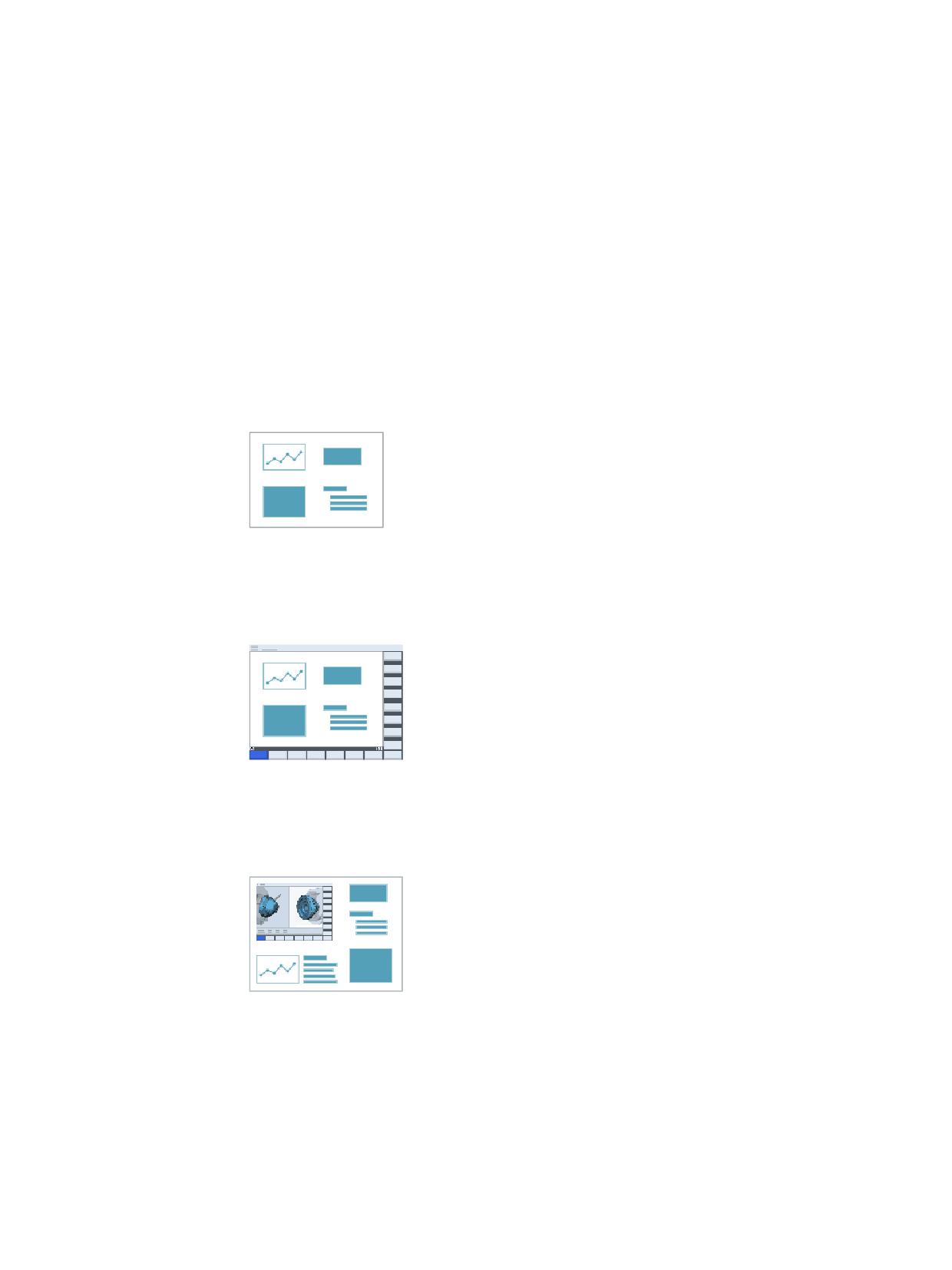
SINUMERIK Integrate Create MyHMI /WinCC V16 extends SIMATIC WinCC Advanced or
WinCC Professional to include various functionalities for implementing customer-specific user
interfaces for CNC machines and plants.
User interfaces can be implemented for the following fundamentally different applications:
● WinCC Runtime, as a customer-specific standalone user interface, i.e. access to
SINUMERIK data, etc. but without a SINUMERIK Operate connection.
Potential application: Supported SIMATIC Panels with integrated WinCC Runtime or
supported PC systems with installed WinCC Runtime
● WinCC Runtime as a customer-specific operating area (OEMFrame) in SINUMERIK
Operate
Potential application: Supported PC systems with installed WinCC Runtime and
SINUMERIK Operate
● WinCC Runtime as a customer-specific framework application with client area for
SINUMERIK Operate (and other applications)
Potential application: Supported PC systems with installed WinCC Runtime and
SINUMERIK Operate
SINUMERIK Integrate Create MyHMI /WinCC V16
Configuration Manual, 12/2019, 6FC5397-8FP40-0BA2
19
Introduction
2.1 Functional scope
These applications are configured differently and some of them have different system
requirements (see below).
Note
Information for users changing over from SINUMERIK HMI configuration package WinCC
flexible 2008
The use of WinCC Runtime as a standalone user interface or as a customer-specific operating
area (OEMFrame) is comparable to the configuration options of the SINUMERIK HMI
configuration package WinCC flexible 2008.
You can find additional information for users who are switching over in the descriptions for
the migration of SINUMERIK HMI projects (Page 47).
WinCC Runtime as standalone user interface
A WinCC Runtime with access to data, alarms and PI services of a SINUMERIK controller can
be used as a standalone user interface on SIMATIC Panels, i.e. without any connection to
SINUMERIK Operate.
Supported functionalities
● Access to data, alarms and PI services of the SINUMERIK controller in the WinCC Runtime
● Activating part programs with screen object "NC part program view"
Supported SIMATIC Panels
● SIMATIC Comfort Panels (e.g. KP400 Comfort)
● SIMATIC Mobile Panels (e.g. Mobile Panel 177 6" DP)
WinCC Runtime is already installed on SIMATIC Panels. You can load the configuration
directly onto the device.
It is also possible to use a standalone user interface on the PC systems supported for
SINUMERIK, if the WinCC Runtime is installed separately.
WinCC Runtime as SINUMERIK Operate operating area
You can adapt SINUMERIK Operate on a PCU 50.5 (and other PC systems) to customer-
specific requirements and extend it with an operating area.
Supported functionalities
● Access to data, alarms and PI services of the SINUMERIK controller in the WinCC Runtime
● Activating part programs with screen object "NC part program view"
● Integrating WinCC Runtime into the OEMFrame area of SINUMERIK Operate
SINUMERIK Integrate Create MyHMI /WinCC V16
20
Configuration Manual, 12/2019, 6FC5397-8FP40-0BA2

Introduction
2.1 Functional scope
Supported PC systems
PC system
PCU basic soft-
SINUMERIK Operate
ware
Variant
Version
SINUMERIK PCU 50.5-C
≥ V10.0 SP3
SINUMERIK
≥ V4.5
Operate /PCU
SINUMERIK PCU 50.5-P
≥ V4.5
SIMATIC IPC427D PN/IE
≥ V11.07
≥ V4.5
SIMATIC IPC627D PN/IE
SIMATIC IPC477D PN/IE
SIMATIC IPC677D PN/IE
SIMATIC IPC427E PN/IE
≥ V11.07
≥ V4.5
SIMATIC IPC477E PN/IE
Standard PC with
--
SINUMERIK
≥ V4.5
Microsoft Windows 7
Operate /PC
Ultimate / Professional 64-bit
The supplied WinCC RT Advanced must be installed separately on PC systems (Page 35).
WinCC Runtime as a framework application
The use of a WinCC Runtime as a customer-specific framework application offers you
additional freedoms in the design of the machine operating interface.
You configure the framework application as a user interface in WinCC (TIA Portal) with the
familiar possibilities and are able to place SINUMERIK Operate as a client area by means of the
"NC operate view" screen object.
Supported functionalities
● Configuration of the framework application as a user interface in WinCC (TIA Portal)
- Access to data, alarms and PI services of the SINUMERIK controller
- Access to data and alarms of FANUC control systems
● Positioning of the NC operate view as client area for SINUMERIK Operate
● Positioning of client areas for applications of other manufacturers:
- Application display for integration of additional applications (e.g. Microsoft Editor)
- FANUC SDF display to integrate a FANUC HMI
● Positioning of the Sm@rtClient display for remote access to PC systems with Sm@rtServer
standalone
Supported PC systems
SINUMERIK Integrate Create MyHMI /WinCC V16
Configuration Manual, 12/2019, 6FC5397-8FP40-0BA2
21

Introduction
2.1 Functional scope
Only the following PC systems are supported with the NC operate view:
PC system
PCU basic soft-
SINUMERIK Operate
ware
Variant
Version
SIMATIC IPC427D PN/IE
≥ V11.07
SINUMERIK
≥ V4.8 SP2
Operate /PCU
SIMATIC IPC627D PN/IE
SIMATIC IPC477D PN/IE
SIMATIC IPC677D PN/IE
SIMATIC IPC427E PN/IE
SIMATIC IPC477E PN/IE
Standard PC with
--
SINUMERIK
≥ V4.8 SP2
Microsoft Windows 7
Operate /PC
Ultimate / Professional 64-bit
The supplied WinCC RT Advanced must be installed separately on PC systems (Page 35).
Note
First-time initialization of NC operate view with touch input is system-dependent, possibly
delayed
On PC systems with single-core processors and touch input, during simultaneous first-time
initialization of NC operate view and virtual keyboard, correct display may be delayed during
runtime.
After initialization, these objects will be displayed without a time delay.
Supported operator panel fronts
Only the following operator panel fronts are supported with NC operate view:
● SINUMERIK TOP 1501
● SINUMERIK TOP 1901
● SINUMERIK TOP 2201
● SINUMERIK OP 015 black
● SINUMERIK OP 019 black
● SIMATIC IFP1200
● SIMATIC IFP1500
● SIMATIC IFP1900
● SIMATIC IFP2200
SINUMERIK Integrate Create MyHMI /WinCC V16
22
Configuration Manual, 12/2019, 6FC5397-8FP40-0BA2
Introduction
2.1 Functional scope
2.1.1
WinCC Sm@rtServer Standalone supported
SINUMERIK Integrate Create MyHMI /WinCC helps to support the use of WinCC Sm@rtServer
Standalone.
WinCC Sm@rtServer Standalone allows you to use the Sm@rtServer functionality on PC
systems on which WinCC RT Advanced is not installed.
So, for example, you can operate an HMI device with WinCC RT Advanced and a configured
Sm@rtClient display without having to install WinCC RT Advanced on the PC system (server)
connected via the Sm@rtClient display.
Differences from the standard version of WinCC Sm@rtServer
● WinCC RT Advanced and WinCC Sm@rtServer Standalone cannot be installed side by
side on the same PC system.
● Sm@rtServer Standalone is not installed and started as a service but can be called as an
application or added to the Windows startup folder.
Further information
With the exception of the differences listed here, the functionality and operation are the same
as those of the standard version of WinCC Sm@rtServer.
You will find documentation in the online help of TIA Portal here:
● Visualizing processes > Options > WinCC Sm@rtServer
● Visualizing processes > Creating screens > Working with operating objects > Objects >
Sm@rtClient display
2.1.2
Additional tools and software
The following software, which is not part of SINUMERIK Integrate Create MyHMI /WinCC, is
mentioned in this documentation:
Software
Available from
SINUMERIK Operate Integration (HMI integration
Contained on the product DVD CNC software ... with SINUMERIK Op-
tool)
10166222)
This separate tool is required for the application of a
customer-specific SINUMERIK Operate operating
area. This tool integrates the configured runtime
"WinCC RT Advanced" into SINUMERIK Operate
on a PC system.
You can make various settings in the corresponding
dialog (Page 177), for example, you can specify the
softkey via which the runtime of SINUMERIK Oper-
ate is called
SINUMERIK PCU-Basesoftware/IPC
Can be ordered in SIEMENS Industry Mall (https://
mall.industry.siemens.com/mall/en/us/Catalog/Products/10166222)
(only for SIMATIC IPC, already installed on SINU-
MERIK PCU 50.5)
SINUMERIK Operate/PCU
Can be ordered in SIEMENS Industry Mall (https://
mall.industry.siemens.com/mall/Catalog/Product/
(for PC systems with PCU-Basesoftware)
6FC5800-0AP88-0YB0)
SINUMERIK Integrate Create MyHMI /WinCC V16
Configuration Manual, 12/2019, 6FC5397-8FP40-0BA2
23
Introduction
2.1 Functional scope
Software
Available from
SINUMERIK Operate/PC
Can be ordered in SIEMENS Industry Mall (https://
mall.industry.siemens.com/mall/Catalog/Product/
(for standard PCs without PCU-Basesoftware)
6FC5800-0AP87-0YB0)
WinCC TagConverter
Available on the Service & Support pages on the Internet:
Importing STEP 7 V5.x variables into the TIA Portal
Tag Converter for WinCC (TIA Portal) (https://
(Page 49)
support.industry.siemens.com/cs/document/56078300/)
HMI SolutionLine alarm text converter
Contained on the product DVD CNC software ... with SINUMERIK Op-
Migration of alarm texts in the HMI-Advanced for-
10166222)
mat (Page 55)
SINUMERIK Integrate Access MyMachine /P2P
Can be ordered in SIEMENS Industry Mall (https://
mall.industry.siemens.com/mall/en/us/Catalog/Products/10166222)
Migration of alarm texts in the HMI-Advanced for-
mat (Page 55)
See also
Overview (Page 35)
SINUMERIK Integrate Create MyHMI /WinCC V16
24
Configuration Manual, 12/2019, 6FC5397-8FP40-0BA2
Introduction
2.2 Communication with SINUMERIK 840D sl
2.2
Communication with SINUMERIK 840D sl
Overview
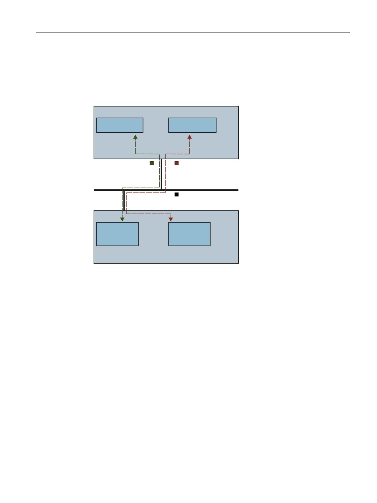
A SINUMERIK NCU includes the integrated subcomponents PLC and NCK.
3& V\VWHP RU 6,0$7,& 3DQHO
&RPPXQLFDWLRQ FKDQQHO
&RPPXQLFDWLRQ FKDQQHO
6,0$7,& 6
6,180(5,. 1&
/RJLFDO FRQQHFWLRQ 3/&
/RJLFDO FRQQHFWLRQ 1&.
3/& WDJ DFFHVV DQG DODUPV DV
5HDGLQJ ZULWLQJ RI 1& DQG *8'
ZLWK DQ 6
FRQWUROOHU
WDJV FDOOLQJ 3, VHUYLFHV
1HWZRUNLQJ
3& V\VWHPV (WKHUQHW
6,0$7,& 3DQHO (WKHUQHW RU 03,
1&8
3/&
1&.
Figure 2-1
Communication principle
WinCC uses different communication drivers to access these subcomponents.
● PLC
- Behaves like an S7-300 controller in respect to data communication.
- Uses the communication driver "SIMATIC S7-300/400".
● NCK
- Requires special tag descriptions and specific services.
- Uses the communication driver "SINUMERIK NC". The "SINUMERIK NC"
communication driver allows you to read/write NC tags and GUDs as well as to access
PI services.
SINUMERIK Integrate Create MyHMI /WinCC V16
Configuration Manual, 12/2019, 6FC5397-8FP40-0BA2
25
Introduction
2.2 Communication with SINUMERIK 840D sl
Depending on the HMI device that you are using, you can use different interfaces on the NCU.
Table 2-1
Assignment of interfaces, HMI devices and communication drivers
HMI device
Runtime
Communication drivers
NCU interface
PLC
NCK
PCU 50.5 with SIN-
Pluggable WinCC
SIMATIC
SINUMERIK
Ethernet interfaces
UMERIK Operate
RT Advanced
S7-300/400
NC
of the CP (X120,
X130)
SIMATIC Panel
Integrated WinCC
SIMATIC
SINUMERIK
MPI (X136)
RT Advanced
S7-300/400
NC
SIMATIC
SINUMERIK
Ethernet interfaces
S7-300/400
NC
of the CP (X120,
X130)
SINUMERIK Integrate Create MyHMI /WinCC V16
26
Configuration Manual, 12/2019, 6FC5397-8FP40-0BA2

Introduction
2.3 Example of a configuring process
2.3
Example of a configuring process
An exemplary configuration procedure when using a PC system (Page 27) or SIMATIC Panel
(Page 28) can be found in the overview tables.
An example project (Page 28) is provided with the installation, which you can open and view
in the TIA Portal.
2.3.1
Configuration procedure when using PC systems
The following table shows an example configuration procedure with use of a Siemens PC
system with WinCC RT Advanced.
For descriptions which concern the default scope of SIMATIC WinCC Advanced, you are
referred to the corresponding chapter in the online help of the TIA Portal.
No.
Step
Additional information
1
Install software on PC system and, if necessary, con-
Section "Configuring your PC system as an HMI device
figure PG/PC interface and virtual keyboard
(Page 35)"
2
Create a project
TIA Portal online help; keyword: "project, create"
3
Add PC system and WinCC RT
Section "Adding a SIEMENS PC system and Runtime
(Page 62)"
4
Specify screen resolution of the operator panel front
Section "Setting the screen resolution (Page 66)"
5
Add screens and templates, if needed
TIA Portal online help, section "Working with screens"
6
Define start screen
TIA Portal online help; keyword: "Start screen"
7
Configure screen size
Section "Configuration of the screen size (Page 68)"
8
Adding a device proxy or NCU
Section "Using device proxies (Page 72)" or the TIA Portal
online help, keyword"NCU, adding"
9
Creating an integrated connection to the PLC
Section "Creating an integrated connection (Page 78)"
10
Creating a non-integrated connection to the NC
Section "Creating a non-integrated connection (Page 82)"
11
Configure the language settings
"Configuring language settings (Page 169)" section
12
Configure tags
"Configuring tags (Page 85)" section
13
Configuring alarms
"Configuring alarms (Page 105)" section
14
Configure screen objects
"Configuring screen objects (Page 125)" section
15
Configure system functions
Section "Configuring PI services of the NC as system func-
tions (Page 155)"
16
Compile project
TIA Portal online help, section "Compile and download"
17
Test configuration as simulation
TIA Portal online help; keyword: "Compile, project"
18
Load configuration onto PC system
Section "Loading and integrating a configuration (Page 177)"
and TIA Portal online help, Section "Compile and download"
If you change your configuration after loading it in the
TIA Portal, you must compile it again and download it
to the PC system.
19
Connecting SINUMERIK Operate and/or WinCC RT Advanced
SINUMERIK Integrate Create MyHMI /WinCC V16
Configuration Manual, 12/2019, 6FC5397-8FP40-0BA2
27

Introduction
2.3 Example of a configuring process
No.
Step
Additional information
a
To display WinCC RT Advanced in the OEMFrame
Chapter "Integrating WinCC Runtime into the OEMFrame
area of SINUMERIK Operate, you must first integrate
area of SINUMERIK Operate (Page 178)"
it.
Usually, you will only have to integrate WinCC RT
Advanced into SINUMERIK Operate once. You only
need to repeat the process if you want to change
something in the settings for the integration of Run-
time in SINUMERIK Operate.
b
No further action is necessary if you want to display
--
SINUMERIK Operate via the NC operate view screen
object in WinCC RT Advanced.
2.3.2
Configuration procedure when using SIMATIC Panels
The following table shows an exemplary configuration procedure when using a SIMATIC Panel.
For descriptions which concern the default scope of SIMATIC WinCC Advanced, you are
referred to the corresponding chapter in the online help of the TIA Portal.
No.
Step
Additional information
1
Create a project
TIA Portal online help; keyword: "project, create"
2
Add a SIMATIC Panel
"Adding a SIMATIC Panel (Page 69)" section
3
Adding a device proxy or NCU
Section "Using device proxies" or the TIA Portal online help,
keyword"NCU, adding"
4
Create a connection
"Configuring connections (Page 77)" section
5
Configure the language settings
"Configuring language settings (Page 169)" section
6
Add screens and templates
TIA Portal online help, section "Working with screens"
7
Define start screen
TIA Portal online help; keyword: "Start screen"
8
Configure tags
"Configuring tags (Page 85)" section
9
Configuring alarms
"Configuring alarms (Page 105)" section
10
Configure screen objects
"Configuring screen objects (Page 125)" section
11
Configure system functions
"Configuring system functions (Page 155)" section
12
Compile project
TIA Portal online help, section "Compile and download"
13
Test configuration as simulation
TIA Portal online help; keyword: "Simulate"
See also: Note "Compatibility of simulation with RT Ad-
vanced < V13 (Page 100)"
14
Load configuration in SIMATIC Panel
TIA Portal online help, section "Compile and download"
2.3.3
Example projects
The example project can be found in this directory:
● <Installation directory of the TIA Portal>\Automation\Portal V15\Data\HMI\Sinumerik
\samples
SINUMERIK Integrate Create MyHMI /WinCC V16
28
Configuration Manual, 12/2019, 6FC5397-8FP40-0BA2
Introduction
2.3 Example of a configuring process
The examples are saved in the TIA Portal archive format "zap15". To open a sample project in
the TIA Portal, retrieve it using the menu command "Project > Retrieve..."
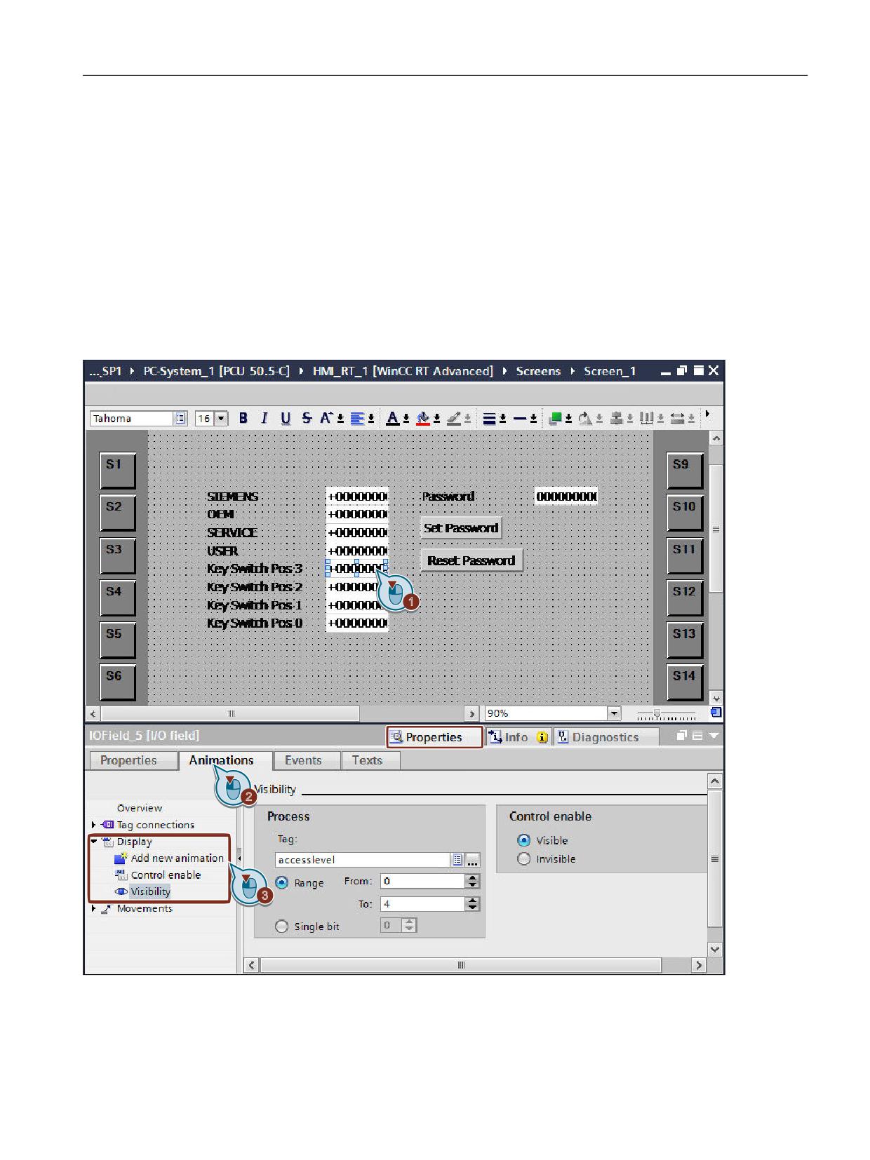
NCSecurity example
The sample project shows how the NC tag "accesslevel" can be used to control the visibility and
operability of an I/O field.
To view the relevant settings, proceed as follows:
1. Double-click "PC_System_1 > HMI_RT_1 > Screens > Screen_1" in the project tree.
2. Select the relevant I/O field. In the "Properties > Animations > View" Inspector window,
switch to the lower-level settings ("Operability" or "Visibility").
Figure 2-2
Settings in the NCSecurity sample project (for "Key Switch Pos 3")
SINUMERIK Integrate Create MyHMI /WinCC V16
Configuration Manual, 12/2019, 6FC5397-8FP40-0BA2
29
Introduction
2.4 Licensing
2.4
Licensing
2.4.1
Licensing for SIMATIC Panels
You need the following licenses:
● Engineering system
SIMATIC WinCC Comfort V15.1, WinCC Advanced V15.1 or WinCC Professional V15.1
● Runtime on the SIMATIC Panel
License P03 - SINUMERIK 840D sl SINUMERIK Integrate Run MyHMI /SIMATIC OP
Article No.: 6FC5800-0AP03-0YB0
2.4.2
Licensing when using PC systems with SINUMERIK Operate
You need the following licenses:
● Engineering system
SIMATIC WinCC Advanced V15.1 or WinCC Professional V15.1
● Runtime
License P61 - SINUMERIK Integrate Run MyHMI /WinCC
Article No.: 6FC5800-0AP61-0YB0
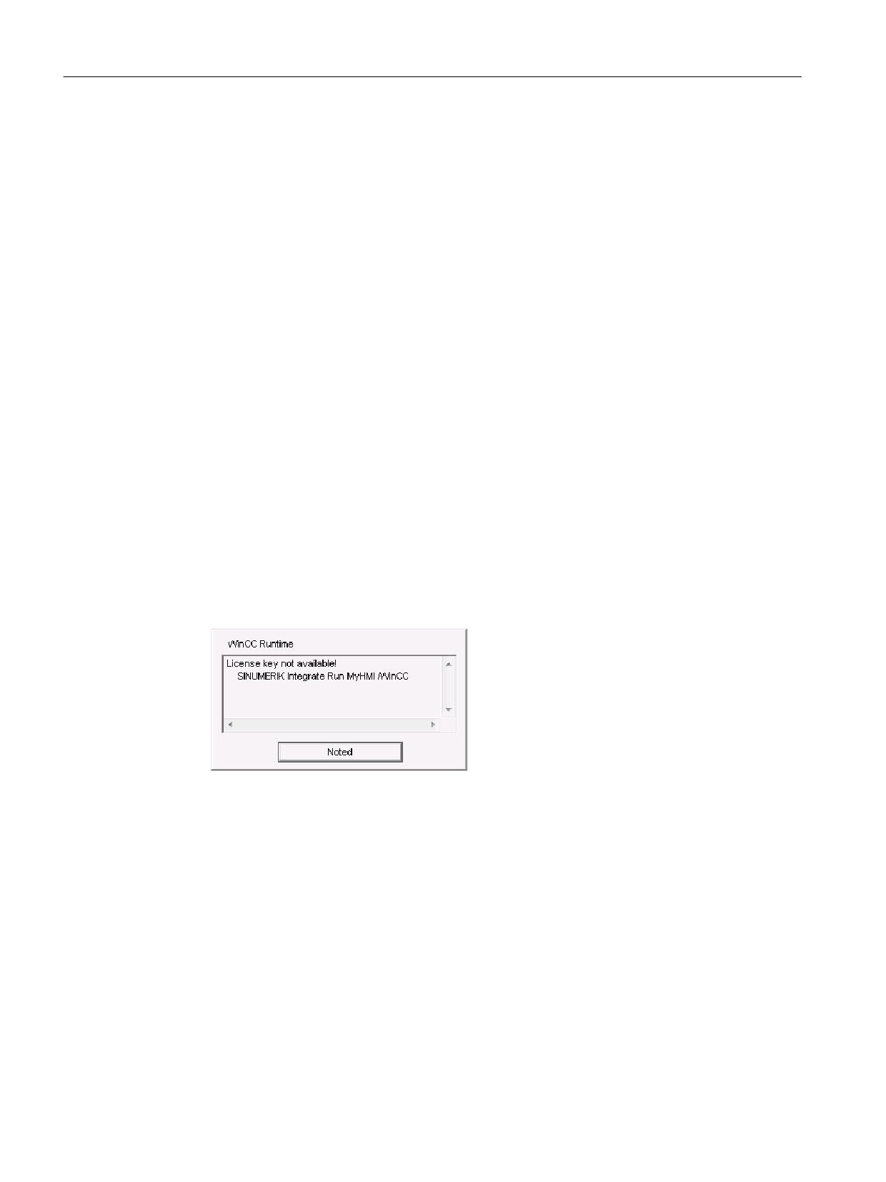
Message if there is no license
In SINUMERIK Operate, if option "SINUMERIK Integrate Run MyHMI /WinCC" is not
licensed, then a request for a license is displayed during the runtime.
The name of the software option to be licensed differs depending on the software version;
however, the license to be ordered is identical (Article No.: 6FC5800-0AP61-0YB0):
- SINUMERIK Operate 4.6 or newer: "SINUMERIK Integrate Run MyHMI /WinCC"
In SINUMERIK Operate, license option P61 "SINUMERIK Integrate Run MyHMI /
WinCC" so that the request is no longer displayed.
- SINUMERIK Operate 4.5 SP2 or older: "Sinumerik HMI sl Runtime OA Configuring"
In SINUMERIK Operate, license option P61 "Sinumerik HMI sl Runtime OA Configuring"
so that the request is no longer displayed.
SINUMERIK Integrate Create MyHMI /WinCC V16
30
Configuration Manual, 12/2019, 6FC5397-8FP40-0BA2
Introduction
2.4 Licensing
2.4.3
Licensing of the connection to the FANUC CNC/PMC
You require the following license to use the communication driver "FANUC CNC/PMC" - or to
establish a connection to a FANUC control system:
● Engineering system
SIMATIC WinCC Advanced V15.1 or WinCC Professional V15.1
● License additionally required (Automation License Manager)
WinCC RT Advanced FANUC (4096)
Article No.: 6FC5861-3YP00-1YB0
SINUMERIK Integrate Create MyHMI /WinCC V16
Configuration Manual, 12/2019, 6FC5397-8FP40-0BA2
31
Introduction
2.4 Licensing
SINUMERIK Integrate Create MyHMI /WinCC V16
32
Configuration Manual, 12/2019, 6FC5397-8FP40-0BA2
Installation on PG/PC and configuration of PC systems
3
3.1
System requirements and installation
SINUMERIK Integrate Create MyHMI /WinCC V16 is an option package for SIMATIC WinCC
Advanced V16 or WinCC Professional V16 with an additional setup.
System requirements
All hardware and software requirements for installing SIMATIC WinCC Advanced V16 or
WinCC Professional V16 apply (refer to the respective documentation).
Requirement
● All other applications (e.g. Microsoft Word and TIA Portal) are closed.
● SIMATIC WinCC Advanced or WinCC Professional is already installed on the PG/PC
Procedure
To install SINUMERIK Integrate Create MyHMI /WinCC, follow these steps:
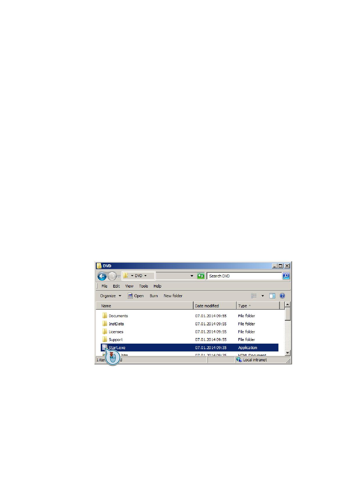
1. In Windows Explorer, browse to the root directory of the product DVD.
2. Double-click the setup file "Start.exe" of SINUMERIK Integrate Create MyHMI /WinCC.
Figure 3-1
Starting SINUMERIK Integrate Create MyHMI /WinCC setup
3. Install the software using the installation wizard.
Result
SINUMERIK Integrate Create MyHMI /WinCC is installed on the PG/PC.
SINUMERIK Integrate Create MyHMI /WinCC V16
Configuration Manual, 12/2019, 6FC5397-8FP40-0BA2
33
Installation on PG/PC and configuration of PC systems
3.1 System requirements and installation
If you are using a PC system as your HMI device, you must install and configure additional
software (Page 35) on it.
SINUMERIK Integrate Create MyHMI /WinCC V16
34
Configuration Manual, 12/2019, 6FC5397-8FP40-0BA2

Installation on PG/PC and configuration of PC systems
3.2 Configuring your PC system as an HMI device (or server)
3.2
Configuring your PC system as an HMI device (or server)
3.2.1
Overview
Depending on the configuration, you will have to install further software and configure
components on the PC system.
Table 3-1
Using a PC system as an HMI device
Application
Procedure
Using a PC system as an HMI device
Installing WinCC RT Advanced (Page 35)
Using SIMATIC Box PC, SIMATIC Panel PC or a standard PC
Configuring the PG/PC interface (Page 36)
Using several runtime languages and the screen keyboard
Add all of the used runtime languages as entry languages
(keyboard layout) in Windows
Optional when using WinCC Runtime as a framework appli-
Activating the virtual keyboard in the setup of SINUMERIK
cation in combination with a touch screen
Operate (Page 38)
Configuring the display of the main and secondary control
panel (Page 43)
Table 3-2
Using a PC system as Sm@rtServer
Application
Procedure
Using the "Sm@rtClient display" in combination with a server
Installing Sm@rtServer Standalone (Page 42)
without WinCC RT Advanced installed
However, you do not need to install the SIMATIC WinCC Advanced engineering system
(TIA Portal) or Create MyHMI /WinCC on the PC system.
3.2.2
Installing WinCC RT Advanced
Note
Minimum 800x480 resolution during installation.
A screen with a minimum resolution of 800 x 480 pixels must be connected during the
installation of the "WinCC RT Advanced" runtime.
For example, if you are using the SINUMERIK OP 010 operator panel front or OP 08T, you must
connect a different screen before installing the runtime.
After installing the runtime, you can reconnect the SINUMERIK operator panel front and use it
in the normal way.
SINUMERIK Integrate Create MyHMI /WinCC V16
Configuration Manual, 12/2019, 6FC5397-8FP40-0BA2
35
Installation on PG/PC and configuration of PC systems
3.2 Configuring your PC system as an HMI device (or server)
Procedure
To install WinCC RT Advanced on a PC system, proceed as follows:
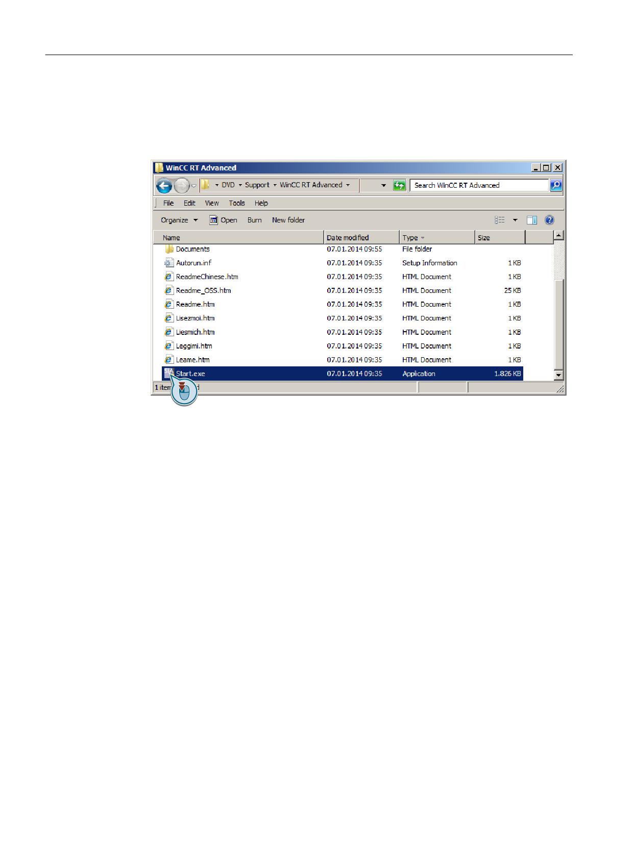
1. On the product DVD, open the directory "\Support\WinCC RT Advanced" and double-click
the WinCC RT Advanced setup file "Start.exe".
Figure 3-2
Starting WinCC RT Advanced runtime setup
2. Install the software using the installation wizard.
3. From the same directory, install the Update 1 setup.
3.2.3
Configuring the PG/PC interface
The PG/PC interface of the PC system must be set for operation via TCP/IP for "WinCC RT
Advanced" runtime to be able to read data from the NCU.
● If you are using SINUMERIK PCU 50.5, the PG/PC interface was automatically configured
when you installed the software.
● If you are using a different PC system, you must configure the PG/PC interface as described
in this chapter.
SINUMERIK Integrate Create MyHMI /WinCC V16
36
Configuration Manual, 12/2019, 6FC5397-8FP40-0BA2
Installation on PG/PC and configuration of PC systems
3.2 Configuring your PC system as an HMI device (or server)
Procedure
Proceed as follows to configure the PG/PC interface of the PC system:
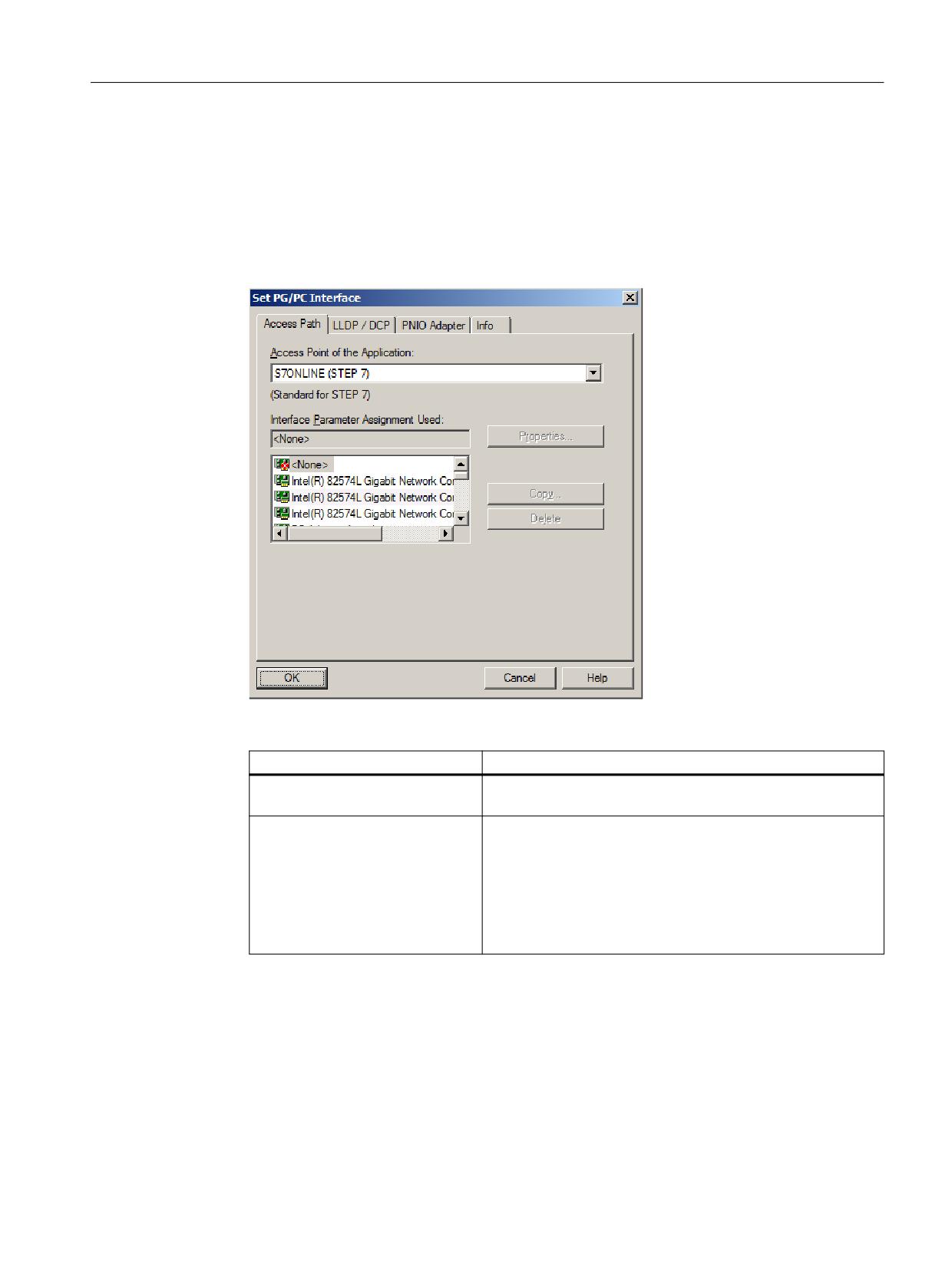
1. Open the Control Panel and activate the "Small Icons" or "Large Icons" view in the "Display"
drop-down list.
2. Click "Set PG/PC Interface".
The dialog is opened.
3. Make the following settings in the "Access Path" tab:
Element
Setting
Access Point of the on the basis of
S7ONLINE (STEP 7)
these state machines
Interface parameterization used
When you select an object in the list, a brief description is
displayed below the list.
Select the network adapter including interface parameter as-
signment (TCP/IP) for the plant network of your SIEMENS PC
system from the list.
(For PCU 50.5: Intel(R) 82574L 190 Gigabit Network Connec-
tion with TCP/IP).
4. Click "OK" to confirm your settings.
SINUMERIK Integrate Create MyHMI /WinCC V16
Configuration Manual, 12/2019, 6FC5397-8FP40-0BA2
37
Installation on PG/PC and configuration of PC systems
3.2 Configuring your PC system as an HMI device (or server)
3.2.4
Activating the virtual keyboard
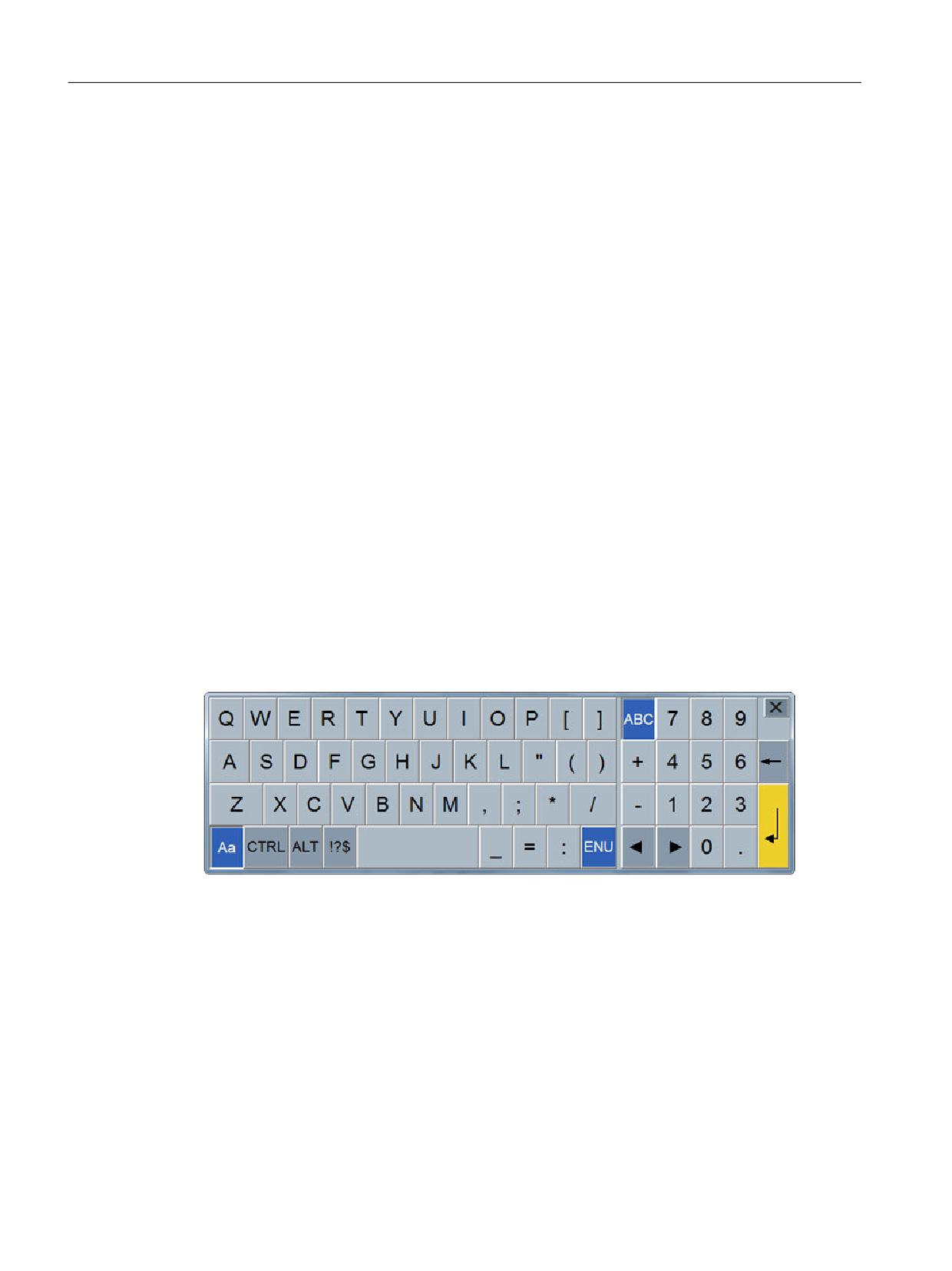
If you use WinCC Runtime as a customer-specific framework application on an HMI device with
a touch screen, you can use the SINUMERIK Operate Virtual Keyboard as an on-screen
keyboard. You make the setting in SINUMERIK Operate (or in the registry) as described in this
chapter.
Alternatively, you can fall back on a hardware keyboard that must be additionally connected in
use cases that are not supported by the NC keyboard view (Page 133) (e.g. WinCC Runtime
system dialogs).
To adapt these settings after you have installed SINUMERIK Operate, you can execute the
setup again or check and modify the registry entries made by the setup.
In addition, you must define that you are using an virtual keyboard in the TIA Portal (Page 129).
Behavior during runtime
Basically, two different on-screen keyboards are available during runtime with Create MyHMI /
WinCC:
● SINUMERIK Operate Virtual Keyboard
(described in this chapter)
● Create MyHMI /WinCC NC keyboard view
If both on-screen keyboards are activated, the NC keyboard view has priority. There will never
be more than one on-screen keyboard displayed at a time. This also applies, for example, if the
NC keyboard view has been configured as a "NUM" type keyboard.
Display of the virtual keyboard during runtime
An (activated) virtual keyboard is always displayed when user entries are required. The virtual
keyboard is not displayed in SINUMERIK Operate (or in the NC operate view), but outside of
it or on a different layer of WinCC RT Advanced. The exact positioning can be defined in the
settings. The keyboard layout and the remaining configuration correspond to SINUMERIK
Operate or the standard on-screen keyboard of WinCC Runtime.
SINUMERIK Integrate Create MyHMI /WinCC V16
38
Configuration Manual, 12/2019, 6FC5397-8FP40-0BA2
Installation on PG/PC and configuration of PC systems
3.2 Configuring your PC system as an HMI device (or server)
Procedure
To adjust the virtual keyboard settings in the SINUMERIK Operate setup, proceed as follows:
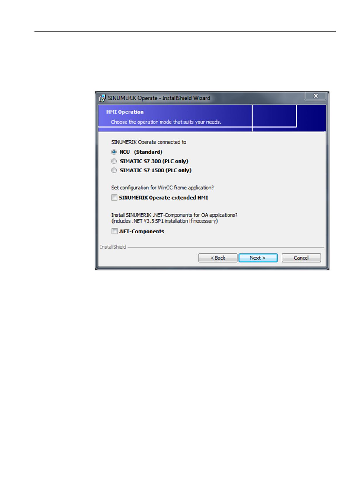
1. Start installation of SINUMERIK Operate and, in the installation wizard, proceed to step
"HMI Operation".
Figure 3-3
Setup of SINUMERIK Operate - SINUMERIK Operate extended HMI
2. Activate the option "SINUMERIK Operate extended HMI", make any further settings, and
click "Next".
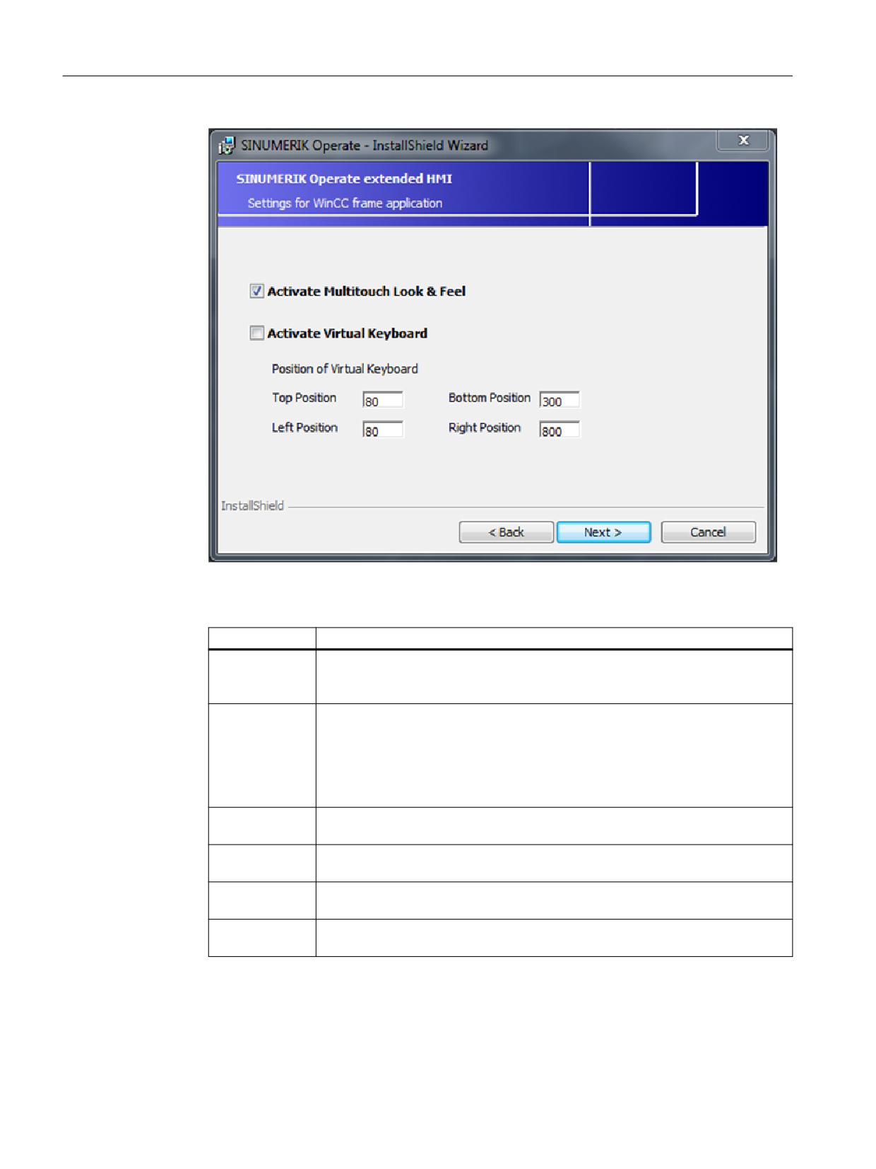
The step "Settings for WinCC frame application" is displayed.
SINUMERIK Integrate Create MyHMI /WinCC V16
Configuration Manual, 12/2019, 6FC5397-8FP40-0BA2
39
Installation on PG/PC and configuration of PC systems
3.2 Configuring your PC system as an HMI device (or server)
Figure 3-4
Setup of SINUMERIK Operate - Settings for WinCC frame application
3. Make the required settings:
Settings
Purpose
Activate Multi-
Activates the SINUMERIK Operate design adapted for modern multitouch
touch Look &
screens.
Feel
Activate Virtual
Activates the virtual keyboard with color scheme and default settings adapted to
Keyboard
SINUMERIK Operate:
● English keyboard layout
● Activated caps lock key
● Alphabetic area displayed
Top Position
Shows the vertical starting position (Y coordinate) of the virtual keyboard in its
fixed position
Left Position
Shows the vertical starting position (Y coordinate) of the virtual keyboard in its
fixed position
Bottom Position
Shows the vertical end position (Y coordinate) of the virtual keyboard. This de-
fines the height of the virtual keyboard.
Right Position
Shows the horizontal end position (X coordinate) of the virtual keyboard. This
defines the width of the virtual keyboard.
4. In the next steps of the installation wizard, make all the necessary settings and confirm the
installation with "Finish".
SINUMERIK Integrate Create MyHMI /WinCC V16
40
Configuration Manual, 12/2019, 6FC5397-8FP40-0BA2

Installation on PG/PC and configuration of PC systems
3.2 Configuring your PC system as an HMI device (or server)
Result
SINUMERIK Operate has been installed and the settings for the virtual keyboard have been
stored in the Windows registry.
You will find the registry key for configuring the virtual keyboard in the registration editor at the
following path:
● HKEY_LOCAL_MACHINE\Software\Siemens\SimaticHmiIM\SinuMode\
Table 3-3
Meaning of the registry keys for configuration the virtual keyboard
Settings
Key / value
Meaning
Selection of the virtual keyboard
(Default) = 0
Virtual keyboard familiar from WinCC RT Advanced.
See: TIA Portal online help; keyword: "Virtual keyboard (RT Ad-
vanced)"
(Default) = 1
Virtual keyboard with color scheme and default settings adapted
to SINUMERIK Operate:
● English keyboard layout
● Activated caps lock key
● Alphabetic area displayed
Positioning
PositionMode = 0
Dynamic positioning of the virtual keyboard as known by WinCC
RT Advanced.
The virtual keyboard is dynamically displayed at a position
where objects relevant to the keyboard entry are not covered up.
PositionMode = 1
Fixed position of the virtual keyboard at a position to be defined
(see below).
The virtual keyboard is always displayed at the same position
without automatically taking account of objects that might be
covered up.
If you use this setting, you must consider or keep free the de-
fined position in the configuration (Page 127).
PosTop
Shows the vertical starting position (Y coordinate) of the virtual
keyboard in its fixed position
PosLeft
Shows the vertical starting position (Y coordinate) of the virtual
keyboard in its fixed position
PosBottom
Shows the vertical end position (Y coordinate) of the virtual key-
board. This defines the height of the virtual keyboard.
PosRight
Shows the horizontal end position (X coordinate) of the virtual
keyboard. This defines the width of the virtual keyboard.
SINUMERIK Integrate Create MyHMI /WinCC V16
Configuration Manual, 12/2019, 6FC5397-8FP40-0BA2
41
Installation on PG/PC and configuration of PC systems
3.2 Configuring your PC system as an HMI device (or server)
3.2.5
Installing Sm@rtServer Standalone
Requirement
● WinCC RT Advanced is not installed on the PC system.
Note
No support of Sm@rtServer Standalone and WinCC RT Advanced on the same PC system.
Simultaneous installation/use of WinCC RT Advanced and WinCC Sm@rtServer
Standalone on the same PC system is not supported.
All hardware and software requirements for installation of SIMATIC WinCC Sm@rtServer
V15.1 also apply.
Procedure
To install Sm@rtServer Standalone on a PC system, proceed as follows:
1. In the Windows Explorer, go to the directory in which you saved the Sm@rtServer
Standalone setup files.
2. Double-click the "SmartServer.exe" setup file of Sm@rtServer Standalone.
3. Install the software using the installation wizard.
The software is installed and a link is created at the following path:
Start > Siemens Automation > Runtime Systems > Sm@rtServer > Sm@rtServer Advanced
Standalone
4. If you want Sm@rtServer Standalone to start automatically when the PC system starts up,
additionally copy the link "Sm@rtServer Advanced Standalone" to the startup folder of the
start menu.
Result
Sm@rtServer Standalone has been installed on your PC system and can be called up in the
start menu with "Start > Siemens Automation > Runtime Systems > Sm@rtServer >
Sm@rtServer Advanced Standalone".
With SIMATIC WinCC you can configure a connection to this PC system via the screen object
"Sm@rtClient view".
Note
Disable multitouch functionality on the server PC system
To prevent simultaneous entries on the server and client device, you must switch to the single-
touch mode for server PC systems with multi-touch functionality.
The Sm@rt options are not supported by devices with multi-touch operation. The Sm@rtServer
setting "No local input during client session" alone only disables single-touch entries.
See also: SIOS FAQ for disabling the multitouch functionality
SINUMERIK Integrate Create MyHMI /WinCC V16
42
Configuration Manual, 12/2019, 6FC5397-8FP40-0BA2

Installation on PG/PC and configuration of PC systems
3.2 Configuring your PC system as an HMI device (or server)
Note
No support of the virtual keyboard
The Sm@rt options do not support the use of the virtual keyboards of SINUMERIK Operate.
Instead, use the NC keyboard view and/or a hardware keyboard.
3.2.6
Configuring the display of the main and secondary control panel
SINUMERIK Operate can consist of one main and one secondary control panel. If you integrate
SINUMERIK Operate into a framework application, adapt this setting to your requirements.
This setting must be contained in the config.ini file on the PC system. A template for this file can
be found at C:\ProgramData\Siemens\MotionControl\siemens\.
Several directories are available into which you can copy and adapt configuration files in order
to make your own settings. In decreasing order of priority, these are:
● C:\ProgramData\Siemens\MotionControl\user\
● C:\ProgramData\Siemens\MotionControl\oem\
● C:\ProgramData\Siemens\MotionControl\addon\
Setting options in the configuration file
The following settings in the config.ini concern the configuration of the main and secondary
control panels. You can perform these settings for all VNC servers (Section [Default]) or for one
particular VNC server (Section [host_x]).
Section
Setting
Description
[Default]
StationType
-1: Local panel is main control panel, TCU panel is secondary control
panel
0: OPERATEFULLSCREEN (secondary control panel)
1: INTEGRATEDDISPLAY (main control panel)
[host_x]
Address=
IP address or host name
StationType=
-1: Local panel is main control panel, TCU panel is secondary control
panel
0: OPERATEFULLSCREEN (secondary control panel)
1: INTEGRATEDDISPLAY (main control panel)
MaxHostIndex
Number of hosts.
Examples
Example for the configuration of all server connections as secondary control panel:
config.ini
[Station]
SINUMERIK Integrate Create MyHMI /WinCC V16
Configuration Manual, 12/2019, 6FC5397-8FP40-0BA2
43
Installation on PG/PC and configuration of PC systems
3.2 Configuring your PC system as an HMI device (or server)
config.ini
mcpIndex=192
tcuIndex=1
eksIndex=0
[DEFAULT]
StationType=0
Example for the configuration as main control panel for 192.168.214.241:
config.ini
[host_x]
Address=192.168.214.241
StationType=1
SINUMERIK Integrate Create MyHMI /WinCC V16
44
Configuration Manual, 12/2019, 6FC5397-8FP40-0BA2
Installation on PG/PC and configuration of PC systems
3.3 Uninstalling the software
3.3
Uninstalling the software
SINUMERIK Integrate Create MyHMI /WinCC must be uninstalled in conformance with
Microsoft Windows:
Uninstall the software in the dialog "Uninstall or change program", which can be found in the
system control under "Programs > Uninstall program":
● Uninstall SINUMERIK Integrate Create MyHMI /WinCC in the dialog box "Uninstall or
change program" using the installation wizard of the TIA Portal "Siemens Totally Integrated
Automation Portal".
● Uninstall SIMATIC WinCC Advanced or Sm@rt Server Standalone using the special entries
in the "Uninstall or change program" dialog box.
SINUMERIK Integrate Create MyHMI /WinCC V16
Configuration Manual, 12/2019, 6FC5397-8FP40-0BA2
45
Installation on PG/PC and configuration of PC systems
3.3 Uninstalling the software
SINUMERIK Integrate Create MyHMI /WinCC V16
46
Configuration Manual, 12/2019, 6FC5397-8FP40-0BA2
Migration of projects
4
4.1
Comparison of functions
SINUMERIK Integrate Create MyHMI /WinCC provides a number of functional changes in
comparison with the SINUMERIK HMI configuration package WinCC flexible 2008. The
following tables compare the configurable scope of functions for the following possible
applications:
● Customer-specific SINUMERIK Operate operating area on a PC system
● Standalone user interface (without SINUMERIK Operate connection) on a SIMATIC Panel
(or PC system)
SINUMERIK Integrate Create MyHMI /WinCC also provides the capability of using WinCC
Runtime as a customer-specific framework application. This possible use is not configurable in
the SINUMERIK HMI configuration package WinCC flexible 2008.
Further information
● For information on the SINUMERIK HMI configuration package WinCC flexible 2008, see
the corresponding configuration manual "SINUMERIK HMI Configuring Package WinCC
flexible 2008"
● You can find an overview for the switchover to SIMATIC WinCC in the TIA Portal online help,
keyword "Switchover to WinCC in the TIA Portal"
Comparison of the functional scope
Table 4-1
Runtime as a customer-specific SINUMERIK Operate operating area
Functionality
SINUMERIK HMI configu-
SINUMERIK Integrate Cre-
ration software WinCC flex-
ate MyHMI /WinCC
ible 2008
Use on PC systems
x
x
Configuration for SINUMERIK HMI Ad-
x
-
vanced
Configuration for SINUMERIK Operate
-
x
Ethernet communication with SINUMER-
x
x
IK 840D sl
PROFIBUS communication with SINUMER-
-
-
IK 840D sl
MPI communication with SINUMER-
x
-
IK 840D sl
MPI communication with SINUMER-
x
-
IK 840D pl
Visualization of NC variables
x
x
Visualization of GUD variables
x
x
SINUMERIK Integrate Create MyHMI /WinCC V16
Configuration Manual, 12/2019, 6FC5397-8FP40-0BA2
47

Migration of projects
4.1 Comparison of functions
Functionality
SINUMERIK HMI configu-
SINUMERIK Integrate Cre-
ration software WinCC flex-
ate MyHMI /WinCC
ible 2008
Visualization of machine and setting data
x
x
NC alarms
x
x
DB2 alarms
x
x
Integration into the m:n concept of SINU-
x
-
MERIK HMI Advanced (up to 8 NCUs)
Controls for HMI data management and NC
x
-
editor
Input controls of SINUMERIK HMI Advanced
x
-
Control for activating subprograms
-
x
Triggering specific PI services (for example,
x
x
NC restart, setting a password)
Triggering a general PI service (using the
x
x
"General PI service" function)
Coordinated language change SINUMERIK
x
x
HMI - WinCC
Symbolic addressing of the PLC element in
x
x
STEP 7 integration
Example project
x
x
Table 4-2
Runtime as standalone user interface
Functionality
SINUMERIK HMI configu-
SINUMERIK Integrate Cre-
ration software WinCC flex-
ate MyHMI /WinCC
ible 2008
Use on a SIMATIC Panel
x
x
Ethernet communication with SINUMER-
x
x
IK 840D sl
PROFIBUS communication with SINUMER-
x
x
IK 840D sl
MPI communication with SINUMER-
x
x
IK 840D sl
MPI communication with SINUMER-
x
-
IK 840D pl
Visualization of NC variables
x
x
Visualization of GUD variables
x
x
Visualization of machine and setting data
x
x
NC alarms and NC messages
x
x
Control for activating subprograms
x
x
Triggering specific PI services (for example,
x
x
NC restart, setting a password)
Triggering a general PI service (using the
x
x
"General PI service" function)
Example project
x
-
SINUMERIK Integrate Create MyHMI /WinCC V16
48
Configuration Manual, 12/2019, 6FC5397-8FP40-0BA2
Migration of projects
4.2 Configure PLC variables symbolically
4.2
Configure PLC variables symbolically
You can continue to use the PLC tags you declared in STEP 7 V5.x in WinCC (TIA Portal).
To do this, you can basically either import your PLC tags, migrate or integrate the STEP 7 V5.x
project in the TIA Portal via a device proxy.
● Configuring a device proxy with the STEP 7 V5.x project as a data source (recommended)
- Read access to PLC tags that are declared in the STEP 7 V5.x project without migrating
them.
- Management of PLC tags in STEP 7 V5.x project and easy updating of the data source
in the TIA Portal for changes.
Further information can be found in Chapter Using device proxies (Page 72) and in the
respective application description under Shared configuration with WinCC (TIA Portal) and
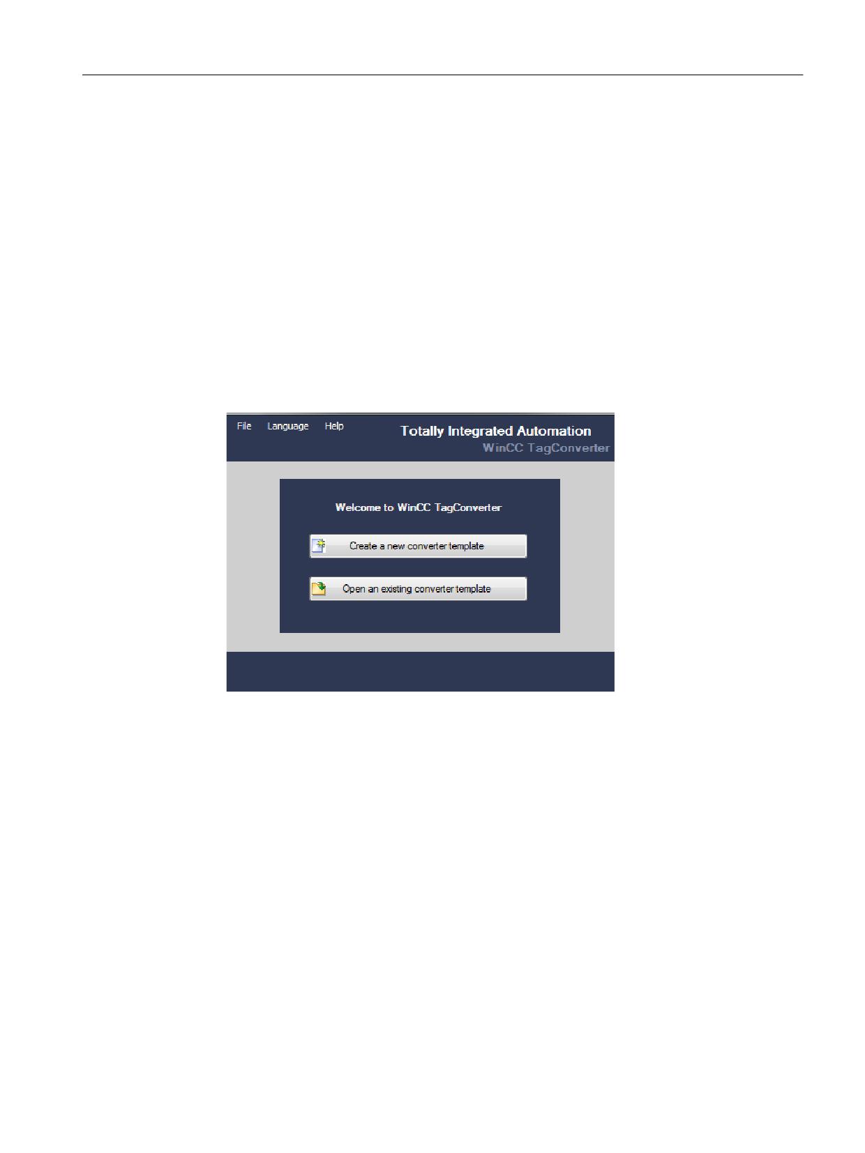
● Conversion of the tag with the WinCC TagConverter
- You can use the WinCC TagConverter tool to create a conversion format with your tags
from your STEP 7 V5.x project, which you can used to import them into WinCC (TIA
Portal).
- If changes are made to the tags, they need to be updated using source export, WinCC
TagConverter and import source.
You can find this tool and relevant documentation on the Service & Support pages on the
Internet:
You can find additional information in the related application description (for WinCC as of
V12) under Shared configuration with WinCC (TIA Portal) and STEP 7 V5.x (http://
support.automation.siemens.com/WW/view/en/73502293).
SINUMERIK Integrate Create MyHMI /WinCC V16
Configuration Manual, 12/2019, 6FC5397-8FP40-0BA2
49
Migration of projects
4.3 Post processing of migrated GUD variables
4.3
Post processing of migrated GUD variables
After you have migrated a WinCC flexible project with GUD variables into the TIA Portal, you
must import the GUD variables (DEF files) into the TIA Portal and re-assign them in the "HMI
variables" editor to the migrated variables.
Requirement
● The configured GUD variables were migrated as HMI variables into TIA Portal.
● The GUD variables are imported (Page 92).
Procedure
To edit the migrated GUD variables, follow these steps:
1. In the project navigation in folder "HMI variables" click on the command "Show all variables",
e.g. "PC system_1 > HMI_RT_1 > HMI variables > Show all variables".
The editor "HMI variables" is opened, in which all variables are on display, including
migrated GUD variables.
2. In the "Address" field, click on the "Expand" symbol.
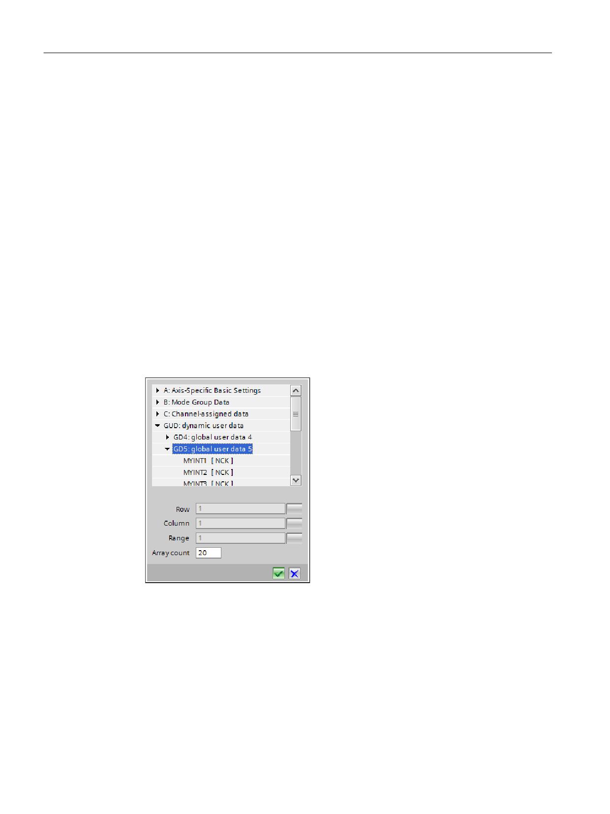
The dialog for selecting the SINUMERIK variables opens. You can find the migrated GUD
variables under "GUD: dynamic user data".
Figure 4-1
Dialog for selecting SINUMERIK variables with GUD
3. Navigate through the structure to the desired variable, select it and click the "Confirm" icon.
4. Click on the "Expand" icon in the "Address" field for each migrated variable, and select the
GUD variable to be addressed.
SINUMERIK Integrate Create MyHMI /WinCC V16
50
Configuration Manual, 12/2019, 6FC5397-8FP40-0BA2
Migration of projects
4.3 Post processing of migrated GUD variables
Result
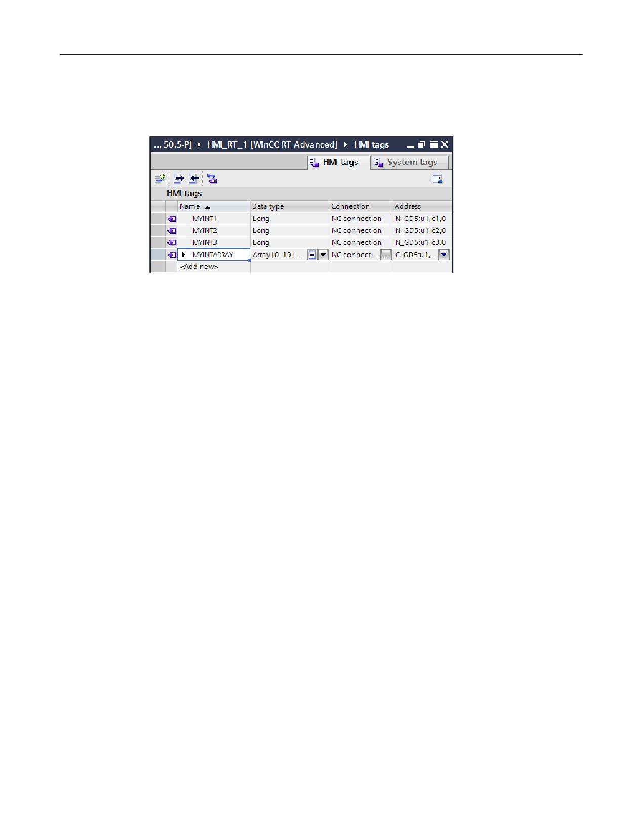
The GUD variables are reconnected.
Figure 4-2
GUD variables associated with newly connected address and symbolic name
You must subsequently linearize multi-dimensional GUD arrays.
See also
Configuring GUD arrays (Page 94)
SINUMERIK Integrate Create MyHMI /WinCC V16
Configuration Manual, 12/2019, 6FC5397-8FP40-0BA2
51
Migration of projects
4.4 Indexing of R parameters and GUD arrays
4.4
Indexing of R parameters and GUD arrays
The method for indexing R parameters or GUD arrays in the TIA Portal depends on the
employed Runtime version or the corresponding SIMATIC Panel:
● If you configure a WinCC RT Advanced with a version earlier than 13.0.0.0 or a SIMATIC
Panel that uses an older Runtime version (CE Panel), note the following when indexing R
parameters and GUD arrays:
Address the R parameter higher by 1 than required during configuration. To display R5 in
runtime, for example, you need to configure R6. (This indexing method is the same method
used in WinCC flexible for SIMATIC CE panels.)
When configuring GUD arrays, address the first GUD element with index 1 (as already done
in WinCC flexible), e.g. def CHAN INT MyGUD[3]
Address the individual elements with MyGUD[1], MyGUD[2], MyGUD[3].
Note
Compatibility of simulation with RT Advanced < V13
The function "Simulation" (menu command "Online > Simulation > Start") uses a WinCC RT
Advanced V13. This only supports the new indexing method.
If you start a simulation for a WinCC RT Advanced with an older version, the tags will be
addressed incorrectly in the simulation.
● If you configure a WinCC RT Advanced as of version 13.0.0.0 (for example, all SIMATIC
Comfort Panels or a PCU 50.5 with WinCC RT Advanced), the exact R parameter you have
configured is displayed in runtime.
SINUMERIK Integrate Create MyHMI /WinCC V16
52
Configuration Manual, 12/2019, 6FC5397-8FP40-0BA2
Migration of projects
4.5 Migrating WinCC flexible projects integrated in STEP 7 V5.x
4.5
Migrating WinCC flexible projects integrated in STEP 7 V5.x
Projects integrated in STEP 7 cannot be migrated.
If a WinCC flexible project is integrated in STEP 7, then WinCC flexible ES can be selected
under "Project > Copy from STEP 7". After selecting an archive location, a copy of the
integrated STEP 7 project is saved there. This autonomous WinCC project can then be
migrated into the TIA Portal.
The connection of the symbols in STEP 7 is lost in the process.
SINUMERIK Integrate Create MyHMI /WinCC V16
Configuration Manual, 12/2019, 6FC5397-8FP40-0BA2
53
Migration of projects
4.6 Migration of two-dimensional GUD tags with column tag
4.6
Migration of two-dimensional GUD tags with column tag
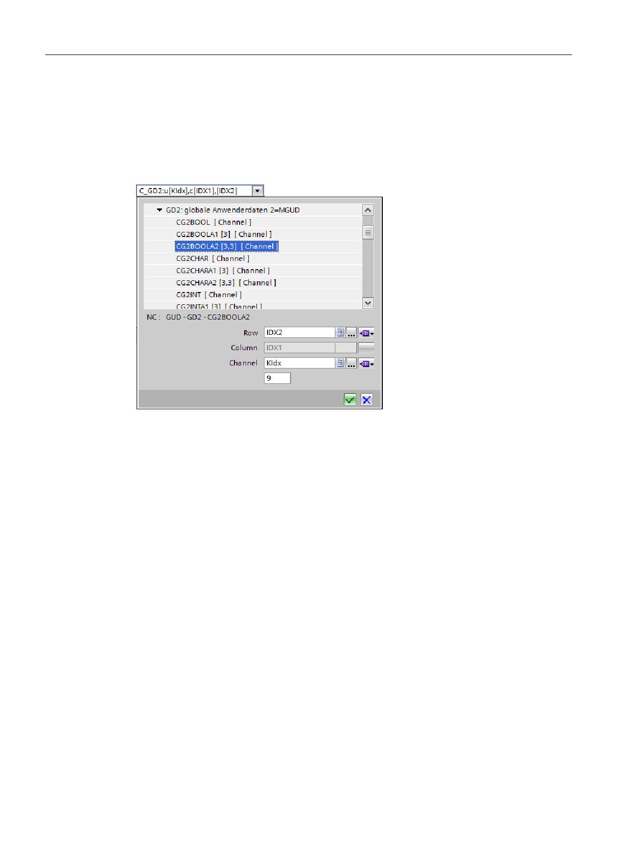
Migrated two-dimensional GUD tags for which an index tag has been configured as "Column"
in WinCC flexible cannot be modified in the TIA Portal.
As can be seen in the screenshot, this index tag is entered in the "Column" field and grayed out
(cannot be edited) after migration of such a tag.
Figure 4-3
Migrated GUD tag with tag in the "Column" field
However, no index tags are allowed in the "Column" field in the TIA Portal, only fixed numbers.
The position of these GUD tags in the DEF file for this GUD group must be in the "Column" field.
● If a fixed value is entered in the "Column" field after migration, this value is correctly adjusted
when the tags are transferred to the TIA Portal.
● If there is a tag in the "Column" field after migration, it cannot be changed in the TIA Portal.
In this case, delete the GUD tag and create a new one.
There can be a tag in the "Row" field in the TIA Portal; this tag then determines the linearized
GUD array element.
See also: Configuration of GUD arrays (Page 94)
SINUMERIK Integrate Create MyHMI /WinCC V16
54
Configuration Manual, 12/2019, 6FC5397-8FP40-0BA2
Migration of projects
4.7 Migration of alarm texts in the HMI-Advanced format
4.7
Migration of alarm texts in the HMI-Advanced format
In order to be able to continue to use your available alarm texts in SINUMERIK Operate and
WinCC, you can migrate these PowerLine alarm texts (HMI Advanced, HMI Embedded, e.g.
myalm_en.com). The DB2 alarms converted to the TS format, can be imported directly into the
TIA Portal (Page 105).
You can perform the migration with one of the following software products:
● HMI SolutionLine Alarm Text Converter
- Contained on the product DVD "CNC software <version> with SINUMERIK Operate":
\tools\alarm_text_converter\Setup_AlarmTextConverter.exe
- User alarm texts of the "com" format of HMI-Advanced/HMI-Embedded are converted to
the "ts" format of SINUMERIK Operate.
● SINUMERIK Integrate Access MyMachine /P2P
- Extensive software that is available separately in the SIEMENS Industry Mall.
- You will find general information on the software at SINUMERIK Integrate Access
MyMachine /P2P (Page 121).
- Specific information on the migration of alarm texts with AMM/P2P can be found in the
associated online help.
SINUMERIK Integrate Create MyHMI /WinCC V16
Configuration Manual, 12/2019, 6FC5397-8FP40-0BA2
55
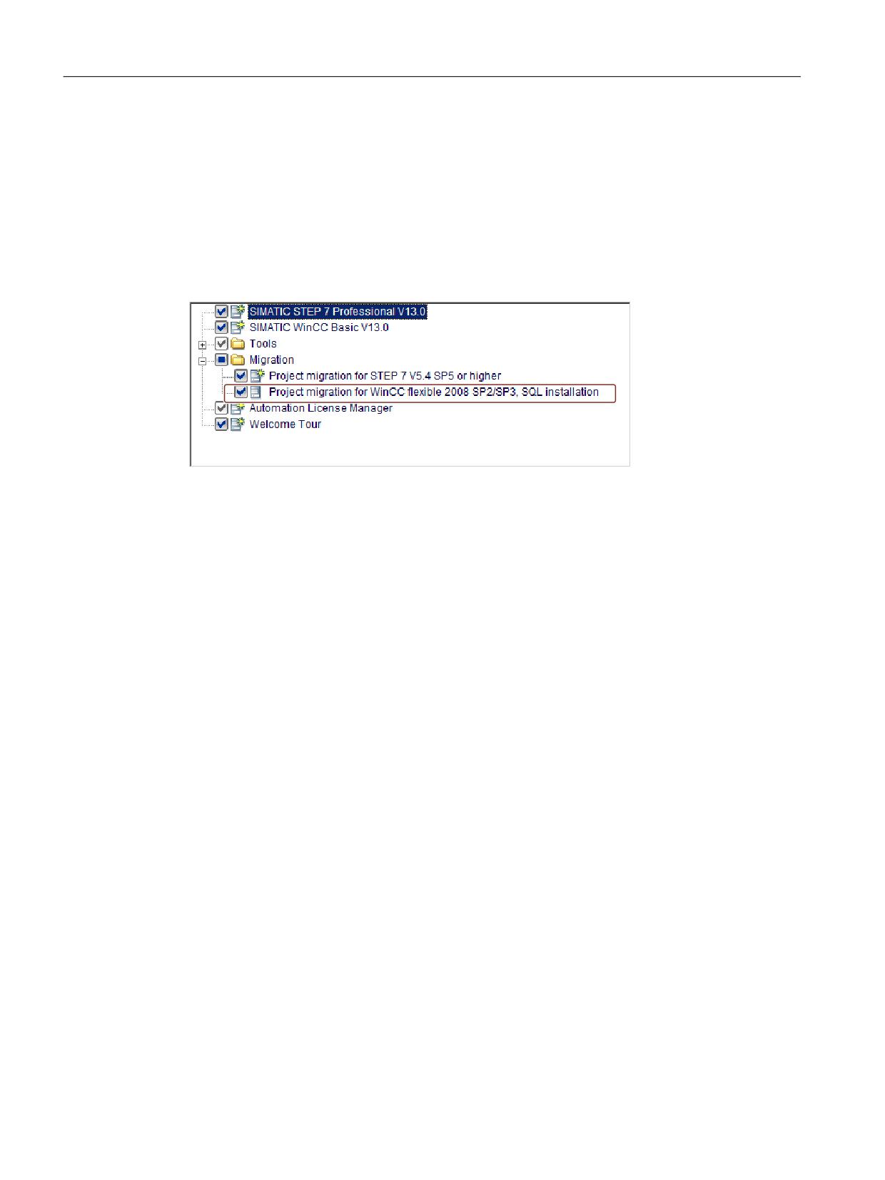
Migration of projects
4.8 Migrating projects
4.8
Migrating projects
You can migrate a SINUMERIK project as well as other projects from WinCC flexible to the
TIA Portal.
As a result of the various operating systems that can be used, you cannot install "SINUMERIK
HMI configuring package WinCC flexible 2008" and WinCC (TIA Portal) on the same PG/PC.
For the migration, you need the migration tool "Project migration for WinCC flexible 2008 SP2/
SP3", which you must select when setting up WinCC (TIA Portal) in the product configuration.
Figure 4-4
Setting up WinCC (TIA Portal): Set the option box for project migration
Restrictions
The following restrictions apply to migration of SINUMERIK projects:
● You can migrate projects from WinCC flexible 2008 SP2
● WinCC flexible projects integrated in STEP 7 V5.x cannot be directly migrated (Page 53)
Read the information on migration provided below as well:
● SINUMERIK PCs and SIMATIC Panel PCs
● SIMATIC Panel
A tabular comparison of the functions in WinCC flexible and WinCC (TIA Portal) is available in
the section Comparison of functions (Page 47).
Additional information
For additional information concerning the migration of projects from WinCC flexible, read the
following information:
● Information system of the TIA Portal, section "Migrating projects and programs > Migrating
projects in a TIA Portal project > Migrating WinCC flexible projects (Advanced)".
● FAQ WinCC (TIA portal) -- working with projects -- migrating projects (http://
support.automation.siemens.com/WW/view/en/54702181).
SINUMERIK Integrate Create MyHMI /WinCC V16
56
Configuration Manual, 12/2019, 6FC5397-8FP40-0BA2
Migration of projects
4.8 Migrating projects
Special features for SINUMERIK projects
The following HMI devices with SINUMERIK components can be migrated:
● SINUMERIK PCs and SIMATIC Panel PCs
● SIMATIC Panel
SINUMERIK PCs and SIMATIC Panel PCs
The following must be observed when migrating SINUMERIK projects:
● In the TIA Portal, you configure the PC system (e.g. PCU 50.5) instead of the operator panel.
This is changed automatically during the migration. You enter the screen resolution of the
operator panel front in the runtime settings.
● The input controls specific to HMI Advanced are not transferred.
● HMI controls for file management and NC editor are not supported.
● Integration in the m:n concept is not supported.
● The communication driver for the PLC-channel SINUMERIK PLC is switched over to the
SIMATIC S7-300/400 communication driver.
● Automatic display of DB2 alarms is not supported.
Import the DB2 alarms separately to the TIA Portal.
For this, you need to add a SINUMERIK NCU or device proxy with a STEP 7 V5.x project as
the data sources.
● GUD tags are not automatically associated with the migration.
Connect migrated GUD tags again after the migration. (Page 50)
● Multidimensional GUD arrays are not used in the TIA Portal even with PC systems (as in
WinCC flexible for CE HMI devices).
Linearize multidimensional GUD arrays or create new ones.
● To use PLC tags from your STEP 7 V5.x project, you must either add a device-proxy or
convert the tags with the WinCC TagConverter.
See: Configure PLC variables symbolically (Page 49)
SIMATIC Panel
● SIMATIC panels as of version 13.0.0.0 support the SINUMERIK parameter indexing
method and must no longer contain the parameter number incremented by 1.
If you configure a SIMATIC Panel as of version 13.0.0.0, adjust the configuration of the R
parameters (Page 52).
SINUMERIK Integrate Create MyHMI /WinCC V16
Configuration Manual, 12/2019, 6FC5397-8FP40-0BA2
57
Migration of projects
4.8 Migrating projects
SINUMERIK Integrate Create MyHMI /WinCC V16
58
Configuration Manual, 12/2019, 6FC5397-8FP40-0BA2
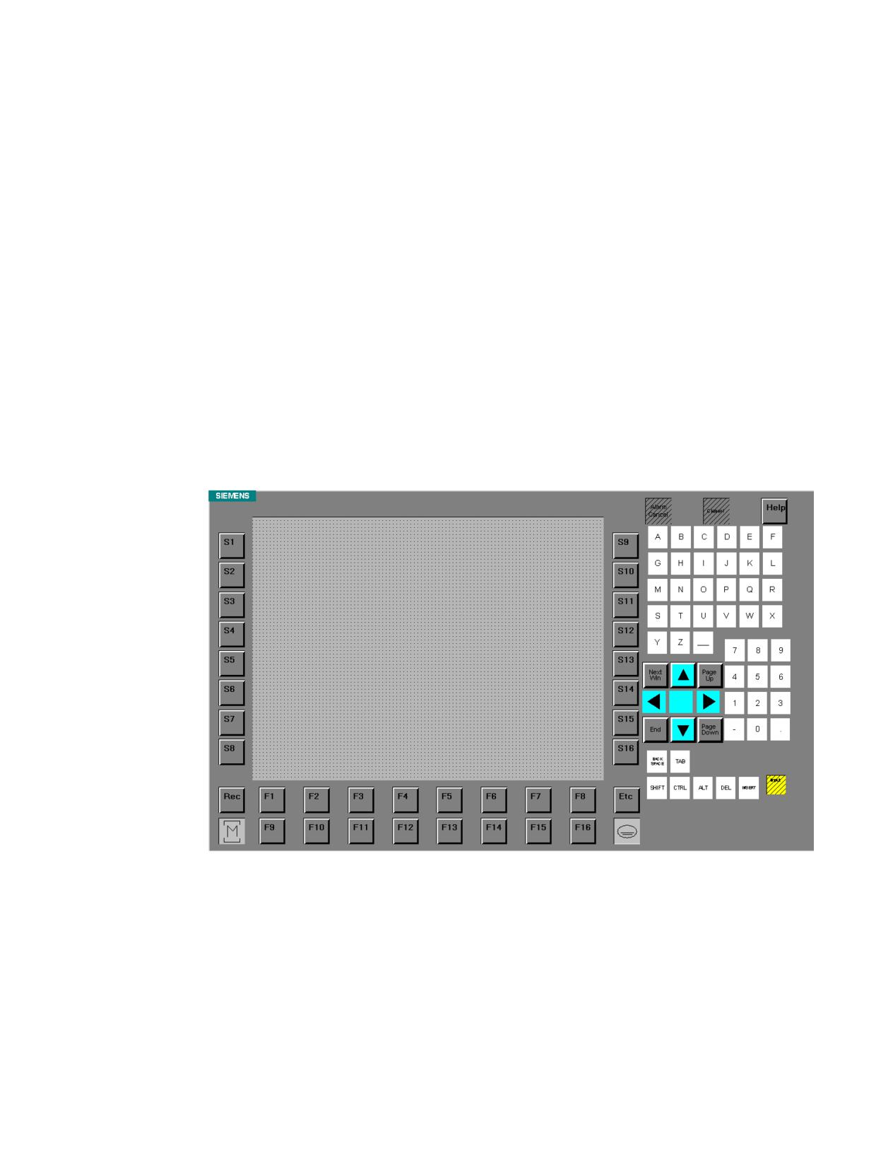
Device configuration
5
5.1
Configurable user interface
PC systems (PCU 50.5, SIMATIC Box PC or standard PC)
If you configure a PC system without an integrated panel, do not select a specific operator panel
front. Include the properties of the operator panel front you are using in the configuration as
follows:
● You can set the screen resolution of the operator panel front in the runtime settings
(Page 66).
● All available function keys are displayed in the inserted screens. When you configure the
function keys make sure that you only use those keys that actually exist on the operator
panel front.
Figure 5-1
User interface of a screen for configuration of the PCU 50.5
SIMATIC Panel or SIMATIC Panel PC
When you configure a SIMATIC Panel or a SIMATIC Panel PC, insert a specific device (e. g.
KP 1200 Comfort). Only those keys are shown as the user interface of a screen that actually
exist on the device in question.
The screen resolution is also specifically set for the inserted device and cannot be altered.
SINUMERIK Integrate Create MyHMI /WinCC V16
Configuration Manual, 12/2019, 6FC5397-8FP40-0BA2
59
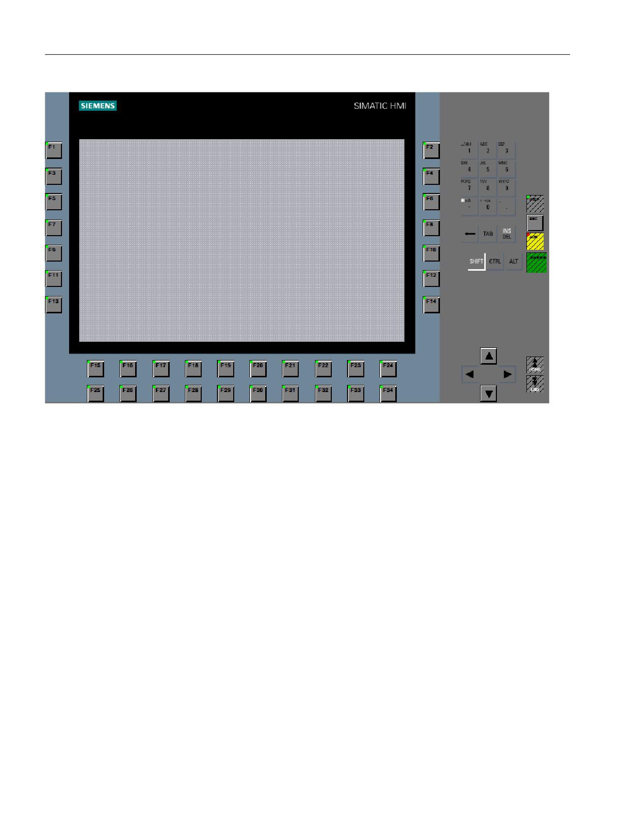
Device configuration
5.1 Configurable user interface
Figure 5-2
User interface of a screen for a SIMATIC Panel KP 1200 Comfort
SINUMERIK Integrate Create MyHMI /WinCC V16
60
Configuration Manual, 12/2019, 6FC5397-8FP40-0BA2
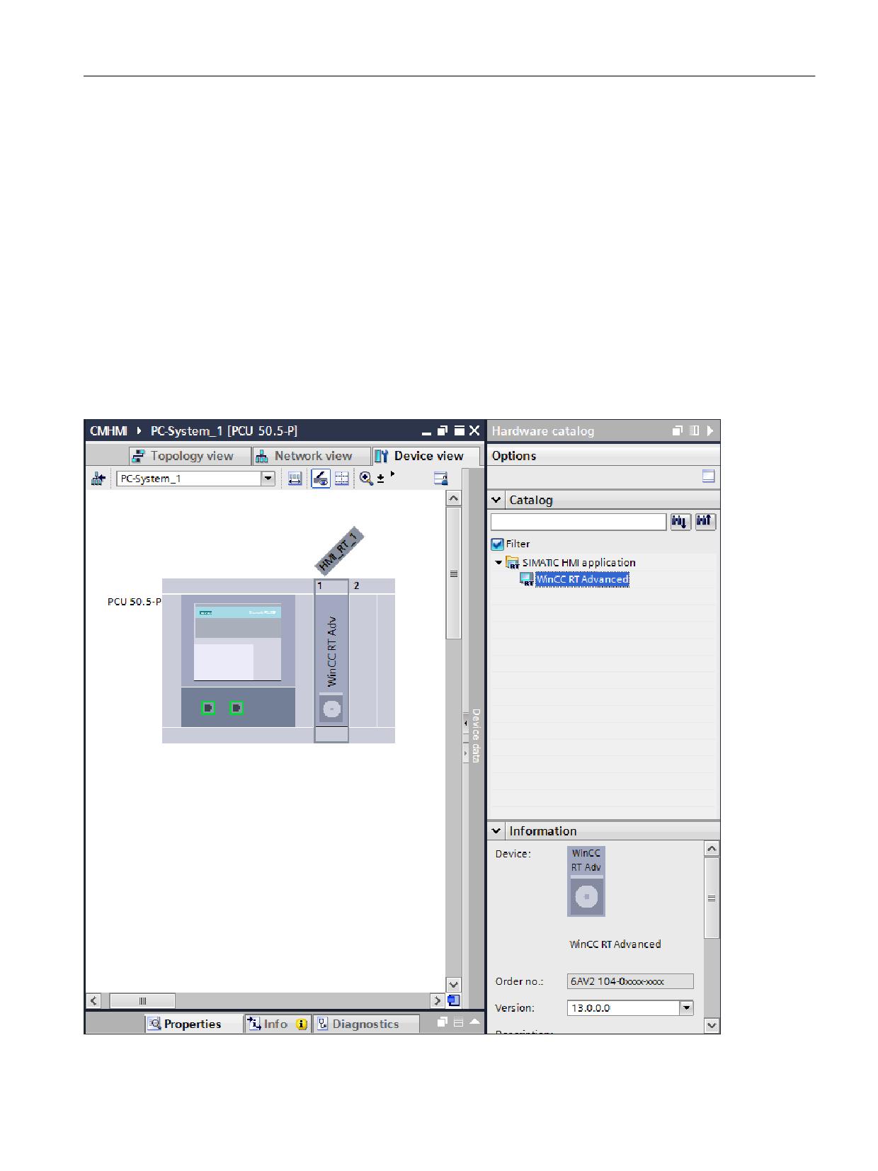
Device configuration
5.2 Runtime configuration
5.2
Runtime configuration
Overview
With runtime "WinCC RT Advanced", you can expand the SINUMERIK user interface on a PC
system (Page 27) or add SINUMERIK functionalities to the SIMATIC Panel (Page 28).
Make a different selection for Runtime or the Runtime version depending on the HMI device
used:
● If you add a SIMATIC Panel, you do not need to insert Runtime separately. SIMATIC Panels
have integrated Runtime, which is automatically available when added. You select the
Runtime version when you add the SIMATIC Panel.
● When you add a PC HMI device and switch to the device view, Runtime is shown in the
hardware catalog. When you select Runtime, you can select the Runtime version in the
"Information" area of the hardware catalog.
Figure 5-3
Device view with hardware catalog (on the right in the image)
SINUMERIK Integrate Create MyHMI /WinCC V16
Configuration Manual, 12/2019, 6FC5397-8FP40-0BA2
61
Device configuration
5.3 Inserting PC system and Runtime
5.3
Inserting PC system and Runtime
The following components in WinCC allow an operating area to be configured for a
SINUMERIK Operate user interface:
● Supported PC system
● WinCC RT Advanced
Requirement
● The TIA Portal has been started.
● A project is open or created.
● The project view is active.
SINUMERIK Integrate Create MyHMI /WinCC V16
62
Configuration Manual, 12/2019, 6FC5397-8FP40-0BA2
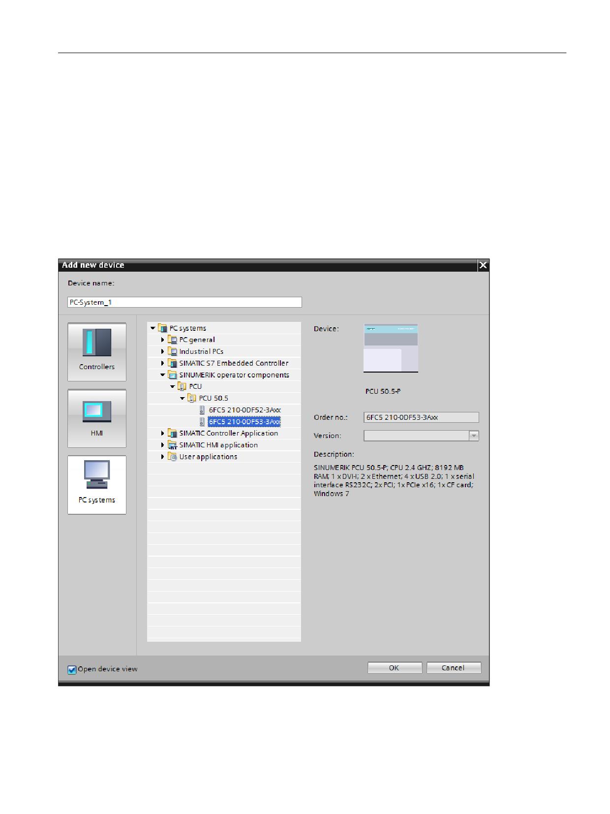
Device configuration
5.3 Inserting PC system and Runtime
Procedure
Proceed as follows to insert a PC system and runtime WinCC RT Advanced:
1. In the project tree, click "Add new device"", click the "PC Systems" button and move to the
supported PC system in the folder hierarchy:
- SINUMERIK operator components > PCU
- Industrial PCs > SIMATIC Box PC
- Industrial PCs > SIMATIC Panel PC
- PC general > PC station
All available variants of the PC system are displayed in the folder hierarchy. Remember that
only certain variants of Create MyHMI /WinCC are supported by Create MyHMI /WinCC.
Figure 5-4
Inserting a PC system - Example for PCU 50.5-P
2. Confirm with "OK".
SINUMERIK Integrate Create MyHMI /WinCC V16
Configuration Manual, 12/2019, 6FC5397-8FP40-0BA2
63
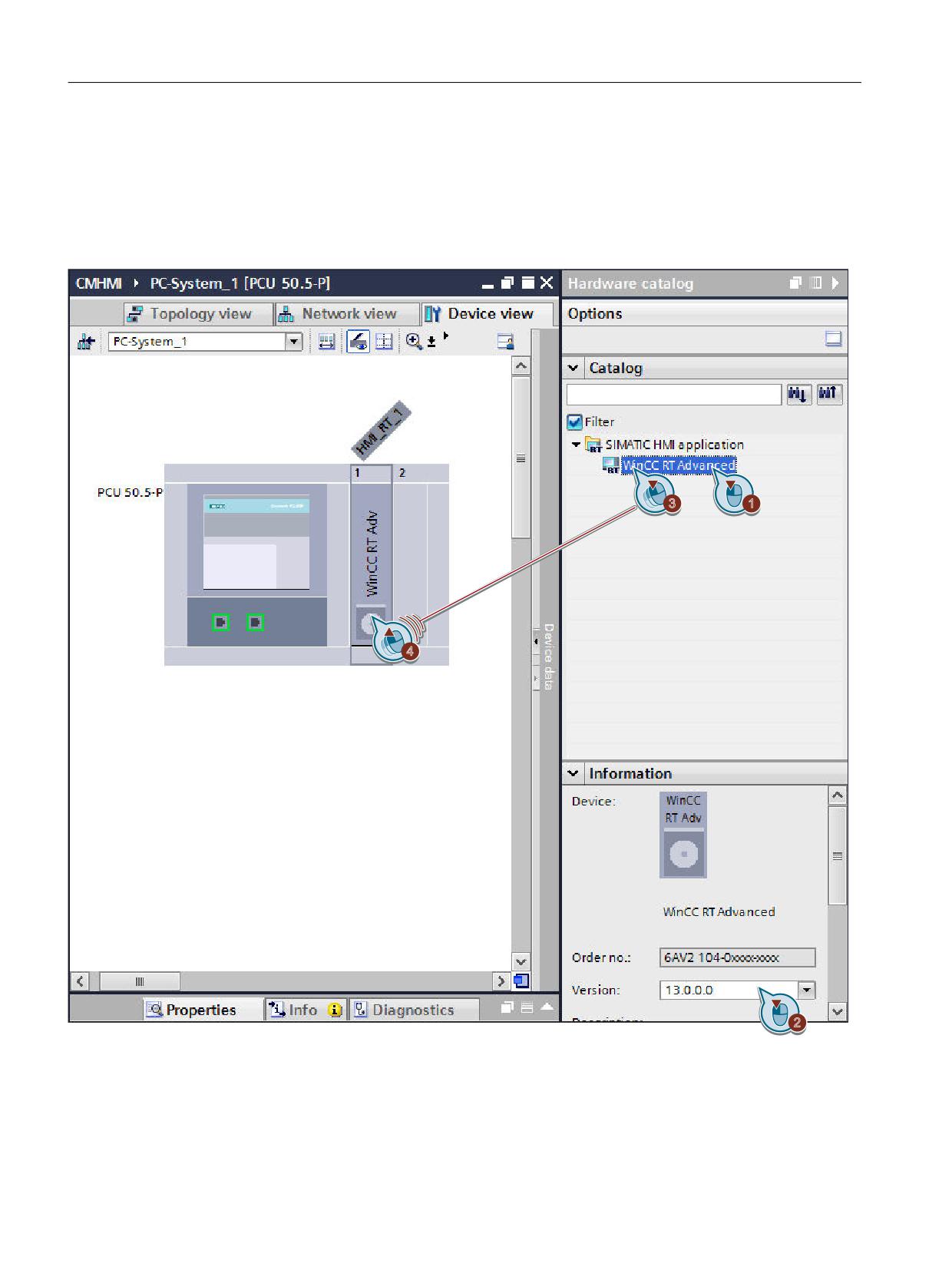
Device configuration
5.3 Inserting PC system and Runtime
The device is added, and the device view opens.
3. In the hardware catalog, select the runtime software from "SIMATIC HMI application >
WinCC RT Advanced", in section "Information" change the version, if necessary, and then
drag it to a free slot of the device in the device view.
The configured Runtime version must match the current Runtime version in use on the PC
system.
Figure 5-5
Adding WinCC RT Advanced
SINUMERIK Integrate Create MyHMI /WinCC V16
64
Configuration Manual, 12/2019, 6FC5397-8FP40-0BA2
Device configuration
5.3 Inserting PC system and Runtime
Result
In the project tree, the configured runtime (e.g. "HMI_RT_1 [WinCC RT Advanced]") is added
to the created device (e.g. "PC-System_1 [PCU 50.5-P]]").
This view provides the following configuration editors:
● "Connections"
● "HMI variables"
● "HMI messages"
● "Screens"
If you have inserted a SINUMERIK PCU 50.5, a SIMATIC Box PC, or a standard PC, in the next
step, set the screen resolution of your operator panel front (Page 66).
SINUMERIK Integrate Create MyHMI /WinCC V16
Configuration Manual, 12/2019, 6FC5397-8FP40-0BA2
65
Device configuration
5.4 Setting the screen resolution for the RT Advanced
5.4
Setting the screen resolution for the RT Advanced
If you have inserted a SINUMERIK PCU 50.5, a SIMATIC Box PC, or a standard PC, the
following screen resolution is reset for the runtime:
● SINUMERIK PCU 50.5 or SIMATIC Box PC: 800 x 600 (corresponds to SINUMERIK OP 12)
● Standard PC: 1024 x 768
Depending on the screen used, you must adapt this setting so that the configured display fills
the screen on the target system. If you enter the wrong screen resolution, the scroll bars or the
picture will not fill the screen on the HMI device. If you subsequently change the screen
resolution in the runtime settings, you must first enable the "Fit to screen" option in the settings
before making the settings in the TIA Portal (see below).
When you configure a SIMATIC Panel or a SIMATIC Panel PC, you do not have to adapt these
settings.
Requirement
● A project with a PC system and runtime software has been created.
See: Inserting PC system and Runtime (Page 62)
● The project view is active.
Procedure
To set the screen resolution of the target system, proceed as follows:
1. Activate the "Fit to screen" option button in the "Tools > Settings > Visualization > Resize
screens and screen objects" menu.
2. Open the runtime settings in the project tree, for example, under "PC_System_1 >
HMI_RT_1 > Runtime settings > Screen resolution".
SINUMERIK Integrate Create MyHMI /WinCC V16
66
Configuration Manual, 12/2019, 6FC5397-8FP40-0BA2

Device configuration
5.4 Setting the screen resolution for the RT Advanced
3.
Make the appropriate setting for your operator panel front:
Operator panel front
Resolution
Screen format
OP 08T
640 x 480
Standard
OP 010
OP 012
800 x 600
Standard
OP 015
1024 x 768
Standard
OP 015 black
1366x768
Widescreen
OP 019
1280 x 1024
Standard
OP 019 black
1366x768
Widescreen
Other screen
See the documentation of the screen used.
Note
"Screen resolution" setting must match the actual resolution of the operator panel front used
If the wrong screen resolution has been entered in the Runtime settings, the scroll bars or
the picture will not fill the screen on the HMI device at runtime.
If the screens are not displayed correctly in runtime, adjust the setting as described above.
4.
To prevent the display of scroll bars or to enable the display of the screen object "NC operate
view", activate fullscreen mode with "Runtime settings > General".
Note
WinCC RT Advanced in window mode not compatible with NC operate view
If you use WinCC RT Advanced in window mode, SINUMERIK Operate might not be
positioned correctly within the window during runtime.
Therefore activate fullscreen mode in the runtime settings.
SINUMERIK Integrate Create MyHMI /WinCC V16
Configuration Manual, 12/2019, 6FC5397-8FP40-0BA2
67
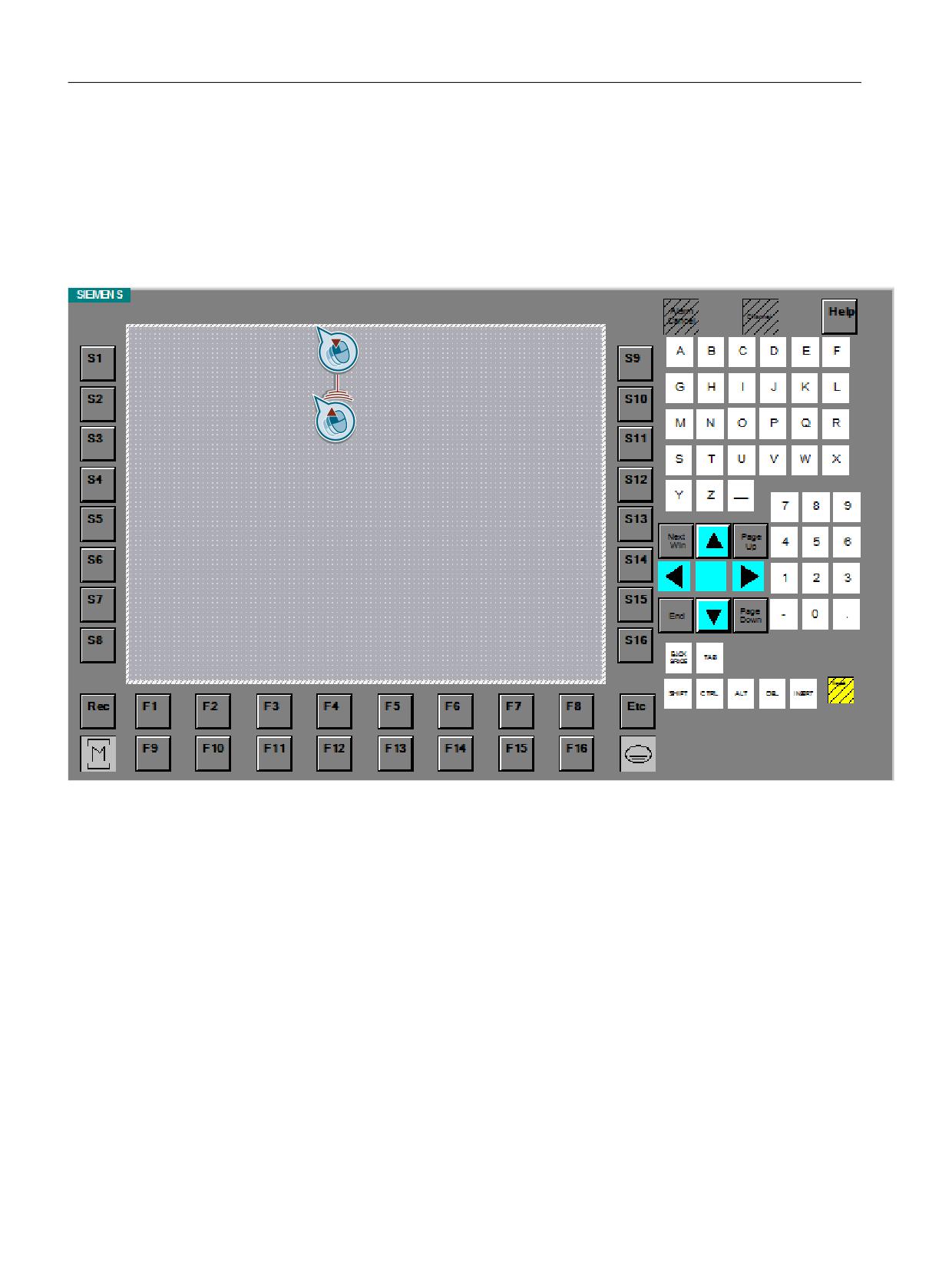
Device configuration
5.5 Configuration of the screen size (PC systems)
5.5
Configuration of the screen size (PC systems)
To prevent the configured screens from covering the header of SINUMERIK Operate, for
example, you can reduce the size of the configured screens.
You can change this setting at any screen. The setting is always applied to all screens.
Using drag-and-drop to make the screen or template smaller.
Figure 5-6
Changing the screen size
You can find additional information on templates in the TIA Portal online help in Chapter
"Working with templates".
SINUMERIK Integrate Create MyHMI /WinCC V16
68
Configuration Manual, 12/2019, 6FC5397-8FP40-0BA2
Device configuration
5.6 Adding a SIMATIC Panel
5.6
Adding a SIMATIC Panel
The following components are required in WinCC to use the SINUMERIK functionality on a
SIMATIC Panel:
● Suitable SIMATIC Panel/Comfort Panel/Multi Panel
See: Supported SIMATIC Panels
Requirement
● The TIA Portal has been started.
● A project is open or created.
● The project view is active.
SINUMERIK Integrate Create MyHMI /WinCC V16
Configuration Manual, 12/2019, 6FC5397-8FP40-0BA2
69
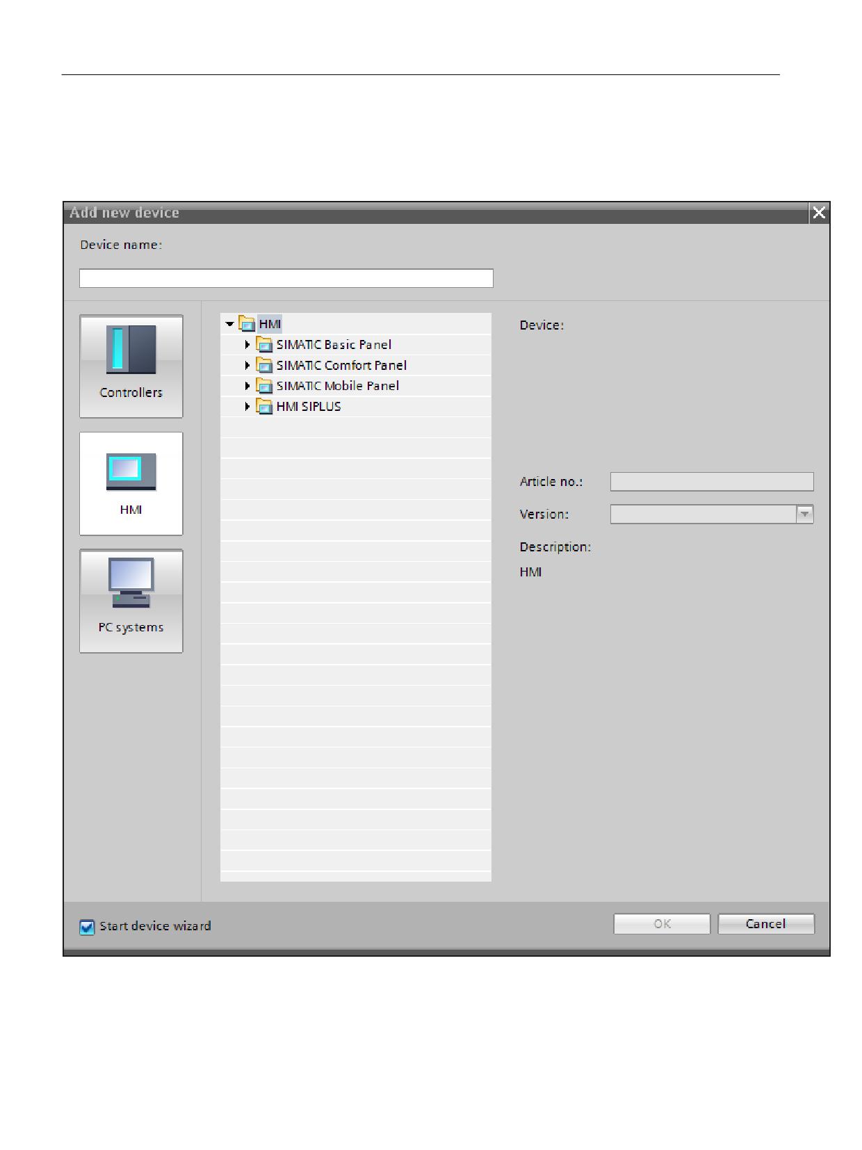
Device configuration
5.6 Adding a SIMATIC Panel
Procedure
To add a SIMATIC Panel, follow these steps:
1. In the project tree, click on "Add new device" and click the "HMI" button.
Figure 5-7
Adding a SIMATIC Panel
SINUMERIK Integrate Create MyHMI /WinCC V16
70
Configuration Manual, 12/2019, 6FC5397-8FP40-0BA2
Device configuration
5.6 Adding a SIMATIC Panel
The "Add new device" dialog box opens and the folder structure displays all available
SIMATIC Panels.
2. Make the required settings:
Element
Purpose
Device name
Assign a device name (e.g. "HMI_SIMATIC_Panel ").
Folder structure
Under "HMI", select a SIMATIC Panel (for example, "MP 177 6" mono
DP")
Version
Runtime is integrated for SIMATIC Panels. Select the required Runtime
version in this drop-down list.
Open the device wizard
To start the HMI device wizard after adding the device, select this check
box.
Use the HMI device wizard to define the basic settings for your HMI
device, for example, the screen layout or the connection to your PLC.
Note that you still need to make other settings in the device view, for
example, you need to create the connection to the NC.
3. Click "OK" to confirm your settings.
Result
The device is added and, depending on your settings, the HMI device wizard or the project view
opens.
The following editors are available in the project tree below the device (for example,
"HMI_SIMATIC_Panel [MP 177 6" mono DP]"):
● "Connections"
● "HMI variables"
● "HMI messages"
● "Screens"
SINUMERIK Integrate Create MyHMI /WinCC V16
Configuration Manual, 12/2019, 6FC5397-8FP40-0BA2
71
Device configuration
5.7 Using device proxies
5.7
Using device proxies
You can embed your STEP 7 V5.x project in the HMI configuration without having to migrate the
project. In this way, you can continue performing the programming and configuration of the PLC
project in STEP 7 V5.x and use WinCC (TIA Portal) for the HMI configuration.
Using a device proxy offers the following advantages when working with SINUMERIK Integrate
Create My HMI /WinCC:
● Configuration of an integrated connection to the PLC without installing STEP 7 (TIA Portal).
● Configuration of SINUMERIK DB2 alarms in the TIA Portal without installing STEP 7
(TIA Portal).
● Read access to PLC tags that are declared in the STEP 7 V5.x project without migrating
them.
● Management of PLC tags in STEP 7 V5.x project and easy updating of the data source in
the TIA Portal for changes.
Configure a device-proxy for this in the TIA Portal with the STEP 7 V5.x project as a data source.
Even if you subsequently change something in the STEP 7 V5.x project, you can easily apply
these changes in the TIA Portal by updating the device proxy data.
SINUMERIK Integrate Create MyHMI /WinCC V16
72
Configuration Manual, 12/2019, 6FC5397-8FP40-0BA2
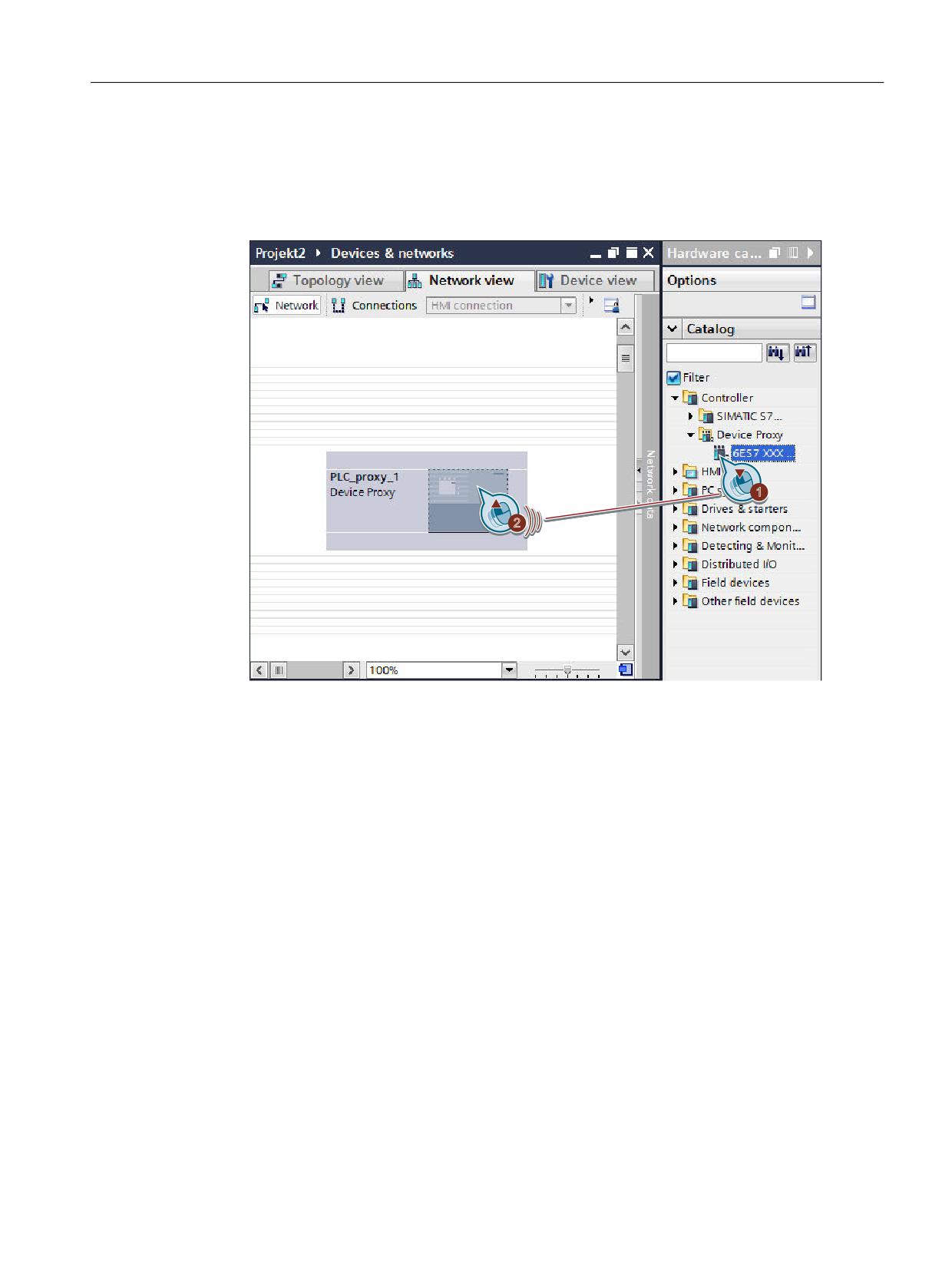
Device configuration
5.7 Using device proxies
Procedure
To integrate a STEP 7 V5.x project in a TIA Portal project via a device proxy, follow these steps:
1. In the hardware catalog, select the device proxy under "Controller > Device Proxy", then use
drag-and-drop to move it to the network view.
2. Right-click on the device proxy and select the "Initialize device proxy" command.
SINUMERIK Integrate Create MyHMI /WinCC V16
Configuration Manual, 12/2019, 6FC5397-8FP40-0BA2
73