SINUMERIK 840D sl. Service - Configuring Commissioning. Manual (2011-2020) - page 83
Drive tuning
10.4 Measuring functions (manual tuning)
10.4
Measuring functions (manual tuning)
Explanation of the measuring functions
A range of measuring functions allows the time and frequency response of drives and controls
to be displayed in graphical form on the screen. For this purpose, test signals with an adjustable
interval are connected to the drives.
The measuring functions are located under "Commissioning" → "Optimization/Test". The current
controller, speed controller, and position controller horizontal softkeys provide access to the
dialogs for each corresponding control loop. The screen navigation, screen layout, and general
logic are identical in each of the three areas. The difference between the areas is that each area
on the relevant control loop offers tailored measurements.
Measurement parameters and signal parameters
The test setpoints are adapted to the application in question by means of measurement or signal
parameters, the units of which are determined by the relevant measuring function or operating
mode. The default setting for all parameters is 0.
The measurement or signal parameter units are subject to the following conditions:
Size
Unit
Velocity
• Metric system:
Specification in mm/min for translatory or rpm for rotary movements
• Inch system:
Specification in inches for translatory or rpm for rotary movements
Distance
• Metric system:
Specification in mm for translatory or degrees for rotary movements
• Inch system:
Specification in inches for translatory or degrees for rotary movements
Time
Specified in ms
Frequency
Specified in Hz
CNC Commissioning: NC, PLC, Drive
288
Commissioning Manual, 10/2020, A5E48312804B AB
Drive tuning
10.4 Measuring functions (manual tuning)
Preconditions for starting measuring functions
To ensure that no erroneous traversing movements due to part programs can be carried out, the
measuring functions have to be started in <JOG> mode.
NOTICE
Avoiding collisions
When traversing movements are carried out within the framework of measuring functions, no
software limit switches and working area limitations are monitored, since these are carried out
in follow-up mode.
Prior to starting traversing movements, the user must therefore ensure that the axes are
positioned such that the traversing limits specified within the framework of the measuring
functions are sufficient to prevent collision with the machine.
Starting measuring functions
Measuring functions initiating a traversing movement are only selected using the specific
softkey. The actual start of the measuring function and thus of the traversing movement is
always carried out with <NC-START> on the machine control panel.
If the main screen of the measuring function is exited without the traversing movement being
initiated, the selection of the traversing function is canceled.
Once the traversing function has been started, the main screen can be exited without any affect
on the traversing movement.
Note
<JOG> mode must be selected when measuring functions are started.
Further safety notices
When using the measuring functions, it must be ensured:
• There are no obstacles in the traversing range.
• The Emergency Stop button is always within reach.
Canceling measuring functions
The following events will cancel active measuring functions:
• Hardware limit switch reached
• Traversing range limits exceeded
• Emergency Stop
• Reset (mode group, channel)
• NC STOP
CNC Commissioning: NC, PLC, Drive
Commissioning Manual, 10/2020, A5E48312804B AB
289
Drive tuning
10.4 Measuring functions (manual tuning)
• No controller enabling command
• Canceling drive enable
• Canceling traversing enable
• Selection of parking (in position-controlled operation).
• Feed override = 0%
• Spindle override = 50%
• Change in operating mode (JOG) or operating mode JOG not selected
• Actuation of traversing keys
• Actuation of handwheel
• Alarms leading to axis shutdown
10.4.1
Measurement of current control loop
Function
The current control loop only needs to be measured for diagnostic purposes if there is a fault or
if there is no standard data for the motor / power unit combination (third-party motor).
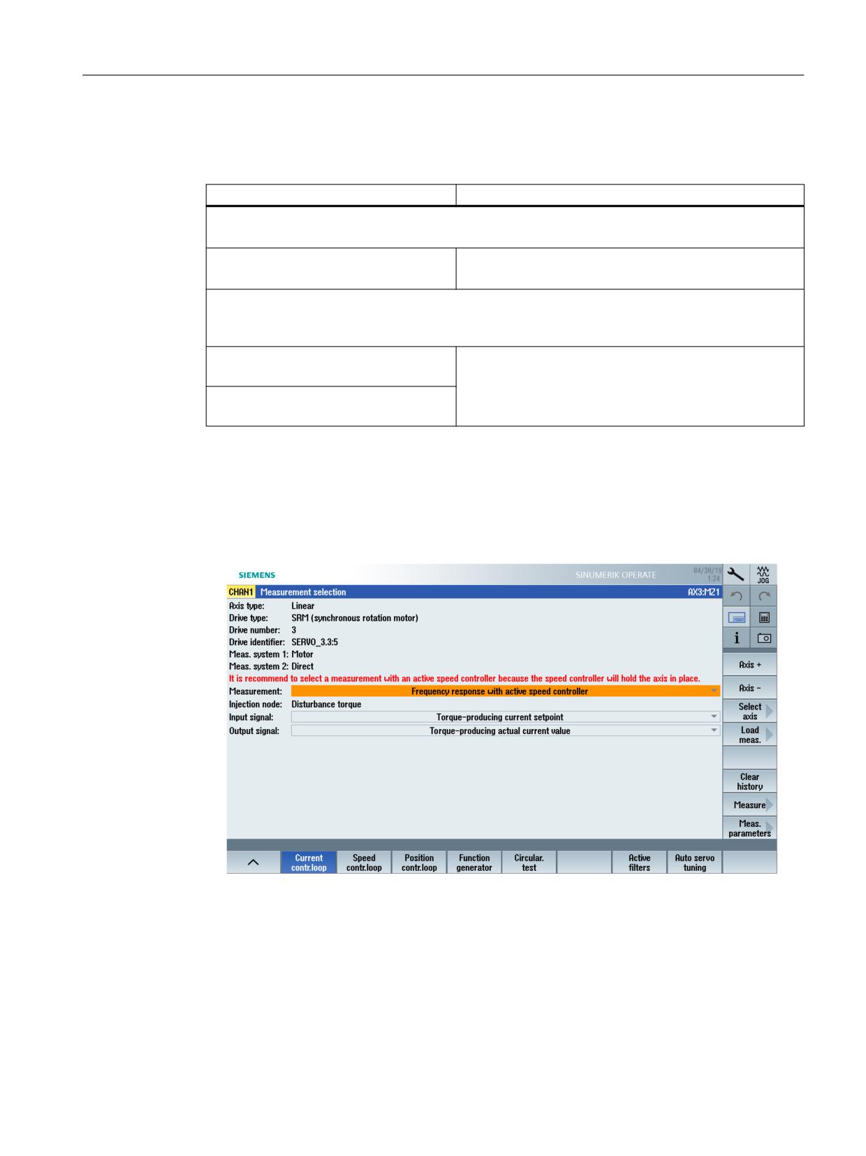
For SINAMICS S120, it is possible to measure the input/output behavior of the current control
loop directly in the speed controller without needing to open it. For this reason, measurements
in the speed controller are preferable. The user is made aware of this advantage as red text in the
center of the "Measurement selection" dialog.
The preferred method for measuring the dynamic response of the current controller is the
"Reference frequency response with active speed controller" measuring type. The other
measuring types are only for experts or for comparison measurements of motors not decoupled
from the mechanical components.
NOTICE
Safety measures for hanging/suspended axes
For hanging/suspended axes, measuring the current control loop requires that users apply
special safety measures, for instance:
• Perform the measurement using external weight compensation.
• Perform the measurement without external weight compensation, e.g. by safely and
reliably clamping/locking the drive.
CNC Commissioning: NC, PLC, Drive
290
Commissioning Manual, 10/2020, A5E48312804B AB
Drive tuning
10.4 Measuring functions (manual tuning)
Measuring procedure
For the following measuring types, the current setpoint filter is not involved:
Measuring type
Measured quantities
Recommended measuring type for experts:
This measuring type is recommended for vertical axes.
• Reference frequency response with ac-
Torque-generating current setpoint (input)
tive speed controller
Torque-generating actual current value (output)
Additional measuring types:
The speed controller is deactivated when measuring the current control loop. This is the reason why a
vertical axis can drop.
• Reference frequency response (after
Torque-generating current setpoint (input)
the current setpoint filter)
Torque-generating actual current value (output)
• Setpoint step (after the current set-
point filter)
Measurement
The measurement sequence is divided into the following steps:
1. Set the traversing range monitoring and release logic.
2. Select the type of measurement:
CNC Commissioning: NC, PLC, Drive
Commissioning Manual, 10/2020, A5E48312804B AB
291
Drive tuning
10.4 Measuring functions (manual tuning)
3. Press the "Meas. parameters >" softkey to adapt the parameters for a measurement.
Measurement parameters:
- Amplitude: Magnitude of the test signal amplitude.
Given in percent of the peak torque. Values from 1 % to 5 % are suitable.
- Bandwidth: The frequency range analyzed with the measurement.
The bandwidth depends on the current controller sampling time.
Example: Sample time: 125 μs, bandwidth: 4000 Hz
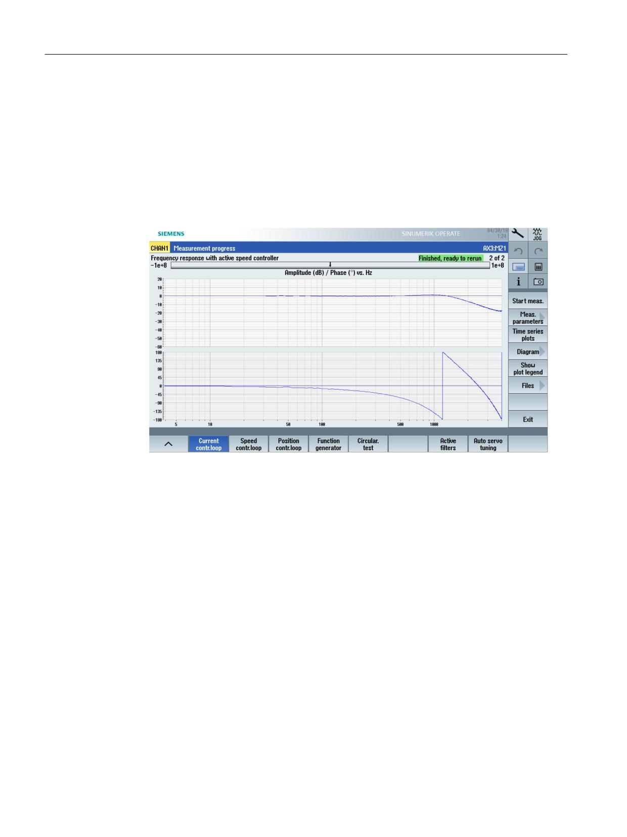
4. To start the measurement, press softkey "Measure >" followed by softkey "Start meas.". Two
measurements are performed and the result is then displayed:
10.4.2
Speed control loop measurement
Function
The response characteristics for the motor measurement system are analyzed when measuring
the speed control loop. Various measurement parameter lists are available depending on the
basic measurement setting which has been selected.
The predefined processes for the speed control loop are listed below. As in the current controller
range, the excitation and measurement signals in the speed controller range refer to the
SINAMICS S120 drive. The speed controller measurements differ in terms of the excitation,
which can either be a disturbing torque, a speed setpoint before the filter or a speed setpoint
after the filter. This is comparable with parameter p0480 for values 2, 3 or 5.
A distinction is made in the table between the input node and the excitation point. The input
node only determines which signal is considered as the input for the subordinate system to be
measured.
CNC Commissioning: NC, PLC, Drive
292
Commissioning Manual, 10/2020, A5E48312804B AB

Drive tuning
10.4 Measuring functions (manual tuning)
Measuring functions
The following measuring functions are available for measuring the speed control loop:
Measuring type
Waveform
Measured variable (in-
Measured value (out-
put)
put)
Reference frequency response (af-
PBRS
Speed setpoint after the
Actual speed value mo-
ter the speed setpoint filter)
filter
tor
Reference frequency response (be-
PBRS
Speed setpoint before
Actual speed value mo-
fore the speed setpoint filter)
the filter
tor
Setpoint step (after the speed set-
PBRS
• Speed setpoint after
Actual speed value mo-
point filter)
the filter
tor
• Actual torque value
Disturbance frequency response
PBRS
Torque setpoint (func-
Actual speed value mo-
(disturbance after the current set-
tion generator)
tor
point filter)
Disturbance variable step (disturb-
Jump
• Torque setpoint
Actual speed value mo-
ance after the current setpoint filter)
(function generator)
tor
• Actual torque value
Speed-controlled system (excitation
PBRS
Actual torque value
Actual speed value mo-
after the current setpoint filter)
tor
Reference frequency response, cur-
PBRS
Speed setpoint after the
Torque-generating ac-
rent control loop
filter
tual current value
APC open control loop *
PBRS
Speed setpoint after the
APC controller output
filter
(r3777[1])
APC closed control loop *
PBRS
Speed setpoint after the
Actual speed value from
filter
the direct measurement
system
APC mechanical system *
PBRS
Actual speed value mo-
Actual speed value from
tor encoder
the direct measurement
system
*)
APC-related inputs appear only when the SINAMICS APC function module is activated. The status of the
APC controller is determined depending on the measurement procedure.
CNC Commissioning: NC, PLC, Drive
Commissioning Manual, 10/2020, A5E48312804B AB
293
Drive tuning
10.4 Measuring functions (manual tuning)
Measurement sequence
The measurement sequence is divided into the following steps:
1. Set the traversing range monitoring and release logic.
2. Select the type of measurement:
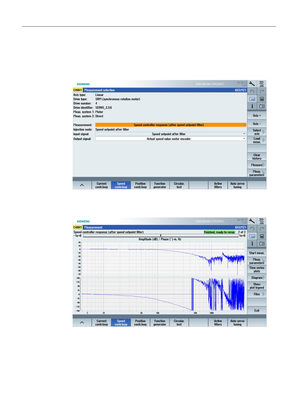
3. Press softkey "Meas. parameters >" to set the parameters.
4. To start the measurement, press softkey "Measure >" followed by softkey "Start meas.". In the
example shown, the speed control loop has not yet been tuned:
CNC Commissioning: NC, PLC, Drive
294
Commissioning Manual, 10/2020, A5E48312804B AB
Drive tuning
10.4 Measuring functions (manual tuning)
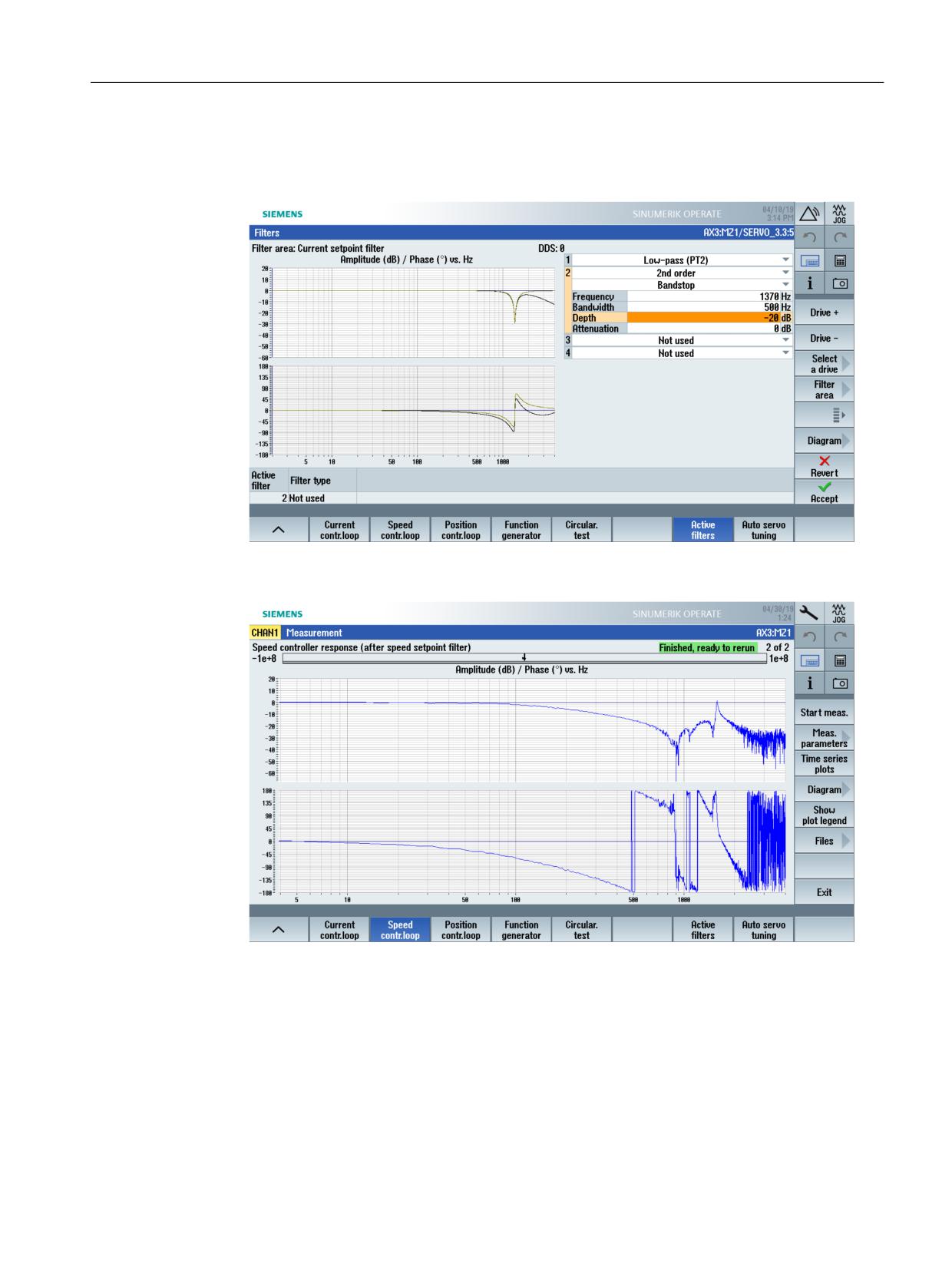
5. A suitable filter parameterization is used to tune the dynamic response. Press the "Active
filter" softkey. The following diagram shows the standard settings for a lowpass filter at
1999 Hz and a bandstop filter:
6. After using the filter, the following tuned measurement curve results for the speed control
loop:
CNC Commissioning: NC, PLC, Drive
Commissioning Manual, 10/2020, A5E48312804B AB
295
Drive tuning
10.4 Measuring functions (manual tuning)
10.4.3
Example: Setting the filter for the following error (speed control loop)
Requirement
The X axis is measured with the following settings:
• With feedrates in SD55822[0...5] $SCS_FRICT_OPT_FEED for step 1 ... 6 and
SD55822[6...8] $SCS_FRICT_OPT_FEED = 0 for step 7 ... 9
• Radius 8 mm in SD55820 $SCS_FRICT_OPT_RADIUS
Measuring the X axis
Procedure:
1. Select the dialog for the tuning via the "NC" and "Friction compensation" softkeys.
2. Select the X axis and press "Start".
3. Confirm the program editor by pressing "OK" without any further inputs. The X axis is not
measured with separate reversal points.
4. Enter a value for step 1 and change the parameters until you are satisfied with the
compensation.
5. Press "Next >" to change to the next step.
Step 1 of 6: 1,000 mm/min
Amplitude: 15.220 mm/min
Decay time: 0.038 s
Active time: 0.012 s
Step 2 of 6: 600 mm/min
Amplitude: 10.750 mm/min
Decay time: 0.034 s
Active time: 0.016 s
6. Repeat this process for all steps. Press "OK" to save the data.
Result
The following graphic shows the characteristic curves of the X axis for various radiuses:
10.4.4
Position control loop measurement
Function
The predefined processes for the position control loop are listed in the following table. The
position controller measurements are performed in the NC. The measurements support three
excitation variants: Position setpoint, speed setpoint, torque setpoint and torque feedforward
control. In cases with two configured measuring systems, the selection of the signal output node
supports encoder 1, encoder 2, and the active encoder.
CNC Commissioning: NC, PLC, Drive
296
Commissioning Manual, 10/2020, A5E48312804B AB

Drive tuning
10.4 Measuring functions (manual tuning)
Predefined measuring procedure
The following measuring procedures are available for measuring the position control loop:
Process
Curve form
Excitation
Input signal
Output signal
point
Reference frequen-
PRBS
Position set-
Position setpoint
Position actual value
cy response
point
Position actual value en-
coder 1
Position actual value en-
coder 2
Setpoint step
Jump
Position set-
Position setpoint
Position actual value
point
System deviation
Contour deviation
Speed actual value
Position actual value en-
coder 1
Position actual value en-
coder 2
Setpoint ramp (rec-
Ramp
Position set-
Position setpoint
Position actual value
ommended)
point
System deviation
Contour deviation
Speed actual value
Position actual value en-
coder 1
Position actual value en-
coder 2
Mechanical frequen-
PRBS
Speed setpoint
Position actual
Position actual value en-
cy response *)
value encoder 1
coder 1
Position actual
Position actual value en-
value encoder 2
coder 1
Disturbance fre-
PRBS
Torque feedfor-
Torque feedfor-
Position actual value
quency response
ward control
ward control (ex-
System deviation
citation)
Contour deviation
Speed actual value
Position actual value en-
coder 1
Position actual value en-
coder 2
*)
The mechanical frequency response represents the relationship between the motor measuring system
and the direct measuring system, and is measured by the position controller. The selection is only
possible if a second encoder has been detected.
CNC Commissioning: NC, PLC, Drive
Commissioning Manual, 10/2020, A5E48312804B AB
297
Drive tuning
10.4 Measuring functions (manual tuning)
Measurement sequence
The measurement sequence is divided into the following steps:
1. Set the traversing range monitoring and release logic.
2. Select the type of measurement:
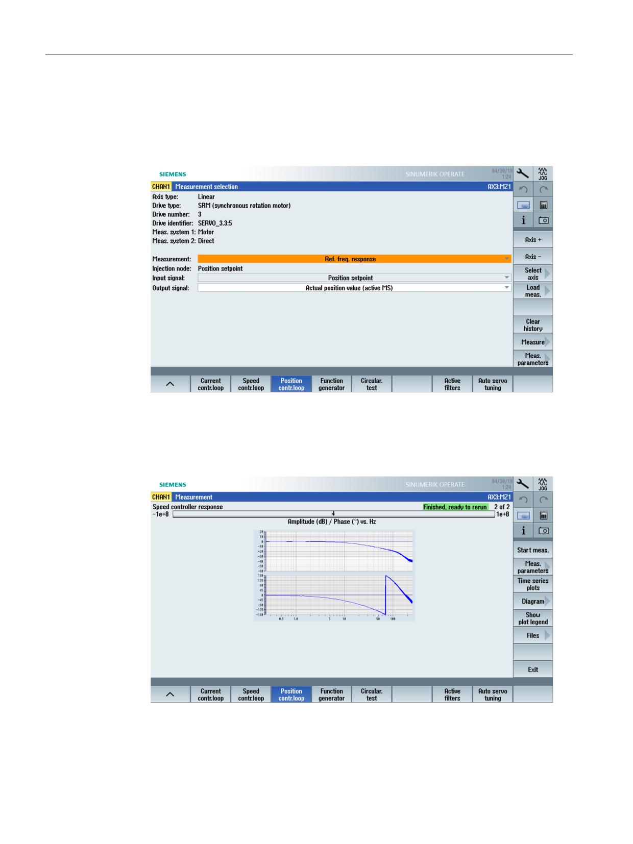
3. Press softkey "Meas. parameters >" to set the parameters.
4. To start the measurement, press softkey "Measure >" followed by softkey "Start meas.". Two
measurements are performed. The result shows a tuned position control loop in which the
servo gain factor has been adapted with the associated machine data
MD32200 $MA_POSCTRL_GAIN.
CNC Commissioning: NC, PLC, Drive
298
Commissioning Manual, 10/2020, A5E48312804B AB
Drive tuning
10.4 Measuring functions (manual tuning)
10.4.5
Examples for the measuring methods (position control loop)
Measuring type: Reference frequency response
The reference frequency response measurement determines the transfer behavior of the
position controller in the frequency range. The position actual value is taken from the active
measuring system. The setpoint filters, control loop gain and feedforward control must be
parameterized so that resonance is avoided wherever possible over the entire frequency range.
Measurement parameters:
• Amplitude
This parameter determines the magnitude of the test signal amplitude. It should be set to the
smallest possible value, e.g. 0.01 mm
• Bandwidth
The bandwidth parameter is used to set the analyzed frequency range. The larger this value,
the finer the frequency resolution and the longer the measurement time. The maximum
value is specified by the position controller cycle (Tposition controller):
Bandwidthmax [Hz] = 1 / (2 * Tposition controller [s])
Example:
- Position controller cycle: 2 ms
- Bandwidthmax = 1 / (2 * 2*10-3) = 250 Hz
• Averaging
The accuracy of the measurement and in turn the measurement duration increase with this
value. A value of 4 is normally adequate.
• Settling time
This value represents the delay between recording of the measured data and injection of the
test setpoint and offset. A value of between 0.2 s and 1 s is recommended. Do not set too low
a value for the settling times or the frequency response and phase diagrams will be distorted.
• Offset
The measurement requires a speed offset of a few motor revolutions per minute. The offset
must be set such that no speed zero crossings occur at the set amplitude, and that the axis
continually moves in one direction.
Measuring type: Setpoint step and setpoint ramp
The transient and the positioning response of the position control in the time domain, and in
particular the effect of setpoint filters, can be assessed with the step and ramp excitation
functions.
Setpoint step:
To avoid overloading the machine mechanical system, for the "Setpoint step" measuring type,
the step amplitude is limited to the following value:
MD32000 $MA_MAX_AX_VELO (maximum axis velocity)
Setpoint ramp:
CNC Commissioning: NC, PLC, Drive
Commissioning Manual, 10/2020, A5E48312804B AB
299
Drive tuning
10.4 Measuring functions (manual tuning)
3RVLWLRQ
$PSOLWXGH
7LPH
6HWWOLQJ WLPH
5LVH WLPH
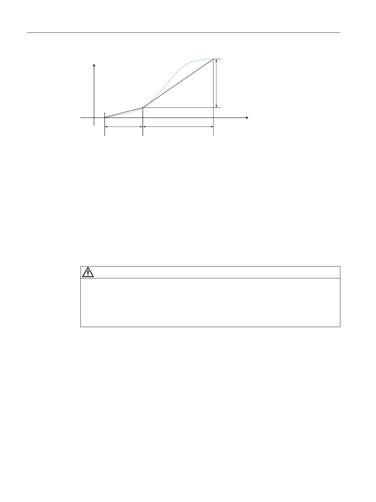
Solid line
At maximum axis acceleration, the velocity changes (almost) according to a
step function.
Dashed line
This characteristic corresponds to a realistic, finite value. The offset compo-
nent is excluded from the display graphic in order to emphasize the transient
processes.
Figure 10-6
Signal characteristic for position control
With measuring type "Setpoint ramp", the following machine data influences the measurement
result:
• MD32000 $MA_MAX_AX_VELO (maximum axis velocity)
The maximum axis velocity limits the ramp gradient (velocity limitation). The drive does not
reach the programmed end position (amplitude).
• MD32300 $MA_MAX_AX_ACCEL (maximum axis acceleration)
The maximum axis acceleration limits the velocity change (acceleration limitation).
CAUTION
Protection of the machine
In normal cases the machine data corresponds exactly with the load capacity of the machine
kinematics and should not be changed (increased) as part of the measurements:
• MD32000 $MA_MAX_AX_VELO (maximum axis velocity)
• MD32300 $MA_MAX_AX_ACCEL (maximum axis acceleration)
Measurement parameters: Setpoint step and setpoint ramp
The transient and the positioning response of the position control in the time domain, and in
particular the effect of setpoint filters, can be assessed with the step and ramp excitation
functions.
Measurement parameters:
• Amplitude
Determines the amplitude of the specified setpoint step or setpoint ramp.
• Rise time
This parameter determines the period of time to be recorded (maximum 2048 position
controller cycles).
CNC Commissioning: NC, PLC, Drive
300
Commissioning Manual, 10/2020, A5E48312804B AB
Drive tuning
10.4 Measuring functions (manual tuning)
• Settling time
This value represents the delay between measured data recording / test setpoint output and
the injection of the offset.
• Rise time
The position setpoint is specified with the "Setpoint ramp" basic setting according to the
selected ramp duration.
• Offset
The step is stimulated from standstill or starting from the constant traverse speed set in this
parameter. If an offset value other than zero is input, the test excitation takes place during the
traverse. For the sake of clarity, the displayed position actual value does not include this
constant component.
10.4.6
Function generator
Function description
The function generator can be used, for example, to perform the following tasks:
• Measuring and optimizing closed-loop control circuits
• Comparing the dynamic properties of coupled drives
• Specifying a straightforward traversing profile without traversing program
The function generator can be used to generate various signal forms.
In the Servo mode, the setpoint can additionally be supplied into the control structure in
accordance with the currently selected mode, for example, as a current setpoint, disturbing
torque or speed setpoint. Any influence of overlaid closed-loop control circuits is suppressed
automatically.
Position of the application points:
6SHHG VHWSRLQW
6SHHG VHWSRLQW
&XUUHQW VHWSRLQW
&XUUHQW VHWSRLQW
EHIRUH WKH ILOWHU
DIWHU WKH ILOWHU
EHIRUH WKH ILOWHU
DIWHU WKH ILOWHU
6HWSRLQW
6SHHG
6HWSRLQW
&XUUHQW
&RQ
ILOWHU
FRQWUROOHU
ILOWHU
FRQWURO
WUROOHG
)URP WKH
OHU
V\VWHP
LQWHUSRODWRU
'LVWXUELQJ WRUTXH
Figure 10-7
Application points
CNC Commissioning: NC, PLC, Drive
Commissioning Manual, 10/2020, A5E48312804B AB
301
Drive tuning
10.4 Measuring functions (manual tuning)
To activate the function generator, select "Commissioning" operating area → "Automatic servo
optimization" → "Function generator".
NOTICE
Starting/stopping the function generator
The motion of the drive is not monitored when the function generator is activated.
With the corresponding ramp-function generator parameter settings (e.g. offset), the axis can
traverse to the end stop.
The travel-release drive test can be performed by the PLC with or without active monitoring of
the axis:
• With PLC
• Without PLC
The NC monitors the position and stops the function generator when the axis position goes
beyond the specified upper or lower limit. The scaling can be changed while the function
generator is running.
Operating mode of the function generator for servo and vector:
• Connector output
Operating modes of the function generator only for servo:
• Current setpoint after the filter
• Disturbing torque
• Speed setpoint after the filter
• Current setpoint before the filter
• Speed setpoint before the filter
Periodic or non-periodic signals with different waveforms are generated by the function
generator. The curve parameters vary depending on the signal type.
Connection point
System
Waveform
• Connector
• Rectangle
• Current setpoint after the filter
• Staircase
SINAMICS
• Disturbing torque
• Triangle
• Speed setpoint after the filter
• PRBS (white noise)
• Current setpoint before the filter
• Sinusoidal
• Speed setpoint before the filter
• Position setpoint
NC
• Rectangle
• PRBS (white noise)
Further actions:
• "Axis +", "Axis -" or "Direct selection >" softkeys to select the axis on which the signal is applied
(that to be excited).
• "Start" softkey to start the function generator.
CNC Commissioning: NC, PLC, Drive
302
Commissioning Manual, 10/2020, A5E48312804B AB
Drive tuning
10.4 Measuring functions (manual tuning)
• "Stop" softkey to stop the function generator.
• "Parameter" softkey to adapt the parameter belonging to the connection point.
10.4.7
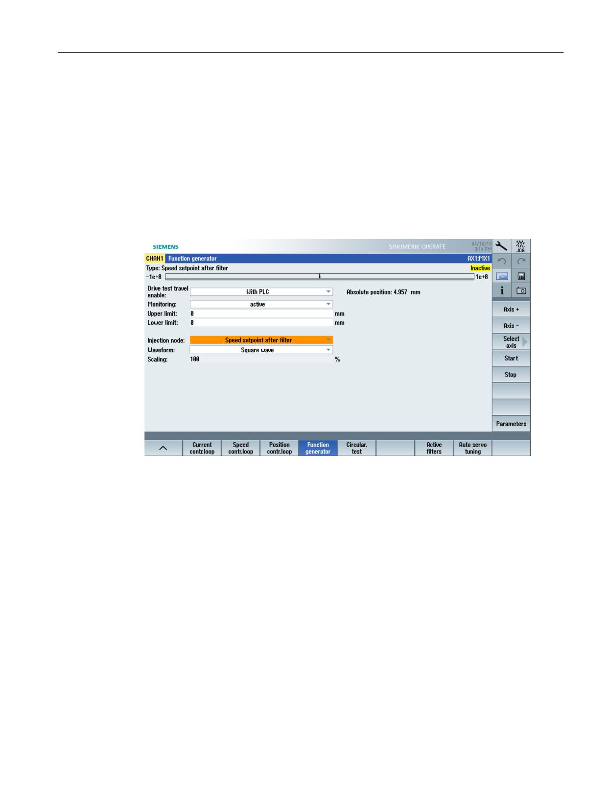
Example, function generator: Speed setpoint after the filter
Example
Function generator with connection point "Speed setpoint after filter":
Description of parameters
Parameter at the connection point "Speed setpoint after filter":
CNC Commissioning: NC, PLC, Drive
Commissioning Manual, 10/2020, A5E48312804B AB
303
Drive tuning
10.4 Measuring functions (manual tuning)
The bars in the upper line indicate the traversing path, the actual position and the software limit
switches. The value for the absolute position is displayed in the first line of the table.
•
Status indicates whether the axis is referenced, and whether sufficient space is available to
the software limit switch. If the measurement parameter results in an excessively long
traversing distance, so that before the end of the measurement, a software limit switch
would be reached, then this is displayed in color, in the "Status" row:
- "Fault" + red: The measurement is not possible, as the software limit switch would be
passed.
- "Caution" + yellow: The measurement is possible, but there is only a limited distance
remaining.
- "No reference point + yellow: The axis is not referenced, the user must check the
traversing distance.
- "OK" + green: The axis is referenced, and a measurement is possible as the traversing
distance lies within the software limit switch.
•
Waveform: Depending on the selection (square wave, staircase, triangular, PBRS, sinusoidal)
•
Amplitude and offset velocity can either be entered as an absolute number or as a
percentage. The amplitude can be specified to be either positive or negative.
- Amplitude: Velocity in [mm/min]
- Amplitude %: Velocity in %
- Offset: Constant velocity in [mm/min]
- Offset %: Constant velocity in %
•
Period: In [ms]
•
Pulse width: In [ms]
•
Ramp-up time: In [ms]
•
Upper/lower limit: The limiting of the output signal to the minimum and maximum value
can be set. If the signal characteristic is greater than the upper limit value, the signal is cut
off above the limit.
•
Upper/lower limit %:
•
Sample time: Time in [ms] until the measurement starts: 0.125 ms (default setting).
Further actions:
• Softkey "<< back", to return to the function generator overview.
CNC Commissioning: NC, PLC, Drive
304
Commissioning Manual, 10/2020, A5E48312804B AB
Drive tuning
10.5 Define filter
10.5
Define filter
Filter types
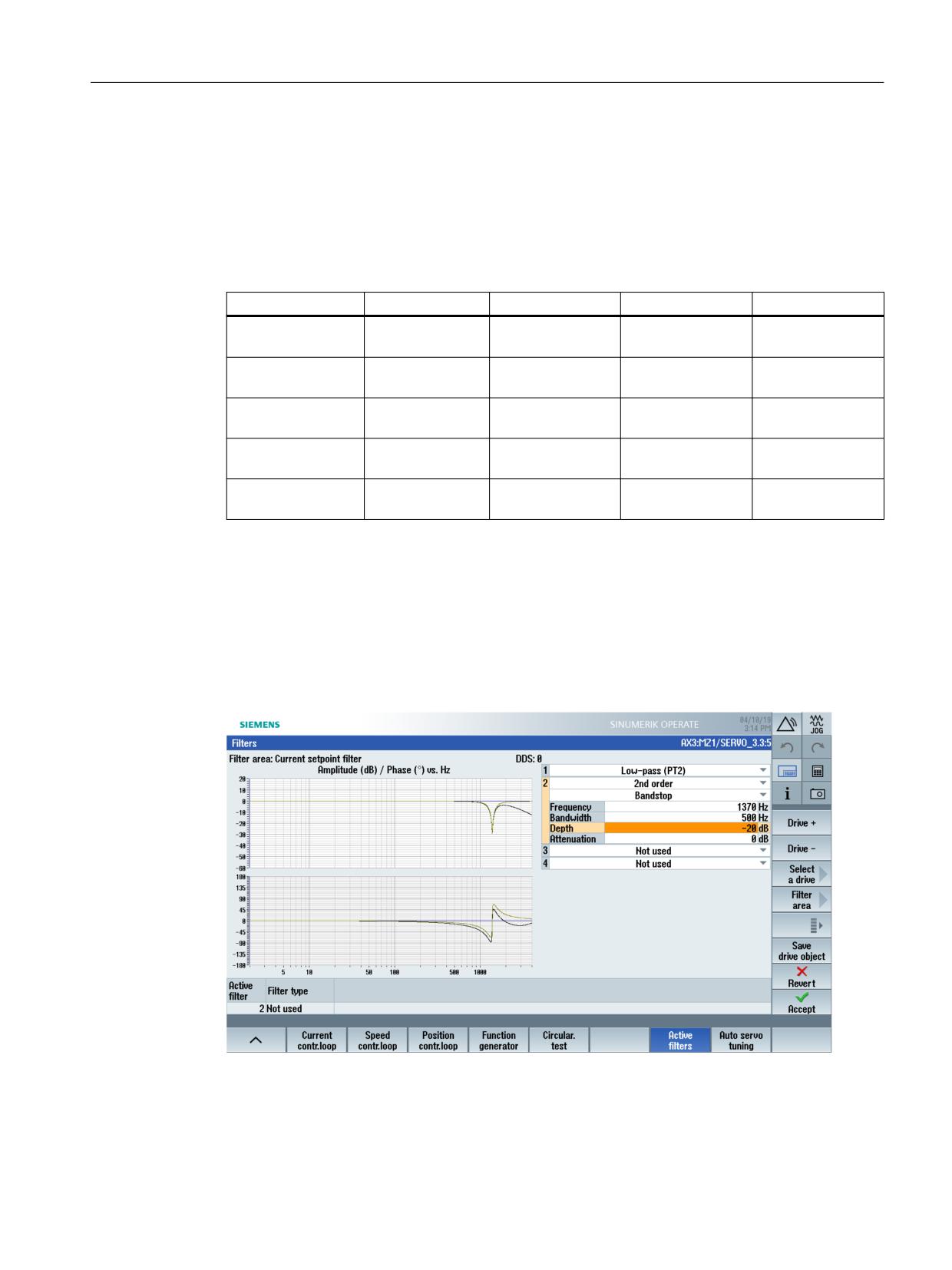
The graphical user interface for the display and processing of filters actively available in the
SINAMICS converter can be found under "Active filter":
Filter type
Parameter 1
Parameter 2
Parameter 3
Parameter 4
PT1 low pass
Time constant
---
---
---
[ms]
PT2 low pass
Frequency [Hz]
Damping (without
---
---
unit)
General 2nd order
Rated frequency
Rated damping
Counter frequency
Counter damping
[Hz]
[without unit]
[Hz]
[without unit]
Band-stop (notch)
Notch frequency
Band frequency
Notch amplitude*)
Final amplitude
[Hz]
[Hz]
[dB]
[dB]
Low-pass with re-
Frequency [Hz]
Damping [without
Final amplitude
---
duction
unit]
[dB]
*) A negative value is often set here in order to attain attenuation of the notch frequency.
Automatic generation and representation of frequency response functions (dB amplitude and
degree phase compared to frequency) provides the user with immediate feedback for each filter
parameter. The units for the filter type and the limits for the parameters are defined directly by
the metadata for the corresponding drive parameters.
Example: "Active filters"
The new values become active in the drive with softkey "Accept".
The values are saved in the drive and backed up in the drive archive with softkey "Save drive
object".
CNC Commissioning: NC, PLC, Drive
Commissioning Manual, 10/2020, A5E48312804B AB
305
Drive tuning
10.6 Circularity test
10.6
Circularity test
10.6.1
Circularity test: Function
Benefits
The circularity test serves to set and assess the dynamic response for interpolating axes and to
analyze the contour accuracy on the quadrant transitions (circular contours) achieved by means
of friction compensation. The circularity test is used to check the interpolation of the axes which
work together. This function measures a circle with reference to the motor or to the direct
measuring system. Alignment of the machine-mechanical equipment is not taken into account
in the result. This gives the commissioning engineer the option of separating problems with the
controller tuning from mechanical problems.
The following axis machine data and parameters are checked with this procedure:
• MD32200, MD32400, MD32402, MD32410, MD32490, MD32500, MD32510, MD32520,
MD32540 MD32620, MD32640, MD32810, MD32900, MD32910, MD32930, MD32940
• p1421 bis p1426, p1400, p1433, p1434
The following compensations should be disabled if this procedure is carried out:
• MD32450 backlash compensation
• MD32500 friction compensation
• MD32700 leadscrew error compensation
• MD32710 Enable sag compensation
• MD32750 Temperature compensation type
Note
MD32450 $MA_BACKLASH: Backlash compensation must be adjusted using an external device,
such as a circularity test or gauge.
Example of an NC program to dimension X-Y axes:
FFWON
SOFT
G90 G01 F3000 X400 Y200 Z500
LAB:
G91 G64 G02 X0 Z0 I10
GOTOB LAB
M30
Position, feedrate and active plane must be adjusted to the machine! Alternatively, you can
generate a program using a softkey.
CNC Commissioning: NC, PLC, Drive
306
Commissioning Manual, 10/2020, A5E48312804B AB
Drive tuning
10.6 Circularity test
Result
The best contour results are achieved when the circular form test results are in the correct actual
size, shape and minimum p/p deviation between a combined interpolation of the axes (X-Y, X-Z,
Y-Z).
An NC program in the MDA operating mode and the circularity test function are used to measure
and evaluate these results. The "worst case" of a circle radius and the path velocity must lead to
a realistic radial acceleration of which the machine is capable.
Circularity tests of machine manufacturers usually use a radius of 100 mm or 150 mm with
feedrate speeds that are determined by the machine manufacturer. The machine manufacturer
determines the specifications for an acceptable result.
High-speed processes generally have higher requirements for testing circles with high-speed
milling machines and can range from circle radii of 10 - 25 mm and feedrates of 5 - 10 m/min.
For high-speed milling machines, the results are generally acceptable if the P/P deviation
≤ 0.010 mm and the actual size of the circle is equal to the programmed radius - or in the worst-
case scenario - to the path velocity.
10.6.2
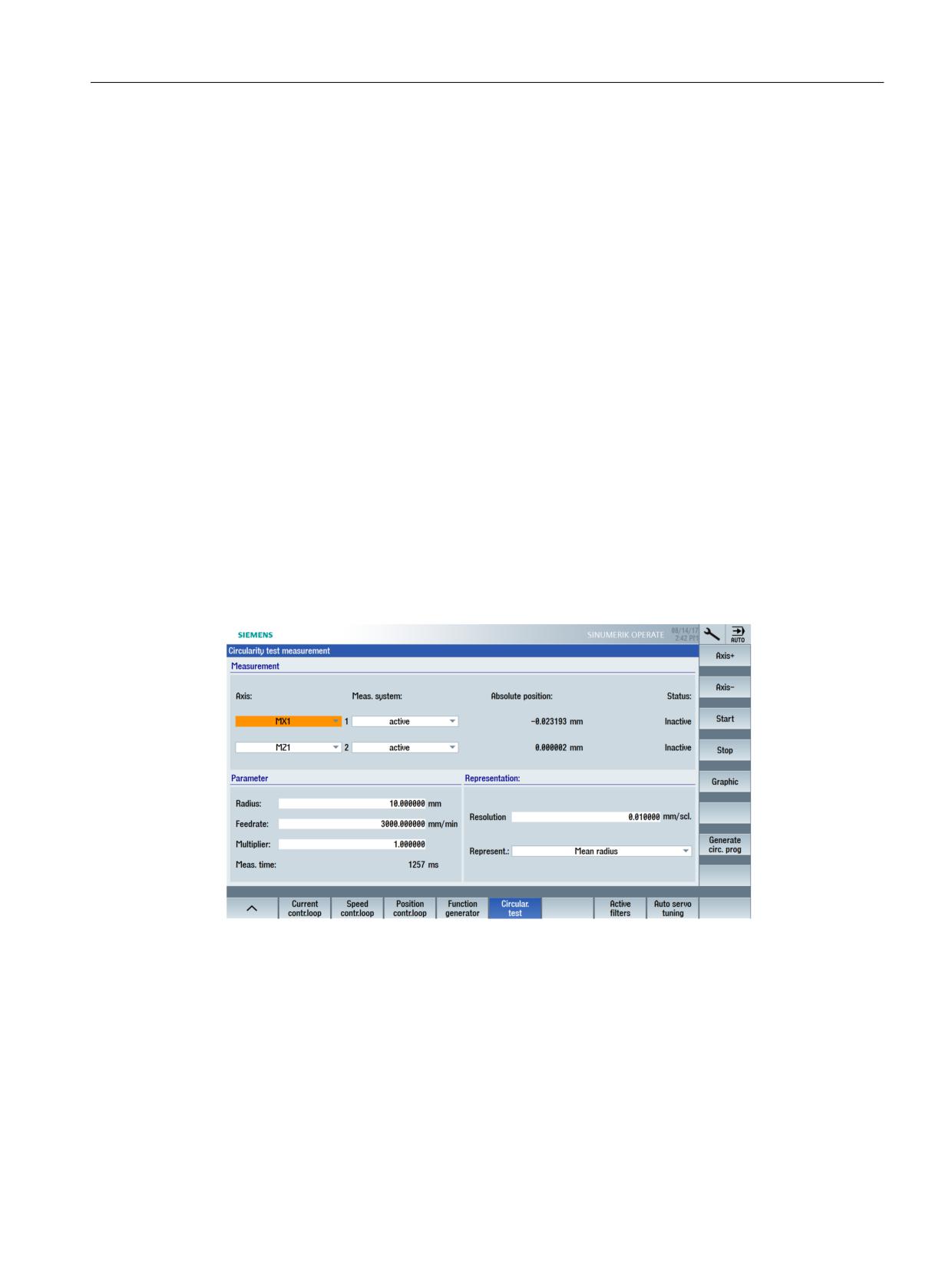
Circularity test: Performing the measurement
Setting parameters
Figure 10-8
Circularity test - measurement
CNC Commissioning: NC, PLC, Drive
Commissioning Manual, 10/2020, A5E48312804B AB
307
Drive tuning
10.6 Circularity test
Enter the following parameters to carry out a measurement:
• "Measurement": Selection of the two axes that are intended to be measured and selection
of the measurement system. Parked encoders are not displayed for selection.
• "Parameter": The parameter settings in the "Radius" and "Feed" input fields must correspond
to the values from the part program that controls the circular motion of the axes, taking
account of the feed override switch setting.
• "Representation": Parameters for displaying the graphics
- "Resolution" (scaling) of the diagram axes in [mm/scaled]
- "Display" via the mean radius or programmed radius
Perform measurement
Procedure:
1. In the "Commissioning" operating area select the "Optim./test" softkey → "Circularity test"
softkey.
2. Select the axes that are intended to be measured with the <SELECT> key or with the "Axis
+"/"Axis -" softkeys.
3. Set the parameters for the measurement: "Radius" and "Feed"
The "Measurement time" display field shows the measurement time calculated from the
"Radius" and "Feed" values for recording the actual position values during the circular
movement:
If the measurement time is not sufficient then only parts of the circle are portrayed. The
measurement time can be increased by reducing the feed value. This also applies if the
circularity test is started from the stationary condition.
4. Set the parameters for displaying the graphic:
If the measurement time calculated from this exceeds the time range that can be displayed
(maximum measurement time = position controller cycle frequency * 2048), an appropriate
sample time is calculated for recording (n * position controller cycle frequency), so that a
complete circle can be displayed.
5. To automatically generate a program, with which you traverse the selected axes, press
softkey "Generate circle program". The program is displayed for checking purposes and must
be confirmed. Ensure that the axes can be traversed according to the program and that the
traversing paths are free.
6. To start the measurement, press the "Start" softkey. The softkeys cannot be used while the
measurement is being performed - with the exception of the "Stop" softkey.
CNC Commissioning: NC, PLC, Drive
308
Commissioning Manual, 10/2020, A5E48312804B AB
Drive tuning
10.6 Circularity test
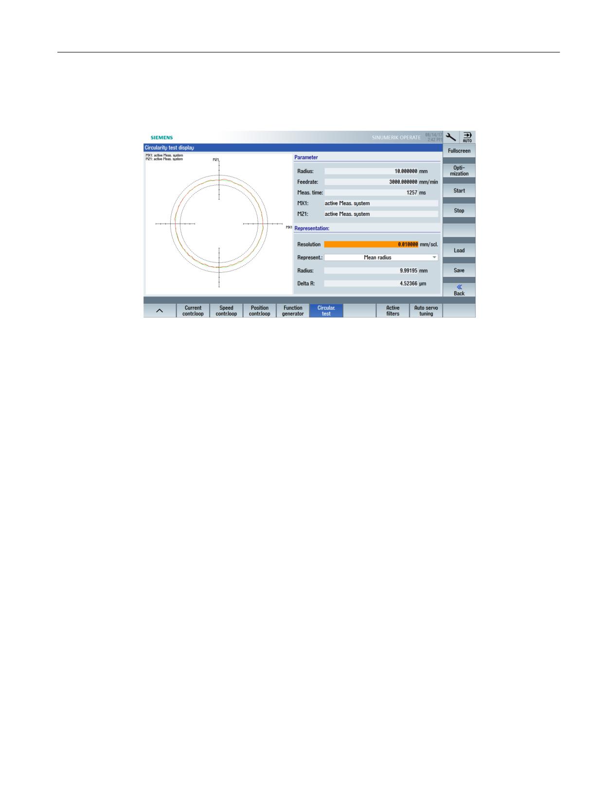
Displaying a graphic
To display the measurement result as a graphic, press the "Graphic" softkey.
Figure 10-9
Circularity test - display
⇒ additional actions:
• Press softkey "Full screen" to display the graphic on a full screen.
If the active "Full screen" softkey is activated a second time, you will return to the previous
display with graphic and display information.
• Press the "Tuning" softkey to carry out additional tuning adaptations. On a new softkey bar,
you can navigate directly to the following areas:
- "Service axis" in the operating area "Diagnostics"
- "Axis machine data"
- "Drive machine data"
- "User views"
• To start the measurement, press the "Start" softkey.
• To stop the measurement, press the "Stop" softkey.
• Press the "Load" softkey to display parameters or the graphic of a measurement.
• Press the "Save" softkey to save parameters or the graphic of a measurement.
The graphic can be saved as a pixel graphic in the PNG or BMP format. The measurement data
are saved in the xml format as *.sud. The following path is set as default path: user/sinumerik/
hmi/log/optimization/circular
• With softkey "<< Back", you return to dialog "Circularity test - measurement".
10.6.3
Circularity test: Examples
The MD32400 $MC_AX_JERK_ENABLE axial jerk limitation is set via a time constant and is always
active.
CNC Commissioning: NC, PLC, Drive
Commissioning Manual, 10/2020, A5E48312804B AB
309
Drive tuning
10.6 Circularity test
Machine data for setpoint filter:
• MD32402 $MC_AX_JERK_MODE = Type 2 is recommended, type 1 is preset for compatibility
reasons. Parameterizing a pure band-stop filter is expressly not recommended.
• MD32402 $MA_AX_JERK_MODE (filter type) and MD32410 $MA_AX_JERK_TIME > 0 is
effective only if MD32400 $MA_AX_JERK_ENABLE = 1 is set.
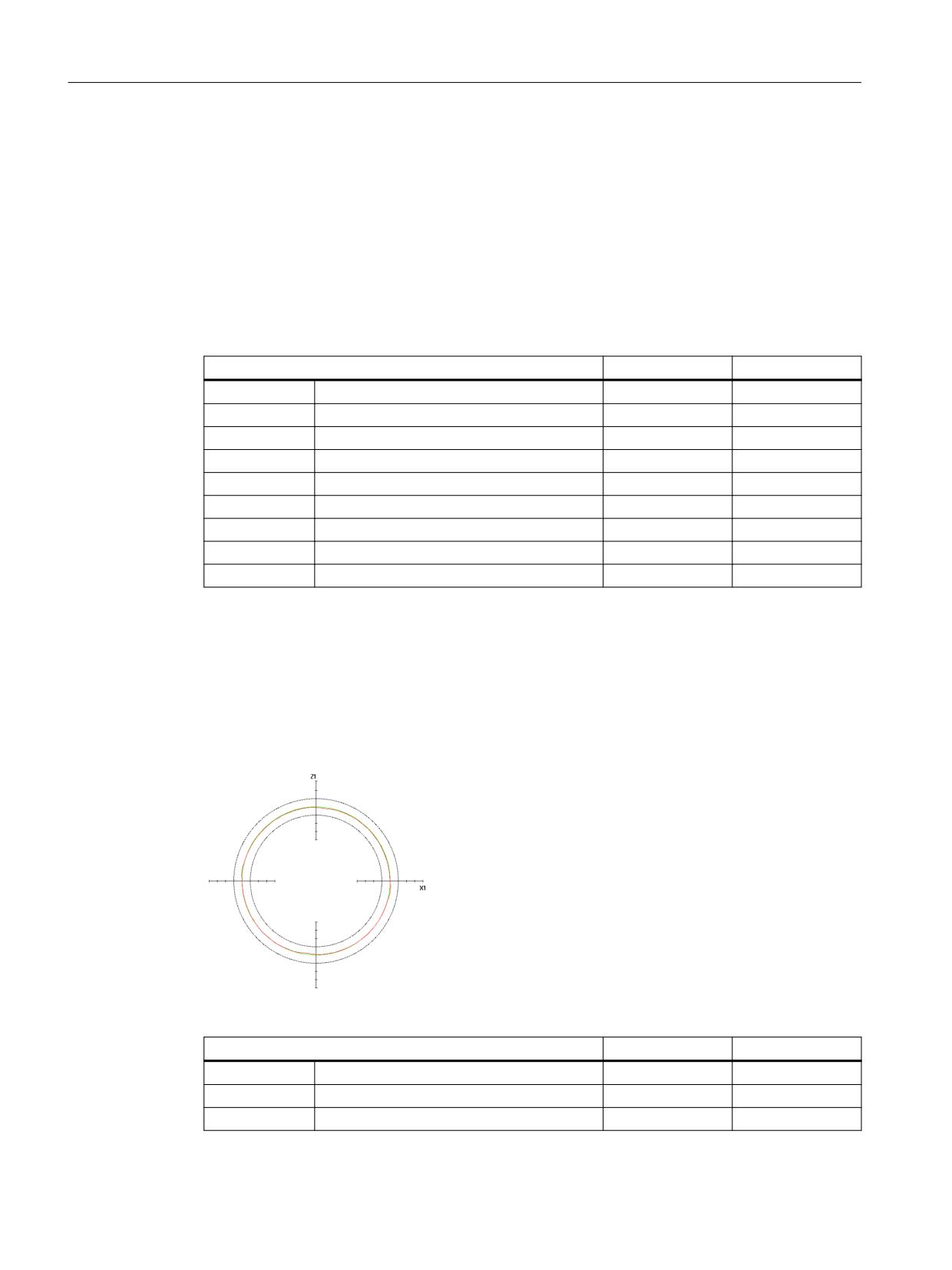
Example 1 for optimization
Machine data after optimization of the axes:
Parameters / machine data
X axis
Z axis
MD32200
$MC_POSCTRL_GAIN
8.500
8.500
p1460
SPEEDCTRL_GAIN1
3.01
3.89
p1462
SPEEDCTRL_INTEGRATOR_TIME_1
6.18
6.18
p1463
SPEEDCTRL_REF_MODEL_FREQ
106.3
106.3
p1440
NUM_SPEED_FILTERS
0
0
MD32610
$MC_VELO_FFW_WEIGHT
1.0
1.0
MD32620
$MC_FFW_MODE
4
4
MD32810
$MC_EQUIV_SPEEDCTRL_TIME
0.0022
0.0022
MD32400
$MC_AX_JERK_ENABLE
0
0
The actual value of the radius is generally too large with optimized feed precontrol. This can be
corrected with the MD32410 $MC_AX_JERK_TIME time constant. Use a time constant in all axes
if required.
This circle displays the results after the feed precontrol has been optimized. However, the mean
radius is 0,0019 mm too large:
X1: active measuring system
Parameter
Z1: active measuring system
Radius:
10.00000 mm
Feedrate:
3000.00000 mm/min
Measure-
1257 ms
ment time:
X1:
active measuring system
Z1:
active measuring system
Representation
Resolution:
0.01000 mm
Display of. mean radius
Radius:
10.00190 mm
Delta R:
4.02698 μm
Parameters / machine data
X axis
Z axis
MD32200
$MC_POSCTRL_GAIN
8.500
8.500
p1460
SPEEDCTRL_GAIN1
3.01
3.89
p1462
SPEEDCTRL_INTEGRATOR_TIME_1
6.18
6.18
CNC Commissioning: NC, PLC, Drive
310
Commissioning Manual, 10/2020, A5E48312804B AB
Drive tuning
10.6 Circularity test
Parameters / machine data
X axis
Z axis
p1463
SPEEDCTRL_REF_MODEL_FREQ
106.3
106.3
p1440
NUM_SPEED_FILTERS
0
0
MD32610
$MC_VELO_FFW_WEIGHT
1.0
1.0
MD32620
$MC_FFW_MODE
3
3
MD32810
$MC_EQUIV_SPEEDCTRL_TIME
0.0022
0.0022
MD32400
$MC_AX_JERK_ENABLE
1
1
MD32402
$MC_AX_JERK_MODE
2
2
MD32410
$MC_AX_JERK_TIME
0.012
0.012
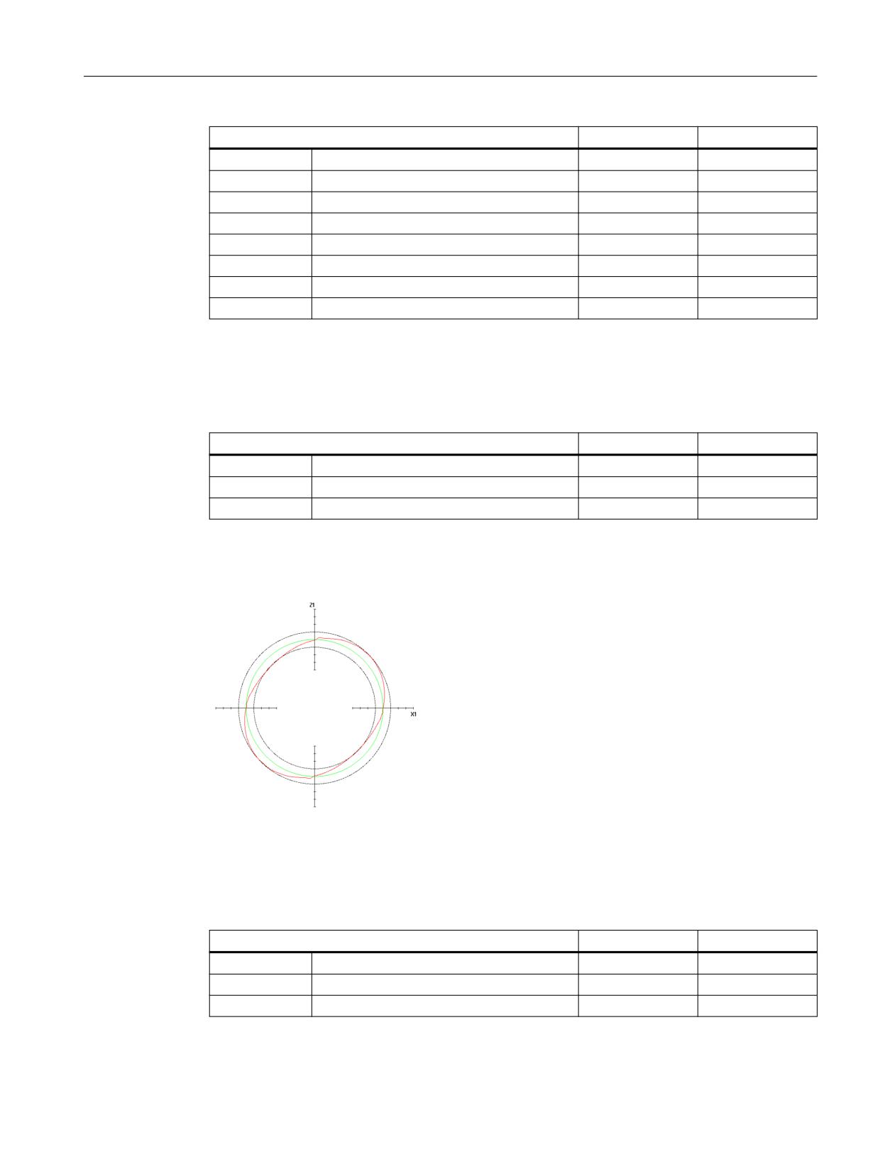
Example 2 for optimization
This circle shows the effect of a slightly different time constant for the axial jerk filter. The time
constant is adapted in order to correct this type of error:
Parameters / machine data
X axis
Z axis
MD32400
$MC_AX_JERK_ENABLE
1
1
MD32402
$MC_AX_JERK_MODE
2
2
MD32410
$MC_AX_JERK_TIME
0.012
0.0125
X1: active measuring system
Parameter
Z1: active measuring system
Radius:
10.00000 mm
Feedrate:
3000.00000 mm/min
Measurement
1257 ms
time:
X1:
active measuring system
Z1:
active measuring system
Representation
Resolution:
0.01000 mm
Representation:
mean radius
Radius:
10.00029 mm
Delta R:
25.47002 μm
Example 3 for optimization
This circle shows the effect of a significantly different time constant for the axial jerk filter. The
time constant is adapted in order to correct this type of error:
Parameters / machine data
X axis
Z axis
MD32400
$MC_AX_JERK_ENABLE
1
1
MD32402
$MC_AX_JERK_MODE
2
2
MD32410
$MC_AX_JERK_TIME
0.015
0.012
CNC Commissioning: NC, PLC, Drive
Commissioning Manual, 10/2020, A5E48312804B AB
311
Drive tuning
10.6 Circularity test
X1: active measuring system
Parameter
Z1: active measuring system
Radius:
10.00000 mm
Feedrate:
3000.00000 mm/min
Measurement
1257 ms
time:
X1:
active measuring system
Z1:
active measuring system
Representation
Resolution:
0.01000 mm
Representation: mean radius
Radius:
9.98971 mm
Delta R:
75.67665 μm
10.6.4
Circularity test: Saving data
Backing up measurement data
The file is structured as follows (with comments in brackets[ ]):
H: CstPic [Identifier for circularity test graphic]
V: 5.0 [Version number of the file format]
@ parameters
P 1: 10 [Radius]
P 2: 3000 [Feed]
P 3: 1257 [Measuring time]
P 4: 0 [Measuring system Axis 1 - 0: active; 1:first; 2: second]
P 5: 0 [Measuring system Axis 2 - 0: active; 1:first; 2: second]
@Representation
P 10: 10 [Resolution]
P 11: 8 [8 = mean R ; 9 = prog. radius]
P 12: X1 [Axis name 1]
P 13: Z1 [Axis name 2]
@Intermediate values
P 20: 15.6632 [max. radius measured values]
P 21: 10.9326 [min. radius measured values]
P 22: 13.6694 [mean radius measured values]
P 23: 1886 [Number of measured values]
CNC Commissioning: NC, PLC, Drive
312
Commissioning Manual, 10/2020, A5E48312804B AB
Drive tuning
10.6 Circularity test
@Additional values
P 30: 1000 [Accuracy (1/P30))
@Physical units
P 40: 5370 [Text number radius unit]
P 41: 5381 [Text number feed unit]
P 42: 6165 [Text number Resolution unit]
P 43: 5346 [Text number DeltaRadius unit]
P 44: 0 [New: Operate: Basislengthunit]
@Abscissa
Ai:
[Abscissa values i : 0..P23]
@Ordinate
Oi:
[Ordinate values i : 0..P23]
@Radius
Ri:
[Radius values i : 0..P23]
CNC Commissioning: NC, PLC, Drive
Commissioning Manual, 10/2020, A5E48312804B AB
313
Drive tuning
10.7 Decision-making support for APC and APC ECO
10.7
Decision-making support for APC and APC ECO
Conditions for Advanced Position Control
There is a vibration on the load side of the axis (carriage, table) in the axis direction:
• The vibration is excited by the axis motion.
• The vibration is excited by the machining process (e.g. milling, first cut).
Software option
In order to use this function a license is required for the following option:
"Advanced Position Control" (6FC5800-0AM13-0YB0)
Criteria for Advanced Position Control
The vibration could also be reduced by a weaker speed controller:
p1460 Speed controller P gain adaptation speed, lower
Increase P gain
p1462 Speed controller integral time adaptation speed, lower Reduce integral time Tn
The noise suppression and dynamic behavior of the closed-loop controller worsens with a weak
speed controller. Disturbance variables, such as friction, then occur more often, especially with
reversing behavior (the quadrant on the circle worsens), and marks become visible on the
workpiece. Use the Advanced Position Control to find a compromise between noise suppression
and oscillation damping.
Conditions for Advanced Position Control ECO
The vibration could also be reduced by a weaker speed controller:
p1460 Speed controller P gain adaptation speed, lower
Increase P gain
p1462 Speed controller integral time adaptation speed, lower Reduce integral time Tn
This is, for example, possible if the gear factor is small or the spindle pitch is at least 10 mm.
Software option
In order to use this function a license is required for the following option:
"Advanced Position Control ECO" (6FC5800-0AM12-0YB0)
Criteria for Advanced Position Control ECO
If the above-mentioned conditions are fulfilled, perform the following steps:
1. Configure Advanced Position Control ECO to identify the frequency of the vibration: Approx.
30% accuracy is adequate.
2. Oscillation damping: Enter frequency, activate Advanced Position Control ECO and then
check the vibration response on the load side.
CNC Commissioning: NC, PLC, Drive
314
Commissioning Manual, 10/2020, A5E48312804B AB
Drive tuning
10.7 Decision-making support for APC and APC ECO
If the oscillation reduction is not effective, another mode can be activated which can specifically
compensate machine base-related oscillation.
It is recommended first to deactivate the oscillation damping of junction ② and to activate the
APC filter for the machine base-related oscillation.
If the filters for the machine base-related oscillation are also ineffective, the causes may be:
1. The vibration does not occur in the axis direction.
2. The vibration cannot be measured on the motor.
3. The vibration is not measured with Advanced Position Control ECO.
For a machine equipped with SINUMERIK 840D sl and a second measuring system for the axis,
it is recommended to install the Advanced Position Control function module with two encoders.
Decision-making support
When is Advanced Position Control needed with a second encoder?
• If the damping achieved by "Advanced Position Control ECO" is inadequate.
• If the motor cannot attenuate the vibration - even with a weak speed controller.
Possible reasons:
• The leadscrew pitch is too small, e.g. 5 mm
• The Gear factor motor/load revolutions is very high, e.g. p0433 ≥ 30
• The drive train has too much self-locking.
• The Tool Center Point is so far from the motor that the vibrations can only be measured by
a nearby direct measuring system.
CNC Commissioning: NC, PLC, Drive
Commissioning Manual, 10/2020, A5E48312804B AB
315
Drive tuning
10.7 Decision-making support for APC and APC ECO
CNC Commissioning: NC, PLC, Drive
316
Commissioning Manual, 10/2020, A5E48312804B AB
Saving and managing data
11
11.1
Saving data
Time of the data backup
The following times are recommended for performing a data backup:
• After commissioning
• After changing machine-specific settings
• After replacing a hardware component
• Before a software upgrade
• Before the activation of memory-configuring machine data
Creating and importing a commissioning archive
In order to create and import a commissioning archive of the type "*.arc", select the softkey "IBN
Archive":
• Creating a commissioning archive
• Creating a PLC hardware upgrade archive (only SDBs)
• Importing a commissioning archive
• Creating an original status archive
• Reading in an original status archive
CNC Commissioning: NC, PLC, Drive
Commissioning Manual, 10/2020, A5E48312804B AB
317

Saving and managing data
11.1 Saving data
What data is saved?
Components
data
NC data
• 3D collision model
• Compile cycles
• Cycles
- User cycles
- Manufacturer cycles
- Standard cycles
• Definitions
• NC active data
- User data (GUD, LUD)
- Machine data
- Compensation data (measuring system error compensation, fric-
tion compensation, sag / angularity error compensation)
- Zero offsets
- Option data
- R parameters
- Protection zones
- Setting data
- Tool and magazine data
- Initialization program (INI)
• Part programs
• Subprograms
• Workpieces
• Comments
NC data with compensation
Note: It only makes sense to archive machine-specific compensation data
data
if the commissioning file is reloaded into the same controller.
NC data with compile cycles
The compile cycles ( * .elf) option is displayed only if compile cycles are
also available.
PLC data
• OB (organization blocks)
• FB (function blocks)
• FC (functions)
• DB (data blocks)
• SFB (system function blocks)
• SFC (system functions)
• SDB (system data blocks).
Note: System data blocks are only used to back up the hardware config-
uration (not the programming logic).
CNC Commissioning: NC, PLC, Drive
318
Commissioning Manual, 10/2020, A5E48312804B AB
Saving and managing data
11.1 Saving data
Components
data
Drive data
• Binary or ASCII format
• Extended selection: Drive units
HMI data
• Applications: User, manufacturer
• Data backups: Commissioning data, network topology
• Easy Extend
• Settings
• Help
• PLC project
• Reports: Action log, screenshots etc.
• Safety Integrated (acceptance test)
• Texts
• Version data
• Templates
• Dictionaries: For Chinese simplified and Chinese traditional (IME)
11.1.1
Backup of PLC data
PLC operating state
When creating a commissioning archive with PLC data, the PLC image that is saved during this
process depends on the operating state of the PLC at the time of creation:
• Original image
• Instantaneous image
• Inconsistent image
The operating state of the PLC can be changed in the following ways:
• With SIMATIC STEP 7 Manager
• With the PLC mode selector on the NCU:
Position " 2" → STOP, position " 0" → RUN
Operating sequence for original image
The original image of the PLC is represented by the PLC-data state immediately after loading the
S7 project into the PLC.
1. Set the PLC to the STOP operating state.
2. Load the appropriate S7 project into the PLC using SIMATIC Manager STEP 7.
3. Create a commissioning archive with PLC data.
4. Set the PLC to the RUN operating state.
CNC Commissioning: NC, PLC, Drive
Commissioning Manual, 10/2020, A5E48312804B AB
319
Saving and managing data
11.1 Saving data
Operating sequence for instantaneous image
If you cannot create an original image, you can save an instantaneous image as an alternative.
1. Set the PLC to the STOP operating state.
2. Archive the PLC data.
3. Set the PLC to the RUN operating state.
Operating sequence for inconsistent image
An inconsistent image results if a commissioning file with PLC data is created and the PLC is in
the RUN state (cyclic operation). The data blocks of the PLC are saved at different times with
contents that have changed in the meanwhile. This may result in a data inconsistency that, once
the data backup has been copied back to the PLC, may under certain circumstances result in a
PLC stop in the PLC program.
NOTICE
Ensure data consistency
The creation of a commissioning file with PLC data while the PLC is in RUN state (cyclic
operation) may result in an inconsistent PLC image in the commissioning archive. After this
commissioning archive has been copied back, the data inconsistency in the PLC program may
under certain circumstances result in a PLC stop.
11.1.2
Creating a commissioning archive
Requirement
The following access levels are required:
• In order to create a commissioning archive, at least access level 4 (key-operated switch 3) is
required.
• In order to import a commissioning archive, at least access level 2 (service) is required.
It is not permissible that the default setting in MD11230 $MN_MD_FILE_STYLE is changed in
order to guarantee that a commissioning file with access level 2 (service) can be read in:
Generate line checksum and MD numbers.
To prevent a topology error, Control Unit parameter p9906 (topology comparison level of all
components) should be set to "Medium" in order to import a commissioning archive.
Creating a commissioning archive
Series commissioning means bringing a series of control systems to the same initial state as
regards their data. A commissioning archive contains NC, PLC, drive and HMI data.
Compensation data of the NC can also be optionally saved. For a data backup, the drive data is
saved as binary data that cannot be read.
CNC Commissioning: NC, PLC, Drive
320
Commissioning Manual, 10/2020, A5E48312804B AB
Saving and managing data
11.1 Saving data
Procedure:
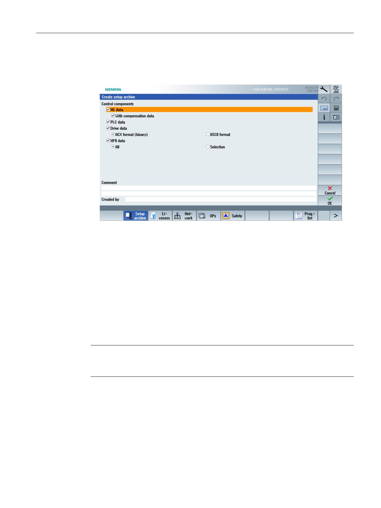
1. To create a commissioning archive, select: "Commissioning" operating area → forward key →
"Commissioning archives" → "Creating a commissioning archive" option:
2. Select the data to be backed up:
- NC data: With/without compensation data
- PLC data
- Drive data: Binary/ASCII
- HMI data: All/selection
3. Enter an archive name.
4. The following directories are offered as a storage location for the archive:
- Archive/user or Archive/manufacturer
Absolute path specification: /user/sinumerik/data/archive or /oem/sinumerik/data/archive
- All configured logical drives (USB, network drives)
Note
USB FlashDrive
USB FlashDrives are not suitable as persistent memory media.
CNC Commissioning: NC, PLC, Drive
Commissioning Manual, 10/2020, A5E48312804B AB
321
Saving and managing data
11.2 Managing data
11.2
Managing data
Application
The "Manage data" function is used to support and simplify the commissioning and provides
functions for backup, load and comparison of machine, setting, compensation and drive data.
In contrast to a commissioning archive, only a single control object (axis, channel, servo, infeed,
etc.) is saved in ASCII format (*.TEA). This file can be edited and transferred to other control
objects of the same type. The "Manage data" function is also the basis for copying DO for
SINAMICS drives.
Managing data
The "Manage data" function offers the following options:
• Transfer data within the controller
• Save data to a file
• Load data in a file
• Compare data
The function is called from "Commissioning" → "Machine data" → "Manage data".
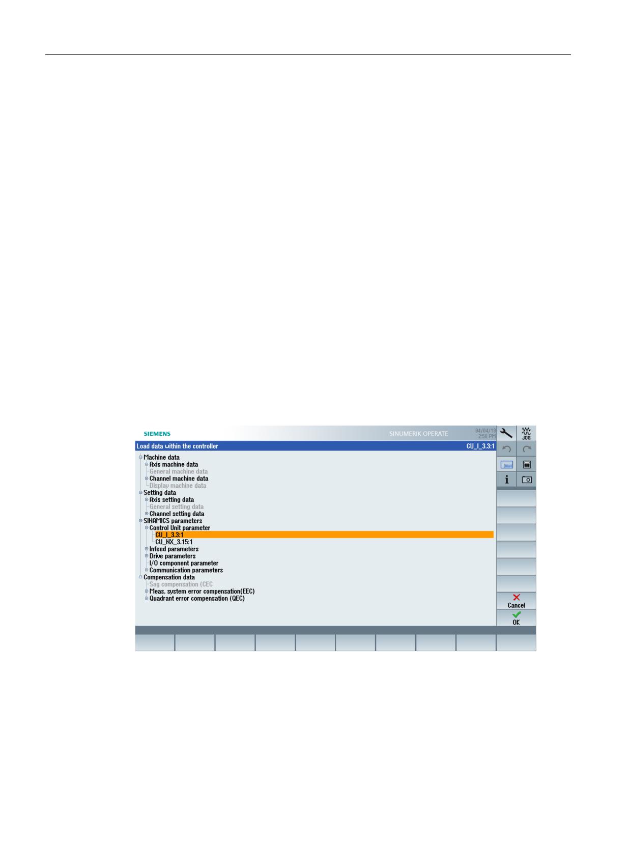
Example of "Transfer data within the controller":
The following data can be saved and stored under the following absolute path on the
CompactFlash card:
• user/sinumerik/hmi/data/backup/ec for compensation data
• user/sinumerik/hmi/data/backup/md for machine data
• user/sinumerik/hmi/data/backup/sd for setting data
• user/sinumerik/hmi/data/backup/snx for SINAMICS parameters
CNC Commissioning: NC, PLC, Drive
322
Commissioning Manual, 10/2020, A5E48312804B AB
Saving and managing data
11.2 Managing data
11.2.1
How to transfer data within the controller
Transfer data within the control
NOTICE
Protection of the machine
For safety reasons, the machine and setting data should only be transferred when the enable
is locked.
Procedure:
1. Select the "Transfer data within the control" option.
2. Select the source data in the data structure and confirm with "OK".
3. In the drop-down list, select an object, e.g. a different axis or a different drive object, to which
you want to transfer the data and confirm with "OK".
4. Observe the safety instructions and check the enable signals at the machine and the drive.
5. For drive data, the "Load" softkey is used to transfer the data to the target object.
11.2.2
To save and load data
Save data to a file
Procedure:
1. Select the "Save data to a file" option.
2. In the data structure, select the data that you want to save to a file and confirm with "OK".
3. Select as the storage location, a directory or a USB storage medium and enter a name.
Note
SINAMICS parameters
An ASCII file (*.TEA) is always generated when saving.
Three files of the following type are generated when saving the drive data:
• A binary file (*.ACX) that cannot be read.
• An ASCII file (*.TEA) that can be read or edited in the ASCII editor.
• A log file (*.log) that contains message texts (error situation) or is empty (successful storage).
CNC Commissioning: NC, PLC, Drive
Commissioning Manual, 10/2020, A5E48312804B AB
323
Saving and managing data
11.2 Managing data
Loading data from a file
NOTICE
Protection of the machine
For safety reasons, the machine and setting data should only be transferred when the enable
is locked.
Procedure:
1. Select the "Load data from a file" option.
2. In the data structure, select the saved file and confirm with "OK".
3. In the drop-down list, select an object, e.g. a different axis or a different drive object, to which
you want to transfer the data and confirm with "OK".
4. Observe the safety instructions and check the enable signals at the machine and the drive.
5. For drive data, the "Load" softkey is used to transfer the data to the target object.
11.2.3
How to compare data
Compare data
Select the data sources to compare the data. For instance, compare the actual data in the control
system with data saved in a file.
Procedure:
1. Select the "Compare data" option.
2. In the data structure, select the data that you want to compare.
3. Press the "Add to list" softkey to transfer the data to the list in the lower area of the display.
4. Press the "Delete from list" softkey to remove the data again.
5. If the list contains more than two data objects, you can activate the checkbox to compare two
or more data objects from the list.
6. Press the "Compare" softkey to start the comparison. The display of the comparison results
can take some time for extensive parameter lists.
7. Press the "Legend" softkey to display or hide the legend. The following display is the default:
- Different parameters are displayed.
- Parameters that do not exist in both data sources, are displayed.
- The same parameters are not displayed.
CNC Commissioning: NC, PLC, Drive
324
Commissioning Manual, 10/2020, A5E48312804B AB
Saving and managing data
11.2 Managing data
11.2.4
Example: Importing/exporting SINAMICS lists
Overview of SINAMICS lists
The following data are processed using the Import/export SINAMICS lists options:
• Motor data list of a "third-party motor" (= not a Siemens motor)
• Valve data list of a SINAMICS S120 Hydraulic Linear Actor Module
Example: Importing/exporting data lists
Import procedure:
1. Select the "Import SINAMICS lists" option to import a list from a USB storage medium.
2. The file name of the valve data list is not relevant. When importing, the file is copied with this
name to the following target folder:
Valve data list: /user/siemens/sinumerik/hmi/cfg/slsuhlvlvs.ini
3. The file name of the motor data list is not relevant. When importing, the file is copied under
the associated name to the folder of the selected CU_I or CU_NX
Motor data list for an induction rotation motor: ../motarm.acx
If a motor data list is already available, a prompt asks whether it should be overwritten.
Procedure for exporting a valve data list:
1. Select the option "Export SINAMICS lists".
2. The archive location for the list is selected automatically.
3. Before copying, you can select a new file name when selecting the target folder.
CNC Commissioning: NC, PLC, Drive
Commissioning Manual, 10/2020, A5E48312804B AB
325
Saving and managing data
11.2 Managing data
CNC Commissioning: NC, PLC, Drive
326
Commissioning Manual, 10/2020, A5E48312804B AB
New installation / upgrading
12
12.1
With the help of an NCU service system
Introduction
The CNC software on the CompactFlash card can be newly installed or upgraded.
• A reinstallation is required if there is no CNC software on the CompactFlash card (see
Section New installation (Page 327)).
• An upgrade is required if an older CNC software is available on the CompactFlash card (see
Chapter Upgrading (Page 334))
Tools for reinstallation/upgrade
You can perform a reinstallation/upgrade using the following tools:
• Access MyMachine /P2P
• WinSCP and VNC Viewer
For a reinstallation/upgrade, you require a bootable USB FlashDrive as an NCU service system.
Additional information is provided in Chapter "Generate service system" in the Operating system
Commissioning Manual
12.1.1
New installation
Introduction
No CNC software was installed on the CompactFlash Card. The CompactFlash Card is empty.
You have the following options of initiating a new installation of the CNC software:
• Automatic installation using USB-FlashDrive
• Installation using USB-FlashDrive
• Installation using WinSCP on PG/PC
• Installation using VNC Viewer on PG/PC
CNC Commissioning: NC, PLC, Drive
Commissioning Manual, 10/2020, A5E48312804B AB
327
New installation / upgrading
12.1 With the help of an NCU service system
12.1.1.1
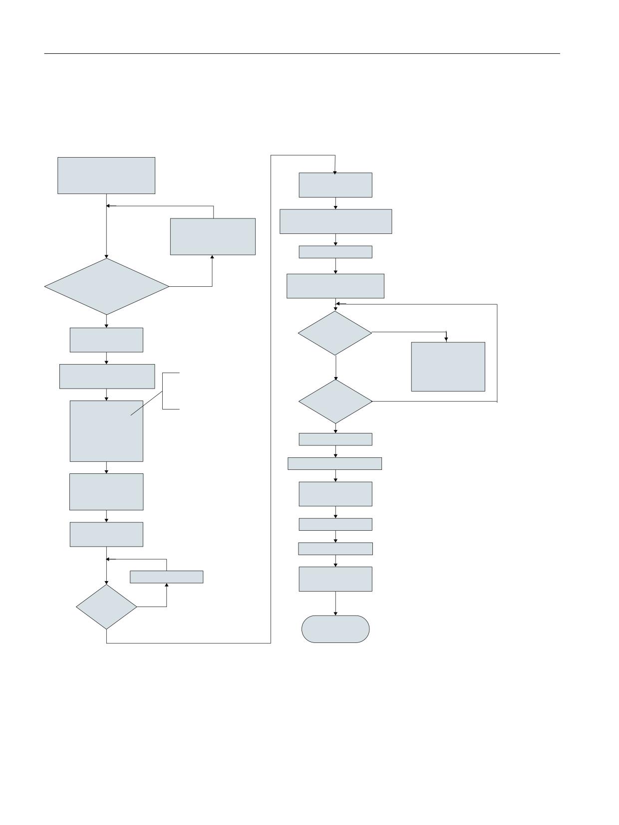
Automatic installation of the CNC software using USB-FlashDrive
Flow diagram
$XWRPDWLF LQVWDOODWLRQ RI
WKH &1& VRIWZDUH E\
86% IODVK GULYH
6,0 1&. !
3/& !
,QVHUW 86% IODVK GULYH LQWR
,QVWDOODWLRQ RI WKH 1&8
1&8 ;
VHUYLFH V\VWHP RQ 86%
IODVK GULYH
1&8 3RZHU 21
,V 86% IODVK GULYH DYDLODEOH
! 5'< /(' IODVKHV JUHHQ
ZLWK 1&8 VHUYLFH V\VWHP"
1R
DSSUR[ bV
<HV
2SHQ :LQGRZV
5'< /(' UHG"
([SORUHU
6HH HUURU FDXVH LQ
WKH DXWRH[HF ORJ ILOH
1R
H J &RPSDFW)ODVK
,QVHUW 86% IODVK GULYH LQWR
3DWK RQ GHOLYHU\ '9'
FDUG WRR VPDOO
3& 3*
?9ROBKPL VO?VWDQGDUG H[SRUW ?
HPHUJHQF\BERRWV\VBQFX?
1R
5'< /(' 2))"
VZBXSGDWH?DXWRH[HF VK
&RS\ DXWRH[HF VK
DQG FQF VZ!WJ] WR
<HV
86% IODVK GULYH URRW
1&8 3RZHU 2))
IROGHU
5HPRYH 86% IODVK GULYH
5HQDPH
6,0 1&. !
FQF VZ! WJ]
3/& !
WR IXOO WJ]
1&8 3RZHU 21
5HPRYH 86% IODVK
GULYH
3/& JHQHUDO UHVHW
6,0 1&. !
1&8 3RZHU 2))
3/& !
1&8
3RZHU 2))"
1R
(1'
Figure 12-1
Automatic installation using USB-FlashDrive
CNC Commissioning: NC, PLC, Drive
328
Commissioning Manual, 10/2020, A5E48312804B AB
New installation / upgrading
12.1 With the help of an NCU service system
12.1.1.2
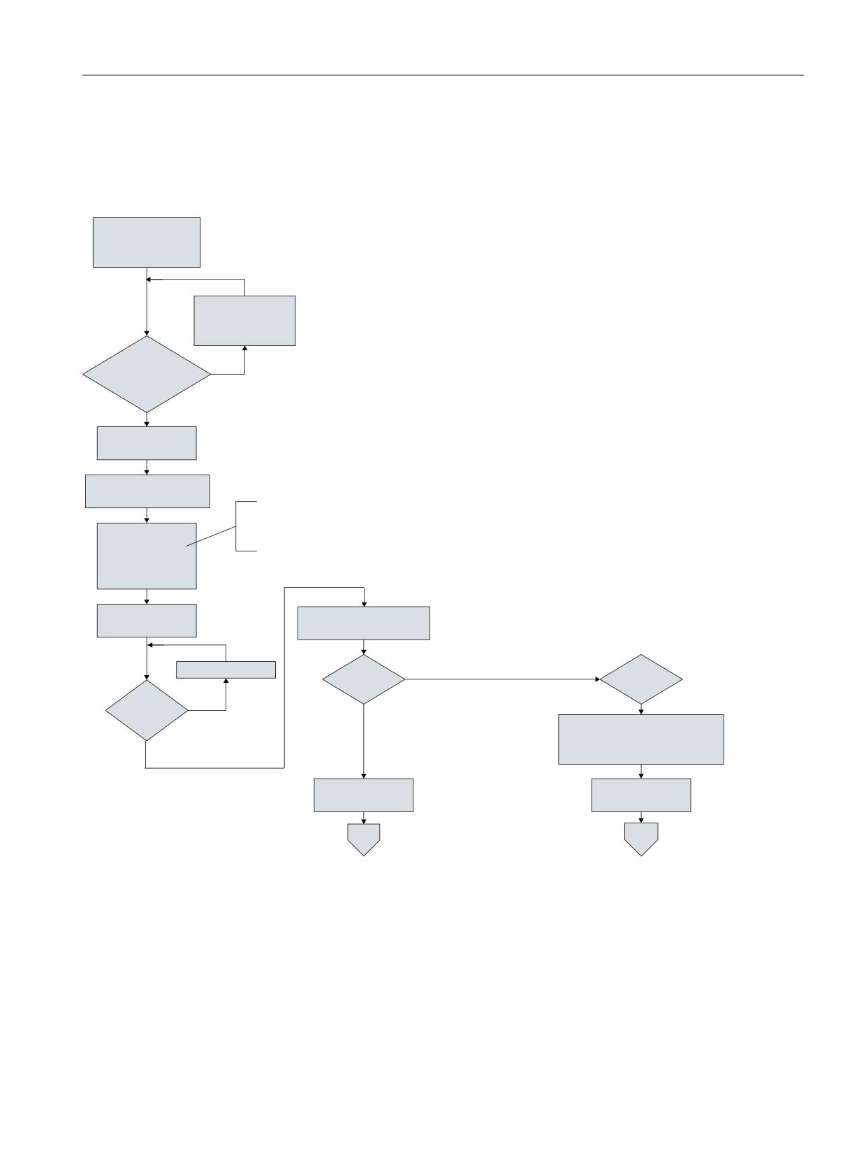
Installation of the CNC software using USB-FlashDrive
Flow diagram
,QVWDOODWLRQ RI WKH
&1& VRIWZDUH
XVLQJ 86% IODVK
GULYH
,QVWDOODWLRQ RI WKH
1&8 VHUYLFH V\VWHP
RQ 86% IODVK GULYH
86% IODVK GULYH
DYDLODEOH ZLWK 1&8
1R
VHUYLFH V\VWHP
2SHQ :LQGRZV
([SORUHU
,QVHUW 86% IODVK GULYH
LQWR 3& 3*
1RWLFH )LOH QDPH RI
FQF VZ!WJ] ORZHU FDVH
&RS\ FQF VZ!WJ]
RQO\
WR 86% IODVK GULYH
URRW IROGHU
5HPRYH 86% IODVK
,QVHUW 86% IODVK GULYH LQWR
GULYH
1&8 ;
1&8 3RZHU 2))
6\VWHP
6\VWHP 3&8"
7&8"
1R
1&8 3RZHU
1R
2))"
&RQQHFW WKH VWDQGDUG 3&
NH\ERDUG WR WKH 86% )URQW RI
3&8 RU 23[
6,0 1&. !
6,0 1&. !
3/& !
3/& !
Figure 12-2
Installing the control software using USB-FlashDrive
CNC Commissioning: NC, PLC, Drive
Commissioning Manual, 10/2020, A5E48312804B AB
329
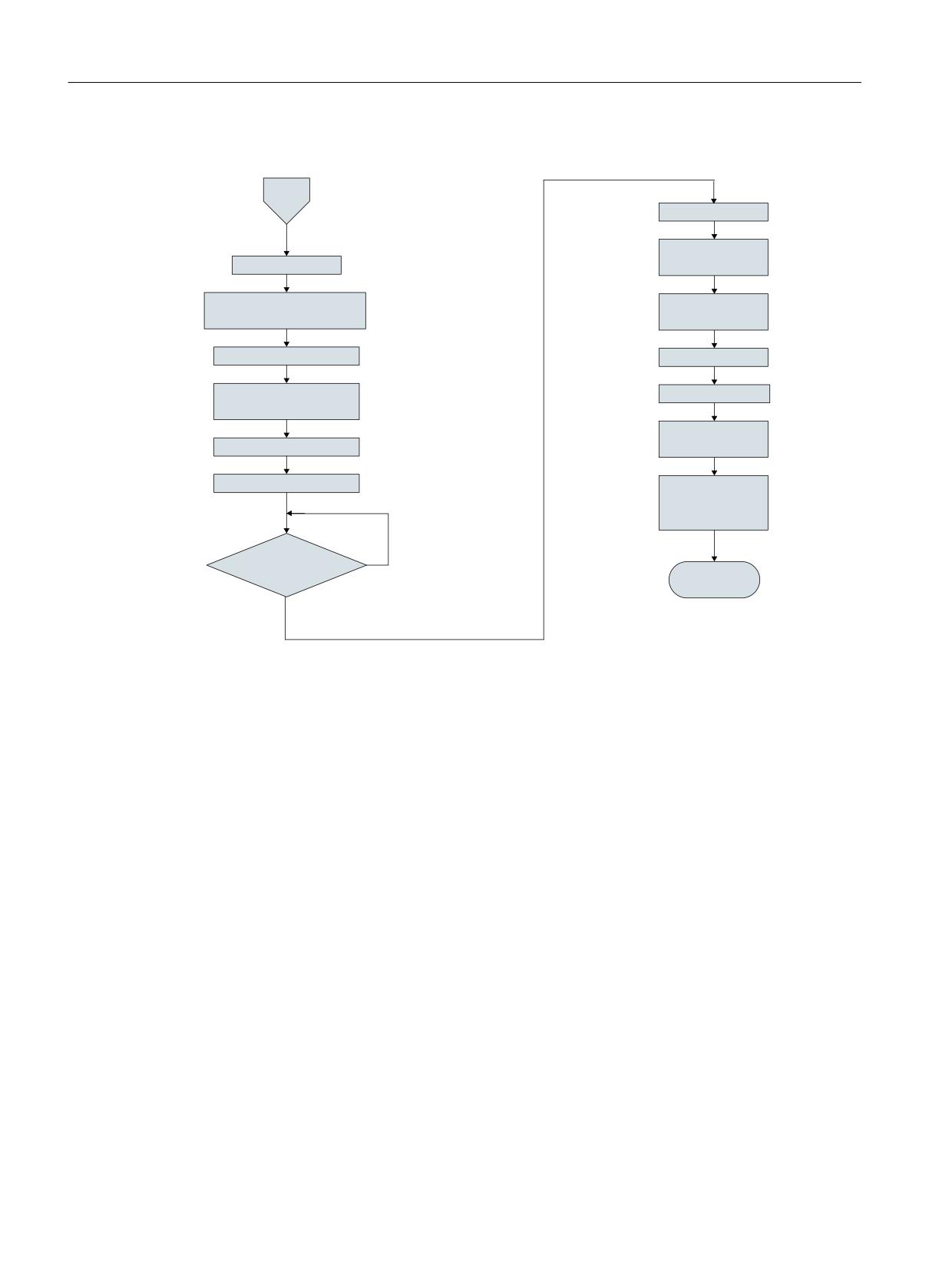
New installation / upgrading
12.1 With the help of an NCU service system
Flow diagram - installation of the system TCU (1) continued
1&8 3RZHU 2))
5HPRYH 86% IODVK
1&8 3RZHU 21
GULYH
0DLQ 0HQX
)
6,0 1&. !
5HVWRUH 1&8 6RIWZDUH
3/& !
) 5HFRYHU IURP 86%
1&8 3RZHU 21
) 5HFRYHU V\VWHP
3/& JHQHUDO UHVHW
IURP VHOHFWHG ILOH
6,0 1&. !
)
2. FRQWLQXH
3/& !
) WR FRQILUP
,QSXW 7&8 QDPH
,3 DGGUHVV
1R
'LVSOD\ 6\QFLQJ
GLVN GRQH "
(1'
Figure 12-3
Installing the control software using USB-FlashDrive - continued (TCU system)
CNC Commissioning: NC, PLC, Drive
330
Commissioning Manual, 10/2020, A5E48312804B AB
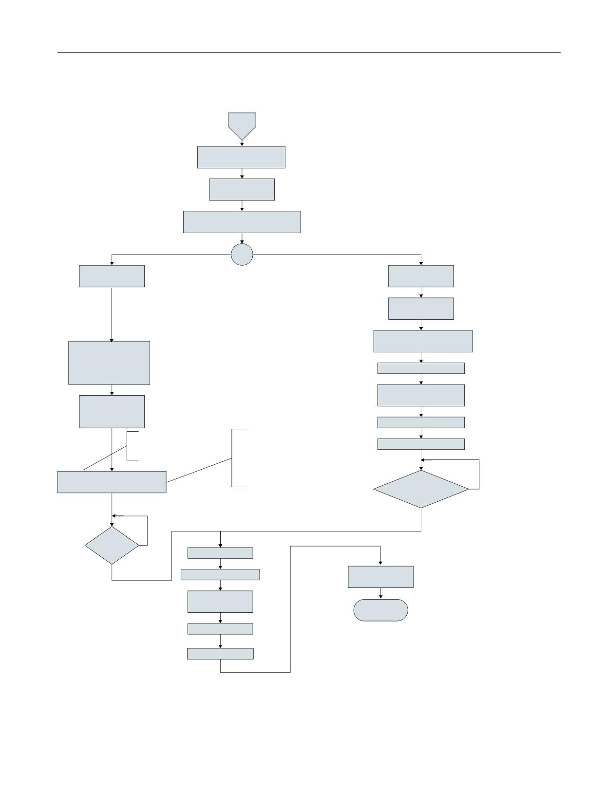
New installation / upgrading
12.1 With the help of an NCU service system
Flow diagram - installation of the system PCU (2) continued
&RQQHFW 3&8 ;[[[ !
1&8 ;
1&8 3&8
3RZHU 21
%RRW 3&8 LQ VHUYLFH PRGH :;3
NH\
! PDQXIDFWXUHU SDVVZRUG
6WDUW :LQ6&3
6WDUW 91& YLHZHU
GHVNWRS LFRQ
GHVNWRS LFRQ
&RQQHFW WR
0DLQ 0HQX
)
5HVWRUH 1&8 6RIWZDUH
/RJLQ WR
ZLWK XVHU DGPLQ
3DVVZRUG
6815,6(
) 5HFRYHU IURP 86%
) 5HFRYHU V\VWHP
IURP VHOHFWHG ILOH
0HQX &RPPDQGV
! 2SHQ WHUPLQDO
)
2. FRQWLQXH
3RVVLEOH HUURU
$Q\ GDWD RQ WKH &RPSDFW
)ODVK FDUG DUH GHOHWHG
VF (5525 XQNQRZQ RSWLRQ
) WR FRQILUP
IXOO GDWD FQF VZ! WJ]
&DXVH 6SDFH PLVVLQJ EHWZHHQ
,QSXW VF UHVWRUH IXOO
IXOO DQG GDWD
GDWD FQF VZ! WJ]
'LVSOD\ 6\QFLQJ GLVN
GRQH "
1R
SURPSW
UHDSSHDUV" 1R
1&8 3RZHU 2))
6,0 1&. !
5HPRYH 86% IODVK GULYH
3/& !
6,0 1&. !
3/& !
(1'
1&8 3RZHU 21
3/& JHQHUDO UHVHW
Figure 12-4
Installing the control software using USB-FlashDrive - continued (PCU system)
CNC Commissioning: NC, PLC, Drive
Commissioning Manual, 10/2020, A5E48312804B AB
331
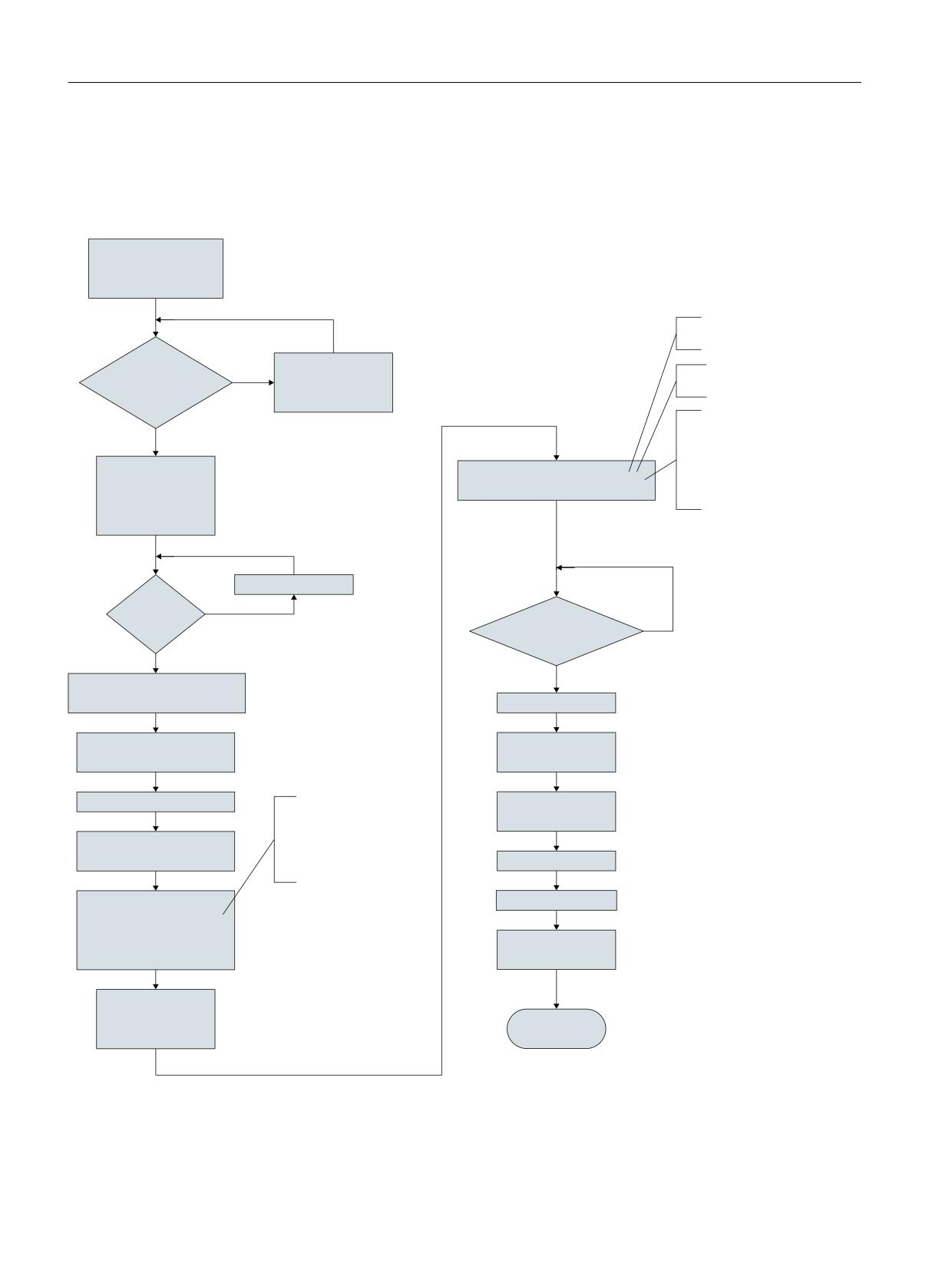
New installation / upgrading
12.1 With the help of an NCU service system
12.1.1.3
Installation of the CNC software using WinSCP on PC/PG
Flow diagram
,QVWDOODWLRQ RI WKH &1&
VRIWZDUH XVLQJ :LQ6&3
RQ 3& 3*
GDWD FRUUHVSRQGV WR WKH
86% IODVK GULYH RQ 1&8 ;
,QVWDOODWLRQ RI WKH
,V 86% IODVK GULYH
1&8 VHUYLFH V\VWHP
$Q\ GDWD RQ WKH &) FDUG DUH
DYDLODEOH ZLWK 1&8 VHUYLFH
GHOHWHG
1R
RQ 86% IODVK GULYH
V\VWHP"
3RVVLEOH HUURU 6F (5525
XQNQRZQ RSWLRQ
IXOO GDWD FQF VZ! WJ]
&RS\ FQF VZ! WJ] WR
,QSXW VF UHVWRUH IXOO GDWD FQF
&DXVH 6SDFH PLVVLQJ
86% IODVK GULYH URRW
VZ! WJ]
EHWZHHQ IXOO DQG GDWD
IROGHU
1&8 3RZHU 2))
1&8 3RZHU 2))"
1R
'LVSOD\ 6\QFLQJ GLVN
GRQH "
1R
,QVHUW 86% IODVK GULYH LQWR
1&8 ;
1&8 3RZHU 2))
&RQQHFW 1&8 ;
!
5HPRYH
3& 3*
86% IODVK GULYH
1&8 3:5 21
6,0 1&. !
,I D FRQQHFWLRQ LV QRW
3/& !
HVWDEOLVKHG GHDFWLYDWH DQG
WKHQ UHDFWLYDWH /RFDO $UHD
6WDUW :LQ6&3 RQ 3& 3*
&RQQHFWLRQ XQGHU 1HWZRUN
FRQQHFWLRQV
1&8 3RZHU 21
/RJLQ WR
3/& JHQHUDO UHVHW
ZLWK XVHU DGPLQ
SDVVZRUG
6815,6(
6,0 1&. !
3/& !
0HQX &RPPDQGV
!
2SHQ WHUPLQDO
(1'
Figure 12-5
Installation using WinSCP on PG/PC
CNC Commissioning: NC, PLC, Drive
332
Commissioning Manual, 10/2020, A5E48312804B AB
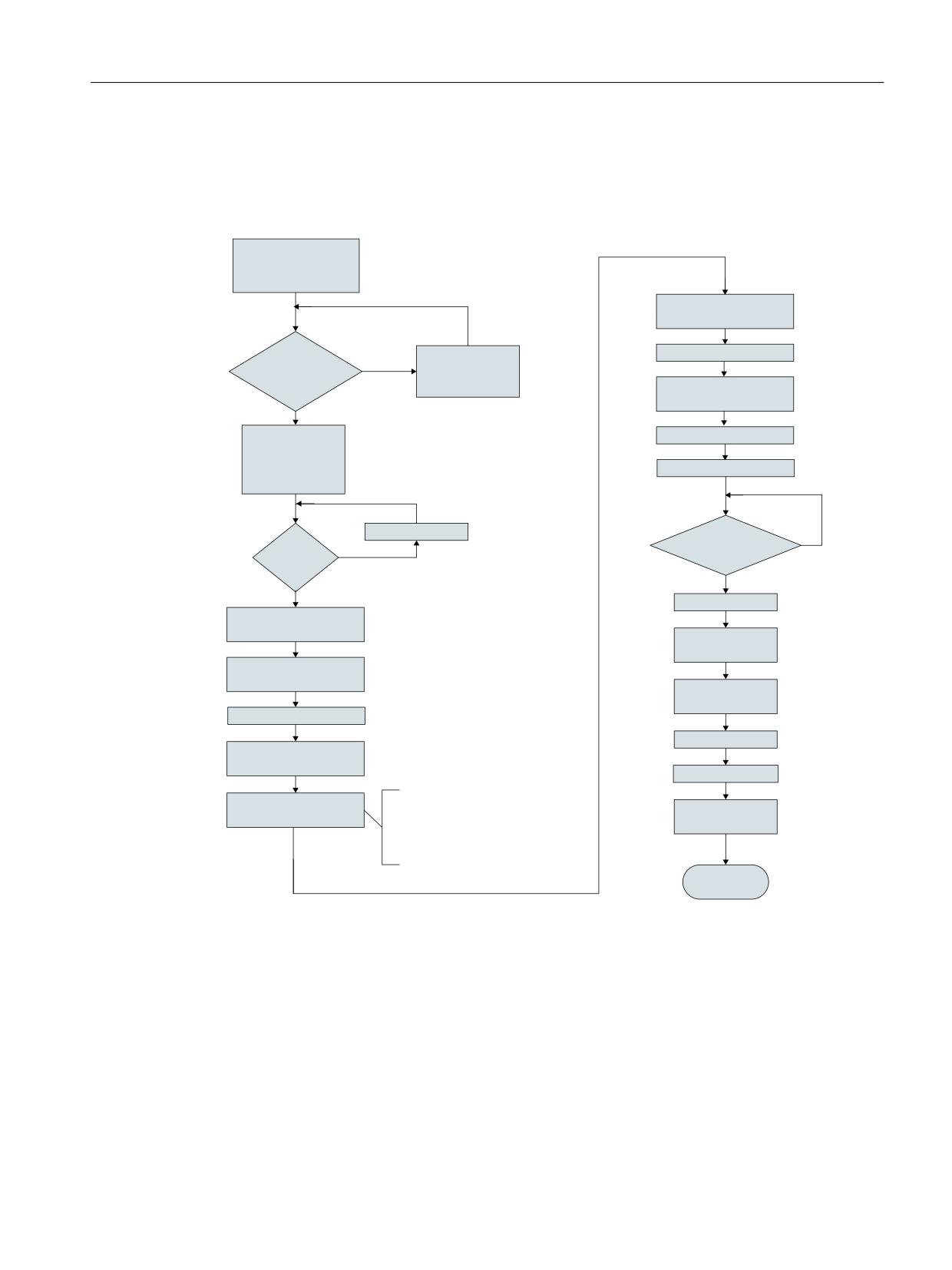
New installation / upgrading
12.1 With the help of an NCU service system
12.1.1.4
Installation of the CNC software using VNC Viewer on PC/PG
Flow diagram
,QVWDOODWLRQ RI WKH &1&
VRIWZDUH XVLQJ 91&
9LHZHU RQ 3& 3*
0DLQ 0HQX
)
5HVWRUH 1&8 6RIWZDUH
,QVWDOODWLRQ RI WKH
) 5HFRYHU IURP 86%
,V 86% IODVK GULYH
1&8 VHUYLFH V\VWHP
DYDLODEOH ZLWK 1&8
1R
RQ 86% IODVK GULYH
VHUYLFH V\VWHP"
) 5HFRYHU V\VWHP
IURP VHOHFWHG ILOH
&RS\ FQF VZ!WJ]
)
2. FRQWLQXH
WR 86% IODVK GULYH
URRW IROGHU
) WR FRQILUP
1&8 3RZHU 2))
'LVSOD\ 6\QFLQJ GLVN
1&8 3RZHU
GRQH "
1R
2))"
1R
1&8 3RZHU 2))
,QVHUW 86% IODVK GULYH
LQWR 1&8 ;
5HPRYH 86% IODVK
GULYH
&RQQHFW 1&8 ;
!
3& 3*
6,0 1& !
3/& !
1&8 3RZHU 21
1&8 3RZHU 21
6WDUW 91& 9LHZHU RQ
3& 3*
3/& JHQHUDO UHVHW
,I D FRQQHFWLRQ LV QRW HVWDEOLVKHG
91& VHUYHU LQSXW
6,0 1& !
GHDFWLYDWH DQG WKHQ UHDFWLYDWH
3/& !
/RFDO $UHD &RQQHFWLRQ XQGHU
1HWZRUN FRQQHFWLRQV
(1'
Figure 12-6
Installation using VNC Viewer on PG/PC
CNC Commissioning: NC, PLC, Drive
Commissioning Manual, 10/2020, A5E48312804B AB
333
New installation / upgrading
12.1 With the help of an NCU service system
12.1.2
Upgrading
Upgrade options
You have the following options of upgrading the CNC software:
• Automatic upgrade using USB-FlashDrive
• Upgrade using USB-FlashDrive
• Upgrade using WinSCP on PG/PC
• Upgrade using VNC Viewer on PG/PC
Note
An upgrade is possible as of CNC software 2.xx. An upgrade from other software versions is
not permitted. In this case, a new installation is required.
Before the upgrade, you can backup the complete CompactFlash card. Using Restore, you can
write back this backup to the CompactFlash card.
Data backup before upgrades
Carry out a data backup before each upgrade:
• Commissioning archive of NC/PLC/drive data
• Load the PLC project into the PC/PG (STEP 7)
• License key
When the software is upgraded, all user data is kept on the CompactFlash card in the directories /
user, /addon, /oem. The license key is kept as well.
Prior to overwriting a licensed CompactFlash card, a backup of the license key is absolutely
necessary. The key is available in file ‘keys.txt’ and is stored under the path keys/sinumerik. The
backup of the key can be performed, for example, with WinSCP, from the PG/PC.
Note
The licenses are permanently assigned to the CompactFlash card (card ID) and can only be used
on this card.
The license key can be read back via Web License Manager (Page 41) using the card number.
Automatic upgrading
For an automatic upgrade with autoexec.sh from the USB-FlashDrive, the CompactFlash card is
first backed up.
The backup file "card_img.tgz" is saved under the following directory:
/machines/[machine name+serial number of the CompactflashCard]
CNC Commissioning: NC, PLC, Drive
334
Commissioning Manual, 10/2020, A5E48312804B AB
New installation / upgrading
12.1 With the help of an NCU service system
An existing data backup is not overwritten. In this case, the operation is exited with an error. The
upgrade is made once the backup has been successfully completed.
12.1.2.1
Backup/Restore
Introduction
Before the upgrade, you can backup the complete CompactFlash Card. Using Restore, you can
write back this backup to the CompactFlash Card.
CNC Commissioning: NC, PLC, Drive
Commissioning Manual, 10/2020, A5E48312804B AB
335
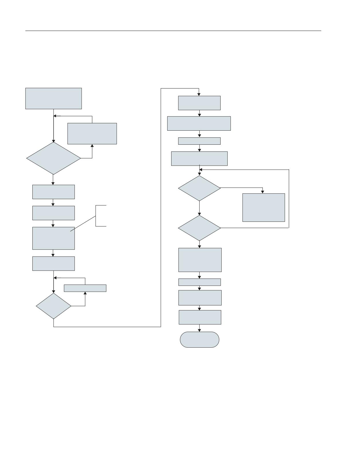
New installation / upgrading
12.1 With the help of an NCU service system
Automatic backup of the complete CompactFlash Card
Flow diagram
$XWRPDWLF EDFNXS RI
WKH FRPSOHWH
6,0 1&. !
&RPSDFW)ODVK &DUG
3/& !
,QVHUW 86% )ODVK'ULYH LQ 1&8
;
,QVWDOODWLRQ RI WKH 1&8
VHUYLFH V\VWHP RQ WKH
86% )ODVK'ULYH
1&8 3RZHU 21
86% )ODVK'ULYH ZLWK
! 5'< /(' IODVKHV JUHHQ
1&8 VHUYLFH V\VWHP
!
1R
DSSUR[ VHFRQGV
DYDLODEOH"
<HV
2SHQ :LQGRZV
5'< /(' UHG"
([SORUHU
6HH HUURU FDXVH LQ
WKH DXWRH[HF ORJ ILOH
1R
H J &RPSDFW)ODVK
,QVHUW 86% )ODVK'ULYH LQ
3DWK RQ GHOLYHU\ '9'
3& 3*
?9ROBKPL VO?VWDQGDUG H[SRUW
&DUG WRR VPDOO
?HPHUJHQF\BERRWV\VBQFX?VZB
XSGDWH?DXWRH[HF VK
1R
5'< /(' 2))"
&RS\ DXWRH[HF VK WR
86% )ODVK'ULYH URRW
GLUHFWRU\
<HV
FDUGBLPJ WJ]
EDFNXS ILOH FUHDWHG
5HPRYH 86%
RQ 86% )ODVK'ULYH
)ODVK'ULYH
1&8 3RZHU 2))
1&8 3RZHU 2))
5HPRYH 86%
1&8
)ODVK'ULYH
3RZHU
1R
2))"
6,0 1&. !
3/& !
(1'
Figure 12-7
Automatic backup of the complete CompactFlash Card
CNC Commissioning: NC, PLC, Drive
336
Commissioning Manual, 10/2020, A5E48312804B AB
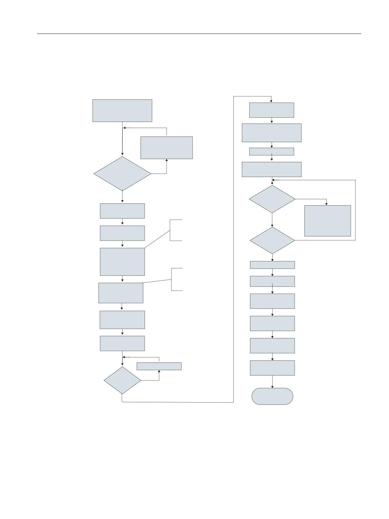
New installation / upgrading
12.1 With the help of an NCU service system
Automatic restoration of the complete CompactFlash Card
Flow diagram
$XWRPDWLF UHVWRUDWLRQ
6,0 1&. !
RI WKH FRPSOHWH
3/& !
&RPSDFW)ODVK &DUG
,QVHUW 86% )ODVK'ULYH LQ
1&8 ;
,QVWDOODWLRQ RI WKH
1&8 VHUYLFH
V\VWHP RQ WKH 86%
1&8 3RZHU 21
)ODVK'ULYH
! 5'< /(' IODVKHV
JUHHQ DSSUR[
86% )ODVK'ULYH ZLWK 1&8
VHFRQGV
VHUYLFH V\VWHP ERRWVWLFN
1R
DYDLODEOH"
<HV
5'< /(' UHG"
2SHQ :LQGRZV
6HH HUURU FDXVH LQ
([SORUHU
WKH DXWRH[HF ORJ ILOH
1R
H J &RPSDFW)ODVK
3DWK RQ GHOLYHU\ '9'
&DUG WRR VPDOO
,QVHUW 86%
?9ROBKPL VO?VWDQGDUG
)ODVK'ULYH LQ
H[SRUW ?HPHUJHQF\BERRWV\VB
3& 3*
QFX?VZBXSGDWH?DXWRH[HF VK
5'< /(' 2))"
1R
&RS\ DXWRH[HF VK
WR 86% )ODVK'ULYH
<HV
URRW GLUHFWRU\
1&8 3RZHU 2))
FDUGBLPJ WJ] LV WKH EDFNXS
ILOH FUHDWHG ZLWK %DFNXS
5HPRYH 86%
&RS\ FDUGBLPJBWJ]
&RPSDFW)ODVK &DUG
)ODVK'ULYH
WR 86% )ODVK'ULYH
URRW GLUHFWRU\
6,0 1&. !
3/& !
5HQDPH
FDUGBLPJ WJ] DV
3/& JHQHUDO UHVHW
IXOO WJ]
5HPRYH 86%
/RDG 1& 3/& GULYH
)ODVK'ULYH
DUFKLYH
6,0 1&. !
1&8 3RZHU 2))
3/& !
1&8 3RZHU
1R
2))"
(1'
Figure 12-8
Automatic restoration of the complete CompactFlash Card
CNC Commissioning: NC, PLC, Drive
Commissioning Manual, 10/2020, A5E48312804B AB
337
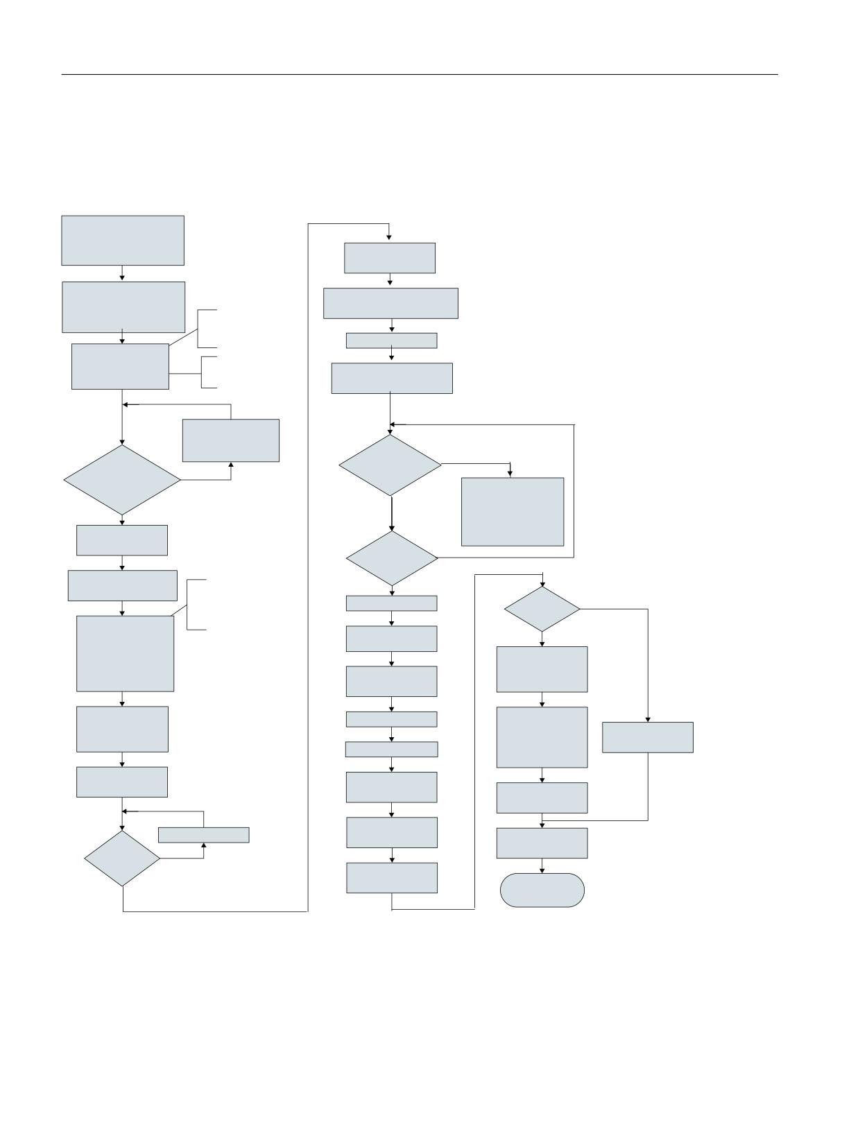
New installation / upgrading
12.1 With the help of an NCU service system
12.1.2.2
Automatic upgrade of the CNC software using USB-FlashDrive
Flow diagram
$XWRPDWLF XSJUDGH RI WKH
&1& VRIWZDUH XVLQJ 86%
IODVK GULYH
6,0 1& ැ
3/& ැ
&UHDWH 1& 3/& GULYH
,QVHUW 86% IODVK GULYH
DUFKLYH RQ &RPSDFW)ODVK
LQWR 1&8 ;
FDUG DQG RU 86% IODVK
YLD SDWFK FDEOH 5-
GULYH
WR 1&8 ;
,3
1&8 3RZHU 21
/RDG 3/& SURMHFW WR
3& 3* 67(3
2QO\ LI QHZ 7RROER[
QHFHVVDU\
5'< /(' IODVKHV
JUHHQ DSSUR[ bV
QVWDOODWLRQ RI WKH 1&8
VHUYLFH V\VWHP RQ
86% IODVK GULYH
<HV
5'< /(' UHG"
,V 86% IODVK GULYH
DYDLODEOH ZLWK 1&8
1R
(UURU FDXVH LQ WKH
VHUYLFH V\VWHP"
DXWRH[HF ORJ ILOH H J
1R
&RPSDFW)ODVK FDUG
WRR VPDOO
2SHQ :LQGRZV
([SORUHU
5'< /(' 2))"
1R
,QVHUW 86% IODVK GULYH
3DWK RQ GHOLYHU\ '9'
LQWR 3& 3*
9ROBKPL VO?VWDQGDUG
1&8 3RZHU 2))
?HPHUJHQF\BERRWV\VBQFX?
1HZ 7RROER["
1R
VZBXSGDWH?DXWRH[HF VK
&RS\ DXWRH[HF VK
5HPRYH 86% IODVK
DQG FQF VZ!WJ] WR
GULYH
86% IODVK GULYH URRW
2SHQ 67(3
3/&
IROGHU
SURMHFW 7RROER[
6,0 1& ැ
ES [ B[[
3/& ැ
5HQDPH
1&8 3RZHU 21
&RS\ QHZ EORFNV
QFX VZ! WJ] DV
IURP 7RROER[
/RDG 3/& DUFKLYH
XSGDWH WJ]
ES [ B[[ WR WKH
3/& JHQHUDO UHVHW
3/& SURMHFW
5HPRYH 86% IODVK
6,0 1& ැ
GULYH
3/& ැ
/RDG 3/& SURMHFW
6HW SDVVZRUG
1&8 3RZHU 2))
/RDG GULYH DUFKLYH
1&8 3RZHU
2))"
1R
/RDG 1& DUFKLYH
(1'
Figure 12-9
Automatic upgrade of the CNC software using USB-FlashDrive
CNC Commissioning: NC, PLC, Drive
338
Commissioning Manual, 10/2020, A5E48312804B AB
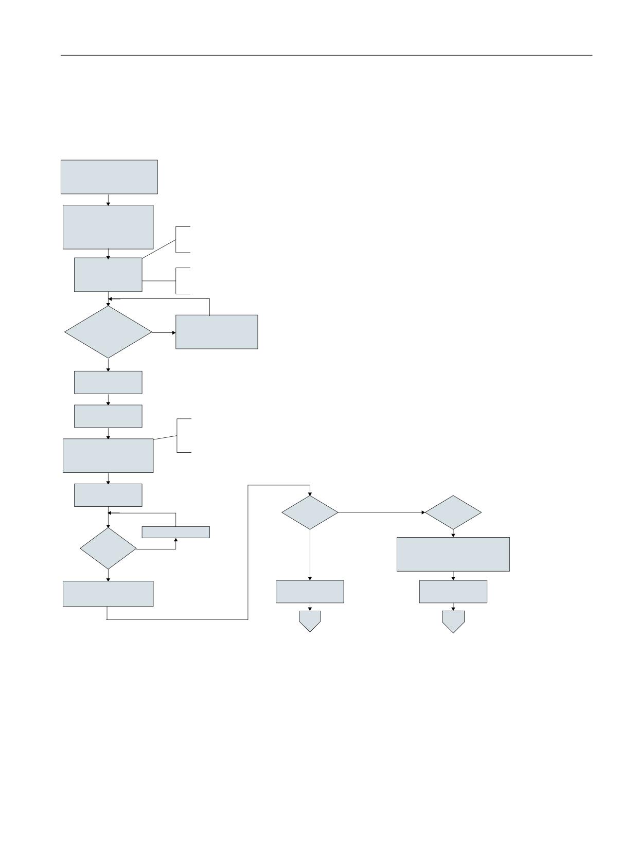
New installation / upgrading
12.1 With the help of an NCU service system
12.1.2.3
Upgrading the CNC software using USB-FlashDrive
Flow diagram
8SJUDGH WKH &1&
VRIWZDUH ZLWK D 86%
IODVK GULYH
&UHDWH 1&
3/& GULYH
DUFKLYH RQ &RPSDFW)ODVK
FDUG 3&8 DQG RU 86%
YLD SDWFK FDEOH 5-
WR 1&8
IODVK GULYH
;
,3
/RDG 3/& SURMHFW
2QO\ LI QHZ 7RROER[
WR 3& 3* 67(3
QHFHVVDU\
,QVWDOODWLRQ RI WKH 1&8
,V 86% IODVK GULYH
VHUYLFH V\VWHP RQ 86%
DYDLODEOH ZLWK 1&8
1R
IODVK GULYH
VHUYLFH V\VWHP"
2SHQ :LQGRZV
([SORUHU
,QVHUW 86% IODVK
GULYH LQWR 3& 3*
1RWLFH )LOH QDPH RI FQF VZ!WJ]
ORZHU FDVH RQO\
&RS\ FQF VZ!WJ] WR
86% IODVK GULYH URRW
IROGHU
5HPRYH 86% IODVK
GULYH
6\VWHP 7&8"
6\VWHP 3&8"
1R
1&8 3RZHU 2))
1&8 3RZHU
&RQQHFW WKH VWDQGDUG 3&
2))"
1R
NH\ERDUG WR WKH 86% )URQW RI
3&8 RU 23[
,QVHUW 86% IODVK GULYH LQWR
6,0 1&. ැ
6,0 1&. ැ
1&8 ;
3/& ැ
3/& ැ
Figure 12-10
Upgrading the CNC software using USB-FlashDrive
CNC Commissioning: NC, PLC, Drive
Commissioning Manual, 10/2020, A5E48312804B AB
339
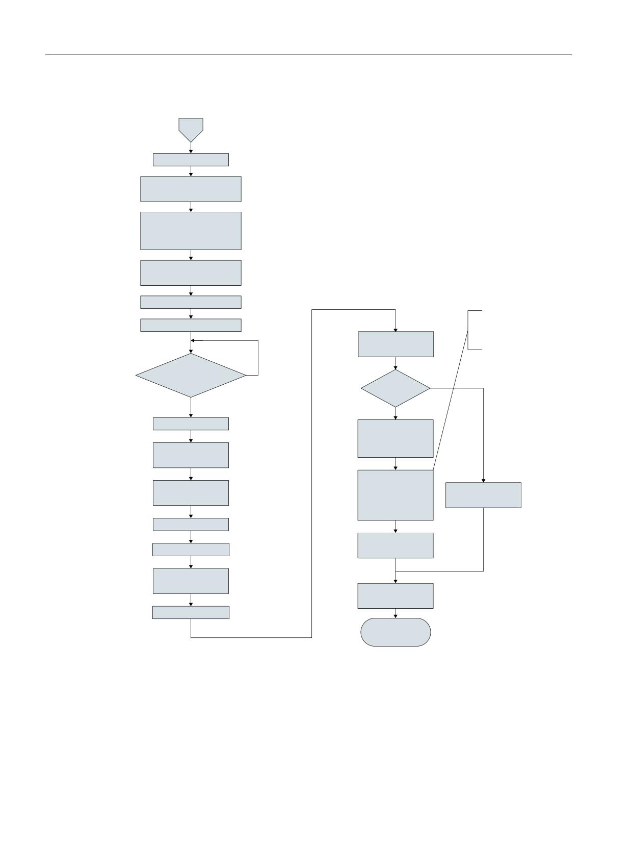
New installation / upgrading
12.1 With the help of an NCU service system
Flow diagram - continued system TCU (1)
1&8 3RZHU 21
0DLQ 0HQX
) 8SGDWH
1&8 6RIWZDUH
) 8SGDWH V\VWHP
VRIWZDUH IURP 86%
PHPRU\ VWLFN
) 8SGDWH V\VWHP
VRIWZDUH E\ VHOHFWHG ILOH
)
2. FRQWLQXH
1RWLFH 'R QRW RYHUZULWH
) WR FRQILUP
EORFNV ZLWK XVHU SURJUDP
H J 2%
2%
HWF
/RDG 1& DUFKLYH
'LVSOD\ 6\QFLQJ GLVN
1R
GRQH "
1HZ 7RROER["
1R
1&8 3RZHU 2))
2SHQ 67(3
3/&
SURMHFW 7RROER[
ES [ B[[
5HPRYH 86% IODVK
GULYH
&RS\ QHZ 7RROER[
6,0 1&. !
ES [ B[[ EORFNV WR
/RDG 3/& DUFKLYH
3/& !
WKH 3/& SURMHFW
1&8 3RZHU 21
/RDG 3/& SURMHFW
3/& JHQHUDO UHVHW
6,0 1&. !
3/& !
/RDG GULYH DUFKLYH
6HW SDVVZRUG
(1'
Figure 12-11
Upgrading the CNC software using USB-FlashDrive - continued (TCU system)
CNC Commissioning: NC, PLC, Drive
340
Commissioning Manual, 10/2020, A5E48312804B AB
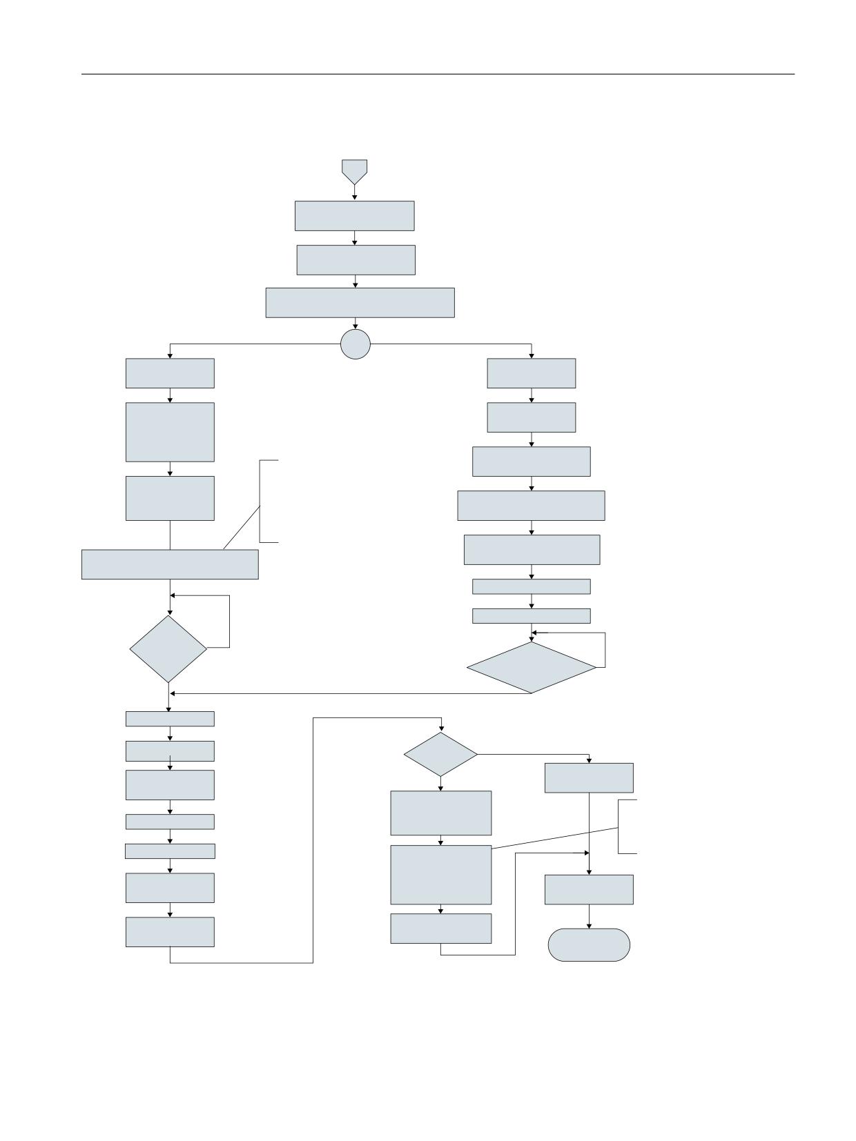
New installation / upgrading
12.1 With the help of an NCU service system
Flow diagram - continued PCU system (2)
&RQQHFW
3&8 ;[[[ ! 1&8 ;
1&8 3&8 ;
3RZHU
21
%RRW 3&8 LQ VHUYLFH PRGH :LQGRZV ;3
NH\
! PDQXIDFWXUHU SDVVZRUG
6WDUW :LQ6&3
6WDUW 91& YLHZHU
GHVNWRS LFRQ
GHVNWRS LFRQ
/RJLQ WR
&RQQHFW WR
ZLWK XVHU
PDQXIDFW 3:
6815,6(
0DLQ 0HQX
)
3RVVLEOH HUURU VF (5525
8SGDWH 1&8 6RIWZDUH
XQNQRZQ RSWLRQ
0HQX &RPPDQGV
XSGDWH GDWD FQF VZ! WJ]
! 2SHQ WHUPLQDO
) 8SGDWH V\VWHP VRIWZDUH
&DXVH 6SDFH PLVVLQJ
IURP 86% PHPRU\ VWLFN
EHWZHHQ XSGDWH DQG GDWD
) 8SGDWH V\VWHP
VRIWZDUH E\ VHOHFWHG ILOH
,QSXW VF UHVWRUH XSGDWH
GDWD FQF VZ! WJ]
)
2. FRQWLQXH
) WR FRQILUP
SURPSW
UHDSSHDUV"
1R
'LVSOD\ 6\QFLQJ GLVN
GRQH "
1R
1&8 3RZHU 2))
5HPRYH 86% IODVK
1R
GULYH
1HZ 7RROER["
/RDG 3/& DUFKLYH
6,0 1&. !
3/& !
2SHQ 67(3
1RWLFH 'R QRW RYHUZULWH
3/& SURMHFW
1&8 3RZHU 21
EORFNV ZLWK XVHU SURJUDP
7RROER[ ES [ B[[
H J 2%
2%
HWF
3/& JHQHUDO UHVHW
&RS\ QHZ 7RROER[
ES [ B[[ EORFNV WR
WKH 3/& SURMHFW
6,0 1&. !
/RDG GULYH DUFKLYH
3/& !
/RDG 3/& SURMHFW
/RDGLQJ
1& DUFKLYH
(1'
Figure 12-12
Upgrading the CNC software using USB-FlashDrive - continued (PCU system)
CNC Commissioning: NC, PLC, Drive
Commissioning Manual, 10/2020, A5E48312804B AB
341
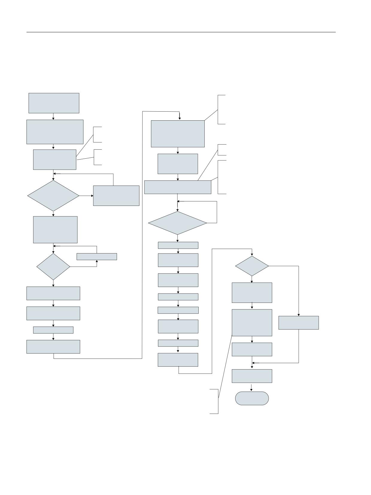
New installation / upgrading
12.1 With the help of an NCU service system
12.1.2.4
Upgrading the CNC software using WinSCP on PC/PG
Flow diagram
8SJUDGH WKH &1&
,I D FRQQHFWLRQ LV QRW HVWDEOLVKHG
VRIWZDUH XVLQJ
GHDFWLYDWH DQG WKHQ UHDFWLYDWH
:LQ6&3 RQ 3& 3*
/RFDO $UHD &RQQHFWLRQ XQGHU
1HWZRUN FRQQHFWLRQV
&UHDWH 1& 3/& GULYH
/RJLQ WR
DUFKLYH RQ &RPSDFW)ODVK
YLD SDWFK FDEOH
ZLWK XVHU DGPLQ
FDUG 3&8 DQG RU 86%
5-
WR 1&8 ;
SDVVZRUG 6815,6(
IODVK GULYH
,3
GDWD FRUUHVSRQGV WR WKH
/RDG 3/& SURMHFW
2QO\ LI QHZ 7RROER[
86% IODVK GULYH RQ 1&8 ;
WR 3& 3* 67(3
QHFHVVDU\
&RPPDQGV PHQX
86% IODVK GULYH
ැ 2SHQ WHUPLQDO
3RVVLEOH HUURU
VF (5525 XQNQRZQ RSWLRQ
XSGDWH GDWD FQF VZ! WJ]
&DXVH 6SDFH PLVVLQJ EHWZHHQ
,QSXW VF UHVWRUH XSGDWH
XSGDWH DQG GDWD
,QVWDOODWLRQ RI WKH
GDWD FQF VZ! WJ]
,V 86% IODVK GULYH
1&8 VHUYLFH V\VWHP
DYDLODEOH ZLWK 1&8
1R
RQ 86% IODVK GULYH
VHUYLFH V\VWHP"
&RS\ FQF VZ!WJ]
'LVSOD\ 6\QFLQJ
WR 86% IODVK GULYH
GLVN GRQH "
1R
URRW IROGHU
1&8 3RZHU 2))
1&8 3RZHU 2))
5HPRYH 86% IODVK
GULYH
1&8 3RZHU
1HZ 7RROER["
2))"
1R
1R
6,0 1&. ැ
3/& ැ
2SHQ 67(3
,QVHUW 86% IODVK GULYH
3/& SURMHFW
LQWR 1&8 ;
1&8 3RZHU 21
7RROER[ ES [ B[[
&RQQHFW 1&8 ;
3/& JHQHUDO UHVHW
3& 3*
&RS\ QHZ 7RROER[
ES [ B[[ EORFNV WR
/RDG 3/& DUFKLYH
6,0 1&. ැ
WKH 3/& SURMHFW
1&8 3RZHU 21
3/& ැ
6HW SDVVZRUG
6WDUW :LQ6&3 RQ 3& 3*
/RDG 3/& SURMHFW
/RDG 1& DUFKLYH
/RDG GULYH DUFKLYH
1RWLFH 'R QRW RYHUZULWH
EORFNV ZLWK XVHU SURJUDP
(1'
HJ 2%
2%
HWF
Figure 12-13
Upgrading the CNC software using WinSCP on PG/PC
CNC Commissioning: NC, PLC, Drive
342
Commissioning Manual, 10/2020, A5E48312804B AB
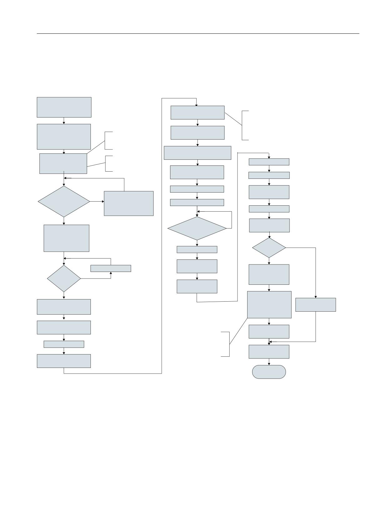
New installation / upgrading
12.1 With the help of an NCU service system
12.1.2.5
Upgrading the CNC software using VNC Viewer on PC/PG
Flow diagram
8SJUDGH WKH &1&
VRIWZDUH XVLQJ 91&
9LHZHU RQ 3& 3*
91& VHUYHU LQSXW
,I D FRQQHFWLRQ LV QRW HVWDEOLVKHG
GHDFWLYDWH DQG WKHQ UHDFWLYDWH
/RFDO $UHD &RQQHFWLRQ XQGHU
&UHDWH 1&
3/& GULYH
0DLQ PHQX
)
1HWZRUN FRQQHFWLRQV
DUFKLYH RQ &RPSDFW
YLD SDWFK FDEOH 5-
8SGDWH 1&8 VRIWZDUH
)ODVK FDUG &8 DQG RU
WR 1&8 ;
ZLWK
86% IODVK GULYH
,3
) 8SGDWH V\VWHP VRIWZDUH
/RDG 3/& SURMHFW
IURP 86% PHPRU\ VWLFN
2QO\ LI QHZ 7RROER[
67(3
WR 3& 3*
1&8 3RZHU 21
QHFHVVDU\
) 8SGDWH V\VWHP
VRIWZDUH E\ VHOHFWHG ILOH
3/& JHQHUDO UHVHW
)
2. FRQWLQXH
6,0 1& ැ
,V WKH 1&8 VHUYLFH
3/& ැ
,V 86% IODVK GULYH
V\VWHP LQVWDOOHG RQ
DYDLODEOH ZLWK 1&8
1R
) WR FRQILUP
86% IODVK GULYH"
VHUYLFH V\VWHP"
6HW SDVVZRUG
/RDG 1& DUFKLYH
&RS\ FQF VZ!WJ]
'LVSOD\ 6\QFLQJ
GLVN GRQH "
1R
WR 86% IODVK GULYH
URRW IROGHU
1HZ 7RROER["
1&8 3RZHU 2))
1R
5HPRYH 86% IODVK
1&8 3RZHU 2))
GULYH
2SHQ 3/& SURMHFW
67(3
7RROER[
1&8 3RZHU
ES [ B[[
2))"
1R
6,0 1& ැ
3/& ැ
&RS\ QHZ EORFNV
IURP 7RROER[
,QVHUW 86% IODVK GULYH
/RDG 3/& DUFKLYH
ES [ B[[ WR WKH 3/&
LQWR 1&8 ;
SURMHFW
&RQQHFW 1&8 ;
DQG 3& 3*
/RDG 3/& SURMHFW
1RWLFH 'R QRW RYHUZULWH
EORFNV ZLWK 3/& SURJUDP
1&8 3RZHU 21
HJ 2%
2%
HWF
/RDG GULYH DUFKLYH
6WDUW 91& 9LHZHU RQ
3& 3*
(1'
Figure 12-14
Upgrading the CNC software using VNC Viewer on PC/PG
CNC Commissioning: NC, PLC, Drive
Commissioning Manual, 10/2020, A5E48312804B AB
343
New installation / upgrading
12.2 With the help of the "Create MyConfig" software
12.2
With the help of the "Create MyConfig" software
Precondition
The "Create MyConfig" software on PG/PC is the precondition to configure a package.
Basic procedure
The descriptions for automatically reinstalling/upgrading using Create MyConfig include the
basic steps for configuring and subsequent automatic execution at the control system. The
"Create MyConfig" software has integrated online help.
12.2.1
Reinstallation with Create MyConfig
Preconditions
The following preconditions must be met for the CompactFlash card of the NCU:
• The CompactFlash card of the NCU is empty or contains executable NCU software.
If any CNC software and possibly irrelevant user data are on the CompactFlash card, then
these are lost when the software is newly installed.
• You have a <name>.tgz file (cnc-sw.tgz ) with the actual software.
• You want to initiate a new installation of the NCU via a USB FlashDrive.
• If the CompactFlash card is empty or does not contain executable CNC software, you need a
USB FlashDrive with installed "NCU Service System".
Operating sequence
In order to configure a package for the reinstallation of the CNC software with "Create MyConfig
Expert":
1. Start the "Create MyConfig Expert" software.
With this software you configure an Installer package that initiates a reinstallation from the
USB Flashdrive to the CompactFlash card of the NCU.
2. Create a new project via the menu "Project" > "New".
CNC Commissioning: NC, PLC, Drive
344
Commissioning Manual, 10/2020, A5E48312804B AB
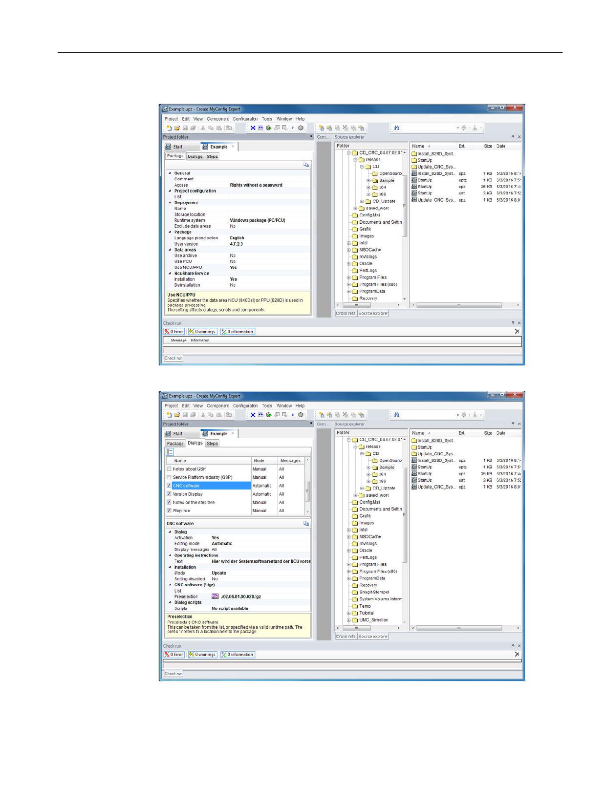
New installation / upgrading
12.2 With the help of the "Create MyConfig" software
3. Activate the "NCU" area under the "Package" tab.
4. Activate the "NCU software" window from the "Dialogs" tab.
CNC Commissioning: NC, PLC, Drive
Commissioning Manual, 10/2020, A5E48312804B AB
345
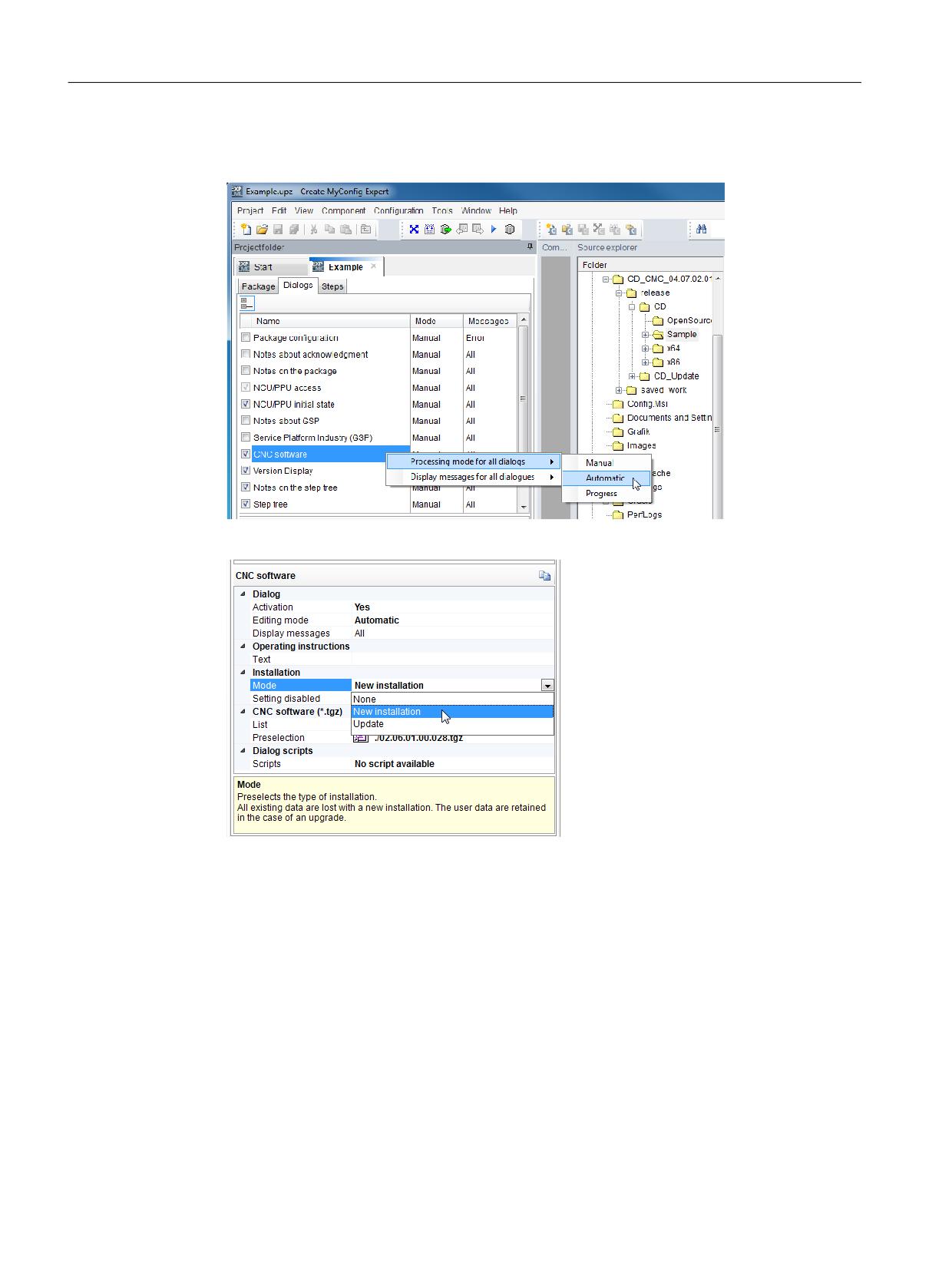
New installation / upgrading
12.2 With the help of the "Create MyConfig" software
5. In the context menu, select > right mouse button > "Edit mode for all dialog boxes" >
"Automatic".
6. In the "CNC software" window under "Installation", select the "New installation" mode.
7. For the file "<name>.tgz" you have the following options:
- The file is embedded in the project or linked to the project.
For the automatic reinstallation, insert the "<name>.tgz" file in the project under "CNC
software (*.tgz)". To do this, enter the name of the tgz file in the "Preselection" area.
- Copy the file to the USB FlashDrive in the root directory in which the package is stored
subsequently. The file is automatically selected while the package is running.
Enter the name with the prefix "./" <name>.tgz in the "Preselection" field under "CNC
software (*.tgz)":
CNC Commissioning: NC, PLC, Drive
346
Commissioning Manual, 10/2020, A5E48312804B AB
New installation / upgrading
12.2 With the help of the "Create MyConfig" software
8. Create a package "<name>.usz" via the menu "File" > "Transfer" > "Linux package (NCU) and
select as target path the root directory of the USB FlashDrive.
Create MyConfig Expert saves the project, performs a validation run, creates and saves the
package under the specified target path.
A "<name>.usz" package is then located in the root directory of the USB FlashDrive.
Depending on the configuration in the previous step, the "<name>.tgz" file is also located
next to the package.
Note
The USB FlashDrive must only be bootable if the CompactFlash card of the NCU does not
contain executable CNC system software.
9. Insert the USB FlashDrive into a USB socket (X125 or X135) of the NCU.
10.Switch the control system off and on again.
Provided that when configuring you configured the "Edit mode of all dialogs" > "Automatic",
then the package is automatically executed when the control system boots-up. The dialogs
are displayed, but require no operator actions.
The CNC software has been installed once the package has been completed.
A logbook about the activities that have been performed can be saved. The logbook
documents all activities performed during the new installation.
11.Switch-off the control system.
12.Remove the USB FlashDrive.
13.Commissioning work can continue after the control system has been switched on.
Optional additional functions for the installation of the CNC software
In the same package - after the CNC software has been installed - the following actions can be
optionally configured, which can either run completely automatically or conditionally at the
machine:
• Loading an SDB Archive
• SINAMICS device configuration
• Renaming DO, SINAMICS components and DO numbers
• Assignment of the drives to NC axes
• Manipulation of display machine data
• Manipulation of individual NC and drive data
• Loading the PLC program or from individual blocks
• Installing software
• Copying, deleting and manipulating files on the CompactFlash card
• Conditional execution of actions, executing, deleting, copying and manipulating
• Messages and interactions to the operator
CNC Commissioning: NC, PLC, Drive
Commissioning Manual, 10/2020, A5E48312804B AB
347
New installation / upgrading
12.2 With the help of the "Create MyConfig" software
12.2.2
Upgrade with Create MyConfig
Introduction
Note
For details on upgrading the CNC software versions, read the "siemensd.rtf" (German) or
"siemense.rtf" (English) file on the product CD of Create MyConfig.
When the software is upgraded, all user data is kept on the CompactFlash card and in the control
areas NC, PLC, and drives. The NC and drive data is automatically transferred into the new CNC
software version. Archives neither have to be created nor imported again.
The "NCK commissioning switch" and "PLC mode selector switch" remain during the upgrade in
position "0".
In conjunction with an upgrade, using the same package, the automatic generation of a backup
can be configured, which is then stored on the USB FlashDrive. It is not necessary to first generate
an archive.
Note
After the CNC software has been upgraded, adaptations may be required. Using the Create
MyConfig Expert, these adaptations can also be configured and therefore automatically
executed.
For information about the necessary adaptations, please refer to the upgrade instructions of the
respective CNC software versions.
Operating sequence
In order to configure a package for the upgrade of the CNC software with "Create MyConfig
Expert":
1. You have started the "Create MyConfig Expert" software.
Using this software, you configure a package that initiates an upgrade of the CNC software
on the CompactFlash card of the NCU.
2. You have created a new project via the menu "Project" > "New".
CNC Commissioning: NC, PLC, Drive
348
Commissioning Manual, 10/2020, A5E48312804B AB
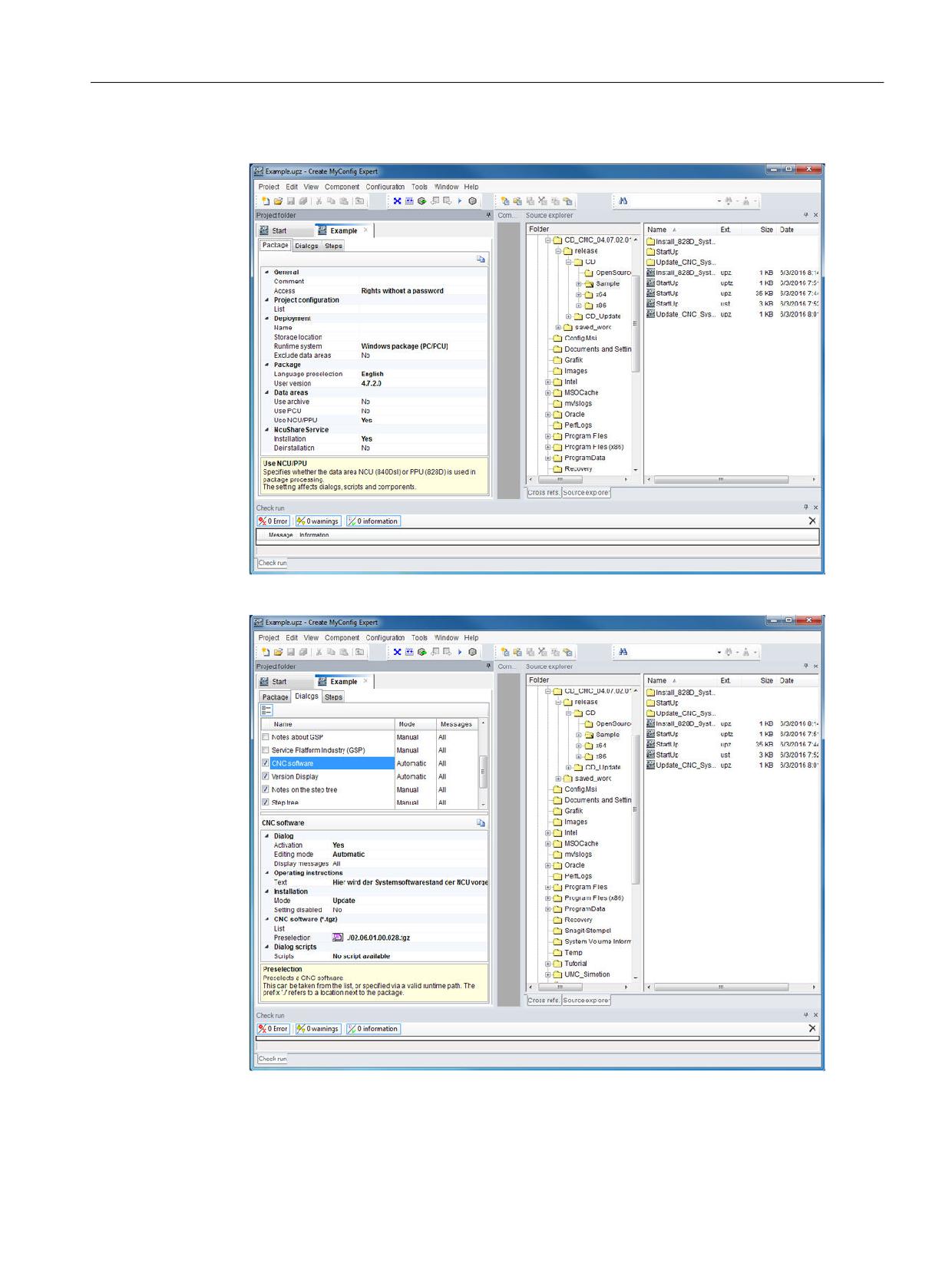
New installation / upgrading
12.2 With the help of the "Create MyConfig" software
3. Activate the "NCU" area under the "Package" tab.
4. Activate the "NCU software" window from the "Dialogs" tab.
CNC Commissioning: NC, PLC, Drive
Commissioning Manual, 10/2020, A5E48312804B AB
349
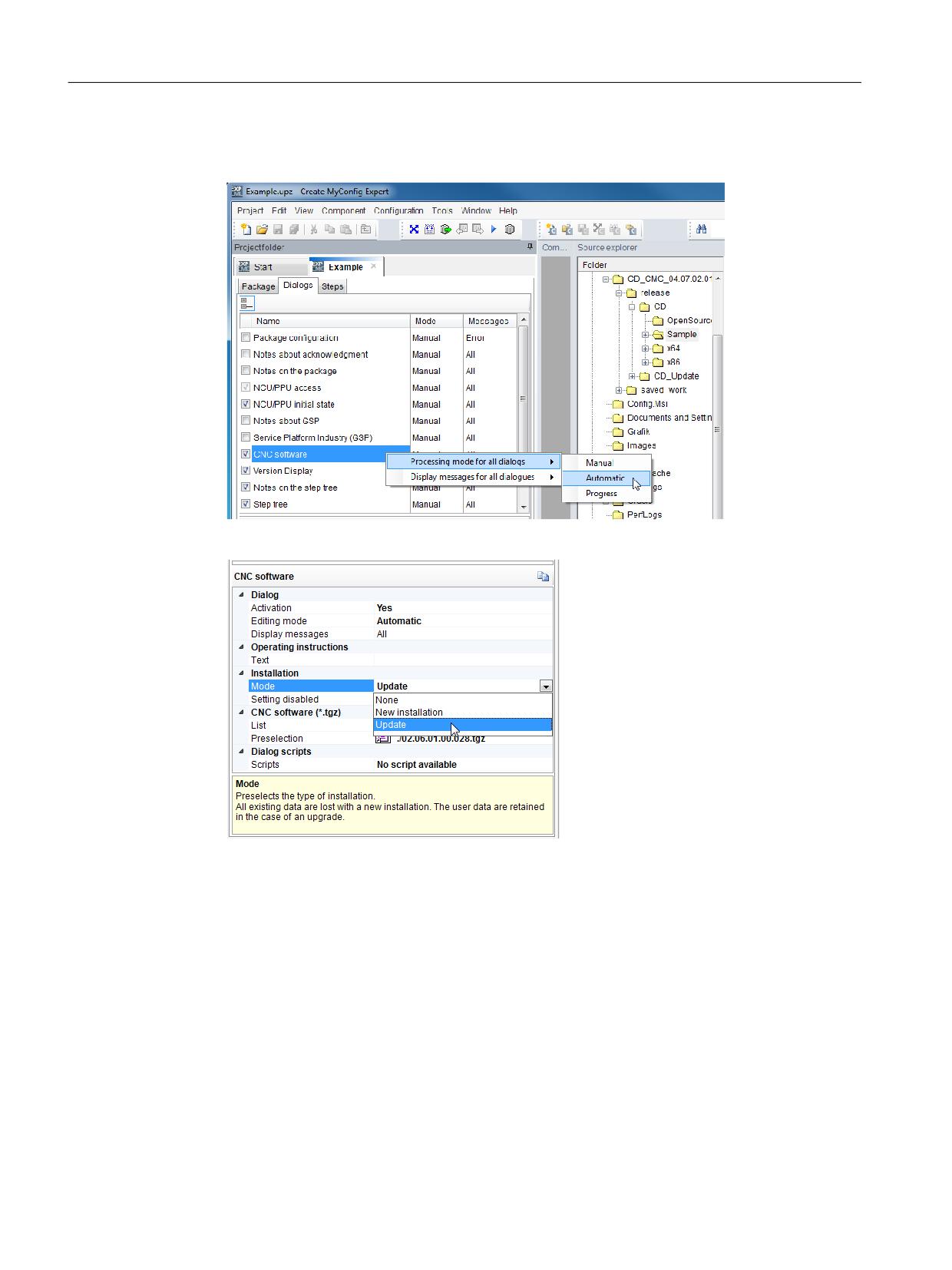
New installation / upgrading
12.2 With the help of the "Create MyConfig" software
5. In the context menu, select > right mouse button > "Edit mode for all dialog boxes" >
"Automatic".
6. In the "CNC software" window under "Installation", select the "Upgrade" mode.
7. For the <name>.tgz files you have the following options:
- The file is embedded in the project or linked to the project.
For the automatic reinstallation, insert the "<name>.tgz" file in the project under "CNC
software (*.tgz)". To do this, enter the name of the tgz file in the "Preselection" area.
- Copy the file to the USB FlashDrive in the root directory in which the package is stored
subsequently. The file is automatically selected while the package is running.
Enter the name with the prefix "./" <name>.tgz in the "Preselection" field under "CNC
software (*.tgz)":
CNC Commissioning: NC, PLC, Drive
350
Commissioning Manual, 10/2020, A5E48312804B AB
New installation / upgrading
12.2 With the help of the "Create MyConfig" software
8. Create a package "<name>.usz" via the menu "File" > "Transfer" > "Linux package (NCU) and
select as target path the root directory of the USB FlashDrive.
Create MyConfig Expert saves the project, performs a validation run, creates and saves the
package under the specified target path.
A "<name>.usz" package is then located in the root directory of the USB FlashDrive.
Depending on the configuration in the previous step, the "<name>.tgz" file is also located
next to the package.
9. Insert the USB FlashDrive into a USB socket (X125 or X135) of the NCU.
10.Switch the control system off and on again.
Provided that when configuring you configured the "Edit mode of all dialogs" → "Automatic",
then the package is automatically executed when the control system boots-up. The CNC
software has been upgraded and all data is available again after the package has been
completed on the NCU.
A logbook about the activities that have been performed can be saved. The logbook
documents all activities performed during the upgrade.
11.Switch-off the control system.
12.Remove the USB FlashDrive.
13.The machine is ready for operation again after switch-on.
Optional additional functions when upgrading the CNC software
In the same package - after the CNC software has been installed - the following actions can be
optionally configured, which can either run completely automatically or conditionally at the
machine:
• Manipulation of display machine data
• Manipulation of individual NC and drive data
• Loading the PLC program or from individual blocks
• Installing software
• Copying, deleting and manipulating files on the CompactFlash card
• Conditional execution of actions, executing, deleting, copying and manipulating
• Messages and interactions to the operator
CNC Commissioning: NC, PLC, Drive
Commissioning Manual, 10/2020, A5E48312804B AB
351
New installation / upgrading
12.2 With the help of the "Create MyConfig" software
CNC Commissioning: NC, PLC, Drive
352
Commissioning Manual, 10/2020, A5E48312804B AB

Appendix
A
A.1
Abbreviations
ACX
Compressed format for XML
ALM
Active Line Module
APC
Advanced Position Control (SINUMERIK option M13)
AUTO
AUTO mode: Continuous and automatic execution of programs
BERO
Proximity limit switch
BI
Binector Input
BICO
Binector Connector
BO
Binector Output
CI
Connector Input
CNC
Computerized Numerical Control:Computerized numerical control
CO
Connector Output
CoL
Certificate of License
CP
Communication Processor: Communications processor
CPU
Central Processing Unit:Central processing unit
CU
Contol Unit
DHCP
Dynamic Host Configuration Protocol: Protocol for automatic assignment of IP ad-
dresses from a DHCP server to a client computer.
DO
Drive Object: Drive object
DP
Distributed I/O
DRAM
Dynamic Random Access Memory
DRF
Differenzial Resolver Funktion: Differential function for rotary resolver
DRIVE-CLiQ
Drive Component Link with IQ
DSC
Dynamic Stiffness Control: Dynamic stiffness control
DWORD
Doubleword
ESD
Electrostatic Sensitive Device
EMC
Electro-Magnetic Compatibility
EN
European standard
EPos
Basic positioning (SINAMICS S120)
GECOS
General Electric Comprehensive Operating System: Information about the identity
of a user under Linux
GSD
Device master file
GUD
Global User Data
IPO
Interpolator
JOG
JOG mode: manual mode for setting up the machine
LAN
Local Area Network
LED
Light-Emitting Diode: Light-emitting-diode display
LUD
Local User Data
CNC Commissioning: NC, PLC, Drive
Commissioning Manual, 10/2020, A5E48312804B AB
353

Appendix
A.1 Abbreviations
MD
Machine Data
MDI
MDI mode (Manual Data Automatic): Enter program blocks manually and execute
MM
Motor Module
MCP
Machine Control Panel
NC
Numerical Control: Numerical control
PIO
Process Image Output
PII
Process Image Input
PCU
PC Unit: computer unit
PELV
Protective Extra Low Voltage
PG
Programming device
PLC
Programmable Logic Control: (component of the CNC)
PM
Power Module
PUD
Program global User Data
RAM
Random Access Memory: Program memory that can be read and written
REF POINT
Function for approaching the reference point in JOG mode.
REPOS
Function for repositioning in JOG mode
SD
Setting Data
SLM
Smart Line Module
SMC
Sensor Module Cabinet Mounted
SME
Sensor Module Externally Mounted
TEACH IN
Function for creating programs in interactive mode with the machine in MDI and
AUTO modes
TCU
Thin Client Unit
USB
Universal Serial Bus
XML
Extensible Markup Language
CNC Commissioning: NC, PLC, Drive
354
Commissioning Manual, 10/2020, A5E48312804B AB
Appendix
A.2 Information about third-party software used
A.2
Information about third-party software used
Printed in the United States of America.
All Rights Reserved.
This software product (LICENSED PRODUCT), implementing the Object Management Group's
"Internet Inter-ORB Protocol", is protected by copyright and is distributed under the following
license restricting its use. Portions of LICENSED PRODUCT may be protected by one or more U.S.
or foreign patents, or pending applications.
LICENSED PRODUCT is made available for your use provided that you include this license and
copyright notice on all media and documentation and the software program in which this
product is incorporated in whole or part. You may copy, modify, distribute, or sublicense the
LICENCED PRODUCT without charge as part of a product or software program developed by you,
so long as you preserve the functionality of interoperating with the Object Management Group's
"Internet Inter-ORB Protocol" version one. However, any uses other than the foregoing uses shall
require the express written consent of Sun Microsystems, Inc.
The names of Sun Microsystems, Inc. and any of its subsidiaries or affiliates may not be used in
advertising or publicity pertaining to distribution of the LICENSED PRODUCT as permitted herein.
This license is effective until terminated by Sun for failure to comply with this license. Upon
termination, you shall destroy or return all code and documentation for the LICENSED PRODUCT.
LICENSED PRODUCT IS PROVIDED AS IS WITH NO WARRANTIES OF ANY KIND INCLUDING THE
WARRANTIES OF DESIGN, MERCHANTIBILITY AND FITNESS FOR A PARTICULAR PURPOSE,
NONINFRINGEMENT, OR ARISING FROM A COURSE OF DEALING, USAGE OR TRADE PRACTICE.
LICENSED PRODUCT IS PROVIDED WITH NO SUPPORT AND WITHOUT ANY OBLIGATION ON THE
PART OF SUN OR ANY OF ITS SUBSIDIARIES OR AFFILIATES TO ASSIST IN ITS USE, CORRECTION,
MODIFICATION OR ENHANCEMENT. SUN OR ANY OF ITS SUBSIDIARIES OR AFFILIATES SHALL
HAVE NO LIABILITY WITH RESPECT TO THE INFRINGEMENT OF COPYRIGHTS, TRADE SECRETS OR
ANY PATENTS BY LICENSED PRODUCT OR ANY PART THEREOF.
IN NO EVENT WILL SUN OR ANY OF ITS SUBSIDIARIES OR AFFILIATES BE LIABLE FOR ANY LOST
REVENUE OR PROFITS OR OTHER SPECIAL, INDIRECT AND CONSEQUENTIAL DAMAGES, EVEN IF
SUN HAS BEEN ADVISED OF THE POSSIBILITY OF SUCH DAMAGES.
Use, duplication, or disclosure by the government is subject to restrictions as set forth in
subparagraph (c)(1)(ii) of the Rights in Technical Data and Computer Software clause at DFARS
252.227-7013 and FAR 52.227-19.
SunOS, SunSoft, Sun, Solaris, Sun Microsystems and the Sun logo are trademarks or registered
trademarks of Sun Microsystems, Inc.
SunSoft, Inc.
2550 Garcia Avenue
Mountain View, California 94043
Permission to use, copy, modify, and distribute this software for any purpose without fee is
hereby granted, provided that this entire notice is included in all copies of any software which
is or includes a copy or modification of this software and in all copies of the supporting
documentation for such software.
THIS SOFTWARE IS BEING PROVIDED "AS IS", WITHOUT ANY EXPRESS OR IMPLIED WARRANTY. IN
PARTICULAR, NEITHER THE AUTHOR NOR AT&T MAKES ANY REPRESENTATION OR WARRANTY OF
CNC Commissioning: NC, PLC, Drive
Commissioning Manual, 10/2020, A5E48312804B AB
355