SINUMERIK 840D sl. Service - Configuring Commissioning. Manual (2011-2020) - page 81
Commissioning NC-controlled drives
6.6 Diagnostics → Trace
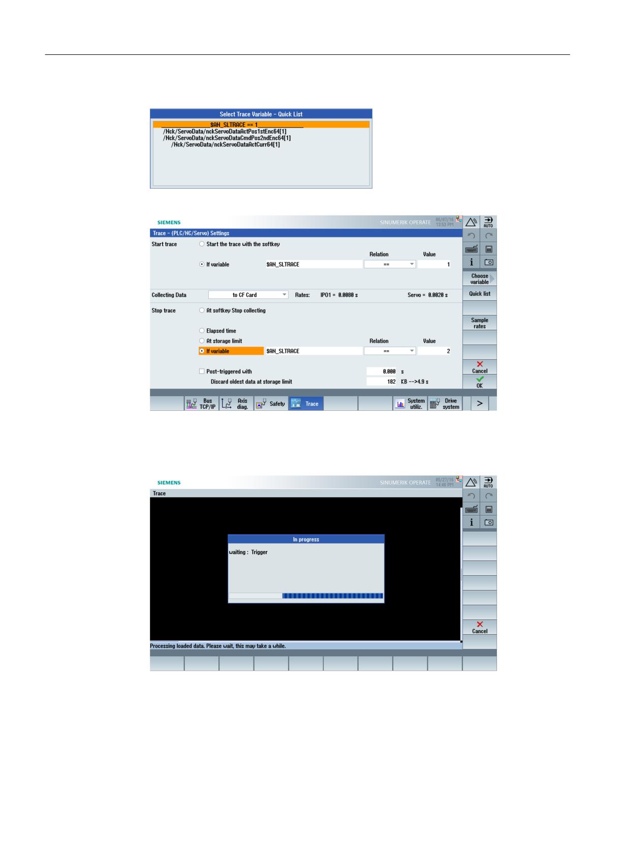
6. Softkey "Quick List" is activated. Select variable $AN_SLTRACE and acknowledge with "OK".
7. Matching the example, select "If variable" to stop the trace and acknowledge with "OK".
8. Select the "View trace >" softkey to open the trace view.
9. Select the "Start trace" softkey to activate the trace.
10.Execute the part program with "NC Start".
CNC Commissioning: NC, PLC, Drive
150
Commissioning Manual, 10/2020, A5E48312804B AB
Commissioning NC-controlled drives
6.6 Diagnostics → Trace
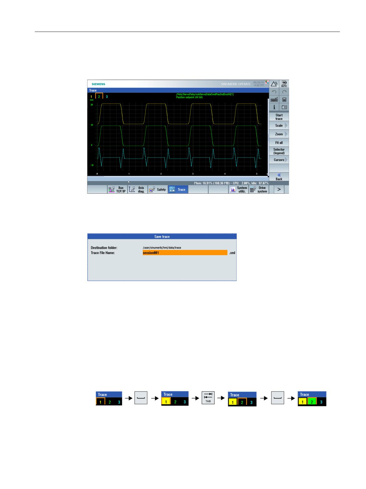
Trace result
The following graphic is displayed after the trace has been stopped:
Select the "≪ Back" softkey to save the session.
Select what you wish to save with the "Save trace >" softkey: Variables and settings with or
without recorded values (graphic).
The name of the session and target directory can be changed.
6.6.3
Example: Zooming in/zooming out
Trace view: Zoom
Procedure:
1. Select the "Fit all" softkey to scale all of the curves.
2. Press the following keys to select curve 1 (position actual value measuring system 1) and
curve 2 (position setpoint) for the next steps:
3. Select the "Zoom >" softkey.
4. Select the "Fit overlaid" softkey to precisely place both curves one above the other. Each curve
is individually scaled using the "Fit separated".
CNC Commissioning: NC, PLC, Drive
Commissioning Manual, 10/2020, A5E48312804B AB
151
Commissioning NC-controlled drives
6.6 Diagnostics → Trace
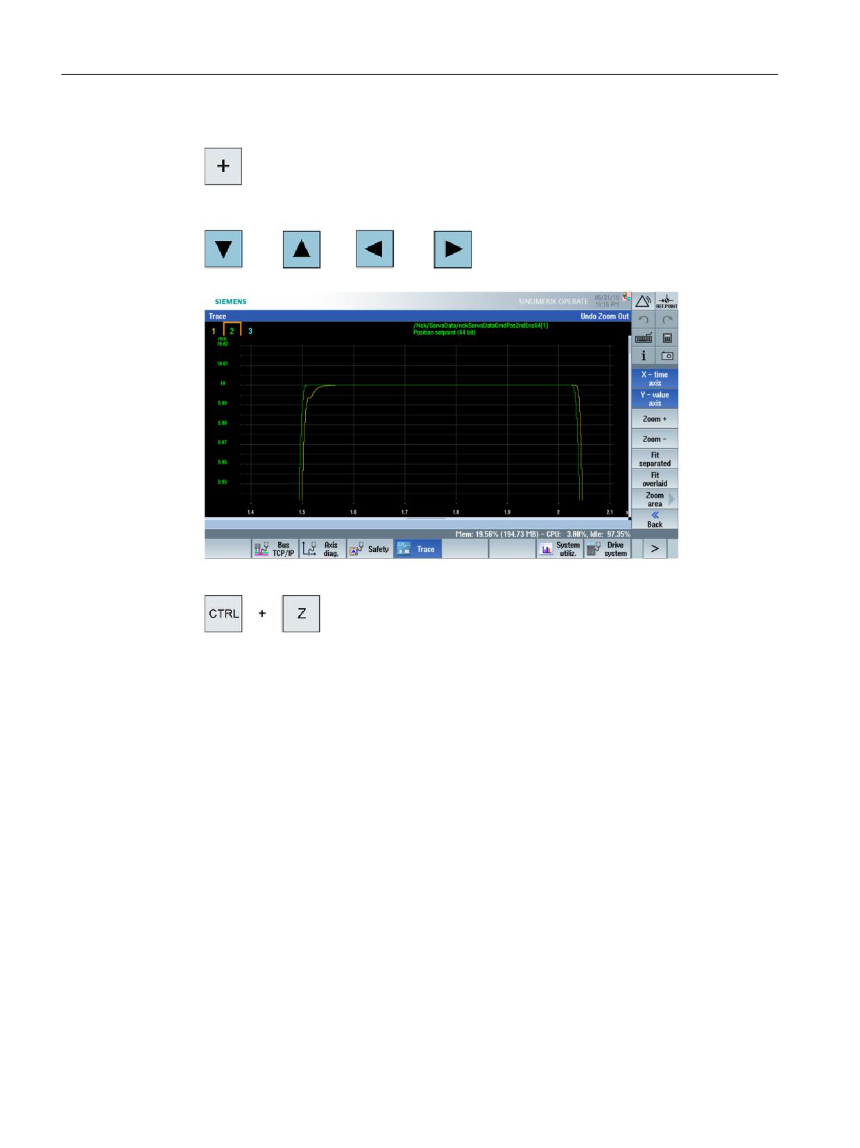
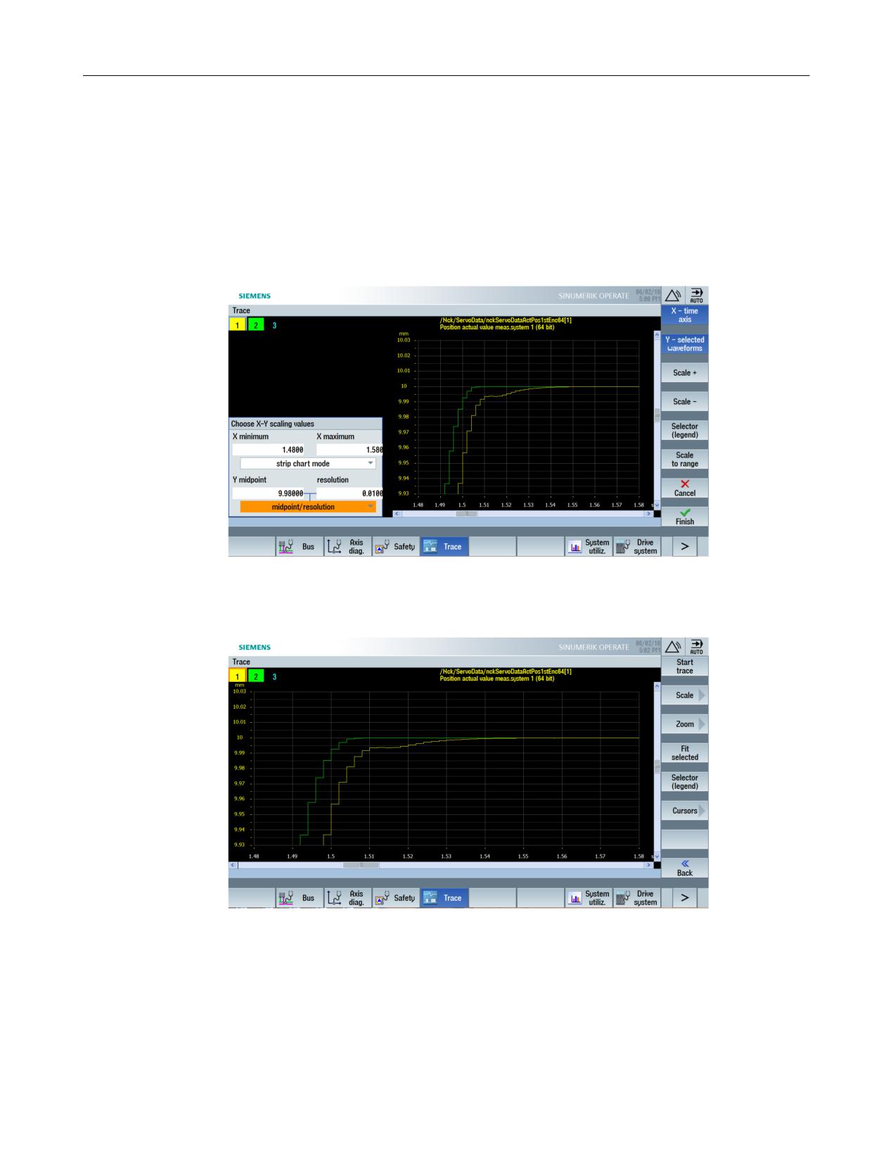
5. Select the "Zoom +" softkey or the <+> softkey to enlarge the image section.
Using the cursor keys, you can move the image section:
6. You can undo the action using keys <CTRL> + <Z>:
CNC Commissioning: NC, PLC, Drive
152
Commissioning Manual, 10/2020, A5E48312804B AB
Commissioning NC-controlled drives
6.6 Diagnostics → Trace
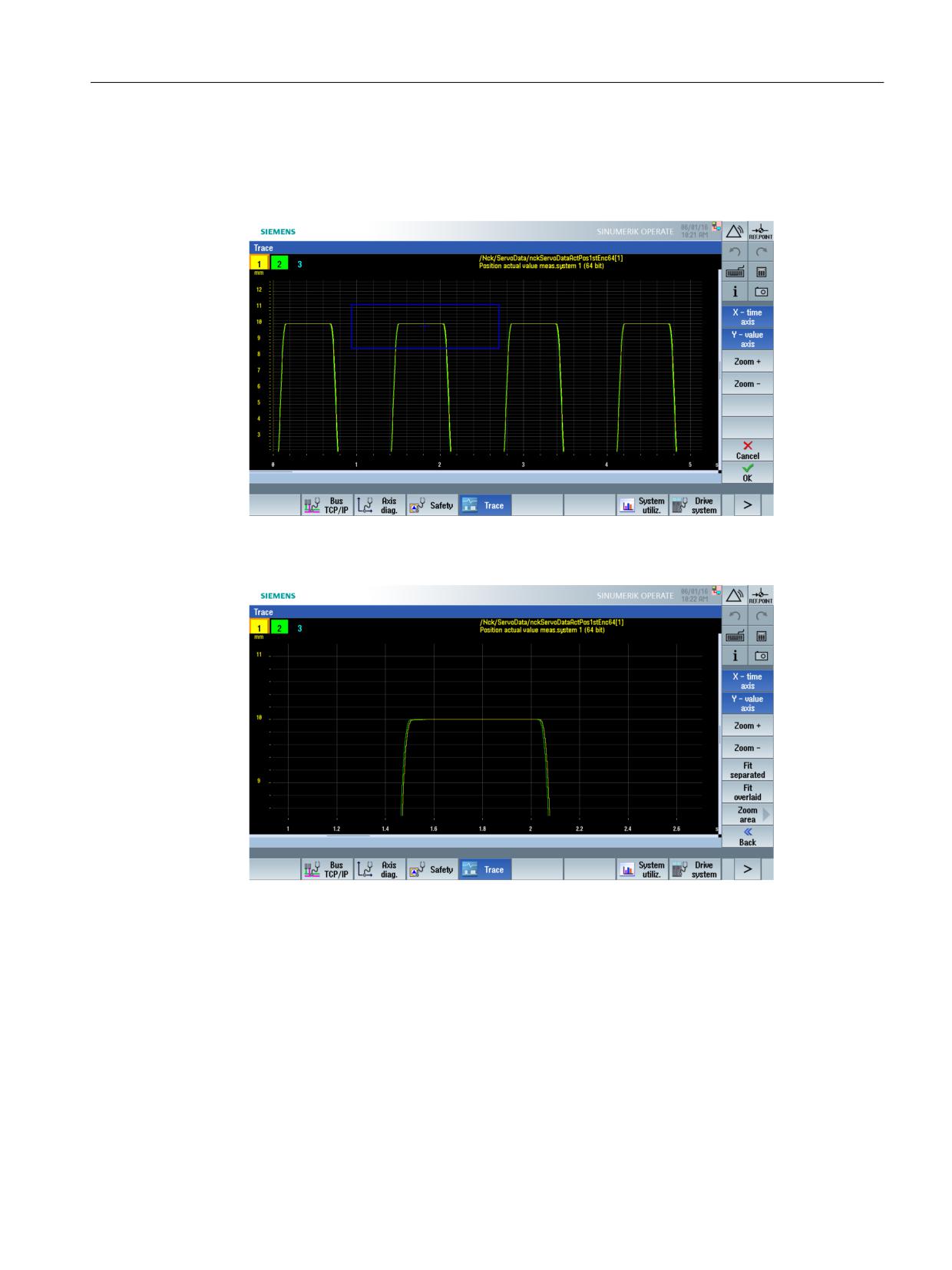
Alternative: Zoom with image section
Procedure:
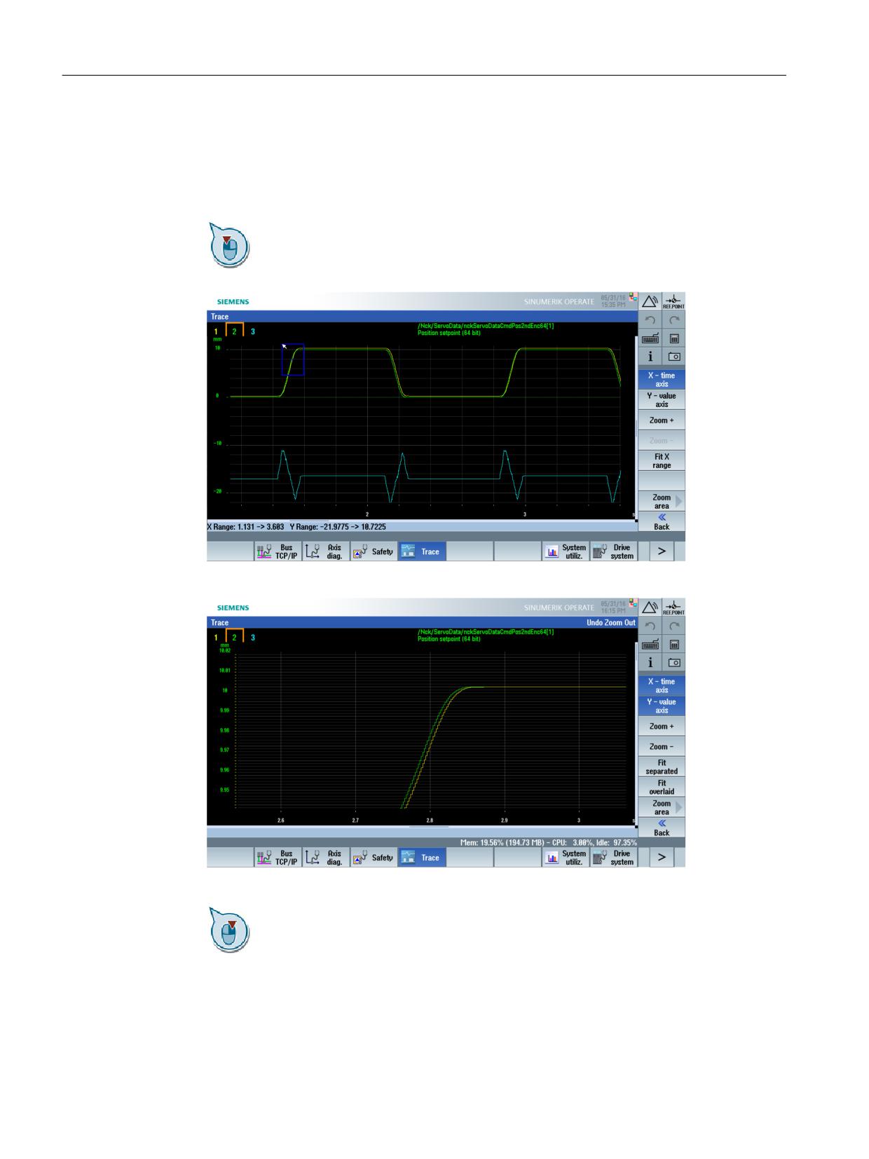
1. Select the "Zoom area >" softkey, to select a defined zoom area:
2. Select the "Zoom +" softkey or the <+> softkey to enlarge the image section.
3. Using the cursor keys, you can move the image section:
CNC Commissioning: NC, PLC, Drive
Commissioning Manual, 10/2020, A5E48312804B AB
153
Commissioning NC-controlled drives
6.6 Diagnostics → Trace
Alternative: Zoom using the mouse
Procedure:
1. While keeping the <CTRL> key pressed, using theleft-handmouse key, drag the section of
the screen that you wish to zoom into:
2. Zoom result after releasing the left-hand mouse key:
3. You can undo the action using <CTRL> and the right-hand mouse key.
CNC Commissioning: NC, PLC, Drive
154
Commissioning Manual, 10/2020, A5E48312804B AB
Commissioning NC-controlled drives
6.6 Diagnostics → Trace
6.6.4
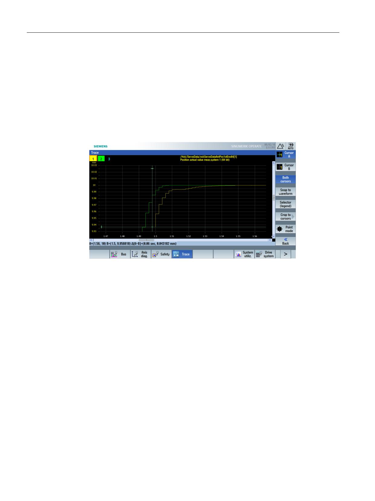
Example: Changing the scale
Changing the scale
Procedure:
1. Select the "≪ Back" softkey to exit the zoom area.
2. Select the "Scale >" softkey to scale the graphic in the X and Y axes:
3. After selecting softkey "X time axis" → and softkey "Scale +" - or directly entering "X minimum"
and "X maximum".
4. Confirm using softkey "✓ Finish".
CNC Commissioning: NC, PLC, Drive
Commissioning Manual, 10/2020, A5E48312804B AB
155
Commissioning NC-controlled drives
6.6 Diagnostics → Trace
6.6.5
Example: Positioning the cursor
Positioning the cursor
Procedure:
1. Select the "Cursors >" softkey and position the active cursor A at the required position.
2. Select the "Cursor B >" softkey and position the active cursor B at the required position.
3. Select the "Both Cursors" softkey in order to read the precise value of the cursor positions
below the graphic:
6.6.6
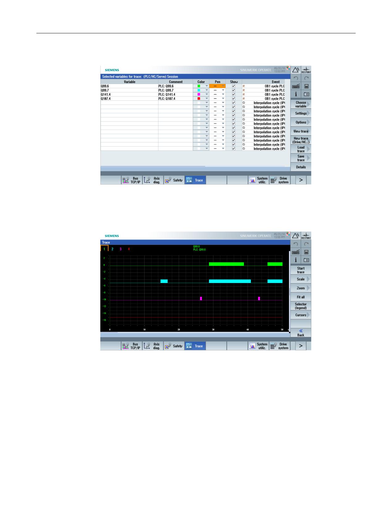
Example: Trace session with PLC variables
Trace recording of PLC signals
Procedure:
1. Using softkey "New trace (Drive/NC)", open a new session.
2. Select the "Choose variable >" softkey, and under "Filter: PLC" to restrict the selection to PLC
variables.
CNC Commissioning: NC, PLC, Drive
156
Commissioning Manual, 10/2020, A5E48312804B AB
Commissioning NC-controlled drives
6.6 Diagnostics → Trace
3. For example, select the following PLC signals:
4. Under "Settings", enter a recording duration of 50 seconds, for example.
5. Select softkey "View trace" followed by "Start trace".
The outputs are set and reset while tracing.
6. The following result is displayed after the set recording time has elapsed:
CNC Commissioning: NC, PLC, Drive
Commissioning Manual, 10/2020, A5E48312804B AB
157
Commissioning NC-controlled drives
6.6 Diagnostics → Trace
6.6.7
Example: Trace session with drive variables
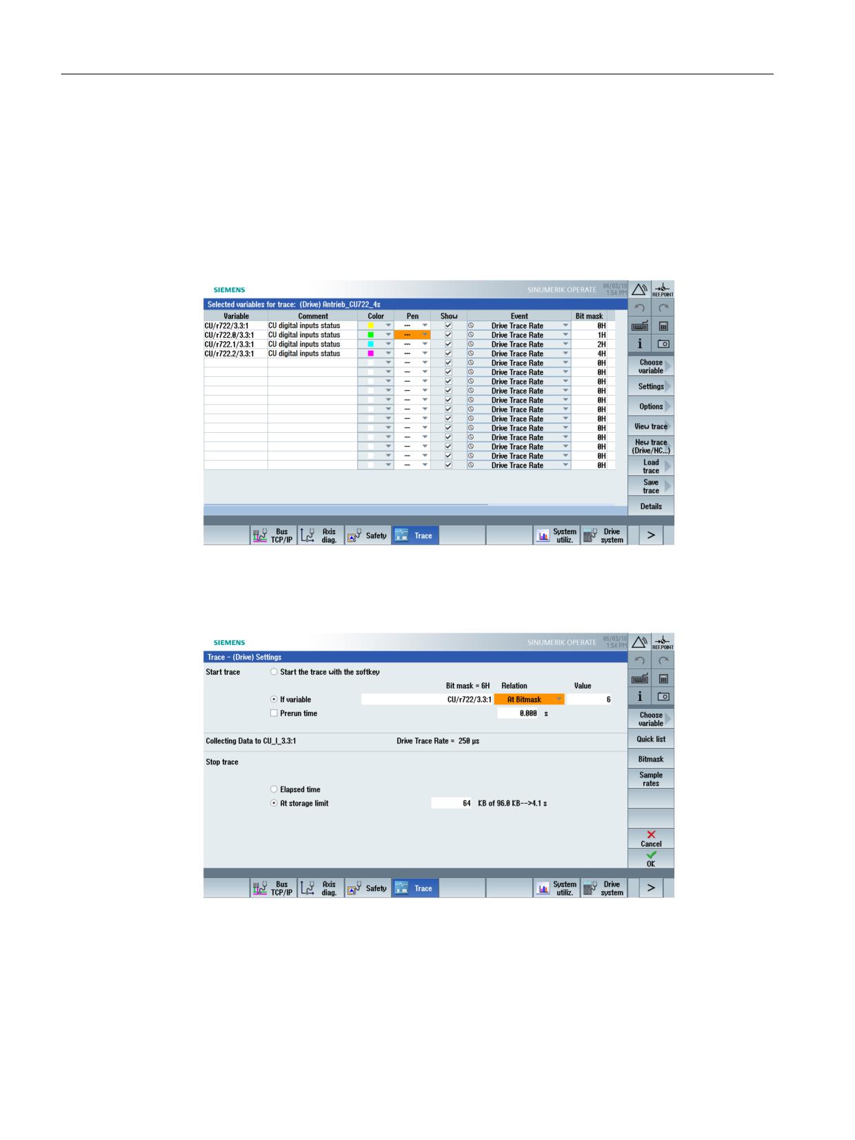
Record the drive trace
Procedure:
1. Open a new session for drive variables.
2. From the list, insert parameter r722 "CU digital inputs status":
3. Select the "Settings" softkey to enter the trigger condition:
4. Select "If variable", and from the "Quick List", insert variable r722.
5. Under condition, select "At bit mask" and enter the required value as decimal number:
6. Confirm with "OK" to accept the settings.
CNC Commissioning: NC, PLC, Drive
158
Commissioning Manual, 10/2020, A5E48312804B AB
Commissioning NC-controlled drives
6.6 Diagnostics → Trace
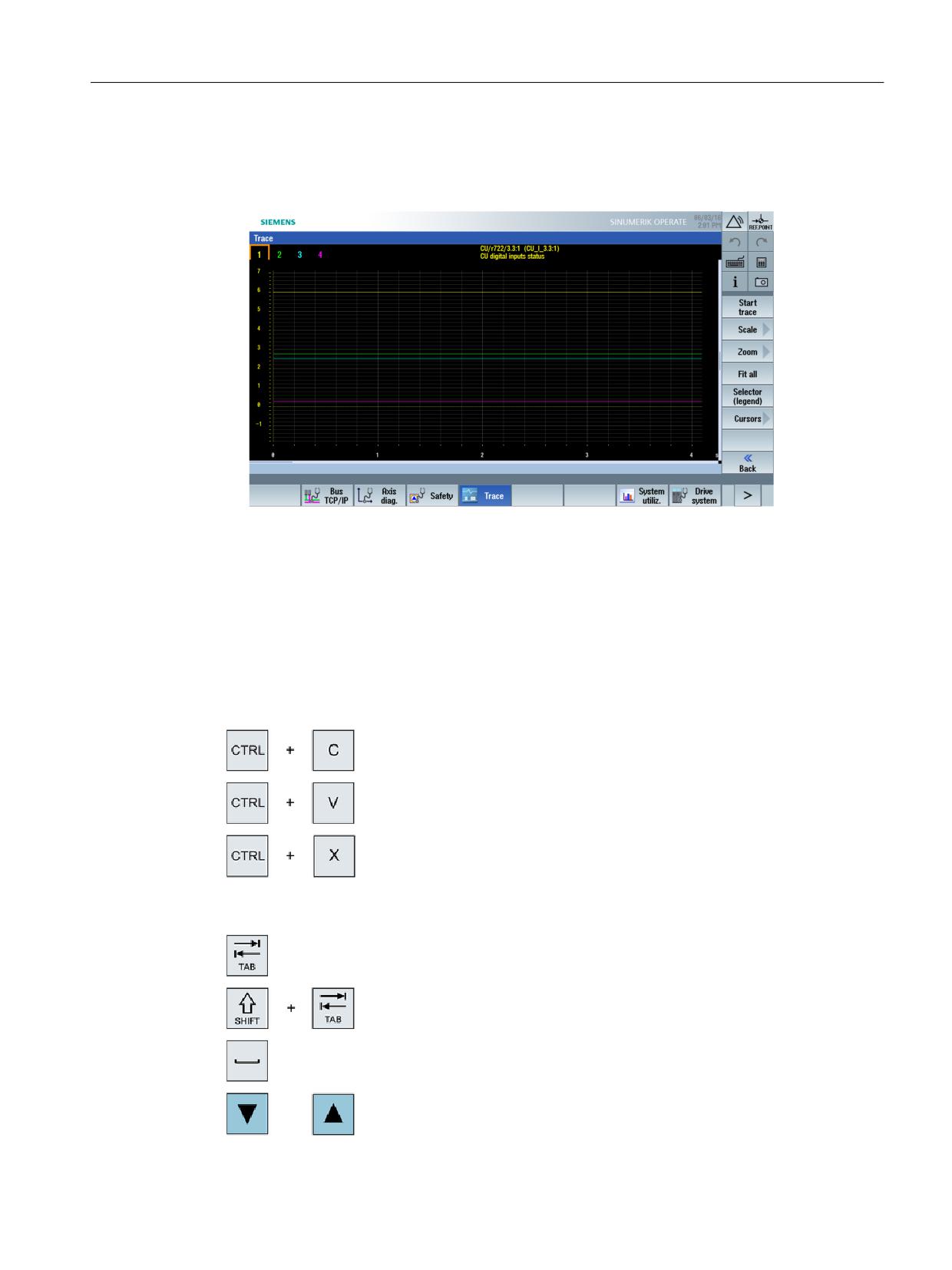
7. Select softkey "View trace" followed by "Start trace".
8. The trace starts, if r722.1=1 and r722.2=1 are set ⇒ decimal value 6 and stops, which means
if the trigger condition is satisfied.
6.6.8
Key combinations to use the trace
Key combinations
Key combinations, which function with the control keys as well as on an external keyboard.
List view:
Copy selection.
Insert selection.
Delete selection.
Trace view:
Display the individual curves from left → right
Display the individual curves from right → left
Spaces: Select the display curve.
(corresponds to the "Select/Legend" softkey)
Arrow keys: Shift the image section either up or down.
CNC Commissioning: NC, PLC, Drive
Commissioning Manual, 10/2020, A5E48312804B AB
159
Commissioning NC-controlled drives
6.6 Diagnostics → Trace
With the cursor quickly to the right.
Move the cursor quickly to the left.
Zoom +
Zoom -
Undo the last action.
CNC Commissioning: NC, PLC, Drive
160
Commissioning Manual, 10/2020, A5E48312804B AB
Commissioning NC-controlled drives
6.7 Diagnostics → drive system
6.7
Diagnostics → drive system
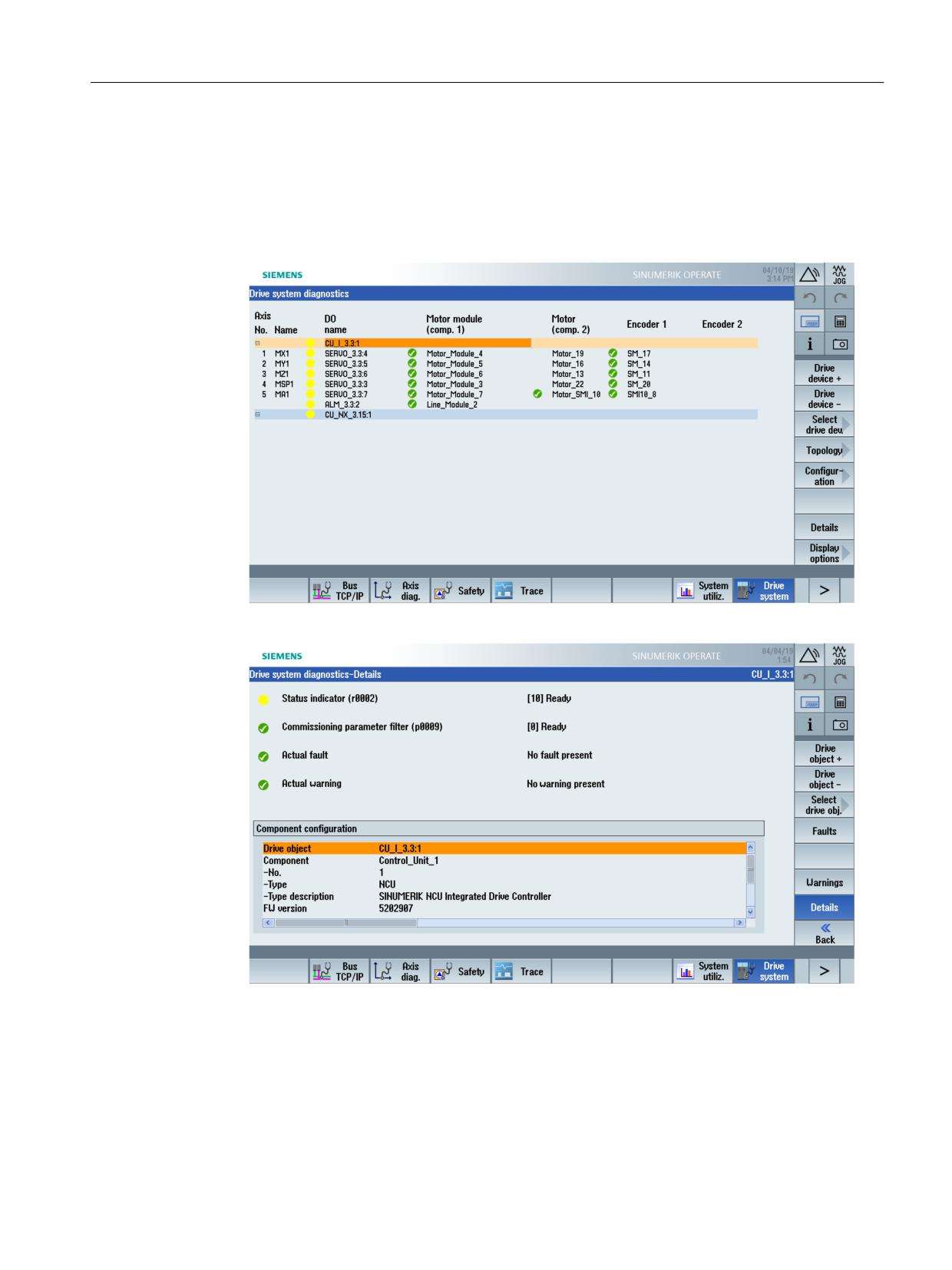
Operating sequence
1. To check the status of the drive, select the "Diagnostics" → "Drive system" operating area:
2. Press the "Details" softkey to display further diagnostics data for a drive object:
3. If faults or warnings are pending for a drive object, change to the list view using the
associated softkey.
CNC Commissioning: NC, PLC, Drive
Commissioning Manual, 10/2020, A5E48312804B AB
161
Commissioning NC-controlled drives
6.7 Diagnostics → drive system
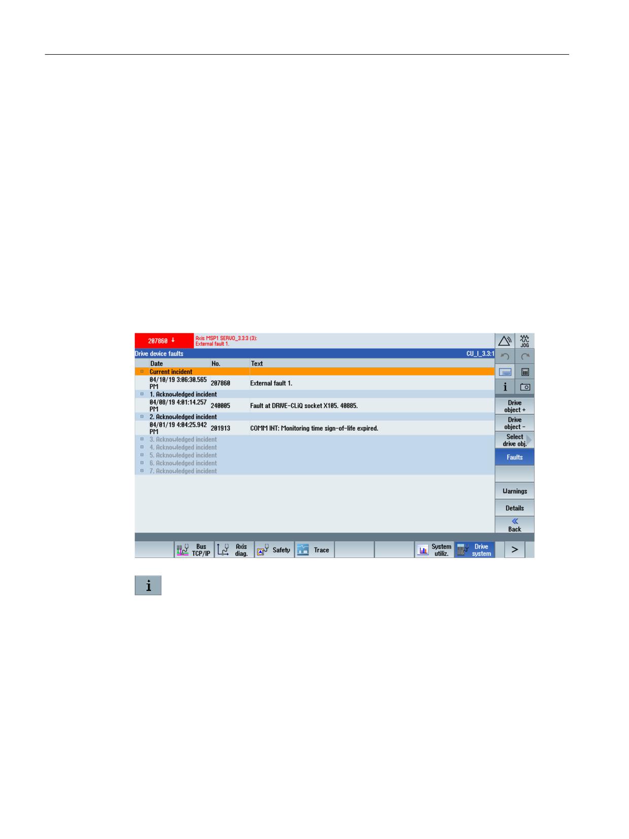
SINAMICS faults and alarms
SINAMICS alarms can be of the alert (A = Alert) or fault (F = Fault) type:
• To activate the fault and warning buffer output for SINAMICS, set
MD13150 $MN_SINAMICS_ALARM_MASK to the hexadecimal value "D0D". This
automatically outputs the pending faults and warnings of the drive in the message line.
• The parameter r0945 shows the number of faults that have occurred.
• Pending warnings are indicated by parameter r2122 of the relevant drive component.
• The number of warnings that have occurred after the last reset is available in parameter
p2111 of the drive components.
• Setting p2111 = 0 results in the deletion of all existing warnings of this component and
updates the current warnings still pending. This parameter is reset to zero for a power on of
the drive unit.
Example
To display the online help for a pending fault or warning on SINUMERIK Operate, the
line must be marked (in orange). You can find remedial measures in the online help.
CNC Commissioning: NC, PLC, Drive
162
Commissioning Manual, 10/2020, A5E48312804B AB
Commissioning NC-controlled drives
6.8 Modular machine
6.8
Modular machine
6.8.1
What does "modular machine" mean?
"Modular machine" concept
The modular machine concept is based on a maximum target topology created offline. The
maximum design of a particular machine type is referred to as the maximum configuration in
which all the machine components that may be used are pre-configured in the target topology.
By deactivating or deleting drive objects (p0105 = 2), sections of the maximum configuration
can be removed. If a component fails, for example, this sub-topology can also be used to allow
a machine to continue running until the spare part is available. In this case, however, no BICO
source must be interconnected from this drive object to other drive objects.
NOTICE
Data backup
To prevent data loss, save the drive data in a commissioning archive (Page 317), before you
make any changes!
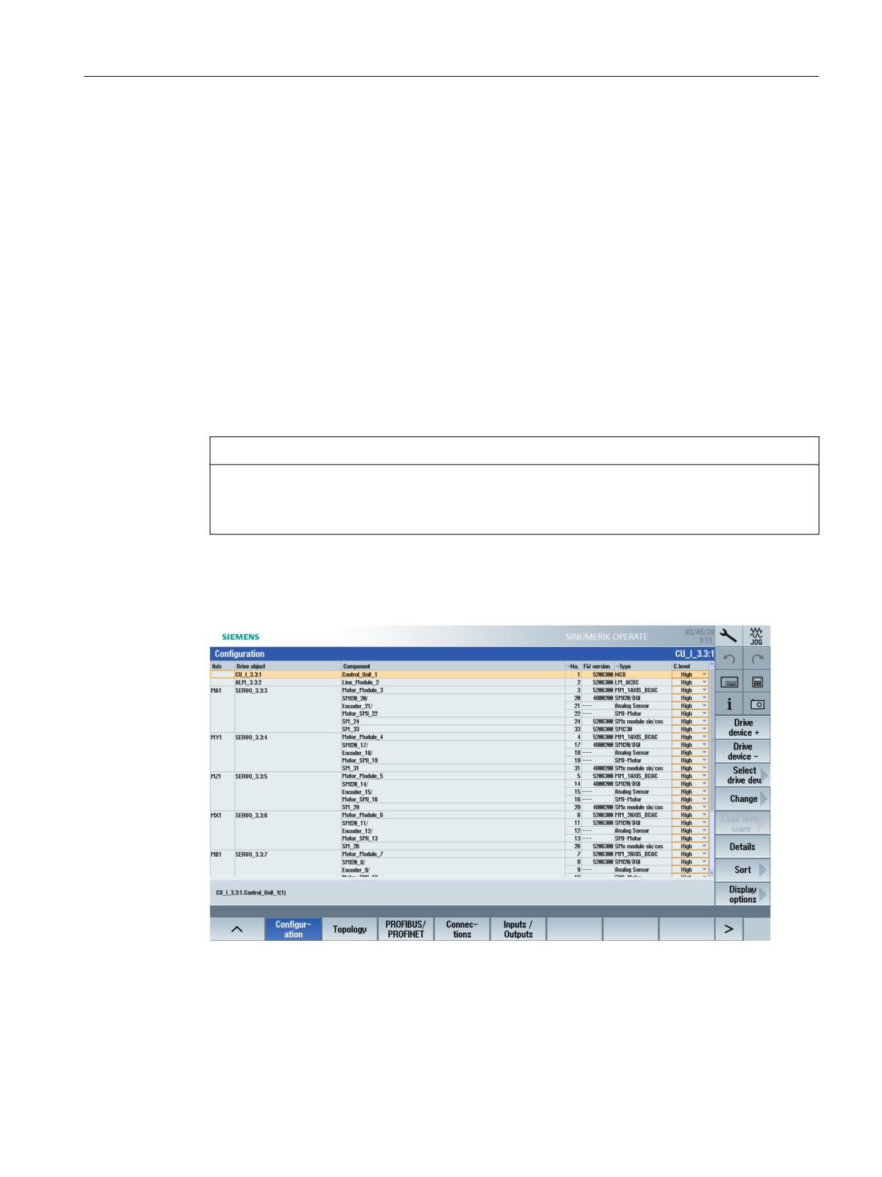
Drive unit - Configuration
CNC Commissioning: NC, PLC, Drive
Commissioning Manual, 10/2020, A5E48312804B AB
163
Commissioning NC-controlled drives
6.8 Modular machine
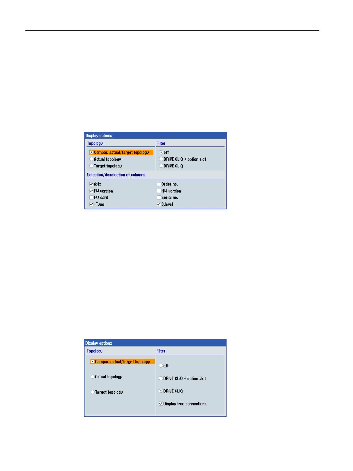
The "Commissioning" → "Drive system" → "Drive unit" operating area provides the following
functions under "Configuration":
• "Configuration" > "Change >"
- Change the name of the drive object
- Change the name of the component
- Change the comparison level
• "Configuration" → "Sort >":
• "Configuration" → "Display options >":
Drive unit - topology
The "Commissioning" → "Drive system" → "Drive unit" operating area provides the following
functions under "Topology":
• "Topology" → "Change >"
- Delete a drive object
- Delete the component
- Enable/disable drive objects
- Drive object: Change name/number
- Component: Change name/number
• "Topology" → "Add component >"
• "Topology" → "Display options >":
CNC Commissioning: NC, PLC, Drive
164
Commissioning Manual, 10/2020, A5E48312804B AB
Commissioning NC-controlled drives
6.8 Modular machine
Note
Changing the topology
Changing the topology does not require that the first commissioning is repeated.
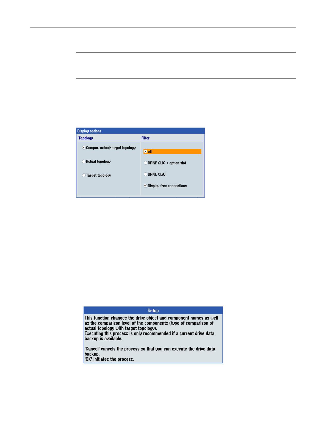
Example: Components without DRIVE-CLiQ
To display components, which are not connected via DRIVE-CLiQ, in "Display options" under
"Filter" select option "off":
6.8.2
Modify configuration
Drive unit: Changing the configuration
Before you make changes to the configuration, create a commissioning archive of the drive data,
or check whether a data backup already exists.
Procedure:
1. In the operating area, select "Commissioning" → "Drive system" → "Drive unit"
→ "Configuration" → Softkey "Change":
2. Before you make changes to the configuration, create a commissioning archive of the drive
data, or check whether a data backup already exists.
3. Navigate to the drive object or the component that is to be changed.
4. A new designation is adopted using key "INSERT".
CNC Commissioning: NC, PLC, Drive
Commissioning Manual, 10/2020, A5E48312804B AB
165
Commissioning NC-controlled drives
6.8 Modular machine
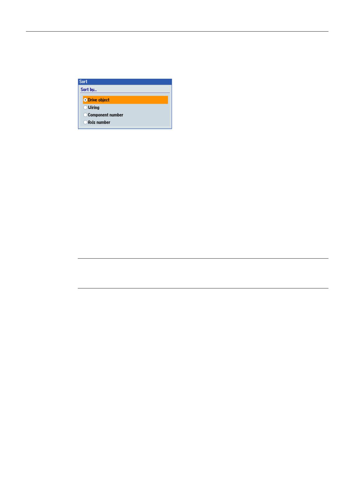
Drive unit: Sorting configuration
Select softkey "Sort >" to sort the display according to one of the following criteria:
6.8.3
Check topology
Comparing topologies
For the topology, you can select between graphic topology display and tabular topology display:
• In the operating area, select "Commissioning" → "Drive system" → "Topology" in the graphic
display.
• In the operating area, select "Commissioning" → "Drive system" → "Drive unit" → "Topology"
in the tabular form.
To check whether the displayed target topology matches the actual topology of the system,
select softkey "Topology comparison" or the view "Comparison actual/target topology".
Note
Component number
You will need the component numbers in order to configure direct measuring systems manually.
Example: Topology display (graphic)
Based on Create MyConfig , the topology is shown graphically and supports the following
functions:
• Selecting the drive device
• Displaying the actual topology
• Displaying the target topology
• Display to compare the target topology (top, white backg60round) with the actual topology
(bottom, bright blue backg60round)
• A fault description when faults are active
• Increasing or decreasing the size of the view using the zoom function
• Displaying the properties of the selected component
• Identifying a component using an LED
CNC Commissioning: NC, PLC, Drive
166
Commissioning Manual, 10/2020, A5E48312804B AB
Commissioning NC-controlled drives
6.8 Modular machine
Note
Functional scope of the "Topology display"
The functionality under "Drive system" → "Topology display" is a display function with the
objective of identifying topology errors.
Contrary to this, in the drive unit functionality under "Drive device" → "Topology " (tabular form)
the following additional functions are integrated:
• Activating/deactivating drive objects
• Deleting drive objects
• Adding and deleting components
Target topology
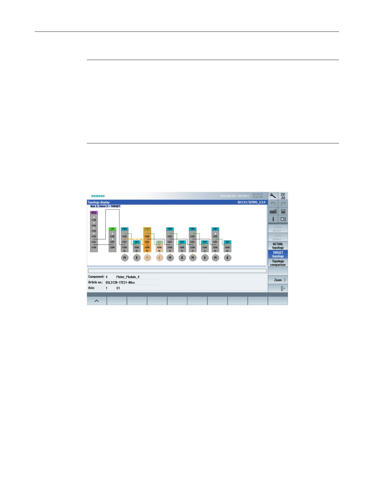
The graphic topology display is shown using the "Target topology" view as example:
Figure 6-4
Target topology - without error
A DRIVE-CLiQ port is always simultaneously selected for the component in focus. The Drive-CLiQ
connection at a selected port is graphically highlighted.
CNC Commissioning: NC, PLC, Drive
Commissioning Manual, 10/2020, A5E48312804B AB
167
Commissioning NC-controlled drives
6.8 Modular machine
Actual topology
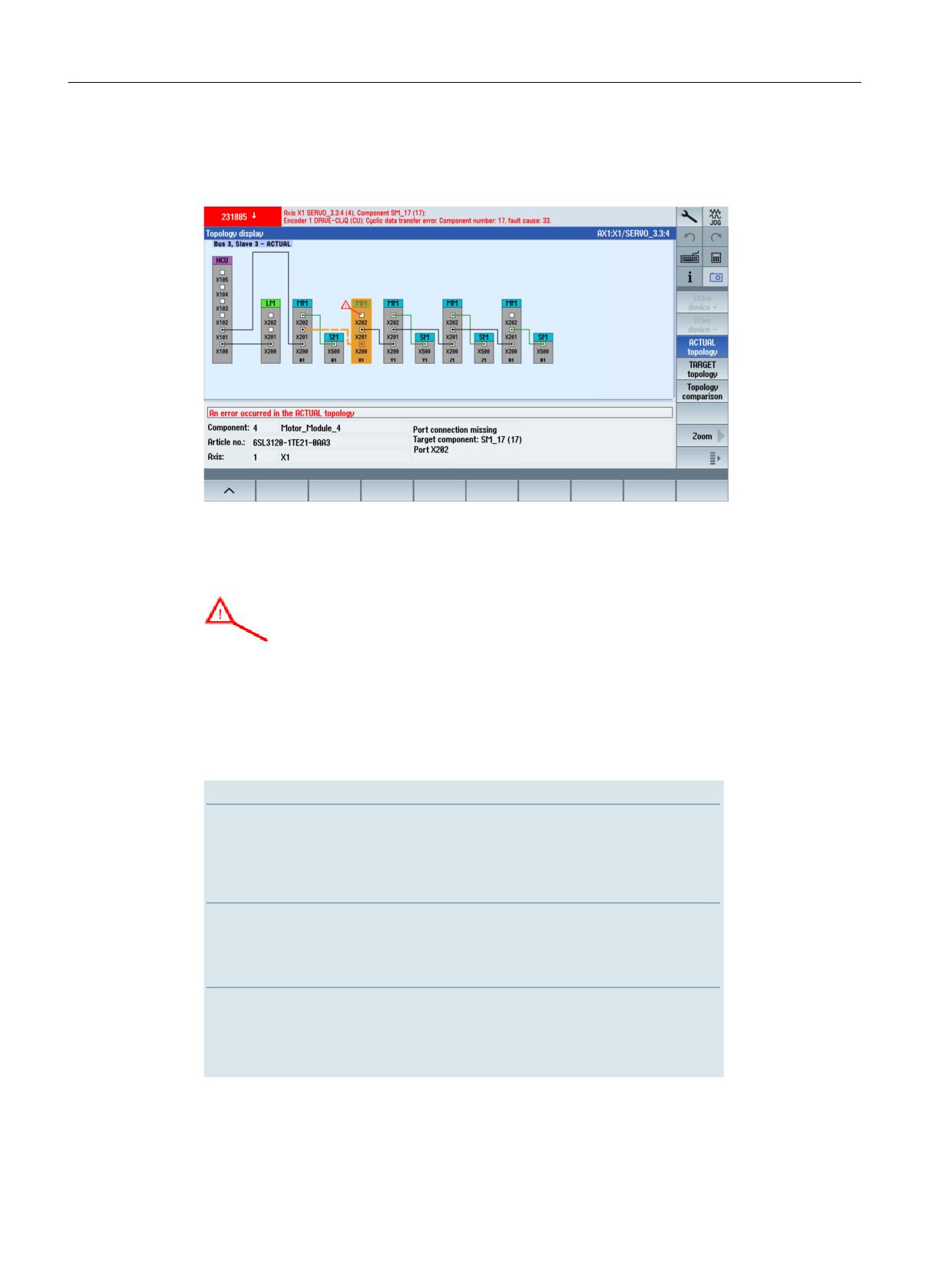
The graphic topology display in the case of an error is shown using the "Actual topology" view:
Figure 6-5
Actual topology - with error
Precondition:
It is assumed that the target topology has no error.
As a consequence, the errors are only displayed in the actual topology.
If a component has an error, then in addition to the symbol in the graphic,
error information is also provided at the bottom right in the detailed view.
Focus on the component involved to analyze the error that has occurred. To do this, change into
the "Topology comparison" view in order to compare the actual topology (top) with the saved
target topology (bottom).
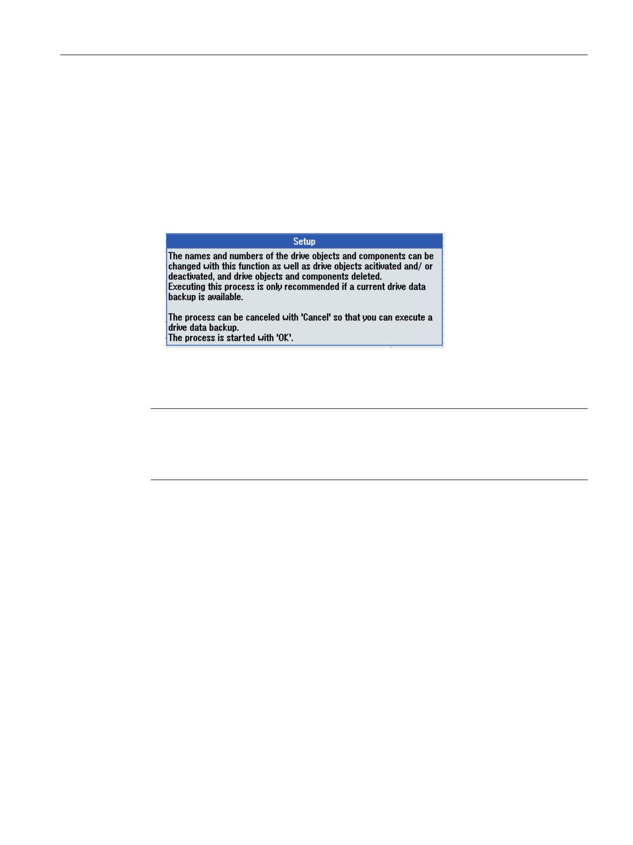
After switching over the vertical softkey bar, the following properties of the focused component
are displayed:
$[LV
$; ;
'ULYH REMHFW
'2 QDPH
6(592B
'2 QXPEHU
7\SH
>
@ 6(592
'2 VWDWXV
'ULYH REMHFW DFWLYH
'2 YDULDEOH
&RPSRQHQW
&RPSRQHQW QDPH
60B
&RPSRQHQW QXPEHU
7\SH
&RPSRQHQW VWDWXV
> @ &RPSRQHQW DFWLYH
'HYLFH
'HYLFH FODVV
6HQVRU 0RGXOH
$UWLFOH QXPEHU
6/
$$
%$
6HULDO QXPEHU
7 62
&RPSDULVRQ OHYHO
KLJK
CNC Commissioning: NC, PLC, Drive
168
Commissioning Manual, 10/2020, A5E48312804B AB
Commissioning NC-controlled drives
6.8 Modular machine
6.8.4
Changing topology
Drive unit: Changing the topology
Before you make changes to the topology, create a commissioning archive with the drive data,
or check whether a data backup already exists.
Procedure:
1. In the operating area, select "Commissioning" → "Drive system" → "Drive unit" → "Topology"
→ Softkey "Change":
2. Navigate to the drive object or the component that is to be changed.
3. A new designation is adopted using key "INSERT".
Note
Effect in the drive firmware:
Changing the name and the number influences the target topology and the actual topology.
Changing the comparison level influences the topology comparison.
6.8.5
Activating/deactivating drive object
Activating/deactivating drive objects
Before you make changes to the topology, create a commissioning archive with the drive data,
or check whether a data backup already exists.
Procedure:
1. In the operating area, select "Commissioning" → "Drive system" → "Drive unit" → "Topology"
→ Softkey "Change".
2. Select a drive object, for example SERVO_3.3:3
CNC Commissioning: NC, PLC, Drive
Commissioning Manual, 10/2020, A5E48312804B AB
169
Commissioning NC-controlled drives
6.8 Modular machine
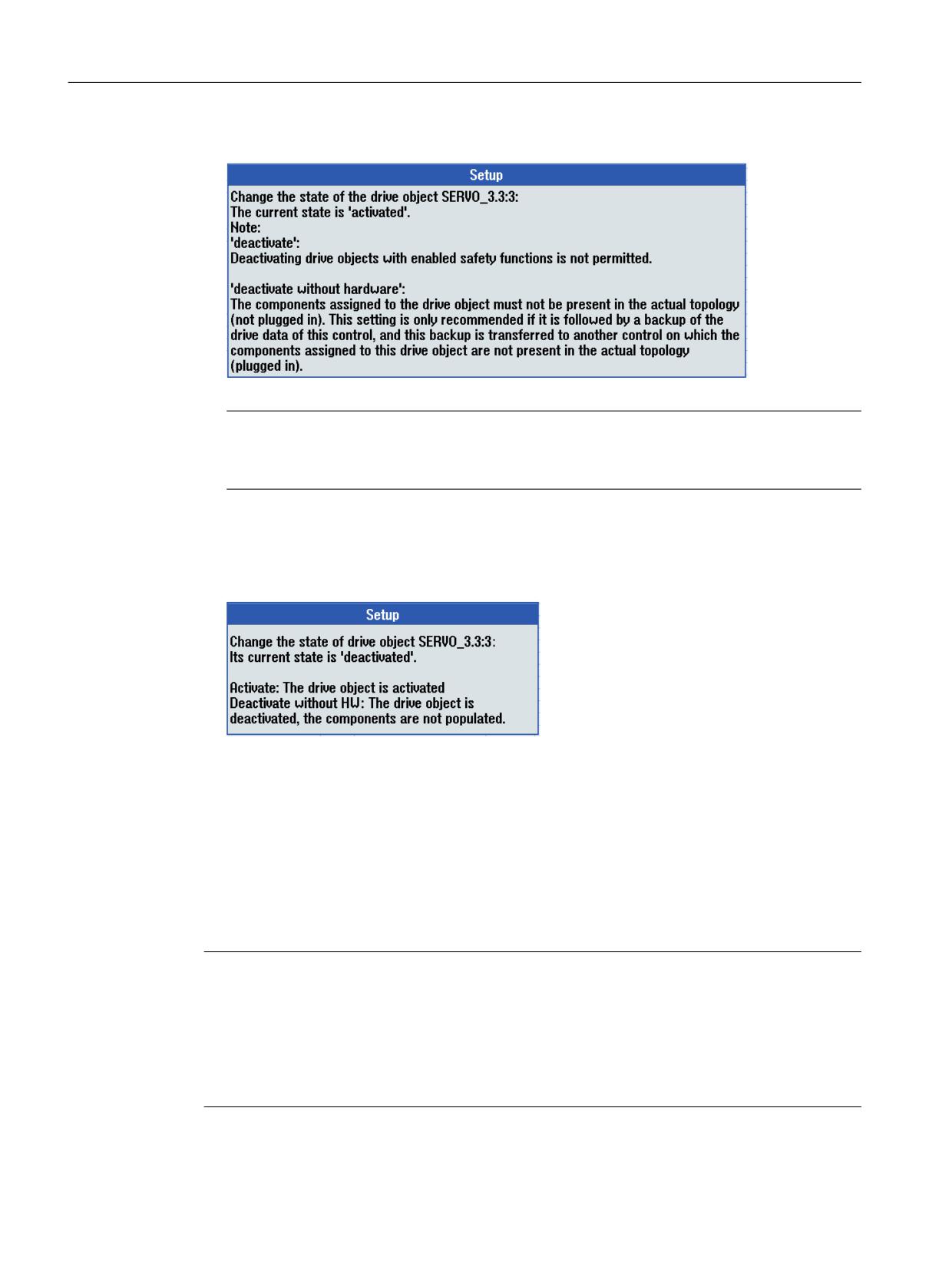
3. Select softkey "Activate/deactivate drive object" and follow the instructions:
Note
Safety Integrated
Note that axes with enabled safety functions cannot be deactivated.
4. Once successfully deactivated, the drive object and the associated components are grayed
out.
5. Select softkey "Activate/deactivate drive object" to again activate the drive object and then
follow the additional instructions:
Example: Series commissioning
When commissioning several machines of the same type (series commissioning), a non existent
drive object is marked with p0105 = 0. This creates a commissioning archive that is transferred
to the next machine.
In this case, to avoid triggering alarm 201416, the serial number of this component must be
deleted, and for this component, parameter p0105 = 2 "Deactivate drive object and not
available" must be set.
Note
General conditions for deactivating:
• If a component is deactivated, only the component with the correct serial number or none
may be inserted.
• If a component with a different serial number is inserted, this is by definition a different
component. If no other component remains, it must certainly be an excess component. This
component is marked as an additional component and alarm 201416 triggered.
CNC Commissioning: NC, PLC, Drive
170
Commissioning Manual, 10/2020, A5E48312804B AB
Commissioning NC-controlled drives
6.8 Modular machine
6.8.6
Deleting a drive object
Deleting a drive object
Before you make changes to the topology, create a commissioning archive with the drive data,
or check whether a data backup already exists.
Procedure:
1. In the operating area, select "Commissioning" → "Drive system" → "Drive unit" → "Topology"
→ Softkey "Change".
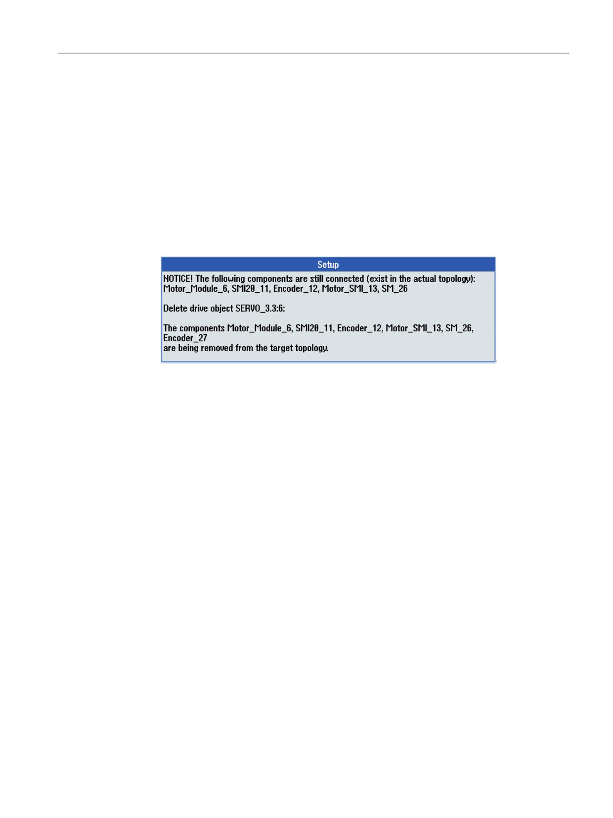
2. Select a drive object, for example SERVO_3.3:6 Only then is softkey "Delete drive object"
active. A security prompt then follows before the drive object is deleted:
3. If a data backup is available, confirm with "OK" to delete the drive object from the target
topology.
4. The Motor Module can now be removed.
6.8.7
Delete the component
Delete the component
Before you make changes to the topology, create a commissioning archive with the drive data,
or check whether a data backup already exists.
CNC Commissioning: NC, PLC, Drive
Commissioning Manual, 10/2020, A5E48312804B AB
171
Commissioning NC-controlled drives
6.8 Modular machine
Procedure:
1. In the operating area, select "Commissioning" → "Drive system" → "Drive unit" → "Topology"
→ Softkey "Change".
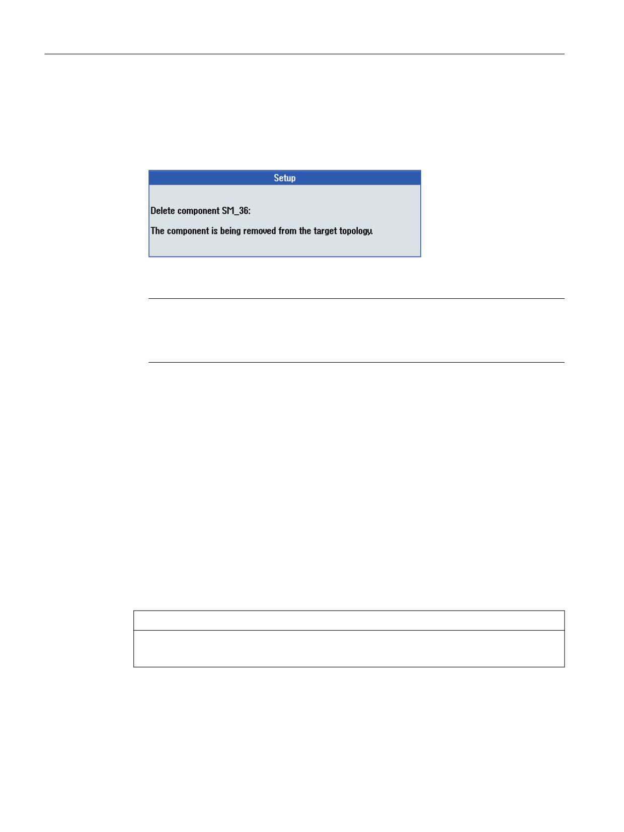
2. Select a component, for example, encoder SM_36. Only then is softkey "Delete component"
active. A security prompt then follows before the component is deleted:
3. If you are certain, confirm with "OK" to delete the component from the target topology and
remove the component.
Note
Comparison actual/target topology
The component is marked in red and an alarm is output as the component is included in the
actual topology as long as it is inserted.
6.8.8
Adding components
Adding components
If you connect a new component (e.g. SMC20) via DRIVE-CLiQ to the drive system, the drive
detects the change in the actual topology and displays the actual/target topology difference.
• GRAY: Desired state, drive object / component not plugged in or deactivated in the drive
system. Use the cursor keys to select the required line. The state is indicated in the bottom
part of the window.
• RED: Actual state, drive object/component available in the actual topology.
New components that have not yet been commissioned have a component number > 200.
The new component must then be configured and assigned to a drive object (Motor Module)
using the drive wizard.
NOTICE
Plugging in components
Only plug in (connect) components when the drive unit is switched off.
In the "Topology" dialog, start at the actual state: The new component has not been connected
yet.
CNC Commissioning: NC, PLC, Drive
172
Commissioning Manual, 10/2020, A5E48312804B AB
Commissioning NC-controlled drives
6.8 Modular machine
Procedure:
1. To connect a new DRIVE-CLiQ component to a Motor Module, select "Commissioning" →
"Drive system" → "Drive device" → "Topology" in the operating area.
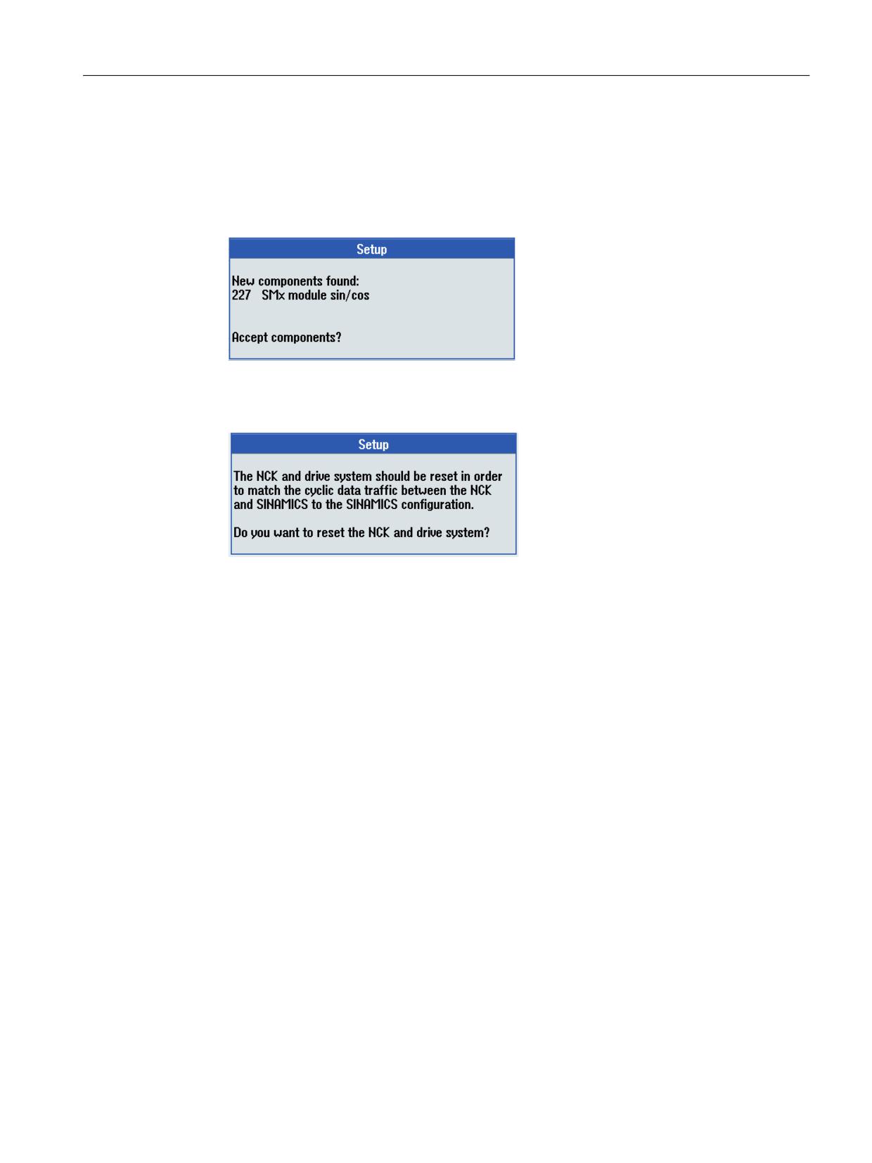
2. Select the Motor Module and press softkey "Add component >". The system identifies the new
component and outputs the following message:
3. Press "OK" as confirmation to configure and accept this component. Determining the device
configuration may take several minutes.
You receive the following prompt after the device configuration:
4. Confirm with "OK" to carry out a power on reset. The unit configuration is finished. The
component has been accepted. The following message will then appear:
The encoder component was added to the target topology.
5. Press "OK" to include the component in the topology although it is not yet assigned to any
drive:
- Select "Drive unit" to open the drive wizard. Select the drive and assign the new encoder
in the encoder configuration to the drive.
- Press "OK" to assign this component to the drive later.
6.8.9
Replacing a SINAMICS S120 component
Requirements
There are two procedures for replacing components:
1. Replacing SMI or SMx motor components.
2. Replacing an existing Motor Module with a more powerful Motor Module.
CNC Commissioning: NC, PLC, Drive
Commissioning Manual, 10/2020, A5E48312804B AB
173
Commissioning NC-controlled drives
6.8 Modular machine
The following preconditions are satisfied:
• The two Motor Modules are of the same type.
• The serial number is different: ⇒ In this case, another configuration is not required.
• The difference between the two Motor Modules, for example, is 9 A instead of 5 A.
Note
Do not make a permanent change in the drive system.
Before you replace the DRIVE-CLiQ component, change the comparison level.
Replacing SMI or SMx motor components
Note
The new SMI/SMx motor component must not yet be inserted!
Operating sequence:
1. You have removed the previous SMI or SMx motor component.
This motor component is missing in the actual topology. SINAMICS indicates this in the form
of a topology error alarm.
The "Commissioning" → "Drive system" → "Drive units" → "Topology" dialog shows the
previous motor component to be replaced in "gray", i.e. present only in the target topology.
2. In the "Commissioning" → "Drive system" → "Drive units" → "Topology" → "Change..." dialog,
remove the SMI/SMx motor component awaiting replacement from the target topology
using the "Delete component" dialog.
NOTICE
Data loss
Save the drive data that has been changed before switching off (for example, to a drive data
archive).
3. Switch off the drive system and switch on again.
4. In the "Commissioning" → "Drive system" → "Drive units" → "Topology" dialog, check whether
the SMI/SMx motor component has been removed from the target topology:
- The alarm topology error is no longer pending.
- The "Commissioning" → "Drive system" → "Drive units" → "Topology" dialog no longer
shows any differences.
5. Switch off the drive system.
6. Plug in the new SMI/SMx motor component.
7. Switch on the drive system.
CNC Commissioning: NC, PLC, Drive
174
Commissioning Manual, 10/2020, A5E48312804B AB
Commissioning NC-controlled drives
6.8 Modular machine
8. Add the new SMI/SMx motor component to the target topology using the "Commissioning"
→ "Drive system" → "Drive units" → "Topology" → "Add component" dialog.
9. Assign the added SMI/SMx motor component via the "Commissioning" → "Drive system" →
"Drives" drive wizard.
Replacing a Motor Module
The replacement of components after the first commissioning, e.g. in order to use an ALM with
a higher power 16 kW → 50 kW, must be performed in such a way that the configuration data
is reimported and is up to date.
Note
Firmware update
The firmware of the configured drive components is updated correctly only when the
components were inserted in the switched-off state. The subsequent insertion of drive
components must ONLY be performed in the switched-off state.
If a drive component is replaced by a component with a different article number, e.g. a more
powerful module, after first commissioning, observe the following sequence:
Procedure:
1. Select "Drive unit" → "Topology" → "Change".
2. Select the module and select "Deactivate drive object".
3. Replace the module in the cabinet.
4. Select the module and select "Activate drive object".
5. The configuration data of the new module is read in.
6. Update the drive data in the commissioning archive with the new configuration data.
6.8.10
Example: Subsequently installing a component
Precondition
To write to Control Unit parameters and drive parameters and activate them, as a minimum, the
"Service" access level is required.
CNC Commissioning: NC, PLC, Drive
Commissioning Manual, 10/2020, A5E48312804B AB
175
Commissioning NC-controlled drives
6.8 Modular machine
Overview of the drive state
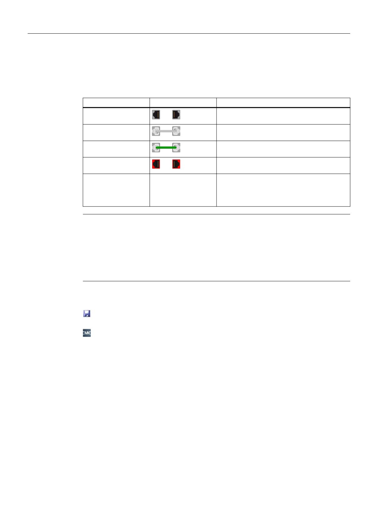
Using the "Activate drives" softkey, in the "Drive state overview" open a table listing all of the
drive objects, which shows the actual state of parameter p0105: "Activate/deactivate drive
objects". Furthermore, the connection status is shown as a symbol:
DO status (p0105)
Symbol
Significance
[0] deactivated
The component is not inserted, and the status is
deactivated.
[0] deactivated
The component is inserted, and the status is deac-
tivated
[1] activated
The component is inserted, and the status is acti-
vated.
[1] activated
The component is inserted, and the status is acti-
vated: Component with fault.
[2] deactivated without
- without symbol -
The component is not inserted, the status is deac-
hardware
tivated:
However, the component is included in the target
topology.
Note
Status p0105 = [2] deactivated without hardware
In the "Drive state overview", only the two states "[1] activated" and "[0] deactivated" are listed
for a drive object.
If a drive object exists with status [2] deactivated without hardware, then the status must be
changed to "[0] deactivated" and then the hardware component must be inserted and
connected.
The "Data backup" column shows the following symbols:
The backup of the drive parameters for every drive object is saved at:
/user/sinamics/smi/backup
Parameter data of drive objects are copied to the CompactFlash card of the control
system from a Create MyConfig package.
If the configuration parameters are overwritten when subsequently connecting the
motor with DQI encoder for the automatic controller data calculation, then when
activating, these parameters are again written to the drive object.
Subsequently inserting a component
In a Create MyConfig package, you can define and transfer the configuration parameters of the
"electronic rating plate" for motors with DQI encoder, without the hardware component having
to be already installed. The motor and encoder data are then already transferred to the
CompactFlash card when reading in the archive; however, the parameters are only activated
after the motor has been installed.
The following procedure applies both when commissioning as well as when replacing parts and
components.
CNC Commissioning: NC, PLC, Drive
176
Commissioning Manual, 10/2020, A5E48312804B AB
Commissioning NC-controlled drives
6.8 Modular machine
Press the "Activate all" softkey to execute the following steps:
1. Read out the motor data on the electronic rating plate.
2. In comparison to p0300 "Select motor type", check as to whether the configured data match
the configured component.
3. Activate the drive object.
4. Automatically calculate the controller data.
5. Overwrite parameters with the configured data from the Create MyConfig package.
6. Backup the parameters.
This operation can take several minutes. A progress display is shown.
When changing the status from "[0] deactivated" → "[1] activated" the backup of this drive object
is created in the following directory on the CompactFlash card: /user/sinamics/smi/backup. The
data for all drive objects is saved at: /user/sinamics/data
If several drive objects are selected, then you can select different procedures for each of the
individual drive objects:
1. "Only activate" softkey to activate parameters that are already saved to the CompactFlash
card.
2. "CMC data" softkey, to calculate the controller data and to activate the data saved from a
Create MyConfig package to the CompactFlash card.
3. "Last backup" softkey to restore the last data backup of the drive object from the backup file.
4. "Exit" softkey to exit the view of the drive objects.
5. You have the following alternatives after successfully completing the procedure:
- "Cancel" softkey to exit the procedure without restarting the system. As a consequence,
the parameters are not yet active.
- Press the softkey "Accept" to activate the parameters and to execute a restart the system
Reset (po).
Replacing a device
SIMOTICS Service Manual: Encoder replacement for SIMOTICS S- 1FK7 G2, S-1FG1 and S-1FT7
CNC Commissioning: NC, PLC, Drive
Commissioning Manual, 10/2020, A5E48312804B AB
177
Commissioning NC-controlled drives
6.9 Tips for commissioning the SINAMICS drives
6.9
Tips for commissioning the SINAMICS drives
6.9.1
Displaying the firmware version of the drive components
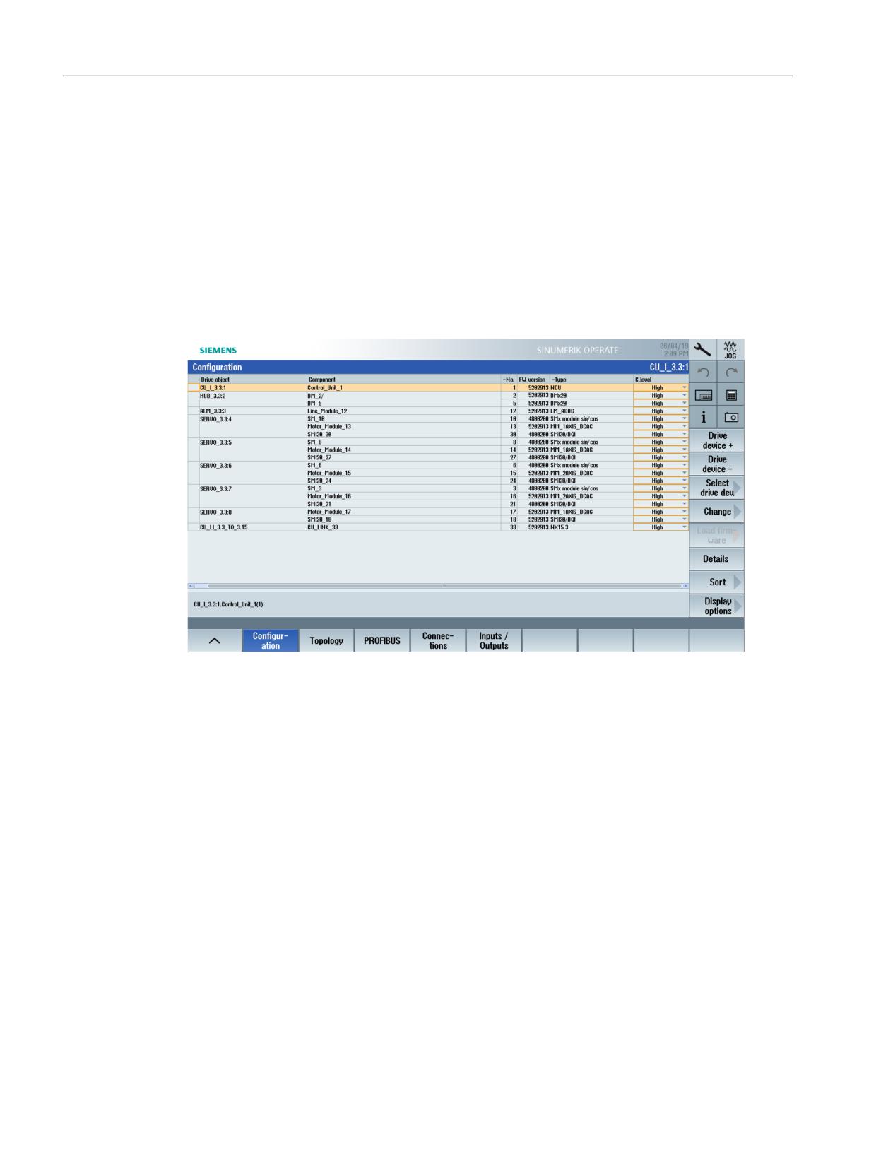
Firmware version of the drive components
To check the version of the drive components, select in the "Commissioning" operating area →
"Drive system" → " Drive device" → "Configuration":
The version for each component is displayed in the "FW version" column. The firmware version
is read out from the following SINAMICS parameters:
• r0018: Firmware version of the integrated Control Unit and of the CU_NX expansion, which
is always identical to the version of the SINAMICS system software.
• r0128: Firmware version of the infeed module
• r0975[2 and 10]: Firmware version of the Motor Module
• r0148[0...2]: Firmware version of the Sensor Modules that belong to the Motor Module
CNC Commissioning: NC, PLC, Drive
178
Commissioning Manual, 10/2020, A5E48312804B AB
Commissioning NC-controlled drives
6.9 Tips for commissioning the SINAMICS drives
6.9.2
Check the line data of the infeed
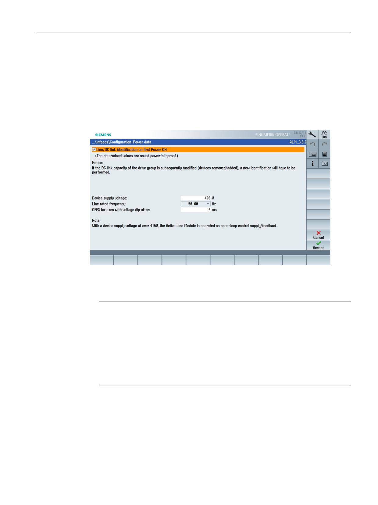
Checking and setting the power data
Finally, after commissioning the drive system, check the power data of the infeed module. In the
operating area "Commissioning" → "Drive system" → "Infeed", the "Power data" softkey is
enabled if the infeed module has already been commissioned and the data have been saved in
the non-volatile memory:
The following power data are configured:
• When the checkbox is selected, the line/DC link identification is activated once the infeed
pulse has been enabled (p3410). The infeed then switches to operational mode.
Note
DC link identification
If the line supply environment changes or the components on the DC link change (e.g. after
setting up the equipment at the customer site or after expanding the drive group), the
checkbox must be set again: Hence the "Line data" softkey in the overview in order to restart
the line/DC link circuit identification.
If p3410 = 5 is saved in the commissioning archive, then the line/DC link identification starts
automatically once the drive data is input into the archive.
Only then can it be guaranteed that the infeed operates with the optimum controller settings.
• Enter the device connection voltage: This is the basis for the mains overvoltage (p0281 -
p0283), for which an alarm is issued when the threshold is exceeded or undershot (warning
threshold and trip threshold). The actual line voltage is determined automatically and the
adjustment is made based on this value.
CNC Commissioning: NC, PLC, Drive
Commissioning Manual, 10/2020, A5E48312804B AB
179
Commissioning NC-controlled drives
6.9 Tips for commissioning the SINAMICS drives
• The actual line frequency for the infeed is determined automatically. In parameter p0284,
p0285 you set the warning threshold at which an alarm is triggered (presetting of the
monitoring function: 45 Hz to 65 Hz).
• Quick stop for axes when the voltage dips after a delay time in [ms]:
In the event of a voltage dip, alarm 207862 "External fault 3" is triggered, followed by alarm
207841 "Drive: Infeed operation withdrawn", and the associated fault response is initiated
from p2101. If an alarm is not to be initiated for very short voltage dips, this can be
configured with the ON-delay time p2101.
The switch-on delay is not active for each specific drive, but per infeed - and therefore for all
the drives connected to this infeed. This does not affect alarms, for example from the DC link,
and they continue to be triggered.
6.9.3
Mains and DC link identification of the infeed module
Objective
To optimally set the current and voltage control, start a mains and DC link identification after
completing the commissioning of the drive.
Automatic identification
The automatic identification determines characteristic mains and DC link characteristics, which
serve as the basis for optimally set controllers in the Line Module. You can adapt the dynamics
of the voltage control with p3560.
CNC Commissioning: NC, PLC, Drive
180
Commissioning Manual, 10/2020, A5E48312804B AB
Commissioning NC-controlled drives
6.9 Tips for commissioning the SINAMICS drives
Manual identification
Further identification methods:
• p3410 = 4 (identify and save controller setting with L adaptation)
An identification run for the total inductance and DC link capacitance is initiated when the
pulses are next enabled: Two measurement routines with different current magnitudes. The
determined data (r3411 and r3412) is entered into p3421 and p3422. At the same time, the
controllers are recalculated and the parameters for current controller adaptation are defined
(p3620, p3622). The parameters for the infeed module are then automatically stored in a
non-volatile memory. The infeed unit continues to operate without any interruption with the
new controller parameters.
• p3410 = 5 (resetting, saving ID and controller setting with L adaption)
The parameter values for line inductance and DC link capacitance are reset before the first
identification run:
p3421 = p0223 and p3422 = p0227
• p3410 = 6 (Setting, C-identifying and saving robust current controller)
For infeed units of the type Chassis 2, use p0220 ≥ 110 to select corresponding Active
Interface Modules of the Chassis 2 (AIM Chassis-2) design and start the automatic controller
setting with p3410 = 6. At the same time, the value of the DC link is determined in a
shortened measurement. All of the other controller parameters are already preset by setting
p3410 = 6.
- Advantage: For modified mains parameters (e.g. switchover to a different mains), no
adaptation of the controller parameters and mains identification is required.
- Disadvantage: Unlike identification over p3410 = 5, the automated controller setting
leads to losses in the dynamic response.
P3410 = 0 is automatically set when an identification routine is successfully completed.
Further information can be found in the SINAMICS S120 Function Manual Drive Functions
6.9.4
Rules for wiring the DRIVE-CLiQ interface
Topology rules
When wiring components with DRIVE-CLiQ, the following rules apply: The rules are subdivided
into obligatory rules, which must be observed, and optional rules, which enable automatic
topology detection if they are adhered to.
Obligatory rules:
• A maximum of 198 DRIVE-CLiQ node components can be connected for each NCU.
• Up to 16 nodes can be connected to a DRIVE-CLiQ socket.
• A maximum of seven nodes can be connected in one row. A row is always considered from
the perspective of the closed-loop control module.
• Ring wiring is not permitted.
• Components must not be double-wired.
Optional rules:
CNC Commissioning: NC, PLC, Drive
Commissioning Manual, 10/2020, A5E48312804B AB
181
Commissioning NC-controlled drives
6.9 Tips for commissioning the SINAMICS drives
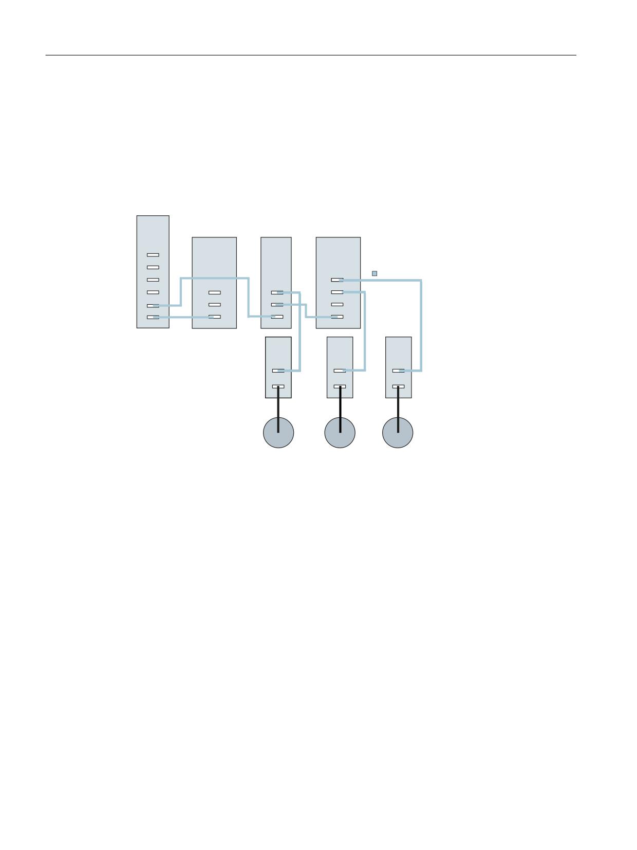
When the optional rules for the DRIVE-CLiQ wiring are observed the components concerned will
be automatically assigned to the drives:
• For one Motor Module, the related motor encoder must also be connected.
• Due to the improved performance utilization, use as many DRIVE-CLiQ points on the NCU as
possible.
• It is essential that you comply with the optional rules when using the macro. This is the only
way to achieve a proper assignment of the drive components.
1&8
600
'00
;
$/0
;
;
;
'5,9( &/L4
;
;
;
;
;
;
;
;
;
;
;
;
60&
60&
60&
;
;
;
;
;
;
0RWRU FDEOH
0
0
0
NCU
SINUMERIK control system
ALM
Active Line Module
SMM
Single Motor Module
DMM
Double Motor Module
M
Motor
Figure 6-6
Topology example
Use of the SMC40
The SMC40 Sensor Module Cabinet-Mounted is used to convert encoder signals from absolute
encoders with EnDat 2.2 to DRIVE-CLiQ. Two encoder systems with EnDat 2.2 can be connected
to the SMC40. Their signals are converted independent of each other on two DRIVE-CLiQ
encoder signals.
CNC Commissioning: NC, PLC, Drive
182
Commissioning Manual, 10/2020, A5E48312804B AB
Commissioning NC-controlled drives
6.9 Tips for commissioning the SINAMICS drives
Connection conditions
To ensure that the SMC40 Sensor Module Cabinet-Mounted is integrated into the topology
during the initial commissioning, you must absolutely observe the following rules:
• Connect at least one of the DRIVE-CLiQ interfaces X500/1 or X500/2 on the SMC40 using
DRIVE-CLiQ.
• Connect one EnDat encoder to the corresponding encoder interface X520/1 (to X500/1) or
X520/2 (to X500/2).
• Operate the SMC40 only in a star topology. The DRIVE-CLiQ X500/1 and X500/2 sockets
cannot be used for a series connection.
NOTICE
Display in the "Topology" dialog
The SMC40 is only integrated into the actual topology if the DRIVE-CLiQ interfaces X500/x and
the corresponding encoder interfaces X520/x are assigned.
Without a connected encoder, it is also not possible to subsequently integrate the SMC40 in the
topology.
6.9.5
Drive-object assignment for PROFIBUS connection
Drive object number
PROFIBUS telegrams (internal PROFIBUS, HW Config) are used to specify the process data to be
exchanged between the NC and the drives. The sequence of the drive objects (configurable/
configured using HW Config) involved in PROFIBUS process-data exchange is defined via a drive-
object list.
The drive-object numbers (DO numbers) can be viewed under "Commissioning > Machine data
> Control Unit MD/Infeed MD/Drive MD" in the component name line. An example of a Control
Unit name might be: "DP3.Slave3:CU_003 (1)". The DO number appears inside the brackets
"(…)".
List of drive objects
You usually configure eight drive objects (default setting): The drive objects have drive-object
numbers and are entered in parameter p0978[0…9] as a list of drive objects:
p0978[0] = 3
Motor Module 1
p0978[1] = 4
Motor Module 2
p0978[2] = 5
Motor Module 3
p0978[3] = 6
Motor Module 4
p0978[4] = 7
Motor Module 5
p0978[5] = 8
Motor Module 6
p0978[6] = 1
Control Unit
CNC Commissioning: NC, PLC, Drive
Commissioning Manual, 10/2020, A5E48312804B AB
183
Commissioning NC-controlled drives
6.9 Tips for commissioning the SINAMICS drives
p0978[7] = 2
Infeed (ALM)
p0978[8] = 0
---
p0978[n] = 0
---
PROFIBUS telegram 370 for the infeed (ALM) is not supported by SINUMERIK. However,
according to the SINAMICS rule, all DO from parameter p0101 have to be assigned in parameter
p0978. For this reason, the DO number of the infeed should be entered in index 9.
Note
The list of DO involved in process-data exchange is completed by entering the value "0".
The list of drive objects is already preassigned in the following sequence by the system upon
initializing the drive (acceptance of topology): ALM, 1st Motor Module … n, CU; e.g. 2-3-4-5-1.
Components that do not communicate via PROFIBUS automatically have "255" preassigned to
them.
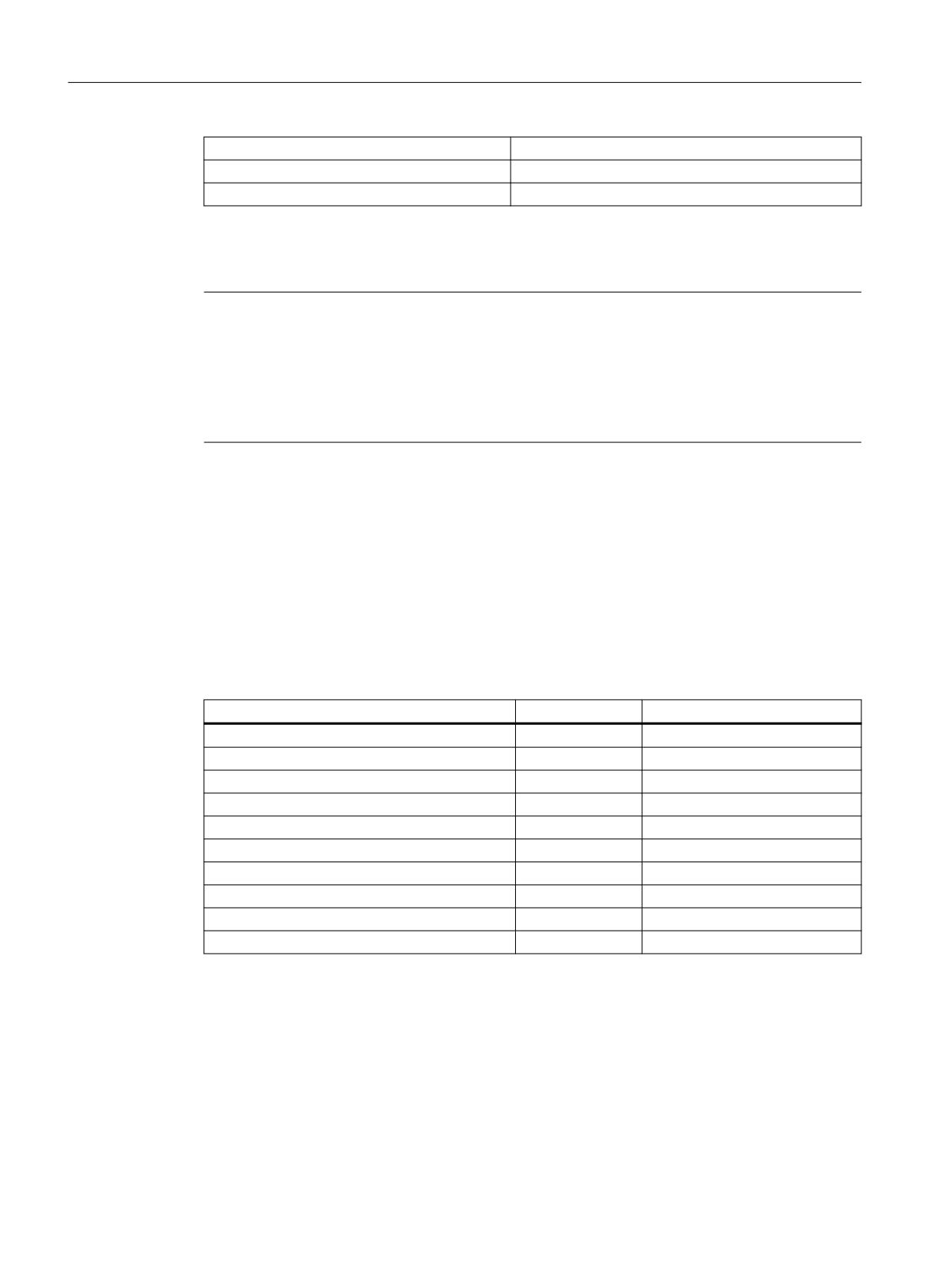
Example: Assigning drive objects
The following table shows on a SINAMICS S120 component structure the drive object
assignment for the drive parameters:
• One Control Unit (CU)
• One Active Line Module (ALM)
• Three Motor Modules
Assignment p0978[0…9] for supply with DRIVE-CLiQ connection:
Component
Index p0978
List of drive objects
1. Motor Module
0
3
2. Motor Module
1
4
3. Motor Module
2
5
not found
3
2551)
not found
4
2551)
not found
5
2551)
CU
6
1
ALM (only if protocol 370 is available)
7
2551)
not found
8
02)
ALM (default setting for SINUMERIK)
9
2
1) Not active
2) Ends the exchange of PZD
The following table describes the assignment of the drive objects in p0978[0…9] for an infeed
without DRIVE-CLiQ connection. This assignment is also done for a drive group with NX
module.
CNC Commissioning: NC, PLC, Drive
184
Commissioning Manual, 10/2020, A5E48312804B AB

Commissioning NC-controlled drives
6.9 Tips for commissioning the SINAMICS drives
Assignment of p0978[0…9] for infeed without DRIVE-CLiQ connection:
Component
Index p0978
List of drive objects
1. Motor Module
0
2
2. Motor Module
1
3
3. Motor Module
2
4
not found
3
2551)
not found
4
2551)
not found
5
2551)
CU
6
1
ALM (only if protocol 370 is available)
7
2551)
not found
8
02)
not found
9
0
1) Not active
2) Ends the exchange of PZD
CNC Commissioning: NC, PLC, Drive
Commissioning Manual, 10/2020, A5E48312804B AB
185
Commissioning NC-controlled drives
6.9 Tips for commissioning the SINAMICS drives
Example: Drive group
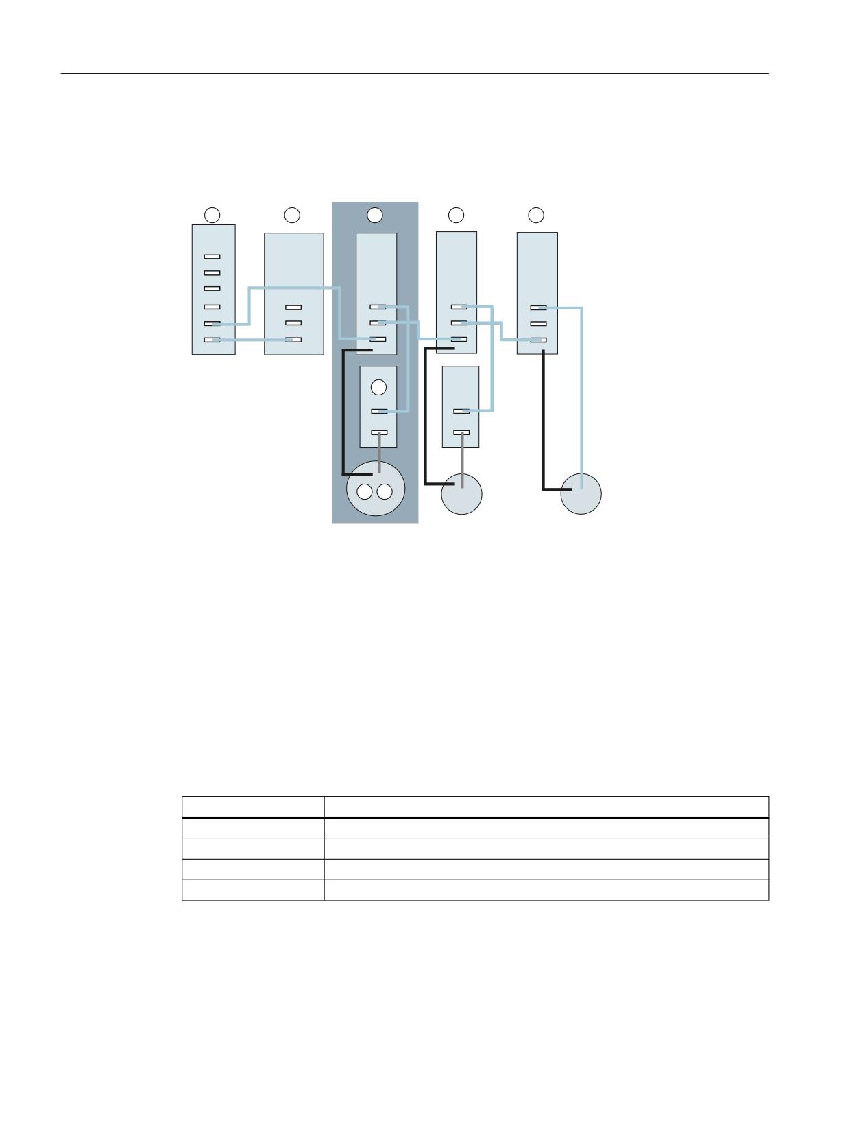
Using the example of a SINAMICS S120 drive line-up, the significance of the drive components
on drive objects is shown: Each drive object has its own parameter list.
1&8
$/0
600
600
600
;
;
;
;
;
;
;
;
;
;
;
;
;
;
;
;
;
;
60&
60&
;
;
;
;
0
0
0
&RQWURO 8QLW 0' ,QIHHG 0' ර
'ULYH 0'
ර
'ULYH 0'
'ULYH 0'
ර
ර
$FWLYH /LQH
$[LV SDUDPHWHU
ර
$[LV SDUDPHWHU OLVW
&RQWURO 8QLW
0RGXOH SDUDPHWHU
OLVW
$[LV SDUDPHWHU
SDUDPHWHU OLVW
OLVW
OLVW
Drive object DO3 comprises the following components:
③ Single Motor Module
⑧ SMC20
⑨ Motor encoder (direct measuring system)
⑩ Motor
Figure 6-7
Drive group
The component number is assigned by the drive after detection of the DRIVE-CLiQ topology. The
associated component numbers can be found in the "Commissioning" → "Machine data" →
"Drive MD" → "Select axis" operating area:
Parameter
Parameter designation
p0121
Power unit component number
p0131
Motor component number
p0141
Sensor Module (encoder interface) component number
p0142
Encoder component number
CNC Commissioning: NC, PLC, Drive
186
Commissioning Manual, 10/2020, A5E48312804B AB
Commissioning NC-controlled drives
6.9 Tips for commissioning the SINAMICS drives
6.9.6
Adjusting speed and brake behavior
Speed adjustment
The following parameters can be set in the "Commissioning" → "Machine data" → "Drive MD"
operating area:
Speed adjustment:
• Spindle drive:
p0500 = 102, speed setpoint in p0322 corresponds to setpoint 4000 0000hex
• Feed drive:
p0500 = 101, speed setpoint in p0311 corresponds to setpoint 4000 0000hex
The speed setpoint can be diagnosed in the relevant drive in r2050[1+2] and r2060[1].
Brake behavior OFF3
Depending on the requirements, the brake behavior for each drive can be adjusted to the signal
2. OFF3.
Default setting p1135 = 0 brake with maximum current.
Using drive-specific parameterization, a flatter braking ramp can be set with the parameters
p1135, p1136, p1137 .
Maximum braking ramp setting: 600 seconds.
CNC Commissioning: NC, PLC, Drive
Commissioning Manual, 10/2020, A5E48312804B AB
187
Commissioning NC-controlled drives
6.9 Tips for commissioning the SINAMICS drives
CNC Commissioning: NC, PLC, Drive
188
Commissioning Manual, 10/2020, A5E48312804B AB
Communication between the NC and the drive
7
7.1
Overview of NC and drive communication
What will be configured next?
The initial commissioning of the PLC and SINAMICS drives is completed.
The machine data that communicates with the drive is:
• General machine data
General machine data required for communication with the drive via PROFIBUS that has been
preset with default values. These values can be taken over during the initial commissioning:
- The telegram type for transfer
- The logical addresses for the PLC
• Axis-specific machine data
The axis component for transfer of the setpoints and actual values for the relevant axis, is set
in the axis machine data.
Assignment of machine data
Using the example of a SINAMICS S120 module structure (one NCU, one ALM, three Motor
Modules (MM)), the following table illustrates the assignment of the machine data for input
address/output address/telegram/setpoint/actual value.
SINAMICS
STEP 7 (HW Config)
General machine data
Axis machine data2)
S120
DP slave properties
Component
Message frame
I/O address1)
MD13120[0]
MD13050
MD13060
MD30110/
MD30130
type and length
I/O address1)
[0...5] I/O ad-
[0...5] mes-
MD30220
Type of out-
dress1)
sage frame
setpoint /
put Setpoint
type
actual value
assignment
MM1
136 - PZD-11/19
4100
4100
136
1
1
MM2
136 - PZD-11/19
4140
4140
136
2
1
MM3
136 - PZD-11/19
4180
4180
136
3
1
Not available
136 - PZD-11/19
4220
4220
136
--
0
Not available
136 - PZD-11/19
4260
4260
136
--
0
Not available
136 - PZD-11/19
4300
4300
136
--
0
CU
391 - PZD-3/7
6500
6500
ALM
370 - PZD-1/1
6514
1)
Do not change preassignment.
2)
The axis-specific machine data for the configuration of the setpoints and actual values is pre-assigned using the "Assign axis"
function.
CNC Commissioning: NC, PLC, Drive
Commissioning Manual, 10/2020, A5E48312804B AB
189
Communication between the NC and the drive
7.2 Configuring the communication to the drive
7.2
Configuring the communication to the drive
Default settings
The telegram length in the hardware configuration is preassigned with the associated I/O
addresses. This pre-assignment for SINAMICS corresponds to the following telegrams with the
maximum possible telegram length:
• Telegram 136: for the axes
• Telegram 391: For the CU
• Telegram 370: for the ALM
This ensures that all telegrams can be supplied without change.
Telegram lengths and I/O addresses
Procedure:
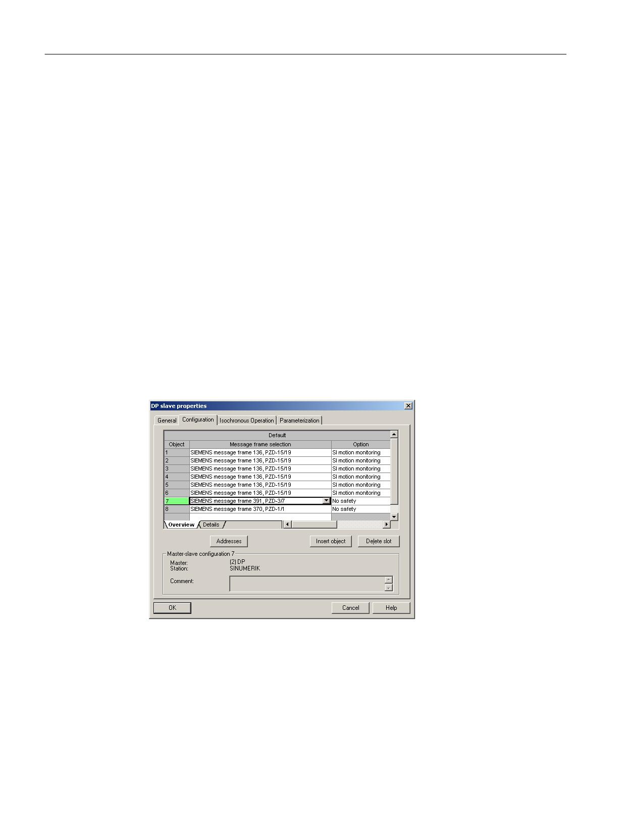
1. To view this configuration, click in the HW Config on the module "SINAMICS Integrated" and
select "Object properties", using the <right mouse button>.
2. Select the "Configuration" tab and select the "Overview" tab to display the lengths of the
preassigned telegrams.
The diagram shows the default setting of the telegrams for 6 axes (object 1 ... 6):
3. Click "OK" to close the dialog.
CNC Commissioning: NC, PLC, Drive
190
Commissioning Manual, 10/2020, A5E48312804B AB
Communication between the NC and the drive
7.2 Configuring the communication to the drive
Example
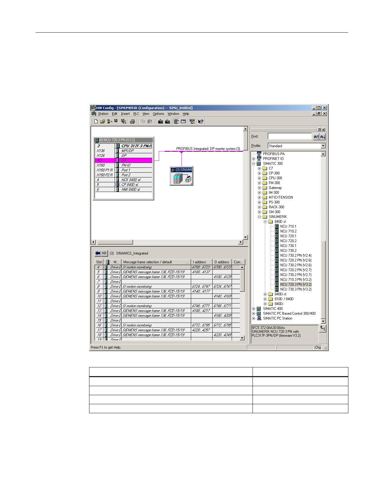
The address areas are displayed in the detail view by clicking the "SINAMICS Integrated" object.
Here, for example, address 4100 corresponds to the address entered in MD13050 $MN_DRIVE-
LOGIC_ADRESS[0]. The addresses have a gap of 40 bytes. The example shows the assignment of
the I/O addresses of the PLC configuration to MD13050 $MN_DRIVE-LOGIC_ADRESS[ 0 … 5]:
Figure 7-1
Telegram lengths and I/O addresses
Default setting in the NC:
MD13050 $MN_DRIVE_LOGIC_ADRESS[0] = 4100
For the 1st axis
MD13050 $MN_DRIVE_LOGIC_ADRESS[1] = 4140
For the 2nd axis
MD13050 $MN_DRIVE_LOGIC_ADRESS[2] = 4180
For the 3rd axis
MD13050 $MN_DRIVE_LOGIC_ADRESS[3] = 4220
For the 4th axis ... etc.
CNC Commissioning: NC, PLC, Drive
Commissioning Manual, 10/2020, A5E48312804B AB
191
Communication between the NC and the drive
7.3 Configuring the I/O address and telegram
7.3
Configuring the I/O address and telegram
Connection to PROFIBUS/PROFINET
The following machine data are preset for the PROFIBUS/PROFINET connection of the axes to the
drive:
• MD13050 $MN_DRIVE_LOGIC_ADDRESS (axis address)
• MD13060 $MN_DRIVE_TELEGRAM_TYPE (telegram type)
• MD13120 $MN_CONTROL_UNIT_LOGIC_ADDRESS (CU address)
CNC Commissioning: NC, PLC, Drive
192
Commissioning Manual, 10/2020, A5E48312804B AB
Communication between the NC and the drive
7.3 Configuring the I/O address and telegram
Procedure:
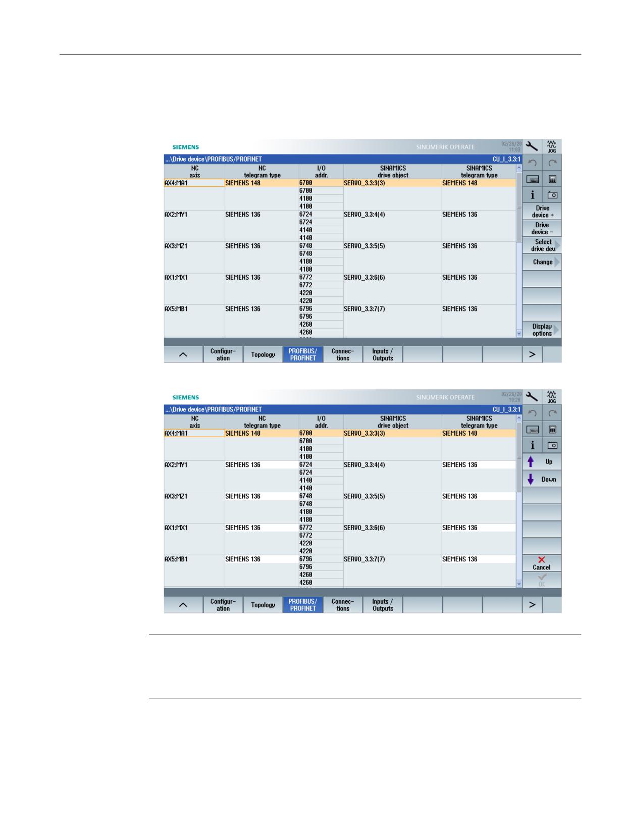
1. The connection of the relevant axes to the drive via PROFIBUS is displayed in operating area
"Commissioning" → "Drive system" → "Drive units" → "PROFIBUS/PROFINET":
2. Select softkey "Change >", to change the assignment with softkeys "Up"/"Down" with arrow:
Note
Communication between the NC and the drive
Carefully ensure that the set I/O addresses and telegram types match the settings in the
hardware configuration to guarantee communication between NC and drive.
CNC Commissioning: NC, PLC, Drive
Commissioning Manual, 10/2020, A5E48312804B AB
193
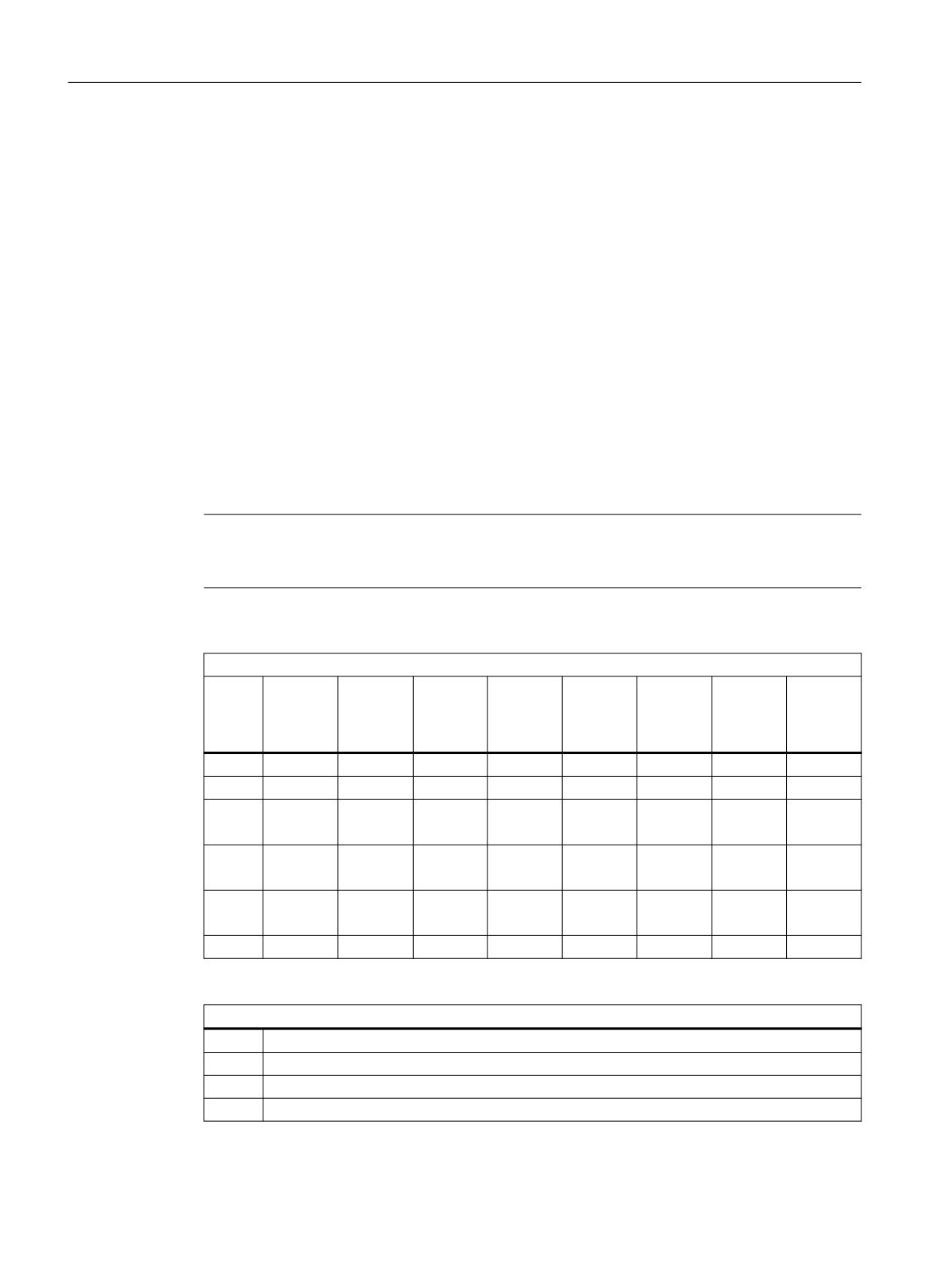
Communication between the NC and the drive
7.4 Process data transfer between the NC and drive
7.4
Process data transfer between the NC and drive
Telegram types
Which telegram types are available?
• Standard telegrams
The standard telegrams are structured in accordance with the PROFIdrive Profile V4.1. The
internal process data links are set up automatically in accordance with the telegram number
setting.
• Manufacturer-specific telegrams
The manufacturer-specific telegrams are structured in accordance with internal company
specifications. The internal process data links are set up automatically in accordance with the
telegram number setting.
The telegram length for communication with the drive is specified in the HW Config, and
depends on the required axis functions, e.g. the number of encoders or the functionality of the
deployed drive.
Note
If the telegram length of a drive component is changed in HW Config, the selection of the
telegram type also has to be adapted in the configuration of the interface in the NC.
The following manufacturer-specific telegrams can be set with parameter p0922:
Telegrams for the axes (SERVO):
Torque
Torque
Position
DSC
Encoder
Encoder
Encoder
Adapta-
reduc-
feedfor-
control-
1
2
3
tion pa-
tion
ward
ler gain
rameter
control
116
x
--
x
x
x
x
--
--
118
x
--
x
x
x
x
--
--
136
x
x
x
x
x
x
--
--
146
x
x
x
x
x
x
--
x
138
x
x
x
x
--
x
x
--
148
x
x
x
x
--
x
x
x
139
x
x
x
x
x
--
--
--
149
x
x
x
x
x
--
--
x
166
x
x
x
x
x
x
--
--
Telegrams 146, 148, 149 also have an additional control and status word.
Telegrams for the integrated SINAMICS Control Unit (CU_I):
370
Infeed
390
without probe for NX extension
391
up to 2 probes for the NCU
395
16 probes and digital inputs/outputs
CNC Commissioning: NC, PLC, Drive
194
Commissioning Manual, 10/2020, A5E48312804B AB
Communication between the NC and the drive
7.4 Process data transfer between the NC and drive
Communication between the NC and the drive
The telegrams from the NC to the drive are transferred via the internal PROFIBUS of the NCU:
• Send telegrams (drive → NC)
• Receive telegrams (NC → drive)
The telegrams are standard telegrams with pre-defined assignment of the process data (PZD),
and are interconnected in the drive object using BICO technology.
The following drive objects can exchange process data:
1. Active Line Module (A_INF)
2. Basic Line Module (B_INF)
3. Motor Module (SERVO)
4. Control Unit (CU_I, CU)
The sequence of the drive objects in the telegram on the drive side can be set in parameter
p0978[0...15]: Operating area "Commissioning" → "Machine data" → "Control Unit parameters".
Selecting a telegram via p0922 of the related drive object ("Commissioning" → "Machine data"
→ "Drive parameters" operating area) determines the process data to be transferred.
The receive and send words comprise the following elements:
• Receive words: Control words or setpoints
• Send words: Status words or actual values
Further details are found in the following SINAMICS Manuals:
• SINAMICS S120 Function Manual (FH1) (https://support.industry.siemens.com/cs/ww/en/
view/109771805) in the Section "Communication"
• SINAMICS S120/S150 List Manual (LH1) (https://support.industry.siemens.com/cs/ww/en/
view/109763271) in the Section "Function block diagrams"
CNC Commissioning: NC, PLC, Drive
Commissioning Manual, 10/2020, A5E48312804B AB
195
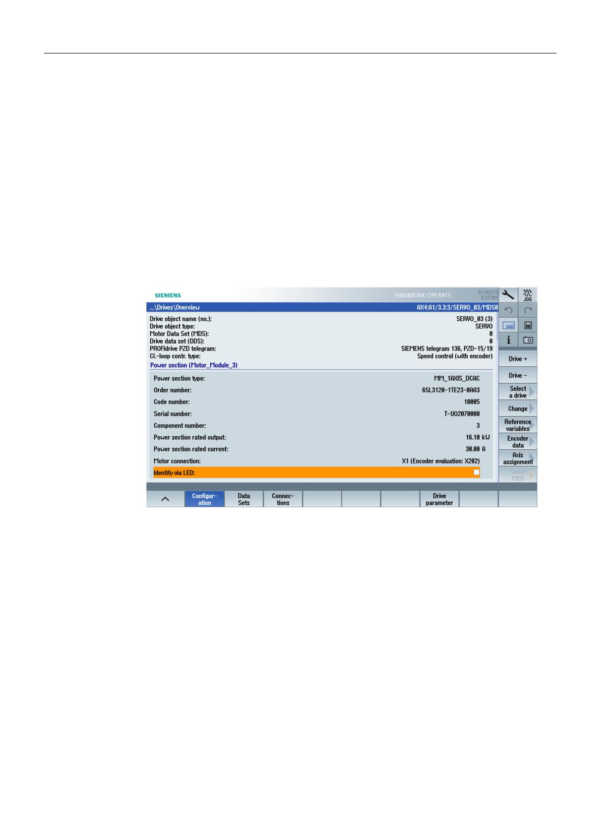
Communication between the NC and the drive
7.5 Drives: Assign axis
7.5
Drives: Assign axis
Condition
The commissioning of the drives has been completed.
Assigning drive and axis
Procedure:
1. Press the "Drive system" → "Drives" softkeys in the "Commissioning" operating area.
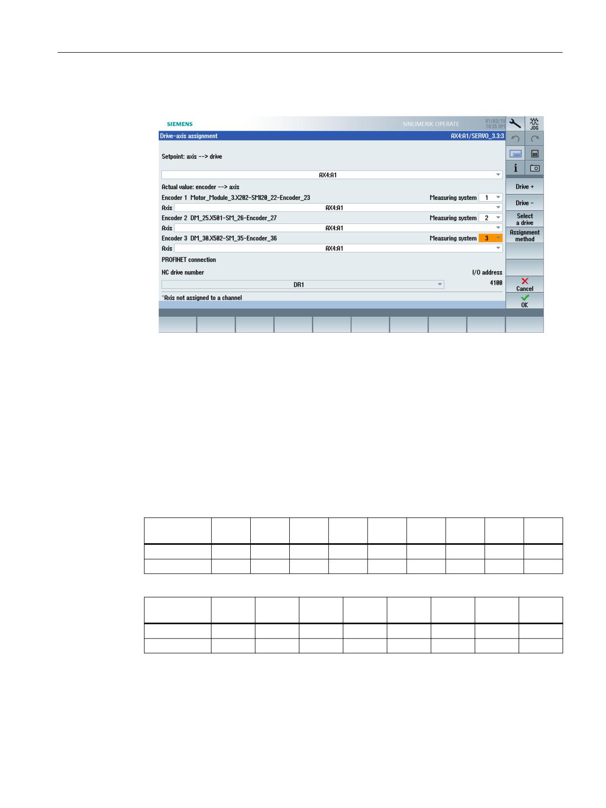
2. With the "Drive +/-" or "Select drive" softkeys, select the drive; in this example, SERVO_3.3:3
for the spindle.
3. To assign the drive to an axis, press the "Axis assignment >" softkey on the vertical softkey bar.
4. Mark the uppermost selection box for the "Setpoint: Axis → drive".
CNC Commissioning: NC, PLC, Drive
196
Commissioning Manual, 10/2020, A5E48312804B AB
Communication between the NC and the drive
7.5 Drives: Assign axis
5. Mark the next selection box for the "Actual value: Encoder → axis" and assign a measuring
system in accordance with the table below.
6. Select the drive object from "NC drive number": The associated I/O address from the PLC
configuring is then displayed automatically.
7. Click "OK" to confirm the assignment and write the data.
Encoder selection and assignment
The assignment of an axis to a drive is called setpoint assignment; the assignment of an
encoder to an axis is called actual value assignment. The assignments are described below. A
setpoint assignment (axis → drive) without encoder assignment is permitted because not all
axes require encoders, e.g. spindles. The encoders are assigned automatically if they have
already been configured for the drive and are transferred in the telegram.
The tables show which SINAMICS encoders are supported by which telegram:
Message
(1 / 2)
3
4
5
6
102
103
104
105
frames
Encoder 1
--
1
1
1
1
1
1
1
1
Encoder 2
--
--
2
--
2
--
2
3
--
Message
106
107
116
118
136/146
138/148
139/149
166
frames
Encoder 1
1
1
1
2
1
2
1
1
Encoder 2
2
3
2
3
2
3
--
2
The numbers in the lines for encoder 1 / encoder 2 indicate the running number of the encoder
on the SINAMICS drive. This number is transferred in the selected telegram to the NC and
assigned to the axis as encoder 1 or encoder 2.
CNC Commissioning: NC, PLC, Drive
Commissioning Manual, 10/2020, A5E48312804B AB
197
Communication between the NC and the drive
7.5 Drives: Assign axis
The telegrams in MD13060 $MN_DRIVE_TELEGRAM_TYPE are preassigned with the values from
the HW Config. This preassignment is set correspondingly for the assignment of the drive to an
axis. The following also applies to a setpoint assignment: MD30130 $MA_CTRLOUT_TYPE[ ] = 1.
Selecting the assignment procedure
Select from the following procedures in the "Assignment Procedure" dialog:
• Via axis machine data (NC drive number)
The NC drive number is retained and written for the selected axis into the following axis
machine data:
MD30110 $MA_CTRL_OUT_MODULE_NR and MD30220 $MA_ENC_MODUL_NR
• Via general machine data (I/O address) = default setting
For this assignment procedure, the I/O address assigned to the drive using the NC drive
number is written to the following general machine
data: MD13050 $MN_DRIVE_LOGIC_ADDRESS[<NC drive number> - 1]. This assumes that
the I/O address default setting is not changed in the PLC project.
• User-defined
If you select this option, the selection list can be edited under "NC drive number". Then assign
a drive number and the displayed I/O address to the axis selected above. This option is
recommended only for experienced machine manufacturers!
CNC Commissioning: NC, PLC, Drive
198
Commissioning Manual, 10/2020, A5E48312804B AB
Communication between the NC and the drive
7.6 Configuring machine axes
7.6
Configuring machine axes
7.6.1
Axis assignment
Introduction
Generally, a distinction is made between four types of axes:
• Machine axes
Machine axes are the motion units existing on a machine, which can also be designated as
linear or rotary axes, depending on their usable movement.
• Channel axes
The total of all machine, geometry and special axes assigned to a channel is designated as
channel axes. In this context, the geometry and special axes constitute the program-
technological part of the machining process, i.e. they are used for programming in the parts
program. The machine axes constitute the physical part of the machining process, i.e. they
carry out the programmed traversing movements on the machine.
• Geometry axes
The geometry axes constitute the rectangular Cartesian basic coordinate system of a
channel. Generally, (Cartesian arrangement of the machine axes) direct imaging of the
geometry axes to the machine axes is possible. If the arrangement of the machine axes,
however, is not Cartesian at right angles, the imaging is performed using a kinematic
transformation.
• Special axes
Special axes are all other channel axes that are not geometry axes. Unlike for geometry axes
(Cartesian coordinate system), no geometric context is defined for special axes, neither
between additional axes nor with respect to geometry axes.
Note
Geometry and special axes
A maximum of three channel axes can be declared as geometry axes. The geometry axes must
be assigned to the channel axes in ascending order without any gaps. All channel axes that are
not geometry axes are special axes.
CNC Commissioning: NC, PLC, Drive
Commissioning Manual, 10/2020, A5E48312804B AB
199
Communication between the NC and the drive
7.6 Configuring machine axes
Axis assignment
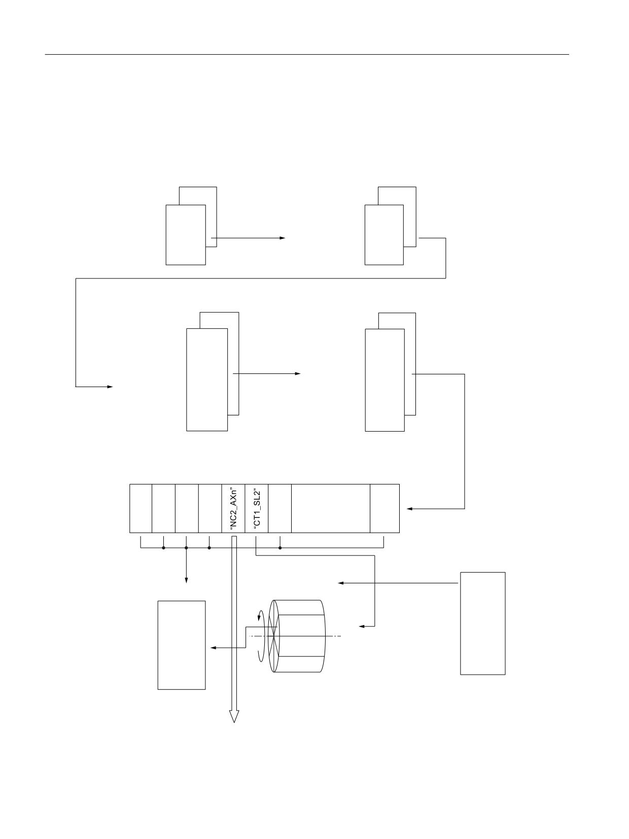
The assignment of geometry axes to channel axes and channel axes to machine axes, as well as
the definition of the names of the different axis types is realized via machine data. The following
diagram illustrates this relationship:
1&8
*HRPHWU\ D[LV QDPHV
&KDQQHO D[HV XVHG
0'
0&B$;&21)B*(2$;B1$0(B7$%>Q@>P@
0'
0&B$;&21)B*(2$;B$66,*1B7$%>Q@>P@
&KDQQHO
&KDQQHO Q
Q
&KDQQHO
&KDQQHO
VW JHRPHWU\ D[LV
> @
ಯ;ರ
VW JHRPHWU\ D[LV
> @
QG JHRPHWU\ D[LV
> @
ಯ<ರ
QG JHRPHWU\ D[LV
> @
UG JHRPHWU\ D[LV
> @
ಯ= ರ
UG JHRPHWU\ D[LV
> @
&KDQQHO D[LV QDPHV
0DFKLQH D[HV XVHG
0'
0&B$;&21)B&+$1$;B1$0(B7$%>Q@>P@
0'
0&B$;&21)B0$&+$;B86('>Q@>P@
&KDQQHO Q
&KDQQHO Q
&KDQQHO
&KDQQHO
VW FKDQQHO D[LV
> @
ಯ;ರ
VW FKDQQHO D[LV
> @
QG FKDQQHO D[LV
> @
ಯ<ರ
QG FKDQQHO D[LV
> @
UG FKDQQHO D[LV
> @
ಯ=ರ
UG FKDQQHO D[LV
> @
WK FKDQQHO D[LV
> @
ಯ$ರ
WK FKDQQHO D[LV
> @
WK FKDQQHO D[LV
> @
ಯ%ರ
WK FKDQQHO D[LV
> @
WK FKDQQHO D[LV
> @
ಯ8ರ
WK FKDQQHO D[LV
> @
WK FKDQQHO D[LV
> @
ಯ9ರ
WK FKDQQHO D[LV
> @
WK FKDQQHO D[LV
> @
ಯರ
WK FKDQQHO D[LV
> @
/RJLFDO PDFKLQH D[LV LPDJH
0'
01B$;&21)B/2*,&B0$&+$;B7$%>Q@
> @
> @
> @
> @
> @
> @
> @
>
@
ಯ$; ರ
ಯ$; ರ
ಯ$; ರ
ಯ$; ರ
ಯ$; ರ
ಯ$; ರ
$[LV FRQWDLQHU QDPHV
0'
01B$;&7B1$0(B7$%>Q@
/RFDO PDFKLQH D[HV
0'
$[LV FRQWDLQHU ಯ&7 ರ
> @
ಯ&7 ರ
01B$;&21)B0$&+$;B1$0(B7$%>Q@
0'
01B$;&7B$;&21)
B$66,*1B7$%
> @
ಯ&7 ರ
VW PDFKLQH D[LV
> @
ಯ$; ರ
1& B$;
6ORW
> @
ಯ&7 ರ
QG PDFKLQH D[LV
> @
ಯ$; ರ
> @
ಯ&7 ರ
UG PDFKLQH D[LV
> @
ಯ$; ರ
1& B$;
6ORW
> @
ಯ&7 ರ
WK PDFKLQH D[LV
> @
ಯ$; ರ
WK PDFKLQH D[LV
> @
ಯ$; ರ
1& B$;
6ORW
> @
ಯ&7 ರ
WK PDFKLQH D[LV
> @
ಯ$; ರ
> @
ಯ&7 ರ
WK PDFKLQH D[LV
> @
ಯರ
1& B$;
6ORW
WK PDFKLQH D[LV
> @
ಯರ
1&QB$;P &RQWDLQHU OLQN D[LV
/LQN D[LV 0DFKLQH D[LV $;Q RQ 1&8
Figure 7-2
Axis assignment
CNC Commissioning: NC, PLC, Drive
200
Commissioning Manual, 10/2020, A5E48312804B AB
Communication between the NC and the drive
7.6 Configuring machine axes
Channel axis gaps
Normally, using MD20070, a channel axis is assigned to one machine axis. Not every channel
axis must be assigned to a machine axis. Each channel axis with MD20070 [n] = 0 is not assigned
any machine axis and represents a channel axis gap.
Channel axis gaps allow the creation of a uniform configuration of the channel axes over
different machine versions of a series. Each channel axis of the series has a defined task or
function. If the function and therefore the machine axis is not available on a specific machine,
the relevant channel axis is not assigned a machine axis:
MD20070 $MC_AXCONF_MACHAX_USED[<channel axis>] = 0
Advantages:
• Commissioning archive with uniform basic configuration
• Simple post configuration for the specific machine
• Flexible portability of part programs
Enabling channel axis gaps
The use of channel axis gaps is enabled using the machine data:
MD11640 $MN_ENABLE_CHAN_AX_GAP = 1 (channel axis gap allowed).
If the use of channel axis gaps has not been enabled, then the value 0 for channel axis n in the
following machine data terminates the allocation of additional machine axes to possible
channel axes from channel axis n onwards:
MD20070 $MC_AXCONF_MACHAX_USED[<channel axis n>]
Supplementary conditions:
• Regarding the number of channel axes and the indexing, a channel axis gap counts just the
same as axes.
• Ensure that a geometry axis is not assigned to a channel axis, that is not assigned to a
machine axis (channel axis gap). No alarm is displayed.
• Transformation: When configuring a channel axis in the following machine data, which is not
assigned a machine axis (channel axis gap), an alarm is output:
- MD24110 ff. $MC_TRAFO_AXES_IN1...8
- MD24120 ff. $MC_TRAFO_GEOAX_ASSIGN_TAB1...8
Example
The 5th channel axis "B" in MD20070 is not assigned to a machine axis.
If channel axis gaps are enabled, six machine axes (1 - 4, 5, 6) are available.
If channel axis gaps are not enabled, then there are four machine axes (1 - 4) available.
CNC Commissioning: NC, PLC, Drive
Commissioning Manual, 10/2020, A5E48312804B AB
201
Communication between the NC and the drive
7.6 Configuring machine axes
&KDQQHO D[LV QDPHV
0DFKLQH D[HV XVHG
0'
0&B$;&21)B&+$1$;B1$0(B7$%>Q@>P@
0'
0&B$;&21)B0$&+$;B86('>Q@>P@
1&8
&KDQQHO Q
&KDQQHO Q
&KDQQHO
&KDQQHO
VW FKDQQHO D[LV
> @
;
VW FKDQQHO D[LV
> @
QG FKDQQHO D[LV
> @
<
QG FKDQQHO D[LV
> @
UG FKDQQHO D[LV
> @
=
UG FKDQQHO D[LV
> @
WK FKDQQHO D[LV
> @
$
WK FKDQQHO D[LV
> @
WK FKDQQHO D[LV
> @
%
&KDQQHO D[LV JDS
WK FKDQQHO D[LV
> @
WK FKDQQHO D[LV
> @
8
WK FKDQQHO D[LV
> @
WK FKDQQHO D[LV
> @
9
WK FKDQQHO D[LV
> @
WK FKDQQHO D[LV
> @
WK FKDQQHO D[LV
> @
Figure 7-3
Axis configuration with channel axis gap
7.6.2
Axis names
Machine axes
Each machine axis, channel axis and geometry axis is assigned an individual name that clearly
identifies the axis. Machine axis names must be unambiguous for the entire NC. The name of the
machine axes are defined via the following machine date:
MD10000 $MN_AXCONF_MACHAX_NAME_TAB [n] (machine axis name)
The specified names and the associated index are used in the following cases:
• Accessing axis-specific machine data (loading, saving, displaying)
• Reference point approach from the parts program G74
• Measuring
• Test point traversing from the parts program G75
• Traversing the machine axis from the PLC
• Display of axis-specific alarms
• Display in the actual-value system (machine-related)
• DRF handwheel function
Channel axes
The name of the channel axes are defined via the following machine date:
MD20080 $MC_AXCONF_CHANAX_NAME_TAB[n] (name of the channel axis in the channel)
Channel axis names must be unambiguous for the entire channel.
Geometry axes
The names of the geometry axes must be absolutely unique throughout the channel, and are
defined using the following machine data:
CNC Commissioning: NC, PLC, Drive
202
Commissioning Manual, 10/2020, A5E48312804B AB
Communication between the NC and the drive
7.6 Configuring machine axes
MD20060 $MC_AXCONF_GEOAX_NAME_TAB [n] (geometry axis in the channel)
The names for channel and geometry axes are used in the part program for programming
general traversing movements and to describe the workpiece contour.
• Path axes
• Synchronized axes
• Positioning axes
• Command axes
• Spindles
• Gantry axes
• Coupled axes
• Guide value coupling axes
7.6.3
Drive assignment
Drive assignment
The assignment of machine axes to the SERVO drive objects is realized using machine data.
/RFDO PDFKLQH D[HV
0'
01B$;&21)B0$&+$;B1$0(B7$%>Q@
VW PDFKLQH D[LV
> @
$;
QG PDFKLQH D[LV
> @
$;
UG PDFKLQH D[LV
> @
$;
WK PDFKLQH D[LV
> @
$;
WK PDFKLQH D[LV
> @
$;
$FWXDO VHWSRLQW FKDQQHO RI WKH PDFKLQH D[HV
0'
0$B&75/287B02'8/(B15> @>Q@
, 2 DGGUHVVHV RI WKH 6(592 GULYH REMHFWV
0'
0$B(1&B02'8/(B15> @>Q@
0'
01B'5,9(B/2*,&B$''5(66>Q@
VW PDFKLQH D[LV
> @
> @
, 2 DGGUHVV RI WKH 6(592 GULYH REMHFW
QG PDFKLQH D[LV
> @
> @
, 2 DGGUHVV RI WKH 6(592 GULYH REMHFW
UG PDFKLQH D[LV
> @
> @
, 2 DGGUHVV RI WKH 6(592 GULYH REMHFW
WK PDFKLQH D[LV
> @
> @
, 2 DGGUHVV RI WKH 6(592 GULYH REMHFW
WK PDFKLQH D[LV
> @
> @
, 2 DGGUHVV RI WKH 6(592 GULYH REMHFW
Figure 7-4
Drive assignment
CNC Commissioning: NC, PLC, Drive
Commissioning Manual, 10/2020, A5E48312804B AB
203
Communication between the NC and the drive
7.6 Configuring machine axes
Assignment:
1. Using this machine data, the NC is informed about the I/O addresses of the SERVO drive
objects defined in the PLC project:
MD13050 $MN_DRIVE_LOGIC_ADDRESS[n]
2. Using the following machine data, the setpoint and actual values of the machine axes are
assigned to the relevant drive objects:
- MD30110 $MA_CTRLOUT_MODULE_NR[0]
- MD30220 $MA_ENC_MODULE_NR[0]
The logical drive number m to be entered into both machine data, refers to the I/O address
entered in ① under index n = (m - 1).
3. Using machine data MD10000 $MN_AXCONF_MACHAX_NAME_TAB, the machine axes in
the NC are assigned a unique name. Index n addresses machine axis (n+1).
CNC Commissioning: NC, PLC, Drive
204
Commissioning Manual, 10/2020, A5E48312804B AB
NC commissioning
8
8.1
Machine and setting data
Setting machine data
Adaptation of the control at the machine is performed using the machine and setting data.
• The machine data (MD) is divided into the following areas:
- General machine data
- Channel-specific machine data
- Axis-specific machine data
- Parameters for the Control Unit
- Parameter for the infeed
- Drive parameters
• The setting data (SD) is divided into the following areas:
- General setting data
- Channel-specific setting data
- Axis-specific setting data
The following table provides an overview of the machine data and setting data areas:
Range
Designation
from 9000 to 9999
Display machine data
from 10000 to 18999
General NC machine data
from 19000 to 19999
Reserved
from 20000 to 28999
Channel-specific machine data
from 29000 to 29999
Reserved
from 30000 to 38999
Axis-specific machine data
from 39000 to 39999
Reserved
from 41000 to 41999
General setting data
from 42000 to 42999
Channel-specific setting data
from 43000 to 43999
Axis-specific setting data
from 51000 to 51299
General configuration machine data
from 51300 to 51999
General cycle machine data
from 52000 to 52299
Channel-specific configuration machine data
from 52300 to 52999
Channel-specific cycle machine data
from 53000 to 53299
Axis-specific configuration machine data
from 53300 to 53999
Axis-specific cycle machine data
CNC Commissioning: NC, PLC, Drive
Commissioning Manual, 10/2020, A5E48312804B AB
205
NC commissioning
8.1 Machine and setting data
The SINUMERIK Operate Online Help provides a context-related description of the
machine data and setting data.
Effectiveness
The effectiveness of a machine data item specifies when the change becomes active:
po
The changed machine data require an "NCK Reset" to become effective.
re
The changed machine data must be activated by pressing the <RESET> key.
cf
The changed machine data must be activated by pressing the "Apply MD" softkey.
so
The changed machine data becomes active immediately.
Changes to the setting data always take effect immediately.
A complete description of the machine data and setting data is provided in the List Manual
Machine Data and Parameters (https://support.industry.siemens.com/cs/document/
109766213)
CNC Commissioning: NC, PLC, Drive
206
Commissioning Manual, 10/2020, A5E48312804B AB

NC commissioning
8.2 Procedure when commissioning the NC
8.2
Procedure when commissioning the NC
NC commissioning
We recommend the following sequence when commissioning the NC:
Procedure
Reference
①
Parameter sets of axis/spindle
• Velocities, setpoint/actual value systems, closed-loop
control
• Spindles
②
Axis configuration
• Axes, coordinate systems, frames
• Synchronous spindles
• Rotary axes
• Compensations
③
Parameterizing axis data:
Velocities, setpoint/actual value systems, closed-loop con-
trol
• Parameterizing the incremental-rotary measuring
system
• Setpoint/actual value system → Actual value resolution
• Parameterizing the incremental-linear measuring
• Setpoint/actual value system → Actual value resolution
system
• Setpoint/actual value system → Actual value resolution
• Parameterizing the absolute measuring system
• Setpoint/actual value system
• Setpoint/actual-value channels
• Tuning of the control
• Dynamic Stiffness Control (DSC)
• Rotary axes
• Rotary axes
• Positioning axes
• Positioning axes
• Closed-loop control
• Position controller
• Closed-loop control
• Speed setpoint calibration
• Velocities
• Axis velocity matching
• Axis monitoring, protection zones
• Axis monitoring functions (static)
• Axis monitoring, protection zones
• Axis monitoring functions (dynamic)
④
Parameterizing the spindle data:
Spindles
• Setpoint/actual-value channels
• Setpoint/actual value system
• Measuring systems
• Setpoint/actual value system
• Gear stages
• Gear stages for spindles and gear change change
• Velocities and setpoint adaptation
• Gear stages for spindles and gear change change
• Spindle positioning
• Spindle modes > Axis mode
• Spindle synchronization
• Reference / synchronize
• Monitoring
• Spindle monitoring
⑤
Referencing axis/spindle:
Reference point approach
• Incremental measuring system
• Referencing with incremental measurement systems
• Distance-coded reference marks
• Referencing with distance-coded reference marks
• Absolute encoder homing
• Referencing with absolute encoders
CNC Commissioning: NC, PLC, Drive
Commissioning Manual, 10/2020, A5E48312804B AB
207
NC commissioning
8.2 Procedure when commissioning the NC
References:
Function Manual
- Axes, coordinate systems, frames
- Various NC/PLC interface signals and functions
• "Monitoring and Compensating" (https://support.industry.siemens.com/cs/document/
109766213)
- Axis monitoring functions
- Compensations
Function Manual
- Velocities, setpoint/actual value systems, closed-loop control
- Positioning axes
- Homing
- Spindles
- Synchronous spindle
Setting the technology
User views are lists of machine data and setting data that are compiled for a special application.
In order to set all the technology-relevant data for a turning machine or milling machine on the
control, the following user views are available to facilitate the commissioning:
• Setup_Milling
• Setup_Turning
The files are stored on the CompactFlash card under:
/user/sinumerik/hmi/template/user_views/param
Product announcement (https://support.industry.siemens.com/cs/de/en/view/
80582059)
CNC Commissioning: NC, PLC, Drive
208
Commissioning Manual, 10/2020, A5E48312804B AB
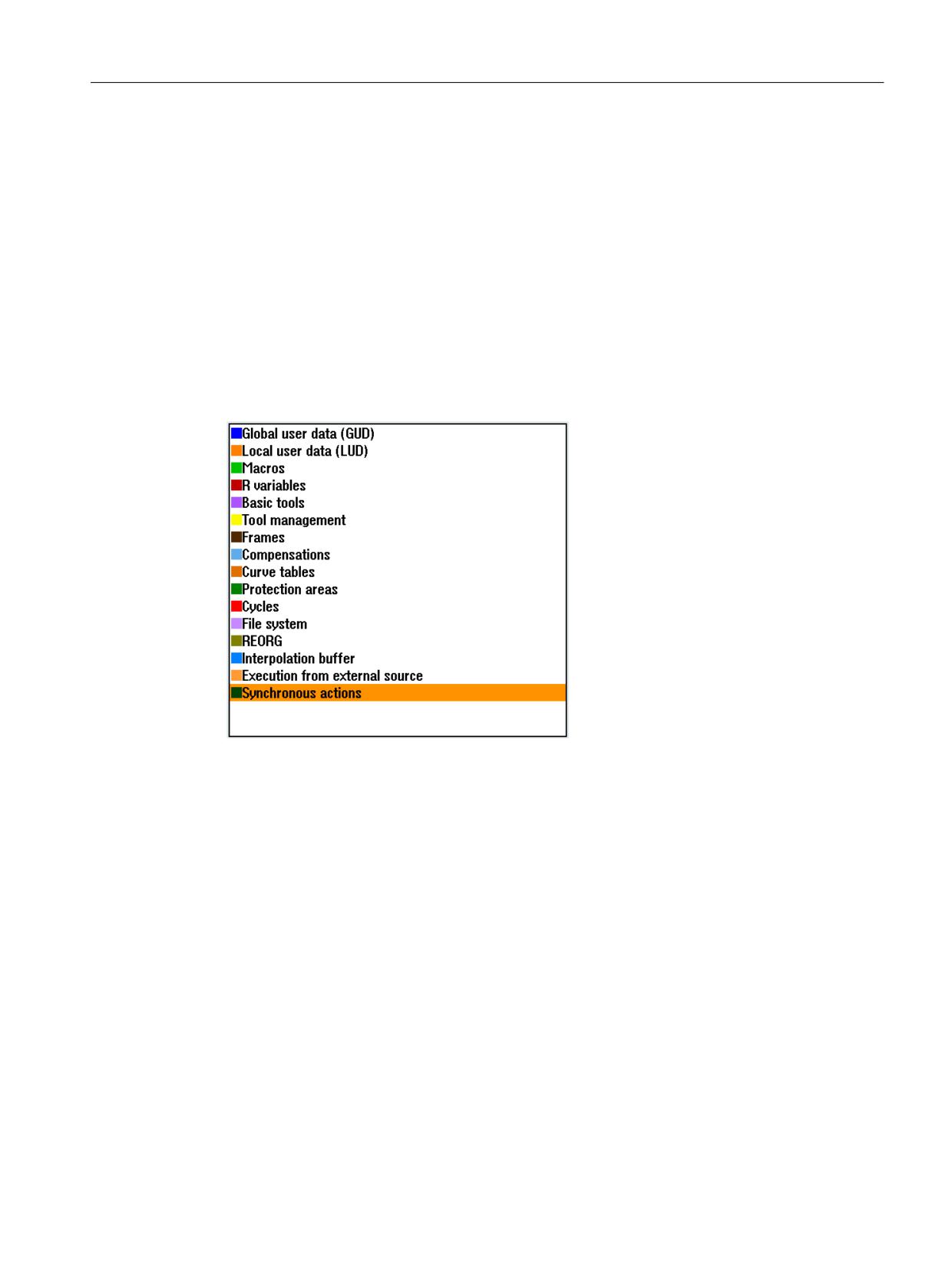
NC commissioning
8.3 Memory configuration
8.3
Memory configuration
Requirement
A dialog is provided in the "Commissioning" → "NC" → "NC memory" operating area which
supports you when partitioning the NC memory. The "Service" access level is required for this.
Memory division
The memory-configuring NC machine data is divided into various function areas, such as tool
management‚ user data‚ zero offsets and memory types. The graphic with the following legend
shows the division of the individual data areas:
The following memory expansions are available as licensed software option:
• Additional 2 MB CNC user memory (6FC5800-0AD00-0YB0)
• Additional PLC user memory (6FC5800-0AD10-0YB0)
• Execution from external storage (EES) (6FC5800-0AN75-0YB0)
• Expanded CNC user memory (6FC5800-0AN77-0YB0)
• Additional user memory on the CompactFlash card of the NCU (6FC5800-0AP12-0YB0)
CNC Commissioning: NC, PLC, Drive
Commissioning Manual, 10/2020, A5E48312804B AB
209
NC commissioning
8.4 Friction compensation with adaptive characteristics
8.4
Friction compensation with adaptive characteristics
8.4.1
Overview
Preconditions
Only those axes are listed for friction compensation for which MD32490 = 3 or 4 is set.
Machine data
Meaning
MD32500 $MA_FRICT_COMP_ENABLE = 1
Enable friction compensation for this axis
Friction compensation with adaptive characteristics:
MD32490 $MA_FRICT_COMP_MODE = 3
Injection time depends on the velocity setpoint
MD32490 $MA_FRICT_COMP_MODE = 4
Injection time depends on the position controller
output
Software option
In order to use this function a license is required for the following option:
"Friction compensation with adaptive characteristic curves" (6FC5800-0_S06-0Yx0)
Call the function at the control in the "Commissioning" → softkey "Friction compensation"
operating area. The softkey is not shown until the option has been set.
Backing up tuning results
When tuning, the axis machine data are changed as follows during the measuring series:
• When a measurement series is started, the friction compensation values in the axis machine
data are reset.
• When the measurement series is exited, the new friction compensation values are written to
the axis machine data and backed up.
• When the measurement series is canceled, the previous friction compensation values are
restored in the machine data.
NOTICE
Backing up tuning results
If the power fails during the tuning process, tuning result data can be lost.
⇒ SINUMERIK 840D sl: In order to avoid that tuning results are lost, it is recommended that you
create a commissioning archive with NC data that contains the axis machine data of the last
complete measurement series. You do not have to select the "With compensation data" option.
⇒ SINUMERIK 828D: In order to avoid that tuning results are lost, it is recommended that you
create a data class archive of the type "INDIVIDUAL" that contains the friction compensation
data of the last complete measurement series.
CNC Commissioning: NC, PLC, Drive
210
Commissioning Manual, 10/2020, A5E48312804B AB
NC commissioning
8.4 Friction compensation with adaptive characteristics
Additional information is provided in Chapter "Compensations" in the "Monitoring and
Compensating" Function Manual.
8.4.2
Axis selection and status display
What is displayed in this dialog?
In the dialog "Axis selection for automatic tuning", for each channel, select the axes for
automatic friction compensation.
Automatic tuning:
Before starting automatic tuning:
For Automatic tuning, in a channel, select several axes that should be automatically tuned one
after the other. The automatic tuning for the selected axes is started for each channel.
Status display:
The following status data is displayed while tuning:
• "waits" for the selected axes, where tuning has still not been started.
• "being tuned" for the axis that is presently being tuned.
• "tuned" for axes, where tuning has already been successfully completed and saved.
Note
Time required (radius, feedrates)
The time required for the automatic tuning is obtained from the selected feedrates and the
radius: Align the feedrates in the channel setting data (Page 216) for the tuning of the axes to
the machining velocities of the machine.
After completing automatic tuning:
To visualize the measurement results, for the automatic tuning process, after each step, the
tuning result is saved as screenshot under the following path: ../user/sinumerik/hmi/data/cst
When tuning an axis, the resolution for the screenshots is the same for all feedrates, and is not
selected less than 1 μm.
After completing tuning of an axis in the channel, the compensation values are written to the
axis machine data and the status display updated.
Tuning quality:
The displayed maximum deviation can vary when repeating the tuning process at the same axis.
If, after measurement, the deviation for a feedrate has not improved when compared to the
initial state, compensation values are not written to the axis machine data.
CNC Commissioning: NC, PLC, Drive
Commissioning Manual, 10/2020, A5E48312804B AB
211
NC commissioning
8.4 Friction compensation with adaptive characteristics
Commissioning archive:
The tuning results in the axis machine data and also the tuning status of the axes are backed up
in the "NC data" commissioning archive. If the commissioning archive with the tuning data from
machine A is read into machine B, then the NC data are completely read in.
• The axis machine data is read in and becomes effective.
• The axis tuning status is read in. Only when selecting the "Friction compensation" dialog, as
a result of the different serial numbers of the system CompactFlash card, you will be
prompted to accept or reject the tuning status.
General conditions for the commissioning sequence:
• For a feed override not equal to 100 %, the selected axis traverses with the reduced feed. The
tuning (automatic and manual) is held, and the circular representation is suppressed until
the feed override has been again set to 100%.
• The computational resolution in MD10200 $MN_INT_INCR_PER_MM and
MD10210 $MN_INT_INCR_PER_DEG must be at least 10000.
• Tuning is not started if, for the selected axes, the following machine data cannot have a value
of 0:
MD32450 $MA_BACKLASH
MD32456 $MA_BACKLASH_DYN
MD32572 $MA_FRICT_V_PULSE_DELAY_TIME
MD32575 $MA_FRICT_V_PULSE_SMOOTH_TIME
MD32578 $MA_FRICT_T_PULSE_SMOOTH_TIME
MD32579 $MA_FRICT_PRETRIGGER_TIME
Manual tuning:
To start manual tuning press the "Manual tuning" softkey. In the next dialog, select the axes that
you wish to tune.
After completing tuning for an axis in the channel, the compensation values are written to the
axis machine data and the status display updated.
⇒ Further actions:
• "Start" softkey to start automatic friction compensation.
• "Manual tuning >" softkey, to start friction compensation with manual input of the
compensation values.
• "OK" softkey to confirm your selection.
• "Cancel" softkey to cancel the selection.
The online help for friction compensation on the SINUMERIK Operate supports you
during optimization.
CNC Commissioning: NC, PLC, Drive
212
Commissioning Manual, 10/2020, A5E48312804B AB
NC commissioning
8.4 Friction compensation with adaptive characteristics
8.4.3
Friction compensation - automatic tuning
Operation on the SINUMERIK Operate
The axes selected in the particular channel are automatically traversed individually one after the
other.
Procedure:
1. The radius and the feedrate for the measurements are preset in the following channel setting
data and apply for all axes in the channel.
Designation
Unit
Machine data
Radius (linear axis)
mm
SD55820 $SCS_FRICT_OPT_RADIUS
Radius (rotary axis)
° (degrees)
SD55821 $SCS_FRICT_OPT_RADIUS_ROT
Feedrate (linear axis)
[mm/min]
SD55822 $SCS_FRICT_OPT_FEED[0...8]
Feedrate (rotary axis)
[°/min]
SD55823 $SCS_FRICT_OPT_FEED_ROT[0...8]
2. Press the "Start" softkey to start measurements. A part program is then automatically
generated; this is done by calling CYCLE790 which reverses the axis with the preset feedrate.
Before the part program is started, a check is made as to whether the entered feedrates can
be achieved based on the dynamic response of the axis. If feedrates are selected to be too
high, a message is output that the feedrates should be reduced.
3. If the entered feedrates have been successfully tested and found to be OK, the part program
is opened in order to add additional program instructions. Confirm with "OK" to close the
window and continue.
On completion of the tuning of an axis in the channel, the compensation values are saved in the
axis machine data and the status display is updated. The next axis is then automatically tuned
in this channel.
Note
Gantry axis grouping
For a gantry axis grouping, only the guide axis is displayed. On completion of the tuning, the
compensation values of the guide axis are copied to the synchronous axes.
⇒ Further actions:
• "Start" softkey to start tuning.
• "Graphic" softkey to change to the graphic display.
• "Data list" softkey to switch to the list of axis machine data and channel setting data.
• "Cancel" softkey to cancel tuning.
CNC Commissioning: NC, PLC, Drive
Commissioning Manual, 10/2020, A5E48312804B AB
213
NC commissioning
8.4 Friction compensation with adaptive characteristics
8.4.4
Friction compensation - manual tuning
Operation on the SINUMERIK Operate
With this function, you can optionally traverse one or two axes. The measurement is graphically
displayed as circle diagram. The values entered for the friction compensation only apply to the
axis which is selected in the header line.
The scaling in the graphic display is adapted automatically as long as a scaling value is not
entered manually. Up to nine measurements with different feedrates can be performed in one
pass. With 1-axis and 2-axis traversing, the upper and the lower reversal points are relevant for
tuning. The measurement consists of an initialization phase and the actual measuring process.
The current status is displayed at the bottom right in the status line via a progress indicator.
Procedure:
1. Press the "Axis +" or "Axis -" softkey to select the axis for which you activated friction
compensation.
The radius, the feedrate and the direction of rotation for the measurements are preset in the
following channel setting data and apply for all axes in the channel. They can be adapted by
pressing the "Data list" softkey:
Designation
Unit
Machine data
Radius (linear axis)
mm
SD55820 $SCS_FRICT_OPT_RADIUS
Radius (rotary axis)
° (degrees)
SD55821 $SCS_FRICT_OPT_RADIUS_ROT
Feedrate (linear axis)
[mm/min]
SD55822 $SCS_FRICT_OPT_FEED[0...8]
Feedrate (rotary axis)
[°/min]
SD55823 $SCS_FRICT_OPT_FEED_ROT[0...8]
Direction of rotation (only
---
SD55828 $SCS_FRICT_OPT_DIR
active for two axes)
2. To start the measurement, press the "Start" softkey. A part program is then automatically
generated and selected by the NC; this is done by calling CYCLE790 which reverses the axis
with the preset feedrate.
Before the part program is started, a check is made as to whether the entered feedrates can
be achieved based on the dynamic response of the axis. If this is not the case, a message is
issued to reduce the feedrates.
3. The part program for the measurement series is then opened if you want to add further
commands. Confirm with "OK" to close the window and continue.
4. Press the NC Start key to start tuning.
CNC Commissioning: NC, PLC, Drive
214
Commissioning Manual, 10/2020, A5E48312804B AB
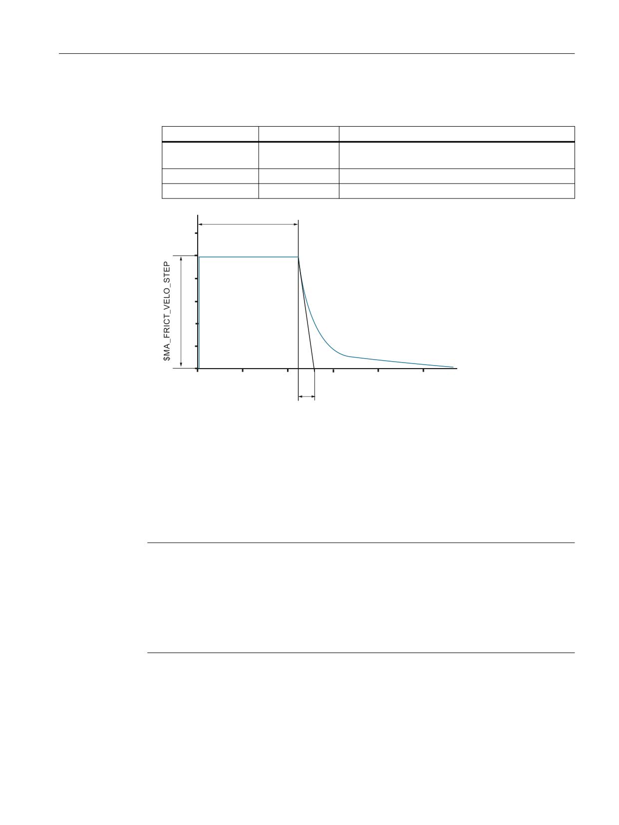
NC commissioning
8.4 Friction compensation with adaptive characteristics
5. The first step with the first feedrate of the measurement series is selected. Enter the friction
compensation values in the following entry fields:
Input field
Unit
Machine data
Amplitude
[mm/min]
MD32571 $MA_FRICT_VELO_STEP
or [°/min]
Decay time
[s]
MD32574 $MA_FRICT_V_PULSE_DECAY_TIME
Active time
[s]
MD32573 $MA_FRICT_V_PULSE_CONST_TIME
0$B)5,&7B9B38/6(B&2167B7,0(
7LPH W >V@
0$B)5,&7B9B38/6(B'(&$<B7,0(
For both traversing directions, as default setting, the same compensation values are entered.
By selecting the option "Set reversal points separately", you can enter different compensation
values for an axis, depending on the particular traversing direction.
6. Press the "Next step" softkey to start a new measurement with the next feedrate and enter
new values. If the measurement is repeated, the values appropriate for the feedrate from the
last measurement are proposed.
After the last step, the measuring series is terminated with "OK" and the data is saved.
Note
Incremental value change
Use the following shortcut keys to change the compensation values incrementally:
• The selected entry field is activated with the <INSERT> key, and the color changes.
• The values are changed with different increments with the <Page Up> / <Page Down> keys
and the ↑↓ cursor keys.
• End the input with the <INPUT> key.
⇒ Further actions:
• "Axis +" or "Axis -" softkey to select the axis for which the friction compensation is activated.
• "Start" softkey to start the measurement.
• "Next step" softkey to select the next feedrate.
CNC Commissioning: NC, PLC, Drive
Commissioning Manual, 10/2020, A5E48312804B AB
215
NC commissioning
8.4 Friction compensation with adaptive characteristics
• "Previous step" softkey to return to the previous feedrate.
• "Data list" softkey to switch to the list of machine data.
• "Cancel" softkey to cancel the recording and reject the entries.
• "OK" softkey to accept the values determined during the friction compensation.
8.4.5
Data list
In the data list, axis machine data and channel setting data are displayed, which are relevant
for "Friction compensation with adaptive characteristics".
The values can be modified before the start. Changes cannot be made while tuning.
To start tuning with fewer than nine steps, overwrite the feedrates that are not required in the
channel setting data MD55822 $SCS_FRICT_OPT_FEED and
MD55823 $SCS_FRICT_OPT_FEED_ROT with zero without any gaps. If, after a feedrate = 0, a
value ≠ 0 is found, then the procedure is canceled.
The following also applies: MD55822[0] ≠ 0 and MD55823[0] ≠ 0
⇒ Further actions:
Softkey "<<" to return to the "Friction compensation" dialog.
8.4.6
Example for a linear axis (automatic tuning)
Requirement
The machine data for activating the friction compensation is set for the Y axis:
• MD32490 = 3
• MD32510 = 1
The Y axis is measured with the following settings:
• Radius 5 mm in SD55820 $SCS_FRICT_OPT_RADIUS
• Feedrates in SD55822[n] $SCS_FRICT_OPT_FEED
• The active time is not adapted.
Result of the Y axis
Step 1 of 8: 700 mm/min
Amplitude: 68.696 mm/min
Decay time: 0.017 s
Step 2 of 8: 560 mm/min
Amplitude: 66.240 mm/min
Decay time: 0.017 s
Step 3 of 8: 350 mm/min
Amplitude: 43.330 mm/min
Decay time: 0.021 s
CNC Commissioning: NC, PLC, Drive
216
Commissioning Manual, 10/2020, A5E48312804B AB
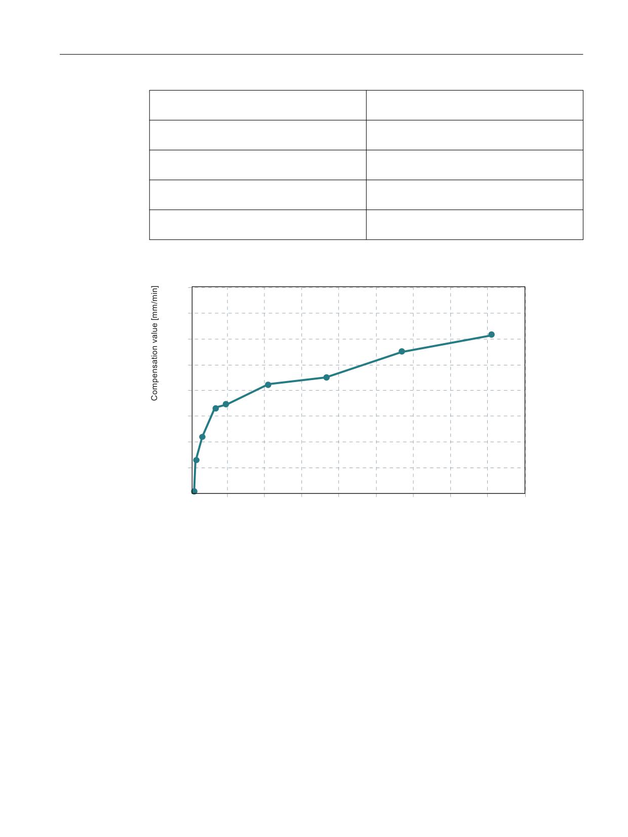
NC commissioning
8.4 Friction compensation with adaptive characteristics
Step 4 of 8: 140 mm/min
Amplitude: 23.848 mm/min
Decay time: 0.038 s
Step 5 of 8: 1060 mm/min
Amplitude: 84.688 mm/min
Decay time: 0.015 s
Step 6 of 8: 1410 mm/min
Amplitude: 90.018 mm/min
Decay time: 0.014 s
Step 7 of 8: 1770 mm/min
Amplitude: 109.839 mm/min
Decay time: 0.012 s
Step 8 of 8: 2120 mm/min
Amplitude: 123.012 mm/min
Decay time: 0.009 s
The following characteristics show the amplitude and the decay time for different acceleration
levels:
$FFHOHUDWLRQ >P Vt@
CNC Commissioning: NC, PLC, Drive
Commissioning Manual, 10/2020, A5E48312804B AB
217