SINUMERIK 840D sl. Service - Configuring Commissioning. Manual (2011-2020) - page 82
NC commissioning
8.4 Friction compensation with adaptive characteristics
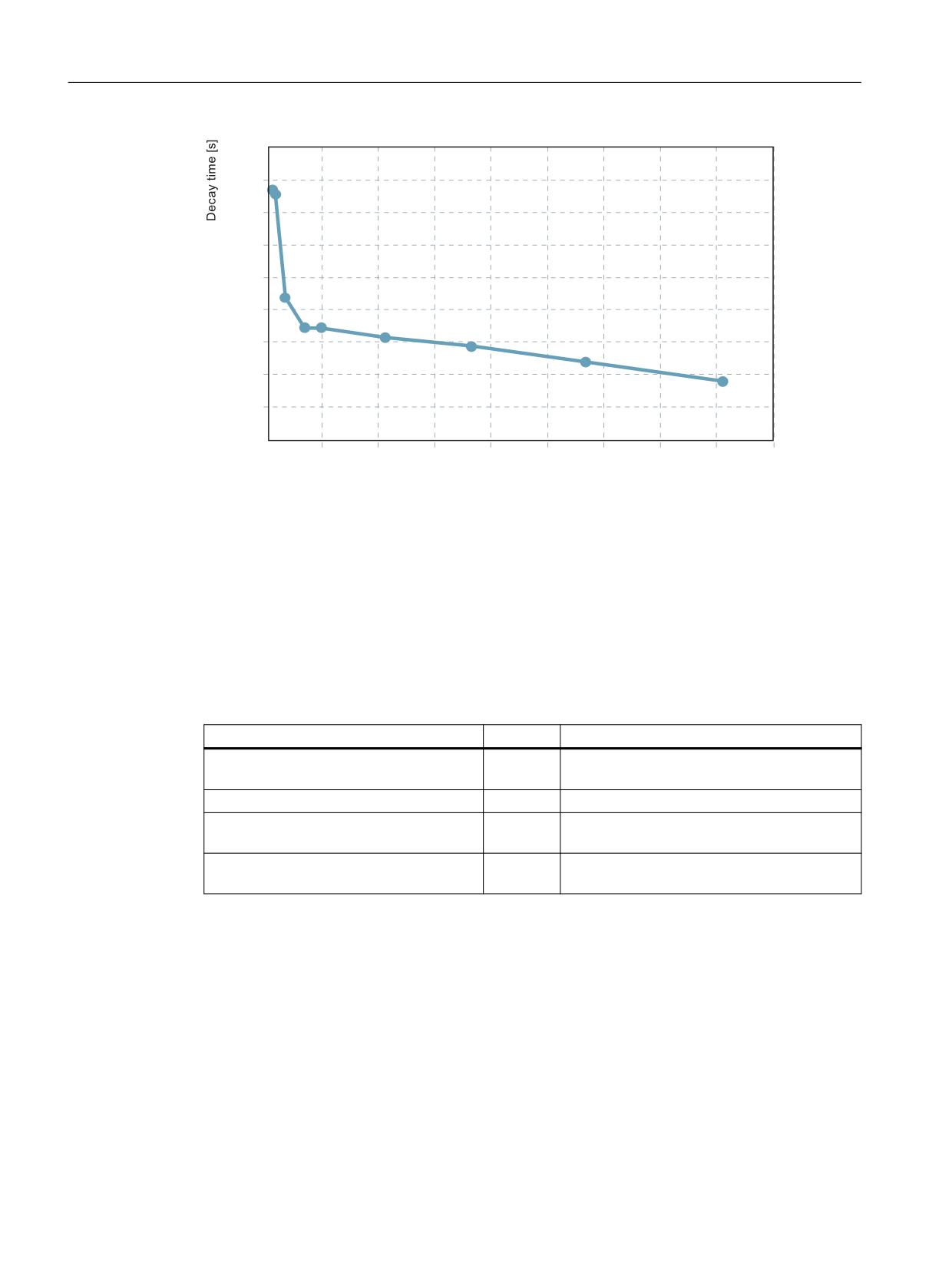
$FFHOHUDWLRQ >P Vt@
8.4.7
Friction compensation with torque injection pulse
Parameterizing machine data
The following axis machine data must be parameterized in order to use an acceleration-
dependent torque injection pulse also for friction compensation:
Designation
Unit
Machine data
Acceleration-dependent amplitude of the
---
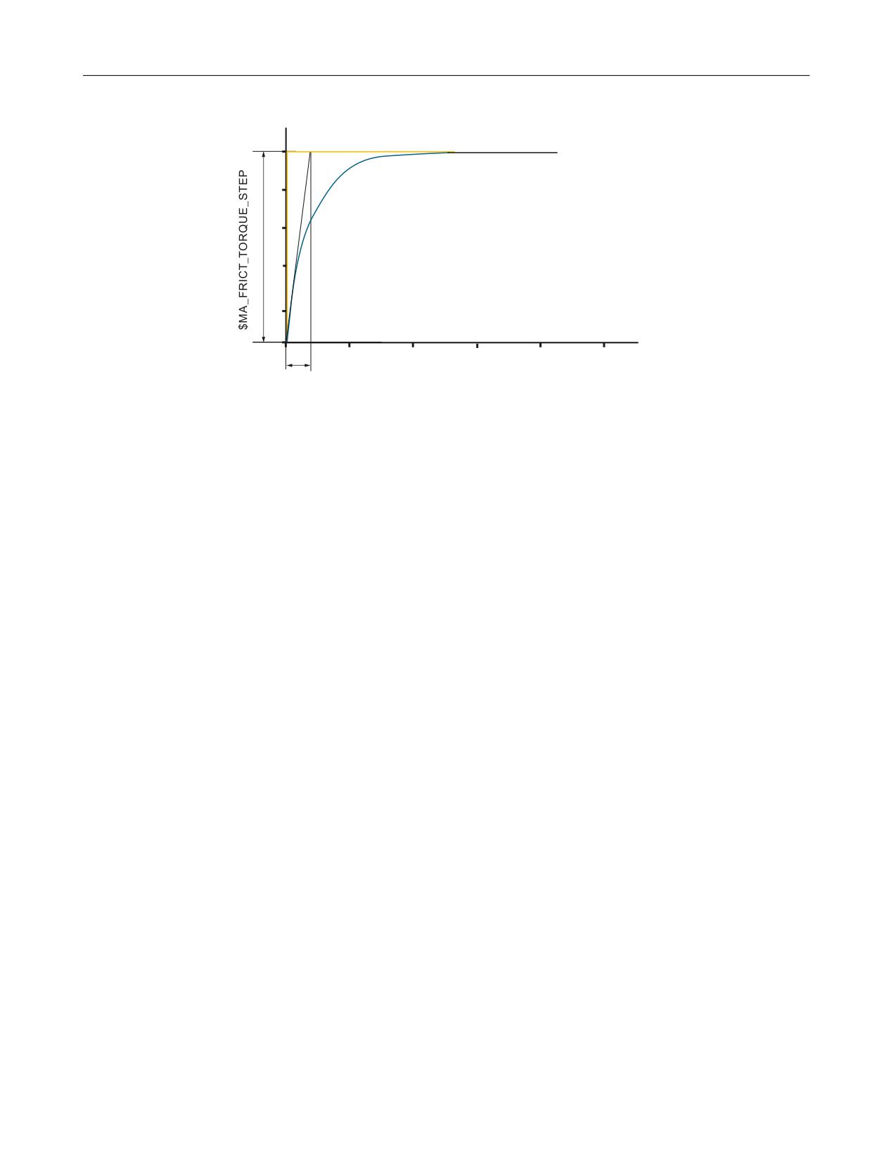
MD32576 $MA_FRICT_TORQUE_STEP
torque injection pulse
Delay time of the torque injection pulse
[s]
MD32577 $MA_FRICT_T_PULSE_DELAY_TIME
Ramp-up time of the torque injection pulse
[s]
MD32578
$MA_FRICT_T_PULSE_SMOOTH_TIME
Weighting factor for the amplitude of the
---
MD32588 $MA_FRICT_T_STEP[0...9]
torque injection pulse
CNC Commissioning: NC, PLC, Drive
218
Commissioning Manual, 10/2020, A5E48312804B AB
NC commissioning
8.4 Friction compensation with adaptive characteristics
7LPH W >V@
0$B)5,&7B7B38/6(B60227+B7,0(
Enter a factor between -1.0 and 1.0 in MD32588 $MA_FRICT_T_STEP[0...9] for each
acceleration value in order to weight the amplitude of the torque injection pulse.
CNC Commissioning: NC, PLC, Drive
Commissioning Manual, 10/2020, A5E48312804B AB
219
NC commissioning
8.5 Nodding compensation
8.5
Nodding compensation
8.5.1
Measuring technique and machine data
Benefits
The nodding compensation enhances precision for machining of the workpiece by
compensating for compliance within the machine and is beneficial for traveling column
machines, for example, in that it improves machining accuracy and surface quality.
Software option
You need licenses for the following options in order to use this function:
• To tune a machine axis with a compensation relationship and position-dependent
adaptation:
"Nodding compensation ECO" (6FC5800-0_S20-0Yx0)
• For the tuning of more than one compensation relationship:
"Nodding compensation ADVANCED" (6FC5800-0_S21-0Yx0)
Call the function at the control in the "Commissioning" → softkey "NC" → softkey "Nodding
compensation" operating area. The softkey is not shown until the option has been set.
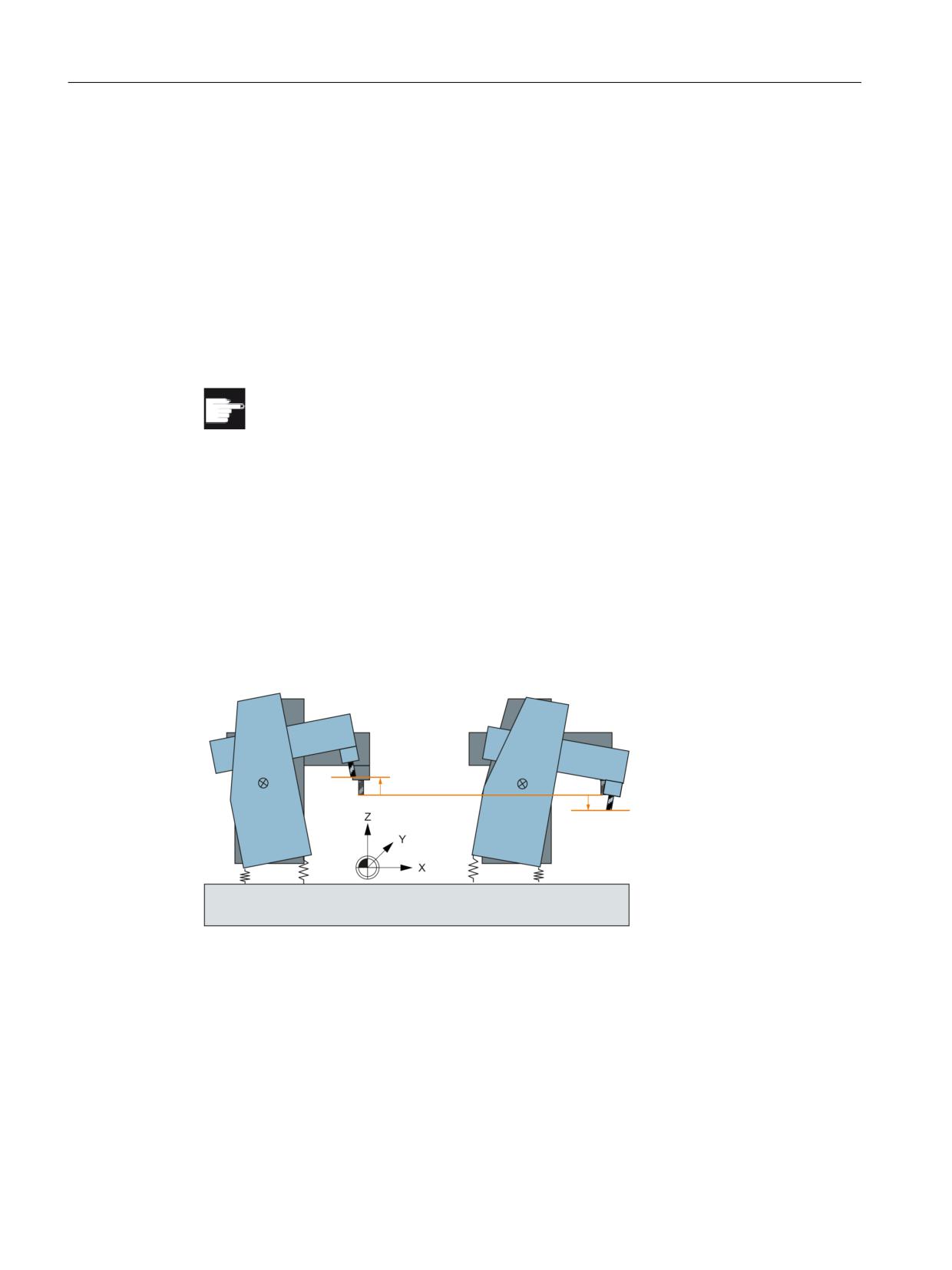
Example
Nodding motion in the Z axis when accelerating in the X axis:
Definition of compliance
From the acceleration or deceleration of an axis as the cause for nodding - and the deviation of
an axis as compliance at the position - a factor can be determined, which describes the
interrelationship between the accelerating or decelerating axis motion, and the position
deviation in the compensated axis. No mass is included in the calculation. The compliance factor
is the inverse value of the stiffness.
CNC Commissioning: NC, PLC, Drive
220
Commissioning Manual, 10/2020, A5E48312804B AB
NC commissioning
8.5 Nodding compensation
Measuring procedure
There are two techniques that can be selected for determining compliance:
• Milling standardized workpiece and selecting the optimum milling path
For a standardized workpiece, a cycle is available to mill several milling paths with different
compliance factors. The compliance factor can be empirically determined based on the
workpiece surface quality.
For the cycle settings, you can also select face milling for the workpiece in order to carry out
several tests with different compliance factors on one workpiece.
• Determining positional deviations using a probe
The position deviation is precisely measured at different positions. Based on this, the
compliance factor can be calculated once the acceleration or deceleration that has been
achieved is known.
Machine data
Axis machine data for nodding compensation:
Number
Name
Effect
Unit
MD37302
$MA_NOCO_FILTER_TIME
Time constant for smoothing nodding
[s]
compensation values
MD37310
$MA_NOCO_INPUT_AX_1
Machine axis, which causes nodding mo-
[1...31]
tion
MD37320
$MA_NOCO_INPUT_AX_2
MD37330
$MA_NOCO_INPUT_AX_3
MD37312
$MA_NOCO_ADAPT_AX_1
Machine axis, whose position influences
[1...31]
nodding motion
MD37322
$MA_NOCO_ADAPT_AX_2
MD37332
$MA_NOCO_ADAPT_AX_3
MD37314
$MA_NOCO_ADAPT_NUM_AX_1
Number of positions of the adaptation
[1...3]
characteristic of nodding compensation
MD37324
$MA_NOCO_ADAPT_NUM_AX_2
MD37334
$MA_NOCO_ADAPT_NUM_AX_3
MD37316
$MA_NOCO_ADAPT_POS_AX_1
Positions of the adaptation characteris-
[mm]
tic of nodding compensation
MD37326
$MA_NOCO_ADAPT_POS_AX_2
MD37336
$MA_NOCO_ADAPT_POS_AX_3
MD37318
$MA_NOCO_COMPLIANCE_1
Nodding compensation compliance fac-
[s2]
tor
MD37328
$MA_NOCO_COMPLIANCE_2
MD37338
$MA_NOCO_COMPLIANCE_3
Additional information is provided in Chapter "Compensations" in the Monitoring and
Manual.
CNC Commissioning: NC, PLC, Drive
Commissioning Manual, 10/2020, A5E48312804B AB
221
NC commissioning
8.5 Nodding compensation
8.5.2
Nodding compensation - overview
What is displayed in this dialog?
A summary of the following data is provided in the "Nodding compensation" overview:
• Accelerating axis: Axis, which results in nodding motion.
• Compensated axis: Machine axis, whose nodding motion is compensated.
• Adaptation axis: Machine axis, whose position influences nodding motion.
• Position [mm] on the adaptation axis
• Factor for compliance [μm / m/s2]
Supplementary conditions:
• Inadmissible entries are color-coded in the table in the "Nodding compensation - overview"
dialog. An explanation is output in the message line below the table.
• A rotary axis is not permissible as accelerating axis, compensated axis or adaptation axis.
• For a gantry axis grouping, only the guide axis is listed. On completion of the tuning, a query
is made whether the compensation values of the guide axis are copied to the synchronous
axes.
• In order that the "Nodding compensation" function may also be used for rotary axes, the
following option is required: RMCC/NOCO nodding compensation (6FC5800-0_N63-0Yx0)..
This option is not part of this description - and is not displayed in this dialog.
⇒ additional actions:
• "New" softkey to create a new compensation:
- Mill test part
- Enter manually
• Softkey "Change" to change the compliance and position dependency of the axes involved.
• Softkey Deactivate/activate, to deactivate existing compensation relationships and
reactivate them again.
• "Delete" softkey, to delete all values in the machine data of this compensation relationship.
The online help for nodding compensation on the SINUMERIK Operate supports you
during optimization.
CNC Commissioning: NC, PLC, Drive
222
Commissioning Manual, 10/2020, A5E48312804B AB
NC commissioning
8.5 Nodding compensation
Activating/deactivating nodding compensation
To analyze the effect of the nodding compensation on the machining, you can deactivate
individual or all compensation relationships without deleting the original parameterization.
Deactivation is useful for the following applications:
• Diagnostics and problem analysis:
The effect of a specific compensation relationship on the workpiece surface should be tested.
Because a superimposition of compensation relationships from different axes and different
compensation relationships is possible, the effect of an individual or all successive
compensation relationships should be tested. For this purpose, the compensation is
deactivated temporarily; the determined compliance values are retained.
• Series commissioning:
The compensation values are loaded via the series commissioning archive and can be
deactivated during the machine tuning, to tune the machine without the effect of the
nodding compensation. On completion of the tuning, the compensation values are
reactivated. As check, a test part can be milled.
Procedure:
1. In the "Nodding compensation - Overview" select the "Deactivate/activate" softkey to
deactivate the compensation relationships.
2. Select the individual compensation relationships or select the "Deactivate all" softkey.
3. The "Back" softkey returns you to the "Nodding compensation - Overview".
4. If the nodding compensation should act again, reset the deactivated compensation
relationships to the "active" status.
The compensation relationships are deactivated bit-by-bit in MD37300 $MA_NOCO_ENABLE.
8.5.3
Determining compliance from the best milling path
Measuring technique: Best milling path
For a standardized workpiece, a cycle is available to mill several milling paths with different
compliance factors. The necessary compliance factor can be empirically determined based on
the surface quality of the milled workpiece.
Note
Active transformation
In order to guarantee a fault-free cycle sequence, active transformations are to be deactivated
before starting the cycle.
CNC Commissioning: NC, PLC, Drive
Commissioning Manual, 10/2020, A5E48312804B AB
223

NC commissioning
8.5 Nodding compensation
For the cycle settings, you can also select face milling for the workpiece in order to carry out
several tests with different compliance factors on one workpiece.
Accelerating axis:
Geometry axes X, Y, Z
Compensated axis:
Machining plane G17: Z axis
Type of machining:
[no] path milling only
[yes] face milling and path milling
Parameter
Meaning
Unit
RP
Retraction plane [abs]
[mm]
SC
Safety clearance [inc]
[mm]
F
Path milling feedrate
[mm/min]
FA
Face milling feedrate
[mm/min]
X0
Corner point 1 X [abs]
[mm]
Y0
Corner point 1 Y [abs]
[mm]
Z0
Height of blank [abs]
[mm]
X1
Corner point 2 in relation to X0 [inc.]
[mm]
Y1
Corner point 2 in relation to Y0 [inc.]
[mm]
Z1
Feed depth for face milling in relation to Z0 [inc.]
[mm]
Z2
without face milling: Feed depth for path milling in relation to
[mm]
Z0 (inc.)
with face milling: Feed depth for path milling in relation to Z1
(inc.)
N
Number of milling paths
---
Minimum value of the compliance factor
[μm / m/s2]
Maximum value of the compliance factor
[μm / m/s2]
Compliance factor of the best milling path
[μm / m/s2]
Note
Test run before machining
To perform a test run before machining, enter a suitable value for the infeed depth.
8.5.4
Nodding compensation - manually enter
Entering compensation data
For the manual input of the compliance factor, all degrees of freedom in the compensation
relationships between accelerating and compensated axes are possible. Further, position-
dependent adaptation values can be entered at the user interface.
CNC Commissioning: NC, PLC, Drive
224
Commissioning Manual, 10/2020, A5E48312804B AB
NC commissioning
8.5 Nodding compensation
Procedure without adaptation:
1. First select the accelerating axis, and then the compensated axis. This can also be the same
axis.
2. If no position dependency exists, then accept the default setting "No".
3. Enter the compliance factor.
Procedure with adaptation:
1. First select the accelerating axis, and then the compensated axis. This can also be the same
axis.
2. If a position dependency exists, select "Yes" and then the adaption axis.
3. Then enter the number of interpolation points and the respective compliance factor for each
interpolation point.
In this dialog you can subsequently change the compliance and the position dependency for the
configured axes.
8.5.5
Determining compliance using a probe
Preconditions
If not yet already available, create a commissioning archive with the drive data and connect the
probe to a free DRIVE-CLiQ interface. Only linear measuring systems are permitted as probes.
NOTICE
Deactivate Safety Integrated temporarily
If axes still have Safety Integrated activated, a message is displayed to inform you that Safety
Integrated must be deactivated in order to configure the probe.
Following configuration of the probe, Safety Integrated must be activated once again.
Initiating trace recording
Procedure:
1. Select "Trace: Yes" to determine the compliance factor of the selected axis using a probe.
2. Select the measuring system for the encoder position actual value:
⇒ Select the drive to which the probe is connected, for example SERVO_3.3:6
⇒ Select an encoder, for example "Encoder 3".
CNC Commissioning: NC, PLC, Drive
Commissioning Manual, 10/2020, A5E48312804B AB
225
NC commissioning
8.5 Nodding compensation
3.
Create a part program which comprises the following components:
- Trigger tag $AN_CUTRACE
- Dwell time of at least 200 ms so that the offset of the probe can be taken into
consideration in the graphic representation.
- Traversing with constant velocity.
- The accelerating axis is accelerated to at least 1 m/s2.
Example:
SOFT
; acceleration with active jerk limitation
DYNNORM
; G command for activating the normal dynamic
response
$AN_CUTRACE=1
; trigger tag
G4 F0.2
; Dwell time
G91 G01 F20000 Y-50
; relative traversing motion with programmed
feed
G4 F0.5
; Dwell time
Y50
; traversing motion
G4 F0.5
; Dwell time
M30
; End of program
4.
Initiate the trace recording with the "Start trace" softkey. Then initiate the part program with
<NC-Start>.
Note
Starting the trace
Once trace recording has been initiated by the trigger in the part program, it is no longer
possible to cancel the recording process.
5.
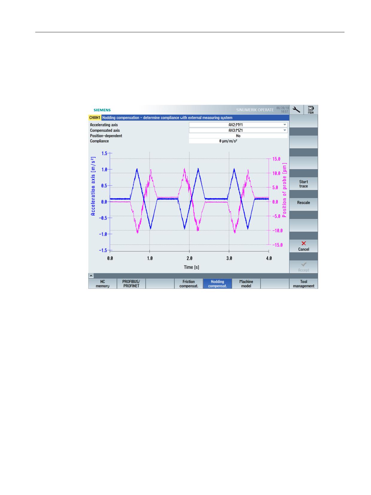
As soon as recording is complete, the following data is displayed in a graphic representation:
- Encoder position actual value (p0479) of the probe
- Acceleration of the accelerating axis
6.
Enter the compliance factor (positional deviation/acceleration) and repeat the
measurement. To clarify the effect of the compliance factor against the first measurement,
scaling of the graphic following the first measurement is retained.
7.
Once you have determined the optimum compliance factor for the axis, rescaling of the
graphic can be performed with the "Rescale" softkey.
8.
As soon as the compliance factor is changed, the measurement must be repeated for
verification. Only then will the "Accept" softkey become active.
⇒ additional actions:
• "Start trace" softkey to initiate recording of the trace.
• "Rescale" softkey to automatically scale the graphic.
• "Cancel" softkey to return to the overview display without any modifications.
• "Accept" softkey to adopt the new compliance values.
CNC Commissioning: NC, PLC, Drive
226
Commissioning Manual, 10/2020, A5E48312804B AB
NC commissioning
8.5 Nodding compensation
8.5.6
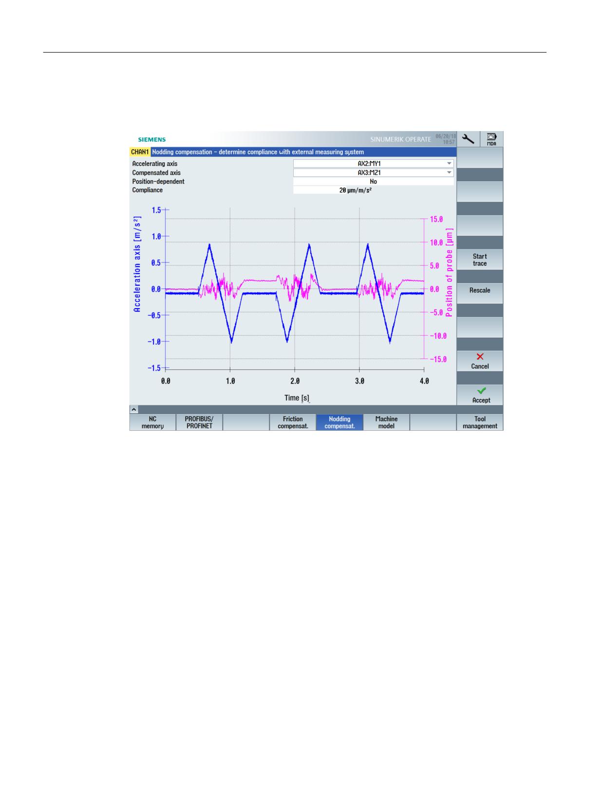
Example: Traveling column machine
Before tuning
The nodding motion of the Z axis when traversing in the Y direction is measured with a probe:
CNC Commissioning: NC, PLC, Drive
Commissioning Manual, 10/2020, A5E48312804B AB
227
NC commissioning
8.5 Nodding compensation
After tuning
Measurement with a compliance value of 20 μm:
CNC Commissioning: NC, PLC, Drive
228
Commissioning Manual, 10/2020, A5E48312804B AB
NC commissioning
8.6 Adaptations
8.6
Adaptations
8.6.1
Intelligent load adjustment - function
Benefits
The "Intelligent load adjustment" function is used to optimize the following characteristics of a
machine tool by adapting dynamic response and control parameters:
• Shorter processing times
• Increased dynamic response
• Greater accuracy
• Enhanced precision
The machine manufacturer is supported in the commissioning of the function by dialogs on the
user interface: "Commissioning" → softkey "NC" → Menu forward key → softkey"Adaptations"
operating area. The softkey is shown after setting the option, and only for the "Manufacturer"
access level.
Precondition
Software option
In order to use this function a license is required for the following option:
"Intelligent load adjustment" (6FC5800-0_S11-0Yx0)
Function description
The"Intelligent load adjustment" function adjusts the dynamic response and control parameters
to the current value of the moment of inertia or the mass of the axis. Adaptations are switched
on and off by means of CYCLE782.
The following dynamic response and control parameters can be adapted:
• Acceleration (dynamic mode)
• Jerk (dynamic mode)
• Servo gain factor (position control gain factor)
• Torque feedforward control
• Drive adaptation factor 1...4: A maximum of 4 drive variables from parameter p2782[0...3]
"Mode adaptation" can be adapted.
CNC Commissioning: NC, PLC, Drive
Commissioning Manual, 10/2020, A5E48312804B AB
229
NC commissioning
8.6 Adaptations
Example
For a rotary table with highly variable loading, the effective acceleration (DYNNORM) should be
adapted to the current moment of inertia. The "Intelligent load adjustment" function is used to
increase acceleration (DYNNORM) at minimal loading to 150%.
$FFHOHUDWLRQ '<11250
>
@
ZLWK DGDSWDWLRQ
ZLWKRXW DGDSWDWLRQ
-PLQ
-PD[
0RPHQW RI LQHUWLD >NJP @
Jmin
⇒ MD16506[0] $MN_CADAPT_INPUT_VALUE_1
Jmax
⇒ MD16507[0] $MN_CADAPT_INPUT_VALUE_2
150%
⇒ MD16508[0] $MN_CADAPT_OUTPUT_VALUE_1
100%
⇒ MD16509[0] $MN_CADAPT_OUTPUT_VALUE_2
Constraints
You can determine the inertia of the axis using automatic servo tuning or the "Moment of inertia
estimator" function module. The function module is enabled under Setup → Drive → Dialog
"Configuration - Motor Module".
For the output variables "Drive adaptation factor 1...4 (Page 232)", you configure a telegram
(Page 194) of the type 146, 148 or 149 and activate the function module "Controller parameter
adaptation".
Further information on function modules can be found in the Function Manual SINAMICS S120
CNC Commissioning: NC, PLC, Drive
230
Commissioning Manual, 10/2020, A5E48312804B AB
NC commissioning
8.6 Adaptations
8.6.2
Intelligent dynamic response adjustment - function
Benefits
The "Intelligent dynamic response adjustment" function is used to optimize the following
characteristics of a machine tool by adapting control parameters:
• Shorter processing times
• Increased dynamic response
• Greater accuracy
• Enhanced precision
The machine manufacturer is supported in the commissioning of the function by dialogs on the
user interface:
"Commissioning" → softkey "NC" → Menu forward key → softkey"Adaptations" operating area.
The softkey is shown after setting the option, and only for the "Manufacturer" access level.
Precondition
Software option
In order to use this function a license is required for the following option:
"Intelligent dynamic response adaptation" (6FC5800-0_S23-0Yx0)
Function description
The "Intelligent dynamic response adjustment" function adjusts the control parameters for axes
with a stability that changes at different positions or at different traversing velocities as a
function of the position or velocity.
The following control parameters can be adapted:
• Servo gain factor (position control gain factor)
• Torque feedforward control
• Drive adaptation factor 1...4: A maximum of 4 drive variables from parameter p2782[0...3]
"Mode adaptation" can be adapted.
Constraints
For the output variables "Drive adaptation factor 1...4 (Page 232)", you configure a telegram
(Page 194) of the type 146, 148 or 149 and activate the function module "Controller parameter
adaptation".
Further information on function modules can be found in the Function Manual SINAMICS S120
CNC Commissioning: NC, PLC, Drive
Commissioning Manual, 10/2020, A5E48312804B AB
231
NC commissioning
8.6 Adaptations
8.6.3
Setting up the adaptations
Setup procedure
The following procedure is recommended for commissioning the functions:
• Set licensed SINUMERIK Option S11 for the "Intelligent load adjustment" function.
The SINAMICS "Moment of inertia estimator" function module can be used to determine the
moment of inertia of the axis.
• Set licensed SINUMERIK Option S23 for the "Intelligent dynamic response adjustment"
function.
• Enter the adaptation in the "Adaptations - Overview" dialog, "New >" softkey.
• Enable adaptation with "Reset (po)".
The online help on SINUMERIK Operate shows you how to enter adaptations.
Note
No adaptation active
Without active adaptation, the dynamic response and control parameters in the machine data
are effective.
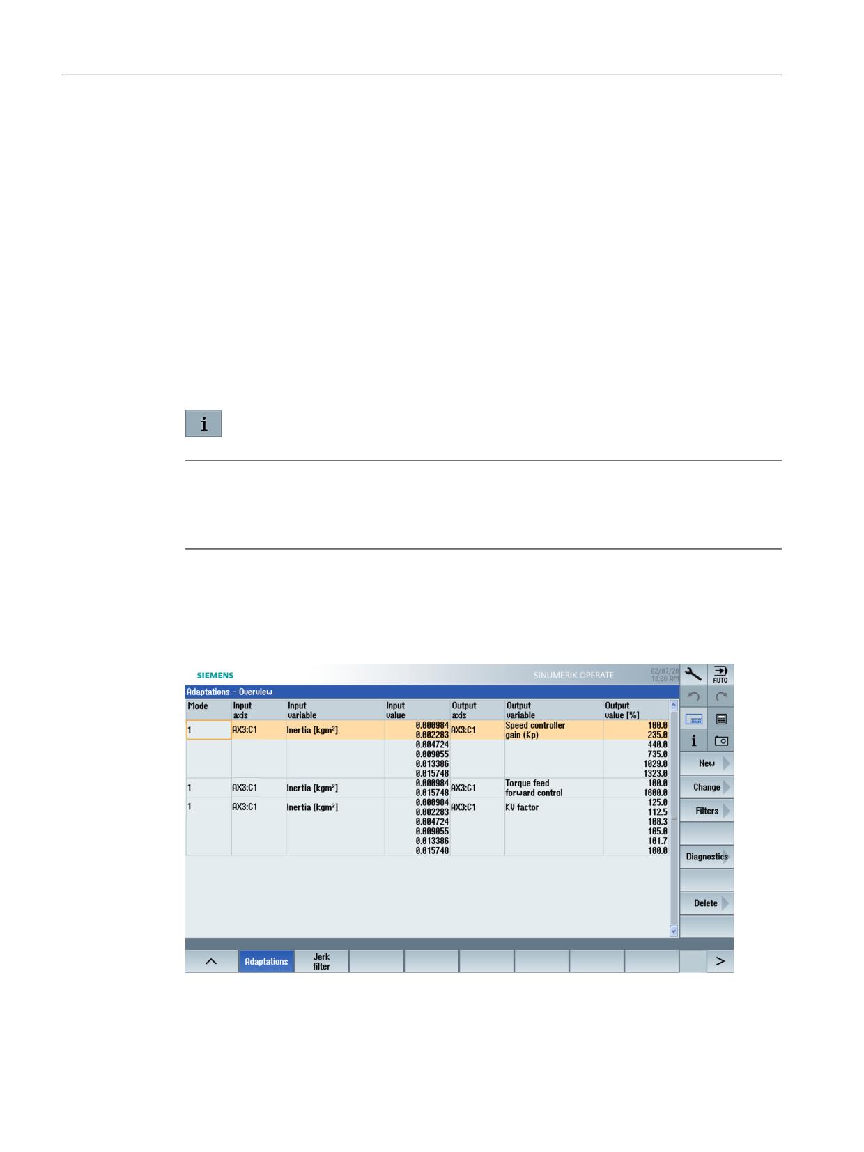
Adaptations - Overview
Example of a grinding machine with adaptations:
In this dialog, all adaptations are shown in a tabular overview.
CNC Commissioning: NC, PLC, Drive
232
Commissioning Manual, 10/2020, A5E48312804B AB
NC commissioning
8.6 Adaptations
The dynamic response and control parameters can be adjusted as functions of the following
input variables:
• Moment of inertia
• Position
• Velocity
Inputting an adaptation writes the following machine data:
Mode
MD16501 $MN_CADAPT_MODE
Input axis
MD16504 $MN_CADAPT_INPUT_AX
Input variable
MD16502 $MN_CADAPT_INPUT = 1 (default setting)
Input value
MD16506 $MN_CADAPT_INPUT_VALUE_1
MD16507 $MN_CADAPT_INPUT_VALUE_2
Output axis
MD16505 $MN_CADAPT_OUTPUT_AX
Output variable
MD16503 $MN_CADAPT_OUTPUT
Output value
MD16508 $MN_CADAPT_OUTPUT_VALUE_1
MD16509 $MN_CADAPT_OUTPUT_VALUE_2
⇒ Additional actions:
• Press the "New >" softkey to enter a new adaptation table.
• Press the "Change >" softkey to change values or the number of table rows.
• Press the "Filter >" softkey to filter the overview by individual columns.
• Press the "Diagnostics" softkey to display the currently effective values.
• Press the "Delete" softkey to delete the selected adaptation table.
Adaptations - Configuring the drive
Procedure:
1. Select a drive parameter for the adaptation:
[1] Speed controller P gain (Kp)
[2] Speed controller integral time inverse value (1/Tn)
[3] Current setpoint filter 1 denominator/numerator frequency
[4] Current setpoint filter 2 denominator/numerator frequency
[5] Speed setpoint filter 1 denominator/numerator frequency
[6] Speed controller reference model natural frequency
2. To select the following drive parameters, you must enable another function modules
(⇒ constraints):
[7] APC/AVS/APC-ECO derivative-action time (Tv)
[8] APC filter 2.1 denominator/numerator frequency
3. The values for "Adaption of lower/upper limit value" are permanently in effect and are preset
to the maximum range of 0...3000%.
4. To enable the adaptation for the drive dataset (DDS), enter the corresponding number.
CNC Commissioning: NC, PLC, Drive
Commissioning Manual, 10/2020, A5E48312804B AB
233
NC commissioning
8.6 Adaptations
Note
Unique parameter assignment
If a drive adaptation factor of 1...4 is assigned as output variable to an input variable with a
parameter [1]...[8], this assignment will be retained for another input variable.
Example:
The output variable "Drive adaptation factor 1" with the parameter [1] Speed controller P gain
(Kp) is assigned to the input variable "Inertia". Thus when adapting the input variable "Position"
the parameter [1] Speed controller P gain (Kp) is also assigned to the drive adaptation factor 1.
⇒ Additional actions:
• Press the "Cancel" softkey to cancel the inputs.
• Press the "Accept" softkey to save the data in the drive.
Constraints
The following settings are checked for the adaptation of drive parameters:
• The same telegram (146, 148 or 149) is configured in the NC and in the drive.
• The "Controller parameter adaptation" function module is enabled for this drive.
The function module is enabled under Setup → Drive → Dialog "Configuration - Motor Module".
• A SINUMERIK license for the option "Advanced Position Control ECO"
(6FC5800-0_M12-0Yx0) is required to use the "Active Vibration Suppression (AVS/APC-ECO)"
function module with SINUMERIK. This allows the following control parameter to be adapted:
[7] APC/AVS/APC-ECO derivative-action time (Tv)
• A SINUMERIK license for the option "Advanced Position Control" (6FC5800-0_M13-0Yx0) is
required to use the "Advanced Positioning Control (APC)" function module with SINUMERIK.
This allows the following control parameters to be adapted:
[7] APC/AVS/APC-ECO derivative-action time (Tv)
[8] APC filter 2.1 denominator/numerator frequency
8.6.4
Example: Enter an adaptation for acceleration
Entering a new adaptation
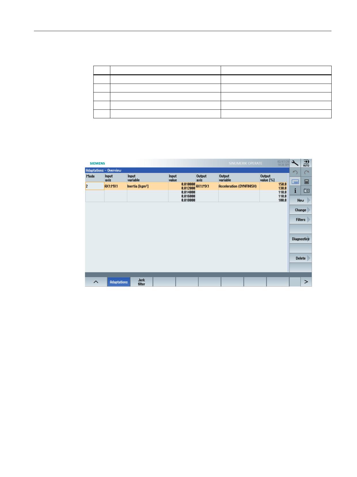
Objective: The acceleration (DYNFINISH) of the X axis should be adapted depending on the
moment of inertia of the X axis.
Procedure:
1. In the operating area, select "Commissioning" → "NC" → Menu forward key → "Adaptations"
and then the "New >" softkey. The "Enter adaptation" dialog is opened.
2. Select the mode, and the X axis as input axis.
3. Select "Acceleration (DYNFINISH)" as output variable.
CNC Commissioning: NC, PLC, Drive
234
Commissioning Manual, 10/2020, A5E48312804B AB
NC commissioning
8.6 Adaptations
4. Expand the table to enter the following values:
Input value [kgm2]
Output value [%]
1
0.010000
150.0
2
0.012000
130.0
3
0.014000
110.0
4
0.016000
110.0
5
0.018000
100.0
5. Press the "Accept" softkey to display the adaptation in the "Adaptations - Overview" dialog.
6. A "Reset (po)" is required to activate the values in the machine data.
The adaptation table is shown in the "Adaptations - Overview" dialog:
Rules for entering adaptations:
• In a simple adaptation table, only one of the two input values is permitted to be zero.
• In a complex adaptation table, the first and last input values are permitted to be zero. When
changing, the input values must be entered in ascending order.
CNC Commissioning: NC, PLC, Drive
Commissioning Manual, 10/2020, A5E48312804B AB
235
NC commissioning
8.7 Jerk filter
8.7
Jerk filter
8.7.1
Putting a jerk filter into operation
Benefits
To achieve high surface quality, the excitation of mechanical oscillations on the machine is kept
to a minimum. When milling freeform surfaces, it can be advantageous to smooth the setpoint
characteristics of the machine axes by means of a jerk filter. The parameterization of an axial jerk
filter depending on the processing technology (dynamic mode) has the following effect:
• Damping of machine vibrations
• Shorter processing time
Precondition
Software option
In order to use this function a license is required for the following option:
"Top Speed" (6FC5800-0_S13-0Yx0)
This option includes the use of the filter type FIR low-pass and the changeover from position
setpoint characteristic filter chains when the axes are at a standstill.
After the option is set, the "Jerk filter" softkey is displayed in the operating area "Commissioning"
→ Softkey "NC" → Menu forward key.
Jerk filter commissioning
Support for commissioning with SINUMERIK Operate is provided for the following jerk filters:
• FIR low-pass (dynamic mode)
MD32402 $MA_AX_JERK_MODE = 5
• Double moving averaging
MD32402 $MA_AX_JERK_MODE = 4
• Moving averaging
MD32402 $MA_AX_JERK_MODE = 2
The online help of SINUMERIK Operate supports you when entering jerk filters.
Function description
For motions outside the workpiece or during roughing, high axial jerk values are used in
combination with strong attenuating filters. This significantly reduces the processing time. An
FIR low-pass filter is parameterized depending on the dynamic mode in order to achieve the
optimum effect for the different types of processing. For an FIR low-pass filter, appropriate values
for the frequency and tolerance are entered for each specific dynamic mode. The machine data
MD32409 $MA_JERK_FIR_WINDOW = 1 (FIR low-pass - window type) is pre-selected.
CNC Commissioning: NC, PLC, Drive
236
Commissioning Manual, 10/2020, A5E48312804B AB
NC commissioning
8.7 Jerk filter
If, when processing with DYNROUGH, minimum processing time and, for DYNPREC, maximum
machining accuracy are important, these requirements can be met with a FIR low-pass.
⇒ FIR low-pass: Robust setting for all axes in the channel
For the active dynamic mode in the part program, the same values are calculated for all of the
axes in the channel and written to the machine data. The calculation leads to an optimal result
if the dynamic response attributes of the axes are similar. The CALCFIR instruction is
reprogrammed after each switchover of the dynamic mode to explicitlyactivate the calculation
for the FIR low-pass filter.
Active dynamic response mode
The active dynamic mode of G code group 59 is read in again during run-up, during an operator
panel reset, and at the end of a part program by evaluating
MD20150 $MC_GCODE_RESET_VALUE[58] and MD20152 $MC_GCODE_RESET_MODE[58].
The following machine data is implicitly recalculated and activated depending on the dynamic
mode during run-up, during an operator panel reset, and at the end of a part program:
MD32407 $MA_JERK_FIR_FREQ
FIR low-pass - corner frequency
MD32408 $MA_JERK_FIR_ORDER
FIR low-pass - filter order
You can find more information on CALCFIR in the NC Programming (https://
support.industry.siemens.com/cs/document/109766213) Programming Manual.
More information on entering jerk filters and the switchover of position setpoint filter chains is
provided in the Axes and Spindles (https://support.industry.siemens.com/cs/document/
109766213) Function Manual.
8.7.2
Entering a new jerk filter
FIR low pass (dynamic mode)
FIR low-pass: Robust setting for all of the axes in the channel
For the active dynamic mode in the part program, the same values are calculated for all of the
axes in the channel and written to the machine data. The calculation leads to an optimal result
if the dynamic response attributes of the axes are similar. The CALCFIR instruction is also newly
programmed after each changeover of the dynamic mode to explicitly activate the calculation
for the FIR low-pass filter.
Precondition:
The maximum axial jerk for a path movement in MD32431 $MA_MAX_AX_JERK lies in the range
of 5 ... 500 m/s3 for the selected linear axis. If a value is outside this range, alarm 21900 is
pending.
Entering a new jerk filter:
Depending on the dynamic mode, enter the following value for the selected axis:
• Frequency [Hz]
• Tolerance for linear axes [mm/inch]
CNC Commissioning: NC, PLC, Drive
Commissioning Manual, 10/2020, A5E48312804B AB
237

NC commissioning
8.7 Jerk filter
The following axis machine data is set active with the "Accept" softkey:
MD32400 $MA_AX_JERK_ENABLE = 1
Axial jerk limitation
MD32405 $MA_CALCFIR_FREQ
FIR low-pass - frequency [Hz]
MD32406 $MA_CALCFIR_TOL
FIR low-pass - tolerance [mm / inch]
MD32404 $MA_CALCFIR_SELECT = 1 or 2
FIR low-pass - Calculation for the selected filter lad-
der
Note
Only one variant of the type "FIR low-pass" is permitted in a position setpoint filter chain.
⇒ Additional actions:
• Use the "Change" softkey to adjust the parameters of the jerk filter.
• Use "Reset (po)" to activate the filter type in the following axis machine data:
- MD32402 $MA_AX_JERK_MODE = x5 in the 1st position setpoint filter ladder
- MD32402 $MA_AX_JERK_MODE = 5x in the 2nd position setpoint filter ladder
• The "Cancel" softkey discards the entries.
• Use the "Accept" softkey to activate the entries for the jerk filter.
Double moving average calculation
Enter the time constants for the smoothing effect for the selected axis.
The following machine data is set active with the "Accept" softkey:
MD32400 $MA_AX_JERK_ENABLE = 1
Axial jerk limitation
MD32410 $MA_AX_JERK_TIME
Axial jerk limitation: Time constant [s]
MD32411 $MA_AX_JERK_TIME_ADD
Axial jerk limitation: Time constant [s] for the filter
type double moving average calculation
Use the "Change" softkey to adjust the parameters of the jerk filter.
Use "Reset (po)" to activate the filter type in the following axis machine data:
MD32402 $MA_AX_JERK_MODE = x4 in the 1st position setpoint filter ladder
MD32402 $MA_AX_JERK_MODE = 4x in the 2nd position setpoint filter ladder
⇒ Additional actions:
• Press the "Cancel" softkey to cancel the inputs.
• Use the "Accept" softkey to accept the entries for the jerk filter.
Moving average calculation
Enter the time constant for the smoothing effect for the selected axis.
CNC Commissioning: NC, PLC, Drive
238
Commissioning Manual, 10/2020, A5E48312804B AB
NC commissioning
8.7 Jerk filter
The following machine data is set active with the "Accept" softkey:
MD32400 $MA_AX_JERK_ENABLE = 1
Axial jerk limitation
MD32410 $MA_AX_JERK_TIME
Axial jerk limitation: Time constant [s]
Use the "Change" softkey to adjust the parameters of the jerk filter.
The filter type is activated in the following axis machine data using a "Reset (po)":
MD32402 $MA_AX_JERK_MODE = x2 in the 1st position setpoint filter ladder
MD32402 $MA_AX_JERK_MODE = 2x in the 2nd position setpoint filter ladder
⇒ Additional actions:
• Press the "Cancel" softkey to cancel the inputs.
• Use the "Accept" softkey to accept the entries for the jerk filter.
CNC Commissioning: NC, PLC, Drive
Commissioning Manual, 10/2020, A5E48312804B AB
239
NC commissioning
8.8 Diagnosis → System utilization
8.8
Diagnosis → System utilization
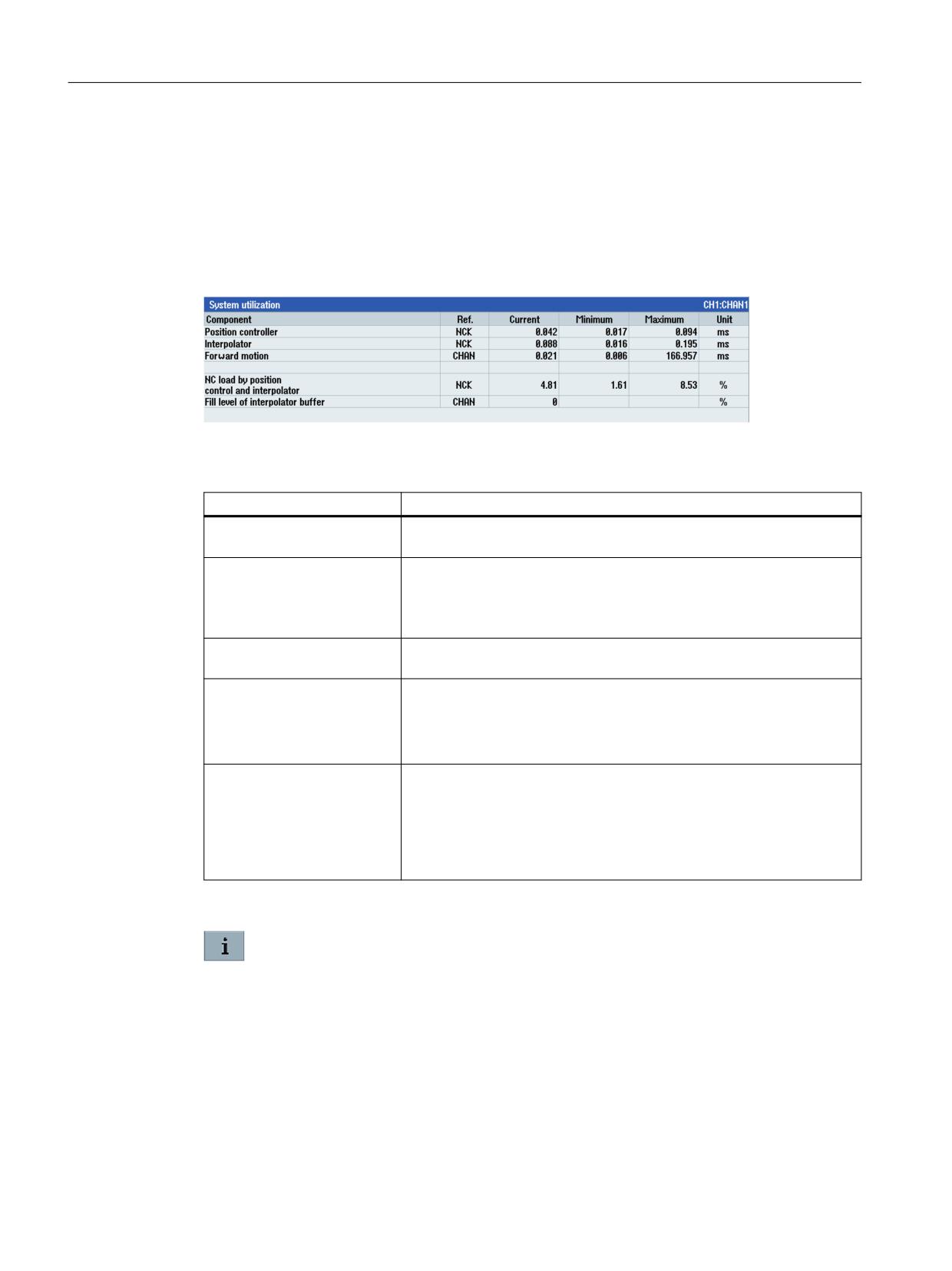
System utilization
The channel-specific system utilization is displayed in the "Diagnostics" → Menu forward key →
"System utilization" operating area:
Total system utilization in milliseconds [ms]: MD10050 $MN_SYSCLOCK_CYCLE_TIME (system
base cycle)
Component
Current value display
Position controller
Position-control cycle time display: MD10061 $MN_POSTCTRL_CY-
CLE_TIME
Interpolator
Interpolation cycle display: MD10071 $MN_IPO_CYCLE_TIME
Synchronized actions
To display the time required for synchronized actions, activate
MD11510 $MN_IPO_MAX_LOAD. Enter the proportion of the interpola-
tor cycle in %.
Preprocessing
The factor for the interpolator cycle can be set in
MD10070 $MN_IPO_SYSCLOCK_TIME_RATIO.
NC load from position control-
MD10185 $MN_NCK_PCOS_TIME_RATIO = 90 (default setting)
ler and interpolator
The average current load should not exceed 50%.
In order to have sufficient reserves for the program processing, the max-
imum load in typical operations should not exceed 75%.
Interpolator buffer level
The channel-specific filling level is displayed in
MD28060 $MC_MM_NUM_IPO_BUFFER_SIZE, and indicates whether
block preparation for block processing can commence.
Jerky machining in continuous-path mode, if for instance a number of
short traversing blocks have been programmed in succession, is a typical
indicator of the interpolator buffer idling.
Observe the settings for isochronous operation: (Page 66)
The SINUMERIK Operate Online Help provides more detailed, context-related infor-
mation about the machine data.
CNC Commissioning: NC, PLC, Drive
240
Commissioning Manual, 10/2020, A5E48312804B AB
Configuring PLC-controlled drives
9
9.1
Introduction
Commissioning of PLC-controlled drives
The following tools support the commissioning of PLC-controlled drives:
• SINUMERIK Operate:
- Guided commissioning (Page 109) with the drive wizard for drive objects.
- Manual commissioning (Page 136) performed by experienced commissioning engineers.
• Access to the parameters of all drive objects in the "Commissioning" → "Machine data"
operating area.
• Support for the series commissioning of the PLC-controlled drives, because the parameters
are contained in the commissioning archive.
• Topology views, including a list of all drive units of this type that have been found.
• Diagnostics (Page 161) with alarms from those PLC drives whose time stamp is synchronized
with the system.
Note
PLC axes with special functions
Guided commissioning, e.g. for vector control, is not provided by the wizard in SINUMERIK
Operate. To do this, the STARTER commissioning software appropriate for the version can be
used.
PLC axes can only be used with the "basic positioning" (EPOS) function module if commissioning
takes place via STARTER.
CNC Commissioning: NC, PLC, Drive
Commissioning Manual, 10/2020, A5E48312804B AB
241

Configuring PLC-controlled drives
9.2 Configuration via PROFIBUS
9.2
Configuration via PROFIBUS
9.2.1
Supplementary conditions for PLC-controlled drives
Supported versions
Note
The SINUMERIK CNC software V4.9x supports the following Control Units with SINAMICS
firmware V5.2:
• CU310-2 DP / CU310-2 PN
• CU320-2 DP / CU320-2 PN
The following applies to PLC-controlled drives:
• Controlled directly from the PLC program.
• Integration in the part program sequence by means of auxiliary functions (H command).
Quantity framework
SINUMERIK 840D sl
Scaling
710.3B PN
720.3B PN
730.3B PN
Drives (drive control DOs) in total2):
15
40
50
• Of which assigned to the NC, maximum2):
8
31
31
• Resulting from this, those not assigned to the
7
9
19
NC, minimum:
• Not assigned to the NC, maximum:
15
40
50
Drive units (DO1) with drive control objects, in to-
9
13
15
tal2):
• Of which at the virtual, integrated PROFIBUS,
4
6
6
maximum3):
• Of which at the virtual, integrated PROFIBUS,
1
1
1
minimum:
• Of which at the DP interface1) minimum:
5
7
9
• Of which at the DP interface1) maximum:
8
12
14
1)
X126: PROFIBUS DP of the integrated PLC; X136: PROFIBUS DP/MPI of the integrated PLC
2)
The sum is monitored using alarm 380077
CNC Commissioning: NC, PLC, Drive
242
Commissioning Manual, 10/2020, A5E48312804B AB
Configuring PLC-controlled drives
9.2 Configuration via PROFIBUS
Extending the quantity framework
With MD13160 $MN_SINAMICS_MAX_SLAVE_ADDRESS >0, all SINAMICS drives whose bus
address or device number (n +1) is greater than the entered value (n) are operated on the PLC
as standard slaves according to the PROFIdrive profile and are not included in the NC quantity
framework according to the above table. This address can be set individually for each bus.
MD13160 $MN_SINAMICS_MAX_SLAVE_ADDRESS[i]
Highest address for each bus type:
$MN_SINAMICS_MAX_SLAVE_ADDRESS[0]
PROFIBUS DP1 (X126)
$MN_SINAMICS_MAX_SLAVE_ADDRESS[1]
PROFIBUS DP2 (X136)
$MN_SINAMICS_MAX_SLAVE_ADDRESS[2]
PROFIBUS DP3 integrated
$MN_SINAMICS_MAX_SLAVE_ADDRESS[3]
PROFINET (X150)
A distinction is made between the following scenarios:
• The default setting MD13160 $MN_SINAMICS_MAX_SLAVE_ADDRESS[i] = 0 means that all
connected and configured drives are included in the quantity framework.
• If $MN_SINAMICS_MAX_SLAVE_ADDRESS[i] > 0, all SINAMICS drives with a bus address or
device number greater than the entered value are not included in the quantity framework,
and can be used, for example, for further PLC axes.
Example:
So that all the drives connected via PROFINET, do not have to be taken into account in the NC
quantity framework, MD13160 $MN_SINAMICS_MAX_SLAVE_ADDRESS[3] must be = 1 (= n)
and must be configured in HW Config as the lowest device number 2 (= n+1).
Supplementary conditions
The extended operator control options for the PLC drives produce the following supplementary
conditions:
• Because the PLC drives create an additional communication load, the number of these drive
objects (DO) is limited depending on the NCU ⇒ observe the quantity framework:
• Alarm 380077 "PROFIBUS/PROFINET: Too many DOs: currently %2, maximum %3 in DO group
%1"
• Depending on the versions used, the texts displayed for the SINAMICS parameters and
messages may be incomplete.
• If the drives are assigned to the NC and distributed across several buses, such as DP and DP
integrated, then it must be ensured that each isochronous bus has the same cycle clock
settings. It is also true for the time of day synchronization via NC with telegram 390 that the
cycle settings match for each isochronous bus.
• A DO1 drive unit is required for the internal virtual PROFIBUS DP3 for access to the onboard
I/O including probe.
CNC Commissioning: NC, PLC, Drive
Commissioning Manual, 10/2020, A5E48312804B AB
243
Configuring PLC-controlled drives
9.2 Configuration via PROFIBUS
Note
PROFIBUS DP (X126)
The following should be observed for all drive units connected to an external PROFIBUS DP:
• In the configuration, the user must take into account the supply as well as the switch-on and
switch-off behavior in interaction with the other axes and their supply.
• For the terminal wiring, observe the "Machine Configuration Guidelines" System Manual. In
the simplest case, the feedback signal of the Line Module must be connected to the PLC-
controlled drives (see also: Terminal assignment (Page 103)).
9.2.2
Example: Configuration of the drive components
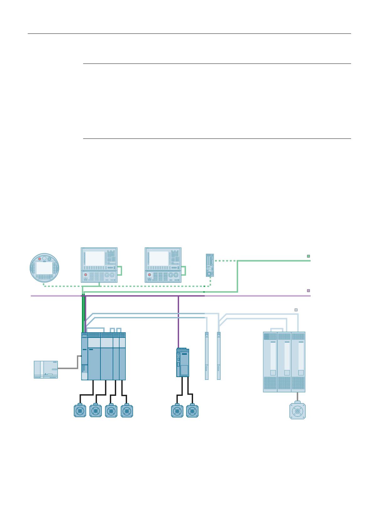
Overview
The SINAMICS drive system for PLC-drives communicates with the PLC via the PROFIBUS DP X126
interface. The commissioning described in this chapter orientates itself on the following
example configuration of the SINAMICS drive line-up:
6,180(5,.
6,180(5,. RSHUDWRU SDQHO IURQW ZLWK 7&8
6,180(5,.
+7
3&8
,QGXVWULDO (WKHUQHW
352),%86 , 2
'5,9( &/L4
6,180(5,.
' VO
1;
6,1$0,&6 6
ZLWK 6,1$0,&6 6
&8
'3
• • •
3RZHU VXSSO\
6HUYRPRWRUV
0DLQ VSLQGOH PRWRU
Figure 9-1
Configuration via PROFIBUS
Already commissioned are:
• NCU and NX15.3 with additional components.
CNC Commissioning: NC, PLC, Drive
244
Commissioning Manual, 10/2020, A5E48312804B AB
Configuring PLC-controlled drives
9.2 Configuration via PROFIBUS
In this section, the following will be put into operation:
• CU320-2 DP with an infeed (Line Module) and a Double Motor Module.
9.2.3
Commissioning the PLC
Overview
The following steps are carried out when commissioning drives controlled from a PLC for the
first time:
1. PLC commissioning
2. Creating a PLC program
3. Commissioning drives controlled from a PLC
4. Commissioning NC ⇔ drive communication
Precondition
• You have connected the PG/PC to the PLC (see Connect PG/PC with PLC (Page 47)).
• You have started the SIMATIC Manager and created a project (see
SIMATIC S7 project overview (Page 48)).
• You have inserted a SIMATIC Station-300 in the project (see
Adding SINUMERIK NCU to the HW Config (Page 49)).
• You have started HW Config.
• On the integrated PROFIBUS you have configured an NCU and NX15.3.
Interfaces
The PLC must be notified about the PROFIBUS interfaces of SINAMICS. You generate a SIMATIC
S7 project using the SIMATIC Manager.
To do this, perform the following steps:
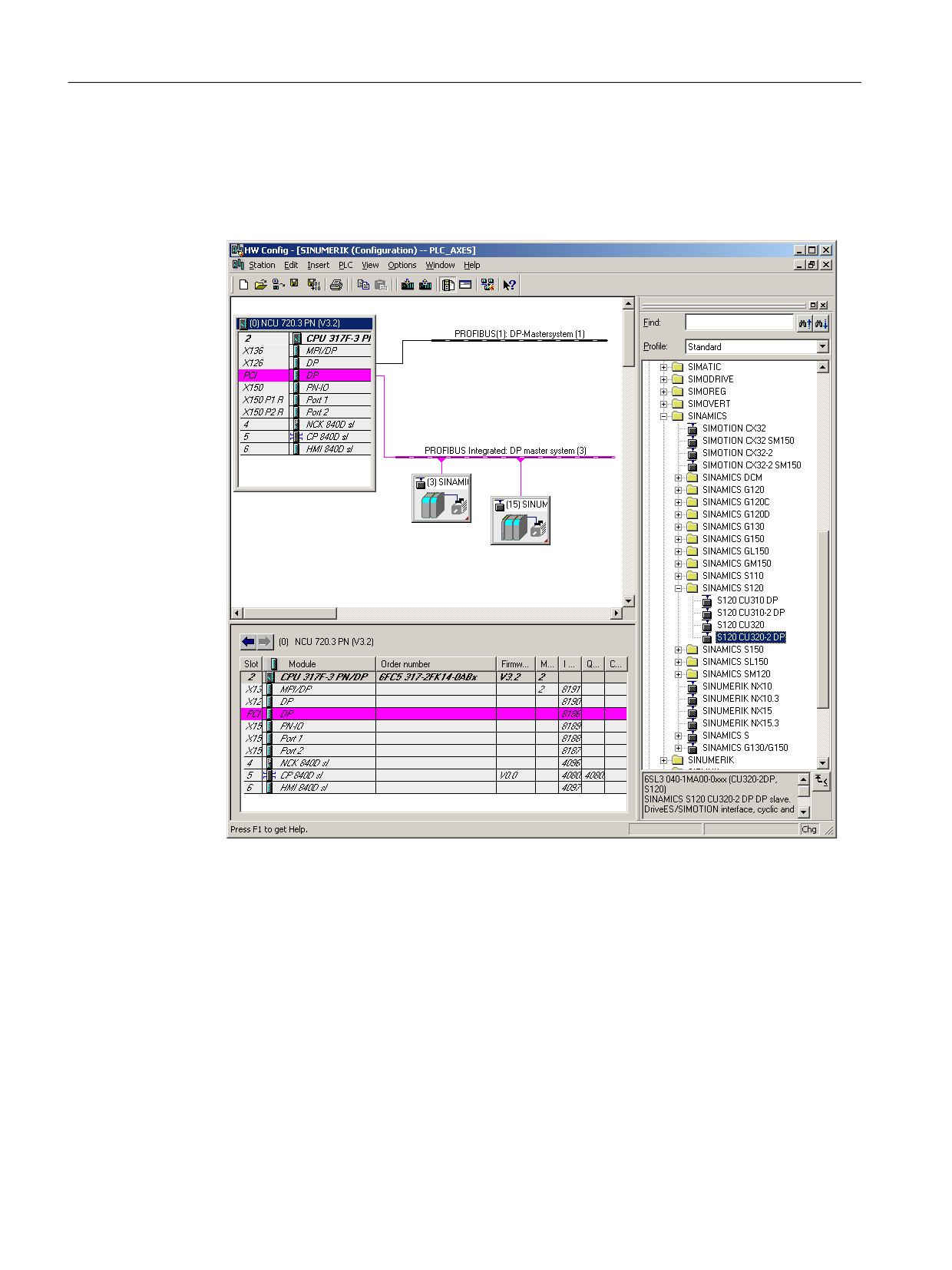
• Insert an S120 CU320-2 DP in HW Config.
• Configure the properties of the PROFIBUS interface.
• Compile the configuration and then download it to the PLC.
Note
The SINUMERIK Toolbox must be installed.
CNC Commissioning: NC, PLC, Drive
Commissioning Manual, 10/2020, A5E48312804B AB
245
Configuring PLC-controlled drives
9.2 Configuration via PROFIBUS
Inserting an S120 CU320-2 DP component
Procedure:
1. Navigate in the catalog to "PROFIBUS DP" → "SINAMICS" → "SINAMICS S120" → "S120
CU320-2 DP":
2. Keeping the left mouse key pressed, drag the "S120 CU320-2 DP" in the station window to
PROFIBUS (1): DP master system.
CNC Commissioning: NC, PLC, Drive
246
Commissioning Manual, 10/2020, A5E48312804B AB
Configuring PLC-controlled drives
9.2 Configuration via PROFIBUS
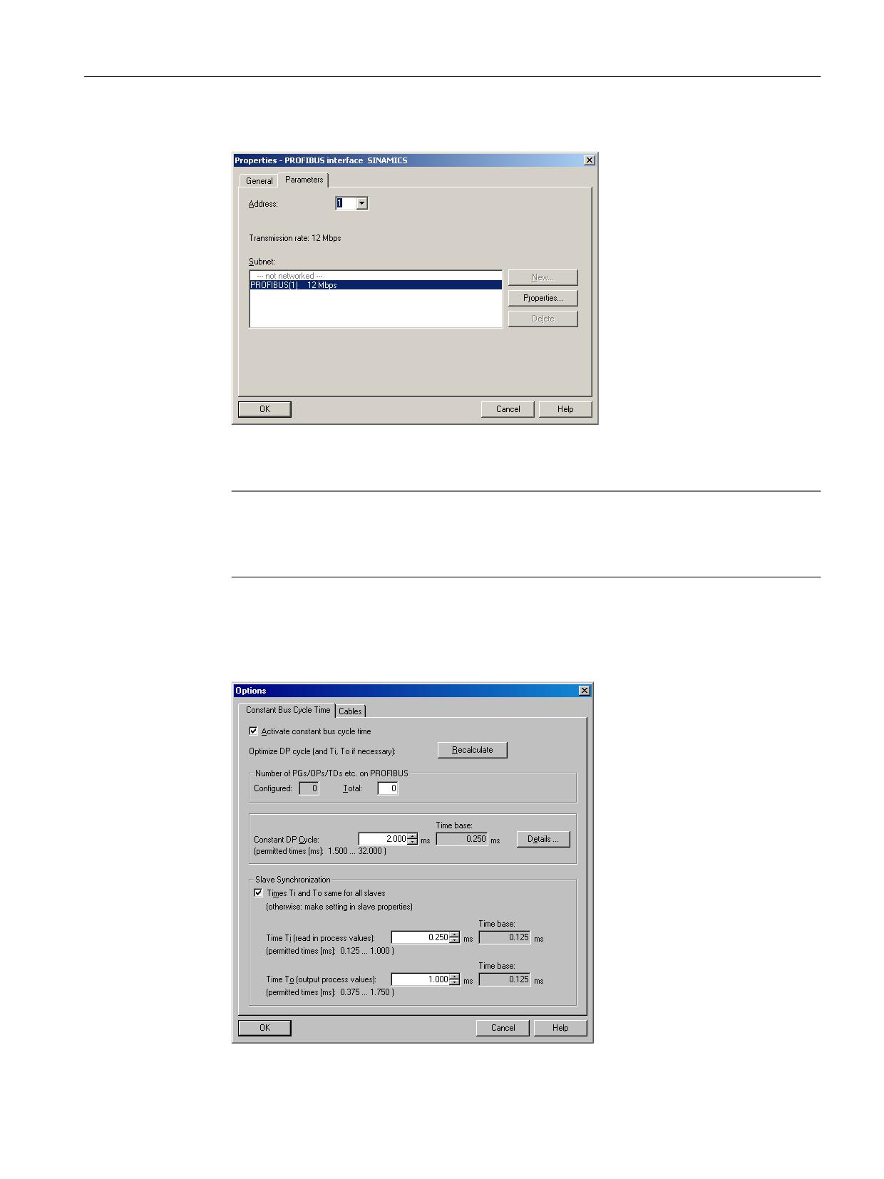
3. After releasing the mouse key, configure the properties of the SINAMICS PROFIBUS interface:
4. Confirm with "OK".
5. In the "Version" selection box, select the firmware version of the Control Unit.
Note
The firmware version must match the version of the CompactFlash card on the CU320-2 DP.
Refer to the upgrade instructions for the versions that have been released for PLC-controlled
drives.
6. Confirm with "OK".
7. In the PROFIBUS DP master system (SINUMERIK NCU) under "Properties" → "Network
settings" → "Options" and under the "Equidistance" tab activate the option "Activate
equidistant bus cycle".
CNC Commissioning: NC, PLC, Drive
Commissioning Manual, 10/2020, A5E48312804B AB
247
Configuring PLC-controlled drives
9.2 Configuration via PROFIBUS
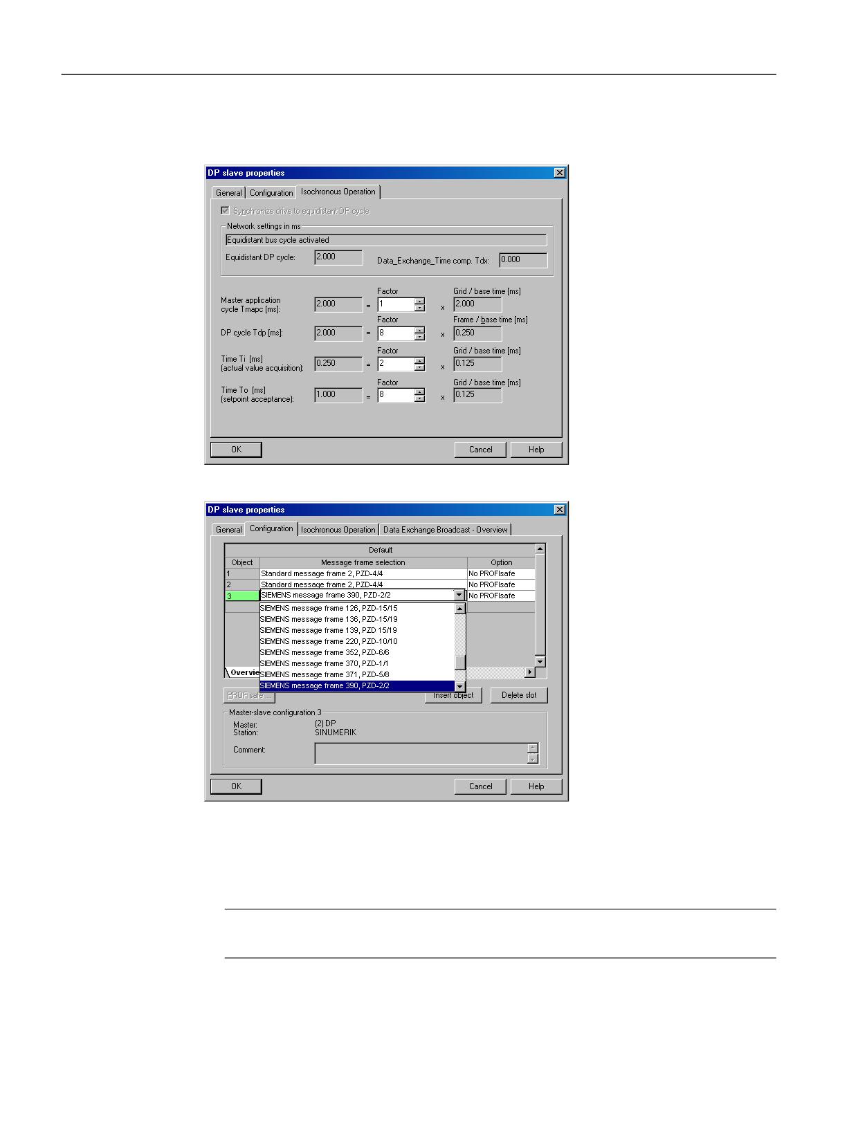
8. In the "DP Slave Properties" of the CU320-2 DP under the "Clock synchronization" tab, activate
the option "Synchronize drive to equidistant DP cycle".
9. In the "DP Slave Properties" dialog box, select the "Configuration" tab.
10.Select in the "Overview" the telegrams required for the individual objects (axes and
CU320-2 DP):
- "Siemens telegram 2, PZD-4/4" for example, for speed-controlled axes
- "Siemens telegram 390, PZD-2/2" for CU320-2 DP
Note
SIEMENS telegram 390 is required for the time stamp of alarms from the PLC.
CNC Commissioning: NC, PLC, Drive
248
Commissioning Manual, 10/2020, A5E48312804B AB
Configuring PLC-controlled drives
9.2 Configuration via PROFIBUS
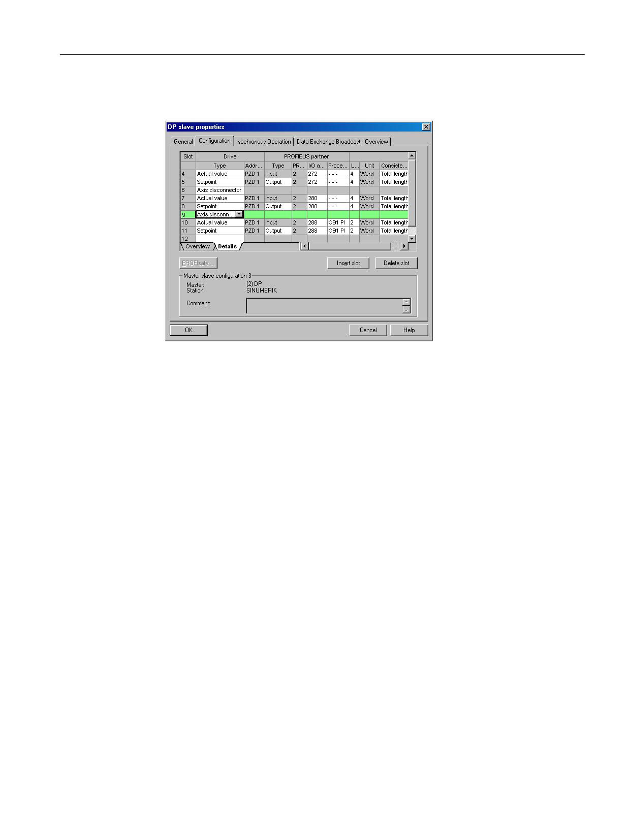
11.Change under "Configuration" to the "Details" view in order to display the associated
generated input and output addresses for the individual objects:
12.Confirm with "OK".
To support automatic device commissioning, the input and output addresses must be identical
because the addresses in the PLC program are required for the FB283.
CNC Commissioning: NC, PLC, Drive
Commissioning Manual, 10/2020, A5E48312804B AB
249
Configuring PLC-controlled drives
9.2 Configuration via PROFIBUS
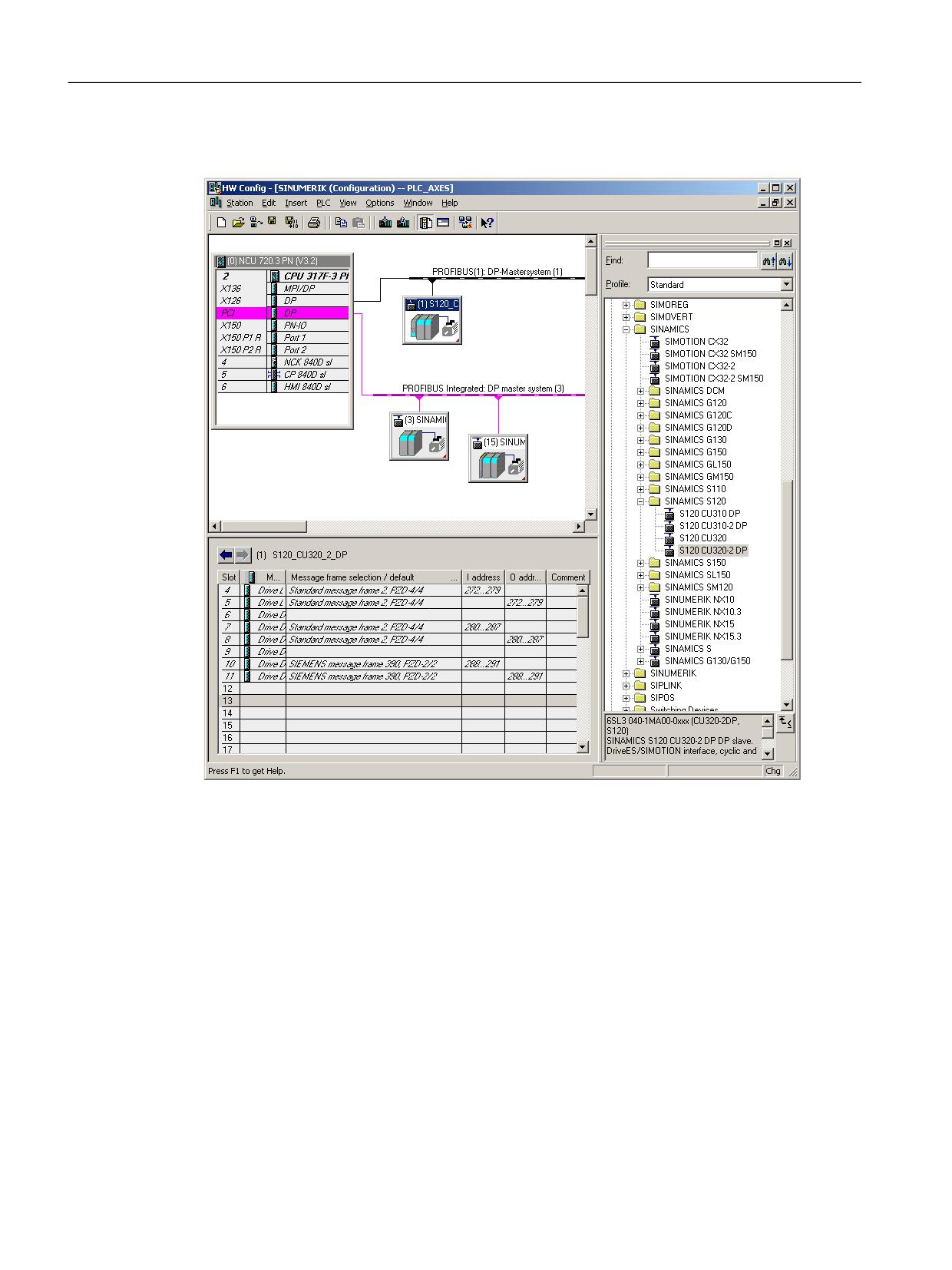
Result
Saving/compiling/loading into the module
Procedure:
1. Select the "Station" → "Save and compile" menu.
2. Click the "Load in module" button to load the configuration to the PLC (Page 65).
In the next step, you create the PLC program.
CNC Commissioning: NC, PLC, Drive
250
Commissioning Manual, 10/2020, A5E48312804B AB
Configuring PLC-controlled drives
9.3 Creating a PLC program
9.3
Creating a PLC program
Requirements
This chapter describes the configuration of PLC drives that are not to be operated as NC axes. The
following expansions of the function blocks are required in the PLC program: You will need
additional S7 function blocks from the SINAMICS toolbox ≥ V2.1. This Zip file contains a manual
in several languages.
The SINAMICS Toolbox is available in the Internet at the following link: SINAMICS Toolbox V2.1
Signals "WR_PZD" and "RD_PZD"
The "WR_PZD" and "RD_PZD" signals for FC70 in the example have the following meaning:
Signal
Typ
Typ
Range of values
Remark
e
e
WR_PZD
I
Any
P#Mm.n byte x
Target range for process data, master → slave (control words / set-
points)
P#DBno.DBXm.n byte x
Here, generally the axis DB is used, i.e. in the pointer, the same DB
number must be specified as formal parameter "NR_ACHS_DB".
The length of the pointer is 30 bytes for Siemens telegram 136.
RD_PZD
I
Any
P#Mm.n byte x
Target range for process data, slave → master (status words / actual
values)
P#DBno.DBXm.n byte x
Here, generally the axis DB is used, i.e. in the pointer, the same DB
number must be specified as formal parameter "NR_ACHS_DB".
The length of the pointer is 38 bytes for Siemens telegram 136.
Example with constant speed (fan, pump)
Procedure:
1. You have already created a project and find yourself on the main screen of the SIMATIC
Manager.
2. Select the "File" → "Open" menu and then click the "User projects" tab.
3. Open the example project and copy the FB283, FC70, DB70 and DB283 blocks as well as all
UDT300xx into your existing project.
4. As the DB70 could be used by another PLC program, rename DB70 as DB111!
5. Create a new FC73. Do not use the FC73 from the SINAMICS toolbox.
In the example, 4000hex corresponds to the rated speed in drive parameter p2000.
CNC Commissioning: NC, PLC, Drive
Commissioning Manual, 10/2020, A5E48312804B AB
251

Configuring PLC-controlled drives
9.3 Creating a PLC program
6.
Edit the OB1, FC70 and FC73 blocks in accordance with the following examples.
Example of OB1:
…
CALL FC70
CALL FC73
…
Example of FC70:
CALL FB283, DB283
NR_ACHS_DB := 111
LADDR := 272
//Logical I/O address
LADDR_DIAG := 8186
//Diagnostic addresses
WR_PZD := P#DB111.DBX172.0 Byte 8
//Source range for outputs
RD_PZD := P#DB111.DBX212.0 Byte 8
//Target range for inputs
CONSIST := TRUE
RESTART := FALSE
AXIS_NO := B#16#3
//Number of the drive object
Example of FC73:
UN E30.0
//E.g. switch for the enable signal
SPB frei
L W#16#47E
//All enables set
T DB111.DBW172
U E3.7
//MCP reset
= DB111.DBX173.7
//Reset fault memory
BEA
frei:
L W#16#47E
//All enable signals except ON/OFF1
T DB111.DBW172
L W#16#4000
//Rated speed in drive parameter p2000
T DB111.DBW174
//Set speed high
7.
You have now finished programming the PLC program. Load the project to the PLC (Page 87).
8.
To synchronize the PLC and NC, a system reset (po) is required:
- NCU: RUN LED is continuously lit green.
- NCU: Status display shows a "6" with a flashing dot.
- SINAMICS CU320-2 DP: LED RDY flashes slowly green (0.5 Hz)
⇒ PLC and NC are in cyclic operation.
CNC Commissioning: NC, PLC, Drive
252
Commissioning Manual, 10/2020, A5E48312804B AB
Configuring PLC-controlled drives
9.4 Commissioning PLC drives
9.4
Commissioning PLC drives
Automatic device configuration
Procedure:
1. Select the "Commissioning" → "Drive system" operating area.
2. Confirm with "OK". You will then be guided through the individual steps of the automatic
device configuration.
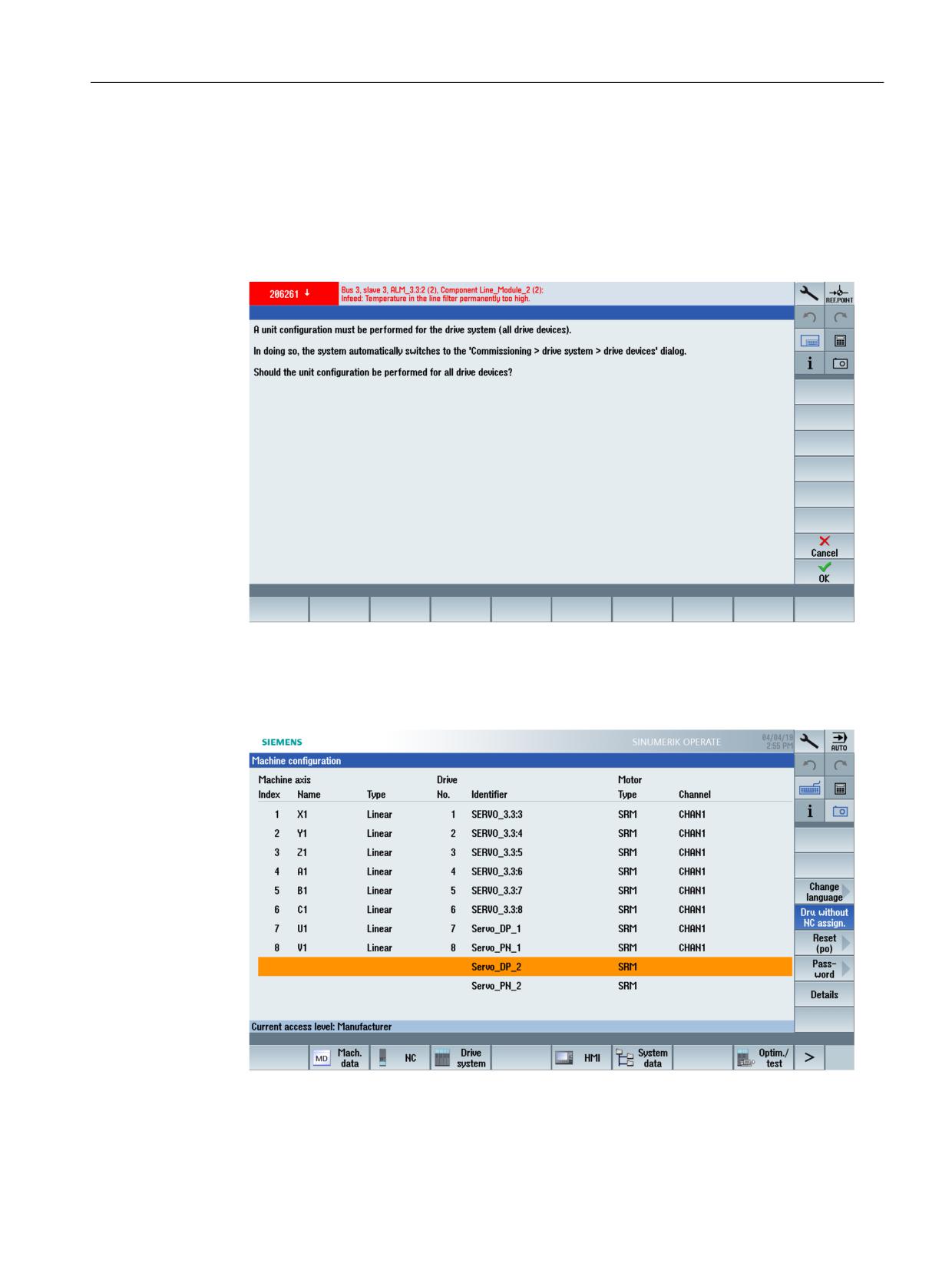
3. In the "Machine configuration" overview, press the "Drives without NC assignment" softkey
to display all drive objects:
CNC Commissioning: NC, PLC, Drive
Commissioning Manual, 10/2020, A5E48312804B AB
253
Configuring PLC-controlled drives
9.4 Commissioning PLC drives
Diagnostics
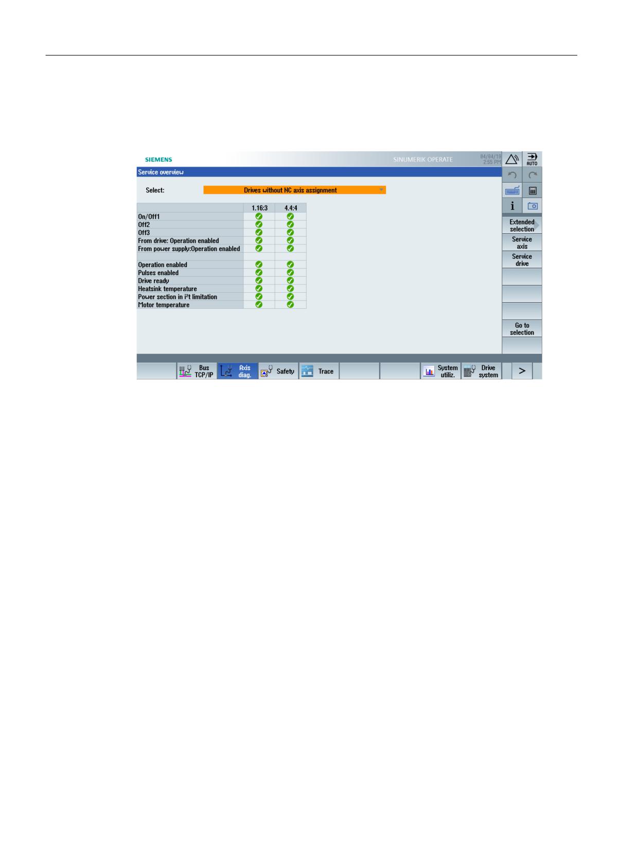
The status is likewise displayed in the "Diagnostics" → "Axis diagnostics" → "Service axis"
operating area with the selection "Drives without NC axis assignment".
CNC Commissioning: NC, PLC, Drive
254
Commissioning Manual, 10/2020, A5E48312804B AB
Configuring PLC-controlled drives
9.5 Checking the communication to the drive
9.5
Checking the communication to the drive
Check configuration
The PLC alarms of the drives must have an identical time stamp with the NC.
For the configuration in the hardware configuration, define the associated Siemens telegram
390 for the SINAMICS CU. The corresponding logical input and output addresses of this
communication interface are entered in the following machine data item:
• MD13120[n] CONTROL_UNIT_LOGIC_ADDRESS
• MD13120[1]...[5] are reserved for NX expansion modules.
Note
You can view these logical addresses in the HW configuration when configuring the
properties of SINAMICS components under "Details".
Procedure:
1. Check the logical address for SINAMICS CU in the "Commissioning" → "Machine data" →
"General MD" operating area and enter, for example, the following value:
MD13120[6] = 288
2. Press the "Reset (po)" softkey to accept the changed machine data.
This completes the commissioning of the PLC drives.
CNC Commissioning: NC, PLC, Drive
Commissioning Manual, 10/2020, A5E48312804B AB
255
Configuring PLC-controlled drives
9.6 Safety functions for PLC drives
9.6
Safety functions for PLC drives
Introduction
This section only partially describes how a PLC drive can be integrated in a safety-related
application. In this case, the published supplement of the PROFIdrive profile that includes drive-
based safety functions via the PROFIsafe supplement with telegram 30 is used.
Basic procedure
The following steps are necessary to integrate drive-based safety functions:
• Configuration with SIMATIC Manager under HW Config.
• Embedding in safe programmable logic (SPL).
Further information
The following Function Manuals for Safety Integrated are binding when it comes to
implementing a safety-related design:
• Chapter "Control via PROFIsafe" in the SINAMICS S120 Safety Integrated (FHS) (https://
support.industry.siemens.com/cs/ww/en/view/109771806) Function Manual
- SINUMERIK 840D sl Safety Integrated Function Manual
- SINUMERIK 840D sl Safety Integrated plus Commissioning Manual
9.6.1
Configuring PROFIsafe
Requirement
In order to configure PROFIsafe, it is necessary that the "S7 Configurations Pack" option is
installed.
CNC Commissioning: NC, PLC, Drive
256
Commissioning Manual, 10/2020, A5E48312804B AB
Configuring PLC-controlled drives
9.6 Safety functions for PLC drives
Configuring the operating sequence for PROFIsafe
Procedure:
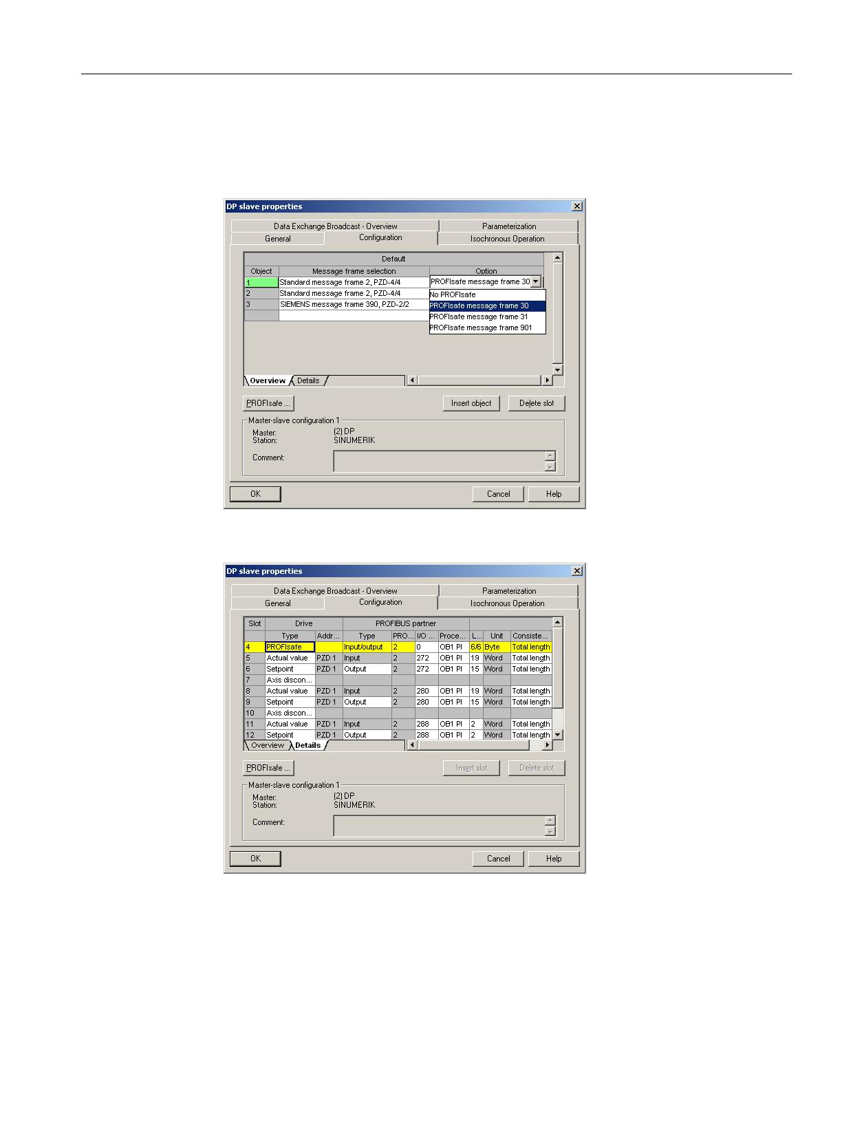
1. For this telegram, select the PROFIsafe telegram 30 in the "Option" selection field.
2. Under the "Details" tab, set the input/output addresses. The PROFIsafe option requires an
additional 6 bytes.
3. Click the "PROFIsafe ... " button to set the F parameters.
CNC Commissioning: NC, PLC, Drive
Commissioning Manual, 10/2020, A5E48312804B AB
257
Configuring PLC-controlled drives
9.6 Safety functions for PLC drives
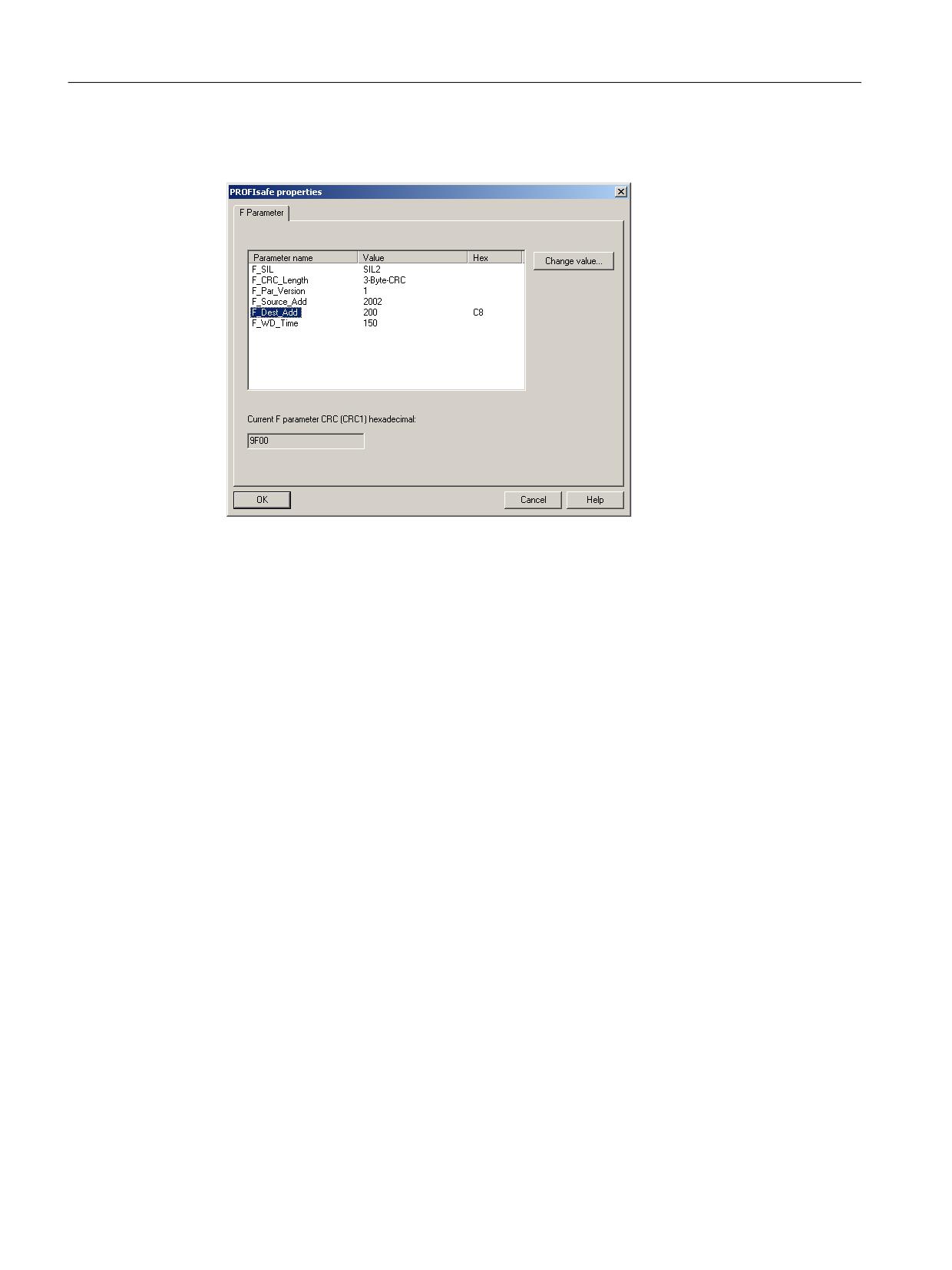
4. To change the "F_Dest_Add" parameter, select "F_Dest_Add" in the "Parameter Name"
column and click the "Change value ..." button.
5. Check the following values/settings:
- The value of the "F_Dest_Add" parameter must be entered as a hexadecimal value in
p9610 and p9810 of the corresponding drive (e.g. 200dec corresponds to C8hex).
- The value of the "F_Source_Add" must match the other used PROFIsafe modules and also
be entered in MD10385 $MN_PROFISAFE_MASTER_ADRESS.
- It must be ensured that the same source address is set for all PROFIsafe modules.
CNC Commissioning: NC, PLC, Drive
258
Commissioning Manual, 10/2020, A5E48312804B AB
Configuring PLC-controlled drives
9.6 Safety functions for PLC drives
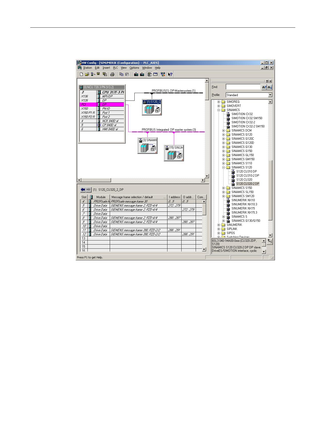
Result of the PROFIsafe configuring
9.6.2
Example: Embedding in safe programmable logic (SPL)
Introduction
The following machine data and files must be taken into account when embedding telegram 30
in a safe programmable logic:
• NC machine data
• Drive machine data
• "safe.SPF" file
• PLC program expansion
CNC Commissioning: NC, PLC, Drive
Commissioning Manual, 10/2020, A5E48312804B AB
259
Configuring PLC-controlled drives
9.6 Safety functions for PLC drives
NC machine data
The SPL PROFIsafe configuration for the basic safety functions STO without SSI are then shown:
Archive excerpt
Comment
CHANDATA(1)
N10385 $MN_PROFISAFE_MASTER_ADDRESS='H50007d2'
N10386 $MN_PROFISAFE_IN_ADDRESS[0]='H50000c8'
;=> entry from HW Config
N10387 $MN_PROFISAFE_OUT_ADDRESS[0]='H50000c8'
;=> entry from HW Config
N10390 $MN_PROFISAFE_IN_ASSIGN[0]=9011
;=> INSE[9] for S_STW1.0 No Safe Torque Off
;=> INSE[10] for S_STW1.1 No Safe Stop 1
;=> INSE[11] for S_STW1.7 INTERNAL_EVENT_ACK
; No extended functions
N10400 $MN_PROFISAFE_OUT_ASSIGN[0]=9011
;=> OUTSE[9] for S_ZSW1.0 Power removed
;=> OUTSE[10] for S_ZSW1.1 Safe Stop 1 not active
;=> OUTSE[11] for S_ZSW1.7 INTERNAL_EVENT
; No extended functions
N13300 $MN_PROFISAFE_IN_FILTER[0]='H83'
N13320 $MN_PROFISAFE_OUT_FILTER[0]='H83'
Drive machine data
Values that have been added as a result of telegram 30:
• p9601=p9801=0x8
• p9610=p9810=0xC8
"safe.SPF" file:
Program example
Comment
IDS = 40 DO $A_OUTSE[09] = $A_INSE[2]
;If the cover is locked then deselect STO
IDS = 41 DO $A_OUTSE[10] = $A_INSE[2]
;If the cover is locked then deselect SS1
PLC program extension:
Program example
Comment
U
"SPL".SPL_DATA.INSEP[2];
// => cover switch locked?
=
"SPL".SPL_DATA.OUTSEP[9];
// $A_OUTSE[9] =1 => Deselect STO
=
"SPL".SPL_DATA.OUTSEP[10];
// $A_OUTSE[10] =1 => Deselect SS1
//Enable signal OFF1 set:
UN
"SPL".SPL_DATA.INSEP[9];
// => No STO?
UN
"SPL".SPL_DATA.INSEP[10];
// => No SS1?
U
E
0.0;
// only if OFF1 is also requested via switch
CNC Commissioning: NC, PLC, Drive
260
Commissioning Manual, 10/2020, A5E48312804B AB
Configuring PLC-controlled drives
9.6 Safety functions for PLC drives
Program example
Comment
=
"CU320_A".Speed_Control.WR_PZD_DREHZAHL.STW1.Aus1 ;
CNC Commissioning: NC, PLC, Drive
Commissioning Manual, 10/2020, A5E48312804B AB
261
Configuring PLC-controlled drives
9.6 Safety functions for PLC drives
CNC Commissioning: NC, PLC, Drive
262
Commissioning Manual, 10/2020, A5E48312804B AB
Drive tuning
10
10.1
Tuning procedure
Precondition
Once the drives have been commissioned and the axes assigned, you must start tuning the
particular machine or a machine type.
• The commissioning of the drives has been completed.
• The topology has been checked and is OK.
Tuning procedure
Depending on the requirements, the following tuning procedure is recommended: Procedure
when tuning axes and drives (Page 34)
Especially efficient procedure: Tuning, utilizing all default settings of the automatic servo tuning:
• Example: This is how you tune the X axis (Page 272)
• Example: This is how you tune the Y axis (Page 276)
• Example: How to start the path interpolation (Page 281)
Procedure for experts:
• Tuning using the automatic servo tuning with manual parameter settings:
Example for experts: Axis tuning (Page 285)
• Tuning using measuring functions and manual parameter settings of the position controller,
speed controller and current controller:
- Example: Setting the filter for the following error (speed control loop) (Page 296)
- Examples for the measuring methods (position control loop) (Page 299)
- Example, function generator: Speed setpoint after the filter (Page 303)
The SINUMERIK Operate Online Help provides more detailed, context-related infor-
mation on the parameterization of the "Automatic Servo Tuning".
Further information can be found in:
Function Manual
• "Monitoring and Compensating (https://support.industry.siemens.com/cs/document/
109766213)"
CNC Commissioning: NC, PLC, Drive
Commissioning Manual, 10/2020, A5E48312804B AB
263
Drive tuning
10.2 Function overview for the tuning
10.2
Function overview for the tuning
Commissioning → Tuning/test
The following functions are available to support the commissioning:
• Automatic servo tuning
• Measuring functions (Page 288) (current control loop, speed control loop, position control
loop)
• Function generator (Page 301)
• Circularity test (Page 306)
• Characteristic curves for the hydraulic module (if present)
• Active filters (Page 305)
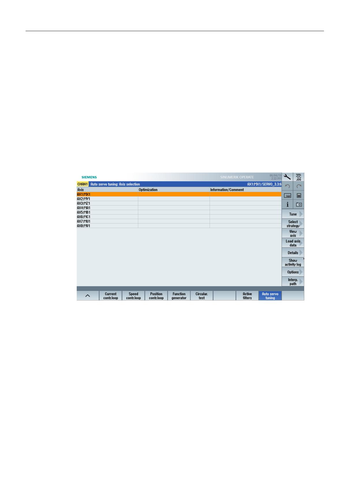
Figure 10-1
Example: "Automatic servo tuning"
Diagnosis → Trace
With the "Trace (Page 147)" function, you select the NC variables, PLC variables or drive variables
whose signal chart is to be visualized:
• Trace for PLC/NC//servo variables
Recording and graphical representation of the signal values with respect to time, such as
actual position value, following error, etc.
• Trace for drive variables
Recording and graphical representation of the signal values with respect to time from the
drive system, such as e.g. speed actual value, current actual value etc.
CNC Commissioning: NC, PLC, Drive
264
Commissioning Manual, 10/2020, A5E48312804B AB
Drive tuning
10.3 Automatic servo tuning
10.3
Automatic servo tuning
Which functions are available?
The following options are available for automatically tuning an axis:
• Selection of an individual axis for tuning
• Selection of a strategy from many options
• Reconfiguration of measurement conditions
• Chart display and activity log for tuning process
• Display of the measured frequency responses (speed control system) and the calculated
frequency responses (open circuit, closed control loop)
• Checking and processing the tuning results for speed and position controller: The response
of the control loop is simulated on the basis of the frequency response and displayed in the
bode diagram.
• Accept or reject the results of the tuning
The function "Automatic servo tuning" is started in the operating area "Commissioning"
→ "Automatic servo tuning", and can be used for all servo and direct drives.
Interpolation axes
For axes which make up an interpolation group, additional tuning steps should be undertaken,
e.g.:
• Path interpolation with the automatic servo tuning.
• Circularity test (Page 306)
• Adjust servo gain factor.
• When using feedforward control, transfer equivalent time constants of the slowest axis
(highest value) in all interpolating axes.
10.3.1
Setting the options for the measurement procedure
Options in JOG mode
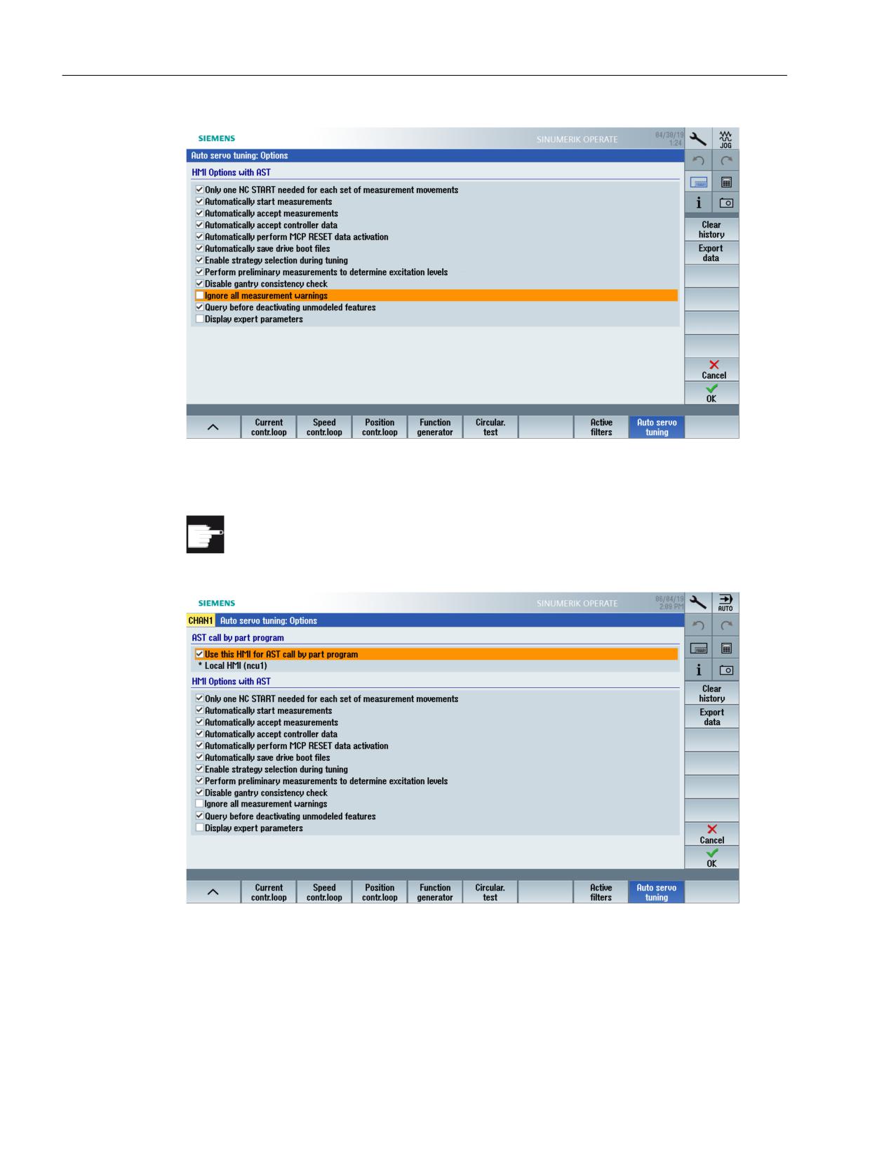
In the first step, press the "Options" softkey to set the general behavior for automatic servo
tuning.
For a predominantly automatic sequence in the JOG mode the following selection is
recommended, utilizing all automatic sequences and settings:
CNC Commissioning: NC, PLC, Drive
Commissioning Manual, 10/2020, A5E48312804B AB
265
Drive tuning
10.3 Automatic servo tuning
Condition for AUTO mode
Software option
In order to use this function a license is required for the following option: "Call AST
from the part program" (6FC5800-0_S10-0YB0)
With the option "Assign this HMI for "Call AST from the part program"", you select SINUMERIK
Operate to perform the automatic servo tuning in the AUTO mode:
•
☑ If this option is selected, the current SINUMERIK Operate performs the automatic servo
tuning.
•
☐ If this option is not selected, a different SINUMERIK Operate performs the automatic servo
tuning.
CNC Commissioning: NC, PLC, Drive
266
Commissioning Manual, 10/2020, A5E48312804B AB
Drive tuning
10.3 Automatic servo tuning
Sequence in AUTO mode
As a result of the changing load, for direct drives (e.g. torque motors) it may be necessary to tune
the axis involved for each new workpiece size or clamping device.
Standard cycles (CYCLE751...759) are available, that machine OEMs can use in a manufacturer
cycle. The automatic servo tuning can be parameterized and started using the cycles. The
previous settings and results from the automatic servo tuning can be employed, using
SINUMERIK Operate. The machine manufacturer provides the machine operator with a
manufacturer's cycle, which includes the appropriate commands. This means that after
retuning, an end user can insert a manufacturer's cycle in his part program, which performs the
tuning and selects the appropriate data sets. The part program does not have to be interrupted
for the retuning.
The following settings must be made by the machine manufacturer so that the cycle call for the
automatic servo tuning from the part program functions at the end user.
• The instance of SINUMERIK Operate on which the cycles are executed has been selected.
• The XML files with the appropriate tuning settings for the respective axis, which are required
by the cycles, are available.
• The manufacturer cycles are available, and when required a parameter set switchover is set
up.
Additional information about the cycles and a description of the syntax are provided in Chapter
"Automatic Retuning" in the "Axes and Spindles (https://support.industry.siemens.com/cs/
document/109766213)" Function Manual.
CNC Commissioning: NC, PLC, Drive
Commissioning Manual, 10/2020, A5E48312804B AB
267
Drive tuning
10.3 Automatic servo tuning
10.3.2
Selecting the tuning strategy
Default setting for "Axis" strategy
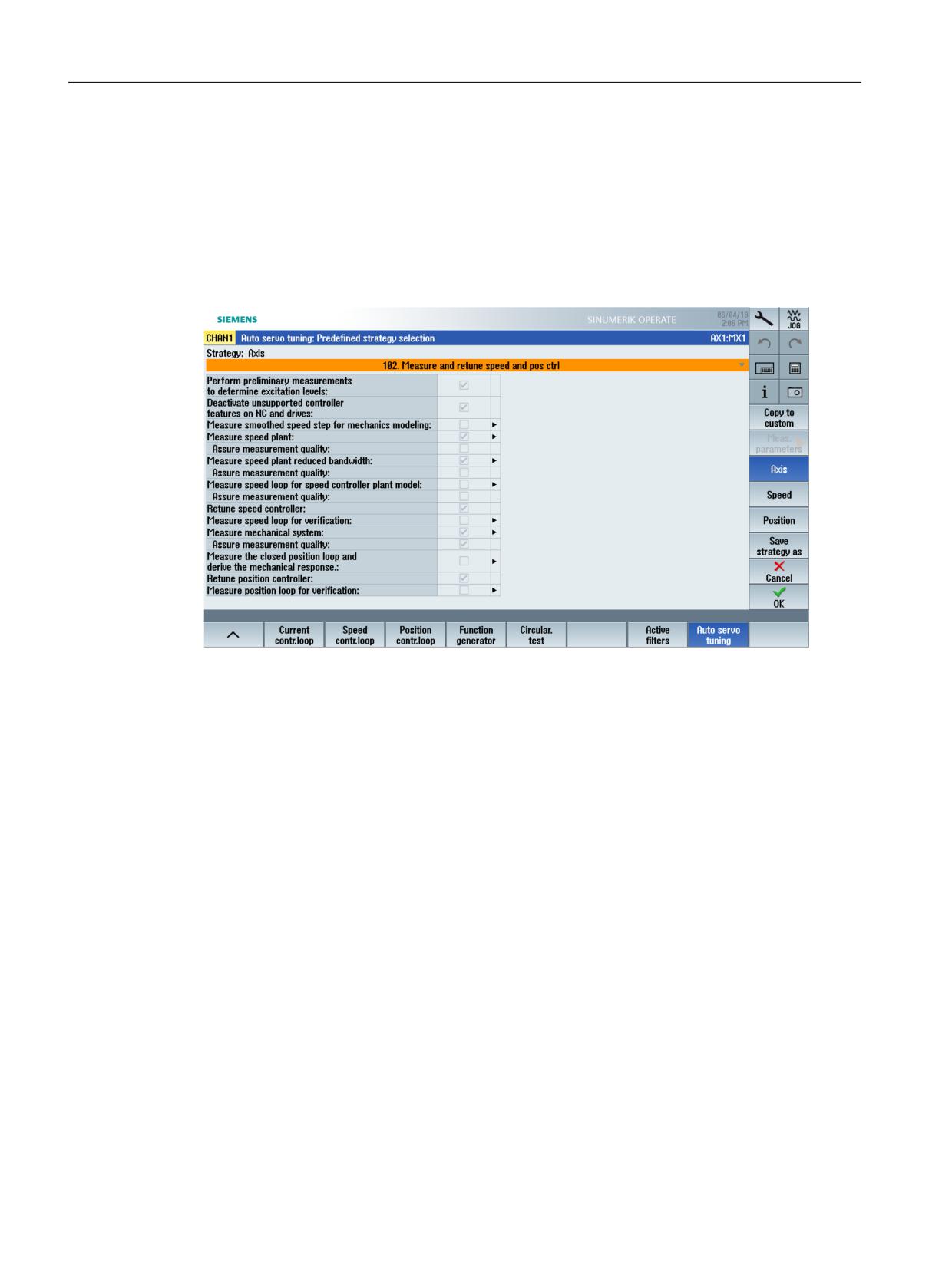
For a predominantly automatic sequence in the JOG mode the following selection is
recommended: Select a tuning strategy for axis, speed controller and position controller using
softkey "Select strategy >". The recommended strategies are 102, 303 and 203.
Figure 10-2
Strategy: Axis example
For the "Axis" strategy, select which controller should be tuned. When doing this, the tuned,
closed control loop can be measured to check the results.
CNC Commissioning: NC, PLC, Drive
268
Commissioning Manual, 10/2020, A5E48312804B AB
Drive tuning
10.3 Automatic servo tuning
Example for "Axis": Strategy 108
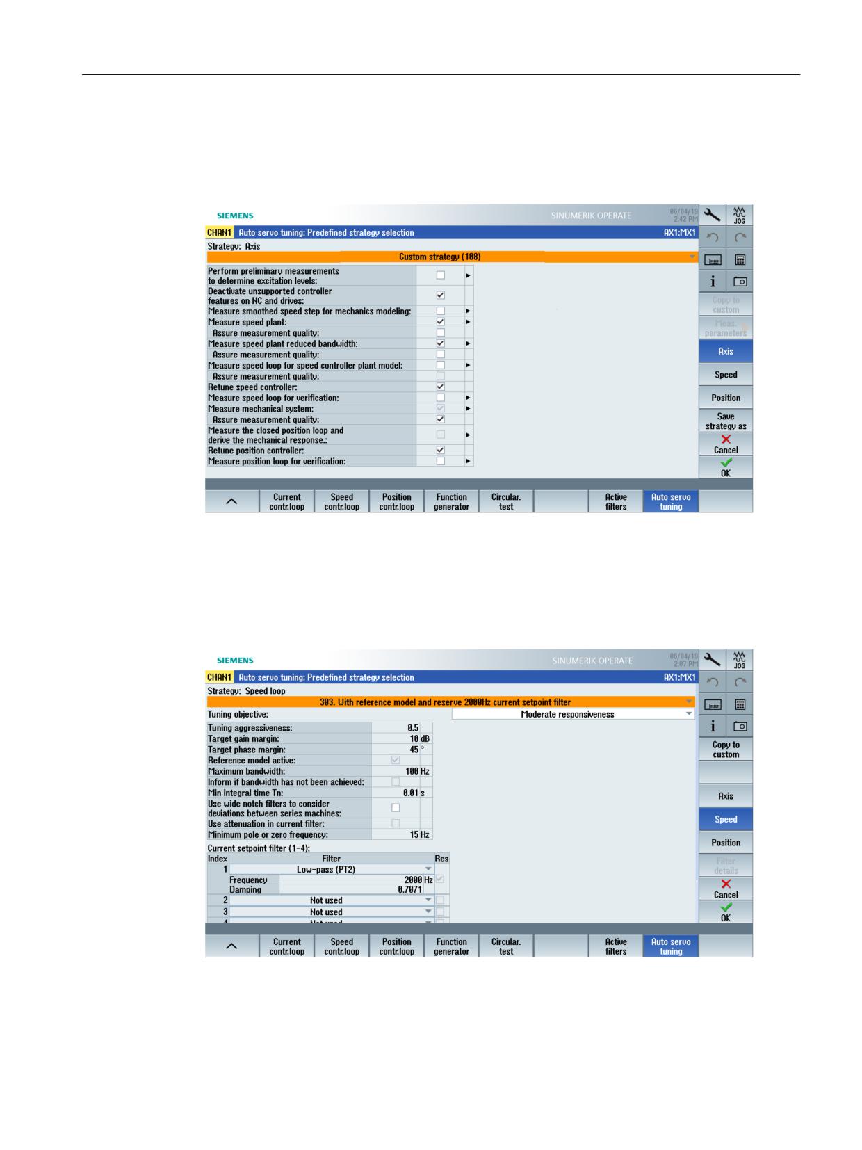
When selecting "User-defined strategy (108)" for the axis, all options are active and can be set
using the "Adapt strategy" softkey:
Figure 10-3
User-defined strategy (108) - example
Further, additional strategies that can be combined with a tuning objective are available in the
list.
Example for "Speed": Strategy 303
Figure 10-4
Strategy: Speed control loop - example
CNC Commissioning: NC, PLC, Drive
Commissioning Manual, 10/2020, A5E48312804B AB
269
Drive tuning
10.3 Automatic servo tuning
The most important settings are: Tuning aggressiveness and minimum integral time Tn.
•
Tuning aggressiveness:
This parameter determines the setting of Kp and Tn based on stability limits. The phase
margin and amplitude margin values are pre-assigned according to this setting.
- Default setting = 0.5
- Min = 0 [maximum stability]
- Max = 1 [maximum aggressiveness]
•
Minimum integral time Tn:
This parameter prevents automatic servo tuning from setting the integrator time of the
speed control loop too low. If the automatic servo tuning sets a value lower than this
parameter has set, the actual value used will be limited to the value set by the minimum
integral time Tn.
A higher integral time ensures a more rugged closed-loop control if changes to the weight or
the moment of inertia are expected. This is recommended for direct drives and main spindles
of turning machines.
- Default setting = 10 ms
- Min = 0.5 ms
- Max = 100 ms
•
Pole/zero point identification as from frequency:
This parameter sets the lower limit value of the frequency range, through which the
automatic servo tuning searches for natural frequency modes: Pole and zero points on the
controlled system. This parameter is intended to prevent measurement noise in the low
frequency range being incorrectly marked as the pole or zero position. The frequencies
identified as pole or zero positions play a role in the estimation of the total inertia of the axis.
For this reason, it is important that the lowest natural frequency of the axis is correctly
identified by the automatic servo tuning.
On large machines with low frequency vibration modes, it may be necessary to reduce the
15 Hz default value of this parameter. The reduction of this parameter may have to be
accompanied by a reduction in the bandwidth of the measurement of the speed-controlled
system.
Default setting: 15 Hz
CNC Commissioning: NC, PLC, Drive
270
Commissioning Manual, 10/2020, A5E48312804B AB
Drive tuning
10.3 Automatic servo tuning
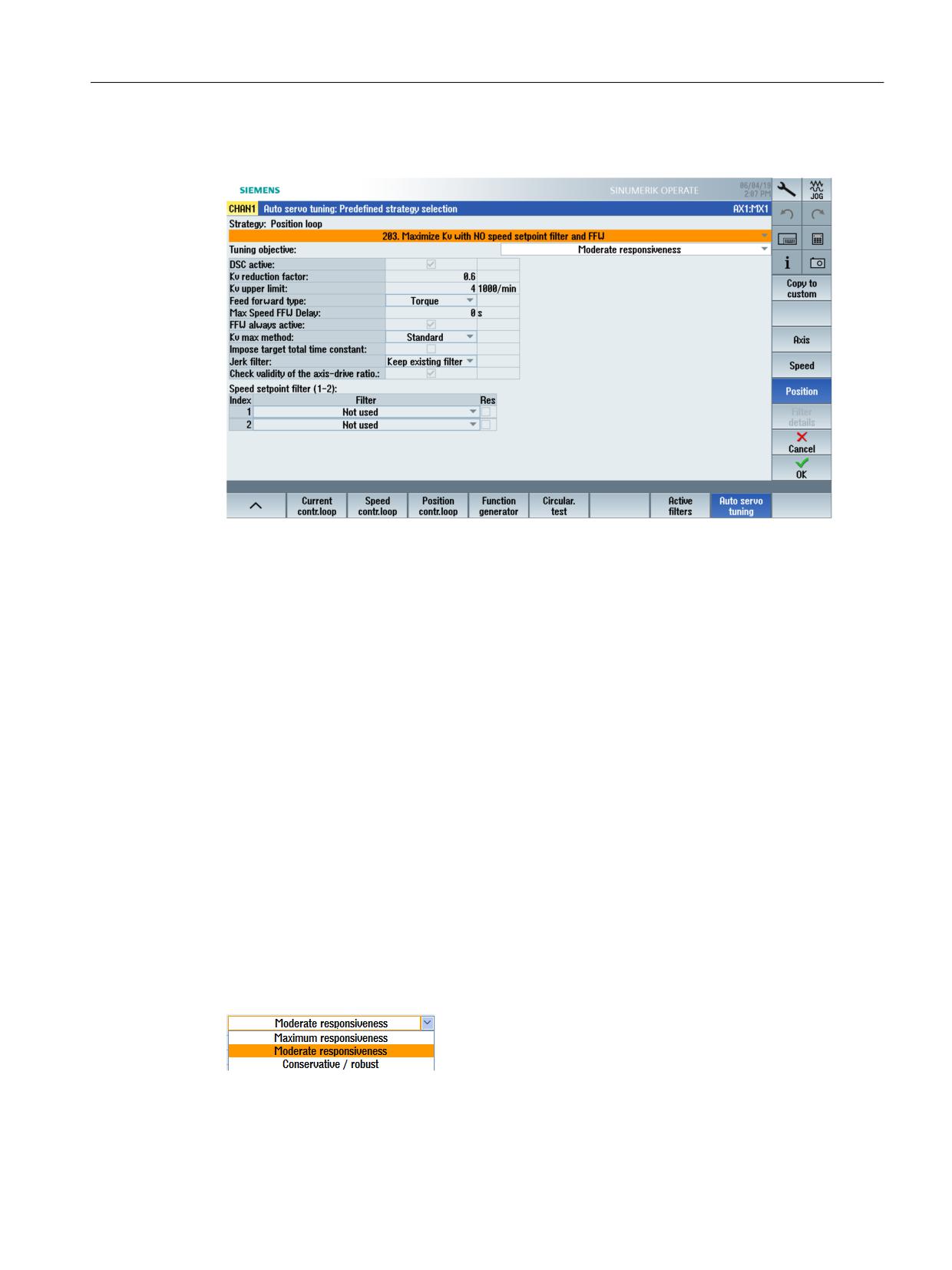
Example for "Position": Strategy 203
Figure 10-5
Strategy: Position control loop - example
The value for reducing the servo gain factor and its upper limit depends on the selected tuning
objective.
• Reduce servo gain factor
The maximum servo gain factor is calculated from the automatic servo tuning; in the process,
no overshoot is allowed with the position controller. The maximum servo gain factor is the
value that does not result in any overshoot. The maximum servo gain factor can be reduced
to increase ruggedness against mechanical changes. A reserve of 40% is set for the tuning
objective "moderate responsiveness". Furthermore, the servo gain factor is limited to 4 mm/
min.
- Default setting = 0.6
- Min = 0.1
- Max = 1 (no reduction)
• Feedforward control mode: Torque feedforward control is recommended.
When telegram 136 is used, the torque feedforward control allows the highest contour
precision to be achieved.
Tuning objective
The default settings for speed and position controllers are adapted by selecting the tuning
objective.
CNC Commissioning: NC, PLC, Drive
Commissioning Manual, 10/2020, A5E48312804B AB
271
Drive tuning
10.3 Automatic servo tuning
• Maximum responsiveness:
The speed and position controller gain (servo gain factor) is tuned with maximum values and
minimum ruggedness.
Application: High-speed machining with maximum suppression of all disturbing forces such
as friction, teeth of the drive belt, strong cutting forces, when machining titanium, for
example. Recommended for high-speed machining with linear motors.
Precondition: The machine must have a rigid design; the dynamic masses do not change
significantly.
• Moderate responsiveness (= default):
This controller dynamic response is sufficient for the majority of machines and applications.
The setting is more rugged than "Maximum responsiveness".
Application: The inertia or the load mass of the axes does not change much and therefore this
setting is suitable for numerous applications.
• Conservative/robust responsiveness:
Only weak control gains are selected in order to ensure as high a level of ruggedness as
possible.
The speed controller is tuned so that it achieves maximum damping to prevent oscillations
and to achieve good position controller gain.
Application: Recommended for machines on which the mechanical axis system or the load
mass can change significantly. Also suitable for axes that respond with oscillations, e.g. main
spindles on turning machines or large axes with high load mass.
Recommended for applications with low requirements on the machining time.
10.3.3
Example: This is how you tune the X axis
Precondition
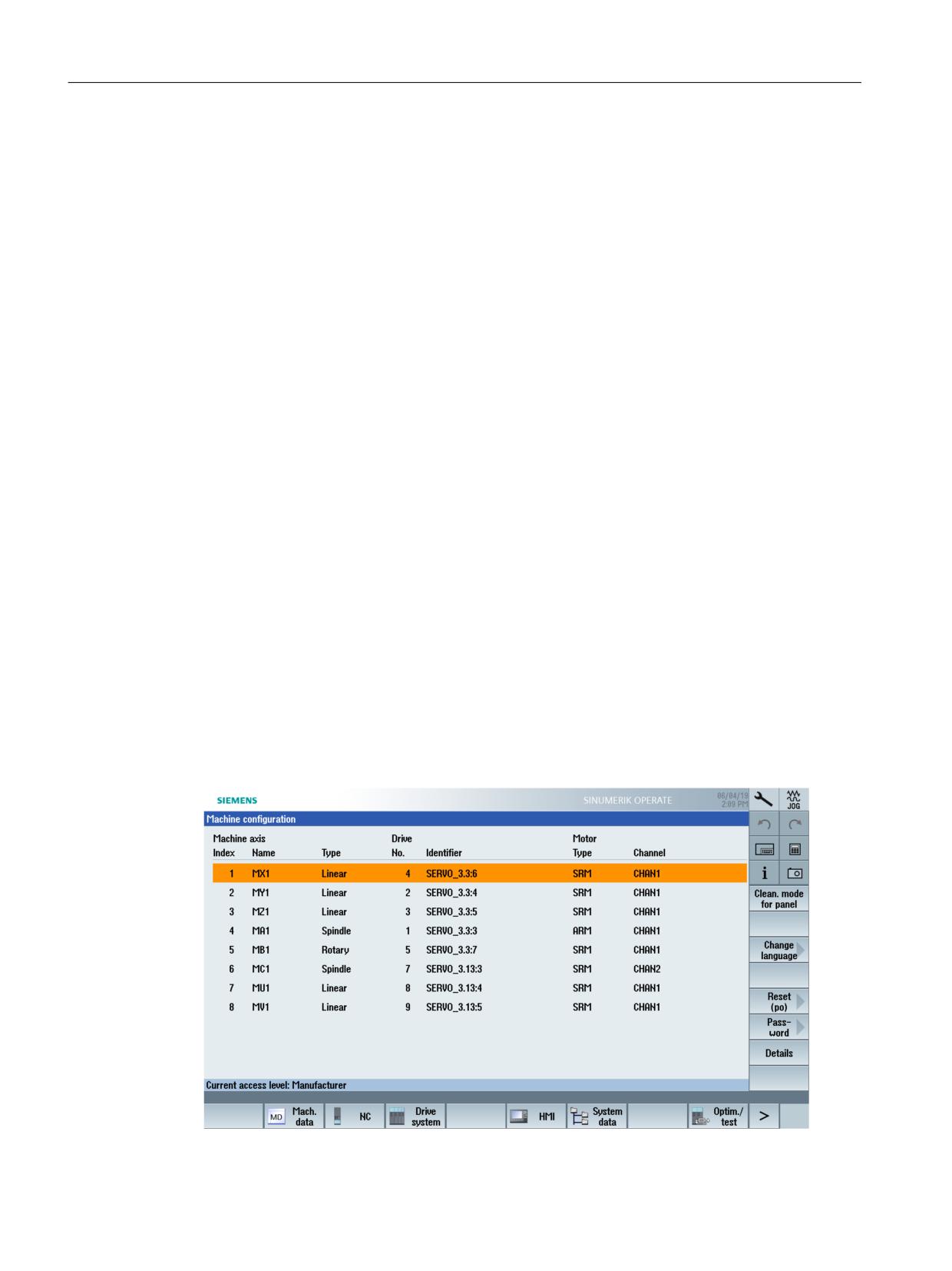
This example shows how to tune the X1 axis using the "Automatic servo tuning" function. In this
case, the following machine configuration is assumed:
CNC Commissioning: NC, PLC, Drive
272
Commissioning Manual, 10/2020, A5E48312804B AB
Drive tuning
10.3 Automatic servo tuning
WARNING
Avoiding unwanted axis movements
Automatic servo tuning is based on the analysis of measurements. These measurements
require the axis to move.
Carefully ensure that all axes are in a safe position and no collisions will occur during the
traversing motion that is required.
Number of measurements
For tuning purposes, the following measurements are taken with the speed controller:
Speed controlled system:
• Overall bandwidth: Preliminary measurement in both directions
• Overall bandwidth: Measurement in both directions
• Reduced bandwidth: Preliminary measurement in both directions
• Reduced bandwidth: Measurement in both directions
Mechanical system motor to DMS:
• Measurement in both directions
Tuning the X axis
Procedure:
1. Softkey "Options >", to select options when performing the measurements.
2. Softkey "Select strategy >", to select a strategy: Default setting 102, 203, 303.
3. Check that the tuning objective "Moderate responsiveness" is selected
CNC Commissioning: NC, PLC, Drive
Commissioning Manual, 10/2020, A5E48312804B AB
273
Drive tuning
10.3 Automatic servo tuning
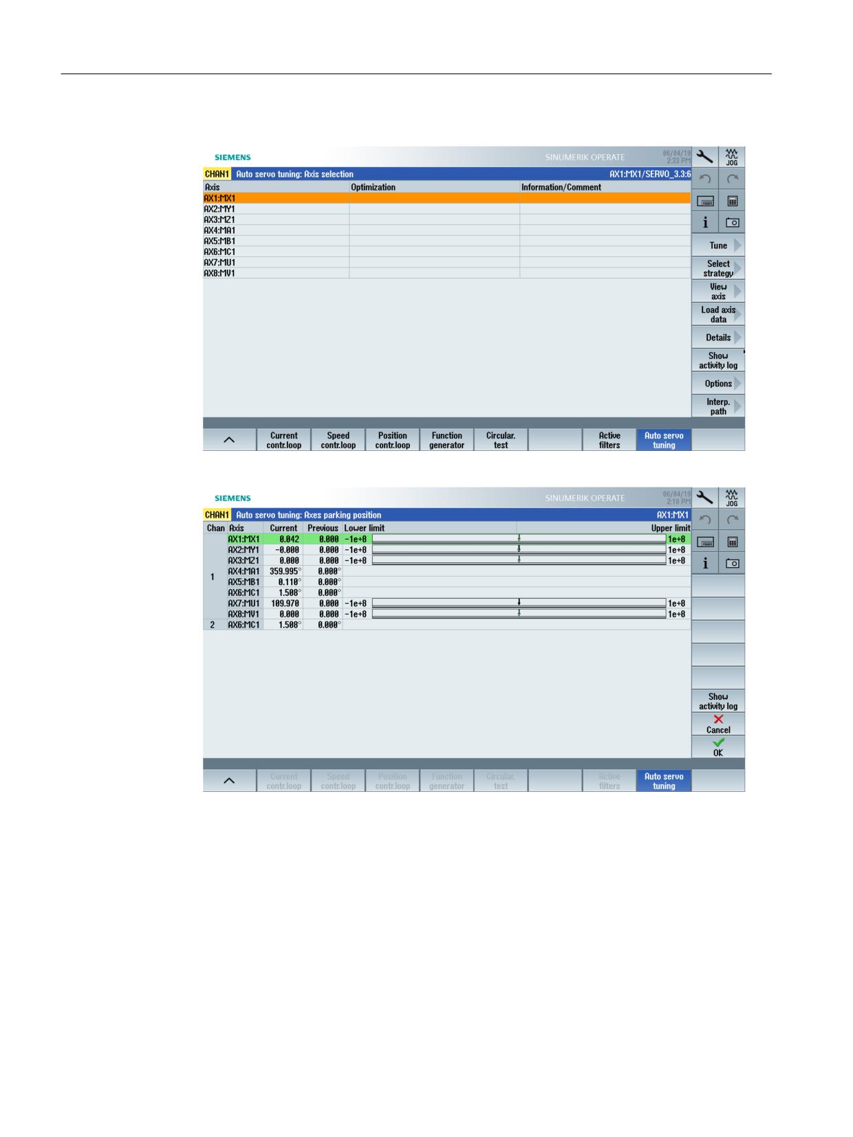
4. In dialog "Axis selection", select the X axis:
5. Start the measurement with the "Tune" softkey.
6. Confirm the "Axis park position" with "OK". Two measurements are performed.
CNC Commissioning: NC, PLC, Drive
274
Commissioning Manual, 10/2020, A5E48312804B AB
Drive tuning
10.3 Automatic servo tuning
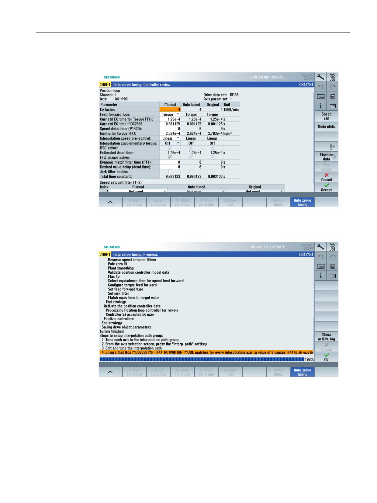
7. Follow the instructions by pressing <NC START>. After the measurements have been
successfully made, the tuned values of the parameters are output:
8. Softkey "Accept", to activate the parameters and exit tuning.
9. OR: Enter suitable values in column "Manual" and confirm using softkey "Accept", to activate
the parameters and exit tuning:
10.After completion of the measurement, you can display the complete tuning log: "Tuning log"
softkey.
CNC Commissioning: NC, PLC, Drive
Commissioning Manual, 10/2020, A5E48312804B AB
275
Drive tuning
10.3 Automatic servo tuning
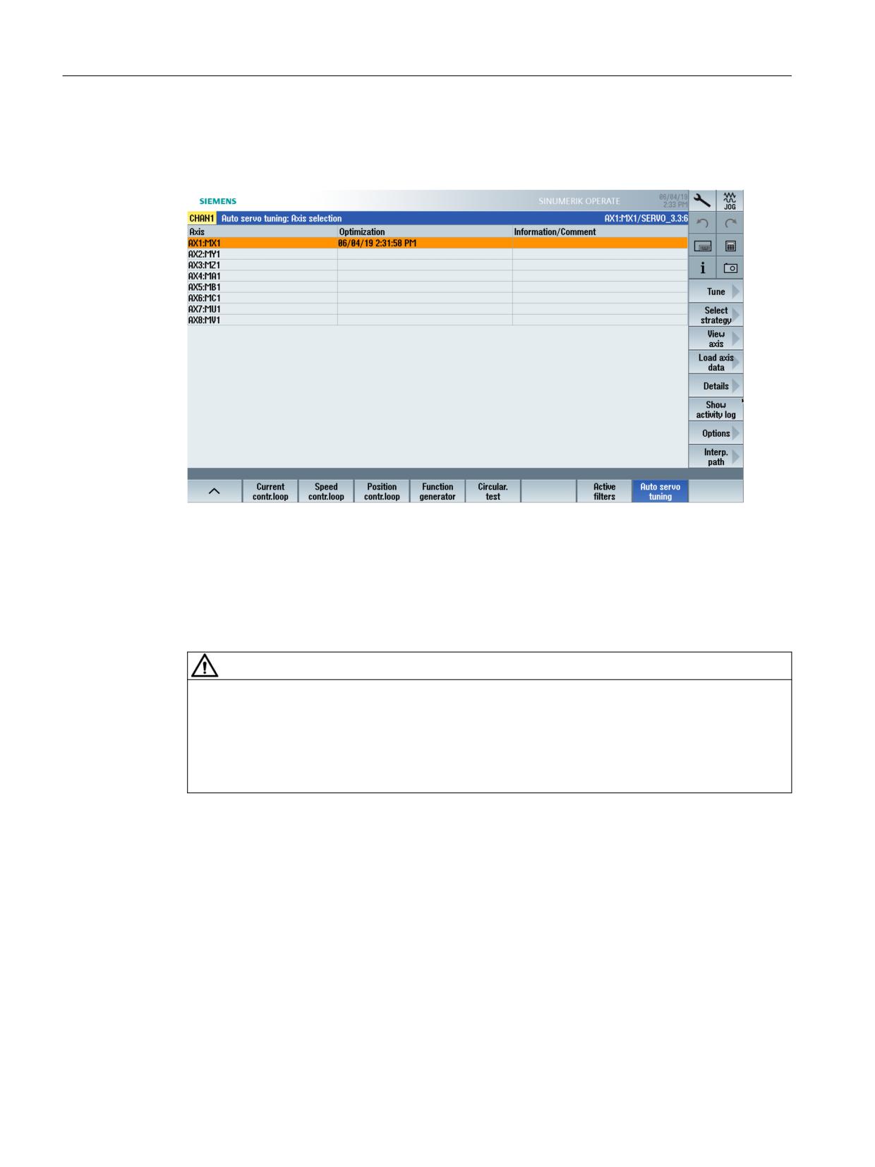
Result for the X axis
After confirming with "OK", you get the following result:
10.3.4
Example: This is how you tune the Y axis
Tuning the Y axis
WARNING
Avoiding unwanted axis movements
Automatic servo tuning is based on the analysis of measurements. These measurements
require the axis to move.
Carefully ensure that all axes are in a safe position and no collisions will occur during the
traversing motion that is required.
CNC Commissioning: NC, PLC, Drive
276
Commissioning Manual, 10/2020, A5E48312804B AB
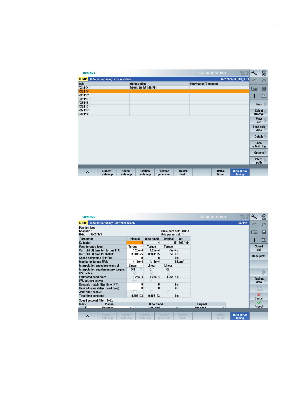
Drive tuning
10.3 Automatic servo tuning
Procedure:
1. The options and strategies that have been set remain valid.
2. In dialog "Axis selection" select the Y axis:
3. Start the measurement with the "Tune" softkey.
4. Confirm the "Axis park position" with "OK". Two measurements are performed.
5. Follow the instructions by pressing <NC START>. After the measurements have been
successfully made, the tuned values of the parameters are output:
6. Softkey "Accept", to activate the parameters and exit tuning.
CNC Commissioning: NC, PLC, Drive
Commissioning Manual, 10/2020, A5E48312804B AB
277
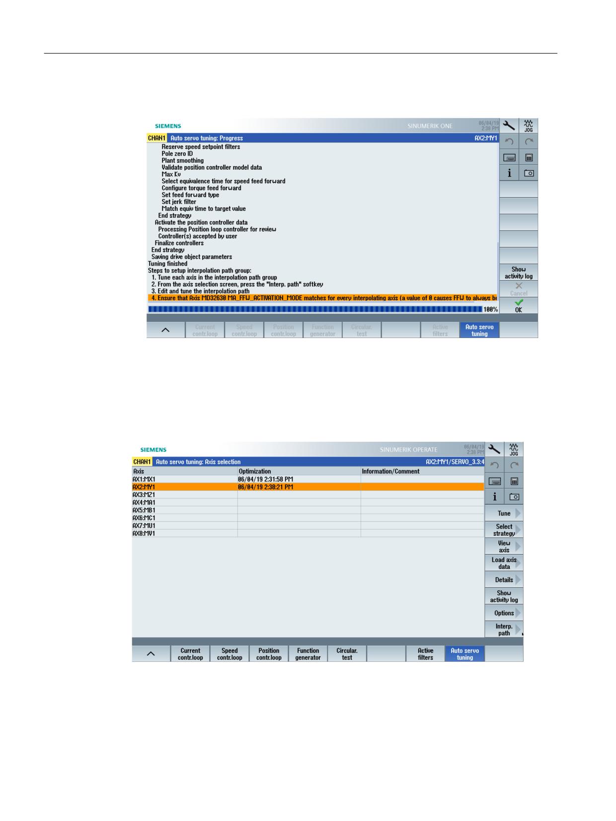
Drive tuning
10.3 Automatic servo tuning
7. OR: Enter suitable values in column "Manual" and confirm using softkey "Accept", to activate
the parameters and exit tuning:
8. After completion of the measurement, you can display the complete tuning log: "Tuning log"
softkey.
Result of the Y axis
After confirming with "OK", you get the following result:
CNC Commissioning: NC, PLC, Drive
278
Commissioning Manual, 10/2020, A5E48312804B AB
Drive tuning
10.3 Automatic servo tuning
10.3.5
Spindle tuning sequence
Benefits
The automatic spindle tuning function supports you in the following scenarios:
• Controller tuning in the various modes: axis mode and spindle mode.
The speed controller, position controller, and feedforward control are optimized.
• Calibration of the following errors for tapping by means of path tuning
• Calibration of the following errors for axis mode by means of path tuning
The progress of spindle tuning is clearly visible to the machine manufacturer:
• The tuning strategy set for the spindle.
• The suitable default setting of the tuning strategy for the selected use case.
• The mode that must still be optimized and the mode that is already optimized.
• The gear stages that must still be optimized and the ones that are already optimized.
Preconditions
Only one channel is supported: MD20000 $MC_CHAN_NAME
Only one gear stage is supported: MD35090 $MA_NUM_GEAR_STEPS = 1
The gear change is disabled: MD35010 $MA_GEAR_STEP_CHANGE_ENABLE = 0H
Axis mode is only supported for the first gear stage:
MD35014 $MA_GEAR_STEP_USED_IN_AXISMODE = 1
Note
Tuning sequence
Only tune the spindle after completing the tuning of all of the other axes.
At least one optimized geometry axis is necessary to optimize the spindle for the tapping.
Spindle tuning sequence
In operating area "Setup" → "Tuning/Test" → "Automatic servo tuning: Axis selection", select the
spindle for tuning:
①
Axis selection
The "Automatic servo tuning: Axis selection" dialog shows the current status of the axes/spindles:
• Select the spindle.
• Start the spindle tuning with the softkey "Tune >".
②
Parameter
• Select the spindle type: e.g. milling spindle, rotary table.
• Select the spindle mode.
When selecting tapping, in the last step the spindle can be optimized for tapping.
CNC Commissioning: NC, PLC, Drive
Commissioning Manual, 10/2020, A5E48312804B AB
279
Drive tuning
10.3 Automatic servo tuning
③
Spindle tuning
Tuning of the first gear stage of the spindle.
The tuning result for the axis mode is identical to the tuning result of the spindle mode.
④
Tapping
If the spindle is used for tapping, the spindle mode and parameter set 2 are automatically selected.
The geometry axis used for tapping also switches to parameter set 2 for the tuning procedure.
The respectively correct parameter set for the spindle and for the geometry axis are selected for path
interpolation.
The tuning status of the parameter sets is displayed in the last step of tuning:
not optimized
axis-optimized
axis-optimized (for spindles only)
path-optimized
Tuning strategy
Different tuning strategies are applied, depending on the operating range of the spindle:
• Spindle for milling machines:
Tuning aggressiveness = 0.3
KP is lower and TN is higher than with a linear axis.
• Spindles for turning machines or grinding machines:
Tuning aggressiveness = 0.2
KP is lower and TN is higher than with a milling spindle.
• The spindle is used as a rotary table.
Tuning aggressiveness = 0.5
KP and TN behave identically to a linear axis.
• If the preset strategy does not meet the requirements, select a different strategy or "Custom
strategy".
• The same tuning strategy that was selected for the path axes is selected for the axis mode.
• The position controller is always optimized for tapping.
Result
The optimized parameters for the axis are displayed in the "Controller review" dialog.
The optimized parameters of the path interpolation are displayed in the "Interpolation path
review" dialog.
CNC Commissioning: NC, PLC, Drive
280
Commissioning Manual, 10/2020, A5E48312804B AB
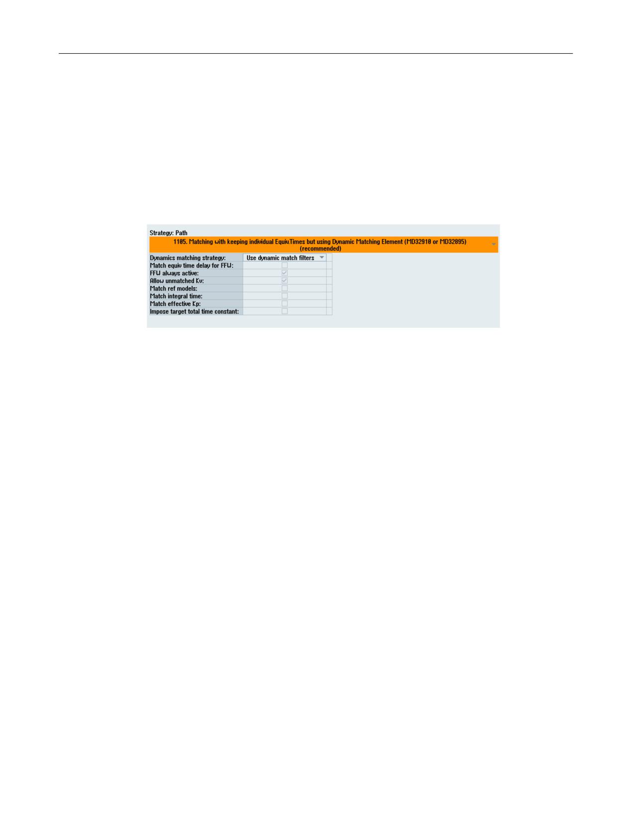
Drive tuning
10.3 Automatic servo tuning
10.3.6
Example: How to start the path interpolation
Strategy selection
Interpolation means that all axes in the channel have the same following error. The controllers
have different settings once all of the individual axes have been tuned. To standardize the
following error, the controllers, including the servo gain factor and feedforward control, are set
corresponding to the axis with the slowest response. The default strategy 1105 is recommended
for this:
Interpolating axes with different dynamic responses can be adapted with a time constant as
dynamic response adaptation to the slowest control loop. The difference between the
equivalent time constants of the slowest control loop and the particular axis should be entered
as time constant for the dynamic response adaptation:
• Different equivalent times after axis tuning are aligned with the time constant (MD32895
$MA_DESVAL_DELAY_TIME).
• The following values are adapted for speed feedforward control: Kp, Tn, reference model and
speed setpoint filter
• The servo gain factor is not adapted for torque feedforward control. The maximum servo gain
factor is adopted after tuning.
• If there is a time constant (MD32895 $MA_DESVAL_DELAY_TIME), then
MD32890 $MA_DESVAL_DELAY_ENABLE =1 is set and the time constant from MD32895 is
used. If there is no time constant, MD32900 $MA_DYN_MATCH_ENABLE = 1 and
MD32910 $MA_DYN_MATCH_TIME are used.
The following strategies are also available:
1102: Adaptation by setting the largest equivalent time constants for all of the path axes and
moderate reduction of the speed control gain factor
1103: Adaptation by setting the largest equivalent time constants for all of the path axes
1104: Interpolation path tuning custom strategy
CNC Commissioning: NC, PLC, Drive
Commissioning Manual, 10/2020, A5E48312804B AB
281
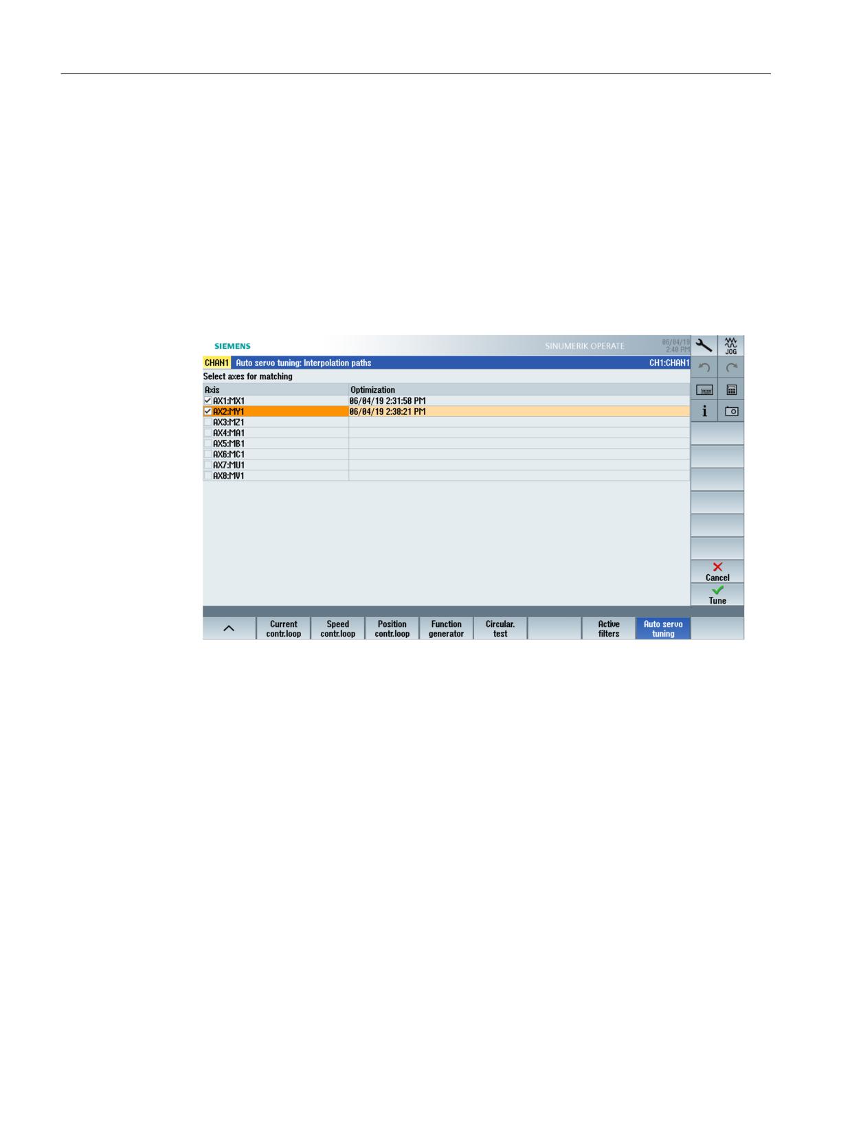
Drive tuning
10.3 Automatic servo tuning
Axis selection
Procedure:
1. Use the "Select strategies to use" to check the interpolation strategy:
The following parameters are adapted with the recommended Strategy 1105:
- Dynamics matching in MD32900 $MA_DYN_MATCH_ENABLE=1 is active.
- The precontrol set in the MD32620 $MA_FFW_MODE=3 (default) is always enabled.
2. Using the "Adapt strategy" softkey, enable the editing to adapt the selected strategy user-
specifically.
3. Using the "Path interpolation" softkey, select the axes for path interpolation:
4. Start the measurements with the "Tune" softkey.
CNC Commissioning: NC, PLC, Drive
282
Commissioning Manual, 10/2020, A5E48312804B AB
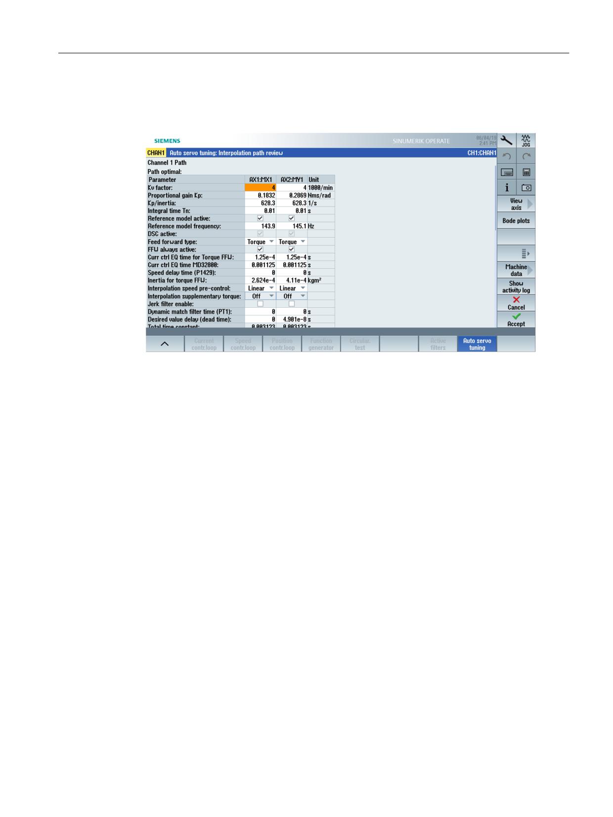
Drive tuning
10.3 Automatic servo tuning
Path interpolation
Once tuning has been completed, the tuned values are shown for the following parameters:
Softkey ">>", to switch over the vertical softkey bar for further processing:
• Softkey: "Retune"
• Softkey: "Revert to auto tuned"
• Softkey: "Revert to axis opt."
• Softkey "<<", to switch over the vertical softkey bar.
• Softkey "Save to file", to save the tuning data to an xml file.
• Softkey "Generate report", to generate a report in the rtf format.
A signal indicates that additional measures are required for path interpolation.
The tuned axis data are activated in the associated machine data using softkey "Accept":
CNC Commissioning: NC, PLC, Drive
Commissioning Manual, 10/2020, A5E48312804B AB
283
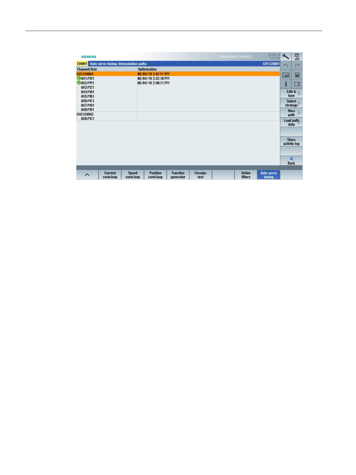
Drive tuning
10.3 Automatic servo tuning
Documenting the result
The following reports are available to document the measurement results:
• After each individual axis has been tuned
• After path interpolation for the interpolating axes
The results are available in the following form:
• Softkey "Save to file", to save the tuning data to an xml file.
• Softkey "Generate report", to generate a report in the rtf format. The report includes
parameters as well as diagrams, and is created in the language set for the control system.
The following directory is the default directory for these reports:
user/sinumerik/hmi/log/optimization
CNC Commissioning: NC, PLC, Drive
284
Commissioning Manual, 10/2020, A5E48312804B AB
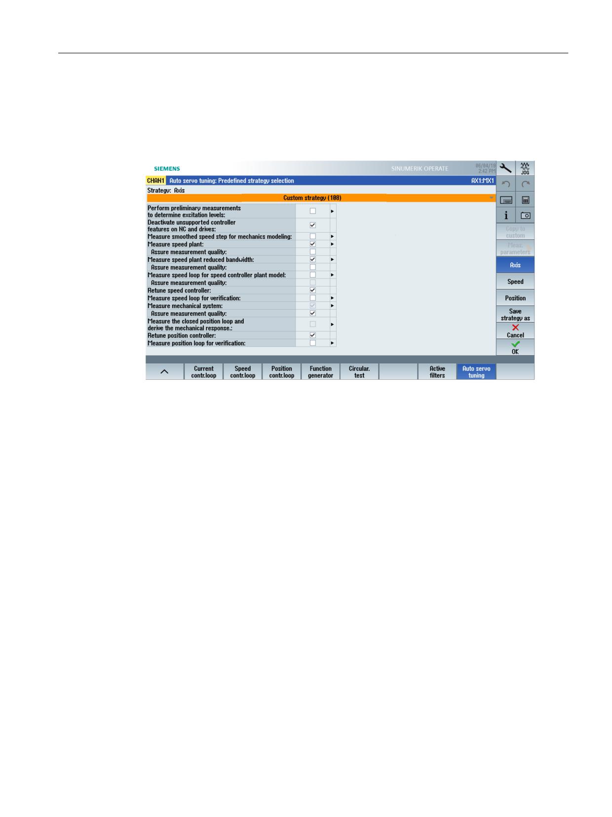
Drive tuning
10.3 Automatic servo tuning
10.3.7
Example for experts: Axis tuning
Axis: User-defined strategy (108)
Manual setting of the measurement parameters
The tuning objective can be directly entered in "Speed" or "Position". Alternatively, a predefined
strategy (102, etc.) can be selected, accepted with "Adapt strategy" and then changes can be
made.
By activating the checkbox, the commissioning engineer selects the individual steps for
measuring and tuning. Several steps are interdependent: For instance, the speed-controlled
system must always be measured before tuning the speed controller. All checkboxes which
result in a measurement are marked with an arrow. Additional default settings are available for
each measurement using the "Meas. parameters >" vertical softkey.
Perform preliminary measurement to determine the excitation:
The preliminary measurement to determine the excitation can always be selected or deselected.
The preliminary measurement is always recommended when first commissioning the axis or for
unknown mass relationships (load/motor). The measurement parameters for the following
measurement are automatically determined after the preliminary measurement. User-defined
measurement parameters are then overwritten.
Deactivate controller properties that are not supported in the NC and drive:
CNC Commissioning: NC, PLC, Drive
Commissioning Manual, 10/2020, A5E48312804B AB
285
Drive tuning
10.3 Automatic servo tuning
The following functions are deactivated if they are used:
• Axis:
MD32220 $MA_POSCTRL_INTEGR_ENABLE = 0
MD32610 $MA_VELO_FFW_WEIGHT = 1.0 (should always be 1)
MD32930 $MA_POSCTRL_OUT_FILTER_ENABLE = 0
• Drive:
If the Advanced Position Control (APC) function module is activated: p3700.0 = 0
Velocity control configuration: p1400.5 = 0
The speed controller adaptation is deactivated.
Speed controller integrator feedback time constant: p1494 = 0.0
Measure smoothed speed setpoint step to create a mechanical model:
At the start of the tuning, the load moment of inertia, the stiffness of the coupling and the
correctness of the current controller setting are unknown. A step response can be measured to
make a first estimate. As a consequence, while measuring the speed-controlled system, it is
easier to automatically determine parameters.
Measure speed-controlled system:
This measurement is required to tune the speed controller.
It is initially performed with the maximum bandwidth (e.g. 4000 Hz)
Measure speed-controlled system with reduced bandwidth:
This measurement is required to tune the speed controller.
This measurement is performed with reduced bandwidth in order to improve the frequency
resolution.
Measure speed control loop for speed controller-controlled system model:
This measurement is necessary if the position control loop (including feedforward control) is to
be automatically tuned, but the speed controller was not tuned with automatic servo tuning.
Tune speed controller:
The parameters for the speed controller (including current setpoint filter) are calculated an the
basis of the measured speed-controlled systems and the specified tuning objective. The
parameters are not transferred into the drive until the axis tuning has been completed, or a
measurement for checking has been performed. The "Speed" settings are applied.
Measure speed control loop for checking:
The closed speed controller is measured with the new parameters. To do this, the new
parameters are written to the drive.
Measure mechanical system:
Measure the transmission link between the motor encoder and direct encoder (e.g. linear scale).
This does not include any influence on the closed-loop control. Using this measurement, the
position control loop can be calculated with closed-loop control on the direct encoder.
Tune position controller: without parameters
Servo gain factor and feedforward control are tuned on the basis of the prior measurements. The
tuning objective is also applied. The "Position" settings are applied. If a second encoder is setup,
then the position control is always calculated as if this second encoder is used for the position
control.
CNC Commissioning: NC, PLC, Drive
286
Commissioning Manual, 10/2020, A5E48312804B AB
Drive tuning
10.3 Automatic servo tuning
Control measurement position control loop:
The closed position controller is measured with the new parameters. To do this, the new speed
and position control parameters are written to the drive and the NC. The feedforward control
must be disabled for this measurement. Depending on the option setting, this is the reason that
a message is output to press the reset button on the machine control panel. After the
measurement, the feedforward control is reactivated; this why another request for a reset (re)
is issued after the measurement .
⇒ Checking the measurement data quality: without parameters
The software for automatic tuning checks whether the excitation and offset velocity were
sufficient, and then outputs an appropriate message.
⇒ Measurement parameters:
Individual measurement parameters can be entered for each of the following measurements:
• Measure speed setpoint step for the mechanical model
• Measure speed-controlled system
• Measure speed-controlled system with reduced bandwidth
• Measure speed control loop for speed controller-controlled system model
• Measure speed control loop for checking
• Measure mechanical system
• Control measurement position control loop
⇒ Additional actions:
• Press the "Adapt strategy" softkey to adapt the default values to a predefined strategy. The
values of the pre-defined strategy are assigned to the user-defined strategy (108). All
parameters can be set in the "User-defined strategy". The tuning objective "Moderate
responsiveness" is the default setting for the "User-defined strategy".
• Press the "Meas. parameters >" softkey to adapt the parameters for a measurement. This
softkey can only be used when selecting the "User-defined strategy".
• Press the "Speed" and "Position" softkeys to toggle between speed controller and position
controller when selecting a strategy.
• "Cancel" and "OK" softkeys to cancel or accept the new settings.
CNC Commissioning: NC, PLC, Drive
Commissioning Manual, 10/2020, A5E48312804B AB
287