SINUMERIK 840D sl. Service - Configuring Commissioning. Manual (2011-2020) - page 80
PLC commissioning
5.3 Extending the SIMATIC S7 project (PROFINET)
4. Select the desired SINAMICS Control Unit from the list of the accessible nodes (participants)
and enter a name. Select LED flashing in order to identify the drive object.
5. To assign the name, confirm with "OK".
See also
The further procedure matches the configuring process via PROFIBUS:
• Creating a PLC program (Page 81)
• Checking the communication to the drive (Page 189)
CNC Commissioning: NC, PLC, Drive
80
Commissioning Manual, 10/2020, A5E48312804B AB
PLC commissioning
5.4 Creating a PLC program
5.4
Creating a PLC program
Introduction
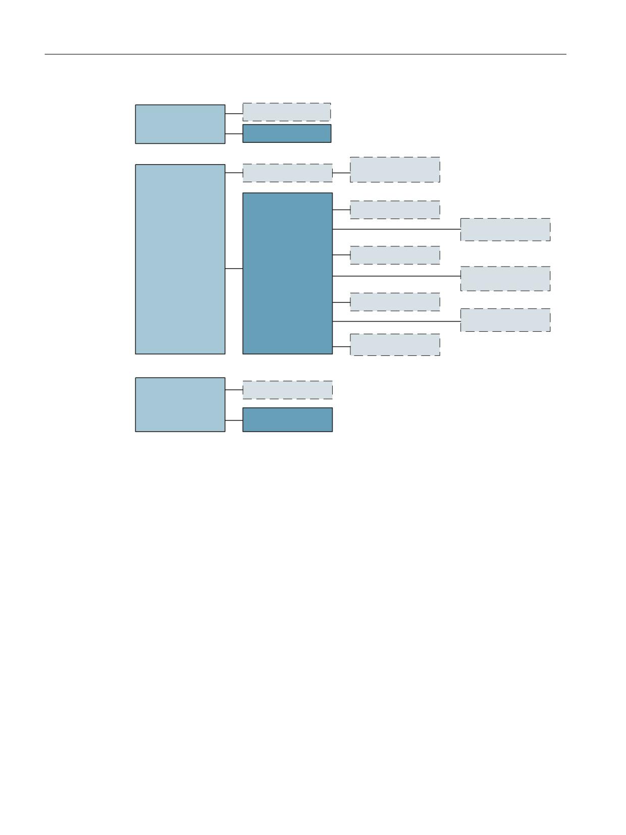
The PLC program is constructed modularly. It comprises the following parts:
• PLC basic program
The PLC basic program organizes the exchange of signals and data between the PLC program
and the NC, HMI, and machine control panel components. The PLC basic program is part of
the SINUMERIK 840D sl Toolbox.
• PLC program (extension by the machine manufacturer)
The PLC program is the machine-specific part of the machine manufacturer by which the PLC
basic program is extended.
For example, the FB1 (boot block of the PLC basic program) must be supplied with variables.
Additional information is provided in the "PLC (https://support.industry.siemens.com/cs/
document/109766213)" Function Manual.
Cyclic operation (OB1)
From a chronological viewpoint, the basic program runs before the PLC program. The NC/PLC
interface is completely processed in cyclic operation. Cyclic monitoring is activated between PLC
and NC once booting and the first OB1 cycle have been completed. A PLC failure produces alarm
"2000 Sign-of-life monitoring PLC".
PLC program
The entry points for machine-specific components of the PLC program are located in the
following PLC basic program blocks:
• OB100 (restart)
• OB1 (cyclic processing)
• OB40 (process alarm)
CNC Commissioning: NC, PLC, Drive
Commissioning Manual, 10/2020, A5E48312804B AB
81
PLC commissioning
5.4 Creating a PLC program
2%
)%
3/& EDVLF SURJUDP
5HVWDUW
3/& SURJUDP
)%
)%
)%
)%
2%
)&
0&3 VLJQDOV
3/& EDVLF SURJUDP
+7
VLJQDOV
)&
)&
)&
7RRO PDQDJHPHQW
)&
6SLQGOH FRQWURO
)&
&\FOLF SURFHV
6WDUW $68%
VLQJ
)%
)%
)%
)%
3/& SURJUDP
9DULDEOH U Z 3,
)&
VHUYLFHV
6WDU GHOWD
)&
'LVSOD\ FRQWURO +7
)&
)DXOW DQG RSHUDWLRQDO
PHVVDJHV
2%
)&
3/& EDVLF SURJUDP
3URFHVV DODUP
3/& SURJUDP
Figure 5-3
PLC program structure
PLC status
The PLC always starts up in RESTART mode, i.e. the PLC operating system runs OB100 after
initialization and starts cyclic operation at the beginning of OB1. No return is made to the
interruption point (for example, in the event of a power failure).
Start-up behavior of the PLC
There are both retentive and non-retentive areas for the markers, timers and counters. The areas
are continuous and are divided by a parameterizable limit, where the area with the higher-value
address range is defined as the non-retentive area. Data blocks are always retentive.
RESTART startup type (OB100)
If the retentive area is not buffered (the buffer battery is empty) start-up is prevented. The
following operations are performed during a restart:
• Delete the UStack, BStack and non-retentive flags, timers and counters
• Delete the process output image (POI)
• Cancel the process and diagnostics alarms
CNC Commissioning: NC, PLC, Drive
82
Commissioning Manual, 10/2020, A5E48312804B AB
PLC commissioning
5.4 Creating a PLC program
• Update the system status list
• Evaluate the parameterization objects of modules (as of SD100) and output the default
parameters to all modules
• Process restart OB (OB100)
• Read in the process input image (PII)
• Cancel command output inhibit (BASP)
5.4.1
Preconditions for creating the PLC program
Software and hardware requirements
The following preconditions apply when processing the PLC program:
• SIMATIC STEP 7 V5.5 SP4
• SIMATIC STEP 7 is installed on the PG/PC
• Installation of the SINUMERIK toolbox (PLC base program, slave OEM, GSD files)
• Edit the blocks in the PLC base program
• Installation of the PLC base program library
To be able to use the blocks of the PLC base ic program (OBs, FBs, DBs) in a SIMATIC S7 project,
the library must first be installed in the SIMATIC Manager.
Editing the blocks in the PLC base program
The SIMATIC STEP 7 documentation describes how to modify and expand the PLC basic program.
The individual blocks in the basic PLC program can be processed in the SIMATIC Manager:
• Select the appropriate block, e.g. OB100, in the blocks folder of the corresponding module
• Use the menu command "Edit" → "Open object" to open the block or double-click the block
with the left mouse button
• Processing modules in the LAD/STL/FBD editor
• Switching the block view using menu command - "View" → "LAD" or STL, FBD.
5.4.2
Insert PLC basic program
Introduction
You have performed the hardware configuration, have saved and compiled the project and have
created the system data for the PLC. You have installed the Toolbox software that also contains
the libraries for the PLC basic program of an NCU.
CNC Commissioning: NC, PLC, Drive
Commissioning Manual, 10/2020, A5E48312804B AB
83
PLC commissioning
5.4 Creating a PLC program
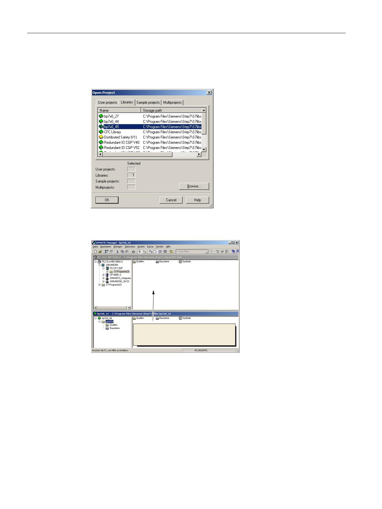
Operating sequence to open the library and copy sources, symbols and blocks
You are on the main screen of the SIMATIC Manager:
1. Select the "File" → "Open" menu and then click the "Libraries" tab.
2. Select the library of the PLC basic program, e.g. "bp7x0_45" and confirm the dialog with "OK".
You have inserted the library and selected the PLC program from "SINU_840Dsl" >
"SINUMERIK" → "PLC 317 2DP" → "S7 program".
&RS\ VRXUFHV EORFNV DQG V\PEROV
LQWR WKH IROGHU IRU WKH 3/& SURJUDP
3. Copy the sources, modules and symbols to the PLC program.
Overwrite OB1
Inserting blocks overwrites the existing organization block OB1. Confirm the query as to
whether you want to overwrite the block with "Yes".
You have now created the PLC basic program.
In the next section you will modify some of the data for the machine control panel in OB100.
CNC Commissioning: NC, PLC, Drive
84
Commissioning Manual, 10/2020, A5E48312804B AB
PLC commissioning
5.4 Creating a PLC program
5.4.3
Modifying machine control panel in OB100
Introduction
The PLC base program transfers the signals from the machine control panel. To ensure that the
signals are transferred correctly to and from the machine control panel, enter the following
parameters in the OB100 on the FB1. Under "Blocks", double-click OB100 to open the editor to
configure the machine control panel .
Example: MCP1 is connected via Industrial Ethernet (IE).
Configuring the machine control panel
OB100
CALL "RUN_UP" , "gp_par"
FB1 / DB7 -- Startup Baseprogram/ Parameters for Base-
program
MCPNum
:=1
// An MCP is present
MCP1In
:=P#E 0.0
MCP1Out
:=P#A 0.0
MCP1StatSend
:=P#A 8.0
MCP1StatRec
:=
MCP1BusAdr
:=192
// IP address: 192.168.214.192 - this ad-
dress must also be set on the DIPFIX switch
MCP1Timeout
:=
of the MCP.
MCP1Cycl
:=
MCP2In
:=
MCP2Out
:=
MCP2StatSend
:=
MCP2StatRec
:=
MCP2BusAdr
:=
MCP2Timeout
:=
MCP2Cycl
:=
MCPMPI
:=FALSE
MCP1Stop
:=FALSE
MCP2Stop
:=
MCP1NotSend
:=FALSE
MCP2NotSend
:=
MCPSDB210
:=
MCPCopyDB77
:=
MCPBusType
:=B#16#05
// Parameter [5] := ETHERNET
CNC Commissioning: NC, PLC, Drive
Commissioning Manual, 10/2020, A5E48312804B AB
85
PLC commissioning
5.4 Creating a PLC program
OB100
BHG
:=
BHGIn
:=
BHGOut
:=
UDInt
:=
UDHex
:=
UDReal
:=
IdentMcpType
:=
IdentMcpLengthIn :=
IdentMcpLengthOut:=
//Insert User program from here
Result
You have completed the configuration of the PLC base program. In the next step, you will load
the project to the PLC.
An example for the connection via PROFIBUS DP can be found at: Modifying PROFIBUS machine
control panel in OB100 (Page 60)
Machine control panel with handwheel
If you have an Ethernet machine control panel with Ethernet handwheel, you must set the
following machine data for the handwheel:
MD11350[0] $MN_HANDWHEEL_SEGMENT = 7Ethernet
The following are true for a PROFINET machine control panel with handwheel:
MD11350[0] = 5 PROFIBUS/PROFINET
CNC Commissioning: NC, PLC, Drive
86
Commissioning Manual, 10/2020, A5E48312804B AB
PLC commissioning
5.5 Download the project to the PLC
5.5
Download the project to the PLC
Introduction
For loading the configured PLC project, the following prerequisites must be fulfilled:
Precondition
• An Ethernet network connection exists between STEP7 and the PLC.
• The configuration to be loaded corresponds to the actual station configuration.
• The NCU is active:
- NC is in cyclic mode.
- PLC in RUN or STOP mode.
Supplementary condition
The following supplementary conditions regarding the system data blocks must be observed
when the configuration is loaded:
• HW Config
When loading the configuration via HW Config, only the system modules and their associated
system data blocks selected in HW Config are loaded into the module. However, global data
defined in SDB 210 is not loaded from the HW Config, for example.
You have loaded the HW Config to the module in the previous "End the hardware
configuration and load to the PLC" chapter.
• SIMATIC Manager
When loading the configuration via the SIMATIC Manager all the system data blocks are
loaded into the module.
Note
When the PLC program is loaded in the "RUN" mode, each block loaded becomes active
immediately. This can result in inconsistencies when executing the active PLC program. It is
therefore advised to place the PLC in the "STOP" mode before loading the configuration, if this
has not already been done.
CNC Commissioning: NC, PLC, Drive
Commissioning Manual, 10/2020, A5E48312804B AB
87
PLC commissioning
5.5 Download the project to the PLC
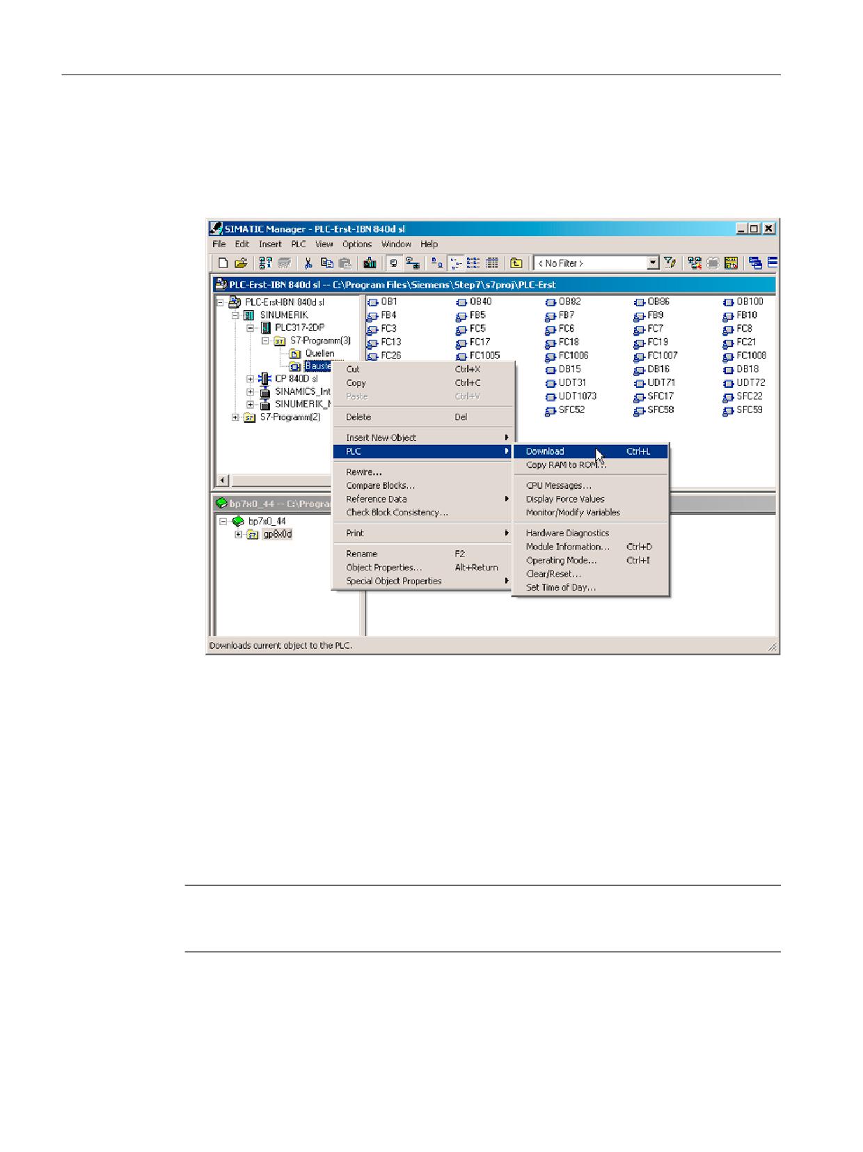
Operating sequence for loading system blocks into the module
1. To load the configuration of the system blocks change to the SIMATIC Manager.
2. In the SIMATIC Manager in the PLC directory, select the directory "Blocks" > right mouse
button > "Target system" > "Load" (see figure below), or the "Load" symbol.
Figure 5-4
Loading system blocks
3. If there is no connection to the target system, you must confirm in sequence the following
dialog requests with:
- "OK" for "Check the required sequence of blocks for correct functioning"
- "Yes" for "Do you want to load system data?"
- "Yes" for "Must system data be deleted on the module and replaced by off-line system
data?"
- "No" for "The module is in STOP mode. Do you want to start the module (cold restart)?"
You have loaded the PLC program to the PLC; the PLC is in "STOP" mode.
Note
If the PLC is stopped via the SIMATIC Manager, then it also has to be started via the
SIMATIC Manager. Starting via the PLC mode selector is also possible.
CNC Commissioning: NC, PLC, Drive
88
Commissioning Manual, 10/2020, A5E48312804B AB
PLC commissioning
5.6 Loading PLC symbols to the controller
5.6
Loading PLC symbols to the controller
Requirements
You require the SIMATIC STEP 7 software and the "PLC Symbols Generator" program that is
provided in the toolbox.
For blocks that already have a symbolic name, these symbols cannot be overwritten by other
user-defined designations. Only those symbols are transferred from the blocks to the control
without preassigned symbols.
Generating PLC symbols
To edit PLC blocks via symbolic names, you can generate the symbols of the STEP 7 project for
SINUMERIK Operate and store them on the CompactFlash card on the control.
Procedure:
1. Open the "PLC Symbols Generator" program and navigate to the corresponding PLC project.
2. To start the generation, first select the required language.
3. Save the "PlcSym.snh" and "PlcSym_xx.snt" files. xx is the language code specified when
creating the file. The generation is then started.
4. Create the following directory on the CompactFlash card and store the generated files
(PlcSym_xx.snt, PlcSym.snh) under the following path: /oem/sinumerik/plc/symbols
This path also applies for SINUMERIK Operate on the PCU 50.
5. After restarting SINUMERIK Operate, the symbol tables are loaded when booting. Select the
"Insert variables" softkey to display the imported symbols in the table of the "NC/PLC
variables".
Note
The notation (upper/lower case) of the file name that the program created is mandatory and
must not be changed.
Transmission log
For the generation and transmission of the symbols, a transmission log is created and stored
under the following path: ../log/symbolimport.log
Example:
Error importing PLC symbols: skip vdi on 840d: Symbol number 16956
CNC Commissioning: NC, PLC, Drive
Commissioning Manual, 10/2020, A5E48312804B AB
89
PLC commissioning
5.7 First commissioning of the PLC completed
5.7
First commissioning of the PLC completed
First commissioning of the PLC completed
To synchronize the PLC and NC, an NC reset (po) is required.
The PLC and NC are in the following state after a reset (po):
• RUN LED is continuously lit green.
• Status display shows a "6" with a flashing dot.
⇒ PLC and NC are in cyclic operation.
You have completed the first commissioning of the PLC.
Continue with the steps for "Guided commissioning (Page 109)" of the SINAMICS drives.
You start with a reset (po) for the NC and drive system.
Note
Response of the PLC in the case of an NC stop
For a stop of the NC, the PLC normally continues to run and the type of stop response is the user's
responsibility depending on the machine situation. In this special case, the NC can no longer
switch the outputs to zero and the current status is retained because the PLC is still running.
In order to switch off the outputs or to force a PLC stop, for example, the "NC READY" signal is
evaluated in the PLC program.
CNC Commissioning: NC, PLC, Drive
90
Commissioning Manual, 10/2020, A5E48312804B AB
PLC commissioning
5.8 Configuring a network (NetPro) for PG/PC
5.8
Configuring a network (NetPro) for PG/PC
5.8.1
Integrating PG/PC into NetPro
Requirements
The following requirements for integrating a PG/PC must be met:
• The NCU is integrated in the S7 project using HW Config (see: Inserting SINUMERIK NCU to
the HW Config (Page 49)).
• The properties of the interfaces are configured (see: Configuring interfaces (Page 52)).
• The machine control panel is inserted (see: Modifying machine control panel in OB100
(Page 85)).
• The configuration has been saved and compiled (see: End the hardware configuration and
load it to the PLC (Page 65)).
• A PLC program has been created.
Inserting PG/PC in the S7 project
To perform routing functions and permit the communication between PG/PC ↔ HMI via
Ethernet, a PG/PC must be included in the SIMATIC Manager under NetPro and the interfaces
configured.
CNC Commissioning: NC, PLC, Drive
Commissioning Manual, 10/2020, A5E48312804B AB
91
PLC commissioning
5.8 Configuring a network (NetPro) for PG/PC
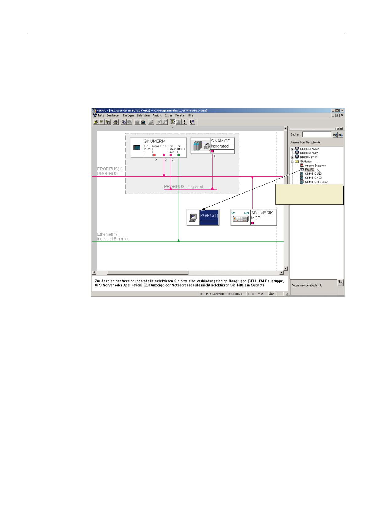
Procedure:
1. To add a PG/PC, open the S7 project in the SIMATIC Manager.
2. In the menu, select "Extras" → "Configure net" or click the button.
3. Insert the PG/PC with drag&drop under "Stations" from the catalog into the network
configuration.
,QVHUW 3* 3& XVLQJ
'UDJ 'URS
The inserted "PG/PC" station does not yet contain any interfaces. These are configured in the next
step.
5.8.2
Configuration of the PG/PC interface
Introduction
Under NetPro, configure the interfaces required for commissioning on the PG/PC:
• PROFIBUS
• Industrial Ethernet
• PROFINET
• MPI
CNC Commissioning: NC, PLC, Drive
92
Commissioning Manual, 10/2020, A5E48312804B AB
PLC commissioning
5.8 Configuring a network (NetPro) for PG/PC
Configuring interfaces on the PG/PC
Procedure:
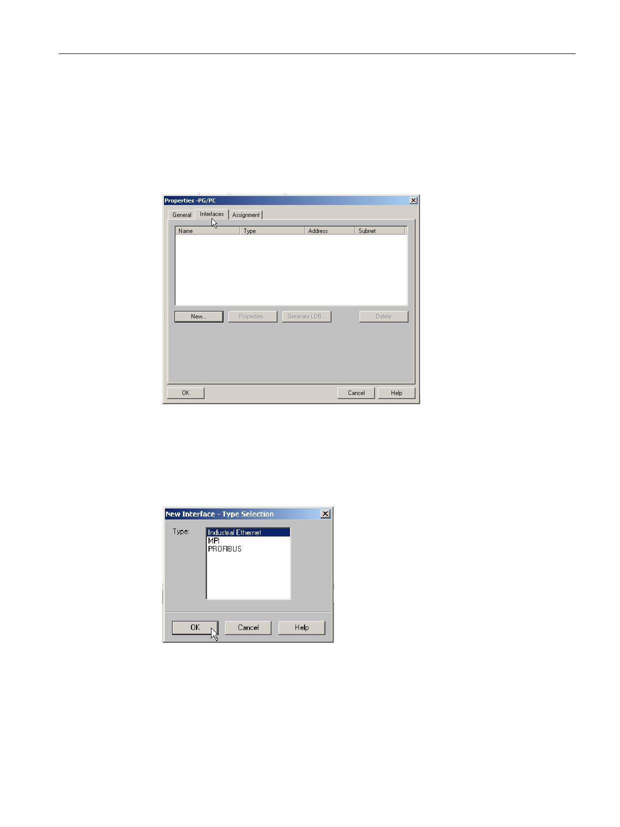
1. Mark the symbol "PG/PC" under NetPro.
2. Select "Object properties" <right-click>.
3. In the displayed "Properties - PG/PC" dialog, select the "Interfaces" tab to configure the
required interfaces.
Example: Configuring Industrial Ethernet
Procedure:
1. Click "New…" to first configure the Ethernet interface.
2. In the selection field, select "Industrial Ethernet".
3. Click "OK".
CNC Commissioning: NC, PLC, Drive
Commissioning Manual, 10/2020, A5E48312804B AB
93
PLC commissioning
5.8 Configuring a network (NetPro) for PG/PC
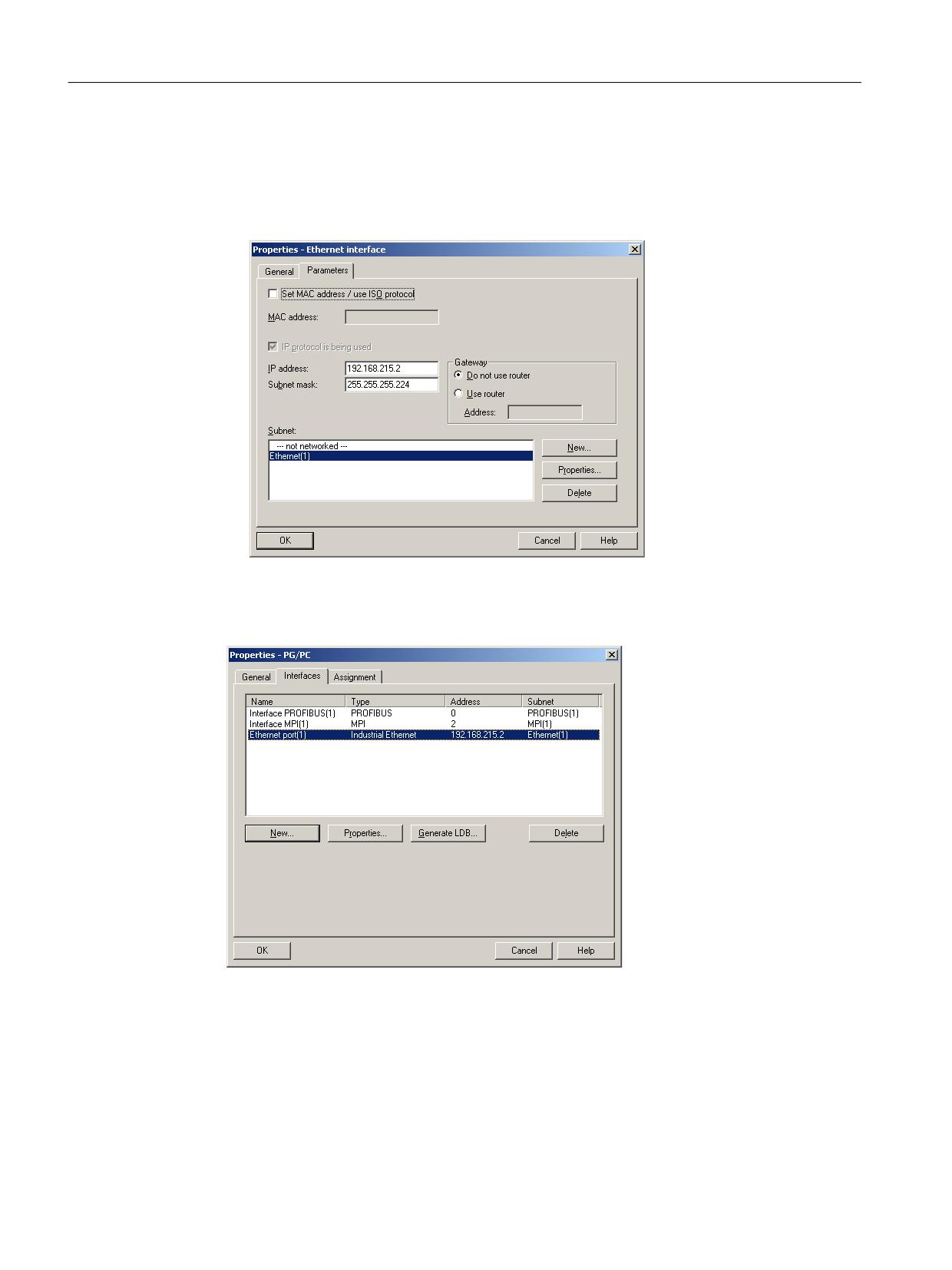
4. Select the subnet "Ethernet(1)" and enter the following IP address and subnet mask for the
PG/PC:
- IP address 192.168.215.2
- Subnet mask 255.255.255.224
5. Deactivate the option "Set MAC address/Use ISO protocol" and confirm with "OK".
6. You can configure additional interfaces via "New".
All configured interfaces can then be viewed under the "Interface" tab:
The configured interfaces must be assigned in a device-specific manner to the available
hardware interfaces on the PG/PC. The sequence steps are laid out in the following section.
CNC Commissioning: NC, PLC, Drive
94
Commissioning Manual, 10/2020, A5E48312804B AB
PLC commissioning
5.8 Configuring a network (NetPro) for PG/PC
5.8.3
Assigning interfaces
Introduction
The interfaces configured in the previous chapter must now be assigned in a device-specific
manner to the available hardware interfaces on the PG/PC.
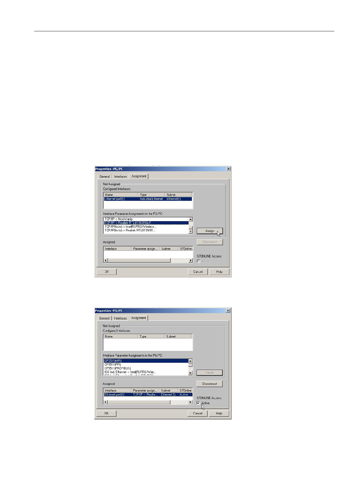
Operating sequence for assigning an Ethernet interface
1. Select the "Assign" tab.
2. Select "Ethernet interface(1)" in the selection field "Configured interfaces".
3. Select in the "Interface parameter assignments in the PG/PC" selection field, the "TCP/IP ->
Realtek RTL8139/810xF…" network card installed on the PG/PC.
4. To transfer the interfaces from the "Not assigned" area to the "Assigned" area and activate
them, click "Assign" and confirm the subsequent prompt on editing the object properties with
"OK".
CNC Commissioning: NC, PLC, Drive
Commissioning Manual, 10/2020, A5E48312804B AB
95
PLC commissioning
5.8 Configuring a network (NetPro) for PG/PC
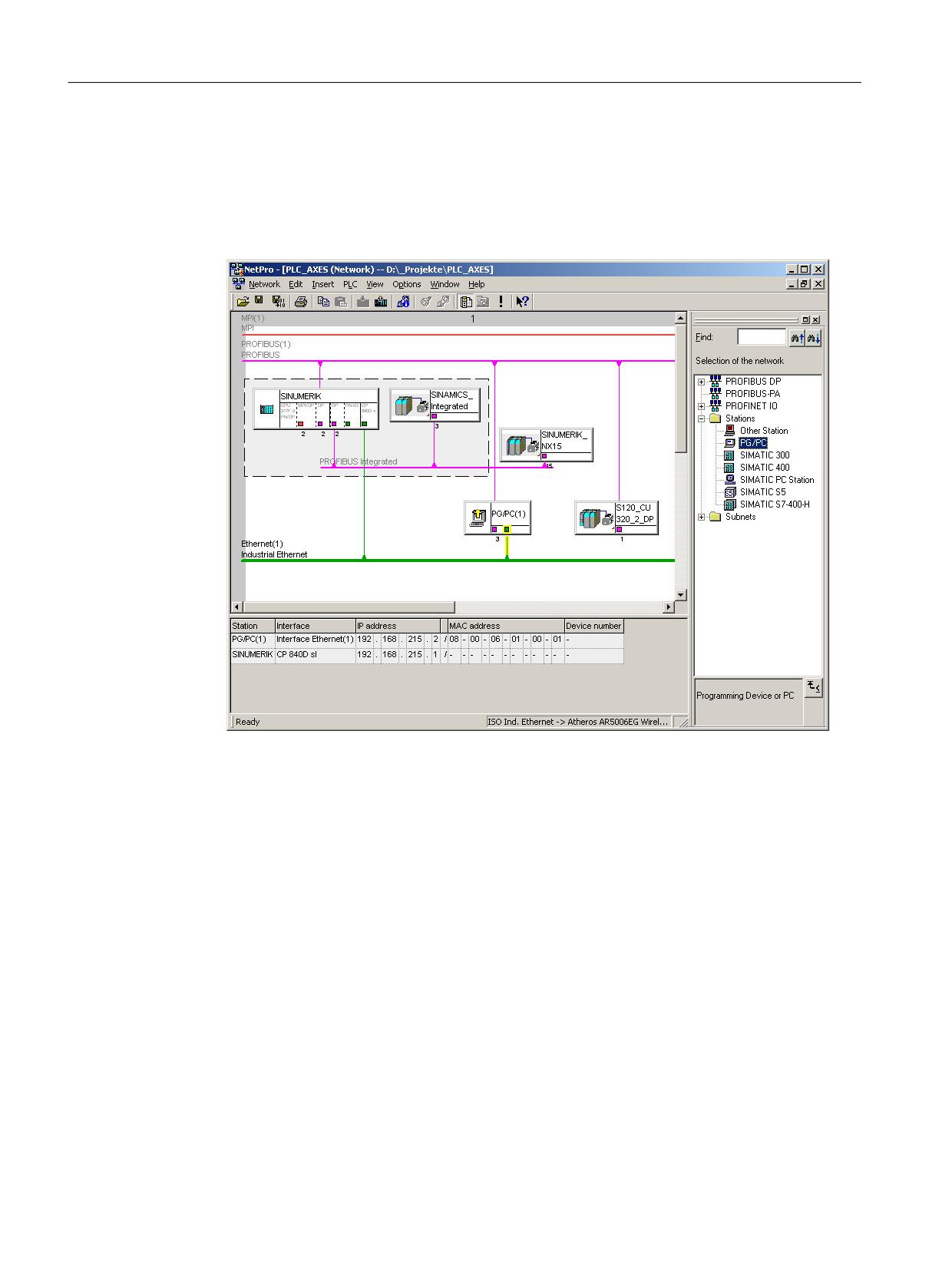
5. Now assign the remaining configured PROFIBUS interfaces. From those interfaces assigned,
one must be marked as "active".
6. Select "Ethernet interface" in the "Assigned" field and mark the field next to it as "active".
7. Click "OK" to end the "Properties - PG/PC" dialog.
In NetPro, the PG/PC interface declared as "active" has a yellow backg60round.
8. Select "Save and compile → Save and check all" and confirm the process with "OK".
The next described operating sequence explains how to load this hardware configuration to the
NCU.
5.8.4
Loading the HW config to NCU
Introduction
The newly created network configuration PG/PC must be introduced to the NCU.
You have established a connection to the Ethernet interface (X120 or X127) and you now load
this configuration from the PG/PC to the NCU.
CNC Commissioning: NC, PLC, Drive
96
Commissioning Manual, 10/2020, A5E48312804B AB
PLC commissioning
5.8 Configuring a network (NetPro) for PG/PC
Operating sequence for loading HW config to the NCU
1. Change from "NetPro" to "HW Config".
2. Click the "Download to module" button.
The two communication partners are automatically marked in the "Select target module"
dialog
3. Confirm the load into the module with "OK".
4. Confirm the following dialog boxes initially with "OK" and then "No" for the query "… Should
the module be started now (restart)?".
Note
Loading the HW config to the NCU is only possible via the Ethernet interface.
CNC Commissioning: NC, PLC, Drive
Commissioning Manual, 10/2020, A5E48312804B AB
97
PLC commissioning
5.8 Configuring a network (NetPro) for PG/PC
CNC Commissioning: NC, PLC, Drive
98
Commissioning Manual, 10/2020, A5E48312804B AB
Commissioning NC-controlled drives
6
6.1
Configuration examples
6.1.1
Example: Configuration of the drive components
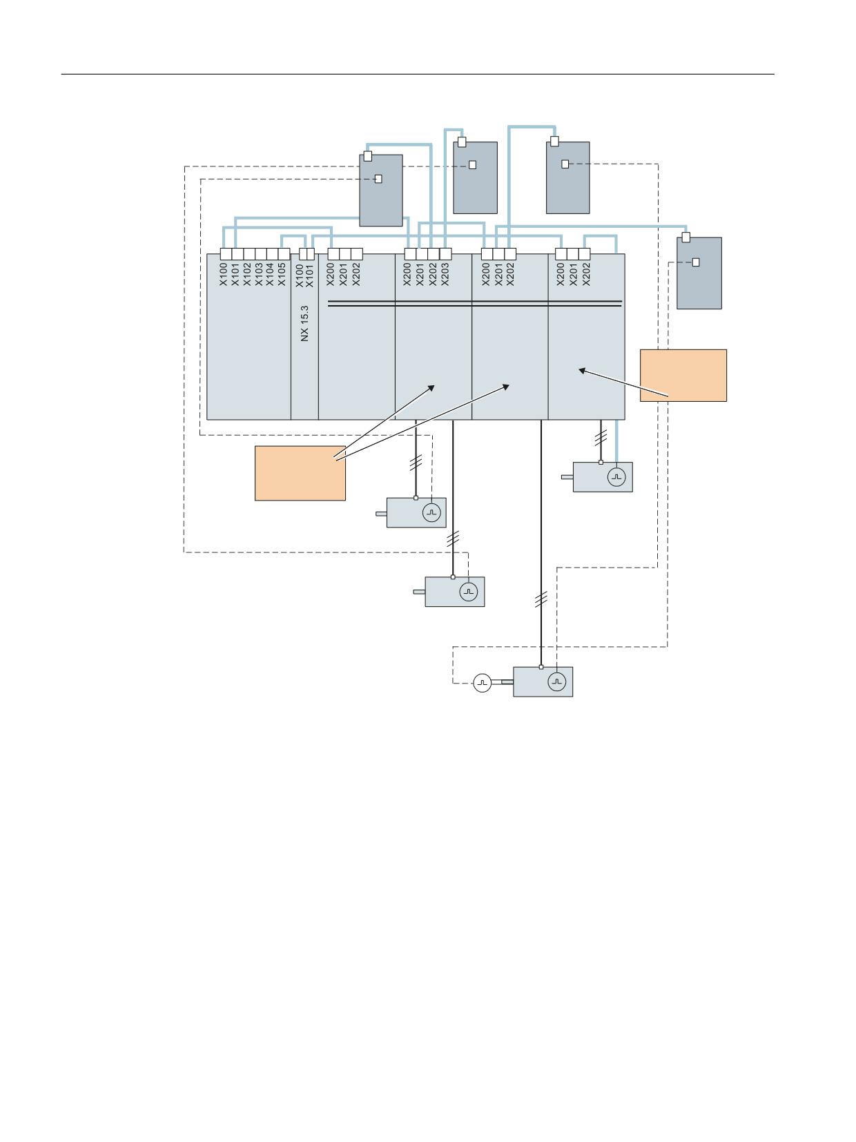
Configuration overview
The commissioning described in this manual is orientated on the following example
configuration of the SINAMICS drive line-up.
• Infeed (Active Line Module)
• NCU 720.3 PN with:
- A Double Motor Module for two motors each with an SMC20 (Sensor Module Cabinet).
- A Single Motor Module for a motor with two SMC20s for the encoders.
• NX 15.3 with:
- A Single Motor Module for a motor with SMI (Sensor Module Integrated)
CNC Commissioning: NC, PLC, Drive
Commissioning Manual, 10/2020, A5E48312804B AB
99
Commissioning NC-controlled drives
6.1 Configuration examples
;
;
;
;
;
;
60&
60&
'5,9( &/L4
60&
;
;
60&
1&8
$FWLYH /LQH
'RXEOH 0RWRU
6LQJOH 0RWRU
6LQJOH 0RWRU
0RGXOH
0RGXOH
0RGXOH
0RGXOH
'ULYH REMHFW
IRU WKH 1;
'ULYH REMHFWV
IRU WKH 1&8
=
;
<
6SLQGOH
Figure 6-1
SINAMICS S120 example configuration
Additional information about DRIVE-CLiQ components of the SINAMICS drive line-up is provided
in:
SINAMICS S120 Booksize Power Units (https://support.industry.siemens.com/cs/ww/en/view/
109771800) Equipment Manual
CNC Commissioning: NC, PLC, Drive
100
Commissioning Manual, 10/2020, A5E48312804B AB
Commissioning NC-controlled drives
6.1 Configuration examples
6.1.2
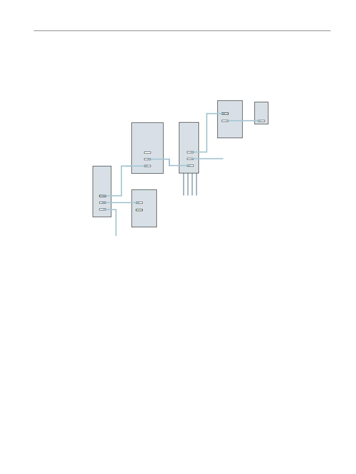
Example: Parallel connection with TM120
Topology
Application: Four motors connected in parallel
70
60[
;
;
;
$/0
600
[ WHPSHUDWXUH LQSXW
;
;
6,180(5,.
;
;
FRQWURO V\VWHP
)XUWKHU 600 RU '00
;
;
;
70
;
;
0
0
;
;
[ WHPSHUDWXUH LQSXW
M1 ... M4
Motor 1 ... motor 4
One KTY and three PTC in series are connected for each motor.
SMx
Sensor Module (motor encoder)
ALM
Active Line Module
DMM
Double Motor Module
SMM
Single Motor Module
TM120
Terminal Module
The shown topology requires four KTY sensors and four PTC sensors:
• Each primary section has one KTY sensor (Temp-F) and three series-connected PTC sensors
(Temp-S).
Two TM120s are required:
• A TM120 is interconnected automatically in series between the Motor Module and the SMx
Sensor Module.
• A TM120 is directly inserted into a Line Module: This requires a manual interconnection by
the commissioning engineer.
CNC Commissioning: NC, PLC, Drive
Commissioning Manual, 10/2020, A5E48312804B AB
101
Commissioning NC-controlled drives
6.1 Configuration examples
Actions
Depending on the topology, the following actions must be performed on the TM120:
1. TM120 between the Motor Module and the SMx Sensor Module
This TM120 evaluates four KTYs => sensor types must be selected by Servo-p4610/TM-
p4100. The associated temperature is output by servo-r4620/TM120-r4105.
2. TM120 directly on the Line Module
This TM120 evaluates four PTCs => sensor types must be selected by TM-p4100. The
associated temperature is output by servo-r4105.
Setting the threshold values in the PTC context:
- TM120-p4102[x]=251 => evaluation Off
- TM120-p4102[x]=120 => evaluation On
Assignment of the TM120 response using fault propagation on the drive => setting of the
propagation by servo-p0609=BICO:<object number>TM120:4105.0
Assignment of the alarms to the motor
The occurring error messages are assigned to the motors as follows:
• Temperature channel on the TM120 in series connection with Motor Modules and encoders:
Alarm 207015 <location>drive: Motor temperature sensor warning
Alarm 207016 <location>drive: Motor temperature sensor fault
Alarm 235920 <location>TM: Temperature sensor channel 0 error
In this case, the output message with reference to the motor and to the temperature
component shows the relevant motor.
• Temperature channel on the TM120 directly to the Line Module:
Alarm 235207 <location>TM: Temperature fault/alarm threshold channel 0 exceeded
Special feature with PTC:
TM120-r4105 = -50 temperature is below the nominal response temperature
TM120-r4105 = 250 temperature is above the nominal response temperature
In this case, a message is output only with reference to the temperature component.
The affected motor can be determined from the information concerning the TM120.
CNC Commissioning: NC, PLC, Drive
102
Commissioning Manual, 10/2020, A5E48312804B AB
Commissioning NC-controlled drives
6.2 Terminal assignment
6.2
Terminal assignment
6.2.1
NCU terminal assignment
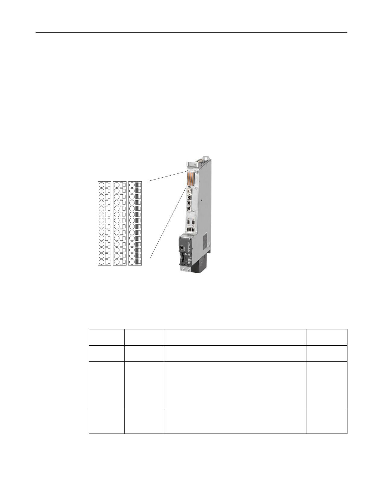
With the drive device configuration (Page 181), the following terminals are pre-assigned on the
NCU:
• X122
• X132
• X142
;
;
;
The terminal assignments for terminal strips X122, X132, X142 are listed in the following tables.
6.2.2
X122 terminal assignment
Terminal
Signal name
Function
Pre-assign-
ment
X122.1
DI 0
Input ON/OFF1 infeed (if one infeed with a DRIVE-CLiQ
x
connection is operated at the NCU)
X122.2
DI 1
Input 2. Operating condition OFF3 drives
x
"OFF3 rapid stop"
Braking with a configurable OFF3 ramp (p1135, p1136,
p1137); thereafter, pulse suppression and switching on
inhibited. The drive stops controlled. The braking re-
sponse can be set separately for each SERVO.
X122.3
DI 2
Selection safe standstill group 1
---
SH/SBC - Group 1 SINAMICS Safety Integrated (SH =
p9601 release)
CNC Commissioning: NC, PLC, Drive
Commissioning Manual, 10/2020, A5E48312804B AB
103

Commissioning NC-controlled drives
6.2 Terminal assignment
Terminal
Signal name
Function
Pre-assign-
ment
X122.4
DI 3
Selection safe standstill group 2
---
SH/SBC - Group 2 SINAMICS Safety Integrated (SH =
p9601 release)
X122.5
DI16
Freely available
---
X122.6
DI17
Freely available
---
X122.7
Ground for terminals 1...6
X122.8
Ground for terminals 9, 10, 12, 13
X122.9
DI/DO 8
Status safe standstill group 1
---
SH/SBC - Group 1
SINAMICS Safety Integrated
X122.10
DI/DO 9
Status safe standstill group 2
---
SH/SBC - Group 2
SINAMICS Safety Integrated
X122.11
Ground for terminals 9, 10, 12, 13
---
X122.12
DI/DO 10
Input, external zero mark - BERO 1
---
X122.13
DI/DO 11
Input probe 1 - central measurement
x
(Check that MD13210 = 0)
Input probe 1 - distributed measurement
---
(Check that MD13210 = 1)
X122.14
Ground for terminals 9, 10, 12, 13
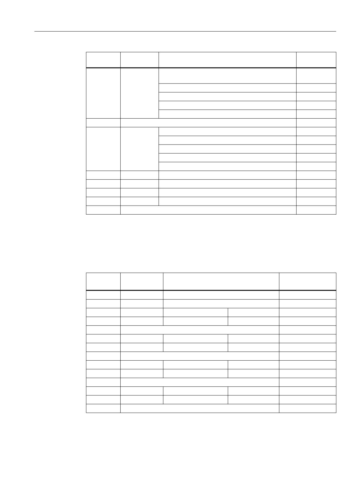
In the "pre-assignment" column, the signals for which the associated SINAMICS parameters are set when
configuring a SINAMICS device are marked with "x".
6.2.3
X132 terminal assignment
Terminal
Signal name
Function
Pre-assign-
ment
X132.1
DI 4
Freely available
---
X132.2
DI 5
Freely available
---
X132.3
DI 6
Freely available
---
X132.4
DI 7
Infeed line contactor feedback signal (if one infeed is
---
operated with a DRIVE-CLiQ connection at the NCU)
X132.5
DI20
Freely available
---
X132.6
DI21
Freely available
---
X132.7
Ground for terminals 1...6
X132.8
Ground for terminals 9, 10, 12, 13
X132.9
DI/DO 12
Output: Infeed operation (if one infeed is operated with
x
a DRIVE-CLiQ connection at the NCU)
Input 2. Operating condition OFF2 drives
---
CNC Commissioning: NC, PLC, Drive
104
Commissioning Manual, 10/2020, A5E48312804B AB
Commissioning NC-controlled drives
6.2 Terminal assignment
Terminal
Signal name
Function
Pre-assign-
ment
X132.10
DI/DO 13
Output: Status, infeed ready to start (if one infeed is
x
operated at the NCU with a DRIVE-CLiQ connection)
Input 2. Operating condition OFF2 drives
---
Input, external zero mark 2
---
Input probe 2 - central measurement
---
Input probe 2 - distributed measurement
---
X132.11
Ground for terminals 9, 10, 12, 13
X132.12
DI/DO 14
Input 2. Operating condition OFF2 drives
---
Input, external zero mark 3
---
Input probe 2 - central measurement
---
Input probe 2 - distributed measurement
---
Infeed, control line contactor
---
X132.13
DI/DO 15
Input 2. Operating condition OFF2 drives
---
Input, external zero mark 4
---
Input probe 2 - central measurement
---
Input probe 2 - distributed measurement
---
X132.14
Ground for terminals 9, 10, 12, 13
In the "pre-assigned" column, the signals for which the associated SINAMICS parameters are set when
configuring a SINAMICS device are marked with "x".
6.2.4
X142 terminal assignment
Terminal
Signal name
Function
Pre-assignment
X142.1
---
Reserved
---
X142.2
---
Reserved
---
X142.3
DI0
NC input
$A_IN[1]
fixed
X142.4
DI1
NC input
$A_IN[2]
fixed
X142.5
Ground for terminals X142.3, 4, 6, 7, 9, 10, 12, 13
---
X142.6
DI2
NC input
$A_IN[3]
fixed
X142.7
DI3
NC input
$A_IN[4]
fixed
X142.8
Ground for terminals X142.3, 4, 6, 7, 9, 10, 12, 13
---
X142.9
DO4
NC output
$A_OUT[1]
fixed
X142.10
DO5
NC output
$A_OUT[2]
fixed
X142.11
Ground for terminals X142.3, 4, 6, 7, 9, 10, 12, 13
---
X142.12
DO6
NC output
$A_OUT[3]
fixed
X142.13
DO7
NC output
$A_OUT[4]
fixed
X142.14
Ground for terminals X142.3, 4, 6, 7, 9, 10, 12, 13
---
CNC Commissioning: NC, PLC, Drive
Commissioning Manual, 10/2020, A5E48312804B AB
105

Commissioning NC-controlled drives
6.2 Terminal assignment
6.2.5
Terminal assignment NX1x.3
The table lists the assignments of the terminals on an NX1x.3 for the X122 terminal strip.
The SINAMICS device configuration sets the following preassignment:
Number
Function
Signal
Pre-assign-
ment
X122.1
DI 0
Input ON/OFF1 infeed (if one infeed with a DRIVE-CLiQ con-
x
nection is operated at the NX)
Input infeed operation - "infeed ready signal" (if no infeed
x
with DRIVE-CLiQ connection is operated at the NX)
X122.2
DI 1
Input 2. Operating condition OFF3 drives
x
Freely available
--
X122.3
DI 2
Selection safe standstill group 1
--
SH/SBC - Group 1 SINAMICS Safety Integrated (SH = p9601
release)
X122.4
DI 3
Selection safe standstill group 2
--
SH/SBC - Group 2 SINAMICS Safety Integrated (SH = p9601
release)
X122.5
DI 16
Freely available
--
X122.6
DI 17
Freely available
--
X122.7
Reference potential for terminals 1…6
X122.8
Mass
X122.9
DI/DO 8
Status safe standstill group 1
-
SH/SBC - Group 1
SINAMICS Safety Integrated
X122.10
DI/DO 9
Status safe standstill group 2
--
SH/SBC - Group 2
SINAMICS Safety Integrated
X122.11
Mass
X122.12
DI/DO 10
Input, external zero mark - BERO 1
--
X122.13
DI/DO 11
Input, external zero mark 2/1
--
Input 2. Operating condition OFF2 drives
--
X122.14
Mass
Those signals for which the associated SINAMICS parameters are set for the SINAMICS device
configuration are marked with "x" in the "Pre-assigned" column.
6.2.6
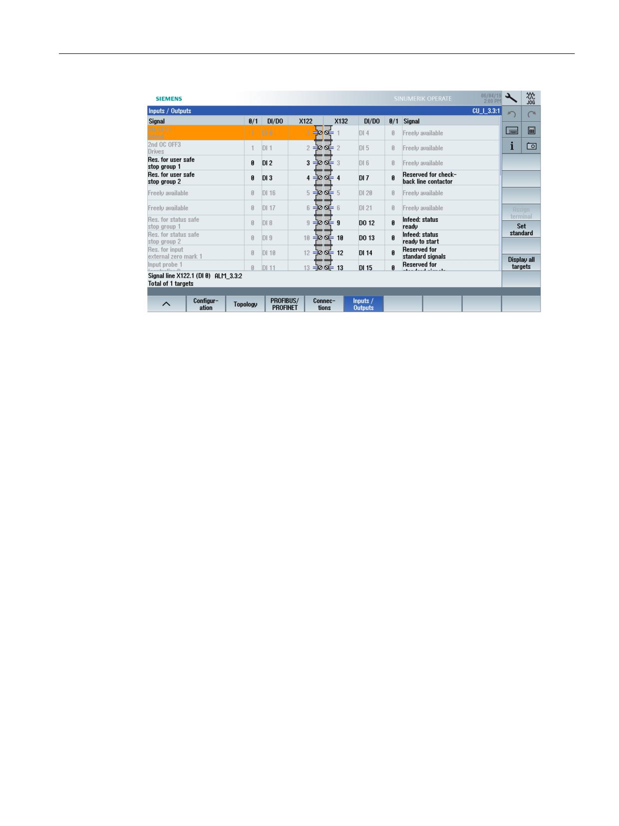
Support for the terminal assignment
Support for terminal assignment
The following overview shows the terminal assignment of those drive units (NCU, NX) involved
in the SINAMICS drive line-up.
"Commissioning" → "Drive system" → "Drive units" → "Inputs/outputs" operating area:
CNC Commissioning: NC, PLC, Drive
106
Commissioning Manual, 10/2020, A5E48312804B AB
Commissioning NC-controlled drives
6.2 Terminal assignment
Figure 6-2
Interconnection of the digital inputs/outputs
6.2.7
BICO interconnections
Introduction
Each drive unit contains a large number of input and output variables as well as internal control
variables. BICO technology (binector connector technology) allows the drive to be adapted to a
wide variety of conditions.
Digital and analog signals, which can be interconnected as required by means of BICO
parameters, are identified by the prefix BI, BO, CI, or CO in their parameter name. These
parameters are identified accordingly in the parameter list or in the function diagrams:
• Binectors (digital): BI: Binector input, BO: Binector output
• Connectors (analog): CI: Connector input, CO: Connector output
To interconnect two signals, a BICO input parameter (signal sink) must be assigned to the
required BICO output parameter (signal source).
CNC Commissioning: NC, PLC, Drive
Commissioning Manual, 10/2020, A5E48312804B AB
107
Commissioning NC-controlled drives
6.2 Terminal assignment
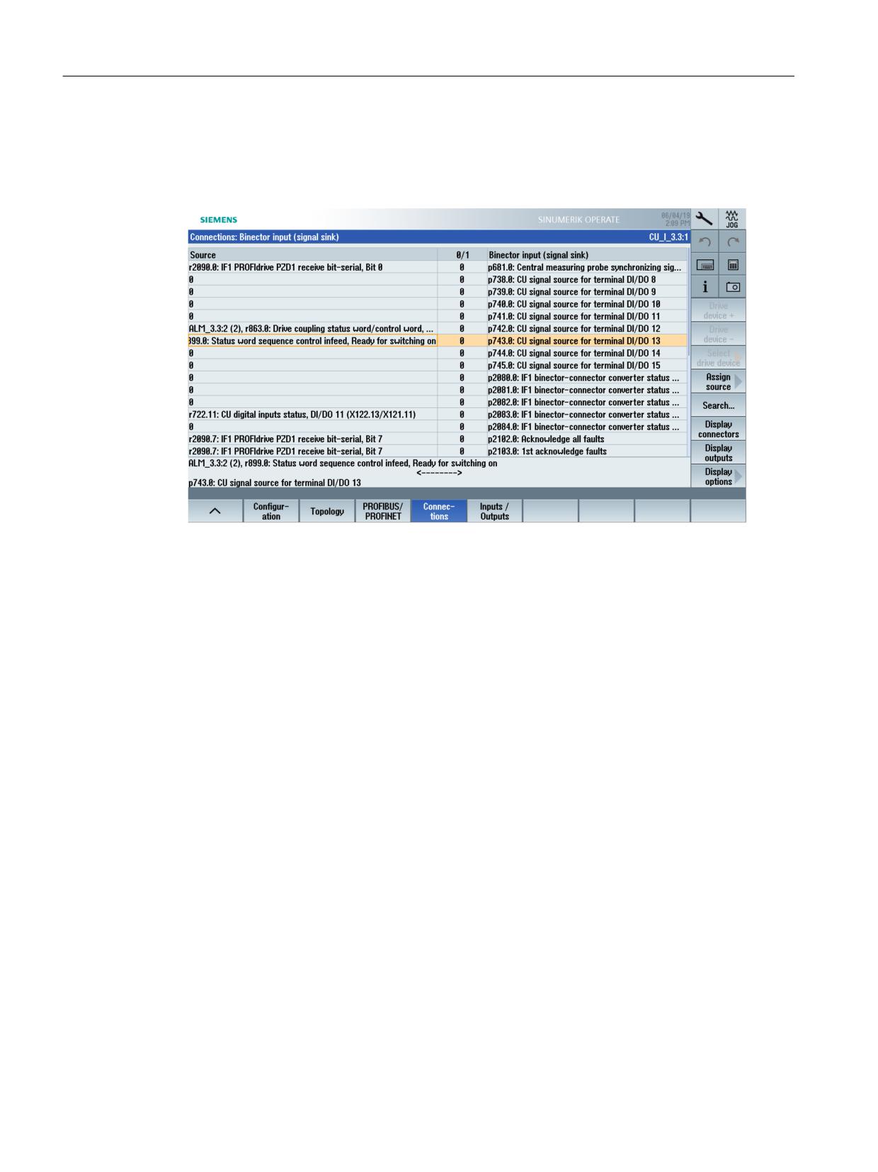
Representation on the control
The following dialog provides support for the BICO interconnection of the components on the
SINAMICS drive line-up:
Figure 6-3
Example: Interconnections
Additional information is provided in Chapter "Function diagrams" in the SINAMICS S120/S150
CNC Commissioning: NC, PLC, Drive
108
Commissioning Manual, 10/2020, A5E48312804B AB
Commissioning NC-controlled drives
6.3 Guided commissioning of SINAMICS drives
6.3
Guided commissioning of SINAMICS drives
6.3.1
Initializing the system
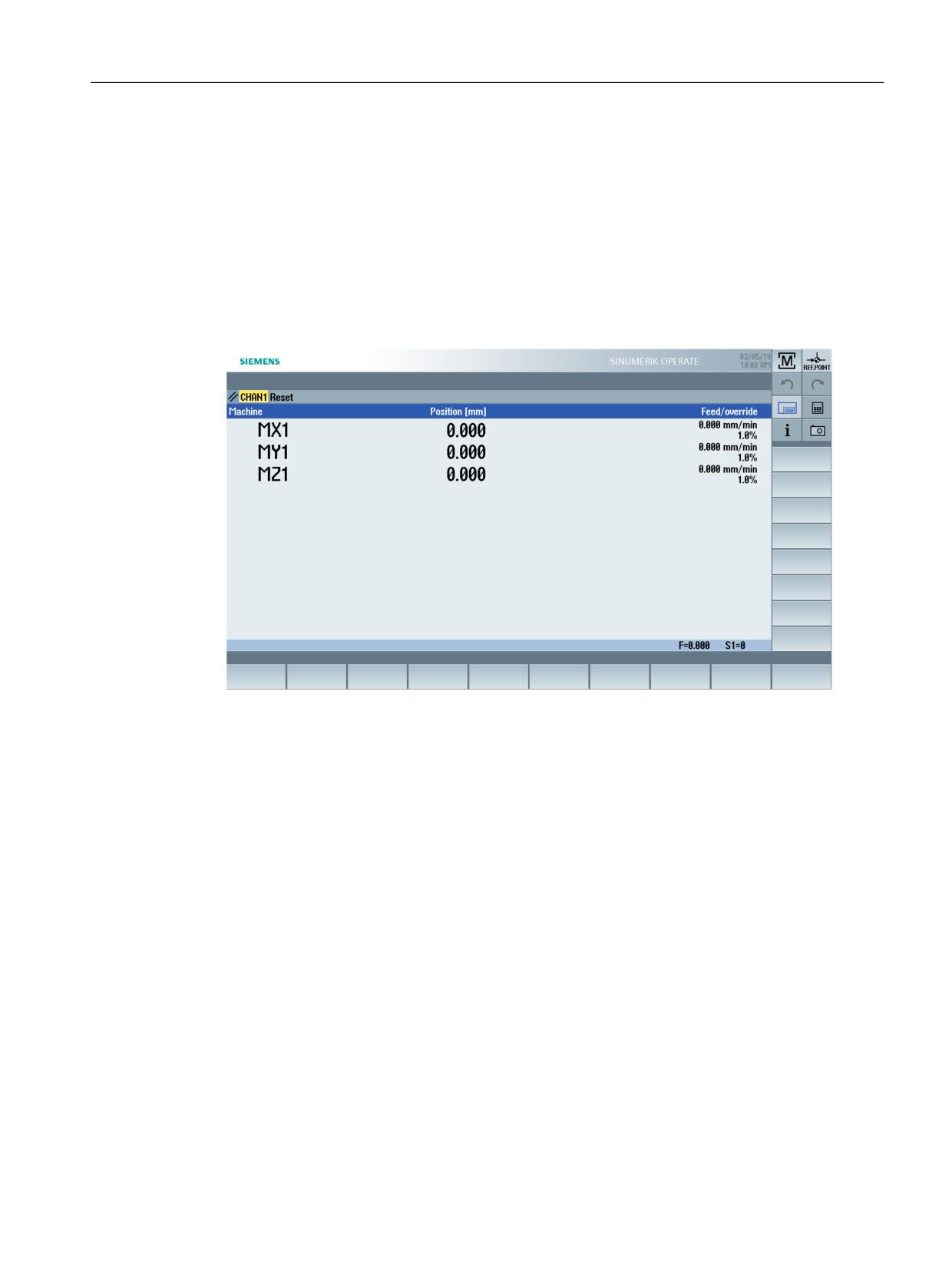
System run-up
After the system has powered up, the "Machine" operating area is displayed:
Alarm response
When loading the project, the PLC is brought into the STOP state. The NC interprets this STOP
state, with a corresponding alarm response, as failure of the PLC. A "Reset (po)" is required for
PLC-NC synchronization. The system responds with alarms. To output all alarms, switch to the
"Diagnostics" → "Alarms" operating area. Additional support for the diagnostics of the drive
system is provided in Chapter Diagnostics → drive system (Page 161).
CNC Commissioning: NC, PLC, Drive
Commissioning Manual, 10/2020, A5E48312804B AB
109
Commissioning NC-controlled drives
6.3 Guided commissioning of SINAMICS drives
Initializing the system
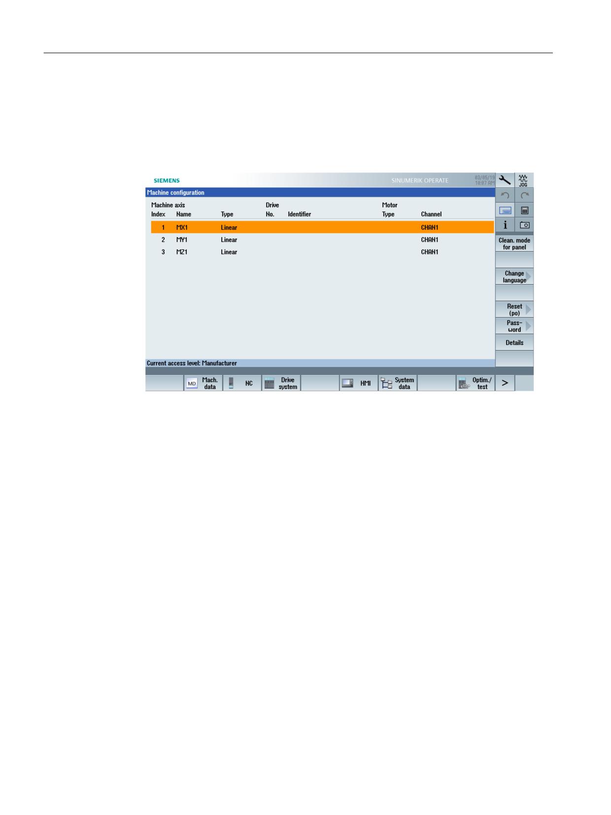
Procedure:
1. Switch to the "Setup" operating area.
2. Use the ""Password >" softkey to enter the password for the "Manufacturer" access level and
confirm with "OK".
3. Press the "Reset (po)" softkey and confirm with "Yes".
The PLC then goes into the RUN state, and the commissioning of the SINAMICS drives is
started with the device configuration.
CNC Commissioning: NC, PLC, Drive
110
Commissioning Manual, 10/2020, A5E48312804B AB
Commissioning NC-controlled drives
6.3 Guided commissioning of SINAMICS drives
6.3.2
Device configuration of the drive system
Automatic initial commissioning
Procedure:
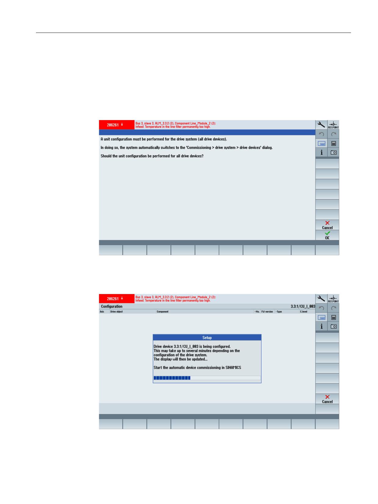
1. After the complete drive system has run-up, a dialog box for automatic device configuration
is displayed: "A device configuration must be performed for the drive system (all drive units)."
2. Select "OK" to start the automatic device configuration. The system topology is then
automatically read-out. This operation can take several minutes.
Alternative: Select "Cancel" to carry out manual commissioning (see: Manual commissioning
of SINAMICS drives (Page 136)).
CNC Commissioning: NC, PLC, Drive
Commissioning Manual, 10/2020, A5E48312804B AB
111
Commissioning NC-controlled drives
6.3 Guided commissioning of SINAMICS drives
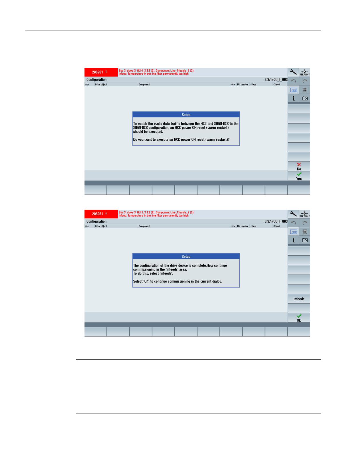
3. The system then requests a Power-On Reset. Confirm with "Yes". This operation can take
several minutes.
4. After the Power-On Reset, switch to the commissioning wizard for the infeed.
5. Confirm with "OK", the "Configuration" dialog box then appears.
Note
Establish a defined initial state
If the device configuration does not start automatically, device configuration has already been
performed:
Load the "Factory settings" to create a defined state or restart. This restores a defined output
state.
CNC Commissioning: NC, PLC, Drive
112
Commissioning Manual, 10/2020, A5E48312804B AB
Commissioning NC-controlled drives
6.3 Guided commissioning of SINAMICS drives
Configuration after initial commissioning
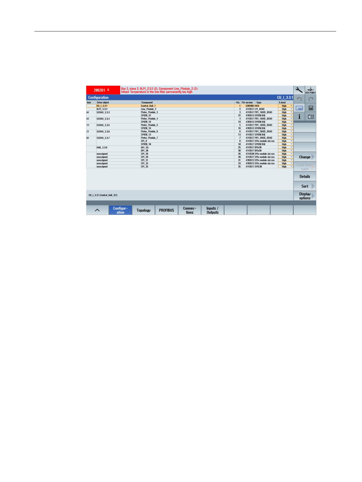
The "Configuration" dialog contains a list of the connected components of the selected drive
unit:
Assignment of the components to the drive objects: For example the assignments of the Motor
Modules, motors and encoders to the drive objects and their assignments to the NC machine
axes (only after axis assignment).
6.3.3
Configuring the infeed
Configuring the infeed
The configuration is described using the example of a SINAMICS S120 Booksize Active Line
Module (ALM).
CNC Commissioning: NC, PLC, Drive
Commissioning Manual, 10/2020, A5E48312804B AB
113
Commissioning NC-controlled drives
6.3 Guided commissioning of SINAMICS drives
Procedure:
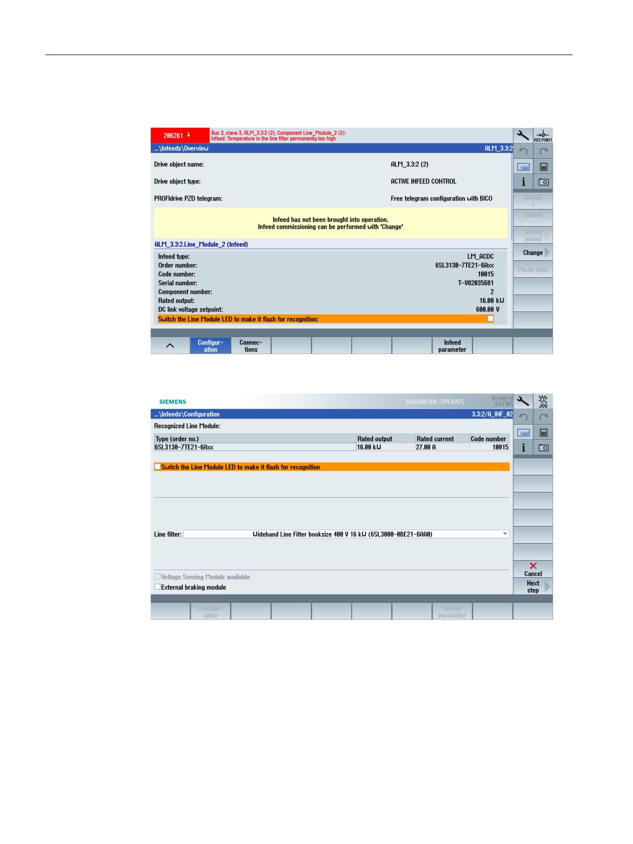
1. Select "Change >" to configure the infeed:
2. The characteristic data of the infeed detected by the automatic device configuration is
displayed:
The following functions can also be activated:
- If you activate the "LED to flash for recognition" option, then the selected infeed will flash
alternately red-green.
- Select the filter type which is connected in front of the infeed from the list under "Line
filter". If it is a filter with temperature monitoring (AIM = Active Interface Module), then
this is automatically activated with the selection (default setting). This option must be
activated if you have inserted a Basic Line Filter in front of the AIM to dampen the
interference emission and RFI suppression.
CNC Commissioning: NC, PLC, Drive
114
Commissioning Manual, 10/2020, A5E48312804B AB
Commissioning NC-controlled drives
6.3 Guided commissioning of SINAMICS drives
- This option is selected if a Voltage Sensing Module has been detected.
- If you activate the external brake control module option, the monitoring of the brake
control module is activated. This requires the appropriate terminal wiring (parameter
p3866 to terminal X21.4 for S120 Booksize,) to have been established, otherwise alarm
206900 is output.
- If you set the option "Activate external brake control module", the function module for the
brake control module is activated. This can be used to monitor the module.
To do so, set the corresponding terminal wiring (e.g. parameter p3866 to terminal X21.4
for S120 Booksize), otherwise alarm 206900 is output. In addition, make a BICO
interconnection from the infeed to the free terminals on the NCU. The parameters that
must be connected for this purpose can be found in the function diagram for the brake
control module in the SINAMICS S120 List Manual.
CNC Commissioning: NC, PLC, Drive
Commissioning Manual, 10/2020, A5E48312804B AB
115
Commissioning NC-controlled drives
6.3 Guided commissioning of SINAMICS drives
3. Select "Next step >".
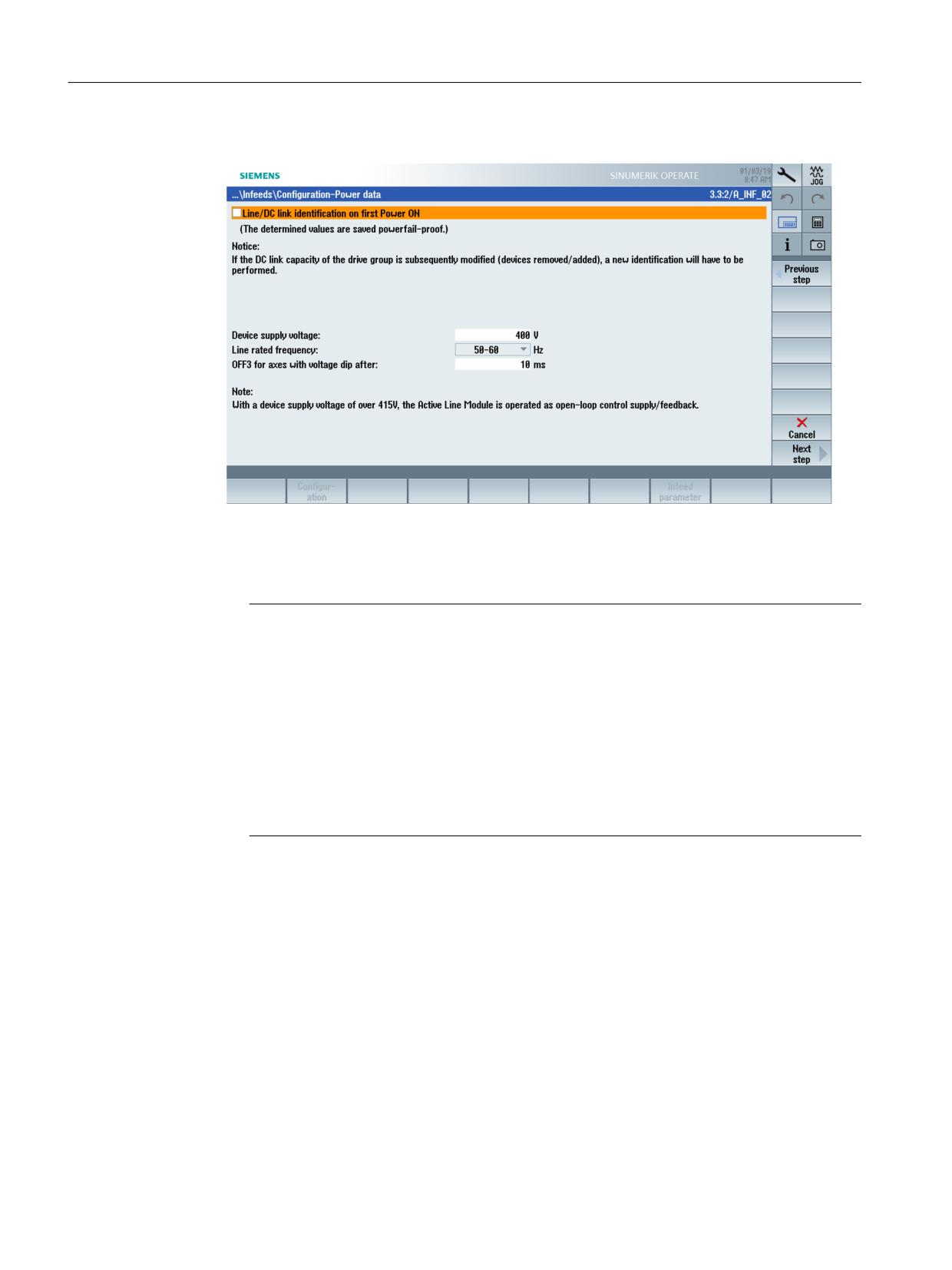
The power data of the infeed is configured here:
- When the checkbox is selected, the line/DC link identification is activated once the infeed
pulse enable has been activated (p3410). The infeed then switches to operational mode.
Note
DC link identification
If the line supply environment changes or the components on the DC link change (e.g.
after setting up the equipment at the customer site or after expanding the drive group),
the checkbox must be set again: Hence the "Power data" softkey in the overview in order
to restart the line/DC link circuit identification.
If p3410 = 5 is saved in the commissioning archive, then the line/DC link identification
starts automatically once the drive data is input into the archive.
Only then can it be guaranteed that the infeed operates with the optimum controller
settings.
- Enter the device connection voltage: This is the basis for monitoring the line voltage
(p0281 - p0283), whereby an alarm is triggered in the case of an overshoot or
undershoot. (Alarm threshold and shutdown threshold). The actual line voltage is
determined automatically and the adjustment is made based on this value.
- The actual line frequency for the infeed is determined automatically.
- In parameters p0284, p0285, set a threshold above which an alarm is triggered (default
setting of the monitoring: 45 Hz to 65 Hz).
CNC Commissioning: NC, PLC, Drive
116
Commissioning Manual, 10/2020, A5E48312804B AB
Commissioning NC-controlled drives
6.3 Guided commissioning of SINAMICS drives
4. Select "Next step >".
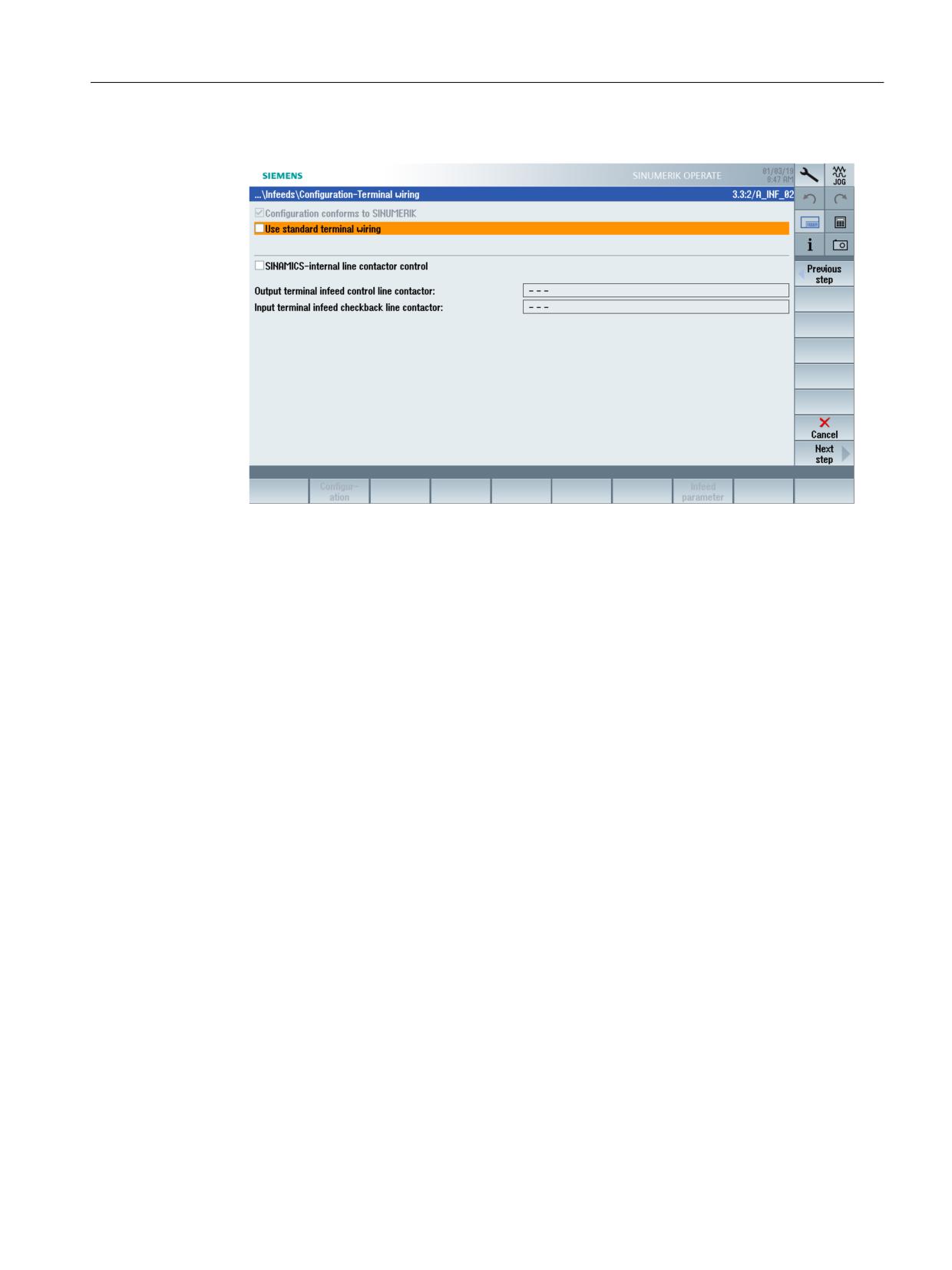
Use a line contactor to ensure galvanic isolation of the drive line-up and the DC link from the
line supply.
The checkbox for the infeed is selected by default. This means that the BICO interconnection
(ON/OFF, both directions) is set with the initial commissioning in accordance with the default
setting. Activate the checkbox in order to restore the default setting for the terminal wiring.
If you use an external line contactor in front of the infeed, you can control it automatically via
SINAMICS. To do this, set the checkbox to activate the "SINAMICS internal line contactor
control" function.
Control via the PLC is also possible as an alternative. The connection is made via the reserved
terminals displayed.
- X132.12: Output terminal infeed for line contactor control
- X132.4: Input terminal infeed for line contactor feedback signal
It is not possible to internally control the line contactor using a drive object on the NCU, as the
line contactor must be controlled from an external PLC or hardware control.
CNC Commissioning: NC, PLC, Drive
Commissioning Manual, 10/2020, A5E48312804B AB
117
Commissioning NC-controlled drives
6.3 Guided commissioning of SINAMICS drives
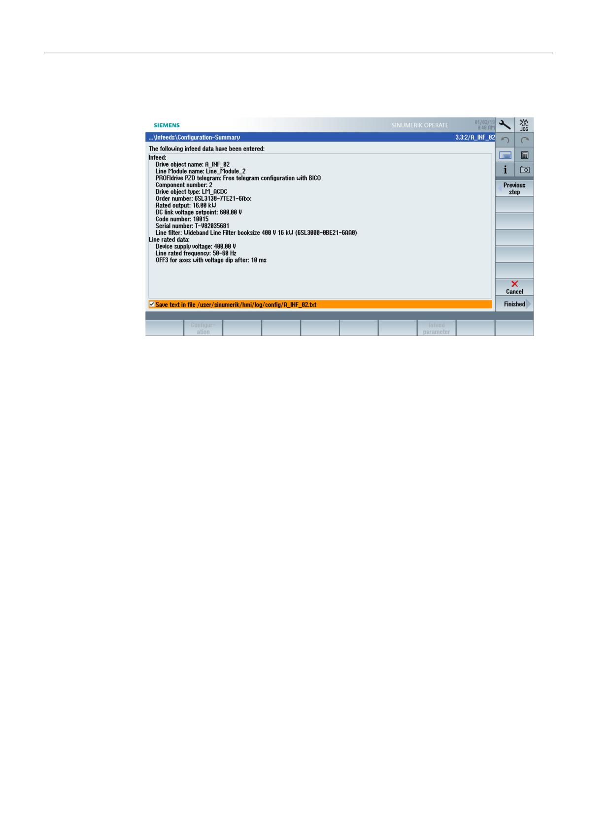
5. Select "Next step >". All data with which the infeed has been configured is displayed in the
summary:
Select the option save "Text in the ../A_INF_02.txt file".
6. Select "Finish >" to complete the infeed configuration.
CNC Commissioning: NC, PLC, Drive
118
Commissioning Manual, 10/2020, A5E48312804B AB
Commissioning NC-controlled drives
6.3 Guided commissioning of SINAMICS drives
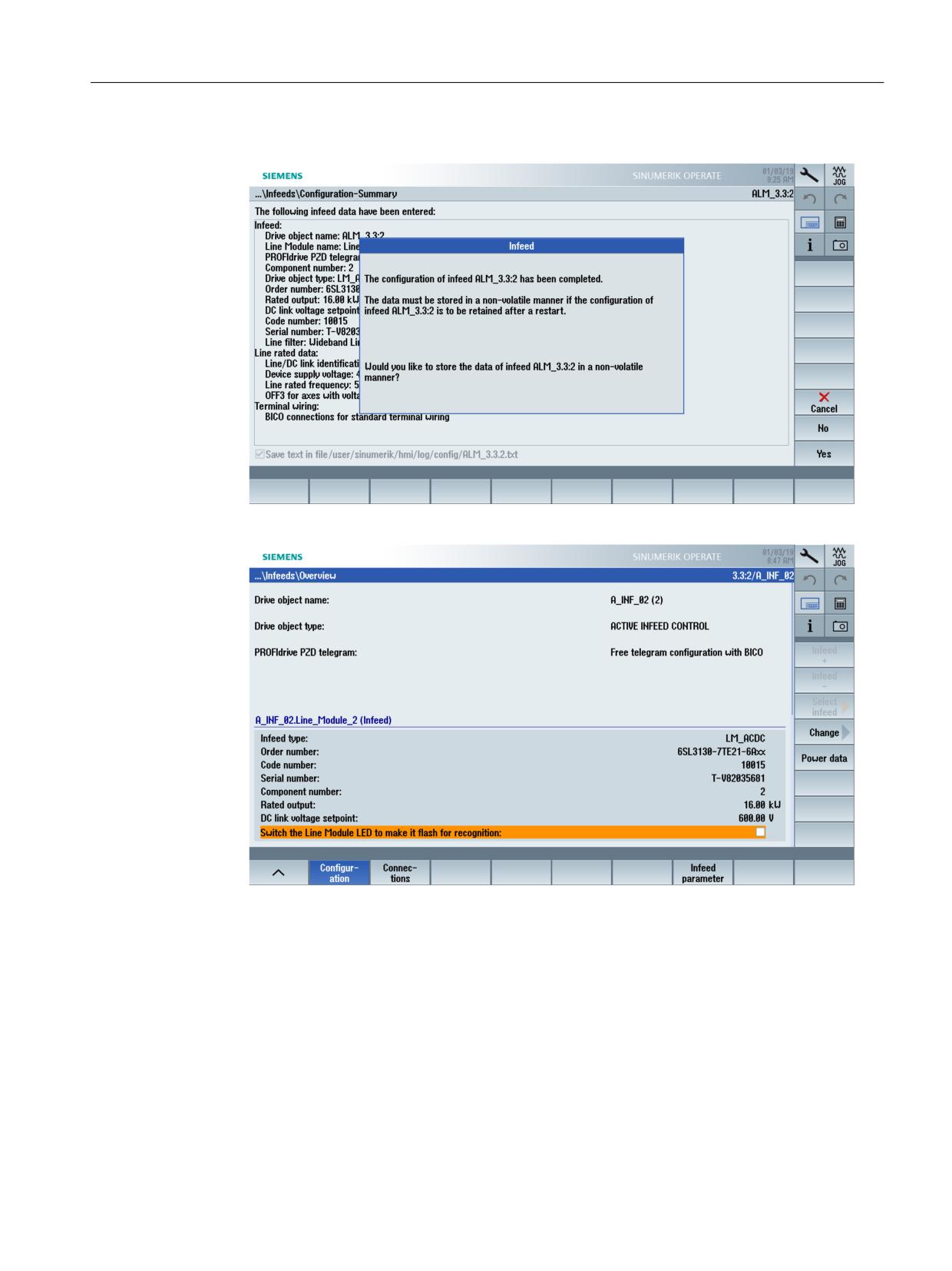
7. Confirm with "OK ✓" to save the configuration data to a non-volatile memory.
8. Then the following overview (multiple pages) is displayed:
CNC Commissioning: NC, PLC, Drive
Commissioning Manual, 10/2020, A5E48312804B AB
119
Commissioning NC-controlled drives
6.3 Guided commissioning of SINAMICS drives
6.3.4
Configuration of two infeeds connected in parallel
Condition
The SINAMICS S120 supports the parallel connection of Line Modules under the following
conditions:
• Same type
• Same type rating:
Available for following Active Line Modules: 55, 80 and 120 kW
• Same rated voltage
• Same firmware version
The parallel connection of two Active Line Modules in booksize format must be supplied by a
shared line connection and controlled synchronously by a shared Control Unit. The modules
must not be connected to galvanically isolated lines.
Benefits
For space reasons, some applications require the use of Line Modules in booksize format, but the
available performance range with a single booksize Line Module is insufficient for the
application.
The parallel connection of booksize Active Line Modules offers the following advantages:
• Extension of the power range by higher S1 and maximum powers for S120 in booksize format
• Higher maximum prechargeable DC-link capacity up to 38 mF
• Only a shared DC link with energy exchange between all connected drives is required.
• Usable in Active Mode, Smart Mode and Extended Smart Mode of the infeed
• Commissioning is simple because no additional parameter assignment is required.
- The commissioning engineer sees only a larger Active Line Module.
- No additional effort is required for commissioning and data backup.
CNC Commissioning: NC, PLC, Drive
120
Commissioning Manual, 10/2020, A5E48312804B AB
Commissioning NC-controlled drives
6.3 Guided commissioning of SINAMICS drives
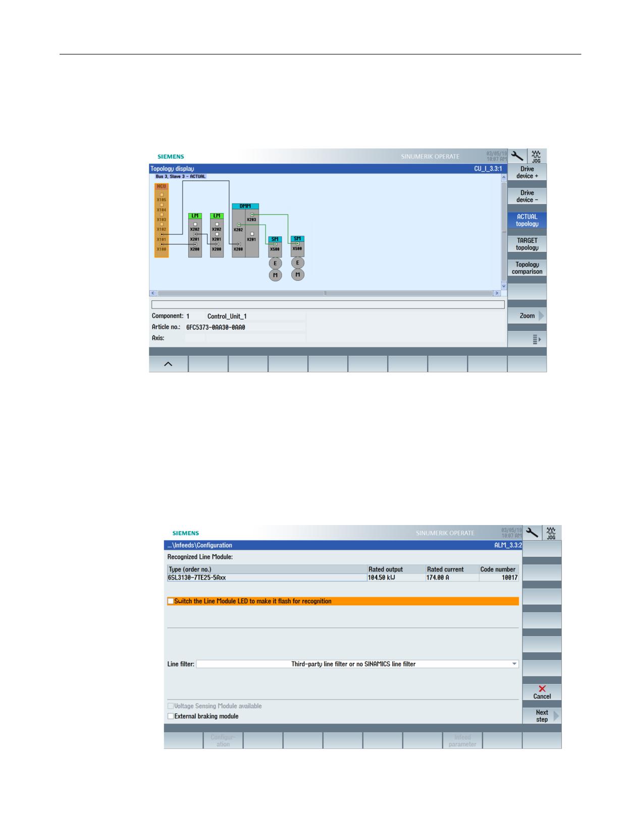
Topology
Select the "Commissioning" → softkey "Drive system" → softkey "Topology" operating area: The
two Line Modules are represented in the topology view:
Infeeds connected in parallel
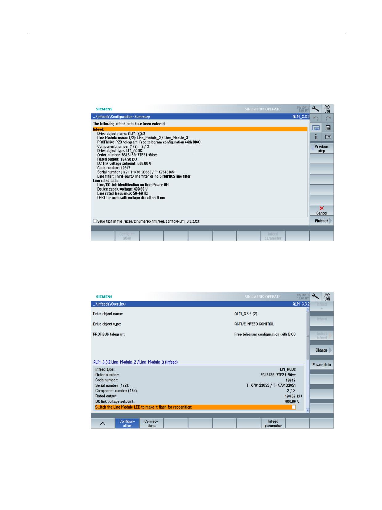
The system detects that the infeed has not yet been commissioned and that initial
commissioning is required:
1. Press the "Change >" softkey to start the commissioning.
2. The data of the Line Module project data is read out and displayed. The two Active Line
Modules connected in parallel can be recognized by the doubled rated power minus the
derating factor of 5%.
Example for 2 x 55 kW: Rated power = 104.50 kW
CNC Commissioning: NC, PLC, Drive
Commissioning Manual, 10/2020, A5E48312804B AB
121
Commissioning NC-controlled drives
6.3 Guided commissioning of SINAMICS drives
3. Accept the default setting of the line data or adjust the data to the power supply conditions
at the operating site.
4. Accept the default setting for the terminal wiring.
5. Check the configuration in the summary. Press the "Finish >" softkey to complete the
commissioning.
You can also save the configuration data in a text file.
6. Confirm the prompt with "Yes" to save the data to non-volatile memory.
7. Select "Cancel" to display the overview of the infeed: The two infeeds connected in parallel
are now commissioned.
CNC Commissioning: NC, PLC, Drive
122
Commissioning Manual, 10/2020, A5E48312804B AB
Commissioning NC-controlled drives
6.3 Guided commissioning of SINAMICS drives
Checking infeed parameters
You can check the setting of the following parameters with the "Machine data" → softkey "Infeed
parameters":
Parameter
Meaning
p0108.15 = 1
Parallel connection of function module activated
r0200[0]
Current power unit code number of the first ALM
r0200[1]
Current power unit code number of the second ALM
…
…
r0204[0]
Power unit hardware properties of the first ALM
r0204[1]
Power unit hardware properties of the second ALM
r7000 = 2
Parallel connection, number of active power units
p7001[0] = 1
Parallel connection, enabling of power units
p7001[1] = 1
Parallel connection, enabling of power units
…
Further information can be found in:
• SINAMICS S120 Drive Functions (https://support.industry.siemens.com/cs/ww/en/view/
109771805) Function Manual, Chapter "Function modules" → "Parallel connection of power
units".
• SINAMICS S120 Application example (https://support.industry.siemens.com/cs/ww/en/view/
109759667) "Parallel connection Active Line Modules in booksize format"
6.3.5
Example: Configuring a catalog motor with encoder
Motor types
You configure motors and encoders using the drive wizard integrated in SINUMERIK Operate. For
the motors, distinction is made between the following motor types:
• Catalog motors are SIMOTICS motors, where all of the motor data is saved in a list and is
automatically identified.
• Third-party motors are motors where you must enter motor data into the drive wizard.
Note
During the device configuration, motors with SMI (DRIVE-CLiQ) are automatically configured
with a drive data set (DDS); however, only with the motor measuring system. Configuration in
the drive wizard is only required for more than one drive/motor data set (DDS/MDS) (Page 141),
or a second (direct) measuring system is connected.
CNC Commissioning: NC, PLC, Drive
Commissioning Manual, 10/2020, A5E48312804B AB
123
Commissioning NC-controlled drives
6.3 Guided commissioning of SINAMICS drives
Drives: Configuration
Procedure:
1. Select the "Commissioning" → "Drive system" -> "Drives" operating area. A first
commissioning is required for the drive object.
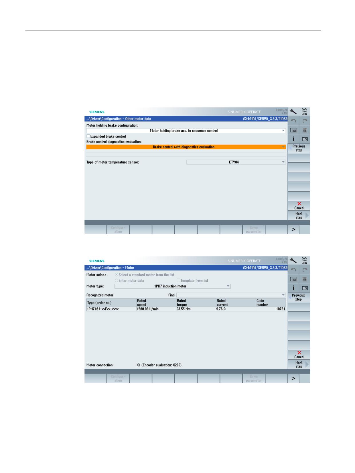
2. Select softkey "Change >". The Motor Module is identified and displayed. If available, activate
the function modules.
3. The motor is a catalog motor, and motor selection "Select a standard motor from the catalog"
is deactivated:
CNC Commissioning: NC, PLC, Drive
124
Commissioning Manual, 10/2020, A5E48312804B AB
Commissioning NC-controlled drives
6.3 Guided commissioning of SINAMICS drives
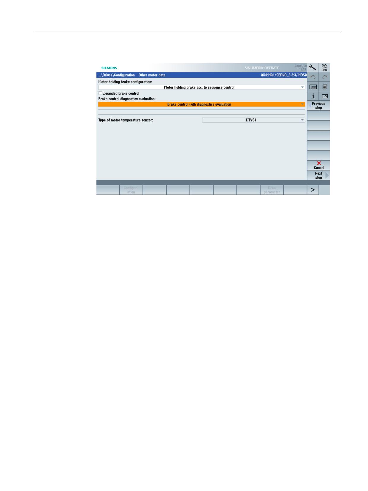
4. Enter additional motor data in the next step "Configuration - motor data":
- If a connected brake is identified during the device configuration, then the system
automatically activates the brake control, and displays the default setting: "Brake control
according to sequence control".
- "Brake control diagnostics evaluation": This parameter is automatically set for booksize
components.
For function "Safe Brake Control", the brake control type is set in parameter p1278: For an
AC drive with "Safe Brake Relay," for example "Brake control with diagnostic evaluation" is
set (p1278 = 0).
- Information about the motor temperature sensor is provided in the following FAQ (https://
support.industry.siemens.com/cs/document/109736364).
Depending on the motor type, additional settings for overvoltage protection and for bearing
version are displayed.
CNC Commissioning: NC, PLC, Drive
Commissioning Manual, 10/2020, A5E48312804B AB
125
Commissioning NC-controlled drives
6.3 Guided commissioning of SINAMICS drives
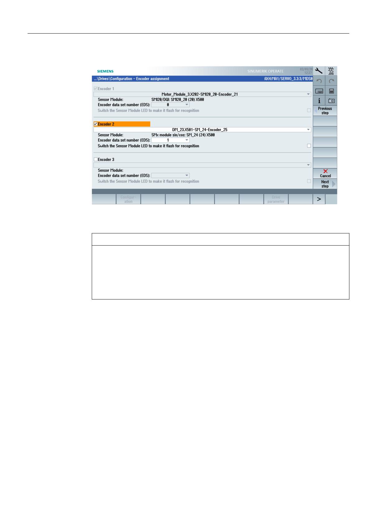
5. In the next step, an identification of the selected encoder is initiated (encoder 1):
The drive unit can identify encoders with EnDat protocol. These encoders are selected from
the encoder list.
NOTICE
Simulated motor encoder
In order to select a simulated motor encoder for a drive, a license is required for the
following option:
"Simulated motor encoder" (6FC5800-0_M90-0Yx0)
The simulated motor encoder is not displayed in the topology view.
CNC Commissioning: NC, PLC, Drive
126
Commissioning Manual, 10/2020, A5E48312804B AB
Commissioning NC-controlled drives
6.3 Guided commissioning of SINAMICS drives
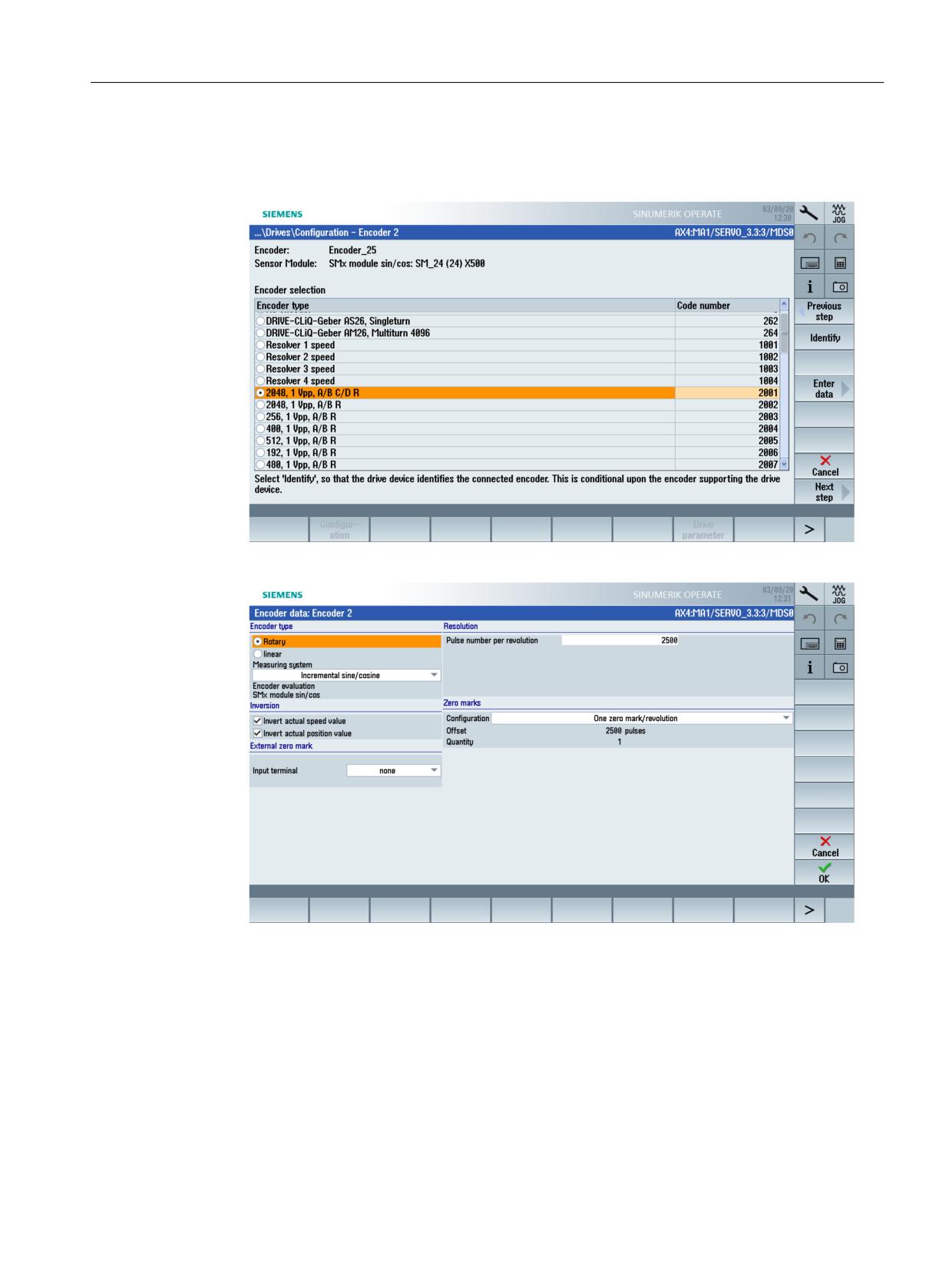
6. The entry "No encoder" is selected in the encoder list for encoders that the drive unit cannot
identify. The connected encoder 2 must be configured. Select an encoder that is as similar as
possible:
7. Select softkey "Enter data >", to enter data for the encoder that has not been identified:
CNC Commissioning: NC, PLC, Drive
Commissioning Manual, 10/2020, A5E48312804B AB
127
Commissioning NC-controlled drives
6.3 Guided commissioning of SINAMICS drives
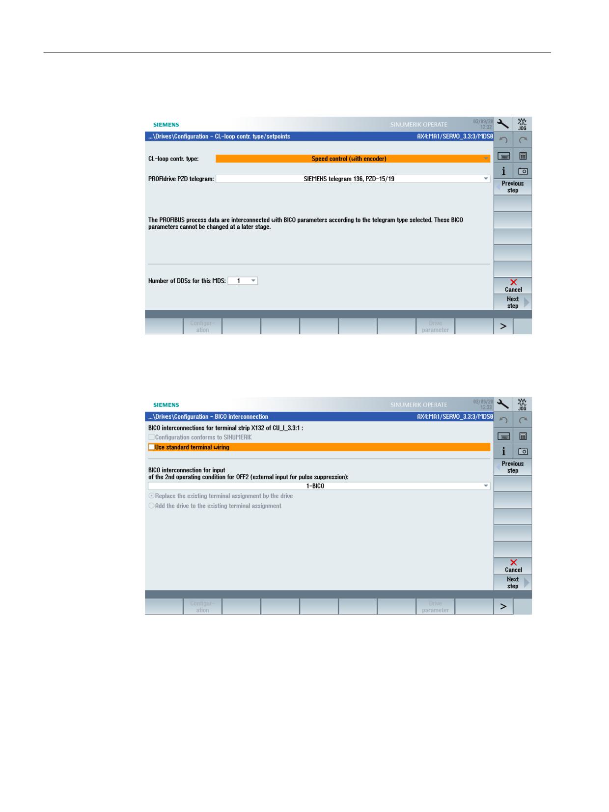
8. The control mode and the PROFIBUS telegram (Page 194)are generally correctly pre-
assigned by the drive wizards.
In many cases, the default setting is sufficient for the number of drive data sets (DDS).
9. Select the 2nd operating condition Input 2nd OFF2 (Page 103) (external input for pulse
cancellation) off:
CNC Commissioning: NC, PLC, Drive
128
Commissioning Manual, 10/2020, A5E48312804B AB
Commissioning NC-controlled drives
6.3 Guided commissioning of SINAMICS drives
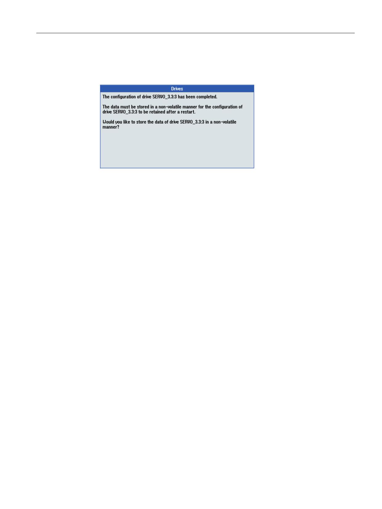
10.The configuration has been completed in the next step. Check the configuration data in the
summary.
11.Select softkey "Finish >", and confirm the following query with "Yes".
If you have successfully configured the device, the LEDs at the drive indicate the following status:
• All upper LEDs of the drives (SERVO) are lit green.
• The lower LEDs of the drives (SERVO) do not change and are always lit yellow.
CNC Commissioning: NC, PLC, Drive
Commissioning Manual, 10/2020, A5E48312804B AB
129
Commissioning NC-controlled drives
6.3 Guided commissioning of SINAMICS drives
6.3.6
Example: Configuring a third-party motor with encoder
Drives: Configuring a third-party motor
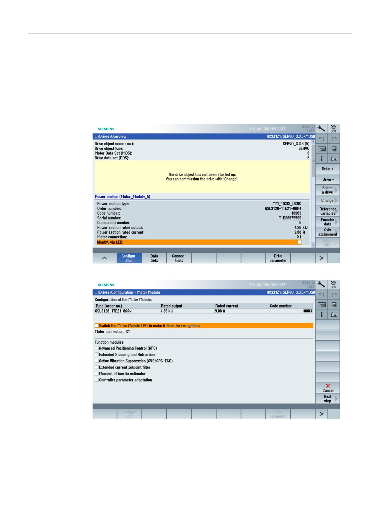
Procedure:
1. Select the "Commissioning" → "Drive system" -> "Drives" operating area. A first
commissioning is required for the drive object:
2. To start the configuration, select softkey "Change >": The Motor Module is identified.
CNC Commissioning: NC, PLC, Drive
130
Commissioning Manual, 10/2020, A5E48312804B AB
Commissioning NC-controlled drives
6.3 Guided commissioning of SINAMICS drives
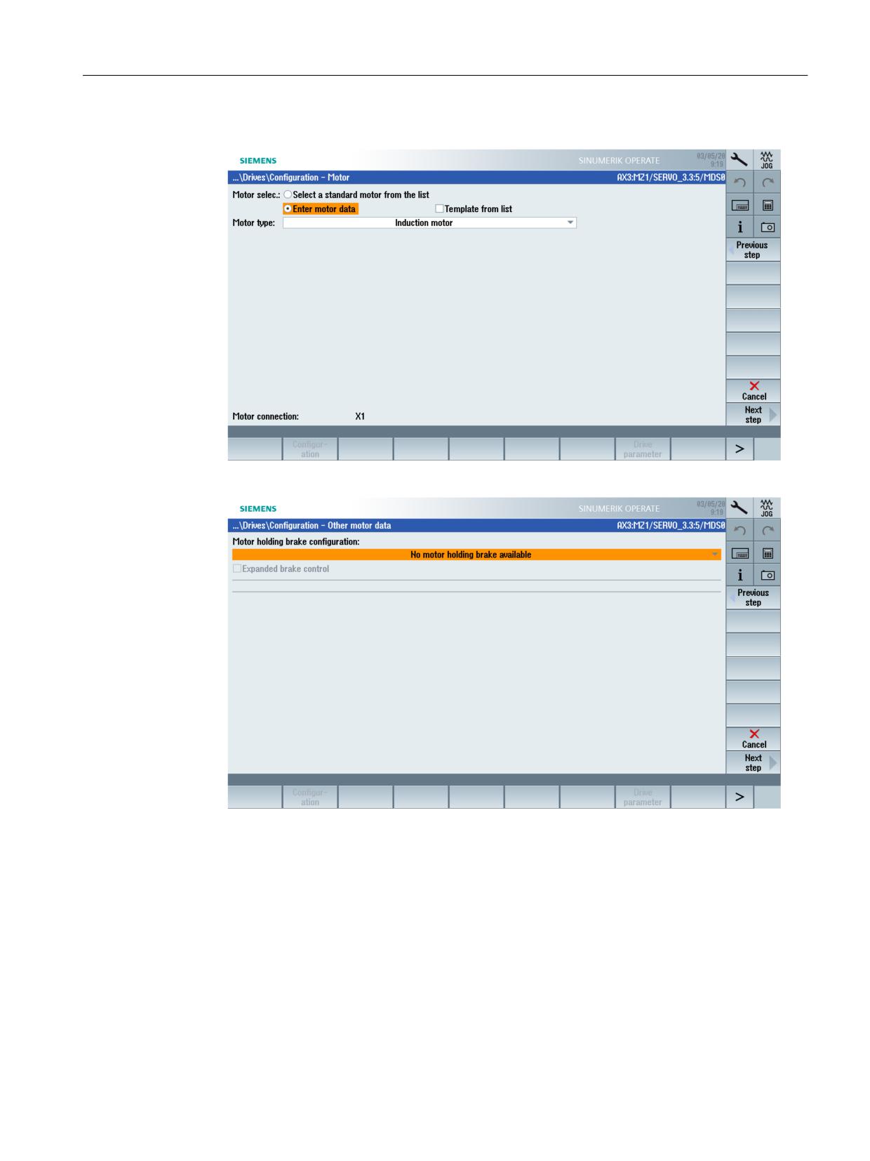
3. In the next step, select option "Enter motor data", to select the motor type:
4. In the next step, configure "Other motor data":
CNC Commissioning: NC, PLC, Drive
Commissioning Manual, 10/2020, A5E48312804B AB
131
Commissioning NC-controlled drives
6.3 Guided commissioning of SINAMICS drives
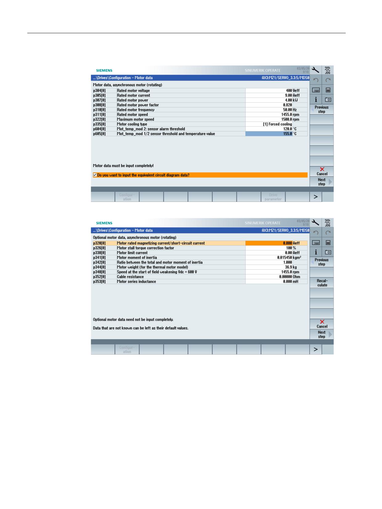
5. In the next step, enter the induction motor data:
6. The preset values are used if the optional data are not completely entered:
CNC Commissioning: NC, PLC, Drive
132
Commissioning Manual, 10/2020, A5E48312804B AB
Commissioning NC-controlled drives
6.3 Guided commissioning of SINAMICS drives
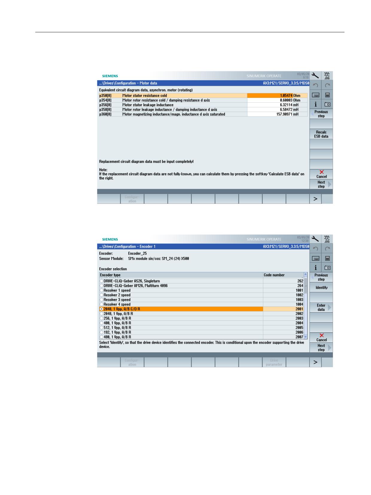
7. If you activated "Equivalent circuit diagram data" (ECD data), then completely enter this
motor data:
8. In the next step, you configure the encoder. The entry "No encoder" is selected in the encoder
list for encoders that the drive unit cannot identify. The connected encoder 1 must be
configured. Select an encoder that is as similar as possible:
CNC Commissioning: NC, PLC, Drive
Commissioning Manual, 10/2020, A5E48312804B AB
133
Commissioning NC-controlled drives
6.3 Guided commissioning of SINAMICS drives
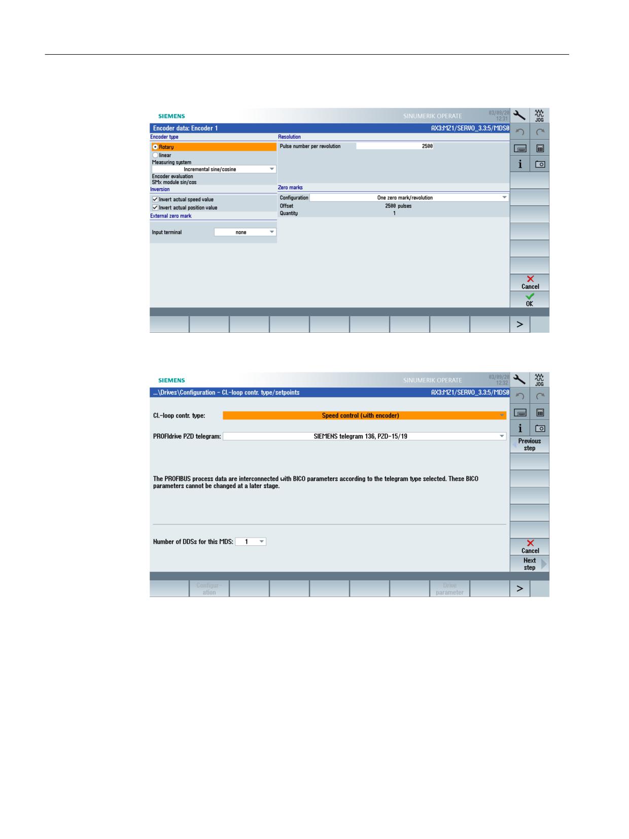
9. Select softkey "Enter data >" to check the data for the encoder or re-enter the data:
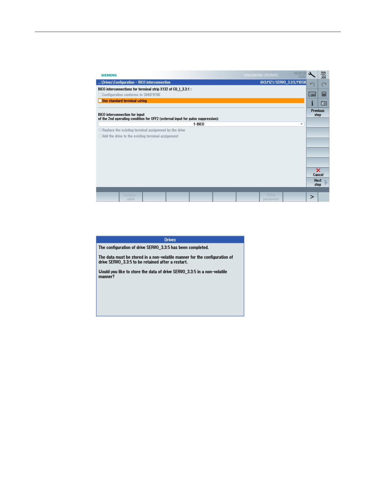
10.The control mode and the PROFIBUS telegram are generally correctly pre-assigned by the
drive wizards.
In many cases, the default setting is sufficient for the number of drive data sets (DDS).
CNC Commissioning: NC, PLC, Drive
134
Commissioning Manual, 10/2020, A5E48312804B AB
Commissioning NC-controlled drives
6.3 Guided commissioning of SINAMICS drives
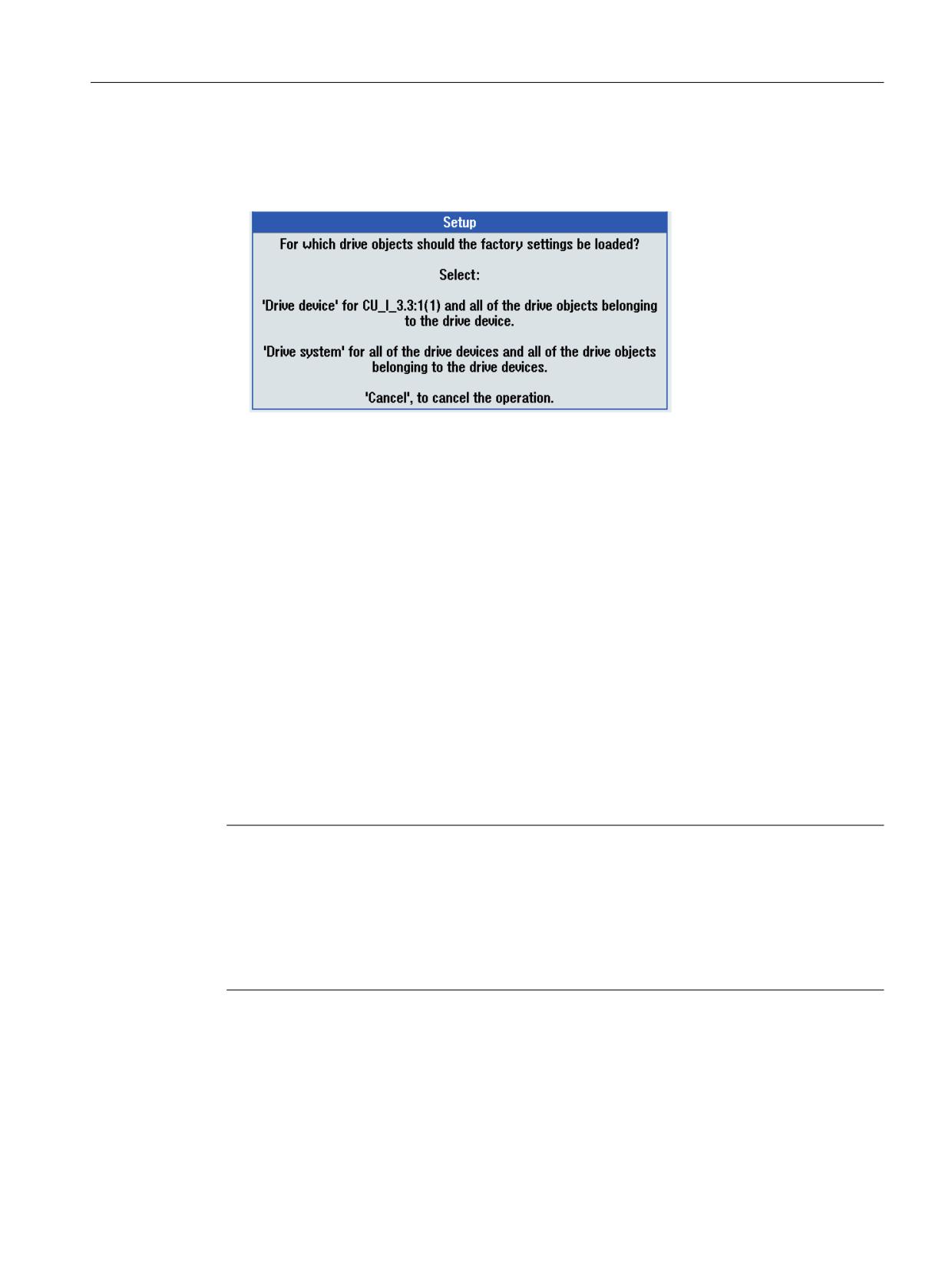
11. In the next step, you select the 2nd operating condition Input 2nd OFF2 (external input for
pulse cancellation) off.
12.The configuration has been completed in the next step. Check the configuration data in the
summary.
13.Select softkey "Finish >", and confirm the following query with "Yes".
If the system detects additional drive objects that have not yet been commissioned, then you are
navigated to the next drive object.
CNC Commissioning: NC, PLC, Drive
Commissioning Manual, 10/2020, A5E48312804B AB
135
Commissioning NC-controlled drives
6.4 Manual commissioning of SINAMICS drives
6.4
Manual commissioning of SINAMICS drives
Machine configuration
Note
Manual commissioning is only recommended for experienced commissioning engineers.
Procedure:
1. Press the <MENU SELECT> key and select the "Commissioning" operating area:
2. Press softkey "Drive system" to display overview "Machine configuration".
The following actions may be required before starting to commission SINAMICS drives:
• Load factory settings (Page 136)
• Update the component firmware (Page 137)
Manually commissioning SINAMICS drives:
• Configure the infeed and drives
• Checking the PROFIBUS connection (Page 139)
6.4.1
Loading SINAMICS factory settings
Loading the factory setting
When loading the factory setting, the drive system is reset and a defined initial state is restored.
NOTICE
Check the voltage
Before loading the factory settings, ensure that the EP terminal (Enable Pulses) of the infeed
(booksize: X21, chassis: X41) is de-energized.
CNC Commissioning: NC, PLC, Drive
136
Commissioning Manual, 10/2020, A5E48312804B AB
Commissioning NC-controlled drives
6.4 Manual commissioning of SINAMICS drives
Procedure:
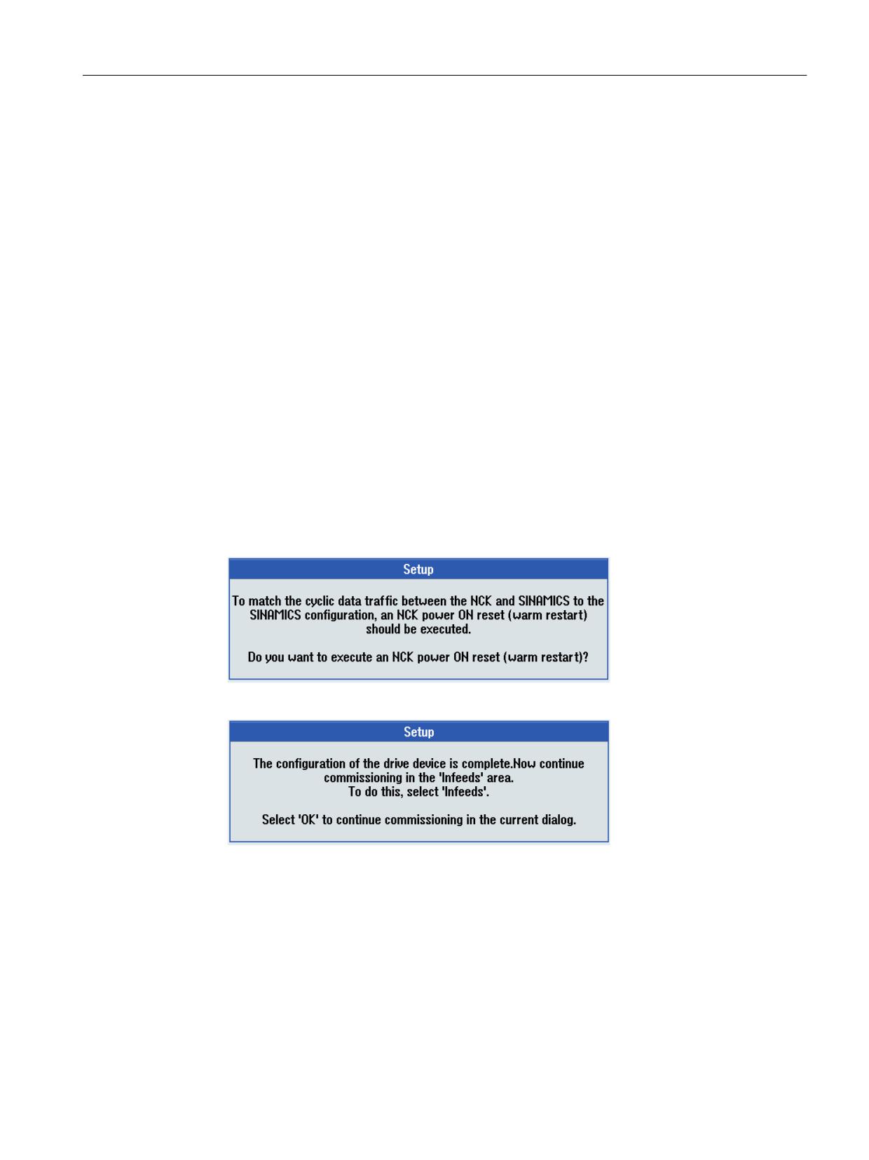
1. Press the <MENU SELECT> key and select the "Commissioning" → Softkey "Factory setting >"
operating area. You have the following choice for the next steps:
2. Select softkey "Drive system" to load the factory settings for all of the drive devices involved
in the system (the integrated CU and the NX module). Also confirm the additional
confirmation prompt with "OK".
3. Switch the system (de-energized drive system) off and on again. Wait until communication
has been established again with the NC.
4. A message is then output that a first commissioning is required and Alarm 120402 is active:
- Press "OK" to start the "Automatic device configuration (Page 139)" of the SINAMICS
drives.
- Press "Cancel" to continue with the manual commissioning.
6.4.2
Firmware update of the drive components
Precondition
All NCU/NX components are connected via DRIVE-CLiQ.
Note
Automatic firmware update
As of SINAMICS V2.5, an automatic firmware update is undertaken when powering up the drive
system if required.
The correct firmware update of the SINAMICS components is performed ONLY if ALL were
inserted in the switched-off state. The subsequent insertion of components may ONLY be
performed in the switched-off state.
CNC Commissioning: NC, PLC, Drive
Commissioning Manual, 10/2020, A5E48312804B AB
137
Commissioning NC-controlled drives
6.4 Manual commissioning of SINAMICS drives
Loading firmware for the entire drive system
Procedure:
1.
Switch on the system.
During run-up, it will be detected that an older firmware version is present. This causes the
update to start automatically and the firmware is loaded from the CompactFlash card to all
DRIVE-CLiQ components of the drive system.
Note
Depending on the configuration of the SINAMICS drive line-up, a complete update of the
component firmware takes approximately 10 minutes. The firmware component currently
being updated is indicated with a flashing LED.
2.
While the firmware is being updated, a progress bar and the following messages inform you
about the current status.
Notice!
The process should not be interrupted! Please wait until the automatic firmware update
has been completed!
The firmware for the DRIVE-CLiQ components of the following drive units is updated:
CU_I_3.3:1
... 39%
CU_NX_3.15:1
... 50%
3.
The following messages are output when the firmware update completes:
Firmware update of the DRIVE-CLiQ components completed.
Notice!
Switch the control system and the entire drive system (all hardware components) off
and then on again to activate the firmware.
Commissioning can then be continued.
CU_I_3.3:1
... 100%
CU_NX_3.15:1
... 100%
4.
You can then continue to commission the drive components (infeed unit, Motor Modules,
encoder).
Note
Loading firmware for individual components
If only certain components of the drive system have an older firmware version, the update
also starts automatically and needs correspondingly less time.
CNC Commissioning: NC, PLC, Drive
138
Commissioning Manual, 10/2020, A5E48312804B AB
Commissioning NC-controlled drives
6.4 Manual commissioning of SINAMICS drives
6.4.3
Automatic device configuration
Precondition
The SINAMICS device configuration starts when commissioning the drive units for the first time:
• Transfer of the DRIVE-CLiQ topology to the drive unit.
When the topology is transferred, all DRIVE-CLiQ components are identified and the drive-
internal data exchange is initialized.
• Drive-object assignment for the PROFIBUS connection.
The PROFIBUS connection is specified via the telegrams in the hardware configuration.
Automatic device configuration
The drive unit is in the first commissioning state.
Procedure:
1. Select the "Commissioning" → Softkey "Drive system" → Softkey "Drive units" operating area.
2. Confirm with "OK" to start the device configuration for the drive system, confirm with "OK".
The device configuration depends on the expansion stage of the drive system and can take
several minutes.
3. Confirm the following prompt with "Yes" to initiate a power on reset:
4. You then have the following selection:
CNC Commissioning: NC, PLC, Drive
Commissioning Manual, 10/2020, A5E48312804B AB
139
Commissioning NC-controlled drives
6.4 Manual commissioning of SINAMICS drives
5. Confirm with "OK". The components belonging to the selected drive unit are displayed in
dialog "Configuration". Toggle between CU-I and NX using softkey "Drive unit +/-".
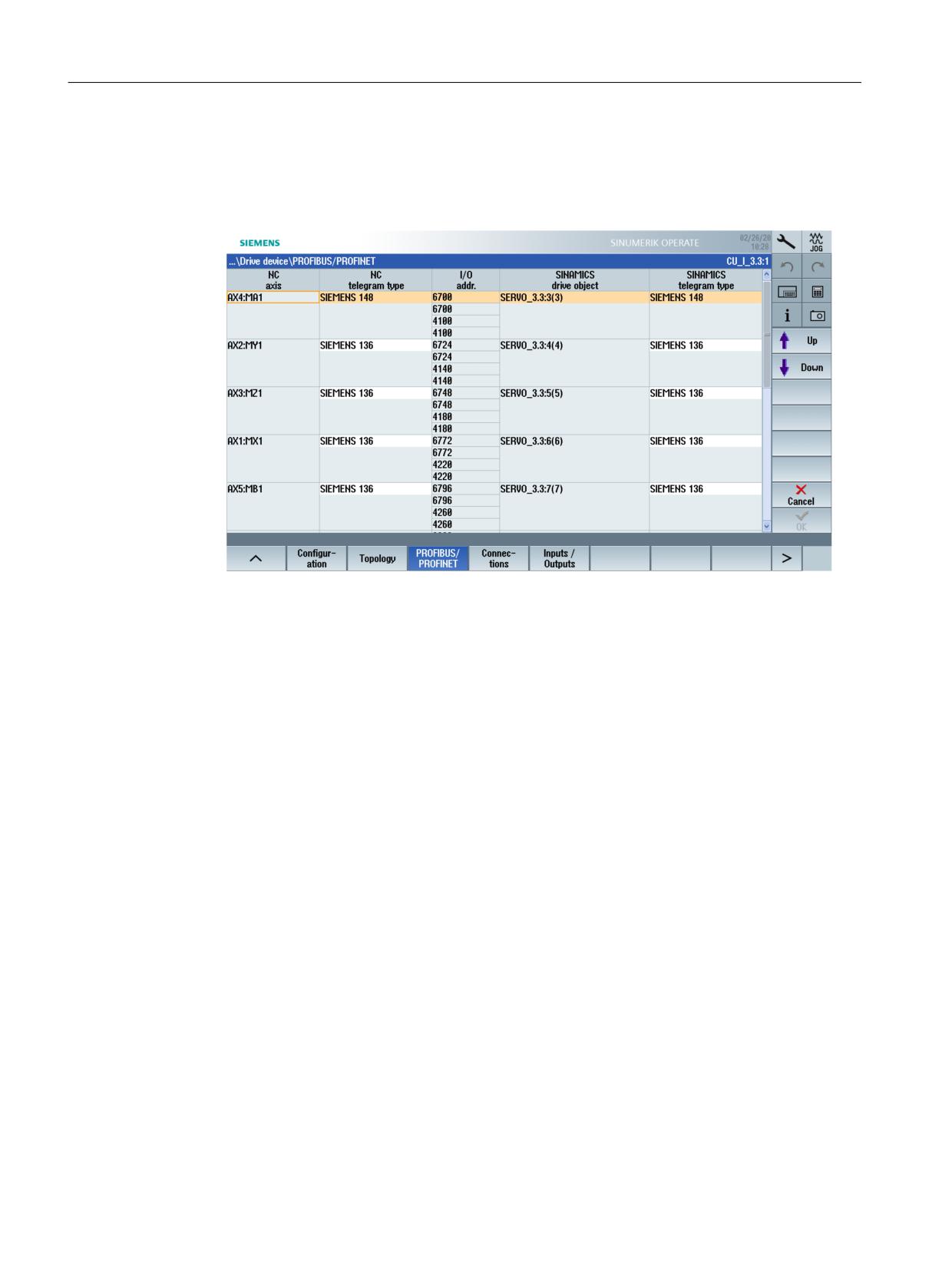
6. Select softkey "PROFIBUS/PROFINET" → "Change >" to subsequently change configuration
settings of drive objects of a drive unit:
You return to the "Drive system overview" using the menu back key.
CNC Commissioning: NC, PLC, Drive
140
Commissioning Manual, 10/2020, A5E48312804B AB
Commissioning NC-controlled drives
6.5 Configuring data sets
6.5
Configuring data sets
6.5.1
Data sets - overview
Benefits
The data set wizard in SINUMERIK Operate offers the machine manufacturer a simple and
efficient solution for duplicating and modifying data in order to configure the behavior of drives,
motors and encoders:
• Motor data set → MDS0...3
• Drive data set → DDS0...31 (max. 8 per MDS)
• Encoder data sets → EDS0...2
Reusability of the data helps to minimize the configuration effort wherever machine data for the
tuning of different components is to be generated, which is required for the synchronization of
the machine dynamics of the individual components.
Data set Wizard
Precondition: The drive must already have undergone commissioning in order be able to create
data sets.
The data sets are configured in the "Commissioning" → Drive system" → "Drives" → "Data sets"
operating area. The data set wizard provide step-by-step guidance through the configuration:
• "Add data set"
• "Remove data set" if additional data sets have already been created.
• "Modify data set"
You can find additional information in the "Basic Functions (https://
support.industry.siemens.com/cs/document/109766213)" Function Manual.
Boundary condition
Note
Drive parameters that affect data sets
Default setting p2038 = 0 for interface mode: SINAMICS
When a message frame is selected via p0922, the parameter p2038 influences the device-
specific assignment of the bits in the control and status words.
For p0922 = 100 ... 199, p2038 = 1 is set automatically and the change of p2038 is blocked. This
permanently sets the "SIMODRIVE 611U" Interface Mode with 8 DDS per MDS for these message
frames.
CNC Commissioning: NC, PLC, Drive
Commissioning Manual, 10/2020, A5E48312804B AB
141
Commissioning NC-controlled drives
6.5 Configuring data sets
NC/PLC interface
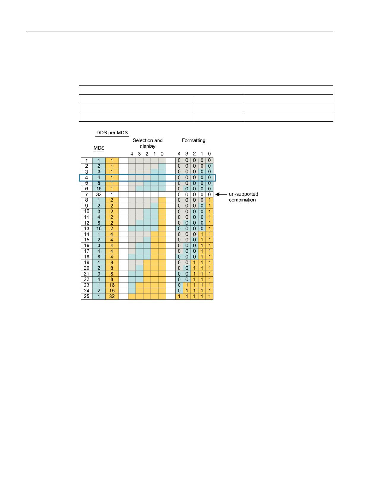
The factory setting is a motor data set MDS0 with a drive data set DDS0. This logic is provided in
the data set wizards in SINUMERIK Operate and corresponds with the first line:
NC/PLC interface
MDS/DDS
DB31, ... DBX21.0 - 4
PLC → NC
Selection
DB31, ... DBX93.0 - 4
NC → PLC
Display
DB31, ... DBX130.0 - 4
NC → PLC
Formatting
Blue Motor data set (MDS)
Yel-
Drive data set (DDS)
low
Gray Invalid bit position
CNC Commissioning: NC, PLC, Drive
142
Commissioning Manual, 10/2020, A5E48312804B AB
Commissioning NC-controlled drives
6.5 Configuring data sets
6.5.2
Example: Add / remove / modify data set
Adding a data set
Procedure:
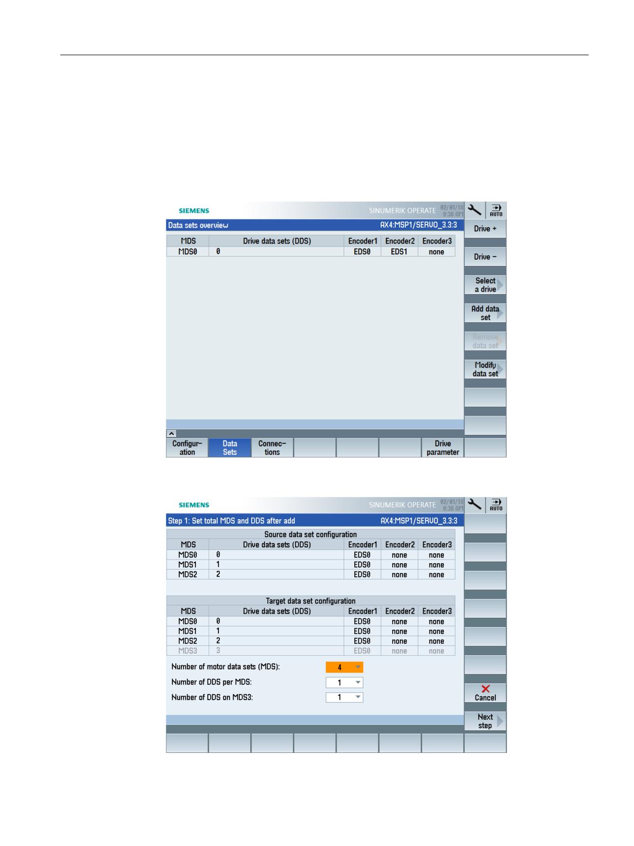
1. Select "Add data set" to add 4 motor data sets with 1 drive data set respectively (line 4
highlighted in blue in the figure at the top):
2. After pressing "Add data set", you will be directed to Step 1 of the data set wizard. For
"Number of MDS", select: 4.
CNC Commissioning: NC, PLC, Drive
Commissioning Manual, 10/2020, A5E48312804B AB
143
Commissioning NC-controlled drives
6.5 Configuring data sets
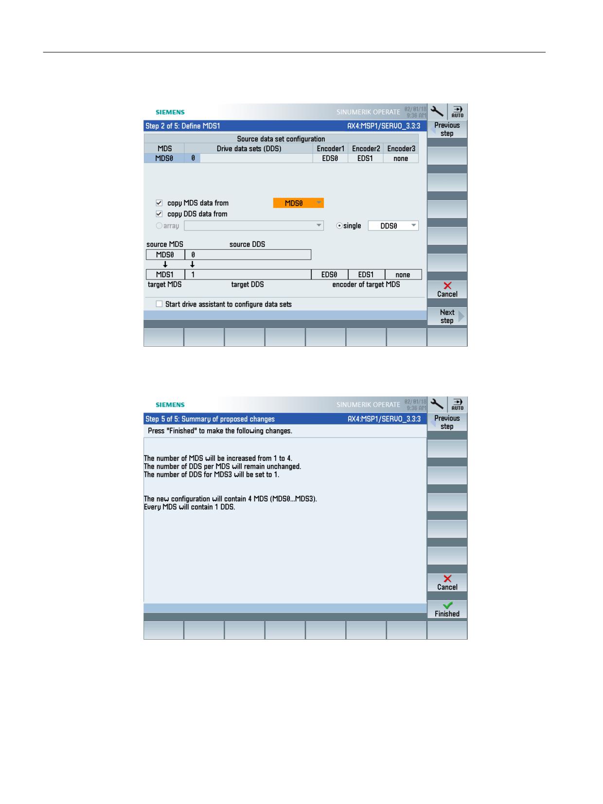
3. Press "Next step >" to select the copy source for MDS0:
The data set wizard will guide you through the next steps.
4. The summary is displayed in the next step. Press "Finished >" to accept the changes.
CNC Commissioning: NC, PLC, Drive
144
Commissioning Manual, 10/2020, A5E48312804B AB
Commissioning NC-controlled drives
6.5 Configuring data sets
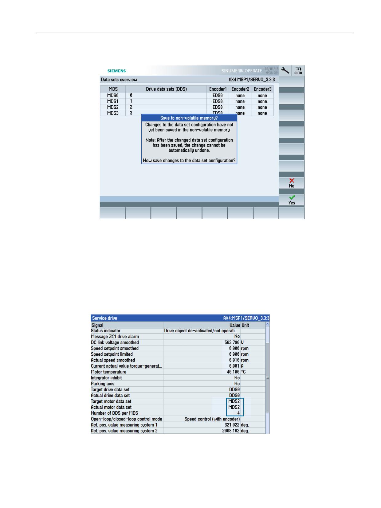
5. Confirm with "OK" to save the data in non-volatile memory. Saving can take several minutes.
6. The "Drives" → "Overview" dialog of the drive object is displayed. The "Select MDS >" softkey
is enabled to select a motor dataset.
Axis diagnostics
In the Diagnostics operating area, the current status is displayed in the "Service drive" overview:
• Following selection via the PLC program, the data set for the selected drive object is displayed
- in this example MDS2.
•
4 DDS are configured per MDS.
CNC Commissioning: NC, PLC, Drive
Commissioning Manual, 10/2020, A5E48312804B AB
145
Commissioning NC-controlled drives
6.5 Configuring data sets
Removing a data set
The "Remove data set" softkey is active under the following conditions:
• Number of DDS > 1 in the MDS ⇒ DDS can be removed.
• Number of MDS > 1 ⇒ MDS can be removed.
Procedure:
1. Select the "Remove data set" softkey: In Step 1, select the number of DDS which are to be
deleted for each MDS: for example 1 MDS.
2. In the next step, select the data set in the first column. Several data sets can also be selected.
3. The summary is displayed in the next step. Press "Finished >" to accept the changes.
When you exit the dialog, press "Yes" to confirm the prompt to save the data to the non-volatile
memory. The result is displayed in the "Data sets overview" dialog.
Modifying a data set
If more than one encoder is assigned to the drive object, one encoder data set is assigned to each
encoder. To change assignment of the data sets, select the "Modify data set" softkey. Open the
selection menu with the <INSERT> key. The "OK" softkey will only become active for adoption of
the change after the assignment has actually been changed.
CNC Commissioning: NC, PLC, Drive
146
Commissioning Manual, 10/2020, A5E48312804B AB
Commissioning NC-controlled drives
6.6 Diagnostics → Trace
6.6
Diagnostics → Trace
6.6.1
Selecting variables for tracing
"Trace" function
The "Trace" function is an oscilloscope function that supports you when optimizing,
troubleshooting and analyzing machines. When selecting the function in the operating area
"Diagnostics" → Menu advance key → Softkey "Trace", the list view is opened to insert variables,
whose signals are to be graphically displayed in the trace view.
A dedicated "Session type" should be used for the following variables:
• NC/PLC/servo variables
• Drive parameters
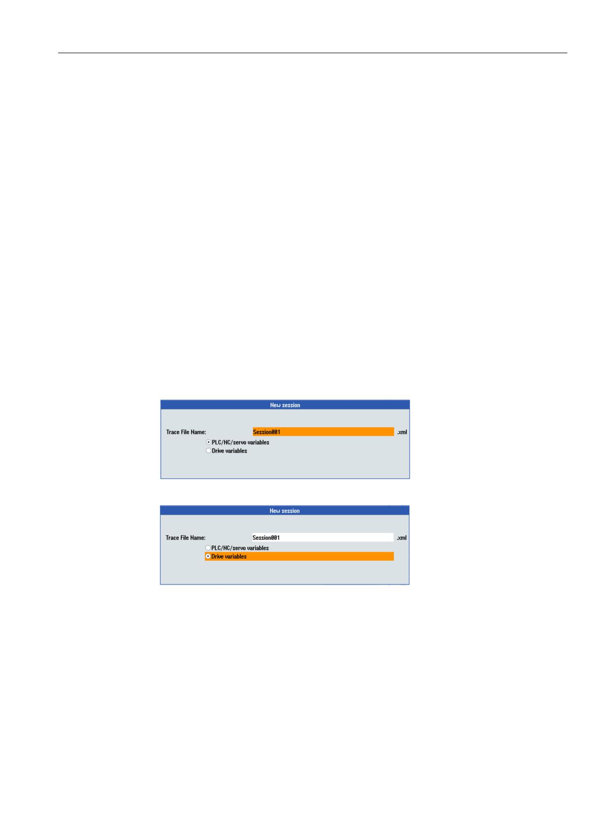
New session
Procedure:
1. Select "New trace (drive/NC) softkey >" to create a new session.
2. Selection for a session with PLC/NC/servo variables:
3. Selection for a session with drive variables:
Examples of traces sessions
Example of a trace session with servo variables (Page 148)
Using servo variables as example, the following procedure is shown:
• "Zoom (Page 151)" softkey including zoom with image section and zoom with mouse
operation
• "Scale (Page 155)" softkey
• "Cursors (Page 156)" softkey
CNC Commissioning: NC, PLC, Drive
Commissioning Manual, 10/2020, A5E48312804B AB
147
Commissioning NC-controlled drives
6.6 Diagnostics → Trace
Example of a trace session with PLC variables (Page 156)
Example of a trace session with drive variables (Page 158)
Key combinations (Page 159)
6.6.2
Example: Trace session with servo variables
Trace session sequence
The trace session is subdivided into the following steps:
• Creating and loading a part program.
• Creating a new session with servo variables.
• Settings for starting and stopping the trace.
Starting/stopping the trace from the part program
To start and stop the trace from the part program, program the $AN_SLTRACE variable that can
be selected using the "Quicklist" softkey. To do this, the following program can be used, for
example:
def int ii
SOFT
$AN_SLTRACE=0
G90 G1 X0 F10000
G4 F0.5
$AN_SLTRACE=1
G91
for ii=1 to 4
X10
G4 F0.5
X-10
G4 F0.5
endfor
$AN_SLTRACE=2
M30
Save the program and load it to the NC.
CNC Commissioning: NC, PLC, Drive
148
Commissioning Manual, 10/2020, A5E48312804B AB
Commissioning NC-controlled drives
6.6 Diagnostics → Trace
Creating a new session
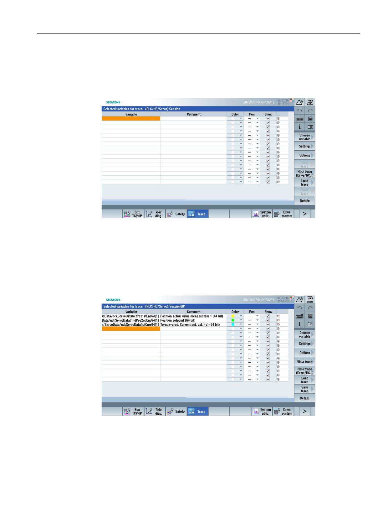
Procedure:
1. Select operating area "Diagnostics" → Menu forward key → "Trace" softkey. The list view
opens:
2. Select softkey "Insert variable >" to open the list of variables.
3. Select at "Filter: Servo" to limit the selection to just servo variables.
4. The following servo variables are inserted in this particular example:
- Position actual value measuring system 1
- Position setpoint
- Torque-generating current actual value i(q)
5. Using the "Settings" softkey, matching the example, select "If variable" to start the trace.
CNC Commissioning: NC, PLC, Drive
Commissioning Manual, 10/2020, A5E48312804B AB
149