SINUMERIK 840D sl. Service - Configuring Commissioning. Manual (2011-2020) - page 79
Fundamental safety instructions
1.1 General safety instructions
WARNING
Spread of fire from built-in devices
In the event of fire outbreak, the enclosures of built-in devices cannot prevent the escape of
fire and smoke. This can result in serious personal injury or property damage.
• Install built-in units in a suitable metal cabinet in such a way that personnel are protected
against fire and smoke, or take other appropriate measures to protect personnel.
• Ensure that smoke can only escape via controlled and monitored paths.
WARNING
Unexpected movement of machines caused by radio devices or mobile phones
Using radio devices or mobile telephones in the immediate vicinity of the components can
result in equipment malfunction. Malfunctions may impair the functional safety of machines
and can therefore put people in danger or lead to property damage.
• Therefore, if you move closer than 20 cm to the components, be sure to switch off radio
devices or mobile telephones.
• Use the "SIEMENS Industry Online Support app" only on equipment that has already been
switched off.
WARNING
Fire due to inadequate ventilation clearances
Inadequate ventilation clearances can cause overheating of components with subsequent fire
and smoke. This can cause severe injury or even death. This can also result in increased
downtime and reduced service lives for devices/systems.
• Ensure compliance with the specified minimum clearance as ventilation clearance for the
respective component.
NOTICE
Overheating due to inadmissible mounting position
The device may overheat and therefore be damaged if mounted in an inadmissible position.
• Only operate the device in admissible mounting positions.
CNC Commissioning: NC, PLC, Drive
Commissioning Manual, 10/2020, A5E48312804B AB
11
Fundamental safety instructions
1.1 General safety instructions
WARNING
Unexpected movement of machines caused by inactive safety functions
Inactive or non-adapted safety functions can trigger unexpected machine movements that
may result in serious injury or death.
• Observe the information in the appropriate product documentation before commissioning.
• Carry out a safety inspection for functions relevant to safety on the entire system, including
all safety-related components.
• Ensure that the safety functions used in your drives and automation tasks are adjusted and
activated through appropriate parameterizing.
• Perform a function test.
• Only put your plant into live operation once you have guaranteed that the functions
relevant to safety are running correctly.
Note
Important safety notices for Safety Integrated functions
If you want to use Safety Integrated functions, you must observe the safety notices in the Safety
Integrated manuals.
WARNING
Malfunctions of the machine as a result of incorrect or changed parameter settings
As a result of incorrect or changed parameterization, machines can malfunction, which in turn
can lead to injuries or death.
• Protect the parameterization against unauthorized access.
• Handle possible malfunctions by taking suitable measures, e.g. emergency stop or
emergency off.
CNC Commissioning: NC, PLC, Drive
12
Commissioning Manual, 10/2020, A5E48312804B AB
Fundamental safety instructions
1.2 Equipment damage due to electric fields or electrostatic discharge
1.2
Equipment damage due to electric fields or electrostatic discharge
Electrostatic sensitive devices (ESD) are individual components, integrated circuits, modules or
devices that may be damaged by either electric fields or electrostatic discharge.
NOTICE
Equipment damage due to electric fields or electrostatic discharge
Electric fields or electrostatic discharge can cause malfunctions through damaged individual
components, integrated circuits, modules or devices.
• Only pack, store, transport and send electronic components, modules or devices in their
original packaging or in other suitable materials, e.g conductive foam rubber of aluminum
foil.
• Only touch components, modules and devices when you are grounded by one of the
following methods:
- Wearing an ESD wrist strap
- Wearing ESD shoes or ESD grounding straps in ESD areas with conductive flooring
• Only place electronic components, modules or devices on conductive surfaces (table with
ESD surface, conductive ESD foam, ESD packaging, ESD transport container).
CNC Commissioning: NC, PLC, Drive
Commissioning Manual, 10/2020, A5E48312804B AB
13
Fundamental safety instructions
1.3 Warranty and liability for application examples
1.3
Warranty and liability for application examples
Application examples are not binding and do not claim to be complete regarding configuration,
equipment or any eventuality which may arise. Application examples do not represent specific
customer solutions, but are only intended to provide support for typical tasks.
As the user you yourself are responsible for ensuring that the products described are operated
correctly. Application examples do not relieve you of your responsibility for safe handling when
using, installing, operating and maintaining the equipment.
CNC Commissioning: NC, PLC, Drive
14
Commissioning Manual, 10/2020, A5E48312804B AB
Fundamental safety instructions
1.4 Security information
1.4
Security information
Siemens provides products and solutions with industrial security functions that support the
secure operation of plants, systems, machines and networks.
In order to protect plants, systems, machines and networks against cyber threats, it is necessary
to implement - and continuously maintain - a holistic, state-of-the-art industrial security
concept. Siemens’ products and solutions constitute one element of such a concept.
Customers are responsible for preventing unauthorized access to their plants, systems,
machines and networks. Such systems, machines and components should only be connected to
an enterprise network or the internet if and to the extent such a connection is necessary and only
when appropriate security measures (e.g. firewalls and/or network segmentation) are in place.
For additional information on industrial security measures that may be implemented, please
visit
Siemens’ products and solutions undergo continuous development to make them more secure.
Siemens strongly recommends that product updates are applied as soon as they are available
and that the latest product versions are used. Use of product versions that are no longer
supported, and failure to apply the latest updates may increase customer’s exposure to cyber
threats.
To stay informed about product updates, subscribe to the Siemens Industrial Security RSS Feed
under
services/cert.html#Subscriptions).
Further information is provided on the Internet:
Industrial Security Configuration Manual (https://support.industry.siemens.com/cs/ww/en/
view/108862708)
WARNING
Unsafe operating states resulting from software manipulation
Software manipulations, e.g. viruses, Trojans, or worms, can cause unsafe operating states in
your system that may lead to death, serious injury, and property damage.
• Keep the software up to date.
• Incorporate the automation and drive components into a holistic, state-of-the-art industrial
security concept for the installation or machine.
• Make sure that you include all installed products into the holistic industrial security concept.
• Protect files stored on exchangeable storage media from malicious software by with suitable
protection measures, e.g. virus scanners.
• On completion of commissioning, check all security-related settings.
CNC Commissioning: NC, PLC, Drive
Commissioning Manual, 10/2020, A5E48312804B AB
15
Fundamental safety instructions
1.5 Residual risks of power drive systems
1.5
Residual risks of power drive systems
When assessing the machine- or system-related risk in accordance with the respective local
regulations (e.g., EC Machinery Directive), the machine manufacturer or system installer must
take into account the following residual risks emanating from the control and drive components
of a drive system:
1.
Unintentional movements of driven machine or system components during commissioning,
operation, maintenance, and repairs caused by, for example,
- Hardware and/or software errors in the sensors, control system, actuators, and cables and
connections
- Response times of the control system and of the drive
- Operation and/or environmental conditions outside the specification
- Condensation/conductive contamination
- Parameterization, programming, cabling, and installation errors
- Use of wireless devices/mobile phones in the immediate vicinity of electronic components
- External influences/damage
- X-ray, ionizing radiation and cosmic radiation
2.
Unusually high temperatures, including open flames, as well as emissions of light, noise,
particles, gases, etc., can occur inside and outside the components under fault conditions
caused by, for example:
- Component failure
- Software errors
- Operation and/or environmental conditions outside the specification
- External influences/damage
3.
Hazardous shock voltages caused by, for example:
- Component failure
- Influence during electrostatic charging
- Induction of voltages in moving motors
- Operation and/or environmental conditions outside the specification
- Condensation/conductive contamination
- External influences/damage
4.
Electrical, magnetic and electromagnetic fields generated in operation that can pose a risk to
people with a pacemaker, implants or metal replacement joints, etc., if they are too close
5.
Release of environmental pollutants or emissions as a result of improper operation of the
system and/or failure to dispose of components safely and correctly
6.
Influence of network-connected communication systems, e.g. ripple-control transmitters or
data communication via the network
For more information about the residual risks of the drive system components, see the relevant
sections in the technical user documentation.
CNC Commissioning: NC, PLC, Drive
16
Commissioning Manual, 10/2020, A5E48312804B AB
Introduction
2
SINUMERIK documentation
The SINUMERIK documentation is organized into the following categories:
• General documentation/catalogs
• User documentation
• Manufacturer/Service Documentation
Further information
You can find information on the topics at the following address (https://
support.industry.siemens.com/cs/de/en/view/108464614):
• Order documentation / documentation overview
• Additional links for downloading documents
• Using documentation online (find and search in manuals/information)
If there are any questions regarding the technical documentation (e.g. suggestions,
corrections), please send an email to the following address
(mailto:docu.motioncontrol@siemens.com).
mySupport/Documentation
you can find information on how to create your own individual documentation based on
Siemens' content, and adapt it for your own machine documentation.
Training
SITRAIN (Siemens training on products, systems and solutions for automation and drives).
FAQs
You can find answers to Frequently Asked Questions in the Service&Support pages at Product
SINUMERIK
You can find information about SINUMERIK at the following address (https://www.siemens.com/
sinumerik).
CNC Commissioning: NC, PLC, Drive
Commissioning Manual, 10/2020, A5E48312804B AB
17
Introduction
Target group
This document is intended for commissioning personnel.
Benefits
The plant or system is installed, connected, and ready to start. The Commissioning Manual
contains all the necessary information or at least references for the following steps, e.g.
configuring the individual components.
Standard scope
This documentation only describes the functionality of the standard version. Additions or
revisions made by the machine manufacturer are documented by the machine manufacturer.
Other functions not described in this documentation might be executable in the control. This
does not, however, represent an obligation to supply such functions with a new delivery or when
servicing.
For the sake of simplicity, this documentation does not contain all detailed information about all
types of the product, and cannot cover every conceivable case of installation, operation, or
maintenance.
Note regarding the General Data Protection Regulation
Siemens observes standard data protection principles, in particular the principle of privacy by
design. For this product, this means: this product does not process / store any personal data, only
technical functional data (e.g. time stamps). If a user links this data with other data (e.g. shift
schedules) or stores personal data on the same storage medium (e.g. hard disk), and thus
establishes a link to a person or persons, then the user is responsible for ensuring compliance
with the relevant data protection regulations.
Technical Support
Country-specific telephone numbers for technical support are provided on the Internet at the
If you have any technical questions, use the online form in the "Support Request" (https://
support.industry.siemens.com/cs/sc/4868)area.
EC Declaration of Conformity
The EC Declaration of Conformity for the EMC Directive can be found on the Internet at the
CNC Commissioning: NC, PLC, Drive
18
Commissioning Manual, 10/2020, A5E48312804B AB
Introduction
SINUMERIK
• Function Manual
Basic Functions (https://support.industry.siemens.com/cs/
document/109766213)
• Function Manual
Axes and Spindles (https://support.industry.siemens.com/cs/
document/109766213)
• Function Manual
109766213)
• Function Manual
Monitoring and Compensating (https://
support.industry.siemens.com/cs/document/109766213)
• Function Manual
Technologies (https://support.industry.siemens.com/cs/
document/109766213)
• Function Manual
Transformations (https://support.industry.siemens.com/cs/
document/109766213)
• Function Manual
109766213)
• Function Manual
Synchronized actions (https://
support.industry.siemens.com/cs/document/109766213)
SINAMICS S120
• Function Manual
Drive functions (https://
support.industry.siemens.com/cs/ww/en/view/109771805)
• Function Manual
Safety Integrated (https://
support.industry.siemens.com/cs/ww/en/view/109771806)
CNC Commissioning: NC, PLC, Drive
20
Commissioning Manual, 10/2020, A5E48312804B AB
Introduction
2.1 Overview of the manuals for SINUMERIK 840D sl
2.1
Overview of the manuals for SINUMERIK 840D sl
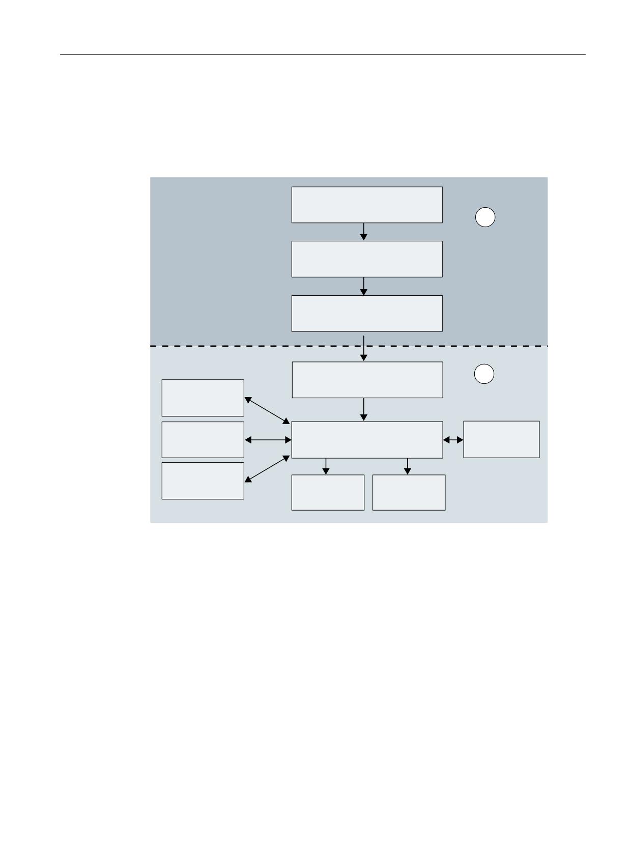
Commissioning steps
Commissioning is split up into two steps:
&RQILJXUH 3/& ORDG EDVLF
SURJUDP
&RQILJXUH GULYHV
1& &RQILJXUH WKH PDFKLQH
&UHDWLQJ D 3/& SURJUDP
*HQHUDO PDFKLQH
GDWD
&KDQQHO VSHFLILF
'LVSOD\ PDFKLQH
PDFKLQH GDWD
1& IXQFWLRQV
GDWD
$[LV PDFKLQH GDWD
&\FOHV
*8' PDFURV
Figure 2-1
Commissioning procedure
Section 1:
• Commissioning Manual: CNC commissioning: NC, PLC, drive
• Function Manual: PLC (Part 1), Basic Functions, Axes and Spindles, Technologies
• Function Manual: Safety Integrated
Section 2:
• Function Manual: PLC (Part 2), synchronized actions, transformations, monitoring
and compensating, tools, tool management
• List manuals: Machine data, system variables, NC/PLC variables
CNC Commissioning: NC, PLC, Drive
Commissioning Manual, 10/2020, A5E48312804B AB
21
Introduction
2.2 General prerequisites
2.2
General prerequisites
Preconditions for components involved
The complete system is connected mechanically and electrically, and has been verified in the
following points:
• All ESD measures are observed for the design of the components.
• All screws are tightened with their prescribed torque.
• All connectors are plugged correctly and locked/screwed.
• All components are grounded and connected to shields.
• The load capacity of the central power supply is taken into account.
Limit values
All components are dimensioned for defined mechanical, climatic and electrical environmental
conditions. No limit value may be exceeded, neither during operation, nor during
transportation. Special attention must be paid to the limit values:
• Power supply conditions
• Pollution burden
• Function-impairing gases
• Ambient environmental conditions
• Storage/transport
• Shock stressing
• Vibration stressing
• Ambient temperature
You can find further details in the following manuals:
• Structure of the drive components: SINAMICS S120 Booksize Power Units (https://
support.industry.siemens.com/cs/ww/en/view/109771800) Equipment Manual
• Interfaces at the control system: SINUMERIK 840D sl Equipment Manual NCU 7x0.3B PN
CNC Commissioning: NC, PLC, Drive
22
Commissioning Manual, 10/2020, A5E48312804B AB
Requirements for commissioning
3
Requirements for commissioning
For the commissioning of SINUMERIK 840D sl, the following points are required:
•
Hardware requirements
- NCU with TCU
- CompactFlash card
- Dual fan/battery module for NCU
- Optional: PCU 50.5 with Windows 7 and operator panel
Note
For the operation of SINUMERIK Operate on the PCU without TCU, the "HMI" subsystem
for SINUMERIK Operate on the NCU must be switched off.
•
Connection to NCU
- Network switch to X120
- Ethernet machine control panel to socket X120
- Ethernet connection from PG/PC to X120 or X127 for commissioning the PLC
- Ethernet connection from the TCU to the Ethernet machine control panel
- Optional: Ethernet connection from the PCU to the Ethernet machine control panel
•
Software requirements
- CNC software with SINUMERIK Operate
- Optional: SINUMERIK Operate for operation on the PCU
- SIMATIC STEP 7 on PG/PC (engineering system)
- SINUMERIK 840D sl Toolbox for STEP 7 package
- GSD files (Toolbox)
Note
The part numbers of the SINAMICS drives, encoders and motors should be available for
parameterization.
CNC Commissioning: NC, PLC, Drive
Commissioning Manual, 10/2020, A5E48312804B AB
23
Requirements for commissioning
3.1 SINUMERIK 840D sl configuration
3.1
SINUMERIK 840D sl configuration
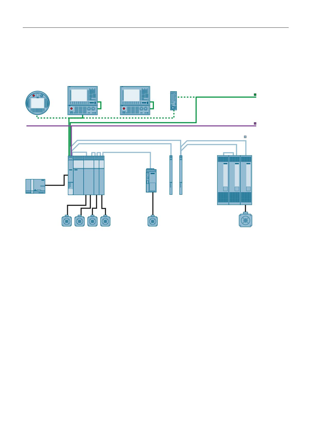
SINUMERIK 840D sl configuration with SINAMICS S120 Booksize
6,180(5,.
6,180(5,. RSHUDWRU SDQHO IURQW ZLWK 7&8
6,180(5,.
+7
3&8
,QGXVWULDO (WKHUQHW
352),%86 , 2
'5,9( &/L4
6,180(5,.
' VO ZLWK
1;
6,1$0,&6 6
6,1$0,&6 6
• • •
3RZHU VXSSO\
• • •
6HUYRPRWRUV
0DLQ VSLQGOH PRWRU
Figure 3-1
Example: Configuration with SINAMICS S120 Booksize
CNC Commissioning: NC, PLC, Drive
24
Commissioning Manual, 10/2020, A5E48312804B AB
Requirements for commissioning
3.1 SINUMERIK 840D sl configuration
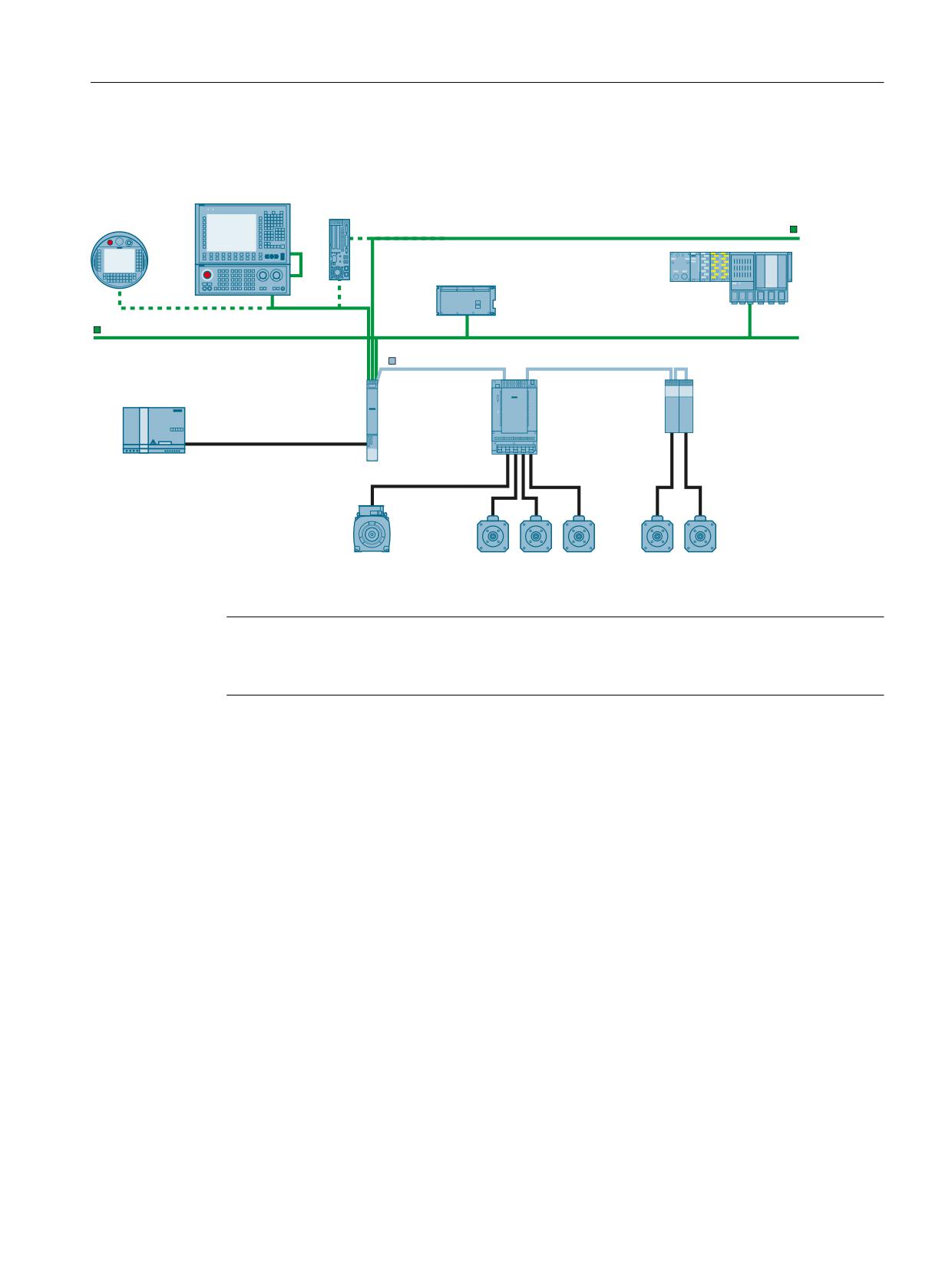
SINUMERIK 840D sl configuration with SINAMICS S120 Combi
6,180(5,. RSHUDWRU SDQHO IURQW ZLWK 7&8
6,180(5,.
6,180(5,. 3&8
+7
,QGXVWULDO (WKHUQHW
33
' 31
33b
'b $b31
6,0$7,&
(7
SUR
352),1(7
'5,9( &/L4
6,180(5,.
' VO
6,1$0,&6 6
6,1$0,&6 6
3RZHU VXSSO\
1&8
% 31
0RWRU 0RGXOH
&RPEL
ERRNVL]H FRPSDFW
IRUPDW
6SLQGOH PRWRU
3+
). IHHG
). IHHG
PRWRUV
PRWRUV
Figure 3-2
Example: Configuration with SINAMICS S120 Combi
Note
SINAMICS S120 Combi
The configuration with SINAMICS S120 Combi is permissible only on an NCU 710.3B PN.
CNC Commissioning: NC, PLC, Drive
Commissioning Manual, 10/2020, A5E48312804B AB
25
Requirements for commissioning
3.2 Position of the interfaces
3.2
Position of the interfaces
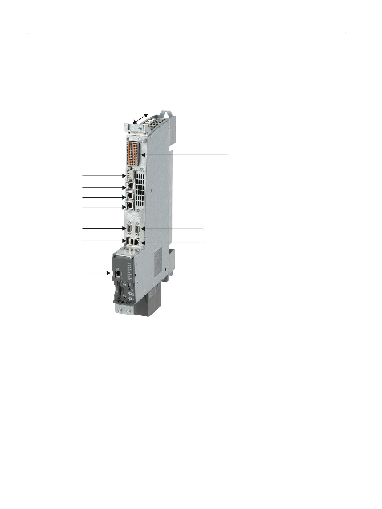
Interfaces on the NCU
The NCU has the following interfaces:
;
;
;
;
;
;
;
;
;
;
;
;
;
;
;
X100 ... X105
DRIVE-CLiQ
for SINAMICS drive components
X124
+24 V DC
external power supply
X125, X135
USB
only for commissioning and servicing
X120
Industrial Ethernet
for connection to a system network
(TCU and/or PCU)
X130
Industrial Ethernet
for connection to a company network
X127
Industrial Ethernet
service interface for PG/PC
X136
PROFIBUS DP / MPI
X126
PROFIBUS DP
PROFIBUS DP (for example for PLC axes)
X150-1, X150-2
PROFINET IO
for PROFINET components
X122, X132, X142
Based on PROFINET
Digital inputs/outputs for I/O devices
Figure 3-3
Position of the interfaces
CNC Commissioning: NC, PLC, Drive
26
Commissioning Manual, 10/2020, A5E48312804B AB
Requirements for commissioning
3.3 Power-On and boot-up
3.3
Power-On and boot-up
3.3.1
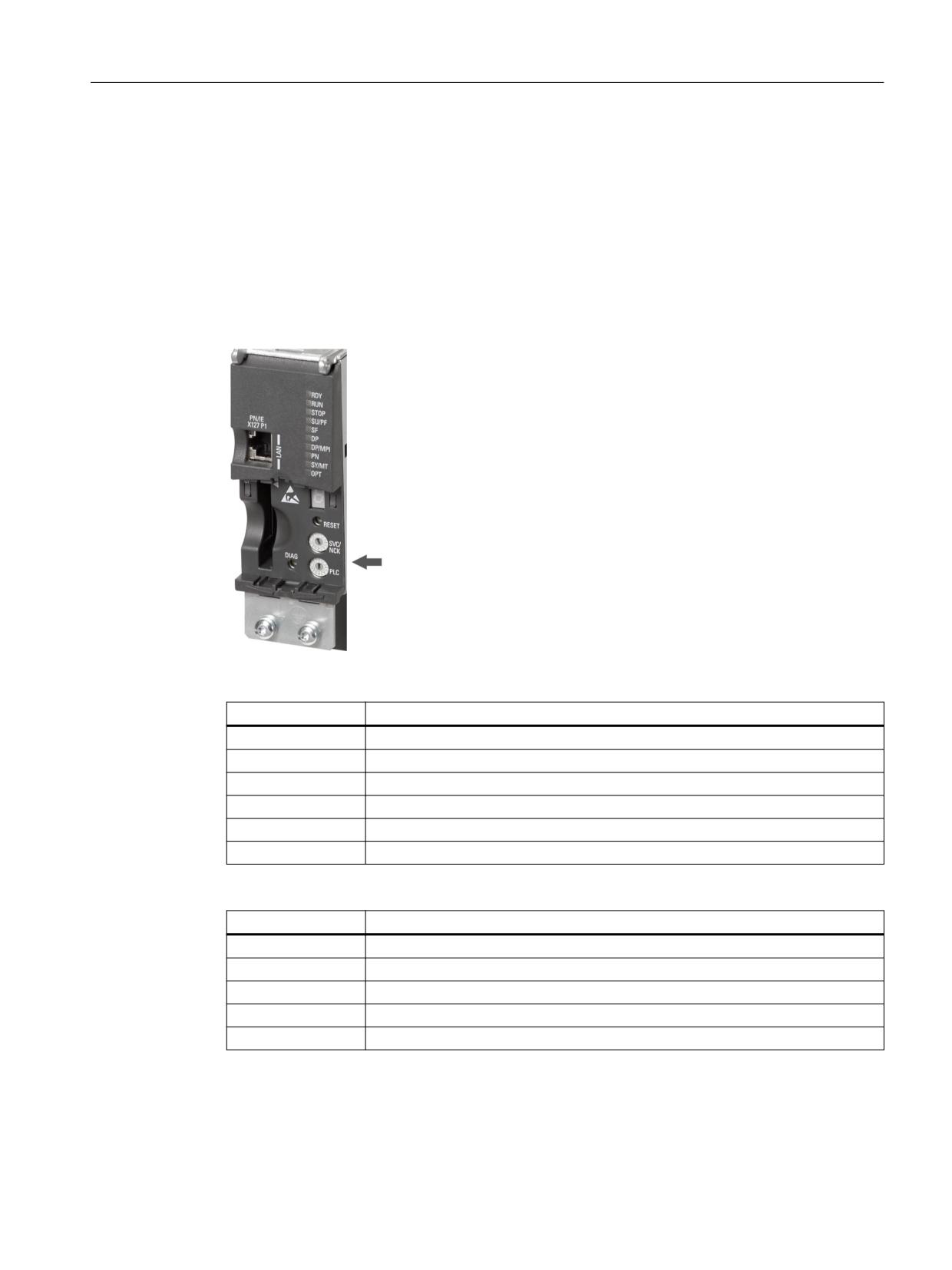
NC and PLC memory reset
SVC/NCK and PLC rotary switches
The NCU has two rotary switches in the lower section of the front panel.
Meaning of the settings at the rotary switch SVC/NCK:
Switch position
NC operating mode
0
Normal power-up of the NC
1
Power-up of the NC with preset values (= general reset)
2
Power-up of the NC with preset values; after powering up, the PLC is in RUN.
7
Debug mode (NC is not started)
8
IP address of the NCU is displayed on the seven-segment display
All others
Not relevant
The settings on the PLC switch have the same meaning as for a SIMATIC S7-CPU:
Switch position
Operating mode of the PLC
0
RUN
1
RUN (protected mode)
2
STOP
3
Memory reset (MRES)
All others
Not relevant
CNC Commissioning: NC, PLC, Drive
Commissioning Manual, 10/2020, A5E48312804B AB
27
Requirements for commissioning
3.3 Power-On and boot-up
Initial commissioning
In order to achieve a defined state of the complete system, for the initial commissioning of the
NCU, a general reset of the NC and the PLC must be performed.
Note
In the following cases, a general PLC reset must always be performed:
• Initial commissioning
• Module replacement
• General reset request by the PLC
• Upgrading the PLC
Procedure:
1. Set the rotary switch of the NCU to the following settings:
- NCK commissioning switch: Switch position "1"
- PLC mode selector: Switch position "3"
2. Initiate a power-on reset by switching-off the control and switching-on again - or by pressing
the Reset button on the front of the NCU. The NC is shut down and is restarted with the
request for a general reset.
Effect:
- The "STOP" LED flashes.
- The "SF" LED illuminates continuously.
3. Within approx. three seconds, turn the PLC mode selector switch to the positions "2" → "3" →
"2".
Effect:
- The "STOP" LED first flashes with about 2 Hz and then illuminates continuously.
4. Turn the PLC mode selector switch back to the "0" position.
Effect:
- The "STOP" LED extinguishes.
- The "RUN" LED flashes initially and then illuminates green continuously.
5. Turn the NCK commissioning selector switch back to the "0" position.
CNC Commissioning: NC, PLC, Drive
28
Commissioning Manual, 10/2020, A5E48312804B AB
Requirements for commissioning
3.3 Power-On and boot-up
Result
The NC has now been generally reset and is in the following state:
• NC
- The user data is deleted.
- The system data is initialized.
- The standard machine data is loaded.
• PLC
The general reset places the PLC in a defined initial state:
- The user data has been deleted (data and program blocks).
- The system data blocks (SDB) have been deleted.
- The diagnostics buffer and the MPI parameters have been reset.
The "RUN" LED illuminates. NC and PLC are in cyclic operation.
Note
PLC general reset
If a general PLC reset is performed using a power-on reset, then the user data must again be
transferred to the PLC, e.g. via a programming device (PG).
After the PLC general reset, no PLC start is performed and at least the following alarm issued:
• Alarm: "2001 PLC not booted"
The alarms have no influence on the next steps.
3.3.2
A general reset is separately performed for the NC and PLC
General reset of the NC
Carry out the following actions to perform an NC general reset:
1. Turn the NCK commissioning switch on the front of the NCU to position "1".
2. Initiate a power on reset by switching-off the control system and switching-on again - or by
pressing the reset button on the front of the NCU (labeled "RESET"). The system is shut down
and is restarted with the request for a general reset of the NC.
3. After the system has booted, turn the NCK commissioning switch back to position "0".
Effect:
- The number "6" and a flashing point are output on the 7-segment display on the front of
the NCU.
- LED "RUN" lights up.
CNC Commissioning: NC, PLC, Drive
Commissioning Manual, 10/2020, A5E48312804B AB
29
Requirements for commissioning
3.3 Power-On and boot-up
The NCU is in the following state after an error-free boot-up:
• The NC is in cyclic operation.
• The static memory of the NC is deleted.
• The machine data is preassigned standard values.
Alternatives
A PLC general reset can be performed with or without power-on reset. Depending on this,
various states are obtained for the PLC program.
General PLC reset without a power-on reset
Carry out the following actions to execute a general PLC reset without a power-on reset:
1. Turn the PLC mode selector switch on the front of the NCU to position "2" (STOP).
Effect:
- The PLC goes into the "STOP" mode.
- The "STOP" LED illuminates.
2. Turn the PLC mode selector switch to position "3" (MRES)
Effect:
- The "STOP" LED goes dark and after approx. three seconds illuminates again.
3. Within approx. three seconds, turn the PLC mode selector switch to the positions "2" → "3"
→ "2"
Effect:
- The "STOP" LED first flashes with about 2 Hz and then illuminates continuously.
4. Turn the PLC mode selector switch back to the "0" position.
Effect:
- The "STOP" LED extinguishes.
- The "RUN" LED illuminates.
The general reset places the PLC in a defined state:
• The PLC is in cyclic operation.
• The time of day and the operating hours counter have not been reset.
• The diagnostics buffer and the MPI parameters have not been reset.
Note
For the general reset without power-on reset, the most recently loaded blocks from the PLC
program are reimported.
CNC Commissioning: NC, PLC, Drive
30
Commissioning Manual, 10/2020, A5E48312804B AB
Requirements for commissioning
3.3 Power-On and boot-up
General PLC reset with power-on reset
Carry out the following actions to execute a general PLC resetwith a power-on reset:
1. Turn the PLC mode selector on the front of the NCU to position "3" (MRES).
2. Initiate a power-on reset by switching-off the control and switching-on again - or by pressing
the Reset button on the front of the NCU. The NCU is terminated and with the request for a
general reset is restarted.
Effect:
- The "STOP" LED flashes.
- The "SF" LED illuminates continuously.
3. Within approx. three seconds, turn the PLC mode selector switch to the positions "2" → "3"
→ "2".
Effect:
- The "STOP" LED first flashes with about 2 Hz and then illuminates continuously.
4. Turn the PLC mode selector switch back to the "0" position.
Effect:
- The "STOP" LED extinguishes.
- The "RUN" LED flashes initially and then illuminates green continuously.
The general reset places the PLC in a defined state:
• The user data has been deleted (data and program blocks).
• The system data blocks (SDB) have been deleted.
• The diagnostics buffer and the MPI parameters have been reset.
3.3.3
Boot completed
Boot completed without error
After an error-free boot of the NCU, the following status is displayed:
• The number "6" and a flashing point
• The "RUN" LED illuminates green continuously.
In the following step, commissioning of the PLC is done with the SIMATIC Manager.
CNC Commissioning: NC, PLC, Drive
Commissioning Manual, 10/2020, A5E48312804B AB
31
Requirements for commissioning
3.4 Procedure for the initial commissioning
3.4
Procedure for the initial commissioning
Checking the system
The mechanical and electrical installation of the system must be completed.
The following is important when starting commissioning:
• The control system with its components boots error-free.
• The EMC guidelines were carefully maintained when configuring the system.
Variants for the commissioning process
When commissioning the system for the first time, the following dependencies to the CNC
software on the CompactFlash card are considered:
• CompactFlash card with current CNC software
• CompactFlash card without CNC software ⇒ new installation
• CompactFlash card with older CNC software ⇒ upgrade
Commissioning with current CNC software
Procedure
Reference to Chapter
①
Powering up the control system with NC/PLC general reset
→ NC/PLC general reset (Page 27)
②
Make a communication connection to the PLC
→ Establishing a communication connection (Page 47)
③
Commission the PLC
→ PLC commissioning (Page 47)
④
Commission the SINAMICS drive system
→ Commissioning NC-controlled drives (Page 99)
⑤
NC ↔ drive communication
→ Communication between the NC and the drive
(Page 189)
⑥
Commission the NC:
• Assign the NC machine data for the communication
→ NC commissioning (Page 205)
• Scale the machine data
• Parameterize the axis data
→ Procedure when commissioning the NC (Page 207)
• Parameterize the spindle data
• Parameterize the measuring systems
⑦
Drive tuning
→ Drive tuning (Page 263)
CNC Commissioning: NC, PLC, Drive
32
Commissioning Manual, 10/2020, A5E48312804B AB

Requirements for commissioning
3.4 Procedure for the initial commissioning
Reinstallation of the CNC software
Procedure
Reference to Chapter
①
Install the CNC software on the CompactFlash card using
→ New installation / upgrade (Page 327)
one of the following media:
• Bootable USB FlashDrive
• WinSCP on PC/PG
• VNC viewer on PC/PG
②
Powering up the control system with NC/PLC general reset
→ NC/PLC general reset (Page 27)
③
Establish a communication connection to the PLC
→ Establishing a communication connection (Page 47)
④
Commission the PLC
→ PLC commissioning (Page 47)
⑤
Commission the SINAMICS drive system
→ Commissioning NC-controlled drives (Page 99)
⑥
NC ↔ drive communication
→ Communication between the NC and the drive
(Page 189)
⑦
Commission the NC:
• Assign the NC machine data for the communication
→ NC commissioning (Page 205)
• Scale the machine data
• Parameterize the axis data
→ Procedure when commissioning the NC (Page 207)
• Parameterize the spindle data
• Parameterize the measuring systems
⑧
Drive tuning
→ Drive tuning (Page 263)
Upgrading the CNC software
Procedure
Reference to Chapter
①
Archive the NC, PLC, HMI and drive data
→ Save data (Page 317)
②
Upgrade CNC software using:
→ New installation / upgrade (Page 327)
• Access MyMachine /P2P
• WinSCP and VNC Viewer
③
Load the archived NC, PLC, HMI and drive data
→ Load data (Page 317)
CNC Commissioning: NC, PLC, Drive
Commissioning Manual, 10/2020, A5E48312804B AB
33

Requirements for commissioning
3.5 Procedure when tuning axes and drives
3.5
Procedure when tuning axes and drives
Precondition
Once the drives have been commissioned and the axes assigned, you must start tuning the
particular machine or a machine type.
• The drives have been commissioned: the axes move.
• The topology has been checked and is OK.
Recommended tuning sequence
Procedure:
109766213) to the Function Manual "Monitoring and Offsets":
Automatic servo tuning
Automatic servo tuning (Page 265)
⇒ including following error compensation
Chapter "Compensations": Dynamic feedforward control (following
error compensation)
Automatic Servo Tuning: Path interpolation
Example for path interpolation
Optional: Manual calibration of the controller using
Measuring functions (manual tuning) (Page 288)
measuring functions
Intelligent load adaptation
Adaptations (Page 229)
Intelligent dynamic response adaptation
Jerk filter
Jerk filter (Page 236)
Circularity test
Circularity test (Page 306)
• Motor encoder
• Measuring system (encoder 1, encoder 2)
1-axis compensations:
Interpolatory compensation
Chapter "Compensations": Leadscrew error and measuring system
error compensation
• Lead screw error compensation
• Measuring system error compensation
Temperature compensation
Chapter "Compensations": Temperature compensation
Backlash compensation:
Chapter "Compensations": Backlash compensation
• Mechanical
• Dynamic
• Dual position feedback
Friction compensation with adaptive characteristics
Friction compensation with adaptive characteristics (Page 210)
Nodding compensation
Nodding compensation (Page 220)
Multi-axis compensations:
Cylinder error compensation (only for cylindrical grind-
Chapter "Compensations": Cylinder error compensation
ing)
Sag compensation
Chapter "Compensations": Sag and angularity error compensation
Compensation in space (option)
---
Volumetric Compensation System (RMCC/VCS)
Volumetric compensation interface (option)
---
Volumetric compensation interface (RMCCI/VCI)
CNC Commissioning: NC, PLC, Drive
34
Commissioning Manual, 10/2020, A5E48312804B AB

Requirements for commissioning
3.6 Access levels
3.6
Access levels
Access to functions and machine data
The access concept controls access to functions and data areas. Access levels 0 to 7 are available,
where 0 represents the highest level and 7 the lowest level. Access levels 0 to 3 are locked using
a password and 4 to 7 using the appropriate key-operated switch.
Access level
Locked by
Area
Data class
1
Password: SUNRISE
Manufacturer
Manufacturer (M)
2
Password: EVENING
Service
Individual (I)
3
Password: CUSTOMER
User
User (U)
4
Key-operated switch setting 3
Programmer, machine setter
User (U)
5
Key-operated switch setting 2
Qualified operator
User (U)
6
Key-operated switch setting 1
Trained operator
User (U)
7
Key-operated switch setting 0
Semi-skilled operator
User (U)
The password remains valid until it is reset with the "Delete Password" softkey. The passwords
can be changed after activation.
If, for example, the passwords are no longer known, reinitialization (boot-up with "NCK default
data") must be carried out. This resets all passwords to the default (see table). A power-on reset
does not reset the password.
Key-operated switch
Access levels 4 to 7 require a corresponding key-operated switch setting on the machine control
panel. Three keys of different colors are provided for this purpose. Each of these keys only
provides access to certain areas.
Access level
Switch position
Key color
4-7
0 to 3
Red
5-7
0 to 2
Green
6-7
0 and 1
Black
7
0 = Key removal position
No key inserted
The position of the key-operated switch can be processed by the PLC program, and appropriately
transferred to the NC/PLC interface .
CNC Commissioning: NC, PLC, Drive
Commissioning Manual, 10/2020, A5E48312804B AB
35
Requirements for commissioning
3.6 Access levels
Set password
Procedure:
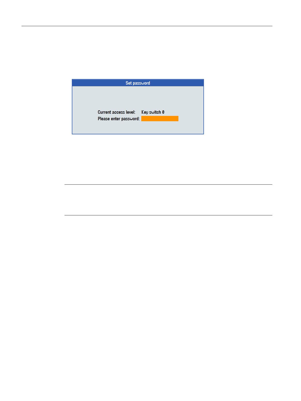
1. Select the "Commissioning" operating area and press the "Password" softkey.
2. Press the "Set password" softkey. The current key-operated switch setting is displayed first:
3. Enter the password for the desired access level and confirm this input with "OK" or with the
<INPUT> button.
A valid password is acknowledged as set and the access level is set. Invalid passwords will be
rejected.
Pressing the "Delete password" softkey deletes the last valid password and displays the current
key-operated switch setting again.
Note
Delete password
The password can also be deleted via the PLC → PI service: LOGOUT → Function Manual "PLC
Rules relating to the password structure
The following rules must be observed when assigning a new password:
• The password has a length of between 8 and 32 characters.
• A password must contain at least one number, at least one uppercase letter, and at least one
lowercase letter.
• A password may contain the following characters:
- Special characters (ASCII 0x20 to 0x7E)
- Uppercase characters
- Lowercase characters
- Numbers
• A new password must not be similar to the following data:
- User name
- Computer name
- Additional user data (GECOS data that can be additionally saved under Linux.)
CNC Commissioning: NC, PLC, Drive
36
Commissioning Manual, 10/2020, A5E48312804B AB
Requirements for commissioning
3.6 Access levels
This information can also be found in the online help of SINUMERIK Operate.
Change password
NOTICE
Change password
Observe the following "Rules relating to the password structure" for the selection of the new
password.
Note the following changes in the handling of passwords:
• A password that has been changed cannot be reset to a default password.
• After a software upgrade to version 4.8 SP3, the passwords valid under Linux
apply immediately in the NC.
• In the following cases, the default passwords in the delivery condition are no longer valid
in the NC and have been replaced by the currently valid passwords under Linux:
- After importing a startup archive
- After a memory reset of the NC
Procedure:
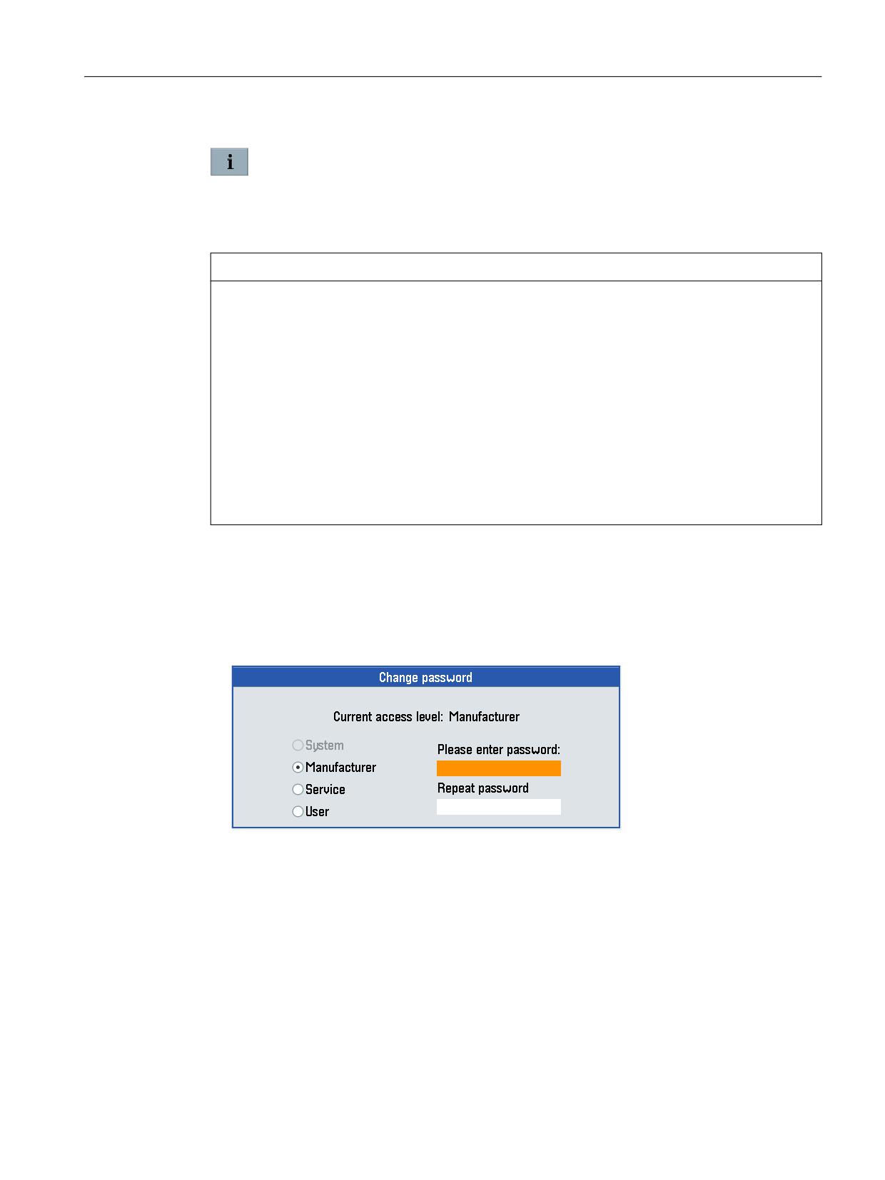
1. To change the default password from the delivery condition, press the "Change password"
softkey.
2. The previous password must first be confirmed. After successful authentication, you are
forwarded automatically to the following dialog:
3. Enter the new password and the repetition, and then confirm with the "OK" softkey. If both
passwords match, the new password becomes valid and is adopted by the system.
CNC Commissioning: NC, PLC, Drive
Commissioning Manual, 10/2020, A5E48312804B AB
37
Requirements for commissioning
3.6 Access levels
Password forgotten?
NOTICE
Password forgotten?
Assigning a new password to replace a forgotten password is a very time-consuming process,
in particular, an unavailable password hinders a service job.
Therefore, please take appropriate actions to ensure that the assigned passwords are available
for a service job.
If the password is no longer available, please contact the supplier.
CNC Commissioning: NC, PLC, Drive
38
Commissioning Manual, 10/2020, A5E48312804B AB
Licensing
4
4.1
SINUMERIK License Key
Basic information on license keys
If a license is required for a product, then with the purchase of the license the purchaser receives
a CoL as proof for the rights to use this product and a corresponding license key as to the
"technical representative" of this license. In conjunction with software products, the license key
usually must be available on the hardware on which the software product is executed.
Note
Trial license
A trial license supports "short-term use" of the software in a non-productive context, e.g. use for
testing and evaluation purposes; it can be transitioned into another license.
SINUMERIK license keys
Depending on the software product, there are license keys with different technical properties.
The essential properties of a SINUMERIK license key are:
• Hardware serial number
Via the hardware serial number contained in the SINUMERIK License Key, there is a direct
relationship between the License Key and the hardware on which it may be used. That means
a License Key that was generated for the hardware serial number of a certain CompactFlash
card is also only valid on this CompactFlash card and rejected as invalid on another
CompactFlash card.
• Total number of assigned licenses
A SINUMERIK license key not only refers to a single license, instead it is the "technical
representative" of all licenses that are assigned to the hardware at the time of its generation.
Content of the CompactFlash card
The CompactFlash card contains the system and user software, the retentive system and user
data, along with the data relevant for the license management of SINUMERIK software products
of a control system:
• Hardware serial number
• License information including the license key
The CompactFlash card thus represents the identity of a SINUMERIK controller. For this reason,
assigning licenses to a controller always occurs using the hardware serial number.
This has the advantage that the CompactFlash card can be inserted into a replacement NCU in
the event of failure and all data is retained.
CNC Commissioning: NC, PLC, Drive
Commissioning Manual, 10/2020, A5E48312804B AB
39
Licensing
4.1 SINUMERIK License Key
CompactFlash card as a spare part
If the CompactFlash card of a SINUMERIK controller is replaced, for example, because of
defective hardware, the license key loses its validity and the system is no longer operational.
In case of defective hardware of the CompactFlash card, contact the "Technical Support". They
will then send you a new license key without delay. The following data is required:
• Hardware serial number of the defective CompactFlash card
• Hardware serial number of the new CompactFlash card
Note
Only CompactFlash cards can be used that were released as spare part, as only these are
known to the license database.
Determining the hardware serial number
The hardware serial number is a permanent part of the CompactFlash card. It is used to identify
a control system uniquely. The hardware serial number can be determined by:
• Certificate of License (CoL)
• SINUMERIK user interface
• Label on the CompactFlash card
Note
Hardware serial number and CoL
The hardware serial number is located only on a CoL of the system software or if the license
was ordered bundled, in other words the system software came together with options.
CNC Commissioning: NC, PLC, Drive
40
Commissioning Manual, 10/2020, A5E48312804B AB
Licensing
4.2 Web License Manager
4.2
Web License Manager
Overview
The use of the installed system software and the options activated on a SINUMERIK control
system require that the licenses purchased for this purpose are assigned to the hardware. In the
course of this assignment, a license key is generated from the license numbers of the system
software, the options, as well as the hardware serial number. Here, a license database
administered by Siemens is accessed via the Internet. Finally, the license information including
the license key is transferred to the hardware.
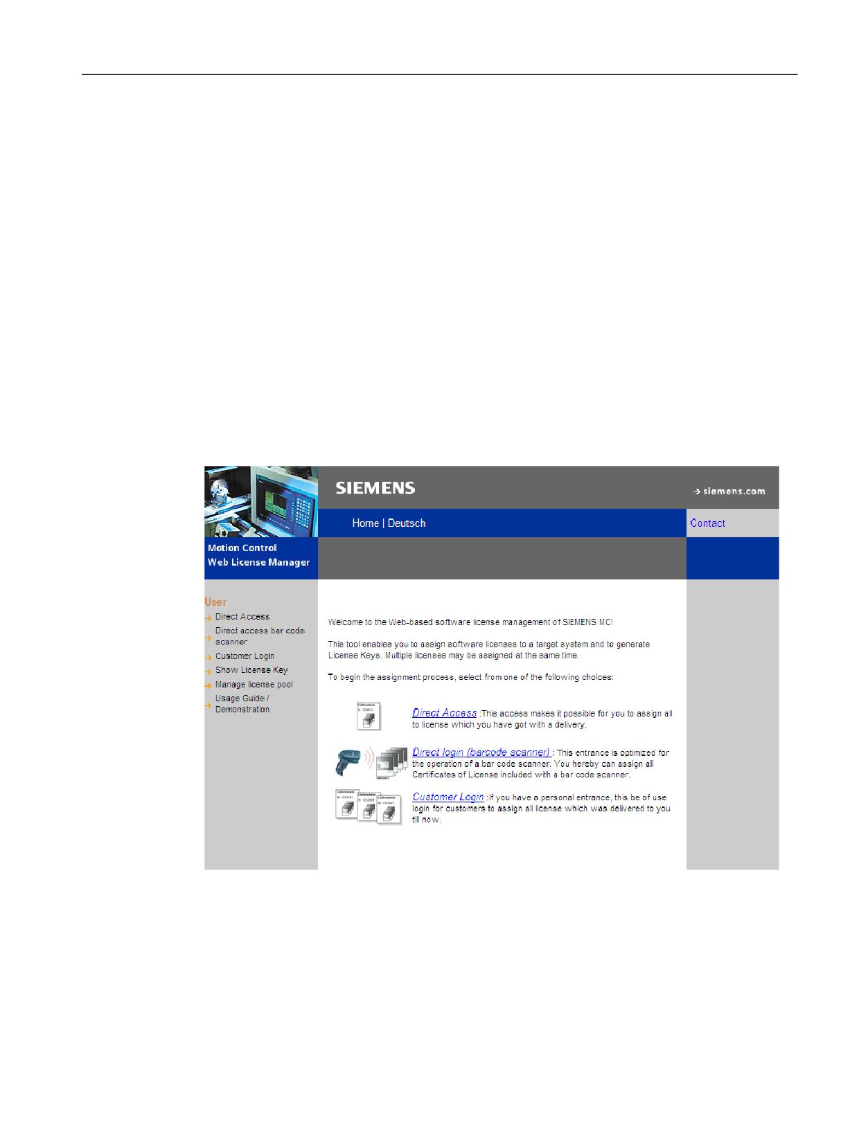
The license database can be accessed using the Web License Manager.
Web License Manager
By using the Web License Manager, you can assign licenses to the hardware in a standard Web
browser. To conclude the assignment, the license key must be entered at the controller via the
user interface.
Internet links
CNC Commissioning: NC, PLC, Drive
Commissioning Manual, 10/2020, A5E48312804B AB
41
Licensing
4.3 License database
4.3
License database
License database access
The license database contains all relevant license information required for the license
management of SINUMERIK software products. The central management of the license
information in the license database ensures that the existing license information regarding a
piece of hardware is always up to date.
Direct access
The direct access in the Web License Manager is made with:
• License number
• Delivery note number
The direct access enables the direct assignment of licenses for which the license numbers are
available, e.g. in the form of a CoL.
Direct access with barcode scanner
The direct access in the Web License Manager is made with:
• Hardware serial number
• Product selection
The direct access enables the assignment of licenses with a barcode scanner for which the
license numbers are available as a barcode, for example in the form of a CoL.
Customer login
The customer login in the Web License Manager is made with:
• User name
• Password
The customer login enables the assignment of all the licenses available to the machine
manufacturer that are delivered at the time of the login and have not yet been assigned to any
machine. Here, the license numbers of licenses that can still be assigned need not be directly at
hand, instead these are displayed from within the license database.
Note
Obtaining access data
You can obtain the address data for the customer login from the Siemens Industry Mall under the
associated selected region with: "> Register" (top).
CNC Commissioning: NC, PLC, Drive
42
Commissioning Manual, 10/2020, A5E48312804B AB
Licensing
4.4 How to perform the assignment
4.4
How to perform the assignment
Assigning a license to a piece of hardware
1. Determine the hardware serial number and the product name ("type of hardware") on the
user interface via the licensing dialog:
Commissioning > menu forward key > Licenses > Overview operating area
Note
Ensure that the hardware serial number displayed is also really the one you want to make the
assignment for. The assignment of a license to a piece of hardware cannot be reversed via the
Web License Manager.
2. Go to the Internet page of the Web License Manager.
3. Click the appropriate access to the license database:
- Direct access
- Direct access (barcode scanner )
- Customer login
4. Follow the instructions in the Web License Manager.
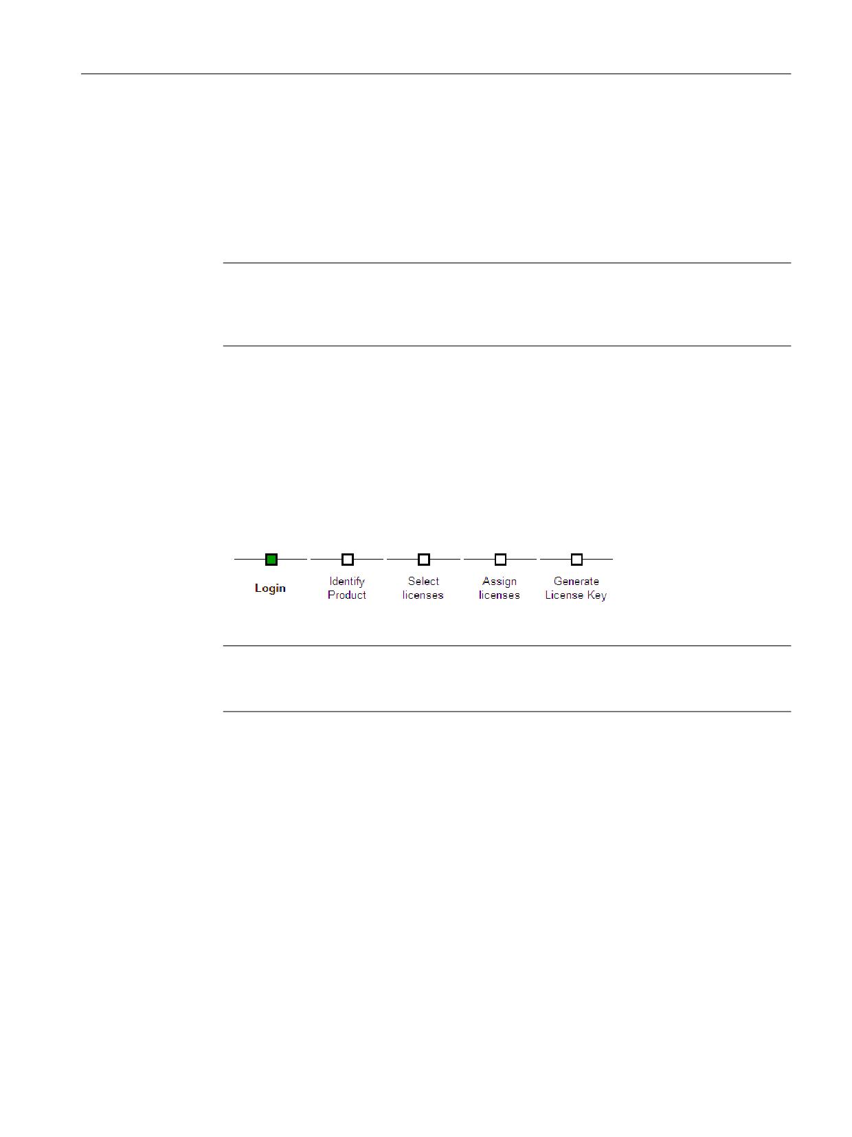
A progress bar shows you the individual steps:
5. Check the details of the selected licenses before confirmation of the assignment process.
Note
After confirmation, the generated license key irrevocably links the selected licenses with the
specified hardware.
6. Confirm the assignment process.
7. After completing the assignment process, enter the license key displayed on the Web License
Manager into the license dialog of the user interface.
Commissioning > menu forward key > Licenses > Overview operating area
8. Press the <INPUT> button to confirm the input of the new license key.
Displaying the license key and sending via e-mail
For archiving or for documentation of the associated machine, you can also send a license report
with the grouping of all assigned licenses. Follow the instructions in the Web License Manager
under "Display License Key".
CNC Commissioning: NC, PLC, Drive
Commissioning Manual, 10/2020, A5E48312804B AB
43
Licensing
4.5 Important licensing terms
4.5
Important licensing terms
Certificate of License (CoL)
The CoL is the proof of the → license. The product may only be used by the holder of the
→ license or authorized persons. The CoL includes the following data relevant for the license
management:
• Product name
• License number
• Delivery note number
• Hardware serial number
CompactFlash card
As the carrier of all non-volatile data in a SINUMERIK solution line control system, the
CompactFlash card represents the identity of this control system. The CompactFlash card is a
memory card that can be plugged into the → Control Unit from outside. The CompactFlash card
also contains the following data relevant for the license management:
• Hardware serial number
• License information including the → license key
Hardware
In the context of license management of SINUMERIK → software products, hardware refers to
the component of a SINUMERIK control system to which → licenses are assigned on the basis of
its unique identifier. The license information is also saved to non-volatile memory on this
component, e.g. on a → CompactFlash card.
Hardware serial number
The hardware serial number is a permanent part of the → CompactFlash card. It is used to
identify a control system uniquely. The hardware serial number can be determined by:
•
→ Certificate of License
• User interface
• Label on the CompactFlash card
License
A license gives the user the legal right to use a → software product. Evidence of this right is
provided by the following:
•
→ Certificate of License (CoL)
•
→ License key
CNC Commissioning: NC, PLC, Drive
44
Commissioning Manual, 10/2020, A5E48312804B AB
Licensing
4.5 Important licensing terms
License key
The License Key is the "technical representative" of the sum of all the → licenses that are assigned
to one particular piece of → hardware, which is uniquely identified by its → hardware serial
number.
License number
The license number is the feature of a → license used for its unique identification.
Option
An option is a SINUMERIK → software product that is not contained in the basic version and
which requires the purchase of a → license for its use.
Product
A product is marked by the data below within the license management of SINUMERIK
→ software products:
• Product designation
• Article number
• License number
Software product
The term software product is generally used to describe a product that is installed on a piece of
→ hardware to process data. Within the license management of SINUMERIK software products,
a corresponding → license is required to use each software product.
CNC Commissioning: NC, PLC, Drive
Commissioning Manual, 10/2020, A5E48312804B AB
45
Licensing
4.5 Important licensing terms
CNC Commissioning: NC, PLC, Drive
46
Commissioning Manual, 10/2020, A5E48312804B AB
PLC commissioning
5
5.1
Connect PG/PC with the PLC
Introduction
SIMATIC Manager is a GUI for online/offline editing of S7 objects (projects, user programs, blocks,
hardware stations and tools).
You can perform the following actions with the SIMATIC Manager:
• Manage projects and libraries
• Call STEP 7 tools
• Establish an online connection to the PLC
A corresponding editing tool is started up when you open the relevant objects. The program
editor starts by double-clicking a program block. The block can be processed.
Starting SIMATIC Manager
After installation, the SIMATIC Manager icon appears on the Windows desktop, and in the Start
menu a "SIMATIC Manager" program item appears under "SIMATIC".
• Start the SIMATIC Manager by double-clicking the link on the Windows desktop or from the
Start menu.
• The online help for the active window is always called by pressing the <F1> function key.
Establishing communication with the PLC
To load the configuration into the PLC, the connection (Ethernet) from the PG/PC to the PLC
required for the loading must be ensured.
Procedure:
1. Select menu command: "Extras" > "Set PG/PC interface..."
2. Under the "Access mode" tab, look for the interface used in the "Interface parameterization
used" selection field, for instance: "TCP/IP → Realtek RTL8139/810x F…"
3. Confirm the parameterization with "OK".
Note
Parameterization of the PG/PC interface can be performed or changed from the SIMATIC
Manager at any time.
CNC Commissioning: NC, PLC, Drive
Commissioning Manual, 10/2020, A5E48312804B AB
47
PLC commissioning
5.2 Creating a SIMATIC S7 project (PROFIBUS)
5.2
Creating a SIMATIC S7 project (PROFIBUS)
5.2.1
SIMATIC S7 project overview
Steps to be taken
A SIMATIC S7 project must be created for the basic commissioning of the PLC, the Ethernet and
PROFIBUS communication as well as the input/output data areas of the NC. To do this, perform
the following steps:
• Create a project
• Insert a SIMATIC station 300
• Insert an NCU to the hardware configuration
• Configuring interfaces
• Insert the machine control panel and handwheel
What do you need to be aware of?
Loading the PLC via interface X130 is also possible if the IP address of the Ethernet interface is
known. Loading an archive may always be performed if the communication HMI↔NC is
available.
Note
Loading the PLC (CP840) is essential for the configuration of the data path for saving/restoring
the drive data.
Additional information about the interface signals is provided in SINUMERIK 840D sl "PLC
Operating sequence
You have started the SIMATIC Manager.
1. To create a new project, select the "File" → "New" menu command in the SIMATIC Manager.
2. Enter the project data:
- Name (for example: SINU_840Dsl)
- Storage location (path)
- Type
3. Confirm the dialog with "OK".
The project window is displayed showing an empty S7 project structure.
CNC Commissioning: NC, PLC, Drive
48
Commissioning Manual, 10/2020, A5E48312804B AB
PLC commissioning
5.2 Creating a SIMATIC S7 project (PROFIBUS)
5.2.2
Inserting SINUMERIK NCU to the HW Config
Overview
Insert the necessary hardware in the following order in the S7 project:
• Insert a SIMATIC station 300
• Start the hardware configuration
• Insert a SINUMERIK NCU
Operating sequence
Procedure:
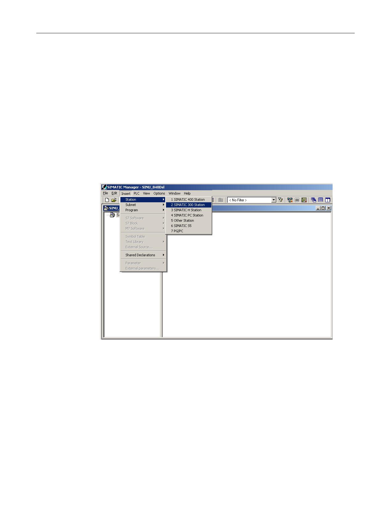
1. Select via the context menu (right-click) "Insert new object" > "SIMATIC 300 station".
2. Double-click the <SIMATIC 300> symbol.
CNC Commissioning: NC, PLC, Drive
Commissioning Manual, 10/2020, A5E48312804B AB
49
PLC commissioning
5.2 Creating a SIMATIC S7 project (PROFIBUS)
3. Double-click the <Hardware> symbol.
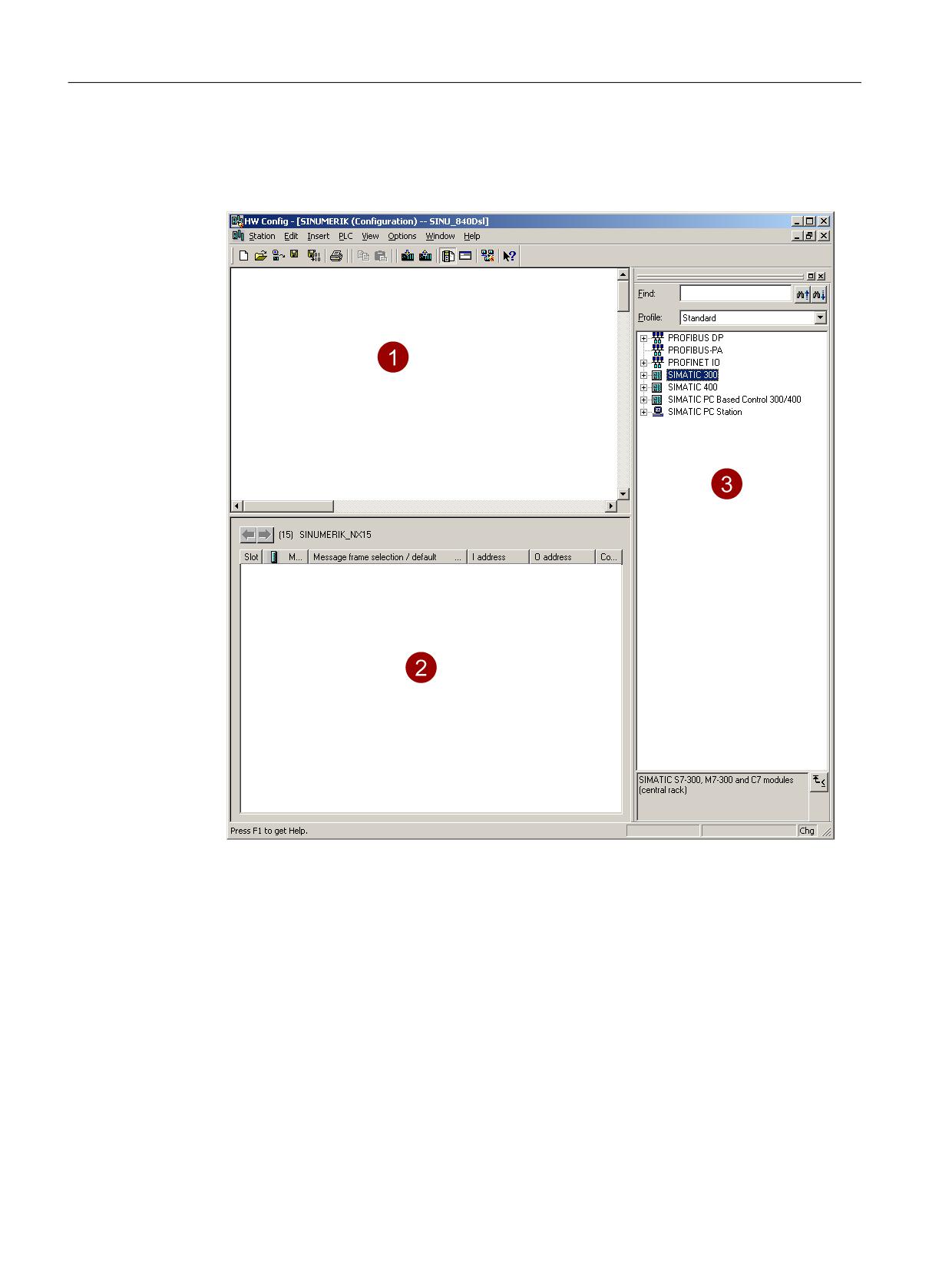
The HW Config for introducing required hardware is started.
4. In the menu, select "View" > "Catalog". The catalog with the modules is displayed.
① Station window:
② Details
③ Hardware catalog
The user interface of the "HW Config" hardware configuration shows the following details:
- Station window:
The station window is split. The upper part displays the structure of the station
graphically, and the lower part provides a detailed view of the selected module.
- Hardware catalog
This catalog also contains the SINUMERIK NCU that you need for configuring the
hardware.
CNC Commissioning: NC, PLC, Drive
50
Commissioning Manual, 10/2020, A5E48312804B AB
PLC commissioning
5.2 Creating a SIMATIC S7 project (PROFIBUS)
Inserting a SINUMERIK NCU
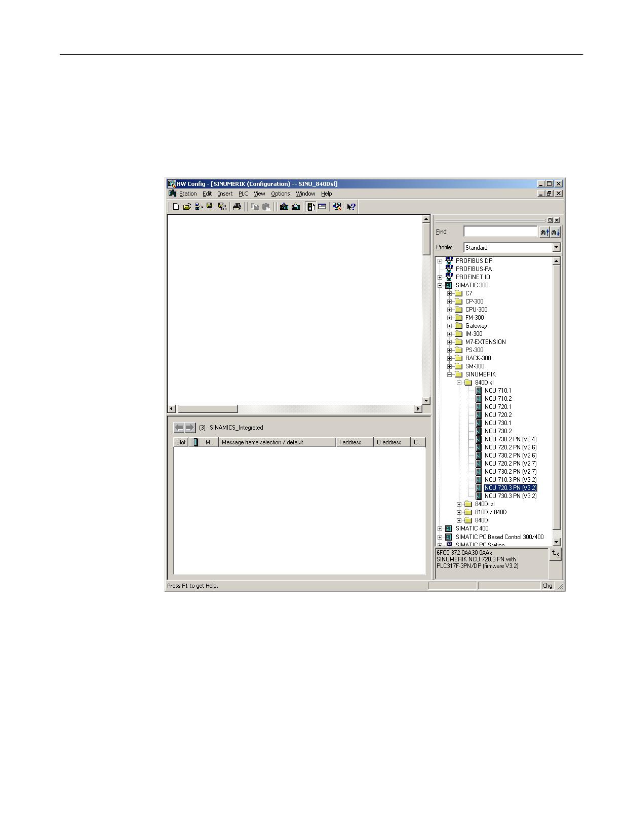
With the operating sequence described below, you insert the NCU 720.3 PN as example:
1. Select "View" > "Catalog".
2. Search for the module in the catalog under "SIMATIC 300" → "SINUMERIK" → "840D sl" > "NCU
720.3 PN".
3. Select "NCU 720.3 PN" with the left mouse button and drag it to the "Station design" station
window while keeping the mouse button pressed.
After you release the mouse button, into the dialog, configure the properties of the interfaces
of the communication processor CP provided on the NCU.
CNC Commissioning: NC, PLC, Drive
Commissioning Manual, 10/2020, A5E48312804B AB
51
PLC commissioning
5.2 Creating a SIMATIC S7 project (PROFIBUS)
5.2.3
Configuring interfaces
Introduction
Configure the following interfaces in the STEP 7 project via which you want to access the NCU:
• Integrated PROFIBUS
• PROFIBUS DP, only with machine control panel for PROFIBUS (Page 60)
• Industrial Ethernet
When creating a new project using the catalog, the configuration of the PROFIBUS interface is
called automatically.
PROFIBUS DP operating sequence
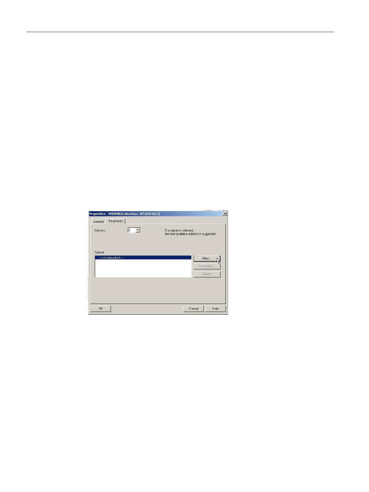
1. Left-click to select an NCU and while holding down the mouse button drag it to the "Station
design" station window.
2. After you release the mouse button, configure the properties of the PROFIBUS DP interface
for socket X126 (machine control panel) in the dialog box.
3. No configuration is necessary for an Ethernet machine control panel: Select "Cancel".
CNC Commissioning: NC, PLC, Drive
52
Commissioning Manual, 10/2020, A5E48312804B AB
PLC commissioning
5.2 Creating a SIMATIC S7 project (PROFIBUS)
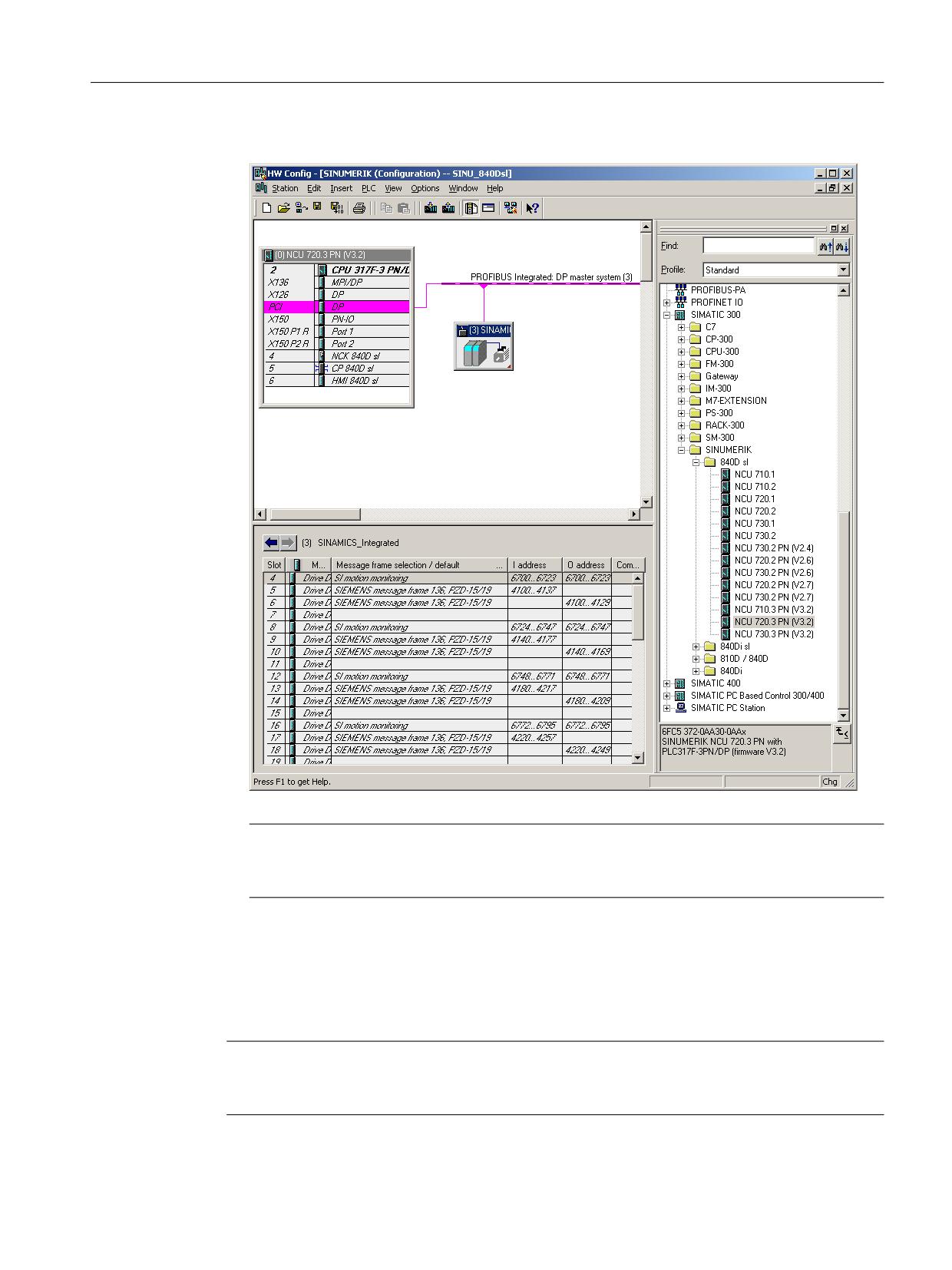
4. The NCU module with SINAMICS S120 is inserted into the HW Config.
Note
With the <F4> key and confirmation of the prompt regarding "Reorganization", you can
reorganize the display in the station window.
5. Confirm with "OK".
Next, specify the properties for the Ethernet interface.
Operating sequence for Ethernet interface
Note
Use service interface X127 when commissioning the PLC. The Ethernet interface does not have
to be configured. This interface is already initialized with the IP address 192.168.215.1
CNC Commissioning: NC, PLC, Drive
Commissioning Manual, 10/2020, A5E48312804B AB
53
PLC commissioning
5.2 Creating a SIMATIC S7 project (PROFIBUS)
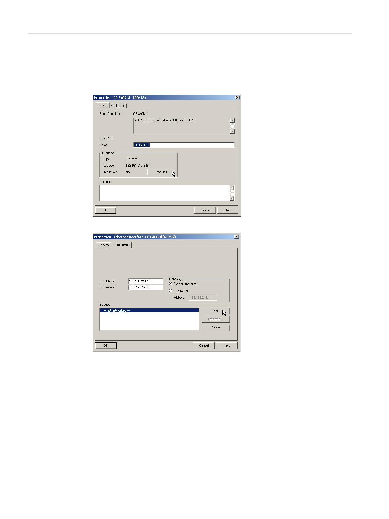
For the initial commissioning with a PG/PC, it is necessary to configure an Ethernet interface. In
our example, this involves the interface to socket X120.
1. Double-click "CP 840D sl" in the basic rack of the NCU. The "Properties - CP 840D sl" dialog
opens.
2. After clicking the "Properties" button, a new Ethernet interface can be created.
3. For socket X120, enter the IP address "192.168.214.1" and the Subnet screen form
"255.255.255.0".
4. Create the Ethernet interface using "New" and then "OK".
5. Click "OK" twice.
CNC Commissioning: NC, PLC, Drive
54
Commissioning Manual, 10/2020, A5E48312804B AB
PLC commissioning
5.2 Creating a SIMATIC S7 project (PROFIBUS)
Setting the isochronous mode on the PROFIBUS DP
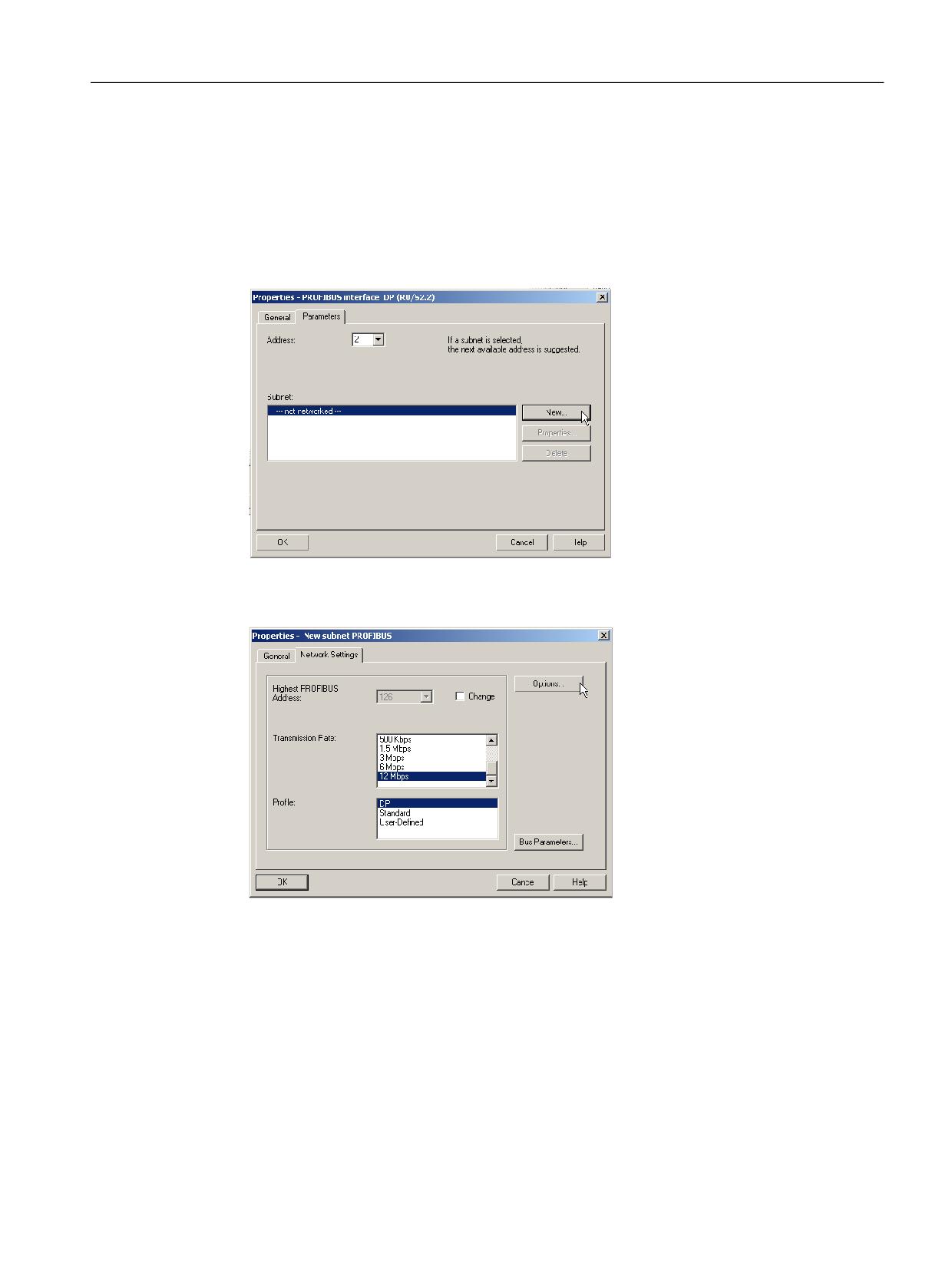
Procedure for configuring the PROFIBUS DP interface in the STEP 7 project:
1. Left-click to select an NCU, and while holding down the mouse button drag it to the "Station
design" station window.
2. After you release the mouse button, configure the properties of the PROFIBUS DP interface
for socket X126 (machine control panel) in the dialog box.
3. Click "New…" and then the "Net settings" tab in the "New PROFIBUS subnet properties" dialog.
4. Select the transmission rate of "12 Mbit/s" for the "DP" profile.
CNC Commissioning: NC, PLC, Drive
Commissioning Manual, 10/2020, A5E48312804B AB
55
PLC commissioning
5.2 Creating a SIMATIC S7 project (PROFIBUS)
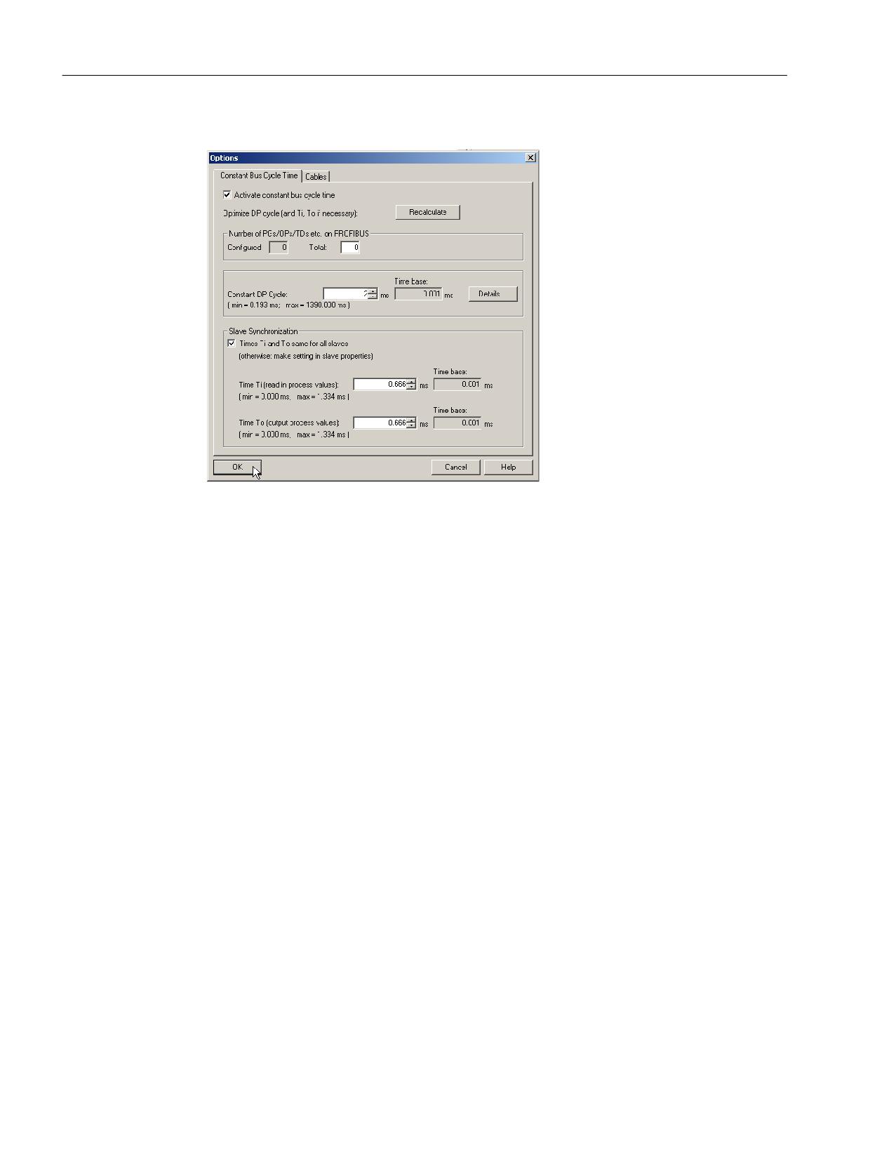
5. Click "Options" and then the "Isochronous mode" tab.
6. To enable reproducible access to peripherals (for handwheel mode), the PROFIBUS DP must
have a constant bus cycle time. The following entries are necessary under Isochronous mode:
- Click the "Activate isochronous bus cycle" field.
- Enter the cycle, e.g. "2 ms" for the "Equidistant DP cycle" for the integrated PROFIBUS (also
see: MD10050 $MN_SYSCLOCK_CYCLE_TIME).
- Click the "Times Ti and To equal for all slaves" field.
- The fields "Time Ti" and "Time To" must contain a value "< 2 ms".
CNC Commissioning: NC, PLC, Drive
56
Commissioning Manual, 10/2020, A5E48312804B AB
PLC commissioning
5.2 Creating a SIMATIC S7 project (PROFIBUS)
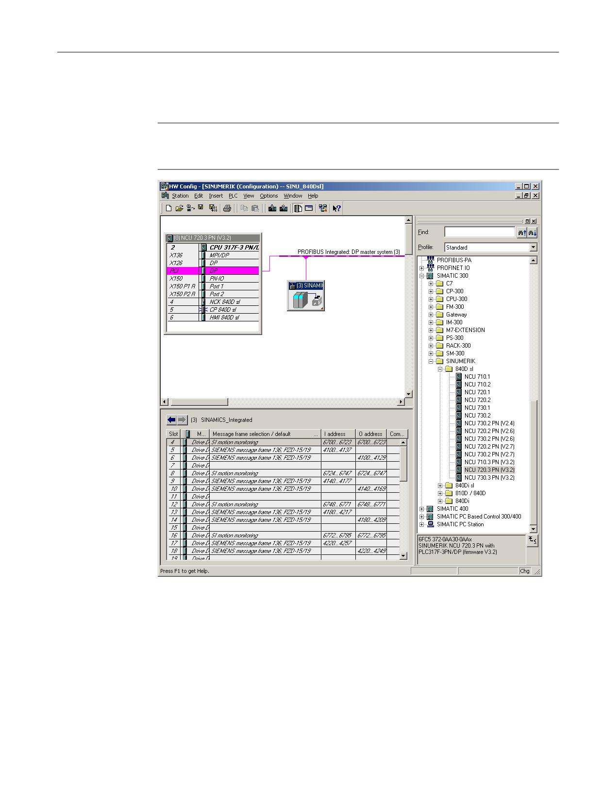
7. Click "OK" three times.
8. The NCU module with SINAMICS S120 is inserted in the HW Config.
Note
With the <F4> key and confirmation of the prompt regarding "Reorganization", you can
reorganize the display in the station window.
As the next step configure a machine control panel with handwheel.
CNC Commissioning: NC, PLC, Drive
Commissioning Manual, 10/2020, A5E48312804B AB
57
PLC commissioning
5.2 Creating a SIMATIC S7 project (PROFIBUS)
5.2.4
Augmenting the machine control panel and handwheel in the HW
configuration
Sequence and requirements
Configuring sequence for a PROFIBUS machine control panel:
1. Configuring the properties of the PROFIBUS DP interface.
2. Augment the machine control panel and handwheel in HW Config.
3. Modify the machine control panel in the OB100.
If a handwheel has been configured, isochronous mode on the PROFIBUS is required. The
PROFIBUS address for the machine control panel is "6". To expand the machine control panel, you
need the device master data (GSD file) with the SINUMERIK machine controlled panel. This file
is part of the STEP 7 package in the toolbox and contains information that a DP master system
requires to link the MCP as DP slave in its PROFIBUS configuration.
Procedure for the installation:
1. Search in the HW Config under "Tools" > "Install GSD file…" in the installation directory of the
toolbox for the corresponding GSD directory under:
..\8x0d\GSD\MCP_310_483
2. Choose the corresponding language you want to install.
3. Select "Install".
4. Exit with "Close".
Augmenting the machine control panel in HW Config
You have created an NCU and an NX in the HW Config and installed the GSD file for the MCP.
Procedure:
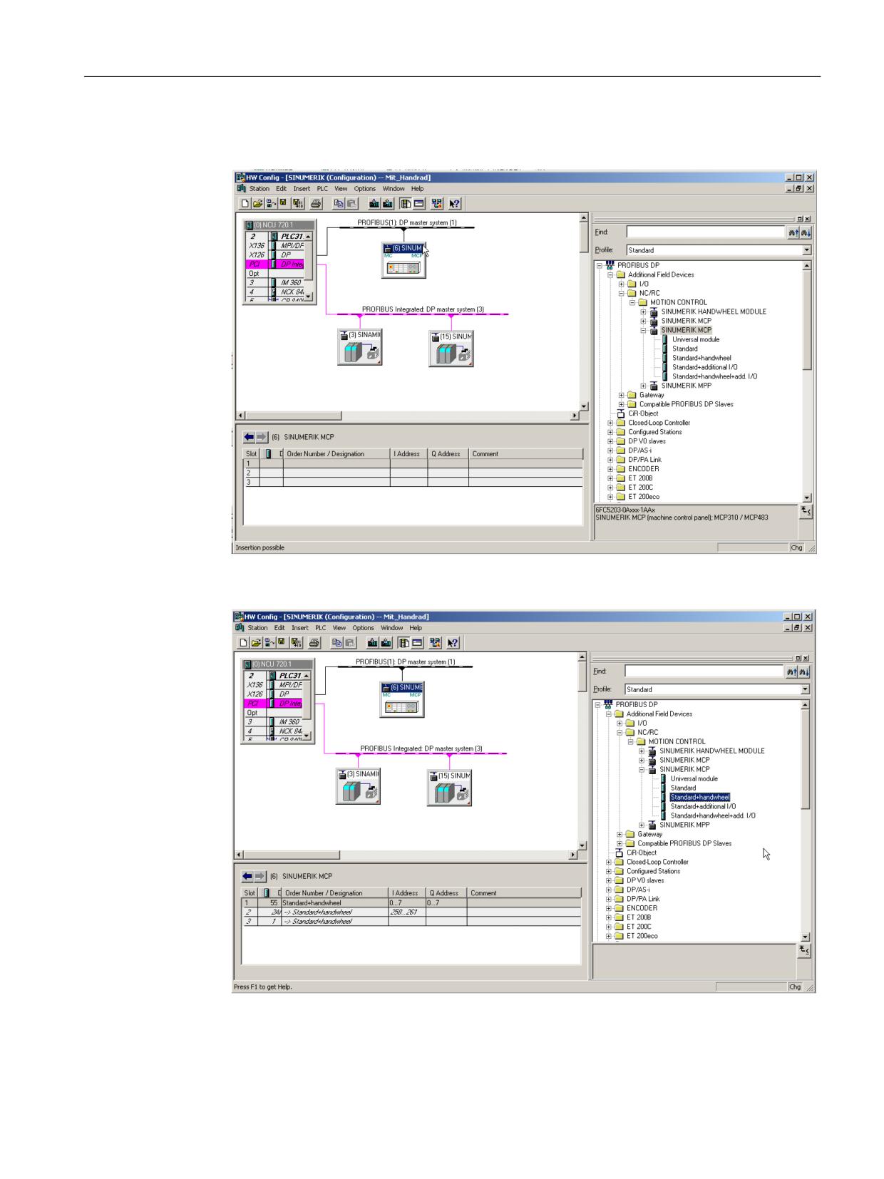
1. Search under "PROFIBUS DP" → "Further field devices" → "NC/RC" → "MOTION CONTROL" in
the hardware catalog for the "SINUMERIK MCP" module.
2. Left-click to select the "SINUMERIK MCP" module and drag it to the chain for the "PROFIBUS
DP master system" in the "Station design" station window.
3. After releasing the mouse key, you have inserted the machine control panel.
4. Select the "MCP" and enter the PROFIBUS address 6 under "Object properties" → "PROFIBUS..."
button → "Parameter" tab → "Address" input field.
CNC Commissioning: NC, PLC, Drive
58
Commissioning Manual, 10/2020, A5E48312804B AB
PLC commissioning
5.2 Creating a SIMATIC S7 project (PROFIBUS)
5. Click "OK" twice. You can now assign the slots of the machine control panel with e.g.
"Standard + handwheel".
6. In the hardware catalog, select "SINUMERIK MCP" → "Standard+Handwheel" and drag it to
slot 1.
In the next step, configure the Web browser. Then save, compile and load the configuration to
the PLC.
CNC Commissioning: NC, PLC, Drive
Commissioning Manual, 10/2020, A5E48312804B AB
59
PLC commissioning
5.2 Creating a SIMATIC S7 project (PROFIBUS)
5.2.5
Modifying PROFIBUS machine control panel in OB100
Configuring the machine control panel
The PLC base program transfers the signals from the machine control panel. To ensure that the
signals are transferred correctly to and from the machine control panel, enter the following
parameters in the OB100 on the FB1. Under "Blocks", double-click OB100 to open the editor to
configure the machine control panel .
Example: MCP1 is connected via PROFIBUS DP.
OB100
CALL "RUN_UP" , "gp_par"
FB1 / DB7 -- Startup Baseprogram/ Parameters for Base-
program
MCPNum
:=1
// An MCP is present
MCP1In
:=P#E 0.0
MCP1Out
:=P#A 0.0
MCP1StatSend
:=P#A 8.0
MCP1StatRec
:=
MCP1BusAdr
:=6
// PROFIBUS DP address: 6
MCP1Timeout
:=
MCP1Cycl
:=
MCP2In
:=
MCP2Out
:=
MCP2StatSend
:=
MCP2StatRec
:=
MCP2BusAdr
:=
MCP2Timeout
:=
MCP2Cycl
:=
MCPMPI
:=FALSE
MCP1Stop
:=FALSE
MCP2Stop
:=
MCP1NotSend
:=FALSE
MCP2NotSend
:=
MCPSDB210
:=
MCPCopyDB77
:=
MCPBusType
:=B#16#03
// Parameter [3] := PROFIBUS DP
CNC Commissioning: NC, PLC, Drive
60
Commissioning Manual, 10/2020, A5E48312804B AB
PLC commissioning
5.2 Creating a SIMATIC S7 project (PROFIBUS)
OB100
BHG
:=
BHGIn
:=
BHGOut
:=
UDInt
:=
UDHex
:=
UDReal
:=
IdentMcpType
:=
IdentMcpLengthIn :=
IdentMcpLengthOut:=
//Insert User program from here
An example for the connection via Industrial Ethernet (IE) can be found at: Modifying machine
control panel in OB100 (Page 85)
Additional information can be found in Chapter "Structure and Basic Program Functions" of the
5.2.6
Configuring the Web server
Operating sequence
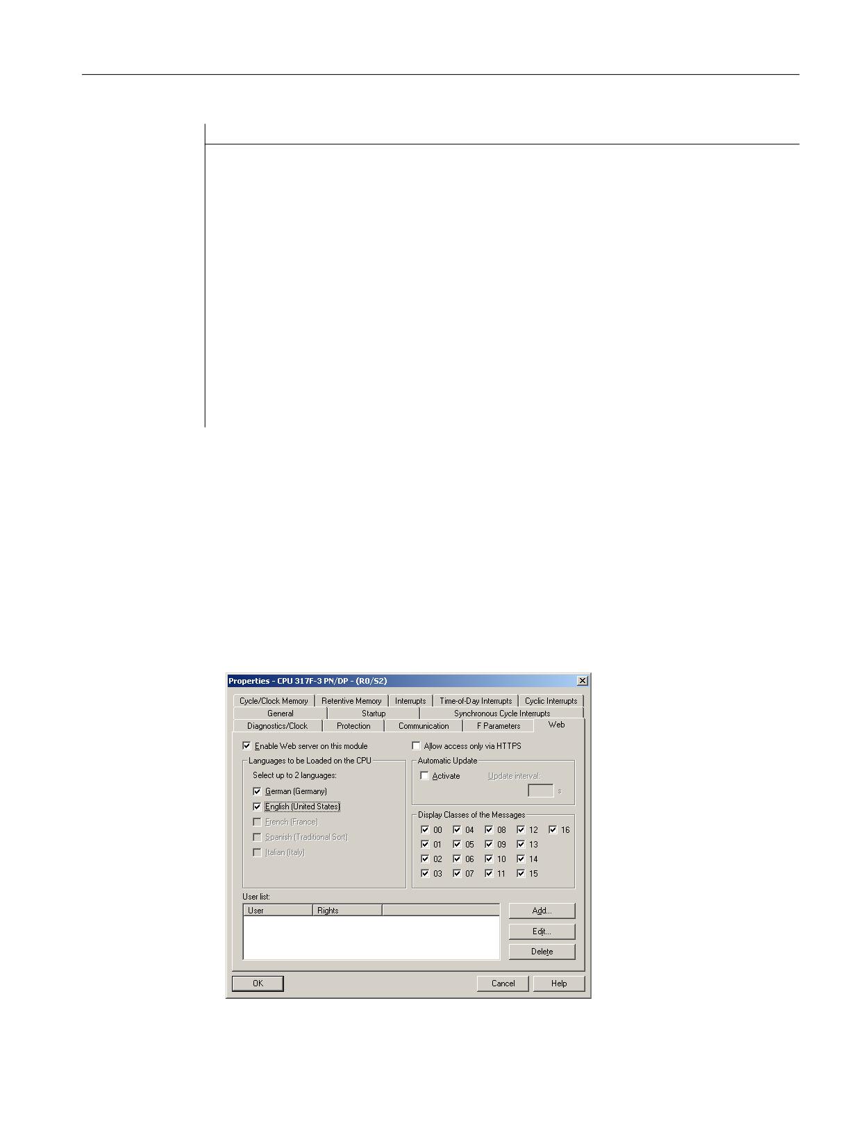
1. Click the SINUMERIK module in the hardware configuration to open the following dialog.
2. Select the "Web" tab.
CNC Commissioning: NC, PLC, Drive
Commissioning Manual, 10/2020, A5E48312804B AB
61

PLC commissioning
5.2 Creating a SIMATIC S7 project (PROFIBUS)
3. Activate the option: "Activate the Web server on this module".
After loading the configuration data, the Web server of the CPU is started to read information
from the PLC.
4. Select the language for language-dependent texts to be loaded into the CPU.
The number of available languages is CPU-dependent. Examples of language-dependent
texts are diagnostics buffer entries or messages.
Note
Available languages
The languages you select here must be installed in the S7 project. You can install the
languages for the project in the SIMATIC Manager from "Extras" → "Language for display
devices ... "
If the languages you select in the SIMATIC Manager have not been installed previously, the
Web server can only display texts in the set default language.
5. Activate the "Automatic update" if you want the Web pages to be updated automatically. The
"Identification" Web page is excluded from the automatic update.
Telegram lengths and I/O addresses
The telegram lengths and I/O addresses for communication between the PLC and the drive (can
be viewed via the object properties of the integrated SINAMICS) have already been pre-assigned
correctly and do not need to be configured.
5.2.7
Inserting an NX to the hardware configuration
Introduction
The NX must be wired to the NCU via the DRIVE-CLiQ. A DRIVE-CLiQ socket is permanently
preassigned for each address. The following table shows the wiring:
DRIVE-CLiQ interface of the NCU
Address on the integrated PROFIBUS
X100
10
X101
11
X102
12
X103
13
X104 *)
14
X105 *)
15
*)
Not available on the NCU 710.3B PN.
CNC Commissioning: NC, PLC, Drive
62
Commissioning Manual, 10/2020, A5E48312804B AB
PLC commissioning
5.2 Creating a SIMATIC S7 project (PROFIBUS)
Operating sequence
An NX component is contained in the example configuration, for the axis to control the spindle.
This component must be integrated in the hardware configuration also when creating the STEP
7 project:
1. Search for the NX module NX15.3 in the hardware catalog under
"PROFIBUS DP" > "SINAMICS" > "SINUMERIK NX…".
2. Left-click to select the "SINUMERIK NX ..." module and drag it to the "PROFIBUS Integrated DP
master system" bus in the "Station design" station window.
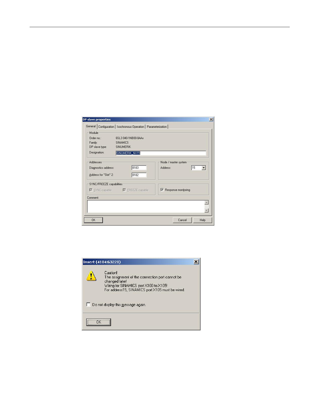
3. The "DP Slave Properties" dialog box opens.
Enter the address for the integrated PROFIBUS in this dialog. "15" is proposed for the first NX
in a configuration.
4. Enter the address and click "OK".
CNC Commissioning: NC, PLC, Drive
Commissioning Manual, 10/2020, A5E48312804B AB
63
PLC commissioning
5.2 Creating a SIMATIC S7 project (PROFIBUS)
5. Confirm the wiring notification with "OK".
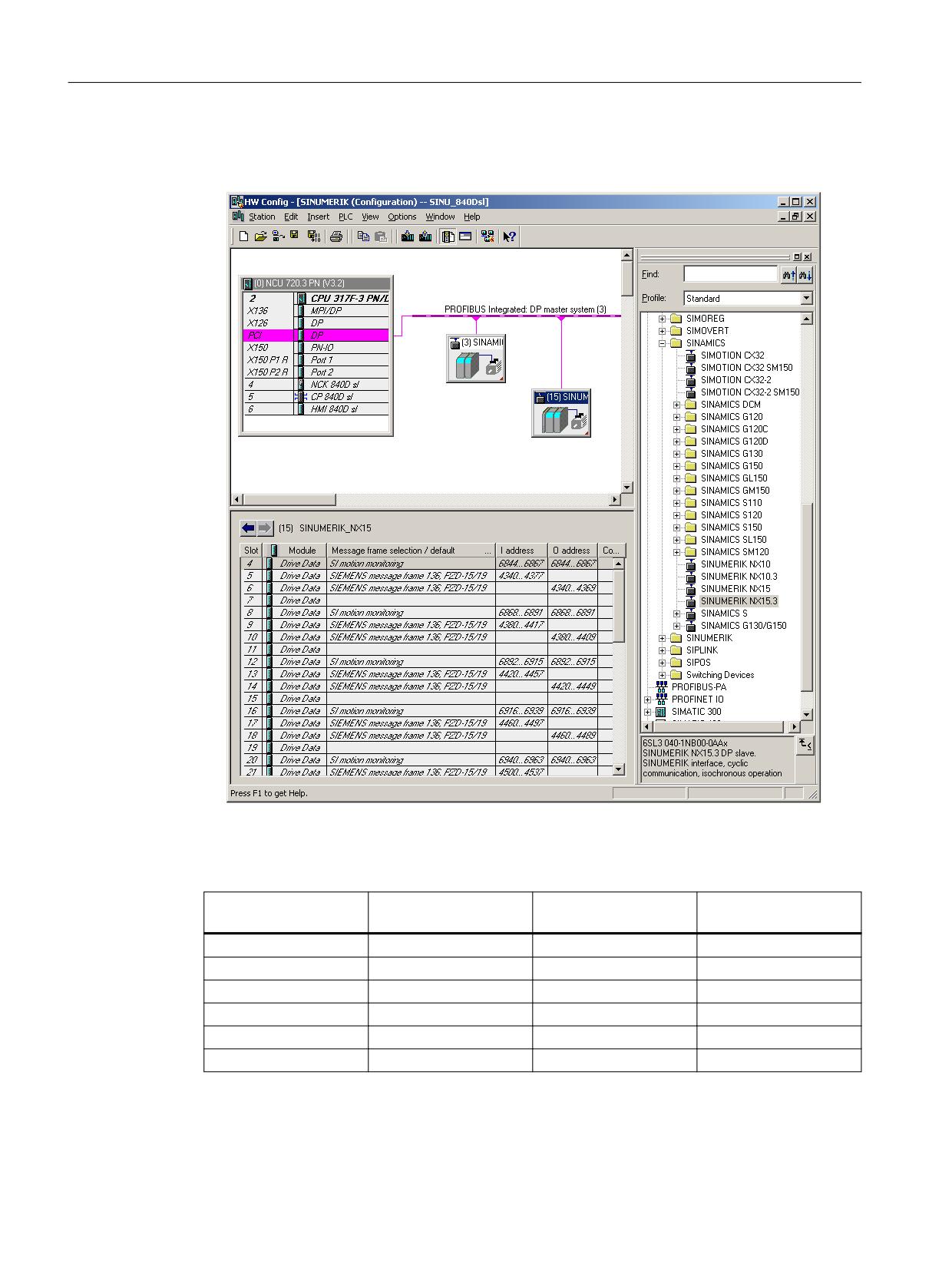
6. After releasing the mouse key, you have inserted the NX module:
When deleting and reinserting NX modules, while configuring, a new address area is assigned
each time. We recommend that addresses are assigned as follows in order to create a transparent
configuration:
DRIVE-CLiQ interface
Address on the integra-
Start address of the
Start address of the
ted PROFIBUS
first slot
last slot
X100
10
5540
5740
X101
11
5300
5500
X102
12
5060
5260
X103
13
4820
5020
X104
14
4580
4780
X105
15
4340
4540
CNC Commissioning: NC, PLC, Drive
64
Commissioning Manual, 10/2020, A5E48312804B AB
PLC commissioning
5.2 Creating a SIMATIC S7 project (PROFIBUS)
5.2.8
End the hardware configuration and load it to the PLC
End the hardware configuration and load the to the PLC
The project must be saved and compiled to exit the overall configuration and generate the
system data for the PLC:
1. Select the "Station" → "Save and compile" menu.
2. Click the "Load in module" button to load the configuration to the PLC.
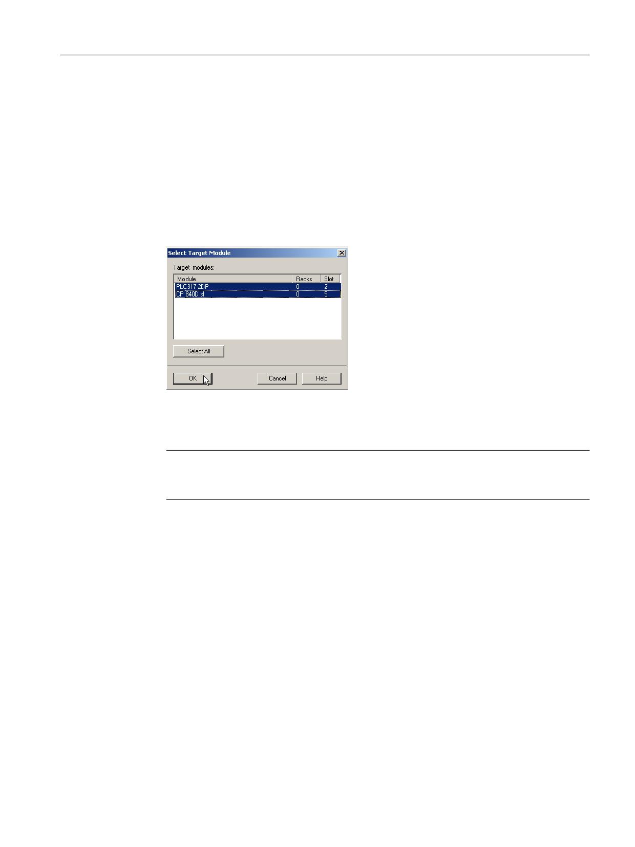
The "Select target module" dialog automatically displays both configured communication
partners.
3. Confirm with OK to load into these two modules.
4. Confirm the dialog boxes displayed subsequently with "OK" or "No" for the query "…Should
the module be started now (restart)?".
Note
Check the communication interface under "Target system" → "Diagnostics" → "Operating
state".
5. Close the "HW Config" window.
The next step is to create the PLC program.
CNC Commissioning: NC, PLC, Drive
Commissioning Manual, 10/2020, A5E48312804B AB
65
PLC commissioning
5.3 Extending the SIMATIC S7 project (PROFINET)
5.3
Extending the SIMATIC S7 project (PROFINET)
5.3.1
Requirements when configuring PROFINET
PROFINET IO IRT (Isochronous Real Time)
I/O modules and drives can use the isochronous PROFINET IO IRT. In addition to IRT, an RT
communication is also possible by default.
PROFINET IO IRT can be used by the PLC as PLC I/O and also by the NC. Drives are typically, but
not exclusively, configured as isochronous devices for use by the NC. The PROFINET IO IRT
devices operated isochronously by the PLC are typically I/O stations.
The concurrent operation of IRT "high performance" and CBA on the same PROFINET bus
interface is not supported. This means either NC drives via PROFINET IO with IRT or system
coupling via PROFINET CBA can be operated on an NCU.
The combination of isochronous PROFINET NC peripherals (drives, inputs/outputs) and NCU-
LINK is not supported.
CNC Commissioning: NC, PLC, Drive
66
Commissioning Manual, 10/2020, A5E48312804B AB
PLC commissioning
5.3 Extending the SIMATIC S7 project (PROFINET)
Settings for isochronous operation
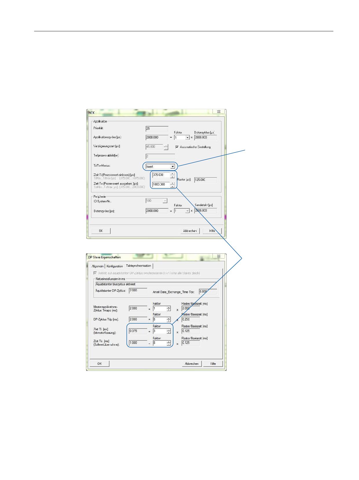
NC-controlled drives connected via PROFINET must be operated isochronously with the same
cycle clocks (Tdp, Ti and To) as the drives, which are connected via the integrated PROFIBUS. The
cycle clock settings are made in STEP 7 (HW Config). For a SINUMERIK, times Ti and To must
match in the complete system.
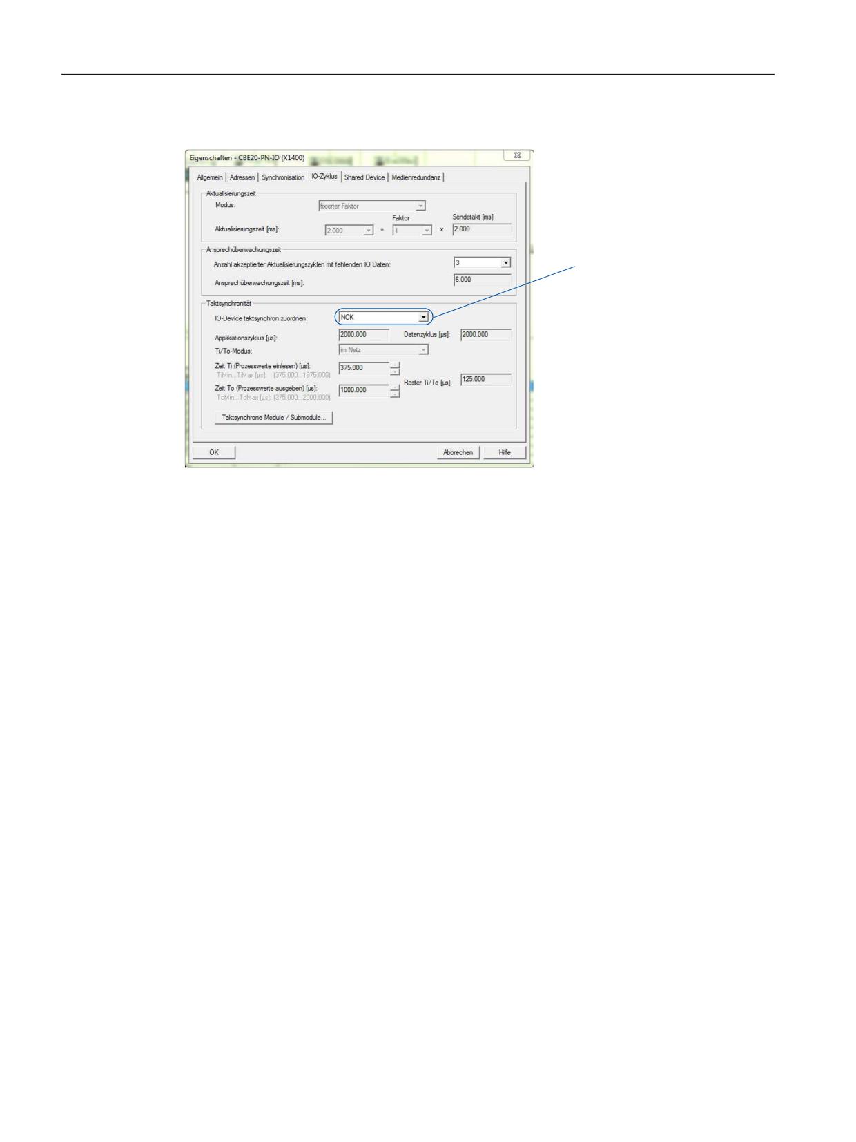
,VRFKURQRXV DODUP 1&. RI WKH 3/&
31 '3
)L[HG PXVW EH VHOHFWHG
KHUH
&ORFN F\FOH VHWWLQJ RI WKH 6,1$0,&6 LQWHJUDWHG RI WKH 1&8
PDWFKLQJ YDOXHV IRU 7L DQG
7R
CNC Commissioning: NC, PLC, Drive
Commissioning Manual, 10/2020, A5E48312804B AB
67
PLC commissioning
5.3 Extending the SIMATIC S7 project (PROFINET)
6HWWLQJ RI WKH LVRFKURQRXV 352),1(7 ,2 GHYLFH
2QO\ 1&. KDV WR EH VHOHFWHG
LQ WKH , 2 GHYLFH YDOXHV 7L DQG
7R DUH DXWRPDWLFDOO\ WDNHQ
IURP WKH V\QFKURQRXV PDVWHU
5.3.2
Sample configuration
Configuration via PROFINET
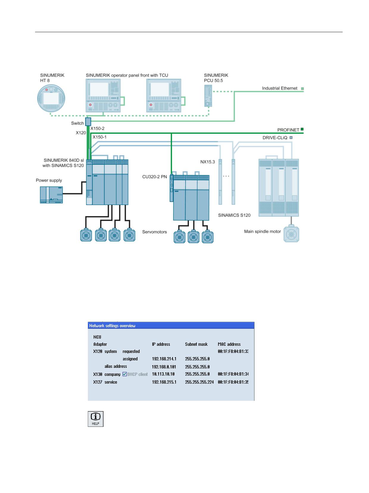
The SINAMICS S120 drives communicate via PROFINET interfaces X150 P1 and X150 P2 with the
NCU. The drives assigned to the SINAMICS CU3x0-2 can be operated NC-controlled or PLC-
controlled. Mixed operation is also permitted. Requirement is that the drives are connected via
PROFINET, with an additional switch between X120 and X150 of the NCU.
• CU310-2 PN
• CU320-2 PN (also with Communication Board CBE20)
• CU320-2 DP with Communication Board CBE20
• Scalance X208 (recommended)
CNC Commissioning: NC, PLC, Drive
68
Commissioning Manual, 10/2020, A5E48312804B AB
PLC commissioning
5.3 Extending the SIMATIC S7 project (PROFINET)
Sample configuration
Figure 5-1
Configuration with 3 PROFINET axes
Communication with the drive
For instance, to establish a network connection from the plant/system network (X120) to the
drive network (X150), we recommend that an alias IP address is allocated. In the operating area,
select "Commissioning" → "Network" → "Overview". Press the "Change" softkey, and enter an
alias address for X120 of the following type:
The SINUMERIK Operate Online Help provides more detailed, context-related informa-
tion on the network settings.
CNC Commissioning: NC, PLC, Drive
Commissioning Manual, 10/2020, A5E48312804B AB
69
PLC commissioning
5.3 Extending the SIMATIC S7 project (PROFINET)
5.3.3
Commissioning the PLC
Basic procedure
Perform the following steps:
• Insert the SINAMICS Control Unit in HW Config.
• Set the sync master and sync slaves.
• Configure the PROFINET interface.
• Configure the isochronous alarms.
• Save the configuration, compile and then download to the PLC.
• Establish the online connection to the target system and assign a device name to the
SINAMICS Control Unit.
Configuring a PROFINET connection
Procedure:
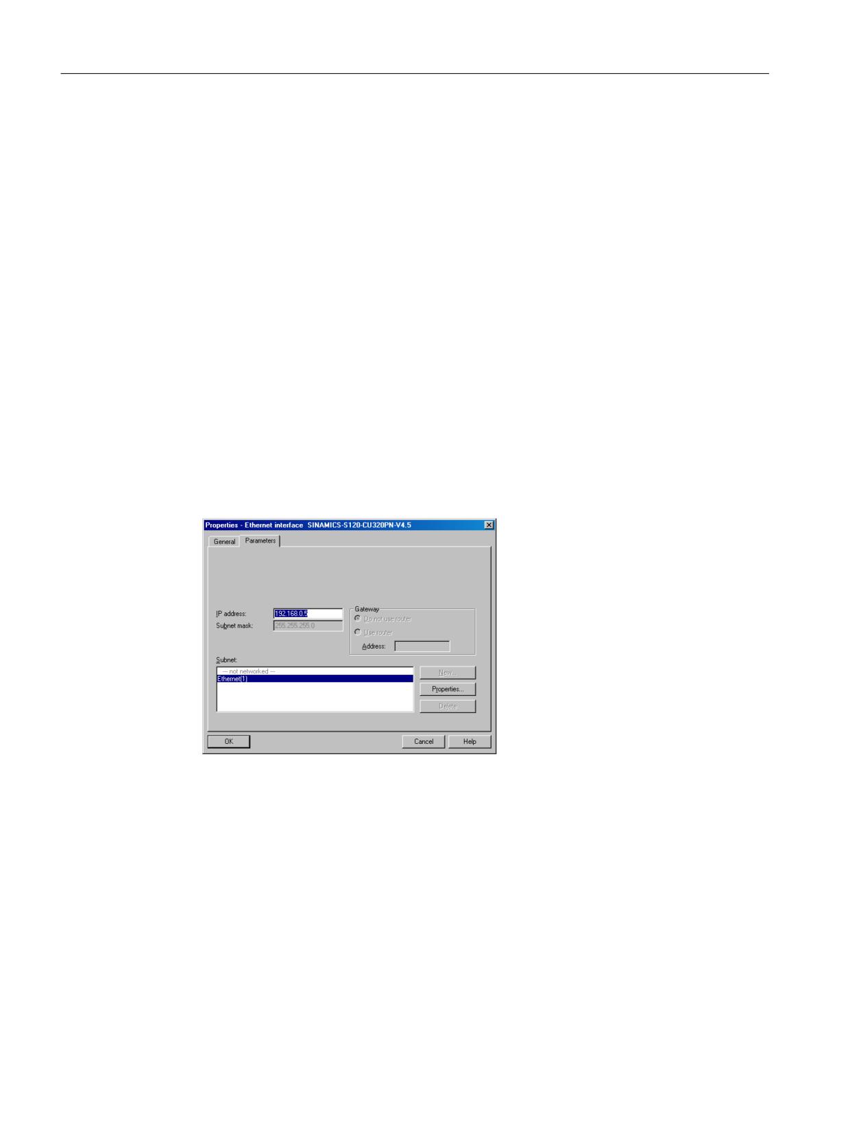
1. At the SINUMERIK NCU, select X150 and insert a PROFINET line via the "Insert" → "PROFINET
IO system" menu. Click the "New" button to insert a new subnet "Ethernet(1)":
2. Navigate in the catalog to "PROFINET IO" → "Drives" → "SINAMICS" → "SINAMICS S120" →
"SINAMICS S120 CU320-2 PN".
CNC Commissioning: NC, PLC, Drive
70
Commissioning Manual, 10/2020, A5E48312804B AB
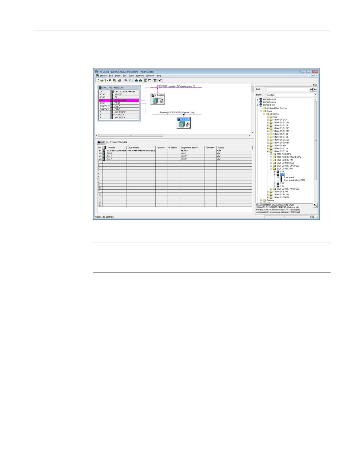
PLC commissioning
5.3 Extending the SIMATIC S7 project (PROFINET)
3. Keeping the left mouse key pressed, drag the object under "S120 CU320-2 PN" in the station
window to the PROFINET IO system.
4. By double-clicking on the SINAMICS Control Unit, you open the "Properties" dialog box to
enter a device name.
Note
Device name for SINAMICS S120
Ensure that you use a meaningful name as device name for the SINAMICS Control Unit.
5. In this dialog box, you also activate the topology-based device initialization by selecting the
option "Assign IP address by I/O controller". See also: Complete the PLC project (Page 78)
6. Confirm with "OK".
7. In the next step, you configure the required number of axes, the same as in the configuration
example in the previous chapter:
Three servo DOs, a Control Unit and an infeed with the telegrams recommended for
SINUMERIK.
CNC Commissioning: NC, PLC, Drive
Commissioning Manual, 10/2020, A5E48312804B AB
71
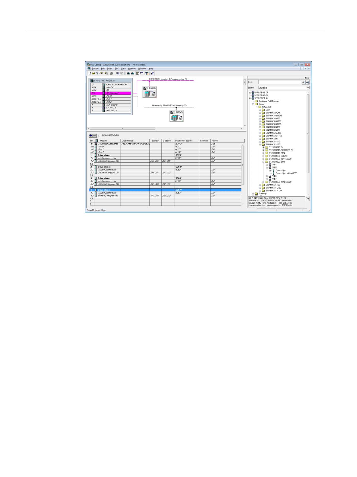
PLC commissioning
5.3 Extending the SIMATIC S7 project (PROFINET)
8. Drag the drive objects and drop them into the SINAMICS Control Unit.
The following sequence must be observed:
1. Number of SERVO DO for the axes
2. SINAMICS Control Unit
3. Infeed (optional)
To do this, the following telegrams are recommended:
- SIEMENS telegram 136, PZD-15/19 for a servo DO for an NC-controlled axis.
- SIEMENS telegram 390, PZD-2/2 for the Control Unit:
Telegram 390 is required for the time synchronization between the drive and the control
system. The time stamps of the drive alarms can then be compared to those of the control
system.
- SIEMENS telegram 370, PZD-1/1 for the infeed (ALM), if available.
9. In the SINUMERIK NCU, select "Port 1" at the X150 P1 interface and open the "Properties"
dialog with a double-click.
CNC Commissioning: NC, PLC, Drive
72
Commissioning Manual, 10/2020, A5E48312804B AB
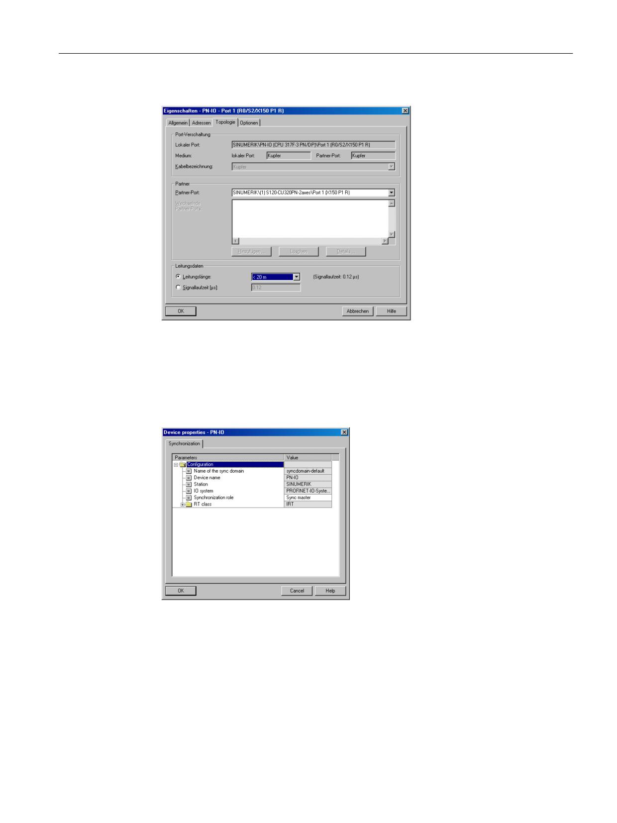
PLC commissioning
5.3 Extending the SIMATIC S7 project (PROFINET)
10.Select the "Topology" tab to assign the "partner port" to X150 P1 and click "OK" to confirm.
Note for the selection of the cable length that a longer cable length also increases the signal
runtime.
11.Select interface X150 in the SINUMERIK NCU and from the shortcut menu "PROFINET IO
Domain Management...".
12.In the list under "Station/device name", select the SINUMERIK NCU and with a double-click,
open the synchronization dialog in order to define the NCU as "Sync master".
CNC Commissioning: NC, PLC, Drive
Commissioning Manual, 10/2020, A5E48312804B AB
73
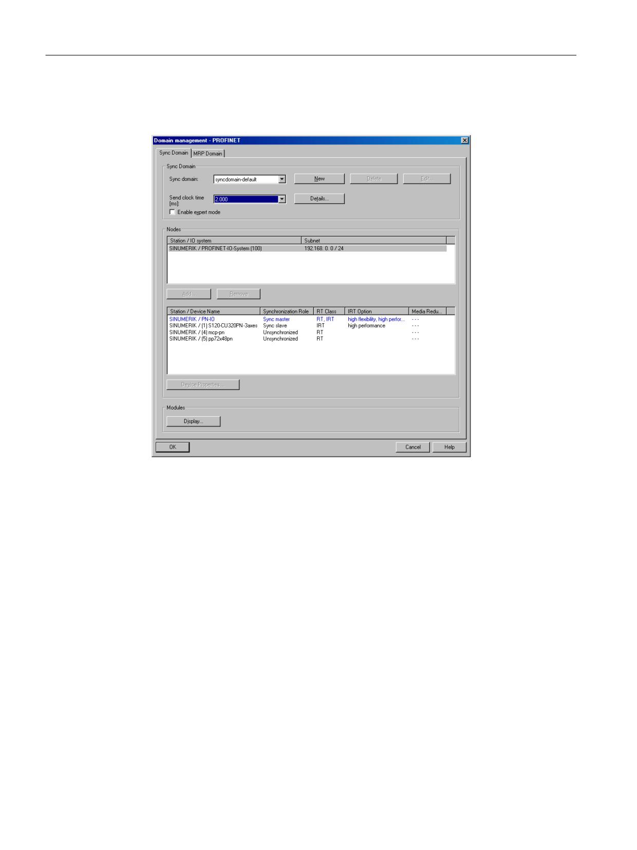
PLC commissioning
5.3 Extending the SIMATIC S7 project (PROFINET)
13.In the list under "Station/device name", select the SINAMICS Control Unit and with a double-
click, open the synchronization dialog in order to define the SINAMICS Control Unit as "Sync
slave".
14.The "Send clock [ms]" text box can then be edited. Here, select the same time as has been set
for SINAMICS Integrated of the NCU (DP cycle), for example 2 ms. Confirm with "OK".
15.Select the PLC in the SINUMERIK NCU and open the "Properties" dialog with a double-click.
CNC Commissioning: NC, PLC, Drive
74
Commissioning Manual, 10/2020, A5E48312804B AB
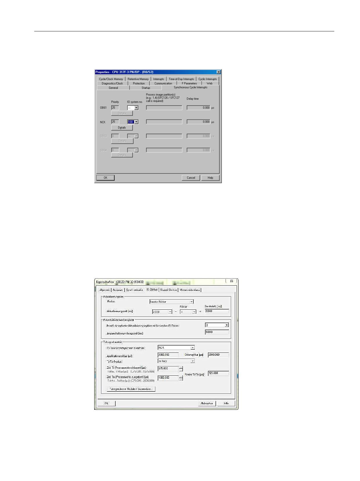
PLC commissioning
5.3 Extending the SIMATIC S7 project (PROFINET)
16.Select the "Clock synchronous alarms" tab and assign the PROFINET IO system number to the
"NCK" line to which you have added the SINAMICS Control Unit.
17.Double-click the "Details" button to open the "NCK" dialog:
Here, enter "2" for the subprocess image and confirm with "OK". For the "Ti/To mode", select
the option "Fixed". The project is then saved and compiled.
Configuring SINAMICS CU320
Procedure:
1. Select interface X150 in the SINAMICS Control Unit.
2. Open the "Properties" dialog and select the "IO cycle" tab.
3. Under "Isochronous Mode", for the option "Assign IO device ...", select → "NCK".
CNC Commissioning: NC, PLC, Drive
Commissioning Manual, 10/2020, A5E48312804B AB
75
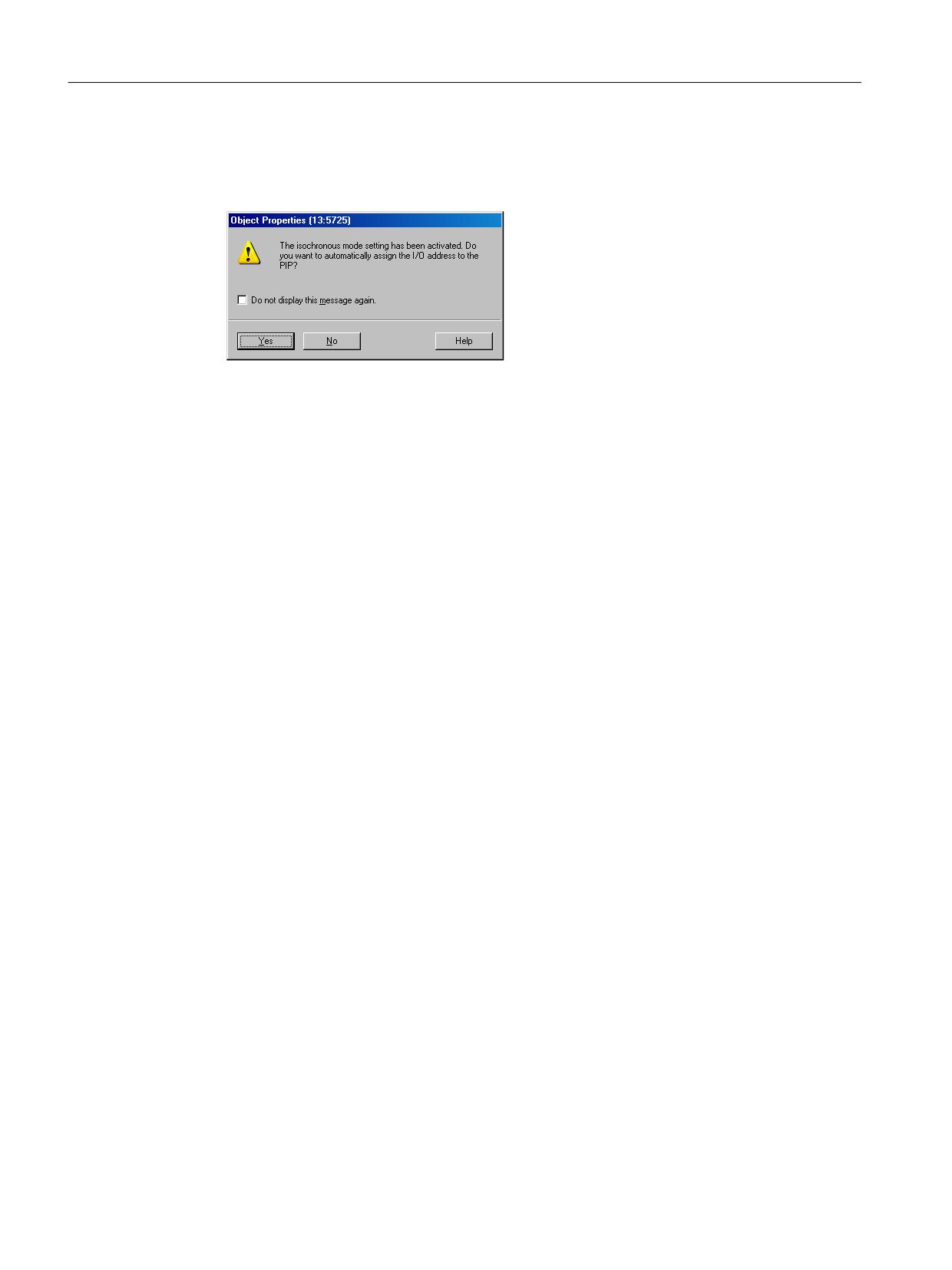
PLC commissioning
5.3 Extending the SIMATIC S7 project (PROFINET)
4. Confirm with "OK".
5. The following message is output regarding isochronous mode, which you must confirm
with "Yes":
5.3.4
Configuring PROFIsafe
Requirement
In order to configure PROFIsafe, it is necessary that the "S7 configurations pack" option is
installed.
CNC Commissioning: NC, PLC, Drive
76
Commissioning Manual, 10/2020, A5E48312804B AB
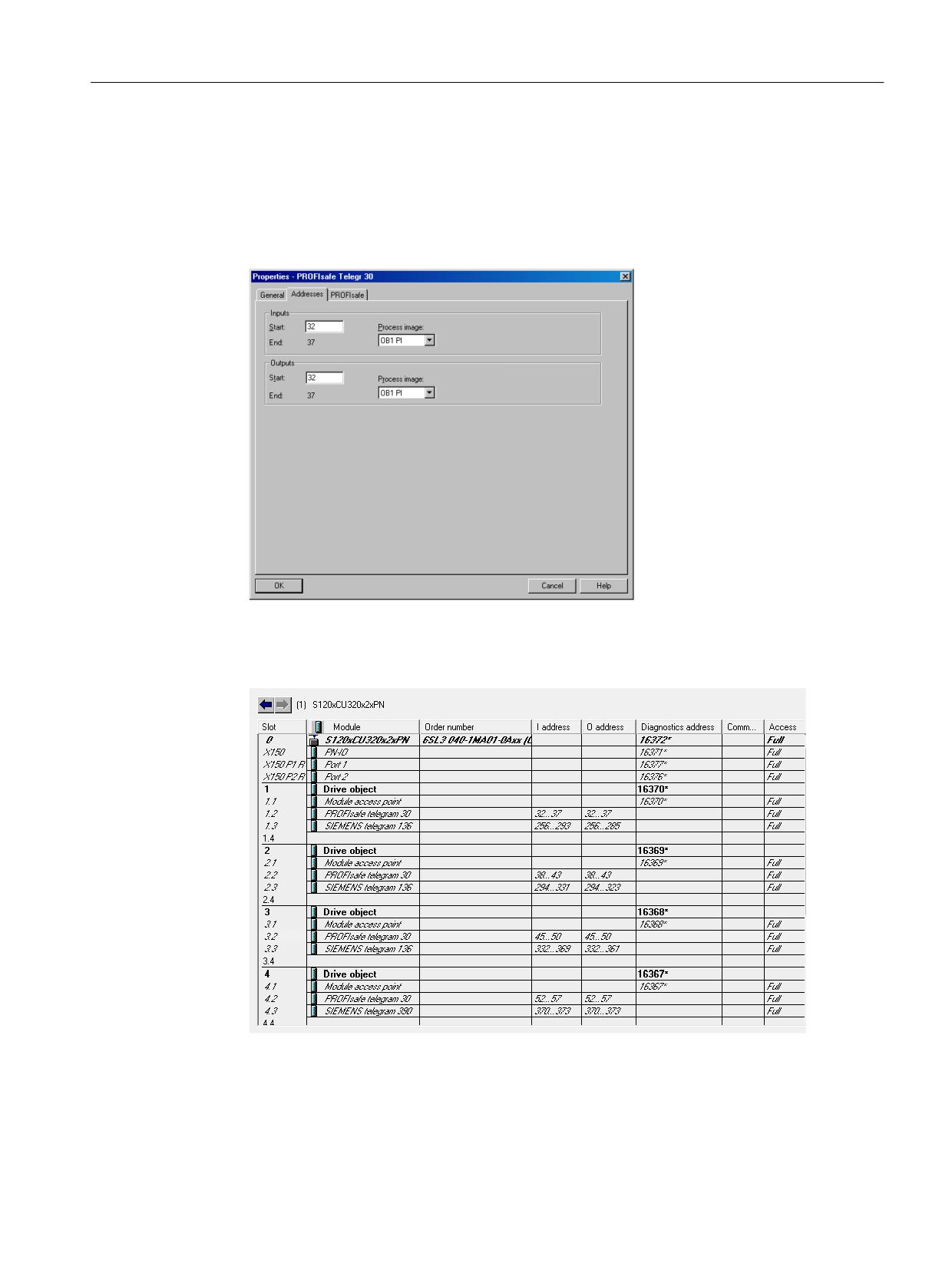
PLC commissioning
5.3 Extending the SIMATIC S7 project (PROFINET)
Configuring PROFIsafe
Procedure:
1. In the hardware catalog, under "DO SERVO", select PROFIsafe telegram 30, and insert it in the
project for the axis for which you wish to configure PROFIsafe.
2. Open properties with a double-click, and enter the start address:
PROFIsafe telegrams must be in the process image with their I/O addresses and must not be
assigned to the isochronous process image partition PIP (1 for PLC, 2 for NC).
Result of the PROFIsafe configuring:
Figure 5-2
Configuring with PROFIsafe (excerpt)
CNC Commissioning: NC, PLC, Drive
Commissioning Manual, 10/2020, A5E48312804B AB
77
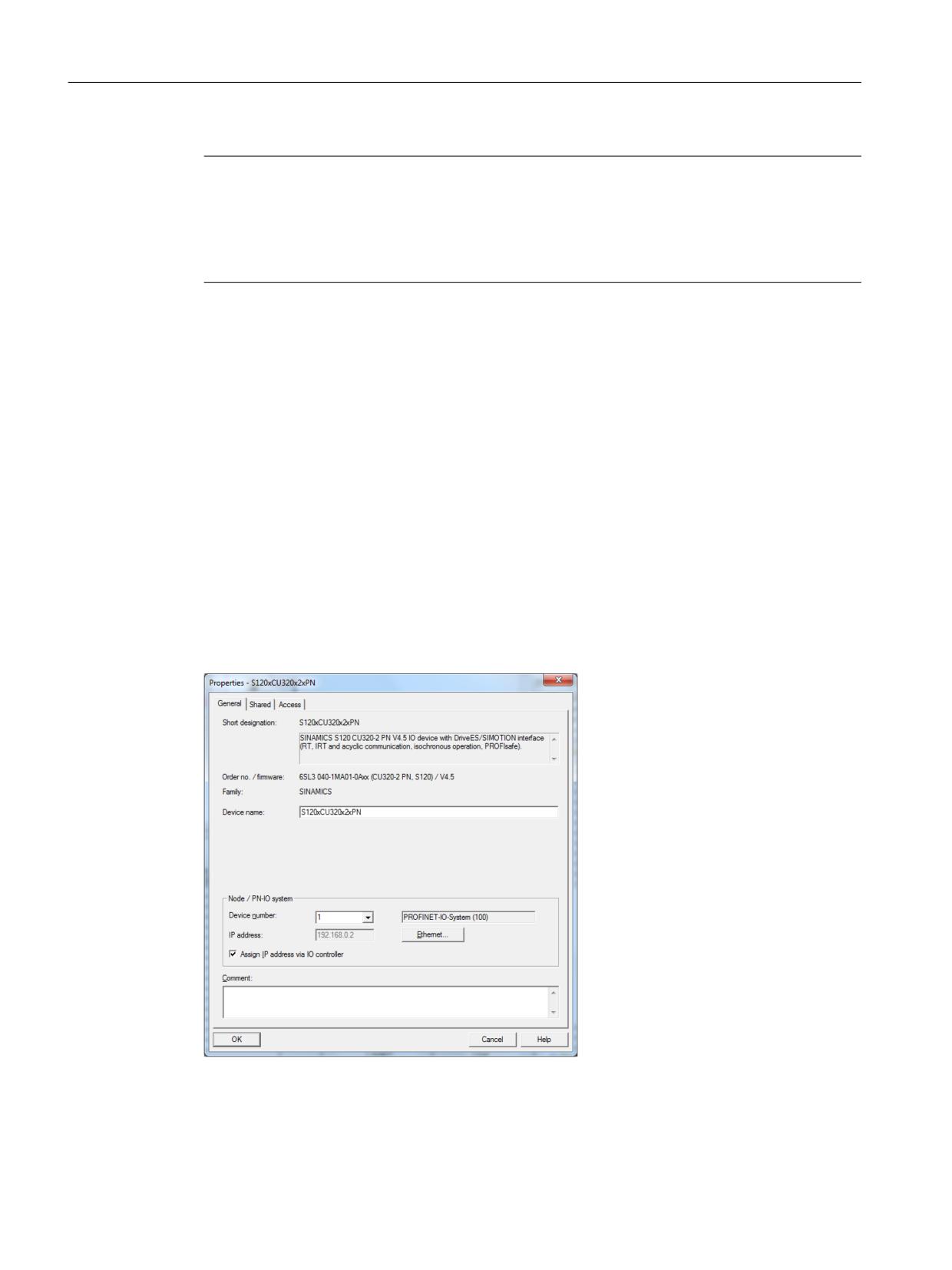
PLC commissioning
5.3 Extending the SIMATIC S7 project (PROFINET)
Note
Telegram 701
If further Safety Integrated functions are to be configured for an axis, telegram 701 is also
required. The configuration procedure is the same as for telegram 30.
The functions available for SINUMERIK are described in the Safety Integrated Function Manual.
5.3.5
Complete the PLC project
Complete the PLC project
Procedure:
1. Select the "Station" → "Save and compile" menu.
2. Click the "Load to module" button to load the configuration to the PLC: End the hardware
configuration and load it to the PLC (Page 87).
Topology-based device initialization
The topology-based device initialization is activated by selecting the option "Assign IP address by
I/O controller".
CNC Commissioning: NC, PLC, Drive
78
Commissioning Manual, 10/2020, A5E48312804B AB
PLC commissioning
5.3 Extending the SIMATIC S7 project (PROFINET)
Note
Topology-based device initialization
If a topology was defined in HW Config of the S7 project for the complete PROFINET IO system,
then it is no longer necessary to assign the device name ("initialization") by STEP 7. As a result
of the defined topology, the PLC-CPU automatically identifies and "initializes" the devices, the so-
called topology-based device initialization.
Displaying the device name in SINUMERIK Operate
The assigned name is output in the "PROFINET diagnostics" window as device name in
SINUMERIK Operate.
PROFINET naming conventions
Device names are assigned to the PROFINET IO devices during the commissioning phase.
In order to communicate with PROFINET devices, they must be initialized (assigned a name).
This name is the device name within the hardware configuration. This name must comply with
the PROFINET naming conventions. The rules of the naming conventions are checked by the
hardware configuration and, if required, corrected. Invalid characters are replaced by "X". The
following supplementary conditions must be maintained:
• Maximum length of 127 characters (letters "a" to "z", numbers "0" to "9", hyphen or period).
• A name component within the device name, e.g. a string between two periods, must not
exceed 63 characters.
• No special characters such as umlauts, parentheses, underscores, slashes, blanks, etc. are
permitted.
• The hyphen is the only special character permitted.
• Upper-case letters must not be used in device names.
• The device name must not begin or end with the "-" or "." character.
• The device name must not begin with numbers.
• The device name must not take the form n.n.n.n (n = 0...999).
• The device name must not start with the character string "port-xyz-" (x,y,z = 0...9).
Specifying device names for SINAMICS CU
Alternative procedure:
To permit the SINAMICS CU to be recognized by the SINUMERIK NCU and the communication via
X150 to be established, a device name must be assigned in the PLC configuring of the SINAMICS
Control Unit.
1. Establish an online connection to the target system via X150 with the PG/PC.
2. Select the SINAMICS Control Unit in HW Config.
3. Select the "Target system" → "Ethernet >" → "Assign device name" menu.
CNC Commissioning: NC, PLC, Drive
Commissioning Manual, 10/2020, A5E48312804B AB
79