SINUMERIK 840D sl. Service - Configuring Commissioning. Manual (2011-2020) - page 78
Installing and configuring updates and automation software
5.6 Configuring a key filter for HMI software
pcuhwsvc.ini (Vorlage im Verzeichnis ...\siemens\System\etc)
# -----------------------
# enable logfile PCUHardwareservice.log
EnableLogFile=0
# Emulating of "Mode-Switch" from Sinumerik PCU50 Box.
# "Mode-Switch" is a rotary switch, which is attached to the rear side of the PCU50 V5 Box.
# About this, different methods of booting the computer are controlled.
# 0 Normal mode
# 3 Desktop mode (welcome screen)
ModeSwitch=0
[SERVER]
FTP=hmisvr_PCU_betaftpd
DHCP=hmisvr_PCU_udhcpd
TFTP=hmisvr_PCU_netkit-tftpd
TCUHWS=hmisvr_TCU_hardware_services
VNC=uvnc_service
[APPLICATION]
# ---------------------------------------
# STARTUP APPLICATION DIAGNOSTIC SECTION
# ---------------------------------------
[KEYB_FILTER]
# -------------------------------------------
# SIEMENS KEYBOARD-FILTER DRIVER SECTION
# -------------------------------------------
# Filtering Key Sequences
# =======================
# Activation of Key-Sequences to be ignored
# SeqAct_x
# The following 20 sequences are implemented
# 0 CTRL-ALT-DEL
# 1 ALT-F4
# 2 ALT-TAB
# 3 LEFTSHIFT-ALT-TAB
# 4 RIGHTSHIFT-ALT-TAB
# 5 CTRL-ESC
# 6 ALT-ESC
# 7 ALT-SPACE
# 8 (SHIFT)-CTRL-F1
# 9 (SHIFT)-CTRL-F2
# 10 (SHIFT)-CTRL-F3
# 11 (SHIFT)-CTRL-F4
# 12 (SHIFT)-CTRL-F5
PCU Base for IPC
Commissioning Manual, 10/2020, 6FC5397-2HP40-0BA1
99
Installing and configuring updates and automation software
5.6 Configuring a key filter for HMI software
pcuhwsvc.ini (Vorlage im Verzeichnis ...\siemens\System\etc)
# 13 (SHIFT)-CTRL-F6
# 14 (SHIFT)-CTRL-F7
# 15 (SHIFT)-CTRL-F8
# 16 M$_1
# 17 M$_2
# 18 CAPSLOCK
# 19 NUMLOCK
# 20 (reserved)
KeySequencesEnable = 0
SeqActive_0= 1
SeqActive_1= 1
SeqActive_2= 1
SeqActive_3= 1
SeqActive_4= 1
SeqActive_5= 1
SeqActive_6= 1
SeqActive_7= 1
SeqActive_8= 1
SeqActive_9= 1
SeqActive_11= 1
SeqActive_12= 1
SeqActive_13= 1
SeqActive_14= 1
SeqActive_15= 1
SeqActive_16= 1
SeqActive_17= 1
SeqActive_18= 1
SeqActive_19= 1
SeqActive_20= 1
# Autorepeat-Suppression of Function Keys F1-F12 and Hardkeys
#===============================================
AutorepeatSuppression = 0
PCU Base for IPC
100
Commissioning Manual, 10/2020, 6FC5397-2HP40-0BA1
Installing and configuring updates and automation software
5.7 Installing STEP 7
5.7
Installing STEP 7
Precondition
• The Service Desktop is active
• The STEP 7 product DVD is available on the PC system, e.g. via an external DVD drive or
network.
Procedure
1. To start the installation assistant of STEP 7, on the product DVD in directory "CD_1", double-
click setup.exe
2. Confirm the preselected directory under C:\Program Files (x86)\Siemens\Step7\
as the installation directory.
3. In step "Transfer license keys", select "No, transfer license keys later".
Note
Licensing of STEP 7 with SINUMERIK Add-on
The licensing for STEP 7 is performed during installation of the SINUMERIK Add-on.
4. After you have installed STEP 7, restart the PC system and switch to the Service Desktop.
5. To start the installation wizard of the SINUMERIK Add-on, double-click setup.exe on the
product DVD in directory "Sinumerik_Add_On".
The installation wizard guides you through the following steps.
6. After you have installed the SINUMERIK Add-on, restart the PC system.
Result
STEP 7 has been installed with SINUMERIK Add-on.
The software has been registered in the Control Panel under the following designations:
• STEP 7
• SINUMERIK add-on for STEP7
PCU Base for IPC
Commissioning Manual, 10/2020, 6FC5397-2HP40-0BA1
101
Installing and configuring updates and automation software
5.8 Linking the HMI software with STEP 7
5.8
Linking the HMI software with STEP 7
If you want to make it possible to start STEP 7 directly from the user interface of the installed HMI
software, add a softkey to it.
Precondition
• STEP 7 V5.5 SP3 or higher is installed
• The SINUMERIK Add-on for STEP 7 V5.5 or higher is installed
• An HMI software version is installed (SINUMERIK Operate or HMI Pro sl)
• The Service Desktop is active
Procedure
To add a softkey to the menu of the HMI software for starting STEP 7, proceed as follows:
1. Double-click the "STEP7-Authorizing" desktop icon.
Result
A softkey for starting STEP 7 has been added to the HMI software. This softkey requires access
level 3.
In C:\Program Files (x86)\Siemens\MotionControl\compat\add_on
\oemframe.ini, the following settings have been made for this purpose:
[s7tgtopx]
; with HMI-Advanced: eliminate minimize- / maximize-buttons of the
STEP7-window
WindowStyle_Off=196608
; with HMI-Advanced: switch to previous task when STEP7 is terminated
nSwitchToTaskAfterTermination= -2
Note
Adjustments for OEM configurations
The entries in oemframe.ini can be modified for OEM configurations.
For more information about templates for parameterizing the system, see Chapter Directory
structure and file conventions (Page 23).
PCU Base for IPC
102
Commissioning Manual, 10/2020, 6FC5397-2HP40-0BA1
Installing and configuring updates and automation software
5.9 PCU Installer
5.9
PCU Installer
5.9.1
Overview
The PCU Installer assists you with the installation of setup packages on PC systems:
• The PCU Installer checks definable setup directories on the PC system, on removable data
storage media, or in the network.
These setup directories must not be write-protected.
• If setup packages exist, they are automatically installed one after the other. The order in
which these packages are installed can be parameterized (Page 107).
• On the top right of the screen, a status display is displayed while the PCU Installer carries out
such activities.
For further information on the activities of the PCU Installer, see Chapter Procedure example
of an installation with the PCU Installer (Page 112).
Overview of the configuration and operation
• When PCU Base for IPC is delivered the PCU Installer is deactivated. You can activate the PCU
Installer during the unsupervised installation of PCU Base for IPC via the response file
or activate it manually after the supervised installation (Page 103).
• After you have made all of the settings for the PCU Installer, using program application
Configure for CMC you can also activate or deactivate the PCU Installer (Page 114).
• You can make all settings in the PCU Installer in the associated configuration file (Page 107).
• Copy the setup packages to the defined directories to start the installation (Page 112).
• The PCU Installer consists of a client and a service, whereby setup packages can also be
installed for a user account without administrator rights.
5.9.2
Activating the PCU Installer
5.9.2.1
Overview
In the delivery condition of the PCU base software, the PCU Installer is deactivated.
If you are supervising the installation of PCU Base for IPC with Windows 10, then you must
manually activate PCU Installer. To do this, use one of the following procedures:
• Copy a preconfigured template of the PCUInst.ini to the "user" directory (Page 104)
• Create your own version of the PCUInst.ini in one of the user directories and set the
appropriate values
See: Reference to the PCUInst.ini configuration file (Page 107)
PCU Base for IPC
Commissioning Manual, 10/2020, 6FC5397-2HP40-0BA1
103
Installing and configuring updates and automation software
5.9 PCU Installer
5.9.2.2
Activating via a configuration template
Requirement
• The PCU Installer is deactivated
• The Service Desktop is active
• The PCU Installer has not been configured yet and there is no adapted PCUInst.ini
configuration file
Procedure
To activate the PCU Installer by copying a preconfigured template, proceed as follows:
1. Copy the following file to the clipboard: D:\etc\Template_PCUInst.ini
2. Paste the file into the following directory: C:\ProgramData\Siemens\MotionControl
\user\system\etc
3. Rename the copied file to PCUInst.ini
Result
The PCU Installer has been activated and checks the setup directories during startup of the PC
system, but not during system operation.
The copied configuration file only differs from the default configuration file by the following
value:
[processing_loginphase]
StartState=activated
The settings of the copied configuration file are used because they are in a directory with higher
priority than the default configuration file.
See: Directory structure and file conventions (Page 23)
To also use the PCU Installer during system operation, you must make an additional setting in the
copied configuration file (Page 107):
[processing_systemphase]
StartState=activated
PCU Base for IPC
104
Commissioning Manual, 10/2020, 6FC5397-2HP40-0BA1
Installing and configuring updates and automation software
5.9 PCU Installer
5.9.3
Deactivating the PCU Installer
When PCU Base for IPC is delivered the PCU Installer is deactivated.
Note
Troubleshooting for incorrect installation routines
If completion of an installation requires a restart, but the installation cannot be completed after
the restart, the Service Desktop is not started.
In this case, restart the PC system in protected mode to prevent the PCU Installer from starting.
Then reconfigure the PCU Installer or remove the setup packages.
Precondition
• The Service Desktop is active
• Hidden directories are not shown (at least C:\ProgramData\)
Further information: Directories hidden in delivery condition (Page 23).
• A copy of the PCUInst.ini configuration file is stored in the user
directory: C:\ProgramData\Siemens\MotionControl\user\System\etc
\PCUInst.ini
• The PCUInst.ini configuration file in the user directory is not write-protected
Procedure
To partly or completely deactivate the installation of the setup files by means of the PCU Installer,
proceed as follows:
1. Open the PCUInst.ini configuration file in the C:\ProgramData\Siemens
\MotionControl\user\System\etc\PCUInst.ini directory.
2. Deactivate the start of the PCU Installer in the desired phase:
- To deactivate the PCU Installer during system operation, change the relevant key value in
the [processing_systemphase] section: StartState=stopped.
- To only deactivate the PCU Installer while a specific application is being executed (e.g.
SINUMERIK Operate), enter the file name of the relevant application in
the [noactivation] section, e.g. APP001=run_hmi.exe
(You can specify any number of applications,
e.g. APP002=Siemens.Automation.Portal.exe)
- To deactivate the PCU Installer during run-up, change the relevant key value in
the [processing_loginphase] section: StartState=stopped.
3. Save and close the file.
PCU Base for IPC
Commissioning Manual, 10/2020, 6FC5397-2HP40-0BA1
105
Installing and configuring updates and automation software
5.9 PCU Installer
Further information
• For information on all configuration options, see Reference to the PCUInst.ini configuration
file (Page 107).
• Windows support: Start Windows 10 in the safe mode (https://support.microsoft.com/en-us/
help/12376/windows-10-start-your-pc-in-safe-mode)
5.9.4
Copying and adapting the configuration file
You can define PCU Installer operation in the associated configuration file. To do this, you must
first copy the configuration file to a user directory.
Alternatively, you can copy a template in which the PCU Installer has already been activated
(Page 104).
For example, you can configure the following in the configuration file:
• Which directories have been checked how many times for new setup packages.
• That installations are not started automatically while certain software is active.
A list of all setting options can be found under Reference to the PCUInst.ini configuration file
(Page 107).
Precondition
• The Service Desktop is active
• The PCU Installer has not been configured yet and there is no adapted PCUInst.ini
configuration file
PCU Base for IPC
106
Commissioning Manual, 10/2020, 6FC5397-2HP40-0BA1
Installing and configuring updates and automation software
5.9 PCU Installer
Procedure
To copy and adapt the configuration file of the PCU Installer, proceed as follows:
1.
Switch to the template directory: C:\ProgramData\Siemens\MotionControl
\siemens\System\etc\
The settings can be viewed in the template PCUInst.ini.
2.
Save a copy of the template PCUInst.ini to one of the user directories:
- C:\ProgramData\Siemens\MotionControl\user\System\etc\
- C:\ProgramData\Siemens\MotionControl\oem\System\etc\
- C:\ProgramData\Siemens\MotionControl\addon\System\etc\
Note
Storage of the configuration file in the setup directory
Alternatively, a configuration file can also be located directly with an installation setup.
In other words, if, for example, E:\Setup is a setup directory, this (or one of the direct
subdirectories) can be the location of a configuration file. Settings made in this configuration
file have a higher weighting than the settings in configuration files in the above-mentioned
directories.
3.
Adapt the values of the keys. You will find information about the syntax and setting options
at Reference to the PCUInst.ini configuration file (Page 107) or in the comments of the
configuration file.
Note
The factory setting is taken if key pairs are missing
All key pairs that are not available in your file are taken automatically from the template in
the siemens directory.
Therefore, in the new file (e.g
\oem\System\etc\PCUInst.ini), delete all the data
except the section names and the keys that are to differ from the template.
Further information: Directory structure and file conventions (Page 23), Reference to the
PCUInst.ini configuration file (Page 107)
4.
Save and close the file.
Result
The configuration file has been copied to a user directory and can be adapted.
Further information on the various setting options is provided in the following Chapters.
5.9.5
Reference to the PCUInst.ini configuration file
You can define PCU Installer operation in the associated PCUInst.ini configuration file.
PCU Base for IPC
Commissioning Manual, 10/2020, 6FC5397-2HP40-0BA1
107
Installing and configuring updates and automation software
5.9 PCU Installer
For example, you can configure the following:
• Which directories have been checked how many times for new setup packages.
• That installations are not started automatically while certain software is active.
The priority concept of this configuration file is the same as that of the other configuration files.
Further information: Directory structure and file conventions (Page 23)
You can also deactivate settings in PCUInst.ini by deleting the value of the key in the higher
priority configuration file. For example, to deactivate DIR002=C:\Setup in a file of lower
priority, enter DIR002= in the file with higher priority.
Note
Maximum length of the file path
The file path to a setup must not exceed 255 characters (including the file name).
Table 5-2
Setting options in the configuration file of the PCU Installer
Section
Setting
Description
[local_setupdirs]
DIR001=
Specifies the local setup directories on the PC system to be checked.
DIR002=
The directories must not be write-protected.
You can specify several directories, which are then checked in the specified order.
You define the order with a number after "DIR".
Subdirectories at the first level are also scanned.
[removable_
DIR001=
Specifies the setup directories on removable data storage media to be checked.
setupdirs]
DIR002=
The directories must not be write-protected.
You can specify several directories, which are then checked in the specified order.
You define the order with a number after "DIR".
Subdirectories at the first level are also scanned.
If you do not know the drive letters to be checked, use the <REMOVABLE_MEDIA> drive
variable, e.g.:
DIR001=<REMOVABLE_MEDIA>:\Install
The drive variable then represents all the removable data storage media that are known
at the time in Windows. You can also specify fixed drive letters without the directories
being checked twice.
The drive variable is only valid in the [removable_setupdirs] section.
[net_setupdirs]
DIR001=
Specifies the setup directories on network drives to be checked.
DIR002=
The directories must not be write-protected.
Further information: Creating a shortcut to the network drive (Page 145)
You can specify several directories, which are then checked in the specified order.
You define the order with a number after "DIR".
Subdirectories at the first level are also scanned.
PCU Base for IPC
108
Commissioning Manual, 10/2020, 6FC5397-2HP40-0BA1

Installing and configuring updates and automation software
5.9 PCU Installer
Section
Setting
Description
[setupdirs_
deleteTmpLocal
Temporary directories are created during installation of a setup from a removable data
storage medium, network drive or the default setup directory D:\Install
settings]
SetupDirs=
Further information: Procedure example of an installation with the PCU Installer
(Page 112)
Here you can specify whether these temporary directories are to be deleted again after
installation.
Possible values: yes; no
keepDInstall
You can specify that subdirectories of D:\Install with a particular prefix in the di-
rectory name are not to be deleted after setup is completed.
SubdirsWithPrefix=
[setupnames]
NAME001=
Specifies which files are setup packages and are to be included in the check of setup
directories.
NAME002=
You can specify entire file names with their file extensions or represent individual parts
of them with wildcard character *.
[setupexecution]
checkSetupLogFile=
Specifies whether a check is to be performed as to whether the file has already been
installed before the installation of a setup file.
The check is performed based on the computer name and the setup name of the setup-
specific log file.
Possible values: yes; no
copyToTmp
You can specify whether setup files on removable data storage media are to be copied
to a temporary, local directory before installation.
LocalSetupDir=
Setup files on network drives are always copied before installation.
Possible values: yes; no
[noactivation]
APP001=
Specifies which applications of the PCU Installer are inactive during operation.
APP002=
This setting is required to prevent operation of the HMI software or another application
from being interrupted during execution of a setup.
PCU Base for IPC
Commissioning Manual, 10/2020, 6FC5397-2HP40-0BA1
109

Installing and configuring updates and automation software
5.9 PCU Installer
Section
Setting
Description
[processing_
StartState=
Specifies whether the PCU Installer is active before the Desktop runs up.
loginphase]
The setting StartState=activated is required, in particular, if an installation re-
quires a cold start.
Possible values:
• activated
PCU Installer starts setups
• stopped
PCU Installer is stopped completely
continueSetups=
Some setups can only be completed after the system has been restarted. In this case, the
PCU Installer waits until you restart the PC system.
You can specify here whether setups such as these are to be continued after a restart.
Further information: Note: Troubleshooting for incorrect installation routines
(Page 112)
Possible values: yes; no
scanSetupDirs=
Specifies whether setup directories are to be checked and, if required, setup files exe-
cuted before the Desktop run-up.
The following directories are checked if this setting has been activated:
• Local setup directories from the [local_setupdirs] setting are always checked.
• You can define separately whether additional directories on removable data storage
media or in the network are to be checked. (See settings "scanRemovableDriveSe-
tupDirs" and "scanNetworkDriveSetupDirs")
If you deactivate this setting, neither local directories, nor directories on removable data
storage media or in the network are checked, i.e. the setting scanSetupDirs=no over-
writes, for example, scanNetworkDriveSetupDirs=yes.
Possible values: yes; no
scanRemovableDrive
Specifies whether directories on removable data storage media are to be checked from
the setting [removable_setupdirs] and, if required, setup files executed before the
SetupDirs=
Desktop run-up.
The setting "scanSetupDirs" must also be activated so that these directories are checked.
Possible values: yes; no
scanNetworkDrive
Specifies whether network directories are to be checked from the setting [net_setup-
dirs] and, if required, setup files executed before the Desktop run-up.
SetupDirs=
The setting "scanSetupDirs" must also be activated so that these directories are checked.
Possible values: yes; no
waitTimeDevicesDete
Specifies the maximum wait time for device detection (removable data storage media)
ction=
in the system run-up. This setting is only relevant if the PCU Installer searches for setups
on removable data storage media prior to the desktop run-up. (See settings "scanSe-
tupDirs", "scanRemovableDriveSetupDirs" in the section [processing_loginphase] and
section [removable_setupdirs])
Possible values:
• Positive integer (milliseconds)
• infinite
waitTimeDriveLetter
Specifies how long the PCU Installer will wait during the system run-up until the system
sAssignment=
has assigned a drive letter to all of the logical drives. This setting is only relevant if the
PCU Installer searches for setups on removable data storage media prior to the desktop
run-up. (See settings "scanSetupDirs", "scanRemovableDriveSetupDirs" in the section
[processing_loginphase] and section [removable_setupdirs])
Possible values:
• Positive integer (milliseconds)
• infinite
PCU Base for IPC
110
Commissioning Manual, 10/2020, 6FC5397-2HP40-0BA1

Installing and configuring updates and automation software
5.9 PCU Installer
Section
Setting
Description
[processing_
StartState=
Specifies whether the PCU Installer is active during operation of the Desktop.
systemphase]
Possible values:
• activated
PCU Installer starts setups
• stopped
PCU Installer is stopped completely
You can define exceptions in Section [noactivation].
scanSetupDirs=
Specifies whether setup directories are to be checked and, if required, setup files exe-
cuted during Desktop operation.
The following directories are checked if this setting has been activated:
• Local setup directories from the [local_setupdirs] setting are always checked.
• You can define separately whether additional directories on removable data storage
media or in the network are to be checked. (See settings "scanRemovableDriveSe-
tupDirs" and "scanNetworkDriveSetupDirs")
If you deactivate this setting, neither local directories, nor directories on removable data
storage media or in the network are checked, i.e. the setting scanSetupDirs=no over-
writes, for example, scanNetworkDriveSetupDirs=yes.
Possible values: yes; no
scanRemovableDrive
Specifies whether directories on removable data storage media are to be checked from
the setting [removable_setupdirs] and, if required, setup files executed during Desktop
SetupDirs=
operation.
The setting "scanSetupDirs" must also be activated so that these directories are checked.
Possible values: yes; no
scanNetworkDrive
Specifies whether network directories are to be checked from the setting [net_setup-
dirs] and, if required, setup files executed during Desktop operation.
SetupDirs=
The setting "scanSetupDirs" must also be activated so that these directories are checked.
Possible values: yes; no
numberOfScanCycles
Specifies whether and how often the setup directories check for new setup packages.
Possible values:
• infinite
Infinite
• Integer
You can define the waiting time between checks in
key waitTimeBetweenScanCycles
waitTimeBetween
Specifies how long the PCU Installer waits after the setup directories have been checked
before checking them again.
ScanCycles
Enter the waiting time in milliseconds.
In key numberOfScanCycles, you can specify how often the setup directories will be
checked.
report
InfoLevel
Specifies how detailed the information is to be which is stored in the log files.
Possible values:
•
1: Only basic information on the actions of the PCU Installer is logged
•
2: All PCU Installer-specific information is logged
•
3: All PCU Installer-specific information and some trace information is logged
•
4: All PCU Installer-specific information and additional trace information is logged
•
5: All PCU Installer-specific information and all trace information is logged
PCU Base for IPC
Commissioning Manual, 10/2020, 6FC5397-2HP40-0BA1
111
Installing and configuring updates and automation software
5.9 PCU Installer
5.9.6
Installing software with the PCU Installer
Precondition
• The PCU Installer is activated
• If you want to install multiple setup packages one after the other, you must have defined
multiple setup directories in the configuration file
• The setup directories to be used are empty and not write-protected
Procedure
To make the PCU Installer accessible to setup packages, proceed as follows:
1. Copy the setup packages to be installed into the setup directories. Copy each setup package
into a separate directory.
Note
Maximum length of the file path
The file path to a setup must not exceed 255 characters (including the file name).
Result
The installation of the setup packages is started.
After a setup has been completed or cancelled, a specific log file is stored in the associated setup
directory. The general log files of the PCU Installer are also supplemented in the log directory.
Further information
• Log files (.log) (Page 113)
• Procedure example of an installation with the PCU Installer (Page 112)
Note
Troubleshooting for incorrect installation routines
If completion of an installation requires a restart, but the installation cannot be completed after
the restart, the Service Desktop is not started.
In this case, restart the PC system in protected mode to prevent the PCU Installer from starting.
Then reconfigure the PCU Installer or remove the setup packages.
5.9.7
Procedure example of an installation with the PCU Installer
The following example describes the activities of the PCU Installer if you have stored a setup file
on a removable data storage media or network drive after the activation and configuration of the
PCU Installer.
PCU Base for IPC
112
Commissioning Manual, 10/2020, 6FC5397-2HP40-0BA1
Installing and configuring updates and automation software
5.9 PCU Installer
In this procedure example, it is assumed that you have already performed the following steps:
• You have activated the PCU Installer
• You have activated the checking of the network directories in the settings of the PCU Installer
and defined an additional setup directory on a network drive.
In the example: F:\Setup with F: as network drive.
• You have stored a setup file in this additional setup directory (e.g. F:\Setup\Update.exe).
• The setup directory is not write-protected.
Example: Activities of the PCU Installer during installation of a network drive
• The defined setup directories are checked.
• The Update.exe file is found in the F:\Setup directory.
As the Update.exe file has not been installed yet, there is no setup-specific log file in the
directory.
• The Update.exe file is copied to a local temporary directory, e.g. D:\Install39\Update.exe
• The copied setup file is executed from the local temporary directory, e.g.
D:\Install39\Update.exe.
• Log files are created after completion of the installation:
- The general log files are extended
- The setup-specific log file is created in the original setup directory F:\Setup and in the local
temporary directory D:\Install39
Further information: Log files (.log) (Page 113)
5.9.8
Log files (.log)
In order to be able to track which setup packages and updates have been installed at any time,
the activities of the PCU Installer are recorded in various log files.
Setup-specific log files
A separate setup-specific log file is created for each setup package that is executed by the
PCU Installer. The name of the setup and the name of the computer are entered in the file name
of the log.
Archiving
The setup directory in which the associated setup file was originally
located, and (if copied by the setup) the local temporary directory.
File name
The log file is designated according to the following scheme:
<Name of the setup file>@<Computer name>.log, e.g. Up-
date@MyIPC.log
If you activate the checkSetupLogFile= setting in the "PCUInst.ini" configuration file (Page 107),
then the setup-specific log file prevents the same setup being installed several times on the same
computer. The check is performed based on the computer name and the setup name.
PCU Base for IPC
Commissioning Manual, 10/2020, 6FC5397-2HP40-0BA1
113
Installing and configuring updates and automation software
5.9 PCU Installer
In the delivery condition of the base software, this setting is deactivated. The setting should
remain deactivated for the series start-up of devices with the same name or for the repair of an
installation.
General log files
The general PCU Installer log files record the operation and the communication of the PCU
Installer client and PCU Installer service. There are therefore separate files for the client and
service.
Archiving
C:\ProgramData\Siemens\MotionControl\User\System
\Log\
File name
PCU Installer client: PCUInstaller_C.log
PCU Installer service: PCUInstaller_S.log
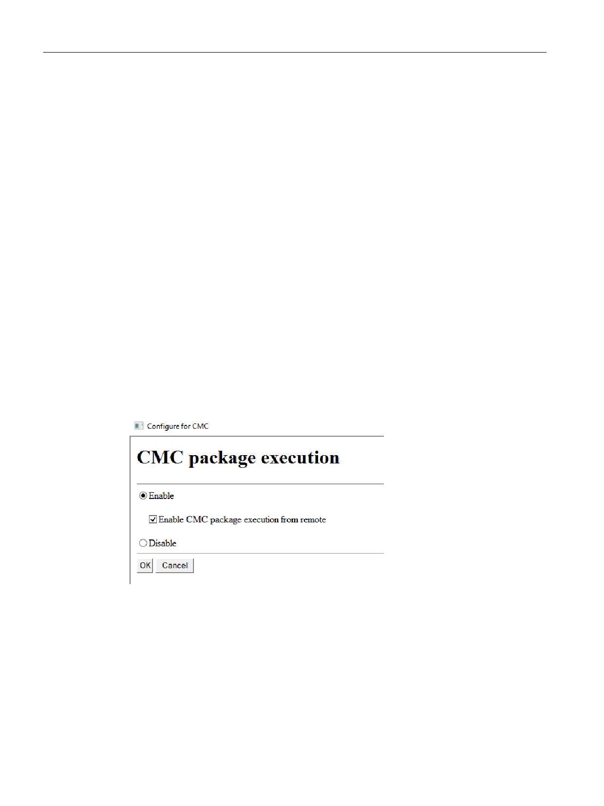
5.9.9
Program application Configure for CMC
Overview
Using Configure for CMC you can activate or deactivate the PCU Installer, and therefore execute
setup packages on the PC system, removable data storage medium or network without having
to make any manual changes to PCUInst.ini.
Figure 5-2
Program application Configure for CMC
Precondition
• The PCU Installer was configured.
• An adapted configuration file PCUInst.ini exists.
PCU Base for IPC
114
Commissioning Manual, 10/2020, 6FC5397-2HP40-0BA1
Installing and configuring updates and automation software
5.9 PCU Installer
Procedure
1. Open the program application using icon "Configure for CMC" on the desktop.
2. Using the option box, activate or deactivate the check for setup packages.
3. Confirm with OK to accept the setting.
The setting becomes active after restarting Windows.
PCU Base for IPC
Commissioning Manual, 10/2020, 6FC5397-2HP40-0BA1
115
Installing and configuring updates and automation software
5.10 Migration
5.10
Migration
Basic procedure
To transfer data from a PCU with Windows 7 to a Siemens PC system with Windows 10, store the
data on a USB flash drive, for example, and then copy it to the PC system:
• For SINUMERIK Operate, use the functions for generating and reading in commissioning
archives.
• For STEP 7, copy the generated STEP 7 project data to the PC system.
Further information
• Further information about how commissioning archives function is provided in the
SINUMERIK Operate Commissioning Manual.
• Information on STEP 7 can be found in the associated online help.
• Information about other SINUMERIK applications is provided in the relevant documentation.
You will find documentation on a large number of products in the SIEMENS Service&Support
portal:
Service&Support portal > CNC automation system SINUMERIK (http://
support.automation.siemens.com/WW/view/en/10805517/133300)
PCU Base for IPC
116
Commissioning Manual, 10/2020, 6FC5397-2HP40-0BA1
Backing up and restoring data
6
6.1
Overview
You can perform installation and commissioning work on the PC system in the Service Center,
which is based on Microsoft Windows PE.
When the Desktop is active, configuration of the Service Center is possible via the "ServiceCenter
Backup-Restore" (Page 63) icon.
Most of the functions of the Service Center are available in the main menu (Page 119).
In particular, you can create or restore disk images in the Service Center. The following options
are available:
• Create a disk image of the SSD (Page 124)
• Restore a disk image of the SSD (Page 126)
• Create a disk image of a partition (Page 128)
• Restore a disk image of a partition (Page 130)
Further information
The Service Center uses the Symantec Ghost (Page 134) software, which you can also call
separately.
PCU Base for IPC
Commissioning Manual, 10/2020, 6FC5397-2HP40-0BA1
117
Backing up and restoring data
6.2 Starting the Service Center
6.2
Starting the Service Center
To start the Service Center, proceed in one of the following ways:
• To call up the Service Center on the SSD while the PC system is running up, select the "Booting
Service System" during run-up in the Windows boot menu.
• To call up the emergency boot system on a USB flash drive while the PC system is running up,
set the service switch to E or press F12 or Esc while running up to show the boot selection.
• To switch to the Service Center while the Service Desktop (Windows 10) is active, click the
"ServiceCenter Backup-Restore" icon on the Desktop and then click "Start ServiceSystem".
PCU Base for IPC
118
Commissioning Manual, 10/2020, 6FC5397-2HP40-0BA1
Backing up and restoring data
6.3 Functions of the Service Center
6.3
Functions of the Service Center
Overview
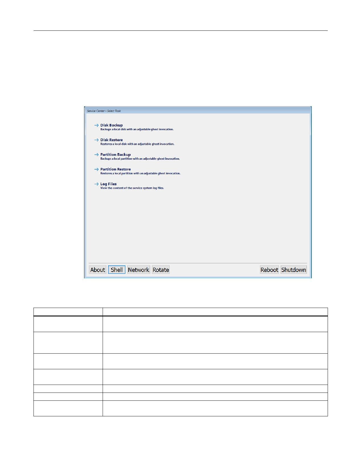
In the upper section of the Service Center main menu, you can select one of five tasks. Buttons
for additional functions are available in the lower section.
Figure 6-1
Service Center - Main menu
Table 6-1
Functions in the main menu of the Service Center
Element of the window
Purpose
Disk Backup
Create a disk image of the local SSD.
With this command, you can create a disk image of the entire SSD (with all partitions).
Disk Restore
Restore the local SSD with an existing disk image.
With this command, you can restore the complete SSD (with all partitions) with a previously created disk
image.
Partition Backup
Create a disk image of a partition on the local SSD.
With this command, you can create a disk image of an individual partition of the SSD.
Partition Restore
Restore a partition on the local SSD with a disk image.
With this command, you can restore an individual partition of the SSD with a previously created disk image.
Log Files
View and save log files.
About
Viewing information about the Service Center.
Shell
Open the Prompt.
Here you can enter commands for executing tasks on the PC system without using a graphic user interface.
PCU Base for IPC
Commissioning Manual, 10/2020, 6FC5397-2HP40-0BA1
119
Backing up and restoring data
6.3 Functions of the Service Center
Element of the window
Purpose
Network
Making network settings (Page 121).
Any network settings you make in this dialog box are temporary. To change network settings permanently,
switch to the Service Desktop.
Rotate
Rotates the screen through 90° in the clockwise direction.
Reboot
Restart the PC system.
Shutdown
Shut down the PC system.
Note
Data backup and restore with CompactFlash cards
If there is a CompactFlash card in the slot of the PC system, you will not be able to back up or
restore data via the Service Center.
Instead, start the "ghost32.exe" program via the prompt of the Service Center.
PCU Base for IPC
120
Commissioning Manual, 10/2020, 6FC5397-2HP40-0BA1
Backing up and restoring data
6.4 Network settings in the Service Center
6.4
Network settings in the Service Center
You can make network settings in the main menu of the Service Center by clicking "Network":
• IP settings at the enterprise network interface X1 (Local Area Connection 2)
• IP settings at the plant network interface X2 (Local Area Connection)
• Configuration of the host
• Configuration of IP routing
Note
Temporarily storing network settings in the Service Center
Any network settings you make in this dialog box are immediately effective, but temporary.
To change network settings permanently, switch to the Service Desktop.
Further information can be found in Chapter Configuration of the Service Center (Page 63).
Overview
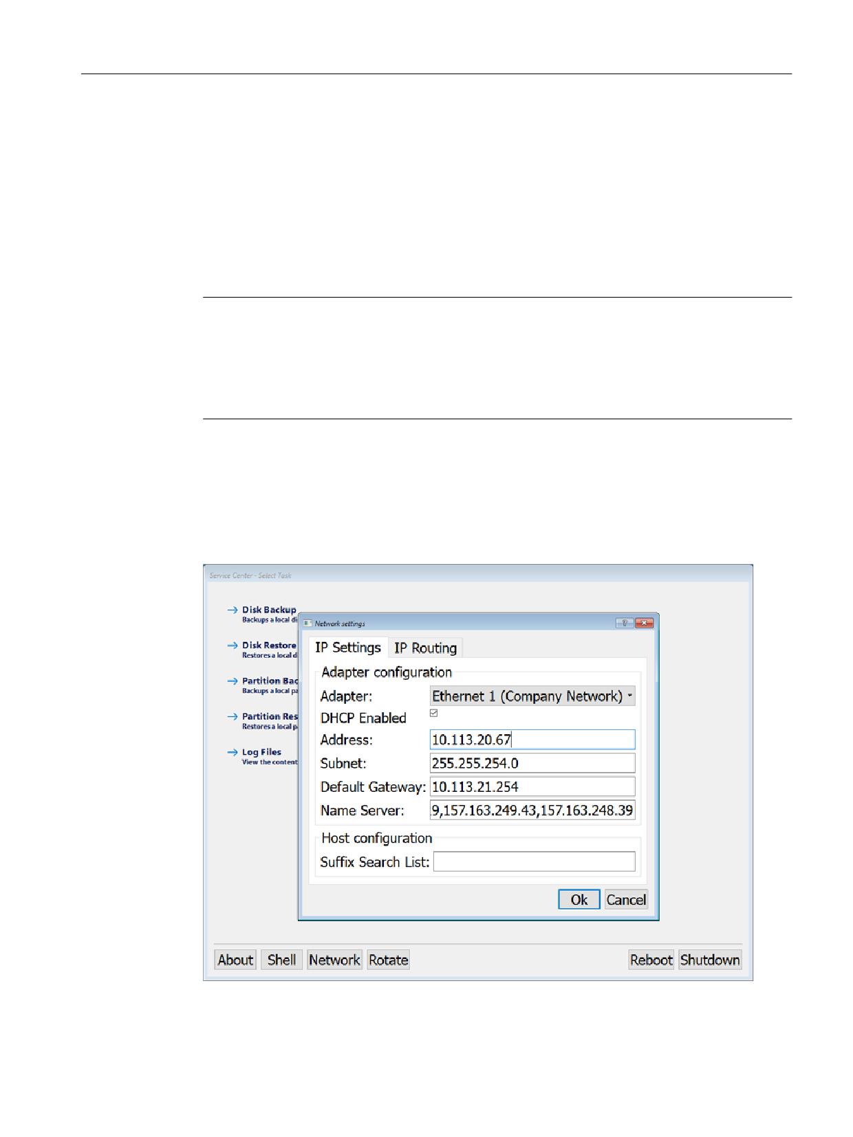
IP settings
You can make the following IP settings in the "Network Settings" dialog box:
Figure 6-2
Service Center - IP settings
PCU Base for IPC
Commissioning Manual, 10/2020, 6FC5397-2HP40-0BA1
121

Backing up and restoring data
6.4 Network settings in the Service Center
Note
The IP settings can only be parameterized with a connected network interface.
Table 6-2
IP settings in the "Network Settings" dialog box
Section
Setting
Purpose
Adapter configuration
Adapter
Select the Ethernet interface that you want to
configure.
All settings in Section "Adapter configuration"
refer to the selected Ethernet interface.
DHCP Enabled
Select whether the addresses are to be fetch-
ed dynamically from the DHCP server.
If the checkbox is deactivated, you must make
the settings manually.
Address
Set the IP address of the NCU.
You can specify an IP address from the follow-
ing range:
192.168.214.250 - 254
Subnet
Specify a subnet mask, e.g. 255.255.255.0
Default Gateway
Set the IP address of the standard gateway.
A standard gateway creates a standard route
in the IP routing table for all destinations that
are not in the subnet.
Name Server
Set the IP address of the name server.
A name server answers questions asked about
a domain name zone using a DNS database.
Host configuration
Suffix Search List
Parameterize a search list for DNS suffix, e.g.
"network.com".
The factory setting of the Ethernet interface
"Local Area Connection" is ".local".
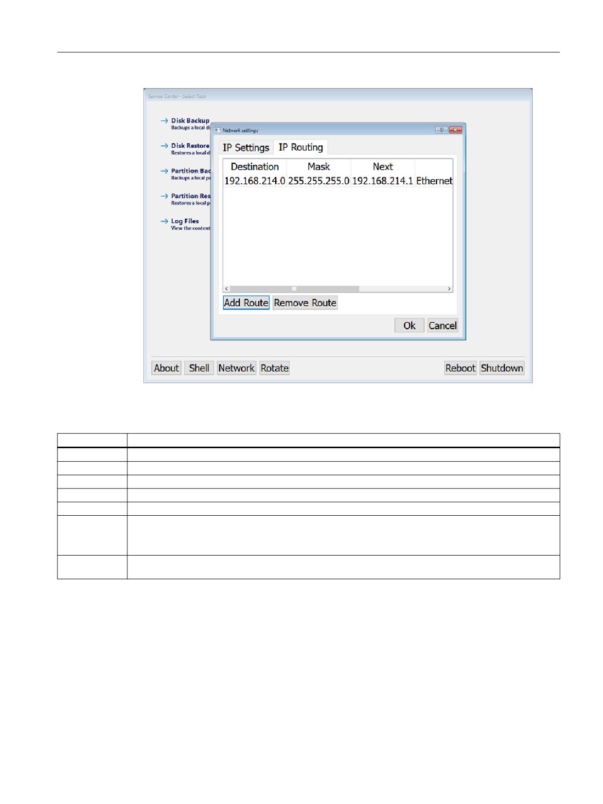
Routing settings
You can make the following routing settings in the "Network Settings" dialog box:
PCU Base for IPC
122
Commissioning Manual, 10/2020, 6FC5397-2HP40-0BA1
Backing up and restoring data
6.4 Network settings in the Service Center
Figure 6-3
Service Center - IP routing
Table 6-3
Routing settings in the "Network Settings" dialog box
Setting
Purpose
Add Route
Add a new route.
Remove Route
Delete a selected route.
Destination
Specify the network destination of the route as an IP address.
Mask
Subnet mask of the specified IP addresses.
Next
Next hop or forwarding IP address via which the network destination can be accessed.
Interface
Select an interface to which the configured IP routing applies:
• Enterprise network interface X1 (Local Area Connection 2)
• Plant network interface X2 (Local Area Connection)
Metric
Integer cost metric (1 to 9999). Required if several routes for sending a packet to a network destination are possible in the
routing table.
PCU Base for IPC
Commissioning Manual, 10/2020, 6FC5397-2HP40-0BA1
123
Backing up and restoring data
6.5 Create a disk image of the SSD
6.5
Create a disk image of the SSD
You can create a disk image of the entire SSD in the Service Center with the "Disk Backup"
function.
Procedure
To save the SSD as a disk image, proceed as follows:
1. Start the Service Center, e.g. from the Windows boot menu.
Further information: Starting the Service Center (Page 118)
2. In the main menu of the Service Center, click "Disk Backup".
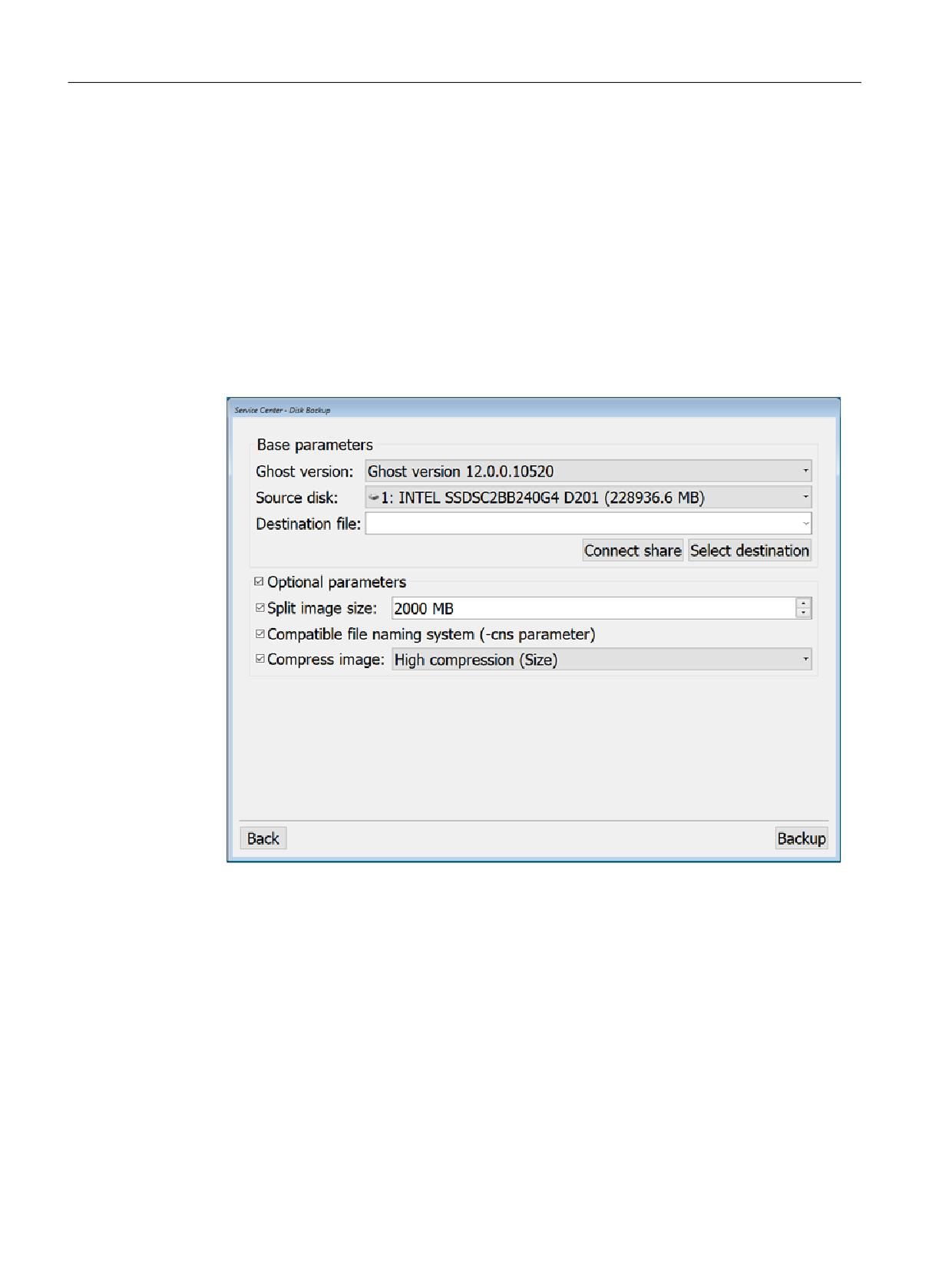
The "Service Center - Disk Backup" dialog box opens.
Figure 6-4
Service Center - Disk Backup
PCU Base for IPC
124
Commissioning Manual, 10/2020, 6FC5397-2HP40-0BA1

Backing up and restoring data
6.5 Create a disk image of the SSD
3. Make the required settings here:
Section
Setting
Purpose
Base parame-
Ghost version
Select the Symantec Ghost version that is to be used when cre-
ters
ating the disk image:
• Version for Windows 10: "Ghost version 12.0.x"
• Version for Windows 7: "Ghost version 11.5.x"
• Version for Windows XP: "Ghost version 8.2.x"
Source disk
Select a data storage medium of which you want to create a disk
image.
Destination file
Specify the target directory and file name.
Disk images can be stored either locally or in the network.
Base parame-
Connect share
Open the "Connect a Share" dialog box (Page 132).
ters > Destina-
You can set up a shared resource (e.g. a directory in the network),
tion file
to which you can store the disk image.
Select destina-
Open the "Select Destination File" dialog box.
tion
You can navigate through a local directory of the PC system and
enter a file name.
Optional pa-
Split image size
Split the disk image and select a split image size.
rameters
You can split the disk image into several files of a defined size.
Split the disk image size in the following cases:
• If the file system (e.g. FAT32) can only manage files of a cer-
tain size.
• If the disk image is to be archived onto multiple data storage
media, for example, when using CDs.
Compatible file
Select the compatibility of the name scheme.
naming system
This option is required so that a disk image with older versions of
the "PCU-Basesoftware Windows XP" can be read in by Windows
XP.
It is not possible to use a different operating system on a Siemens
PC system other than the pre-installed system (e.g. Windows XP
running on a Windows 10 IPC).
Compress im-
Activate Compression or select a compression level.
age
Higher compression results in a smaller file size, but increases the
time needed to compress or decompress the data.
4. Confirm your settings with "Backup" to start generation of the disk image.
PCU Base for IPC
Commissioning Manual, 10/2020, 6FC5397-2HP40-0BA1
125
Backing up and restoring data
6.6 Restore a disk image of the SSD
6.6
Restore a disk image of the SSD
If your system is no longer functioning stably, you can restore it with a disk image.
Note
Restoring replaces all current files
When you restore the PC system from a disk image, all programs, settings and files are
completely replaced by the disk image. You cannot restore individual files or exclude individual
files from restoration.
Precondition
A disk image exists
Further information: Create a disk image of the SSD (Page 124)
Procedure
To restore a disk image, proceed as follows:
1. Start the Service Center, e.g. from the Windows boot menu.
Further information: Starting the Service Center (Page 118)
2. In the main menu of the Service Center, click "Disk Restore".
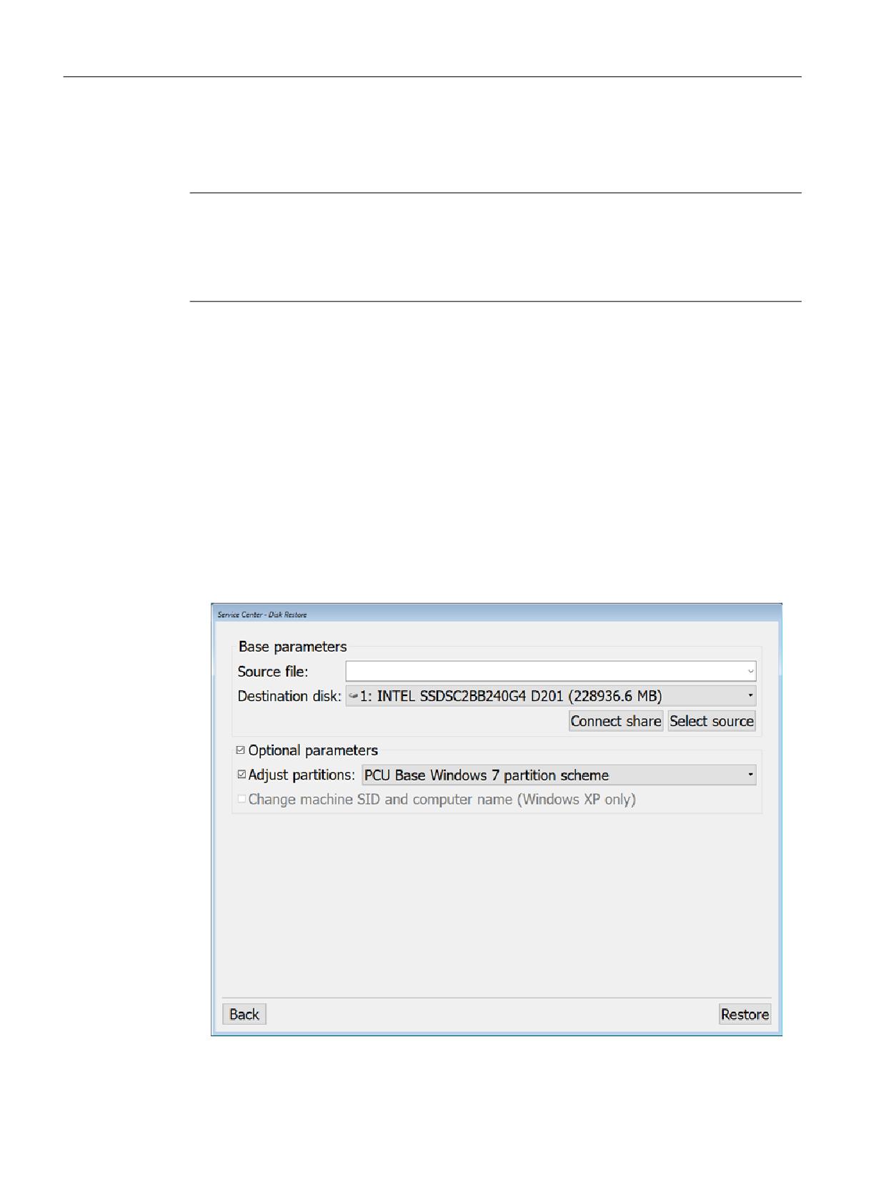
The "Disk Restore" dialog box opens.
Figure 6-5
Service Center - Disk Restore
PCU Base for IPC
126
Commissioning Manual, 10/2020, 6FC5397-2HP40-0BA1

Backing up and restoring data
6.6 Restore a disk image of the SSD
3. Make the required settings here:
Section
Setting
Purpose
Base parame-
Source file
Select the disk image from which the SSD is to be restored.
ters
You can use local disk images or disk images stored in the net-
work.
Destination disk
Select the SSD to be restored from the disk image.
Base parame-
Connect share
Open the "Connect a Share" dialog box (Page 132).
ters > Destina-
You can manage a shared resource (e.g. a directory in the net-
tion disk
work), to use a disk image stored on the network to restore the
SSD.
Select source
Open the "Select Source File" dialog box.
You can navigate through a local directory of the PC system and
select a disk image for restoration.
Optional pa-
Adjust parti-
Only PCU 50.x:
rameters
tions
Select the partition scheme to be used when restoring the disk
image on a PCU 50.x:
• If the PCU-Basesoftware Windows 7 is on the disk image,
choose "PCU Base Windows 7 partition scheme".
• If the PCU-Basesoftware Windows XP is on the disk image,
choose "PCU Base Windows XP partition scheme".
It is not possible to use a different operating system on a Siemens
PC system other than the pre-installed system (e.g. Windows XP
running on a Windows 10 IPC).
If you are using a different PC system than the PCU 50.5, you must
deactivate the "Adjust partitions" setting.
Change ma-
Only Windows XP:
chine SID and
After restoring the image, changes the computer name and the
Computer
computer SID. This option is only available if the Windows XP
Name
partition schematic was selected.
4. To start the restore process and entirely replace the existing data on the SSD with the disk
image, confirm the settings with "Restore".
Result
The restore process is started.
Note
Troubleshooting if reading in of the disk image fails
If data transfer is interrupted during the restore process, the PC system will have no executable
system.
In this case, use a bootable USB flash drive with Service Center to read the disk image in again.
PCU Base for IPC
Commissioning Manual, 10/2020, 6FC5397-2HP40-0BA1
127
Backing up and restoring data
6.7 Create a disk image of a partition
6.7
Create a disk image of a partition
You can create a disk image of an individual partition of the SSD in the Service Center with the
"Partition Backup" function.
Procedure
To save a partition of the SSD as a disk image, proceed as follows:
1. Start the Service Center, e.g. from the Windows boot menu.
Further information: Starting the Service Center (Page 118)
2. In the main menu of the Service Center, click "Partition Backup".
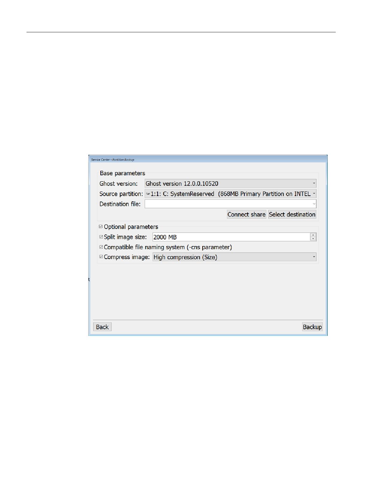
The "Service Center - Partition Backup" dialog box opens.
Figure 6-6
Service Center - Partition Backup
PCU Base for IPC
128
Commissioning Manual, 10/2020, 6FC5397-2HP40-0BA1

Backing up and restoring data
6.7 Create a disk image of a partition
3. Make the required settings here:
Section
Setting
Purpose
Base parame-
Ghost version
Select the Symantec Ghost version that is to be used when cre-
ters
ating the disk image:
• Version for Windows 10: "Ghost version 12.0.x"
• Version for Windows 7: "Ghost version 11.5.x"
• Version for Windows XP: "Ghost version 8.2.x"
Source partition
Select a data storage medium of which you want to create a disk
image.
Destination file
Enter a destination directory and file name.
Disk images can be stored either locally or in the network.
Base parame-
Connect share
Open the "Connect a Share" dialog box (Page 132).
ters > Destina-
You can set up a shared resource (e.g. a directory in the network),
tion file
to which you can store the disk image.
Select destina-
Open the "Select destination file" dialog box.
tion
You can navigate through a local directory of the PC system and
enter a file name.
Optional pa-
Split image size
Only PCU 50.x:
rameters
Split the disk image and select a split image size.
If you are using a PCU 50.5, you can split the disk image into
several files of a defined size.
Split the disk image size in the following cases:
• If the file system (e.g. FAT32) can only manage files of a cer-
tain size.
• If the disk image is to be archived onto multiple data storage
media, for example, when using CDs.
If you are using a different PC system than the PCU 50.5, you must
deactivate the "Split image size" setting.
Compatible file
Only Windows XP:
naming system
Select the compatibility of the name scheme.
This option is required so that a disk image with older versions of
the "PCU-Basesoftware Windows XP" can be read in by Windows
XP.
It is not possible to use a different operating system on a Siemens
PC system other than the pre-installed system (e.g. Windows XP
running on a Windows 10 IPC).
Compress im-
Activate Compression or select a compression level.
age
Higher compression results in a smaller file size, but increases the
time needed to compress or decompress the data.
4. Confirm your settings with "Backup" to start generation of the disk image.
PCU Base for IPC
Commissioning Manual, 10/2020, 6FC5397-2HP40-0BA1
129
Backing up and restoring data
6.8 Restore a disk image of a partition
6.8
Restore a disk image of a partition
If your system is no longer functioning stably, you can restore it with a disk image.
Note
Restoring replaces all current files
When you restore a partition from a disk image, all programs, settings, and files are completely
replaced on this partition by the disk image. You cannot restore individual files or exclude
individual files from restoration.
Precondition
A disk image of a partition exists
Further information: Starting the Service Center (Page 118)
Procedure
To restore a partition from a disk image, proceed as follows:
1. Start the Service Center, e.g. from the Windows boot menu.
Further information: Create a disk image of a partition (Page 128)
2. In the main menu of the Service Center, click "Partition Restore".
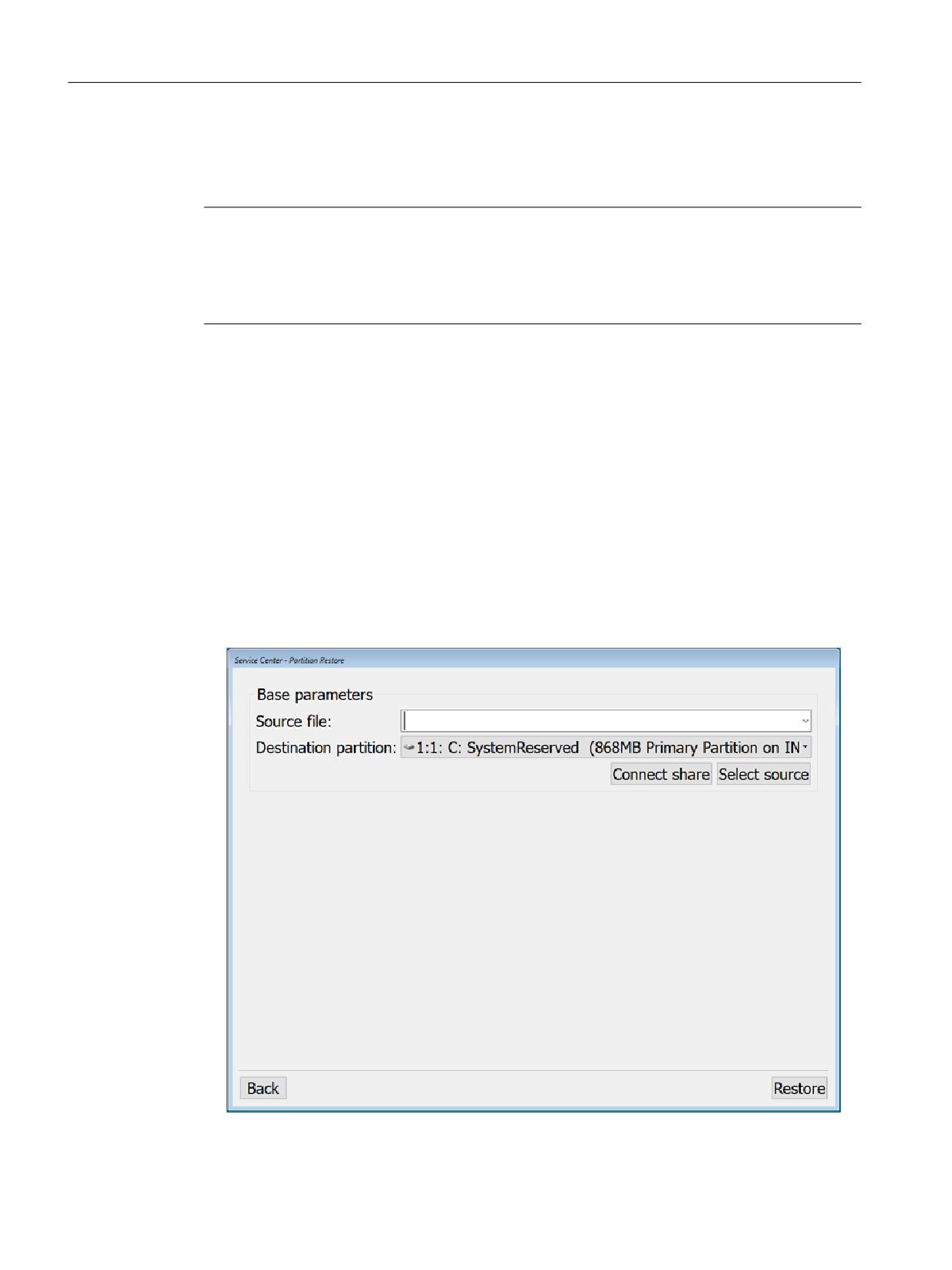
The "Partition Restore" dialog box opens.
Figure 6-7
Service Center - Partition Restore
PCU Base for IPC
130
Commissioning Manual, 10/2020, 6FC5397-2HP40-0BA1
Backing up and restoring data
6.8 Restore a disk image of a partition
3. Make the required settings here:
Section
Setting
Purpose
Base parame-
Source file
Select the disk image from which the partition is to be restored.
ters
You can use local disk images or disk images stored in the net-
work.
Destination par-
Select the partition to be restored from the disk image.
tition
Base parame-
Connect share
Open the "Connect a Share" dialog box (Page 132).
ters > Destina-
You can manage a shared resource (e.g. a directory in the net-
tion partition
work), to use a disk image stored on the network to restore the
SSD.
Select source
Open the "Select source file" dialog box.
You can navigate through a local directory on the PC system and
select a disk image for restoration.
4. To start the restore process and entirely replace the existing data on the partition with the
disk image, confirm the settings with "Restore".
Result
The restore process is started.
Note
Troubleshooting if reading in of the disk image fails
If data transfer is interrupted during the restore process, the PC system will have no executable
system.
In this case, use a bootable USB flash drive with Service Center to read the disk image in again.
PCU Base for IPC
Commissioning Manual, 10/2020, 6FC5397-2HP40-0BA1
131
Backing up and restoring data
6.9 Network settings in the Service Center
6.9
Network settings in the Service Center
To manage a disk image in the network, you can display a shared network directory on the PC
system as a drive.
In the Service Center, you configure network drives in the "Connect a share" dialog box. You can
call this dialog box directly from the relevant dialog boxes to both create (Page 124) and restore
(Page 126) disk images.
Precondition
The network directory is shared with the relevant user accounts in the domain and on the PC
system.
Further information: Release directory of the PC/PC in the network (Page 142)
Overview
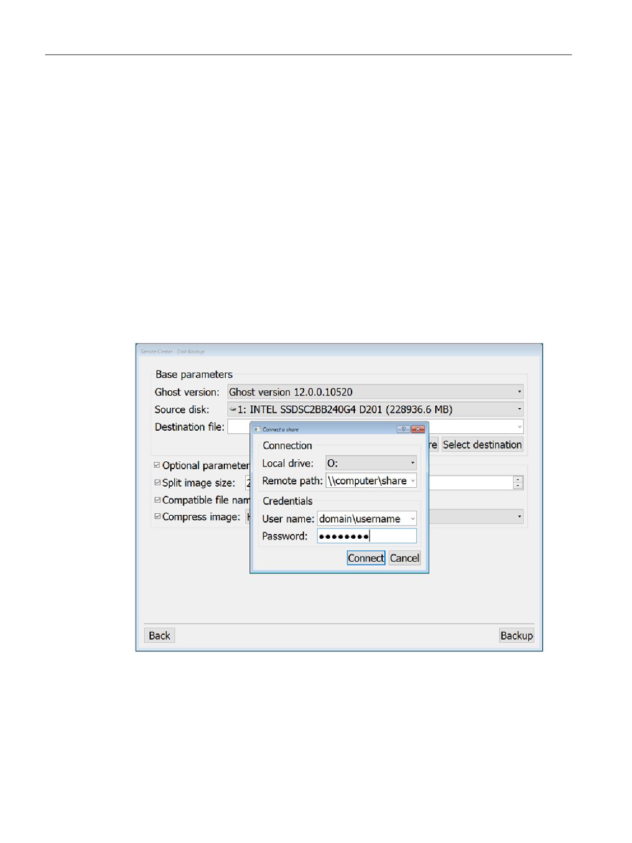
The setting options in the "Connect a share" dialog box have the following meaning:
Figure 6-8
"Connect a Share" dialog box
PCU Base for IPC
132
Commissioning Manual, 10/2020, 6FC5397-2HP40-0BA1
Backing up and restoring data
6.9 Network settings in the Service Center
Table 6-4
Settings in the "Connect a Share" dialog box in the Service Center
Section
Setting
Purpose
Connection
Local drive
Select drive letters under which the network directories are to be accessible on the PC system.
The drive letters Z, Y and X are assigned to USB interfaces on SINUMERIK TCUs and operator panels. Do not use
these drive letters for other purposes in order to avoid problems when using these USB interfaces.
Remote path
Specify the device in the network and share name of the resource.
Syntax: \\Name of the server\share name of the network directory
Example: \\Backup_Server\PCU_Backup
Credentials
User name
Enter the user account under which the resource in the network can be accessed.
If you have shared the resource on the server for certain users only, you must enter one of these user accounts
here.
Password
Enter the password of the user account.
Further information
You will find information about sharing directories in the network and network drives in the
following chapters:
• Release directory of the PC/PC in the network (Page 142)
• Creating a shortcut to the network drive (Page 145)
PCU Base for IPC
Commissioning Manual, 10/2020, 6FC5397-2HP40-0BA1
133
Backing up and restoring data
6.10 Starting Symantec Ghost directly
6.10
Starting Symantec Ghost directly
With the "Symantec Ghost" software you can store the entire contents of an SSD as a disk image.
Disk images can be kept on various storage media for subsequent restoration of the data on the
SSD.
Symantec Ghost is included in the PCU Base for IPC scope of delivery and on the replacement part
SSD for the IPC. Symantec Ghost is used by the components of PCU Base for IPC to back up or
restore data.
You can also start Symantec Ghost directly from the prompt to execute the data backup tasks
from the user interface of Ghost. This is necessary, for example, when using CompactFlash cards.
Procedure
To start Symantec Ghost directly, proceed as follows:
1. Call the prompt from the Service Center or the Service Desktop.
2. Enter "ghost.32.exe" or "ghost64.exe" and confirm your entry.
Further information
PCU Base for IPC
134
Commissioning Manual, 10/2020, 6FC5397-2HP40-0BA1
Backing up and restoring data
6.11 Bootable USB flash drive
6.11
Bootable USB flash drive
Usage
You can generate a bootable Service Center (Emergency Boot System) based on Microsoft
Windows PE on a USB flash drive as preventive measure against a defect.
The Ghost image for the creation of the bootable USB flash drive is on the installed
PCU Base for IPC under: D:\Eboot\eboot.gho
Precondition
• The Windows Service Desktop is active
• You have a USB flash drive (e.g. SIMATIC PC USB flash drive)
Procedure
To create a bootable USD flash drive, proceed as follows:
1. Connect the USB flash drive to a USB interface of the PC system.
2. Start Symantec Ghost, for example, by entering Ghost32.exe in the search bar in the start
menu.
or
For IPCxxxE (EFI boot), start Ghost via link D:\Eboot\Ghost for Eboot Stick.lnk.
3. In Symantec Ghost, select the "From Image" command from the "Local > Disk" menu.
4. Select D:\Eboot\eboot.gho as the source and the USB flash drive as the destination.
Result
The Emergency Boot System is installed on the USB flash drive and the data storage medium is
renamed to "EBOOT". The Service Center on the bootable USB flash drive can now be used.
PCU Base for IPC
Commissioning Manual, 10/2020, 6FC5397-2HP40-0BA1
135
Backing up and restoring data
6.12 Operating a service PC/PC in the network
6.12
Operating a service PC/PC in the network
6.12.1
Overview
System network
In the following applications, you will need, for example, a connection between the PC system
and a PG/PC in the system network:
• Save the disk image of the SSD to a PG/PC
• Restore the SSD of a PC system via the DVD drive of a PG/PC
• Start up the replacement SSD
• Install the software on the PC system via the DVD drive of a PG/PC
Company network
If you want to connect the service PG/PC via a company network (Local Area Connection 2;
interface X1), contact your network service center.
Further information on the Windows Firewall settings in the company network can be found in
the Chapter Adapting the firewall settings (Page 66).
6.12.2
Connection options in the system network
Overview
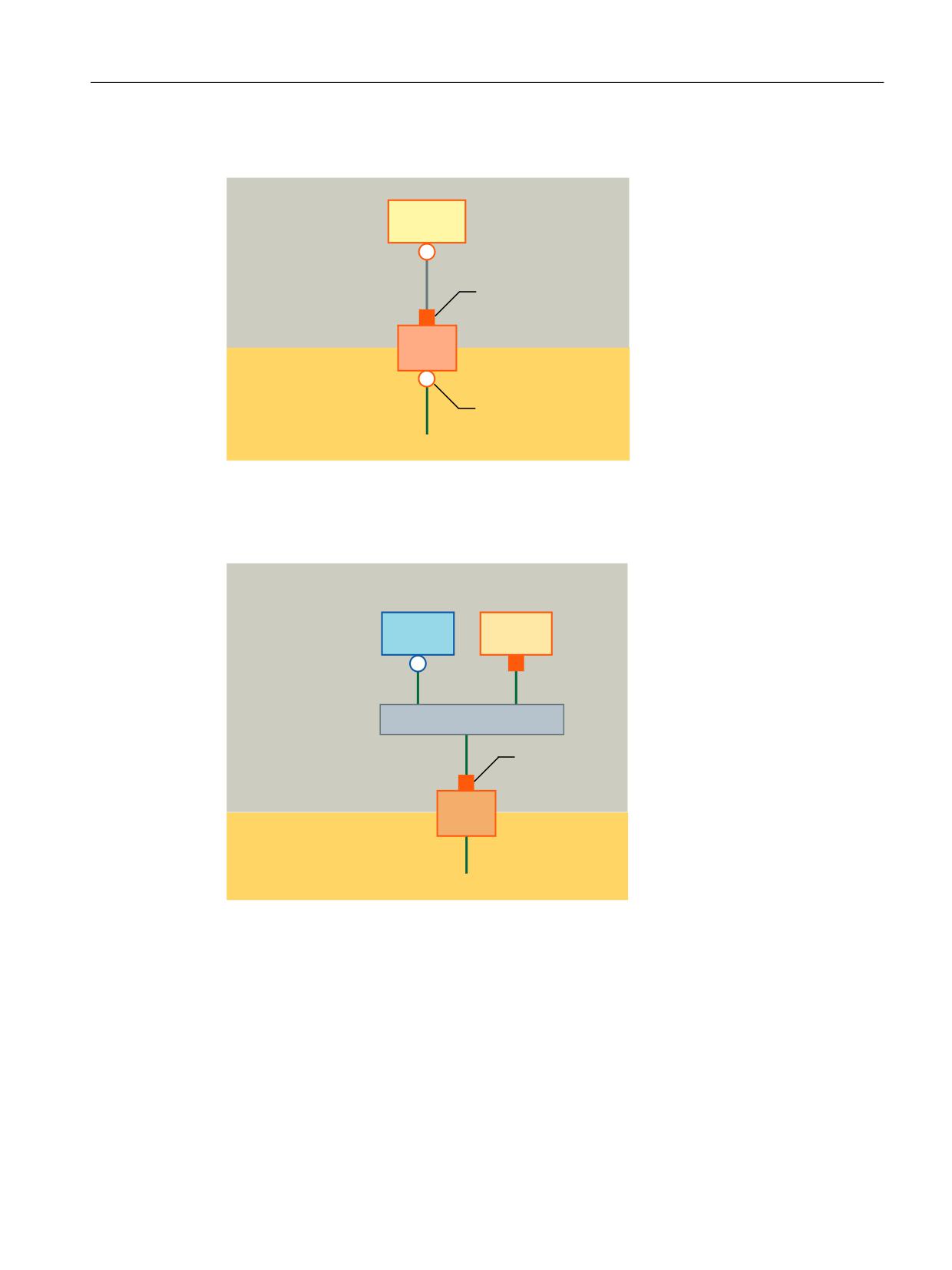
The following figures show the typical connection options in the system network:
• Service PG/PC with (twisted) Ethernet cable direct to interface "X2" of the Siemens PC system.
• Service PG/PC with (non-twisted) Ethernet cable via switch to interface "X2" of the Siemens
PC system.
PCU Base for IPC
136
Commissioning Manual, 10/2020, 6FC5397-2HP40-0BA1
Backing up and restoring data
6.12 Operating a service PC/PC in the network
Configuration using the PG/PC directly at the Siemens PC system
3* 3&
6\VWHP QHWZRUN
;
,3&
&RPSDQ\ QHWZRUN
;
Figure 6-9
Connecting a PG/PC directly at the IPC
Configuration with PG/PC and switch at the Siemens PC system
6\VWHP QHWZRUN
7&8
3* 3&
6ZLWFK
;
,3&
&RPSDQ\ QHWZRUN
Figure 6-10
Connecting a PG/PC at the IPC via a switch
Basic procedure
On the PG/PC with Windows 7/10:
• Connecting a PG/PC to a Siemens PC system according to one of the configurations shown
above.
• The network protocol used is: TCP/IP.
TCP/IP is already pre-configured on the Siemens PC system.
PCU Base for IPC
Commissioning Manual, 10/2020, 6FC5397-2HP40-0BA1
137

Backing up and restoring data
6.12 Operating a service PC/PC in the network
• Setting up IP addresses on the same subnetwork.
• Sharing a directory on the PG/PC for network access.
On the Siemens PC system in the Service Center:
• Start the Service Center on the IPC.
• Establish a network connection to the shared directory of the PG/PC.
Further information: Functions of the Service Center (Page 119)
6.12.3
Configuring routing in the network
Overview
If you have connected a PG/PC at interface X127 of the NCU, configure the network routing to
establish the connection between the PG/PC and the IPC.
7&8
6\VWHP QHWZRUN ,QGXVWULDO (WKHUQHW
;
;
1&8
,3&
;
;
;
3* 3&
&RPSDQ\ QHWZRUN
Figure 6-11
A networking example using IP routing
Preconditions
The following conditions must be met in order to use this function:
• The PG must be connected to interface X127 of an NCU in the system network.
• NCU and IPC are connected via the system network.
PCU Base for IPC
138
Commissioning Manual, 10/2020, 6FC5397-2HP40-0BA1
Backing up and restoring data
6.12 Operating a service PC/PC in the network
• On the NCU, the routing is activated in one of the following ways:
- In SINUMERIK Operate, the routing is configured in the user interface "System network
settings".
- In the configuration file basesys.ini, key EnableSysNetToIBNForwarding=1 is set.
• If you wish to access a network directory, it must be shared.
• The user account in question is known to the PG/PC.
• The Service Center is active.
Procedure
To configure the IP routing in the Service Center, proceed as follows:
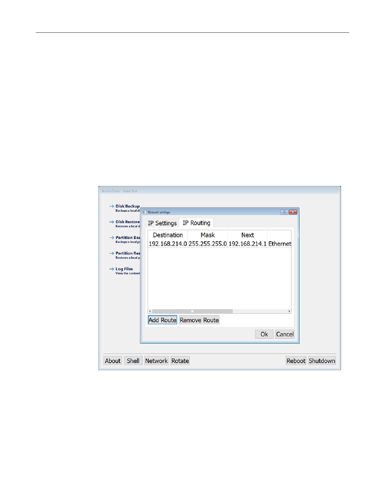
1. In the main menu of the Service Center, click "Network".
2. In the "Network Settings" dialog box, click the "IP Routing" tab.
Figure 6-12
Service Center - IP routing
3. Configure the necessary routes.
Further information: Network settings in the Service Center (Page 121)
Result
The routing has been configured and the PG/PC and Siemens PC system are connected via the
NCU.
Now, perform the desired steps, for example, a Restore a disk image of the SSD (Page 126).
PCU Base for IPC
Commissioning Manual, 10/2020, 6FC5397-2HP40-0BA1
139
Backing up and restoring data
6.12 Operating a service PC/PC in the network
6.12.4
Configure the network settings of the PG/PC
Once you have connected a PG/PC in the network, make the network settings on the PG/PC.
The basic procedure for setup under Windows 10 or Windows 7 is described below. Further
information from Microsoft is in the Internet: Microsoft Windows support (https://
support.microsoft.com/en-us/hub/4338813/windows-help?os=windows-10)
Precondition
• The PG/PC is linked with the Siemens PC system in one of the following ways:
- The PG/PC is connected to the PC system using an Ethernet cable (either directly or using
a switch)
Further information: Connection options in the system network (Page 136)
- The PG/PC is networked with the PC system via an interface of the NCU and the routing is
configured.
Further information: Configuring routing in the network (Page 138)
• A current Microsoft Windows operating system is installed on the PG/PC
• The PG/PC is switched on
PCU Base for IPC
140
Commissioning Manual, 10/2020, 6FC5397-2HP40-0BA1
Backing up and restoring data
6.12 Operating a service PC/PC in the network
Procedure
To configure the network settings of the PG/PC for connecting a PC system in the system network,
proceed as follows:
1. Open the "network connections" window:
- To do this under Windows 7: in the Control Panel in category "Network and Internet > View
network status and tasks," choose "Change adapter settings".
- To do this under Windows 10: enter "Control Panel" in the search field, then click on
"Control Panel > Network and Sharing Center > Change Adapter Settings".
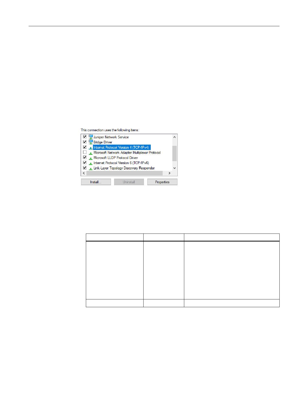
2. Right-click on the network adapter you want to configure, then in the shortcut menu click on
"Properties".
Dialog "Properties of <connection>" opens.
Figure 6-13
Properties of <connection>
3. Make the following settings:
- Click "File and Printer Sharing for Microsoft Networks."
- To change the IP address of the PG/PC, double-click "Internet Protocol Version 4 (TCP/
IPv4)", then configure the settings as follows:
Section
Element
Setting
Use the following IP ad-
IP address
The following IP addresses in the system net-
dress
work can be used for the PG/PC:
•
192.168.214.250
•
192.168.214.251
•
192.168.214.252
•
192.168.214.253
•
192.168.214.254
Subnet mask
•
255.255.255.0
Result
The network settings of the PG/PC are now configured for use with the Siemens PC system.
PCU Base for IPC
Commissioning Manual, 10/2020, 6FC5397-2HP40-0BA1
141
Backing up and restoring data
6.12 Operating a service PC/PC in the network
6.12.5
Release directory of the PC/PC in the network
If you want to, for example, store disk images on a PG/PC that you have linked to the Siemens PC
system via the network, set up a network drive.
As soon as it has been set up, a new drive will appear on the PC system, which is really a directory
on the PG/PC.
The basic procedure for setup under Windows 10 or Windows 7 is described below. Further
information from Microsoft is in the Internet: Microsoft Windows support (https://
support.microsoft.com/en-us/hub/4338813/windows-help?os=windows-10)
Precondition
• The PG/PC is switched on.
• There is sufficient free space on the PG/PC, to save disk images of the PC system, for example.
• The user accounts to which you want to grant share rights are known in the domain or on the
Siemens PC system.
Procedure
Proceed as follows to share a directory for use in the network:
1. On the PG/PC, in the Control Panel call up Computer Management.
2. Under "System > Shared Folders" select the file "Shares."
3. In the "Action" menu, click the "New File Share..." command.
The "Create A Shared Folder Wizard" opens.
PCU Base for IPC
142
Commissioning Manual, 10/2020, 6FC5397-2HP40-0BA1
Backing up and restoring data
6.12 Operating a service PC/PC in the network
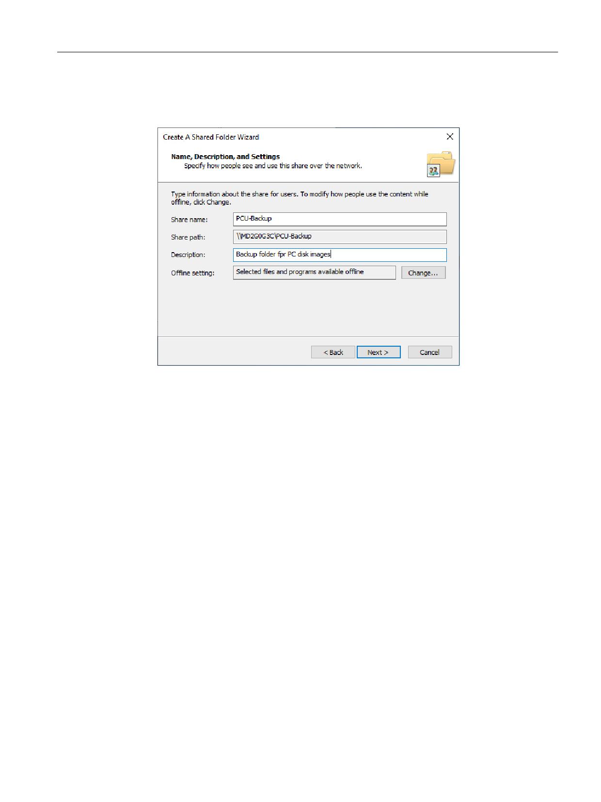
4. Under step "Name, Description, and Settings," make a note of the Share path, which is a
combination of the computer name and the share name. You will have to specify this name
when you create a link to the network drive on the Siemens PC system.
Figure 6-14
Create A Shared Folder Wizard - Name, Description, and Settings
PCU Base for IPC
Commissioning Manual, 10/2020, 6FC5397-2HP40-0BA1
143
Backing up and restoring data
6.12 Operating a service PC/PC in the network
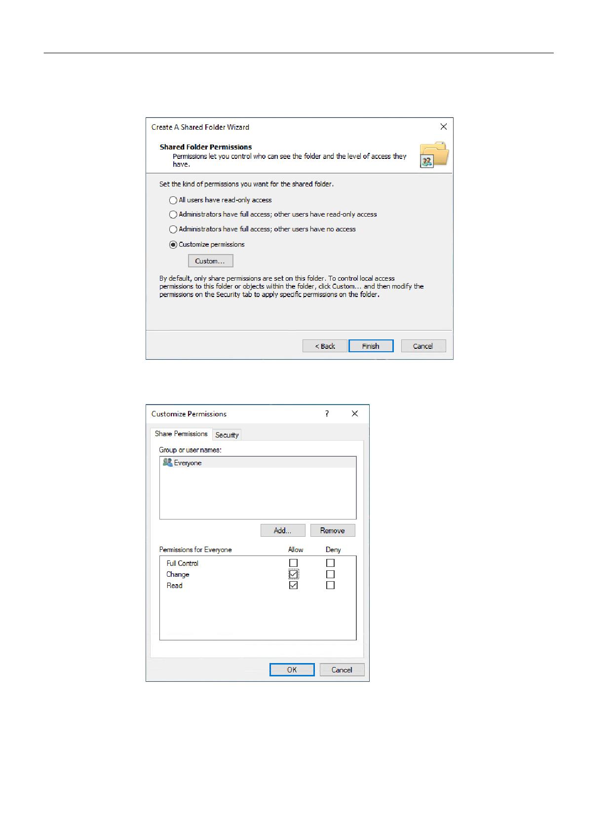
5. Under step "Shared Folder Permissions," select the "Customize permissions" option button,
then click "Custom..."
Figure 6-15
Create a Shared Folder Wizard - Shared Folder Permissions
The "Customize Permissions" dialog box opens.
Figure 6-16
"Customize Permissions" dialog box
PCU Base for IPC
144
Commissioning Manual, 10/2020, 6FC5397-2HP40-0BA1
Backing up and restoring data
6.12 Operating a service PC/PC in the network
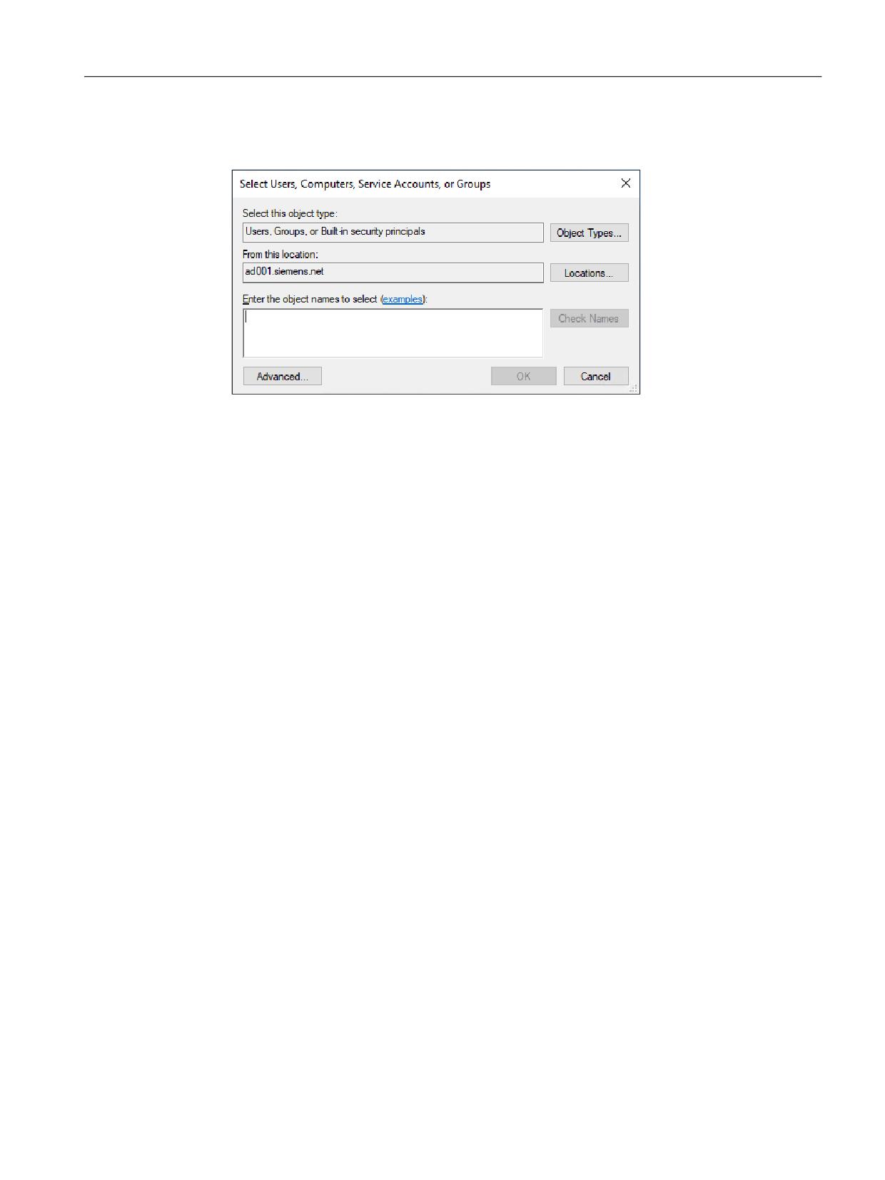
6. In section "Group or user names," click "Add..."
The "Select Users, Computers, Service Accounts, or Groups" opens.
Figure 6-17
"Select Users, Computers, Service Accounts, or Groups" dialog box
7. In section "Permissions for <user name>," under column "Allow," click the "Change" checkbox.
8. Confirm these settings in the "Customize Permissions" dialog box with "OK."
9. In the next steps of the wizard, make all the settings you require and confirm the share with
"Finish".
6.12.6
Creating a shortcut to the network drive
To be able to access the shared directory on the PG/PC from the Siemens PC system, after you
have connected and configured the PG/PC in the network, you must set up the shared folder on
the PC system as network drive.
As soon as it has been set up, a new drive will appear on the PC system, which is really a directory
on the PG/PC.
The basic procedure for setup under Windows 10 or Windows 7 is described below. Further
information from Microsoft is in the Internet: Microsoft Windows support (https://
support.microsoft.com/en-us/hub/4338813/windows-help?os=windows-10)
Precondition
• The PG/PC is switched on.
• The Service Desktop is active.
• The folder on the PG/PC is shared for the relevant user accounts on the domain and on the PC
system.
PCU Base for IPC
Commissioning Manual, 10/2020, 6FC5397-2HP40-0BA1
145
Backing up and restoring data
6.12 Operating a service PC/PC in the network
Procedure
Proceed as follows to connect a shared directory as a network drive:
1. Start the Windows Explorer and click the "Map network drive" button.
2. Make the following settings in the "Map network drive" dialog box:
Setting
Purpose
Drive
Select drive letters under which the network directories are to be accessible on
the PC system.
The drive letters Z, Y and X are assigned to USB interfaces on SINUMERIK TCUs
and operator panels. Do not use these drive letters for other purposes in order
to avoid problems when using these USB interfaces.
Folder
Specify the device in the network and share name of the resource.
Syntax: \\Name of the server\share name of the network
directory
Example: \\Backup_Server\PCU_Backup
Reconnect at logon
Activate this checkbox to automatically connect the network drive while run-
ning up.
Connect using dif-
Activate this checkbox if you have not shared the directory in the network with
ferent credentials
the user for whom you would like to set up the network drive.
In the next dialog box "Enter Network Password," enter the log-on information
of a user with whom the network directory is shared.
3. Confirm your settings with "Finish".
PCU Base for IPC
146
Commissioning Manual, 10/2020, 6FC5397-2HP40-0BA1
Backing up and restoring data
6.13 Starting up the replacement SSD
6.13
Starting up the replacement SSD
Further information
Further information on the replacement or installation of an SSD can be found in the hardware
documentation for your PC system in the SIMATIC IPC Operating Instructions:
Note
Troubleshooting if reading in of the disk image fails
If data transfer is interrupted during the reading process, there will be no executable operating
system available on the Siemens PC system.
In this case, use a bootable USB flash drive with Service Center to read the disk image in again.
Further information to restore a disk image is provided under Restore a disk image of the SSD
(Page 126).
PCU Base for IPC
Commissioning Manual, 10/2020, 6FC5397-2HP40-0BA1
147
Backing up and restoring data
6.13 Starting up the replacement SSD
PCU Base for IPC
148
Commissioning Manual, 10/2020, 6FC5397-2HP40-0BA1
Service and diagnostics
7
7.1
Setting of the operating mode during run-up
7.1.1
Software-side setting (SIMATIC IPC)
In contrast to SINUMERIK PCUs, SIMATIC IPCs have no service switch on the hardware side for
selecting the mode. Therefore, on the SIMATIC devices, you can define the mode on the software
side in the configuration file pcuhwsvc.ini.
Archiving of the configuration file pcuhwsvc.ini
The template is located in directory C:\ProgramData\Siemens\MotionControl
\siemens\System\etc\
Do not overwrite this template, but save a copy of the template pcuhwsvc.ini in one of the
user directories:
• C:\ProgramData\Siemens\MotionControl\user\System\etc\
• C:\ProgramData\Siemens\MotionControl\oem\System\etc\
• C:\ProgramData\Siemens\MotionControl\addon\System\etc\
You can find further information on how configuration files function in the Chapter Directory
structure and file conventions (Page 23).
Table 7-1
Mode setting in configuration file pcuhwsvc.ini
Section
[GLOBAL]
Key
ModeSwitch=
Value
0 = Normal mode
3 = Desktop mode (run-up in the welcome screen)
Other modes are not permitted in the software-side setting for SIMATIC IPC.
Factory setting
0
PCU Base for IPC
Commissioning Manual, 10/2020, 6FC5397-2HP40-0BA1
149
Service and diagnostics
7.2 Switching to the Service Desktop during autostart / autologon operation
7.2
Switching to the Service Desktop during autostart / autologon
operation
If you have set up the autologon operation and the autostart of SINUMERIK Operate with the
activated keyboard filter, the PC system runs up with SINUMERIK Operate after being switched
on.
To be able to switch to the Windows desktop in this case, interrupt the run-up of SINUMERIK
Operate with an entry, as described here.
Alternatively, you can switch over the operating mode for the next run-up in the software
(SIMATIC IPC) (Page 149).
Precondition
• SINUMERIK Operate is installed and autologon mode is set up.
Further information: Setting up SINUMERIK Operate for autologon mode (Page 94)
• The PC system is switched off.
PCU Base for IPC
150
Commissioning Manual, 10/2020, 6FC5397-2HP40-0BA1
Service and diagnostics
7.2 Switching to the Service Desktop during autostart / autologon operation
Procedure
To switch to the desktop when the autostart/autologon mode is activated, proceed as follows:
1. Switch on the PC system and wait until the "SINUMERIK" welcome screen is displayed.
2. While the "SINUMERIK" welcome screen is being displayed, make one of the following entries:
- Press the key 3 on your keyboard.
- Click or tip the copyright information.
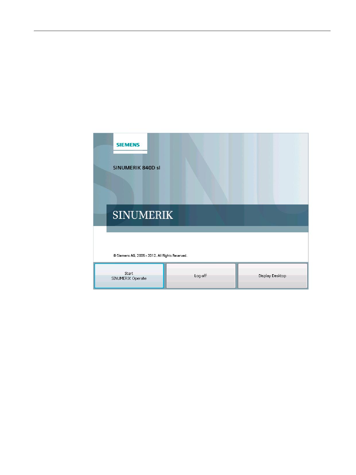
The counter for starting SINUMERIK Operate is suspended and you can select one of three
options:
Figure 7-1
Welcome screen "SINUMERIK" after key input
3. Select the "Display Desktop" option.
Result
The Service Desktop opens.
PCU Base for IPC
Commissioning Manual, 10/2020, 6FC5397-2HP40-0BA1
151
Service and diagnostics
7.3 Configuring the SINUMERIK power up screen
7.3
Configuring the SINUMERIK power up screen
You can parameterize various settings to change to the service desktop or to the SINUMERIK
welcome screen. These settings can be especially helpful if you wish to carry out diagnostics and
maintenance to a system in the headless mode.
Precondition
• In the corresponding user directory, file slstartup.ini is either not available, or there is
no slstartup.ini with different settings in a user directory with a higher priority.
• If the file already exists in the corresponding user directory, then do not create a
new slstartup.ini, but instead, adapt the existing file or insert
section [StartScreen] using the appropriate keys.
Procedure
Proceed as follows to create the configuration file for the direct control key layout:
1. Open a text editor, and as character coding, set ASCII or ANSI.
2. Insert the section designation:
[StartScreen]
PCU Base for IPC
152
Commissioning Manual, 10/2020, 6FC5397-2HP40-0BA1
Service and diagnostics
7.3 Configuring the SINUMERIK power up screen
3.
Enter those keys, whose values you wish to parameterize, and make the required settings:
Setting/key
Possible values
Description
ShowButtons=
[true|false]
Specifies as to whether the buttons are displayed with run-
up options directly in the "SINUMERIK" welcome screen.
For "ShowButtons=false", the buttons are only displayed
note).
Timeout=
s
Time in seconds, after which the system runs up with SIN-
UMERIK Operate.
The counter starts to run after an operator panel, screen or
a VNC connection has been identified.
MaxTimeout=
s
Maximum time in seconds, after which the system runs up
with SINUMERIK Operate.
The counter starts to run immediately, irrespective of
whether an operator panel, screen or a VNC connection
exists.
ShutdownTimeout=
s
Time in seconds, within which the system power down can
ShowCountdown=
[true|false]
Displays a countdown until the system runs up with SINU-
MERIK Operate.
4.
Save the file as slstartup.ini in one of the user directories.
- C:\ProgramData\Siemens\MotionControl\user\sinumerik\hmi\cfg
\slstartup.ini
- C:\ProgramData\Siemens\MotionControl\oem\sinumerik\hmi\cfg
\slstartup.ini
- C:\ProgramData\Siemens\MotionControl\addon\sinumerik\hmi\cfg
\slstartup.ini
Further information: Directory structure and file conventions (Page 23)
Example
Default setting of the section [StartScreen] in startup.ini
[StartScreen]
ShowButtons=false
Specifies as to whether the buttons are displayed with run-up options
directly in the "SINUMERIK" welcome screen (without key 3 or clicking on the
copyright note).
Timeout=5
# Time in seconds, after which the system runs up with SINUMERIK Operate
(assuming that a screen was identified).
MaxTimeout=300
# Maximum time in seconds, after which the system runs up with SINUMERIK
Operate (without a screen having been identified).
ShutdownTimeout=3
# Time in seconds, within which the system power down can be interrupted
PCU Base for IPC
Commissioning Manual, 10/2020, 6FC5397-2HP40-0BA1
153
Service and diagnostics
7.3 Configuring the SINUMERIK power up screen
Default setting of the section [StartScreen] in startup.ini
ShowCountdown=true
# Displays a countdown until the system runs up with SINUMERIK Operate.
PCU Base for IPC
154
Commissioning Manual, 10/2020, 6FC5397-2HP40-0BA1
Service and diagnostics
7.4 Remote access
7.4
Remote access
7.4.1
Overview
You can use a remote connection to access other devices via the network:
• Access to maintenance with prompt (SSH) via PuTTY.
• Access via VNC Viewer with all of the operating and servicing options, which are also
provided directly on the Siemens PC system.
Further information: Setting up and using SSH (Page 159)
7.4.2
Searching for devices in the system network
The "sc_show_net" command shows devices available in the system network in the prompt and
offers additional information about these devices.
As both these functions rely on SNMP (Simple Network Management Protocol), only SNMP-
capable devices will be found. In the case of Windows-based devices, this depends on the
software version. If a simple call is made without any additional options, a list of the devices
found will appear showing the relevant IP address, DNS name (if known), and a short description
(module name).
sc_show_net command
This command is executed in the prompt:
Syntax:
sc_show_net [-xml] [[-hw] [-tco] [-sw | -swfull] [-loc] [-panel] [-
dhcp] [-switch] | -all] [HOSTS...]
Authorization level:
None
7.4.3
Display of accessible stations in SINUMERIK Operate
You can use the network diagnostics function in SINUMERIK Operate to show accessible nodes
in the system network.
Procedure
Proceed as follows to show accessible nodes:
1. Select "MENU SELECT" to open the menu.
2. In the horizontal softkey menu, choose "Diagnostics > Bus TCP/IP".
3. In the vertical softkey menu, select "TCP/IP > Diagnostics Network > Accessible nodes".
The "Accessible nodes" user interface opens showing all nodes that use the SNMP or DCP
protocol.
PCU Base for IPC
Commissioning Manual, 10/2020, 6FC5397-2HP40-0BA1
155
Service and diagnostics
7.4 Remote access
Further information
Information about showing accessible nodes in SINUMERIK Operate is provided in
the SINUMERIK Operate Commissioning Manual.
7.4.4
Remote access to the PCU for operation and maintenance
You can connect to devices that have an active VNC server, e.g. IPC or NCU, using remote access.
• The remote access to the Siemens PC system from a PG/PC in the system network (Page 136)
is activated via the factory setting. You can optionally define a password for this:
If you want to access the PC system via the company network instead or in addition, you must
adapt the firewall settings (Page 72) and define a password.
Note
Access to the PC system in the company network requires a secure password
A password is required to access the PC system via remote access in the company network.
The password is not yet defined in the factory settings. If the PC is to be accessed in the
company network, you must specify a password.
• The factory settings only enable you to monitor a PC system via an external VNC Viewer.
To operate the system from another station, the system in question must grant permission.
You make the necessary settings in the tcu.ini in section [VNCViewer].
Defining the password
To define passwords for remote access to the PC system, call the prompt and enter the
"sc_vncpwd" command.
Command
Param-
Value
Meaning
eter
sc_vncpwd
set
companynetwork|systemnetwork
Sets the specified password and acti-
[password]
vates the password prompt for remote
access
reset
companynetwork|systemnetwork
Deactivates the password prompt (re-
mote access without password)
• Example for company network (X1):
sc_vncpwd set companynetwork mypasswd
• Command for system network (X2):
sc_vncpwd set systemnetwork mypasswd
The password may contain a maximum of 8 characters. Passwords are saved in encrypted form
in the following file:
PCU Base for IPC
156
Commissioning Manual, 10/2020, 6FC5397-2HP40-0BA1
Service and diagnostics
7.4 Remote access
C:\ProgramData\Siemens\MotionControl\user\System\etc\sinumerikvnc.ini
Note
The password must also be specified when remotely accessing an NCU (without IPC) in the
company network
As from SINUMERIK Operate V4.8 SP2, a password is required for access via VNC to an NCU in the
company network. The password is not yet defined in the factory settings. If the NCU is to be
accessed in the company network, you must specify a password as follows:
1. Call the command line of the NCU (TCU menu "Select service session > Show command shell
of NCU") or PuTTY.
2. Log in as user "manufact".
3. Execute the "sc vncpwd set companynetwork mypasswd" command, whereby
"mypasswd" is a password with a maximum of 8 characters.
Further information is displayed when entering "sc vncpwd".
Options for the VNC Viewer
Note
Do not change the factory settings!
To ensure that the VNC Viewer works properly, the following options must not be changed.
Table 7-2
Connection settings in the start dialog of the VNC Viewer
Option
Factory setting
VNC Server
192.168.214.241
Quick Options
AUTO (Auto select best settings)
PCU Base for IPC
Commissioning Manual, 10/2020, 6FC5397-2HP40-0BA1
157
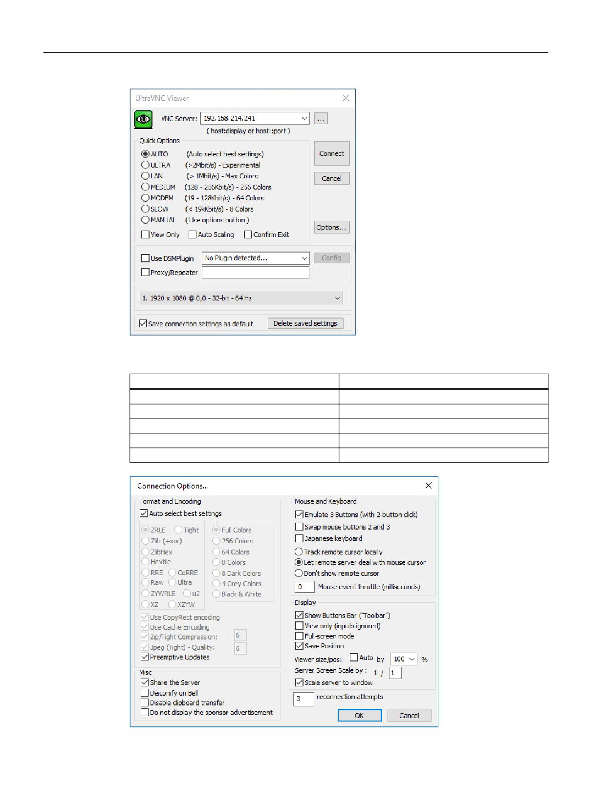
Service and diagnostics
7.4 Remote access
Table 7-3
Further connection settings ("Options..." button)
Option
Factory setting
Format and Encoding
Auto select best settings
Misc
Share the Server
Mouse Buttons
Emulate 3 Buttons (with 2-button click)
Mouse Cursor
Let remote server deal with mouse cursor
Display
Show Buttons Bar ("Toolbar")
PCU Base for IPC
158
Commissioning Manual, 10/2020, 6FC5397-2HP40-0BA1
Service and diagnostics
7.4 Remote access
7.4.5
Setting up and using SSH
You can use remote access to access devices from the PC system.
An SSH environment is pre-installed when installing PCU Base for IPC for Windows 10. You can
log on with PuTTY.
You can use an SSH key to log on. A script for setting up the infrastructure on devices is provided.
However, for security reasons no previously generated keys have been stored.
Further information
• Chapter Remote access (Page 155)
• Chapter Encryption via SSH protocol (Page 160)
Setting up remote access with SSH and key pair
The procedure for setting up users and using remote access is the same as the usual procedure
for remote access with SSH.
Table 7-4
Support with setting up remote access
Task
Recommended application
Storage path
Help
Generate key pair
PuTTY Key Generator
C:\Program Files (x86)\PuTTY
Online help in PuTTY
\puttygen.exe
(Chapter Public key for pasting into au-
thorized_keys file)
Set up infrastructure on devices
Supplied script ssh_key_log-
C:\ProgramData\Siemens\Mo-
Call up the script via the prompt. To do
in.bat
tion Control\siemens
this, enter user name and file name of
\etc.\ssh_key_login.bat
the public key as the parameters.
Syntax:
ssh_key_login.bat <user
name> <public key>
Example:
ssh_key_login.bat username
publicKey.pub
Access devices via remote con-
PuTTY
C:\Program Files (x86)\PuTTY
Online help in PuTTY
nection
\putty.exe
IP address of the PCU (factory setting):
• System network: 192.168.214.241
• Company network: The IP address
is taken from the DHCP server
PCU Base for IPC
Commissioning Manual, 10/2020, 6FC5397-2HP40-0BA1
159
Service and diagnostics
7.4 Remote access
7.4.6
Encryption via SSH protocol
Security
The security of SSH is ensured by a series of cryptographic algorithms for encryption and
authentication.
Authentication
The server identifies itself to the client with an RSA, DSA or ECDSA certificate, which enables
detection of manipulation in the network (no other server can identify itself as a known server).
The client can authenticate itself either by public key authentication with a private key whose
public key is stored on the server, or with a normal password. While in the latter case, user
interaction is always necessary (unless the password is stored unencrypted on the client
computer), public key authentication allows client computers to log on to SSH servers without
user interaction, without a password having to be stored in plain text on the client. However, for
added security the private SSH keys can also be protected with a password.
Subsystems
In the case of Secure Subsystem Execution, subsystems that were defined in an SSH server
installation can be executed remotely without knowing the precise path of the program
executed on the server. SFTP is the most common subsystem.
Further information
• Chapter Setting up and using SSH (Page 159)
• Commissioning Manual NCU Operating System.
• Description of PuTTY
PCU Base for IPC
160
Commissioning Manual, 10/2020, 6FC5397-2HP40-0BA1
Fundamental safety
1
instructions
2
Introduction
Requirements for
3
commissioning
SINUMERIK
4
Licensing
SINUMERIK 840D sl
CNC Commissioning: NC, PLC, Drive
5
PLC commissioning
Commissioning NC-
6
controlled drives
Commissioning Manual
Communication between
7
the NC and the drive
8
NC commissioning
Configuring PLC-controlled
9
drives
10
Drive tuning
11
Saving and managing data
12
New installation / upgrading
A
Appendix
Valid for:
SINUMERIK 840D sl/840DE sl
CNC-Software
Version
4.94
10/2020
A5E48312804B AB
Table of contents
1
Fundamental safety instructions
9
1.1
General safety instructions
9
1.2
Equipment damage due to electric fields or electrostatic discharge
13
1.3
Warranty and liability for application examples
14
1.4
Security information
15
1.5
Residual risks of power drive systems
16
2
Introduction
17
2.1
Overview of the manuals for SINUMERIK 840D sl
21
2.2
General prerequisites
22
3
Requirements for commissioning
23
3.1
SINUMERIK 840D sl configuration
24
3.2
Position of the interfaces
26
3.3
Power-On and boot-up
27
3.3.1
NC and PLC memory reset
27
3.3.2
A general reset is separately performed for the NC and PLC
29
3.3.3
Boot completed
31
3.4
Procedure for the initial commissioning
32
3.5
Procedure when tuning axes and drives
34
3.6
Access levels
35
4
Licensing
39
4.1
SINUMERIK License Key
39
4.2
Web License Manager
41
4.3
License database
42
4.4
How to perform the assignment
43
4.5
Important licensing terms
44
5
PLC commissioning
47
5.1
Connect PG/PC with the PLC
47
5.2
Creating a SIMATIC S7 project (PROFIBUS)
48
5.2.1
SIMATIC S7 project overview
48
5.2.2
Inserting SINUMERIK NCU to the HW Config
49
5.2.3
Configuring interfaces
52
5.2.4
Augmenting the machine control panel and handwheel in the HW configuration
58
5.2.5
Modifying PROFIBUS machine control panel in OB100
60
5.2.6
Configuring the Web server
61
CNC Commissioning: NC, PLC, Drive
Commissioning Manual, 10/2020, A5E48312804B AB
3
Table of contents
5.2.7
Inserting an NX to the hardware configuration
62
5.2.8
End the hardware configuration and load it to the PLC
65
5.3
Extending the SIMATIC S7 project (PROFINET)
66
5.3.1
Requirements when configuring PROFINET
66
5.3.2
Sample configuration
68
5.3.3
Commissioning the PLC
70
5.3.4
Configuring PROFIsafe
76
5.3.5
Complete the PLC project
78
5.4
Creating a PLC program
81
5.4.1
Preconditions for creating the PLC program
83
5.4.2
Insert PLC basic program
83
5.4.3
Modifying machine control panel in OB100
85
5.5
Download the project to the PLC
87
5.6
Loading PLC symbols to the controller
89
5.7
First commissioning of the PLC completed
90
5.8
Configuring a network (NetPro) for PG/PC
91
5.8.1
Integrating PG/PC into NetPro
91
5.8.2
Configuration of the PG/PC interface
92
5.8.3
Assigning interfaces
95
5.8.4
Loading the HW config to NCU
96
6
Commissioning NC-controlled drives
99
6.1
Configuration examples
99
6.1.1
Example: Configuration of the drive components
99
6.1.2
Example: Parallel connection with TM120
101
6.2
Terminal assignment
103
6.2.1
NCU terminal assignment
103
6.2.2
X122 terminal assignment
103
6.2.3
X132 terminal assignment
104
6.2.4
X142 terminal assignment
105
6.2.5
Terminal assignment NX1x.3
106
6.2.6
Support for the terminal assignment
106
6.2.7
BICO interconnections
107
6.3
Guided commissioning of SINAMICS drives
109
6.3.1
Initializing the system
109
6.3.2
Device configuration of the drive system
111
6.3.3
Configuring the infeed
113
6.3.4
Configuration of two infeeds connected in parallel
120
6.3.5
Example: Configuring a catalog motor with encoder
123
6.3.6
Example: Configuring a third-party motor with encoder
130
6.4
Manual commissioning of SINAMICS drives
136
6.4.1
Loading SINAMICS factory settings
136
6.4.2
Firmware update of the drive components
137
6.4.3
Automatic device configuration
139
6.5
Configuring data sets
141
6.5.1
Data sets - overview
141
6.5.2
Example: Add / remove / modify data set
143
CNC Commissioning: NC, PLC, Drive
4
Commissioning Manual, 10/2020, A5E48312804B AB
Table of contents
6.6
Diagnostics → Trace
147
6.6.1
Selecting variables for tracing
147
6.6.2
Example: Trace session with servo variables
148
6.6.3
Example: Zooming in/zooming out
151
6.6.4
Example: Changing the scale
155
6.6.5
Example: Positioning the cursor
156
6.6.6
Example: Trace session with PLC variables
156
6.6.7
Example: Trace session with drive variables
158
6.6.8
Key combinations to use the trace
159
6.7
Diagnostics → drive system
161
6.8
Modular machine
163
6.8.1
What does "modular machine" mean?
163
6.8.2
Modify configuration
165
6.8.3
Check topology
166
6.8.4
Changing topology
169
6.8.5
Activating/deactivating drive object
169
6.8.6
Deleting a drive object
171
6.8.7
Delete the component
171
6.8.8
Adding components
172
6.8.9
Replacing a SINAMICS S120 component
173
6.8.10
Example: Subsequently installing a component
175
6.9
Tips for commissioning the SINAMICS drives
178
6.9.1
Displaying the firmware version of the drive components
178
6.9.2
Check the line data of the infeed
179
6.9.3
Mains and DC link identification of the infeed module
180
6.9.4
Rules for wiring the DRIVE-CLiQ interface
181
6.9.5
Drive-object assignment for PROFIBUS connection
183
6.9.6
Adjusting speed and brake behavior
187
7
Communication between the NC and the drive
189
7.1
Overview of NC and drive communication
189
7.2
Configuring the communication to the drive
190
7.3
Configuring the I/O address and telegram
192
7.4
Process data transfer between the NC and drive
194
7.5
Drives: Assign axis
196
7.6
Configuring machine axes
199
7.6.1
Axis assignment
199
7.6.2
Axis names
202
7.6.3
Drive assignment
203
8
NC commissioning
205
8.1
Machine and setting data
205
8.2
Procedure when commissioning the NC
207
8.3
Memory configuration
209
8.4
Friction compensation with adaptive characteristics
210
8.4.1
Overview
210
CNC Commissioning: NC, PLC, Drive
Commissioning Manual, 10/2020, A5E48312804B AB
5
Table of contents
8.4.2
Axis selection and status display
211
8.4.3
Friction compensation - automatic tuning
213
8.4.4
Friction compensation - manual tuning
214
8.4.5
Data list
216
8.4.6
Example for a linear axis (automatic tuning)
216
8.4.7
Friction compensation with torque injection pulse
218
8.5
Nodding compensation
220
8.5.1
Measuring technique and machine data
220
8.5.2
Nodding compensation - overview
222
8.5.3
Determining compliance from the best milling path
223
8.5.4
Nodding compensation - manually enter
224
8.5.5
Determining compliance using a probe
225
8.5.6
Example: Traveling column machine
227
8.6
Adaptations
229
8.6.1
Intelligent load adjustment - function
229
8.6.2
Intelligent dynamic response adjustment - function
231
8.6.3
Setting up the adaptations
232
8.6.4
Example: Enter an adaptation for acceleration
234
8.7
Jerk filter
236
8.7.1
Putting a jerk filter into operation
236
8.7.2
Entering a new jerk filter
237
8.8
Diagnosis → System utilization
240
9
Configuring PLC-controlled drives
241
9.1
Introduction
241
9.2
Configuration via PROFIBUS
242
9.2.1
Supplementary conditions for PLC-controlled drives
242
9.2.2
Example: Configuration of the drive components
244
9.2.3
Commissioning the PLC
245
9.3
Creating a PLC program
251
9.4
Commissioning PLC drives
253
9.5
Checking the communication to the drive
255
9.6
Safety functions for PLC drives
256
9.6.1
Configuring PROFIsafe
256
9.6.2
Example: Embedding in safe programmable logic (SPL)
259
10
Drive tuning
263
10.1
Tuning procedure
263
10.2
Function overview for the tuning
264
10.3
Automatic servo tuning
265
10.3.1
Setting the options for the measurement procedure
265
10.3.2
Selecting the tuning strategy
268
10.3.3
Example: This is how you tune the X axis
272
10.3.4
Example: This is how you tune the Y axis
276
10.3.5
Spindle tuning sequence
279
10.3.6
Example: How to start the path interpolation
281
10.3.7
Example for experts: Axis tuning
285
CNC Commissioning: NC, PLC, Drive
6
Commissioning Manual, 10/2020, A5E48312804B AB
Table of contents
10.4
Measuring functions (manual tuning)
288
10.4.1
Measurement of current control loop
290
10.4.2
Speed control loop measurement
292
10.4.3
Example: Setting the filter for the following error (speed control loop)
296
10.4.4
Position control loop measurement
296
10.4.5
Examples for the measuring methods (position control loop)
299
10.4.6
Function generator
301
10.4.7
Example, function generator: Speed setpoint after the filter
303
10.5
Define filter
305
10.6
Circularity test
306
10.6.1
Circularity test: Function
306
10.6.2
Circularity test: Performing the measurement
307
10.6.3
Circularity test: Examples
309
10.6.4
Circularity test: Saving data
312
10.7
Decision-making support for APC and APC ECO
314
11
Saving and managing data
317
11.1
Saving data
317
11.1.1
Backup of PLC data
319
11.1.2
Creating a commissioning archive
320
11.2
Managing data
322
11.2.1
How to transfer data within the controller
323
11.2.2
To save and load data
323
11.2.3
How to compare data
324
11.2.4
Example: Importing/exporting SINAMICS lists
325
12
New installation / upgrading
327
12.1
With the help of an NCU service system
327
12.1.1
New installation
327
12.1.1.1
Automatic installation of the CNC software using USB-FlashDrive
328
12.1.1.2
Installation of the CNC software using USB-FlashDrive
329
12.1.1.3
Installation of the CNC software using WinSCP on PC/PG
332
12.1.1.4
Installation of the CNC software using VNC Viewer on PC/PG
333
12.1.2
Upgrading
334
12.1.2.1
Backup/Restore
335
12.1.2.2
Automatic upgrade of the CNC software using USB-FlashDrive
338
12.1.2.3
Upgrading the CNC software using USB-FlashDrive
339
12.1.2.4
Upgrading the CNC software using WinSCP on PC/PG
342
12.1.2.5
Upgrading the CNC software using VNC Viewer on PC/PG
343
12.2
With the help of the "Create MyConfig" software
344
12.2.1
Reinstallation with Create MyConfig
344
12.2.2
Upgrade with Create MyConfig
348
A
Appendix
353
A.1
Abbreviations
353
A.2
Information about third-party software used
355
Index
357
CNC Commissioning: NC, PLC, Drive
Commissioning Manual, 10/2020, A5E48312804B AB
7
Fundamental safety instructions
1
1.1
General safety instructions
WARNING
Electric shock and danger to life due to other energy sources
Touching live components can result in death or severe injury.
• Only work on electrical devices when you are qualified for this job.
• Always observe the country-specific safety rules.
Generally, the following steps apply when establishing safety:
1. Prepare for disconnection. Notify all those who will be affected by the procedure.
2. Isolate the drive system from the power supply and take measures to prevent it being
switched back on again.
3. Wait until the discharge time specified on the warning labels has elapsed.
4. Check that there is no voltage between any of the power connections, and between any of
the power connections and the protective conductor connection.
5. Check whether the existing auxiliary supply circuits are de-energized.
6. Ensure that the motors cannot move.
7. Identify all other dangerous energy sources, e.g. compressed air, hydraulic systems, or
water. Switch the energy sources to a safe state.
8. Check that the correct drive system is completely locked.
After you have completed the work, restore the operational readiness in the inverse sequence.
WARNING
Electric shock due to connection to an unsuitable power supply
When equipment is connected to an unsuitable power supply, exposed components may carry
a hazardous voltage. Contact with hazardous voltage can result in severe injury or death.
• Only use power supplies that provide SELV (Safety Extra Low Voltage) or PELV- (Protective
Extra Low Voltage) output voltages for all connections and terminals of the electronics
modules.
CNC Commissioning: NC, PLC, Drive
Commissioning Manual, 10/2020, A5E48312804B AB
9
Fundamental safety instructions
1.1 General safety instructions
WARNING
Electric shock due to equipment damage
Improper handling may cause damage to equipment. For damaged devices, hazardous
voltages can be present at the enclosure or at exposed components; if touched, this can result
in death or severe injury.
• Ensure compliance with the limit values specified in the technical data during transport,
storage and operation.
• Do not use any damaged devices.
WARNING
Electric shock due to unconnected cable shields
Hazardous touch voltages can occur through capacitive cross-coupling due to unconnected
cable shields.
• As a minimum, connect cable shields and the cores of cables that are not used at one end
at the grounded housing potential.
WARNING
Electric shock if there is no ground connection
For missing or incorrectly implemented protective conductor connection for devices with
protection class I, high voltages can be present at open, exposed parts, which when touched,
can result in death or severe injury.
• Ground the device in compliance with the applicable regulations.
NOTICE
Damage to equipment due to unsuitable tightening tools.
Unsuitable tightening tools or fastening methods can damage the screws of the equipment.
• Be sure to only use screwdrivers which exactly match the heads of the screws.
• Tighten the screws with the torque specified in the technical documentation.
• Use a torque wrench or a mechanical precision nut runner with a dynamic torque sensor and
speed limitation system.
CNC Commissioning: NC, PLC, Drive
10
Commissioning Manual, 10/2020, A5E48312804B AB