SINUMERIK 840D sl. Service - Configuring Commissioning. Manual (2011-2020) - page 77
Configuration of the system
4.3 Changing the name of the PC system
4.3
Changing the name of the PC system
A unique computer name is set after installing PCU Base for IPC. You can view and change it in
the Control Panel of the Service Desktop.
You can find the computer name in the Control Panel under Category "System", Section
"Computer name, domain and workgroup settings".
PCU Base for IPC
Commissioning Manual, 10/2020, 6FC5397-2HP40-0BA1
31
Configuration of the system
4.4 Setting the IP address and domain
4.4
Setting the IP address and domain
The network settings in the state when delivered have been adapted for use with the SINUMERIK
system, and usually do not have to be changed.
If you want to distinguish your network configuration from the factory settings, you can adapt
them in the Windows Control Panel.
You can find the settings in the following menu (icon view):
• "Control Panel > Network and Sharing Center > View network connections"
Further information
You can adapt the network settings for backing up and restoring disk images in the
configuration of the Service Center (Page 63).
PCU Base for IPC
32
Commissioning Manual, 10/2020, 6FC5397-2HP40-0BA1
Configuration of the system
4.5 Configuring USB interfaces
4.5
Configuring USB interfaces
To prevent malicious software from entering the control or the system network via the USB
interfaces, you can deactivate the USB interfaces.
You can configure the USB interfaces on the Service Desktop via a command in the "Run" dialog
box in the prompt.
Procedure
To activate or deactivate the USB interfaces, enter the relevant command on the Service Desktop
in the "Run" dialog box or at the prompt:
Table 4-1
Disabling USB interfaces with the "sc_usb disable" command
Syntax:
sc_usb disable [-minutes] [all] [HOSTS...]
Description:
• Without a time indication [-minutes], a permanent disable is set.
With time indication, the disable takes the time set in minutes.
• The disable may refer to all network nodes of the system network,
or a list of host names or IP addresses may be specified to which
the disable should apply.
Table 4-2
Activating USB interfaces with the "sc_usb enable" command
Syntax:
sc_usb enable
Description:
With "sc_usb enable" USB storage units on permanently disabled USB
interfaces or on certain host names or IP addresses are enabled again.
PCU Base for IPC
Commissioning Manual, 10/2020, 6FC5397-2HP40-0BA1
33
Configuration of the system
4.6 Configuring network access on the USB data storage medium
4.6
Configuring network access on the USB data storage medium
If you connect a removable data storage medium (e.g. a USB flash drive) to a USB interface of the
PC system, a network drive is set up automatically. In this way, a removable data storage medium
can be accessed from an NCU in the network. The file and the printer release is activated
automatically by Windows.
If you do not require network access to USB removable data storage medium, you should
deactivate the automatic network release.
You can find this setting in the basesys.ini at EnableUSBShares.
Precondition
• Hidden directories are visible
• A copy of the basesys.ini configuration file is stored in the user directory: C:\ProgramData
\Siemens\MotionControl\user\System\etc\basesys.ini
• The basesys.ini configuration file in the user directory is not write-protected
Further information at Directory structure and file conventions (Page 23)
Procedure
To configure the automatic network release of USB data storage media of the PC system, proceed
as follows:
1. Open the basesys.ini configuration file in the C:\ProgramData\Siemens
\MotionControl\user\System\etc\ directory.
2. Remove the semicolon in front of the EnableUSBShares line and set the required value.
- EnableUSBShares=0
The automatic network release of USB data storage media (and the associated file and
printer release) is deactivated.
- EnableUSBShares=1 (default value)
The automatic network release of USB data storage media is activated.
3. Save and close the file.
PCU Base for IPC
34
Commissioning Manual, 10/2020, 6FC5397-2HP40-0BA1
Configuration of the system
4.7 Configuring the keyboard layout
4.7
Configuring the keyboard layout
It is assumed that the English keyboard layout is used in SINUMERIK Operate and for the
SINUMERIK operator panel fronts.
If a different keyboard layout is set in Windows, this should therefore be changed before
commissioning the SIEMENS PC system or before using SINUMERIK Operate.
The setting of the keyboard layout as well as the display of the active keyboard layout is shown
in the Windows task bar.
PCU Base for IPC
Commissioning Manual, 10/2020, 6FC5397-2HP40-0BA1
35
Configuration of the system
4.8 Setting up an external screen
4.8
Setting up an external screen
You can connect an external screen to the Siemens PC system. The procedure follows the usual
procedure under Windows 10.
Preconditions
• The PC system is switched off.
• The external screen is connected to the DisplayPort interface of the PC system (with an
adapter, if necessary).
Procedure
To use an external screen for the Service Desktop or service system, proceed as follows:
1. Let the PC system run up in the Service desktop.
2. Right-click on the Desktop and then select the "Display settings" command from the shortcut
menu.
3. In the "Display" dialog box, select the screen and set the resolution:
- If you are using an LCD or LED screen, you should ideally set the native resolution of your
screen.
- If you are using an older CRT screen, you can select any resolution.
4. Click "OK" to confirm the settings.
Result
The external screen has been connected and can be used.
PCU Base for IPC
36
Commissioning Manual, 10/2020, 6FC5397-2HP40-0BA1
Configuration of the system
4.9 Setting the screen resolution
4.9
Setting the screen resolution
You can set the screen resolution directly in Windows 10 or use the PCU Base-specific file tcu.ini.
The settings in tcu.ini overwrite the Windows system settings. Compared with Windows, they
offer additional functions for switching over the resolution of the PC system depending on, for
example, the screen connected during run-up.
Further information regarding configuration file tcu.ini is available in the following Chapter
(Page 38).
PCU Base for IPC
Commissioning Manual, 10/2020, 6FC5397-2HP40-0BA1
37
Configuration of the system
4.10 Set the resolution in the tcu.ini
4.10
Set the resolution in the tcu.ini
Overview
The system behavior during run-up for the screen resolution is set in the tcu.ini file in Section
[VNCServer].
You will find a template of the tcu.ini under C:\ProgramData\Siemens\Motion
Control\siemens\System\etc\
Do not overwrite this template, but rather create your own tcu.ini inside one of the user
directories.
Further information
• Chapter Directory structure and file conventions (Page 23)
• Equipment Manual Operating Components
Setting the resolution during run-up of the PC system
The following options are available for selection in the tcu.ini file in the [VNCServer] section
(below the # RESOLUTION comment):
0 = SYSTEM
1 = AUTO_OP_1 (default)
2 = AUTO_OP_2
3 = AUTO_MON_1
4 = AUTO_MON_2
5 = 640x480
6 = 800x600
7 = 1024x768
8 = 1280x1024
9 = 800x480
10 = 1280x800
11 = 1366x768
12 = 1920x1080
13=3840x2160
PCU Base for IPC
38
Commissioning Manual, 10/2020, 6FC5397-2HP40-0BA1
Configuration of the system
4.10 Set the resolution in the tcu.ini
The meaning of the settings are as follows:
Table 4-3
Settings in the configuration file tcu.ini
Setting
Meaning
SYSTEM
The resolution is not specially set during run-up. i.e. the resolution last used in
the system is active, e.g. the resolution which had been set manually in the
Control Panel.
AUTO_OP_1
Default setting:
During run-up, the resolution is automatically set ("PCU panel" has priority) in
accordance with the following scenarios:
Example 1:
There is a PCU panel (irrespective of whether there is a PCU monitor and TCU
panels):
[In active TCU mode:
The following additional condition applies: PCU is activated (with dynamic
resolution switching enabled)]:
The resolution is set to the max. resolution of the PCU panel
(max. 1920x1080).
Example 2:
There is no PCU panel, however there is a PCU monitor (irrespective of whether
there are any TCU panels):
[In active TCU mode:
The following additional condition applies: PCU is activated (with dynamic
resolution switching enabled)]:
The resolution is not specially set, i.e. the resolution last used in the system is
active, e.g. the resolution which had been set manually in the Control Panel.
(Difference with respect to AUTO_OP_2 !)
AUTO_OP_2
Like AUTO_OP_1, except:
Example 2: There is no PCU panel, however there is a PCU monitor (irrespective
of whether there are any TCU panels):
[In active TCU mode:
The following additional condition applies: PCU is activated (with dynamic
resolution switching enabled)]:
The resolution is set to the max. resolution of the PCU monitor, reduced to the
next lowest SINUMERIK resolution. The SINUMERIK resolutions are 640x480,
800x600, 1024x768, 1280x1024, 800x480, 1280x800, 1366x768 and
1920x1080.
Example: In the case of a PCU monitor with a max. resolution of 2048x1152,
the SINUMERIK resolution setting is 1920x1080.
AUTO_MON_1
During run-up, the resolution is automatically set ("PCU monitor" has priority)
in accordance with the following scenarios:
PCU Base for IPC
Commissioning Manual, 10/2020, 6FC5397-2HP40-0BA1
39
Configuration of the system
4.10 Set the resolution in the tcu.ini
Setting
Meaning
Example 1:
There is a PCU monitor (irrespective of whether there is a PCU panel and TCU
panels):
[In active TCU mode:
The following additional condition applies: PCU is activated (with dynamic
resolution switching enabled)]:
The resolution is set to the max. resolution of the PCU monitor, reduced to the
next lowest SINUMERIK resolution. SINUMERIK resolutions are 640x480,
800x600, 1024x768, 1280x1024, 800x480, 1280x800, 1366x768 and
1920x1080.
Example: In the case of a PCU monitor with a max. resolution of 2048x1152,
the SINUMERIK resolution setting is 1920x1080.
If there is a PCU panel, the display there is panned if the max. resolution of the
PCU panel is lower than the max. resolution of the PCU monitor.
Example 2:
There is no PCU monitor, however there is a PCU panel (irrespective of whether
there are any TCU panels):
[In active TCU mode:
The following additional condition applies: PCU is activated (with dynamic
resolution switching enabled)]:
The resolution is not specially set; i.e. the resolution last used in the system is
active, e.g. the resolution which had been set manually in the Control Panel.
(Difference with respect to AUTO_MON_2 !)
Example 3:
There is no PCU monitor and no PCU panel (headless operation):
A) In active TCU mode:
a) Dynamic resolution switching is enabled (resolution adaptation entry in
TCU.ini) and at least one TCU is already logged on:
The resolution is set to the resolution of the TCU which is currently active.
b) Dynamic resolution switching is enabled (resolution adaptation entry in
tcu.ini) and no TCU has logged on yet or dynamic resolution switching is dis-
abled:
The resolution is set to the max. resolution of the current PCU panel, i.e. which
logged on during the previous session.
Default setting: Default TCU resolution in accordance with the registry.
Notice: The first TCU panel to log on is activated. The focus handler then
automatically sets the resolution to this TCU panel's resolution (in the case of
dynamic resolution switching).
B) In inactive TCU mode:
The resolution is not specially set, i.e. the resolution used during the previous
session in the system is active, e.g. the resolution set manually in the Control
Panel.
AUTO_MON_2
Like AUTO_MON_1, except:
Example 2: There is no PCU monitor, however there is a PCU panel (irrespective
of whether there are any TCU panels):
[In active TCU mode:
The following additional condition applies: PCU is activated (with dynamic
resolution switching enabled)]:
The resolution is set to the max. resolution of the PCU panel
(max. 1920x1080).
640x480
During run-up, the SINUMERIK resolution is set to 640x480.
PCU Base for IPC
40
Commissioning Manual, 10/2020, 6FC5397-2HP40-0BA1
Configuration of the system
4.10 Set the resolution in the tcu.ini
Setting
Meaning
800x600
During run-up, the SINUMERIK resolution is set to 800x600.
1024x768
During run-up, the SINUMERIK resolution is set to 1024x768.
1280x1024
During run-up, the SINUMERIK resolution is set to 1280x1024.
800x480
During run-up, the SINUMERIK resolution is set to 800x480.
1280x800
During run-up, the SINUMERIK resolution is set to 1280x800.
1366x768
During run-up, the SINUMERIK resolution is set to 1366x768.
1920x1080
During run-up, the SINUMERIK resolution is set to 1920x1080.
3840x2160
During run-up, the SINUMERIK resolution is set to 3840x2160.
PCU Base for IPC
Commissioning Manual, 10/2020, 6FC5397-2HP40-0BA1
41
Configuration of the system
4.11 Setting the color depth in the tcu.ini file
4.11
Setting the color depth in the tcu.ini file
The color depth of the SIEMENS PC system is set to 16 bit as default setting via the tcu.ini
configuration file, and is reset to this value each time the system runs up.
To use a different color depth, you must adapt the setting in the tcu.ini file in the [VNCServer]
section.
Precondition
• Hidden directories are visible
• A copy of the tcu.ini configuration file is stored in the user directory: C:\ProgramData
\Siemens\MotionControl\user\System\etc\tcu.ini
• The tcu.ini configuration file in the user directory is not write-protected
Procedure
To adapt the color depth of the PC system, proceed as follows:
1. Open the tcu.ini configuration file in the C:\ProgramData\Siemens\MotionControl
\user\System\etc\ directory.
2. Enter the required value in the [VNCServer] section (below the #COLOR DEPTH comment):
- ColorDepth=0
The color depth is not changed during run-up, but rather the color depth used last is
retained. In this way, you can adapt the color depth in the Windows settings.
- ColorDepth=1 (default value)
The color depth is set to 16 bit while running up.
- ColorDepth=2
The color depth is set to 32 bit while running up.
3. Save and close the file.
PCU Base for IPC
42
Commissioning Manual, 10/2020, 6FC5397-2HP40-0BA1
Configuration of the system
4.12 Activating/deactivating the multitouch operation of TCUs
4.12
Activating/deactivating the multitouch operation of TCUs
If you use SINUMERIK TCUs, which support capacitive multitouch operation, you can centrally
activate/deactivate this functionality in the configuration file tcu.ini for all of the connected
TCUs.
Multitouch operation is activated via a default setting.
Precondition
• Hidden directories are visible
• A copy of the tcu.ini configuration file is stored in the user directory: C:\ProgramData
\Siemens\MotionControl\user\System\etc\tcu.ini
• The tcu.ini configuration file in the user directory is not write-protected
Procedure
Proceed as follows to configure multitouch operation:
1. Open the tcu.ini configuration file in the C:\ProgramData\Siemens\MotionControl
\user\System\etc\ directory.
2. Enter the desired value:
- TouchSupport=1 (default value)
Multitouch operation is centrally activated for all of the TCUs that support the
functionality.
- TouchSupport=0
Multitouch operation is centrally deactivated for all of the TCUs that support the
functionality.
3. Save and close the file.
Result
The setting has been changed and is active after a restart of the Siemens PC system.
PCU Base for IPC
Commissioning Manual, 10/2020, 6FC5397-2HP40-0BA1
43
Configuration of the system
4.13 Calibrating the touch operation of a screen
4.13
Calibrating the touch operation of a screen
If you use an operator panel or screen with touch functionality, you may have to calibrate it.
The calibration of the touch functionality is always relative to the set screen resolution and is
specifically saved for it after the calibration.
Precondition
• The Service Desktop is active.
Procedure
To calibrate the touch functionality of a screen, proceed as follows:
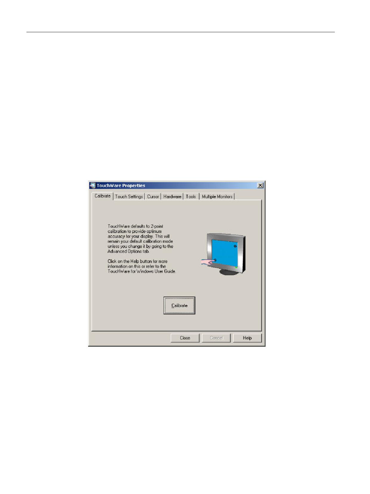
1. In the Start menu, click on "Start > Touchware > UPDD".
The "TouchWare Properties" dialog box opens.
2. In the "Calibrate" tab, click on "Calibrate" and follow the instructions that appear on screen.
You can find further information in the dialog by pressing the "Help" button.
PCU Base for IPC
44
Commissioning Manual, 10/2020, 6FC5397-2HP40-0BA1
Configuration of the system
4.14 Activating/deactivating the touchpad or other pointer devices
4.14
Activating/deactivating the touchpad or other pointer devices
If you are using an operator panel with touchpad and mouse pointer device, for example the
OP 012, inadvertent operating errors may occur. Therefore, if required, you can deactivate the
touchpad in the Windows Device Manager.
Note
The procedure described will be made easier using a USB-connected mouse. Alternatively, you
can carry out changes using the keyboard.
Requirement
You must be logged in as the administrator to be able to execute these steps.
Procedure
1. Search for the Device Manager by typing "Device Manager" into the entry field of the Start
menu.
You are given a list of options.
2. Open the "Device Manager" in the "Control Panel" selection.
3. Search the list for "Mice and other pointing devices" and then double-click on the device
name.
4. Right-click on "HID-compliant mouse" and select "Enable" or "Disable".
The touchpad is activated/deactivated.
PCU Base for IPC
Commissioning Manual, 10/2020, 6FC5397-2HP40-0BA1
45
Configuration of the system
4.15 Configuring virtual direct control keys (VDCK)
4.15
Configuring virtual direct control keys (VDCK)
4.15.1
General information
Direct control keys allow key states to be directly transferred to the PLC. These key signals are
transferred in a 2-byte key image and are evaluated by the PLC as digital inputs. Depending on
the panel being used, there are different options for using direct control keys via the system
network, e.g. using a direct control key module or machine control panel.
Virtual direct control keys (VDCK)
PCU Base for IPC extends the direct key configuration options to include Virtual Direct Control
Keys.
VDCK supports multitouch operation and therefore supplements the new SINUMERIK and
SIMATIC operating concept to include the corresponding virtual direct control keys.
Functional scope
Maximum number of suppor- 16
ted direct control keys:
Direct control keys that can Depending on the multitouch functionality of the Panel being
be simultaneously actuated: used, e.g.:
• SINUMERIK OP 015 black: 10 touch points
• SINUMERIK OP 019 black: 5 touch points
• SIMATIC ITC 1200/1500/1900/2200 V3: 5 touch points
• SIMATIC IFP 1500/1900/2200/2400: 5 touch points
• SIMATIC IPC 277/477/677: 5 touch points
You can find an overview of the compatible SIMATIC configura-
tions in the section titled "PCU Base for IPC Windows 10
(Page 19)".
Layout of the direct control
1 global direct control key layout for all HMI operating screens
keys
Assignment of the direct con- Direct control keys 1…16 are permanently assigned bits (0…15)
trol keys
in the image. Deactivating individual direct control keys (or using
less than 16 direct control keys) does not influence the assign-
ment to the relevant bits.
Signal transfer
1-channel
NOTICE
Signals of the virtual direct control keys are transferred from the HMI to the PLC through
1 channel
In addition, use a permanently wired acknowledgment button or a 2nd Channel from the HMI
(HMI Pro only) in order to guarantee functional safety.
PCU Base for IPC
46
Commissioning Manual, 10/2020, 6FC5397-2HP40-0BA1
Configuration of the system
4.15 Configuring virtual direct control keys (VDCK)
PLC basic program functionality
The direct control key functionality in the PLC basic program (activating the data transfer,
interface signal, addressing, alarms etc.) is identical when using virtual direct control keys and
real direct control keys.
You can find further information in the PLC Function Manual.
4.15.2
Creating a configuration file
You can define the layout of the virtual direct control keys in the associated configuration file. To
do this, you must create the configuration file in the user directory on the system which is the
active boot server.
Precondition
• The direct control keys are activated in the operator panel settings.
• A valid TCU index is configured in the operator panel settings.
You can find further information about these settings in the corresponding manual.
Procedure
Proceed as follows to create the configuration file for the direct control key layout:
1. Open a text editor, and as character coding, set ASCII or ANSI.
2. Copy the content from Reference to the vdck.ini configuration file (Page 49) to the text
editor.
3. Save the file as vdck.ini in one of the user directories of the system that is the active boot
server.
PC system as active boot server:
- C:\ProgramData\Siemens\MotionControl\user\common\tcu\<Name of
the TCU>\common\tcu\vdck.ini
- C:\ProgramData\Siemens\MotionControl\oem\common\tcu\<Name of
the TCU>\common\tcu\vdck.ini
- C:\ProgramData\Siemens\MotionControl\addon\common\tcu\<Name of
the TCU>\common\tcu\vdck.ini
NCU as active boot server:
- /user/common/tcu/<name of the TCU>/common/tcu/vdck.ini
- /oem/common/tcu/<name of the TCU>/common/tcu/vdck.ini
- /addon/common/tcu/<name of the TCU>/common/tcu/vdck.ini
Further information on the various setting options is provided in the following Chapters.
Result
The configuration file has been created in a user directory and can be adapted.
PCU Base for IPC
Commissioning Manual, 10/2020, 6FC5397-2HP40-0BA1
47
Configuration of the system
4.15 Configuring virtual direct control keys (VDCK)
4.15.3
Adapting the layout of the virtual direct control keys
You can adapt the following settings of the virtual direct control key layout.
Please note that the direct control key numbering (Page 49) and the assignment to the
appropriate bits in the image is fixed and cannot be changed. Moving or deactivating a control
key does not change the assignment or numbering.
Precondition
• Configuration file vdck.ini is saved in one of the user directories, and opened in an editor.
Additional information under Creating a configuration file (Page 47) and Reference to the
vdck.ini configuration file (Page 49)
Adapting the position of a direct control key
1. In vdck.ini adapt the required value for the horizontal (x) and vertical (y) positions, and note
the following:
- The control key positions are entered in the vdck.ini in the corresponding sections under
X_POS_<control key number> and Y_POS_<control key number>.
- The positioning of the individual control keys is specified in per mill and not in pixels. This
means that the direct control key layout is independent of the screen resolution.
- When parameterizing, orientate yourself using the diagram (Page 49).
2. If necessary, make other modifications or save and close the file.
Adapting the size of a direct control key
1. In vdck.ini adapt the required height and width, and note the following:
- In vdck.ini, width and height are entered in the corresponding sections under
WIDTH_<control key number> and HEIGHT_<control key number>.
- The size of the individual control keys is specified in per mill and not in pixels. This means
that the direct control key layout is independent of the screen resolution.
- In the default setting, every control key has a size of 146 x 112 per mill (width x height).
- When parameterizing, orientate yourself using the diagram (Page 49).
2. If necessary, make other modifications or save and close the file.
Hiding a direct control key
1. For the corresponding direct control key, change the values for height and width to 0. For
example, to hide direct control key 1, set the following values:
WIDTH_1 = 0
HEIGHT_1 = 0
2. If necessary, make other modifications or save and close the file.
PCU Base for IPC
48
Commissioning Manual, 10/2020, 6FC5397-2HP40-0BA1

Configuration of the system
4.15 Configuring virtual direct control keys (VDCK)
4.15.4
Default setting for the direct control key layout
In the configuration file vdck.ini, the direct control keys are defined and positioned as follows in
the default setting.
Note
Use of the virtual direct control keys by HMI Pro
Please note that HMI Pro does not use the 4 outer virtual direct control keys (direct control keys
1, 8, 9 and 16).
+0,
4.15.5
Reference to the vdck.ini configuration file
Configuration file vdck.ini contains the settings of the virtual direct control key layout.
The individual virtual direct control keys are defined in per mill and not in pixel. This means that
you can use the same direct control key layout for several operator panels with different
resolutions.
Archiving
The file must be located on the active boot server in the directory of the TCU.
Example for an IPC: C:\ProgramData\siemens\MotionControl\user\common\tcu\<Name of the
TCU>\common\tcu\vdck.ini
Example for an NCU: /user/common/tcu/<Name of the TCU>/common/tcu/vdck.ini
Character coding to be used
ASCII
Configuration file for the default layout
vdck.ini
[VDCK]
NUM_LAYOUTS = 1
[LAYOUT_1]
PCU Base for IPC
Commissioning Manual, 10/2020, 6FC5397-2HP40-0BA1
49
Configuration of the system
4.15 Configuring virtual direct control keys (VDCK)
vdck.ini
# Number of keys
NUM_KEYS = 16
# X positions in per mill of the resolution in the width
X_POS_1 = 0
X_POS_2 = 0
X_POS_3 = 0
X_POS_4 = 0
X_POS_5 = 0
X_POS_6 = 0
X_POS_7 = 0
X_POS_8 = 0
X_POS_9 = 854
X_POS_10 = 854
X_POS_11 = 854
X_POS_12 = 854
X_POS_13 = 854
X_POS_14 = 854
X_POS_15 = 854
X_POS_16 = 854
# Y positions in per mill of the resolution in the height
Y_POS_1 = 49
Y_POS_2 = 161
Y_POS_3 = 273
Y_POS_4 = 385
Y_POS_5 = 499
Y_POS_6 = 611
Y_POS_7 = 724
Y_POS_8 = 836
Y_POS_9
= 49
Y_POS_10 = 161
Y_POS_11 = 273
Y_POS_12 = 385
Y_POS_13 = 499
Y_POS_14 = 611
Y_POS_15 = 724
Y_POS_16 = 836
# Width per mill of the resolution
WIDTH_1 = 146
WIDTH_2 = 146
WIDTH_3 = 146
WIDTH_4 = 146
WIDTH_5 = 146
WIDTH_6 = 146
WIDTH_7 = 146
PCU Base for IPC
50
Commissioning Manual, 10/2020, 6FC5397-2HP40-0BA1
Configuration of the system
4.15 Configuring virtual direct control keys (VDCK)
vdck.ini
WIDTH_8 = 146
WIDTH_9 = 146
WIDTH_10 = 146
WIDTH_11 = 146
WIDTH_12 = 146
WIDTH_13 = 146
WIDTH_14 = 146
WIDTH_15 = 146
WIDTH_16 = 146
# Height in per mill of the resolution
HEIGHT_1 = 112
HEIGHT_2 = 112
HEIGHT_3 = 112
HEIGHT_4 = 112
HEIGHT_5 = 112
HEIGHT_6 = 112
HEIGHT_7 = 112
HEIGHT_8 = 112
HEIGHT_9 = 112
HEIGHT_10 = 112
HEIGHT_11 = 112
HEIGHT_12 = 112
HEIGHT_13 = 112
HEIGHT_14 = 112
HEIGHT_15 = 112
HEIGHT_16 = 112
PCU Base for IPC
Commissioning Manual, 10/2020, 6FC5397-2HP40-0BA1
51
Configuration of the system
4.16 Configuring the SITOP UPS module for use with PCU Base for IPC
4.16
Configuring the SITOP UPS module for use with PCU Base for IPC
4.16.1
Overview of SITOP UPS
SITOP UPS modules can continue operation of the SIEMENS PC system temporarily if a power
failure occurs and/or shut down the system correctly.
For example, a SITOP UPS module also protects against data loss when the SIEMENS PC system
hardware is shut down, because for technical reasons with Windows-based systems, data is still
written to the SSD after shutdown.
• You will find general information about SITOP UPS modules used in combination with
PCU Base for IPC in Chapter SITOP modules for IPC (Page 53).
• If you want to use a SITOP UPS module in combination with PCU Base for IPC, you must
first adapt the settings of the SITOP software (Page 54).
• Optionally, you can adapt the delay time after which the HMI software will be forced to shut
down (Page 57).
• You must configure the hardware (Page 60) of the SITOP UPS module before using it with
PCU Base for IPC.
NOTICE
Ensure the readiness for operation of the SITOP power supply
In order to prevent data loss, the SITOP power supply must be ready for operation. Note the
following:
• The SITOP power supply may not be ready for operation immediately after being switched
on (a capacitor-buffered UPS500 requires 1-2 minutes make time, for example).
• The operating system and the SITOP software must have run up so that the SITOP software
can shut down the system correctly when a power failure occurs.
• The readiness for operation and the functional capability of the SITOP power supply must be
ensured (e.g. battery of capacitor charged).
• Please also note all the information on the readiness for operation in the documentation of
your SITOP device.
Further information
Information on using SITOP UPS modules in combination with PCU Base for IPC can also be found
on the Internet:
• Service & Support Portal: Example of using an uninterruptible power supply (http://
support.automation.siemens.com/WW/view/en/90142681)
• Service & Support Portal: Typical values for an operator station with Windows (http://
support.automation.siemens.com/WW/view/en/76773241)
of a SITOP UPS module)
PCU Base for IPC
52
Commissioning Manual, 10/2020, 6FC5397-2HP40-0BA1
Configuration of the system
4.16 Configuring the SITOP UPS module for use with PCU Base for IPC
• Catalog KT 10.1 SITOP Power Supply
• SIEMENS Industry Mall > 24 V DC Uninterruptible Power Supplies (https://
eb.automation.siemens.com/mall/en/US/Catalog/Products/7010117)
4.16.2
SITOP modules for IPC
Suitable SITOP UPS modules
SITOP UPS modules can continue operation of a PC system temporarily if a power failure occurs
and/or shut down the system correctly.
In conjunction with PCU Base for IPC, all specific applications are taken into account (e.g. HMI
software) with the USVShutdown.bat component.
Safe shutdown after a power failure of an IPC in the state that it was delivered takes
approximately 20 seconds. For a typical power consumption of approx. 60 W, a capacitor-
buffered UPS with an energy storage device of 2.5 kW is recommended. If longer buffer times are
required, then several expansion modules can be connected in a cascade connection.
Example of a SITOP UPS module that can be used (USB):
SITOP 500S (15 A / 2.5 kWs capacitor)
Article No.: 6EP1933-2EC41
Example of a SITOP UPS with Ethernet/PROFINET interface that can be used:
SITOP UPS1600 starter kit
• DC-UPS SITOP UPS1600 24V DC/10A
• SITOP UPS1100 3.2 AH battery module
Article No.: 6EP4134-3AB00-2AP0
Note
Information about the test environment for machine OEMs
The functionality has been tested in the standard configuration with PCU Base for IPC.
When installing add-on or OEM software components, you must check the shutdown procedure
of the entire system and adapt the factory setting (180 seconds).
Further information at Parameterizing a delay time for quitting the HMI software (Page 57)
PCU Base for IPC
Commissioning Manual, 10/2020, 6FC5397-2HP40-0BA1
53
Configuration of the system
4.16 Configuring the SITOP UPS module for use with PCU Base for IPC
4.16.3
Configuring SITOP software for PCU Base
4.16.3.1
Configuring SITOP software V3.x (USB)
Configuring SITOP software V3.x (USB)
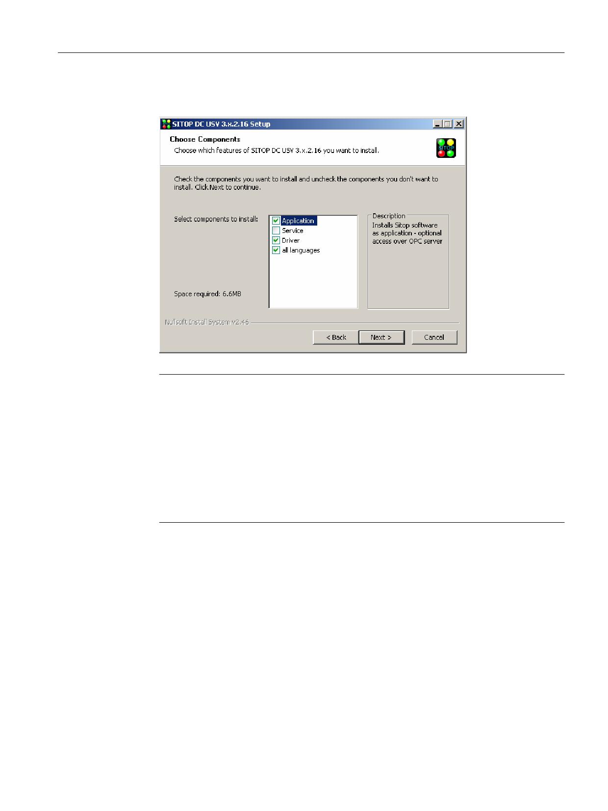
If you want to use a SITOP UPS module in combination with PCU Base for IPC, you must first adapt
the settings of the SITOP software.
Precondition
• The SITOP UPS hardware is connected via the USB interface.
• The SITOP software of version 3.x.2.16 or later is installed in directory C:\Program Files
(x86)\SITOP\
PCU Base for IPC
54
Commissioning Manual, 10/2020, 6FC5397-2HP40-0BA1
Configuration of the system
4.16 Configuring the SITOP UPS module for use with PCU Base for IPC
• If you want to use SITOP software of version 3.2.1.16 or older, this must be installed as a
normal application, not as a service.
Note
Windows service of the SITOP software version 3.2.1.16 or older is not compatible with
PCU Base for IPC
If you use SITOP software of version 3.2.1.16 or older as a Windows service with
PCU Base for IPC, the correct shutdown procedure cannot be performed!
If you have installed the SITOP software of version 3.2.1.16 as a Windows service, you must
uninstall this and install it again as an application in order to be able to use it in conjunction
with PCU Base.
From version 3.2.1.17, the SITOP software can be used as service with PCU Base for IPC and
is recommended.
• The SITOP software was configured during the installation so that it starts automatically
when Windows is run up (factory setting).
• The Service Desktop is active.
PCU Base for IPC
Commissioning Manual, 10/2020, 6FC5397-2HP40-0BA1
55
Configuration of the system
4.16 Configuring the SITOP UPS module for use with PCU Base for IPC
Procedure
Proceed as follows to configure the SITOP software for use with PCU Base for IPC:
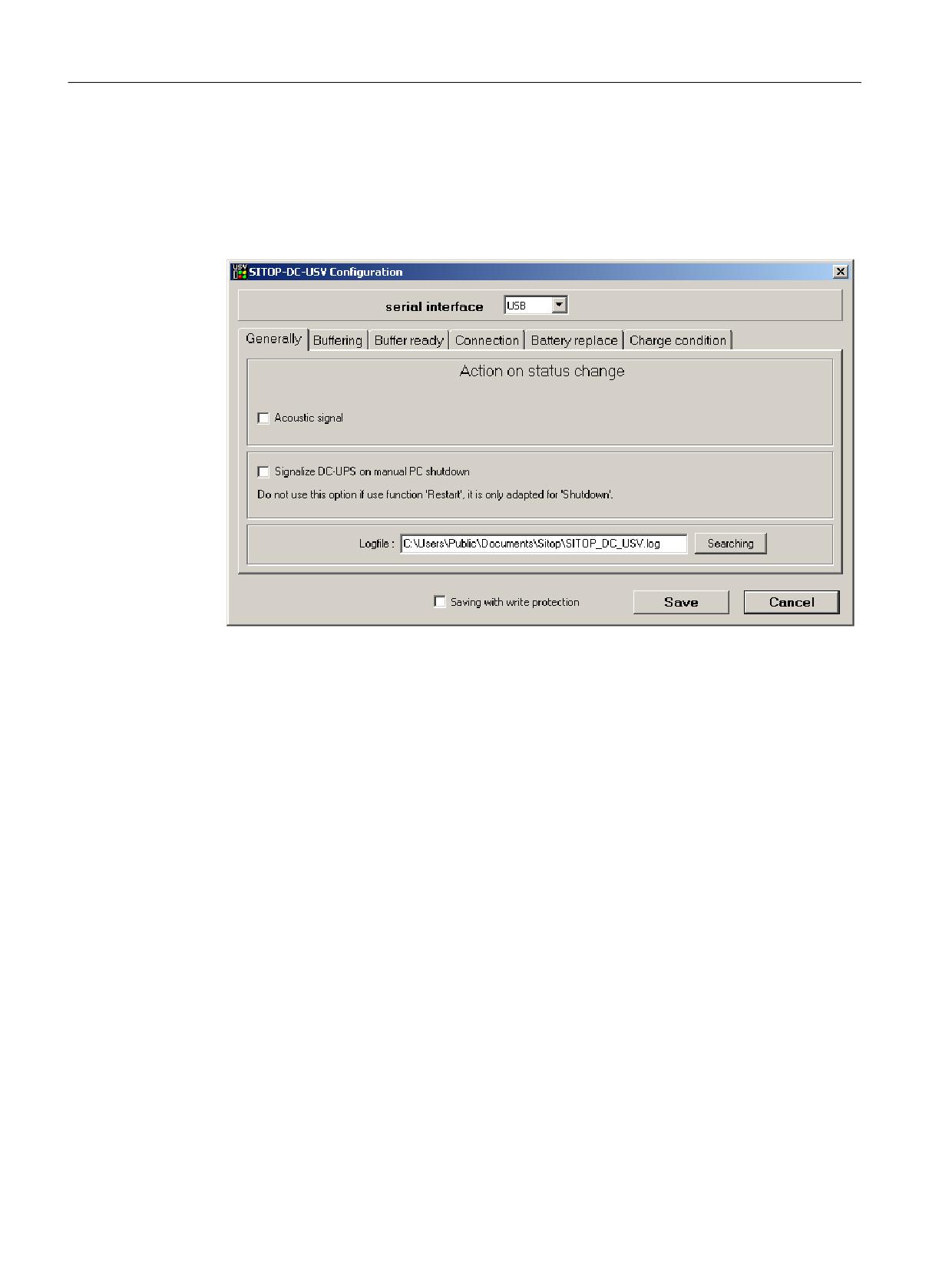
1. Call the settings of the SITOP software, for example, by right-clicking the SITOP UPS icon in
the Windows information area and then selecting "Configuration".
The "SITOP DC UPS Configuration" dialog box opens.
2. In the "General" tab, select "UPS" in the drop-down list at "Serial interface".
PCU Base for IPC
56
Commissioning Manual, 10/2020, 6FC5397-2HP40-0BA1
Configuration of the system
4.16 Configuring the SITOP UPS module for use with PCU Base for IPC
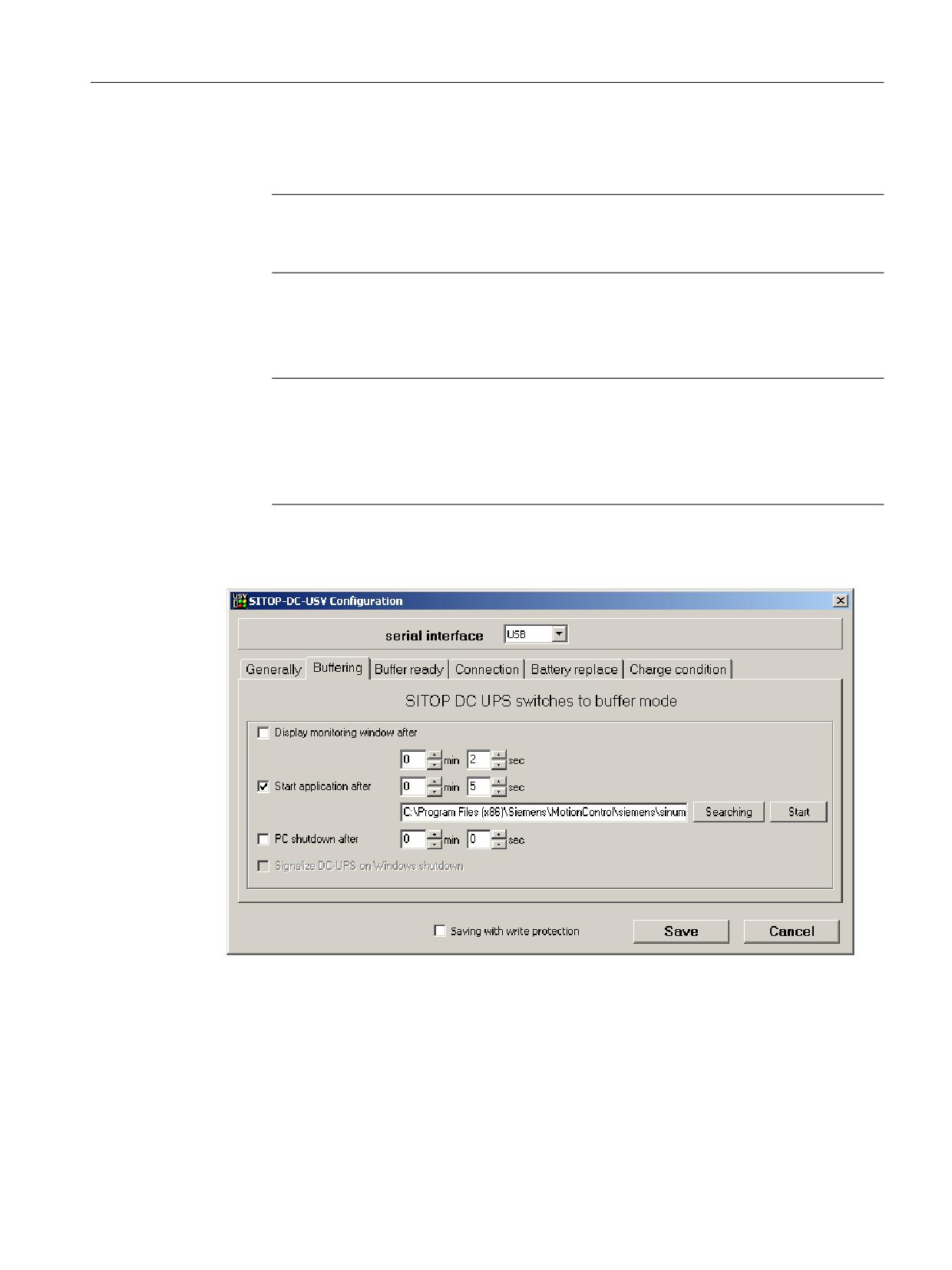
3. Switch to the "Floating operation" tab and make the following settings:
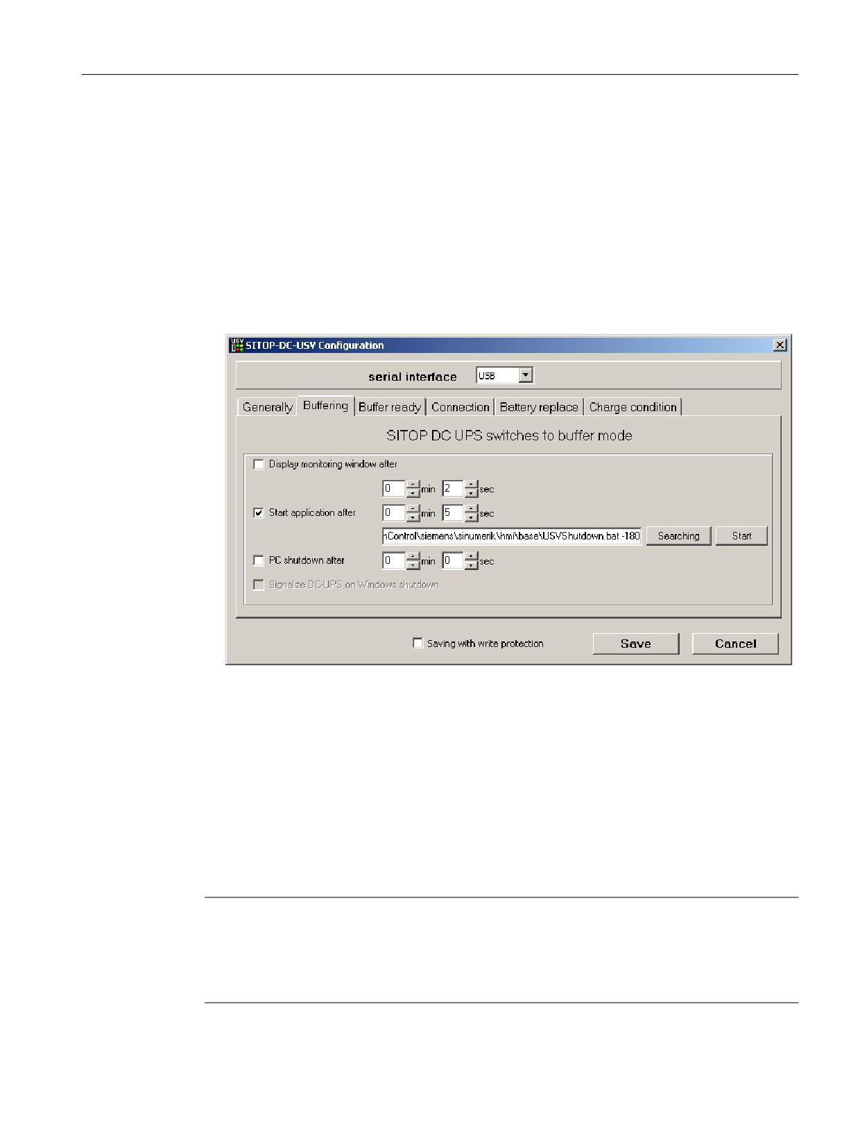
- Deactivate the "Display monitoring window after" checkbox
Note
Deactivating the monitoring window
Display of the monitoring window can cause malfunctioning of the HMI software.
- Click directly in the text field at "Start application after" and specify the path of
the USVShutdown.bat:
C:\Program Files (x86)\Siemens\MotionControl\siemens\sinumerik
\hmi\base\USVShutdown.bat
Note
Do not use the "Browse" button
The dialog can crash if you use the "Browse" button to specify the path of
the USVShutdown.bat.
Instead, enter the path directly in the text field.
- After you have specified the path of the USVShutdown.bat, activate the "Start
application after" checkbox. Optionally, you can specify the wait time after which
the USVShutdown.bat is to be executed (e.g. 5 seconds).
4. Confirm the settings with "Save".
Parameterizing a delay time for quitting the HMI software
Before the SITOP monitor closes Windows, USVShutdown.bat shuts down operation of the
HMI software.
If the HMI software cannot be shut down within 180 seconds (factory setting) due to an error,
HMI software shutdown is forced and Windows is shut down.
PCU Base for IPC
Commissioning Manual, 10/2020, 6FC5397-2HP40-0BA1
57
Configuration of the system
4.16 Configuring the SITOP UPS module for use with PCU Base for IPC
If the HMI software of your OEM installation is not shut down within 180 seconds, you can
parameterize this wait time manually.
Note
Information about the test environment for machine OEMs
The function "SITOP UPS" has been tested in the standard configuration with PCU Base for IPC.
When installing add-on or OEM software components, you must check the shutdown procedure
of the entire system and adapt the factory setting.
Precondition
• The SITOP UPS module is configured for use with PCU Base for IPC.
For further information see under Configuring SITOP software V3.x (USB) (Page 54).
• The Service Desktop is active.
PCU Base for IPC
58
Commissioning Manual, 10/2020, 6FC5397-2HP40-0BA1
Configuration of the system
4.16 Configuring the SITOP UPS module for use with PCU Base for IPC
Procedure
Proceed as follows to change the delay time:
1. Call the settings of the SITOP software, for example, by right-clicking the SITOP UPS icon in
the information area and then selecting "Configuration".
2. In the "SITOP DC UPS Configuration" dialog box, enter the wait time in seconds as a command
line parameter in the "Buffering" tab:
- Syntax: <Path>\USVShutdown.bat -<time in seconds>
- Example: C:\Program Files (x86)\Siemens\MotionControl\siemens
\sinumerik\hmi\base\USVShutdown.bat -180
Figure 4-1
SITOP Monitor Floating operation
3. Confirm the setting with "Save".
4.16.3.2
Configuring SITOP UPS Manager (Ethernet)
Precondition
• The SITOP UPS hardware is connected via the Ethernet interface.
• The SITOP-UPS Manager has been installed and configured for Ethernet.
Note
Validity of the information on the SITOP components in this manual
This information only involves the configuration of the settings relevant for PCU Base. In
addition, all the information and notes in the corresponding manuals of your SITOP UPS
hardware and SITOP UPS Manager apply.
PCU Base for IPC
Commissioning Manual, 10/2020, 6FC5397-2HP40-0BA1
59

Configuration of the system
4.16 Configuring the SITOP UPS module for use with PCU Base for IPC
Procedure
1. Call the SITOP UPS Manager.
2. Change to "Software configuration > Buffer mode".
3. Make the following settings:
- Activate the checkbox "Start application on power failure" - and there, enter the path of
USVShutdown.bat:
C:\Program Files (x86)\Siemens\MotionControl\siemens\sinumerik\hmi\base
\USVShutdown.bat
- When required, configure the wait time until the HMI software is terminated by
USVShutdown.bat (factory setting = 180 seconds).
Note
Information about the test environment for machine OEMs
The function "SITOP UPS" has been tested in the standard configuration with
PCU Base for IPC. When installing add-on or OEM software components, you must check
the shutdown procedure of the entire system and adapt the factory setting.
To do this, enter the wait time in seconds as command line parameter:
Syntax: <Path>\USVShutdown.bat -<time in seconds>
Example: C:\Program Files (x86)\Siemens\MotionControl\siemens\sinumerik\hmi\base
\USVShutdown.bat -180
4. Confirm the settings with "Configuration changed, restart application now".
4.16.4
Hardware configuration of the SITOP UPS module
Buffering parameterization
The UPS module can be used to select whether buffering should be completed after a
predetermined period of time or not until the accumulator’s lowest discharge threshold (=
maximum buffer time) has been reached. Both buffering parameterizations result from this.
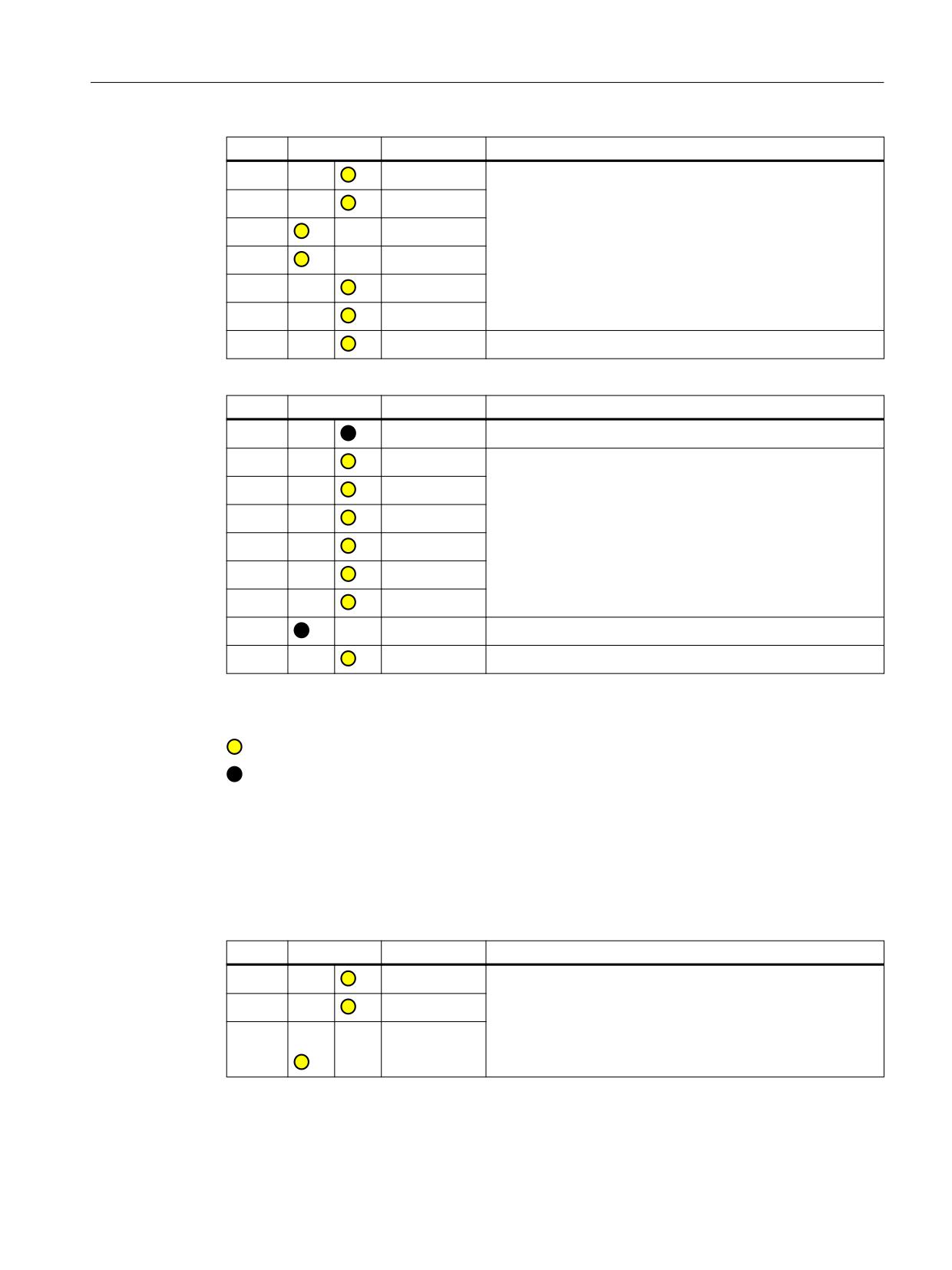
"Maximum buffer time" mode
This mode enables the system to be shut down in a time-optimized manner. The UPS module is
synchronized with the shutdown of the operating system. Buffering is maintained until the
operating system has been shut down. The operating system must shut down within a
maximum of 5 minutes (including all applications). Otherwise, the UPS module buffers for the
maximum buffer time (dependent on the accumulator state).
Required settings on the UPS module (USB interface)
On - Off
1
+2V
Cut-in threshold
2
+1V
+22V fixed
3
+0.5V
PCU Base for IPC
60
Commissioning Manual, 10/2020, 6FC5397-2HP40-0BA1
Configuration of the system
4.16 Configuring the SITOP UPS module for use with PCU Base for IPC
On - Off
4
+1V
5
+1V
End-of-charge voltage
6
+0.5V
+ 26.3V fixed
7
+0.2V
8
+0.2V
9
+0.1V
10
0.35A / 0.7A
Charging current
On - Off
1
Set time/max. time
2
+320 s
3
+160s
Buffer time
4
+80s
5
+40s
6
+20s
+5 s fixed
7
+10s
8
Disconnection
9
Battery operating state on/off
Legend:
Delivery condition setting
Setting for operation on the PCU
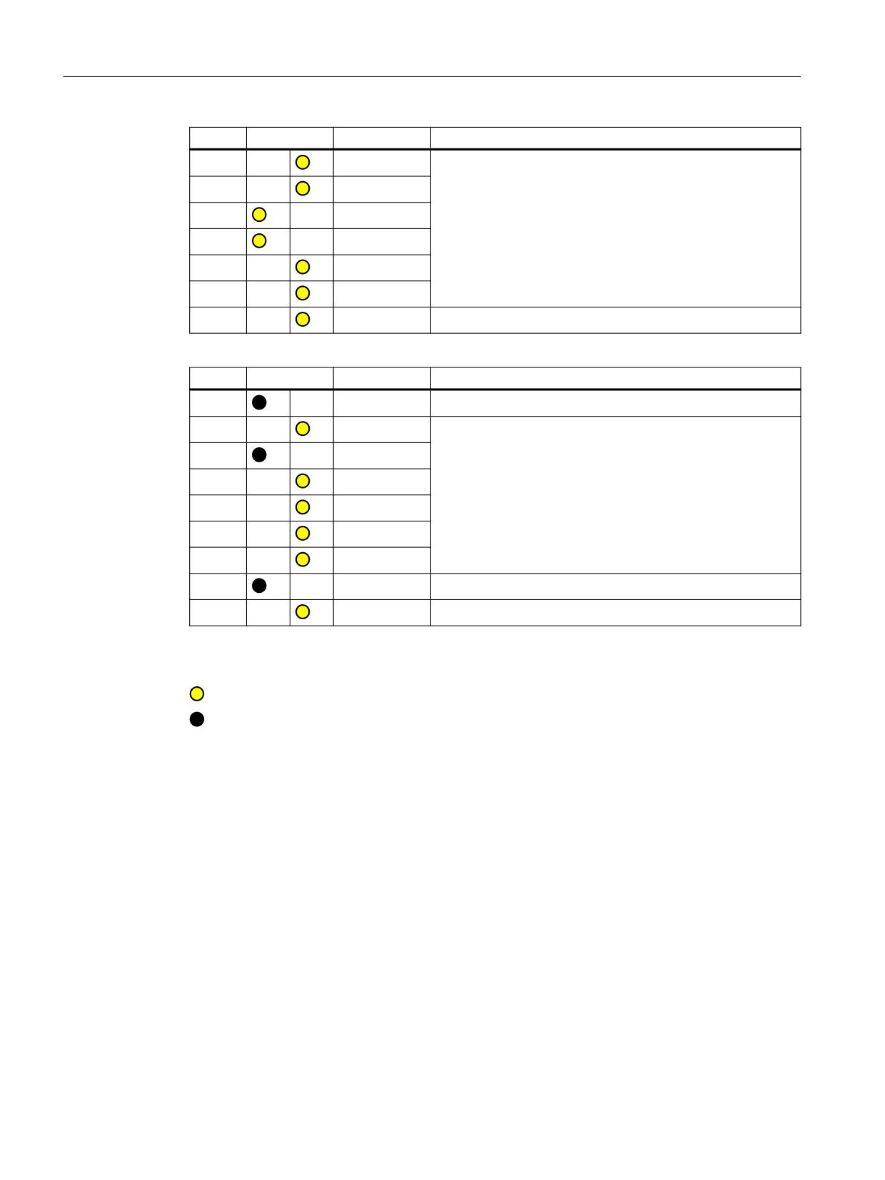
"Fixed buffer time" mode
In this mode, the UPS module always buffers for the pre-selected, fixed period of time. It is not
possible to synchronize the UPS module with the operating system shutdown.
Required settings on the UPS module
On - Off
1
+2V
Cut-in threshold
2
+1V
+22V fixed
3
+0.5V
PCU Base for IPC
Commissioning Manual, 10/2020, 6FC5397-2HP40-0BA1
61
Configuration of the system
4.16 Configuring the SITOP UPS module for use with PCU Base for IPC
On - Off
4
+1V
∘
∘
5
+1V
End-of-charge voltage
6
+0.5V
+ 26.3V fixed
7
+0.2V
8
+0.2V
9
+0.1V
10
0.35A / 0.7A
Charging current
On - Off
1
Set time/max. time
2
+320 s
∘
∘
3
+160s
Buffer time
4
+80s
+5 s fixed
5
+40s
6
+20s
7
+10s
8
Disconnection
9
Battery operating state on/off
Legend:
Delivery condition setting
Setting for operation on the PCU
PCU Base for IPC
62
Commissioning Manual, 10/2020, 6FC5397-2HP40-0BA1
Configuration of the system
4.17 Configuration of the Service Center
4.17
Configuration of the Service Center
4.17.1
Overview
You can permanently adapt the settings for the backup and restoration of disk images (Service
Center (Page 117) component) in the "Service Center Backup/Restore" dialog box:
• Configuration of the network adapter (Page 63)
• Configuration of the host (Page 64)
Adaptations that you make here are stored in the servicesystem.ini configuration file.
You can also adapt the settings directly in the associated configuration files:
• servicesystem.ini
• Additional settings: ghost.ini
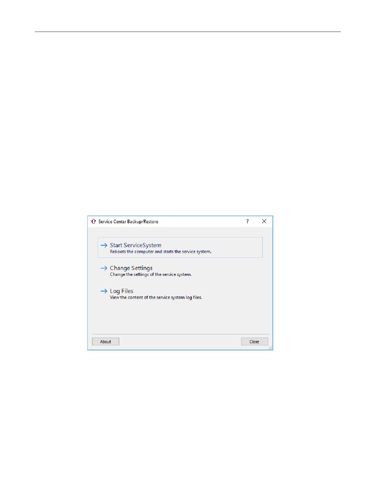
You can also view the log files of the Service Center or restart the PC system in the Service Center
in the "Service Center Backup/Restore" dialog box.
To open the dialog box, click the ServiceCenter Backup-Restore icon on the Desktop.
Figure 4-2
ServiceCenter Backup/Restore
4.17.2
Configuration of the network adapter
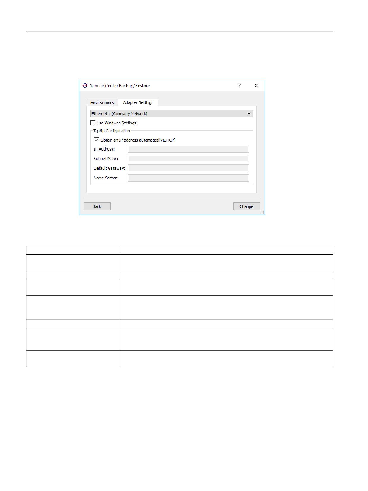
You can make the network settings in the "Adapter Settings" tab and permanently save this
configuration, in contrast to the settings in the "Network Settings" dialog box of the Service
Center (Page 121).
Settings that you make in this dialog box are stored in the servicesystem.ini configuration
file.
PCU Base for IPC
Commissioning Manual, 10/2020, 6FC5397-2HP40-0BA1
63
Configuration of the system
4.17 Configuration of the Service Center
Overview
You can make the following IP settings in the "Adapter Settings" dialog box:
Figure 4-3
Adapter settings - Ethernet 1 (company network)
Table 4-4
Settings in the "Adapter Settings" dialog box
Settings
Purpose
Adapter
Select the Ethernet interface that you want to configure.
All settings in this dialog box refer to the selected Ethernet interface.
Use Windows Settings
Select whether the values set in the Control Panel are to be used.
Obtain an IP address automatically (DHCP)
Select whether the addresses are to be fetched dynamically from the DHCP server.
If the checkbox is deactivated, you must make the settings manually.
IP Address
Set the IP address of the NCU.
You can specify an IP address from the following range:
192.168.214.250 - 254
Subnet Mask
Specify a subnet mask, e.g. 255.255.255.0
Default Gateway
Set the IP address of the standard gateway.
A standard gateway creates a standard route in the IP routing table for all destinations that are not
in the subnet.
Name Server
Set the IP address of the name server.
A name server answers questions asked about a domain name zone using a DNS database.
4.17.3
Configuration of the host
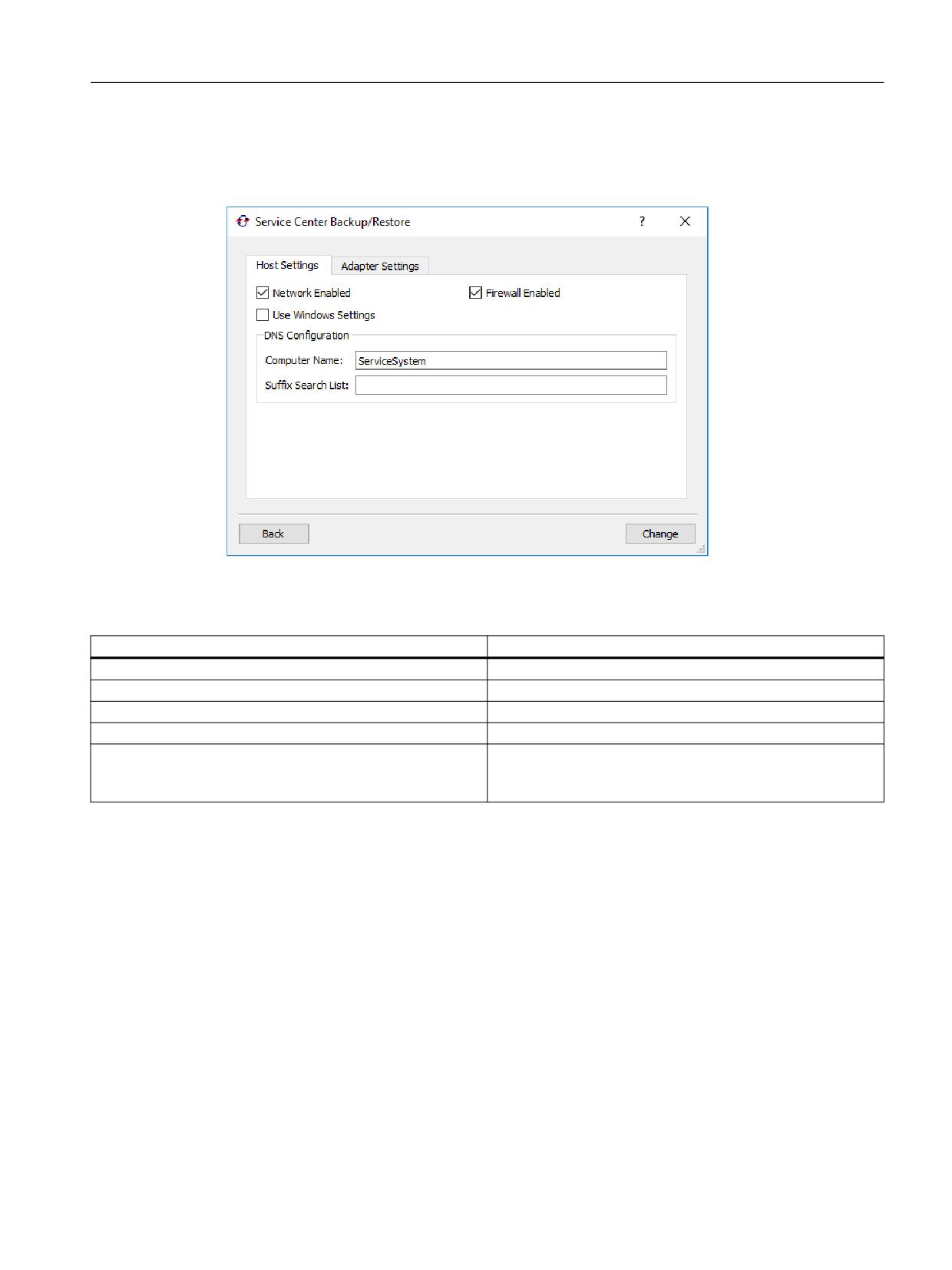
You can make the network settings in the "Host Settings" tab and permanently save this
configuration, in contrast to the settings in the "Network Settings" dialog box of the Service
Center (Page 121).
Settings that you make in this dialog box are stored in the servicesystem.ini configuration
file.
PCU Base for IPC
64
Commissioning Manual, 10/2020, 6FC5397-2HP40-0BA1
Configuration of the system
4.17 Configuration of the Service Center
Overview
You can make the following settings in the "Host Settings" dialog box:
Figure 4-4
Host settings
Table 4-5
IP settings in the "Host Settings" dialog box
Settings
Purpose
Network enabled
Activate or deactivate the network interfaces of the PC system.
Firewall enabled
Activate or deactivate the firewall of the PC system.
Use Windows Settings
Select whether the values set in the Control Panel are to be used.
DNS Configuration > Computer Name
Specify the DNS computer name.
DNS Configuration > Suffix Search List
Parameterize a search list for DNS suffix, e.g. "network.com".
The factory setting of the Ethernet interface "Local Area Connection"
is ".local".
PCU Base for IPC
Commissioning Manual, 10/2020, 6FC5397-2HP40-0BA1
65
Configuration of the system
4.18 Adapting the firewall settings
4.18
Adapting the firewall settings
4.18.1
Overview
From a PG/PC in the plant network, you can directly access resources on the Siemens PC system.
The same applies when accessing a PG/PC from the Siemens PC system in the plant network or
in the company network.
If you want to access the Siemens PC system via the company network instead or in addition, you
must adapt the firewall settings.
&RPSDQ\ QHWZRUN
6\VWHP QHWZRUN
3* 3&
,3&
)LUHZDOO
You can adapt the following settings:
• Activate the remote access to the PC system (Page 72)
• Enabling SNMP communication (Page 70)
• Activation/deactivation of the file and printer release (Page 74)
• Activation of the ping execution (ICMP) (Page 84)
As a rule, you can make these settings in the Control Panel or via the prompt or a script/batch file
(relevant for series commissioning) (Page 69).
You can save and restore (Page 86) the firewall settings. (Even on different Siemens PC systems,
e.g. due to series commissioning)
Also note the general information in this chapter:
• Factory setting of the Windows Firewall on the Siemens PC system (Page 67)
• General information on the operating principle of the Windows Firewall (Page 68)
• General information on the settings recommended for Windows (Page 68)
PCU Base for IPC
66
Commissioning Manual, 10/2020, 6FC5397-2HP40-0BA1

Configuration of the system
4.18 Adapting the firewall settings
4.18.2
Factory setting of the Windows Firewall on the Siemens PC system
The Windows Firewall settings on your Siemens PC system are appropriately configured by
PCU Base for IPC for the use of SINUMERIK software and systems. For security reasons, the
Windows Firewall is activated in the company network and expanded by additional rules. The
Windows Firewall is deactivated in the system network. The descriptions in this chapter
therefore largely relate to the adaptation of the firewall settings for the company network.
Table 4-6
Factory settings for network adapter and Windows Firewall
System network
Company network
Interface
X2
X1
Network name IPC
Local Area Connection
Local Area Connection 2
Network profile
Public
Public
Status Windows Firewall
Deactivated
Activated
Further information: General informa-
tion on the settings recommended for
Windows (Page 68)
File and printer release
Activated and permit-
Deactivated and blocked by firewall
ted
Further information: Activation/deactiva-
tion of the file and printer release
(Page 74)
SNMP communication
Permitted
Blocked
Further information: Enabling SNMP
communication (Page 70)
Remote access (via port 5900)
Permitted
Blocked
Further information: Activate the remote
access to the PC system (Page 72)
Outgoing ICMP Ping requests from the PC
Permitted
Permitted
system
Further information: Activation of the
ping execution (ICMP) (Page 84)
Incoming ICMP Ping requests on the PC
Permitted
Blocked
system
Further information: Activation of the
ping execution (ICMP) (Page 84)
Note
Automatic network release of USB data storage media results in activation of the file and
printer release
The automatic network release of USB data storage media is activated in the default setting of
PCU Base for IPC. The file and printer release is then activated by Windows when a USB data
storage medium is connected.
Further information: Configuring network access on the USB data storage medium (Page 34)
PCU Base for IPC
Commissioning Manual, 10/2020, 6FC5397-2HP40-0BA1
67
Configuration of the system
4.18 Adapting the firewall settings
4.18.3
General information on the operating principle of the Windows Firewall
Windows Firewall rules are structured as follows:
• The firewall rules are divided into Inbound Rules and Outbound Rules.
• Each firewall rule is valid for one or several network profiles (Profiles).
Each network connection in Windows is assigned to a specific network profile. In the factory
settings state of the PC system, both the plant network ("Local Area Connection") and the
company network ("Local Area Connection 2") have the network profile "Public".
• Some firewall rules are already assigned to so-called "Groups". As a result, you can more easily
activate or deactivate specific related network functionalities (e.g. file and printer release).
You can make the Windows Firewall settings using the Control Panel and using the prompt or
script/batch files. The use of script/batch files is particularly recommended for series
commissioning. Alternatively, for series commissioning, you can make all of the Windows
Firewall settings on an individual PC system, save these settings, and apply them on other
devices (Page 86).
4.18.4
General information on the settings recommended for Windows
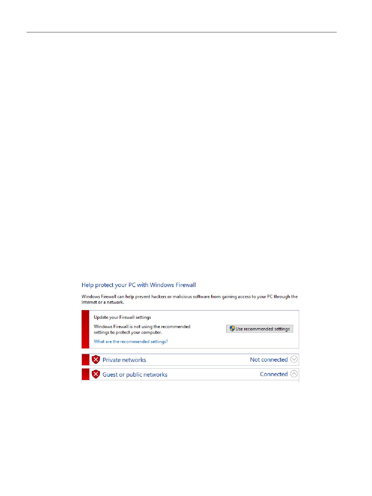
Firewall settings recommended by Windows are unsuitable for use in the plant network
In the Control Panel, under "Windows Defender Firewall", there is a display indicating that the
firewall settings do not correspond to the settings recommended and automatically checked by
Windows. The corresponding sections are highlighted in red:
The settings automatically recommended by Windows are not suitable for use in the plant
network, however, and would limit the functioning of the system. The network security in the
PCU Base for IPC
68
Commissioning Manual, 10/2020, 6FC5397-2HP40-0BA1
Configuration of the system
4.18 Adapting the firewall settings
plant network must therefore be ensured by other security precautions. In this regard, observe
the information on industrial security (Page 92).
Note
Do not use the firewall settings that are automatically recommended by Windows!
The command "Use recommended settings" overwrites the existing firewall settings, which are
required for operating PCU Base for IPC, and therefore this command must not be used.
Otherwise, the Windows Firewall will be activated in the plant network and communication of
internal services of the PCU Base will be inhibited.
4.18.5
Configuration by means of a prompt or script/batch file
You can make most of the settings described in this chapter both using the Control Panel and
using the prompt or script/batch files. The use of script/batch files is particularly recommended
for series commissioning.
Basic procedure
You can enter these commands either directly into the prompt or save the command in a script
or batch file:
• Direct input of the command:
- Call the prompt as the administrator.
- You can enter the commands either directly or in succession.
• Calling the command via a script file (or batch file):
- Save the command in a text file.
- Call the prompt as the administrator.
- Specify the script file as follows:
netsh -f <File name of the script file>
Further information
Descriptions of the commands and of all of the associated parameters of Netsh within the
Advfirewall firewall context can be found on the Microsoft website:
• Microsoft TechNet: Netsh (command line program) (https://docs.microsoft.com/en-us/
previous-versions/windows/it-pro/windows-server-2003/cc785383(v=ws.10)?
redirectedfrom=MSDN)
PCU Base for IPC
Commissioning Manual, 10/2020, 6FC5397-2HP40-0BA1
69
Configuration of the system
4.18 Adapting the firewall settings
• Microsoft TechNet: Netsh AdvFirewall Firewall Commands (https://docs.microsoft.com/en-
us/previous-versions/windows/it-pro/windows-server-2008-R2-and-2008/
dd734783(v=ws.10)?redirectedfrom=MSDN#BKMK_3_set)
• Microsoft TechNet: Netsh Commands for Windows Firewall with Advanced Security (https://
docs.microsoft.com/en-us/previous-versions/windows/it-pro/windows-server-2008-R2-
and-2008/cc771920(v=ws.10)?redirectedfrom=MSDN)
4.18.6
Enabling SNMP communication
Some network diagnostics functions use SNMP communication (e.g. in SINUMERIK Operate).
This is not blocked in the plant network. If, however, you have productively linked your plant in
the company network, SNMP communication is partially blocked:
• In the factory settings version of the PCU Base for IPC, incoming SNMP communication is
blocked in the company network.
• Outgoing SNMP communication in the company network is not blocked.
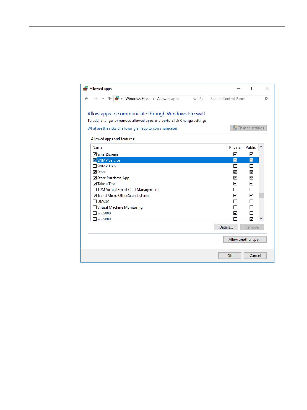
In the settings for the Windows Firewall, you can activate SNMP communication via the
checkbox "SNMP Service" for specific network profiles.
Procedure
To permit incoming SNMP communication on the Siemens PC system, proceed as follows:
1. Enter "Control Panel" in the search field and then click on "Control Panel" in the search results.
The desktop App "Control Panel" opens.
2. Click on the display selection and switch from the "Category" view to "Icons".
The "All Control Panel Items" dialog box opens.
PCU Base for IPC
70
Commissioning Manual, 10/2020, 6FC5397-2HP40-0BA1
Configuration of the system
4.18 Adapting the firewall settings
3. Click on "Windows Defender Firewall" > "Allow a app or feature through Windows Defender
Firewall".
The "Allowed apps" dialog box opens. The various checkboxes for "SNMP Service" are checked
and displayed with a green or gray backg58round, because the SNMP service is partially
activated: Incoming queries are blocked on the Siemens PC system and outgoing queries
from the PC system are permitted.
4. Click on "Change Settings" and confirm with "Yes", if applicable.
5. Activate the checkbox of the corresponding network profile completely, e.g. "Public" for the
company network (factory setting).
6. Click "OK" to confirm the change.
PCU Base for IPC
Commissioning Manual, 10/2020, 6FC5397-2HP40-0BA1
71
Configuration of the system
4.18 Adapting the firewall settings
4.18.7
Activate the remote access to the PC system
4.18.7.1
Overview
Basically, it is possible to access the Siemens PC system both via the plant network and via the
company network via VNC:
• The remote access to the Siemens PC system from a PG/PC in the system network is activated
via the factory setting.
Further information: Connection options in the system network (Page 136)
• If you want to access the Siemens PC system via the company network instead or in addition,
you must adapt the firewall settings.
&RPSDQ\ QHWZRUN
6\VWHP QHWZRUN
3* 3&
,3&
91& 9LHZHU
91& VHUYHU
3RUW
The inbound rule "vnc5900", which is deactivated in the factory settings state, is available for
this purpose in the expanded settings for the Windows Firewall. To activate the remote access
to the PC system in the company network, you can activate this rule either directly in the
Control Panel (Page 72), or in the prompt or by means of a script/batch file (Page 73).
Further information
In addition to the firewall settings, you may have to adapt other settings to establish a remote
connection in the company network.
You can find further information on this in Chapter Remote access (Page 155), especially under
Remote access to the PCU for operation and maintenance (Page 156).
4.18.7.2
Via the Control Panel
Procedure
To activate remote access from the PG/PC in the company network to the Siemens PC system,
proceed as follows:
1. Enter "Control Panel" in the search field and then click on "Control Panel" in the search results.
The desktop App "Control Panel" opens.
2. Click on the display selection and switch from the "Category" view to "Icons".
The "All Control Panel Items" dialog box opens.
3. Click on "Windows Defender Firewall".
PCU Base for IPC
72
Commissioning Manual, 10/2020, 6FC5397-2HP40-0BA1
Configuration of the system
4.18 Adapting the firewall settings
4. Click on "Advanced settings" and confirm the call of the expanded settings with "Yes" if
necessary.
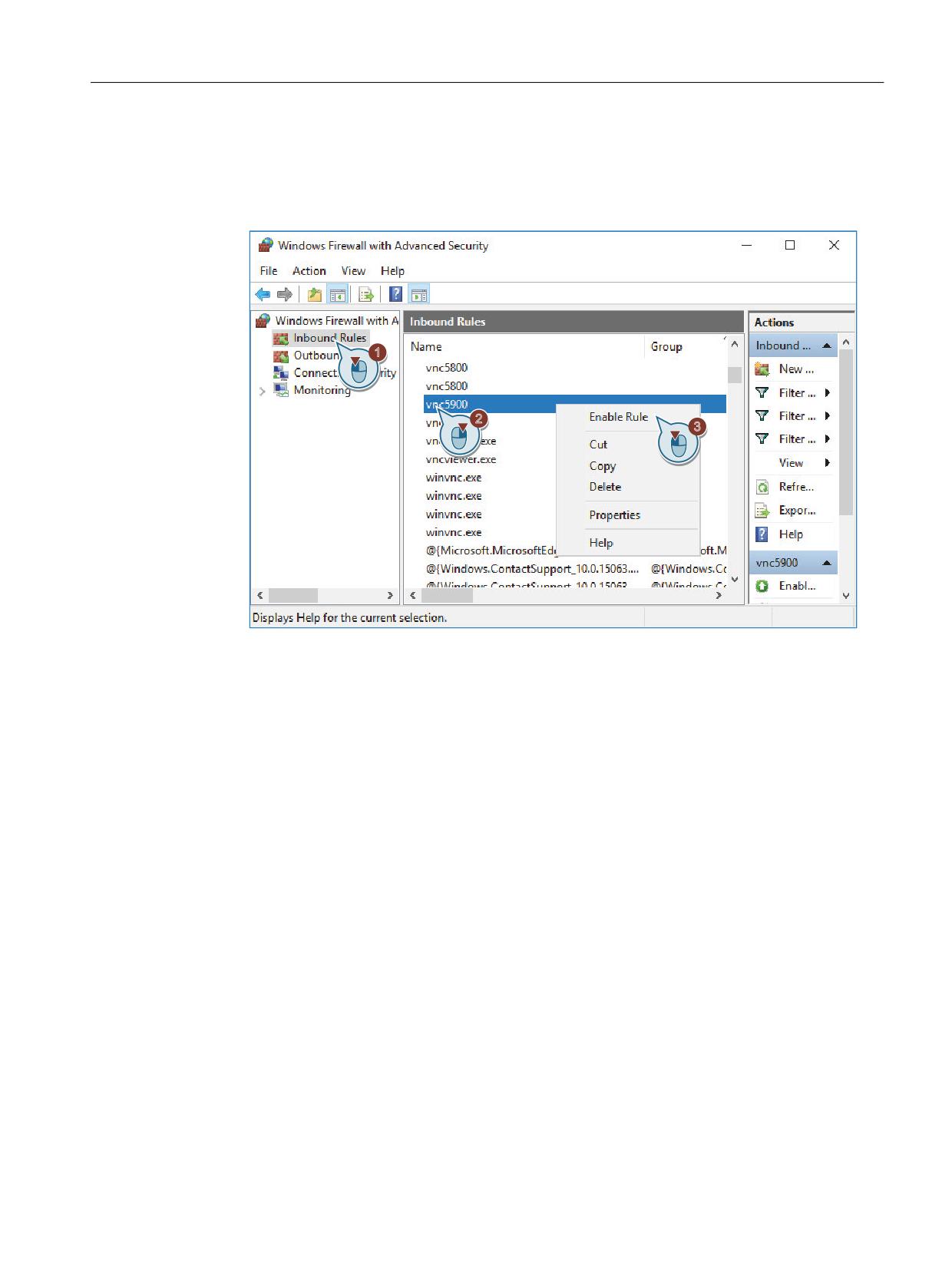
5. In the "Windows Firewall with Advanced Security" dialog, right-click under "Inbound Rules"
on the rule "vnc5900", then click on "Enable Rule".
Result
With the activation of the inbound rule "vnc5900", Port 5900 was activated in the company
network, which allows remote access from a PG/PC to the Siemens PC system in the company
network.
If you want to deactivate remote access in the company network, right-click on the rule
"vnc5900" and select "Disable Rule" in the shortcut menu.
Further information
You can find general information on remote access to the Siemens PC system (via VNC Viewer or
SSH client) in Chapter Remote access (Page 155).
4.18.7.3
By prompt, script or batch file
Basic procedure
With a command according to the following scheme, you can activate remote access from the
PG/PC in the company network to the Siemens PC system.
To do this, call the prompt as the administrator and enter the command either completely or
successively.
PCU Base for IPC
Commissioning Manual, 10/2020, 6FC5397-2HP40-0BA1
73
Configuration of the system
4.18 Adapting the firewall settings
Alternatively, you can save the command and the associated parameters in a script file (Page 69).
Syntax for activating a firewall rule via the prompt
netsh advfirewall firewall set rule name="<Name of the firewall rule>" new
enable=yes profile=<Name of the network profile>
Table 4-7
Description of the Netsh commands in the context of the advfirewall firewall
Com-
Parameter
Description
Value
mand
netsh
Specification of the command line pro-
-
gram, which executes the following
commands.
adv-
Defines the context in which the follow-
-
firewall
ing commands are to be carried out.
firewall
Subcontext of "advfirewall".
-
set
Adaptation of an existing firewall rule.
-
rule
name
Name of the firewall rule in quotation
"vnc5900" | ... | all
marks
new
Specifies that the following parameters
-
are to be changed or added.
enable
Activates or deactivates the specified fire-
yes | no
wall rule.
profile
Name of the network profile for which
public | private | domain | any | ...
the corresponding firewall rule is to be
activated or deactivated.
Example
Activation of the firewall rule "vnc5900" for the "Public" profile.
netsh advfirewall firewall set rule name="vnc5900" new enable=yes profile=public
4.18.8
Activation/deactivation of the file and printer release
4.18.8.1
Overview
From a PG/PC in the plant network, you can easily and directly access a directory on the Siemens
PC system.
If you want to access the PC system via the company network instead or in addition, you must
adapt the firewall settings.
PCU Base for IPC
74
Commissioning Manual, 10/2020, 6FC5397-2HP40-0BA1
Configuration of the system
4.18 Adapting the firewall settings
&RPSDQ\ QHWZRUN
6\VWHP QHWZRUN
3* 3&
,3&
:LQGRZV ([SORUHU
'LUHFWRU\
)LOH DQG
SULQWHU UHOHDVH
Figure 4-5
Access to a shared directory in the IPC from a PG/PC in the company network
Overview
You can activate the file and printer release either for all of the network profiles, for a specific
network profile, or for a specific network connection:
• General activation for all network profiles (Page 76)
- Via the Control Panel (Page 76)
- By prompt or script file (Page 78)
• Activation for a specific network profile (Page 79)
- Via the Control Panel (Page 79)
- By prompt or script file (Page 81)
• Activation for a specific connection (Page 83)
- Via the Control Panel (Page 83)
- By prompt or script file (Page 84)
PCU Base for IPC
Commissioning Manual, 10/2020, 6FC5397-2HP40-0BA1
75
Configuration of the system
4.18 Adapting the firewall settings
4.18.8.2
General information
General information on the file and printer release in Windows
In Windows, there are basically settings for the file and printer release at two different locations:
In the settings of the corresponding network adapter and in the Windows Firewall settings.
• In the Windows Firewall settings, the file and printer release is at least partially blocked:
- The Windows Firewall is deactivated in the plant network, however, which allows access
to USB flash drives and external hard disks.
- In the company network, the Windows Firewall is activated and the file and printer release
is blocked by the Windows Firewall.
These settings can be changed in various dialog boxes, e.g. in the "Network and Sharing
Center" or in the "Allowed apps" dialog box.
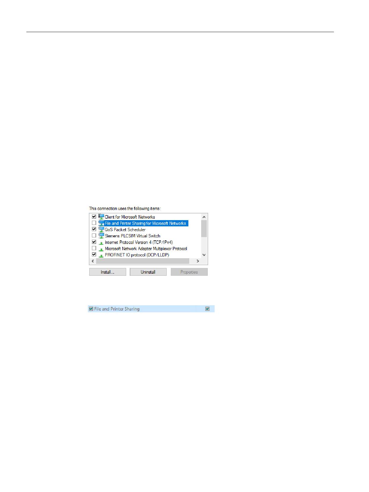
• In the settings of the network adapter for the plant network, the file and printer release is
activated. However, in the settings of the network adapter for the company network, the file
and printer release is deactivated. This setting primarily takes effect prior to the general
setting of the Windows Firewall.
This can be seen in the corresponding Windows Firewall settings dialogs by means of a
partially activated checkbox (green or gray backg58round).
Further information
Further information on file and printer sharing is provided in Microsoft Windows support (https://
support.microsoft.com/en-us/hub/4338813/windows-help?os=windows-10).
4.18.8.3
General activation for all network profiles
Via the Control Panel
There are several procedures for activating the file and printer release for all of the network
profiles in the Windows Firewall. (For example, there is the alternative procedure via the
"Network and Sharing Center" under "Change advanced sharing settings").
PCU Base for IPC
76
Commissioning Manual, 10/2020, 6FC5397-2HP40-0BA1
Configuration of the system
4.18 Adapting the firewall settings
Procedure
To activate the file and printer release on the Siemens PC system, proceed as follows:
1. Enter "Control Panel" in the search field and then click on "Control Panel" in the search results.
The desktop App "Control Panel" opens.
2. Click on the display selection and switch from the "Category" view to "Icons".
The "All Control Panel Items" dialog box opens.
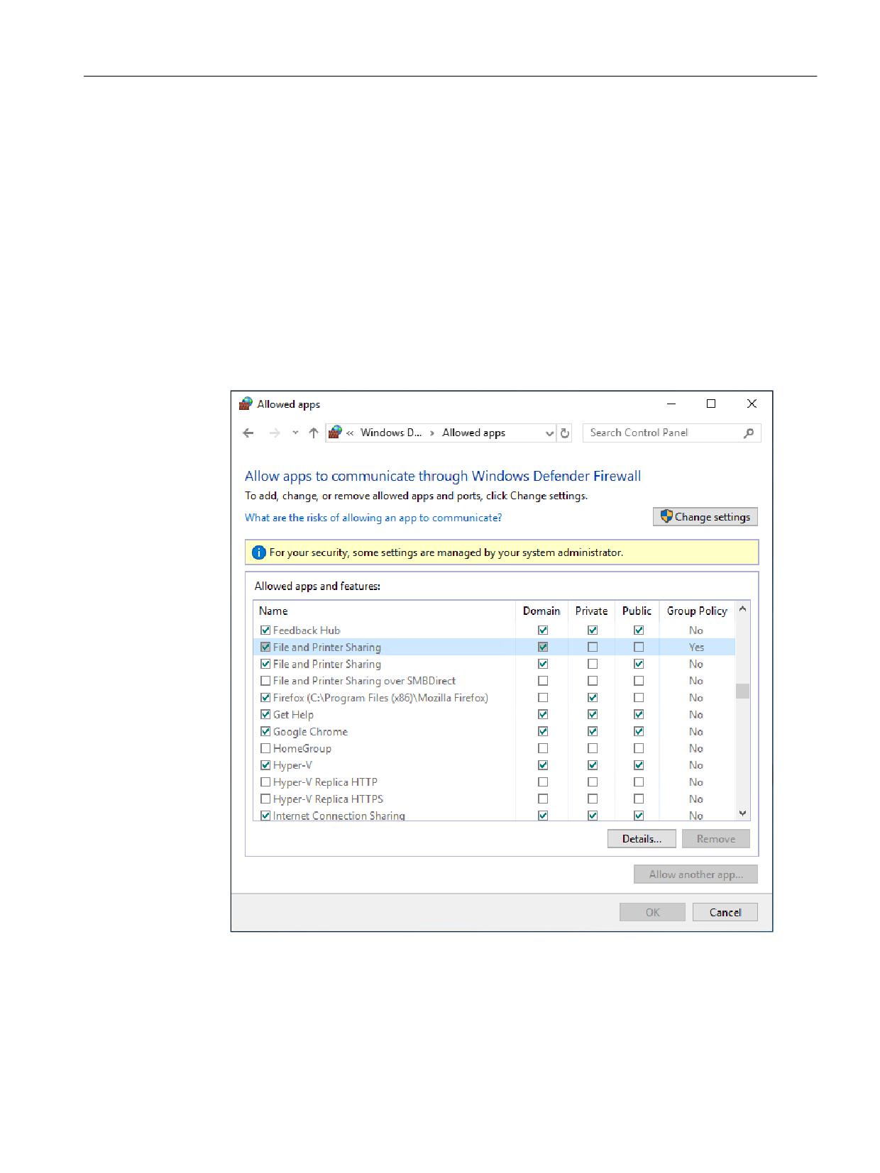
3. Click on "Windows Defender Firewall" > "Allow a app or feature through Windows Defender
Firewall".
4. Click on "Change Settings" and confirm with "Yes", if applicable.
The "Allowed apps" dialog box opens.
Also observe the entry in the column "Group Policy" and the color of the checkboxes (a
checkbox with a green or gray backg58round indicates partial activation).
5. Activate the corresponding checkbox for the corresponding entry "File and Printer Sharing"
for the desired network profiles.
6. Click "OK" to confirm the change.
PCU Base for IPC
Commissioning Manual, 10/2020, 6FC5397-2HP40-0BA1
77

Configuration of the system
4.18 Adapting the firewall settings
By prompt, script or batch file
Basic procedure
With a command according to the following scheme, you can allow the file and printer release
in the company network for all of the network profiles together. All of the firewall rules of the
group "File and Printer Sharing" are changed for all network profiles.
To do this, call the prompt as the administrator and enter the command either completely or
successively.
Alternatively, you can save the command and the associated parameters in a script file (Page 69).
Syntax for activating a group of firewall rules via the prompt
netsh advfirewall firewall set rule group="<group name>" new enable=yes
Table 4-8
Description of the Netsh commands in the context of the advfirewall firewall
Com-
Parameter
Description
Value
mand
netsh
Specification of the command line pro-
-
gram, which executes the following
commands.
adv-
Defines the context in which the follow-
-
firewall
ing commands are to be carried out.
firewall
Subcontext of "advfirewall".
-
set
Adaptation of existing firewall rules.
-
rule
group
Name of the group with firewall rules
"File and Printer Sharing" | ...
new
Specifies that the following parameters
-
are to be changed or added.
enable
Activates or deactivates the specified
yes | no
group of firewall rules.
Example
Activation of the firewall rule "File and printer release" for the "Public" profile.
netsh advfirewall firewall set rule group="File and Printer Sharing" new enable=yes
PCU Base for IPC
78
Commissioning Manual, 10/2020, 6FC5397-2HP40-0BA1
Configuration of the system
4.18 Adapting the firewall settings
4.18.8.4
Activation for a specific network profile
Via the Control Panel
Procedure
Proceed as follows to share a PG/PC file and printer in the company network with the IPC for a
specific network profile:
1. Enter "Control Panel" in the search field and then click on "Control Panel" in the search results.
The desktop App "Control Panel" opens.
2. Click on the display selection and switch from the "Category" view to "Icons".
The "All Control Panel Items" dialog box opens.
3. Click on "Windows Defender Firewall".
4. Click on "Advanced settings" and confirm the call of the expanded settings with "Yes" if
necessary.
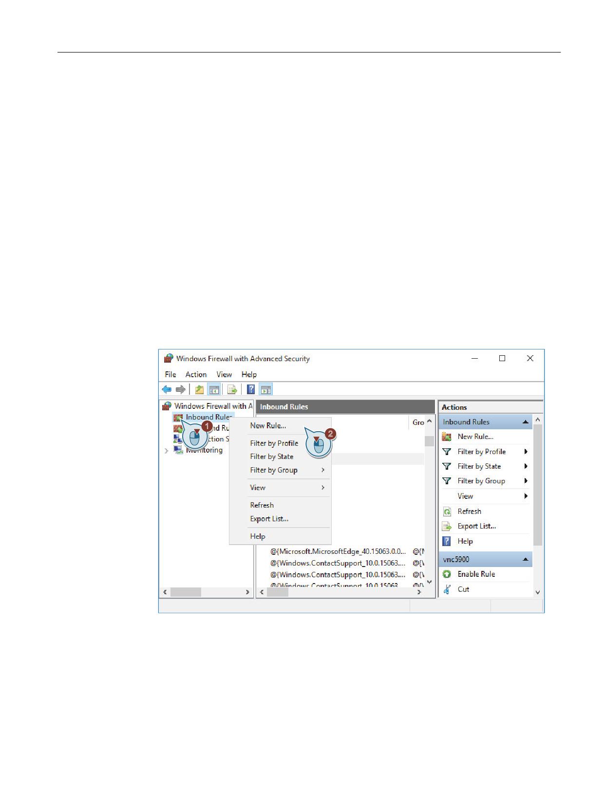
5. In the "Windows Defender Firewall with Advanced Security" dialog, right-click on the rule
"Inbound Rules", then click on "New Rule..."
PCU Base for IPC
Commissioning Manual, 10/2020, 6FC5397-2HP40-0BA1
79
Configuration of the system
4.18 Adapting the firewall settings
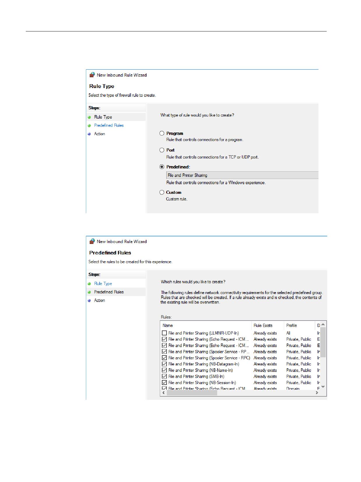
6. In the "New Inbound Rule Wizard" dialog, select the option button "Predefined", select in the
"File and Printer Sharing" drop-down list, and click on "Next".
7. Depending on the network profile (e.g. Public or Domain) for which the file and printer
release is to be activated, check the corresponding checkbox.
8. Click on "Next".
9. Select the option button "Allow the connection" and click on "Finish".
PCU Base for IPC
80
Commissioning Manual, 10/2020, 6FC5397-2HP40-0BA1
Configuration of the system
4.18 Adapting the firewall settings
By prompt, script or batch file
Basic procedure
With a command according to the following scheme, you can switch off the blocking of the file
and printer release by the Windows Firewall for a special network profile.
To do this, call the prompt as the administrator and enter the command either completely or
successively.
Alternatively, you can save the command and the associated parameters in a script file (Page 69).
Syntax for the activation of all firewall rules regarding file and printer release
netsh
advfirewall firewall
set rule name="File and Printer
Sharing (NB-Session-In)" new enable=yes
profile=<profile>
set rule name="File and Printer
Sharing (NB-Session-Out)" new enable=yes
profile=<profile>
set rule name="File and Printer
Sharing (SMB-In)" new enable=yes
profile=<profile>
set rule name="File and Printer
Sharing (SMB-Out)" new enable=yes
profile=<profile>
set rule name="File and Printer
Sharing (NB-Name-In)" new enable=yes
profile=<profile>
set rule name="File and Printer
Sharing (NB-Name-Out)" new enable=yes
profile=<profile>
set rule name="File and Printer
Sharing (NB-Datagram-In)" new enable=yes
profile=<profile>
set rule name="File and Printer
Sharing (NB-Datagram-Out)" new enable=yes
profile=<profile>
set rule name="File and Printer
Sharing (Spooler Service - RPC)" new
enable=yes profile=<profile>
set rule name="File and Printer Sharing (Spooler Service - RPC-EPMAP)" new
enable=yes profile=<profile>
set rule name="File and Printer
Sharing (Echo Request - ICMPv4-In)" new
enable=yes profile=<profile>
set rule name="File and Printer
Sharing (Echo Request - ICMPv4-Out)" new
enable=yes profile=<profile>
set rule name="File and Printer
Sharing (Echo Request - ICMPv6-In)" new
enable=yes profile=<profile>
set rule name="File and Printer
Sharing (Echo Request - ICMPv6-Out)" new
enable=yes profile=<profile>
set rule name="File and Printer
Sharing (LLMNR-UDP-In)" new enable=yes
profile=<profile>
set rule name="File and Printer
Sharing (LLMNR-UDP-Out)" new enable=yes
profile=<profile>
PCU Base for IPC
Commissioning Manual, 10/2020, 6FC5397-2HP40-0BA1
81
Configuration of the system
4.18 Adapting the firewall settings
Table 4-9
Description of the Netsh commands in the context of the advfirewall firewall
Com-
Parameter
Description
Value
mand
netsh
Specification of the command line pro-
-
gram, which executes the following
commands.
adv-
Defines the context in which the follow-
-
firewall
ing commands are to be carried out.
firewall
Subcontext of "advfirewall".
-
set
Adaptation of existing firewall rules.
-
rule
name
Name of the firewall rule in quotation
"File and Printer Sharing (NB-Ses-
marks.
sion-In)" | ...
new
Specifies that the following parameters
-
are to be changed or added.
enable
Activates or deactivates the specified fire-
yes | no
wall rule.
PCU Base for IPC
82
Commissioning Manual, 10/2020, 6FC5397-2HP40-0BA1
Configuration of the system
4.18 Adapting the firewall settings
Example
Example for the activation of all firewall rules regarding file and printer release
netsh
advfirewall firewall
set rule name="File and Printer
Sharing (NB-Session-In)" new enable=yes
profile=public
set rule name="File and Printer
Sharing (NB-Session-Out)" new enable=yes
profile=public
set rule name="File and Printer
Sharing (SMB-In)" new enable=yes
profile=public
set rule name="File and Printer
Sharing (SMB-Out)" new enable=yes
profile=public
set rule name="File and Printer
Sharing (NB-Name-In)" new enable=yes
profile=public
set rule name="File and Printer
Sharing (NB-Name-Out)" new enable=yes
profile=public
set rule name="File and Printer
Sharing (NB-Datagram-In)" new enable=yes
profile=public
set rule name="File and Printer
Sharing (NB-Datagram-Out)" new enable=yes
profile=public
set rule name="File and Printer
Sharing (Spooler Service - RPC)" new
enable=yes profile=public
set rule name="File and Printer Sharing (Spooler Service - RPC-EPMAP)" new
enable=yes profile=public
set rule name="File and Printer
Sharing (Echo Request - ICMPv4-In)" new
enable=yes profile=public
set rule name="File and Printer
Sharing (Echo Request - ICMPv4-Out)" new
enable=yes profile=public
set rule name="File and Printer
Sharing (Echo Request - ICMPv6-In)" new
enable=yes profile=public
set rule name="File and Printer
Sharing (Echo Request - ICMPv6-Out)" new
enable=yes profile=public
set rule name="File and Printer
Sharing (LLMNR-UDP-In)" new enable=yes
profile=public
set rule name="File and Printer
Sharing (LLMNR-UDP-Out)" new enable=yes
profile=public
4.18.8.5
Activation for a specific connection
Via the Control Panel
Procedure
To activate the file and printer release for a specific connection (e.g. company network), proceed
as follows:
1. Enter "Control Panel" in the search field and then click on "Control Panel" in the search results.
The desktop App "Control Panel" opens.
2. Click on the display selection and switch from the "Category" view to "Icons".
The "All Control Panel Items" dialog box opens.
3. Click on "Network and Sharing Center".
PCU Base for IPC
Commissioning Manual, 10/2020, 6FC5397-2HP40-0BA1
83
Configuration of the system
4.18 Adapting the firewall settings
4. Click on the desired connection, e.g. "Local Area Connection 2" (company network).
5. Click on "Properties" and confirm the call of the properties with "Yes" if applicable.
6. In the "Networking" tab, check the checkbox "File and Printer Sharing for Microsoft Networks"
and confirm the change with "OK".
By prompt, script or batch file
In Windows, the activation of the file and printer release for a specific connection via the prompt
or script/batch file is not supported. However, this is possible using the special command line
program "Hyper-V Network VSP Bind (nvspbind)", which is free of charge:
Example: Activation of the file and printer release for "Local Area Connection 2" (company network)
nvspbind -e "Local Area Connection 2" ms_server
Further information
You can find further information in the documentation for nvspbind under Microsoft TechNet -
Hyper-V Network VSP Bind (nvspbind) (https://gallery.technet.microsoft.com/Hyper-V-Network-
VSP-Bind-cf937850).
(Command line program for configuring network adapters and connections via the prompt)
4.18.9
Activation of the ping execution (ICMP)
4.18.9.1
Via the Control Panel
In the factory setting state, incoming ping requests are blocked on the company network
interface (X1) of the Siemens PC system. Outgoing ping requests are permitted.
Note
Dependency for the file and printer release
If you activated the file and printer release in the company network, incoming ping requests are
already permitted because they are required for the file and printer release.
Procedure
To permit ICMP pings, which arrive at the company network interface (X1) of the Siemens PC
system, proceed as follows:
1. Enter "Control Panel" in the search field and then click on "Control Panel" in the search results.
The desktop App "Control Panel" opens.
2. Click on the display selection and switch from the "Category" view to "Icons".
The "All Control Panel Items" dialog box opens.
3. Click on "Windows Defender Firewall".
PCU Base for IPC
84
Commissioning Manual, 10/2020, 6FC5397-2HP40-0BA1
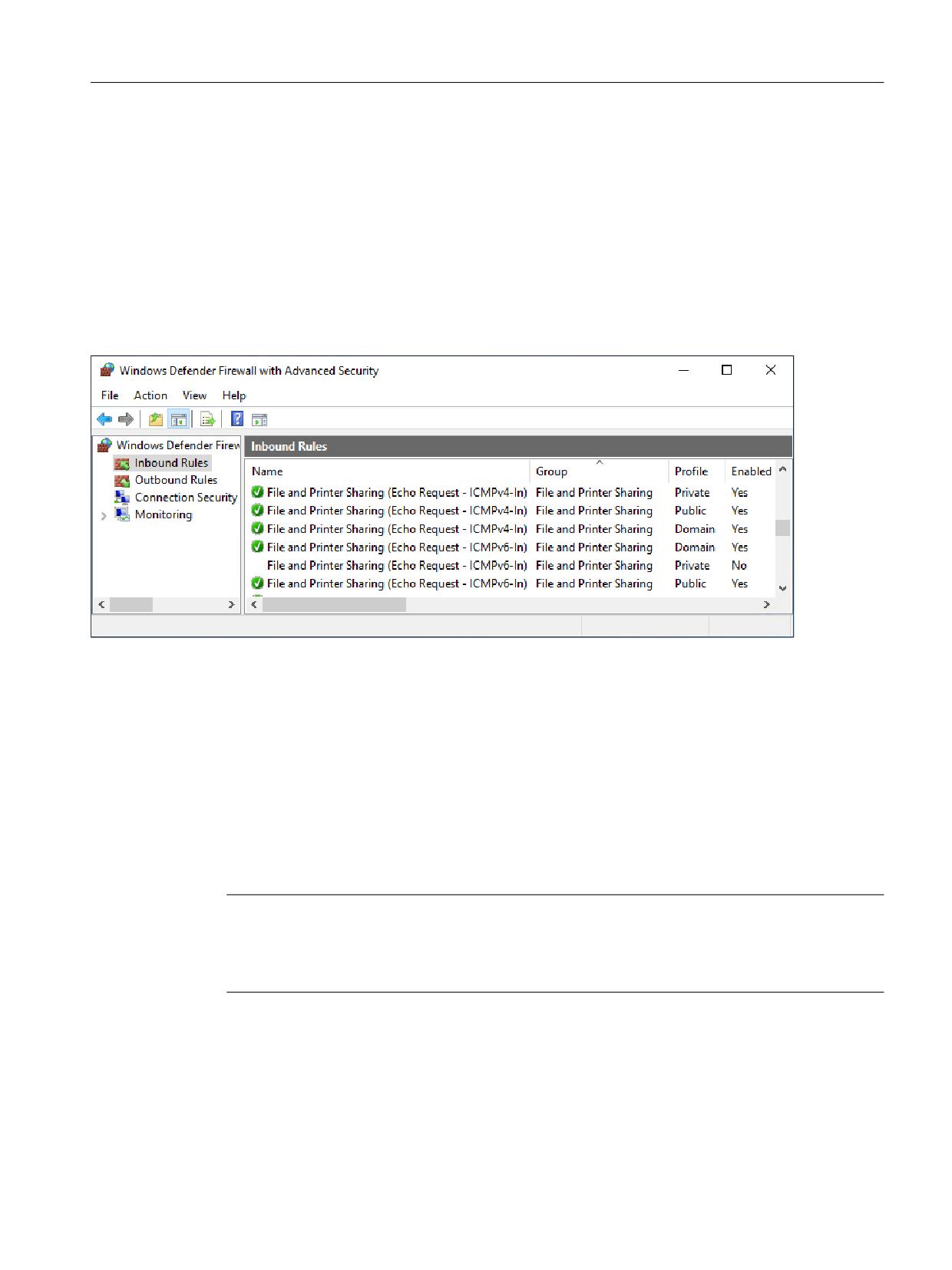
Configuration of the system
4.18 Adapting the firewall settings
4. Click on "Advanced settings" and confirm the call of the expanded settings with "Yes" if
necessary.
5. In the "Windows Defender Firewall with Advanced Security" dialog, click on "Inbound Rules".
6. Select the corresponding rule for the relevant network profile:
- File and Printer Sharing (Echo Request - ICMPv4-In) - Profile "Domain"
- File and Printer Sharing (Echo Request - ICMPv4-In) - Profile "Public"
- File and Printer Sharing (Echo Request - ICMPv4-In) - Profile "Private"
In the factory setting state, the network profile "Public" is assigned to the company network.
Figure 4-6
Rules for incoming ICMP pings, separate for each network profile
7. Right-click on the selected rule, then click "Enable Rule".
4.18.9.2
By prompt, script or batch file
Basic procedure
With a command according to the following scheme, you can permit ICMP pings which arrive at
the company network interface (X1) of the Siemens PC system. Outgoing pings from the
Siemens PC system are already activated.
Note
Dependency for the file and printer release
If you activated the file and printer release in the company network, incoming ping requests are
already permitted because they are required for the file and printer release.
The name of the relevant firewall rule is "File and Printer Sharing (Echo Request - ICMPv4-In)". To
do this, call the prompt as the administrator and enter the command either completely or
successively.
PCU Base for IPC
Commissioning Manual, 10/2020, 6FC5397-2HP40-0BA1
85

Configuration of the system
4.18 Adapting the firewall settings
Alternatively, you can save the command and the associated parameters in a script or batch file
(Page 69).
Syntax for activating a firewall rule via the prompt
netsh advfirewall firewall set rule name="<Name of the firewall rule>" new enable=yes
profile=<Name of the network profile>
Table 4-10
Description of the Netsh commands in the context of the advfirewall firewall
Com-
Parameter
Description
Value
mand
netsh
Specification of the command line pro-
-
gram, which executes the following
commands.
adv-
Defines the context in which the follow-
-
firewall
ing commands are to be carried out.
firewall
Subcontext of "advfirewall".
-
set
Adaptation of existing firewall rules.
-
rule
name
Name firewall rule
"File and Printer Sharing (Echo Re-
quest - ICMPv4-In)" | ...
new
Specifies that the following parameters
-
are to be changed or added.
enable
Activates or deactivates the specified fire-
yes | no
wall rule.
profile
Name of the network profile for which
the firewall rule is to be changed.
Example
Activation of incoming ping requests
netsh advfirewall firewall set rule name="File and Printer Sharing (Echo Request - ICMPv4-
In)" new enable=yes profile=public
4.18.10
Saving and restoring firewall settings
4.18.10.1
Overview
Overview
You can save all of the Windows Firewall settings of the Siemens PC system as a policy file with
the file extension ".wfw". Policy files are saved in binary format and are Windows version-
dependent.
PCU Base for IPC
86
Commissioning Manual, 10/2020, 6FC5397-2HP40-0BA1
Configuration of the system
4.18 Adapting the firewall settings
You have the following options for backing up or restoring the firewall settings:
• Backup of firewall settings (Page 87)
- Via the Control Panel (Page 87)
- By prompt, script or batch file (Page 87)
• Restoring of firewall settings (Page 88)
You can restore the firewall settings on the same Siemens PC system or import the same
policy file to different Siemens PC systems for the purpose of series commissioning.
- Via the Control Panel (Page 88)
- By prompt, script or batch file (Page 89)
4.18.10.2
Backup of firewall settings
Via the Control Panel
Procedure
To back up the Windows Firewall settings of the Siemens PC, proceed as follows:
1. Enter "Control Panel" in the search field and then click on "Control Panel" in the search results.
The desktop App "Control Panel" opens.
2. Click on the display selection and switch from the "Category" view to "Icons".
The "All Control Panel Items" dialog box opens.
3. Click on "Windows Defender Firewall".
4. Click on "Advanced settings" and confirm the call of the expanded settings with "Yes" if
necessary.
5. Right-click on the master object "Windows Defender Firewall with Advanced Security on
Local Computer" and then click on "Export Policy...".
6. In the "Save As" dialog, select a save location and file name and confirm with "Save".
By prompt, script or batch file
Basic procedure
With a command according to the following scheme, you can back up the Windows Firewall
settings in a policy file (.wfw).
To do this, call the prompt as the administrator and first define the save location of the policy
memory, then enter a file path for backing up the policy file.
PCU Base for IPC
Commissioning Manual, 10/2020, 6FC5397-2HP40-0BA1
87

Configuration of the system
4.18 Adapting the firewall settings
Alternatively, you can save the commands and the associated parameters in a script or batch file
(Page 69).
Syntax of the Netsh commands for defining the policy memory and for exporting the policy file
netsh advfirewall set store local
export <File path and file name>.wfw
Table 4-11
Description of the Netsh commands for defining the policy memory and for exporting the
policy file
Com-
Parameter
Description
Value
mand
netsh
Specification of the command line pro-
-
gram, which executes the following
commands.
adv-
Defines the context in which the follow-
-
firewall
ing commands are to be carried out.
set
Definition of the save location of the pol-
-
store
icy memory for the following com-
mands.
local
Defines that the work is to be done with
-
the local policy memory.
export
Backup of all firewall settings in a policy
<File path and file name>.wfw
file (.wfw).
Example
Example of the Netsh commands for defining the policy memory and for exporting the policy file
netsh advfirewall set store local
export D:\Backup\DefaultSettings.wfw
4.18.10.3
Restoring of firewall settings
Via the Control Panel
Procedure
Note
Importing a policy file overwrites all existing firewall rules
When the firewall settings are restored, all of the existing firewall rules are overwritten. You
cannot undo the import of firewall rules via a policy file.
Therefore, back up (export) the existing firewall settings before you import a policy file.
PCU Base for IPC
88
Commissioning Manual, 10/2020, 6FC5397-2HP40-0BA1
Configuration of the system
4.18 Adapting the firewall settings
To restore the Windows Firewall settings of the Siemens PC system, proceed as follows:
1. Enter "Control Panel" in the search field and then click on "Control Panel" in the search results.
The desktop App "Control Panel" opens.
2. Click on the display selection and switch from the "Category" view to "Icons".
The "All Control Panel Items" dialog box opens.
3. Click on "Windows Defender Firewall".
4. Click on "Advanced settings" and confirm the call of the expanded settings with "Yes" if
necessary.
5. Right-click on the master object, then click "Windows Defender Firewall with Advanced
Security on Local Computer", then click on "Import Policy..." and confirm the command with
"Yes".
6. In the "Open" dialog, select the policy file and confirm with "Open".
By prompt, script or batch file
Basic procedure
Note
Importing a policy file overwrites all existing firewall rules
When the firewall settings are restored, all of the existing firewall rules are overwritten. You
cannot undo the import of firewall rules via a policy file.
Therefore, back up (export) the existing firewall settings before you import a policy file.
With a command according to the following scheme, you can restore the Windows Firewall
settings from a policy file (.wfw).
To do this, call the prompt as the administrator and first define the save location of the policy
memory, then enter a file path for backing up the policy file.
Alternatively, you can save the commands and the associated parameters in a script or batch file
(Page 69).
Syntax of the Netsh commands for defining the policy memory and for importing the policy file
netsh advfirewall set store local
import <File path and file name>.wfw
PCU Base for IPC
Commissioning Manual, 10/2020, 6FC5397-2HP40-0BA1
89
Configuration of the system
4.18 Adapting the firewall settings
Table 4-12
Description of the Netsh commands for defining the policy memory and for importing the
policy file
Com-
Parameter
Description
Value
mand
netsh
Specification of the command line pro-
-
gram, which executes the following
commands.
adv-
Defines the context in which the follow-
-
firewall
ing commands are to be carried out.
set
Definition of the save location of the pol-
-
store
icy memory for the following com-
mands.
local
Defines that the work is to be done with
-
the local policy memory.
import
Restoration of firewall settings from a
<File path and file name>.wfw
policy file (.wfw).
Example of the Netsh commands for defining the policy memory and for importing the policy file
netsh advfirewall set store local
import D:\Backup\DefaultSettings.wfw
PCU Base for IPC
90
Commissioning Manual, 10/2020, 6FC5397-2HP40-0BA1
Installing and configuring updates and automation
software
5
5.1
Overview
Once you have completed installation of PCU Base for IPC and possibly configured the network
settings, you can set up handling of the security updates, patches, and software installations or
install them directly.
• You will find information about Windows updates and the network security of an automation
system in Chapter Patch management and security updates (Page 92).
• The PCU Installer (Page 103) will assist you with automatic installation of setup packages.
• You can install SINUMERIK Operate (Page 94) or other HMI software and at the same time
(Page 94) or subsequently (Page 96) set it up for autologon mode.
• To prevent operation of the HMI software from being interrupted by key combinations such
as CTRL+ALT+DEL, you can activate and configure the key filter (Page 97).
• You can install STEP 7 and the SINUMERIK add-on (Page 101) and add a softkey to the HMI
software to start STEP 7 (Page 102).
• If you want to transfer existing data to the newly installed automation software, read
Chapter Migration (Page 116).
PCU Base for IPC
Commissioning Manual, 10/2020, 6FC5397-2HP40-0BA1
91
Installing and configuring updates and automation software
5.2 Patch management and security updates
5.2
Patch management and security updates
Microsoft regularly eliminates security holes in Windows 10, and makes these updates available
on its "Windows Update" website.
"Start > Settings > Update & Security"
As a solution for managing and making Windows updates available in a network, Microsoft
offers the components in the Microsoft Update Catalog (http://
Industrial security
You will find information about network security for an automation system and a comprehensive
protection concept under Industrial Security on the SIEMENS website:
SIEMENS Industrial Security (https://new.siemens.com/global/en/products/automation/topic-
areas/industrial-security.html)
SINUMERIK-specific information about Industrial Security can also be found in the following
documents:
SINUMERIK/SIMOTION/SINAMICS Configuration Manual Industrial Security (https://
support.industry.siemens.com/cs/document/108862708?lc=en-WW)
Compatibility with automation software
Information about compatibility of a Windows update with specific application software of
SIEMENS may possibly be available on the product pages of the application software in question
in the Service&Support portal:
Generally, it is recommended that you check the compatibility of updates in a dedicated project
test environment before installing it in a productive environment.
PCU Base for IPC
92
Commissioning Manual, 10/2020, 6FC5397-2HP40-0BA1
Installing and configuring updates and automation software
5.3 Configuring saving Windows log files
5.3
Configuring saving Windows log files
As a result of Windows updates and other operations, larger quantities of data can accumulate
that are no longer required, e.g. temporary update and system files or Windows log files
(CBS.log).
PCU Base for IPC contains 2 batch files, which you can use to configure how files such as these
are saved:
• Deactivate saving
- Saving new log files CBS.log is deactivated, and existing files are deleted:
C:\Windows\Logs\CBS
- The temporary directory is cleared once:
C:\Windows\Temp
- The data storage medium cleanup is carried out.
• Activate saving
- Reactivates that new log files CBS.log are saved for diagnostics.
You can refer to the information file in the following directory to identify whether the log files are
being saved or not: C:\Windows\Logs\CBS
Precondition
• You require administrator rights to run batch files.
Procedure
1. Change to directory D:\etc and double-click on the appropriate batch file.
PCU Base for IPC
Commissioning Manual, 10/2020, 6FC5397-2HP40-0BA1
93
Installing and configuring updates and automation software
5.4 Setting up SINUMERIK Operate for autologon mode
5.4
Setting up SINUMERIK Operate for autologon mode
If you want the PC system to start automatically in SINUMERIK Operate after switching on
without having to make any further entries, set up the Autologon mode.
During installation of SINUMERIK Operate, you can define an existing user account as an
autologon account. The PC system then starts without the password for this user account being
entered. SINUMERIK Operate is then started automatically because a link is created in the
"Startup" Autostart folder.
For security reasons, you should use a special user account without administrator rights.
You can also configure the key filter and deactivate certain keyboard entries (Page 97), e.g. to
prevent a switchover from SINUMERIK Operate to the Windows Desktop. (Desktop access is then
only possible via the splash screen (Page 150).)
Requirement
• A Windows user account without administrator rights is set up.
• SINUMERIK Operate is not installed.
• You are logged on as an administrator or you know the password of the administrator
account.
• The keyboard layout of the system is set to English.
See: Configuring the keyboard layout (Page 35)
PCU Base for IPC
94
Commissioning Manual, 10/2020, 6FC5397-2HP40-0BA1
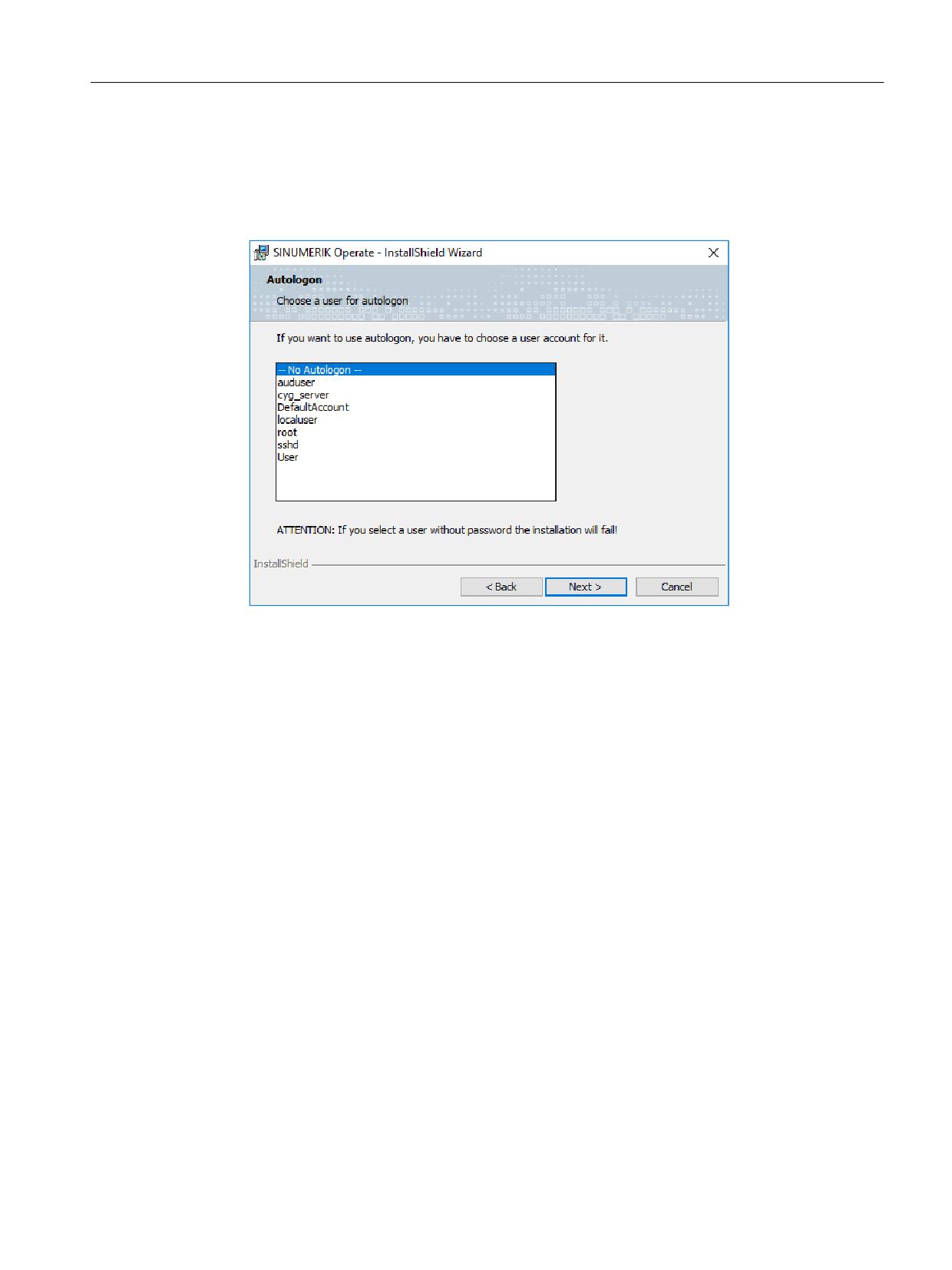
Installing and configuring updates and automation software
5.4 Setting up SINUMERIK Operate for autologon mode
Procedure
To set up autologon mode, proceed as follows:
1. Start installation of SINUMERIK Operate and, in the installation wizard, proceed to step
"Autologon".
Figure 5-1
SINUMERIK Operate Installer - Autologon
2. In the list, select the user account to be logged on automatically.
3. Confirm with "Next", then in the next steps of the installation wizard make all the necessary
settings and confirm the installation with "Finish".
Result
SINUMERIK Operate is installed and Autologon mode of the PC system is set up. During this
process the password of the autologon user account is stored encrypted in Windows, and
SINUMERIK Operate is linked with the autostart folder "Startup".
Autologon mode is active at the next startup. The autologon user account is automatically
logged on and SINUMERIK Operate is started.
PCU Base for IPC
Commissioning Manual, 10/2020, 6FC5397-2HP40-0BA1
95
Installing and configuring updates and automation software
5.5 Modifying the user account for autologon mode.
5.5
Modifying the user account for autologon mode.
Because of the way autologon works, only one user account can ever be set up for autologon
mode.
If you set up autologon mode during installation of SINUMERIK Operate for one particular user
account, but now want to use another user account for autologon mode, you can change this
manually in the Service Desktop.
Precondition
• SINUMERIK Operate is installed and autologon mode is set up.
• The Service Desktop is active.
Procedure
To change the user account that is used for automatic run-up in autologon mode, proceed as
follows:
1. To open the "User Accounts" dialog box, proceed in one of the following ways:
- On the Desktop, double-click the "Netplwiz" icon.
- In the search field of the Start menu, enter netplwiz and confirm the entry.
- At the prompt, enter control userpasswords2.
The "User Accounts" dialog box opens.
2. Activate the "Users must enter a user name and password to use this computer" checkbox.
3. In the "Users for this computer" list, select the user account to be used for autologon mode.
4. Deactivate the "Users must enter a user name and password to use this computer" checkbox.
You may be prompted to enter a password.
5. Confirm these settings in the "User Accounts" dialog box with "OK".
6. In the Autostart folder of the autologon mode user account, create a link to SINUMERIK
Operate.
PCU Base for IPC
96
Commissioning Manual, 10/2020, 6FC5397-2HP40-0BA1
Installing and configuring updates and automation software
5.6 Configuring a key filter for HMI software
5.6
Configuring a key filter for HMI software
To prevent unwanted interruption of the HMI software while it is running, you can specify that
certain keyboard entries will be filtered out and thus ignored.
You can configure the key filter in the pcuhwsvc.ini configuration file:
• This key filter is not activated as delivered.
• You can activate the key filter and individually select which of the 20 filterable keyboard
entries will be ignored. During this, you can deactivate known shortcut keys, for example, or
even deactivate individual add-on keys, such as the left (SeqActive_16) or right
(SeqActive_17) Windows key.
You cannot configure any additional keyboard entries to be filtered.
• You can also completely deactivate the repeat function of the F1-F12 keys and all hard keys
with the key filter. When the repeat function is deactivated, a key held pressed is considered
as pressed once and not as pressed repeatedly.
Per default, the repeat function is activated during Service or Desktop operation. The repeat
function is always deactivated during operation of SINUMERIK Operate.
Precondition
• The Windows Service Desktop is active
• Hidden directories are visible
Further information: Directory structure and file conventions (Page 23)
Procedure
To configure the key filter, proceed as follows:
1. Switch to the template directory: C:\ProgramData\Siemens\MotionControl
\siemens\System\etc\
The settings can be viewed in the template pcuhwsvc.ini.
2. Save a copy of the template pcuhwsvc.ini to one of the user directories:
- C:\ProgramData\Siemens\MotionControl\user\System\etc\
- C:\ProgramData\Siemens\MotionControl\oem\System\etc\
- C:\ProgramData\Siemens\MotionControl\addon\System\etc\
3. In the new file (e.g
\oem\System\etc\pcuhwsvc.ini), delete all data except for
the section name [KEYB_FILTER] and the keys that are to differ from the template.
All data and keys that do not occur in your file are automatically taken over from the template
in the siemens directory.
4. Save your file.
PCU Base for IPC
Commissioning Manual, 10/2020, 6FC5397-2HP40-0BA1
97
Installing and configuring updates and automation software
5.6 Configuring a key filter for HMI software
Example: Activating the key filter, but allowing use of the NUM-lock key.
This example activates the key filter (KeySequencesEnable = 1) and filters all possible
keyboard entries except the NUM-lock key.
KEYB_FILTER
Section name (mandatory):
KeySequencesEnable = 1
Activate key filter
SeqActive_19= 0
Do not filter NUM-lock key
In the adapted file in the user directory (e.g
\oem\System\etc\) therefore only the
section name [KEYB_FILTER] is mandatory as well as the settings that you want to adapt. All
other settings and values are taken over from the template.
Template of the key filter in the delivery condition
The template is located in directory C:\ProgramData\Siemens\MotionControl
\siemens\System\etc\
Do not overwrite this template, but save a copy of this template pcuhwsvc.ini in one of the
user directories.
• C:\ProgramData\Siemens\MotionControl\user\System\etc\
• C:\ProgramData\Siemens\MotionControl\oem\System\etc\
• C:\ProgramData\Siemens\MotionControl\addon\System\etc\
How the configuration file works
You can configure the key filter in section [KEYB_FILTER]. The lines identified by a number
sign (#) are comments as to which line further down deactivates a particular keyboard entry.
• To activate a particular keyboard entry, find the key in the comment and then set the value
to 0.
• To allow all keyboard entries and thus deactivate the key filter (factory setting), set the value
to 0 in the KeySequencesEnable key.
If the value 0 is set for this key, all other keys will be ignored and the key filter is deactivated.
• To completely deactivate the repeat function of the F1-F12 keys and all hard keys, set the
value 1 at the AutorepeatSuppression key.
Table 5-1
Overview: Key filter in the configuration file pcuhwsvc.ini
Section
[KEYB_FILTER]
Key
SeqActive_x
Value
0 = specific keyboard entry activated
1 = specific keyboard entry will be filtered and is deactivated
Factory setting
1
pcuhwsvc.ini (Vorlage im Verzeichnis ...\siemens\System\etc)
[GLOBAL]
# -----------------------
# SIEMENS GLOBAL SECTION
PCU Base for IPC
98
Commissioning Manual, 10/2020, 6FC5397-2HP40-0BA1