SINUMERIK 840D sl. Service - Configuring Commissioning. Manual (2011-2020) - page 85
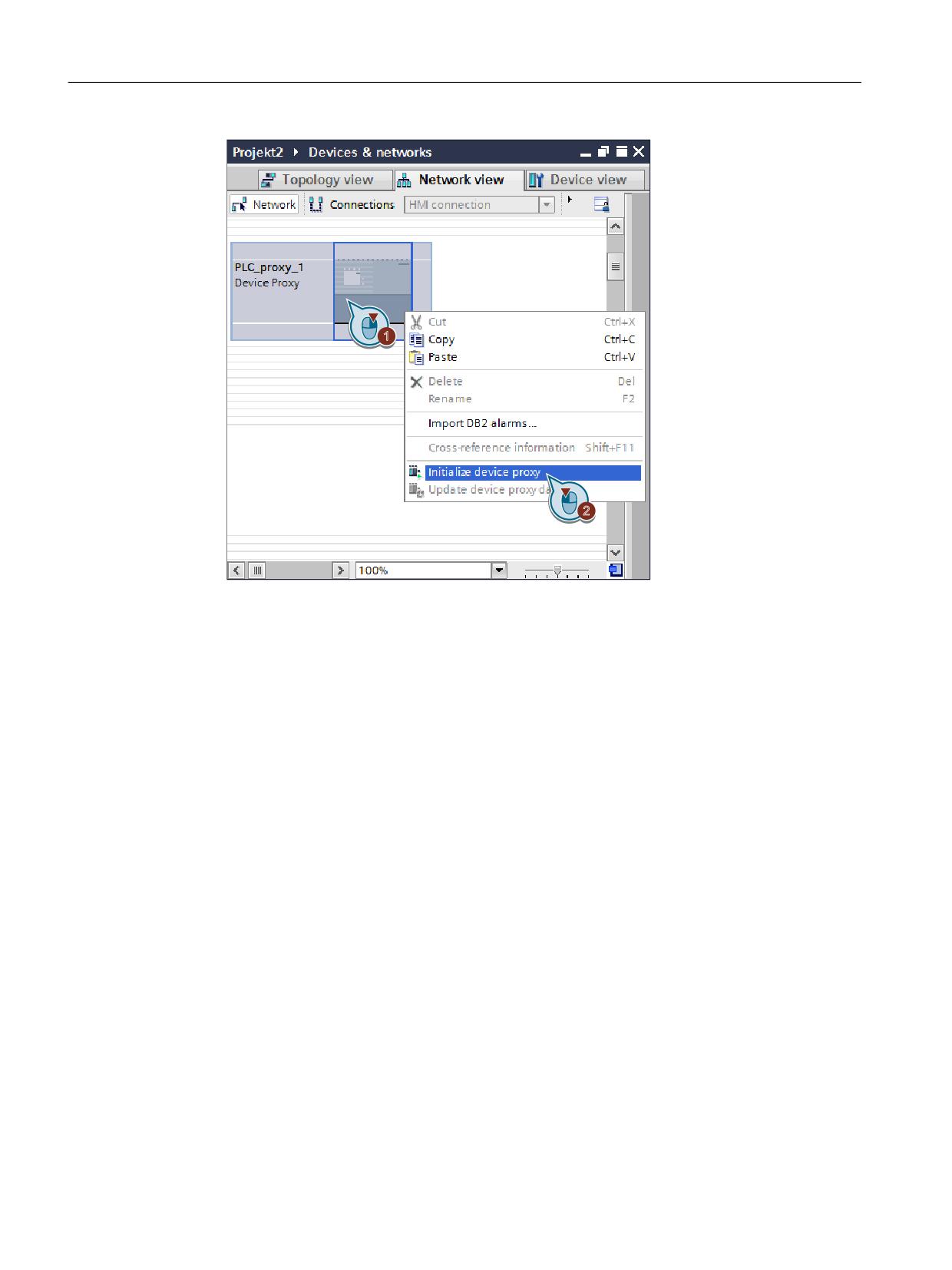
Device configuration
5.7 Using device proxies
3. In the "Open device proxy data source" dialog. select the STEP 7 V5.x project (*.s7p) and
confirm the selection with "Open".
4. In the "Initialize device proxy" dialog, select the PLC data to be integrated in the device proxy
and confirm the selection with "OK".
Result
A device proxy has been added and selected the STEP 7 V5.x project as the data source.
Under the device proxy in the project tree, the corresponding data of the SINUMERIK PLC are
displayed from the STEP 7 V5.x project, e.g. PLC tags and program blocks. However, you only
have read access to this data via the device proxy. To change something, edit the project in
STEP 7 V5.x. Then select the command "Update device proxy data" in the context menu of the
device proxy.
The device proxy serves as a connection partner to form an integrated connection between a
SIMATIC Panel or PC system with WinCC RT Advanced and a PLC (see Configuring
integrated connection to the SINUMERIK PLC (Page 78)). Therefore you can also use this to
import SINUMERIK PLC alarm texts (Page 105).
Additional information
You can find information about the general functionality of device proxies in the online help
under the keyword "Initialize device proxy via project file".
You can find information on integrating STEP 7 V5.x projects via device proxies in the
Service & Support portal:
SINUMERIK Integrate Create MyHMI /WinCC V16
74
Configuration Manual, 12/2019, 6FC5397-8FP40-0BA2
Device configuration
5.7 Using device proxies
Shared configuration with WinCC (TIA Portal) and STEP 7 V5.x (https://
support.industry.siemens.com/cs/document/73502293/)
Pay particular attention there to the available application description for WinCC (TIA Portal) as
of V13.
SINUMERIK Integrate Create MyHMI /WinCC V16
Configuration Manual, 12/2019, 6FC5397-8FP40-0BA2
75
Device configuration
5.7 Using device proxies
SINUMERIK Integrate Create MyHMI /WinCC V16
76
Configuration Manual, 12/2019, 6FC5397-8FP40-0BA2

Configuring connections
6
6.1
Overview
You can configure the communication from the operator panel to a SIMATIC controller as an
integrated connection. Connections from the HMI device to other controllers are possible via
the corresponding communication drivers. These connections are designated as non-
integrated connections.
SINUMERIK Integrate Create MyHMI /WinCC additionally supports the following
communication drivers in the TIA Portal:
● SINUMERIK NC
● FANUC CNC/PMC
You can set up the connection to the SINUMERIK PLC as an integrated connection or as a non-
integrated connection via the "SIMATIC S7 300/400" communication driver.
Integrated connection
Non-integrated connection
Supported connection partners
● SIMATIC PLC
● SIMATIC PLC
● SINUMERIK PLC (Page 78)
● SINUMERIK PLC
● Device proxy with connection to a
● SINUMERIK NC (Page 82)
SIMATIC or SINUMERIK PLC of a
Various controllers from third-party suppli-
STEP 7 V5.4 project (or newer)
ers, such as FANUC (Page 84)
Configuring the connection
"Devices & Networks" editor
"Connections" editor of the WinCC Run-
time
Configuring associated tags
● Direct access to configured PLC
● No direct access to configured PLC
tags in the HMI-tags editor
tags
● Where necessary, depending on the
communication driver, address
selection dialog with assignment of tag
names, addresses and data types
(available for SINUMERIK NC and
FANUC CNC/PMC)
Connection of configured PLC tags in
Connection and direct access possible
Not supported
the HMI tags editor
Address selection dialog with assign-
The address is automatically selected
Supported, dependent on communication
ment of tag names, addresses and
through the variable link
driver (available for SINUMERIK NC and
data type
FANUC CNC/PMC)
Displaying imported DB2 alarms in
Supported (Page 117)
Not supported
WinCC screen objects
SINUMERIK Integrate Create MyHMI /WinCC V16
Configuration Manual, 12/2019, 6FC5397-8FP40-0BA2
77
Configuring connections
6.2 Configuring integrated connection to the SINUMERIK PLC
6.2
Configuring integrated connection to the SINUMERIK PLC
An integrated connection to the SINUMERIK PLC permits, among other things, the display of
imported DB2 alarms in WinCC screen objects and direct connection of PLC tags to HMI tags.
A prerequisite for the integrated connection is a configured SINUMERIK NCU (or a device
proxy with SINUMERIK NCU).
Requirement
● A PC system with WinCC RT Advanced or a SIMATIC Panel has been added.
See Inserting PC system and Runtime (Page 62)
● A device proxy (Page 72) or a SINUMERIK NCU is inserted.
● The network view is active.
SINUMERIK Integrate Create MyHMI /WinCC V16
78
Configuration Manual, 12/2019, 6FC5397-8FP40-0BA2
Configuring connections
6.2 Configuring integrated connection to the SINUMERIK PLC
Procedure
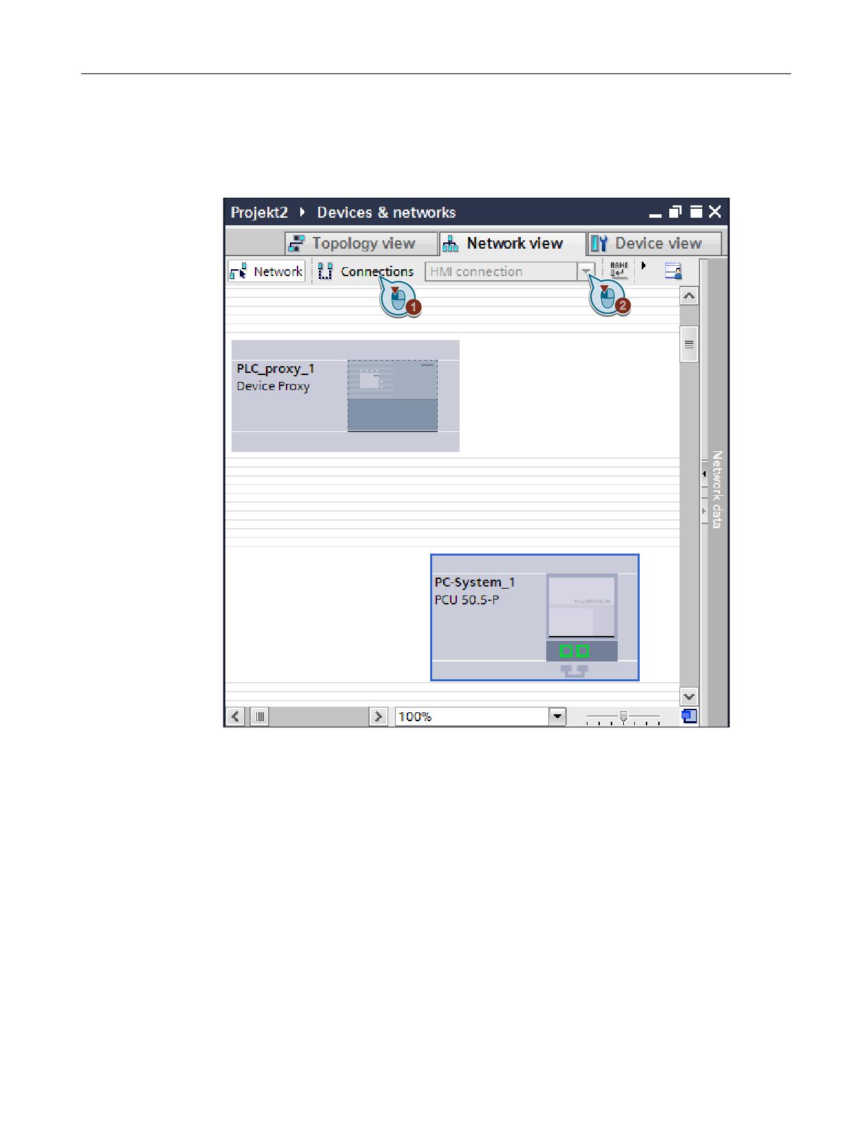
To create an integrated HMI connection to the PLC, proceed as follows:
1. Click "Connections" and select "HMI connection" from the drop-down list.
Figure 6-1
"Connections" button
The components that you can connect (WinCC RT and, e.g. device proxy) are highlighted
in color.
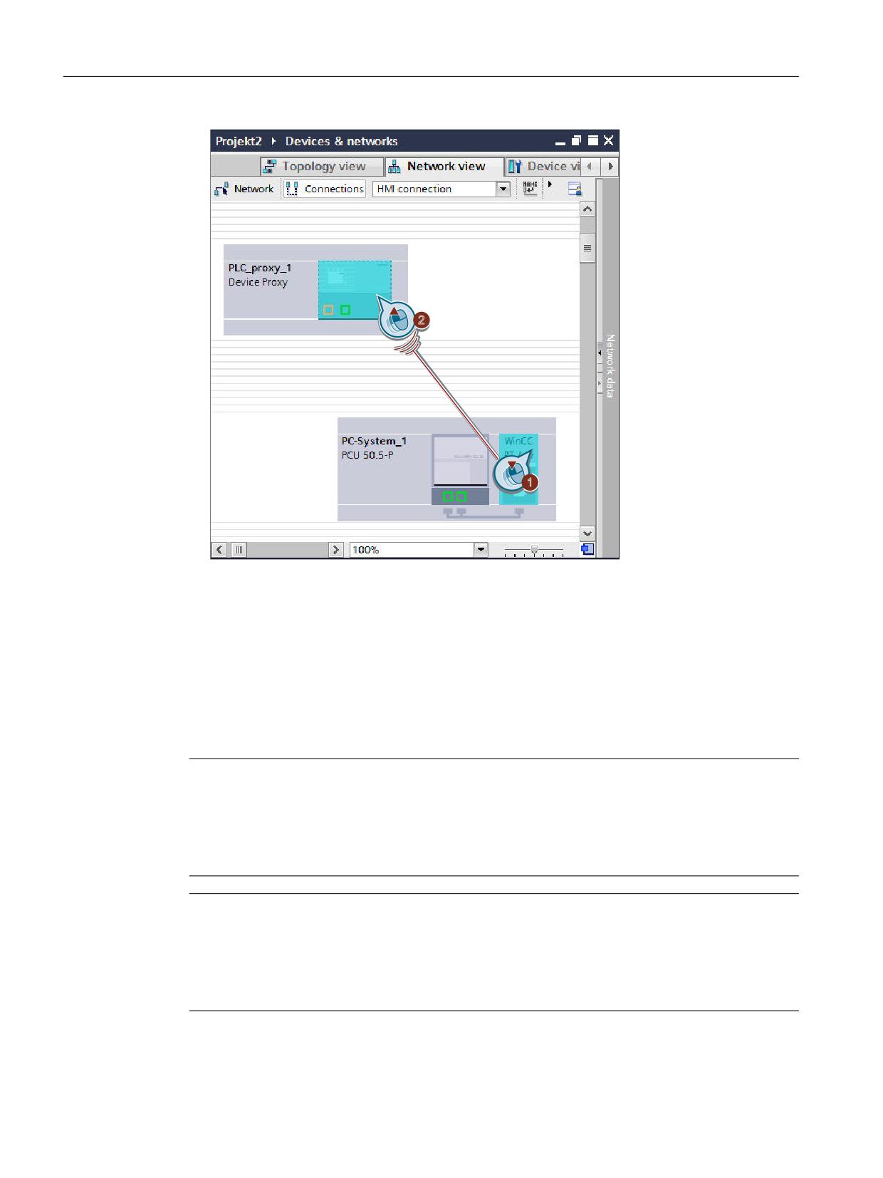
2. Drag a connection from the WinCC RT Advanced or the SIMATIC Panel to the PLC or the
device proxy.
SINUMERIK Integrate Create MyHMI /WinCC V16
Configuration Manual, 12/2019, 6FC5397-8FP40-0BA2
79
Configuring connections
6.2 Configuring integrated connection to the SINUMERIK PLC
Figure 6-2
Creating a connection with drag and drop - with PCU 50.5-P, WinCC RT Advanced and
NCU 730.3 PN in the example
Result
The connection between the communication partners has been created as an integrated
connection and is automatically assigned a name.
You can see the connection in the "Connections" editor and change the assigned name, if
necessary.
Note
Interface type and IP address of the NC and PLC connection must match
If you are configuring connections to the SINUMERIK NC and PLC, the same interface type
(e.g. ETHERNET) and the same IP address must be set for both.
Both connections will be marked as being faulty if these settings do not match.
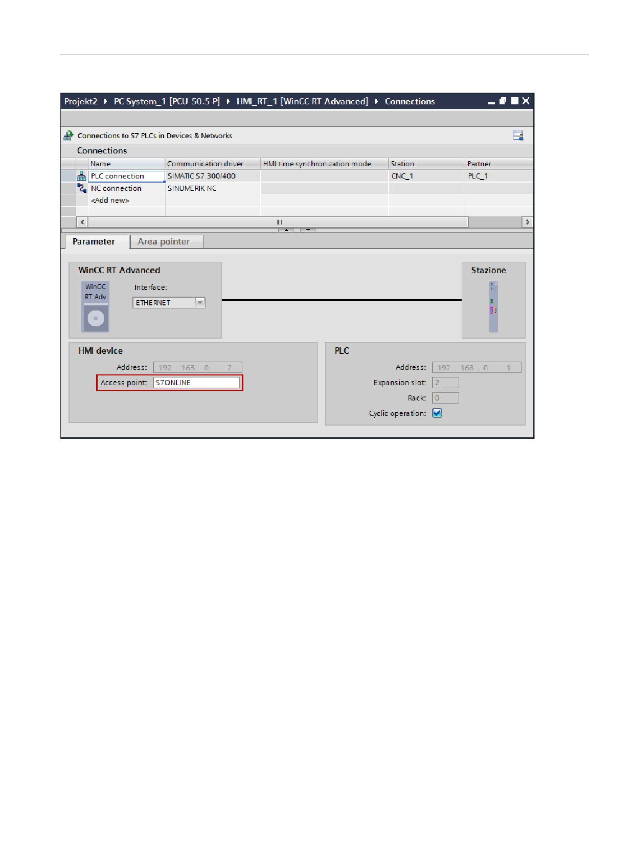
Note
Access point for both HMI connections must be "S7ONLINE"
Depending on the order in which you configure the HMI connections, an incorrect access point
may be entered (e.g. "S7ONLINE1" instead of "S7ONLINE").
In this case, change the name of the access point to "S7ONLINE" in the "Connections" editor.
SINUMERIK Integrate Create MyHMI /WinCC V16
80
Configuration Manual, 12/2019, 6FC5397-8FP40-0BA2
Configuring connections
6.2 Configuring integrated connection to the SINUMERIK PLC
Figure 6-3
Setting of the access point in the "Connections" editor
See also
Configuring connection to the SINUMERIK NC (Page 82)
SINUMERIK Integrate Create MyHMI /WinCC V16
Configuration Manual, 12/2019, 6FC5397-8FP40-0BA2
81
Configuring connections
6.3 Configuring connection to the SINUMERIK NC
6.3
Configuring connection to the SINUMERIK NC
Requirement
● You have created a project.
● The HMI device to be configured has been added (SIMATIC Panel or PC system with
WinCC RT Advanced).
Procedure
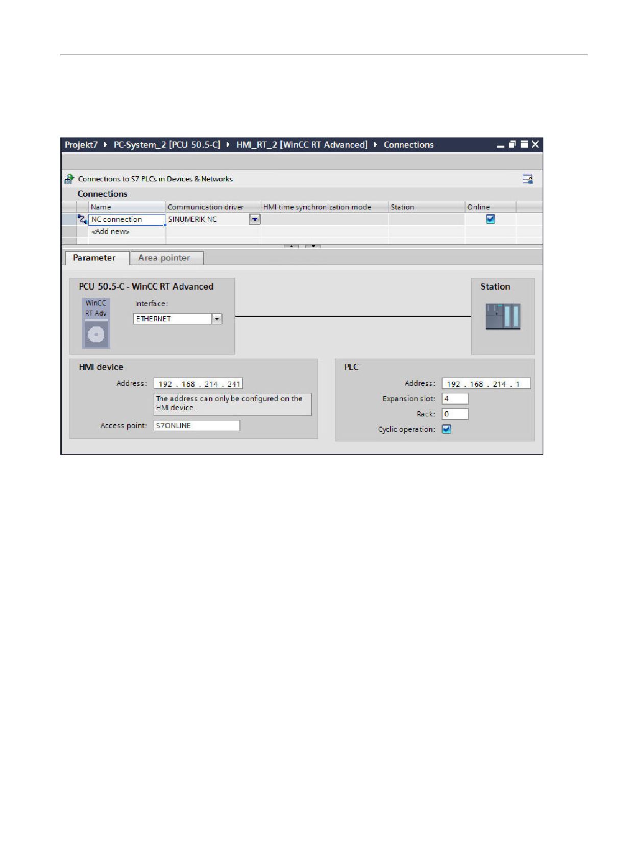
In order to configure a connection to the NC, proceed as follows:
1. In the project tree, navigate to the device to be configured.
2. Double-click "Connections" in the project tree below the device, for example, "PC-System_1
> HMI_RT_1 > Connections".
The editor for connections opens.
3. Double-click on "<Add>" in the "Name" column and assign a memorable name, e.g. "NC
connection".
4. Select "SINUMERIK NC" as the communication driver.
5. In the "Parameters" tab, make the required settings for each individual connection:
- In the "Interface" drop-down list, select the required option, for example, "ETHERNET".
- In the "PLC" section, specify expansion slot "4".
- In the "PLC" section, specify the IP address of the NCU.
Note
Interface type and IP address of the NC and PLC connection must match
If you are configuring connections to the SINUMERIK NC and PLC, the same interface type
(e.g. ETHERNET) and the same IP address must be set for both.
Both connections will be marked as being faulty if these settings do not match.
Note
Operating PCU 50.5 on the company network
If the PCU 50.5 is not in the system network, but operated in a company network, then the
IP address allocated via the DHCP server must be entered for the HMI device.
SINUMERIK Integrate Create MyHMI /WinCC V16
82
Configuration Manual, 12/2019, 6FC5397-8FP40-0BA2
Configuring connections
6.3 Configuring connection to the SINUMERIK NC
Result
A non-integrated connection to the NC has been configured
Figure 6-4
Example of a non-integrated connection between PCU 50.5 and SINUMERIK NC with default IP address of the
NCU at X120 (192.168.214.1).
SINUMERIK Integrate Create MyHMI /WinCC V16
Configuration Manual, 12/2019, 6FC5397-8FP40-0BA2
83
Configuring connections
6.4 Configuring a connection to a FANUC control system
6.4
Configuring a connection to a FANUC control system
A connection via the FANUC CNC/PMC communication driver to a compatible controller is the
prerequisite for the use of the following functionalities:
● Screen object Fanuc SDF view (Page 151)
● Fanuc system functions (Page 166)
● Access to functions of the FANUC FOCAS2 library (Page 101)
● Displaying alarms output from a FANUC control system which (Page 118)
No more than one connection can be connection figured via this communication driver.
Requirement
● You have created a project.
● The HMI device to be configured has been added
Procedure
In order to configure a connection to a controller via the FANUC CNC/PMC communication
driver, proceed as follows:
1. In the project tree, navigate to the device to be configured.
2. Double-click "Connections" in the project tree below the device, for example, "PC-System_1
> HMI_RT_1 > Connections".
The editor for connections opens.
3. Double-click on "<Add>" in the "Name" column and assign a memorable name.
4. In the "Communication drivers" column, select the "FANUC CNC/PMC" driver.
5. On the "Parameters" tab, enter the IP address and port of the controller in the network.
SINUMERIK Integrate Create MyHMI /WinCC V16
84
Configuration Manual, 12/2019, 6FC5397-8FP40-0BA2
Using variables
7
You can create PLC variables in the "HMI variables" editor.
The PLC variables available depend on the selected connection and the communication
channel defined in the connection:
● For the "SIMATIC S7-300/400" communication channel the range of variables that can be
used corresponds to the S7-300/400 channel.
You can find additional information in the information system, keyword "Variable, creating
an external variable".
● For the "SINUMERIK NC" communication channel, the following PLC variables can be used:
- All NC variables of the operator panel interface (Page 86)
- All general, channel-specific and axis-specific machine and setting data (Page 86)
- GUD variables (user-defined PLC variables) (Page 90)
These variables can be configured using their symbolic name.
● The FANUC CNC/PMC communication driver allows many FANUC FOCAS2 library
functions to be accessed using a variable editor (Page 101).
Further information
General information about working with variables in WinCC is available in the corresponding
section of Help for WinCC.
SINUMERIK Integrate Create MyHMI /WinCC V16
Configuration Manual, 12/2019, 6FC5397-8FP40-0BA2
85
Using variables
7.1 Configuring SINUMERIK variables
7.1
Configuring SINUMERIK variables
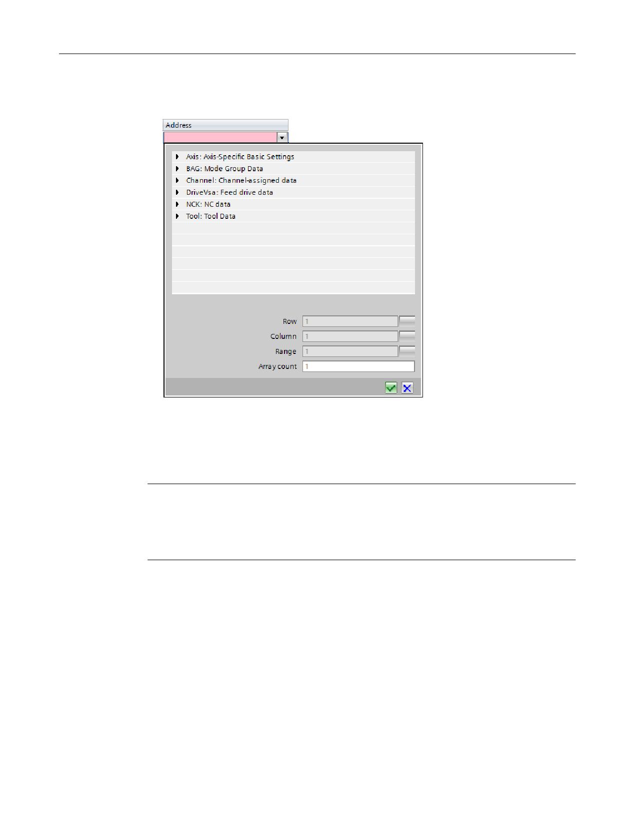
You can select SINUMERIK variables in the "HMI variables" editor in the "Address" field, if the
NC connection has been selected in the "Connection" field.
Note
Methods for indexing R parameters and GUD arrays
The method for indexing R parameters and GUD arrays depends on the employed runtime
version or SIMATIC Panel.
Requirement
● An NC connection with communication channel "SINUMERIK NC" has been created.
Procedure
To create an external variable, proceed as follows:
1. In the project tree, open the "HMI variables" folder and double-click on "Show all variables"
or on a variable table.
2. In the variable table, double-click in the "Name" column on "Add".
A new variable is created.
3. Select a previously created connection with the "SINUMERIK NC" communication driver in
the "Connection" field.
SINUMERIK Integrate Create MyHMI /WinCC V16
86
Configuration Manual, 12/2019, 6FC5397-8FP40-0BA2
Using variables
7.1 Configuring SINUMERIK variables
4. Click the "Expand" icon in the "Address" field.
The dialog for selecting SINUMERIK variables opens.
Figure 7-1
Dialog for selecting SINUMERIK variables
5. Select the required variable in the structure, adapt the values, if necessary (for example, for
the channel or axis), and click "Confirm".
6. Make optional settings in the inspector window under "Properties > Properties > General":
Note
Creating variables directly at the point of use
You can also create new variables directly at the point of use, for example, at an I/O field. To
do this, click the "Add" button in the object list. You then configure the new variable in the
Inspector window.
See also
Indexing of R parameters and GUD arrays (Page 100)
SINUMERIK Integrate Create MyHMI /WinCC V16
Configuration Manual, 12/2019, 6FC5397-8FP40-0BA2
87
Using variables
7.2 NC variable descriptions
7.2
NC variable descriptions
Overview
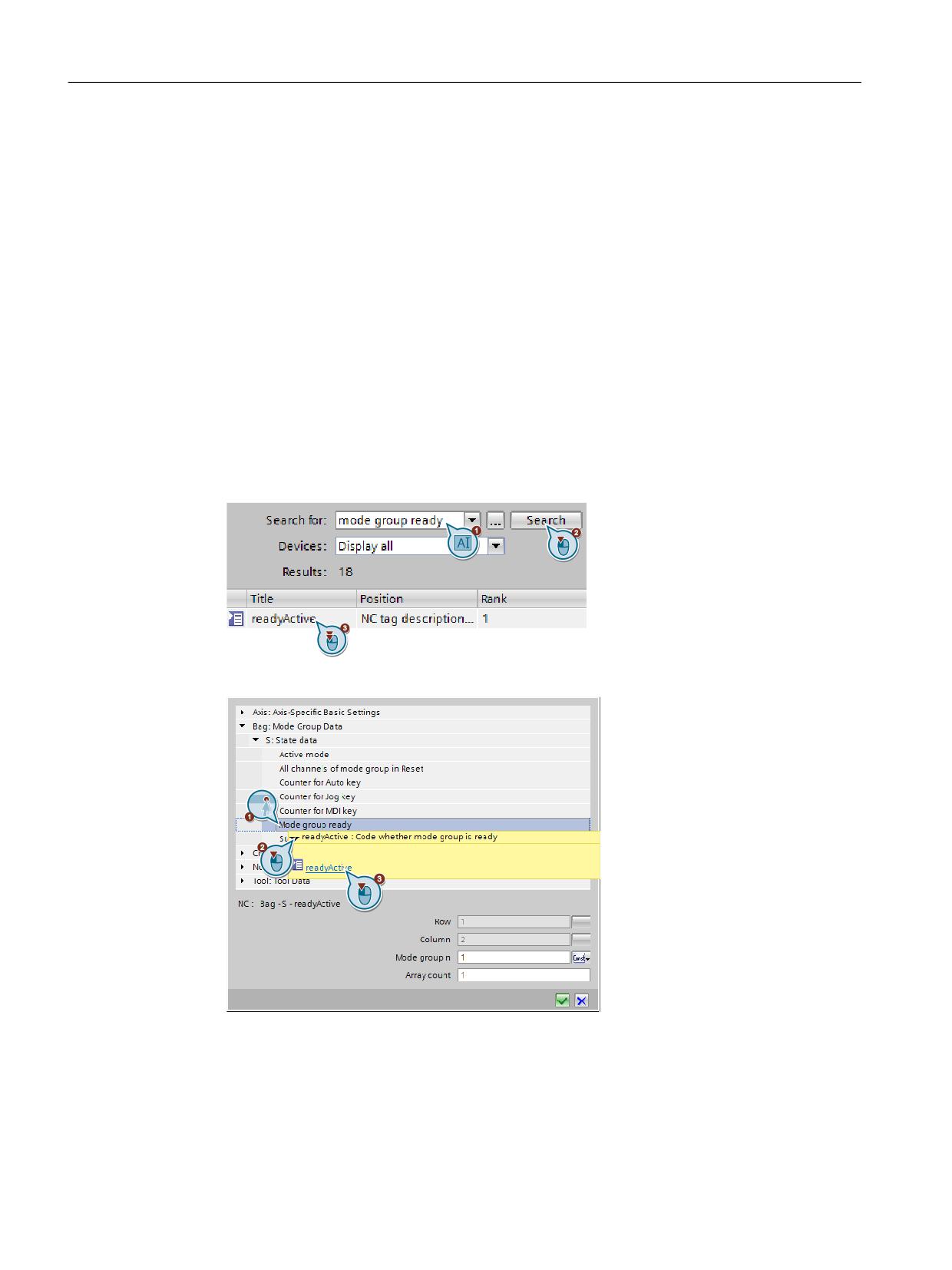
With SINUMERIK Integrate Create MyHMI /WinCC, you can configure various NC tags
(Page 86). The descriptions for these NC variables can be found in the following
documentations:
● SINUMERIK 840D sl NC Variables and Interface Signals List Manual (https://
support.industry.siemens.com/cs/document/109481500/)
● Online help of TIA Portal
Display NC variable description in the online help
You have the following options for finding the description of a specific tag:
● Search function of the online help
You can browse the online help, e.g. by tag name, description text or keywords.
● Link in the tooltip of an NC tag
● Navigation via chapter structure of the online help
Alternatively, you can also navigate to the tags via the chapter structure. The chapters are
structured according to associated area and block.
SINUMERIK Integrate Create MyHMI /WinCC V16
88
Configuration Manual, 12/2019, 6FC5397-8FP40-0BA2
Using variables
7.2 NC variable descriptions
Further information
In the descriptions of the individual NC tags, it is specified which system tag or which machine
data or setting data is returned via the respective NC tag.
You can find additional information about these tags in the respective manuals:
● SINUMERIK 840D sl / 828D List Manual system tags (https://
support.industry.siemens.com/cs/document/109481494/)
● SINUMERIK 840D sl / SINAMICS S120 List Manual machine data and parameters (https://
support.industry.siemens.com/cs/document/109481530/)
Observe that available read/write authorizations of the corresponding system tags/machine
data differ from those of the associated NC tags.
SINUMERIK Integrate Create MyHMI /WinCC V16
Configuration Manual, 12/2019, 6FC5397-8FP40-0BA2
89
Using variables
7.3 Configuring GUD tags
7.3
Configuring GUD tags
7.3.1
Introduction
Overview
GUD are Global User Data that users can define themselves on the NCU and subsequently use
in the NC. WinCC lets you visualize these tag values.
● To use the GUD tags of the NCU in the TIA Portal, you must first import (Page 91) them.
● If you work with GUD arrays, read the corresponding Notes for GUD arrays in the TIA Portal
(Page 100).
● Whenever you change the DEF files, you must also repeat the import procedure (Page 98).
● The DEF files of the GUD database used in the TIA Portal must match the DEF files in the
NC so that the WinCC RT Advanced Runtime can correctly access the GUD tags.
At an early phase in the configuring, coordinate the GUDs to be used on the NCU and in the
TIA Portal. If subsequent additions are required, attach these at the end of the DEF files,
below the existing data. If you make changes to the complete DEF file, you must reconnect
all GUD of this DEF file.
Note
Data consistency between the TIA Portal and SINUMERIK Operate
If you change something in the data in SINUMERIK Operate after the import into the
TIA Portal, these changes are not automatically synchronized between the systems.
Repeat the import process, therefore, if you change something in the GUD data in
SINUMERIK Operate.
File type "DEF"
GUD tags are saved on the NCU in "Definition files of dynamic user data" (<file name>.def).
You can operate these files with SINUMERIK Operate.
These DEF files are needed during runtime on the NCU and can be imported into the TIA Portal.
The GUD tags defined in the DEF files can be configured in the TIA Portal after the import
process.
Character explanation
Table 7-1
Character explanation for the definition of GUD tags
Value
Meaning
NCK
Global PLC tag
CHAN
Channel-specific tag
Type
Tag type (BOOL, CHAR, INT, REAL, STRING)
Name
Tag name
SINUMERIK Integrate Create MyHMI /WinCC V16
90
Configuration Manual, 12/2019, 6FC5397-8FP40-0BA2

Using variables
7.3 Configuring GUD tags
Value
Meaning
Rows
Line number
Columns
Column number
Additional information
You can find further information on GUD variables in the SINUMERIK 840D sl/828D
programming manual for work preparation, Chapter "Definition of user tags (DEF)".
7.3.2
Overview
You can use GUD tags in the TIA Portal after you have copied the DEF files defined in
SINUMERIK Operate to the PG/PC and imported them into the TIA Portal.
Note
Data consistency between the TIA Portal and SINUMERIK Operate
If you change something in the GUD tags in SINUMERIK Operate after the import into the
TIA Portal, these changes are not automatically synchronized between the systems.
Repeat the import process if you change something in the GUD data in SINUMERIK Operate.
See: Subsequently changing DEF files (Page 98)
Note
GUD tags not compatible with libraries
GUD tags are not compatible with libraries and are not stored in a library when you copy a
configuration.
Procedure overview
To use GUD in the TIA Portal, proceed as follows:
Step
Description
1
Using SINUMERIK Operate, export the existing DEF files from the NCU and copy them to the configuration PC
(Page 92).
2
Import the DEF files into the TIA Portal (Page 92).
3
Configure the imported GUD tags just like other SINUMERIK tags (Page 86).
(op-
In the "HMI tags" editor, you can also define the respective GUD name as a tag name as needed (column "Name").
tio-
If you have specified the tag name in the "HMI Tags" editor, you can address the tags using their symbolic names.
nal)
SINUMERIK Integrate Create MyHMI /WinCC V16
Configuration Manual, 12/2019, 6FC5397-8FP40-0BA2
91
Using variables
7.3 Configuring GUD tags
7.3.3
Copying DEF files to the configuration PC
The following describes the basic procedure for copying the DEF files from the NCU.
Requirement
● In SINUMERIK Operate, the USB port is enabled under "Commissioning > HMI >
Log.Drive."
● A USB flash drive is plugged in.
Procedure
To make the GUD on the NCU available to the TIA Portal, proceed as follows:
1. Select the "Definitions" directory from the SINUMERIK Operate user interface in the
operating area "Commissioning > System data > NC data", and press the "Copy" softkey.
The "Definitions" directory is copied to the clipboard with all DEF files.
2. Select the USB flash drive in the folder structure, then press the "Paste" softkey.
The "Definitions" directory is copied to the USB flash drive.
7.3.4
Importing GUD variables
Requirement
● A PC system with WinCC RT Advanced or a compatible SIMATIC panel is configured.
● All of the DEF files to be imported are saved in the same folder (without subfolders) and this
folder is available on the PG/PC.
See: Copying DEF files to the configuration PC (Page 92)
● No GUD variables are available in the TIA Portal or the existing GUD variables are to be
replaced.
Note
A re-import process deletes all of the GUD variables that have already been imported
All of the variables that have already been imported are deleted when you (successfully)
carry out a re-import process. Therefore, always re-import all of the DEF files, even those
that have not changed.
When later changing the GUD variables, take the corresponding notes into consideration
(Page 98) so that the variable addressing that was configured in the TIA Portal is retained
if possible.
SINUMERIK Integrate Create MyHMI /WinCC V16
92
Configuration Manual, 12/2019, 6FC5397-8FP40-0BA2
Using variables
7.3 Configuring GUD tags
Procedure
To import DEF files into the TIA Portal, proceed as follows:
1. In the project tree, right-click on the device or WinCC RT Advanced, then select the
command "Import SINUMERIK GUD variables for WinCC".
2. In the "Find folder" dialog, select the folder in which you saved the DEF files and confirm with
"OK".
Result
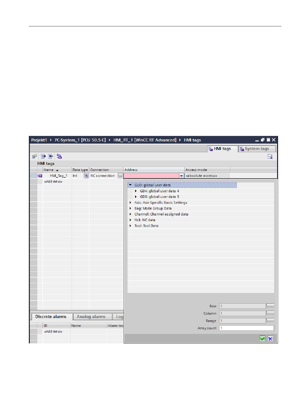
The GUD variables have been imported from all of the DEF files, which were saved in the
selected import folder. These variables can be configured in the "HMI variables" editor in the
"Address" column if a connection to the NC is selected in the "Connection" column.
Figure 7-2
Imported GUD variables in the HMI variable editor for a variable with a connection to the NC
SINUMERIK Integrate Create MyHMI /WinCC V16
Configuration Manual, 12/2019, 6FC5397-8FP40-0BA2
93
Using variables
7.3 Configuring GUD tags
See also
Configuring SINUMERIK variables (Page 86)
7.3.5
Configuring GUD arrays
7.3.5.1
Overview
Introduction
GUDs in the NCU can also be defined as arrays, specifically as one, two and three-dimensional
arrays.
Table 7-2
Definition of the GUD arrays in the NCU
GUD definition
Example
DEF {NCK|CHAN} type Name[number of lines,
DEF NCK REAL REALNGUD[2,3]
number of columns]
DEF CHAN REAL REALCGUD[2,3]
DEF {NCK|CHAN} STRING[number of characters]
DEF NCK STRING[8] NTEXT[5]
Name[number of strings]
In WinCC (TIA Portal), however, multi-dimensional arrays must be linearized, which means
access is only performed via a single index:
● In one-dimensional arrays, this is simply the required index, starting at 0.
● With multi-dimensional arrays, the index must be calculated.
If, in WinCC (TIA Portal) you wish to dynamically access a GUD array via an index variable,
observe the associated notes (Page 97).
Note
Methods for indexing R parameters and GUD arrays
The method for indexing R parameters and GUD arrays depends on the employed runtime
version or SIMATIC Panel.
Table 7-3
Addressing array elements in WinCC
Control system
WinCC configuration
Variable [A1, A2]
C_GD4:u1,c"x", (A1*A2)-1
● "x" stands for the number of the GUD in the DEF file.
● "A1" stands for the maximum index of dimension 1.
● "A2" stands for the maximum index of dimension 2.
SINUMERIK Integrate Create MyHMI /WinCC V16
94
Configuration Manual, 12/2019, 6FC5397-8FP40-0BA2
Using variables
7.3 Configuring GUD tags
For additional information on converting or linearizing GUD arrays, please refer to the following
sections:
● Linearization based on the sorting in SINUMERIK Operate (Page 95)
● Converting a three-dimensional GUD array for linear access (Page 96)
Example
Linearizing a two-dimensional array, e.g. [2,3] looks like this:
Table 7-4
Example for the linearization of a two-dimensional index'
Two-dimensional index in the NC
One-dimensional index in WinCC
0 0
0
0 1
1
0 2
2
1 0
3
1 1
4
1 2
5
The example is two-dimensional and has three elements in each dimension.
Table 7-5
Example for addressing array elements in WinCC
Control system
WinCC configuration
REALGUD[0,0]
C_GD4:u1,c"x",0
REALGUD[0,1]
C_GD4:u1,c"x",1
REALGUD[0,2]
C_GD4:u1,c"x",2
REALGUD[1,0]
C_GD4:u1,c"x",3
REALGUD[1,1]
C_GD4:u1,c"x",4
REALGUD[1,2]
C_GD4:u1,c"x",5
● GUD definition: DEF {NCK|CHAN} type Name[number of lines, number of columns]
● "x" stands for the number of the GUD in the DEF file.
See also
Indexing of R parameters and GUD arrays (Page 100)
7.3.5.2
Linearization based on the sorting in SINUMERIK Operate
Independent of whether an array is two or three dimensional, you can linearize the sorting in
SINUMERIK Operate.
SINUMERIK Integrate Create MyHMI /WinCC V16
Configuration Manual, 12/2019, 6FC5397-8FP40-0BA2
95
Using variables
7.3 Configuring GUD tags
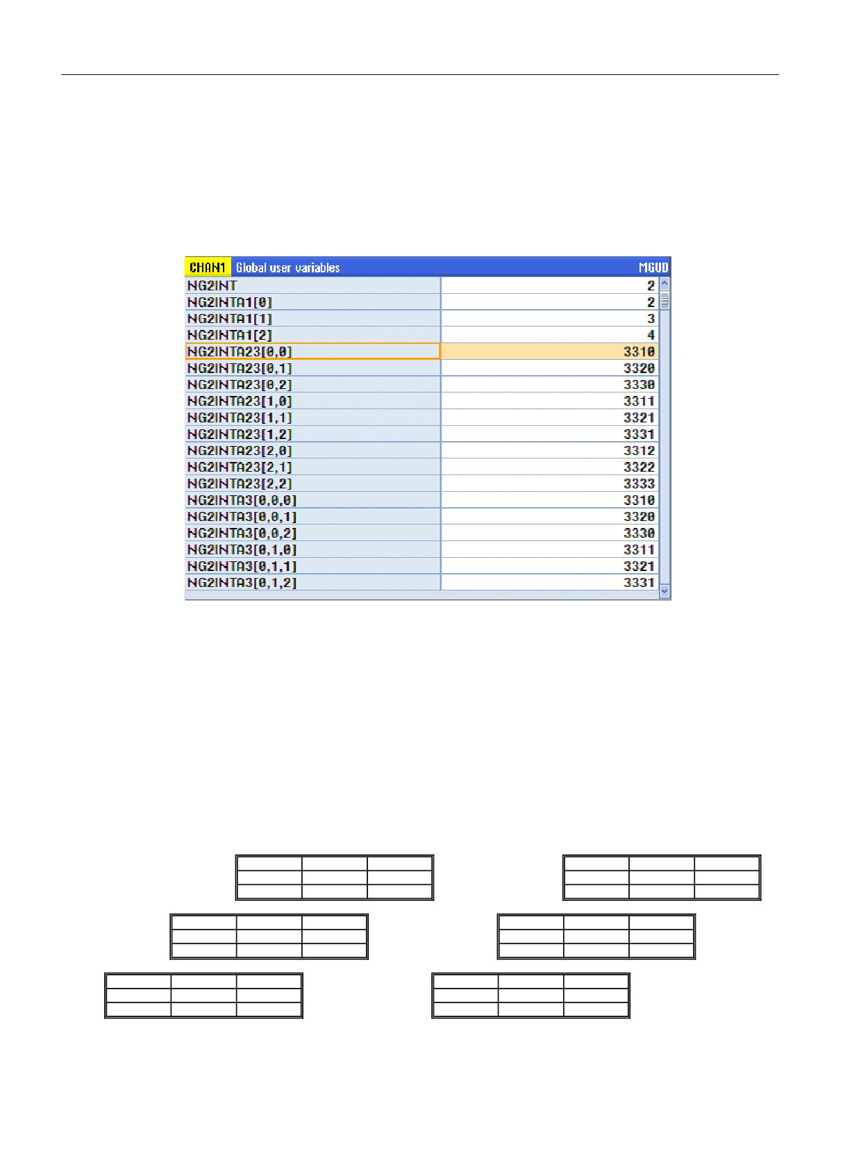
Open a GUD array in SINUMERIK Operate under "Parameter > User variables > Global GUD
> GUD selection".
● The uppermost element [0,0] is addressed with index=0.
● The uppermost element [0,1] is addressed with index=1.
● etc. until the lowest or last element, which is addressed with MaxIndex.
Figure 7-3
Screen "Global GUD > GUD selection" in SINUMERIK Operate: The selected variable is
addressed using index=0, the variable below, using index=1 etc.
7.3.5.3
Converting a three-dimensional GUD array for linear access
The following diagram shows you the linearization of a three-dimensional array. You can find
the linearized numbering to a three-dimensional array at the left in the corresponding table cell
of the table to the right, e.g. (2,1,1) = (22).
The linearization of a two-dimensional GUD array is also included in it: One page of a three-
dimensional array corresponds to one page of a two-dimensional array, whereby the side index
is eliminated, e.g. (0,1,2) = (1,2).
GLPHQVLRQDO DUUD\
/LQHDUL]HG DUUD\
3DJH
(2,0,0)
(2,0,1)
(2,0,2)
(18)
(19)
(20)
(2,1,0)
(2,1,1)
(2,1,2)
(21)
(22)
(23)
(2,2,0)
(2,2,1)
(2,2,2)
(24)
(25)
(26)
3DJH
(1,0,0)
(1,0,1)
(1,0,2)
(9)
(10)
(11)
(1,1,0)
(1,1,1)
(1,1,2)
(12)
(13)
(14)
(1,2,0)
(1,2,1)
(1,2,2)
(15)
(16)
(17)
3DJH
(0,0,0)
(0,0,1)
(0,0,2)
/LQH
(0)
(1)
(2)
(0,1,0)
(0,1,1)
(0,1,2)
/LQH
(3)
(4)
(5)
(0,2,0)
(0,2,1)
(0,2,2)
/LQH
(6)
(7)
(8)
&ROXPQ
&ROXPQ
&ROXPQ
SINUMERIK Integrate Create MyHMI /WinCC V16
96
Configuration Manual, 12/2019, 6FC5397-8FP40-0BA2
Using variables
7.3 Configuring GUD tags
Figure 7-4
Linearization of three dimensional arrays
Information about the conversion
● Access, three-dimensional array:
Array[page;line;column]
● Conversion to linearized numbering:
Array index linear = (number of lines*number of columns) * page index
+ number of
columns * line index
+ column index
● Access linearized array:
Array[Arrayindexlinear]
In the prevailing 3x3x3 array, the following applies for the conversion:
Number of lines = 3
Number of columns = 3
The indices can only have the values 0, 1 or 2:
Permissible values, page index are: {0|1|2}
Permissible values, line index are: {0|1|2}
Permissible values, column index are: {0|1|2}
7.3.5.4
Accessing GUD arrays using an index tag
In the "HMI tags" editor, if you insert a new tag as GUD array, then as a default setting, the array
length (parameter "Field number") is entered to permanently access an individual array
element (e.g. Field number=9).
SINUMERIK Integrate Create MyHMI /WinCC V16
Configuration Manual, 12/2019, 6FC5397-8FP40-0BA2
97
Using variables
7.3 Configuring GUD tags
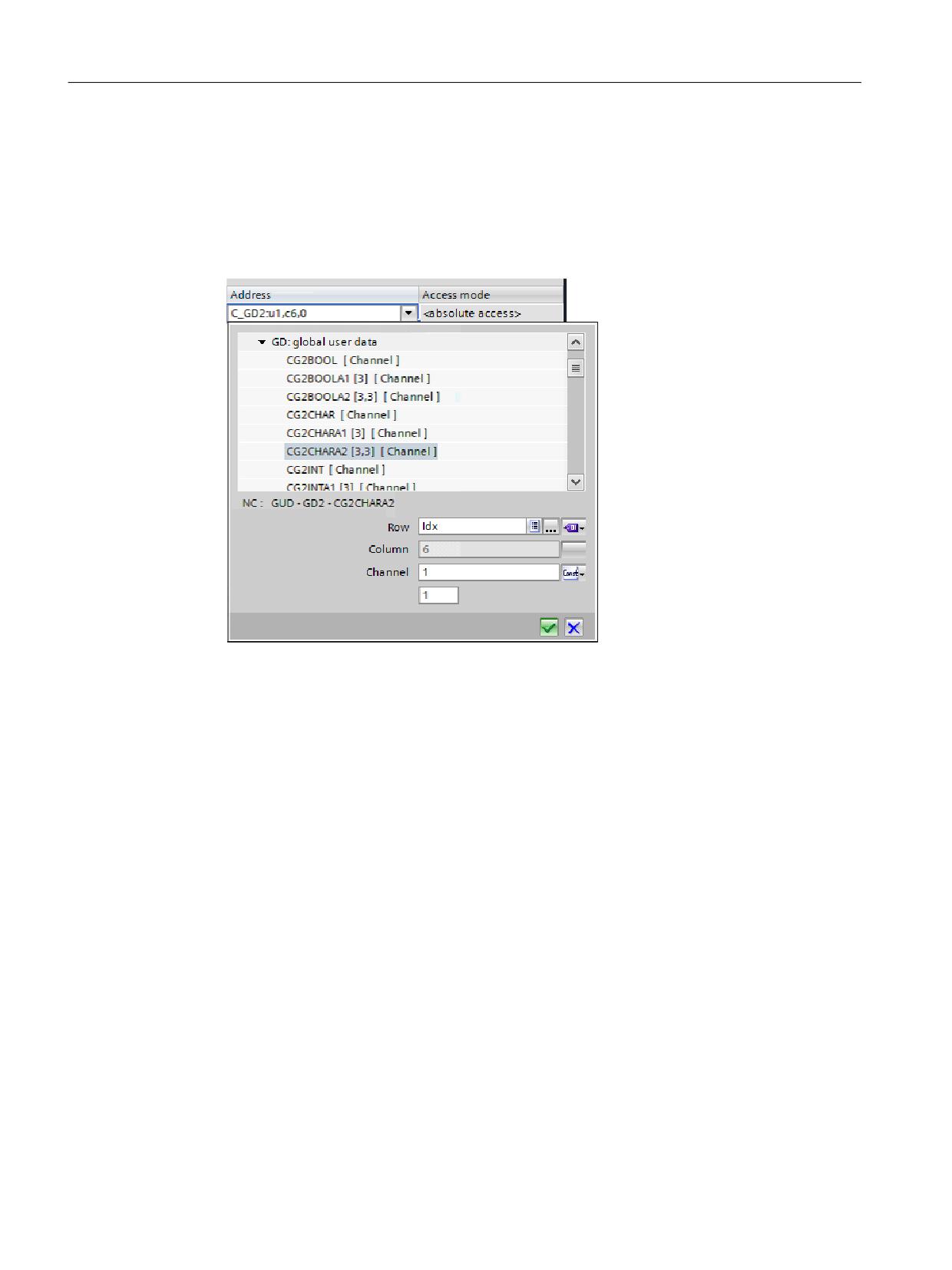
In order to be able to dynamically access individual elements of the GUD array using an index
tag that you have created yourself, you must make the following settings in the Address column
in the editor:
● "Field number" parameter: Change the default value here to "1", so that you can configure
the "Line" parameter with an index tag.
● "Line" parameter: Select the previously created index tag (from the diagram,"Idx").
Figure 7-5
Parameters completed as example when using index tags for addressing
7.3.6
Subsequently changing DEF files
GUD tags are not automatically synchronized between the TIA Portal and the NCU. If you
change DEF files on the NCU after you imported them into the TIA Portal, you must re-import
them.
Observe the following when making later changes to DEF files:
● If you would like to add a new date in a DEF file, append the date at the end of the file. The
addressing of the previous data item therefore remains unchanged. GUD tags that are
already configured in the TIA Portal remain correctly addressed.
● If you insert a new GUD tag between existing GUD tags in a DEF file, the addressing of all
of the following data changes.
WinCC RT Advanced would access incorrect data as a result. Thus, if you insert a new date
between existing GUD tags, you must re-configure all of the affected tags after you import
the updated DEF file in the "HMI tags" editor.
● If you change the data of existing GUD tags (e.g. data type), you must check and correct the
corresponding tags after re-importing the DEF file. This applies both to the configuration of
the tags in the "HMI tags" editor and to the usage in the I/O field.
SINUMERIK Integrate Create MyHMI /WinCC V16
98
Configuration Manual, 12/2019, 6FC5397-8FP40-0BA2
Using variables
7.4 Configuring variables for address multiplexing
7.4
Configuring variables for address multiplexing
Introduction
Using address multiplexing, you can use a single variable to access a multitude of memory
locations within the PLC's address range. You read and write to the addresses without defining
a variable for each individual address. This efficient method allows you to process a large
amount of data.
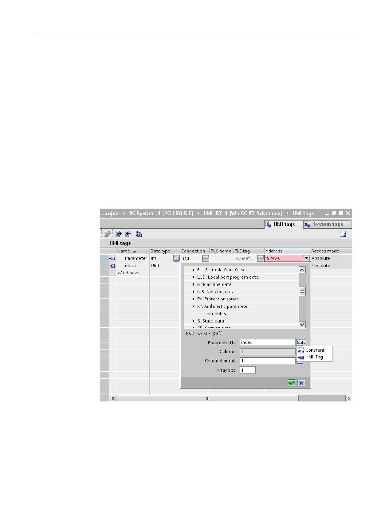
Example of a procedure using R parameters as a basis
1. Create a local "index" variable.
2. Create a variable with a connection to a control, and in area C and in the RP block, select
the R parameter variable.
3. You can make a selection from the operator control to the right next to the input for the
parameter number.
4. Select HMI_variable followed by the "index" variable.
Figure 7-6
Address multiplexing
Result
By changing the "index" variable during the runtime, another R parameter is accessed.
SINUMERIK Integrate Create MyHMI /WinCC V16
Configuration Manual, 12/2019, 6FC5397-8FP40-0BA2
99
Using variables
7.5 Indexing of R parameters and GUD arrays
7.5
Indexing of R parameters and GUD arrays
The method for indexing R parameters or GUD arrays in the TIA Portal depends on the
employed Runtime version or the corresponding SIMATIC Panel:
● If you configure a WinCC RT Advanced with a version earlier than 13.0.0.0 or a SIMATIC
Panel that uses an older Runtime version (CE Panel), note the following when indexing R
parameters and GUD arrays:
Address the R parameter higher by 1 than required during configuration. To display R5 in
runtime, for example, you need to configure R6. (This indexing method is the same method
used in WinCC flexible for SIMATIC CE panels.)
When configuring GUD arrays, address the first GUD element with index 1 (as already done
in WinCC flexible), e.g. def CHAN INT MyGUD[3]
Address the individual elements with MyGUD[1], MyGUD[2], MyGUD[3].
Note
Compatibility of simulation with RT Advanced < V13
The function "Simulation" (menu command "Online > Simulation > Start") uses a WinCC RT
Advanced V13. This only supports the new indexing method.
If you start a simulation for a WinCC RT Advanced with an older version, the tags will be
addressed incorrectly in the simulation.
● If you configure a WinCC RT Advanced as of version 13.0.0.0 (for example, all SIMATIC
Comfort Panels or a PCU 50.5 with WinCC RT Advanced), the exact R parameter you have
configured is displayed in runtime.
SINUMERIK Integrate Create MyHMI /WinCC V16
100
Configuration Manual, 12/2019, 6FC5397-8FP40-0BA2
Using variables
7.6 Accessing FANUC FOCAS functions in the variable editor
7.6
Accessing FANUC FOCAS functions in the variable editor
The FANUC CNC/PMC communication driver supports access to many functions of the
FANUC FOCAS2 library. You can select the functions in the "Address" column of the tag editor.
You will find the configurable functions in the dialog for selecting the functions. Information on
the individual functions can be found in the documentation for FANUC FOCAS2.
Requirement
● The connection to the FANUC CNC/PMC is configured.
Procedure
In order to access a tag of the FANUC FOCAS2 library in WinCC, proceed as follows:
1. In the project navigation, open the "HMI tags" folder and double-click on "Show all tags" or
on a tag table.
2. In the tag table, double-click in the "Name" column on "Add".
A new tag is created.
3. Select a previously created connection with the "FANUC CNC/PMC" communication driver
in the "Connection" field.
SINUMERIK Integrate Create MyHMI /WinCC V16
Configuration Manual, 12/2019, 6FC5397-8FP40-0BA2
101
Using variables
7.6 Accessing FANUC FOCAS functions in the variable editor
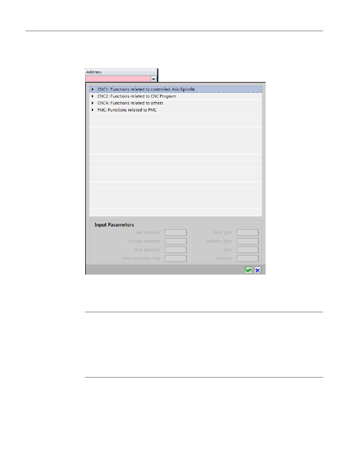
4. Click the "Expand" icon in the "Address" field.
The dialog opens for selecting the functions of the FANUC FOCAS2 library.
5. In the structure, select the required function, enter the parameters required and then click
on the "Confirm" symbol.
Information about functions and parameters is provided in the appropriate FANUC
documentation.
Note
Parameterizing the "Read/Write PMC data" function
● To read/write a PMC parameter, the correct data type and address type ("Address type"
or "kind of PMC address", e.g. "G") must be specified as numerical "ID Code". Take the
corresponding ID code from the FANUC documentation (e.g. B-64513EN) - or what is
displayed in the FANUC HMI.
● The communication driver does not support the use of PMC memory type D or setting
option "Nonvolatile PMC data table area expansion (40KB)".
6. Make optional settings in the inspector window under "Properties > Properties > General":
SINUMERIK Integrate Create MyHMI /WinCC V16
102
Configuration Manual, 12/2019, 6FC5397-8FP40-0BA2
Using variables
7.6 Accessing FANUC FOCAS functions in the variable editor
Note
Creating tags directly at the point of use
You can also create new tags directly at the point of use, for example, at an I/O field. To do this,
click the "Add" button in the object list. You then configure the new tag in the Inspector window.
SINUMERIK Integrate Create MyHMI /WinCC V16
Configuration Manual, 12/2019, 6FC5397-8FP40-0BA2
103
Using variables
7.6 Accessing FANUC FOCAS functions in the variable editor
SINUMERIK Integrate Create MyHMI /WinCC V16
104
Configuration Manual, 12/2019, 6FC5397-8FP40-0BA2
Configuring alarms
8
8.1
Importing alarms
8.1.1
Overview
The procedure overview below describes how to copy the SINUMERIK user alarm files directly
from an NCU and import them into TIA Portal.
Alternatively, the import of alarm files in CSV format is also supported. This can, for example,
be created if you manage your language-dependent text files with SINUMERIK Integrate
Access My Machine /P2P (Page 120).
Requirement
● The user alarms are available in SINUMERIK Operate (or AMM/P2P).
● A SINUMERIK NCU or device proxy (PLC 300) is inserted in the TIA Portal project.
Procedure overview
To use SINUMERIK user alarms in the TIA Portal, proceed as follows:
Ste
Description
p
1
Make the user alarm files available in the required languages. You can copy the files via the SINUMERIK Operate user
interface, for example to a USB flash drive (Page 105).
2
Check whether all languages or language variants in which you want to import SINUMERIK user alarms are enabled
as project languages in the TIA Portal.
● To check which exported alarm files correspond to which project languages in the TIA Portal, refer to
Section Language assignment in language-dependent texts (Page 171).
● How to activate the project languages is described in Section Enable project languages (Page 170).
3
Import the SINUMERIK user alarms into the TIA Portal (Page 106).
8.1.2
Exporting TS files from SINUMERIK Operate
This section describes how the DB2 alarm texts are exported from the user interface of
SINUMERIK Operate.
If you have installed SINUMERIK Operate on a Siemens PC system, you can alternatively copy
the files via the Windows Explorer.
SINUMERIK Integrate Create MyHMI /WinCC V16
Configuration Manual, 12/2019, 6FC5397-8FP40-0BA2
105
Configuring alarms
8.1 Importing alarms
Requirement
● A USB flash drive is inserted into a PC system with SINUMERIK Operate.
● In SINUMERIK Operate, the USB port is activated under "Commissioning > HMI > Log.
Drive"
● Access rights of access level 3 (user) are available in SINUMERIK Operate.
Procedure
To copy TS files from SINUMERIK Operate, proceed as follows:
1. In SINUMERIK Operate select the screen "Commissioning > System data" - and in the
folder structure, navigate in the "HMI data/Texts/Manufacturer/" directory.
2. Select the required TS files and actuate the "Copy" softkey.
3. Select the directory structure of your USB flash drive and press the "Paste" softkey.
Result
The DB2 alarm texts were copied from SINUMERIK Operate as TS files.
You can then subsequently import these files into the TIA Portal.
8.1.3
Importing SINUMERIK PLC alarm texts
Note
System-specific differences
Importing and saving alarm texts can differ in the TIA Portal depending on the specific system.
Note the corresponding subsection applicable for the system being used,
e.g. SINUMERIK 840D sl.
SINUMERIK Integrate Create MyHMI /WinCC V16
106
Configuration Manual, 12/2019, 6FC5397-8FP40-0BA2
Configuring alarms
8.1 Importing alarms
Requirement
● A SINUMERIK controller or a device proxy (PLC 300) is inserted.
● The languages in which the TS files are available are activated as project languages
(Page 170) in the TIA Portal.
If you would like to assign a TS file that is to be imported to several language variants, enable
all of the desired language variants.
● The TS files of the corresponding language are available on the configuration computer.
Note
Check TS files
Before importing, it should be ensured that all TS files have been fully translated and match
each other, this means that the same number of alarms are imported and the same alarm
numbers are used for each of the various languages.
Procedure
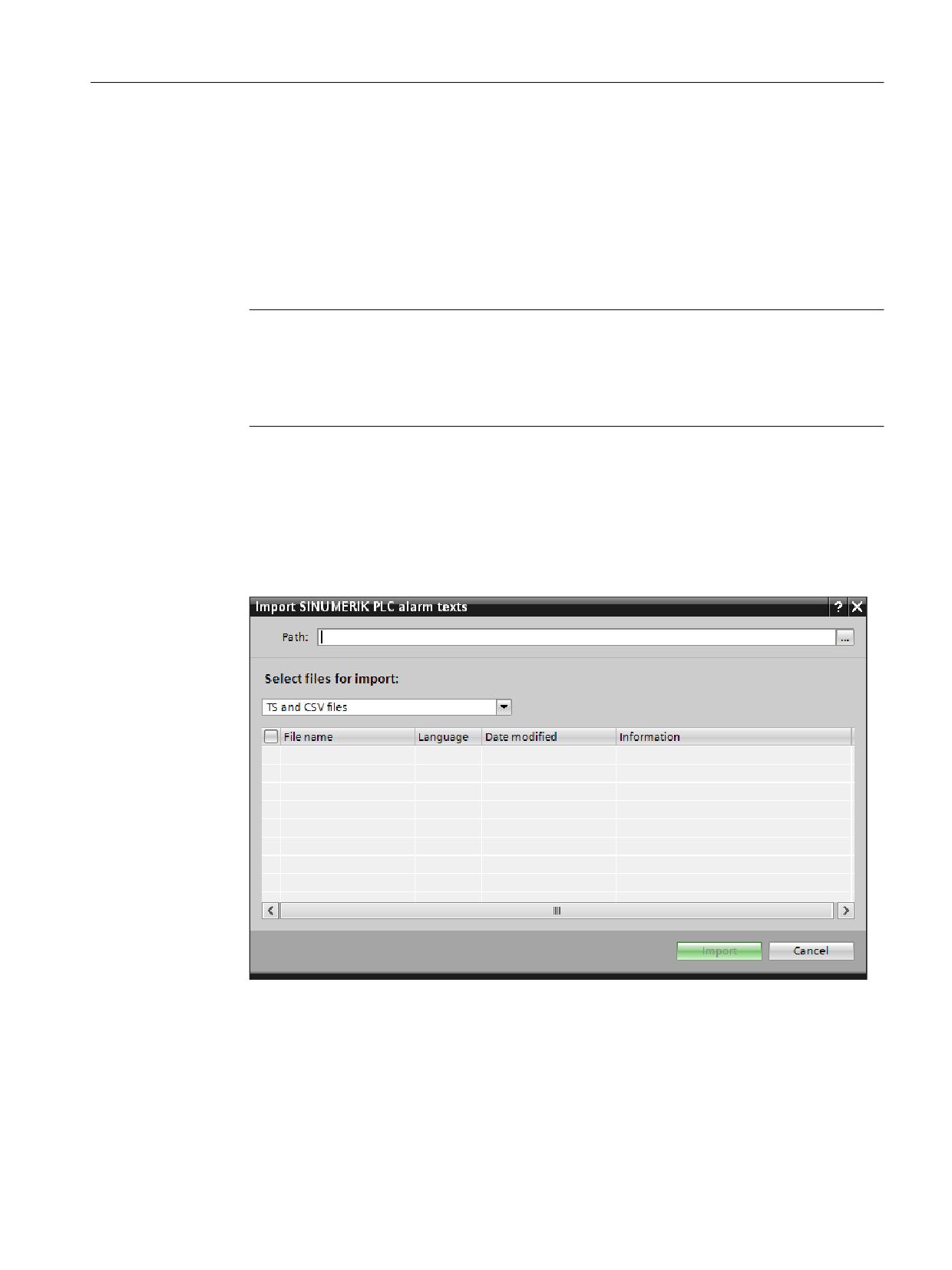
To import SINUMERIK user alarm texts into the TIA Portal, proceed as follows:
1. In the Project tree, right-click the controller or the device proxy, then select "Import
SINUMERIK PLC alarm texts" in the shortcut menu.
The "Import SINUMERIK PLC alarm texts" dialog opens.
2. Enter the path in which you have saved the user alarm files.
3. Select the file formats which you would like to import in the "File type" drop-down list.
- TS and CSV files
- TS files: Importing DB2 alarm texts that were copied directly from the controller.
- CSV file: Importing of DB2 alarm texts that were converted beforehand into the CSV
format, for example with AMM /P2P.
SINUMERIK Integrate Create MyHMI /WinCC V16
Configuration Manual, 12/2019, 6FC5397-8FP40-0BA2
107
Configuring alarms
8.1 Importing alarms
4. Check the checkboxes of the desired files individually or activate the higher-level
checkboxes to import all of the displayed files.
5. Confirm the selection with "Import".
Result
The SINUMERIK user alarm texts have been imported.
Only the alarm texts of the alarm numbers 5xx.xxx … 9xx.xxx relevant in the TIA Portal are
taken into account here.
Note that the imported texts are only visible in the TIA Portal if one of the languages is selected
as the editing language for which the texts were imported.
If the SINUMERIK PLC alarm texts are re-imported, the texts in the TIA Portal are deleted or
overwritten.
See also
Exporting TS files from SINUMERIK Operate (Page 105)
SINUMERIK Integrate Create MyHMI /WinCC V16
108
Configuration Manual, 12/2019, 6FC5397-8FP40-0BA2
Configuring alarms
8.2 Displaying alarms in WinCC picture objects
8.2
Displaying alarms in WinCC picture objects
8.2.1
Overview
Introduction
You can view both HMI alarms and SINUMERIK-specific alarms in the WinCC control "Alarm
view" in runtime:
● NC alarms
- To display NC alarms in the alarm view, you must configure the settings (Page 110).
- You can customize the displayed alarm texts directly on the configuration PC (Page 111).
● SINUMERIK DB2 alarms from the PLC (alarm numbers 500,000 to 799,999)
- You can import DB2 alarms from the NCU (Page 105).
● SIMATIC PLC alarms
- HMI messages defined in WinCC are always displayed in the message display.
Configuring information is provided in the TIA Portal Online Help, Chapter "Configuring
messages".
● Additional configured HMI messages
With the FANUC CNC/PMC communication driver, the alarm status of a FANUC control
system can be output to the message display using the FOCAS function CNC_ALARM2
(Page 118).
Additional information
This section describes what you need to consider when configuring the SINUMERIK-specific
alarms / messages.
General information on configuring alarms/messages in WinCC can be found in the information
system, Section "Working with alarms".
Information on the configuration and operation of alarms in SINUMERIK Operate can be found
in the SINUMERIK Operate Commissioning Manual (IM9) under "Configuring alarms".
See also
SINUMERIK 840D sl Commissioning Manual SINUMERIK Operate (IM9) (https://
support.industry.siemens.com/cs/document/109481529/)
SINUMERIK Integrate Create MyHMI /WinCC V16
Configuration Manual, 12/2019, 6FC5397-8FP40-0BA2
109
Configuring alarms
8.2 Displaying alarms in WinCC picture objects
8.2.2
Displaying NC alarms
8.2.2.1
Settings for display of NC alarms
Requirements
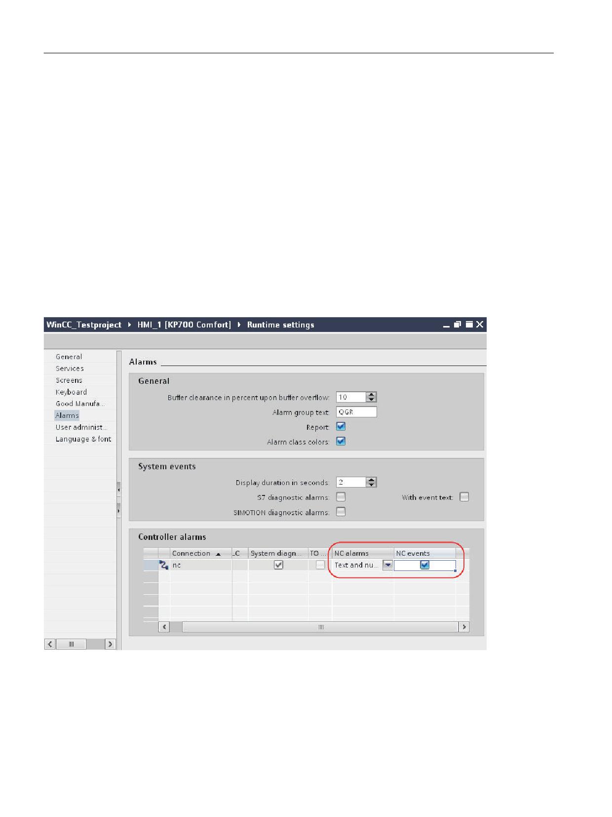
To display NC alarms in the alarm view at runtime, the following requirements must be met:
● A connection to the NC is configured.
See Configuring connection to the SINUMERIK NC (Page 82).
● The SINUMERIK alarm classes are activated.
These settings can be found in the project tree in the runtime settings under "Alarms". The
following settings for the connection to the NC must be made in the PLC alarms table:
- NC alarms: Texts and figures
- NC events: Activated
Figure 8-1
Settings for PLC alarms of the connection (the name of the connection is "nc" in the screen)
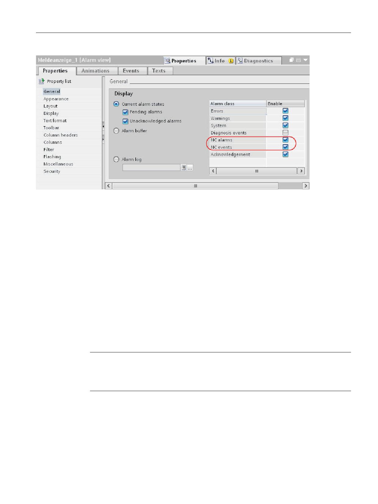
● The SINUMERIK alarm classes "NC alarms" and "NC events" are activated in the properties
of the "Alarm view" control.
SINUMERIK Integrate Create MyHMI /WinCC V16
110
Configuration Manual, 12/2019, 6FC5397-8FP40-0BA2
Configuring alarms
8.2 Displaying alarms in WinCC picture objects
Figure 8-2
Alarm classes in the properties of the "Alarm view" control
8.2.2.2
Changing NC alarm texts
The NC alarm texts are stored on the configuration PC during installation of SINUMERIK
Integrate Create MyHMI /WinCC. Here, the familiar weighting concept of SINUMERIK is used
with the Siemens, OEM and User folders.
When you adapt the alarm text, read the information about file storage, the weighting concept
and character set in this section.
Storing
Templates of the NC alarm texts are saved in the following directory on the configuration PC
during installation of the TIA Portal:
● <Installation directory of the TIA Portal>\Data\Hmi\Sinumerik\Alarmtexts
● E. B.: C:\Program Files (x86)\Siemens\Automation\Portal V15\Data\Hmi\Sinumerik
\Alarmtexts\
Note
Using original files for the NC alarm text only as template
To avoid losing the original files of the NC alarm texts, copy them to the user directory before
you change them.
The SINUMERIK alarm texts stored in the installation directory serve as template.
SINUMERIK Integrate Create MyHMI /WinCC V16
Configuration Manual, 12/2019, 6FC5397-8FP40-0BA2
111
Configuring alarms
8.2 Displaying alarms in WinCC picture objects
If you only want to modify texts, copy the corresponding alarm directory to the directory of the
relevant TIA Portal project:
● <Project directory>\AdditionalFiles\HMI\Sinumerik\Alarmtexts
● E. G.: C:\Users\Admin\Documents\Automation\My_Project\AdditionalFiles\HMI\Sinumerik
\Alarmtexts
At this point in the project, alarm texts can now be changed.
Weighting concept
The alarm texts are read line-by-line in the following order:
1. Siemens
2. OEM
3. User
Which means a changed alarm text in the OEM directory overrides the alarm text in the
Siemens directory.
A changed alarm text in the User directory in turn overrides the alarm text in the OEM or
Siemens directories.
Character set and encoding
When you adapt the alarm texts, pay attention to the character set used (e.g. ANSI) and the
encoding. Do not use any characters or any text editors which are not compatible with the
character set or encoding.
The respective alarm text file indicates the character set used.
ANSI in conjunction with GB2312 (Chinese simplified) encoding is used for Chinese alarm
texts.
8.2.3
Displaying SINUMERIK user alarms (DB2)
8.2.3.1
Introduction
You can import the alarm texts (*.ts, *.csv) of the SINUMERIK PLC alarms in the range of
500,000 to 799,999 and display them in WinCC screen objects during runtime. These alarms
are referred to as DB2 alarms to distinguish them from SIMATIC PLC alarms, for example,
which are handled differently.
A DB2 alarm is checked and displayed in runtime as follows:
● A bit is set or deleted in the ALMSG_DB [DB2] data block.
● When the AL_MSG [FC10] block is called, the ALMSG_DB [DB2] data block is checked for
changes.
● In the event that new bits have been set, the corresponding alarm is triggered via the
ALARM_S system function.
SINUMERIK Integrate Create MyHMI /WinCC V16
112
Configuration Manual, 12/2019, 6FC5397-8FP40-0BA2
Configuring alarms
8.2 Displaying alarms in WinCC picture objects
General information on configuration and commissioning
● For the PLC programming, cyclically call the AL_MSG [FC10] block in the basic program
which checks the ALMSG_DB [DB2] data block for incoming and outgoing alarms.
● In SINUMERIK Operate, you can assign these alarms language-dependent alarm texts.
● You can import these DB2 alarm texts from two different file formats into the TIA Portal:
- TS files
Can be copied directly from SINUMERIK Operate; XML-based file format
- CSV files
Can be converted from TS files with SINUMERIK Integrate Access My Machine /P2P;
used by translation agencies, for example; text file with separators.
● DB2 alarms are ALARM_S alarms which belong to the PLC and therefore require an
integrated connection to the PLC in your HMI project. Select one of the following options
depending on technical or plant-specific factors:
- Integrated connection via a device proxy in the HMI project of the TIA Portal
Additionally required software components: STEP 7 as of V5.4 SP3 with SINUMERIK
add-on and project file (*.s7p)
- Integrated connection to a SINUMERIK NCU insert in the TIA Portal
Additionally required software components: SINUMERIK TIA Portal Toolbox and
SIMATIC STEP 7 (TIA Portal)
See: Required software components for DB2 alarms (Page 117)
● You can display the imported alarms in runtime with the "Alarm view" control.
Note
Data consistency between the TIA Portal and SINUMERIK Operate
If you make changes to the data in SINUMERIK Operate after the import, these changes will not
automatically be synchronized between the systems.
Repeat the import process if you change something in the DB2 alarm texts in SINUMERIK
Operate.
Note
DB2 alarms not compatible with libraries
DB2 alarms are not compatible with libraries and are not stored in a library when you copy a
configuration.
Additional information
Information on "FC 10: AL_MSG error and operating messages" are listed in the SINUMERIK
840D sl/828D Basic Functions Function Manual in "P3: PLC basic program for SINUMERIK
840D sl".
Information on the configuration and operation of alarms in SINUMERIK Operate can be found
in the SINUMERIK Operate Commissioning Manual (IM9) under "Configuring alarms".
SINUMERIK Integrate Create MyHMI /WinCC V16
Configuration Manual, 12/2019, 6FC5397-8FP40-0BA2
113
Configuring alarms
8.2 Displaying alarms in WinCC picture objects
General information on configuring alarms/messages in WinCC can be found in the TIA Portal
online help, Chapter "Working with messages".
See also
Importing alarms (Page 105)
8.2.3.2
Configuring the alarm view
The following section describes how you can activate the display of DB2 alarms in a specific
alarm view.
Note that you can only activate the display of the DB2 alarms as a whole for an alarm view - not
differentiated by alarms requiring acknowledgment and not requiring acknowledgment.
Requirement
● You have configured a screen with alarm view.
SINUMERIK Integrate Create MyHMI /WinCC V16
114
Configuration Manual, 12/2019, 6FC5397-8FP40-0BA2
Configuring alarms
8.2 Displaying alarms in WinCC picture objects
Procedure
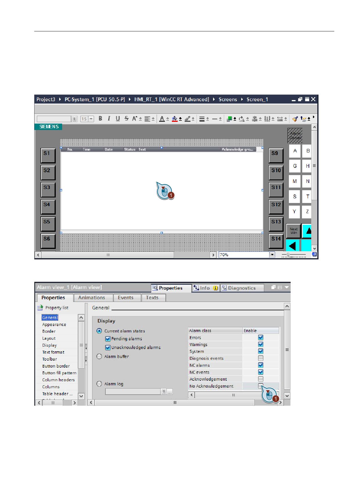
To display the DB2 alarms during runtime in an alarm view, proceed as follows:
1. Open the "Screens" editor for the screen in which the alarm view is configured.
2. Select the alarm view.
3. In the Inspector window "Properties > General", activate the "No Acknowledgement" check
box.
SINUMERIK Integrate Create MyHMI /WinCC V16
Configuration Manual, 12/2019, 6FC5397-8FP40-0BA2
115
Configuring alarms
8.2 Displaying alarms in WinCC picture objects
Note
Acknowledgment of DB2 alarms and "No Acknowledgement" setting
You can only activate the display of the DB2 alarms as a whole - not differentiated by alarms
requiring acknowledgment and not requiring acknowledgment.
Acknowledgment of the DB2 alarms is controlled via the SINUMERIK PLC basic program,
not via WinCC RT Advanced.
Therefore, all DB2 alarms are assigned to the alarm class "No Acknowledgement" in
WinCC.
Result
The DB2 alarms are displayed during runtime in this alarm view.
8.2.3.3
Configuring runtime settings
Requirement
● A PC system with WinCC RT Advanced or a SIMATIC Panel has been added.
See Inserting PC system and Runtime (Page 62) or Adding a SIMATIC Panel (Page 69)
SINUMERIK Integrate Create MyHMI /WinCC V16
116
Configuration Manual, 12/2019, 6FC5397-8FP40-0BA2
Configuring alarms
8.2 Displaying alarms in WinCC picture objects
Procedure
Proceed as follows to configure the runtime settings for displaying DB2 alarms:
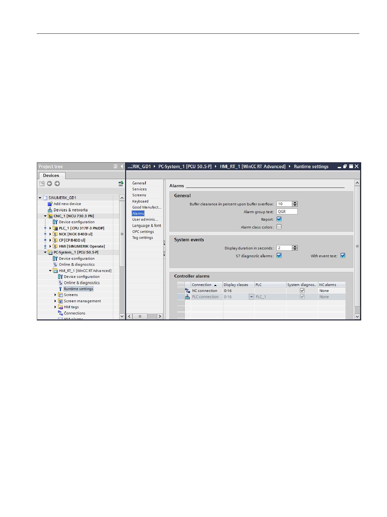
1. In the project tree, double-click under WinCC RT Advanced on "Runtime settings", for
example "PC system_1 > HMI_RT_1 > Runtime settings".
2. In the Runtime settings, click on "Alarms" in the area navigation.
3. Select the following checkboxes in the "System alarms" section:
- S7 diagnostic messages (number)
- Display alarm text
Figure 8-3
Settings for displaying DB2 alarms
8.2.3.4
Required software components for DB2 alarms
DB2 alarms are ALARM_S alarms that belong to the PLC. You therefore require an integrated
connection to the PLC in your HMI project.
Depending on technical or plant-specific factors, configure a device proxy or a SINUMERIK
NCU as connection partner of the SIMATIC Panel or PC system.
Device proxy with PLC data of a STEP 7 project as of V5.4
● If you have not installed STEP 7 Professional (TIA Portal), you can continue to use your
STEP 7 project as of V5.4.
● Additionally required software components: STEP 7 as of V5.4 SP3 with SINUMERIK add-
on and project file (*.s7p)
SINUMERIK Integrate Create MyHMI /WinCC V16
Configuration Manual, 12/2019, 6FC5397-8FP40-0BA2
117
Configuring alarms
8.2 Displaying alarms in WinCC picture objects
● Integrated connection to the STEP 7 V5.x project via a device proxy in the HMI configuration
of the TIA Portal
● Advantage: You can leave the hardware configuration and the PLC program in STEP 7
V5.x. You do not have to migrate the STEP 7 V5.x project, instead you can establish an
integrated connection to this PLC project via a device proxy.
● The handling is similar to a WinCC flexible project which is integrated in the SIMATIC
Manager.
● Detailed information can be found in the Service & Support Portal on page Shared
configuration with WinCC (TIA Portal) and STEP 7 V5.x (https://
support.industry.siemens.com/cs/document/73502293/).
Note particularly the application description for WinCC (TIA Portal) as of V13.
SINUMERIK NCU
● If you want to manage the HMI configuration, hardware configuration and the PLC program
in the same project, ideally you should configure a SINUMERIK NCU.
● Additionally required software components: SINUMERIK STEP 7 Toolbox and SIMATIC
STEP 7 Professional (TIA Portal)
● Advantage: All devices can be completely configured directly in the TIA Portal, including the
hardware configuration of the NCU and programming of the PLC program.
● You can find more information in the online help of the TIA Portal, keyword "Insert, NCU".
8.2.4
Displaying the alarms of a FANUC control system
The alarm status of a FANUC control system can be output to the message display via the
linked FANUC FOCAS library and the CNC_ALARM2 function.
The FANUC control system outputs this status value using the LONG data type (32 bit);
however, this is not compatible with the WinCC message display. This is the reason that
CNC_ALARM2 is available in the TIA Portal as split output value in 2 INT variables, and can be
output as most significant and least significant WORD:
Received alarm status
Type
Bit
Data type of the WinCC
(FOCAS)
variable
Data type
Data type
ID
2
LONG
0…31
LONG
1
WORD
0
0…15
INT
1
WORD
1
16…31
INT
Using these 2 variables - data type INT - in WinCC you can configure bit messages, and output
these as usual in the message display.
(The alarm status is still available in the LONG data type; however, this cannot be used in
conjunction with bit messages.)
SINUMERIK Integrate Create MyHMI /WinCC V16
118
Configuration Manual, 12/2019, 6FC5397-8FP40-0BA2
Configuring alarms
8.2 Displaying alarms in WinCC picture objects
Further information
● Information on configuring bit messages is provided in the help for WinCC under "Working
with bit messages".
● Information on the alarm status of FANUC control systems, the significance of the return
value and the CNC_ALARM2 function are provided in the documentation for FANUC
FOCAS.
SINUMERIK Integrate Create MyHMI /WinCC V16
Configuration Manual, 12/2019, 6FC5397-8FP40-0BA2
119
Configuring alarms
8.3 Conversion of alarm files (TS/CSV)
8.3
Conversion of alarm files (TS/CSV)
8.3.1
Overview
SINUMERIK Integrate Create My HMI /WinCC also supports the import of DB2 alarm files in
CSV format. If you manage the files on your NCU with SINUMERIK Integrate Access My
Machine /P2P, you can use the CSV format that is also used by translation agencies, for
example.
This section has the following descriptions
● General information on SINUMERIK Integrate Access My Machine /P2P (Page 121)
● Converting DB2 alarms to CSV format (Page 122)
SINUMERIK Integrate Create MyHMI /WinCC V16
120
Configuration Manual, 12/2019, 6FC5397-8FP40-0BA2
Configuring alarms
8.3 Conversion of alarm files (TS/CSV)
8.3.2
SINUMERIK Integrate Access MyMachine /P2P
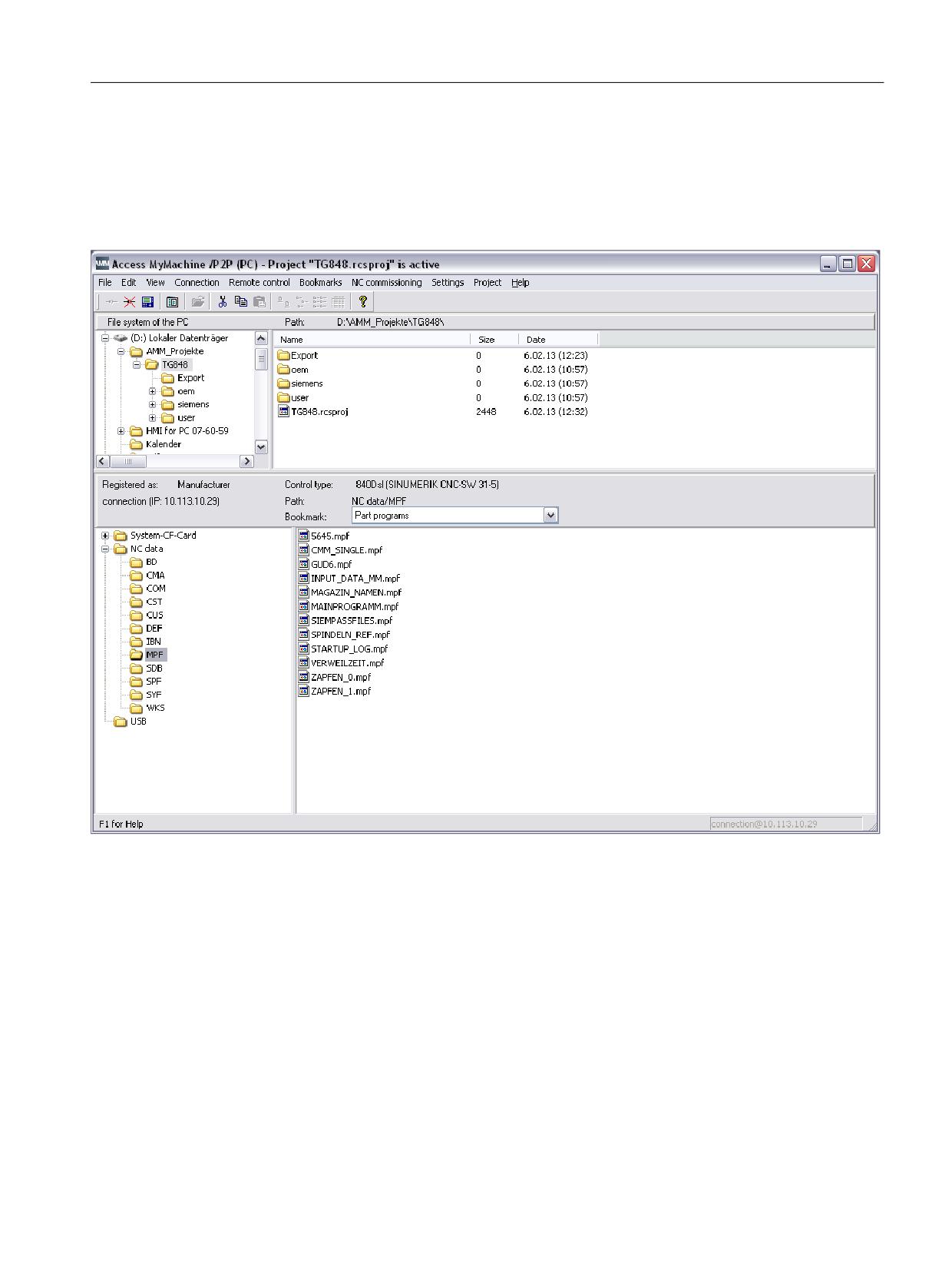
SINUMERIK Integrate Access My Machine /P2P (AMM /P2P) is a comprehensive software
product for commissioning and configuration engineers. It allows you to establish a connection
to your SINUMERIK NCU and manage and edit a large number of files directly on your PG/PC.
Functionalities
AMM /P2P also has functions for managing language-dependent text files:
● Converting TS files to CSV format, for example for easy and rapid delivery to translation
agencies.
The CSV format generated by AMM /P2P, is also supported in the TIA Portal.
● Integrated editor for form-based editing of language-dependent text files (TS files)
● Converting alarm texts in PowerLine format (e.g. myalm_it.com) to SolutionLine format (e.g.
"oem_alarms_ita.ts")
Further information
Access MyMachine /P2P in Siemens Industry Mall (https://mall.industry.siemens.com/mall/en/
us/Catalog/Products/10166222)
SINUMERIK Integrate Create MyHMI /WinCC V16
Configuration Manual, 12/2019, 6FC5397-8FP40-0BA2
121
Configuring alarms
8.3 Conversion of alarm files (TS/CSV)
8.3.3
Converting DB2 alarms into the CSV format
The following section describes how to convert AMM /P2P (without an online connection) with
existing TS files to CSV format.
You can learn how to export the files and simultaneously convert them with an online
connection in the online help for SINUMERIK Integrate Access MyMachine /P2P in the section
"Exporting a file".
Requirement
● The USB flash drive with copied TS files is inserted and/or the TS files are available
elsewhere.
● SINUMERIK Integrate Access MyMachine /P2P is installed
See SINUMERIK Integrate Access MyMachine /P2P (Page 121)
Procedure
To copy TS files from SINUMERIK Operate, and to convert them into the CSV format using
SINUMERIK Integrate Access MyMachine /P2P, proceed as follows:
1. Start Access MyMachine /P2P, e.g. using the entry in the start menu:
"Start > All programs > SINUMERIK > Tools > Access MyMachine P2P (PC)"
SINUMERIK Integrate Access MyMachine /P2P is opened.
Note
Settings to be made when starting for the first time
If you are starting the tool for the first time, you must assign a password and when
necessary, make connection settings.
Additional information on this is provided in the online help for Access MyMachine /P2P.
2. Click in the menu "File" on "New > Project...", enter the project properties and confirm with
"Save".
SINUMERIK Integrate Create MyHMI /WinCC V16
122
Configuration Manual, 12/2019, 6FC5397-8FP40-0BA2
Configuring alarms
8.3 Conversion of alarm files (TS/CSV)
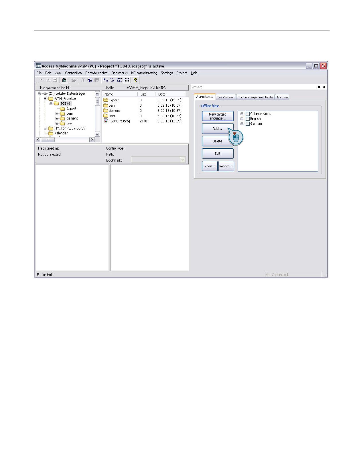
3. Click in the "Project" area on "Add...".
Figure 8-4
SINUMERIK Integrate Access MyMachine /P2P
SINUMERIK Integrate Create MyHMI /WinCC V16
Configuration Manual, 12/2019, 6FC5397-8FP40-0BA2
123
Configuring alarms
8.3 Conversion of alarm files (TS/CSV)
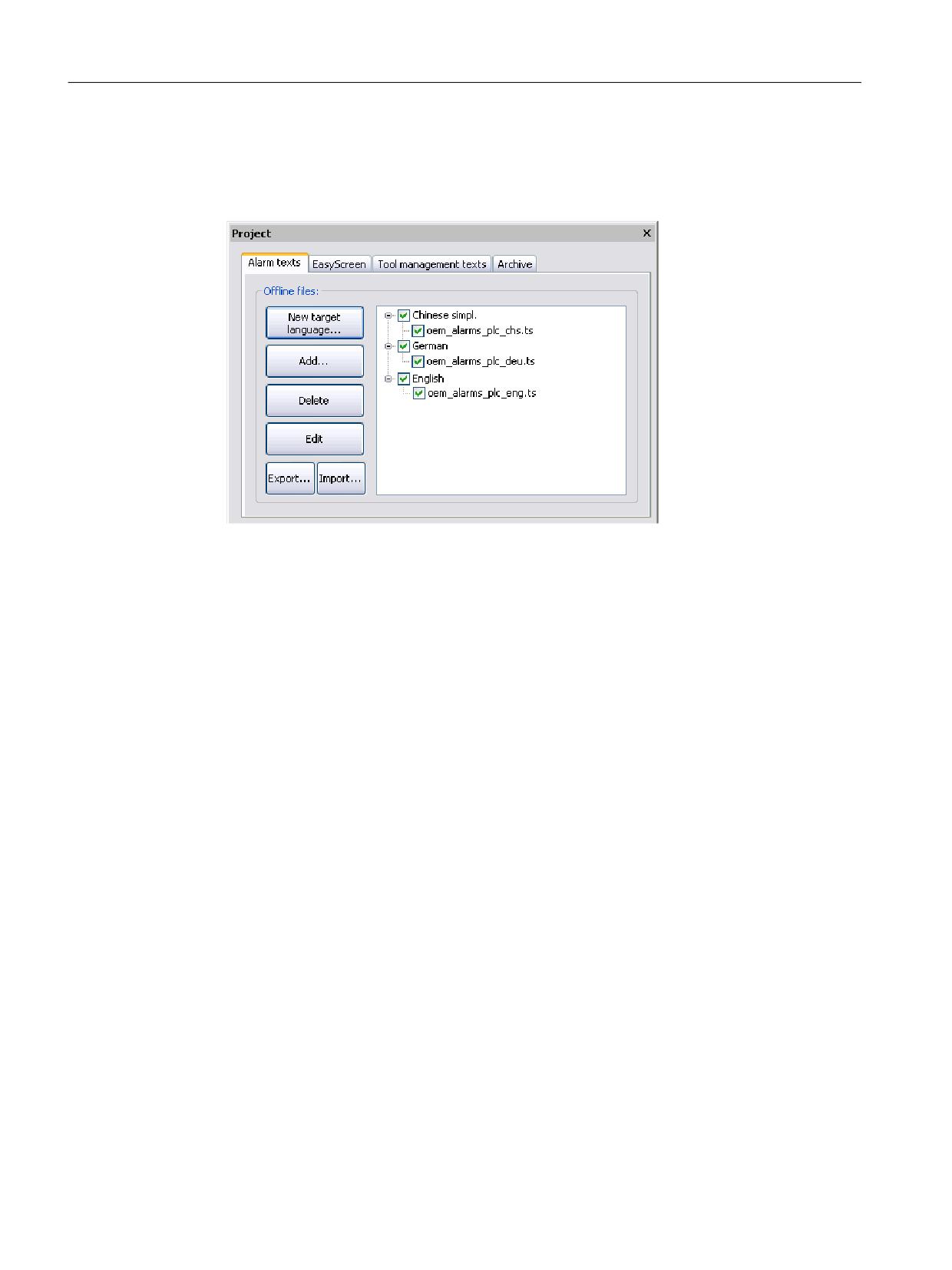
4. In the "Open" dialog, navigate to the USB flash drive with the copied TS files, select them
and click "Open."
The TS files are displayed in the "Project" area in the tree structure below the associated
language.
Figure 8-5
Project area with added TS files
5. Select the check box for the TS files you want to use in the TIA Portal, click "Export" and
select a folder where the CSV files are to be stored.
Result
The DB2 alarms were converted using Access MyMachine /P2P into the CSV format.
You can import (Page 105) these CSV files into the TIA Portal.
SINUMERIK Integrate Create MyHMI /WinCC V16
124
Configuration Manual, 12/2019, 6FC5397-8FP40-0BA2
Configuring screen objects
9
9.1
Overview
Overview
Once you have planned and implemented the structure and number of screens in your
configuration, you can add screen objects in the required screens.
In addition to the standard scope of the screen objects in SIMATIC WinCC, the following
SINUMERIK-specific screen objects can be configured:
● NC operate view
- Necessary settings (Page 129)
- Configuration and properties (Page 127)
- Operation during runtime (Page 131)
- Changing client area screen objects using runtime scripting (Page 154)
● NC keyboard view (Page 133)
● NC part program view
- Configuration and properties (Page 138)
- Operation during runtime (Page 140)
You can change the properties of this screen object during runtime using a script
(Page 141).
Note
Additional adaptation options are directly available in SINUMERIK Operate
In addition to the configuration scope of WinCC, you can also configure or restrict certain
operator functions with SINUMERIK Operate, e. g.:
● Selection and editing of subprograms by the operator (Page 142)
Further, Create MyHMI /WinCC allows client areas for applications from other manufacturers
to be integrated:
● Screen object FANUC SDF display (Page 151), to integrate the HMI of a FANUC control
system
● Screen object Application display (Page 143) to integrate additional supported applications
These can also be changed through scripting (Page 154).
SINUMERIK Integrate Create MyHMI /WinCC V16
Configuration Manual, 12/2019, 6FC5397-8FP40-0BA2
125
Configuring screen objects
9.1 Overview
Additional information
You can find information on screen objects included in the standard scope of SIMATIC WinCC
in the associated help under "Working with objects" and "Display and operating objects".
SINUMERIK Integrate Create MyHMI /WinCC V16
126
Configuration Manual, 12/2019, 6FC5397-8FP40-0BA2
Configuring screen objects
9.2 Screen object NC operate view
9.2
Screen object NC operate view
9.2.1
Properties and configuration
If you use WinCC Runtime as a customer-specific framework application, you can display
SINUMERIK Operate in a frameless client area via the screen object "NC operating display".
If, however, you use WinCC Runtime as a standalone user interface or as a SINUMERIK
Operate operating area (OEMFrame), you do not need the screen object "NC operating
display".
See also: Possible applications and scope of functions
Configuration
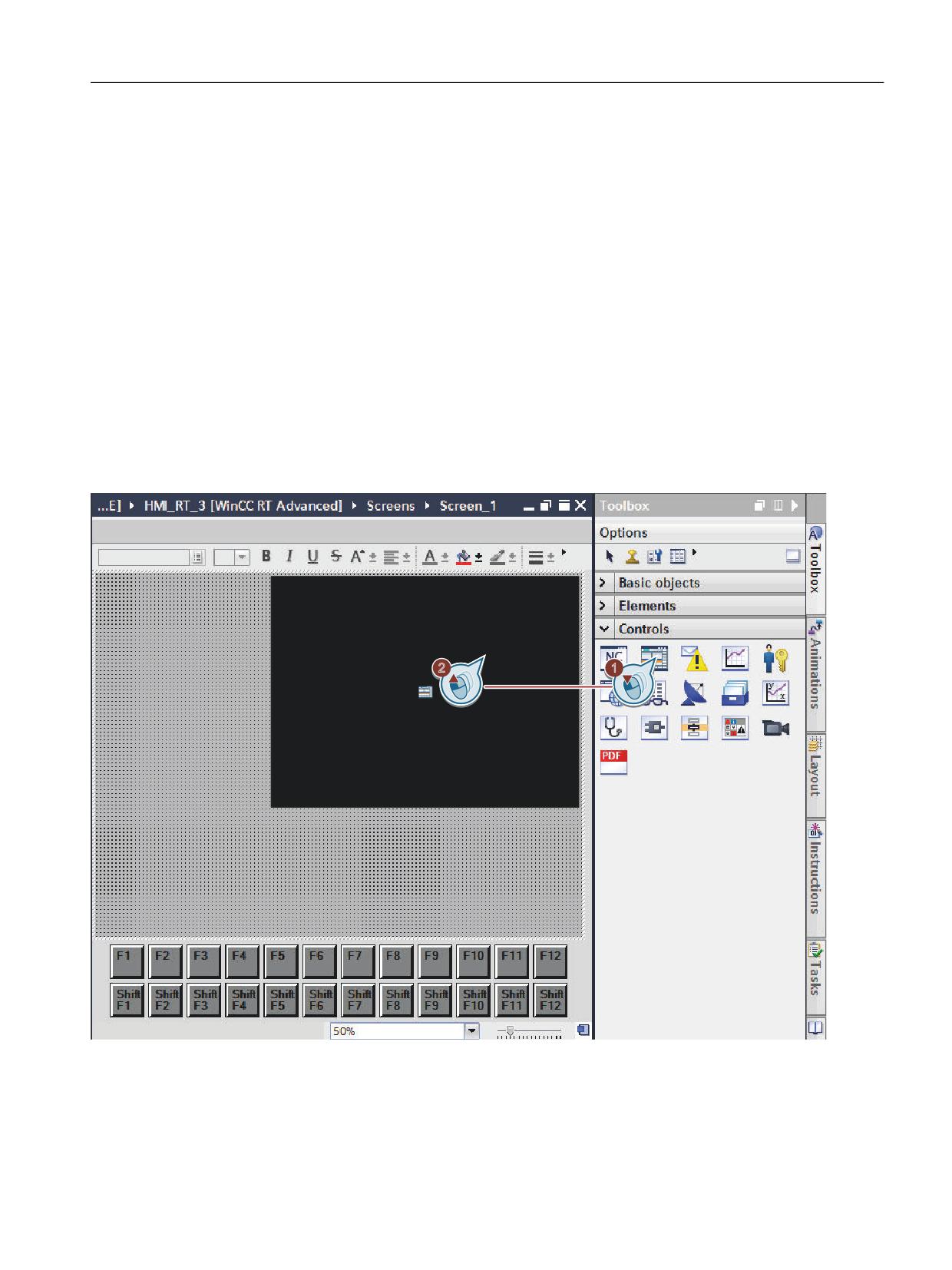
You will find the screen object on the task card "Tools" below "Controls".
Figure 9-1
Inserting a screen object with drag and drop
SINUMERIK Integrate Create MyHMI /WinCC V16
Configuration Manual, 12/2019, 6FC5397-8FP40-0BA2
127
Configuring screen objects
9.2 Screen object NC operate view
Note
Requirements for display during runtime
To ensure that NC operate view functions correctly during runtime, certain requirements must
be fulfilled (Page 129).
Note
Considering the display of a virtual keyboard (during runtime) already at the configuration stage
The activatable virtual keyboard (Page 38) is not displayed in SINUMERIK Operate or in the NC
operate view but outside on a different layer of WinCC RT Advanced.
If you use the "fixed position" setting, you must consider the space required by the virtual
keyboard when you are configuring and keep it vacant. Otherwise, objects that are relevant to
keyboard entry may be covered or the virtual keyboard may be displayed at an unexpected
position.
As an aid, you can, for example, configure another object of the same size and at the same
position as a placeholder on the screens for the virtual keyboard display during runtime.
Remove this placeholder again before you load your configuration onto the HMI device.
Properties
If you select a configured NC operate view in the "Screens" editor, you can change the following
properties:
Property
Possible settings
Further information
Display >
0 … 32767
Specifies the position of the screen object on the screen in screen coordi-
Position & Size >
nates.
X / Y
You can either enter the coordinates in the input field or move the screen
object around the screen, which will update the coordinates.
See the help for WinCC under "Position object"
The width and height of the NC operate view cannot be set here individu-
ally but only jointly in the drop-down list "Resolution".
Display >
●
640 x 480
Selection of the required resolution (width x height) from the drop-down list.
Resolution
●
800 x 480
●
800 x 600
●
1024 x 768
●
1080 x 810
●
1280 x 768
●
1280 x 800
●
1280 x 1024
●
1366 x 768
●
1440 x 1080
●
1920 x 1080
SINUMERIK Integrate Create MyHMI /WinCC V16
128
Configuration Manual, 12/2019, 6FC5397-8FP40-0BA2
Configuring screen objects
9.2 Screen object NC operate view
Property
Possible settings
Further information
Miscellaneous >
Freely definable text
Display or information about the object name
Object > Name
The object name must uniquely identify the object in the project.
See the help for WinCC under "Working with objects"
Miscellaneous >Ob-
Layer of the screen
Display or selection of the layer on which the screen object is located.
ject
Please note that, irrespective of this setting, the NC operate view may be
Layer
displayed (as a borderless object) in front of the other objects if the focus
is on it during runtime.
See the help for WinCC under "Working with layers"
9.2.2
Preconditions and required settings
To ensure that SINUMERIK Operate is displayed correctly in WinCC RT Advanced during
runtime, the following criteria must be met:
● The HMI device supports configuring of the NC operate view.
See: Functional scope (Page 19)
● The runtime setting "Full screen mode" is activated, e. g. under "PC System_1 > HMI_RT_1
> Runtime settings > General".
Note
WinCC RT Advanced in window mode not compatible with NC operate view
If you use WinCC RT Advanced in window mode, SINUMERIK Operate might not be
positioned correctly within the window during runtime.
Therefore activate full screen mode in the runtime settings.
SINUMERIK Integrate Create MyHMI /WinCC V16
Configuration Manual, 12/2019, 6FC5397-8FP40-0BA2
129
Configuring screen objects
9.2 Screen object NC operate view
●
If a virtual keyboard is to be used during runtime, it must be activated in the runtime settings,
e. g. under "PC System_1 > HMI_RT_1 > Runtime settings > Keyboard".
You can configure an activated virtual keyboard outside the TIA Portal (Page 38), however,
you may have to consider its position when during configuration (Page 127).
●
Only functions that are compatible with the NC operate view are used with it.
Note
Unsupported WinCC functions
The screen object "NC operate view" cannot be used in the following editors:
● Faceplates
● Templates
● Permanent areas
● Slide-in images
Nor can the TAB order definition be used in combination with the NC operate view.
Note
Use of function keys in combination with the NC operate view
Function keys that are operated during runtime (F1…F12), are not registered by
SINUMERIK Operate, but by WinCC RT Advanced.
Note
Use in conjunction with pop-up screens
An NC operate view configured in a pop-up screen covers any alarm views that are
configured non-modally during runtime.
In this case, configure the alarm display in another way. e.g. as a modal dialog.
Note
Use of NC operator display and application display in the same area
If you configure the NC operator display and application display in the same area or
overlapping areas and control the display at runtime using a script, you must proceed as
follows:
● During the screen event "Loaded", set the displays to "false" (with the exception of the
display to be displayed)
● After the event, all displays must be disabled via a script and then the display that is to
be displayed must be set to visible.
Note
No support in connection with customer-specific SINUMERIK Operate operating area
(OEMFrame)
When you integrate SINUMERIK Operate into an NC operator display and switch to an
OEMFrame, the OEMFrame is not displayed.
The combination of the two integration options is not supported.
SINUMERIK Integrate Create MyHMI /WinCC V16
130
Configuration Manual, 12/2019, 6FC5397-8FP40-0BA2
Configuring screen objects
9.2 Screen object NC operate view
Note
The "Windows - classic" design is not supported
If "SINUMERIK Operate extended HMI" is configured in the setup of SINUMERIK Operate,
then it is not permissible that the Windows design is set to "Windows - classic". Otherwise,
when exiting WinCC Runtime, SINUMERIK Operate would not be correctly exited.
9.2.3
Operation during runtime
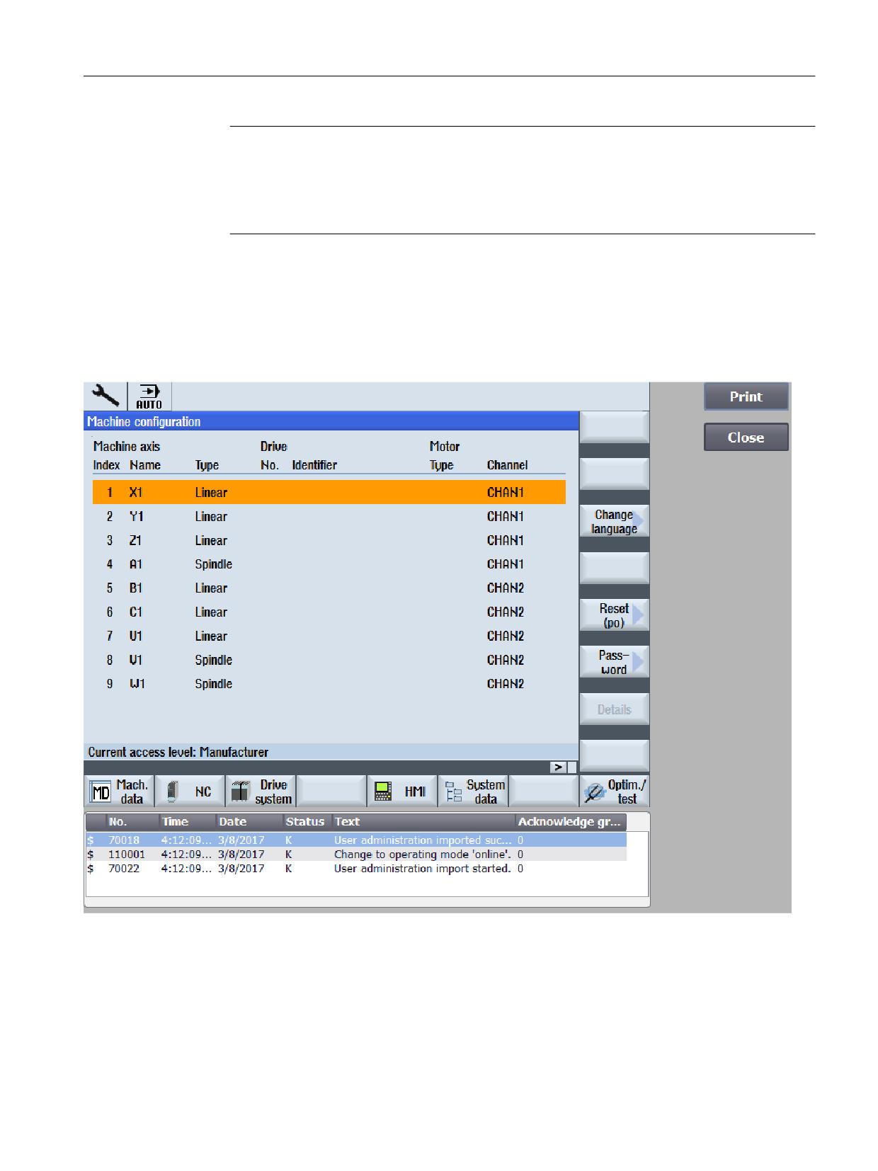
During runtime, the operator can use all the functions familiar from SINUMERIK Operate in the
NC operate view.
Figure 9-2
NC operate view during runtime
Operation
The operator can place the focus on the NC operate view by clicking it and pressing the mouse
button, but its object type means that the focus cannot be placed on it via the TAB.
SINUMERIK Integrate Create MyHMI /WinCC V16
Configuration Manual, 12/2019, 6FC5397-8FP40-0BA2
131
Configuring screen objects
9.2 Screen object NC operate view
The size of the display is defined during configuration and cannot be changed by the operator
during runtime.
Operation of SINUMERIK Operate in WinCC RT Advanced corresponds to the operator
concept familiar from SINUMERIK Operate.
The online help of SINUMERIK Operate provides additional information about operating
SINUMERIK Operate.
Operation after disconnection of the online connection
Disconnecting the online connection in the TIA Portal does not impact the NC operating display.
Linking the SINUMERIK Operate application to the NCU is not controlled via the TIA Portal.
See also
Activating the virtual keyboard (Page 38)
SINUMERIK Integrate Create MyHMI /WinCC V16
132
Configuration Manual, 12/2019, 6FC5397-8FP40-0BA2
Configuring screen objects
9.3 Screen object NC keyboard view
9.3
Screen object NC keyboard view
9.3.1
Properties and configuration
Using the "NC keyboard view" screen object, you can configure a virtual keyboard within
WinCC screens.
Note
No operation of modal system dialogs via NC keyboard view
The NC keyboard view cannot be used for making entries during runtime in modal system
dialogs that are displayed by the WinCC RT Advanced.
For dialogs of this type, you resort to the virtual keyboard (Page 38), if activated. Alternatively,
you can use a hardware keyboard for this purpose.
Note
Activating the screen keyboard in the runtime settings
When using a general PC station or a SIMATIC Box PC, you must set the settings for the screen
keyboard, e.g. under "PC system_1 > HMI_RT_1 > Runtime settings > Keyboard".
Compatibility with the Fanuc SDF display
Note
Current Windows update required
If the NC keyboard display is used during the runtime, without SINUMERIK Operate being
installed, then longer load times can be incurred.
Resolve the problem by installing the current Windows update. Alternatively, you can set the
following registry keys:
[HKEY_LOCAL_MACHINE\SOFTWARE\Microsoft\Windows\CurrentVersion\Policies
\System]
"EnableLUA"=dword:00000000
"FilterAdministratorToken"=dword:00000000
SINUMERIK Integrate Create MyHMI /WinCC V16
Configuration Manual, 12/2019, 6FC5397-8FP40-0BA2
133
Configuring screen objects
9.3 Screen object NC keyboard view
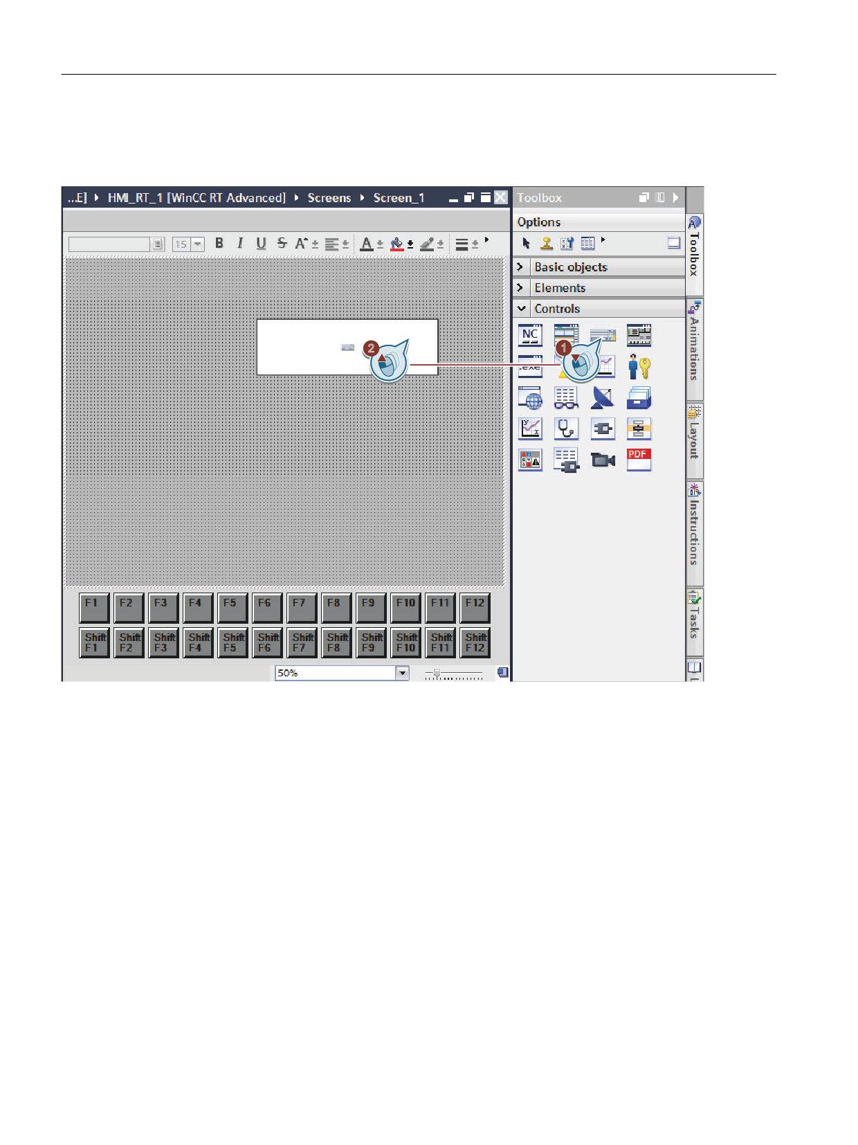
Configuration
You will find the screen object on the task card "Tools" under "Controls".
Figure 9-3
Inserting a screen object with drag and drop
SINUMERIK Integrate Create MyHMI /WinCC V16
134
Configuration Manual, 12/2019, 6FC5397-8FP40-0BA2
Configuring screen objects
9.3 Screen object NC keyboard view
Properties
If you select a configured NC keyboard view in the "Screens" editor, you can change the
following properties:
Property
Possible settings
Further information
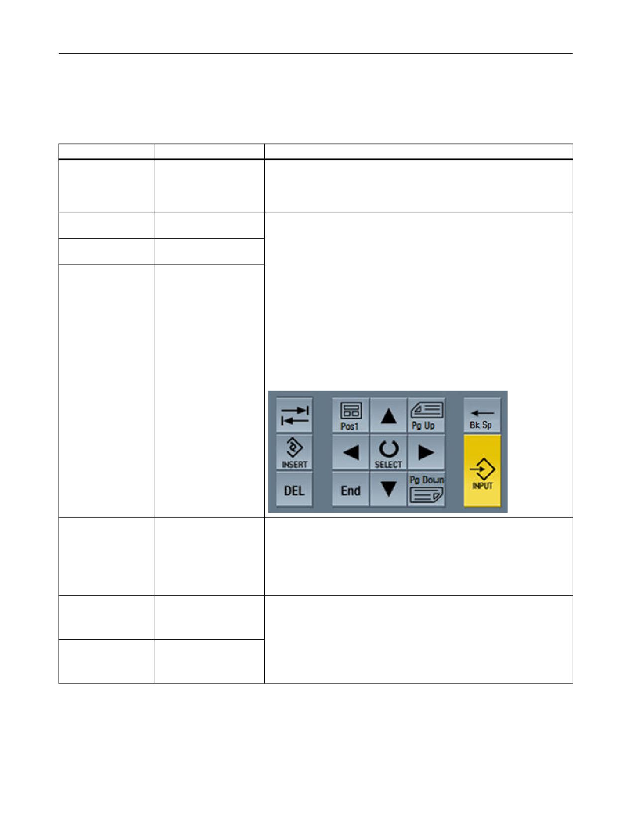
General > Keyboard
● QWERTY
Under "Keyboard type" you can choose between 3 different types of key-
type
board (Page 136).
● ABC
If you adapt this setting, the size of the configured object is adapted, or the
● NUM
settings under "Layout" are reset to the default values.
Design > General >
RGB value
Under "Design" you can configure in what color the NC keyboard view is
Background color
displayed during runtime.
Design > General >
3D or flat
This enables you to configure the backg62round color of the keyboard, the
Key style
key style (3D or flat) and the colors of three different groups of keys:
Design > General >
RGB value
● Colors of all normal keys (or hard keys), i.e. letters, numerals and
Normal keys / Spe-
special characters
cial keys / Input key
● Colors of all special keys (toggle keys, special keys, cursor keys, etc.),
i.e. all other keys
● Color of the input key
For each group of keys you can define the key backg62round color and text
color for both the actuated and non-actuated status of the key. The colors
of the graphic symbols shown on some of the keys cannot be changed, but
only the respective text, e.g. "Pos1".
Layout > Position &
0 … 32767
Specifies the position of the screen object on the screen in screen coordi-
Size > X/Y
nates.
You can either enter the coordinates in the input field or move the screen
object around the screen, which will update the coordinates.
See TIA Portal online help, "Visualizing processes > Working with objects
> Positioning object"
Layout > Position &
QWERTY: 420 … 32767
Specification of the keyboard size.
Size > Width
ABC: 220 … 32767
These values are dependent on the type of keyboard (see above) and are
reset to the corresponding default or minimal values if the type of keyboard
NUM: 160 … 32767
is changed.
Layout > Position &
QWERTY: 130 … 32767
Size > Height
ABC: 440 … 32767
NUM: 160 … 32767
SINUMERIK Integrate Create MyHMI /WinCC V16
Configuration Manual, 12/2019, 6FC5397-8FP40-0BA2
135
Configuring screen objects
9.3 Screen object NC keyboard view
9.3.2
Operation during runtime
During runtime the operator can make entries in the currently active screen object by means of
a configured NC keyboard view.
This option is terminated if the screen changes, or the NC keyboard view is hidden.
Interaction of NC keyboard view and SINUMERIK virtual keyboard
If both the NC keyboard view and the virtual keyboard (Page 38) are activated, the display of
the NC keyboard view always has priority. There will never be more than one on-screen
keyboard displayed at a time. This also applies, for example, if the NC keyboard view has been
configured as a "NUM" type keyboard.
Only in the following cases does it resort to the activated SINUMERIK virtual keyboard:
● If user inputs are necessary on a screen on which no NC keyboard view is configured
● If a modal dialog (e.g. a system dialog displayed by WinCC RT Advanced) demands inputs
SINUMERIK Integrate Create MyHMI /WinCC V16
136
Configuration Manual, 12/2019, 6FC5397-8FP40-0BA2
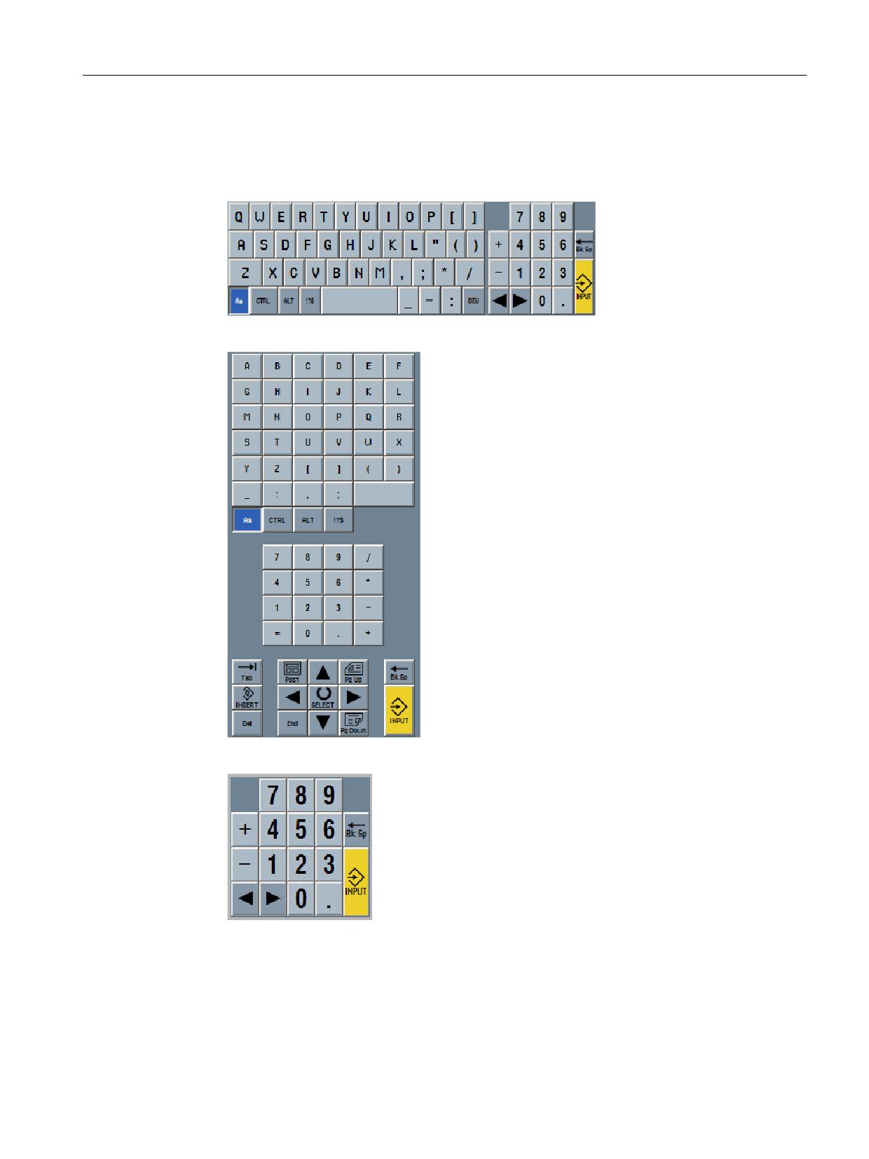
Configuring screen objects
9.3 Screen object NC keyboard view
Keyboard types
The keyboard is displayed during runtime with the configured keyboard type:
● QWERTY
● ABC
● NUM
SINUMERIK Integrate Create MyHMI /WinCC V16
Configuration Manual, 12/2019, 6FC5397-8FP40-0BA2
137
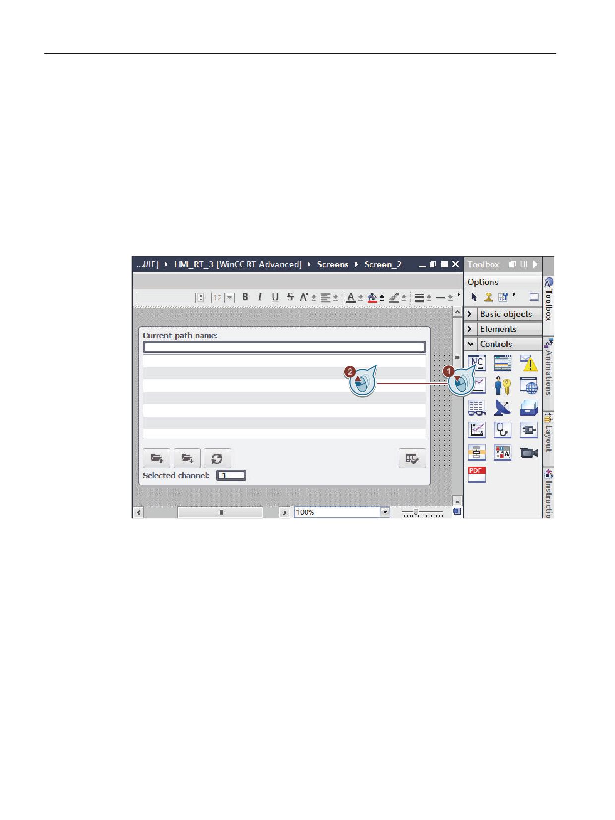
Configuring screen objects
9.4 Screen object NC part program view
9.4
Screen object NC part program view
9.4.1
Properties and configuration
The NC part program view is a WinCC screen object of type "Control" for displaying NC part
programs in WinCC RT Advanced.
Configuration
You will find the screen object on the task card "Tools" below "Controls".
Figure 9-4
Insert NC part program view
To make the NC part program view functionally complete, you can configure function keys or
configured command buttons with functions, e.g. navigating and selecting in the list directory.
Customize CPU properties
You have several ways of configuring the "NC part program view" screen object in the
"Screens" editor. These selection options are available for a selected screen object in the
Inspector window below Properties.
SINUMERIK Integrate Create MyHMI /WinCC V16
138
Configuration Manual, 12/2019, 6FC5397-8FP40-0BA2
Configuring screen objects
9.4 Screen object NC part program view
General properties
Under "General", you can make the following settings for subprogram selection:
Property
Description
Connection > Name
Select the connection to NC.
Path > Name
Select a predefined path name (max. 29 characters, in uppercase
letters). For example, WKS_DIR, MPF_DIR, SPF_DIR, CST_DIR,
CUS_DIR or CMA_DIR.
Path > Variable
Select the connected path variable.
Channel > Name
Select one of the predefined channels (1 - 10).
Channel > Variable
Select the connected channel variable.
Channel > Editable
You can enable/disable editing of the paths or channels by selecting
the "Editable" field.
Path > Editable
Additional properties
You can customize the overall appearance of the "NC part program view" screen object using
Design, Layout, Representation, Text, Flashing and Miscellaneous.
"Layout" property
You can select which buttons, etc. should be displayed in the screen object under "Layout".
Further information concerning the properties of WinCC screen objects
You can call information about the individual properties using the tooltips. Alternatively, you can
find these descriptions in the help for WinCC under "working with objects".
Events
In order also to be able to operate screen object "NC part program view" externally or,
depending on the functionality, to allocate an appropriate authorization, command buttons can
be hidden in the screen object during configuration. The required functionality can be triggered
via softkeys with various authorization levels.
If you have selected the "NC part program view" screen object, you can configure functions for
Events in the Inspector window using "Properties > Events".
Table 9-1
Events for the "NC part program view" screen object
Event
Meaning
Enable
On selection, the screen object is activated.
Disable
On deselection, the screen object is deactivated.
Additional information
You will find information on configurable functions of the screen object "NC part program view"
in Section Functions for the NC part program view screen object (Page 156).
SINUMERIK Integrate Create MyHMI /WinCC V16
Configuration Manual, 12/2019, 6FC5397-8FP40-0BA2
139
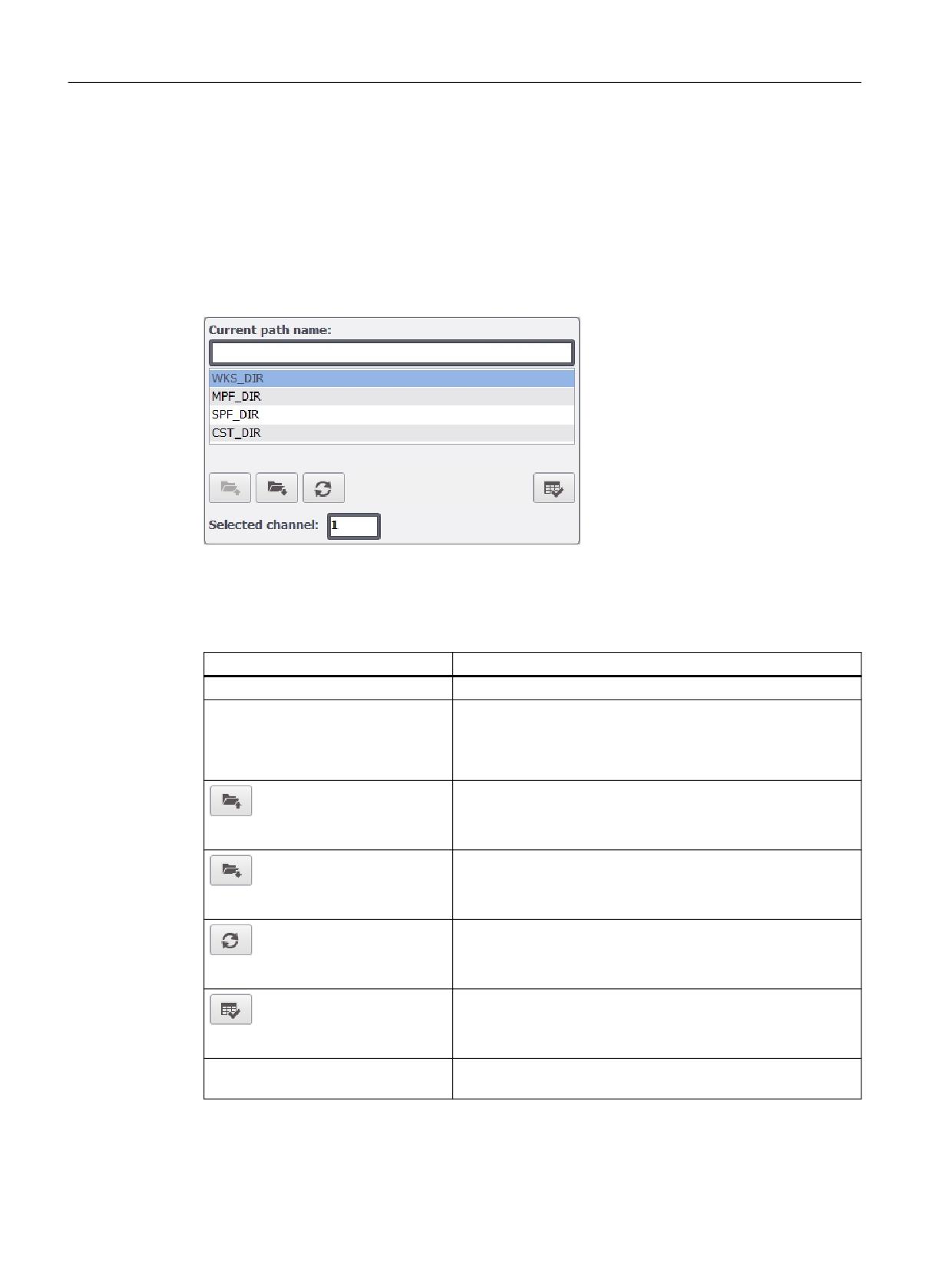
Configuring screen objects
9.4 Screen object NC part program view
9.4.2
Operation during runtime
With the screen object "NC part program view", the operator can display and select part
programs, subprograms or workpieces as an overview during runtime.
Operation of the NC part program view screen object during runtime
The following screenshot shows the screen object "NC part program view" during runtime.
Figure 9-5
Screen object NC part program view during runtime
During the runtime, command buttons can be used to:
Table 9-2
Command buttons for the screen object
Element
Function
Current path name
The path of the opened directory is displayed, e.g. MPF, SPF.
List box below "Current path name"
Part program names and lower-level directories are displayed
line-by-line in the list.
Select in the list box the directory to be opened or the required
program by clicking with the mouse or using the touchscreen.
Moves up one directory
Directory up
Changes to the selected directory.
Select the directory
Updates the view of the list box.
Update
Selects the selected part program / workpiece on the NC for
editing.
Select the part program
Selected channel
Enter the NC channel as integer in the "Selected channel" text
box.
SINUMERIK Integrate Create MyHMI /WinCC V16
140
Configuration Manual, 12/2019, 6FC5397-8FP40-0BA2
Configuring screen objects
9.4 Screen object NC part program view
9.4.3
Changing the screen objects using scripts in WinCC
You can also modify screen object properties at runtime in WinCC using scripts.
This provides a means, for example, of changing the colors or the NC part program view path
dynamically:
VBScript
Dim view
Set view = HmiRuntime.Screens("Screen_1").ScreenItems("NC Part Program_1")
view.Channel=1
view.BackColor=RGB(0, 255, 0)
view.GridlineColor=RGB(0, 0, 255)
view.Path="MPF_DIR"
Further information
You can find general information on changing screen objects using the VBScript in the help for
WinCC under "Working with system functions and runtime scripting".
SINUMERIK Integrate Create MyHMI /WinCC V16
Configuration Manual, 12/2019, 6FC5397-8FP40-0BA2
141