SINUMERIK 840D sl. Service - Configuring Commissioning. Manual (2011-2020) - page 57
Customer Specific Object Model (CSOM)
4.4 CSOM dialog in SINUMERIK Operate
4.4.4
Deleting OPC UA model
Procedure
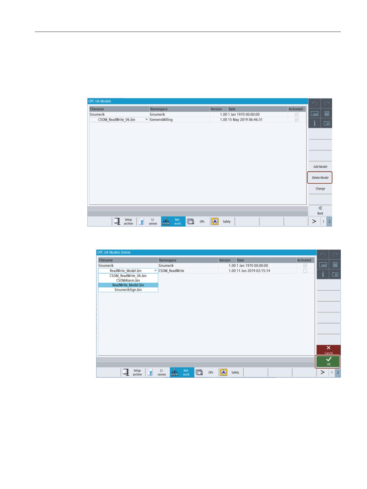
1. To delete a customer specific object model press the softkey "Delete Model".
Figure 4-55
Softkey Delete Model
2. Select the model you want to delete from the CSOM drop-down list and then click "OK".
Figure 4-56
OPC UA Models Delete
A pop-up screen will appear asking you for confirmation of deletion:
SINUMERIK Access MyMachine / OPC UA
Configuration Manual, 10/2020, 6FC5397-1DP41-0BA5
79
Customer Specific Object Model (CSOM)
4.4 CSOM dialog in SINUMERIK Operate
Figure 4-57
Delete Model popup
Pressing the softkey "Cancel" will do no action and return to "OPC UA Models" screen.
Pressing the softkey "OK" will delete the customer model.
SINUMERIK Access MyMachine / OPC UA
80
Configuration Manual, 10/2020, 6FC5397-1DP41-0BA5
Customer Specific Object Model (CSOM)
4.4 CSOM dialog in SINUMERIK Operate
4.4.5
Activating / Deactivating OPC UA model and SINUMERIK namespace
Procedure
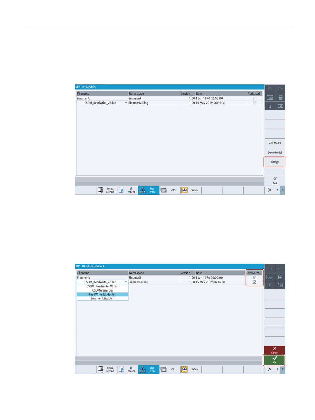
1. Press the softkey "Change".
Figure 4-58
Softkey Change
2. The following screen appears where you can perform the following functions:
- Selecting the CSOM file from the drop-down list.
- Activating the CSOM file by selecting the check box.
- Deactivating the CSOM file by clearing the check box.
- Activating the SINUMERIK namespace by selecting the check box.
- Deactivating the SINUMERIK namespace by clearing the check box.
SINUMERIK Access MyMachine / OPC UA
Configuration Manual, 10/2020, 6FC5397-1DP41-0BA5
81
Customer Specific Object Model (CSOM)
4.4 CSOM dialog in SINUMERIK Operate
Figure 4-59
OPC UA Models Select
Pressing the softkey "Cancel" will do no action and return to "OPC UA Models" screen.
Pressing the softkey "OK" will apply the changes.
SINUMERIK Access MyMachine / OPC UA
82
Configuration Manual, 10/2020, 6FC5397-1DP41-0BA5
User administration
5
5.1
Overview
The admin can add/delete users and access rights via OPC UA methods provided by the server.
Therefore a connection with a generic client must be established, using the admin credentials.
Users and access rights can then be assigned using the following OPC UA server methods:
• Add users (AddUser, AddCertificateUser)
• Delete users (DeleteUser)
• List users (GetUserList)
• Change password (ChangeMyPassword)
• Give access rights (GiveUserAccess)
• Remove access rights (DeleteUserAccess)
• List access rights (GetMyAccessRights, GetUserAccessRights)
NOTICE
Misuse of access rights
As an administrator, you are fully responsible for the administration of users and their access
rights. Any error in the administration process can lead to the misuse of access rights.
Note
Anonymous connection
You can also establish an anonymous connection during commissioning, if this setting is active,
but the methods will not be available (feedback: "BadRequestNotAllowed").
Note
Anonymous user
Anonymous users don't have any access (Read/Write) rights after installation. As an
administrator, you have to set these access rights explicitly.
Note
Administrator has only read rights
Note that the administrator has only read rights per default. Other rights need to be set explicitly.
Note
You can only add or remove users or access rights if you are connected as administrator. If you
call the methods with a different user, you will receive the message "BadInvalidArgument".
SINUMERIK Access MyMachine / OPC UA
Configuration Manual, 10/2020, 6FC5397-1DP41-0BA5
83

User administration
5.2 User management
5.2
User management
A new user created with the "AddUser" or "AddCertficateUser" function has no access rights at all.
The user administrator has the responsibility for the user management and the associated
access rights. All users must use a secure password.
Table 5-1
Methods for user administration
Method
Description
AddUser
Creates a new user for accessing OPC UA.
Input arguments:
UserName
User Name
Initially, the password of the new user is the user name. It should then be changed using the
method "ChangeMyPassword".
AddCertificateUser
Creates a new user for accessing OPC UA via certificate authentication.
Input arguments:
UserName
user, certificate is issued to
CertficateData
Certificate(.der) as byte string
DeleteUser
Deletes a user who was added previously using the method "AddUser" and "AddCertificateUser".
Input arguments:
UserName
User Name
The administrator user, created when OPC UA was set up, cannot be deleted.
GetUserList
The administrator can read the list of all users.
Input arguments:
-
List of users
ChangeMyPassword
Changes the password for the connected user.
Input arguments:
OldPwd
Current password
NewPwd1
New password
NewPwd2
New password (security prompt)
Important!
Whereas the methods "AddUser", "DeleteUser", "GiveUserAccess" and "DeleteUserAccess" can
only be called up if the user is connected as the administrator, the user must connect as the
corresponding user in order to change the password.
SINUMERIK Access MyMachine / OPC UA
84
Configuration Manual, 10/2020, 6FC5397-1DP41-0BA5

User administration
5.3 Access rights management
5.3
Access rights management
After setting up the OPC UA components, the administrator user has read access to all data
("SinuReadAll") but no write access. These access rights must be set explicitly.
The administrator can also add the user access rights for individual PLC DBs.
Table 5-2
Methods for user administration
Method
Description
GetMyAccessRights
The currently connected user can read his access rights.
Input Arguments:
-
Rights
GetUserAccessRights
The administrator can read the access rights of another user.
Input Arguments:
User name
Rights
DeleteUserAccess
Deletes the specified access rights for a user.
Input Arguments:
User
A user whose access rights are to be
deleted
Realm
The access rights to be deleted as a
string.
If a user wants to delete several access
rights, they must be separated by a
semicolon.
For all possible realm strings, see chapter "List of access rights".
Example:
DeleteUserAccess("John","PlcReadDB100")
Admin wants to delete read rights of user "John" for PLC data block DB100.
Major access rights versus minor access rights
A possibility to reset all user access rights is to use the general OPC UA access rights behaviour
that by deleting a major access right all minor access rights will be deleted too. So if you have
granted several read rights for special users to read certain data blocks beforehand, you can reset
all of these access rights by deleting "SinuReadAll".
See also
List of access rights (Page 86)
SINUMERIK Access MyMachine / OPC UA
Configuration Manual, 10/2020, 6FC5397-1DP41-0BA5
85
User administration
5.4 List of access rights
5.4
List of access rights
Below is the list of access rights a user is assigned:
SINUMERIK Access MyMachine / OPC UA
86
Configuration Manual, 10/2020, 6FC5397-1DP41-0BA5

User administration
5.4 List of access rights
Table 5-3
List of access rights
Method
Description
GiveUserAccess
Sets the specified access rights for a user. The access rights below can be combined in any
combination.
Input Arguments:
User
User name which is to given the access rights
Realm
The access rights to be set as a string.
If a user wants to set several access rights, they
must be separated by a semicolon.
Some possible realm strings are:
"StateRead"
Status data - NC, channel, axis, read access
"StateWrite"
Status data - NC, channel, axis, write access
"FrameRead"
Zero offsets, read access
"FrameWrite"
Zero offsets, write access
"SeaRead"
Setting data, read access
"SeaWrite"
Setting data, write access
"TeaRead"
Machine data, read access
"TeaWrite"
Machine data, write access
"ToolRead"
Tool and magazine data, read access
"ToolWrite"
Tool and magazine data, write access, Tool
management methods
"DriveRead"
Drive data, read access
"DriveWrite"
Drive data, write access
"GudRead"
User data, read access
"GudWrite"
User data, write access
"FsRead"
File system, read access
"FsWrite"
File system, write access
"PlcRead"
PLC, read access
"PlcWrite"
PLC, write access
"AlarmRead"
Allows to subscribe to alarms
"RandomRead"
Random, read access
"RandomWrite"
Random, write access
"SinuReadAll"
All of the read access operations mentioned
"SinuWriteAll"
All of the write access operations mentioned
"ApWrite"
Allows to call method "Select"
"PlcReadDBx"
PLC DB read access (x indicates the DB number)
"PlcWriteDBx"
PLC DB write access (x indicates the DB number)
"CsomReadx"
CSOM read access (x indicates the namespace
number, possible numbers: 3-9)1
"CsomWritex"
CSOM write access (x indicates the namespace
number, possible numbers: 3-9)1
Examples:
• GiveUserAccess ("MyUser", "GudRead; PlcWrite")
Sets the read access for user data for the "MyUser" user and sets the write access for the PLC.
SINUMERIK Access MyMachine / OPC UA
Configuration Manual, 10/2020, 6FC5397-1DP41-0BA5
87
User administration
5.4 List of access rights
Method
Description
• GiveUserAccess ("John","PlcReadDB100")
Admin gives read rights to user "John" for PLC data block DB100.
1)
CSOM read and write access rights is sufficient to access the CSOM namespace. It overwrites all the other user rights.
Therefore, no other additional rights are needed for reading or writing in CSOM address space ( for example, PLC read access
rights is not needed to read the PLC data in CSOM).
Note
CSOM access is not covered by SinuReadAll / SinuWriteAll, but must be assigned individually.
SINUMERIK Access MyMachine / OPC UA
88
Configuration Manual, 10/2020, 6FC5397-1DP41-0BA5
User administration
5.5 Changing access rights for OPC UA configuration screens in SINUMERIK Operate
5.5
Changing access rights for OPC UA configuration screens in
SINUMERIK Operate
It is possible for the machine manufacturer to change the access rights for the OPC UA server
configuration screens according to the protection level of the configuration.
Therefore the machine builder can change the access level needed to change, for example, the
authentication information for the admin or the CSOM within the OPC UA server.
The access rights for OPC UA configuration screens in SINUMERIK Operate can be adjusted in the
following path:
• for NCU "/card/user/sinumerik/hmi/opcua/cfg/opcuiaccess.conf"
• for PCU/IPC "C:\Program Files (x86)\Siemens\MotionControl/user/sinumerik/hmi/opcua/cfg/
opcuiaccess.ini"
Note
Bear in mind that changing access rights can allow the customer to change essential
configurations of the OPC UA server, especially gaining access to variables that the machine
manufacturer may not want to offer.
Access rights for the SINUMERIK Operate screens can only be changed with the manufacturer's
access rights.
Procedure
1. Open the file "opcuiaccess.conf" on your embedded controller.
2. Change the access right for the desired OPC UA functionality. The access rights mirror the
SINUMERIK Operate access levels from 1 to 7.
Access level
Protected by
Area
1
Password: SUNRISE (default value)
Manufacturer
2
Password: EVENING (default value)
Service
3
Password: CUSTOMER (default value)
User
4
Keyswitch 3
Programmer, machine setter
5
Keyswitch 2
Qualified operator
6
Keyswitch 1
Trained operator
7
Keyswitch 0
Semi-skilled operator
3. Save the file again.
SINUMERIK Access MyMachine / OPC UA
Configuration Manual, 10/2020, 6FC5397-1DP41-0BA5
89
User administration
5.5 Changing access rights for OPC UA configuration screens in SINUMERIK Operate
SINUMERIK Access MyMachine / OPC UA
90
Configuration Manual, 10/2020, 6FC5397-1DP41-0BA5
Functionality
6
6.1
Overview
Overview
The OPC UA server provides the possibility to communicate with SINUMERIK via OPC UA. The
following functionalities of the OPC UA specification are supported by the server:
• Data Access:
Read, write and subscribe to SINUMERIK variables (NC, PLC)
• Alarms & Conditions:
Event based provision of SINUMERIK alarms and messages from HMI, NC and PLC
• Methods:
User management, file transfer, tool management and program selection
This chapter describes the address space of the OPC UA server and gives further information how
to address some SINUMERIK specific values. Especially since a lot of SINUMERIK values are stored
in arrays or matrices.
Furthermore you can find description on the SINUMERIK alarm object and how to get the alarms
from the server.
At the end of this chapter explanation on how users can transfer files from or to the server using
the SINUMERIK file system.
SINUMERIK Access MyMachine / OPC UA
Configuration Manual, 10/2020, 6FC5397-1DP41-0BA5
91
Functionality
6.2 Address space model
6.2
Address space model
Address space model
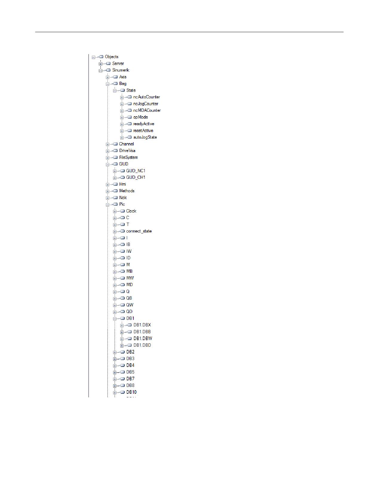
If the OPC UA server is browsed, the available address space is mapped under the "Sinumerik"
node.
Global User Data (GUD) can be found under the "/Sinumerik/GUD" node.
The PLC blocks (inputs, outputs, bit memory, data blocks) can be found under the "/Sinumerik/
Plc" node.
Machine data can be found under the node "/Sinumerik/TEA".
Setting data can be found under the node "/Sinumerik/SEA".
Observe the following while browsing:
• In the address space of the NC, the displayed variables always represent only the first
parameter of the corresponding unit.
Example:
The R parameters can be found under "Sinumerik > Channel > Parameter > R". The
corresponding identifier is called "/Channel/Parameter/R", which is finally mapped to "/
Channel/Parameter/R[u1, 1]". If you want to access other parameters, you need to specify the
corresponding index in brackets, e. g. "/Channel/Parameter/R[u2,56]".
• In the address space of the PLC, the displayed variables represent the access format that has
to be extended accordingly.
Example:
The variable "/Plc/MB" is in the address space and is mapped to "/Plc/MB0". For accessing
further bytes this variable must be extended by the appropriate byte number, e.g. "/Plc/MB6".
• The address space of the NC also contains variables that are not available in a corresponding
machine configuration. These variables return "BadAttributeIdInvalid" as value.
SINUMERIK Access MyMachine / OPC UA
92
Configuration Manual, 10/2020, 6FC5397-1DP41-0BA5
Functionality
6.2 Address space model
Figure 6-1
Browsing
SINUMERIK Access MyMachine / OPC UA
Configuration Manual, 10/2020, 6FC5397-1DP41-0BA5
93
Functionality
6.3 Variable access
6.3
Variable access
6.3.1
Variable paths for NC access operations
Note
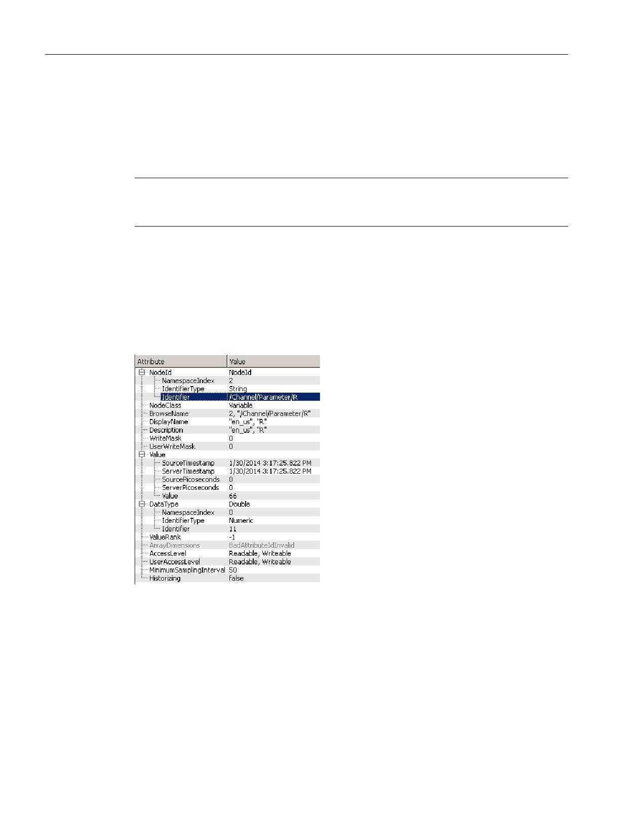
You have to pay attention to the correct upper-case and lower-case of the "nodeID". The
respective identifier of the "nodeID" provides information on the correct notation.
Variable access
The variable paths for NC access are stored in the address space of the SINUMERIK Operate OPC
UA server.
You can obtain further information from the List Manual for 840D sl and 828D "NC variables
Figure 6-2
Identifier for R parameter
The displayed NC variables always represent only the first parameter of the corresponding NC
data area (channel, TO area, mode group).
Example
Syntax of the R parameter is as follows: R[Channel,Parameter]
SINUMERIK Access MyMachine / OPC UA
94
Configuration Manual, 10/2020, 6FC5397-1DP41-0BA5
Functionality
6.3 Variable access
The R parameters are found under the identifier "/Channel/Parameter/R", which is eventually
mapped to "/Channel/Parameter/R[u1, 1]". If you want to access other parameters, you must
correspondingly extend the identifier, for example "/Channel/Parameter/R[u2, 56]".
Table 6-1
Examples of variable paths (NC access operations)
Variable path
Description
/Channel/Parameter/R[u1,10]
R parameter 10 in channel 1
/Channel/Parameter/R[u1,1,5]
R parameter array
/Channel/Parameter/R[u1,1,#5]
R parameters 1 to 5 in channel 1
/Channel/GeometricAxis/name[u2,3]
Name of the 3rd axis in channel 2
/Channel/GeometricAxis/actToolBasePos[u1,3]
Position of the 3rd axis in channel 1
Note
Please keep in mind that with array access only max 149 parameters are allowed in one access
operation (for example /Channel/Parameter/R[u1, 1, #149]).
6.3.2
Variable paths for GUD access operations
GUD variables can be found in the OPC UA server under the "/Sinumerik/GUD" node.
The displayed GUD variables always represent only the first parameter (for GUD arrays) of the
first NC channel (for channel-dependent GUD variables). If you want to access a different
parameter of a GUD array or a different channel, you must extend the identifier accordingly for
the NC access.
GUD arrays are 1-indexed for access, and access is always one-dimensional. This means, the
index must be calculated for multi-dimensional arrays.
Example 1: One-dimensional array, NC-global GUD array
"UGUD.DEF" file
DEF NCK INT ARRAY[2]
M17
Access is performed as follows:
ARRAY[0] → /NC/_N_NC_GD3_ACX/ARRAY[1]
ARRAY[1] → /NC/_N_NC_GD3_ACX/ARRAY[2]
Example 2: Two-dimensional array, channel-dependent GUD array
"UGUD.DEF" file
DEF CHAN INT ABC[3,3]
M17
SINUMERIK Access MyMachine / OPC UA
Configuration Manual, 10/2020, 6FC5397-1DP41-0BA5
95

Functionality
6.3 Variable access
Access is performed as follows:
ABC[0,0] → /NC/_N_CH_GD3_ACX/ABC[u1, 1]
ABC[0.1] → /NC/_N_CH_GD3_ACX/ABC[u1, 2]
ABC[0.2] → /NC/_N_CH_GD3_ACX/ABC[u1, 3]
ABC[1.0] → /NC/_N_CH_GD3_ACX/ABC[u1, 4]
ABC[1.1] → /NC/_N_CH_GD3_ACX/ABC[u1, 5]
ABC[1.2] → /NC/_N_CH_GD3_ACX/ABC[u1, 6]
ABC[2.0] → /NC/_N_CH_GD3_ACX/ABC[u1, 7]
ABC[2.1] → /NC/_N_CH_GD3_ACX/ABC[u1, 8]
ABC[2.2] → /NC/_N_CH_GD3_ACX/ABC[u1, 9]
6.3.3
Variable paths for PLC access operations
PLC variables can be found in the OPC UA server under the "/Sinumerik/Plc" node.
In the address space of the PLC, the displayed variables represent the access format that has to
be extended accordingly.
Example
Syntax of the PLC variable is as follows: "/Plc/MB"
This variable must be extended by the appropriate byte number, e.g. to "/Plc/MB6".
Note
On SINUMERIK 828D, you can only access the freely definable customer data blocks from
DB9000.
Access formats
The various access formats are shown in the following table. They need to be prefixed with "/Plc/".
Note
The data type is converted during access with the OPC UA data access interface. Refer to the
following table for the data type conversions.
Table 6-2
PLC syntax
Area
Address (IEC)
Permissible data types
OPC UA data type
Output image
Qx.y
BOOL
Boolean
Output image
QBx
BYTE, CHAR,
UInt32
STRING
String
Output image
QWx
WORD, CHAR,
UInt32
INT,
Int32
SINUMERIK Access MyMachine / OPC UA
96
Configuration Manual, 10/2020, 6FC5397-1DP41-0BA5
Functionality
6.3 Variable access
Area
Address (IEC)
Permissible data types
OPC UA data type
Output image
QDx
DWORD,
UInt32
DINT,
Int32
REAL
Double
Data block
DBz.DBXx.y
BOOL
Boolean
Data block
DBz.DBBx
BYTE, CHAR,
UInt32
STRING
String
Data block
DBz.DBWx
WORD, CHAR,
UInt32
INT
Int32
Data block
DBz.DBDx
DWORD,
UInt32
DINT,
Int32
REAL
Double
Input image
Ix.y
BOOL
Boolean
Input image
IBx
BYTE, CHAR,
UInt32
STRING
String
Input image
IWx
WORD, CHAR,
UInt32
INT
Int32
Input image
IDx
DWORD,
UInt32
DINT,
Int32
REAL
Double
Bit memory
Mx.y
BOOL
Boolean
Bit memory
MBx
BYTE, CHAR,
UInt32
STRING
String
Bit memory
MWx
WORD, CHAR,
UInt32
INT
Int32
Bit memory
MDx
DWORD,
UInt32
DINT,
Int32
REAL
Double
Counters
Cx
-
Byte
Timers
Tx
-
UInt32
PLC time
Clock
-
UInt16
Notes regarding the table:
• "x" represents the byte offset; "y" the bit number in the byte and "z" the data block number.
• The data type in bold characters is the default data type and does not have to be specified. The
specifications DB2.DBB5.BYTE and DB2.DBB5 are equivalent.
• Square brackets are used to access arrays, e.g. "/Plc/DB5.DBW2:[10]" (word array of length
10).
• Access to STRING arrays ("/Plc/DB123.DBB0:STRING[5]") is not supported.
Examples of variable paths (PLC access operations)
Table 6-3
Examples of variable paths (PLC access operations)
Variable path
Description
/Plc/M5.0
Memory bit 0 at byte offset 5
/Plc/DB5.DBW2
Word (16-bit) at byte offset 2 in data block 5
SINUMERIK Access MyMachine / OPC UA
Configuration Manual, 10/2020, 6FC5397-1DP41-0BA5
97
Functionality
6.3 Variable access
Variable path
Description
/Plc/DB8.DBB2:STRING
UTF8 string beginning at byte offset 2 in data block 8
/Plc/DB8.DBW2:[10]
Array of 10 words beginning at byte offset 2 in data block 8
/Plc/DB100.DBB1
Byte at byte offset 1 in data block 100
/Plc/DB2.DBD0:REAL[10]
Array of 10 double words (32-bit) beginning at byte offset 0 in data block 2, which are
formatted as a floating-point number
Note
• Timers can only be read. A timer is active if it contains a value other than 0.
• If the data type CHAR or STRING is used in conjunction with a byte access, UTF8 characters
are read, but if either data type is used in conjunction with a word access, UTF16 characters
are read.
• Variables of the STRING type contain the maximum length in the first byte and the actual
length in the second byte. When strings are written, the actual length is adapted accordingly.
The maximum length is not changed.
• For the STRING data type in conjunction with a byte access (e.g. "/Plc/DB99.DBB0:STRING"),
the maximum string length is 255 characters. As a result of the UTF8 formatting, for some
characters (e.g. for the "µ"), two bytes are required so that the maximum string length is
correspondingly reduced.
• Only one-dimensional arrays are supported.
6.3.4
Variable paths for machine and setting data
The variable paths for machine and setting data are stored in the address space of the OPC UA
server under the nodes "/Sinumerik/TEA" and "/Sinumerik/SEA". Pay attention to the correct
upper-case and lower-case of the "nodeID". The respective identifier of the "nodeID" provides
information on the correct notation.
The displayed machine and setting variables always represent only the first parameter of the
corresponding data area (channel, axis).
Table 6-4
Examples of variable paths (machine and setting data)
Variable path
Description
/NC/_N_CH_TEA_ACX/$MC_CHAN_NAME
Channel name of channel 1
/NC/_N_CH_TEA_ACX/$MC_CHAN_NAME[u2]
Channel name of channel 2
Machine data arrays are 1-indexed for access.
6.3.5
Variable paths for 1:N configuration (only target system PCU)
By default, data is accessed on the NCU which is being viewed by SINUMERIK Operate. Switching
to a different NCU in the SINUMERIK Operate results in a situation where the OPC UA server is also
looking at the value of the now active NCU.
If the access is to be to a specific NCU, the NodeId must be expanded with a prefix:
SINUMERIK Access MyMachine / OPC UA
98
Configuration Manual, 10/2020, 6FC5397-1DP41-0BA5
Functionality
6.3 Variable access
/Random@<NCUName><NodeId> Examples of variable paths (1:N constellation)
Examples of variable paths (1:N constellation)
Variable path
Description
/Random@NCU_1/Channel/Parameter/R[u1,10]
R parameter 10 in channel 1 of
NCU_1R parameter 10 in channel
1 of NCU_2
/Random@NCU_2/Channel/Parameter/R[u1,10]
/Random@NCU_1/Plc/DB123.DBB0
Byte at byte offset 0 in data block
123 of NCU_1
Note
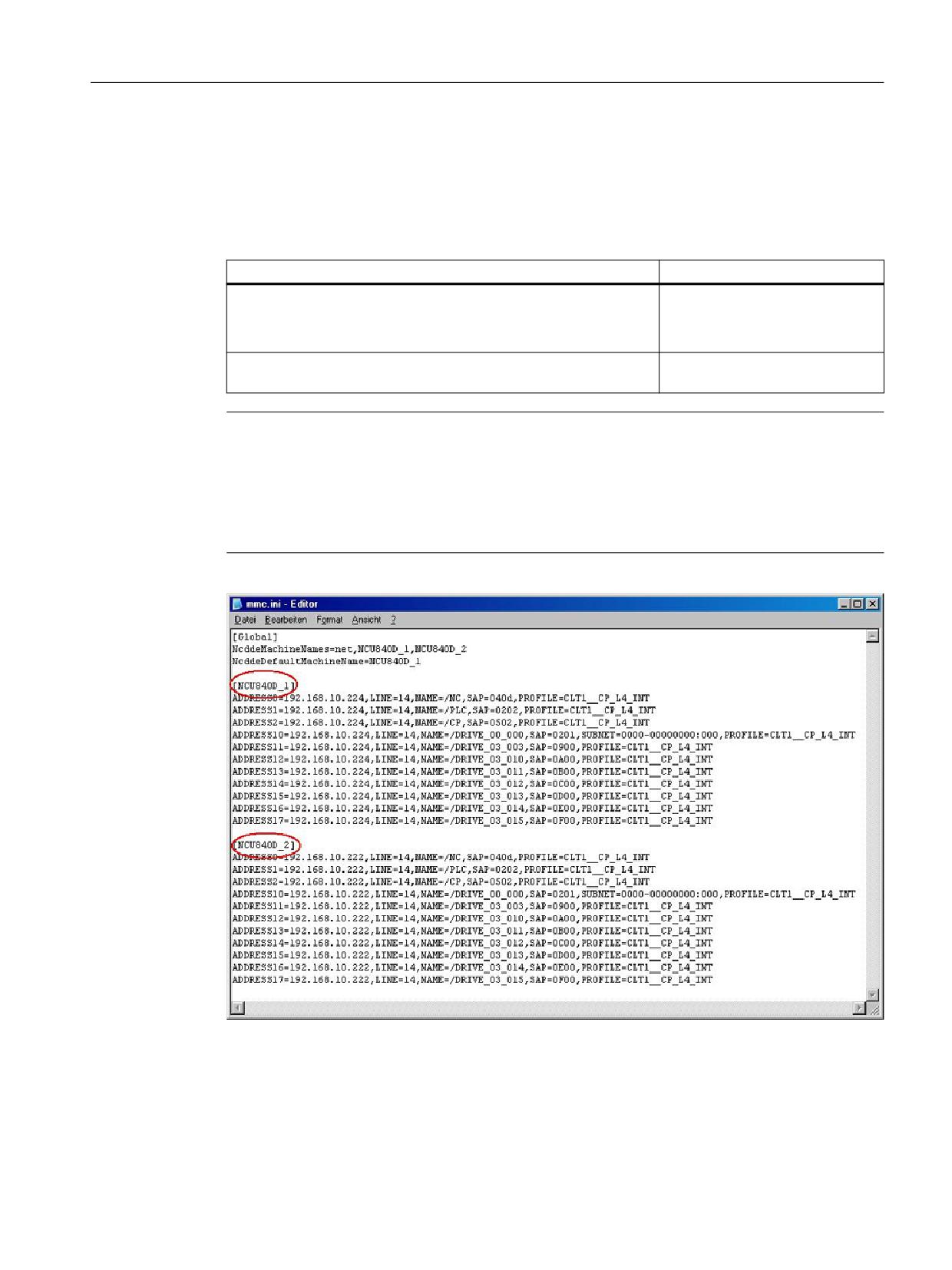
The NCU names are listed in the "MMC.ini" file.
Entry:
[GLOBAL]
NcddeMachineNames=NCU1,NCU2
Figure 6-3
NCU names with 1:N
SINUMERIK Access MyMachine / OPC UA
Configuration Manual, 10/2020, 6FC5397-1DP41-0BA5
99
Functionality
6.3 Variable access
6.3.6
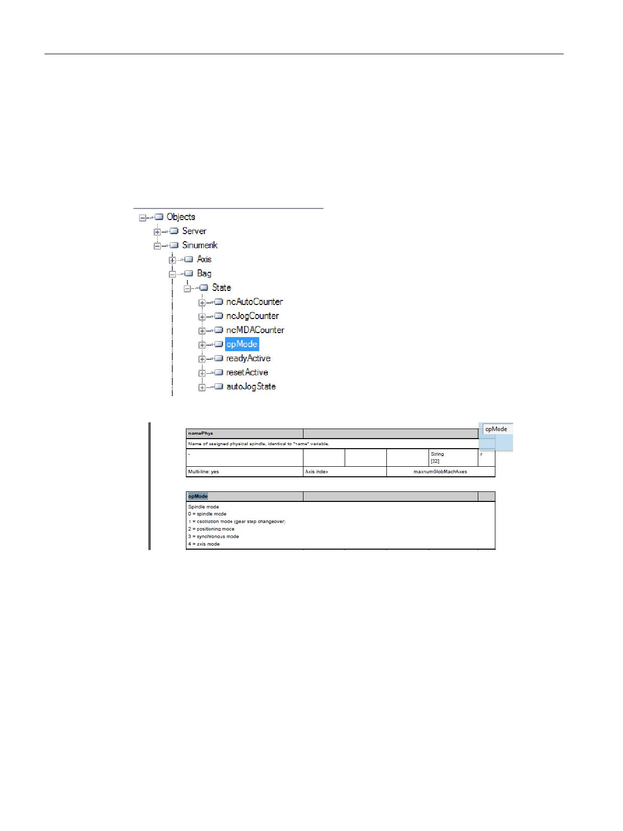
Finding of OPC UA variables
You can find further information on variable documentation in the list manual NC variables
Example 1: Finding an OPC UA variable in the variable documentation
You want to find the variable "opMode" in folder "/Bag/State".
1. Refer to the document mentioned above. Search for "opMode".
SINUMERIK Access MyMachine / OPC UA
100
Configuration Manual, 10/2020, 6FC5397-1DP41-0BA5
Functionality
6.3 Variable access
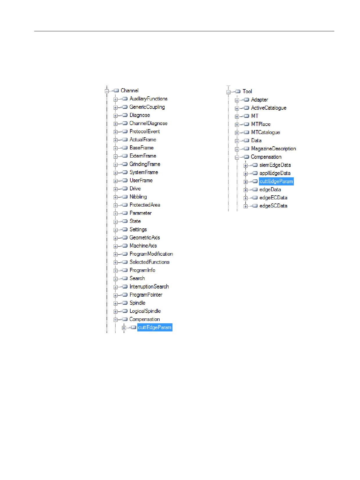
Example 2: Finding an OPC UA variable occurring in different folders in the variable documentation
You want to find the variable "cuttEdgeParam" which occurs in the folder "/Channel/
Compensation" and "/Tool/Compensation".
SINUMERIK Access MyMachine / OPC UA
Configuration Manual, 10/2020, 6FC5397-1DP41-0BA5
101
Functionality
6.3 Variable access
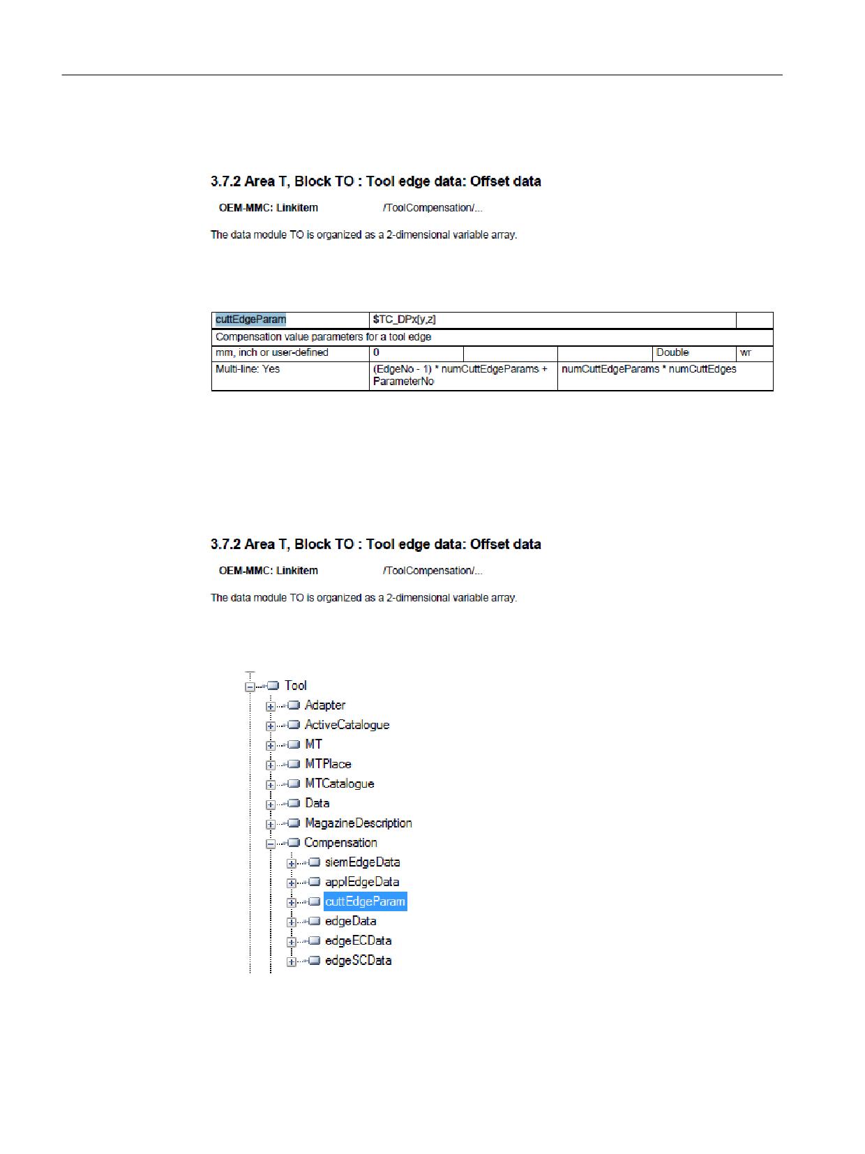
1. At the beginning of each chapter for variable sections, you find the information "OEM-MMC:
LinkItem" specifying "/ToolCompensation/“.
2. Refer to the document and search for "ChannelCompensation" and then navigate manually
to the requested parameter "cuttEdgeParam".
Example 3: Finding a variable from documentation on OPC UA client
You want to find the variable "cuttEdgeParam" in the Tool edge data section.
1. At the beginning of each chapter of the variable documentation you find the information
"OEM-MMC: LinkItem" specifying here "/ToolCompensation/".
2. Therefore you will find the variable "cuttEdgeParam" in the OPC UA Browse Tree in the folder
"Tool", subfolder "Compensation".
SINUMERIK Access MyMachine / OPC UA
102
Configuration Manual, 10/2020, 6FC5397-1DP41-0BA5
Functionality
6.3 Variable access
6.3.7
Monitored items
An OPC UA client can subscribe to a selection of nodes of interest and let the server monitor
these items. Only in case of changes, e.g. to their values, the server notifies the client about such
changes. This mechanism reduces the amount of transferred data immensely. Besides the
reduction of bandwidth this mechanism introduces further advantages and is the
recommended mechanism to “read” information from a UA server.
A client can subscribe to different types of information provided by an OPC UA server. The
purpose of a subscription is to group these sources of information, called monitored items,
together, forming a piece of information called a notification.
A subscription consists of at least one monitored item, which has to be created within the
context of a session and can be transferred to another session. To create a session, a secure
channel between the client and the server has to be established.
There are two different types of “changes” a client can subscribe to when adding monitored
items to the subscription:
• subscribe to data changes of Variable Values (Value attribute of a Variable)
• subscribe to Events of Objects (EventNotifier attribute of an Object)
Publish interval
Clients define MonitoredItems to subscribe to data and Events. Each MonitoredItem identifies
the item to be monitored and the Subscription to use to send Notifications. The item to be
monitored may be any Node Attribute.
Notifications are data structures that describe the occurrence of data changes and Events. They
are packaged into NotificationMessages for transfer to the Client. The Subscription periodically
sends NotificationMessages at a user-specified publishing interval, and the cycle during which
these messages are sent is called a publishing cycle." (see OPC UA Part 4 - Services 1.03
Sampling interval
Each MonitoredItem created by the Client is assigned a sampling interval that is either inherited
from the publishing interval of the Subscription or that is defined specifically to override that
rate. [...] The sampling interval indicates the fastest rate at which the server should sample its
underlying source for data changes. (see OPC UA Part 4 - Services 1.03 Specification.pdf (https://
opcfoundation.org/))
See also
Technical data (Page 163)
SINUMERIK Access MyMachine / OPC UA
Configuration Manual, 10/2020, 6FC5397-1DP41-0BA5
103
Functionality
6.4 Alarms
6.4
Alarms
6.4.1
Overview
Any OPC UA client supporting Alarms & Conditions connected to the OPC UA server can
subscribe to alarms to get the notifications of alarms.
All OPC UA Clients that have subscribed for SINUMERIK alarms will be provided with an alarm as
soon as it becomes active. Also if the alarm becomes inactive, the status of the corresponding
alarm/s will be updated automatically.
Alarms and Conditions support subscription of all the pending and active alarms of the
SINUMERIK system. Part program messages are not supported as part of Alarms and Conditions,
but can be received using data access. The OPC UA Server provides all alarms that will be
provided by the SINUMERIK AlarmService:
• HMI alarms
• NCK alarms including drive alarms
• Diagnostic buffer alarms
• PLC alarms (FC10)
• Alarm_S(Q) alarms (SFC17/18, PDiag, HiGraph, S7-Graph) with results of criteria analysis.
Multi language support for the alarms and warnings messages are supported and the required
alarm language can be selected during session creation in OPC UA Client. If the desired language
is not supported in the operate, the default English language is supported.
The SINUMERIK Alarm object is of the "CNCAlarmType" which is defined in the Companion
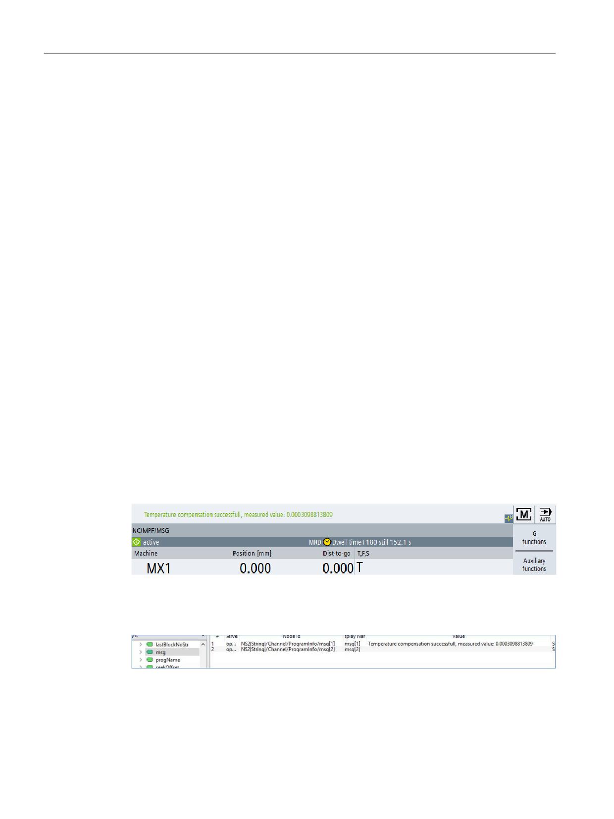
Part program messages
Part program messages are not considered as alarms from OPC UA point of view.
Figure 6-4
Part program messages
They will not be reported in an alarm subscription. In order to have access to part program
messages, use the variable path: "/Channel/ProgramInfo/msg".
Figure 6-5
Variable path
SINUMERIK Access MyMachine / OPC UA
104
Configuration Manual, 10/2020, 6FC5397-1DP41-0BA5
Functionality
6.4 Alarms
6.4.2
Subscribe / unsubscribe to alarms
Subscribe to alarms
The SINUMERIK Alarm Event object is connected to the SINUMERIK node. To receive the alarms,
an event subscription must be placed at the SINUMERIK node. The following example describes
how to receive the alarms using the OPC UA Foundation Client:
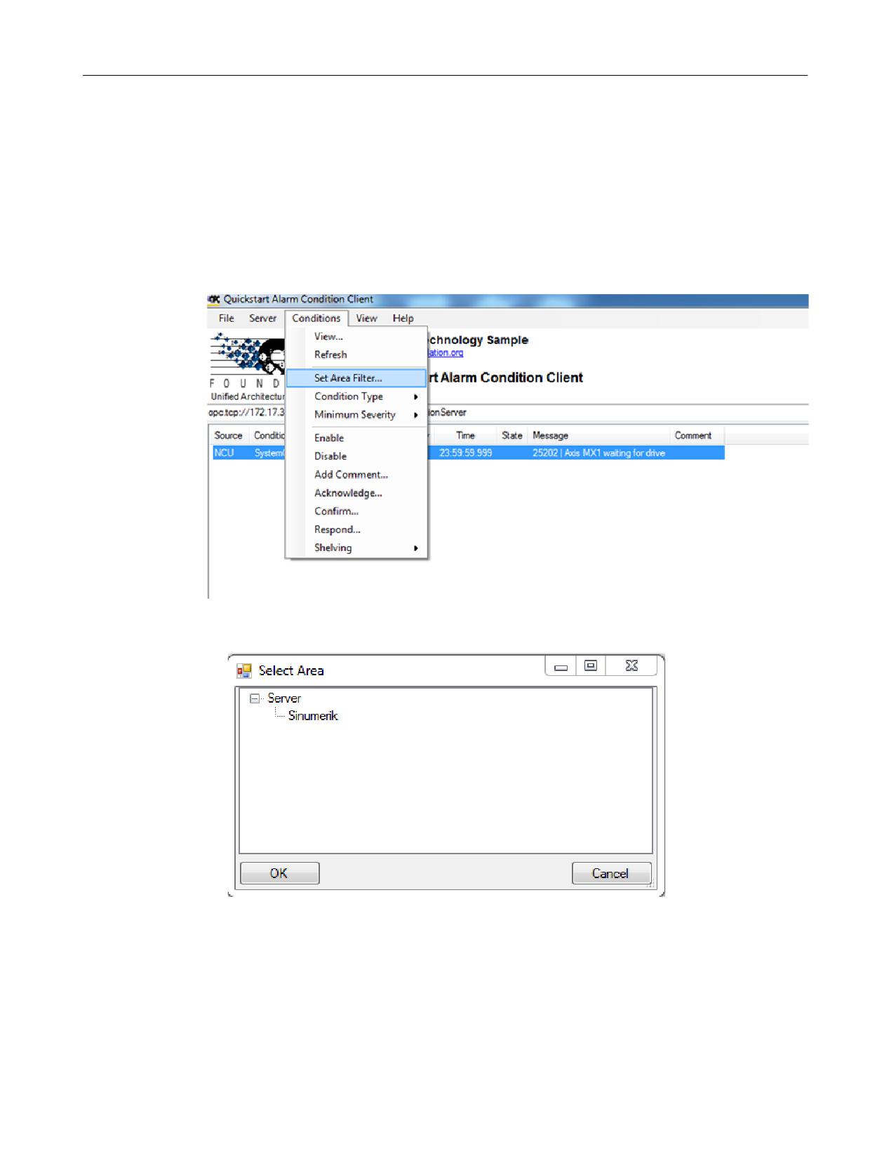
1. Open the "Quickstart Alarm Condition Client".
Figure 6-6
Alarm Condition Client
2. Click "Conditions > Set Area Filter…". The "Select Area" window appears.
Figure 6-7
The Select Area Window
3. Select "Sinumerik".
4. Click "OK".
The alarms will be displayed on the screen.
SINUMERIK Access MyMachine / OPC UA
Configuration Manual, 10/2020, 6FC5397-1DP41-0BA5
105
Functionality
6.4 Alarms
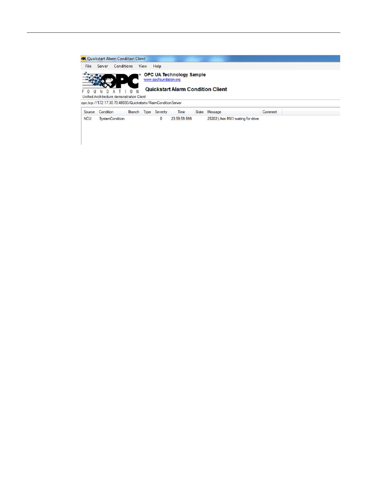
Figure 6-8
Alarm List
Unsubscribe to alarms
1. Click "Conditions > Set Area Filter…". The "Select Area" window appears.
2. Right click on "Sinumerik" and select "Remove Monitored Item" to unsubscribe the server
from the Quickstart Alarm Condition Client.
6.4.3
Sequence description of alarms
The OPC UA server automatically sends an object of the "CNCAlarmtype" to the OPC UA client
containing the single alarm which has just been triggered.
The OPC UA server automatically resends an object of the "CNCAlarmtype" with the same
content as when the corresponding alarm was triggered, except a change in the status.
To get all the active alarms, the client has to subscribe to the Sinumerik node.
6.4.4
SINUMERIK Alarm object
6.4.4.1
Description
Every variable or object in the address space of an OPC UA server is called a node. Every node has
a server unique node id, its symbolic name, addressing information inside the address model
and some other attributes.
Events are by themselves not visible as nodes in the address space. They can only be received via
objects. Not all objects can signal events. Whether an object can signal events is specified at the
object by the EventNotifier attribute. Only objects where this attribute has been set can be
specified in the Event Monitored Item and received in Clients Events.
The Server Object serves as root notifier, that is, its EventNotifier Attribute shall be set providing
Events. However Server object will not be allowed to subscribe for the Events. Only the
"Sinumerik" Object node is accessible and can subscribe to the events.
SINUMERIK Access MyMachine / OPC UA
106
Configuration Manual, 10/2020, 6FC5397-1DP41-0BA5
Functionality
6.4 Alarms
6.4.4.2
OPC UA event messages and alarms
Access to alarms
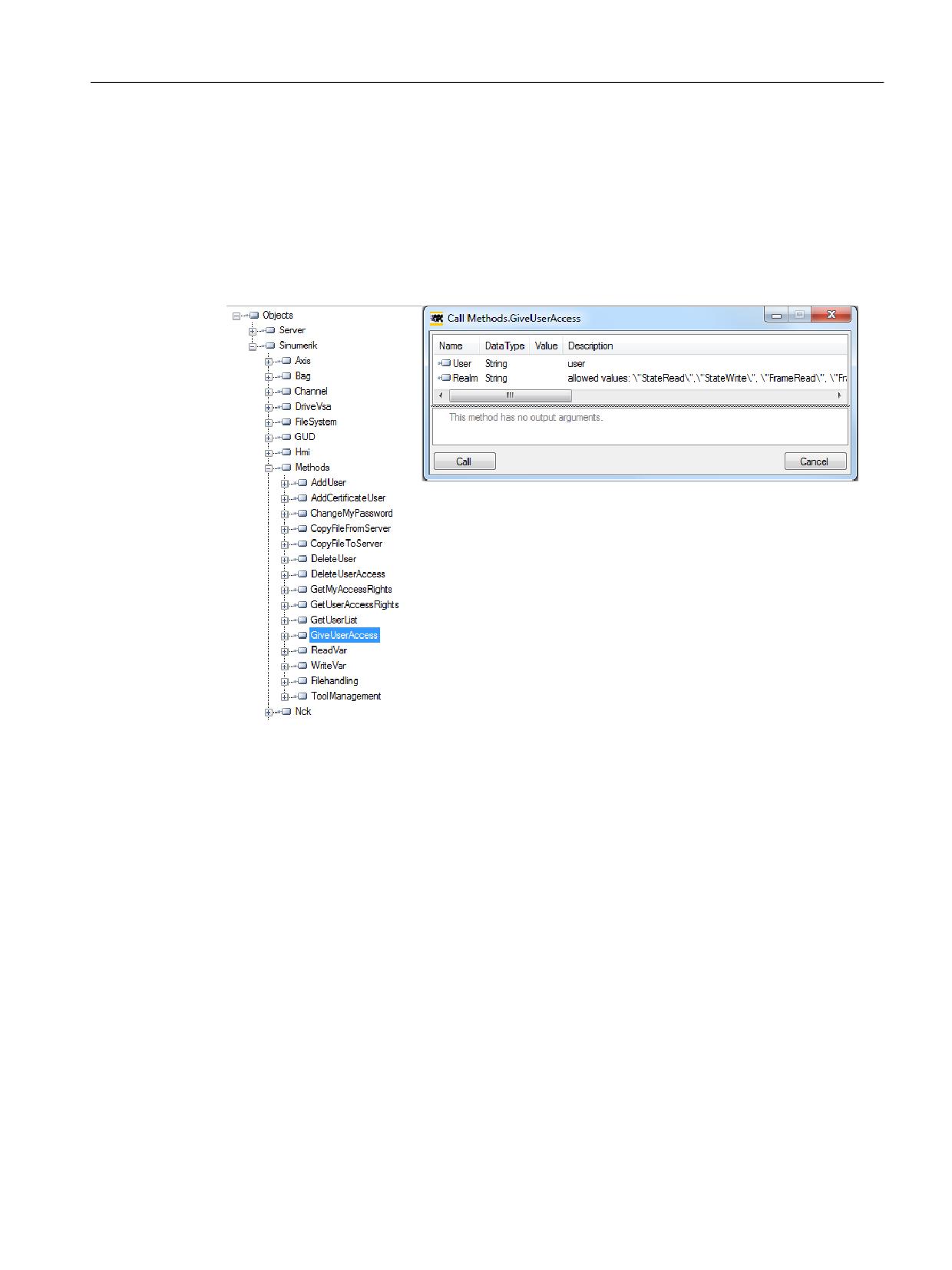
User access right is required to subscribe the Events of the Sinumerik object. User access right
with access permission has to be set to “SinuReadAll“ or “AlarmRead“.The access right is provided
using Method Call “GiveUserAccess” as shown below.
Figure 6-9
Alarm access rights
If the client does not have the access with “SinuReadAll “or “AlarmRead” and user tries to
subscribe to the Events, server will return error code with “BadUserAccessDenied”.
Event types
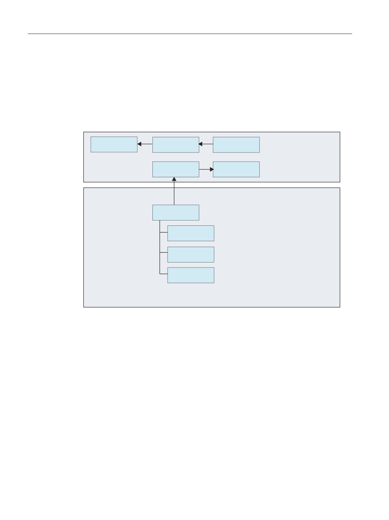
The SINUMERIK Alarm object is of the “CNCAlarmType” which is defined in the Companion
The root of the derivation hierarchy is the BaseEventType. The types for Alarms and Conditions
are available below the ConditionType. The Application-specific event types such as
CncAlarmType can be derived. The CncAlarmType extends the DiscreteAlarmType.
An alarm is composed of various nested or parallel state machines. Monitoring can generally be
enabled or disabled. If monitoring is enabled, the alarm can be active or otherwise inactive.
Acknowledgment, confirm and comments of alarms is currently not supported.
The basic type for all condition objects is the condition type. It is derived from BaseEventType.
All mechanisms for alarm processing work even without the condition objects are contained in
the address space.
If a condition object changes one or several states, the server sends an event with the requested
event fields to the client. So only the alarms, where a status change happens after the
SINUMERIK Access MyMachine / OPC UA
Configuration Manual, 10/2020, 6FC5397-1DP41-0BA5
107
Functionality
6.4 Alarms
connection is established, will be sent. To receive all currently active alarms the refresh method
can be used.
CncAlarmType
The CncAlarmType, which is specified in the Companion Specification “OPC UA Information
Model for CNC Systems” is derived from the DiscreteAlarmType, which is defined by the OPC
Foundation.
%DVH 23& 8$
%DVH(YHQW7\SH
$FNQRZOHGJHDEOH
&RQGLWLRQ7\SH
,QIRUPDWLRQ 0RGHO
&RQGLWLRQ7\SH
'LVFUHWH$ODUP
$ODUP&RQGLWLRQ
7\SH
7\SH
&QF$ODUP7\SH
$ODUP,GHQWLILHU
$X[3DUDPHWHUV
+HOS6RXUFH
23& 8$ ,QIRUPDWLRQ PRGHO
IRU &1& 6\VWHPV
Figure 6-10
OPC UA Information Model for CNC Systems
Description of the CncAlarmType
Since the CncAlarmType is derived from a number of types as you can see in Figure 5-8, it does
not only contain the three attributes AlarmIdentifier, AuxParameters and HelpSource, but also
all the other attributes which are inherited from the objects.
SINUMERIK Access MyMachine / OPC UA
108
Configuration Manual, 10/2020, 6FC5397-1DP41-0BA5

Functionality
6.4 Alarms
Attributes of BaseEventType
Attribute
Data type
Mapping with respect to SINU-
M/O
Description
MERIK
EventId
String
Unique node id generated from
M
EventId is generated by the server to
SINUMERIK system.
uniquely identify a particular Event Notifi-
cation.
The EventId shall always be returned as val-
ue and the server is not allowed to return a
StatusCode for the EventId indicating an er-
ror.
EventType
NodeId
It is always set to ‘CncAlarmType’.
M
The EventType shall always be returned as
value and the server is not allowed to return
a StatusCode for the EventType indicating
an error.
SourceNode
NodeId
Alarm source identifier provided by
M
SourceNode identifies the Node that the
SINUMERIK system.
Event originated from. If the Event is not
specific to a Node, the NodeId is set to null.
SourceName
String
Supported alarm source names are
M
SourceName provides a description of the
HMI, NCK, and PLC.
source of the Event. This could be the string-
part of the DisplayName of the Event source
using the default locale of the server.
If it is not possible for a CNC system to pro-
vide this information in detail, the Source-
Name should provide the main component
responsible for this alarm (e.g. CNC, PLC, or
even Channel).
Time
UtcTime
Alarm time stamp
M
Time provides the time of the Event occur-
red. Once set, intermediate OPC UA servers
shall not alter the value.
ReceiveTime
UtcTime
Alarm time stamp of the server.
M
ReceiveTime provides the time the OPC UA
server received the Event from the underly-
ing device of another server.
Message
Localized Text
Reading attributes via
M
Alarm Message provides a human readable
(SLAE_EV_ATTR_MSG TEXT)
and localizable text description of the Event.
Severity
UInt16
Reading attributes via
M
Severity of the event message. The range of
(SLAE_EV_ATTR_SEVE RITY)
values of the severity is from 1 to 1000,
where 1000 corresponds to the highest se-
verity.
LocalTime
TimeZoneData-
Offset and the DaylightSavingI-
O
LocalTime is a structure containing the Off-
Type
nOffset flag
set and the DaylightSavingInOffset flag. The
Offset specifies the time difference (in mi-
nutes) between the Time Property and the
time at the location in which the event was
issued.
If DaylightSavingInOffset is -
TRUE: Standard/Daylight savings time (DST)
at the originating location is in effect and
Offset includes the DST correction.
FALSE: The Offset does not include DST cor-
rection and DST may or may not have been
in effect.
SINUMERIK Access MyMachine / OPC UA
Configuration Manual, 10/2020, 6FC5397-1DP41-0BA5
109

Functionality
6.4 Alarms
Severity of Alarms
SINUMERIK systems use three severity levels (e.g. Information, Warning and Error). The table
below shows the values at SINUMERIK system and its mapping in OPC UA server/client:
Severity Level
SINUMERIK System
OPC UA server/client
Information
0-1
1
Warning
2-999
500
Error
1000
1000
Additional attributes of the ConditionType
Attribute
Data type
Mapping with respect to SINU-
M/O
Description
MERIK
ConditionCla
NodeId
Unique node id (sum of alarm id
M
String NodeID
ssId
and alarm instance)
SystemConditionClassType
ConditionCla
String
Set to “SystemConditionClassType"
M
SystemConditionClassType
ssName
ConditionNa
String
Set to “SystemCondition”.
M
ConditionName identifies the Condition in-
me
stance that the Event originated from. It can
be used together with the SourceName in a
user display to distinguish between differ-
ent Condition instances.
Retain
Boolean
True when the alarm is active.
M
Information whether or not the alarm shall
be displayed.
False otherwise.
This is set to true by default.
Quality
String
According to SINUMERIK quality at-
M
The quality provides information about the
tribute, below string will be set:
reliability of an alarm.
• BAD
Possible values of SINUMERIK:
• GOOD
AlarmQuality.QUALITY_BAD = 0
• UNCERTAIN
AlarmQuality.QUALITY_GOOD =
192
AlarmQuality.QUALITY_UNCERTAIN
= 64
LastSeverity
UInt16
Reading attributes
M
LastSeverity provides the previous severity
via(SLAE_EV_ATTR_SEVERITY)
of the ConditionBranch. Initially this Varia-
ble contains a zero value; it will return a val-
ue only after a severity change. The new
severity is supplied via the Severity Property
which is inherited from the BaseEventType.
BranchId
NodeId
Null
M
BranchId is Null for all Event Notifications
that relate to the current state of the Con-
dition instance.
Comment
LocalizedText
Null
M
The value of this Variable is set to null.
ClientUserId
String
Null
M
The value of this Variable is set to null.
Enable
Not supported
M
Servers do not expose Condition instances
in the AddressSpace.
Disable
Not supported
M
Servers do not expose Condition instances
in the AddressSpace.
SINUMERIK Access MyMachine / OPC UA
110
Configuration Manual, 10/2020, 6FC5397-1DP41-0BA5

Functionality
6.4 Alarms
Attribute
Data type
Mapping with respect to SINU-
M/O
Description
MERIK
AddComment
Not supported
M
Not supported and the result code should
return Bad_MethodInvalid.
ConditionRe-
None
When the method is called up, an event
freshMethod
with the current state is triggered for the
calling client for all conditions. Only those
conditions are updated for which the Retain
flag has been set.
Additional attributes of the AcknowledgeableConditionType
Attribute
Data type
Mapping with respect to SINU-
M/O
Description
MERIK
AckedState
Localized text
True / False
M
AckedState when FALSE indicates that the
Condition instance requires acknowledge-
ment for the reported Condition state.
When the Condition instance is acknowl-
edged, the AckedState is set to TRUE.
Confirmed-
LocalizedText
True / False
O
ConfirmedState indicates whether it re-
State
quires confirmation.
EnabledState
Localized text
True / False
M
Always set to true
Acknowledge
Not supported
M
Not Supported and the return error code
shall be Bad_MethodInvalid.
Confirm
O
The Confirm Method is used to confirm an
Event Notifications for a Condition instance
state where ConfirmedState is FALSE. Nor-
mally, the NodeId of the object instance as
the ObjectId is passed to the Call Service.
However, some Servers do not expose Con-
dition instances in the AddressSpace. There-
fore all Servers shall also allow Clients to call
the Confirm Method by specifying Conditio-
nId as the ObjectId. The Method cannot be
called with an ObjectId of the Acknowledg-
eableConditionType Node.
Additional attributes of the CncAlarmType
The CNCAlarmType is defined in the VDW Companion Specification “OPC UA Information Model
for CNC Systems”.
Attribute
Data type
Mapping with respect to SINU-
M/O
Description
MERIK
AlarmIdentifi-
String
Unique Alarm id.
M
Unique alarm number. This mapped to
er
Alarm ID.
AuxParame-
String
All available (out of 10) parame-
M
10 Auxilliary parameter values provided by
ters
ters will be displayed in ‘ ‘ separated
SINUMERIK system.
value.
SINUMERIK Access MyMachine / OPC UA
Configuration Manual, 10/2020, 6FC5397-1DP41-0BA5
111
Functionality
6.4 Alarms
6.4.5
Language of alarms
6.4.5.1
OPC UA language specification
The OPC UA server has a built-in data type "LocalizedText" to store the language specific alarm
text. This data type defines a structure containing a string in a locale-specific translation
specified in the identifier for the locale. The elements are defined in the table below :-
Name
Type
Description
LocalizedText
structure
text
String
The localized text.
locale
LocaleId
The identifier for the locale (e.g. “en-
US”).
The "LocaleId" is a simple data type that is specified as a string that is composed of a language
component and a country/region component as specified by IEEE 754-1985 (http://
standards.ieee.org/findstds/interps/index.html), IEEE Standard for Binary Floating-Point
Arithmetic. The <country/region> component is always preceded by a hyphen.
The format of the LocaleId string is shown below:
<language>[-<country/region>]
• <language> is the two letter ISO 639 code for a language
• <country/region> is the two letter ISO 3166 code for the country/region
You can find further information in the specification OPC UA Part3 - Address Space Model
1.03 Specification.pdf
6.4.5.2
SINUMERIK language specification
The SINUMERIK system currently supports 31 languages which are mentioned below. These
languages are identified by the 3-letter abbreviation that follows Microsoft conventions.
Note
In the list of languages that are mentioned, not every language is supported always.
6.4.5.3
Mapping of SINUMERIK LanguageID with OPC UA LocaleID
Mapping of the SINUMERIK LanguageID with the OPC UA specific LocaleId for each of the
supported languages.
Language
SINUMERIK LanguageID
OPC UA Specific LocaleId
German - Germany
deu
de-DE
English - United Kingdom
eng
en-GB
Chinese (Simplified)
chs
zh-CHS
Chinese (Traditional)
cht
zh-CHT
Czech - Czech Republic
csy
cs-CZ
SINUMERIK Access MyMachine / OPC UA
112
Configuration Manual, 10/2020, 6FC5397-1DP41-0BA5
Functionality
6.4 Alarms
Language
SINUMERIK LanguageID
OPC UA Specific LocaleId
Danish - Denmark
dan
da-DK
Bulgarian - Bulgaria
bgr
bg-BG
Greek - Greece
ell
el-GR
Spanish - Spain
esp
es-ES
Finnish - Finland
fin
fi-FI
French - France
fra
fr-FR
Hindi - India
hin
hi-IN
Croatian - Croatia
hrv
hr-HR
Hungarian - Hungary
hun
hu-HU
Indonesian - Indonesia
ind
id-ID
Italian - Italy
ita
it-IT
Japanese - Japan
jpn
ja-JP
Korean - Korea
kor
ko-KR
Malay - Malaysia
msl
ms-MY
Dutch - The Netherlands
nld
nl-NL
Polish - Poland
plk
pl-PL
Portuguese - Brazil
ptb
pt-BR
Romanian - Romania
rom
ro-RO
Russian - Russia
rus
ru-RU
Slovak - Slovakia
sky
sk-SK
Slovenian - Slovenia
slv
sl-SI
Swedish - Sweden
sve
sv-SE
Tamil - India
tam
ta-IN
Thai - Thailand
tha
th-TH
Turkish - Turkey
trk
tr-TR
Vietnamese - Vietnam
vit
vi-VN
In the above list “OPC UA Specific LocaleId” is used by the OPCU UA client to connect with the
server.
6.4.6
OPC UA alarms and conditions constraints
Below are the features which are not supported in this version:
• Acknowledgements and confirmation of the alarms.
• Part program messages
• Only alarm text will be available in localized text. All other attributes will be available in
English only.
SINUMERIK Access MyMachine / OPC UA
Configuration Manual, 10/2020, 6FC5397-1DP41-0BA5
113
Functionality
6.4 Alarms
6.4.7
OPC UA alarms and conditions client
User interface
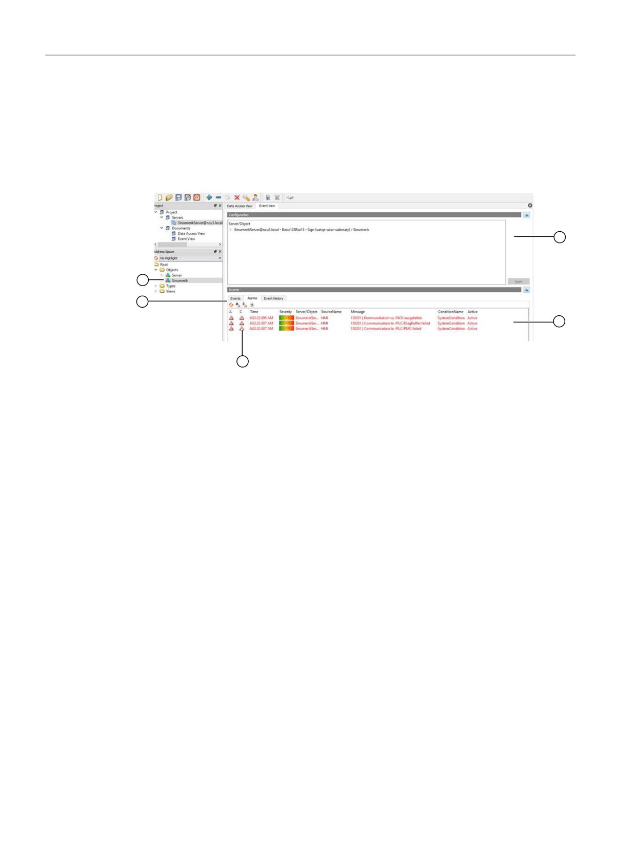
The figure and table below describes the user interface of the UaExpert client example with
which the information of the namespace of an OPC UA server can be conveniently accessed.
① The Alarm window
② Displays the received events with preconfigured event fields. The standard event fields are:
• In the Events tab: Time, ReceiveTime, Severity, SourceName, Message, EventType and Sour-
ceNode
• In the Alarms tab: AcknowledgeState, Time, Severity, SourceName, Message, Condition-
Name, ActiveState and Retain Flag
③ In the first column of the Alarm tab, a symbol indicates whether an event has already been
Acknowledged. (red flag: unacknowledged, green checkmark: acknowledged)
④ The Alarm / Event Subscription View
⑤ Alarm / Event Instances:
The user needs to subscribe to these instances (by dragging or by configuring).
Figure 6-11
User interface UaExpert client
SINUMERIK Access MyMachine / OPC UA
114
Configuration Manual, 10/2020, 6FC5397-1DP41-0BA5
Functionality
6.4 Alarms
6.4.8
OPC UA multi-language alarms and conditions client
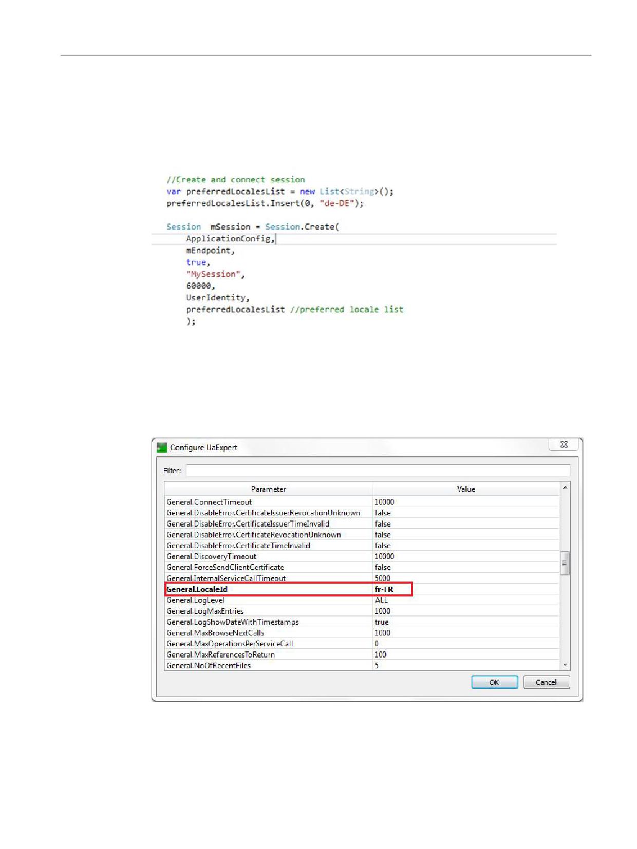
The OPC UA client must explicitly provide the OPC UA specific language "LocaleId" to change the
alarm texts. Below is an example of changing the client language using OPC UA foundation stack
client.
Figure 6-12
OPC UA multi-language alarms and conditions client using OpcUa foundation .Net Client
In the case of UaExpert client proceed as follows:
1. Open the “Configure UaExpert” window under "Settings" Tab in the client
2. Provide the OPC UA specific "LocaleId" as value for the parameter "General.LocaleId".
3. Then connect to the server.
Figure 6-13
Client User Interface for changing Session Language
SINUMERIK Access MyMachine / OPC UA
Configuration Manual, 10/2020, 6FC5397-1DP41-0BA5
115
Functionality
6.4 Alarms
Language
OPC UA Specific LocaleId
German - Germany
de-DE
English - United Kingdom
en-GB
Chinese (Simplified)
zh-CHS
Chinese (Traditional)
zh-CHT
Czech - Czech Republic
cs-CZ
Danish - Denmark
da-DK
Bulgarian - Bulgaria
bg-BG
Greek - Greece
el-GR
Spanish - Spain
es-ES
Finnish - Finland
fi-FI
French - France
fr-FR
Hindi - India
hi-IN
Croatian - Croatia
hr-HR
Hungarian - Hungary
hu-HU
Indonesian - Indonesia
id-ID
Italian - Italy
it-IT
Japanese - Japan
ja-JP
Korean - Korea
ko-KR
Malay - Malaysia
ms-MY
Dutch - The Netherlands
nl-NL
Polish - Poland
pl-PL
Portuguese - Brazil
pt-BR
Romanian - Romania
ro-RO
Russian - Russia
ru-RU
Slovak - Slovakia
sk-SK
Slovenian - Slovenia
sl-SI
Swedish - Sweden
sv-SE
Tamil - India
ta-IN
Thai - Thailand
th-TH
Turkish - Turkey
tr-TR
Vietnamese - Vietnam
vi-VN
SINUMERIK Access MyMachine / OPC UA
116
Configuration Manual, 10/2020, 6FC5397-1DP41-0BA5
Functionality
6.5 File system
6.5
File system
6.5.1
Overview
SINUMERIK OPC UA supports the standard OPC UA file and folder objects, which allows transfer
of files as well as the manipulation of the file systems.
Furthermore, the server offers 2 comfort methods to copy NC part programs from the OPC UA
client to the OPC UA server and vice versa. Due to the nature of the method this comfort methods
are limited to a file size of 16 MB. For bigger files please use the file and folder objects as described
in chapter File transfer exceeding 16 MB between client and server (Page 122).
Operations
This allows an OPC UA client to use the following operations within the part of the SINUMERIK
file system:
1. Create files/directories
2. Copy files/directories
3. Moving files/directories
4. Deleting files/directories
5. Renaming files/directories
File system
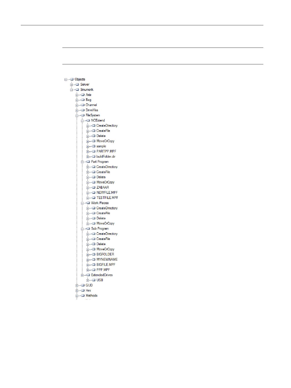
The standard OPC UA file system is placed in the SINUMERIK folder and the file structure of the
NCU is as shown below:
1. Part Programs
2. Sub Programs
3. Work Pieces
4. NCExtend (External SD Card/internal SD Card)
Note
For 840D sl
For NCU, external SD Card/internal SD Card is supported.
For IPC/PCU, SSD/Harddisk is supported.
5. ExtendedDrives (USB/Networkshare)
Note
The ExtendedDrives folder will only be displayed if there are external drives available. Please
keep in mind that a licence my be required to use these external drive.
SINUMERIK Access MyMachine / OPC UA
Configuration Manual, 10/2020, 6FC5397-1DP41-0BA5
117
Functionality
6.5 File system
Note
NCExtend and ExternalDrives option is supported for SINUMERIK Operate version 4.7 or later.
Figure 6-14
The file system
6.5.2
Prerequisites
The OPC UA server allows the OPC UA client to support the transfer of files between the client and
the server.
SINUMERIK Access MyMachine / OPC UA
118
Configuration Manual, 10/2020, 6FC5397-1DP41-0BA5
Functionality
6.5 File system
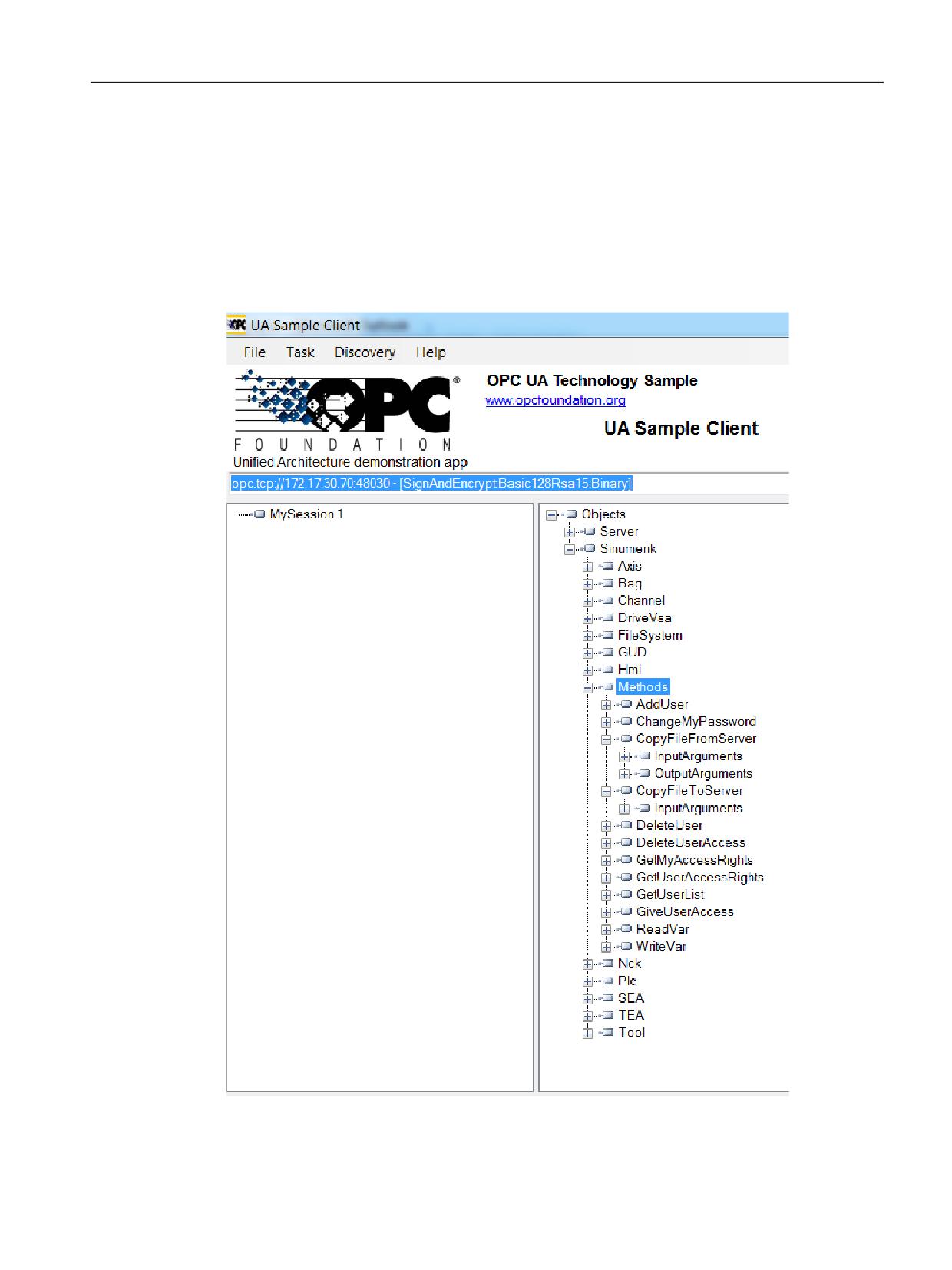
As a user, you will require user access rights to access these files from the server. The access rights
are provided using the "GiveUserAccess" method. The following access rights can be provided for
the file system (also see chapter List of rights (Page 86)):
• FsRead for the standard file system methods like Open, GetPosition, Read as well as the
CopyFileFromServer method.
• FsWrite for the standard file system methods like CreateDirecotry, CreateFile, Delete,
MoveOrCopy, Write, SetPosition, Close as well as the CopyFileToServer method.
Figure 6-15
Standard Method
SINUMERIK Access MyMachine / OPC UA
Configuration Manual, 10/2020, 6FC5397-1DP41-0BA5
119
Functionality
6.5 File system
6.5.3
Standard file system support
6.5.3.1
File transfer with standard methods
The SINUMERIK OPC UA server supports the "FileType"/"FolderType" as described in the OPC UA
Specification Part 5, which allows manipulating files and folders via OPC UA.
Folder methods
The folders, "Part Programs", "Sub Programs", "Work Pieces", "NCExtend", and "ExtendedDrives"
are of the "FolderType", which contain the following methods:
Method/Attribute
Description
CreateDirectory
To create new folders under parent folder.
CreateFile
To create new file under parent folder.
Delete
To delete folder and file under parent folder.
MoveOrCopy
To copy or move files from source to destination
within server filesystem.
You can create, delete, move or copy folders and files using the above methods. When you create
a new folder using "CreateDirectory"’, a new node will be created with "FolderType" and name
provided by the user in OPC UA client. This folder contains all methods and attributes specified
in above table.
The node in the address space, under which the "CreateDirectory" method is called, is the
"parent" node of the new folder node.
The folder methods exist under all folder type objects in the file system. Please note that you
must always call the method under the direct parent node of the file or folder.
For the methods "Delete" and "MoveOrCopy" you must always provide the full identifier of the
node to be moved, copied or deleted.
Whenever you create a new file using the method "CreateFile", a new node will be created with
"FileType" with a user provided name. This file again contains all methods and attributes
specified in the table above. The node in address space, under which the "CreateFile" method is
called, is the "parent" node of the new file node. For specific information for the described
methods, check the Typedefinition in the OPC UA Specification Part 5.
Examples for the usage of the folder methods
Name
Signature
Usage
CreateDirectory
[in] String directoryName
Call from parent folder/directory, e. g.:
Sinumerik/FileSystem/Work Pieces
[out] NodeId directoryNodeId
CreateFile
[in] String fileName
Call from parent folder/directory, e. g.:
Sinumerik/FileSystem/Part Program File-
[in] Boolean requestFileOpen
name including extension, e. g.: myPart-
[out] NodeId fileNodeId
Prog.mpf
[out] UInt32 fileHandle
SINUMERIK Access MyMachine / OPC UA
120
Configuration Manual, 10/2020, 6FC5397-1DP41-0BA5

Functionality
6.5 File system
Name
Signature
Usage
Delete
[in] NodeId objectToDelete
Call from parent folder/directory, e. g.:
Sinumerik/FileSystem/Part Program
MoveOrCopy
[in] NodeId objectToMoveOrCopy
Call from parent folder/directory of ob-
ject to move/copy, e. g.: copy a part pro-
[in] NodeId targetDirectory
gram the parent folder is: Sinumerik/File-
[in] Boolean createCopy
System/Part Program
[in] String newName
[out] NodeId newNodeId
Note
For further details on methods and method signatures please refer to OPC UA Specification Part
5.
File methods
All files which are in the above mentioned folders will be of the "FileType" type and consist of the
following methods and properties:
Method/Attribute
Description
Open
Opens the file either in read/write mode.
Read
Reads contents of the file.
Write
Writes data to the file. (if write permission is avail-
able)
Close
Closes the file. (succeeds if file is open)
GetPosition
Gets the position of current position of file pointer
while file read/write operation.
SetPosition
Sets the position of current position of file pointer
while file read/write operation.
OpenCount
Gives the number of file open instances.
Size
Gives the file size details.
UserWritable
Set to true if current user has access to modify the
content of the file.
Writable
Set to false if the file is read only.
Whenever you create a new file using the method "CreateFile", a new node will be created with
"FileType" type with a user provided name. This file again contains all methods and attributes
specified in the table above. The node in address space, under which the "CreateFile" method is
called, is the "parent" node of the new file node. For specific information for the described
methods, check the type definition in the OPC UA Specification Part 5 Annex C.
Note
No multiple extensions supported
The methods "CreateFile","CopyFileToServer", "CopyFileFromServer" and "MoveOrCopy" will not
support files with multiple extensions (i.e. test.mpf.mpf).
SINUMERIK Access MyMachine / OPC UA
Configuration Manual, 10/2020, 6FC5397-1DP41-0BA5
121
Functionality
6.5 File system
6.5.3.2
File transfer exceeding 16 MB between client and server
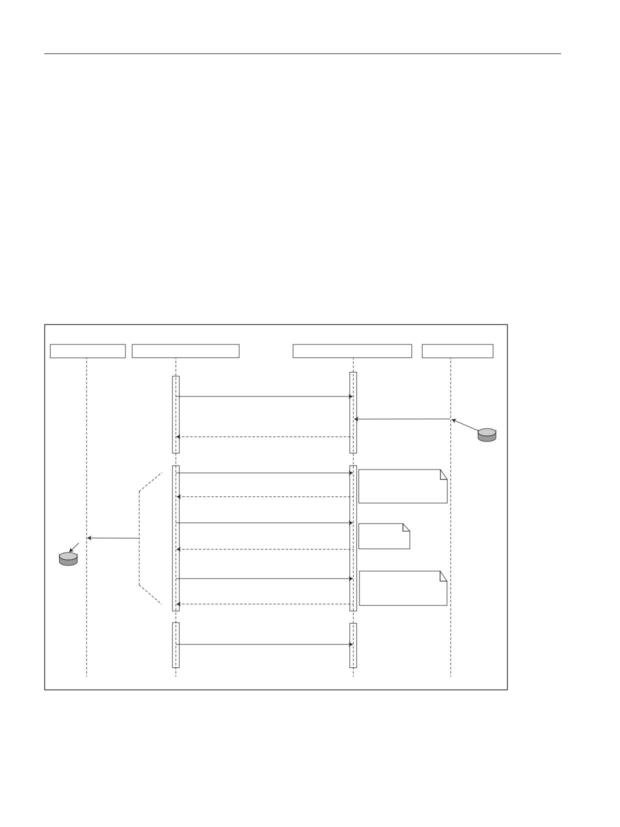
For file transfer, the OPC UA specification v1.0X, Part 5, Annex C offers the use of file and folder
object methods.
How can a file transfer be implemented in a client using the file and folder object methods?
The basic idea is to open a file and copy the content from location A to B and then close the file.
Therefore to copy a file from the SINUMERIK to an OPC UA client the client needs to do the
following:
• Open the file on the SINUMERIK via the Open method,
• then pass the received handle to the Read method and operate on arrays of bytes,
• then close the file via the Close method.
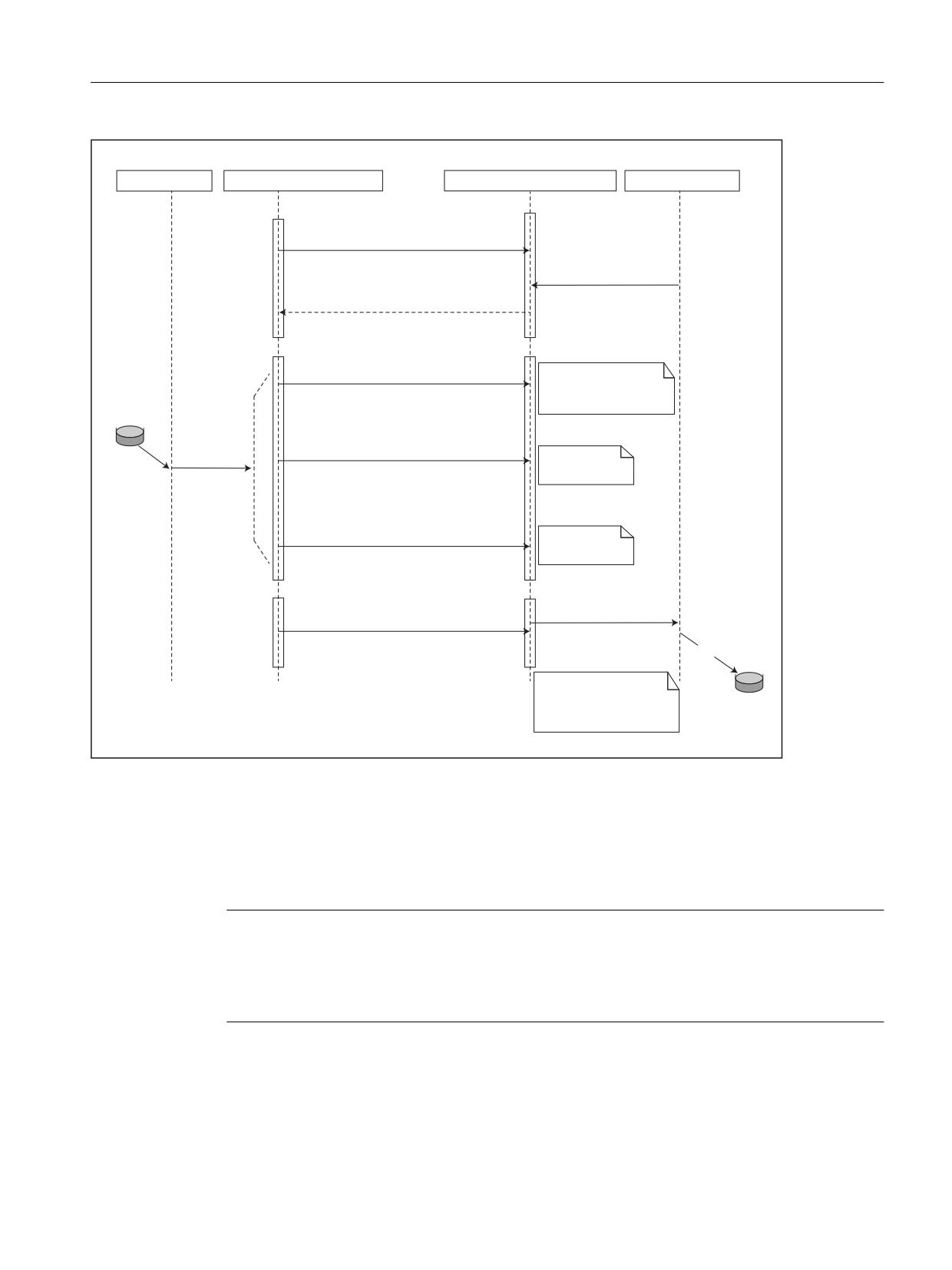
For the other direction, the file has to be created on the SINUMERIK file system first, using the
Create method.
23& 8$ &OLHQW
23& 8$ &OLHQW )LOH 7\SH
23& 8$ 6HUYHU )LOH 7\SH
23& 8$ 6HUYHU
2SHQ PRGH
ILOH+DQGOH
WHVW PSI
ILOH+DQGOH
5HDG ILOH+DQGOH OHQJWK GDWD
)LUVW 1 GDWD
1 ! LW FDQ GLIIHU
GHSHQGLQJ RQ WKH FOLHQW
'DWD
VHWWLQJV
5HDG ILOH+DQGOH OHQJWK GDWD
'DWD
WHVW PSI
1H[W 1 GDWD
'DWD
5HDG ILOH+DQGOH OHQJWK GDWD
,I WKH %\WH6WULQJ LV
HPSW\ LW LQGLFDWHV WKDW
WKH HQG RI WKH ILOH LV
'DWD
UHDFKHG
&ORVH ILOH+DQGOH
Figure 6-16
File transfer from server to client using standard file system methods
SINUMERIK Access MyMachine / OPC UA
122
Configuration Manual, 10/2020, 6FC5397-1DP41-0BA5
Functionality
6.5 File system
23& 8$ &OLHQW
23& 8$ &OLHQW )LOH 7\SH
23& 8$ 6HUYHU )LOH 7\SH
23& 8$ 6HUYHU
2SHQ PRGH
ILOH+DQGOH
ILOH+DQGOH
)LUVW 1 %\WH GDWD
:ULWH ILOH+DQGOH OHQJWK GDWD
1 ! LW FDQ GLIIHU
GHSHQGLQJ RQ WKH FOLHQW
VHWWLQJV
:ULWH ILOH+DQGOH OHQJWK GDWD
WHVW PSI
'DWD
1H[W 1 %\WH GDWD
:ULWH ILOH+DQGOH OHQJWK GDWD
/DVW 1 %\WH GDWD
'DWD ZULWWHQ WR ILOH
&ORVH ILOH+DQGOH
WHVW PSI
7KH VHVVLRQ LV HQGHG
ZLWKRXW FDOOLQJ WKH &ORVH
PHWKRG
'DWD ZLOO EH ORVW
Figure 6-17
File transfer to server from client using standard file system methods
6.5.3.3
Comfort methods for file transfer < 16 MB
In addition to the standard file system, two additional methods are provided to transfer files from
server to client and vice versa.
Note
With these methods, you will be able to transfer maximum of 16 MB by default, depending on
the client settings. As the maximum ByteString and message size depends on the server and
client-side stack limit. For file transfer more than 16 MB, it is recommended to use OPC UA
standard file transfer methods.
SINUMERIK Access MyMachine / OPC UA
Configuration Manual, 10/2020, 6FC5397-1DP41-0BA5
123
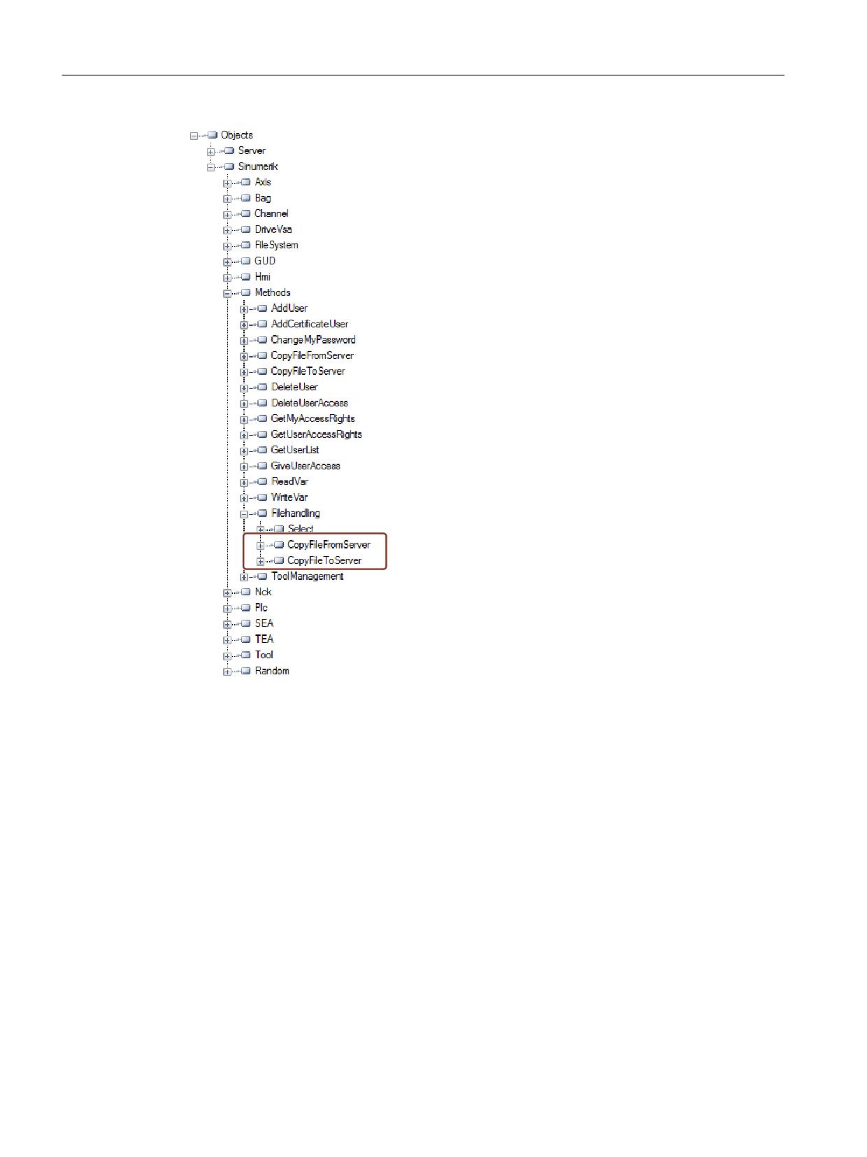
Functionality
6.5 File system
Figure 6-18
Methods for the file transfer
SINUMERIK Access MyMachine / OPC UA
124
Configuration Manual, 10/2020, 6FC5397-1DP41-0BA5
Functionality
6.5 File system
Procedure and Example
1. CopyFileFromServer:
- Allows copying file from SINUMERIK OPC UA server to client location.
- The user shall provide the name of the file with full path to be copied.
- On completion of the file transfer, an appropriate message will be displayed.
Type
Data type
Argument
Description
Input parameter
string
SourceFile
Name of the file need to
be copied with abso-
lute path.
Output parameter
ByteString
Data
Raw file data
2. CopyFileToServer:
- Allows copying a client file to a specified SINUMERIK NC memory location.
- The user shall select the file to be transferred and specify the location on server.
Type
Data type
Argument
Description
Input parameter
string
TargetFilename
Target file name with
absolute path
Input parameter
ByteString
Data
Raw file Data
Input parameter
Boolean Overwrite
Overwrite
True: Overwrite the file
if already exists. False:
File will not be overwrit-
ten.
For example:
The complete path of the files can be provided as below:
• Sinumerik/FileSystem/Part Program/partprg.mpf
• Sinumerik/FileSystem/Sub Program/subprg.spf
• Sinumerik/FileSystem/Work Pieces/wrkprg.wpf
• Sinumerik/FileSystem/NCExtend/Program.mpf
• Sinumerik/FileSystem/ExtendedDrives/USBdrive/Q3.mpf
SINUMERIK Access MyMachine / OPC UA
Configuration Manual, 10/2020, 6FC5397-1DP41-0BA5
125
Functionality
6.6 Select
6.6
Select
6.6.1
Overview
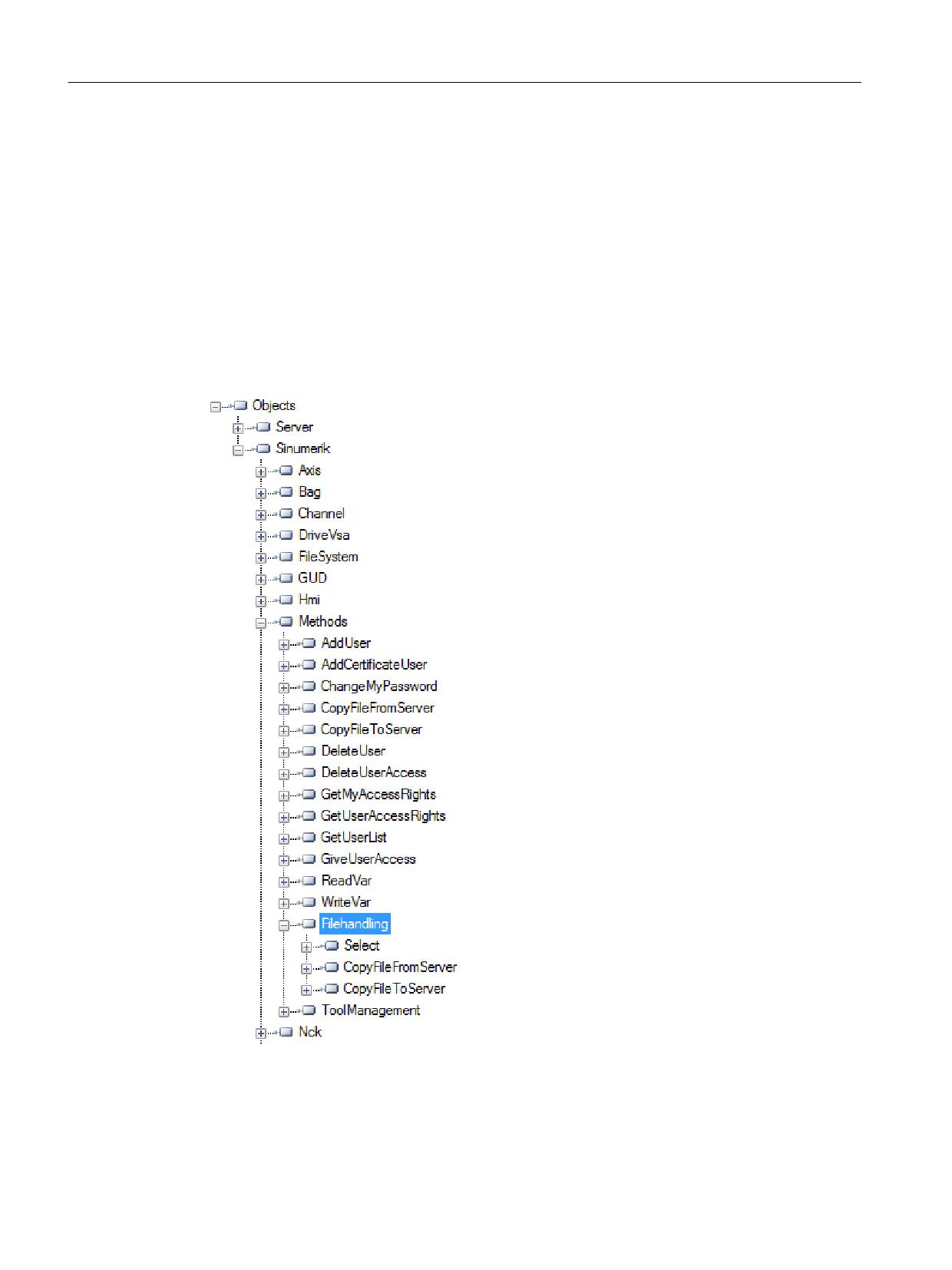
The "Select" method is provided under "Methods > Filehandling" in the address space, which
allows the selecting of a part program from the NC file system. You can call this method and
select the file to be executed by providing the node identifier of the file in address space and the
channel number.
By calling this method, you can only select the program for execution and not start the execution
of the program itself.
SINUMERIK Access MyMachine / OPC UA
126
Configuration Manual, 10/2020, 6FC5397-1DP41-0BA5
Functionality
6.6 Select
6.6.2
Description
You are allowed to select the part program file for execution from the NC file system and external
memory, which includes "local drive", "USB" and "network share". As part of the file system
feature, the NC file system is exposed in the OPC UA address space.
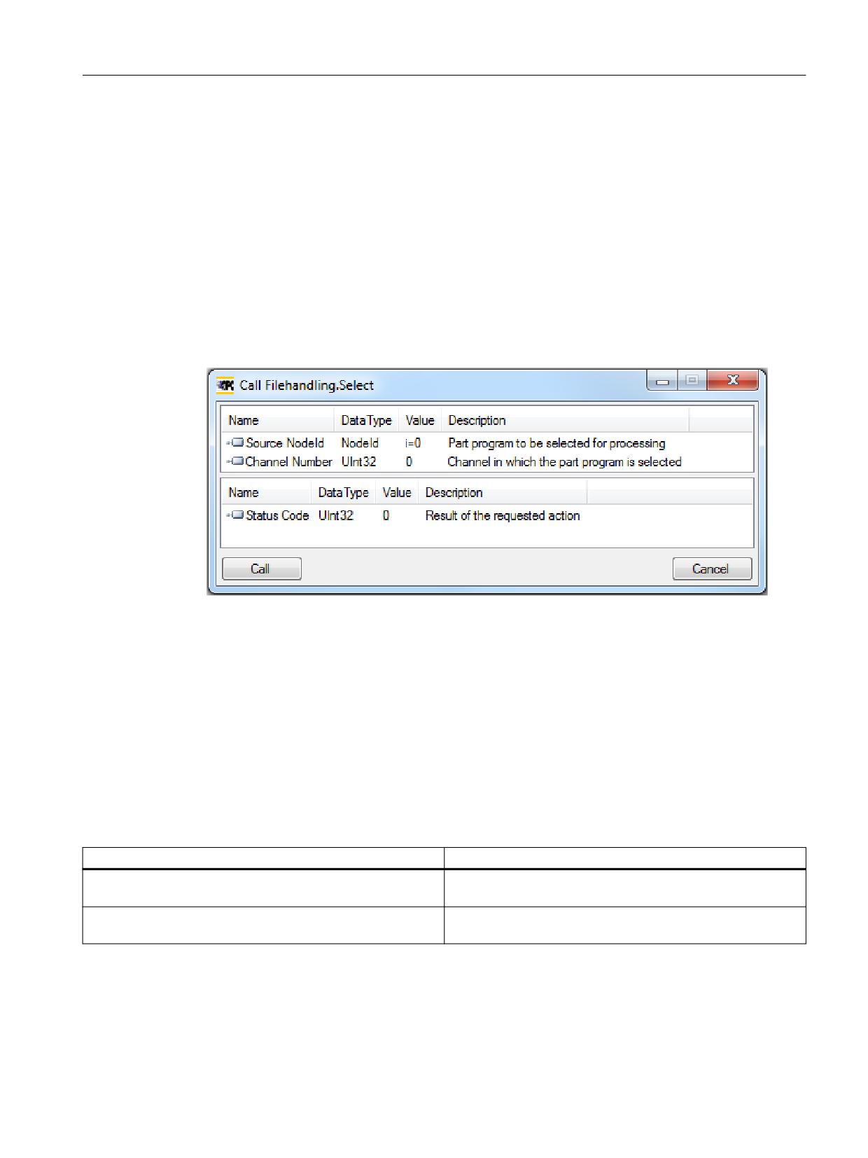
There are two input values to be provided to call the "Select" method.
• Node identifier of the file to be selected for execution.
• Channel number.
Each part program file on the file system is associated with a node identifier in the OPC UA
address space and is provided as the input. Only one part program can be selected for a channel.
An error will be displayed otherwise.
Status code is an output parameter which indicates the error code in case of failures.
6.6.3
Input and output arguments
Signature of the method "Select" is as follows:
Select (
[in] string SourceFileNodeId,
[in] int32 ChannelNumber,
[out] int32 Status Code)
Argument
Description
SourceFileNodeId
Represents the node identifier of the file with absolute path
(which is selected for execution).
Channel Number
A number which represents the channel to be used while pro-
gram execution.
SINUMERIK Access MyMachine / OPC UA
Configuration Manual, 10/2020, 6FC5397-1DP41-0BA5
127
Functionality
6.6 Select
Prerequisites
• Channel to be used during program execution must be in the state "Reset".
• User with "ApWrite" access right can call "Select" method. If the user does not have the access
"ApWrite" and tries to call "Select" method, it fails and server will return with OpcUa status
"BadUserAccessDenied".
Note
The access right for the user is provided using the "GiveUserAccess" method.
Status Code of the method call
The following table gives details on values and description on the status of the "Select" method
call. As part of output argument, the result code (value) is displayed in the OPC UA client.
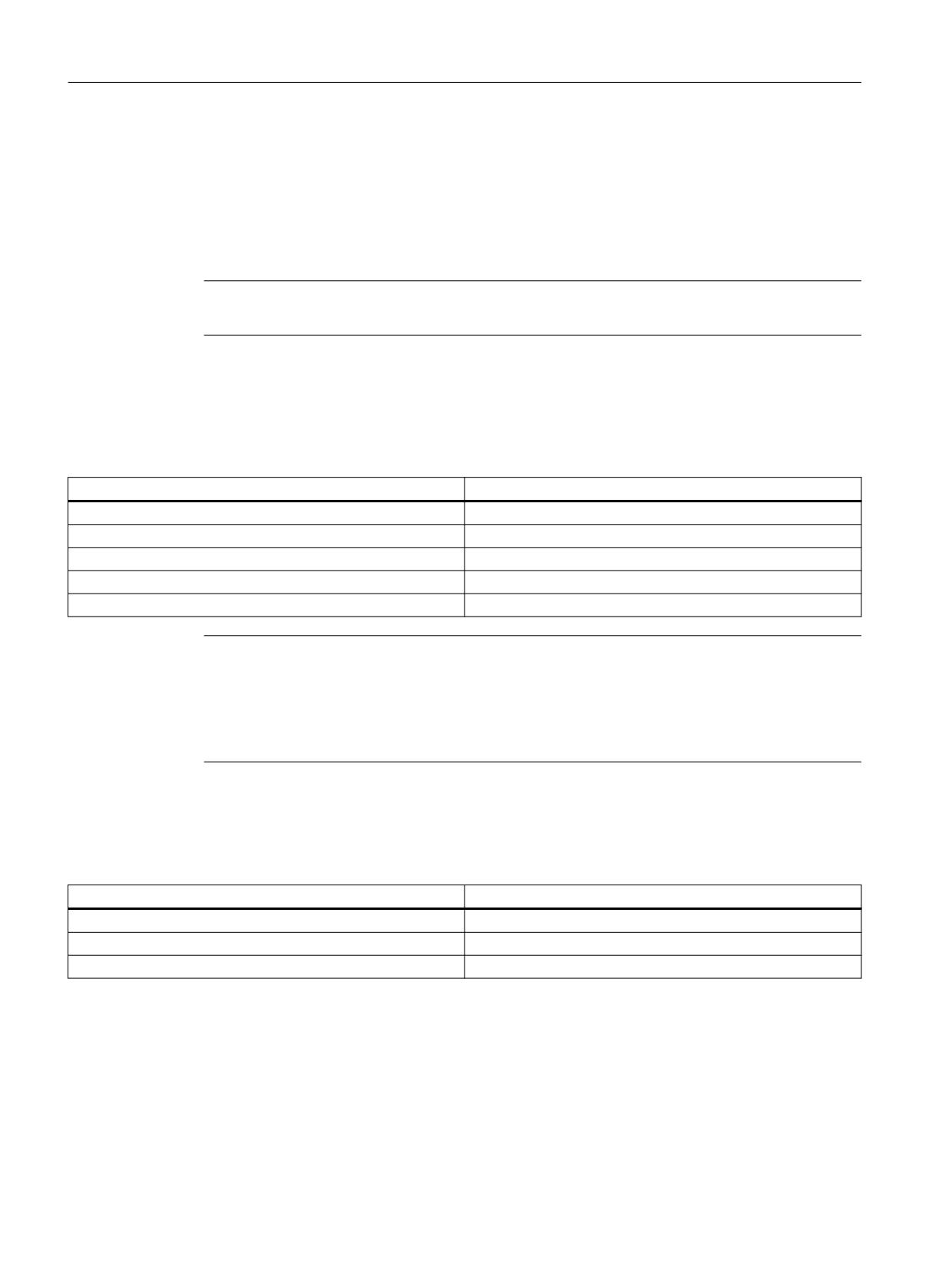
Status Code (value)
Description
0
Successful
1
Channel does not exist
2
Part Program cannot be found
3
Channel is not in Reset
4
Target rejected requested action.
Note
No file restriction
Notice that a file with any extension is allowed to be selected through OPC UA "Select" method.
OPC UA does not restrict selecting files with any file extension.
Joblists cannot be selected.
OPC UA Status
The following table gives details on values and description of the OPC UA method call status:
Result
Description
Succeeded
Method is executed with success/failure.
OpcUa_BadInvalidArgument
Invalid inputs are provided.
OpcUa_BadUserAccessDenied
User does not have permission to invoke the method.
SINUMERIK Access MyMachine / OPC UA
128
Configuration Manual, 10/2020, 6FC5397-1DP41-0BA5
Functionality
6.6 Select
6.6.4
Example call
Procedure
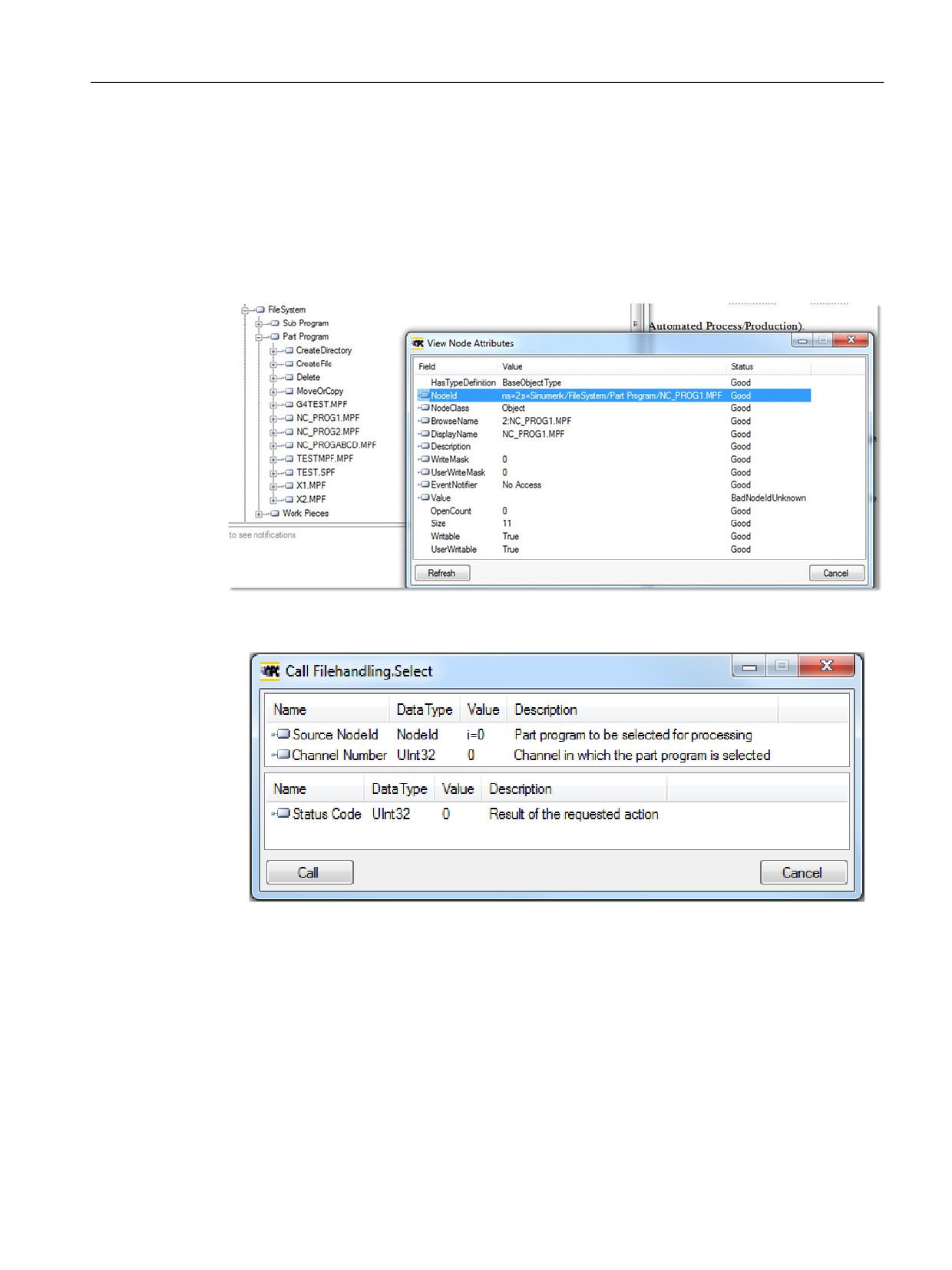
1. Look for the NodeID of the particular part program you want to select (for example
"NC_PROG1.MPF").
2. Navigate in the "File System" node until you reach the particular file.
Figure 6-19
Finding of NodeID
3. Specify the NodeID and the channel number in the call of the method.
Figure 6-20
Arguments of select method
The particular part program will be selected.
SINUMERIK Access MyMachine / OPC UA
Configuration Manual, 10/2020, 6FC5397-1DP41-0BA5
129
Functionality
6.7 Tool management
6.7
Tool management
6.7.1
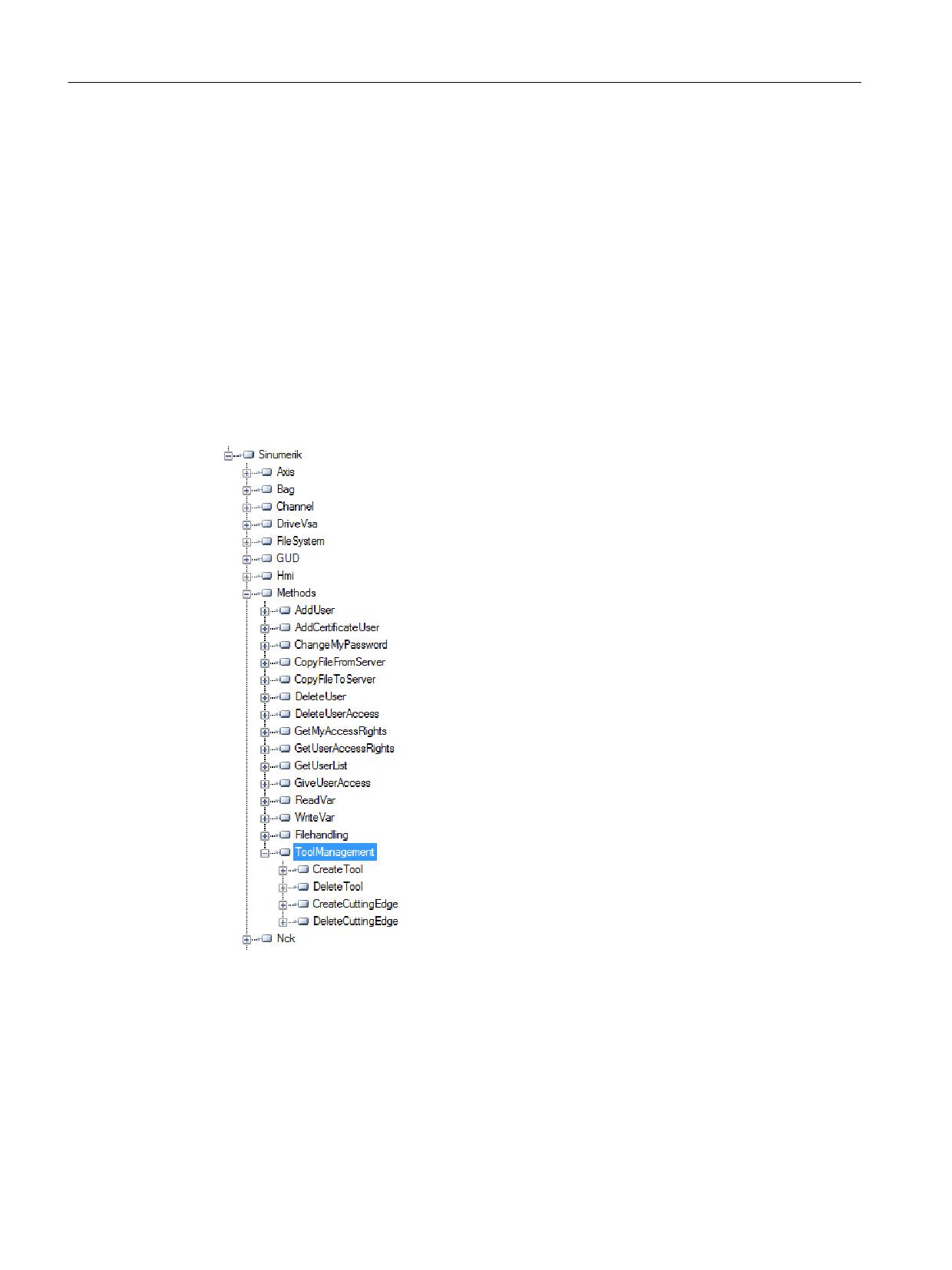
Description
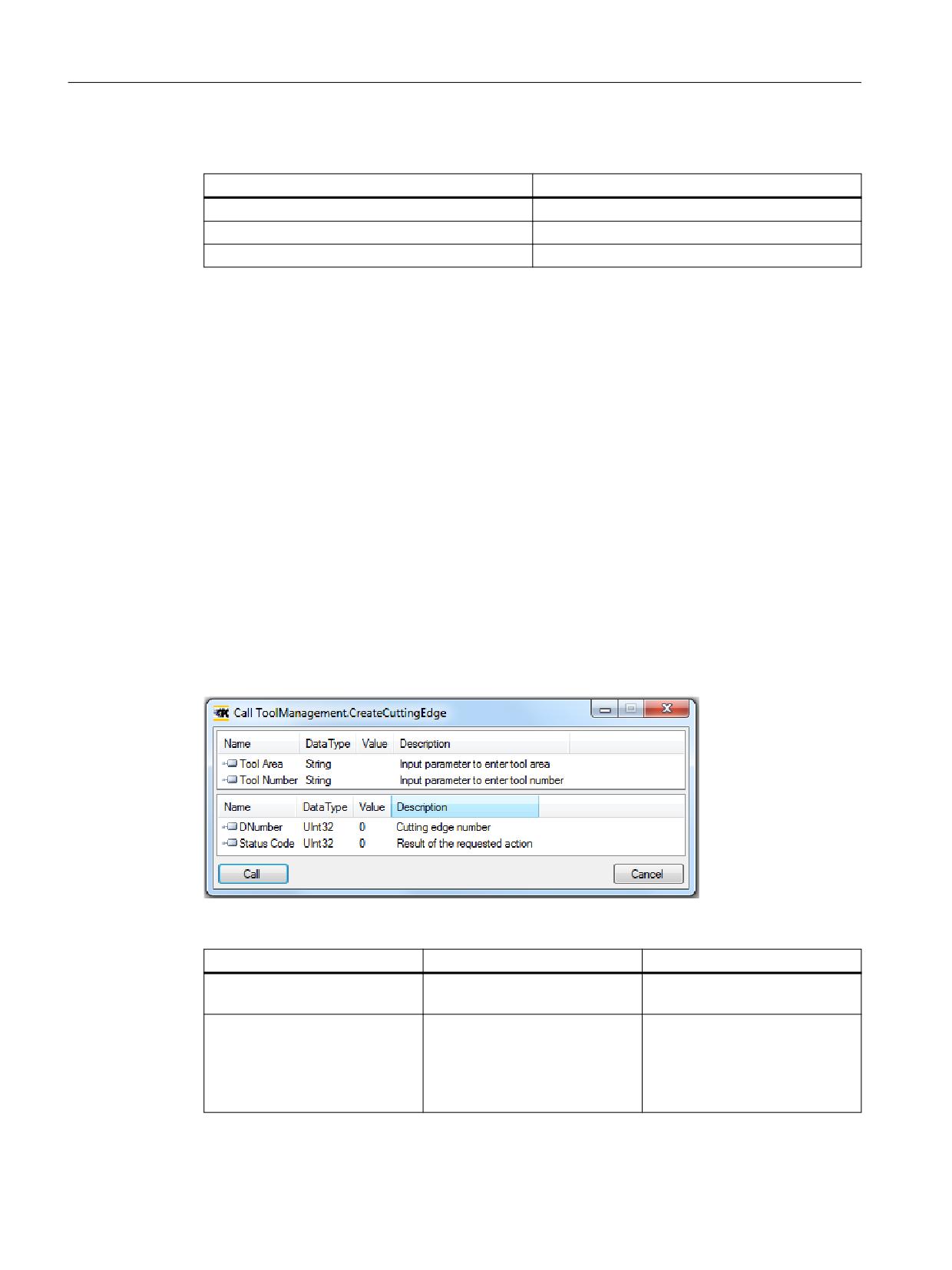
The OPC UA server supports the creation and deletion of tools and cutting edges. The methods
for this operation can be found under "Sinumerik > Methods > ToolManagement" folder.
Following are the four methods present in "ToolManagement" folder:
• CreateTool
• DeleteTool
• CreateCuttingEdge
• DeleteCuttingEdge
Example calls
For example calls of the provided methods, please refer to the shown screenshots of
OpcFoundation Client.
SINUMERIK Access MyMachine / OPC UA
130
Configuration Manual, 10/2020, 6FC5397-1DP41-0BA5
Functionality
6.7 Tool management
Prerequisites
User with "ToolWrite" access right can call "ToolManagement" methods. If the user does not have
the access "ToolWrite" and tries to call "ToolManagement" methods, it fails and server will return
with OpcUa status "BadUserAccessDenied".
Note
The access right for the user is provided using the "GiveUserAccess" method.
6.7.2
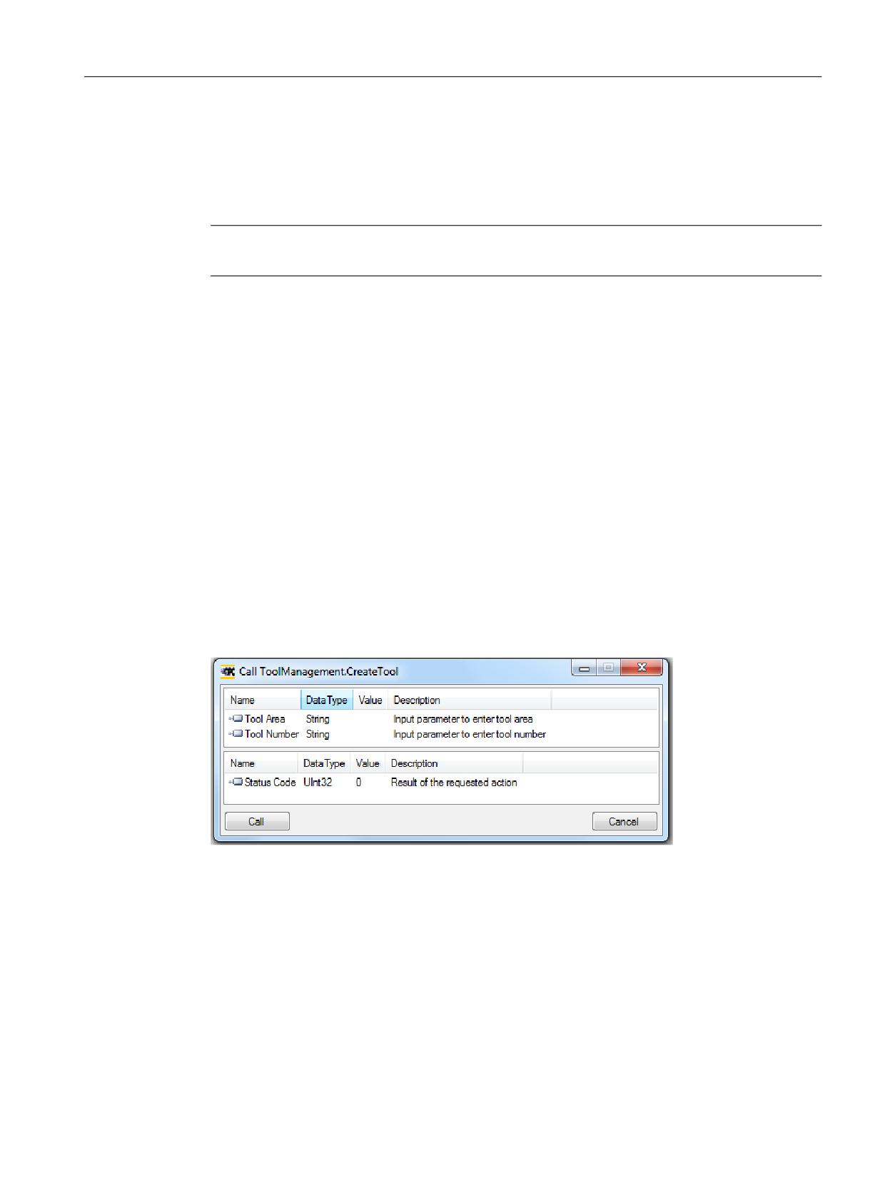
CreateTool
The "CreateTool" method is used to create a new tool with a special T-number in Tool List section
of the SINUMERIK, and appears under the folder “Methods/ToolManagement”. The CreateTool
method does not contain the settings of tool parameters. The tool parameters e.g.: tool type,
cutting edge date etc. are set via data access functions.
The CreateTool method has two input parameters and one output parameter.
Signature:
CreateTool(
[in] string ToolArea
[in] string ToolNumber
[out] Uint32 StatusCode
)
SINUMERIK Access MyMachine / OPC UA
Configuration Manual, 10/2020, 6FC5397-1DP41-0BA5
131
Functionality
6.7 Tool management
The following table will give details about the parameters of the method:
Type
Parameters
Description
Input
Tool Area
Input parameter to enter tool area.
Input
Tool Number
5 digit number given to the created
tool.
For range of number please refer to
828D or 840D sl documentation re-
spectively.
Output
Status Code
A number which gives a feedback if
the method was executed successful-
ly or not.
The method returns a value which indicates whether the creation was successful or not. If the
creation was not successful the return value will give information about the reason of the failure.
Status code
The status code is the result of the requested action which is a number as shown in the table
below:
Status Code
Reason
0
OK.
1
Tool area does not exist.
2
Tool number out of range.(Reason wrong parame-
ter)
3
Tool number exists already.
4
Maximum number of tools reached.
Method Result Codes
Result
Description
Succeeded
Method executed with success/failure reason.
BadInvalidArgument
Arguments provided are not correct.
BadUserAccessDenied
"ToolWrite" access is not provided.
6.7.3
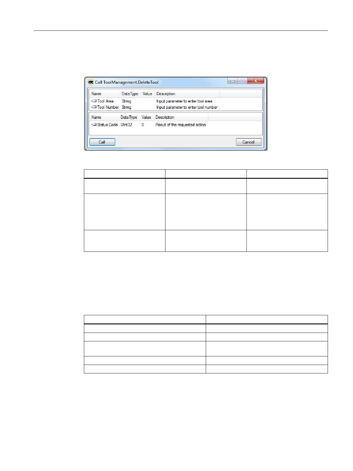
DeleteTool
The "DeleteTool" method is used to delete an existing tool in Tool List section of the SINUMERIK,
and appears under the folder “Methods/ToolManagement”.
The method deletes the tool with all cutting edges in all data blocks where it is saved.
DeleteTool(
[in] string ToolArea
[in] string ToolNumber
SINUMERIK Access MyMachine / OPC UA
132
Configuration Manual, 10/2020, 6FC5397-1DP41-0BA5
Functionality
6.7 Tool management
[out] Uint32 StatusCode
)
The following table will give details about the Parameters of the method:
Type
Parameters
Description
Input
Tool Area
Input parameter for the end user
to enter tool area.
Input
ToolNumber
5 digit number which is to be de-
leted.
For range of number please refer
to 828D or 840D sl documenta-
tion respectively.
Output
StatusCode
A number which gives a feedback
if the method was executed suc-
cessfully or not.
The method returns a value which indicates whether the delete was successful or not. If the
delete was not successful the return value will give information about the reason of the failure.
Status code
If the deletion of the tool was not successful the return value will give information about the
reason of the failure which are explained in the table below.
StatusCode
Description
0
OK.
1
Tool area does not exist.
2
Tool number out of range.(Reason wrong parame-
ter)
3
Tool does not exist.
6
Tool active.(Reason tool in use)
Method Result Codes
The Result return "Succeeded" when the method is correctly executed and the StatusCode gives
the reason of Success/Failure.
SINUMERIK Access MyMachine / OPC UA
Configuration Manual, 10/2020, 6FC5397-1DP41-0BA5
133
Functionality
6.7 Tool management
It returns "BadInvalidArgument", if inputs are not according to OPC UA standards.
Result
Description
Succeeded
Method executed with success/failure reason.
BadInvalidArgument
Arguments provided are not correct.
BadUserAccessDenied
"ToolWrite" access is not provided.
6.7.4
CreateCuttingEdge
The "CreateCutting Edge" method is used to create a new cutting edge of an existing tool in “Tool
List” section of the SINUMERIK. The next superior free D number will be created.
The ”CreateCuttingEdge” method appears under the folder “Methods/ToolManagement”. This
method does not contain the settings of cutting edge parameters.
The CreateCuttingEdge method has two inputs and two output parameters.
Signature:
CreateCuttingEdge(
[in] string ToolArea
[in] string ToolNumber
[out] Uint32 DNumber
[out] Uint32 StatusCode
)
The following table will give details about the parameters of the method:
Type
Parameters
Description
Input
Tool Area
Input parameter to enter tool
area.
Input
Tool Number
5 digit number which is to be de-
leted.
For range of number please refer
to 828D or 840D sl documenta-
tion respectively.
SINUMERIK Access MyMachine / OPC UA
134
Configuration Manual, 10/2020, 6FC5397-1DP41-0BA5
Functionality
6.7 Tool management
Type
Parameters
Description
Output
DNumber
Cutting Edge Number of the tool.
Output
Status Code
A number which gives a feedback
if the method was executed suc-
cessfully or not.
The method returns a value which indicates whether the creation was successful or not. If the
creation was successful the DNumber under which the new cutting edge was created will be
returned. If the creation was not successful the return value will give information about the
reason of the failure.
Status code
The status code is the result of the requested action and is represented by a number, as shown
in the table below:
Status Code
Reason
0
OK.
2
Tool number out of range.
4
Maximum cutting edges reached no more cutting
edges.
5
There is no tool for which edge can be created.
(Reason wrong tool area or tool number)
Method Result Codes
Result
Description
Succeeded
Method executed with success/failure reason.
BadInvalidArgument
Arguments provided are not correct.
BadUserAccessDenied
"ToolWrite" access is not provided.
6.7.5
DeleteCuttingEdge
The "DeleteCuttingEdge" is used to delete a cutting edge of an existing tool in "Tool List" section
of the SINUMERIK. This method appears under the folder "Methods/ToolManagement".
The DeleteCuttingEdge method has three input and one output parameters.
Signature:
DeleteCuttingEdge(
[in] string ToolArea
[in] string ToolNumber
[in] string CuttingEdgeNumber
[out] Uint32 StatusCode
)
SINUMERIK Access MyMachine / OPC UA
Configuration Manual, 10/2020, 6FC5397-1DP41-0BA5
135
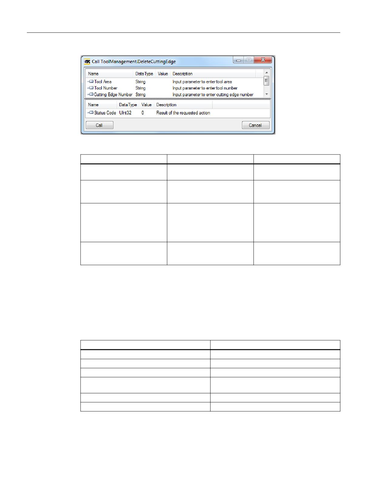
Functionality
6.7 Tool management
Following table will give details about the Parameters of the method:
Type
Parameters
Description
Input
Tool Area
Input parameter to enter tool
area.
Input
Tool Number
Tool number of an existing tool
whose cutting edge is to be de-
leted.
Input
Cutting Edge Number
5 digit number which is to be de-
leted.
For range of number please refer
to 828D or 840D sl documenta-
tion respectively.
Output
Status Code
A number which gives a feedback
if the method was executed suc-
cessfully or not.
The method should return a value which indicates whether the delete was successful or not. If
the delete was not successful the return value should give information about the reason of the
failure.
Status code
The status code is the result of the requested action which is a number as shown in the table
below:
Status Code
Reason
0
OK
2
Tool number out of range.
4
Cutting edge does not exist.
5
There is no tool for which edge can be deleted
(Reason wrong tool area or tool number)
6
Tool active. (Reason tool in use)
7
The first cutting edge cannot be deleted.
SINUMERIK Access MyMachine / OPC UA
136
Configuration Manual, 10/2020, 6FC5397-1DP41-0BA5
Functionality
6.7 Tool management
Method Result Codes
Result
Description
Succeeded
Method executed with success/failure reason.
BadInvalidArgument
Arguments provided are not correct.
BadUserAccessDenied
"ToolWrite" access is not provided.
SINUMERIK Access MyMachine / OPC UA
Configuration Manual, 10/2020, 6FC5397-1DP41-0BA5
137
Functionality
6.7 Tool management
SINUMERIK Access MyMachine / OPC UA
138
Configuration Manual, 10/2020, 6FC5397-1DP41-0BA5
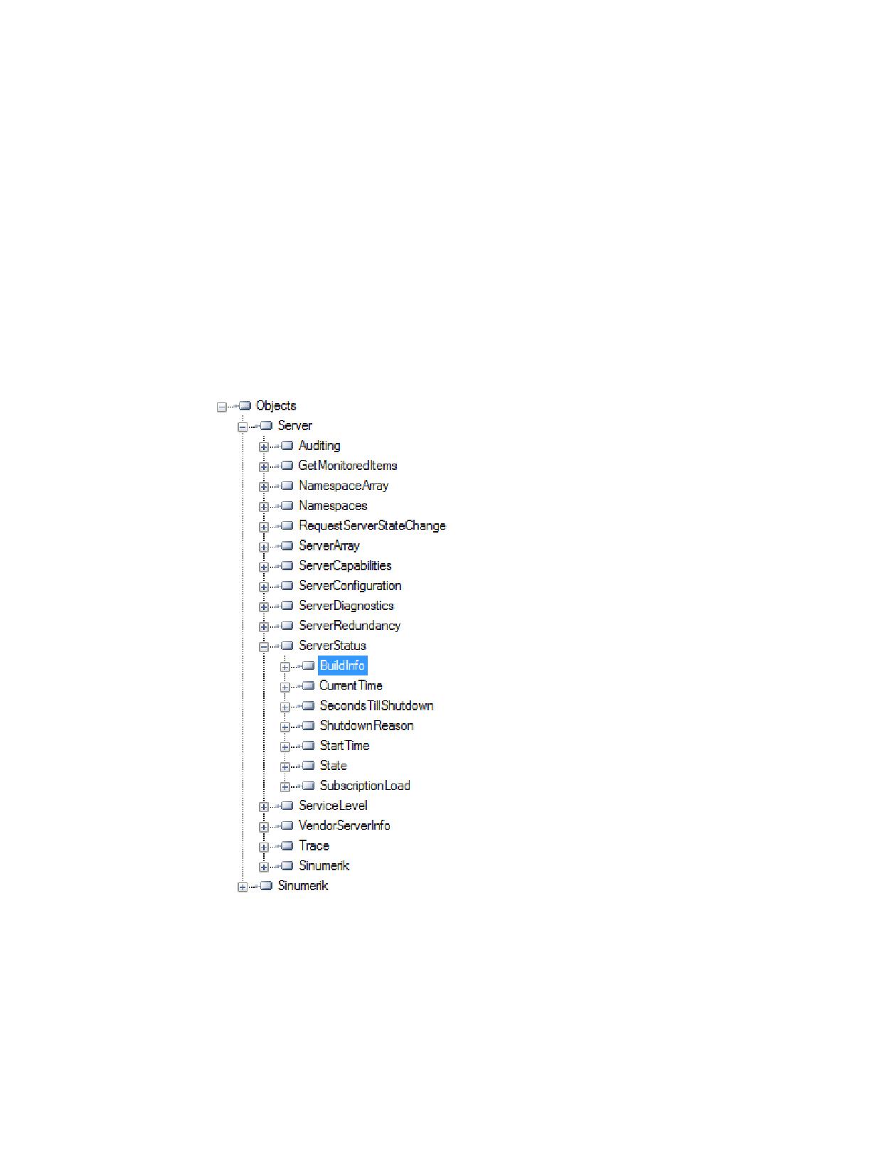
Diagnosis
7
7.1
Overview
Overview
The OPC UA server offers a variety of diagnostics information, as described in the OPC UA
Standard Part 5 - "Information Model", Chapter 6.
This diagnostics information can be found under the Server Node:
Figure 7-1
Diagnostics Information - Server Node
SINUMERIK Access MyMachine / OPC UA
Configuration Manual, 10/2020, 6FC5397-1DP41-0BA5
139
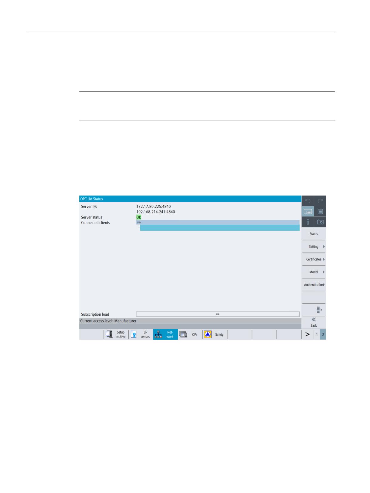
Diagnosis
7.2 Status screen
7.2
Status screen
Requirement
Note
To show the correct status of OPC UA server you must have at least one type of message
encryption (128 bit or 256 bit) enabled.
Status screen
Additional to the server status information available via OPC UA, there is a SINUMERIK Operate
screen, which shows the actual status of the OPC UA server.
To open the Status screen, select the operating area "Startup > Network" in SINUMERIK Operate,
then press the "OPC UA" softkey. The OPC UA status screen is the first screen to be displayed.
Figure 7-2
Status
SINUMERIK Access MyMachine / OPC UA
140
Configuration Manual, 10/2020, 6FC5397-1DP41-0BA5
Diagnosis
7.2 Status screen
Value
Description
Further explanation
Server IPs
Server IPs and ports of the company network,
systems network or service network where the
OPC UA server is accessible
Server status
Possible status of the server:
There are too many sessions used by
other clients. External clients are al-
• Ok (server up and running)
lowed to create 5 sessions with 828D
• Not activated (OPC UA server deactivated)
and 10 sessions with 840D sl.
• No connection can be set up (error within
The session limitation is 6 and 11 in
the OPC UA server)
the configuration file, respectively,
to have one more session for the sta-
• No more sessions possible. All sessions are in
tus client.
use by other clients. The status screen can-
not create a session.
Connected cli-
Clients which are connected to the server
ents
Example:
• MD1EXMQC: remote PC of the client
• SiemensAG:OpcUaTestsApp: URN of the ap-
plication of the remote PC
•
10788… Session ID
• OpcUaTestConsole: Session Name
Subscription
Utilized capacity of the OPC UA server regarding
load
possible subscriptions (see chapter Technical da-
ta (Page 163)), not the overall load.
SINUMERIK Access MyMachine / OPC UA
Configuration Manual, 10/2020, 6FC5397-1DP41-0BA5
141
Diagnosis
7.3 Diagnosis screen
7.3
Diagnosis screen
Overview
Diagnosis screen offers support for troubleshooting and service for OEM with SIEMENS.
Diagnosis functionalities are used only for service purpose.
From the Diagnosis screen user can:
• Activate or deactivate the OPC UA Server logging.
• Configure OPC UA Server logging.
• Reset the OPC UA Server to factory settings.
• Export the diagnosis data to an external data storage (for example, USB/Networkshare).
Note
Diagnosis softkey is visible by default only for manufacturer, service and user access levels.
OPC UA Diagnosis
1. Press the "OPC UA" softkey.
2. Press the extended softkey as shown in the below image.
Note
If the extended softkey is disabled then it means the OPC UA Server license is not active.
SINUMERIK Access MyMachine / OPC UA
142
Configuration Manual, 10/2020, 6FC5397-1DP41-0BA5
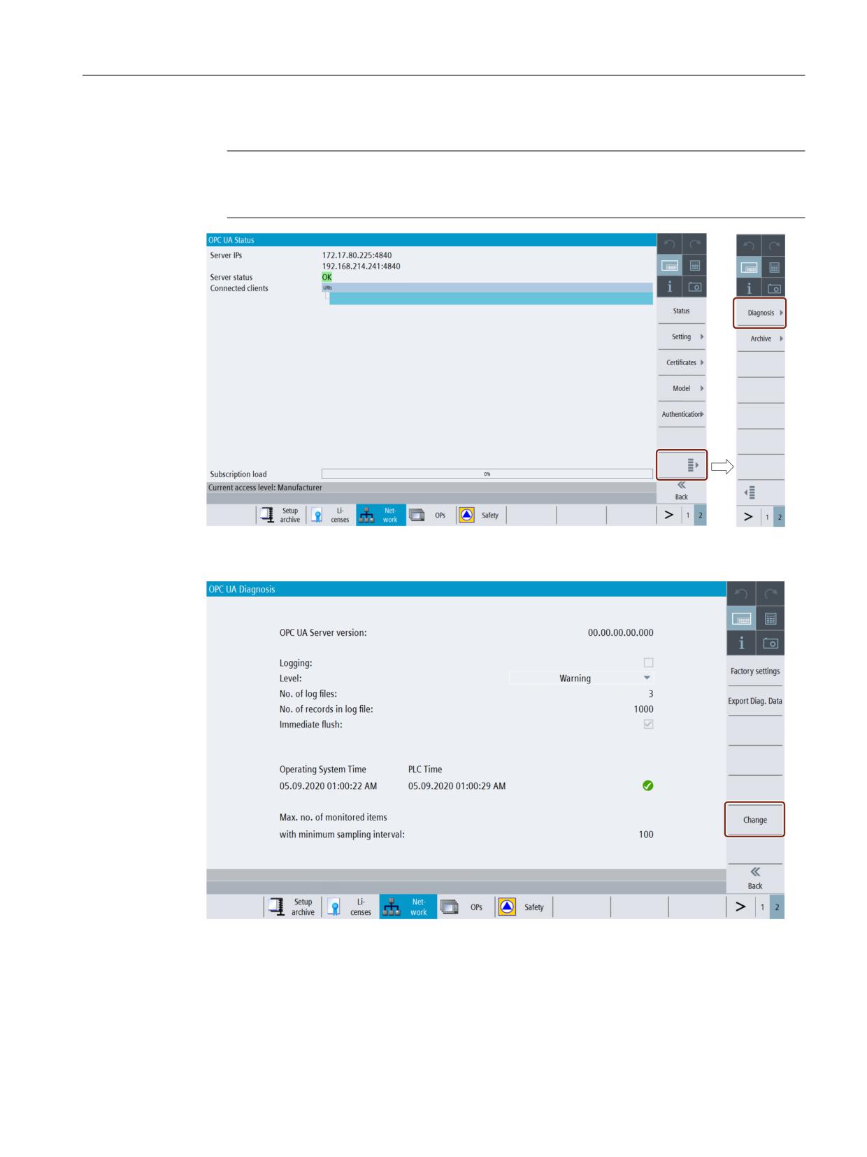
Diagnosis
7.3 Diagnosis screen
3. Press the "Diagnosis" softkey.
Note
The "Diagnosis" softkey will not be visible if OPC UA Server is not actiavted. User need to
activate the OPC UA Server from the OPC UA settings screen.
Figure 7-3
Softkey Diagnosis
4. The "OPC UA Diagnosis" dialog will appear. Then press the "Change" softkey.
Figure 7-4
Softkey Change
SINUMERIK Access MyMachine / OPC UA
Configuration Manual, 10/2020, 6FC5397-1DP41-0BA5
143
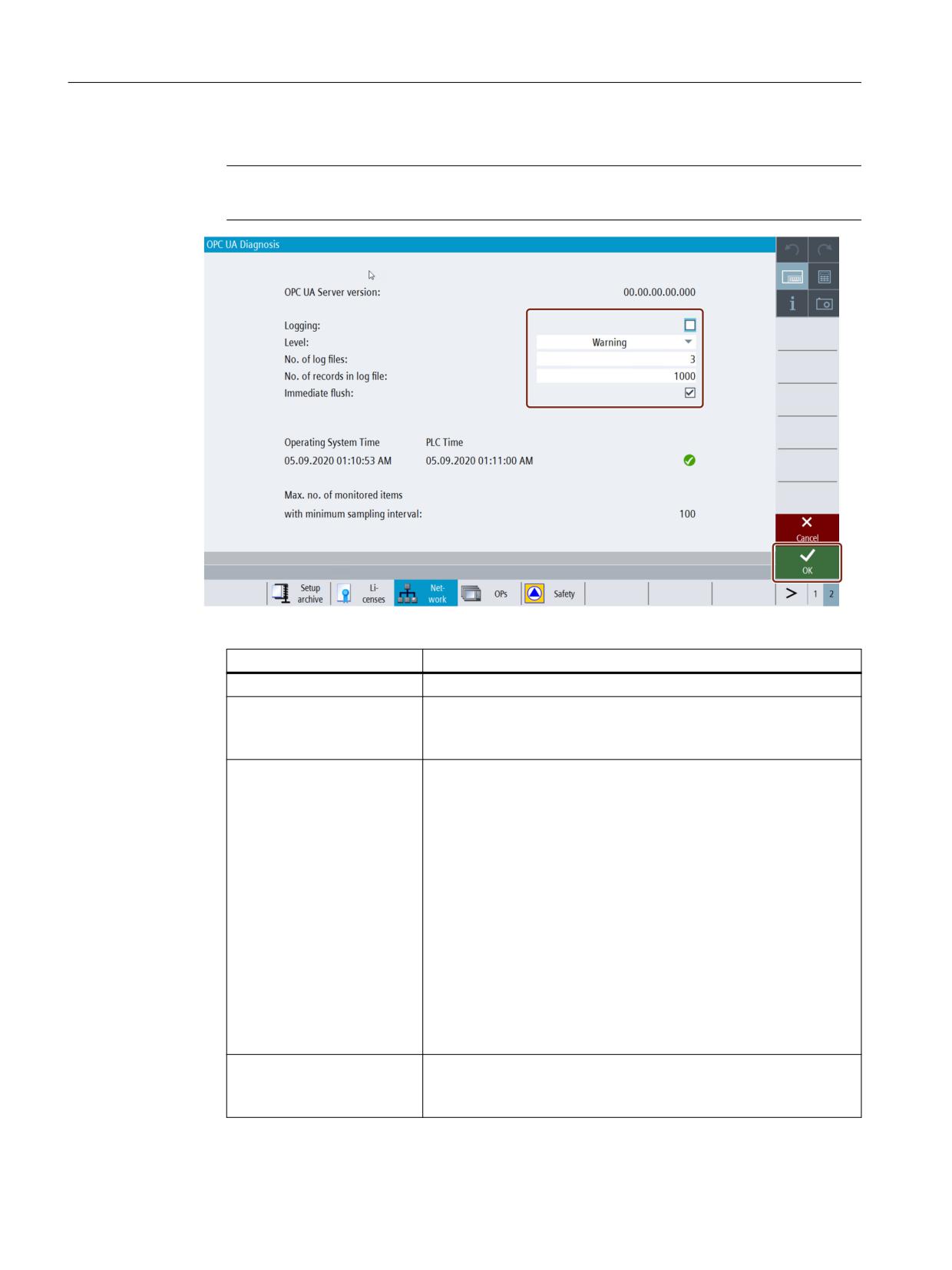
Diagnosis
7.3 Diagnosis screen
5. Make the necessary settings for logging.
Note
The changes become effective only after the restart of the SINUMERIK Operate.
Figure 7-5
Activate Logging option
Field
Description
"OPC UA Server Version"
Shows the OPC UA Server version installed.
"Logging"
Place the checkmark to activate logging and remove the checkmark
to deactivate it.
By activating logging, it generates the log of the OPC UA Server.
"Level"
Select the type of level from the drop down list. The drop down list
has the following types of level:
• None
• Error
• Warning (by dafault)
• System
• Info
• Debug
• Content
• All
The log will be generated based on the selection of level type.
No log will be generated if you have activated logging and selected
"None" from the list.
"No. of log files"
Enter the no. of log files between 3 - 10.
If the user selects 10, and the 10th log file is already generated, then
it will replace the 1st log file.
SINUMERIK Access MyMachine / OPC UA
144
Configuration Manual, 10/2020, 6FC5397-1DP41-0BA5
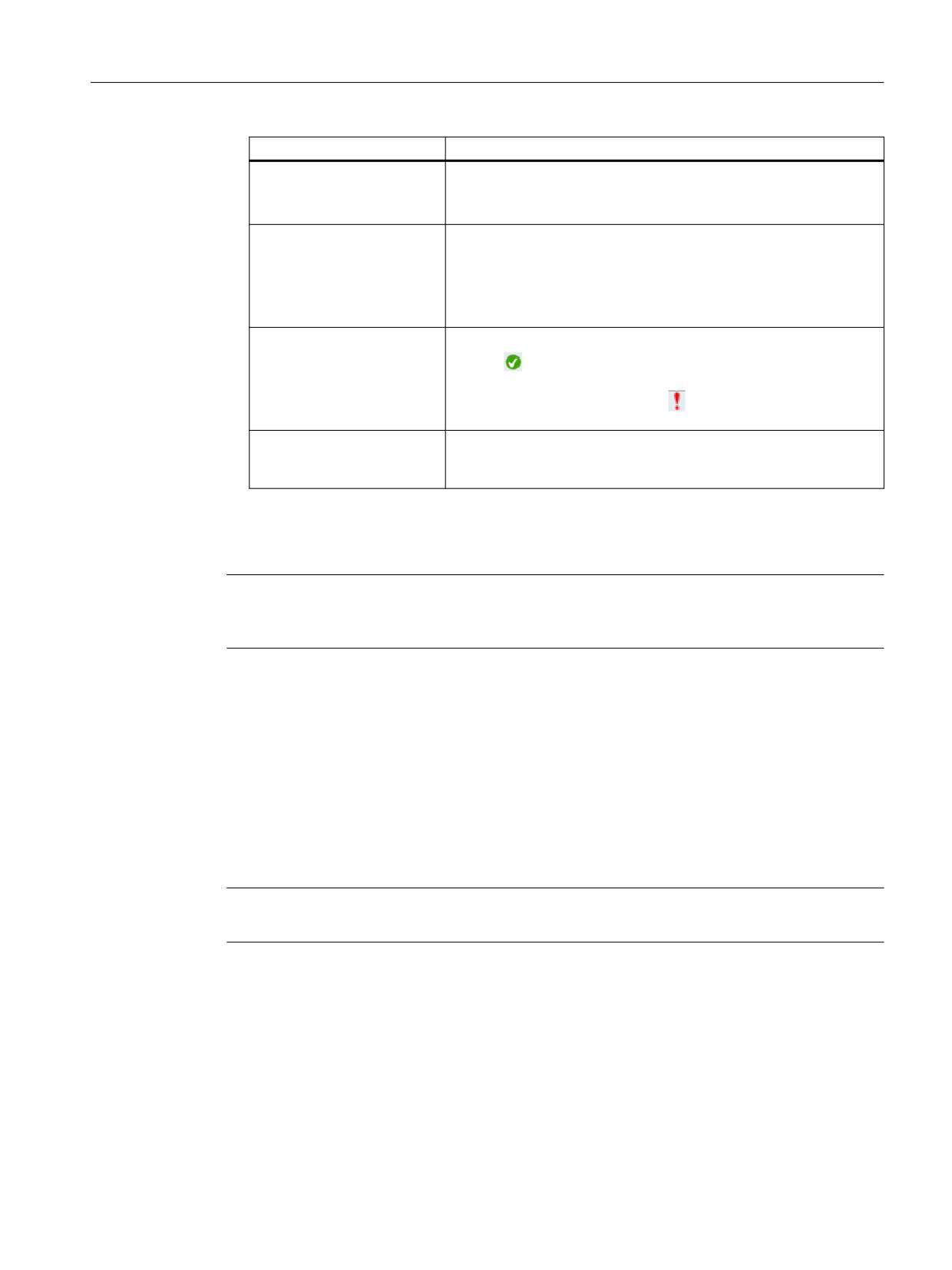
Diagnosis
7.3 Diagnosis screen
Field
Description
"No. of records in log file"
Enter the no. of records in log file between 1000 - 99999.
If the user selects 99999, and the 99999th record is already gener-
ated, then it will replace the 1st record.
"Immediate flush"
Place the checkmark to activate the immediate flush and remove the
checkmark to deactivate it.
By activating immediate flush, every record will be written immedi-
ately into the log file.
This option should be used only for logging without delays.
"Operating System Time and
Operating System and PLC date and time are displayed.
PLC Time"
The tick
icon indicates that the PLC time is in sync with the oper-
ating system (HMI Operate) time.
If the date and time is not in sync, icon is shown and it indicates
that time should be updated.
"Max. no. of monitored items
This field provides information about the max. no. of items which can
with minimum sampling in-
be monitored with minimum sampling interval".
terval"
6. Then press "OK".
7. The changes become effective only after the restart of the SINUMERIK Operate.
Note
If the OPC UA server logging is activated for more than 30 days, then it will be automatically
disabled on the next HMI restart.
Resetting the OPC UA Server to factory settings
This helps the user to reset the OPC UA configuration of the SINUMERIK device to its initial state.
This would be helpful when the current OPC UA configuration is not valid and needs to be reset.
User shall use this as the last option to reconfigure the OPC UA server to its initial state. All
settings, IP, Port, and certificates will be deleted and the default values will be restored.
After the restart of the SINUMERIK Operate, OPC UA server need to be activated again with
necessary changes.
Note
Model files will not be deleted during this process.
1. Press the "OPC UA" softkey.
2. Press the extended softkey.
3. Press the "Diagnosis" softkey. The "OPC UA Diagnosis" dialog will appear.
SINUMERIK Access MyMachine / OPC UA
Configuration Manual, 10/2020, 6FC5397-1DP41-0BA5
145
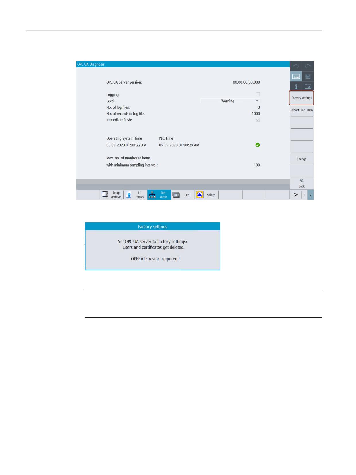
Diagnosis
7.3 Diagnosis screen
4. Then press the "Factory settings" softkey.
Figure 7-6
Softkey Factory Settings
5. The "Factory settings" popup window will appear.
Figure 7-7
Factory settings popup
Note
If the user performs factory settings, the OPC UA Server will be reset to default setting. User
need to enable the OPC UA Server again from the OPC UA settings screen (Page 21).
6. Then press "OK". A status message is shown at the bottom, "changes become effective after
the restart of OPERATE".
Exporting diagnosis data to an external data storage
This feature exports the OPC UA configuration, log files and other diagnostic information from
the SINUMERIK system, onto the selected USB or Network shared location.
This can be used to analyze details of behavior of the system or root cause of the situation in case
of problems.
1. Press the "OPC UA" softkey.
2. Press the extended softkey.
3. Press the "Diagnosis" softkey. The "OPC UA Diagnosis" dialog will appear.
SINUMERIK Access MyMachine / OPC UA
146
Configuration Manual, 10/2020, 6FC5397-1DP41-0BA5
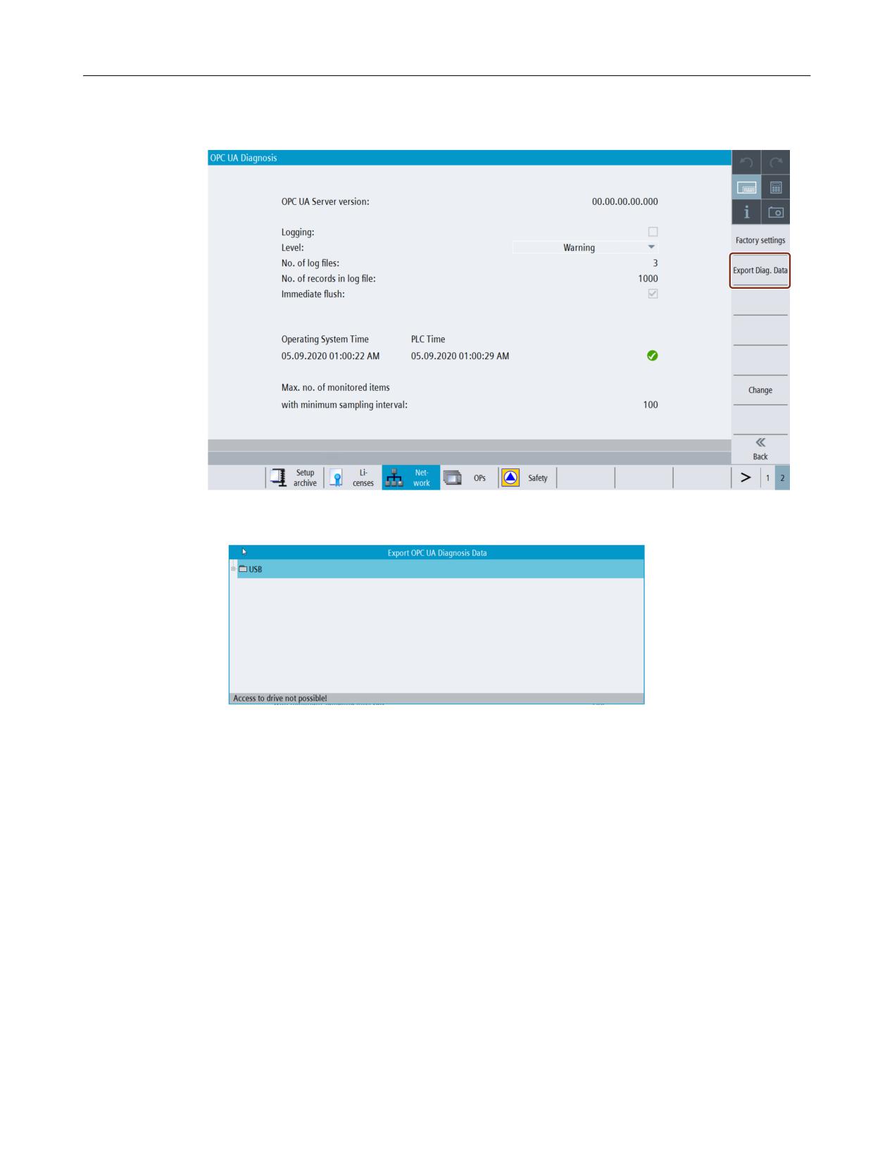
Diagnosis
7.3 Diagnosis screen
4. Then press the "Export Diag. data" softkey.
Figure 7-8
Softkey Export Diag data
5. The "Export OPC UA Diagnosis Data" popup window will appear.
Figure 7-9
Export OPC UA Diagnosis data popup
6. Select either USB/Networkshare.
7. Then press "OK".
8. The diagnosis data will be saved to the folder (as selected USB/networkshare) in the format
"OpcUaDiagnosisData_Year_Month_Day-Hour_Minute_Second",(for example:
"OpcUaDiagnosisData_2020_06_22-11_12_56").
SINUMERIK Access MyMachine / OPC UA
Configuration Manual, 10/2020, 6FC5397-1DP41-0BA5
147