SINUMERIK 840D sl. Service - Configuring Commissioning. Manual (2011-2020) - page 58
Diagnosis
7.4 OPC UA Archiving
7.4
OPC UA Archiving
Overview
Archiving feature enables the user to generate a backup of OPC UA Server so that in case of need,
all settings and data can be restored. Also, user can generate a setup archive for serial
commissioning and update new machines with setup archive.
From Archiving screen user can:
• Generate OPC UA Server backup archive (i.e, full archive)
• Generate OPC UA Server setup archive for serial commissioning
• Restore backup archive
• Read in setup archive for serial commissioning
Prerequisite
OPC UA archive is only part of Operate archive, if the archive service in OPC UA has been done
before. Therefore create an OPC UA backup first, before taking full backup of Operate.
OPC UA Server backup archiving
The user can generate a backup archive of OPC UA Server (including configuration, user
management, models, and certificates) and restore it back when required. The OPC UA back up
archive can only be restored on the same controller or the same SD card, since the server
certificate is part of the backup.
SINUMERIK Access MyMachine / OPC UA
148
Configuration Manual, 10/2020, 6FC5397-1DP41-0BA5
Diagnosis
7.4 OPC UA Archiving
Generating Archive
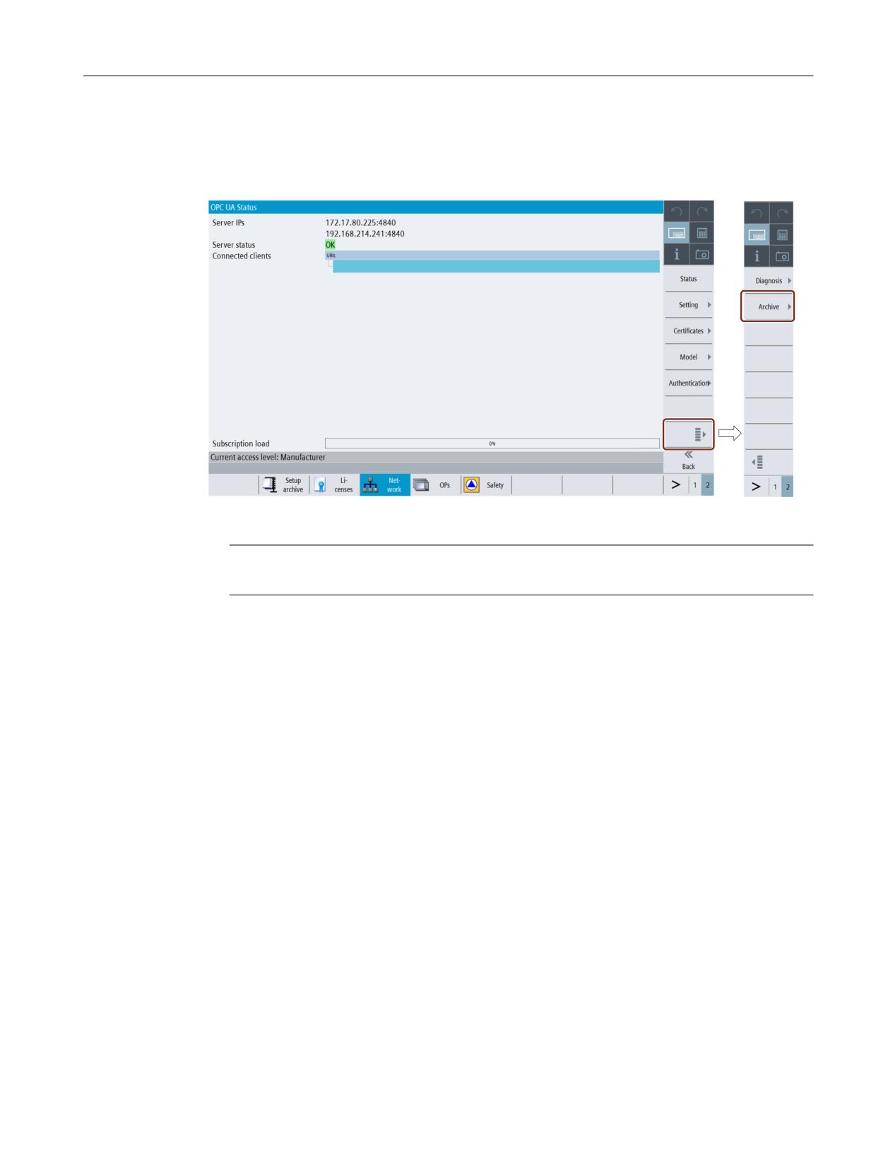
1. Press the "OPC UA" softkey.
2. Press the extended softkey as shown in the below image.
Figure 7-10
Softkey Extended
Note
If the OPC UA server license is not active, then the extended softkey is disabled.
3. Press the "Archive" softkey.
SINUMERIK Access MyMachine / OPC UA
Configuration Manual, 10/2020, 6FC5397-1DP41-0BA5
149
Diagnosis
7.4 OPC UA Archiving
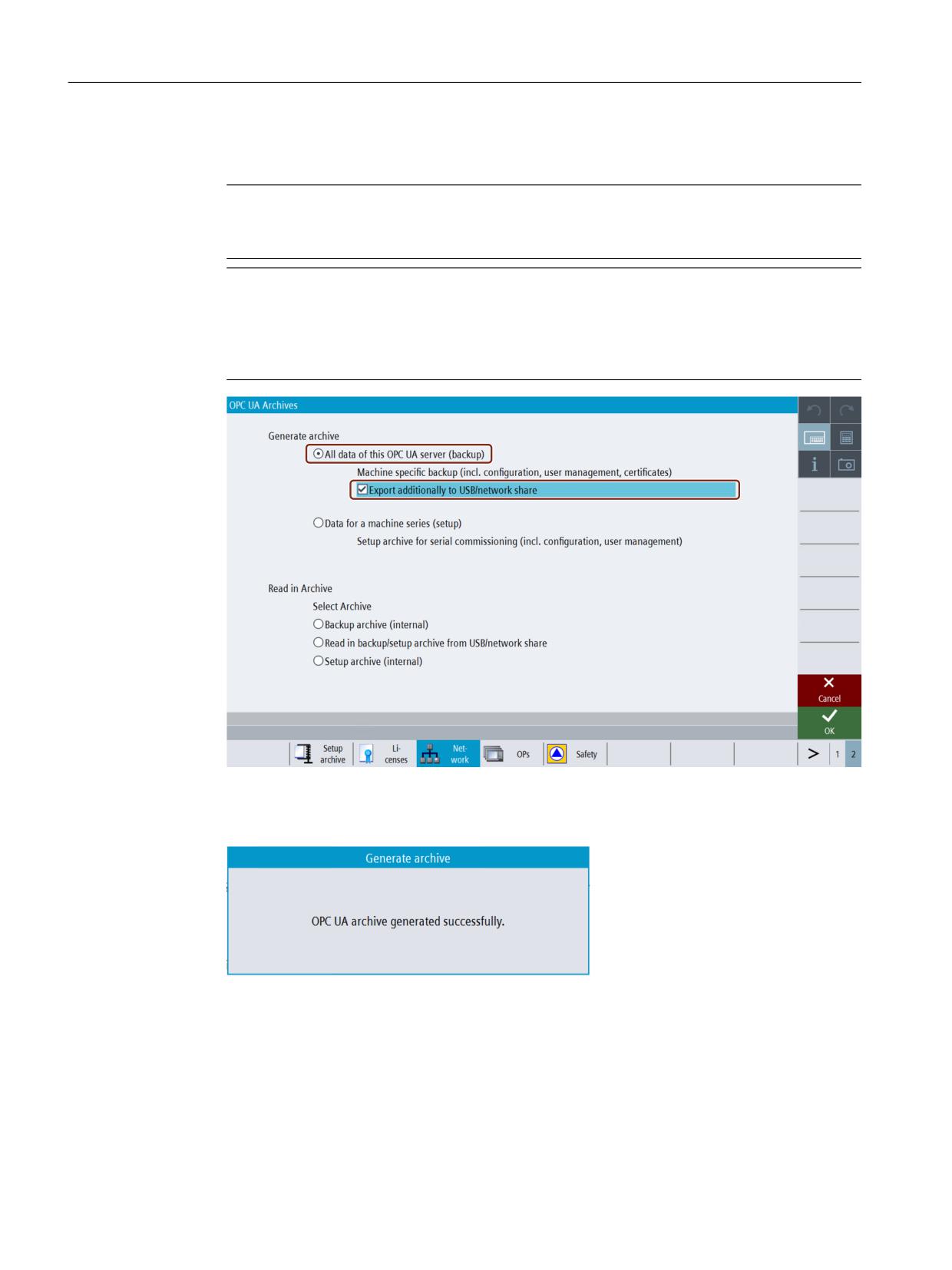
4. The "OPC UA Archives" dialog will appear. Select "All data of this OPC UA server (backup)"
radio button under "Generate archive".
Note
The radio button "All data of this OPC UA server (backup)" is enabled by default only for
manufacturer, service and user access levels.
Note
If additionally, you want the backup file to be copied to USB or network share, then select
"Export additionally to USB/network share" check box. After Pressing "OK", a popup window
appears. Select the location in the USB or network share where you want to save the backup
file.
Figure 7-11
OPC UA Server generate backup archiving
5. Then press "OK". The popup window appears with message, "OPC UA archive generated
successfully".
Figure 7-12
Generate archive popup
6. Press "OK". The backup file is saved automatically in the local folder (internal memory) and in
the USB/network share as selected. The internal path for NCU will be "/card/user/
sinumerik/hmi/cfg" and for PCU/IPC "C:\Program Files (x86)\Siemens\MotionControl/user/
sinumerik/hmi/cfg".
SINUMERIK Access MyMachine / OPC UA
150
Configuration Manual, 10/2020, 6FC5397-1DP41-0BA5
Diagnosis
7.4 OPC UA Archiving
Restoring backup archive
Note
• Backup archives can only be restored on the backed up target system.
• By restoring backup archive, all the current settings and data of the OPC UA Server will be
replaced with the backup file data.
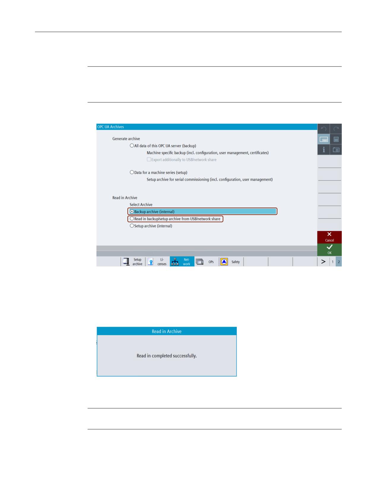
1. Select "Backup archive (internal)" radio button under "Read in Archive".
Figure 7-13
OPC UA Server restore backup archiving
In case, if you have saved and want to select the backup file from the USB/network share, then
select "Read in backup/setup archive from USB/network share" radio button. After Pressing
"OK", a popup window appears. Select the backup file from USB/network share.
2. Then Press "OK". With the valid input file, a popup window appears with message, "Read in
completed successfully".
Figure 7-14
Read in archive success popup
3. Press "OK". The backup file is restored.
Note
The changes become effective only after the restart of the SINUMERIK Operate.
SINUMERIK Access MyMachine / OPC UA
Configuration Manual, 10/2020, 6FC5397-1DP41-0BA5
151
Diagnosis
7.4 OPC UA Archiving
OPC UA Server setup archiving for serial commissioning
The user generates a setup archive of OPC UA Server for serial commissioning (including
configuration, user management, and models) and update new machines with setup archive.
Generating Archive
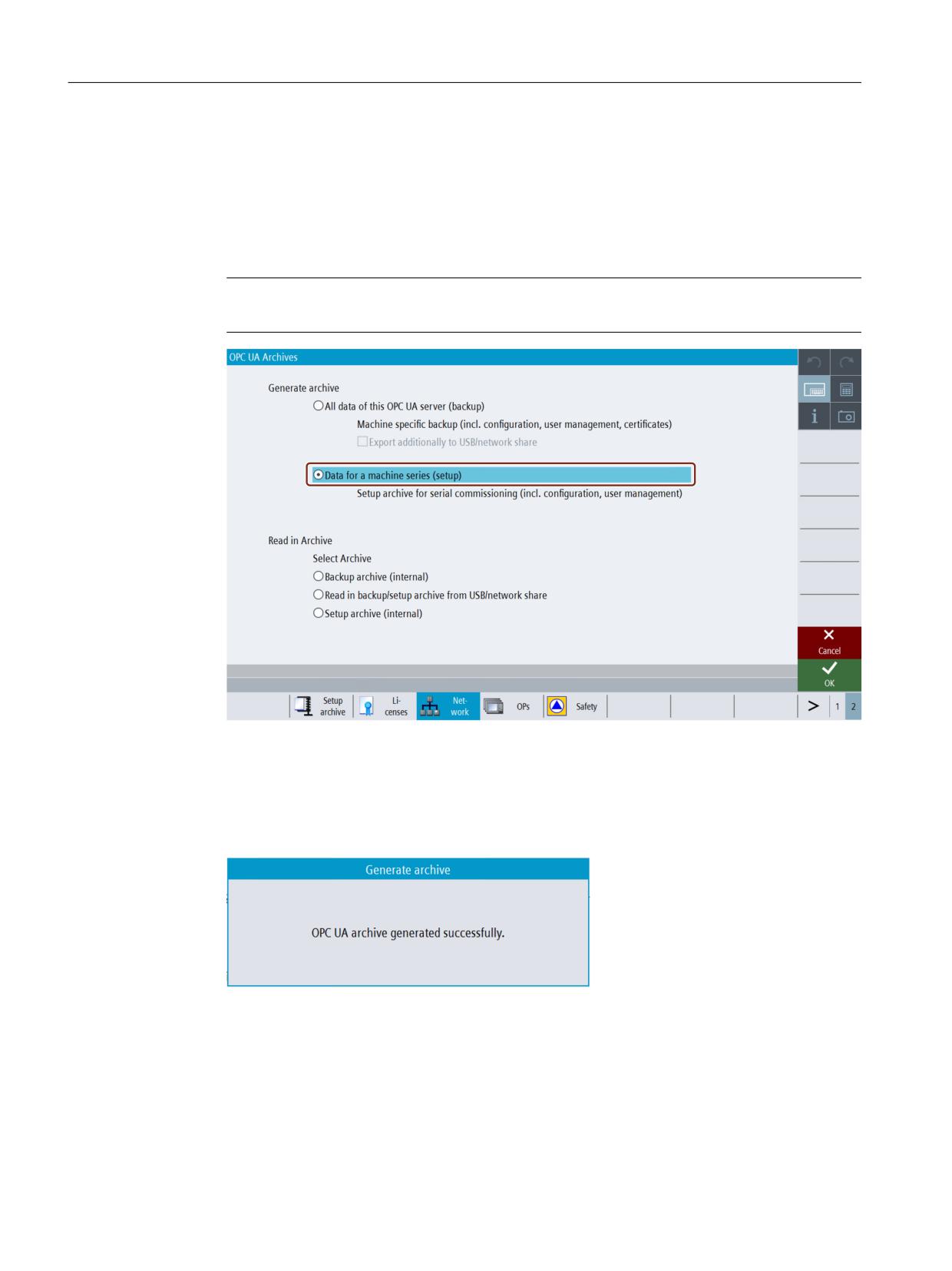
1. Select "Data for a machine series (setup)" radio button under "Generate archive".
Note
This option is enabled only with manufacturer’s access levels.
Figure 7-15
OPC UA Server generate setup archiving for serial commissioning
2. Press "OK". A popup window appears.
3. Select the location in the USB or network share where you want to save the setup file.
4. Then press "OK". The popup window appears with message, "OPC UA archive generated
successfully".
Figure 7-16
Generate archive success popup
5. Press "OK". The setup file is saved in the USB/network share as selected.
SINUMERIK Access MyMachine / OPC UA
152
Configuration Manual, 10/2020, 6FC5397-1DP41-0BA5
Diagnosis
7.4 OPC UA Archiving
Setup archive
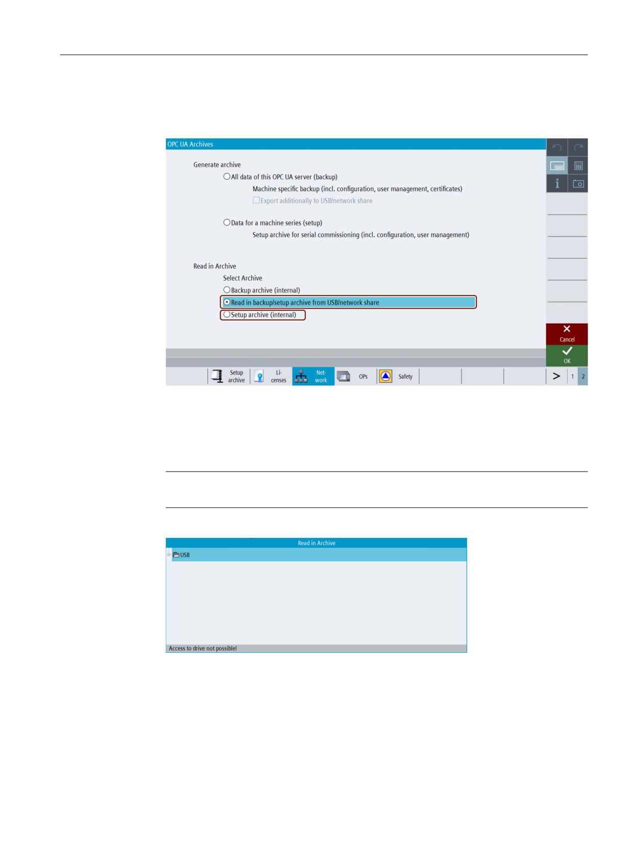
1. Select "Read in backup/setup archive from USB/network share" radio button under "Read in
Archive".
Figure 7-17
OPC UA Server setup archiving for serial commissioning
In case, if you have saved and want to select the setup file from local folder (internal
memory), then select "Setup archive (internal)" radio button. The internal path for NCU will
be "/card/user/sinumerik/hmi/cfg" and for PCU/IPC "C:\Program Files (x86)\Siemens
\MotionControl/user/sinumerik/hmi/cfg".
Note
The "Setup archive (internal)" option is enabled only with manufacturer’s access levels.
2. Press "OK". A popup window appears.
Figure 7-18
Setup archive USB_Networkshare popup
3. Select the setup file from USB/network share. Then Press "OK".
SINUMERIK Access MyMachine / OPC UA
Configuration Manual, 10/2020, 6FC5397-1DP41-0BA5
153
Diagnosis
7.4 OPC UA Archiving
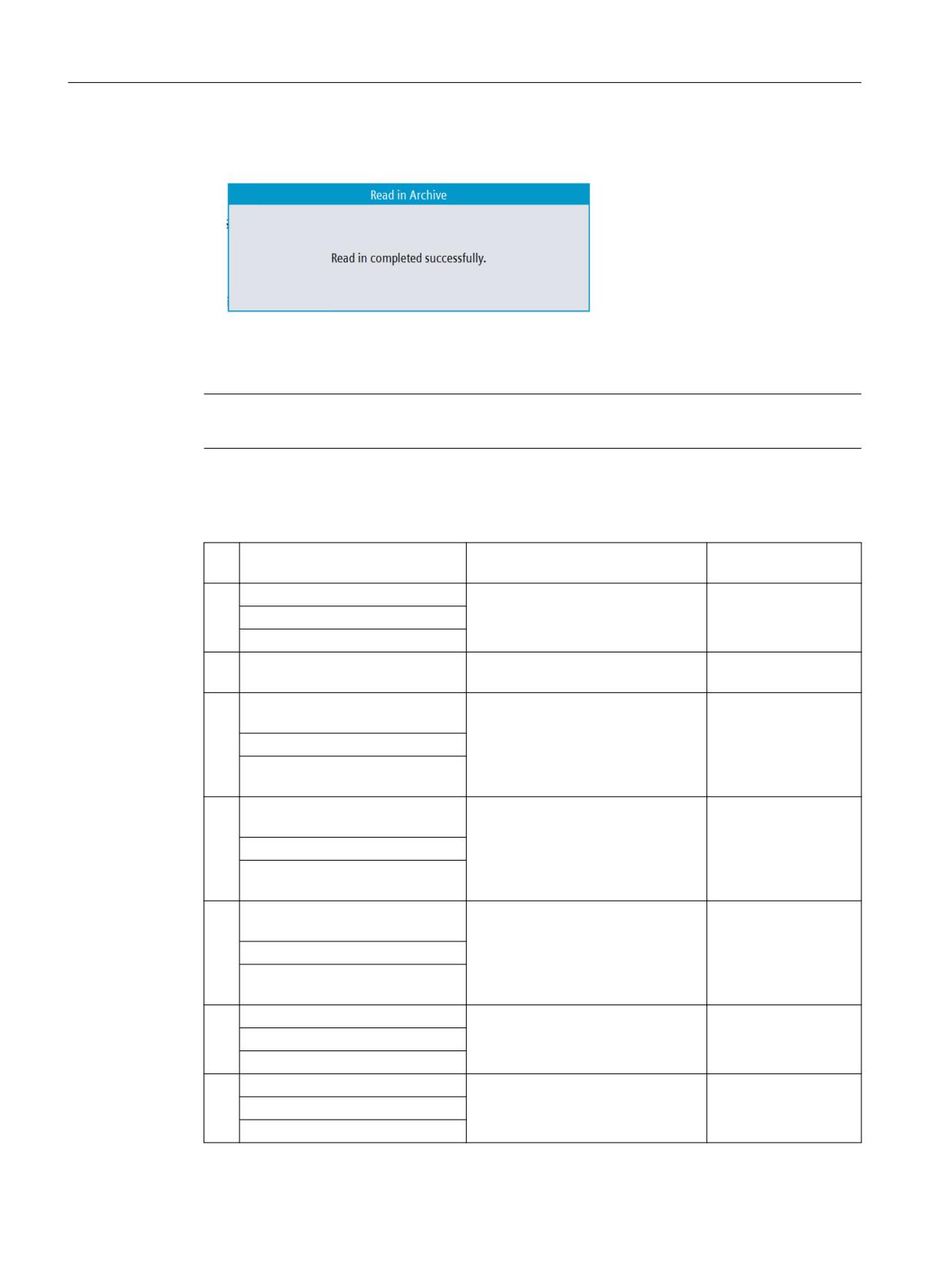
4. With the valid input file, a popup window appears with message, "Read in completed
successfully".
Figure 7-19
Read in archive success popup
5. Press "OK". The setup archive is completed.
Note
The changes become effective only after the restart of the SINUMERIK Operate.
Possible scenarios and error messages
Sl
Selection
Scenario description
Error message
no.
1
Generate backup archive
Generation of any archive, if comple-
OPC UA archive gener-
ted without any issues.
ated successfully.
OR
Generate setup archive
2
Generate backup archive (internal
If there is no sufficient memory avail-
Insufficient memory
memory)
able.
on IPC/NCU.
3
Generate backup archive (on USB/
If there is no sufficient memory avail-
Insufficient USB/
Netshare)
able.
network memory
OR
Generate setup archive (on USB/
Netshare)
4
Generate backup archive (on USB/
If the selected location is write pro-
No write permission
Netshare)
tected or not accessible.
on the selected medi-
um.
OR
Generate setup archive (on USB/
Netshare)
5
Generate backup archive (on USB/
If the selected location is write pro-
Access to drive is not
Netshare)
tected or not accessible.
possible.
OR
Generate setup archive (on USB/
Netshare)
6
Read in Backup archive
No valid OPC UA archive file is found
No OPC UA archive is
in internal memory.
available on internal
Or
memory
Read in Setup archive
7
Read in Backup archive
No error in reading in file.
Read in completed suc-
cessfully.
Or
Read in Setup archive
SINUMERIK Access MyMachine / OPC UA
154
Configuration Manual, 10/2020, 6FC5397-1DP41-0BA5
Diagnosis
7.4 OPC UA Archiving
8
Read in Backup archive
If the selected file is not a valid OPC
Read in failed. Invalid
UA Archive or the file is tampered by
file.
Or
editing.
Read in Setup archive
9
Read in Backup archive (external
If backup archive is not from the
Read in failed. Backup
memory)
same machine
Archive is generated
on different Sinumerik
device.
SINUMERIK Access MyMachine / OPC UA
Configuration Manual, 10/2020, 6FC5397-1DP41-0BA5
155
Diagnosis
7.5 OPC UA server version
7.5
OPC UA server version
OPC UA server version
OPC UA server version and OPC UA dialog version information can be found in SINUMERIK
OPERATE version screen.
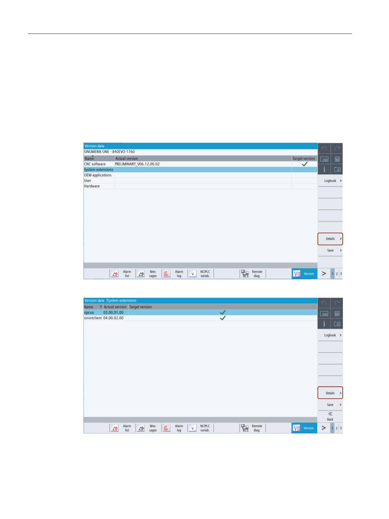
1. Open SINUMERIK OPERATE and choose operating area "Diagnostics". Press the softkey
"Version".
2. Select “System extensions" and press softkey "Details".
Figure 7-20
Version data
Figure 7-21
Version data / system extensions
SINUMERIK Access MyMachine / OPC UA
156
Configuration Manual, 10/2020, 6FC5397-1DP41-0BA5
Diagnosis
7.5 OPC UA server version
The OPC UA entry is found.
3. Select the entry and press "Details" again to show more detailed information on OPC UA
components.
SINUMERIK Access MyMachine / OPC UA
Configuration Manual, 10/2020, 6FC5397-1DP41-0BA5
157
Diagnosis
7.5 OPC UA server version
SINUMERIK Access MyMachine / OPC UA
158
Configuration Manual, 10/2020, 6FC5397-1DP41-0BA5
Update of OPC UA server
8
8.1
Overview
Compatibility
This version of OPC UA server is supported by SINUMERIK 840D sl and SINUMERIK 828D.
An update process is possible with the following SINUMERIK software versions:
• Software line 4.5: with versions ≥ V4.5 SP4.
• Software line 4.7: with versions ≥ V4.7 SP2.
• Software line 4.8: with versions ≥ V4.8 SP1.
• Software line 4.9.
SINUMERIK Create MyConfig (CMC)
The necessary update (CMC) file can be provided by your regional SIEMENS office.
SINUMERIK Access MyMachine / OPC UA
Configuration Manual, 10/2020, 6FC5397-1DP41-0BA5
159
Update of OPC UA server
8.2 Compatibility
8.2
Compatibility
Compatibility
Below are the compatibility issues of OPC UA:
• Password
The Password length has changed to min. 8 characters.
• User rights
- The behavior in setting “SinuReadAll” and “SinuWriteAll” is different from previous
versions.
- Different from previous version is that removing the right “SinuReadAll” will remove all
read rights. In previous versions additionally added read rights have not been deleted with
removing “SinuReadAll”.
Same applies to “SinuWriteAll”.
Note
If you face any other compatibility issues or for further details, refer to hotline (https://
support.industry.siemens.com/cs/sc/2090/).
SINUMERIK Access MyMachine / OPC UA
160
Configuration Manual, 10/2020, 6FC5397-1DP41-0BA5
Update of OPC UA server
8.3 Installation of OPC UA server
8.3
Installation of OPC UA server
Requirements
The installation procedure of the OPC UA server varies depending whether a PCU or a PPU/NCU
is being used. The following operating systems are required:
• PCU Base and SINUMERIK Operate on Windows 7 / Windows 10 systems
• SINUMERIK Operate on NCU840D (embedded).
Below are the instructions for both options:
See also
Update of OPC UA server (Page 167)
8.3.1
Installation/Upgrade on a PCU/IPC
1. Load OPC UA software (OpcUaDeployWindows_XXX.XXX.exe) on USB stick.
2. Start PCU in the service mode.
3. Insert USB stick in USB port of operator panel.
4. Start Windows Explorer.
5. Navigate to .exe file and execute it.
6. Follow the installation instructions.
7. After successful installation, restart the PCU.
Note
If OPC UA was active before the installation, users and access rights are being preserved.
8.3.2
Installation/Upgrade a PPU/NCU
Note
Different installation procedure for 828D / V4.5
Please not that the server update procedure for 828D with CNC software version V4.5 varies
from the standard process below (see chapterUpdate of OPC UA server (Page 167)).
1. Load OPC UA software (OpcUaDeployLinux_XXX.XXX.usz) on USB stick.
2. Insert USB stick in USB port of NCU/PPU.
3. Switch off NCU/PPU and switch it on again.
SINUMERIK Access MyMachine / OPC UA
Configuration Manual, 10/2020, 6FC5397-1DP41-0BA5
161
Update of OPC UA server
8.3 Installation of OPC UA server
4. Follow the installation instructions.
5. After successful installation, restart the NCU/PPU.
Note
If OPC UA was active before the installation, users and access rights are being preserved.
SINUMERIK Access MyMachine / OPC UA
162
Configuration Manual, 10/2020, 6FC5397-1DP41-0BA5

Technical data
9
Technical data
Description
Value
Number of sessions 1)
828D
5
840 D sl
10
Number of subscriptions 2)
828D
5
840D sl
10
Maximum samples / second 3)
828D
500 1/s
840D sl
1000 1/s
Maximum no. of monitored items 4)
controller specific
Min. sampling interval 3)
100 ms
Sampling intervals
{100, 250, 500, 1000, 2500, 5000} ms
Min. publishing interval
100 ms
Publishing intervals
{100, 250, 500, 1000, 2500, 5000} ms
Max. number of users
20
Max. lifetime interval (LifeTime Count)
1 h
Session timeout
60 s
Max. monitored items queue size (Subscription
10000
Queue size) 5)
1)
Session = Connection of a client to a server
2)
Subscription = In an existing session a subscription is a functionality for monitoring data items.
3)
Accessible communication performance / quantity structure depends on the working load of the control
4)
The maximum no. of monitored items depends on the update rate of all monitored items over all
sessions and a controller specific performance index.
5)
Total queue size over all subscriptions and all monitored items
Calculating maximum no. of monitored items
The maximum number of monitored items depends on the update rate of all monitored items
and a performance index of the controller. The maximum number of monitored items can be
calculated as shown below:
Max. no. monitored items = (Performance Index / 1000) x Sampling Rate (ms)
Performance Index
•
828D = 500
•
840D sl = 1000
SINUMERIK Access MyMachine / OPC UA
Configuration Manual, 10/2020, 6FC5397-1DP41-0BA5
163
Technical data
See also
Monitored items (Page 103)
SINUMERIK Access MyMachine / OPC UA
164
Configuration Manual, 10/2020, 6FC5397-1DP41-0BA5
Exceptions: 828D / V4.5
10
The following chapter describes the exceptions regarding 828D control with CNC software
version V4.5.
SINUMERIK Access MyMachine / OPC UA
Configuration Manual, 10/2020, 6FC5397-1DP41-0BA5
165
Exceptions: 828D / V4.5
10.1 Starting of configuration dialog
10.1
Starting of configuration dialog
Because of certain prerequisites of OPERATE V4.5 and 828D, it was not possible to implement
the startup of the OPC UA configuration dialog the same way as in OPC UA standard software
releases. Therefore you reach the OPC UA configuration dialog via a different way:
Executing the OPC UA configuration dialog
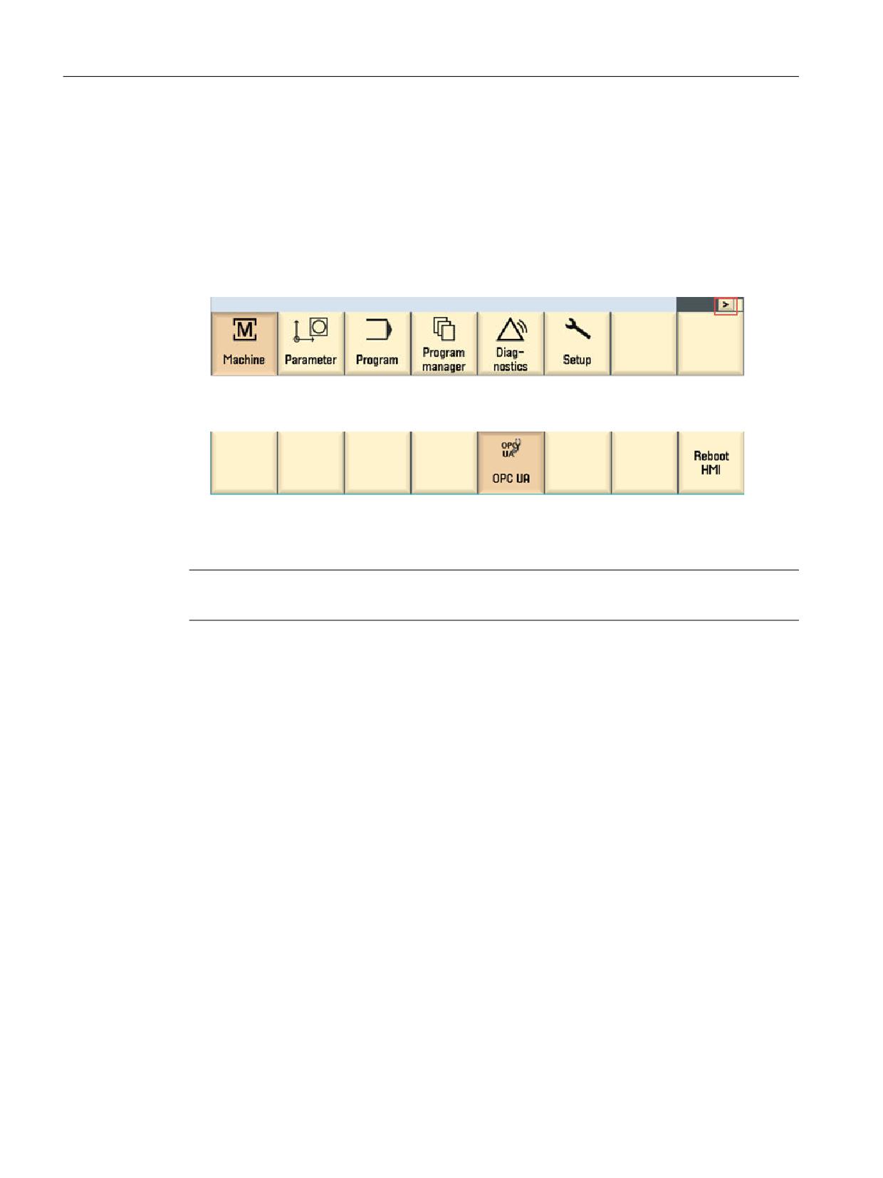
1. Press “menu select”. The operating area will appear.
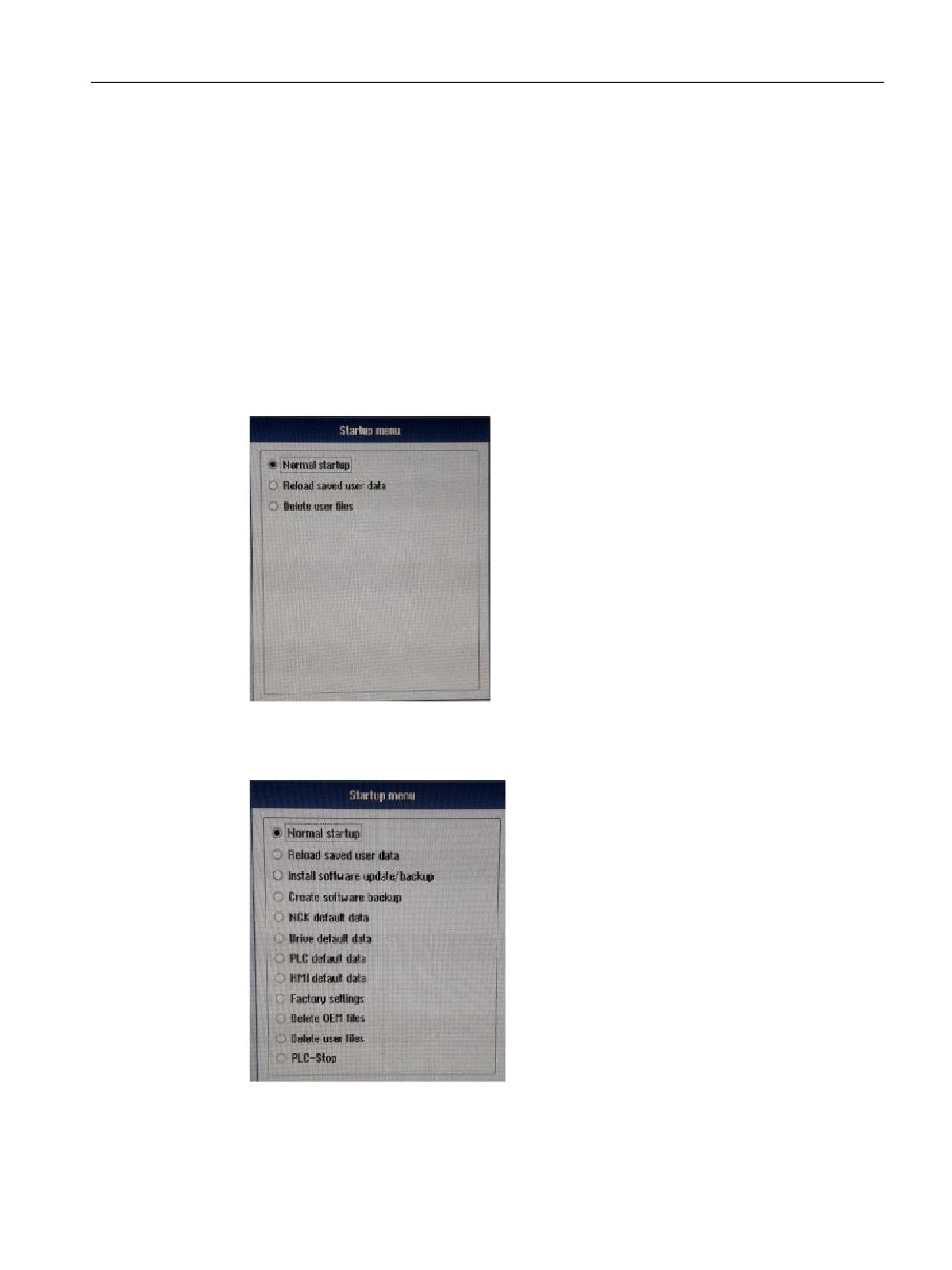
Figure 10-1
Operating area
2. Press the softkey ">". The second operating area will appear.
Figure 10-2
Operating area
3. Press the softkey "OPC UA". The settings dialog will appear.
Note
The operating of the settings dialog is explained in chapter Commissioning (Page 21).
SINUMERIK Access MyMachine / OPC UA
166
Configuration Manual, 10/2020, 6FC5397-1DP41-0BA5
Exceptions: 828D / V4.5
10.2 Update of OPC UA server
10.2
Update of OPC UA server
The update procedure for 828D with CNC software version V4.5 varies from the standard update
procedure described in chapter Installation of OPC UA server (Page 161).
Prerequisite
A .tgz file (e. g.: hmi_sl_opcua_02.02.00.00.007.tgz) is provided on an USB stick.
Installation of OPC UA server
1. Power on the control.
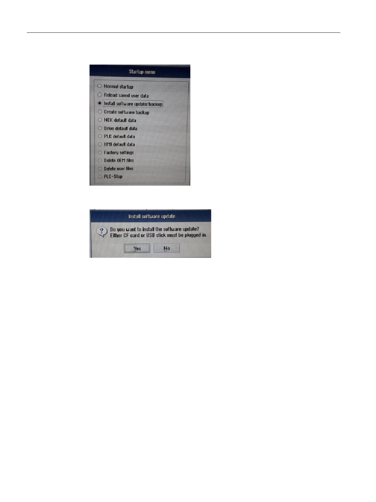
2. Go to "Startup menu" (press "Select" button when a message appears on the screen).
Figure 10-3
Startup menu
3. Press key "^", then 2nd horizontal softkey, then 2nd vertical softkey to get to extended "startup
menu".
Figure 10-4
Extended startup menu
4. Plug in the USB drive with the provided .tgz file at the front of the 828D control.
SINUMERIK Access MyMachine / OPC UA
Configuration Manual, 10/2020, 6FC5397-1DP41-0BA5
167
Exceptions: 828D / V4.5
10.2 Update of OPC UA server
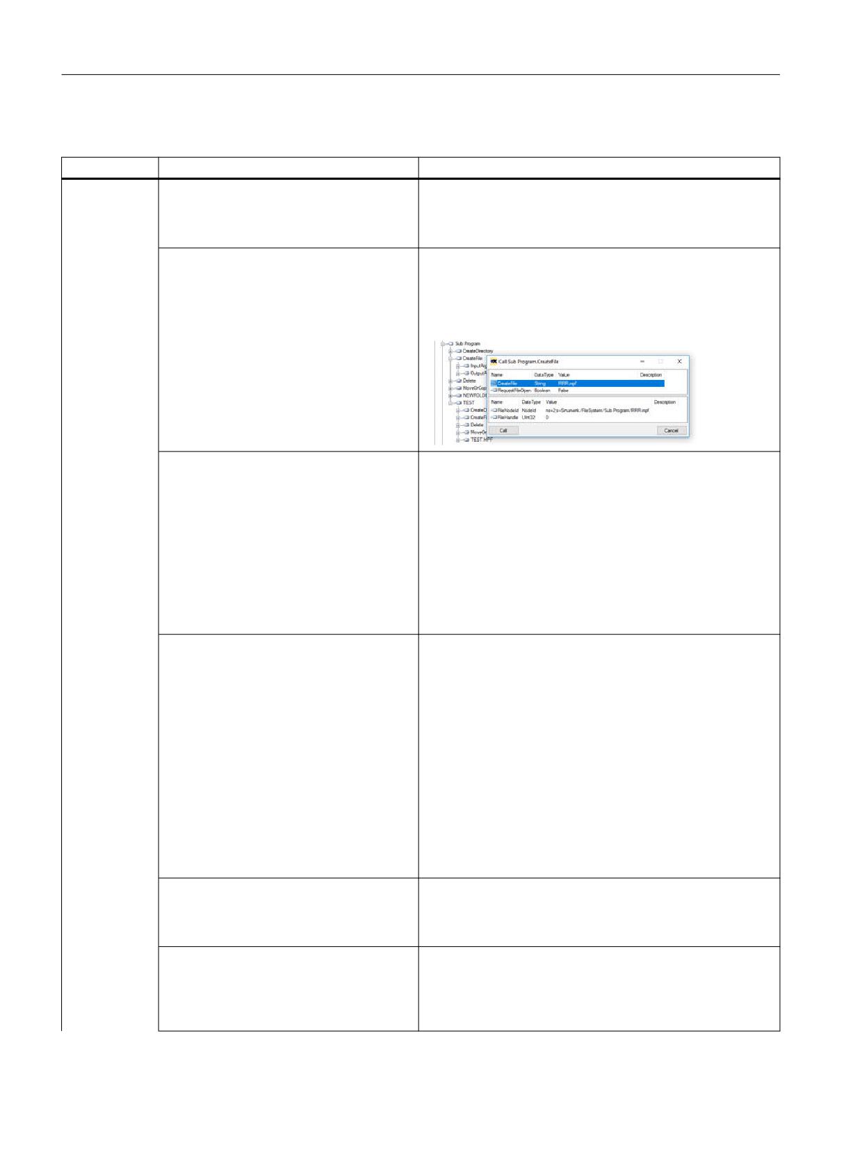
5. Select "Install software update/backup".
Figure 10-5
Install software update/backup
6. Confirm the popup message with "Yes".
Figure 10-6
Confirmation message
7. Select the package to install.
The OPC UA dialogs will become available after power off/on.
SINUMERIK Access MyMachine / OPC UA
168
Configuration Manual, 10/2020, 6FC5397-1DP41-0BA5

Trouble shooting
11
11.1
Frequently asked questions (FAQs)
Topic
Question
Possible solution
OPC UA client has no connec-
In spite of correct commissioning my OPC UA
If no connection is possible, though you have
tion
client cannot connect. What can I do?
operated the commissioning of the OPC UA
server thoroughly, it is recommended to re-
store factory settings of the OPC UA server.
Proceed as follows:
• Deactivate OPC UA in the setting dialog
• Switch off IPC/NCU and on again
• Activate OPC UA again in the setting dialog
• Switch off IPC/NCU and on again
The server cannot be found by the client. What
• Check whether the IP address of the net-
can I do?
working dialog is compatible to those of
the OPC UA dialog.
• If the IP addresses are not compatible,
press "Change" in the OPC UA setting dia-
log. The new addresses will be directly
transferred into the setting dialog.
• Confirm with "Ok" and restart the SINU-
MERIK.
The connection the server should function
properly now.
The OPC UA server status shows OK but the
• Power Off/On, the control in order to acti-
client is not able to connect. What can I do?
vate all necessary firewall settings (e.g.:
port number changed).
OPC UA export diagnosis data
How can I export OPC UA diagnosis data?
Refer to topic, "Exporting diagnosis data to an
external data storage" under chapter, "Diag-
nosis screen (Page 142)".
OPC UA client cannot connect
• Certificate user is created
Please check date and time of the target sys-
as certificate user
tem. In case the target system time is not
• Certificate for certificate user is trusted
within the period of validity (valid from - valid
• OPC UA client cannot connect as certifi-
to) of the client certificate, the connection
cate user
gets refused (BadIdentityTokenRejected).
OPC UA server is not accessi-
After a server update, the server cannot be
• Check that the time on the HMI is set cor-
ble after update
accessed anymore. What can I do?
rectly.
• Check the validity periods of the servers
and client certificates.
• Check whether port is open in the firewall.
SINUMERIK Access MyMachine / OPC UA
Configuration Manual, 10/2020, 6FC5397-1DP41-0BA5
169
Trouble shooting
11.1 Frequently asked questions (FAQs)
File Sysytem
Topic
Question
Possible solution
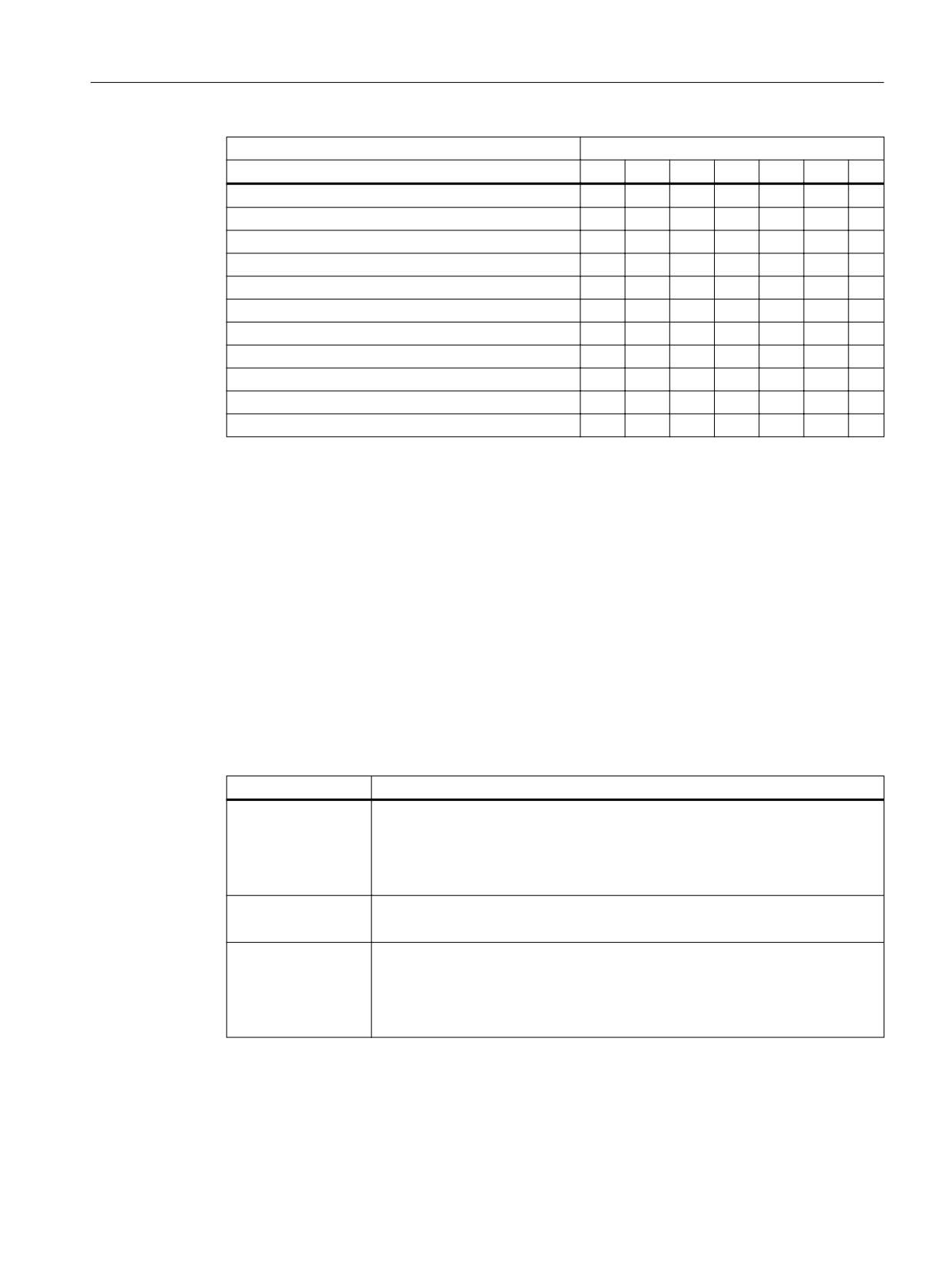
File System
How to use "CreateDirectory" method?
The OPC UA server can create a folder with any extension or
with no extensions in the USB drive, network share, and local
drive. However in the NC drive, we can create an extension
with "DIR" only.
How to use "CreateFile" method?
The "CreateFile" method is used to create a new file. The cre-
ated file can be written using the "Write" method of the File-
Type. The OPC UA server can create file without extension in
the USB drive, network share, and local drive but not in the NC
memory.
How to use "Delete" method?
• The "Delete" method is used to delete a file/directory. The
OPC UA server will not allow to delete the file if the file is
opened for the file operation. You must close the file handle
to delete the file. In case of directory, all the file and direc-
tory objects below the directory to delete are deleted re-
cursively.
• A file which is selected for execution or a folder which con-
tains the selected file are not allowed to be moved. How-
ever if the file is moved there is a possibility that an empty
file will be created.
How to use "MoveOrCopy " method?
• The "MoveOrCopy" method is used to move or copy a file/
directory to another directory or to rename a file/directory.
• The OPC UA server can move any file or folder without ex-
tension in the USB drive, network share, and local drive but
not in the NC memory. In the NC memory, a folder with the
extension "DIR" can only be allowed to be moved to the NC
memory.
• The OPC UA server will not allow to move the folder if the
file is opened for the file operation.
• A file which is selected for execution or a folder which con-
tains the selected file, are not allowed to be moved. How-
ever if the file is moved there is a possibility that an empty
file will be created.
How to use "Open " method?
When a client opens a file, it gets a file handle that is valid while
the session is open. Clients shall use the "Close" method to
release the handle when they do not need access to the file
anymore. Clients can open the same file several times for read.
How to use "Read " method?
The "Read" method is used to read a part of the file starting
from the current file position. The file position is advanced by
the number of bytes read. The data contains the returned data
of the file. If the ByteString is empty, it indicates that the end of
the file is reached.
SINUMERIK Access MyMachine / OPC UA
170
Configuration Manual, 10/2020, 6FC5397-1DP41-0BA5

Trouble shooting
11.1 Frequently asked questions (FAQs)
Topic
Question
Possible solution
How to use "Write " method?
The "Write" method is used to write a part of the file, starting
from the current file position. The file position is advanced by
the number of bytes written. When the client session is closed,
all the open file handled will be closed for the respective ses-
sion. In this scenario, if there is any existing file opened with
write mode or append mode, the current data will be lost.
How to use "Close " method?
The "Close" method is used to close a file represented by a
FileType. When a client closes a file, the handle becomes inva-
lid.
How to use "GetPostion " method?
The "GetPosition" method is used to provide the current posi-
tion of the file handle. If a "Read" or "Write" method is called, it
starts at that position.
How to use "SetPosition " method?
The "SetPosition" method is used to set the current position of
the file handle. If a "Read" or "Write" method is called, it starts
at that position. If the position is higher than the file size, the
position is set to the end of the file.
Does OPC UA standard file system support
No, only the default machine name is mapped (target system
1:N constellation?
IPC only).
See also
SINUMERIK Access MyMachine / OPC UA
Configuration Manual, 10/2020, 6FC5397-1DP41-0BA5
171
Trouble shooting
11.2 Reference to OPC UA error code
11.2
Reference to OPC UA error code
You can find all relevant information on error codes at Github (https://github.com/
OPCFoundation/UA-Nodeset/blob/master/DotNet/Opc.Ua.StatusCodes.cs).
Technical Support
Country-specific telephone numbers for technical support are provided in the Internet at the
If you have any technical questions, use the online form in the "Support Request" area.
SINUMERIK Access MyMachine / OPC UA
172
Configuration Manual, 10/2020, 6FC5397-1DP41-0BA5
Preface
Fundamental safety
1
instructions
2
Introduction
SINUMERIK
3
NC variables
SINUMERIK 840D sl
NC variables
A
Appendix A
List Manual
Valid for:
Control
SINUMERIK 840D sl / 840DE sl
Software
CNC software, Version 4.94
10/2020
6FC5397-3CP40-6BA4
Table of contents
Preface
3
1
Fundamental safety instructions
9
1.1
General safety instructions
9
1.2
Warranty and liability for application examples
9
1.3
Security information
9
2
Introduction
11
2.1
Overview
11
2.2
References
11
3
NC variables
13
3.1
Explanations on the NC variables
13
3.1.1
Data blocks
13
3.1.2
NC areas
15
3.1.3
Variable types
16
3.1.4
Data types
19
3.1.5
Structure of the data tables
19
3.2
NC variable descriptions
20
3.2.1
Axis: Axis-Specific Basic Settings
20
3.2.1.1
M: Machine data
20
3.2.1.2
SE: Setting data
77
3.2.2
Bag: Mode Group Data
83
3.2.2.1
S: State data
83
3.2.3
Channel: Channel-assigned data
85
3.2.3.1
AUXFU: Active auxiliary functions
85
3.2.3.2
CP: Generic coupling
90
3.2.3.3
DIAG: Diagnostics data, available only for internal development purposes
102
3.2.3.4
DIAGN: Diagnostic module
108
3.2.3.5
EPSP: Reserved for internal use only (ePS)
114
3.2.3.6
ETP: Event types
117
3.2.3.7
FA: Active Work Offset
126
3.2.3.8
FB: Base Frame
128
3.2.3.9
FE: External Work Offset
130
3.2.3.10
FG: Frames for grinding applications
132
3.2.3.11
FS: System Frame
134
3.2.3.12
FU: Settable Work Offset
136
3.2.3.13
M: Machine data
138
3.2.3.14
NIB: Nibbling data
186
3.2.3.15
O: Internal
188
3.2.3.16
PA: Protection zones
189
3.2.3.17
RP: Arithmetic parameter
208
3.2.3.18
S: State data
208
3.2.3.19
SE: Setting data
361
NC variables
List Manual, 10/2020, 6FC5397-3CP40-6BA4
5
Inhaltsverzeichnis
3.2.3.20
SEGA: Extended state in the WCS
365
3.2.3.21
SEMA: Extended state data in MCS
386
3.2.3.22
SGA: State data in the WCS
480
3.2.3.23
SINF: Part program-specific state data
486
3.2.3.24
SMA: State data in the MCS
491
3.2.3.25
SNCF: Active G-functions
494
3.2.3.26
SPARP: Part program information
496
3.2.3.27
SPARPF: Search pointer for block search
511
3.2.3.28
SPARPI: Program pointer at interruption
516
3.2.3.29
SPARPP: Program pointer in automatic operation mode
521
3.2.3.30
SSP: State data spindle
528
3.2.3.31
SSP2: Spindle status data for spindle conversion
544
3.2.3.32
SSYNAC: Synchronous actions
560
3.2.3.33
SYNACT: Channel-specific synchronous actions
564
3.2.3.34
TO: Tool offsets
569
3.2.3.35
VSYN: NCK-specific user variable for synchronous actions
570
3.2.3.36
WAL: Working area limitation
572
3.2.3.37
Y: System data
574
3.2.4
DriveHsa: Main spindle drive data
586
3.2.4.1
S: State data
586
3.2.5
Drive: HMI data
587
3.2.5.1
S: State data
587
3.2.6
Nck: NC data
588
3.2.6.1
CP: Generic coupling
588
3.2.6.2
DIAG: Diagnostics data, available only for internal development purposes
592
3.2.6.3
DIAGN: Diagnostic module
597
3.2.6.4
ETPD: Data list for protocolling
633
3.2.6.5
FA: Active Work Offset
636
3.2.6.6
FB: Base Frame
637
3.2.6.7
FG: Frames for grinding applications
640
3.2.6.8
FU: Settable Work Offset
642
3.2.6.9
M: Machine data
644
3.2.6.10
O: Internal
685
3.2.6.11
PA: Protection zones
688
3.2.6.12
RP: Arithmetic parameter
743
3.2.6.13
S: State data
744
3.2.6.14
SALA: Alarm list, oldest alarm
867
3.2.6.15
SALAC: Alarm actions, oldest alarm
870
3.2.6.16
SALAL: Alarm list, most recent alarm
874
3.2.6.17
SALAP: Alarm list, highest priority alarm
877
3.2.6.18
SD: Servo data
880
3.2.6.19
SE: Setting data
977
3.2.6.20
SEMA: Extended state data in MCS
984
3.2.6.21
SMA: State data in the MCS
1077
3.2.6.22
SSP: State data spindle
1081
3.2.6.23
SSP2: Spindle status data for spindle conversion
1096
3.2.6.24
VSYN: NCK-specific user variable for synchronous actions
1111
3.2.6.25
Y: System data
1111
3.2.6.26
YFAFL: NCK instruction group list (Fanuc)
1140
3.2.6.27
YNCFL: NCK instruction group list
1141
3.2.7
Tool: Tool Data
1142
3.2.7.1
AD: Adapter data (not for new developments)
1142
NC variables
6
List Manual, 10/2020, 6FC5397-3CP40-6BA4
Inhaltsverzeichnis
3.2.7.2
ADN: Adapter data
1143
3.2.7.3
AEV: Working offsets: Directory
1151
3.2.7.4
MTAD: Application-specific multitool data
1154
3.2.7.5
MTAP: Application-specific multitool place data
1155
3.2.7.6
MTD: Multitool data, general data
1155
3.2.7.7
MTP: Multitool data, place data
1161
3.2.7.8
MTUD: Multitool data, user-defined data
1162
3.2.7.9
MTUP: Multitool place user data
1163
3.2.7.10
MTV: Multitool data, directory
1163
3.2.7.11
TAD: Application-specific data
1166
3.2.7.12
TAM: Application-specific magazine data
1167
3.2.7.13
TAMD: Application-specific magazine data double
1167
3.2.7.14
TAO: Application-specific tool edge data
1168
3.2.7.15
TAP: Application-specific magazine location data
1169
3.2.7.16
TAPD: Application-specific magazine location data double
1170
3.2.7.17
TAS: Application-specific monitoring data
1172
3.2.7.18
TC: Toolholder parameters
1173
3.2.7.19
TD: Tool data, general data
1194
3.2.7.20
TDC: Tool parameters of the Siemens application
1203
3.2.7.21
TF: Used as parameter and return value of the PI-Services _N_TMGETT and _N_TSEARC... 1204
3.2.7.22
TG: Tool data, grinding-specific data
1215
3.2.7.23
TISO: ISO tool offset data
1219
3.2.7.24
TM: Magazine data, general data
1219
3.2.7.25
TMC: Magazine data, configuration data
1227
3.2.7.26
TMV: Magazine data, directory
1236
3.2.7.27
TO: Tool offsets
1238
3.2.7.28
TOE: Edge-related location-dependent coarse total offsets, setup offsets
1240
3.2.7.29
TOET: Edge-related location-dependent coarse total offsets, transformed setup offsets
1241
3.2.7.30
TOS: Edge-related positional fine total offsets
1243
3.2.7.31
TOST: Edge-related location-dependent total offsets, transformed
1245
3.2.7.32
TOT: Edge data, transformed offset data
1247
3.2.7.33
TP: Magazine location data
1251
3.2.7.34
TPM: Magazine data, multiple assignment of place data
1255
3.2.7.35
TS: Tool monitoring data
1256
3.2.7.36
TT: Magazine location data
1257
3.2.7.37
TU: Tool data for OEM
1258
3.2.7.38
TUE: Tool edge data for OEM
1259
3.2.7.39
TUM: Mgazine user data
1260
3.2.7.40
TUMD: User magazine data double
1261
3.2.7.41
TUP: Magazine place user data
1261
3.2.7.42
TUPD: User magazine location data double
1262
3.2.7.43
TUS: User monitoring data
1262
3.2.7.44
TV: Tool data, directory
1263
3.2.8
DriveVsa: Feed drive data
1266
3.2.8.1
M: Machine data
1266
3.2.8.2
S: State data
1267
A
Appendix A
1269
A.1
List of abbreviations
1269
A.2
Documentation overview SINUMERIK 840D sl
1275
NC variables
List Manual, 10/2020, 6FC5397-3CP40-6BA4
7
Fundamental safety instructions
1
1.1
General safety instructions
WARNING
Danger to life if the safety instructions and residual risks are not observed
If the safety instructions and residual risks in the associated hardware documentation are not
observed, accidents involving severe injuries or death can occur.
• Observe the safety instructions given in the hardware documentation.
• Consider the residual risks for the risk evaluation.
WARNING
Malfunctions of the machine as a result of incorrect or changed parameter settings
As a result of incorrect or changed parameterization, machines can malfunction, which in turn
can lead to injuries or death.
• Protect the parameterization against unauthorized access.
• Handle possible malfunctions by taking suitable measures, e.g. emergency stop or
emergency off.
1.2
Warranty and liability for application examples
Application examples are not binding and do not claim to be complete regarding configuration,
equipment or any eventuality which may arise. Application examples do not represent specific
customer solutions, but are only intended to provide support for typical tasks.
As the user you yourself are responsible for ensuring that the products described are operated
correctly. Application examples do not relieve you of your responsibility for safe handling when
using, installing, operating and maintaining the equipment.
1.3
Security information
Siemens provides products and solutions with industrial security functions that support the
secure operation of plants, systems, machines and networks.
In order to protect plants, systems, machines and networks against cyber threats, it is necessary
to implement - and continuously maintain - a holistic, state-of-the-art industrial security
concept. Siemens’ products and solutions constitute one element of such a concept.
Customers are responsible for preventing unauthorized access to their plants, systems,
machines and networks. Such systems, machines and components should only be connected to
NC variables
List Manual, 10/2020, 6FC5397-3CP40-6BA4
9
Fundamental safety instructions
1.3 Security information
an enterprise network or the internet if and to the extent such a connection is necessary and only
when appropriate security measures (e.g. firewalls and/or network segmentation) are in place.
For additional information on industrial security measures that may be implemented, please
visit
Siemens’ products and solutions undergo continuous development to make them more secure.
Siemens strongly recommends that product updates are applied as soon as they are available
and that the latest product versions are used. Use of product versions that are no longer
supported, and failure to apply the latest updates may increase customer’s exposure to cyber
threats.
To stay informed about product updates, subscribe to the Siemens Industrial Security RSS Feed
under
services/cert.html#Subscriptions).
Further information is provided on the Internet:
Industrial Security Configuration Manual (https://support.industry.siemens.com/cs/ww/en/
view/108862708)
WARNING
Unsafe operating states resulting from software manipulation
Software manipulations, e.g. viruses, Trojans, or worms, can cause unsafe operating states in
your system that may lead to death, serious injury, and property damage.
• Keep the software up to date.
• Incorporate the automation and drive components into a holistic, state-of-the-art industrial
security concept for the installation or machine.
• Make sure that you include all installed products into the holistic industrial security concept.
• Protect files stored on exchangeable storage media from malicious software by with suitable
protection measures, e.g. virus scanners.
• On completion of commissioning, check all security-related settings.
NC variables
10
List Manual, 10/2020, 6FC5397-3CP40-6BA4
Introduction
2
2.1
Overview
General
The NC variables can be accessed from the user interface or from the PLC via the operator panel
interface (OPI).
The structure of the NC variables and their processing is described in Section Explanations on the
NC variables (Page 13).
The tables of the NC variables contain references to further manuals with detailed information.
The references to manuals are listed in the list of manuals.
You will find more information in Chapter: References (Page 11).
2.2
References
References
The variable table has a dedicated "Lit" field for references to additional literature.
As a cross reference to the functional description of the data, the "Lit" field contains the short
designation of the corresponding chapter of a function manual respectively the short
designation of a manual.
Examples:
W1
Function Manual SINUMERIK 840D sl Tools; W1 = tool offset
FBWsl
Function Manual SINUMERIK 840D sl Tool Management
List of manuals
Reference is made to the following chapters respectively manuals:
• Function Manual Basic Functions, Chapter: A2, A4, B1, B3, H2, K1, K2, K5, K7, K10, N2, S7,
V2, TE7
• Function Manual Axes and Spindles, Chapter: B2, F1, G1, G2, H1, M3, N3, P1, P2, P5, R1, R2,
R3, S1, S3, S9, T1, T4, T5, T6, V1
• Function Manual Technologies, Chapter: M5, N4, R3, T3, TE01, TE02, TE1, TE3, TE4, TE6, TE7,
TE8
• Function Manual Tools, Chapter: W1, W4, W5
• Function Manual Transformations, Chapter: F2, K12, M1
NC variables
List Manual, 10/2020, 6FC5397-3CP40-6BA4
11
Introduction
2.2 References
• Function Manual Monitoring and Compensation, Chapter: A3, A5, K3, K6, K8, K9, K11, TE1,
TE9
• Diagnostics Manual Alarms, DA
• Safety Integrated Commissioning Manual, FBSI
• Function Manual Tool Management, FBWsl
• Function Manual Synchronous Actions, FBSY
• Description of Functions, ISO Dialects for SINUMERIK, FBFA
• Programming Manual, PG
• Programming Manual Job Planning, PGA
• Basic Software and Operating Software Commissioning Manual, IM9, BE2, IM7, IM10
• System Manual Ctrl-Energy, SCE
NC variables
12
List Manual, 10/2020, 6FC5397-3CP40-6BA4

NC variables
3
3.1
Explanations on the NC variables
3.1.1
Data blocks
Overview of the available data blocks
The following table contains an overview of available data blocks for variables of the NC and
their assignment to the individual areas.
Only those data blocks whose variables can be read or written with direct access are represented.
Data blocks whose variables can be freely defined by the programmer (e.g. global user data) are
read from the operating software or PLC using other mechanisms.
Data block
Area
A
B
C
H
N
T
V
AD
x
MTUD
x
TAO
x
TDC
x
TMV
x
TOT
x
TUE
x
TV
x
AEV
x
MTUP
x
TAP
x
TF
x
TO
x
TP
x
TUM
x
MTAD
x
MTV
x
TAPD
x
TG
x
TOE
x
TPM
x
TUMD
x
MTAP
x
NC variables
List Manual, 10/2020, 6FC5397-3CP40-6BA4
13
NC variables
3.1 Explanations on the NC variables
Data block
Area
A
B
C
H
N
T
V
TAD
x
TAS
x
TISO
x
TOET
x
TS
x
TUP
x
MTD
x
TAM
x
TC
x
TM
x
TOS
x
TT
x
TUPD
x
MTP
x
TAMD
x
TD
x
TMC
x
TOST
x
TU
x
TUS
x
ETP
x
ETPD
x
DIAGN
x
FA
x
x
FB
x
x
FE
x
FU
x
x
M
x
x
NIB
x
PA
x
x
RP
x
S
x
x
x
x
x
SALA
x
SALAL
x
SALAP
x
SE
x
x
x
SEGA
x
SEMA
x
x
SGA
x
SINF
x
SMA
x
x
SNCF
x
NC variables
14
List Manual, 10/2020, 6FC5397-3CP40-6BA4
NC variables
3.1 Explanations on the NC variables
Data block
Area
A
B
C
H
N
T
V
SPARP
x
SPARPF
x
SPARPI
x
SPARPP
x
SSP
x
x
SSP2
x
x
SSYNAC
x
SYNACT
x
VSYN
x
Y
x
x
YNCFL
x
More information
More information on which data blocks this mechanism is used for can be found in
Function Manual SINUMERIK 840D sl PLC
3.1.2
NC areas
NC areas
The NC variables are organized in data blocks that are assigned to the following NC areas.
Table 3-1
Assignment of the TO areas
Area
NC variable
NC (N)
Contains all variables that apply to the entire NC, e.g.
• System data (Y)
• Protection areas (PA)
• G groups (YNCFL), etc.
Mode group (B)
Contains all variables that apply to the mode group, e.g.
• Status data (S)
Channel (C)
Contains all variables that apply to the relevant channel, e.g.
• System data (Y)
• Protection areas (PA)
• Global status data (S)
NC variables
List Manual, 10/2020, 6FC5397-3CP40-6BA4
15
NC variables
3.1 Explanations on the NC variables
Area
NC variable
Tool (T)
Contains all variables that apply to the tools on the machine, e.g.
• Tool offset data (TO)
• General tool data (TD)
• Tool monitoring data (TS), etc.
Each tool area (T) is assigned to a channel.
Axis (A)
Contains machine and setting data that applies to the relevant axis or spindle.
More information on the axis-specific machine data can be found in
List Manual SINUMERIK 840D sl Machine Data and Parameters
Feed/main drive (V/
Contains machine data or machine data as service values that apply to the rele-
H)
vant drive.
3.1.3
Variable types
Access to an NC variable
In general, the NC variables are stored as structures or arrays of structures (tables) in the areas.
This means the following details must be specified in the address for access to an NC variable:
• Area and area number
• Block
• NC variable name (or column number)
• Line number
NC variable type
Generally, a distinction can be made between three variants for the NC variables:
• NC variables that consist of one line
• NC variables that consist of several lines
• NC variables that consist of several columns and lines
Single-line NC variable
A single-line NC variable consists of just a single value. The following information is required to
access an NC variable of this type:
• Area (and possibly the area number)
• Block
• NC variable name
NC variables
16
List Manual, 10/2020, 6FC5397-3CP40-6BA4
NC variables
3.1 Explanations on the NC variables
Table 3-2
Single-line NC variant type
numMachAxes
Number of the highest existing channel axis
-
UWord
r
Multi-line: No
Example for reading the number of axes in channel 1:
HMI:
/Channel/Configuration/numMachAxes[u1]
HMI:
P_C_Y_numMachAxes
PLC with NC variable selector:
Area
C[.]
Block
Y
NC variable
numMachAxes
Area number
1
Multi-line NC variable
This NC variable is generally defined as a one-dimensional array. The following information is
required to access an NC variable of this type:
• Area and possibly the area number
• Block
• NC variable name
• Line number
Table 3-3
Multi-line variant type
actFeedRate
S5
Actual value axial feedrate if the axis is a positioning axis.
Actual value single axis feedrate if the axis is a special axis.
mm/min, inch/min, userdef
Double
r
Multi-line: Yes
Axis number
maxnumGlobMachAxes
Example for reading the current speed of axis 3 in channel 1:
HMI:
/Channel/MachineAxis/actFeedRate[u1, 3]
HMI:
P_C_SEMA_actFeedRate
PLC with NC variable selector:
Area
C[.]
NC variables
List Manual, 10/2020, 6FC5397-3CP40-6BA4
17
NC variables
3.1 Explanations on the NC variables
Block
SEMA
NC variable
actFeedRate[.]
Area number
1
Line
3
Multi-line and multi-column NC variable
This NC variable is generally defined as a two-dimensional array. The following information is
required to access an NC variable of this type:
• Area and possibly the area number
• Block
• NC variable name
• Column number
• Line number
In this example, the complete data block consists only of these two-dimensional NC variables.
Table 3-4
Multi-line and multi-column variant type
cuttEdgeParam
Parameters of the active tool cutting edge
-
0
Double
r
Multi-line: Yes
Number of the parameter:
35
(EdgeNo - 1) * numCuttEdgeParams +
ParameterNo
Example of reading and writing the current cutting edge data for cutting edge 3 / parameter 1
of tool 3 in T area 1.
The example assumes that each tool cutting edge is defined with (numCuttEdgeParams =) 35
parameters:
HMI:
/Tool/Compensation/cuttEdgeParam[u1,c3, 51]
HMI:
P_T_TO_cuttEdgeParam
[y,z] array which is queried in SINUMERIK Operate.
PLC with NC variable selector:
Area
T[.]
Block
TO
NC variable
cuttEdgeParam[.]
Area number
1
Column
3
Line
51
NC variables
18
List Manual, 10/2020, 6FC5397-3CP40-6BA4
NC variables
3.1 Explanations on the NC variables
3.1.4
Data types
The control provides the following data types that can be used for programming:
Table 3-5
Data types
Data type
Range of values
BOOLEAN
false, true
BYTE
-128 to +127
UBYTE
0 to +255
DWORD
-2,147,483,648 to +2,147,483,647
UDWORD
0 to +4,294,967,295
DOUBLE
-1.7*10308 to +1.7*10308
STRING
Sequence of characters (→ UBYTE) with any arbitrary/specified length.
3.1.5
Structure of the data tables
Table fields
Table 3-6
Meaning of table fields
NC variable name (<Range>,
Reference to assigned machine data
Lit.
<Block>)
<NC variable brief description/ NC variable description>
Units and value ranges
Physical unit:
Data type:
Initial value:
Minimum va-
Maximum value:
lue:
Addressing
Line index description:
Maximum line index:
Read and write access
Lit.
Reference according to the list of references
See: Chapter References (Page 11)
Write access
Variable may be overwritten
Read access
Variable can be read
NC variables
List Manual, 10/2020, 6FC5397-3CP40-6BA4
19

NC variables
3.2 NC variable descriptions
3.2
NC variable descriptions
3.2.1
Axis: Axis-Specific Basic Settings
3.2.1.1
M: Machine data
OEM-MMC: LinkItem /Axis/Drive/...
Axis-specific machine data
AA_OFF_MODE (A, M)
MD 36750: $MA_AA_OFF_MODE
MD 36750: $MA_AA_OFF_MODE
Units and value ranges
Physical unit:
Data type:
-
TYPE_CHAR
Read access
ACCEL_REDUCTION_FACTOR (A, M)
MD 35230: $MA_ACCEL_REDUCTI-
ON_FACTOR
MD 35230: $MA_ACCEL_REDUCTION_FACTOR
Units and value ranges
Physical unit:
Data type:
-
TYPE_DOUBLE
Read access
ACCEL_REDUCTION_SPEED_POINT (A, M)
MD 35220: $MA_ACCEL_REDUCTI-
ON_SPEED_POINT
MD 35220: $MA_ACCEL_REDUCTION_SPEED_POINT
Units and value ranges
Physical unit:
Data type:
-
TYPE_DOUBLE
Read access
ACCEL_REDUCTION_TYPE (A, M)
MD 35242: $MA_ACCEL_REDUCTION_TY-
PE
MD 35242: $MA_ACCEL_REDUCTION_TYPE
Units and value ranges
Physical unit:
Data type:
-
TYPE_CHAR
Read access
ACCEL_TYPE_DRIVE (A, M)
MD 35240: $MA_ACCEL_TYPE_DRIVE
MD 35240: $MA_ACCEL_TYPE_DRIVE
NC variables
20
List Manual, 10/2020, 6FC5397-3CP40-6BA4
NC variables
3.2 NC variable descriptions
ACCEL_TYPE_DRIVE (A, M)
MD 35240: $MA_ACCEL_TYPE_DRIVE
Units and value ranges
Physical unit:
Data type:
-
TYPE_BOOLEAN
Read access
ACT_POS_ABS (A, M)
MD 30250: $MA_ACT_POS_ABS
MD 30250: $MA_ACT_POS_ABS
Units and value ranges
Physical unit:
Data type:
-
TYPE_DOUBLE
Addressing
Line index:
Max. line index:
2
Read access
AC_FILTER_TIME (A, M)
MD 32920: $MA_AC_FILTER_TIME
MD 32920: $MA_AC_FILTER_TIME
Units and value ranges
Physical unit:
Data type:
s, user defined
TYPE_DOUBLE
Read access
LOAD_SMOOTH_FILTER_TIME (A, M)
MD 32925: $MA_LOAD_SMOOTH_FIL-
TER_TIME
MD 32925: $MA_LOAD_SMOOTH_FILTER_TIME
Units and value ranges
Physical unit:
Data type:
s, user defined
TYPE_DOUBLE
Read access and write access
POWER_SMOOTH_FILTER_TIME (A, M)
MD 32926: $MA_POWER_SMOOTH_FIL-
TER_TIME
MD 32926: $MA_POWER_SMOOTH_FILTER_TIME
Units and value ranges
Physical unit:
Data type:
s, user defined
TYPE_DOUBLE
Read access and write access
AUTO_GET_TYPE (A, M)
MD 30552: $MA_AUTO_GET_TYPE
MD 30552: $MA_AUTO_GET_TYPE
Units and value ranges
Physical unit:
Data type:
NC variables
List Manual, 10/2020, 6FC5397-3CP40-6BA4
21
NC variables
3.2 NC variable descriptions
AUTO_GET_TYPE (A, M)
MD 30552: $MA_AUTO_GET_TYPE
-
TYPE_CHAR
Read access
AXCONF_ASSIGN_MASTER_CHAN (A, M)
MD 30550: $MA_AXCONF_ASSIGN_MAS-
TER_CHAN
MD 30550: $MA_AXCONF_ASSIGN_MASTER_CHAN
Units and value ranges
Physical unit:
Data type:
-
TYPE_CHAR
Read access
AXIS_DIAGNOSIS (A, M)
MD 36690: $MA_AXIS_DIAGNOSIS
MD 36690: $MA_AXIS_DIAGNOSIS
Units and value ranges
Physical unit:
Data type:
-
TYPE_DWORD
Read access
AX_EMERGENCY_STOP_TIME (A, M)
MD 36610: $MA_AX_EMERGEN-
CY_STOP_TIME
MD 36610: $MA_AX_EMERGENCY_STOP_TIME
Units and value ranges
Physical unit:
Data type:
s, user defined
TYPE_DOUBLE
Read access
AX_INERTIA (A, M)
MD 32650: $MA_AX_INERTIA
MD 32650: $MA_AX_INERTIA
Units and value ranges
Physical unit:
Data type:
-
TYPE_DOUBLE
Read access
AX_JERK_ENABLE (A, M)
MD 32400: $MA_AX_JERK_ENABLE
MD 32400: $MA_AX_JERK_ENABLE
Units and value ranges
Physical unit:
Data type:
-
TYPE_BOOLEAN
Read access
AX_JERK_TIME (A, M)
MD 32410: $MA_AX_JERK_TIME
MD 32410: $MA_AX_JERK_TIME
Units and value ranges
Physical unit:
Data type:
NC variables
22
List Manual, 10/2020, 6FC5397-3CP40-6BA4
NC variables
3.2 NC variable descriptions
AX_JERK_TIME (A, M)
MD 32410: $MA_AX_JERK_TIME
s, user defined
TYPE_DOUBLE
Read access
AX_MASS (A, M)
MD 32652: $MA_AX_MASS
MD 32652: $MA_AX_MASS
Units and value ranges
Physical unit:
Data type:
-
TYPE_DOUBLE
Read access
AX_MOTION_DIR (A, M)
MD 32100: $MA_AX_MOTION_DIR
MD 32100: $MA_AX_MOTION_DIR
Units and value ranges
Physical unit:
Data type:
-
TYPE_DWORD
Read access
AX_VELO_LIMIT (A, M)
MD 36200: $MA_AX_VELO_LIMIT
MD 36200: $MA_AX_VELO_LIMIT
Units and value ranges
Physical unit:
Data type:
-
TYPE_DOUBLE
Addressing
Line index:
Max. line index:
2
Read access
BACKLASH (A, M)
MD 32450: $MA_BACKLASH
MD 32450: $MA_BACKLASH
Units and value ranges
Physical unit:
Data type:
-
TYPE_DOUBLE
Addressing
Line index:
Max. line index:
2
Read access
BERO_CYCLE (A, M)
MD 31100: $MA_BERO_CYCLE
MD 31100: $MA_BERO_CYCLE
Units and value ranges
Physical unit:
Data type:
-
TYPE_DWORD
NC variables
List Manual, 10/2020, 6FC5397-3CP40-6BA4
23
NC variables
3.2 NC variable descriptions
BERO_CYCLE (A, M)
MD 31100: $MA_BERO_CYCLE
Addressing
Line index:
Max. line index:
2
Read access
BERO_DELAY_TIME_MINUS (A, M)
MD 31123: $MA_BERO_DELAY_TIME_MI-
NUS
MD 31123: $MA_BERO_DELAY_TIME_MINUS
Units and value ranges
Physical unit:
Data type:
s, user defined
TYPE_DOUBLE
Addressing
Line index:
Max. line index:
2
Read access
BERO_DELAY_TIME_PLUS (A, M)
MD 31122: $MA_BERO_DE-
LAY_TIME_PLUS
MD 31122: $MA_BERO_DELAY_TIME_PLUS
Units and value ranges
Physical unit:
Data type:
s, user defined
TYPE_DOUBLE
Addressing
Line index:
Max. line index:
2
Read access
BERO_EDGE (A, M)
MD 31120: $MA_BERO_EDGE
MD 31120: $MA_BERO_EDGE
Units and value ranges
Physical unit:
Data type:
-
TYPE_BOOLEAN
Addressing
Line index:
Max. line index:
2
Read access
BERO_EDGE_TOL (A, M)
MD 31110: $MA_BERO_EDGE_TOL
MD 31110: $MA_BERO_EDGE_TOL
Units and value ranges
Physical unit:
Data type:
-
TYPE_DWORD
NC variables
24
List Manual, 10/2020, 6FC5397-3CP40-6BA4
NC variables
3.2 NC variable descriptions
BERO_EDGE_TOL (A, M)
MD 31110: $MA_BERO_EDGE_TOL
Addressing
Line index:
Max. line index:
2
Read access
BRAKE_MODE_CHOICE (A, M)
MD 36600: $MA_BRAKE_MODE_CHOICE
MD 36600: $MA_BRAKE_MODE_CHOICE
Units and value ranges
Physical unit:
Data type:
-
TYPE_CHAR
Read access
CEC_ENABLE (A, M)
MD 32710: $MA_CEC_ENABLE
MD 32710: $MA_CEC_ENABLE
Units and value ranges
Physical unit:
Data type:
-
TYPE_BOOLEAN
Read access
CEC_MAX_SUM (A, M)
MD 32720: $MA_CEC_MAX_SUM
MD 32720: $MA_CEC_MAX_SUM
Units and value ranges
Physical unit:
Data type:
-
TYPE_DOUBLE
Read access
CEC_MAX_VELO (A, M)
MD 32730: $MA_CEC_MAX_VELO
MD 32730: $MA_CEC_MAX_VELO
Units and value ranges
Physical unit:
Data type:
-
TYPE_DOUBLE
Read access
CLAMP_POS_TOL (A, M)
MD 36050: $MA_CLAMP_POS_TOL
MD 36050: $MA_CLAMP_POS_TOL
Units and value ranges
Physical unit:
Data type:
-
TYPE_DOUBLE
Read access
COMPRESS_POS_TOL (A, M)
MD 33100: $MA_COMPRESS_POS_TOL
MD 33100: $MA_COMPRESS_POS_TOL
NC variables
List Manual, 10/2020, 6FC5397-3CP40-6BA4
25
NC variables
3.2 NC variable descriptions
COMPRESS_POS_TOL (A, M)
MD 33100: $MA_COMPRESS_POS_TOL
Units and value ranges
Physical unit:
Data type:
-
TYPE_DOUBLE
Read access
COMP_ADD_VELO_FACTOR (A, M)
MD 32760: $MA_COMP_ADD_VELO_FAC-
TOR
MD 32760: $MA_COMP_ADD_VELO_FACTOR
Units and value ranges
Physical unit:
Data type:
-
TYPE_DOUBLE
Read access
CONTOUR_TOL (A, M)
MD 36400: $MA_CONTOUR_TOL
MD 36400: $MA_CONTOUR_TOL
Units and value ranges
Physical unit:
Data type:
-
TYPE_DOUBLE
Read access
CORR_VELO (A, M)
MD 32070: $MA_CORR_VELO
MD 32070: $MA_CORR_VELO
Units and value ranges
Physical unit:
Data type:
-
TYPE_DWORD
Read access
COUPLE_POS_TOL_COARSE (A, M)
MD 37200: $MA_COUPLE_POS_TOL_CO-
ARSE
MD 37200: $MA_COUPLE_POS_TOL_COARSE
Units and value ranges
Physical unit:
Data type:
-
TYPE_DOUBLE
Read access
COUPLE_POS_TOL_FINE (A, M)
MD 37210: $MA_COUPLE_POS_TOL_FINE
MD 37210: $MA_COUPLE_POS_TOL_FINE
Units and value ranges
Physical unit:
Data type:
-
TYPE_DOUBLE
Read access
NC variables
26
List Manual, 10/2020, 6FC5397-3CP40-6BA4
NC variables
3.2 NC variable descriptions
COUPLE_VELO_TOL_COARSE (A, M)
MD 37220: $MA_COUPLE_VELO_TOL_CO-
ARSE
MD 37220: $MA_COUPLE_VELO_TOL_COARSE
Units and value ranges
Physical unit:
Data type:
-
TYPE_DOUBLE
Read access
COUPLE_VELO_TOL_FINE (A, M)
MD 37230: $MA_COUPLE_VELO_TOL_FI-
NE
MD 37230: $MA_COUPLE_VELO_TOL_FINE
Units and value ranges
Physical unit:
Data type:
-
TYPE_DOUBLE
Read access
CTRLOUT_LIMIT (A, M)
MD 36210: $MA_CTRLOUT_LIMIT
MD 36210: $MA_CTRLOUT_LIMIT
Units and value ranges
Physical unit:
Data type:
-
TYPE_DOUBLE
Read access
CTRLOUT_LIMIT_TIME (A, M)
MD 36220: $MA_CTRLOUT_LIMIT_TIME
MD 36220: $MA_CTRLOUT_LIMIT_TIME
Units and value ranges
Physical unit:
Data type:
s, user defined
TYPE_DOUBLE
Read access
CTRLOUT_NR (A, M)
MD 30120: $MA_CTRLOUT_NR
MD 30120: $MA_CTRLOUT_NR
Units and value ranges
Physical unit:
Data type:
-
TYPE_CHAR
Read access
CTRLOUT_SEGMENT_NR (A, M)
MD 30100: $MA_CTRLOUT_SEGMENT_NR
MD 30100: $MA_CTRLOUT_SEGMENT_NR
Units and value ranges
Physical unit:
Data type:
-
TYPE_CHAR
Read access
NC variables
List Manual, 10/2020, 6FC5397-3CP40-6BA4
27
NC variables
3.2 NC variable descriptions
DES_VELO_LIMIT (A, M)
MD 36520: $MA_DES_VELO_LIMIT
MD 36520: $MA_DES_VELO_LIMIT
Units and value ranges
Physical unit:
Data type:
-
TYPE_DOUBLE
Read access
DIG_P_MAX (A, M)
MD 37310: $MA_DIG_P_MAX
MD 37310: $MA_DIG_P_MAX
Units and value ranges
Physical unit:
Data type:
-
TYPE_DOUBLE
Read access
DIG_P_MIN (A, M)
MD 37300: $MA_DIG_P_MIN
MD 37300: $MA_DIG_P_MIN
Units and value ranges
Physical unit:
Data type:
-
TYPE_DOUBLE
Read access
DIG_V_MAX (A, M)
MD 37320: $MA_DIG_V_MAX
MD 37320: $MA_DIG_V_MAX
Units and value ranges
Physical unit:
Data type:
-
TYPE_DOUBLE
Read access
DISPLAY_IS_MODULO (A, M)
MD 30320: $MA_DISPLAY_IS_MODULO
MD 30320: $MA_DISPLAY_IS_MODULO
Units and value ranges
Physical unit:
Data type:
-
TYPE_BOOLEAN
Read access
DRIFT_ENABLE (A, M)
MD 36700: $MA_DRIFT_ENABLE
MD 36700: $MA_DRIFT_ENABLE
Units and value ranges
Physical unit:
Data type:
-
TYPE_BOOLEAN
Read access
NC variables
28
List Manual, 10/2020, 6FC5397-3CP40-6BA4
NC variables
3.2 NC variable descriptions
DRIFT_LIMIT (A, M)
MD 36710: $MA_DRIFT_LIMIT
MD 36710: $MA_DRIFT_LIMIT
Units and value ranges
Physical unit:
Data type:
-
TYPE_DOUBLE
Read access
DRIFT_VALUE (A, M)
MD 36720: $MA_DRIFT_VALUE
MD 36720: $MA_DRIFT_VALUE
Units and value ranges
Physical unit:
Data type:
-
TYPE_DOUBLE
Read access
DRIVE_AX_RATIO_DENOM (A, M)
MD 31050: $MA_DRIVE_AX_RATIO_DE-
NOM
MD 31050: $MA_DRIVE_AX_RATIO_DENOM
Units and value ranges
Physical unit:
Data type:
-
TYPE_DWORD
Addressing
Line index:
Max. line index:
2
Read access
DRIVE_AX_RATIO_NUMERA (A, M)
MD 31060: $MA_DRIVE_AX_RATIO_NU-
MERA
MD 31060: $MA_DRIVE_AX_RATIO_NUMERA
Units and value ranges
Physical unit:
Data type:
-
TYPE_DWORD
Addressing
Line index:
Max. line index:
2
Read access
DRIVE_ENC_RATIO_DENOM (A, M)
MD 31070: $MA_DRIVE_ENC_RATIO_DE-
NOM
MD 31070: $MA_DRIVE_ENC_RATIO_DENOM
Units and value ranges
Physical unit:
Data type:
-
TYPE_DWORD
Addressing
Line index:
Max. line index:
NC variables
List Manual, 10/2020, 6FC5397-3CP40-6BA4
29
NC variables
3.2 NC variable descriptions
DRIVE_ENC_RATIO_DENOM (A, M)
MD 31070: $MA_DRIVE_ENC_RATIO_DE-
NOM
2
Read access
DRIVE_ENC_RATIO_NUMERA (A, M)
MD 31080: $MA_DRIVE_ENC_RATIO_NU-
MERA
MD 31080: $MA_DRIVE_ENC_RATIO_NUMERA
Units and value ranges
Physical unit:
Data type:
-
TYPE_DWORD
Addressing
Line index:
Max. line index:
2
Read access
DRIVE_SIGNAL_TRACKING (A, M)
MD 36730: $MA_DRIVE_SIGNAL_TRA-
CKING
MD 36730: $MA_DRIVE_SIGNAL_TRACKING
Units and value ranges
Physical unit:
Data type:
-
TYPE_CHAR
Read access
DYN_MATCH_ENABLE (A, M)
MD 32900: $MA_DYN_MATCH_ENABLE
MD 32900: $MA_DYN_MATCH_ENABLE
Units and value ranges
Physical unit:
Data type:
-
TYPE_BOOLEAN
Read access
DYN_MATCH_TIME (A, M)
MD 32910: $MA_DYN_MATCH_TIME
MD 32910: $MA_DYN_MATCH_TIME
Units and value ranges
Physical unit:
Data type:
s, user defined
TYPE_DOUBLE
Addressing
Line index:
Max. line index:
2
Read access
ENC_ABS_TURNS_MODULO (A, M)
MD 34220: $MA_ENC_ABS_TURNS_MO-
DULO
MD 34220: $MA_ENC_ABS_TURNS_MODULO
NC variables
30
List Manual, 10/2020, 6FC5397-3CP40-6BA4
NC variables
3.2 NC variable descriptions
ENC_ABS_TURNS_MODULO (A, M)
MD 34220: $MA_ENC_ABS_TURNS_MO-
DULO
Units and value ranges
Physical unit:
Data type:
-
TYPE_DWORD
Addressing
Line index:
Max. line index:
2
Read access
ENC_CHANGE_TOL (A, M)
MD 36500: $MA_ENC_CHANGE_TOL
MD 36500: $MA_ENC_CHANGE_TOL
Units and value ranges
Physical unit:
Data type:
-
TYPE_DOUBLE
Read access
ENC_COMP_ENABLE (A, M)
MD 32700: $MA_ENC_COMP_ENABLE
MD 32700: $MA_ENC_COMP_ENABLE
Units and value ranges
Physical unit:
Data type:
-
TYPE_BOOLEAN
Addressing
Line index:
Max. line index:
2
Read access
ENC_DIFF_TOL (A, M)
MD 36510: $MA_ENC_DIFF_TOL
MD 36510: $MA_ENC_DIFF_TOL
Units and value ranges
Physical unit:
Data type:
-
TYPE_DOUBLE
Read access
ENC_FEEDBACK_POL (A, M)
MD 32110: $MA_ENC_FEEDBACK_POL
MD 32110: $MA_ENC_FEEDBACK_POL
Units and value ranges
Physical unit:
Data type:
-
TYPE_DWORD
Addressing
Line index:
Max. line index:
2
Read access
NC variables
List Manual, 10/2020, 6FC5397-3CP40-6BA4
31
NC variables
3.2 NC variable descriptions
ENC_FREQ_LIMIT (A, M)
MD 36300: $MA_ENC_FREQ_LIMIT
MD 36300: $MA_ENC_FREQ_LIMIT
Units and value ranges
Physical unit:
Data type:
-
TYPE_DOUBLE
Addressing
Line index:
Max. line index:
2
Read access
ENC_FREQ_LIMIT_LOW (A, M)
MD 36302: $MA_ENC_FREQ_LIMIT_LOW
MD 36302: $MA_ENC_FREQ_LIMIT_LOW
Units and value ranges
Physical unit:
Data type:
-
TYPE_DOUBLE
Addressing
Line index:
Max. line index:
2
Read access
ENC_GRID_POINT_DIST (A, M)
MD 31010: $MA_ENC_GRID_POINT_DIST
MD 31010: $MA_ENC_GRID_POINT_DIST
Units and value ranges
Physical unit:
Data type:
-
TYPE_DOUBLE
Addressing
Line index:
Max. line index:
2
Read access
ENC_INPUT_NR (A, M)
MD 30230: $MA_ENC_INPUT_NR
MD 30230: $MA_ENC_INPUT_NR
Units and value ranges
Physical unit:
Data type:
-
TYPE_CHAR
Addressing
Line index:
Max. line index:
2
Read access
ENC_INVERS (A, M)
MD 34320: $MA_ENC_INVERS
MD 34320: $MA_ENC_INVERS
NC variables
32
List Manual, 10/2020, 6FC5397-3CP40-6BA4
NC variables
3.2 NC variable descriptions
ENC_INVERS (A, M)
MD 34320: $MA_ENC_INVERS
Units and value ranges
Physical unit:
Data type:
-
TYPE_BOOLEAN
Addressing
Line index:
Max. line index:
2
Read access
ENC_IS_DIRECT (A, M)
MD 31040: $MA_ENC_IS_DIRECT
MD 31040: $MA_ENC_IS_DIRECT
Units and value ranges
Physical unit:
Data type:
-
TYPE_BOOLEAN
Addressing
Line index:
Max. line index:
2
Read access
ENC_IS_INDEPENDENT (A, M)
MD 30242: $MA_ENC_IS_INDEPENDENT
MD 30242: $MA_ENC_IS_INDEPENDENT
Units and value ranges
Physical unit:
Data type:
-
TYPE_BOOLEAN
Addressing
Line index:
Max. line index:
2
Read access
ENC_IS_LINEAR (A, M)
MD 31000: $MA_ENC_IS_LINEAR
MD 31000: $MA_ENC_IS_LINEAR
Units and value ranges
Physical unit:
Data type:
-
TYPE_BOOLEAN
Addressing
Line index:
Max. line index:
2
Read access
ENC_MARKER_INC (A, M)
MD 34310: $MA_ENC_MARKER_INC
MD 34310: $MA_ENC_MARKER_INC
Units and value ranges
Physical unit:
Data type:
-
TYPE_DOUBLE
NC variables
List Manual, 10/2020, 6FC5397-3CP40-6BA4
33
NC variables
3.2 NC variable descriptions
ENC_MARKER_INC (A, M)
MD 34310: $MA_ENC_MARKER_INC
Addressing
Line index:
Max. line index:
2
Read access
ENC_REFP_MARKER_DIST (A, M)
MD 34300: $MA_ENC_REFP_MAR-
KER_DIST
MD 34300: $MA_ENC_REFP_MARKER_DIST
Units and value ranges
Physical unit:
Data type:
-
TYPE_DOUBLE
Addressing
Line index:
Max. line index:
2
Read access
ENC_REFP_MODE (A, M)
MD 34200: $MA_ENC_REFP_MODE
MD 34200: $MA_ENC_REFP_MODE
Units and value ranges
Physical unit:
Data type:
-
TYPE_CHAR
Addressing
Line index:
Max. line index:
2
Read access
ENC_REFP_STATE (A, M)
MD 34210: $MA_ENC_REFP_STATE
MD 34210: $MA_ENC_REFP_STATE
Units and value ranges
Physical unit:
Data type:
-
TYPE_CHAR
Addressing
Line index:
Max. line index:
2
Read access
ENC_RESOL (A, M)
MD 31020: $MA_ENC_RESOL
MD 31020: $MA_ENC_RESOL
Units and value ranges
Physical unit:
Data type:
-
TYPE_DWORD
Addressing
Line index:
Max. line index:
NC variables
34
List Manual, 10/2020, 6FC5397-3CP40-6BA4
NC variables
3.2 NC variable descriptions
ENC_RESOL (A, M)
MD 31020: $MA_ENC_RESOL
2
Read access
ENC_SEGMENT_NR (A, M)
MD 30210: $MA_ENC_SEGMENT_NR
MD 30210: $MA_ENC_SEGMENT_NR
Units and value ranges
Physical unit:
Data type:
-
TYPE_CHAR
Addressing
Line index:
Max. line index:
2
Read access
ENC_SSI_MESSAGE_FORMAT (A, M)
MD 34420: $MA_ENC_SSI_MES-
SAGE_FORMAT
MD 34420: $MA_ENC_SSI_MESSAGE_FORMAT
Units and value ranges
Physical unit:
Data type:
-
TYPE_CHAR
Addressing
Line index:
Max. line index:
2
Read access
ENC_SSI_MESSAGE_LENGTH (A, M)
MD 34410: $MA_ENC_SSI_MES-
SAGE_LENGTH
MD 34410: $MA_ENC_SSI_MESSAGE_LENGTH
Units and value ranges
Physical unit:
Data type:
-
TYPE_CHAR
Addressing
Line index:
Max. line index:
2
Read access
ENC_SSI_STATUS (A, M)
MD 34400: $MA_ENC_SSI_STATUS
MD 34400: $MA_ENC_SSI_STATUS
Units and value ranges
Physical unit:
Data type:
-
TYPE_CHAR
Addressing
Line index:
Max. line index:
NC variables
List Manual, 10/2020, 6FC5397-3CP40-6BA4
35
NC variables
3.2 NC variable descriptions
ENC_SSI_STATUS (A, M)
MD 34400: $MA_ENC_SSI_STATUS
2
Read access
ENC_ZERO_MONITORING (A, M)
MD 36310: $MA_ENC_ZERO_MONITO-
RING
MD 36310: $MA_ENC_ZERO_MONITORING
Units and value ranges
Physical unit:
Data type:
-
TYPE_DWORD
Addressing
Line index:
Max. line index:
2
Read access
EPS_TLIFT_TANG_STEP (A, M)
MD 37400: $MA_EPS_TLIFT_TANG_STEP
MD 37400: $MA_EPS_TLIFT_TANG_STEP
Units and value ranges
Physical unit:
Data type:
-
TYPE_DOUBLE
Read access
EQUIV_CURRCTRL_TIME (A, M)
MD 32800: $MA_EQUIV_CURRCTRL_TIME
MD 32800: $MA_EQUIV_CURRCTRL_TIME
Units and value ranges
Physical unit:
Data type:
s, user defined
TYPE_DOUBLE
Addressing
Line index:
Max. line index:
2
Read access
EQUIV_SPEEDCTRL_TIME (A, M)
MD 32810:
$MA_EQUIV_SPEEDCTRL_TIME
MD 32810: $MA_EQUIV_SPEEDCTRL_TIME
Units and value ranges
Physical unit:
Data type:
s, user defined
TYPE_DOUBLE
Addressing
Line index:
Max. line index:
2
Read access
NC variables
36
List Manual, 10/2020, 6FC5397-3CP40-6BA4
NC variables
3.2 NC variable descriptions
FFW_ACTIVATION_MODE (A, M)
MD 32630: $MA_FFW_ACTIVATION_MO-
DE
MD 32630: $MA_FFW_ACTIVATION_MODE
Units and value ranges
Physical unit:
Data type:
-
TYPE_CHAR
Read access
FFW_MODE (A, M)
MD 32620: $MA_FFW_MODE
MD 32620: $MA_FFW_MODE
Units and value ranges
Physical unit:
Data type:
-
TYPE_CHAR
Read access
FIPO_TYPE (A, M)
MD 33000: $MA_FIPO_TYPE
MD 33000: $MA_FIPO_TYPE
Units and value ranges
Physical unit:
Data type:
-
TYPE_CHAR
Read access
FIXED_STOP_ACKN_MASK (A, M)
MD 37060: $MA_FI-
XED_STOP_ACKN_MASK
MD 37060: $MA_FIXED_STOP_ACKN_MASK
Units and value ranges
Physical unit:
Data type:
-
TYPE_CHAR
Read access
FIXED_STOP_ALARM_MASK (A, M)
MD 37050: $MA_FI-
XED_STOP_ALARM_MASK
MD 37050: $MA_FIXED_STOP_ALARM_MASK
Units and value ranges
Physical unit:
Data type:
-
TYPE_CHAR
Read access
FIXED_STOP_ANA_TORQUE (A, M)
MD 37070: $MA_FIXED_STOP_ANA_TOR-
QUE
MD 37070: $MA_FIXED_STOP_ANA_TORQUE
Units and value ranges
Physical unit:
Data type:
NC variables
List Manual, 10/2020, 6FC5397-3CP40-6BA4
37
NC variables
3.2 NC variable descriptions
FIXED_STOP_ANA_TORQUE (A, M)
MD 37070: $MA_FIXED_STOP_ANA_TOR-
QUE
-
TYPE_DOUBLE
Read access
FIXED_STOP_BY_SENSOR (A, M)
MD 37040: $MA_FIXED_STOP_BY_SEN-
SOR
MD 37040: $MA_FIXED_STOP_BY_SENSOR
Units and value ranges
Physical unit:
Data type:
-
TYPE_CHAR
Read access
FIXED_STOP_MODE (A, M)
MD 37000: $MA_FIXED_STOP_MODE
MD 37000: $MA_FIXED_STOP_MODE
Units and value ranges
Physical unit:
Data type:
-
TYPE_CHAR
Read access
FIXED_STOP_THRESHOLD (A, M)
MD 37030: $MA_FIXED_STOP_THRES-
HOLD
MD 37030: $MA_FIXED_STOP_THRESHOLD
Units and value ranges
Physical unit:
Data type:
-
TYPE_DOUBLE
Read access
FIXED_STOP_TORQUE_DEF (A, M)
MD 37010: $MA_FIXED_STOP_TOR-
QUE_DEF
MD 37010: $MA_FIXED_STOP_TORQUE_DEF
Units and value ranges
Physical unit:
Data type:
-
TYPE_DOUBLE
Read access
FIXED_STOP_WINDOW_DEF (A, M)
MD 37020: $MA_FIXED_STOP_WIND-
OW_DEF
MD 37020: $MA_FIXED_STOP_WINDOW_DEF
Units and value ranges
Physical unit:
Data type:
-
TYPE_DOUBLE
Read access
NC variables
38
List Manual, 10/2020, 6FC5397-3CP40-6BA4
NC variables
3.2 NC variable descriptions
FIX_POINT_POS (A, M)
MD 30600: $MA_FIX_POINT_POS
MD 30600: $MA_FIX_POINT_POS
Units and value ranges
Physical unit:
Data type:
-
TYPE_DOUBLE
Addressing
Line index:
Max. line index:
2
Read access
FRAME_OR_CORRPOS_NOTALLOWED (A, M)
MD 32074: $MA_FRAME_OR_CORR-
POS_NOTALLOWED
MD 32074: $MA_FRAME_OR_CORRPOS_NOTALLOWED
Units and value ranges
Physical unit:
Data type:
-
TYPE_DWORD
Read access
FREQUENCY1 (A, M)
MD 31310: $MA_FREQUENCY1
MD 31310: $MA_FREQUENCY1
Units and value ranges
Physical unit:
Data type:
-
TYPE_DOUBLE
Read access
FREQUENCY2 (A, M)
MD 31320: $MA_FREQUENCY2
MD 31320: $MA_FREQUENCY2
Units and value ranges
Physical unit:
Data type:
-
TYPE_DOUBLE
Read access
FREQ_REDUCTION_POINT1 (A, M)
MD 31330: $MA_FREQ_REDUCTI-
ON_POINT1
MD 31330: $MA_FREQ_REDUCTION_POINT1
Units and value ranges
Physical unit:
Data type:
-
TYPE_DOUBLE
Read access
FREQ_REDUCTION_POINT2 (A, M)
MD 31340: $MA_FREQ_REDUCTI-
ON_POINT2
MD 31340: $MA_FREQ_REDUCTION_POINT2
NC variables
List Manual, 10/2020, 6FC5397-3CP40-6BA4
39
NC variables
3.2 NC variable descriptions
FREQ_REDUCTION_POINT2 (A, M)
MD 31340: $MA_FREQ_REDUCTI-
ON_POINT2
Units and value ranges
Physical unit:
Data type:
-
TYPE_DOUBLE
Read access
FREQ_STEP_LIMIT (A, M)
MD 31350: $MA_FREQ_STEP_LIMIT
MD 31350: $MA_FREQ_STEP_LIMIT
Units and value ranges
Physical unit:
Data type:
-
TYPE_DOUBLE
Read access
FRICT_COMP_ACCEL1 (A, M)
MD 32550: $MA_FRICT_COMP_ACCEL1
MD 32550: $MA_FRICT_COMP_ACCEL1
Units and value ranges
Physical unit:
Data type:
-
TYPE_DOUBLE
Read access
FRICT_COMP_ACCEL2 (A, M)
MD 32560: $MA_FRICT_COMP_ACCEL2
MD 32560: $MA_FRICT_COMP_ACCEL2
Units and value ranges
Physical unit:
Data type:
-
TYPE_DOUBLE
Read access
FRICT_COMP_ACCEL3 (A, M)
MD 32570: $MA_FRICT_COMP_ACCEL3
MD 32570: $MA_FRICT_COMP_ACCEL3
Units and value ranges
Physical unit:
Data type:
-
TYPE_DOUBLE
Read access
FRICT_COMP_ADAPT_ENABLE (A, M)
MD 32510:
$MA_FRICT_COMP_ADAPT_ENABLE
MD 32510: $MA_FRICT_COMP_ADAPT_ENABLE
Units and value ranges
Physical unit:
Data type:
-
TYPE_BOOLEAN
Read access
NC variables
40
List Manual, 10/2020, 6FC5397-3CP40-6BA4
NC variables
3.2 NC variable descriptions
FRICT_COMP_CONST_MAX (A, M)
MD 32520:
$MA_FRICT_COMP_CONST_MAX
MD 32520: $MA_FRICT_COMP_CONST_MAX
Units and value ranges
Physical unit:
Data type:
-
TYPE_DOUBLE
Read access
FRICT_COMP_CONST_MIN (A, M)
MD 32530:
$MA_FRICT_COMP_CONST_MIN
MD 32530: $MA_FRICT_COMP_CONST_MIN
Units and value ranges
Physical unit:
Data type:
-
TYPE_DOUBLE
Read access
FRICT_COMP_ENABLE (A, M)
MD 32500: $MA_FRICT_COMP_ENABLE
MD 32500: $MA_FRICT_COMP_ENABLE
Units and value ranges
Physical unit:
Data type:
-
TYPE_BOOLEAN
Read access
FRICT_COMP_INC_FACTOR (A, M)
MD 32580: $MA_FRICT_COMP_INC_FAC-
TOR
MD 32580: $MA_FRICT_COMP_INC_FACTOR
Units and value ranges
Physical unit:
Data type:
-
TYPE_DOUBLE
Read access
FRICT_COMP_MODE (A, M)
MD 32490: $MA_FRICT_COMP_MODE
MD 32490: $MA_FRICT_COMP_MODE
Units and value ranges
Physical unit:
Data type:
-
TYPE_CHAR
Read access
FRICT_COMP_TIME (A, M)
MD 32540: $MA_FRICT_COMP_TIME
MD 32540: $MA_FRICT_COMP_TIME
Units and value ranges
Physical unit:
Data type:
s, user defined
TYPE_DOUBLE
Read access
NC variables
List Manual, 10/2020, 6FC5397-3CP40-6BA4
41
NC variables
3.2 NC variable descriptions
GANTRY_AXIS_TYPE (A, M)
MD 37100: $MA_GANTRY_AXIS_TYPE
MD 37100: $MA_GANTRY_AXIS_TYPE
Units and value ranges
Physical unit:
Data type:
-
TYPE_CHAR
Read access
GANTRY_BREAK_UP (A, M)
MD 37140: $MA_GANTRY_BREAK_UP
MD 37140: $MA_GANTRY_BREAK_UP
Units and value ranges
Physical unit:
Data type:
-
TYPE_BOOLEAN
Read access
GANTRY_POS_TOL_ERROR (A, M)
MD 37120: $MA_GANTRY_POS_TOL_ER-
ROR
MD 37120: $MA_GANTRY_POS_TOL_ERROR
Units and value ranges
Physical unit:
Data type:
-
TYPE_DOUBLE
Read access
GANTRY_POS_TOL_REF (A, M)
MD 37130: $MA_GANTRY_POS_TOL_REF
MD 37130: $MA_GANTRY_POS_TOL_REF
Units and value ranges
Physical unit:
Data type:
-
TYPE_DOUBLE
Read access
GANTRY_POS_TOL_WARNING (A, M)
MD 37110: $MA_GANT-
RY_POS_TOL_WARNING
MD 37110: $MA_GANTRY_POS_TOL_WARNING
Units and value ranges
Physical unit:
Data type:
-
TYPE_DOUBLE
Read access
NC variables
42
List Manual, 10/2020, 6FC5397-3CP40-6BA4
NC variables
3.2 NC variable descriptions
GEAR_STEP_CHANGE_ENABLE (A, M)
MD 35010: $MA_GE-
AR_STEP_CHANGE_ENABLE
Parameterize gear stage change
Meaning of bit places:
o Bit 0 = 0 and bit 1 = 0:
There is an invariable transformation ratio between motor and load. The MD of the first gear stage is active. Gear stage change
is not possible with M40 to M45.
o Bit 0 = 1:
Gear stage change at undefined change position. The gearbox can have up to 5 gear stages, which can be selected via M40,
M41 to M45. To support the gear stage change, the motor can carry out oscillating motions, which must be enabled by the PLC
program.
o Bit 1 = 1:
Same meaning as bit 0 = 1, but the gear stage change is carried out at a configured spindle position. The change position is
configured in MD35012 $MA_GEAR_STEP_CHANGE_POSITION. The position is approached in the current gear stage before the
gear stage change. If this bit is set, bit 0 is not taken into account!
o Bit 2: Reserved
o Bit 3 = 1:
The gear stage change dialog between NCK and PLC is simulated. The setpoint gear stage is output to the PLC. The system does
not wait for a feedback signal from the PLC to the NCK. The acknowledgment is generated internally in the NCK.
o Bit 4: Reserved
o Bit 5 = 1:
The second gear stage data set is used when tapping with G331/G332. The bit must be set for the master spindle used when
tapping. Bit 0 or bit 1 must be set.
Units and value ranges
Physical unit:
Data type:
-
TYPE_DWORD
Read access
GEAR_STEP_MAX_VELO (A, M)
MD 35110: $MA_GEAR_STEP_MAX_VELO
MD 35110: $MA_GEAR_STEP_MAX_VELO
Units and value ranges
Physical unit:
Data type:
-
TYPE_DOUBLE
Addressing
Line index:
Max. line index:
2
Read access
GEAR_STEP_MAX_VELO_LIMIT (A, M)
MD 35130: $MA_GEAR_STEP_MAX_VE-
LO_LIMIT
MD 35130: $MA_GEAR_STEP_MAX_VELO_LIMIT
Units and value ranges
Physical unit:
Data type:
-
TYPE_DOUBLE
NC variables
List Manual, 10/2020, 6FC5397-3CP40-6BA4
43
NC variables
3.2 NC variable descriptions
GEAR_STEP_MAX_VELO_LIMIT (A, M)
MD 35130: $MA_GEAR_STEP_MAX_VE-
LO_LIMIT
Addressing
Line index:
Max. line index:
2
Read access
GEAR_STEP_MIN_VELO (A, M)
MD 35120: $MA_GEAR_STEP_MIN_VELO
MD 35120: $MA_GEAR_STEP_MIN_VELO
Units and value ranges
Physical unit:
Data type:
-
TYPE_DOUBLE
Addressing
Line index:
Max. line index:
2
Read access
GEAR_STEP_MIN_VELO_LIMIT (A, M)
MD 35140: $MA_GEAR_STEP_MIN_VE-
LO_LIMIT
MD 35140: $MA_GEAR_STEP_MIN_VELO_LIMIT
Units and value ranges
Physical unit:
Data type:
-
TYPE_DOUBLE
Addressing
Line index:
Max. line index:
2
Read access
GEAR_STEP_POSCTRL_ACCEL (A, M)
MD 35210: $MA_GE-
AR_STEP_POSCTRL_ACCEL
MD 35210: $MA_GEAR_STEP_POSCTRL_ACCEL
Units and value ranges
Physical unit:
Data type:
-
TYPE_DOUBLE
Addressing
Line index:
Max. line index:
2
Read access
GEAR_STEP_SPEEDCTRL_ACCEL (A, M)
MD 35200: $MA_GE-
AR_STEP_SPEEDCTRL_ACCEL
MD 35200: $MA_GEAR_STEP_SPEEDCTRL_ACCEL
Units and value ranges
Physical unit:
Data type:
-
TYPE_DOUBLE
NC variables
44
List Manual, 10/2020, 6FC5397-3CP40-6BA4
NC variables
3.2 NC variable descriptions
GEAR_STEP_SPEEDCTRL_ACCEL (A, M)
MD 35200: $MA_GE-
AR_STEP_SPEEDCTRL_ACCEL
Addressing
Line index:
Max. line index:
2
Read access
HANDWH_MAX_INCR_SIZE (A, M)
MD 32080:
$MA_HANDWH_MAX_INCR_SIZE
MD 32080: $MA_HANDWH_MAX_INCR_SIZE
Units and value ranges
Physical unit:
Data type:
-
TYPE_DOUBLE
Read access
HANDWH_MAX_INCR_VELO_SIZE (A, M)
MD 32082:
$MA_HANDWH_MAX_INCR_VELO_SIZE
MD 32082: $MA_HANDWH_MAX_INCR_VELO_SIZE
Units and value ranges
Physical unit:
Data type:
-
TYPE_DOUBLE
Read access
HANDWH_STOP_COND (A, M)
MD 32084: $MA_HANDWH_STOP_COND
MD 32084: $MA_HANDWH_STOP_COND
Units and value ranges
Physical unit:
Data type:
-
TYPE_DWORD
Read access
HANDWH_VELO_OVERLAY_FACTOR (A, M)
MD 32090: $MA_HANDWH_VELO_OVER-
LAY_FACTOR
MD 32090: $MA_HANDWH_VELO_OVERLAY_FACTOR
Units and value ranges
Physical unit:
Data type:
-
TYPE_DOUBLE
Read access
HIRTH_IS_ACTIVE (A, M)
MD 30505: $MA_HIRTH_IS_ACTIVE
MD 30505: $MA_HIRTH_IS_ACTIVE
Units and value ranges
Physical unit:
Data type:
-
TYPE_BOOLEAN
Read access
NC variables
List Manual, 10/2020, 6FC5397-3CP40-6BA4
45
NC variables
3.2 NC variable descriptions
INDEX_AX_ASSIGN_POS_TAB (A, M)
MD 30500: $MA_INDEX_AX_AS-
SIGN_POS_TAB
Axis is an indexing axis
The variable defines the axis as an indexing axis.
Machine axes which only have to approach certain positions can be defined as indexing axes. The positions are shown in
position tables 1 and 2:
Multiple axes can also be assigned to an indexing position table.
The requirement for this is that these indexing axes are of the same type (linear axis,
rotary axis).
Return value
o =0: The axis is not declared as an indexing axis.
o =1: The axis is an indexing axis. The associated indexing positions are shown in
table 1 (MD10910 $MN_INDEX_AX_POS_TAB_1).
o =2: The axis is an indexing axis. The associated indexing positions are shown in
table 2 (MD10930 $MN_INDEX_AX_POS_TAB_2).
o =3: Equidistant indexing
o >3: Alarm 17090 "Value greater than upper limit"
Units and value ranges
Physical unit:
Data type:
-
TYPE_CHAR
Read access
INDEX_AX_DENOMINATOR (A, M)
MD 30502: $MA_INDEX_AX_DENOMINA-
TOR
MD 30502: $MA_INDEX_AX_DENOMINATOR
Units and value ranges
Physical unit:
Data type:
-
TYPE_DWORD
Read access
INDEX_AX_NUMERATOR (A, M)
MD 30501: $MA_INDEX_AX_NUMERATOR
MD 30501: $MA_INDEX_AX_NUMERATOR
Units and value ranges
Physical unit:
Data type:
-
TYPE_DOUBLE
Read access
INDEX_AX_OFFSET (A, M)
MD 30503: $MA_INDEX_AX_OFFSET
MD 30503: $MA_INDEX_AX_OFFSET
Units and value ranges
Physical unit:
Data type:
-
TYPE_DOUBLE
Read access
NC variables
46
List Manual, 10/2020, 6FC5397-3CP40-6BA4
NC variables
3.2 NC variable descriptions
IS_CC_AX (A, M)
MD 30400: $MA_IS_CC_AX
MD 30400: $MA_IS_CC_AX
Units and value ranges
Physical unit:
Data type:
-
TYPE_BOOLEAN
Read access
IS_CONCURRENT_POS_AX (A, M)
MD 30450: $MA_IS_CONCUR-
RENT_POS_AX
MD 30450: $MA_IS_CONCURRENT_POS_AX
Units and value ranges
Physical unit:
Data type:
-
TYPE_BOOLEAN
Read access
IS_ROT_AX (A, M)
MD 30300: $MA_IS_ROT_AX
MD 30300: $MA_IS_ROT_AX
Units and value ranges
Physical unit:
Data type:
-
TYPE_BOOLEAN
Read access
IS_VIRTUAL_AX (A, M)
MD 30132: $MA_IS_VIRTUAL_AX
Axis is a virtual axis
The variable defines an axis as a virtual axis.
A virtual axis is an axis which is interpolated in follow-up mode. The virtual axis is used with master value coupling.
Examples are the electronic transfer CP, master value coupling with curve tables or flying scissors.
Units and value ranges
Physical unit:
Data type:
-
TYPE_BOOLEAN
Read access
JOG_AND_POS_JERK_ENABLE (A, M)
MD 32420:
$MA_JOG_AND_POS_JERK_ENABLE
MD 32420: $MA_JOG_AND_POS_JERK_ENABLE
Units and value ranges
Physical unit:
Data type:
-
TYPE_BOOLEAN
Read access
JOG_AND_POS_MAX_JERK (A, M)
MD 32430:
$MA_JOG_AND_POS_MAX_JERK
MD 32430: $MA_JOG_AND_POS_MAX_JERK
NC variables
List Manual, 10/2020, 6FC5397-3CP40-6BA4
47
NC variables
3.2 NC variable descriptions
JOG_AND_POS_MAX_JERK (A, M)
MD 32430:
$MA_JOG_AND_POS_MAX_JERK
Units and value ranges
Physical unit:
Data type:
-
TYPE_DOUBLE
Read access
JOG_INCR_WEIGHT (A, M)
MD 31090: $MA_JOG_INCR_WEIGHT
MD 31090: $MA_JOG_INCR_WEIGHT
Units and value ranges
Physical unit:
Data type:
-
TYPE_DOUBLE
Read access
JOG_REV_VELO (A, M)
MD 32050: $MA_JOG_REV_VELO
MD 32050: $MA_JOG_REV_VELO
Units and value ranges
Physical unit:
Data type:
-
TYPE_DOUBLE
Read access
JOG_REV_VELO_RAPID (A, M)
MD 32040: $MA_JOG_REV_VELO_RAPID
MD 32040: $MA_JOG_REV_VELO_RAPID
Units and value ranges
Physical unit:
Data type:
-
TYPE_DOUBLE
Read access
JOG_VELO (A, M)
MD 32020: $MA_JOG_VELO
Jog axis velocity
The specified velocity applies to traversing in JOG mode with an axial feedrate override switch setting of 100%.
The velocity is only used if the general SD41110 $SN_JOG_SET_VELO = 0 and the linear feedrate is selected
(SD41100 $SN_JOG_REV_IS_ACTIVE = 0) for linear axes, or SD41130 $SN_JOG_ROT_AX_SET_VELO = 0 is selected for rotary
axes.
Units and value ranges
Physical unit:
Data type:
-
TYPE_DOUBLE
Read access
NC variables
48
List Manual, 10/2020, 6FC5397-3CP40-6BA4