SINUMERIK 840D sl. Service - Configuring Commissioning. Manual (2011-2020) - page 49
Generating user dialogs
2.19 Project-specific text files
Dialog script
xmldial.xml
<DialogGui textfile="main_form_screens">
<menu name = "main">
<open_form name = "main_form" />
<softkey POSITION="1">
<caption>Menu 2</caption>
<navigation>menu_2</navigation>
</softkey>
</menu>
<menu name = "menu_2" textfile="main2_sktext_screens">
<open_form name = "form2" />
<softkey POSITION="1">
<caption>$$SK1</caption>
</softkey>
<softkey_back>
<navigation>main</navigation>
</softkey_back>
</menu>
<form name="main_form" >
<init>
<data_access type = "true" />
<caption>$$MAIN_FORM_TITLE</caption>
</init>
<paint>
<text xpos="5" ypos="30">$$MAIN_FORM_TEXT</text>
</paint>
</form>
<form name="form2" textfile="form2_screens">
<init>
<data_access type = "true" />
<caption>$$FORM2_TITLE</caption>
</init>
<paint>
<text xpos="5" ypos="30">$$FORM2_TEXT</text>
</paint>
</form>
</DialogGui>
2.19.2
Specifying text context
Grouping of the texts is possible within a text file by way of independently named area names.
The area identifier is defined within the context tag with the name tag.
Syntax
<context>
<name>name</name>
</context>
Easy XML
Programming Manual, 10/2020, 6FC5397-1DP40-6BA4
245
Generating user dialogs
2.19 Project-specific text files
Example
<context>
<name>my context 1</name>
</context>
<context>
<name>my context 2</name>
</context>
If particular context is being used, the context name is to be specified together with the text file
name for a project, a form or a menu via the TEXTCONTEXT attribute. Access to texts stored
within the context remains possible until a new context is set. Thus, a context set for the project
is replaced by the context set for a form or a menu.
Project example
form2_screens_deu.ts
?xml version="1.0" encoding="UTF-8" ?>
<!DOCTYPE TS>
<TS>
<context>
<name>EASY_XML</name>
<message>
<source>FORM2_TITLE</source>
<translation>Form2 Title</translation>
</message>
<message>
<source>FORM2_TEXT</source>
<translation>Form2 text from text file</translation>
</message>
</context>
<context>
<name>MY_FORM_CONTEXT</name>
<message>
<source>FORM3_TITLE</source>
<translation>Title from the text context MY_FORM_CONTEXT</translation>
</message>
<message>
<source>FORM3_TEXT</source>
<translation>Form3 text from text file</translation>
</message>
</context>
<context>
<name>MY_SOFTKEY_CONTEXT</name>
<message>
<source>MENU3_SK1</source>
<translation>SK%n1</translation>
</message>
</context>
</TS>
Easy XML
246
Programming Manual, 10/2020, 6FC5397-1DP40-6BA4
Generating user dialogs
2.19 Project-specific text files
using_textcontext.xml
<menu name = "menu3" textfile="form2_screens"
textcontext="MY_SOFTKEY_CONTEXT">
<open_form name = "menu3_form" />
<softkey POSITION="1">
<caption>$$SK1</caption>
</softkey>
<softkey_back>
<navigation>main</navigation>
</softkey_back>
</menu>
<form name="menu3_form" textfile="form2_screens"
textcontext="MY_FORM_CONTEXT">
<init>
<data_access type = "true" />
<caption>$$FORM3_TITLE</caption>
</init>
<paint>
<text xpos="5" ypos="30">$$FORM3_TEXT</text>
</paint>
</form>
2.19.3
Specifying Textfilelist
The name of a file in a list of text files to be loaded can be specified with the TEXTFILELIST
attribute value.
Notation of the text file names is realized line by line and must be concluded with a line break.
The name of the file without language extension and file extension is expected as text file name
Example
The file form2_screens_deu.ts is to appear in the list as form2_screens.
textfilelist.ini
form2_screens
Activation
<DialogGui textfilelist="txtfilelist.ini">
</DialogGui>
Easy XML
Programming Manual, 10/2020, 6FC5397-1DP40-6BA4
247
Generating user dialogs
2.20 Restoring the session
2.20
Restoring the session
When an Easy XML project is closed, all local variables are enabled and script instructions are
unloaded. If you want to retain data for variables after the control is switched off, these variables
are to be designated the permanent attribute. Data which is to be retained until the control is
switched off must be designated the poweroff attribute.
If the Easy XML application is selected again, it is possible in the main menu to control the menu
or the form which is to be activated following renewed selection of the application. It is the
responsibility of the programmer to ensure that all data required in this regard is made available.
If the restoresession attribute is set in the DialogGUI tag, the parser organizes reselection of the
menu last opened and the last opened form. The programmer is responsible for providing the
necessary data.
Easy XML
248
Programming Manual, 10/2020, 6FC5397-1DP40-6BA4
Generating commissioning dialogs
3
3.1
Overview of functions
Purpose
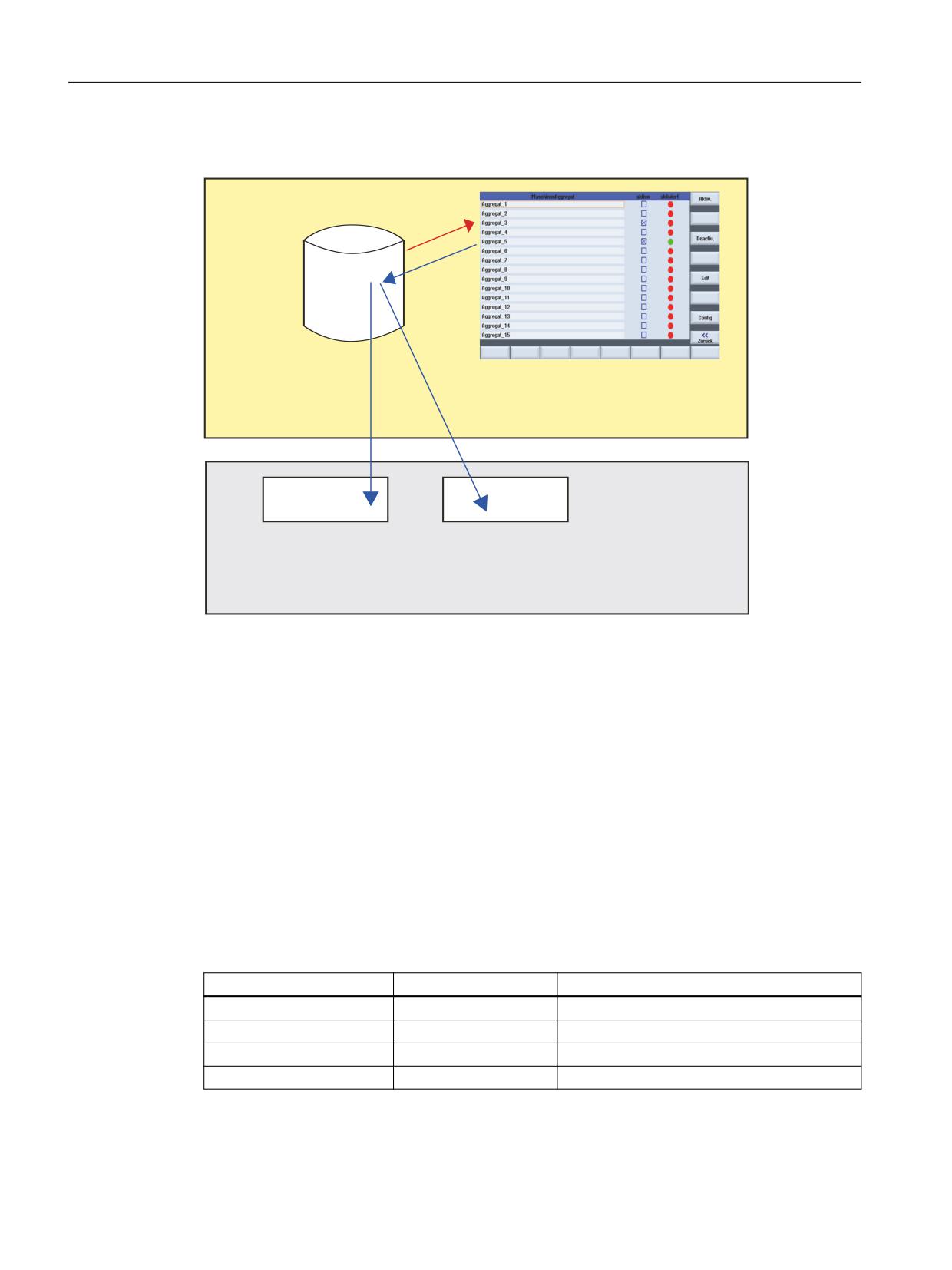
The "Easy Extend" function provides a simple way of commissioning, activating, deactivating, or
testing optional equipment. The available equipment and device states are displayed in a list by
the control system. The system can manage a maximum of 64 devices.
Softkeys are used to activate or deactivate a device.
The "Easy Extend" function is available in the "Parameters" operating area.
Figure 3-1
Main screen "Parameters"
Easy XML
Programming Manual, 10/2020, 6FC5397-1DP40-6BA4
249
Generating commissioning dialogs
3.1 Overview of functions
Configuration
;0/ VFULSW
+0,
+0,
1&. LQWHUIDFH
+0,
3/& LQWHUIDFH
1&. 3/& '5,9(
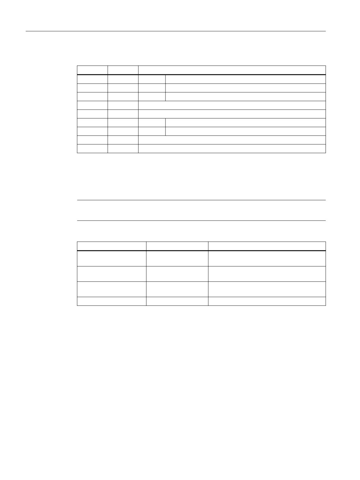
Figure 3-2
How "Easy Extend" works
To use the "Easy Extend" function, the following functions must be configured by the machine
manufacturer:
• PLC ↔ HMI interface
The optional devices are managed via the interface between the user interface and the PLC.
• Script processing
The machine manufacturer saves the sequences to be executed for commissioning,
activating, deactivating or testing a device, in a statement script.
• Parameter dialog (optional)
The parameter dialog shows device information that is saved in the script file.
Storage of the files
The files belonging to "Easy Extend" are stored on the system CompactFlash card in directory
"dvm" (machine manufacturer).
File
Name
Target directory
Text file
oem_aggregate_xxx.ts
\oem\sinumerik\hmi\lng
Script file
agm.xml
\oem\sinumerik\hmi\dvm
Archive file
Any
\oem\sinumerik\hmi\dvm\archives
PLC user program
Any
PLC
Easy XML
250
Programming Manual, 10/2020, 6FC5397-1DP40-6BA4
Generating commissioning dialogs
3.2 Configuration in the PLC user program
3.2
Configuration in the PLC user program
Loading configurations
The configurations created are transferred to the manufacturer directory of the control, with the
script and text file. Additionally, the corresponding PLC user program should be loaded.
Programming the equipment
Communication between the operator component and the PLC takes place in the PLC user
program via a data block defined by the programmer, in which 128 words are reserved for the
management of the devices. The description for the data block identifier is provided in Chapter
"PLC_INTERFACE (Page 262)."
The data block must be generated and loaded as a user block. The relevant block must be
declared to the EasyExtend function using the plc_interface tag in the "agm.xml" script.
Note
Compatibility
We recommend defining data block DB9905 as the PLC interface so that the scripts are also
compatible with SINUMERIK 828D.
Example:
<plc_interface name = "plc/db1000.dbb0" />
To create the block, data formats and symbolic identifiers from the following table can be used:
Data format/symbolic identifier
Meaning
DBX0.0 Enable_1 BOOL Bit OFF OFF HMI → PLC
Device has been started up
DBX0.1 Activate_1 BOOL Bit OFF OFF HMI → PLC
Device is to be activated
DBX0.2 Deactivate_1 BOOL Bit OFF OFF HMI → PLC
Device is to be deactivated
DBB1 Res_1 BYTE Unsigned 0 0
Reserved for future use
DBX2.0 IsActive_1 BOOL Bit OFF OFF PLC → HMI
Device is active
DBX2.1 Error_1 BOOL Bit OFF OFF PLC → HMI
Device has an error
DBB3 DeviceId_1 BYTE Unsigned 0 0
Unique device number
PLC words are assigned beginning with Device 1:
Data block
Device designation
DB9905.DBB0
Device 1
DB9905.DBB4
Device 2
DB9905.DBB192
Device 49
DB9905.DBB196
Device 50
Easy XML
Programming Manual, 10/2020, 6FC5397-1DP40-6BA4
251
Generating commissioning dialogs
3.2 Configuration in the PLC user program
Four bytes with the following meanings are used for each device:
Byte
Bit
Description
0
0
== 1
Device has been started up (HMI acknowledgment)
1
== 1
Device is to be activated (HMI request)
2
== 1
Device is to be deactivated (HMI request)
3-7
Reserved
1
0-7
Reserved
2
0
== 1
Device is active (PLC acknowledgment)
1
== 1
Device has an error
2-7
Reserved
3
0-7
Unique identifier for the device
Storage of the files
The Easy Extend files are stored on the system CompactFlash card in the "oem"
(MANUFACTURER) and "oem_i" (INDIVIDUAL) directory.
Note
The file name may only contain lower case letters.
File
Name
Target directory
Text file
oem_aggregate_xxx.ts
/oem/sinumerik/hmi/lng/
/oem_i/sinumerik/hmi/lng/
Script file
agm.xml
/oem/sinumerik/hmi/dvm
/oem_i/sinumerik/hmi/dvm
Archive file
Any
/oem/sinumerik/hmi/dvm/archives
/oem_i/sinumerik/hmi/dvm/archives
PLC user program
Any
PLC
Easy XML
252
Programming Manual, 10/2020, 6FC5397-1DP40-6BA4
Generating commissioning dialogs
3.2 Configuration in the PLC user program
General sequence
The machine manufacturer must execute the following steps to make the required data
available:
1. Creating a PLC user program which activates the device during activation on the PLC.
2. Commissioning of the "standard machine" followed by backup of the data in a series startup
archive.
3. Installation of the devices, commissioning, followed by read-out of the data as a differential
series startup archive.
Note
Changing the machine configuration
Should there be any need to edit the drive machine data, this should be adapted in the control
first. This procedure should be repeated for all devices and constellations.
Adding axes
If the machine is extended with machine axes, it is important to install the drive objects (DO) in a
fixed sequence because the series startup archive contains the constellation of the machine
manufacturer's reference machine and cannot be applied if the sequence is changed.
It is recommended that the following settings be selected for the "control components":
• NC data
• PLC data
• Drive data
- ACX format (binary)
Easy XML
Programming Manual, 10/2020, 6FC5397-1DP40-6BA4
253
Generating commissioning dialogs
3.3 Display on the user interface
3.3
Display on the user interface
Dialogs on the user interface
The following dialogs are available for the "Easy Extend" function:
• The control offers a configurable dialog, in which the available devices are shown.
• If first commissioning has not taken place yet, the control opens the commissioning dialog.
If a commissioning procedure (XML instruction: "START_UP") has been programmed, and the
device has still not been commissioned, then the control starts the commissioning procedure.
This involves a complete data backup before the series startup archives saved in the script file are
read in.
In the event of an error, the commissioning engineer can decide whether to roll back the
commissioning procedure or to rectify possible errors in machine configurations manually.
• Commissioning can be aborted early with the "Cancel" function. The control then copies the
previously saved commissioning files back.
If the machine has to be switched off after successful completion of the commissioning, the XML
statement "POWER_OFF" can be used to program that a corresponding message is output on the
control.
Easy XML
254
Programming Manual, 10/2020, 6FC5397-1DP40-6BA4
Generating commissioning dialogs
3.4 Creating language-dependent texts
3.4
Creating language-dependent texts
Structure of text file
The XML files with the language-dependent texts must be created in UTF8 format:
Examples
oem_aggregate_eng.ts
<?xml version="1.0" encoding="UTF-8" ?>
<!DOCTYPE TS>
<TS>
<context>
<name>EASY_EXTEND</name>
<message>
<source>DEVICE_ONE</source>
<translation>Device one</translation>
</message>
<message>
<source>DEVICE_TWO</source>
<translation>Device two</translation>
</message>
</context>
</TS>
oem_aggregate_deu.ts
<?xml version="1.0" encoding="UTF-8" ?>
<!DOCTYPE TS>
<TS>
<context>
<name>EASY_EXTEND</name>
<message>
<source>DEVICE_ONE</source>
<translation>First device</translation>
</message>
<source>DEVICE_TWO</source>
<translation>Second device</translation>
</message>
</context>
</TS>
Easy XML
Programming Manual, 10/2020, 6FC5397-1DP40-6BA4
255
Generating commissioning dialogs
3.5 User example for a power unit
3.5
User example for a power unit
Activating the drive object
The drive object to be activated has already been commissioned and deactivated again by the
machine manufacturer, to market the axis (axes) as an option.
To activate the axis carry out the following steps:
• Activate the drive object via p0105.
• Enable 2nd axis in the channel machine data.
• Back up the drive machine data via p0971.
• Wait until the data has been written.
• Restart the NCK and the drives.
Programming:
<DEVICE>
<list_id>1</list_id>
<name> "Activate the drive" </name>
<SET_ACTIVE>
<data name = "drive/dc/p105[DO5]">1</data>
<data name = "$MC_AXCONF_MACHAX_USED[4]">5</data>
<data name = "drive/dc/p971[DO5]">1</data>
<while>
<condition> "drive/dc/p971[DO5]" !=0 </condition>
</while>
<control_reset resetnc ="true" resetdrive = "true"/>
</SET_ACTIVE>
<SET_INACTIVE>
<data name = "drive/dc/p105[DO5]">0</data>
<data name = "$MC_AXCONF_MACHAX_USED[4]">0</data>
<data name = "drive/dc/p971[DO5]">1</data>
<while>
<condition> "drive/dc/p971[DO5]" !=0 </condition>
</while>
<control_reset resetnc ="true" resetdrive = "true"/>
</SET_INACTIVE>
</DEVICE>
Activating the PLC-controlled device
The device is addressed via output byte 10 and signals data set ready to the PLC via input byte
9.
The output byte is set to the specified coding for activation. The While loop then waits for the
data set ready of the device.
Easy XML
256
Programming Manual, 10/2020, 6FC5397-1DP40-6BA4
Generating commissioning dialogs
3.5 User example for a power unit
Programming:
<SET_ACTIVE>
<DATA name = "plc/qb10"> 8 </DATA>
<while>
<condition> "plc/ib9" !=1 </condition>
</while>
</SET_ACTIVE>
Easy XML
Programming Manual, 10/2020, 6FC5397-1DP40-6BA4
257
Generating commissioning dialogs
3.6 Script language
3.6
Script language
Note
All script elements described in the Generating user dialogs (Page 17) function form the basis for
the "Easy Extend" function. Additional script elements are defined to manage additional devices.
Program parts of the script
The script is divided into the following areas:
• "Easy Extend" identifier
• Frame to define the actions that can be executed for a device
• Identifier for the device
• Identifier for commissioning the device
• Identifier for activating the device
• Identifier for deactivating the device
• Identifier for testing the device
• Identifier for the parameter dialog
The individual tags are described in the following chapters.
Description
Identifier <tag>
Meaning
AGM
Identifier for the "Startup Wizard"
DEVICE
Identifier for the description of the device.
Attributes:
• option_bit
The device is assigned a fixed bit number for the option manage-
ment.
NAME
The identifier specifies the name of the device to be displayed in the
dialog.
If a text reference is used, the dialog displays the text which is saved for
the identifier.
START_UP
The identifier contains a description of the sequences required for
commissioning the device.
SET_ACTIVE
The identifier contains a description of the sequences required to ac-
tivate the device.
Attributes:
• timeout
The attribute permits a timeout to be specified in seconds. The
system interrupts processing if the script has still not been com-
pleted after this time.
Easy XML
258
Programming Manual, 10/2020, 6FC5397-1DP40-6BA4
Generating commissioning dialogs
3.6 Script language
Identifier <tag>
Meaning
SET_INACTIVE
The identifier contains a description of the sequences required to shut
down the device.
Attributes:
• timeout
The attribute permits a timeout to be specified in seconds. The system
interrupts processing if the script has still not been completed after this
time.
TEST
The identifier contains the statements for testing the operating capa-
bility of a device.
Attributes:
• timeout
The attribute permits a timeout to be specified in seconds. The system
interrupts processing if the script has still not been completed after this
time.
UID
Unique numerical identifier to identify the device in the PLC ↔ HMI
interface.
VERSION
Identifier for a version
Negative acknowledgment of the function execution
With the automatically provided variable "$actionresult", the system can inform the XML parser
of a negative execution result. If the value is set to zero, the parser aborts the function
processing.
Example
<?xml version="1.0" encoding="utf-8"?>
<!DOCTYPE AGM>
<AGM>
Identifier for the "Startup Wizard"
<DEVICE>
<NAME> Device 1 </NAME>
Identifier for the device
<START_UP>
Identifier for commissioning the device
…
</START_UP>
<SET_ACTIVE>
Identifier for activating the device
…
</SET_ACTIVE>
<SET_INACTIVE>
Identifier for deactivating the device
…
</SET_INACTIVE>
<TEST>
Identifier for testing the device
…
</TEST>
</DEVICE>
…
</AGM>
Easy XML
Programming Manual, 10/2020, 6FC5397-1DP40-6BA4
259
Generating commissioning dialogs
3.6 Script language
3.6.1
CONTROL_RESET
Description
This identifier allows one or more control components to be restarted. Execution of the script is
only continued when the control has resumed cyclic operation.
Programming
Identifier:
CONTROL_RESET
Syntax:
<CONTROL_RESET resetnc="TRUE" />
Attributes:
resetnc="true"
The NC component is restarted.
resetdrive="true"
The drive components are restarted.
3.6.2
FILE
Description
The identifier enables standard archives to be read in or created.
• Reading in an archive:
The file name of the archive must be specified for reading in an archive.
• Creating an archive:
If the attribute create= "true" is specified, the function creates a standard archive (*.arc)
under the specified name and stores the file in the …/dvm/archives directory.
Programming
Identifier:
FILE
Syntax:
<file name ="<archive name>" />
<file name ="<archive name>" create="true" class="<data classes>"
group="<area>" />
Attributes:
name
Identifier for the file name
Easy XML
260
Programming Manual, 10/2020, 6FC5397-1DP40-6BA4
Generating commissioning dialogs
3.6 Script language
create
A commissioning archive is created under the specified
name in the …/dvm/archives/ directory.
group
Specifies the data groups that are to be contained in the
archive. If several data groups are to be saved, the groups
should be separated by a blank.
The following data groups can be contained in the ar-
chive:
• NC
• PLC
• HMI
• DRIVES
Example
<!-- Create data class archive -->
<file name="user.arc" create="true"
group="nc plc hmi" />
<!-Read archive into the control->
<file name="user.arc" />
3.6.3
OPTION_MD
Description
The identifier allows option machine data to be redefined. As delivered, the system uses
MD14510 $MN_USER_DATA_INT[0] to $MN_USER_DATA_INT[3].
If the PLC user program manages the options, the appropriate data words must be provided in
a data block or GUD.
The data is structured in bits. Starting with bit 0, there is a fixed assignment of the bits to the
listed devices, i.e. bit 0 is assigned to device 1, bit 1 to device 2, etc. If more than 16 devices are
managed, the address identifiers of the device groups 1-3 are assigned via the area index.
Note
Converting the value range
The value range of MD14510 $MN_USER_DATA_INT[i] is from -32768 to +32767. To activate the
devices bit-by-bit via the machine data dialog, the bit combination must be converted to decimal
representation.
Easy XML
Programming Manual, 10/2020, 6FC5397-1DP40-6BA4
261
Generating commissioning dialogs
3.6 Script language
Programming
Identifier:
OPTION_MD
Syntax:
Area 0:
<option_md name = "Address identifier of the data" />
OR:
<option_md name = "Address identifier of the data" index= "0"/>
Area 1 to 3:
<option_md name = "Address identifier of the data" index= "Area index"/>
Attributes:
name
Identifier for the address, e.g. $MN_USER_DA-
TA_INT[0]
index
Identifier for the area index:
0 (default setting): Device 1 to 16
1: Device 17 to 32
2: Device 33 to 48
3: Device 49 to 64
3.6.4
PLC_INTERFACE
Description
This identifier permits the PLC ↔ HMI interface to be redefined. The system expects 128
addressable words.
Note
The identifier is not preset and must be defined by the programmer.
Programming
Identifier:
PLC_INTERFACE
Syntax:
<plc_interface name = "Address identifier of the data" />
Attributes:
name
Identifier for the address, e.g. "plc/mb170"
Example: plc/mb170
Easy XML
262
Programming Manual, 10/2020, 6FC5397-1DP40-6BA4
Generating commissioning dialogs
3.6 Script language
3.6.5
POWER_OFF
Description
Identifier for a message prompting the operator to switch the machine off. The message text is
permanently saved in the system.
Programming
Identifier:
POWER_OFF
Syntax:
<power_off />
Attributes:
--
3.6.6
WAITING
Description
After a reset of the NC or the drive, there is a wait for the restart of the respective component.
Programming
Identifier:
WAITING
Syntax:
<WAITING WAITINGFORNC ="TRUE" />
Attributes:
waitingfornc="true"
There is a wait for the restart of the NC.
waitingfordrive="true"
There is a wait for the restart of the drive.
3.6.7
XML identifiers for the dialog
Dialog for the parameterization
A dialog can be configured for each device so that additional parameters can be set or output
during runtime. This is displayed by pressing the "Additional parameters" softkey.
All of the script elements described in Chapter Generating user dialogs (Page 17) can be used to
generate the dialog.
Easy XML
Programming Manual, 10/2020, 6FC5397-1DP40-6BA4
263
Generating commissioning dialogs
3.6 Script language
Example
<?xml version="1.0" encoding="utf-8"?>
<!DOCTYPE AGM>
<AGM>
<DEVICE>
<NAME> Device 1 </NAME>
<START_UP>
…
</START_UP>
<SET_ACTIVE>
…
</SET_ACTIVE>
…
<FORM name="<dialog name>">
Identifier for a user dialog
<INIT>
<CONTROL name = "edit1" .../>
Identifier for an input field
</INIT>
<PAINT>
Identifier for text or image display
<TEXT>hello world !</TEXT>
</PAINT>
</FORM>
</DEVICE>
…
</AGM>
3.6.8
SOFTKEY_OK, SOFTKEY_CANCEL
Description
The identifier SOFTKEY_OK overwrites the standard behavior when closing a dialog by means of
the "OK" softkey. The identifier SOFTKEY_CANCEL overwrites the standard behavior when
closing a dialog by means of the "CANCEL" softkey.
The following functions can be performed within this identifier:
• Data manipulation
• Conditional processing
• Loop processing
Easy XML
264
Programming Manual, 10/2020, 6FC5397-1DP40-6BA4
Generating commissioning dialogs
3.6 Script language
Programming
Identifier:
SOFTKEY_OK
Syntax:
<SOFTKEY_OK>
…
</SOFTKEY_OK>
Identifier:
SOFTKEY_CANCEL
Syntax:
<SOFTKEY_CANCEL>
…
</SOFTKEY_CANCEL>
Easy XML
Programming Manual, 10/2020, 6FC5397-1DP40-6BA4
265
Generating commissioning dialogs
3.6 Script language
Easy XML
266
Programming Manual, 10/2020, 6FC5397-1DP40-6BA4
Index
Control is modified, 153
Control is visible, 153
C
Control local time, 152
Control set modified, 153
Configuration file, 19
Control set working area, 154
Copy value and read, 140
Copying and writing a value, 141
E
Cosine, 165
Easy Extend, 249
Delete control, 173
Easy XML diagnostics, 34
Delete number of characters of a string, 159
DeleteItem, 175
Deleting a file, 170
F
display resolution, 144
Empty, 177
File
Exist, 172
struct_def.xml, 125
Extracting script parts, 171
Finger gestures, 190
FLOOR, 183
Get cursor selection, 178
getfocus, 178
G
GetItem, 179
Generating commissioning dialogs, 249
GetItemData, 179
imagebox, 193
ImageBoxGet, 181
M
ImageBoxSet, 87, 180, 181, 194
InsertItem, 175
Menu tree, 19
ISNUMERIC, 189
LoadItem, 176, 177
LOG, 183
S
LOG10, 184
Start softkey, 19
MAX, 184
MIN, 184
MMC, 185
X
NC program selection, 172
Ncfunc bico to int, 149
XML
Ncfunc Get drive by axis index, 146
HTML special characters, 63
Ncfunc Get drive by axis name, 145
Operators, 64
Ncfunc Get drive by bud address, 148
Syntax, 62
Ncfunc Get drive by drive name, 147
System variables, 65
Ncfunc get MD limits, 149
XML diagnostics, 34
Ncfunc int to bico, 150
XML functions
Ncfunc is bico str valid, 150
Abs, 183
Ncfunc password, 151
AddItem, 174
PI service, 142, 143
ARCOS, 166
PI service, channel-related, 144
ARCSIN, 166
POW, 184
ARCTAN, 167
RANDOM, 184
Bitmap dimensions, 182
Reading a file, 168
CEIL, 183
ROOT, 189
Control exist, 152
ROUND, 183
Control form color, 151
Easy XML
Programming Manual, 10/2020, 6FC5397-1DP40-6BA4
267
Index
Screen resolution, 182
ELLIPSE, 112
Screen resolution HMI, 182
ELSE, 41
SDEG, 183
FILE, 260
Set cursor selection, 179
FOCUS_IN, 77
setfocus, 178
FOR, 42
Setting an individual bit, 173
FORM, 42, 67
Sine, 165
FUNCTION, 114, 208
SQRT, 183
FUNCTION_BODY, 115
SRAD, 183
GESTURE_EVENT, 92, 192
String comparison, 154, 155
HELP_CONTEXT, 89
String find, 160
HMI_RESET, 42
String GetAt, 161
IF, 43
String pixel height, 162
IMG, 107
String pixel width, 163
INCLUDE, 44
String reverse find, 161
INDEX_CHANGED, 92
String SetAt, 163
INIT, 70
String Split, 164
KEY_EVENT, 71
string.icmp, 155
LANGUAGE_CHANGED, 77
string.insert, 158
LAYOUT, 68
string.left, 155
LET, 45, 241
string.length, 157
LINE, 116
string.middle, 156
LOCK_OPERATING_AREA, 48
string.remove, 158
MENU, 92
string.replace, 157
MESSAGE, 73, 196
string.right, 156
MOUSE_EVENT, 72
Tangent, 166
MSG, 48
Title bar height, 182
MSGBOX, 48
Writing to a file, 169
NAME, 258
XML identifier
NAVIGATION, 93
AGM, 258
NC_INSTRUCTION, 122
ARC, 110
OP, 49
AUTOSCALE_CONTENT, 67
OPEN_FORM, 94
BOX, 112
OPERATION, 50
BREAK, 37
OPTION_MD, 262
CAPTION, 78, 200, 213
PAINT, 78
CHANNEL_CHANGED, 77
PASSWORD, 50
CLOSE, 78
PLC_INTERFACE, 262
CLOSE_FORM, 79
POWER_OFF, 50, 263
CONTROL, 37, 80, 204, 210
PRINT, 51
CONTROL_RESET, 37, 260
PROGRESS_BAR, 52
CREATE_CYCLE, 123
PROPERTY, 95, 198, 202, 209
CREATE_CYCLE_EVENT, 38
RECALL, 120
DATA, 39
REQUEST, 119
DATA_ACCESS, 90
RESIZE, 75
DATA_LIST, 40
SEND_MESSAGE, 53, 74
DEBUG, 91
SET_ACTIVE, 258
DEBUG_MSG, 40
SET_INACTIVE, 259
DEVICE, 258
SHOW_CONTROL, 53
DIALOGGUI, 40
SLEEP, 54
DO_WHILE, 41
SOFTKEY, 102, 240
DYNAMIC_INCLUDE, 41
SOFTKEY_ACCEPT, 106
EDIT_CHANGED, 92
SOFTKEY_BACK, 106
Easy XML
268
Programming Manual, 10/2020, 6FC5397-1DP40-6BA4
Index
SOFTKEY_CANCEL, 105, 265
SOFTKEY_OK, 105, 265
START_UP, 258
STOP, 54
SWITCH, 54
SWITCHTOAREA, 55
SWITCHTODYNAMICTARGET, 55
TEST, 259
TEXT, 106
TEXTCONTEXT, 68
TEXTFILE, 68
THEN, 55
TIMER, 78
TYPE_CAST, 55
TYPEDEF, 56, 240
UID, 259
UNLOCK_OPERATING_AREA, 57
UPDATE_CONTROLS, 120
VERSION, 259
WAITING, 57, 263
WHILE, 58
XML_PARSER, 58
Easy XML
Programming Manual, 10/2020, 6FC5397-1DP40-6BA4
269
Index
Easy XML
270
Programming Manual, 10/2020, 6FC5397-1DP40-6BA4
Preface
Fundamental safety
1
instructions
2
Introduction
3
Getting Started
4
Fundamentals
SINUMERIK 840D sl
5
SINUMERIK Integrate Run
Dialogs
MyScreens
6
Variables
7
Programming Manual
Programming commands
8
Graphic and logic elements
9
"Custom" operating area
10
Dialog selection
11
Examples for cycle masks
Configuration in the side
12
screen
Configuration in the Display
13
Manager
A
Reference lists
B
Tips and tricks
C
Animated elements
D
Documentation overview
Valid for
CNC software Version 4.94
10/2020
A5E40869575B AD
Legal information
Warning notice system
This manual contains notices you have to observe in order to ensure your personal safety, as well as to prevent damage
to property. The notices referring to your personal safety are highlighted in the manual by a safety alert symbol, notices
referring only to property damage have no safety alert symbol. These notices shown below are graded according to
the degree of danger.
DANGER
indicates that death or severe personal injury will result if proper precautions are not taken.
WARNING
indicates that death or severe personal injury may result if proper precautions are not taken.
CAUTION
indicates that minor personal injury can result if proper precautions are not taken.
NOTICE
indicates that property damage can result if proper precautions are not taken.
If more than one degree of danger is present, the warning notice representing the highest degree of danger will be
used. A notice warning of injury to persons with a safety alert symbol may also include a warning relating to property
damage.
Qualified Personnel
The product/system described in this documentation may be operated only by personnel qualified for the specific
task in accordance with the relevant documentation, in particular its warning notices and safety instructions.
Qualified personnel are those who, based on their training and experience, are capable of identifying risks and
avoiding potential hazards when working with these products/systems.
Proper use of Siemens products
Note the following:
WARNING
Siemens products may only be used for the applications described in the catalog and in the relevant technical
documentation. If products and components from other manufacturers are used, these must be recommended or
approved by Siemens. Proper transport, storage, installation, assembly, commissioning, operation and maintenance
are required to ensure that the products operate safely and without any problems. The permissible ambient
conditions must be complied with. The information in the relevant documentation must be observed.
Trademarks
All names identified by ® are registered trademarks of Siemens AG. The remaining trademarks in this publication may
be trademarks whose use by third parties for their own purposes could violate the rights of the owner.
Disclaimer of Liability
We have reviewed the contents of this publication to ensure consistency with the hardware and software described.
Since variance cannot be precluded entirely, we cannot guarantee full consistency. However, the information in this
publication is reviewed regularly and any necessary corrections are included in subsequent editions.
Siemens AG
A5E40869575B AD
Digital Industries
Ⓟ 10/2020 Subject to change
All rights reserved
Postfach 48 48
90026 NÜRNBERG
GERMANY
Preface
SINUMERIK documentation
The SINUMERIK documentation is organized into the following categories:
• General documentation/catalogs
• User documentation
• Manufacturer/service documentation
Additional information
You can find information on the following topics at the following address (https://
support.industry.siemens.com/cs/de/en/view/108464614):
• Ordering documentation/overview of documentation
• Additional links to download documents
• Using documentation online (find and search in manuals/information)
If you have any questions regarding the technical documentation (e.g. suggestions,
corrections), please send an e-mail to the following address
(mailto:docu.motioncontrol@siemens.com).
mySupport/Documentation
you can find information on how to create your own individual documentation based on
Siemens' content, and adapt it for your own machine documentation.
Training
SITRAIN (Siemens training on products, systems and solutions for automation and drives).
FAQs
You can find Frequently Asked Questions in the Service&Support pages under Product Support
SINUMERIK
You can find information about SINUMERIK at the following address (https://www.siemens.com/
sinumerik).
SINUMERIK Integrate Run MyScreens
Programming Manual, 10/2020, A5E40869575B AD
3
Preface
Target group
This document addresses programmers and configuring engineers.
Benefits
Using the Programming Manual, the target group can develop, write, test, and debug programs
and software user interfaces.
Standard scope
This documentation only describes the functionality of the standard version. Additions or
modifications made by the machine manufacturer are documented by the machine
manufacturer.
Other functions not described in this documentation might be executable in the control. This
does not, however, represent an obligation to supply such functions with a new control or when
servicing.
For the sake of simplicity, this documentation does not contain all detailed information about all
types of the product and cannot cover every conceivable case of installation, operation, or
maintenance.
Note regarding the General Data Protection Regulation
Siemens observes standard data protection principles, in particular the principle of privacy by
design. That means that
this product does not process / store any personal data, only technical functional data (e.g. time
stamps). If a user links this data with other data (e.g. a shift schedule) or stores personal data on
the same storage medium (e.g. hard drive) and thus establishes a link to a person or persons,
then the user is responsible for ensuring compliance with the relevant data protection
regulations.
Technical Support
Country-specific telephone numbers for technical support are provided on the Internet at the
area.
If you have any technical questions, use the online form in the "Support Request" area.
SINUMERIK Integrate Run MyScreens
4
Programming Manual, 10/2020, A5E40869575B AD
Table of contents
Preface
3
1
Fundamental safety instructions
11
1.1
General safety instructions
11
1.2
Warranty and liability for application examples
12
1.3
Security information
13
2
Introduction
15
3
Getting Started
19
3.1
Introduction
19
3.2
Project example
20
3.2.1
Task description
20
3.2.2
Creating the configuration file (example)
24
3.2.3
Saving the configuration file in the OEM directory (example)
27
3.2.4
Creating the online help (example)
28
3.2.5
Integrating the online help and saving the files to the OEM directory (example)
31
3.2.6
Copying "easyscreen.ini" into the OEM directory (example)
32
3.2.7
Registering the COM file in "easyscreen.ini" (example)
32
3.2.8
Testing the project (example)
32
4
Fundamentals
35
4.1
Structure of configuration file
35
4.2
Structure of the menu tree
37
4.3
Definition and functions for start softkeys
39
4.3.1
Defining the start softkey
39
4.3.2
Functions for start softkeys
40
4.4
Troubleshooting (log book)
42
4.5
Notes on "easyscreen.ini"
44
4.6
Notes for personnel changing over to "Run MyScreens"
47
4.7
Extended configuration syntax
49
4.8
SmartOperation and MultiTouch operation
51
5
Dialogs
53
5.1
Structure and elements of a dialog
53
5.1.1
Defining a dialog
53
5.1.2
Defining dialog properties
55
5.1.3
Defining dialog elements
62
5.1.4
Defining dialogs with multiple columns
64
5.1.5
Password dialogs
65
5.1.6
Using display images/graphics
67
SINUMERIK Integrate Run MyScreens
Programming Manual, 10/2020, A5E40869575B AD
5
Table of contents
5.2
Defining softkey menus
68
5.2.1
Changing softkey properties during runtime
70
5.2.2
Language-dependent text
73
5.3
Configuring the online help
77
5.3.1
Overview
77
5.3.2
Generating HTML files
78
5.3.3
Generating the help book
81
5.3.4
Integrating the online help in SINUMERIK Operate
83
5.3.5
Saving help files
85
5.3.6
Help files in PDF format
85
6
Variables
87
6.1
Defining variables
87
6.2
Application examples
88
6.3
Example 1: Assigning the variable type, texts, help display, colors, tooltips
90
6.4
Example 2: Assigning the Variable Type, Limits, Attributes, Short Text Position properties
91
6.5
Example 3: Assigning the Variable Type, Default, System or User Variable, Input/Output
Field Position properties
92
6.6
Example 4: Toggle field and list field
93
6.7
Example 5: Image display
94
6.8
Example 6: Progress bar
95
6.9
Example 7: Password input mode (asterisk)
97
6.10
Variable parameters
98
6.11
Details on the variable type
104
6.12
Details on the toggle field
107
6.13
Details on the default setting
109
6.14
Details on the position of the short text, position of the input/output field
110
6.15
Use of strings
112
6.16
CURPOS variable
114
6.17
CURVER variable
115
6.18
ENTRY variable
116
6.19
ERR variable
117
6.20
FILE_ERR variable
118
6.21
FOC variable
120
6.22
Variable S_ALEVEL
121
6.23
S_CHAN variable
122
6.24
Variable S_CONTROL
123
6.25
Variable S_LANG
124
6.26
Variable S_NCCODEREADONLY
125
SINUMERIK Integrate Run MyScreens
6
Programming Manual, 10/2020, A5E40869575B AD
Table of contents
6.27
Variables S_RESX and S_RESY
126
7
Programming commands
127
7.1
Operators
127
7.1.1
Mathematical operators
127
7.1.2
Bit operators
130
7.2
Methods
132
7.2.1
ACCESSLEVEL
132
7.2.2
CHANGE
133
7.2.3
CHANNEL
134
7.2.4
CONTROL
134
7.2.5
FOCUS
135
7.2.6
LANGUAGE
136
7.2.7
LOAD
136
7.2.8
UNLOAD
137
7.2.9
OUTPUT
138
7.2.10
PRESS
139
7.2.11
PRESS(ENTER)
140
7.2.12
PRESS(TOGGLE)
140
7.2.13
RESOLUTION
141
7.2.14
RESUME
141
7.2.15
SUSPEND
142
7.2.16
Example: Version management with OUTPUT methods
142
7.3
Functions
145
7.3.1
Reading and writing drive parameters: RDOP, WDOP, MRDOP
145
7.3.2
Subprogram call (CALL)
147
7.3.3
Define block (//B)
148
7.3.4
Check Variable (CVAR)
149
7.3.5
CLEAR_BACKGROUND
150
7.3.6
Copy Program file function (CP)
151
7.3.7
Delete Program file function (DP)
151
7.3.8
Exist Program file function (EP)
152
7.3.9
Move Program file function (MP)
153
7.3.10
Select Program file function (SP)
154
7.3.11
File accesses: RDFILE, WRFILE, RDLINEFILE, WRLINEFILE
155
7.3.12
Dialog line (DLGL)
157
7.3.13
DEBUG
158
7.3.14
Exit dialog (EXIT)
159
7.3.15
Dynamic manipulation of the lists of toggle fields or list box fields
161
7.3.16
Evaluate (EVAL)
163
7.3.17
Exit Loading Softkey (EXITLS)
164
7.3.18
Function (FCT)
165
7.3.19
Generate code (GC)
167
7.3.20
Password functions
169
7.3.21
Load Array (LA)
170
7.3.22
Load Block (LB)
171
7.3.23
Load Mask (LM)
172
7.3.24
Load Softkey (LS)
174
7.3.25
Load Grid (LG)
175
7.3.26
Multiple selection SWITCH
176
7.3.27
Multiple Read NC PLC (MRNP)
177
SINUMERIK Integrate Run MyScreens
Programming Manual, 10/2020, A5E40869575B AD
7
Table of contents
7.3.28
PI services
179
7.3.29
Reading (RNP) and writing (WNP) system or user variables
179
7.3.30
RESIZE_VAR_IO and RESIZE_VAR_TXT
180
7.3.31
Register (REG)
181
7.3.32
RETURN
183
7.3.33
Recompile
184
7.3.34
Recompile without user comment
185
7.3.35
Search Forward, Search Backward (SF, SB)
188
7.3.36
STRING functions
189
7.3.37
WHILE/UNTIL loops
195
7.3.38
Cyclic execution of scripts: START_TIMER, STOP_TIMER
198
8
Graphic and logic elements
201
8.1
Line, dividing line, rectangle, circle and ellipse
201
8.2
Defining an array
204
8.2.1
Accessing the value of an array element
205
8.2.2
Example Access to an array element
206
8.2.3
Scanning the status of an array element
208
8.3
Table description (grid)
210
8.3.1
Defining a table (grid)
211
8.3.2
Defining columns
212
8.3.3
Focus control in the table (cell)
213
8.4
Custom widgets
214
8.4.1
Defining custom widgets
214
8.4.2
Structure of the custom widget library
214
8.4.3
Structure of the custom widget interface
215
8.4.4
Interaction between custom widget and dialog box - Automatic data exchange
217
8.4.5
Interaction between custom widget and dialog box - Manual data exchange
218
8.4.5.1
Reading and writing properties
218
8.4.5.2
Executing a method of the custom widget
220
8.4.5.3
Response to a custom widget signal
222
8.5
SIEsGraphCustomWidget
225
8.5.1
SIEsGraphCustomWidget
225
8.5.2
Notes regarding performance
227
8.5.3
Reading and writing properties
227
8.5.4
Properties
228
8.5.5
Functions
238
8.5.6
Signals
253
8.6
SlEsTouchButton
255
8.6.1
SlEsTouchButton
255
8.6.2
Reading and writing properties
256
8.6.3
Properties
257
8.6.4
Functions
273
8.6.5
Signals
274
8.6.6
Positioning and aligning picture and text
277
8.6.7
Language-dependent texts
279
9
"Custom" operating area
281
9.1
How to activate the "Custom" operating area
281
SINUMERIK Integrate Run MyScreens
8
Programming Manual, 10/2020, A5E40869575B AD
Table of contents
9.2
How to configure the "Custom" softkey
282
9.3
How to configure the "Custom" operating area
283
9.4
Programming example for the "Custom" area
284
10
Dialog selection
289
10.1
Dialog selection using PLC softkeys
289
10.1.1
Calling Run MyScreens-cycle screens in the program editor
290
10.2
Dialog selection using PLC hard keys
292
10.3
Dialog selection via NC
295
11
Examples for cycle masks
297
11.1
Examples for cycle masks
297
12
Configuration in the side screen
299
12.1
Display of a Run MyScreens configuration in a side screen page
300
12.2
Display of several Run MyScreens configurations in a side screen page
302
12.3
Adding Run MyScreens configurations to a side screen page
304
12.4
Adding Run MyScreens configurations to a side screen element
306
12.5
Notes on carrying out Run MyScreens configurations in the side screen
308
13
Configuration in the Display Manager
309
13.1
Displaying Run MyScreens configurations in the Display Manager
309
13.2
Integration in SISideScreenDialog
310
13.3
Integration into SIWidgetsApp
311
13.4
Notes on carrying out Run MyScreens configurations in the Display Manager
312
A
Reference lists
313
A.1
Lists of start softkeys
313
A.1.1
List of start softkeys for turning
313
A.1.2
List of start softkeys for milling
314
A.2
List of predefined softkeys
316
A.3
List of access levels
317
A.4
List of colors
318
A.5
List of language codes used in file names
319
A.6
List of accessible system variables
320
A.7
Behavior when opening the dialog (attribute CB)
321
B
Tips and tricks
323
B.1
General tips
323
B.2
Tips for debugging
325
B.3
Tips for the CHANGE method
326
B.4
Tips for DO LOOP loops
328
SINUMERIK Integrate Run MyScreens
Programming Manual, 10/2020, A5E40869575B AD
9
Table of contents
C
Animated elements
329
C.1
Introduction
329
C.2
Modeling
331
C.2.1
Requirements
331
C.2.2
Rules for modeling
331
C.2.3
Importing graphics (models)
333
C.2.4
Modeling templates
335
C.3
XML commands
337
C.3.1
Overview
337
C.3.2
Structure of the scene description file
337
C.3.3
Mirroring and rotations
340
C.3.4
View type
341
C.4
Conversion to hmi file
342
C.5
Display in Create MyHMI /3GL
343
C.5.1
X3D Viewer
343
C.5.2
Class SlX3dViewerWidget
343
C.5.3
Public methods
343
C.5.4
Public slots
344
C.5.5
Libraries
345
C.5.6
Implementation example
345
C.5.7
Machine data
345
C.5.8
Notes about use
345
C.6
Display in Run MyScreens
346
D
Documentation overview
347
Index
349
SINUMERIK Integrate Run MyScreens
10
Programming Manual, 10/2020, A5E40869575B AD
Fundamental safety instructions
1
1.1
General safety instructions
WARNING
Danger to life if the safety instructions and residual risks are not observed
If the safety instructions and residual risks in the associated hardware documentation are not
observed, accidents involving severe injuries or death can occur.
• Observe the safety instructions given in the hardware documentation.
• Consider the residual risks for the risk evaluation.
WARNING
Malfunctions of the machine as a result of incorrect or changed parameter settings
As a result of incorrect or changed parameterization, machines can malfunction, which in turn
can lead to injuries or death.
• Protect the parameterization against unauthorized access.
• Handle possible malfunctions by taking suitable measures, e.g. emergency stop or
emergency off.
SINUMERIK Integrate Run MyScreens
Programming Manual, 10/2020, A5E40869575B AD
11
Fundamental safety instructions
1.2 Warranty and liability for application examples
1.2
Warranty and liability for application examples
Application examples are not binding and do not claim to be complete regarding configuration,
equipment or any eventuality which may arise. Application examples do not represent specific
customer solutions, but are only intended to provide support for typical tasks.
As the user you yourself are responsible for ensuring that the products described are operated
correctly. Application examples do not relieve you of your responsibility for safe handling when
using, installing, operating and maintaining the equipment.
SINUMERIK Integrate Run MyScreens
12
Programming Manual, 10/2020, A5E40869575B AD
Fundamental safety instructions
1.3 Security information
1.3
Security information
Siemens provides products and solutions with industrial security functions that support the
secure operation of plants, systems, machines and networks.
In order to protect plants, systems, machines and networks against cyber threats, it is necessary
to implement - and continuously maintain - a holistic, state-of-the-art industrial security
concept. Siemens’ products and solutions constitute one element of such a concept.
Customers are responsible for preventing unauthorized access to their plants, systems,
machines and networks. Such systems, machines and components should only be connected to
an enterprise network or the internet if and to the extent such a connection is necessary and only
when appropriate security measures (e.g. firewalls and/or network segmentation) are in place.
For additional information on industrial security measures that may be implemented, please
visit
Siemens’ products and solutions undergo continuous development to make them more secure.
Siemens strongly recommends that product updates are applied as soon as they are available
and that the latest product versions are used. Use of product versions that are no longer
supported, and failure to apply the latest updates may increase customer’s exposure to cyber
threats.
To stay informed about product updates, subscribe to the Siemens Industrial Security RSS Feed
under
services/cert.html#Subscriptions).
Further information is provided on the Internet:
Industrial Security Configuration Manual (https://support.industry.siemens.com/cs/ww/en/
view/108862708)
WARNING
Unsafe operating states resulting from software manipulation
Software manipulations, e.g. viruses, Trojans, or worms, can cause unsafe operating states in
your system that may lead to death, serious injury, and property damage.
• Keep the software up to date.
• Incorporate the automation and drive components into a holistic, state-of-the-art industrial
security concept for the installation or machine.
• Make sure that you include all installed products into the holistic industrial security concept.
• Protect files stored on exchangeable storage media from malicious software by with suitable
protection measures, e.g. virus scanners.
• On completion of commissioning, check all security-related settings.
SINUMERIK Integrate Run MyScreens
Programming Manual, 10/2020, A5E40869575B AD
13
Fundamental safety instructions
1.3 Security information
SINUMERIK Integrate Run MyScreens
14
Programming Manual, 10/2020, A5E40869575B AD
Introduction
2
Overview
"Run MyScreens" can be used to create user interfaces that display functional expansions
designed by the machine manufacturer or user, or to implement your own layout.
Cycle calls can also be generated with user interfaces that you have created. Dialogs can be
created directly on the control system.
"Run MyScreens" is implemented with an Interpreter and configuration files that describe the
user interfaces.
"Run MyScreens" is configured using ASCII files: These configuration files contain the description
of the user interface. The syntax that must be applied in creating these files is described in the
following chapters.
Basic configuration
The "Run MyScreens" function enables machine manufacturers to configure their own dialogs.
Even with the basic configuration, it is possible to configure five dialogs in the operator menu
tree or for customer-specific cycle dialogs.
Software option
To expand the number of dialogs, you require one of the following software options:
• SINUMERIK 828D/840D sl, SINUMERIK Integrate Run MyScreens
(6FC5800-0AP64-0YB0)
• SINUMERIK 840D sl, SINUMERIK Integrate Run MyHMI / 3GL
(6FC5800-0AP60-0YB0)
• SINUMERIK 840D sl, SINUMERIK Integrate Run MyHMI / WinCC
(6FC5800-0AP61-0YB0)
Supplementary conditions
The following conditions must be met:
• It is only possible to switch between dialogs within a single operating area.
• User variables may not have the same names as system or PLC variables (also see List Manual
System Variables /PGAsl/).
• The dialogs activated by the PLC form a separate operating area (similar to measuring cycle
screens).
SINUMERIK Integrate Run MyScreens
Programming Manual, 10/2020, A5E40869575B AD
15

Introduction
Tools
• UTF8-capable editor (e.g. the integrated editor of the user interface or Notepad)
• A graphics program is needed to create graphics/display images.
File names and coding
Note
When using HMI Operate in the NCU, note that all file names are written in lower case letters
(com, png, txt) on the CF card. This is required because of Linux.
File names are not case-sensitive on the PCU. However, it is recommended that you also use
lower case letters here, in case of a possible subsequent transfer to Linux.
Note
When saving configuration and language files, ensure that the coding is set to UTF-8 for the
editor you are using.
Storage paths
Note the following convention when storing the configuration files, help files, etc.
[System siemens-directory]
Linux:
/card/siemens/sinumerik/hmi
Windows 7:
C:\ProgramData\Siemens\MotionControl\siemens
[System oem-directory]
Linux:
/card/oem/sinumerik/hmi
Windows 7:
C:\ProgramData\Siemens\MotionControl\oem
[System user-directory]
Linux:
/card/user/sinumerik/hmi
Windows 7:
C:\ProgramData\Siemens\MotionControl\user
[System addon-directory]
Linux:
/card/addon/sinumerik/hmi
Windows 7:
C:\ProgramData\Siemens\MotionControl\addon
Storage locations
"Run MyScreens" configuration:
[System oem-directory]/proj
Configuration file:
[System oem-directory]/cfg
Language files:
[System oem-directory]/lng
SINUMERIK Integrate Run MyScreens
16
Programming Manual, 10/2020, A5E40869575B AD
Introduction
Image files:
[System oem-directory]/Ico/ico[resolution]
Example:
[System oem-directory]/Ico/ico640
Online help:
[System oem-directory]/hlp/[language]
Example:
[System oem-directory]/hlp/eng
Use
You can implement the following functions:
•
Display dialogs containing the following elements:
- Softkeys
- Variables
- Texts and Help texts
- Graphics and Help displays
•
Call dialogs by:
- Pressing the (start) softkeys
- Selection from the PLC/NC
•
Restructure dialogs dynamically:
- Edit and delete softkeys
- Define and design variable fields
- Insert, exchange, and delete display texts (language-dependent or language-neutral)
- Insert, exchange, and delete graphics
•
Initiate operations in response to the following actions:
- Displaying dialogs
- Inputting values (variables)
- Selecting a softkey
- Exiting dialogs
- Value change of a system or user variable
•
Data exchange between dialogs
•
Variables:
- Read (NC, PLC and user variables)
- Write (NC, PLC and user variables)
- Combine with mathematical, comparison or logic operators
SINUMERIK Integrate Run MyScreens
Programming Manual, 10/2020, A5E40869575B AD
17
Introduction
• Execute functions:
- Subprograms
- File functions
- PI services
• Apply protection levels according to user groups
SINUMERIK Integrate Run MyScreens
18
Programming Manual, 10/2020, A5E40869575B AD
Getting Started
3
3.1
Introduction
Using the following example, you get to know the steps necessary to insert your own dialogs into
the SINUMERIK Operate user interface using Run MySreens. You also learn how to create your
own dialogs, insert context-sensitive help screens and help calls, define softkeys and how you
can navigate between the dialogs.
SINUMERIK Integrate Run MyScreens
Programming Manual, 10/2020, A5E40869575B AD
19
Getting Started
3.2 Project example
3.2
Project example
3.2.1
Task description
In the project example you create the dialogs described in the following, including a context-
sensitive help.
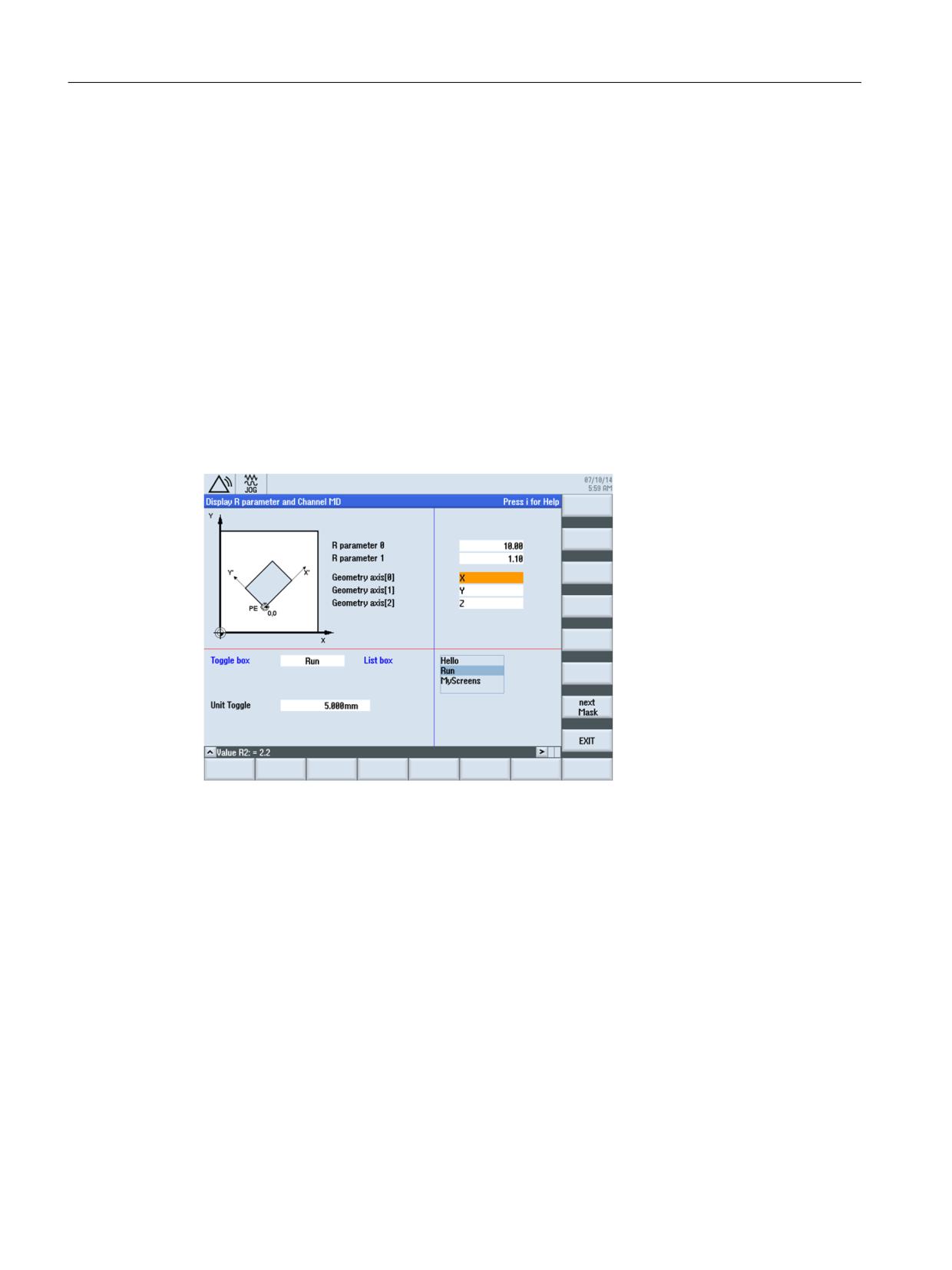
Dialog 1
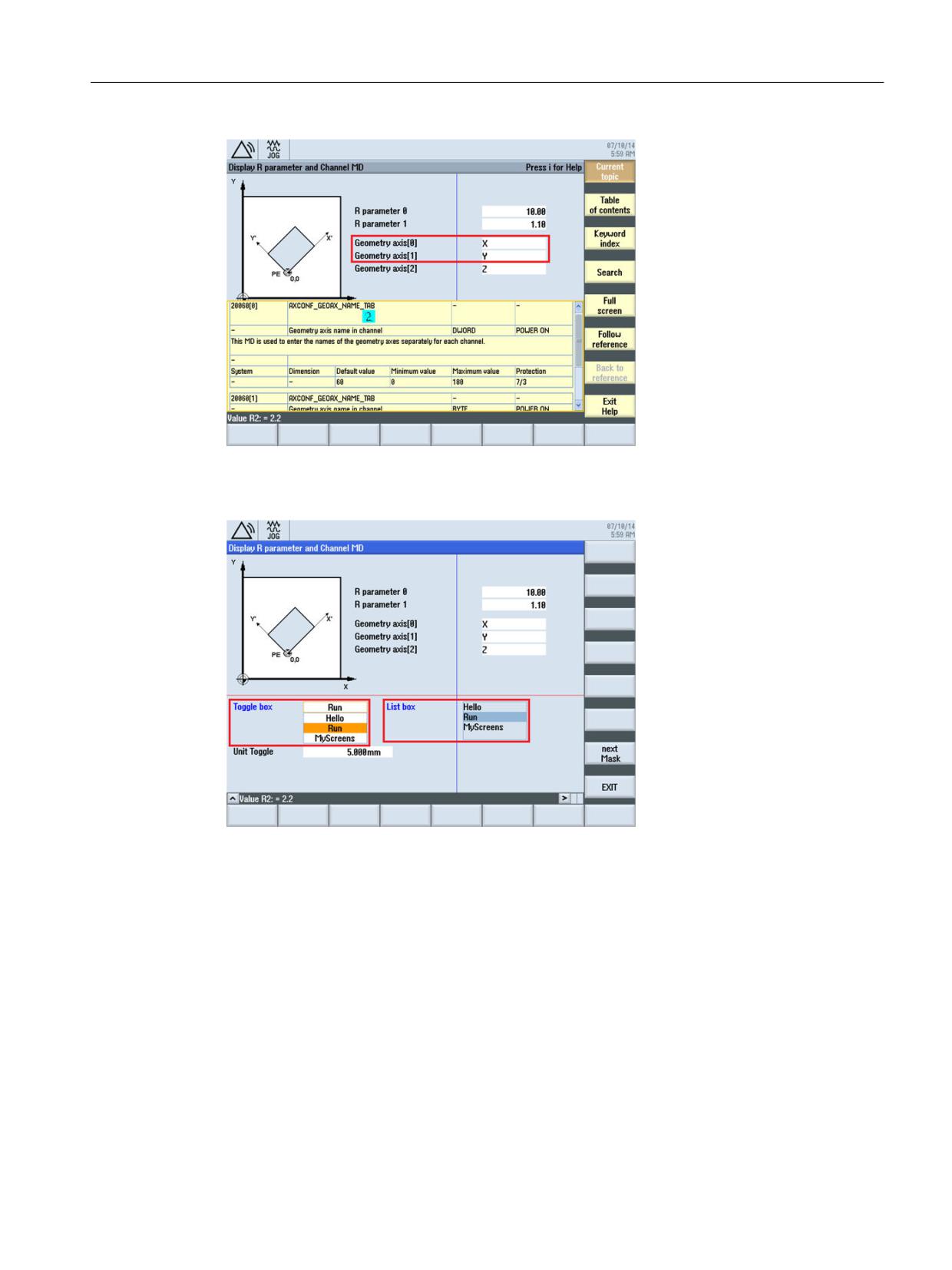
R parameters that can be written to (0 and 1) and geometry axis names are displayed in the first
dialog (input fields). The corresponding help screens are linked in for the two R parameters. A
context-sensitive help is linked in for the geometry axes. Further, the dialog includes examples
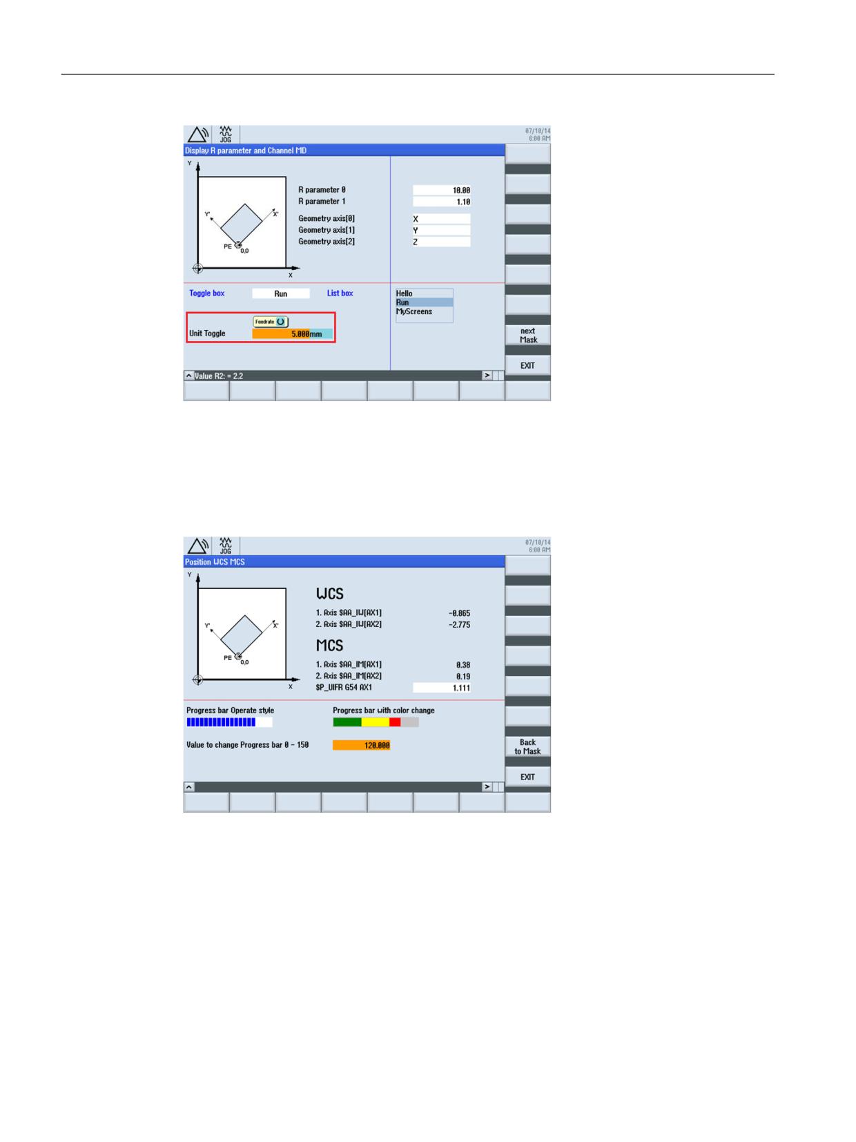
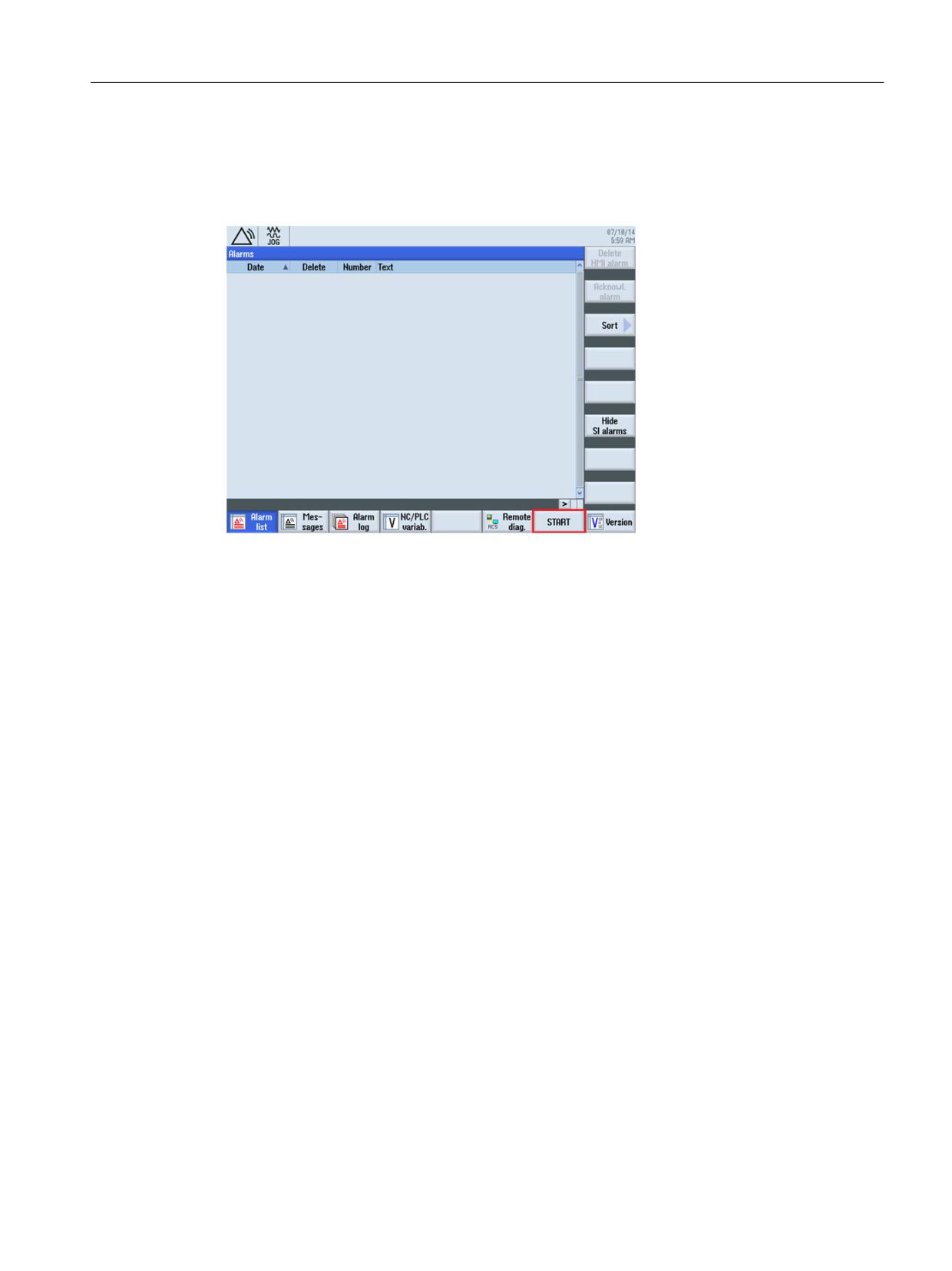
for separating lines (horizontal and vertical), toggle fields, input/output fields with integrated
unit selection and progress bars (with and without color change).
Figure 3-1
R parameters with help displays
SINUMERIK Integrate Run MyScreens
20
Programming Manual, 10/2020, A5E40869575B AD
Getting Started
3.2 Project example
Figure 3-2
Geometry axes with context sensitive help
Figure 3-3
Toggle fields: List and box
SINUMERIK Integrate Run MyScreens
Programming Manual, 10/2020, A5E40869575B AD
21
Getting Started
3.2 Project example
Figure 3-4
I/O field with integrated unit selection
Dialog 2
MCS and WCS values are displayed in the second dialog. The dialog also contains examples of
progress bars with and without color change.
Figure 3-5
Progress bars with (right) and without (left) color change
SINUMERIK Integrate Run MyScreens
22
Programming Manual, 10/2020, A5E40869575B AD
Getting Started
3.2 Project example
Navigation
The first dialog is called using the "START" softkey in the diagnostics operating area. The
horizontal SK7 softkey is used.
Figure 3-6
Start softkey „START“ in the machine operating area, AUTO mode
You can call the second dialog from the first dialog with the "Next Mask" softkey. You can return
to the root screen of the operating area by pressing the "EXIT" softkey (see the screen above).
Using the "EXIT" softkey, you can also return to the root screen of the operating area from the
second dialog (see the screen above). You can return to the first dialog via the "Back to Mask"
softkey.
Procedure
The necessary steps are described in the following chapters:
1. Creating the configuration file (COM file) (Page 24)
2. Saving the configuration file in the OEM directory (Page 27)
3. Creating the online help (Page 28)
4. Integrating the online help and saving the files to the OEM directory (Page 31)
5. Copying "easyscreen.ini" into the OEM directory (Page 32)
6. Registering the COM file in "easyscreen.ini" (Page 32)
7. Testing the project (Page 32)
SINUMERIK Integrate Run MyScreens
Programming Manual, 10/2020, A5E40869575B AD
23
Getting Started
3.2 Project example
3.2.2
Creating the configuration file (example)
Content of the configuration file
Using a UTF8-capable editor, create the configuration file "diag.com" for the two dialogs.
; Start identifier of start softkey
//S(START)
; Start softkey only text
HS7=("START")
; Start softkey with language-dependent text and png
;HS7=([$80792,"\\sk_ok.png"])
; Press method
PRESS(HS7)
; LM or LS function
LM("MASK1")
; LM, specifying a com file
LM("MASK1","TEST.COM")
END_PRESS
; End identifier of start softkey
//END
; Definition of dialog 1 with header and screen
//M(MASK1/"Display R parameter and Channel MD"/"mz961_01.png")
; Definition of the variables
DEF VAR1 = (R2///,"R parameter 0"///"$R[0]"/200,50,150/400,50,100,)
; With help screen
DEF VAR2 = (R2///,"R parameter 1"//"mz961_02.png"/"$R[1]"/200,70,150/400,70,100)
; With online help
DEF ACHS_NAM1 = (S///"Press i for Help","Geometry axis[0]"////200,100,150/400,100,100//"sinumer-
ik_md_1.html","20060[0]")
; With online help
DEF ACHS_NAM2 = (S///"Press i for Help","Geometry axis[1]"////200,120,150/400,120,100//"sinumer-
ik_md_1.html","20060[1]")
DEF ACHS_NAM3 = (S///,"Geometry axis[2]"////200,140,150/400,140,100)
; Definition of toggle fields and unit toggle
DEF VAR_TGL = (S/* "Hello", "Run", "MyScreens"/"Run"/,"Toggle box"////10,230,100/120,230,100/,,6)
DEF VAR_TGB = (S/* "Hello", "Run", "MyScreens"/"Run"/,"List box"/
dt4///250,230,100/370,230,100,60/,,"#0602ee")
; BC, FC, BC_ST, FC_ST, BC_GT, FC_GT, BC_UT, FC_UT, SC1, SC2
DEF VarEdit = (R///,"Unit Toggle",,,"Feedrate"///"$R[11]"/5,300,100/120,300,100///"VarTgl"),
VarTgl = (S/*0="mm",1="inch"/0//WR2////220,300,40)
SINUMERIK Integrate Run MyScreens
24
Programming Manual, 10/2020, A5E40869575B AD
Getting Started
3.2 Project example
; Softkey definition in the dialog
HS1=("")
HS2=("")
HS3=("")
HS4=("")
HS5=("")
HS6=("")
HS7=("")
HS8=("")
VS1=("")
VS2=("")
VS3=("")
VS4=("")
VS5=("")
VS6=("")
VS7=("Next Mask")
VS8=("EXIT")
; Definition LOAD block
LOAD
; Read value with RNP
ACHS_NAM1 = RNP("$MC_AXCONF_GEOAX_NAME_TAB[0]")
ACHS_NAM2 = RNP("$MC_AXCONF_GEOAX_NAME_TAB[1]")
ACHS_NAM3 = RNP("$MC_AXCONF_GEOAX_NAME_TAB[2]")
; Output of a dialog line
DLGL("Value R2: = " << RNP("$R[2]"))
; Write WNP to a value
WNP("$R[3]",VAR0)
; Vertical dividing line
V_SEPARATOR(360,1,6,1)
; Horizontal dividing line
H_SEPARATOR(220,1,7,1)
END_LOAD
; Press method
PRESS(VS7)
; Load an additional dialog
LM("MASK2")
; End identifier press method
END_PRESS
; Press method
PRESS(VS8)
SINUMERIK Integrate Run MyScreens
Programming Manual, 10/2020, A5E40869575B AD
25
Getting Started
3.2 Project example
; Exit the dialog
EXIT
; End identifier press method
END_PRESS
; End identifier dialog 1
//END
; Definition of dialog 2 with header and screen
//M(MASK2/"Position WCS MCS"/"mz961_01.png")
; Definition of the variables
DEF TEXT1 = (I///,"WCS"/WR0,fs2///230,30,120/,,1)
DEF VAR1 = (R3///,"1. Axis $AA_IW[AX1]"/WR1//"$AA_IW[AX1]"/230,70,150/400,70,100)
DEF VAR2 = (R3///,"2. Axis $AA_IW[AX2]"/WR1//"$AA_IW[AX2]"/230,90,150/400,90,100)
DEF TEXT2 = (I///,"MCS"/WR0,fs2///230,120,120/,,1)
DEF VAR3 = (R2///,"1. Axis $AA_IM[AX1]"/WR1//"$AA_IM[AX1]"/230,160,150/400,160,100)
DEF VAR4 = (R2///,"2. Axis $AA_IM[AX2]"/WR1//"$AA_IM[AX2]"/230,180,150/400,180,100)
DEF VAR5 = (R3///,"$P_UIFR G54 AX1"///"$P_UIFR[1,AX1,TR]"/230,200,150/400,200,100)
; Definition of the progress bar
DEF PROGGY0 = (R/0,150//,"Progress bar Operate style"/DT2,DO0//"$R[10]"/5,240,190/5,260,150/6,10)
DEF PROGGY4 = (R/0,150,50,100/120/,"Progress bar with color change"/DT1,DO0//"$R[10]"/
260,240,190/260,260,150/3,4,,,9,7)
; Definition of the variables
DEF PROGVAL = (R/0,150//,"Value to change Progress bar 0 - 150"///"$R[10]"/5,300,230/260,300,100)
; Softkey definition in the dialog
HS1=("")
HS2=("")
HS3=("")
HS4=("")
HS5=("")
HS6=("")
HS7=("")
HS8=("")
VS1=("")
VS2=("")
VS3=("")
VS4=("")
VS5=("")
VS6=("")
VS7=("Back to Mask")
VS8=("EXIT")
SINUMERIK Integrate Run MyScreens
26
Programming Manual, 10/2020, A5E40869575B AD
Getting Started
3.2 Project example
; Load method
LOAD
H_SEPARATOR(230,1,7,1)
END_LOAD
; Change method
CHANGE(VAR5)
; Function PI_START
PI_START("/NC,201,_N_SETUFR")
; End identifier change method
END_CHANGE
; Press method
PRESS(RECALL)
; Return to the calling mask
LM("MASK1")
; End identifier press method
END_PRESS
; Press method
PRESS(VS7)
; Return to the calling mask
LM("MASK1")
; End identifier press method
END_PRESS
; Press method
PRESS(VS8)
; Exit the dialog to the standard application
EXIT
; End identifier press method
END_PRESS
; Dialog end identifier
//END
3.2.3
Saving the configuration file in the OEM directory (example)
Storage path
Save the configuration file "diag.com" under the following path:
[System oem-directory]/proj
SINUMERIK Integrate Run MyScreens
Programming Manual, 10/2020, A5E40869575B AD
27
Getting Started
3.2 Project example
3.2.4
Creating the online help (example)
Create the HTML file "sinumerik_md_1.html". The example under "Content of the online help"
shows the context-sensitive help call via name="20060[0]" and name="20060[1]".
Notes
You can find notes on creating HTML files in Chapter Generating HTML files (Page 78).
Notes regarding the integration of online help are provided in Section Integrating the online
help and saving the files to the OEM directory (example) (Page 31).
SINUMERIK Integrate Run MyScreens
28
Programming Manual, 10/2020, A5E40869575B AD
Getting Started
3.2 Project example
Content of the online help
The example has no comments.
SINUMERIK Integrate Run MyScreens
Programming Manual, 10/2020, A5E40869575B AD
29
Getting Started
3.2 Project example
<html><head><meta http-equiv="Content-Type" content="text/html; charset="UTF-8"/><title></
title></head>
<body>
<table border="1" cellspacing="0" cellpadding="2" width="100%">
<tr>
<td><a name="20060[0]"><b>20060[0]</b></a></td>
<td colspan="3">AXCONF_GEOAX_NAME_TAB</td>
<center>
<img src="../picture/bitmap3.png">
</center>
<td>-</td>
<td>-</td>
</tr>
<tr>
<td>-</td>
<td colspan="3">Geometry axis name in channel</td>
<td>DWORD</td>
<td>POWER ON</td>
</tr>
<tr>
<td colspan="6">This MD is used to enter the names of the geometry axes
separately for each channel.<br />
<tr>
<td>-</td>
<td colspan="5"> </td>
</tr>
<tr>
<td width="16*">System</td><td width="16*">Dimension</td><td width="16*">Default
value</td>
<td width="16*">Minimum value</td><td width="16*">Maximum value</td>
<td width="16*">Protection</td>
</tr>
<tr>
<td>-</td>
<td>-</td>
<td>60</td>
<td>0</td>
<td>180</td>
<td>7/3</td>
</tr>
</table>
<p></p>
<table border="1" cellspacing="0" cellpadding="2" width="100%">
<tr>
<td><a name="20060[1]"><b>20060[1]</b></a></td>
<td colspan="3">AXCONF_GEOAX_NAME_TAB</td>
<td>-</td>
<td>-</td>
</tr>
<tr>
<td>-</td>
<td colspan="3">Geometry axis name in channel</td><td>BYTE</td>
<td>POWER ON</td>
</tr>
<tr>
SINUMERIK Integrate Run MyScreens
30
Programming Manual, 10/2020, A5E40869575B AD
Getting Started
3.2 Project example
<td colspan="6">This MD is used to enter the names of the geometry axes
separately for each channel.<br />
<tr>
<td>-</td>
<td colspan="5"> </td>
</tr>
<tr>
<td width="16*">System</td>
<td width="16*">Dimension</td>
<td width="16*">Default value</td>
<td width="16*">Minimum value</td>
<td width="16*">Maximum value</td>
<td width="16*">Protection</td>
</tr>
<tr>
<td>-</td>
<td>-</td>
<td>0</td>
<td>0</td>
<td>2</td>
<td>7/3</td>
</tr>
</table>
<p></p>
</body>
</html>
3.2.5
Integrating the online help and saving the files to the OEM directory
(example)
Integrating the online help
The syntax to integrate the online help is analogous to SINUMERIK Operate.
DEF RFP=(R//1/,"RFP","RFP"///////"sinumerik_md_1.html","9006")
Note
As a result of LINUX, the HTML file must be written in lower case letters!
Storage path
Save the HTML file "sinumerik_md_1.html" for the English help under the following path:
[System oem-directory]/hlp/eng
You must create a folder for additional languages as required (e.g. chs, deu, esp, fra, ita, etc.).
A list of language codes is provided in the Appendix "Reference lists".
SINUMERIK Integrate Run MyScreens
Programming Manual, 10/2020, A5E40869575B AD
31
Getting Started
3.2 Project example
Further information
Detailed information about creating OEM-specific online help files is provided in
Chapter Configuring the online help (Page 77).
3.2.6
Copying "easyscreen.ini" into the OEM directory (example)
Storage path
Copy the file "easyscreen.ini" from the directory
[System siemens-directory]/cfg
to the directory
[System oem-directory]/cfg.
3.2.7
Registering the COM file in "easyscreen.ini" (example)
Adaptation of the "easyscreen.ini"
Make the following change in the "easyscreen.ini" in the OEM directory. You have thus registered
the "diag.com" configuration file.
;########################
;# AREA Diagnosis
#
;########################
;<===============================================================>
;< OEM Softkey on first horizontal Main Menu
>
;< SOFTKEY position="7"
>
;<===============================================================>
StartFile28 = area := AreaDiagnosis, dialog:= SlDgDialog, menu := DgGlobalHu, startfile := diag.com
3.2.8
Testing the project (example)
Testing the dialog call
Switch to the diagnostics operating area. Click the "START" horizontal softkey.
If "Run MyScreens" detects errors when interpreting the configuration files, these errors will be
written to the "easyscreen_log.txt" text file. Further information can be found in Chapter
Troubleshooting (log book) (Page 42).
SINUMERIK Integrate Run MyScreens
32
Programming Manual, 10/2020, A5E40869575B AD
Getting Started
3.2 Project example
Testing context sensitive help screens and online help
Test the context sensitive help screens and the online help. If errors occur, then check the paths
where files have been saved.
SINUMERIK Integrate Run MyScreens
Programming Manual, 10/2020, A5E40869575B AD
33
Getting Started
3.2 Project example
SINUMERIK Integrate Run MyScreens
34
Programming Manual, 10/2020, A5E40869575B AD
Fundamentals
4
4.1
Structure of configuration file
Introduction
The description of new user interfaces is stored in configuration files. These files are
automatically interpreted and the result displayed on the screen. Configuration files are not
stored in the software supplied and must be set up by the user.
A UTF-8-capable editor (e.g. the integrated editor of the user interface or Notepad) is used to
create the configuration files and language files. The description can also be explained using
comments. A ";" is inserted as comment character before every explanation.
Note
When saving configuration and language files, ensure that the coding is set to UTF-8 for the
editor you are using.
However, keywords - also in an UTF-8-coded COM file - may only comprise characters that are
contained in the ASCII character set. Otherwise the interpretation and therefore the display of
the screens/dialogs cannot be guaranteed.
Configuration
Each HMI operating area has permanent start softkeys which can be used to access newly
generated dialogs.
In the event of a "Load a screen" (LM) or a "Load softkey menu" (LS) call in a configuration file,
a new file name containing the object called can be specified. This makes it possible to structure
the configuration, e.g. all functions in one operating level in a separate configuration file.
Structure of the configuration file
A configuration file consists of the following elements:
1. Description of the start softkeys
2. Definition of the dialogs
3. Definition of the variables
4. Description of the methods
5. Definition of the softkey menus
SINUMERIK Integrate Run MyScreens
Programming Manual, 10/2020, A5E40869575B AD
35
Fundamentals
4.1 Structure of configuration file
Note
Sequence
The specified sequence in the configuration file must be maintained.
Example:
//S (START)
; Definition of the start softkey (optional)
//END
//M (
)
; Definition of the dialog
DEF
; Definition of the variables
LOAD
; Description of the blocks
END_LOAD
UNLOAD
END_UNLOAD
//END
//S (...)
; Definition of a softkey menu
//END
Storing the configuration files
The configuration files are stored in the directory [System user-directory]/proj and accordingly
also in the directories [System addon-directory] and [System oem-directory].
Converting texts from other HMI applications
Procedure to convert a text file with code page coding to text-coding UTF-8:
1. Open the text file on a PG/PC in a text editor.
2. When saving, set the UTF-8 coding.
The read-in mechanism via code page code is still supported.
SINUMERIK Integrate Run MyScreens
36
Programming Manual, 10/2020, A5E40869575B AD
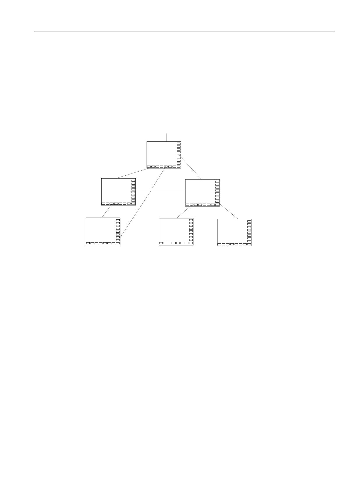
Fundamentals
4.2 Structure of the menu tree
4.2
Structure of the menu tree
Menu tree principle
Several interlinked dialogs create a menu tree. A link exists if you can switch from one dialog to
another. You can use the newly defined horizontal/vertical softkeys in this dialog to call the
preceding or any other dialog.
A menu tree can be created behind each start softkey:
6WDUW VRIWNH\
Figure 4-1
Menu tree
Start softkeys
One or more softkeys (start softkeys), which are used to initiate your own operating sequences,
are defined in the configuration files specified in "easyscreen.ini".
The loading of a dedicated dialog is associated with a softkey definition or another softkey menu.
These are then used to perform the subsequent actions.
Pressing the start softkey loads the assigned dialog. This will also activate the softkeys associated
with the dialog. Variables will be output to the standard positions unless specific positions have
been configured.
Reverting to the standard application
You can exit the newly created dialog and return to the standard operating area.
SINUMERIK Integrate Run MyScreens
Programming Manual, 10/2020, A5E40869575B AD
37
Fundamentals
4.2 Structure of the menu tree
You can use the <RECALL> key to close new user interfaces if you have not configured this key
for any other task.
Note
Calling dialogs in the PLC user program
Dialogs can be selected from the PLC as well as via softkeys: An interface signal is available in
DB19.DBB10 for signal exchange between the PLC → HMI.
SINUMERIK Integrate Run MyScreens
38
Programming Manual, 10/2020, A5E40869575B AD
Fundamentals
4.3 Definition and functions for start softkeys
4.3
Definition and functions for start softkeys
4.3.1
Defining the start softkey
Dialog-independent softkey
Start softkeys are dialog-independent softkeys which are not called from a dialog, but which
have been configured before the first new dialog. In order to access the start dialog or a start
softkey menu, the start softkey must be defined.
Programming
The definition block for a start softkey is structured as follows:
//S(Start)
; Start identifier of start softkey
HS1=(...)
; Define the start softkey: horizontal SK 1
PRESS(HS1)
; Method
LM...
; LM or LS function
END_PRESS
; End of method
//END
; End identifier of start softkey
Permissible positions for start softkeys
The following positions for "Run MyScreens" start softkeys are permissible in the operating
areas:
Operating area
Position
Machine
HSK6
Parameter
HSK7
Program
HSK6 and HSK15
Measuring cycles: HSK13 and HSK14
Program Manager
HSK2-8 and HSK12-16, if not assigned to drives.
Diagnostics
HSK7
Commission
HSK7
Start softkeys are configured in special files. The names of these files are stated in the
"easyscreen.ini" file. They usually have a name which is specific to an operating area (e.g.
"startup.com" operating area for the startup area). The machine operating area represents an
exception. There are several mode-specific files in the machine operating area ("ma_jog.com",
"ma_auto.com").
The softkey menu with the start softkeys is called "Start". Existing configurations for start
softkeys can still be used. The function where start softkeys are merged with the softkeys for the
respective HMI application (operating area) in the start softkey menu is not supported.
SINUMERIK Integrate Run MyScreens
Programming Manual, 10/2020, A5E40869575B AD
39
Fundamentals
4.3 Definition and functions for start softkeys
This means that until the first dialog call is made - in other words, the time at which full
functionality becomes available (e.g. execution of PRESS blocks) - menus or softkey menus can
only be replaced by others in their entirety.
Template for configuration of the start softkey
A detailed description of all permissible positions for start softkeys and their configuration is
located in the "easyscreen.ini" file in the following directory:
[System siemens-directory]/cfg
This file is used as a template for your own configuration of the start softkey.
See also
Lists of the start softkeys
4.3.2
Functions for start softkeys
Functions for dialog-independent softkeys
Only certain functions can be initiated with start softkeys.
The following functions are permitted:
• The LM function can be used to load another dialog: LM("Identifier"[,"File"])
• The LS function can be used to display another softkey menu: LS("Identifier"[, "File"][,
Merge])
• You can use the "EXIT" function to exit newly configured user interfaces and return to the
standard application.
• You can use the "EXITLS" function to exit the current user interface and load a defined
softkey menu.
PRESS method
The softkey is defined within the definition block and the "LM" or "LS" function is assigned in the
PRESS method.
If the start softkey definition is designated as a comment (semicolon (;) at beginning of line) or
the configuration file removed, the start softkey will not function.
//S(Start)
; Start identifier
HS6=("1st screen")
; Label horizontal SK 6 with "1st screen"
PRESS(HS6)
; PRESS method for horizontal SK 6
LM("Screen1")
; Load screen1 function, where Screen 1 must be
defined within the same file.
SINUMERIK Integrate Run MyScreens
40
Programming Manual, 10/2020, A5E40869575B AD
Fundamentals
4.3 Definition and functions for start softkeys
END_PRESS
; End of PRESS method
HS7=("2nd screen")
; Label horizontal SK 7 with "2nd screen"
PRESS(HS7)
; PRESS method for horizontal SK 7
LM("Screen2")
; Load Screen2 function, where Screen2 must be de-
fined within the same file.
END_PRESS
; End of PRESS method
//END
; End identifier of entry block
Example
HS1 = ("new softkey menu")
HS2 = ("no function")
PRESS (HS1)
LS("Menu1")
; Load new softkey menu
END_PRESS
PRESS (HS2)
; Empty PRESS method
END_PRESS
Various configurations of the start softkeys
Various configurations of the start softkeys are merged. In this case, initially the name of the file
to be interpreted is read-out of "easyscreen.ini". A search is made for *.com files in the following
directories:
• [System user-directory]/proj
• [System oem-directory]/proj
• [System addon-directory]/proj
• [System siemens-directory]/proj
The configurations included for the start softkeys are now merged to form a configuration, i.e.
the individual softkeys are compared. If there are two or more configurations for a softkey, the
higher order configuration is always used in the merge version.
Softkey menus or dialogs that are possibly included are ignored. If a softkey has a command
without file information, e.g. LM ("test"), as the required softkey menu or dialog is contained in
the same file, then the corresponding file name is supplemented in the internal merge version
so that in this case, no changes are required. The merge configuration obtained is then
subsequently displayed.
SINUMERIK Integrate Run MyScreens
Programming Manual, 10/2020, A5E40869575B AD
41
Fundamentals
4.4 Troubleshooting (log book)
4.4
Troubleshooting (log book)
Overview
If "Run MyScreens" detects errors when interpreting the configuration files, these errors will be
written to the "easyscreen_log.txt" text file. Only errors of the currently selected dialog are
entered. Error entries from previously selected dialogs are deleted.
The file contains the following information:
• The action during which an error occurred.
• The line and column number of the first faulty character.
• The entire faulty line of the configuration file.
• The entries made by the DEBUG function.
Note
Each entry has a prefix with the current time stamp in square brackets. This can be helpful,
for example, when analyzing time-critical configurations.
Saving "easyscreen-log.txt"
The "easyscreen_log.txt" file is saved in the following directory:
[System user-directory]/log
Syntax
The system does not start to interpret the syntax until the start softkey has been defined and a
dialog with start and end identifiers as well as a definition line has been configured.
//S(Start)
HS6=("1st screen")
PRESS(HS6)
LM("Maske1")
END_PRESS
//END
//M(Maske1)
DEF Var1=(R)
DEF VAR2 = (R)
LOAD
VAR1 = VAR2 + 1
; Error message in logbook, as VAR2 has no value
//END
SINUMERIK Integrate Run MyScreens
42
Programming Manual, 10/2020, A5E40869575B AD
Fundamentals
4.4 Troubleshooting (log book)
; correct way would be, for
example:
//M(Maske1)
DEF Var1=(R)
DEF VAR2 = (R)
LOAD
VAR2 = 7
VAR1 = VAR2 + 1 ;
SINUMERIK Integrate Run MyScreens
Programming Manual, 10/2020, A5E40869575B AD
43