SINUMERIK 840D sl. Service - Configuring Commissioning. Manual (2011-2020) - page 45
SINUMERIK Operate on PCU/IPC
21.4 FindWindow program application
Example
An application is to be integrated that contains the start time in the attribute window name:
oemframe.ini
[MyQtTest]
fFindWindowWithWildcards = 1
systemconfiguration.ini
[processes]
PROC500=process:=ProcessOEM, cmdline:="C:\\Program Files(x86)\\Siemens\\
MotionControl\\oem\\sinumerik\\hmi\\appl\\MyQtTest.exe",oemframe:=true,
windowname:="MyQtTest - ??:??:??", classname:="QWidget",deferred:=true
[areas]
AREA500=name:=Test, process:=ProcessOEM
21.3
Creating OEM subdirectories
If you would like to integrate several OEM applications (user interface dialogs or OEM frame
applications), you can distribute them to their own OEM subdirectories. The advantage is the
clear assignment of the files to a particular OEM application. This is especially true for the
"systemconfiguration.ini" file as there is a risk of it being accidentally overwritten when copying,
which may hide other OEM applications.
Create OEM subdirectories with any directory name under /oem/sinumerik/hmi. These
subdirectories are communicated in the file "systemconfiguration.ini" in directory /oem/
sinumerik/hmi/cfg. Create the following syntax in section [oem_dirs]:
OEM_<Number>=<OEM subdirectory name>
Example
[oem_dirs]
OEM_1=oem_example
OEM_2=oem_new
Under the two subdirectories /oem/sinumerik/hmi/oem_example and /oem/sinumerik/hmi/
oem_new, create directories "appl", "cfg", "Ing", "hlp", etc. again as required.
21.4
FindWindow program application
You can use the FindWindow program to determine all the parameters in the
"systemconfiguration.ini" file that are relevant for integrating an OEMFrame application into
SINUMERIK Operate.
SINUMERIK Operate
Commissioning Manual, 10/2020, 6FC5397-1DP40-6BA4
567
SINUMERIK Operate on PCU/IPC
21.5 Activating/deactivating window mode
Requirement
For changes to become effective in SINUMERIK Operate through the FindWindow program, you
need access level 2 (Service).
Installation
FindWindow can be used on any PCU without being installed.
FindWindow (findwindow.exe) is located in the following directory:
C:\Program Files (x86)\Siemens\MotionControl\Common\FindWindow\
Application
1. Start the PCU.
2. Install the application to be integrated using OEMFrame.
3. Open the application.
4. Open the FindWindow program.
5. Left-click to drag the red cross to the title bar of the application in the FindWindow program.
6. Check the application parameters "FileName", "ClassName", etc.
7. Select the parameters "Gimmekey", "Disablekeys", etc. via the checkboxes as needed.
If the configuration file "systemconfiguration.ini" exists and you want to expand it:
8. Copy the entries to the clipboard by clicking on "Copy to Clipboard".
9. Open the existing configuration file and insert the parameters from the clipboard. To do this,
right-click on the position at which the parameters are to be inserted and then click on
"Insert".
10 Save the modified configuration file.
- OR -
If the configuration file "systemconfiguration.ini" does not exist and you want to create it:
8. Click on the "Create systemconfiguration.ini" button.
A new configuration file is simultaneously created in the directory for FindWindow. Any
existing configuration file will be overwritten.
9. Insert a copy of the new configuration file into the provided directory.
Note
If you include a 64-bit application, no parameter data is displayed under "FileName". In this case,
an information dialog opens, which allows you to manually select the application.
Note
Only use the 8.3 Notation for file names if problems occur without this parameterization.
21.5
Activating/deactivating window mode
By default, SINUMERIK Operate is displayed without window mode on PCU/IPC.
SINUMERIK Operate
568
Commissioning Manual, 10/2020, 6FC5397-1DP40-6BA4

SINUMERIK Operate on PCU/IPC
21.6 Setting text legibility by means of font smoothing
Activate the window mode for the operating software in the file "slguiconfig.ini".
Procedure
1. Copy the "slguiconfig.ini" file from the folder
/siemens/sinumerik/hmi/template/cfg.
2. Insert the copy into the folder
/oem/sinumerik/hmi/cfg or /user/sinumerik/hmi/cfg.
3. Open the file in the editor.
4. To activate or deactivate the window mode, make the following settings:
- Activate window mode:
In the section [WindowMode], ActivateWindowMode = true
- Deactivate window mode:
In the section [WindowMode], ActivateWindowMode = false
5. Restart SINUMERIK Operate.
When the system has finished booting, the operating software is displayed in the window
mode.
21.6
Setting text legibility by means of font smoothing
To ensure that particularly small TrueType fonts can be read more easily, the text display is
already optimized under Windows by default. The settings perform fine font smoothing of the
font and provide an improved display on the screen (Windows ClearType technology).
If you want to change the text legibility for SINUMERIK Operate, you can adjust the following
parameters via the "slstartup.ini" file.
Adapting the "startup.ini" file
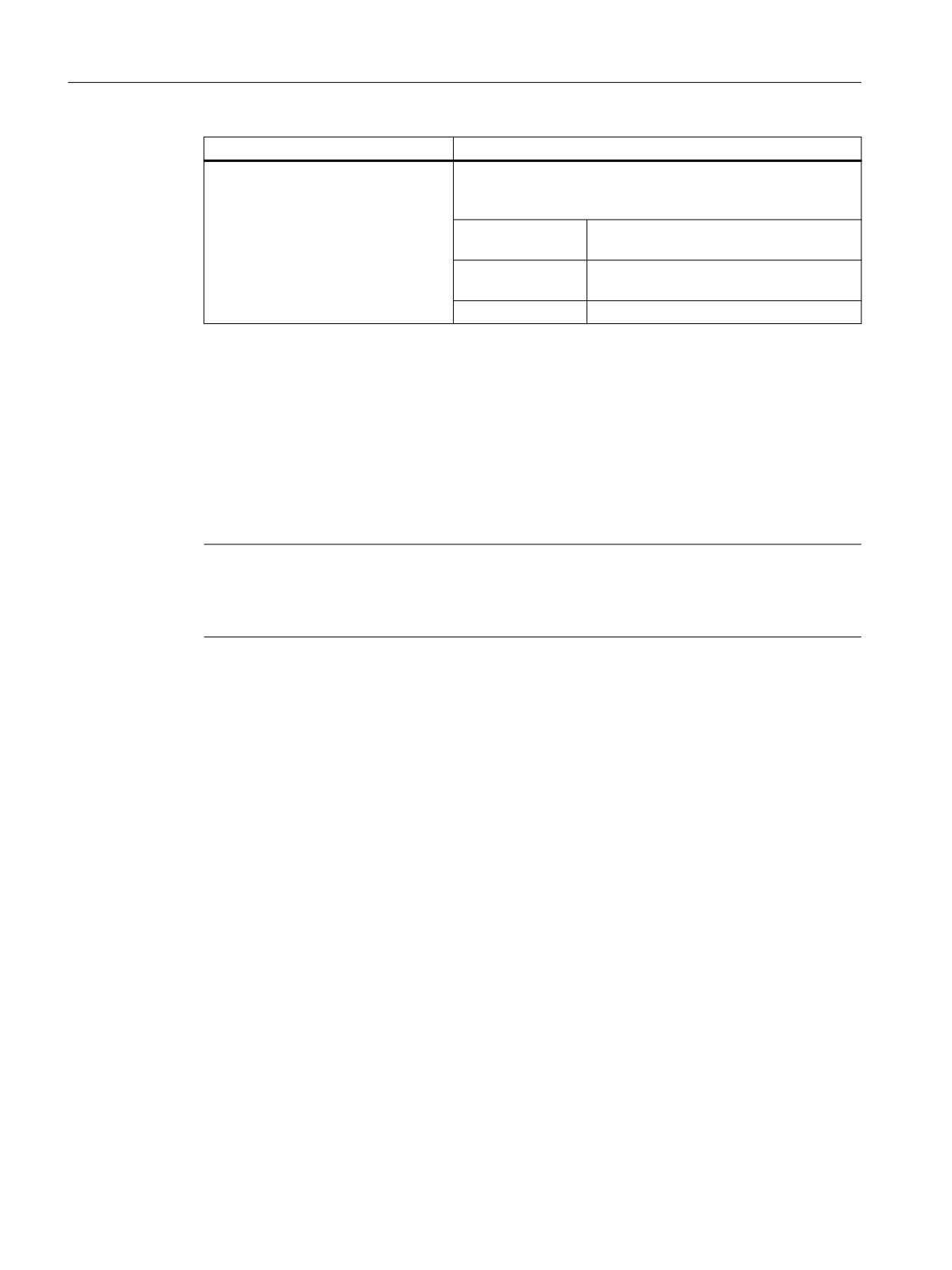
Parameter
Description
[FontSmoothing]
Describes the section in which all of the parameters for setting
the text legibility are located
UseSystemSettings
Defines which system settings will be used for font smoothing
and optimizing the display
= true
Windows settings
= false
SINUMERIK Operate settings (default)
UseFontSmoothing
Activates font smoothing of the font type used in SINUMER-
IK Operate (only possible with
parameters UseSystemSettings switched off)
= true
Switch on font smoothing
= false
Switch off font smoothing (default)
SINUMERIK Operate
Commissioning Manual, 10/2020, 6FC5397-1DP40-6BA4
569
SINUMERIK Operate on PCU/IPC
21.7 Using interactive or silent installation versions
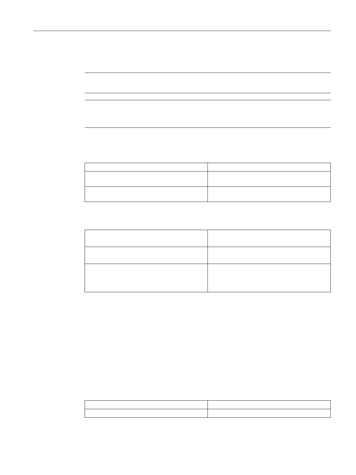
Parameter
Description
UseFontSmoothingType
Activates the Windows display optimization ClearType (only
possible with switched off parameter UseSystemSettings
and switched on parameter UseFontSmoothing)
= 1
Only use font smoothing
FE_FONTSMOOTHINGSTANDARD
= 2
Use ClearType technology
FE_FONTSMOOTHINGCLEARTYPE
= 0
Switch off function (default)
Archive
The template of the file "slstartup.ini" for SINUMERIK Operate is stored in the following directory:
<Installation path>/siemens/sinumerik/hmi/cfg/slstartup.ini
Copy the file to one of the following directories:
<Installation path>/user/sinumerik/hmi/cfg
<Installation path>/oem/sinumerik/hmi/cfg
Note
If you want to achieve a better overview of the changes you have made yourself, simply delete
the unchanged parameters from the file copy "slstartup.ini". The missing parameters continue
to be read by the directory /siemens/sinumerik/hmi/cfg from the template.
21.7
Using interactive or silent installation versions
General Information
If you install SINUMERIK Operate using PC/PCU, then the execution is realized using an MSI setup.
The following installation versions are available, which you can use in the interactive or silent
mode using the appropriate Windows command line:
• SINUMERIK Operate complete installation
• SINUMERIK Operate base installation with auxiliary files
• SINUMERIK Operate base installation without auxiliary files
Execution
You control setup execution using command line arguments. The interactive mode /v allows
you to transfer parameter strings to setup.exe. If you wish to run setup without user interaction,
then you can extend the parameter string with the silent mode /qn.
Place the parameter string in inverted commas. If you use several parameters in the string,
separate these using spaces.
SINUMERIK Operate
570
Commissioning Manual, 10/2020, 6FC5397-1DP40-6BA4
SINUMERIK Operate on PCU/IPC
21.7 Using interactive or silent installation versions
If you do not specify any arguments when calling setup.exe, then the complete installation is run
in the interactive mode.
Note
Do not put any spaces between /v and the parameter string.
Note
If you want a progress display in the silent mode, then instead of specifying /qn you can also
specify /qb!.
Interactive installation versions
setup.exe
Complete installation in the interactive mode
setup.exe /v"BASEONLY=1"
Base installation in the interactive mode with help
files
setup.exe /v"BASEONLY=1 HELPFILES=0"
Base installation in the interactive mode without
help files
Silent installation versions
setup.exe /v"/qn"
Complete installation in the silent mode
setup.exe /s /v"/qn"
(/s suppresses all of the setup messages)
setup.exe /v"/qn BASEONLY=1"
Base installation in the silent mode with help files
setup.exe /s /v"/qn BASEONLY=1"
(/s suppresses all of the setup messages)
setup.exe /v"/
Base installation in the silent mode without help
qn BASEONLY=1 HELPFILES=0"
files
setup.exe /s /v"/
(/s suppresses all of the setup messages)
qn BASEONLY=1 HELPFILES=0"
Additional parameter assignments
Installation path
If you install the PC version of SINUMERIK Operate, then you can additionally specify the
installation path:
setup.exe /s /v"/qn INSTALLDIR=C:\Programme\testdir"
For spaces in the path:
setup.exe /s /v"/qn INSTALLDIR=\"C:\Program Files\testdir\""
Exit code
You can identify a successful installation or errors based on the exit code of the setup.exe call:
Exit code == 0
No error
Exit code <> 0
Error
SINUMERIK Operate
Commissioning Manual, 10/2020, 6FC5397-1DP40-6BA4
571
SINUMERIK Operate on PCU/IPC
21.8 Setting the IP address of the NCU
Log file
During the installation you can generate a log file with /L:
setup.exe /s /v"/qb! /L*vx log.txt"
21.8
Setting the IP address of the NCU
From the user interface of the SINUMERIK Operate, you can set the IP address of the NCU with
which it should connect.
Procedure
1.
Select the "Start-up" operating area.
2.
Press the "HMI" softkey and the ">>" softkey.
Press the vertical softkey "NCU connection".
The "NCU Connection" window opens.
Enter the IP address of the NCU into the input field.
3.
Press the "OK" softkey to confirm the data.
SINUMERIK Operate
572
Commissioning Manual, 10/2020, 6FC5397-1DP40-6BA4
SINUMERIK Operate on PCU/IPC
21.9 SINUMERIK Operate exiting
21.9
SINUMERIK Operate exiting
Procedure
1.
Press the <MENU SELECT> key on the operator panel.
OR:
Activate the <M> symbol on the touch panel.
External keyboard: Press the <F10> key.
2.
Press the menu forward key.
External keyboard: Press the <Shift> + <F9> keys.
3.
Press the "EXIT" softkey.
External keyboard: Press <F8>
• on the PCU to terminate SINUMERIK Operate and the Windows sys-
tem.
• If you started SINUMERIK Operate operating software on the PCU in
the service mode, then only the operating software is exited.
• On the PC itself, only SINUMERIK Operate is exited.
SINUMERIK Operate
Commissioning Manual, 10/2020, 6FC5397-1DP40-6BA4
573
SINUMERIK Operate on PCU/IPC
21.9 SINUMERIK Operate exiting
SINUMERIK Operate
574
Commissioning Manual, 10/2020, 6FC5397-1DP40-6BA4
Handheld terminals
22
The mobile HT 8 and HT 10 handheld terminals combined the functions of an operator panel and
a machine control panel in one device. They therefore allow a machine to be completely
operated and monitored.
Additional information
Additional information on operating and commissioning the handheld terminal is provided in
the:
• Operating Manual Universal/Turning/Milling/Grinding
• Equipment Manual HT 8 Handheld Terminal
• Equipment Manual HT 10 Handheld Terminal
22.1
Configuring HT 8 traversing keys
The traversing keys of the HT 8 are not labeled as their type of action is not predefined. The
labeling of the traversing keys should adapt dynamically to the type of action of the keys. To
recognize the type of action of the traversing keys, they are shown within the display in the
vertical softkey area.
The menu of the traversing keys consists of two vertical rows each with eight keys so that up to
16 texts can be configured. The top and bottom traversing key row remain empty and can be
assigned other functions.
The following data can be displayed:
• Machine axis name
• Alias name for machine axis
• Any language-dependent text
• Symbol
The following user-specific files are required. You can use the sample files as template:
File
Meaning
"sljkconfig.ini" configuration file
File in which the traversing keys are configured.
Text file "oem_sljk_xxx.ts"
File for labeling traversing keys in a foreign language, xxx =
language code
SINUMERIK Operate
Commissioning Manual, 10/2020, 6FC5397-1DP40-6BA4
575
Handheld terminals
22.1 Configuring HT 8 traversing keys
"sljkconfig.ini" configuration file
Entries
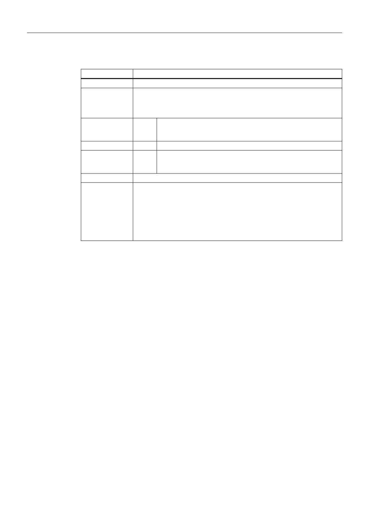
Meaning
[State_1]
Labeling type - changed via the PLC.
ParamText_x_y
Text of the traversing key that is made up of parameters.
Two-line labeling is possible, whereby max. five characters are possible per line.
x: Specifies the position of the key within the row (2 to 7).
y: Specifies the key row (1 or 2).
%m1
The machine axis name of the first axis is referenced and displayed as text.
The current active axis number is read out from data block DB10. The
name from the machine data is determined via this index.
%n
Defines the position in the text for the line break.
%a1
The alias axis name of the first axis is referenced and displayed as text. The
current active axis number is read out from data block DB10. The name
from the "oem_sljk_eng.ts" text file is determined via this index.
TextId_x_y
Text of the traversing key that is read from the text file (target language text).
Picture_x_y
File name of the icon to be displayed.
The files with the icons must be located in the following directories: /oem/sinumerik/
hmi/ico and
depending on the resolution, in subdirectories:
/ico640
/ico800
/ico1024
/ico1280
Procedure
1. Copy the "sljkconfig.ini" configuration file from the folder
/siemens/sinumerik/hmi/template/cfg
2. Place the copy into the folder /oem/sinumerik/hmi/cfg
or /user/sinumerik/hmi/cfg
3. Open the copy in the Editor and define the traversing key labeling.
Example of a "sljkconfig.ini" configuration file
12 axes are defined in the example, with text for softkey 1 and softkey 2, as well as an image on
softkey 3 and softkey 4.
[Settings]
FileType = INI
; A few examples for further configuration options
; Alias names of machine-axes (%a1, %a2, etc.), from oem_sljk_deu.ts
(example)
[State_1]
TextId_1_1 = OEM_JK_TEXT_1
SINUMERIK Operate
576
Commissioning Manual, 10/2020, 6FC5397-1DP40-6BA4
Handheld terminals
22.1 Configuring HT 8 traversing keys
TextId_1_2 = OEM_JK_TEXT_2
ParamText_2_1 = %a1%n-
ParamText_2_2 = %a1%n+
ParamText_3_1 = %a2%n-
ParamText_3_2 = %a2%n+
ParamText_4_1 = %a3%n-
ParamText_4_2 = %a3%n+
ParamText_5_1 = %a4%n-
ParamText_5_2 = %a4%n+
ParamText_6_1 = %a5%n-
ParamText_6_2 = %a5%n+
ParamText_7_1 = %a6%n-
ParamText_7_2 = %a6%n+
Picture_8_1 = AlarmCancel.png
Picture_8_2 = AlarmNCReset.png
"oem_sljk_eng.ts" text file
Entries
Meaning
name
Freely selectable name of the text context.
In the text file template, the name of the text context is "SIJkLabels" and stands for the
traversing key labeling (solution line jog key labels). This identifier is already stored in the
configuration file.
source
Traversing key identifier of the respective axis. This text ID is referenced in the "sljkcon-
fig.ini" configuration file with the "TextId_2_1".
The text IDs for the alias names (JK_AXISNAME_2 to JK_AXISNAME_7) must not be
changed.
translation
Input of the foreign language text for the axis specified in <source>.
Language code in file names "xxx"
Language
Language code
German
deu
English
eng
French
fra
Spanish
esp
Italian
ita
Chinese
chs
SINUMERIK Operate
Commissioning Manual, 10/2020, 6FC5397-1DP40-6BA4
577
Handheld terminals
22.1 Configuring HT 8 traversing keys
Procedure
1. You can copy the sample file "oem_sljk_deu.ts" from the following folder: /siemens/
sinumerik/hmi/template/lng.
2. Store or create the file in the /oem/sinumerik/hmi/lng or
/user/sinumerik/hmi/lng directory.
3. Assign the file a name, e.g. for German texts: "sljk_deu.ts".
If you wish to set-up the labeling for additional languages, a separate file must be created for
each language. Save the file with the appropriate language code in the file name. To do this,
use the language codes specified above.
4. Open the file and in the <message> and </message> area, define the labeling.
5. Restart the HMI.
In order that the labeling is displayed during the program runtime, the file must be converted
into a binary format. This conversion is only executed when the HMI powers up.
Example of a text file "sljk_deu.ts"
12 axes are defined in the example, with text for softkey 1 (SF1) and softkey 2 (SF2):
<?xml version="1.0" encoding="utf-8"?>
<!DOCTYPE TS>
<TS>
<context>
<name>SlJkLabels</name>
<!-- Alias names for machine axis (%a1, %a2, etc.) -->
<!-- Do not change the text ID (JK_AXISNAME_1, etc.) -->
<message>
<source>JK_AXISNAME_1</source>
<translation>X</translation>
</message>
<message>
<source>JK_AXISNAME_2</source>
<translation>Y</translation>
</message>
<message>
<source>JK_AXISNAME_3</source>
<translation>Z</translation>
</message>
<message>
<source>JK_AXISNAME_4</source>
<translation>A</translation>
</message>
<message>
<source>JK_AXISNAME_5</source>
<translation>B</translation>
SINUMERIK Operate
578
Commissioning Manual, 10/2020, 6FC5397-1DP40-6BA4
Handheld terminals
22.1 Configuring HT 8 traversing keys
</message>
<message>
<source>JK_AXISNAME_6</source>
<translation>C</translation>
</message>
<message>
<source>JK_AXISNAME_7</source>
<translation>U</translation>
</message>
<message>
<source>JK_AXISNAME_8</source>
<translation>V</translation>
</message>
<message>
<source>JK_AXISNAME_9</source>
<translation>W</translation>
</message>
<message>
<source>JK_AXISNAME_10</source>
<translation>UV1</translation>
</message>
<message>
<source>JK_AXISNAME_11</source>
<translation>UV2</translation>
</message>
<message>
<source>JK_AXISNAME_12</source>
<translation>UV3</translation>
</message>
<!-- User defined language dependent text (example) -->
<message>
<source>OEM_JK_TEXT_1</source>
<translation>SF1</translation>
</message>
<message>
<source>OEM_JK_TEXT_2</source>
<translation>SF2</translation>
</message>
</TS>
SINUMERIK Operate
Commissioning Manual, 10/2020, 6FC5397-1DP40-6BA4
579
Handheld terminals
22.3 Activating/deactivating the virtual keyboard
22.2
HT 10 traversing keys
If an HT 10 is connected to the system, you can automatically select the axes in the operating
software using checkboxes, and traverse them using the keys +/- or the handwheel.
Selecting an axis using the checkbox
To activate selection of the axis with the checkbox using Panels with touch function, set the
following channel-specific machine data:
MD52210 $MCS_FUNCTION_MASK_DISP
Function screen display
Bit 16
Selection of JOG axis via HMI
Note
A selection made at the HT 10 has no effect if you select an axis at the machine control, e.g. for
switching over between MCS and WCS.
22.3
Activating/deactivating the virtual keyboard
The virtual keyboard is configured in file "slguiconfig.ini".
Procedure
1. Copy the "slguiconfig.ini" file from the folder
/siemens/sinumerik/hmi/template/cfg.
2. Insert the copy into the folder:
/oem/sinumerik/hmi/cfg or /user/sinumerik/hmi/cfg.
3. Open the file in the editor.
4. To activate or deactivate the keyboard, make the following settings:
- Activating the virtual keyboard:
In the section [TouchPanel], EnableTouch = true
In the section [Keyboard], EnableVirtualKeyBoard = true
- Deactivating the virtual keyboard:
In the section [TouchPanel], EnableTouch = true
In the section [Keyboard], EnableVirtualKeyBoard = false
5. Double click in the input field to display the keyboard.
SINUMERIK Operate
580
Commissioning Manual, 10/2020, 6FC5397-1DP40-6BA4
Handheld terminals
22.4 Configuring user-specific key labeling
22.4
Configuring user-specific key labeling
Labeling of the keys on the handheld terminal
The texts of the CPF menu (CPF: Control Panel Function) for the HT 8 or HT 10 can be labeled with
your own texts in the particular language of the country.
The texts are created in the "slck_xxx.ts" file.
"xxx" = language code for the corresponding language-specific labeling.
You can create and edit this file using SINUMERIK Operate or also externally on a PC.
Note
If you wish to create or edit the file on a PC, use an editor that supports UTF-8 coding.
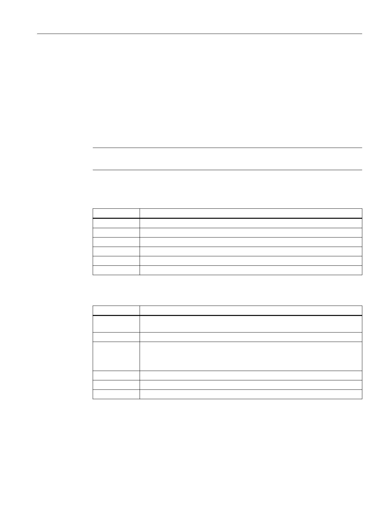
Language code in file names "xxx"
Language
Language code
German
deu
English
eng
French
fra
Spanish
esp
Italian
ita
Chinese
chs
Creating key labeling
Tag
Meaning
source
Designation for the user softkey. "SK_USERKEY1" to "SK_USERKEY16" are possible,
whereby the names may not be changed.
comment
User-specific description of the key assignment.
translation
Text that should be shown on the key.
• A maximum of 10 characters are possible per line.
•
2-line labeling is possible, whereby the line break is set using "%n".
remark
Remark for key assignment.
chars
Number of characters. A maximum of 10 characters per line are possible.
lines
Number of lines. 2 lines are possible.
Procedure
1. You can copy the sample file "oem_slck_deu.ts" from the following folder: /siemens/
sinumerik/hmi/template/lng.
2. Store or create the file in the /oem/sinumerik/hmi/lng or
/user/sinumerik/hmi/lng directory.
SINUMERIK Operate
Commissioning Manual, 10/2020, 6FC5397-1DP40-6BA4
581
Handheld terminals
22.4 Configuring user-specific key labeling
3. Give the file a name, e.g. for German texts: "slck_deu.ts".
If you wish to create the key labeling for additional languages, then a separate file must be
created for each language. Save the file with the appropriate language code in the file name.
To do this, use the language codes specified above.
4. Open the file and in the <message> and </message> area, define the key labeling.
5. Restart the user interface.
In order that the key labeling is displayed during the program runtime, the file must be
converted into a binary format. This conversion is only performed when the user interface
runs up.
Example of a key label
<!DOCTYPE TS><TS>
<context>
<name>SlCkDialog</name
<message>
<source>SK_USERKEY1</source>
<comment></comment>
<translation>U1</translation>
<remark>User key 1</remark>
<chars>10</chars>
<lines>2</lines>
<languageIndependent>true</languageIndependent>
</message>
<message>
<source>SK_USERKEY2</source>
<comment></comment>
<translation>U2</translation>
<remark>User key 2</remark>
<chars>10</chars>
<lines>2</lines>
<languageIndependent>true</languageIndependent>
</message>
<message>
</message>
</context>
</TS>
SINUMERIK Operate
582
Commissioning Manual, 10/2020, 6FC5397-1DP40-6BA4
Handheld terminals
22.5 Configuring the function display at user-specific keys (U keys)
22.5
Configuring the function display at user-specific keys (U keys)
Function
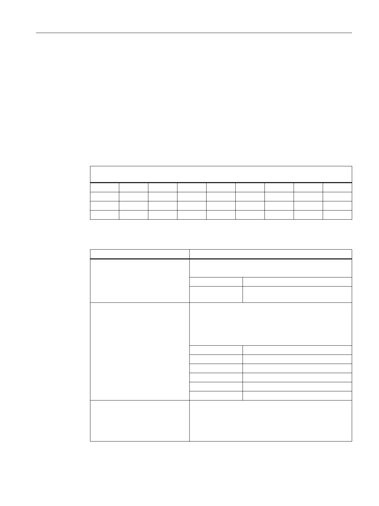
Active functions can be displayed at the configurable user keys via the PLC. For instance, small
LEDs can be emulated on the softkeys.
You configure the function in the "slckcpf.ini" file.
Interface signals
The PLC bits are in the output image of the PLC-HT 8/HT 10 interface and are analogous to those
in the input image.
Signals to the MCP1 (or MCP2)
Interface PLC → HT 8/HT 10
Byte
Bit 7
Bit 6
Bit 5
Bit 4
Bit 3
Bit 2
Bit 1
Bit 0
AB n + 1
U4
U3
U2
U1
AB n + 4
U9
U10
U11
U12
U13
U14
U15
U16
AB n + 5
U8
U7
U6
U5
Adapt the display in the "slckcpf.ini" file
Section
Description
UserKeyLEDIcon
Name of the icon file.
Standard entry: led_green.png
OFF
Deactivates the icon display.
PRESSED
Displays the active functions by pressing
down the softkey.
UserKeyLEDIconAlignment
Specifies the position of the icon.
Standard position: AlignLeft | AlignTop
Horizontal and vertical alignments can be combined. The two
names are separated by the "|" character.
The following alignments are possible:
AlignLeft
Left
AlignRight
Right
AlignHCenter
Horizontal, center
AlignTop
Top
AlignBottom
Bottom
AlignVCenter
Vertical, center
UserKeyLEDMap
Specifies the start address of the output image.
Entries can be made in the following form: "DBx.DBBy", "ABx",
"MBx".
Default setting: The start address is determined using
DB7 MCP1Out (or MCP2Out).
SINUMERIK Operate
Commissioning Manual, 10/2020, 6FC5397-1DP40-6BA4
583

Handheld terminals
22.5 Configuring the function display at user-specific keys (U keys)
Section
Description
U1LED ... U16LED
The status bit address can be defined - different from the output
VarIncLED
image - using these entries.
Note: The offsets from the HT 8 or HT 10 output image, for one
SBLLED
or more softkeys, are not taken into consideration.
WCSLED
showVarIncLED
true
When the increment mode is active, the icon is also
displayed on the "[VAR]" softkey.
false
The icon is not displayed.
showSBLLED
true
When the SingleBlock mode is active, then the icon is
also displayed on the "Single Block" softkey.
false
The icon is not displayed.
showWCSLED
true
When the SingleBlock mode is active, then the icon is
also displayed on the "Single Block" softkey.
false
The icon is not displayed.
1. You can copy the sample file "slckcpf.ini" from the following folder: /siemens/sinumerik/hmi/
template/cfg
2. Store the file in the /oem/sinumerik/hmi/cfg or /user/sinumerik/hmi/cfg directory.
3. If you use your own icon, then locate it together with the corresponding resolution for HT 8
or HT 10 in the directory: e.g. /oem/sinumerik/hmi/ico/ico640 or /user/sinumerik/hmi/ico/
ico640.
4. Open the file and make the appropriate settings.
Sample file "slckcpf.ini"
Template for the configuration of the
; HT 8/HT 10 control panel function menu
;
; To activate the settings remove the
; commentary ';' at the beginning of the line
;; Display settings of the user key softkey leds
[UserKeyLED]
; Filename of the LED icon
;UserKeyLEDIcon = led_green.png
; Alignment of the LED icon
;UserKeyLEDIconAlignment= AlignLeft | AlignTop
; Use following led map start address instead of calculating
DB7.MCP1Out
;UserKeyLEDMap = AB0
SINUMERIK Operate
584
Commissioning Manual, 10/2020, 6FC5397-1DP40-6BA4
Handheld terminals
22.5 Configuring the function display at user-specific keys (U keys)
; Use the following settings to use this status bits instead of the
led map for a specific sk
;U1LED=/channel/parameter/R[U1,1]
;
;U16LED=/channel/parameter/R[U1,16]
;VarIncLED = DB11.DBX8.5
;SBLLED = DB21.DBX0.4
;WCSLED = DB19.DBX0.7
; Show a LED for the var inc sk
;showVarIncLED = true
; Show a LED for the var single block sk
;showSBLLED = true
; Show a LED for the var wcs/mcs sk
;showWCSLED = true
SINUMERIK Operate
Commissioning Manual, 10/2020, 6FC5397-1DP40-6BA4
585
Handheld terminals
22.5 Configuring the function display at user-specific keys (U keys)
SINUMERIK Operate
586
Commissioning Manual, 10/2020, 6FC5397-1DP40-6BA4

List of abbreviations/acronyms
A
Abbreviation
Description
ASCII
American Standard Code for Information Interchange:
American coding standard for the exchange of information
Mode group
Mode group
OPI
Operator Panel Interface
CNC
Computerized Numerical Control: Computerized numerical control
CEC
Cross Error Compensation: Sag compensation
CP
Communication Processor
DCP
Discovery and basic Configuration Protocol: ProfiNet protocol
DHCP
Dynamic Host Configuration Protocol
DIN
Deutsche Industrie Norm
DNS
Domain Name System
DIR
Directory: Directory
DRAM
Dynamic Random Access Memory
DRF
Differential Resolver Function: Differential resolver function (handwheel)
EES
Execution from External Storage
ERTEC
Enhanced Real Time Ethernet Controller
ESR
Extended stop and retract
ETC
ETC key ">"; Softkey bar extension in the same menu
FRAME
Data block (FRAME)
FIFO
First In - First Out: Method of storing/retrieving data in/from a memory.
GDIR
Global Directory: Global part program memory
GUD
Global User Data: Global user data
GUI
Graphical User Interface
MSD
Main Spindle Drive
HSC
High Speed Cutting: High-speed machining
ILC
Intelligent Load Control: Intelligent load adjustment
INC
Increment: Incremental dimension
INI
Initializing Data: Initializing data
IP
Internet Protocol
IPO
Interpolator
ISO
International Standard Organization
JOG
Jogging: Setup mode
LED
Light Emitting Diode: Light emitting diode
LLDP
Link Layer Discovery Protocol
LUD
Local User Data: Local user data
MAC
Media Access Control
MB
Megabyte
MD
Machine data
SINUMERIK Operate
Commissioning Manual, 10/2020, 6FC5397-1DP40-6BA4
587
List of abbreviations/acronyms
Abbreviation
Description
MDA
Manual Data Automatic: Manual input
MCS
Machine Coordinate System
MLFB
Maschinenlesbare Fabrikatbezeichnung
MPF
Main Program File: NC part program (main program)
MCP
Machine Control Panel: Machine control panel
NC
Numerical Control: Numerical control
NCK
Numerical Control Kernel: NC kernel with block preparation, traversing range, etc.
NCU
Numerical Control Unit: NCK hardware unit
NFS
Network File System
NTP
Network Time Protocol
ZO
Zero offset
OEM
Original Equipment Manufacturer
OID
Object Identifier: Information identifier
OP
Operator Panel
PCU
Programmable Control Unit
PI service
Program Invocation Services
PG
Programming device
PLC
Programmable Logic Control
RCS
Remote Control System
RFC
Request for Comments
REF
REFerence point approach function
REPOS
REPOSition function
ROV
Rapid Override: Input correction
RPA
R-Parameter Active: Memory area in NCK for R- NCK for R parameter numbers
SBL
Single Block: Single block
SD
Setting Data
SDB
System Data Block
SEA
Setting Data Active: Identifier (file type) for setting data
SK
Softkey
SMB
Server Message Block
SNMP
Simple Network Management Protocol
SPF
Sub Program File: Subroutines
SRAM
Static Random Access Memory: Static RAM (non-volatile)
SSH
Secure Shell: Network protocol
SW
Software
SYF
System Files: System files
TCU
Thin Client Unit
TEA
Testing Data Active: Identifier for machine data
TMA
Tool Magazine Active: Magazine data
TO
Tool Offset: Tool offset
TOA
Tool Offset Active: Identifier (file type) for tool offsets
UDP
User Datagram Protocol: Network protocol
UFR
User frame
SINUMERIK Operate
588
Commissioning Manual, 10/2020, 6FC5397-1DP40-6BA4
List of abbreviations/acronyms
Abbreviation
Description
VNC
Virtual Network Computing
FD
Feed Drive
WCS
Workpiece Coordinate System
TM
Tool management
SINUMERIK Operate
Commissioning Manual, 10/2020, 6FC5397-1DP40-6BA4
589
List of abbreviations/acronyms
SINUMERIK Operate
590
Commissioning Manual, 10/2020, 6FC5397-1DP40-6BA4
Index
Creating, 188
Creating foreign-language texts, 187
3
Deactivating a warning, 217
Registering the file, 189
3D simulation, 159, 163
Replacing, 200
Replacing standard alarm texts, 200
Select font color, 185
A
Standard parameter specification, 205
Access levels, 55
Supported languages, 548
Access MyMachine, 28, 35
alarmtext_conversion.log, 189, 192, 195, 203, 206
Access right
Analog spindle, 170
Effect, 60
Archive
Global, 59
create for Hotline, 228
individual, 59
Creating, 223
Remote access, 59
Line checksum, 220
Action log
Login data (credentials) handling, 50
actlog.ini, 311
Reading in, 224
Log file, 308
AS-i
Open log file, 306
Components, 344
Saving log file, 308
Configure diagnostics, 346
Search for events, 307
Diagnostics, 344
Setting the log size, 311
Axis diagnostics, 277
Settings, 303
Axis-specific machine data, 119
action.com, 308
Axis-specific setting data, 122
action.log, 308
Activate keyboard, 44, 580
Activating/deactivating window mode, 569
B
actlog.ini, 311
Backing up setup data, 232
Actual value window
Setting font size, 141
actual_actionlog.com, 303
C
actual_crashlog.com, 303
Adapt to load, 496
Changing the design, 46
Adapt tool measurement
Channel menu
Examples when milling, 533
Configuring, 109
for turning, 538
Configuring operator stations, 112
when milling, 532
Configuring the total structure, 111
Adapt workpiece measurement, 527
Defining channel groups, 111
Additional language
Channel operating message
installing, 547
Standard configuration, 146
Uninstalling, 548
Channel operational message, 145
Alarm log
Channel-specific machine data, 119
Filter properties, 209
Channel-specific setting data, 122
Settings, 208
Circular position pattern, 385
Alarm number ranges, 204
Circumferential groove, 385
Alarm texts
Clamping
Changing colors, 196
Setting up function, 165
Create file, 188
Cleaning mode, 47
creating, 185
Cleaning mode for panel, 47
SINUMERIK Operate
Commissioning Manual, 10/2020, 6FC5397-1DP40-6BA4
591
Index
Comment input
Cycles version
ini file, 35
Define, 545
XML file, 34
Displaying, 544
Commissioning the drive system, 183
Cylinder surface transformation
config.ini, 113
in turning, 410
Configuring operator stations, 112
Milling, examples, 390
Contour grooving, 405
under milling, 389
Contour milling, 385
under ShopTurn, 412
Contour turning, 405
with slot side offset, 413
Coordinate system
without slot side correction, 411
MD52000, 370
Cylindrical grinding, 422
crash.com, 308
Displaying softkeys, 370
crash.log, 308
Creating online help
Creating a directory, 360
D
HTML_Creating file, 357
Data admin, 131
Replacing the standard online help, 359
Data backup, 219
XML_Creating file, 359
Date
CSV file, 299
Selecting the format, 38
CUST_782.SPF, 376, 499
Setting, 39
CUST_800.SPF, 376
Deactivate keyboard, 44, 580
CUST_832.SPF, 376, 504
dealer.xml, 294
CUST_CLAMP, 377
Defining channel groups, 111
CUST_M6, 377, 379
Device registration, 42
CUST_MEACYC
DHCP server detection, 261
Structogram, 511
Diagnostics
CUST_MEACYC.SPF, 376
AS-i, 346
CUST_MEAPROT.SPF, 377, 542
Ethernet/PROFINET network, 261
CUST_MULTICHAN, 377, 383
HMI trace, 311
CUST_T, 377, 379
Direction of rotation
CUST_TECHCYC.SPF, 376
Counterspindle, 402
Aligning, 381
Main spindle, 396
Cycle alarms, 433
Directory structure, 29
CYCLE495, 423
Display filter
CYCLE60, 385
Machine data, 126
CYCLE63, 385
Display groups, 127
CYCLE64, 385
Display machine data, 122
CYCLE782, 496
Search, 130
CYCLE79, 385
Display Manager
CYCLE800
activating, 78
Structogram, 474
Display configurations, 78
CYCLE832
Displaying AS-i, 346
Top Surface, 500
Drilling, 374
CYCLE84, 375
Drive
CYCLE840, 375
Global part program memory, 107
CYCLE930, 405
Logical drive, 105
CYCLE950, 405
Set EXTCALL, 106
CYCLE951, 405
Setting up, 105
CYCLE952, 405
Drive parameters
CYCLE99, 405
Display/change, 124
CYCLE9960, 480
for machine data, 119
SINUMERIK Operate
592
Commissioning Manual, 10/2020, 6FC5397-1DP40-6BA4
Index
Drive system
Diagnostics, 315
Diagnostics - details, 316
H
Drive-specific machine data, 119
Handheld terminal
Activating, deactivating the virtual keyboard, 580
Key labeling, 581
E
LED display on user keys, 583
Editing an xml file, 34
slguiconfig.ini, 580
Editing enum values, 129
Hardware components
Engraving, 385
Adding, 299
Entering BICO values, 129
Entering, 298
Error analysis, 249
High Speed Settings, 500
Error file of the alarms, 206
Hirth joint, 490
Ethernet/PROFINET
Hirth teeth, 429
Diagnostics, 261
HMI PRO RT, 342
Displaying messages, 262
HMI restart
Network trace, 263
Displaying the softkey, 44
Trace parameters, 264
execution, 44
EXIT, 573
HMI trace, 311
Displaying the softkey, 44
HOLES2, 385
Expert parameters, 127
HT 10
EXTCALL
Traversing keys, 580
switch off and on again, 106
HT 8
Activating, deactivating the virtual keyboard, 44
Configuring the traversing keys, 575
F
oem_sljk_deu.ts, 577
slguiconfig.ini, 44
Face machining
sljkconfig.ini, 576
in turning, 414
under ShopTurn, 416
fast block search, 151
I
File
Copy, 32
identSNAPSHOT, 291
Copying with WinSCP, 35
Inclined Y axis
Cut, 33
in turning, 417
Delete, 33
under ShopTurn, 418
Displaying in preview window, 34
Index text file for alarms
External editing, 34
Create file, 190
insert, 32
Creating texts, 190
Open, 32
Registering, 191
Renaming, 33
Inserting a run up screen, 47
Font smoothing, 569
Installation
Form-truing, 423
Interactive, 571
silent, 571
Intelligent load adjustment, 496
G
G code groups
K
Configuring the display, 143
G group 59, 503
Keyboard
General machine data, 119
Setting, 43
General setting data, 122
Kinematics
Generating a crashlog file, 304
Check list, 433
SINUMERIK Operate
Commissioning Manual, 10/2020, 6FC5397-1DP40-6BA4
593
Index
Examples, commissioning, 447
Manual machine
measured, 480
Activating the function, 153
with Hirth teeth, 429
Parameter assignment, 153
Message texts
Creating, 193
L
creating for several channels, 194
Part program, 192
Language
Milling
Defining the selection mode, 37
Cylinder surface transformation, 389
Language code, 548, 549
Direction of rotation for position pattern, 387
License key
Displaying softkeys, 370
Backing up from CompactFlash card, 102
Examples, setting-up a milling machine, 390
Entering, 102
Settings under ShopMill, 386
Reading in, 102
Tool measurement, 518
License requirement
Turning on milling machines, 481
Exporting, 101
Workpiece measurement, 516, 530
Licenses, 97
Multiple clamping of different workpieces
Log file
(option), 393
Action log, 308
Multiple edge, 385
Logbook, 300
Documenting startups, 301
Entry search, 303
N
Import templates, 296
Machine identity, 291
NC/PLC variables
Making an entry, 302
Changing, 271
Output, 297
displaying, 269
Logging the measurements
NCU connection
Settings for AUTOMATIC, 541
setting - under PCU, 572
Logging the measuring
setting - under Windows, 572
Settings for JOG, 541
netnames.ini, 112
Network
Configuring, 237
M
Network adapter, 248
Configuring, 258
ma_types.xml, 295
Network diagnostics, 247
Machine data
Number ranges of alarms, 204
Axis selection, 121
Configuring plain texts, 138
Display filter, 126
O
Displaying, 119
Editing enum values, 129
OEM subdirectories, 567
Editing hexadecimal values, 128
oem.xml, 295
Entering BICO values, 129
oem_ae_database_conversion.log, 199
Information, 120
oem_alarms_eng.ts, 188
Overview, 119
oem_indextexts_eng.ts, 190
Search, 130
oem_slaedatabase.xml, 196
Machine identity, 291
oem_slaesvcadapconf.xml, 189
Machine operating area, 141
oem_slck_deu.ts, 581
Machine-specific information, 297
oem_sljk_deu.ts, 578
Create a template, 293
oem_text_conversion.log, 189, 206
Entering, 292
OEMFrame application
Machining time recording
configuring, 551
activating, 157
extended parameterization, 559
SINUMERIK Operate
594
Commissioning Manual, 10/2020, 6FC5397-1DP40-6BA4
Index
FindWindow program application, 568
integrating, 551
oemsubs.xml, 295
R
Offset
RCS Commander, 28
Configuring, 157
Remote diagnostics
Operating state, 274
Adapting, 318
Operator panels
Replacing standard alarm texts
Configuring, 244
Create file, 200
Orientable tool holder, 539
Creating texts, 200
Registering the alarm text file, 201
Replacing the logo, 142
P
Reset
parallel user interfaces, 48
Extended, 125
Password
Changing, 57
Delete, 58
S
Set, 57
Screen
PDF file
darken screen, 47
Language switchover, 366
saver, 46
PDF help
Time until the screen is darkened, 46
Language switchover, 366
Screenshots
Performing a start-up
Copy, 291
Reading in original status, 227
Creating, 290
PLC hardware upgrade archive
Open, 291
Creating, 224
Search
Probe
Display machine data, 130
Example of a test program, 507
Machine data, 130
Testing the function, 507
Setting data, 130
to measure the tool, 506
Search mode
to measure the workpiece, 506
Configuring, 149
PROFIBUS
Searching
Connections, 312
Logbook entry, 303
DP slaves, 314
Service drive
PROFIBUS/PROFINET diagnostics, 342, 343
Display, 282
PROG_EVENT.SPF, 312, 377
Parameter description, 283
Extend, 378
Service overview, 274
Program access
Axes and drives, 276
setting via protection level, 64
Service Platform Industry, 291
Program list
Setting data
Configuring a softkey, 65
Axis selection, 124
Creating, 65
Channel selection, 124
Program test
Displaying, 122
activating, 147
Overview, 119
deactivate, 147
Search, 130
Programming G code programs, 153
Setting up a counterspindle
ShopTurn, 401
Setting-up a lathe with milling tools, 409
Q
Setting-up measuring in JOG, 513
QR code, 42
ShopMill
Settings for milling, 386
SINUMERIK Operate
Commissioning Manual, 10/2020, 6FC5397-1DP40-6BA4
595
Index
ShopTurn
Spindle utilization
Cylinder surface transformation, 412
Display of time remaining, 43
Face machining, 416
Standard parameter specifications of alarm texts, 205
Inclined Y axis, 418
Starting SINUMERIK Operate
Setting up a counterspindle, 401
IPC, 27
Settings for turning, 396
NCU, 27
Sidescreen
PCU, 27
activating, 68
under Windows, 27
Display ABC keyboard, 70
Start-up archive
Display camera, 76
Creating, 220, 233
Display machine control panel, 71
Reading in, 224
Display translations, 75
STAT, 147
In-house configuration, 73
Station-related network diagnostics, 247
Simulation
Status display
Cycle application, 378
Inserting a logo, 142
deactivate, 162
Status display with icons, 155
from kinematic chain, 163
Stock removal, corner, 405
General conditions, 159
Surface grinding, 422
Grinding technology, 161
Displaying softkeys, 370
Milling technology, 161
Swiveling
Tool change time, 163
activating, 424
Turning technology, 161
Commissioning machine kinematics, 434
Simultaneous measurement, 539
Configuring input masks, 424
Simultaneous recording, 164
Creating angled tools, 428
Activating the machining time, 164
Declare data sets, 427
Option, 163
Display variants, 436
slaesvcadapconf.xml, 189, 191, 193, 201, 217
Example HEAD_1, 447
slaesvcconf.xml, 194, 203
Example HEAD_2 (chain), 449
slckcpf.ini, 584
Example HEAD_2 (classic), 452
slhlp.xml, 355
Example MIXED_45 (chain), 456
slmagcodeconfig.ini, 143
Example MIXED_45 (classic), 458
SLOT2, 385
Example of a milling machine with B axis for
sltlprodiaghmi.ini, 344, 345
turning, 469
Softkey
Example of turning machine with B axis
Access level, 63
(chain), 462
Original setting, 63
Example of turning machine with B axis
Source ID, 204, 205
(classic), 466
Source URL, 204, 205
Example TABLE_45 (chain), 453
Specify the IP address of the NCU, 572
Example TABLE_45 (classic), 455
Spindle analog, 170
Example TABLE_5 (classic), 459
Spindle control, 169
Retraction, 439
Spindle diagnostics, 171
Rotary axes, 446
Additional temperature sensor, 175
Tool carrier via chain, 440
Clamping state, 177
Tool carrier, classic, 442
Clamping time statistics, 181
System utilization, 289
Diagnostic statistics, 180
Logistics data, 181
Motor temperature sensor, 175
T
Speed limitation, 179
Tailstock
Spindle load, 176
Option, 163
Temperature, 173
Tapping, 375
Temperature histograms, 176
TEACH IN, 149
SINUMERIK Operate
596
Commissioning Manual, 10/2020, 6FC5397-1DP40-6BA4
Index
Technology
Settings (PLC, NC, servo), 332
Cylindrical grinding, 422
Start recording, 336
Drilling, 374
Starting a session, 326
Milling, 384
Stop recording, 336
Surface grinding, 422
Variable attributes, 328
Swiveling, 423
Zooming characteristic graphs, 339
Turning, 405
TRACON, 419
Template files, 32
TRACYL, 420
Test license, 100
in turning, 410
Text legibility, 569
under ShopTurn, 412
TextPad, 28
Transformation
Thread-cutting, 405
Settings for milling, 391
Time
TRANSMIT
Selecting the format, 39
in turning, 414
Setting, 39
under ShopTurn, 416
Time server, 41
with Y axis, 415
Time zone, 42
TU, 147
Tool clamping angle, 490
Turning
Tool measurement
Cylinder surface transformation, 410
in turning, 524
Displaying softkeys, 370
under milling, 518
Examples, setting-up a lathe, 410
Topologies, 266
Face machining, 414
TRAANG, 419
Inclined Y axis, 417
in turning, 417
Settings under ShopTurn, 396
under ShopTurn, 418
Speed limitation, 420
Trace
Technology cycles, 405
Changing the scale, 338
Tool measurement, 524
Creating a session, 324
Workpiece measurement, 537
Cursor A/B positioning, 340
Turning on milling machines
Data acquisition, 332
Behavior at power on, 489
Data storage on CU, 334
Behavior at reset, 489
Define zoom area, 340
Block search, 495
Display peak-to-peak value, 341
CUST_800, 492
Display peak-to-valley value, 341
Hirth joint, 490
Displaying details of the variables, 331
Kinematics transformation, 487
Drive variables, 327
Setting the coordinate system, 491
Editing a session, 328
Setting up, 481
Editing the graphic display, 336
Tool clamping angle, 490
Filtering variables, 326
Insert variable, 327
Load session, 326
U
Overview, 322
USB FlashDrive, 28
PLC/NC/servo variables, 326
USB keyboard, 28
Replace variable, 328
User view
Save options, 335
Creating, 135
Save session, 325
Delete, 138
Searching for variables, 326
Editing, 136
Selecting a variable, 327, 338
Importing, 134
Sequence, 323
user.xml, 295
Session, 327
Using angular tools, 428
Setting grid lines, 335
Settings (drive), 333
SINUMERIK Operate
Commissioning Manual, 10/2020, 6FC5397-1DP40-6BA4
597
Index
V
Variable screen forms, 273
VNC operating area
Settings, 51
setup, 50
W
WEB Browser operating area
Settings, 54
setup, 54
Window mode, 569
WinSCP, 28, 35
Work station safety, 58
Workpiece measurement
under milling, 516, 530
under turning, 537
SINUMERIK Operate
598
Commissioning Manual, 10/2020, 6FC5397-1DP40-6BA4
Preface
Fundamental security
1
instructions
2
Generating user dialogs
SINUMERIK
Generating commissioning
3
dialogs
SINUMERIK 840D sl
Easy XML
Programming Manual
Valid for:
CNC software
Version 4.94
10/2020
6FC5397-1DP40-6BA4
Legal information
Warning notice system
This manual contains notices you have to observe in order to ensure your personal safety, as well as to prevent damage
to property. The notices referring to your personal safety are highlighted in the manual by a safety alert symbol, notices
referring only to property damage have no safety alert symbol. These notices shown below are graded according to
the degree of danger.
DANGER
indicates that death or severe personal injury will result if proper precautions are not taken.
WARNING
indicates that death or severe personal injury may result if proper precautions are not taken.
CAUTION
indicates that minor personal injury can result if proper precautions are not taken.
NOTICE
indicates that property damage can result if proper precautions are not taken.
If more than one degree of danger is present, the warning notice representing the highest degree of danger will be
used. A notice warning of injury to persons with a safety alert symbol may also include a warning relating to property
damage.
Qualified Personnel
The product/system described in this documentation may be operated only by personnel qualified for the specific
task in accordance with the relevant documentation, in particular its warning notices and safety instructions.
Qualified personnel are those who, based on their training and experience, are capable of identifying risks and
avoiding potential hazards when working with these products/systems.
Proper use of Siemens products
Note the following:
WARNING
Siemens products may only be used for the applications described in the catalog and in the relevant technical
documentation. If products and components from other manufacturers are used, these must be recommended or
approved by Siemens. Proper transport, storage, installation, assembly, commissioning, operation and maintenance
are required to ensure that the products operate safely and without any problems. The permissible ambient
conditions must be complied with. The information in the relevant documentation must be observed.
Trademarks
All names identified by ® are registered trademarks of Siemens AG. The remaining trademarks in this publication may
be trademarks whose use by third parties for their own purposes could violate the rights of the owner.
Disclaimer of Liability
We have reviewed the contents of this publication to ensure consistency with the hardware and software described.
Since variance cannot be precluded entirely, we cannot guarantee full consistency. However, the information in this
publication is reviewed regularly and any necessary corrections are included in subsequent editions.
Siemens AG
Document order number: 6FC5397-1DP40-6BA4
Digital Industries
Ⓟ 10/2020 Subject to change
All rights reserved
Postfach 48 48
90026 NÜRNBERG
GERMANY
Preface
SINUMERIK documentation
The SINUMERIK documentation is organized into the following categories:
• General documentation/catalogs
• User documentation
• Manufacturer/service documentation
Additional information
You can find information on the following topics at the following address (https://
support.industry.siemens.com/cs/de/en/view/108464614):
• Ordering documentation/overview of documentation
• Additional links to download documents
• Using documentation online (find and search in manuals/information)
If you have any questions regarding the technical documentation (e.g. suggestions,
corrections), please send an e-mail to the following address
(mailto:docu.motioncontrol@siemens.com).
mySupport/Documentation
you can find information on how to create your own individual documentation based on
Siemens' content, and adapt it for your own machine documentation.
Training
SITRAIN (Siemens training on products, systems and solutions for automation and drives).
FAQs
You can find Frequently Asked Questions in the Service&Support pages under Product Support
SINUMERIK
You can find information about SINUMERIK at the following address (https://www.siemens.com/
sinumerik).
Easy XML
Programming Manual, 10/2020, 6FC5397-1DP40-6BA4
3
Preface
Target group
This publication is intended for:
• Programmers
• Project engineers
Benefits
The Programming Manual enables the target group to design customer and application-specific
user interfaces with XML-based script elements.
Standard scope
This Programming Manual describes the functionality of the standard scope. Additions or
modifications made by the machine manufacturer are documented by the machine
manufacturer.
Other functions not described in this documentation might be executable in the control. This
does not, however, represent an obligation to supply such functions with a new control or when
servicing.
Furthermore, for the sake of clarity, this documentation does not contain all detailed
information about all product types and cannot cover every conceivable case of installation,
operation or maintenance.
Note regarding the General Data Protection Regulation
Siemens observes standard data protection principles, in particular the principle of privacy by
design. That means that
this product does not process / store any personal data, only technical functional data (e.g. time
stamps). If a user links this data with other data (e.g. a shift schedule) or stores personal data on
the same storage medium (e.g. hard drive) and thus establishes a link to a person or persons,
then the user is responsible for ensuring compliance with the relevant data protection
regulations.
Technical Support
Country-specific telephone numbers for technical support are provided on the Internet at the
area.
If you have any technical questions, use the online form in the "Support Request" area.
Easy XML
4
Programming Manual, 10/2020, 6FC5397-1DP40-6BA4
Table of contents
Preface
3
1
Fundamental security instructions
9
1.1
General safety instructions
9
1.2
Equipment damage due to electric fields or electrostatic discharge
13
1.3
Warranty and liability for application examples
14
1.4
Security information
15
1.5
Residual risks of power drive systems
16
2
Generating user dialogs
17
2.1
Scope of functions
17
2.2
Fundamentals of Configuration
19
2.3
Configuration files
24
2.4
Structure of configuration file
27
2.5
Language dependency
33
2.6
XML diagnostics
34
2.7
XML identifier
36
2.7.1
General structure
36
2.7.2
Instruction/identifier descriptions
37
2.7.3
Color coding
62
2.7.4
Special XML syntax
62
2.7.5
HTML special characters
62
2.7.6
Operators
64
2.7.7
System variables
65
2.7.8
Generating softkey menus and dialog forms
66
2.8
Generating user menus
121
2.8.1
Creating processing cycle forms
121
2.8.2
Substitution characters
124
2.9
Creating the file struct_def.xml
125
2.10
Addressing components
127
2.10.1
PLC addressing
127
2.10.2
Addressing NC variables
128
2.10.3
Channel-specific addressing
128
2.10.4
Generating NC/PLC addresses during the runtime
128
2.10.5
Addressing drive components
129
2.10.6
Example: Determine the DO number for the Motor Module
131
2.10.7
Addressing machine and setting data
137
2.10.8
Channel-specific machine data
138
2.10.9
Addressing user data
139
Easy XML
Programming Manual, 10/2020, 6FC5397-1DP40-6BA4
5
Table of contents
2.11
Predefined functions
140
2.12
Multitouch operation
190
2.12.1
Multitouch function
190
2.12.2
Programming finger gestures
192
2.12.3
Gesture control for graphics
193
2.12.4
Gesture processing
196
2.13
Configuring your own buttons
198
2.13.1
Pushbutton
198
2.13.2
Functions of the pushbutton
200
2.13.2.1
Sub-tags for the pushbutton
200
2.13.2.2
Properties for the pushbutton
202
2.13.2.3
Control variables for the pushbutton
204
2.13.3
Switch on/off
208
2.13.4
Functions of the switch
209
2.13.4.1
Properties for the switch
209
2.13.4.2
Control variables for the switch
210
2.13.5
Radio button
212
2.13.6
Checkbox
212
2.13.7
Groupbox
213
2.13.8
Scroll area
214
2.14
Sidescreen application
217
2.14.1
Easy XML in the Sidescreen
217
2.14.2
Integrating Sidescreen dialogs
218
2.14.3
Language and text management
219
2.14.4
Sidescreen components
220
2.14.4.1
Sidescreen element
220
2.14.4.2
Sidescreen widget
221
2.14.4.3
Sidescreen page
223
2.15
Display Manager application
225
2.15.1
Easy XML in the Display Manager
225
2.15.2
Integrating the Customer Area in the Display Manager menu
225
2.15.3
Display Manager widget
227
2.15.4
Display Manager sidescreen page
229
2.16
Dialog selection via PLC hardkeys
231
2.17
Assigning user dialogs to reserved softkeys
234
2.17.1
Defining language-neutral softkey text
235
2.17.2
Assigning an Easy XML area
236
2.17.3
Tag descriptions
240
2.18
Creating language-neutral texts
242
2.19
Project-specific text files
243
2.19.1
Creating project-specific text files
243
2.19.2
Specifying text context
245
2.19.3
Specifying Textfilelist
247
2.20
Restoring the session
248
3
Generating commissioning dialogs
249
3.1
Overview of functions
249
Easy XML
6
Programming Manual, 10/2020, 6FC5397-1DP40-6BA4
Table of contents
3.2
Configuration in the PLC user program
251
3.3
Display on the user interface
254
3.4
Creating language-dependent texts
255
3.5
User example for a power unit
256
3.6
Script language
258
3.6.1
CONTROL_RESET
260
3.6.2
FILE
260
3.6.3
OPTION_MD
261
3.6.4
PLC_INTERFACE
262
3.6.5
POWER_OFF
263
3.6.6
WAITING
263
3.6.7
XML identifiers for the dialog
263
3.6.8
SOFTKEY_OK, SOFTKEY_CANCEL
264
Index
267
Easy XML
Programming Manual, 10/2020, 6FC5397-1DP40-6BA4
7
Table of contents
Easy XML
8
Programming Manual, 10/2020, 6FC5397-1DP40-6BA4
Fundamental security instructions
1
1.1
General safety instructions
WARNING
Electric shock and danger to life due to other energy sources
Touching live components can result in death or severe injury.
• Only work on electrical devices when you are qualified for this job.
• Always observe the country-specific safety rules.
Generally, the following steps apply when establishing safety:
1. Prepare for disconnection. Notify all those who will be affected by the procedure.
2. Isolate the drive system from the power supply and take measures to prevent it being
switched back on again.
3. Wait until the discharge time specified on the warning labels has elapsed.
4. Check that there is no voltage between any of the power connections, and between any of
the power connections and the protective conductor connection.
5. Check whether the existing auxiliary supply circuits are de-energized.
6. Ensure that the motors cannot move.
7. Identify all other dangerous energy sources, e.g. compressed air, hydraulic systems, or
water. Switch the energy sources to a safe state.
8. Check that the correct drive system is completely locked.
After you have completed the work, restore the operational readiness in the inverse sequence.
WARNING
Electric shock due to connection to an unsuitable power supply
When equipment is connected to an unsuitable power supply, exposed components may carry
a hazardous voltage. Contact with hazardous voltage can result in severe injury or death.
• Only use power supplies that provide SELV (Safety Extra Low Voltage) or PELV- (Protective
Extra Low Voltage) output voltages for all connections and terminals of the electronics
modules.
Easy XML
Programming Manual, 10/2020, 6FC5397-1DP40-6BA4
9
Fundamental security instructions
1.1 General safety instructions
WARNING
Electric shock due to equipment damage
Improper handling may cause damage to equipment. For damaged devices, hazardous
voltages can be present at the enclosure or at exposed components; if touched, this can result
in death or severe injury.
• Ensure compliance with the limit values specified in the technical data during transport,
storage and operation.
• Do not use any damaged devices.
WARNING
Electric shock due to unconnected cable shields
Hazardous touch voltages can occur through capacitive cross-coupling due to unconnected
cable shields.
• As a minimum, connect cable shields and the cores of cables that are not used at one end
at the grounded housing potential.
WARNING
Electric shock if there is no ground connection
For missing or incorrectly implemented protective conductor connection for devices with
protection class I, high voltages can be present at open, exposed parts, which when touched,
can result in death or severe injury.
• Ground the device in compliance with the applicable regulations.
NOTICE
Damage to equipment due to unsuitable tightening tools.
Unsuitable tightening tools or fastening methods can damage the screws of the equipment.
• Be sure to only use screwdrivers which exactly match the heads of the screws.
• Tighten the screws with the torque specified in the technical documentation.
• Use a torque wrench or a mechanical precision nut runner with a dynamic torque sensor and
speed limitation system.
Easy XML
10
Programming Manual, 10/2020, 6FC5397-1DP40-6BA4
Fundamental security instructions
1.1 General safety instructions
WARNING
Spread of fire from built-in devices
In the event of fire outbreak, the enclosures of built-in devices cannot prevent the escape of
fire and smoke. This can result in serious personal injury or property damage.
• Install built-in units in a suitable metal cabinet in such a way that personnel are protected
against fire and smoke, or take other appropriate measures to protect personnel.
• Ensure that smoke can only escape via controlled and monitored paths.
WARNING
Unexpected movement of machines caused by radio devices or mobile phones
Using radio devices or mobile telephones in the immediate vicinity of the components can
result in equipment malfunction. Malfunctions may impair the functional safety of machines
and can therefore put people in danger or lead to property damage.
• Therefore, if you move closer than 20 cm to the components, be sure to switch off radio
devices or mobile telephones.
• Use the "SIEMENS Industry Online Support app" only on equipment that has already been
switched off.
WARNING
Fire due to inadequate ventilation clearances
Inadequate ventilation clearances can cause overheating of components with subsequent fire
and smoke. This can cause severe injury or even death. This can also result in increased
downtime and reduced service lives for devices/systems.
• Ensure compliance with the specified minimum clearance as ventilation clearance for the
respective component.
NOTICE
Overheating due to inadmissible mounting position
The device may overheat and therefore be damaged if mounted in an inadmissible position.
• Only operate the device in admissible mounting positions.
Easy XML
Programming Manual, 10/2020, 6FC5397-1DP40-6BA4
11
Fundamental security instructions
1.1 General safety instructions
WARNING
Unexpected movement of machines caused by inactive safety functions
Inactive or non-adapted safety functions can trigger unexpected machine movements that
may result in serious injury or death.
• Observe the information in the appropriate product documentation before commissioning.
• Carry out a safety inspection for functions relevant to safety on the entire system, including
all safety-related components.
• Ensure that the safety functions used in your drives and automation tasks are adjusted and
activated through appropriate parameterizing.
• Perform a function test.
• Only put your plant into live operation once you have guaranteed that the functions
relevant to safety are running correctly.
Note
Important safety notices for Safety Integrated functions
If you want to use Safety Integrated functions, you must observe the safety notices in the Safety
Integrated manuals.
WARNING
Malfunctions of the machine as a result of incorrect or changed parameter settings
As a result of incorrect or changed parameterization, machines can malfunction, which in turn
can lead to injuries or death.
• Protect the parameterization against unauthorized access.
• Handle possible malfunctions by taking suitable measures, e.g. emergency stop or
emergency off.
Easy XML
12
Programming Manual, 10/2020, 6FC5397-1DP40-6BA4
Fundamental security instructions
1.2 Equipment damage due to electric fields or electrostatic discharge
1.2
Equipment damage due to electric fields or electrostatic discharge
Electrostatic sensitive devices (ESD) are individual components, integrated circuits, modules or
devices that may be damaged by either electric fields or electrostatic discharge.
NOTICE
Equipment damage due to electric fields or electrostatic discharge
Electric fields or electrostatic discharge can cause malfunctions through damaged individual
components, integrated circuits, modules or devices.
• Only pack, store, transport and send electronic components, modules or devices in their
original packaging or in other suitable materials, e.g conductive foam rubber of aluminum
foil.
• Only touch components, modules and devices when you are grounded by one of the
following methods:
- Wearing an ESD wrist strap
- Wearing ESD shoes or ESD grounding straps in ESD areas with conductive flooring
• Only place electronic components, modules or devices on conductive surfaces (table with
ESD surface, conductive ESD foam, ESD packaging, ESD transport container).
Easy XML
Programming Manual, 10/2020, 6FC5397-1DP40-6BA4
13
Fundamental security instructions
1.3 Warranty and liability for application examples
1.3
Warranty and liability for application examples
Application examples are not binding and do not claim to be complete regarding configuration,
equipment or any eventuality which may arise. Application examples do not represent specific
customer solutions, but are only intended to provide support for typical tasks.
As the user you yourself are responsible for ensuring that the products described are operated
correctly. Application examples do not relieve you of your responsibility for safe handling when
using, installing, operating and maintaining the equipment.
Easy XML
14
Programming Manual, 10/2020, 6FC5397-1DP40-6BA4
Fundamental security instructions
1.4 Security information
1.4
Security information
Siemens provides products and solutions with industrial security functions that support the
secure operation of plants, systems, machines, and networks.
In order to protect plants, systems, machines and networks against cyber threats, it is necessary
to implement - and continuously maintain - a holistic, state-of-the-art industrial security
concept. Siemens’ products and solutions form one element of such a concept.
Customers are responsible for preventing unauthorized access to their plants, systems,
machines and networks. These systems, machines and components should only be connected
to the enterprise network or the Internet if and only to the extent necessary and with appropriate
security measures (firewalls and/or network segmentation) in place.
You can find more information on protective measures in the area of industrial security by
visiting:
Siemens’ products and solutions undergo continuous development to make them more secure.
Siemens strongly recommends performing product updates as soon as they are available and
using only the latest product versions. Use of product versions that are no longer supported, and
failure to apply latest updates may increase customer’s exposure to cyber threats.
To stay informed about product updates, subscribe to the Siemens Industrial Security RSS Feed
under
services/cert.html#Subscriptions).
Further information is provided on the Internet:
Industrial Security Configuration Manual (https://support.industry.siemens.com/cs/ww/en/
view/108862708)
WARNING
Unsafe operating states resulting from software manipulation
Software manipulations, e.g. viruses, Trojans, or worms, can cause unsafe operating states in
your system that may lead to death, serious injury, and property damage.
• Keep the software up to date.
• Incorporate the automation and drive components into a holistic, state-of-the-art industrial
security concept for the installation or machine.
• Make sure that you include all installed products into the holistic industrial security concept.
• Protect files stored on exchangeable storage media from malicious software by with suitable
protection measures, e.g. virus scanners.
• On completion of commissioning, check all security-related settings.
Easy XML
Programming Manual, 10/2020, 6FC5397-1DP40-6BA4
15
Fundamental security instructions
1.5 Residual risks of power drive systems
1.5
Residual risks of power drive systems
When assessing the machine- or system-related risk in accordance with the respective local
regulations (e.g., EC Machinery Directive), the machine manufacturer or system installer must
take into account the following residual risks emanating from the control and drive components
of a drive system:
1.
Unintentional movements of driven machine or system components during commissioning,
operation, maintenance, and repairs caused by, for example,
- Hardware and/or software errors in the sensors, control system, actuators, and cables and
connections
- Response times of the control system and of the drive
- Operation and/or environmental conditions outside the specification
- Condensation/conductive contamination
- Parameterization, programming, cabling, and installation errors
- Use of wireless devices/mobile phones in the immediate vicinity of electronic components
- External influences/damage
- X-ray, ionizing radiation and cosmic radiation
2.
Unusually high temperatures, including open flames, as well as emissions of light, noise,
particles, gases, etc., can occur inside and outside the components under fault conditions
caused by, for example:
- Component failure
- Software errors
- Operation and/or environmental conditions outside the specification
- External influences/damage
3.
Hazardous shock voltages caused by, for example:
- Component failure
- Influence during electrostatic charging
- Induction of voltages in moving motors
- Operation and/or environmental conditions outside the specification
- Condensation/conductive contamination
- External influences/damage
4.
Electrical, magnetic and electromagnetic fields generated in operation that can pose a risk to
people with a pacemaker, implants or metal replacement joints, etc., if they are too close
5.
Release of environmental pollutants or emissions as a result of improper operation of the
system and/or failure to dispose of components safely and correctly
6.
Influence of network-connected communication systems, e.g. ripple-control transmitters or
data communication via the network
For more information about the residual risks of the drive system components, see the relevant
sections in the technical user documentation.
Easy XML
16
Programming Manual, 10/2020, 6FC5397-1DP40-6BA4
Generating user dialogs
2
2.1
Scope of functions
Overview
The "Generate user dialogs" function offers an open structure and enables the user to develop
customer-specific and application-specific user interfaces in SINUMERIK Operate.
The control system offers an XML-based script language for generating user dialogs.
This script language makes it possible to display machine-specific menus and dialog forms in the
<CUSTOM> operating area in SINUMERIK Operate.
All dialog forms can be designed on a language-neutral basis. In such cases, the system reads out
the texts to be displayed from the accompanying language database.
Use
The defined XML instructions offer the following properties:
1. Display dialogs containing the following elements:
- Softkeys
- Variables
- Text and help text
- Graphics and help displays
2. Call dialogs by:
- Pressing the (start) softkeys
3. Restructure dialogs dynamically:
- Edit and delete softkeys
- Define and design variable fields
- Insert, exchange, and delete display texts (language-dependent or language-neutral)
- Insert, exchange, and delete graphics
- Dynamically create executable script parts and include them in the script processing
4. Initiate operations in response to the following actions:
- Displaying dialogs
- Inputting values (variables)
- Selecting a softkey
- Exiting dialogs
5. Data exchange between dialogs
Easy XML
Programming Manual, 10/2020, 6FC5397-1DP40-6BA4
17
Generating user dialogs
2.1 Scope of functions
6. Variables
- Read (NC, PLC and user variables)
- Write (NC, PLC and user variables)
- Combine with mathematical, comparison or logic operators
7. Execute functions:
- Subprograms
- File functions
- PI services
8. Apply protection levels according to user groups
The valid elements (tags) for the script language are described in the "XML tags" (Page 36)
section.
Note
The following section "Basic principles of configuration" is not intended as a comprehensive
description of XML (Extensible Markup Language). Please refer to the relevant specialist
literature for additional information.
Easy XML
18
Programming Manual, 10/2020, 6FC5397-1DP40-6BA4
Generating user dialogs
2.2 Fundamentals of Configuration
2.2
Fundamentals of Configuration
Configuration files
The description of new user interfaces is stored in configuration files. These files are
automatically interpreted and the result displayed on the screen. Configuration files are not
stored in the software supplied and must first be set up and loaded by the user.
An XML editor or another form of text editor can be used to generate the configuration files.
Note
File names may only contain lowercase letters.
Menu tree principle
Several interlinked dialogs create a menu tree. A link exists if you can switch from one dialog to
another. You can use the newly defined horizontal/vertical softkeys in this dialog to call the
preceding or any other dialog.
Configured start softkeys can be used to create a further menu tree behind the start menu:
6WDUW PHQX
Figure 2-1
Menu tree for user dialogs
Start menu
The start menu is defined by the name "main" in the "xmldial.xml" file. The start menu is used to
initiate your own operating sequences.
You can use the "main" menu to link your own dialogs or additional softkey bars so that they can
be loaded and used for executing additional actions.
The figure below shows the manufacturer’s folder "System CF-Card/oem/sinumerik/hmi" on the
control.
Easy XML
Programming Manual, 10/2020, 6FC5397-1DP40-6BA4
19
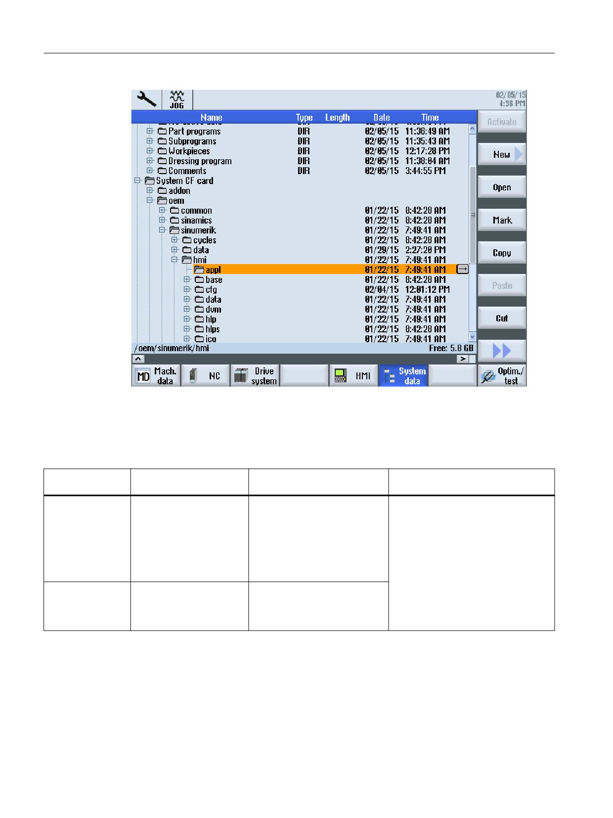
Generating user dialogs
2.2 Fundamentals of Configuration
Figure 2-2
OEM directory
The following files in the OEM directory "System CF-Card/oem/sinumerik/hmi" on the control are
needed to configure user dialogs:
Table 2-1
Files for configuration
File type
Name of the file
Meaning
Storage location in operating area
Setup > System data
Script file
"xmldial.xml"
Standard text file
OEM directory > subdirectory "appl" for
the applications
This script file uses XML tags to
control how the configured soft-
key menus and dialog forms in
SINUMERIK Operate will appear
in the <CUSTOM> operating
area.
Application-specif-
"xxx.xml"
Freely selectable file name. The
ic script file
reference to this name is estab-
lished via the corresponding INI
files.
Easy XML
20
Programming Manual, 10/2020, 6FC5397-1DP40-6BA4

Generating user dialogs
2.2 Fundamentals of Configuration
File type
Name of the file
Meaning
Storage location in operating area
Setup > System data
Text file
"oem_xml_screens_xxx.ts"
Standard text file for the custom-
OEM directory > subdirectory "lng" for
er operating area
the desired languages
This text file contains the texts for
the menus and dialog forms for
the individual languages.
User-specific text
"yyy_xxx.ts"
Freely selectable file name. The
file
reference to this name is estab-
lished using the corresponding
attributes at tags DialogGUI,
menu or form. The description is
provided in Chapter "Project-spe-
cific text files (Page 243)".
For Sidescreen or Display Manag-
er applications, the text file name
is derived from the page or widg-
et name. You can find an exam-
ple in Chapter "Language and
text management (Page 219)".
Bitmaps
The control system supports BMP
OEM directory > subdirectory "ico"
and PNG formats.
XML files inserted
E.g. "machine_set-
These files also contain program-
OEM directory > subdirectory "appl" for
in the "xmldial.xml"
tings.xml"
med instructions for displaying
the applications
control file with the
the dialog forms and parameters
"INCLUDE" XML tag.
in SINUMERIK Operate.
Easy XML connection points
The following connection points are available for Easy XML scripts:
Hardkey/Softkey
Connection point
Softkey operating menu
Standard script file name "xmldial.xml"
Activated in the file "slamconfig.ini"
Example:
[CustomXML]
TextId=SL_AM_CUSTOM
SidescreenTextId=SL_SIDESCREEN_CUSTO
M
TextFile=slam
TextContext=SlAmAreaMenu
SoftkeyPosition=12
Visible=true
Menu User
Standard script file name "menu_user.xml"
Menu Function
Standard script file name "menu_function.xml"
Easy XML
Programming Manual, 10/2020, 6FC5397-1DP40-6BA4
21
Generating user dialogs
2.2 Fundamentals of Configuration
Hardkey/Softkey
Connection point
PLC hardkey
The script file name relates to the key description.
Example:
KEY50.0 = area:=CustomXML,
dialog:=SlEECustomDialog,
cmdline:="-conf slagmdialog.hmi -
mainModule restore.xml -entry cmc2"
KEY51.0 = area:=CustomXML,
dialog:=SlEECustomDialog,
cmdline:="-conf slagmdialog.hmi -
mainModule activate.xml -entry cmc1"
MMC command
The script file name relates to the NC command
description.
Example:
MMC("XML, XML_ON, TEST.XML,
cmd1","A")
Easy XML
22
Programming Manual, 10/2020, 6FC5397-1DP40-6BA4
Generating user dialogs
2.2 Fundamentals of Configuration
Hardkey/Softkey
Connection point
Reserved softkeys of an operating area
To integrate an OEM application into an operating
area, the appropriate templates are available in di-
rectory
siemens\sinumerik\hmi\template\cfg\
(sl<operating area>_oem.xml). The XML file be-
longing to the operating area should be copied to
directory
oem\sinumerik\hmi\cfg
and edited as follows:
Function switchToDialog should be programmed
as softkey response. Keywords area with
value CustomXML and dialog with value SlEECus-
tomDialog should be specified as arguments.
Syntax:
<FUNCTION args="-area CustomXML -
dialog SlEECustomDialog -mainModule
<name of the main module> -entry
<menu name>" name="switchToDialog"/>
Example:
Integrating an Easy XML application into the diag-
nostics area:
"dg.xml" was used as script file name. In this file,
menu with name main should be called.
<MENU name="DgGlobalHu">
<ETCLEVEL id="0">
<SOFTKEYGROUP name="GroupEtc">
<SOFTKEY position="7">
<PROPERTY name="textID"
type="QString">DG_SK</PROPERTY>
<PROPERTY name="translationContext"
type="QString">EASY_XML</PROPERTY>
<FUNCTION args="-area CustomXML -
dialog SlEECustomDialog -
mainModuledg.xml -entry main"
name="switchToDialog"/>
</SOFTKEY>
</SOFTKEYGROUP>
</ETCLEVEL>
</MENU>
Sidescreen
The script file name relates to the sidescreen de-
scription of the file "slsidescreen.ini".
Easy Extend softkey
Standard script file name "agm.xml"
Easy XML
Programming Manual, 10/2020, 6FC5397-1DP40-6BA4
23
Generating user dialogs
2.3 Configuration files
2.3
Configuration files
Introduction
The figure below shows the manufacturer’s folder "System CF-Card/oem/sinumerik/hmi" on the
control.
Figure 2-3
Manufacturer's folder
The following files in the manufacturer's folder "System CF-Card/oem/sinumerik/hmi" on the
control are needed to configure user dialogs:
Table 2-2
Files for configuration
File type
Name of the file
Meaning
Storage location in operat-
ing area Setup > System da-
ta
Script file
"xmldial.xml"
This script file uses XML tags to
Manufacturer's folder > sub-
control how the configured
directory "appl" for the appli-
softkey menus and dialog
cations
forms in SINUMERIK Operate
will appear in the <CUSTOM>
operating area.
Text file
"oem_xml_screens_xxx.ts"
This text file contains the texts
Manufacturer's folder > sub-
for the menus and dialog forms
directory "lng" for the lan-
for the individual languages.
guages
Easy XML
24
Programming Manual, 10/2020, 6FC5397-1DP40-6BA4
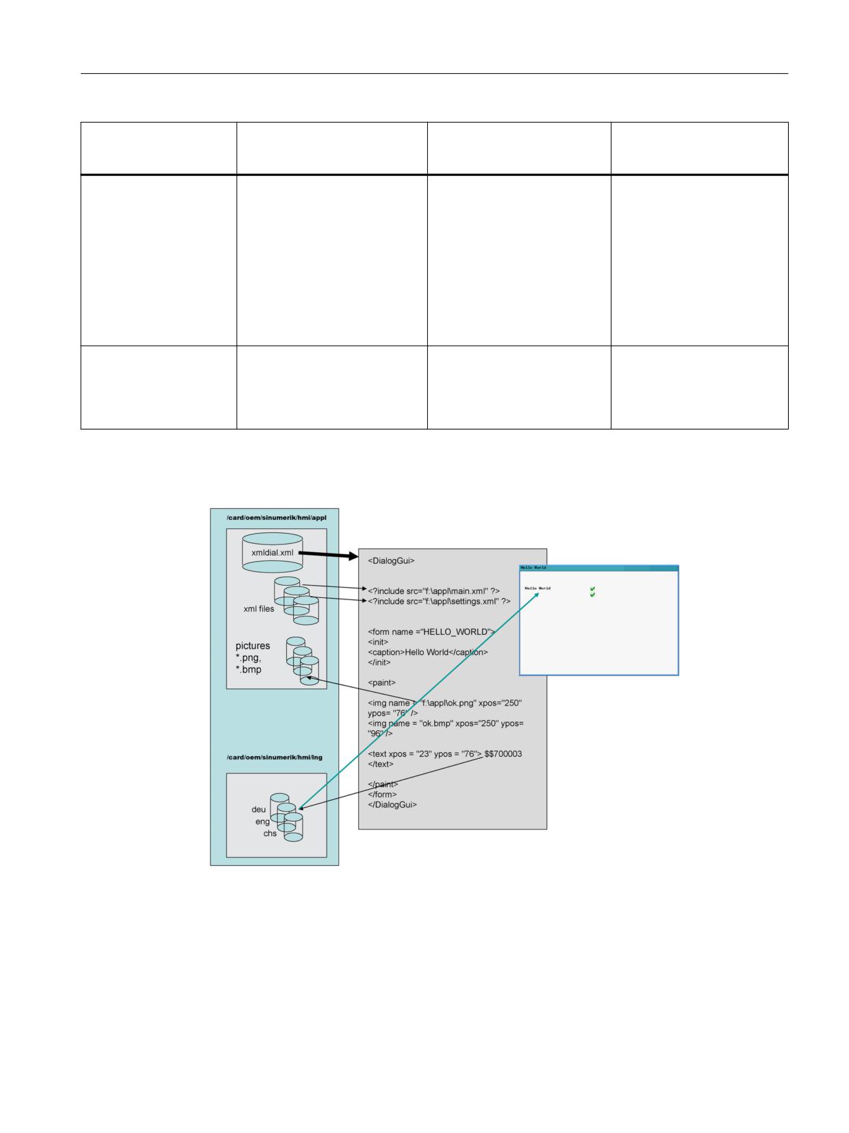
Generating user dialogs
2.3 Configuration files
File type
Name of the file
Meaning
Storage location in operat-
ing area Setup > System da-
ta
Bitmaps
The control system supports
Manufacturer's folder > sub-
BMP and PNG formats.
directory "ico"
The bitmaps are saved in the
subdirectory for the screen
resolution belonging to the
control.
Note: If a path to the bitmap
file is specified, the files can be
stored in this directory direct-
ly.
XML files inserted in the
E.g. "machine_settings.xml"
These files also contain pro-
Manufacturer's folder > sub-
"xmldial.xml" control file
grammed instructions for dis-
directory "appl" for the appli-
with the "INCLUDE" XML
playing the dialog forms and
cations
tag.
parameters in SINUMERIK Op-
erate.
Dependencies of files for configuring user dialogs
Figure 2-4
Dependencies
Easy XML
Programming Manual, 10/2020, 6FC5397-1DP40-6BA4
25
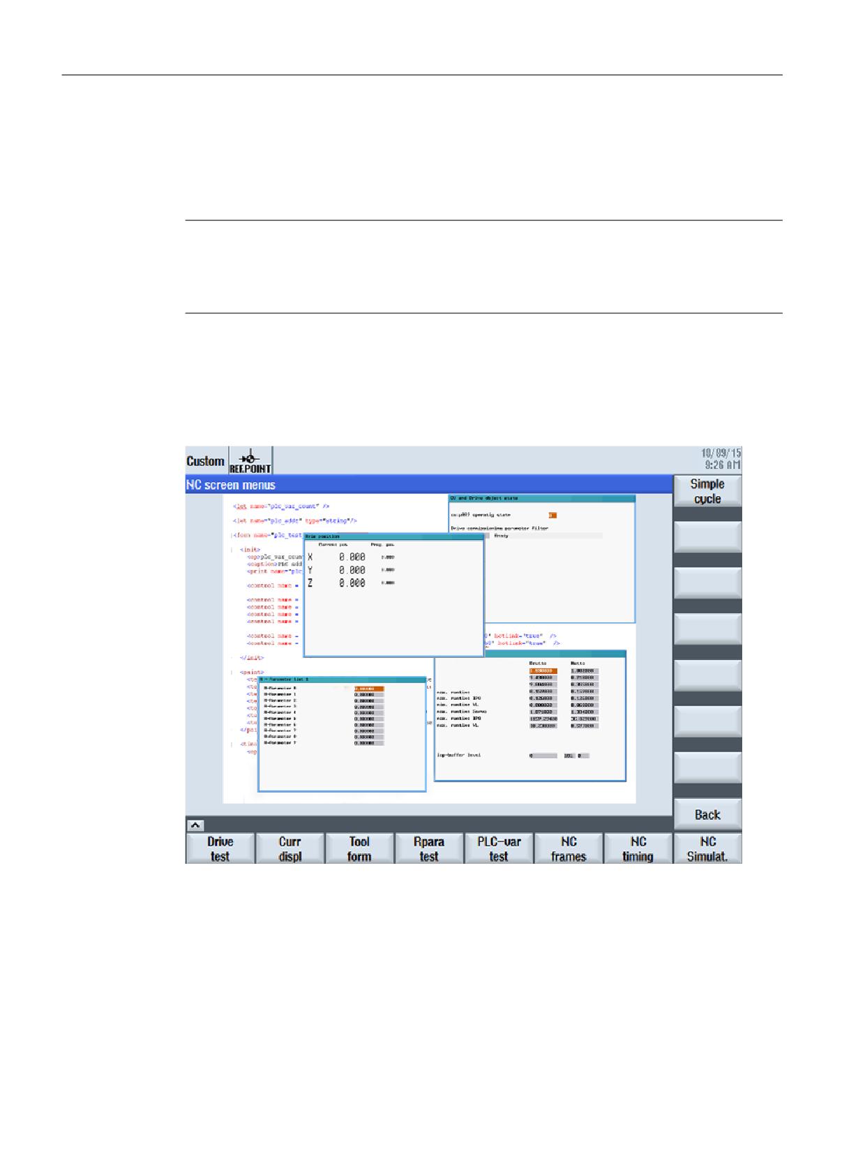
Generating user dialogs
2.3 Configuration files
Load configuration
As described in the "Storage location in the operating area" column in the previous "Files for
configuration" table, the generated files must be copied to the appropriate subdirectories in the
manufacturer's folder.
Note
As soon as there is a script file "xmldial.xml" in the subdirectory for applications, the user can start
this user dialog in the <CUSTOM> operating area.
After the initial copying process, the HMI must be reset via a "Normal power-up".
Example of a user dialog in SINUMERIK Operate
The configured softkey menus are displayed when the <CUSTOM> operating area is called. This
enables the user to operate the dialog forms which have been configured.
Figure 2-5
Example of a user dialog in the <CUSTOM> operating area
Further examples are provided in the toolbox.
See also
Predefined functions (Page 140)
Easy XML
26
Programming Manual, 10/2020, 6FC5397-1DP40-6BA4
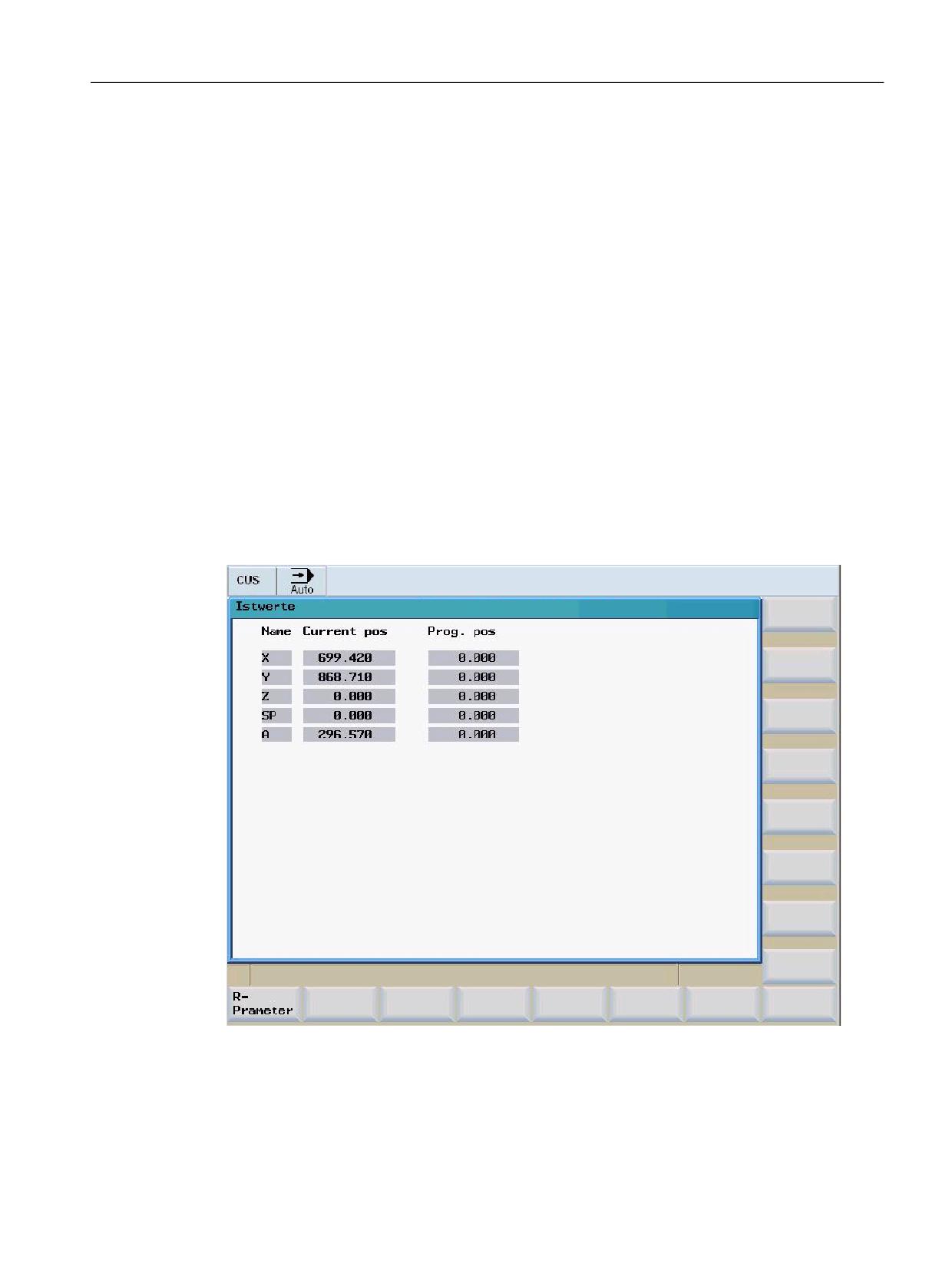
Generating user dialogs
2.4 Structure of configuration file
2.4
Structure of configuration file
Overview
A configuration file consists of the following elements:
• Description of the "main" start menu with start softkeys
• Definition of the dialogs
• Definition of the variables
• Description of the blocks
• Definition of softkey bars
The following examples show the XML script for the "xmldial.xml" file and the corresponding
screenshots.
The script contains the dialogs for displaying actual values and residual distances, as well as an
R parameter list.
Dialog form section "Actual values"
Easy XML
Programming Manual, 10/2020, 6FC5397-1DP40-6BA4
27
Generating user dialogs
2.4 Structure of configuration file
xmldial.xml
<DialogGui>
<!--
main menu
It is called by the system software. It starts the application.
The menu tag manages the soft key reactions. One input form can be assigned
to a menu tag.
-->
<menu name = "MAIN">
<OPEN_FORM name = "CURRENT_DISPLAY" />
<softkey POSITION="1">
<caption>R-%nPrameter</caption>
<navigation>MENU_R_PARAMETER</navigation> <!-- opens the menu R parameter --
>
</softkey>
</menu>
<form name = "CURRENT_DISPLAY">
<init>
<caption>Istwerte</caption>
<control name = "label1" xpos = "36" ypos = "56" width = "32"
fieldtype="readonly" refvar="nck/Channel/GeometricAxis/name[0]" />
<control name = "label2" xpos = "36" ypos = "76" width = "32"
fieldtype="readonly" refvar="nck/Channel/GeometricAxis/name[1]" />
<control name = "label3" xpos = "36" ypos = "96" width = "32"
fieldtype="readonly" refvar="nck/Channel/GeometricAxis/name[2]" />
<control name = "label4" xpos = "36" ypos = "116" width = "32"
fieldtype="readonly" refvar="nck/Channel/GeometricAxis/name[3]" />
<control name = "label5" xpos = "36" ypos = "136" width = "32"
fieldtype="readonly" refvar="nck/Channel/GeometricAxis/name[4]" />
<control name = "edit1" xpos = "80" ypos = "56" refvar="nck/Channel/
GeometricAxis/actProgPos[0]" hotlink="true" fieldtype="readonly"
format="%9.3f" time="super fast"/>
<control name = "edit2" xpos = "80" ypos = "76" refvar="nck/Channel/
GeometricAxis/actProgPos[1]" hotlink="true" fieldtype="readonly"
format="%9.3f" time="super fast"/>
<control name = "edit3" xpos = "80" ypos = "96" refvar="nck/Channel/
GeometricAxis/actProgPos[2]" hotlink="true" fieldtype="readonly"
format="%9.3f" time="super fast"/>
<control name = "edit4" xpos = "80" ypos = "116" refvar="nck/Channel/
GeometricAxis/actProgPos[3]" hotlink="true" fieldtype="readonly"
format="%9.3f" time="super fast"/>
<control name = "edit5" xpos = "80" ypos = "136" refvar="nck/Channel/
GeometricAxis/actProgPos[4]" hotlink="true" fieldtype="readonly"
format="%9.3f" time="super fast"/>
Easy XML
28
Programming Manual, 10/2020, 6FC5397-1DP40-6BA4
Generating user dialogs
2.4 Structure of configuration file
xmldial.xml
<control name = "edit11" xpos = "210" ypos = "56" refvar="nck/Channel/
GeometricAxis/progDistToGo[0]" hotlink="true" fieldtype="readonly"
format="%9.3f" time="super fast"/>
<control name = "edit12" xpos = "210" ypos = "76" refvar="nck/Channel/
GeometricAxis/progDistToGo[1]" hotlink="true" fieldtype="readonly"
format="%9.3f" time="super fast"/>
<control name = "edit13" xpos = "210" ypos = "96" refvar="nck/Channel/
GeometricAxis/progDistToGo[2]" hotlink="true" fieldtype="readonly"
format="%9.3f" time="super fast"/>
<control name = "edit14" xpos = "210" ypos = "116" refvar="nck/Channel/
GeometricAxis/progDistToGo[3]" hotlink="true" fieldtype="readonly"
format="%9.3f" time="super fast"/>
<control name = "edit15" xpos = "210" ypos = "136" refvar="nck/Channel/
GeometricAxis/progDistToGo[4]" hotlink="true" fieldtype="readonly"
format="%9.3f" time="super fast"/>
</init>
<paint>
<text xpos= "36" ypos="30">Name</text>
<text xpos= "80" ypos="30">Current pos</text>
<text xpos= "210" ypos="30">Prog. pos</text>
</paint>
</form>
Easy XML
Programming Manual, 10/2020, 6FC5397-1DP40-6BA4
29
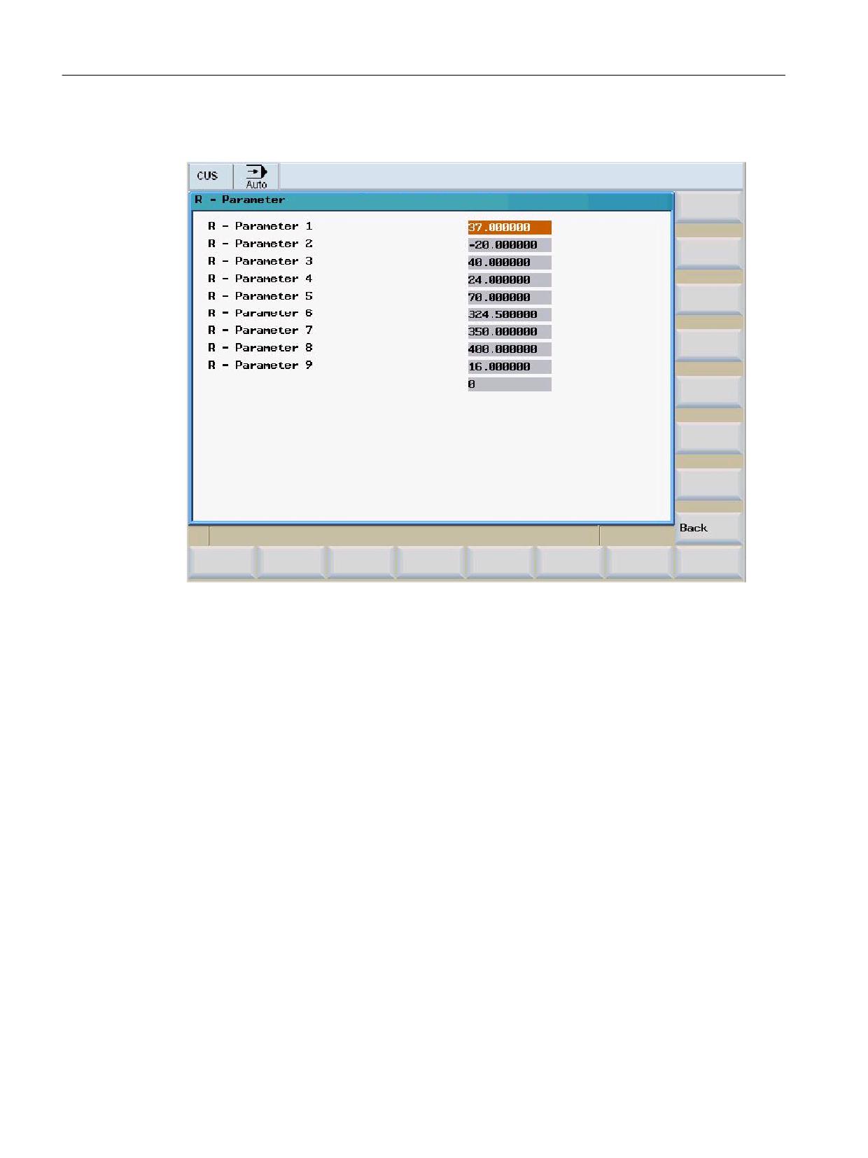
Generating user dialogs
2.4 Structure of configuration file
Dialog form section "R Parameters"
Easy XML
30
Programming Manual, 10/2020, 6FC5397-1DP40-6BA4
Generating user dialogs
2.4 Structure of configuration file
xmldial.xml
<!-- ***************************************************************
Menu R- Parameter
-->
<menu name ="MENU_R_PARAMETER">
<OPEN_FORM name = "R-Parameter" />
<softkey POSITION="16">
<caption>Back</caption>
<navigation>MAIN</navigation>
</softkey>
</menu>
<form name = "R-Parameter">
<init>
<DATA_ACCESS type="true" />
<caption>R - Parameter</caption>
<control name = "edit1" xpos = "322" ypos = "34" refvar="nck/Channel/
Parameter/R[1]" />
<control name = "edit2" xpos = "322" ypos = "54" refvar="nck/Channel/
Parameter/R[2]" />
<control name = "edit3" xpos = "322" ypos = "74" refvar="nck/Channel/
Parameter/R[3]" />
<control name = "edit4" xpos = "322" ypos = "94" refvar="nck/Channel/
Parameter/R[4]" />
<control name = "edit5" xpos = "322" ypos = "114" refvar="nck/Channel/
Parameter/R[5]" />
<control name = "edit6" xpos = "322" ypos = "134" refvar="nck/Channel/
Parameter/R[6]" />
<control name = "edit7" xpos = "322" ypos = "154" refvar="nck/Channel/
Parameter/R[7]" />
<control name = "edit8" xpos = "322" ypos = "174" refvar="nck/Channel/
Parameter/R[8]" />
<control name = "edit9" xpos = "322" ypos = "194" refvar="nck/Channel/
Parameter/R[9]" />
<control name = "edit10" xpos = "322" ypos = "214" refvar="nck/Channel/
Parameter/R[10]" />
<control name = "edit10" xpos = "322" ypos = "214" refvar="plc/mb170" />
</init>
<paint>
<text xpos = "23" ypos = "34">R - Parameter 1</text>
<text xpos = "23" ypos = "54">R - Parameter 2</text>
<text xpos = "23" ypos = "74">R - Parameter 3</text>
<text xpos = "23" ypos = "94">R - Parameter 4</text>
<text xpos = "23" ypos = "114">R - Parameter 5</text>
<text xpos = "23" ypos = "134">R - Parameter 6</text>
<text xpos = "23" ypos = "154">R - Parameter 7</text>
<text xpos = "23" ypos = "174">R - Parameter 8</text>
<text xpos = "23" ypos = "194">R - Parameter 9</text>
Easy XML
Programming Manual, 10/2020, 6FC5397-1DP40-6BA4
31
Generating user dialogs
2.4 Structure of configuration file
xmldial.xml
</paint>
</form>
</DialogGui>
Easy XML
32
Programming Manual, 10/2020, 6FC5397-1DP40-6BA4
Generating user dialogs
2.5 Language dependency
2.5
Language dependency
Language-dependent texts are used for:
• Softkey labels
• Headers
• Help texts
• Any other texts
The language-dependent texts are stored in text files.
Note
You will need to perform the following steps when using these text files:
• Make them available in the required languages.
• Transfer them into the relevant language directories of the control system.
Easy XML
Programming Manual, 10/2020, 6FC5397-1DP40-6BA4
33
Generating user dialogs
2.6 XML diagnostics
2.6
XML diagnostics
The system provides the Easy XML diagnostic function for diagnosing and finding script errors.
The use of the diagnostic function checks the XML syntax and runs through all the scripts
belonging to the project. To do this, functions, menus, forms and the existence and validity of
variables are also checked. The errors found are listed.
The Easy XML diagnostics function can be activated either by an attribute in the DialogGui tag
or by Display machine data.
Activate easy XML diagnostics
Example:
<DialogGui diagnose="true" >
…
…
</DialogGui >
or
Display machine data:
MD9113 $MM_EASY_XML_DIAGNOSE
Diagnostics and correction help support
for Easy XML scripts
= 0
No diagnostics active
= 1
Syntax check active
Diagnostics using trace outputs
Trace outputs can be integrated into a script using tag debug. Data is only saved if
attribute debug_msg with the value on is specified in tag DialogGui.
Softkey function overview
Dialog
Softkey
Function
Main menu "EasyXML diagnos-
Start script
The loaded program is started di-
tics"
rectly.
Start check
The syntax check is being started.
All accrued messages can be
seen. Renewed checking is avail-
able.
Easy XML
34
Programming Manual, 10/2020, 6FC5397-1DP40-6BA4
Generating user dialogs
2.6 XML diagnostics
Dialog
Softkey
Function
"Errors" and "Warnings" dialogs
Errors
The result are displayed, sorted
according to errors and warnings.
Warnings
Go to error
If errors or warnings are found,
the softkey is displayed.
The softkey opens the marked
XML file from the error list for ed-
iting. The cursor is automatically
placed on the erroneous row.
Check result
All accrued messages can be
seen.
"Document" dialog
Save
Changes in the XML file are being
saved.
Cancel
The XML file is closed un-
changed. The check result is dis-
played again.
Easy XML
Programming Manual, 10/2020, 6FC5397-1DP40-6BA4
35
Generating user dialogs
2.7 XML identifier
2.7
XML identifier
2.7.1
General structure
Structure and instructions of the script file for dialog configuration
All dialog configurations should be stored in the DialogGui tag.
<DialogGui>
…
</DialogGui>
Example:
<?xml version="1.0" encoding="utf-8"?>
<DialogGui>
…
<FORM name ="Hello_World">
<INIT>
<CAPTION>Hello World</CAPTION>
</INIT>
</FORM>
</DialogGui>
Instructions
The language offers the following instructions for executing conditional instructions and loop
controls:
• For loop
• WHILE loop
• Do while loop
• Conditional processing
• Switch and Case instructions
• Operator controls in a dialog form
• Softkey descriptions
• Define variables
A detailed description of the instructions can be obtained in section "Instruction/identifier
descriptions (Page 37)".
Easy XML
36
Programming Manual, 10/2020, 6FC5397-1DP40-6BA4
Generating user dialogs
2.7 XML identifier
2.7.2
Instruction/identifier descriptions
The following XML tags are defined for generating dialogs and menus, and for executing
program sequences:
Note
Attribute values that are in quotation marks "<...>" should be replaced by the currently used
expressions.
Example:
<DATA_LIST action="read/write/append" id="<list name>">
is programmed as follows:
<DATA_LIST action="read/write/append" id="my datalist">
When copying multi-line XML tags and examples, care must be taken that the markups are not
separated by unwanted line breaks.
Tag identifier
Meaning
BREAK
Conditional cancellation of a loop.
CONTROL
The tag is used to generate control elements. The description is provided in Chapter "Gen-
erating softkey menus and dialog forms (Page 66)".
CONTROL_RESET
The tag enables one or more control components to be restarted.
Syntax:
<CONTROL_RESET resetnc="TRUE" />
Attributes:
• RESETNC = "TRUE"
The NC component is restarted
• RESETDRIVE = "TRUE"
The drive components are restarted.
Easy XML
Programming Manual, 10/2020, 6FC5397-1DP40-6BA4
37