SINUMERIK 840D sl. Service - Configuring Commissioning. Manual (2011-2020) - page 44
Technologies and cycles
19.9 Load-dependent controller setting
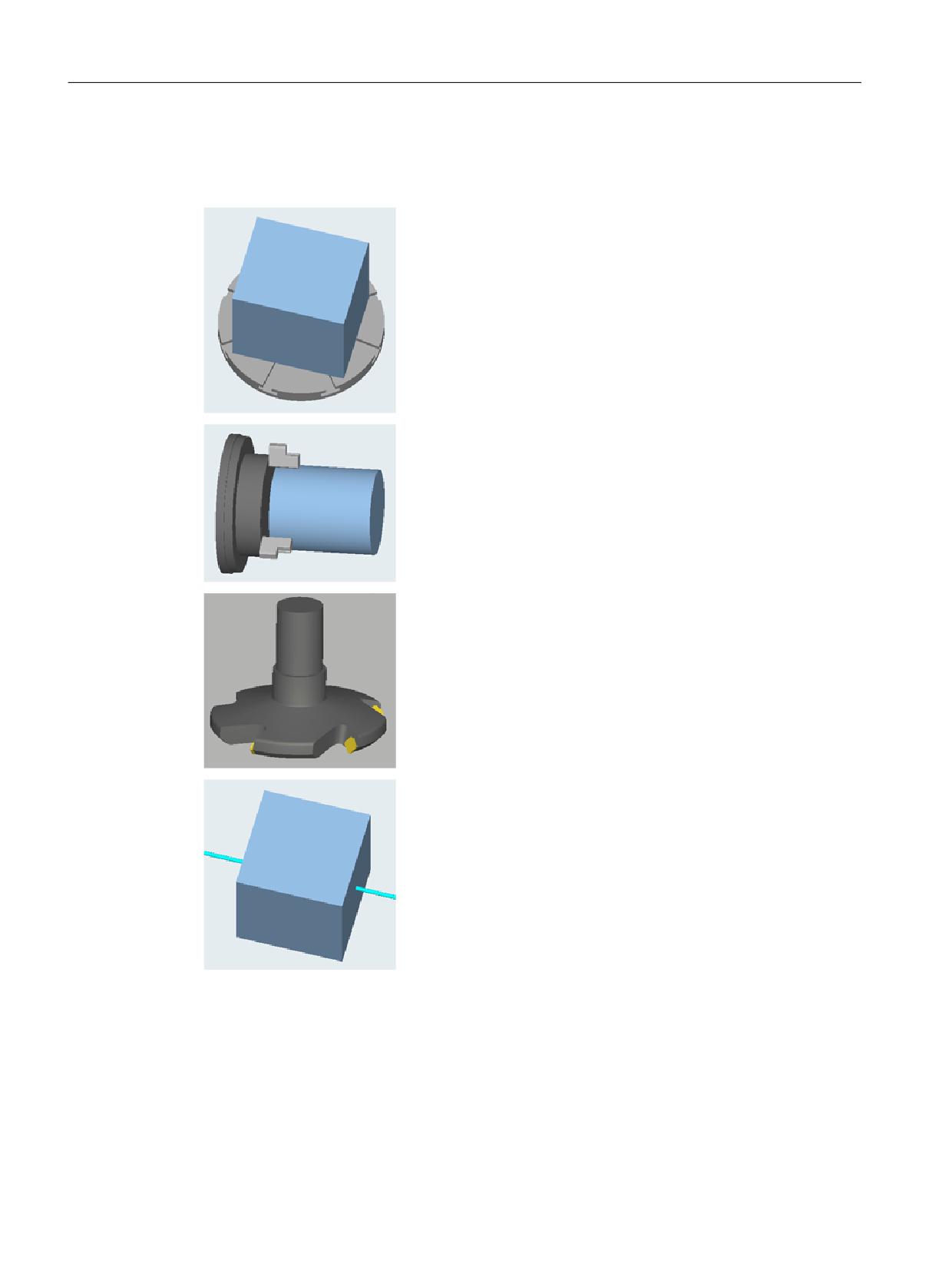
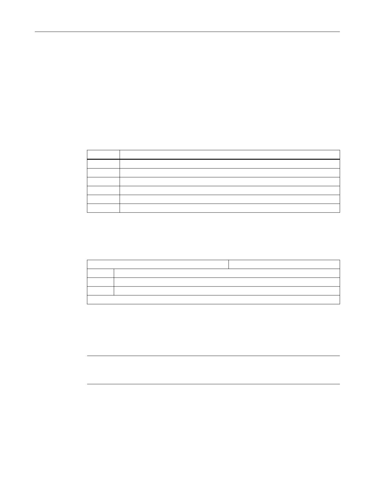
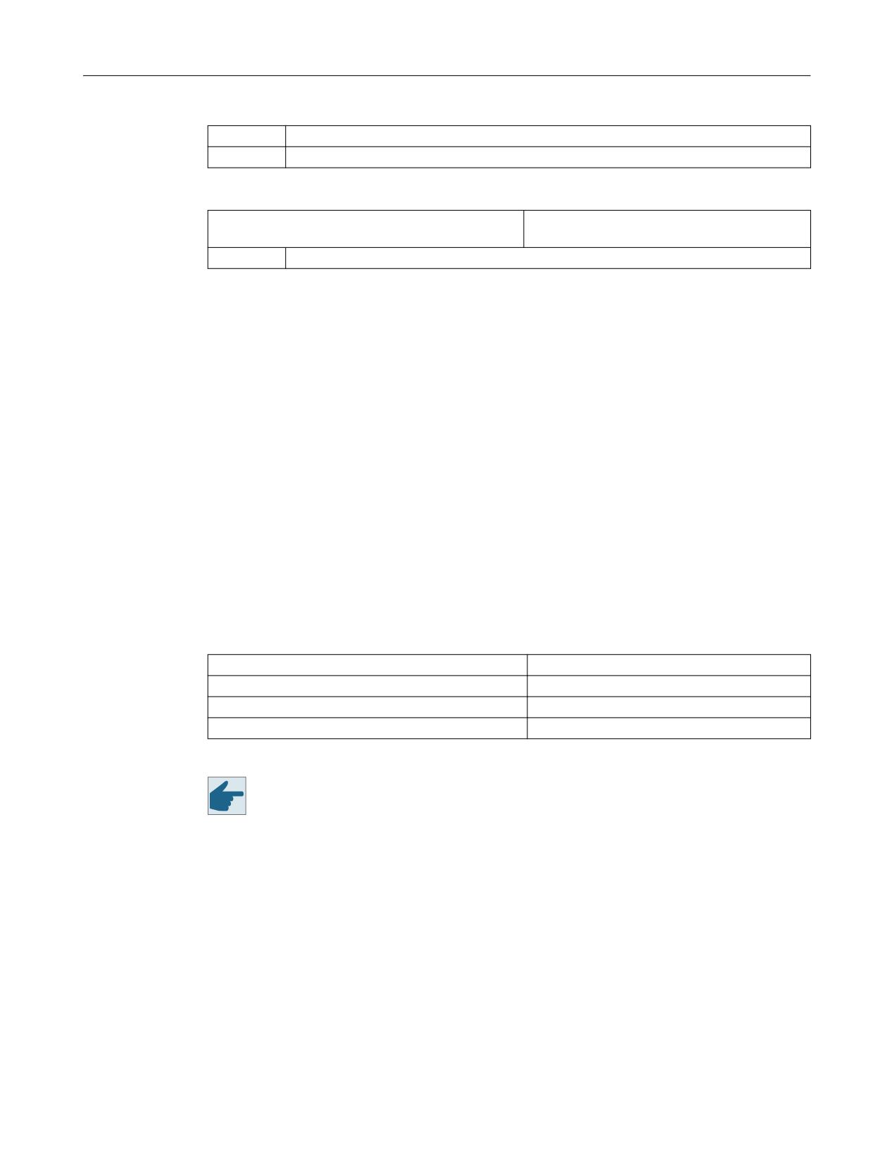
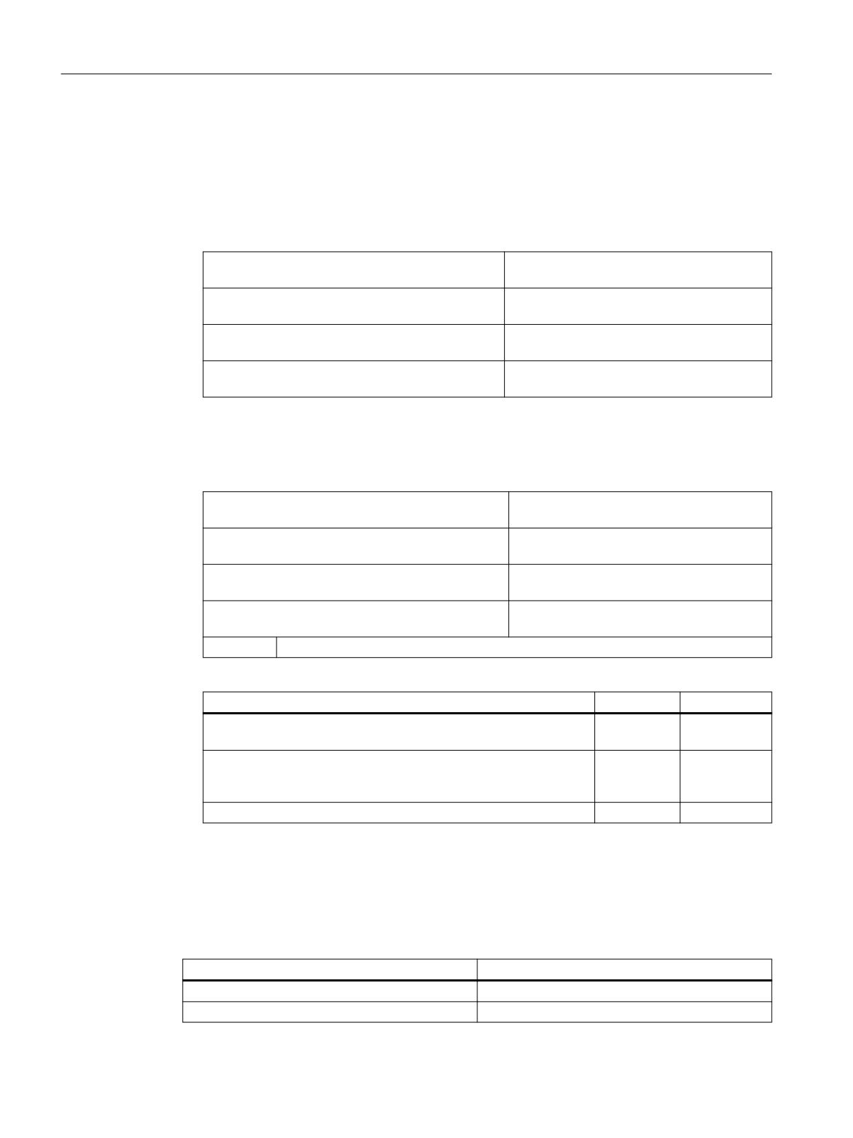
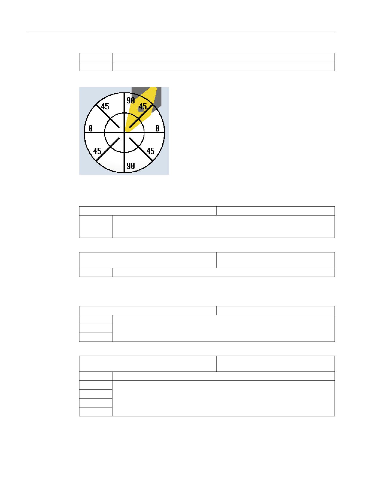
Auxiliary screens for axes
Depending on the type of axis, the following help screens are displayed, for example:
C axis
Main spindle
Tool spindle around Z
Linear axis
SINUMERIK Operate
498
Commissioning Manual, 10/2020, 6FC5397-1DP40-6BA4
Technologies and cycles
19.9 Load-dependent controller setting
19.9.3
Manufacturer cycle CUST_782.SPF
Function
Cycle CUST_782 is called internally by CYCLE782 (determine the load). It is used to execute the
required traverse distances and traverse conditions for determining the load. These are specific
to the machine and must be set accordingly by the machine manufacturer.
Adapting manufacturer cycle CUST_782.SPF
You can execute the following actions with the aid of the _MODE parameter:
Marker
Action
_M1
Call at the start of CYCLE782
_M10
Go to starting position
_M11
Traverse movements for determining the load
_M12
Traverse movements for determining the friction
_M19
Go to end position
_M99
Call at the end of CYCLE782
Resetting value for the moment of inertia
Before each determination of the load, the moment of inertia last determined can be reset to a
defined value in the CUST_782 movement profile by writing the following variables.
$VA_RESET_INERTIA_TOTAL[ax]
Resetting the moment of inertia estimator
= -1
Reset moment of inertia and load
= 0
No action (default when reading)
= 1
Reset moment of inertia
ax = axes in the system
To ensure that the old moment of inertia does not have any influence on the new result, reset
the last estimated moment of inertia prior to each new traversing with the parameterization = 1.
This will allow the estimation results determined to be reproduced.
Should you wish to reset the estimated load torque at the same time (e.g. the friction force), use
the parameterization = -1.
Note
System variable $VA_RESET_INERTIA_TOTAL is only available for SINAMICS drives. It describes
the SINAMICS parameter p1565.
SINUMERIK Operate
Commissioning Manual, 10/2020, 6FC5397-1DP40-6BA4
499
Technologies and cycles
19.10 High-speed machining free-form surfaces
Additional information
Additional information regarding the set parameters, commissioning and the boundary
conditions for the axis functions is provided in:
• Function Manual SINAMICS S120 Drive Functions
• SINAMICS S120/S150 List Manual
19.10
High-speed machining free-form surfaces
19.10.1
High speed settings: Configuring CYCLE832
Function
The High Speed Settings function (CYCLE832) is used to preset data for the machining of free-
form surfaces so that optimum machining is possible. The call of CYCLE832 contains three
parameters:
• Tolerance
• Machining type (technology)
• Input of the orientation tolerance
The 3rd parameter is significant only for machines with multi-axis orientation transformation
(TRAORI).
The High Speed Settings function (CYCLE832) offers, in addition to Advanced Surface, the
extension Top Surface. Top Surface can be used to improve the quality of free-form surfaces. If
set actively, the continuous-path control is optimized within contour tolerances. The CYCLE832
call also contains the smoothing parameter.
Software option
To use this function, you need the software option:
"Top Surface"
Setting up parameters
Set the following machine and setting data to set up the Top Surface extension:
SD55220 $SCS_FUNCTION_MASK_MILL_TOL_SET
Function mask High Speed Settings CYCLE832
Bit 2
Mold making function can be selected in High Speed Settings screen form
= 0
The best available mold making function is automatically used:
• Top Surface not active → Advanced Surface
• Top Surface active → Top Surface
= 1
The mold making function (Advanced Surface or Top Surface) can be selected in the input
mask.
Bit 4
Display selection "Smoothing"
SINUMERIK Operate
500
Commissioning Manual, 10/2020, 6FC5397-1DP40-6BA4
Technologies and cycles
19.10 High-speed machining free-form surfaces
= 0
Do not display selection "Smoothing" in the screen form (corresponds to smoothing = yes)
= 1
Display selection "Smoothing" in the screen form
MD52441 $MCS_LIMIT_RES_PATH_SPEED
Limitation of the resulting velocity of the path
motion
mm/min
MD52441 $MCS_LIMIT_RES_PATH_SPEED can be used to limit or reduce the speed of the path
movement resulting from the axial limitation values in critical program sections.
The resulting path velocity is limited to the value specified in the machine data. No limitation
takes effect with the value 0.
Furthermore, limitation is deactivated upon deselection of CYCLE832 or upon reset or end of
part program.
Axis/contour tolerance
The distinguishing feature between "Advanced Surface" and "Top Surface" functions is as
follows:
For "Advanced Surface", the axis tolerance for the linear axes (geometry axes) is transferred to
the CNC with the NC command CTOL.
CTOL = √3 * Axis tolerance
For "Top Surface", the contour tolerance is transferred to the CNC with the NC command CTOL.
Tolerance value = 0: Tolerance value (CTOL) is loaded from the following setting data:
Example: CYCLE832(0,_ROUGH,1) → tolerance value from SD55446 is used.
SD55446 $SCS_MILL_TOL_VALUE_ROUGH
Tolerance value for roughing CYCLE832
SD55447 $SCS_MILL_TOL_VALUE_SEMIFIN
Tolerance value for semi-finishing CYCLE832
SD55448 $SCS_MILL_TOL_VALUE_FINISH
Tolerance value for finishing CYCLE832
SD55449 $SCS_MILL_TOL_VALUE_PRECISION
Tolerance value for smooth-finishing CYCLE832
Software option
To use the contour tolerance, you require the software option:
"Top Surface"
Orientation tolerance
If rotary axes are involved in the machining (multi-axis transformation), the orientation
tolerance value is transferred to the CNC with the NC command OTOL.
SINUMERIK Operate
Commissioning Manual, 10/2020, 6FC5397-1DP40-6BA4
501
Technologies and cycles
19.10 High-speed machining free-form surfaces
There are 2 options available for this:
1.
Direct entry of the orientation tolerance OTOL
Machining types: _ORI_ROUGH, _ORI_SEMIFIN, _ORI_FINISH _ORI_PRECISION
To enter the orientation tolerance in the input mask for CYCLE832,
SD55220 $SCS_FUNCTION_MASK_MILL_TOL_SET Bit 1=1 must be set in the setting data.
The standard values for the orientation tolerance are stored in the following setting data:
SD55451 $SCS_MILL_ORI_TOL_ROUGH
Orientation tolerance value for roughing CY-
CLE832
SD55452 $SCS_MILL_ORI_TOL_SEMIFIN
Orientation tolerance value for rough-finish-
ing CYCLE832
SD55453 $SCS_MILL_ORI_TOL_FINISH
Orientation tolerance value for finishing CY-
CLE832
SD55454 $SCS_MILL_ORI_TOL_PRECISION
Orientation tolerance value for smooth-finish-
ing CYCLE832
2.
Tolerance is transferred with a factor on the NC command OTOL.
OTOL = Tolerance * Factor * √2
Machining types: _ROUGH, _SEMIFIN, _FINISH, _PRECISION
This factor can be set in the following channel-specific setting data for each machining type:
SD55441 $SCS_MILL_TOL_FACTOR_ROUGH
Factor, tolerance of the rotary axes for rough-
ing of the G group 59.
SD55442 $SCS_MILL_TOL_FACTOR_SEMIFIN
Factor, tolerance of the rotary axes for semi-
finishing of the G group 59.
SD55443 $SCS_MILL_TOL_FACTOR_FINISH
Factor, tolerance of the rotary axes for finish-
ing of the G group 59.
SD55444 $SCS_MILL_TOL_FACTOR_PRECISION
Factor, tolerance of the rotary axes for
smooth-finishing of the G group 59.
= 10
Example: Multi-axis transformation, SCS_MILL_TOL_FACTOR...=10
CTOL
OTOL
CYCLE832(0.1,_ROUGH,1)
0.1 * √3
0.1 * √2 * Fac-
= 0.173
tor = 1.414
CYCLE832(0.05,TOP_SURFACE_SMOOTH_ON+_SEMIFIN,1)
0.05
0.05 * √2
* Factor
= 1.414
CYCLE832(0.05,TOP_SURFACE_SMOOTH_ON+_ORI_SEMIFIN,0.3)
0.05
0.3
Smoothing
For the "Top Surface" function, smoothing can be switched off via CYCLE832. The setting data
SD55220 $SCS_FUNCTION_MASK_MILL_TOL_SET Bit 4=1 must be set for this purpose.
Mold-making function
Plain text
Top Surface without smoothing
TOP_SURFACE_SMOOTH_OFF+
Top Surface with smoothing
TOP_SURFACE_SMOOTH_ON+
SINUMERIK Operate
502
Commissioning Manual, 10/2020, 6FC5397-1DP40-6BA4
Technologies and cycles
19.10 High-speed machining free-form surfaces
Machining type and technology G group 59
The machining types of the technology G group 59 are permanently assigned in CYCLE832 or in
CUST_832.SPF:
Machining type
Plain text
Technology G group 59
Array index
Deselection
_OFF
DYNNORM
0
Roughing
_ROUGH
DYNROUGH
2
Semi-finishing
_SEMIFIN
DYNSEMIFIN
3
Finishing/speed
_FINISH
DYNFINISH
4
Smooth-finishing/Precision
_PRECISION
DYNPREC
5
Roughing *)
_ORI_ROUGH
DYNROUGH
2
Semi-finishing *)
_ORI_SEMIFIN
DYNSEMIFIN
3
Finishing/speed *)
_ORI_FINISH
DYNFINISH
4
Smooth-finishing/Precision *)
_ORI_PRECISION
DYNPREC
5
*)
With entry of an orientation tolerance
Dynamic parameters can be adapted to the respective machining operation with the technology
G groups. Using the commands of technology G group 59, the value of channel and axis-
specific machine data of the dynamic path response is activated using the corresponding array
index.
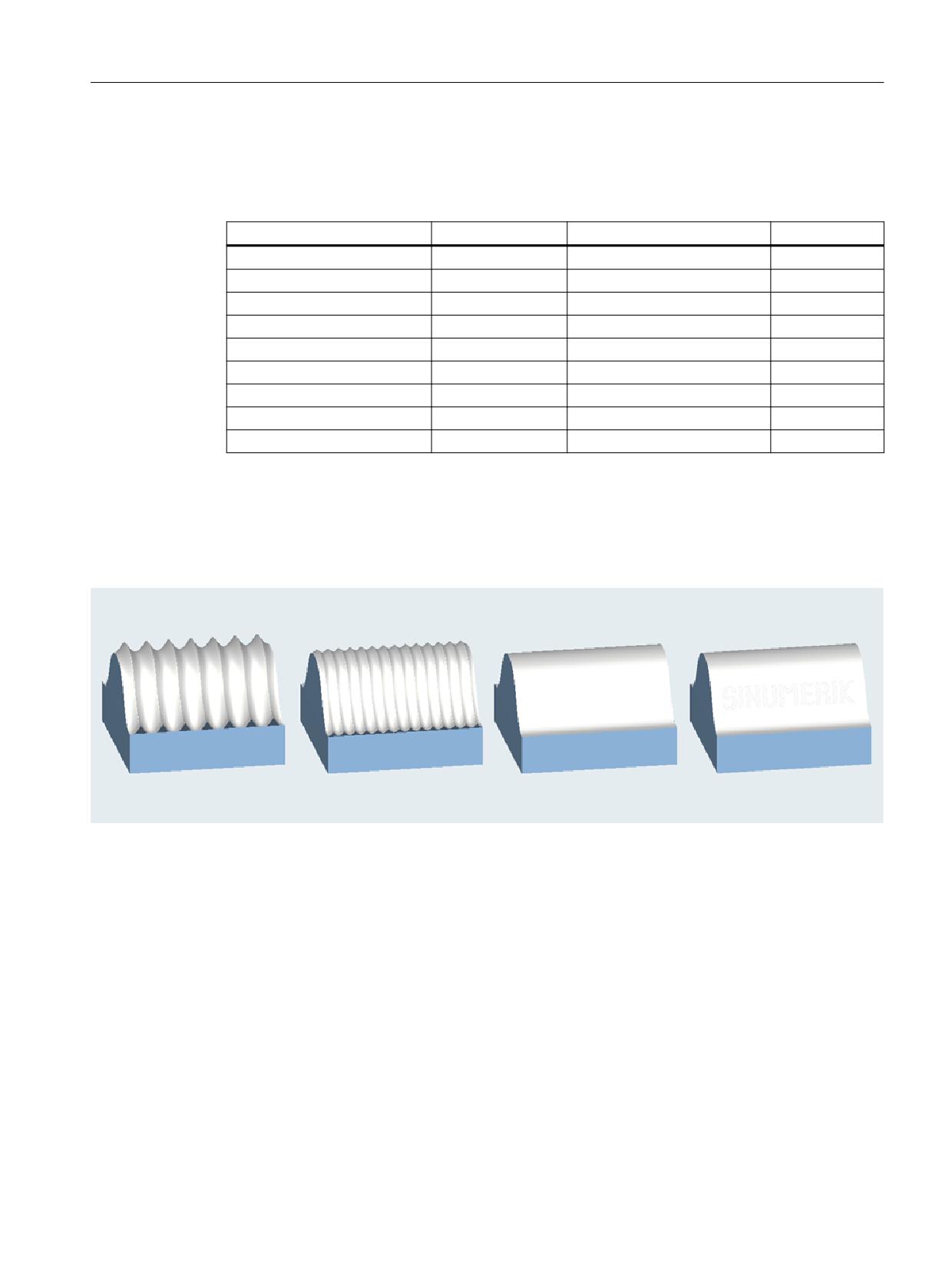
Figure 19-26
Roughing, rough-finishing, finishing or smooth-finishing
More information
More information regarding the dynamic response mode for path interpolation is provided in the
Function Manual Basic Functions.
The setting instructions for Advanced Surface/Top Surface are available at the following address
check-programs-for-advanced-surface-top-surface-settings?dti=0&lc=en-WW).
SINUMERIK Operate
Commissioning Manual, 10/2020, 6FC5397-1DP40-6BA4
503
Technologies and cycles
19.10 High-speed machining free-form surfaces
Machining type, deselection
When CYCLE832 is deselected, the G groups are programmed for the settings during the
program run time; these settings are declared in machine data
MD20150 $MC_GCODE_RESET_VALUES[ ]. This involves the G groups 1, 4, 10, 12, 21, 24, 30,
45, 59, 61.
The contour and orientation tolerance is deactivated (CTOL=-1, OTOL=-1).
19.10.2
Manufacturer cycle CUST_832.SPF
Function
In contrast to the settings (G functions) by CYCLE832.SPF, these settings can be modified in the
manufacturer cycle CUST_832.SPF.
The following markers are prepared in CUST_832.SPF:
_M_INIT:
Initialization _FGREF
_M_NORM:
For deselection _OFF CYCLE832
_M_TOP_SURFACE_PRESICION Processing precision finishing _PRECISION and _ORI_PRECI-
:
SION with COMPSURF
_M_TOP_SURFACE_FINISH:
Processing finishing _FINISH and _ORI_FINISH with COMPSURF
_M_TOP_SURFACE_SEMIFINIS Processing semi-finishing _SEMIFIN and _ORI_SEMIFIN with
H:
COMPSURF
_M_TOP_SURFACE_ROUGH:
Processing roughing _ROUGH and _ORI_ROUGH with COMP-
SURF
_M_FINISH:
For finishing _FINISH and _ORI_FINISH with COMPCAD
_M_SEMIFINISH:
For semi-finishing _SEMIFIN and _ORI_SEMIFIN with COMPCAD
_M_ROUGH:
For roughing _ROUGH and _ORI_ROUGH with COMPCAD
The following G functions are programmed in CUST_832.SPF:
SOFT
COMPCAD / COMPSURF
G645
FIFOCTRL
UPATH
;FFWON
The calculation of the FIR lowpass jerk filter is explicitly activated using the CALCFIR instruction:
;CALCFIR
Depending on the machining type used, the following G commands of G group 59 are
programmed:
DYNNORM
DYNPREC
DYNFINISH
DYNSEMIFIN
DYNROUGH
SINUMERIK Operate
504
Commissioning Manual, 10/2020, 6FC5397-1DP40-6BA4
Technologies and cycles
19.10 High-speed machining free-form surfaces
The programming of FGREF () is useful when machining with active multi-axis transformation
(e.g. TRAORI). In this case, in CUST_832.SPF, variable _FGREF is pre-assigned a value of 10 mm.
This value can also be modified. In CYCLE832.SPF, the value of variable _FGREF is written to the
rotary axes involved in the machining, which are declared as orientation axis of a 5-axis
transformation, using the FGREF (rotary axis) command. When G70/G700 is active, the value
from _FGREF is converted into inches before writing to the command FGREF.
Additional information
Additional information about the CALCFIR instruction is provided in the:
• Programming Manual NC Programming
• Function Manual Axes and Spindles
Including fewer than three rotary axes (geometry axes) in CYCLE832
With Advanced Surface, the CYCLE832 converts an axis tolerance internally into a contour
tolerance because the NC can only work with a contour tolerance CTOL, e.g.:
CYCLE832(0.01,_Rough,1) → CTOL = 0.01 * √3 = 0.0173
The NC is always set so that a contour is created with CTOL and three geometry axes. If fewer
than three geometry axes are configured in the channel, CUST_832 CTOL must be adjusted so
that a correct contour is also produced with two geometry axes. The value is displayed on the
user interface.
Including more than two rotary axes (orientation axes) in CYCLE832
In CYCLE832, a maximum of two rotary axes of the orientation transformation (TRAORI) are
taken into account for FGREF. If more than two rotary axes are declared per channel for the
orientation transformation, you can write the value to FGREF using the following syntax in the
CUST_832:
FGREF[AA]=$AA_FGREF[C]
C = rotary axis 1 (axis is taken into account by CYCLE832)
AA = rotary axis 4
In the manufacturer cycle CUST_832.SPF, parameter _MOTOL is available for the evaluation of
the "Multi-axis programming yes/no".
_MOTOL=0
No multi-axis programming
_MOTOL=1
Multi-axis programming where the orientation tolerance is en-
tered
With the following setting data, additional G functions can be programmed in CUST_832.SPF for
using multi-axis programming:
SD55220 $SCS_FUNCTION_MASK_MILL_TOL_SET
Function screen form, high speed settings CY-
CLE832
Bit 1
Orientation tolerance (OTOL) as a factor of the tolerance (CTOL) or directly entered
SINUMERIK Operate
Commissioning Manual, 10/2020, 6FC5397-1DP40-6BA4
505
Technologies and cycles
19.11 Measuring cycles and measurement functions
Example
Using _MOTOL in CUST_832.SPF for the marker for finishing:
_M_FINISH:
IF _MOTOL==1
; if multi-axis programming
ORISON
ELSE
; no multi-axis programming
ORISOF
ENDIF
Including more than one transformation in CYCLE832
The following evaluation of the machine data and system variables is possible with CYCLE832 to
determine the transformation of the TRAORI type used and its rotary axes:
• No transformation configuration with $MC_TRAFO_TYPE,
none with $NT_NAME ⇒ unique
• One transformation configuration with $MC_TRAFO_TYPE,
none, one or more with $NT_NAME ⇒ the transformation with $MC_TRAFO_TYPE
• Two transformation configurations with $MC_TRAFO_TYPE,
none, one or more with $NT_NAME ⇒ the second transformation with $MC_TRAFO_TYPE
• No transformation configuration with $MC_TRAFO_TYPE,
one with $NT_NAME ⇒ unique
• No transformation configuration with $MC_TRAFO_TYPE,
several with $NT_NAME ⇒ the last (highest index) transformation with $NT_NAME
Note
If an active transformation is to be performed in mold making, for example, this transformation
must be activated prior to the CYCLE832.
19.11
Measuring cycles and measurement functions
19.11.1
Measuring cycles and measurement functions, general
Requirement
Two types of electronic probes are used for measuring:
• Probe to measure the workpiece
• Probe to measure the tool
SINUMERIK Operate
506
Commissioning Manual, 10/2020, 6FC5397-1DP40-6BA4
Technologies and cycles
19.11 Measuring cycles and measurement functions
The electronic probe must be connected to the NCU 7x0.
More information
More information about the digital inputs and outputs of the measuring probe is provided in the
NCU Equipment Manual.
Note
In the NCU Equipment Manual, the electronic measuring probe is just called measuring probe.
Setting the switching behavior
You set the electrical polarity of the connected probe using the following general machine data:
MD13200 $MN_MEAS_PROBE_LOW_ACTIVE
Polarity change of the probe
= 0
Probe in the non-deflected state, 0 V default value
Probe in the deflected state, 24 V
= 1
Probe in the non-deflected state, 24 V
Probe in the deflected state, 0 V
MD13210 $MN_MEAS_TYPE
Measuring type for distributed drives
= 0
Default value
Testing the probe function
You can test the switching function of the probe by manually deflecting it and checking the
following PLC interface signals:
DB 10
Bit 7
Bit 6
Bit 5
Bit 4
Bit 3
Bit 2
Bit 1
Bit 0
Probe actuated
DBB107
Probe 2
Probe 1
To test the switching behavior and the measured value transfer, use an NC test program with, for
example, the following NC commands:
MEAS
Measurement with deletion of distance-to-go
$AC_MEA[n]
Check the switching operation, n = measurement input number
$AA_MW[axis name]
Measured value of the axes in workpiece coordinates
$AA_MM[axis name]
Measured value of the axes in machine coordinates
Example of a test program
Program code
Comment
%_N_PRUEF_MESSTASTER_MPF
SINUMERIK Operate
Commissioning Manual, 10/2020, 6FC5397-1DP40-6BA4
507
Technologies and cycles
19.11 Measuring cycles and measurement functions
Program code
Comment
$PATH=/_N_MPF_DIR
;Testing program probe connection
N00 DEF INT MTSIGNAL
;Bit memory to check the switching state
N05 G17 G54 T="3D_Taster" D1
;Select tool geometry for probe
N10 M06
;Activate tool
N15 G0 G90 X0 F150
;Starting position and meas. velocity
N20 MEAS=1 G1 X100
;Measurement at measuring input 1 in the
X axis
N30 MTSIGNAL=$AC_MEA[1]
;Switching operation at the 1st measuring
input completed, ;YES / NO
N35 IF MTSIGNAL == 0 GOTOF _FEHL1
;Evaluation of the signal
N40 R1=$AA_MM[X]
;Save measured value in machine coordi-
nates at R1
N45 R2=$AA_MW[X]
;Save measured value in workpiece coordi-
nates at R2
N50 M0
;Check measured value in R1/R2
N55 M30
N60 _FEHL1: MSG ("Probe does not switch!")
N65 M0
N70 M30
General function settings for measuring cycles
MD51740 $MNS_MEA_FUNCTION_MASK
Measuring cycles function screen
Bit 0
Workpiece, monitoring the calibration status
Bit 1
Workpiece, length reference of the probe in the infeed axis with relation to the sphere cir-
cumference
= 0
Tool length L1, referred to the center of the probe sphere
= 1
Tool length L1, referred to the sphere circumference of the probe sphere
Bit 2
Workpiece, offset into tool, tool carrier taken into account
Bit 4
Workpiece, probe permanently affixed to the machine (not in a spindle)
Bit 5
Workpiece, coarse offset in ZO if no fine ZO has been set up
Bit 6
Measuring blocks in the measuring cycles with feed override 100%
Bit 7
Workpiece, accept active into inactive WO, JOG mode only, set edge
Bit 14
Workpiece, simultaneous measurement function active
Bit 15
Workpiece, traverse measuring block with path behavior G60
Bit 16
Tool, turning technology, consideration of tool holders
Note
After changing this machine data, the probe must be re-calibrated.
MD52740 $MCS_MEA_FUNCTION_MASK
Measuring cycles function screen
Bit 0
Workpiece probe connected to measurement sensing input 2
SINUMERIK Operate
508
Commissioning Manual, 10/2020, 6FC5397-1DP40-6BA4

Technologies and cycles
19.11 Measuring cycles and measurement functions
= 0
Workpiece probe at the CNC measuring input 1, active - default
= 1
Workpiece probe at the CNC measuring input 2, active
Bit 1
Workpiece, turning technology, measuring in the third geometry axis (Y)
Bit 2
Calculation of the correction angle with/without active orientation transformation
Bit 16
Tool probe connected to measurement sensing input 2
= 0
Tool probe at the CNC measuring input 1, active
= 1
Workpiece probe at the CNC measuring input 2, active - default
Bit 17
Tool measurement turning, recoding of cutting edge position
SD54740 $SNS_MEA_FUNCTION_MASK
Measuring cycles function screen
Bit 0
Workpiece, repeat measurement if TSA, TDIF exceeded
Bit 1
Workpiece, repeat measurement with M0 if TSA, TDIF exceeded
Bit 2
Workpiece, stop at M0 if TUL, TLL exceeded
Bit 3
Workpiece, accept calibrated probe sphere radius in tool data
Bit 4
Workpiece, plane can vary between calibration and measurement
Bit 16
Tool, repeat measurement if TDIF, TSA exceeded
Bit 17
Tool, repeat measurement with stop at M0 if TDIF, TSA exceeded
Bit 19
Tool, milling, reduction of spindle speed during last probing
SD55740 $SCS_MEA_FUNCTION_MASK
Measuring cycles function screen
Bit 0
Workpiece, collision monitoring for intermediate positioning
Bit 1
Workpiece, coupling of spindle position with coordinate rotation around the infeed axis
Bit 2
Workpiece, reverse positioning direction if spindle position is coupled
Bit 3
Workpiece, no repetition if probe does not switch
Bit 4
Workpiece, 1st probing for every measurement with rapid measuring feedrate
Bit 5
Workpiece, rapid retraction following measurement
Bit 6
Workpiece, deactivate probe during spindle positioning
Bit 7
Kinematics, scaling on the basis of the input values of the rotary axis vectors
Bit 8
Kinematics, measuring with swiveling (TCARR) or active TRAORI
Bit 9
Kinematics, user-specific scaling of the rotary axis vectors
Bit 10
Kinematics, measure completely with reference
Bit 11
Kinematics, number of measurement points when measuring calibration sphere
Bit 15
Workpiece, calibrating radius with starting point in center of ring, JOG mode only
Bit 16
Tool, collision monitoring for intermediate positioning
Bit 17
Tool, no repetition if probe does not switch
Bit 19
Tool, rapid retraction following measurement
Bit 28
Continuous measuring standard log in JOG (attach)
Bit 29
Table format for measuring standard log in JOG
SINUMERIK Operate
Commissioning Manual, 10/2020, 6FC5397-1DP40-6BA4
509
Technologies and cycles
19.11 Measuring cycles and measurement functions
19.11.2
Manufacturer and user cycle CUST_MEACYC.SPF
Function
The CUST_MEACYC.SPF is part of the measuring cycle functionality. It is called in every
measuring cycle before and after executing the measurement task. The CUST_MEACYC.SPF acts
in the same way when measuring in the JOG mode and measuring in the AUTOMATIC mode.
You can use the CUST_MEACYC.SPF to program and execute sequences that are necessary
before and/or after a measurement (e.g. activating/deactivating a probe).
Note
Copy the CUST_MEACYC cycle before performing the changes from the directory NC data/Cycles/
Standard cycles to the directory NC data/Cycles/Manufacture cycles or
NC data/Cycles/User cycles. Changes for CUST_MEACYC only take effect in these directories.
SINUMERIK Operate
510
Commissioning Manual, 10/2020, 6FC5397-1DP40-6BA4
Technologies and cycles
19.11 Measuring cycles and measurement functions
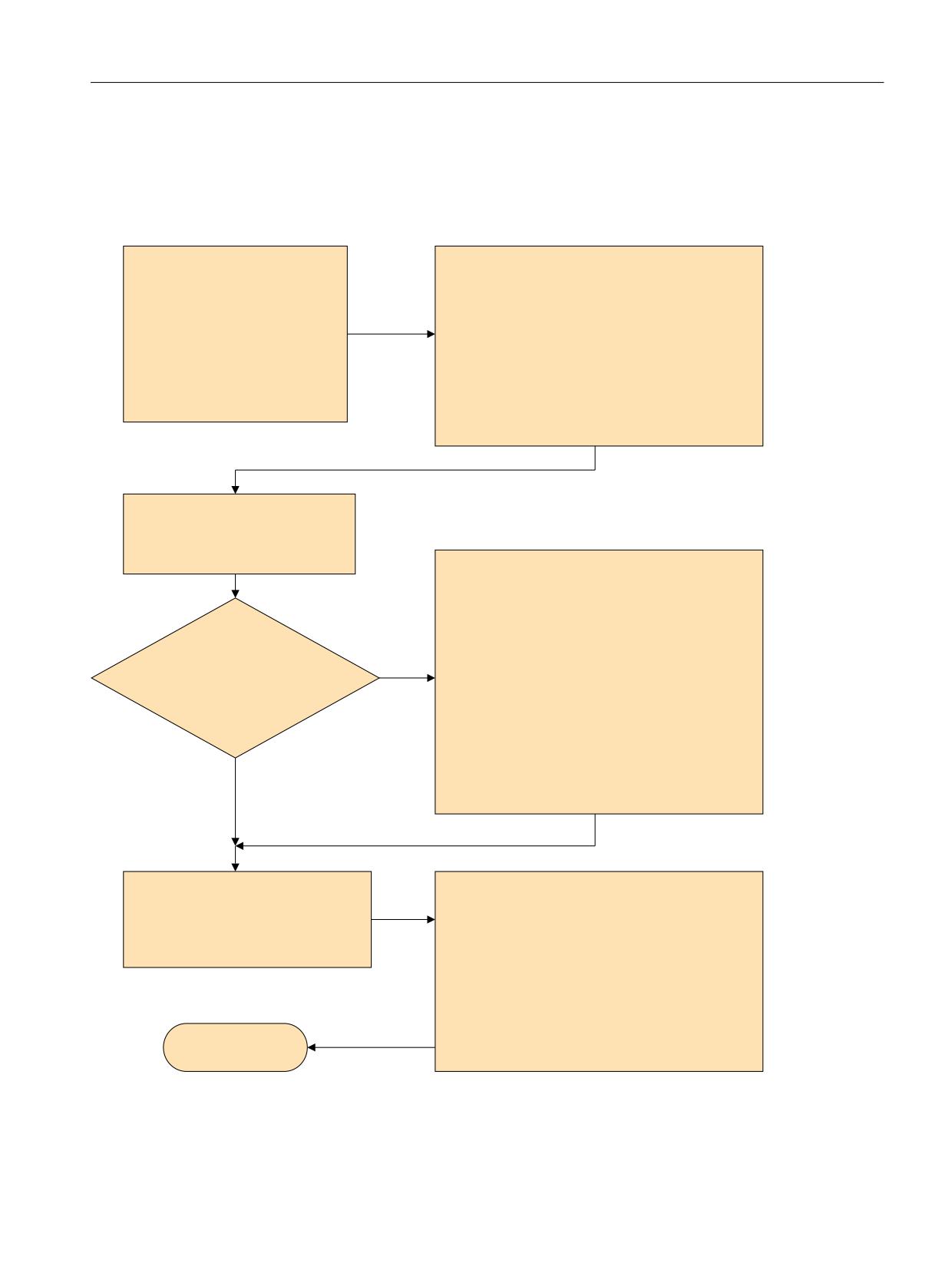
CUST_MEACYC structogram
Sequence in the AUTOMATIC mode, using measure bore as example, CYCLE977 with probe type
712.
6WUXFWXUH &<&/(
&867B0($&<&
,QSXW YDOXHV
B02'( JHQHUDWHG E\ PHDVXULQJ F\FOH
PHDVXULQJ YDULDQW
-XPS WR ODEHO
VSHFLILF VHWWLQJV
B0
EHIRUH ZRUNSLHFH PHDVXUHPHQW &<&/(
RIIVHW W\SH
XVHU VSHFLILF HQWULHV IRU H[DPSOH FRRODQW RII
RIIVHW WDUJHW
*272) B$0B:3B0(6
ಹ
VHWSRLQW
B$0B:3B0(6
PRQLWRULQJ SDUDPHWHUV
EHIRUH ZRUNSLHFH PHDVXUHPHQW
ಹ
0
SUHSDUDWLRQ RI PHDVXUHPHQW
FDOFXODWLRQV
SRVLWLRQ LQ IURQW RI WKH VW
PHDVXULQJ SRLQW
B02'( JHQHUDWHG E\ PHDVXULQJ F\FOH
-XPS WR ODEHO
B0($&<&B072))21
XVHU VSHFLILF 1& FRPPDQGV
WR GHDFWLYDWH WKH SUREH
IRU H[DPSOH 0 RU + FRPPDQGV
6'
\HV
ಹ
6&6B0($B)81&7,21B0$6. %LW
6326
SRVLWLRQ VSLQGOH
4XHULHG EHIRUH HDFK IXUWKHU
ಹ
GHILQHG E\ F\FOH
6326 ಹ
ಹ
B0($&<&B0721
XVHU VSHFLILF 1& FRPPDQGV
WR DFWLYDWH WKH SUREH
IRU H[DPSOH 0 RU + FRPPDQGV
QR
5(7
SURFHVV DOO RWKHU PHDVXULQJ SRLQWV
B02'( JHQHUDWHG E\ PHDVXULQJ F\FOH
FDOFXODWH PHDVXUHPHQW GLIIHUHQFH
-XPS WR ODEHO
FKHFN UHVXOW
B0(
DIWHU ZRUNSLHFH PHDVXUHPHQW &<&/(
H[HFXWH RIIVHW
XVHU VSHFLILF HQWULHV IRU H[DPSOH FRRODQW RQ
*272) B%0B:3B0(6
ಹ
B%0B:3B0(6
DIWHU ZRUNSLHFH PHDVXUHPHQW
(QG RI F\FOH
ಹ
0
Figure 19-27
Structure: CYCLE977 / CUST_MEACYC
SINUMERIK Operate
Commissioning Manual, 10/2020, 6FC5397-1DP40-6BA4
511
Technologies and cycles
19.11 Measuring cycles and measurement functions
Note
Commenting out spindle SPOS commands
If the spindle SPOS command is to be commented out in the CUST_MEACYC.SPF cycle, set the
cycle setting in SD55740 $SCS_MEA_FUNCTION_MASK to active with Bit 1 = 1.
You can see how to comment out a spindle SPOS command in the CUST_MEACYC.SPF cycle in
the following example:
Example
;
;*#1 Example application for spindle pre-positioning if there is no coupling
;*##1 between spindle and the coordinate system active!
;*#1 This example can be removed if necessary!
;*#2 User example for spindel positioning, if you do not have a coupling
;*##2 between the spindel and the coordinate system!
;*#2 If this lines are not necessary, the user can delete this example!
;
; cycle is calling from the AUTOMATIC-mode AND the spindel is positionable
IF NOT(_OVI[14]) AND NOT(_SPOS_MOD)
; no coupling between the spindel and the coordinate system!
; SD55740, Bit 1 = 0
IF ($SCS_MEA_FUNCTION_MASK B_AND 'B10')==0
; SPOS=0 ; <===== commented out
ENDIF
ENDIF
M17
;
19.11.3
Measuring in JOG mode
Requirements
You have already made the settings from the previous Chapter "Measuring cycles and
measurement functions, general (Page 506)".
SINUMERIK Operate
512
Commissioning Manual, 10/2020, 6FC5397-1DP40-6BA4

Technologies and cycles
19.11 Measuring cycles and measurement functions
Workpiece measurement
For milling:
• The probe has been inserted in the tool spindle.
• The probe has been selected in the tool list as type 7xx (probe).
• The probe is activated as tool in the current NC channel.
Tool measurement
To measure tools, an appropriate probe must be located in the machine space so that this can be
reliably and safely reached with a tool in the spindle.
The following tool types are supported with measure tool:
• Milling technology: Tool types 1xx and 2xx
• Turning technology: Tool types 5xx, 1xx and 2xx
For the specified tool types, the tool lengths and the tool radii can be measured.
Setting general data
SD54782 $SNS_J_MEA_FUNCTION_MASK_TOOL
Settings for the input mask, measuring in
JOG, tool measurement.
Bit 2 = 1
Activates the "Enable automatic tool measuring" function.
Bit 3 = 1
Selects the tool probe calibration data field, enable
Bit 10 = 1
Selects the individual cutting edge measurement
Bit 11 = 1
Selects the spindle reversal when calibrating in the plane
MD51784 $MNS_J_MEA_T_PROBE_APPR_AX_DIR [i]
Measuring in JOG: Approach direction in the plane to the tool probe
-2
Negative direction 2nd measuring axis
-1
Negative direction 1st measuring axis (default)
0
Positive direction 1st measuring axis
1
2
Positive direction 2nd measuring axis
MD52750 $MCS_J_MEA_FIXPOINT
Z value for measurement with respect to a
fixed point
mm
The Z position for "Measure: Fixed point" is saved with MD52750. In milling technology, the
fixed point serves as the reference point for manual tool measurement in JOG. The value can be
set via the input mask "Calibration: Fixed point".
MD52751 $MCS_J_MEA_MAGN_GLAS_POS
Zoom-in position for tool measurement
mm
SINUMERIK Operate
Commissioning Manual, 10/2020, 6FC5397-1DP40-6BA4
513
Technologies and cycles
19.11 Measuring cycles and measurement functions
[0]
Position in the 1st axis
[1]
Position in the 2nd axis
If there is a magnifying glass on the machine, it can be used
to determine the tool geometry. In this case, SINUMERIK
Operate calculates the tool offset data from the known po-
sitions of the tool carrier reference point and the cross-hairs
of the magnifying glass.
Checking and setting the general machine data
MD11450 $MN_SEARCH_RUN_MODE
"Search run" programming.
Bit 1 = 1
Automatic ASUB start after output of the action blocks (see also
MD11620 $MN_PROG_EVENT_NAME). Alarm 10208 is not output until the ASUB is com-
pleted.
MD11604 $MN_ASUP_START_PRIO_LEVEL
Priorities from which ASUP_START_MASK is ef-
fective.
= 1 - 64
Priorities for ASUP_START_MASK.
Setting channel-specific machine data
MD20050 $MC_AXCONF_GEOAX_ASIGN_TAB[ ]
Assignment, geometry axis to channel axis.
[0]
For measuring in JOG mode, all of the geometry axes must be available. Preferably XYZ.
[1]
[2]
MD20110 $MC_RESET_MODE_MASK
Defines the basic control settings after reset / TP
end.
= 4045H
Minimum value
Bit 0 = 1
Basic control setting after power on and reset.
Bit 2 = 1
Bit 6 = 1
Bit 14 = 1
SINUMERIK Operate
514
Commissioning Manual, 10/2020, 6FC5397-1DP40-6BA4
Technologies and cycles
19.11 Measuring cycles and measurement functions
MD20112 $MC_START_MODE_MASK
Definition of the basic control setting after part
program start.
= 400H
Minimum value
Bit 6 = 0
Definition of the basic control setting after NC start.
MD20310 $MC_TOOL_MANAGEMENT_MASK
Activates tool manager functions.
= 4002H
Minimum value
Bit 1 = 1
Tool manager and monitoring functions active.
Bit 14 = 1
Automatic tool change for RESET and Start.
MD28082 $MC_SYSTEM_FRAME_MASK
System frames (SRAM).
Bit 0 = 0
Do not setup system frames for actual value setting and scratching.
Bit 0 = 1
Setup system frames for actual value setting and scratching.
The following channel-specific machine data is only effective if the system frame actual value
setting and scratching is set up using the above mentioned machine data
MD28082 $MC_SYSTEM_FRAME_MASK, bit 0 = 0.
MD24006 $MC_CHSFRAME_RESET_MASK
Active system frames after reset.
Bit 0 = 1
Reset response of the system frames or actual value setting.
MD24007 $MC_CHSFRAME_RESET_CLEAR_MASK
Clear system frames at reset.
Bit 0 = 0
Clear response of the system frames on reset.
Note
If you create the conditions described in this section and you have set and checked the machine
setting data, then in JOG mode, you can measure a workpiece using a workpiece probe at a
milling machine!
In JOG mode, you can measure a tool using a tool probe at a milling machine or turning machine!
A description is provided in the following chapters as to which settings you can make in order to
adapt measuring to the specific requirements of your particular machine.
19.11.3.1
Measuring workpieces at the milling machines
Measuring in the "Machine" operating area can be appropriately adapted to the specific
requirements using the following channel-specific general machine data and channel-specific
cycle setting data.
SINUMERIK Operate
Commissioning Manual, 10/2020, 6FC5397-1DP40-6BA4
515
Technologies and cycles
19.11 Measuring cycles and measurement functions
General configuration machine data
SD55630 $SCS_MEA_FEED_MEASURE
Measuring feedrate for workpiece meas-
urement in JOG and AUTOMATIC
300
Default value
Note
Measuring feedrate for workpiece measuring
All measuring cycles use the value saved in SD54611 as the measuring feedrate value following
calibration of the workpiece probe. A different measuring feedrate can be assigned for each
calibration field [n].
When calibrating the probe, either the measuring feedrate from SD55630
$SCS_MEA_FEED_MEASURE is used, or the measuring feedrate can be overwritten in the input
screen when calibrating. Bit 4 = 1 must be set in the
SD54760 $SNS_MEA_FUNCTION_MASK_PIECE for this purpose.
MD52207 $MCS_AXIS_USAGE_ATTRIB[n]
Attributes of the axes
[n] channel axis number
Bit 6
Request rotational axis as offset target for measuring
= 0
Default value
= 1
Rotary axis is displayed as offset target in the "Measuring in JOG" window
Bit 9
SPOS behavior of main spindle influenced in connection with measuring cycles
= 0
The positioning behavior of the tool spindle is not influenced
= 1
The measuring cycles do not position the tool spindle (no SPOS)
Note
If the tool spindle is never SPOS-capable, Bit 9 = 1 must be set.
MD51740 $MS_MEA_FUNCTION_MASK
Measuring cycles, workpiece- tool measure-
ment function screen
Bit 7
Workpiece, accept active into inactive WO, JOG mode only, set edge
SINUMERIK Operate
516
Commissioning Manual, 10/2020, 6FC5397-1DP40-6BA4

Technologies and cycles
19.11 Measuring cycles and measurement functions
= 0
In JOG mode, "Set edge" function with correction of the measuring result to an inactive work
offset (target frame), of the geometry axes in the target frame, only the measuring axis is
specified with the result
No values are adopted from the active work offset (source frame) for geometry axes which
have not been measured. (compatibility)
From all non-geometric axes (rotary and auxiliary axes), mirroring, rotations and translations
are adopted from the active work offset (source frame) into the selected inactive work offset
(target frame). (compatibility)
= 1
In JOG mode, "Set edge" function with correction of the measuring result to an inactive work
offset (target frame), the measuring axis is specified in the target frame with the measure-
ment result
For all other axes (geometry axes, rotary axes and auxiliary axes), mirroring, rotations and
translations are also adopted from the active work offset (source frame) into the selected
inactive work offset (target frame)
This description applies for automatic measuring with electronic sensor, and likewise for the
"scratching" function with processing tool, refer to Section "Measuring without electronic probe
in JOG (Page 525)".
MD51751 $MNS_J_MEA_M_DIST_MANUELL
Measurement path in mm, in front of and
behind the measurement point
= 10
Default value
MD51757 $MNS_J_MEA_COLL_MONIT_FEED
Position feedrate in mm/min, in the working
plane for active collision monitoring
= 1000
Default value
MD51758 $MNS_J_MEA_COLL_MONIT_POS_FEED
Position feedrate in mm/min, in the infeed
axis for active collision monitoring
= 1000
Default value
MD51770 $MNS_J_MEA_CAL_RING_DIAM[n]
Pre-assignment of the calibration ring diam-
eter in mm specifically for the calibration da-
ta sets
= -1
Default value
MD51772 $MNS_J_MEA_CAL_HEIGHT_FEEDAX[n]
Pre-assignment of the calibration height
in mm in the infeed axis, specifically for
the calibration data sets
= -99999
Default value
SINUMERIK Operate
Commissioning Manual, 10/2020, 6FC5397-1DP40-6BA4
517
Technologies and cycles
19.11 Measuring cycles and measurement functions
General cycle setting data
SD54780 $SNS_J_MEA_FUNCTION_MASK_PIECE
Configuration of the input screens for
measuring in the "Machine" operating
area in the JOG operating mode
= 512
Default value
Bit 2 = 1
Activates measurements with an electronic probe
Bit 3 = 1
Selects the probe calibration data, enable
Bit 6 = 1
Selects ZO correction in the basis reference (SETFRAME), enable
Bit 7 = 1
Selects ZO correction in channel-specific basic frames, enable
Bit 8 = 1
Selects ZO correction in the global basic frame, enable
Bit 9 = 1
Selects ZO correction in adjustable frames, enable
Bit 16 = 1
Selects workpiece measurement with spindle reversal
Bit 17 = 1
Selects align workpiece probe in the switching direction
Bit 28 = 1
Selects adjust workpiece length, enable
19.11.3.2
Measuring tools at the milling machines
Measuring feed for tool measurement in JOG and AUTOMATIC
SD55628 $SCS_MEA_TP_FEED_MEASURE
Calibrate measuring feed for tool
probe and measure tool with station-
ary spindle.
= 300
Default value
Note
Measuring feed for tool measuring
All measuring cycles use the value saved in SD54636 or SD54651 as the measuring feed after
the tool probe has been calibrated. A different measuring feed can be assigned for each
calibration field [n].
When calibrating the probe, either the measuring feed from
SD55628 SCS_MEA_TP_FEED_MEASURE is used, or the measuring feed can be overwritten in
the input mask when calibrating. To do this, SD54762 $SNS_MEA_FUNCTION_MASK_TOOL bit
4 must be set to 1.
MD51757 $MNS_J_MEA_COLL_MONIT_FEED
Position feedrate in mm/min, in the working
plane for active collision monitoring
= 1000
Default value
MD51758 $MNS_J_MEA_COLL_MONIT_POS_FEED
Position feedrate in mm/min, in the infeed
axis for active collision monitoring
= 1000
Default value
SINUMERIK Operate
518
Commissioning Manual, 10/2020, 6FC5397-1DP40-6BA4
Technologies and cycles
19.11 Measuring cycles and measurement functions
In the following setting data, index [k] stands for the number of the current data field (probe
number -1) of the probe.
SD54633 $SNS_MEA_TP_TYPE[k]
Probe type, cube/disk
= 0
Compatibility (measuring cycles: cube, turning surface shows probe, milling surface shows
disk)
= 101
Disk in XY, working plane G17
= 201
Disk in ZX, working plane G18
= 301
Disk in YZ, working plane G19
= 2
Probe head
= 3
Cube
The following setting data is used to define in which axes and directions it is possible to calibrate
a tool probe.
SD54632 $SNS_MEA_T_PROBE_ALLOW_AX_DIR[k]
Axes and directions for "calibration"
= 133
Default value
Decimal place
ONES
1st axis
= 0
axis not possible
= 1
only minus direction
= 2
only plus direction
= 3
both directions
TENS
2nd axis
= 0
axis not possible
= 1
only minus direction
= 2
only plus direction
= 3
both directions
HUNDREDS
3rd axis
= 0
axis not possible
= 1
only minus direction
= 2
only plus direction
= 3
both directions
Example
If the general setting data SD54632 $SNS_MEA_T_PROBE_ALLOW_AX_DIR[k] has the value 123,
the tool probe is calibrated as follows in the G17 plane:
• X in both directions
• Y only in plus direction
• Z only in minus direction
SINUMERIK Operate
Commissioning Manual, 10/2020, 6FC5397-1DP40-6BA4
519
Technologies and cycles
19.11 Measuring cycles and measurement functions
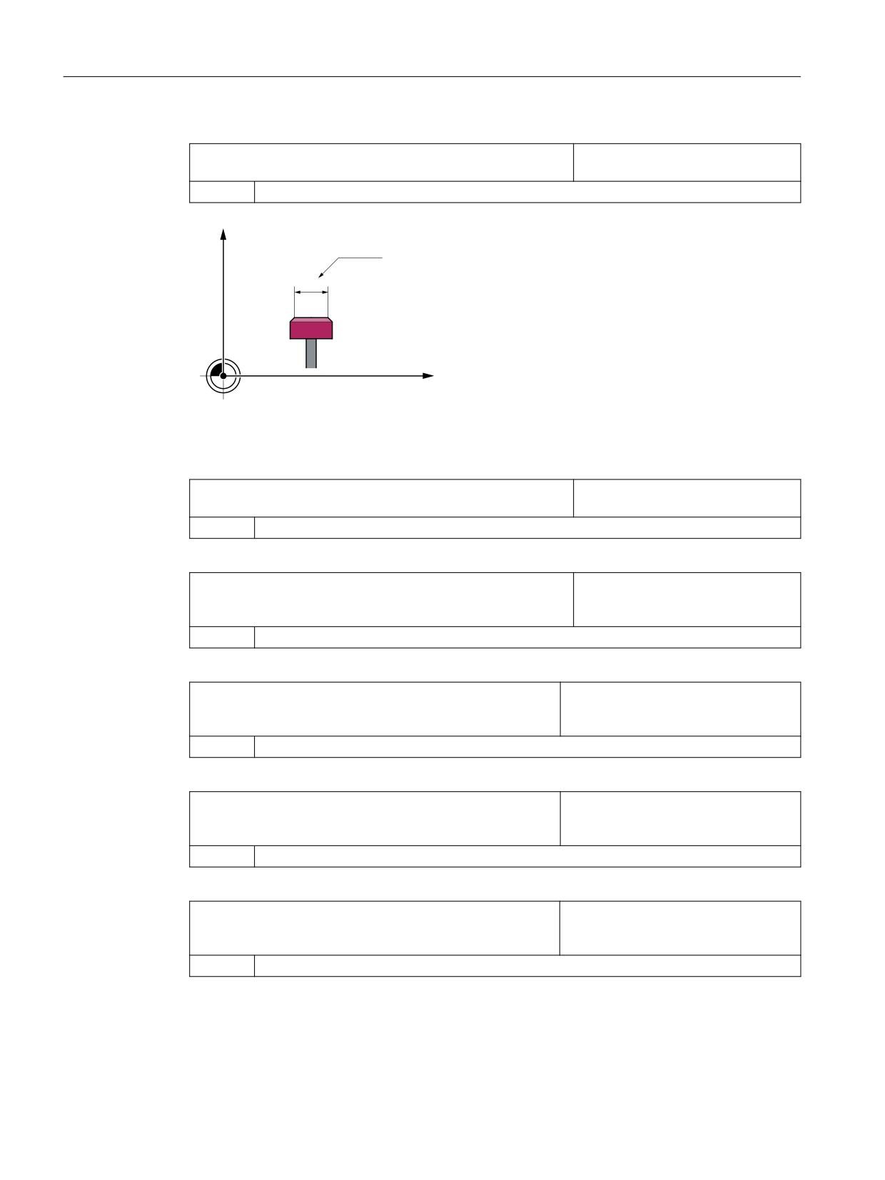
SD54631 $SNS_MEA_TP_EDGE_DISK_SIZE[k]
Effective diameter of the tool probe
for length measurement.
= 0
Default value
Z
SD54631
Ø
X
M
General cycle machine/setting data for tool probe
MD51780 $MNS_J_MEA_T_PROBE_DIAM_RAD[k]
Effective diameter of the tool probe
for radius measurement.
= 0
Default value
SD54634 $SNS_MEA_TP_CAL_MEASURE_DEPTH[n]
Distance between the tool probe up-
per edge and the milling tool lower
edge.
= 2
Default value
MD51752 $MNS_J_MEA_M_DIST_TOOL_LENGTH
Measurement path for tool length
measurement with rotating spindle for
the JOG mode.
= 2
Default value
MD51753 $MNS_J_MEA_M_DIST_TOOL_RADIUS
Measurement path for tool radius meas-
urement with rotating spindle for JOG
mode.
= 1
Default value
MD51786 $MNS_J_MEA_T_PROBE_MEASURE_DIST
Measurement path to calibrate the
probe or for measurements with sta-
tionary spindle for JOB mode.
= 10
Default value
SINUMERIK Operate
520
Commissioning Manual, 10/2020, 6FC5397-1DP40-6BA4

Technologies and cycles
19.11 Measuring cycles and measurement functions
General cycle setting data when measuring with rotating spindle
SD54670 $SNS_MEA_CM_MAX_PERI_SPEED[0]
Maximum permissible peripheral speed
of the tool to be measured.
= 100
Default value
SD54671 $SNS_MEA_CM_MAX_REVOLUTIONS[0]
Maximum permissible tool speed of the
tool to be measured. The speed is auto-
matically reduced when exceeded.
= 1000
Default value
SD54672 $SNS_MEA_CM_MAX_FEEDRATE[0]
Maximum permissible feedrate to
probe the tool to be measured at the
probe.
= 20
Default value
SD54673 SNS_MEA_CM_MIN_FEEDRATE[0]
Minimum feedrate for the first probing
of the tool to be measured at the probe.
This avoids excessively small feedrates
for large tool radii.
= 1
Default value
SD54674 $SNS_MEA_CM_SPIND_ROT_DIR[0]
Spindle direction of rotation to measure
tools.
= 4
Spindle rotation the same as M4 (default value)
Note
If the spindle is already rotating when the measuring cycle is called, this direction of rotation
remains independent of the setting of this data.
SD54675 $SNS_MEA_CM_FEEDFACTOR_1[0]
Feedrate factor 1
= 10
Default value
= 0
Only single probing with the feedrate calculated by the cycle. However, as a minimum, the
value from SD54673[0] $SNS_MEA_CM_MIN_FEEDRATE.
>= 1
First probing with feedrate. However, as a minimum with the value from
SD54673[0] $SNS_MEA_CM_MIN_FEEDRATE)
SD54675[0] $SNS_MEA_CM_FEEDFACTOR_1
SINUMERIK Operate
Commissioning Manual, 10/2020, 6FC5397-1DP40-6BA4
521
Technologies and cycles
19.11 Measuring cycles and measurement functions
SD54676 $SNS_MEA_CM_FEEDFACTOR_2[0]
Feedrate factor 2
= 0
Second probing with the feedrate calculated by the measuring cycle. This is only effective for
SD54673[0] $SNS_MEA_CM_FEEDFACTOR_1 > 0, default value
>= 1
Second probing with the calculated feedrate from SD54673[0] $SNS_MEA_CM_MIN_FEE-
DRATE feedrate factor 2.
Third probing with the calculated feedrate.
Note
Feedrate factor 2 should be less than feedrate factor 1.
SD54677 $SNS_MEA_CM_MEASURING_ACCURACY[0]
Specified measuring accuracy.
The value of this parameter always
refers to the last probing of the tool at
the probe!
= 0.005
Default value
SD54692 $SNS_MEA_T_CIRCULAR_ARC_DIST
Arc distance for the single cutting edge
measurement of the radius.
= 0.25 *)
Default value
SD54693 $SNS_MEA_T_MAX_STEPS
Maximum number of probe contacts for
single cutting edge measurement of
the radius.
= 10 *)
Default value
*)
If the value = 0, then the "highest point on the longest cutting edge" is not sought, but the measured
value of the contact with the rotating spindle taken.
SINUMERIK Operate
522
Commissioning Manual, 10/2020, 6FC5397-1DP40-6BA4
Technologies and cycles
19.11 Measuring cycles and measurement functions
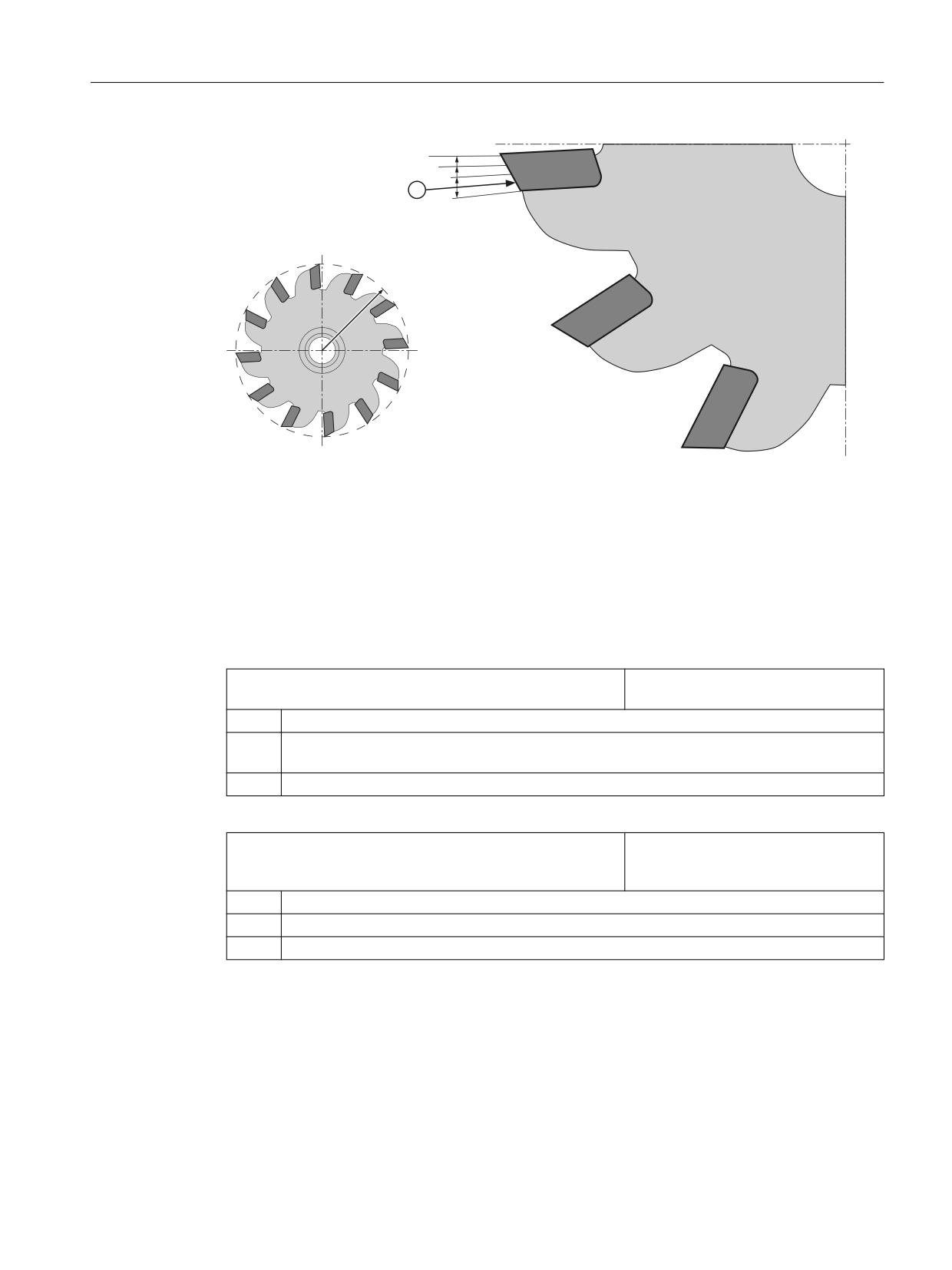
EQ
E
E
E
U
r
Effective radius of the tool
b
Arc distance = SD54692
n
Maximum number of probe contacts = SD54693
① 1st measuring point.
Figure 19-28
Single cutting edge measurement
General cycle setting data for correction using the correction tables when forming measurements
with rotating spindle.
SD54691 $SNS_MEA_T_PROBE_OFFSET
Activate the measuring result compen-
sation
= 0
No data, default value
= 1
Correction in the cycle. This is only effective if SD54689 $SNS_MEA_T_PROBE_MANUFACTUR-
ER>0.
= 2
Correction using user-defined correction table
SD54689 $SNS_MEA_T_PROBE_MANUFACTURER
Activates pre-configured compensation
tables for several tool probe models
(customer-specific)
= 0
No data, default value
= 1
TT130 (Heidenhain)
= 2
TS27R (Renishaw)
SINUMERIK Operate
Commissioning Manual, 10/2020, 6FC5397-1DP40-6BA4
523
Technologies and cycles
19.11 Measuring cycles and measurement functions
19.11.3.3
Measuring tools at the turning machines
Measuring feed for tool measurement in turning operation
SD55628 $SCS_MEA_TP_FEED_MEASURE
Calibrate measuring feed for tool
probe and measure tool with station-
ary spindle.
= 300
Default value
Note
Measuring feed for tool measuring
All measuring cycles use the value saved in SD54636 or SD54651 as the measuring feed after
the tool probe has been calibrated. A different measuring feed can be assigned for each
calibration field [n].
When calibrating the probe, either the measuring feed from SD55628 is used, or the measuring
feed can be overwritten in the input mask when calibrating. To do this,
SD54762 $SNS_MEA_FUNCTION_MASK_TOOL bit 4 must be set to 1.
General cycle machine/setting data for measurement path/feed
SD42950 $SC_TOOL_LENGTH_TYPE
Assignment of the tool length offset
independent of tool type.
= 2
The assignment of the tool length components is, independent of the actual tool type, always
the same as for turning and grinding tools.
This setting is recommended for measuring milling tools and drill bits.
MD51786 $MNS_J_MEA_T_PROBE_MEASURE_DIST
Measurement path to calibrate the
probe or for measurements with sta-
tionary spindle.
= 10
Default value
SD55628 $SCS_MEA_TP_FEED_MEASURE
Feedrate for the calibration of a tool
probe with stationary spindle.
= 300
Default value
Calibrating tool probes
Use the following general cycle machine data to set the access level as of which the "Calibrate
probe" softkey is displayed. This requires that the automatic tool measurement is enabled using
the setting data SD54782 (bit 2 = 1).
MD51070 $MNS_ACCESS_CAL_TOOL_PROBE
Calibrate tool probe access level.
= 7
Access rights: Access level 7 (keyswitch 0)
SINUMERIK Operate
524
Commissioning Manual, 10/2020, 6FC5397-1DP40-6BA4
Technologies and cycles
19.11 Measuring cycles and measurement functions
= 4
Read access rights: Access level 4 (keyswitch 3), default value
= 3
Write access: Access level 3 (user)
19.11.3.4
Measuring without electronic probe in JOG
Measure workpiece
For manual measuring functions in the JOG operating mode, for which a rotating spindle is
required, the following applies:
• The channel state must be reset at the instant in time that the measured value is transferred.
• The spindle can be moved or positioned either using the T,S,M menu or using the bits in
DB3x.DBB30.
• The following preconditions apply when using the DB3x.DBB30 technology functions with
fixed speed:
Setting the machine data
MD10709 $MN_PROG_SD_POWERON_INIT_TAB [0] = 0
Setting data to be initialized
MD35035 $MA_SPIND_FUNCTION_MASK
Bit 4 = 0
Spindle functions
Bit 5 = 1
SD43200 $SA_SPIND_S
Speed setting value
Note
The entry in SD43200 $SA_SPIND_S is kept at power on.
With these settings, the spindle velocity for manual operation, which is set in SD41200
$SN_JOG_SPIND_SET_VELO, is no longer effective.
19.11.4
Measuring in the AUTOMATIC mode
Requirement
Software option
In order to use the "Measuring in AUTOMATIC" function, you require the software
option: "Measuring cycles"
You have already made the settings from Chapter "Measuring cycles and measurement
functions, general (Page 506)".
SINUMERIK Operate
Commissioning Manual, 10/2020, 6FC5397-1DP40-6BA4
525
Technologies and cycles
19.11 Measuring cycles and measurement functions
Workpiece measurement
Sequence in milling technology:
1. The probe has been selected in the tool list as type 7xx (probe).
2. The probe has been inserted in the tool spindle.
3. The probe is activated in the actual NC channel.
Sequence in turning technology:
1. Tool type 580 (3D probe, turning) is selected.
2. Tool is activated in the actual NC channel.
Tool measurement
To measure tools, an appropriate probe must be located in the machine space so that this can be
reliably and safely reached with a tool in the spindle.
The following tool types are supported with tool measurement:
• Milling technology: Tool types 1xx and 2xx
• Turning technology: Tool types 5xx, 1xx and 2xx
For the specified tool types, the tool lengths and the tool radii can be measured.
Channel-specific cycle setting data
Using the following channel-specific cycle setting data, you can adapt the workpiece and tool
measuring in the "Program" operating area to specific requirements. As a general rule, no
changes are required.
SD55613 $SCS_MEA_RESULT_DISPLAY
Selects the screen display of the measur-
ing result
= 0
No screen display of the measuring result (default value).
= 1
Screen display of the measuring result is displayed for 8 seconds.
= 3
The measuring cycle stops an internal machine data, the measuring result is statically displayed
on the screen!
Continue with NC start, the measuring result screen is deselected.
= 4
The measuring result is only displayed on the screen for cycle alarms 61303, 61304, 61305,
61306.
Continue with NC start, the measuring result display on the screen is deselected.
SD55614 $SCS_MEA_RESULT_MRD
Setting of the program control of the measurement result dis-
play MRD
= 0
Switch off the measurement result display
= 1
Switch on the measurement result display
SINUMERIK Operate
526
Commissioning Manual, 10/2020, 6FC5397-1DP40-6BA4
Technologies and cycles
19.11 Measuring cycles and measurement functions
SD55623 $SCS_MEA_EMPIRIC_VALUE[n]
Empirical values
= 0
Default value
SD55618 $SCS_MEA_SIM_ENABLE
Measuring cycle simulation
= 0
When calling measuring cycles in conjunction with SINUMERIK Operate, ShopMill or ShopTurn
simulation, the measuring cycles are skipped, default value.
= 1
Default setting:
When calling measuring cycles in conjunction with SINUMERIK Operate, ShopMill or ShopTurn
simulation, the measuring cycles are run through. However, no corrections are performed and
there is no logging. There is no screen display of the measuring result.
Additional information
Additional information on SD55618 is provided in the
Programming Manual Measuring Cycles
Configuring input screens for measuring cycles in the program editor
Using the following setting data, you configure the display screen and the correction options
when making measurements in the AUTOMATIC mode:
• SD54760 $SNS_MEA_FUNCTION_MASK_PIECE measure workpiece: Measuring cycles in the
milling area, see Chapter "Measuring workpieces, general (Page 527)"
• SD54762 $SNS_MEA_FUNCTION_MASK_TOOL measure tool: Measuring cycles in the milling
area, see Chapter "Measuring tools at the milling machines (Page 531)"
Note
If you have created the prerequisites described in this chapter and you have set and checked the
machine/setting data, you can perform measurements at the machine with a workpiece or tool
probe in the AUTOMATIC mode!
If you wish to set up workpiece measurement on a turning machine, then additional settings are
required. Refer to Chapter "Measuring workpieces at the turning machines (Page 537)" for the
settings.
If you wish to set-up tool measurement using a tool probe, then you must also make additional
settings. Please refer to Chapters "Measuring tools at the turning machines (Page 538)" or
"Measuring tools at the milling machines (Page 531)" for the settings.
A description is provided in the following chapters as to which settings you can make in order to
adapt measuring to the specific requirements of your particular machine.
19.11.4.1
Measuring workpieces, general
Using the following general and channel-specific cycle setting data, you can appropriately adapt
workpiece measurement to the specific requirements in the "Program" operating area.
SINUMERIK Operate
Commissioning Manual, 10/2020, 6FC5397-1DP40-6BA4
527

Technologies and cycles
19.11 Measuring cycles and measurement functions
Requirement
You have already made the settings from the Chapter "Measuring cycles and measurement
functions, general (Page 506)".
Settings
General cycle setting data
SD54760 $SNS_MEA_FUNCTION_MASK_PIECE
Settings for the input screen, measuring
cycles in AUTOMATIC, workpiece measure-
ment.
Bit 1
Display select softkey 3D measurement
Bit 3
Enable probe calibration field to be selected
Bit 4
Select calibration input measuring feed 1)
Bit 6
Enable NP correction in the basis reference (SETFRAME) to be selected
Bit 7
Enable NP correction in channel-specific basic frame to be selected
Bit 8
Enable NP correction in global basic frame to be selected
Bit 9
Enable NP correction in adjustable frame to be selected
Bit 10
Enable NP correction coarse and fine to be selected
Bit 11
Select tool offset, geometry and wear
Bit 12
Select tool offset, not inverted and inverted
Bit 13
Select tool offset L1, R or L1, L2, L3 R
Bit 14
Select tool offset, zero offset (_TZL)
Bit 15
Select tool offset, dimensional difference monitoring (_TDIF)
Bit 16
Select workpiece measurement with spindle reversal
Bit 17
Selects align workpiece probe in the switching direction
Bit 18
Select number of measurements (_NMSP)
Bit 19
Select offset with mean value generation (_TMV) 1)
Bit 20
Select experience values (_EVNUM)
Bit 21
Select total setting-up offset
Bit 22
Select calibration to unknown or to known center point
Bit 24
Select calibration with/without position deviation
Bit 25
Select zero offset when measuring the angulation of the spindle
Bit 26
Selects tool offset, do not enable
Bit 27
Selects measure tolerance of the linear vector for kinematics, do not enable
Bit 28
Enable tool offset adjust length to be selected
Channel-specific cycle setting data
SD55630 $SCS_MEA_FEED_MEASURE
Measuring feedrate [mm/rev]
= 300
Measuring feedrate when calibrating the workpiece probe
SINUMERIK Operate
528
Commissioning Manual, 10/2020, 6FC5397-1DP40-6BA4

Technologies and cycles
19.11 Measuring cycles and measurement functions
Note
Measuring feedrate for workpiece measuring
All measuring cycles use the value saved in SD54611 $SNS_MEA_WP_FEED[n] as measuring
feedrate after the tool probe has been calibrated.
A different measuring feedrate can be assigned for each calibration field [n].
When calibrating the probe, either the measuring feedrate from SD55630
$SCS_MEA_FEED__MEASURE is used, or the measuring feedrate can be overwritten in the input
screen when calibrating. To do this, SD54760 MEA_FUNCTION_MASK_PIECE bit 4 must be set to
1.
SD55632 $SCS_MEA_FEED_RAPID_IN_PERCENT
Percentage reduction
= 50
Default value of the percentage reduction of the rapid traverse velocity for internal cycle
intermediate positioning without collision monitoring.
The setting of the channel-specific cycle setting data SD55600 SCS_MEA_COLLISION_MONI-
TORING must be = 0.
SD55634 $SCS_MEA_FEED_PLANE_VALUE
Feedrate of the intermediate positioning
in the working plane with active collision
monitoring.
= 1000
Default value
SD55636 $SCS_MEA_FEED_FEEDAX_VALUE
Feedrate of the intermediate positioning
in the infeed axis with active collision mon-
itoring.
= 1000
Default value
SD55638 $SCS_MEA_FEED_FAST_MEASURE
Fast measuring feedrate
= 900
Default value
SD55640 $SCS_MEA_FEED_CIRCLE
Feedrate with circle programming
= 1000
Default value
SINUMERIK Operate
Commissioning Manual, 10/2020, 6FC5397-1DP40-6BA4
529
Technologies and cycles
19.11 Measuring cycles and measurement functions
SD55642 $SCS_MEA_EDGE_SAVE_ANG
Safety angle when measuring a corner
(CYCLE961)
= 0
Degrees
This angle is added to the angle that the user entered between the workpiece reference edge and the 1st
axis of the active coordinate system in a positive direction, and refers to the corner measurement in the
automatic mode (CYCLE961).
The angle of the user specifications is designated "α0" in the parameterization screen corner measurement.
For compatibility programs, the designation is _STA1.
Notice:
For compatibility programs, $SCS_MEA_EDGE_SAVE_ANG should be set = 10.
19.11.4.2
Measuring workpieces at the milling machines
Measuring in the "Program" operating area can be adapted corresponding to the specific
requirements using the channel-specific cycle setting data.
Settings
SD55625 $SCS_MEA_AVERAGE_VALUE[n]
Number of mean values.
= 0
Default value
The following cycle setting data are written to by the measuring cycles with the "Calibrate probe"
measuring function. User parameterization is not necessary here. However, after the probe has
been calibrated, you can check these values and if required, evaluate the probe quality, e.g. for
position deviations, no values > 0.1 mm should be reached. Otherwise, the probe must be
mechanically readjusted.
The measuring feedrate at the time of calibration is used for all subsequent applications of the
measuring cycles.
Note
Observe the manufacturer's instructions for the probe.
SD54600 $SNS_MEA_WP_BALL_DIAM[n]
Effective diameter of the probe ball of the
workpiece probe.
SD54601 $SNS_MEA_WP_TRIG_MINUS_DIR_AX1[n]
Trigger point, minus direction,
1st measuring axis in the plane.
SD54602 $SNS_MEA_WP_TRIG_PLUS_DIR_AX1[n]
Trigger point, plus direction,
1st measuring axis in the plane.
SD54603 $SNS_MEA_WP_TRIG_MINUS_DIR_AX2[n]
Trigger point, minus direction,
2nd measuring axis in the plane.
SD54604 $SNS_MEA_WP_TRIG_PLUS_DIR_AX2[n]
Trigger point, plus direction,
2nd measuring axis in the plane.
SD54605 $SNS_MEA_WP_TRIG_MINUS_DIR_AX3[n]
Trigger point, minus direction,
3rd measuring axis in the tool direction.
SINUMERIK Operate
530
Commissioning Manual, 10/2020, 6FC5397-1DP40-6BA4
Technologies and cycles
19.11 Measuring cycles and measurement functions
SD54606 $SNS_MEA_WP_TRIG_PLUS_DIR_AX3[n]
Trigger point, plus direction,
3rd measuring axis opposite to the tool di-
rection. In the default case = 0.
SD54607 $SNS_MEA_WP_POS_DEV_AX1[n]
Position deviation,
1st measuring axis in the plane.
SD54608 $SNS_MEA_WP_POS_DEV_AX2[n]
Position deviation,
2nd measuring axis in the plane.
SD54609 $SNS_MEA_WP_STATUS_RT
Calibration status of the axis positions
SD54610 $SNS_MEA_WP_STATUS_GEN[n]
Calibration status
SD54611 $SNS_MEA_WP_FEED[n]
Measuring feedrate when calibrating
19.11.4.3
Measuring tools at the milling machines
Settings
SD54762 $SNS_MEA_FUNCTION_MASK_TOOL
Setting for the input screen, measuring
cycles in the automatic mode, tool meas-
urement
Bit 3
Setting for the input screen, measuring cycles in the automatic mode, tool measurement, en-
able tool probe calibration data field to be selected
Bit 4
Select calibration input measuring feed (VMS) 1)
Bit 5
Select input feedrate and spindle speeds when probing
Bit 7
Select measurement in MCS and WCS
Bit 8
Select measurement, absolute and incremental
Bit 9
Select tool offset, geometry and wear
Bit 10
Select individual cutting edge measurement
Bit 11
Selects spindle reversal when calibrating in the plane
Bit 12
Select number of measurements (_NMSP)
Bit 13
Select experience values (_EVNUM)
1)
Input, measurement feedrate is valid for AUTOMATIC and JOG
SD55634 $SCS_MEA_FEED_PLANE_VALUE
Feedrate of the intermediate positioning
in the working plane with active collision
monitoring.
= 1000
Default value
SD55636 $SCS_MEA_FEED_FEEDAX_VALUE
Feedrate of the intermediate positioning
in the infeed axis with active collision mon-
itoring.
= 1000
Default value
SINUMERIK Operate
Commissioning Manual, 10/2020, 6FC5397-1DP40-6BA4
531
Technologies and cycles
19.11 Measuring cycles and measurement functions
Calibration data of the tool probe, referred to the machine coordinate system
Before calibration is started, the position of the tool probe in the machine coordinate system
(MCS) must be entered into the following general cycle setting data. In this case, the reference
point is the outer diameter or the tool length of the active tool in the spindle. If there is no tool
in the spindle, the reference points are the spindle center point and the tool reference point at
the spindle.
Note
Calibrate probe
If you have calibrated the tool probe in JOG mode, then the calibration data has already been
correctly entered in: SD54632 $SNS_MEA_TP_AX_DIR_AUTO_CAL[k]
You do not need to recalibrate the tool probe in the AUTOMATIC mode.
Index [k] stands for the number of the actual data field (probe number -1).
SD54625 $SNS_MEA_TP_TRIG_MINUS_DIR_AX1[k]
Trigger point of the 1st measuring axis in
the negative direction.
SD54626 $SNS_MEA_TP_TRIG_PLUS_DIR_AX1[k]
Trigger point of the 1st measuring axis in
the positive direction.
SD54627 $SNS_MEA_TP_TRIG_MINUS_DIR_AX2[k]
Trigger point of the 2nd measuring axis in
the negative direction.
SD54628 $SNS_MEA_TP_TRIG_PLUS_DIR_AX2[k]
Trigger point of the 2nd measuring axis in
the positive direction.
SD54629 $SNS_MEA_TP_TRIG_MINUS_DIR_AX3[k]
Trigger point of the 3rd measuring axis in
the negative direction.
SD54630 $SNS_MEA_TP_TRIG_PLUS_DIR_AX3[k]
Trigger point of the 3rd measuring axis in
the positive direction.
SD54631 $SNS_MEA_TP_EDGE_DISK_SIZE[k]
Tool probe, edge length / disk diameter.
SD54632 $SNS_MEA_TP_AX_DIR_AUTO_CAL[k]
Axes and directions for calibrating in AU-
TOMATIC mode.
SD54634 $SNS_MEA_TP_CAL_MEASURE_DEPTH[k]
Distance between the upper edge of the
tool probe and lower edge of the tool
(calibration depth, measuring depth for
milling radius).
SD54635 $SNS_MEA_TPW_STATUS_GEN[k]
Calibration status
SD54636 $SNS_MEA_TPW_FEED[k]
Measuring feedrate when calibrating
The general cycle setting data SD54632 $SNS_MEA_TP_AX_DIR_AUTO_CAL, is used to define in
which axes and directions it is possible to calibrate the tool probe.
Decimal place
ONES
1st axis
= 0
axis not possible
= 1
only minus direction
= 2
only plus direction
= 3
both directions
TENS
2nd axis
SINUMERIK Operate
532
Commissioning Manual, 10/2020, 6FC5397-1DP40-6BA4
Technologies and cycles
19.11 Measuring cycles and measurement functions
Decimal place
= 0
axis not possible
= 1
only minus direction
= 2
only plus direction
= 3
both directions
HUNDREDS
3rd axis
= 0
axis not possible
= 1
only minus direction
= 2
only plus direction
= 3
both directions
Example
If the general cycle machine data SD54632 $SNS_MEA_TP_AX_DIR_AUTO_CAL has the value
123, the tool probe is calibrated as follows in the G17 plane:
• X in both directions
• Y only in plus direction
• Z only in minus direction
SD54633 $SNS_MEA_TP_TYPE[k]
Probe version
= 0
Compatibility (measuring cycles: cube, turning surface shows probe, milling surface shows disk)
= 101
Disk in XY, working plane G17.
= 201
Disk in ZX, working plane G18.
= 301
Disk in YZ, working plane G19.
= 2
Probe
= 3
Cube
Calibration data of the tool probe referred to the workpiece coordinate system
Before calibration is started, the position of the tool probe in the workpiece coordinate system
(WCS) must be roughly entered into the following general cycle setting data. In this case, the
reference point is the outer diameter or the tool length of the active tool in the spindle. If there
is no tool in the spindle, the reference points are the spindle center point and the tool reference
point at the spindle.
Note
When measuring tools, ensure that the data of the adjustable work offset or the basic reference
always correspond to the data when calibrating (measuring in WCS!).
Always make measurements and calibrate with the same adjustable work offset.
SINUMERIK Operate
Commissioning Manual, 10/2020, 6FC5397-1DP40-6BA4
533
Technologies and cycles
19.11 Measuring cycles and measurement functions
SD54640 $SNS_MEA_TPW_TRIG_MINUS_DIR_AX1[k]
Trigger point of the 1st measuring axis
in the negative direction.
SD54641 $SNS_MEA_TPW_TRIG_PLUS_DIR_AX1[k]
Trigger point of the 1st measuring axis
in the positive direction.
SD54642 $SNS_MEA_TPW_TRIG_MINUS_DIR_AX2[k]
Trigger point of the 2nd measuring axis
in the negative direction.
SD54643 $SNS_MEA_TPW_TRIG_PLUS_DIR_AX2[k]
Trigger point of the 2nd measuring axis
in the positive direction.
SD54644 $SNS_MEA_TPW_TRIG_MINUS_DIR_AX3[k]
Trigger point of the 3rd measuring axis
in the negative direction.
SD54645 $SNS_MEA_TPW_TRIG_PLUS_DIR_AX3[k]
Trigger point of the 3rd measuring axis
in the positive direction.
SD54646 $SNS_MEA_TPW_EDGE_DISK_SIZE[k]
Tool probe, edge length / disk diameter.
SD54647 $SNS_MEA_TPW_AX_DIR_AUTO_CAL[k]
Automatic calibration of tool probe, en-
able axes/directions
SD54648 $SNS_MEA_TPW_TYPE[k]
Probe version
= 0
Compatibility (measuring cycles: cube, turning surface shows probe, milling surface shows disk)
= 101
Disk in XY, working plane G17.
= 201
Disk in ZX, working plane G18.
= 301
Disk in YZ, working plane G19.
= 2
Probe
= 3
Cube
SD54649 $SNS_MEA_TPW_CAL_MEASURE_DEPTH[k]
Distance between the upper edge of
the tool probe and lower edge of the
tool (calibration depth, measuring
depth for milling radius).
SD54650 $SNS_MEA_TPW_STATUS_GEN[k]
Calibration status
SD54651 $SNS_MEA_TPW_FEED[k]
Measuring feedrate when calibrating
The following general cycle setting data SD54647 $SNS_MEA_TPW_AX_DIR_AUTO_CAL is used
to define in which axes and directions it is possible to calibrate a tool probe.
Decimal place
ONES
1st axis
= 0
axis not possible
= 1
only minus direction
= 2
only plus direction
= 3
both directions
TENS
2nd axis
= 0
axis not possible
= 1
only minus direction
= 2
only plus direction
= 3
both directions
HUNDREDS
3rd axis
= 0
axis not possible
= 1
only minus direction
SINUMERIK Operate
534
Commissioning Manual, 10/2020, 6FC5397-1DP40-6BA4
Technologies and cycles
19.11 Measuring cycles and measurement functions
Decimal place
= 2
only plus direction
= 3
both directions
Example
If the general cycle machine data SD54647 $SNS_MEA_TPW_AX_DIR_AUTO_CAL has the value
123, the tool probe is calibrated as follows in the G17 plane:
• X in both directions
• Y only in plus direction
• Z only in minus direction
Monitoring when measuring with a rotating spindle
SD54670 $SNS_MEA_CM_MAX_PERI_SPEED[0]
Maximum permissible peripheral speed
of the tool to be measured.
= 100
Default value
SD54671 $SNS_MEA_CM_MAX_REVOLUTIONS[0]
Maximum permissible tool speed of the
tool to be measured. The speed is auto-
matically reduced when exceeded.
= 1000
Default value
SD54672 $SNS_MEA_CM_MAX_FEEDRATE[0]
Maximum permissible feedrate to
probe the tool to be measured at the
probe.
= 20
Default value
SD54673 $SNS_MEA_CM_MIN_FEEDRATE[0]
Minimum feedrate for the first probing
of the tool to be measured at the probe.
This avoids excessively small feedrates
for large tool radii.
= 1
Default value
SD54674 $SNS_MEA_CM_SPIND_ROT_DIR[0]
Spindle direction of rotation to measure
tools.
4 = M4
Default value
Note
If the spindle is already rotating when the measuring cycle is called, this direction of rotation
remains independent of the setting of this data.
SINUMERIK Operate
Commissioning Manual, 10/2020, 6FC5397-1DP40-6BA4
535

Technologies and cycles
19.11 Measuring cycles and measurement functions
SD54675 $SNS_MEA_CM_FEEDFACTOR_1[0]
Feedrate factor 1
= 10
Default value
= 0
Only single probing with the feedrate calculated by the cycle. However, as a minimum, the value
from SD54673[0] $SNS_MEA_CM_MIN_FEEDRATE.
= ≥1
First probing with feedrate. However, as a minimum with the value from
SD54673[0] $SNS_MEA_CM_MIN_FEEDRATE)
SD54675[0] $SNS_MEA_CM_FEEDFACTOR_1
SD54676 $SNS_MEA_CM_FEEDFACTOR_2[0]
Feedrate factor 2
= 0
Second probing with the feedrate calculated by the cycle. This is only effective for
SD54673 $SNS_MEA_CM_FEEDFACTOR_1[0] > 0, default value.
= ≥1
Second probing with the calculated feedrate from SD54673 $SNS_MEA_CM_MIN_FEEDRATE[0]
feedrate factor 2.
Third probing with the calculated feedrate.
Note
Feedrate factor 2 should be less than feedrate factor 1.
SD54677 $SNS_MEA_CM_MEASURING_ACCURACY[0]
Specified measuring accuracy.
The value of this parameter always
refers to the last probing of the tool at
the probe.
= 0.005
Default value
Measurement with rotating spindle: Measured value correction using correction tables
SD54691 $SNS_MEA_T_PROBE_OFFSET
Activates the measuring result correc-
tion
= 0
No data, default value
= 1
Correction in the cycle. This is only effective if SD54690 $SNS_MEA_T_PROBE_MANUFACTUR-
ER>0.
= 2
Correction using user-defined correction table
SD54689 $SNS_MEA_T_PROBE_MANUFACTURER
Activate pre-configured compensation
tables for several tool probe models
(customer-specific).
= 0
No data, default value
= 1
TT130 (Heidenhain)
= 2
TS27R (Renishaw)
SINUMERIK Operate
536
Commissioning Manual, 10/2020, 6FC5397-1DP40-6BA4
Technologies and cycles
19.11 Measuring cycles and measurement functions
Correction values for users
If the general cycle setting data SD54691 $SNS_MEA_T_PROBE_OFFSET= 2, the following
settings apply:
SD54695 to SD54700
Correction values for radius meas-
See the subsequent general cycle set-
urement.
ting data.
SD54705 to SD54710
Correction values for length meas-
See the subsequent general cycle set-
urement.
ting data.
SD54695 $SNS_MEA_RESULT_OFFSET_TAB_RAD1[n]
Radius measurement
SD54705 $SNS_MEA_RESULT_OFFSET_TAB_LEN1[n]
Length measurement
= 0
0
= 1
1st radius
= 2
2nd radius
= 3
3rd radius
= 4
4th radius
19.11.4.4
Measuring workpieces at the turning machines
General settings for turning
MD52740 $MNS_MEA_FUNCTION_MASK
Measuring cycles function screen
Bit 1
Workpiece measurement, measuring in the third geometry axis (Y, when turning
= 0
The measuring cycles do not support a third geometry axis (Y axis)!
=1
Setpoint input and parameterization (SETVAL, _TUL, _TLL, SZO) refer to the third geometry axis
(Y axis). The correction of the tool length or zero offset is however realized in the second
geometry axis (X axis, ordinate) active components (i.e. measure in Y and correct in X). The
correction target can be influenced using parameter _KNUM!
Bit 16
Measuring input, tool probe
Calibration data of the tool probe, referred to the machine coordinate system
Before calibration is started, the position of the tool probe in the machine coordinate system
(MCS) must be entered into the following general cycle setting data.
SD54615 $SNS_MEA_CAL_EDGE_BASE_AX1[n]
Calibration slot base referred to the 1st
measuring axis.
SD54617 $SNS_MEA_CAL_EDGE_PLUS_DIR_AX1[n]
Calibration slot edge in the positive direc-
tion of the 1st measuring axis.
SD54618 $SNS_MEA_CAL_EDGE_MINUS_DIR_AX1[n]
Calibration slot edge in the negative direc-
tion of the 1st measuring axis.
SD54619 $SNS_MEA_CAL_EDGE_BASE_AX2[n]
Calibration slot base referred to the 2nd
measuring axis.
SD54620 $SNS_MEA_CAL_EDGE_UPPERE_AX2[n]
Upper calibration slot edge referred to the
2nd measuring axis.
SINUMERIK Operate
Commissioning Manual, 10/2020, 6FC5397-1DP40-6BA4
537
Technologies and cycles
19.11 Measuring cycles and measurement functions
SD54621 $SNS_MEA_CAL_EDGE_PLUS_DIR_AX2[n]
Calibration slot edge in the positive direc-
tion of the 2nd measuring axis.
SD54622 $SNS_MEA_CAL_EDGE_MINUS_DIR_AX2[n]
Calibration slot edge in the negative direc-
tion of the 2nd measuring axis.
Note
For a standard lathe with axes X and Z (G18), axis Z is the 1st measuring axis and axis X is the 2nd
measuring axis.
19.11.4.5
Measuring tools at the turning machines
Calibration data of the tool probe referred to the machine coordinate system
If you wish to calibrate the tool probe in the machine coordinate system, then the position of the
tool probe in the machine coordinate system must be entered into the following general cycle
setting data.
SD54625 $SNS_MEA_TP_TRIG_MINUS_DIR_AX1[k]
Trigger point in minus direction of the
1st measuring axis (for G18 Z).
SD54626 $SNS_MEA_TP_TRIG_PLUS_DIR_AX1[k]
Trigger point in plus direction of the
1st measuring axis (for G18 Z).
SD54627 $SNS_MEA_TP_TRIG_MINUS_DIR_AX2[k]
Trigger point in minus direction of the
2nd measuring axis (for G18 X).
SD54628 $SNS_MEA_TP_TRIG_PLUS_DIR_AX2[k]
Trigger point in plus direction of the
2nd measuring axis (for G18 X).
Calibration data of the tool probe referred to the workpiece coordinate system
If you wish to calibrate the tool probe in the workpiece coordinate system, then the position of
the tool probe in the workpiece coordinate system must be entered into the following general
cycle setting data. In this case, the reference point is the outer diameter or the tool length of the
active tool in the spindle.
Index [k] stands for the number of the actual data field (probe number -1).
SD54640 $SNS_MEA_TPW_TRIG_MINUS_DIR_AX1[k]
Trigger point in minus direction of the
1st measuring axis (for G18 Z).
SD54641 $SNS_MEA_TPW_TRIG_PLUS_DIR_AX1[k]
Trigger point in plus direction of the
1st measuring axis (for G18 Z).
SD54642 $SNS_MEA_TPW_TRIG_MINUS_DIR_AX2[k]
Trigger point in minus direction of the
2nd measuring axis (for G18 X).
SD54643 $SNS_MEA_TPW_TRIG_PLUS_DIR_AX2[k]
Trigger point in plus direction of the
2nd measuring axis (for G18 X).
SINUMERIK Operate
538
Commissioning Manual, 10/2020, 6FC5397-1DP40-6BA4
Technologies and cycles
19.11 Measuring cycles and measurement functions
Tool measurement using the "Orientable tool holder" or "Swivel tool" function
If the general cycle machine data MD52740 $MNS_MEA_FUNCTION_MASK, bit 16 = 1, then the
following setting applies:
MD51618 $MNS_MEA_CM_ROT_AX_POS_TOL
Tolerance parameter for rotary axis set-
tings
= 0.5
Default value
The real angular position of rotary axes can deviate from that programmed (exact stop fine
window) This deviation depends on the position control properties of the axis. The maximum
deviation that can be expected at a specific axis should be entered into the parameter. When the
tolerance is exceeded, Alarm 61442 is output - "Tool holder not parallel to the geometry axes".
19.11.4.6
Simultaneous measurement on double spindles
Requirement
Software option
To use the "Simultaneous measurement", you require the software option: "Meas-
urement level 2"
Checking and setting the general machine data
MD51740 $MNS_MEA_FUNCTION_MASK
Measuring cycles function screen
Bit 14
Workpiece, simultaneous measurement function active
= 0
Simultaneous measurement function for double-spindle machine not active
= 1
Simultaneous measurement function for double-spindle machine active
MD18660 $MN_MM_NUM_SYNACT_GUD_REAL[0]
Number of configurable real-type GUD var-
iables
= 2
Minimum value
General cycle setting data
SD54740 $SNS_MEA_FUNCTION_MASK
Measuring cycles function screen
Bit 3 = 0
Do not take the calibrated radius of the workpiece probe over into the tool data
SD54760 $SNS_MEA_FUNCTION_MASK_PIECE
Setting for the input screen, measuring cy-
cles in automatic mode, workpiece meas-
urement.
Bit 3 = 1
Enable probe calibration data field to be selected
Bit 6 = 0
Enable selection of WO correction in the basis reference
Bit 7 = 0
Enable selection of WO correction in the channel-specific basic WO
SINUMERIK Operate
Commissioning Manual, 10/2020, 6FC5397-1DP40-6BA4
539
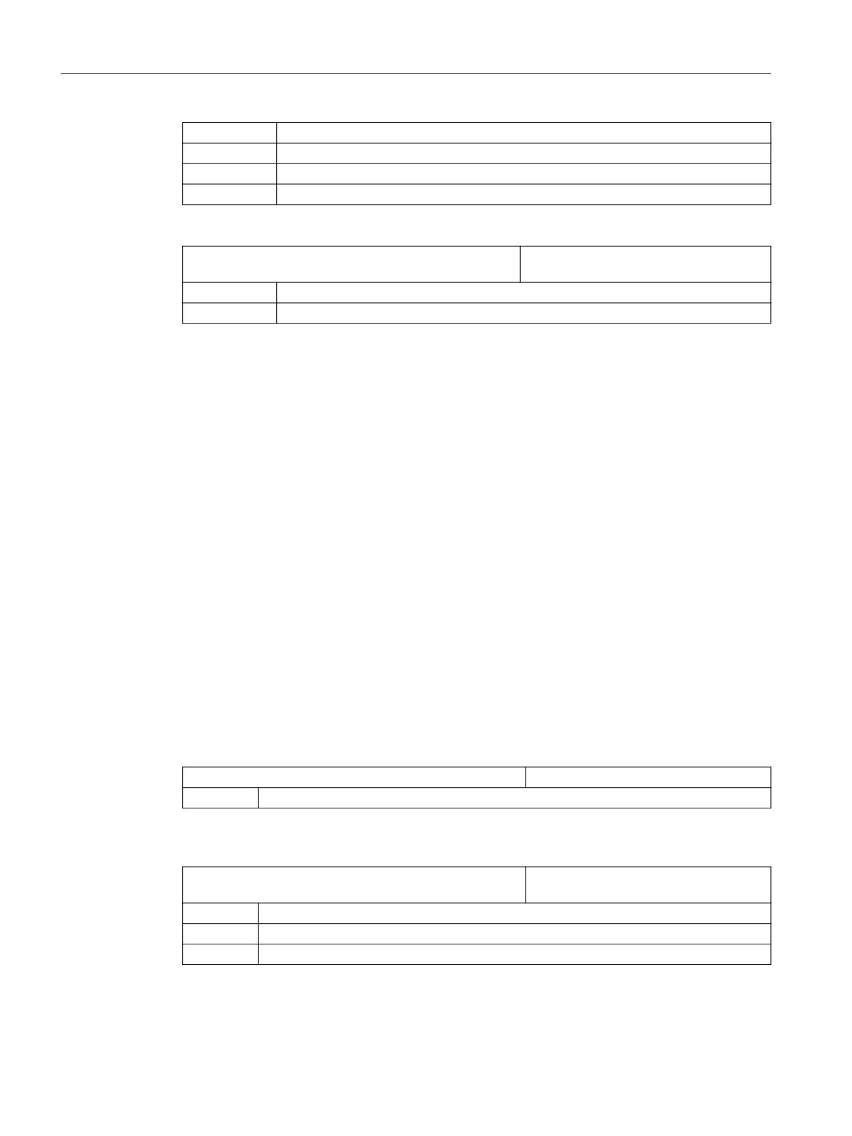
Technologies and cycles
19.11 Measuring cycles and measurement functions
Bit 8 = 0
Enable selection of WO correction in the global basic WO
Bit 9 = 0
Enable selection of WO correction in the work offset
Bit 26 = 0
Do not enable selection of the tool offset
Bit 28 = 1
Enable selection of adapt tool length
SD54780 $SNS_J_MEA_FUNCTION_MASK_PIECE
Setting for the workpiece measurement in
JOG input screen.
Bit 3 = 1
Enable probe calibration data field to be selected
Bit 28 = 1
Enable selection of adapt tool length
19.11.5
Logging
19.11.5.1
Logging the measuring, general
General logging can be performed without special settings:
• In the passive file system of the NC
• On the local drive of the CF card
If you want to use a logical drive for the logging, you require the Execution from External Storage
(EES) function.
Additional information
A detailed description of the EES function is provided in the
Function Manual Basic Functions.
General machine data
Logging can be controlled via the following machine data settings:
MD11420 $MN_LEN_PROTOCOL_FILE
File size for log files (KB)
≥ 20
recommended value
Increase the value of machine data MD11420 if larger log files have to be stored in the file system
of the NC.
MD11422 $MN_PROTOCOL_FILE_MODE
Setting the behavior of the WRITE com-
mand
Bit 0
Persistence behavior
= 0
time-delayed WRITE command (immediately persistent)
= 1
= fast WRITE command (time-delayed persistent)
SINUMERIK Operate
540
Commissioning Manual, 10/2020, 6FC5397-1DP40-6BA4
Technologies and cycles
19.11 Measuring cycles and measurement functions
Note
Set MD11422 bit 0 = 1 so that the program runtimes are not lengthened significantly.
19.11.5.2
Logging while measuring in the JOG mode
You can set the following setting data in the "Settings for Measurement Log" window for the JOG
mode.
Additional information
Additional information about the setting procedure is provided in the
Operating Manual Turning/Milling/Grinding.
Cycle channel setting data
SD55774 $SCS_J_MEA_PROTOCOL_FILE
Name and path for the log file for measuring in JOG
//NC:/WKS.DIR/TEMP.WPD/J_MEAPROT.TXT
Default setting
SD55740 $SCS_MEA_FUNCTION_MASK
Measuring cycles function screen, workpiece/tool
measurement
Bit 28
Select new log or continuos log for measuring standard log in JOG
= 0
New log (default value)
= 1
Continuous, i.e. always attach to the existing log
Bit 29
Select file format for measuring standard log in JOG
= 0
Text format (default value)
= 1
Tabular format
19.11.5.3
Logging while measuring in the AUTOMATIC mode
Cycle channel setting data
SD55730 $SCS_MEA_PROTOCOL_USER_EXT
File extension for user log
TXT
Default setting
SD55614 $SCS_MEA_RESULT_MRD
Setting of the program control of the measurement
result display MRD
= 0
Switch off the measurement result display
= 1
Switch on the measurement result display (default value)
SINUMERIK Operate
Commissioning Manual, 10/2020, 6FC5397-1DP40-6BA4
541
Technologies and cycles
19.11 Measuring cycles and measurement functions
Definition file: User GUD block
Data for user logs are generally logged from the S_PROTTXT[10] GUD array (PGUD).
If the data array is not sufficient, you can create a second array with the predefined name
S_USERTXT[n] in a separate GUD block (e.g. MGUD or UGUD):
DEF NCK STRING[200] S_USERTXT[n]
; n = number of field elements
Note
The logging operation checks whether the S_USERTXT array is available. If S_USERTXT is
available, the content of the array is logged. If S_USERTXT is not available, the content of the
S_PROTTXT array is logged.
19.11.5.4
Manufacturer and user cycle CUST_MEAPROT.SPF
Function
You can make individual adaptations to the log form and content in the CUST_MEAPROT cycle.
Procedure
1. Open the CUST_MEAPROT.SPF cycle file.
2. Select the program lines in the _MARK1 block.
3. Copy the contents from the _MARK1 block to the _MARK2 block.
4. Adapt the parameters individually in the _MARK2 block.
5. Save the changed cycle file.
The original default values are retained and can be activated/deactivated at any time (setting
of comment characters).
Parameter
In the CUST_MEAPROT cycle, all the possible parameter changes are described in detail in the
_MARK2_1 block.
You can adapt the following parameters:
Parameter
Default value
Input area
Characters per line
66
> 66 possible (1
Characters per column 2 to 4
14
Min. 12, max. 14
Workpiece counter
""
Identifier
Column space
" "
Blank string (≥ 2 * blanks)
Identifier for tolerance specifica-
"#"
1 character
tion
SINUMERIK Operate
542
Commissioning Manual, 10/2020, 6FC5397-1DP40-6BA4
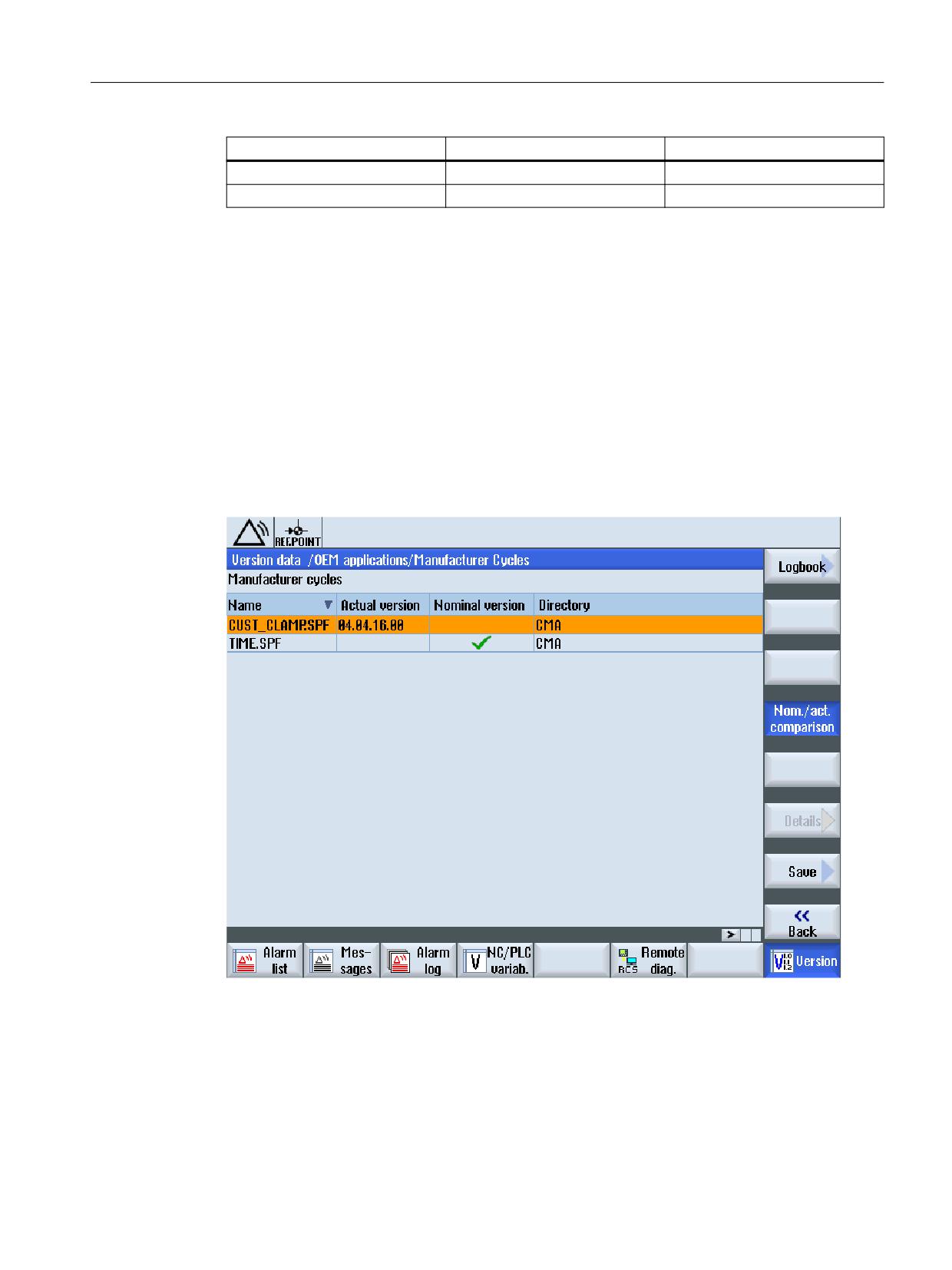
Technologies and cycles
19.12 Compare cycles version
Parameter
Default value
Input area
Identifier for tolerance violation
"!"
1 character
Log header lines 5 to 7
""
Any text
1)
66 characters per line correspond to the screen width in the default setting. A log line is therefore
displayed completely on the screen. If logging is mainly performed in the file system of the NC, this
setting should be retained because of the better readability. If you perform logging mainly in external
files, you can increase the line width accordingly. In this case, the width of column 1 is increased
automatically (with the same width for columns 2, 3 and 4 and the same column space).
19.12
Compare cycles version
19.12.1
Display cycles version
If cycles have version details, you can display them in the version screen.
Precondition
The version details are included in the cycles files in the following form:
;VERSION: <Version> ;DATE: <YYYY-MM-DD>
SINUMERIK Operate
Commissioning Manual, 10/2020, 6FC5397-1DP40-6BA4
543
Technologies and cycles
19.12 Compare cycles version
Example:
;VERSION: 05.05.05.00 ;DATE: 2012-11-30
Procedure
1.
Select the "Diagnostics" operating area.
2.
Press the "Version" softkey.
It takes some time to call the version display. While the version data is
being determined a progress message box and the appropriate text are
displayed in the dialog line.
3.
Select the "OEM applications /manufacturer cycles" areas and press the
"Details" softkey.
The "Manufacturer Cycles" window opens.
The "Planned-actual comparison" softkey is selected by default.
See also
Save information (Page 297)
Logbook (Page 300)
SINUMERIK Operate
544
Commissioning Manual, 10/2020, 6FC5397-1DP40-6BA4
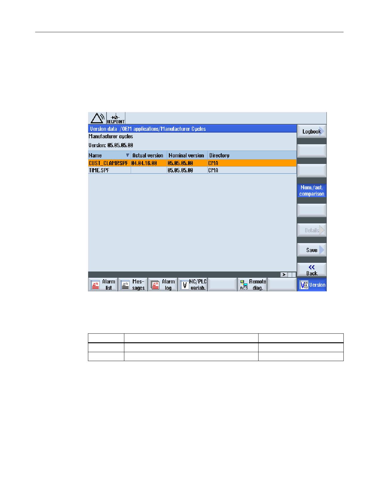
Technologies and cycles
19.12 Compare cycles version
19.12.2
Specify cycles version
General
You have the possibility to compare a required cycles version with the existing cycles version in
the version view.
File overview
The following files are required:
Name
Path
Meaning
versions.xml
/siemens/sinumerik/hmi/data/version/oem/cma
Version file
versions.xml
/oem/
Version path file
Adapting the version file
The cycles version specification requires a manual adaptation of the version file.
1. Copy the "versions.xml" sample file from the following directory:
/siemens/sinumerik/hmi/data/version/oem/cma
2. Save the sample file in its own directory under /oem.
The standard directory for this purpose is /oem/sinumerik/hmi/data/version/oem/cma.
3. Open the file.
SINUMERIK Operate
Commissioning Manual, 10/2020, 6FC5397-1DP40-6BA4
545
Technologies and cycles
19.12 Compare cycles version
4. Enter the planned version for the cycles files in the <info> tag with "defaultFileVersion" and
the details for the complete version in the <Version> tag.
5. Close the file to save the changes.
Example:
<info defaultFileType=" *.spf *.cpf" defaultFileVersion="05.05.00.00"
linkname="CMA" linkpath="//NC/CMA.DIR" EffDirOrder="CUS CMA">
<Name>Manufacturer cycles</Name>
<Version>5.5.0.0</Version>
<Link>
<Name>CUS</Name>
<Path>//NC/CUS.DIR</Path>
</Link>
</info>
Adapting the version path file
If the version file is saved in the standard directory, and a current oem\versions.xml is available,
no changes are required. In all other cases, the path data can be manually changed:
1. Open the versions.xml file under /oem
2. Replace the standard path in the <Path> tag for the "Manufacturers Cycles" with your own
path for the version file.
3. Close the file to save the changes.
Standard:
<Component>
<Name>Manufacturer Cycles</Name>
<Path>/siemens/sinumerik/hmi/data/version/oem/cma</Path>
</Component>
Example:
<Component>
<Name>Manufacturer Cycles</Name>
<Path>/oem/sinumerik/hmi/data/version/oem/cma</Path>
</Component>
SINUMERIK Operate
546
Commissioning Manual, 10/2020, 6FC5397-1DP40-6BA4
Additional language
20
20.1
Installing additional languages
Additional languages
In addition to the already existing standard languages, additional user interface languages are
available on a separate DVD.
The integrated online help is either displayed in the relevant language of the country or in
English.
Refer to Section "Supported languages (Page 548)" to view the languages in which this
interface is available.
Requirement
Software option
You require the following software option in order to use this function:
"Additional languages"
• After the installation, approx. 256 MB memory must be available on the CompactFlash Card.
• Language extension software "hmi_sl_language_xxx_02.06.00.00.00y.arc".
xxx = language code, y = internal version ID
Is supplied on the language extension DVD.
Installing a language
Install the language the same as for a commissioning archive (ARC). For the procedure, please
refer to Section "Reading-in a start-up archive (Page 223)".
Note
Language extensions software of the previous version is compatible with the current operating
software.
SINUMERIK Operate
Commissioning Manual, 10/2020, 6FC5397-1DP40-6BA4
547
Additional language
20.3 Supported languages
20.2
Uninstalling languages
If you no longer require a language interface, then you can uninstall this.
Note
Standard languages and the currently active language for the operating software cannot be
uninstalled.
Procedure
1.
Select the "Startup" operating area.
2.
Press the "Change language" softkey.
The "Language selection" window opens. The language most recently set
is highlighted.
3.
Switch the cursor to the required language.
4.
Press the "Delete language" softkey.
The "Delete language" window opens.
5.
Press the "OK" softkey.
The operating software uninstalls the selected language.
20.3
Supported languages
Table 20-1
Supported languages
Language
Language code
Standard languages
Chinese simplified
chs
X
Chinese (traditional)
cht
Danish
dan
German
eng
X
English
eng
X
Finnish
fin
French
fra
X
Indonesian
ind
Italian
ita
X
Japanese
jpn
Korean
kor
Malay
msl
Dutch
nld
Polish
plk
SINUMERIK Operate
548
Commissioning Manual, 10/2020, 6FC5397-1DP40-6BA4
Additional language
20.3 Supported languages
Language
Language code
Standard languages
Portuguese
ptb
Romanian
rom
Russian
rus
Swedish
sve
Slovenian
slv
Slovakian
sky
Spanish
esp
X
Thai
tha
Czech
csy
Turkish
trk
Hungarian
hun
Vietnamese
vit
SINUMERIK Operate
Commissioning Manual, 10/2020, 6FC5397-1DP40-6BA4
549
Additional language
20.3 Supported languages
SINUMERIK Operate
550
Commissioning Manual, 10/2020, 6FC5397-1DP40-6BA4
SINUMERIK Operate on PCU/IPC
21
21.1
Link OEMFrame application
Integrating an OEM application
The following files should be adapted and created in order to integrate an OEMFrame application
into the operating software:
• Configuration file "systemconfiguration.ini"
The operating software is started and controlled from the system manager; the system
manager also controls the OEMFrame applications. The system manager is configured using
the "systemconfiguration.ini" configuration file.
• Configuring the start softkey
In order to start an OEMFrame application from the operating software, configure a softkey
on the expansion bar of the operating area.
• Configuration file "slamconfig.ini"
In order to configure the softkey position with text and/or symbol for the OEMFrame
application, generate the "slamconfig.ini" file.
• Save the language-dependent text for a softkey in the file mytext_<Ing>.ts.
"systemconfiguration.ini" file
In order to integrate an OEMFrame application into the operating software, copy the
"systemconfiguration.ini" configuration file and place it in one of the two directories:
<Installation path>/user/sinumerik/hmi/cfg
<Installation path>/oem/sinumerik/hmi/cfg
All of the processes to be managed by the system manager, as well as the applications that are
to be integrated as OEMFrame applications are in the [processes] section.
Value
Meaning
process
Symbolic name of the OEMFrame application. This is required to configure the op-
erating areas.
cmdline
Command line which is transferred to the "oemframe.exe" process when starting.
oemframe
For OEMFrame applications, always set to "true".
windowname
Window name of the OEMFrame application - determined with "findwindow.exe".
classname
Class name of the OEMFrame application - determined with "findwindow.exe".
deferred
true: OEMFrame application is not started when SINUMERIK Operate powers up,
but only when selected for the first time.
SINUMERIK Operate
Commissioning Manual, 10/2020, 6FC5397-1DP40-6BA4
551

SINUMERIK Operate on PCU/IPC
21.1 Link OEMFrame application
Value
Meaning
startupTime
The linked process starts as follows:
immediately: immediately (default)
afterServices: after all services have started
afterGuis: after all GUI components have started
If SINUMERIK Operate is shut down, the process goes in reverse:
immediately: immediately (default)
afterServices: after all services have shut down
afterGuis: after all GUI components have shut down
gimmekeys
Release mask for system configuration keys that are to be handled by the OEMFrame
application. The parameterization is performed in the form of a bit mask.
disablekeys
Parameterization for the keyboard filter behavior. The parameterization is per-
formed in the form of a bit mask.
menuselectkey
The value is used for changing the key that calls the operating area menu (default
F10). The value is a logically ORed combination of the modifications (Microsoft
definition) Key_Shift, Key_Alt, Key_Ctrl, and the virtual key code.
timeout
Maximum duration for the search for the OEMFrame application in milliseconds. If
the OEMFrame application was not found within this time, it is not managed by the
System Manager.
Default setting in the "systemconfiguration.ini" file:
[miscellaneous]
startTimeoutDefault
shutdowntime
Maximum duration for downloading the OEMFrame application in milliseconds. If
the OEMFrame application was not found after this period of time, the process is
canceled.
Default setting in the "systemconfiguration.ini" file:
[miscellaneous]
shutdownTimeoutDefault
Bit mask "gimmekeys"
The bit mask for an OEMFrame application is set to the binary value 0xF by default. All of the key
combinations from F1 to F8 are fed to the OEMFrame application. The OEMFrame application
itself can handle a specific key/key combination by setting additional bits. Otherwise, the system
configuration will evaluate the key/key combination and it will not even reach the OEMFrame
application.
You can parameterize the bit mask "gimmekeys" as follows:
Bit
Keys
Meaning
0
F1 - F8
Horizontal softkeys (upper bar, HU)
1
Shift+F1 - Shift+F8
Vertical softkeys (right bar, VR)
2
Ctrl+F1 - Ctrl+F8
Horizontal softkeys (lower bar, HL)
3
Shift+Ctrl+F1 - Shift+Ctrl+F8
Vertical softkeys (left bar, VL)
4
F9
Recall
5
Shift+F9
ETC switchover
6
F10
Operating area menu
7
Shift+F10
M key
SINUMERIK Operate
552
Commissioning Manual, 10/2020, 6FC5397-1DP40-6BA4
SINUMERIK Operate on PCU/IPC
21.1 Link OEMFrame application
Bit
Keys
Meaning
8
F11
Channel switchover key
9
Shift+F11
M key (hard key)
10
F12
Info/help
11
Shift+F12
Custom key (hard key)
12
ESC
Alarm cancel
13
HOME
Window switchover key
14
END
PROGRAM (hard key)
15
PAGE UP
ALARM (hard key)
16
PAGE DOWN
TOOL OFFSET (hard key)
17
HOME (NUMPAD)
PROGRAM MANAGER (hard key)
18
F13 - F20
Extended, horizontal softkeys (upper bar, HU)
19
Shift+F13 - Shift+F20
Extended, vertical softkeys (right bar, VR) and right direct keys
HT8
20
Ctrl+F13 - Ctrl+F20
Extended, horizontal softkeys (lower bar, HL)
21
Shift+Ctrl+F13 - Shift+Ctrl+F20
Extended, vertical softkeys (left bar, VL) and left direct keys
HT8
Bit mask "disablekeys"
The bit mask for an OEMFrame application is set to the binary value 0x3FFFF by default. Thus,
all of the keyboard sequences are filtered out and not forwarded to the OEMFrame application.
If a bit is set to 0, the keyboard filter for the corresponding sequence is deactivated and the
OEMFrame application is able to receive the keyboard sequence.
If, for example, an OEMFrame application is to receive all of the softkeys of left and bottom
softkey bar, set the "disablekeys" bit mask to the binary value 0x300FF.
You can parameterize the bit mask "disablekeys" as follows:
Bit
Keys
Meaning
0 - 7
Reserved
8
(Shift)+Ctrl+F1
Lower and left-hand softkey bar (HL, VL)
9
(Shift)+Ctrl+F2
Lower and left-hand softkey bar (HL, VL)
10
(Shift)+Ctrl+F3
Lower and left-hand softkey bar (HL, VL)
11
(Shift)+Ctrl+F4
Lower and left-hand softkey bar (HL, VL)
12
(Shift)+Ctrl+F5
Lower and left-hand softkey bar (HL, VL)
13
(Shift)+Ctrl+F6
Lower and left-hand softkey bar (HL, VL)
14
(Shift)+Ctrl+F7
Lower and left-hand softkey bar (HL, VL)
15
(Shift)+Ctrl+F8
Lower and left-hand softkey bar (HL, VL)
16
Reserved
17
Reserved
Bit mask "disablekeyshigh"
It may be necessary to map key sequences because the operating system already responds to
Ctrl-F4 and Ctrl-F6 in certain situations.
SINUMERIK Operate
Commissioning Manual, 10/2020, 6FC5397-1DP40-6BA4
553
SINUMERIK Operate on PCU/IPC
21.1 Link OEMFrame application
You can parameterize the bit mask "disablekeyshigh" as follows:
Bit
Meaning
0 - 28
Reserved
29
Key sequences Ctrl-F1 to Ctrl-F8 can be mapped onto key sequences Ctrl-F13 to Ctrl-F20.
30 - 31
Reserved
Note
The "gimmekeys", "disablekeys" and "disablekeyshigh" bit masks can be specified both with a
decimal code (e.g. 31) and a hexadecimal code (e.g. 0x1F).
Examples
Note
Write error
Avoid write errors. Determine the entries for the sections "processes" and "areas" only with the
FindWindow program.
"notepad.exe" and "calc.exe"
In the following example, the two Windows applications "notepad.exe" and "calc.exe" are
configured as OEMFrame applications:
[processes]
PROC500=process:=notepadOEM, cmdline:="C:\\WINDOWS\\system32\
\notepad.exe", oemframe:=true, deferred:=true,
windowname:="Untitled - Notepad", classname:="Notepad"
PROC501=process:=calcOEM, cmdline:="C:\\WINDOWS\\system32\
\calc.exe", oemframe:=true, deferred:=true,
windowname:="Calculator", classname:="SciCalc"
[areas]
AREA500=name:=AreaNote, process:=notepadOEM
AREA501=name:=AreaCalc, process:=calcOEM
"keycatcher.exe"
The Windows application "keycatcher.exe" is integrated in the following example. In this case, all
four softkey bars and the Recall key will reach the Windows application. The keyboard filter for
the lower and the left-hand softkey bar is deactivated:
[processes]
SINUMERIK Operate
554
Commissioning Manual, 10/2020, 6FC5397-1DP40-6BA4
SINUMERIK Operate on PCU/IPC
21.1 Link OEMFrame application
PROC500= process:=keycatcherOEM, cmdline:="keycatcher.exe",
oemframe:=true, deferred:=true, windowname:="keycatcher",
classname:="QWidget", gimmekeys:=0x1F, disablekeys:=0x300FF
[areas]
AREA500=name:=AreaKeyCatcher, process:= keycatcherOEM
The Windows application "keycatcher.exe" is integrated in the following example. In this case, all
four softkey bars and the F10 key will reach the Windows application. Press Ctrl+F12 to show the
operating area menu when a Windows application is displaying (the system configuration no
longer evaluates F10):
[processes]
PROC500= process:=keycatcherOEM, cmdline:="keycatcher.exe",
oemframe:=true, deferred:=true, windowname:="keycatcher",
classname:="QWidget", gimmekeys:=0x4F, disablekeys:=0x300FF,
menuselectkey:=Key_Control|0x7B
[areas]
AREA500=name:=AreaKeyCatcher, process:= keycatcherOEM
The Windows application "keycatcher.exe" is integrated in the following example. In this case, all
four softkey bars are fed to the Windows application. Key sequences Ctrl-F1 to Ctrl-F8 can be
mapped onto key sequences Ctrl-F13 to Ctrl-F20:
[processes]
PROC500= process:=keycatcherOEM, cmdline:="keycatcher.exe",
oemframe:=true, deferred:=true, windowname:="keycatcher",
classname:="QWidget", gimmekeys:=0xF, disablekeys:=0x300FF
[areas]
AREA500=name:=AreaKeyCatcher, process:= keycatcherOEM
The [areas] section
The SINUMERIK Operate operating areas are configured in this section.
Value
Meaning
name
Symbolic name for the operating area
process
Name of the OEMFrame application according to section [processes]
panel
Name of the panel (header) to be used
Only "SlHdStdHeaderPanel" is currently available for OEMFrame applications.
plcid
ID to identify the operating area using the SINUMERIK Operate monitor
Only values in the range of 150 to 199 are permitted.
SINUMERIK Operate
Commissioning Manual, 10/2020, 6FC5397-1DP40-6BA4
555
SINUMERIK Operate on PCU/IPC
21.1 Link OEMFrame application
NOTICE
Basic components are overwritten
If you use numbers less than 500, then it is possible that Siemens basis components will be
overwritten. In the "processes" and "areas" sections, the number range 500 - 999 is permissible.
Example
[areas]
AREA600= name:=AreaOEM, process:=notepadOEM
AREA601= name:=AreaCalc, process:=calcOEM, panel:=SlHdStdHeaderPanel
Note
Only OEMFrame applications are supported that use programming interfaces of
SINUMERIK Operate.
The [miscellaneous] section
You can make various settings in this section. Generally, only the start operating area is changed.
Key
Value
startuparea
Name of the start operating area
Example
[miscellaneous]
startuparea = AreaOEM
Configuring the operating area menu
The operating area menu is intended for switching over the operating areas configured in the
"systemconfiguration.ini" configuration file. A softkey for selecting the appropriate operating
area is provided on the horizontal softkey bar for each operating area configured.
The operating area displays the names of the operating areas from the "systemconfiguration.ini"
configuration file as the text on the operating area softkeys. The system automatically searches
for a free softkey on the horizontal softkey bar for each operating area.
Configuring additional settings
In order to configure the following settings you require the "slamconfig.ini" configuration file:
• Assigning a softkey position to a specific operating area.
• Creating a language-dependent text for the softkey.
• Displaying a symbol for the operating area on the softkey.
SINUMERIK Operate
556
Commissioning Manual, 10/2020, 6FC5397-1DP40-6BA4
SINUMERIK Operate on PCU/IPC
21.1 Link OEMFrame application
Creating the "slamconfig.ini" configuration file
Copy the "slamconfig.ini" and place the file in the same directory in which the
"systemconfiguration.ini" file is located:
<Installation path>/user/sinumerik/hmi/cfg
<Installation path>/oem/sinumerik/hmi/cfg
"slamconfig.ini" file
In the "slamconfig.ini" configuration file, for every operating area, you can create a section that
was configured in the "systemconfiguration.ini" file. The section must bear the configured name
of the appropriate operating area, e.g. AreaOEM.
Value
Meaning
TextId
Text ID for a foreign-language text which will be displayed as the softkey label.
TextContext
Context of the foreign-language text.
TextFile
Name of the text file which includes the context and the foreign-language text.
Graphic
Name of an image file which will be used as an icon for the softkey.
SoftkeyPositi
Fixed softkey position of the area softkey. In this case, softkey positions 1 to 8 are
on
located on the 1st horizontal bar and softkey positions 9 to 16 on the 2nd horizontal
bar, etc.
AccessLevel
Access level from which the softkey will be displayed. If this value is not specified,
the access level 7 (keyswitch position 0) is set.
Example
The softkey for the "AreaOEM" operating area with the following properties is configured in the
following example:
• The softkey displays the text which has been stored in the "mytext_<lng>.ts" text file under
the context "mycontext" with the "MY_AREA" TextID.
• The "mypicture.png" icon is displayed on the softkey.
• The softkey is located at position 7 in the operating area menu.
• The softkey with access level 5 (keyswitch position 2) is displayed.
[AreaOEM]
; Text-ID of a language dependent text
TextId = MY_AREA
; File name of the text file which contains the Text-ID
TextFile = mytext
; Context in the text file to which the Text-ID is assigned to
TextContext = mycontext
; File name of an icon shown on the area softkey
Picture = mypicture.png
; Position of the area softkey on area menu,
SINUMERIK Operate
Commissioning Manual, 10/2020, 6FC5397-1DP40-6BA4
557
SINUMERIK Operate on PCU/IPC
21.1 Link OEMFrame application
; If no position is specified, an empty position is searched
SoftkeyPosition = 7
; Access level of the area softkey
AccessLevel = 5
Note
Operating area position 7 is reserved for OEM users.
Labeling text for the softkey
Storage path:
<Installation path>/user/sinumerik/hmi/lng
<Installation path>/oem/sinumerik/hmi/lng
The XML identifiers have the following meanings:
Attribute
Description
context
Context within the text file.
Each file must have at least one context.
name
Name of the context.
message
Text translation.
There must be at least one message per context.
source
Text identifier.
translation
Translated text.
remark
Text comment (optional).
chars
Maximum possible length of the text in characters. If nothing is specified, the
text can have any length (optional).
lines
Maximum number of lines available for display. If nothing is specified, the
number of lines is unlimited (optional).
Structure of the language-dependent ts file that contains the labeling text for the softkey:
mytext_<lng>.ts
<?xml version="1.0" encoding="utf-8" standalone="yes"?>
<!DOCTYPE TS>
SINUMERIK Operate
558
Commissioning Manual, 10/2020, 6FC5397-1DP40-6BA4
SINUMERIK Operate on PCU/IPC
21.2 Parameterizing the OEMFrame application
mytext_<lng>.ts
<TS>
<context>
<name>mycontext</name>
<message>
<source>MY_AREA</source>
<translation>Text, which is displayed on the softkey</translation>
<remark>comment (optional)</remark>
<chars>20</chars>
<lines>2</lines>
</message>
</context>
</TS>
<lng> stands for the language code.
21.2
Parameterizing the OEMFrame application
File "oemframe.ini"
Using the "oemframe.ini" file, it is possible to further parameterize OEMFrame applications.
Create the file in the following directory:
<Installation path>/compat/oem
Create a separate section with the required parameters for each OEMFrame application. Name
the section according to the corresponding program file without a filename extension. Place the
name in square brackets.
Example
[notepad]
Parameter overview
The following parameters can be used for OEM applications:
Parameter
Meaning
Default value
WindowStyle_On
Defines properties to be assigned
0
to the window
WindowStyte_Off
Defines properties that the win-
0
dow must not have
x
Horizontal starting coordinate of
0
the OEMFrame application (unit:
pixels)
y
Vertical starting coordinate of
0
the OEMFrame application (unit:
pixels)
SINUMERIK Operate
Commissioning Manual, 10/2020, 6FC5397-1DP40-6BA4
559
SINUMERIK Operate on PCU/IPC
21.2 Parameterizing the OEMFrame application
Parameter
Meaning
Default value
Width
Width of the OEMFrame applica-
Desktop width
tion (unit: pixels)
Height
Height of the OEMFrame applica-
Desktop height
tion (unit: pixels)
nDelayInitComplete
Delays the feedback to the Sys-
0
tem Manager
fSearchOnlyForTaskWindow
States whether the window speci-
1
fied in the "systemconfigura-
tion.ini" file belongs to the task
specified there
fRestoreTaskWindow
Defines the behavior when exit-
0
ing an application that was star-
ted from the OEMFrame applica-
tion
fKeepPlacement
Deactivates the size adaptation
0
fForceTaskFocus
Define which window of the
0
fSearchForPopUps
OEMFrame application will be
1
displayed when starting.
nInitShowMode
State in which the window of the
SW_SHOWMINNOACTIVE
OEMFrame application is dis-
played when the application is
started.
nShowMode
State in which the window of the
SW_SHOWNORMAL
OEMFrame application is dis-
played when it is shown.
nUnShowMode
State into which the window of
SW_SHOWMINNOACTIVE
the OEMFrame application is put
when it is hidden.
fWinForms
Must be set if the application is a
0
"Windows Forms Application"
nSwitchToTaskAfterTermination
Controls the behavior when the
-1
OEMFrame application is exited
fFindWindowWithWildcards
Used for wildcards (?, *) for the
0
attribute Windowname
WindowStyle_On/WindowStyle_Off
The appearance of a Windows application is defined with the aid of the Windows API
function SetWindowLong. When the SetWindowLong function is called, the appearance of
the application is controlled using an 8-byte word. 2 bytes of this word can be changed using
the WindowStyle_On and WindowStyle_Off parameters.
The WindowStyle_On parameter defines properties to be assigned to the window. The
WindowStyle_Off defines properties that the window must not have.
SINUMERIK Operate
560
Commissioning Manual, 10/2020, 6FC5397-1DP40-6BA4

SINUMERIK Operate on PCU/IPC
21.2 Parameterizing the OEMFrame application
The following control options are possible with WindowsStyle parameters (binary characteristic
values):
0000
0000
xxxx
xxxx
0000
0000
0000
0000
1010
Header
1000
Border
0100
Type of window frame on a dialog box
0010
Vertical scroll bar
0001
Horizontal scroll bar
1000
System menu
0100
Frame (Thickframe)
0010
Minimize box
0001
Maximize box
Assign binary characteristic values to the WindowStyle parameters as decimal numbers. It is
possible to do the conversion using the calculator in Windows, for example.
Example conversion
The properties of the system menu as well as the horizontal and vertical scroll bar should be
defined. According to the table, these are:
0000 0000 0011 1000 0000 0000 0000 0000 binary or
0038 0000 hexadecimal
1. Select Hex on the calculator.
2. Enter the digit string 00380000 (leading zeroes can be omitted).
3. Select Dec.
Result: 3670016
4. Assign the result to the parameter as a characteristic value.
Application examples
For the Windows application Notepad, the system menu as well as the horizontal and vertical
scroll bar should be activated:
[notepad]
WindowStyle_On = 3670016
No minimize box and no maximize box should be displayed for the Windows application
Notepad:
[notepad]
WindowStyle_Off = 196608
x/y
The parameters x and y define the starting coordinates of the window of the Windows
application to be linked, measured from an origin in the upper left corner of the screen. x is the
horizontal coordinate, y is the vertical coordinate pointing downward. The unit of measurement
is pixels.
SINUMERIK Operate
Commissioning Manual, 10/2020, 6FC5397-1DP40-6BA4
561
SINUMERIK Operate on PCU/IPC
21.2 Parameterizing the OEMFrame application
The available working area depends on the screen layout being used.
Width
This parameter defines the width of the window for the Windows application, measured in pixels
from the window origin according to parameter x.
Height
This parameter defines the height of the window for the Windows application, measured in
pixels from the window origin according to parameter y.
nDelayInitComplete
As soon as the window of a Windows application has been initiated, the information is sent to
the System Manager. The Windows application can then be selected using the System Manager.
This information can be delayed using the nDelayInitComplete parameter. The unit is
specified in milliseconds.
A delay is necessary, for example, if the Windows application must carry out other actions while
generating its window. If the window is activated too soon by the system manager, display errors
will occur in the Window.
Example
After creating its window, the Windows application "app.exe" reads additional status data from
a database. The window of the Windows application may only be displayed after all status data
has been read. This read operation should take approximately one second. The following
parameter assignment is possible:
[app]
nDelayInitComplete = 2000
fSearchOnlyForTaskWindow
This parameter specifies whether the window specified in the file "systemconfiguration.ini"
using ClassName/WindowName belongs to the task that is also specified there.
The following values can be used:
fSearchOnlyForTaskWindow
= 0
The window does not belong to the specified task.
= 1
The window belongs to the specified task.
When searching, not only are the windows of the task configured in "systemconfiguration.ini"
taken into account, but all of the windows that exist in the system at the time of the search.
Example
The Windows application comprises more than one process, e.g. a "startup.exe" and a "user.exe".
In the "systemconfiguration.ini" file, only "startup.exe" is entered, from which "user.exe" is
started. The application window belongs to "user.exe" and is therefore not found when
searching is restricted to the windows of "startup.exe".
SINUMERIK Operate
562
Commissioning Manual, 10/2020, 6FC5397-1DP40-6BA4
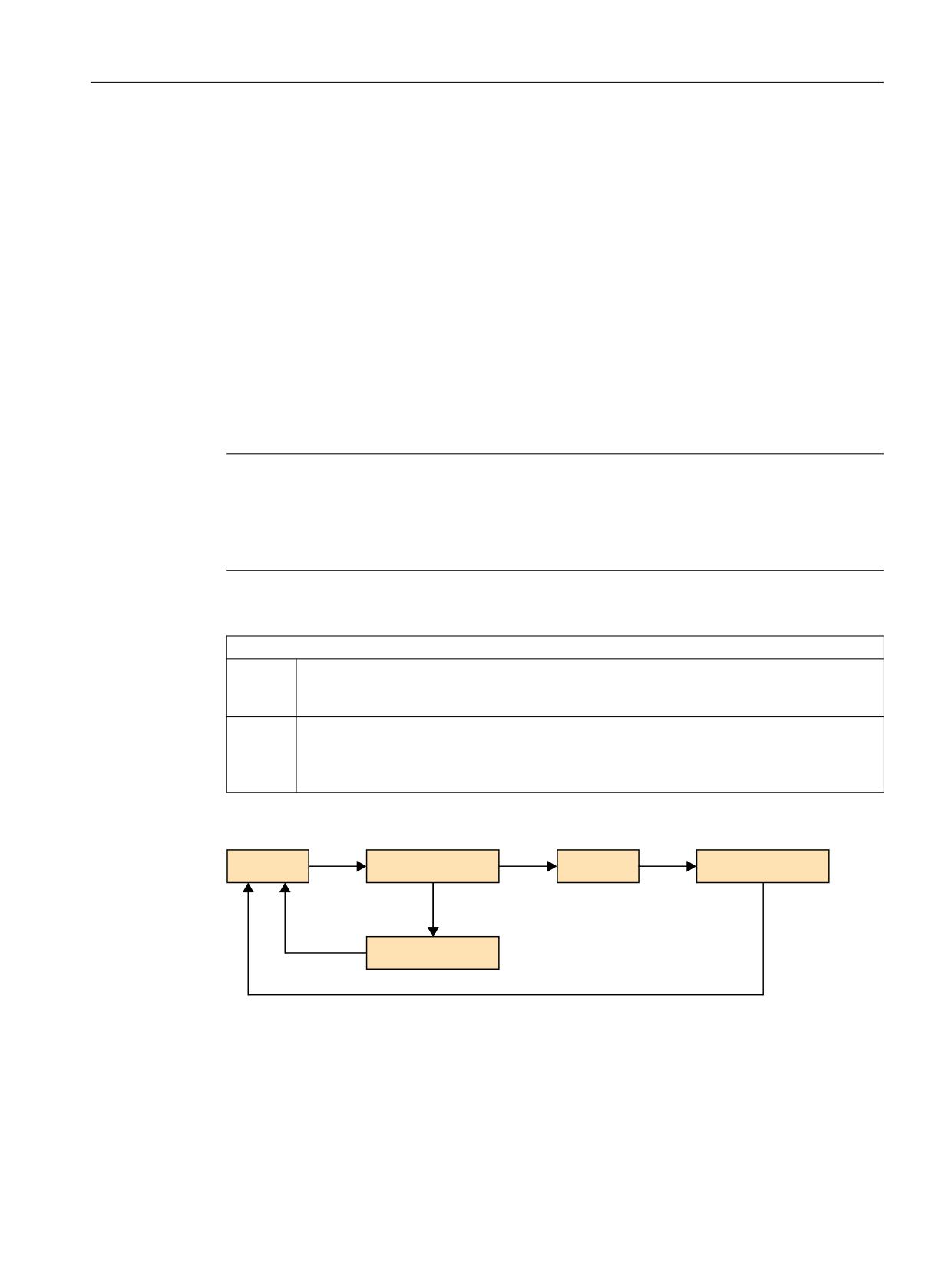
SINUMERIK Operate on PCU/IPC
21.2 Parameterizing the OEMFrame application
The following parameter assignment is possible:
[startup]
fSearchOnlyForTaskWindow = 0
fRestoreTaskWindow
This parameter defines the behavior when exiting a Windows application that was started from
the OEMFrame application as second task level.
When the OEMFrame application is deselected, the last window that was active
(ForegroundWindow) is saved by default. When reselecting the OEMFrame application, this
window is reactivated.
If another application was started from the OEMFrame application, then the active window
refers to the new Windows application.
Note
Incorrect displays
In many cases, the proxy application "oemframe.exe" cannot detect when the new Windows
application ends. Display errors can occur in the second task level. Activate a basic window for
the OEMFrame application.
The behavior can be influenced via the following values:
fRestoreTaskWindow
= 0
When selecting the OEMFrame application or starting a Windows application from the OEM-
Frame application, the ForegroundWindow is activated. When ending the second task level,
the OEMFrame application is displayed.
= 1
When selecting the OEMFrame application or starting a Windows application from the OEM-
Frame application, a basic window is activated before the ForegroundWindow is activated.
When ending the second task level, the basic window of the OEMFrame application is always
displayed.
Schematic
2(0)UDPH
2(0 DSSOLFDWLRQ
$SSOLFDWLRQ
)RUHJURXQG:LQGRZ
%DVLF ZLQGRZ
fForceTaskFocus/fSearchForPopUps
These two parameters define which window the OEMFrame application will activate after it has
been deselected and reselected again.
SINUMERIK Operate
Commissioning Manual, 10/2020, 6FC5397-1DP40-6BA4
563
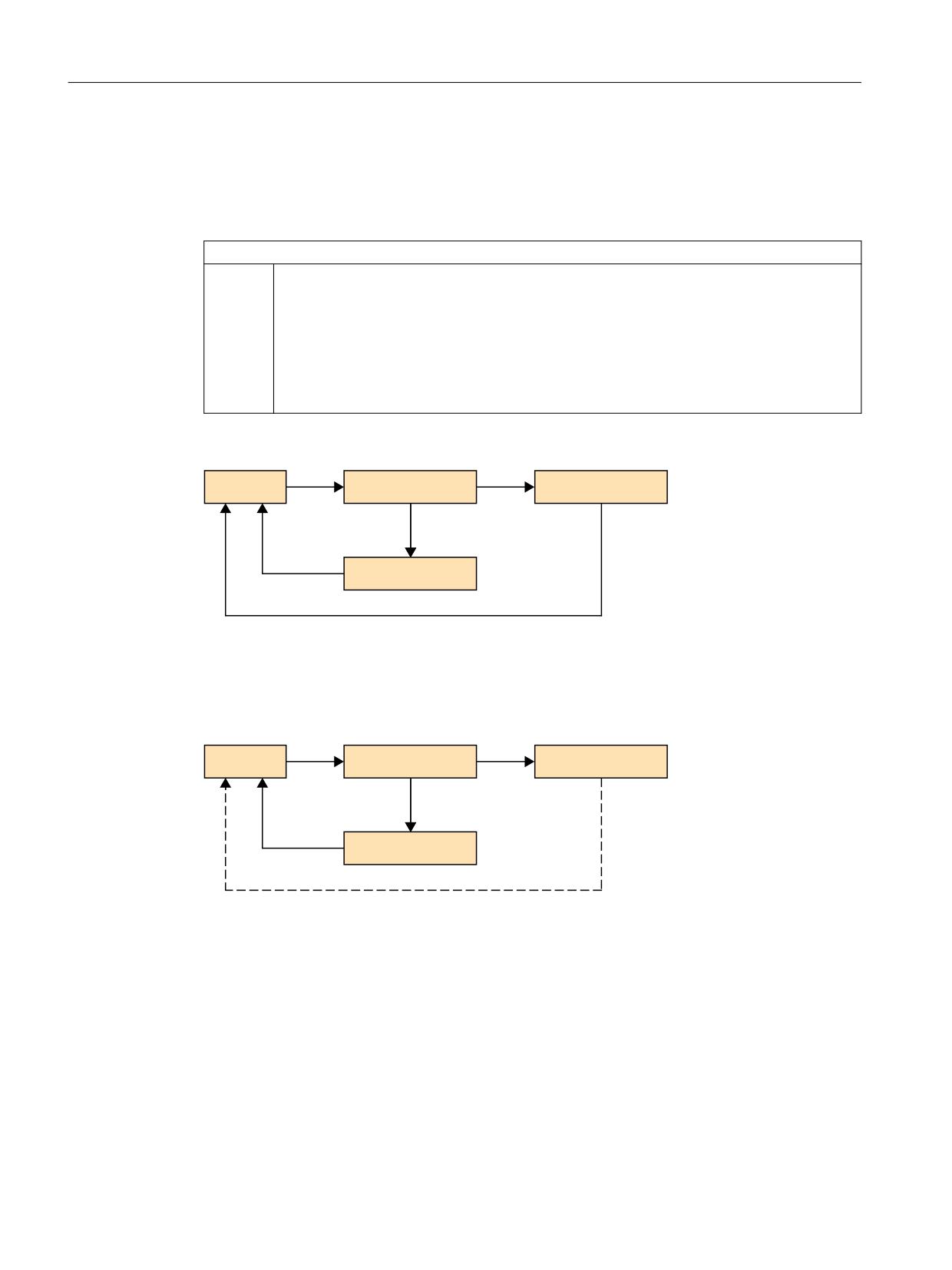
SINUMERIK Operate on PCU/IPC
21.2 Parameterizing the OEMFrame application
On switching from one operating area to another, the last active window ForegroundWindow
of the OEMFrame application is saved. When reselecting the application, the
ForegroundWindow window is then reactivated.
The behavior can be changed via the following values:
fForceTaskFocus and fSearchForPopUps
= 1
When the OEMFrame application is deselected, an active popup window is searched for rather
than the ForegroundWindow window.
Behavior of the search:
• If a popup window was found, it is displayed when the OEMFrame application is reselec-
ted.
• If no popup window exists or was found, the basic window of the application is displayed
when the application is reselected.
Schema fForceTaskFocus/fSearchForPopUps with value 1
2(0)UDPH
2(0 DSSOLFDWLRQ
3RS8S:LQGRZ
%DVLF ZLQGRZ
With the following value change, only the basic window of the OEMFrame application is taken
into consideration when an application is selected or deselected. The basic window is specified
in ClassName/WindowName in the "systemconfiguration.ini" file:
Schema fForceTaskFocus with value 1 and fSearchForPopUps with value 0
2(0)UDPH
2(0 DSSOLFDWLRQ
)RUHJURXQG:LQGRZ
%DVLF ZLQGRZ
LUUHOHYDQW
fKeepPlacement
This parameter deactivates the resizing (zooming) for the basic window of the OEMFrame
application. By default, the application is zoomed to the screen size before it is displayed. In the
case of applications that do not allow their windows to be zoomed, the resizing can result in
display problems. In such cases, the zoom function must be deactivated.
Example
An application "fixres.exe" should be displayed in its programmed window size. The following
parameter assignment is required:
SINUMERIK Operate
564
Commissioning Manual, 10/2020, 6FC5397-1DP40-6BA4

SINUMERIK Operate on PCU/IPC
21.2 Parameterizing the OEMFrame application
[fixres]
fKeepPlacement = 1
fSearchForPopUps
= 0
No active pop-up window is searched for.
nInitShowMode/nShowMode/nUnShowMode
The three parameters define how the application window will be displayed when the application
is started, hidden, and shown.
The parameter nInitShowMode starts the application. The nShowMode parameter refers to
showing the application (area is activated). The parameter nUnShowMode hides the application.
The following value range exists for the parameters nShowMode and nUnShowMode:
nShowMode and nUnShowMode
= 0
The application window is hidden (SW_HIDE).
= 1
The application window is displayed in its original form (position, size) and has the input focus
(SW_SHOWNORMAL, SW_NORMAL).
= 2
The application window is minimized and has the input focus
(SW_SHOWMINIMIZED).
= 3
The application window is maximized (SW_SHOWMAXIMIZED).
= 4
The application window is displayed without having the input focus
(SW_SHOWNOACTIVATE).
= 5
The application window is displayed and has the input focus (SW_SHOW).
= 6
The application window is minimized and loses the input focus (SW_MINIMIZE).
= 7
The application window is minimized without having the input focus
(SW_SHOWMINNOACTIVE).
= 8
The application window is displayed without having the input focus
(SW_SHOWNA).
= 9
The application window is displayed in its original form (position, size) (SW_RESTORE).
= 10
The application window is displayed in the same way as when the application was started
(SW_SHOWDEFAULT).
Note
Display problems
The default settings function for most of the applications.
In exceptional cases, display problems can occur in applications with Borland-Delphi
development, i.e. shifted windows, etc.
Use the following parameters in this case:
nUnShowMode = 0
fKeepPlacement = 1
or
nInitShowMode = 1
SINUMERIK Operate
Commissioning Manual, 10/2020, 6FC5397-1DP40-6BA4
565

SINUMERIK Operate on PCU/IPC
21.2 Parameterizing the OEMFrame application
fWinForms
Windows Forms parameters provide control elements to applications which also use Windows
default applications, e.g. dialog boxes, menus and buttons.
If the OEMFrame application is a Windows Forms application, then the following
parameterization is required:
[<app-name>]
fWinForms = 1
Note
Deactivated size adjustment
If the parameter fWinForms is not set, the OEMFrame application does not open to the
maximum size. The specified size adjustments (x, y, Width and Height) are deactivated.
nSwitchToTaskAfterTermination
This parameter controls the behavior when the OEMFrame application is exited. Normally in this
situation, the system manager displays the operating area switchover, which can be used to
switch over to another area.
The parameter nSwitchToTaskAfterTermination can be used to initiate an automatic
switch to the previously active area:
nSwitchToTaskAfterTermination
= -1
Display of the operating area switchover (default)
= -2
Switchover to the previously active area
Example
When the "closeapp.exe" Windows application is exited, a switch should be made to the previous
area. The following parameter assignment is required:
[closeapp]
nSwitchToTaskAfterTermination = -2
fFindWindowWithWildcards
With this parameter, a wildcard search can be activated for the attribute Windowname. In this
way it is possible to identify applications that do not have the same attribute window name at
every start, e.g. access level, time-of-day under window name, etc.:
fFindWindowWithWildcards
= 0
Wildcard search is switched off
= 1
Wildcard search is switched on
Wildcard:
?
One arbitrary character
*
Any number of characters
SINUMERIK Operate
566
Commissioning Manual, 10/2020, 6FC5397-1DP40-6BA4