SINUMERIK 840D sl. Service - Configuring Commissioning. Manual (2011-2020) - page 42
Technologies and cycles
19.5 Turning
;
;------------------------------------
_NV=_NPV+_ACT ; Calculate current zero offset
N10 G[8]=_NV ; There must not be a calculation here
RET
19.5
Turning
19.5.1
General
All settings for machine and setting data of the standard cycles are also applicable for milling
under ShopMill and turning under ShopTurn.
19.5.2
Setting up cycles for turning
Setting the coordinate system
MD52000 $MCS_DISP_COORDINATE_SYSTEM
Position of the coordinate system
= 0
Default setting
Examples:
0: Vertical turning machine (carousel-type turning machine)
19: Horizontal turning machine, machining in front of the turning center
34: Horizontal turning machine, machining behind the turning center (inclined bed turning
machine)
A detailed description of MD52000 is given in Section: "Activating turning/milling/drilling/
grinding technologies (Page 369)."
Turning function screen
Enable various functions under the Turning function screen in the following channel-specific
configuration machine data.
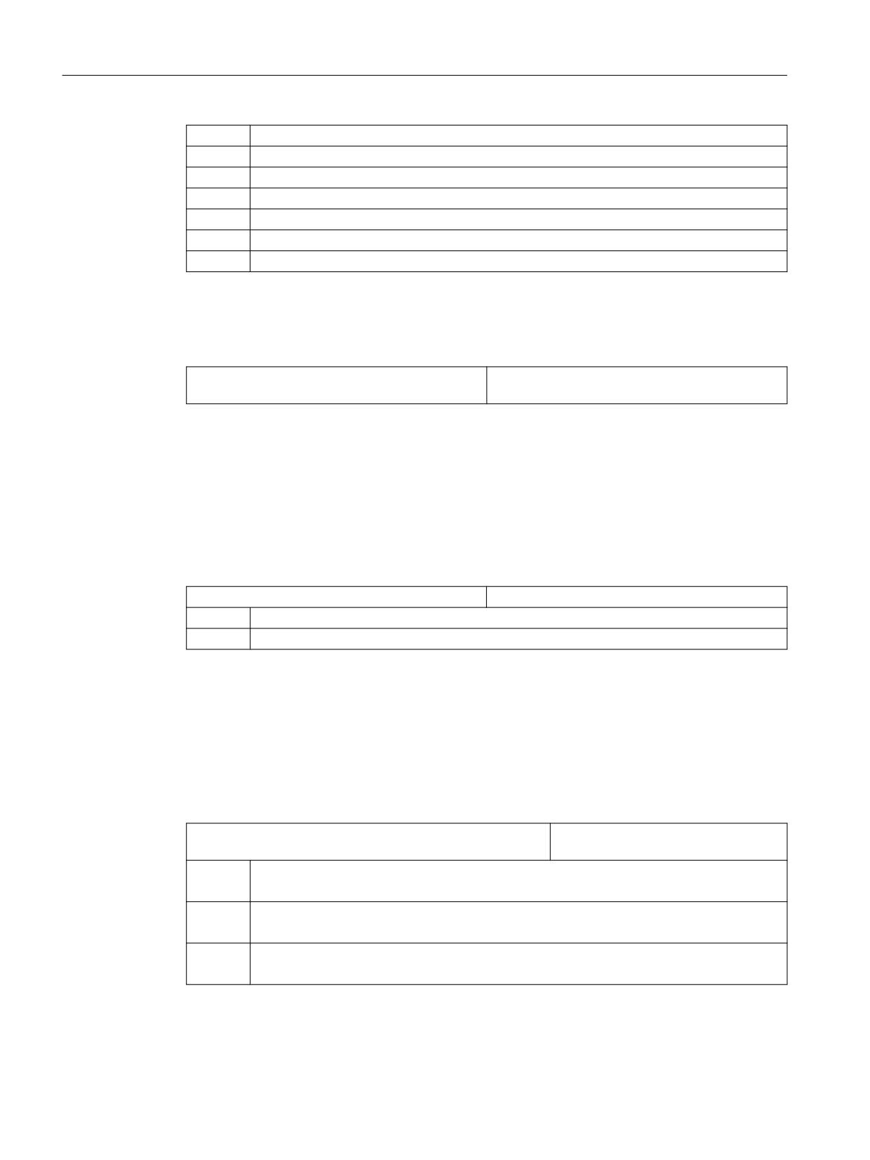
MD52218 $MCS_FUNCTION_MASK_TURN
Turning function screen
Bit 0
Enable zoom under manual for tool measurement
Bit 1
Enable part catcher for cut-off
Bit 2
Enable tailstock
Bit 3
Enable spindle control of main spindle via user interface
Bit 4
Enable spindle control of the counterspindle control via user interface
Bit 5
Enable spindle control of the tool spindle via user interface
SINUMERIK Operate
Commissioning Manual, 10/2020, 6FC5397-1DP40-6BA4
395
Technologies and cycles
19.5 Turning
Bit 6
Enable balance cutting for two-channel stock removal
Bit 7
Retraction when cutting along the contour with G1
Bit 8
Enter the spindle chuck data in the program
Bit 9
Additional input of the tailstock data in the program
Bit 10
Enable crowned thread
Bit 12
Deactivate thread synchronization
Bit 13
Cutting along the contour with CYCLE95 (828D programGUIDE without Advanced Technology
Meaning of the axes
You set the meaning of the axes in machine data MD52206 $MCS_AXIS_USAGE[n].
MD52206 $MCS_AXIS_USAGE[n]
Meaning of the axes in the channel
[n] channel axis number
A detailed description of MD52206 is provided in Chapter "Activating turning/milling/drilling/
grinding technologies (Page 369)
Traversing direction
In order that the user interface and cycles know in which direction the spindles and rotary axes
rotate, the following settings must be made.
You set the direction of rotation of an NC rotary axis via MD32100 $MA_AX_MOTION_DIR.
MD32100 $MA_AX_MOTION_DIR
Traversing direction
-1
Direction reversal
0, 1
No direction reversal
Defining the direction of rotation
In order to ensure that the direction of rotation of the spindle and C axis is correctly displayed on
the user interface and when programming, the correct direction of rotation is executed, you
must make several settings that are coordinated with one another. You must base these settings
on the actual direction of rotation of the spindle/C axis on the machine.
You specify the settings in the following machine data:
MD52207 $MCS_AXIS_USAGE_ATTRIB[n]
Attributes of the axes
[n] channel axis number
Bit 3
Displayed positive direction of rotation is counter-clockwise (for rotary axes)
The view must be from the inside of the machine (operator's view) to the axis of rotation.
Bit 4
Displayed direction of rotation for M3 is counter-clockwise (for spindles)
This bit can be set from the operator's view or according to DIN 66025.
Bit 5
Direction of rotation for M3 corresponds to minus rotary axis (for spindles)
This bit must be set analogous to PLC bit DB31, ... DBX17.6!
SINUMERIK Operate
396
Commissioning Manual, 10/2020, 6FC5397-1DP40-6BA4
Technologies and cycles
19.5 Turning
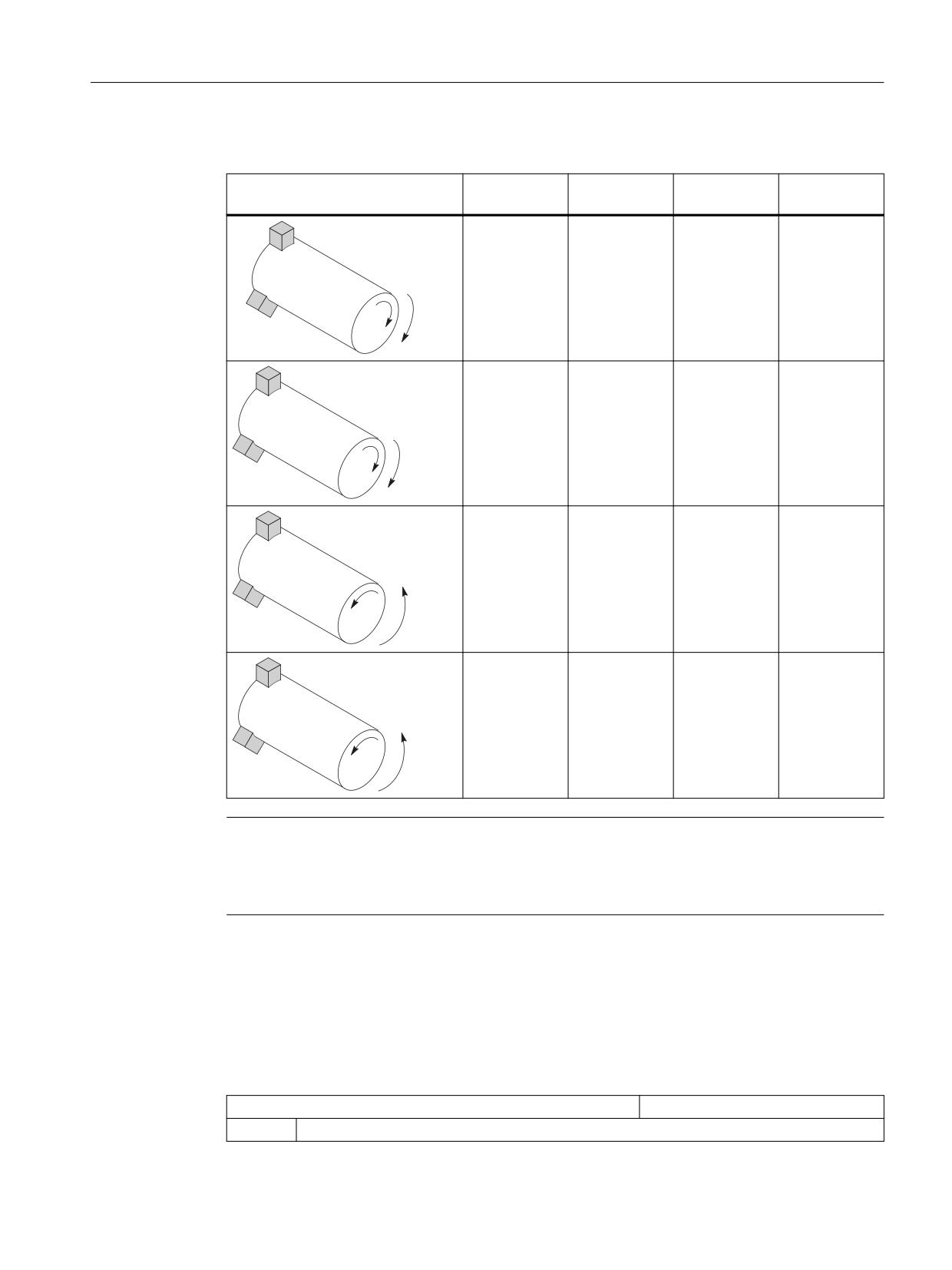
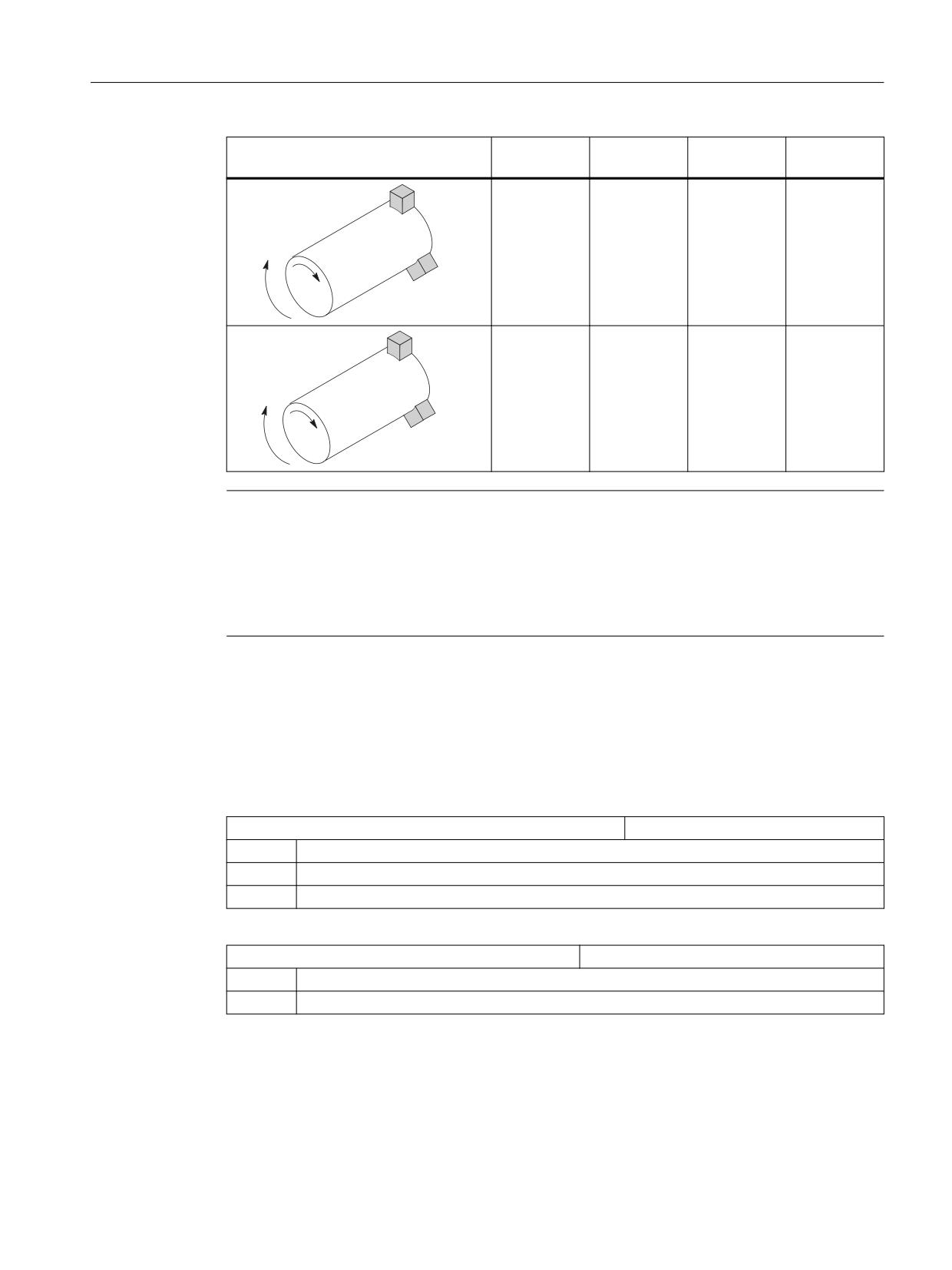
As a result, the following setting options are obtained for the main spindle:
Main spindle direction of rotation
52207[n]
52207[n]
52207[n]
DB31, ...
bit 3 =
bit 4 = *)
bit 5 =
DBX17.6
0
0
0
0
0
&
0
1
1
1
0
&
1
1
0
0
&
0
1
0
1
1
&
0
Note
MD52207[n] bit 4 = *)
Bit 4 can be set from the operator's view (values as specified) or according to DIN ("0" and "1" are
then interchanged).
Dimensions
To define the reference point for moving the counterspindle, you must first communicate the
dimensions of the counterspindle. You can either enter the dimensions in the following axis-
specific cycle machine data or in menu "Parameter" → "Setting data" → "Spindle chuck data".
Changes to the machine data are automatically accepted in the menu and vice versa.
MD53240 $MAS_SPINDLE_PARAMETER[ ]
Spindle chuck data
[0]
Chuck dimensions
SINUMERIK Operate
Commissioning Manual, 10/2020, 6FC5397-1DP40-6BA4
397

Technologies and cycles
19.5 Turning
[1]
Stop dimensions
[2]
Jaw dimensions
MD53241 $MAS_SPINDLE_CHUCK_TYPE[ ]
Spindle jaw type
= 0
Clamping, outer
= 1
Clamping, inner
Additional settings
The M code, e.g. M34 or M1 = 34 for the spindle chuck is defined in the following machine data.
The manufacturer cycle CUST_TECHCYC.SPF also takes the M functions from the following
machine data:
MD52250 $MCS_M_CODE_CHUCK_OPEN[ ]
M code for open chuck with station-
ary spindle
[0]
Main spindle
[1]
Counterspindle
MD52251 $MCS_M_CODE_CHUCK_CLOSE_OPEN_ROT[ ]
M code for open chuck with spindle
rotating
[0]
Main spindle
[1]
Counterspindle
MD52252 $MCS_M_CODE_CHUCK_CLOSE[ ]
M code for close chuck
[0]
Main spindle
[1]
Counterspindle
MD52253 $MCS_M_CODE_TAILSTOCK_FORWARD[ ]
M code for quill forward
[0]
Quill opposite the main spindle
[1]
MD52254 $MCS_M_TAILSTOCK_BACKWARD[ ]
M code for quill back
[0]
Quill opposite the main spindle
[1]
Quill opposite the main spindle
Contour turning (CYCLE952)
SD55212 $SCS_FUNCTION_MASK_TECH_SET
General function screen for all technologies
= 6
Bit 3
Delete programs generated by contour cycles (CYCLE63, CYCLE64, CYCLE952)
= 0
Generated programs are not deleted (compatibility as before)
= 1
Generated programs are deleted as soon as they have been executed by the calling cycle.
SINUMERIK Operate
398
Commissioning Manual, 10/2020, 6FC5397-1DP40-6BA4
Technologies and cycles
19.5 Turning
Rounding the contour
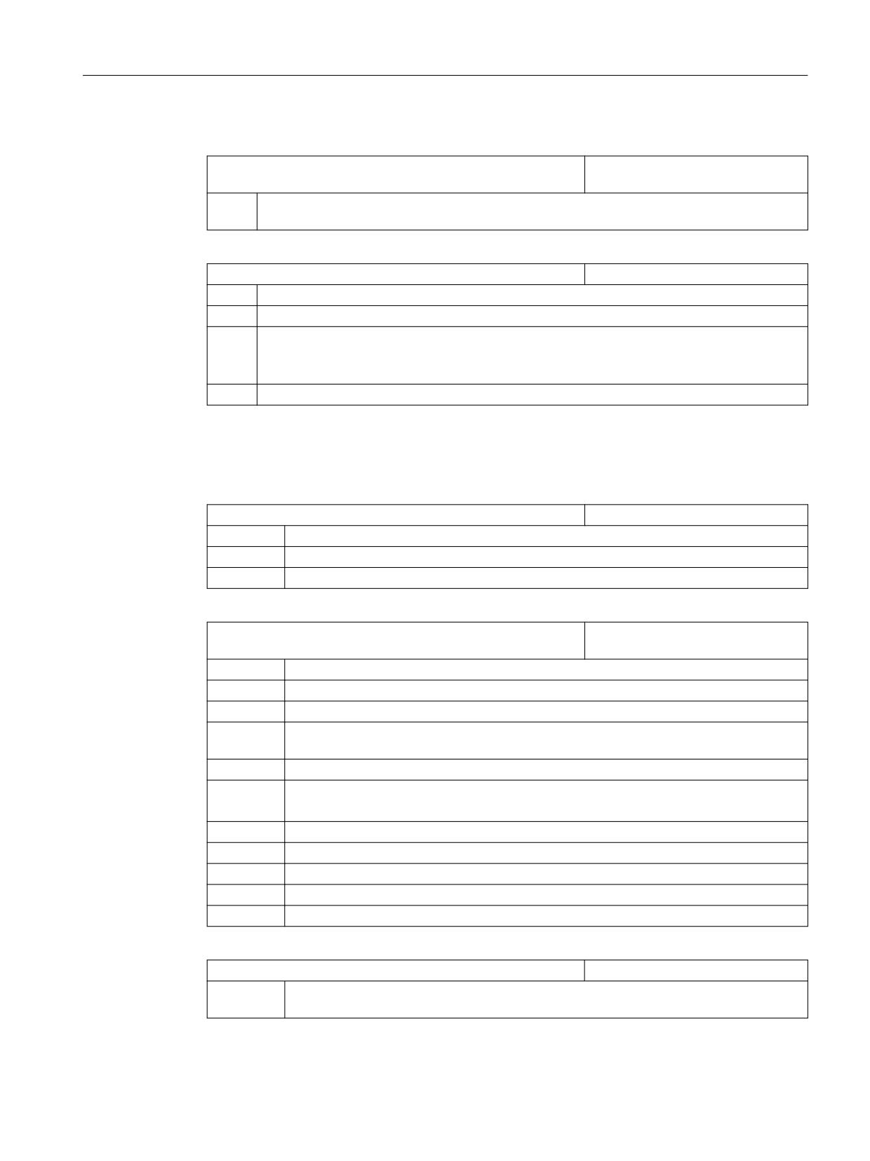
SD55582 $SCS_TURN_CONT_TRACE_ANGLE
Contour turning: Minimum angle for
rounding the contour
= 5
Specifies the angle between the cutting edge and contour, above which for contour turning, the
contour is rounded in order to remove residual material (default value).
SD 55218 $SCCS_FUNCTION_MASK_TURN_SET
Turning function screen
Bit 3
Chamfer in CYCLE930 as chamfer length (CHF)
Bit 4
Retraction from internal machining (CYCLE951)
= 0
Compatibility as before
If, during the cycle, the necessity for tightening is detected at the corner, the tool is retracted
from the internal machining, otherwise it is not.
= 1
Retraction from internal machining is generally in the cutting axis.
19.5.3
Setting-up ShopTurn cycles for turning
MD52210 $MCS_FUNCTION_MASK_DISP
Function mask for display
Bit 0 = 1
Measuring system for programs always in the base system (default)
Bit 1 = 1
Face view when turning (default setting)
Bit 4 = 1
Show follow-on tool in T, F, S window
MD52212 $MCS_FUNCTION_MASK_TECH
General function screen for all tech-
nologies
Bit 2
Approach logic for step drill
Bit 3
Block search cycle for ShopMill / ShopTurn
= 0
The E__ASUB or F_S_ASUB cycles are not called in the block search cycle PROG_EVENT.SPF
= 1
The E__ASUP (under ShopMill) or F_S_ASUP (under ShopTurn) cycles are called in the block
search cycle PROG_EVENT.SPF
Bit 4
Approach logic using the cycle
Bit 5
The cycle for SERUPRO (CYCLE207) is called in the block search cycle PROG_EVENT.SPF.
Bit 3 has no effect when bit 5 is set.
Bit 6
Work offset value WO cannot be entered
Bit 7
Identification of the end of tool lives in the program (ShopMill / ShopTurn)
Bit 8
Manual machine (ShopMill / ShopTurn)
Bit 9
Selection/deselection of work offset via softkey
Bit 11
Deactivate position check for drilling and milling tools
MD52214 $MCS_FUNCTION_MASK_MILL
Function mask for milling
Bit 3
"Inner/rear" machining is enabled in the ShopTurn masks which themselves define the
machining plane.
SINUMERIK Operate
Commissioning Manual, 10/2020, 6FC5397-1DP40-6BA4
399

Technologies and cycles
19.5 Turning
Bit 4
If you have implemented the "Clamp/release spindle" function using the manufacturer
cycle CUST_TECHCYC.SPF, then using this machine data, you can activate the "Clamp/
release spindle" parameter in the drilling and milling masks.
= 0
The "Clamp/release spindle" parameter is not displayed in the drilling and milling screens.
ShopTurn automatically clamps the spindle if it makes sense for the particular machining
operation.
= 1
The "Clamp/release spindle" parameter is displayed in the drilling and milling masks.
You decide for which machining operation the spindle should be clamped.
Bit 8
Release damping brake (C axis)
= 0
"Damping brake on/off" parameter is not displayed in the milling masks.
= 1
The "Damping brake on/off" parameter is displayed in the milling masks.
You decide for which machining operation (Face C/Per.surf.C) the C axis is braked.
If you have implemented the "Damping brake" function by means of the machine manu-
facturer cycle CUST_TECHCYC.SPF, you can activate the "Damping brake on/off" parameter
in the milling masks with this machine data.
MD52216 $MCS_FUNCTION_MASK_DRILL
Function mask for drilling
Bit 3
Constant cutting speed referred to the diameter of the centering
= 0
Constant cutting speed referred to the diameter of the tool
= 1
Constant cutting speed referred to the diameter of the centering
MD52218 $MCS_FUNCTION_MASK_TURN
Function mask for turning
Bit 2
Enable tailstock
Bit 5
Enable spindle control of tool spindle via surface
Bit 6
Enable balance cutting for dual-channel stock removal
MD52229 $MCS_ENABLE_QUICK_M_CODES
Enable fast M commands
= 0
Bit 0
Coolant OFF
Bit 1
Coolant 1 ON
Bit 2
Coolant 2 ON
Bit 3
Coolants 1 and 2 ON
MD52230 $MCS_M_CODE_ALL_COOLANTS_OFF
M code for all coolants Off
= 9
This machine data is used to define the M function for switching off the coolant; which is
output when the tool is changed.
MD52231 $MCS_M_CODE_COOLANT_1_ON
M code for coolant 1 On
= 8
This machine data is used to define the M function for coolant 1, which is output when the tool
is changed.
SINUMERIK Operate
400
Commissioning Manual, 10/2020, 6FC5397-1DP40-6BA4
Technologies and cycles
19.5 Turning
MD52232 $MCS_M_CODE_COOLANT_2_ON
M code for coolant 2 On
= 7
This machine data is used to define the M function for coolant 2, which is output when the tool
is changed.
MD52233 $MCS_M_CODE_COOLANT_1_AND_2_ON
M code for both coolants On
= -1
This machine data is used to define the M function for coolant 1 and 2, which is output when
the tool is changed.
SD55505 $SCS_TURN_ROUGH_O_RELEASE_DIST
Return distance stock removal for ex-
ternal machining
= 1
Specifies the distance by which the tool is retracted from the contour when removing stock
from an outer corner. This does not apply to stock removal at a contour (default value).
= -1
The distance is internally defined.
SD55506 $SCS_TURN_ROUGH_'I_RELEASE_DIST
Return distance stock removal for in-
ternal machining
= 0.5
Specifies the distance by which the tool is retracted from the contour when removing stock
from an internal corner. This does not apply to stock removal at a contour (default value).
= -1
The distance is internally defined.
19.5.4
Setting up a counterspindle
Software option
You require the following software option in order to use the counterspindle on your
machine:
"Generic coupling 'CP-STATIC'" or higher
Function
If your turning machine has a counterspindle, you can machine workpieces using turning,
drilling and milling functions on the front and rear faces without reclamping the workpiece
manually.
Before machining the rear face, the counterspindle must grip the workpiece, pull it out of the
main spindle, and position it at the new machining position.
Meaning of the axes
MD52206 $MCS_AXIS_USAGE[n]
Meaning of the axes in the channel
[n] channel axis number
A detailed description of MD52006 is provided in Chapter "Activating turning/milling/drilling/
grinding technologies (Page 369)".
SINUMERIK Operate
Commissioning Manual, 10/2020, 6FC5397-1DP40-6BA4
401
Technologies and cycles
19.5 Turning
Traversing direction
In order that the user interface and cycles know in which direction the spindles and rotary axes
rotate, the following settings must be made.
You set the direction of rotation of an NC rotary axis via MD32100 $MA_AX_MOTION_DIR.
MD32100 $MA_AX_MOTION_DIR
Traversing direction (not control direction)
-1
Direction reversal
0, 1
No direction reversal
Defining the direction of rotation
You set the directions of rotation for the user interface in the following machine data:
MD52207 $MCS_AXIS_USAGE_ATTRIB[n]
Attributes of the axes in the channel
[n] channel axis number
Bit 3
Displayed positive direction of rotation is counter-clockwise (for rotary axes)
The view must be from the inside of the machine (operator's view) to the axis of rotation.
Bit 4
Displayed direction of rotation for M3 is counter-clockwise (for spindles)
This bit can be set from the operator's view or according to DIN.
Bit 5
Direction of rotation for M3 corresponds to minus rotary axis (for spindles)
This bit must be set analogous to PLC bit DB31, ... DBX17.6!
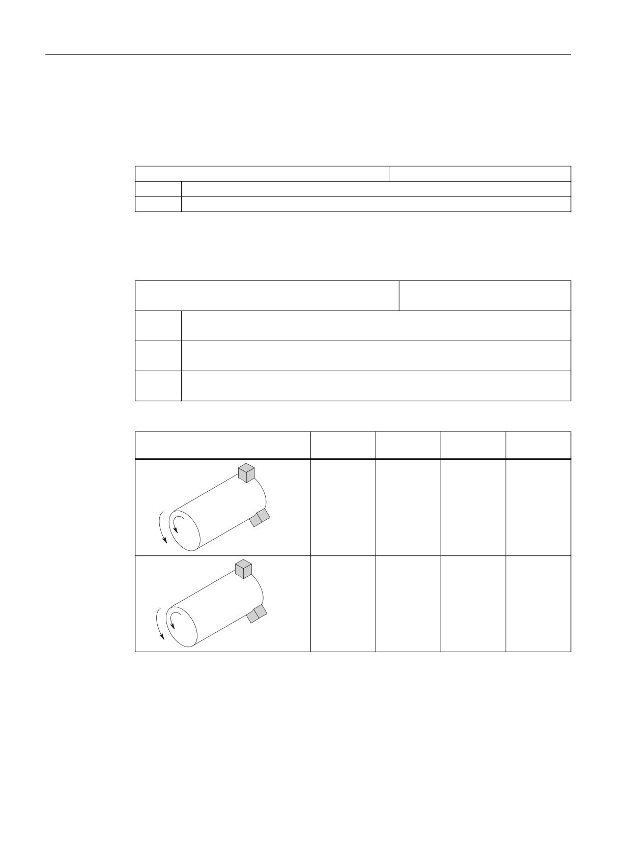
As a result, the following setting options are obtained for the counterspindle:
Counterspindle direction of rotation
52207[n]
52207[n]
52207[n]
DB31, ...
bit 3 =
bit 4 = *)
bit 5 =
DBX17.6
1
1
0
0
0
&
1
0
1
1
0
&
SINUMERIK Operate
402
Commissioning Manual, 10/2020, 6FC5397-1DP40-6BA4
Technologies and cycles
19.5 Turning
Counterspindle direction of rotation
52207[n]
52207[n]
52207[n]
DB31, ...
bit 3 =
bit 4 = *)
bit 5 =
DBX17.6
0
0
0
0
&
0
0
1
1
1
0
&
Note
MD52207[n] bit 4 = *)
Bit 4 can be set from the operator's view (values as specified) or according to DIN ("0" and "1" are
then interchanged).
The display must be the same for the main spindle and the counterspindle ("from operator's
view" or "according to DIN").
Dimensions
To define the reference point for moving the counterspindle, you must first announce the
dimensions of the counterspindle. You can either enter the dimensions in the following axis-
specific cycle machine data or in menu "Parameter" → "Setting data" → "Spindle chuck data".
Changes to the machine data are automatically accepted in the menu and vice versa.
MD53240 $MAS_SPINDLE_PARAMETER[ ]
Spindle chuck data
[0]
Chuck dimensions
[1]
Stop dimensions
[2]
Jaw dimensions
MD52241 $MCS_SPINDLE_CHUCK_TYPE
Spindle jaw type
= 0
Clamping, outer
= 1
Clamping, inner
SINUMERIK Operate
Commissioning Manual, 10/2020, 6FC5397-1DP40-6BA4
403
Technologies and cycles
19.5 Turning
19.5.5
Setting up the counterspindle under ShopTurn
Software option
You require the following software option in order to use the counterspindle on your
machine:
"Generic coupling 'CP-STATIC'" or higher
The position to which the counterspindle travels when the program starts is defined in the
following channel-specific cycle setting data:
SD55232 $SCS_SUB_SPINDLE_REL_POS
Retraction position Z for counterspindle
The following channel-specific setting data becomes effective when traveling to the fixed stop:
SD55550 $SCS_TURN_FIXED_STOP_DIST
Distance for travel to fixed stop.
SD55551 $SCS_TURN_FIXED_STOP_FEED
Feedrate for travel to fixed stop.
SD55552 $SCS_TURN_FIXED_STOP_FORCE
Force for travel to fixed stop in %.
Between traveling to the fixed stop and gripping, the counterspindle can retract a short distance
to counteract compressive stress in the workpiece.
SD55553 $SCS_TURN_FIXED_STOP_RETRACTION
Retraction distance before clamping af-
ter fixed stop.
After gripping you can cut off the workpiece. Before doing so, the counterspindle can retract a
short distance with the workpiece to exert tensile stress on the workpiece. This relieves pressure
on the tool when cutting off.
SD55543 $SCS_TURN_PART_OFF_RETRACTION
Retraction distance before cut-off.
After cut-off, you can carry out a cut-off check and for turning, use the "Travel to fixed stop"
function. You can activate/deactivate the cut-off check using the channel-specific cycle setting
data:
SD55540 $SCS_TURN_PART_OFF_CTRL_DIST
Distance for cut-off check.
SD55541 $SCS_TURN_PART_OFF_CTRL_FEED
Feedrate for cut-off check.
SD55542 $SCS_TURN_PART_OFF_CTRL_FORCE
Force for cut-off check in %.
The cut-off is successful when travel to fixed stop fails. The following alarms are output:
Alarm
Alarm text
20091
Axis %1 has not reached the fixed stop.
20094
Axis %1 end stop has been aborted.
You can switch off the alarm display using the following machine data:
MD37050 $MA_FIXED_STOP_ALARM_MASK
Enabling the fixed stop alarms.
= 2
Suppressing alarms 20091 and 20094.
You can set this machine data axis-specifically in the "Machine Data" window in the "Tool zero"
operating area.
SINUMERIK Operate
404
Commissioning Manual, 10/2020, 6FC5397-1DP40-6BA4
Technologies and cycles
19.5 Turning
If, however, the specified force is reached during the cut-off check (i.e. travel to fixed stop is
successful), alarm 61255 "Error during cut-off: Tool break?" is issued.
Note
The "Travel to fixed stop" function can also be used when gripping the spindle (see above). If
travel to fixed stop does not succeed when gripping, an alarm will of course still be issued.
Instead of alarms 20091 and 20094, the alarm 61254 "Error during travel to fixed stop" will be
issued.
Note
MD37050 can also contain values not equal to 2, e.g. 10 = 2 + 8. Make sure that the value 2 is
always contained logically so that the monitoring for travel to fixed stop can be hidden. If
MD37050 does not contain the value 2, the cut-off check is not active.
Machine manufacturer cycle
If you perform one of the following actions, you must adapt the machine manufacturer cycle
CUST_TECHCYC.SPF.
• Switch between spindle and C axis mode for the main spindle or counterspindle.
• Open, close, flush chuck (main spindle / counterspindle).
• Change default settings for the coupling of the main spindle and counterspindle.
Please refer to the following section for the procedure:
Setting-up ShopTurn cycles for turning (Page 399)
19.5.6
Technology cycles for turning
Thread-cutting (CYCLE99)
To correctly machine the thread, it is necessary to set the machine data MD52207
$MCS_AXIS_USAGE_ATTRIB[n] with bit 3, see Chapter: Setting up a counterspindle (Page 401).
Contour groovingCYCLE930, contour turning CYCLE950, stock removal at corner CYCLE951, contour
turning CYCLE952
SD55500 $SCS_TURN_FIN_FEED_PERCENT
Enter the finishing feedrate for complete ma-
chining, roughing and finishing. The percent-
age of the value corresponds to that entered
under parameter F (feedrate).
= 100
100% finishing feedrate
SINUMERIK Operate
Commissioning Manual, 10/2020, 6FC5397-1DP40-6BA4
405
Technologies and cycles
19.5 Turning
SD55510 $SCS_TURN_GROOVE_DWELL_TIME
Dwell time, which is necessary between
grooving and retracting for grooving tech-
nology. Tool clearance time during grooving
at the base.
= > 0
Dwell time in seconds
= < 0
Dwell time in spindle revolutions
SD55580 $SCS_TURN_CONT_RELEASE_ANGLE
Angle, through which the tool is lifted from
the contour for contour turning, roughing.
= 45
Retraction angle of 45 degrees
Angle
SD55581 $SCS_TURN_CONT_RELEASE_DIST
Amount, by which the tool is lifted when
roughing a contour taking into account the
retraction angle SD55580
$SCS_TURN_CONT_RELEASE_ANGLE.
This also applies to stock removal, grooving
and plunge turning.
= 1
1 mm or 1 inch retraction distance
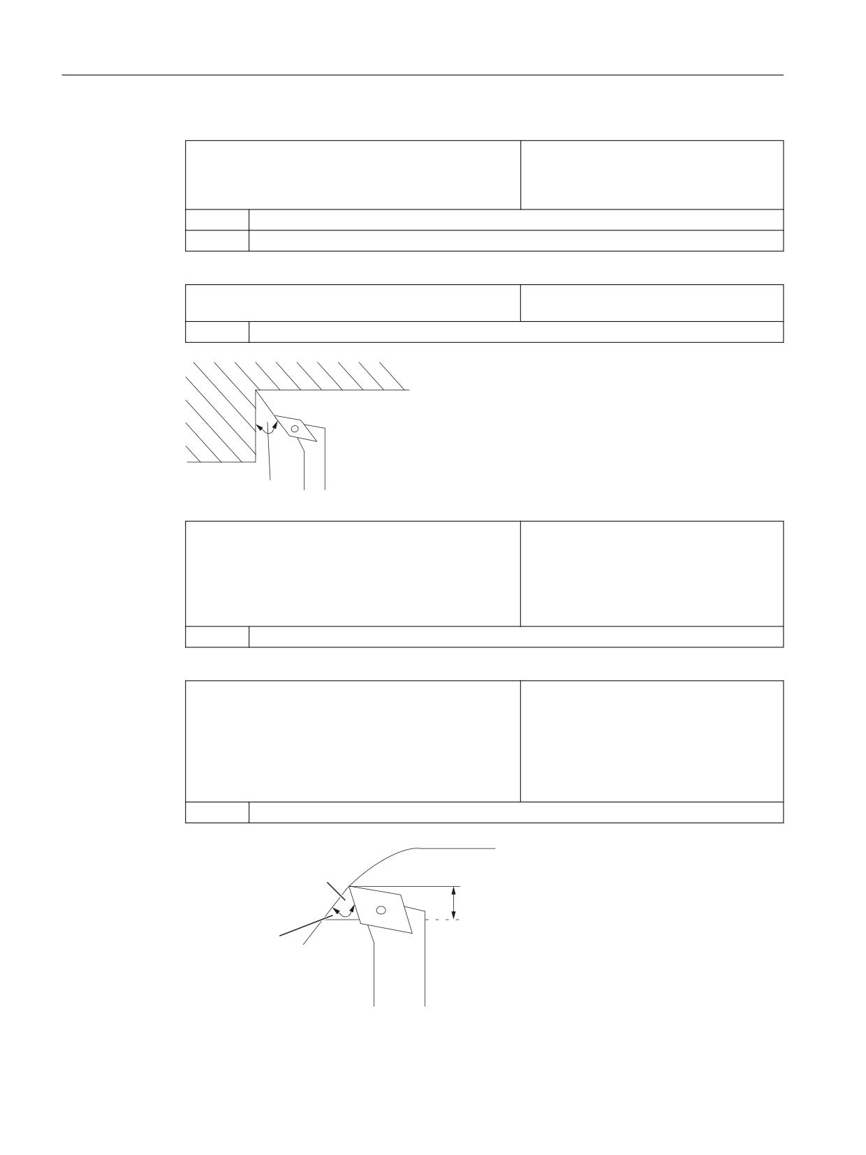
SD55582 $SCS_TURN_CONT_TRACE_ANGLE
The angle between cutting edge and con-
tour as of which rounding is performed on
the contour during contour turning in order
to remove residual material.
If the angle of the residual material is greater
than that specified in the setting data, the
tool will round the contour.
= 5
5 degree angle
&RQWRXU
$QJOH
&XUUHQW FXWWLQJ GHSWK '
5HVLGXDO PDWHULDO
SINUMERIK Operate
406
Commissioning Manual, 10/2020, 6FC5397-1DP40-6BA4

Technologies and cycles
19.5 Turning
SD55583 $SCS_TURN_CONT_VARIABLE_DEPTH
Percentage of the changing cutting depth
when turning a contour
You can select changing the cutting depth
for stock removal and for removing residual
material.
= 20
20% variable cutting depth
SD55584 $SCS_TURN_CONT_BLANK_OFFSET
Safety clearance when avoiding obstacles, to
avoid collisions during approach or retrac-
tion from the machining.
This also applies to stock removal, grooving
and plunge turning.
= 1
1 mm or 1 inch blank allowance
SD55585 $SCS_TURN_CONT_INTERRUPT_TIME
Time for the feedrate interruption for con-
tour turning.
This also applies to stock removal, grooving
and plunge turning.
= > 0
Interruption time in seconds
= < 0
Interruption time in revolutions
= 0
No interruption
Note
The channel-specific cycle setting data SD55585 is only evaluated if
SD55586 $SCS_TURN_CONT_INTER_RETRACTION = 0.
SD55586 $SCS_TURN_CONT_INTER_RETRACTION
Retraction distance for contour turning
for feedrate interruption.
This also applies to stock removal,
grooving and plunge turning.
= > 0
Retraction distance at feed interruption
SD55585 $SCS_TURN_CONT_INTERRUPT_TIME has no effect.
= 0
No retraction distance
SINUMERIK Operate
Commissioning Manual, 10/2020, 6FC5397-1DP40-6BA4
407
Technologies and cycles
19.5 Turning
SD55587 $SCS_TURN_CONT_MIN_REST_MAT_AX1
Limit value during contour turning for
removal of residual material in the di-
rection of axis 1 (for G18 Z).
This also applies to residual machining -
stock removal, grooving and plunge
turning.
50
The roughing step for residual machining is not executed, if the material to be removed is less
than 50% of the finishing allowance. The material is only removed when finishing.
Example: If the SD is set to 50% and the final machining allowance is 0.5 mm, any residual material less than
0.25 mm is not removed with the residual machining - but is removed during finishing. If during a
machining step, less residual material is present than defined in the SD, the error message "No material
present" is issued. This means that this residual material roughing step can be omitted because no
machining is performed.
SD55588 $SCS_TURN_CONT_MIN_REST_MAT_AX2
Limit value during contour turning for
removal of residual material in the di-
rection of axis 2 (for G18 X).
This also applies to residual machining -
stock removal, grooving and plunge
turning.
50
The roughing step for residual machining is not executed, if the material to be removed is less
than 50% of the finishing allowance. The material is only removed when finishing.
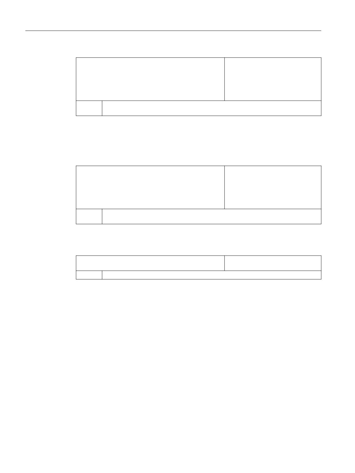
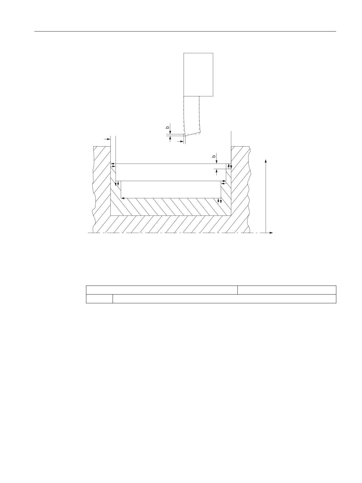
As the tool bends during plunge turning, the tool cannot travel right up to the contour during
stock removal. The lateral distance to the last cut by which the next cut is shortened is specified
in the following channel-specific cycle setting data.
SD55595 $SCS_TURN_CONT_TOOL_BEND_RETR
Retraction distance because of tool
bending
0.1
0.1 mm or 0.1 inch retraction distance
SINUMERIK Operate
408
Commissioning Manual, 10/2020, 6FC5397-1DP40-6BA4
Technologies and cycles
19.5 Turning
a
a
X
Z
a
Distance to the last cut, SD55595
b
Retraction between plunge-cutting and stock removal, SD55596
As the tool bends during plunge turning, the tool would make an excessively deep cut during
stock removal. The retraction distance of the tool between plunge-cutting and stock removal is
specified in the following channel-specific cycle setting data:
SD55596 $SCS_TURN_CONT_TURN_RETRACTION
Retraction depth before turning
= 0.1
0.1 mm or 0.1 inch retraction depth
19.5.7
Axis configuration of a lathe
General configuration
If driven milling tools are available on a lathe, then the following functions can also be set-up on
this machine:
• Cylinder surface transformation (TRACYL) (Page 410)
• End face machining (TRANSMIT) (Page 414)
SINUMERIK Operate
Commissioning Manual, 10/2020, 6FC5397-1DP40-6BA4
409
Technologies and cycles
19.5 Turning
Lathe with X and Z axes, main and tool spindle
For example, for a lathe with X and Z axes, main spindle (C1) and tool spindle (WZ), you can
configure the following channel-specific machine data:
MD20080 $MC_AXCONF_CHANAX_NAME_TAB[ ]
Channel axis name in the channel
[0] = XC
Channel axis XC
[1] = ZC
Channel axis ZC
[2] = C1
Main spindle C1
[3] = WZ
Tool spindle WZ
Lathe with X and Z axes, main and tool spindle and counterspindle
For example, for a lathe with X and Z axes, main spindle (C1), tool spindle (WZ) and
counterspindle (C2), you can configure the following machine data:
MD20080 $MC_AXCONF_CHANAX_NAME_TAB[ ]
Channel axis name in the channel
[0] = XC
Channel axis XC
[1] = ZC
Channel axis ZC
[2] = C1
Main spindle C1
[3] = WZ
Tool spindle WZ
[5] = C2
Counterspindle C2
Lathe with X and Z axes, main and tool spindle and Y axis
For example, for a lathe with X, Z and Y axes, main spindle (C1) and tool spindle (WZ), you can
configure the following machine data:
MD20080 $MC_AXCONF_CHANAX_NAME_TAB[ ]
Channel axis name in the channel
[0] = XC
Channel axis XC
[1] = ZC
Channel axis ZC
[2] = C1
Main spindle C1
[3] = WZ
Tool spindle WZ
[5] = YC
Channel axis YC
19.5.8
Cylinder surface transformation (TRACYL)
Software option
You require the following software option in order to use this function:
"Transmit and peripheral surface transformation"
Function
Using the cylinder surface transformation function (TRACYL), you can machine the peripheral
surface of a turned part.
SINUMERIK Operate
410
Commissioning Manual, 10/2020, 6FC5397-1DP40-6BA4
Technologies and cycles
19.5 Turning
Setting up
General settings for cylinder transformation:
MD10602 $MN_FRAME_GEOAX_CHANGE_MODE
Frames when switching over geometry axes.
= 1
The actual total frame (work offsets) and when switching over geometry axes (selecting -
deselecting TRACYL) is recalculated.
MD24040 $MC_FRAME_ADAPT_MODE
Adapting the active frames.
Bit 0 = 1
Rotations in active frames that rotate coordinate axes for which there are no geometry axes,
are deleted from the active frames.
Bit 1 = 1
Shearing angles in active frames are made orthogonal.
Bit 2 = 1
Scaling factors of all geometry axes in the active frames are set to 1.
MD28082 $MC_MM_SYSTEM_FRAME_MASK
Bit 6 = 1
Configuration of the transformation frame for the compensation.
When setting up the functions, you can take the following channel-specific machine data into
account:
MD24300 $MC_TRAFO_TYPE_3
Cylinder surface transformation, main spin-
dle: Transformation 3
= 512
Without slot side offset (without Y axis)
= 513
With slot side offset (with Y axis)
= 514
With or without slot side offset and Y offset
MD24400 $MC_TRAFO_TYPE_4
Cylinder surface transformation, counter-
spindle: Transformation 4
= 512
Without slot side offset (without Y axis)
= 513
With slot side offset (with Y axis)
= 514
With or without slot side offset and Y offset
Note
You must also set up other machine data for each of the individual transformations.
Cylinder surface transformation without slot side offset
MD24300 $MC_TRAFO_TYPE_3
Definition of the 3rd transformation in the
channel.
= 512
TRACYL main spindle.
MD24310 $MC_TRAFO_AXES_IN_3[ ]
Axis assignment for transformation 3.
[0] = 1
Perpendicular to the rotary axis XC
SINUMERIK Operate
Commissioning Manual, 10/2020, 6FC5397-1DP40-6BA4
411
Technologies and cycles
19.5 Turning
[1] = 3
Rotary axis (main spindle) C1
[2] = 2
Parallel to the rotary axis ZC
MD24320 $MC_TRAFO_GEOAX_ASSIGN_TAB_3[ ]
Assignment of geometry axes to channel ax-
es for transformation 3.
[0] = 1
1st channel axis X
[1] = 3
2nd channel axis Y
[2] = 2
3rd channel axis Z
MD24800 $MC_TRACYL_ROT_AX_OFFSET_1
Offset of the rotary axis for the 1st TRACYL
transformation.
= 0
MD24805 $MC_TRACYL_ROT_AX_FRAME_1
Axial offset of the rotary axis is taken into
account during TRACYL.
= 2
MD24810 $MC_TRACYL_ROT_SIGN_IS_PLUS_1
Sign of the rotary axis for the 1st TRACYL
transformation.
= 1
MD24820 $MC_TRACYL_BASE_TOOL_1[ ]
Vector of the base tool for the 1st TRACYL
transformation.
[0] = 0
[1] = 0
[2] = 0
Setting up cylinder surface transformation under ShopTurn
In addition, set the following channel-specific configuration machine data:
MD52214 $MCS_FUNCTION_MASK_MILL
Milling function screens
Bit 3
Enable "internal / rear" machining in ShopTurn screens that define the machining plane
themselves.
Bit 4
If you have implemented the "Clamp/release spindle" function using the machine manu-
facturer cycle CUST_TECHCYC.SPF, then using this machine data, you can activate the
"Clamp/release spindle" parameter in the drilling and milling screens.
= 0
The "Clamp/release spindle" parameter is not displayed in the drilling and milling screens.
ShopTurn automatically clamps the spindle if it makes sense for the particular machining
operation.
= 1
The "Clamp/release spindle" parameter is displayed in the drilling and milling screens.
The operator decides for which machining operation the spindle should be clamped.
Bit 8
Release damping brake (C axis)
SINUMERIK Operate
412
Commissioning Manual, 10/2020, 6FC5397-1DP40-6BA4
Technologies and cycles
19.5 Turning
= 0
"Damping brake on/off" parameter is not displayed in the milling masks.
= 1
The "Damping brake on/off" parameter is displayed in the milling masks.
You decide for which machining operation (Face C/Per.surf.C) the C axis is braked.
If you have implemented the "Damping brake" function by means of the machine manu-
facturer cycle CUST_TECHCYC.SPF, you can activate the "Damping brake on/off" parameter
in the milling masks with this machine data.
Cylinder surface transformation with slot side offset
MD24300 $MC_TRAFO_TYPE_3
Definition of the 3rd transformation in the
channel.
= 513
TRACYL main spindle
MD24310 $MC_TRAFO_AXES_IN_3[ ]
Axis assignment for transformation 3.
[0] = 1
Perpendicular to the rotary axis XC
[1] = 3
Rotary axis (main spindle) C1
[2] = 2
Parallel to the rotary axis ZC
[3] = 6
Parallel to the cylinder surface and perpendicular to the rotary axis ZC
MD24320 $MC_TRAFO_GEOAX_ASSIGN_TAB_3[ ]
Assignment of geometry axes to channel ax-
es for transformation 3.
[0] = 1
1st channel axis X
[1] = 3
2nd channel axis Y
[2] = 2
3rd channel axis Z
MD24800 $MC_TRACYL_ROT_AX_OFFSET_1
Offset of the rotary axis for the 1st TRACYL
transformation.
= 0
MD24805 $MC_TRACYL_ROT_AX_FRAME_1
Axial offset of the rotary axis is taken into
account during TRACYL.
= 2
MD24810 $MC_TRACYL_ROT_SIGN_IS_PLUS_1
Sign of the rotary axis for the 1st TRACYL
transformation.
= 1
MD24820 $MC_TRACYL_BASE_TOOL_1[ ]
Vector of the base tool for the 1st TRACYL
transformation.
[0] = 0
[1] = 0
[2] = 0
SINUMERIK Operate
Commissioning Manual, 10/2020, 6FC5397-1DP40-6BA4
413
Technologies and cycles
19.5 Turning
19.5.9
End face machining (TRANSMIT)
Software option
You require the following software option in order to use this function:
"Transmit and peripheral surface transformation"
Function
Using the end face machining function (TRANSMIT), you can machine the end face of a turned
part.
Setting up
For general settings for transformations, please refer to Chapter "Cylinder surface
transformation (TRACYL) (Page 410)".
You can make additional settings in the following channel-specific machine data:
MD24100 $MC_TRAFO_TYPE_1
End face machining, main spindle: Trans-
formation 1
= 256
Machining without Y axis
= 257
Machining with Y axis
MD24200 $MC_TRAFO_TYPE_2
End face machining, counterspindle:
Transformation 2
= 256
Machining without Y axis
= 257
Machining with Y axis
MD24110 $MC_TRAFO_AXES_IN_1[ ]
Axis assignment for the 1st transforma-
tion in the channel
[0] = 1
Perpendicular to the rotary axis XC
[1] = 3
Rotary axis (main spindle) C1
[2] = 2
Parallel to the rotary axis ZC
MD24120 $MC_TRAFO_GEOAX_ASSIGN_TAB_1[ ]
Assignment of the geometry axes to chan-
nel axes for transformation 1
[0] = 1
1st channel axis X
[1] = 3
2nd channel axis Y
[2] = 2
3rd channel axis Z
MD24900 $MC_TRANSMIT_ROT_AX_OFFSET_1
= 0
Offset of the rotary axis for the 1st TRANSMIT transformation.
SINUMERIK Operate
414
Commissioning Manual, 10/2020, 6FC5397-1DP40-6BA4

Technologies and cycles
19.5 Turning
MD24905 $MC_TRANSMIT_ROT_AX_FRAME_1
= 2
Axial offset of the rotary axis is taken into account during TRANSMIT 1.
MD24910 $MC_TRANSMIT_ROT_SIGN_IS_PLUS_1
= 0
Sign of the rotary axis for the 1st TRANSMIT transformation.
MD24911 $MC_TRANSMIT_POLE_SIDE_FIX_1
= 1
Limitation of working range in front of/behind the pole, 1st TRANSMIT.
MD24920 $MC_TRANSMIT_BASE_TOOL_1[ ]
Vector of the base tool for the 1st TRANS-
MIT transformation.
[0] = 0
[1] = 0
[2] = 0
TRANSMIT with real Y axis
MD24100 $MC_TRAFO_TYPE_1
= 257
Definition of transformation 1 in the channel: TRANSMIT main spindle.
MD24110 $MC_TRAFO_AXES_IN_1[ ]
Axis assignment for the 1st transforma-
tion in the channel.
[0] = 1
Perpendicular to the rotary axis XC
[1] = 3
Rotary axis C1
[2] = 2
Parallel to the rotary axis ZC
MD24120 $MC_TRAFO_GEOAX_ASSIGN_TAB_1[ ]
Assignment of the geometry axes to chan-
nel axes for transformation 1.
[0] = 1
1st channel axis X
[1] = 3
2nd channel axis Y
[2] = 2
3rd channel axis Z
MD24900 $MC_TRANSMIT_ROT_AX_OFFSET_1
= 0
Offset of the rotary axis for the 1st TRANSMIT transformation.
MD24905 $MC_TRANSMIT_ROT_AX_FRAME_1
= 2
Axial offset of the rotary axis is taken into account during TRANSMIT 1.
SINUMERIK Operate
Commissioning Manual, 10/2020, 6FC5397-1DP40-6BA4
415
Technologies and cycles
19.5 Turning
MD24910 $MC_TRANSMIT_ROT_SIGN_IS_PLUS_1
= 0
Sign of the rotary axis for the 1st TRANSMIT transformation.
MD24911 $MC_TRANSMIT_POLE_SIDE_FIX_1
= 1
Limitation of working range in front of/behind the pole, 1st TRANSMIT.
MD24920 $MC_TRANSMIT_BASE_TOOL_1[ ]
Vector of the base tool for the 1st TRANS-
MIT transformation.
[0] = 0
[1] = 0
[2] = 0
Additional settings for rotary axes
If you want to integrate rotary axes, in addition to the following machine data you also require
MD28082 with bit 6, see Chapter "Cylinder surface transformation (TRACYL) (Page 410)".
MD24906 $MC_TRANSMIT_BASE_TOOL_COMP_1
Compensation of the basic offset in the 1st
transformation frame.
Bit 0
1st geometry axis
Bit 1
2nd geometry axis
Bit 2
3rd geometry axis
MD24956 $MC_TRANSMIT_BASE_TOOL_COMP_2
Compensation of the basic offset in the 2nd
transformation frame.
Bit 0
1st geometry axis
Bit 1
2nd geometry axis
Bit 2
3rd geometry axis
Additional information can be found in Chapter "Clamping a blank (Page 165)".
Face machining under ShopTurn
If you wish to use the face machining function under ShopTurn function, set the following
additional channel-specific configuration machine data:
MD52214 $MCS_FUNCTION_MASK_MILL
Function screens, ShopTurn.
Bit 3
Enable "internal / rear" machining in ShopTurn screens that define the machining plane
themselves.
Bit 4
If you have implemented the "Clamp/release spindle" function using the machine manufac-
turer cycle CUST_TECHCYC.SPF, then using this machine data, you can activate the "Clamp/
release spindle" parameter in the drilling and milling screens.
SINUMERIK Operate
416
Commissioning Manual, 10/2020, 6FC5397-1DP40-6BA4
Technologies and cycles
19.5 Turning
= 0
The "Clamp/release spindle" parameter is not displayed in the drilling and milling screens.
ShopTurn automatically clamps the spindle if it makes sense for the particular machining
operation.
= 1
The "Clamp/release spindle" parameter is displayed in the drilling and milling screens. The
operator decides for which machining operation the spindle should be clamped.
Note
The face end machining is automatically integrated in the cycles, with the exception of the
straight line and circle.
You can select the functions for these two cycles in the "Program" operating area at "Straight line"
and "Circle".
Additional information
You can find additional information about face (end) side machining in the
Function Manual Transformations.
19.5.10
Inclined Y axis (TRAANG)
Software option
You require the following software option in order to use the inclined Y axis function
on your machine:
"Inclined axis"
Function
If your turning machine has an inclined Y axis (i.e. this axis is not perpendicular to axes X and Z),
you can still completely program machining operations in Cartesian coordinates. The control
uses the inclined axis function (TRAANG) to transform the Cartesian coordinates to the motion
of the inclined axis.
Setting up
You still have to set up the inclined axis function (TRAANG) via machine data.
SINUMERIK Operate
Commissioning Manual, 10/2020, 6FC5397-1DP40-6BA4
417
Technologies and cycles
19.5 Turning
Inclined axis under ShopTurn
Please also note the following:
Note
In the user interface, the inclined axis function is automatically integrated in the cycles after
setting up. For machining with inclined axis, in the screen forms of the machining plane, you can
select "Face Y" or "Peripheral surface Y" and enter the Cartesian coordinates.
Additional information
You will find additional information on the inclined Y axis function in:
• Function Manual Transformations
• Programming Manual NC Programming
Example
For example, for a turning machine with X and Z axes and inclined Y axis, main spindle (C) and
tool spindle (WZ), you must configure the following machine data:
MD20050 $MC_AXCONF_GEOAX_ASSIGN_TAB[ ]
Assignment of geometry axis to channel
axis.
[0] = 1
1st real geometry axis X axis.
[1] = 0
2nd real geometry axis Y axis not available.
[2] = 2
3rd real geometry axis Z axis.
MD20110 $MC_RESET_MODE_MASK
Bit 0 = 1
TRAANG is retained after ramp-up.
Bit 7 = 0
MD20112 $MC_START_MODE_MASK
Bit 7 = 1
TRAANG is retained after "Cycle start".
MD20118 $MC_GEOAX_CHANGE_RESET
= 1
Allow automatic geometry axis change.
MD20140 $MC_TRAFO_RESET_VALUE
= 5
TRAANG always active after reset.
MD20144 $MC_TRAFO_MODE_MASK
Bit 0 = 1
TRAANG runs in the backg26round (persistent) and is not shown on the user interface.
SINUMERIK Operate
418
Commissioning Manual, 10/2020, 6FC5397-1DP40-6BA4
Technologies and cycles
19.5 Turning
MD20070 $MC_AXCONF_MACHAX_USED[4]
= 5
Channel axis YC = 5th machine axis.
MD20080 $MC_AXCONF_CHANAX_NAME_TAB[ ]
Name of channel axis in the channel.
[0] = XC
1st channel axis XC
[1] = ZC
2nd channel axis ZC
[2] = C
3rd channel axis C
[3] = WZ
4th channel axis WZ
[4] = YC
5th channel axis YC
Data set for inclined axis:
MD24430 $MC_TRAFO_TYPE_5
= 1024
Transformation 5: TRAANG
MD24432 $MC_TRAFO_AXES_IN_5[ ]
Axis assignment for transformation 5.
[0] = 5
1st transformation axis = channel axis, YC
[1] = 1
2nd transformation axis = channel axis, XC
[2] = 2
3rd transformation axis = channel axis, ZC
MD24434 $MC_TRAFO_GEOAX_ASSIGN_TAB_5[ ]
Assignment of geometry axes to channel
axes for transformation 5.
[0] = 1
1st axis = channel axis XC
[1] = 5
2nd axis = channel axis YC
[2] = 2
3rd axis = channel axis ZC
MD24436 $MC_TRAFO_INCLUDES_TOOL_5
= 0
Tool handling with active 5th transformation.
MD24700 $MC_TRAANG_ANGLE_1
= 55
Angle between 1st and 2nd transformer axis data record for linking (TRACON) of end face
machining on main spindle (TRANSMIT) and inclined axis (TRAANG).
Data set for linking (TRACON) of end face machining on main spindle (TRANSMIT) and
inclined axis (TRAANG):
MD24440 $MC_TRAFO_TYPE_6
= 8192
Type of transformation that is available as sixth in the channel.
MD24444 $MC_TRAFO_GEOAX_ASSIGN_TAB_6[ ]
Assignment of geometry axes to channel
axes for transformation 6.
[0] = 1
1st axis = channel axis XC
SINUMERIK Operate
Commissioning Manual, 10/2020, 6FC5397-1DP40-6BA4
419

Technologies and cycles
19.5 Turning
[1] = 3
2nd axis = channel axis YC
[2] = 2
3rd axis = channel axis ZC
MD24995 $MC_TRACON_CHAIN_1[ ]
Transformation linking
[0] = 1
Number of the TRANSMIT transformation (main spindle) for linking.
[1] = 5
Number of the TRAANG transformation for linking. Data set for linking (TRACON) of cylinder
surface transformation on main spindle (TRACYL) and inclined axis (TRAANG).
Data set for linking (TRACON) of cylinder surface transformation on main spindle (TRACYL)
and inclined axis (TRAANG):
MD24450 $MC_TRAFO_TYPE_7
= 8192
Type of transformation 7 in the TRACON channel.
MD24454 $MC_TRAFO_GEOAX_ASSIGN_TAB_7[ ]
Assignment of geometry axes to channel
axes for transformation 7.
[0] = 1
1st axis = channel axis XC
[1] = 3
2nd axis = channel axis YC
[2] = 2
3rd axis = channel axis ZC
MD24996 $MC_TRACON_CHAIN_2[ ]
Transformation linking
[0] = 3
Number of the TRACYL transformation (main spindle) for linking.
[1] = 5
Number of the TRAANG transformation for linking.
19.5.11
Spindle speed limitation for current program
Speed limits are programmed in the part program. If the part program is applied, the spindle
speed limits are entered in the setting data and saved there after the end of program.
However, if the modified speed limits must not apply after the end of the program, you can
change the property with the following commands in the GUD block of the machine
manufacturer:
Changing spindle speed limits for the current program only
REDEF $SA_SPIND_MAX_VELO_LIMS PRLOC
; maximum spindle speed limit for V
constant (G96)
REDEF $SA_SPIND_MAX_VELO_G26 PRLOC
; maximum spindle speed limit for rpm
(G26)
Additional information
You can find additional information about speed limiting in the
SINUMERIK Operate
420
Commissioning Manual, 10/2020, 6FC5397-1DP40-6BA4
Technologies and cycles
19.6 Grinding
Programming Manual NC Programming.
19.6
Grinding
General
Grinding tools are identified by tool type 400, 410; dressing tools are identified by tool type 490.
The "New tool" function offers these types for selection. The tool list shows the "Grinding disk"
and "Dressing tool" tool types listed according to their tool type. To generate the grinding disk
correction, a tool setter creates a dressing program. Depending on the complexity, the tool setter
makes use of external or internal code generators. This program will be assigned later to a
grinding disk.
Oscillation cycles
These grinding cycles permit the machining of workpieces with grinding machines using two
geometry axes.
The machines type does not exist because the cycles create only an oscillating movement that
can be used as required on every machine.
This requires a SINUMERIK control as well as fast inputs/outputs for the program processing.
The cycles package provides the following cycles:
• CYCLE4071: Longitudinal grinding with infeed at the reversal point
• CYCLE4072: Longitudinal grinding with infeed at the reversal point and measurement
control
• CYCLE4073: Longitudinal grinding with continuous infeed
• CYCLE4074: Longitudinal grinding with continuous infeed and measurement control
• CYCLE4075: Surface grinding with infeed at the reversal point
• CYCLE4077: Surface grinding, plunge grinding with measurement control
• CYCLE4078: Surface grinding with continuous infeed
• CYCLE4079: Surface grinding with intermittent infeed
Oscillation cycles: Activate GUD variables for synchronized actions
MD18661 $MN_MM_NUM_SYNACT_GUD_INT[n]
Number of configurable integer-type
GUD variables
> 0
With the machine data, the individual GUD blocks can be extended by additional channel-
specific parameter areas of the type integer.
[n] is equivalent to the access rights data block
SINUMERIK Operate
Commissioning Manual, 10/2020, 6FC5397-1DP40-6BA4
421
Technologies and cycles
19.6 Grinding
Additional information
You can find additional information about oscillating cycles and GUD variables for synchronized
actions in the:
• Programming Manual NC Programming
• Function Manual Synchronized Actions
Grinding function screen
MD51840 $MNS_GRIND_FUNCTION_MASK
Grinding cycles function screen
Bit 0
Reference point for measuring the dresser/wheel is a work offset
= 0
Deselection of the work offset as reference point
= 1
Selection of the work offset as reference point
MD52840 $MCS_FUNCTION_MASK
Grinding cycles function screen
Bit 7
Retraction when form-truing with G1
= 0
Retraction when form-truing with rapid traverse (G0)
= 1
Retraction when form-truing with feedrate (G1)
Activate and display fit-dependent corrections
Activate fit-dependent corrections
MD18603 $MN_MM_NUM_GLOBAL_G_FRAMES
Number of global grinding frames
(SRAM)
The value corresponds to the number of field elements for the pre-defined field $P_GFR[].
If the value of the data is > 0, then all settable frames are only global. MD28079 is then ignored.
MD28079 $MC_MM_NUM_G_FRAMES
Number of grinding frames (SRAM)
Defines the number of predefined grinding frames.
Display fit-dependent corrections in the operating area "Parameters" → "Work offsets" window:
MD52211 $MCS_FUNCTION_MASK_DISP_ZOA
Function screen Display overview of
work offsets
Bit 22
Display fit-dependent corrections ($P_GFRAME)
Details of disk size
MD52842 $MCS_GRIND_DIAMETER_LENGTH
Number of the tool length for the disk
diameter
= 1
Length 1 is disk diameter
= 2
Length 2 is disk diameter
SINUMERIK Operate
422
Commissioning Manual, 10/2020, 6FC5397-1DP40-6BA4
Technologies and cycles
19.7 Swiveling
MD52843 $MCS_GRIND_WIDTH_LENGTH
Number of the tool length for the disk
width
= 1
Length 1 is disk width
= 2
Length 2 is disk width
Form-truing (CYCLE495)
SD55880 $SCS_GRIND_CONT_RELEASE_ANGLE
Angle of retraction
This setting data is used to specify the angle of retraction from the contour during form-truing.
SD55881 $SCS_GRIND_CONT_RELEASE_DIST
Retraction distance
This setting data is used to specify the distance retracted in both axes during form-truing.
SD55884 $SCS_GRIND_CONT_BLANK_OFFSET
Blank allowance
This setting data is used to specify the distance to the grinding wheel as of which the switch-
over is made from G0 to G1 during form-truing.
19.7
Swiveling
19.7.1
Technology cycles for swiveling
Requirement
The commissioning of the machine kinematics is a mandatory requirement for correct swiveling
functionality (CYCLE800). The vectors of the machine kinematics are stored in the tool
parameters $TC_CARR1 to $TC_CARR65. The machine kinematics are stored in the kinematic
chain and be accessed via the $TC_CARR_KIN... tool parameters. The vectors of the machine
kinematics can also be stored in the tool parameters $TC_CARR1 to $TC_CARR65 without the
kinematic chain.
Note
The vectors of the machine kinematics can be corrected with the "Measurement of machine
kinematic" measuring function (CYCLE9960).
To activate the swivel function, there must be at least one tool carrier that can be oriented
(swivel data set) in the NCK, and the workpiece, tool and rotary table reference system frames
must be activated:
MD18088 $MN_MM_NUM_TOOL_CARRIER
Maximum number of definable tool holders
> 0
SINUMERIK Operate
Commissioning Manual, 10/2020, 6FC5397-1DP40-6BA4
423
Technologies and cycles
19.7 Swiveling
MD28082 $MC_MM_SYSTEM_FRAME_MASK
System frames (SRAM)
= 7DH
Bit 2 = 1
TCARR and PAROT
Bit 3 = 1
TOROT and TOFRAME
Bit 4 = 1
Workpiece reference points
Bit 5 = 1
System frame for cycles
Bit 6 = 1
Transformations
Note
Changing machine data MD18088 and MD28082 causes the buffered memory to be
reorganized.
After changing the machine data, a series start-up file must be generated and downloaded,
otherwise, it can be assumed that data will be lost.
To change machine data, you require the following authorization: Access level 1 (manufacturer).
More information
More information can be found in:
• Tools Function Manual
• Programming Manual Measuring Cycles
Activating the swivel function
The swivel function is enabled on the user interface via the following channel-machine data:
MD52212 $MCS_FUNCTION_MASK_TECH
General function screen for all technologies
Bit 0 = 1
Enable swivel
Configuring input masks
You can configure the input mask for swiveling using the following channel-specific cycle setting
data. The setting data is effective for all of the declared swivel data sets.
SD55221 $SCS_FUNKTION_MASK_SWIVEL_SET
Function screen, swiveling CYCLE800
Bit 0
Input field "No swiveling"
= 0
Hide
= 1
Display
Bit 1
Select text when retracting "Z, ZY" or "Fixed position 1/2"
= 0
Display text Z = "Z", display text Z, XY = "Z,XY"
= 1
Display text Z = "Fixed point 1", Display text Z, XY = "Fixed point 2".
If you wish to modify the retraction version "Z" or "Z, XY" via the manufacturer cycle
CUST_800.SPF, the neutral text "Fixed point 1" and "Fixed point 2" can be displayed.
Bit 2
Select, permit "deselection" of the swivel data set
SINUMERIK Operate
424
Commissioning Manual, 10/2020, 6FC5397-1DP40-6BA4

Technologies and cycles
19.7 Swiveling
= 0
If deselection is not permitted, the "Swivel data set" (TC) selection field is not displayed in
the "Swivel" input mask.
= 1
Deselection permitted
see also swivel data set parameter $TC_CARR37
HUNDRED MILLIONS position
Bit 3
Displays the active swivel plane under swivel in JOG. The setting in the swivel function
screen acts on all swivel data sets.
Bit 4
Positioning in the basic position (pole position) of the kinematics
= 0
Evaluation of the input values in pole position of the machine kinematics
= 1
Compatibility
Bit 5
Tool alignment absolute or via frame calculation
= 0
Tool alignment via frame calculation (TCOFRY for G18)
= 1
Tool alignment absolute (TCOABS)
For B axis kinematics of a turning machine, the tool spindle can be set in the basic position
of the kinematics, either parallel to Z or to X. Therefore, the function "Align milling tool" is
required for rotary milling machine bit 5 = 1.
Bit 6
Do not list swivel mode "direct" under swivel in JOG
Bit 7
Swivel plane: Direction selection in basic position of the kinematic
= 0
With direction selection + or -, both calculated solutions for the rotary axes are approached
= 1
With direction selection + or -, only one of the calculated solutions for the rotary axes is
approached
Bit 8
Traverse the work offset for the rotary axes of the swivel data set as offset
= 0
Only take the work offset for the rotary axes of the swivel data set into account in the WCS
(compatibility)
= 1
Traverse the work offset for the rotary axes of the swivel data set as offset
Bit 8 is set in conjunction with MD21186.
Bit 9
Swivel data set TC permanently assigned to the tool
= 0
Show number of the swivel data set TC
= 1
Do not show number of the swivel data set TC
The swivel data set is assigned to the tool with parameter SGUD_TC_GNO if technology
MD52200 = 3 is set for cylindrical grinding.
Example:
The machine manufacturer can write the current tool _TC_GNO = $P_TOOLNO into pa-
rameter _TC_GNO in the tool change program L6. As a result, the tool holder will be up-
dated whenever a tool is changed.
Bit 10
Swivel plane: Show input field "Positioning direction"
= 0
Input field "Positioning direction" is not displayed
= 1
Input field "Positioning direction" is displayed with swivel table and swivel head/table com-
binations
The selected positioning direction is stored in GUD _TC_POS_DIR and can be evaluated in
CUST_800:
_TC_POS_DIR = 0: Automatic (shortest path)
_TC_POS_DIR = -1: Direction -
_TC_POS_DIR = +1: Direction +
The function must be implemented by the manufacturer.
Bit 11
Positioning both solutions of AB kinematics
= 0
Positions only one solution of some swivel angles (compatibility)
SINUMERIK Operate
Commissioning Manual, 10/2020, 6FC5397-1DP40-6BA4
425
Technologies and cycles
19.7 Swiveling
= 1
Positions both solutions calculated by the NC
Bit 11 should be set for kinematics = 1 where, in the kinematics basic setting, neither of the
two rotary axes rotates about the tool axis (AB kinematics in tool axis in the Z direction)
Bit 12
Swivel plane, align tool: Reset behavior takes account of rotary axis positions
= 0
Reset condition refers to the final position of the rotary axes of the swivel data set (com-
patibility)
Linear axis identifiers are written into parameters $TC_CARR21/22. On reset (TCOABS), the
tool holder is initialized with the final positions of the rotary axes ($TC_CARR13/14).
= 1
Reset condition refers to the current position of the rotary axes of the swivel data set
The rotary axis names of the swivel data set are written into parameters $TC_CARR21/22.
On reset (TCOABS), the tool holder is initialized with the actual values of the rotary axes.
Bit 13
Activates the extended evaluation of rotations for axis-by-axis swiveling in the pole position
= 0
The rotations when swiveling in the pole position (compatibility) are not evaluated, the
settings of bits 4 and 11 apply
= 1
Extended evaluation of rotations when swiveling in the pole position
Using the following channel-specific setting data, you can set the status of the "Swivel plane"
input mask when actuating the "Basic Position" softkey:
SD55410 $SCS_MILL_SWIVEL_ALARM_MASK
Hide and unhide cycle alarms
Displaying CYCLE800, CYCLE996, CYCLE9960 cycle alarms
Bit 0
Display alarm 62186: Active work offset G54 and following and base (base reference)
contain rotations
Bit 1
Display alarm 62187: Active base and base reference (G500) contain rotations
Bit 2
Display alarm 61148: Swiveling of plane with active turning tool not possible
SD55420 $SCS_MILL_SWIVEL_RESET_RETRACT
Swivel initial setting: Retraction
This setting information can be used to set the status of the "Retract" toggle switch on the
"Swivel Plane" screen when the "Basic Position" softkey is pressed
No change
= 1
No
= 2
Z
= 3
Z XY
= 4
Tool direction, max.
= 5
Tool direction, inc.
SD55421 $SCS_MILL_SWIVEL_RESET_TRACK
Swivel initial setting: Track tool
This setting information can be used to set the status of the "Track tool" toggle switch on the
"Swivel Plane" mask when the "Basic Position" softkey is pressed
= 0
No change
= 1
Do not track
= 2
Track
SINUMERIK Operate
426
Commissioning Manual, 10/2020, 6FC5397-1DP40-6BA4

Technologies and cycles
19.7 Swiveling
SD55422 $SCS_MILL_SWIVEL_RESET_MODE
Swivel initial setting: Swivel mode
This setting information can be used to set the status of the "Swivel Mode" toggle switch on
the "Swivel Plane" screen when the "Basic Position" softkey is pressed
= 0
Axis-by-axis
= 1
directly
SD55423 $SCS_MILL_SWIVEL_RESET_SEQ_AXIS
Swivel initial setting: Axis sequence
This setting information can be used to set the status of the "Axis sequence" toggle switch
on the "Swivel Plane" screen when the "Basic Position" softkey is pressed
= 0
XYZ
= 1
XZY
= 2
YXZ
= 3
YZX
= 4
ZXY
= 5
ZYX
Additional settings
For the swivel function, set the following machine data as a minimum to the following -
although this deviates from the default value:
MD10602 $MN_FRAME_GEOAX_CHANGE_MODE
= 1
The actual total frame (zero offsets) is recalculated when switching over geometry axes
(selecting/deselecting TRAORI).
MD10760 $MN_G53_TOOLCORR
Method of operation with G53, G153 and
SUPA
Bit 0 = 1
If the machine axis/axes are to be retracted before swiveling, see Chapter "Manufacturer
cycle CUST_800.SPF (Page 471)"
MD11450 $MN_SEARCH_RUN_MODE
Settings, block search
Bit 1 = 1
Activate PROG_EVENT.SPF after block search. This means that for a block search, the rotary
axes of the active swivel data set are pre-positioned.
Declare swivel data sets
For the swivel function, swivel data sets must be created in the NCK and declared in the machine
data MD18088 $MN_MM_NUM_TOOL_CARRIER.
SINUMERIK Operate
Commissioning Manual, 10/2020, 6FC5397-1DP40-6BA4
427
Technologies and cycles
19.7 Swiveling
If several channels are declared in the NCU, the number of swivel data sets is split up, taking
MD28085 $MC_MM_LINK_TOA_UNIT into account.
MD28085 $MC_MM_LINK_TOA_UNIT
Assigning a TO unit to a channel (SRAM)
If several channels are set-up, then the following can be set in the machine data:
Assignment of the TO units (tools and orientable tool holders) to the NC channel. One TO unit can be
assigned to several channels.
- OR -
Each NC channel is assigned one TO unit.
Example 1:
Machine has two channels with different TO units.
Channel 1: MD28085 $MC_MM_LINK_TOA_UNIT= 1
Channel 2: MD28085 $MC_MM_LINK_TOA_UNIT= 2
Three swivel data sets (SDS) are required for each TO unit.
MD18088 = (number of TO units) x (number of SDS per TO unit) = 2 x 3 = 6
Example 2:
Machine has three channels with two different TO units.
Channel 1: MD28085 $MC_MM_LINK_TOA_UNIT= 1
Channel 2: MD28085 $MC_MM_LINK_TOA_UNIT= 2
Channel 3: MD28085 $MC_MM_LINK_TOA_UNIT= 1
One swivel data set (SDS) is required for each TO unit.
MD18088 = (number of TO units) x (number of SDS per TO unit) = 2 x 1 = 2
Using angular tools
Angular tools are created and managed in the NC with tool type 130. The tool lengths are
entered in the tool of tool type 130. If an angular tool is also used on a swiveled machining plane
(CYCLE800), the basic tool orientation must be enabled with
MD18114 $MM_ENABLE_TOOL_ORIENT = 2. This enables a direction vector to be transferred to
the tool in the tool parameters $TC_DPV3[n] to $TC_DPV5[n]. The TOROT (G17), TOROTY (G18),
and TOROTX (G19) commands must be programmed for the tool change so that the basic tool
orientation is updated.
n = internal tool number
MD18114 $MM_ENABLE_TOOL_ORIENT
Assign orientation to cutting edges.
Basic tool orientation
= 0
No basic tool orientation active
= 2
Basic tool orientation active
Used for angular tools and swiveling
SINUMERIK Operate
428
Commissioning Manual, 10/2020, 6FC5397-1DP40-6BA4