SINUMERIK 840D sl. Service - Configuring Commissioning. Manual (2011-2020) - page 40
Service and diagnostics
16.5 Machine identity
Copy file
1.
Select the "Start-up" operating area.
2.
Press the "System data" softkey.
3.
Open the folder specified above, and select the required screenshots.
4.
Press the "Copy" softkey.
- OR -
Press the "Cut" softkey.
5.
Open the required archive directory, e.g. on a USB flash drive and press the
"Paste" softkey.
Note
You can also copy the screenshots using "WinSCP" to a Windows PC.
Note
If you wish to view the screenshots, then you can open the files in SINUMERIK Operate. On a
Windows PC, you can open the data using a graphic program, e.g. "Office Picture Manager".
16.5
Machine identity
Important information about the machine that was previously only available on paper can now
be stored electronically, e.g. for an end-user certificate. When the equipment is serviced, these
entries can be viewed by means of remote diagnostics or can be transmitted for the purpose of
registering the machine on the Siemens Service Platform Industry.
You can store the following data for each machine:
• Machine type
• Machine number
• Manufacturer information
• Dealer information
• End user information
• Component list of the control technology that has been installed
• Logbook entries for changes to the machine
You save the machine information and address information in the "identSNAPSHOT" window.
You can either enter the data manually or import it from templates.
SINUMERIK Operate
Commissioning Manual, 10/2020, 6FC5397-1DP40-6BA4
291
Service and diagnostics
16.5 Machine identity
Machine information
Entries
Meaning
Machine No.
The unique machine number (serial number of the CompactFlash card) is dis-
played in the header. This number serves as information only and cannot be
changed.
Machine name
The manufacturer assigns a unique machine number in this field which is stored
in machine data MD17400 $MN_OEM_GLOBAL_INFO.
Note: The machine name is a mandatory field. No data can be stored until this
field is completed.
Machine type
Machine type.
Address information
Under Addresses you can enter the following data for the manufacturer/manufacturer's regional
office, dealer and end customer:
• Customer number
• Manufacturer name and, if required, Branch name / Dealer name / End user name
• Street, Postal code/ZIP code, Location, Country (can be selected from a selection list), Region/
State
• Address of contact: Name, Phone, Fax, E-mail, URL
16.5.1
Entering machine-specific information
Preconditions
You must have the following access rights to be able to enter or change machine-specific
information.
Access level 1 (manufacturer)
Access level 2 (service)
Access level 3 (user)
SINUMERIK Operate
292
Commissioning Manual, 10/2020, 6FC5397-1DP40-6BA4
Service and diagnostics
16.5 Machine identity
Procedure
1.
Select the "Diagnostics" operating area.
2.
Press the "Version" softkey.
It takes some time to call the version display. While the version data is
being determined a progress message box and the appropriate text are
displayed in the dialog line.
3.
Press the "Logbook" softkey.
4.
Press the "Change" softkey.
The "IdentSNAPSHOT" window opens.
5.
Enter the machine name and the machine type.
- or -
Import a template: Import template (Page 295)
6.
Select which address information you wish to enter. To do this, press one
of the following softkeys:
• "Manufacturer"
If you press the "Manufacturer" softkey again, it changes to "Manufac-
turer branch".
• "Manufacturer branch"
Pressing the softkey once again changes it back to "Manufacturer".
• "Dealer"
• "End user"
7.
Enter the address data in the respective text fields.
- or -
Import a template: Import template (Page 295)
Press the "OK" softkey to save the changes.
See also
1. Documenting startup (Page 301)
2. Defining start-up (Page 301)
Making a logbook entry (Page 302)
16.5.2
Create a template
You use the templates to prepare the machine information and address information and transfer
it to the controller. This means that it does not have to be manually entered.
SINUMERIK Operate
Commissioning Manual, 10/2020, 6FC5397-1DP40-6BA4
293
Service and diagnostics
16.5 Machine identity
Alternatively, you can use the "PridaNet identSNAPSHOT" program to export the machine and
address information from the Service Platform Industry database and use it as a template. This
ensures that the information is clear.
Templates
The directory HMI Data/Templates/Examples/Machine identity contains a selection of templates.
You will find the following templates on the controller:
• "dealer.xml" for dealer data
• "ma_types.xml" for machine types
• "oem.xml" for manufacturer data
• "oemsubs.xml" for manufacturer data of a regional office
• "user.xml" for end user data
Procedure
1.
Select the "Start-up" operating area.
2.
Press the "System data" softkey.
3.
Copy the files from the folder
/HMI-data/templates/examples/machine identity to a data carrier.
4.
Copy the files to your PC for processing.
5.
After processing, copy the data to a data storage medium and transfer
them to the controller.
6.
Insert the copies into the folder HMI-data/Templates/Manufacturer/
Machine identity or use the "Import data" softkey.
The addresses or machine types are displayed in drop-down list boxes.
When you select a list, the data stored for that address is automatically
entered in the input fields.
Entering dealer data
You enter the address data of any number of dealers in the file "dealer.xml". If you want to enter
additional dealers, copy the <Dealer> to <Dealer> area for each dealer.
<?xml version="1.0" encoding="utf-8" ?>
<Addresses>
<Dealer>
SINUMERIK Operate
294
Commissioning Manual, 10/2020, 6FC5397-1DP40-6BA4
Service and diagnostics
16.5 Machine identity
<Customer-Id></Customer-Id>
<Name></Name>
<Street></Street>
<ZIP code></ZIP code>
<Location></Location>
<Country></Country>
<State></State>
<Contact></Contact>
<Phone></Phone>
<Fax></Fax>
<E-mail></E-mail>
<URL></URL>
</Dealer>
</Addresses>
You enter the address data of any number of manufacturers in the "oem.xml" file. If you want to
enter additional manufacturers, copy the area <Manufacturer> to </Manufacturer> for each
dealer.
You enter the address data of any number of manufacturer subsidiaries in the "oemsubs.xml"
file. If you want to enter additional subsidiaries, copy the area <Manufacturer-Subsidiary> to </
Manufacturer-Subsidiary> in each case.
You enter the address data of any number of users in the "user.xml" file. If you want to enter
additional users, copy the area <User> to </User> in each case.
Example of file "ma_types.xml"
You enter the available machine types in the file "ma_types.xml".
<?xml version="1.0" encoding="utf-8" ?>
<Machinetypes>
<Type>LC 80</Type>
<Type>LC 82</Type>
<Type>LC 120</Type>
<Type>LC 122</Type>
<Type>LC 150</Type
</Machinetypes>
16.5.3
Import template
You read your templates directly into the controller. You select and import the files from a local
drive, network drive or USB depending on the configuration. The data is then automatically
copied into the following folder: /oem/sinumerik/hmi/template/identity or HMI-data/templates/
manufacturer/machine identity.
SINUMERIK Operate
Commissioning Manual, 10/2020, 6FC5397-1DP40-6BA4
295
Service and diagnostics
16.5 Machine identity
Templates
You have the capability of importing files with any name. The content of the files is evaluated.
The new file name is derived from the contained information.
File
Information
ma_types.xml
Machine types
dealer.xml
Dealer's data
oem.xml
Manufacturer's data
oemsubs.xml
Manufacturer's data of a regional office
user.xml
End customer data
Procedure
1.
Select the "Diagnostics" operating area.
2.
Press the "Version" softkey.
It takes some time to call the version display. The progress of the data
determination is displayed in the dialog line.
3
Press the "Logbook" and "Change" softkeys.
4.
Press the "Import data" softkey.
5.
Select the appropriate drive and the required file.
6.
Press the "OK" softkey.
The file is automatically copied to the correct location in the system.
If the template only contains one data set, the data is transferred directly
to the entry fields and saved.
7.
If the entry fields already contain data, use the "Yes" softkey to confirm
overwriting of this information.
8.
If the template contains several data sets, select one data set from the list.
The relevant data is transferred to the entry fields.
9.
Press the "OK" softkey.
The selection or the manual change is confirmed and saved.
See also
Create a template (Page 293)
SINUMERIK Operate
296
Commissioning Manual, 10/2020, 6FC5397-1DP40-6BA4
Service and diagnostics
16.5 Machine identity
16.5.4
Save information
All the machine-specific information of the control is combined in a configuration via the user
interface. You then have the option of saving the machine-specific information on the drives that
have been set up.
Procedure
1.
Select the "Diagnostics" operating area.
2.
Press the "Version" softkey.
It takes some time to call the version display. While the version data is
being determined a progress message box and the appropriate text are
displayed in the dialog line.
3.
Press the "Save" softkey.
The "Save version information: Select Archive" window opens. The fol-
lowing storage locations are offered depending on the configuration:
• Local drive
• Network drives
• USB
• Version data (archive: Data tree in the "HMI data" directory)
4.
Then press the "New directory" softkey if you wish to create your own
directory.
5.
Press the "OK" softkey. The directory is created.
6.
Press the "OK" softkey again to confirm the storage location.
The "Save version information: Name" window opens.
7.
Specify the desired settings.
• "Name:" input field
the file name is pre-assigned with <Machine name/no.>+<CF-card
number>. "_config.xml" or "_version.txt" is automatically attached to
the file names.
• "Comment:" input field
You can enter a comment that is stored with the configuration data.
• Version data (.TXT)
Activate the checkbox if you wish to output the pure version data in the
text format.
• Configuration data (.XML)
Activate the checkbox if you wish to output the configuration data in
the XML format.
The configuration file contains the data you entered under Machine
identity, the license requirements, the version information and the
logbook entries.
8.
Press the "OK" softkey to start the data transfer.
SINUMERIK Operate
Commissioning Manual, 10/2020, 6FC5397-1DP40-6BA4
297
Service and diagnostics
16.5 Machine identity
16.5.5
Adding hardware components
Most of the hardware components supplied by Siemens are already electronically acquired. You
can add further hardware components.
You can view and supplement the hardware components in the version screen at the user
interface.
All of the hardware components are listed in the version display and in the configuration data.
Precondition
You require access level 2 (service) to add more hardware components.
Entering additional components
If new hardware components are added, they must be assigned to the appropriate categories.
The "Select component" drop-down list box offers the following categories in the "Add HW
Comp." window:
Category
• NCU/PLC
• Operator Panel
• PLC-peripheral devices
• Drive/Motor
• Cable
• Accessories/Miscellaneous
You record the following data in the "Enter Additional Components (Configuration Data)"
window.
Entries
Meaning
Name
Hardware designation
Version
Version of the program
Order No.[MLFB]
Order number
Serial number
Serial number
Number
Number of components
SINUMERIK Operate
298
Commissioning Manual, 10/2020, 6FC5397-1DP40-6BA4
Service and diagnostics
16.5 Machine identity
Procedure
1.
Select the "Diagnostics" operating area.
2.
Press the "Version" softkey.
It takes some time to call the version display. While the version data is
being determined a progress message box and the appropriate text are
displayed in the dialog line.
3.
Select the "Hardware" area and press the "Details" softkey. The "Version
Data / Hardware" window opens.
The "Add HW comp." softkey appears.
4.
Press the "Add HW comp." softkey.
The "Select component type" drop-down list box opens.
5.
Select a category under which you would like to store the hardware infor-
mation.
The "Enter Additional Hardware Components" input window opens.
6.
Enter additional hardware components via the keyboard.
- OR -
If you are using a CSV file (CSV = Comma Separated Values), for example
a Service Platform Industry parts list, you can also read in the data.
Select the storage location where the CSV file is located.
Select the file and press "OK".
The data is transferred from the CSV file into the table. It is read-in ac-
cording to the CSV format of the Service Platform Industry parts list. For
each component, quantity, MLFB, name and serial number are entered.
The version is not saved and is not transferred.
Example:
QUANTITY;MLFB;Z_OPTION;SERIAL
12;6AV7812-0BB11-2AC0;;
1;6FC52030AB110AA2;;T-0815
7.
Press the "OK" softkey.
The data is written to the "versions.xml" configuration file and is therefore
electronically acquired.
All hardware components are displayed in the "Version Data / Hardware"
window.
The manually entered components are assigned a "+", e.g. Cable+.
SINUMERIK Operate
Commissioning Manual, 10/2020, 6FC5397-1DP40-6BA4
299
Service and diagnostics
16.6 Logbook
16.5.6
Configuration data
The machine-specific information is stored in the configuration data. This file stored in XML
format is the basis for further processing on the Service Platform Industry.
• The data can be read by remote diagnostics.
• The data can also be transferred directly to the Service Platform Industry.
Configuration data
The configuration data includes:
• Machine-specific data that is stored in the "Machine identity" dialog box
• Hardware/software versions that are stored in the "Versions" dialog box
• Options requiring licenses that are stored in the "Licensing" dialog box
• Logbook whose entries are stored in the "Logbook" dialog box
Storage path
Depending on how the drives have been configured, the configuration data can be stored in the
available directories.
See also
Machine identity (Page 291)
Adding hardware components (Page 298)
Licensing (Page 97)
Logbook (Page 300)
16.6
Logbook
The logbook provides an electronic machine history.
The time and date of commissioning is recorded in the logbook, and if the machine is serviced,
this can also be logged electronically. This helps to optimize the service.
Stored entries cannot be changed or deleted.
SINUMERIK Operate
300
Commissioning Manual, 10/2020, 6FC5397-1DP40-6BA4
Service and diagnostics
16.6 Logbook
16.6.1
1. Documenting startup
Precondition
As a minimum, the machine name/No., the customer No. and the country where the
manufacturer is located must be entered into the machine identity.
Procedure
1.
The machine-specific information data are entered.
2.
Start-up (commission) the machine.
3.
Press the "1st startup completed" softkey.
The "1.SETUP" entry is displayed in the "Machine logbook" window to-
gether with the time and date.
Note
2. Perform commissioning
On completion of first commissioning, you will be prompted to perform the 2nd commissioning.
If the 2nd commissioning is not performed, then you will be prompted at regular intervals to
complete the 2nd commissioning.
See also
Entering machine-specific information (Page 292)
16.6.2
2. Defining start-up
Precondition
As a minimum, the country of the end customer must be entered into the machine identity.
Procedure
The machine-specific information data are entered.
2.
Start-up (commission) the machine.
3.
Press the "2nd startup completed" softkey.
The "2.SETUP" entry is displayed in the "Machine logbook" window to-
gether with the time and date.
SINUMERIK Operate
Commissioning Manual, 10/2020, 6FC5397-1DP40-6BA4
301
Service and diagnostics
16.6 Logbook
Note
Registering the machine identity on the Service Platform Industry.
After completion of the 2nd start-up, you are prompted to send the machine identity to the
Service Platform Industry database via the Internet.
See also
Entering machine-specific information (Page 292)
16.6.3
Making a logbook entry
Using the "New logbook entry" window to make a new entry into the logbook.
Enter your name, company and department and a brief description of the measure taken or a
description of the fault.
Note
Setting line breaks
If you wish to make line breaks in the "Fault diagnostics/measure" field, use the key combination
<ALT> + <INPUT>.
The date and entry number are automatically added.
Sorting the entries
The logbook entries are displayed numbered in the "machine logbook" window.
More recent entries are always added at the top in the display.
Procedure
1.
The logbook is opened.
2.
Press the "New entry" softkey.
The "New logbook entry" window opens.
3.
Enter the required data and press the "OK" softkey.
You return to the "Machine logbook" window and the entry is displayed
below the machine identity data.
Note
Deleting logbook entries
Up to the completion of the 2nd commissioning, you have the option to delete the logbook
entries up to the time of the first commissioning using the "Clear" softkey.
SINUMERIK Operate
302
Commissioning Manual, 10/2020, 6FC5397-1DP40-6BA4
Service and diagnostics
16.7 Action log
Searching for a logbook entry
You have the option for searching for specific entries using the search function.
1.
The "Machine logbook" window is opened.
2.
Press the "Find" softkey.
3.
Enter the desired term in the search form. You can make a search accord-
ing to date/time, company name/department or according to fault diag-
nostics/measure.
The cursor is positioned on the first entry that corresponds to the search
term.
4.
Press the "Continue search" softkey if the entry found is not the one that
you are looking for.
Additional search option
Press the "Go to Beginning" softkey to start the search at the latest entry.
Press the "Go to End" softkey to start the search at the oldest entry.
16.7
Action log
16.7.1
Setting the action log
In the "Action Log Settings" window you specify whether the operating sequences are to be
logged.
Here, you select which control actions should be logged, so that operator actions and sequences
can be tracked and understood at a later date.
Note
No liability
Siemens accepts no responsibility for the completeness of the action log data or for any
subsequent data manipulation.
When the action log is active, you can display recorded traces in the system data using the
following files:
• "actual_actionlog.com", actual action log report
• "actual_crashlog.com", crashlog backup
SINUMERIK Operate
Commissioning Manual, 10/2020, 6FC5397-1DP40-6BA4
303
Service and diagnostics
16.7 Action log
Data that can be logged
Logging on
Logging is activated or deactivated.
Alarm status change
Incoming and outgoing alarms are logged.
Keyboard actions
All actions on the operator panel front and on an external keyboard
are logged.
Channel status change
NC/PLC states are logged via the information channel status. If this
information can be obtained in a timely manner, in many cases
these states can be used to verify the operation of the machine
control panel.
Window switchover
The form and dialog names (assigned by the programmer) are log-
ged each time a window is opened or closed.
Writing NCK/PLC data
The writing of NCK and PLC variables is logged.
File access
Copying to the NC is logged.
Function calls in the NCK
Some program calls, for example, ASUB, are logged.
(PI service)
Curr. program status
Additional information for particular events is activated. For impor-
tant alarms that require NC stop, NC start, or NC reset, actual values
and the current block are recorded for example.
The program ascertains which channel and which spindle are used
for the additional information.
Write interval file
Settings for updating files:
• "automatic": The action log saves the information to an internal
buffer. If the buffer is full the entries are written to the CF card.
The entries may be lost when the controller is switched off.
• "after every event": All entries are backed up directly, this pre-
vents data loss due to a power failure or similar.
Notice: As CF cards only permit a limited number of write ac-
cesses, this setting is not recommended for normal operation.
• "time-controlled": New entries are backed-up for a particular
length of time. An additional input field appears in which you
can specify a period in seconds.
Save log as file for alarm(s) The alarm numbers for which a "crash log" is generated are speci-
fied. The alarms are entered separated by a comma.
Generating a crashlog file
"actual_crashlog.com" is a backup file of the actual log when a critical event occurs (for example,
Emergency Stop alarm).
The file is then no longer stored in the ring buffer of the action log and can no longer be
overwritten with new entries.
The entries in the crash log file are only overwritten when yet another critical events occurs.
At the beginning, the file has no entries and is only written to after the following events:
• Interface signal DB19.DBX0.6 "Save teleprinter log" changes from 0 to 1.
• The alarm entered in the "Save log as file for alarm(s)" entry field is output.
SINUMERIK Operate
304
Commissioning Manual, 10/2020, 6FC5397-1DP40-6BA4
Service and diagnostics
16.7 Action log
Interface signal
DB19 (PLC → HMI)
Bit 7
Bit 6
Bit 5
Bit 4
Bit 3
Bit 2
Bit 1
Bit 0
DBB00
Save ac-
tion log
Procedure
1.
Select the "Start-up" operating area.
2.
Press the "HMI", "Diagnostics", and "Action log" softkeys
The "Action Log Settings" window opens.
The "Data selection" area is active by default.
3.
Activate the "Logging on" checkbox to activate the action log.
4.
Check the relevant checkbox if you want to acquire particular events in the
action log.
16.7.2
Inserting variables
In the "Action Log Settings" window, you can insert up to 50 variables that you want to log or
monitor.
You select available variables from the drop-down list or add them manually to the list.
Inserting variables from a variable list
1.
You are in the "Action Log Settings" window.
2.
Press the "Variable selection" softkey.
The "Variables for ongoing monitoring" window opens.
3.
Press the "Insert variable" softkey to insert a variable from a list of all
existing variables.
The "Select variable" window opens.
4.
Select the desired variable from the list.
5.
Click on the "Insert" softkey.
The "Variable properties" window opens.
6.
Accept or, if necessary, change the displayed properties, for example, the
axis assignment.
SINUMERIK Operate
Commissioning Manual, 10/2020, 6FC5397-1DP40-6BA4
305
Service and diagnostics
16.7 Action log
7.
To limit the variable display, select the relevant category in the header, e.g.
"System variables".
- OR -
Press the "Filter/search" softkey to limit the display of variables via the
"Filter" selection box and/or select the desired variable via the "Search"
entry field.
8.
To delete the search query, press the "Clear search" softkey.
9.
Press the "OK" softkey to confirm changes.
- OR -
Press the "Cancel" softkey to cancel the changes.
Inserting variables manually
1.
You are in the "Action Log Settings" window.
2.
Press the "Variable selection" softkey.
The "Variables for ongoing monitoring" window opens.
3.
Position the cursor in the "Variable" column and enter the required variable.
4.
In the "Format" column, select the supported variable format from the drop-down list.
5.
Press the "OK" softkey to confirm the changes or the deletion.
- OR -
Press the "Cancel" softkey to cancel the changes.
16.7.3
Displaying the log file
Loggable data that was logged when the action log function was active is displayed in the
"Action Log File" window.
Log files
The actual data can be displayed using the following files:
• "actual_actionlog.com"
• "actual_crashlog.com"
Procedure
1.
Select the "Start-up" operating area.
2.
Press the "System data" softkey.
The data tree is displayed.
SINUMERIK Operate
306
Commissioning Manual, 10/2020, 6FC5397-1DP40-6BA4
Service and diagnostics
16.7 Action log
You will find the saved files in the HMI data folder under /logs/action log.
3.
Select the desired com file and press the "Open" softkey or double-click the
file.
4.
Press the "Display new" softkey to update the display of events in the log
(actual_actionlog.com).
The entries made since the log file was called up are displayed.
16.7.4
Searching in the log files
You can search for specific events in the log.
Precondition
The relevant log file is open.
Procedure
1.
Press the "Search" softkey.
A new vertical softkey bar appears. The "Search" window opens at the
same time.
2.
Enter the desired search term in the "Text" field.
3.
Position the cursor in the "Direction" field and choose the search direction
(forward, backward) with the <SELECT> key.
4.
Press the "OK" softkey to start the search.
If the text you are searching for is found, the corresponding line is high-
lighted.
Press the "Continue search" softkey to continue the search, as necessary.
- OR -
Press the "Cancel" softkey when you want to cancel the search.
Additional search option
1.
Press the "Go to End" softkey to scroll to the end of a large log. You get to
the oldest entry of the recording.
2.
Press the "Go to Beginning" software to return quickly to the most recent
log entry.
SINUMERIK Operate
Commissioning Manual, 10/2020, 6FC5397-1DP40-6BA4
307
Service and diagnostics
16.7 Action log
16.7.5
Storing a log
You can store the displayed log in the "HMI data/Logs/Alarm logs" directory. It is stored as a binary
file as well as ASCII file. You can read an ASCII file with any editor.
The following logs are generated:
• action.com (binary file)
• action.log (ASCII file)
• crash.com (binary file)
• crash.log (ASCII file)
Requirement
The relevant log file is open.
Procedure
1.
Press the "Save log" softkey.
The log is stored in the "HMI data/Logs/Alarm logs" directory.
Note
The "Save log" softkey is only available for files that have not yet been saved.
16.7.6
Structure of a log file
Content of the log file
The following data is recorded for every logged event:
HMI version
NC version
System
Entry keyword
Date/time
Entry text
DETAILS
Entry
Description
HMI and NC version output
System:
HMI
Keystrokes, window change
NC
Write variables, PI services
MSG
Alarm entries
USR
Entries generated by the machine manufacturer for the user
SINUMERIK Operate
308
Commissioning Manual, 10/2020, 6FC5397-1DP40-6BA4

Service and diagnostics
16.7 Action log
Entry
Description
ERR
Action log error, e.g. log file not found
Entry keyword:
HMI_START
Entry of an HMI boot
HMI_EXIT
Entry of an HMI shutdown
PLC_CRASH
Entry of a PLC crash
KEY_PRESSED
Entry of a keystroke
KEY_HOLD
Entry of a key hold
KEY_RELEASED
Entry of a key released
ALARM_ON
Entry of an incoming alarm event
See below
"Alarm display"
ALARM_OFF
Entry of an alarm going event
ALARM_ACK
Entry of an alarm acknowledgement event
OPEN_WINDOW
Entry of a window opening
CHN_STATE_CHANGED
Entry of a channel status change
OPMODE_CHANGED
Entry of an operating mode change
TOOL_CHANGED
Entry of a tool change
OVERRIDE_CHANGED
Entry of override changes
DOM_CMD
Entry of a download to the NC
PI_CMD
Entry of a PI service
WRITE_VAR
Entry of a write to NCK/PLC variable
AREA_CHANGED
Entry of an area changeover
NC_CONNECTION
Entry of an coming/going NC connection
USER
User entry via the OEM interface
ACTIVATED
Action log was activated
DEACTIVATED
Action log was deactivated
INTERNAL
Internal action log entry
Date/time
Date and time of the event
For HMI_Start, PLC_Crash or date change since the last entry, the
intermediate period between the entry keyword and date is des-
ignated with an "-".
Entry text
Event data is written in plain text.
DETAILS
If additional information regarding an entry is known, e.g. a
recorded IPO trace.
Example
Note
DB19.DBW24 interface signal
The DB19.DBW24 interface signal used in the example does not apply to the SINUMERIK 840D
sl. It is DB1900.DBW4 for the SINUMERIK 828D.
NCK
WRITE_VAR
18.02.2009
09:40:12
ncu1.local wrote variable: DB19.DBW24 = 0
SINUMERIK Operate
Commissioning Manual, 10/2020, 6FC5397-1DP40-6BA4
309
Service and diagnostics
16.7 Action log
HMI
KEY_PRESSED
18.02.2009
09:40:12
Key up: "Return" (1000004/ 0)
HMI
HMI_START ----------------------------
18.02.2009
09:34:15
HMI started.
Alarm display
MSG
ALARM
Date/time
No.
Deletion criterion
Text
DETAILS
Entry
Description
MSG
ALARM
Type of alarm: ALARM_ON, ALARM_OFF, ALARM_ACK
Date/time
Data and time of the event
No.
Alarm number
Deletion criterion:
Information as to how the alarm was acknowledged
AUTOMATIC
Automatic acknowledgement
POWER ON
Acknowledgement using PowerOn
RESET
Acknowledgement using NCK reset
NC START
Acknowledgement using NC start
NC RESET
Acknowledgement using NC reset
ALARM CANCEL
Acknowledgement using Alarm Cancel key
RECALL
Acknowledgement using the Recall key
HMI
Acknowledgement using HMI
PLC
Acknowledgement using PLC
Text
Display of the English alarm text
DETAILS
If additional information regarding an entry is known.
Example
MSG
ALARM_ON
20.02.2009
14:25:37
8020
POWER ON
: Option 'activation of more than 1 channels' not
set
DETAILS:
Mode: JOG Program: canceled Channel: interrupted
Program-Level information:
Level Program running:
Invoc
Offset
1
/_N_MPF0
0
0
SINUMERIK Operate
310
Commissioning Manual, 10/2020, 6FC5397-1DP40-6BA4
Service and diagnostics
16.8 HMI trace
16.7.7
Advanced settings
You define the size of the log file of the action log in the "actlog.ini" configuration file.
Procedure
1. You can copy a sample configuration file "actlog.ini" from the following directory: /siemens/
sinumerik/hmi/template/cfg.
2. Save or create the file in the /oem/sinumerik/hmi/cfg or
/user/sinumerik/hmi/cfg directory.
3. Open the file and after "; ActionLogSize=", enter the file size (in bytes).
"actlog.ini" configuration file
Template for the configuration of Action Log
;
; To activate the settings remove the
; commentary ';' at the beginning of the line
[ActionLogSettings]
;To change the path of the internal action log file use the following
setting
;ActionLogPath=/user/sinumerik/hmi/ac_log/action.com
;To change the size of the internal action log file use the following
setting
;ActionLogSize=5000000
;To change the path of the internal crash log file use the following
setting
;CrashLogPath=/user/sinumerik/hmi/ac_log/crash.com
16.8
HMI trace
Creating an HMI trace
The "HMI trace" function is available for extended diagnostics of the operating software. The
prerequisite is at least access level 3 (user).
Procedure to create an HMI trace file:
1. An expert of the Service & Support Center provides a sltrc_keybitset.ini file. Copy the
sltrc_keybitset.ini file to a USB memory medium and load the file on the controller or operator
panel.
2. In the operating area, select "Start-up" → "HMI" → "Diagnostics >" → "HMI trace".
SINUMERIK Operate
Commissioning Manual, 10/2020, 6FC5397-1DP40-6BA4
311
Service and diagnostics
16.9 PROFIBUS diagnosis
3. Select the INI file on the USB memory medium with the "Load configuration" softkey.
4. Start the trace by activating the checkbox or from any place on the user interface with the
following key combination:
<Alt> + <T> on the operator panel
<Alt> + <Shift> + <T> on an external keyboard
The following icon is displayed at the top right in the header to show that a trace is active:
5. On the user interface, repeat the operating sequence whose cause is to be clarified.
6. Stop the trace by deactivating the checkbox or from any place on the user interface with the
following key combination:
<Ctrl> + <T> on the operator panel
<Ctrl> + <Shift> + <T> on an external keyboard
7. A sltrc.out output file is generated which you can copy to the storage medium with the
"Export data" softkey.
8. Send the sltrc.out file for analysis back to the Service & Support Center.
Note
On completion of the analysis, it is recommended to delete all files under the following path: ../
user/sinumerik/hmi/log/sltrc
Note
"Extended" softkey
The other options in this dialog support suitably qualified service engineers in the analysis of the
system and evaluation of the HMI trace.
16.9
PROFIBUS diagnosis
Display the PROFIBUS status for diagnostic purposes during the configuration or when errors
occur. This diagnostics window is only intended for information purposes. You cannot make any
changes in it.
PROFIBUS connections
• DP1 X126
• DP2 X136
• DP integrated
SINUMERIK Operate
312
Commissioning Manual, 10/2020, 6FC5397-1DP40-6BA4
Service and diagnostics
16.9 PROFIBUS diagnosis
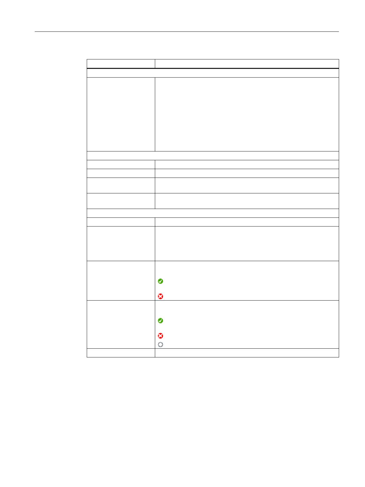
Display
Meaning/information
Status
Bus status
POWER_ON (0): State after the control has been switched on
OFFLINE (1): Basic initialization has been performed
STOP (2): Start in accordance with the hardware configuration (SDB)
CLEAR (3): PROFIBUS slaves have been parameterized and configured in
accordance with the hardware configuration (SDB) and taken into the cyclic
data exchange with zero output data
OPERATE (4): Cyclic data exchange with the PROFIBUS slaves running
ERROR (9): A fatal error had been detected (e.g. invalid or faulty SDB)
(<n>) corresponds to the OPI variable value for the bus state.
Bus configuration
S7 Subnet ID
S7 Subnet ID of the PROFIBUS subnet
Baud rate
Transmission rate in Mbd
Cycle time
Configured bus cycle time in ms; defines the position control cycle clock at
the same time.
Sync. Component (TDX)
Configured interval in ms for the cyclic data exchange within a PROFIBUS DP
cycle.
PROFIBUS diagnostics/slaves
Slave address
Configured number of the DP slave
Assignment
Information as to whether the DP slave is assigned to the NC or to the PLC.
NC: e.g. one or more drives controlled by the NC
PLC: e.g. I/O peripherals or an axis controlled by the PLC
NC/PLC (for DP integrated)
Communication state
Information as to whether the DP slave is identified on the bus via the com-
munication state.
Green: DP slave has been detected on the PROFIBUS DP and data ex-
change with the assigned component (NC and/or PLC) is working error-free
Red: Incorrect response / no communication
Synchr. with NC
Information as to whether the DP slave is running synchronously to NC on
the bus.
Green: DP slave runs synchronously to NC on the PROFIBUS DP, i.e. there
is an isochronous data exchange
Red: Incorrect response / no communication
Gray: DP slave is not assigned to the NC, but to the PLC
Number of slots
Number of configured slots within the DP slave
Further information
Further information about the configuration of the properties of the network interface for
PROFIBUS can be found in
CNC Commissioning Manual: NCK, PLC, drive.
SINUMERIK Operate
Commissioning Manual, 10/2020, 6FC5397-1DP40-6BA4
313
Service and diagnostics
16.9 PROFIBUS diagnosis
Procedure
1.
Select the "Diagnostics" operating area.
2.
Press the menu forward key and the "Bus TCP/IP" softkey.
The "PROFIBUS Diagnostics" window opens.
3.
If multiple PROFIBUS connections have been configured, press the "Bus -"
or "Bus +" softkey to select the configuration you require.
- OR -
Press the "Select bus" softkey and, when the list is displayed, select the
required configuration in it.
Press the "OK" softkey.
16.9.1
Displaying details for DP slaves
Further information about the slots of a selected DP slave is displayed here.
Display
Meaning/information
Slave
Address
The DP slave selected in the PROFIBUS diagnostics / slaves pane
Communication state
Data regarding the NC and/or PLC assignment of the DP slave
In synchronism with NC
Data regarding NC synchronous operation of the DP slave
If a synchronous value is not available for the DP slave, then the display
remains hidden.
Slots
No.
Slot number within the DP slave
I/O addr.
I/O address in the I/O address space of the PLC, assigned to this slot
For NC axes, the setpoint and the actual value must always be configured on
the same I/O address.
Type
Data as to whether the slot is input, output or diagnostic slot
If the slot is assigned to an NC axis, then the output is always denoted as
setpoint value and the input always as actual value.
Length (bytes)
Length of the I/O area reserved for the slot in the STEP7 I/O address space
SINUMERIK Operate
314
Commissioning Manual, 10/2020, 6FC5397-1DP40-6BA4
Service and diagnostics
16.10 Drive system
Display
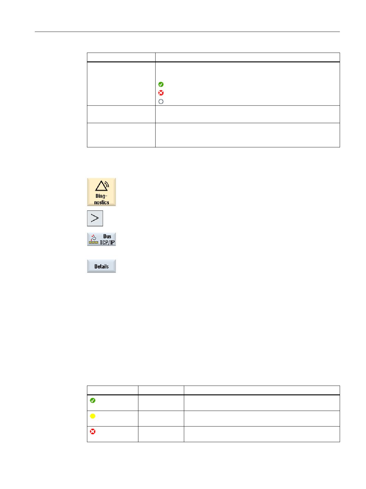
Meaning/information
Communication state
Actual communication state of the slot
If a value is not available for the NC axes, then the display remains hidden.
Green: Slot used by the NC, communication active
Red: Slot used by the NC, communication currently not active
Gray: No NC axis
Machine axis
Display of the name defined in the machine data for this slot
If the slot is not assigned to any NC axis, then the display remains hidden.
Telegr. type (NC)
Displays the assigned telegram type
If a telegram type is not assigned in the NC machine data, then the display
remains hidden.
Procedure
1.
Select the "Diagnostics" operating area.
2.
Press the "Menu forward" key and the "Bus TCP/IP" softkey.
The "PROFIBUS Diagnostics" window is opened.
3.
Select the PROFIBUS configuration for which you want to display details.
4.
Press the "Details" softkey.
The "PROFIBUS Diagnostics ... - Details" window is opened.
16.10
Drive system
16.10.1
Displaying drive states
Status display
The "Drive System Diagnostics" window displays the status information about the drive units and
the associated drive objects. The status symbols have the following meaning:
Display icon
Meaning
Green
The drive object is in (cyclic) operation, without any detected
problems.
Yellow
The drive object has detected a less serious problem, i.e. a
warning is pending, for example, or enables are missing.
Red
This drive object has detected a serious problem, for example,
an alarm is pending.
SINUMERIK Operate
Commissioning Manual, 10/2020, 6FC5397-1DP40-6BA4
315
Service and diagnostics
16.10 Drive system
Display icon
Meaning
Gray
The drive status could not be determined for this drive object.
#
Special charac-
Error when reading the data.
ters
Procedure
1.
Select the "Diagnostics" operating area.
2.
Press the menu forward key and the "Drive system" softkey.
3.
The "Drive System Diagnostics" window opens.
The name of the selected drive object is displayed in the window title.
Press the "Drive object +" or "Drive object -" softkey.
The next (+) or previous (-) drive object is selected.
- OR -
Press the "Select drive unit" softkey.
The "Select Drive Unit" window opens.
4.
Select the desired drive unit via the drop-down list box and press "OK" to
confirm the selection.
See also
Displaying details of the drive objects (Page 316)
16.10.2
Displaying details of the drive objects
Drive system diagnostics - details
The following information is displayed for the drive objects:
• Status display (r0002)
- The status display (parameter r0002) of the drive object is displayed.
• Missing enable signals (r0046)
- The enable signals are diagnosed except for the drive objects that do not have enable
signals (e.g. Control Unit). Missing enables are shown in a pane below the displays.
SINUMERIK Operate
316
Commissioning Manual, 10/2020, 6FC5397-1DP40-6BA4
Service and diagnostics
16.10 Drive system
•
Commissioning parameter filter
- (p0009) - control unit
The value of the "Device commissioning parameter filter" control unit parameter (p0009)
is displayed.
- (p0010) - further drive object
The value of the "Drive object commissioning parameter filter" parameter (p0010) is
displayed.
•
Current fault
The alarm number of the actual drive object fault is displayed or "No fault present", when no
drive object fault is pending.
You obtain an overview of the pending faults with the following data in an additional
window:
- Alarm number
- Time: Date and time
- Alarm text
•
Current warning
The number of the current drive object warning is displayed or "No warning present", when
no drive object warning is pending.
You obtain an overview of the pending alarms with the following data in an additional
window:
- Alarm number
- Time: Date and time
- Alarm text
Meaning of the symbols
Display icon
Meaning
Green
The relevant value of the drive object signals no problem detected.
Yellow
The relevant value of the drive object signals a less serious problem,
i.e. a warning is pending, for example, or enables are missing.
Red
The relevant value of the drive object signals a a serious problem, for
example, an alarm is pending.
Gray
The drive status could not be determined for this drive object.
#
Special characters
Error when reading the data.
Procedure
1.
Select the "Diagnostics" operating area.
2.
Press the menu forward key and the "Drive system" softkey.
SINUMERIK Operate
Commissioning Manual, 10/2020, 6FC5397-1DP40-6BA4
317
Service and diagnostics
16.11 Remote diagnostics
The "Drive System Diagnostics" window opens.
3.
Select the drive object for which you want to display further details.
4.
Press the "Details" softkey.
The "Drive System Diagnostics - Details " window opens.
The name of the drive object is displayed in the window header.
Press the "Faults" softkey.
The "Drive Unit Faults" window opens that shows an overview of the faults
that have been output.
Press the "Alarms" softkey.
The "Drive Unit Alarms" window opens that shows an overview of the
alarms that have been output.
You can display the pending SI messages if Safety Integrated is integrated
in your controller.
16.11
Remote diagnostics
16.11.1
Adapting remote diagnostics
Depending on the operating mode, the initiative for remote diagnostics comes from the service
provider or from the controller.
If the initiative comes from the controller, the "Request remote diagnostics" softkey is set-up.
The display of the "Request remote diagnostics" softkey is defined in the "tcu.ini" file under the
[PINGSERVICE] section.
• Variable PingServiceMode
0 = disable
1 = enable
In additional variables of this section, the data for the request telegram for service should be set.
• Variable PingServerIP
IP address of the service provider to which the request telegram should be sent, e.g.
PingServerIP = 128.45.234.19
• Variable PingTransmissionData
A text that should be sent out as data content in the request telegram,
e.g. PingTransmissionData = help at machine 35
• Variable PingTransmissionPeriod
The length in minutes that the telegram should be sent,
e.g. PingTransmissionPeriod = 5
SINUMERIK Operate
318
Commissioning Manual, 10/2020, 6FC5397-1DP40-6BA4
Service and diagnostics
16.11 Remote diagnostics
• Variable PingTransmissionInterval
Duration in seconds after which send is repeated,
e.g. PingTransmissionInterval = 15
• Variable PingServerPor
Port number of the Ping service with the manufacturer,
e.g. PingServerPort=6201
16.11.2
Remote diagnostics via Teleservice adapter IE at X127
The following settings must be made for remote diagnostics via modem using a Teleservice
adapter IE (TS Adapter) that is connected at X127.
Settings in the TS Adapter required
• IP address of the adapter: 192.168.215.30, subnet mask 255.255.255.224
• IP address of the caller: 192.168.215.29
These two addresses are also stored as standard in the "tcu.ini" file. If other addresses are
used, then appropriately change the entries "X127ModemIP" and "X127RemoteAccessIP" in
the "tcu.ini" file.
• Enable the ports for the services for S7 communication, http, HTTPS, SSH as well as VNC (port
5900) in the firewall.
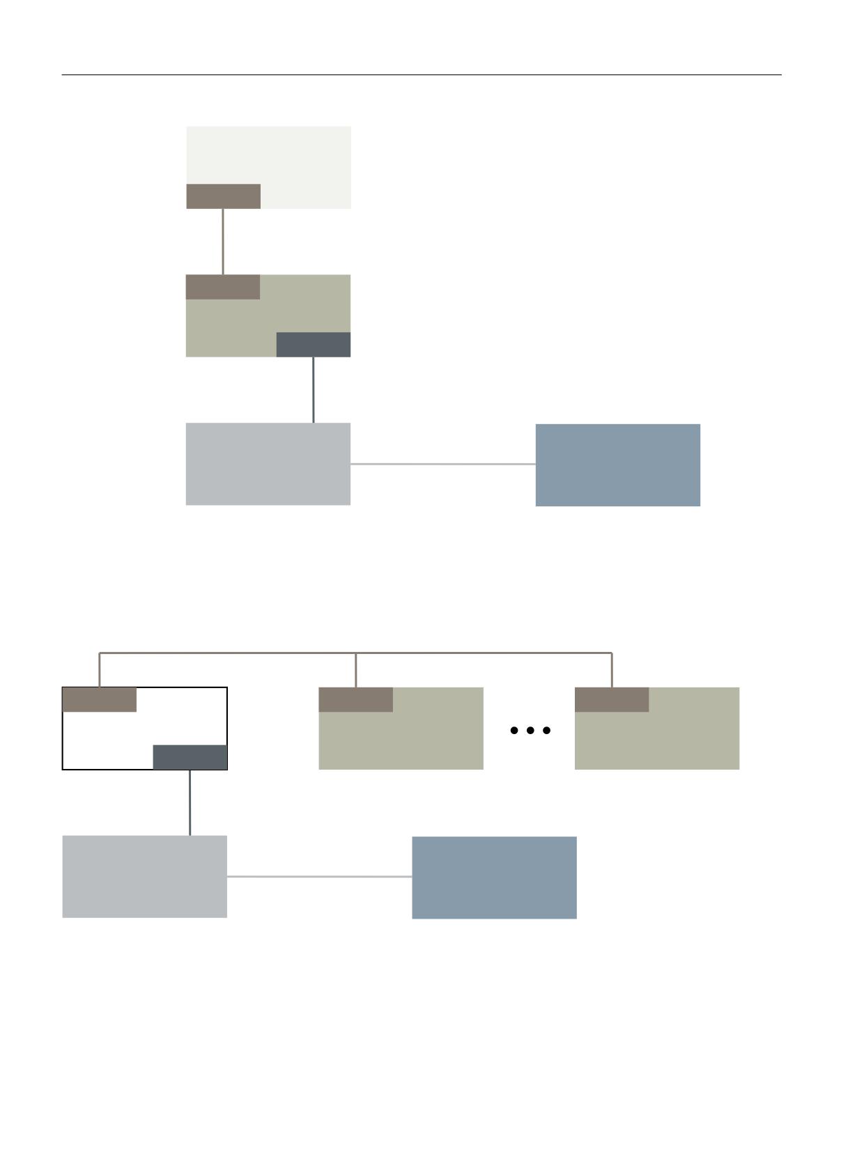
Connecting the modem for remote diagnostics
1&8
;
7HOHVHUYLFH DGDSWHU
6HUYLFH 3&
Figure 16-1
Basic system with SINUMERIK Operate on NCU (and operating station with TCU)
With the previously mentioned settings and the default values, in this configuration, remote
diagnostics via TS Adapter is possible without any additional changes having to be made.
SINUMERIK Operate
Commissioning Manual, 10/2020, 6FC5397-1DP40-6BA4
319
Service and diagnostics
16.11 Remote diagnostics
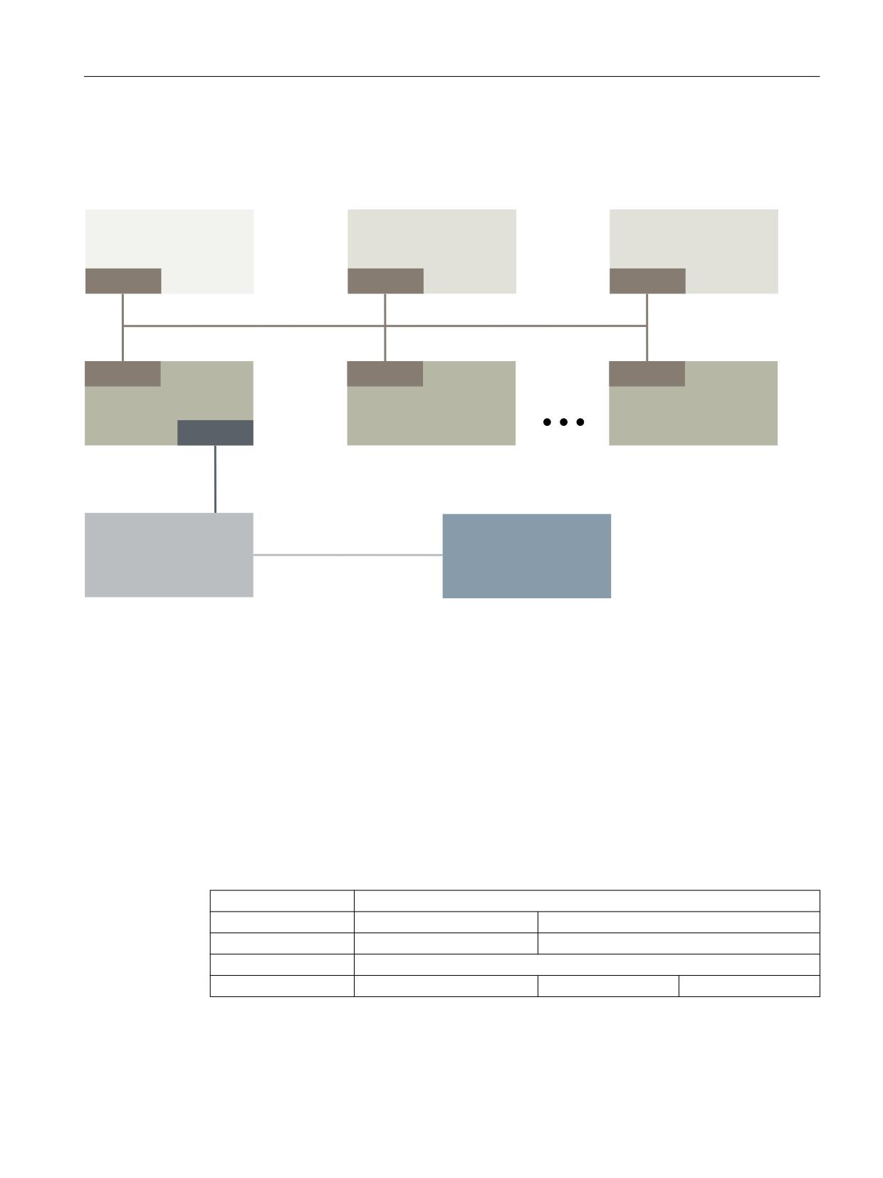
6,180(5,. 2SHUDWH
RQ 3&8
;
;
1&8
;
7HOHVHUYLFH DGDSWHU
6HUYLFH 3&
Figure 16-2
Basic system with SINUMERIK Operate on PCU
With the previously mentioned settings and the default values, in this configuration, remote
diagnostics via TS Adapter is possible without any additional changes having to be made. When
operating a SINUMERIK Operate on a PCU, the SINUMERIK Operate in the NCU must be switched
off.
;
;
;
VW 1&8
QG 1&8
Q 1&8
;
7HOHVHUYLFH DGDSWHU
6HUYLFH 3&
Figure 16-3
System with several NCUs and a fixed modem
The "Access MyMachine /P2P" option only has to be set for the NCU to which the TS Adapter is
connected at the X127 interface. Modem access can only be permitted by making the
appropriate entries at the SINUMERIK Operate in this NCU and the "Request remote control"
function executed. If modem access is permitted, then the service PC implicitly has access to all
other NCUs and their operating software. On the other hand, the operating screens to control
SINUMERIK Operate
320
Commissioning Manual, 10/2020, 6FC5397-1DP40-6BA4
Service and diagnostics
16.11 Remote diagnostics
the remote access can be used and set at each station (SINUMERIK Operate in the NCU)
individually for the station in conjunction with the relevant local PLC.
6,180(5,. 2SHUDWH
6,180(5,. 2SHUDWH
6,180(5,. 2SHUDWH
RQ VW 3&8
RQ QG 3&8
RQ UG 3&8
;
;
;
;
;
;
VW 1&8
QG 1&8
Q 1&8
;
7HOHVHUYLFH DGDSWHU
6HUYLFH 3&
Figure 16-4
System with several NCUs, several PCUs and a fixed modem
The "Access MyMachine /P2P" option only has to be set for the NCU to which the TS Adapter is
connected at the X127 interface. Modem access can only be permitted by making the
appropriate entries at the SINUMERIK Operate on the PCU that is assigned to this NCU and the
"Request remote control" function executed. If modem access is permitted, then the service PC
implicitly has access via the plant or system network to all other NCUs and PCUs and their
operating software. The operating screens to control the remote access can be individually used
and set at each station (SINUMERIK Operate in the NCU) for the station in conjunction with the
relevant local PLC.
16.11.3
PLC control for remote access
In the PLC user program, you can control external viewers using the following settings.
DB19.DBX1.0
PLCExtViewerReject
Value
= 0
= 1
Meaning
Permit remote control
No remote control
DB19.DBX1.1
PLCExtViewerMode
Value
= 0
= 1
ignored
SINUMERIK Operate
Commissioning Manual, 10/2020, 6FC5397-1DP40-6BA4
321
Service and diagnostics
16.12 Trace
Meaning
Operating rights for remote
Only monitoring for
-
control
remote control
Result
Operating rights for remote
Only monitoring for
No remote control
control
remote control
16.12
Trace
The trace provides you with an oscilloscope function that allows the following data (signals) to
be graphically displayed:
• General NC data
• PLC data
Trace session
The function serves for troubleshooting and resolving faults as well as to analyze the machine
and process performance. In a session, data (signals) are recorded briefly before and after an
event.
Graphic display
The recorded data is optically displayed in the form of curves, the so-called characteristics
graphs.
You have the option of individually setting the recording type.
Saving and downloading data
You can store the recorded data in an XML file. The saved file can then be re-loaded so that it can
be evaluated at a later time.
Recording fundamentals: Signals (data)
Signals (data) specify what is to be recorded:
• NC variables (axis data, drive data, channel data, etc.)
• PLC data
Cyclic events
Interpolation clock cycle (IPO clock cycle)
PLC cycle OB1
Position control clock cycle (servo clock cycle)
Non-cyclic events
Starting a session
• Recording using a trigger
• Manually starting and stopping a trace
SINUMERIK Operate
322
Commissioning Manual, 10/2020, 6FC5397-1DP40-6BA4
Service and diagnostics
16.12 Trace
Analyzing the result
The following functions are available to analyze the result:
• Scaling characteristic graphs
• Zooming characteristic graphs
• Defining a characteristic range using markers
16.12.1
General procedure
Sequence
• Create a trace session file as follows:
- Select the variable and define its representation type.
- Set the graphics window, and the save mode
- Set the trigger property to define the start and end of recording
• Save the recording and its associated properties that have been set
• Analyze the result by making the settings for the display in order to view additional details
(e.g. zoom in, scroll, select section, etc.)
See also
Trace options (Page 335)
Saving the trace file (Page 324)
Variable for trace (Page 326)
Trace settings (Page 332)
Evaluate a trace (Page 336)
SINUMERIK Operate
Commissioning Manual, 10/2020, 6FC5397-1DP40-6BA4
323
Service and diagnostics
16.12 Trace
16.12.2
Trace session
16.12.2.1
Creating a session file
Procedure
1.
Select the "Diagnostics" operating area.
2.
Press the menu forward key and the “Trace" softkey.
3.
Press the "Load trace" and "New" softkeys.
The "New Session" window opens in which the "Session" name is recom-
mended. The file format is automatically specified as ".xml".
4.
Supplement the file name or enter a new file name.
5.
Select a variable type and press the "OK" softkey.
You return to the "Select variables for trace:
” window.
The name of the session that has been newly created is displayed in the
header.
See also
Variables filter/search (Page 326)
16.12.2.2
Saving the trace file
There are two options of saving a trace session:
• Variables and settings: Only the variables and the settings are saved.
• Variables, settings and recorded values: The variables, settings and the recorded values are
saved.
Note
Save option
If you have activated the "Save file in both formats" checkbox at "Trace" → "Options
(Page 335)", the session file is saved as a csv file in addition to xml format.
SINUMERIK Operate
324
Commissioning Manual, 10/2020, 6FC5397-1DP40-6BA4
Service and diagnostics
16.12 Trace
Procedure
1.
You have edited an active trace session.
2.
Press the "Store trace" softkey.
The "Save Trace: Session ... " window opens and offers the following stor-
age options.
3.
Activate the corresponding checkbox and press the "OK" softkey.
The "Store Trace" window opens and specifies the file name in the "Name
of trace file:" entry field. The file format is automatically specified as ".xml"
and cannot be changed.
4.
Press the "OK" softkey to save the session file.
If the session file already exists, then you obtain a corresponding confir-
mation prompt.
5.
Press the "OK" softkey if you wish to overwrite the existing session file.
- OR -
Press the "Save as" softkey if you do not wish to overwrite the existing
session file.
A new name is suggested but you can specify a name yourself.
- OR -
Press the "Change directory" softkey if you wish to store the session file in
a directory other than in the standard "Trace" directory.
The data tree opens and you can select between the configured drives.
Press the "New directory" softkey if you wish to create a new directory.
The "New Directory" window opens in which you can assign a directory
name.
Press the "OK" softkey.
The "Store Trace" window opens in which the names of the target direc-
tory and the session file are displayed.
You can change the name of the session file.
6.
To save the session file, press the "OK" softkey one more time.
- OR -
If the session file with this name already exists, then you obtain a corre-
sponding confirmation prompt.
16.12.2.3
Load trace session file
You have the option of loading already saved session data, to restart them or to display the trace
that has been recorded.
Settings
Meaning
Variables, settings
You can restart a trace session that has already been created.
Variables, settings and recorded val-
You can view the result of a trace session, change the variable
ues
and if required, restart.
SINUMERIK Operate
Commissioning Manual, 10/2020, 6FC5397-1DP40-6BA4
325
Service and diagnostics
16.12 Trace
Precondition
A session file of recorded traces is available.
Procedure
1.
You have selected the "Trace" function.
2.
Press the "Load trace" softkey.
The "Load Session File: Please Select File" window opens.
3.
Select the desired session file from the appropriate directory, e.g. "Trace",
and press the "Display trace" softkey.
The "Load trace: session..." is opened.
4.
Select the checkbox "Variables, settings", if you wish to immediately start
the trace session.
5.
Press the "OK" softkey and the "Start trace" softkey to restart the trace.
- OR -
Select the checkbox "Variables, settings and recorded values", if you wish
to display the trace session.
Press the "OK" softkey.
The data of the selected session are loaded displayed in the "Trace" win-
dow.
16.12.3
Variable for trace
16.12.3.1
Variables filter/search
Searching for PLC/NC/servo variables
To limit the selection of variables for PLC/NC/servo, set a filter and/or enter a start value for the
search:
Filter:
Display of the following variables:
System variable
System variables
NC
NC variables
Axis
Axis variables
Channel
Channel variables
Mode groups
Variables of the mode groups in OPI notation
Servo
Servo trace variables
Global user data
GUD such as: SGUD, MGUD, UGUD, GUD4, ...
SINUMERIK Operate
326
Commissioning Manual, 10/2020, 6FC5397-1DP40-6BA4
Service and diagnostics
16.12 Trace
Filter:
Display of the following variables:
PLC
PLC variables
PLC alarms
Manufacturer-specific PLC alarm signals
All (no filter)
All variables in alphabetical order
Inserting variables
The start value for "Filter/Search" of variables differs. For example, to insert the variable $R[0],
enter the following start value:
• The start value is 0 if you filter according to "System variables".
• The start value is 1 if you filter according to "All (no filter)". In this case, all signals are displayed
and shown in the OPI notation.
The GUD from the machine data is only displayed in the Search window for the variable selection
when the associated definition file has been activated. Otherwise, the sought variables must be
entered manually, e.g. GUD/SYG_RM[1]
The following machine data is representative for all variable types (INT, BOOL, AXIS, CHAR,
STRING): MD18660 $MN_MM_NUM_SYNACT_GUD_REAL
Searching for drive variables
The restriction of the search is performed in this case via the selected drive object. In the Search
window, you can restrict the selection by entering alphanumeric values, for example. Further
restrictions of the selection are possible via the "All" or "Recommended" interconnections.
Procedure
For a trace session, in the "Selected Variables for Trace: Session ... " window, set the variables
whose signals are to be traced.
1.
In the "Select variables for trace: Session..." window, a trace session is
displayed.
2.
Position the cursor in the "Variable" column in an empty line.
- OR -
Position the cursor in the "Variable" column on a variable that you wish to
replace by another.
3.
Press the "Insert variable" softkey.
The "Select Variable" window opens.
Note:
When selecting a "Drive parameter", firstly select the drive object (DO) and
then insert the desired parameter from the list of corresponding param-
eters.
4.
Press the "Filter/search" softkey to start a specific search.
In the "Filter" selection box, select a variable area.
- OR -
SINUMERIK Operate
Commissioning Manual, 10/2020, 6FC5397-1DP40-6BA4
327
Service and diagnostics
16.12 Trace
Directly enter the variable into the "Search" entry field.
The cursor jumps to the term that is found.
Press the "Delete search" softkey if you wish to terminate the search.
5.
Press the "Add" softkey to enter the required variable into a trace session.
The "Variable Attributes" window opens and you can select the appropri-
ate value (e.g. channel data, drive bus no.) from a combobox.
- OR -
Press the "Replace" softkey to replace an already selected version by an-
other one.
6.
Press the "OK" softkey to add or replace the variable.
Each variable is automatically allocated a reference number, which is dis-
played in the upper section of the window. This number is opened auto-
matically allocated. If a version is removed, then the following variables
are re-numbered.
7.
Now, select the desired settings for display, such as color, pen, qty., event.
etc.
Editing variables of a trace session
Key combination
Effect
Ctrl + X
Press the key combination or open the shortcut menu in order to
cut out a variable.
or right-click, shortcut menu "Cut"
Ctrl + C
Press the key combination or open the shortcut menu in order to
copy a variable.
or right-click, shortcut menu "Copy"
Ctrl + V
Press the key combination or open the shortcut menu in order to
insert a variable.
or right-click, shortcut menu "Paste"
16.12.3.2
Selecting attributes of a variable
Attributes
For a trace session, select the variables and assign the corresponding attributes:
Column
Meaning
Variable
Address of the variables
Attributes
Meaning
Comment
• Name of the selected variables
• A general description for the variables.
Color
Color selection, the representation of the characteristic graphs.
When creating a variable, the next color from the available palette is automati-
cally used.
SINUMERIK Operate
328
Commissioning Manual, 10/2020, 6FC5397-1DP40-6BA4

Service and diagnostics
16.12 Trace
Attributes
Meaning
Pen
Line type selection to display the characteristic graphs.
• No line
• Solid line
• Dashed line
• Dash-dot line
• Dash-dot-dot line
• Dotted line
• Stepped line XY
• Stepped line YX
• "* line" (line made up of * symbols)
•
+ line
• X line
Qty.
Defines whether the characteristic of the variables is displayed in the "Trace"
window. If the checkbox is not selected, then no characteristic graphs are dis-
played.
Events
Event selection which triggers that the signal is traced:
• Interpolation clock cycle (IPO clock cycle)
• Interpolation cycle (IPO2)
• Position control clock cycle (servo clock cycle)
• PLC cycle OB1
• Drive trace rate
• Start geometry axis/direction change
• Stop geometry axis
• Machine axis start / direction change
• Machine axis stop
• NC start (program runs)
• NC start (program ran)
• Start of the data recording
SINUMERIK Operate
Commissioning Manual, 10/2020, 6FC5397-1DP40-6BA4
329
Service and diagnostics
16.12 Trace
Attributes
Meaning
•
Block start, type 1 or block end (all program levels, without intermediate
blocks)
•
Block start, type 2 or block end (all program levels, with intermediate blocks)
•
Block start, type 3 or block end (all main programs, without intermediate
blocks)
•
Block start or block end, block search (all program levels, without intermedi-
ate blocks)
•
Geo axis start / direction change (2nd event)
•
Geo axis stop (2nd event)
•
Block start, type 2 (2nd event: all program levels, without intermediate
blocks)
•
Block end, type 2 (2nd event: all program levels, with intermediate blocks)
•
Block start, block advance, type 1 (2nd event)
•
OEM test event 1 (non-cyclic, block advance)
•
OEM test event 2 (non-cyclic, main run)
•
Activate/deactivate synchronized action
•
Synchronized action initiated (condition fulfilled)
•
Signaled alarm
•
Cancel softkey pressed
•
Program level change
•
Block end (Interpreter)
•
Trace end (last event!)
•
Start trace
•
WRTPR part program command
•
WRTPR part program command (block search)
•
Tool change
•
Cutting edge change
•
Tool change (block search)
•
Cutting edge (block search)
•
Start trigger initiated
•
Stop trigger initiated
•
Block end (block advance)
•
Block end (2nd event: Block search)
•
WRTPR part program command (block advance)
•
Tool change (block advance)
•
Cutting edge (block advance)
Event channel
This means that the channel can be defined in SINUMERIK in which a specific
event occurs. For events which are not channel-specific, the field remains empty.
SINUMERIK Operate
330
Commissioning Manual, 10/2020, 6FC5397-1DP40-6BA4
Service and diagnostics
16.12 Trace
Attributes
Meaning
Bit mask
In the case of an integer variable, a bit mask can be specified in this field. For a bit
mask, the particular signal value is AND'ed before being displayed. After the
mask has been applied, all of the selected bits are moved to the right so that it
looks as if the bit or the bits all start with bit zero.
This means, if all bits with the exception of bit 7 have been masked, then the
integer number that would have been obtained would either have a value of 0 or
1, however, not 0 or 128.
If all of the bits with the exception of bit 7 and 0 have been masked, the resulting
integer number would either have the value 0, 1, 2 or 3, however, not 0, 1, 128
or 129.
Decimal places
This setting is used to define how many places to the right of the decimal point
are displayed at the axis identifiers.
Coord. axis
The coordinate axes are displayed to the left or right in the graphic window or
there is no display.
Display Y
Value input or 0
Scale factor
Defines the scale.
Units
Displays the measurement unit, e.g. mm/min. The system specifies this and it
cannot be changed.
16.12.3.3
Displaying details of a variable
The most important information and settings are displayed at a glance in the detail window:
• Variable address
• Comment with a description of the variables
• Events
• Channel, axis, access level, mode group, etc.
• Smaller graphic display with the event; when this event occurs the characteristic graphs are
recorded as well as their attributes, such as color or line type.
Procedure
1.
You are in the "Select variables for trace: ..." window.
2.
Position the cursor to the required variable, and press the "Details" softkey.
A subscreen with the most important information as well as the graphic
display is shown in the lower half of the window.
3.
Press the "Details" softkey again to display the subscreen.
SINUMERIK Operate
Commissioning Manual, 10/2020, 6FC5397-1DP40-6BA4
331

Service and diagnostics
16.12 Trace
16.12.4
Trace settings
16.12.4.1
Trace settings (PLC, NC, servo)
In the "Trace Settings (PLC, NC, Servo)" window, you define the conditions for starting and
stopping the trace session.
Condition for Start trace
With "Start trace" softkey
The recording is started immediately after pressing the "Start trace" softkey.
If variable
The session is activated by a variable. The desired variable is selected via the
"Insert variable" softkey or "Quick list" softkey.
• Condition and value
After the session has been activated, this defines at which value the trace
recording is started.
The following values are offered: = =, ≠, >, >=, <, <=, ascending, descending,
changed.
Data acquisition [s]
Specifies where the recorded data is saved:
• With "On NCK", the recorded data is saved in the NC work memory until the recording is stopped. Only
then is the session file saved on the CompactFlash card.
• With "CF card" or "On hard disk", the data is saved during the recording on the CompactFlash card or
hard disk (e.g. of the PCU). As a consequence, more signals can be processed.
Condition for Stop trace
With "Stop trace" softkey
The recording is stopped after pressing the "Stop trace" softkey.
If the time has expired
Defines the period which after expiry, the trace recording is exited.
If the memory is full
The trace session is terminated when the specified data volume (KB) is
reached.
If variable
The recording is stopped by a variable. The desired variable is selected via
the "Insert variable" or "Quick list" softkey.
• Condition and value
After the session has been activated, this defines at which value the trace
recording is exited.
The following values are offered: = =, ≠, >, >=, <, <=, ascending, descending,
changed.
• Delay time [s]
This defines how long the trace still runs after the session has been exited.
• Overwrite at memory
Defines from which memory limit the data is overwritten (ring buffer).
limit (KB)
SINUMERIK Operate
332
Commissioning Manual, 10/2020, 6FC5397-1DP40-6BA4
Service and diagnostics
16.12 Trace
Note
Loss of recorded data when maximum duration is exceeded
Traces with the parameter assignment "Stop trace - If variable - Overwrite at memory limit" may
not exceed a maximum period between the start and the finish of the recording.
If the maximum period is exceeded, the stop event is ineffective and the recording cannot be
completed as usual.
The maximum period can be calculated as follows:
Use the temporary setting "Stop trace - When time expired" to find out how much memory space
is required per minute for the set recording, e.g. 602 kB/min.
The maximum permissible time in minutes which may pass between the start and finish of a
recording is computed using the following formula:
231 (2 147 483 648) bytes / memory space required for the set recording in bytes per minute
602 kB = 602 * 1 024 bytes = 616 448 bytes, per minute 2 147 483 648 bytes / 616 448 bytes
per minute = 3 483 minutes = 58 hours
Note
Stop condition with non-effective overtravel time and memory limit
The settings for the overtravel time and memory limit are not effective if you select PLC signals
with the result "PLC cycle OB1" for the trace.
Set at least one PLC signal before the trace to the result "Interpolation cycle (IPO cycle)" so that
the data for the overtravel time and memory limit are recorded.
16.12.4.2
Trace settings (drive)
In the "Trace Settings (Drive)" window, you define the conditions for starting and stopping the
trace session:
SINUMERIK Operate
Commissioning Manual, 10/2020, 6FC5397-1DP40-6BA4
333

Service and diagnostics
16.12 Trace
Condition for Start trace
With "Start trace" softkey
The recording is started immediately after pressing the "Start
trace" softkey.
If variable
The recording is activated after pressing the "Start trace" soft-
key when the selected variable clearly satisfies the condition
and the specified value.
The following conditions are offered:
• Positive edge
• Negative edge
• With bit mask
The "Bit mask" softkey is displayed when the "Bit mask" con-
dition is selected in order to select the desired bits. Irrespec-
tive of the maximum value (hexadecimal) which is possible
through the bit mask, a "Value" (decimal) can be entered at
which the trace recording starts precisely.
Example:
The trace recording is started when the following bits are set:
Bit 0 = 0; bit 1 = 1; bit 2 = 0; bit 3 = 1
Bit mask = fH
Condition
Value (decimal)
Variable: CU/
With bit mask
10
r722/3.3.1
☑ Bit 0
☑ Bit 1
☑ Bit 2
☑ Bit 3
Preprocessing time [s]:
The input of a preprocessing time corresponds to the func-
tional parameter p4722 "Trace trigger delay":
• A positive preprocessing time starts the recording before
the trigger event.
• A negative preprocessing time starts the recording after
the trigger event.
When entering a preprocessing time, the entire duration of
the recording must be taken into account:
• If the preprocessing time is greater than the entire dura-
tion of the recording, the entry is rejected.
• If too large a preprocessing time is entered, the trigger
event may not be recorded.
Data storage on CU
Drive trace rate [μs]:
Enter a factor with the "Sampling rates" softkey to set the ef-
fective sampling rate. With a higher sampling rate, the record-
ing duration is also longer.
Condition for Stop trace
If the time has expired
Defines the period which after expiry, the recording is exited.
If the memory is full
The recording is terminated when the specified data volume
(KB) is reached.
SINUMERIK Operate
334
Commissioning Manual, 10/2020, 6FC5397-1DP40-6BA4
Service and diagnostics
16.12 Trace
16.12.4.3
Trace options
You define the following properties of a trace session in the "Trace - Options" window.
•
Setting the graphic window
- Displaying main grid lines: You define whether a horizontal grid is displayed and in which
color.
- Displaying grid sub-lines: You define whether a vertical grid should be displayed and in
which color.
- Background: You select the backg24round color of the graphic window.
•
Defining storage options
- Activate the "Confirm file overwrite" checkbox in order to receive a confirmation prompt
each time a trace session is to be overwritten. If the checkbox is deactivated, the trace
session is overwritten without a confirmation prompt.
- Activate the "Save file in both formats" checkbox in order to also save the data as a csv file
(Page 324) in addition to the xml session file. The file in csv format cannot be imported
again.
- Activate the check box "Save file in HMI Advanced Servo Trace Format" in order to store
additional export data in the HMI Advanced servo-trace format. The following file formats
are supported:
SVT files (trace session settings)
st1 files (variables of the first and second trace sessions)
st2 files (variables of the third and fourth trace sessions)
Procedure
1.
You are in the "Select Variables for Trace: ..." window and a trace session
has been selected.
2.
Press the "Options" softkey.
The "Trace - Options" window opens.
3.
Select the desired settings and press the "OK" softkey in order to accept
the settings.
16.12.4.4
Starting the trace
In the "Trace" window, you obtain the curve with the data of the variables selected for a trace
session.
The diagram comprises two Cartesian coordinates:
• Time axis
The horizontal x axis supplies the time values.
• Value axis
The vertical y axis displays the resolution fineness (amplitude).
SINUMERIK Operate
Commissioning Manual, 10/2020, 6FC5397-1DP40-6BA4
335
Service and diagnostics
16.12 Trace
Note
Display of real values of PLC variables
If the value format is displayed incorrectly in the trace, extend the variable specification in the
"Select variable for trace" window with the parameter assignment :REAL, e.g. to
DB21.DBD76:REAL. The real values of the variable will then be displayed in the trace.
Recording the trace session
• Manually starting and stopping a trace
• Starting and stopping recording using a trigger
Procedure
1.
You have listed the desired variables for a trace section.
2.
Press the "Display trace" softkey.
The "Trace" window is opened. The recording is loaded and the procedure
is displayed in progress window.
3.
Press the "Start trace" softkey if you wish to immediately start recording.
- OR -
The recording is triggered by the trigger condition.
4.
If you wish to manually end the recording, press the "Stop trace" softkey.
- OR -
The recording is stopped by the trigger condition.
16.12.5
Evaluate a trace
16.12.5.1
Setting trace views
In order to permit a precise evaluation of the recorded signals, you have the option to edit the
view as well as the display of the characteristic graphs:
• Selection/legend
- Show legend: In addition to the graphic display, the data of the variable is displayed as
comment, numbered and in color.
- Make a selection: You define which variables are displayed in the graphic window.
• Scale
- Specifying scaling factors for minimum and maximum X and Y value
SINUMERIK Operate
336
Commissioning Manual, 10/2020, 6FC5397-1DP40-6BA4
Service and diagnostics
16.12 Trace
• Zoom
- Increasing or decreasing the section
• Cursors: The cursor display provides functions that allow one, two or both curves to be
precisely measured.
- Cursor A
- Cursor B
- Both cursors
- Snap to curve: The cursor precisely moves along the curve
- Point mode: Cursor jumps directly to various values.
- High point mode: The cursor jumps from one peak value to the next.
- Low point mode: Cursor jumps to the lowest values.
Requirement
The "Trace" graphic window is open and the trace has been recorded.
Editing curves
You jump from one variable to the next using the <TAB> key.
You jump back using the <Ctrl> and <TAB> keys.
With the cursor keys, you set marks, move to individual values and can
define a zoom range.
16.12.5.2
Selecting a variable
You have the option of displaying the selected variables as legend and to make a selection using
a checkbox.
Legend
Numbering the variables
Axis identifier
Comment of the variables
SINUMERIK Operate
Commissioning Manual, 10/2020, 6FC5397-1DP40-6BA4
337
Service and diagnostics
16.12 Trace
Displaying a legend and selecting a variable
1.
A recording is opened in the "Trace" graphics window.
2.
Press the "Legend / selection" softkey.
The graphic window is halved. The variables are displayed as comment
and with checkbox in the left-hand section of the window.
3.
Activate or deactivate the required variable using the checkbox to display
it as curve.
4.
Press the softkey again to hide the legend area again.
16.12.5.3
Scaling the display
The scaling allows you to make a precise measurement of selected variables from the X time axis
as well as from the Y value axis. You have the option of saving the larger or smaller display in a
user-defined way
Setting
Meaning
X minimum or
Highest or lowest value of the X time axis. The values are used for recording
X maximum
when the trace is started again.
Fixed scale, X axis
Values of the X time axis are kept.
Strip chart recorder mode
The values of the X time axis are used while
recording.
Y minimum or
Defining the highest or lowest value of the Y value axis (amplitude).
Y maximum
Offset or
Defining the rms values (mean values) of the amplitudes.
resolution
The scale is changed by a factor of 10.
Scaling the time and value axis
1.
A recording is opened in the "Trace" graphics window.
2.
Press the "Scale" softkey in order to scale the display.
The "Select X-Y Scaling" input window opens and the values of the X time
axis are displayed.
3.
Press the "X time axis" softkey again if you wish to hide the values.
- OR -
Press the "Y selected curves" softkey to display the values of the Y value
axis.
Press the softkey again if you wish to hide the values.
- OR -
SINUMERIK Operate
338
Commissioning Manual, 10/2020, 6FC5397-1DP40-6BA4
Service and diagnostics
16.12 Trace
You have selected both axes.
4.
Press the "Scale +" or "Scale -" softkey until the desired scaling is reached.
- OR -
Enter the scaling values directly into the input window and select the
appropriate property.
5.
Press the "Scale" softkey to save the settings.
- OR -
Press the "Adapt selected" softkey to display the selected characteristic
graphs in the full graphic window.
Press the "Fit one" softkey to display the selected characteristic graphs in
the full graphic window.
16.12.5.4
Zooming the display
Using the zoom function, you have the option of viewing selected sections of curves in detail.
After you have defined an area or a section, you can increase or decrease the size of it (zoom in
or zoom out).
Procedure
1.
A recording is opened in the "Trace" graphics window.
2.
Press the "Zoom" softkey if you wish to zoom-in or zoom-out on the char-
acteristic graphs.
3.
The "X time axis" or "Y value axis" softkey is selected.
4.
Press the "Adapt individually" or "Adapt all" softkey if you wish to display all
selected characteristic graphs in a separate area positioned one above the
other.
or
- OR -
Press the "Adapt together" softkey if you wish to adapt all of the charac-
teristic graphs to the graphic window.
As all of the curves fill the complete window area, they are displayed
superimposed on one another.
- OR -
SINUMERIK Operate
Commissioning Manual, 10/2020, 6FC5397-1DP40-6BA4
339
Service and diagnostics
16.12 Trace
Press the "Individually adapt X" softkey if you wish to normalize the X time
axis only in the graphic window.
- OR -
Press the "Individually adapt Y" or "Adapt all" softkey if you only wish to
scale the Y value axis in the graphic window.
or
- OR -
Press the "Adapt Y together" softkey if you wish to adapt the value axis of
all characteristic graphs to the graphic window.
As all curves fill the complete window area, they are displayed superim-
posed.
5.
Press the "Zoom +" or "Zoom -" softkey until the desired display size is
reached.
Zoom in/zoom out area
Press the "Zoom area" softkey to define a specific section.
A frame is displayed.
Press the "Zoom +" or "Zoom -" softkey to change the frame step-by-step.
Press the "OK" softkey to display the zoom area.
16.12.5.5
Position the cursor
Using the cursor, you have the option of determining the precise values from a defined section.
To do this, the cursor is positioned directly on the curve.
Procedure
1.
A recording is opened in the "Trace" graphics window.
2.
Press the "Cursor A" softkey.
The reference number, color of the variables and the color of the coordi-
nate crossing point are displayed on the softkey.
SINUMERIK Operate
340
Commissioning Manual, 10/2020, 6FC5397-1DP40-6BA4
Service and diagnostics
16.12 Trace
3.
Position "(A)" at the position on the curve where you wish to start the
measurement.
The coordinates are specified in a tooltip and in the status line.
4.
Press the "Cursor B" softkey.
The reference number, color of the variables as well as the color of the
coordinate crossing point are also displayed on this softkey.
Position "(B)" at the position on the curve where you wish to end the
measurement.
5.
Press the "Both cursors" softkey to display the area between A and B.
The coordinates of A and B as well as the difference "Δ" are displayed in the
status line.
Press the active "Cursor A" and "Cursor B" softkeys again to deselect the
position.
When re-selected, the positions are reset.
Press the "Crop to screen" softkey to display the area, defined by "Cursor A"
and "Cursor B", in the complete graphic window.
Press the "Snap to waveform" softkey to move the cursor along the curve
step-by-step.
16.12.5.6
Acquiring measured values
You have the option of directly determining the following values of a curve:
• Peak-to-peak value
• Peak-to-valley value
Procedure
A recording is opened in the "Trace" graphics window.
Press the "Point Mode" softkey to continuously move the cursor along the
curve.
Press the "Peak Mode" softkey to position the cursor at the highest value.
Press the "Valley Mode" softkey to position the cursor at the lowest value.
SINUMERIK Operate
Commissioning Manual, 10/2020, 6FC5397-1DP40-6BA4
341
Service and diagnostics
16.13 PROFIBUS/PROFINET and AS-i bus diagnostics
If you press the "Peaks" softkey, the cursor only goes to the peak-peak
values.
If you press the "Minimum" softkey, the cursor only goes to the peak-valley
values.
16.13
PROFIBUS/PROFINET and AS-i bus diagnostics
16.13.1
PROFIBUS/PROFINET
With the PROFIBUS/PROFINET diagnostics, you obtain a quick overview from which, when
required, you can call status and detailed information for external DP master systems and
PROFINET IO systems.
Precondition for detailed diagnostics
When using HMI PRO RT, the diagnostics can be extended by additional information (e.g.
module and Order No.). This data involves offline data, which can be extracted from the
associated Step7 project.
• You can create offline data using the HMIPRO CS program.
• You transfer data to the control using the HMIPRO program.
Software option
For faulted modules, in order that in addition to the status information, detailed
information can also be displayed, you now require the following option:
"Operating software SW HMI PRO sl RT".
In order that detailed information can be displayed for PROFINET-IO systems, the PLC block
FB_SL_COM from the HMI PRO block library must be used. Use DB449 as the associated instance
DB.
Note
Detailed information for DP master systems is also available without using FB_SL_COM.
Diagnostics information from the DP master systems
You can configure the following versions:
1. Software option not available and HMIPRO offline data not available
2. Software option available and HMIPRO offline data not available
3. Software option available and HMIPRO offline data available
SINUMERIK Operate
342
Commissioning Manual, 10/2020, 6FC5397-1DP40-6BA4
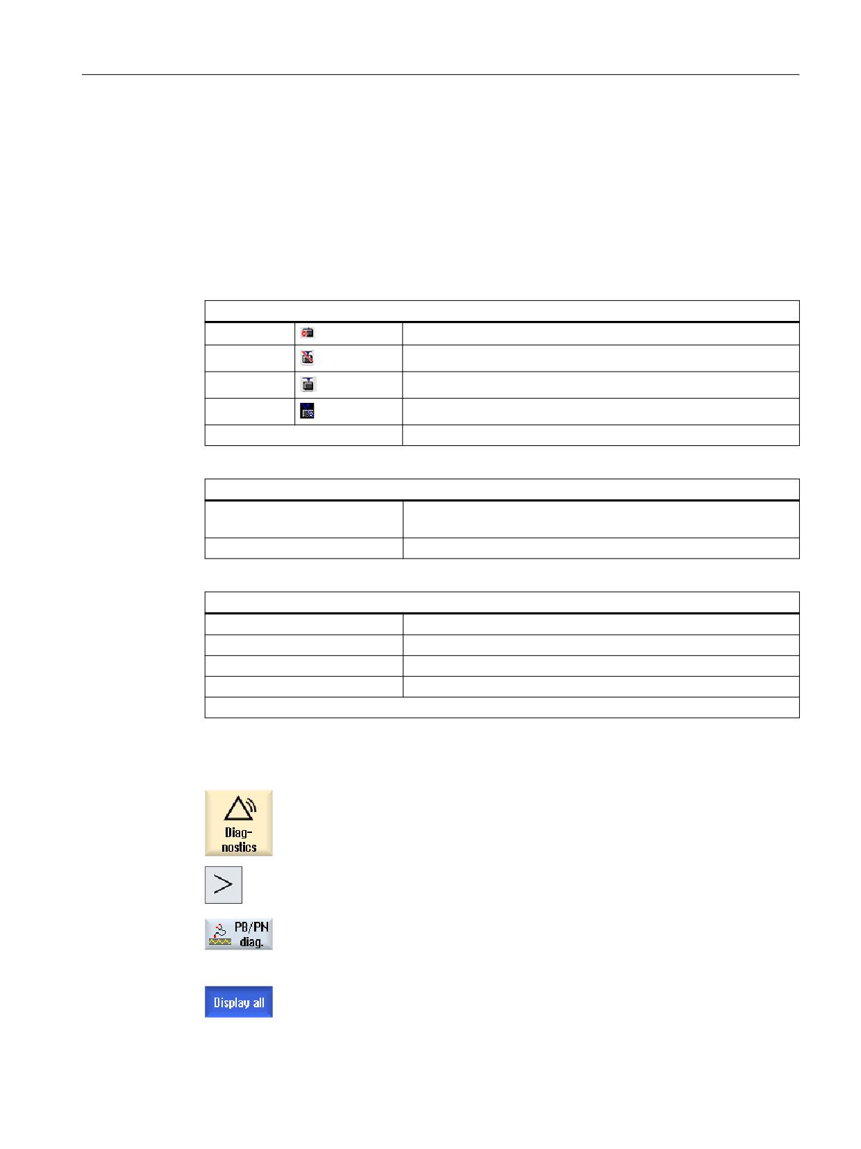
Service and diagnostics
16.13 PROFIBUS/PROFINET and AS-i bus diagnostics
16.13.2
Displaying PROFIBUS/PROFINET diagnostics
Diagnostics information from the DP master systems
From the user interface, you can display the fieldbus diagnostics known from HMIPRO. The
module state is displayed using diagnostic symbols.
The following diagnostics information is displayed depending on the particular version that you
have configured:
Information for all versions
Status
Module has a fault
Module has failed
Module is OK
Module is suppressed (this is only possible with HMI PRO RT)
PROFIBUS address
PROFIBUS address data
Additional information for the second version
PROFIBUS/PROFINET module or
channel diagnostics
Device diagnostics
For Siemens DP/DP coupler and diagnostics repeater
Additional diagnostic information for the third version
Name
Module designation from the HMI offline data
Name
Module name from the HMI offline data
Order no.
Order number of the module from the HMI offline data
IP address
IP address of the module from HMI offline data (only for PROFINET)
Graphic display of the complete hardware configuration in a dedicated window
Procedure
1.
Select the "Diagnostics" operating area.
2.
Press the "Menu forward" key twice and the "PB/PN diag." softkey.
The "PROFIBUS/PROFINET Diagnostics" window opens.
3.
Select the required DP master system.
The complete diagnostics information is displayed.
SINUMERIK Operate
Commissioning Manual, 10/2020, 6FC5397-1DP40-6BA4
343
Service and diagnostics
16.13 PROFIBUS/PROFINET and AS-i bus diagnostics
4.
Press the "Available devices" softkey to display the diagnostics data of
the available modules.
- OR -
Press the "Suppressed devices" softkey to display the diagnostics data
of the suppressed modules.
- OR -
Press the "Failed devices" softkey to display the diagnostics data of the
failed modules.
- OR -
Press the "Faulty devices" softkey to display the diagnostics data of the
faulty modules.
16.13.3
Configuring the AS-i bus
You obtain a fast overview of the existing AS-Interface network using the AS-Interface (AS-i)
diagnostics. Permanent monitoring and an error search function provide you with the following
information:
• Status flags acc. to the AS-i specification
• States of the AS-i slaves
Precondition
• For AS-i diagnostics, it is absolutely necessary to use the FB_SL_COM PLC block from the HMI
PRO block library.
• The configuration file "sltlprodiaghmi.ini" must be available.
AS-i components
The following AS-i components are supported:
CP142-2
(Type ID 1)
CP343-2
(Type ID 2)
DP/AS-i link
(Type ID 3)
DP/AS-i link 20E
(Type ID 4)
DP-AS-i link Advanced
(Type ID 6)
Diagnostic information
All of the AS-i components to be diagnosed must be parameterized in the "sltlprodiaghmi.ini"
configuration file.
Entry
Description
[SKO]
ComboCount=x
Number of entries (x) in the selection list
SINUMERIK Operate
344
Commissioning Manual, 10/2020, 6FC5397-1DP40-6BA4
Service and diagnostics
16.13 PROFIBUS/PROFINET and AS-i bus diagnostics
Entry
Description
[SKO_Index0]
1. Entry
DiagType= 6
Type ID of the AS-i component (refer above)
TypeSection=DP-AS-i-Link-
Designation of the AS-i component, which should be
Advanced 1
output in the selection list
Logical_Address=43
E address of the AS-i component from the hardware
configuration
RequestDB=449
Instance DB of the function block "FB_SL_COM" being
used
Example of the "sltlprodiaghmi.ini" with 5 components
[SK0]
ComboCount=5
[SK0_Index0]
DiagType= 1
TypeSection=CP142-2
Logical_Address=43
RequestDB=449
[SK0_Index1]
DiagType= 2
TypeSection=CP343-2
Logical_Address=75
RequestDB=449
[SK0_Index2]
DiagType= 3
TypeSection=DP-AS-i-Link
Logical_Address=75
RequestDB=449
[SK0_Index3]
DiagType= 4
TypeSection=DP-AS-i-Link-20E
Logical_Address=75
RequestDB=449
SINUMERIK Operate
Commissioning Manual, 10/2020, 6FC5397-1DP40-6BA4
345
Service and diagnostics
16.13 PROFIBUS/PROFINET and AS-i bus diagnostics
[SK0_Index4]
DiagType= 6
TypeSection=DP-AS-i-Link-Advanced
Logical_Address=75
RequestDB=449
Procedure
1. Copy the "sltlprodiaghmi.ini" file from the /siemens/sinumerik/hmi/template/cfg directory.
2. Place the file in the directory: /oem/sinumerik/hmi/cfg or /user/sinumerik/hmi/cfg.
If the file is already available in the directory, then just supplement this by the corresponding
entries.
3. Open the file and enter the corresponding data of the AS-i components.
4. Save and close the file.
The diagnostics information is displayed on the user interface.
16.13.4
Displaying AS-i bus diagnostics
Diagnostics information from AS-i components
Using the user interface, you have the option of displaying information about the networking of
binary sensors and actuators (AS-i).
Software option
Additional error counter can be displayed for the component DP-AS-i Link Advanced if
the option "Operating SW HMI PRO sl RT" is set.
Diagnostic information
Flags acc. to the AS-i specification
Description
Offline
Offline operating state
Internal
Internal operating state
EEPROM OK
Internal EEPROM OK
Auto-Addr.progr. enabled
Automatic address assignment enabled
I/O fault
Peripheral fault present
Master Power On - Start
Starting after Master Power On
Offline ready
Offline phase completed
AS-i cable voltage too low
AS-i cable voltage too low
CP in normal operation
CP in normal operation
SINUMERIK Operate
346
Commissioning Manual, 10/2020, 6FC5397-1DP40-6BA4
Service and diagnostics
16.13 PROFIBUS/PROFINET and AS-i bus diagnostics
Flags acc. to the AS-i specification
Description
Operating mode
Operating mode state
Auto.-Addr.progr. executed
Automatic address assignment executed
Auto-Addr.progr. possible
Automatic address assignment possible
AS-i slave with addr.=0 available
Slave with address 0 available
Reference config. = Actual config.
Target configuration equal to actual configuration
State
Marking
Slave OK
Green
Slave fault
Red
Slave is available, but not configured
Yellow
Procedure
1.
Select the "Diagnostics" operating area.
2.
Press the menu forward key twice and the "AS-i diag." softkey.
The "Diagnostics AS-Interface" window opens.
3.
Select the required DP AS-Interface.
The complete diagnostics information is displayed.
The values in italics indicate an error counter > 0.
SINUMERIK Operate
Commissioning Manual, 10/2020, 6FC5397-1DP40-6BA4
347
Service and diagnostics
16.13 PROFIBUS/PROFINET and AS-i bus diagnostics
SINUMERIK Operate
348
Commissioning Manual, 10/2020, 6FC5397-1DP40-6BA4
OEM-specific online help
17
17.1
Overview
In addition to the existing extensive online help, you also have the option of generating a
manufacturer-specific online help and then linking this into SINUMERIK Operate.
This online help is generated in the HTML format, i.e. it comprises HTML documents that are
linked with one another. The subject being searched for is called in a separate window from a
contents or index directory. Similar to a document browser (e.g. Windows Explorer), a list of
possible selections is displayed in the left-hand half of the window and when you click on the
required subject, the explanation is displayed in the right hand half of the window.
Context sensitive selection of online help pages is not possible.
Procedure
1. Generating HTML files
2. Generating a help book
3. Integrating the online help in SINUMERIK Operate
4. Saving help files
Other application cases
Online help for the following OEM-specific expansions can be created and used to supplement
the SINUMERIK Operate online help system:
• Online help for cycles and/or M functions of the machine manufacturer which extend the
programming options for SINUMERIK control systems. This online help is called in just the
same way as the SINUMERIK Operate online help "Programming".
• Online help for OEM-specific variables of the machine manufacturer. This online help is
called from the variable view of SINUMERIK Operate.
Programming online help
You can use the "SINUMERIK HMI programming package sl" for additional options for
configuring the online help. Using this programming package, it is possible to develop high-level
language applications in the C++ programming language for SINUMERIK Operate on the NCU
7x0.
Note
The "SINUMERIK HMI programming package sl" must be ordered separately as a software option.
The associated documentation is provided together with the programming package.
SINUMERIK Operate
Commissioning Manual, 10/2020, 6FC5397-1DP40-6BA4
349
OEM-specific online help
17.2 Generating HTML files
17.2
Generating HTML files
Generating help files in the HTML format. It is possible to save all information in a single HTML
file or to distribute the information over several HTML files.
You can assign the file names yourself, however, you must observe the following:
• References within HTML files should always be specified with relative paths. Only then can it
be ensured that the references function in precisely the same way on both the development
computer as well as on the target system.
• If jumps are to be made to certain points within an HTML file per link, then so-called anchors
must be defined for this purpose.
Example of an HTML anchor:
<a name="myAnchor">This is an anchor</a>
• The contents of HTML documents must be saved with the UTF-8 coding. Only then is it
guaranteed that the HTML documents are correctly displayed in all of the country languages
supported by SINUMERIK Operate.
• The following sub-sets of the HTML functional scope are supported:
HTML tags
Tag
Description
Comment
a
Anchor or link
Supported attributes: href and name
address
Address
big
Larger font
block quote
Indented paragraph
body
Document body
Supported attributes: bgcolor (#RRGGBB)
br
Line break
center
Centered paragraph
cite
Inline citation
Same effect as tag i
code
Code
Same effect as tag tt
dd
Definition data
dfn
Definition
Same effect as tag i
div
Document division
The standard block attributes are supported
dl
Definition list
The standard block attributes are supported
dt
Definition term
The standard block attributes are supported
em
Emphasized
Same effect as tag i
font
Font size, family, color
Supported attributes: size, face, and color (#RRGGBB)
h1
Level 1 heading
The standard block attributes are supported
h2
Level 2 heading
The standard block attributes are supported
h3
Level 3 heading
The standard block attributes are supported
h4
Level 4 heading
The standard block attributes are supported
h5
Level 5 heading
The standard block attributes are supported
h6
Level 6 heading
The standard block attributes are supported
head
Document header
SINUMERIK Operate
350
Commissioning Manual, 10/2020, 6FC5397-1DP40-6BA4
OEM-specific online help
17.2 Generating HTML files
Tag
Description
Comment
hr
Horizontal line
Supported attributes: width (can be specified as absolute or
relative value)
html
HTML document
i
Italic
img
Image
Supported attributes: src, width, height
kbd
User-entered text
meta
Meta information
li
List item
nobr
Non-breakable text
ol
Ordered list
The standard attributes for lists are supported
p
Paragraph
The standard block attributes are supported (default setting:
left-aligned)
pre
Preformatted text
s
Strikethrough
samp
Sample code
Same effect as tag tt
small
Small font
span
Grouped elements
strong
Strong
Continuous text is heavily emphasized, replaces tag b
sub
Subscript
sup
Superscript
table
Table
Supported attributes: border, bgcolor (#RRGGBB), cellspac-
ing, cellpadding, width (absolute or relative), height
tbody
Table body
No effect
td
Table data cell
The standard attributes for table cells are supported
tfoot
Table footer
No effect
th
Table header cell
The standard attributes for table cells are supported
thead
Table header
This is used to print tables that extend over several pages
title
Document title
tr
Table row
Supported attributes: bgcolor (#RRGGBB)
tt
Typewrite font
u
Underlined
ul
Unordered list
The standard attributes for lists are supported
var
Variable
Same effect as tag tt
Block attributes
The following attributes are supported by the tags div, dl, dt, h1, h2, h3, h4, h5, h6, p:
• align (left, right, center, justify)
• dir (ltr, rtl)
SINUMERIK Operate
Commissioning Manual, 10/2020, 6FC5397-1DP40-6BA4
351

OEM-specific online help
17.2 Generating HTML files
Standard attributes for lists
The following attributes are supported by tags ol and ul:
• type (1, a, A, square, disc, circle)
Standard attributes for tables
The following attributes are supported by tags td and th:
• width (absolute, relative, no-value)
• bgcolor (#RRGGBB)
• colspan
• rowspan
• align (left, right, center, justify)
• valign (top, middle, bottom)
CSS properties
The following table includes the supported CSS functional scope:
Property
Values
Description
backg24round color
<color>
Background color for elements
backg24round-image
<uri>
Background image for elements
color
<color>
Foreground color for text
text-indent
<length>px
Indent the first line of a paragraph in pixels
white-space
normal | pre | nowrap | pre-
Defines how whitespace characters are handled
wrap
in HTML documents
margin-top
<length>px
Width of the upper edge of the paragraph in pixels
margin-bottom
<length>px
Width of the lower edge of the paragraph in pixels
margin-left
<length>px
Length of the left hand edge of the paragraph in
pixels
margin-right
<length>px
Width of the right-hand edge of the paragraph in
pixels
vertical-align
baseline | sub | super | middle
Vertical alignment for text (in tables, only the val-
| top | bottom
ues middle, top and bottom are supported)
border-color
<color>
Border color for text tables
border-style
none | dotted | dashed | dot-
Border style for text tables
dash | dot-dot-dash | solid |
double | groove | ridge | inset
| outset
backg24round
[ <'backg24round-color'> ||
Short notation for backg24round property
<'backg24round-image'> ]
page-break-before
[ auto | always ]
Page break before a paragraph/table
page-break-after
[ auto | always ]
Page break after a paragraph/table
backg24round-image
<uri>
Background image for elements
SINUMERIK Operate
352
Commissioning Manual, 10/2020, 6FC5397-1DP40-6BA4

OEM-specific online help
17.3 Generating the help book
Supported CSS selectors
All of the CSS 2.1 selector classes are supported, with the exception of so-called pseudo-selector
classes, such as :first-child, :visited and :hover.
17.3
Generating the help book
The help book is an XML file in which the structure of the online help is defined. In this file, you
define:
• HTML documents
• Contents and subject index
Syntax for the help book
Tag
Number
Meaning
HMI_SL_HELP
1
Root element of the XML document
I-BOOK
Identifies a help book. The name can be freely selected under the con-
I
straint that no name predefined by the system is used (such as sinu-
I
merik_alarm_plc_pmc).
I
In the example, the name of the help book is "hmi_myhelp"
I
Attributes:
I
+
I
ref
Identifies the HTML document that is displayed as the entry
I
page for the help book.
I
title
Title of the help book that is displayed in the table of con-
I
tents.
helpdir
Directory that contains the online help of the help book.
I-ENTRY
Section of the online help
II
Attributes:
II
ref
Identifies the HTML document that is displayed as entry
II
page for the section.
II
*
II
title
Title of the section that is displayed in the table of contents.
II
II
II-INDEX_ENTRY
Subject (keyword) to be displayed
II
Attributes:
II
ref
Identifies the HTML document that is jumped to for this
II
subject index entry.
II
*
II
title
Title of the subject that is displayed in the subject index.
II
II
The following applies for the "Number" column:
* means 0 or more
+ means 1 or more
SINUMERIK Operate
Commissioning Manual, 10/2020, 6FC5397-1DP40-6BA4
353
OEM-specific online help
17.3 Generating the help book
Example for a help book
In the following example, the structure of a help book with the "My Help" name is described.
Further, it forms the basis for the table of contents and subject index.
<?xml version="1.0" encoding="utf-8"?>
<HMI_SL_HELP language="en-US">
<BOOK ref="index.html" title="My Help" helpdir="hmi_myhelp">
<ENTRY ref="section_1.html" title="Section 1">
<INDEX_ENTRY ref="section_1html#Keyword_1" title="Keyword_1"/>
<INDEX_ENTRY ref="section_1.html#Keyword_2" title="Keyword_2"/>
</ENTRY>
<ENTRY ref="section_2.html" title="Section 2">
<INDEX_ENTRY ref="section_2.html#Keyword_3" title="Keyword_3"/>
</ENTRY>
<ENTRY ref="section_3.html" title="Section 3">
<ENTRY ref="section_31.html" title="Section 31">
INDEX_ENTRY ref="section_31.html#test" title="test;section31"/>
</ENTRY>
<ENTRY ref="section_32.html" title="Section 32">
INDEX_ENTRY ref="section_32.html#test" title="test;section32"/>
</ENTRY>
</ENTRY>
</BOOK>
</HMI_SL_HELP>
The book comprises three sections, whereby the third section has two subsections. The various
subject words (keywords) are defined within the section.
SINUMERIK Operate
354
Commissioning Manual, 10/2020, 6FC5397-1DP40-6BA4
OEM-specific online help
17.4 Integrating the online help in SINUMERIK Operate
You have the following three options to format the subject index:
1. Single entry:
<INDEX_ENTRY ...title="index"/>
2. Two two-stage entry, whereby each title has a main and a subentry. Separate the entries from
one another using a comma.
<INDEX_ENTRY ...title="mainIndex_1,subIndex_1 with mainIndex_1"/>
3. Two-stage entry, whereby the first title is the main entry and the second title is the subentry.
Separate the entries from one another using a semicolon.
<INDEX_ENTRY ...title="mainIndex_2;subIndex_2 without
mainIndex_1"/>
17.4
Integrating the online help in SINUMERIK Operate
If you wish to integrate the generated help book into the online help system of
SINUMERIK Operate, then you require the "slhlp.xml" file.
Format description of the "slhlp.xml"
Tag
Num-
Meaning
ber
CONFIGURATION
1
Root element of the XML document. Designates that this in-
volves a configuration file.
I-OnlineHelpFiles
1
Introduces the section about the online help books.
II-<help_book>
*
Introduces the section of a help book.
III-EntriesFile
File name of the help book with the list of contents and subject
III
(keyword) entries.
III
Attributes:
1
III
value
Name of the XML file
III
type
Data type of the value (QString)
III
III-Technology
Specifies the technology that applies to the help book.
III
"All" applies to all technologies.
III
If the help book applies to several technologies, then the tech-
III
nologies are listed separated by comma.
III
0, 1
Possible values:
III
All, Universal, Milling, Turning, Grinding, Stroking, Punching
III
III
Attributes:
III
value
Technology data
III
type
Data type of the value (QString)
IIII
SINUMERIK Operate
Commissioning Manual, 10/2020, 6FC5397-1DP40-6BA4
355

OEM-specific online help
17.4 Integrating the online help in SINUMERIK Operate
Tag
Num-
Meaning
ber
III -DisableSearch
Disable the subject (keyword) search for the help book.
III
Attributes:
III
0, 1
value
true, false
III
III
type
type, data type of the value (bool)
III
III-DisableFullTextSearch
Disable the full text search for the help book.
III
Attributes:
III
0, 1
value
true, false
III
type
type, data type of the value (bool)
III
III-DisableIndex
Disable the subject index for the help book.
III
Attributes:
III
0, 1
value
true, false
III
III
type
type, data type of the value (bool)
III-DisableContent
Disable the table of contents for the help book.
III
Attributes:
0, 1
III
value
true, false
III
type
type, data type of the value (bool)
III
III-DefaultLanguage
Abbreviation for the language that should be displayed if the
III
actual country language is available for the help book.
III
Attributes:
0, 1
III
value
chs, deu, eng, esp, fra, ita, ...
III
type
Data type of the value (QString)
III
The following applies for the "Number" column:
* means 0 or more
Example of a file "slhlp.xml"
The help book "hmi_myhelp.xml" is made known to SINUMERIK Operate in the following
example.
The subject index has not been activated for the help book.
<?xml version="1.0" encoding="UTF-8" standalone="yes"?>
<!DOCTYPE CONFIGURATION>
<CONFIGURATION>
<OnlineHelpFiles>
<hmi_myHelp>
<EntriesFile value="hmi_myhelp.xml" type="QString"/>
<DisableIndex value="frue" type="bool"/>
</hmi_myHelp>
</OnlineHelpFiles>
</CONFIGURATION>
SINUMERIK Operate
356
Commissioning Manual, 10/2020, 6FC5397-1DP40-6BA4
OEM-specific online help
17.6 Generating online help for user alarms and machine data
17.5
Saving help files
Saving help files in the target system
1. Open the /oem/sinumerik/hmi/hlp directory and create a new folder for the required
language. For this purpose, use the specified language code.
It is mandatory that the folder names are written in lower-case letters.
For instance, if you are integrating a help function for German and English, then create the
"deu" and "eng" folders.
2. Place the help book, e.g. "hmi_myhelp.xml" in the "deu" and "eng" folders.
3. Copy the help files into the directories, e.g. /oem/sinumerik/hmi/hlp/deu/hmi_myhelp for
German and /oem/sinumerik/hmi/hlp/eng/hmi_myhelp for English help files.
4. Place the configuration file "slhlp.xml" into the directory /oem/sinumerik/hmi/cfg.
5. Restart the HMI.
Note
When displaying the list of contents and subject index of a help book, the help files are saved
in the binary format (slhlp_<Hilfe-Buch_*.hmi) under the directory /siemens/sinumerik/
sys_cache/hmi/hlp for faster use. If you change the help book, you must always delete these
files.
See also
Supported languages (Page 548)
17.6
Generating online help for user alarms and machine data
You have the option to create a dedicated online help for user-specific PLC alarms. These can be
opened context-sensitive from the alarm list when the alarms occur.
The help texts for the user-specific PLC alarms are realized in the HTML file
"sinumerik_alarm_oem_plc_pmc.html".
Creating an HTML file
1. Create the HTML file in the following directory: /oem/sinumerik/hmi/hlp/<lng>/
sinumerik_alarm_plc_pmc/ or
/user/sinumerik/hmi/hlp/<lng>/sinumerik_alarm_plc_pmc/.
<lng> signifies the language code, e.g. eng, deu, etc. When creating a language directory,
always use the language code from the table in Section "Supported languages (Page 548)".
2. Assign the "sinumerik_alarm_oem_plc_pmc.html" name to the file. If you create help texts
for several languages, then create the corresponding number of HTML files with precisely
these names. This file name must not be changed and is applicable for all languages.
SINUMERIK Operate
Commissioning Manual, 10/2020, 6FC5397-1DP40-6BA4
357
OEM-specific online help
17.6 Generating online help for user alarms and machine data
3. Store the files in the corresponding language directories. For example, store the file for the
German help text in the following directory: /oem/sinumerik/hmi/hlp/deu/
sinumerik_alarm_plc_pmc/sinumerik_alarm_oem_plc_pmc.html
4. Delete the file "slhlp_sinumerik_alarm_plc_pmc_*.hmi" in the /siemens/sinumerik/
sys_cache/hmi//hlp directory and restart the operating software.
"sinumerik_alarm_oem_plc_pmc.html" file
Entry
Meaning
<a name="AlarmNr">AlarmNr</a>
Hyperlink to the alarm number
<b>
</b>
Help text for the corresponding alarm
<td width="85%">
</td>
Text that is displayed after the "Explanation" or "Remedy" field.
Example
The alarm number is used as HTML anchor.
<?xml version="1.0" encoding="UTF-8"?><!DOCTYPE html PUBLIC "-//W3C//DTD
HTML 4.0 Transitional//EN" >
- <html>
<head><title></title></head>
- <body>
-
<table>
-
<tr>
-
<td width="15%">
<b><a name="510000">510000</a></b>
</td>
-
<td width="85%">
<b>This is the help for user alarm 510000</b>
</td>
</tr>
-
<tr>
-
<td valign="top" width="15%">
<b>Explanation</b>
</td>
<td width="85%"> This is the explanation of user alarm 510000.</td>
</tr>
-
<tr>
<td valign="top" width="15%"><b>Remedy:</b></td>
<td width="85%">Eliminate reason for alarm. </td>
</tr>
</table>
</body>
</html>
SINUMERIK Operate
358
Commissioning Manual, 10/2020, 6FC5397-1DP40-6BA4
OEM-specific online help
17.6 Generating online help for user alarms and machine data
Distribute the online help for user alarms over several HTML files
You have the option of distributing the online help for user alarms over several HTML files.
1. Store an XML file with the name "sinumerik_alarm_plc_pmc.xml" in the following
directory: /oem/sinumerik/hmi/hlp/<lng>/ or /user/sinumerik/hmi/hlp/<lng>/
<lng> stands for the language code, e.g. deu, eng, etc. When you create a language
directory, use the language code from the table in Section "Supported languages (Page 548)".
2. Open the XML file and in the tag <NUM_AREAS> enter the number ranges of the alarms and
the corresponding HTML files.
3. Store the HTML files that are specified in the XML file in the following directory:
/oem/sinumerik/hmi/hlp/<lng>/sinumerik_alarm_plc_pmc or
/user/sinumerik/hmi/hlp/<lng>/sinumerik_alarm_plc_pmc file
Example: Creating an XML file
Entry
Meaning
<BOOK>
Help book
<NUM_AREAS>
Number ranges of the alarms and the reference to the particular HTML file
The following example includes the online helps for the
alarms from 500000 to 599999 in the HTML file "sinumerik_alarm_oem_1.html",
the alarms from 600000 to 699999 in the HTML file "sinumerik_alarm_oem_2.html",
the alarms from 700000 to 799999 in the HTML file "sinumerik_alarm_oem_3.html",
the alarms from 800000 to 899999 in the HTML file "sinumerik_alarm_oem_4.html".
<?xml version="1.0" encoding="utf-8" standalone="yes"?>
<!DOCTYPE HMI_SL_HELP>
<HMI_SL_HELP>
<BOOK>
<NUM_AREAS>
<NUM_AREA from="500000" to="599999"
ref="sinumerik_alarm_oem_1.html" />
<NUM_AREA from="600000" to="699999"
ref="sinumerik_alarm_oem_2.html" />
<NUM_AREA from="700000" to="799999"
ref="sinumerik_alarm_oem_3.html" />
<NUM_AREA from="800000" to="899999"
ref="sinumerik_alarm_oem_4.html" />
</NUM_AREAS>
</BOOK>
</HMI_SL_HELP>
Replacing the standard online help
You have the option of generating your own online help for the HMI, NC and PLC alarms as well
as machine data. This means that you can replace the standard online help by your own online
help.
SINUMERIK Operate
Commissioning Manual, 10/2020, 6FC5397-1DP40-6BA4
359