SINUMERIK 840D sl. Service - Configuring Commissioning. Manual (2011-2020) - page 36
Table of contents
14
Data backup
219
14.1
Overview
219
14.2
Creating a start-up archive
220
14.3
Reading-in a start-up archive
223
14.4
Backing up the hardware configuration
224
14.5
Creating an archive with original data
225
14.6
Reading in an archive with original data
227
14.7
Generating the complete archive
228
14.8
Serial interface (V24 / RS232)
228
14.8.1
Reading-in and reading-out archives via a serial interface
228
14.8.2
Setting interface parameters
231
14.9
Backing up setup data
232
14.10
Network settings
233
15
Configuring the network
237
15.1
Displaying the network overview
237
15.2
Settings of the system network
238
15.3
Settings of the factory network
241
15.4
Saving network settings
243
15.5
Configuring operator panels
244
15.5.1
Displaying the available operator panels
244
15.5.2
Configuring VNC connections
245
15.5.3
T:M:N configuration
246
15.6
Station-related network diagnostics
247
15.6.1
Displaying network adapters
248
15.6.2
Error analysis
249
15.6.2.1
Performing error diagnostics
249
15.6.2.2
MCP/EKS as network participant cannot be accessed
250
15.6.2.3
HMI on the PCU cannot establish a network connection to the NC
250
15.6.2.4
TCU cannot establish a network connection to the HMI
255
15.6.2.5
The TCU cannot establish a network connection to the assigned PCU
257
15.6.3
Configuring TCP/IP diagnostics
258
15.6.4
Ethernet network diagnostics
261
15.6.4.1
Diagnostics of the network and DHCP server
261
15.6.4.2
Messages
262
15.6.4.3
Network trace
263
15.6.4.4
Accessible nodes
266
16
Service and diagnostics
269
16.1
NC/PLC variables
269
16.1.1
Displaying and editing PLC and NC variables
269
16.1.2
Saving and loading screen forms
273
16.2
Displaying the Service overview
274
16.2.1
Selecting axes and drives
275
SINUMERIK Operate
Commissioning Manual, 10/2020, 6FC5397-1DP40-6BA4
13
Table of contents
16.2.2
Axis diagnostics
277
16.2.3
Service drive
282
16.3
System utilization
289
16.4
Creating screenshots
290
16.5
Machine identity
291
16.5.1
Entering machine-specific information
292
16.5.2
Create a template
293
16.5.3
Import template
295
16.5.4
Save information
297
16.5.5
Adding hardware components
298
16.5.6
Configuration data
300
16.6
Logbook
300
16.6.1
1. Documenting startup
301
16.6.2
2. Defining start-up
301
16.6.3
Making a logbook entry
302
16.7
Action log
303
16.7.1
Setting the action log
303
16.7.2
Inserting variables
305
16.7.3
Displaying the log file
306
16.7.4
Searching in the log files
307
16.7.5
Storing a log
308
16.7.6
Structure of a log file
308
16.7.7
Advanced settings
311
16.8
HMI trace
311
16.9
PROFIBUS diagnosis
312
16.9.1
Displaying details for DP slaves
314
16.10
Drive system
315
16.10.1
Displaying drive states
315
16.10.2
Displaying details of the drive objects
316
16.11
Remote diagnostics
318
16.11.1
Adapting remote diagnostics
318
16.11.2
Remote diagnostics via Teleservice adapter IE at X127
319
16.11.3
PLC control for remote access
321
16.12
Trace
322
16.12.1
General procedure
323
16.12.2
Trace session
324
16.12.2.1
Creating a session file
324
16.12.2.2
Saving the trace file
324
16.12.2.3
Load trace session file
325
16.12.3
Variable for trace
326
16.12.3.1
Variables filter/search
326
16.12.3.2
Selecting attributes of a variable
328
16.12.3.3
Displaying details of a variable
331
16.12.4
Trace settings
332
16.12.4.1
Trace settings (PLC, NC, servo)
332
16.12.4.2
Trace settings (drive)
333
16.12.4.3
Trace options
335
SINUMERIK Operate
14
Commissioning Manual, 10/2020, 6FC5397-1DP40-6BA4
Table of contents
16.12.4.4 Starting the trace
335
16.12.5
Evaluate a trace
336
16.12.5.1
Setting trace views
336
16.12.5.2
Selecting a variable
337
16.12.5.3
Scaling the display
338
16.12.5.4
Zooming the display
339
16.12.5.5
Position the cursor
340
16.12.5.6
Acquiring measured values
341
16.13
PROFIBUS/PROFINET and AS-i bus diagnostics
342
16.13.1
PROFIBUS/PROFINET
342
16.13.2
Displaying PROFIBUS/PROFINET diagnostics
343
16.13.3
Configuring the AS-i bus
344
16.13.4
Displaying AS-i bus diagnostics
346
17
OEM-specific online help
349
17.1
Overview
349
17.2
Generating HTML files
350
17.3
Generating the help book
353
17.4
Integrating the online help in SINUMERIK Operate
355
17.5
Saving help files
357
17.6
Generating online help for user alarms and machine data
357
17.7
Example: This is how you create an online help for NC/PLC variables
361
17.8
Example: This is how you create a programming online help
363
17.9
Help files in PDF format
365
17.10
Language support for PDF files
365
18
SINUMERIK Integrate - AMB, AMC, AMM
367
19
Technologies and cycles
369
19.1
Activating turning/milling/drilling/grinding technologies
369
19.2
Technology cycles for drilling
374
19.3
Manufacturer cycles
376
19.3.1
Manufacturer cycles
376
19.3.2
Prerequisites for the simulation mode
378
19.3.3
Extending the PROG_EVENT standard cycle
378
19.3.4
Manufacturer cycle for tool change CUST_T and CUST_M6
379
19.3.5
CUST_TECHCYC.SPF manufacturer cycle
380
19.3.6
CUST_MULTICHAN user cycle
383
19.4
Milling
384
19.4.1
General
384
19.4.2
Technology cycles for milling
384
19.4.3
Setting-up ShopMill cycles for milling
385
19.4.4
Cylinder surface transformation (TRACYL)
389
19.4.5
Example: Milling machine with the XYZ-AC axis configuration
389
19.4.6
ShopMill cycles for multiple clamping
393
19.5
Turning
395
SINUMERIK Operate
Commissioning Manual, 10/2020, 6FC5397-1DP40-6BA4
15
Table of contents
19.5.1
General
395
19.5.2
Setting up cycles for turning
395
19.5.3
Setting-up ShopTurn cycles for turning
399
19.5.4
Setting up a counterspindle
401
19.5.5
Setting up the counterspindle under ShopTurn
404
19.5.6
Technology cycles for turning
405
19.5.7
Axis configuration of a lathe
409
19.5.8
Cylinder surface transformation (TRACYL)
410
19.5.9
End face machining (TRANSMIT)
414
19.5.10
Inclined Y axis (TRAANG)
417
19.5.11
Spindle speed limitation for current program
420
19.6
Grinding
421
19.7
Swiveling
423
19.7.1
Technology cycles for swiveling
423
19.7.2
CYCLE800 checklist for the identification of the machine kinematics
433
19.7.3
Setting up a tool carrier/swivel data set
434
19.7.4
Setting up the tool carrier based on kinematic chain
439
19.7.5
Setting up classic tool carrier swivel data
442
19.7.6
Examples of machine kinematics for setting up the classic tool carrier
446
19.7.7
Manufacturer cycle CUST_800.SPF
471
19.7.8
Indirectly programming the name of the swivel data set
479
19.7.9
CYCLE9960 workpiece - Measurement of machine kinematic
480
19.8
Turning on milling machines
481
19.8.1
Setting up machine data and setting data
481
19.8.2
Setting up a kinematics transformation
486
19.8.3
Behavior at reset and power on
489
19.8.4
Setting the tool clamping angle
489
19.8.5
Setting up the Hirth joint
490
19.8.6
Different coordinate systems for milling and turning
491
19.8.7
Adaptations for CUST_800
492
19.8.8
Rotary axis positioning during block search
495
19.8.9
Follow-up for rotary axis positioning after block search
495
19.9
Load-dependent controller setting
496
19.9.1
Adapt to load CYCLE782
496
19.9.2
CYCLE782: Help screens
497
19.9.3
Manufacturer cycle CUST_782.SPF
499
19.10
High-speed machining free-form surfaces
500
19.10.1
High speed settings: Configuring CYCLE832
500
19.10.2
Manufacturer cycle CUST_832.SPF
504
19.11
Measuring cycles and measurement functions
506
19.11.1
Measuring cycles and measurement functions, general
506
19.11.2
Manufacturer and user cycle CUST_MEACYC.SPF
510
19.11.3
Measuring in JOG mode
512
19.11.3.1
Measuring workpieces at the milling machines
515
19.11.3.2
Measuring tools at the milling machines
518
19.11.3.3
Measuring tools at the turning machines
524
19.11.3.4
Measuring without electronic probe in JOG
525
19.11.4
Measuring in the AUTOMATIC mode
525
19.11.4.1
Measuring workpieces, general
527
SINUMERIK Operate
16
Commissioning Manual, 10/2020, 6FC5397-1DP40-6BA4
Table of contents
19.11.4.2 Measuring workpieces at the milling machines
530
19.11.4.3 Measuring tools at the milling machines
531
19.11.4.4 Measuring workpieces at the turning machines
537
19.11.4.5 Measuring tools at the turning machines
538
19.11.4.6 Simultaneous measurement on double spindles
539
19.11.5
Logging
540
19.11.5.1
Logging the measuring, general
540
19.11.5.2
Logging while measuring in the JOG mode
541
19.11.5.3
Logging while measuring in the AUTOMATIC mode
541
19.11.5.4
Manufacturer and user cycle CUST_MEAPROT.SPF
542
19.12
Compare cycles version
543
19.12.1
Display cycles version
543
19.12.2
Specify cycles version
545
20
Additional language
547
20.1
Installing additional languages
547
20.2
Uninstalling languages
548
20.3
Supported languages
548
21
SINUMERIK Operate on PCU/IPC
551
21.1
Link OEMFrame application
551
21.2
Parameterizing the OEMFrame application
559
21.3
Creating OEM subdirectories
567
21.4
FindWindow program application
567
21.5
Activating/deactivating window mode
568
21.6
Setting text legibility by means of font smoothing
569
21.7
Using interactive or silent installation versions
570
21.8
Setting the IP address of the NCU
572
21.9
SINUMERIK Operate exiting
573
22
Handheld terminals
575
22.1
Configuring HT 8 traversing keys
575
22.2
HT 10 traversing keys
580
22.3
Activating/deactivating the virtual keyboard
580
22.4
Configuring user-specific key labeling
581
22.5
Configuring the function display at user-specific keys (U keys)
583
A
List of abbreviations/acronyms
587
Index
591
SINUMERIK Operate
Commissioning Manual, 10/2020, 6FC5397-1DP40-6BA4
17
Fundamental safety instructions
1
1.1
General safety instructions
WARNING
Electric shock and danger to life due to other energy sources
Touching live components can result in death or severe injury.
• Only work on electrical devices when you are qualified for this job.
• Always observe the country-specific safety rules.
Generally, the following steps apply when establishing safety:
1. Prepare for disconnection. Notify all those who will be affected by the procedure.
2. Isolate the drive system from the power supply and take measures to prevent it being
switched back on again.
3. Wait until the discharge time specified on the warning labels has elapsed.
4. Check that there is no voltage between any of the power connections, and between any of
the power connections and the protective conductor connection.
5. Check whether the existing auxiliary supply circuits are de-energized.
6. Ensure that the motors cannot move.
7. Identify all other dangerous energy sources, e.g. compressed air, hydraulic systems, or
water. Switch the energy sources to a safe state.
8. Check that the correct drive system is completely locked.
After you have completed the work, restore the operational readiness in the inverse sequence.
WARNING
Electric shock due to connection to an unsuitable power supply
When equipment is connected to an unsuitable power supply, exposed components may carry
a hazardous voltage. Contact with hazardous voltage can result in severe injury or death.
• Only use power supplies that provide SELV (Safety Extra Low Voltage) or PELV- (Protective
Extra Low Voltage) output voltages for all connections and terminals of the electronics
modules.
SINUMERIK Operate
Commissioning Manual, 10/2020, 6FC5397-1DP40-6BA4
19
Fundamental safety instructions
1.1 General safety instructions
WARNING
Electric shock due to equipment damage
Improper handling may cause damage to equipment. For damaged devices, hazardous
voltages can be present at the enclosure or at exposed components; if touched, this can result
in death or severe injury.
• Ensure compliance with the limit values specified in the technical data during transport,
storage and operation.
• Do not use any damaged devices.
WARNING
Electric shock due to unconnected cable shields
Hazardous touch voltages can occur through capacitive cross-coupling due to unconnected
cable shields.
• As a minimum, connect cable shields and the cores of cables that are not used at one end
at the grounded housing potential.
WARNING
Electric shock if there is no ground connection
For missing or incorrectly implemented protective conductor connection for devices with
protection class I, high voltages can be present at open, exposed parts, which when touched,
can result in death or severe injury.
• Ground the device in compliance with the applicable regulations.
NOTICE
Damage to equipment due to unsuitable tightening tools.
Unsuitable tightening tools or fastening methods can damage the screws of the equipment.
• Be sure to only use screwdrivers which exactly match the heads of the screws.
• Tighten the screws with the torque specified in the technical documentation.
• Use a torque wrench or a mechanical precision nut runner with a dynamic torque sensor and
speed limitation system.
SINUMERIK Operate
20
Commissioning Manual, 10/2020, 6FC5397-1DP40-6BA4
Fundamental safety instructions
1.1 General safety instructions
WARNING
Spread of fire from built-in devices
In the event of fire outbreak, the enclosures of built-in devices cannot prevent the escape of
fire and smoke. This can result in serious personal injury or property damage.
• Install built-in units in a suitable metal cabinet in such a way that personnel are protected
against fire and smoke, or take other appropriate measures to protect personnel.
• Ensure that smoke can only escape via controlled and monitored paths.
WARNING
Unexpected movement of machines caused by radio devices or mobile phones
Using radio devices or mobile telephones in the immediate vicinity of the components can
result in equipment malfunction. Malfunctions may impair the functional safety of machines
and can therefore put people in danger or lead to property damage.
• Therefore, if you move closer than 20 cm to the components, be sure to switch off radio
devices or mobile telephones.
• Use the "SIEMENS Industry Online Support app" only on equipment that has already been
switched off.
WARNING
Fire due to inadequate ventilation clearances
Inadequate ventilation clearances can cause overheating of components with subsequent fire
and smoke. This can cause severe injury or even death. This can also result in increased
downtime and reduced service lives for devices/systems.
• Ensure compliance with the specified minimum clearance as ventilation clearance for the
respective component.
NOTICE
Overheating due to inadmissible mounting position
The device may overheat and therefore be damaged if mounted in an inadmissible position.
• Only operate the device in admissible mounting positions.
SINUMERIK Operate
Commissioning Manual, 10/2020, 6FC5397-1DP40-6BA4
21
Fundamental safety instructions
1.1 General safety instructions
WARNING
Unexpected movement of machines caused by inactive safety functions
Inactive or non-adapted safety functions can trigger unexpected machine movements that
may result in serious injury or death.
• Observe the information in the appropriate product documentation before commissioning.
• Carry out a safety inspection for functions relevant to safety on the entire system, including
all safety-related components.
• Ensure that the safety functions used in your drives and automation tasks are adjusted and
activated through appropriate parameterizing.
• Perform a function test.
• Only put your plant into live operation once you have guaranteed that the functions
relevant to safety are running correctly.
Note
Important safety notices for Safety Integrated functions
If you want to use Safety Integrated functions, you must observe the safety notices in the Safety
Integrated manuals.
WARNING
Malfunctions of the machine as a result of incorrect or changed parameter settings
As a result of incorrect or changed parameterization, machines can malfunction, which in turn
can lead to injuries or death.
• Protect the parameterization against unauthorized access.
• Handle possible malfunctions by taking suitable measures, e.g. emergency stop or
emergency off.
SINUMERIK Operate
22
Commissioning Manual, 10/2020, 6FC5397-1DP40-6BA4
Fundamental safety instructions
1.4 Security information
1.2
Equipment damage due to electric fields or electrostatic discharge
Electrostatic sensitive devices (ESD) are individual components, integrated circuits, modules or
devices that may be damaged by either electric fields or electrostatic discharge.
NOTICE
Equipment damage due to electric fields or electrostatic discharge
Electric fields or electrostatic discharge can cause malfunctions through damaged individual
components, integrated circuits, modules or devices.
• Only pack, store, transport and send electronic components, modules or devices in their
original packaging or in other suitable materials, e.g conductive foam rubber of aluminum
foil.
• Only touch components, modules and devices when you are grounded by one of the
following methods:
- Wearing an ESD wrist strap
- Wearing ESD shoes or ESD grounding straps in ESD areas with conductive flooring
• Only place electronic components, modules or devices on conductive surfaces (table with
ESD surface, conductive ESD foam, ESD packaging, ESD transport container).
1.3
Warranty and liability for application examples
Application examples are not binding and do not claim to be complete regarding configuration,
equipment or any eventuality which may arise. Application examples do not represent specific
customer solutions, but are only intended to provide support for typical tasks.
As the user you yourself are responsible for ensuring that the products described are operated
correctly. Application examples do not relieve you of your responsibility for safe handling when
using, installing, operating and maintaining the equipment.
1.4
Security information
Siemens provides products and solutions with industrial security functions that support the
secure operation of plants, systems, machines and networks.
In order to protect plants, systems, machines and networks against cyber threats, it is necessary
to implement - and continuously maintain - a holistic, state-of-the-art industrial security
concept. Siemens’ products and solutions constitute one element of such a concept.
Customers are responsible for preventing unauthorized access to their plants, systems,
machines and networks. Such systems, machines and components should only be connected to
an enterprise network or the internet if and to the extent such a connection is necessary and only
when appropriate security measures (e.g. firewalls and/or network segmentation) are in place.
For additional information on industrial security measures that may be implemented, please
visit
SINUMERIK Operate
Commissioning Manual, 10/2020, 6FC5397-1DP40-6BA4
23
Fundamental safety instructions
1.4 Security information
Siemens’ products and solutions undergo continuous development to make them more secure.
Siemens strongly recommends that product updates are applied as soon as they are available
and that the latest product versions are used. Use of product versions that are no longer
supported, and failure to apply the latest updates may increase customer’s exposure to cyber
threats.
To stay informed about product updates, subscribe to the Siemens Industrial Security RSS Feed
under
services/cert.html#Subscriptions).
Further information is provided on the Internet:
Industrial Security Configuration Manual (https://support.industry.siemens.com/cs/ww/en/
view/108862708)
WARNING
Unsafe operating states resulting from software manipulation
Software manipulations, e.g. viruses, Trojans, or worms, can cause unsafe operating states in
your system that may lead to death, serious injury, and property damage.
• Keep the software up to date.
• Incorporate the automation and drive components into a holistic, state-of-the-art industrial
security concept for the installation or machine.
• Make sure that you include all installed products into the holistic industrial security concept.
• Protect files stored on exchangeable storage media from malicious software by with suitable
protection measures, e.g. virus scanners.
• On completion of commissioning, check all security-related settings.
SINUMERIK Operate
24
Commissioning Manual, 10/2020, 6FC5397-1DP40-6BA4
Fundamental safety instructions
1.5 Residual risks of power drive systems
1.5
Residual risks of power drive systems
When assessing the machine- or system-related risk in accordance with the respective local
regulations (e.g., EC Machinery Directive), the machine manufacturer or system installer must
take into account the following residual risks emanating from the control and drive components
of a drive system:
1.
Unintentional movements of driven machine or system components during commissioning,
operation, maintenance, and repairs caused by, for example,
- Hardware and/or software errors in the sensors, control system, actuators, and cables and
connections
- Response times of the control system and of the drive
- Operation and/or environmental conditions outside the specification
- Condensation/conductive contamination
- Parameterization, programming, cabling, and installation errors
- Use of wireless devices/mobile phones in the immediate vicinity of electronic components
- External influences/damage
- X-ray, ionizing radiation and cosmic radiation
2.
Unusually high temperatures, including open flames, as well as emissions of light, noise,
particles, gases, etc., can occur inside and outside the components under fault conditions
caused by, for example:
- Component failure
- Software errors
- Operation and/or environmental conditions outside the specification
- External influences/damage
3.
Hazardous shock voltages caused by, for example:
- Component failure
- Influence during electrostatic charging
- Induction of voltages in moving motors
- Operation and/or environmental conditions outside the specification
- Condensation/conductive contamination
- External influences/damage
4.
Electrical, magnetic and electromagnetic fields generated in operation that can pose a risk to
people with a pacemaker, implants or metal replacement joints, etc., if they are too close
5.
Release of environmental pollutants or emissions as a result of improper operation of the
system and/or failure to dispose of components safely and correctly
6.
Influence of network-connected communication systems, e.g. ripple-control transmitters or
data communication via the network
For more information about the residual risks of the drive system components, see the relevant
sections in the technical user documentation.
SINUMERIK Operate
Commissioning Manual, 10/2020, 6FC5397-1DP40-6BA4
25
System overview
2
2.1
System overview
Note
PCU / IPC
In this document, any textual use of PCU also applies to IPC.
NCU
The SINUMERIK Operate V4.x operating software is an integral component of the CNC software
V4.x and can therefore run on an NCU 7x0.3. The NCU's CompactFlash card is the standard data
carrier of the CNC software.
The SINUMERIK Operate operating software is started automatically when the NCU software
boots and in the delivery state offers its standard functional scope, which depends on the actual
NC and PLC configuration.
PCU/IPC
The SINUMERIK Operate operating software is supplied on DVD and must then be installed on
the hard disk of the PCU/IPC. The operating software is automatically started when the controller
boots.
PC
The SINUMERIK Operate operating software is supplied on DVD and can be installed in a freely
selectable directory.
The following sections describe the expansions and adaptations that the machine manufacturer
can make using the SINUMERIK Operate operating software.
Additional information
For a description of the commissioning procedure for the SINUMERIK 840D sl controller, please
refer to the following documentation:
CNC Commissioning Manual: NCK, PLC, Drive
The integration of SINUMERIK Operate in WinCC / TIAP is described in the following
documentation:
Configuration Manual SINUMERIK Integrate Create MyHMI /WinCC
SINUMERIK Operate
Commissioning Manual, 10/2020, 6FC5397-1DP40-6BA4
27
System overview
2.2 System requirements
2.2
System requirements
Overview
It is a requirement that all system components be fully mounted, installed and configured.
Commissioning of the NC and PLC must have been completed. The PLC is in the "Run" condition.
• Storage medium, e.g. USB FlashDrive and/or network connection: Handles data exchange
with an external PC/PG.
Note
USB keyboard
You can use a USB keyboard to enter uppercase and lowercase text.
Note
When you load user data with a USB FlashDrive, the data size must not be larger than 4 GB!
SINUMERIK Operate under Windows
You require the following software if you use SINUMERIK Operate under Windows:
• PCU 50.5: WinXP PCU basic software as of V1.2
• PCU 50.5: Win7 PCU basic software as of V11.4
• IPC: Win7 PCU basic software as of V11.4
• IPC: PCU Base for IPC Win 10 as of V13
• PC: Windows XP SP3 / Windows 7 / Windows 10 operating system
Additional programs
• TextPad text editor: Used for the external creation and editing of XML and INI files in
Windows. You can get the program on the Internet at:
• WinSCP: Enables protected data transfer between different computers (NCU - PC). You can
get the program on the Internet at:
• SINUMERIK Integrate Access MyMachine /P2P (previously RCS Commander): Permits the
remote maintenance for machines with the SINUMERIK Operate operating software from a
standard Windows PC.
• SINUMERIK Integrate Create MyConfig: Due to the modular concept, it enables automatic
series production and the upgrade of different machines of a series with one package.
• Access MyMachine provides a special conversion function to transfer alarm texts of HMI
Advanced or HMI Embedded to SINUMERIK Operate.
SINUMERIK Operate
28
Commissioning Manual, 10/2020, 6FC5397-1DP40-6BA4
Principles of start-up
3
3.1
Data structure of SINUMERIK Operate
For SINUMERIK Operate, all files are saved on the CompactFlash card (NCU) or to the hard disk
(PCU/IPC) or DVD (PC).
The file system is at the uppermost level:
• On the NCU in the "/System CF-Card/" directory
• On the PCU/IPC in the directory "C:\Program Files (x86)\Siemens\MotionControl"
• On the PC, the drive can be freely selected, e.g. "C:\Programs\siemens\sinumerik
The directory structure comprises the following directories:
• addon
• compat (PC/PCU/IPC only)
• oem
• siemens
• user
These directories have essentially an identical structure.
Note
The files in the “siemens” directory represent the original status and cannot be modified!
Files, whose contents can be supplemented or modified, are available as templates (specimen
files) in the following directories:
Files
Directory
Configuration files
/siemens/sinumerik/hmi/template/cfg
Text files
/siemens/sinumerik/hmi/template/lng
Before making any changes/supplements, these files should be copied into the /cfg or /lng
in /oem/sinumerik/hmi/, /addon/sinumerik/hmi/ or /user/sinumerik/hmi/ directories.
Structure
The section of the directory structure relevant for SINUMERIK Operate is shown below:
siemens directory
/siemens/sinumerik
/hmi
/appl
// applications (operating areas)
/base
// basis system components
SINUMERIK Operate
Commissioning Manual, 10/2020, 6FC5397-1DP40-6BA4
29
Principles of start-up
3.1 Data structure of SINUMERIK Operate
siemens directory
/cfg
// all configuration files
/data
// version data
/hlp
// online help files
/hlps
// online help files, zipped and version files
/ico
// symbol files
/Ico640
// icons in resolution 640x480
/ico800
// icons in resolution 800x600
/ico1024
// icons in resolution 1024x768
/ico1280
// icons in resolution 1280x1024
/ico1600
// icons in resolution 1600x1240
/lng
// text files
/lngs
// text files zipped and versions files
/osal
/ace
// ACE/TAO
/qt
// Qt
/proj
// EasyScreen configuring
/template
// various templates
/cfg
// templates for configuration files
/ing
// templates for text files
/tmpp
// storage, temporary data
/sys_cache/hmi
// various log files
compat directory
/compat
// files for integrating the OEMFrame applications
/add_on
/hmi_adv
/mmc2
/oem
/user
addon directory
/addon/sinumerik
/hmi
/appl
// applications (operating areas)
/cfg
// configuration files
/data
// version data
/hlp
// online help files, zipped and version files
/ico
// symbol files
/Ico640
// icons in resolution 640x480
/ico800
// icons in resolution 800x600
/ico1024
// icons in resolution 1024x768
SINUMERIK Operate
30
Commissioning Manual, 10/2020, 6FC5397-1DP40-6BA4

Principles of start-up
3.1 Data structure of SINUMERIK Operate
addon directory
/ico1280
// icons in resolution 1280x1024
/ico1600
// icons in resolution 1600x1240
/lng
// text files
/lngs
// text files zipped and versions files
/proj
// EasyScreen configuring
/template
// various templates
oem directory
/oem/sinumerik
/data
// version data
/archive
// manufacturer archive
/hmi
/appl
// applications (operating areas)
/cfg
// configuration files
/data
// version data
/hlp
// online help files
/hlps
// online help files, zipped and version files
/ico
// symbol files
/Ico640
// icons in resolution 640x480
/ico800
// icons in resolution 800x600
/ico1024
// icons in resolution 1024x768
/ico1280
// icons in resolution 1280x1024
/ico1600
// icons in resolution 1600x1240
/lng
// text files
/lngs
// text files zipped and versions files
/proj
// EasyScreen configuring
/template
// various templates
user directory
/user/sinumerik
/data
// version data
/archive
// user-specific archive
/prog
// user-specific programs
/hmi
/cfg
// configuration files
/data
// version data
/hlp
// online help files
/ico
// symbol files
/Ico640
// icons in resolution 640x480
/ico800
// icons in resolution 800x600
/ico1024
// icons in resolution 1024x768
SINUMERIK Operate
Commissioning Manual, 10/2020, 6FC5397-1DP40-6BA4
31
Principles of start-up
3.2 Editing files
user directory
/ico1280
// icons in resolution 1280x1024
/ico1600
// icons in resolution 1600x1240
/lng
// text files
/proj
// EasyScreen configuring
/log
// log files
/md
// machine data views
/proj
// EasyScreen configuring
3.2
Editing files
3.2.1
Editing the file at the controller
Use can use a copy of the sample file in order to make specific adjustments. Template files are
available in the following directories:
/siemens/sinumerik/hmi/template/cfg and /siemens/sinumerik/hmi/template/lng
Save the sample file in the "user" or "oem" directory - in the appropriate folder.
Note
As soon as the file is in the user-specific directory, the entries of this file have priority over the
Siemens file. If an entry is missing in a user-specific file, the corresponding entry from the
Siemens file is used instead.
You need to restart the operating software for the settings made in the file to take effect.
Precondition
• If you copy files, you require access level 1 (manufacturer).
• When assigning a new file name, ensure that only files with a maximum name length of 49
characters can be managed.
Copying / pasting / opening a file
1.
Select the "Start-up" operating area.
2.
Press the "System data" softkey.
The data tree is displayed.
3.
For instance, on the NCU directory, "System CF card", under "siemens"
open the required directory (e.g. /sinumerik/hmi/template/cfg).
SINUMERIK Operate
32
Commissioning Manual, 10/2020, 6FC5397-1DP40-6BA4
Principles of start-up
3.2 Editing files
4.
Position the cursor on the desired file.
5.
Press the "Copy" softkey.
6.
For instance, on the NCU in the "System CF card" directory, under "oem" or
"user" open the required directory (e.g. /sinumerik/hmi/cfg), in which the
copied file should be saved.
7.
Press the "Paste" softkey.
If a file of the same name already exists, you receive a message. You can
overwrite or rename the file.
8.
Press the "OK" softkey.
9.
You can open the selected file in the editor by pressing the "Open" softkey.
- OR -
Press the <INPUT> key.
- OR -
Double-click the highlighted file.
Rename file
1.
Select the required file.
2.
Press the ">>" and "Properties" softkeys.
The "Properties of..." window opens.
The following data is displayed:
• Path:
• Name:
• Creation date and time:
• Date of change and time:
3.
To change the file name, place the cursor in the "Name" entry field and
overwrite the name. Date of change and time are simultaneously updated.
4.
Press the "OK" softkey to save the new name.
Cut-out/delete file
1.
Select the required file.
2.
Press the "Cut" softkey.
The file is copied into the buffer and at the same time deleted from the
previous directory.
As the file is located in the buffer, you can also insert the file into another
directory.
SINUMERIK Operate
Commissioning Manual, 10/2020, 6FC5397-1DP40-6BA4
33
Principles of start-up
3.2 Editing files
- OR -
2.
Press the ">>" and "Delete" softkeys.
You receive an alarm and you can delete the file by pressing the "OK"
softkey.
Press the "Cancel" softkey to cancel the delete operation.
Displaying the file in the preview window
1.
Select the required file.
2.
Press the ">>" and "Preview window" softkeys.
The preview window is displayed in the lower area of the window together
with the file contents.
Press the "Preview window" softkey again to close the window.
3.2.2
Editing a file externally
To create or edit an XML file on an external PC with Windows, use a text editor that supports the
required "UTF-8" coding, e.g. "TextPad".
This means that you can enter or directly insert all characters of the unicode system without
rewriting them using the keyboard.
If files with a different coding are saved, the special characters are not correctly displayed in the
editor. In SINUMERIK Operate, there is no automatic conversion into the UTF-8 coding!
Saving the XML file in UTF-8 coding
1. Select the "Save As" dialog box.
2. Set the character set to "UTF-8".
Entering comments in an XML file
If you are entering comments to explain a program, you must keep the following in mind:
• A comment always begins with the character string: <!--
• A comment ends with the character string: -->
SINUMERIK Operate
34
Commissioning Manual, 10/2020, 6FC5397-1DP40-6BA4
Principles of start-up
3.2 Editing files
Example
<!-- Work offset: -->
Note
In the comment itself, you can never use two minus signs one right after the other!
Special characters
If you use characters in the text where the syntax of XML is of significance, then these must
specifically formatted:
Special charac-
Notation
ters
&
&
'
'
<
<
>
>
"
"
Comments in an ini file
If you enter a comment in an ini file, start the comment line with a semicolon.
Copy file
Using the "WinSCP" or "Access MyMachine" program, copy the file from an external computer to
the NCU via a network connection - or in the opposite direction from the NCU to an external PC.
Further information
A detailed description of the function Save/Restore Data and the service tools WinSCP and PuTTY
is provided in
NCU Operating System Commissioning Manual.
See also
Configuring alarm and message texts via alarm text files (Page 187)
SINUMERIK Operate
Commissioning Manual, 10/2020, 6FC5397-1DP40-6BA4
35
Principles of start-up
3.2 Editing files
SINUMERIK Operate
36
Commissioning Manual, 10/2020, 6FC5397-1DP40-6BA4
General settings
4
4.1
Changing the language
The operating software is available as standard in several languages.
Selecting a language
You can define the language selection mode using the following machine data.
MD9100 $MM_CHANGE_LANGUAGE_MODE
Language selection mode
= 1
The user-interface language is specified via the "Language Selection" window (default value).
1.
Select the "Start-up" operating area.
2.
Press the "Change language" softkey.
The "Language Selection" window opens. The language most recently set
is highlighted.
3.
Switch the cursor to the required language.
4.
Press the <INPUT> key.
- OR -
Press the "OK" softkey.
The operating software switches to the language selected.
Defining two languages
MD9100 $MM_CHANGE_LANGUAGE_MODE
Language selection mode
= 2
Selection of two languages. During operation, the "Change language" softkey can be used to
toggle between these languages.
1.
Select the "Start-up" operating area.
2.
Press the "HMI" softkey.
3.
Press the ">>" softkey.
SINUMERIK Operate
Commissioning Manual, 10/2020, 6FC5397-1DP40-6BA4
37
General settings
4.2 Set date/time
4.
Press the "Language selection" softkey.
The "Language Selection" window opens.
All the installed languages are displayed in the fields "First language" and
"Second language".
5.
Select a language in each of these.
6.
Press the <INPUT> key.
- OR -
Press the "OK" softkey.
During operation, you can switch between the two languages by pressing
the "Change language" softkey.
4.2
Set date/time
You have the possibility of manually setting the date and time for the NCU (PLC and Linux) or PCU/
PC (Windows). In so doing, you can select from various display formats.
Formats of the date display
Format
Example
d.M.yy
3.1.09
dd.MM.yy
03.01.09
dd.MM.yyyy
03.01.2009
d/M/yy
3/01/09
dd/MM/yy
03/01/09
dd/MM/yyyy
03/01/2009
M/d/yy
1/3/09
MM/dd/yy
01/03/09
MM/dd/yyyy
01/03/2009
yyyy/MM/dd
2009/01/03
The following applies:
Date
Description of the entry
d
Single or double digit day of the month (1 - 31).
dd
Double digit day of the month, with leading zero (01 - 31).
M
Single or double digit month of the year (1 - 12).
MM
Double digit month of the year, with leading zero (01 - 12).
yy
Double digit year (00 - 99).
yyyy
Four-digit year (e.g. 2009).
SINUMERIK Operate
38
Commissioning Manual, 10/2020, 6FC5397-1DP40-6BA4
General settings
4.2 Set date/time
Time display formats
Format
Example
Hour system
H:m:s AP
1:2:4 PM
24 hour system, with display of "AM" / "PM"
h:m:s ap
1:2:8 pm
12 hour system, with display of "am" / "pm"
HH:mm:ss AP
13:02:08 PM
24 hour system, with display of "AM" / "PM"
hh:mm:ss ap
01:02:09 pm
12 hour system, with display of "am" / "pm"
H:mm:ss AP
1:02:09 PM
24 hour system, with display of "AM" / "PM"
h:mm:ss ap
1:02:09 pm
12 hour system, with display of "am" / "pm"
h:mm:ss
13:02:09
24 hour system
hh:mm:ss
13:12:04
24 hour system
The following applies:
Time symbol:
Description of the entry
h
Single or double digit hour (0 - 23 or 1 - 12 for am/pm).
hh
Double digit hour, with leading zero (00 - 23 or 01 - 12 for am/pm).
H
Single or double digit hour (0 - 23 for AM/PM).
HH
Double digit hour, with leading zero (00 - 23 for AM/PM).
m
Single or double digit minute (0 - 59).
mm
Double digit minute, with leading zero (00 - 59).
s
Single or double digit second (0 - 59).
ss
Double digit second, with leading zero (00 - 59).
AP
Display of the time of day:
AM or am = before midday or
PM or pm = after midday
Procedure
1.
Select the "Start-up" operating area.
2.
Press the "HMI" softkey.
3.
Press the "Date/Time" softkey.
The "Set Date and Time" window opens.
4.
Select the required formats for the date and time with the <SELECT> key
in the "Format" field.
5.
For SINUMERIK Operate in the NCU: In the entry fields after "new" enter the
actual date and time.
For SINUMERIK Operate on PCU/PC: In the entry fields after "new NCU +
PCU" enter the actual date and time.
6.
Confirm the entry with the "OK" softkey.
The new date and time details are accepted and output in the fields "actual
NCU" and "actual PCU".
SINUMERIK Operate
Commissioning Manual, 10/2020, 6FC5397-1DP40-6BA4
39
General settings
4.3 Using the time server
Note
You require administrator rights to set the date and time on the PCU/PC.
4.3
Using the time server
To ensure that the correct time information is always automatically available to the control, you
can connect up to three time servers to the operating software. Make your settings in the "Set
Date and Time" window.
Note
The "Use time server" setting is not available for SINUMERIK Operate on PCU/PC/IPC.
NOTICE
Time synchronization errors
Do not set the time synchronization on two different systems; this means:
Select the NTP server either in the PLC project via PROFINET IO (X150) or in the file "basesys.ini"
on the NCU in section [LinuxBase], but not in both simultaneously, as an additional time zone
can be specified on the NCU and not in the PLC project.
Additional information
You can find additional information on the configuration file "basesys.ini" and the use of external
time servers in the following document:
Commissioning Manual NCU Operating System.
Requirement
You require as a minimum access level 3 (User) to use time servers.
Checking the connection status
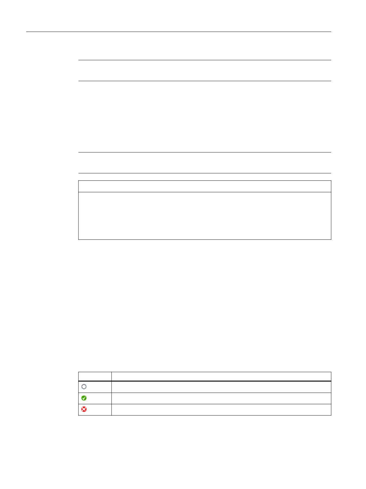
The icon on the right in field "Name / IP" shows the status of the server connection.
Symbol
Meaning
The connection status is unknown. The settings have not yet been processed or set.
You are connected to the time server. The system is successfully synchronizing times.
The system is still attempting to synchronize with a time server.
SINUMERIK Operate
40
Commissioning Manual, 10/2020, 6FC5397-1DP40-6BA4
General settings
4.4 Use time zone
Note
The system checks the time server connection cyclically. If a change is made, it may take a few
seconds for the setting to take effect.
Procedure
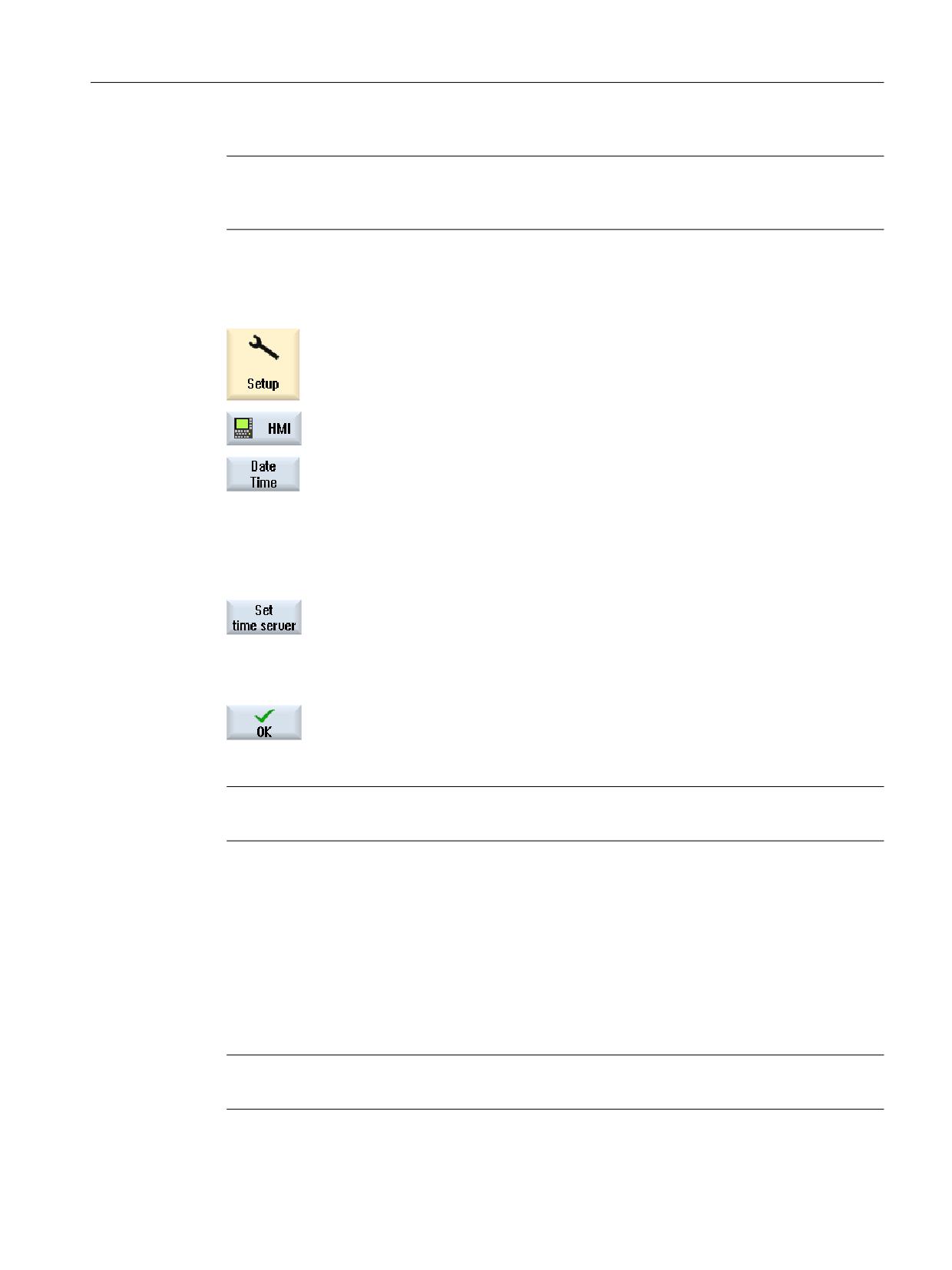
1.
Select the "Start-up" operating area.
2.
Press the "HMI" softkey.
3.
Press the "Date/Time" softkey.
The "Set Date and Time" window opens.
4.
Select the "Use time server" check box.
The "Name / IP" input field is displayed.
5.
In field "Name / IP," enter the DNS name or IP address of the time server.
You can enter up to three time servers separated by blanks.
6.
Press the "Set time server" softkey.
If a connection to a time server exists, the settings will be synchronized
with the system immediately. After that, a cyclic check is made as to
whether the settings are effective. The "Set Date and Time" window re-
mains open.
7.
Confirm the entry with the "OK" softkey.
The time server settings and the current times are taken over from the
control.
Note
If the field "Use time server" is cleared again, the standard "UTC" time zone will apply again.
4.4
Use time zone
To ensure that the controller has the correct time information even in countries with different
time zones, you can select the appropriate time zone.
The time zone set here is used by the entire system to translate Universal Time Coordinated
(UTC) time into local time.
Note
UTC is the default.
SINUMERIK Operate
Commissioning Manual, 10/2020, 6FC5397-1DP40-6BA4
41
General settings
4.5 Device registration
Procedure
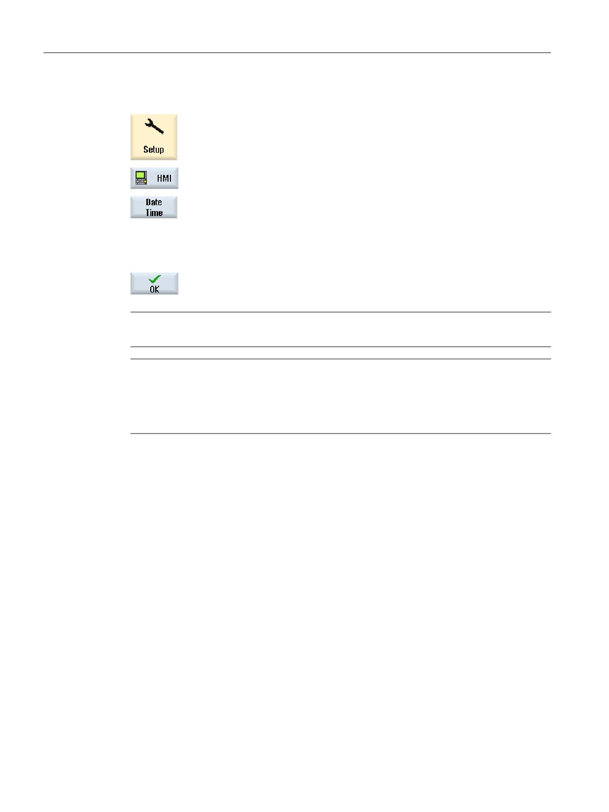
1.
Select the "Start-up" operating area.
2.
Press the "HMI" softkey.
3.
Press the "Date/Time" softkey.
The "Set Date and Time" window opens.
4.
Set the check mark in the "Use time zone" field.
The "Time zone" input field becomes active.
5.
Enter your time zone in the "Time zone" field.
6.
Confirm the entry with the "OK" softkey.
The current time zone is applied by the controller.
Note
Changing the time zone can take a few seconds.
Note
Zones without daylight saving time/standard time
When changing the time zone, take into account the local daylight saving time/standard time.
For example, regions like China or Japan have no daylight saving time/standard time, but Europe
and the USA do.
Examples
Hours are added or subtracted from the UTC time. You can set the following time zones, for
example:
Europe Etc/Universal (UTC)
Europe/Amsterdam (UTC-1:00)
Europe/Berlin (UTC-1:00)
USA
US/Central (UTC+6:00)
US/Michigan (UTC+5:00)
US/Pacific (UTC+8:00)
China Asia/Hong Kong (UTC-8:00)
Japan Tokyo (UTC-9)
4.5
Device registration
You must register your machine in order that Siemens Support supports your machine. The
registration is relevant for the warranty.
SINUMERIK Operate
42
Commissioning Manual, 10/2020, 6FC5397-1DP40-6BA4
General settings
4.7 Configuring Caps Lock
Message 150412 is displayed if the machine is not registered:
No information about SIEMENS warranty available.
Note
Message 150412 cannot be acknowledged.
Register the machine in the Diagnostics operating area:
"Diagnostics" → "Version" → "Register machine"
Additional information
Additional information on how to register the machine is provided in the online documentation
Commissioning Functions and Service.
4.6
Activation of the display for the remaining time of spindle
utilization
In order to protect the spindle from overload, you can display the maximum remaining time of
the spindle utilization in seconds in the T,F,S window in addition to the control display of the
spindle utilization. The time and spindle utilization symbol are displayed when the remaining
time is less than 120 seconds at the current spindle load.
Axis machine data
Set the following machine data:
MD53035 $MAS_SHOW_SPINDLE_UTIL_TIME
Show spindle utilization time
= 0
Do not show spindle utilization time
= 1
Show spindle utilization time
4.7
Configuring Caps Lock
The "CAPSLOCK on" function ensures that text entered via an external keyboard is always
entered in upper case and not in lower case.
The key behavior is set using the following display machine data.
Setting
MD9009 $MM_KEYBOARD_STATE
= 0
CAPSLOCK off (default value)
= 2
CAPSLOCK on
If the machine data is changed, the system must be rebooted.
SINUMERIK Operate
Commissioning Manual, 10/2020, 6FC5397-1DP40-6BA4
43
General settings
4.10 Setting OEM functions for the softkeys "HMI restart" and "EXIT"
4.8
Activating/deactivating the virtual keyboard
The virtual keyboard is configured in the file "slguiconfig.ini".
Procedure
1. Copy the "slguiconfig.ini" file from the folder
/siemens/sinumerik/hmi/template/cfg.
2. Paste the copy of the file into the following directory:
/oem/sinumerik/hmi/cfg or /user/sinumerik/hmi/cfg.
3. Open the file in the editor.
4. To activate or deactivate the keyboard, make the following settings:
- Activating the virtual keyboard:
In the section [TouchPanel], EnableTouch = true
In the section [Keyboard], EnableVirtualKeyBoard = true
- Deactivating the virtual keyboard:
In the section [TouchPanel], EnableTouch = true
In the section [Keyboard], EnableVirtualKeyBoard = false
5. Double click in the input field to display the keyboard.
4.9
Defining the access rights for the "HMI restart" softkey
Display machine data
Using the following display machine data, set the access rights from which access level the "HMI
restart" softkey is displayed.
For SINUMERIK Operate on PC or PCU, the "EXIT" softkey is displayed.
MD9110_$MM_ACCESS_HMI_EXIT
Access level of the "EXIT" softkey
= 1
Access level 1 (manufacturer), default value
Restart the HMI
Use the following procedure to restart SINUMERIK Operate:
Open the operating area, e.g. with the <MENU SELECT> key → "Menu step enable key" → "HMI
restart"
4.10
Setting OEM functions for the softkeys "HMI restart" and "EXIT"
You can influence the default functional behavior of the "HMI restart" or "EXIT" softkey. You can
set the configuration in the "slamconfig.ini" file.
SINUMERIK Operate
44
Commissioning Manual, 10/2020, 6FC5397-1DP40-6BA4
General settings
4.10 Setting OEM functions for the softkeys "HMI restart" and "EXIT"
Creating the "slamconfig.ini" configuration file
Insert a copy of the "slamconfig.ini" file into one of the following directories:
<Installation path>/user/sinumerik/hmi/cfg
<Installation path>/oem/sinumerik/hmi/cfg
Configuring the "slamconfig.ini" file
Configure the values via the following sections in the "slamconfig.ini" file:
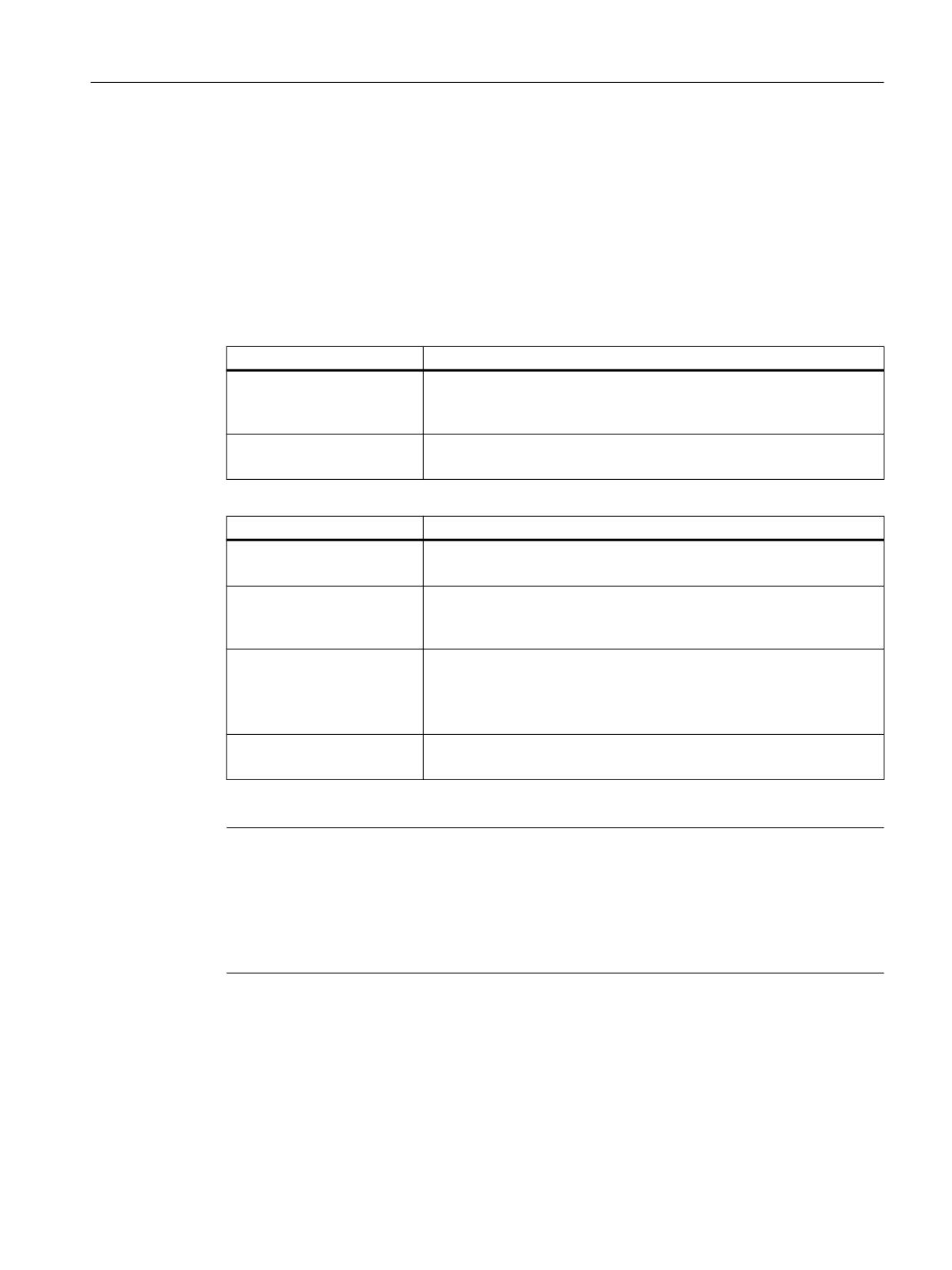
Section
Description
[ExitSoftkey]
Section for Exit softkey
With SINUMERIK Operate on NCU, the "HMI restart" softkey is displayed
with this configuration.
[RebootSoftkey]
Section for HMI restart softkey
This section only works with SINUMERIK Operate on PCU/IPC.
Value
Description
Visible
true or false
Switches the softkey to visible or invisible in the operating area
SoftkeyPosition
Fixed softkey position of the area softkey
In this case, softkey positions 1 to 8 are located on the 1st horizontal bar
and softkey positions 9 to 16 on the 2nd horizontal bar, etc.
AccessLevel
0 to 7
Access level as of which the softkey will be displayed
This value is a compatibility value for operating software without
MD9110 support.
QueryUser
true or false
Activates or deactivates a confirmation dialog
Note
Compatibility value for access level
Please note that the configuration for the access right with the value AccessLevel has no
effect in this version of SINUMERIK Operate. You set the access right via MD9110.
You can find more information in Chapter "Defining the access rights for the "HMI restart"
softkey (Page 44)".
Example
The following example describes the default configuration for "slamconfig.ini":
[ExitSoftkey]
Visible=true
SINUMERIK Operate
Commissioning Manual, 10/2020, 6FC5397-1DP40-6BA4
45
General settings
4.12 Setting the screensaver
SoftkeyPosition=16
AccessLevel=1
QueryUser=false
[RebootSoftkey]
Visible=false
SoftkeyPosition=15
AccessLevel=1
QueryUser=false
More information
More information on the "slamconfig.ini" configuration file can be found in Chapter "Link
OEMFrame application (Page 551)".
4.11
Changing the skin design
Display machine data
You can change the skin design via the following item of machine data.
MD9112 $MM_HMI_SKIN
Skin design
The number of the skin is indicated
= 0
Skin 0
= 1
Skin 1 (standard)
= 2
Skin 2
After changing the machine data, the operating software must be restarted.
4.12
Setting the screensaver
Defining the time until the screen is darkened (screensaver)
The duration (in minutes), after which the screen is automatically darkened if no keyboard key
is pressed, can be specified using the display machine data
MD9006 $MM_DISPLAY_SWITCH_OFF_INTERVAL.
NOTICE
Influence of screen darkening on the service life
To extend its service life, the recommended duration for darkening a screen is 60 minutes. If
you significantly reduce the duration, i.e. the screen is switched dark too often, this tends to
shorten the screen service life.
SINUMERIK Operate
46
Commissioning Manual, 10/2020, 6FC5397-1DP40-6BA4
General settings
4.14 Inserting a user-specific run up screen
Interface signal
The screen is darkened by setting an interface signal.
DB 19 byte
Signals to the operator panel front (PLC → HMI)
DBB0
Bit 1
Bit 0
Darken screen
Brighten screen
The following applies when actively darkening the screen using the interface signal:
• It is no longer possible to light up the screen again from the keyboard.
• The first keystroke on the operator panel already triggers an operator action.
Note
In order to prevent accidental operator actions via the interface signal when the screen is
darkened, we recommend disabling the keyboard at the same time.
4.13
Setting cleaning mode for the operator panel
The cleaning mode helps you to clean the operator panel without changing the data displayed
on the screen. If you activate the "Cleaning mode for panel" function, the multitouch and key
functions of the operator panel will be disabled for a few seconds. The progress bar shows you
the remaining time.
Activate the cleaning mode for the operator panel using a special softkey in the "Commissioning"
operating area:
"Commissioning" → "Cleaning mode for panel"
Note
The cleaning mode can only be used on operator panels with a Touch Panel.
Display machine data
You can set the inhibit time via the following display machine data.
MD9116 $MM_PANEL_CLEAN_MODE_TIME
Duration of cleaning mode
= 30
Define the duration in seconds for which the cleaning mode must be activated
Setting range 10 to 60 seconds, 30 seconds is standard
4.14
Inserting a user-specific run up screen
OEM-specific run up screen
You can replace the Siemens run up screen by your own run up screen.
SINUMERIK Operate
Commissioning Manual, 10/2020, 6FC5397-1DP40-6BA4
47
General settings
4.15 Using user interfaces in parallel
Procedure:
1. Call your own run up screen "splash.png".
Note
The file name must not contain any lower case letters.
2. Save your own run up screen in one of the following directories:
/user/sinumerik/hmi/ico/ico640 or
/oem/sinumerik/hmi/ico/ico640 or
/addon/sinumerik/hmi/ico/ico640
Note
The size of the screen is of no significance. A resolution of 640x480 pixels is always set.
4.15
Using user interfaces in parallel
It is possible to use SINUMERIK Operate in parallel on several user interfaces connected with one
NCU. When doing so, only one user interface may be used as the main interface, while all other
user interfaces behave passively and can only be used to a limited extent. To avoid function
conflicts between the individual user interfaces and the controlled system, adapt the following
configuration file:
"systemconfiguration.ini" file
Create the new "systemconfiguration.ini" configuration file in one of the two directories:
<Installation path>/user/sinumerik/hmi/cfg
<Installation path>/oem/sinumerik/hmi/cfg
SINUMERIK Operate
48
Commissioning Manual, 10/2020, 6FC5397-1DP40-6BA4
General settings
4.16 Setting how login data (credentials) are handled when archiving
In the configuration file, enter the section [miscellaneous] with the parameter
HMIFunctionMode and the appropriate value. The following value specifications are possible:
Value
Description
PanelMode or <empty>
The operating software and the system behave by default.
It can lead to errors in the system if SINUMERIK Operate is operated in
parallel on another user interface.
InterfaceMode
SINUMERIK Operate is switched to passive in the system and does not log
on as a regular user interface. The operating software:
• does not write to the PLC interface
• does not monitor PLC hardkeys
• does not monitor MMC commands
• does not monitor language selection via PLC
• does not monitor PLC commands
• does not monitor Ctrl-Energy
• does not monitor dark-ON via PLC
• does not set HMI-Ready in the PLC
TerminalMode
SINUMERIK Operate is used in the system as a tool loading station. The user
interface behaves passively.
Example
For a CNC machine, two user interfaces are to be used in the same system with one NCU.
Setting of the main user interface:
[miscellaneous]
HMIFunctionMode=PanelMode
Setting of the secondary user interface:
[miscellaneous]
HMIFunctionMode=InterfaceMode
More information
More information on functions and settings on the user interface for interface signals (DB19)
and commands can be found in:
• PLC Function Manual
• Programming Manual NC Programming
• Programming Manual Easy XML
4.16
Setting how login data (credentials) are handled when archiving
If you generate a commissioning archive, then SINUMERIK Operate issues a dialog query as to
whether all of the login data for the set up drives and OPC UA should also be saved to the archive.
You parameterize the login data handling using the following display machine data:
SINUMERIK Operate
Commissioning Manual, 10/2020, 6FC5397-1DP40-6BA4
49
General settings
4.17 VNC remote connections
Display machine data
MD9112 $MM_SAVE_CREDENTIALS
Backing up access authorization for network drives when
archiving
= 0
Dialog is displayed (default setting)
= 1
No dialog, access authorizations are not saved
= 2
No dialog, access authorizations are always saved
Note
Using shortcut key CTRL+ALT+S, no login data is saved to the archive.
4.17
VNC remote connections
From SINUMERIK Operate, you have the possibility of operating external systems via VNC:
• Define a remote access, and link the selection via a softkey configured in the operating area.
• Define key forwarding to use key combinations in the VNC control area as an alternative.
The remote connection is started using a softkey configured in the operating area menu. If the
sidescreen is activated, the VNC operating area can be additionally called using the navigation
bar of the sidescreen.
Note
The VNC operating area only supports hextile encoding with color depths of 16 or 32 bits.
Requirement
In the plant or company network, there is at least one system where a VNC server has been set
up.
Examples
The following use cases are possible, for example:
• Connection to additional controls
• Connection to the CAD system
• Connection to tool measuring station
• Connection to other PCs
Procedure
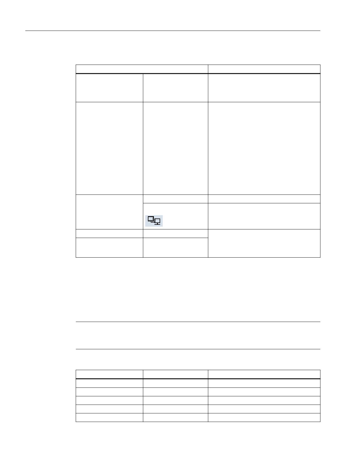
You make the remote connection settings via the "Setting up the operating area" window:
Operating area "Commissioning" → "HMI" → "Operating area menu"
SINUMERIK Operate
50
Commissioning Manual, 10/2020, 6FC5397-1DP40-6BA4

General settings
4.17 VNC remote connections
Press the "Details" softkey if you want to parameterize additional key forwarding or the "Display
VNC source" drop-down list.
You can define an alternative shortcut key for the "Select menu" key.
Note
Reserved softkeys
Softkeys reserved for the system are marked, and are not available for free configuration.
General information
Entry
Description
Operating area 1 - 24
Type
VNC
Remote access to an external control or PC
Empty
A VNC that has already been set up is deleted
Computer name
Name or IP address of the external system
Password
Password for logging on to the VNC server
The password is displayed encrypted as "*".
Status bar
Off
Display position of the VNC access information:
Top
• Name of the system or IP address
Bottom
• Port
• Connection status (e.g. for an incorrect
connection)
Port
Interface to the VNC server
The default port is 5900.
Display VNC source
Cutout
Definition of the displayed range
(only visible if "Details"
Left
The VNC viewer display shows the entire
softkey selected)
source screen.
Width
To enable the source screen to be completely
Top
visible in the VNC viewer, it must often be
Height
stretched or compressed (possibly by changing
Full screen
the aspect ratio).
Configuring the size and position of the picture
details defines the area of the VNC source
screen which you would like to see in the
VNC viewer.
This picture detail is also stretched or com-
pressed (possibly by changing the aspect ratio)
to enable it to be completely visible in the VNC
viewer.
Operate header
On
Display bar for operating area and message
line active/inactive
Off
SINUMERIK Operate
Commissioning Manual, 10/2020, 6FC5397-1DP40-6BA4
51
General settings
4.17 VNC remote connections
Specifications for the configured softkey
Entry
Description
Access level
Key-operated switch, po-
Assign access rights to the actual connection:
sition 0
from access level 7 (key operated switch posi-
tion 0) to access level 1 (manufacturer).
manufacturer
Softkey text
Two-line label on the softkey
%n is accepted as a line separator.
If the first line is too long, then a line break is
automatically inserted.
If a space is present, it is taken as a line sepa-
rator.
For language-dependent softkey texts, the text
ID is entered, which is used to search in the text
file.
If nothing is specified in the entry field, then
the symbolic name of the operating area,
which is automatically assigned, is used as
softkey text (e.g. AreaVNC_500).
Softkey icon
No icon
No icon is displayed on the softkey.
hd_vnc.png
File names of the icon displayed on the softkey.
Text file
File and context for the language-dependent
softkey text. If nothing is specified in the input
Text context
fields, the text appears on the softkey as was
specified in the "Softkey text" input field.
Key transfer to the external system
Press the "Details" softkey to display the area "Key forwarding", and activate the appropriate
checkbox.
When you press "Menu Select" an additional window opens in which you can select the key
combination that you want to use.
Note
Be aware that, depending on the operator panel that you are using, not all keys will be available
to you.
Designation
Key combination
Description
M
Shift+F10
Calls the "Machine" operating area (M key)
Cancel alarm
Esc
Deletes alarms and messages
Machine
Shift+F11
Calls the "Machine" operating area (hard key)
Program manager
Home (numpad)
Calls the "Program Manager" operating area
Channel
F11
Switches further for multiple channels
SINUMERIK Operate
52
Commissioning Manual, 10/2020, 6FC5397-1DP40-6BA4

General settings
4.18 Setting the WEB browser
Designation
Key combination
Description
Program
End (Numpad)
Calls the "Program" operating area
Alarm
Page Up (Numpad)
Calls the "Diagnosis" operating area
Menu Select
F10
Opens the operating area menu
You can change the shortcut key in the input
field. When attempting to edit, the "Alternative
key combination for Menu Select" dialog
opens, allowing the following parameteriza-
tion be made:
A - Z, F1 - F12, Home, End, Page Up, Page Down
AND combinable with SHIFT, CTRL, ALT
Help
F12
Calls the context-sensitive online help for the
selected window
Offset
Page Down (Numpad)
Calls the "Parameter" operating area
Custom
Shift+F12
Calls the "Custom" operating area
Next Window
Home
Toggles between the windows
Automatic key transfer
If the VNC operating area is selected, then the following keys and/or key combinations are
directly transferred to the VNC server:
Keys of the operator panel
Key combination
Horizontal softkeys (upper bar, HU)
F1 - F8
Vertical softkeys (right bar, VR)
Shift+F1 - Shift+F8
Horizontal softkeys (lower bar, HL)
Ctrl+F1 - Ctrl+F8
Vertical softkeys (left bar, VL)
Shift+Ctrl+F1 - Shift+Ctrl+F8
Recall
F9
ETC switchover
Shift+F9
Extended horizontal softkeys (upper bar, HU)
F13 - F20
Extended, vertical softkeys (right bar, VR) and right direct keys HT8
Shift+F13 - Shift+F20
Extended horizontal softkeys (lower bar, HL)
Ctrl+F13 - Ctrl+F20
Extended, vertical softkeys (left bar, VL) and left direct keys HT8
Shift+Ctrl+F13 - Shift+Ctrl+F20
Lower and left-hand softkey bar (HL, VL)
(Shift)+Ctrl+F1 - (Shift)+Ctrl+F8
4.18
Setting the WEB browser
In SINUMERIK Operate you have the possibility to set up the additional operating area "WEB
Browser".
With the WEB Browser you can display web pages directly on the control.
You adapt the WEB Browser operating area to your requirements by configuring it accordingly.
The WEB Browser is started by means of a configured softkey configured in the operating area
menu. If the sidescreen is activated, the VNC operating area can be additionally called via the
navigation bar of the sidescreen.
SINUMERIK Operate
Commissioning Manual, 10/2020, 6FC5397-1DP40-6BA4
53

General settings
4.18 Setting the WEB browser
Requirement
The control system is connected in the network with the Internet, intranet or a web server.
Example
To obtain additional information for your activity, you use web pages on the Internet or intranet.
Procedure
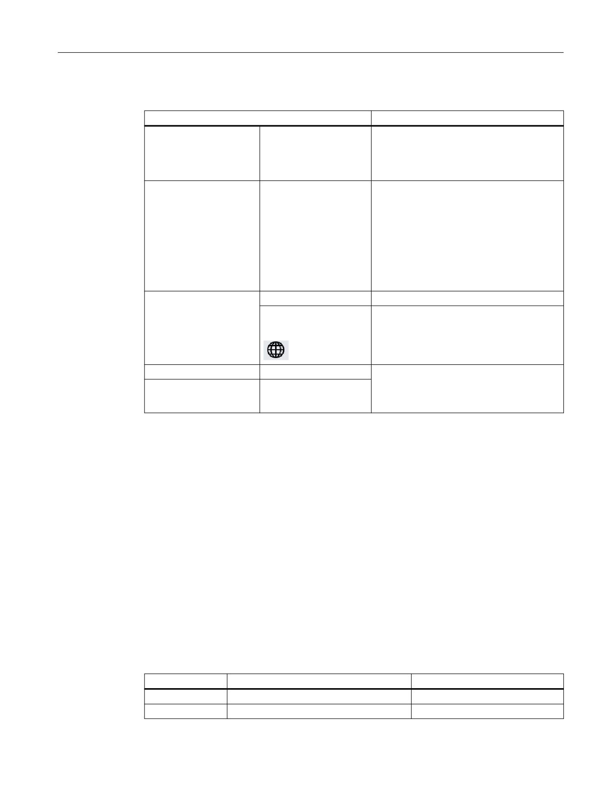
You make the WEB Browser settings via the "Setting up the operating area" window:
Operating area "Commissioning" → "HMI" → "Operating area menu"
General information
Entry
Description
Operating area 1 - 24
Type
WEB Browser
Displays web pages on the control
Start URL
URL which is displayed when the WEB browser
is started.
Address specification
On
Field for entering the URL/Internet address in
the WEB browser
Off
Status display
On
Status display in the WEB browser, e.g. loading
the progress indicator for URL
Off
Search
On
Search field in WEB Browser
Off
Home URL
If a Home URL is specified, the corresponding
icon appears in the WEB Browser.
If you press the Home URL icon, the Home URL
is accessed.
Operate header
On
Display bar for operating area and message line
Off
Navigation
On
Navigation arrow in WEB Browser
Off
SINUMERIK Operate
54
Commissioning Manual, 10/2020, 6FC5397-1DP40-6BA4
General settings
4.19 Access levels
Specifications for the configured softkey
Entry
Description
Access level
Operability of the configured softkey
Keyswitch position 0
Access level 7 - job-trained operator
Manufacturer
Access level 1 - manufacturer
Softkey text
A text-ID for language-specific text or a two-
line label for the softkey
%n is accepted as a line separator.
If the first line is too long, a line break is auto-
matically inserted. Any spaces are used as line
breaks.
For language-specific softkey texts, the text ID
is entered which is used to search in the text
file.
Softkey icon
No icon
No icon is displayed on the softkey.
sk_web.png
File names of the icon displayed on the softkey.
Text file
File and context for language-dependent soft-
key text. If nothing is specified in the entry
Text context
fields, the text in input field "Softkey text" is
used for all languages.
4.19
Access levels
4.19.1
Definition of access levels
Access to programs, data and functions is protected in a user-oriented hierarchical system of
seven access levels. These are divided into
• Three password levels for manufacturer, service and users
• Four keyswitch positions for users
There are access levels 1 to 7 (see table below); where
•
1 is the highest and
•
7 is the lowest level.
Table 4-1
Access level concept
Access level
Protected by
Area
1
Password: SUNRISE (default value)
Manufacturer
2
Password: EVENING (default value)
Service
SINUMERIK Operate
Commissioning Manual, 10/2020, 6FC5397-1DP40-6BA4
55

General settings
4.19 Access levels
Access level
Protected by
Area
3
Password: CUSTOMER (default value)
User
4
Keyswitch 3
Programmer, machine setter
5
Keyswitch 2
Qualified operator
6
Keyswitch 1
Trained operator
7
Keyswitch 0
Semi-skilled operator
Password security
Note
Assigning secure passwords
Observe the following rules when assigning new passwords:
• When assigning new passwords, never choose passwords that can be easily guessed, e.g.
simple words, sequences of consecutive keys on the keyboard, etc.
• Passwords must always contain a combination of upper-case and lower-case letters as well
as numbers and special characters. Passwords must comprise at least eight characters. PINS
must comprise an arbitrary sequence of digits.
• Wherever possible and where it is supported by the IT systems and the software, a password
must always have a character sequence as complex as possible.
You can use a password management program to assist you when dealing with passwords. With
its help, you can save passwords and PINs in encrypted form, manage them and generate secure
passwords.
Note
Changing passwords between SINUMERIK Operate and NC
The access levels for SINUMERIK Operate and NC have been merged. Changing a password for
SINUMERIK Operate simultaneously changes the relevant NC password and vice versa. It is
important to note the following behavior:
• When a general NC reset is performed, no passwords are reset to the default passwords.
• Following a software upgrade, the SINUMERIK Operate passwords apply to the NC.
• Once changed, a password can no longer be reset - not even by SIEMENS service. The
possibility of resetting passwords violates requirements relating to IT security.
Therefore, make sure that you store the changed password in a safe place.
Losing a password means that the SINUMERIK system has to be completely reinstalled using
a backup file (restore).
Additional information on how to install a backup is provided in the
Commissioning Manual NCU Operating System.
SINUMERIK Operate
56
Commissioning Manual, 10/2020, 6FC5397-1DP40-6BA4
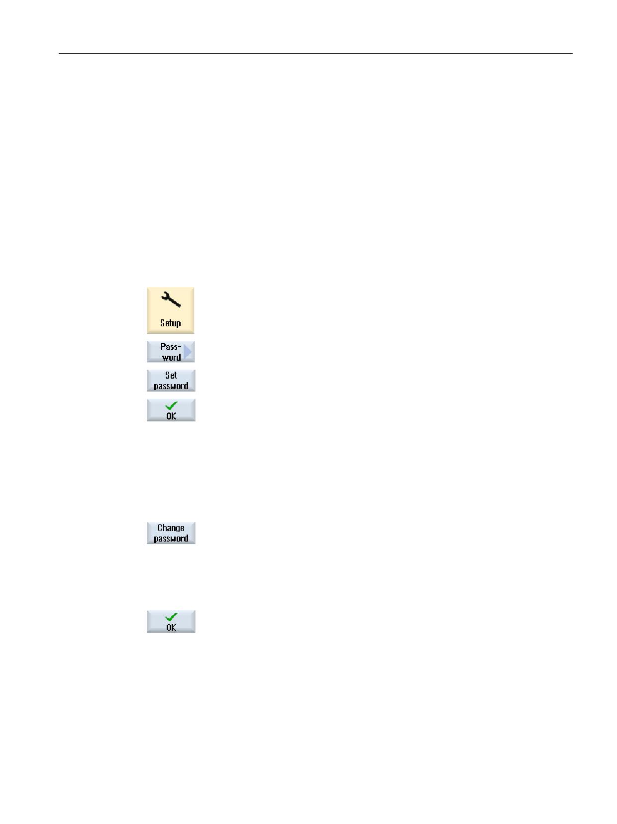
General settings
4.19 Access levels
4.19.2
Modifying the access levels password
Overview
You can activate the access levels protected with passwords from the user interface.
The following options are available for editing the passwords:
• Set new password
• Change password
• Delete password
Setting the password
1.
Select the "Start-up" operating area.
2.
Press the "Password" softkey.
3.
Press the "Set password" softkey.
The "Set Password" window opens.
4.
Enter one of the possible default passwords and press the "OK" softkey
to confirm the entry.
A permissible password is set and the valid access level is displayed.
Invalid passwords will be rejected.
Change password
You must change the standard passwords to obtain a secure access protection.
1.
Press the "Change password" softkey.
The "Change Password" window opens.
2.
Select the area (e.g. user) for which you want to assign a new password.
3.
Enter the new password in the input fields "New password" and "Repeat
password".
Always assign a secure password.
4.
Press the "OK" softkey to confirm your entry.
A new, valid password is only accepted if the two terms entered are
identical.
SINUMERIK Operate
Commissioning Manual, 10/2020, 6FC5397-1DP40-6BA4
57
General settings
4.19 Access levels
Note
Invalid passwords are rejected by the operating software. Note the rules for strong passwords,
for example:
• Minimum length of 8 characters
• At least one uppercase letter
• At least one lowercase letter
• At least one number
• At least one special character (ASCII 0x20 to 0x7E)
Delete password
Press the "Delete password" softkey. The access authorization is reset.
Note
Access authorization is not automatically deleted at POWER ON.
4.19.3
Work station safety
In order to secure machines against manipulation and protect people from accidents, proceed
as follows when leaving the work station:
1.
Set the keyswitch to 0 and then remove it.
2.
Press the "Delete password" softkey.
Access authorization is then reset.
4.19.4
Access levels for programs
Objective
Access levels can be allocated to protect information; they can also be used to prevent
unauthorized operation or deliberate damage to the control system or machine.
With access authorization levels to files and directories, it can be defined as to which users are
authorized to execute which operations on a directory or a file in a file system. Operations in this
sense include:
• Reading the contents of a file (READ), copying the file or placing the file in an archive.
• Changing the content of a file (WRITE) or deleting the file.
• Executing a file (EXECUTE).
SINUMERIK Operate
58
Commissioning Manual, 10/2020, 6FC5397-1DP40-6BA4
General settings
4.19 Access levels
• Listing and displaying a file in a directory (SHOW).
• Creating a file in a directory.
• Displaying or reading the contents of a directory.
• Creating or deleting a directory.
Function description
The individual allocation of access rights acts, in the passive NC file system, on the following
directories:
• Part programs
• Subprograms
• Manufacturer cycle directory
• User cycle directory
• Workpiece directory
• Workpiece directories
Further, the function acts on the files of the main program type (*.mpf) and subprograms or
cycle (*.spf).
In addition, the technique can be expanded to include the following directories on the local
drive:
• Part programs
• Subprograms
• Workpiece directory
• Workpiece directories
Note
Working via remote access
When working via remote access (e.g. WinSCP or Access MyMachine), the same access rights
apply for editing or saving files and directories as directly at the control system.
Additional information
Information about access rights with WinSCP or Access MyMachine is provided in:
• Commissioning Manual NCU Operating System.
• SINUMERIK Integrate Access MyMachine /OPC UA
Access rights via machine data
The following machine data is still available to globally allocate access rights:
MD51050 $MNS_ACCESS_WRITE_PROGRAM
SINUMERIK Operate
Commissioning Manual, 10/2020, 6FC5397-1DP40-6BA4
59
General settings
4.19 Access levels
Default setting = 4 (access level: User)
Note
Effect of access rights
The more restrictive setting is always effective both when individual access rights have been
allocated and when settings have been made via MD51050 $MNS_ACCESS_WRITE_PROGRAM.
Settings in the "slfsfileattributes.ini" file
The "slfsfileattributes.ini" file is available as a template in the following directory:
../siemens/sinumerik/hmi/template/cfg
The values from 1 ... 7 correspond to the access levels that, for example, also apply to the
password. The 4-digit numbers designate the sequence according to the following rights:
Significance from left to right: R W X S
R
READ
Reading files and directories
W
WRITE
Changing, deleting or creating files and directories
X
EXECUTE
Executes program: For files, for directories, always 7
S
SHOW
Outputs a list of files and directories
Copy the "slfsfileattributes.ini" file into one of the following directories:
../oem/sinumerik/hmi/cfg or ../user/sinumerik/hmi/cfg
The operating software must be restarted in order that the changes become effective.
Example
The paths are composed of the data type identifiers. In the following example, "\wks.dir\*.wpd
\*.mpf" comprises the data type for workpiece directories "wks.dir" the workpieces "*.wpd" and
the part programs "*.mpf".
For all workpieces, 7777 is defined as default setting for new part programs.
All entries are in the section [ACCESSMASKS] and have the following form:
[ACCESSMASKS]
\wks.dir\*.wpd\*.mpf = 7777
\mpf.dir\*.mpf = 6577
\cus.dir\*.spf = 6577
See also
Definition of access levels (Page 55)
SINUMERIK Operate
60
Commissioning Manual, 10/2020, 6FC5397-1DP40-6BA4
General settings
4.19 Access levels
4.19.5
Access rights for files
Changing access rights
Access rights for execution, writing, listing and reading are displayed in the "Properties" window.
• Execute: is used for the selection for execution.
• Write: controls the changing and deletion of a file or a directory.
For NC files, you have the option to set the access rights from keyswitch 0 to the current access
level, to be set separately for each file.
If an access level is higher than the current access level, it cannot be changed.
For external files (e.g. on a local drive), the access rights are displayed to you only if settings have
been executed for these files by the machine manufacturer. They cannot be changed via the
"Properties" window.
Note
Settings for the access rights to directories and files
Via the configuration file and MD51050, access rights of the directories and file types of the NC
memory and user memory (local drive) can be changed and pre-assigned.
Configuration file "slfsfileattributes.ini"
The access rights defined in the configuration file "slfsfileattributes.ini" and in MD51050 become
valid in the NC when creating new files and can then be changed individually in the Program
Manager using the "Properties" function. The access rights are an individual attribute of each
file in the NC.
The access rights defined in the configuration file "slfsfileattributes.ini" and MD51050 become
valid for external data on the CompactFlash Card of the NCU, or on the hard disk of the PCU/PC
immediately for all the specified directories and file types, and cannot be changed through
operation. The access rights can only be set globally for external data.
4.19.6
Access levels for softkeys
Use
The display and operation of softkeys can be suppressed by both the manufacturer as well as the
user. This allows the operating software to be specifically adapted to the required functional
scope and therefore be configured as transparently as possible.
This means that the functional scope of the system is restricted, to prevent access to functions
in the operating software, or to restrict the possibility of operator errors.
SINUMERIK Operate
Commissioning Manual, 10/2020, 6FC5397-1DP40-6BA4
61
General settings
4.19 Access levels
Access hierarchy
A new access level can only be allocated for those softkeys that are also visible and can be used
in the actual access level.
Example: If a softkey is only accessible with the "Manufacturer" access level, then the access level
cannot be changed by an operator with access level "Key-operated switch setting 3".
Restrictions
In order to guarantee that the system remains stable and operable, certain softkeys are excluded
from the access level change, e.g. the "Customize softkeys" softkey itself, in order that the undo
path is not cut-off or the softkey "<< Back" to the vertical softkey bar.
The following softkeys cannot be hidden or the access level changed:
• All "OK" softkeys
• All "Cancel" softkeys
• All "Accept" softkeys
• All "<<" Back and ">>" Continue softkeys
The access level for softkeys in the cycle dialog boxes can also be changed; this does not apply
to softkeys in Easy Screen dialog boxes.
Note
Software upgrade
As all changes of the access levels for softkeys are described using the softkey ID, they still remain
valid after a software upgrade, which may have resulted in softkeys being shifted.
Softkeys, where access is already protected by machine data - for example MD51045
$MNS_ACCESS_TEACH_IN - are only protected by the allocated access level after a new one has
been allocated. The machine data is no longer evaluated.
All of the softkeys hidden using this mechanism can be temporarily displayed again using the
access rights specified by the system. This is done using the "Show all softkeys" softkey. The
softkey is deactivated as long as no softkeys have been allocated new access levels: This setting
remains effective until the system is rebooted.
Note
Applicability of modified access levels for softkeys
The setting of specific access levels for softkeys on a PCU has an exclusive effect on the respective
PCU softkeys themselves. To implement access rights on the NCU, both the manufacturer and
the user must use the appropriate mechanisms and set the rights accordingly, see Chapter
"Access levels for programs (Page 58)".
SINUMERIK Operate
62
Commissioning Manual, 10/2020, 6FC5397-1DP40-6BA4
General settings
4.19 Access levels
4.19.7
This is how you define new access levels for softkeys
General sequence
In order to allocate a new access level to a softkey, proceed as follows:
• Activate the adaptation mode.
• Change the access level of a softkey.
• Accept the changes and confirm.
Preconditions
Access to the "Customize softkeys" is protected using a general MD51073
$MNS_ACCESS_SET_SOFTKEY_ACCESS. This machine data is pre-assigned access level 3, i.e. the
function is available from "Service" password and higher. In order that an operator with "User"
access level can use this function, set this machine data to a value > 3.
An external mouse is required in order to make changes.
Changing the access level of a softkey
Procedure
1. In the "Start-up" operating area, select the "HMI" menu.
2. On the expansion bar ">>" select the "Customize softkeys" softkey.
You can obtain precise information about the procedure in the following dialog.
3. Confirm with "OK", in order to activate the "Customize the softkey access levels active" mode.
A table is displayed.
4. Select an operating area.
5. Place the mouse cursor on a softkey and using the right-hand mouse key call the context
menu "Define access level", in order to define a new access level for this softkey.
- The displayed access level is the default setting.
- A softkey is practically made invisible with "Always hide".
- You can reset the additionally allocated access level using "Original setting". This selection
is only listed after an individual access level was set.
6. In order to accept changes, return to the "Start-up" operating area and there, press the "Close
customizing" softkey. This means that you exit the "Customize the softkey access levels
active" mode.
If you acknowledge the following query with "OK", then the changes are accepted and
become effective once the system has rebooted.
7. If the changes to a softkey are not to be applied, select the line in the "Adapt softkey access
levels" window and press the "Original setting" softkey. The identifier "Original setting" is
entered in the "New access level" column. After the end of the softkey adaptation and system
restart, the original setting of the softkey is restored and the line entry in the "Adapt softkey
access levels" window is deleted.
SINUMERIK Operate
Commissioning Manual, 10/2020, 6FC5397-1DP40-6BA4
63
General settings
4.19 Access levels
Example
The following access levels were changed:
Softkey
New access level
SISuMainScreenMenuHu::0::3
Manufacturer
SIMaJogMillMenuHU::jogHuMore::6
User
SISuPaUserDataMenu::::4
Service
Once selected, the identifier and position of the softkey are transferred to the "Softkey" column.
Result
When the changes have been accepted, a configuration file with the name "slsoftkeyaccess.xml"
is created and saved in the file system under the following path: ../user/sinumerik/hmi/cfg. Files
can also be saved on the /oem path; these files are evaluated when the system boots. The
following priority applies: oem < user.
Note
Editing the file "slsoftkeyaccess.xml"
In order to avoid errors in the xml syntax and for the softkey identifier the "slsoftkeyaccess.xml"
file may only be edited via the operating software as described above, and not directly in the file
system under "System data". It is possible that the complete file or individual entries for softkeys
can no longer be interpreted.
4.19.8
Setting the MDA program access via protection level
Use the following general machine data to set the protection level from which programs can be
edited in MDA operating mode. The setting also applies to program overwriting in Automatic
mode. The access levels 0 to 7 are possible.
Setting the protection level
MD51075 $MNS_ACCESS_WRITE_MDI
Write protection level MDA program
= 7
No interlock, editing is permitted (standard)
Note
A change of the protection level is activated after POWER ON.
If the current access level is not sufficient, a program under MDA mode can neither be edited nor
changed using the "Load MDA" and "Delete blocks" softkeys.
SINUMERIK Operate
64
Commissioning Manual, 10/2020, 6FC5397-1DP40-6BA4
General settings
4.20 Program selection
4.20
Program selection
4.20.1
Displaying the softkey
The softkeys on the user interface for calling the program lists are activated via general
configuration machine data.
Configuring a softkey
MD51041 $MNS_ENABLE_PROGLIST_USER
0
No softkey
1
The "Prog. list" softkey is displayed
MD51043 $MNS_ENABLE_PROGLIST_MANUFACT
0
No softkey
1
The "MANUFACTURER" softkey is displayed
Precondition
To create program lists, you require the following authorization:
• "Program manager" operating area: Access level 3 (password: User) or
• "Start-up" operating area: Access level 1 (password: Manufacturer).
Program lists
You can create a program list by combining desired programs from the NC data, e.g. workpieces,
part programs and subprograms. These programs can then be selected by the PLC for execution.
Program lists
Directory
plc_proglist_user.ppl
/user/sinumerik/hmi/plc/programlist
plc_proglist_manufacturer.ppl
/oem/sinumerik/hmi/plc/programlist
Procedure
1.
Select the "Start-up" operating area if you have the authorization for ac-
cess level 1 (password: Manufacturer).
- OR -
SINUMERIK Operate
Commissioning Manual, 10/2020, 6FC5397-1DP40-6BA4
65
General settings
4.20 Program selection
Select the "Program manager" operating area if you have the authoriza-
tion for access level 3 (password: User).
2.
Press the menu forward key and the "Prog. list" softkey.
The "Program List" window opens.
3.
Press the "Manufacturer" softkey if you want to create a program list that
can be used for all machines of a certain series.
4.
Place the cursor in the desired line (program number).
5.
Press the "Select program" softkey.
The "Programs" window opens. The data tree of the NC memory with the
directories "Workpieces", "Part programs" and "Subprograms" is displayed.
6.
Place the cursor on the desired program and press the "OK" softkey.
The selected program is inserted in the first line of the list together with
its path.
- OR -
Enter the program name directly in the list.
If you are making entries manually, check that the path is correct
(e.g. //NC/WKS.DIR/MEINPROGRAMM.WPD/MEINPROGRAMM.MPF).
If required, the extension (.MPF) is added.
Note:
A syntax check is not performed.
With workpieces, make sure that there is a main program or a job list with
the same name in the workpiece itself.
7.
To remove a program from the list, place the cursor on the appropriate line
and press the "Delete" softkey.
- OR -
To delete all programs from the program list, press the "Delete all" softkey.
SINUMERIK Operate
66
Commissioning Manual, 10/2020, 6FC5397-1DP40-6BA4
General settings
4.21 Activate and configure the Sidescreen window
4.21
Activate and configure the Sidescreen window
4.21.1
Activate Sidescreen
In addition to SINUMERIK Operate, Multitouch Panels with widescreen displays offer the option
of displaying more elements on the additional area at the side of the screen. As default, widgets
that quickly and continually display important information are shown. Further, pages that
include a virtual keyboard and virtual MCP are prepared. In addition, you can also configure your
own pages.
More information
More information and examples on the sidescreen function can be found in:
• Programming Manual Easy XML
• Programming Manual Run MyScreens
• Operating Manual Universal/Turning/Milling/Grinding
Requirement
To use the function, you need a Multitouch panel in the widescreen format (resolution,
1366x768, 1920x1080).
SINUMERIK Operate
Commissioning Manual, 10/2020, 6FC5397-1DP40-6BA4
67
General settings
4.21 Activate and configure the Sidescreen window
Sidescreen structure
Several pages can be displayed on the sidescreen. Only one page is active at a time. You can
toggle between the pages using the page selection keys.
The standard page contains a standard element to display widgets. You can configure additional
elements on this page.
① Widgets in the Siemens standard element
② Element (OEM) on a standard page
③ Page
④ Navigation bar for SINUMERIK Operate
⑤ Keys to select pages
Activation
WARNING
Unexpected machine movements caused by incorrect operation
Incorrect operation of devices with touch screen can result in unexpected machine
movements. This can result in personal injury or damage to property.
• Prevent unintentional incorrect operation by configuring the user interface appropriately,
e.g. by placing the buttons for starting and stopping machine components far enough
apart.
• Configure the machine in such a way that safety-related functions are not operated with the
touch screen.
SINUMERIK Operate
68
Commissioning Manual, 10/2020, 6FC5397-1DP40-6BA4
General settings
4.21 Activate and configure the Sidescreen window
You activate the Sidescreen function via the following display machine data:
MD9114 $MM_SIDESCREEN
SINUMERIK Operate Sidescreen
= 1
Enables the additional Sidescreen display area of the Multitouch Panel (HD Ready or Full
HD).
= 2
Enables the sidescreen display area in HD Ready.
Enables the Display Manager in full HD.
Note
Automatically hiding the Windows taskbar
In some situations SINUMERIK Operate is covered by the Windows taskbar on PCU/IPC. You can
hide the taskbar automatically to ensure proper user interface operation:
Right-click the taskbar and open the "Properties" (Windows 7) or "Taskbar settings"
(Windows 10) item in the menu. In the "Task bar" tab, select the option "Automatically hide the
taskbar" (Windows 7) or "Automatically hide the taskbar in desktop mode" (Windows 10).
The bar and value displays for widgets are defined via machine data:
Axis load display
Software option
To use this function, you need the software option:
"Evaluation of internal drive variables"
You can activate the detection of additional drive actual values for the axis load display in the
sidescreen:
MD36730 $MA_DRIVE_SIGNAL_TRACKING
Detection of additional drive actual values
= 1
$AA_LOAD: Drive load
$AA_POWER: Drive efficiency
$AA_TORQUE: Drive torque setpoint
$AA_CURR: Smoothed current actual value (quadrature-axis current) of the drive
Note
Detection for the axis load display is only possible if actual values are available from the drive.
Bar display for axis and spindle power
You can assign parameters for the bar display for the axis power using the following axis-
machine data:
MD53030 $MAS_AXIS_MAX_POWER
Maximum value of the axis power display
= 100
Default
Maximum permitted axis power in percent
The bar display is green in the range between 0 and the value of AXIS_MAX_POWER.
SINUMERIK Operate
Commissioning Manual, 10/2020, 6FC5397-1DP40-6BA4
69
General settings
4.21 Activate and configure the Sidescreen window
MD53031 $MAS_AXIS_POWER_RANGE
Display range of the axis power display
= 100
Default
Full-scale value for axis power display in percent
This value must be greater than or equal to AXIS_MAX_POWER. The bar display is red in
the range between the values of AXIS_MAX_POWER and
AXIS_POWER_RANGE.
You can assign parameters for the bar display for the spindle power using the following general
machine data:
MD51030 $MNS_SPIND_MAX_POWER
Maximum value of the spindle power display
= 100
Default
Maximum permitted spindle power in percent
The bar display is green in the range between 0 and the value of SPIND_MAX_POWER.
MD51031 $MNS_SPIND_POWER_RANGE
Display range of the spindle power display
= 100
Default
Full-scale value for spindle power display in percent
The value must be equal to or greater than SPIND_MAX_POWER. The bar display is red in
the range between the values of SPIND_MAX_POWER and SPIND_POWER_RANGE.
Note
If you do not need a standard widget, set the comment character ";" before the corresponding
keyword in the sample file "slsidescreen.ini".
4.21.2
Display Sidescreen ABC keyboard
Not only the standard windows but also the window for an ABC keyboard can be displayed in the
Sidescreen display of the Multitouch panel.
Procedure
1. Copy the sample file "slsidescreen.ini" from the directory
/siemens/sinumerik/hmi/template/sidescreen
2. Place the copy of the file in one of the following directories:
/oem/sinumerik/hmi/cfg or
/user/sinumerik/hmi/cfg
3. Open the copy and delete the comment sign ";" in front of the keyword PAGE002.
Note
The values of the attributes name and implementation must not be changed.
4. Save the setting.
The ABC keyboard can be selected after a run-up.
SINUMERIK Operate
70
Commissioning Manual, 10/2020, 6FC5397-1DP40-6BA4
General settings
4.21 Activate and configure the Sidescreen window
4.21.3
Display Sidescreen machine control panel
Not only the standard windows but also the window for machine control panel functions can be
displayed in the Sidescreen display of the Multitouch panel.
Multiple machine control panel windows can be optionally displayed.
The example of a machine control panel is displayed by the following procedure:
Procedure
1.
Copy the sample files "slsidescreenmcppageconfig.xml", "slsidescreenmcppage_eng.ts" and
the subdirectories of the icon files from the directory
/siemens/sinumerik/hmi/template/sidescreen/mcp/
The icon files are stored in the following subdirectories:
/ico1024 for HD Ready
/ico1920 for Full HD
2.
Place the copy of "slsidescreenmcppageconfig.xml" in one of the following directories:
/oem/sinumerik/hmi/proj or
/user/sinumerik/hmi/proj
3.
Place the copy of "slsidescreenmcppage_eng.ts" in one of the following directories:
/oem/sinumerik/hmi/lng or
/user/sinumerik/hmi/lng
Note
The TS file is automatically integrated by the system during startup.
4.
Save the icon files under the following path in one of the intended subdirectories:
/oem/sinumerik/hmi/ico or
/user/sinumerik/hmi/ico
Depending on the screen resolution, there are the following subdirectories:
/ico1024 for HD Ready
/ico1920 for Full HD
5.
Copy the sample file "slsidescreen.ini" from the directory
/siemens/sinumerik/hmi/template/sidescreen
6.
Place the copy of "slsidescreen.ini" in one of the following directories:
/oem/sinumerik/hmi/cfg or
/user/sinumerik/hmi/cfg
7.
Open the copy of the file "slsidescreen.ini", and delete the comment sign ";" in front of the
keyword PAGE003.
Multiple machine control panels are optionally available:
PAGE004, PAGE005 and PAGE006
Note
The values of the attributes name and implementation must not be changed.
8.
Save the setting.
The machine control panel can be selected after a run-up.
SINUMERIK Operate
Commissioning Manual, 10/2020, 6FC5397-1DP40-6BA4
71
General settings
4.21 Activate and configure the Sidescreen window
4.21.3.1
Configuring your own keys on the machine control panel
Own keys can also be displayed in the Sidescreen for the machine control panel. To do this, the
keys must be configured in the file "slsidescreenmcppageconfig.xml". The properties, position of
the keys and the headers are specified here.
Example of the file "slsidescreenmcppageconfig.xml"
<sideScreenControlPanel>
<mainBlock id="sideScreenMcpBlock1">
<block position="1" title="SPINDLE">
<row position="1">
<buttonGroup spacing="false" title="COOLANT">
<button position="1" text="ON" icon="slsidescreenmcp_cooling.png"
style="redStyle" title="Spindle">
<onPressed address="HmiUserKey1"/>
<active address="HmiUserLed1"/>
<disabled address="DisableHmiUserKey1"/>
</button>
<button position="2" text="OFF" icon="slsidescreenmcp_cooling_off.png">
<onPressed address="HmiUserKey2"/>
<active address="HmiUserLed2"/>
</button>
</buttonGroup>
</row>
</block>
</mainBlock>
************************************************************************
*** optional
***
************************************************************************
<mainBlock id="sideScreenMcpBlock2">
<.../>
</mainBlock>
<mainBlock id="sideScreenMcpBlock3">
<.../>
</mainBlock>
<mainBlock id="sideScreenMcpBlock4">
<.../>
</mainBlock>
<mainBlock id="sideScreenMcpBlockBelow1">
<.../>
</mainBlock>
<mainBlock id="sideScreenMcpBlockBelow2">
<.../>
</mainBlock>
<mainBlock id="sideScreenMcpBlockBelow3">
<.../>
</mainBlock>
<mainBlock id="sideScreenMcpBlockBelow4">
<.../>
</mainBlock>
</sideScreenControlPanel>
SINUMERIK Operate
72
Commissioning Manual, 10/2020, 6FC5397-1DP40-6BA4
General settings
4.21 Activate and configure the Sidescreen window
Adaptation options of the file "slsidescreenmcppageconfig.xml"
You can make the settings for your own keys in the <sideScreenControlPanel> tag:
Tag
Description
<mainBlock
Is the internal name of the machine control panel window
id="sideScreenMcpBlock1">
<block position="1"
A main section has any number of blocks.
title="SPINDLE">
position
Order of the blocks
title
Block header
<row position="1">
Each block has any number of lines.
position
Positioning of the lines
<buttonGroup
A key group combines two keys under one header.
spacing="false"
spacing
The property enables the display type of
title="COOLANT">
the keys to be determined:
together "false" or separate "true".
The default is separate.
title
All the keys in a key group have the same
header.
<button position="1"
Defines the key properties
text="ON"
position
Position of the key
icon="slsidescreenmcp_cooli
text
Labeling shown on the key
ng.png" style="redStyle"
title="Spindle">
icon
Icon of the key
The icon is displayed above the text la-
bel. If there is no labeling, then the icon
also takes up the labeling space.
style
Changes the backg20round color assigned to
the key
Possible values are:
"redStyle" for a red key
"greenStyle" for a green key
The default is "defaultStyle"
title
A key that does not belong to any group
can have its own header.
<onPressed
If the key is pressed, then the PLC bit is set to 1.
address="HmiUserKeyX"/>
The value remains at 1 as long as the key remains actuated. With
a brief press, the value remains at 1 for at least 300 ms.
address
Alias name "HmiUserKeyX" for the ad-
dressed PLC bit
Values of 1 to 64 are permitted for X.
HmiUserKey1 to HmiUserKey64 stand
for DB19.DBB404.0 to DB19.DBB411.7.
SINUMERIK Operate
Commissioning Manual, 10/2020, 6FC5397-1DP40-6BA4
73
General settings
4.21 Activate and configure the Sidescreen window
Tag
Description
<active
The key is shown as active (LED animation at the top edge of the
address="HmiUserLedX"/>
key).
address
Alias name of the PLC bit from which the
active identifier is derived
Values of 1 to 64 are permitted for X.
HmiUserLed1 to HmiUserLed64 stand
for DB19.DBB412.0 to DB19.DBB419.7.
<disabled address=
The key is shown as inactive (icon and text grayed out).
"DisableHmiUserKeyX"/>
address
Alias name of the PLC bit from which the
inactive identifier is derived.
Values of 1 to 64 are permitted for X.
DisableHmiUserKey1
to DisableHmiUserKey64 stand for
DB19.DB420.0 to DB19.DB427.7.
Store own icons
You can create your own icon files under one of the following paths:
/oem/sinumerik/hmi/ico or
/user/sinumerik/hmi/ico
Depending on the screen resolution, under the following subdirectories:
/ico1024 for HD Ready
/ico1920 for Full HD
Note
The icon file names must be the same as the names used in the XML file,
e.g. icon="slsidescreenmcp_cooling.png".
4.21.3.2
Create own translations of texts for the machine control panel
You can display all machine control panel texts in different languages. Translations are created
in the file "slsidescreenmcppage_xxx.ts".
"xxx" stands for a language code, e.g. "deu" for German, "eng" for English, and so on. You will
find the supported languages at "Supported languages (Page 548)"
SINUMERIK Operate
74
Commissioning Manual, 10/2020, 6FC5397-1DP40-6BA4
General settings
4.21 Activate and configure the Sidescreen window
Procedure
1. Create the file "slsidescreenmcppage_xxx.ts" with the desired language code in one of the
following directories:
/oem/sinumerik/hmi/lng or
/user/sinumerik/hmi/lng
2. Open the language file and insert the designations accordingly.
The following texts may be displayed in translation:
- All headers, e.g. title="COOLANT"
- All key labels e.g. text="ON"
3. Save the language file.
The translations are displayed after a run-up and the language has been changed.
Adaptation options of the file "slsidescreenmcppage_xxx.ts"
You can insert the translations in the <message> tag:
Tag
Description
<source>ON</source>
This is the language code of the original language.
<translation>ON</
This is the translation.
translation>
<chars>8</chars>
This is the maximum length of the translation.
The tag serves merely a note for the translator.
Example extract of the file "slsidescreenmcppage_eng.ts"
<message>
<source>ON</source>
<translation>EIN</translation>
<chars>8</chars>
</message>
4.21.4
Display sidescreen camera
In addition to the standard windows, up to two camera images can be displayed in the
sidescreen display of the Multitouch Panel.
Note
Compatibility
This function is not supported for an NCU 710.
SINUMERIK Operate
Commissioning Manual, 10/2020, 6FC5397-1DP40-6BA4
75
General settings
4.22 SINUMERIK Operate Display Manager
Procedure
1. Copy the sample file "slsidescreen.ini" from the directory
/siemens/sinumerik/hmi/template/sidescreen
2. Place the copy of the file in one of the following directories:
/oem/sinumerik/hmi/cfg or
/user/sinumerik/hmi/cfg
3. Open the copy and delete the comment sign ";" in front of the keyword ELEMENT009 for
Camera 1 and in front of ELEMENT010 for Camera 2.
Note
The values of the attributes name and implementation must not be changed.
4. Save the setting.
The cameras can be selected following power up.
Additional information
Additional information regarding setup of the cameras can be obtained in the online help
Commissioning functions and service.
4.22
SINUMERIK Operate Display Manager
4.22.1
Display configurations
Using the Display Manager and display configurations, it is possible to reduce
SINUMERIK Operate, in other words, run in less than full-screen mode, and to allocate the space
that is freed up to other applications. These applications are either standard Windows
applications (.EXE) or applications that belong to the Display Manager. Both types of
applications can also be developed by third parties using the OA Toolkit from
SINUMERIK Operate and integrated into a display configuration. To display the applications, the
screen is divided into "frames". Each frame may contain an application or a menu for controlling
an application displayed in another frame. Several screen segments or "Displays" are possible
and you can navigate between them during the program runtime. These displays are combined
into a display configuration. There may be multiple display configurations, for example, for
different screen resolutions.
A display configuration is defined either for a specific screen resolution or for a specific operating
unit. The available display configurations must be made known to the system in the
[displayConfigurations] section of the systemconfguration.ini file. The display
configuration itself is described in a separate configuration file.
SINUMERIK Operate
76
Commissioning Manual, 10/2020, 6FC5397-1DP40-6BA4
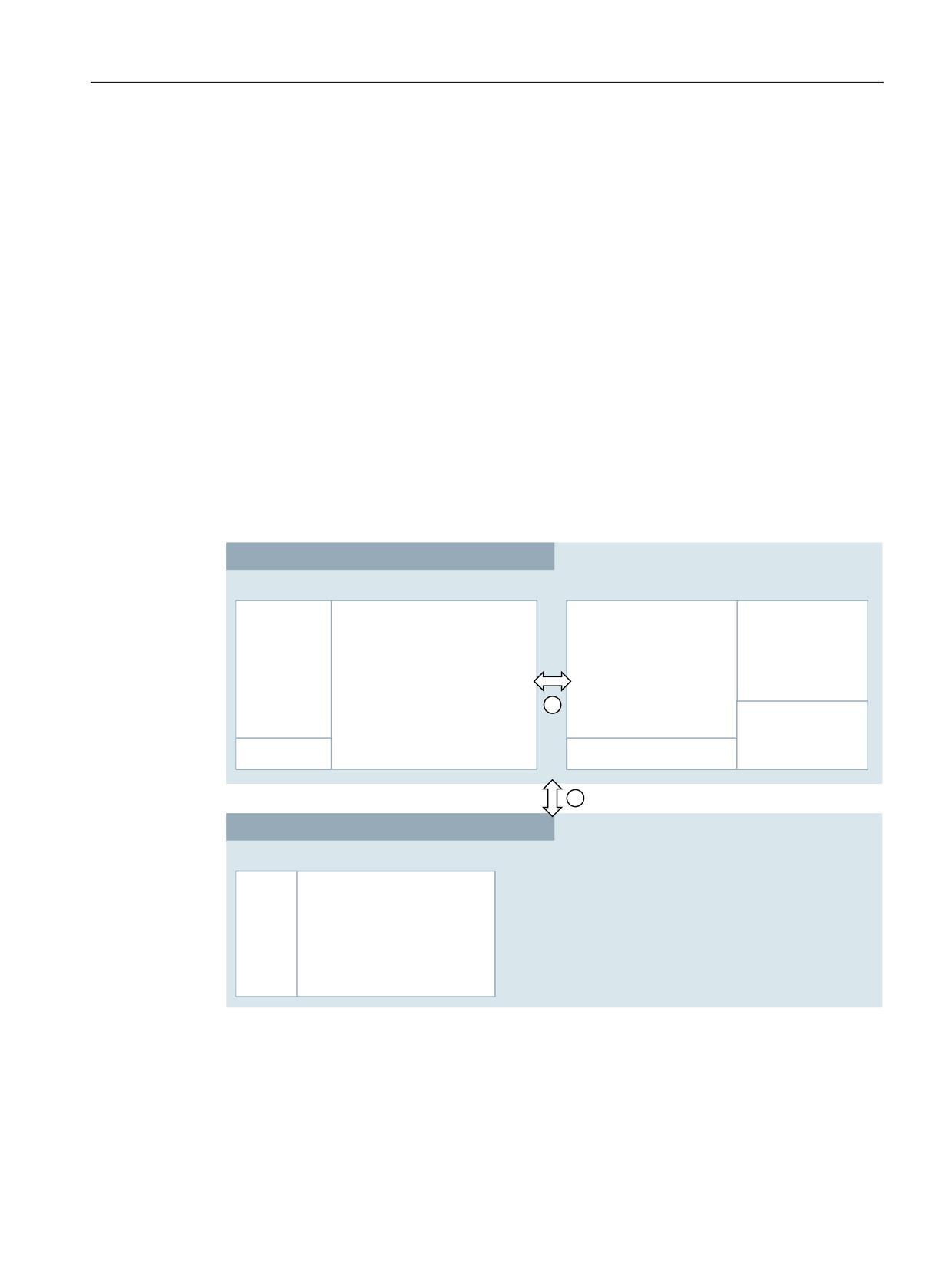
General settings
4.22 SINUMERIK Operate Display Manager
System requirement
The display manager is supported by the following systems:
• PC, PCU/IPC
• NCU 720 and NCU 730
More information
More information and examples relating to the Display Manager can be found in the following
documentation:
• Programming Manual Run MyScreens
• Operating Manual Universal/Turning/Milling/Grinding
Display configurations (examples)
'LVSOD\ FRQILJXUDWLRQ IRU
[
'LVSOD\
'LVSOD\
)UDPH
)UDPH
)UDPH
)UDPH
6LGHVFUHHQ
+0, 2SHUDWH
2QOLQH KHOS
+0, 2SHUDWH
)UDPH
&DPHUD
)UDPH
)UDPH
6ZLWFKRYHU PHQX
6ZLWFKRYHU PHQX
'LVSOD\ FRQILJXUDWLRQ IRU
[
'LVSOD\
)UDPH
)UDPH
6LGH
+0, 2SHUDWH
VFUHHQ
① Changing using the switchover menu
② Changing using TCU or the resolution switchover
SINUMERIK Operate
Commissioning Manual, 10/2020, 6FC5397-1DP40-6BA4
77
General settings
4.22 SINUMERIK Operate Display Manager
Example of the "systemconfiguration.ini" file
[displayConfigurations]
DC001 = res:=1366x768, file:=sldm_1366x768
DC002 = res:=1920x1080, file:=sldm_1920x1080
DC003 = tcu:=TCU1, file:=tcu1_layout
The example includes three display configurations. The names of the entries always begin with
the string "DC" followed by a sequential number. Each entry has a "file" property that points to the
file with the display configuration. The file can have any name. Like other configuration files, it
is also searched for in the cfg directories under siemens, addon, oem, and user. The ".ini" file
name extension does not have to be specified. The "res" property indicates the resolution to
which the respective display configuration applies. Different Display Manager configurations can
be displayed on various panels using property "tcu".
Note
Special aspects
• The size of the manufacturer layout must match the parameterized resolution, otherwise
display errors may occur on the user interface.
• If multiple display configurations are parameterized for a user interface, the display priority
"tcu" → "res" applies
• If no display configuration is applicable, the user interface is displayed in the full-screen
mode.
Activation
WARNING
Unexpected machine movements caused by incorrect operation
Incorrect operation of devices with touch screen can result in unexpected machine
movements. This can result in personal injury or damage to property.
• Prevent unintentional incorrect operation by configuring the user interface appropriately,
e.g. by placing the buttons for starting and stopping machine components far enough
apart.
• Configure the machine in such a way that safety-related functions are not operated with the
touch screen.
To activate the SINUMERIK Operate Display Manager, the following display machine data must
be set.
MD9114 $MM_SIDESCREEN
SINUMERIK Operate Sidescreen
= 2
Enables the sidescreen display area in HD Ready.
Enables the Display Manager in full HD.
SINUMERIK Operate
78
Commissioning Manual, 10/2020, 6FC5397-1DP40-6BA4
General settings
4.22 SINUMERIK Operate Display Manager
The default configurations used by the Display Manager for the two screen resolutions,
1920x1080 and 1366x768, are in the two files:
• sldm_1920x1080.ini
• sldm_1366x768.ini
These files can be used as a template for custom display configurations. This section describes
how to create custom display configurations.
Note
Automatically hiding the Windows taskbar
In some situations SINUMERIK Operate is covered by the Windows taskbar on PCU/IPC. You can
hide the taskbar automatically to ensure proper user interface operation:
Right-click the taskbar and open the "Properties" (Windows 7) or "Taskbar settings"
(Windows 10) item in the menu. In the "Task bar" tab, select the option "Automatically hide the
taskbar" (Windows 7) or "Automatically hide the taskbar in desktop mode" (Windows 10).
4.22.2
Creating your own display configurations
4.22.2.1
Displays
One or more displays can be defined in the respective configuration file for each display
configuration. A name and a list of frames are specified for each of these displays. The frames
describe the division of the display into rectangular areas in which applications or menus can be
displayed.
Note
The order of configured displays is arbitrary.
Example
[displays]
DISPLAY001= name:=display_1, frames:="frame1, frame2, frame3"
DISPLAY002= name:=display_2, frames:="frame4, frame5, frame6, frame7"
…
Property
Meaning
name
Name of the display. Required, for example, for switching displays
frames
Contains a comma-separated list of frames that should be present on this
display to describe the layout of the display
SINUMERIK Operate
Commissioning Manual, 10/2020, 6FC5397-1DP40-6BA4
79
General settings
4.22 SINUMERIK Operate Display Manager
Property
Meaning
enableMirrorMode
Activates (true) or deactivates (false) mirror mode for the display
(true|false)
When the mirror mode is activated, all frames of the display are displayed
mirrored horizontally when the setMirrorMode (true) function is called.
Otherwise, the appearance of the frames remains unchanged after call-
ing the setMirrorMode (true) function.
"true" is default.
onStartup
Contains a semicolon-separated list of actions to be performed when the
display first appears
The possible actions are described below.
onShow
Contains a semicolon-separated list of actions to be performed each
time the display fades
The possible actions are described below.
4.22.2.2
Frames
A frame is a container for applications or menus and primarily describes the desired position and
size of the application and menus in pixels. In addition, this is also where the application or menu
that should be displayed in the frame after the Display Manager starts is specified. The
applications that can be assigned to the frames are specified in
the systemconfiguration.ini file.
Example
[frames]
FRAME001= name:=frame1, x:=0, y:=0, width:=460, height:=970,
app:=mydialog
FRAME002= name:=frame2, x:=460, y:=0, width:=1460, height:=1080,
app:=OPERATE
FRAME003= name:=frame3, x:=0, y:=970, width:=460, height:=110,
menu:=mymenu
FRAME004= name:=frame4, x:=0, y:=0, width:=1280, height:=970,
app:=mydialog2, runableApps:="mydialog, mydialog2"
FRAME005= name:=frame5, x:=0, y:=970, width:=1280, height:=110,
menu:=menu2
FRAME006= name:=frame6, x:=1280, y:=0, width:=640, height:=480,
app:=OPERATE
FRAME007= name:=frame7, x:=1280, y:=480, width:=640, height:=600,
app:=mydialog3
…
If SINUMRIK Operate is to be displayed in a frame, the application name is specified as "OPERATE".
It should be noted that SINUMERIK Operate can only be used in certain sizes. The currently
supported sizes (in pixels) are:
•
640x480
•
760x505
•
800x480
•
800x600
SINUMERIK Operate
80
Commissioning Manual, 10/2020, 6FC5397-1DP40-6BA4
General settings
4.22 SINUMERIK Operate Display Manager
•
1024x768
•
1024x1014
•
1080x810
•
1280x768
•
1280x800
•
1280x1024
•
1300x768
•
1366x768
•
1440x1080
•
1454x1080
•
1854x1014
•
1854x1080
•
1920x1080
Property
Meaning
name
Name of the frame. Used in the frame list of the displays, for example
x, y, width, height
Absolute position (x, y), width and height of the frame in pixels
app
Application displayed in the frame the first time the frame is displayed.
runableApps
List of applications that may be displayed in this frame in case an appli-
cation is swapped.
menu
Menu that is displayed in the frame.
Ignored if "app" is used at the same time
SINUMERIK Operate
Commissioning Manual, 10/2020, 6FC5397-1DP40-6BA4
81
General settings
4.22 SINUMERIK Operate Display Manager
4.22.2.3
Menus
In addition to applications, menus can also be displayed in the frames of a display. These menus
are typically used to display certain applications in another frame or to switch displays.
A menu configuration consists of four parts:
• Description of the individual menu items (section [menuitems])
• Description of the look and feel of the menu items (section [menuitemstyle])
• Description of the menu structure (section [menus])
• Description of the look and feel of the menu (section [menustyle])
The [menuitems] section defines the menu items (keys/buttons). Each entry corresponds to a
key/button. The properties of the menu items can be configured.
The following properties are available:
Property
Meaning
name
Unique name of the menu item.
onClicked
Action to be triggered by clicking on this menu item. The actions that are
possible are described in the "Menu actions" section.
text
Text displayed on the menu item. Line breaks can be generated with \n
or %n.
textID
A text ID that references a language-dependent text. If the text can be
read, it replaces the text specified in the "text" property.
textContext
The context associated with the text ID. The context can also be specified
when configuring a menu or globally on the file level. Specifying a context
in the menu item overwrites any existing context information in the menu
or on the file level. Specifying a context in the menu overwrites any ex-
isting context information on the file level.
image
File name of the icon that is displayed on the menu item.
Special case for display button:
For buttons that are used to switch displays, the icon to be displayed on
the button can be generated automatically by the Display Manager. To do
this, you specify the name of the display to be switched with the file
extension ".auto" as the file name. A schematic drawing of the display is
then displayed as an icon. The stroke width and stroke color used for this
representation can be specified with the properties strokeWidth and stro-
keColor.
Display buttons have no text and no "imagePressed" icon.
strokeWidth1)
Stoke width of the schematic drawing for display buttons (see Property
image). Default: 1.
strokeColor1)
Color of the stokes of the schematic drawing for display buttons (see
Property image).
Default: Qt::lightGray
imagePressed
File name of the icon displayed on the menu item in the pressed state. As
an alternative to specifying this property, a file named "<image>_activa-
ted" is automatically used, if available; <image> is the name specified in
the "image" property.
SINUMERIK Operate
82
Commissioning Manual, 10/2020, 6FC5397-1DP40-6BA4
General settings
4.22 SINUMERIK Operate Display Manager
Property
Meaning
accessLevel
Access level from which the menu item is displayed:
System, Manufacturer, Service, Customer, Key_3, Key_2, Key_1, Key_0 or
numerical equivalent (0-7)
Default: Key_0 (7)
menuItemStyle
Style of the menu item that defines all visual properties of the menu item.
Note
All of the properties described below can be specified for configuring the
respective menu items as well as for defining the MenuItemStyles. An
entry in the menu item overwrites the corresponding entry in the MenuI-
temStyle.
textSize2)
Font size
textAlignment2)
Alignment of the text of the menu item:
Left, Right, Top, Bottom, TopLeft, TopRight, BottomLeft, BottomRight (an-
alog Qt::Alignment)
You can also specify the values of the Qt flag field in hex (0x00) or decimal.
Default: Qt::AlignCenter
imageAlignment2)
Alignment of the icon of the menu item:
Left, Right, Top, Bottom, TopLeft, TopRight, BottomLeft, BottomRight (an-
alog Qt::Alignment)
You can also specify the values of the Qt flag field in hex (0x00) or decimal.
Default: Qt::AlignCenter
width2)
Width of the menu item in pixels.
Default behavior:
The menu items equally share the available space in the menu (horizontal
menu) less spacing, or are as wide as the menu minus the margin (column
menu).
For grid menus, the menu items equally share height and width.
height2)
Height of the menu item in pixels.
Default behavior:
The menu items equally share the available space in the menu (vertical
menu) less spacing, or are as tall as the menu minus the margin (row
menu).
For grid menus, the menu items equally share height and width.
color2)
Color of the menu item.
See paragraph "Color definitions".
Default: Qt::lightGray
pressedColor2)
Color of the menu item in the pressed state.
See paragraph "Color definitions".
Default: Qt::blue
textColor2)
Color of the menu item text
See paragraph "Color definitions".
Default: Qt::black
pressedTextColor2)
Color of the menu item text in the pressed state of the menu item
See paragraph "Color definitions".
Default: Qt::white
SINUMERIK Operate
Commissioning Manual, 10/2020, 6FC5397-1DP40-6BA4
83