SINUMERIK 840D sl. Service - Configuring Commissioning. Manual (2011-2020) - page 35

Safety Integrated
9.1 Safety Integrated terminology
EN ISO 13849-1 (SINUMERIK 840D sl)
EN 61800-5-2 (SINAMICS S120)
German
English
Abbr.
German
English
Abbr.
Sichere Software-
Safe Software Limit
SE
Sicher begrenzte Lage
Safely-Limited Position
SLP
Endschalter
Switch
Sicheres
Safe Brake
SBM
-
-
-
Bremsenmanagement
Management
Sichere
Safe Brake Control
SBC
Sichere
Safe Brake Control
SBC
Bremsenansteuerung
Bremsenansteuerung
Sicherer Bremsentest
Safe Brake Test
SBT
-
-
-
Sichere Software-
Safe Software Cam
SN
Sichere Nocken
Safe Cam
SCA
Nocken
Sicherheitsgerichteter
n < nx
-
Sichere
Safe Speed Monitor
SSM
Ausgang n < nx
Geschwindigkeits-
überwachung
-
-
Sichere Bewegungs-
Safe Direction
SDI
/Drehrichtungsüberwac
hung
Sichere
Safe Programmable
SPL
-
-
-
programmierbare
Logic
Logik
Sicherheitsgerichtete
Safety-related I/O
SGE/SG
-
Failsafe Digital Input
F-DI
Ein-/Ausgabesignale
A
Failsafe Digital Output
F-DO
Integrierter
-
-
-
-
-
Abnahmetest
Guidelines for machine configuration
484
System Manual, MA 01/2013, 6FC5397-6CP10-0BA2
Safety Integrated
9.2 SINAMICS Safety Integrated
9.2
SINAMICS Safety Integrated
9.2.1
Safety functions
All of the Safety Integrated functions (SI functions) available with SINAMICS S120 are listed
in this chapter.
The safety functions listed here conform to:
● Safety Integrity Level (SIL) 2 according to DIN EN 61508
● Category 3 according to DIN EN ISO 13849-1
● Performance level (PL) d according to DIN EN ISO 13849-1
The safety functions correspond to the functions according to DIN EN 61800-5-2.
SINAMICS makes a distinction between Safety Integrated Basic Functions and Safety
Integrated Extended Functions. Extended Functions, however, are not available with
SINUMERIK. For this reason, the information below will not address them in any further
detail.
Safety Integrated Basic Functions
These functions are part of the standard scope of the drive and can be used without
requiring an additional license. They are always available. They do not require an encoder
and/or do not place any special requirements on the encoder used.
Function
Abbr.
Meaning
Safe Torque Off
STO
Safe Torque Off is a safety function that prevents the drive from starting unexpectedly, in
accordance with EN 60204-1. STO prevents the motor from being supplied with energy
that can generate a torque, and corresponds to stop category 0.
Safe Stop 1
SS1
Safe Stop 1 is based on the "Safe Torque Off" function. This means that a category 1 stop
(according to EN 60204-1) can be implemented after a delay time (time-controlled).
Safe Brake Control
SBC
Safe Brake Control is used to control a holding brake safely.
Notes
1. The functions must be enabled using parameters.
2. It is possible to group the control terminals for the Safe Torque Off (STO) function.
3. The functions are drive-integrated, i.e. they are present for each drive and must be
individually brought into operation for each drive.
Guidelines for machine configuration
System Manual, MA 01/2013, 6FC5397-6CP10-0BA2
485
Safety Integrated
9.2 SINAMICS Safety Integrated
9.2.2
Basic Functions
Note
Basic functions do not require an encoder
The Safety Integrated Basic Functions are functions for safely stopping the drive. You do not
require an encoder.
9.2.2.1
Safe Torque Off (STO)
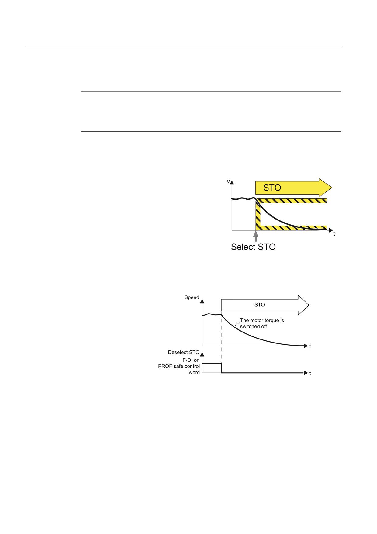
Definition according to EN 61800-5-2:
"The STO function prevents energy from being
supplied to the motor, which can generate a
torque."
Principle of operation
The inverter recognizes
the selection of STO via
a fail-safe input or via
the safe communication
PROFIsafe.
The inverter then safely
switches off the torque
of the connected motor.
Guidelines for machine configuration
486
System Manual, MA 01/2013, 6FC5397-6CP10-0BA2
Safety Integrated
9.2 SINAMICS Safety Integrated
Application examples
Example
Possible solution
After an Emergency Stop button has been pressed,
• Wire the Emergency Stop button with a fail-
the drive must be braked as quickly as possible and
safe input.
brought into the STO state.
• Select STO via the fail-safe input.
A central Emergency Stop button ensures that
• Evaluate an Emergency Stop button in a
several drives are braked as quickly as possible
central control.
and brought into the STO state.
• Select STO via PROFIsafe.
Controlling the Safe Torque Off (STO) safety function using terminals
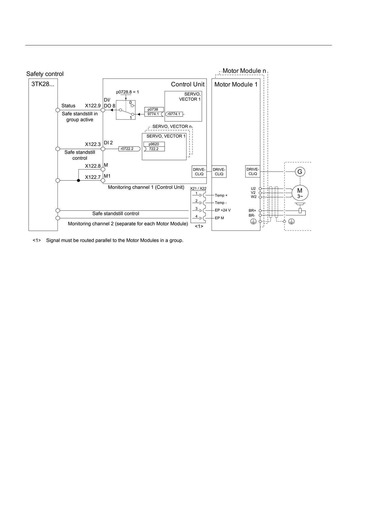
The Safe Torque Off function is selected/deselected separately for each drive using a
specific terminal on the Control Unit and Motor Module.
● Control Unit
The desired input terminal for STO is selected via BICO interconnection (BI: p9620).
Digital input DI 0 ... DI 7 on the Control Unit can be used as a signal source (NCU). The
NX modules have DI 0 to DI 3 digital input.
● Motor Module
The input terminal for STO is the "EP" pulse enable (Enable Pulses) terminal.
Both terminals must be simultaneously energized, otherwise a fault will be issued.
Note
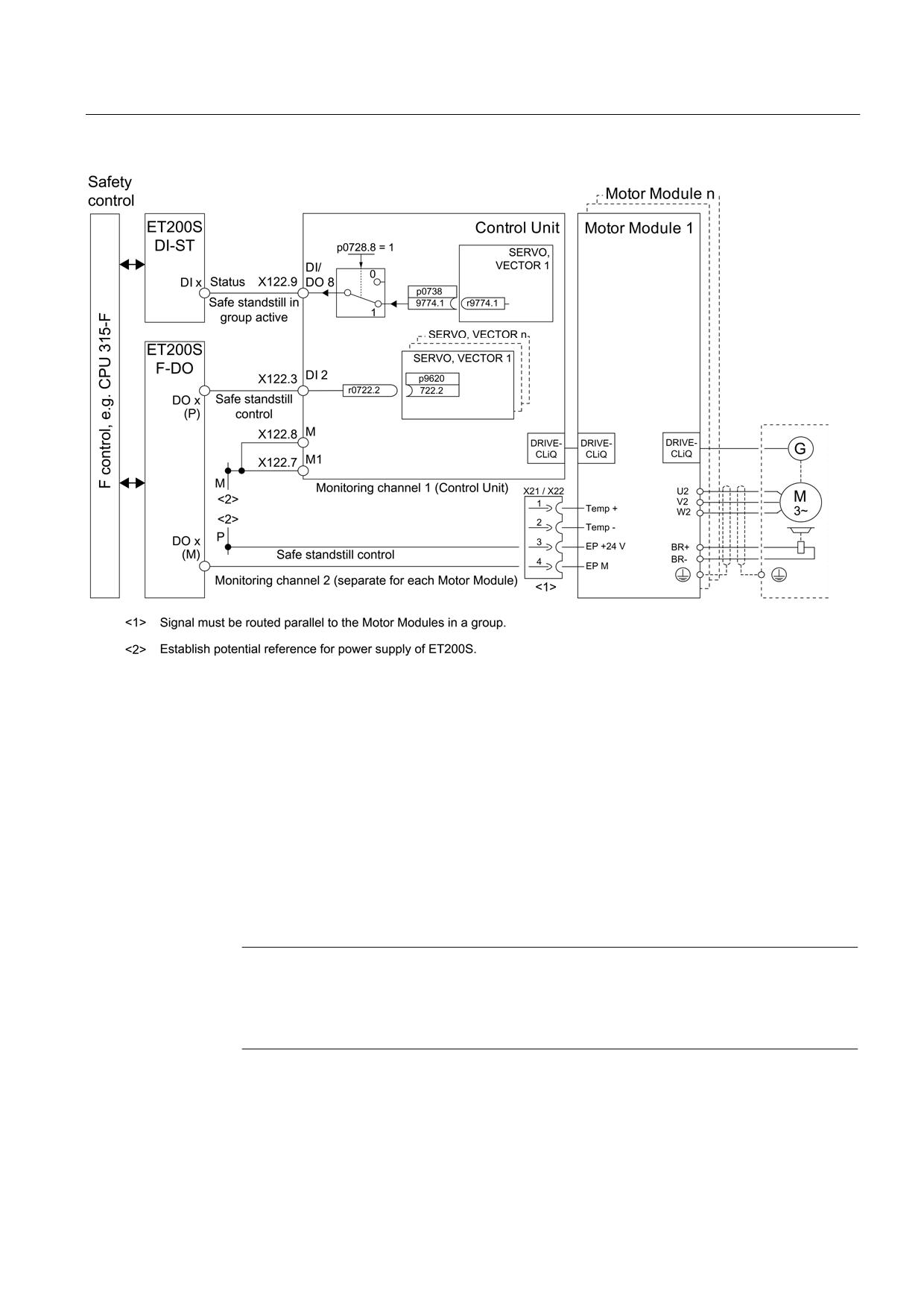
To enable safe control of the safety functions using terminals, an external safety control such
as a safety relay (3TK28...) or SIMATIC S7 F control (e.g. ET200S F-DO- P/M-switching)
conforming to EN 13849-1 must be provided.
Guidelines for machine configuration
System Manual, MA 01/2013, 6FC5397-6CP10-0BA2
487
Safety Integrated
9.2 SINAMICS Safety Integrated
Figure 9-1
Terminals for Safe Torque Off
Guidelines for machine configuration
488
System Manual, MA 01/2013, 6FC5397-6CP10-0BA2
Safety Integrated
9.2 SINAMICS Safety Integrated
Figure 9-2
Safe Torque Off terminals; control using ET200S fail-safe output, for example
Grouping drives
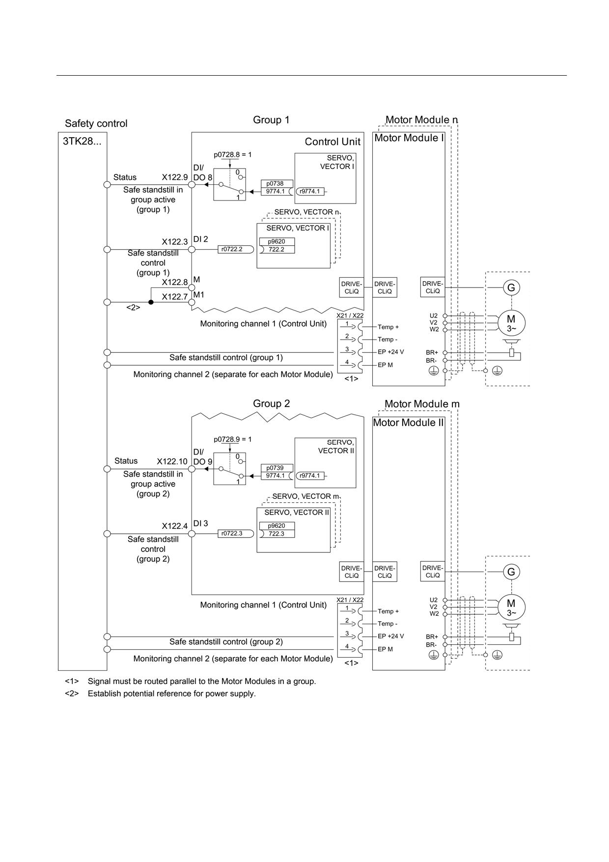
If the function is to be initiated for several drives simultaneously, the terminals for the
corresponding drives must be grouped together:
● Control Unit
By appropriately interconnecting the binector input to a joint input terminal for the drives
to be combined to form a group.
● Motor Module
By appropriately connecting terminal "EP" for the individual Motor Modules belonging to a
group.
Note
The same grouping must be set in both monitoring channels.
If a fault in a drive leads to an STO, the other drives in the same group will not
automatically enter the STO state.
Guidelines for machine configuration
System Manual, MA 01/2013, 6FC5397-6CP10-0BA2
489
Safety Integrated
9.2 SINAMICS Safety Integrated
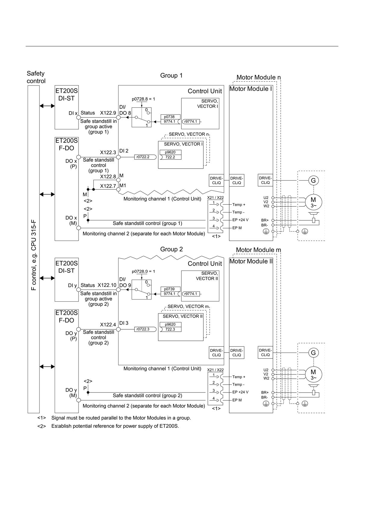
Example: Terminal grouping for Safe Torque Off (STO)
It must be possible to select/deselect the Safe Torque Off function separately for group 1
(drive 1 and 2) and group 2 (drive 3 and 4).
For this purpose, the same grouping for Safe Torque Off must be performed on both the
Control Unit and the Motor Modules.
Guidelines for machine configuration
490
System Manual, MA 01/2013, 6FC5397-6CP10-0BA2
Safety Integrated
9.2 SINAMICS Safety Integrated
Figure 9-3
Terminal grouping for Safe Torque Off
Guidelines for machine configuration
System Manual, MA 01/2013, 6FC5397-6CP10-0BA2
491
Safety Integrated
9.2 SINAMICS Safety Integrated
Figure 9-4
Terminal grouping for Safe Torque Off; control using ET200S fail-safe output, for example
Guidelines for machine configuration
492
System Manual, MA 01/2013, 6FC5397-6CP10-0BA2
Safety Integrated
9.2 SINAMICS Safety Integrated
Enabling the Safe Torque Off (STO) function
The Safe Torque Off function is enabled via the following parameters:
p9601.0
STO using terminals on the Control Unit
p9801.0
STO using terminals on the Motor Module
The Safe Torque Off function does not need to be enabled for applications that do not
require Safety Integrated. All input terminals on the Control Unit can be used.
The STO terminal on the Motor Module does not need to be used.
Selecting/Deselecting Safe Torque Off
The Safe Torque Off function must be selected/deselected simultaneously in both monitoring
channels using the input terminals and is only effective for the associated drive.
1 signal: Deselection of the function
0 signal: Selection of the function
Restart after the Safe Torque Off function has been selected
1. Deselect the function in each monitoring channel via the input terminals.
2. Issue drive enable signals.
3. Cancel the power-on inhibit and power-up again.
-
1/0 edge at input signal "ON/OFF1" (cancel power-on inhibit)
–
0/1 edge at input signal "ON/OFF1" (power-up drive)
4. Move/traverse the drives again.
Status for Safe Torque Off
The status of the Safe Torque Off function is displayed using the following parameters:
r9772
CO/BO: Safety Integrated Status (Control Unit)
r9872
CO/BO: Safety Integrated Status (Motor Module)
r9773
CO/BO: Safety Integrated Status (Control Unit + Motor Module)
r9774
CO/BO: Safety Integrated Status (Safe Torque Off group)
Further information
For further details and information on how to assign parameters for this function, see the
"SINAMICS S120, Safety Integrated" Function Manual.
Guidelines for machine configuration
System Manual, MA 01/2013, 6FC5397-6CP10-0BA2
493
Safety Integrated
9.2 SINAMICS Safety Integrated
9.2.2.2
Safe Stop 1 (SS1)
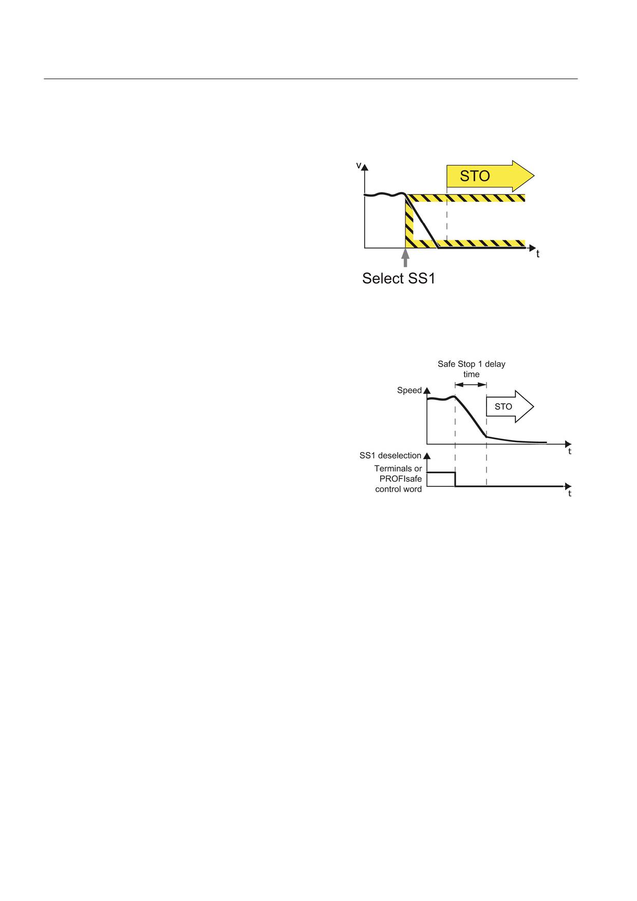
Definition according to EN 61800-5-2:
"The function SS1 brakes the motor and
trips the function STO after a delay time."
Principle of operation
The drive brakes once "Safe Stop 1" has
been selected, and goes into the "Safe
Torque Off" (STO) state once the delay
time has expired.
Selecting SS1
As soon as the converter identifies that SS1 has been selected via a terminal or via
PROFIsafe safe communication, the following happens:
● If the motor has already been switched off when SS1 was selected, then the converter
safely switches off the motor torque (STO).
● If the motor is switched on when SS1 is selected, the converter brakes the motor with the
AUS3 ramp-down time.
Guidelines for machine configuration
494
System Manual, MA 01/2013, 6FC5397-6CP10-0BA2
Safety Integrated
9.2 SINAMICS Safety Integrated
Application examples
Example
Possible solution
After an Emergency Stop button has been pressed,
• Wire the Emergency Stop button with a fail-
the drive must be braked as quickly as possible and
safe input.
brought into the STO state.
• Select SS1 via the fail-safe input.
A central Emergency Stop button ensures that
• Evaluate an Emergency Stop button in a
several drives are braked as quickly as possible
central control.
and brought into the STO state.
• Select SS1 via PROFIsafe.
Further information
For further details and information on how to assign parameters for this function, see the
"SINAMICS S120, Safety Integrated" Function Manual.
9.2.2.3
Safe Brake Control (SBC)
Principle of operation
The "Safe Brake Control" function (SBC) is used to control holding brakes that function
according to the closed-circuit principle (e.g. motor holding brake).
SBC is (if configured) initiated together with STO. The Motor Module / Safe Brake Relay /
Safe Brake Module then carries out the action and activates the outputs for the brake.
Brake activation via the brake connection on the Motor Module / Safe Brake Relay / Safe
Brake Module involves a safe, two-channel method.
Features
● SBC is executed when "Safe Torque Off" (STO) is selected.
● In contrast to conventional brake control, SBC is executed via two channels.
● SBC is executed regardless of the brake control or mode set in p1215. SBC is not
recommended, however, when 1215 = 0 or 3.
● When the state changes, electrical faults, such as a short-circuit in the brake winding or
wire breakage can be detected.
Guidelines for machine configuration
System Manual, MA 01/2013, 6FC5397-6CP10-0BA2
495
Safety Integrated
9.2 SINAMICS Safety Integrated
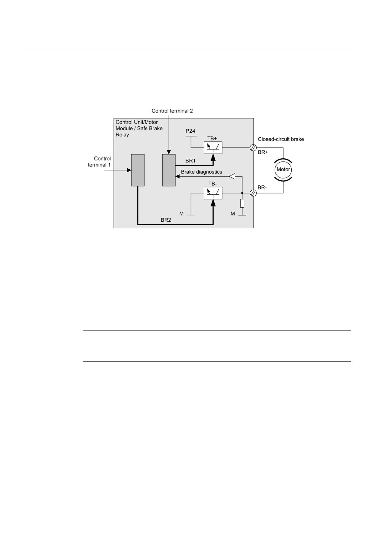
Two-channel brake control
The brake is essentially controlled from the Control Unit. Two signal paths are available for
applying the brake.
Figure 9-5
Two-channel brake control, blocksize (example)
For the "Safe Brake Control" function, the Motor/Power Module assumes a monitoring
function to ensure that when the Control Unit fails or malfunctions the brake current is
interrupted therefore closing the brake.
The brake diagnostics can only reliably detect a malfunction in either of the switches (TB+,
TB-) when the status changes, i.e. when the brake is released or applied.
If the Motor Module or Control Unit detects a fault, the brake current is switched off and the
safe status is reached.
Note
The monitoring and the forced checking procedure of the brake outlet is only possible if the
brake is connected directly to the connection terminals, and not using a coupling relay!
Further information
For further details and information on how to assign parameters for this function, see the
"SINAMICS S120, Safety Integrated" Function Manual.
Guidelines for machine configuration
496
System Manual, MA 01/2013, 6FC5397-6CP10-0BA2

Safety Integrated
9.3 SINUMERIK Safety Integrated
9.3
SINUMERIK Safety Integrated
9.3.1
Safety functions
SINUMERIK Safety Integrated provides integrated safety functions for monitoring standstill,
speed, and working area.
Table 9- 2
SINUMERIK 840D sl safety functions
Function
Abbr.
Meaning
Safe Stopping Process
SS1
Brakes the drives safely down to standstill if monitoring or a sensor is triggered.
Safe Acceleration Monitor
SBR
Monitors the speed characteristic. The speed must be reduced after a stop request
has been issued.
Safe Operating Stop
SBH
Monitors the drives during standstill (to ensure that they remain stationary). The
drives remain fully functional for position control.
Safe Standstill
SH
The drive pulses are suppressed, allowing the energy feed to be safely and
electronically disconnected.
Safely Reduced Speed
SG
Monitoring of configurable speed limits
Safety-Related Output
-
Safe speed detection for a drive
n < nx
Safe Software Limit Switch
SE
Variable traversing range limits
Safe Software Cam
SN
Range detection
Safety-Related Input/Output
SGE/
Interface with process
Signals
SGA
Safe Programmable Logic
SPL
Direct connection of all safety-related signals and their internal logical operations
Safe Brake Management
SBM
•
2-channel brake control (SBC) (integrated into Motor Module)
• Cyclic brake test (SBT)
Safety-related
-
• Connection of distributed I/O for process and safety signals via PROFIBUS or
communication via standard
PROFINET using the PROFIsafe protocol
bus
• Safety-related CPU - CPU communication via PROFIBUS or PROFINET
Integrated acceptance test
-
Partially automated acceptance test for all safety-related functions. Simple
operation of the test process, automatic configuration of trace functions, and
automatic generation of an acceptance report.
Guidelines for machine configuration
System Manual, MA 01/2013, 6FC5397-6CP10-0BA2
497
Safety Integrated
9.3 SINUMERIK Safety Integrated
Note
External safety-related process signals are connected via safe input/output modules of the
ET200S, ET200M, ET200eco, or ET200pro, and connected to SINUMERIK 840D sl via
PROFIBUS or PROFINET.
The safe sensors and actuators are processed within the safe programmable logic, which
means that external safety relays are no longer required.
Note
Further information
You can find a detailed description of the individual safety functions in the SINUMERIK
Safety Integrated Function Manual (FBSI sl).
9.3.2
Connecting safe sensors and actuators to the SINUMERIK
The following example illustrates the wiring possibilities of the ET200S PROFIsafe
component.
No complete plant with all required hardware and software settings is shown. Only the data
always required for the application is described for each of the used ET200S components. A
detailed description is contained in the associated product/function manuals.
The sensor/actuator connection for SINUMERIK Safety Integrated is established using
PROFIBUS or PROFINET with PROFIsafe profile and PROFIsafe-compliant I/O modules
(e.g. ET200S, ET200eco, ET200pro, or ET200M).
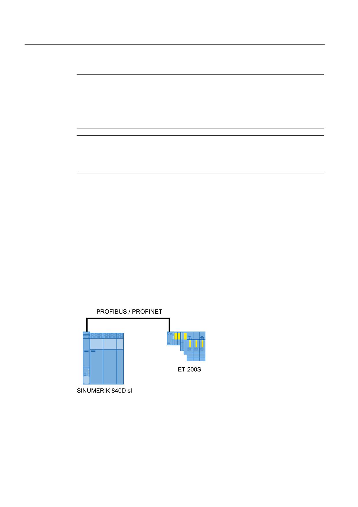
Overview of the ET200S peripheral connection to the NCU
Figure 9-6
Overview of the ET200S peripheral connection to the NCU
Guidelines for machine configuration
498
System Manual, MA 01/2013, 6FC5397-6CP10-0BA2
Safety Integrated
9.3 SINUMERIK Safety Integrated
Signal assignment and significance
Part of the signal assignment and significance for the PROFIsafe modules is explained in the
following section:
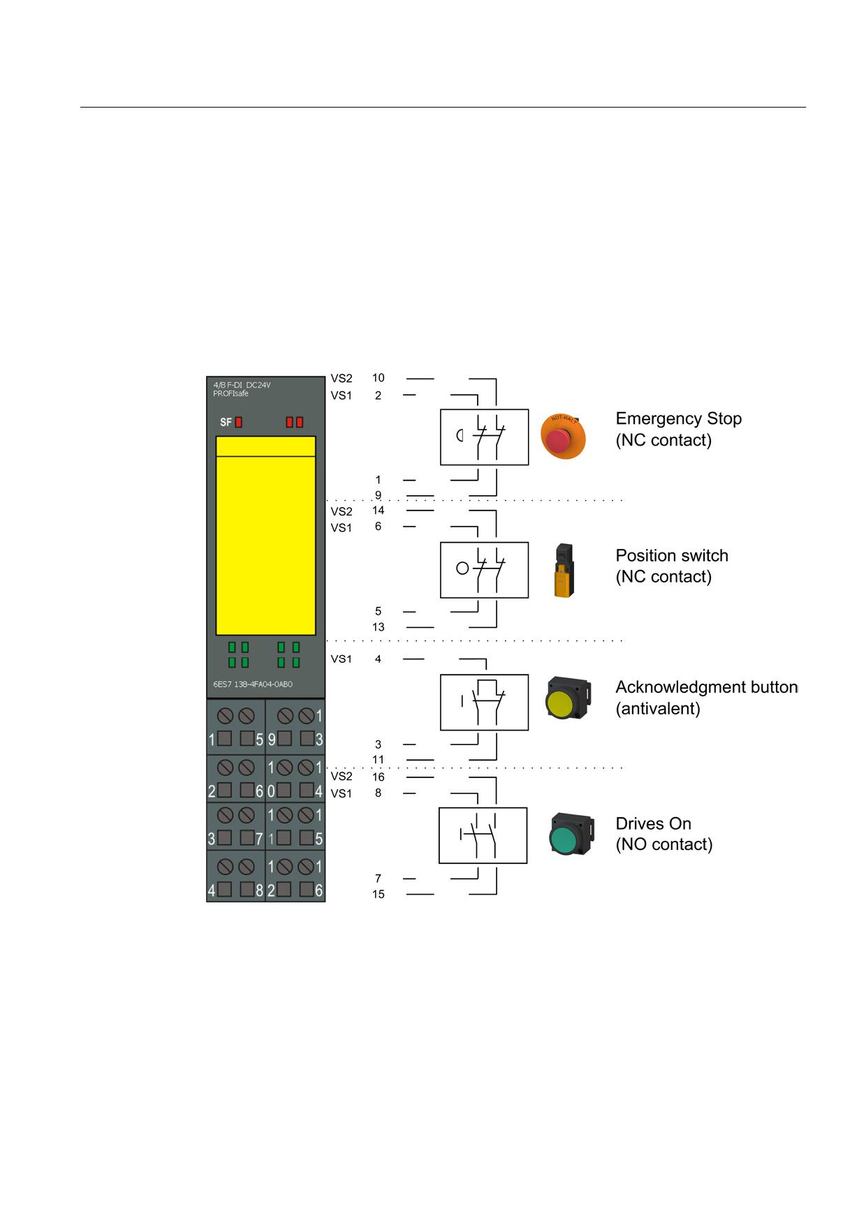
4/8 F-DI 24 VDC PROFIsafe electronic module
The safety-related I/O input signals are connected to this module. These sensors in the
example are optionally exclusive OR with two break contacts (Emergency Stop actuator and
protective door interlocked state), i.e. provided with a break contact and a make contact
(agreement button) or with two make contacts (<drive on> button).
All of the sensor signals are connected through two channels.
Figure 9-7
Signal assignment, electronics module, 4/8F-DI, 24 VDC, PROFIsafe
Guidelines for machine configuration
System Manual, MA 01/2013, 6FC5397-6CP10-0BA2
499
Safety Integrated
9.3 SINUMERIK Safety Integrated
Meaning and use of the individual signals
Emergency Stop actuator [F-DI terminal 1 (channel 0), terminal 9 (channel 4)]
Signal state channel 0 = "1" and channel 4 = "1":
Emergency Stop actuator not pressed.
Signal state channel 0 = "0" and channel 4 = "0":
Emergency Stop actuator pressed.
Protective door interlocked state [F-DI terminal 5 (channel 1), terminal 13 (channel 5)]
The door switch only interlocks if the actuator is inserted. The contacts of the monitoring
circuit then signal the status "closed and interlocked"
Signal state channel 1 = "1" and channel 5 = "1":
Protective door closed and interlocked.
Signal state channel 1 = "0" and channel 5 = "0":
Protective door not closed or not interlocked.
Agreement button [F-DI terminal 3 (channel 2), terminal 11 (channel 6)]
Signal state channel 2 = "1" and channel 6 = "0":
Acknowledgment button pressed.
Signal state channel 2 = "0" and channel 6 = "1":
Acknowledgment button not pressed.
Drives On button [F-DI terminal 7 (channel 3), terminal 15 (channel 7)]
Signal state channel 3 = "0" and channel 7 = "0":
Drives On button not pressed.
Signal state channel 3 = "1" and channel 7 = "1":
Drives On button pressed.
VS1: internal sensor supply for channel 0 to 3
VS2: internal sensor supply for channel 4 to 7
These two sensor supplies must be used when the short-circuit test is activated. The
exclusive OR sensor agreement button is an exception. For this sensor variant, in
conjunction with the short-circuit test, the VS1 sensor supply must be used for both contacts.
Guidelines for machine configuration
500
System Manual, MA 01/2013, 6FC5397-6CP10-0BA2
Safety Integrated
9.3 SINUMERIK Safety Integrated
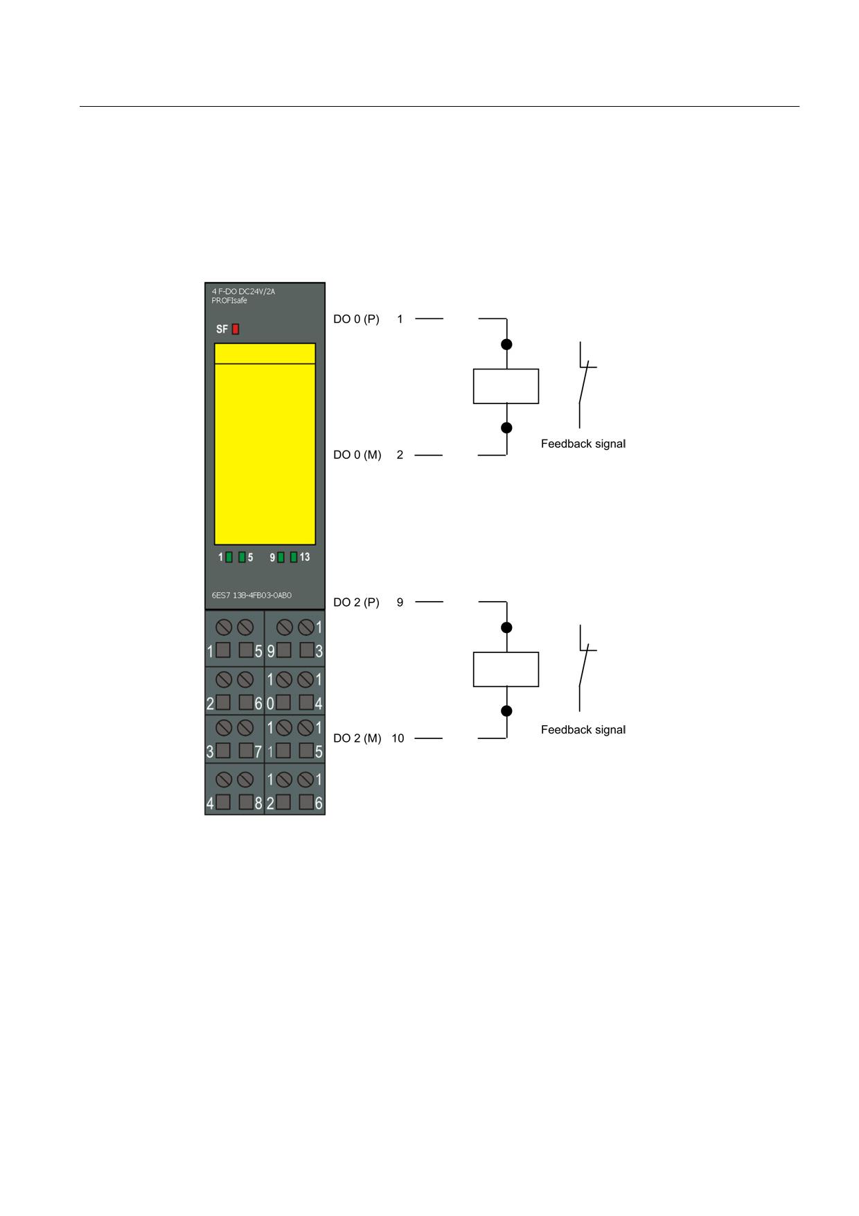
Electronics module 4 F-DO 24 VDC/2 A PROFIsafe
The actuators that must be shut-down in a safety-related fashion are connected through two
channels. Each output channel can be separately shutdown.
Two valve units are connected in the configuration example. These are used to control the
motion of the supplementary pneumatic axis.
Figure 9-8
Signal assignment electronics module, 4F-DO, 24 VDC_2 A, PROFIsafe
Meaning and use of the individual signals
Valve unit 1 F-DO terminal 1,2 (channel 0 P/M)
Signal state channel 0 = "0"
Valve in the locked neutral position
Signal state channel 0 = "1"
Valve in the flow position
Not assigned [F-DO terminal 5,6 (channel 1 P/M)]
Guidelines for machine configuration
System Manual, MA 01/2013, 6FC5397-6CP10-0BA2
501
Safety Integrated
9.3 SINUMERIK Safety Integrated
Valve unit 2 [F-DO terminal 9,10 (channel 2 P/M)]
Signal state channel 2 = "0"
Valve in the locked neutral position
Signal state channel 2 = "1"
Valve in the flow position
Not assigned [F-DO terminal 13.14 (channel 3 P/M)]
Power Module PM-E F
This module combines two functions. Not only can individual actuators (comparable with the
functionality of an F-DO module) be connected to all three two-channel output channels, but
the third DO2 output channel also has a further function.
The DO2 output channel is used to internally (no external wiring required) disconnect safety-
oriented (i.e. with two potentials) to supply power for the subsequent standard DO or also
standard DI modules. Namely, the outputs on the DO modules can not only be controlled
using a single channel in the PLC for the "normal" function, but also a safety-oriented
shutdown of the power supply for all DO modules following the PM-E F module is possible.
Power Module PM-D F 24 V DC PROFIsafe
The Power Module can switch off the SG 1 to SG 6 voltage buses in a fail-safe way using six
digital outputs. The outputs are implemented using two P switches in each case. There is a
main switch for all six shutdown groups and six subsequent (downstream) individual
switches for each shutdown group.
The voltage bus U 1 (electronics power supply for the motor starter) is supplied with 24 VDC.
In the event of an overvoltage or undervoltage condition, U 1 is shut down by two P switches
and the subsequent (downstream) motor starters are deactivated. If the motor starter is
safely shutdown, U 1 is not shutdown.
With the six available shutdown groups (SG1...SG6), the Power Module is suitable for tasks
including supplying fail-safe motor starters such as F-DS1e-x and F-RS1e-x.
Fail-safe direct starters F-DS1e-x
The fail-safe direct starter with electronic overload protection can either power-up or power-
down the connected motor (implemented in the application through the PLC I/O interface).
Further, when the SG signal is missing at the upstream PM-D F, the PM module can
shutdown the motor in a safety-related fashion.
Depending on the type, three-phase motors up to 7.5 kW can be connected and operated
with integrated protection against overload and short-circuit.
On the one hand, the SG 1...SG 6 safe shutdown group will be assigned to the fail-safe
motor starter using the STEP 7 hardware configuration. On the other hand, the assignment
is realized using the coding connector on the terminal module of the motor starter. Both
assignments must match one another.
Guidelines for machine configuration
502
System Manual, MA 01/2013, 6FC5397-6CP10-0BA2
Signal Interconnection
10
Note
This chapter is still undergoing revision.
Guidelines for machine configuration
System Manual, MA 01/2013, 6FC5397-6CP10-0BA2
503
Signal Interconnection
Guidelines for machine configuration
504
System Manual, MA 01/2013, 6FC5397-6CP10-0BA2
Typical circuit diagrams
11
Note
This chapter is still undergoing revision.
Guidelines for machine configuration
System Manual, MA 01/2013, 6FC5397-6CP10-0BA2
505
Typical circuit diagrams
Guidelines for machine configuration
506
System Manual, MA 01/2013, 6FC5397-6CP10-0BA2
Activate/Deactivate Drive System
12
12.1
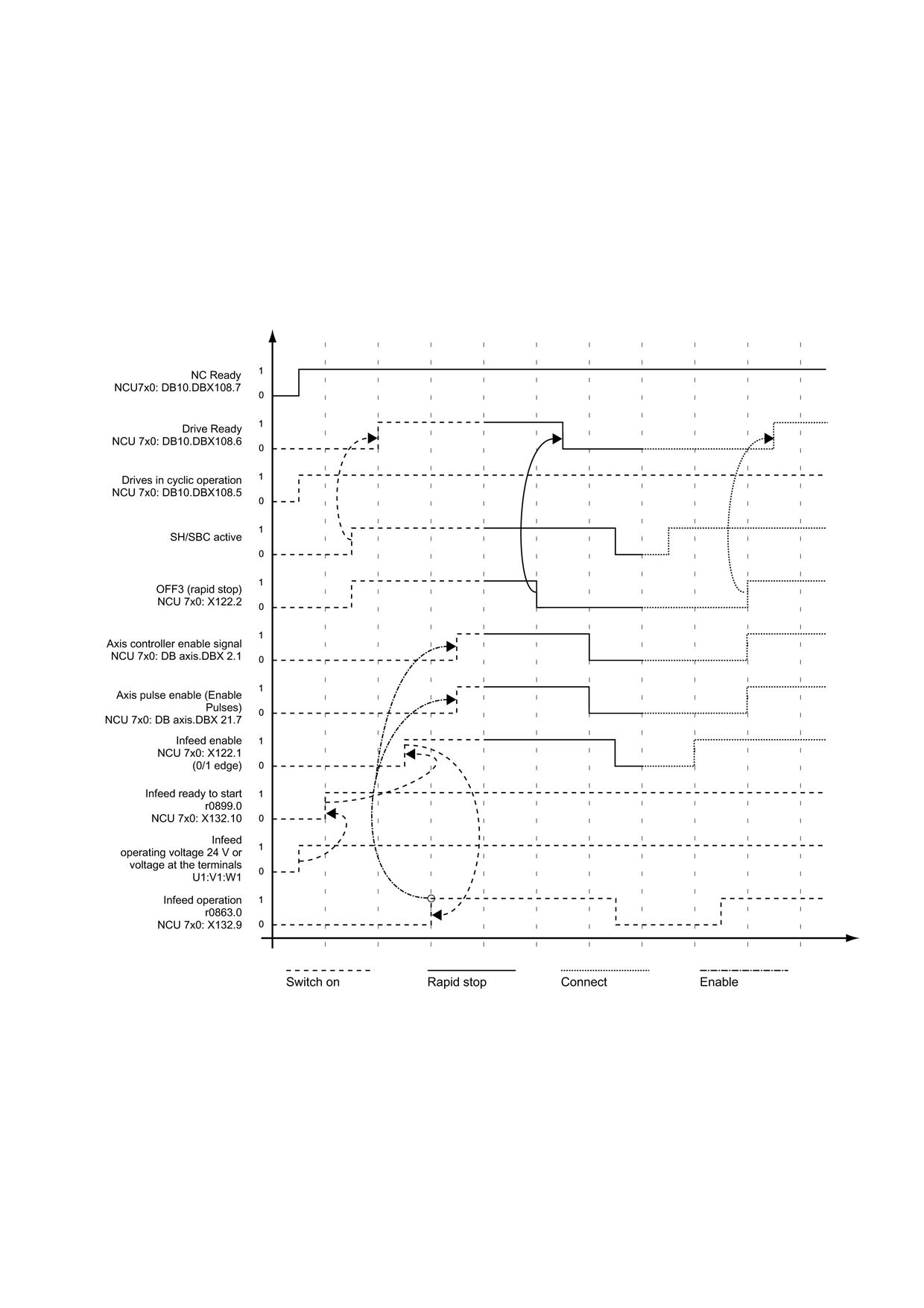
Overview of the Status Signals
Figure 12-1 Overview of the Status Signals
Guidelines for machine configuration
System Manual, MA 01/2013, 6FC5397-6CP10-0BA2
507
Activate/Deactivate Drive System
12.2 Drive Group with Several Axes
12.2
Drive Group with Several Axes
The Motor Module is controlled via terminals -X21, -X22 and the DRIVE-CLiQ interfaces -
X200/-X201/-X202/-X203 (-X22 and -X203 are only available with Double Motor Modules).
You can find a detailed function description for the individual signals and control/status
words in the following document:
\LH1\SINAMICS S120/S150 List Manual
To enable the Motor Module, the "infeed ready" signal must be connected from the Line
Module.
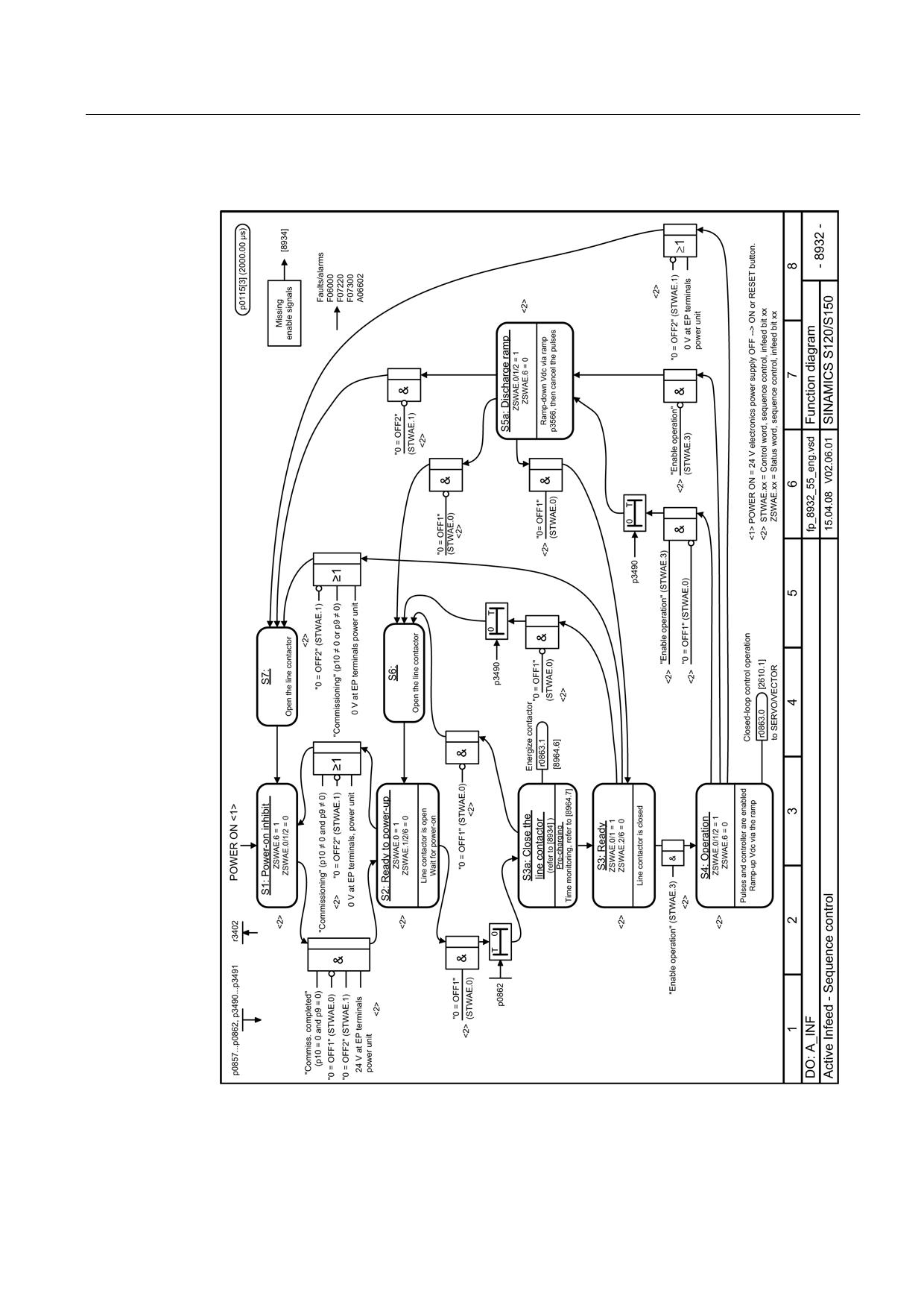
The following function diagrams show how the individual signals interact.
Guidelines for machine configuration
508
System Manual, MA 01/2013, 6FC5397-6CP10-0BA2
Activate/Deactivate Drive System
12.2 Drive Group with Several Axes
Activating the infeed
Figure 12-2 "Infeed activation" function diagram
Guidelines for machine configuration
System Manual, MA 01/2013, 6FC5397-6CP10-0BA2
509
Activate/Deactivate Drive System
12.2 Drive Group with Several Axes
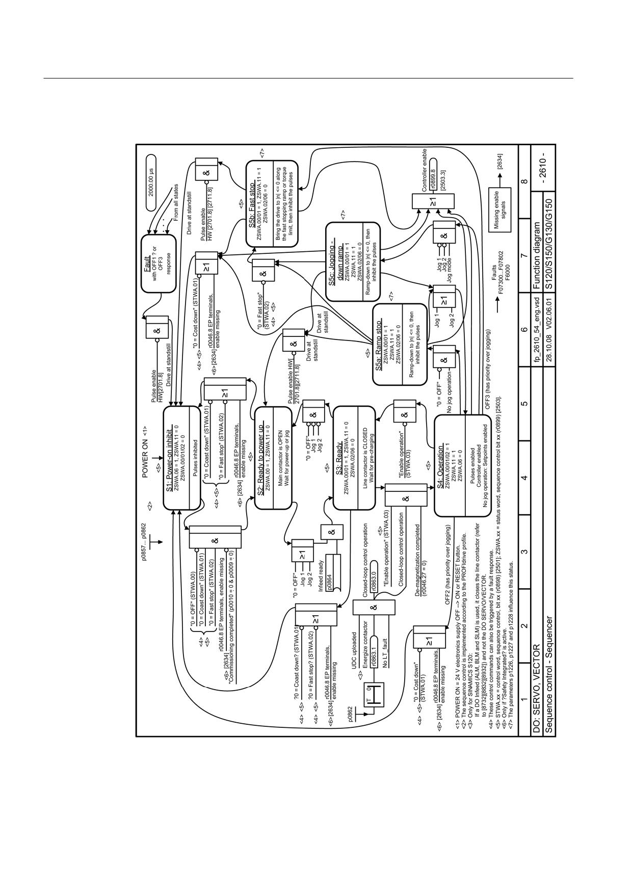
Activating the drive
Figure 12-3 "Drive activation" function diagram
Guidelines for machine configuration
510
System Manual, MA 01/2013, 6FC5397-6CP10-0BA2
Activate/Deactivate Drive System
12.2 Drive Group with Several Axes
Note
Applies to CU320; with integrated drive solutions (e.g. NCU, NX, etc.), some signals are
already processed by means of internal communication
Off responses
● OFF1
- The immediate specification of n_set = 0 at the ramp generator return ramp (p1121)
causes the drive to be braked.
- When zero speed is detected, the motor holding brake (if parameterized) is closed
(p1215). The pulses are suppressed when the closing time (p1217) expires. The zero
speed is detected when the speed actual value is lower than the speed threshold
(p1226) or when the monitoring time (p1227) started when speed setpoint ≤ speed
threshold (p1226) has expired.
● OFF2
- Immediate pulse suppression, the drive coasts to standstill.
- The motor holding brake (if parameterized) is closed immediately.
- Closing lockout is activated.
● OFF3
- The immediate specification of n_set = 0 at the OFF3 return ramp (p1135) causes the
drive to be braked.
- When zero speed is detected, the motor holding brake (if parameterized) is closed.
The pulses are suppressed when the closing time of the holding brake (p1217)
expires. The zero speed is detected when the speed actual value is lower than the
speed threshold (p1226) or when the monitoring time (p1227) started when speed
setpoint ≤ speed threshold (p1226) has expired.
- Closing lockout is activated.
Guidelines for machine configuration
System Manual, MA 01/2013, 6FC5397-6CP10-0BA2
511

Activate/Deactivate Drive System
12.2 Drive Group with Several Axes
Control and status signals
Table 12- 1 Switching on/switching off the control system
Signal name
Internal control word
Binector input
PROFIBUS message
VDI interface (PLC)
frame 2 … 106
0 = OFF1
STWA.00
p0840 ON/OFF1
STW1.0
DB(AX).DBX2.1
STWAE.00
(controller enable)
DB(AX).DBX1.5/6
(measuring system
selected and OK)
DB(AX).DBX21.7
(pulse enable)
0 = OFF2
STWA.01
p0844 1. OFF2
STW1.1
1
STWAE.01
p0845 2. OFF2
0 = OFF3
STWA.02
p0848 1. OFF3
STW1.2
1
P0849 2. OFF3
Enable operation
STWA.03
p0852 operation
STW1.3
DBX21.7
STWAE.03
enabled
Table 12- 2 Activate/deactivate status signals
Signal name
Internal status word
Parameter
PROFIBUS message frame 2 … 106
Ready to start
ZSWA.00
r0899.0
ZSW1.0
ZSWAE.00
Ready
ZSWA.01
r0899.1
ZSW1.1
ZSWAE.01
Operation enabled
ZSWA.02
r0899.2
ZSW1.2
ZSWAE.02
Closing lockout
ZSWA.06
r0899.6
ZSW1.6
ZSWAE.06
Pulses enabled
ZSWA.11
r0899.11
ZSW1.11
Function block diagram overview (see SINAMICS S List Manual)
●
2610 sequence control - sequencer
●
2634 missing enables, line contactor control
●
8732 basic infeed - sequencer
●
8832 smart infeed - sequencer
●
8932 active infeed - sequencer
Guidelines for machine configuration
512
System Manual, MA 01/2013, 6FC5397-6CP10-0BA2

Appendix
A
A.1
Screw terminals
The type of screw terminal can be taken from the interface description of the particular
component.
Table A- 1 Connectable conductor cross-sections and tightening torques for screw terminals
Screw terminal type
1
Connectable conductor cross-
Rigid, flexible
0.08 mm2 to 1.5 mm2
sections
With wire end ferrule, without plastic sleeve
0.25 mm2 to 1.5 mm2
With wire end ferrule, with plastic sleeve
0.25 mm2 to 0.5 mm2
Stripping length
7 mm
Tool
Screwdriver 0.4 x 2.0 mm
Tightening torque
0.22 to 0.25 Nm
1_1
Connectable conductor cross-
Rigid, flexible
0.14 mm2 to 1.5 mm2
sections
With wire end ferrule, without plastic sleeve
0.25 mm2 to 1.5 mm2
With wire end ferrule, with plastic sleeve
0.25 mm2 to 0.5 mm2
Stripping length
7 mm
Tool
Screwdriver 0.4 x 2.5 mm
Tightening torque
0.22 to 0.25 Nm
2
Connectable conductor cross-
Rigid, flexible
0.08 mm2 to 2.5 mm2
sections
With wire end ferrule, without plastic sleeve
0.5 mm2 to 2.5 mm2
With wire end ferrule, with plastic sleeve
0.5 mm2 to 1.5 mm2
Stripping length
7 mm
Tool
Screwdriver 0.6 x 3.5 mm
Tightening torque
0.5 to 0.6 Nm
3
Connectable conductor cross-
Flexible
0.2 mm2 to 2.5 mm2
sections
With wire end ferrule, without plastic sleeve
0.25 mm2 to 1 mm2
With wire end ferrule, with plastic sleeve
0.25 mm2 to 1 mm2
Stripping length
9 mm
Tool
Screwdriver 0.6 x 3.5 mm
Tightening torque
0.5 to 0.6 Nm
4
Connectable conductor cross-
Flexible
0.2 mm2 to 4 mm2
sections
With wire end ferrule, without plastic sleeve
0.25 mm2 to 4 mm2
With wire end ferrule, with plastic sleeve
0.25 mm2 to 4 mm2
Stripping length
7 mm
Tool
Screwdriver 0.6 x 3.5 mm
Tightening torque
0.5 to 0.6 Nm
Guidelines for machine configuration
System Manual, MA 01/2013, 6FC5397-6CP10-0BA2
513

Appendix
A.1 Screw terminals
Screw terminal type
5
Connectable conductor cross-
Flexible
0.5 mm2 to 6 mm2
sections
With wire end ferrule, without plastic sleeve
0.5 mm2 to 6 mm2
With wire end ferrule, with plastic sleeve
0.5 mm2 to 6 mm2
Stripping length
12 mm
Tool
Screwdriver 1.0 x 4.0 mm
Tightening torque
1.2 to 1.5 Nm
6
Connectable conductor cross-
Flexible
0.5 mm2 to 10 mm2
sections
With wire end ferrule, without plastic sleeve
0.5 mm2 to 10 mm2
With wire end ferrule, with plastic sleeve
0.5 mm2 to 10 mm2
Stripping length
11 mm
Tool
Screwdriver 1.0 x 4.0 mm
Tightening torque
1.5 to 1.8 Nm
7
Connectable conductor cross-
0.5 mm2 to 16 mm2
sections
Stripping length
14 mm
Tool
Screwdriver 1.0 x 4.0 mm
Tightening torque
1.5 to 1.7 Nm
Guidelines for machine configuration
514
System Manual, MA 01/2013, 6FC5397-6CP10-0BA2

Appendix
A.2 Spring-loaded terminals
A.2
Spring-loaded terminals
The type of spring-loaded terminal can be taken from the interface description of the
particular component.
Table A- 2 Connectable conductor cross-sections for spring-loaded terminals
Spring-loaded terminal type
1
Connectable conductor cross-
Rigid
0.14 mm2 to 0.5 mm2
sections
Flexible
0.14 mm2 to 0.5 mm2
Flexible with end sleeve without plastic sleeve
0.25 mm2 to 0.5 mm2
AWG/kcmil
26 to 20
Stripping length
8 mm
2
Connectable conductor cross-
Flexible
0.08 mm2 to 2.5 mm2
sections
Stripping length
8 to 9 mm
3
Connectable conductor cross-
Rigid
0.2 mm2 to 1 mm2
sections
Flexible
0.2 mm2 to 1.5 mm2
Flexible with end sleeve without plastic sleeve
0.25 mm2 to 1.5 mm2
Flexible with end sleeve with plastic sleeve
0.25 mm2 to 0.75 mm2
AWG/kcmil
24 to 16
Stripping length
8 mm
3_1
Connectable conductor cross-
Rigid
0.2 mm2 to 1.5 mm2
sections
Flexible
0.2 mm2 to 1.5 mm2
Flexible with end sleeve without plastic sleeve
0.25 mm2 to 1.5 mm2
Flexible with end sleeve with plastic sleeve
0.25 mm2 to 0.75 mm2
AWG/kcmil
24 to 16
Stripping length
10 mm
4
Connectable conductor cross-
25 mm2 to 95 mm2
sections
AWG 4 to 4/0
Stripping length
35 mm
5
Connectable conductor cross-
Rigid
0.2 mm2 to 10 mm2
sections
Flexible
0.2 mm2 to 6 mm2
Flexible with end sleeve without plastic sleeve
0.25 mm2 to 6 mm2
Flexible with end sleeve with plastic sleeve
0.25 mm2 to 4 mm2
AWG/kcmil
24 to 8
Stripping length
15 mm
Guidelines for machine configuration
System Manual, MA 01/2013, 6FC5397-6CP10-0BA2
515
Appendix
A.3 Power loss of components
A.3
Power loss of components
A.3.1
Power Loss of the SINUMERIK Components
The following power losses apply to operation with rated power:
Table A- 3 List of power losses
Component
Power loss
NCU 710.2
22 W
NCU 720.2
25 W
NCU 720.2 PN
55 W
NCU 730.2
55 W
NCU 730.2 PN
65 W
NX1x.x
20 W
A.3.2
Power loss of SINAMICS components
The tables below provide an overview of the power loss of all components during rated
operation. The characteristic values apply for the following conditions:
● Line voltage for Line Modules 400 V
● Pulse frequency of the Motor Modules 4 kHz
● Rated pulse frequency of the Active Line Modules 8 kHz
● Operating components at their rated power
The total losses of the relevant power unit (Line Module, Motor Module) are calculated from
the power loss and the corresponding electronics loss of the power unit.
A.3.2.1
Power loss for Control Units, Sensor Modules, and other system components
Table A- 4 Overview of power loss during rated operation for Control Units, Sensor Modules, and
other system components
Unit
Power loss
Control Units and Option Boards
CU320-2
W
24
CBC10
W
< 3
CBE20
W
2.8
Sensor Modules
SMC10
W
< 10
SMC20
W
< 10
SMC30
W
< 10
Guidelines for machine configuration
516
System Manual, MA 01/2013, 6FC5397-6CP10-0BA2

Appendix
A.3 Power loss of components
Unit
Power loss
SME20/25
W
≤ 4
SME120/125
W
≤ 4.5
Terminal Modules
TM15
W
< 3
TM41
W
12
TM120
W
2.4
DC link components
Braking Module Booksize
W
20
Braking Module Booksize Compact
W
< 40
Capacitor Module
W
25
Control Supply Module
Line
W
70
DC link
W
65
Voltage Clamping Module
W
50
A.3.2.2
Power loss for line filters and line reactors
Table A- 5 Overview of power loss during rated operation for line filters and line reactors
Unit
Power loss
Basic Line Filters for Active Line Modules
16 kW
W
16
36 kW
W
26
55 kW
W
43
80 kW
W
56
120 kW
W
73
Basic Line Filter for Active Line Modules with Active Interface Module
16 kW
W
16
36 kW
W
26
55 kW
W
43
80 kW
W
56
120 kW
W
73
Wideband Line Filter for Active Line Modules
16 kW
W
70
36 kW
W
90
55 kW
W
110
80 kW
W
150
120 kW
W
200
Basic Line Filter for Smart Line Modules
5 kW
W
5
10 kW
W
9
16 kW
W
16
Guidelines for machine configuration
System Manual, MA 01/2013, 6FC5397-6CP10-0BA2
517

Appendix
A.3 Power loss of components
Unit
Power loss
36 kW
W
26
55 kW
W
43
Basic Line Filter for Basic Line Modules
20 kW
W
16
40 kW
W
26
100 kW
W
73
Active Interface Modules
16 kW
W
270 1)
36 kW
W
340 1)
55 kW
W
380 1)
80 kW
W
490 1)
120 kW
W
585 1)
Line reactors for Active Line Modules
16 kW
W
170
36 kW
W
250
55 kW
W
350
80 kW
W
450
120 kW
W
590
Line reactors for Smart Line Modules
5 kW
W
62
10 kW
W
116
16 kW
W
110
36 kW
W
170
55 kW
W
200
Line reactors for Basic Line Modules
20 kW
W
130
40 kW
W
270
100 kW
W
480
1) Referred to VDC link 600 V
A.3.2.3
Power loss for power units with internal air cooling
Table A- 6 Overview of power loss at rated operation for power units with internal air cooling
(including electronics losses)
Unit
Power loss
Active Line Modules
16 kW
W
282.8
36 kW
W
666
55 kW
W
945.6
80 kW
W
1383.6
120 kW
W
2243.2
Guidelines for machine configuration
518
System Manual, MA 01/2013, 6FC5397-6CP10-0BA2

Appendix
A.3 Power loss of components
Unit
Power loss
Smart Line Modules Booksize
5 kW
W
79.2
10 kW
W
141.6
16 kW
W
187.8
36 kW
W
406
55 kW
W
665.6
Smart Line Modules Booksize Compact
16 kW
W
187.8
Basic Line Modules
20 kW
W
144
40 kW
W
283.6
100 kW
W
628
Single Motor Modules Booksize
3 A
W
50.4
5 A
W
73.4
9 A
W
100.4
18 A
W
185.4
30 A
W
309.2
45 A
W
455.2
60 A
W
615.2
85 A
W
786
132 A
W
1270.4
200 A
W
2070.4
Single Motor Modules Booksize Compact
3 A
W
68 1)
5 A
W
98 1)
9 A
W
100.4
18 A
W
185.4
Double Motor Modules Booksize
3 A
W
97.6
5 A
W
132.6
9 A
W
187.6
18 A
W
351.2
Double Motor Modules Booksize Compact
1.7 A
W
114 1)
3 A
W
134 1)
5 A
W
194 1)
1) Power loss at 8 kHz
Guidelines for machine configuration
System Manual, MA 01/2013, 6FC5397-6CP10-0BA2
519

Appendix
A.3 Power loss of components
A.3.2.4
Power loss for power units with external air cooling
Table A- 7 Overview of power loss at rated operation for power units with external air cooling (including electronics
losses)
Unit
Internal
External power loss
Total power loss
Power loss 1)
Active Line Modules
16 kW
W
82.8 (60 + 22,8)
200
282.8
36 kW
W
171 (135 + 36,0)
495
666
55 kW
W
245.6 (200 + 45,6)
700
945.6
80 kW
W
338.6 (305 + 33,6)
1045
1383.6
120 kW
W
533.2 (490 + 43,2)
1710
2243.2
Smart Line Modules
5 kW
W
41.2 (22 + 19,2)
38
79.2
10 kW
W
66.6 (45 + 21,6)
75
141.6
16 kW
W
64.8 (42 + 22,8)
123
187.8
36 kW
W
116 (80 + 36)
290
406
55 kW
W
185.6 (140 + 45,6)
480
665.6
Single Motor Modules
3 A
W
35.4 (15 + 20,4)
15
50.4
5 A
W
43.4 (23 + 20,4)
30
73.4
9 A
W
55.4 (35 + 20,4)
45
100.4
18 A
W
95.4 (75 + 20,4)
90
185.4
30 A
W
99.2 (80 + 19,2)
210
309.2
45 A
W
135.2 (110 + 25,2)
320
455.2
60 A
W
160.2 (135 + 25,2)
455
615.2
85 A
W
196 (160 + 36,0)
590
786
132 A
W
270.4 (250 + 20,4)
1000
1270.4
200 A
W
455.4 (435 + 20,4)
1615
2070.4
Double Motor Modules
3 A
W
62.6 (35 + 27,6)
35
97.6
5 A
W
72.6 (45 + 27,6)
60
132.6
9 A
W
92.6 (65 + 27,6)
95
187.6
18 A
W
111.2 (80 + 31,2)
240
351.2
1) Power loss of the power electronics + power loss of the 24 V electronics
Guidelines for machine configuration
520
System Manual, MA 01/2013, 6FC5397-6CP10-0BA2

Appendix
A.3 Power loss of components
A.3.2.5
Power loss for power units with cold plate
With cold-plate cooling, only part of the power loss remains in the cabinet.
The table below shows the internal and external power loss of the components.
Table A- 8 Overview of power loss at rated operation for power units with cold plate (including electronics losses)
Unit
Internal power loss 1)
External power loss
Total power loss
Active Line Modules
16 kW
W
70.4 (50 + 20,4)
210
280.4
36 kW
W
135.2 (110 + 25,2)
520
655.2
55 kW
W
187.6 (160 + 27,6)
740
927.6
80 kW
W
283.6 (250 + 33,6)
1100
1383.6
120 kW
W
443.2 (400 + 43,2)
1800
2243.2
Smart Line Modules Booksize
5 kW
W
34.4 (20 + 14,4)
40
74.4
10 kW
W
56.8 (40 + 16,8)
80
136.8
Smart Line Modules Booksize Compact
16 kW
W
56.6 (36,2 + 20,4)
130
186.6
Basic Line Modules
20 kW
W
46.6 (25 + 21,6)
95
141.6
40 kW
W
71.4 (45 + 26,4)
205
276.4
100 kW
W
168.4 (130 + 38,4)
450
618.4
Single Motor Modules Booksize
3 A
W
27.6 (12 + 15,6)
18
45.6
5 A
W
35.6 (20 + 15,6)
35
70.6
9 A
W
45.6 (30 + 15,6)
50
95.6
18 A
W
80.6 (65 + 15,6)
100
180.6
30 A
W
85.6 (70 + 15,6)
220
305.6
45 A
W
108 (90 + 18,0)
340
448
60 A
W
128 (110 + 18,0)
480
608
85 A
W
149.2 (130 + 19,2)
620
769.2
132 A
W
220.4 (200 + 20,4)
1050
1270.4
200 A
W
370.4 (350 + 20,4)
1700
2070.4
Single Motor Modules Booksize Compact
3 A
W
25.6 (10 + 15,6)
40
65.6
5 A
W
30.6 (15 + 15,6)
65
95.6
9 A
W
45.6 (30 + 15,6)
50
95.6
18 A
W
80.6 (65 + 15,6)
100
180.6
Guidelines for machine configuration
System Manual, MA 01/2013, 6FC5397-6CP10-0BA2
521

Appendix
A.3 Power loss of components
Unit
Internal power loss 1)
External power loss
Total power loss
Double Motor Modules Booksize
2x3 A
W
55.6 (34 + 21,6)
36
91.6
2x5 A
W
61.6 (40 + 21,6)
65
126.6
2x9 A
W
81.6 (60 + 21,6)
100
181.6
2x18 A
W
95.2 (70 + 25,2)
250
345.2
Double Motor Modules Booksize Compact
2x1.7 A
W
42 (20,4 + 21,6)
72
114
2x3 A
W
44 (22,4 + 21,6)
90
134
2x5 A
W
59 (37,4 + 21,6)
135
194
1) Power loss of the power electronics + power loss of the 24 V electronics
Note
Lower average power losses are obtained for intermittent duty.
A.3.2.6
Power loss for liquid-cooled power units
Table A- 9 Overview of power loss during rated operation for liquid-cooled power units (including electronics losses)
Unit
Internal power loss 1)
External power loss
Total power loss
Active Line Modules
120 kW
W
443.2 (400 + 43,2)
1800
2243.2
Single Motor Modules
200 A
W
370.4 (350 + 20,4)
1700
2070.4
1) Power loss of the power electronics + power loss of the 24 V electronics
Guidelines for machine configuration
522
System Manual, MA 01/2013, 6FC5397-6CP10-0BA2

Appendix
A.3 Power loss of components
A.3.3
Electronics losses of power units
Table A- 10 Electronics losses for power units with internal/external air cooling
Component
Internal/external air cooling
Power loss [W]
Single Motor Modules
3 A
20.4
5 A
20.4
9 A
20.4
18 A
20.4
30 A
19.2
45 A
25.2
60 A
25.2
85 A
36.0
132 A
20.4
200 A
20.4
Single Motor Modules Booksize
3 A
20.4
Compact
5 A
20.4
9 A
20.4
18 A
20.4
Double Motor Modules
3 A
27.6
5 A
27.6
9 A
27.6
18 A
31.2
Double Motor Modules Booksize
1.7 A
27.6
Compact
3 A
27.6
5 A
27.6
Active Line Modules
16 kW
22.8
36 kW
36.0
55 kW
45.6
80 kW
33.6
120 kW
43.2
Basic Line Modules
20 kW
24
40 kW
33.6
100 kW
48
Smart Line Module
5 kW
19.2
10 kW
21.6
16 kW
22.8
36 kW
36.0
55 kW
45.6
Smart Line Module Booksize Compact
16 kW
22.8
Guidelines for machine configuration
System Manual, MA 01/2013, 6FC5397-6CP10-0BA2
523
Appendix
A.3 Power loss of components
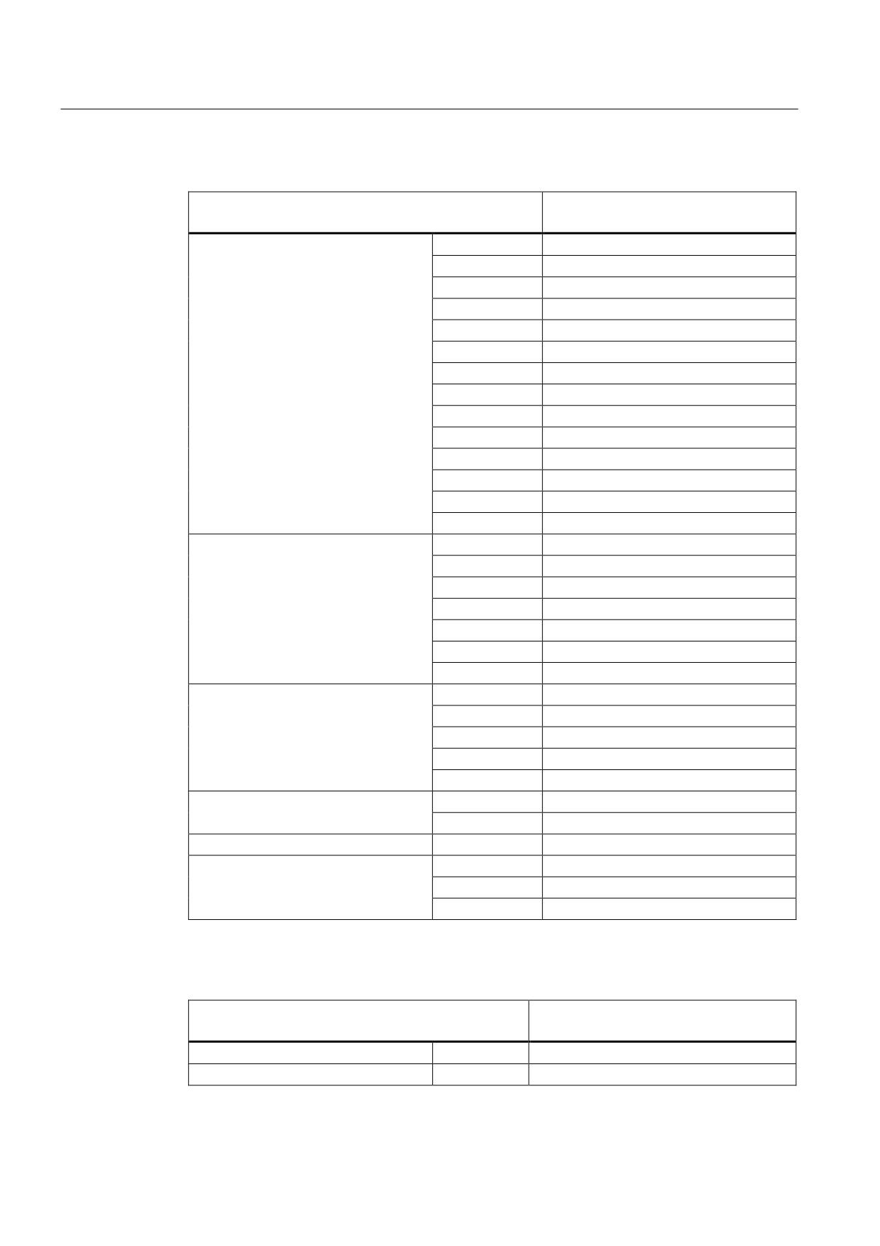
Table A- 11 Electronics losses for power units with cold plate
Component
Cold plate
Power loss [W]
Motor Modules Booksize
3 A
15.6
5 A
15.6
9 A
15.6
18 A
15.6
30 A
15.6
45 A
18.0
60 A
18.0
85 A
19.2
132 A
20.4
200 A
20.4
2x3 A
21.6
2x5 A
21.6
2x9 A
21.6
2x18 A
25.2
Motor Modules Booksize Compact
3 A
15.6
5 A
15.6
9 A
15.6
18 A
15.6
2x1.7 A
21.6
2x3 A
21.6
2x5 A
21.6
Active Line Modules
16 kW
20.4
36 kW
25.2
55 kW
27.6
80 kW
33.6
120 kW
43.2
Smart Line Module Booksize
5 kW
14.4
10 kW
16.8
Smart Line Module Booksize Compact
16 kW
20.4
Basic Line Modules
20 kW
21.6
40 kW
26.4
100 kW
38.4
Table A- 12 Electronics losses for liquid-cooled power units
Component
Liquid cooled
Power loss [W]
Motor Module
200 A
20.4
Active Line Module
120 kW
43.2
Guidelines for machine configuration
524
System Manual, MA 01/2013, 6FC5397-6CP10-0BA2
Appendix
A.3 Power loss of components
A.3.4
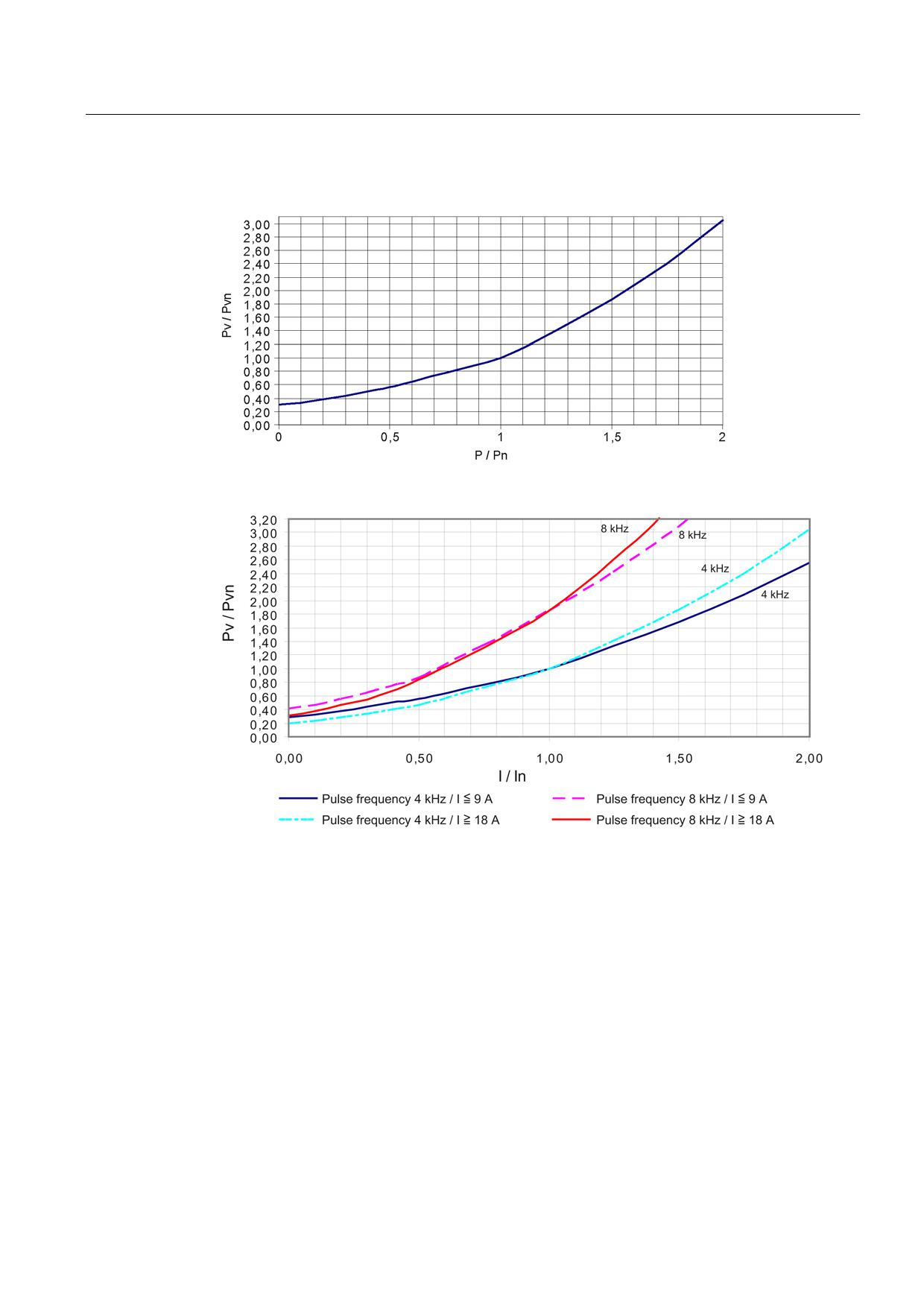
Losses for power units in the partial load range
Figure A-1 Losses in the partial load range for Active Line Modules and Smart Line Modules
Figure A-2 Losses in the partial load range for Motor Modules
Guidelines for machine configuration
System Manual, MA 01/2013, 6FC5397-6CP10-0BA2
525

Appendix
A.3 Power loss of components
A.3.5
Typical power losses for Motor Modules
The information on the power losses in the previous chapters are maximum values, which
occur in the most unfavorable case. For typical applications, the losses are lower.
The following applies as typical application:
● Maximum motor cable length, 30 m
●
4 kHz pulse frequency
● DC link voltage 540 V - 600 V
The power loss for typical applications can be calculated using the following formula:
PV [W] = a + S1 • (I1 + I2) + S2 • (I12 + I22)
a
Electronics losses of the Motor Module
S1, S2
Coefficients to calculate power loss
I1
Current (arithmetic mean value) of the 1st axis
I2
Current (arithmetic mean value) of the 2nd axis
Overview of required coefficients
Table A- 13 Coefficients to calculate the power loss in the control cabinet for internally cooled Motor
Modules for typical applications
Motor Module
a [W]
S1 [W/A]
S2 [W/A2]
Single Motor Module 3 A
14
3.29
0.205
Single Motor Module 5 A
14
3.29
0.205
Single Motor Module 9 A
14
3.29
0.205
Single Motor Module 18 A
14
3.29
0.205
Single Motor Module 30 A
20
4.71
0.113
Single Motor Module 45 A
25
5.50
0.054
Single Motor Module 60 A
25
5.50
0.054
Single Motor Module 85 A
36
6.11
0.030
Single Motor Module 132 A
150
6.01
0.018
Single Motor Module 200 A
150
6.01
0.017
Double Motor Module 3 A
19
5.20
0.200
Double Motor Module 5 A
19
5.20
0.200
Double Motor Module 9 A
19
5.18
0.247
Double Motor Module 18 A
22
5.57
0.091
Guidelines for machine configuration
526
System Manual, MA 01/2013, 6FC5397-6CP10-0BA2

Appendix
A.3 Power loss of components
Table A- 14 Coefficients to calculate the power loss in the control cabinet for externally cooled Motor
Modules for typical applications
Motor Module
a [W]
S1 [W/A]
S2 [W/A2]
Single Motor Module 3 A
10
2.30
0.100
Single Motor Module 5 A
10
2.30
0.100
Single Motor Module 9 A
10
2.30
0.100
Single Motor Module 18 A
10
2.34
0.101
Single Motor Module 30 A
16
1.29
0.057
Single Motor Module 45 A
21
1.31
0.015
Single Motor Module 60 A
27
1.37
0.006
Single Motor Module 85 A
32
1.37
0.006
Single Motor Module 132 A
50
1.06
0.004
Single Motor Module 200 A
50
1.06
0.004
Double Motor Module 3 A
15
1.37
0.240
Double Motor Module 5 A
15
1.37
0.240
Double Motor Module 9 A
15
1.37
0.240
Double Motor Module 18 A
18
1.56
0.056
Overview of typical power losses at the rated operating point
Table A- 15 Typical power losses in the control cabinet for operation at the rated operating point for
internally and externally cooled Motor Modules
Motor Module
PVn [W]
PVn [W]
internal air cooling
external air cooling
Single Motor Module 3 A
26
18
Single Motor Module 5 A
36
24
Single Motor Module 9 A
60
39
Single Motor Module 18 A
140
85
Single Motor Module 30 A
263
106
Single Motor Module 45 A
382
110
Single Motor Module 60 A
550
130
Single Motor Module 85 A
772
192
Single Motor Module 132 A
1257
260
Single Motor Module 200 A
2032
422
Double Motor Module 3 A
54
28
Double Motor Module 5 A
81
41
Double Motor Module 9 A
152
79
Double Motor Module 18 A
281
110
Guidelines for machine configuration
System Manual, MA 01/2013, 6FC5397-6CP10-0BA2
527

Appendix
A.4 Abbreviations
A.4
Abbreviations
Table A- 16 Abbreviations and meanings, German/English
Abbreviation
German meaning
English meaning
AC
Wechselstrom
Alternating current
ALM
Active Line Module
Active Line Module
CBC
Communication Board CAN
Communication Board CAN
CBE
Communication Board Ethernet
Communication Board Ethernet
CPU
Zentrale Recheneinheit
Central Processing Unit
CSM
Control Supply Module
Control Supply Module
CU
Control Unit
Control Unit
DC
Gleichstrom
Direct Current
DO
Antriebsobjekt
Drive Object
DP
Dezentrale Peripherie
Decentralized Peripherals
DRIVE-CLiQ
Drive Component Link with IQ
Drive Component Link with IQ
EP
Impulsfreigabe
Enable Pulses
EMC
Elektromagnetische Verträglichkeit
Electromagnetic Compatibility (EMC)
EN
Europäische Norm
European Standard
FI
Fehlerstrom-Schutzschalter
Earth Leakage Circuit Breaker (ELCB)
HMI
Mensch-Maschine-Schnittstelle
Human Machine Interface
IEC
Internationale Norm in der Elektrotechnik
International Electrotechnical Commission
IT
Drehstromversorgungsnetz ungeerdet
Insulated three-phase supply network
LED
Leuchtdiode
Light Emitting Diode
LM :
Line Module
Line Module
NC
Numerische Steuerung
Numerical Control
NCK
Numerik-Kern mit Satzaufbereitung,
Numerical Control Kernel
Verfahrbereich usw.
NCU
Numerical Control Unit
Numerical Control Unit
NX
Numerical Extension
Numerical Extension
OP
Bedientafelfront
Operator Panel
PE
Schutzerde
Protective Earth
PLC
Speicherprogrammierbare Steuerung (SPS)
Programmable Logic Controller
SBC
Safe Brake Control
Safe Brake Control
SH
Sicherer Halt
Safe standstill
SIL
Sicherheitsintegritätsgrad
Safety Integrity Level
SLM
Smart Line Module
Smart Line Module
SMC
Sensor Module Cabinet
Sensor Module Cabinet
SME
Sensor Module External
Sensor Module External
SPL
Sichere Programmierbare Logik
Safe Programmable Logic
STW
Steuerwort
Control word
TCU
Thin Client Unit
Thin Client Unit
TM
Terminal Module
Terminal Module
Guidelines for machine configuration
528
System Manual, MA 01/2013, 6FC5397-6CP10-0BA2
Appendix
A.4 Abbreviations
Abbreviation
German meaning
English meaning
TN
Drehstromversorgungsnetz geerdet (Terre
Grounded three-phase supply network
Neutre)
TT
Drehstromversorgungsnetz geerdet (Terre
Grounded three-phase supply network
Terre)
VPM
Voltage Protection Module
Voltage Protection Module
VS
Power supply
Voltage Supply
ZSW
Zustandswort
Status word
Guidelines for machine configuration
System Manual, MA 01/2013, 6FC5397-6CP10-0BA2
529
Preface
Fundamental safety
1
instructions
2
SINUMERIK Operate
SINUMERIK
3
Easy XML
SINUMERIK 840D sl
Basesoftware and operating
SINUMERIK Integrate Run
4
MyScreens
software
5
NCU operating system
Commissioning Manual
A
Appendix
Valid for
Control:
SINUMERIK 840D sl/840DE sl
Software:
CNC software
V4.94
SINUMERIK Operate V4.94
10/2020
6FC5397-1DP40-6BA4
Preface
SINUMERIK documentation
The SINUMERIK documentation is organized into the following categories:
• General documentation/catalogs
• User documentation
• Manufacturer/service documentation
Additional information
You can find information on the following topics at the following address (https://
support.industry.siemens.com/cs/de/en/view/108464614):
• Ordering documentation/overview of documentation
• Additional links to download documents
• Using documentation online (find and search in manuals/information)
If you have any questions regarding the technical documentation (e.g. suggestions,
corrections), please send an e-mail to the following address
(mailto:docu.motioncontrol@siemens.com).
mySupport/Documentation
you can find information on how to create your own individual documentation based on
Siemens' content, and adapt it for your own machine documentation.
Training
SITRAIN (Siemens training on products, systems and solutions for automation and drives).
FAQs
You can find Frequently Asked Questions in the Service&Support pages under Product Support
SINUMERIK
You can find information about SINUMERIK at the following address (http://www.siemens.com/
sinumerik).
Basesoftware and operating software
Commissioning Manual, 10/2020, 6FC5397-1DP40-6BA4
3
Preface
Target group
This documentation is intended for commissioning personnel.
The plant or system is readily assembled and wired. For the
following steps, e.g. configuring the individual components,
the Commissioning Manual contains all necessary information or at least references.
Benefits
The intended target group can use the Commissioning Manual to test and commission the
system or the plant correctly and safely.
Utilization phase: Setup and commissioning phase
Standard scope
This documentation only describes the functionality of the standard version. Additions or
revisions made by the machine manufacturer are documented by the machine manufacturer.
Other functions not described in this documentation might be executable in the control. This
does not, however, represent an obligation to supply such functions with a new control or when
servicing.
For the sake of simplicity, this documentation does not contain all detailed information about all
types of the product and cannot cover every conceivable case of installation, operation, or
maintenance.
Note regarding the General Data Protection Regulation
Siemens observes standard data protection principles, in particular the principle of privacy by
design. That means that
this product does not process / store any personal data, only technical functional data (e.g. time
stamps). If a user links this data with other data (e.g. a shift schedule) or stores personal data on
the same storage medium (e.g. hard drive) and thus establishes a link to a person or persons,
then the user is responsible for ensuring compliance with the relevant data protection
regulations.
Technical Support
Country-specific telephone numbers for technical support are provided on the Internet at the
area.
If you have any technical questions, use the online form in the "Support Request" area.
Basesoftware and operating software
4
Commissioning Manual, 10/2020, 6FC5397-1DP40-6BA4
Preface
CompactFlash Cards
• Do not remove the memory card while it is being accessed. This can lead to damage of the
memory card and the SINUMERIK as well as the data on the memory card.
• Insert the memory card carefully and the right way round into the memory card slot (observe
indicators such as arrow or similar). This way you avoid mechanical damage to the memory
card or the device.
• Only use memory cards that have been approved by Siemens for use with SINUMERIK. Even
though SINUMERIK follows general industry standards for memory cards, it is possible that
memory cards from some manufacturers will not function perfectly in this device or are not
completely compatible with it (you can obtain information on compatibility from the
memory card manufacturer or supplier).
• For further information on handling CompactFlash cards, please refer to the NCU manuals.
Basesoftware and operating software
Commissioning Manual, 10/2020, 6FC5397-1DP40-6BA4
5
Table of contents
Preface
3
1
Fundamental safety instructions
9
1.1
General safety instructions
9
1.2
Equipment damage due to electric fields or electrostatic discharge
13
1.3
Warranty and liability for application examples
14
1.4
Security information
15
1.5
Residual risks of power drive systems
16
2
SINUMERIK Operate
17
3
Easy XML
615
4
SINUMERIK Integrate Run MyScreens
885
5
NCU operating system
1239
A
Appendix
1341
A.1
Documentation overview
1341
Basesoftware and operating software
Commissioning Manual, 10/2020, 6FC5397-1DP40-6BA4
7
Fundamental safety instructions
1
1.1
General safety instructions
WARNING
Electric shock and danger to life due to other energy sources
Touching live components can result in death or severe injury.
• Only work on electrical devices when you are qualified for this job.
• Always observe the country-specific safety rules.
Generally, the following steps apply when establishing safety:
1. Prepare for disconnection. Notify all those who will be affected by the procedure.
2. Isolate the drive system from the power supply and take measures to prevent it being
switched back on again.
3. Wait until the discharge time specified on the warning labels has elapsed.
4. Check that there is no voltage between any of the power connections, and between any of
the power connections and the protective conductor connection.
5. Check whether the existing auxiliary supply circuits are de-energized.
6. Ensure that the motors cannot move.
7. Identify all other dangerous energy sources, e.g. compressed air, hydraulic systems, or
water. Switch the energy sources to a safe state.
8. Check that the correct drive system is completely locked.
After you have completed the work, restore the operational readiness in the inverse sequence.
WARNING
Electric shock due to connection to an unsuitable power supply
When equipment is connected to an unsuitable power supply, exposed components may carry
a hazardous voltage. Contact with hazardous voltage can result in severe injury or death.
• Only use power supplies that provide SELV (Safety Extra Low Voltage) or PELV- (Protective
Extra Low Voltage) output voltages for all connections and terminals of the electronics
modules.
Basesoftware and operating software
Commissioning Manual, 10/2020, 6FC5397-1DP40-6BA4
9
Fundamental safety instructions
1.1 General safety instructions
WARNING
Electric shock due to equipment damage
Improper handling may cause damage to equipment. For damaged devices, hazardous
voltages can be present at the enclosure or at exposed components; if touched, this can result
in death or severe injury.
• Ensure compliance with the limit values specified in the technical data during transport,
storage and operation.
• Do not use any damaged devices.
WARNING
Electric shock due to unconnected cable shields
Hazardous touch voltages can occur through capacitive cross-coupling due to unconnected
cable shields.
• As a minimum, connect cable shields and the cores of cables that are not used at one end
at the grounded housing potential.
WARNING
Electric shock if there is no ground connection
For missing or incorrectly implemented protective conductor connection for devices with
protection class I, high voltages can be present at open, exposed parts, which when touched,
can result in death or severe injury.
• Ground the device in compliance with the applicable regulations.
NOTICE
Damage to equipment due to unsuitable tightening tools.
Unsuitable tightening tools or fastening methods can damage the screws of the equipment.
• Be sure to only use screwdrivers which exactly match the heads of the screws.
• Tighten the screws with the torque specified in the technical documentation.
• Use a torque wrench or a mechanical precision nut runner with a dynamic torque sensor and
speed limitation system.
Basesoftware and operating software
10
Commissioning Manual, 10/2020, 6FC5397-1DP40-6BA4
Fundamental safety instructions
1.1 General safety instructions
WARNING
Spread of fire from built-in devices
In the event of fire outbreak, the enclosures of built-in devices cannot prevent the escape of
fire and smoke. This can result in serious personal injury or property damage.
• Install built-in units in a suitable metal cabinet in such a way that personnel are protected
against fire and smoke, or take other appropriate measures to protect personnel.
• Ensure that smoke can only escape via controlled and monitored paths.
WARNING
Unexpected movement of machines caused by radio devices or mobile phones
Using radio devices or mobile telephones in the immediate vicinity of the components can
result in equipment malfunction. Malfunctions may impair the functional safety of machines
and can therefore put people in danger or lead to property damage.
• Therefore, if you move closer than 20 cm to the components, be sure to switch off radio
devices or mobile telephones.
• Use the "SIEMENS Industry Online Support app" only on equipment that has already been
switched off.
WARNING
Fire due to inadequate ventilation clearances
Inadequate ventilation clearances can cause overheating of components with subsequent fire
and smoke. This can cause severe injury or even death. This can also result in increased
downtime and reduced service lives for devices/systems.
• Ensure compliance with the specified minimum clearance as ventilation clearance for the
respective component.
NOTICE
Overheating due to inadmissible mounting position
The device may overheat and therefore be damaged if mounted in an inadmissible position.
• Only operate the device in admissible mounting positions.
Basesoftware and operating software
Commissioning Manual, 10/2020, 6FC5397-1DP40-6BA4
11
Fundamental safety instructions
1.1 General safety instructions
WARNING
Unexpected movement of machines caused by inactive safety functions
Inactive or non-adapted safety functions can trigger unexpected machine movements that
may result in serious injury or death.
• Observe the information in the appropriate product documentation before commissioning.
• Carry out a safety inspection for functions relevant to safety on the entire system, including
all safety-related components.
• Ensure that the safety functions used in your drives and automation tasks are adjusted and
activated through appropriate parameterizing.
• Perform a function test.
• Only put your plant into live operation once you have guaranteed that the functions
relevant to safety are running correctly.
Note
Important safety notices for Safety Integrated functions
If you want to use Safety Integrated functions, you must observe the safety notices in the Safety
Integrated manuals.
WARNING
Malfunctions of the machine as a result of incorrect or changed parameter settings
As a result of incorrect or changed parameterization, machines can malfunction, which in turn
can lead to injuries or death.
• Protect the parameterization against unauthorized access.
• Handle possible malfunctions by taking suitable measures, e.g. emergency stop or
emergency off.
Basesoftware and operating software
12
Commissioning Manual, 10/2020, 6FC5397-1DP40-6BA4
Fundamental safety instructions
1.2 Equipment damage due to electric fields or electrostatic discharge
1.2
Equipment damage due to electric fields or electrostatic discharge
Electrostatic sensitive devices (ESD) are individual components, integrated circuits, modules or
devices that may be damaged by either electric fields or electrostatic discharge.
NOTICE
Equipment damage due to electric fields or electrostatic discharge
Electric fields or electrostatic discharge can cause malfunctions through damaged individual
components, integrated circuits, modules or devices.
• Only pack, store, transport and send electronic components, modules or devices in their
original packaging or in other suitable materials, e.g conductive foam rubber of aluminum
foil.
• Only touch components, modules and devices when you are grounded by one of the
following methods:
- Wearing an ESD wrist strap
- Wearing ESD shoes or ESD grounding straps in ESD areas with conductive flooring
• Only place electronic components, modules or devices on conductive surfaces (table with
ESD surface, conductive ESD foam, ESD packaging, ESD transport container).
Basesoftware and operating software
Commissioning Manual, 10/2020, 6FC5397-1DP40-6BA4
13
Fundamental safety instructions
1.3 Warranty and liability for application examples
1.3
Warranty and liability for application examples
Application examples are not binding and do not claim to be complete regarding configuration,
equipment or any eventuality which may arise. Application examples do not represent specific
customer solutions, but are only intended to provide support for typical tasks.
As the user you yourself are responsible for ensuring that the products described are operated
correctly. Application examples do not relieve you of your responsibility for safe handling when
using, installing, operating and maintaining the equipment.
Basesoftware and operating software
14
Commissioning Manual, 10/2020, 6FC5397-1DP40-6BA4
Fundamental safety instructions
1.4 Security information
1.4
Security information
Siemens provides products and solutions with industrial security functions that support the
secure operation of plants, systems, machines and networks.
In order to protect plants, systems, machines and networks against cyber threats, it is necessary
to implement - and continuously maintain - a holistic, state-of-the-art industrial security
concept. Siemens’ products and solutions constitute one element of such a concept.
Customers are responsible for preventing unauthorized access to their plants, systems,
machines and networks. Such systems, machines and components should only be connected to
an enterprise network or the internet if and to the extent such a connection is necessary and only
when appropriate security measures (e.g. firewalls and/or network segmentation) are in place.
For additional information on industrial security measures that may be implemented, please
visit
Siemens’ products and solutions undergo continuous development to make them more secure.
Siemens strongly recommends that product updates are applied as soon as they are available
and that the latest product versions are used. Use of product versions that are no longer
supported, and failure to apply the latest updates may increase customer’s exposure to cyber
threats.
To stay informed about product updates, subscribe to the Siemens Industrial Security RSS Feed
under
services/cert.html#Subscriptions).
Further information is provided on the Internet:
Industrial Security Configuration Manual (https://support.industry.siemens.com/cs/ww/en/
view/108862708)
WARNING
Unsafe operating states resulting from software manipulation
Software manipulations, e.g. viruses, Trojans, or worms, can cause unsafe operating states in
your system that may lead to death, serious injury, and property damage.
• Keep the software up to date.
• Incorporate the automation and drive components into a holistic, state-of-the-art industrial
security concept for the installation or machine.
• Make sure that you include all installed products into the holistic industrial security concept.
• Protect files stored on exchangeable storage media from malicious software by with suitable
protection measures, e.g. virus scanners.
• On completion of commissioning, check all security-related settings.
Basesoftware and operating software
Commissioning Manual, 10/2020, 6FC5397-1DP40-6BA4
15
Fundamental safety instructions
1.5 Residual risks of power drive systems
1.5
Residual risks of power drive systems
When assessing the machine- or system-related risk in accordance with the respective local
regulations (e.g., EC Machinery Directive), the machine manufacturer or system installer must
take into account the following residual risks emanating from the control and drive components
of a drive system:
1.
Unintentional movements of driven machine or system components during commissioning,
operation, maintenance, and repairs caused by, for example,
- Hardware and/or software errors in the sensors, control system, actuators, and cables and
connections
- Response times of the control system and of the drive
- Operation and/or environmental conditions outside the specification
- Condensation/conductive contamination
- Parameterization, programming, cabling, and installation errors
- Use of wireless devices/mobile phones in the immediate vicinity of electronic components
- External influences/damage
- X-ray, ionizing radiation and cosmic radiation
2.
Unusually high temperatures, including open flames, as well as emissions of light, noise,
particles, gases, etc., can occur inside and outside the components under fault conditions
caused by, for example:
- Component failure
- Software errors
- Operation and/or environmental conditions outside the specification
- External influences/damage
3.
Hazardous shock voltages caused by, for example:
- Component failure
- Influence during electrostatic charging
- Induction of voltages in moving motors
- Operation and/or environmental conditions outside the specification
- Condensation/conductive contamination
- External influences/damage
4.
Electrical, magnetic and electromagnetic fields generated in operation that can pose a risk to
people with a pacemaker, implants or metal replacement joints, etc., if they are too close
5.
Release of environmental pollutants or emissions as a result of improper operation of the
system and/or failure to dispose of components safely and correctly
6.
Influence of network-connected communication systems, e.g. ripple-control transmitters or
data communication via the network
For more information about the residual risks of the drive system components, see the relevant
sections in the technical user documentation.
Basesoftware and operating software
16
Commissioning Manual, 10/2020, 6FC5397-1DP40-6BA4
Preface
Fundamental safety
1
instructions
2
System overview
SINUMERIK
3
Principles of start-up
SINUMERIK 840D sl
SINUMERIK Operate
4
General settings
5
Licensing
Commissioning Manual
6
Creating drive connections
7
Channel menu
8
Machine and setting data
Customizing the "Machine"
9
operating area
Simulation and
10
simultaneous recording
11
Spindle functions
12
Drive system
13
Configuring alarms
Valid for
Control:
14
Data backup
SINUMERIK 840D sl/840DE sl
Software:
CNC software
V4.94
15
SINUMERIK Operate V4.94
Configuring the network
10/2020
Continued on next page
6FC5397-1DP40-6BA4
Continued
16
Service and diagnostics
17
OEM-specific online help
SINUMERIK Integrate - AMB,
18
AMC, AMM
SINUMERIK 840D sl
SINUMERIK Operate
19
Technologies and cycles
20
Additional language
Commissioning Manual
SINUMERIK Operate on PCU/
21
IPC
22
Handheld terminals
List of abbreviations/
A
acronyms
Legal information
Warning notice system
This manual contains notices you have to observe in order to ensure your personal safety, as well as to prevent damage
to property. The notices referring to your personal safety are highlighted in the manual by a safety alert symbol, notices
referring only to property damage have no safety alert symbol. These notices shown below are graded according to
the degree of danger.
DANGER
indicates that death or severe personal injury will result if proper precautions are not taken.
WARNING
indicates that death or severe personal injury may result if proper precautions are not taken.
CAUTION
indicates that minor personal injury can result if proper precautions are not taken.
NOTICE
indicates that property damage can result if proper precautions are not taken.
If more than one degree of danger is present, the warning notice representing the highest degree of danger will be
used. A notice warning of injury to persons with a safety alert symbol may also include a warning relating to property
damage.
Qualified Personnel
The product/system described in this documentation may be operated only by personnel qualified for the specific
task in accordance with the relevant documentation, in particular its warning notices and safety instructions.
Qualified personnel are those who, based on their training and experience, are capable of identifying risks and
avoiding potential hazards when working with these products/systems.
Proper use of Siemens products
Note the following:
WARNING
Siemens products may only be used for the applications described in the catalog and in the relevant technical
documentation. If products and components from other manufacturers are used, these must be recommended or
approved by Siemens. Proper transport, storage, installation, assembly, commissioning, operation and maintenance
are required to ensure that the products operate safely and without any problems. The permissible ambient
conditions must be complied with. The information in the relevant documentation must be observed.
Trademarks
All names identified by ® are registered trademarks of Siemens AG. The remaining trademarks in this publication may
be trademarks whose use by third parties for their own purposes could violate the rights of the owner.
Disclaimer of Liability
We have reviewed the contents of this publication to ensure consistency with the hardware and software described.
Since variance cannot be precluded entirely, we cannot guarantee full consistency. However, the information in this
publication is reviewed regularly and any necessary corrections are included in subsequent editions.
Siemens AG
Document order number: 6FC5397-1DP40-6BA4
Digital Industries
Ⓟ 10/2020 Subject to change
All rights reserved
Postfach 48 48
90026 NÜRNBERG
GERMANY
Preface
SINUMERIK documentation
The SINUMERIK documentation is organized into the following categories:
• General documentation/catalogs
• User documentation
• Manufacturer/service documentation
Additional information
You can find information on the following topics at the following address (https://
support.industry.siemens.com/cs/de/en/view/108464614):
• Ordering documentation/overview of documentation
• Additional links to download documents
• Using documentation online (find and search in manuals/information)
If you have any questions regarding the technical documentation (e.g. suggestions,
corrections), please send an e-mail to the following address
(mailto:docu.motioncontrol@siemens.com).
mySupport/Documentation
you can find information on how to create your own individual documentation based on
Siemens' content, and adapt it for your own machine documentation.
Training
SITRAIN (Siemens training on products, systems and solutions for automation and drives).
FAQs
You can find Frequently Asked Questions in the Service&Support pages under Product Support
SINUMERIK
You can find information about SINUMERIK at the following address (http://www.siemens.com/
sinumerik).
SINUMERIK Operate
Commissioning Manual, 10/2020, 6FC5397-1DP40-6BA4
5
Preface
Target group
This documentation is intended for commissioning personnel.
The plant or system is readily assembled and wired. For the
following steps, e.g. configuring the individual components,
the Commissioning Manual contains all necessary information or at least references.
Benefits
The intended target group can use the Commissioning Manual to test and commission the
system or the plant correctly and safely.
Utilization phase: Setup and commissioning phase
Standard scope
This documentation only describes the functionality of the standard version. Additions or
revisions made by the machine manufacturer are documented by the machine manufacturer.
Other functions not described in this documentation might be executable in the control. This
does not, however, represent an obligation to supply such functions with a new control or when
servicing.
For the sake of simplicity, this documentation does not contain all detailed information about all
types of the product and cannot cover every conceivable case of installation, operation, or
maintenance.
Note regarding the General Data Protection Regulation
Siemens observes standard data protection principles, in particular the principle of privacy by
design. That means that
this product does not process / store any personal data, only technical functional data (e.g. time
stamps). If a user links this data with other data (e.g. a shift schedule) or stores personal data on
the same storage medium (e.g. hard drive) and thus establishes a link to a person or persons,
then the user is responsible for ensuring compliance with the relevant data protection
regulations.
Technical Support
Country-specific telephone numbers for technical support are provided on the Internet at the
area.
If you have any technical questions, use the online form in the "Support Request" area.
SINUMERIK Operate
6
Commissioning Manual, 10/2020, 6FC5397-1DP40-6BA4
Preface
CompactFlash Cards
• Do not remove the memory card while it is being accessed. This can lead to damage of the
memory card and the SINUMERIK as well as the data on the memory card.
• Insert the memory card carefully and the right way round into the memory card slot (observe
indicators such as arrow or similar). This way you avoid mechanical damage to the memory
card or the device.
• Only use memory cards that have been approved by Siemens for use with SINUMERIK. Even
though SINUMERIK follows general industry standards for memory cards, it is possible that
memory cards from some manufacturers will not function perfectly in this device or are not
completely compatible with it (you can obtain information on compatibility from the
memory card manufacturer or supplier).
• For further information on handling CompactFlash cards, please refer to the NCU manuals.
SINUMERIK Operate
Commissioning Manual, 10/2020, 6FC5397-1DP40-6BA4
7
Table of contents
Preface
5
1
Fundamental safety instructions
19
1.1
General safety instructions
19
1.2
Equipment damage due to electric fields or electrostatic discharge
23
1.3
Warranty and liability for application examples
23
1.4
Security information
23
1.5
Residual risks of power drive systems
25
2
System overview
27
2.1
System overview
27
2.2
System requirements
28
3
Principles of start-up
29
3.1
Data structure of SINUMERIK Operate
29
3.2
Editing files
32
3.2.1
Editing the file at the controller
32
3.2.2
Editing a file externally
34
4
General settings
37
4.1
Changing the language
37
4.2
Set date/time
38
4.3
Using the time server
40
4.4
Use time zone
41
4.5
Device registration
42
4.6
Activation of the display for the remaining time of spindle utilization
43
4.7
Configuring Caps Lock
43
4.8
Activating/deactivating the virtual keyboard
44
4.9
Defining the access rights for the "HMI restart" softkey
44
4.10
Setting OEM functions for the softkeys "HMI restart" and "EXIT"
44
4.11
Changing the skin design
46
4.12
Setting the screensaver
46
4.13
Setting cleaning mode for the operator panel
47
4.14
Inserting a user-specific run up screen
47
4.15
Using user interfaces in parallel
48
4.16
Setting how login data (credentials) are handled when archiving
49
SINUMERIK Operate
Commissioning Manual, 10/2020, 6FC5397-1DP40-6BA4
9
Table of contents
4.17
VNC remote connections
50
4.18
Setting the WEB browser
53
4.19
Access levels
55
4.19.1
Definition of access levels
55
4.19.2
Modifying the access levels password
57
4.19.3
Work station safety
58
4.19.4
Access levels for programs
58
4.19.5
Access rights for files
61
4.19.6
Access levels for softkeys
61
4.19.7
This is how you define new access levels for softkeys
63
4.19.8
Setting the MDA program access via protection level
64
4.20
Program selection
65
4.20.1
Displaying the softkey
65
4.21
Activate and configure the Sidescreen window
67
4.21.1
Activate Sidescreen
67
4.21.2
Display Sidescreen ABC keyboard
70
4.21.3
Display Sidescreen machine control panel
71
4.21.3.1
Configuring your own keys on the machine control panel
72
4.21.3.2
Create own translations of texts for the machine control panel
74
4.21.4
Display sidescreen camera
75
4.22
SINUMERIK Operate Display Manager
76
4.22.1
Display configurations
76
4.22.2
Creating your own display configurations
79
4.22.2.1
Displays
79
4.22.2.2
Frames
80
4.22.2.3
Menus
82
4.22.2.4
Menu actions
87
4.22.2.5
Applications
89
4.22.2.6
Global settings
95
5
Licensing
97
5.1
Determining the license requirement
98
5.2
Activating the test license
100
5.3
Exporting license requirements
101
5.4
Reading in the license key
101
5.5
Backing up the license of a new CompactFlash card
102
6
Creating drive connections
105
6.1
Setting up drives
105
6.2
Setting EXTCALL
106
6.3
Creating a global part program memory
107
7
Channel menu
109
7.1
Configuring a channel menu
109
7.2
Constraints
110
SINUMERIK Operate
10
Commissioning Manual, 10/2020, 6FC5397-1DP40-6BA4
Table of contents
7.3
General structure of the channel menu
110
7.4
Defining channel groups in the "netnames.ini" file
111
7.5
Configuring operating stations in the "config.ini" file
112
7.6
Example: Settings for 1:N
113
7.7
Distribution via job lists in the case of 1:N
115
8
Machine and setting data
119
8.1
Machine and setting data
119
8.2
Displaying/editing machine data
119
8.3
Displaying/editing display machine data
122
8.4
Displaying/editing setting data
122
8.5
Displaying/editing drive parameters
124
8.6
Machine data display options
126
8.7
Editing machine data and drive parameters
128
8.7.1
Editing hexadecimal values
128
8.7.2
Editing BICO values
128
8.7.3
Editing enum values
129
8.8
Searching for data
130
8.9
Data admin
131
8.10
User views
134
8.10.1
Creating a user view
135
8.10.2
Editing the user view
136
8.10.3
Deleting a user view
138
8.11
Plain texts for machine and setting data
138
9
Customizing the "Machine" operating area
141
9.1
Setting the font size of the actual value display
141
9.2
Inserting a user-specific logo
142
9.3
Configuring the display of the G-code groups
143
9.4
Configuring the channel operational message
145
9.5
Deactivating program test
147
9.6
Display articulated joint position STAT and rotary axis position TU
147
9.7
Activating the "Teach In" function
148
9.8
Block search
149
9.8.1
Activating block search mode
149
9.8.2
Accelerated block search for execution from external
151
9.9
Multi-channel support
151
9.10
Manual machine
153
9.11
User status display (OEM)
155
SINUMERIK Operate
Commissioning Manual, 10/2020, 6FC5397-1DP40-6BA4
11
Table of contents
9.12
Configuring the offset display
157
9.13
Activate machining time recording
157
10
Simulation and simultaneous recording
159
10.1
Simulation overview
159
10.2
Setting the technology for simulation
161
10.3
Simultaneous recording overview
163
10.4
Clamping a blank
165
11
Spindle functions
169
11.1
Spindle control
169
11.2
Analog spindle
170
11.3
Spindle diagnostics
171
11.3.1
Spindle diagnostics
171
11.3.2
Temperatures
173
11.3.3
Motor temperature sensor
175
11.3.4
Additional temperature sensor
175
11.3.5
Temperature histograms
176
11.3.6
Speed/torque
176
11.3.7
Clamping system
177
11.3.8
Clamping system: Speed limits
179
11.3.9
Clamping system: Diagnostic statistics
180
11.3.10
Clamping system: Clamping time statistics
181
11.3.11
Fetching the logistics data
181
12
Drive system
183
12.1
Commissioning of drives
183
13
Configuring alarms
185
13.1
Creating alarm and message texts via the user interface
185
13.2
Configuring alarm and message texts via alarm text files
187
13.2.1
Creating in-house alarm texts
188
13.2.2
Creating texts for indexed alarm parameters
190
13.2.3
Creating part program message texts
192
13.2.4
Changing alarm attributes
196
13.2.5
Replacing standard alarm texts
200
13.2.6
Range of alarms
204
13.2.7
Parameter specifications in alarm texts
205
13.2.8
Opening error file
206
13.3
Configuring an alarm log
206
13.3.1
Setting alarm logs from the user interface
208
13.3.2
Loading alarm log via configuration file
208
13.4
PLC alarms with parameters
212
13.4.1
Definition of a parameter of the octet string data type
213
13.4.2
Definition of the language-dependent formatting
215
13.5
Deactivating a warning
216
SINUMERIK Operate
12
Commissioning Manual, 10/2020, 6FC5397-1DP40-6BA4