SINUMERIK 840D sl. Service - Configuring Commissioning. Manual (2011-2020) - page 34
Connection of the components in SINAMICS drive system
8.4 Connection of motor modules
8.4.4.7
Technical specifications
Single Motor Modules
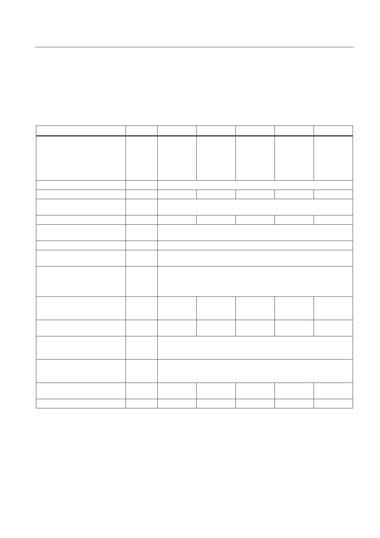
Table 8- 117 Technical data Single Motor Modules Booksize (3 to 30 A)
Cold plate
6SL3126-
1TE13-0AAx
1TE15-0AAx
1TE21-0AAx
1TE21-8AAx
1TE23-0AAx
Output current
Rated current (In)
AACrms
3
5
9
18
30
Base-load current (IH)
A
2.6
4.3
7.7
15.3
25.5
Intermittent duty current (IS6)
40%
AACrms
3.5
6
10
24
40
Peak current (Imax)
AACrms
6
10
18
36
56
Output voltage
VACrms
0 - 0.717 x DC link voltage
DC link current Id
ADC
3.6
6
11
22
36
DC link voltage
VDC
510 -720
(up to 2000 m above sea level)
DC link capacitance
μF
110
110
110
220
710
Overvoltage trip
VDC
820 ±2%
Undervoltage trip1)
VDC
380
Electronics power supply
VDC
24 (20.4 - 28.8)
Electronics current consumption
ADC
0.65
at 24 V DC
Current carrying capacity
DC link busbars
ADC
100
Reinforced DC link busbars
ADC
150
24 VDC busbars
ADC
20
Unit rating
Based on In (600 VDC; 4 kHz)
kW
1.6
2.7
4.8
9.7
16
Based on IH
kW
1.1
2.3
4.1
8.2
13.7
Total power loss
W
45.5
70.6
95.6
180.6
305.6
(incl. electronics losses)2)
Max. pulse frequency
without derating
kHz
4
with derating
kHz
16
Max. ambient temperature
without derating
°C
40
with derating
°C
55
Max. permissible heat sink
°C
80
80
80
80
70
temperature
Weight
kg
4.2
4.2
4.5
4.5
6.1
1)
Default for 400 V line systems; undervoltage trip threshold can be reduced by up to 80 V and is adjusted to the
parameterized rated voltage
2)
For an overview, see the power loss tables in the Appendix
Guidelines for machine configuration
System Manual, MA 01/2013, 6FC5397-6CP10-0BA2
415

Connection of the components in SINAMICS drive system
8.4 Connection of motor modules
Table 8- 118 Technical data Single Motor Modules (45A to 200A)
Cold plate
6SL3126-
1TE24-5AAx
1TE26-0AAx
1TE28-5AAx
1TE31-3AAx
1TE32-0AAx
Output current
Rated current (In)
AACrms
45
60
85
132 (105)1)
200 (140)1)
Base-load current (IH)
A
38
51
68
105 (84)1)
141 (99)1)
Intermittent duty current (IS6)
40%
AACrms
60
80
110
150 (120)1)
230 (161)1)
Peak current (Imax)
AACrms
85
113
141
210
282
Output voltage
VACrms
0 - 480
DC link current Id
ADC
54
72
102
158
200
DC link voltage
VDC
510 -720
(up to 2000 m above sea level)
DC link capacitance
μF
1175
1410
1880
2820
3995
Overvoltage trip Undervoltage
VDC
820 ±2%
trip2)
VDC
380
Electronics power supply
VDC
24 (20.4 - 28.8)
Electronics current consumption
ADC
0.75
0.75
0.8
0.85
0.85
at 24 V DC
Current carrying capacity
DC link busbars
ADC
200
24 VDC busbars
ADC
20
Unit rating
Based on In (600 VDC; 4 kHz)
kW
24
32
46
71 (57) 1)
107 (75) 1)
Based on IH
kW
21
28
37
57 (46) 1)
76 (53) 1)
Total power loss
W
448
608
769.2
1270.4
2070.4
(incl. electronics losses)3)
Max. pulse frequency
without derating
kHz
4
with derating
kHz
16
Max. ambient temperature
without derating
°C
40
with derating
°C
55
Max. permissible heat sink
°C
80
73
83
75
79
temperature
(70%
derating)
Weight
kg
9.1
9.1
12.5
18.0
18.0
1)
Derating must be applied due to the transfer of heat to the external heat sink. At a temperature of 40 °C at the interface
to the power unit, 80% derating occurs for 6SL3126-1TE31-3AAx and 70% for 6SL3126-1TE32-0AAx.
2)
Default for 400 V line systems; undervoltage trip threshold can be reduced by up to 80 V (exception: 132 A and 200 A
Motor Modules) and is adjusted to the parameterized rated voltage.
3)
For an overview, see the power loss tables in the Appendix
Note
New systems with 132 A and 200 A Motor Modules should ideally be designed with 200 A
liquid-cooled Motor Modules in order to avoid current derating.
Guidelines for machine configuration
416
System Manual, MA 01/2013, 6FC5397-6CP10-0BA2

Connection of the components in SINAMICS drive system
8.4 Connection of motor modules
Double Motor Modules
Table 8- 119 Technical data Double Motor Modules (2 x 3 to 2 x18 A)
Cold plate
6SL3126-
2TE13-0AAx
2TE15-0AAx
2TE21-0AAx
2TE21-8AAx
Output current
Rated current (In)
AACrms
2 x 3
2 x 5
2 x 9
2 x 18
Base-load current (IH)
A
2 x 2.6
2 x 4.3
2 x 7.7
2 x 15.3
Intermittent duty current (IS6) 40%
AACrms
2 x 3.5
2 x 6
2 x 10
2 x 24
Peak current (Imax)
AACrms
2 x 6
2 x 10
2 x 18
2 x 36
Output voltage
VACrms
0 - 480
DC link current Id
ADC
7.2
12
22
43
DC link voltage
VDC
510 -720
DC link capacitance
μF
110
220
220
705
Overvoltage trip
VDC
820 ±2%
Undervoltage trip1)
VDC
380
Electronics power supply
VDC
24 (20.4 - 28.8)
Electronics current consumption at 24 V
ADC
0.9
0.9
0.9
1.05
DC
Current carrying capacity
DC link busbars
ADC
100
100
100
100
Reinforced DC link busbars
ADC
150
150
150
150
24 VDC busbars
ADC
20
20
20
20
Unit rating
Based on In (600 VDC; 4 kHz)
kW
2 x 1.6
2 x 2.7
2 x 4.8
2 x 9.7
Based on IH
kW
2 x 1.4
2 x 2.3
2 x 4.1
2 x 8.2
Total power loss
W
91.6
126.6
181.6
345.2
(incl. electronics losses)2)
Max. pulse frequency
without derating
kHz
4
with derating
kHz
16
Max. ambient temperature
without derating
°C
40
with derating
°C
55
Max. permissible heat sink temperature
°C
80
80
90
90
Weight
kg
4.5
4.5
4.5
5.9
1)
Default for 400 V line systems; undervoltage trip threshold can be reduced by up to 80 V and is adjusted to the
parameterized rated voltage
2)
For an overview, see the power loss tables in the Appendix
Guidelines for machine configuration
System Manual, MA 01/2013, 6FC5397-6CP10-0BA2
417
Connection of the components in SINAMICS drive system
8.4 Connection of motor modules
Characteristics
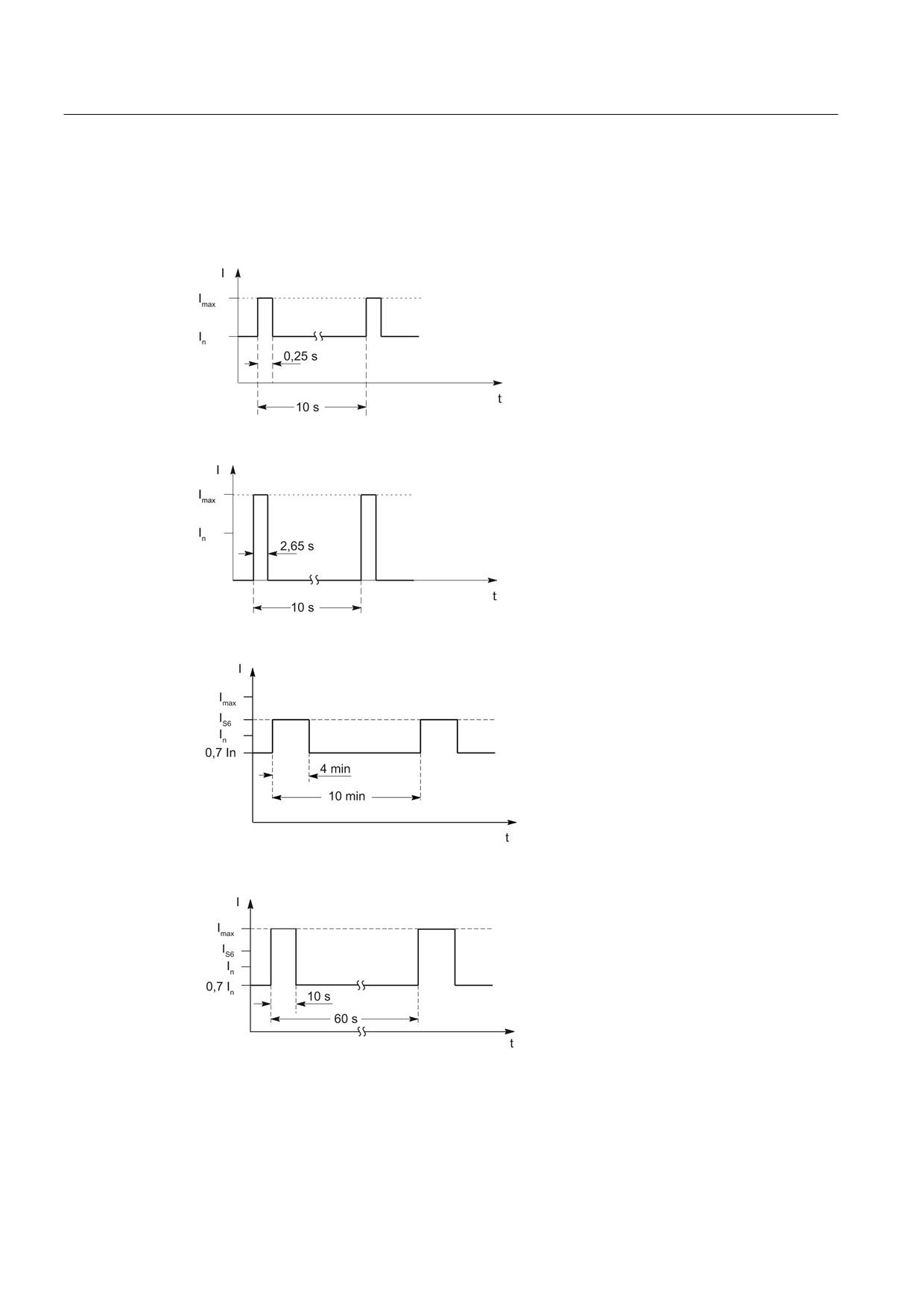
Rated duty cycles Motor Modules Booksize
Figure 8-153 Duty cycle with initial load (for servo drives)
Figure 8-154 Duty cycle without initial load (for servo drives)
Figure 8-155 S6 duty cycle with initial load with a duty cycle duration of 600 s (for servo drives)
Figure 8-156 S6 duty cycle with initial load with a duty cycle duration of 60 s (for servo drives)
Guidelines for machine configuration
418
System Manual, MA 01/2013, 6FC5397-6CP10-0BA2
Connection of the components in SINAMICS drive system
8.4 Connection of motor modules
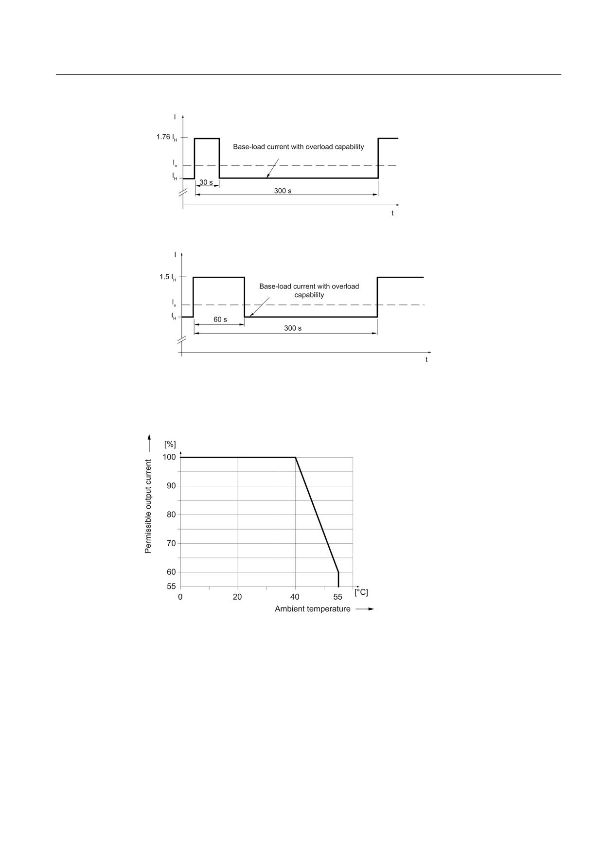
Figure 8-157 Duty cycle with 30 s overload for a duty cycle duration of 300 s
Figure 8-158 Duty cycle with 60 s overload for a duty cycle duration of 300 s
Derating characteristics for Motor Modules Booksize
Figure 8-159 Output current as a function of the ambient temperature
Guidelines for machine configuration
System Manual, MA 01/2013, 6FC5397-6CP10-0BA2
419
Connection of the components in SINAMICS drive system
8.4 Connection of motor modules
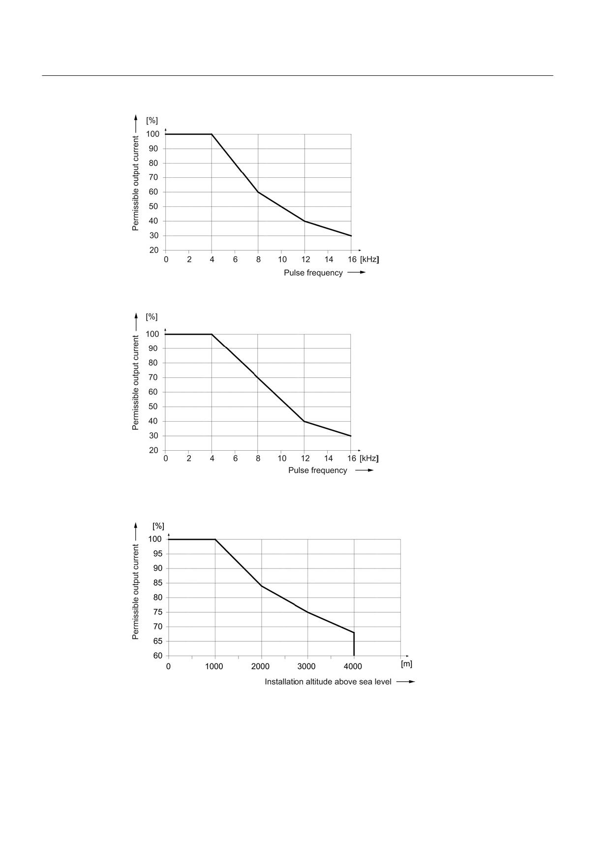
Figure 8-160 Output current as a function of the pulse frequency
Figure 8-161 Output current as a function of the pulse frequency for 200 A Motor Modules
(applies from order number 6SL312x-1TE32-0AA4)
Figure 8-162 Output current as a function of the installation altitude
Guidelines for machine configuration
420
System Manual, MA 01/2013, 6FC5397-6CP10-0BA2
Connection of the components in SINAMICS drive system
8.4 Connection of motor modules
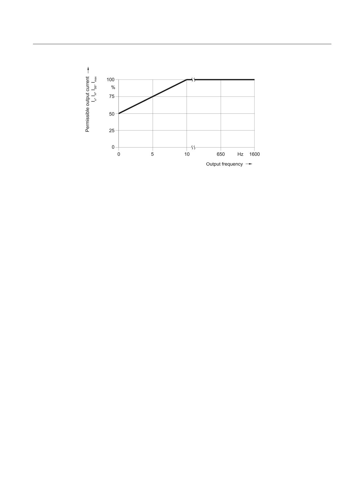
Figure 8-163 Output current as a function of the output frequency
At installation altitudes > 2000 m, an isolation transformer must be used (see the chapter
titled "System overview/Function of installation altitude and ambient temperature"). The
design of the secondary line system must be as follows:
● TN system with grounded neutral point (no grounded line conductor)
● IT system
A reduction of the line supply voltage phase-phase is not necessary.
8.4.5
Motor Modules Liquid Cooled
8.4.5.1
Description
A Motor Module is a power unit (inverter) that provides the power supply for the connected
motor(s). Power is supplied by means of the DC link of the drive unit. A Motor Module must
be connected to a Control Unit via DRIVE-CLiQ. The open-loop and closed-loop control
functions for the Motor Module are stored in the Control Unit.
Guidelines for machine configuration
System Manual, MA 01/2013, 6FC5397-6CP10-0BA2
421
Connection of the components in SINAMICS drive system
8.4 Connection of motor modules
8.4.5.2
Interface description
Overview
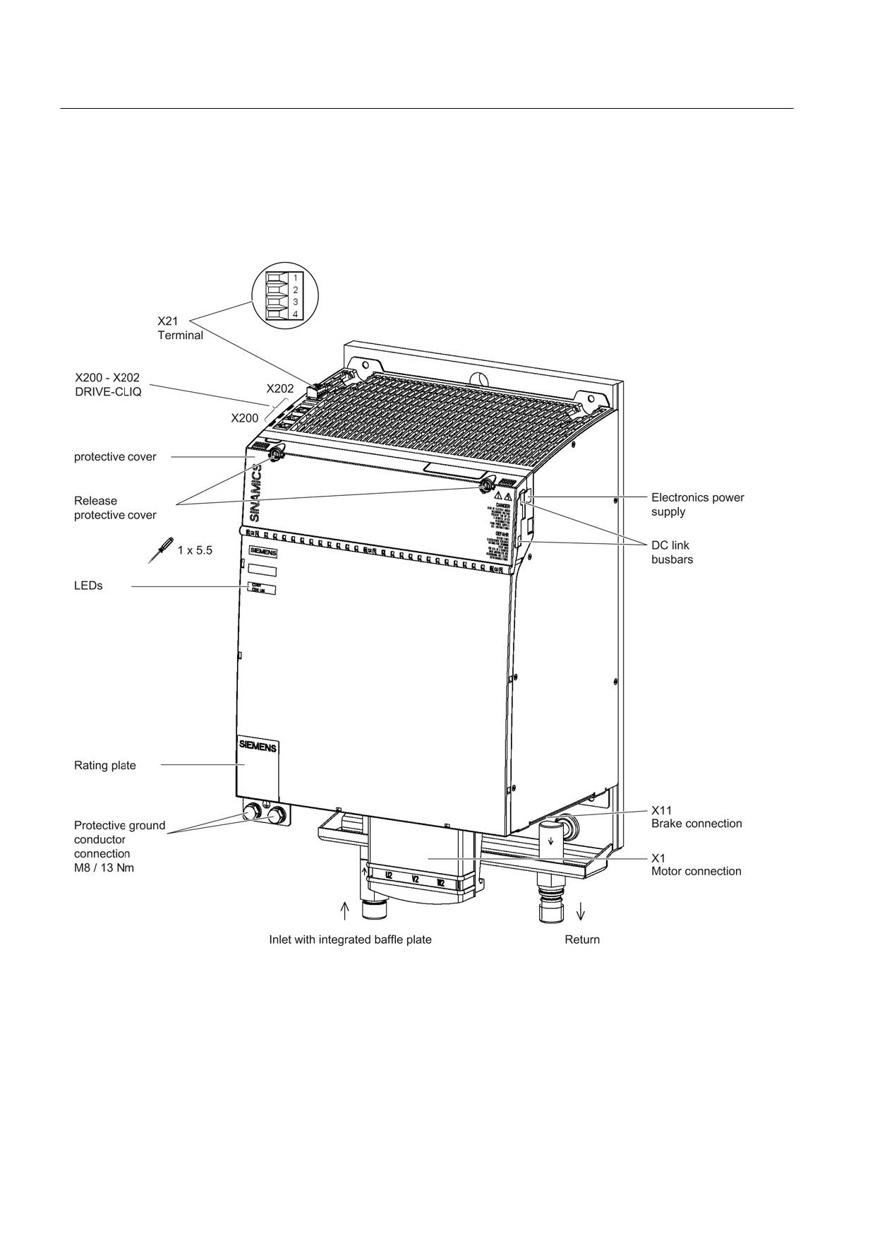
Figure 8-164 Interface overview, Motor Module Liquid Cooled (200 A)
Guidelines for machine configuration
422
System Manual, MA 01/2013, 6FC5397-6CP10-0BA2
Connection of the components in SINAMICS drive system
8.4 Connection of motor modules
Motor and brake connection, Liquid Cooled
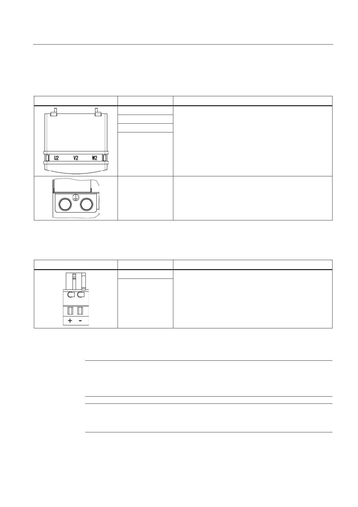
Table 8- 120 X1 Motor connection
Terminal
Technical data
U2
Threaded bolt M8/13 Nm 1)
V2
W2
- (BR-)
PE connection
Threaded hole M8/13 Nm 1
1) For ring cable lugs in accordance with DIN 46234
Table 8- 121 X11 brake connector
Terminal
Technical data
+ (BR+)
Voltage 24 VDC
Max. load current 2 A
- (BR-)
Min. load current 0.1 A
Max. connectable cross-section 2.5 mm2
Type: Spring-loaded terminal 2
(see Appendix, Chapter "Spring-loaded terminals")
The brake connector is part of the prefabricated cable
The circuit for protecting the brake against overvoltage is integrated in the Motor Module and does not need to be installed
externally. The max. load current is 2 A, the min. load current 0.1 A.
Note
The total length of the power cables (motor supply cables and DC link cables) must not
exceed the values listed in the chapter titled "Possible line reactor and line filter
combinations (Page 158)".
Note
The motor brake must be connected via connector X11. Directly connecting the BR- cable to
the electronics ground M is not permitted.
Guidelines for machine configuration
System Manual, MA 01/2013, 6FC5397-6CP10-0BA2
423
Connection of the components in SINAMICS drive system
8.4 Connection of motor modules
WARNING
Safety extra-low voltages at connections and terminals
Only protective extra-low voltages (DVC A) that comply with EN 60204-1 may be connected
to all connections and terminals between 0 and 48 VDC.
The voltage tolerances of the motor holding brakes (24 V ±10%) must be taken into
account.
X21 EP terminal/temperature sensor
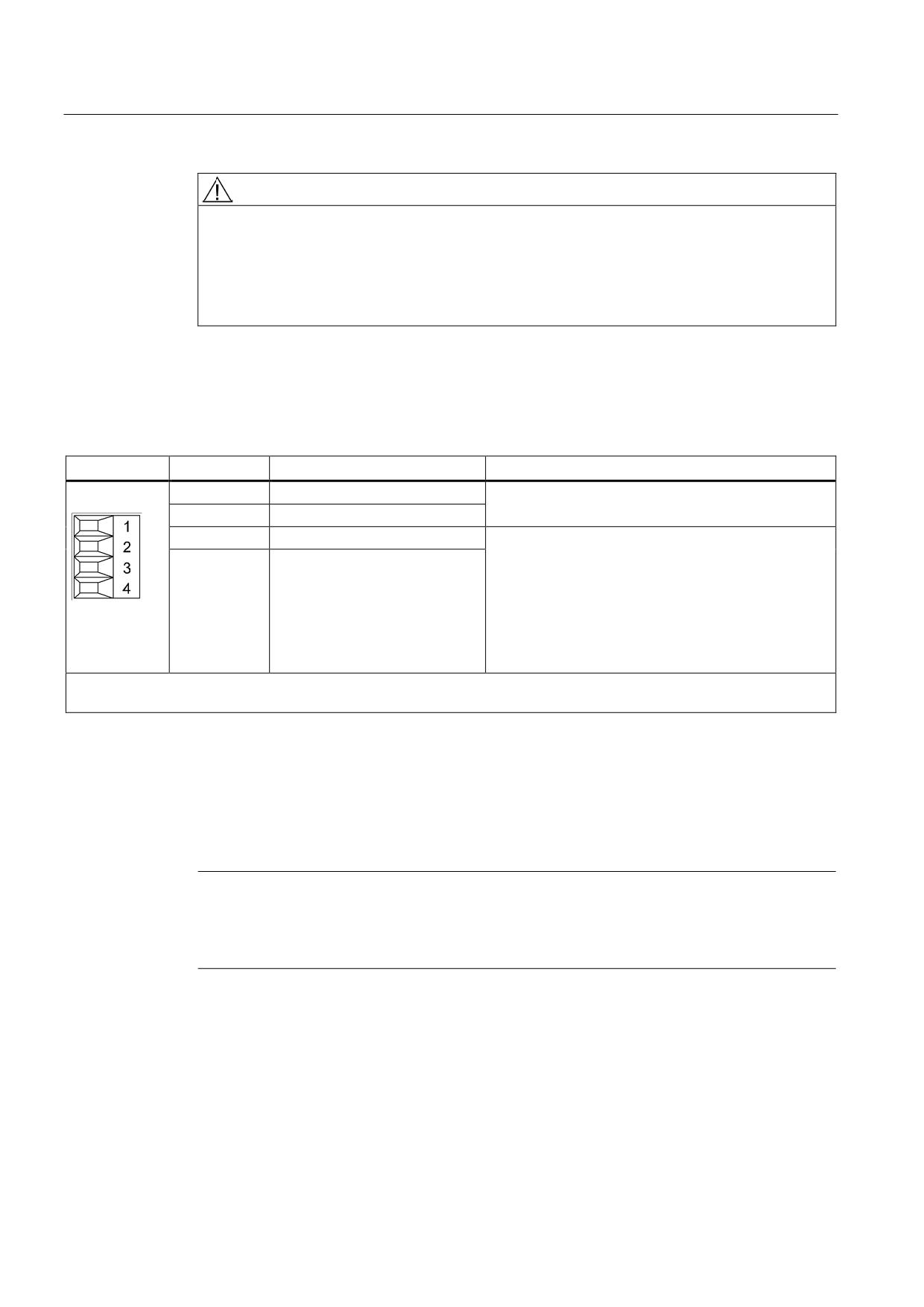
Table 8- 122 X21 EP terminal/temperature sensor
Terminal
Function
Technical data
1
+ Temp
Temperature sensors: KTY84-1C130/PTC/bimetallic
switch with NC contact
2
- Temp
3
EP +24 V (Enable Pulses)
Supply voltage: 24 VDC (20.4 V - 28.8 V)
Current consumption: 10 mA
4
EP M1 (enable pulses)
Isolated input
Signal propagation times:
L → H: 100 μs
H → L: 1000 μs
The pulse inhibit function is only available when Safety
Integrated Basic Functions are enabled.
Max. connectable cross-section 1.5 mm2
Type: Screw terminal 1 (see Appendix A.1)
EP terminals
The filter times to debounce terminals X21.3 and X21.4 are set using parameter p9651.
Additional parameter settings are also required in order to prevent discrepancy errors when
performing bit pattern tests (light/dark tests). For comprehensive information, see the
SINAMICS S120 Safety Integrated Function Manual, Chapter "Controlling the safety
functions".
Note
Function of the EP terminals
The function of the EP terminals is only available when Safety Integrated Basic Functions
are enabled.
Guidelines for machine configuration
424
System Manual, MA 01/2013, 6FC5397-6CP10-0BA2
Connection of the components in SINAMICS drive system
8.4 Connection of motor modules
Temperature sensor connection
NOTICE
Risk of the motor overheating due to an incorrectly connected KTY temperature sensor
A KTY temperature sensor connected with incorrect polarity cannot detect if the motor
overheats.
• Always connect the KTY temperature sensor with the correct polarity.
Note
The temperature sensor input is not needed if the motors feature an integrated DRIVE-CLiQ
interface or if temperature values are detected by means of a different module (SMC, SME,
TM).
DANGER
Danger to life through electric shock
Only temperature sensors that meet the safety isolation specifications stipulated in
EN 61800-5-1 may be connected to terminals "+Temp" and "-Temp". If safe electrical
separation cannot be guaranteed (for linear motors or third-party motors, for example), a
Sensor Module External (SME120 or SME125) or Terminal Module TM120 must be used.
If these instructions are not complied with, there is danger to life!
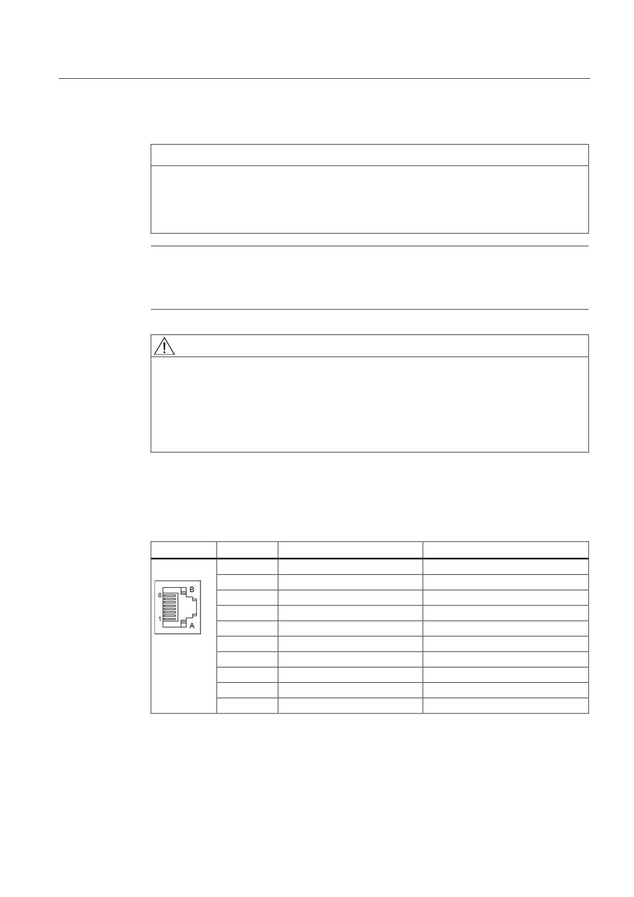
X200-X202 DRIVE-CLiQ interface
Table 8- 123 X200-X202: DRIVE-CLiQ interfaces
Pin
Name
Technical data
1
TXP
Transmit data +
2
TXN
Transmit data -
3
RXP
Receive data +
4
Reserved, do not use
5
Reserved, do not use
6
RXN
Receive data -
7
Reserved, do not use
8
Reserved, do not use
A
+ (24 V)
Power supply
B
M (0 V)
Electronics ground
The blanking covers for the DRIVE-CLiQ interfaces are included in the scope of delivery.
Blanking cover (50 pcs.) Order number: 6SL3066-4CA00-0AA0
Guidelines for machine configuration
System Manual, MA 01/2013, 6FC5397-6CP10-0BA2
425
Connection of the components in SINAMICS drive system
8.4 Connection of motor modules
8.4.5.3
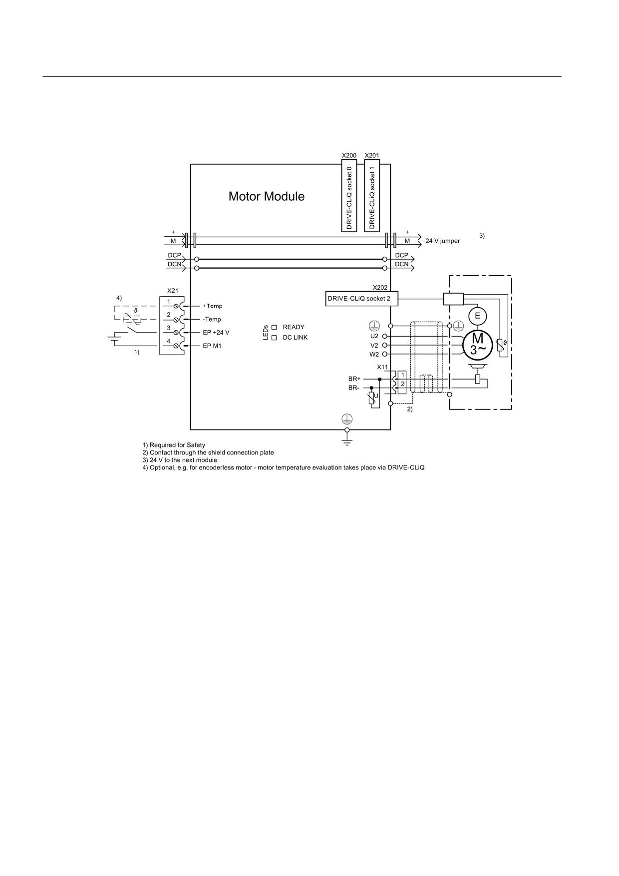
Connection example
Figure 8-165 Connection example for Motor Module Liquid Cooled (200 A)
Guidelines for machine configuration
426
System Manual, MA 01/2013, 6FC5397-6CP10-0BA2
Connection of the components in SINAMICS drive system
8.4 Connection of motor modules
8.4.5.4
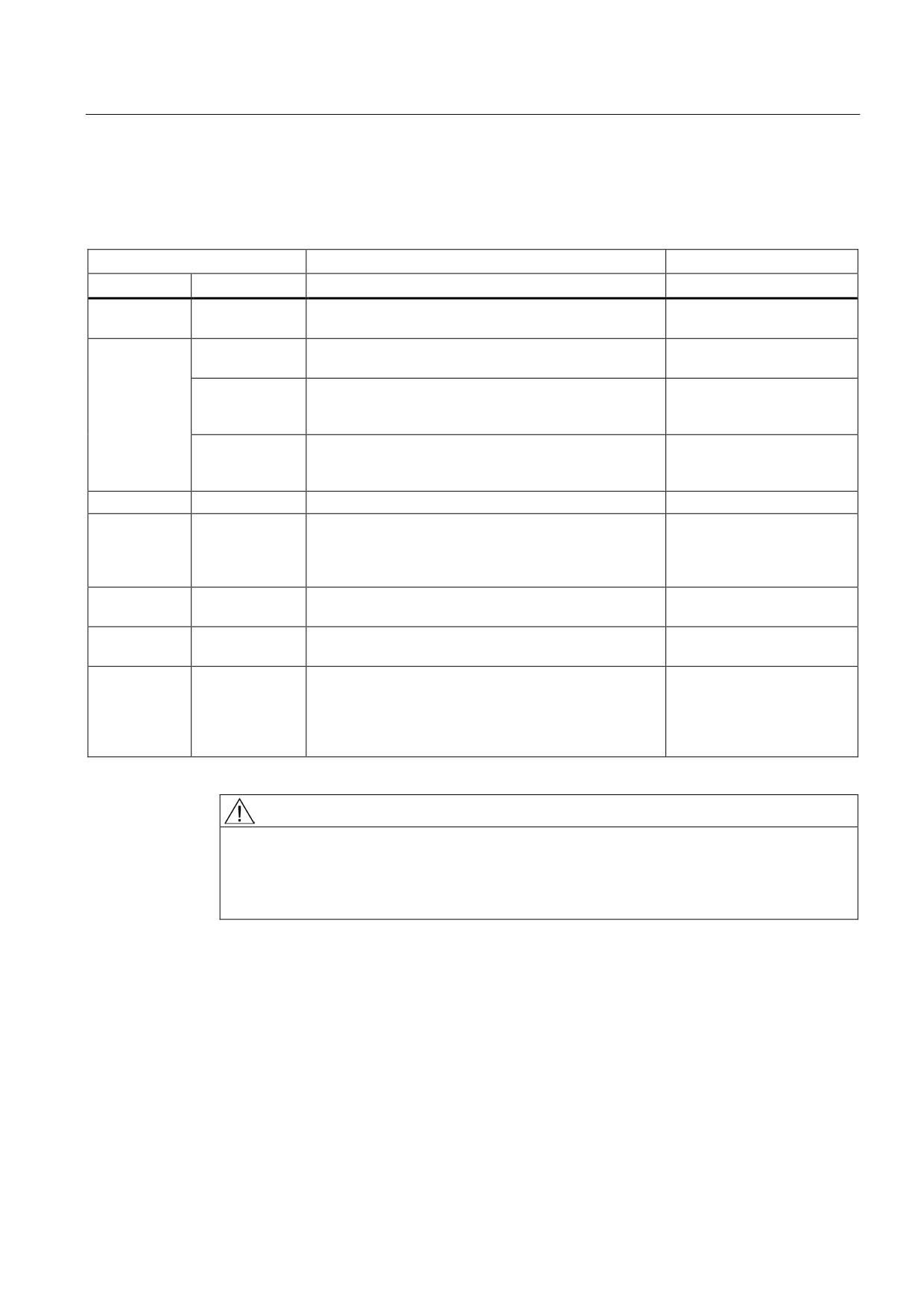
Meaning of LEDs
Table 8- 124 Meaning of LEDs
Status
Description, cause
Remedy
RDY
DC LINK
Off
Off
Electronics power supply is missing or outside
-
permissible tolerance range.
Green
--
The component is ready for operation and cyclic DRIVE-
-
CLiQ communication is taking place.
Orange
The component is ready for operation and cyclic DRIVE-
-
CLiQ communication is taking place.
The DC link voltage is present.
Red
The component is ready for operation and cyclic DRIVE-
Check line voltage
CLiQ communication is taking place.
The DC link voltage is too high.
Orange
Orange
DRIVE-CLiQ communication is being established.
-
Red
--
At least one fault is present in this component.
Remedy and acknowledge
Note:
fault
The LED is activated regardless of whether the
corresponding messages have been reconfigured.
Green/red
--
Firmware is being downloaded.
-
(0.5 Hz)
Green/red
--
Firmware download is complete. Wait for POWER ON.
Carry out a POWER ON
(2 Hz)
Green/orange
--
Detection of the components via LED is activated
-
or
(p0124).
Red/orange
Note:
Both options depend on the LED status in the case of
activation via p0124 = 1.
WARNING
Hazardous DC link voltage
Hazardous DC link voltages may be present at any time regardless of the status of the
"DC LINK" LED.
The warning information on the components must be carefully observed!
Guidelines for machine configuration
System Manual, MA 01/2013, 6FC5397-6CP10-0BA2
427
Connection of the components in SINAMICS drive system
8.4 Connection of motor modules
8.4.5.5
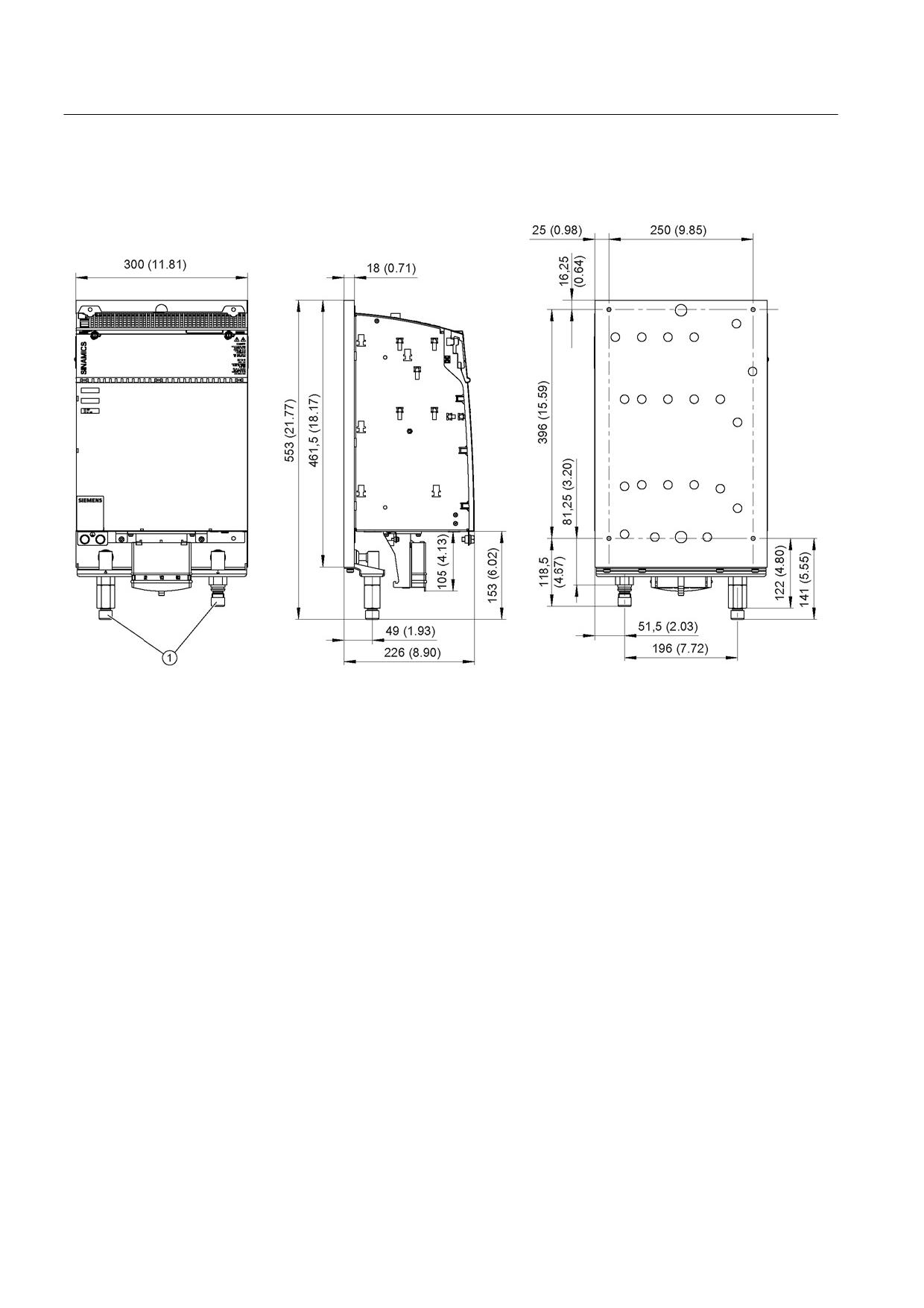
Dimension drawing
①
Pipe thread ISO 228 G ½ B.
Figure 8-166 Dimension drawing of Motor Module Liquid Cooled (200 A), all dimensions in mm and (inches)
Guidelines for machine configuration
428
System Manual, MA 01/2013, 6FC5397-6CP10-0BA2
Connection of the components in SINAMICS drive system
8.4 Connection of motor modules
8.4.5.6
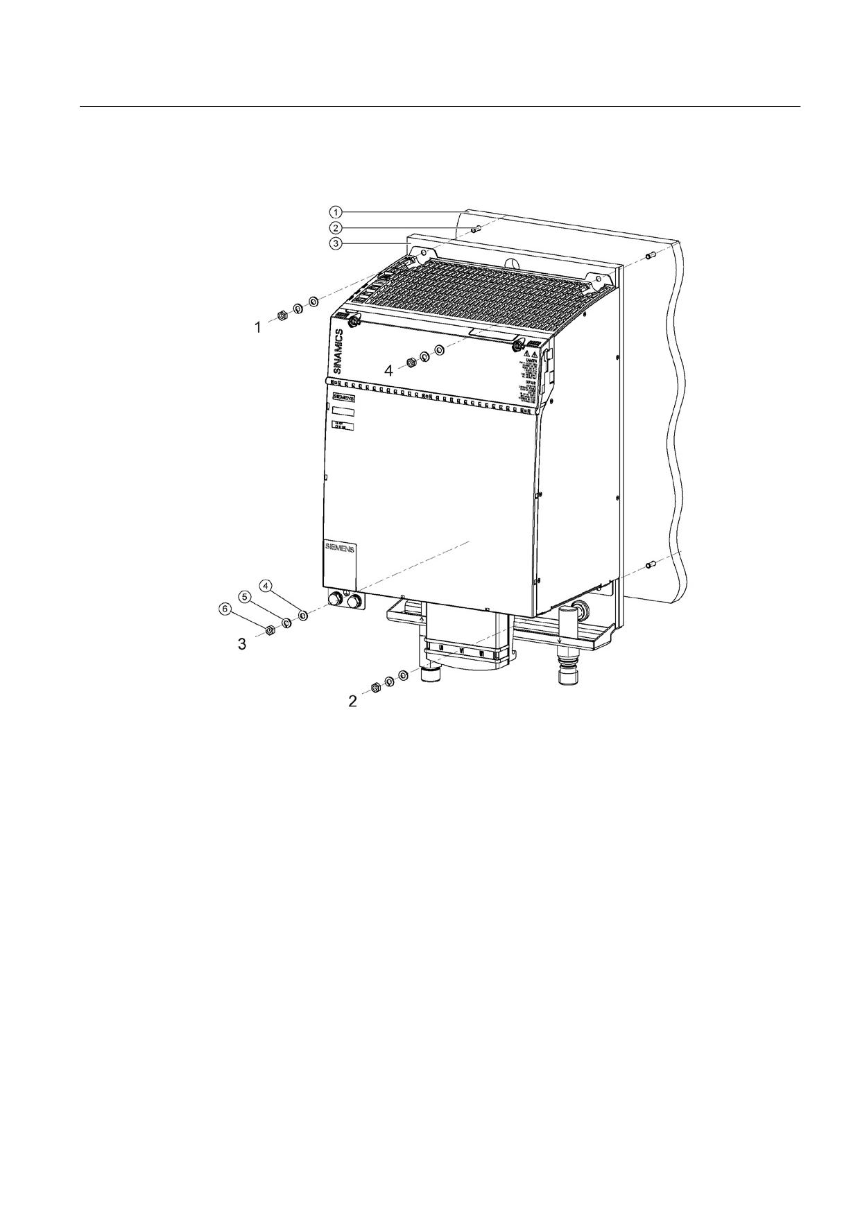
Installation
①
Mounting surface
②
M6 studs
③
Heat sink
④
Washer
⑤
Spring washer
⑥
M6 nut
Figure 8-167 Installing a Motor Module Liquid Cooled
Tightening torques:
● Initially, tighten the nuts by hand (0.5 Nm)
● Then tighten with 10 Nm (in the specific sequence 1 to 4)
For installation, M6 screw bolts and hexagon nuts/grub screws ISO 7436-M6x40-14 H,
property class 8.8 are recommended.
The coolant connections are located on the lower side of the components. All connection
elements can be accessed using an appropriate tool.
● Thread type of water connections: Pipe thread ISO 228 G ½ B.
Guidelines for machine configuration
System Manual, MA 01/2013, 6FC5397-6CP10-0BA2
429

Connection of the components in SINAMICS drive system
8.4 Connection of motor modules
8.4.5.7
Technical specifications
Technical data
Table 8- 125 Technical data for Motor Module Liquid Cooled 200 A
Liquid Cooled
6SL3125-1TE32-0AAx
Output current
Rated current (In)
AACrms
200
Base-load current (IH)
A
141
Intermittent duty current (IS6) 40%
AACrms(Is6)
230
Peak current (Imax)
AACrms(Imax)
282
Output voltage
VACrms
0 - 480
DC link current Id
ADC
200
DC link voltage (up to 2000 m above sea level)
VDC
510 -720
DC link capacitance
μF
3995
Overvoltage trip
VDC
820 ±2%
Undervoltage trip1)
VDC
380 ±2%
Electronics power supply
VDC
24 (20.4 - 28.8)
Electronics current consumption at 24 V DC
ADC
0.85
Current carrying capacity
DC link busbars
ADC
200
24 VDC busbars
ADC
20
Unit rating
Based on In (600 VDC; 4 kHz)
kW
107
Based on IH
kW
76
Total power loss(including electronics losses)2)
W
2070.4
Max. pulse frequency
without derating
kHz
4
with derating
kHz
16
Max. ambient temperature
without derating
°C
40
with derating
°C
55
Max. coolant temperature
without derating
°C
45
with derating
°C
50
Max. permissible heat sink temperature
°C
79 (70% derating)
Rated volumetric flow
l/min
8
for water at 70 kPa pressure drop3)
Volume of liquid internal
ml
100
Weight
kg
21
1)
Default for 400 V line systems; undervoltage trip threshold is adjusted to the parameterized rated voltage
2)
For an overview, see the power loss tables in Appendix A.3
3)
This value applies to the water coolant option; for other coolant types, see the SINAMICS S120 Booksize Power Units
Equipment Manual (GH2), Chapter "Cooling circuit and coolant properties".
Guidelines for machine configuration
430
System Manual, MA 01/2013, 6FC5397-6CP10-0BA2
Connection of the components in SINAMICS drive system
8.4 Connection of motor modules
Characteristics
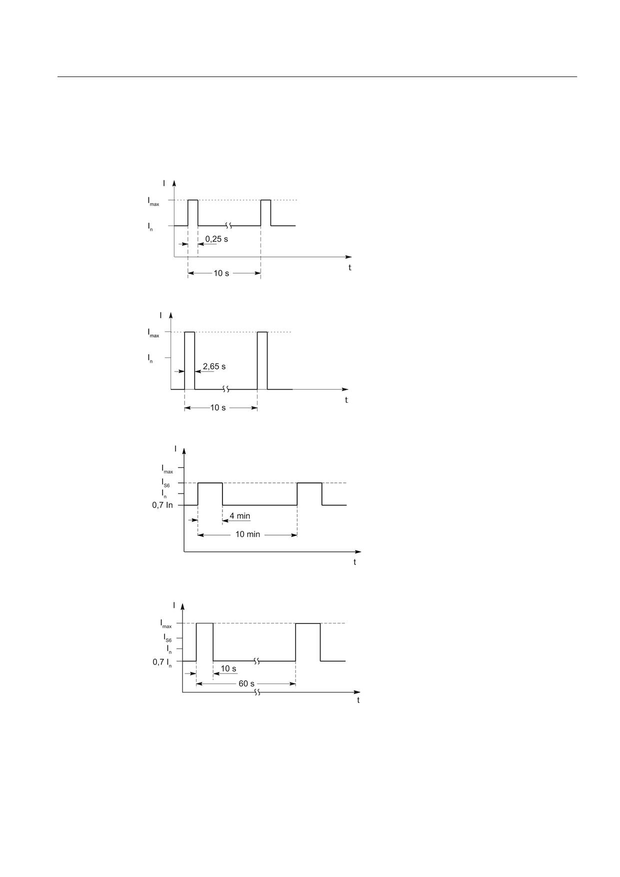
Rated duty cycles Motor Modules Booksize
Figure 8-168 Duty cycle with initial load (for servo drives)
Figure 8-169 Duty cycle without initial load (for servo drives)
Figure 8-170 S6 duty cycle with initial load with a duty cycle duration of 600 s (for servo drives)
Figure 8-171 S6 duty cycle with initial load with a duty cycle duration of 60 s (for servo drives)
Guidelines for machine configuration
System Manual, MA 01/2013, 6FC5397-6CP10-0BA2
431
Connection of the components in SINAMICS drive system
8.4 Connection of motor modules
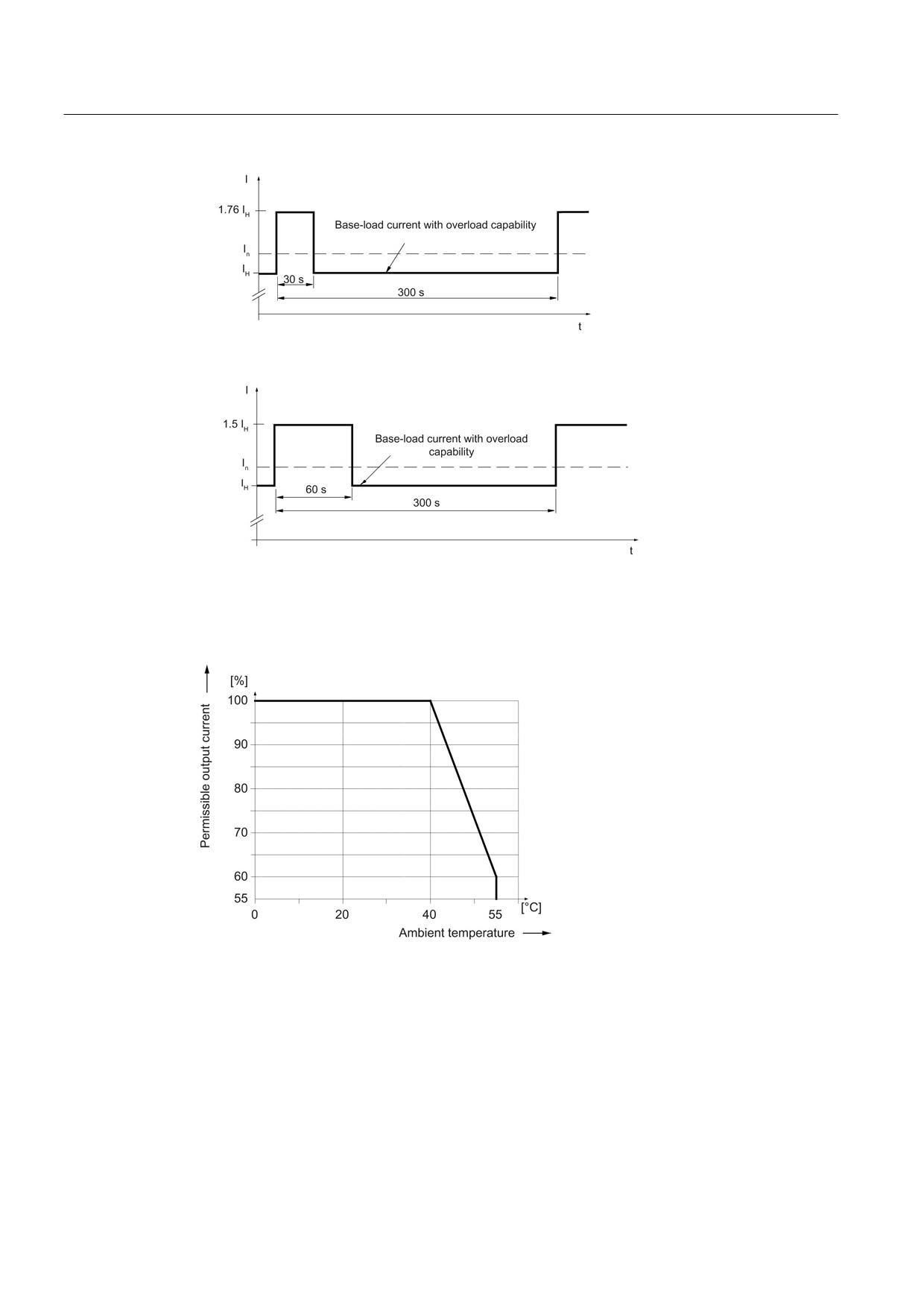
Figure 8-172 Duty cycle with 30 s overload for a duty cycle duration of 300 s
Figure 8-173 Duty cycle with 60 s overload for a duty cycle duration of 300 s
Derating characteristics for Motor Modules Booksize
Figure 8-174 Output current as a function of the ambient temperature
Guidelines for machine configuration
432
System Manual, MA 01/2013, 6FC5397-6CP10-0BA2
Connection of the components in SINAMICS drive system
8.4 Connection of motor modules
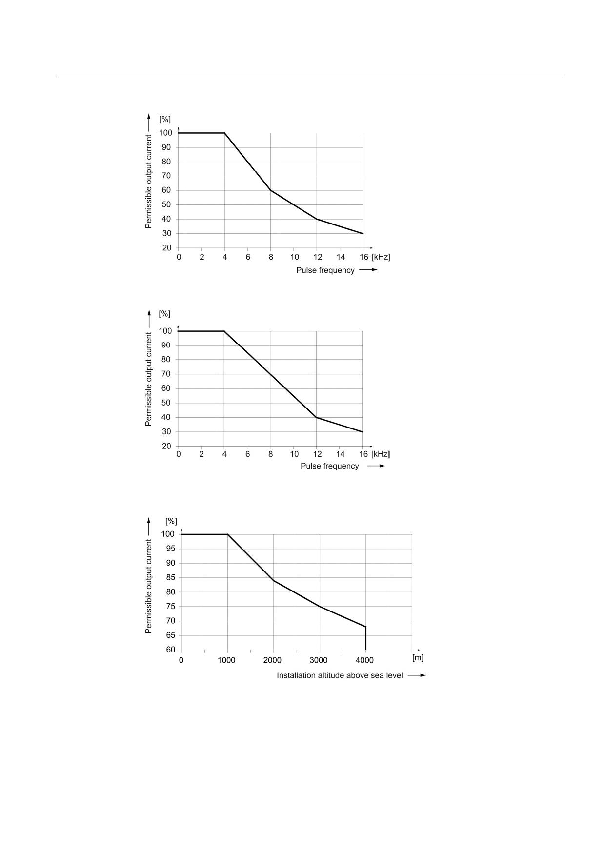
Figure 8-175 Output current as a function of the pulse frequency
Figure 8-176 Output current as a function of the pulse frequency for 200 A Motor Modules
(applies from order number 6SL312x-1TE32-0AA4)
Figure 8-177 Output current as a function of the installation altitude
Guidelines for machine configuration
System Manual, MA 01/2013, 6FC5397-6CP10-0BA2
433
Connection of the components in SINAMICS drive system
8.4 Connection of motor modules
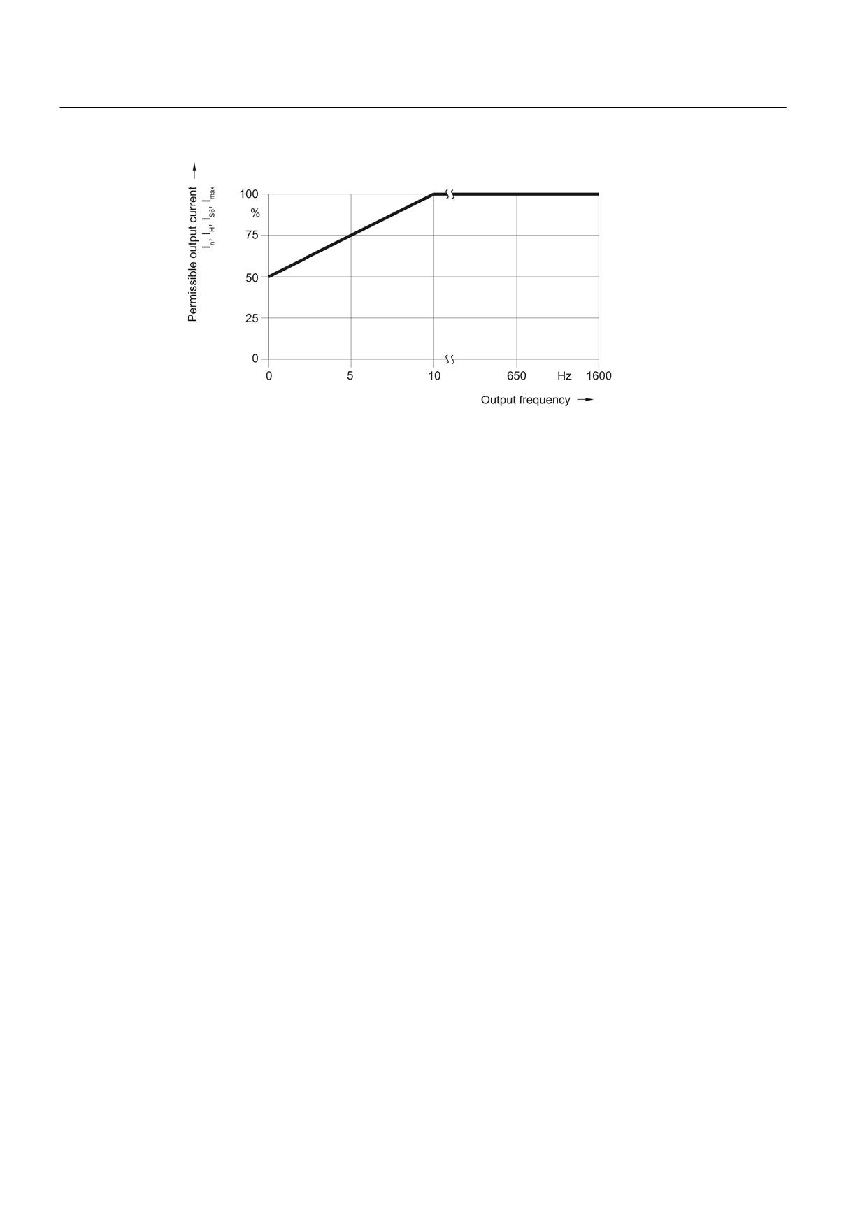
Figure 8-178 Output current as a function of the output frequency
At installation altitudes > 2000 m, an isolation transformer must be used (see the chapter
titled "System overview/Function of installation altitude and ambient temperature"
(Page 32)). The design of the secondary line system must be as follows:
● TN system with grounded neutral point (no grounded line conductor)
● IT system
A reduction of the line supply voltage phase-phase is not necessary.
Guidelines for machine configuration
434
System Manual, MA 01/2013, 6FC5397-6CP10-0BA2
Connection of the components in SINAMICS drive system
8.5 DRIVE-CLiQ Hub Modules (DMC20, DME20)
8.5
DRIVE-CLiQ Hub Modules (DMC20, DME20)
8.5.1
DMC20
8.5.1.1
Description
The DMC20 DRIVE-CLiQ Hub Module is used to implement a star-shaped configuration of a
DRIVE-CLiQ line. With the DMC20, an axis grouping can be expanded by up to 5 DRIVE-
CLiQ sockets for additional subgroups.
The component is especially suitable for applications which require DRIVE-CLiQ nodes to be
removed in groups, without interrupting the DRIVE-CLiQ line and, therefore, the data
exchange process.
DMC20 can be used for the SINUMERIK 840D sl with CNC SW 2.6 and higher.
8.5.1.2
Overview
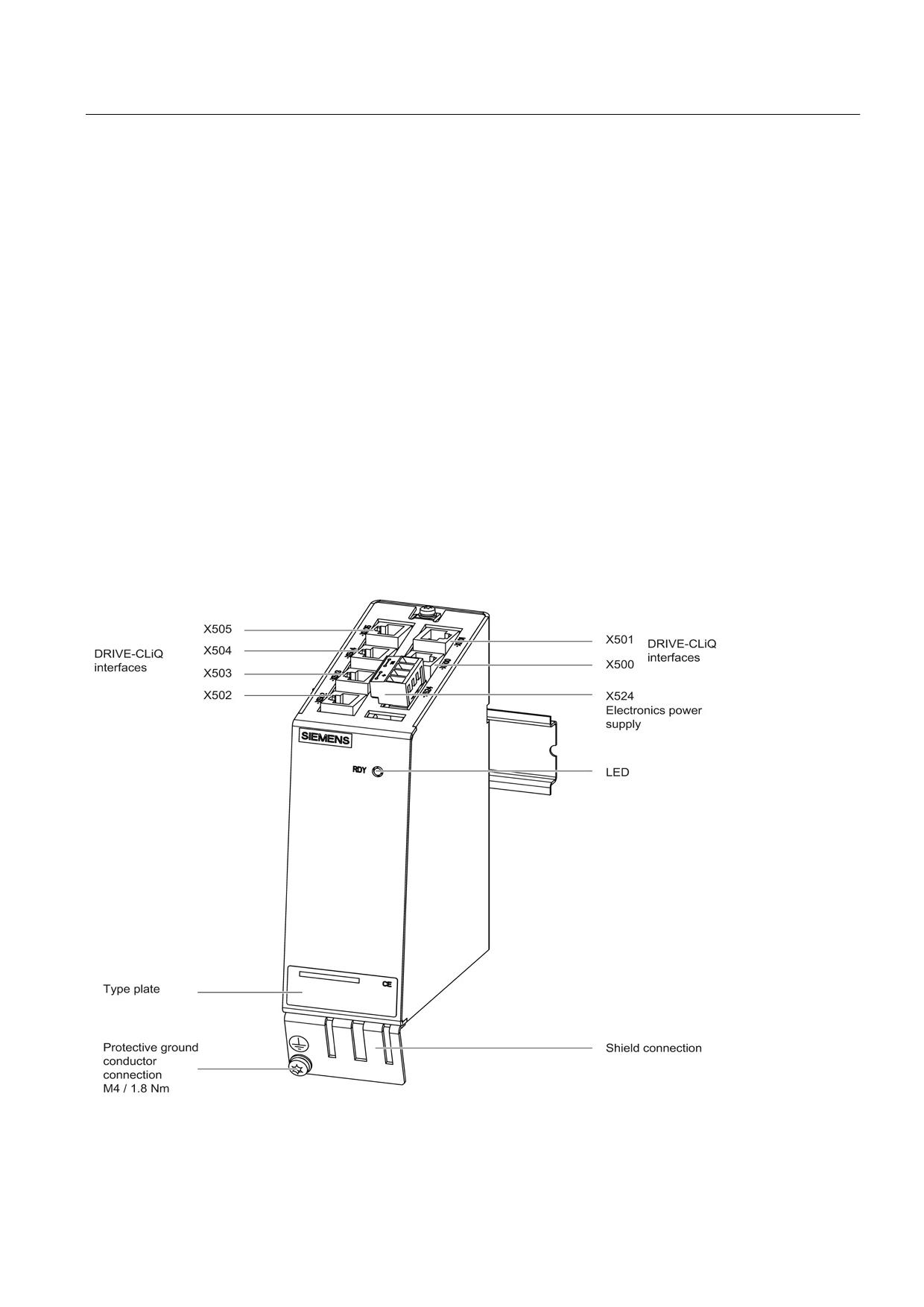
Figure 8-179 Interface description of the DMC20
Guidelines for machine configuration
System Manual, MA 01/2013, 6FC5397-6CP10-0BA2
435
Connection of the components in SINAMICS drive system
8.5 DRIVE-CLiQ Hub Modules (DMC20, DME20)
8.5.1.3
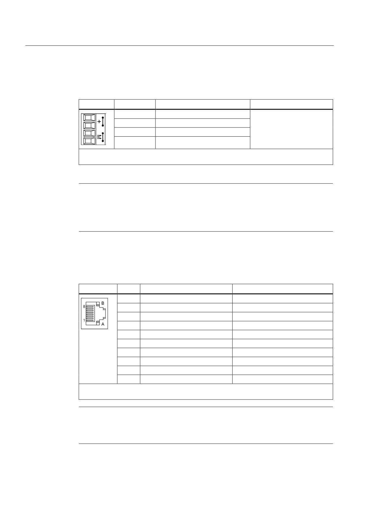
Electronics power supply X524
Table 8- 126 X524 terminals for the electronics power supply
Terminal
Name
Technical specifications
+
Electronics power supply
24 DC (20.4 - 28.8)
+
N. c.
M
Electronics ground
M
Electronics ground
Maximum connectable cross-section: 2.5 mm2
Type: Screw terminal type 2
Note
The two "+" or "M" terminals are jumpered in the connector. This ensures the supply voltage
is looped through.
The current consumption increases by the value for the DRIVE-CLiQ node and digital
outputs.
8.5.1.4
DRIVE-CLiQ interface
Table 8- 127 DRIVE-CLiQ interfaces X500 - X505
Pin
Signal name
Technical specifications
1
TXP
Transmit data +
2
TXN
Transmit data -
3
RXP
Receive data +
4
Reserved, do not use
5
Reserved, do not use
6
RXN
Receive data -
7
Reserved, do not use
8
Reserved, do not use
A
+ (24 V)
Power supply
B
M (0 V)
Electronics ground
Type: RJ45 plus socket
Blanking plate for DRIVE-CLiQ interface: Yamaichi, order number: Y-ConAS-13
Note
Only MOTION-CONNECT DRIVE-CLiQ cables may be used to establish connections.
The maximum lengths of MOTION-CONNECT 500 and MOTION-CONNECT 800 cables are
100 m and 50 m respectively.
Guidelines for machine configuration
436
System Manual, MA 01/2013, 6FC5397-6CP10-0BA2
Connection of the components in SINAMICS drive system
8.5 DRIVE-CLiQ Hub Modules (DMC20, DME20)
8.5.1.5
Significance of the LED on the DMC20
Table 8- 128 Significance of the LED on the DMC20
LED
Color
Status
Description
READY
-
Off
Electronics power supply outside the permissible
tolerance range.
Green
Steady light
The component is ready for operation and cyclic
DRIVE-CLiQ communication is taking place.
Orange
Steady light
DRIVE-CLiQ communication is being established.
Red
Steady light
At least one fault is present in this component.
Green
Flashing
The firmware is being downloaded.
Red
2 Hz
Component recognition via LED is activated (p0154).
8.5.1.6
Dimension drawing
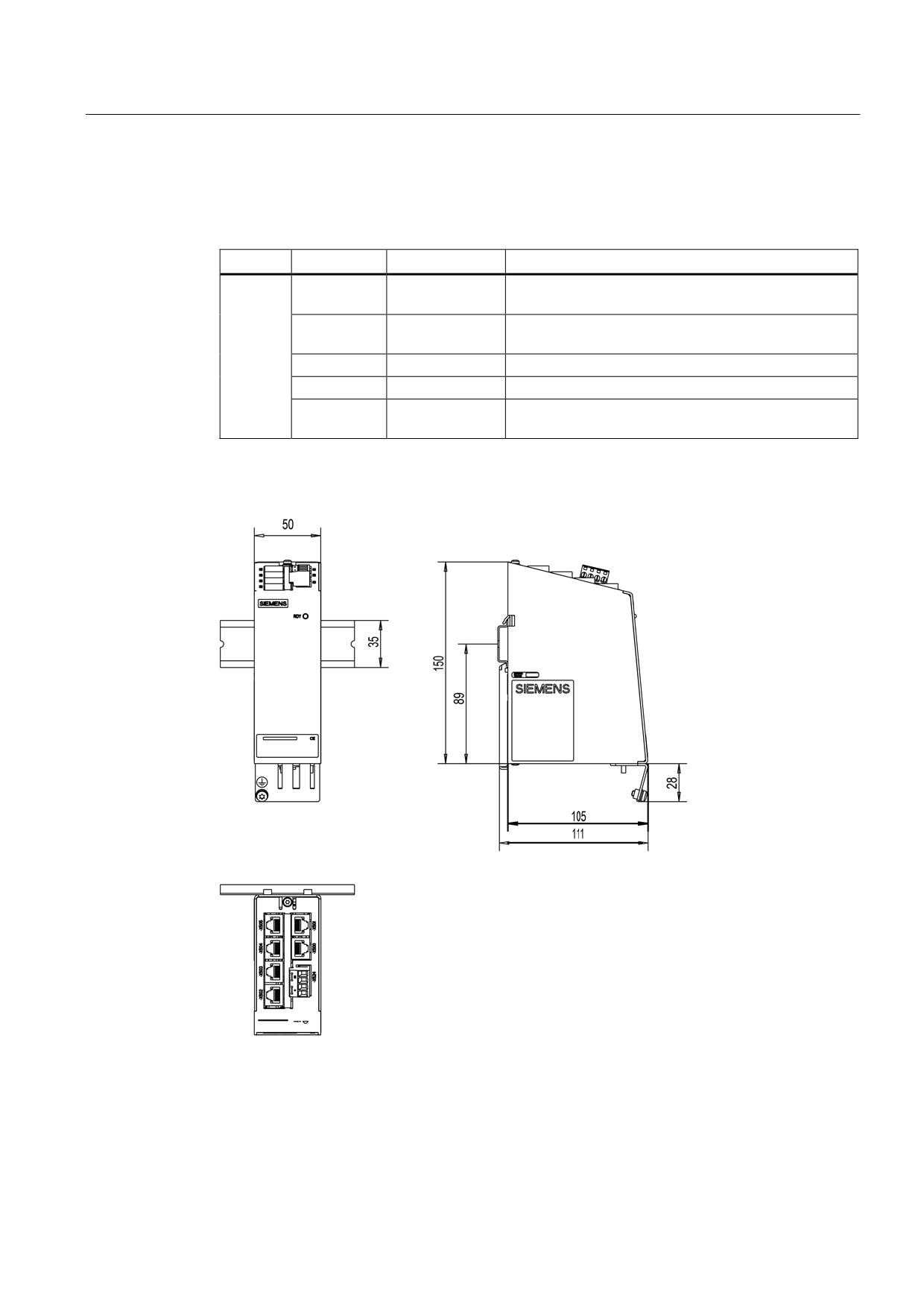
Figure 8-180 Dimension drawing of the DMC20
Guidelines for machine configuration
System Manual, MA 01/2013, 6FC5397-6CP10-0BA2
437
Connection of the components in SINAMICS drive system
8.5 DRIVE-CLiQ Hub Modules (DMC20, DME20)
8.5.1.7
Technical data
Table 8- 129 Technical data of the DMC20
Unit
Value
Electronics power supply
Voltage
VDC
24 DC (20.4 - 28.8)
Current (without DRIVE-CLiQ
ADC
0.15
consumer)
PE/ground connection
At the housing with M4/1.8 Nm stud
Weight
kg
0.8
8.5.2
DME20
8.5.2.1
Description
The DRIVE-CLiQ Hub Module External DME20 is used to implement star-shaped distribution
of a DRIVE-CLiQ line. With the DME20, an axis grouping can be expanded by up to 5
DRIVE-CLiQ sockets for additional subgroups.
The component has degree of protection IP67 and is especially suitable for applications
which require DRIVE-CLiQ nodes to be removed in groups, without interrupting the DRIVE-
CLiQ line and therefore the data exchange.
With firmware 2.6 and higher, the DME20 can be used in conjunction with the SINUMERIK
840D sl CNC SW2.6.
8.5.2.2
Safety information
Note
In order to guarantee degree of protection IP67, all of the plug connectors must be correctly
screwed into place and appropriately locked.
Note
The unused DRIVE-CLiQ interfaces must be closed using a protective cap (included in the
scope of delivery).
Guidelines for machine configuration
438
System Manual, MA 01/2013, 6FC5397-6CP10-0BA2
Connection of the components in SINAMICS drive system
8.5 DRIVE-CLiQ Hub Modules (DMC20, DME20)
Note
All components operated on the DRIVE-CLiQ must be integrated into the equipotential
bonding concept.
They should preferably be connected by installing them on bright machine parts and devices,
which are all bonded to one another in an equipotential manner.
Alternatively, equipotential bonding can be achieved by means of a conductor (min. 6 mm²),
which should be routed parallel to the DRIVE-CLiQ where possible. This applies to all
distributed DRIVE-CLiQ nodes, such as DM20, SME2x, SM12x, etc.
For the DME20 this also applies to the 24 V power supply.
8.5.2.3
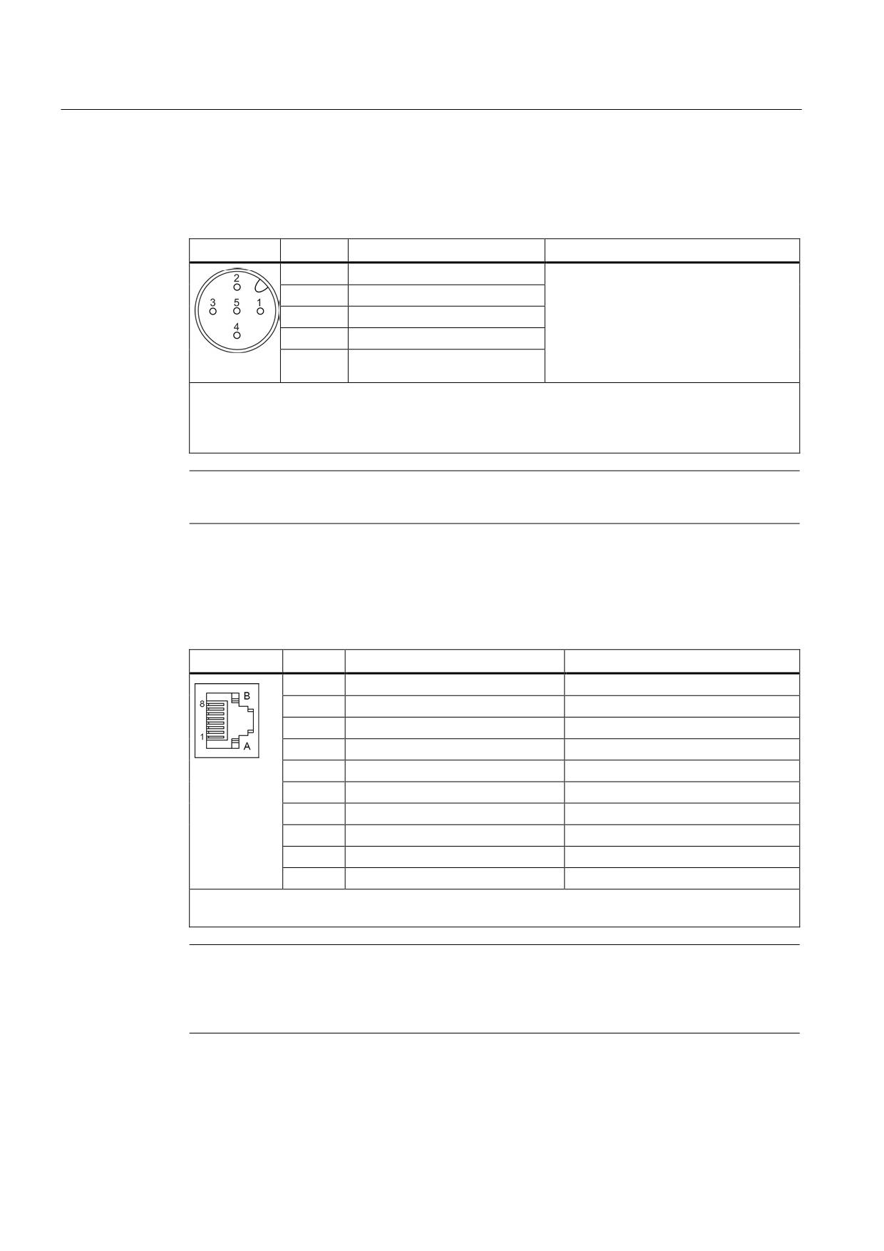
Overview
Figure 8-181 Interface overview: DME20
Guidelines for machine configuration
System Manual, MA 01/2013, 6FC5397-6CP10-0BA2
439
Connection of the components in SINAMICS drive system
8.5 DRIVE-CLiQ Hub Modules (DMC20, DME20)
8.5.2.4
Electronics power supply X524
Table 8- 130 X524 socket for the electronics power supply
Pin
Designation
Technical specifications
1
Electronics power supply
The connection voltage of 20.4 V -
28.8 V refers to the (terminal) voltage at
2
Electronics power supply
the DME20. This must be taken into
3
Electronics ground
account when selecting the cable cross-
4
Electronics ground
section and supply cable lengths.
Pins 1 and 2: jumpered internally
5
not connected
Pins 3 and 4: jumpered internally
Max. connectable cross-section: 4 x 0.75 mm2
e.g. 5-pole shielded connector, user-assembled: Phoenix company, Order No.: 1508365,
4-pole non-shielded connector, user-assembled, Speedcon quick-lock: Phoenix company, Order No.
1521601
Note
The maximum cable length for the P24 supply of the DME20 is 100 m.
8.5.2.5
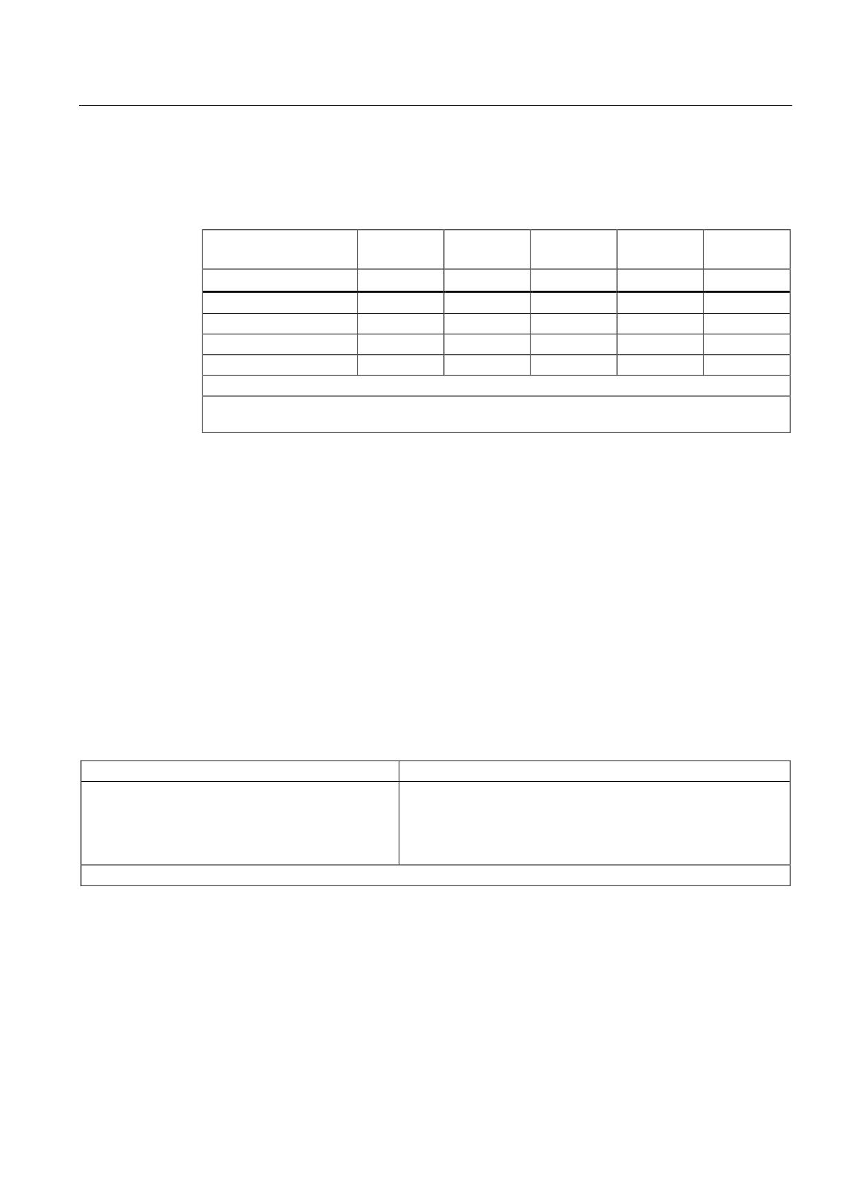
DRIVE-CLiQ interface
Table 8- 131 DRIVE-CLiQ interface X500, X501, X502, X503, X504, X505
Pin
Signal name
Technical specifications
1
TXP
Transmit data +
2
TXN
Transmit data -
3
RXP
Receive data +
4
Reserved, do not use
5
Reserved, do not use
6
RXN
Receive data -
7
Reserved, do not use
8
Reserved, do not use
A
+ (24 V)
Power supply
B
M (0 V)
Electronics ground
Type: RJ45 plus socket
Blanking plates for DRIVE-CLiQ interfaces are included in the scope of delivery.
Note
Only MOTION-CONNECT DRIVE-CLiQ cables may be used to establish connections.
The maximum lengths of MOTION-CONNECT 500 and MOTION-CONNECT 800 cables are
100 m and 50 m respectively.
Guidelines for machine configuration
440
System Manual, MA 01/2013, 6FC5397-6CP10-0BA2
Connection of the components in SINAMICS drive system
8.5 DRIVE-CLiQ Hub Modules (DMC20, DME20)
8.5.2.6
Cable lengths
Table 8- 132 Cable length of P24 supply cable:
Connected
1
2
3
4
5
consumers 1)
Cross section
0.34 mm²
75 m
45 m
30 m
25 m
20 m
2 x 0.34 mm²
100 m
90 m
65 m
50 m
40 m
0.75 mm²
100 m
100 m
75 m
60 m
50 m
2 x 0.75 mm²
100 m
100 m
100 m
100 m
100 m
1) Connected motors with DRIVE-CLiQ encoder, DRIVE CLiQ mounted encoder SME
Ta = 55 °C
100 m DRIVE-CLiQ
8.5.2.7
Specifications for use with UL approval
Pre-assembled cables
Sensor/actuator cable, 5-pin, variable cable,
free cable end at straight socket M12-SPEEDCON,
cable length: 2, 5, 10, 15 m
SAC-5P-xxx-186/FS SCO
Up to 100 m on request
Phoenix Contact, www.phoenixcontact.com
Cables to be assembled by the user
Table 8- 133 Assembled by the user
Cable
Connector
Cable coil, black PUR/PVC, 5-pin
Sensor/actuator connector, socket, straight, 5-pin, M12, A-coded
Conductor colors: brown/white/blue/black/gray
Screw connection, metal knurl, cable gland Pg9
Cable length: 100 m
SACC-M12FS-5CON-PG9-M
SAC-5P-100.0-186/0.75
Order number: 1681486
Order number: 1535590
Phoenix Contact, www.phoenixcontact.com
Power supply
The DME20 must be connected to a 24 V power supply with voltage limitation.
● SITOP 6EP1x.. or 6ES7307..
● SINAMICS Control Supply Module 6SL3100-1DE22-0Axx
Guidelines for machine configuration
System Manual, MA 01/2013, 6FC5397-6CP10-0BA2
441
Connection of the components in SINAMICS drive system
8.5 DRIVE-CLiQ Hub Modules (DMC20, DME20)
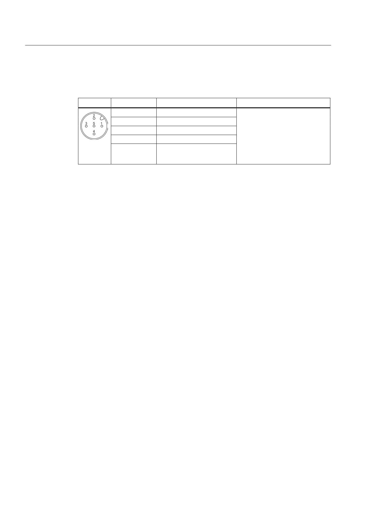
Pin assignment of the cable
Table 8- 134 Connection to X524 electronics power supply
Pin
Designation
Technical specifications
1 (brown) 1)
Electronics power supply
The connection voltage of 20.4 V -
28.8 V refers to the (terminal)
2 (white) 1)
Electronics power supply
voltage at the DME20. This must be
3 (black) 1)
Electronics ground
taken into account when selecting
4 (blue) 1)
Electronics ground
the cable cross-section and supply
cable lengths.
5 (gray) 1)
Not connected internally
Pins 1 and 2: jumpered internally
Pins 3 and 4: jumpered internally
1) The colors stated refer to the cable specified above
Guidelines for machine configuration
442
System Manual, MA 01/2013, 6FC5397-6CP10-0BA2
Connection of the components in SINAMICS drive system
8.5 DRIVE-CLiQ Hub Modules (DMC20, DME20)
8.5.2.8
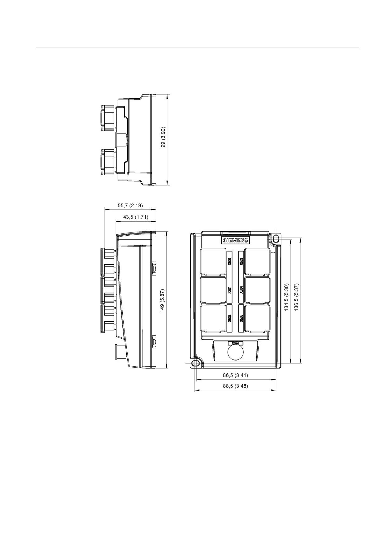
Dimension drawing
Figure 8-182 Dimension drawing: DME20
Guidelines for machine configuration
System Manual, MA 01/2013, 6FC5397-6CP10-0BA2
443
Connection of the components in SINAMICS drive system
8.5 DRIVE-CLiQ Hub Modules (DMC20, DME20)
8.5.2.9
Installation
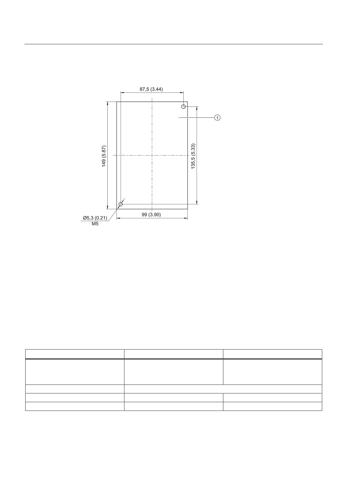
Figure 8-183 DME20 installation
Installation
1. Place the hole drilling template on the contact surface.
2. The contact surfaces must be unpainted metal.
3. Holes Ø5.3 or threads M5
4. Tighten with a tightening torque of 6.0 Nm.
8.5.2.10
Technical data
Table 8- 135 Technical data of the DME20
Unit
Value
Electronics power supply
Voltage
VDC
24 DC (20.4 - 28.8)
Current (without DRIVE-CLiQ node)
ADC
0,15
PE/ground connection
Fastened to housing M5 / 6 Nm
Degree of protection
IP67
Weight
kg
0,8
Guidelines for machine configuration
444
System Manual, MA 01/2013, 6FC5397-6CP10-0BA2

Connection of the components in SINAMICS drive system
8.6 Connecting Terminal Modules
8.6
Connecting Terminal Modules
8.6.1
TM15: Terminal expansion for digital inputs/outputs
The Terminal Module TM15 is a terminal expansion for snapping on to an EN 60715 DIN rail.
The TM15 can be used to increase the number of available digital inputs/outputs within a
drive system.
Table 8- 136 Interface overview of the TM15
Type
Number
DRIVE-CLiQ interfaces
2
Electronics power supply
1
Bidirectional digital inputs/outputs
24 (electrical isolation in three groups each with eight
DI/DO)
Note
Please observe the safety instructions in Chapter 1 when using the Terminal Module.
8.6.2
TM41: Emulating an incremental encoder
The TM41 Terminal Module is an expansion module that is snapped onto an EN 60715 DIN
rail.
The encoder interface of the TM41 can be used to emulate an incremental encoder. The
TM41 can also be used to connect analog controls to SINAMICS.
The TM41 contains the following interfaces:
Table 8- 137 Interface overview of the TM41
Type
Number
DRIVE-CLiQ interfaces
2
Power supply
2
Digital inputs, floating
4
Bidirectional digital inputs/outputs
4
Analog inputs
1
TTL encoder output
1
Note
Please observe the safety instructions in Chapter 1 when using the Terminal Module.
Guidelines for machine configuration
System Manual, MA 01/2013, 6FC5397-6CP10-0BA2
445
Connection of the components in SINAMICS drive system
8.6 Connecting Terminal Modules
8.6.3
TM120: DRIVE-CLiQ component for temperature evaluation with safe electrical
separation
The TM120 Terminal Module is a DRIVE-CLiQ component for safe electrically isolated
temperature evaluation. It can be used for 1FN, 1FW6, and third-party motors in which the
temperature sensors cannot be installed with safe electrical separation. The TM120 is
installed in the control cabinet and can be snapped on to a DIN rail (EN 60715).
When a TM120 is being used, temperature evaluation and encoder evaluation functions are
separated off from one another. The TM120 can detect the motor temperature via 4
channels with different temperature sensors. Encoder evaluation functions are performed via
Sensor Modules (e.g. SMCxx, SMExx). This means that, when connected to a Sensor
Module SMCxx, the TM120 represents a control cabinet alternative to the SME120/SME125.
The TM120 contains the following interfaces:
Table 8- 138 Overview of the TM120 interfaces
Type
Number
DRIVE-CLiQ interfaces
2
Electronics power supply
1
Temperature sensor inputs
4
Guidelines for machine configuration
446
System Manual, MA 01/2013, 6FC5397-6CP10-0BA2
Connection of the components in SINAMICS drive system
8.7 Sensor Systems Connection
8.7
Sensor Systems Connection
8.7.1
Introduction
The encoder system should be connected to SINAMICS S120 via DRIVE-CLiQ.
Motors with DRIVE-CLiQ interfaces (e.g. synchronous motors 1FK7 and 1FT7, and induction
motors 1PH7) are designed for this purpose. These motors simplify commissioning and
diagnostics because the motor and encoder type are identified automatically.
Motors and external encoders without DRIVE-CLiQ interface
Motors without DRIVE-CLiQ interfaces, as well as external encoders without integrated
DRIVE-CLiQ interfaces, must be connected via Sensor Modules to enable the encoder and
temperature signals to be evaluated. Sensor Modules Cabinet-Mounted (SMC) are available
for installation in control cabinets and Sensor Modules External (SME) for installation outside
control cabinets.
If not otherwise specified, only one encoder system can be connected to each Sensor
Module.
Motors and external encoders with DRIVE-CLiQ interface
Motors with DRIVE-CLiQ interfaces can be connected to the associated Motor Module
directly via the MOTION-CONNECT DRIVE-CLiQ cables available. The connection of the
MOTION-CONNECT DRIVE-CLiQ cable at the motor has degree of protection IP67.
The DRIVE-CLiQ interface supplies the motor encoder via the integrated 24 VDC supply and
transfers the motor encoder and temperature signals and the electronic rating plate data,
e.g. a unique identification number, rated data (voltage, current, torque), directly to the
Control Unit. Different encoder cables are therefore no longer required for the various
encoder types, e.g. resolvers or absolute encoders. Wiring can be effected throughout with a
MOTION-CONNECT DRIVE-CLiQ cable.
DRIVE-CLiQ encoder
A DRIVE-CLiQ encoder is an absolute encoder with integrated DRIVE-CLiQ interface (see
the chapter titled "DRIVE-CLiQ encoder").
CAUTION
Preventing encoder faults
Unfavorable material combinations generate frictional electricity between the belt pulley and
the belt. This electrostatic charge (several kV) can discharge via the motor shaft and the
encoder, which leads to disturbance of the encoder signals (encoder error).
Remedy: Use an antistatic version of the belt (special conductive polyurethane mixture).
Guidelines for machine configuration
System Manual, MA 01/2013, 6FC5397-6CP10-0BA2
447
Connection of the components in SINAMICS drive system
8.7 Sensor Systems Connection
Note
Disconnecting and connecting encoder cables
The encoder cables to Siemens motors may only disconnected and connected when the
system is in a no-voltage condition.
For direct measuring systems (third-party encoders), ask the manufacturer whether it is
permissible to disconnected/connect under voltage.
8.7.2
Overview of Sensor Modules
Sensor Modules Cabinet-Mounted (SMC)
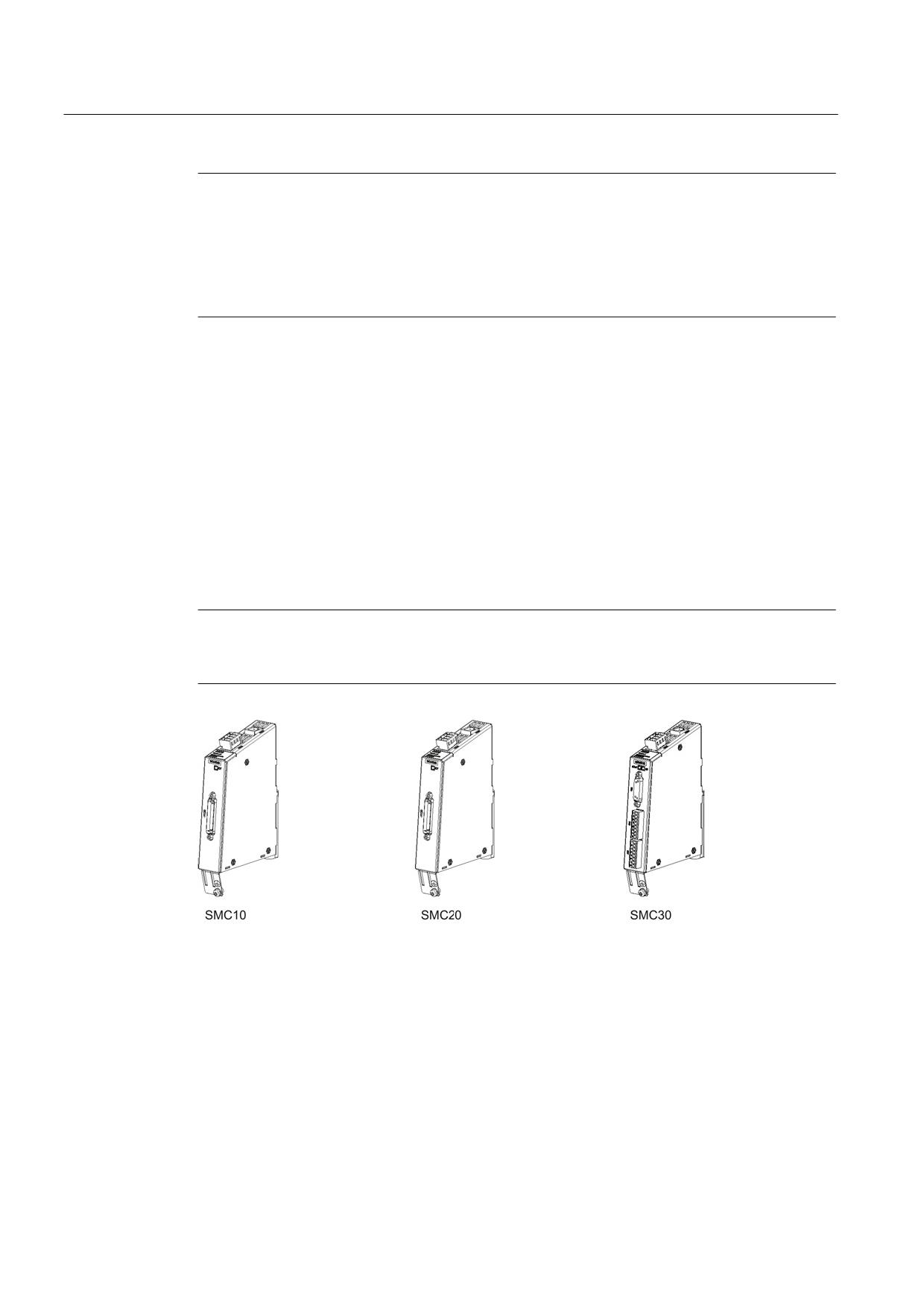
Sensor Modules Cabinet-Mounted SMC10, SMC20 and SMC30 can be ordered and
configured separately. They are used when a motor with a DRIVE-CLiQ interface is not
available or when external encoders in addition to the motor encoder are required. Only one
encoder system can be connected to each Sensor Module Cabinet-Mounted. The SMCs
evaluate these measuring systems and convert the calculated values to DRIVE-CLiQ.
Neither motor nor encoder data are saved.
Note
The SMC supplies the power to the encoder; the SMC, however, must be provided
separately with 24 VDC power.
Figure 8-184 Overview of Sensor Modules Cabinet-Mounted (SMC)
Guidelines for machine configuration
448
System Manual, MA 01/2013, 6FC5397-6CP10-0BA2
Connection of the components in SINAMICS drive system
8.7 Sensor Systems Connection
Sensor Modules External (SME)
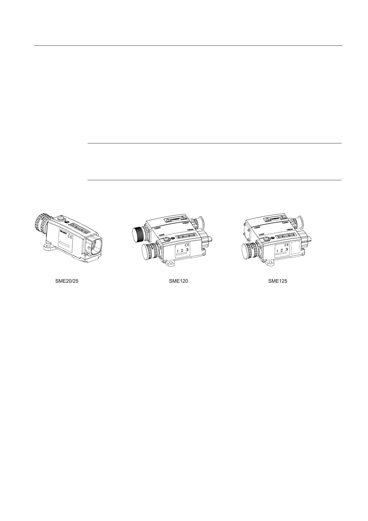
The Sensor Modules External SME20, SME25, SME120, and SME125 are only intended for
use on machines (in North America, in accordance with the NFPA 79 "Electrical Standard for
Industrial Machinery") and may only be connected to the DRIVE-CLiQ interfaces of the
components.
Direct encoder systems outside the cabinet can be connected to the Sensor Modules
External. The SMEs evaluate these encoder systems and convert the calculated values to
DRIVE-CLiQ. No motor or encoder data is stored in the SMEs.
Note
The SME provides the encoder power supply. The power supply for the SME is provided
from the connected DRIVE-CLiQ cable. This must be taken into consideration when the
DRIVE-CLiQ cable is selected.
The Sensor Modules External have a higher degree of protection (IP67) and are therefore
suitable for installation outside the cabinet.
Figure 8-185 Overview of Sensor Modules External (SME)
Guidelines for machine configuration
System Manual, MA 01/2013, 6FC5397-6CP10-0BA2
449
Connection of the components in SINAMICS drive system
8.7 Sensor Systems Connection
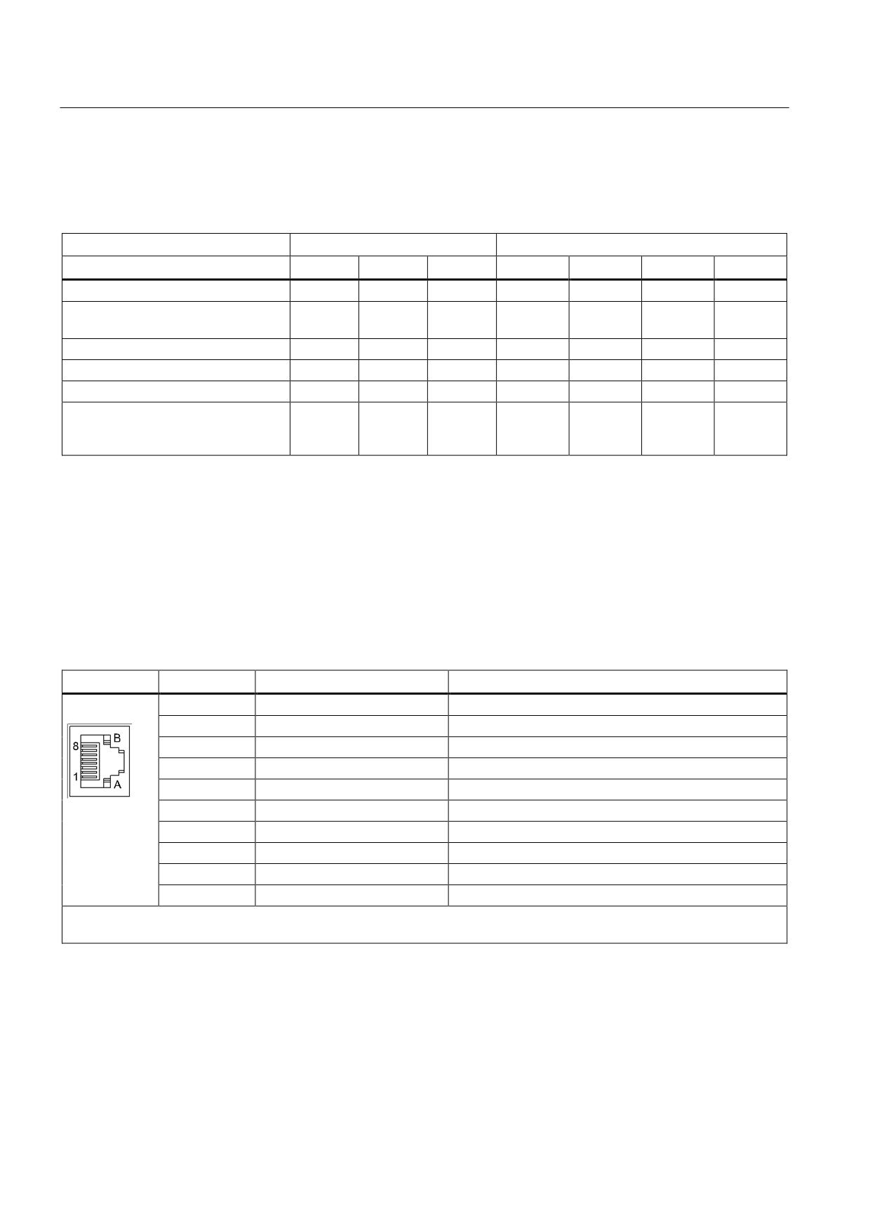
Connectable encoder systems
Table 8- 139 Overview of the connectable encoder systems
SMC
SME
Encoder systems
SMC10
SMC20
SMC30
SME20
SME25
SME120
SME125
Resolver
Yes
-
-
-
-
-
-
Incremental encoder sin/cos (1 Vpp)
-
Yes
-
Yes
-
Yes
-
with/without reference signal
Absolute encoder EnDat 2.1
-
Yes
-
-
Yes
-
Yes
Incremental encoder TTL / HTL
-
-
Yes
-
-
-
-
Absolute encoder SSI
-
Yes 1)
Yes 2)
-
Yes 1)
-
Yes 1)
Temperature evaluation
Yes
Yes
Yes
Yes 3)
-
Yes
Yes
(electricall
(electricall
y isolated)
y isolated)
1) Only possible for SSI encoders with 5 V supply
2) Possible for SSI encoders with 5 V or 24 V supply
3) With prescribed adapter cable 6FX8002-2CA88
8.7.3
X200-X203 DRIVE-CLiQ interface
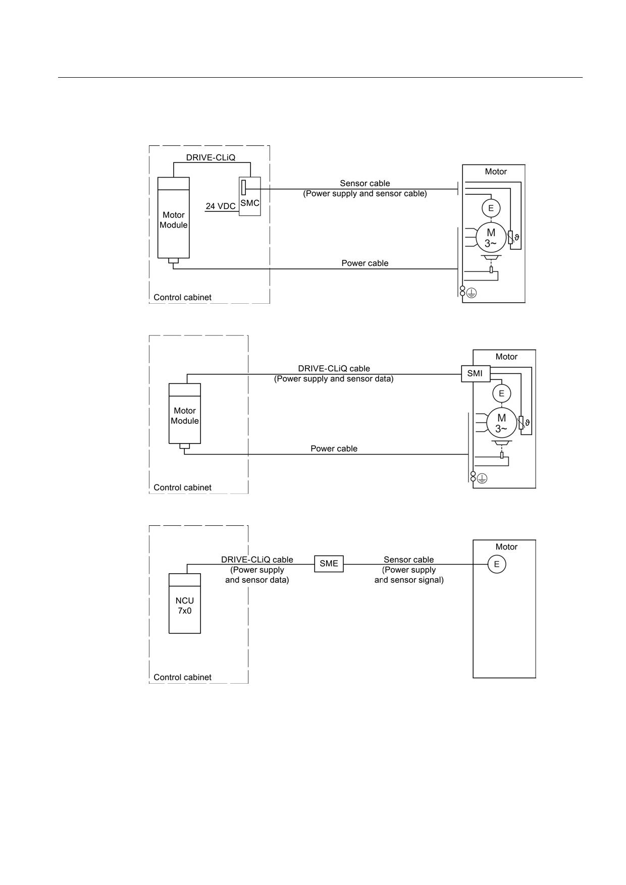
Table 8- 140 DRIVE-CLiQ interface X200-X202: Single Motor Module
DRIVE-CLiQ interface X200-X203: Double Motor Module
Pin
Name
Technical specifications
1
TXP
Transmit data +
2
TXN
Transmit data -
3
RXP
Receive data +
4
Reserved, do not use
5
Reserved, do not use
6
RXN
Receive data -
7
Reserved, do not use
8
Reserved, do not use
A
+ (24 V)
Power supply
B
M (0 V)
Electronics ground
Blanking plate for DRIVE-CLiQ interfaces included in the scope of delivery;
blanking plate (50 pieces) Order number: 6SL3066-4CA00-0AA0
Guidelines for machine configuration
450
System Manual, MA 01/2013, 6FC5397-6CP10-0BA2
Connection of the components in SINAMICS drive system
8.7 Sensor Systems Connection
8.7.4
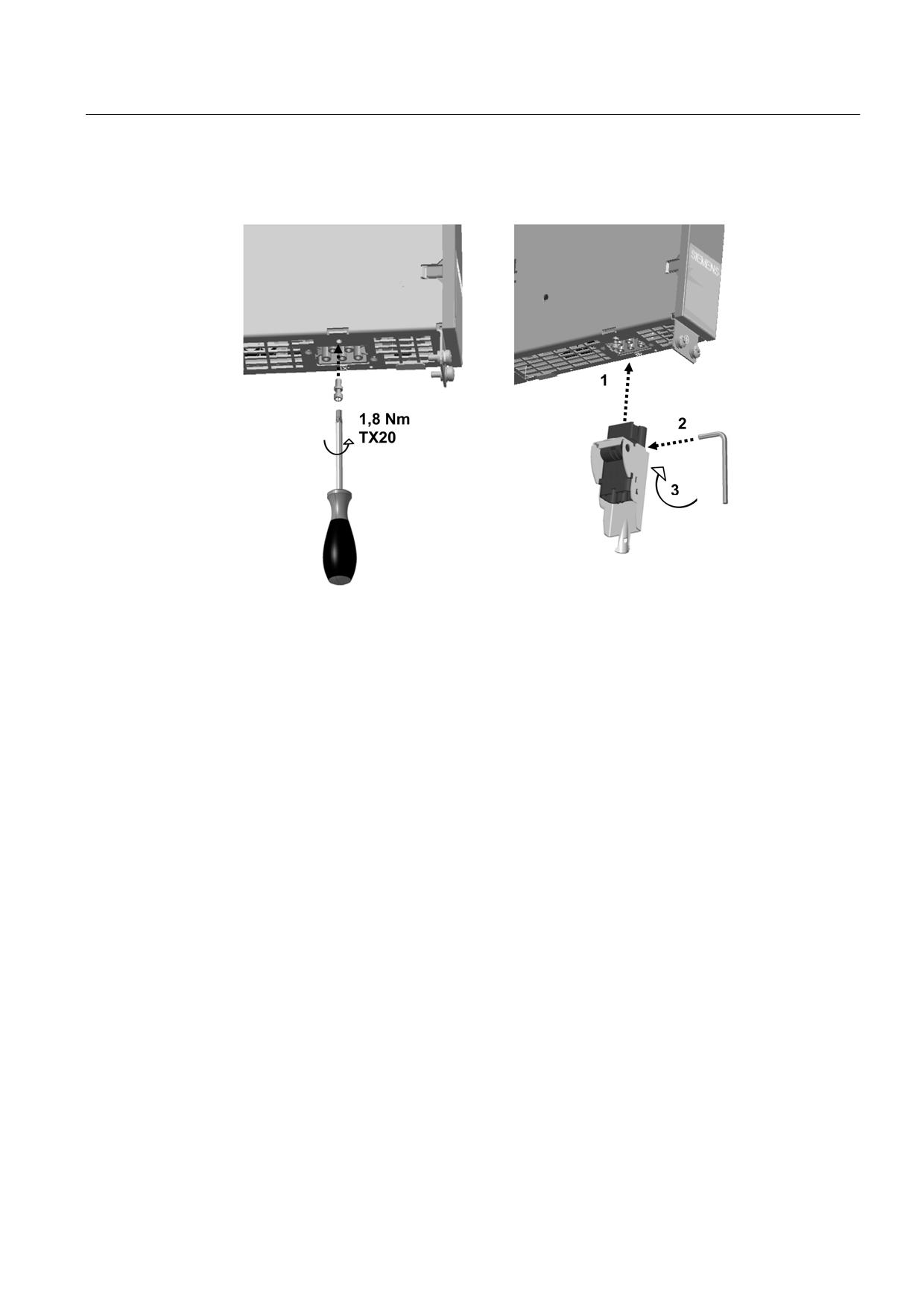
Examples of encoder connections
Figure 8-186 Sensor connection using Sensor Module Cabinet (SMC)
Figure 8-187 Sensor connection via a motor with a DRIVE-CLiQ interface
Figure 8-188 Sensor connection using Sensor Module External (SME)
Guidelines for machine configuration
System Manual, MA 01/2013, 6FC5397-6CP10-0BA2
451
Connection of the components in SINAMICS drive system
8.8 Motor Connection
8.8
Motor Connection
8.8.1
Motor connection plug
8.8.1.1
Introducing the motor connector
Motor Modules 3 A to 30 A are supplied without a motor connector. Prefabricated MOTION-
CONNECT power cables with pre-assembled motor connectors or unassembled power
cables can be used to connect motors. In this case the motor connector must be ordered
separately.
The motor connector is equipped with an interlock mechanism. Mounting on the Motor
Module is described in the following.
8.8.1.2
Installation of the motor connection plug with locking mechanism
Motor connection plugs with locking mechanism are available in two versions:
● Crimp plug for pre-assembled motor cables
● Screw connector for motor cables that need to be assembled
The way in which the motor connection plug is installed depends on the type of Motor
Module used.
Note
With Double Motor Modules, the rear motor connection plug must be installed first and then
locked.
Guidelines for machine configuration
452
System Manual, MA 01/2013, 6FC5397-6CP10-0BA2
Connection of the components in SINAMICS drive system
8.8 Motor Connection
Installation on Motor Modules without pre-assembled interlock bolt
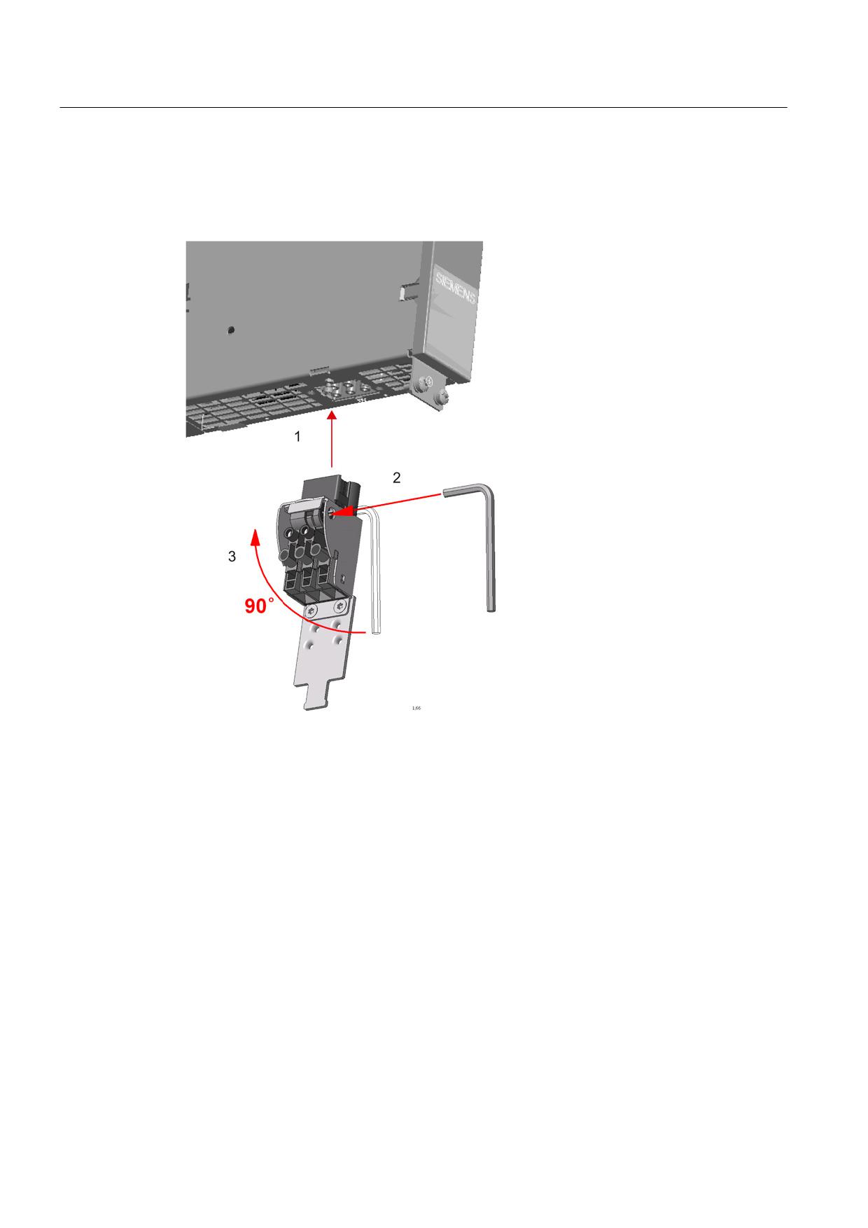
Figure 8-189 Installation example: Crimp plug
1. Screw the interlock bolt into the threaded socket provided in the enclosure.
2. Insert the plug, including the motor cable, and lock it in place by turning a screwdriver or
size 4 hexagon socket-head screw clockwise by a ¼ turn (90°).
Guidelines for machine configuration
System Manual, MA 01/2013, 6FC5397-6CP10-0BA2
453
Connection of the components in SINAMICS drive system
8.8 Motor Connection
Installation on Motor Modules with pre-assembled interlock bolt
If Motor Modules with a pre-assembled interlock bolt are used, step 1 described above can
be omitted.
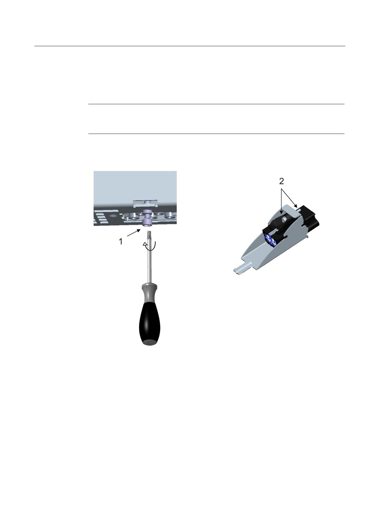
Figure 8-190 Installation example: Screw connector
Simply insert the connector, including the motor cable, and lock it in place by turning a
screwdriver or size 4 hexagon socket-head screw clockwise by a ¼ turn (90°).
Guidelines for machine configuration
454
System Manual, MA 01/2013, 6FC5397-6CP10-0BA2
Connection of the components in SINAMICS drive system
8.8 Motor Connection
8.8.1.3
Installation of the motor connection plug with screwed joint
The way in which the motor connection plug with screwed joint is installed depends on the
type of Motor Module used.
Note
With Double Motor Modules, the rear motor connection plug must be installed first and then
locked.
Installation on Motor Modules with interlock bolt
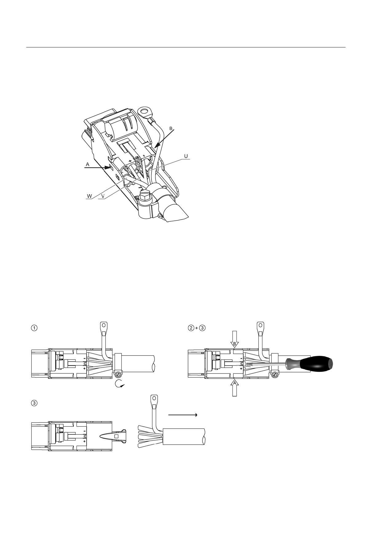
Figure 8-191 Installation of the motor connection plug with screwed joint
1. Use a TX20 screwdriver to remove the interlock bolt from the lower side of the enclosure.
2. Insert the plug, including the motor cable, and screw in with a TX20 screwdriver.
Installation on Motor Modules without interlock bolt
If the motor connection plug with screwed joint is being installed on a Motor Module without a
pre-assembled interlock bolt, step 1 described above can be omitted.
Simply insert the plug, including the motor cable, and screw in with a TX20 screwdriver.
Guidelines for machine configuration
System Manual, MA 01/2013, 6FC5397-6CP10-0BA2
455
Connection of the components in SINAMICS drive system
8.8 Motor Connection
8.8.1.4
Removing the motor connector plug from prefabricated power cables
The motor connection plug of a pre-assembled motor cable might have to be removed if the
cable needs to be routed through narrow cable glands, for example.
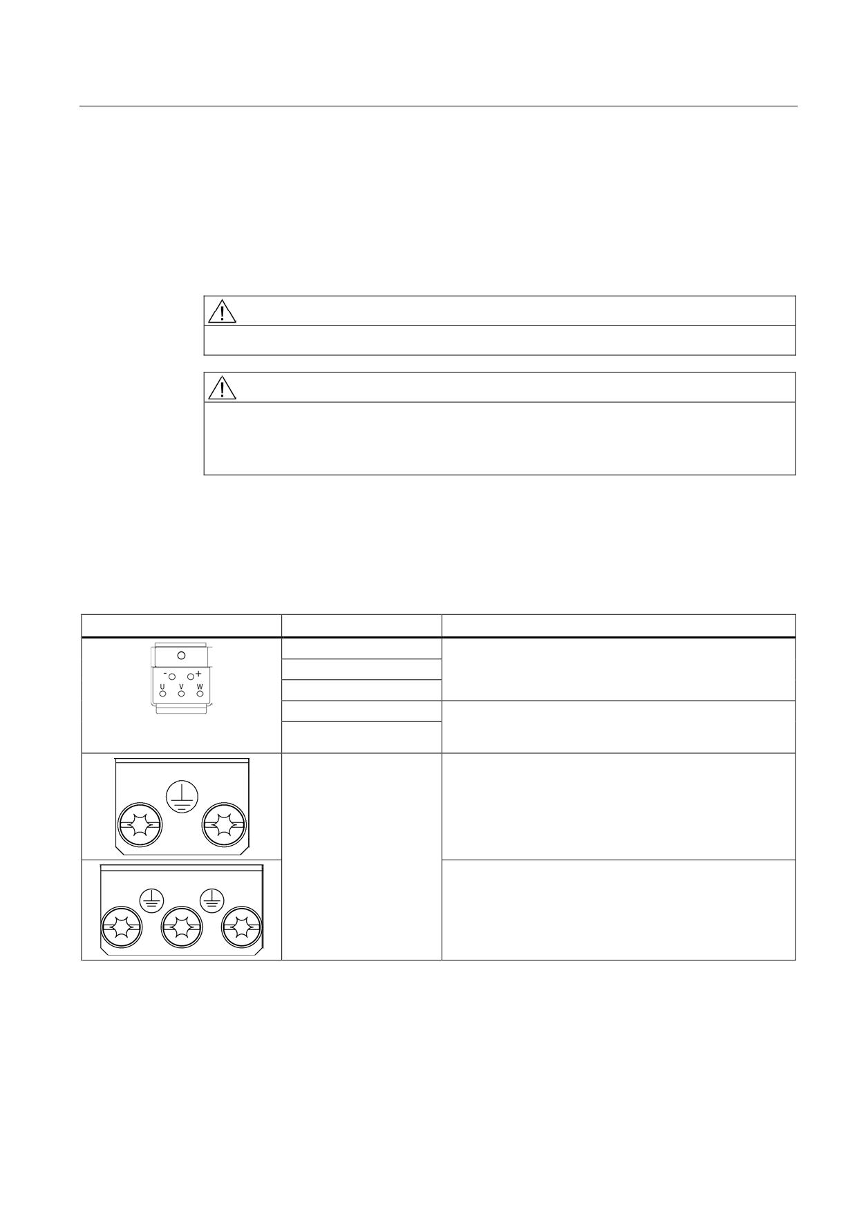
Figure 8-192 Motor connector, crimped version
Removing the motor connection plug
1. First loosen the clamp.
2. Simultaneously press tabs A and B on both sides of the connector using a screwdriver.
3. Keep both tabs pressed and lift the interlocking mechanism in the connector, e.g. using a
screwdriver.
4. Remove the insert and withdraw the motor cable from the connector.
Figure 8-193 Removing the motor connector, crimped version
Guidelines for machine configuration
456
System Manual, MA 01/2013, 6FC5397-6CP10-0BA2
Connection of the components in SINAMICS drive system
8.8 Motor Connection
8.8.2
Brake connection
8.8.2.1
General Notes
The motors are optionally available with integrated holding brake. The holding brake
prevents the axes from making unwanted movements in the switched off state.
WARNING
The use of the motor holding brake as operational brake is not permitted!
WARNING
When holding brakes are used, the user must observe the special technological and
machine-specific regulations and standards to ensure the person and machine protection.
In addition, the residual risks must be evaluated, for example, the effects of hanging axes.
8.8.2.2
Motor and brake connection
Table 8- 141 X1/X2 motor and brake connection for Single Motor Modules 3 A to 30 A and Double Motor Modules 3 A to
18 A
Terminal
Technical data
U (U2)
Motor connection
V (V2)
W (W2)
+ (BR+)
Brake connection
max. load current 2 A
- (BR-)
min. load current 0.1 A
PE connection
Single Motor Modules 3 A to 30 A:
Threaded hole M5/3 Nm1)
Double Motor Modules 3 A to 18 A:
Threaded hole M5/3 Nm1)
1)
For ring cable lugs in accordance with DIN 46234
Guidelines for machine configuration
System Manual, MA 01/2013, 6FC5397-6CP10-0BA2
457
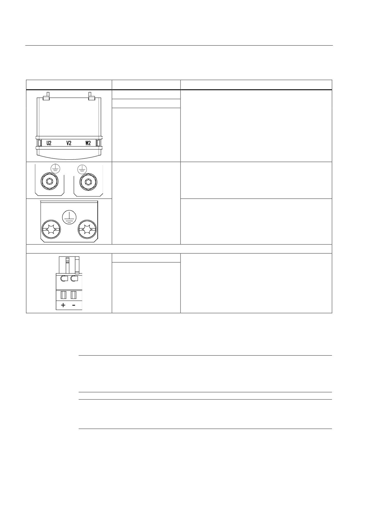
Connection of the components in SINAMICS drive system
8.8 Motor Connection
Table 8- 142 X1 motor connection and X11 brake connection for Single Motor Modules 45 A to 200 A
Terminal
Technical data
U2
45 A to 60 A:
Threaded bolts M6/6 Nm1)
V2
85 A:
W2
Threaded bolts M8/13 Nm1)
132 A to 200 A:
Threaded bolts M8/13 Nm1)
PE connection
45 A to 60 A:
Threaded bolts for motor cables: M6/6 Nm1)
Threaded hole for PE: M6/6 Nm1)
85 A:
Threaded bolts for motor cables: M8/13 Nm1)
Threaded hole for PE: M6/6 Nm1)
132 A to 200 A:
Threaded bolts for motor cables: M8/13 Nm1)
Threaded hole for PE: M8/13 Nm1)
+ (BR+)
X11 brake connector2):
- (BR-)
Voltage 24 VDC
Max. load current 2 A
Min. load current 0.1 A
Max. connectable cross-section 2.5 mm2
Type: Spring-loaded terminal 2 (see Appendix A.2)
The brake connector is part of the prefabricated cable
1)
For ring cable lugs in accordance with DIN 46234
2)
The circuit for protecting the brake against overvoltage is integrated in the Motor Module and does not need to be
installed externally. The max. load current is 2 A, the min. load current 0.1 A.
Note
The total length of the power cables (motor supply cables and DC link cables) must not
exceed the values listed in the chapter titled "Possible line reactor and line filter
combinations".
Note
The motor brake must be connected via connector X11. It is not permitted to directly connect
the cable BR - to the electronics ground M.
Guidelines for machine configuration
458
System Manual, MA 01/2013, 6FC5397-6CP10-0BA2
Connection of the components in SINAMICS drive system
8.8 Motor Connection
WARNING
Only protective extra-low voltages are permitted.
Only protective extra-low voltages (DVC A) that comply with EN 60204-1 may be connected
to all connections and terminals between 0 and 48 VDC.
The voltage tolerances of the motor holding brakes (24 V ±10%) must be taken into
account.
See also
Spring-loaded terminals (Page 515)
Possible combinations of line reactors and line filters (Page 158)
8.8.2.3
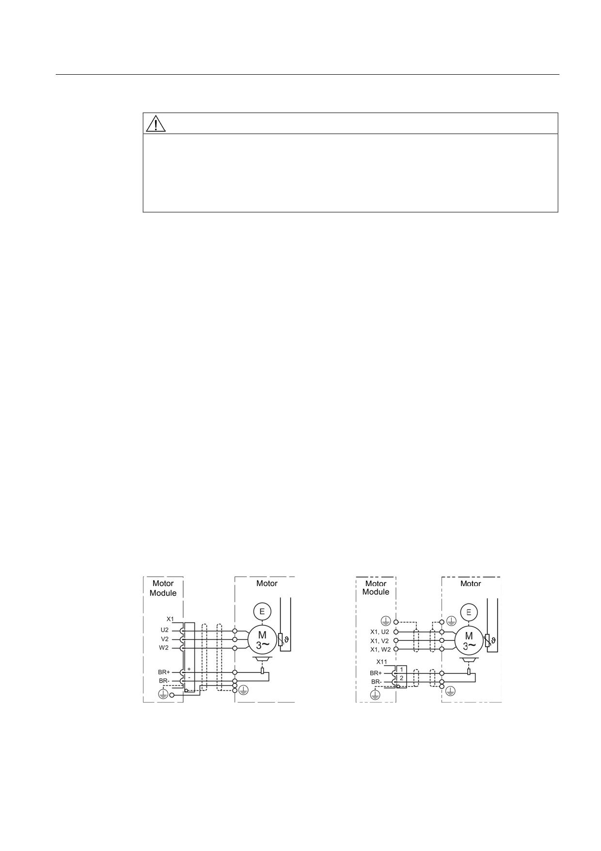
Connection of the Brake Directly on the Motor Module
A brake control is integrated in the Motor Module. The maximum output current is 24 VDC
2 A.
The power supply for the BR+/BR- connection terminals is provided directly from the
integrated 24 VDC power supply busbar.
The connection of the brake supply cable is made at the appropriate terminal blocks
provided on the Motor Module. The brake cables are normally integrated in the
preassembled motor supply cable that is also shielded.
The maximum cable length of the brake supply cable is 50 meters.
● Connection for the device size 3 A to 30 A or 2 x 3 A to 2 x 18 A
The connection is made to the shared -X1 motor connection terminal: BR+/BR- terminal,
max. connectable cross-section 1.5 mm2
● Connection for device size 45 A to 200 A
The connection is made to a separate -X11 brake connection terminal: BR+/BR- terminal,
max. connectable cross-section 1.5 mm2
Motor Module 3 A to 30 A;
Motor Module 45 A to 200 A
2 x 3 A to 2 x 18 A
Guidelines for machine configuration
System Manual, MA 01/2013, 6FC5397-6CP10-0BA2
459
Connection of the components in SINAMICS drive system
8.8 Motor Connection
The brake output is internally equipped with an overvoltage protection circuit. This reduces
high voltage peaks that can occur when the brake is switched off and protects the electronic
outputs. An additional external protective circuit for the brake output is not required. The
brake output is short-circuit resistant. The following monitoring is also performed on the
brake output:
● Current flow only when the brake is switched on; monitors whether a consumer is
attached
● Wire breakage only when the brake is switched on
Note
The above-mentioned monitoring is possible only when the brake is directly attached to
the Motor Module without interface contactor.
8.8.2.4
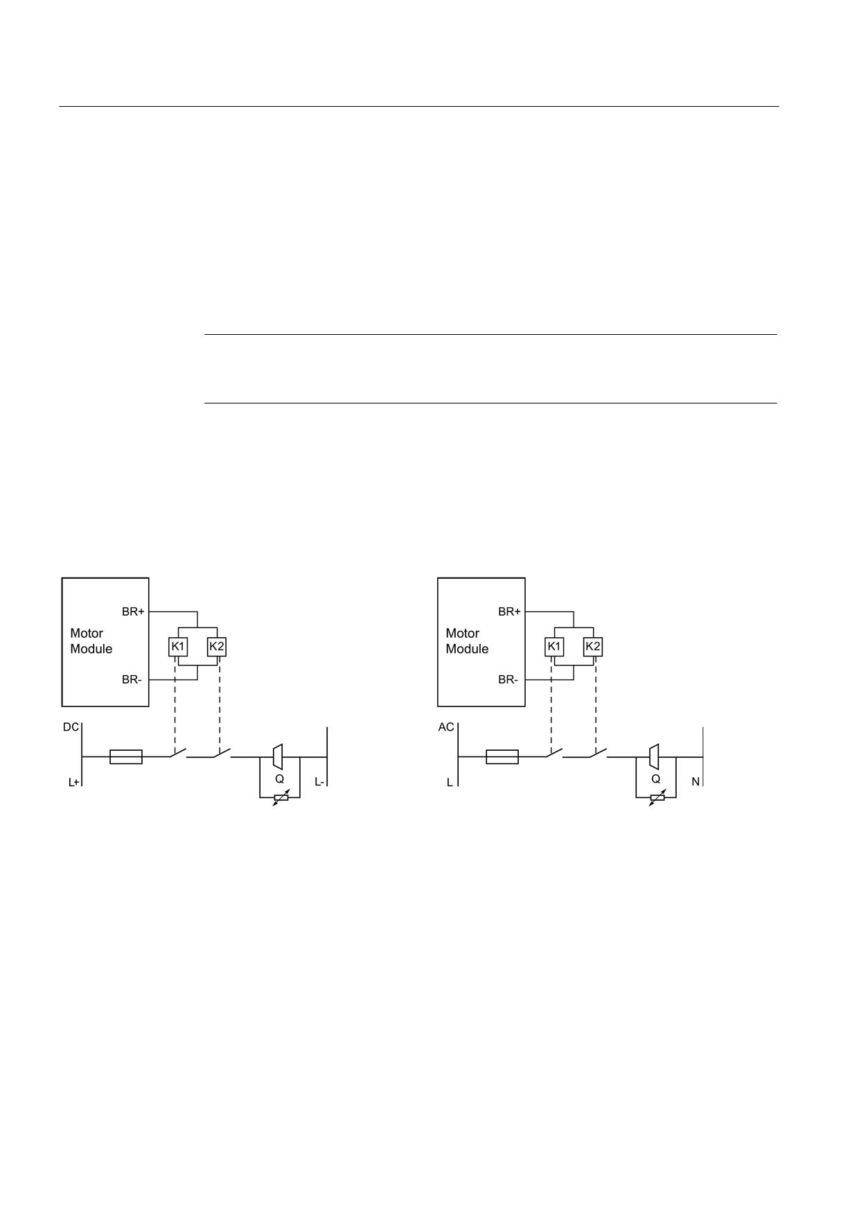
Connection of the Brake using Interface Relay
The motor holding brake can be attached directly to the provided connecting terminal or
indirectly using an interface relay switched between. This may be necessary, for example, if
the brake rated current IBR > 2 ADC or the supply voltage of the brake is 1AC 230 V. It is
important, however, that the rated current of the interface relay is > 100 mA to prevent a fault
message from the brake monitoring.
Figure 8-194 For brake current IBR > 2 ADC with direct current (left) and alternating current (right)
Brake activation via the brake connection on the Motor Module is carried out using a safe,
two-channel method.
A protective circuit for the coupling relay (Kx) is not required because this function exists in
the Motor Module. A protective circuit, however, must be provided for the brake (Q).
For the choice of the protective circuit, ensure that the demagnetization of the brake is
achieved fast. This is performed, for example, with varistors for an AC supply power (also
refer to the motors configuring guide).
Guidelines for machine configuration
460
System Manual, MA 01/2013, 6FC5397-6CP10-0BA2
Connection of the components in SINAMICS drive system
8.8 Motor Connection
Note
To determine whether the relays have switched, it is necessary to evaluate the feedback
from both of them for diagnostics purposes.
8.8.2.5
Brake Control
For the brake control, a differentiation is made between:
● Conventional brake control and
● Safe brake control
The control command to open or close the holding brake is transferred directly to the Motor
Module over the DRIVE-CLiQ from the Control Unit that logically links and monitors the
signals with the system-internal execution sequences. The Motor Module then performs the
action and controls the output for the holding brake appropriately.
Conventional brake control
The exact execution control is described in the SINAMICS S [2701…2704] List Manual. For
example, the p1215, p1219, p1224 and p0855 parameters can be used to configure the
operation of the holding brake.
The control (open/close) of the holding brake is differentiated as follows:
● Opening of the holding brake after pulse enable (e.g. using ON/OFF1)
● Immediate closing of the holding brake after pulse suppression (e.g. using BB/OFF2)
The brake acts immediately after pulse suppression. It is possible that the holding brake
operates against any motion that occurs. In the long term, this will damage the holding
brake. Consequently, the direct pulse suppression and closing of the holding brake
should be avoided.
● Close the holding brake only after braking with pulse suppression (e.g. using
ON/OFF1=1->0)
The holding brake acts when the motor has been brought to a standstill. The pulse
suppression results after a deceleration time.
● Unconditional opening of the holding brake using the execution control command and the
p0855 parameter.
Note
For the selection/deselection of the brake, any pending pulse enable will not be further
influenced. Unconditional opening of the holding brake can, for example, lead to
dangerous motions involving hanging axes. Additional safety measures may need to be
adopted.
Guidelines for machine configuration
System Manual, MA 01/2013, 6FC5397-6CP10-0BA2
461
Connection of the components in SINAMICS drive system
8.8 Motor Connection
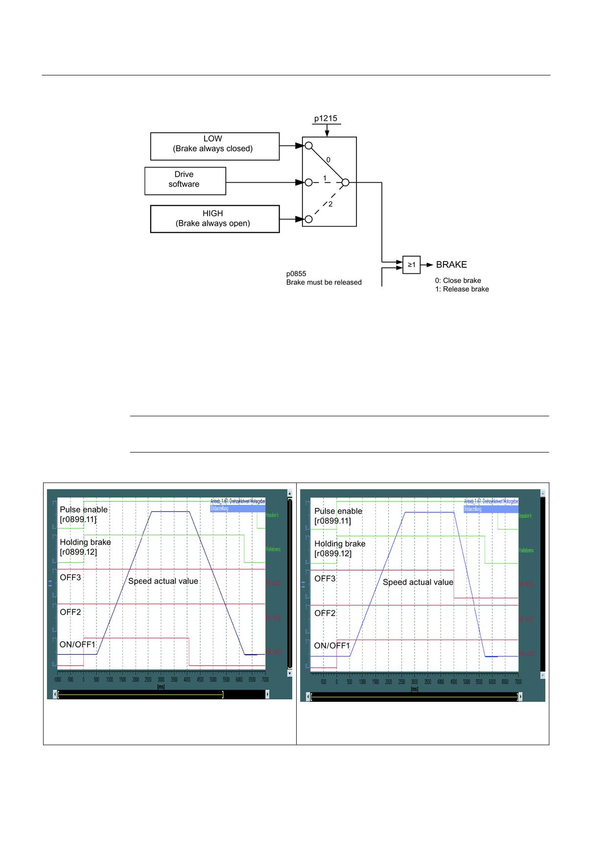
Figure 8-195 Operating modes of the conventional brake control
Timing examples:
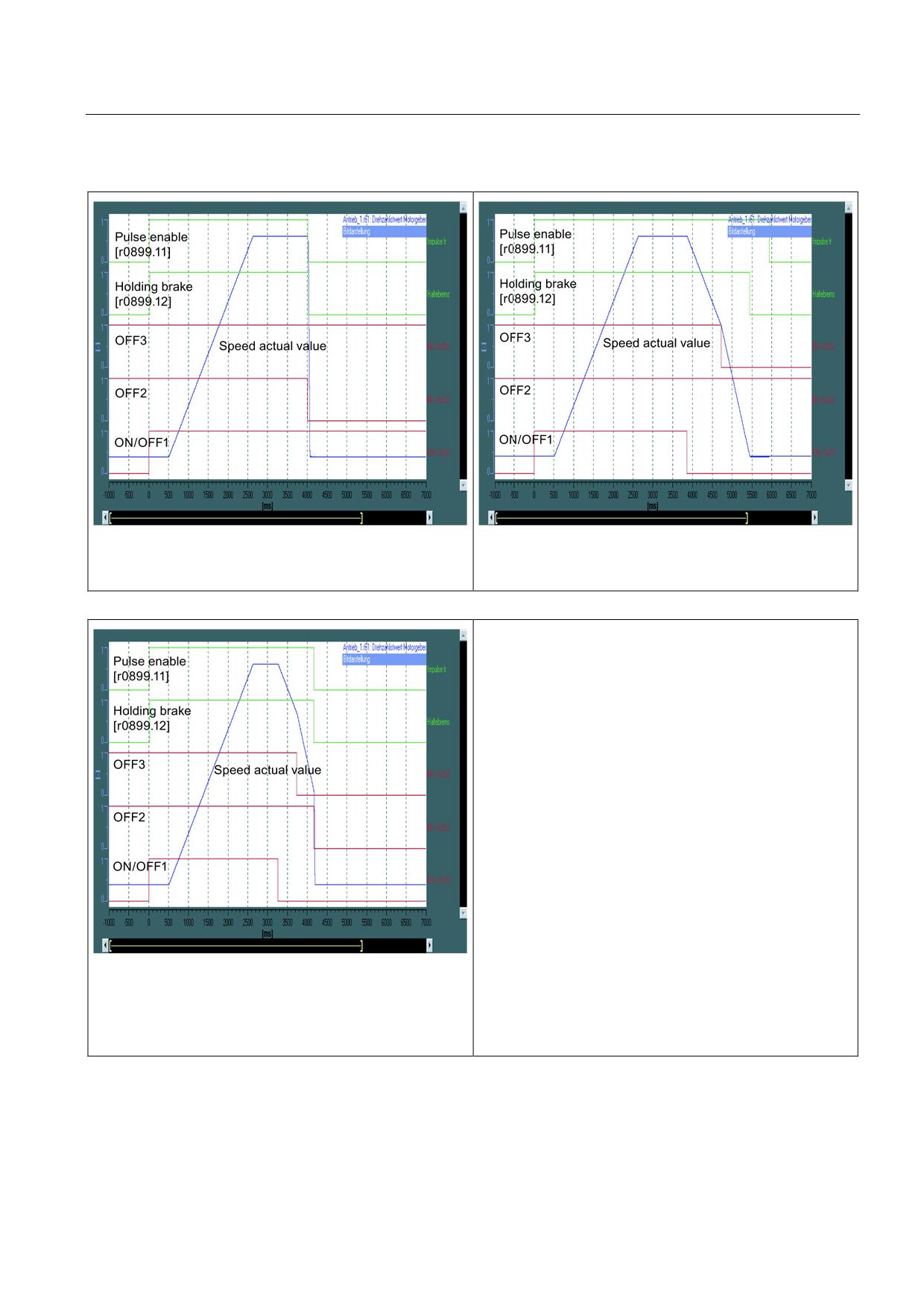
In all cases listed below, the drive starts the motion with an ON command (ON/OFF1). For
clarification, the closing and opening times are set to 500 ms. The acceleration and
deceleration times are 7 s (OFF1) and 4 s (OFF3), respectively. The drive will be accelerated
to a speed of 2000 RPM. Important control and status bits (OFF1/2/3, holding brake status,
pulse enable) are also shown.
Note
In the diagrams below, the motor is only accelerated to a fraction of the rated speed.
Start with ON command;
Start with ON command;
stop with OFF1 command
stop with OFF3 command (rapid stop)
Guidelines for machine configuration
462
System Manual, MA 01/2013, 6FC5397-6CP10-0BA2
Connection of the components in SINAMICS drive system
8.8 Motor Connection
Start with ON command;
Start with ON command; stop with OFF1 command and
stop with OFF2 command (coast down)
during braking; stop with OFF3 Command
Start with ON command;
stop with OFF1 command;
stop with OFF3;
stop with OFF2
The switch-off behavior in a fault situation will be assigned to the associated fault numbers
and largely corresponds to a stop behavior OFF1/2/3.
Guidelines for machine configuration
System Manual, MA 01/2013, 6FC5397-6CP10-0BA2
463
Connection of the components in SINAMICS drive system
8.8 Motor Connection
Safe Brake Control (SBC)
Note
The "Safe brake control" function is activated only in conjunction with the enable of the "Safe
standstill" (SH) function.
"Safe brake control" does not detect any fault in the holding brake itself, such as a short
circuit of the brake winding, worn out brake, etc.
Wire breakage will be monitored only for each activation of the brake, not, however, during
operation.
The control paths must be provided as two channels for the "Safe brake control". This is
performed by means of Control Unit and Motor Module control methods, which are logically
separate. These logically separate units, which communicate via DRIVE-CLiQ, switch and
monitor the brake control independently of one another.
For safety-related functions, it is necessary for the fault detection to perform in a defined
interval a test using forced dynamization. In this case, the switch-off path must be performed
and tested in the two monitoring channels at least once within a defined interval. The "forced
checking procedure" cycle must be controlled externally and mechanically in the appropriate
manner by means, for example, of a brief interruption to the two "Safe standstill" (SH) inputs
on the Control Unit and on the Motor Module.
The dynamization is also performed:
● For each brake control with "open holding brake" and "close holding brake"
● For selection of the "Safe standstill" function
Note
The monitoring and the forced checking procedure of the brake outlet is only possible if
the brake is connected directly to the connection terminals, and not using a coupling
relay! The p9602 and p9802 parameters can be used to specify the control operation.
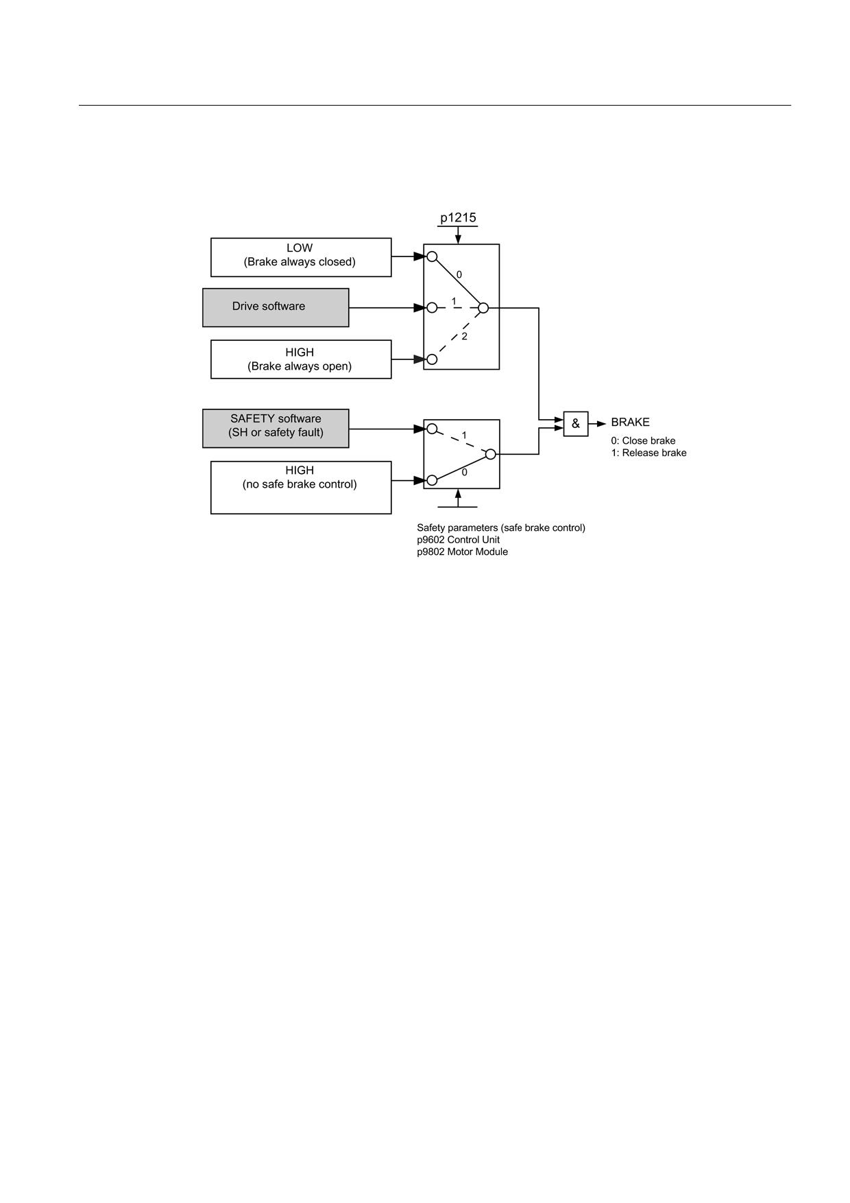
The "Safe brake control" is performed independent of the setting in p1215. A "Safe brake
initiation" always has priority over the conventional brake control.
Guidelines for machine configuration
464
System Manual, MA 01/2013, 6FC5397-6CP10-0BA2
Connection of the components in SINAMICS drive system
8.8 Motor Connection
When the "Safe standstill" function is selected, an internal OFF2 command will be issued
and the holding brake closed immediately.
Figure 8-196 Operating modes of the safe brake control
Guidelines for machine configuration
System Manual, MA 01/2013, 6FC5397-6CP10-0BA2
465
Connection of the components in SINAMICS drive system
8.8 Motor Connection
8.8.3
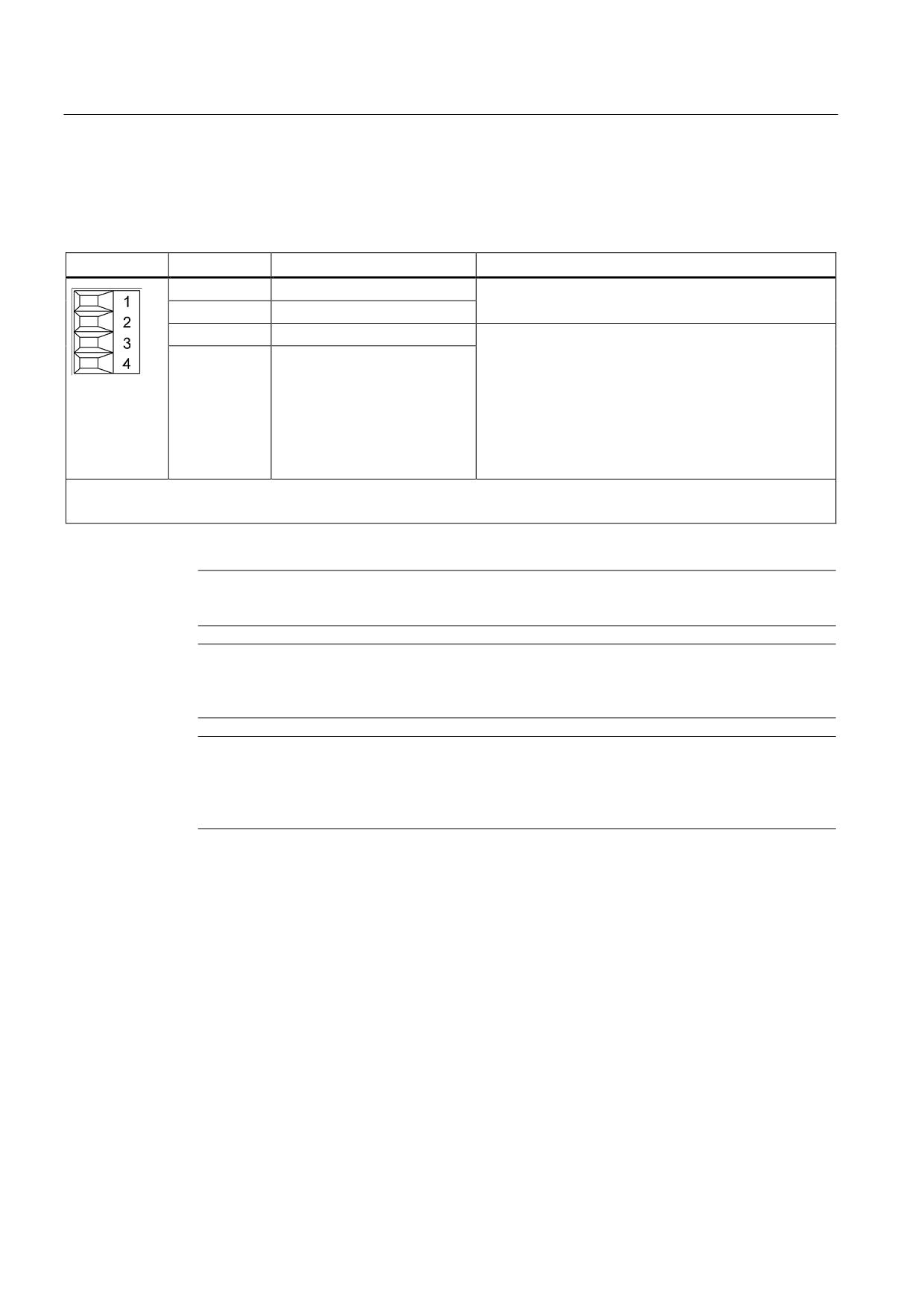
X21/X22 EP terminals / temperature sensor Motor Module
Table 8- 143 Terminal strip X21/X22
Terminal
Function
Technical specifications
1
+ Temp
Temperature sensors: KTY 84-1C130/PTC/bimetallic
switch with NC contact
2
- Temp
3
EP +24 V (Enable Pulses)
Supply voltage: 24 V DC (20.4 V - 28.8 V)
Current consumption: 10 mA
4
EP M1 (Enable Pulses)
Isolated input
Signal propagation times:
L → H: 100 μs
H → L: 1000 μs
The pulse inhibit function is only available when Safety
Integrated Basic Functions are enabled.
Max. connectable cross-section 1.5 mm2
Type: Screw terminal 1 (see chapter Connection methods)
Note
The KTY temperature sensor must be connected with the correct polarity.
Note
The function of the EP terminals is only available when Safety Integrated Basic Functions
are enabled.
Note
The temperature sensor input is not needed if the motors feature an integrated DRIVE-CLiQ
interface or if temperature values are detected by means of a different module (SMC, SME,
TM).
Guidelines for machine configuration
466
System Manual, MA 01/2013, 6FC5397-6CP10-0BA2
Connection of the components in SINAMICS drive system
8.9 Voltage Protection Module (VPM), external
8.9
Voltage Protection Module (VPM), external
General information
The external Voltage Protection Module (VPM) is used for the 1FE1 and 2SP1 motors and
for motors with an electromagnetic force (EMF) of 800 V to 2,000 V to limit the DC link
voltage at the converter in a fault situation.
If the line voltage fails when the motor is running at maximum speed, or as consequence the
pulses at the converter are cleared, the motor returns high-voltage energy to the DC link.
The Voltage Protection Module detects an excessive DC link voltage (> 800 V) and short-
circuits the three motor supply cables. The energy stored in the motor is converted into heat
by the short circuit between the motor supply cables.
Integration
● The installation must be performed in accordance with the VPM 120 or VPM 200
connection diagram.
● Above and below the device, clearance spaces of approx. 200 mm must be provided for
the cable routing.
● Any installation position is possible.
● No switching elements may be added to the U, V, W connection cables between the
drive, VPM and motor!
● The air intake temperature measured 10 mm below the device must not exceed 55 °C.
CAUTION
In the event of non-compliance and if the limit values specified in the "technical data"
are exceeded (see VPM operating instructions), there is a danger of device overloading,
irreparable damage to the device, and impairment of electrical safety.
Note
The device must be equipped with a safety switching unit and may be used only for its
proper purpose. Other applications, e.g. armature short circuits in operation, are not
permissible.
The warning notices attached to the device must be observed.
Operation with VPM is possible only in conjunction with SINAMICS, SIMODRIVE 611 digital,
SIMODRIVE 611 universal HR/HRS, and 1FE1/2SP1 motors. When the external VPM is
used, shielded 6FX8 motor supply cables are required.
Guidelines for machine configuration
System Manual, MA 01/2013, 6FC5397-6CP10-0BA2
467
Connection of the components in SINAMICS drive system
8.9 Voltage Protection Module (VPM), external
Note
Depending on the size of the type used, the conditions associated with the relevant VPM
operating instructions must be observed.
VPM 120, order No.: A5E00302281B
VPM 120 PG, order No.: A5E01017613A
VPM 200, order No.: A5E00302261B
VPM 200 PG, order No.: A5E01018358A
VPM 200 DYN, order No.: A5E00777655A
WARNING
Under fault conditions, voltages up to 2 kV can occur at cables that are cut or damaged.
Depending on the speed of the motors, the motor terminal voltage of the 1FE1 motors can
attain values as high as 2 kV.
Guidelines for machine configuration
468
System Manual, MA 01/2013, 6FC5397-6CP10-0BA2
Connection of the components in SINAMICS drive system
8.9 Voltage Protection Module (VPM), external
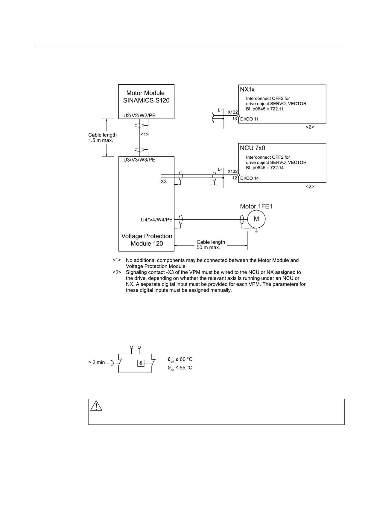
Connection example for VPM 120
Figure 8-197 Connection of Voltage Protection Module VPM 120
Signaling contact X3
The X3 signaling contact closes after t > 2 min or after resetting the temperature switch.
Figure 8-198 Signaling contact X3 of the Voltage Protection Module
WARNING
Measures must be adopted to prevent the drive from starting automatically.
Guidelines for machine configuration
System Manual, MA 01/2013, 6FC5397-6CP10-0BA2
469
Connection of the components in SINAMICS drive system
8.9 Voltage Protection Module (VPM), external
If the external VPM is being used, the following parameter needs to be set on the NCU or
NX:
p0643[0...n]
● Description:
Setting overvoltage protection for synchronous motors in field weakening mode
● Value:
0: No action
1: Voltage Protection Module (VPM)
Additional references
For more detailed information on the external Voltage Protection Module, please refer to the
following:
/GH2/SINAMICS S120/, Booksize Power Units, Motor Side Power Components, VPM/
Guidelines for machine configuration
470
System Manual, MA 01/2013, 6FC5397-6CP10-0BA2
Connection of the components in SINAMICS drive system
8.10 Cables
8.10
Cables
8.10.1
General information
NOTICE
Damage to components due to deficient cable shielding or excessively long cables
If the shielding procedures described and the specified cable lengths are not observed, this
may result in damage to the components or the machine failing to operate correctly.
• Observe the shielding and maximum cable length specifications outlined below.
8.10.2
Cable shielding and routing
In order to comply with the EMC requirements, certain cables must be routed apart from
other cables and from certain components. To full EMC requirements, the following cables
must be used with shields:
● Line supply conductors from line filter via line reactor to Line Module
● All motor cables (if necessary, including cables for motor holding brake)
● Cables for "fast inputs" of the Control Unit
● Cables for analog direct voltage/current signals
● Signal cables for sensors
● Cables for temperature sensors
DANGER
A suitable PE conductor must be connected to all devices in protection class I.
The protective conductor connection of the individual components must be at least 4
mm².
Alternative measures (e.g. routing behind mounting plates, suitable clearances) can also be
used provided they have similar results. This excludes measures that relate to the design,
installation, and routing of motor power cables and signal cables. If unshielded cables are
used between the line supply connection point and line filter, make sure that no interfering
cables are routed in parallel.
The cable shields must be connected as close to the conductor terminal connections as
possible to ensure a low-impedance connection with cabinet ground. For Siemens power
cables in which the shield is connected to the connector shell (see relevant catalog), this is a
sufficiently good shield support.
Guidelines for machine configuration
System Manual, MA 01/2013, 6FC5397-6CP10-0BA2
471
Connection of the components in SINAMICS drive system
8.10 Cables
With components that do not have any special shield connection or where the shield
connection is not sufficient, the cable shields can be connected to the metal mounting plate
using hose clamps and toothed rails. The cable length between the shield contact point and
the terminals for cable conductors must be kept as short as possible.
Shield contact plates with pre-prepared clip contacts are available for contacting the shields
for power cables of Line Modules and Motor Modules. Up to a module width of 100 mm,
these plates are part of the scope of delivery of the components, or they are integrated in the
connector.
All cables inside the cabinet must be routed as closely as possible to parts connected with
cabinet ground, such as a mounting plate or cabinet wall. Ducts made of sheet steel or
cables routed between steel sheets (e.g. between the mounting plate and back wall) should
provide adequate shielding.
Avoid, where possible, routing unshielded cables, connected to the drive line-up, in the
immediate vicinity of noise sources, e.g. transformers. Signal cables (shielded and
unshielded) connected to the drive line-up must be laid at a great distance from strong
external magnetic sources (e.g. transformers, line reactors). In both cases, a distance of ≥
300 mm is usually sufficient.
DANGER
The drive components generate high leakage currents in the protective conductor. The
components must only be operated in cabinets or in closed electrical operating areas and
must be connected with the protective conductor. To protect against electric shock, the
protective conductor connection at the control cabinet or machine must be implemented in
accordance with one of the following measures:
• Fixed connection and protective conductor connection by means of ≥ 10 mm2 Cu or ≥
16 mm2 Al
• Fixed connection and automatic disconnection of the supply system if the protective
conductor is interrupted
Guidelines for machine configuration
472
System Manual, MA 01/2013, 6FC5397-6CP10-0BA2
Connection of the components in SINAMICS drive system
8.10 Cables
8.10.3
Equipotential Bonding
The SINAMICS S120 Booksize drive system is designed for use in control cabinets with
protective conductor terminal.
If the drive line-up is arranged on a common unpainted metal-surfaced mounting plate, e.g.
with a galvanized surface, no additional equipotential bonding is needed within the drive line-
up as
● All parts of the switchgear assembly are connected to the protective conductor system.
● The mounting plate is connected with the external PE conductor by means of a finely-
stranded copper conductor with a cross-section of 16 mm², including the outer conductor.
From a cross-section of 25 mm² copper, the outer cross-section of the finely-stranded
conductor is halved.
For other installation methods, equipotential bonding must be implemented using conductor
cross-sections as stated in the second item in the list or at least equal to the conductance.
If components are mounted on DIN rails, the data listed in the second item applies for
equipotential bonding. If only smaller connection cross-sections are permitted on the
components, use the largest possible, e.g. 6 mm2 for SMC. These requirements also apply
to distributed components located outside the cabinet.
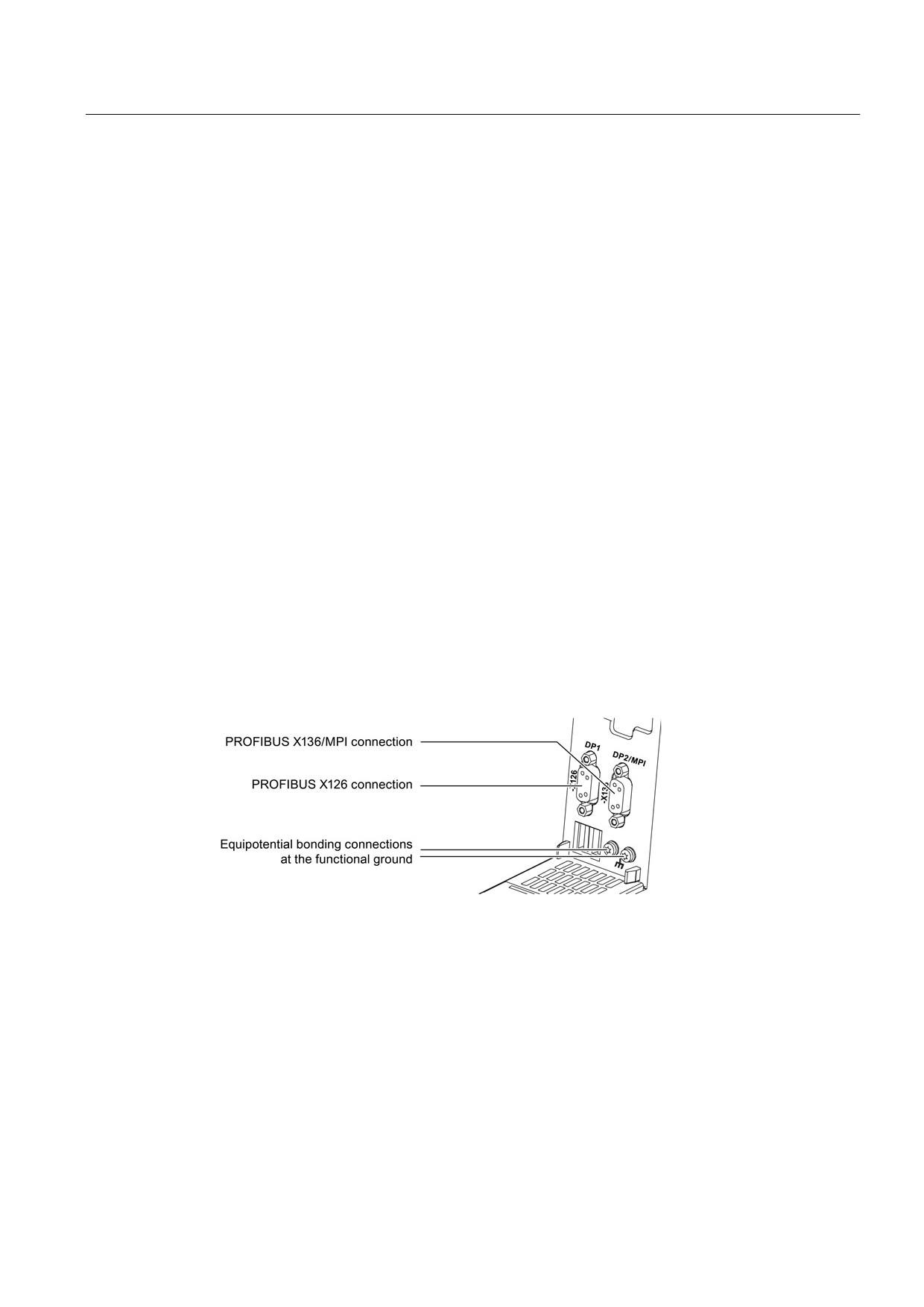
For a PROFIBUS connection between two control cabinets, a fine-wire potential equalizing
conductor with a cross-section of 4 mm2 should be used. This conductor must be laid
together with the PROFIBUS connection cable and connected to the NCU 7x0 using a cable
lug.
Equipotential bonding and shielding for PROFIBUS
The cable shield must be connected over a large contact surface area.
Figure 8-199 PROFIBUS and function ground connections
8.10.4
Protective Ground Connection
The bodies of electrical resources which because of their fastening cannot be included in the
protective measure must be connected with the protective conductor circuit of the switching
device combination (control cabinet) in order to establish the protection connection.
All protective conductors must be selected to conform with EN 60204-1 or EN 60439-1 and
connected in accordance with the specifications of the associated device manuals.
Guidelines for machine configuration
System Manual, MA 01/2013, 6FC5397-6CP10-0BA2
473

Connection of the components in SINAMICS drive system
8.10 Cables
8.10.5
Maximum cable lengths
The table below provides an overview of the maximum permissible cable lengths for signal
and supply cables, power cables, and DC link cables.
Table 8- 144 Maximum cable lengths
Type
Maximum length [m]
24 VDC supply cables 1)
10
24 V signal cables 1)
30
DRIVE-CLiQ signal cables MC500 (RJ45)
100
DRIVE-CLiQ signal cables MC500 (M12)
30
DRIVE-CLiQ signal cables MC800PLUS (RJ45)
75
DRIVE-CLiQ signal cables MC800PLUS (M12)
30
DC link, including extensions
10
Total cable length for Active Line Modules 16 kW and 36 kW with Active Interface
630 (shielded) 3)
Module 4)
Total cable length for Active Line Modules 55 kW up to 120 kW with Active Interface
1000 (shielded) 3)
Module 4)
Total cable length for Active Line Modules with line reactor 4)
350 (shielded) 3)
Total cable length for Basic Line Modules 4)
630 (shielded) 3)
Total cable length for Smart Line Modules 4)
350 (shielded) 3)
Power cable between line filter and line reactor
10 (shielded/unshielded) 2)
Power cable between line reactor and Line Module
10 (shielded/unshielded) 2)
Power cable between Active Interface Module and Active Line Module
10 (shielded/unshielded) 2)
Power cable between Active Interface Module and Basic Line Filter
10 (shielded/unshielded) 2)
Power cable between
50 (shielded)
motor and Motor Module up to In = 9 A
75 (unshielded)
Power cable between
70 (shielded)
motor and Motor Module In = 18 A
100 (unshielded)
Power cable between
100 (shielded)
motor and Motor Module In ≥ 30 A
150 (unshielded)
Power cable between Braking Module and braking resistor
10
1)
For longer lengths, suitable wiring must be connected by the user to provide overvoltage
protection.
2)
To comply with EMC limit values, shielded cables (preferably MOTION CONNECT
cables) must be used.
3)
Restrictions regarding the total cable length and the secondary conditions required to
comply with the corresponding radio interference suppression category are listed in the
chapter titled "Possible line reactor and line filter combinations" (Page 158).
4)
The total lengths specified for power cables in the drive line-up include motor cables, DC
link cable(s), and the line supply conductor from the line filter output on.
Guidelines for machine configuration
474
System Manual, MA 01/2013, 6FC5397-6CP10-0BA2
Connection of the components in SINAMICS drive system
8.11 DRIVE-CLiQ cabinet bushings
8.11
DRIVE-CLiQ cabinet bushings
8.11.1
Description
A DRIVE-CLiQ cabinet bushing is used to connect the DRIVE-CLiQ cables between the
inside and outside of the control cabinet. It is used in a control cabinet panel. The data lines
and the voltage supply contacts of the DRIVE-CLiQ are also routed through the bushing. The
DRIVE-CLiQ cabinet bushing for DRIVE-CLiQ cables is available with RJ45 connector and
M12 plug/socket.
DRIVE-CLiQ cabinet bushing for RJ45 connectors
The cabinet bushing has degree of protection IP54 according to EN 60529 from the outside
towards the inside. Inside the control cabinet, a connection is established according to
degree of protection IP20 or IPXXB acc. to EN 60529. So that the complete outside of the
cabinet bushing, including the DRIVE-CLiQ interface, has degree of protection IP54, a
DRIVE-CLiQ cable must be used, which as a minimum must also have degree of protection
IP54.
DRIVE-CLiQ cabinet bushing for M12 plug/socket
The cabinet bushing has degree of protection IP67 according to EN 60529 from the outside
towards the inside. Inside the cabinet a connection according to degree of protection IP67 in
compliance with EN 60529 is realized.
Guidelines for machine configuration
System Manual, MA 01/2013, 6FC5397-6CP10-0BA2
475
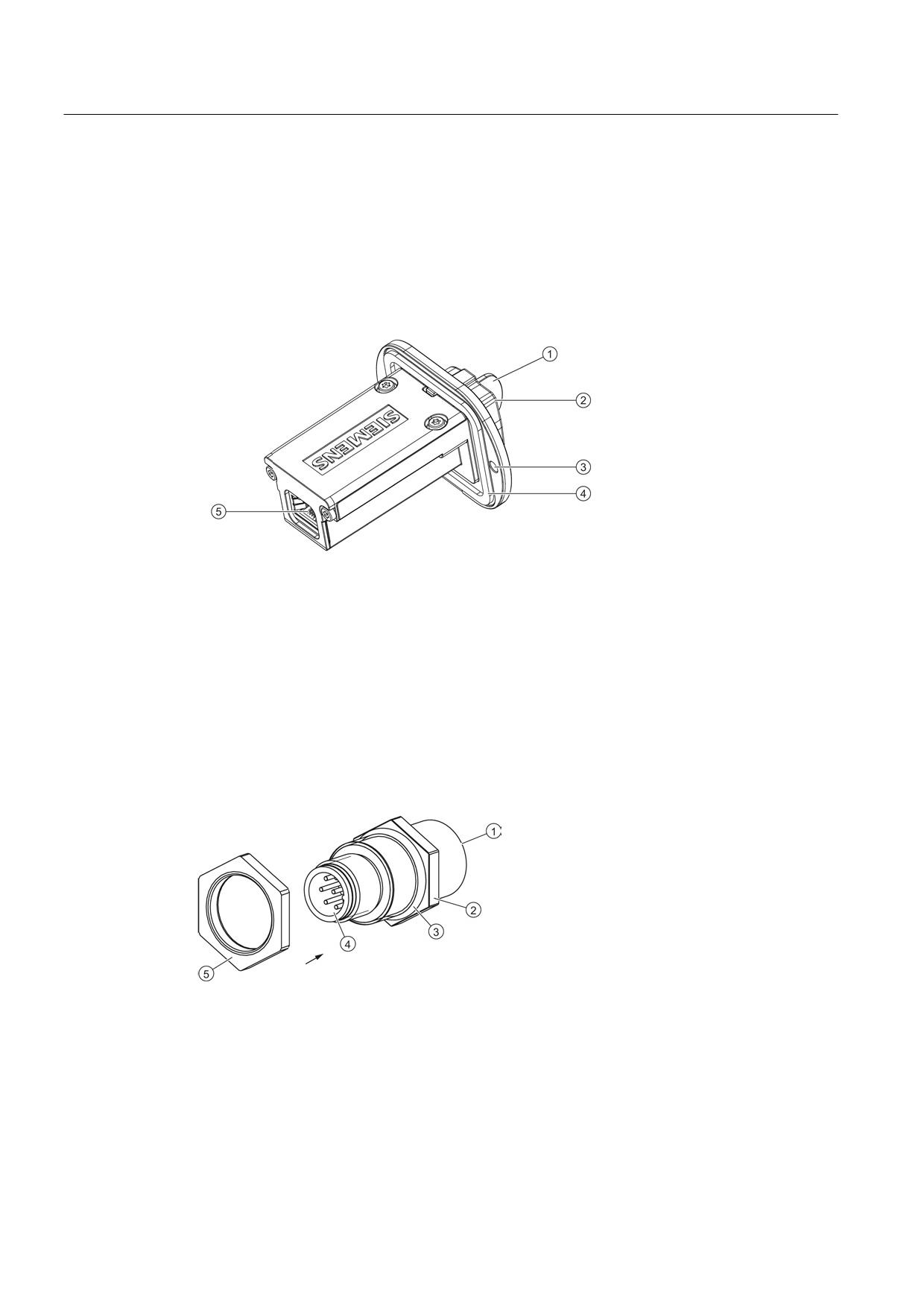
Connection of the components in SINAMICS drive system
8.11 DRIVE-CLiQ cabinet bushings
8.11.2
Interface description
8.11.2.1
Overview
DRIVE-CLiQ cabinet bushing for DRIVE-CLiQ cables with RJ45 plug
① Protective cap, Yamaichi, order number: Y-ConAS-24-S
② DRIVE-CLiQ interface RJ45 on the outside (to connect DRIVE-CLiQ signal cables MOTION-
CONNECT with IP67 degree of protection)
③ Mounting holes
④ Flange-type seal to ensure degree of protection IP54 on the outside of the control cabinet
⑤ DRIVE-CLiQ interface RJ45 on the inside (to connect DRIVE-CLiQ signal cables MOTION-
CONNECT with IP20 degree of protection)
Figure 8-200 Interface overview, DRIVE-CLiQ cabinet bushing RJ45
DRIVE-CLiQ cabinet bushing for DRIVE-CLiQ cables with M12 plug/socket
① DRIVE-CLiQ interface with M12 socket (8-pin)
② Flange, SW18
③ Seal
④ DRIVE-CLiQ interface with M12 plug (8-pin)
⑤ O ring, SW20, tightening torque: 3 - 4 Nm
Figure 8-201 Interface overview, DRIVE-CLiQ cabinet bushing M12
Guidelines for machine configuration
476
System Manual, MA 01/2013, 6FC5397-6CP10-0BA2
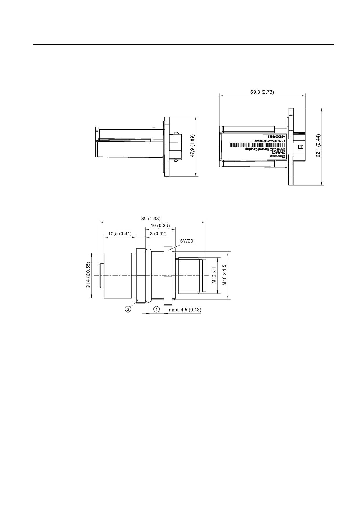
Connection of the components in SINAMICS drive system
8.11 DRIVE-CLiQ cabinet bushings
8.11.3
Dimension drawings
Figure 8-202 Dimension drawing of the DRIVE-CLiQ cabinet bushing RJ45, all dimensions in mm and
(inches)
①
Cabinet panel
②
Flange, SW18
Figure 8-203 Dimension drawing of the DRIVE-CLiQ cabinet bushing M12, all dimensions in mm and
(inches)
Guidelines for machine configuration
System Manual, MA 01/2013, 6FC5397-6CP10-0BA2
477
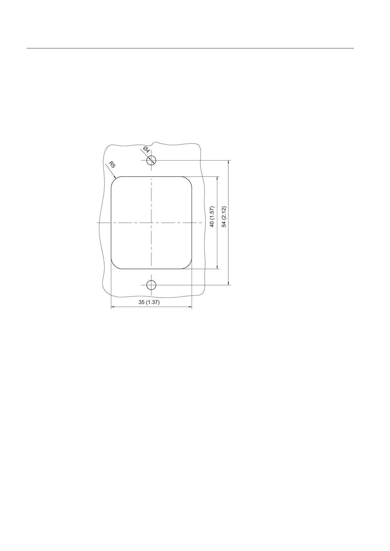
Connection of the components in SINAMICS drive system
8.11 DRIVE-CLiQ cabinet bushings
8.11.4
Installation
8.11.4.1
DRIVE-CLiQ cabinet bushing for cables with RJ45 connectors
In order to install the DRIVE-CLiQ cabinet bushing RJ45, you must make a cutout in the
control cabinet panel as shown in the diagram below.
Figure 8-204 Cut-out for the cabinet
Guidelines for machine configuration
478
System Manual, MA 01/2013, 6FC5397-6CP10-0BA2
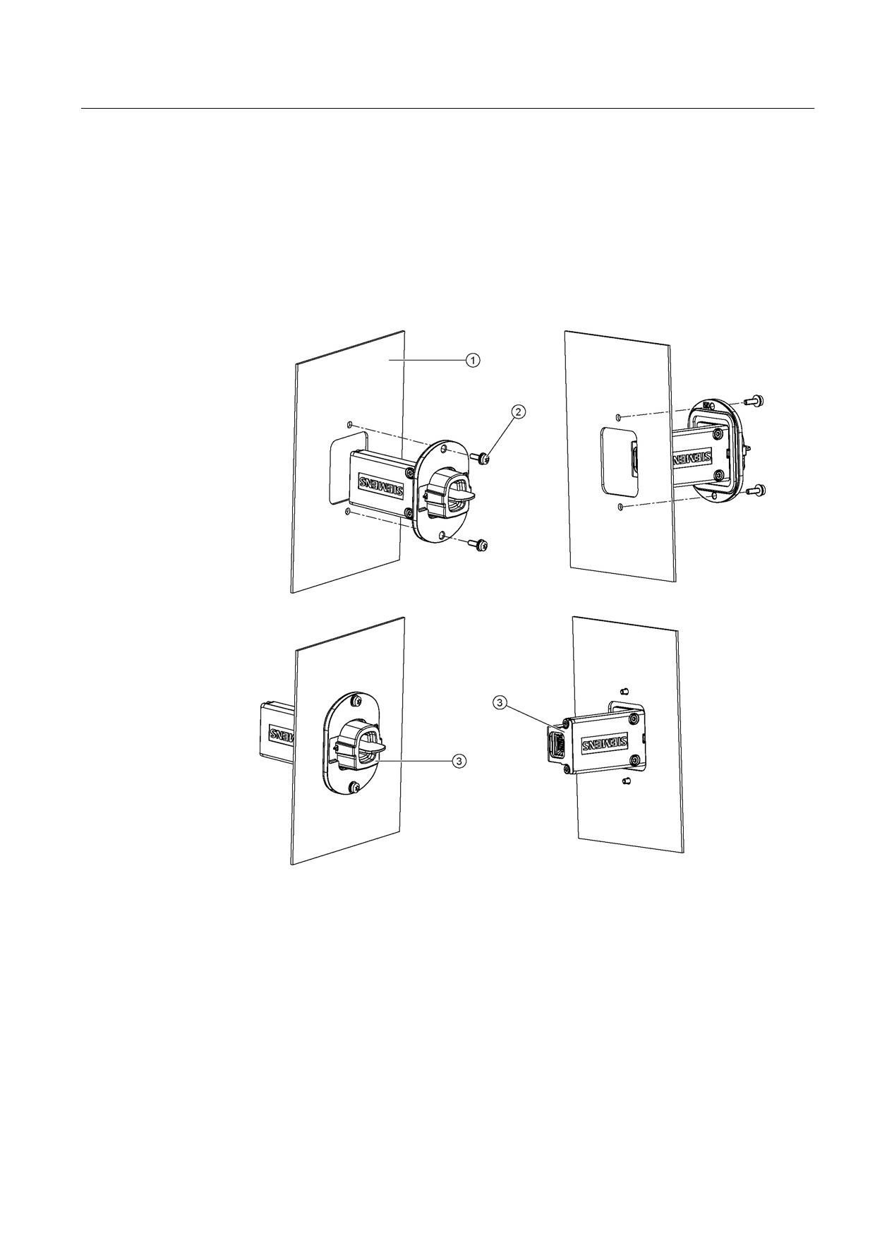
Connection of the components in SINAMICS drive system
8.11 DRIVE-CLiQ cabinet bushings
Installation
1. Insert the DRIVE CLiQ cabinet bushing from the outside of the control cabinet through the
opening in the control cabinet.
2. Fix the DRIVE-CLiQ cabinet gland to the outer control cabinet panel using two M3 screws
and two nuts. In order to ensure good electromagnetic compatibility, a good electrical
connection must be established between the DRIVE-CLiQ cabinet gland and the cabinet
panel over a large surface area.
①
Control cabinet panel
②
M3 screw, tightening torque 0.8 Nm
③
DRIVE-CLiQ cabinet bushing RJ45
Figure 8-205 Mounting DRIVE-CLiQ cabinet bushings for cables with RJ45 connectors
Guidelines for machine configuration
System Manual, MA 01/2013, 6FC5397-6CP10-0BA2
479
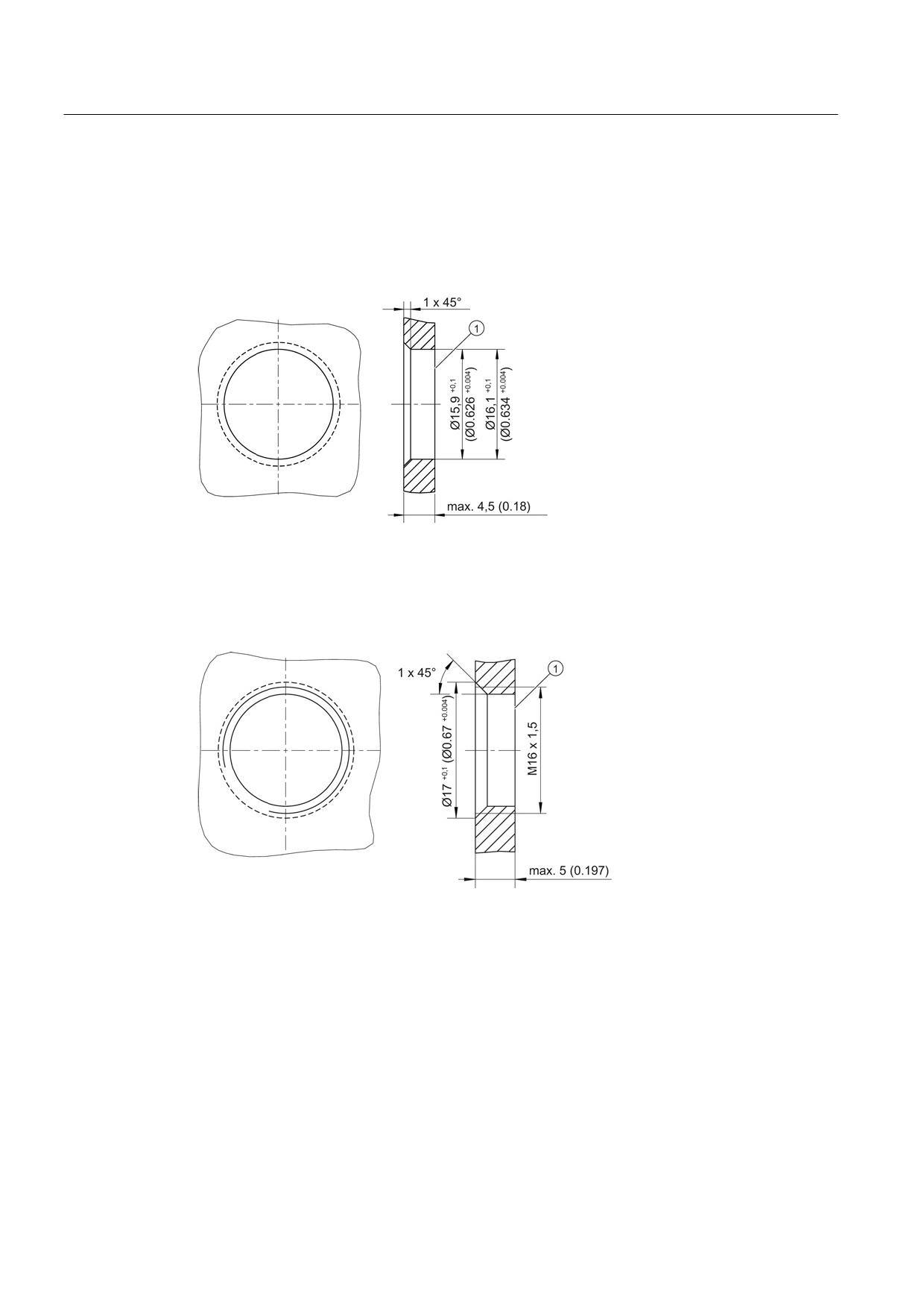
Connection of the components in SINAMICS drive system
8.11 DRIVE-CLiQ cabinet bushings
8.11.4.2
DRIVE-CLiQ cabinet bushing for cables with M12 plug/socket
Prepare the cabinet panel for mounting the DRIVE-CLiQ cabinet bushing M12 as shown
below. The removable O ring can be screwed from the inside or the outside.
Mounting from the inside using an O ring that can be screwed
①
Through-hole with chamfer
Figure 8-206 Through-hole for mounting the DRIVE-CLiQ cabinet bushing M12 with an O-ring that can
be screwed from the inside
Mounting from the outside using an O ring that can be screwed
①
Threaded hole with chamfer
Figure 8-207 Threaded hole for mounting the DRIVE-CLiQ cabinet bushing M12 with an O-ring that
can be screwed from the outside
Guidelines for machine configuration
480
System Manual, MA 01/2013, 6FC5397-6CP10-0BA2
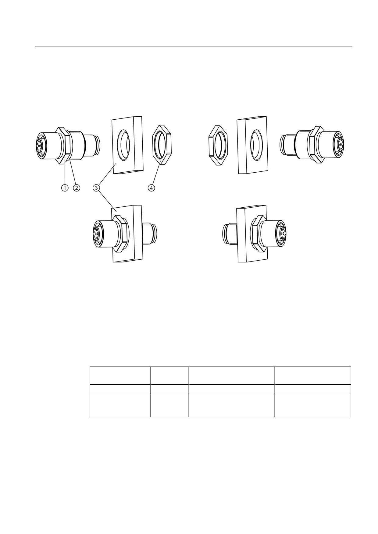
Connection of the components in SINAMICS drive system
8.11 DRIVE-CLiQ cabinet bushings
Installation
1. Insert the DRIVE-CLiQ cabinet bushing through the opening in the cabinet.
2. Fasten the DRIVE-CLiQ cabinet bushing using the associated O ring with a tightening
torque of 3 - 4 Nm
①
Flange, SW18
②
Seal
③
Cabinet panel
④
O ring, SW20, tightening torque: 3 - 4 Nm
Figure 8-208 Mounting DRIVE-CLiQ cabinet bushings for cables with M12 connectors
8.11.5
Technical data
Table 8- 145 Technical data of DRIVE-CLiQ cabinet bushings
Unit
6SL3066-2DA00-0AA0
6FX2003-0DT67
RJ45
M12
Weight
kg
0.165
0.035
Degree of protection
IP54 outside the control cabinet
IP67
according to
IP20 or IPXXB inside the
EN 60529
control cabinet
Guidelines for machine configuration
System Manual, MA 01/2013, 6FC5397-6CP10-0BA2
481
Connection of the components in SINAMICS drive system
8.11 DRIVE-CLiQ cabinet bushings
Guidelines for machine configuration
482
System Manual, MA 01/2013, 6FC5397-6CP10-0BA2

Safety Integrated
9
Note
The following chapter describes the uses of the "Safety Integrated" functionality. Detailed
knowledge of the "Safety Integrated sl" Function Manual (FBSI sl) is assumed as a
prerequisite.
Note
No support for TM54F Terminal Module
SINUMERIK 840D sl does not support the TM54F Terminal Module. For this reason, safety
solutions that use the TM54F are not described here.
9.1
Safety Integrated terminology
Safety Integrated terminology for SINAMICS S120 and SINUMERIK 840D sl
Only some of the safety functions in the SINAMICS S120 drive system and the SINUMERIK
840D sl control system are the same. Beyond these, the two systems use different
terminology to refer to their respective functions. SINUMERIK 840D sl uses EN ISO 13849-1
designations and abbreviations that refer to German terms, whereas SINAMICS S120 is
based on EN 61800-5-2 and uses abbreviations that refer to English terms. The table below
compares the designations.
Table 9- 1
SINUMERIK 840D sl and SINAMICS S120 safety functions
EN ISO 13849-1 (SINUMERIK 840D sl)
EN 61800-5-2 (SINAMICS S120)
German
English
Abbr.
German
English
Abbr.
Sicherer Halt (STOPP
Safe standstill (STOP
SH
Sicher abgeschaltetes
Safe Torque Off
STO
A)
A)
Moment
STOPP B
STOP B
-
Sicherer Stopp 1
Safe Stop 1
SS1
STOPP C
STOP C
-
Sicherer Stopp 2
Safe Stop 2
SS2
STOPP D
STOP D
-
Sicherer Stopp 2
Safe Stop 2
SS2
STOPP E
STOP E
-
Sicherer Stopp 2
Safe Stop 2
SS2
Sicherer Stopp 1
Safe Stop 1
SS1
Sicherer Stopp 1
Safe Stop 1
SS1
Sicherer Betriebshalt
Safe Operating Stop
SBH
Sicherer Betriebshalt
Safe Operating Stop
SOS
Sichere Überwachung
Safe Acceleration
SBR
-
-
-
auf Beschleunigung
Monitor
Sicher reduzierte
Safely Reduced
SG
Sicher begrenzte
Safely-Limited Speed
SLS
Geschwindigkeit
Speed
Geschwindigkeit
Guidelines for machine configuration
System Manual, MA 01/2013, 6FC5397-6CP10-0BA2
483