SINUMERIK 840D sl. Service - Configuring Commissioning. Manual (2011-2020) - page 32
Connection of the components in SINAMICS drive system
8.3 Connection of line modules
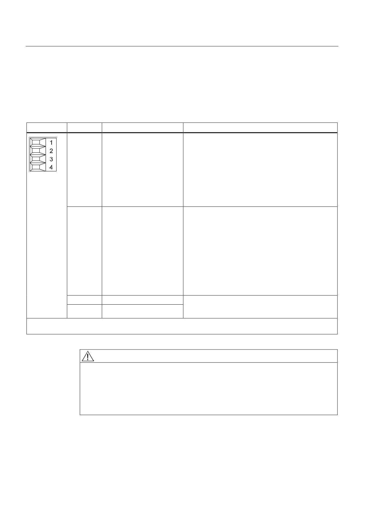
X21 EP terminals
Smart Line Modules 5 kW and 10 kW
Table 8- 51 X21 EP terminal for Smart Line Modules 5 kW and 10 kW
Terminal
Designation
Technical data
1
DO: Ready
Checkback signal: Smart Line Module ready
The signal switches to high level when the following
conditions have been met:
• Electronics power supply (X24) OK
• DC link is precharged
• Pulses enabled (X21.3/4)
• No overtemperature
• No overcurrent
2
DO: Prewarning
DO: Prewarning
High = no prewarning
Low = prewarning
• Overtemperature warning threshold/I2t
5 kW
prewarning: 64°C, overtemperature threshold: 69°C
10 kW
prewarning: 68°C, overtemperature threshold: 73°C
• No regenerative feedback capability due to a line fault
[only monitored when regenerative feedback is activated
(see terminal X22.2)]
3
EP +24 V (Enable Pulses)
Voltage 24 VDC
Current consumption: 10 mA
4
EP M (Enable Pulses)
Isolated input
Max. connectable cross-section: 1.5 mm2
Type: Screw terminal 1 (see Appendix, Chapter "Screw terminals")
WARNING
Danger to life due to charged DC link
For operation, the 24 VDC voltage must be connected to terminal X21.3 and ground to
terminal X21.4. When withdrawn, pulse suppression is activated. The regenerative
feedback is deactivated. If the Line Module is not disconnected from the supply system
when the EP terminal is deactivated (e.g. a line contactor is not installed), the DC link
remains charged.
Guidelines for machine configuration
278
System Manual, MA 01/2013, 6FC5397-6CP10-0BA2
Connection of the components in SINAMICS drive system
8.3 Connection of line modules
NOTICE
Device damage due to incorrect activation or deactivation sequence
It is essential that a particular switch-on and switch-off sequence is followed in order to
control the 5 kW and 10 kW Smart Line Modules; if this sequence is not observed, the
Smart Line Module could be damaged beyond repair.
• To prevent this, evaluate the "Ready" signal at output terminal X21.1 (see the chapter
titled "Safety instructions").
Note
Output terminal X21.1 must be wired to a digital input on the CU. The drives supplied with
power by the Smart Line Module have to use this signal as a "Ready" message (BI: p0864 =
digital input). This ensures that a pulse enable can only be issued for the drives (motor or
generator operation) when the infeed is ready.
If interconnection with a digital input on the CU is not possible, the signal must be evaluated
by a higher-level control instead. The control system cannot set the drives to ready until the
infeed "Ready" signal is present.
Note
The "Prewarning" signal at output terminal X21.2 warns against an overload. If this signal is
set, the control system should shut the drives down before the "Ready" signal switches to
"low". If the "Ready" signal switches to "low", the drive pulses must be suppressed within
4 ms.
Note
If an active drive line-up is switched off by means of the disconnector unit, the voltage at
terminals X21.3 (EP +24 V) and X21.4 (EP M) must be interrupted beforehand. This can be
carried out using a leading (≥ 10 ms) breaking auxiliary contact, for example.
This protects external loads located parallel to the drive on the same switching component.
Note
The Smart Line Module signals that it is ready, even if one of the line conductors is not
available. In this case, regenerative feedback is deactivated and an alarm is output at X21.2
(DO, Warning I2t). If regenerative feedback was deactivated by applying a "high" signal to
terminal X22.2 (DI, Disable), no alarm will be output at X21.2 (DO, Warning I2t).
Guidelines for machine configuration
System Manual, MA 01/2013, 6FC5397-6CP10-0BA2
279
Connection of the components in SINAMICS drive system
8.3 Connection of line modules
16 kW to 55 kW Smart Line Modules
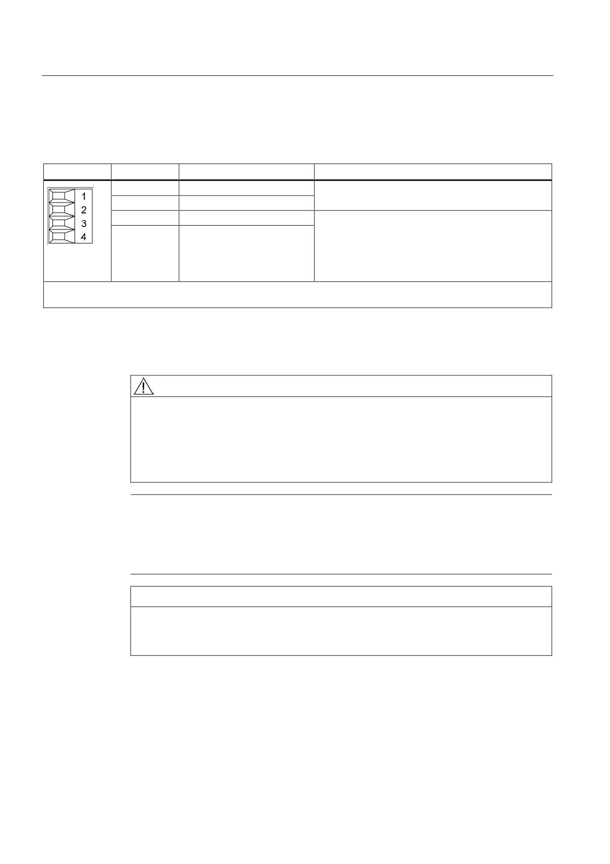
Table 8- 52 X21 EP terminal/temperature Sensor for 16 kW to 55 kW Smart Line Modules
Terminal
Function
Technical data
1
+ Temp
Temperature sensors1): KTY84-1C130/PTC/bimetallic
switch with NC contact
2
- Temp
3
EP +24 V (Enable Pulses)
Voltage: 24 VDC
Current consumption: 10 mA
4
EP M (Enable Pulses)
Isolated input
Signal propagation times:
L → H: 100 μs
H → L: 1000 μs
Max. connectable cross-section 1.5 mm2
Type: Screw terminal 1 (see Appendix, Chapter "Screw terminals")
1) The temperature sensor type can be selected via parameter p0601; the temperature is displayed via r0035 (see
SINAMICS S120/S150 List Manual).
Temperatures are detected but not evaluated in the Smart Line Module.
WARNING
Danger to life due to charged DC link
For operation, the 24 VDC voltage must be connected to terminal X21.3 and ground to
terminal X21.4. When withdrawn, pulse suppression is activated. Regenerative feedback is
deactivated and the bypass relay drops out. If the Line Module is not disconnected from the
supply system when the EP terminal is deactivated (e.g. a line contactor is not installed),
the DC link remains charged.
Note
If an active drive line-up is switched off by means of the disconnector unit, the voltage at
terminals X21.3 (EP +24 V) and X21.4 (EP M) must be interrupted beforehand. This can be
carried out using a leading (≥ 10 ms) breaking auxiliary contact, for example.
This protects external loads located parallel to the drive on the same switching component.
NOTICE
Risk of the motor overheating due to an incorrectly connected KTY temperature sensor
The KTY temperature sensor must be connected with the correct polarity.
If the sensor is connected with the incorrect polarity, it cannot detect if a motor overheats.
Guidelines for machine configuration
280
System Manual, MA 01/2013, 6FC5397-6CP10-0BA2
Connection of the components in SINAMICS drive system
8.3 Connection of line modules
Temperature-sensor connection safety information
DANGER
Risk of electric shock!
Only temperature sensors that meet the safety isolation specifications contained in
EN 61800-5-1 may be connected to terminals "+Temp" and "-Temp". If safe electrical
separation cannot be guaranteed (for linear motors or third-party motors, for example), a
Sensor Module External (SME120 or SME125) or Terminal Module TM120 must be used.
If these instructions are not complied with, there is a risk of electric shock!
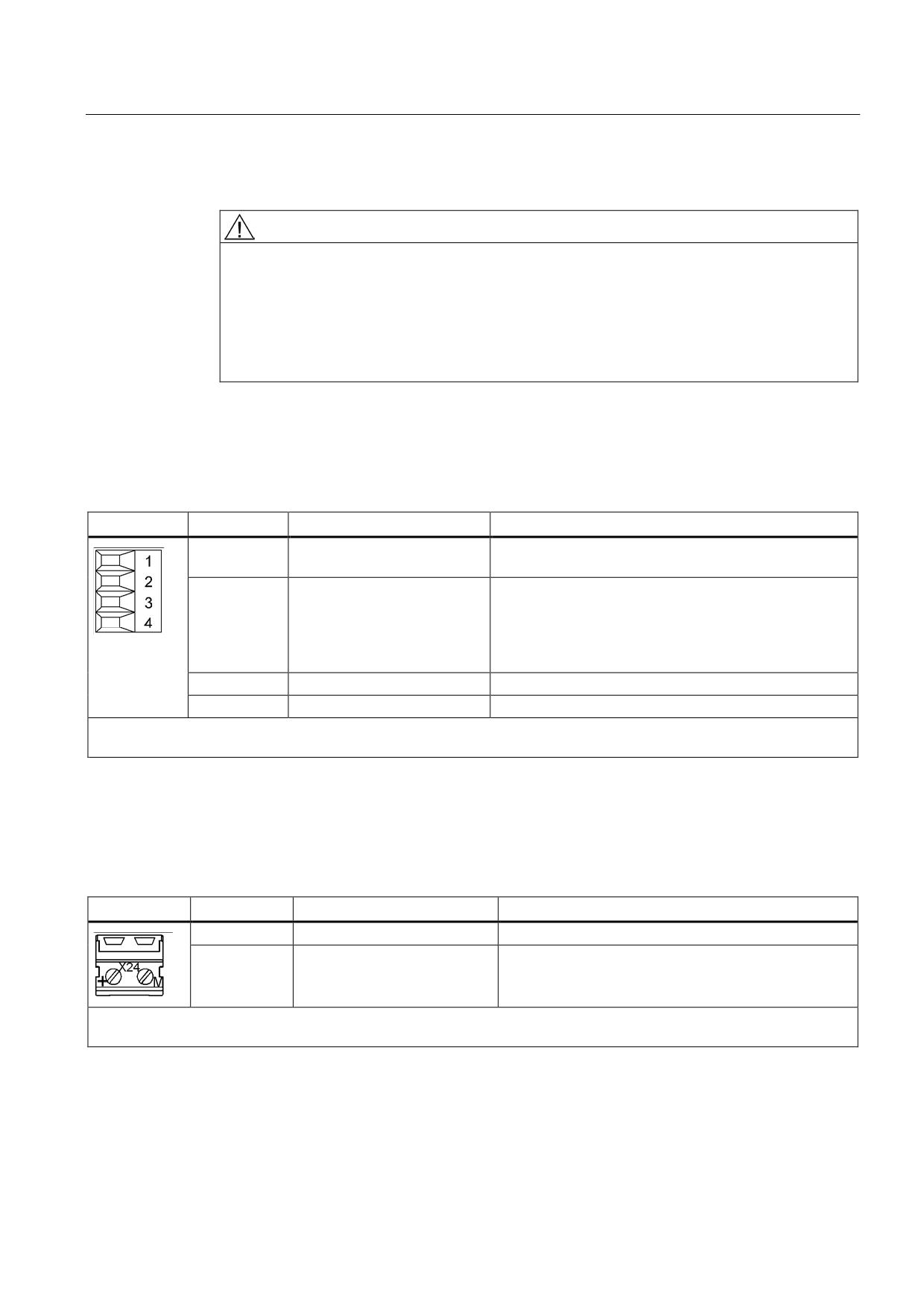
X22 digital inputs
Table 8- 53 X22 digital inputs for Smart Line Modules 5 kW and 10 kW
Terminal
Description 1)
Technical specifications
1
24 V power supply
Electronic power supply for controlling digital inputs
X22.2 and 3.
2
DI: Disable Regeneration
Deactivate regenerative feedback (high active).
No power is supplied back to the network from the DC
link. The regenerative energy of the motors may have to
be reduced using a combination of the Braking Module
and braking resistor.
3
DI: Reset
Reset faults (negative edge)
4
Ground
Electronics ground
Max. connectable cross-section: 1.5 mm2
Type: Screw terminal 1 (see Appendix, Chapter "Screw terminals")
1) DI: Digital input
X24 24 V terminal adapter
Table 8- 54 X24 24 V terminal adapter
Terminal
Description
Technical specifications
+
24 V power supply
24 VDC supply voltage
M
Ground
Electronics ground
Max. connectable cross-section: 6 mm2
Type: Screw terminal 5 (see Appendix, Chapter "Screw terminals")
The 24 V terminal adapter is included in the scope of delivery.
Guidelines for machine configuration
System Manual, MA 01/2013, 6FC5397-6CP10-0BA2
281
Connection of the components in SINAMICS drive system
8.3 Connection of line modules
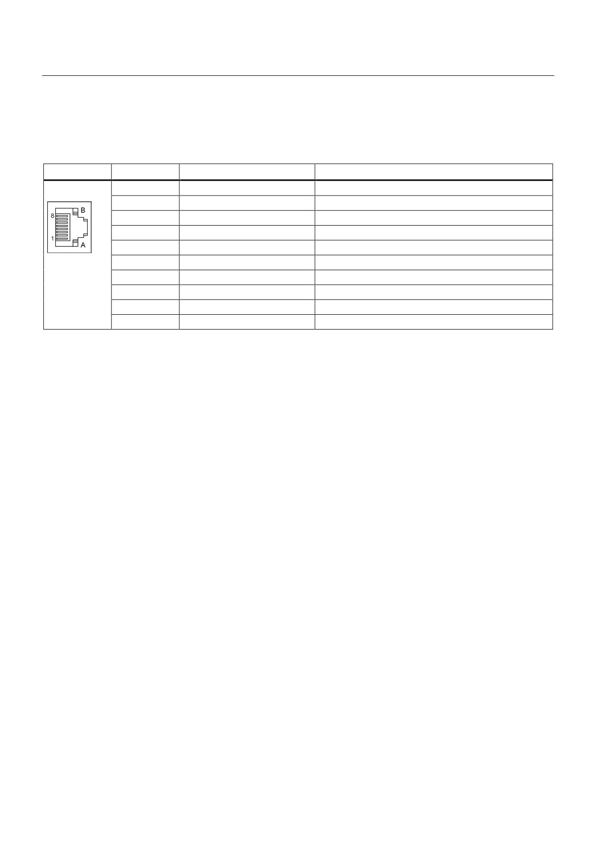
X200-X202 DRIVE-CLiQ interfaces
Table 8- 55 X200-X202 DRIVE-CLiQ interfaces
PIN
Signal name
Technical specifications
1
TXP
Transmit data +
2
TXN
Transmit data -
3
RXP
Receive data +
4
Reserved, do not use
5
Reserved, do not use
6
RXN
Receive data -
7
Reserved, do not use
8
Reserved, do not use
A
+(24 V)
24 V power supply
B
M (0 V)
Electronics ground
The blanking covers for the DRIVE-CLiQ interfaces are included in the scope of delivery.
Blanking cover (50 pcs.) Order number: 6SL3066-4CA00-0AA0
Guidelines for machine configuration
282
System Manual, MA 01/2013, 6FC5397-6CP10-0BA2
Connection of the components in SINAMICS drive system
8.3 Connection of line modules
8.3.7.4
Connection examples
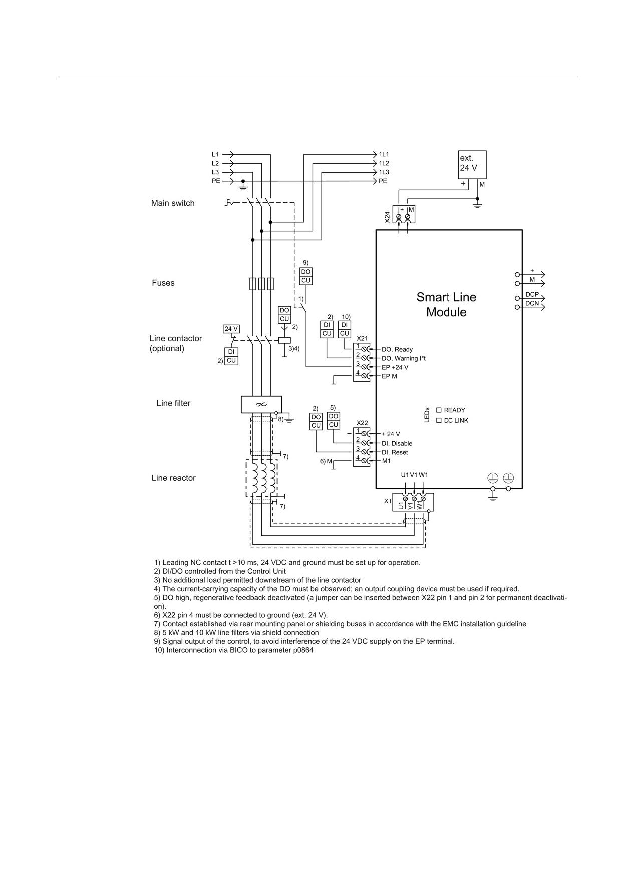
Figure 8-61 Connection example for 5 kW and 10 kW Smart Line Modules
Guidelines for machine configuration
System Manual, MA 01/2013, 6FC5397-6CP10-0BA2
283
Connection of the components in SINAMICS drive system
8.3 Connection of line modules
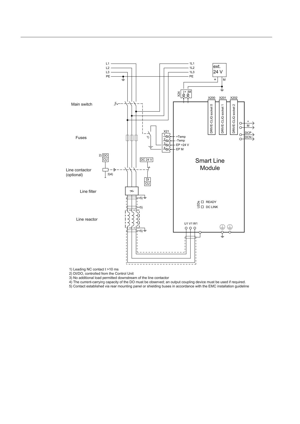
Figure 8-62 Connection example for 16 kW to 55 kW Smart Line Modules
Guidelines for machine configuration
284
System Manual, MA 01/2013, 6FC5397-6CP10-0BA2
Connection of the components in SINAMICS drive system
8.3 Connection of line modules
8.3.7.5
Meaning of LEDs
Smart Line Modules 5 kW and 10 kW
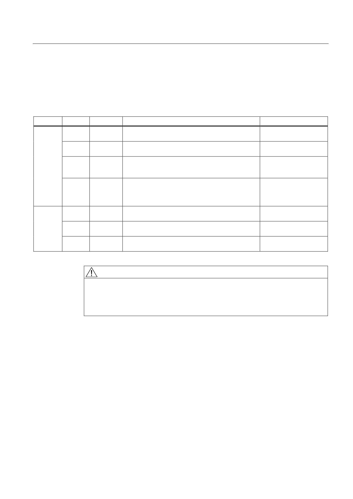
Table 8- 56 Meaning of the LEDs on 5 kW and 10 kW Smart Line Modules
LED
Color
Status
Description, cause
Remedy
RDY
-
Off
Electronics power supply is missing or outside
-
permissible tolerance range.
Green
Continuous
Component is ready to operate.
-
light
Yellow
Continuous
Pre-charging not yet complete.
-
light
Bypass relay dropped out
EP terminals not supplied with 24 VDC.
Red
Continuous
Overtemperature,
Diagnose fault (via output
light
overcurrent
terminals) and
acknowledge it (via input
terminal)
DC LINK
-
Off
Electronics power supply is missing or outside
-
permissible tolerance range.
Yellow
Continuous
DC link voltage within permissible tolerance range.
-
light
Red
Continuous
DC link voltage outside permissible tolerance range.
Check line voltage.
light
Power system fault.
WARNING
Danger to life due to high DC link voltage, regardless of LED display
Hazardous DC link voltages may be present at any time regardless of the status of the
"DC LINK" LED.
• Observe the warning information on the component.
Guidelines for machine configuration
System Manual, MA 01/2013, 6FC5397-6CP10-0BA2
285
Connection of the components in SINAMICS drive system
8.3 Connection of line modules
16 kW to 55 kW Smart Line Modules
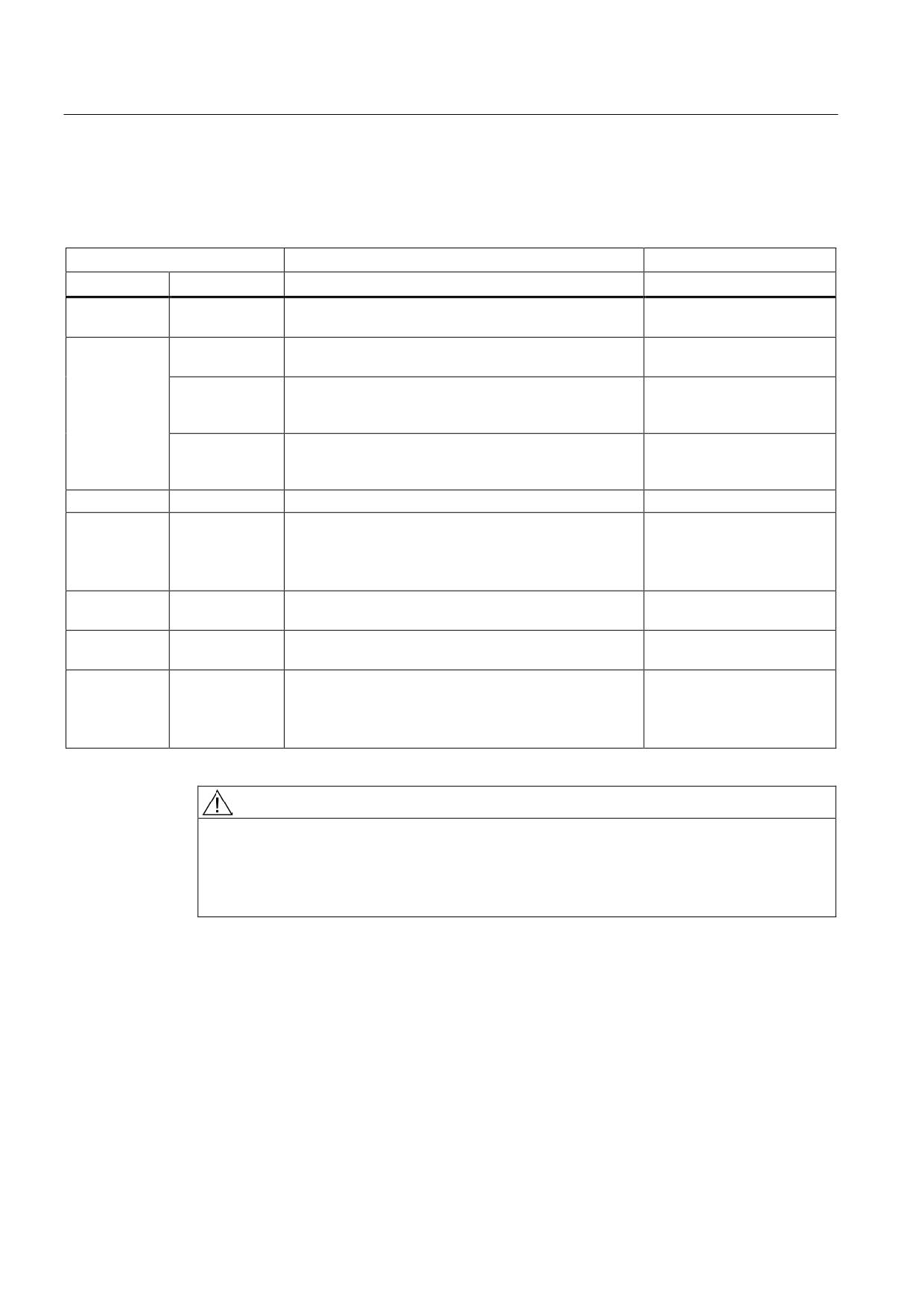
Table 8- 57 Meaning of the LEDs on Smart Line Modules ≥ 16 kW
Status
Description, cause
Remedy
RDY
DC LINK
Off
Off
Electronics power supply is missing or outside
-
permissible tolerance range.
Green
--
The component is ready for operation and cyclic DRIVE-
-
CLiQ communication is taking place.
Orange
The component is ready for operation and cyclic DRIVE-
-
CLiQ communication is taking place.
The DC link voltage is present.
Red
The component is ready for operation and cyclic DRIVE-
Check line voltage
CLiQ communication is taking place.
The DC link voltage is too high.
Orange
Orange
DRIVE-CLiQ communication is being established.
-
Red
--
At least one fault is present in this component.
Remedy and acknowledge
fault
Note:
The LED is activated regardless of whether the
corresponding messages have been reconfigured.
Green/red
--
Firmware is being downloaded.
-
(0.5 Hz)
Green/red
--
Firmware download is complete. Wait for POWER ON.
Carry out a POWER ON
(2 Hz)
Green/orange
--
Component detection via LED is activated (p0124).
-
or
Note:
Red/orange
Both options depend on the LED status in the case of
activation via p0124 = 1.
WARNING
Danger to life due to high DC link voltage, regardless of LED display
Hazardous DC link voltages may be present at any time regardless of the status of the
"DC LINK" LED.
• Observe the warning information on the component.
Guidelines for machine configuration
286
System Manual, MA 01/2013, 6FC5397-6CP10-0BA2
Connection of the components in SINAMICS drive system
8.3 Connection of line modules
8.3.7.6
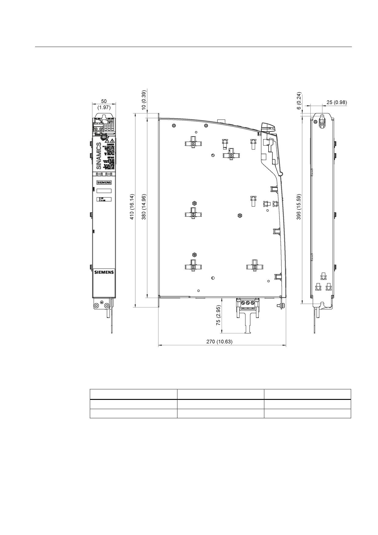
Dimension drawings
Figure 8-63 Dimension drawing of 5 kW and 10 kW Smart Line Modules with internal air cooling, all
dimensions in mm and (inches)
Table 8- 58 Dimensions of Smart Line Modules with internal air cooling (5 kW and 10 kW)
Smart Line Module
Order number
W in mm (inches)
5 kW
6SL3130-6AE15-0Axx
50 (1.97)
10 kW
6SL3130-6AE21-0Axx
50 (1.97)
Guidelines for machine configuration
System Manual, MA 01/2013, 6FC5397-6CP10-0BA2
287
Connection of the components in SINAMICS drive system
8.3 Connection of line modules
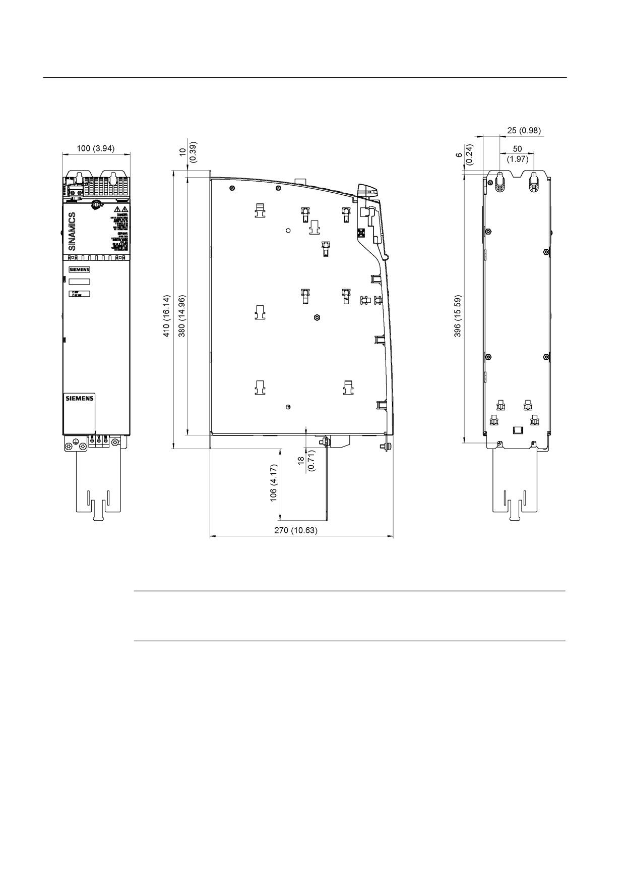
Figure 8-64 Dimension drawing of 16 kW Smart Line Module with internal air cooling, all dimensions in mm and (inches)
Note
The shield connecting plate is included in the scope of delivery of the 50 mm and 100 mm
Smart Line Modules.
Guidelines for machine configuration
288
System Manual, MA 01/2013, 6FC5397-6CP10-0BA2
Connection of the components in SINAMICS drive system
8.3 Connection of line modules
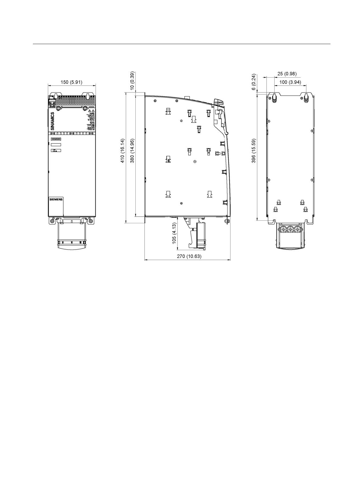
Figure 8-65 Dimension drawing of 36 kW Smart Line Module with internal air cooling, all dimensions in mm and (inches)
Guidelines for machine configuration
System Manual, MA 01/2013, 6FC5397-6CP10-0BA2
289
Connection of the components in SINAMICS drive system
8.3 Connection of line modules
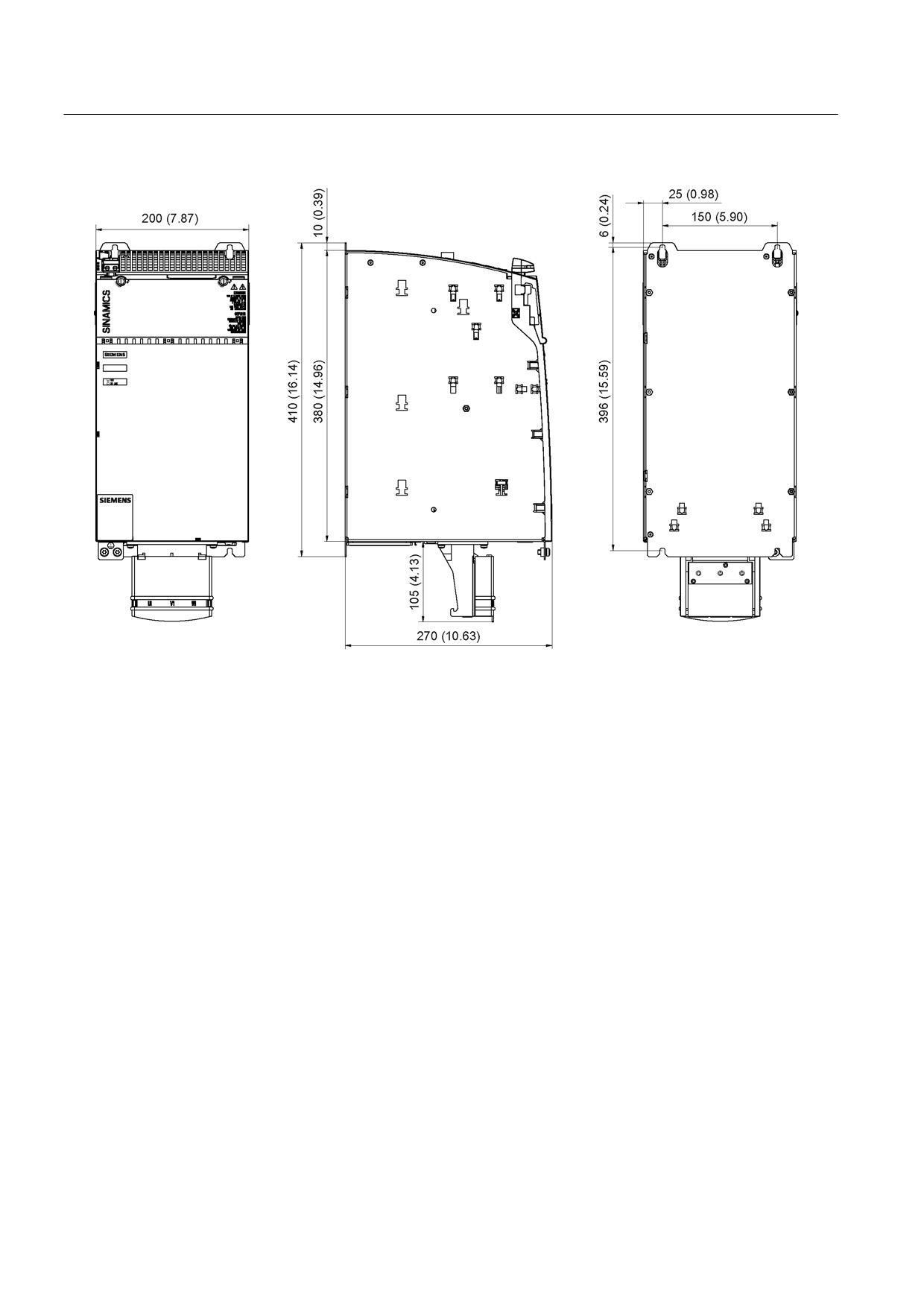
Figure 8-66 Dimension drawing of 55 kW Smart Line Module with internal air cooling, all dimensions in mm and (inches)
Guidelines for machine configuration
290
System Manual, MA 01/2013, 6FC5397-6CP10-0BA2
Connection of the components in SINAMICS drive system
8.3 Connection of line modules
8.3.7.7
Installation
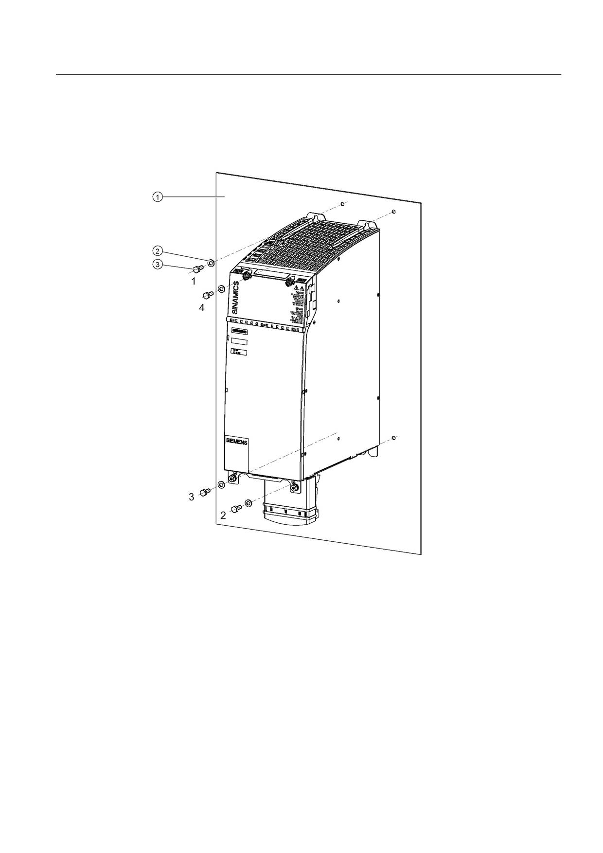
Smart Line Modules are designed for installation in the control cabinet. They are fixed to the
control cabinet panel or a mounting panel using M6 screws.
①
Control cabinet panel/mounting panel
②
Washer
③
M6 screw
Figure 8-67 Mounting a Smart Line Module with internal air cooling (example: 36 kW)
Tightening torques:
● Initially, tighten the nuts by hand (0.5 Nm)
● Then tighten with 6 Nm (in the specific sequence 1 to 4)
Guidelines for machine configuration
System Manual, MA 01/2013, 6FC5397-6CP10-0BA2
291
Connection of the components in SINAMICS drive system
8.3 Connection of line modules
8.3.7.8
Technical specifications
Technical specifications
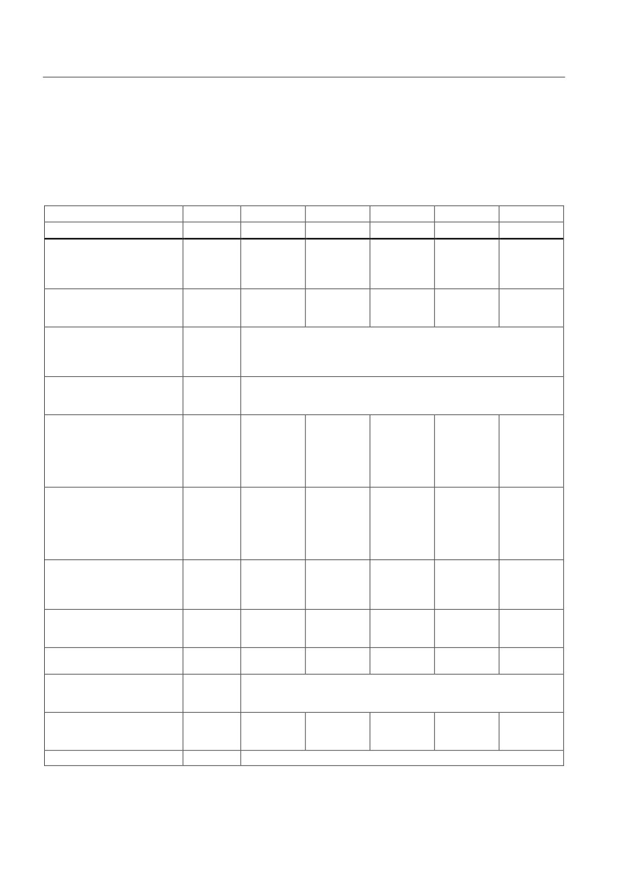
Table 8- 59 Technical data for Smart Line Modules in booksize format with internal air cooling
Internal air cooling
6SL3130-
6AE15-0Axx
6AE21-0Axx
6TE21-6Axx
6TE23-6Axx
6TE25-5AAx
Rated power
kW
5
10
16
36
55
Infeed
Rated power (S1)1)
kW (Pn)
5
10
16
36
55
S6 operation (40%)1)
kW (PS6)
6.5
13
21
47
71
Peak infeed power1)
kW (Pmax)
10
20
35
70
91
Energy recovery
Continuous regenerative power
kW
5
10
16
36
55
Peak regenerative power
kW
10
20
35
70
91
Supply voltages
Line voltage
VAC
3 AC 380 -10% (-15% < 1 min) to 3 AC 480 +10%
Line frequency
Hz
47 to 63
Electronics power supply
VDC
24 (20.4 - 28.8)
DC link voltage
VDC
510 - 720
Overvoltage trip
VDC
820 ±2%
Undervoltage trip2)
VDC
360 ±2%
Input currents
Rated input current
at 400 VAC
AAC
8.1
16.2
27.5
59
90
at 380 VAC/480 VAC
AAC
8.6 / 6.7
17 / 12.8
29 / 24.5
62 / 51
94 / 77
S6 (40%) at 400 VAC;
AAC
10.6
21.1
35
76
106
Peak current at 400 VAC
AAC
15.7
31.2
57.5
112
130
DC link currents
DC link output current
at 600 V
ADC
8.3
16.6
27
60
92
at 540 V
ADC
9.3
18.5
30
67
105
S6 (40%) at 600 VDC
ADC
11
22
35
79
138
Peak current at 600 VC
ADC
16.6
33.2
59
118
178
Current-carrying capacity
DC link busbar
ADC
100
100
100
200
200
Reinforced DC link busbars:
ADC
150
150
150
--
--
24 V busbar:
ADC
20
20
20
20
20
Electronics current
ADC
0.8
0.9
0.95
1.5
1.9
consumption
at 24 VDC
Total power loss
W
79.2
141.6
187.8
406
665.6
(including electronics losses)3)
Max. ambient temperature
without derating
°C
40
with derating
°C
55
DC link capacitance
Smart Line Module
μF
220
330
705
1410
1880
Drive line-up, max.
μF
6000
6000
20000
20000
20000
Power factor
cos ϕ
0.98
Guidelines for machine configuration
292
System Manual, MA 01/2013, 6FC5397-6CP10-0BA2
Connection of the components in SINAMICS drive system
8.3 Connection of line modules
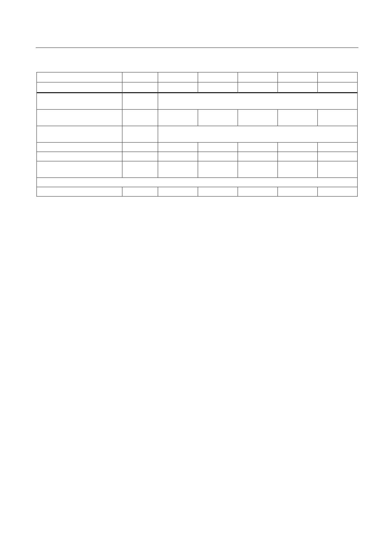
Internal air cooling
6SL3130-
6AE15-0Axx
6AE21-0Axx
6TE21-6Axx
6TE23-6Axx
6TE25-5AAx
Rated power
kW
5
10
16
36
55
Circuit breaker
See Chap. "Overcurrent protection using line fuses and circuit breakers
(IEC 60947 and UL)
(Page 116)"
Rated short-circuit current
kA
65
65
65
65
65
SCCR4)
Cooling method (internal air
Internal fan
cooling)
Sound pressure level
dB(A)
<60
<60
<60
<65
<60
Cooling air requirement
m3/h
29.6
29.6
56
112
160
Max. permissible heat sink
°C
695)
735)
77
80
75
temperature
Rated voltage for rated data 3 AC 380 V
Weight
kg
4.7
4.8
7
10
17
1)
The specified power ratings apply to the line voltage range from 380 V to 480 V.
2)
For 16 kW and 36 kW Smart Line Modules: Default for 400 V line systems; undervoltage trip threshold is adjusted to the
parameterized rated voltage.
3)
For an overview, see the power loss tables in the Appendix.
4)
The resulting rated short-circuit current is obtained from the combination of the fuse, or circuit breaker, and the Line
Module in the drive system.
5)
Values cannot be read out by the system (STARTER).
Guidelines for machine configuration
System Manual, MA 01/2013, 6FC5397-6CP10-0BA2
293
Connection of the components in SINAMICS drive system
8.3 Connection of line modules
Characteristics
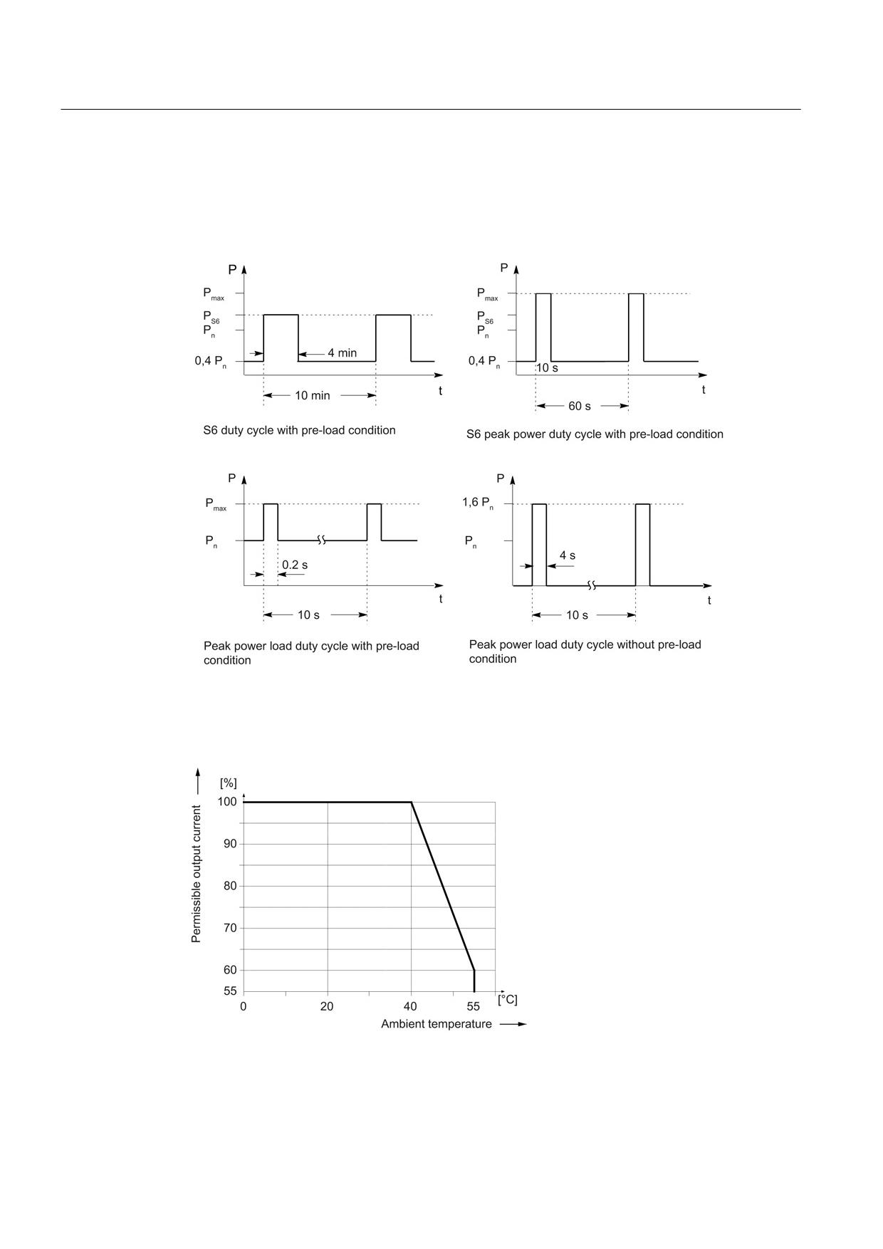
Rated duty cycles of Smart Line Modules
Figure 8-68 Rated duty cycles of Smart Line Modules
Derating characteristics
Figure 8-69 Output current as a function of the ambient temperature
Guidelines for machine configuration
294
System Manual, MA 01/2013, 6FC5397-6CP10-0BA2
Connection of the components in SINAMICS drive system
8.3 Connection of line modules
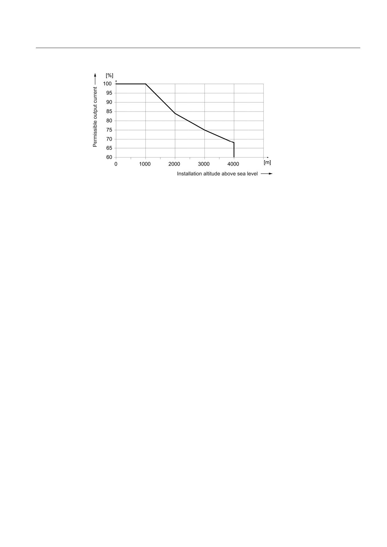
Figure 8-70 Output current as a function of the installation altitude
At installation altitudes > 2000 m, an isolation transformer must be used (see the chapter
titled "System overview/Function of installation altitude and ambient temperature"
(Page 32)). The design of the secondary line system must be as follows:
● TN system with grounded neutral point (no grounded line conductor)
● IT system
A reduction of the line supply voltage phase-phase is not necessary.
8.3.8
Smart Line Modules with external air cooling
8.3.8.1
Description
The Smart Line Module is a non-regulated infeed/regenerative feedback unit. The Smart
Line Module supplies the Motor Module(s) with a non-regulated DC voltage at the DC output.
In the infeed mode the Smart Line Module exhibits the typical current and voltage waveforms
of a 6-pulse diode rectifier bridge.
In feedback mode, the current waveform is square waved. Regenerative feedback can be
deactivated if required. On 5 kW and 10 kW Smart Line Modules, this is done via a terminal,
since these modules do not feature a DRIVE-CLiQ connection. On 16 kW to 55 kW Smart
Line Modules, regenerative feedback can be deactivated via parameters, as, just like Active
Line Modules, these modules are equipped with a DRIVE-CLiQ connection.
The DC link starts precharging as soon as the supply voltage is applied and is independent
of its phase sequence direction. Load can be applied to the DC link after the module has
been enabled. An optional main contactor is required for disconnecting the voltage.
Smart Line Modules are suitable for direct operation on TN, IT, and TT systems. The
modules have an integrated overvoltage protection function.
Guidelines for machine configuration
System Manual, MA 01/2013, 6FC5397-6CP10-0BA2
295
Connection of the components in SINAMICS drive system
8.3 Connection of line modules
External air cooling uses the "through-hole" method. This is a cooling method that is only
available for SINAMICS booksize units. The Smart Line Module and its heat sink can be
inserted in a rectangular knockout at the rear of the control cabinet and mounted with a seal.
The heat sink and the fan (included in the scope of supply) project beyond the rear of the
control cabinet and the heat is dissipated outside the control cabinet or in a separate air
duct.
8.3.8.2
Product-specific safety information for the Smart Line Modules in booksize format
The safety instructions described in this chapter apply specifically to Smart Line Modules in
booksize format.
In addition, you should strictly observe the safety instructions in Chapter 1.
NOTICE
It is essential that a particular switch-on and switch-off sequence is followed in order to
control the 5 kW and 10 kW Smart Line Modules; if this sequence is not observed, the
Smart Line Module could be damaged beyond repair. To prevent the SLM being destroyed,
the "Ready" signal must be evaluated at output terminal X21.1.
Activation:
•
24 VDC power supply X24 ON
• Line contactor ON
• EP signal X21 pins 3 and 4 ON
• Wait until precharging is complete
• "Ready" signal at terminal X21 pin 1 set to "high"
• Infeed is ready, pulse enable possible for motors
Deactivation:
• Shut drives down
• Cancel pulse enable for motors (OFF1 signal)
• EP signal X21 pins 3 and 4 OFF
• Line contactor OFF
•
24 VDC power supply X24 OFF
Overload:
• "Prewarning" signal at terminal X21 pin 2 set to "low"
• Shut drives down via the control system
• "Ready" signal at terminal X21 pin 1 set to "low"
• Pulse inhibit for all the drives supplied by this infeed within 4 ms
Note
Operation without the line reactor is not permissible.
Guidelines for machine configuration
296
System Manual, MA 01/2013, 6FC5397-6CP10-0BA2
Connection of the components in SINAMICS drive system
8.3 Connection of line modules
Note
Connection to the public low-voltage network
Smart Line Modules have been designed for use in the industrial environment and generate
current harmonics on the line side as a result of the rectifier circuit.
When connecting a machine with integrated Smart Line Modules to the public low-voltage
network, authorization is required in advance from the local power supply company (utility
company) if
• The rated current of the machine ≤ 16 A per conductor, and
• The rated machine current does not comply with the requirements specified in EN 61000-
3-2 regarding current harmonics.
Guidelines for machine configuration
System Manual, MA 01/2013, 6FC5397-6CP10-0BA2
297
Connection of the components in SINAMICS drive system
8.3 Connection of line modules
8.3.8.3
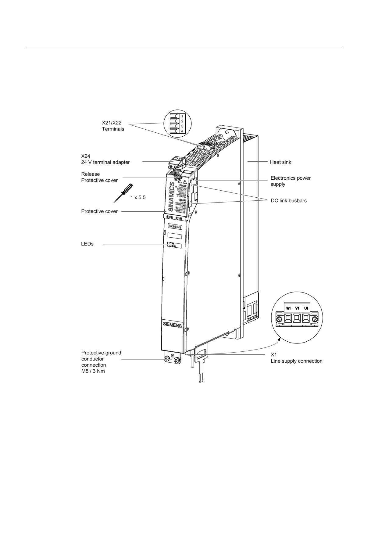
Interface description
Overview
Figure 8-71 Interface overview, 5 kW and 10 kW Smart Line Modules with external air cooling
(example: 5 kW)
Guidelines for machine configuration
298
System Manual, MA 01/2013, 6FC5397-6CP10-0BA2
Connection of the components in SINAMICS drive system
8.3 Connection of line modules
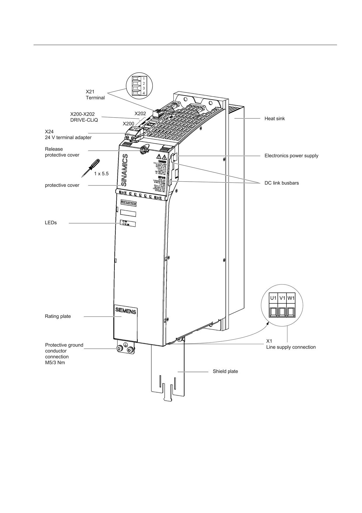
Figure 8-72 Interface overview, 16 kW Smart Line Module with external air cooling
Guidelines for machine configuration
System Manual, MA 01/2013, 6FC5397-6CP10-0BA2
299
Connection of the components in SINAMICS drive system
8.3 Connection of line modules
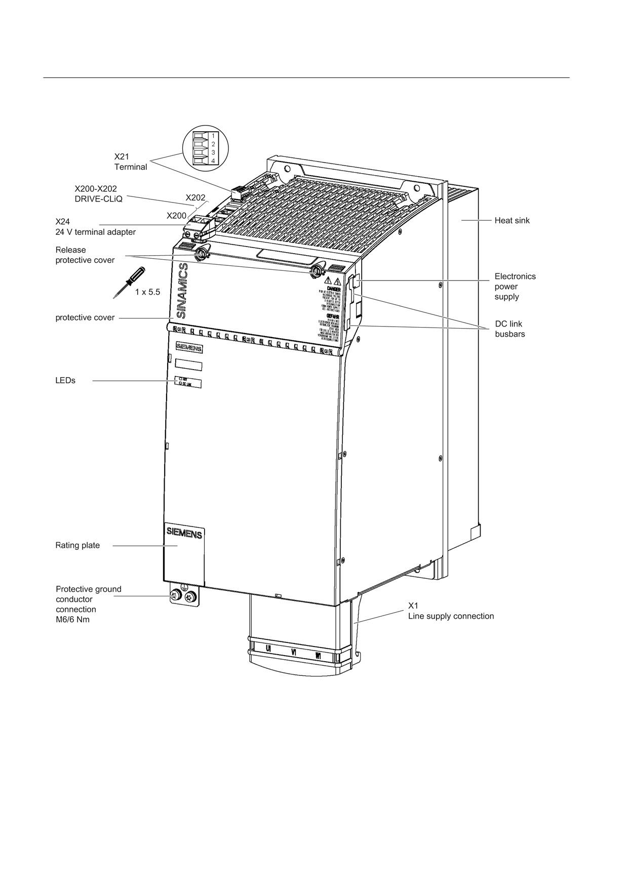
Figure 8-73 Interface overview, 36 kW and 55 kW Smart Line Modules with external air cooling (example: 55 kW)
Guidelines for machine configuration
300
System Manual, MA 01/2013, 6FC5397-6CP10-0BA2
Connection of the components in SINAMICS drive system
8.3 Connection of line modules
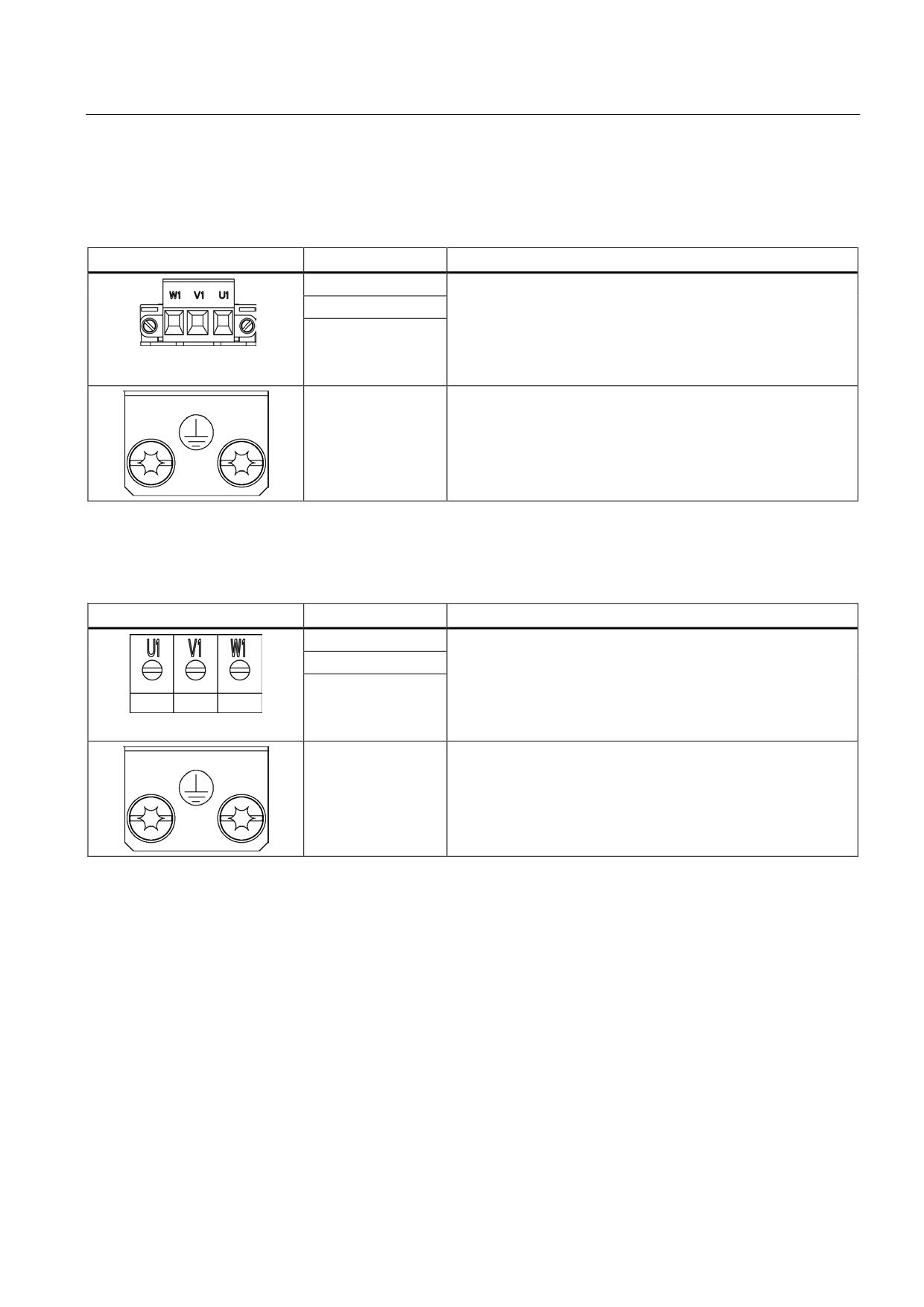
X1 line connection
Table 8- 60 X1: Line connection for Smart Line Modules 5 kW and 10 kW
Terminal
Technical specifications
U1
Supply voltage:
3 AC 380 V - 480 V, 50/60 Hz
V1
Max. connectable cross-section: 6 mm2
W1
Type: Screw terminal 5 (see Appendix, Chapter "Screw
terminals")
Tightening torque: 1.2 - 1.5 Nm
PE connection
Threaded hole M5/3 Nm 1)
1) For ring cable lugs in accordance with DIN 46234
Table 8- 61 X1: Line supply connection for Smart Line Modules 16 kW
Terminal
Technical specifications
U1
Supply voltage:
3 AC 380 V - 480 V, 50/60 Hz
V1
Max. connectable cross-section: 10 mm2
W1
Type: Screw terminal 6 (see Appendix, Chapter "Screw
terminals")
Tightening torque: 1.5 - 1.8 Nm
PE connection
Threaded hole M5/3 Nm 1)
1) For ring cable lugs in accordance with DIN 46234
Guidelines for machine configuration
System Manual, MA 01/2013, 6FC5397-6CP10-0BA2
301
Connection of the components in SINAMICS drive system
8.3 Connection of line modules
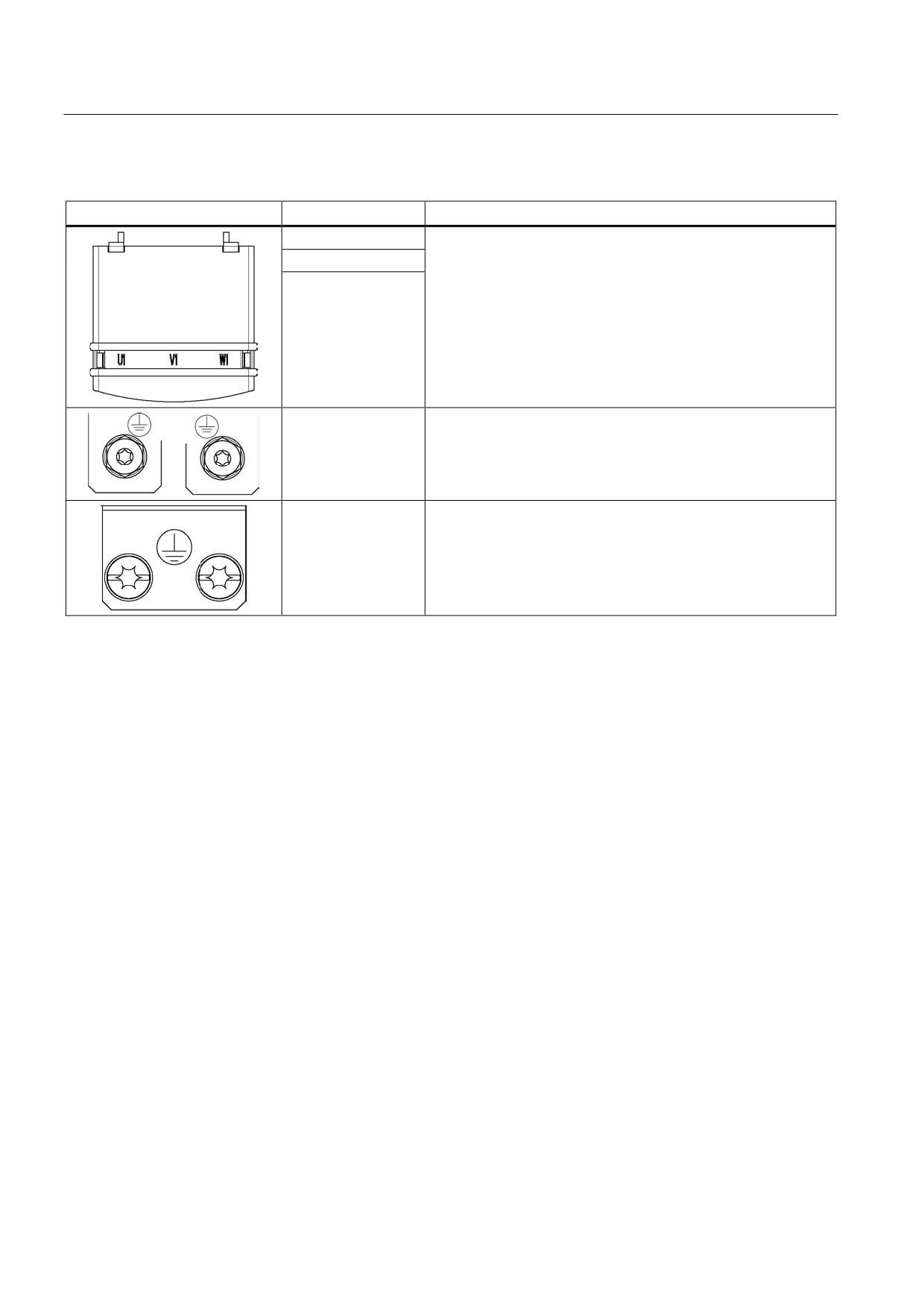
Table 8- 62 X1: Line connection for Smart Line Modules 36 kW and 55 kW
Terminal
Technical specifications
U1
Supply voltage:
3 AC 380 V - 480 V, 50/60 Hz
V1
36 kW: Threaded bolt M6/6 Nm 1)
W1
55 kW: Threaded bolt M8/13 Nm 1)
PE connection
36 kW: Threaded hole M6/6 Nm 1)
55 kW: Threaded hole M6/6 Nm 1)
1) For ring cable lugs in accordance with DIN 46234
Guidelines for machine configuration
302
System Manual, MA 01/2013, 6FC5397-6CP10-0BA2
Connection of the components in SINAMICS drive system
8.3 Connection of line modules
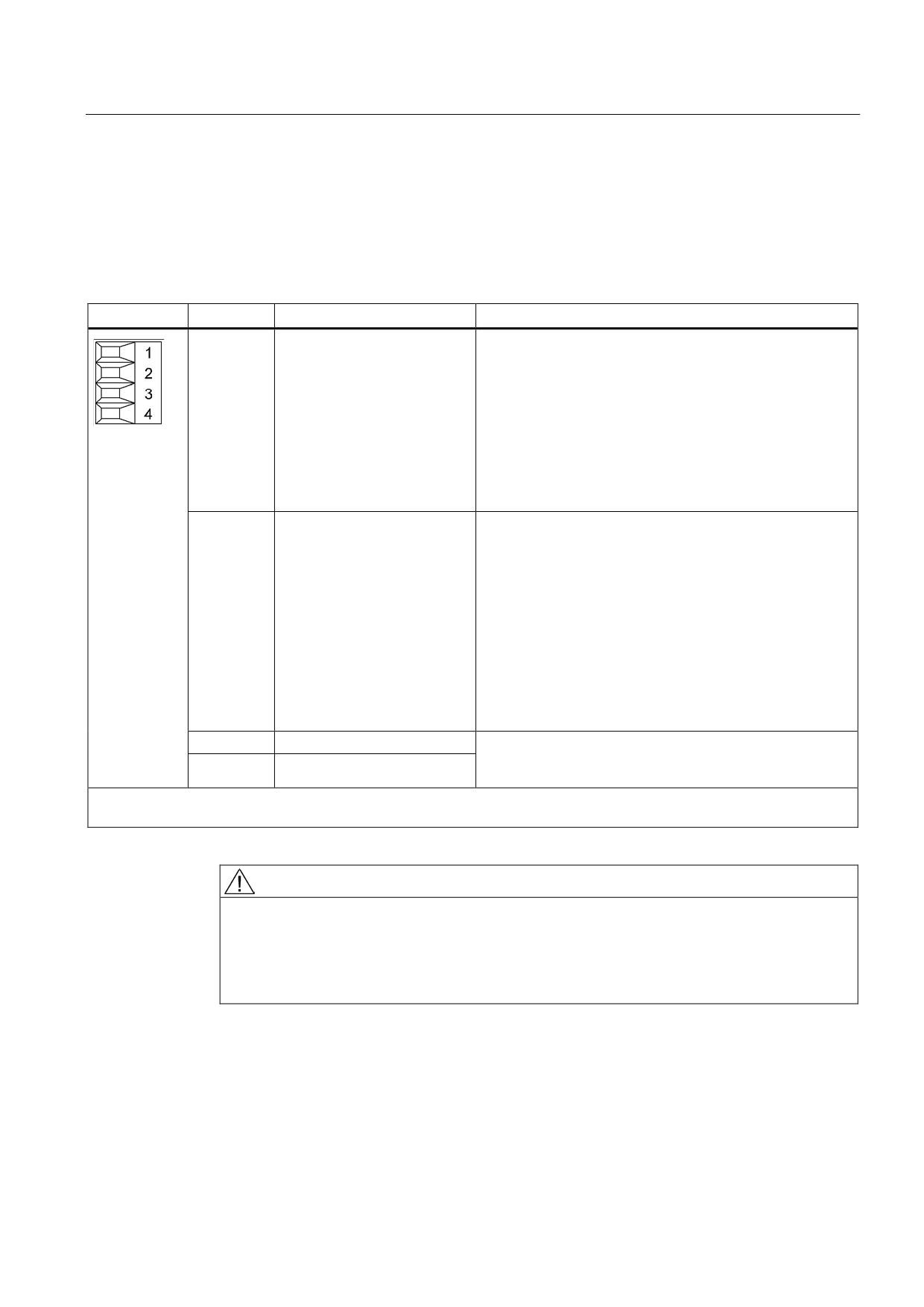
X21 EP terminals
Smart Line Modules 5 kW and 10 kW
Table 8- 63 X21 EP terminal for Smart Line Modules 5 kW and 10 kW
Terminal
Description
Technical specifications
1
DO: Ready
Checkback signal: Smart Line Module ready
The signal switches to high level when the following
conditions have been met:
• Electronic power supply (X24) OK
• DC link is precharged
• Pulses enabled (X21.3/4)
• No overtemperature
• No overcurrent
2
DO: Prewarning
DO: Prewarning
High = no prewarning
Low = prewarning
• Overtemperature warning threshold/I2t
5 kW
prewarning: 64°C, overtemperature threshold: 69°C
10 kW
prewarning: 68°C, overtemperature threshold: 73°C
• No regenerative feedback capability due to a line fault
[only monitored when regenerative feedback is activated
(see terminal X22.2)]
3
EP +24 V (Enable Pulses)
Voltage 24 VDC
Current consumption: 10 mA
4
EP M (Enable Pulses)
Isolated input
Max. connectable cross-section: 1.5 mm2
Type: Screw terminal 1 (see Appendix, Chapter "Screw terminals")
WARNING
For operation, the 24 VDC voltage must be connected to terminal X21.3 and ground to
terminal X21.4. When withdrawn, pulse suppression is activated. The regenerative
feedback is deactivated. If the Line Module is not disconnected from the supply system
when the EP terminal is deactivated (e.g. a line contactor is not installed), the DC link
remains charged.
Guidelines for machine configuration
System Manual, MA 01/2013, 6FC5397-6CP10-0BA2
303
Connection of the components in SINAMICS drive system
8.3 Connection of line modules
NOTICE
It is essential that a particular switch-on and switch-off sequence is followed in order to
control the 5 kW and 10 kW Smart Line Modules; if this sequence is not observed, the
Smart Line Module could be damaged beyond repair. To prevent the SLM being destroyed,
the "Ready" signal must be evaluated at output terminal X21.1 (see the chapter titled
"Safety instructions")
Note
Output terminal X21.1 must be wired to a digital input on the CU. The drives supplied with
power by the Smart Line Module have to use this signal as a "Ready" message (BI: p0864 =
digital input). This ensures that a pulse enable can only be issued for the drives (motor or
generator operation) when the infeed is ready.
If interconnection with a digital input on the CU is not possible, the signal must be evaluated
by a higher-level control system instead. The control system cannot set the drives to ready
until the infeed "Ready" signal is present.
Note
The "Prewarning" signal at output terminal X21.2 warns against an overload. If this signal is
set, the control system shuts the drives down before the "Ready" signal switches to "low". If
the "Ready" signal changes to "low", the drive pulses must be suppressed within 4 ms.
Note
If an active drive line-up is switched off by means of the disconnector unit, the voltage at
terminals X21.3 (EP +24 V) and X21.4 (EP M) must be interrupted beforehand. This can be
carried out using a leading (≥ 10 ms) breaking auxiliary contact, for example.
This protects external loads located parallel to the drive on the same switching component.
Note
The Smart Line Module signals that it is ready, even if one of the line conductors is not
available. In this case, regenerative feedback is deactivated and an alarm is output at X21.2
(DO, Warning I2t). If regenerative feedback was deactivated by applying a "high" signal to
terminal X22.2 (DI, Disable), no alarm will be output at X21.2 (DO, Warning I2t).
Guidelines for machine configuration
304
System Manual, MA 01/2013, 6FC5397-6CP10-0BA2
Connection of the components in SINAMICS drive system
8.3 Connection of line modules
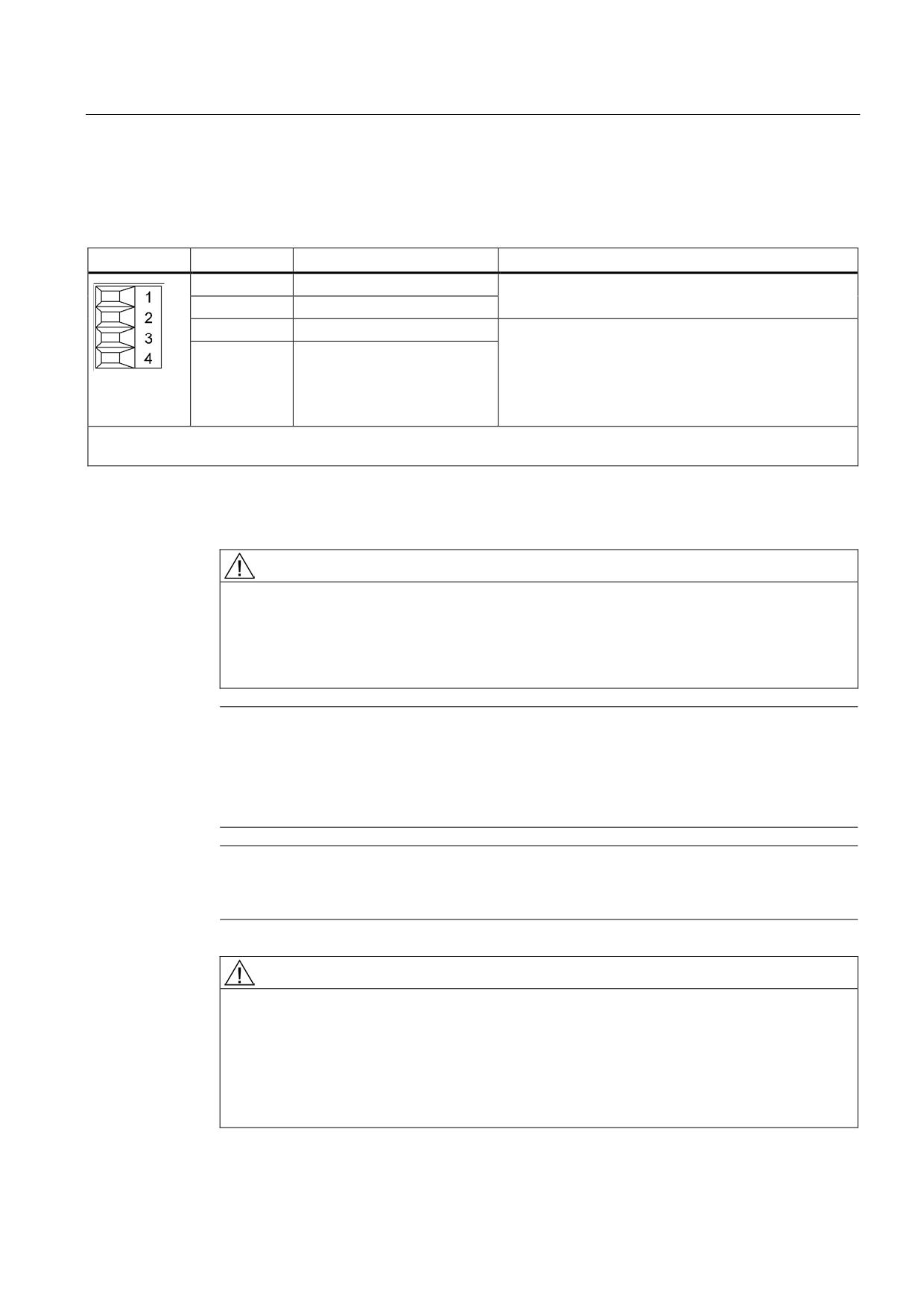
16 kW to 55 kW Smart Line Modules
Table 8- 64 X21 EP terminal/temperature Sensor for 16 kW to 55 kW Smart Line Modules
Terminal
Function
Technical specifications
1
+ Temp
Temperature sensors1): KTY84-1C130/PTC/bimetallic
switch with NC contact
2
- Temp
3
EP +24 V (Enable Pulses)
Voltage: 24 VDC
Current consumption: 10 mA
4
EP M (Enable Pulses)
Isolated input
Signal propagation times:
L → H: 100 μs
H → L: 1000 μs
Max. connectable cross-section 1.5 mm2
Type: Screw terminal 1 (see Appendix, Chapter "Screw terminals")
1) The temperature sensor type can be selected via parameter p0601; the temperature is displayed via r0035 (see
SINAMICS S120/S150 List Manual).
Temperatures are detected but not evaluated in the Smart Line Module.
WARNING
For operation, the 24 VDC voltage must be connected to terminal X21.3 and ground to
terminal X21.4. When withdrawn, pulse suppression is activated. Regenerative feedback is
deactivated and the bypass relay drops out. If the Line Module is not disconnected from the
supply system when the EP terminal is deactivated (e.g. a line contactor is not installed),
the DC link remains charged.
Note
If an active drive line-up is switched off by means of the disconnector unit, the voltage at
terminals X21.3 (EP +24 V) and X21.4 (EP M) must be interrupted beforehand. This can be
carried out using a leading (≥ 10 ms) breaking auxiliary contact, for example.
This protects external loads located parallel to the drive on the same switching component.
Note
The KTY temperature sensor must be connected with the correct polarity.
If the sensor is connected with the incorrect polarity, it cannot detect if a motor overheats.
DANGER
Risk of electric shock!
Only temperature sensors that meet the safety isolation specifications contained in
EN 61800-5-1 may be connected to terminals "+Temp" and "-Temp". If safe electrical
separation cannot be guaranteed (for linear motors or third-party motors, for example), a
Sensor Module External (SME120 or SME125) or Terminal Module TM120 must be used.
If these instructions are not complied with, there is a risk of electric shock!
Guidelines for machine configuration
System Manual, MA 01/2013, 6FC5397-6CP10-0BA2
305
Connection of the components in SINAMICS drive system
8.3 Connection of line modules
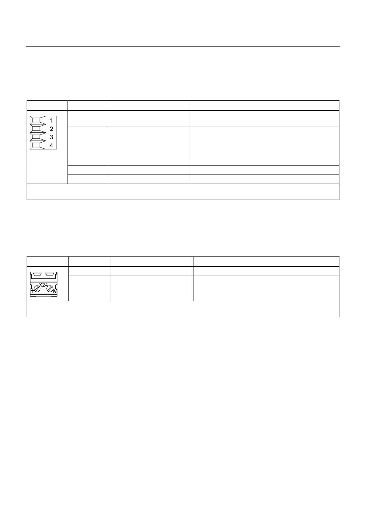
X22 digital inputs
Table 8- 65 X22 digital inputs for Smart Line Modules 5 kW and 10 kW
Terminal
Description 1)
Technical specifications
1
24 V power supply
Electronic power supply for controlling digital inputs
X22.2 and 3.
2
DI: Disable regeneration
Deactivate regenerative feedback (high active).
No power is supplied back to the network from the DC
link. The regenerative energy of the motors may have to
be reduced using a combination of the Braking Module
and braking resistor.
3
DI: Reset
Reset faults (negative edge)
4
Ground
Electronics ground
Max. connectable cross-section: 1.5 mm2
Type: Screw terminal 1 (see Appendix, Chapter "Screw terminals")
1) DI: Digital input
X24 24 V terminal adapter
Table 8- 66 X24 24 V terminal adapter
Terminal
Description
Technical specifications
+
24 V power supply
24 VDC supply voltage
M
Ground
Electronics ground
Max. connectable cross-section: 6 mm2
Type: Screw terminal 5 (see Appendix, Chapter "Screw terminals")
The 24 V terminal adapter is included in the scope of delivery.
Guidelines for machine configuration
306
System Manual, MA 01/2013, 6FC5397-6CP10-0BA2
Connection of the components in SINAMICS drive system
8.3 Connection of line modules
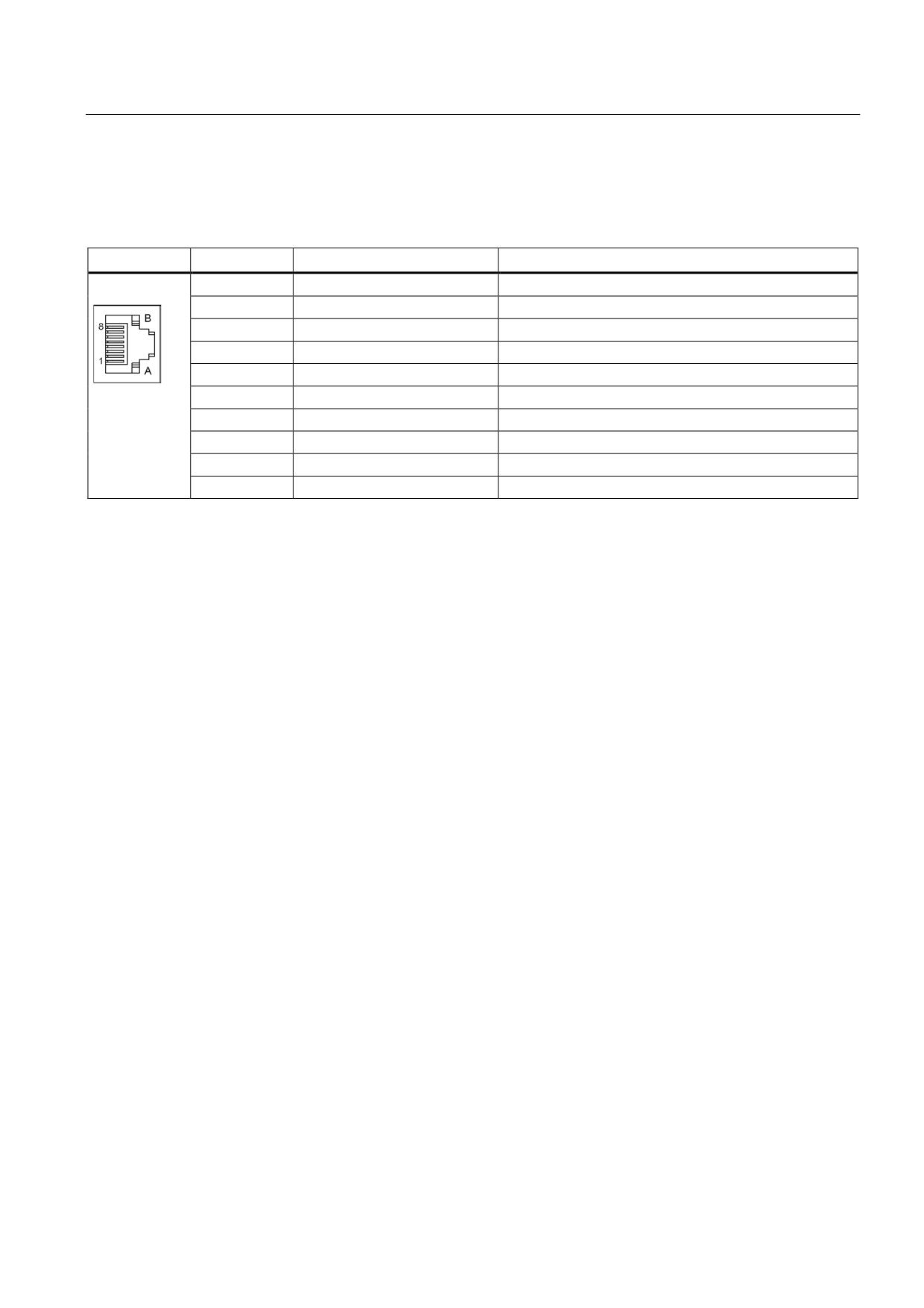
X200-X202 DRIVE-CLiQ interfaces
Table 8- 67 X200-X202 DRIVE-CLiQ interfaces
PIN
Signal name
Technical specifications
1
TXP
Transmit data +
2
TXN
Transmit data -
3
RXP
Receive data +
4
Reserved, do not use
5
Reserved, do not use
6
RXN
Receive data -
7
Reserved, do not use
8
Reserved, do not use
A
+(24 V)
24 V power supply
B
M (0 V)
Electronics ground
The blanking covers for the DRIVE-CLiQ interfaces are included in the scope of delivery.
Blanking cover (50 pcs.) Order number: 6SL3066-4CA00-0AA0
Guidelines for machine configuration
System Manual, MA 01/2013, 6FC5397-6CP10-0BA2
307
Connection of the components in SINAMICS drive system
8.3 Connection of line modules
8.3.8.4
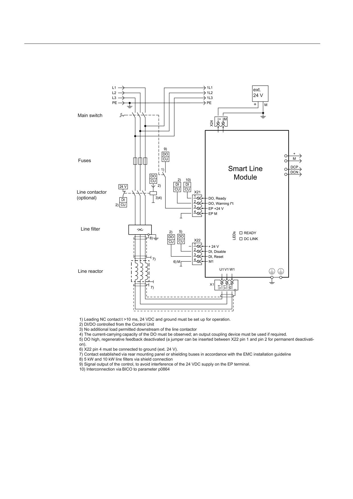
Connection examples
Figure 8-74 Connection example for 5 kW and 10 kW Smart Line Modules
Guidelines for machine configuration
308
System Manual, MA 01/2013, 6FC5397-6CP10-0BA2
Connection of the components in SINAMICS drive system
8.3 Connection of line modules
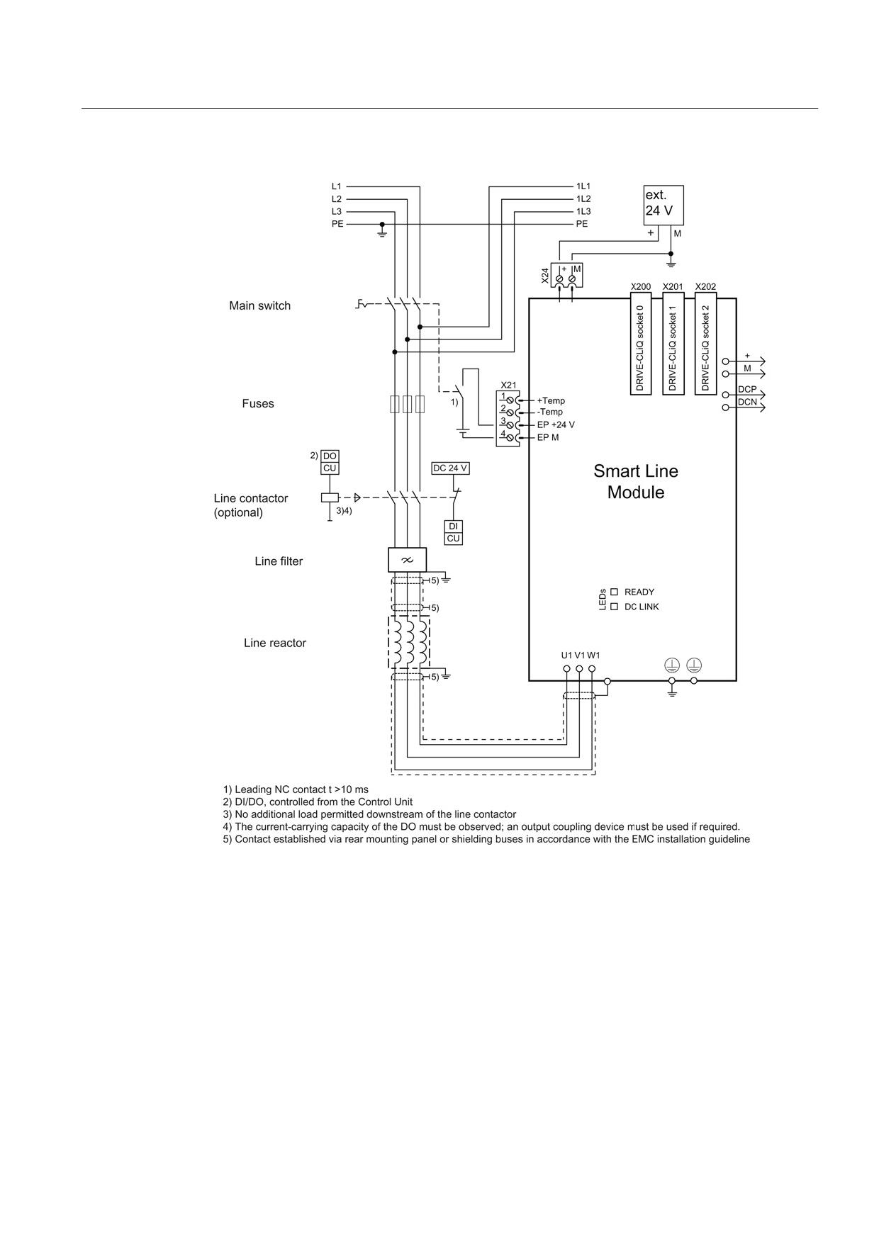
Figure 8-75 Connection example for 16 kW to 55 kW Smart Line Modules
Guidelines for machine configuration
System Manual, MA 01/2013, 6FC5397-6CP10-0BA2
309
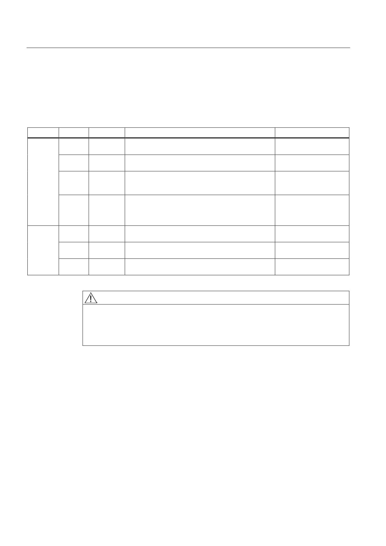
Connection of the components in SINAMICS drive system
8.3 Connection of line modules
8.3.8.5
Meaning of LEDs
Smart Line Modules 5 kW and 10 kW
Table 8- 68 Meaning of the LEDs on 5 kW and 10 kW Smart Line Modules
LED
Color
Status
Description, cause
Remedy
RDY
-
Off
Electronics power supply is missing or outside
-
permissible tolerance range.
Green
Continuous
Component is ready to operate.
-
light
Yellow
Continuous
Pre-charging not yet complete.
-
light
Bypass relay dropped out
EP terminals not supplied with 24 VDC.
Red
Continuous
Overtemperature,
Diagnose fault (via output
light
overcurrent
terminals) and
acknowledge it (via input
terminal)
DC LINK
-
Off
Electronics power supply is missing or outside
-
permissible tolerance range.
Yellow
Continuous
DC link voltage within permissible tolerance range.
-
light
Red
Continuous
DC link voltage outside permissible tolerance range.
Check line voltage.
light
Power system fault.
WARNING
Danger to life due to high DC link voltage, regardless of LED display
Hazardous DC link voltages may be present at any time regardless of the status of the
"DC LINK" LED.
• Observe the warning information on the component.
Guidelines for machine configuration
310
System Manual, MA 01/2013, 6FC5397-6CP10-0BA2
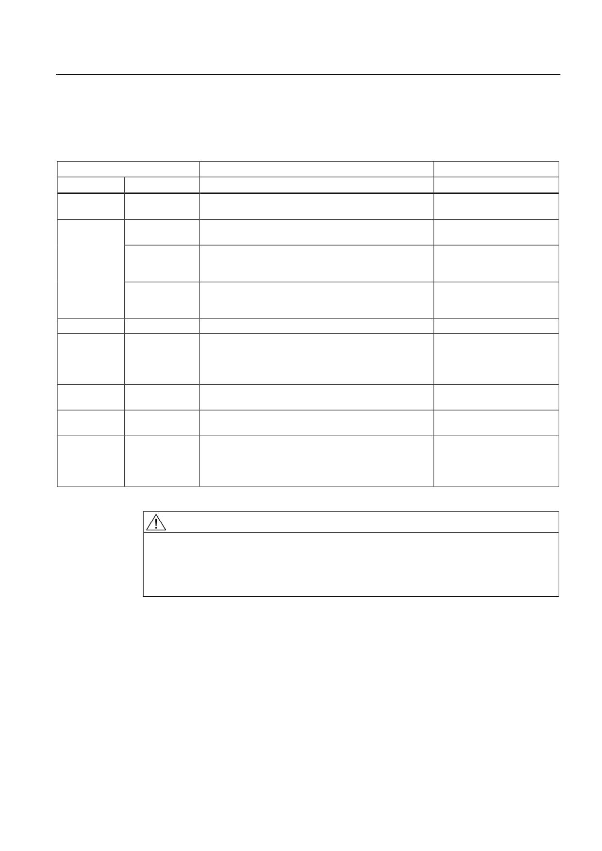
Connection of the components in SINAMICS drive system
8.3 Connection of line modules
16 kW to 55 kW Smart Line Modules
Table 8- 69 Meaning of the LEDs on Smart Line Modules ≥ 16 kW
Status
Description, cause
Remedy
RDY
DC LINK
Off
Off
Electronics power supply is missing or outside
-
permissible tolerance range.
Green
--
The component is ready for operation and cyclic DRIVE-
-
CLiQ communication is taking place.
Orange
The component is ready for operation and cyclic DRIVE-
-
CLiQ communication is taking place.
The DC link voltage is present.
Red
The component is ready for operation and cyclic DRIVE-
Check line voltage
CLiQ communication is taking place.
The DC link voltage is too high.
Orange
Orange
DRIVE-CLiQ communication is being established.
-
Red
--
At least one fault is present in this component.
Remedy and acknowledge
fault
Note:
The LED is activated regardless of whether the
corresponding messages have been reconfigured.
Green/red
--
Firmware is being downloaded.
-
(0.5 Hz)
Green/red
--
Firmware download is complete. Wait for POWER ON.
Carry out a POWER ON
(2 Hz)
Green/orange
--
Component detection via LED is activated (p0124).
-
or
Note:
Red/orange
Both options depend on the LED status in the case of
activation via p0124 = 1.
WARNING
Danger to life due to high DC link voltage, regardless of LED display
Hazardous DC link voltages may be present at any time regardless of the status of the
"DC LINK" LED.
• Observe the warning information on the component.
Guidelines for machine configuration
System Manual, MA 01/2013, 6FC5397-6CP10-0BA2
311
Connection of the components in SINAMICS drive system
8.3 Connection of line modules
8.3.8.6
Dimension drawings
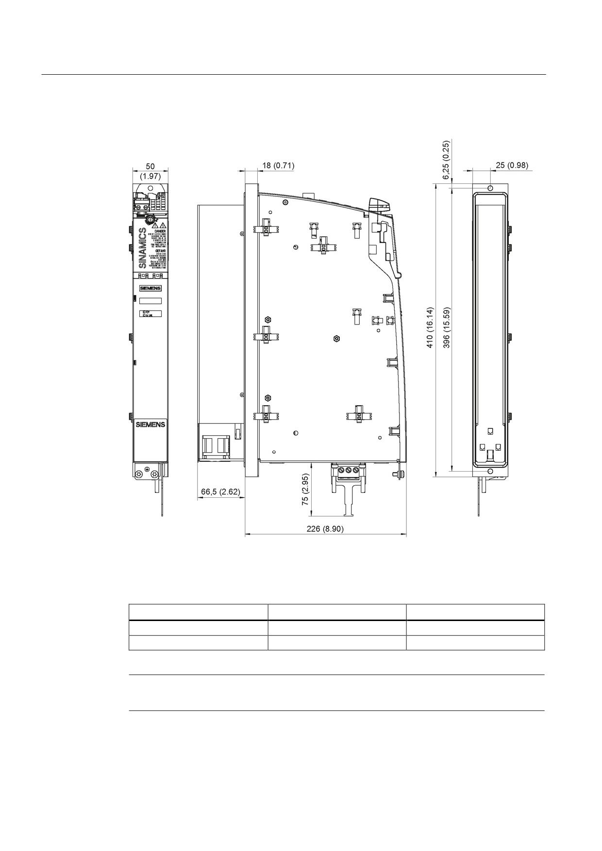
Figure 8-76 Dimension drawing of 5 kW and 10 kW Smart Line Modules with external air cooling, all
dimensions in mm and (inches)
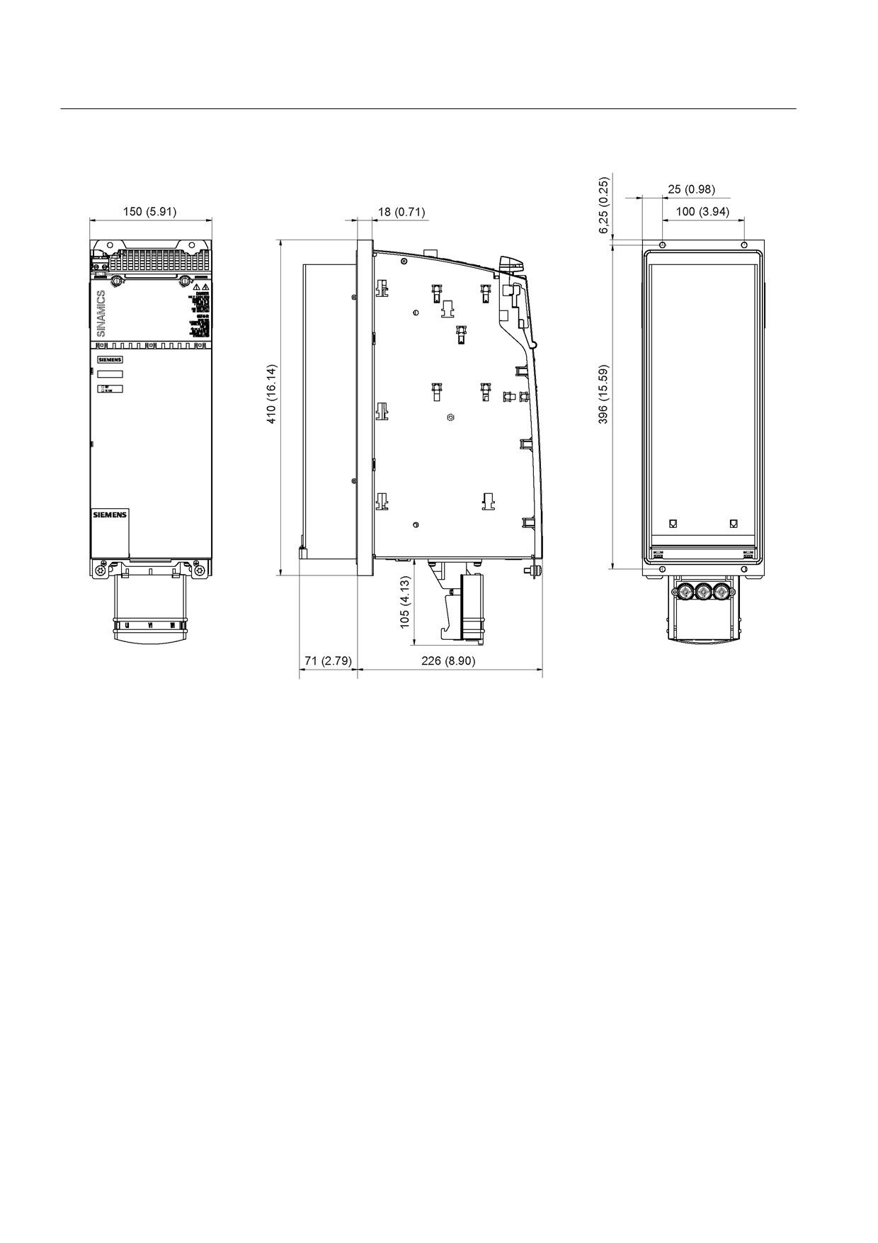
Table 8- 70 Dimensions of Smart Line Modules with external air cooling
Line Module
Order number
W [mm] (inches)
5 kW
6SL3131-6AE15-0AAx
50 (1.97)
10 kW
6SL3131-6AE21-0AAx
50 (1.97)
Note
The shield connecting plate is part of the scope of supply of the 50 mm Smart Line Module.
Guidelines for machine configuration
312
System Manual, MA 01/2013, 6FC5397-6CP10-0BA2
Connection of the components in SINAMICS drive system
8.3 Connection of line modules
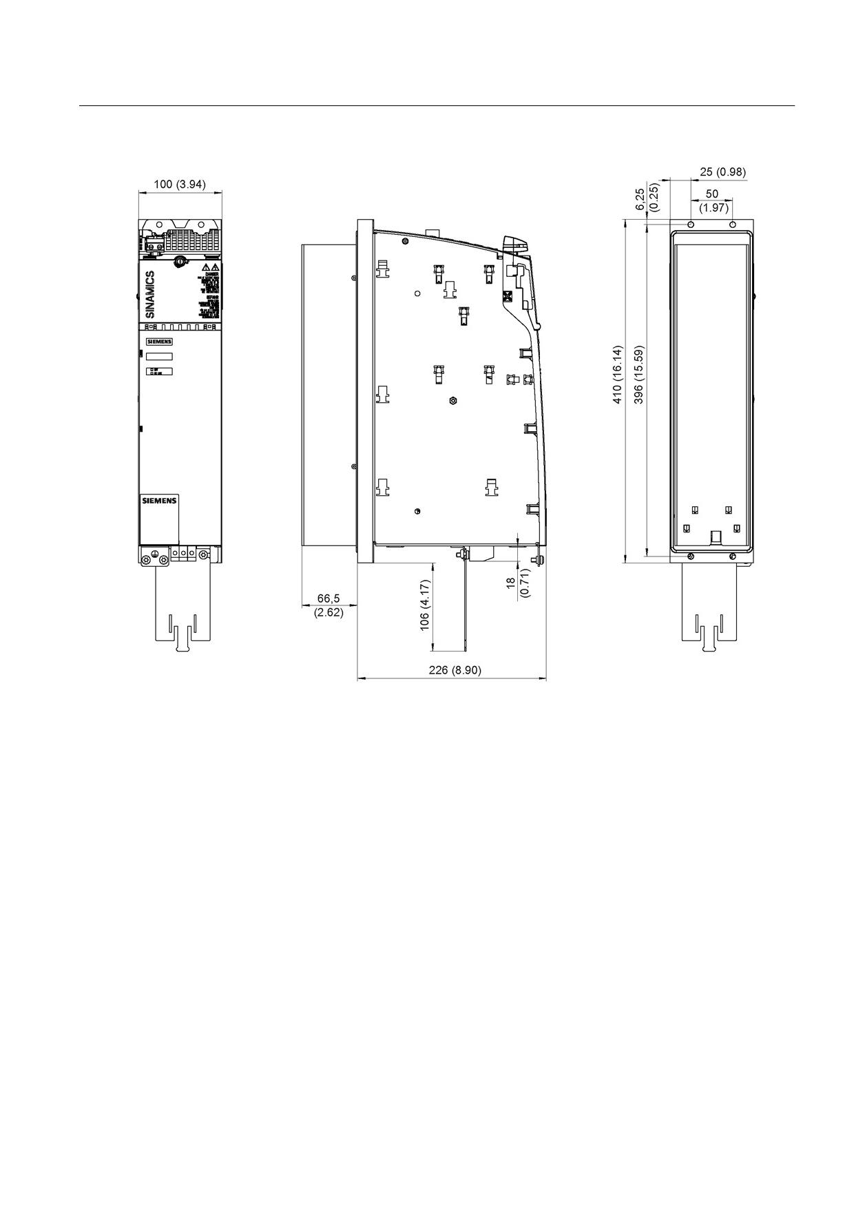
Figure 8-77 Dimension drawing of 16 kW Smart Line Module with external air cooling, all dimensions in mm and (inches)
Guidelines for machine configuration
System Manual, MA 01/2013, 6FC5397-6CP10-0BA2
313
Connection of the components in SINAMICS drive system
8.3 Connection of line modules
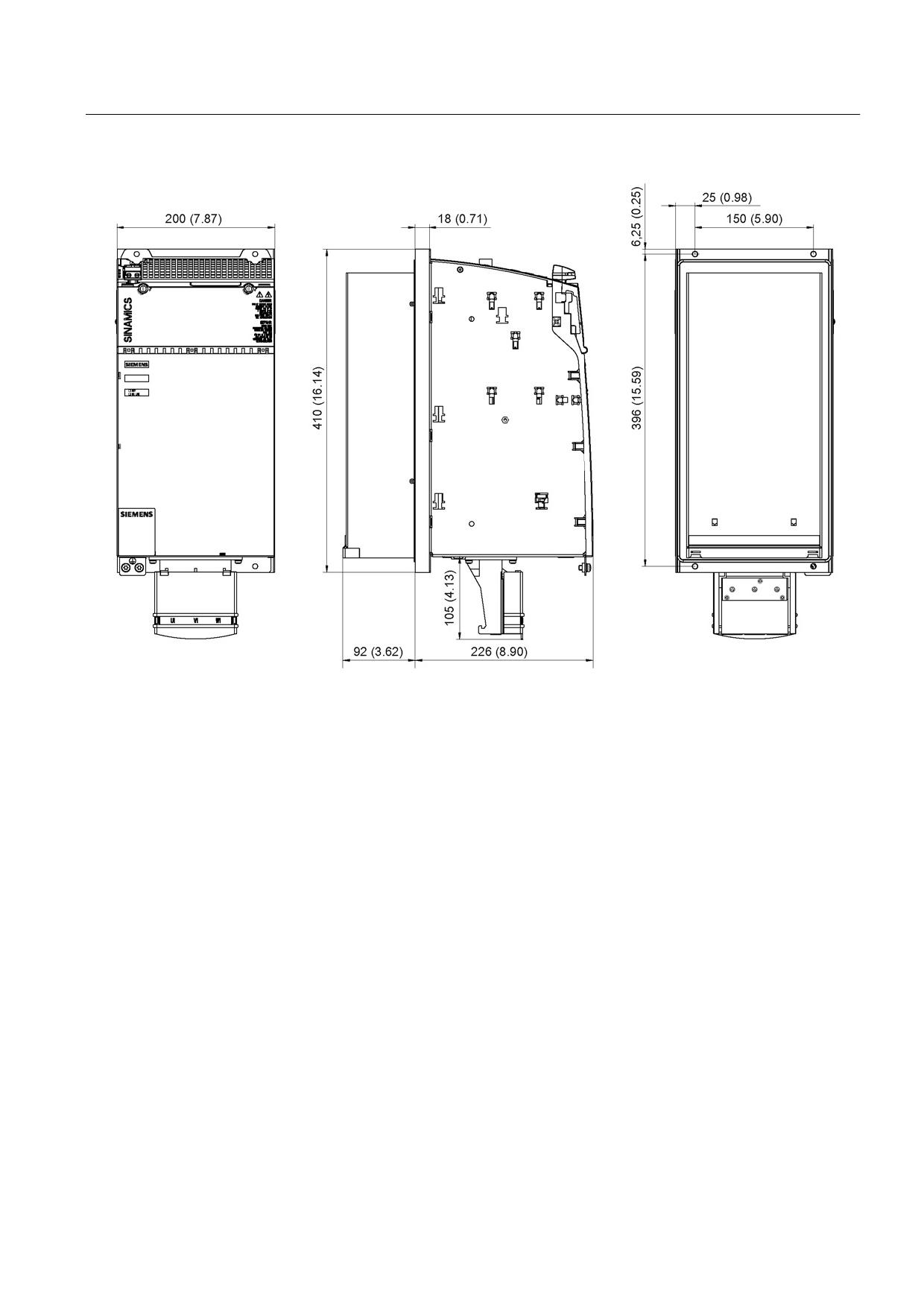
Figure 8-78 Dimension drawing of 36 kW Smart Line Module with external air cooling, all dimensions in mm and (inches)
Guidelines for machine configuration
314
System Manual, MA 01/2013, 6FC5397-6CP10-0BA2
Connection of the components in SINAMICS drive system
8.3 Connection of line modules
Figure 8-79 Dimension drawing of 55 kW Smart Line Module with external air cooling, all dimensions in mm and (inches)
Guidelines for machine configuration
System Manual, MA 01/2013, 6FC5397-6CP10-0BA2
315
Connection of the components in SINAMICS drive system
8.3 Connection of line modules
8.3.8.7
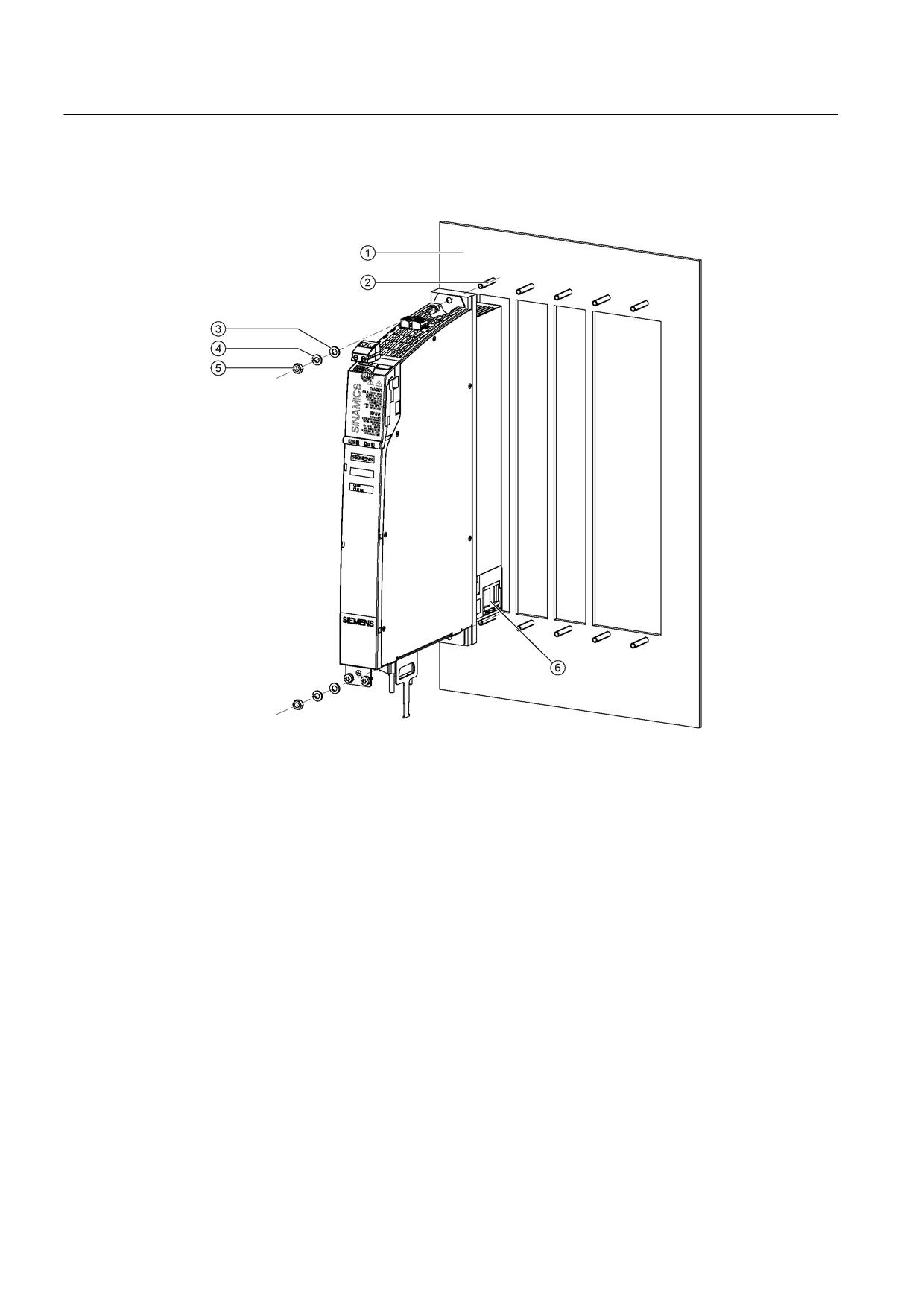
Installation
①
Mounting plate with openings
②
M6 studs
③
Washer
④
Spring washer
⑤
M6 nut, width A/F 10 (hexagon head)
⑥
Fan assembly
Figure 8-80 Installing a Smart Line Module with external air cooling on a mounting plate, using a
5 kW Smart Line Module as an example
Tightening torques:
● Initially, tighten by hand (0.5 Nm)
● Then tighten with 6 Nm.
Guidelines for machine configuration
316
System Manual, MA 01/2013, 6FC5397-6CP10-0BA2
Connection of the components in SINAMICS drive system
8.3 Connection of line modules
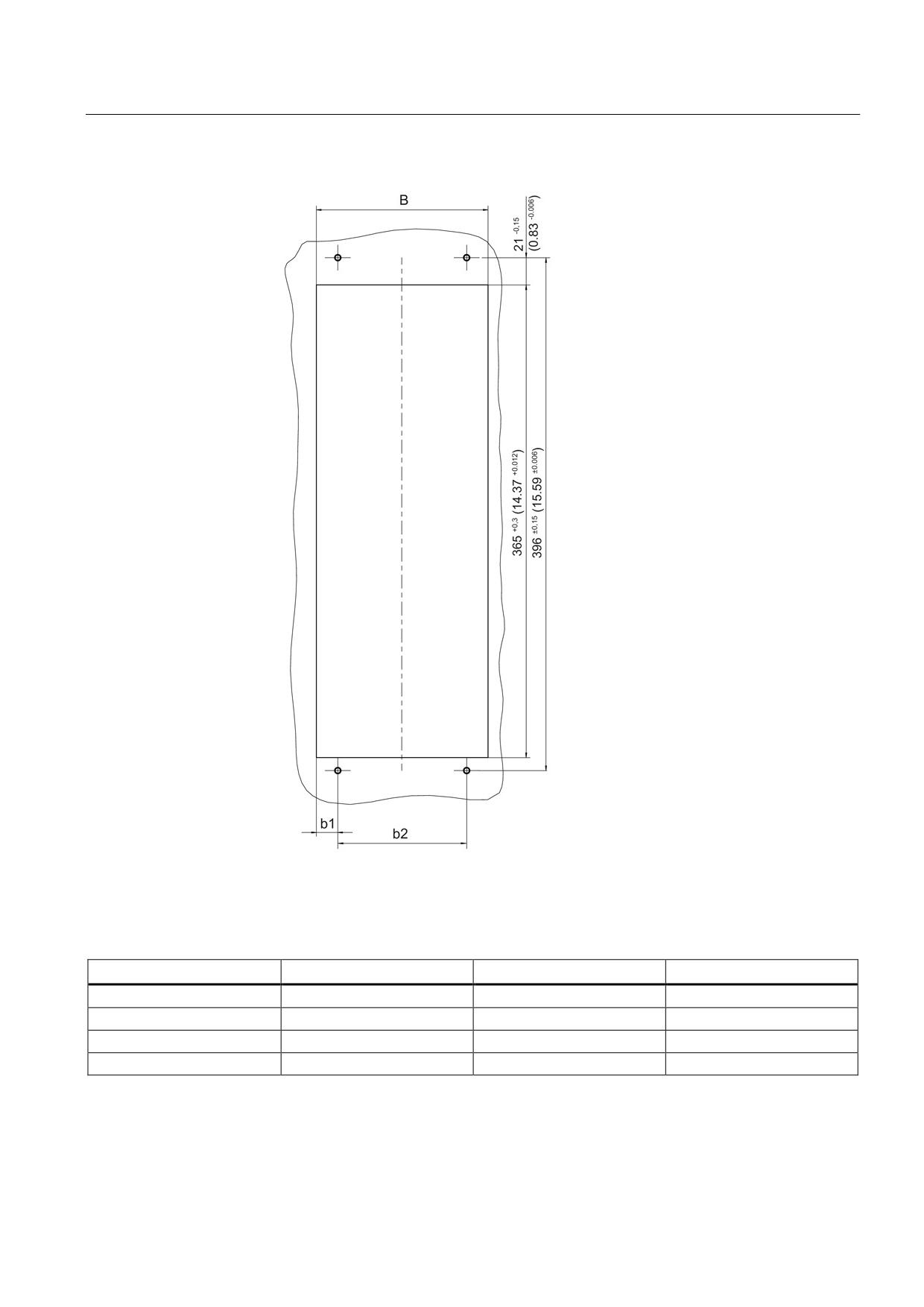
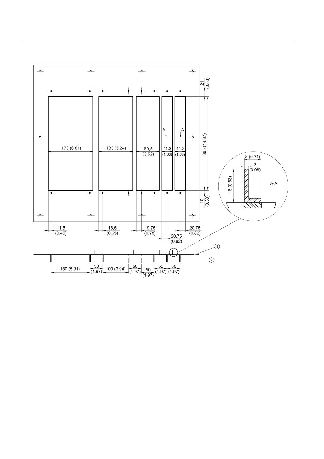
Figure 8-81 Installation opening for Smart Line Modules 50 mm to 200 mm with external air
cooling, all data in mm and (inches)
Table 8- 71 Dimensions of installation openings for Smart Line Modules with external air cooling
Module width
W in mm (inches)
w1 in mm (inches)
w2 in mm (inches)
50 mm
41.5 +0.3 (1.63 +0.012)
20.75 +0.15 (0.82 +0.006)
--
100 mm
89.5 +0.3 (3.52 +0.012)
19.75 +0.15 (0.78 +0.006)
50 ±0.15 (1.97 ±0.006)
150 mm
133 +0.3 (5.24 +0.012)
16.5 +0.15 (0.65 +0.006)
100 ±0.15 (3.94 ±0.006)
200 mm
173 +0.3 (6.81 +0.012)
11.5 +0.15 (0.45 +0.006)
150 ±0.15 (5.91 ±0.006)
Guidelines for machine configuration
System Manual, MA 01/2013, 6FC5397-6CP10-0BA2
317
Connection of the components in SINAMICS drive system
8.3 Connection of line modules
①
Insert or mounting plate
②
Threaded bolts M5 x 28
Figure 8-82 Example of a mounting plate for a drive line-up with external air cooling
During installation it must be ensured that the component's seal is tight throughout. The
cross-pieces must have the appropriate stability. If necessary, the cross-pieces of the
openings must be reinforced.
In our example, the cross-pieces have been reinforced using brackets to EN 755-9. You are
free to select the way that the bracket is attached to the insert.
Guidelines for machine configuration
318
System Manual, MA 01/2013, 6FC5397-6CP10-0BA2
Connection of the components in SINAMICS drive system
8.3 Connection of line modules
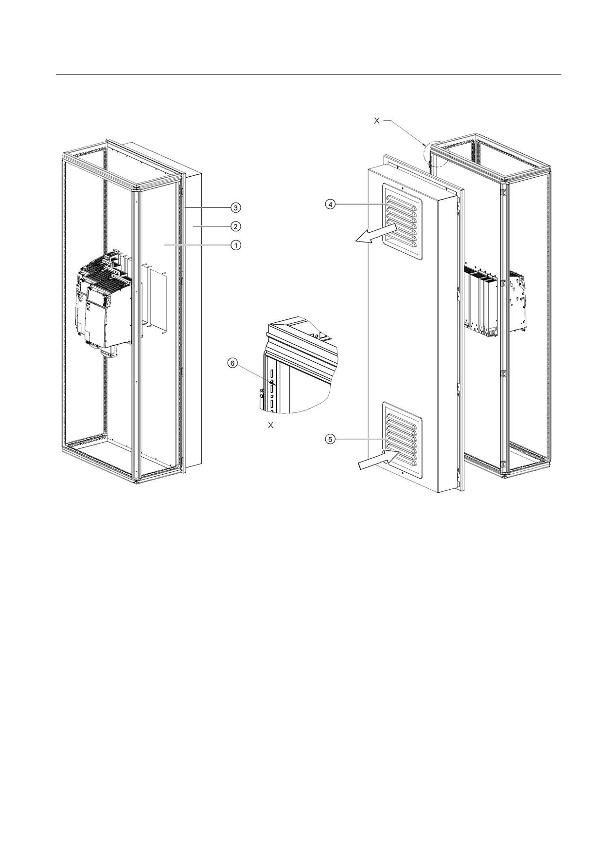
①
Mounting plate
②
Cover
③
Rear panel
④
Air discharge
⑤
Air inlet - filter with filter fan
⑥
To comply with degree of protection IP54, the surfaces ⑥ between the mounting plate and the cabinet strip must
be sealed all round. (for example, sealant Terostat-91 from the Teroson company)
Figure 8-83 Example 1: installation in cabinet with mounting plate
Guidelines for machine configuration
System Manual, MA 01/2013, 6FC5397-6CP10-0BA2
319
Connection of the components in SINAMICS drive system
8.3 Connection of line modules
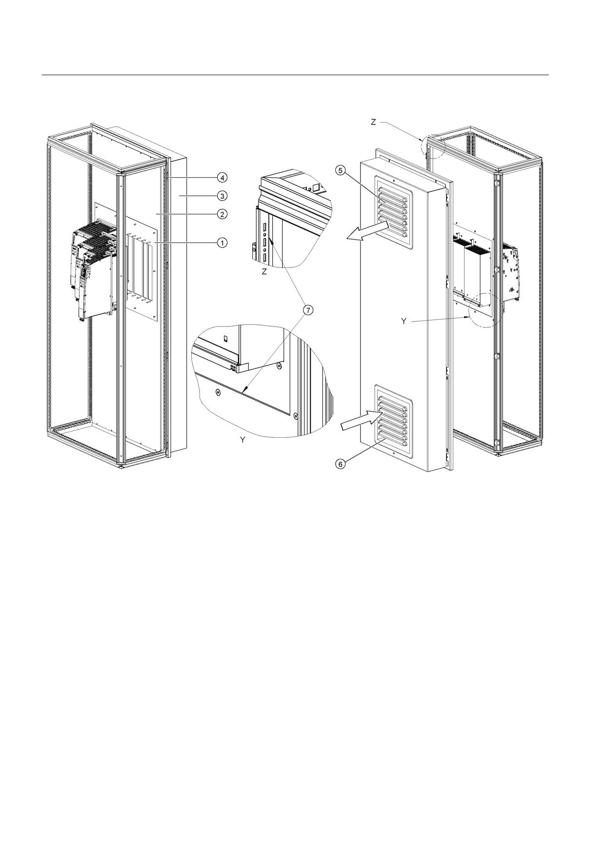
①
Insert
②
Mounting plate
③
Cover
④
Rear panel
⑤
Air discharge
⑥
Air inlet - filter with filter fan
⑦
To maintain the degree of protection IP54, the surfaces ⑦ between the mounting plate and the cabinet strip as
well as between the mounting plate and insert must be sealed all around. (for example, sealant Terostat-91 from
the Teroson company)
Figure 8-84 Example 2: installation in cabinet with mounting plate
We recommend that you attach a cover and filter fan to the cabinet.
The filtered fan must be fitted in such a way that the cooling air required by the drive line-up
is not restricted. The overall cooling air requirement is obtained from the sum of the
individual components (refer to Chapter, "Technical data").
Guidelines for machine configuration
320
System Manual, MA 01/2013, 6FC5397-6CP10-0BA2
Connection of the components in SINAMICS drive system
8.3 Connection of line modules
Note
If the cooling air requirement is not covered by the filtered fan, the components cannot
output their specified power.
The filters with a filter fan must be regularly checked for dirt and cleaned if necessary.
Help with the mechanical control cabinet installation is available from:
Siemens AG
Industry Sector, IA SE WKC
TCCCC (Technical Competence Center Cabinets Chemnitz)
P.O. Box 1124
09070 Chemnitz, Germany
E-mail: cc.cabinetcooling.aud@siemens.com
8.3.8.8
Technical specifications
Table 8- 72 Technical data Smart Line Modules Booksize external air cooling
Internal air cooling
6SL3131-
6AE15-0AAx
6AE21-0AAx
6TE21-6AAx
6TE23-6AAx
6TE25-5AAx
Rated power
kW
5
10
16
36
55
Infeed
Rated power (S1)1)
kW (Pn)
5
10
16
36
55
S6 operation (40%)1)
kW (Ps6)
6.5
13
21
47
71
Peak infeed power1)
kW (Pmax)
10
20
35
70
91
Energy recovery
Continuous regenerative
power
kW
5
10
16
36
55
Peak regenerative power
kW
10
20
35
70
91
Supply voltages
Line voltage
VAC
3 AC 380 -10% (-15% < 1 min) to 3 AC 480 +10%
Line frequency
Hz
47 to 63
Electronics power supply
VDC
24 (20.4 - 28.8)
DC link voltage
VDC
510 - 720
Overvoltage trip
VDC
820 ±2%
Undervoltage trip2)
VDC
360 ±2%
Input currents
Rated input current
at 400 VAC
AAC
8.1
16.2
27.5
59
90
at 380 VAC/480 VAC
AAC
8.6 / 6.7
17 / 12.8
29 / 24.5
62 / 51
94 / 77
S6 (40%) at 400 VAC;
AAC
10.6
21.1
35
76
106
peak current at 400 VAC
AAC
15.7
31.2
57.5
112
130
DC link currents
DC link output current
at 600 VDC
ADC
8.3
16.6
27
60
92
at 540 VDC
ADC
9.3
18.5
30
67
105
S6 (40%) at 600 VDC
ADC
11
22
35
79
138
Peak current at 600 VDC
ADC
16.6
33.2
59
118
178
Guidelines for machine configuration
System Manual, MA 01/2013, 6FC5397-6CP10-0BA2
321
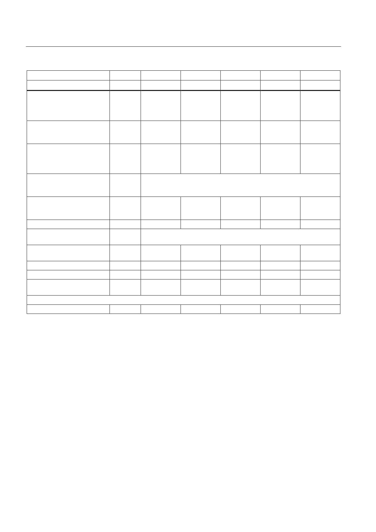
Connection of the components in SINAMICS drive system
8.3 Connection of line modules
Internal air cooling
6SL3131-
6AE15-0AAx
6AE21-0AAx
6TE21-6AAx
6TE23-6AAx
6TE25-5AAx
Rated power
kW
5
10
16
36
55
Current-carrying capacity
DC link busbar
ADC
100
100
100
200
200
Reinforced DC link busbars:
ADC
150
150
150
--
--
24 V busbar:
ADC
20
20
20
20
20
Electronics current
ADC
0.8
0.9
0.95
1.5
1.9
consumption
at 24 VDC
Total power loss
W
79.2
141.6
187.8
406
665.6
(incl. electronics losses)3)
Internal
W
41.2
66.6
64.8
116
185.6
External
W
38
75
123
290
480
Max. ambient temperature
without derating
°C
40
with derating
°C
55
DC link capacitance
Smart Line Module
μF
220
330
705
1410
1880
Drive line-up, max.
μF
6000
6000
20000
20000
20000
Power factor
cos ϕ
0.98
0.98
0.98
0.98
0.98
Circuit breaker
See Chap. "Overcurrent protection using line fuses and circuit breakers
(IEC 60947 and UL)
(Page 116)"
Rated short-circuit
kA
65
65
65
65
65
current SCCR4)
Sound pressure level
dB(A)
< 60
< 60
< 60
<65
< 60
Cooling air requirement
m3/h
29.6
29.6
56
112
160
Max. permissible heat sink
°C
695)
735)
77
80
75
temperature
Rated voltage for rated data 3 AC 380 V
Weight
kg
5.3
5.4
8.8
13.8
18.5
1)
The specified power ratings apply to the line voltage range from 380 V to 480 V
2)
For 16 kW and 36 kW Smart Line Modules: Default for 400 V line systems; undervoltage trip threshold is adjusted to the
parameterized rated voltage.
3)
For an overview, see the power loss tables in the Appendix
4)
The resulting rated short-circuit current is obtained from the combination of the fuse, or circuit breaker, and the Line
Module in the drive system.
5)
Values cannot be read out by the system (STARTER).
Guidelines for machine configuration
322
System Manual, MA 01/2013, 6FC5397-6CP10-0BA2
Connection of the components in SINAMICS drive system
8.3 Connection of line modules
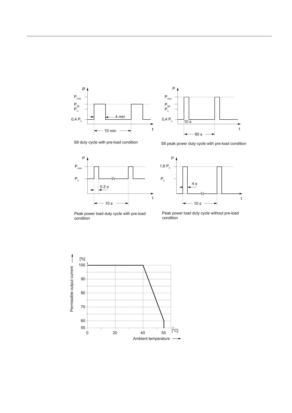
Characteristics
Rated duty cycles of Smart Line Modules
Figure 8-85 Rated duty cycles of Smart Line Modules
Derating characteristics
Figure 8-86 Output current as a function of the ambient temperature
Guidelines for machine configuration
System Manual, MA 01/2013, 6FC5397-6CP10-0BA2
323
Connection of the components in SINAMICS drive system
8.3 Connection of line modules
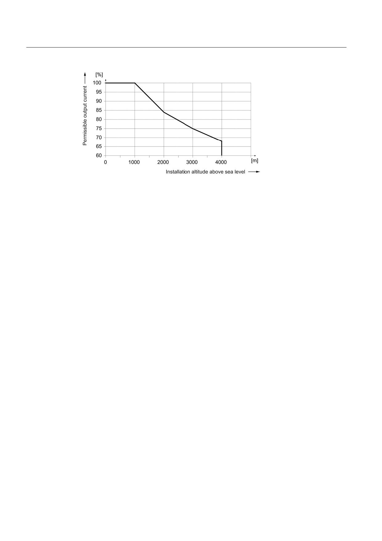
Figure 8-87 Output current as a function of the installation altitude
At installation altitudes > 2000 m, an isolation transformer must be used (see the chapter
titled "System overview/Function of installation altitude and ambient temperature"
(Page 32)). The design of the secondary line system must be as follows:
● TN system with grounded neutral point (no grounded line conductor)
● IT system
A reduction of the line supply voltage phase-phase is not necessary.
8.3.9
Smart Line Modules with cold plate
8.3.9.1
Description
The Smart Line Module is a non-regulated infeed/regenerative feedback unit. The Smart
Line Module supplies the Motor Module(s) with a non-regulated DC voltage at the DC output.
In the infeed mode the Smart Line Module exhibits the typical current and voltage waveforms
of a 6-pulse diode rectifier bridge.
In feedback mode, the current waveform is square waved. Feedback can be deactivated by
means of a terminal because these Smart Line Modules are not equipped with a DRIVE-
CLiQ connection.
The DC link starts precharging as soon as the supply voltage is applied and is independent
of its phase sequence direction. Load can be applied to the DC link after the module has
been enabled. An optional main contactor is required for disconnecting the voltage.
Smart Line Modules are suitable for direct operation on TN, IT, and TT systems. The
modules have an integrated overvoltage protection function.
Guidelines for machine configuration
324
System Manual, MA 01/2013, 6FC5397-6CP10-0BA2
Connection of the components in SINAMICS drive system
8.3 Connection of line modules
8.3.9.2
Product-specific safety information for the Smart Line Modules in booksize format
The safety instructions described in this chapter apply specifically to Smart Line Modules in
booksize format.
In addition, you should strictly observe the safety instructions in Chapter 1.
NOTICE
It is essential that a particular switch-on and switch-off sequence is followed in order to
control the 5 kW and 10 kW Smart Line Modules; if this sequence is not observed, the
Smart Line Module could be damaged beyond repair. To prevent the SLM being destroyed,
the "Ready" signal must be evaluated at output terminal X21.1.
Activation:
•
24 VDC power supply X24 ON
• Line contactor ON
• EP signal X21 pins 3 and 4 ON
• Wait until precharging is complete
• "Ready" signal at terminal X21 pin 1 set to "high"
• Infeed is ready, pulse enable possible for motors
Deactivation:
• Shut drives down
• Cancel pulse enable for motors (OFF1 signal)
• EP signal X21 pins 3 and 4 OFF
• Line contactor OFF
•
24 VDC power supply X24 OFF
Overload:
• "Prewarning" signal at terminal X21 pin 2 set to "low"
• Shut drives down via the control system
• "Ready" signal at terminal X21 pin 1 set to "low"
• Pulse inhibit for all the drives supplied by this infeed within 4 ms
Note
Operation without the line reactor is not permissible.
Guidelines for machine configuration
System Manual, MA 01/2013, 6FC5397-6CP10-0BA2
325
Connection of the components in SINAMICS drive system
8.3 Connection of line modules
Note
Connection to the public low-voltage network
Smart Line Modules have been designed for use in the industrial environment and generate
current harmonics on the line side as a result of the rectifier circuit.
When connecting a machine with integrated Smart Line Modules to the public low-voltage
network, authorization is required in advance from the local power supply company (utility
company) if
• The rated current of the machine ≤ 16 A per conductor, and
• the rated machine current does not comply with the requirements specified in EN 61000-
3-2 regarding current harmonics.
Guidelines for machine configuration
326
System Manual, MA 01/2013, 6FC5397-6CP10-0BA2
Connection of the components in SINAMICS drive system
8.3 Connection of line modules
8.3.9.3
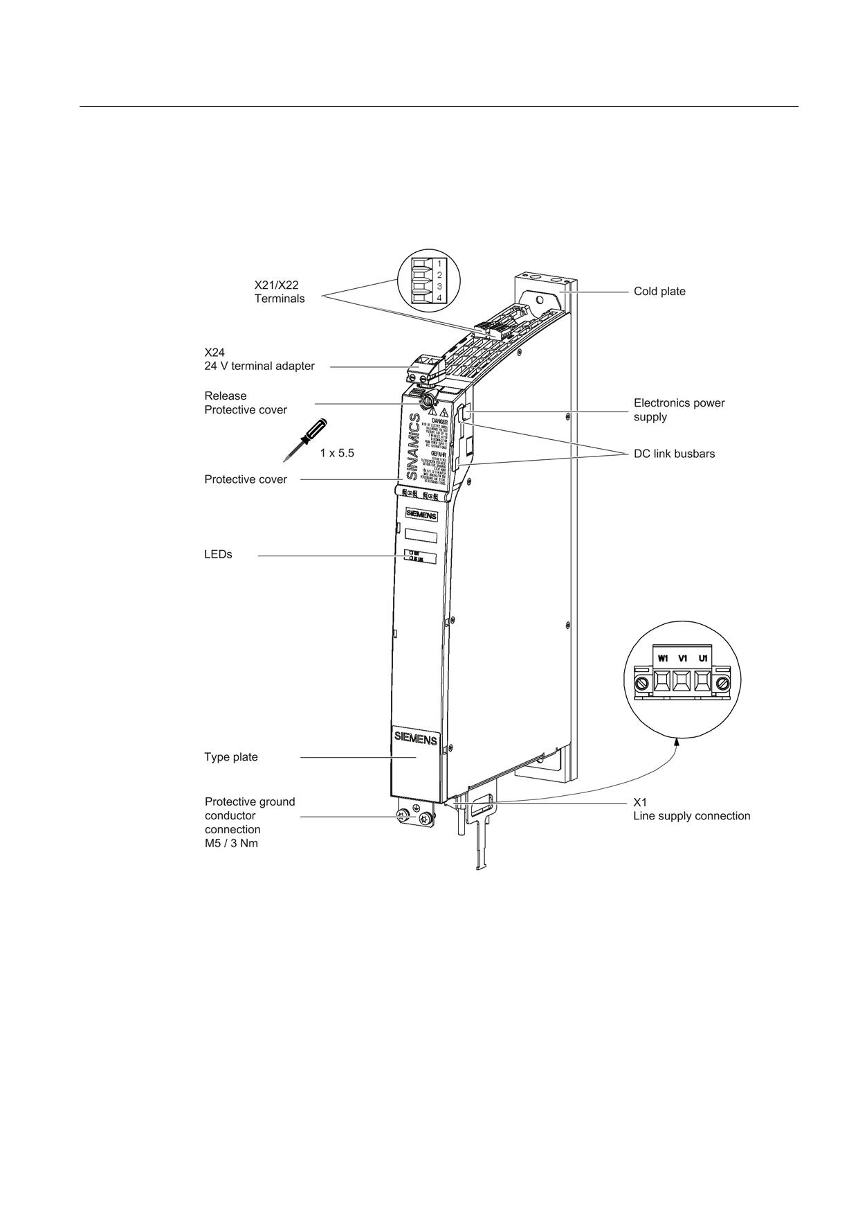
Interface description
Overview
Figure 8-88 Interface overview, Smart Line Module with cold plate (example: 5 kW)
Guidelines for machine configuration
System Manual, MA 01/2013, 6FC5397-6CP10-0BA2
327
Connection of the components in SINAMICS drive system
8.3 Connection of line modules
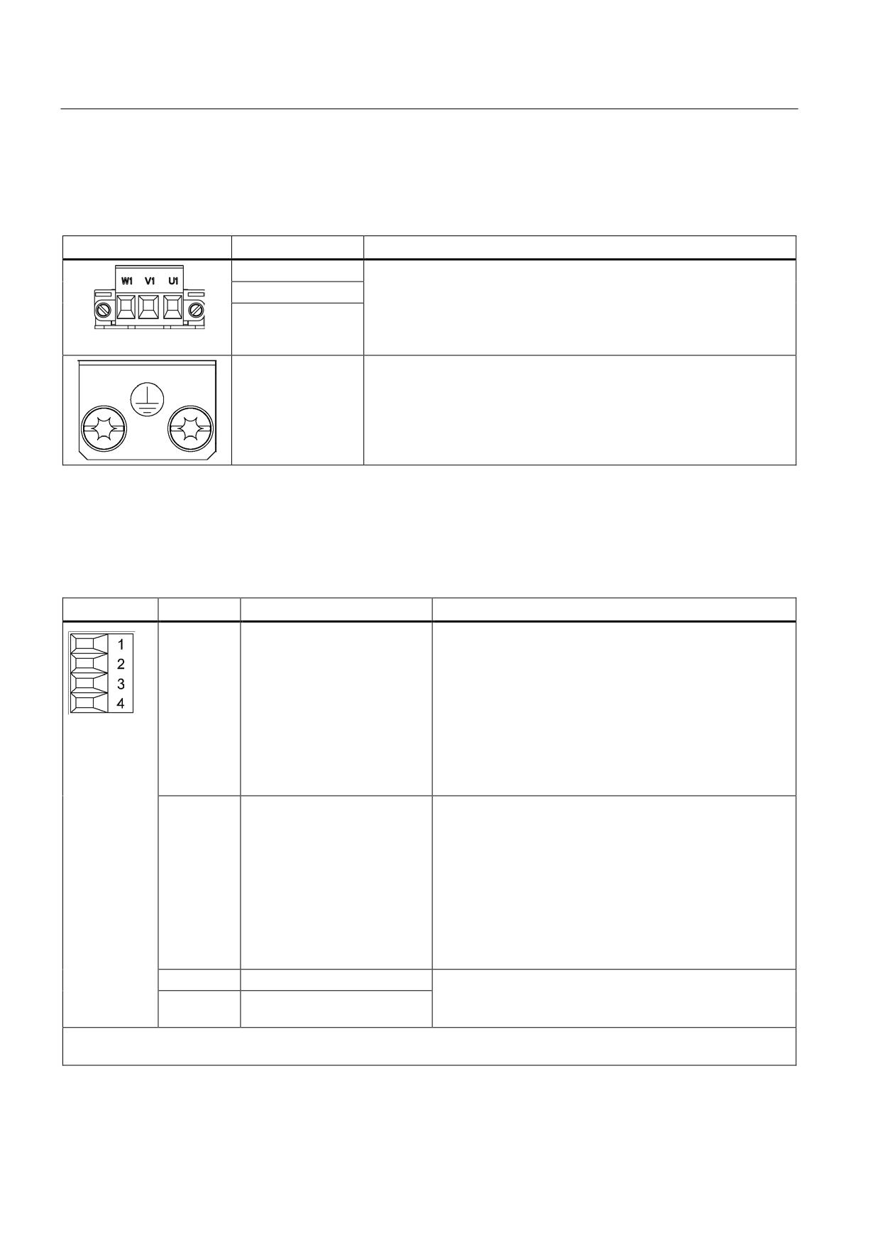
X1 line connection
Table 8- 73 X1 line connection
Terminal
Technical specifications
U1
Supply voltage:
3 AC 380 V - 480 V, 50/60 Hz
V1
Max. connectable cross-section: 6 mm2
W1
Type: Screw terminal 5 (see Appendix, Chapter "Screw terminals")
Tightening torque: 1.2 - 1.5 Nm
PE connection
Threaded hole M5/3 Nm 1)
1) For ring cable lugs in accordance with DIN 46234
X21 EP terminals
Table 8- 74 X21 EP terminals
Terminal
Designation
Technical data
1
DO: Ready
Checkback signal: Smart Line Module ready
The signal switches to high level when the following
conditions have been met:
• Electronics power supply (X24) OK
• DC link is precharged
• Pulses enabled (X21.3/.4)
• No overtemperature
• No overcurrent switch-off
2
DO: Prewarning
DO: Prewarning
High = no prewarning
Low = prewarning
• Overtemperature warning threshold / I*t
5 kW prewarning: 64 °C, disconnection: 69 °C
10 kW prewarning: 68 °C, disconnection: 73°C
• No regenerative feedback capability due to a line fault
[only monitored when regenerative feedback is activated
(see terminal X22.2)]
3
EP +24 V (Enable Pulses)
Voltage 24 VDC
Current consumption: 10 mA
4
EP M (Enable Pulses)
Isolated input
Max. connectable cross-section: 1.5 mm2
Type: Screw terminal 1 (see Appendix, Chapter "Screw terminals")
Guidelines for machine configuration
328
System Manual, MA 01/2013, 6FC5397-6CP10-0BA2
Connection of the components in SINAMICS drive system
8.3 Connection of line modules
WARNING
Danger to life due to charged DC link
For operation, the 24 VDC voltage must be connected to terminal X21.3 and ground to
terminal X21.4. When withdrawn, pulse suppression is activated. Regenerative feedback is
deactivated and the bypass relay drops out. If the Line Module is not disconnected from the
supply system when the EP terminal is deactivated (e.g. a line contactor is not installed),
the DC link remains charged.
NOTICE
Device damage due to incorrect activation or deactivation sequence
It is essential that a particular switch-on and switch-off sequence is followed in order to
control the Smart Line Modules; if this sequence is not observed, the Smart Line Module
could be destroyed.
• To prevent this, evaluate the "Ready" signal at output terminal X21.1 (see the chapter
titled "Safety instructions").
Note
Output terminal X21.1 must be wired to a digital input on the CU. The drives supplied with
power by the Smart Line Module have to use this signal as a "Ready" message (BI: p0864 =
digital input). This ensures that a pulse enable can only be issued for the drives (motor or
generator operation) when the infeed is ready.
If interconnection with a digital input on the CU is not possible, the signal must be evaluated
by a higher-level control instead. The control may not set the drives to ready until the infeed
"Ready" signal is present.
Note
The "Prewarning" signal at output terminal X21.2 warns against an overload. If this signal is
set, the control system should shut the drives down before the "Ready" signal switches to
"low". If the "Ready" signal switches to "low", the drive pulses must be suppressed within
4 ms.
Note
If an active drive line-up is switched off by means of the disconnector unit, the voltage at
terminals X21.3 (EP +24 V) and X21.4 (EP M) must be interrupted beforehand. This can be
carried out using a leading (≥ 10 ms) breaking auxiliary contact, for example.
This protects external loads located parallel to the drive on the same switching component.
Note
The Smart Line Module signals that it is ready, even if one of the line conductors is not
available. In this case, regenerative feedback is deactivated and an alarm is output at X21.2
(DO, Warning I2t). If regenerative feedback was deactivated by applying a "high" signal to
terminal X22.2 (DI, Disable), no alarm will be output at X21.2 (DO, Warning I2t).
Guidelines for machine configuration
System Manual, MA 01/2013, 6FC5397-6CP10-0BA2
329
Connection of the components in SINAMICS drive system
8.3 Connection of line modules
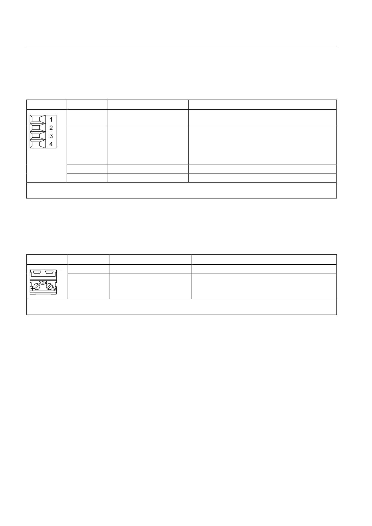
X22 digital inputs
Table 8- 75 X22 digital inputs for Smart Line Modules 5 kW and 10 kW
Terminal
Description 1)
Technical specifications
1
24 V power supply
Electronic power supply for controlling digital inputs
X22.2 and 3.
2
DI: Disable regeneration
Deactivate regenerative feedback (high active).
No power is supplied back to the network from the DC
link. The regenerative energy of the motors may have to
be reduced using a combination of the Braking Module
and braking resistor.
3
DI: Reset
Reset faults (negative edge)
4
Ground
Electronics ground
Max. connectable cross-section: 1.5 mm2
Type: Screw terminal 1 (see Appendix, Chapter "Screw terminals")
1) DI: Digital input
X24 24 V terminal adapter
Table 8- 76 X24 24 V terminal adapter
Terminal
Description
Technical specifications
+
24 V power supply
24 VDC supply voltage
M
Ground
Electronics ground
Max. connectable cross-section: 6 mm2
Type: Screw terminal 5 (see Appendix, Chapter "Screw terminals")
The 24 V terminal adapter is included in the scope of delivery.
Guidelines for machine configuration
330
System Manual, MA 01/2013, 6FC5397-6CP10-0BA2
Connection of the components in SINAMICS drive system
8.3 Connection of line modules
8.3.9.4
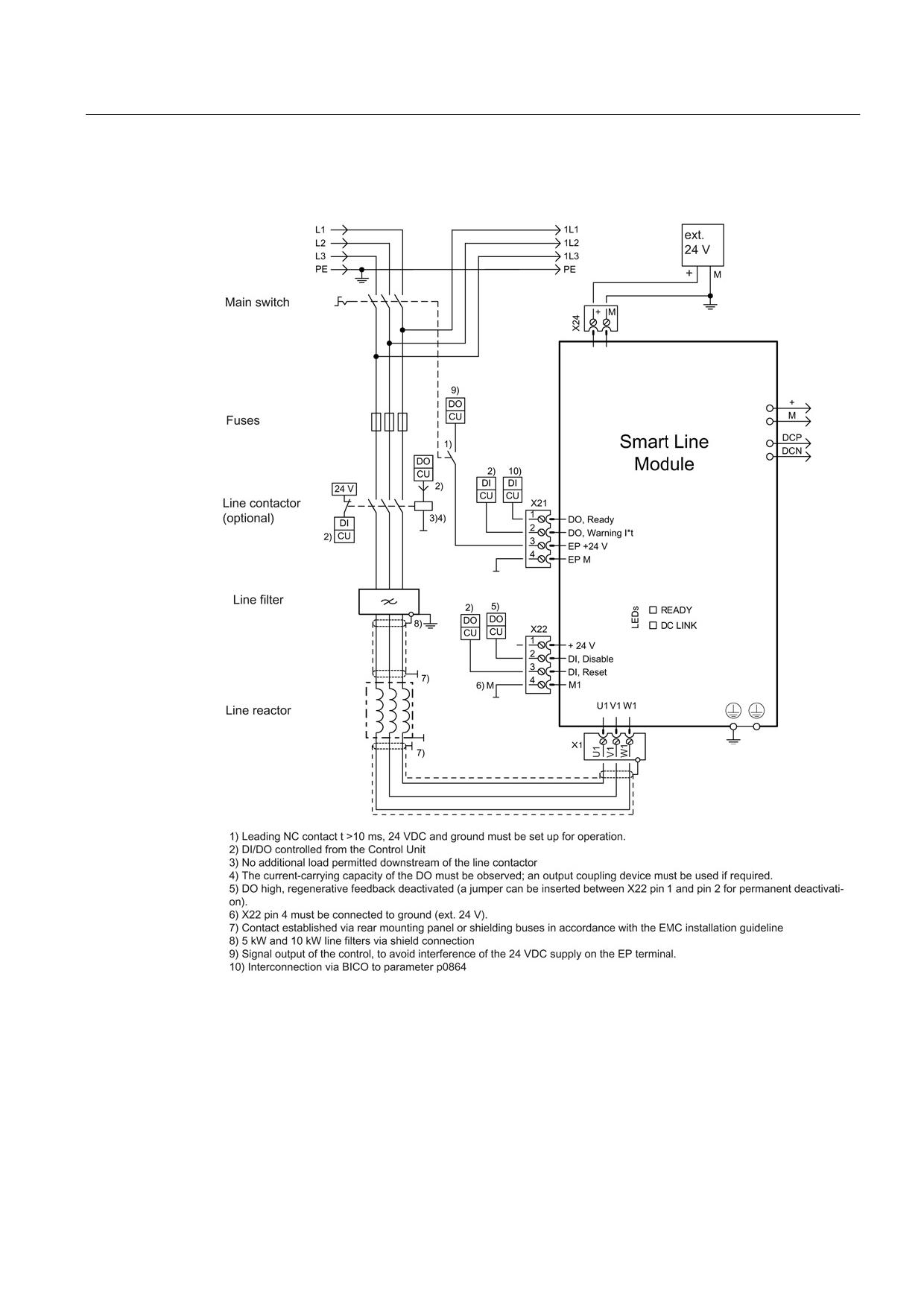
Connection example
Figure 8-89 Connection example for 5 kW and 10 kW Smart Line Modules
Guidelines for machine configuration
System Manual, MA 01/2013, 6FC5397-6CP10-0BA2
331
Connection of the components in SINAMICS drive system
8.3 Connection of line modules
8.3.9.5
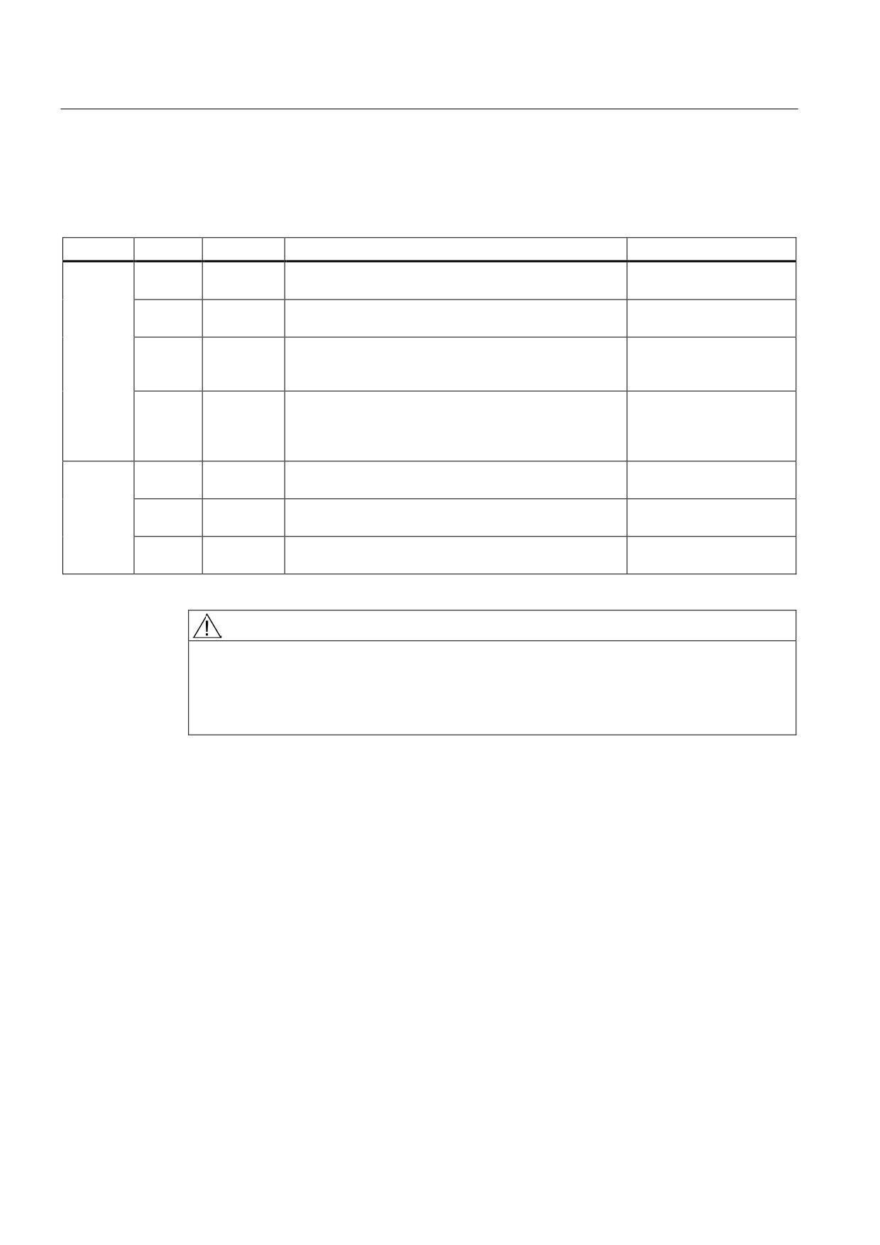
Meaning of LEDs
Table 8- 77 Meaning of the LEDs on 5 kW and 10 kW Smart Line Modules
LED
Color
Status
Description, cause
Remedy
RDY
-
Off
Electronics power supply is missing or outside
-
permissible tolerance range.
Green
Continuous
Component is ready to operate.
-
light
Yellow
Continuous
Pre-charging not yet complete.
-
light
Bypass relay dropped out
EP terminals not supplied with 24 VDC.
Red
Continuous
Overtemperature,
Diagnose fault (via output
light
overcurrent
terminals) and
acknowledge it (via input
terminal)
DC LINK
-
Off
Electronics power supply is missing or outside
-
permissible tolerance range.
Yellow
Continuous
DC link voltage within permissible tolerance range.
-
light
Red
Continuous
DC link voltage outside permissible tolerance range.
Check line voltage.
light
Power system fault.
WARNING
Danger to life due to high DC link voltage, regardless of LED display
Hazardous DC link voltages may be present at any time regardless of the status of the
"DC LINK" LED.
• Observe the warning information on the component.
Guidelines for machine configuration
332
System Manual, MA 01/2013, 6FC5397-6CP10-0BA2
Connection of the components in SINAMICS drive system
8.3 Connection of line modules
8.3.9.6
Dimension drawings
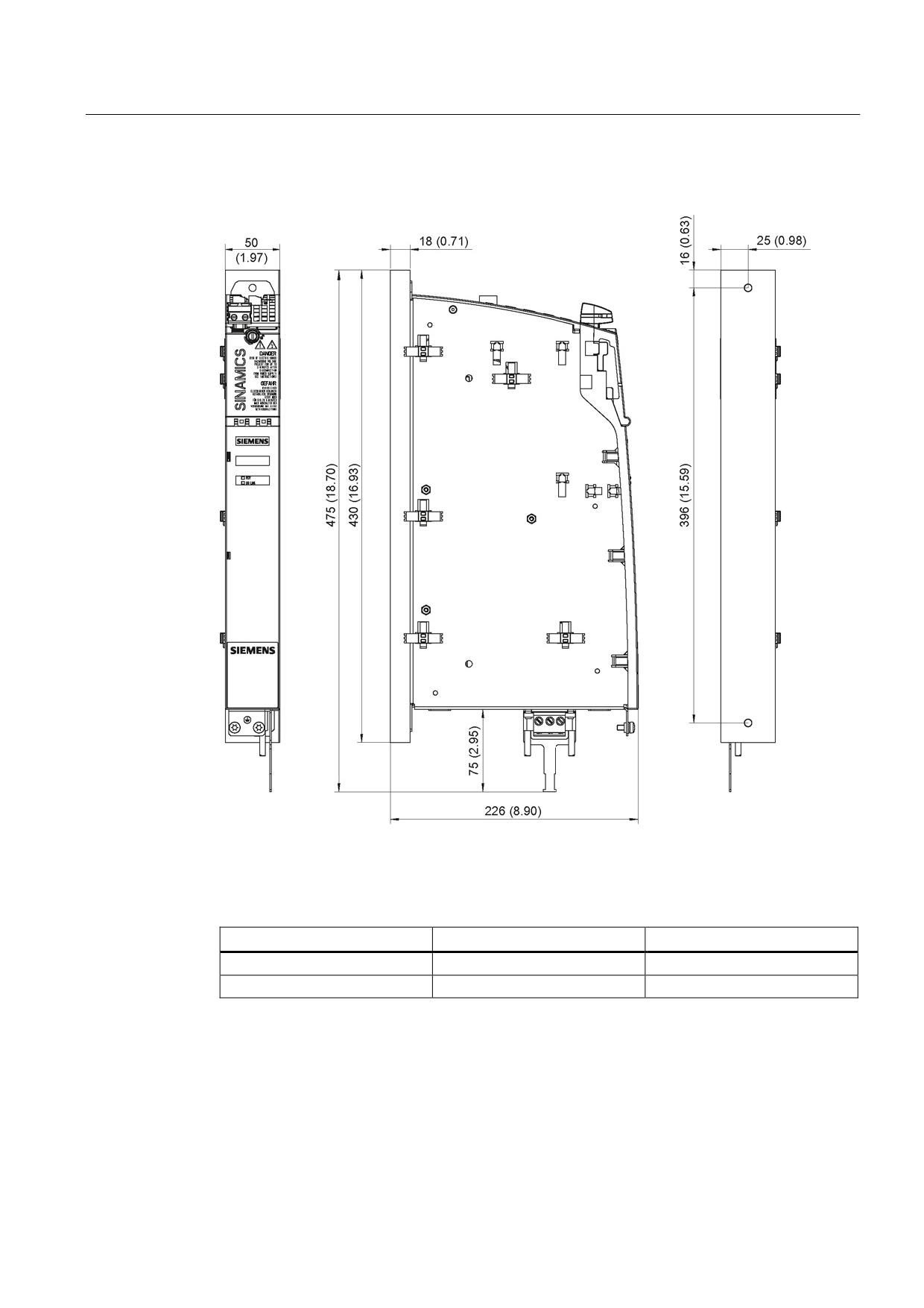
Figure 8-90 Dimension drawing of Smart Line Module with cold plate (5 kW and 10 kW), all
dimensions in mm and (inches)
Table 8- 78 Dimensions of Smart Line Modules with cold plate
Line Module
Order number
W [mm] (inches)
5 kW
6SL3136-6AE15-0AAx
50 (1.97)
10 kW
6SL3136-6AE21-0AAx
50 (1.97)
Guidelines for machine configuration
System Manual, MA 01/2013, 6FC5397-6CP10-0BA2
333
Connection of the components in SINAMICS drive system
8.3 Connection of line modules
8.3.9.7
Installation
Please note the following before installing a Smart Line Module with cold plate on a
customer-specific heat sink:
● Before the installation, check the surface of the heat sink to ensure that it is not damaged.
● To improve heat transfer, a heat-conducting medium must be used. Special spherical-
indented heat-conducting foil must be used for this purpose. Every cold plate power unit
is supplied with heat-conducting foil cut to the right size. Note the mounting position of the
heat-conducting foil (see figures below).
Note
When a component is replaced, the heat-conducting foil must also be replaced. Only heat-
conducting foil approved or supplied by Siemens may be used.
Order number
Heat-conducting foil, 50 mm
6SL3162-6FB00-0AA0
Note
M6 screw bolts and hexagon nuts/grub screws (ISO 7436-M6x40-14 H, property class 8.8)
are recommended for installing the components.
Guidelines for machine configuration
334
System Manual, MA 01/2013, 6FC5397-6CP10-0BA2
Connection of the components in SINAMICS drive system
8.3 Connection of line modules
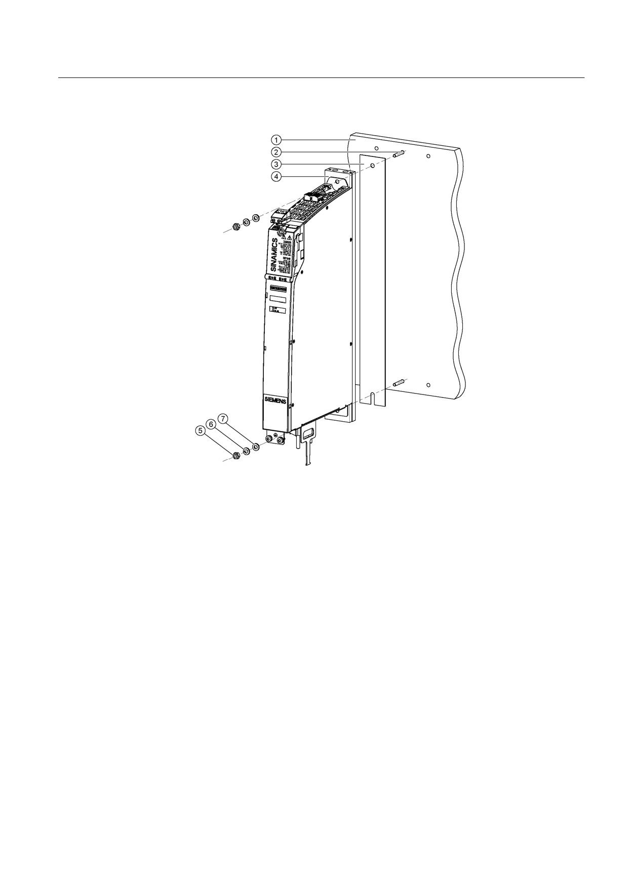
①
External heat sink (air or liquid)
②
M6 studs
③
Heat-conducting foil
④
Cold plate
⑤
M6 nut
⑥
Spring washer
⑦
Washer
Figure 8-91 Installing a Smart Line Module with cold plate on an external heat sink, using a 5 kW
Smart Line Module as an example
Tightening torques:
● Initially, only tighten the nuts by hand (0.5 Nm)
● Then tighten with 10 Nm.
Help with the mechanical control cabinet installation is available from:
Siemens AG
Industry Sector, IA SE WKC
TCCCC (Technical Competence Center Cabinets Chemnitz)
P.O. Box 1124
09070 Chemnitz, Germany
E-mail: cc.cabinetcooling.aud@siemens.com
Guidelines for machine configuration
System Manual, MA 01/2013, 6FC5397-6CP10-0BA2
335
Connection of the components in SINAMICS drive system
8.3 Connection of line modules
Properties of the heat sink
We recommend using AlMgSi 0.5 as the heat sink material.
The roughness of the external heat sink surface should be at least Rz 16 and the contact
surface between the heat sink and cold plate should have an evenness of 0.2 mm.
Note
The machine manufacturer can adapt the heat sink version to his special requirements. The
specified rated data for the Power Modules can only be achieved if the power losses can be
dissipated by the external heat sink under the specified general conditions.
Note
When mounting, ensure that the threaded bolts do not damage the cold plate.
8.3.9.8
Technical data
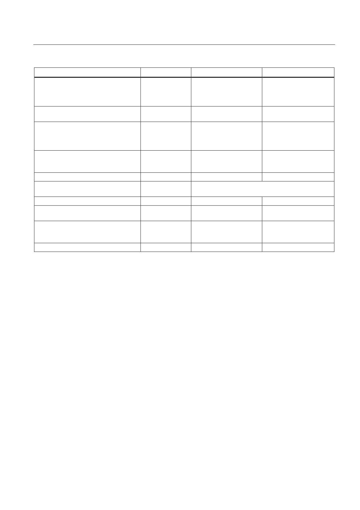
Table 8- 79 Technical data for Smart Line Modules with cold plate cooling
6SL3136-6AE
15-0AAx
21-0AAx
Rated power
kW
5
10
Infeed
Rated power (S1)1)
kW (Pn)
5
10
Infeed power (S6-40%)1)
kW (PS6)
6,5
13
Peak infeed power1)
kW (Pmax)
10
20
Energy recovery
Continuous regenerative power
kW
5
10
Peak regenerative power
kW
10
20
Supply voltages
Line voltage
VAC
3 AC 380 -10% (-15% < 1 min) to 3 AC 480 +10%
Line frequency
Hz
47 to 63
Electronics power supply
VDC
24 (20.4 - 28.8)
DC link voltage
VDC
510 - 720
Overvoltage trip
VDC
820 ±2%
Undervoltage trip
VDC
360 ±2%
Input currents
Rated input current
at 400 VAC:
AAC
8.1
16.2
Input current
at 380 VAC/480 VAC
AAC
8.6 / 6.7
17 / 12.8
at 400 VAC; S6-40%
AAC
10.6
21.1
at 400 VAC; peak current
AAC
15.7
31.2
DC link currents
Rated DC link current
at 600 V:
ADC
8.3
16.6
DC link current
at 540 V:
ADC
9.3
18.5
at 600 VDC; at S6-40%
ADC
11
22
at 600 VDC; peak current
ADC
16.6
33.2
Guidelines for machine configuration
336
System Manual, MA 01/2013, 6FC5397-6CP10-0BA2
Connection of the components in SINAMICS drive system
8.3 Connection of line modules
6SL3136-6AE
15-0AAx
21-0AAx
Current-carrying capacity
DC link busbar
ADC
100
100
Reinforced DC link busbars:
ADC
150
150
24 V busbar:
ADC
20
20
Electronics current consumption at 24 V
ADC
0.6
0.7
DC
Power loss distribution
(incl. electronics losses)2)
internal
W
34.4
56.8
external
W
40
80
DC link capacitance
Smart Line Module
μF
220
330
Drive line-up, max.
μF
6000
6000
Power factor
cosϕ
1
1
Circuit breaker
See Chap. "Overcurrent protection using line fuses and
(IEC 60947 and UL)
circuit breakers (Page 116)"
Rated short-circuit current SCCR3)
kA
65
65
Max. permissible
°C
60
65
heat sink temperature
Max. ambient temperature
without derating
°C
40
40
with derating
°C
55
55
Weight
kg
4.0
4.0
1)
The specified power ratings apply to the line voltage range from 380 V to 480 V
2)
For an overview, see the power loss tables in the Appendix
3)
The resulting rated short-circuit current is obtained from the combination of the fuse, or circuit breaker, and the Line
Module in the drive system.
Guidelines for machine configuration
System Manual, MA 01/2013, 6FC5397-6CP10-0BA2
337
Connection of the components in SINAMICS drive system
8.3 Connection of line modules
Characteristics
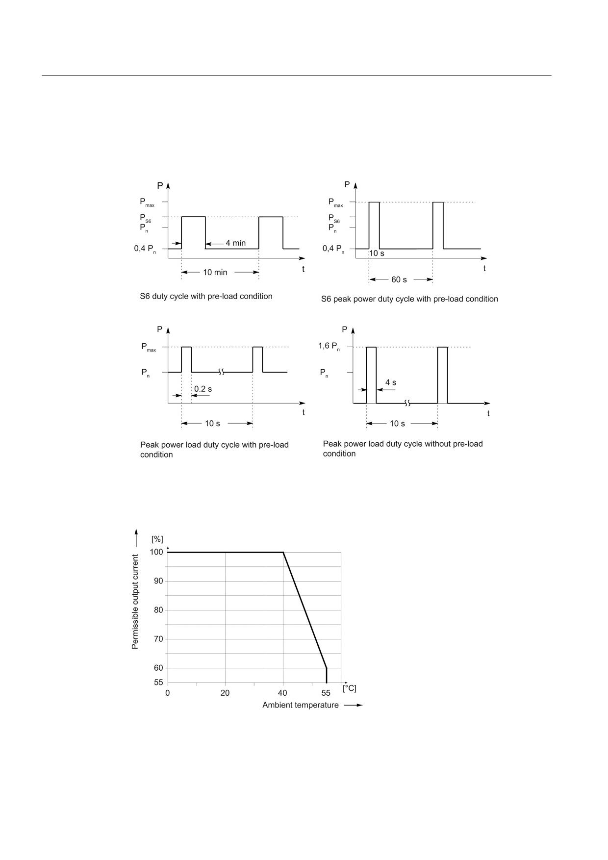
Rated duty cycles of Smart Line Modules
Figure 8-92 Rated duty cycles of Smart Line Modules
Derating characteristics
Figure 8-93 Output current as a function of the ambient temperature
Guidelines for machine configuration
338
System Manual, MA 01/2013, 6FC5397-6CP10-0BA2
Connection of the components in SINAMICS drive system
8.3 Connection of line modules
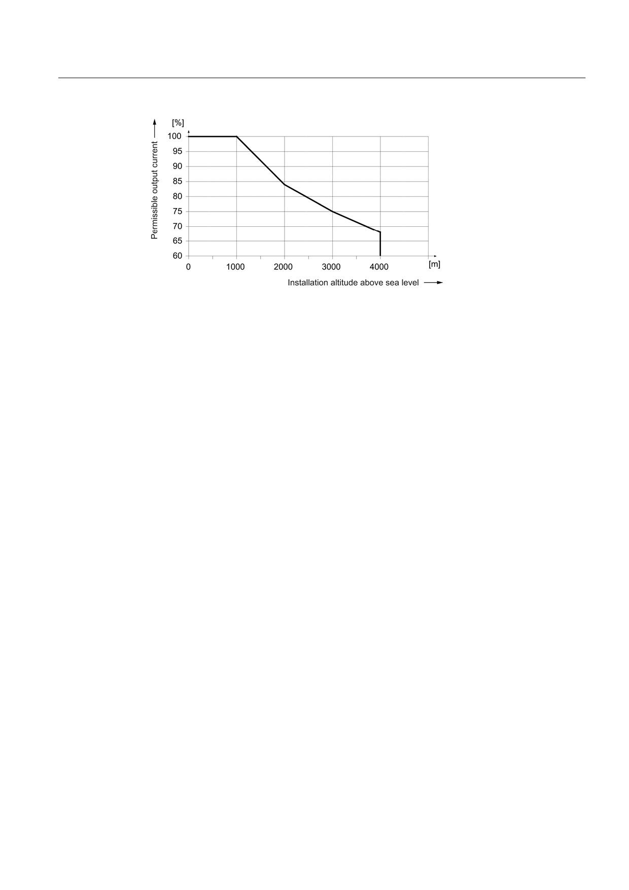
Figure 8-94 Output current as a function of the installation altitude
At installation altitudes > 2000 m, an isolation transformer must be used (see the chapter
titled "System overview/Function of installation altitude and ambient temperature"
(Page 32)). The design of the secondary line system must be as follows:
● TN system with grounded neutral point (no grounded line conductor)
● IT system
A reduction of the line supply voltage phase-phase is not necessary.
Guidelines for machine configuration
System Manual, MA 01/2013, 6FC5397-6CP10-0BA2
339
Connection of the components in SINAMICS drive system
8.3 Connection of line modules
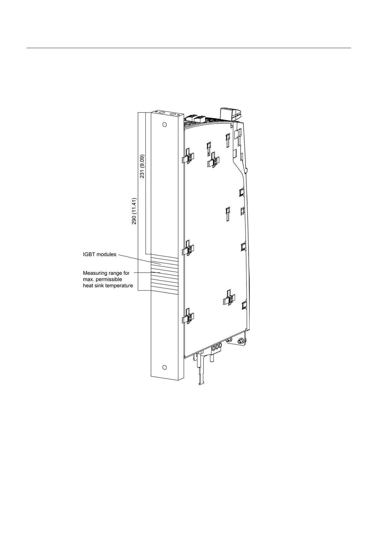
Measuring the heat sink temperature
The maximum permissible heat sink temperature is calculated at the cold plate in the
measuring range shown below.
Figure 8-95 Measuring range for max. permissible heat-sink temperature for a Smart Line Module
with cold plate
Guidelines for machine configuration
340
System Manual, MA 01/2013, 6FC5397-6CP10-0BA2
Connection of the components in SINAMICS drive system
8.4 Connection of motor modules
8.4
Connection of motor modules
8.4.1
Safety instructions for Motor Modules Booksize
Note
When using a Motor Module Booksize, also observe the safety instructions in Section 1.
DANGER
Danger to life through electric shock due to the residual charge of the DC link capacitors
Because of the DC link capacitors, a hazardous voltage is present for up to five minutes
after the power supply has been switched off.
Contact with live parts can result in death or serious injury.
• Do not open the protective cover of the DC link until five minutes have elapsed.
• Measure the voltage before starting work on the DCP and DCN DC link terminals.
DANGER
Danger to life through electric shock when the protective cover of the DC link is open
Contact with live parts can result in death or serious injury.
• Only operate the components with closed protective cover.
WARNING
Danger to life through electric shock due to incorrect connection to the DC link
Incorrect connections can lead to overheating and therefore a risk of fire. There is also a
risk of an electric shock. This can result in serious injury or death.
• Only use adapters (DC link adapters and DC link rectifier adapters) released by
Siemens for the connection to the DC link.
WARNING
Danger to life through electric shock due to incorrectly installed DC link bridges
Incorrectly installed DC link bridges at the left-hand end of the drive line-up can cause an
electric shock.
• For all 50 mm wide modules (exception: Smart Line Module), remove the DC link bridge,
including the screws. Do not tighten the screws without the DC link bridges.
• For all components that are 75 mm wide or wider, the DC link bridges must not be
moved to the left or removed.
Guidelines for machine configuration
System Manual, MA 01/2013, 6FC5397-6CP10-0BA2
341
Connection of the components in SINAMICS drive system
8.4 Connection of motor modules
WARNING
Danger to life through electric shock due to missing DC link side covers
There is a danger of an electric shock through contact when the side covers of the DC link
are missing.
• Mount the side covers on the first and last component in the drive line-up.
You can order missing side covers (order number: 6SL3162-5AA00-0AA0).
WARNING
Danger to life through interruption of the external protective conductor due to high leakage
currents
The drive components conduct a high leakage current via the protective conductor.
Touching conductive parts when the protective conductor is interrupted can result in death
or serious injury.
• Ensure that the external protective conductor satisfies at least one of the following
conditions:
- It has been laid so that it is protected against mechanical damage.1)
- If it is a single cable, it has a cross-section of at least 10 mm² Cu.
- If it is a conductor of a multi-conductor cable, it has a cross-section of at least 2.5
mm² Cu.
- It has a second protective conductor in parallel with the same cross-section.
- It complies with the local regulations for equipment with increased leakage current.
1) Cables laid within control cabinets or closed machine housings are considered to be
adequately protected against mechanical damage.
WARNING
Danger to life through electric shock due to incorrectly laid brake cables
If brake cables are laid without safe electrical separation, the insulation can fail with an
electric shock.
• Close the holding brake with the specified MOTION-CONNECT cable.
• Only use third-party cables with safe electrically separated brake cores or lay the brake
cores with safe electrical separation.
WARNING
Danger of an accident due to missing warning labels in the national language.
Missing warning labels in the national language can result in death or serious injury.
• Attach the component warning labels in the national language.
Guidelines for machine configuration
342
System Manual, MA 01/2013, 6FC5397-6CP10-0BA2
Connection of the components in SINAMICS drive system
8.4 Connection of motor modules
WARNING
Fire hazard due to overheating because of inadequate ventilation clearances
Inadequate ventilation clearances can cause overheating with a risk for personnel through
smoke development and fire. This can also result in more downtimes and reduced service
lives of Motor Modules.
• Maintain the 80 mm clearances above and below the Motor Modules.
• For the 132 A and 200 A Motor Modules, a ventilation clearance of 50 mm must also be
maintained in front of the fan.
NOTICE
Material damage due to loose power connections
Insufficient tightening torques or vibrations can result in faulty electrical connections. This
can cause fire damage or malfunctions.
• Tighten all power connections with the specified tightening torques, e.g. line supply
connection, motor connection, DC link connections.
• Check the tightening torques of all power connections at regular intervals and tighten
them when required. This applies in particular after transport.
NOTICE
Damage to the equipment when performing a voltage test as a result of connections that
are not disconnected
As part of routine tests, SINAMICS S components undergo a voltage test according to EN
61800-5-1. Connected devices can be damaged.
• Disconnect or unplug all SINAMICS devices before the voltage test of the machine
equipment according to EN 60204-1, Section 18.4.
NOTICE
Temperature signal disturbances and failure of components as a result of unshielded or
incorrectly routed cables
With unshielded or incorrectly laid cables, it can be expected that interference will be
coupled into the signal processing electronics from the power side. This can result in
significant disturbances (fault messages) up to failure of individual components (destruction
of the devices).
• Only use shielded cables as temperature sensor cables.
• Only use temperature sensor cables that are routed together with the motor cable and
twisted in pairs and shielded separately.
• Connect the cable shield to the chassis potential at both ends over a large surface area.
Guidelines for machine configuration
System Manual, MA 01/2013, 6FC5397-6CP10-0BA2
343
Connection of the components in SINAMICS drive system
8.4 Connection of motor modules
NOTICE
Destruction of the motor/brake due to incorrect power supply
With an incorrect power supply, the brake can malfunction, i.e. the brake does not open
reliably. If the motor constantly runs against the closed brake, the brake and/or the motor
will be destroyed.
• Always use a regulated DC power supply to operate motors with a built-in holding brake.
The voltage is supplied via the internal 24 V busbars.
• Take note of the motor holding brake voltage tolerances (24 V ± 10%) and the
connecting cable voltage drop.
• Set the DC power supply to 26 V. This ensures that the supply voltage for the brake
remains within the permissible range when the following conditions are fulfilled:
- Use of Siemens three-phase motors
- Use of Siemens MOTION-CONNECT power cables
- Motor cable lengths, max. 100 m
NOTICE
Damage through use of incorrect DRIVE-CLiQ cables
Damage or malfunctions can occur on the devices or system when incorrect or unreleased
DRIVE-CLiQ cables are used.
• Only use suitable DRIVE-CLiQ cables that have been released by Siemens for the
respective application.
Note
Malfunctions due to polluted DRIVE-CLiQ interfaces
Malfunctions can occur in the system through the use of polluted DRIVE-CLiQ interfaces.
• Cover unused DRIVE-CLiQ interfaces with the supplied blanking covers.
Guidelines for machine configuration
344
System Manual, MA 01/2013, 6FC5397-6CP10-0BA2
Connection of the components in SINAMICS drive system
8.4 Connection of motor modules
Special features for Motor Modules with external air cooling
Note
Insufficient cooling power when the external heat sinks are polluted
For components with external air cooling, the fan and the heat sinks can accumulate a lot of
pollution. If the cooling air requirement is not provided by the filter fan, the components
cannot output their specified power. This can cause the temperature monitoring function in
the components to respond.
• Check the fans and heat sinks for pollution at regular intervals and clean them when
necessary.
Note
Checking the seal
• After mounting, check the seal on the rear of the device to ensure that it is tight.
• If required, use additional sealing.
Note
Using an installation frame
• Only use an installation frame when the cabinet has an unpainted metal surface.
8.4.2
Motor Modules with internal air cooling
8.4.2.1
Description
A Motor Module is a power unit (inverter) that provides the power supply for the connected
motor(s). Power is supplied by means of the DC link of the drive unit. A Motor Module must
be connected to a Control Unit via DRIVE-CLiQ. The open-loop and closed-loop control
functions for the Motor Module are stored in the Control Unit.
One motor can be connected to Single Motor Modules and two motors can be connected to
Double Motor Modules.
Guidelines for machine configuration
System Manual, MA 01/2013, 6FC5397-6CP10-0BA2
345