SINUMERIK 840D sl. Service - Configuring Commissioning. Manual (2011-2020) - page 30
Line connection
6.5 Active Interface Module (AIM)
6.5.6
Technical data
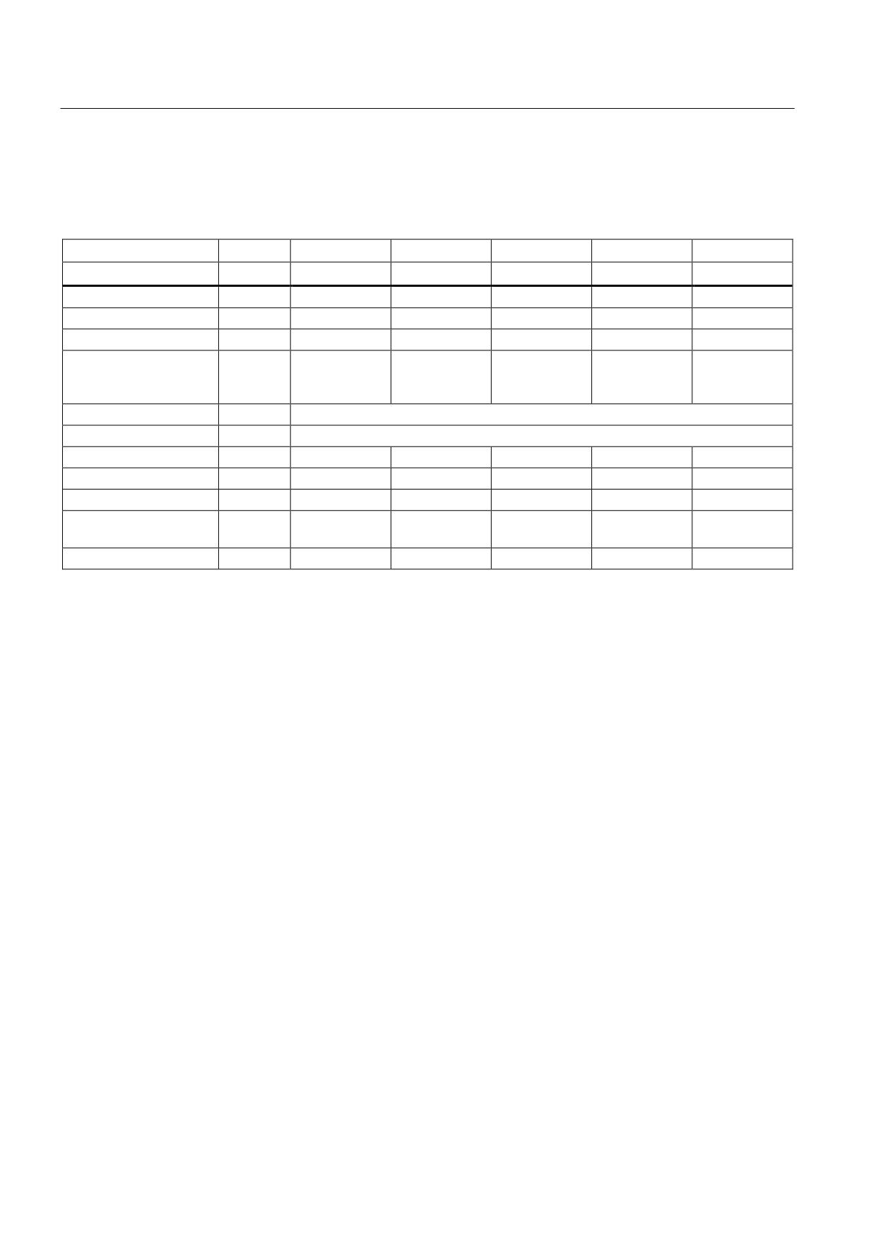
Table 6- 7
Technical data
Active Interface Module
6SL3100-
0BE21-6ABx
0BE23-6ABx
0BE25-5ABx
0BE28-0ABx
0BE31-2ABx
16 kW
36 kW
55 kW
80 kW
120 kW
Pmax
kW
35
70
110
131
175
Irated
A
27
60
88
132
200
Imax
A
59
117
176
218
292
Current requirements of
A
0.25
0.49
0.6
1.2
1.2
the 24 VDC electronics
power supply
Line voltage
V
380 V to 480 V 3 AC ±10%
Line frequency
Hz
47 - 63
Cooling air requirement
m3/h
112
160
300
600
600
Power loss 1)
W
270
340
380
490
585
Weight
kg
10.7
18.5
21
29
35.5
Connection cross-
mm2
10
35
50
120
120
section
PE connecting studs
M5
M5
M6
M8
M8
1)
Based on VDC link 600 V; for an overview, see the power loss tables in Appendix A.3
Guidelines for machine configuration
140
System Manual, MA 01/2013, 6FC5397-6CP10-0BA2
Line connection
6.6 Line reactors
6.6
Line reactors
6.6.1
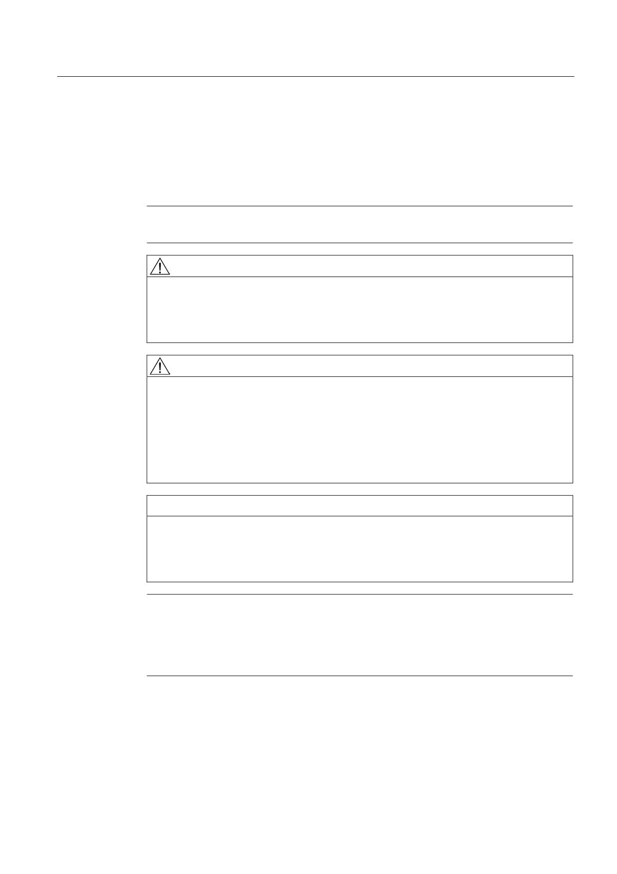
Safety instructions for line reactors
Note
When using a line reactor, also observe the safety instructions in Section 1.
WARNING
Danger to life due to high voltages on the additional winding of the HFD line reactor
If system oscillations do occur and no damping resistor is connected, impermissibly high
voltages may arise on the additional winding of the HFD line reactor.
• Connect a damping resistor to the HFD line reactor.
CAUTION
Risk of burns due to high surface temperatures
The line reactors can become very hot. You can get seriously burnt when touching the
surface.
• Mount the line reactors so that contact is not possible. If this is not possible, attach
clearly visible and understandable warning notices at hazardous positions.
• To prevent adjacent components from suffering damage due to these high
temperatures, maintain a clearance of 100 mm on all sides of the line reactors.
NOTICE
Damage or destruction of components
Unsuitable line reactors can cause damage/faults on Line Modules. Line harmonics can
also occur that damage/disturb loads connected to the same line supply.
• Only use line reactors or Active Interface Modules described in this manual.
Note
Malfunctions through magnetic fields
Reactors produce magnetic fields that can disturb or damage components and cables.
• Arrange the components and cables at a suitable distance (at least 200 mm) or shield the
magnetic fields appropriately.
Guidelines for machine configuration
System Manual, MA 01/2013, 6FC5397-6CP10-0BA2
141
Line connection
6.6 Line reactors
Note
Keep the connection cables as short as possible
The connection cables between line reactor and Line Module, as well as between line
reactor and line filter, must be kept as short as possible (max. 10 m).
You must use shielded connection cables, whose cable shields are attached at both ends.
Shielding can only be omitted if the following conditions are met:
• The cables do not exceed 1 m in length.
• The cables are laid flush with the rear metal wall of the control cabinet.
• The cables are laid in a way that keeps them physically separate from signal cables.
Do not route any cables near the line reactor. If this cannot be avoided, observe a minimum
distance of 200 mm.
6.6.2
HFD line reactors for Active Line Module
6.6.2.1
Description
HFD line reactors are used in older systems for connecting regulated infeed/regenerative
feedback components (Active Line Modules) to the network.
They perform the following functions:
● Limiting of low-frequency line reactions
● Energy store for the step-up operation of the infeed units
● Current limiting for line supply oscillations
● Together with a damping resistor, the HFD line reactors as an HFD package dampen the
system oscillations of the converter system.
The HFD line reactor should be mounted as close as possible to the line supply infeed
component.
Note
In newer systems, Active Interface Modules are usually used in place of HFD packages (see
the chapter titled Active Interface Module (AIM) (Page 129)
Guidelines for machine configuration
142
System Manual, MA 01/2013, 6FC5397-6CP10-0BA2
Line connection
6.6 Line reactors
6.6.2.2
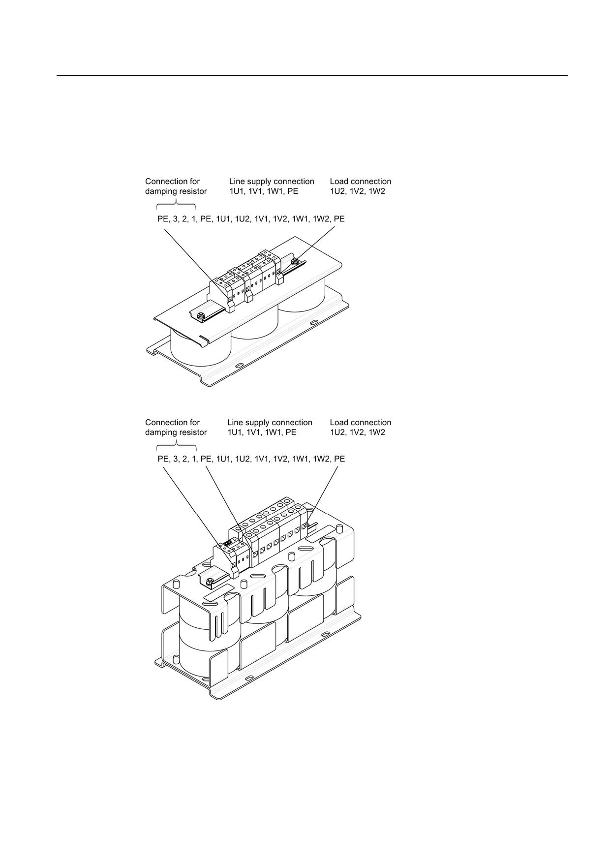
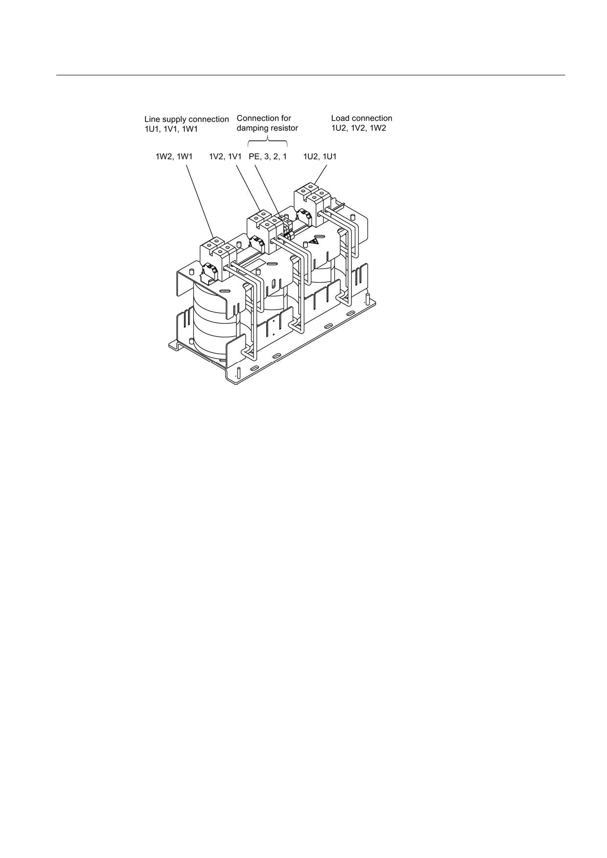
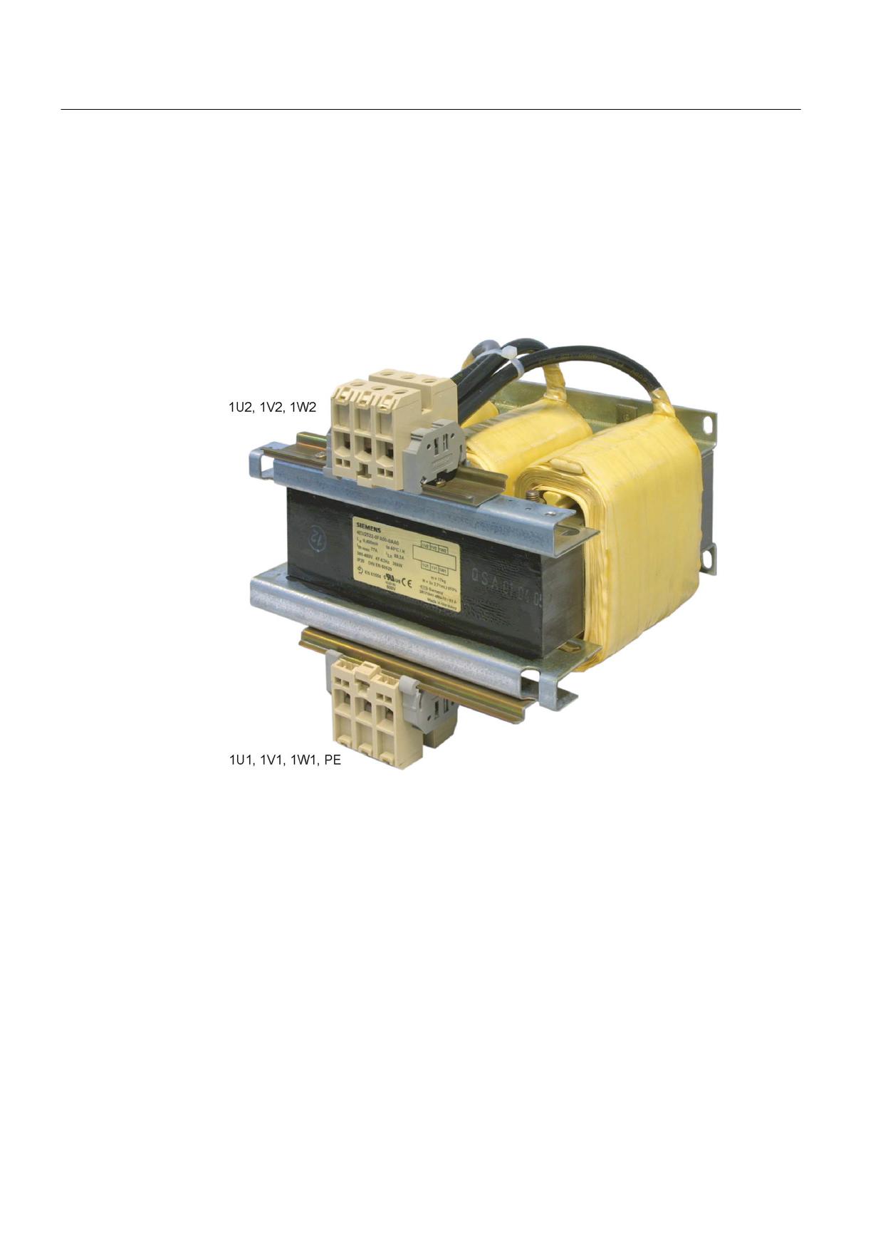
Interface description
Overview
Figure 6-15 HFD line reactor 16 kW
Figure 6-16 HFD line reactor 36 kW
Guidelines for machine configuration
System Manual, MA 01/2013, 6FC5397-6CP10-0BA2
143
Line connection
6.6 Line reactors
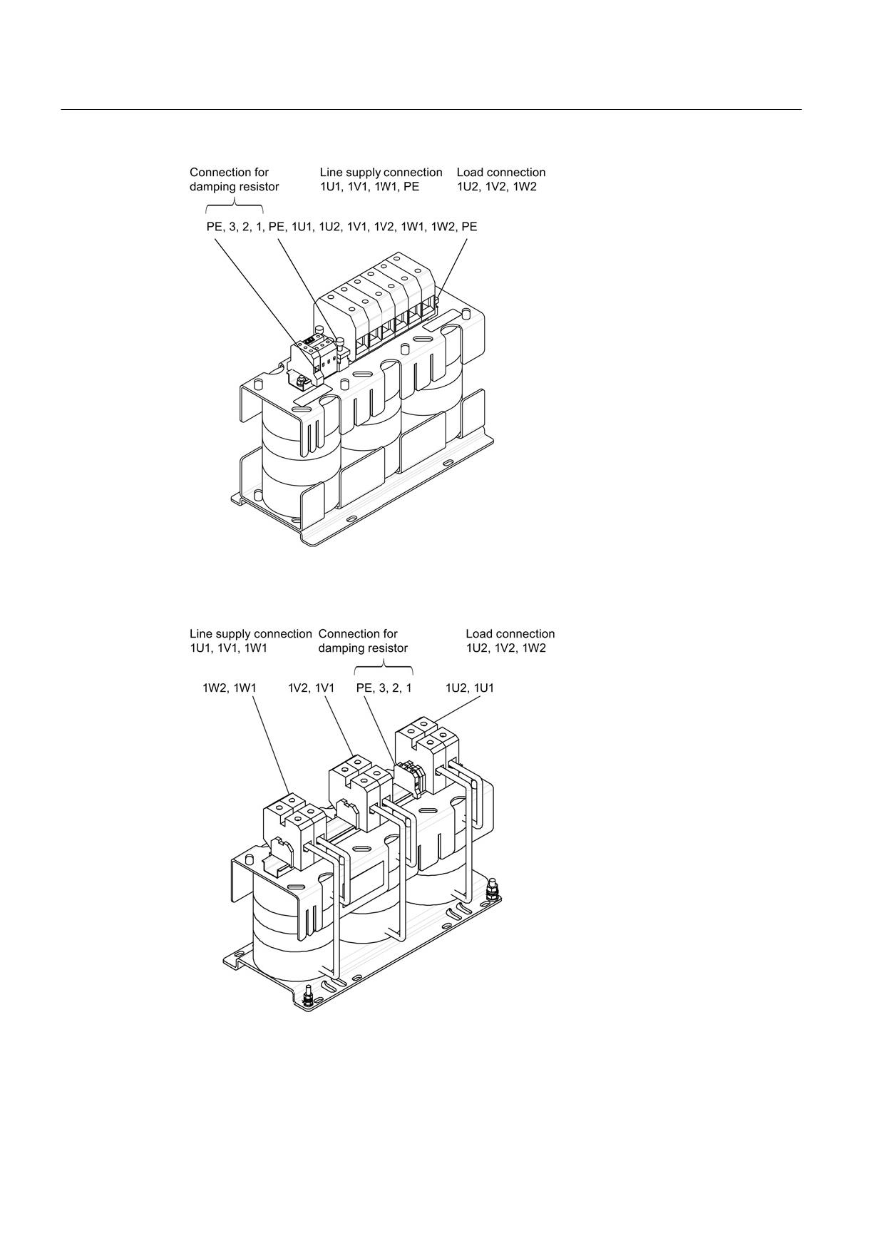
Figure 6-17 HFD line reactor 55 kW
Figure 6-18 HFD line reactor 80 kW
Guidelines for machine configuration
144
System Manual, MA 01/2013, 6FC5397-6CP10-0BA2
Line connection
6.6 Line reactors
Figure 6-19 HFD line reactor 120 kW
Guidelines for machine configuration
System Manual, MA 01/2013, 6FC5397-6CP10-0BA2
145
Line connection
6.6 Line reactors
6.6.2.3
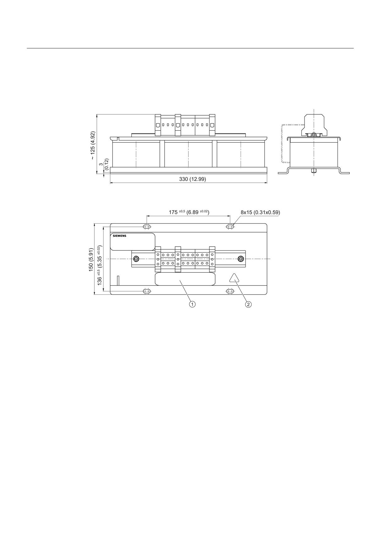
Dimension drawings
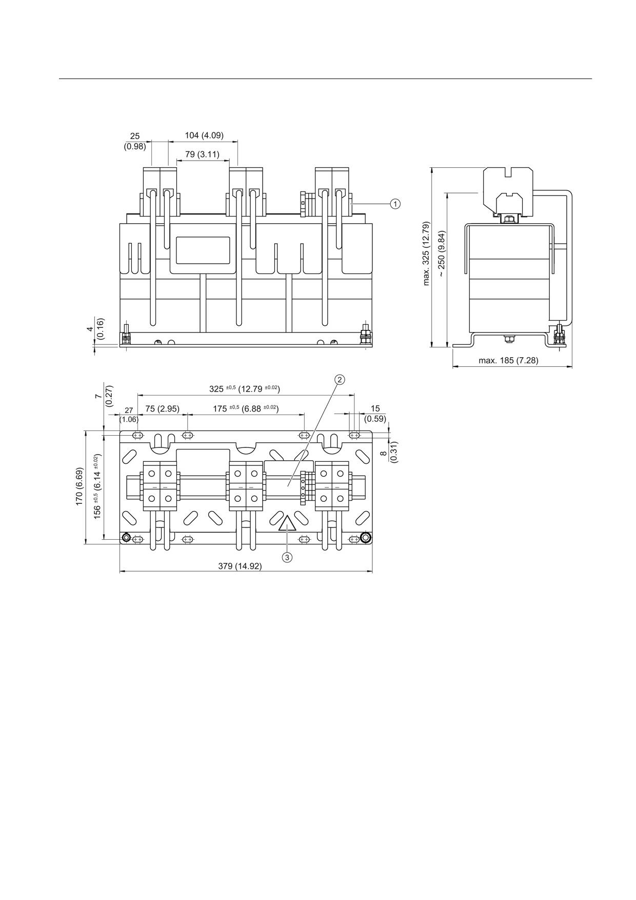
①
Terminal arrangement
②
Warning label
Figure 6-20 Dimension drawing of HFD line reactor 16 kW, all dimensions in mm and (inches)
Guidelines for machine configuration
146
System Manual, MA 01/2013, 6FC5397-6CP10-0BA2
Line connection
6.6 Line reactors
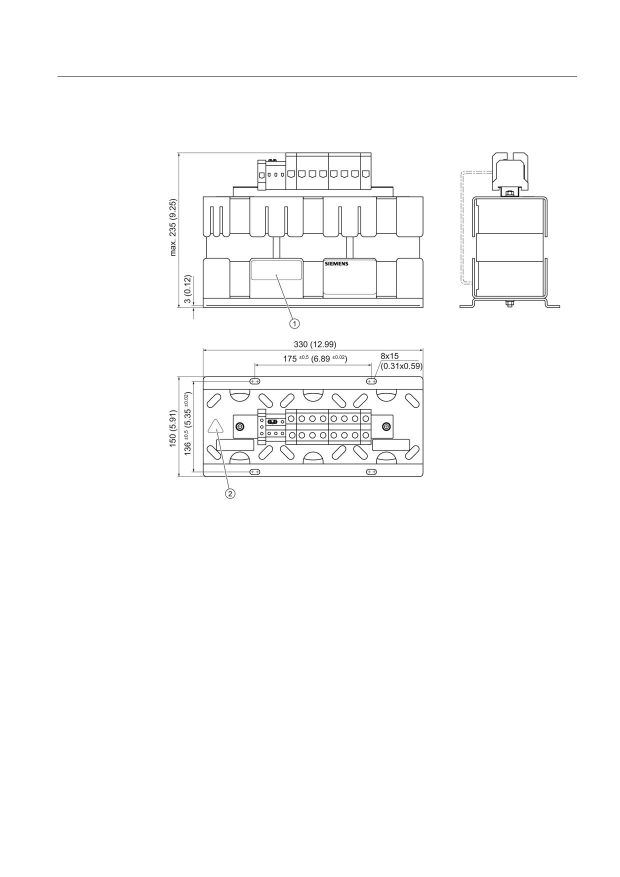
①
Terminal arrangement
②
Warning label
Figure 6-21 Dimension drawing of HFD line reactor 36 kW, all dimensions in mm and (inches)
Guidelines for machine configuration
System Manual, MA 01/2013, 6FC5397-6CP10-0BA2
147
Line connection
6.6 Line reactors
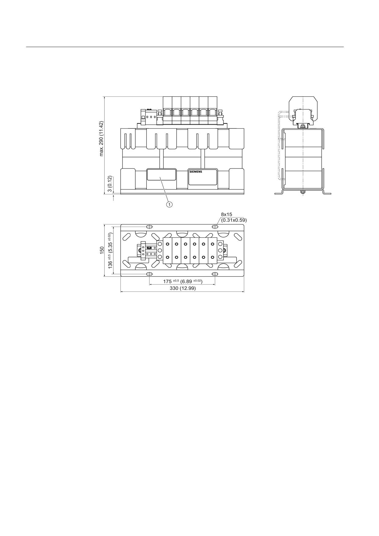
①
Terminal arrangement
Figure 6-22 Dimension drawing of HFD line reactor 55 kW, all dimensions in mm and (inches)
Guidelines for machine configuration
148
System Manual, MA 01/2013, 6FC5397-6CP10-0BA2
Line connection
6.6 Line reactors
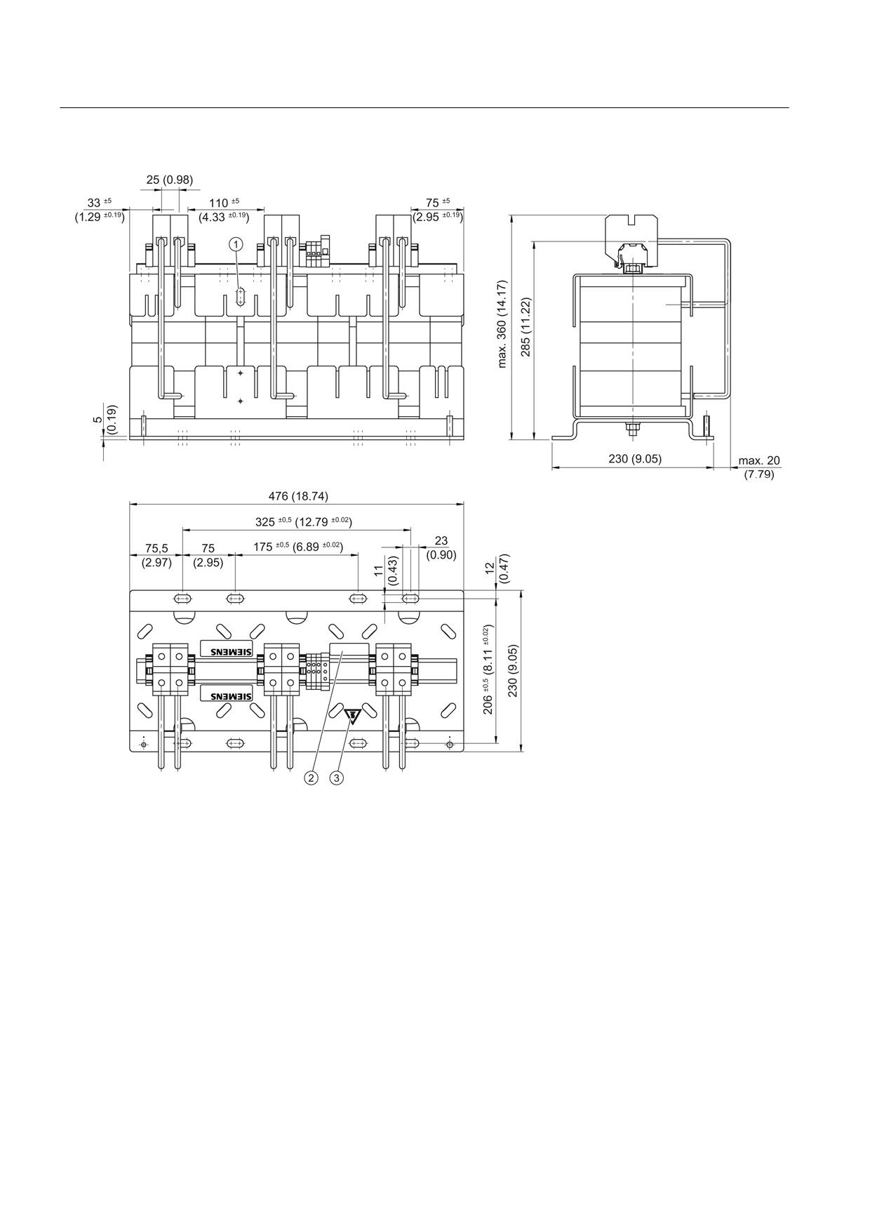
①
End retainers
②
Terminal arrangement
③
Warning label
Figure 6-23 Dimension drawing of HFD line reactor 80 kW, all dimensions in mm and (inches)
Guidelines for machine configuration
System Manual, MA 01/2013, 6FC5397-6CP10-0BA2
149
Line connection
6.6 Line reactors
①
Transport eyebolts 10 x 25 mm (0.39 x 0.98 inch)
②
Terminal arrangement
③
Warning label
Figure 6-24 Dimension drawing of HFD line reactor 120 kW, all dimensions in mm and (inches)
Guidelines for machine configuration
150
System Manual, MA 01/2013, 6FC5397-6CP10-0BA2
Line connection
6.6 Line reactors
6.6.2.4
Technical data
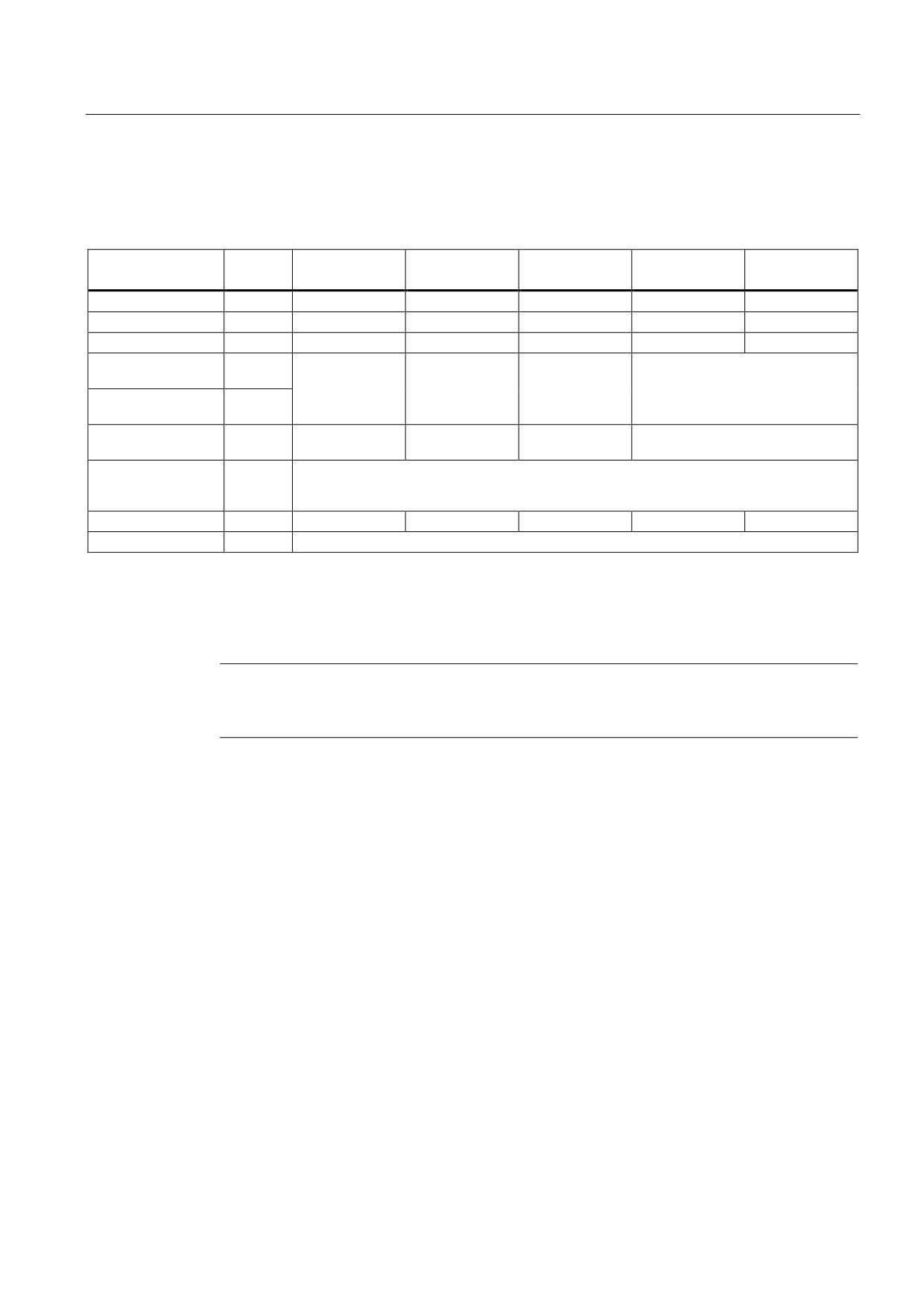
Table 6- 8
Technical data for HFD line reactors
6SL3000-0DE21-
6SL3000-0DE23-
6SL3000-0DE25-
6SL3000-0DE28-
6SL3000-0DE31-
6AAx
6AAx
5AAx
0AAx
2AAx
Unit
Power
kW
16
36
55
80
120
Rated current
Arms
30
67
103
150
225
Power loss1)
W
170
250
350
450
590
Line connection
Screw terminal
Screw terminal
Screw terminal
Power cage clamps 95 mm2/self-
1U1, 1V1, 1W1
16 mm2/1.2 Nm
35 mm2/2.5 Nm
70 mm2/7 Nm
locking 2)
Load connection
1U2, 1V2, 1W2
PE connection
Screw terminal
Screw terminal
Screw terminal
PE connecting lug M10/25 Nm for ring
16 mm2/1.2 Nm
35 mm2/2.5 Nm
70 mm2/3.5 Nm
cable lugs according to DIN 46234 3)
Damping-resistor
Screw terminal max. 1.5 mm2/1.2 Nm
connection
1, 2, 3 PE
Weight
kg
9
21
27
37
67
Mounting position
Any
1) For specifications concerning rated operation/for an overview, see the power loss tables in the Appendix
2) See Appendix "Spring-loaded terminals"
3) No touch protection (IP00B acc. to EN 60529)
Note
Data relating to the permissible tightening torques can also be found on the label showing
the terminal layout of the screw terminal for the corresponding HFD line reactor.
Guidelines for machine configuration
System Manual, MA 01/2013, 6FC5397-6CP10-0BA2
151
Line connection
6.6 Line reactors
6.6.3
Line reactors for Smart Line Modules
6.6.3.1
Interface description
Overview
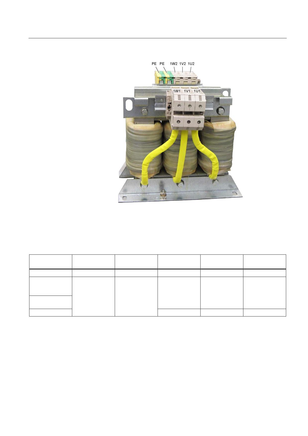
Figure 6-25 Interface overview, line reactors for Smart Line Modules (example: 36 kW)
Guidelines for machine configuration
152
System Manual, MA 01/2013, 6FC5397-6CP10-0BA2
Line connection
6.6 Line reactors
Figure 6-26 Interface overview, line reactors for Smart Line Modules (example: 55 kW)
Line/load connection
Table 6- 9
Line and load connection line reactors for Smart Line Modules
6SL3000-0CE15-
6SL3000-0CE21-
6SL3000-0CE21-
6SL3000-0CE23-
6SL3100-0CE25-
0AAx
0AAx
6AAx
6AAx
5DAx
Power
5 kW
10 kW
16 kW
36 kW
55 kW
Line supply
Screw terminals
Screw terminals
Screw terminals
Screw terminals
Screw terminals
connection
4 mm2
10 mm2
10 mm2
16 mm2
70 mm2
1U1, 1V1, 1W1
Load connection
0.5 - 0.6 Nm
1.2 - 1.5 Nm
1.2 - 1.5 Nm
1.5 - 1.8 Nm
8-12 Nm
1U2, 1V2, 1W2
PE connection
Terminal studs M51)
Terminal studs M61)
Terminal studs M81)
1) For ring cable lug in accordance with DIN 46234
Guidelines for machine configuration
System Manual, MA 01/2013, 6FC5397-6CP10-0BA2
153
Line connection
6.6 Line reactors
6.6.3.2
Dimension drawings
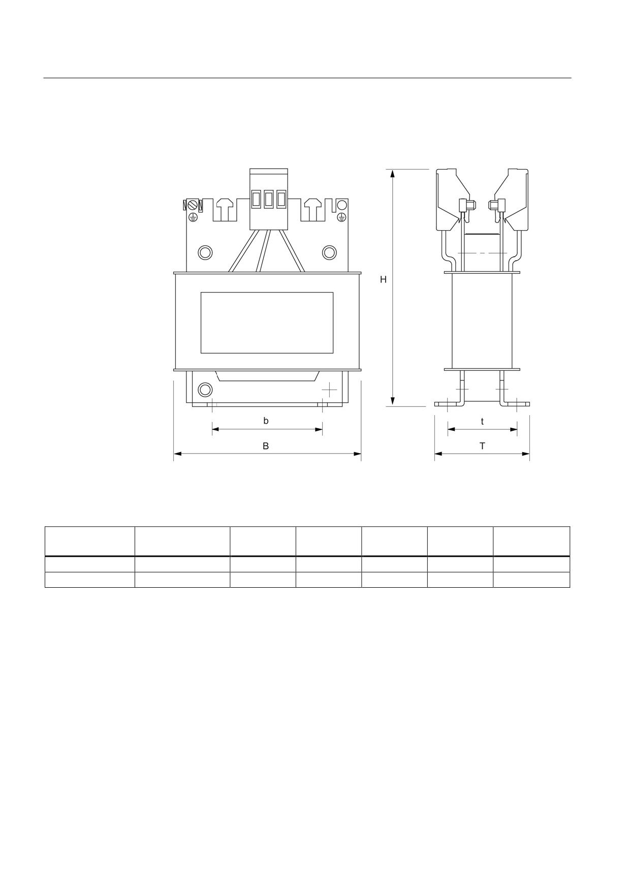
Figure 6-27 Dimension drawing of line reactor for Smart Line Modules (5 kW and 10 kW)
Table 6- 10 Dimensions of line reactors for Smart Line Modules (5 kW and 10 kW)
Order number
B [mm]
b [mm] 1)
H [mm]
D [mm]
t [mm] 1)
6SL3000-
(inches)
(inches)
(inches)
(inches)
(inches)
5 kW
0CE-15-0AAx
150 (5.91)
113 (4.53)
175 (6.89)
66.5
(2.62)
49.5
(1.95)
10 kW
0CE-21-0AAx
177 (6.97)
136 (5.35)
196 (7.72)
86 (3.39)
67 (2.64)
1) The lengths b and t correspond to the hole spacing
Guidelines for machine configuration
154
System Manual, MA 01/2013, 6FC5397-6CP10-0BA2
Line connection
6.6 Line reactors
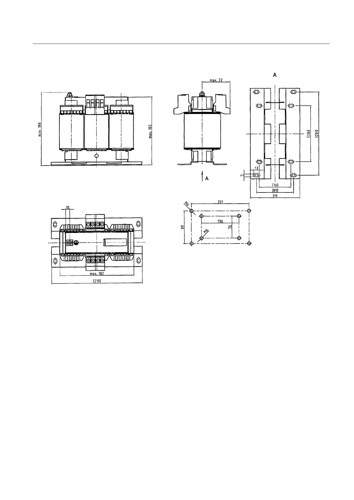
Figure 6-28 Dimension drawing of line reactor for Smart Line Module 16 kW
Guidelines for machine configuration
System Manual, MA 01/2013, 6FC5397-6CP10-0BA2
155
Line connection
6.6 Line reactors
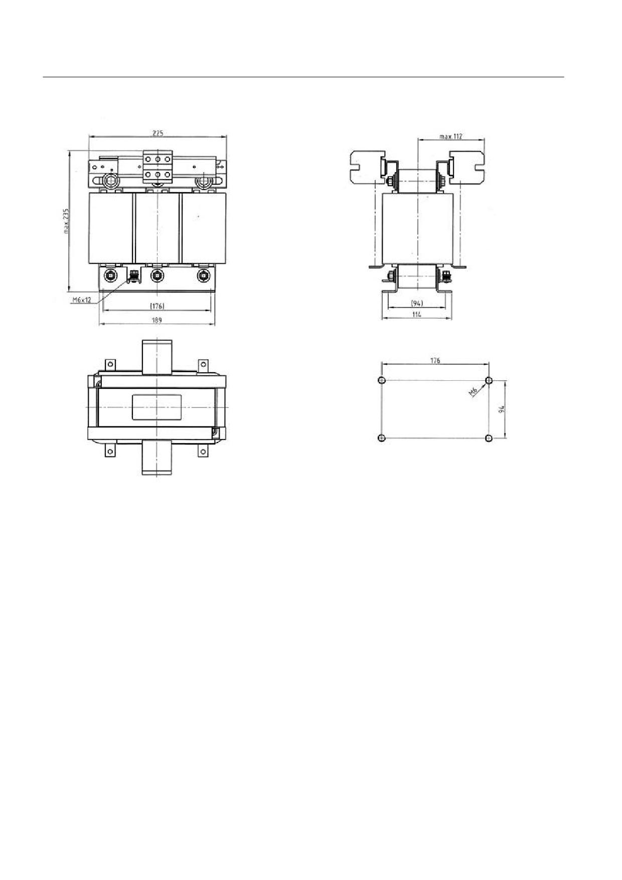
Figure 6-29 Dimension drawing of line reactor for Smart Line Module 36 kW
Guidelines for machine configuration
156
System Manual, MA 01/2013, 6FC5397-6CP10-0BA2
Line connection
6.6 Line reactors
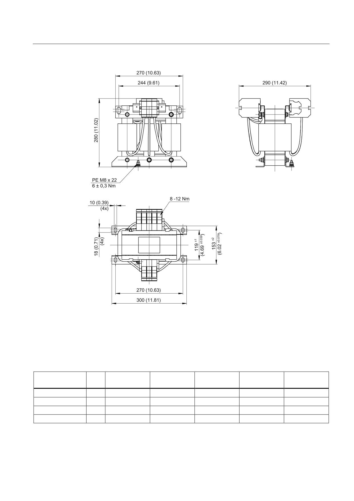
Figure 6-30 Dimension drawing of line reactor for Smart Line Module 55 kW, all dimensions in mm
and (inches)
6.6.3.3
Technical data
Table 6- 11 Technical data of line reactors for the Smart Line Module
6SL3000-
6SL3000-
6SL3000-
6SL3000-
6SL3100-
0CE15-0AAx
0CE21-0AAx
0CE21-6AAx
0CE23-6AAx
0CE25-5AAx
Power
kW
5
10
16
36
55
Rated current
Arms
14
28
35
69
103
Power loss 1)
W
62
116
110
170
190
Weight
kg
3.7
7.5
9.5
17
37
1) For an overview, see the power loss tables in the Appendix
Guidelines for machine configuration
System Manual, MA 01/2013, 6FC5397-6CP10-0BA2
157
Line connection
6.7 Possible combinations of line reactors and line filters
6.7
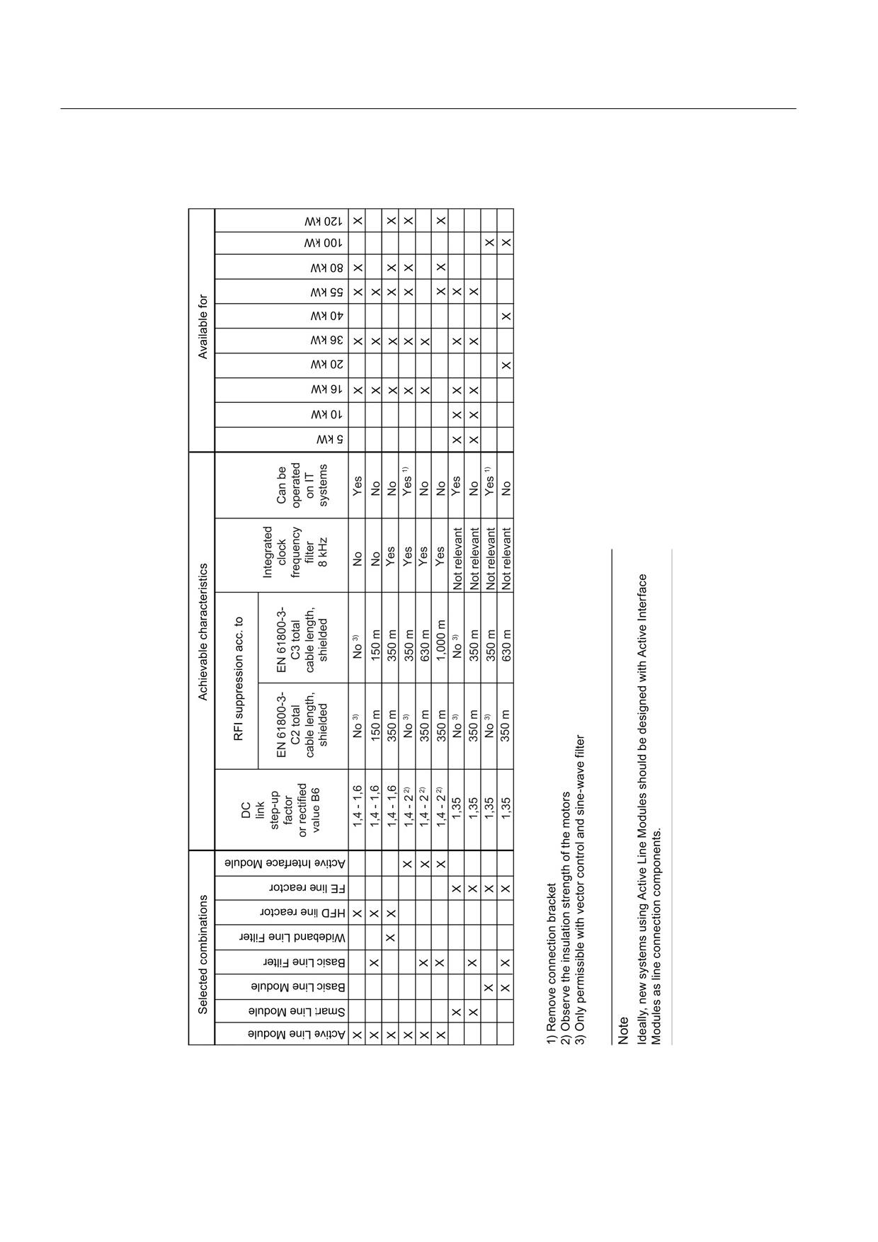
Possible combinations of line reactors and line filters
Figure 6-31 Options for combining line reactors and line filters
Guidelines for machine configuration
158
System Manual, MA 01/2013, 6FC5397-6CP10-0BA2
DC link
7
7.1
Function of the DC link
Properties
Line Modules generate a DC voltage from the three-phase line voltage, and feed this into the
DC link. The DC link is used as a source of energy, which supplies DC voltage to the Motor
Modules (inverters). There are DC link components which buffer energy or dissipate excess
energy in order to stabilize the energy supply.
DC link busbars or DC link adapters are used for voltage transfer within the DC link.
7.2
DC link components
The information below provides only a brief explanation of the DC link components. For more
detailed information, refer to the SINAMICS S120 Booksize Power Units Equipment Manual.
Note
Safety instructions in the Booksize Power Units Equipment Manual
Observe the safety instructions for DC link components in the SINAMICS S120 Booksize
Power Units Equipment Manual.
Note
Information on the Control Supply Module (CSM)
You can find information on the Control Supply Module in the chapter titled Internal power
supply via the Control Supply Module (CSM) (Page 178)
Guidelines for machine configuration
System Manual, MA 01/2013, 6FC5397-6CP10-0BA2
159
DC link
7.2 DC link components
7.2.1
Braking Module
The Braking Module Booksize is always used together with an external braking resistor. It
has the following tasks:
● Specific stop of the drives in the event of a line failure
(e.g. emergency retraction or EMERGENCY OFF category 1).
● Limit the DC link voltage for brief periods of generator operation (e.g. if the regenerative
feedback capability of the Line Module is deactivated or is not adequately dimensioned).
● Convert braking energy into thermal energy if a Line Module without regenerative
feedback capability (BLM) is being used.
The Braking Module includes the necessary power electronics and control. When the
Braking Module is in operation, the energy which is fed back into the DC link is dissipated via
an external braking resistor.
External braking resistors
Braking resistors without thermostatic switch 6SN1113-1AA00-0DA0 (PN = 0.3 kW) and
6SL3100-1BE31-0AA0 (PN = 1.5 kW) can be operated at the Braking Module Booksize.
The cable lengths between the Braking Module and braking resistor is limited to a maximum
of 10 m.
The scope of delivery of the braking resistor 6SN1113-1AA00-0DA0 includes a shielded
connection cable (3 m, 3 x 1.5 mm2).
Rapid discharge of DC link capacitors
Furthermore, the Braking Module Booksize can used with a braking resistor to quickly
discharge the DC link capacitors The DC link is discharged in a controlled manner via the
braking resistor once the infeed unit has been switched off and the line-up has been
disconnected from the line supply (e.g. via the main switch or line contactor). The function
can be activated via a digital input on the braking module. A quick discharge makes sense,
for example, when maintenance tasks are to be performed at the Motor Module and/or motor
installation (reduction of the discharge time).
CAUTION
Rapid discharge only when motors are at a standstill
The drive system must be completely disconnected from the line supply in order for rapid
discharge to take place. The motors must be at a standstill.
Monitoring functions
● Automatic detection of braking resistors and braking power monitoring
● I2t monitoring of the braking resistors.
● Temperature monitoring of the Braking Module
● Short circuit and overload detection
● Ground fault detection
Guidelines for machine configuration
160
System Manual, MA 01/2013, 6FC5397-6CP10-0BA2
DC link
7.3 Current Carrying Capacity of the DC Link Busbar
7.2.2
Capacitor Module
Capacitor Modules are used for making energy savings, particularly in multi-axis systems.
They store the energy supplied to the DC link in such a way that it is neither dissipated as
heat loss nor returned to the line system in a way that is subject to losses. If the energy
requirements of the connected Motor Modules increase, the energy is removed from storage.
Only when this energy store is fully charged is the additional excess energy dissipated as
heat loss via a braking resistor.
Due to its storage capacity the Capacitor Module can also bridge short-term power failures.
Capacitor modules function autonomously. It is connected to the DC link voltage via the
integrated DC link busbars.
Several capacitor modules can be operated in parallel.
7.3
Current Carrying Capacity of the DC Link Busbar
The current carrying capacity of the DC link busbar must be observed for the configuring and
the construction of the drive group.
Depending on the width of the power units, the maximum current carrying capacity of the DC
link busbar is represented by the following values:
● With power units between 3 A and 30 A (max. width 100 mm) and DC link components
(Braking, Capacitor, and Control Supply Modules), the DC link busbar can be loaded with
100 A
● With power units between 45 A and 200 A (150/300 mm width), the DC link busbar can
be loaded with 200 A
DC link busbar gain
Gain is possible as an option. It may be required if the drive group is fed via a Line Module >
55 kW or a DC link adapter.
Using reinforced DC link busbars raises the current-carrying capacity from 100 A to 150 A for
all booksize components with widths of 50 mm or 100 mm.
Table 7- 1
"Reinforced DC link busbar" option
Area
Order No.
Suitable for 50 mm components
6SL3162-2DB00-0AAx
Suitable for 100 mm components
6SL3162-2DD00-0AAx
Guidelines for machine configuration
System Manual, MA 01/2013, 6FC5397-6CP10-0BA2
161
DC link
7.3 Current Carrying Capacity of the DC Link Busbar
Optimizing current load
The current in the DC link busbar is directly dependent on the current active power of the
motor. To calculate the current generated, the entire process operation associated with the
drive group connected to the DC link needs to be considered. The current load for the DC
link busbar can be optimized if influencing variables such as partial load, duty cycles, and the
simultaneity factors of the individual drive motors are taken into account.
If the current carrying capacity of the DC link busbar is exceeded, two solutions are possible:
either the building of the drive group with infeed from left and right (center infeed; see below)
or the use of another Line Module.
Note
The following examples are based on the concurrent use and loading of the Motor Modules
with the rated output current of the Motor Modules. The current values are taken from the
Booksize Power Units Equipment Manual or the NC62 catalog.
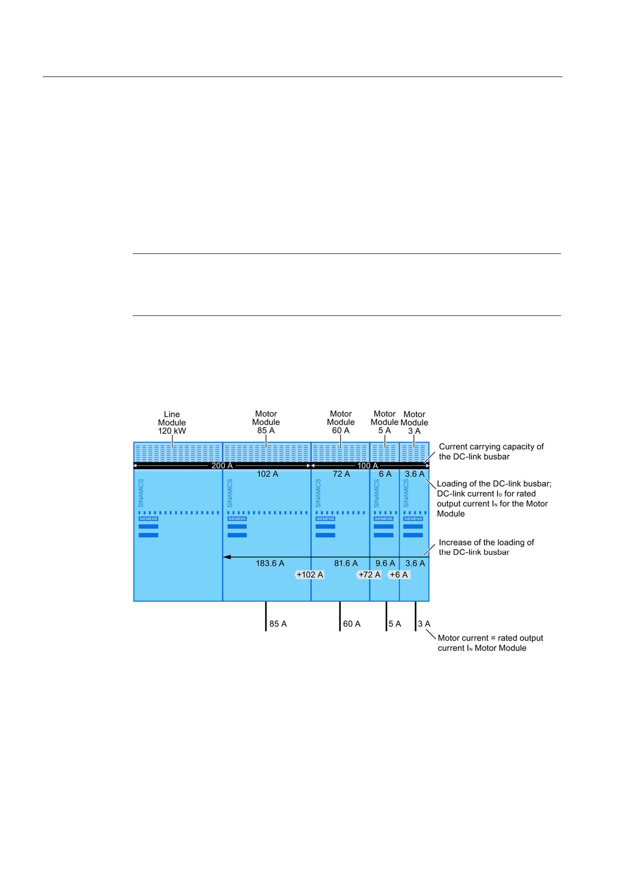
Example 1:
Connection of several Motor Modules with different current carrying capacity of the DC link
busbar to a Line Module.
Figure 7-1
Regular construction; DC link busbars not overloaded
Guidelines for machine configuration
162
System Manual, MA 01/2013, 6FC5397-6CP10-0BA2
DC link
7.3 Current Carrying Capacity of the DC Link Busbar
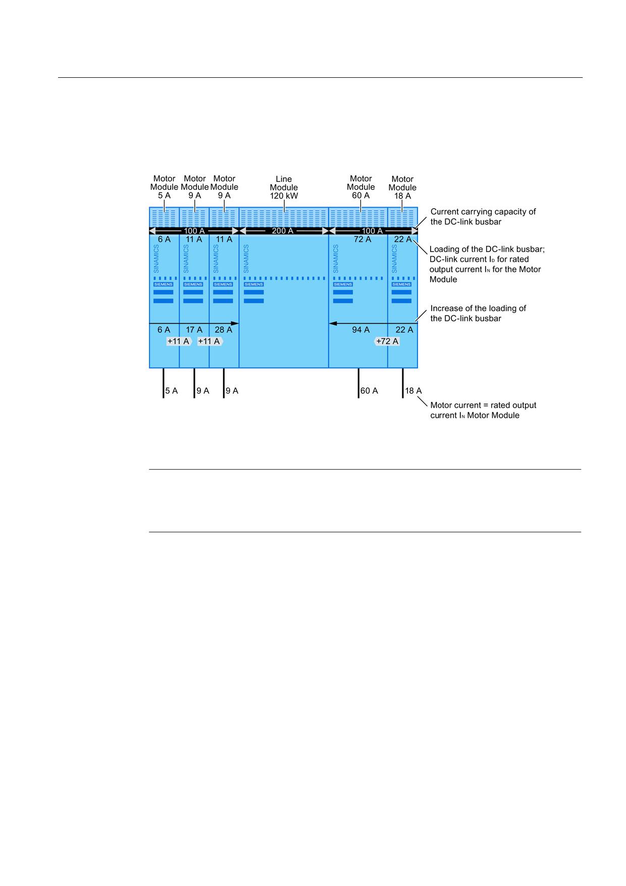
Example 2:
Connection of several Motor Modules with the same current carrying capacity of the DC link
busbar to a Line Module with center infeed.
Figure 7-2
Infeed from left and right (center infeed)
Note
A center infeed with Motor Modules to the right and left of the Line Module can be configured
for all Line Modules.
Exception: Smart Line Modules 5 kW and 10 kW
A single-sided infeed would overload the DC link busbar for a 60 A Motor Module. This type
of configuration is therefore not permitted.
Guidelines for machine configuration
System Manual, MA 01/2013, 6FC5397-6CP10-0BA2
163
DC link
7.4 DC link rectifier adapter
7.4
DC link rectifier adapter
The DC link rectifier adapter supplies the DC link voltage directly. It is best used for
supplying an individual component. With a direct supply, each component is connected to
the DC link separately. The internal DC link busbar is not used here.
If the DC link rectifier adapter is to be used for supplying more than one component, it is
important to remember that it can only be installed on the component on the far right. The
choice of connection cable diameter should be based on the required summation current for
all the connected components.
The connection cables must be fused accordingly.
Mounting on components with reinforced DC link busbars is not possible.
Note
When a DC link rectifier adapter and DC busbars are used, the limit values for radio
interference suppression under Category C2 according to EN 61800-3 can no longer be
observed.
Table 7- 2
Available DC link rectifier adapters
Order number
Screw terminals
Used for Line/Motor Modules with these sizes
6SL3162-2BD00-0AA0
0.5 to 10 mm²
50 mm; 75 mm; 100 mm
6SL3162-2BM00-0AA0
35 to 95 mm²
150 mm; 200 mm; 300 mm
Note
Safety instructions
For more details of the DC link rectifier adapter, refer to the SINAMICS S120 Booksize
Power Units Equipment Manual.
In particular, please observe the associated safety instructions.
Guidelines for machine configuration
164
System Manual, MA 01/2013, 6FC5397-6CP10-0BA2
DC link
7.5 DC link adapter
7.5
DC link adapter
The DC link adapter is required when the drive line-up needs to be divided up (e.g. into two
rows). The sub-line-ups are connected using cables (35 mm2 to 95 mm2). Shielded individual
cores are recommended.
The DC link adapter can be used for all Line Modules and Motor Modules in the booksize
format. Mounting on components with reinforced DC link busbars is not possible.
Note
Safety instructions
For more details of the DC link adapter, refer to the SINAMICS S120 Booksize Power Units
Equipment Manual.
In particular, please observe the associated safety instructions.
Guidelines for machine configuration
System Manual, MA 01/2013, 6FC5397-6CP10-0BA2
165
DC link
7.5 DC link adapter
Guidelines for machine configuration
166
System Manual, MA 01/2013, 6FC5397-6CP10-0BA2
Connection of the components in SINAMICS drive
system
8
8.1
Electronics Power Supply
For the electronics power supply, a differentiation is made between:
● external power supply with SITOP modular
● internal power supply with Control Supply Module (CSM)
8.1.1
External power supply (SITOP)
An external SITOP modular power supply must be provided for the electronics power supply
of the individual SINAMICS components. This ensures the trouble-free operation of all
SINAMICS components. The SITOP electronics power supply also has the advantage that
the power supply is already equipped with an internal line filter (class B in accordance with
EN55022). This ensures an EMC-conform operation.
If a power supply other than SITOP is used, the required rated data (see Equipment Manual
for Booksize Power Units) must be observed to ensure a trouble-free operation.
24 VDC power is required to supply
● the electronics of the SINAMICS components using the integrated 24 V busbar
● the electronics for Control Units, Option Boards and Sensor Modules, and the process
voltage of their digital inputs
● the load voltage of the digital outputs
● the motor holding brakes
Other consumers may be connected to the power supply devices provided they have
separate protection against excess current.
CAUTION
If other consumers are connected to the power supply, switch inductances (contactors,
relays) must be provided with suitable over-voltage protective circuits.
The operation of motors with integrated holding brake requires a regulated DC power supply.
The power is supplied from the internal 24 V busbars. The voltage tolerances of the motor
holding brakes and the voltage losses of the connection cables must be observed.
Guidelines for machine configuration
System Manual, MA 01/2013, 6FC5397-6CP10-0BA2
167
Connection of the components in SINAMICS drive system
8.1 Electronics Power Supply
The DC power supply should be set to 26 V. The Control Supply Module supplies 26 V. This
ensures that the voltage supplied to the brake lies within the permitted range when the
following general conditions are satisfied:
● Use of Siemens three-phase motors
● Use of Siemens MOTION-CONNECT power cables
● Motor cable lengths maximum 100 m
8.1.1.1
Selection of the Power Supply Devices
Devices specified in the following table are recommended. These devices satisfy the
associated EN 60204-1 requirements.
Table 8- 1
SITOP Power modular recommendation
Rated output current [A]
Input voltage range [V]
Short-circuit current [A]
Order number
5
2AC 85-132/170 - 550
5.5
6EP1333-3BA00
10
2AC 85-132/176 - 550
30 for 25 ms
6EP1334-3BA00
20
3AC 320 - 550
23
6EP1436-3BA.0
40
3AC 320 - 550
46
6EP1437-3BA.0
Table 8- 2
Control Supply Module recommendation
Rated output current [A]
Input voltage range [V]
Short-circuit current [A]
Order number
20
3AC 380 -10% (-15% < 1 min) to
DC 300 - 800 < 24
6SL3100-1DE22-0AA0
3AC 480 +10%
See also NC62 catalog.
WARNING
Danger to life due to missing protective conductor connection
When using external power supplies, e.g. SITOP, the ground potential must be connected
using the protective conductor connection (PELV).
Guidelines for machine configuration
168
System Manual, MA 01/2013, 6FC5397-6CP10-0BA2
Connection of the components in SINAMICS drive system
8.1 Electronics Power Supply
8.1.1.2
24 V current consumption of the components
A separate 24 V power supply must be used for the SINAMICS S120 drive group.
The following table can be used to calculate the 24 VDC power supply for the components.
The values of the typical power consumption serve as configuring basis.
Table 8- 3
Overview of 24 VDC current consumption
Component
Typical current consumption [ADC]
NCU 7x0 (without load at the digital outputs)
2.1
NX1x
0.8
CSM
1.1
CU320 without load
0.8
each digital output
0.1
PROFIBUS teleservice
CBC10
0.1
Active Line Modules
16 kW
1.1
36 kW
1.5
55 kW
1.9
80 kW
1.7
120 kW
2.1
Smart Line Modules
5 kW
0.9
10 kW
1.0
16 kW
1.1
36 kW
1.5
DRIVE-CLiQ and brake
DRIVE-CLiQ (e.g. motors with DRIVE-CLiQ interface)
typ. 0.25, max. 0.45
Brake (e.g. motor holding brake)
typ. 0.4 to 1.1; max. 2
Single Motor Modules
3 A (+ 1 x DRIVE-CLiQ; + 1 x brake)
0.85
5 A (+ 1 x DRIVE-CLiQ; + 1 x brake)
0.85
9 A (+ 1 x DRIVE-CLiQ; + 1 x brake)
0.85
18 A (+ 1 x DRIVE-CLiQ; + 1 x brake)
0.85
30 A (+ 1 x DRIVE-CLiQ; + 1 x brake)
0.9
45 A (+ 1 x DRIVE-CLiQ; + 1 x brake)
1.2
60 A (+ 1 x DRIVE-CLiQ; + 1 x brake)
1.2
85 A (+ 1 x DRIVE-CLiQ; + 1 x brake)
1.5
132 A (+ 1 x DRIVE-CLiQ; + 1 x brake)
1.2
200 A (+ 1 x DRIVE-CLiQ; + 1 x brake)
1.2
Guidelines for machine configuration
System Manual, MA 01/2013, 6FC5397-6CP10-0BA2
169
Connection of the components in SINAMICS drive system
8.1 Electronics Power Supply
Component
Typical current consumption [ADC]
Double Motor Modules
2 x 3 A (+ 2 x DRIVE-CLiQ; + 2 x brake)
1.15
2 x 5 A (+ 2 x DRIVE-CLiQ; + 2 x brake)
1.15
2 x 9 A (+ 2 x DRIVE-CLiQ; + 2 x brake)
1.15
2 x 18 A (+ 2 x DRIVE-CLiQ; + 2 x brake)
1.3
Sensor Modules Cabinet
SMC 10
0.25
SMC 20
0.25
SMC 30
0.33
Sensor Modules External
SME 20
0.19
SME 25
0.19
SME 120
0.24
SME 125
0.24
Additional system components
Braking Module
0.5
The details apply to Motor Modules / Line Modules with internal/external heat dissipation.
Guidelines for machine configuration
170
System Manual, MA 01/2013, 6FC5397-6CP10-0BA2
Connection of the components in SINAMICS drive system
8.1 Electronics Power Supply
8.1.1.3
Calculation of the 24 VDC Power Requirement Example
Table 8- 4
Example of 24 VDC current requirements
Component
Number
Current consumption
Total current consumption [A]
[A]
NCU7x0
1
2.10
2.10
8 digital outputs
8
0.10
0.80
Active Line Module 36 kW
1
1.50
1.50
Motor Module 18 A
2
0.85
1.70
Motor Module 30 A
3
0.90
2.70
SMC
5
0.25
1.25
Brake
5
1.10
5.50
Total:
15.55
The following conditions should be considered for the configuring:
● The line infeed of the power supply devices must be tapped in front of the line filter of the
Line Module.
● The line connection of the power supply should be made directly and without additional
switched feeders.
● The dimensioning of the output rated current of the power supply is determined by the
load of the connected consumers.
● A load reserve should be provided; a utilization of 0.7 to 0.8 IN is recommended.
● The total length (sum of all cables) of the supply cables for the 24 VDC electronics power
supply between the power supply and the SINAMICS components must not exceed
10 meters.
● The connection cable does not need to be shielded nor twisted. The maximum value of
the ripple voltage, however, must not be exceeded. If this is the case, appropriate
measures must be adopted.
● Where possible, the additional supply for consumers exterior to the SINAMICS system,
such as contactors, valves, etc., should come from a separate power supply. This
reduces any interactions (voltage dips, etc.).
Guidelines for machine configuration
System Manual, MA 01/2013, 6FC5397-6CP10-0BA2
171
Connection of the components in SINAMICS drive system
8.1 Electronics Power Supply
8.1.1.4
Assignment of the power supply to other components
For Smart/Active Line Module, Motor Module and for the NX component, the supply voltage
is monitored by the system. The components are connected using DRIVE-CLiQ; the
monitoring is performed in the Control Unit.
Connection via 24 V terminal adapter
The component's front cover will need to be opened before establishing a 24 V connection to
a module in booksize format. This exposes other live components, such as DC link busbars.
DANGER
Risk of electric shock
A hazardous DC link voltage is present for up to 5 minutes after the power supply has been
switched off.
The protective cover may only be opened after this time has elapsed.
When opening the protective cover for the DC link, you must press the release catch. A
suitable tool (e.g. screwdriver or supplied unlocking tool) must be used for this purpose.
An integrated 24 VDC busbar is used for the electronic power supply of the
Line/Motor/Braking and Capacitor Modules. The current carrying capacity of this busbar is
max. 20 A. The integrated busbar also supplies the motor brake control terminals of the
Motor Modules.
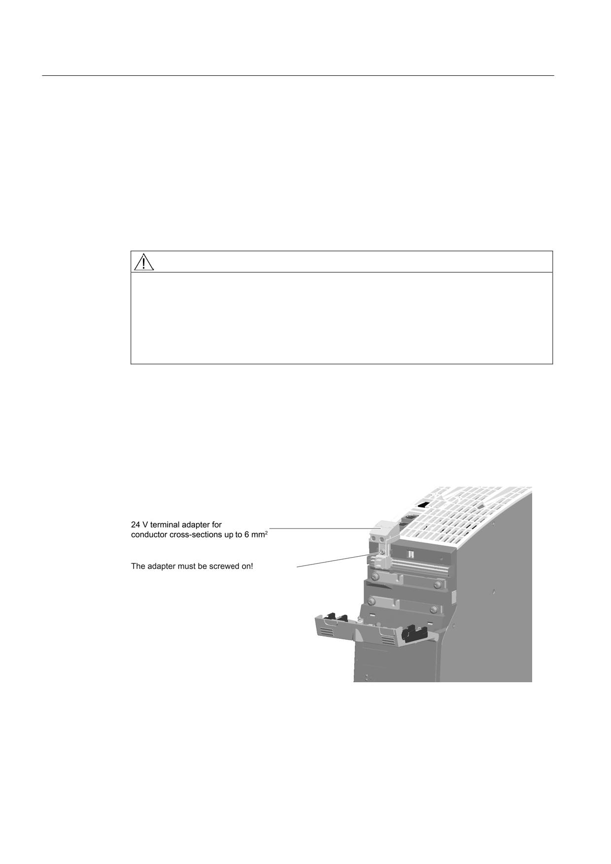
The infeed of the electronic power supply is normally made directly on the Line Module using
the 24 V terminal adapter (max. connectable cross-section 6 mm2, max. fuse 20 A) supplied
with the Line Modules.
Figure 8-1
24 V terminal adapter on the booksize module, front cover open
Guidelines for machine configuration
172
System Manual, MA 01/2013, 6FC5397-6CP10-0BA2
Connection of the components in SINAMICS drive system
8.1 Electronics Power Supply
The 24 V busbar is used to pass the 24 VDC power between the individual components.
24 V jumper plugs (supplied with the Line Modules) are used to jumper the 24 V busbar at
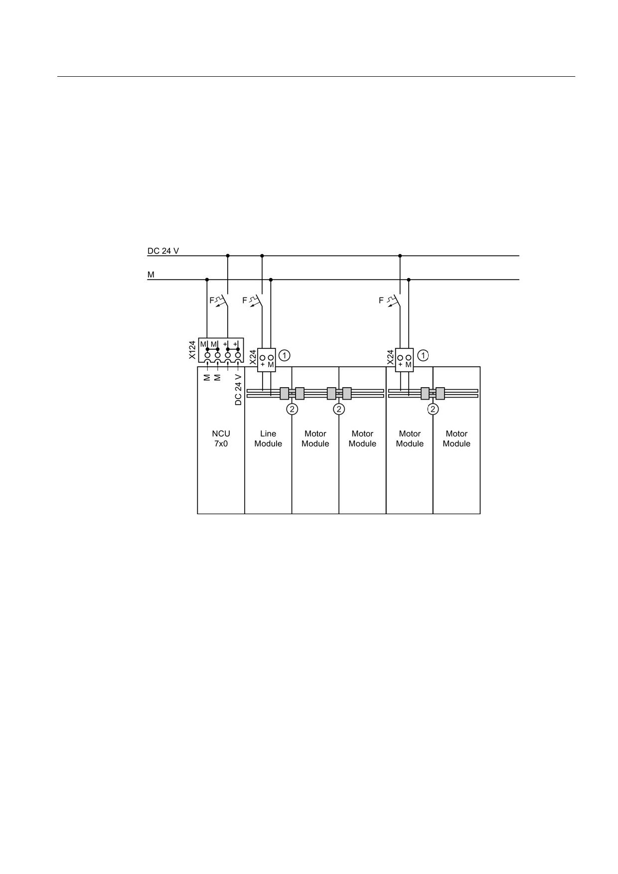
the component transitions.
If the maximum current carrying capacity (20 A ) of the 24 V busbar is exceeded, an
additional electronic current infeed must be provided. This must be implemented, for
example, on a Motor Module using an additional 24 V terminal adapter, which must be
ordered separately (order no. 6SL3162-2AA00-0AA0). The 24 V busbar must not be
jumpered upstream of the new infeed, because a new potential begins downstream of the
additional infeed.
①
DC 24 V terminal adapter
②
Jumper plugs
Figure 8-2
Electronic power supply infed more than once
For all other components, such as Control Unit or Sensor Module, the electronic power
supply is connected using appropriate infeed plugs at the associated component. The infeed
plugs are identical for all components. The maximum connectable cross-section is 2.5 mm2
and the maximum current carrying capacity is 20 A.
To improve the wiring of the individual components with each other, a potential jumpering at
the infeed plugs is possible. The total current of all attached components, however, must not
exceed 20 A.
Power is supplied to the digital inputs/outputs at the Control Unit and Sensor Module, for
example, via appropriate terminals (max. 0.5 mm2).
Guidelines for machine configuration
System Manual, MA 01/2013, 6FC5397-6CP10-0BA2
173
Connection of the components in SINAMICS drive system
8.1 Electronics Power Supply
8.1.1.5
Overcurrent protection
On the primary side and on the secondary side of the power supply device, devices and
cables must be protected from over-current using suitable protection devices.
Primary side
Recommended circuit-breakers (IEC 898) in the suppy cable can be found in the technical
data of the SITOP devices in the KT 10.1 catalog. The cable cross-section must be
considered.
The primary protection is responsible for providing device protection for the SITOP power
supply as well as line protection between the protective device and the power supply.
Secondary side
For the protection of the secondary side, particular attention must be paid to:
● Loading due to loads, possibly the simultaneity factor in response to machine operation
● The current carrying capacity of the cables in normal operation and in a short-circuit
situation
● The ambient temperature
● The effect of bundling together cables, e.g. where these are laid in a common duct
● Cable laying method to EN 60204-1
EN 60204-1, Section 14, can be used to determine the overcurrent protection devices.
Protection of the load feeders
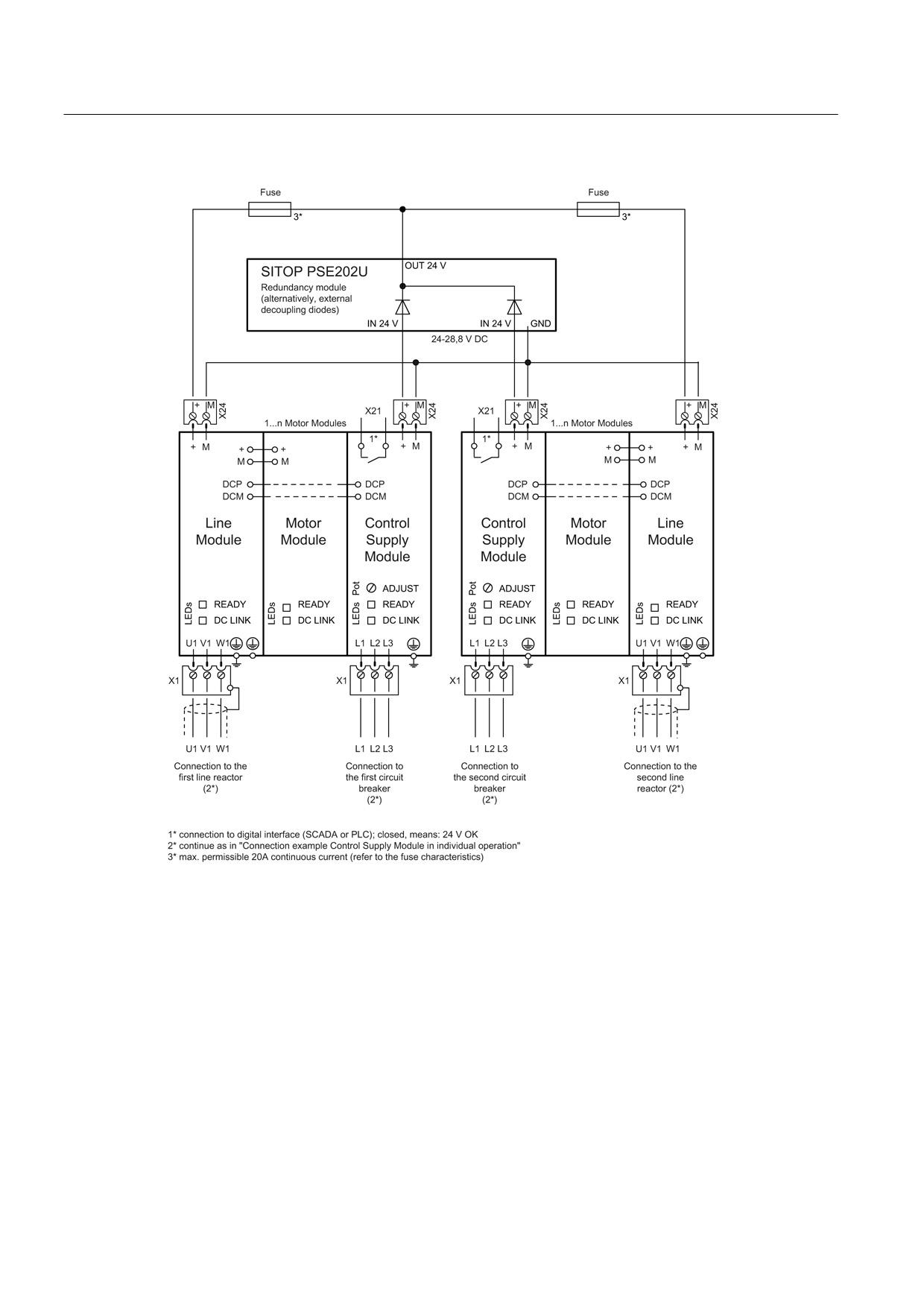
Load feeders must be protected selectively. Circuit-breakers are suitable (order no.: 5S…,
ETB1 catalog) or the SITOP select diagnostic component (order no.: 6EP1961-2BA.0).
Configuration details for the secondary protection of the load feeders are contained in the KT
10.1 catalog (SITOP Power Supplies, "Technical Information and Configuration Notes"
section).
The rated size of the protective devices depends on the current need. The protective device
also performs the line protection and sometimes also the device protection of the attached
consumers. In a fault situation, the used power supply must be able to supply the required
power until being controlled.
Regulated power supplies (such as SITOP power) must be provided, in accordance with EN
60204-1, with integrated electronic short-circuit protection capable of independently
protecting SITOP power and the supplied 24 VDC circuits against overloading in the event of
overloads/short circuits.
Guidelines for machine configuration
174
System Manual, MA 01/2013, 6FC5397-6CP10-0BA2
Connection of the components in SINAMICS drive system
8.1 Electronics Power Supply
Circuit-breakers
When selecting circuit breakers from the table below, the following cable conditions need to
be considered:
● Ambient temperature 40 °C or 55 °C
● Max. 1 conductor pair bunched
● Conductor limit temperature 70 °C for normal operation
● Maximum cable length:
-
10 m for the supply cables
-
30 m for signal lines
● To be laid separately from other cables and conductors carrying operating current
● Cable type: PVC conductor cable
Table 8- 5
Types of circuit breaker depending on conductor cross-section and temperature
Conductor cross-
Max. value up to 40 °C
Max. value up to 55 °C
section
1.5 mm2
10 A
10 A
2.5 mm2
20 A
10 A
4 mm2
25 A
16 A
6 mm2
32 A
20 A
24 V busbar
20 A
20 A
The tripping characteristic of the circuit-breakers must be chosen appropriately for the
consumers to be protected and the maximum current provided by the power supply device in
a short-circuit situation.
The MCBs can be selected according to Siemens catalog "BETA Modular Installation
Devices - ET B1".
8.1.1.6
Line formation
The corresponding different supply lines should be configured and constructed depending on
the size of the drive group and the overall length. This ensures that should one line fail, the
power supply to all attached consumers does not fail. The fault-free consumer lines remain
operational.
The maximum connectable cross-section of the consumers must also be considered:
●
6.0 mm2 for the 24 V power supply terminal adapter of the power busbar
●
2.5 mm2 for the 24 V power supply infeed terminal of the CU and SMC components
●
0.5 mm2 for the digital inputs/outputs and analog inputs/outputs
Guidelines for machine configuration
System Manual, MA 01/2013, 6FC5397-6CP10-0BA2
175
Connection of the components in SINAMICS drive system
8.1 Electronics Power Supply
Example for the splitting of the consumer lines:
● NCU / NX
● Line / Motor Modules
● Supply of the Sensor Modules
● Consumers such as relays, valves, etc.
● Additional brakes not supplied from the Motor Module
Multiple power supplies are recommended for larger plant concepts.
Example of the separation:
● Power supply for the direct drive system (NCU, NX, LM, MM, SME and SMC)
● Power supply for additional consumers, such as brakes, valves and power contactors
If required, the circuit-breakers can be equipped with additional auxiliary switches. If these
signal contacts are fed to a higher-level controller, a detailed fault diagnosis can be
performed when the circuit-breakers trip.
Notes
● SINAMICS components have a reverse polarity protection on the 24 VDC infeed side.
● Line, Motor, Braking, Capacitor and Control Supply Modules are short-circuit resistant on
the 24 V busbar for a maximum current of 20 A. The 24 V terminal adapter for the infeed
has a maximum connection cross-section of 6 mm2.
● If no higher short-circuit current can occur, a protection can be omitted. This means the
components can be connected directly to the power supply.
● If higher short-circuit current occur, a protection against over-current / short-circuit must
be provided, max. 20 A, however. In a fault situation, the used power supply must be able
to supply the required current until tripping.
● The maximum protection of the power supply infeed for Control Unit and Sensor Module
Cabinet depends on the connected cable cross-section (max. 2.5 mm2), maximum 20 A,
however.
● The maximum protection of the controller inputs/outputs at the other components
depends on the connected cable cross-section:
Guidelines for machine configuration
176
System Manual, MA 01/2013, 6FC5397-6CP10-0BA2
Connection of the components in SINAMICS drive system
8.1 Electronics Power Supply
Table 8- 6
Controller inputs/outputs and their connectable cross-sections
Component
max. cable cross-section
Control Unit NCU7x0.3
1.5 mm2
NX1x.3 extension unit
1.5 mm2
CU320-2 Control Unit
1.5 mm2
Active Line Module
1.5 mm2
Smart Line Module
1.5 mm2
Motor Module
1.5 mm2
Sensor Module Cabinet (SMC)
1.5 mm2
TM15, TM41 Terminal Modules
1.5 mm2
TM120 Terminal Module
6.0 mm2
● Controller outputs at the Line, Motor and Braking Module, Control Unit and Sensor
Module Cabinet are short-circuit resistant.
8.1.1.7
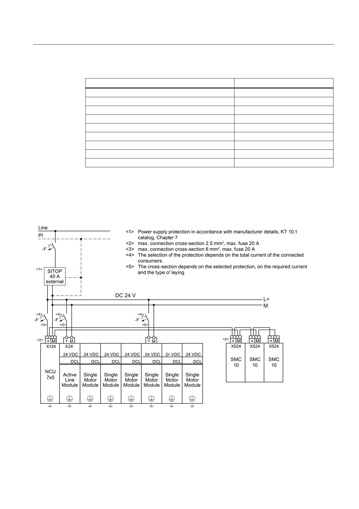
Power Supply Connection Example
Figure 8-3
Power Supply Connection Example
Guidelines for machine configuration
System Manual, MA 01/2013, 6FC5397-6CP10-0BA2
177
Connection of the components in SINAMICS drive system
8.1 Electronics Power Supply
8.1.2
Internal power supply via the Control Supply Module (CSM)
The Control Supply Module (CSM) is a 24 VDC power supply unit integrated as a separate
SINAMICS component in the drive line-up. It provides an output voltage of 24 VDC - 28.8
VDC. This can be adjusted using an integrated potentiometer.
The CSM supplies all SINAMICS components in the drive line-up and also components,
such as Control Unit or Sensor Module Cabinet with 24 VDC. The maximum output current is
20 A DC. An external power supply is not essential.
In normal operation, the Control Supply Module is supplied from the line voltage. In the event
of a power failure, the module automatically changes over to supply from the DC link.
Depending on the energy content in the DC link, the CSM can maintain the supply of the 24
V busbar. This allows transient line fluctuations to be bridged without the drive line-up failing.
To achieve longer bridging times, additional Capacitor Modules can be used to increase the
DC link capacity. The consequent increased storage capacity of the DC link acts positively
should the line voltage drop.
Specific emergency return movements, such as those required in the machine tool area, can
also be initiated. This is necessary, for example, to stop rapidly rotating spindles as fast as
possible or to protect expensive workpieces by making appropriate return movements of the
axes. Further measures, however, must be considered for the realization.
The Control Supply Module has safe electrical separation between the line potential and the
DC link potential. This therefore ensures that the DC link is not unintentionally charged. The
Control Supply Module can therefore remain connected to the supply if the Line Module is
galvanically isolated from the supply, for example via a line contactor.
The 24 V ground of the Control Supply Module is internally grounded.
The Control Supply Module is cooled using an internal fan.
Temperature and voltages are internally monitored.
Temperature monitoring:
In the event of an overtemperature in the Control Supply Module, a temperature advance
warning is issued via a signaling contact. If the temperature falls below the limit value within
the advance warning time, then the module remains operational and the signaling contact is
de-energized. If the overtemperature condition persists, the module is switched off and
restarted.
Voltage monitoring:
When the monitoring threshold (32 V) of the output voltage is exceeded for more than 20 ms,
the Control Supply Module switches off and attempts a restart after 10 s. This is
supplemented by a hardware-based overvoltage limiting. This prevents that more than 35 V
can be output in the case of a fault.
The Control Supply Module can be operated individually or as part of a parallel connection of
up to ten Control Supply Modules. The switchover between single and parallel operation is
realized in a no-current state using a DIP switch on the upper side of the module.
Guidelines for machine configuration
178
System Manual, MA 01/2013, 6FC5397-6CP10-0BA2
Connection of the components in SINAMICS drive system
8.1 Electronics Power Supply
Note
Compatibility
The new Control Supply Module 6SL3100-1DE22-0AA1 with extended functions described
here replaces Control Supply Module 6SL3100-1DE22-0AA0. The modules are spare-part-
compatible.
CSM in the event of line failure
When planning the line failure concepts, those components located outside the SINAMICS
drive line-up must also be considered (line contactor, controller, etc.). If, in the event of a
fault, the primary energy supply of the CSM comes from the DC link, this can be performed
only in the voltage range UDC link = 430 - 882 VDC (300 - 430 VDC for < 1 min). If these limits
are overshot or undershot, the corresponding error messages will be generated by the
system and internal pulse suppression will be triggered. The drives coast to a standstill and
can no longer be controlled. To limit the maximum/minimum DC link voltage, the use of
Capacitor and Braking Modules may be necessary.
Note
The supply voltage corresponds to PELV (protective extra-low voltage). The required
connection of the ground potential to the protective conductor system is realized in the CSM.
Note
Safety instructions and other information
You can find detailed information on the Control Supply Module in the SINAMICS S120
Booksize Power Units Equipment Manual.
It is absolutely essential that you follow the safety instructions listed there.
Guidelines for machine configuration
System Manual, MA 01/2013, 6FC5397-6CP10-0BA2
179
Connection of the components in SINAMICS drive system
8.1 Electronics Power Supply
8.1.2.1
Connection
The Control Supply Module is connected to the line supply (3-ph. 380 VAC -10 % to 480
VAC +10 %) via interface X1 (screw terminals 0.2 to 4 mm 2) This connection should
preferably be made without using an isolating device (e.g. a contactor).
The CSM has an internal line filter (Class A for TN systems) and the pre-charging circuit for
the DC link inside the unit, from which the isolated 24 V supply is generated.
The CSM also features a current limitation function. When using cables with a cross-section
of 2.5 mm2, no additional protection is required on the 24 V side if a type XLPE or EPR cable
is used, or a cable with a similar quality and with thermal stability of up to 90 °C.
Note
Observe the connection sequence
If a selectively tripping, AC/DC-sensitive RCCB is used for the drive line-up, the Control
Supply Module must always be connected to the line supply downstream of this circuit
breaker. Otherwise, the residual current operated circuit breaker will trip erroneously if the
direct-current component is asymmetrically withdrawn in certain operating states.
Guidelines for machine configuration
180
System Manual, MA 01/2013, 6FC5397-6CP10-0BA2
Connection of the components in SINAMICS drive system
8.1 Electronics Power Supply
8.1.2.2
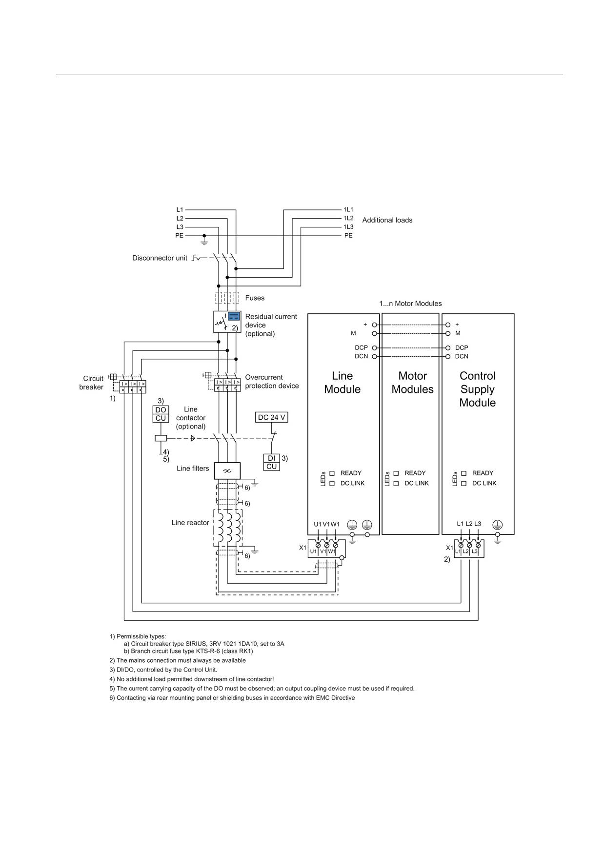
Single operation
When used alone, the Control Supply Module must be connected to the drive line-up via the
DC link busbars as well as the 24 V busbars. The red 24 V connector from the accessories
pack provided must be inserted under all circumstances. The DIP switch on the Control
supply Module must be set to "single mode" The connection can be established as shown
below.
Figure 8-4
Connection example for Control Supply Module in single operation
Guidelines for machine configuration
System Manual, MA 01/2013, 6FC5397-6CP10-0BA2
181
Connection of the components in SINAMICS drive system
8.1 Electronics Power Supply
8.1.2.3
Parallel operation
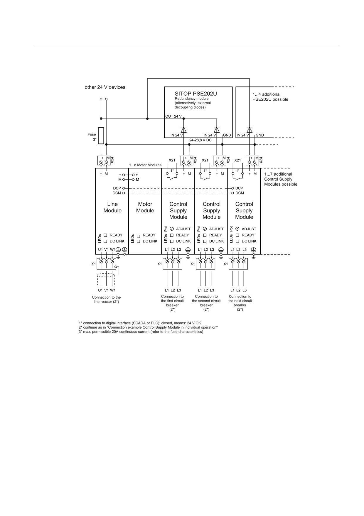
A maximum of 10 Control Supply Modules can be connected in parallel.
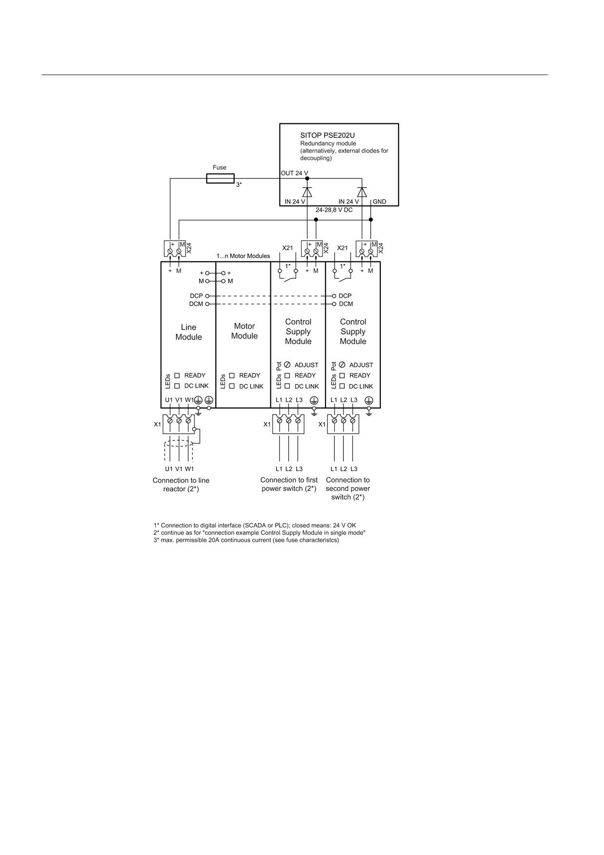
The DIP switch of the Control supply Module must be set to "parallel mode". The same
output voltage must be set for all modules at the adjusting potentiometer.
In parallel mode, each Control Supply Module should supply the 24 VDC voltage via the 24
V terminal adapter. For this reason, the red 24 V connector must not be used (see
connection examples).
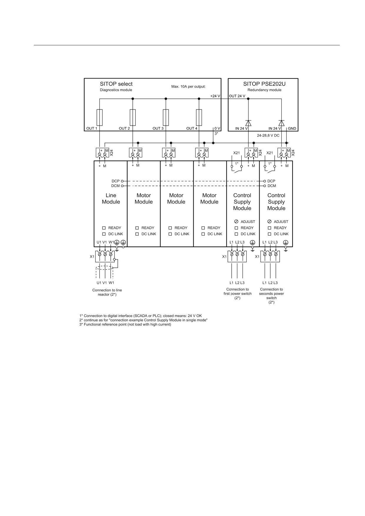
Use of a SITOP redundancy module (6EP1961-3BA20) is recommended for parallel
connection. One SITOP redundancy module must be used for two Control Supply Modules
in this case. Alternatively, a connection with external diodes to decouple the individual
Control Supply Modules is possible. If a Control Supply Module fails, an alarm is generated
and provided via the X21 signaling contact. The 24 V supply is maintained via the second
module.
Note
Only Control Supply Modules with order number 6SL3100-1DE22-0AA1 may be used for
parallel connection.
Guidelines for machine configuration
182
System Manual, MA 01/2013, 6FC5397-6CP10-0BA2
Connection of the components in SINAMICS drive system
8.1 Electronics Power Supply
Figure 8-5
Connection example for parallel connection of 2 to 10 Control Supply Modules via SITOP PSE202U
redundancy module
Guidelines for machine configuration
System Manual, MA 01/2013, 6FC5397-6CP10-0BA2
183
Connection of the components in SINAMICS drive system
8.1 Electronics Power Supply
Figure 8-6
Connection example for a redundancy circuit with two Control Supply Modules via SITOP PSE202U
redundancy module
Guidelines for machine configuration
184
System Manual, MA 01/2013, 6FC5397-6CP10-0BA2
Connection of the components in SINAMICS drive system
8.1 Electronics Power Supply
Figure 8-7
Connection example for parallel connection of Control Supply Modules via SITOP PSE202U redundancy
module and a SITOP select diagnostic module (6EP1961-2BA00)
Guidelines for machine configuration
System Manual, MA 01/2013, 6FC5397-6CP10-0BA2
185
Connection of the components in SINAMICS drive system
8.1 Electronics Power Supply
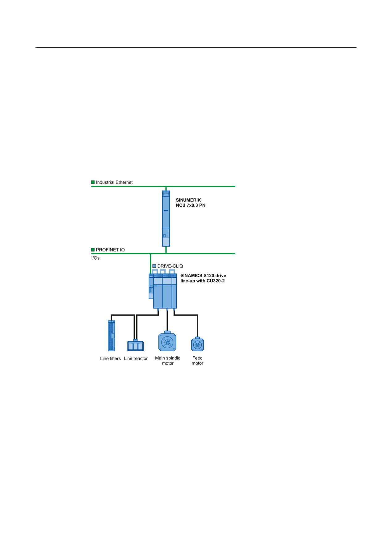
Figure 8-8
Connection example for operation of 2 units with Control Supply Modules via a SITOP PSE202U redundancy
module
Guidelines for machine configuration
186
System Manual, MA 01/2013, 6FC5397-6CP10-0BA2
Connection of the components in SINAMICS drive system
8.2 Connection of a SINAMICS Control Unit CU320-2
8.2
Connection of a SINAMICS Control Unit CU320-2
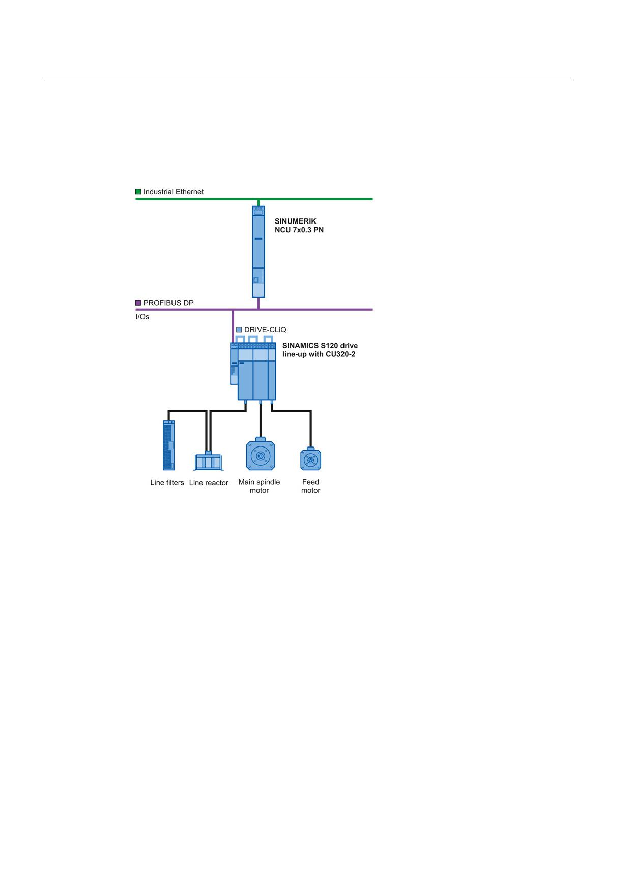
The SINUMERIK NCU 7x0.3 PN can function as a higher-level control for multiple
SINAMICS S120 drive line-ups. In this case, the drive line-ups often have a separate
SINAMICS CU320-2; this is responsible for straightforward functions such as positioning.
The CU320-2 is connected via PROFINET IO or via PROFIBUS DP.
Connection via PROFINET IO
The NCU 7x0.3 PN generation comes with PROFINET interfaces as standard, so that the
SINAMICS CU320-2 can be connected directly via a port of the X150 interface without
additional components. The maximum transmission rate is 100 Mbps.
Figure 8-9
NCU 7x0.3 - CU320-2 connection via PROFINET IO
Guidelines for machine configuration
System Manual, MA 01/2013, 6FC5397-6CP10-0BA2
187
Connection of the components in SINAMICS drive system
8.2 Connection of a SINAMICS Control Unit CU320-2
Connection via PROFIBUS DP
The conventional method of connecting the SINAMICS CU320-2 via PROFIBUS DP can be
used with the NCU 7x0.3 PN too. The connection is established via the X126 interface. The
maximum transmission rate is 12 Mbps.
Figure 8-10 NCU 7x0.3 - CU320-2 connection via PROFIBUS DP
Guidelines for machine configuration
188
System Manual, MA 01/2013, 6FC5397-6CP10-0BA2
Connection of the components in SINAMICS drive system
8.3 Connection of line modules
8.3
Connection of line modules
8.3.1
Introduction
The Line Module is used to connect the drive group to the energy supply system.
The Line Module is used for the power infeed into the DC link.
In generator operation, the energy of the drives fed into the DC link is returned to the energy
supply system. For an energy supply system that cannot accept any regenerative energy
(e.g. diesel generator), the regenerative capability of the Line Module must be deactivated.
The braking energy must then be converted into heat via a Braking Module with braking
resistor that also needs to be included in the drive group.
Line Modules can be directly connected to TN and TT systems, both with grounded neutral
point and grounded line conductor; they can also be connected to IT systems. Line Modules
have an integrated overvoltage protection function.
Active Line Module
The self-managed infeed/regenerative unit with booth converter creates an increased
controlled DC link voltage. This makes the connected Motor Modules independent of
tolerances in the energy supply system.
The Control Unit is used to control, trigger and monitor the Active Line Module. Data
exchange is performed via the DRIVE-CLiQ interface.
Control types:
The Active Line Module operates in two different control types depending on the
parameterized line voltage (p0210).
● Active Mode
The Active Line Module can control the DC link voltage in a rated voltage range of 3 AC
380 V to 3 AC 415 V (input voltage); boost converter with controlled DC link voltage and
sinusoidal line voltage.
● Smart Mode
In the rated voltage range of 3 AC 416 V to 3 AC 480 V (input voltage), Smart Mode is
automatically activated and the supply system transistors are switched so that they are
synchronous with the supply system. The DC link voltage is not regulated, but is based
on the rectified line voltage according to the following formula: UDC link = Usupply * 1.35.
The setpoint for the DC link voltage (p3510) will be preassigned automatically.
Guidelines for machine configuration
System Manual, MA 01/2013, 6FC5397-6CP10-0BA2
189
Connection of the components in SINAMICS drive system
8.3 Connection of line modules
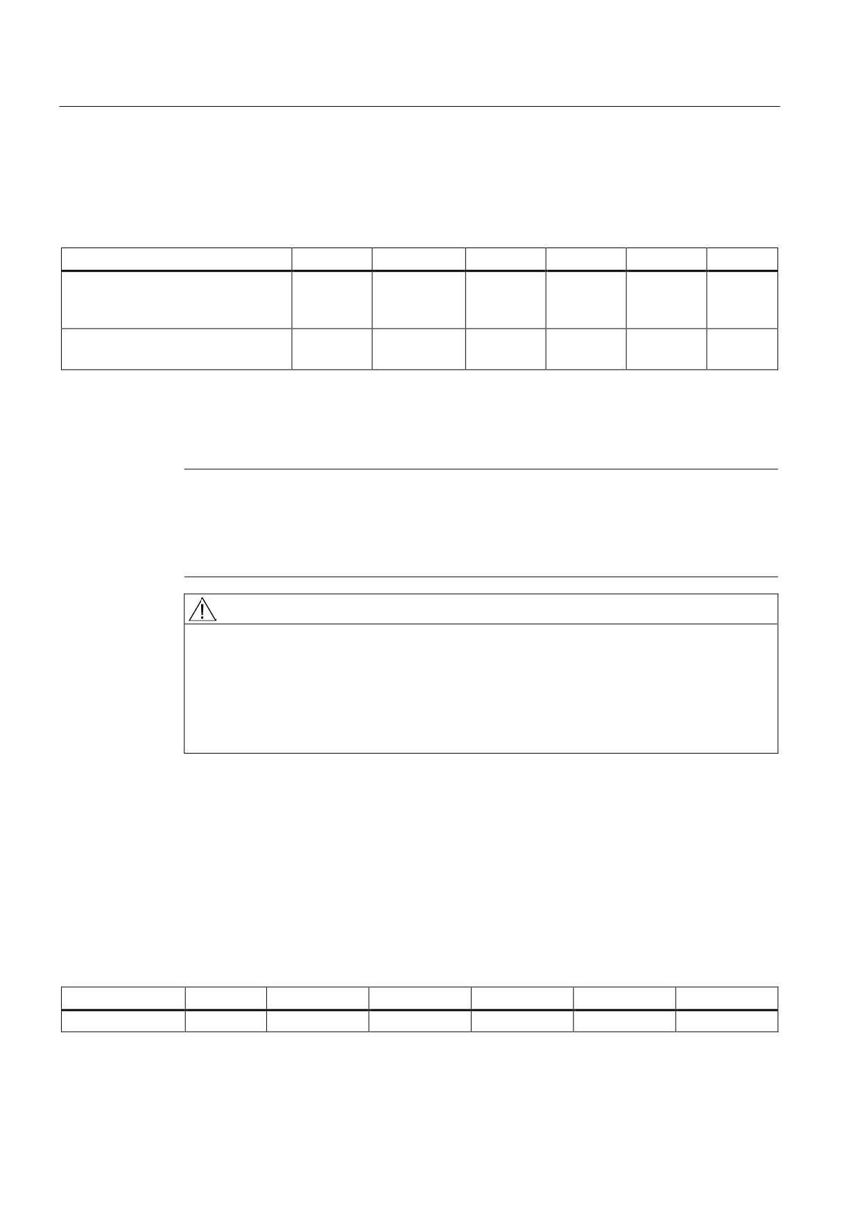
The following DC link values will be attained for the Active Line Module in Active / Smart
Mode:
Table 8- 7
Active Line Module DC link voltages
Line voltage p0210
380 V
400 V
415 V
440 V
460 V
480 V
Active Mode (default values)
600 V
600 V
600 V
-
-
-
VDC set p3510 [V]
(with boost converter p3400.0=1)
Smart Mode (p0210 x 1.35)
513 V1)
540 V1)
561 V1)
594 V2)
621 V2)
648 V2)
(without boost converter p3400.0=1)
1)
Smart Mode can be selected using parameter p3400.0=0.
2)
Smart Mode sets itself automatically during the parameter assignment for the line voltage p0210 > 416 V. It is possible
to select Active Mode if the connected motors are suitable for > 650 VDC.
Note
Observe the insulation voltage
The setpoint for the DC link voltage (p3510) can be changed. The insulation voltage of the
motors must be observed. (See the NC62 catalog or the Configuration Manual for the
motors.)
CAUTION
Dangerous voltage at the DC link
As soon as the energy supply is present at the infeed terminals (-X1:U1/V1/W1) of the
Active Line Module, the DC link will be precharged (UDC link = USupply x 1.35).
Once the "Enable Pulses" enabling signal is also present at the Active Line Module, the
boost converter increases the DC link to the specified setpoint p3510 (e.g. UDC link = 600 V
for Usupply = 400 V).
Smart Line Module
The Smart Line Module is a non-regulated infeed/regenerative feedback unit. The
regenerative capability can be deactivated using a digital input.
The DC link is supplied using an uncontrolled diode bridge. The size of the DC link voltage is
based on the line voltage according to the following formula: UDC link = Usupply * 1.35.
The following DC link values are achieved for the Smart Line Module:
Table 8- 8
Smart Line Module DC link voltages
Line voltage
380 V
400 V
415 V
440 V
460 V
480 V
UDC link
513 V
540 V
561 V
594 V
621 V
648 V
Guidelines for machine configuration
190
System Manual, MA 01/2013, 6FC5397-6CP10-0BA2
Connection of the components in SINAMICS drive system
8.3 Connection of line modules
Note
Observe the insulation voltage
The insulation voltage of the motors must be observed. (See the NC62 catalog or the
Configuration Manual for the motors.)
CAUTION
Dangerous voltage at the DC link
As soon as the energy supply is present at the infeed terminals (-X1:U1/V1/W1) of the
Smart Line Module, the DC link will be precharged.
For the 5/10 kW types, control and monitoring of the Smart Line Module is carried out
exclusively via digital inputs/outputs. No connection to the Control Unit using DRIVE-CLiQ
exists.
Basic Line Module
The Basic Line Module can only feed energy from the supply system into the DC link; energy
cannot be fed back into the supply system. Therefore, this module is only suitable for
applications in which there is no regenerative energy, or in which the energy exchange takes
place between the motor-driven and generator-driven axes in the DC link.
This documentation does not contain a description of the Basic Line Module.
Additional references
/GH2/ SINAMICS S120, Booksize Power Units, chapter titled "Line Modules Booksize".
Guidelines for machine configuration
System Manual, MA 01/2013, 6FC5397-6CP10-0BA2
191
Connection of the components in SINAMICS drive system
8.3 Connection of line modules
8.3.2
Safety instructions for Line Modules Booksize
Note
When using a Line Module Booksize, it is imperative that you observe the safety instructions
in Section 1.
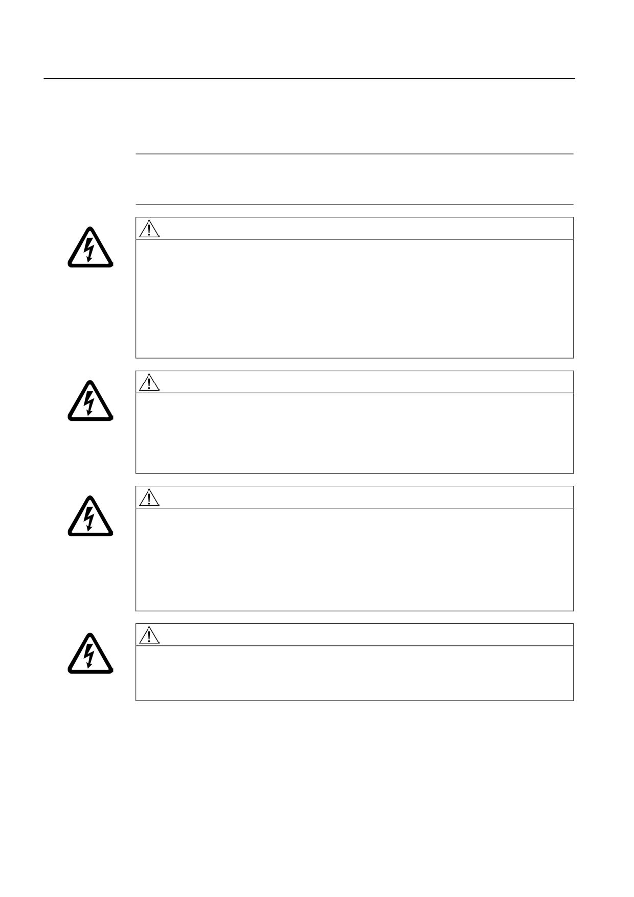
DANGER
Danger to life through electric shock as well as fire hazard due to overcurrent protective
devices that trip too late
Overcurrent protective devices that do not trip or trip too late can cause an electric shock or
fire.
• To protect personnel and for fire protection purposes, at the infeed point, the short-
circuit rating and loop impedance must correspond to the specifications in the
documentation in order that the installed overcurrent protection devices trip within the
specified time.
DANGER
Danger to life through electric shock due to a high DC link voltage
As long as the Line Module is connected to the line supply, the DC link is charged with a
high voltage. Contact with components can result in death or serious injury.
• Isolate the Line Module from the line supply during installation or maintenance work,
e.g. via the line contactor or main switch.
DANGER
Danger to life through electric shock due to the residual charge of the DC link capacitors
Because of the DC link capacitors, a hazardous voltage is present for up to five minutes
after the power supply has been switched off.
Contact with live parts can result in death or serious injury.
• Do not open the protective cover of the DC link until five minutes have elapsed.
• Measure the voltage before starting work on the DCP and DCN DC link terminals.
DANGER
Danger to life through electric shock when the protective cover of the DC link is open
Contact with live parts can result in death or serious injury.
• Only operate the components with closed protective cover.
Guidelines for machine configuration
192
System Manual, MA 01/2013, 6FC5397-6CP10-0BA2
Connection of the components in SINAMICS drive system
8.3 Connection of line modules
WARNING
Danger to life through interruption of the external protective conductor due to high leakage
currents
The drive components conduct a high leakage current via the protective conductor.
Touching conductive parts when the protective conductor is interrupted can result in death
or serious injury.
• Ensure that the external protective conductor satisfies at least one of the following
conditions:
- It has been laid so that it is protected against mechanical damage. 1)
- If it is a single cable, it has a cross-section of at least 10 mm² Cu.
- If it is a conductor of a multi-conductor cable, it has a cross-section of at least 2.5
mm² Cu.
- It has a second protective conductor in parallel with the same cross-section.
- It complies with the local regulations for equipment with increased leakage current.
1) Cables laid within control cabinets or closed machine housings are considered to be
adequately protected against mechanical damage.
WARNING
Danger to life through electric shock due to incorrect connection to the DC link
Incorrect connections can lead to overheating and therefore a risk of fire. There is also a
risk of an electric shock. This can result in serious injury or death.
• Only use adapters (DC link adapters and DC link rectifier adapters) released by
Siemens for the connection to the DC link.
WARNING
Danger to life through electric shock due to incorrectly installed DC link bridges
Incorrectly installed DC link bridges at the left-hand end of the drive line-up can cause an
electric shock.
• For all 50 mm wide modules (exception: Smart Line Modules), remove the DC link
bridge, including the screws. Do not tighten the screws without the DC link bridges.
• For all components that are 75 mm wide or wider, the DC link bridges must not be
moved to the left or removed.
WARNING
Danger to life through electric shock due to missing DC link side covers
There is a danger of an electric shock through contact when the side covers of the DC link
are missing.
• Mount the side covers on the first and last component in the drive line-up.
You can order missing side covers (order number: 6SL3162-5AA00-0AA0).
Guidelines for machine configuration
System Manual, MA 01/2013, 6FC5397-6CP10-0BA2
193
Connection of the components in SINAMICS drive system
8.3 Connection of line modules
WARNING
Danger of an accident due to missing warning labels in the national language.
Missing warning labels in the national language can result in death or serious injury.
• Attach the component warning labels in the national language.
WARNING
Fire hazard due to overheating because of inadequate ventilation clearances
Inadequate ventilation clearances can cause overheating with a risk for personnel through
smoke development and fire. This can also result in more downtimes and reduced service
lives of Line Modules.
• Maintain the 80 mm clearances above and below the Line Modules.
• For the 80 kW and 120 kW Active Line Modules, a ventilation clearance of 50 mm must
also be maintained in front of the fan.
CAUTION
Fire hazard due to overheating when the total length of the power cables is exceeded
Overheating and a fire can result when the total length of the power cables is exceeded.
• Ensure that the total length of the power cables (motor supply cables and DC link
cables) does not exceed the values specified in Section "Possible line reactor and line
filter combinations".
NOTICE
Material damage due to loose power connections
Insufficient tightening torques or vibrations can result in faulty electrical connections. This
can cause fire damage or malfunctions.
• Tighten all power connections with the specified tightening torques, e.g. line supply
connection, motor connection, DC link connections.
• Check the tightening torques of all power connections at regular intervals and tighten
them when required. This applies in particular after transport.
NOTICE
Damage to the equipment when performing a voltage test as a result of connections that
are not disconnected
As part of routine tests, SINAMICS S components undergo a voltage test according to EN
61800-5-1. Connected devices can be damaged.
• Disconnect or unplug all SINAMICS devices before the voltage test of the machine
equipment according to EN 60204-1, Section 18.4.
Guidelines for machine configuration
194
System Manual, MA 01/2013, 6FC5397-6CP10-0BA2
Connection of the components in SINAMICS drive system
8.3 Connection of line modules
NOTICE
Damage to the equipment due to excess energy not being fed back to non-regenerative
supply systems
Excess energy that is not fed back can damage equipment.
• For line supplies without regenerative feedback capability (e.g. diesel generator),
deactivate the regenerative feedback capability of the Active Line Modules and Smart
Line Modules via parameter p3533.
• The braking energy must then be dissipated via an additional Braking Module with
braking resistor in the drive line-up.
Exception: For 5 kW and 10 kW Smart Line Modules, the regenerative feedback capability
must be deactivated as follows:
• Jumper between terminals X22.1 and X22.2
• Ground at X22.4
NOTICE
Damage to external loads when using a disconnector unit without prior voltage interruption
For Line Modules with regenerative feedback capability, switching off a running drive line-
up with a disconnector unit can destroy external loads that remain on the same switching
component parallel to the drive.
• Therefore, interrupt the voltage first at terminals X21.3 (EP +24 V) and X21.4 (EP M).
This can be achieved using a leading breaking auxiliary contact (≥ 10 ms), for example.
NOTICE
Damage through use of incorrect DRIVE-CLiQ cables
Damage or malfunctions can occur on the devices or system when incorrect or unreleased
DRIVE-CLiQ cables are used.
• Only use suitable DRIVE-CLiQ cables that have been released by Siemens for the
respective application.
Note
Malfunctions due to polluted DRIVE-CLiQ interfaces
Malfunctions can occur in the system through the use of polluted DRIVE-CLiQ interfaces.
• Cover unused DRIVE-CLiQ interfaces with the supplied blanking covers.
Guidelines for machine configuration
System Manual, MA 01/2013, 6FC5397-6CP10-0BA2
195
Connection of the components in SINAMICS drive system
8.3 Connection of line modules
Special features for Line Modules with external air cooling
NOTICE
Component failure due to the pollution of external heat sinks
For components with external air cooling, the fan and the heat sinks can accumulate a lot of
pollution. If the cooling air requirement is not provided by the filtered fan, the components
cannot output their specified power. This can cause the temperature monitoring function in
the components to respond.
• Check the fans and heat sinks for pollution at regular intervals and clean them when
necessary.
Note
Checking the seal
• After installation, check the seal on the rear of the device to ensure that it is tight.
• If required, use additional sealing.
Note
Using an installation frame
• Only use an installation frame when the cabinet has an unpainted metal surface.
Note
The Active Line Module (16 kW, 36 kW) and the Smart Line Module (16 kW, 36 kW)
interfaces are identical.
Guidelines for machine configuration
196
System Manual, MA 01/2013, 6FC5397-6CP10-0BA2
Connection of the components in SINAMICS drive system
8.3 Connection of line modules
8.3.3
Active Line Modules with internal air cooling
8.3.3.1
Description
Active Line Modules generate a constant, regulated DC voltage in the DC link from the three-
phase line supply voltage that supplies the connected Motor Modules with power.
This ensures that they are not influenced by network fluctuations.
When the motors are in feedback mode, Active Line Modules supply power back to the
network. The regenerative feedback capability of the modules can be deactivated by
parameterization.
The DC link starts precharging as soon as the supply voltage is applied and is independent
of its phase sequence direction. Load can be applied to the DC link after the modules have
been enabled. An optional main contactor is required for disconnecting the voltage.
Active Line Modules can be directly connected to TN and TT line supplies - both with
grounded neutral point and also with grounded protective conductor; they can also be
connected to IT line supplies. The Line Modules have an integrated overvoltage protection
function.
Guidelines for machine configuration
System Manual, MA 01/2013, 6FC5397-6CP10-0BA2
197
Connection of the components in SINAMICS drive system
8.3 Connection of line modules
8.3.3.2
Interface description
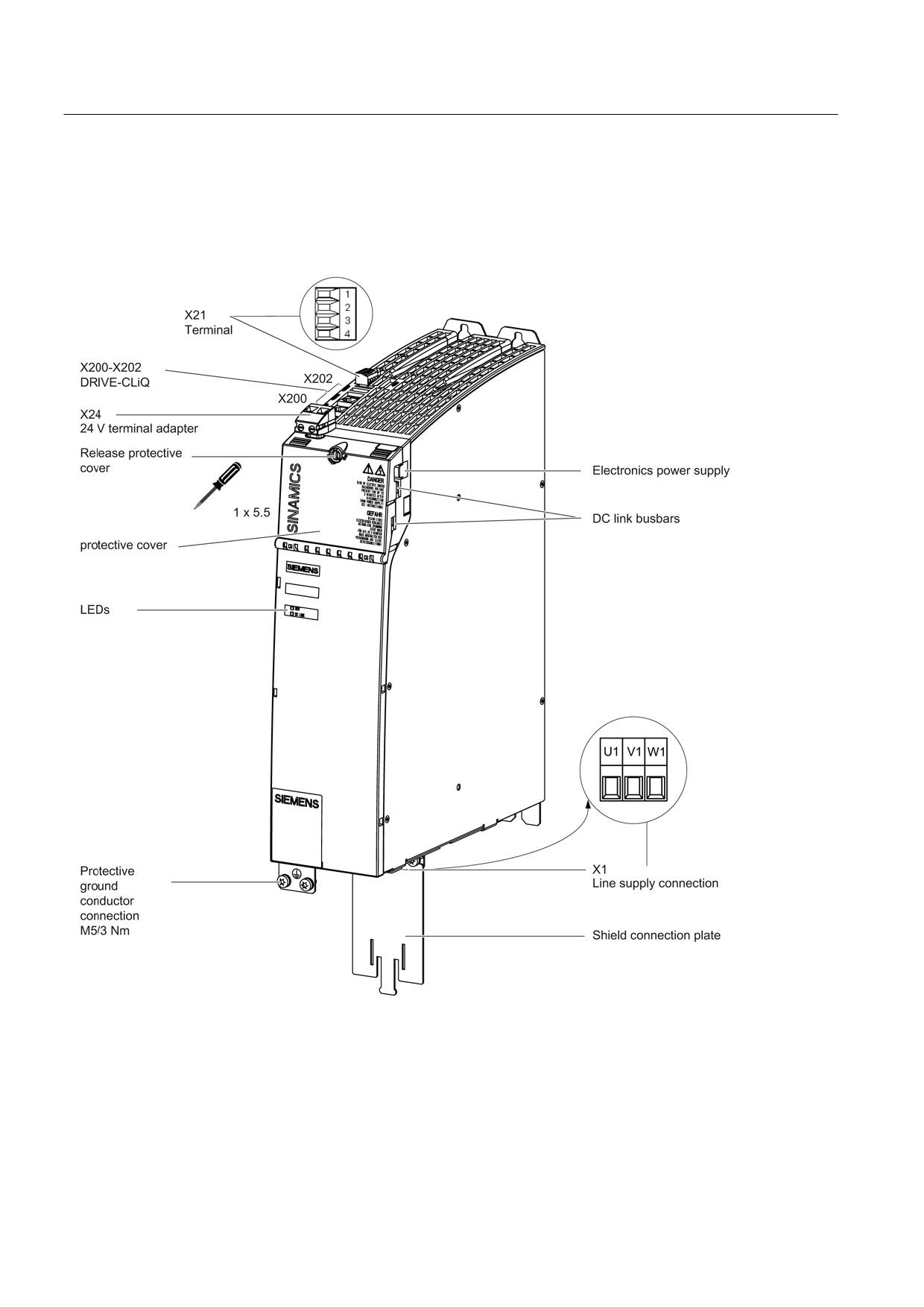
Overview
Figure 8-11 Interface overview, Active Line Module with internal air cooling (example: 16 kW)
Guidelines for machine configuration
198
System Manual, MA 01/2013, 6FC5397-6CP10-0BA2
Connection of the components in SINAMICS drive system
8.3 Connection of line modules
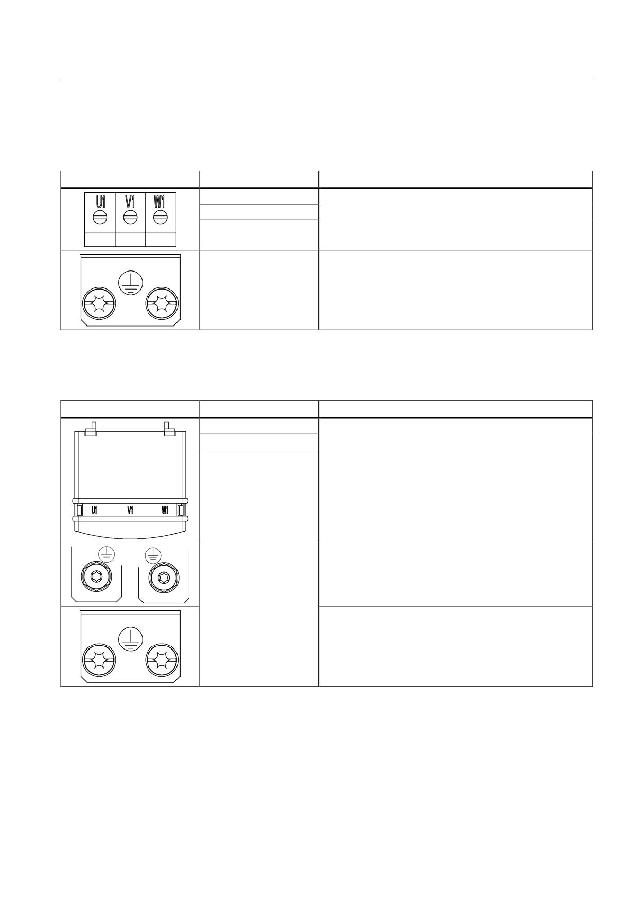
X1 line connection
Table 8- 9
X1: Line connection for Active Line Modules 16 kW
Terminal
Technical specifications
U1
Max. connectable cross-section: 10 mm2
V1
Type: Screw terminal 6 (see Appendix, Chapter "Screw
terminals")
W1
Tightening torque: 1.5 - 1.8 Nm
PE connection
Threaded hole M5/3 Nm 1)
1) For ring cable lugs in accordance with DIN 46234
Table 8- 10 X1: Line connection for Active Line Modules 36 kW to 120 kW
Terminal
Technical specifications
U1
Supply voltage:
3 AC 380 V - 480 V, 50/60 Hz
V1
36 kW: Threaded bolts M6/6 Nm 1)
W1
55 kW, 80 kW and 120 kW: Threaded bolts M8/13 Nm 1)
PE connection
36 kW: Threaded hole M6/6 Nm 1)
55 kW: Threaded hole M6/6 Nm 1)
80 kW and 120 kW: Threaded hole M8/13 Nm 1)
1) For ring cable lugs in accordance with DIN 46234
Guidelines for machine configuration
System Manual, MA 01/2013, 6FC5397-6CP10-0BA2
199
Connection of the components in SINAMICS drive system
8.3 Connection of line modules
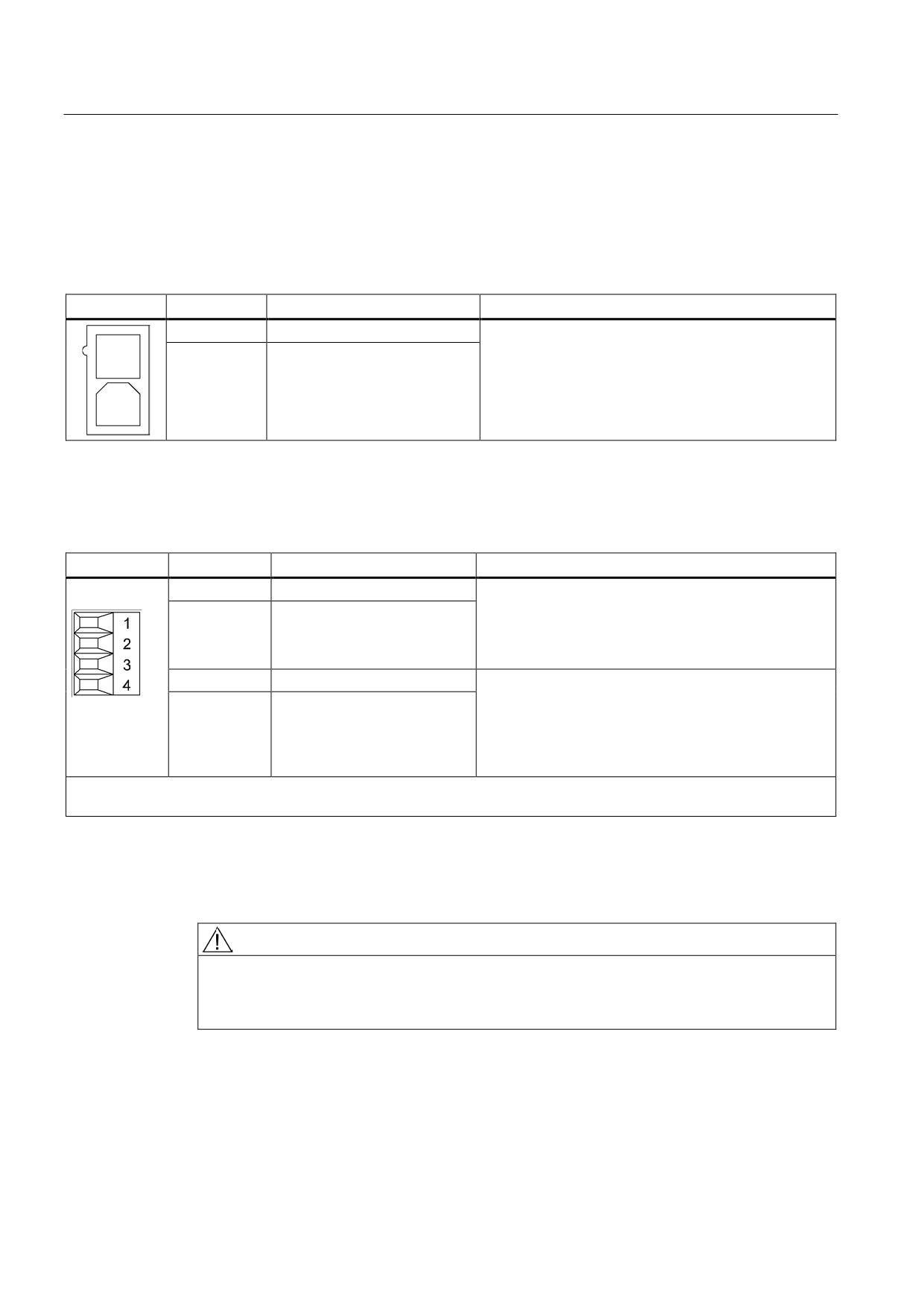
X12 fan connection
Active Line Modules 80 kW and 120 kW are equipped with an interface for connecting the
sub-chassis fan. The interface is located on the underside of the Line Module.
Table 8- 11 X12 fan connection
Terminal
Function
Technical specifications
1
Fan connection +
Voltage 48 V DC for the supplied fan
2
Fan connection -
X21 EP terminals
Table 8- 12 X21 EP terminal/temperature sensor
Terminal
Designation
Technical data
1
+ Temp
Temperature sensors1): KTY84-
1C1302)/PTC2)/bimetallic switch with NC contact
2
- Temp
If an Active Interface Module is used, the temperature
input must be connected to the Active Interface Module
sensor (bimetallic switch with NC contact).
3
EP +24 V (Enable Pulses)
Voltage: 24 VDC
Current consumption: 10 mA
4
EP M (Enable Pulses)
Isolated input
Signal propagation times:
L → H: 100 μs
H → L: 1000 μs
Max. connectable cross-section: 1.5 mm2
Type: Screw terminal 1 (see Appendix, Chapter "Screw terminals")
1) The temperature sensor type can be selected via parameter p0601; the temperature is displayed via r0035 (see
SINAMICS S120/S150 List Manual LH1).
2) Temperatures are detected but not evaluated in the Active Line Module.
CAUTION
Connecting the temperature sensor
If an Active Interface Module is connected, the temperature output of the Active Interface
Module must be connected to terminals 1 and 2.
Guidelines for machine configuration
200
System Manual, MA 01/2013, 6FC5397-6CP10-0BA2
Connection of the components in SINAMICS drive system
8.3 Connection of line modules
WARNING
Danger to life due to charged DC link
For operation, the 24 VDC voltage must be connected to terminal 3 and ground to terminal
4. When withdrawn, pulse suppression is activated. Regenerative feedback is deactivated
and the bypass relay drops out. If the Line Module is not disconnected from the supply
system when the EP terminal is deactivated (e.g. a line contactor is not installed), the DC
link remains charged.
Note
If an active drive line-up is switched off by means of the disconnector unit, the voltage at
terminals 3 (EP +24 V) and 4 (EP M) must be interrupted beforehand. This can be carried
out using a leading (≥ 10 ms) breaking auxiliary contact, for example.
This protects external loads located parallel to the drive on the same switching component.
DANGER
Risk of electric shock!
Only temperature sensors that meet the safety isolation specifications contained in
EN 61800-5-1 may be connected to terminals "+Temp" and "-Temp". If safe electrical
separation cannot be guaranteed (for linear motors or third-party motors, for example), a
Sensor Module External (SME120 or SME125) or Terminal Module TM120 must be used.
If these instructions are not complied with, there is a risk of electric shock!
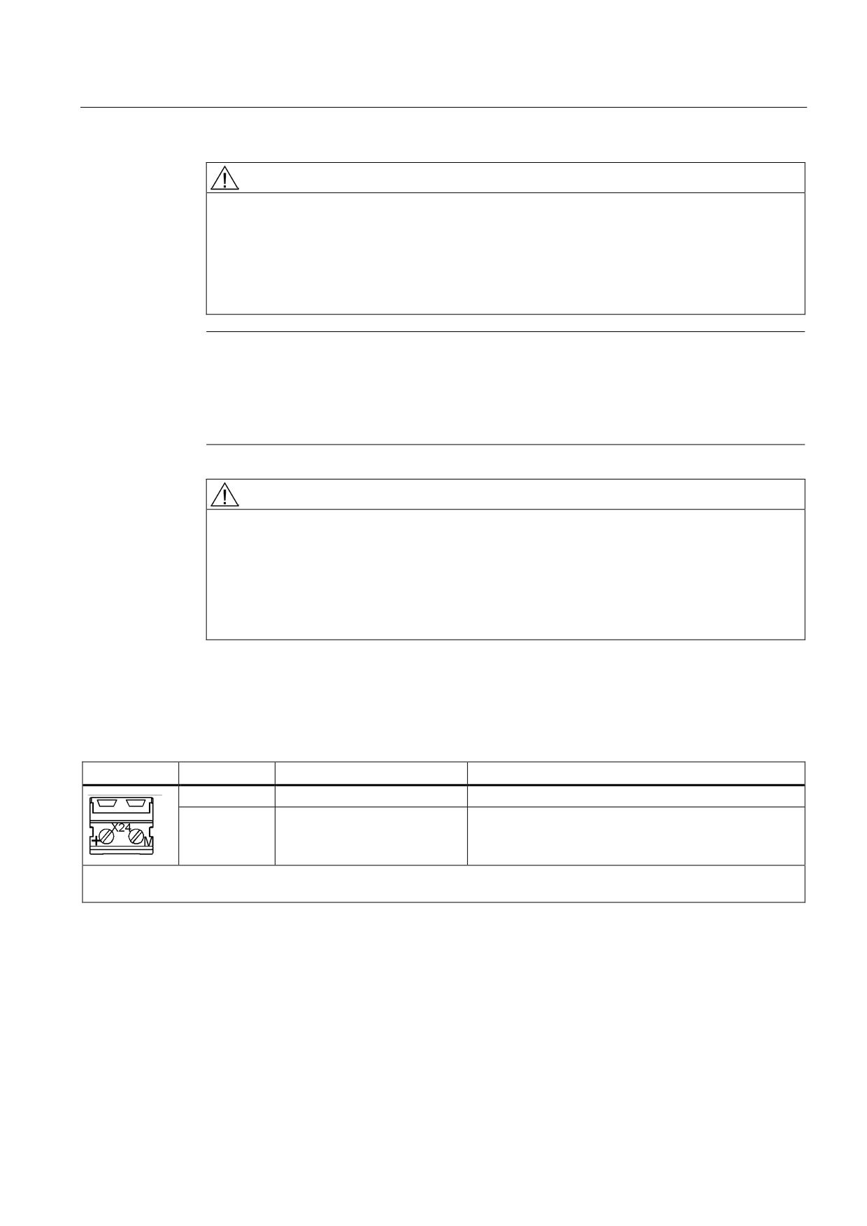
X24 24 V terminal adapter
Table 8- 13 X24 24 V terminal adapter
Terminal
Description
Technical specifications
+
24 V power supply
24 VDC supply voltage
M
Ground
Electronics ground
Max. connectable cross-section: 6 mm2
Type: Screw terminal 5 (see Appendix, Chapter "Screw terminals")
The 24 V terminal adapter is included in the scope of delivery.
Guidelines for machine configuration
System Manual, MA 01/2013, 6FC5397-6CP10-0BA2
201
Connection of the components in SINAMICS drive system
8.3 Connection of line modules
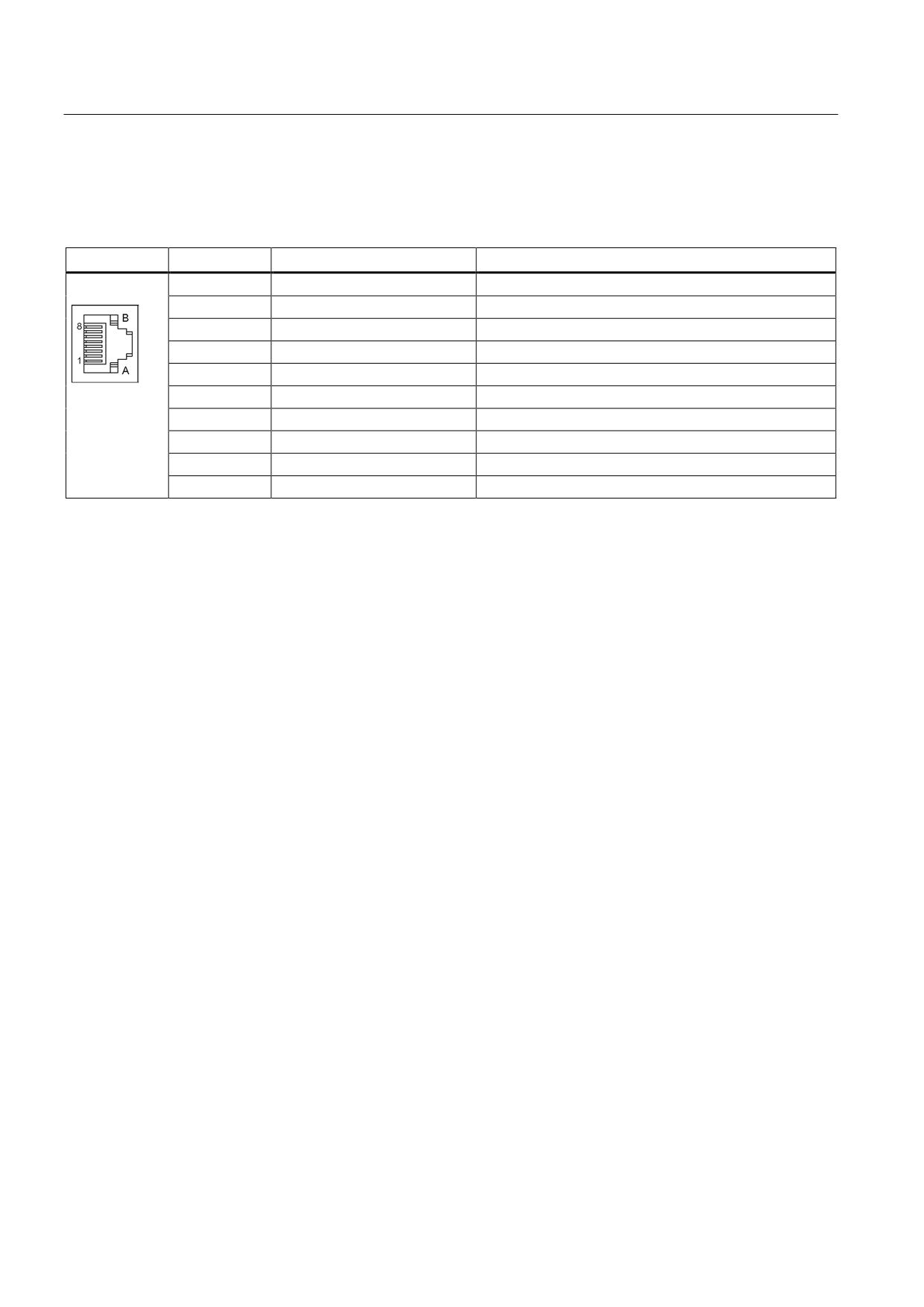
X200-X202 DRIVE-CLiQ interfaces
Table 8- 14 X200-X202 DRIVE-CLiQ interfaces
PIN
Signal name
Technical specifications
1
TXP
Transmit data +
2
TXN
Transmit data -
3
RXP
Receive data +
4
Reserved, do not use
5
Reserved, do not use
6
RXN
Receive data -
7
Reserved, do not use
8
Reserved, do not use
A
+(24 V)
24 V power supply
B
M (0 V)
Electronics ground
The blanking covers for the DRIVE-CLiQ interfaces are included in the scope of delivery.
Blanking cover (50 pcs.) Order number: 6SL3066-4CA00-0AA0
Guidelines for machine configuration
202
System Manual, MA 01/2013, 6FC5397-6CP10-0BA2
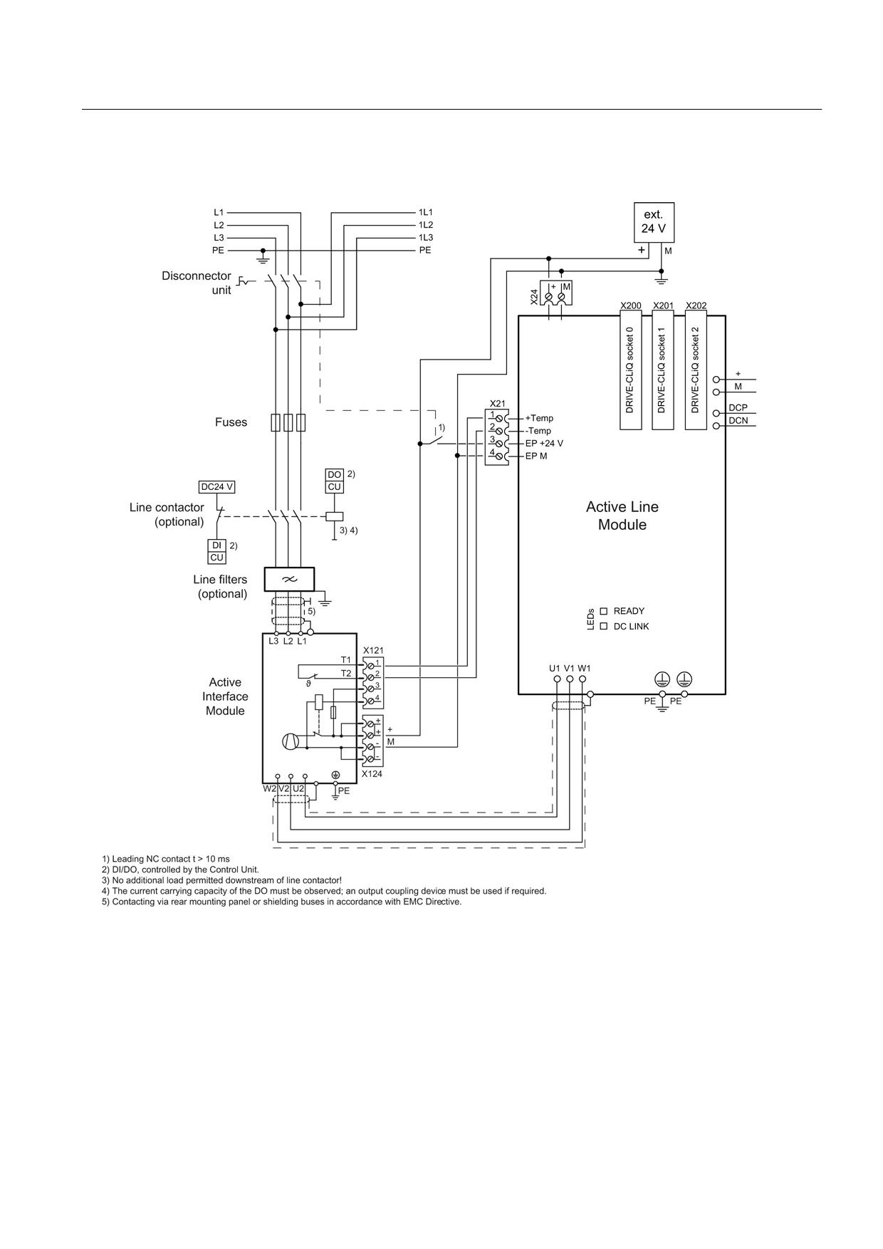
Connection of the components in SINAMICS drive system
8.3 Connection of line modules
8.3.3.3
Connection example
Figure 8-12 Example connection of Active Line Module
Guidelines for machine configuration
System Manual, MA 01/2013, 6FC5397-6CP10-0BA2
203
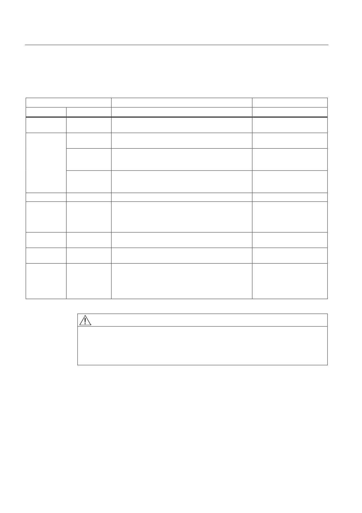
Connection of the components in SINAMICS drive system
8.3 Connection of line modules
8.3.3.4
Meaning of LEDs
Table 8- 15 Meaning of the LEDs on the Active Line Module
Status
Description, cause
Remedy
RDY
DC LINK
off
off
Electronics power supply is missing or outside
-
permissible tolerance range.
Green
--
The component is ready for operation and cyclic DRIVE-
-
CLiQ communication is taking place.
Orange
The component is ready for operation and cyclic DRIVE-
-
CLiQ communication is taking place.
The DC link voltage is present.
Red
The component is ready for operation and cyclic DRIVE-
Check line voltage
CLiQ communication is taking place.
The DC link voltage is too high.
Orange
Orange
DRIVE-CLiQ communication is being established.
-
Red
--
At least one fault is present in this component.
Remedy and acknowledge
fault
Note:
The LED is activated regardless of whether the
corresponding messages have been reconfigured.
Green/red
--
Firmware is being downloaded.
-
(0.5 Hz)
Green/red
--
Firmware download is complete. Wait for POWER ON.
Carry out a POWER ON
(2 Hz)
Green/orange
--
Detection of the components via LED is activated
-
or
(p0124).
red/orange
Note:
Both options depend on the LED status in the case of
activation via p0124 = 1.
WARNING
Danger to life due to high DC link voltage, regardless of LED display
Hazardous DC link voltages may be present at any time regardless of the status of the
"DC LINK" LED.
• Observe the warning information on the component.
Guidelines for machine configuration
204
System Manual, MA 01/2013, 6FC5397-6CP10-0BA2
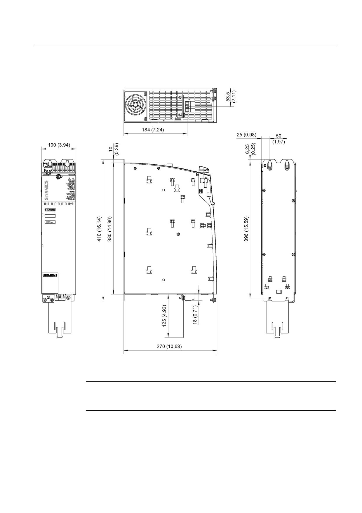
Connection of the components in SINAMICS drive system
8.3 Connection of line modules
8.3.3.5
Dimension drawings
Figure 8-13 Dimension drawing of 16 kW Active Line Module with internal air cooling, all dimensions in mm and (inches)
Note
The shield connecting plate is supplied as standard with a 100 mm Line Module.
For more information, see the chapter titled "Accessories".
Guidelines for machine configuration
System Manual, MA 01/2013, 6FC5397-6CP10-0BA2
205
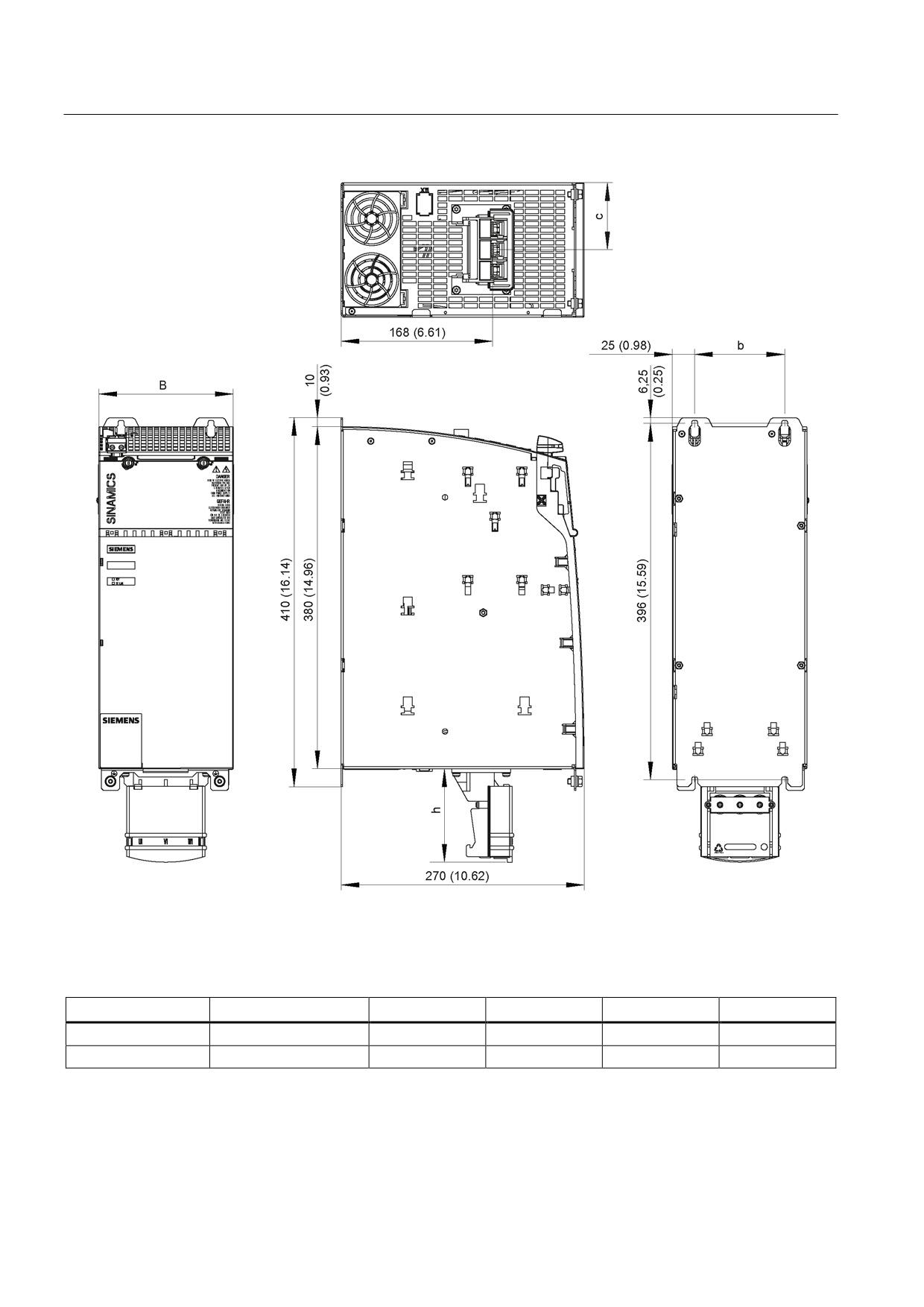
Connection of the components in SINAMICS drive system
8.3 Connection of line modules
Figure 8-14 Dimension drawing of 36 kW and 55 kW Active Line Modules with internal air cooling (example, 36 kW), all
dimensions in mm and (inches)
Table 8- 16 Dimensions of 36 kW and 55 kW Active Line Modules with internal air cooling
Active Line Module
Order number
B [mm] (inches)
b [mm] (inches)
c [mm] (inches)
h [mm] (inches)
36 kW
6SL3130-7TE23-6AAx
150 (5.91)
100 (3.94)
75 (2.95)
105 (4.13)
55 kW
6SL3130-7TE25-5AAx
200 (7.87)
150 (5.91)
100 (3.94)
105 (4.13)
Guidelines for machine configuration
206
System Manual, MA 01/2013, 6FC5397-6CP10-0BA2
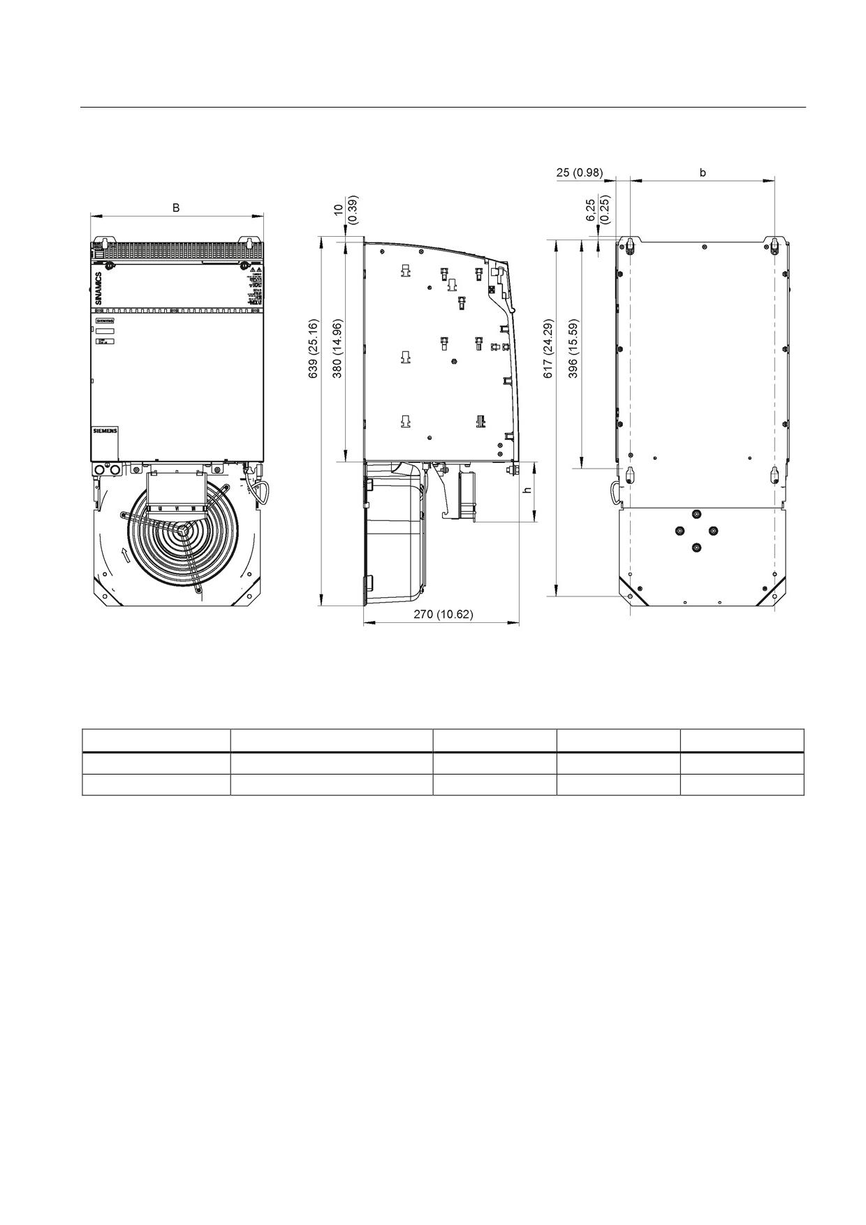
Connection of the components in SINAMICS drive system
8.3 Connection of line modules
Figure 8-15 Dimension drawing of 80 kW and 120 kW Active Line Modules with internal air cooling, all dimensions in mm
and (inches)
Table 8- 17 Dimensions of 80 kW and 120 kW Active Line Modules with internal air cooling
Active Line Module
Order number
B [mm] (inches)
b [mm] (inches)
h [mm] (inches)
80 kW
6SL3130-7TE28-0AAx
300 (11.81)
250 (9.84)
105 (4.13)
120 kW
6SL3130-7TE31-2AAx
300 (11.81)
250 (9.84)
105 (4.13)
Guidelines for machine configuration
System Manual, MA 01/2013, 6FC5397-6CP10-0BA2
207