SINUMERIK 840D sl. Service - Configuring Commissioning. Manual (2011-2020) - page 31
Connection of the components in SINAMICS drive system
8.3 Connection of line modules
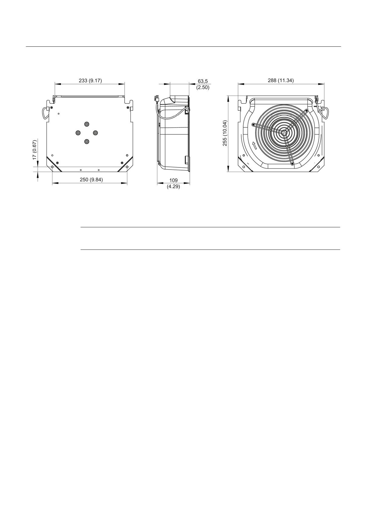
Figure 8-16 Dimension drawing of fan for 80 kW and 120 kW Active Line Modules with internal air cooling, all dimensions
in mm and (inches)
Note
The fan for the 80 kW and 120 kW Active Line Modules is included in the scope of delivery.
Guidelines for machine configuration
208
System Manual, MA 01/2013, 6FC5397-6CP10-0BA2
Connection of the components in SINAMICS drive system
8.3 Connection of line modules
8.3.3.6
Installation
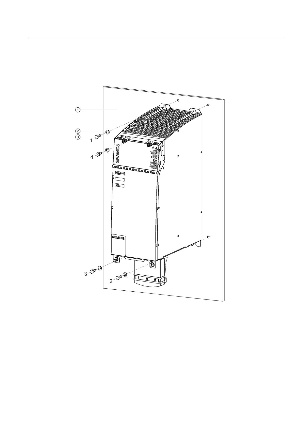
Active Line Modules are designed for installation in the control cabinet. They are fixed to the
control cabinet panel or a mounting panel using M6 screws.
①
Control cabinet panel/mounting panel
②
Washer
③
M6 screw
Figure 8-17 Mounting an Active Line Module with internal air cooling (example: 36 kW)
Tightening torques:
● Initially, tighten the nuts by hand (0.5 Nm)
● Then tighten with 6 Nm (in the specific sequence 1 to 4)
Guidelines for machine configuration
System Manual, MA 01/2013, 6FC5397-6CP10-0BA2
209
Connection of the components in SINAMICS drive system
8.3 Connection of line modules
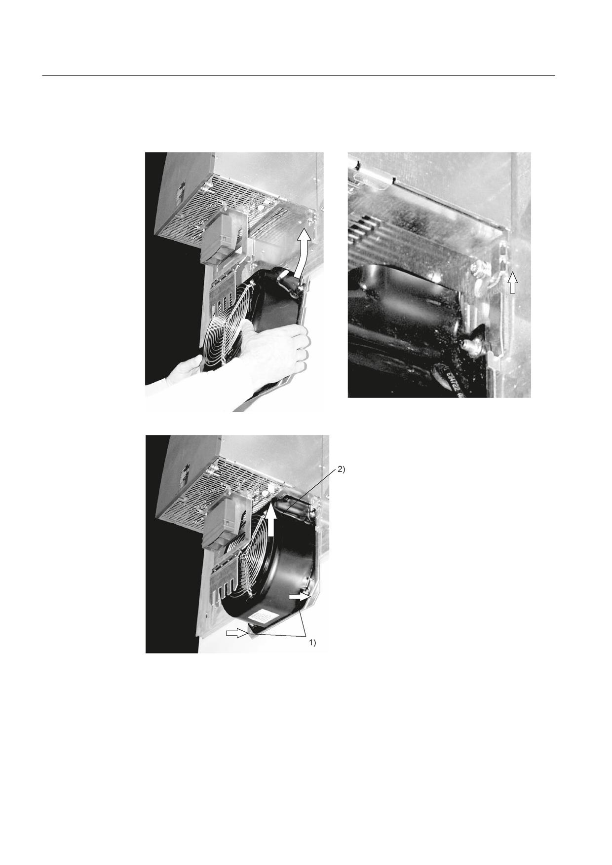
Installing the sub-chassis fan
Figure 8-18 Mounting the fan for Active Line Modules 80 kW and 120 kW
1. Attach the fan with M6 / 6 Nm screws
2. Connect the power supply for the fan
Guidelines for machine configuration
210
System Manual, MA 01/2013, 6FC5397-6CP10-0BA2
Connection of the components in SINAMICS drive system
8.3 Connection of line modules
8.3.3.7
Technical specifications
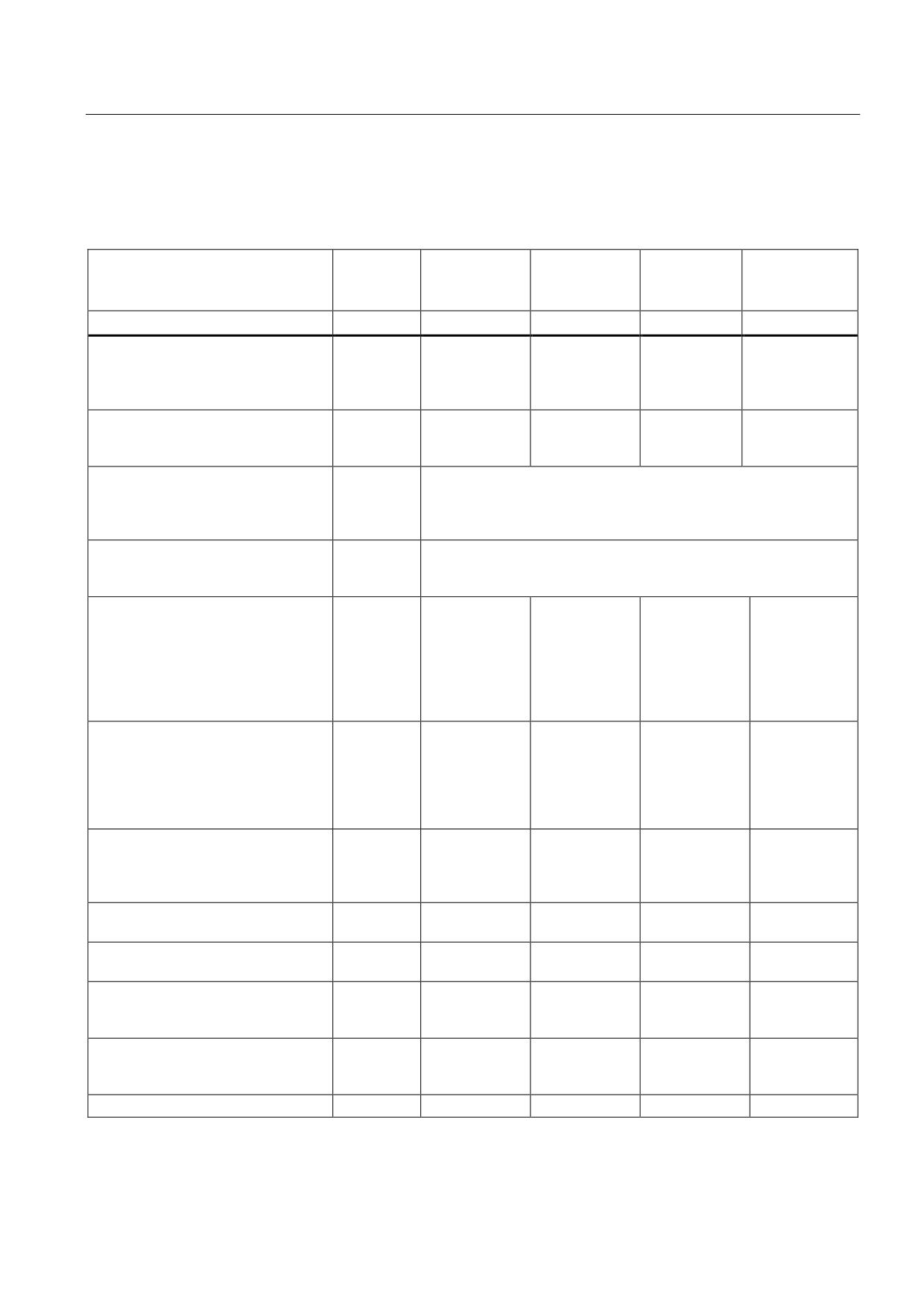
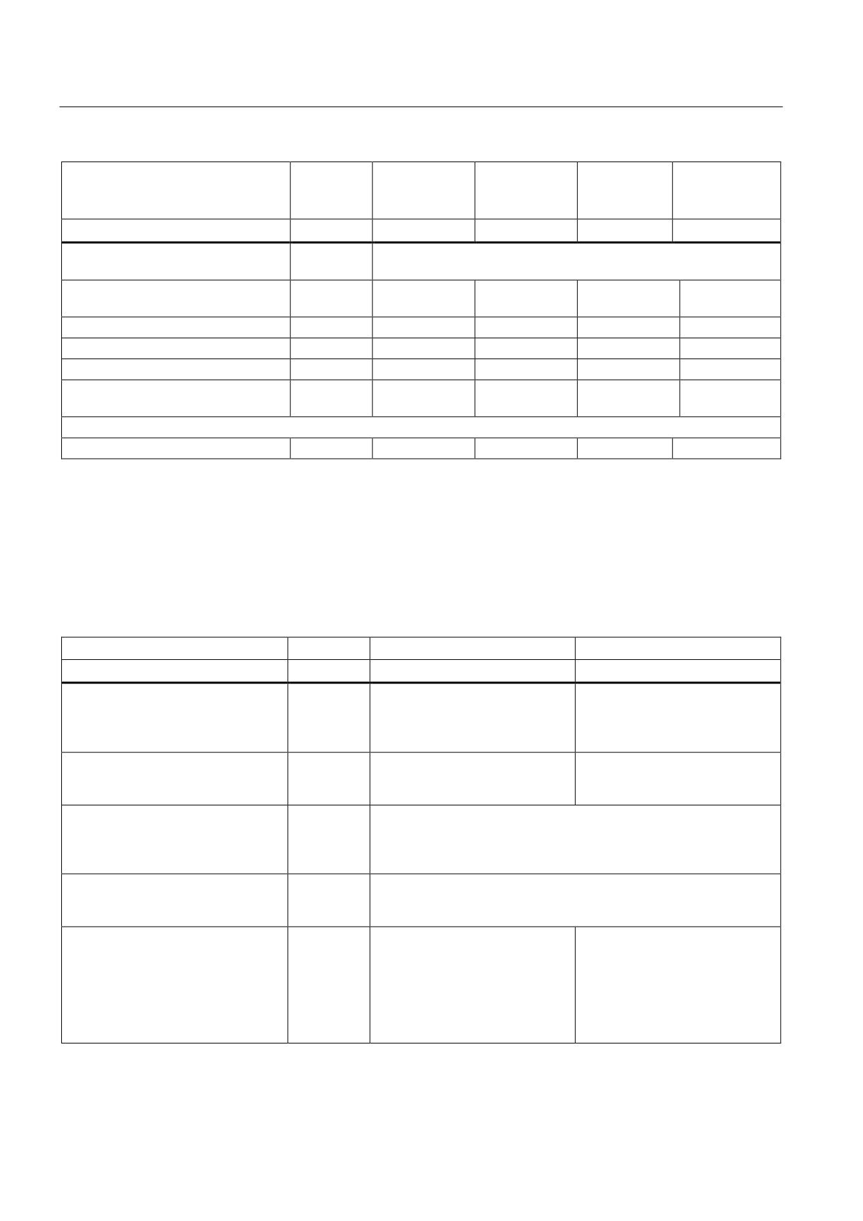
Table 8- 18 Technical data of Active Line Modules
Internal air cooling
6SL3130-
7TE21-6AAx
7TE23-6AAx
7TE25-5AAx
7TE25-5AA3 +
Active Interface
Module
Rated power
kW
16
36
55
55
Infeed
Rated power (S1)1)
kW (Pn)
16
36
55
55
Infeed power (S6-40%)1)
kW (Ps6)
21
47
71
71
Peak infeed power1)
kW (Pmax)
35
70
91
110
Energy recovery
Continuous regenerative power
kW
16
36
55
55
Peak regenerative power
kW
35
70
91
110
Supply voltages
Line voltage
VACrms
3 AC 380 to 480 ±10% (-15% < 1 min)
Line frequency
Hz
47 to 63
Electronics power supply
VDC
24 (20.4 - 28.8)
DC link voltage
VDC
510 - 720
Overvoltage trip
VDC
820 ±2%
Undervoltage trip2)
VDC
360 ±2%
Input currents
Rated input current
at 400 VAC:
AAC
25
55
84
84
Input current
at 380 VAC/480 VAC
AAC
26 / 21
58 /46
88 / 70
88 /70
at 400 VAC; S6-40%
AAC
32
71
108
108
at 400 VAC; peak current
AAC
54
107
139
168
DC link currents
Rated DC link current
at 600 V:
ADC
27
60
92
92
DC link current:
at 600 VDC; at S6-40%
ADC
35
79
121
121
at 600 VDC; peak current
ADC
59
117
152
176
Current-carrying capacity
DC link busbar
ADC
100
200
200
200
Reinforced DC link busbars:
ADC
150
--
--
--
24 V busbar:
ADC
20
20
20
20
Electronics current consumption
ADC
0.95
1.5
1.9
1.9
at 24 V DC
Total power loss
W
282.8
666
945.6
945.6
(including electronics losses)3)
Max. ambient temperature
without derating
°C
40
40
40
40
with derating
°C
55
55
55
55
DC link capacitance
Active Line Module
μF
705
1410
1880
1880
Drive line-up, max.
μF
20000
20000
20000
20000
Power factor
cosϕ
1
1
1
1
Guidelines for machine configuration
System Manual, MA 01/2013, 6FC5397-6CP10-0BA2
211
Connection of the components in SINAMICS drive system
8.3 Connection of line modules
Internal air cooling
6SL3130-
7TE21-6AAx
7TE23-6AAx
7TE25-5AAx
7TE25-5AA3 +
Active Interface
Module
Rated power
kW
16
36
55
55
Circuit breaker
See Chap. "Overcurrent protection using line fuses and circuit
(IEC 60947 and UL)
breakers (Page 116)"
Rated short-circuit current
kA
65
65
65
65
SCCR4):
Cooling method (internal air cooling)
Internal fan
Internal fan
Internal fan
Internal fan
Sound pressure level
dB(A)
<60
<65
<60
<60
Cooling air requirement
m3/h
56
112
160
160
Max. permissible heat sink
°C
85
90
83
83
temperature
Rated voltage for rated data 3 AC 380 V
Weight
kg
7
10
17
17
1)
The specified power ratings apply to the line voltage range from 380 V to 480 V
2)
Default for 400 V line systems; undervoltage trip threshold is adjusted to the parameterized rated voltage
3)
For an overview, see the power loss tables in the Appendix
4)
The resulting rated short-circuit current is obtained from the combination of the fuse, or circuit breaker, and the Line
Module in the drive system.
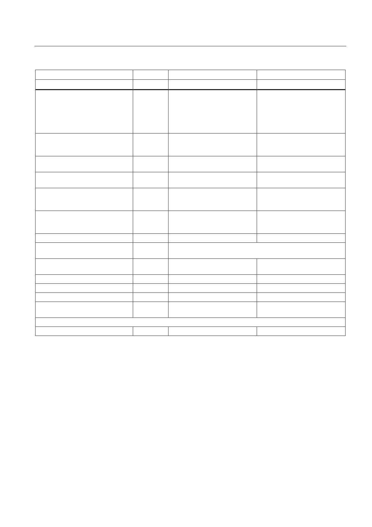
Table 8- 19 Technical data of Active Line Modules
Internal air cooling
6SL3130-
7TE28-0AAx
7TE31-2AAx
Rated power
kW
80
120
Infeed
Rated power (S1)1)
kW (Pn)
80
120
Infeed power (S6-40%)1)
kW (Ps6)
106
145
Peak infeed power1)
kW (Pmax)
131
175
Energy recovery
Continuous regenerative power
kW
80
120
Peak regenerative power
kW
131
175
Supply voltages
Line voltage
VACrms
3 AC 380 to 480 ±10% (-15% < 1 min)
Line frequency
Hz
47 to 63
Electronics power supply
VDC
24 (20.4 - 28.8)
DC link voltage
VDC
510 - 720
Overvoltage trip
VDC
820 ±2%
Undervoltage trip2)
VDC
360 ±2%
Input currents
Rated input current
at 400 VAC:
AAC
122
182
Input current
at 380 VAC/480 VAC
AAC
128 / 102
192 / 152
at 400 VAC; S6-40%
AAC
161
220
at 400 VAC; peak current
AAC
200
267
Guidelines for machine configuration
212
System Manual, MA 01/2013, 6FC5397-6CP10-0BA2
Connection of the components in SINAMICS drive system
8.3 Connection of line modules
Internal air cooling
6SL3130-
7TE28-0AAx
7TE31-2AAx
Rated power
kW
80
120
DC link currents
Rated DC link current
at 600 V:
ADC
134
200
DC link current:
at 600 VDC; at S6-40%
ADC
176
244
at 600 VDC; peak current
ADC
218
292
Current-carrying capacity
DC link busbar:
ADC
200
200
24 V busbar:
ADC
20
20
Electronics current consumption
ADC
1.4
1.8
at 24 V DC
Total power loss
W
1383.6
2243.2
(including electronics losses)3)
Max. ambient temperature
without derating
°C
40
40
with derating
°C
55
55
DC link capacitance
Active Line Module
μF
2820
3995
Drive line-up, max.
μF
20000
20000
Power factor
cosϕ
1
1
Circuit breaker
See Chap. "Overcurrent protection using line fuses and circuit
(IEC 60947 and UL)
breakers (Page 116)"
Rated short-circuit current
kA
65
65
SCCR4):
Cooling method (internal air cooling)
Mounted fan
Mounted fan
Sound pressure level
dB(A)
<73
<73
Cooling air requirement
m3/h
520
520
Max. permissible heat sink
°C
70
75
temperature
Rated voltage for rated data 3 AC 380 V
Weight
kg
23
23
1)
The specified power ratings apply to the line voltage range from 380 V to 480 V
2)
Default for 400 V line systems; undervoltage trip threshold is adjusted to the parameterized rated voltage
3)
For an overview, see the power loss tables in the Appendix
4)
The resulting rated short-circuit current is obtained from the combination of the fuse, or circuit breaker, and the Line
Module in the drive system.
Guidelines for machine configuration
System Manual, MA 01/2013, 6FC5397-6CP10-0BA2
213
Connection of the components in SINAMICS drive system
8.3 Connection of line modules
Characteristics
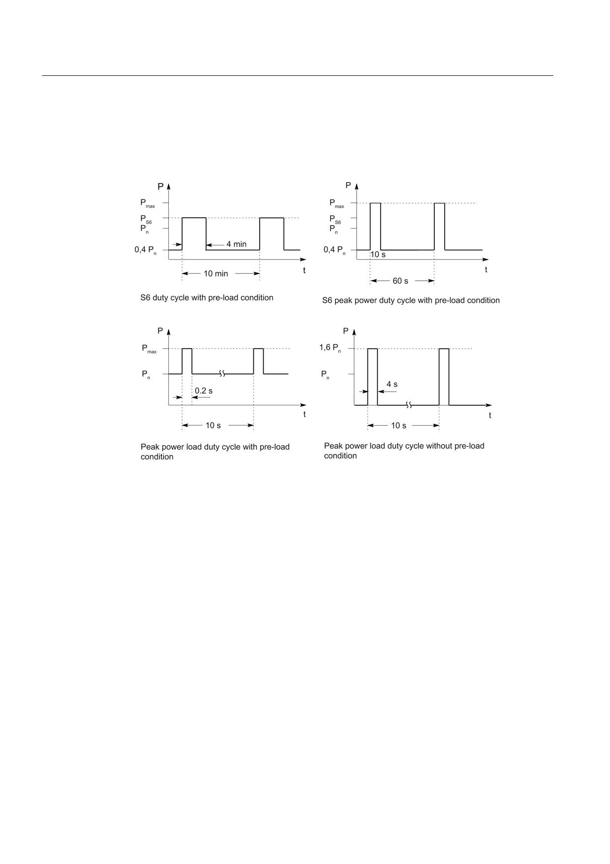
Rated duty cycles for Active Line Modules
Figure 8-19 Rated duty cycles for Active Line Modules (exception: not applicable for 55 kW Active
Line Module with Active Interface Module)
Guidelines for machine configuration
214
System Manual, MA 01/2013, 6FC5397-6CP10-0BA2
Connection of the components in SINAMICS drive system
8.3 Connection of line modules
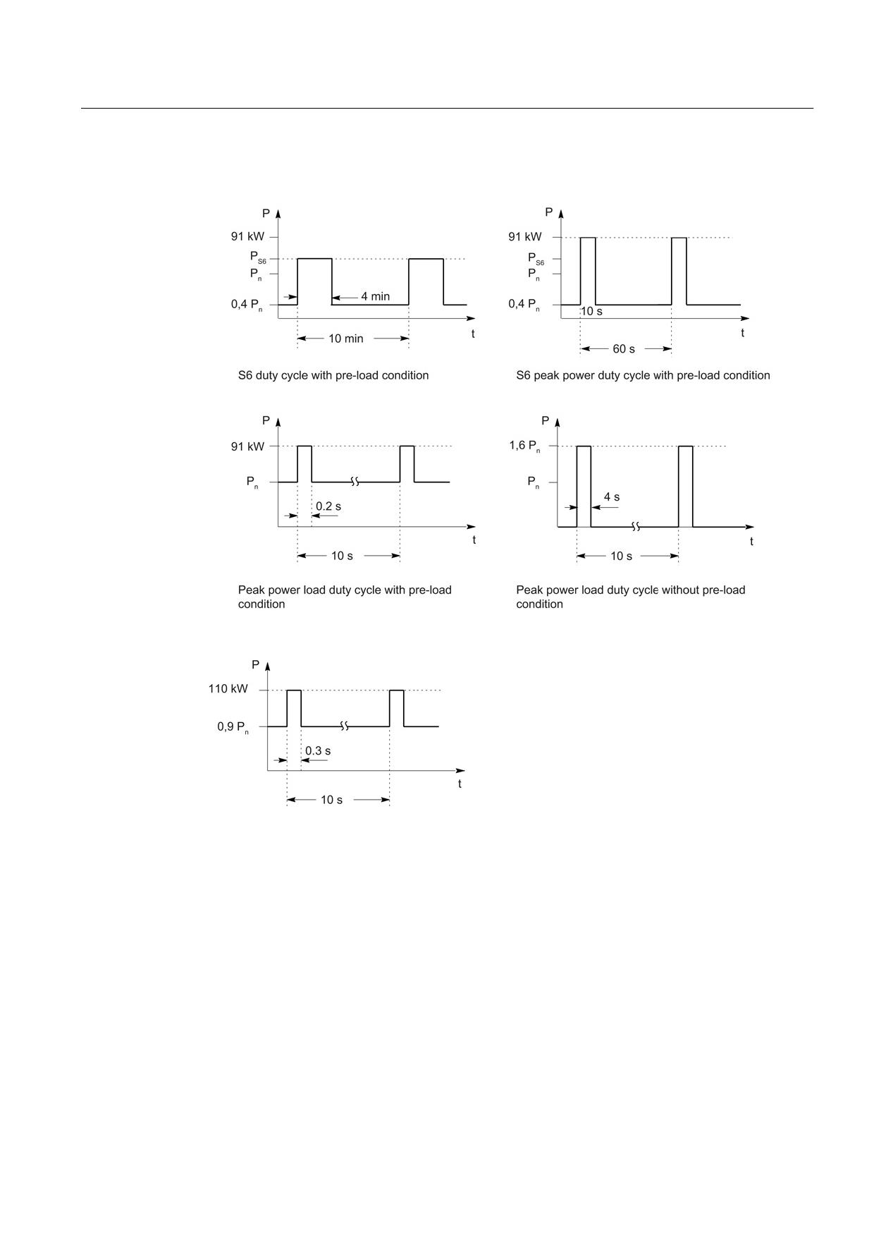
Rated duty cycles for Active Line Modules with Active Interface Modules
Figure 8-20 Duty cycles for 55 kW Active Line Modules with Active Interface Modules
Figure 8-21 Peak duty cycle with initial load for 55 kW Active Line Modules with Active Interface
Modules
Guidelines for machine configuration
System Manual, MA 01/2013, 6FC5397-6CP10-0BA2
215
Connection of the components in SINAMICS drive system
8.3 Connection of line modules
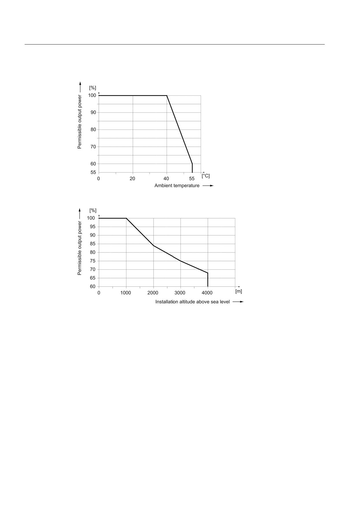
Derating characteristics
Figure 8-22 Output power as a function of the ambient temperature
Figure 8-23 Output power as a function of the installation altitude
At installation altitudes > 2000 m, an isolation transformer must be used (see the chapter
titled "System overview/Function of installation altitude and ambient temperature"
(Page 32)). The design of the secondary line system must be as follows:
● TN system with grounded neutral point (no grounded line conductor)
● IT system
A reduction of the line supply voltage phase-phase is not necessary.
Guidelines for machine configuration
216
System Manual, MA 01/2013, 6FC5397-6CP10-0BA2
Connection of the components in SINAMICS drive system
8.3 Connection of line modules
8.3.4
Active Line Modules with external air cooling
8.3.4.1
Description
The Motor Modules are connected to the power supply network via the Active Line Modules
with external air cooling, which provide the Motor Modules with a constant DC link voltage.
This ensures that they are not influenced by network fluctuations.
When the motors are in feedback mode, Active Line Modules supply power back to the
system. The regenerative feedback capability of the modules can be deactivated by
parameterization.
The DC link starts precharging as soon as the supply voltage is applied and is independent
of its phase sequence direction. Load can be applied to the DC link after the modules have
been enabled. An optional main contactor is required for disconnecting the voltage.
The Active Line Modules are suitable for direct operation on TN, IT, and TT systems. The
Line Modules have an integrated overvoltage protection function.
External air cooling uses the "through-hole" method. This is a cooling method for SINAMICS
power units that is only available for booksize devices. The power unit and its heat sink can
be inserted in a rectangular knockout at the rear of the control cabinet and mounted with a
seal. The heat sink and the fan (included in the scope of supply) project beyond the rear of
the control cabinet and the heat is dissipated outside the control cabinet or in a separate air
duct.
Guidelines for machine configuration
System Manual, MA 01/2013, 6FC5397-6CP10-0BA2
217
Connection of the components in SINAMICS drive system
8.3 Connection of line modules
8.3.4.2
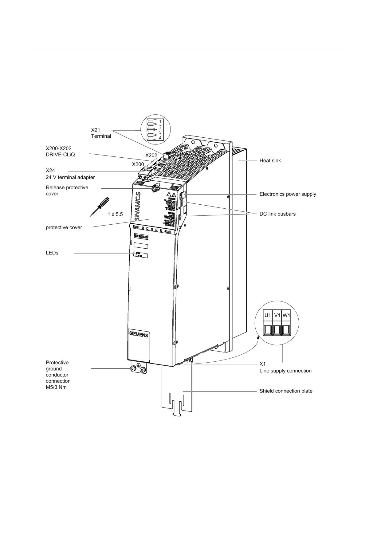
Interface description
Overview
Figure 8-24 Interface overview, Active Line Module with external air cooling (example: 16 kW)
Guidelines for machine configuration
218
System Manual, MA 01/2013, 6FC5397-6CP10-0BA2
Connection of the components in SINAMICS drive system
8.3 Connection of line modules
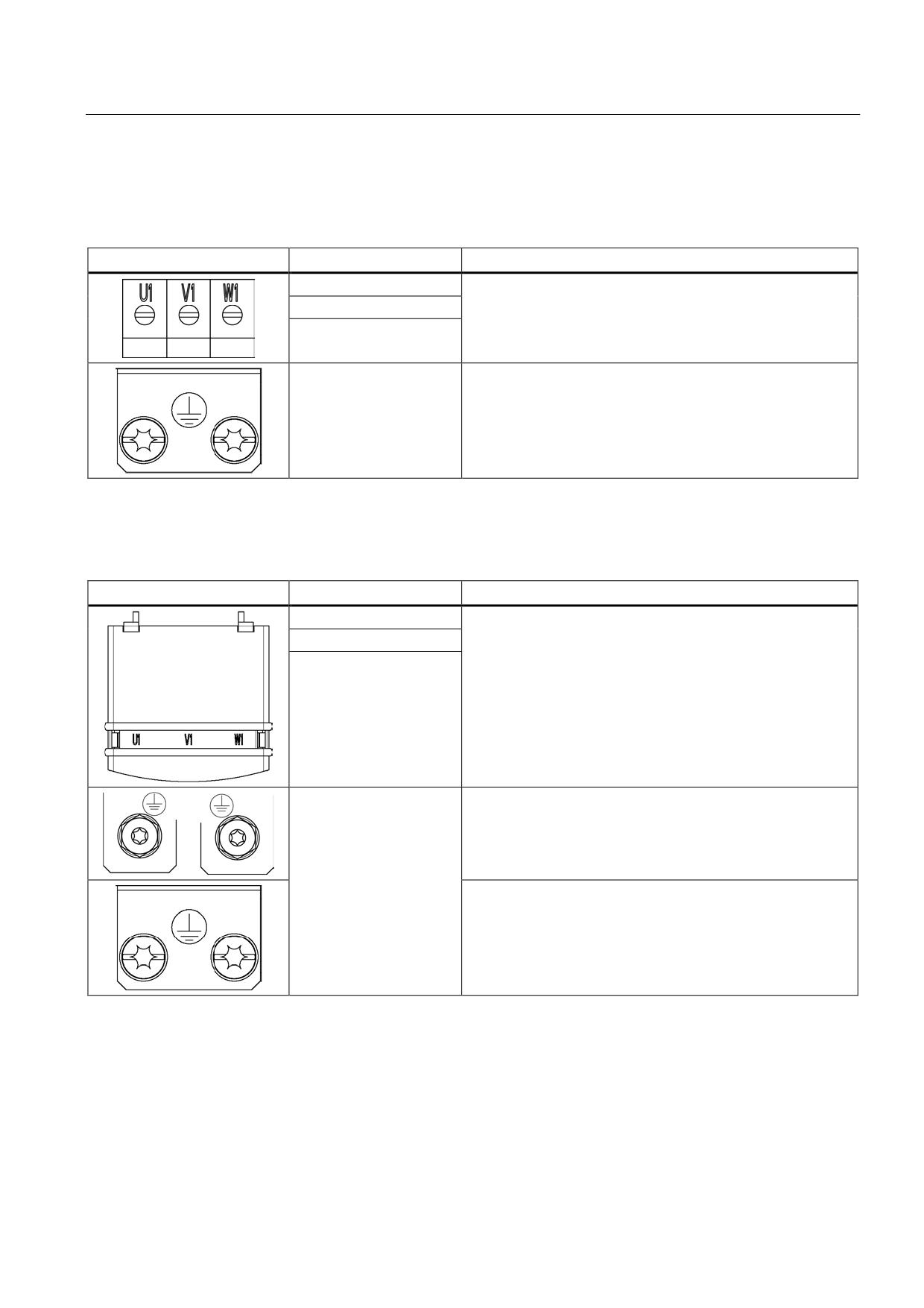
X1 line connection
Table 8- 20 X1: Line connection for Active Line Modules 16 kW
Terminal
Technical specifications
U1
Max. connectable cross-section: 10 mm2
V1
Type: Screw terminal 6 (see Appendix, "Screw terminals")
Tightening torque: 1.5 - 1.8 Nm
W1
PE connection
Threaded hole M5/3 Nm 1)
1) For ring cable lugs in accordance with DIN 46234
Table 8- 21 X1: Line connection for Active Line Modules 36 kW to 120 kW
Terminal
Technical specifications
U1
Supply voltage:
3 AC 380 V - 480 V, 50/60 Hz
V1
36 kW: Threaded bolts M6/6 Nm 1)
W1
55 kW, 80 kW and 120 kW: Threaded bolts M8/13 Nm 1)
PE connection
36 kW: Threaded hole M6/6 Nm 1)
55 kW: Threaded hole M6/6 Nm 1)
80 kW and 120 kW: Threaded hole M8/13 Nm 1)
1) For ring cable lugs in accordance with DIN 46234
Guidelines for machine configuration
System Manual, MA 01/2013, 6FC5397-6CP10-0BA2
219
Connection of the components in SINAMICS drive system
8.3 Connection of line modules
X12 fan connection
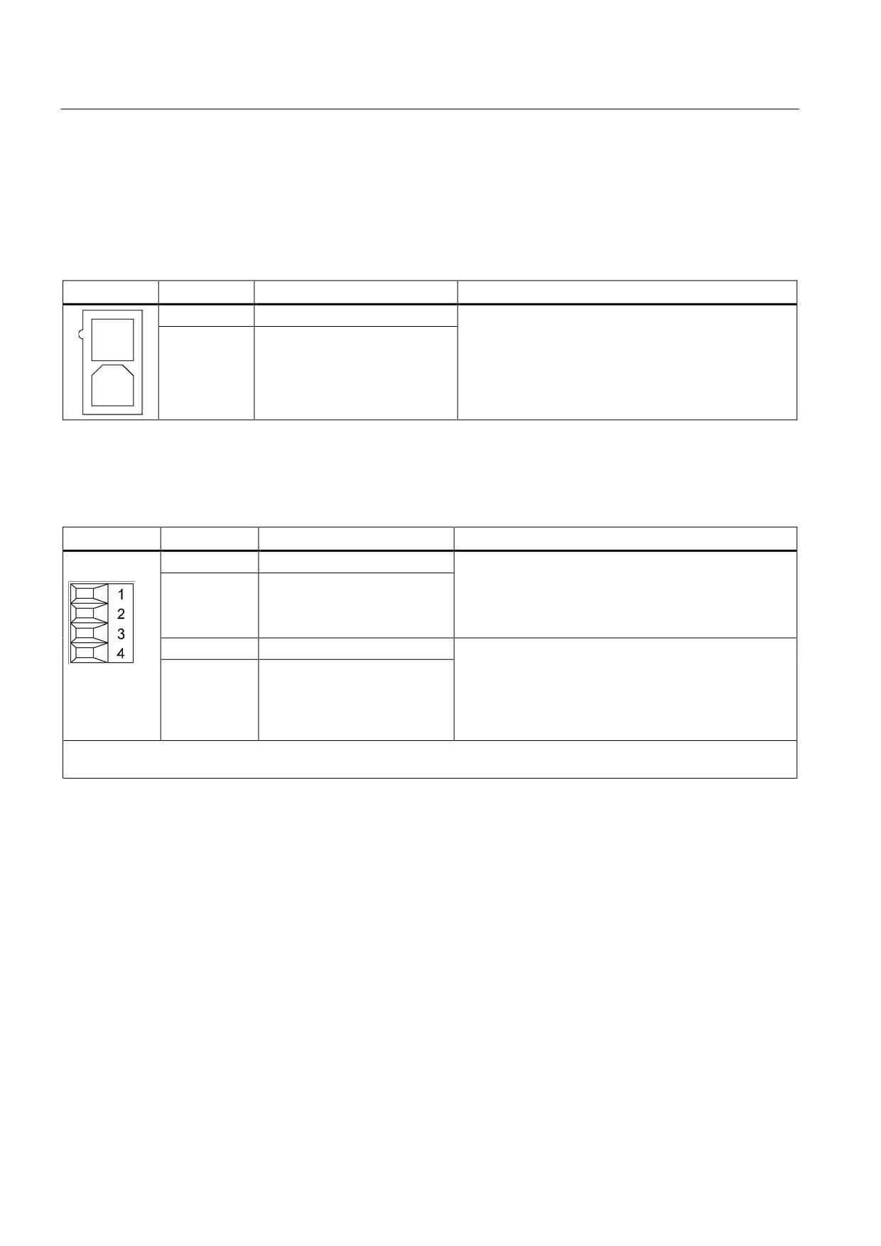
Active Line Modules 80 kW and 120 kW are equipped with an interface for connecting the
sub-chassis fan. The interface is located on the underside of the Line Module.
Table 8- 22 X12 fan connection
Terminal
Function
Technical specifications
1
Fan connection +
Voltage 48 V DC for the supplied fan
2
Fan connection -
X21 EP terminals
Table 8- 23 X21 EP terminal/temperature sensor
Terminal
Designation
Technical data
1
+ Temp
Temperature sensors1): KTY84-
1C1302)/PTC2)/bimetallic switch with NC contact
2
- Temp
If an Active Interface Module is used, the temperature
input must be connected to the Active Interface Module
sensor (bimetallic switch with NC contact).
3
EP +24 V (Enable Pulses)
Voltage 24 VDC
Current consumption: 10 mA
4
EP M (Enable Pulses)
Isolated input
Signal propagation times:
L → H: 100 μs
H → L: 1000 μs
Max. connectable cross-section: 1.5 mm2
Type: Screw terminal 1 (see Appendix, "Screw terminals")
1) The temperature sensor type can be selected via parameter p0601; the temperature is displayed via r0035 (see
SINAMICS S120/S150 List Manual LH1).
2) Temperatures are detected but not evaluated in the Active Line Module.
Guidelines for machine configuration
220
System Manual, MA 01/2013, 6FC5397-6CP10-0BA2
Connection of the components in SINAMICS drive system
8.3 Connection of line modules
CAUTION
Connecting the temperature sensor
If an Active Interface Module is connected, the temperature output of the Active Interface
Module must be connected to terminals 1 and 2.
WARNING
Danger to life due to charged DC link
For operation, the 24 VDC voltage must be connected to terminal 3 and ground to terminal
4. When withdrawn, pulse suppression is activated. Regenerative feedback is deactivated
and the bypass relay drops out. If the Line Module is not disconnected from the supply
system when the EP terminal is deactivated (e.g. a line contactor is not installed), the DC
link remains charged.
Note
If an active drive line-up is switched off by means of the disconnector unit, the voltage at
terminals 3 (EP +24 V) and 4 (EP M) must be interrupted beforehand. This can be carried
out using a leading (≥ 10 ms) breaking auxiliary contact, for example.
This protects external loads located parallel to the drive on the same switching component.
DANGER
Risk of electric shock!
Only temperature sensors that meet the safety isolation specifications contained in
EN 61800-5-1 may be connected to terminals "+Temp" and "-Temp". If safe electrical
separation cannot be guaranteed (for linear motors or third-party motors, for example), a
Sensor Module External (SME120 or SME125) or Terminal Module TM120 must be used.
If these instructions are not complied with, there is a risk of electric shock!
Guidelines for machine configuration
System Manual, MA 01/2013, 6FC5397-6CP10-0BA2
221
Connection of the components in SINAMICS drive system
8.3 Connection of line modules
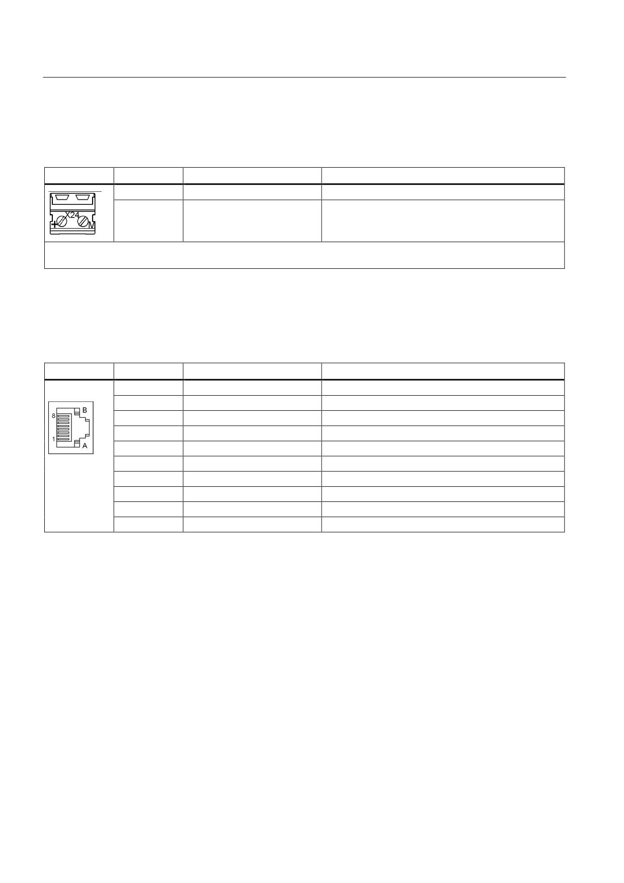
X24 24 V terminal adapter
Table 8- 24 X24 24 V terminal adapter
Terminal
Description
Technical specifications
+
24 V power supply
24 VDC supply voltage
M
Ground
Electronics ground
Max. connectable cross-section: 6 mm2
Type: Screw terminal 5 (see Appendix, "Screw terminals")
The 24 V terminal adapter is included in the scope of delivery.
X200-X202 DRIVE-CLiQ interfaces
Table 8- 25 X200-X202 DRIVE-CLiQ interfaces
PIN
Signal name
Technical specifications
1
TXP
Transmit data +
2
TXN
Transmit data -
3
RXP
Receive data +
4
Reserved, do not use
5
Reserved, do not use
6
RXN
Receive data -
7
Reserved, do not use
8
Reserved, do not use
A
+(24 V)
24 V power supply
B
M (0 V)
Electronics ground
The blanking covers for the DRIVE-CLiQ interfaces are included in the scope of delivery.
Blanking cover (50 pcs.) Order number: 6SL3066-4CA00-0AA0
Guidelines for machine configuration
222
System Manual, MA 01/2013, 6FC5397-6CP10-0BA2
Connection of the components in SINAMICS drive system
8.3 Connection of line modules
8.3.4.3
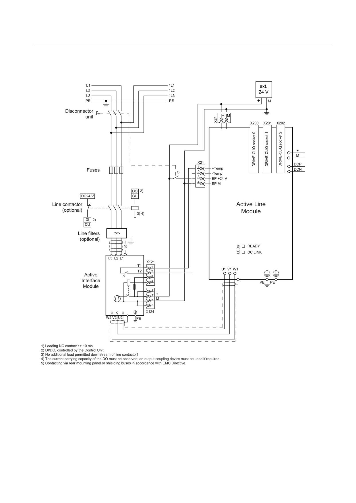
Connection example
Figure 8-25 Example connection of Active Line Module
Guidelines for machine configuration
System Manual, MA 01/2013, 6FC5397-6CP10-0BA2
223
Connection of the components in SINAMICS drive system
8.3 Connection of line modules
8.3.4.4
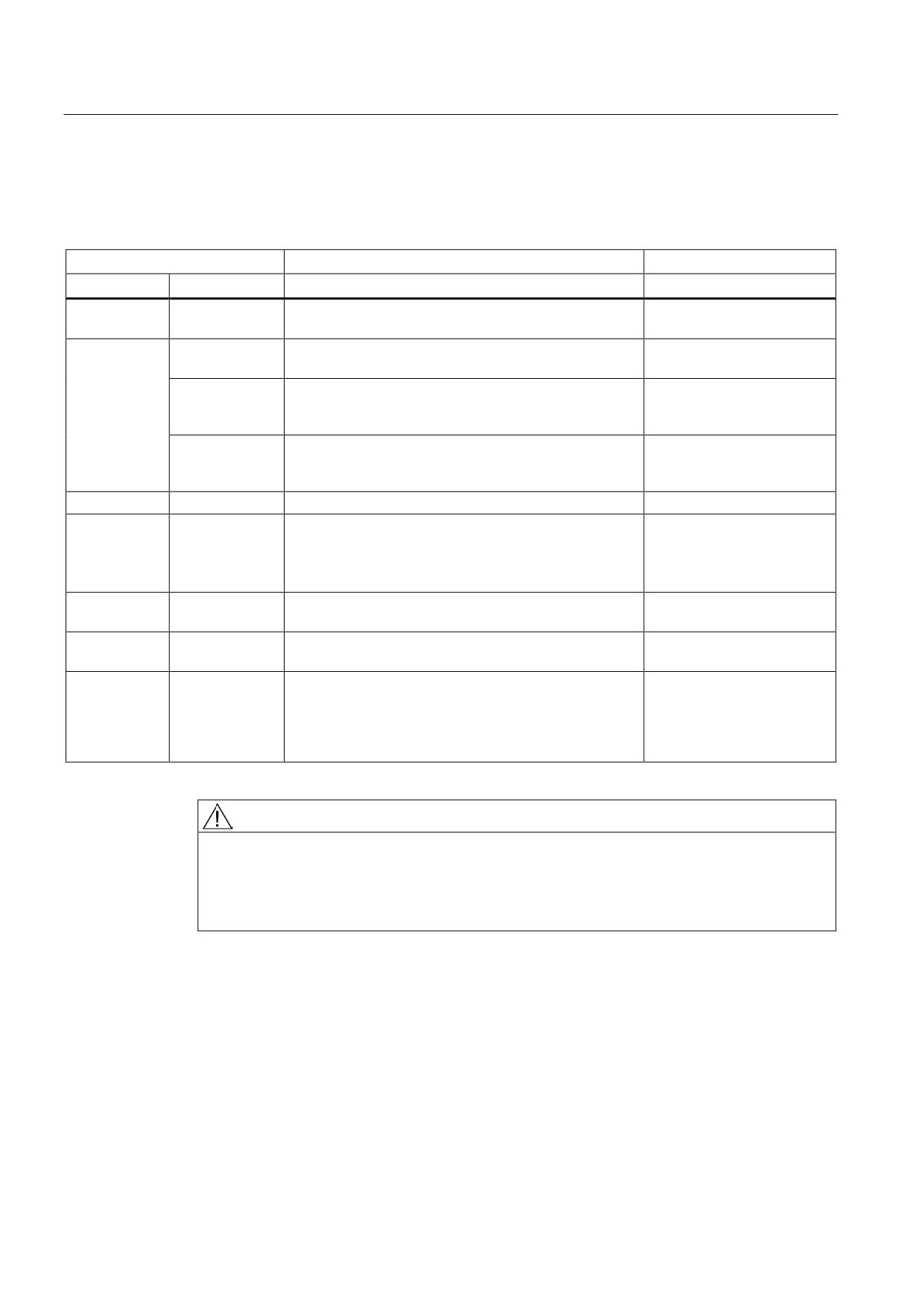
Meaning of LEDs
Table 8- 26 Meaning of the LEDs on the Active Line Module
Status
Description, cause
Remedy
RDY
DC LINK
off
Off
Electronics power supply is missing or outside
-
permissible tolerance range.
Green
--
The component is ready for operation and cyclic DRIVE-
-
CLiQ communication is taking place.
Orange
The component is ready for operation and cyclic DRIVE-
-
CLiQ communication is taking place.
The DC link voltage is present.
Red
The component is ready for operation and cyclic DRIVE-
Check line voltage
CLiQ communication is taking place.
The DC link voltage is too high.
Orange
Orange
DRIVE-CLiQ communication is being established.
-
Red
--
At least one fault is present in this component.
Remedy and acknowledge
fault
Note:
The LED is activated regardless of whether the
corresponding messages have been reconfigured.
Green/red
--
Firmware is being downloaded.
-
(0.5 Hz)
Green/red
--
Firmware download is complete. Wait for POWER ON.
Carry out a POWER ON
(2 Hz)
Green/orange
--
Detection of the components via LED is activated
-
or
(p0124).
Red/orange
Note:
Both options depend on the LED status in the case of
activation via p0124 = 1.
WARNING
Danger to life due to high DC link voltage, regardless of LED display
Hazardous DC link voltages may be present at any time regardless of the status of the
"DC LINK" LED.
• Observe the warning information on the component.
Guidelines for machine configuration
224
System Manual, MA 01/2013, 6FC5397-6CP10-0BA2
Connection of the components in SINAMICS drive system
8.3 Connection of line modules
8.3.4.5
Dimension drawings
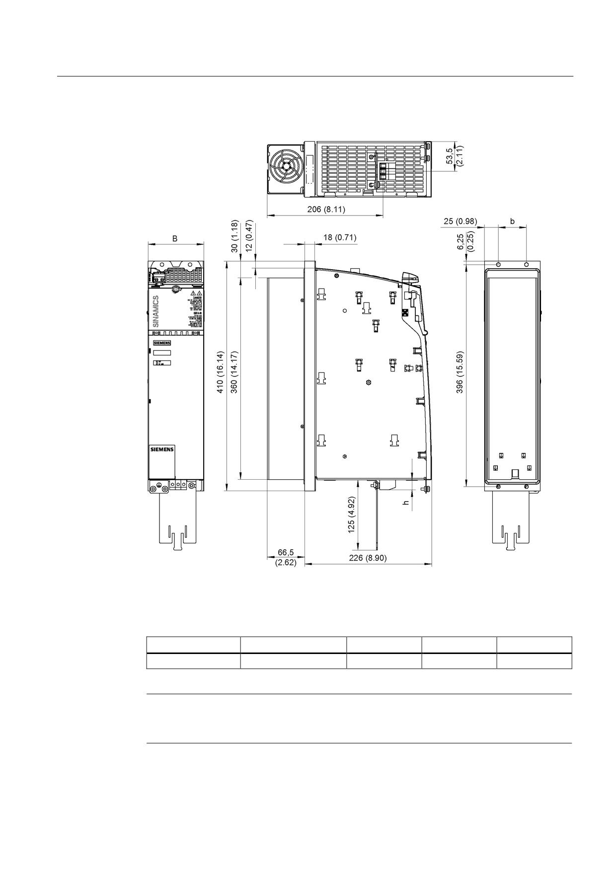
Figure 8-26 Dimension drawing of 16 kW Active Line Module with external air cooling, all dimensions
in mm and (inches)
Table 8- 27 Dimensions of 16 kW Active Line Module with external air cooling
Active Line Module
Order number
B [mm] (inches)
b [mm] (inches)
h [mm] (inches)
16 kW
6SL3131-7TE21-6AAx
100 (3.94)
50 (1.97)
18 (0.71)
Note
The shield connecting plate is supplied as standard with a 100 mm Line Module.
For more information, see the chapter titled "Accessories".
Guidelines for machine configuration
System Manual, MA 01/2013, 6FC5397-6CP10-0BA2
225
Connection of the components in SINAMICS drive system
8.3 Connection of line modules
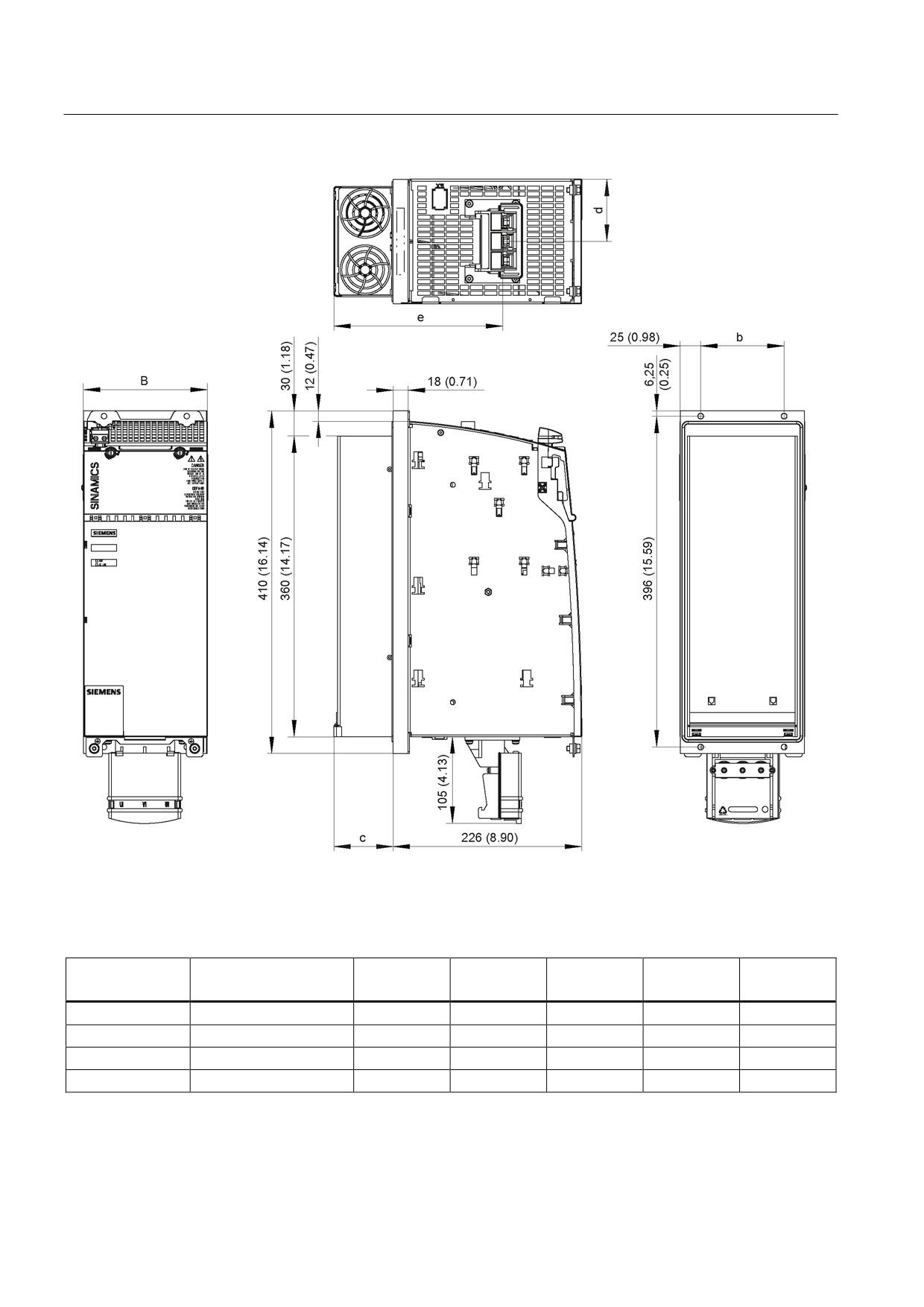
Figure 8-27 Dimension drawing of 36 kW, 55 kW, 80 kW, and 120 kW Active Line Modules with external air cooling
(example 36 kW), all dimensions in mm and (inches)
Table 8- 28 Dimensions of 36 kW, 55 kW, 80 kW, and 120 kW Active Line Modules with external air cooling
Active Line
Order number
B [mm]
b [mm]
c [mm]
d [mm]
e [mm]
Module
(inches)
(inches)
(inches)
(inches)
(inches)
36 kW
6SL3131-7TE23-6AAx
150 (5.91)
100 (3.94)
71 (2.80)
75 (2.95)
203 (7.99)
55 kW
6SL3131-7TE25-5AAx
200 (7.87)
150 (5.91)
92 (3.62)
100 (3.94)
224 (8.82)
80 kW
6SL3131-7TE28-0AAx
300 (11.81)
250 (9.84)
82 (3.23)
150 (5.91)
214 (8.43)
120 kW
6SL3131-7TE31-2AAx
300 (11.81)
250 (9.84)
82 (3.23)
150 (5.91)
214 (8.43)
Guidelines for machine configuration
226
System Manual, MA 01/2013, 6FC5397-6CP10-0BA2
Connection of the components in SINAMICS drive system
8.3 Connection of line modules
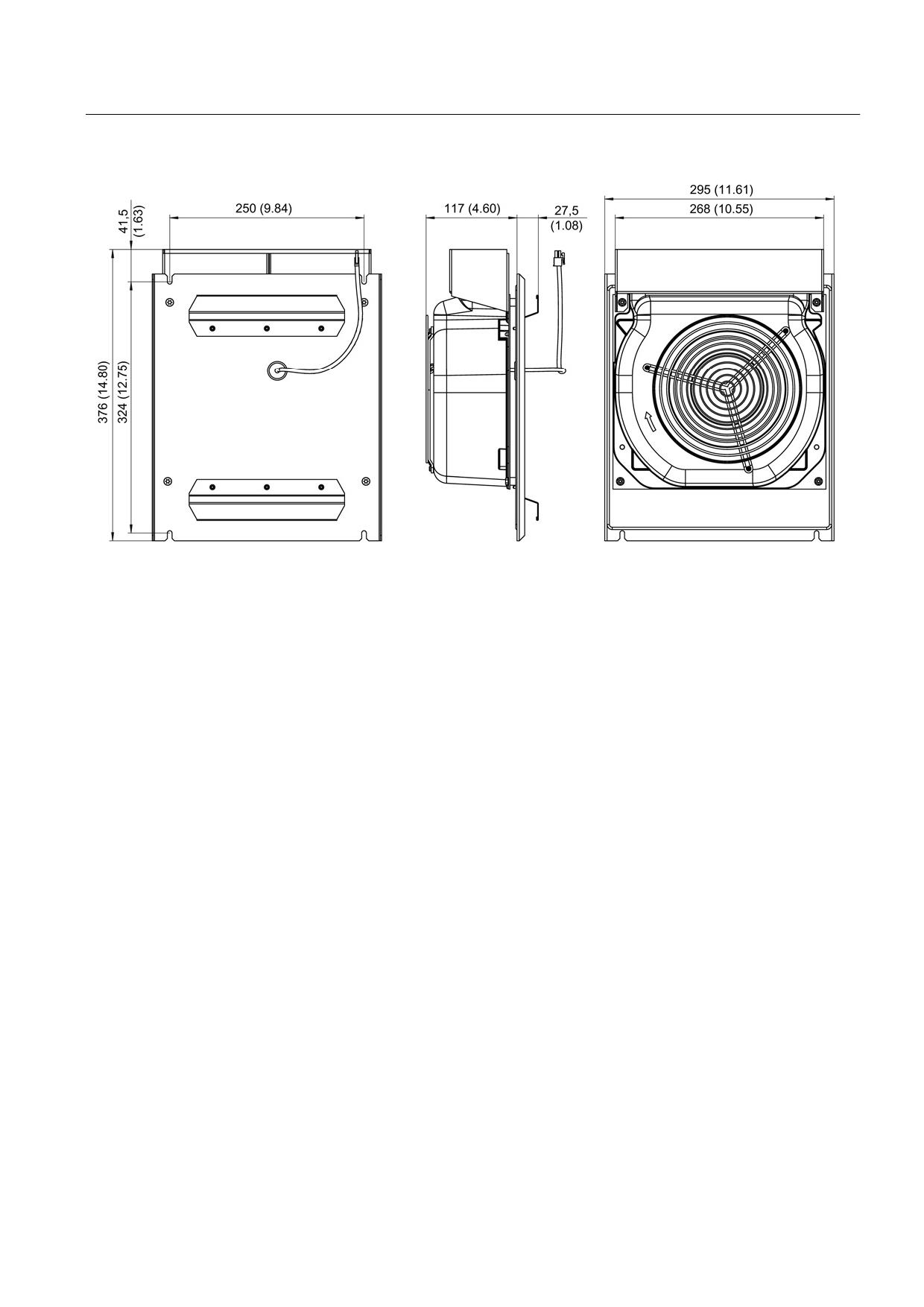
Figure 8-28 Dimension drawing of fan for 80 kW and 120 kW Active Line Modules with external air cooling, all dimensions
in mm and (inches)
Guidelines for machine configuration
System Manual, MA 01/2013, 6FC5397-6CP10-0BA2
227
Connection of the components in SINAMICS drive system
8.3 Connection of line modules
8.3.4.6
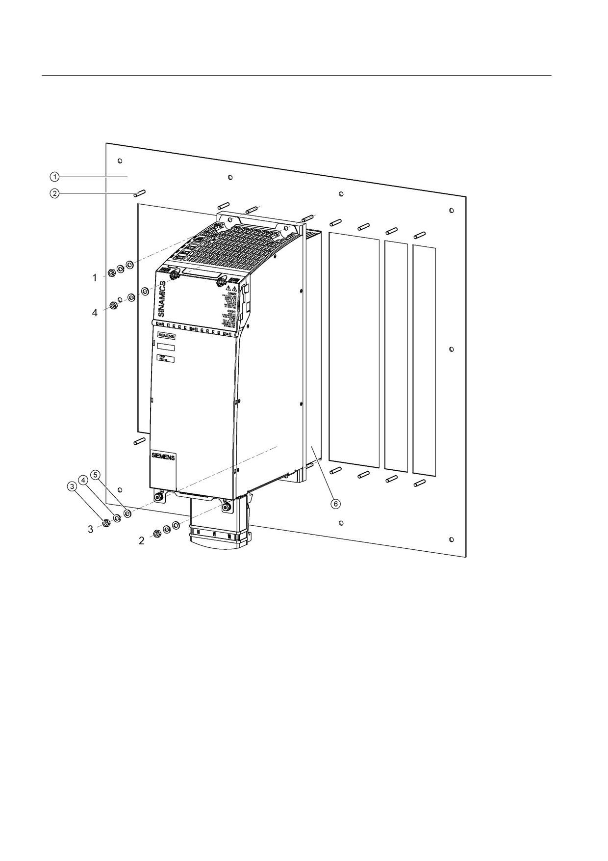
Installation
①
Mounting plate with installation openings
②
M6 studs
③
M6 nut
④
Spring washer
⑤
Washer
⑥
Fan assembly
Figure 8-29 Mounting an Active Line Module with external air cooling (example: 36 kW)
Tightening torques:
● Initially, tighten the nuts by hand (0.5 Nm)
● Then tighten with 6 Nm (in the specific sequence 1 to 4)
Guidelines for machine configuration
228
System Manual, MA 01/2013, 6FC5397-6CP10-0BA2
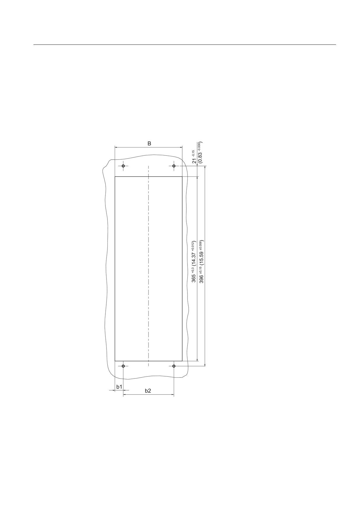
Connection of the components in SINAMICS drive system
8.3 Connection of line modules
Help with the mechanical control cabinet installation is available from:
Siemens AG
Industry Sector, IA SE WKC
TCCCC (Technical Competence Center Cabinets Chemnitz)
P.O. Box 1124
09070 Chemnitz, Germany
E-mail: cc.cabinetcooling.aud@siemens.com
Figure 8-30 Installation openings for Active Line Modules 50 mm to 200 mm with external air cooling,
all data in mm and (inches)
Guidelines for machine configuration
System Manual, MA 01/2013, 6FC5397-6CP10-0BA2
229
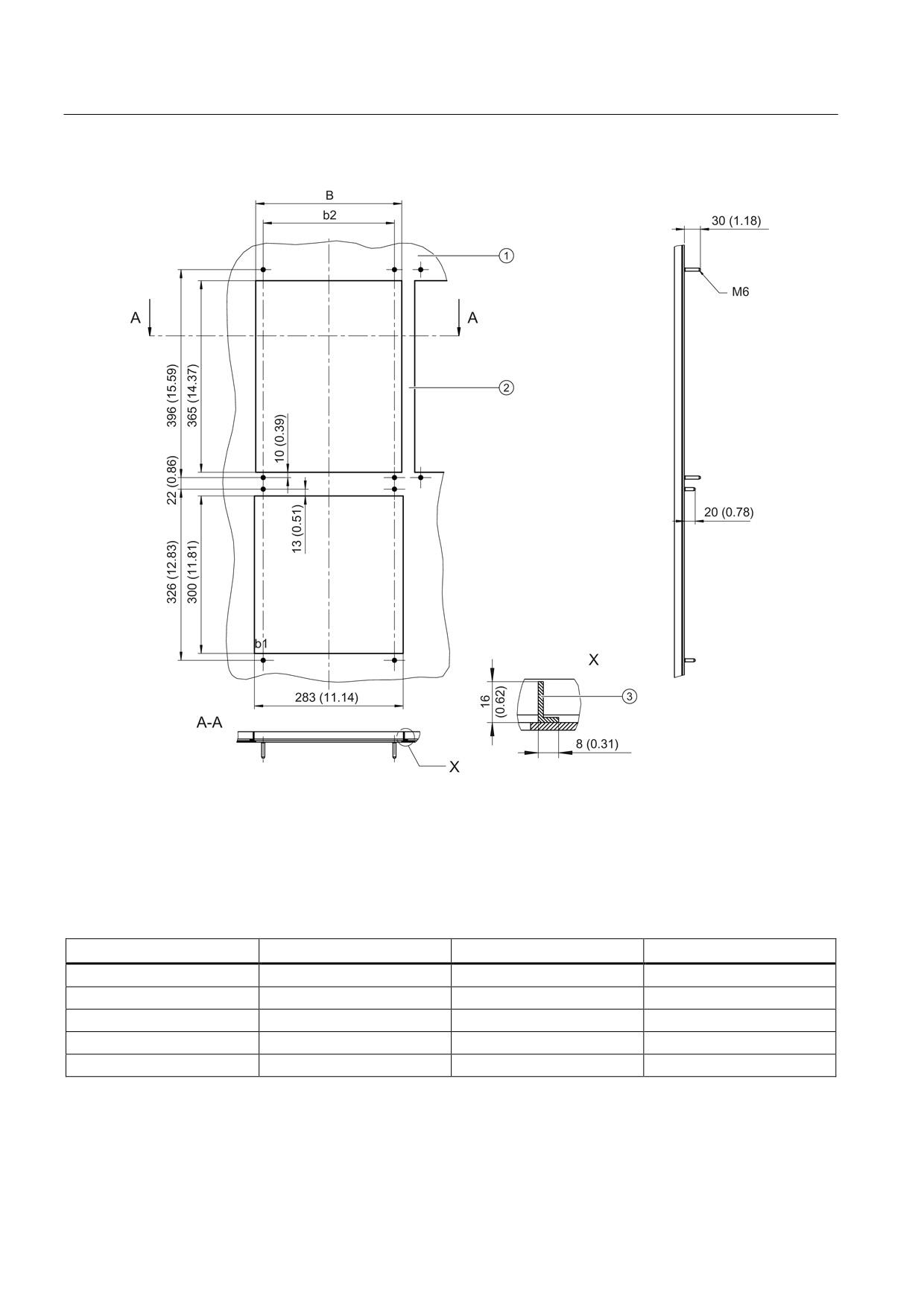
Connection of the components in SINAMICS drive system
8.3 Connection of line modules
①
Insert or mounting plate
②
Cross-piece
③
Reinforcing bracket
Figure 8-31 Installation openings for an Active Line Modules 300 mm with external air cooling, all data in mm and (inches)
Table 8- 29 Dimensions of installation openings for Active Line Modules with external air cooling
Component width
B [mm] (inches)
w1 [mm] (inches)
w2 [mm] (inches)
50 mm
41.5 +0.3 (1.63 +0.012)
20.75 +0.15 (0.82 +0.006)
0
100 mm
89.5 +0.3 (3.52 +0.012)
19.75 +0.15 (0.78 +0.006)
50 ±0.15 (1.97 ±0.006)
150 mm
133 +0.3 (5.24 +0.012)
16.5 +0.15 (0.65 +0.006)
100 ±0.15 (3.94 ±0.006)
200 mm
173 +0.3 (6.81 +0.012)
11.5 +0.15 (0.45 +0.006)
150 ±0.15 (5.91 ±0.006)
300 mm
278 +0.3 (10.94 +0.012)
14.0 ± 0.15 (0.55 ±0.006)
250 +0.15 (9.84 +0.006)
Guidelines for machine configuration
230
System Manual, MA 01/2013, 6FC5397-6CP10-0BA2
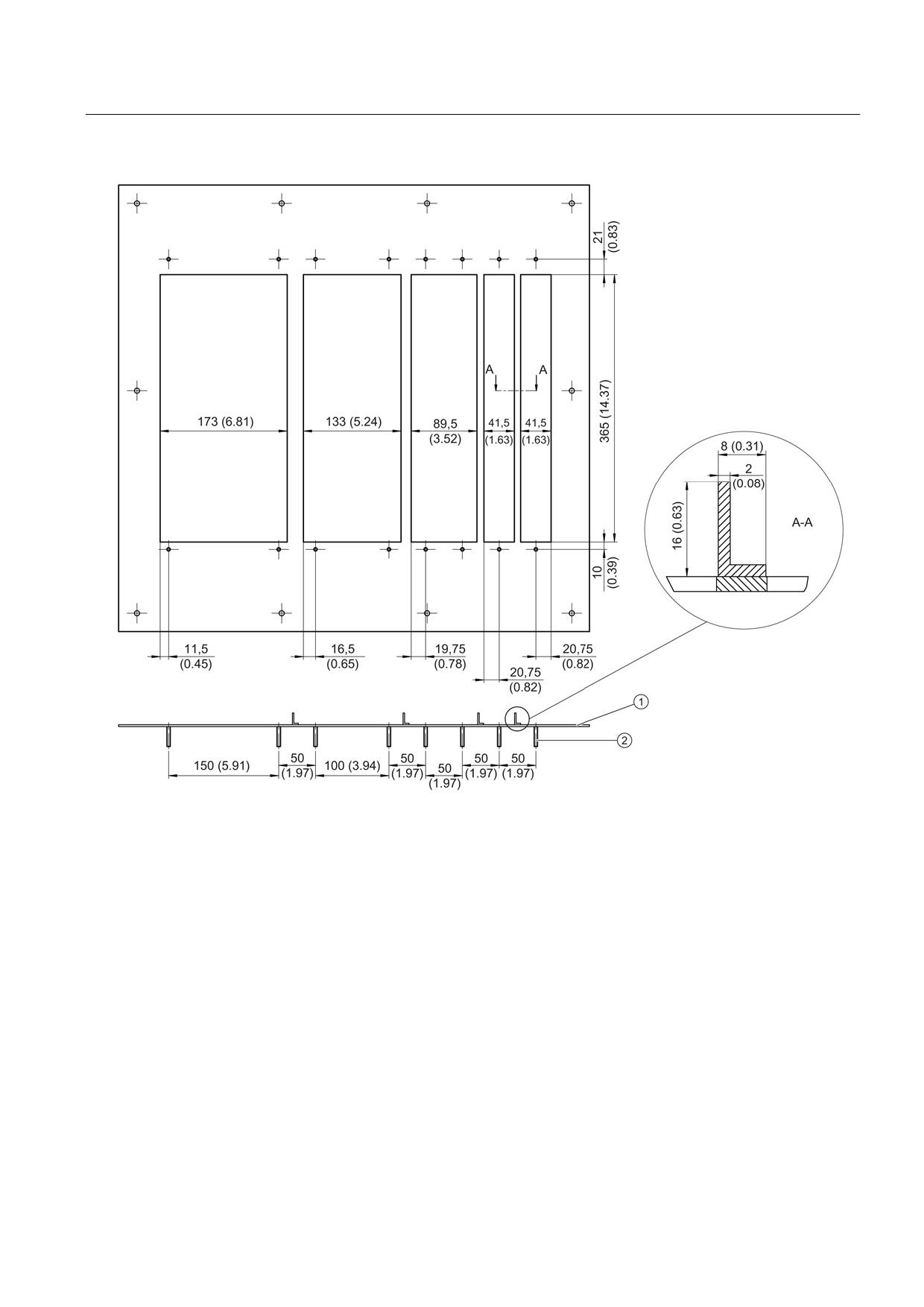
Connection of the components in SINAMICS drive system
8.3 Connection of line modules
①
Insert or mounting plate
②
Threaded bolts M5 x 28
Figure 8-32 Example of a mounting plate for a drive line-up with external air cooling
During installation it must be ensured that the component's seal is tight throughout. The
cross-pieces must have the appropriate stability. If necessary, the cross-pieces of the
openings must be reinforced.
In our example, the cross-pieces have been reinforced using brackets to EN 755-9. You are
free to select the way that the bracket is attached to the insert.
Guidelines for machine configuration
System Manual, MA 01/2013, 6FC5397-6CP10-0BA2
231
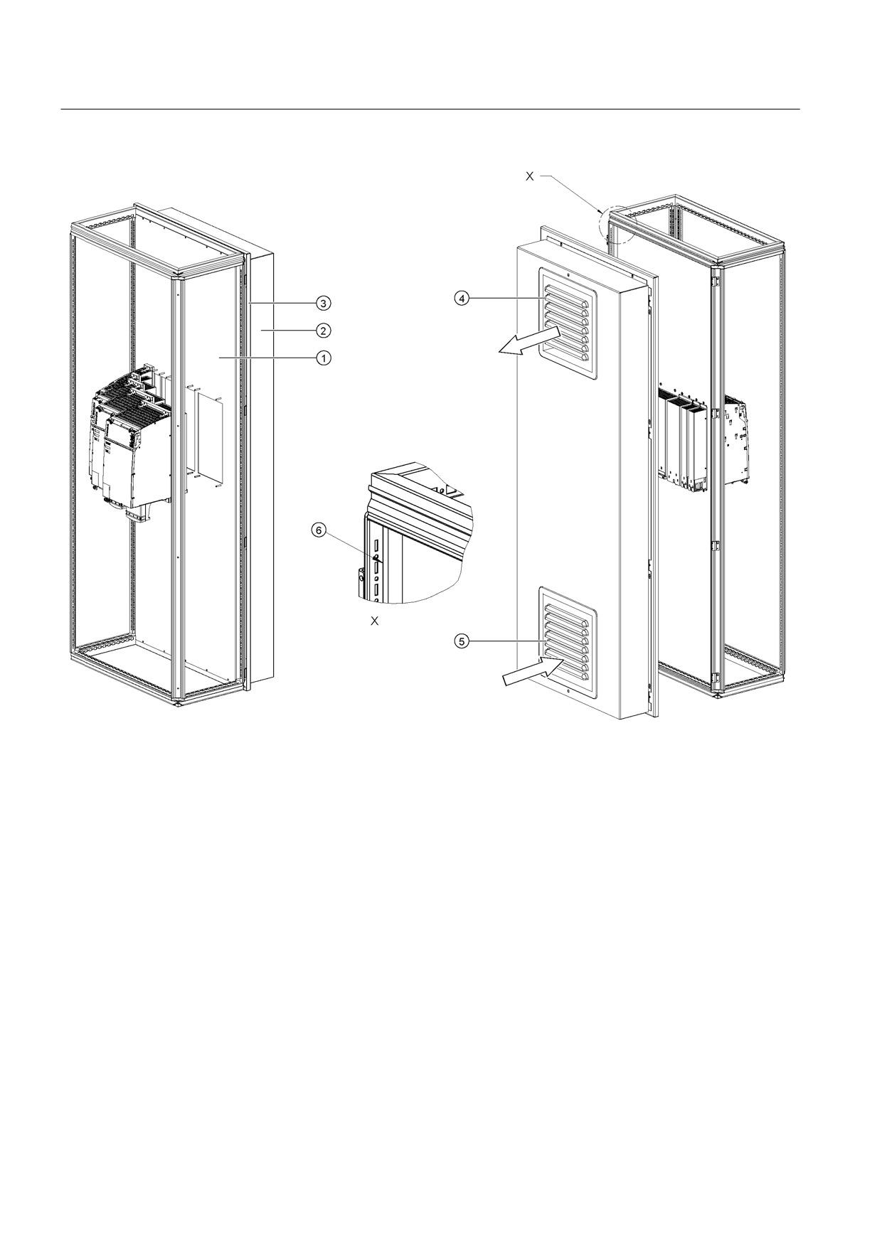
Connection of the components in SINAMICS drive system
8.3 Connection of line modules
①
Mounting plate
②
Cover
③
Rear panel
④
Air discharge
⑤
Air inlet - filter with filter fan
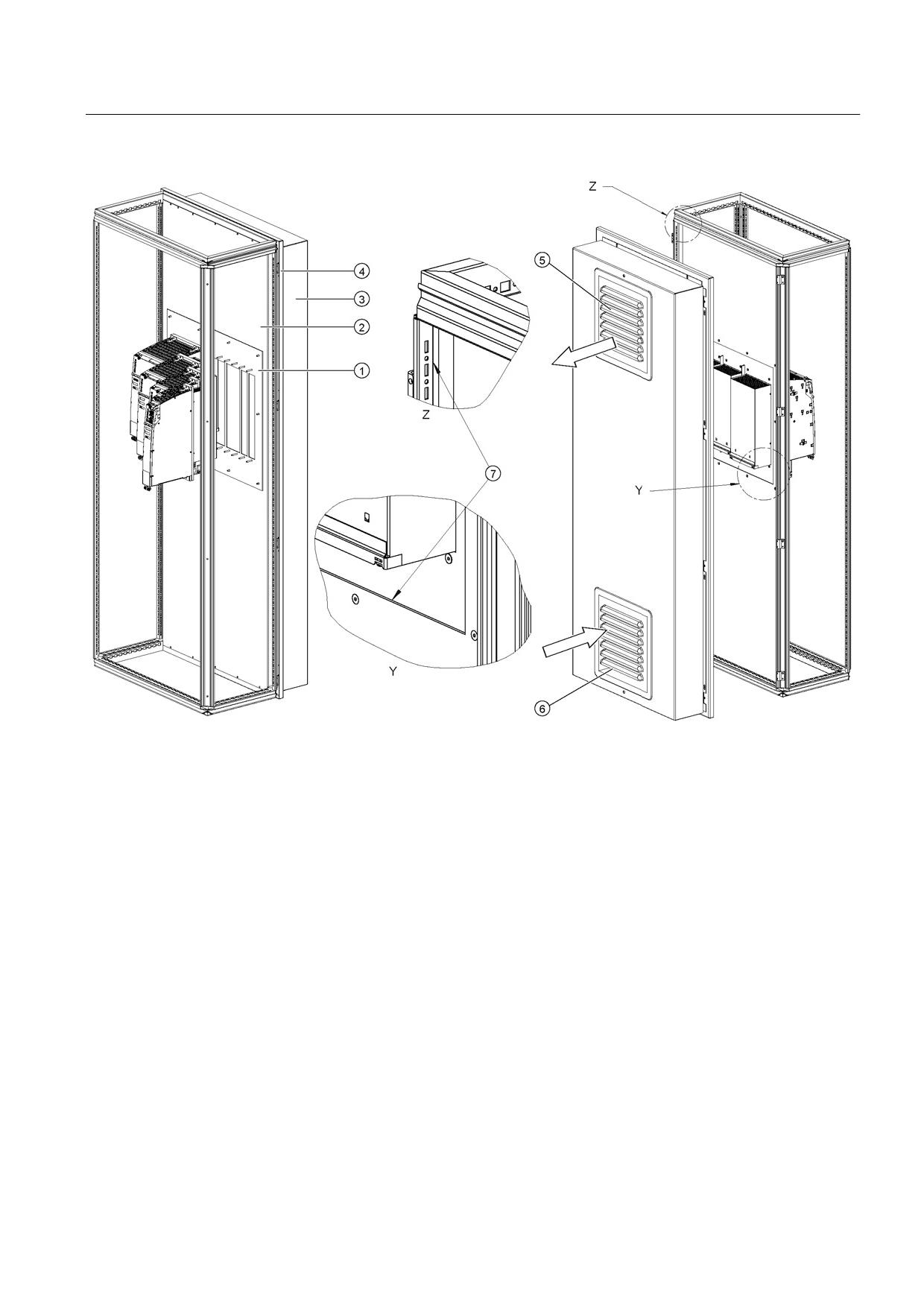
⑥
To comply with degree of protection IP54, the surfaces ⑥ between the mounting plate and the cabinet strip must
be sealed all round. (for example, sealant Terostat-91 from the Teroson company)
Figure 8-33 Example 1: installation in cabinet with mounting plate
Guidelines for machine configuration
232
System Manual, MA 01/2013, 6FC5397-6CP10-0BA2
Connection of the components in SINAMICS drive system
8.3 Connection of line modules
①
Insert
②
Mounting plate
③
Cover
④
Rear panel
⑤
Air discharge
⑥
Air inlet - filter with filter fan
⑦
To maintain the degree of protection IP54, the surfaces ⑦ between the mounting plate and the cabinet strip as
well as between the mounting plate and insert must be sealed all around. (for example, sealant Terostat-91 from
the Teroson company)
Figure 8-34 Example 2: installation in cabinet with mounting plate
We recommend that you attach a cover and filter fan to the cabinet.
The filtered fan must be fitted in such a way that the cooling air required by the drive line-up
is not restricted. The overall cooling air requirement is obtained from the sum of the
individual components (refer to Chapter, "Technical data").
Guidelines for machine configuration
System Manual, MA 01/2013, 6FC5397-6CP10-0BA2
233

Connection of the components in SINAMICS drive system
8.3 Connection of line modules
Note
If the cooling air requirement is not covered by the filtered fan, the components cannot
output their specified power.
The filters with a filtered fan must be regularly checked for dirt and cleaned if necessary.
8.3.4.7
Technical data
Table 8- 30 Technical data for Active Line Modules with external air cooling, part 1
External air cooling
6SL3131-
7TE21-6AAx
7TE23-6AAx
7TE25-5AAx
7TE25-5AA3
+ Active
Interface
Module
Rated power
kW
16
36
55
55
Infeed
Rated power (S1)1)
kW (Pn)
16
36
55
55
Infeed power (S6-40%)1)
kW (Ps6)
21
47
71
71
Peak infeed power1)
kW (Pmax)
35
70
91
110
Energy recovery
Continuous regenerative power
kW
16
36
55
55
Peak regenerative power
kW
35
70
91
110
Supply voltages
Line voltage
VACrms
3 AC 380 to 480 ±10% (-15% < 1 min)
Line frequency
Hz
47 to 63 Hz
Electronics power supply
VDC
24 (20.4 - 28.8)
DC link voltage
VDC
510 - 720
Overvoltage trip
VDC
820 ±2%
Undervoltage trip2)
VDC
360 ±2%
Input currents
Rated input current
at 400 VAC:
AAC
25
55
84
84
Input current
at 380 VAC/480 VAC
AAC
26 / 21
58 /46
88 / 70
88 /70
at 400 VAC; S6-40%
AAC
32
71
108
108
at 400 VAC; peak current
AAC
54
107
139
168
DC link currents
Rated DC link current
at 600 V:
ADC
27
60
92
92
DC link current:
at 600 VDC; at S6-40%
ADC
35
79
121
121
at 600 VDC; peak current
ADC
59
117
152
176
Current-carrying capacity
DC link busbar
ADC
100
200
200
200
Reinforced DC link busbars:
ADC
150
--
--
--
24 V busbar:
ADC
20
20
20
20
Guidelines for machine configuration
234
System Manual, MA 01/2013, 6FC5397-6CP10-0BA2
Connection of the components in SINAMICS drive system
8.3 Connection of line modules
External air cooling
6SL3131-
7TE21-6AAx
7TE23-6AAx
7TE25-5AAx
7TE25-5AA3
+ Active
Interface
Module
Rated power
kW
16
36
55
55
Electronics current consumption
ADC
0.95
1.5
1.9
1.9
at 24 V DC
Total power loss
W
282.8
666
945.6
945.6
(including electronics losses)3)
Max. ambient temperature
without derating
°C
40
40
40
40
with derating
°C
55
55
55
55
DC link capacitance
Active Line Module
μF
705
1410
1880
1880
Drive line-up, max.
μF
20000
20000
20000
20000
Power factor
cosϕ
1
1
1
1
Circuit breaker
See Chap. "Overcurrent protection using line fuses and circuit
(IEC 60947 and UL)
breakers (Page 116)"
Rated short-circuit current
kA
65
65
65
65
SCCR4)
Sound pressure level
dB(A)
<60
<65
<60
<60
Cooling air requirement
m3/h
56
112
160
160
Max. permissible heat sink
°C
85
90
88
88
temperature
Rated voltage for rated data 3 AC 380 V
Weight
kg
8.78
13.77
18.5
18.5
1)
The specified power ratings apply to the line voltage range from 380 V to 480 V
2)
Default for 400 V line systems; undervoltage trip threshold is adjusted to the parameterized rated voltage
3)
For an overview, see the power loss tables in the Appendix
4)
The resulting rated short-circuit current is obtained from the combination of the fuse, or circuit breaker, and the Line
Module in the drive system.
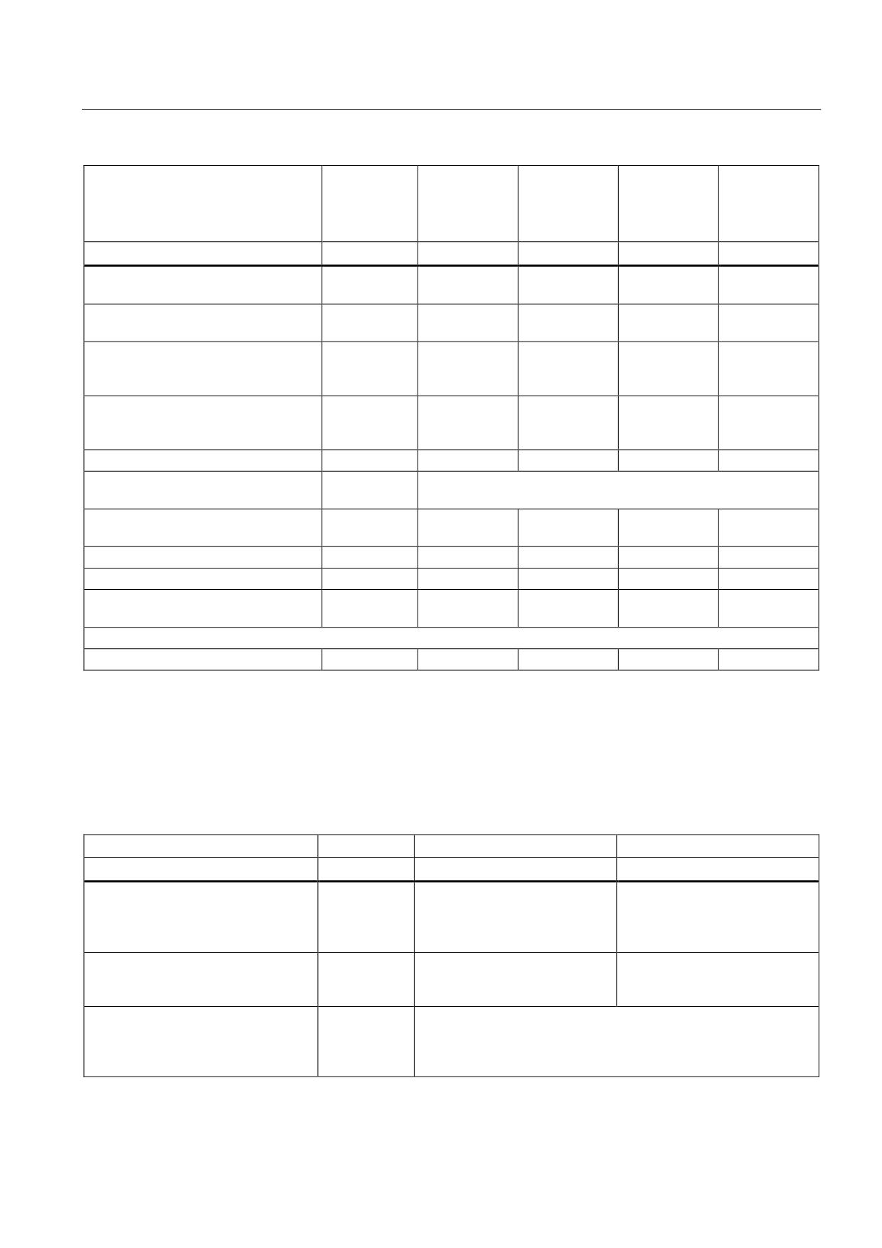
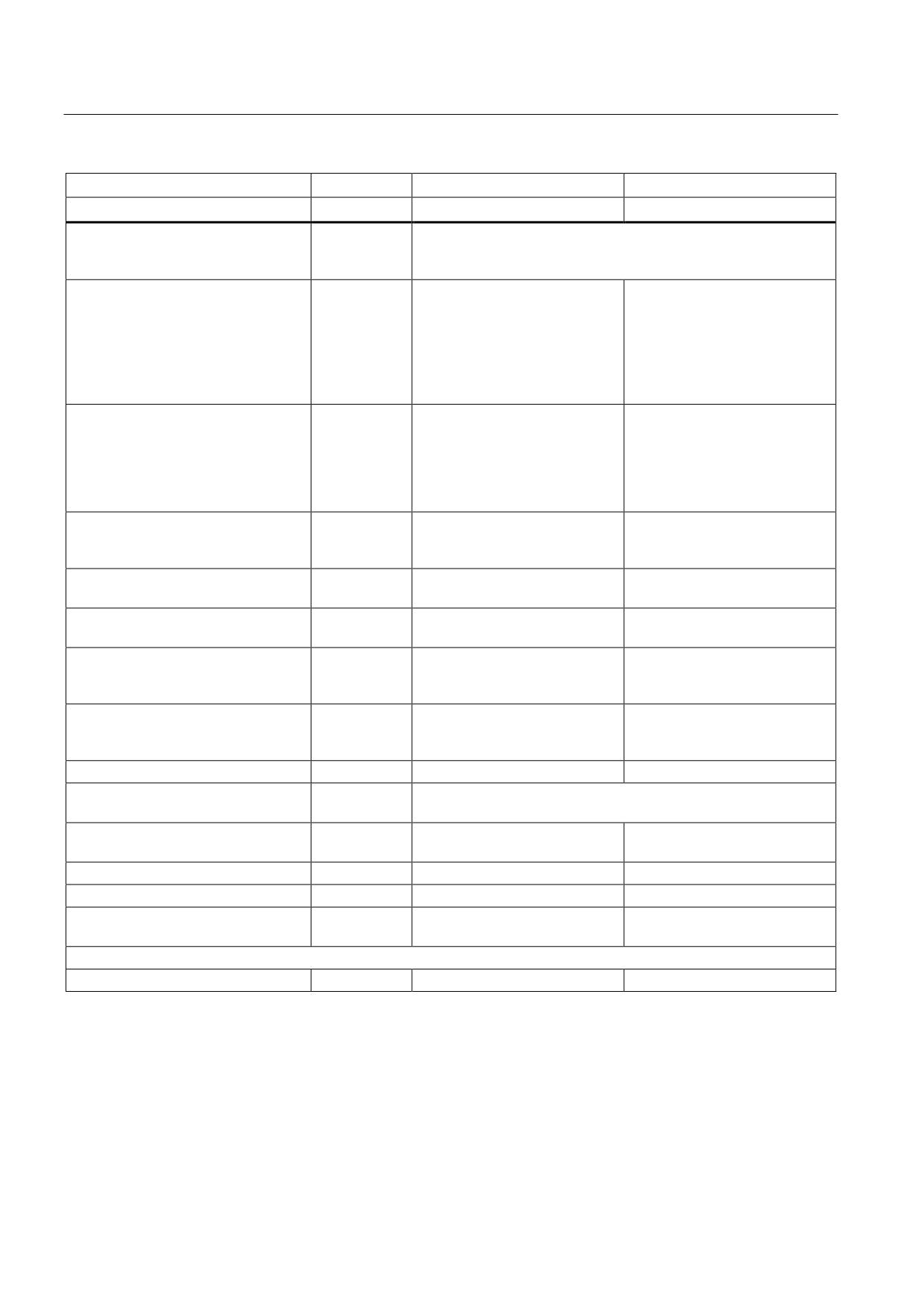
Table 8- 31 Technical data for Active Line Modules with external air cooling, part 2
External air cooling
6SL3131-
7TE28-0AAx
7TE31-2AAx
Rated power
kW
80
120
Infeed
Rated power (S1)1)
kW (Pn)
80
120
Infeed power (S6-40%)1)
kW (Ps6)
106
145
Peak infeed power1)
kW (Pmax)
131
175
Energy recovery
Continuous regenerative power
kW
80
120
Peak regenerative power
kW
131
175
Supply voltages
Line voltage
VACrms
3 AC 380 to 480 ±10% (-15% < 1 min)
Line frequency
Hz
47 to 63 Hz
Electronics power supply
VDC
24 (20.4 - 28.8)
Guidelines for machine configuration
System Manual, MA 01/2013, 6FC5397-6CP10-0BA2
235
Connection of the components in SINAMICS drive system
8.3 Connection of line modules
External air cooling
6SL3131-
7TE28-0AAx
7TE31-2AAx
Rated power
kW
80
120
DC link voltage
VDC
510 - 720
Overvoltage trip
VDC
820 ±2%
Undervoltage trip2)
VDC
360 ±2%
Input currents
Rated input current
at 400 VAC:
AAC
122
182
Input current
at 380 VAC/480 VAC
AAC
128 / 102
192 / 152
at 400 VAC; S6-40%
AAC
161
220
at 400 VAC; peak current
AAC
200
267
DC link currents
Rated DC link current
at 600 V:
ADC
134
200
DC link current:
at 600 VDC; at S6-40%
ADC
176
244
at 600 VDC; peak current
ADC
218
292
Current-carrying capacity
DC link busbar:
ADC
200
200
24 V busbar:
ADC
20
20
Electronics current consumption
ADC
1.4
1.8
at 24 V DC
Total power loss
W
1383.6
2243.2
(including electronics losses)3)
Max. ambient temperature
without derating
°C
40
40
with derating
°C
55
55
DC link capacitance
Active Line Module
μF
2820
3995
Drive line-up, max.
μF
20000
20000
Power factor
cosϕ
1
1
Circuit breaker
See Chap. "Overcurrent protection using line fuses and circuit
(IEC 60947 and UL)
breakers (Page 116)"
Rated short-circuit current
kA
65
65
SCCR4)
Sound pressure level
dB(A)
<73
<73
Cooling air requirement
m3/h
520
520
Max. permissible heat sink
°C
73
83
temperature
Rated voltage for rated data 3 AC 380 V
Weight
kg
27.66
30.74
1)
The specified power ratings apply to the line voltage range from 380 V to 480 V
2)
Default for 400 V line systems; undervoltage trip threshold is adjusted to the parameterized rated voltage
3)
For an overview, see the power loss tables in the Appendix
4)
The resulting rated short-circuit current is obtained from the combination of the fuse, or circuit breaker, and the Line
Module in the drive system.
Guidelines for machine configuration
236
System Manual, MA 01/2013, 6FC5397-6CP10-0BA2
Connection of the components in SINAMICS drive system
8.3 Connection of line modules
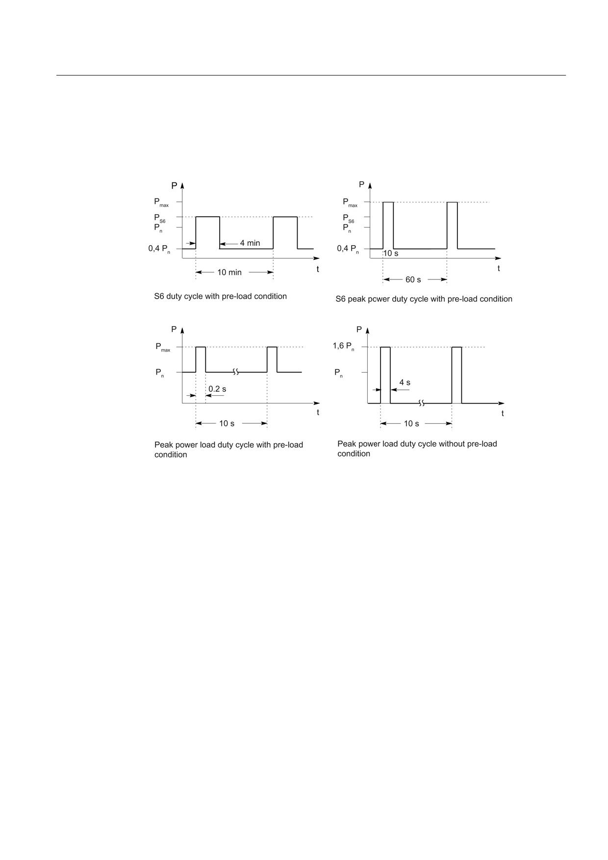
Characteristics
Rated duty cycles for Active Line Modules
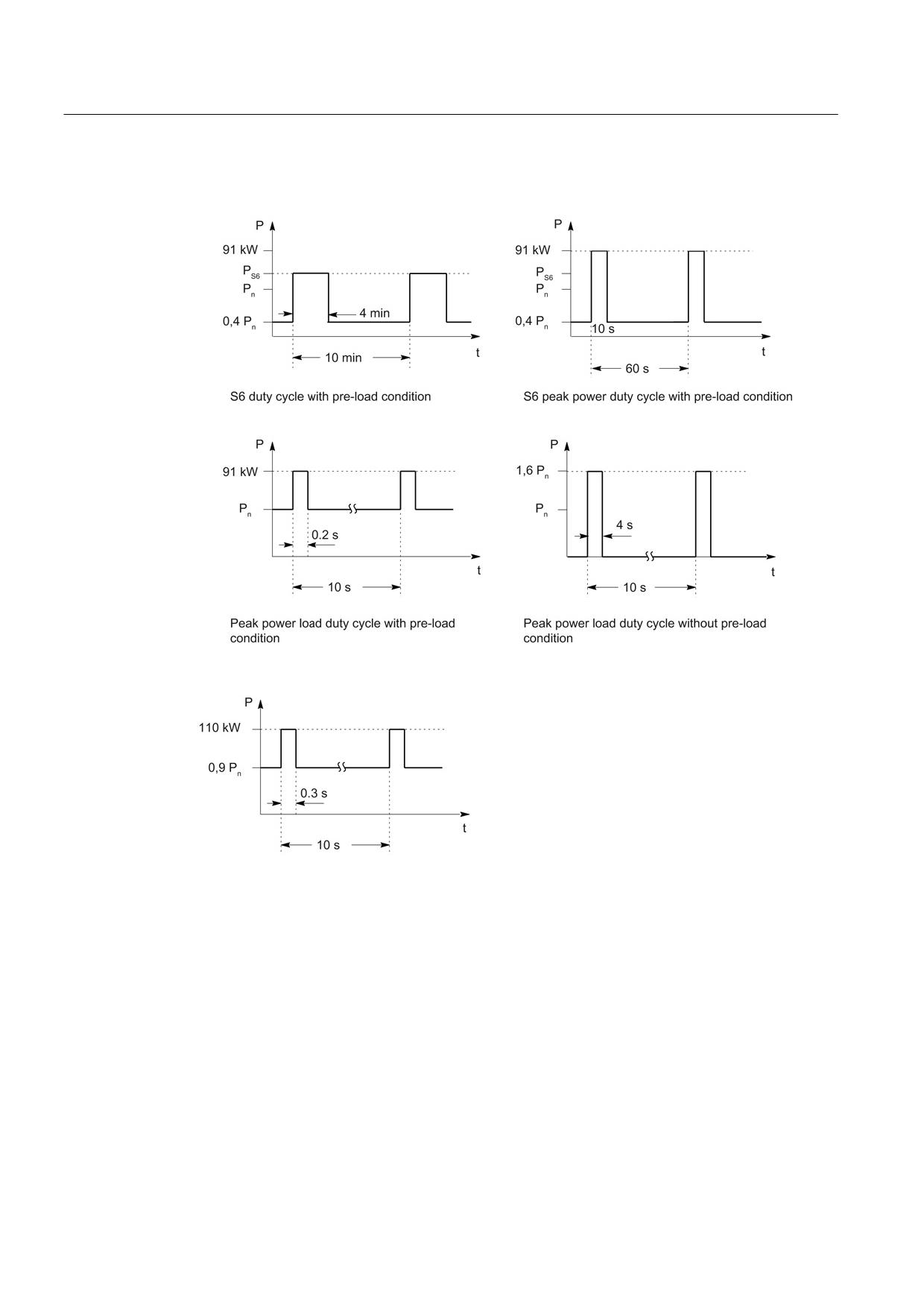
Figure 8-35 Rated duty cycles for Active Line Modules (exception: not applicable for 55 kW Active
Line Module with Active Interface Module)
Guidelines for machine configuration
System Manual, MA 01/2013, 6FC5397-6CP10-0BA2
237
Connection of the components in SINAMICS drive system
8.3 Connection of line modules
Rated duty cycles for Active Line Modules with Active Interface Modules
Figure 8-36 Duty cycles for 55 kW Active Line Modules with Active Interface Modules
Figure 8-37 Peak duty cycle with initial load for 55 kW Active Line Modules with Active Interface
Modules
Guidelines for machine configuration
238
System Manual, MA 01/2013, 6FC5397-6CP10-0BA2
Connection of the components in SINAMICS drive system
8.3 Connection of line modules
Derating characteristics
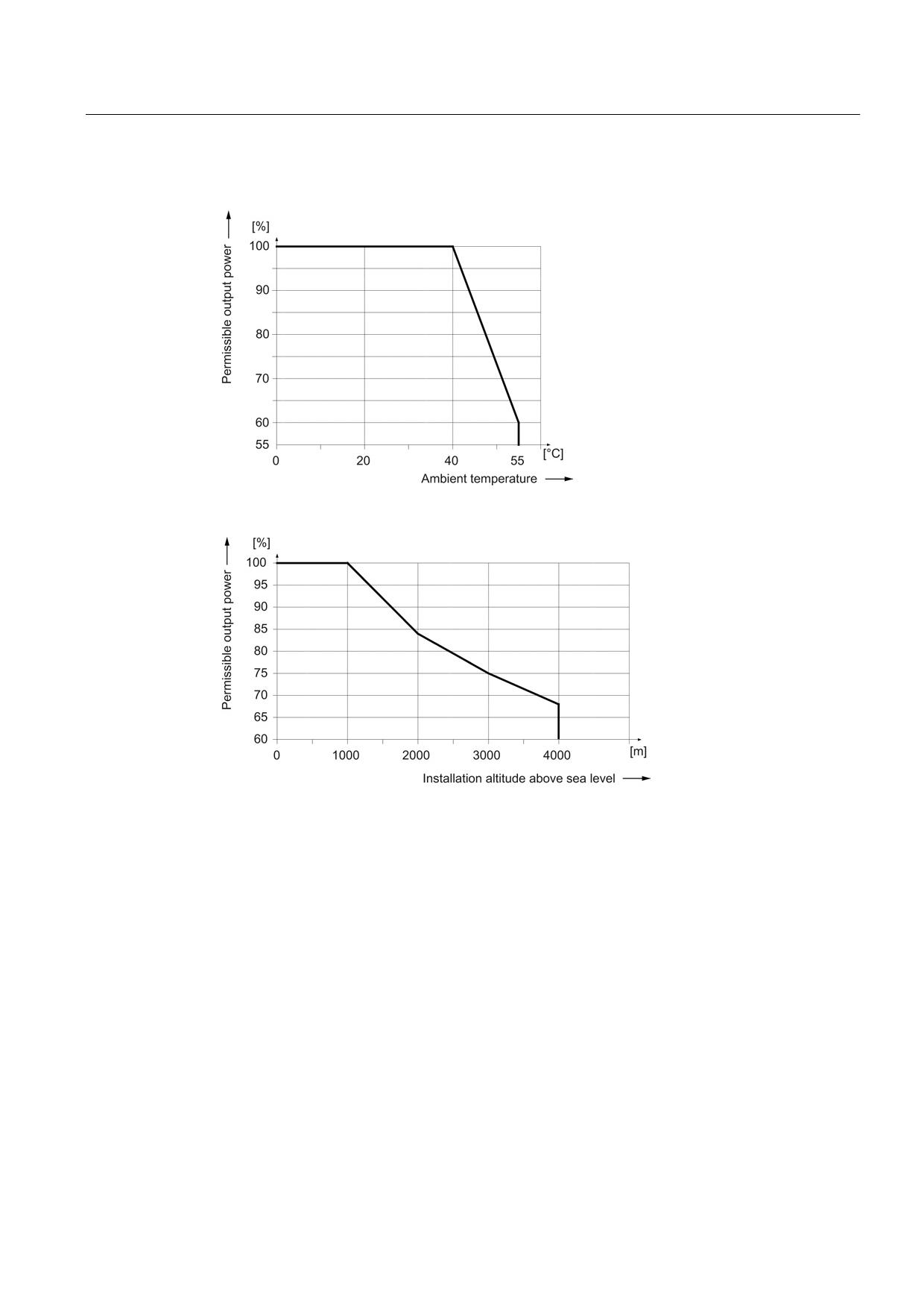
Figure 8-38 Output power as a function of the ambient temperature
Figure 8-39 Output power as a function of the installation altitude
At installation altitudes > 2000 m, an isolation transformer must be used (see the chapter
titled "System overview/Function of installation altitude and ambient temperature"
(Page 32)). The design of the secondary line system must be as follows:
● TN system with grounded neutral point (no grounded line conductor)
● IT system
A reduction of the line supply voltage phase-phase is not necessary.
Guidelines for machine configuration
System Manual, MA 01/2013, 6FC5397-6CP10-0BA2
239
Connection of the components in SINAMICS drive system
8.3 Connection of line modules
8.3.5
Active Line Modules with cold plate
8.3.5.1
Description
Active Line Modules generate a constant, regulated DC voltage in the DC link from the three-
phase line supply voltage that supplies the connected Motor Modules with power.
This ensures that they are not influenced by network fluctuations.
When the motors are in feedback mode, Active Line Modules supply power back to the
network. The regenerative feedback capability of the modules can be deactivated by
parameterization.
The DC link starts precharging as soon as the supply voltage is applied and is independent
of its phase sequence direction. Load can be applied to the DC link after the modules have
been enabled. An optional main contactor is required for disconnecting the voltage.
Active Line Modules can be directly connected to TN and TT line supplies - both with
grounded neutral point and also with grounded protective conductor; they can also be
connected to IT line supplies. The Line Modules have an integrated overvoltage protection
function.
Guidelines for machine configuration
240
System Manual, MA 01/2013, 6FC5397-6CP10-0BA2
Connection of the components in SINAMICS drive system
8.3 Connection of line modules
8.3.5.2
Interface description
Overview
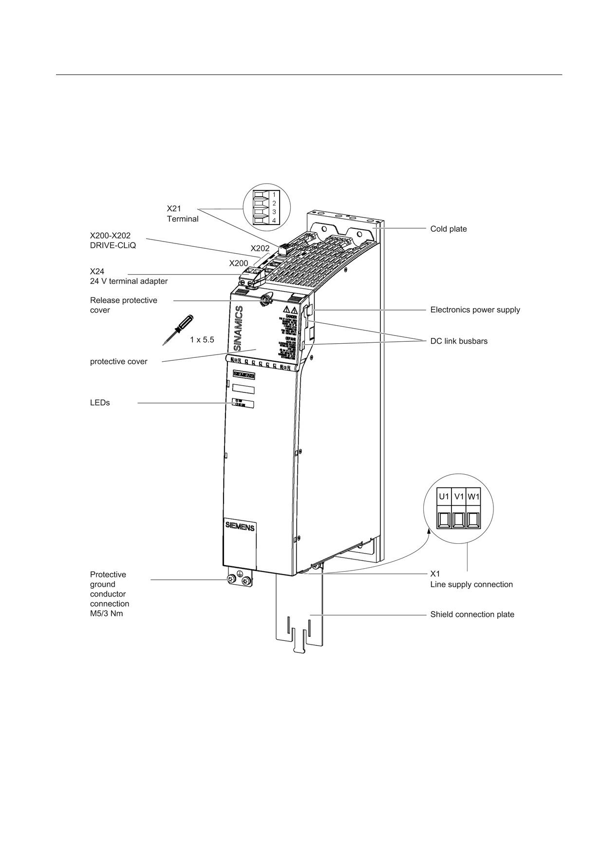
Figure 8-40 Interface overview, Active Line Module with cold plate (example: 16 kW)
Guidelines for machine configuration
System Manual, MA 01/2013, 6FC5397-6CP10-0BA2
241
Connection of the components in SINAMICS drive system
8.3 Connection of line modules
X1 line connection
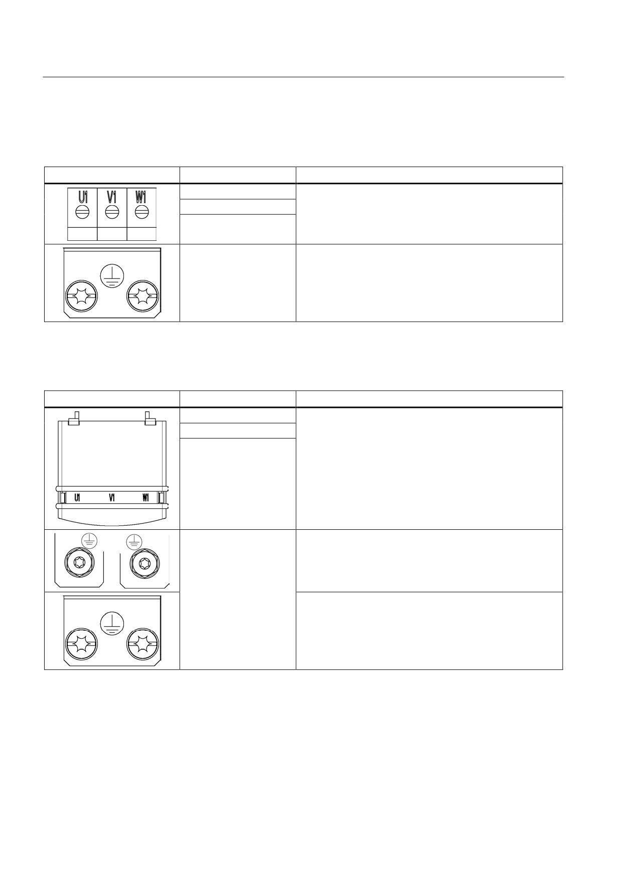
Table 8- 32 X1: Line connection for Active Line Modules 16 kW
Terminal
Technical specifications
U1
Max. connectable cross-section: 10 mm2
V1
Type: Screw terminal 6 (see Appendix, Chapter "Screw
terminals")
W1
Tightening torque: 1.5 - 1.8 Nm
PE connection
Threaded hole M5/3 Nm 1)
1) For ring cable lugs in accordance with DIN 46234
Table 8- 33 X1: Line connection for Active Line Modules 36 kW to 120 kW
Terminal
Technical specifications
U1
Supply voltage:
3 AC 380 V - 480 V, 50/60 Hz
V1
36 kW: Threaded bolts M6/6 Nm 1)
W1
55 kW, 80 kW and 120 kW: Threaded bolts M8/13 Nm 1)
PE connection
36 kW: Threaded hole M6/6 Nm 1)
55 kW: Threaded hole M6/6 Nm 1)
80 kW and 120 kW: Threaded hole M8/13 Nm 1)
1) For ring cable lugs in accordance with DIN 46234
Guidelines for machine configuration
242
System Manual, MA 01/2013, 6FC5397-6CP10-0BA2
Connection of the components in SINAMICS drive system
8.3 Connection of line modules
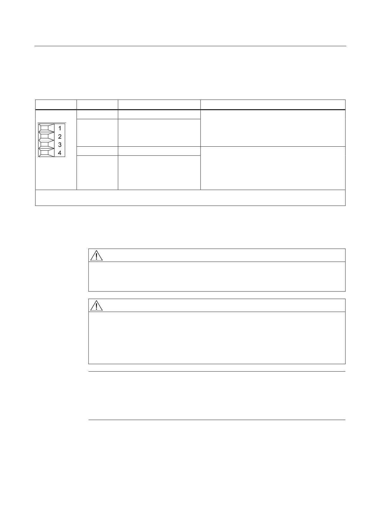
X21 EP terminals
Table 8- 34 X21 EP terminal/temperature sensor
Terminal
Designation
Technical data
1
+ Temp
Temperature sensors1): KTY84-
1C1302)/PTC2)/bimetallic switch with NC contact
2
- Temp
If an Active Interface Module is used, the temperature
input must be connected to the Active Interface Module
sensor (bimetallic switch with NC contact).
3
EP +24 V (Enable Pulses)
Voltage 24 VDC
Current consumption: 10 mA
4
EP M (Enable Pulses)
Isolated input
Signal propagation times:
L → H: 100 μs
H → L: 1000 μs
Max. connectable cross-section: 1.5 mm2
Type: Screw terminal 1 (see Appendix, Chapter "Screw terminals")
1) The temperature sensor type can be selected via parameter p0601; the temperature is displayed via r0035 (see
SINAMICS S120/S150 List Manual LH1).
2) Temperatures are detected but not evaluated in the Active Line Module.
CAUTION
Connecting the temperature sensor
If an Active Interface Module is connected, the temperature output of the Active Interface
Module must be connected to terminals 1 and 2.
WARNING
Danger to life due to charged DC link
For operation, the 24 VDC voltage must be connected to terminal 3 and ground to terminal
4. When withdrawn, pulse suppression is activated. Regenerative feedback is deactivated
and the bypass relay drops out. If the Line Module is not disconnected from the supply
system when the EP terminal is deactivated (e.g. a line contactor is not installed), the DC
link remains charged.
Note
If an active drive line-up is switched off by means of the disconnector unit, the voltage at
terminals 3 (EP +24 V) and 4 (EP M) must be interrupted beforehand. This can be carried
out using a leading (≥ 10 ms) breaking auxiliary contact, for example.
This protects external loads located parallel to the drive on the same switching component.
Guidelines for machine configuration
System Manual, MA 01/2013, 6FC5397-6CP10-0BA2
243
Connection of the components in SINAMICS drive system
8.3 Connection of line modules
DANGER
Risk of electric shock!
Only temperature sensors that meet the safety isolation specifications contained in
EN 61800-5-1 may be connected to terminals "+Temp" and "-Temp". If safe electrical
separation cannot be guaranteed (for linear motors or third-party motors, for example), a
Sensor Module External (SME120 or SME125) or Terminal Module TM120 must be used.
If these instructions are not complied with, there is a risk of electric shock!
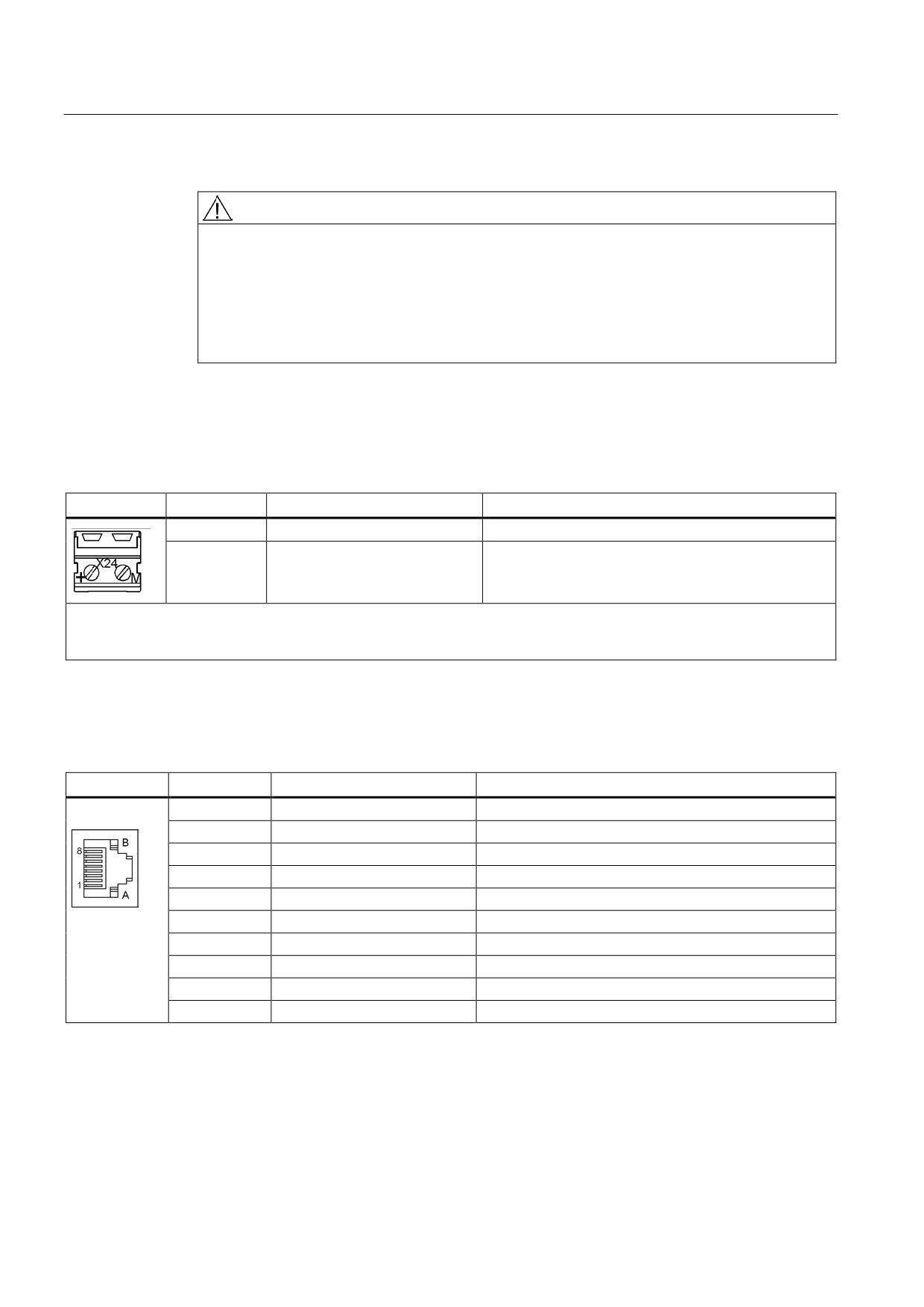
X24 24 V terminal adapter
Table 8- 35 X24 24 V terminal adapter
Terminal
Description
Technical specifications
+
24 V power supply
24 VDC supply voltage
M
Ground
Electronics ground
The 24 V terminal adapter is included in the scope of delivery.
Max. connectable cross-section: 6 mm2
Type: Screw terminal 5 (see Appendix, Chapter "Screw terminals")
X200-X202 DRIVE-CLiQ interfaces
Table 8- 36 X200-X202 DRIVE-CLiQ interfaces
PIN
Signal name
Technical specifications
1
TXP
Transmit data +
2
TXN
Transmit data -
3
RXP
Receive data +
4
Reserved, do not use
5
Reserved, do not use
6
RXN
Receive data -
7
Reserved, do not use
8
Reserved, do not use
A
+(24 V)
24 V power supply
B
M (0 V)
Electronics ground
The blanking covers for the DRIVE-CLiQ interfaces are included in the scope of delivery.
Blanking cover (50 pcs.) Order number: 6SL3066-4CA00-0AA0
Guidelines for machine configuration
244
System Manual, MA 01/2013, 6FC5397-6CP10-0BA2
Connection of the components in SINAMICS drive system
8.3 Connection of line modules
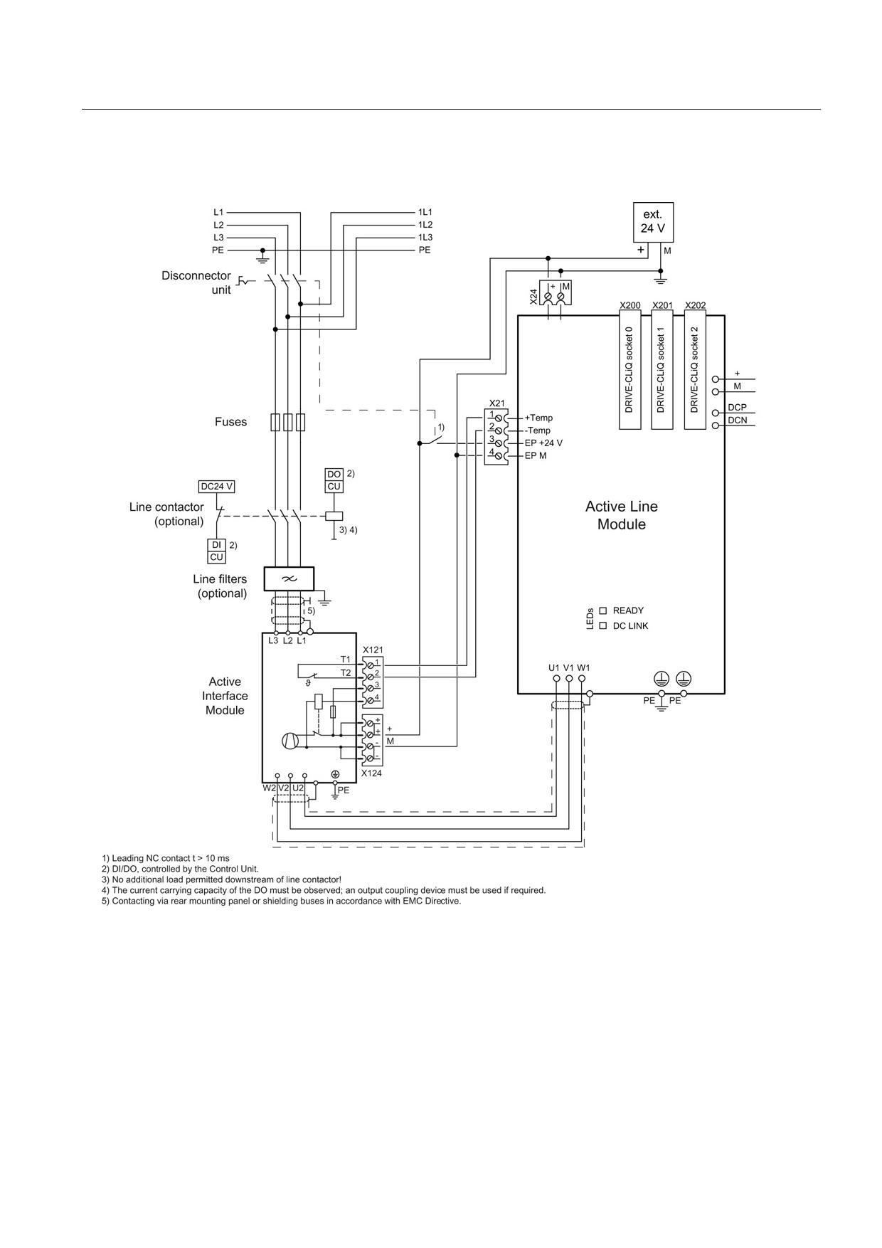
8.3.5.3
Connection example
Figure 8-41 Connection example: Active Line Module with cold plate
Guidelines for machine configuration
System Manual, MA 01/2013, 6FC5397-6CP10-0BA2
245
Connection of the components in SINAMICS drive system
8.3 Connection of line modules
8.3.5.4
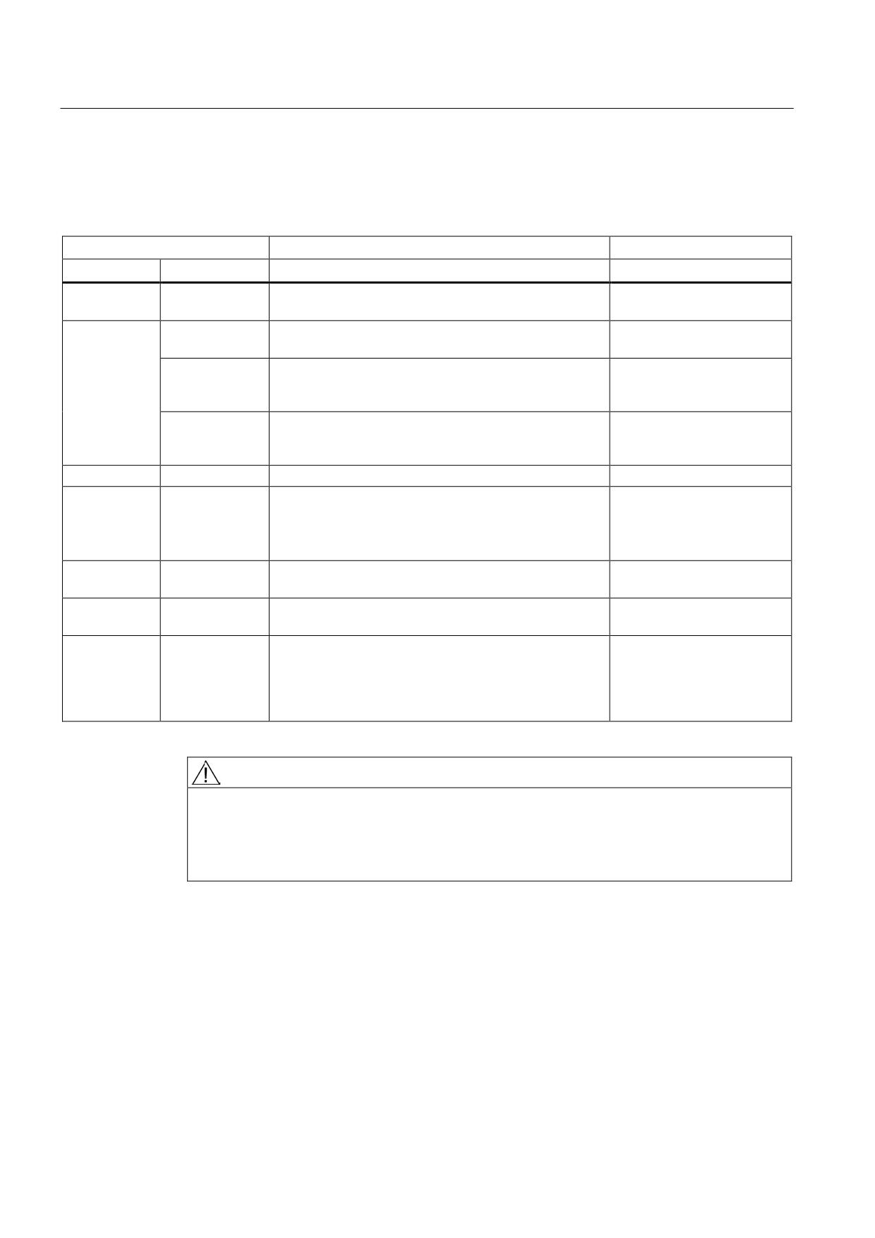
Meaning of LEDs
Table 8- 37 Meaning of the LEDs on the Active Line Module
Status
Description, cause
Remedy
RDY
DC LINK
Off
Off
Electronics power supply is missing or outside
-
permissible tolerance range.
Green
--
The component is ready for operation and cyclic DRIVE-
-
CLiQ communication is taking place.
Orange
The component is ready for operation and cyclic DRIVE-
-
CLiQ communication is taking place.
The DC link voltage is present.
Red
The component is ready for operation and cyclic DRIVE-
Check line voltage
CLiQ communication is taking place.
The DC link voltage is too high.
Orange
Orange
DRIVE-CLiQ communication is being established.
-
Red
--
At least one fault is present in this component.
Remedy and acknowledge
fault
Note:
The LED is activated regardless of whether the
corresponding messages have been reconfigured.
Green/red
--
Firmware is being downloaded.
-
(0.5 Hz)
Green/red
--
Firmware download is complete. Wait for POWER ON.
Carry out a POWER ON
(2 Hz)
Green/orange
--
Detection of the components via LED is activated
-
or
(p0124).
Red/orange
Note:
Both options depend on the LED status in the case of
activation via p0124 = 1.
WARNING
Danger to life due to high DC link voltage, regardless of LED display
Hazardous DC link voltages may be present at any time regardless of the status of the
"DC LINK" LED.
• Observe the warning information on the component.
Guidelines for machine configuration
246
System Manual, MA 01/2013, 6FC5397-6CP10-0BA2
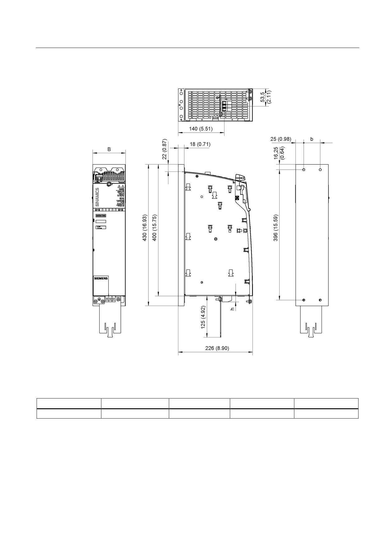
Connection of the components in SINAMICS drive system
8.3 Connection of line modules
8.3.5.5
Dimension drawings
Figure 8-42 Dimension drawing of 16 kW Active Line Module with cold plate, all dimensions in mm
and (inches)
Table 8- 38 Dimensions of 16 kW Active Line Module with cold plate
Active Line Module
Order number
B [mm] (inches)
b [mm] (inches)
h [mm] (inches)
16 kW
6SL3136-7TE21-6AAx
100 (3.94)
50 (1.97)
18 (0.71)
Guidelines for machine configuration
System Manual, MA 01/2013, 6FC5397-6CP10-0BA2
247
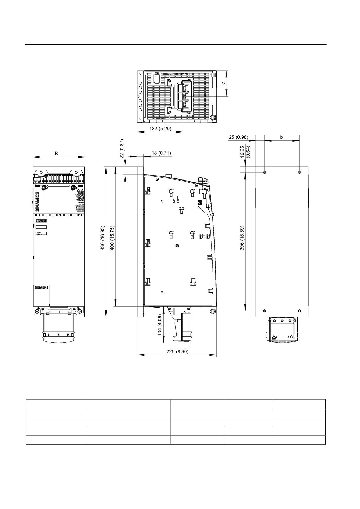
Connection of the components in SINAMICS drive system
8.3 Connection of line modules
Figure 8-43 Dimension drawing of 36 kW, 55 kW, 80 kW, and 120 kW Active Line Modules with cold plate, all dimensions
in mm and (inches)
Table 8- 39 Dimensions of 36 kW, 55 kW, 80 kW, and 120 kW Active Line Modules with cold plate
Active Line Module
Order number
B [mm] (inches)
b [mm] (inches)
c [mm] (inches)
36 kW
6SL3136-7TE23-6AAx
150 (5.91)
100 (3.94)
75 (2.95)
55 kW
6SL3136-7TE25-5AAx
200 (7.87)
150 (5.91)
100 (3.94)
80 kW
6SL3136-7TE28-0AAx
300 (11.81)
250 (9.84)
150 (5.91)
120 kW
6SL3136-7TE31-2AAx
300 (11.81)
250 (9.84)
150 (5.91)
Guidelines for machine configuration
248
System Manual, MA 01/2013, 6FC5397-6CP10-0BA2
Connection of the components in SINAMICS drive system
8.3 Connection of line modules
8.3.5.6
Installation
Please note the following before installing an Active Line Module with cold plate on a
customer-specific heat sink:
● Check the surface of the heat sink to ensure that it is not damaged.
● To improve heat transfer, a heat-conducting medium must be used. Special spherical-
indented heat-conducting foil must be used for this purpose. Every component with cold
plate is supplied with heat-conducting foil cut to the right size. Note the installation
position of the heat-conducting foil (see diagram below).
Note
When a component is replaced, the heat-conducting foil must also be replaced.
Only heat-conducting foil approved or supplied by Siemens can be used.
Table 8- 40 Overview of heat-conducting foils
Order number
Heat-conducting foil, 50 mm
6SL3162-6FB00-0AA0
Heat-conducting foil, 100 mm
6SL3162-6FD00-0AA0
Heat-conducting foil, 150 mm
6SL3162-6FF00-0AA0
Heat-conducting foil, 200 mm
6SL3162-6FH00-0AA0
Heat-conducting foil, 300 mm
6SL3162-6FM00-0AA0
Note
M6 studs and hexagon nuts/grub screws (ISO 7436-M6x40-14 H, property class 8.8) are
recommended for installing the components.
Guidelines for machine configuration
System Manual, MA 01/2013, 6FC5397-6CP10-0BA2
249
Connection of the components in SINAMICS drive system
8.3 Connection of line modules
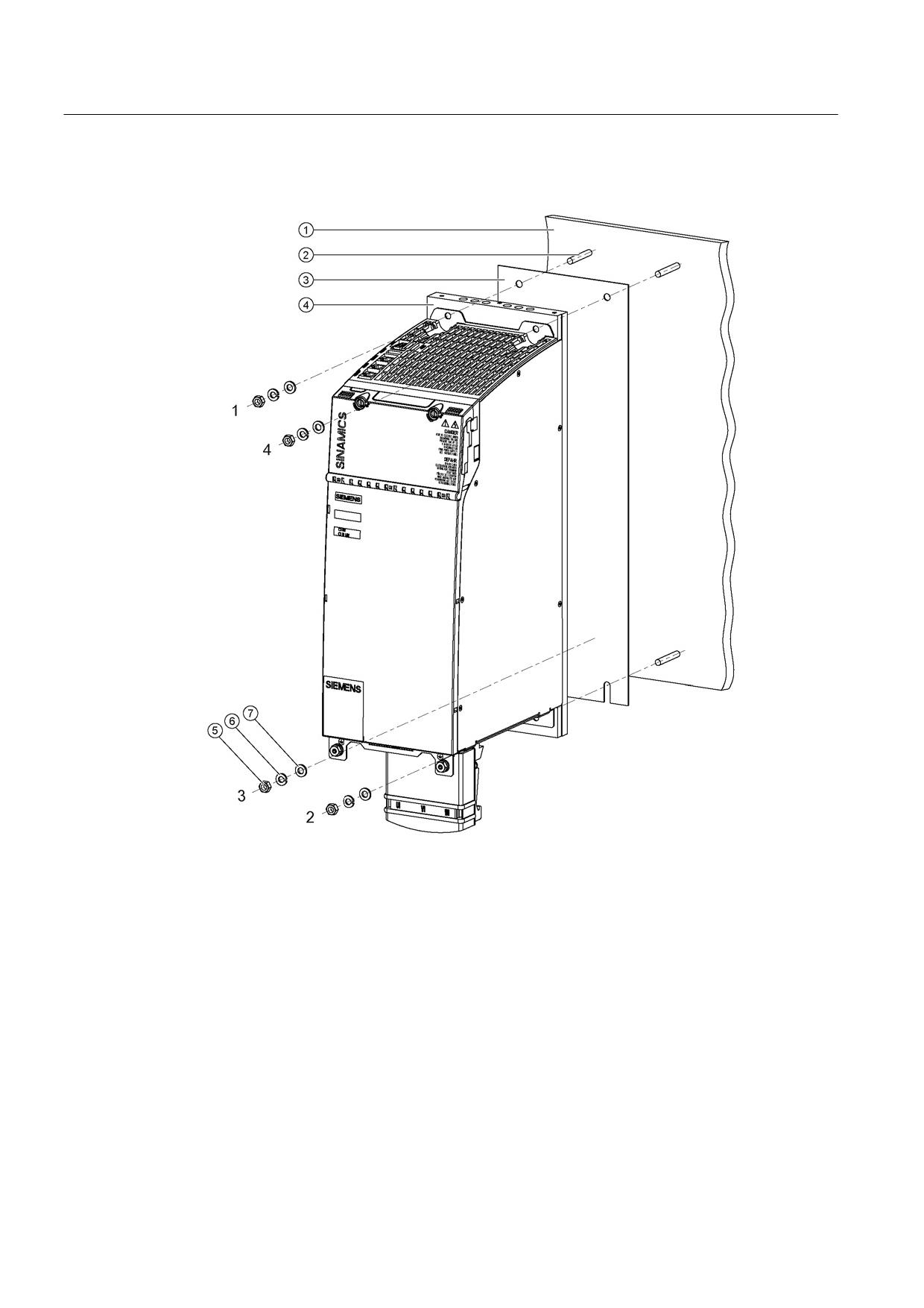
Installation
①
External heat sink (air or liquid)
②
M6 studs
③
Heat-conducting foil
④
Cold plate
⑤
M6 nut
⑥
Spring washer
⑦
Washer
Figure 8-44 Mounting an Active Line Module with cold plate on an external heat sink (example: 36
kW)
Tightening torques:
● Initially, tighten the nuts by hand (0.5 Nm)
● Then tighten with 10 Nm (in the specific sequence 1 to 4)
Guidelines for machine configuration
250
System Manual, MA 01/2013, 6FC5397-6CP10-0BA2
Connection of the components in SINAMICS drive system
8.3 Connection of line modules
Help with the mechanical control cabinet installation is available from:
Siemens AG
Industry Sector, IA SE WKC
TCCCC (Technical Competence Center Cabinets Chemnitz)
P.O. Box 1124
09070 Chemnitz, Germany
E-mail: cc.cabinetcooling.aud@siemens.com
Properties of the heat sink
We recommend using AlMgSi 0.5 as the heat sink material.
The roughness of the external heat sink surface should be at least Rz 16. The contact
surface between the heat sink and cold plate should have an evenness of 0.2 mm
(applicable to a height of 450 mm and a width of 300 mm).
Note
The machine manufacturer can adapt the heat sink version to his special requirements. The
specified rated data for the Line Modules can only be achieved if the power losses can be
dissipated by the external heat sink under the specified general conditions.
Note
Avoid damage to the cold plate
During the installation, you must ensure that the threaded bolts do not damage the cold
plate.
Guidelines for machine configuration
System Manual, MA 01/2013, 6FC5397-6CP10-0BA2
251

Connection of the components in SINAMICS drive system
8.3 Connection of line modules
8.3.5.7
Technical specifications
Table 8- 41 Technical data for Active Line Modules with cold plate cooling
Cold plate
6SL3136-
21-6AAx
23-6AAx
25-5AAx
25-5AA3 +
28-0AAx
31-2AAx
7TE
Active
Interface
Module
Rated power
kW
16
36
55
55
80 (64)1)
120 (84)1)
Infeed
Rated power (S1)2)
kW (Pn)
16
36
55
55
80 (64)1)
120 (84)1)
Infeed power
kW (Ps6)
21
47
71
71
106 (85)1)
145 (116)1)
(S6-40%) 2)
Peak infeed power2)
kW (Pmax)
35
70
91
110
131
175
Energy recovery
Continuous regenerative
power
kW
16
36
55
55
80 (64)1)
120 (84)1)
Peak regenerative power
kW
35
70
91
110
131
175
Supply voltages
Line voltage
VACrms
3 AC 380 to 480 ±10% (-15% < 1 min)
Line frequency
Hz
47 to 63
Electronics power supply
VDC
24 (20.4 - 28.8)
DC link voltage
VDC
510 - 720
Overvoltage trip
VDC
820 ±2%
Undervoltage trip3)
VDC
360 ±2%
Input currents
Rated input current
at 400 VAC:
AAC
25
55
84
84
122 (98)1)
182 (127)1)
Input current
at 380 VAC
AAC
26
58
88
88
128 (102)1)
192 (134)1)
at 480 VAC
AAC
21
46
70
70
102 (82) 1)
152 (106)1)
at 400 VAC; S6-40%
AAC
32
71
108
108
161 (129)1)
220 (154)1)
at 400 VAC; peak current
AAC
54
107
139
168
200
267
DC link currents
Rated DC link current
at 600 V:
ADC
27
60
92
92
134 (99)1)
200 (140)
DC link current:
at 600 VDC; at S6-40%
ADC
35
79
121
121
176 (141)1)
244 (171)1)
at 600 VDC; peak current
ADC
59
117
152
176
195
292
Current-carrying capacity
DC link busbar
AACrms
100
200
200
200
200
200
Reinforced DC link busbars:
AACrms
150
--
--
--
--
--
24 V busbar:
AACrms
20
20
20
20
20
20
Electronics current
ADC
0.85
1.05
1.15
1.15
1.4
1.8
consumption
at 24 VDC
Total power loss5)
W
280.4
655.2
927.6
927.6
1383.6
2243.2
(including electronics
losses)
DC link capacitance
Active Line Module
μF
710
1410
1880
1880
2820
3760
Drive line-up, max.:
μF
20000
20000
20000
20000
20000
20000
Guidelines for machine configuration
252
System Manual, MA 01/2013, 6FC5397-6CP10-0BA2
Connection of the components in SINAMICS drive system
8.3 Connection of line modules
Cold plate
6SL3136-
21-6AAx
23-6AAx
25-5AAx
25-5AA3 +
28-0AAx
31-2AAx
7TE
Active
Interface
Module
Power factor
cosϕ
1
1
1
1
1
1
Circuit breaker
See Chap. "Overcurrent protection using line fuses and circuit breakers
(IEC 60947 and UL)
(Page 116)"
Rated short-circuit current
kA
65
65
65
65
65
65
SCCR4)
Max. permissible heat sink
°C
70
73
83
83
75
80
temperature
Max. ambient temperature
Without derating
°C
40
40
40
40
40
40
With derating
°C
55
55
55
55
55
55
Weight
kg
6.1
10.2
13.8
13.8
20.3
20.4
1)
Derating must be applied due to the transfer of heat to the external heat sink. At a temperature of 40 °C at the interface
to the power unit, 80% derating occurs for 6SL3136-7TE28-0AAx and 70% for 6SL3136-7TE31-2AAx
2)
The specified power ratings apply to the line voltage range from 380 V to 480 V
3)
Default for 400 V line systems; undervoltage trip threshold is adjusted to the parameterized rated voltage
4)
The resulting rated short-circuit current is obtained from the combination of the fuse, or circuit breaker, and the Line
Module in the drive system.
5)
For an overview, see the power loss tables in the Appendix
Note
New systems with 80 kW and 120 kW Active Line Modules should ideally be designed with
120 kW Active Line Modules Liquid Cooled in order to avoid power derating.
Guidelines for machine configuration
System Manual, MA 01/2013, 6FC5397-6CP10-0BA2
253
Connection of the components in SINAMICS drive system
8.3 Connection of line modules
Characteristics
Rated duty cycles for Active Line Modules
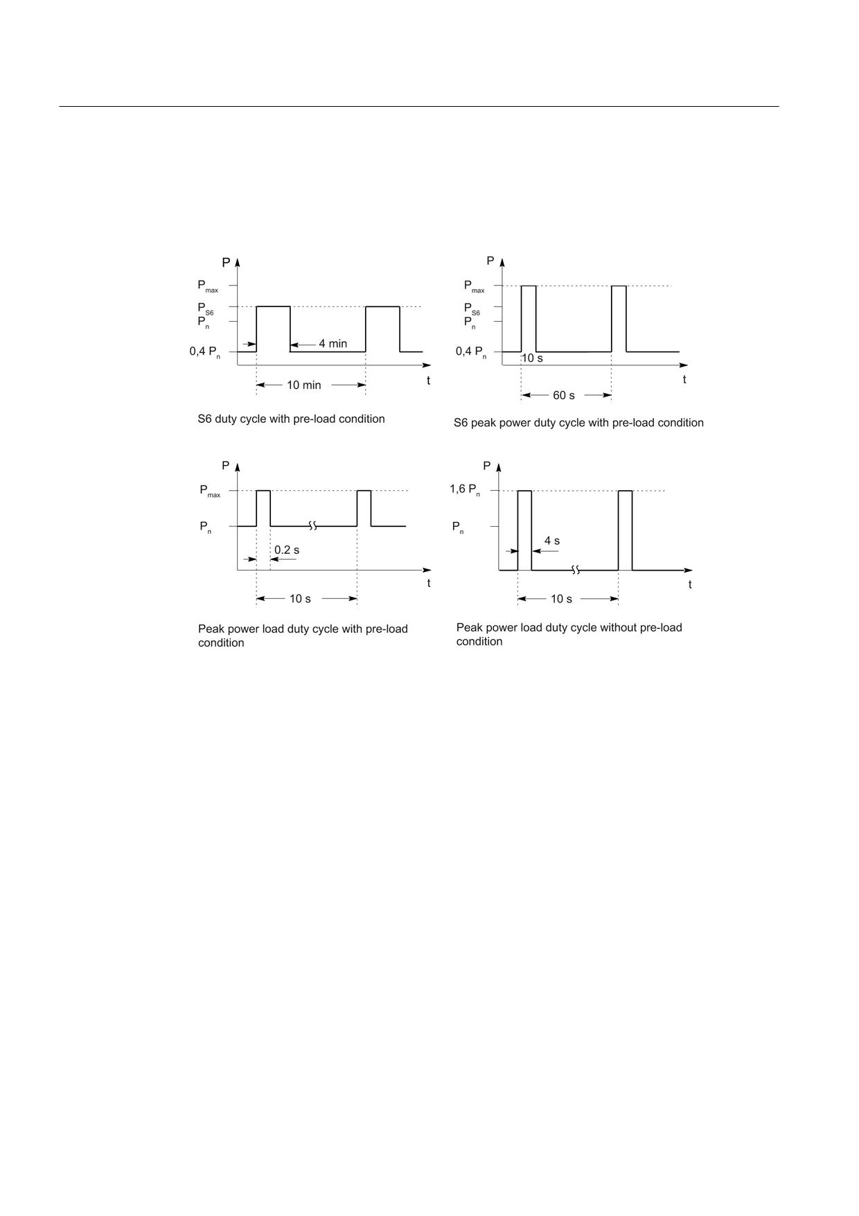
Figure 8-45 Rated duty cycles for Active Line Modules (exception: not applicable for 55 kW Active
Line Module with Active Interface Module)
Guidelines for machine configuration
254
System Manual, MA 01/2013, 6FC5397-6CP10-0BA2
Connection of the components in SINAMICS drive system
8.3 Connection of line modules
Rated duty cycles for Active Line Modules with Active Interface Modules
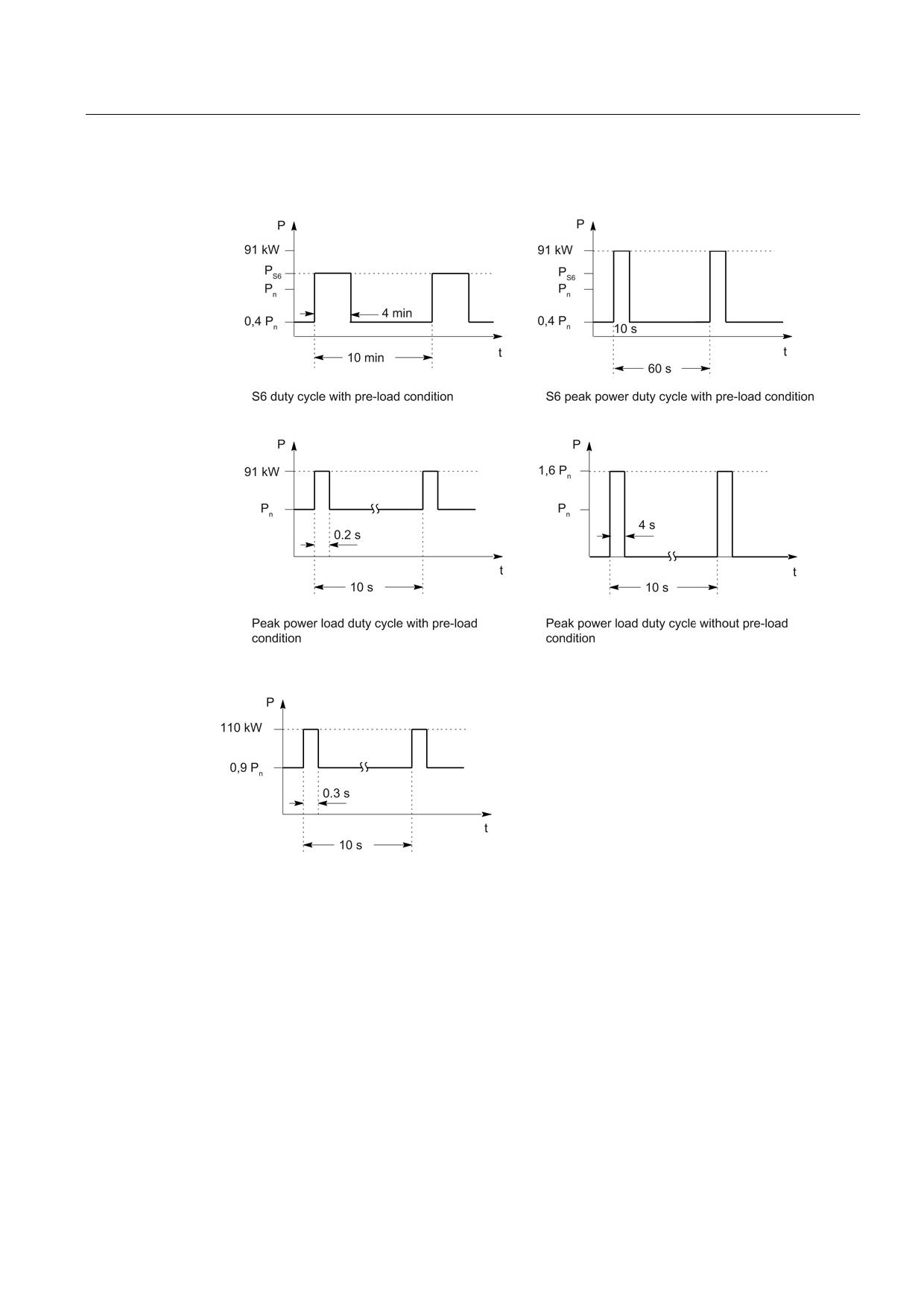
Figure 8-46 Duty cycles for 55 kW Active Line Modules with Active Interface Modules
Figure 8-47 Peak duty cycle with initial load for 55 kW Active Line Modules with Active Interface
Modules
Guidelines for machine configuration
System Manual, MA 01/2013, 6FC5397-6CP10-0BA2
255
Connection of the components in SINAMICS drive system
8.3 Connection of line modules
Derating characteristics
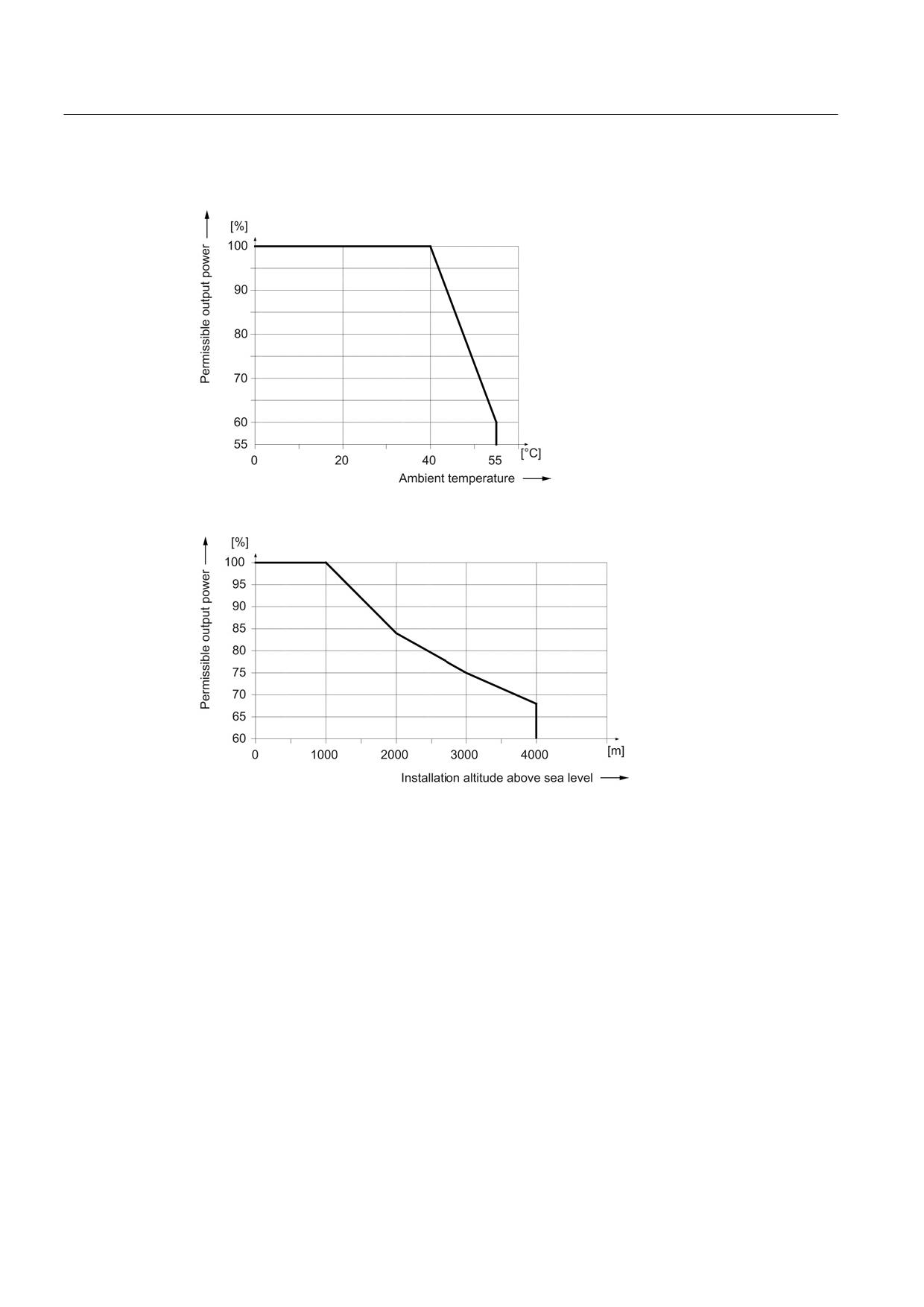
Figure 8-48 Output power as a function of the ambient temperature
Figure 8-49 Output power as a function of the installation altitude
At installation altitudes > 2000 m, an isolation transformer must be used (see the chapter
titled "System overview/Function of installation altitude and ambient temperature"
(Page 32)). The design of the secondary line system must be as follows:
● TN system with grounded neutral point (no grounded line conductor)
● IT system
A reduction of the line supply voltage phase-phase is not necessary.
Guidelines for machine configuration
256
System Manual, MA 01/2013, 6FC5397-6CP10-0BA2
Connection of the components in SINAMICS drive system
8.3 Connection of line modules
8.3.6
Active Line Modules Liquid Cooled
8.3.6.1
Description
Active Line Modules generate a constant, regulated DC voltage in the DC link from the three-
phase line voltage that supplies the connected Motor Modules with power.
This ensures that they are not influenced by network fluctuations.
When the motors are in feedback mode, Active Line Modules supply power back to the
system. The regenerative feedback capability of the modules can be deactivated by
parameterization.
The DC link starts precharging as soon as the line voltage is applied and is independent of
its phase sequence direction. Load can be applied to the DC link after the module has been
enabled. An optional line contactor is required for disconnecting the voltage.
Active Line Modules can be directly connected to TN and TT systems - both with grounded
neutral point and also with grounded line conductor; they can also be connected to IT
systems. The Line Modules have an integrated overvoltage protection function.
Guidelines for machine configuration
System Manual, MA 01/2013, 6FC5397-6CP10-0BA2
257
Connection of the components in SINAMICS drive system
8.3 Connection of line modules
8.3.6.2
Interface description
Overview
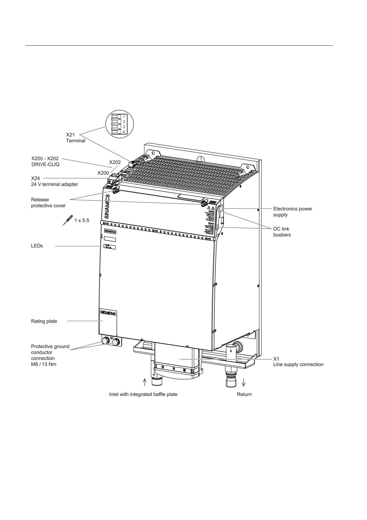
Figure 8-50 Interface overview, Active Line Module Liquid Cooled (120 kW)
Guidelines for machine configuration
258
System Manual, MA 01/2013, 6FC5397-6CP10-0BA2
Connection of the components in SINAMICS drive system
8.3 Connection of line modules
X1 line connection
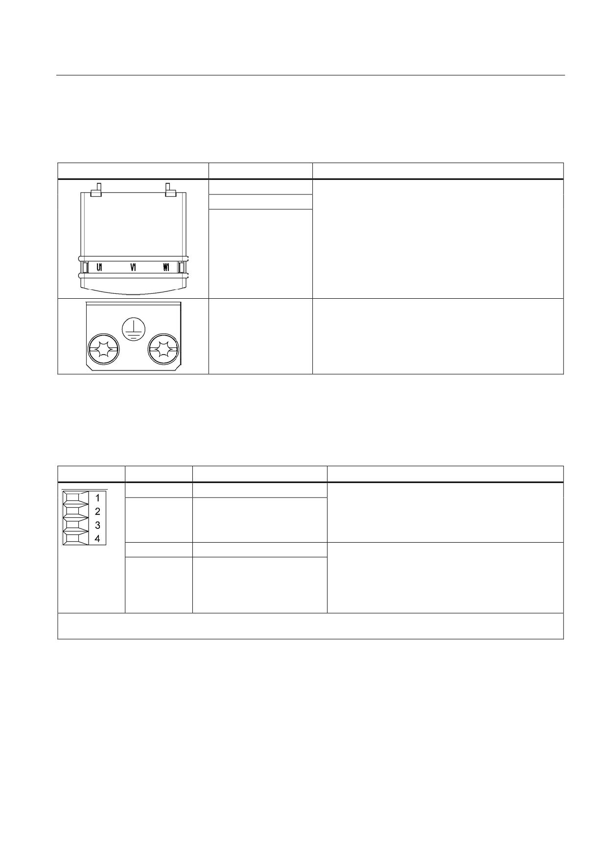
Table 8- 42 X1 line connection
Terminals
Technical specifications
U1
Supply voltage:
V1
380 V - 480 V 3 AC, 50 / 60 Hz
W1
Threaded bolts M8 / 13 Nm 1)
PE connection
Threaded hole M8 / 13 Nm 1)
1) For ring cable lugs in accordance with DIN 46234
X21 EP terminals
Table 8- 43 X21 EP terminal/temperature sensor
Terminal
Designation
Technical data
1
+ Temp
Temperature sensors1): KTY84-
1C1302)/PTC2)/bimetallic switch with NC contact
2
- Temp
If an Active Interface Module is used, the temperature
input must be connected to the Active Interface Module
sensor (bimetallic switch with NC contact).
3
EP +24 V (Enable Pulses)
Voltage 24 VDC
Current consumption: 10 mA
4
EP M (Enable Pulses)
Isolated input
Signal propagation times:
L → H: 100 μs
H → L: 1000 μs
Max. connectable cross-section: 1.5 mm2
Type: Screw terminal 1 (see Appendix, Chapter "Screw terminals")
1) The temperature sensor type can be selected via parameter p0601; the temperature is displayed via r0035 (see
SINAMICS S120/S150 List Manual LH1).
2) Temperatures are detected but not evaluated in the Active Line Module.
Guidelines for machine configuration
System Manual, MA 01/2013, 6FC5397-6CP10-0BA2
259
Connection of the components in SINAMICS drive system
8.3 Connection of line modules
CAUTION
Connecting the temperature sensor
If an Active Interface Module is connected, the temperature output of the Active Interface
Module must be connected to terminals 1 and 2.
WARNING
Danger to life due to charged DC link
For operation, the 24 VDC voltage must be connected to terminal 3 and ground to terminal
4. When withdrawn, pulse suppression is activated. Regenerative feedback is deactivated
and the bypass relay drops out. If the Line Module is not disconnected from the supply
system when the EP terminal is deactivated (e.g. a line contactor is not installed), the DC
link remains charged.
Note
If an active drive line-up is switched off by means of the disconnector unit, the voltage at
terminals 3 (EP +24 V) and 4 (EP M) must be interrupted beforehand. This can be carried
out using a leading breaking auxiliary contact (≥ 10 ms), for example.
This protects external loads located parallel to the drive on the same switching component.
DANGER
Risk of electric shock!
Only temperature sensors that meet the safety isolation specifications contained in
EN 61800-5-1 may be connected to terminals "+Temp" and "-Temp". If safe electrical
separation cannot be guaranteed (for linear motors or third-party motors, for example), a
Sensor Module External (SME120 or SME125) or Terminal Module TM120 must be used.
If these instructions are not complied with, there is a risk of electric shock!
Guidelines for machine configuration
260
System Manual, MA 01/2013, 6FC5397-6CP10-0BA2
Connection of the components in SINAMICS drive system
8.3 Connection of line modules
X24 24 V terminal adapter
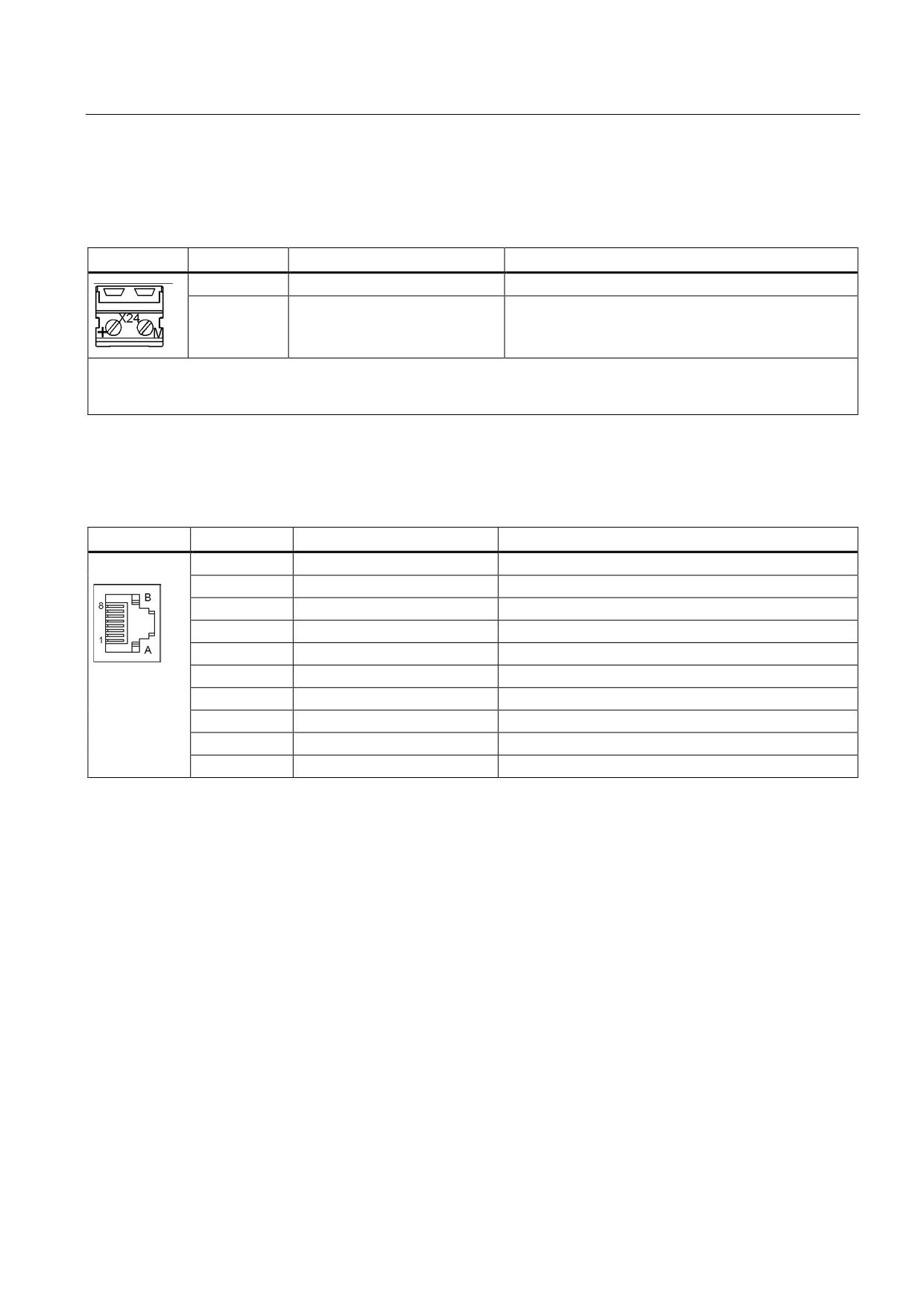
Table 8- 44 X24 24 V terminal adapter
Terminal
Description
Technical specifications
+
24 V power supply
24 VDC supply voltage
M
Ground
Electronics ground
The 24 V terminal adapter is included in the scope of delivery.
Max. connectable cross-section: 6 mm2
Type: Screw terminal 5 (see Appendix, Chapter "Screw terminals")
X200-X202 DRIVE-CLiQ interfaces
Table 8- 45 X200-X202 DRIVE-CLiQ interfaces
PIN
Signal name
Technical specifications
1
TXP
Transmit data +
2
TXN
Transmit data -
3
RXP
Receive data +
4
Reserved, do not use
5
Reserved, do not use
6
RXN
Receive data -
7
Reserved, do not use
8
Reserved, do not use
A
+(24 V)
24 V power supply
B
M (0 V)
Electronics ground
The blanking covers for the DRIVE-CLiQ interfaces are included in the scope of delivery.
Blanking cover (50 pcs.) Order number: 6SL3066-4CA00-0AA0
Guidelines for machine configuration
System Manual, MA 01/2013, 6FC5397-6CP10-0BA2
261
Connection of the components in SINAMICS drive system
8.3 Connection of line modules
8.3.6.3
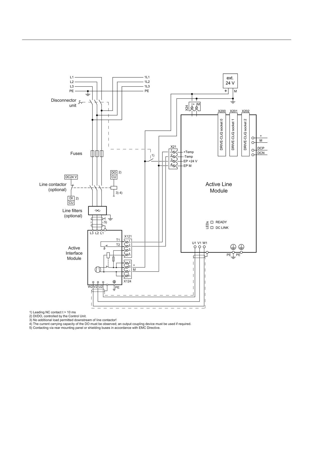
Connection example
Figure 8-51 Example connection of Active Line Module
Guidelines for machine configuration
262
System Manual, MA 01/2013, 6FC5397-6CP10-0BA2
Connection of the components in SINAMICS drive system
8.3 Connection of line modules
8.3.6.4
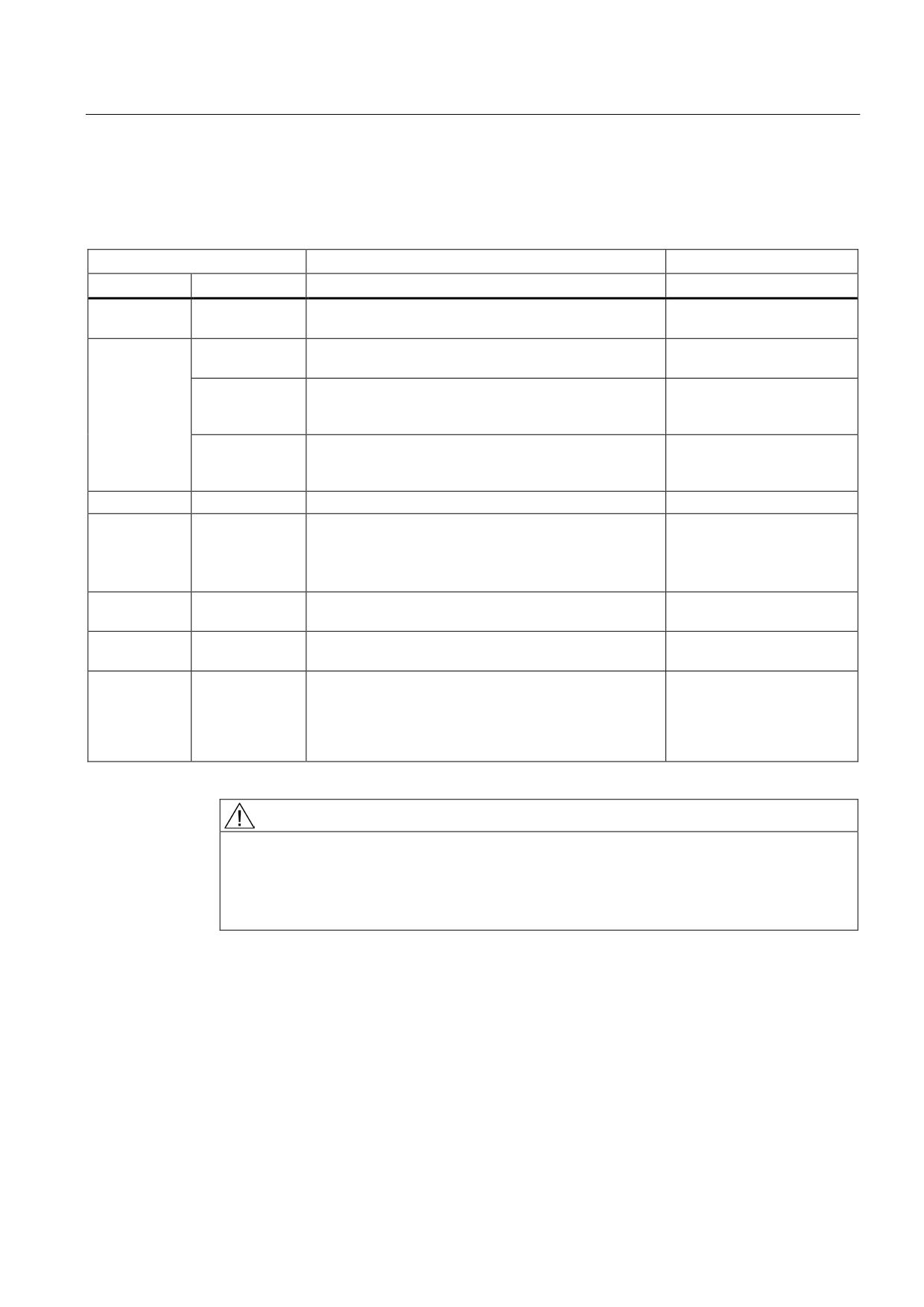
Meaning of LEDs
Table 8- 46 Meaning of the LEDs on the Active Line Module
Status
Description, cause
Remedy
RDY
DC LINK
Off
Off
Electronics power supply is missing or outside
-
permissible tolerance range.
Green
--
The component is ready for operation and cyclic DRIVE-
-
CLiQ communication is taking place.
Orange
The component is ready for operation and cyclic DRIVE-
-
CLiQ communication is taking place.
The DC link voltage is present.
Red
The component is ready for operation and cyclic DRIVE-
Check line voltage
CLiQ communication is taking place.
The DC link voltage is too high.
Orange
Orange
DRIVE-CLiQ communication is being established.
-
Red
--
At least one fault is present in this component.
Remedy and acknowledge
fault
Note:
The LED is activated regardless of whether the
corresponding messages have been reconfigured.
Green/red
--
Firmware is being downloaded.
-
(0.5 Hz)
Green/red
--
Firmware download is complete. Wait for POWER ON.
Carry out a POWER ON
(2 Hz)
Green/orange
--
Detection of the components via LED is activated
-
or
(p0124).
Red/orange
Note:
Both options depend on the LED status in the case of
activation via p0124 = 1.
WARNING
Danger to life due to high DC link voltage, regardless of LED display
Hazardous DC link voltages may be present at any time regardless of the status of the
"DC LINK" LED.
• Observe the warning information on the component.
Guidelines for machine configuration
System Manual, MA 01/2013, 6FC5397-6CP10-0BA2
263
Connection of the components in SINAMICS drive system
8.3 Connection of line modules
8.3.6.5
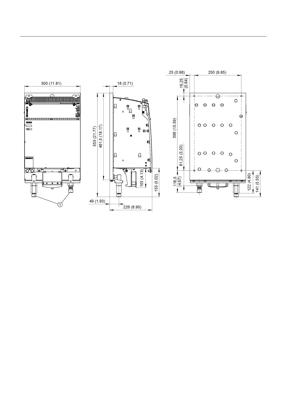
Dimension drawing
①
Pipe thread ISO 228 G ½ B.
Figure 8-52 Dimension drawing of Active 120 kW Line Module Liquid Cooled, all dimensions in mm and (inches)
Guidelines for machine configuration
264
System Manual, MA 01/2013, 6FC5397-6CP10-0BA2
Connection of the components in SINAMICS drive system
8.3 Connection of line modules
8.3.6.6
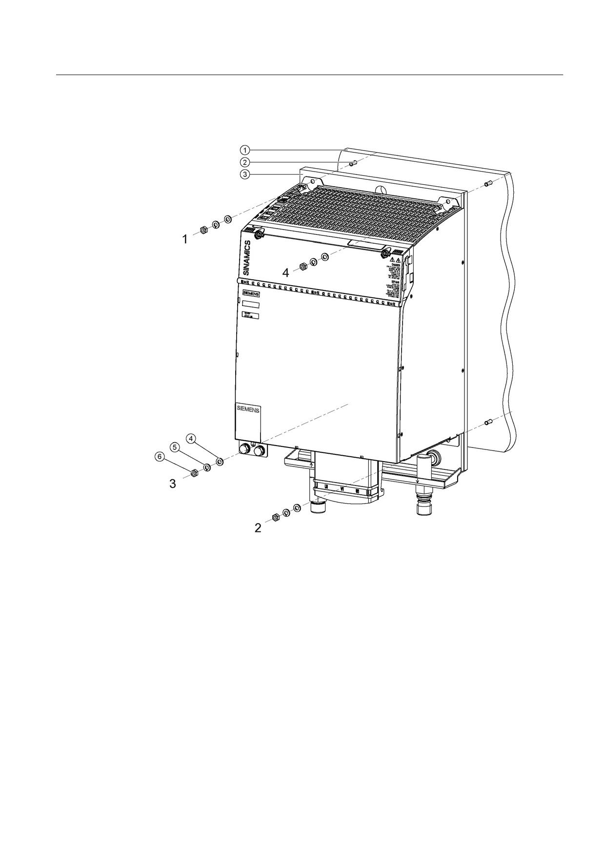
Installation
①
Mounting surface
②
M6 studs
③
Heat sink
④
Washer
⑤
Spring washer
⑥
M6 nut
Figure 8-53 Mounting an Active Line Module Liquid Cooled
Guidelines for machine configuration
System Manual, MA 01/2013, 6FC5397-6CP10-0BA2
265
Connection of the components in SINAMICS drive system
8.3 Connection of line modules
Tightening torques:
● Initially, tighten the nuts by hand (0.5 Nm)
● Then tighten with 10 Nm (in the specific sequence 1 to 4)
For installation, M6 screw bolts and hexagon nuts/grub screws ISO 7436-M6x40-14 H,
property class 8.8 are recommended.
The coolant connections are located on the lower side of the components. All connection
elements can be accessed using an appropriate tool.
● Thread type of water connections: Pipe thread ISO 228 G ½ B.
8.3.6.7
Technical specifications
Table 8- 47 Technical data for an Active Line Module Liquid Cooled
Liquid Cooled
6SL3135-7TE31-2AA3
Rated power
kW
120
Infeed
Rated power (S1)1)
kW (Pn)
120
Infeed power (S6-40%)1)
kW (PS6)
145
Peak infeed power1)
kW (Pmax)
175
Energy recovery
Continuous regenerative power
kW
120
Peak regenerative power
kW
175
Supply voltages
Line voltage
VACrms
3 AC 380 to 480 ±10% (-15% < 1 min)
Line frequency
Hz
47 to 63
Electronics power supply
VDC
24 (20.4 - 28.8)
DC link voltage
VDC
510 - 720
Overvoltage trip
VDC
820 ±2%
Undervoltage trip2)
VDC
360 ±2%
Input currents
Rated input current at 400 VAC:
AAC
182
Input current
at 380 VAC/480 VAC
AAC
192 / 152
at 400 VAC; S6-40%
AAC
220
at 400 VAC; peak current
AAC
267
DC link currents
Rated DC link current at 600 V:
ADC
200
DC link current:
at 600 VDC; at S6-40%
ADC
244
at 600 VDC; peak current
ADC
292
Current-carrying capacity
DC link busbar:
ADC
200
24 V busbar:
ADC
20
Electronics current consumption at 24 V DC
ADC
1.8
Total power loss
W
2243.2
(including electronics losses)3)
Guidelines for machine configuration
266
System Manual, MA 01/2013, 6FC5397-6CP10-0BA2
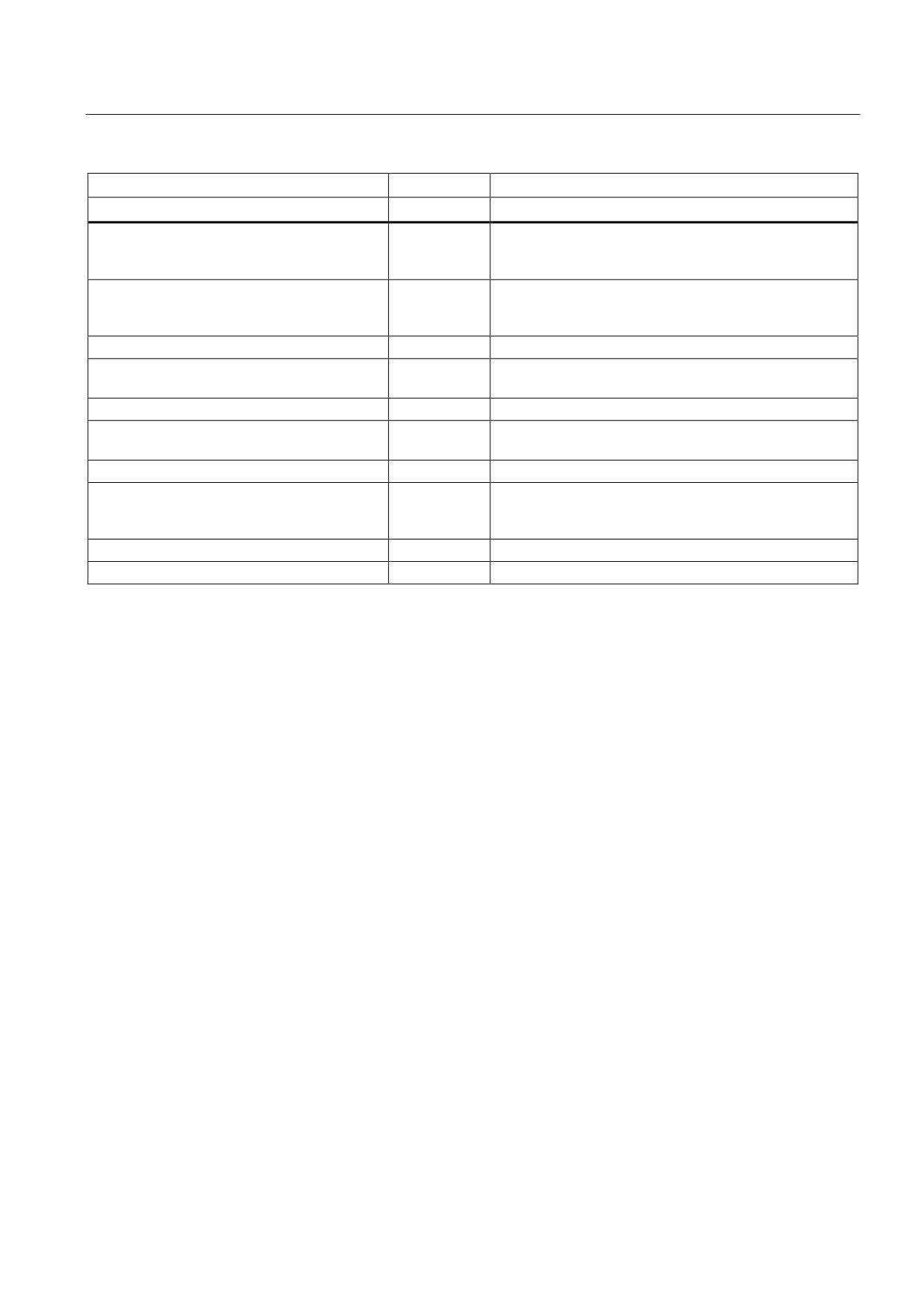
Connection of the components in SINAMICS drive system
8.3 Connection of line modules
Liquid Cooled
6SL3135-7TE31-2AA3
Rated power
kW
120
Max. ambient temperature
without derating
°C
40
with derating
°C
55
DC link capacitance:
Active Line Module
μF
3995
Drive line-up, max.
μF
20000
Power factor
cosϕ
1
Circuit breaker (IEC 60947 and UL)
See Chap. "Overcurrent protection using line fuses and
circuit breakers (Page 116)"
Rated short-circuit current SCCR4)
kA
65
Rated volumetric flow for water
l/min
8
at 70 kPa pressure drop5)
Volume of liquid internal
ml
100
Max. coolant temperature
without derating
°C
45
with derating
°C
50
Max. permissible heat sink temperature
°C
80
Weight
kg
23
1)
The specified power ratings apply to the line voltage range from 380 V to 480 V
2)
Default for 400 V line systems; undervoltage trip threshold is adjusted to the parameterized rated voltage
3)
For an overview, see the power loss tables in the Appendix
4)
The resulting rated short-circuit current is obtained from the combination of the fuse, or circuit breaker, and the Line
Module in the drive system.
5)
This value applies to the water coolant option; for other coolant types, see the SINAMICS S120 Booksize Power Units
Equipment Manual (GH2), Chapter "Cooling circuit and coolant properties".
Guidelines for machine configuration
System Manual, MA 01/2013, 6FC5397-6CP10-0BA2
267
Connection of the components in SINAMICS drive system
8.3 Connection of line modules
Characteristics
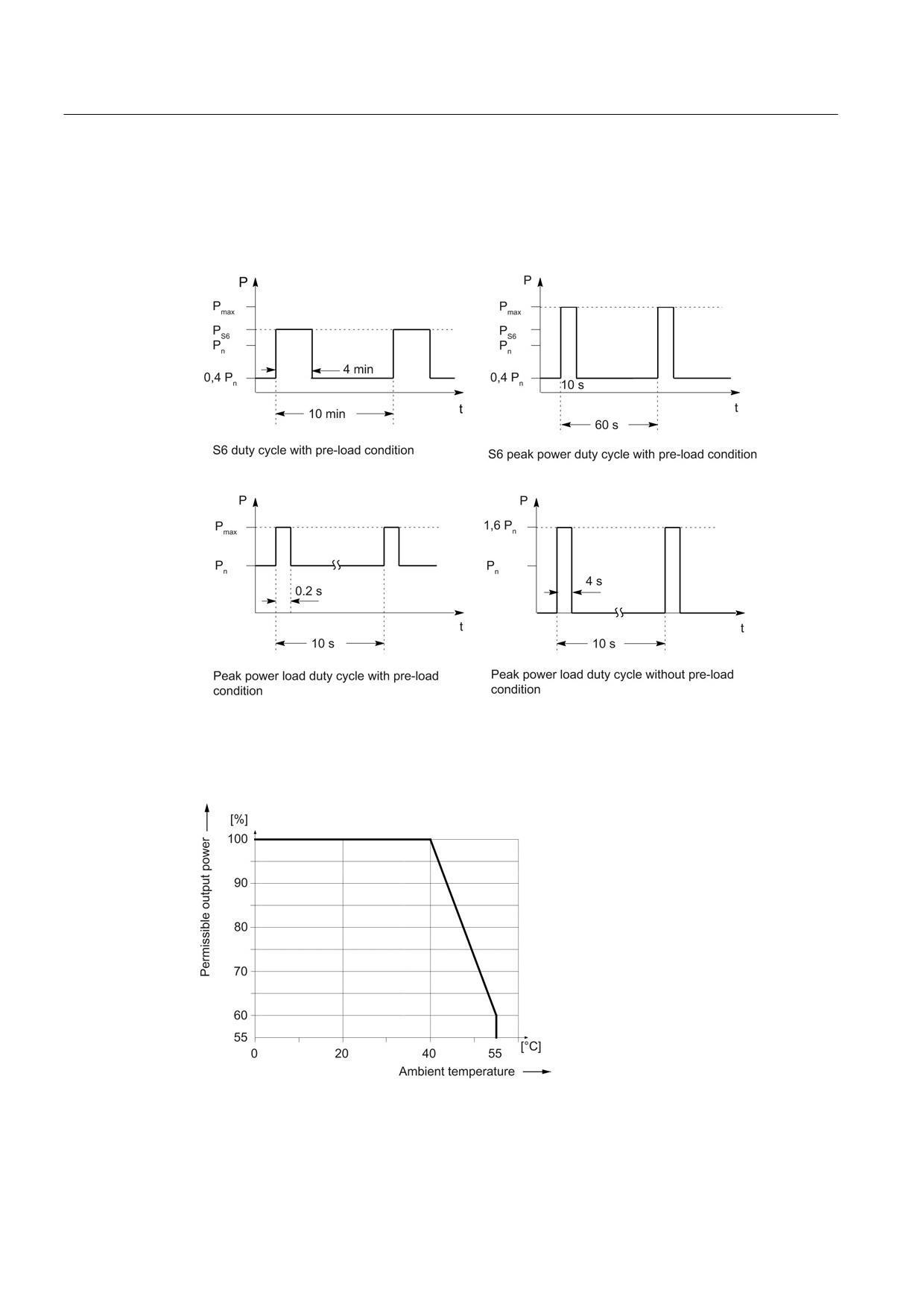
Rated duty cycles of Active Line Modules Liquid Cooled
Figure 8-54 Rated duty cycles of Active Line Modules
Derating characteristics
Figure 8-55 Output power as a function of the ambient temperature
Guidelines for machine configuration
268
System Manual, MA 01/2013, 6FC5397-6CP10-0BA2
Connection of the components in SINAMICS drive system
8.3 Connection of line modules
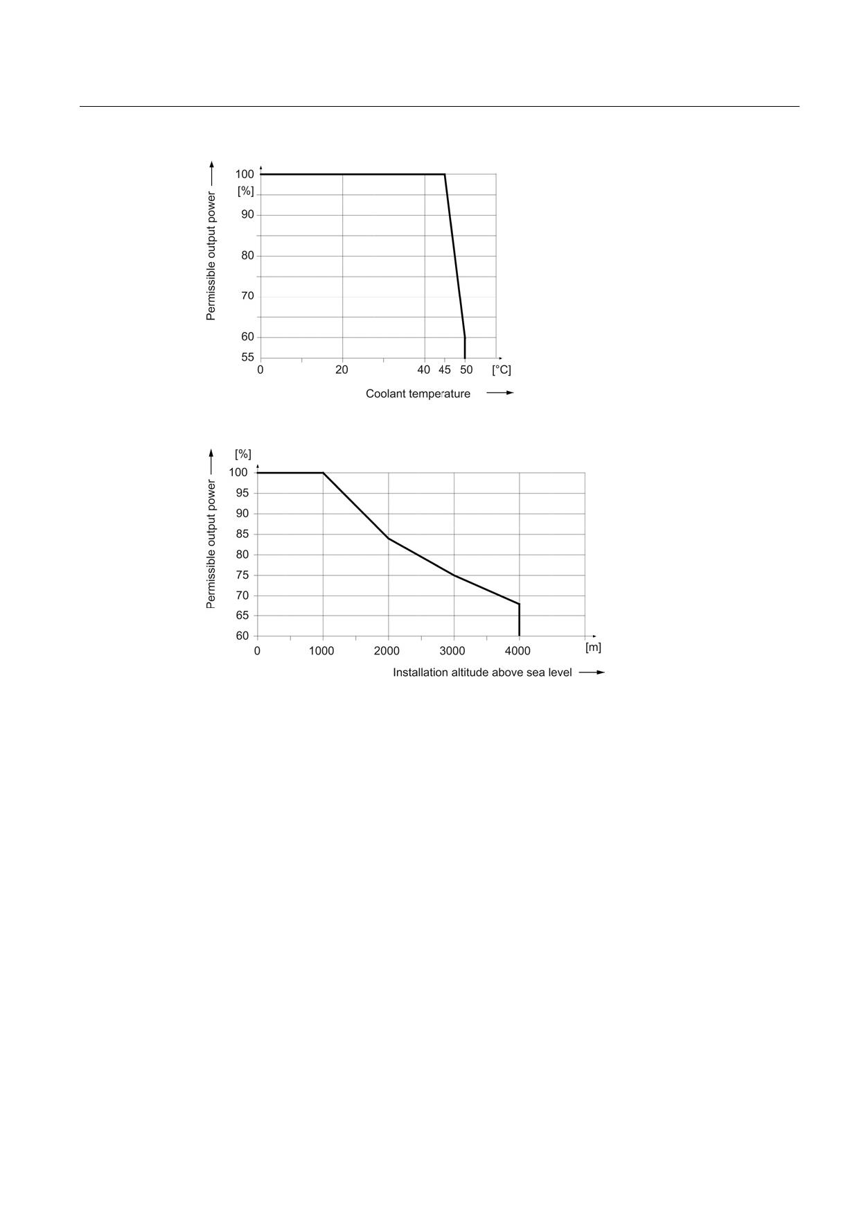
Figure 8-56 Output power as a function of the coolant temperature
Figure 8-57 Output power as a function of the installation altitude
At installation altitudes > 2000 m, an isolation transformer must be used (see the chapter
titled "System overview/Function of installation altitude and ambient temperature"
(Page 32)). The design of the secondary line system must be as follows:
● TN system with grounded neutral point (no grounded line conductor)
● IT system
A reduction of the line supply voltage phase-phase is not necessary.
Guidelines for machine configuration
System Manual, MA 01/2013, 6FC5397-6CP10-0BA2
269
Connection of the components in SINAMICS drive system
8.3 Connection of line modules
8.3.7
Smart Line Modules with internal air cooling
8.3.7.1
Description
The Smart Line Module is a non-regulated infeed/regenerative feedback unit. The Smart
Line Module supplies the Motor Module(s) with a non-regulated DC voltage at the DC output.
In the infeed mode the Smart Line Module exhibits the typical current and voltage waveforms
of a 6-pulse diode rectifier bridge.
In feedback mode, the current waveform is square waved. Regenerative feedback can be
deactivated if required. On 5 kW and 10 kW Smart Line Modules, this is done via a terminal,
since these modules do not feature a DRIVE-CLiQ connection. On 16 kW to 55 kW Smart
Line Modules, regenerative feedback can be deactivated via parameters, as, just like Active
Line Modules, these modules are equipped with a DRIVE-CLiQ connection.
The DC link starts precharging as soon as the supply voltage is applied and is independent
of its phase sequence direction. Load can be applied to the DC link after the module has
been enabled. An optional main contactor is required for disconnecting the voltage.
Smart Line Modules are suitable for direct operation on TN, IT, and TT systems. The
modules have an integrated overvoltage protection function.
Guidelines for machine configuration
270
System Manual, MA 01/2013, 6FC5397-6CP10-0BA2
Connection of the components in SINAMICS drive system
8.3 Connection of line modules
8.3.7.2
Product-specific safety information for the Smart Line Modules in booksize format
The safety instructions described in this chapter apply specifically to Smart Line Modules in
booksize format.
In addition, you should strictly observe the safety instructions in Chapter 1.
NOTICE
Device damage due to incorrect activation or deactivation sequence
It is essential that a particular switch-on and switch-off sequence is followed in order to
control the 5 kW and 10 kW Smart Line Modules; if this sequence is not observed, the
Smart Line Module could be damaged beyond repair. To prevent the SLM being destroyed,
the "Ready" signal must be evaluated at output terminal X21.1.
Activation:
•
24 VDC power supply X24 ON
• Line contactor ON
• EP signal X21 pins 3 and 4 ON
• Wait until precharging is complete
• "Ready" signal at terminal X21 pin 1 set to "high"
• Infeed is ready, pulse enable possible for motors
Deactivation:
• Shut drives down
• Cancel pulse enable for motors (OFF1 signal)
• EP signal X21 pins 3 and 4 OFF
• Line contactor OFF
•
24 VDC power supply X24 OFF
Overload:
• "Prewarning" signal at terminal X21 pin 2 set to "low"
• Shut drives down via the control system
• "Ready" signal at terminal X21 pin 1 set to "low"
• Pulse inhibit for all the drives supplied by this infeed within 4 ms
Note
Operation without the line reactor is not permissible.
Guidelines for machine configuration
System Manual, MA 01/2013, 6FC5397-6CP10-0BA2
271
Connection of the components in SINAMICS drive system
8.3 Connection of line modules
Note
Connection to the public low-voltage network
Smart Line Modules have been designed for use in the industrial environment and generate
current harmonics on the line side as a result of the rectifier circuit.
When connecting a machine with integrated Smart Line Modules to the public low-voltage
network, authorization is required in advance from the local power supply company (utility
company) if
• The rated current of the machine ≤ 16 A per conductor, and
• The rated machine current does not comply with the requirements specified in EN 61000-
3-2 regarding current harmonics.
Guidelines for machine configuration
272
System Manual, MA 01/2013, 6FC5397-6CP10-0BA2
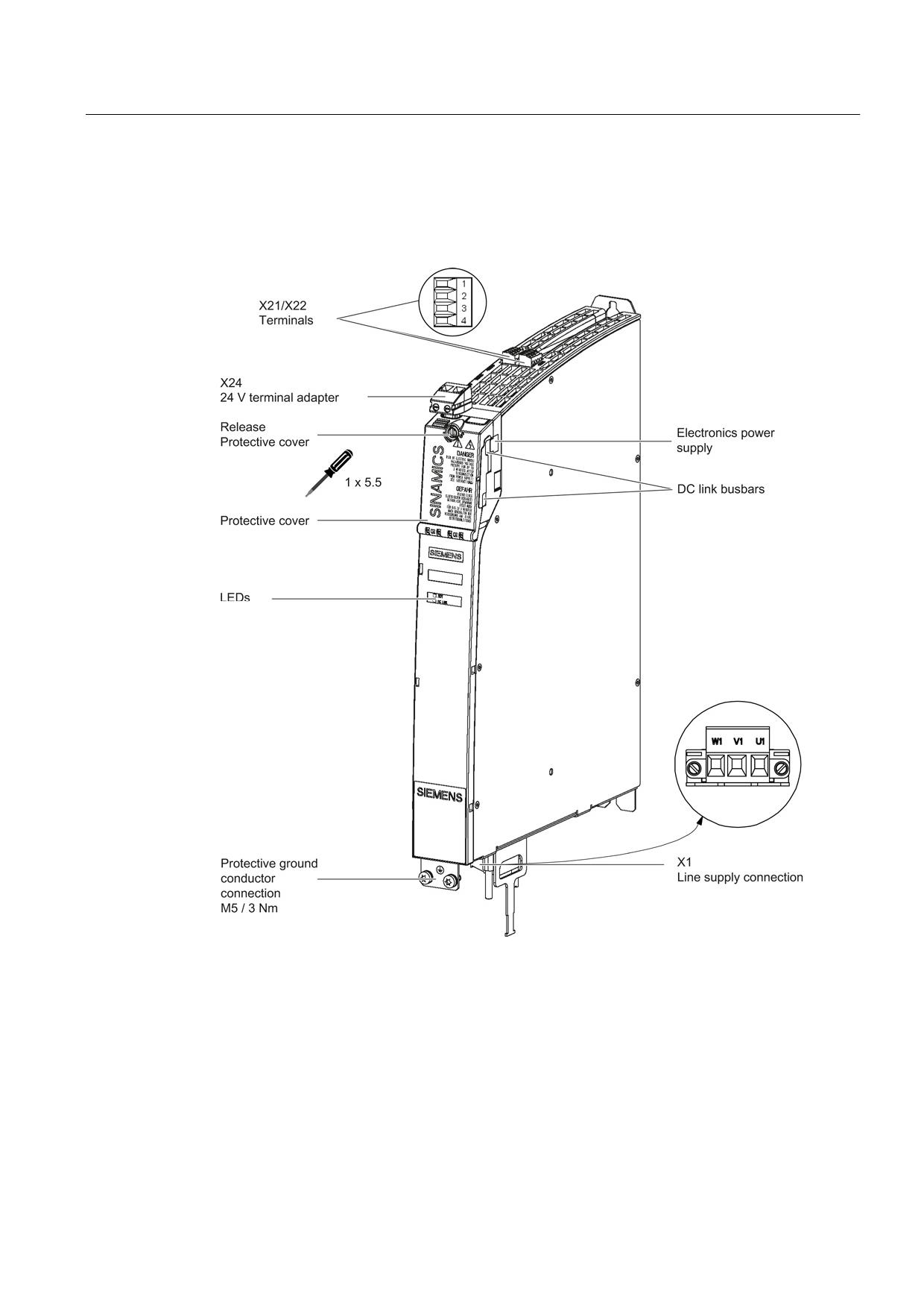
Connection of the components in SINAMICS drive system
8.3 Connection of line modules
8.3.7.3
Interface description
Overview
Figure 8-58 Interface overview, 5 kW and 10 kW Smart Line Modules with internal air cooling
(example: 5 kW)
Guidelines for machine configuration
System Manual, MA 01/2013, 6FC5397-6CP10-0BA2
273
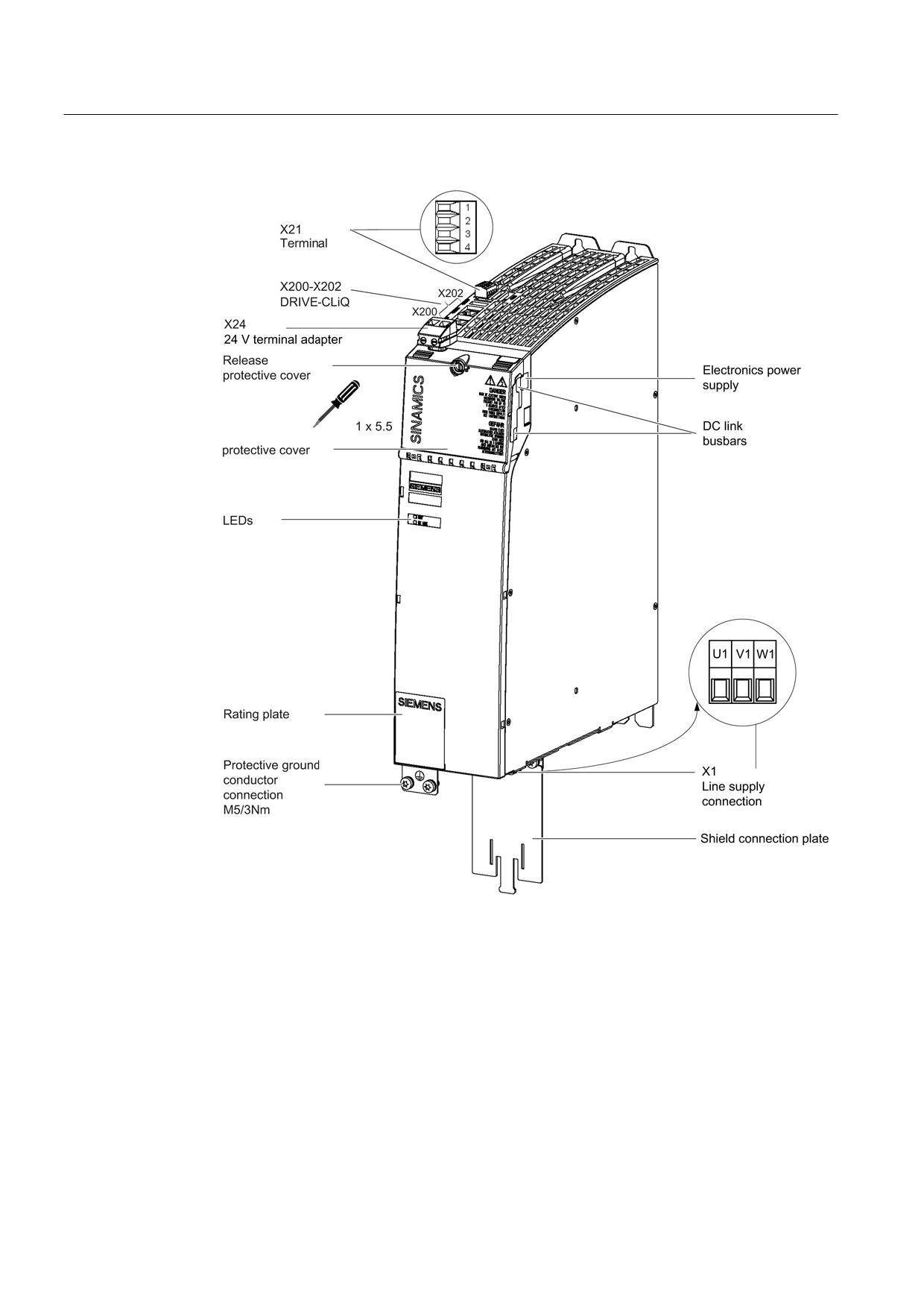
Connection of the components in SINAMICS drive system
8.3 Connection of line modules
Figure 8-59 Interface overview, 16 kW Smart Line Module with internal air cooling
Guidelines for machine configuration
274
System Manual, MA 01/2013, 6FC5397-6CP10-0BA2
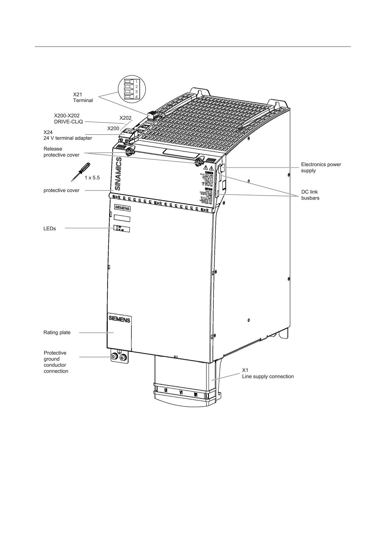
Connection of the components in SINAMICS drive system
8.3 Connection of line modules
Figure 8-60 Interface overview, 36 kW and 55 kW Smart Line Modules with internal air cooling (example: 55 kW)
Guidelines for machine configuration
System Manual, MA 01/2013, 6FC5397-6CP10-0BA2
275
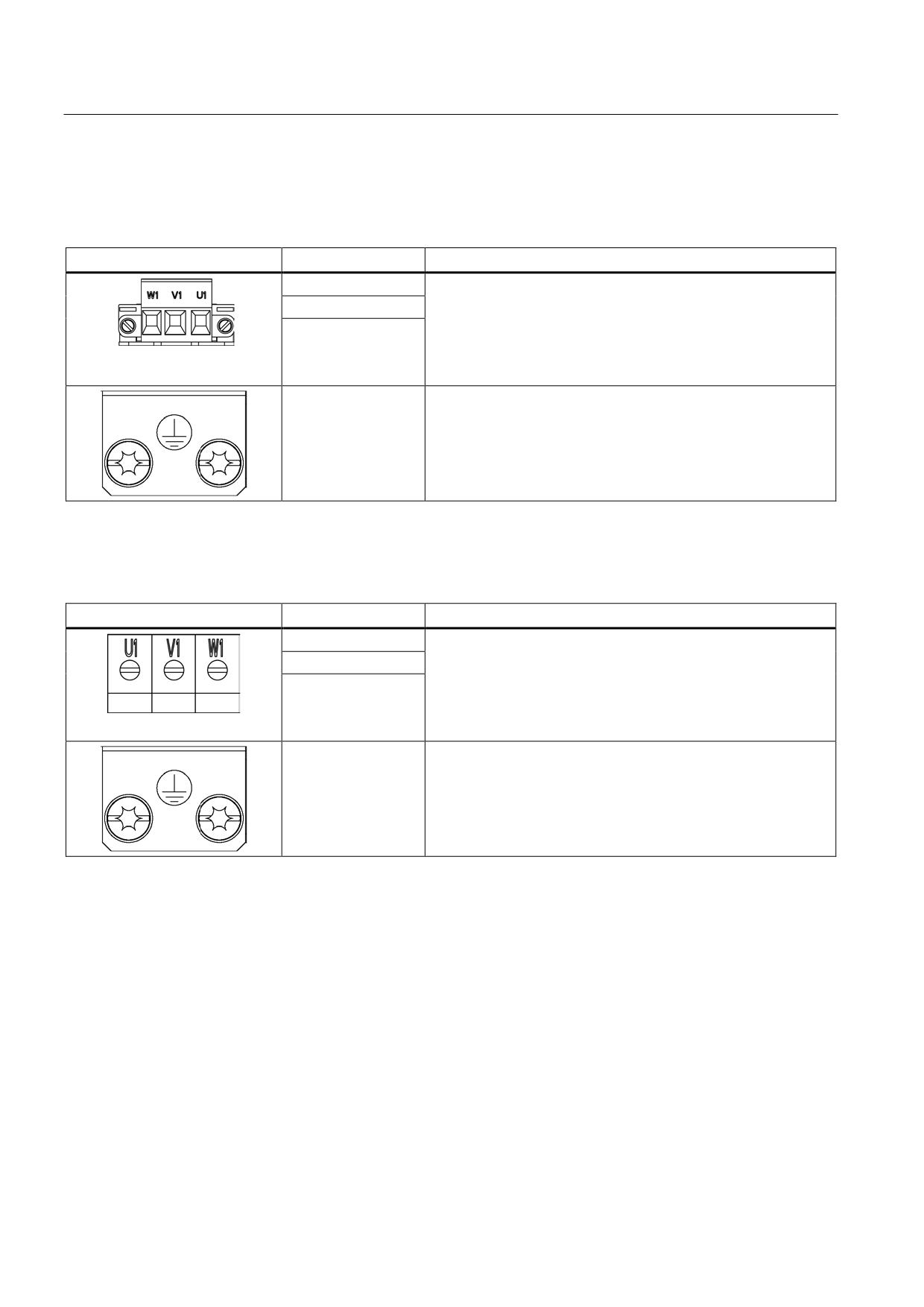
Connection of the components in SINAMICS drive system
8.3 Connection of line modules
X1 line connection
Table 8- 48 X1: Line connection for Smart Line Modules 5 kW and 10 kW
Terminal
Technical specifications
U1
Supply voltage:
3 AC 380 V - 480 V, 50/60 Hz
V1
Max. connectable cross-section: 6 mm2
W1
Type: Screw terminal 5 (see Appendix, Chapter "Screw
terminals")
Tightening torque: 1.2 - 1.5 Nm
PE connection
Threaded hole M5/3 Nm 1)
1) For ring cable lugs in accordance with DIN 46234
Table 8- 49 X1: Line supply connection for Smart Line Modules 16 kW
Terminal
Technical specifications
U1
Supply voltage:
3 AC 380 V - 480 V, 50/60 Hz
V1
Max. connectable cross-section: 10 mm2
W1
Type: Screw terminal 6 (see Appendix, Chapter "Screw
terminals")
Tightening torque: 1.5 - 1.8 Nm
PE connection
Threaded hole M5/3 Nm 1)
1) For ring cable lugs in accordance with DIN 46234
Guidelines for machine configuration
276
System Manual, MA 01/2013, 6FC5397-6CP10-0BA2
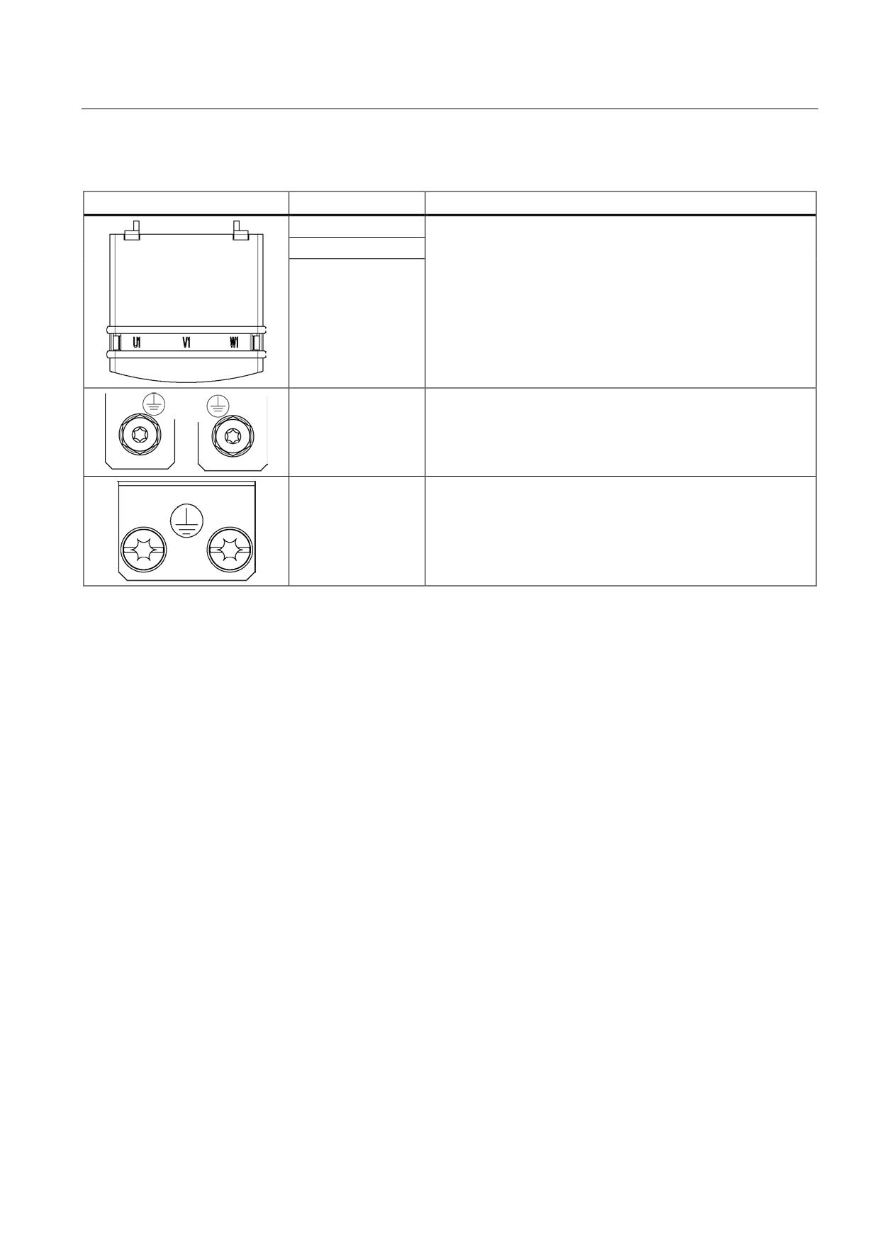
Connection of the components in SINAMICS drive system
8.3 Connection of line modules
Table 8- 50 X1: Line connection for Smart Line Modules 36 kW and 55 kW
Terminal
Technical specifications
U1
Supply voltage:
3 AC 380 V - 480 V, 50/60 Hz
V1
36 kW: Threaded bolt M6/6 Nm 1)
W1
55 kW: Threaded bolt M8/13 Nm 1)
PE connection
36 kW: Threaded hole M6/6 Nm 1)
55 kW: Threaded hole M6/6 Nm 1)
1) For ring cable lugs in accordance with DIN 46234
Guidelines for machine configuration
System Manual, MA 01/2013, 6FC5397-6CP10-0BA2
277