SINUMERIK 840D sl. Service - Configuring Commissioning. Manual (2011-2020) - page 29
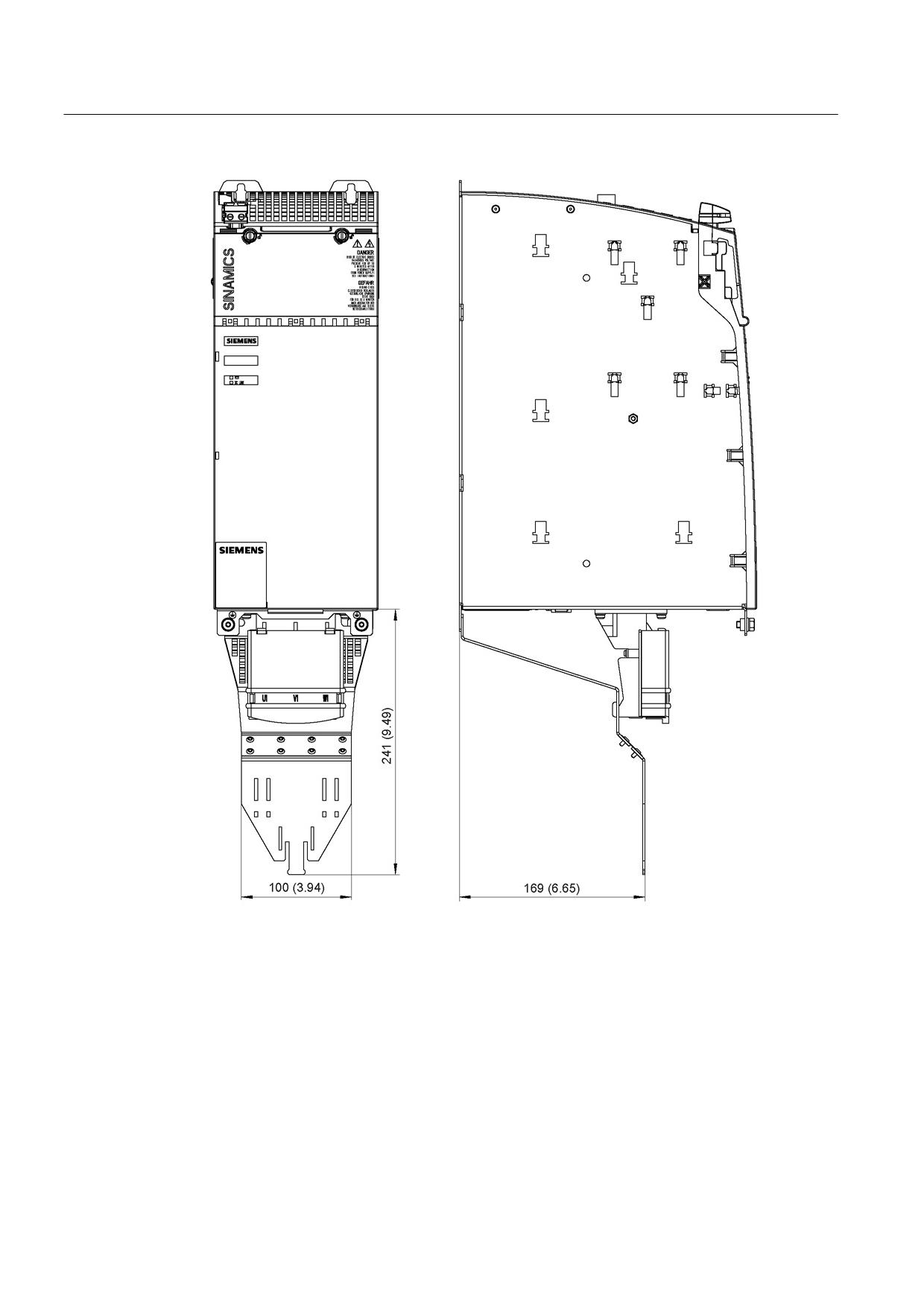
SINAMICS drive line-up
4.3 Shield Connection
Figure 4-15 Dimension drawing of shield connecting plate on a 150 mm component with internal air
cooling, all dimensions in mm and (inches)
Guidelines for machine configuration
70
System Manual, MA 01/2013, 6FC5397-6CP10-0BA2
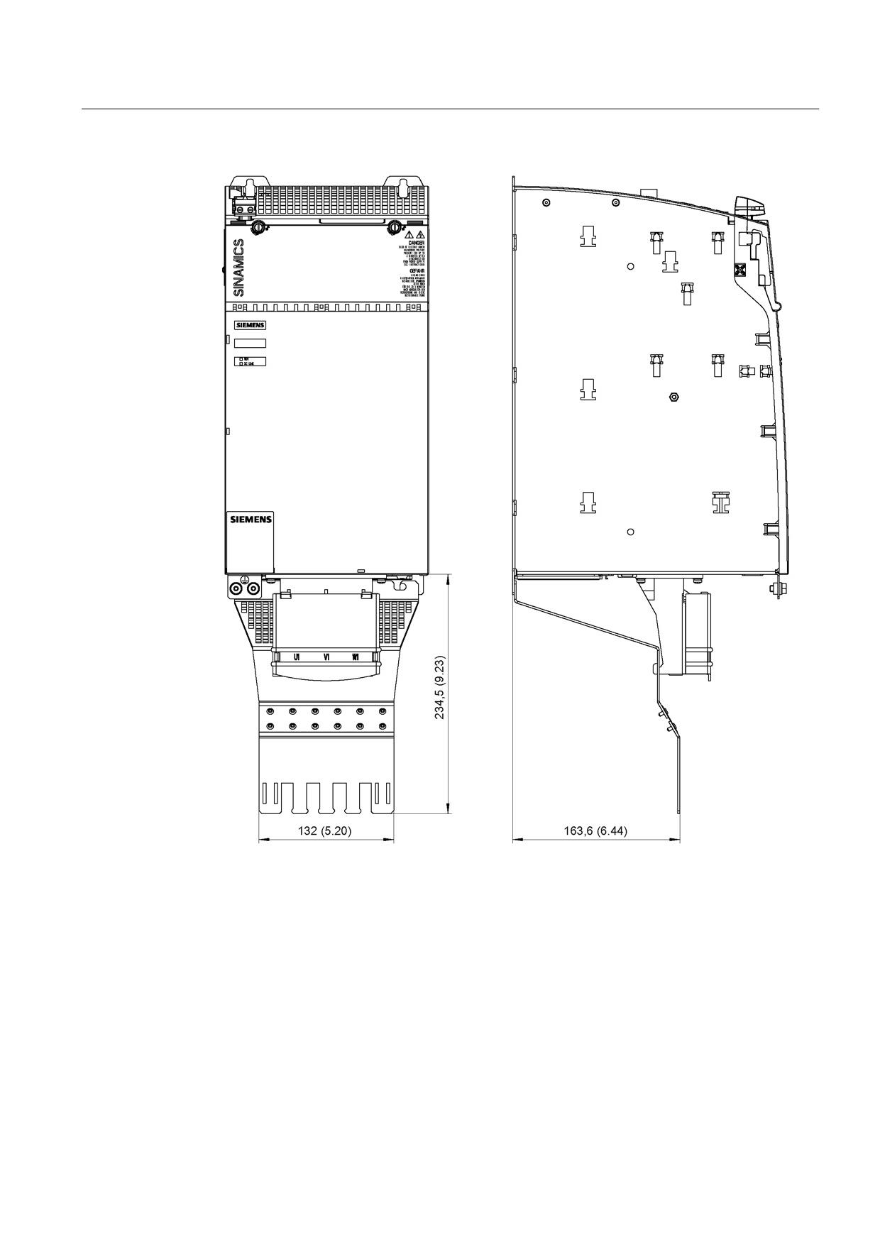
SINAMICS drive line-up
4.3 Shield Connection
Figure 4-16 Dimension drawing of shield connecting plate on a 200 mm component with internal air
cooling, all dimensions in mm and (inches)
Guidelines for machine configuration
System Manual, MA 01/2013, 6FC5397-6CP10-0BA2
71
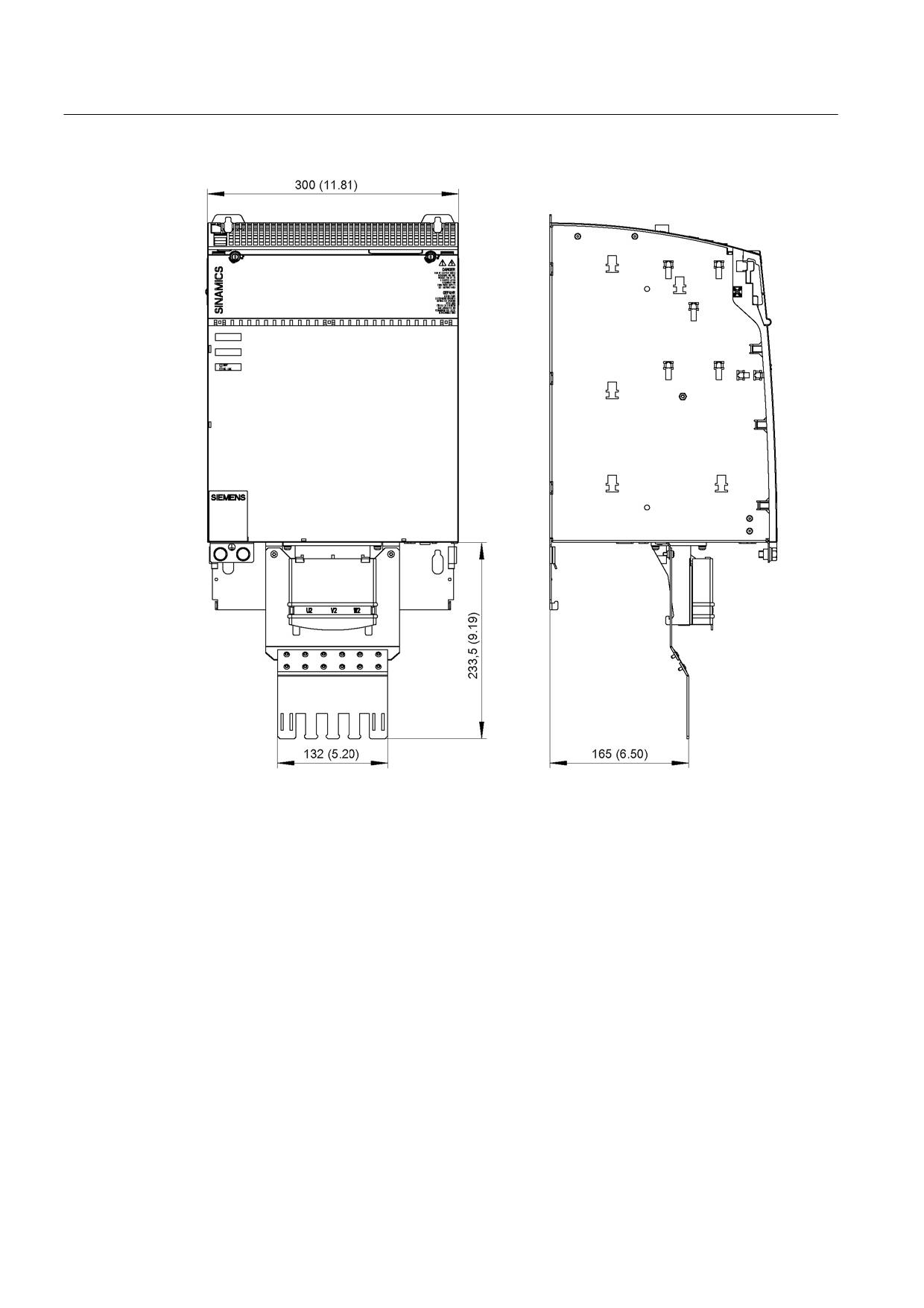
SINAMICS drive line-up
4.3 Shield Connection
Figure 4-17 Dimension drawing of shield connecting plate on a 300 mm component with internal air
cooling, all dimensions in mm and (inches)
Guidelines for machine configuration
72
System Manual, MA 01/2013, 6FC5397-6CP10-0BA2
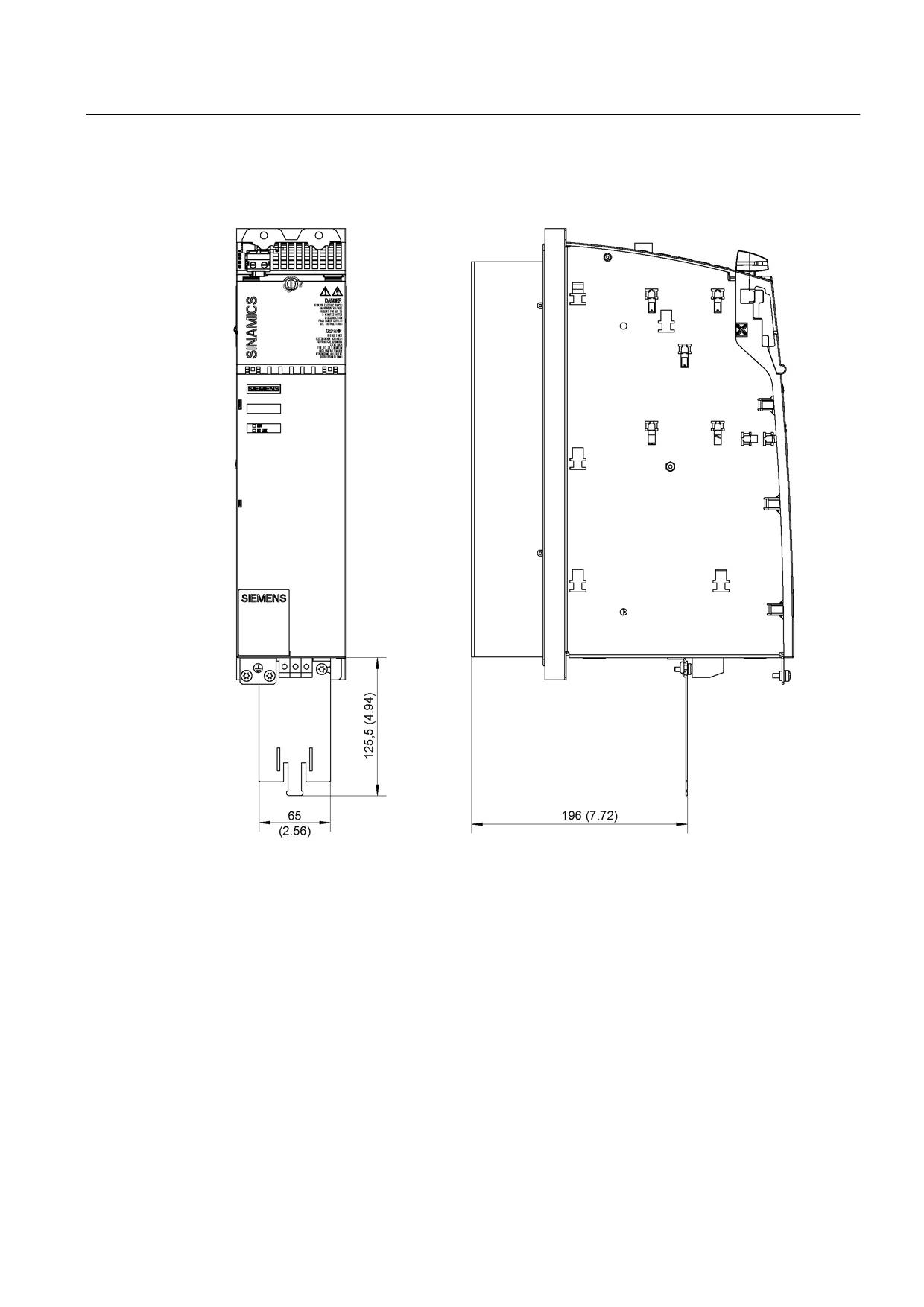
SINAMICS drive line-up
4.3 Shield Connection
4.3.2
SINAMICS Components Dimension Drawings (External Air Cooling)
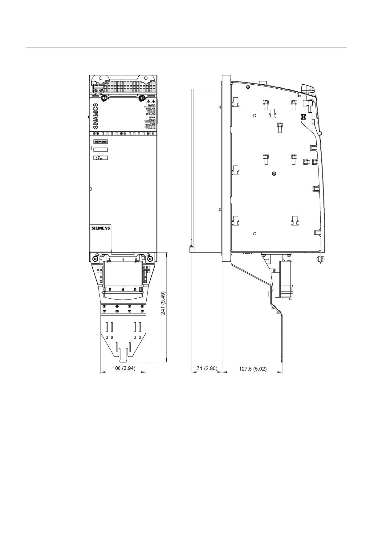
Figure 4-18 Dimension drawing of shield connecting plate on a 100 mm component with external air
cooling, all dimensions in mm and (inches)
Guidelines for machine configuration
System Manual, MA 01/2013, 6FC5397-6CP10-0BA2
73
SINAMICS drive line-up
4.3 Shield Connection
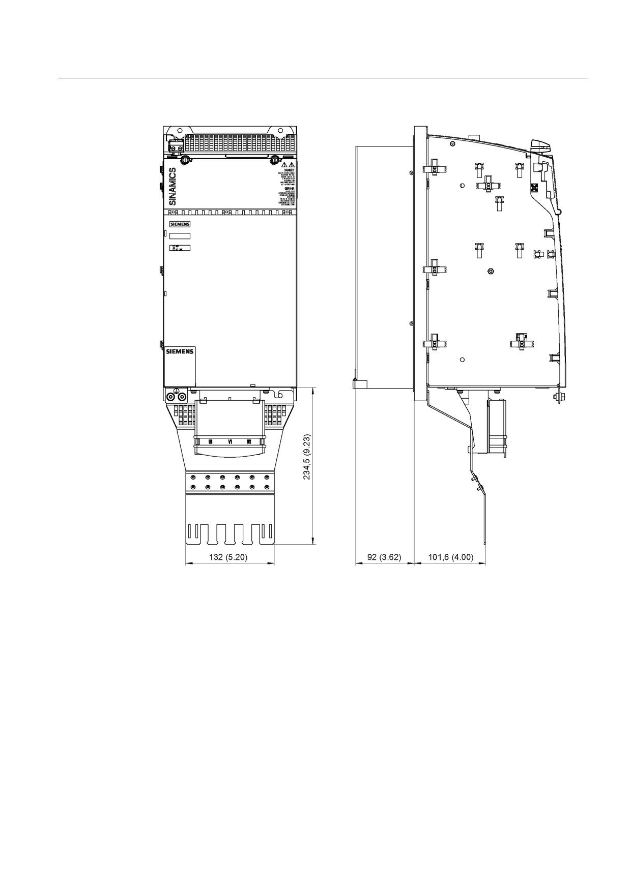
Figure 4-19 Dimension drawing of shield connecting plate on a 150 mm component with external air
cooling, all dimensions in mm and (inches)
Guidelines for machine configuration
74
System Manual, MA 01/2013, 6FC5397-6CP10-0BA2
SINAMICS drive line-up
4.3 Shield Connection
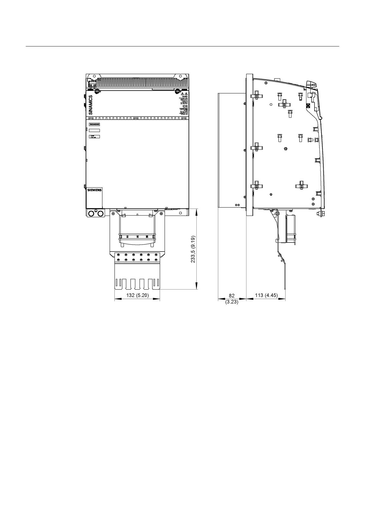
Figure 4-20 Dimension drawing of shield connecting plate on a 200 mm component with external air
cooling, all dimensions in mm and (inches)
Guidelines for machine configuration
System Manual, MA 01/2013, 6FC5397-6CP10-0BA2
75
SINAMICS drive line-up
4.3 Shield Connection
Figure 4-21 Dimension drawing of shield connecting plate on a 300 mm component with external air
cooling, all dimensions in mm and (inches)
Guidelines for machine configuration
76
System Manual, MA 01/2013, 6FC5397-6CP10-0BA2
SINAMICS drive line-up
4.3 Shield Connection
4.3.3
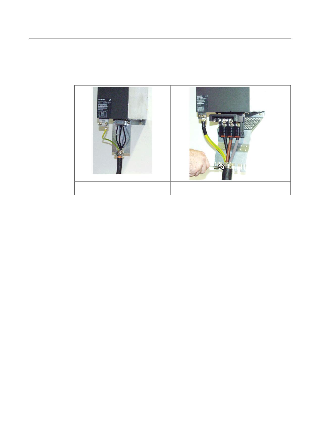
Shield Connection for Internal Heat Dissipation
The two examples for preassembled cables on power components of different width follow:
Preassembled cable on a 100 mm
Preassembled cable on a 200 mm component
component
Guidelines for machine configuration
System Manual, MA 01/2013, 6FC5397-6CP10-0BA2
77
SINAMICS drive line-up
4.4 Note for the installation clearance for the connection cables
4.4
Note for the installation clearance for the connection cables
4.4.1
General information
The arrangement of the components and equipment takes account of
● Space requirements
● Cable routing
● Bending radii of the connection cables
MOTION-CONNECT cables, refer to catalog PM21 or NC62
● Heat dissipation
● EMC
The components of the drive line-up should preferably be installed on a conductive mounting
surface to ensure low impedance between the component and the mounting surface.
Mounting plates with a galvanized surface are suitable.
Components are usually located centrally in a cabinet. The necessary mounting and
installation clearances above an below the components can, under certain circumstances,
exceed the minimum clearances specified in the product documentation.
The components can be arranged in one or more tiers. In a multiple-tier arrangement,
vertical installation or, in a cabinet row, side-by-side installation in different cabinet sections
is possible.
To determine the cross-section, use the DC link busbar current carrying capacity given in the
relevant technical data.
A ventilation clearance of 100 mm must be maintained around the line reactor (not including
the mounting surface).
DANGER
Risk of electric shock by incorrectly installed DC link bridge
Incorrectly installed DC link bridges at the left-hand end of the drive line-up can cause an
electric shock.
• Remove the DC link bridges including the screws on a 50 mm-wide Motor Module or DC
link module.
• Do not tighten the screws without the DC link bridges.
• For all components that are 75 mm wide or wider, the DC link bridges must not be
moved to the left or removed.
Guidelines for machine configuration
78
System Manual, MA 01/2013, 6FC5397-6CP10-0BA2
SINAMICS drive line-up
4.4 Note for the installation clearance for the connection cables
4.4.2
Clearance of the Power Components
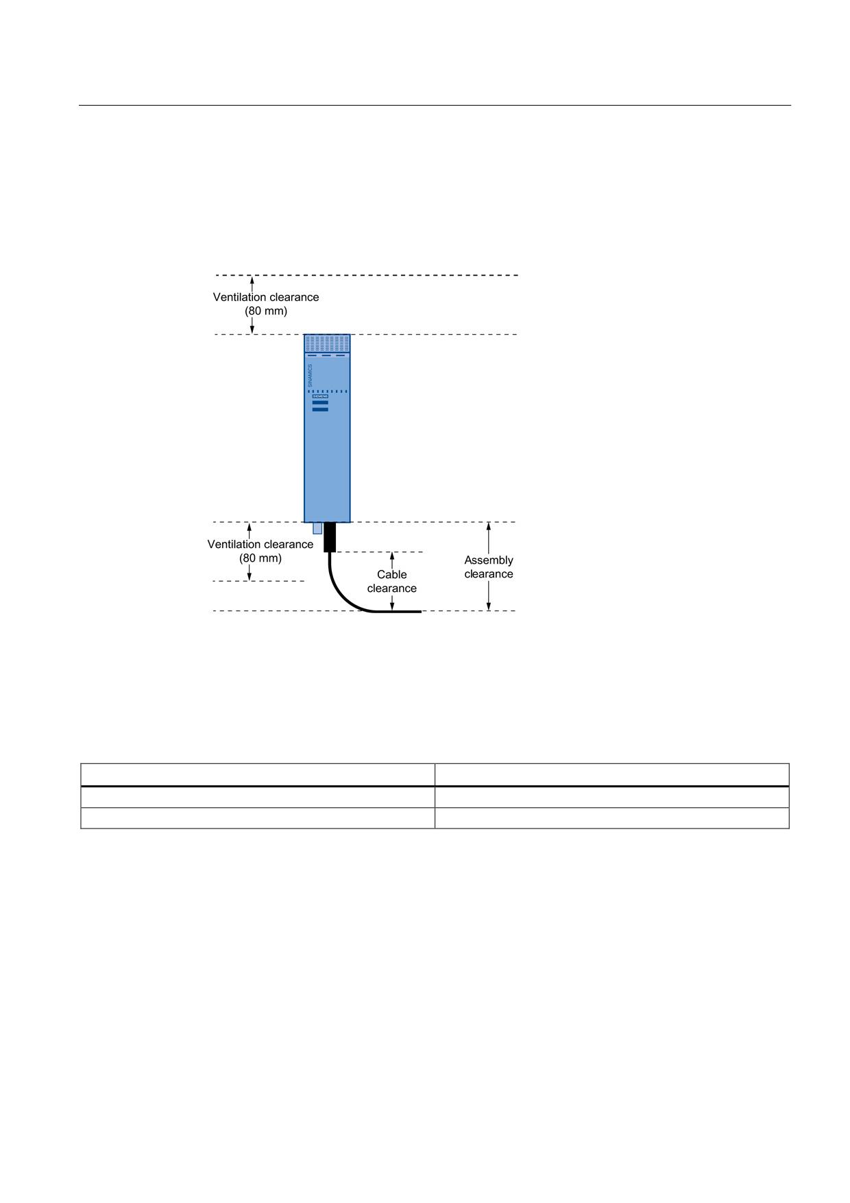
The installation clearance is defined by
● Ventilation clearance
● Cable clearance
Figure 4-22 Clearance in the vicinity of the power components
4.4.3
Ventilation Clearances of the SINUMERIK Components
Table 4- 2
Ventilation clearances above and below the components
Component
Clearance [mm]
NCU 7x0
80 mm
NX1x
80 mm
Guidelines for machine configuration
System Manual, MA 01/2013, 6FC5397-6CP10-0BA2
79
SINAMICS drive line-up
4.5 Heat Dissipation of the Control Cabinet
4.5
Heat Dissipation of the Control Cabinet
4.5.1
Control cabinet cooling options
The following options are available for cooling the control cabinet:
● Filter fans
● Heat exchangers
● Cooling units
● Liquid cooling
● External air cooling
● External liquid cooling
The device to be used depends on the associated environmental conditions and the required
cooling capacity.
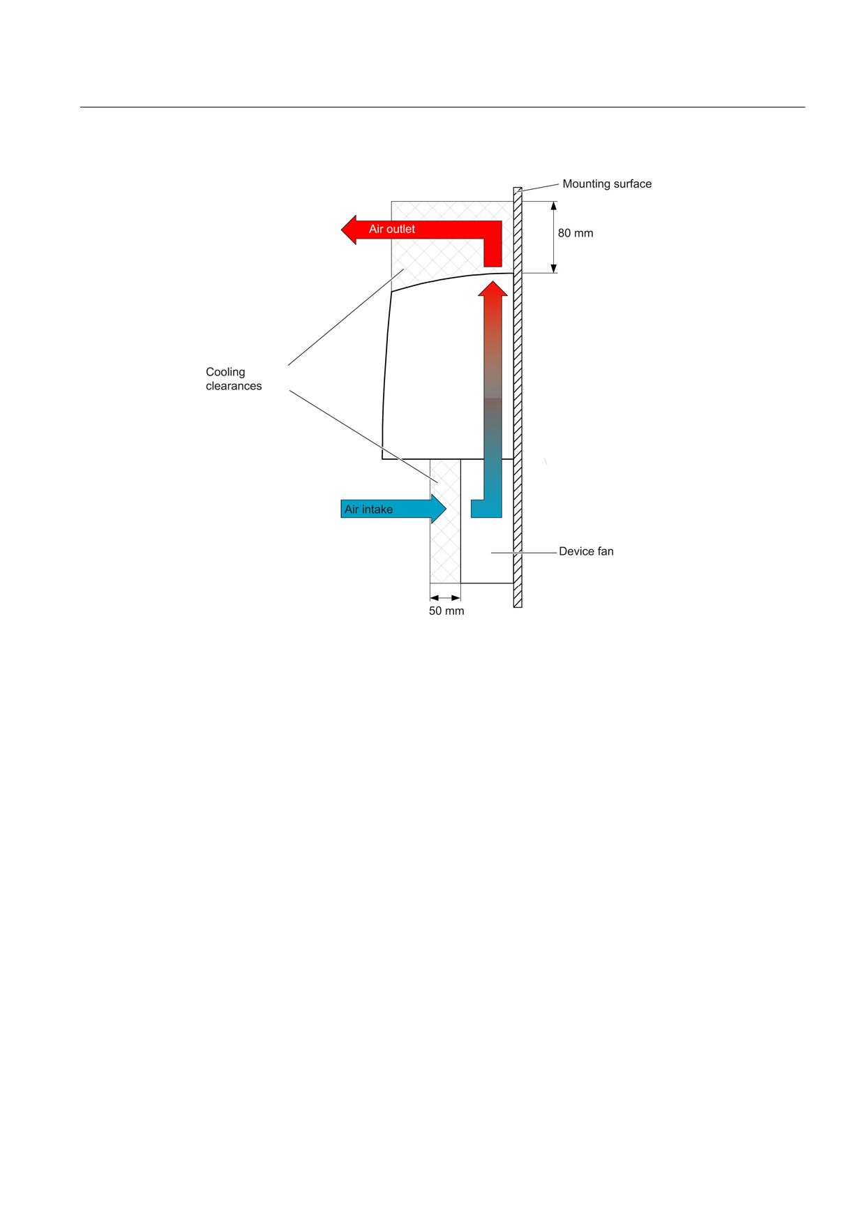
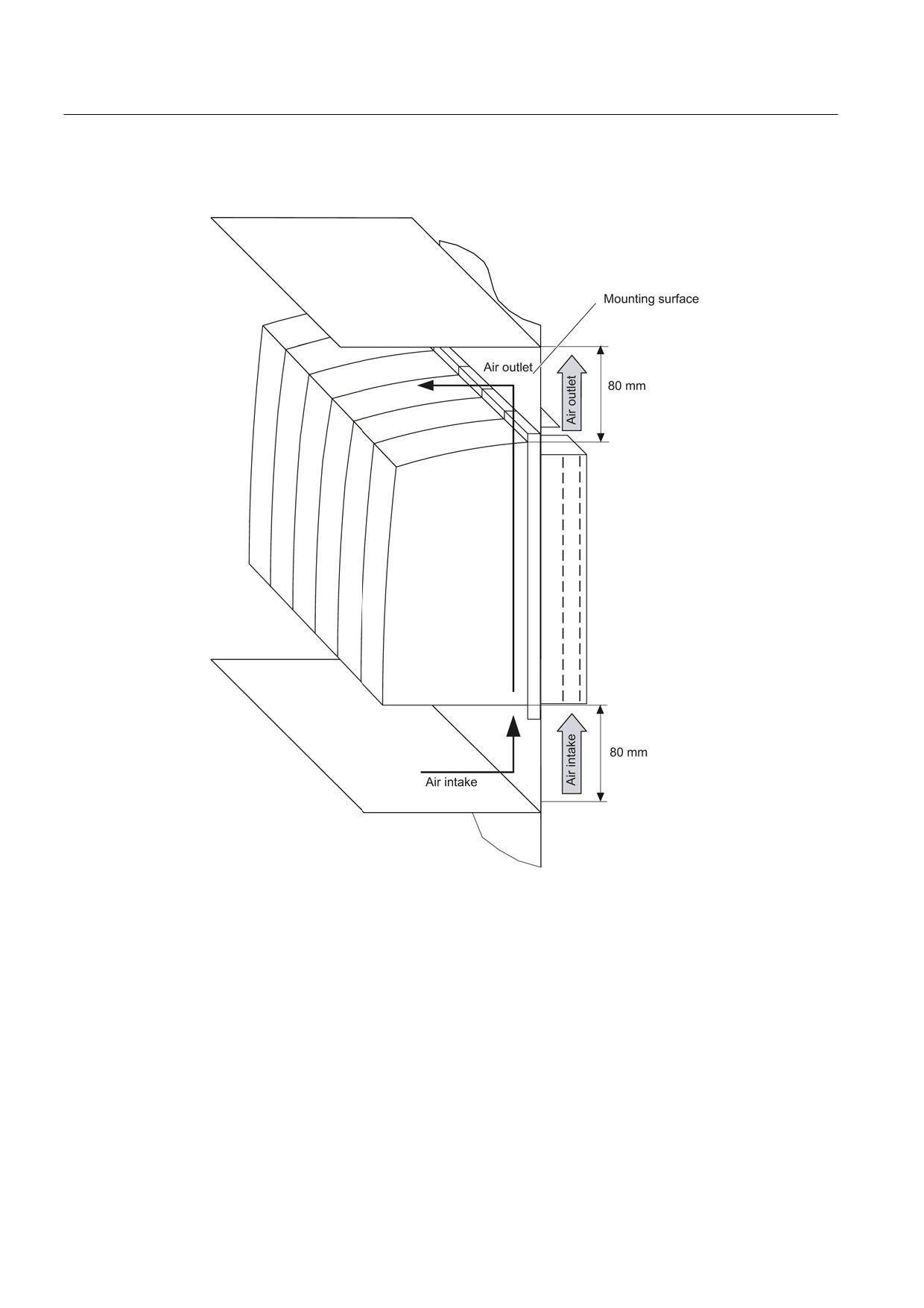
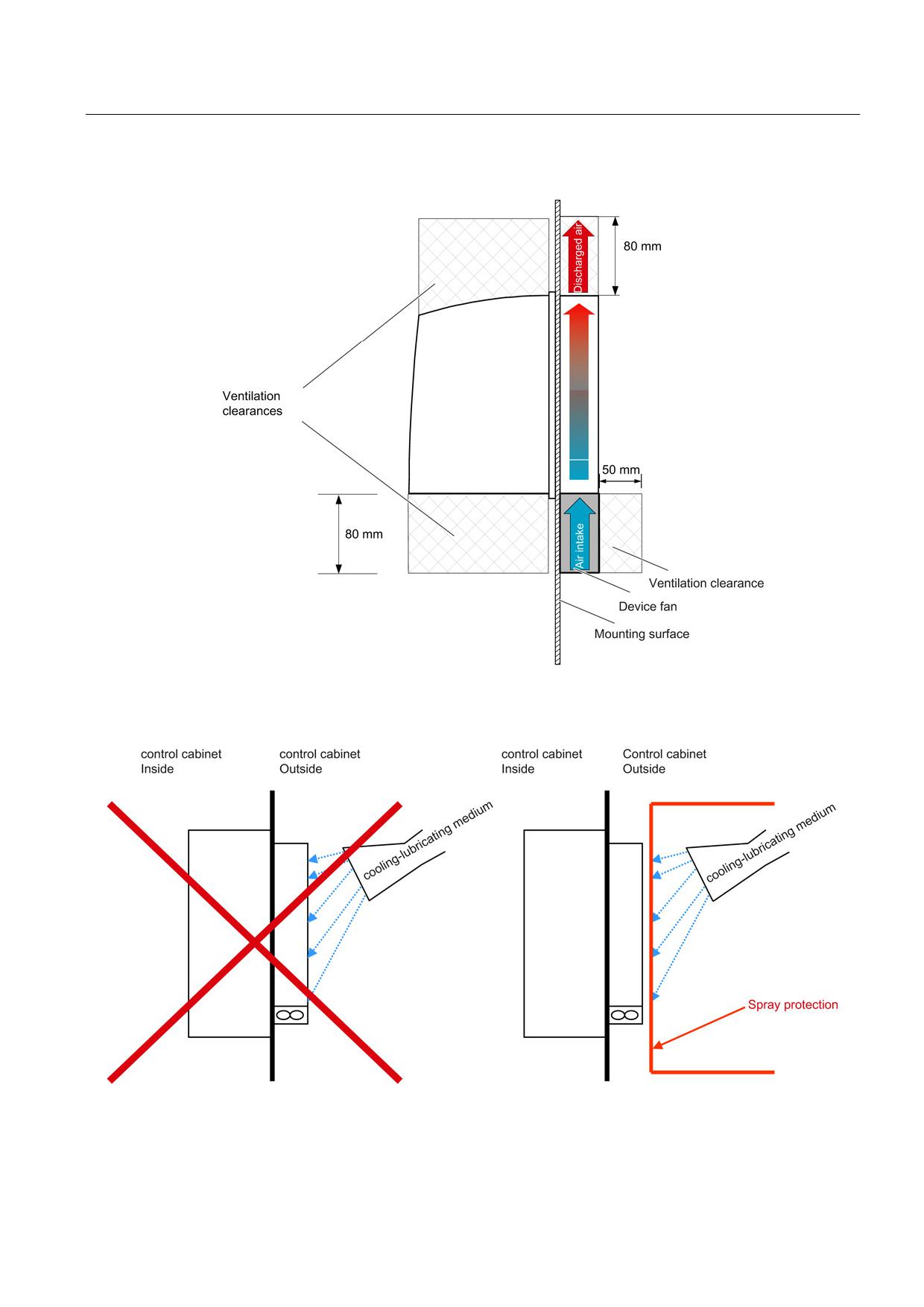
The air routing within the control cabinet and the cooling clearances specified must be
observed. No components may be installed and no cables routed in the cooling clearance
spaces.
NOTICE
Failure of components due to incorrect installation
Installing SINAMICS components incorrectly in the cabinet can reduce their service life and
cause them to fail prematurely.
• Observe the guidelines for installing SINAMICS components in the cabinet.
You must take into account the following specifications when installing a SINAMICS drive
line-up:
● Ventilation clearance
● Wiring and cabling
● Air guidance, air-conditioner
Guidelines for machine configuration
80
System Manual, MA 01/2013, 6FC5397-6CP10-0BA2
SINAMICS drive line-up
4.5 Heat Dissipation of the Control Cabinet
4.5.2
General information on ventilation
SINAMICS components are force-ventilated using integrated fans, and in some cases
through natural convection. The fans are not equipped with temperature-dependent speed
control; only the states "on" or "off" exist.
The fans start when the pulse enable is set, and switch off with a small hysteresis as soon as
the temperature falls below the heat sink temperature saved in the power stack data
(typically 56 °C). The run-on time of the fan depends on various factors such as ambient
temperature, output current, duty cycle and, therefore, cannot be determined directly.
Note
For the 5 kW and 10 kW Smart Line Modules, the fan runs permanently.
WARNING
Risk of fire due to overheating as a result of insufficient ventilation clearances
Insufficient ventilation clearances can cause overheating and present a risk for personnel
due to smoke development and fire. This can also result in more failures and reduced
service lives of devices and systems.
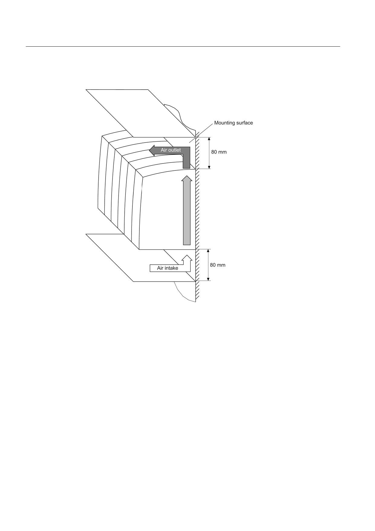
• Maintain ventilation clearances of at least 80 mm above and below the components.
• Make sure that warm air can escape at the top.
• If you are using filter fans, heat exchangers, or air conditioners, make sure that the air is
flowing in the right direction.
WARNING
Risk of fire due to overheating resulting from covered ventilation slots
Covered ventilation slots can cause overheating and present a risk for personnel due to
smoke development and fire. This can also result in more failures and reduced service lives
of devices and systems.
• Route the connected signal and power cables to the components in such a way that
they do not cover the ventilation slots.
WARNING
Risk of fire due to hot spots resulting from a lack of air circulation in sealed cabinets
If air cannot circulate in the cabinet, this can lead to hot spots that present a risk for
personnel due to smoke development and fire. This can also result in more failures and
reduced service lives of devices and systems.
• Install an internal air circulation system that will ensure the air can flow.
• Install the fan above the components to optimize the air flow (suction).
Air circulation is not required if you are using switchgear with a passive heat dissipation
system.
Guidelines for machine configuration
System Manual, MA 01/2013, 6FC5397-6CP10-0BA2
81
SINAMICS drive line-up
4.5 Heat Dissipation of the Control Cabinet
Note
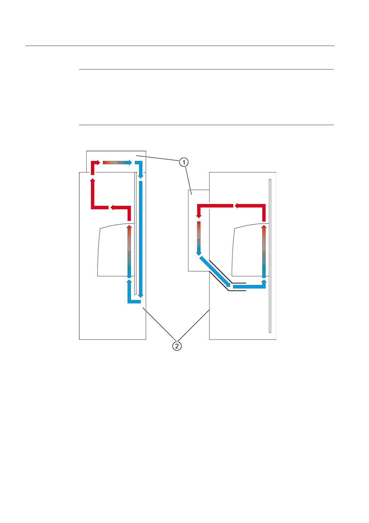
The cooling air must flow through the components vertically from bottom (cooler region) to
top (region heated by operation).
The distance between the blow-out aperture of the air conditioner and the electronic
equipment must be at least 200 mm. With distances that are shorter than this, air baffle
plates must be used in order to divert the air.
①
Cooling unit
②
Control cabinet
Figure 4-23 Examples of cabinet ventilation
Guidelines for machine configuration
82
System Manual, MA 01/2013, 6FC5397-6CP10-0BA2
SINAMICS drive line-up
4.5 Heat Dissipation of the Control Cabinet
NOTICE
Failure of components due to condensation
If air conditioners are used, the relative air humidity of the expelled air increases as the air
in the air conditioner cools and may exceed the dew point. If the relative humidity of the air
entering the SINAMICS components is over 80% for an extended period of time, it can be
assumed that the insulation of the components will fail as a result of electrochemical
reactions.
• Select the air guidance and arrangement of the cooling equipment in such a way that no
condensation can form on the components.
• Use air baffle plates, for example, to ensure that the cold air expelled from the air
conditioner mixes with warm air in the cabinet before it enters the components. This
reduces the relative air humidity to uncritical values.
• Prevent cold air from being blown directly onto electronic equipment.
• If required, install cabinet enclosure heating.
4.5.3
Cooling clearances
Table 4- 3
Cooling clearances required above and below SINAMICS components
Component
Clearance [mm]
CU320-2
80
Sensor Modules Cabinet-Mounted SMCxx
50
Terminal Modules TMx
50
Line filter for Line Modules
100
Active Interface Modules
80
Line reactors for Line Modules
100
Active Line Modules
16 kW - 55 kW
80
80 kW - 120 kW
80 (additional 50 in front of fan)
Smart Line Modules in booksize format
80
Basic Line Modules
80
Motor Modules Booksize
< 132 A
80
132 A and 200 A
80 (additional 50 in front of fan)
Braking Module Booksize
80
Control Supply Module
80
Capacitor Module
80
Guidelines for machine configuration
System Manual, MA 01/2013, 6FC5397-6CP10-0BA2
83
SINAMICS drive line-up
4.5 Heat Dissipation of the Control Cabinet
Drive line-up with internal air cooling
Figure 4-24 Cooling clearances for a drive line-up with internal air cooling (components up to 200
mm width)
Guidelines for machine configuration
84
System Manual, MA 01/2013, 6FC5397-6CP10-0BA2
SINAMICS drive line-up
4.5 Heat Dissipation of the Control Cabinet
Figure 4-25 Cooling clearances for 300 mm wide components with internal air cooling with mounted
unit fan
Guidelines for machine configuration
System Manual, MA 01/2013, 6FC5397-6CP10-0BA2
85
SINAMICS drive line-up
4.5 Heat Dissipation of the Control Cabinet
Drive line-up with external air cooling
Figure 4-26 Cooling clearances for a drive line-up with external air cooling (components up to 200
mm width)
Guidelines for machine configuration
86
System Manual, MA 01/2013, 6FC5397-6CP10-0BA2
SINAMICS drive line-up
4.5 Heat Dissipation of the Control Cabinet
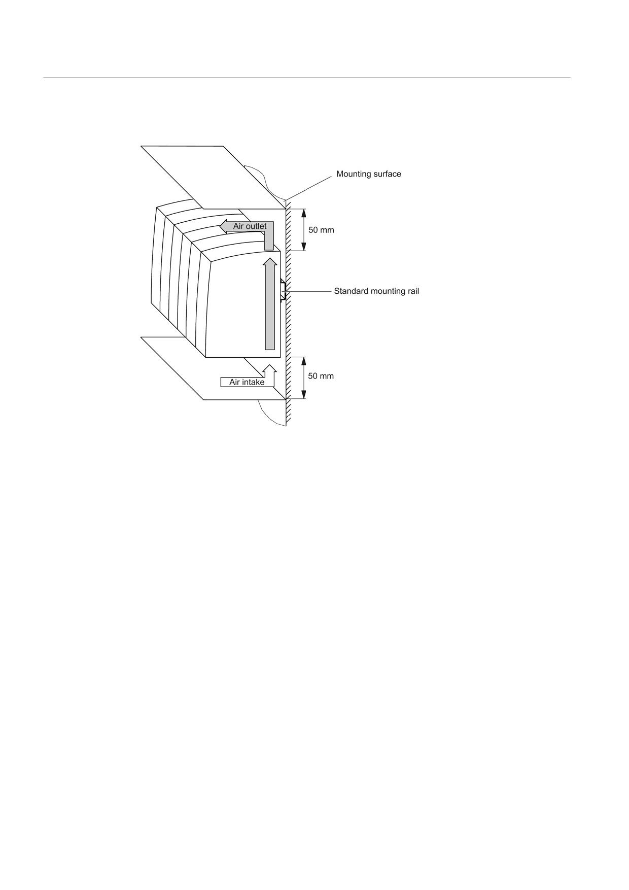
Figure 4-27 Cooling clearances for 300 mm wide components with external air cooling with mounted
unit fan
Figure 4-28 Spray protection for a drive line-up with external air cooling
Guidelines for machine configuration
System Manual, MA 01/2013, 6FC5397-6CP10-0BA2
87
SINAMICS drive line-up
4.5 Heat Dissipation of the Control Cabinet
Rail-mounted components
Figure 4-29 Ventilation clearances for rail-mounted components (e.g. SMC, TM, DMC)
Guidelines for machine configuration
88
System Manual, MA 01/2013, 6FC5397-6CP10-0BA2
SINAMICS drive line-up
4.5 Heat Dissipation of the Control Cabinet
4.5.4
Dimensioning Climate Control Equipment
Cabinet manufacturers provide calculation programs for selecting climate control equipment.
It is important to know the power losses for the components and devices in the control
cabinet.
Formula to calculate the power loss
q = Q - k • A • ΔT
q = thermal power that has to be dissipated through a refrigerator [W]
Q = internal power loss (incl. electronics losses) [W]
∆T = temperature difference between the room and cabinet interior [K]
k = heat transfer coefficient, e.g. sheet steel, painted 5.5 [W/(m2 * K)]
A = freestanding cabinet surface area [m2]
Example
Table 4- 4
Power loss calculation for a drive configuration
Component
Number
Total power loss [W]
Total power loss [W]
(including electronic losses)
CU320-2
1
24
24
Basic Line Filter for AIM/ALM 36
1
26
26
kW
Active Interface Module 36 kW
1
340
340
Active Line Module 36 kW
1
666
666
Motor Module 18 A
2
185.4
370.8
Motor Module 30 A
3
309.2
927.6
SMC
5
10
50
SITOP 20
1
53
53
Line contactor
1
12
12
Total:
2469.4
● Assumption:
- freestanding cabinet surface area A = 5 m2
- temperature difference between the room and cabinet interior ∆T = 10 K
q = 2469.4 W - 5.5 W/(m2 K) • 5 m2• 10 K = 2194.4 W.
See also
Power Loss of the SINUMERIK Components (Page 516)
Power loss of SINAMICS components (Page 516)
Guidelines for machine configuration
System Manual, MA 01/2013, 6FC5397-6CP10-0BA2
89
SINAMICS drive line-up
4.6 Cooling of power units
4.6
Cooling of power units
With the SINAMICS S120 system, there are four distinct cooling methods for cooling power
units:
● Internal air cooling
● External air cooling
● Cold plate cooling
● Liquid cooling (liquid cooled)
4.6.1
Internal Air Cooling
All SINAMICS S120 booksize components are installed within a control cabinet. The total
heat loss of all components is dissipated in the control cabinet. There are three ways to
remove the heat from the control cabinet:
● Filter fans
● Heat exchangers
● Cooling units
The device to be used depends on the associated environmental conditions and the required
cooling capacity. The configuring must also maintain the specified clearances for the
ventilation. No other components may be placed in these areas.
Guidelines for machine configuration
90
System Manual, MA 01/2013, 6FC5397-6CP10-0BA2
SINAMICS drive line-up
4.6 Cooling of power units
4.6.2
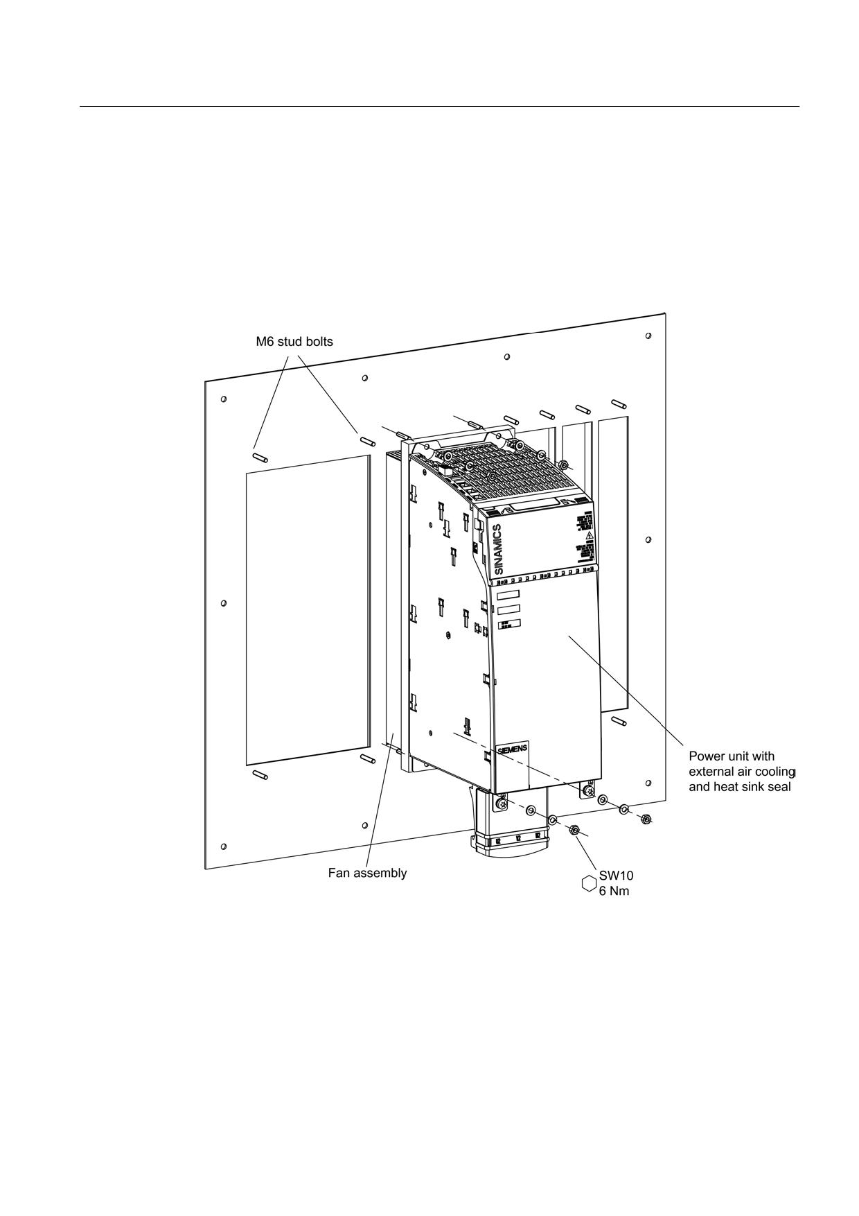
External Air Cooling
The external air cooling is a cooling system for SINAMICS booksize power units. The
through-hole technology is used for this construction form. The booksize power unit with its
heat sink can be placed in the rectangular cutout of the control cabinet rear wall and installed
with a seal. The heat sink with its cooling fins and fan (contained in scope of delivery)
extends at the back out of the control cabinet and the heat dissipation is made externally
from the control cabinet or in a separate air duct.
Figure 4-30 Installation of a booksize power section with external air cooling
Guidelines for machine configuration
System Manual, MA 01/2013, 6FC5397-6CP10-0BA2
91
SINAMICS drive line-up
4.6 Cooling of power units
4.6.3
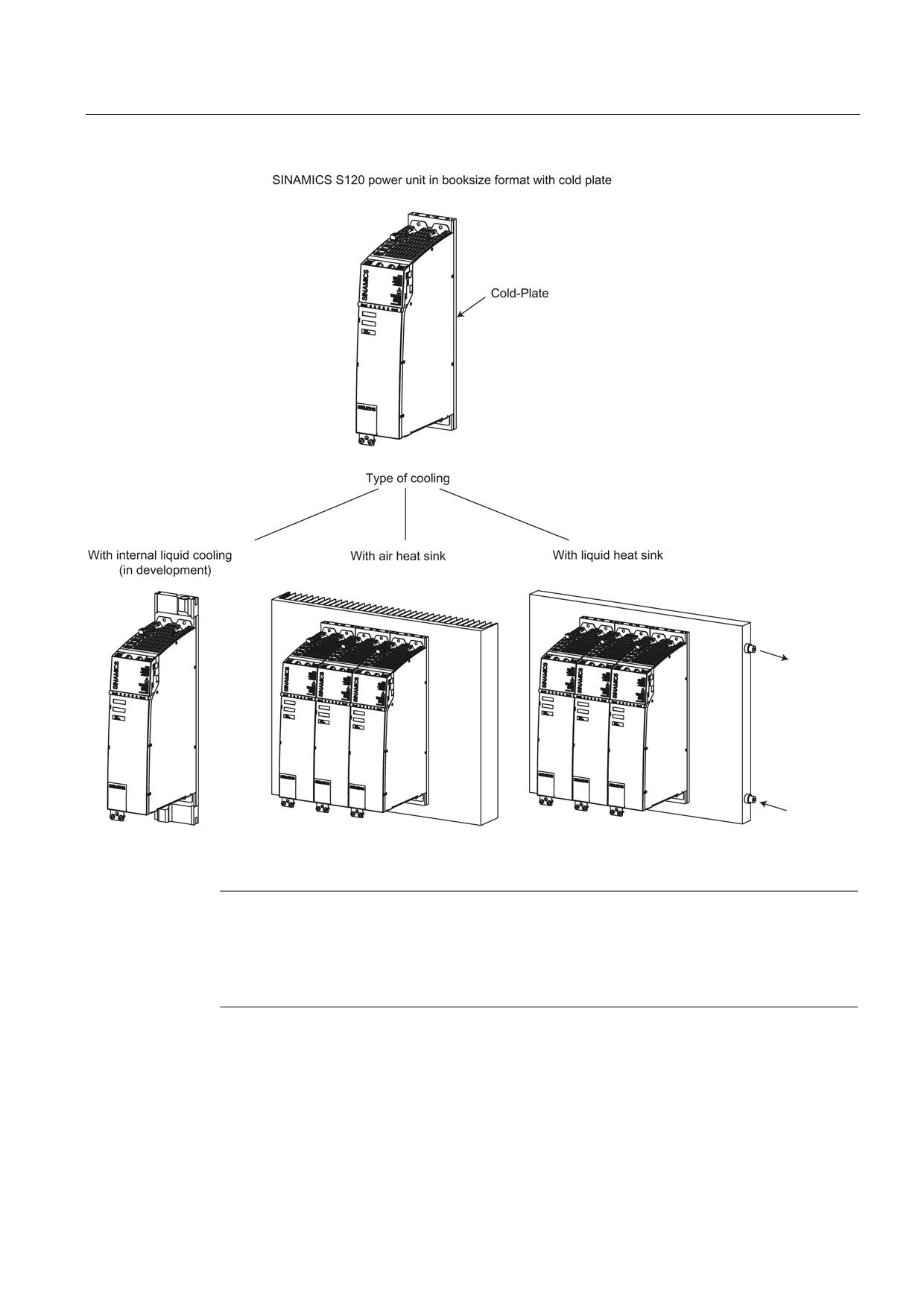
Cold plate cooling
Cold plate cooling is a cooling system for SINAMICS S120 booksize power units. The flat
aluminum cooling plate located at the rear side of the devices serves as thermal interface.
Special advantages of the cold plate technology
1. It is particularly suitable for machine concepts in which a high level of dirt accumulates in
the machine vicinity. The reduction of the cabinet-internal heat loss simplifies the heat
dissipation of a sealed control cabinet (IP54).
2. Advantageous for machine concepts for which liquid is already present in the process.
This heat dissipation method is thus suitable for both internal and external cold plate
cooling of the power components.
A distinction is made between:
● Cold plate with air heat sink
The components of the drive line-up are typically all attached with screws to the cooling
fins of an air heat sink.
● Cold plate with liquid heat sink
The components of the drive line-up are typically all attached with screws to the liquid
heat sink.
● Cold plate with internal liquid heat sink
This is considered to be a liquid cooling using a connection adapter. The liquid passes
through the integrated channels in the cold plate.
Note
Derating at a temperature of 40 °C and above
In the case of 300 mm-wide modules, derating must be applied due the heat transferred
to the external heat sink. If the temperature at the interface to the power unit is 40 °C,
derating is 20% for 6SL3136-7TE28-0AAx/6SL3126-1TE31-3AAx and 30% for 6SL3136-
7TE31-2AAx/6SL3126-1TE32-0AAx.
When the Active Line Modules and Motor Modules feature direct (internal) liquid cooling
(6SL3135-7TE31-2AA3/6SL3125-1TE32-0AA3), this derating does not apply to the cold
plate components referred to above.
Guidelines for machine configuration
92
System Manual, MA 01/2013, 6FC5397-6CP10-0BA2
SINAMICS drive line-up
4.6 Cooling of power units
Figure 4-31 Cooling systems for cold plate
Note
Important for configuration
The associated notes contained in the manuals must be observed for the configuring and the
layout of the corresponding component. This ensures that devices in the control cabinet are
not damaged as a result of leaks, etc.
Guidelines for machine configuration
System Manual, MA 01/2013, 6FC5397-6CP10-0BA2
93
SINAMICS drive line-up
4.6 Cooling of power units
4.6.4
Liquid cooling (liquid cooled)
Liquid cooling is used only for large power units (Active Line Module 120 kW as well as
single Motor Module 200 A).
For liquid cooling, the power semiconductors are mounted on a heat sink, through which the
coolant flows. The power loss of the device is, to large extent, absorbed by the cooling
medium and can be dissipated outside the cabinet.
Additional references
/GH2/ SINAMICS S120 Booksize Power Modules, chapter "Cooling circuit and coolant
properties".
Guidelines for machine configuration
94
System Manual, MA 01/2013, 6FC5397-6CP10-0BA2
Communication within the system
5
5.1
Communication overview
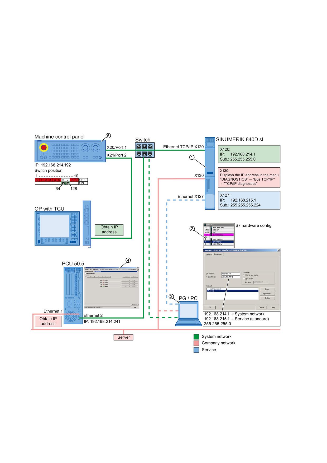
The NCU 7x0.3 PN establishes the connection to the operating components and service
units via its Ethernet interfaces. Communication takes place via various networks.
Figure 5-1
Example based on the SINUMERIK 840D sl network configuration
Guidelines for machine configuration
System Manual, MA 01/2013, 6FC5397-6CP10-0BA2
95
Communication within the system
5.1 Communication overview
Note
The significance of items ① to ⑤ is explained on the pages that follow.
① (NCU)
● IP assignment of the server
● The ports need to be activated if VNC and HMI/Step7 are to be used (SW2.4.xxx and
higher):
/user/system/etc/basesys.ini
[LinuxBase]
FirewallOpenPorts="TCP/102 TCP/5900"
② (S7 Hardware Config)
Access parameters need to be set in the S7 hardware configuration.
1. Check the network connection (ping on selected access path X120/X130/X127).
2. Select the PG/PC interface in SIMATIC Manager.
Note
Do not select "TCP/IP (AUTO)…" or "ISO Ind. Ethernet ..." under any circumstances!
3. Set parameters for HW Config → Machine control panel using the selected access IP
address (X120/X130/X127).
4. Load the parameter assignment to the station.
Note
As of SW 2.4:
The ports must first be activated where connections via the company network are
involved (X130).
Guidelines for machine configuration
96
System Manual, MA 01/2013, 6FC5397-6CP10-0BA2
Communication within the system
5.1 Communication overview
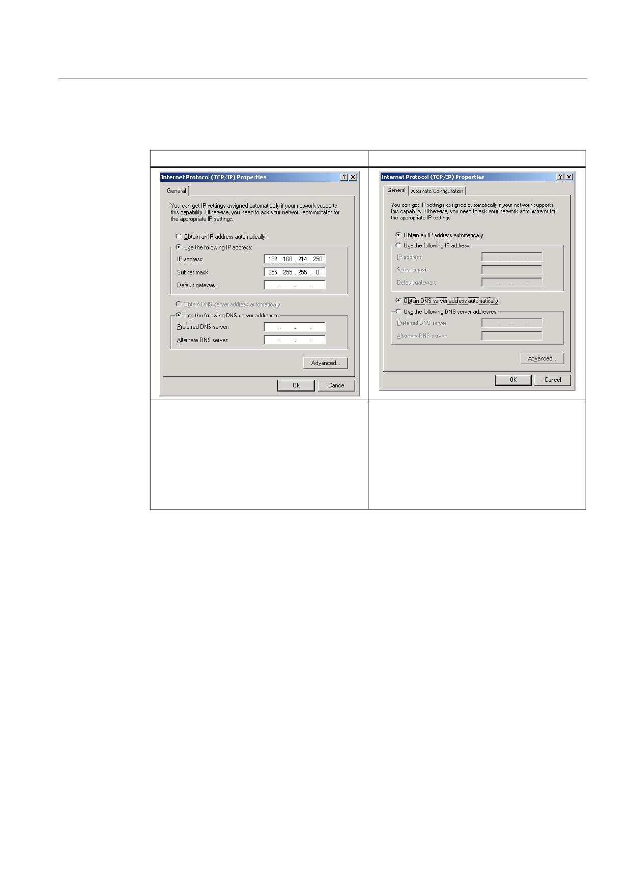
③ (PG/PC)
On the system network (X120):
On the service network (X127):
• TCP/IP Internet protocol
• TCP/IP Internet protocol
- properties
- properties
- general
- general
- Set fixed IP addresses
- IP address obtained automatically
• Example:
- IP: 192.168.214.250
- Sub.: 255.255.255.0
④ (System Network Center > TCU support)
When TCU - PCU50.5 (HMI Advanced) is powered up, the IP address of the PCU must be
entered in the
/user/common/<TCU-Name>/common/tcu/config.ini
file:
[Station]
mcpIndex=…
tcuIndex=…
dckEnable=…
MaxHostIndex=1
[host_1]
Address=192.168.214.241
● If the DHCP of the NCU (X120) is active:
Set the "Settings system network" program on the "TCU support" tab.
● Set "No boot support".
Guidelines for machine configuration
System Manual, MA 01/2013, 6FC5397-6CP10-0BA2
97
Communication within the system
5.1 Communication overview
⑤ (machine control panel - Industrial Ethernet)
Note
The Service menu (Backup/Restore) is only available for an analog monitor, TCU OP, or
PCU OP.
● mcp_client.ini file:
- copy mcp_client.ini from
/siemens/sinumerik/mcp_client/mcp_client.ini
to
/user/sinumerik/mcp_client/mcp_client.ini
- "addrMode" change: 1=DNS (default) 0=HWS
This may be required after a change of software if the machine control panel no longer
uses PROFIBUS for communication
● Organization block 100 (OB100):
CALL "RUN_UP" , "gp_par
"MCPNum :=1
MCP1BusAdr :=192 // bus address in accordance with MCP switch
MCPMPI :=FALSE
MCPSDB210 :=FALSE
MCPCopyDB77 :=FALSE
MCPBusType :=B#16#55 (PROFIBUS = 3)
Note
In B#16#55, the initial "5" refers to the first machine control panel and the last "5" refers to
the second.
Guidelines for machine configuration
98
System Manual, MA 01/2013, 6FC5397-6CP10-0BA2
Communication within the system
5.2 DRIVE-CLiQ Topologies
5.2
DRIVE-CLiQ Topologies
5.2.1
DRIVE-CLiQ topology
Introduction
DRIVE-CLiQ (Drive Component Link with IQ) is a communication system for connecting the
various SINAMICS components (e.g. Control Unit, Line Module, Motor Modules, motors, and
encoders).
In SINAMICS contexts, the term "topology" refers to the structure of a drive system, including
its DRIVE-CLiQ wiring and other wiring elements.
DRIVE-CLiQ supports the following functions:
● Automatic detection of components by the Control Unit (NCU 7x0.3 or CU320-2)
● Standard interfaces to all components
● Standardized diagnostics down to component level
● Standardized service down to component level
Electronic rating plate
DRIVE-CLiQ components have an electronic type plate in which the characteristic device
data is stored. When connecting the device to the Control Unit, the following information is
transferred via DRIVE-CLiQ:
● Component type (e.g. SMC20)
● Order number (e.g. 6SL3055-0AA0-5BA0)
● Manufacturer (e.g. SIEMENS)
● Hardware version (e.g. A)
● Serial number (e.g. T-PD3005049)
● Technical data (e.g. rated current)
Actual topology
The actual topology is the actual DRIVE-CLiQ cabling tree, which is detected automatically
via DRIVE-CLiQ when the drive system components are started up.
Guidelines for machine configuration
System Manual, MA 01/2013, 6FC5397-6CP10-0BA2
99
Communication within the system
5.2 DRIVE-CLiQ Topologies
Target topology
The target topology is stored on the memory card on the Control Unit and is compared with
the actual topology when the Control Unit is started up.
The target topology can be specified in two ways and saved on the memory card:
● Via the SINUMERIK 840D sl drive wizard or via the STARTER commissioning tool (by
creating the configuration and loading it to the drive unit)
● Via quick commissioning (automatic configuration):
the actual topology is read and the target topology written to the memory card.
Comparison of topologies at Power On
Comparing the topologies prevents a component from being controlled/evaluated incorrectly
(e.g. drive 1 and 2).
When the drive system starts up, the Control Unit compares the detected actual topology
and the electronic rating plates with the relevant target topology stored on the memory card.
You can specify how the electronic rating plates are compared for all the components of a
Control Unit via p9906. The type of comparison can be changed subsequently for each
individual component. You can use p9908 for this or right-click in the topology view in the
STARTER tool. All data on the electronic rating plate are compared by default.
The following data in the target and actual topologies is compared depending on the settings
made in p9906/9908:
● p9906/p9908 = 0 component type, order number, hardware version, manufacturer, serial
number
● p9906/p9908 = 1 component type, order number
● p9906/p9908 = 2 component type
● p9906/p9908 = 3 component class (e.g. Sensor Module or Motor Module)
Guidelines for machine configuration
100
System Manual, MA 01/2013, 6FC5397-6CP10-0BA2
Communication within the system
5.2 DRIVE-CLiQ Topologies
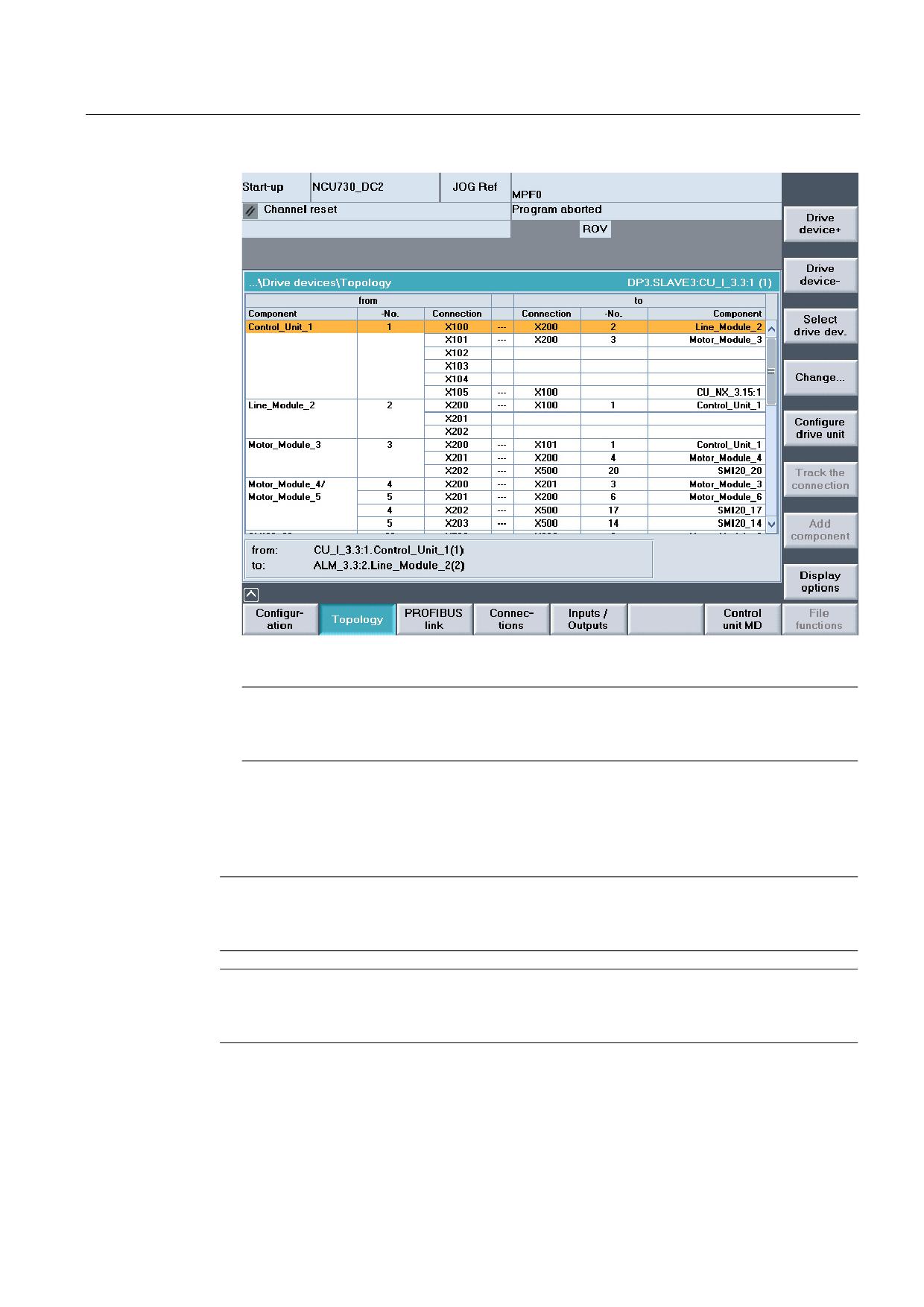
Figure 5-2
Topology of the SINUMERIK drive wizard
Note
The Control Unit and the Option Board are not monitored. A replacement of components
is accepted automatically and not displayed.
5.2.2
DRIVE-CLiQ wiring
Note
Unless otherwise specified, Control Unit always refers to a SINUMERIK NCU 7x0.3 in the
information below.
Note
The components of the SINAMICS S120 drive family and the Control Unit are interconnected
using DRIVE-CLiQ. When connecting the components, please note the following rules.
Guidelines for machine configuration
System Manual, MA 01/2013, 6FC5397-6CP10-0BA2
101
Communication within the system
5.2 DRIVE-CLiQ Topologies
Rules for wiring DRIVE-CLiQ
Boundary conditions
● On the SINUMERIK 840D sl, only SERVO control is possible. Vector operation is not
possible.
● The following information about quantity structures only applies if Terminal Modules of
type TM120 alone are being used. With a sampling time of 125 μs, a maximum of two
TM120 modules are allowed; with 62.5 μs, a maximum of one.
● Add-ons in addition to the linear axis or the rotary safety axis are not permitted.
● The current hardware configuration specifies the components to be considered.
Deactivated drive objects/Sensor Modules must also be taken into account in the quantity
structure.
● SINUMERIK Safety Integrated is intended for all axes.
● PROFIBUS DP ≥ 2 ms cycle
SINUMERIK Safety Integrated ≥ 12 ms cycle
● The sampling times are set using parameter p0112:
p0112 = 3: Standard (125 μs)
p0112 = 4: High Performance (62.5 µs)
p0112 = 5: High Performance (31.25 µs)
MANDATORY conditions
● A maximum of 14 nodes are permitted on an NCU DRIVE-CLiQ socket. A Double Motor
Module counts as two components. The maximum possible number of nodes is reduced
in the case of a faster clock rate.
Clock rate
Max. number of nodes
125 μs
14
62.5 μs
5
31.25 μs
2
Dependence of clock rate and number of nodes on a DRIVE-CLiQ interface
● Drive modules are connected in series (line topology) with the Motor Modules. Ring wiring
is not permitted. The measuring systems assigned to these drives must relate to the
same Control Unit or NX.
● A maximum of eight nodes in series is permissible. A Double Motor Module counts as two
nodes. A row is always regarded as starting at the control unit.
● NX modules must be wired from the NCU using a point-to-point configuration. Cascading
is not permitted. NX modules may not be operated downstream of a DRIVE-CLiQ hub or
another DRIVE-CLiQ component.
● The components may not be double-wired, i.e. a DRIVE-CLiQ component must not be
associated with two DRIVE-CLiQ cables.
Guidelines for machine configuration
102
System Manual, MA 01/2013, 6FC5397-6CP10-0BA2
Communication within the system
5.2 DRIVE-CLiQ Topologies
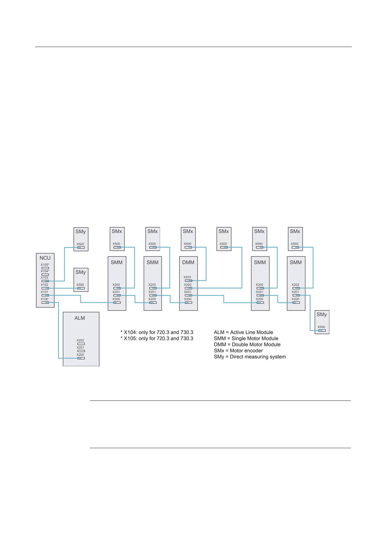
● Only one ALM/SLM may be connected per Control Unit. The DC links of different
ALMs/SLMs may not be connected to one another.
● To enable the "Automatic configuration" function to assign the encoders to the drives, the
rules below must be observed:
- The connection from the Control Unit to the first infeed and the first Motor Module
must each be established at the X200 interface.
- The DRIVE-CLiQ cables between the Motor Modules must each be connected from
the X201 interface to the X200 interface on the next component.
- The power line to the motor and the associated motor encoder must be connected to a
Motor Module.
- The following applies to Double Motor Modules:
X200: from the previous node
X201 standard assignment: to the next node or SMx for 2nd axis
X202 standard assignment: SMx 1st axis
X203 standard assignment: SMx 2nd axis
Figure 5-3
DRIVE-CLiQ topology for NCU 7x0.3
Note
ALM and Motor Modules should preferably have a star topology
The Active Line Module and the Motor Modules can also be connected with a line topology.
In order to achieve more uniform utilization, however, a star topology (i.e. connection to
separate DRIVE-CLiQ lines) is preferable.
Tips for optimum commissioning
Guidelines for machine configuration
System Manual, MA 01/2013, 6FC5397-6CP10-0BA2
103
Communication within the system
5.2 DRIVE-CLiQ Topologies
● The Active Line Module or Smart Line Module should always be assigned the DO number
"2".
● The motor measuring systems should be connected to the associated Motor Modules
(X202/X203).
● NX modules should always be populated on the NCU from the rear. This means that they
will automatically be assigned with PROFIBUS addresses in reverse order (15 - 12).
● A DRIVE-CLiQ hub should ideally be attached to a separate DRIVE-CLiQ port on the
NCU, so as not to exceed the maximum quantity structures of DRIVE-CLiQ components.
If there are no free connectors here, the DRIVE-CLiQ hub is connected to the last Motor
Module (observe the rule of 14 components in a line, and a maximum of eight of these in
series).
● A DRIVE-CLiQ cycle of less than 125 μs should only be used if an increased pulse
frequency is necessary due to an increased speed.
● A Double Motor Module, a DMC20, and a DME20 each correspond to two DRIVE-CLiQ
nodes. This also applies to Double Motor Modules, at which just one drive is configured.
● If the current controller sampling time for a drive object has to be changed in such a way
that the modified sampling time is no longer in line with the other drive objects on the
DRIVE-CLiQ line, the following options are available:
- Reconnect the drive object to a separate DRIVE-CLiQ line.
- Change the current controller sampling times and/or the sampling times of the
inputs/outputs of the other drive objects so that they fit into the new pattern.
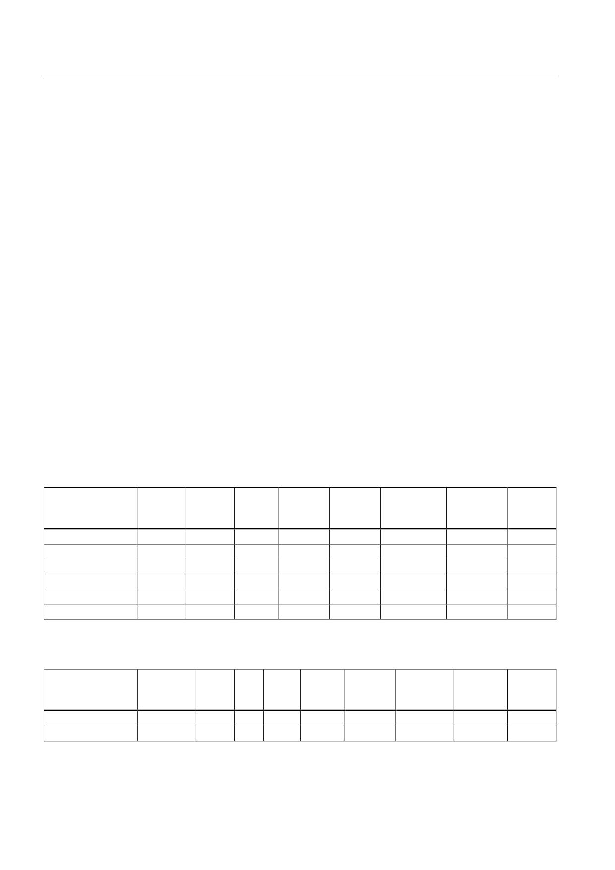
Maximum quantity structures for stand-alone system and extended systems
Table 5- 1
Standard applications with the same DQ cycle
Quantity structures
DQ cycle
NCU
NX
ALM
Motor
Motor
Direct
DRIVE-
Module
measuring
measuring
CLiQ Hub
systems
systems
Stand alone
125 μs
1
1-5
1
6
6
6
4
NX15
125 μs
1
6
6
6
4
NX15
62.5 μs
1
3
3
3
1
NX15
31.25 μs
1
1
1
1
1
NX10
125 μs
1
3
3
3
1
NX10
62.5 μs
1
1
1
1
Table 5- 2
Special applications with mixed DQ cycle
Quantity structures
DQ cycle
NCU
NX
ALM
MoMo
MoMo
Motor
Direct
DRIVE-
62.5 μs
125 μs
measuring
measuring
CLiQ Hub
systems
systems
Stand alone
mixed
1
1-5
1
1
4
5
5
1
NX15
mixed
1
1
4
5
5
1
Guidelines for machine configuration
104
System Manual, MA 01/2013, 6FC5397-6CP10-0BA2
Communication within the system
5.2 DRIVE-CLiQ Topologies
Specifications for sampling times
● For Active Line Modules in booksize format, only a current controller sampling time of
125.0 µs or 250.0 µs can be set.
● A current controller sampling time between 31.25 µs and 250.0 µs can be set for servo
drives (31.25 µs ≤ p0115[0] ≤ 250.0 µs).
● For servo drives with a current controller sampling time of p0115[0] = 62.5 µs, the
following applies:
- only possible in booksize and blocksize format
- maximum quantity structure:
- booksize: 2x servo with p0115[0] = 62.5 µs + Line Module (connected to a different
DRIVE-CLiQ line)
- servo drives in booksize format can be combined on one DRIVE-CLiQ line with a
servo with p0115[0] = 125.0 µs (but with same quantity structure).
- A DRIVE-CLiQ hub DMC20 cannot be operated with servo drives with p0115[0] =
62.5 µs on a DRIVE-CLiQ line but must instead be connected to a separate DRIVE-
CLiQ line.
- blocksize: 1 servo with p0115[0] = 62.5 µs
● When a unit in chassis format is connected to a DRIVE-CLiQ line, the smallest current
controller sampling time must be at least 250 µs.
Example: A mixture of chassis and booksize units on a DRIVE-CLiQ line.
● Motor Modules in chassis format with different current controller cycles must be
connected to separate DRIVE-CLiQ lines. For this reason, Chassis Motor Modules and
Booksize Motor Modules with a current controller sampling time < 250 µs must also be
connected to separate DRIVE-CLiQ lines.
● The sampling times (p0115[0] and p4099) of all components that are connected to a
DRIVE-CLiQ line must be divisible by one another with an integer result.
Table 5- 3
Connecting the motor encoder to the Motor Module via DRIVE-CLiQ
Component
Connecting the motor encoder via DRIVE-CLiQ
Single Motor Module booksize
• Encoder at X202
Double Motor Module booksize
• Motor connection X1: Encoder at X202
• Motor connection X2: Encoder at X203
Guidelines for machine configuration
System Manual, MA 01/2013, 6FC5397-6CP10-0BA2
105
Communication within the system
5.2 DRIVE-CLiQ Topologies
Note
If an additional encoder is connected to a Motor Module, it is assigned to this drive as
encoder 2 in the automatic configuration.
Note
The SINAMICS S120 Function Manual contains further information on the DRIVE-CLiQ
topology.
Guidelines for machine configuration
106
System Manual, MA 01/2013, 6FC5397-6CP10-0BA2
Line connection
6
6.1
Power Supply Interface Variants
6.1.1
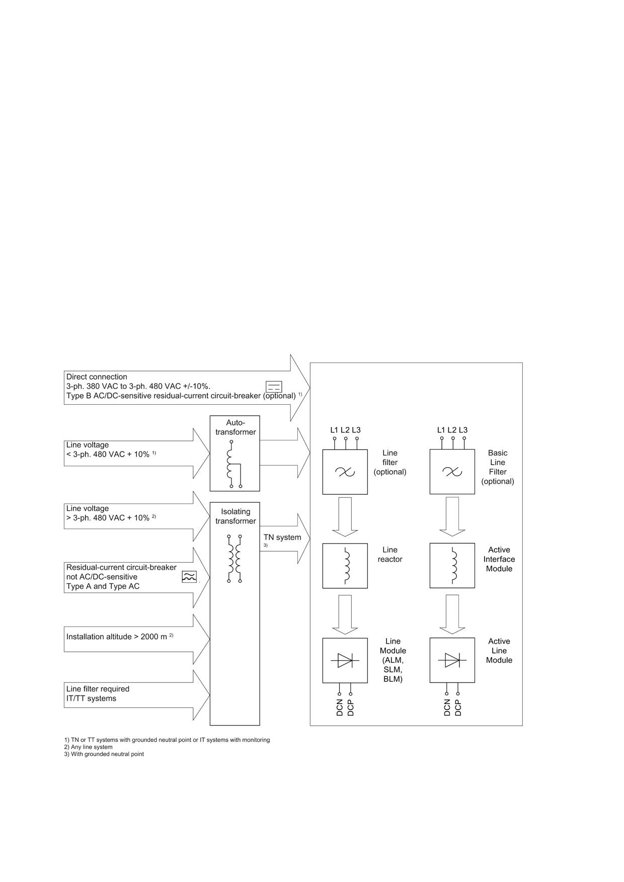
Ways of connecting the line supply
A distinction is made between:
● Direct operation of the line connection components on the supply system
● Operating line connection components via an autotransformer
● Operating line connection components via an isolating transformer
Figure 6-1
Overview of line connection versions
Guidelines for machine configuration
System Manual, MA 01/2013, 6FC5397-6CP10-0BA2
107
Line connection
6.1 Power Supply Interface Variants
Note
Line connection of motors
In combination with the drive system, the motors are generally approved for operation on TN
and TT systems with grounded neutral point and on IT systems.
When operated on IT systems, the occurrence of a first fault between an active part and
ground must be signaled by a monitoring device. In accordance with IEC 60364-4-41, it is
recommended that the first fault be eliminated as quickly as is practically possible in order to
minimize the temporary overload of the motor insulation.
In all other systems, except TN and TT systems with a grounded neutral point and IT
systems such as systems with a grounded line conductor, an isolation transformer with
grounded neutral point (secondary side) must be connected between the line system and the
drive system in order to protect the motor insulation from excessive stress.
6.1.2
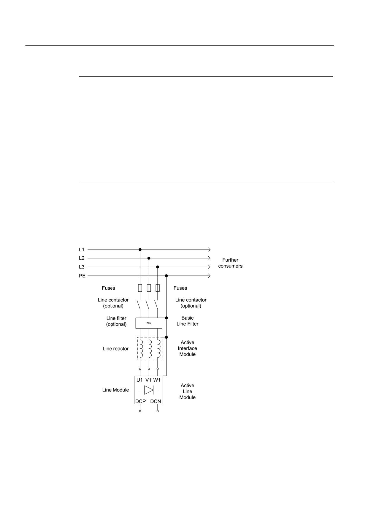
Operation of the line connection components on the supply network
The SINAMICS S Booksize converter system is rated for direct operation on TN, TT, and IT
line supply systems with a rated voltage of 380 V 3 AC to 480 V 3 AC.
Figure 6-2
Direct operation on the line supply
Guidelines for machine configuration
108
System Manual, MA 01/2013, 6FC5397-6CP10-0BA2
Line connection
6.1 Power Supply Interface Variants
6.1.3
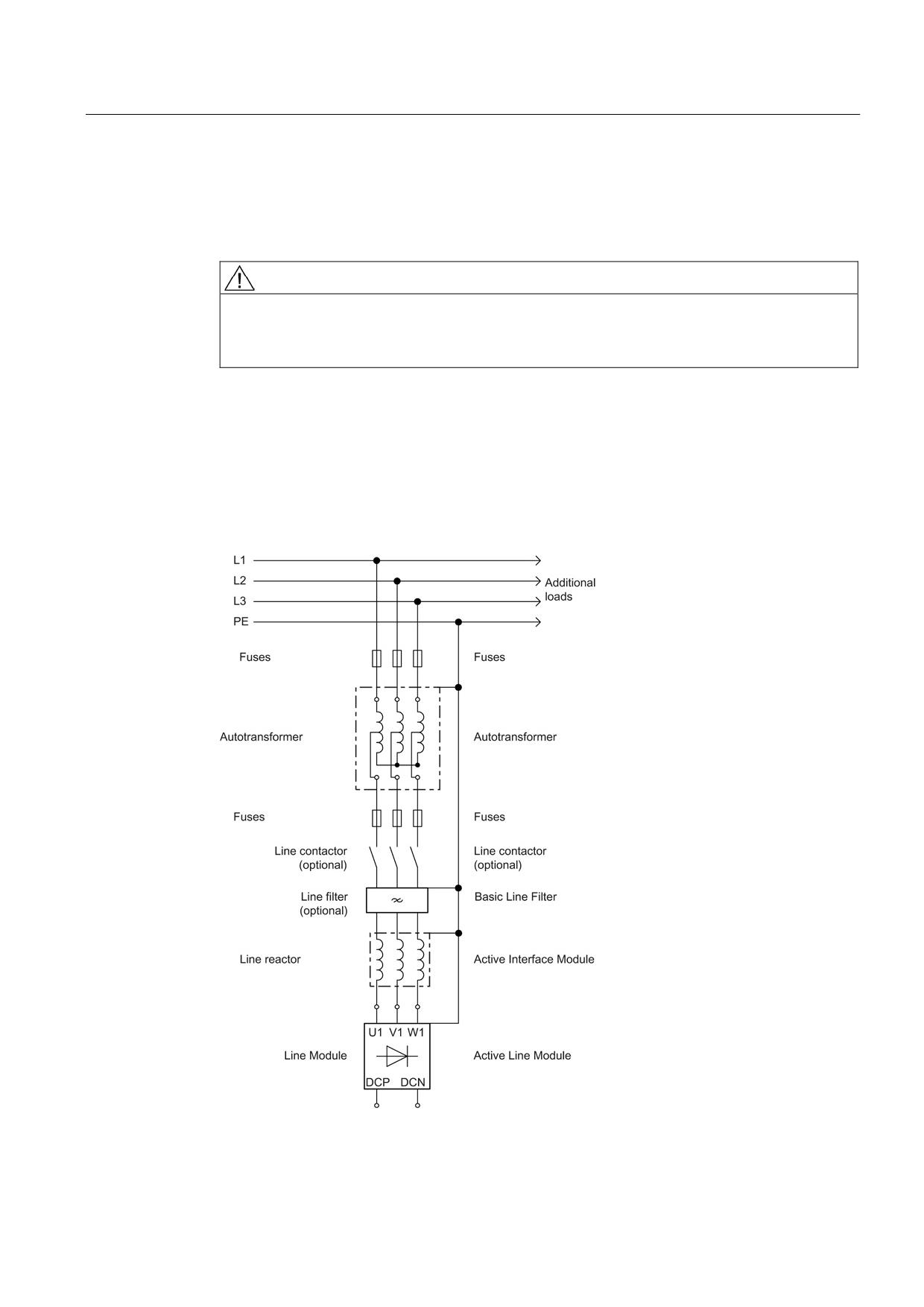
Operating line connection components via an autotransformer
An autotransformer can be used to adapt the voltage in the range up to 3-ph. 480 VAC
+10%.
DANGER
Risk of electric shock
To ensure protective separation an isolating transformer must be used for voltages greater
than 3-ph. AC 480 VAC +10%.
Applications:
● The motor insulation must be protected from excessive voltages.
● The Active Line Module must supply a regulated DC link voltage. This is possible with a
rated voltage of 380 V to 415 V.
A combination with motors that may be operated with a DC link voltage of up to 660 V,
and a line voltage > 415 V requires a controlled DC link voltage.
Figure 6-3
Operation of a Line Module via an autotransformer
Guidelines for machine configuration
System Manual, MA 01/2013, 6FC5397-6CP10-0BA2
109
Line connection
6.1 Power Supply Interface Variants
6.1.4
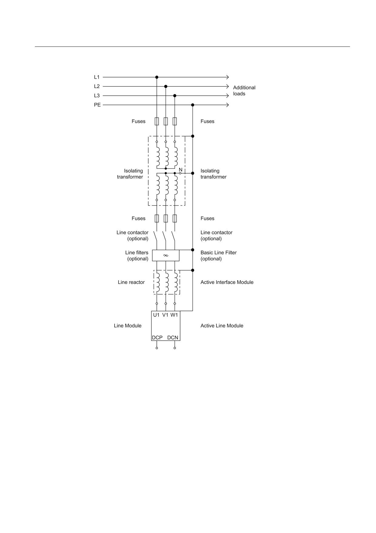
Operating line connection components via an isolating transformer
An isolating transformer converts the line supply type of the plant or system (e.g. IT/TT
system) to a TN system. Additional voltage adaptation to the permissible voltage tolerance
range is possible.
An isolating transformer must be used in the following cases:
● The insulation of the Motor Module and/or the motor is not suitable for the voltages that
occur.
● There is no compatibility with an existing residual-current protective device.
● The installation altitude is greater than 2000 m above sea level.
● A line filter should be used in a line supply system that is not a TN line supply system with
grounded neutral conductor.
DANGER
Danger to life through electric shock
If the line supply voltage is greater than 480 V +10%, it is not permissible to use an
autotransformer.
An isolating transformer must be used to ensure protective separation.
An isolating transformer must have the following properties:
● The transformer secondary must be in the star connection (a delta connection is not
permissible).
● The neutral conductor must be brought out. It must be connected to the PE of the line
filter, line reactor or AIM and Line Module (infeed).
Caution: If the neutral conductor is not brought out and/or not connected, then all of the
restrictions of an IT system apply.
● If the line supply is available in a star connection on the primary side, then the vector
group that is required is: Yyn0
● If the line supply is available in a delta connection on the primary side, then the vector
group that is required is: Dyn5
Guidelines for machine configuration
110
System Manual, MA 01/2013, 6FC5397-6CP10-0BA2
Line connection
6.1 Power Supply Interface Variants
Figure 6-4
Operation of a Line Module via an isolating transformer
Guidelines for machine configuration
System Manual, MA 01/2013, 6FC5397-6CP10-0BA2
111
Line connection
6.1 Power Supply Interface Variants
6.1.5
Residual-current operated circuit breakers (RCD)
Residual-current operated circuit breakers (RCD) can be used in addition to the overcurrent
protection devices provided. They are the preferred solution for operation on TT systems.
WARNING
Danger to life through electric shock due to unsuitable overcurrent protective devices
Residual-current operated circuit breakers alone are not permissible to provide protection
against direct and indirect contact. Always install residual-current protective device in
addition to suitable overcurrent protective devices.
Note
Operation on residual-current operated circuit breakers is currently only possible with Line
Modules up to and including 36 kW.
Observe the following conditions when using residual-current operated circuit breakers:
● Only use a delayed tripping, selective AC/DC-sensitive residual-current operated circuit
breaker, type B.
● Ensure compliance with the max. permissible ground resistance of the "selective
protective device" (83 Ω max. for residual-current devices with 0.3 A rated differential
current).
● Connect parts of the drive system and the machine that can be touched to the system's
protective conductor.
● Check the total length of the shielded power cables (motor cables incl. line supply
conductors from line filters to the connecting terminals of the Line Module) in the drive
line-up. The total length must be less than 350 m.
● Only operate the system with the recommended line filters.
● Only connect one residual-current operated circuit breaker in series. Cascading is not
permissible.
● Ensure that the switching elements (disconnector unit, contactors) for connecting and
disconnecting the drive system have max. 35 ms delay time between the closing/opening
of the individual main contacts.
Guidelines for machine configuration
112
System Manual, MA 01/2013, 6FC5397-6CP10-0BA2
Line connection
6.1 Power Supply Interface Variants
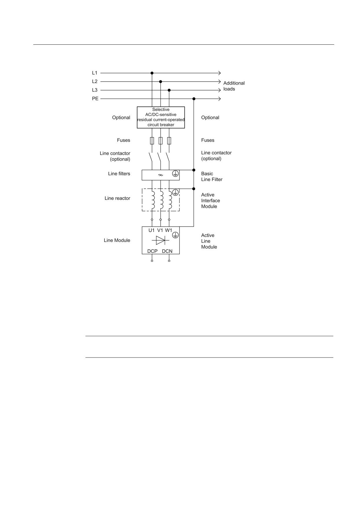
Figure 6-5
Connecting a residual-current operated circuit breaker
Recommendation
SIEMENS selectively switching AC/DC-sensitive residual-current circuit-breakers according
to EN 61009-1 of the 5SM series (e.g. 5SM3646-4 or 5SM3646-4+5SW3300 with an
auxiliary disconnector (1 NC contact / 1 NO contact) for a rated current of 63 A and rated
fault current of 0.3 A (see Catalog "BETA Modular Installation Devices - ET B1")).
Note
AC or pulse-sensitive RCCBs are not suitable.
Guidelines for machine configuration
System Manual, MA 01/2013, 6FC5397-6CP10-0BA2
113
Line connection
6.1 Power Supply Interface Variants
6.1.6
Residual-current monitors (RCM)
Used in conjunction with appropriate circuit breakers, residual-current monitors (RCMs)
provide fire and system protection even at high levels of grounding resistance (in TT
systems, for example). When operating on TT systems for infeed powers exceeding 55 kW,
and with systems that extend across a large area, residual current monitors must be installed
in addition to the appropriate circuit breakers.
WARNING
Fire hazard and danger of a plant standstill when residual currents occur
Residual currents in the power supply that are not detected can cause fires and failures in
the entire system.
• Always install residual-current monitors in conjunction with suitable circuit breakers.
Note the points below when using residual-current monitors:
● Only use AC/DC-sensitive RCM type B devices with delayed tripping that guarantee
reliable tripping even for smoothed DC residual currents.
● Connect parts of the power drive system and the machine that can be touched to the
system's protective conductor.
● Do not route the protective conductor through the measuring current transformer, as this
would cancel its protection function.
Guidelines for machine configuration
114
System Manual, MA 01/2013, 6FC5397-6CP10-0BA2
Line connection
6.1 Power Supply Interface Variants
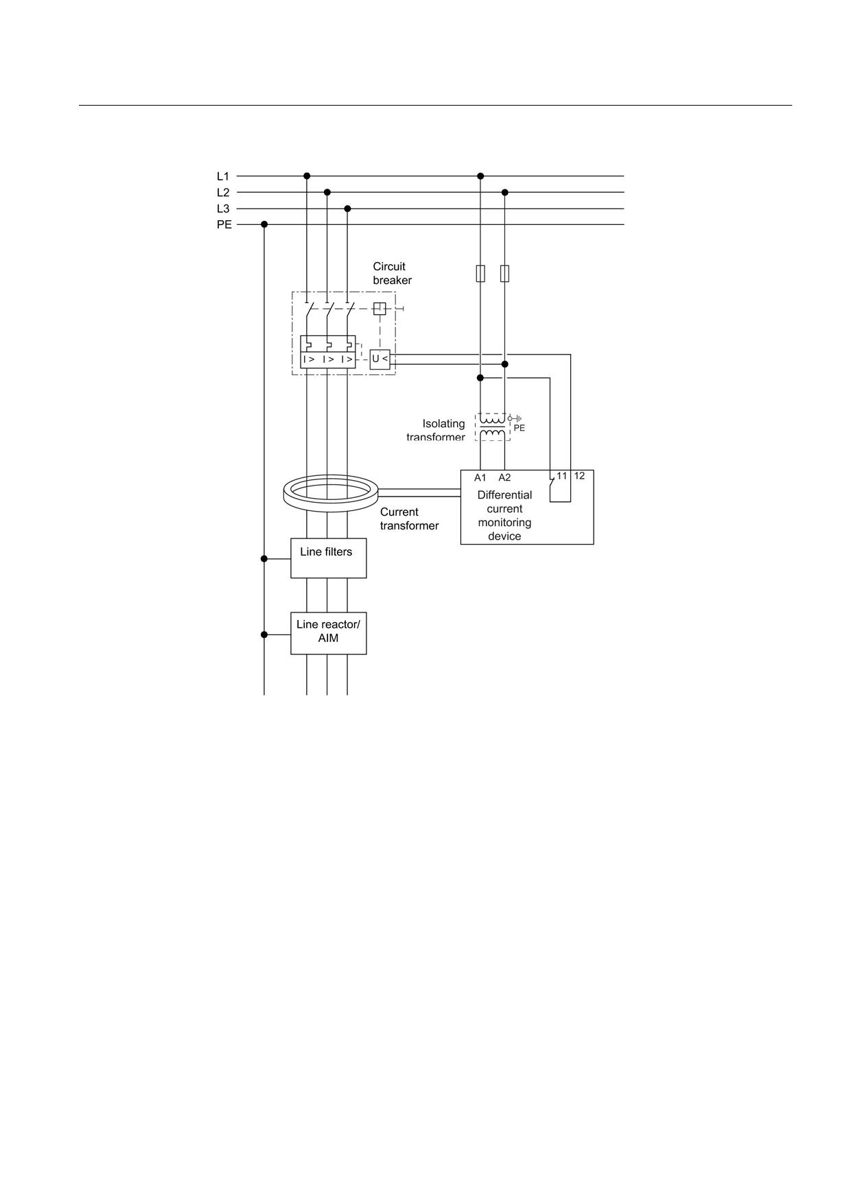
Figure 6-6
Connecting a residual-current monitor
Recommendation
● Bender AC/DC-sensitive residual-current monitor RCMA471LY, with measuring current
transformer W120B (120 mm) or W210B (210 mm)
● Circuit breaker with thermal overload release, short-circuit release, and undervoltage
release
To protect the units against line-side surge voltages, you are advised to install an
overvoltage protection device directly at the infeed point (upstream of the main switch). To
fulfill the requirements of CSA C22.2 no. 14-05, surge protection is essential. For examples
of suitable voltage surge arresters, see www.raycap.com (for example)
Guidelines for machine configuration
System Manual, MA 01/2013, 6FC5397-6CP10-0BA2
115
Line connection
6.2 Overcurrent protection by means of line fuses and circuit breakers
6.2
Overcurrent protection by means of line fuses and circuit breakers
Line fuses or, preferably, circuit breakers must be used for line/overcurrent protection in
order to limit the damage to a Line Module if a fault occurs. NH, D, and DO type fuses with a
gL characteristic or suitable circuit breakers according to IEC 60947 can be used for this
purpose.
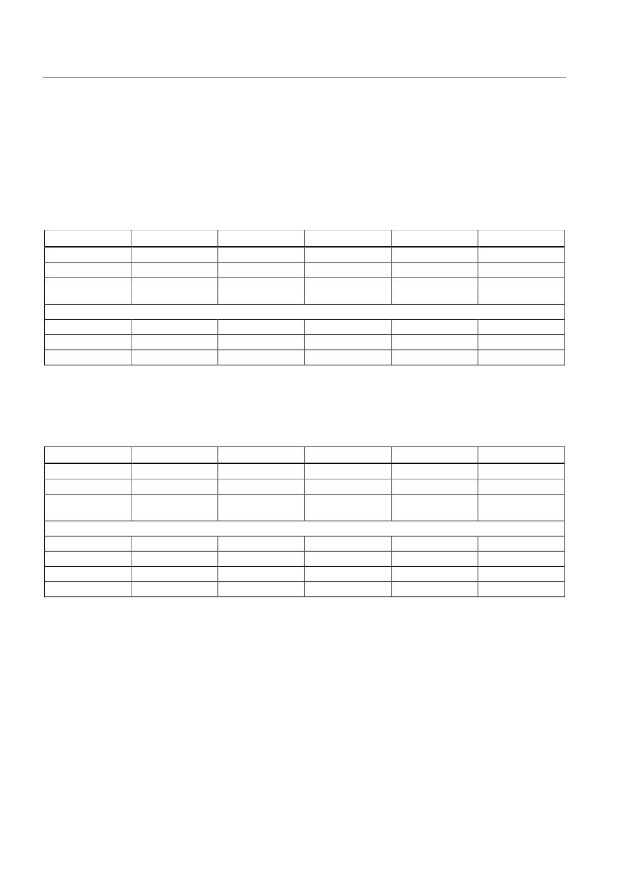
Table 6- 1
Recommended line fuses and circuit breakers for Active Line Modules
16 kW
36 kW
55 kW
80 kW
120 KW
In fuse
35 A
80 A
125 A
160 A
250 A
LV HRC line fuse
3NA3 814
3NA3 824
3NA3 132
3NA3 136
3NA3 144
Circuit breaker
3RV1031-4FA10
3RV1041-4LA10
3VL2712-1DC33
3VL3720-1DC33
3VL3725-1DC36
(IEC 60947)
UL-application
Rated current
35 A
80 A
125 A
175 A
250 A
Line fuse 1)
AJT35
AJT80
AJT125
AJT175
AJT250
Circuit breaker
3VL1135-2KM30
3VL2108-2KN30
3VL2112-2KN30
3VL3117-2KN30
3VL3125-2KN30
1) Type AJT class J, source of supply: Ferraz Shawmut
Table 6- 2
Recommended line fuses and circuit breakers for Smart Line Modules in booksize and booksize compact
format
5 kW
10 kW
16 kW
36 kW
55 kW
In fuse
16 A
35 A
35 A
80 A
125 A
LV HRC line fuse
3NA3 805
3NA3 814
3NA3 814
3NA3 824
3NA3 132
Circuit breaker
3RV1031-4BA10
3RV1031-4FA10
3RV1031-4FA10
3RV1041-4LA10
3VL2712-1DC33
(IEC 60947)
UL-application
Rated current
17.5 A
35 A
35 A
80 A
125 A
Line fuse 1)
AJT17-1/2
AJT35
AJT35
AJT80
AJT125
Rated current
20 A
35 A
35 A
80 A
125 A
Circuit breaker
3VL1102-2KM30
3VL1135-2KM30
3VL1135-2KM30
3VL2108-2KN30
3VL2112-2KN30
1) Type AJT class J, source of supply: Ferraz Shawmut
If used in conjunction with a residual-current monitor (RCM), circuit breakers providing an
"undervoltage tripping" option should be used, with the following suffixes added to the order
numbers:
...-2AJ0 for 380 VAC - 415 VAC
...-2AK0 for 440 VAC - 480 VAC
Guidelines for machine configuration
116
System Manual, MA 01/2013, 6FC5397-6CP10-0BA2
Line connection
6.3 Line Contactor Control
WARNING
Risk of electric shock and risk of fire due to insufficient overcurrent protection devices
In order to avoid the risk of fire or electric shock, overcurrent protection devices should be
dimensioned so that, when a fault occurs, the equipment is switched off sufficiently quickly.
Measurements must be taken at the installation site to determine whether the short-circuit
current is sufficient to trip the protective devices quickly enough. Not only must the loop
impedance be measured and the expected short-circuit current calculated, but the time-
current characteristics of the overcurrent protection devices must also be compared, using
measuring instruments in accordance with EN 61557-3.
If the necessary break times are not maintained, then the next smallest overcurrent
protection devices must be used. Under no circumstances may fuses with a higher rated
current ln than specified be used.
Note
The devices can be connected to supply systems of up to 480 VAC, which can supply a
maximum of 65 kA symmetrically ("prospective current" according to EN 60269-1).
6.3
Line Contactor Control
The line contactor is used for the electrical isolation of the drive group and the DC link from
the energy supply system.
When selecting a line contactor, the characteristic values in the technical data apply. The
cable routing, the bundling factor, and the factor for the ambient temperature according to
EN 60204-1 must be taken into account when dimensioning the various cables.
CAUTION
Line contactors must not be switched under load.
Note
To limit the switching overvoltage, the contactor coil must be connected to a surge
suppression device (e.g. freewheeling diode or varistor).
When the digital output is used to control the line contactor, its switching capacity must be
taken into account.
Guidelines for machine configuration
System Manual, MA 01/2013, 6FC5397-6CP10-0BA2
117
Line connection
6.3 Line Contactor Control
6.3.1
Line contactor control for Line Modules without DRIVE-CLiQ interface (5 kW
and 10 kW versions)
If a line contactor is required for Line Modules without DRIVE-CLiQ interface, it must be
controlled and monitored using an external controller.
NOTICE
Device damage due to incorrect activation or deactivation sequence
The line contactor or Line Module may be destroyed if an incorrect activation or
deactivation sequence is used.
• When controlling the line contactor, make sure that switching of it is largely load-free.
• It is essential that you adhere to the following specifications for activation and
deactivation:
Activation:
Once the line contactor has been activated and a feedback is present, the pulse enable
(Enable Pulses) of the -X21:3/4 terminal can be made.
Deactivation:
Deactivation of the line contactor (LC) may only be carried out in a specific timing for the
pulse enable (Enable Pulses) (-X21:3/4) and/or Ready (-X21:1) signals.
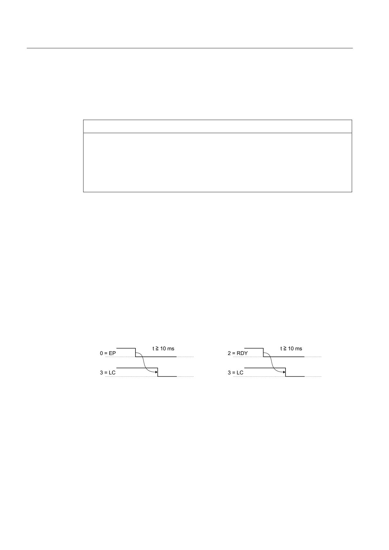
● Pulse enable (EP):
A deactivation of the line contactor may only be made when the pulse enable (EP) signal
has been removed previously (t ≥ 10 ms). The current is removed during the delay time.
● Ready:
When the ready message leaves the SLM, the line contactor may only, if required, be
deactivated after a delay time (t ≥ 10 ms). The current is removed during the delay time.
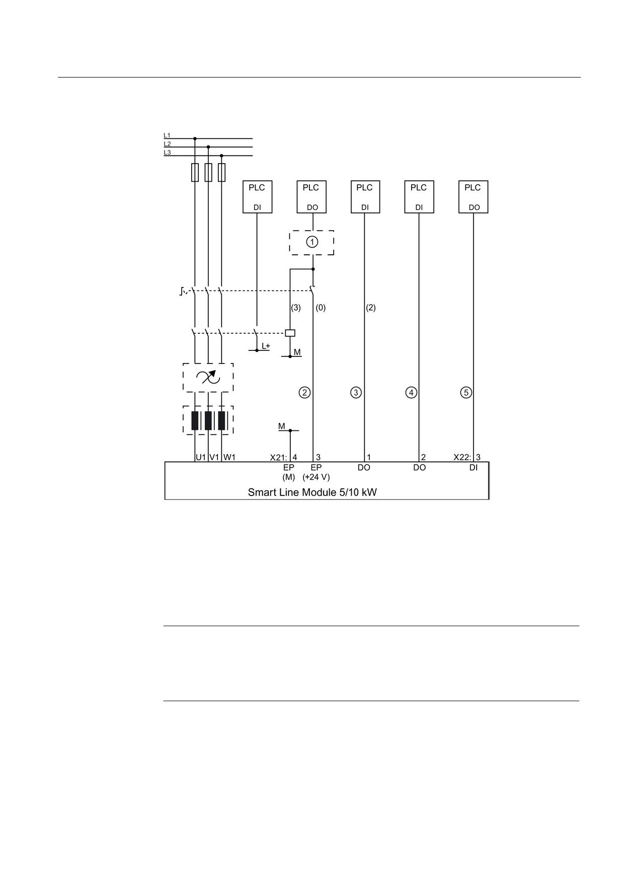
Figure 6-7
Line contactor control signal chart
Guidelines for machine configuration
118
System Manual, MA 01/2013, 6FC5397-6CP10-0BA2
Line connection
6.3 Line Contactor Control
① Safety control
② Pulse enable
③ Ready
④ Prewarning
⑤ Reset
The numbers in brackets (3), (0), (2) refer to the numbers in the previous graphic.
Figure 6-8
Line Contactor Control for Smart Line Module without DRIVE-CLiQ
Note
If the line contactor should also be safely disconnected (safety), the control must be
integrated in an existing safety control. This is the only way to ensure the line contactor is
switched in accordance with the required safety categories; see also the chapter titled
Safety Integrated (Page 483).
Guidelines for machine configuration
System Manual, MA 01/2013, 6FC5397-6CP10-0BA2
119
Line connection
6.3 Line Contactor Control
6.3.2
Line Contactor Control for Line Modules with DRIVE-CLiQ Interface
Line Modules with DRIVE-CLiQ interface can control an external line contactor. The closing
and opening of the line contactor can be monitored by evaluating the feedback contact of the
line contactor. This control ensures that the line contactor always switches in a defined
manner and so prevents overloading or damaging the line contactor and/or the infeed.
The line contactor can be controlled using the r0863.1 bit of the INFEED drive object (for
840D sl and 16 kW to 120 kW Line Module).
Note
For further information about the line contactor, refer to the device manuals.
Note
If the line contactor should also be safely disconnected (safety), the control must be
integrated in an existing safety control. This is required so that the line contactor is switched
in accordance with the required safety categories. See also Section Safety Integrated
(Page 483).
Guidelines for machine configuration
120
System Manual, MA 01/2013, 6FC5397-6CP10-0BA2
Line connection
6.3 Line Contactor Control
6.3.3
Line Contactor Control Commissioning using an Example
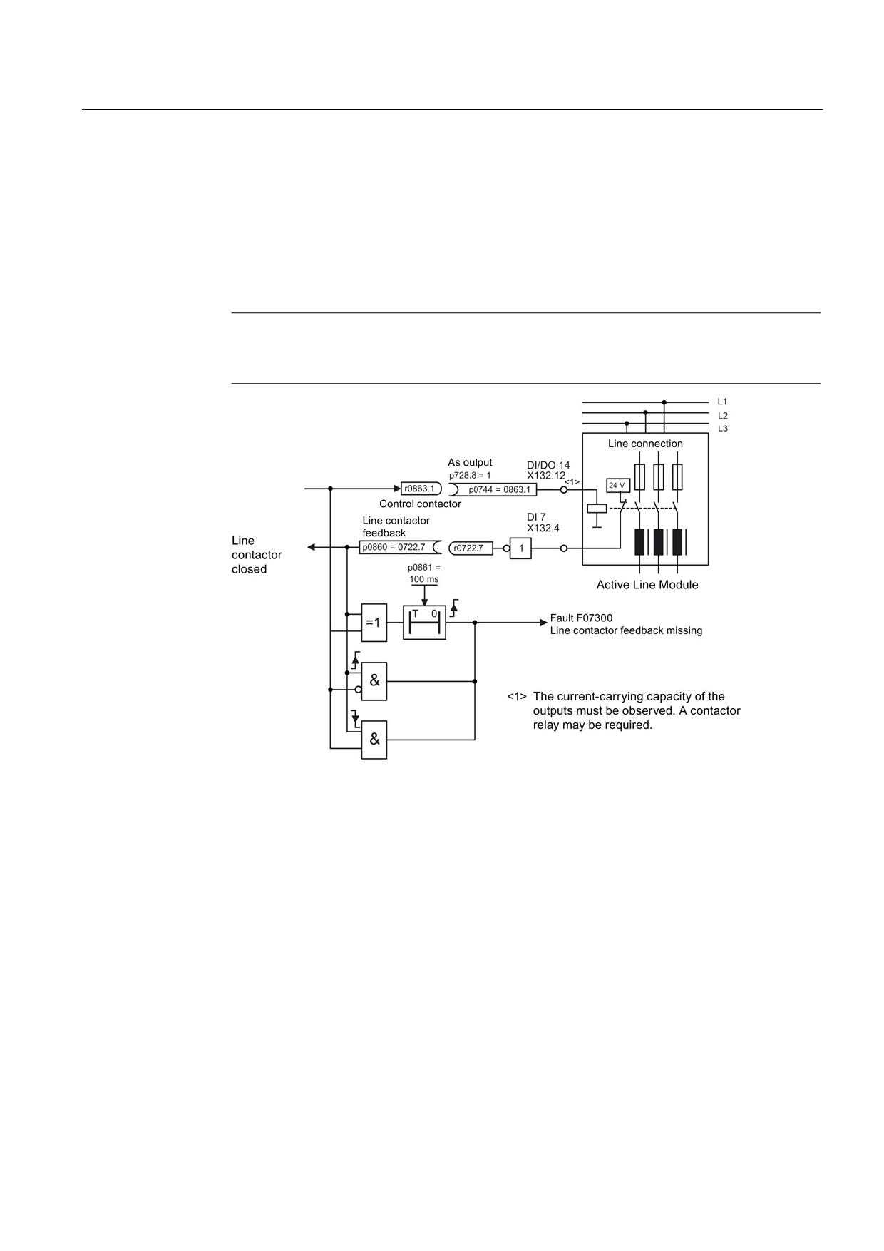
Assumption:
● Line contactor control uses a digital output of the Control Unit (DI/DO 14)
● Line contactor feedback uses a digital input of the Control Unit (DI/DO 7)
● Line contactor switching time is less than 100 ms
Note
The parameter assignment for interface X132 at pins 4 and 12 must be changed using
the "SINUMERIK Operate" drive commissioning wizard.
Figure 6-9
Line Contactor Control
Guidelines for machine configuration
System Manual, MA 01/2013, 6FC5397-6CP10-0BA2
121
Line connection
6.3 Line Contactor Control
Commissioning steps:
Note
If the current carrying capacity of the digital output may be exceeded, an auxiliary contactor
must be used (refer to the Booksize Power Units Equipment Manual).
1. Connect control contact of the line contactor to DI/DO 14.
2. Parameterize DI/DO 14 as output (p0728.14 = 1).
3. Interconnect (BI: p0744 = r0863.1 of NCU) DI/DO 14 with "control contactor" signal
(r0863.1 of infeed).
4. Connect the feedback contact of the line contactor to DI 7.
5. Interconnect (BI: p0860 = r0722.7) p0860 with inverted input signal (p0722.7).
6. Enter the monitoring time of the line contactor (p0861 = 100 ms).
Function diagram overview
●
8934 missing enables, line contactor control
Parameter overview
● r0863.1 CO/BO: Drive coupling status word/control word
● p0860 BI: Line contactor feedback
References
/LH1/SINAMICS S120/S150 List Manual
Guidelines for machine configuration
122
System Manual, MA 01/2013, 6FC5397-6CP10-0BA2
Line connection
6.4 Line filters
6.4
Line filters
6.4.1
Safety instructions for line filters
Note
When using a line filter, also observe the safety instructions in Section 1.
CAUTION
Risk of burns due to high surface temperatures
The line filter can become very hot. You can get seriously burnt when touching the surface.
• Mount the line filter so that contact is not possible. If this is not possible, attach a clearly
visible and understandable warning notice at hazardous positions.
• To prevent adjacent components from suffering damage due to these high
temperatures, maintain a clearance of 100 mm on all sides of the line filter.
NOTICE
Line filter damage by connecting to impermissible line supplies
Line filters are only suitable for direct connection to TN line supplies.
NOTICE
Line filter damage due to interchanged connections
The input and output connections/terminals must not be interchanged:
• Incoming line cable to LINE L1, L2, L3, and
• Outgoing line to line reactor at LOAD L1´, L2´, L3´ (U, V, W).
The line filter may be damaged if this is not observed.
WARNING
Fire hazard due to overheating because of inadequate ventilation clearances
Inadequate ventilation clearances cause overheating with a risk for personnel through
smoke development and fire. Damage can still occur on the line filter.
• For this reason, maintain the 100 mm clearances above and below the line filter.
NOTICE
Using an incorrect line filter
Line filters may only be used in combination with the components listed in Section
"Possible line reactor and line filter combinations".
Guidelines for machine configuration
System Manual, MA 01/2013, 6FC5397-6CP10-0BA2
123
Line connection
6.4 Line filters
NOTICE
Damage or destruction of additional loads as a result of undesirable line harmonics
Only the line filters described in this manual must be used. Other line filters can cause line
harmonics that can interfere with or damage other loads fed from the line supply.
NOTICE
Damage or destruction of additional loads by connecting after the line filter
The associated Line Module must only be connected to the SINAMICS line filter via the
associated line reactor. Additional loads must be connected upstream of the SINAMICS line
filter (if required, via a separate line filter). If this is not observed, other loads could be
damaged or destroyed.
Note
Disconnect the line filter for a high-voltage test
If a high-voltage test is conducted with alternating voltage in the system, the existing line
filters must be disconnected in order to obtain accurate measurements.
Guidelines for machine configuration
124
System Manual, MA 01/2013, 6FC5397-6CP10-0BA2
Line connection
6.4 Line filters
6.4.2
Overview of line filters
Used in conjunction with line reactors and a consistent EMC-compliant system configuration,
line filters limit the conducted electromagnetic emissions generated by the Line Modules to
limit values that conform to EN 61800-3. For the SINAMICS S120 drive line-up, a separate
line filter must be used on the basis of the table below.
Note
Avoid mutual interference of multiple line filters
An additional line filter must be used to suppress interference in other loads. To prevent
mutual interference, this line filter must not be equipped with line-side capacitors with respect
to ground. Filter series B84144A*R120 (EPCOS) is recommended.
Note
According to product standard EN 61800-3, RFI suppression commensurate with the
relevant rated conditions must be provided and is a legal requirement in the EU (EMC
Directive). Line filters and line reactors are required in order to comply with this standard.
The use of filters of other makes can lead to limit value violations, resonances, overvoltages,
and irreparable damage to motors or other equipment. The machine manufacturer must
provide verification that the machinery to be operated with the drive products and the
installed suppression elements, e.g. line filters, are CE/EMC-compliant before the machines
are approved for delivery.
Line filter ranges that are coordinated with the different power stages are available for the
SINAMICS S120 drive system. These line filters differ with regard to the frequency range in
which they reduce the conducted emissions.
The line filter versions listed below are available for use with Line Modules.
Table 6- 3
Overview of line filters
Order number
Basic Line Filter for Active Line Modules with line reactor
16 kW
6SL3000-0BE21-6DAx
36 kW
6SL3000-0BE23-6DA1
55 kW
6SL3000-0BE25-5DAx
Basic Line Filter for Active Line Modules with Active Interface Modules
16 kW
6SL3000-0BE21-6DAx
36 kW
6SL3000-0BE23-6DA1
55 kW
6SL3000-0BE25-5DAx
80 kW
6SL3000-0BE28-0DAx
120 kW
6SL3000-0BE31-2DAx
Guidelines for machine configuration
System Manual, MA 01/2013, 6FC5397-6CP10-0BA2
125
Line connection
6.4 Line filters
Order number
Wideband Line Filter for Active Line Modules
16 kW
6SL3000-0BE21-6AAx
36 kW
6SL3000-0BE23-6AAx
55 kW
6SL3000-0BE25-5AAx
80 kW
6SL3000-0BE28-0AAx
120 kW
6SL3000-0BE31-2AAx
Basic Line Filter for Smart Line Modules
5 kW
6SL3000-0HE15-0AAx
10 kW
6SL3000-0HE21-0AAx
16 kW
6SL3000-0BE21-6DAx
36 kW
6SL3000-0BE23-6DA1
55 kW
6SL3000-0BE25-5DAx
6.4.3
Wideband Filter for Active Line Modules
Wideband Line Filters for Active Line Modules are mainly effective in the frequency range
from 150 kHz to 30 MHz; this is the range relevant to ensure compliance with the appropriate
standard. Wideband Line Filters can also effectively limit low-frequency line harmonics of
2 kHz and above; this protects additional loads connected to the same supply system
against disturbances and damage. As a result, these line filters have an extended function
area, which means that they can, to a certain extent, be used regardless of the machine
installation location and any unknown line properties (e.g. line impedance).
Wideband Line Filters must always be used in conjunction with an HFD line reactor for
Active Line Modules and not with an Active Interface Module.
Wideband Line Filters for Active Line Modules can achieve the interference voltage
categories listed below, when used in conjunction with the associated HFD line reactor and
an EMC-compliant design (see also the chapter titled "Combination options: Line reactors
and line filters"):
● EN 61800-3 category C2 up to a total cable length 1) of 350 m (shielded) for 16 kW,
36 kW, 55 kW, 80 kW, and 120 kW components
● EN 61800-3 category C3 up to a total cable length 1) of 350 m (shielded) for 16 kW,
36 kW, 55 kW, 80 kW, and 120 kW components
1) Maximum total cable length = Σ motor cables, line supply conductor from line filter to Line
Module
Note
Further information
For more detailed information on Wideband Line Filters, refer to the SINAMICS S120
Booksize Power Units Equipment Manual.
Guidelines for machine configuration
126
System Manual, MA 01/2013, 6FC5397-6CP10-0BA2
Line connection
6.4 Line filters
6.4.4
Basic Line Filters for Active Line Modules
Basic Line Filters for Active Line Modules are designed to attenuate conducted interference
emissions in accordance with the specifications contained in the relevant EMC legislation.
They are mainly effective in the frequency range from 150 kHz to 30 MHz; this is the range
relevant to ensure compliance with the appropriate standard.
Basic Line Filters can be used in conjunction with a line reactor for 16 kW, 36 kW, and
55 kW Active Line Modules or with an Active Interface Module for 16 kW, 36 kW, 55 kW,
80 kW, and 120 kW Active Line Modules. Assuming that an EMC-compatible design is used,
the interference voltage categories listed below will be achieved (see also the chapter titled
"Combination options: Line reactors and line filters").
Basic Line Filter for Active Line Modules and line reactor
● EN 61800-3 category C2 up to a total cable length 1) of 150 m (shielded) for 16 kW,
36 kW, and 55 kW components
● EN 61800-3 category C3 up to a total cable length 1) of 150 m (shielded) for 16 kW,
36 kW, and 55 kW components
Basic Line Filters for Active Line Modules and Active Interface Module
● EN 61800-3 category C2 up to a total cable length 1) of 350 m (shielded) for 16 kW,
36 kW, 55 kW, 80 kW, and 120 kW components
● EN 61800-3, category C3, up to a total cable length 1) of
-
630 m (shielded) for 16 kW and 36 kW components
–
1000 m (shielded) for 55 kW, 80 kW and 120 kW components.
1) Maximum total cable length = Σ motor cables, line supply conductor from line filter to Line
Module
The Basic Line Filters can be used in accordance with the following general conditions for
ensuring CE conformity with regard to cable-borne interference:
● The machine/system must only be used in industrial power systems
● Only connect the Basic Line Filters to TN systems; otherwise, an isolation transformer will
be required
● Number of axes ≤ 12 when using a Basic Line Filter with an Active Line Module and a line
reactor
Note
Basic Line Filters for Active Line Modules with line reactor must be approved (incurs a fee).
Note
Further information
For more detailed information on Basic Line Filters, refer to the SINAMICS S120 Booksize
Power Units Equipment Manual.
Guidelines for machine configuration
System Manual, MA 01/2013, 6FC5397-6CP10-0BA2
127
Line connection
6.4 Line filters
6.4.5
Basic Line Filter for Smart Line Modules
Basic Line Filters for Smart Line Modules are designed to attenuate conducted interference
emissions in accordance with the specifications contained in the relevant EMC legislation.
They are mainly effective in the frequency range from 150 kHz to 30 MHz; this is the range
relevant to ensure compliance with the appropriate standard.
Basic Line Filters for Smart Line Modules can achieve the interference voltage categories
listed below, when used in conjunction with the associated line reactors and an EMC-
compliant design (see also the chapter titled "Combination options: Line reactors and line
filters"):
● EN 61800-3 category C2 up to a total cable length 1) of 350 m (shielded) for 5 kW to
55 kW components
● EN 61800-3 category C3 up to a total cable length 1) of 350 m (shielded) for 5 kW to
55 kW components
Basic Line Filters are only suitable for direct connection to TN systems. An isolation
transformer is required for other systems.
1) Maximum total cable length = Σ motor cables, line supply conductor from line filter to Line
Module
Note
Further information
For more detailed information on Basic Line Filters, refer to the SINAMICS S120 Booksize
Power Units Equipment Manual.
Guidelines for machine configuration
128
System Manual, MA 01/2013, 6FC5397-6CP10-0BA2
Line connection
6.5 Active Interface Module (AIM)
6.5
Active Interface Module (AIM)
6.5.1
Description
Active Interface Modules are line-side interfaces for the Active Line Modules.
They contain the following functional units:
● Line reactor
● Low-frequency/switching frequency filters
● Line filter to EN61800-3, category C3, max. total motor cable length 350 m (shielded)
● Reduction of the stress on the motor insulation from system-dependent resonance factors
In conjunction with an Active Line Module and an EMC-compliant configuration the following
radio interference voltage categories are achieved:
● EN 61800-3 category C3 without an additional line filter up to a total cable length of
350 m (shielded) for 16 kW, 36 kW, 55 kW, 80 kW and 120 kW components
● EN 61800-3 category C2 with an additional Basic Line Filter up to a total cable length of
350 m (shielded) for 16 kW, 36 kW, 55 kW, 80 kW and 120 kW components
● EN 61800-3, category C3, with an additional Basic Line Filter up to a total cable length of
-
630 m (shielded) for 16 kW and 36 kW components
-
1000 m (shielded) for 55 kW, 80 kW, and 120 kW components
The Active Interface Module is fitted with a fan. The 24 V supply is essential for operating the
component. Connection of the temperature signaling contact to the Active Line Module is
also required.
Guidelines for machine configuration
System Manual, MA 01/2013, 6FC5397-6CP10-0BA2
129
Line connection
6.5 Active Interface Module (AIM)
6.5.2
Safety instructions for Active Interface Modules
Note
When using an Active Interface Module, also observe the safety instructions in Section 1.
NOTICE
Destruction of the Active Interface Module through incorrect settings made during
commissioning
The Active Interface Module can be destroyed through incorrect settings in the software.
Operate Active Interface Modules only with the following settings in the commissioning
wizard:
• Set the "Line filter available" option for the Active Line Module.
• Select line filter "AIM 400 V xxkW (6SL3100-0BE**-*AB*)"
In conjunction with SINAMICS V2.6, the appropriate Active Interface Module is already
preset by running the wizard in STARTER.
With firmware version SINAMICS V2.5, the default setting in STARTER/SCOUT is
"Wideband Line Filter". Parameter p0220 must be changed to "AIM".
Operation with a SINAMICS firmware less than V2.5 is not permitted.
NOTICE
Destruction of the Active Interface Module through incorrect/missing wiring
The Active Interface Module can be destroyed through incorrect wiring or a missing 24 V
supply.
• Before commissioning the Active Interface Module, it is essential to connect the 24 V
DC at connector X124 to supply the fans. Current required ≤ 1.2 A.
• Connect the temperature signaling contact of the Active Interface Module to the
temperature input of the associated Active Line Module.
CAUTION
Risk of burns due to high surface temperatures
The Active Interface Module can become very hot. You can get seriously burnt when
touching the surface.
• Mount the Active Interface Module so that contact is not possible. If this is not possible,
attach a clearly visible and understandable warning notice at hazardous positions.
• To prevent adjacent components from suffering damage due to these high
temperatures, maintain a clearance of 100 mm on all sides of the Active Interface
Module.
Guidelines for machine configuration
130
System Manual, MA 01/2013, 6FC5397-6CP10-0BA2
Line connection
6.5 Active Interface Module (AIM)
WARNING
Fire hazard due to overheating because of inadequate ventilation clearances
Inadequate ventilation clearances cause overheating with a risk for personnel through
smoke development and fire. Damage can still occur on the Active Interface Module.
• Maintain the 80 mm clearances above and below the Active Interface Module.
NOTICE
Permitted mounting position
The Active Interface Modules must only be operated when mounted in a vertical position
("hanging").
NOTICE
Connection cables
The connection cables between the Active Interface Module and the Active Line Module, as
well as between the Active Interface Module and the Basic Line Filter, must be kept as
short as possible (max. 10 m in total).
Shielded connection cables must be used in order to achieve interference voltage category
C2. The cable shields must be connected on both sides.
Guidelines for machine configuration
System Manual, MA 01/2013, 6FC5397-6CP10-0BA2
131
Line connection
6.5 Active Interface Module (AIM)
6.5.3
Interface description
6.5.3.1
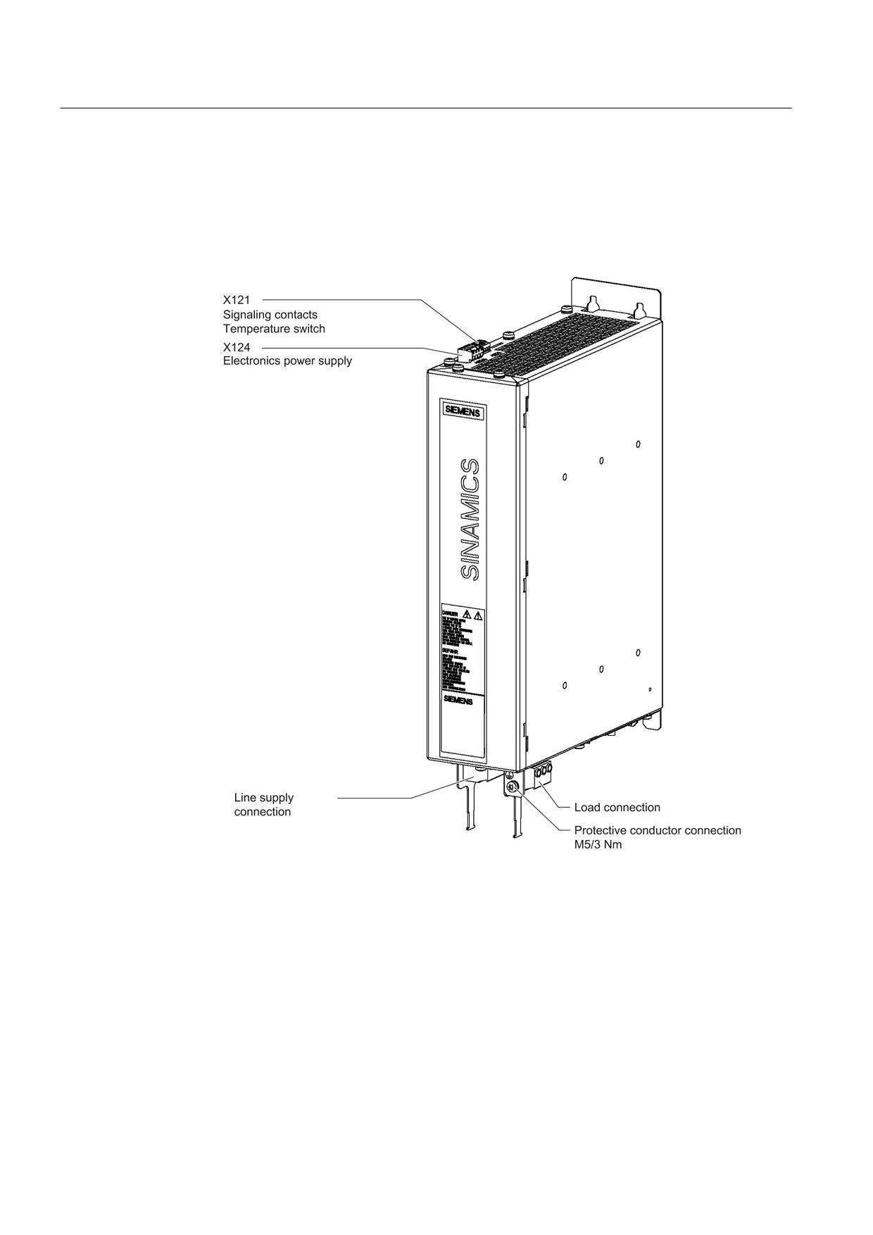
Overview
Figure 6-10 Interface overview, Active Interface Module 16 kW
Guidelines for machine configuration
132
System Manual, MA 01/2013, 6FC5397-6CP10-0BA2
Line connection
6.5 Active Interface Module (AIM)
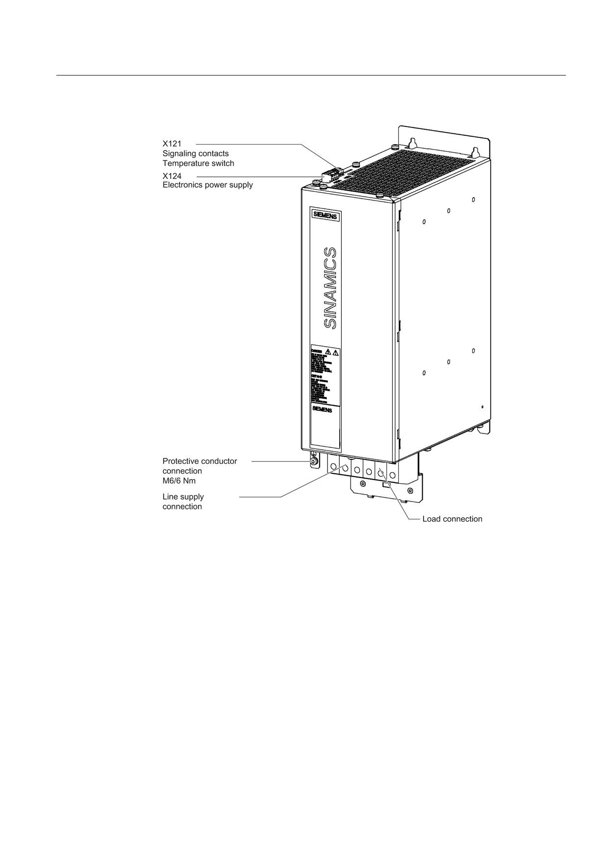
Figure 6-11 Interface overview, Active Interface Module 36 kW
Guidelines for machine configuration
System Manual, MA 01/2013, 6FC5397-6CP10-0BA2
133
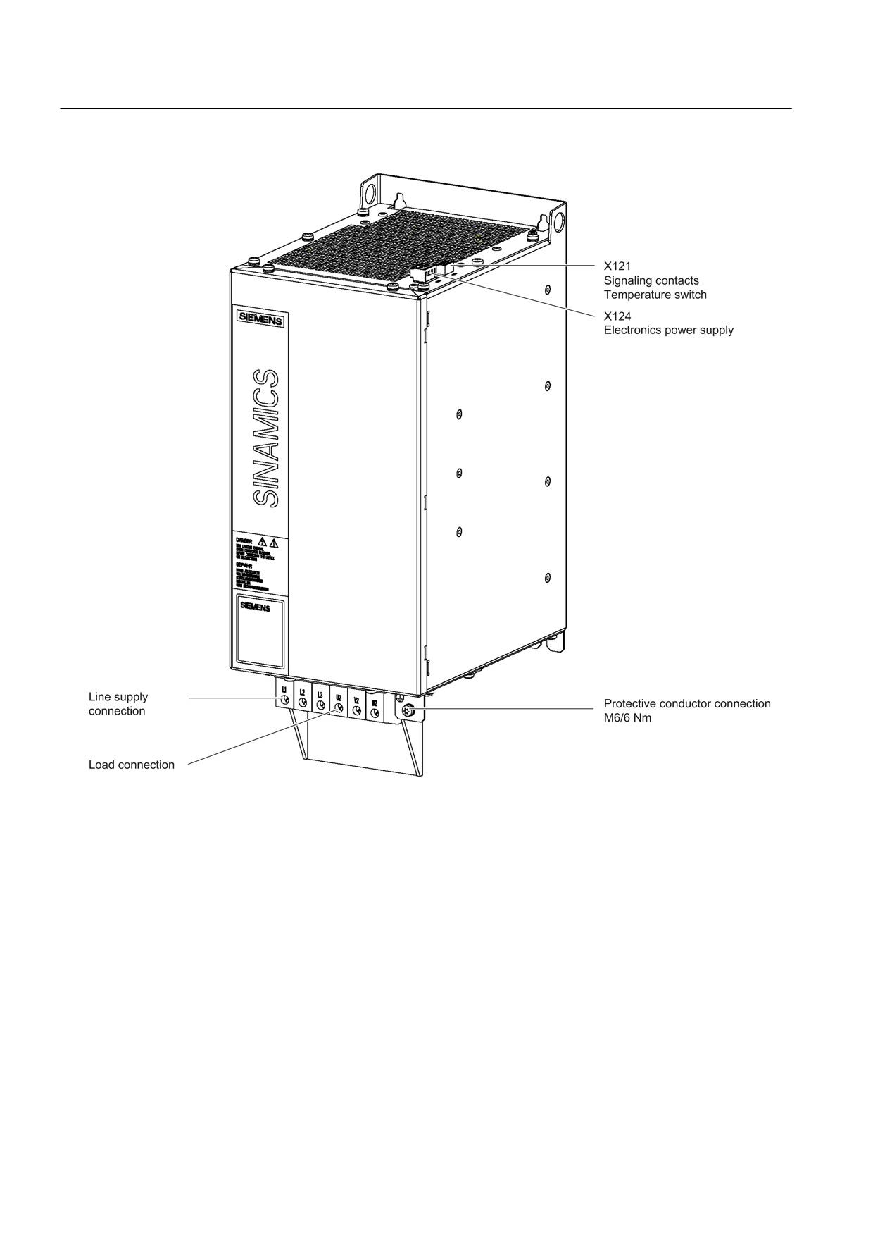
Line connection
6.5 Active Interface Module (AIM)
Figure 6-12 Interface overview, Active Interface Module 55 kW
Guidelines for machine configuration
134
System Manual, MA 01/2013, 6FC5397-6CP10-0BA2
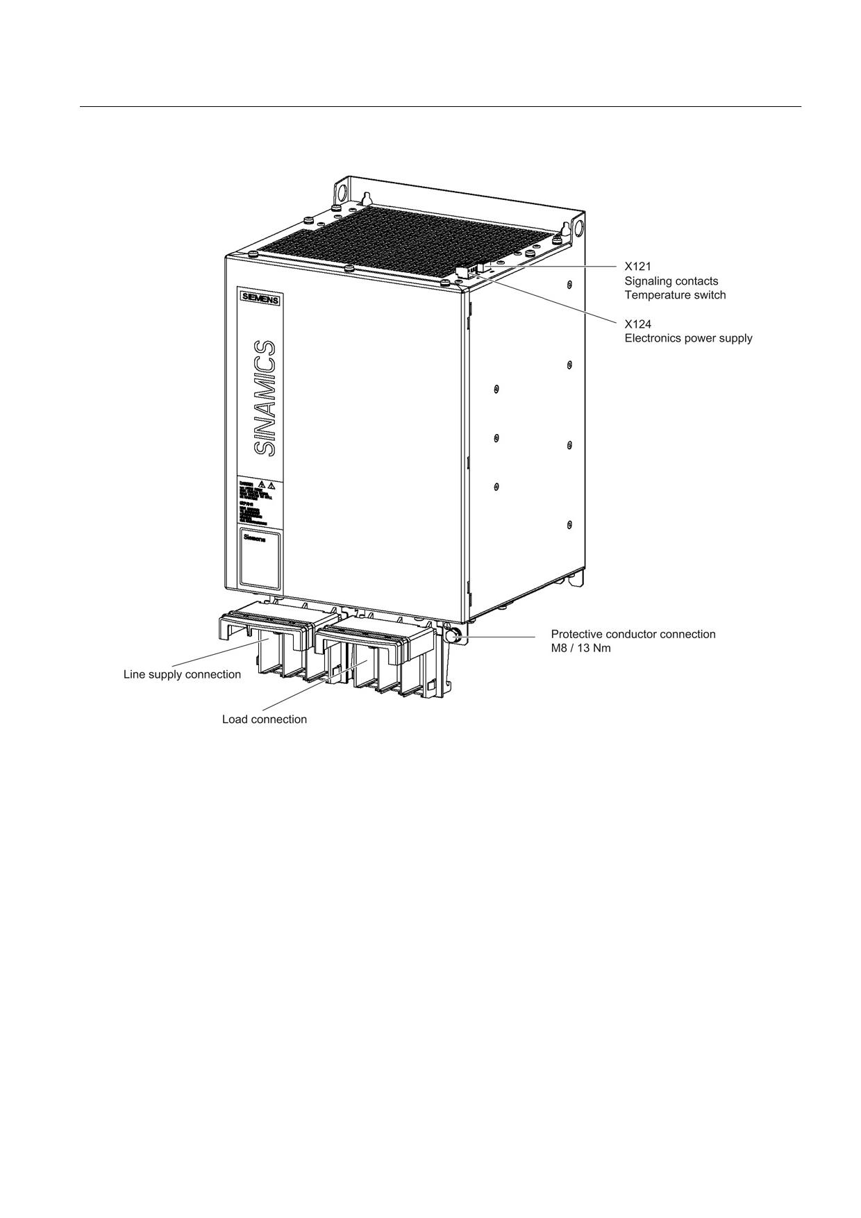
Line connection
6.5 Active Interface Module (AIM)
Figure 6-13 Interface overview, Active Interface Module 80 kW and 120 kW
Guidelines for machine configuration
System Manual, MA 01/2013, 6FC5397-6CP10-0BA2
135
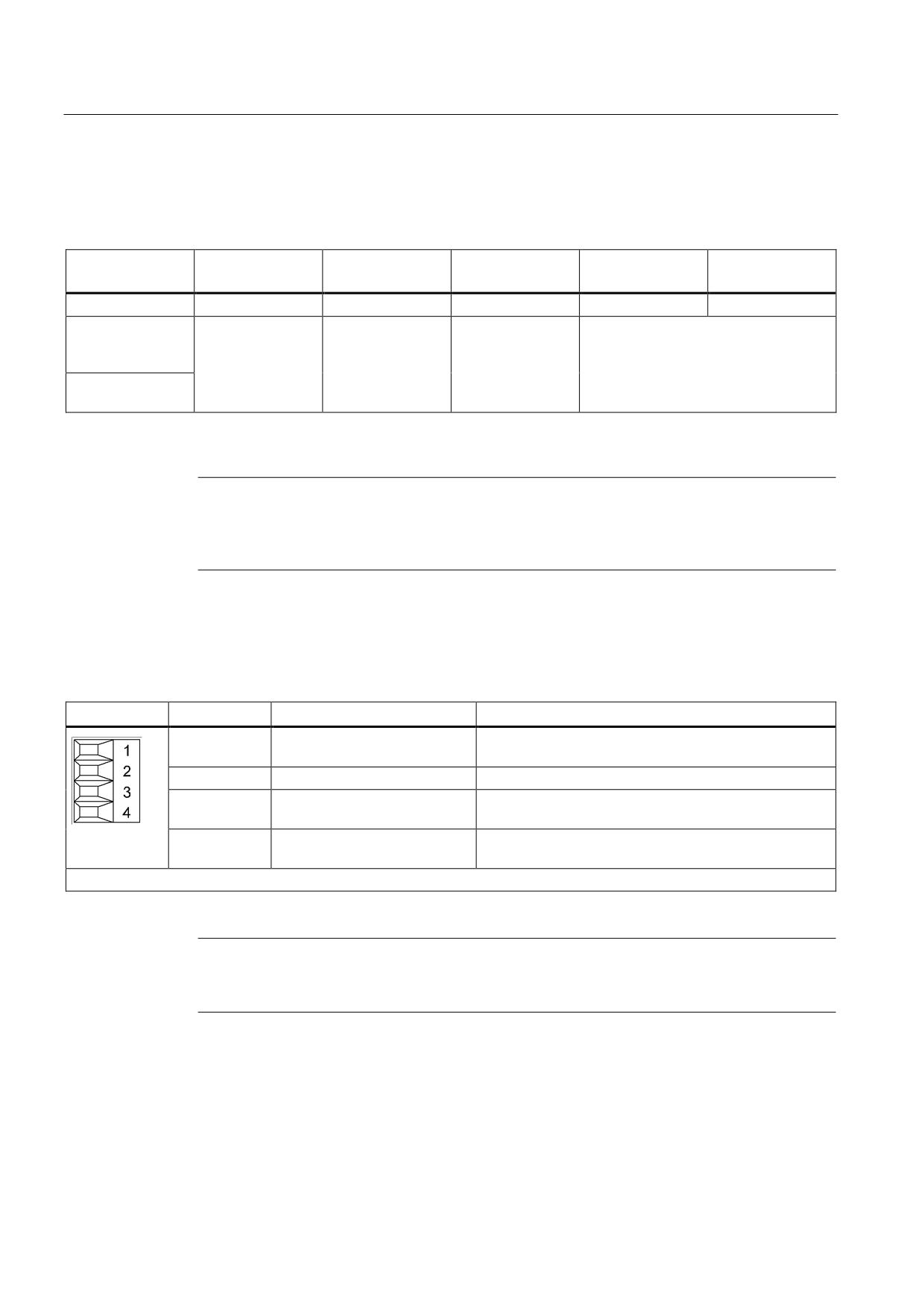
Line connection
6.5 Active Interface Module (AIM)
6.5.3.2
Line/load connection
Table 6- 4
Line and load connection Active Interface Module
6SL3100-0BE21-
6SL3100-0BE23-
6SL3100-0BE25-
6SL3100-0BE28-
6SL3100-0BE31-
6ABx
6ABx
5ABx
0ABx
2ABx
Power
16 kW
36 kW
55 kW
80 kW
120 kW
Line supply
Connector, 16
Screw terminal
Screw terminal
Threaded bolt M8,
connection
mm²
50 mm², end
50 mm², end
cross-section 120 / 2 x 50 mm²,
L1, L2, L3
sleeve,
sleeve,
1.7 Nm
13 Nm1)
Load connection
6 Nm
6 Nm
U2, V2, W2
1) For ring cable lugs in accordance with DIN 46234
Note
The connection terminals of the 36 kW and 55 kW Active Interface Modules are only certain
to be safe from touch protection according to EN 60529 if cables with a minimum cross-
section of 25 mm² and insulated end sleeve are used.
6.5.3.3
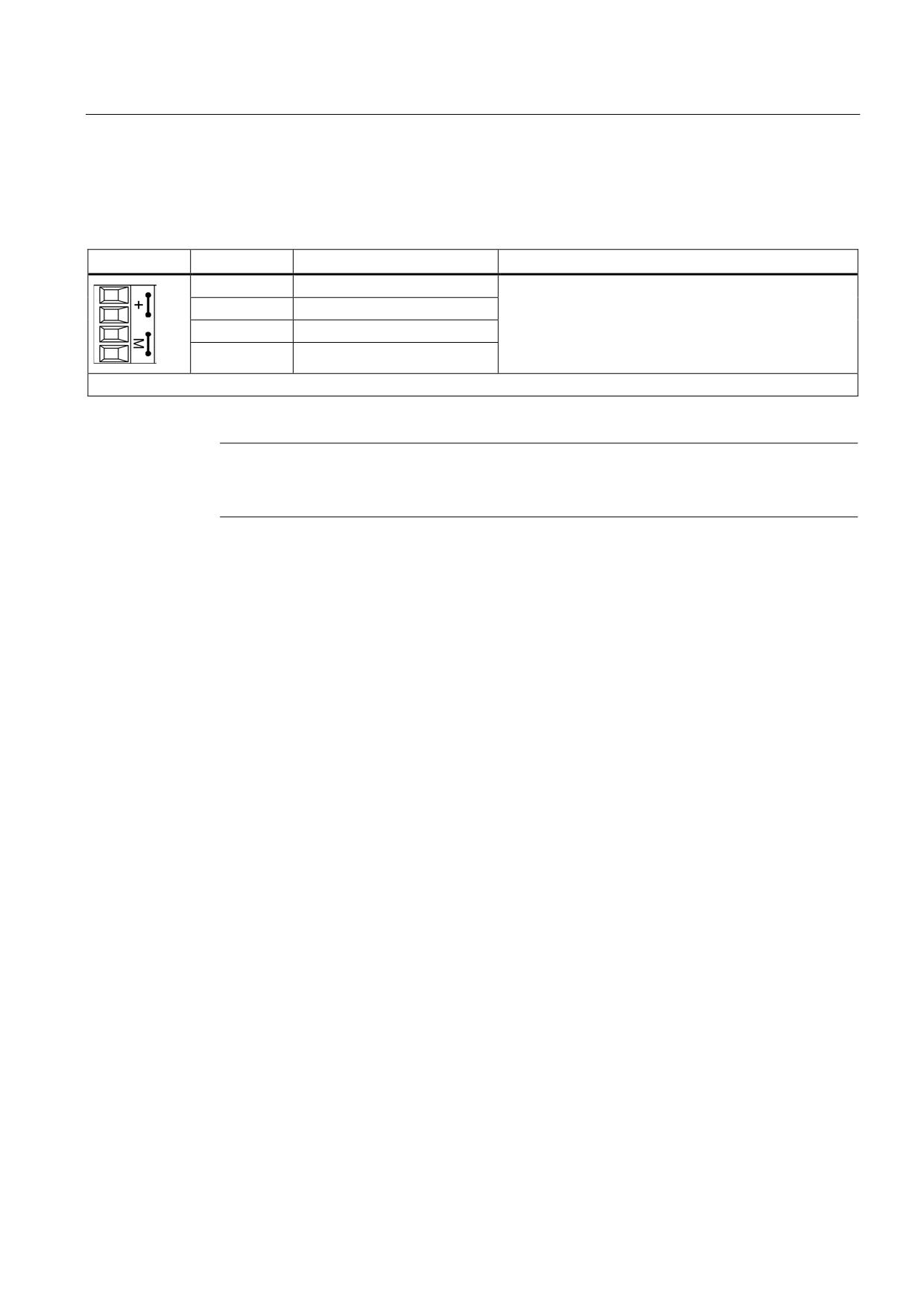
X121 temperature sensor and fan control
Table 6- 5
Plug-in screw terminal X121
Terminal
Designation
Technical specifications
1
+Temp
Output temperature switch
Must be connected to X21 of the Active Line Module
2
-Temp
Temperature switch output
3
+24 V power supply for digital
Current carrying capacity: 500 mA
inputs
4
Disable Fan
The fan can be disabled. The fan may only be switched
off while the Active Line Module is disabled.
Max. connectable cross-section: 1.5 mm2
Note
If the terminals are not connected (or connected with low level), the fan will run in continuous
mode.
Guidelines for machine configuration
136
System Manual, MA 01/2013, 6FC5397-6CP10-0BA2
Line connection
6.5 Active Interface Module (AIM)
6.5.3.4
Electronics power supply X124
Table 6- 6
Terminal block X124
Terminal
Function
Technical specifications
+
Electronics power supply
Voltage: 24 VDC (20.4 V - 28.8 V)
+
Electronics power supply
Current consumption: max. 1.6 A
M
Electronics ground
Max. current via jumper in connector:
20 A at 55 °C
M
Electronics ground
Max. connectable cross-section: 2.5 mm2
Note
The two "+" or "M" terminals are jumpered in the connector. This ensures the supply voltage
is looped through.
6.5.4
Operation on an isolated-neutral system (IT system)
6.5.4.1
IT systems
In IT systems, all live parts are isolated from ground, or one point is connected to ground
through an impedance. The exposed conductive parts of the electrical installation are either
grounded separately or grounded together, or jointly connected to the system ground.
Only Line Modules without a line filter are to be operated on this system type. The emitted
interference can exceed the limit values of category C3. The Active Interface Module must
be set for operation on an IT system.
Guidelines for machine configuration
System Manual, MA 01/2013, 6FC5397-6CP10-0BA2
137
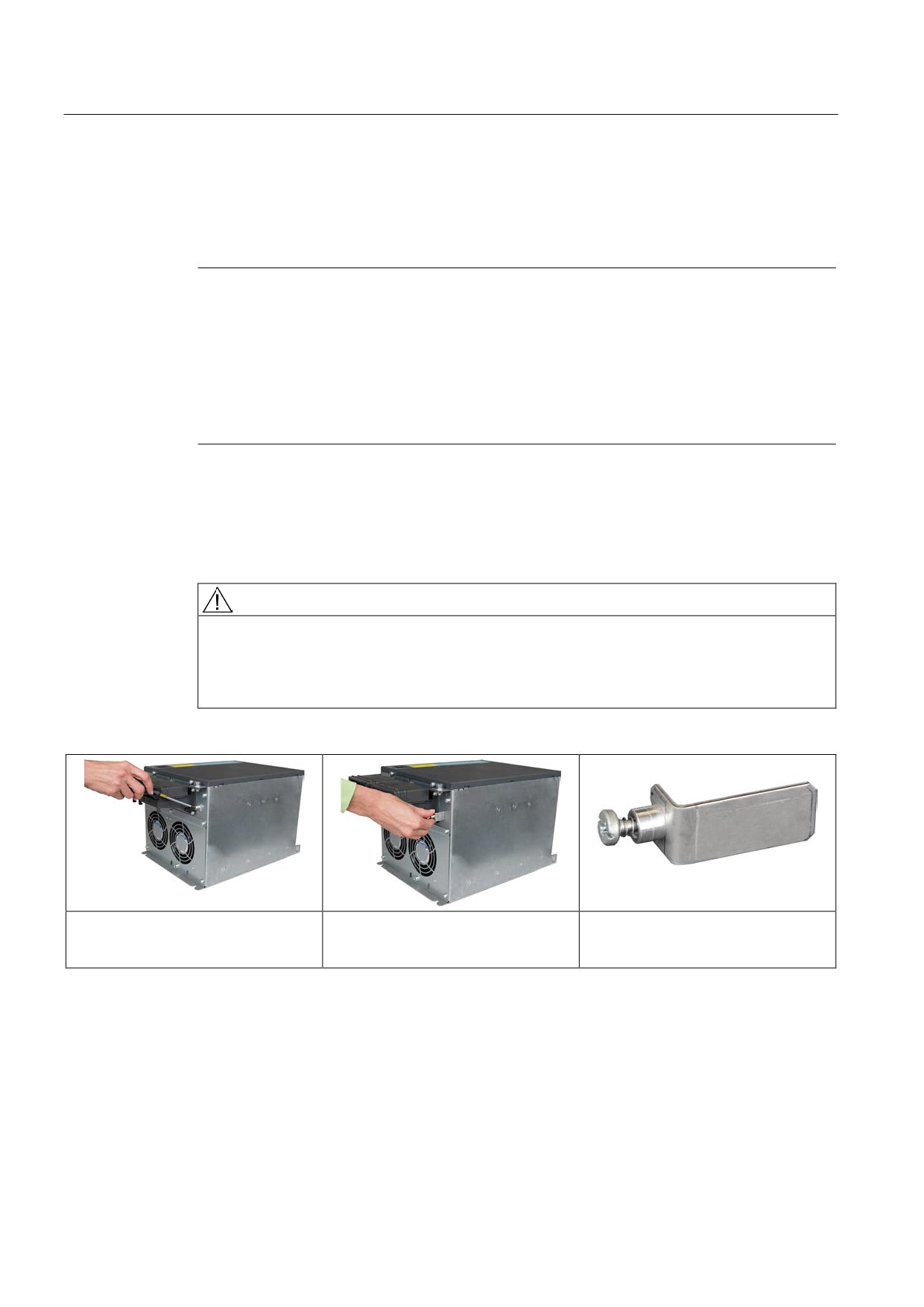
Line connection
6.5 Active Interface Module (AIM)
6.5.4.2
Operating an Active Interface Module on an isolated-neutral line supply (IT line supply)
Operating an Active Interface Module on an isolated-neutral line supply (IT line supply)
Note
When an Active Interface Module is operated in an isolated-neutral line supply (IT line
supply), the connection bracket for the interference suppression capacitor in the AIM must
be removed. The connection bracket for the interference-suppression capacitor is located on
the lower side of the component.
If the connection bracket for the interference-suppression capacitor is not removed, an
insulated supply will be grounded and may cause tripping of the isolation monitor in the case
of failure.
There are no limits of interference for isolated-neutral systems. Removing the connection
bracket to the interference-suppression capacitor eliminates the effect of the filter against
ground. It nevertheless makes sense to install an Active Interface Module because the clock
frequency filter is still active and also protects other loads on the same network from clock
frequency disturbances.
DANGER
De-energize the device before removing the connection bracket
The connecting bracket may only be removed in the de-energized state.
Risk of electric shock. A hazardous voltage is still present for up to five minutes after the
power supply has been switched off.
Remove the connection bracket for the
Remove the connection bracket.
Connection bracket for the
interference-suppression capacitor with
interference-suppression capacitor
a Tx25 screwdriver.
Guidelines for machine configuration
138
System Manual, MA 01/2013, 6FC5397-6CP10-0BA2
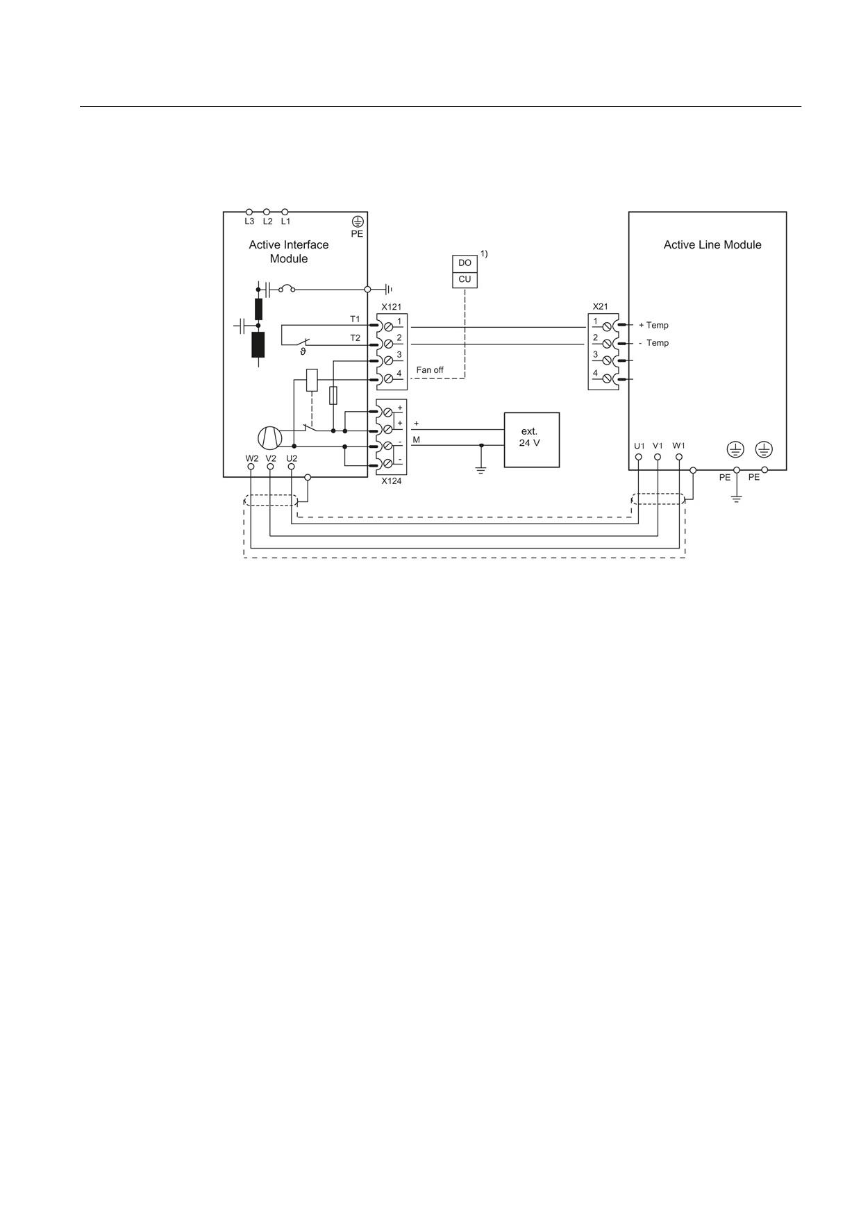
Line connection
6.5 Active Interface Module (AIM)
6.5.5
Connection example
Figure 6-14 Connection example: Active Interface Module
1) Digital output (DO) controlled from the Control Unit
Guidelines for machine configuration
System Manual, MA 01/2013, 6FC5397-6CP10-0BA2
139