SINUMERIK 840D sl. Service - Configuring Commissioning. Manual (2011-2020) - page 33
Connection of the components in SINAMICS drive system
8.4 Connection of motor modules
8.4.2.2
Interface description
Overview
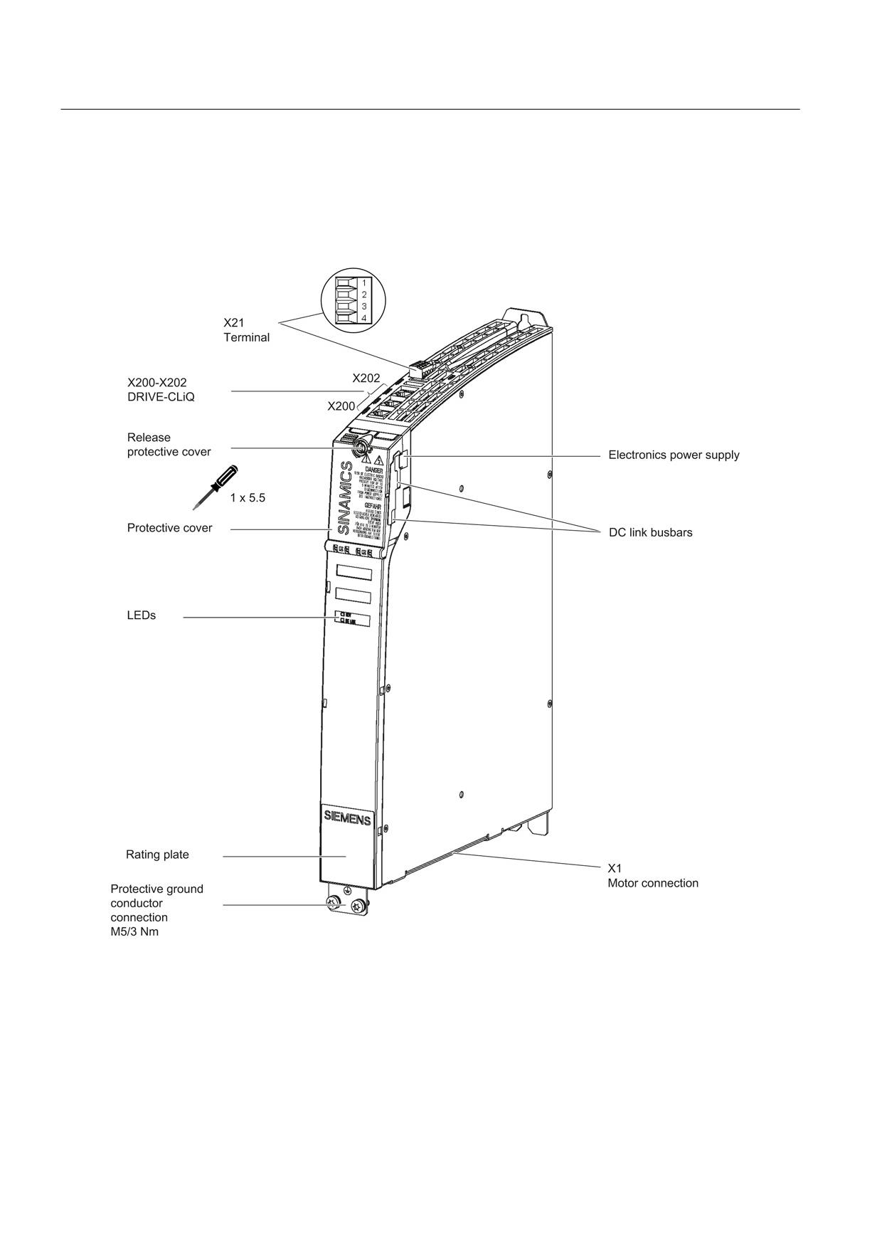
Figure 8-96 Interface overview, Single Motor Module Booksize with internal air cooling (example: 5 A)
Guidelines for machine configuration
346
System Manual, MA 01/2013, 6FC5397-6CP10-0BA2
Connection of the components in SINAMICS drive system
8.4 Connection of motor modules
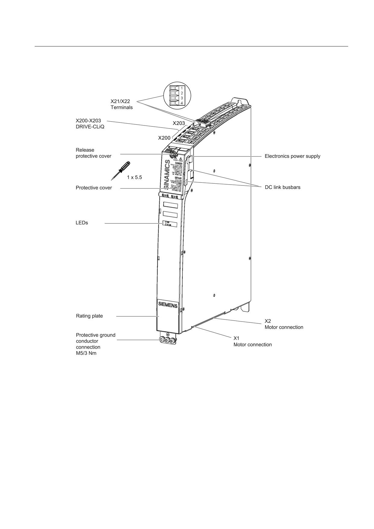
Figure 8-97 Interface overview, Double Motor Module Booksize with internal air cooling (example: 2 x 5 A)
Guidelines for machine configuration
System Manual, MA 01/2013, 6FC5397-6CP10-0BA2
347
Connection of the components in SINAMICS drive system
8.4 Connection of motor modules
Motor and brake connection
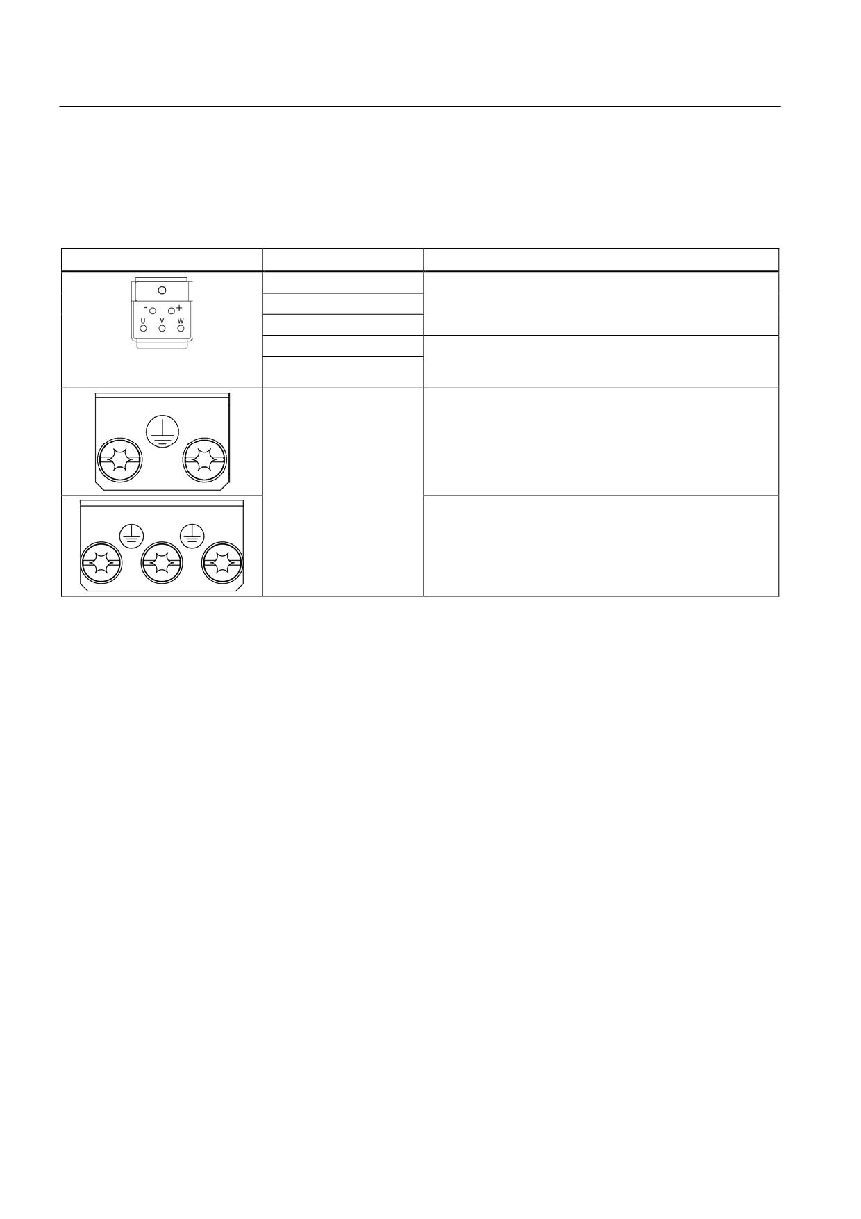
Table 8- 80 X1/X2 motor and brake connection for Single Motor Modules 3 A to 30 A and Double Motor Modules 3 A to
18 A
Terminal
Technical data
U (U2)
Motor connection
V (V2)
W (W2)
+ (BR+)
Brake connection
max. load current 2 A
- (BR-)
min. load current 0.1 A
PE connection
Single Motor Modules 3 A to 30 A:
Threaded hole M5/3 Nm 1)
Double Motor Modules 3 A to 18 A:
Threaded hole M5/3 Nm 1)
1) For ring cable lugs in accordance with DIN 46234
Guidelines for machine configuration
348
System Manual, MA 01/2013, 6FC5397-6CP10-0BA2
Connection of the components in SINAMICS drive system
8.4 Connection of motor modules
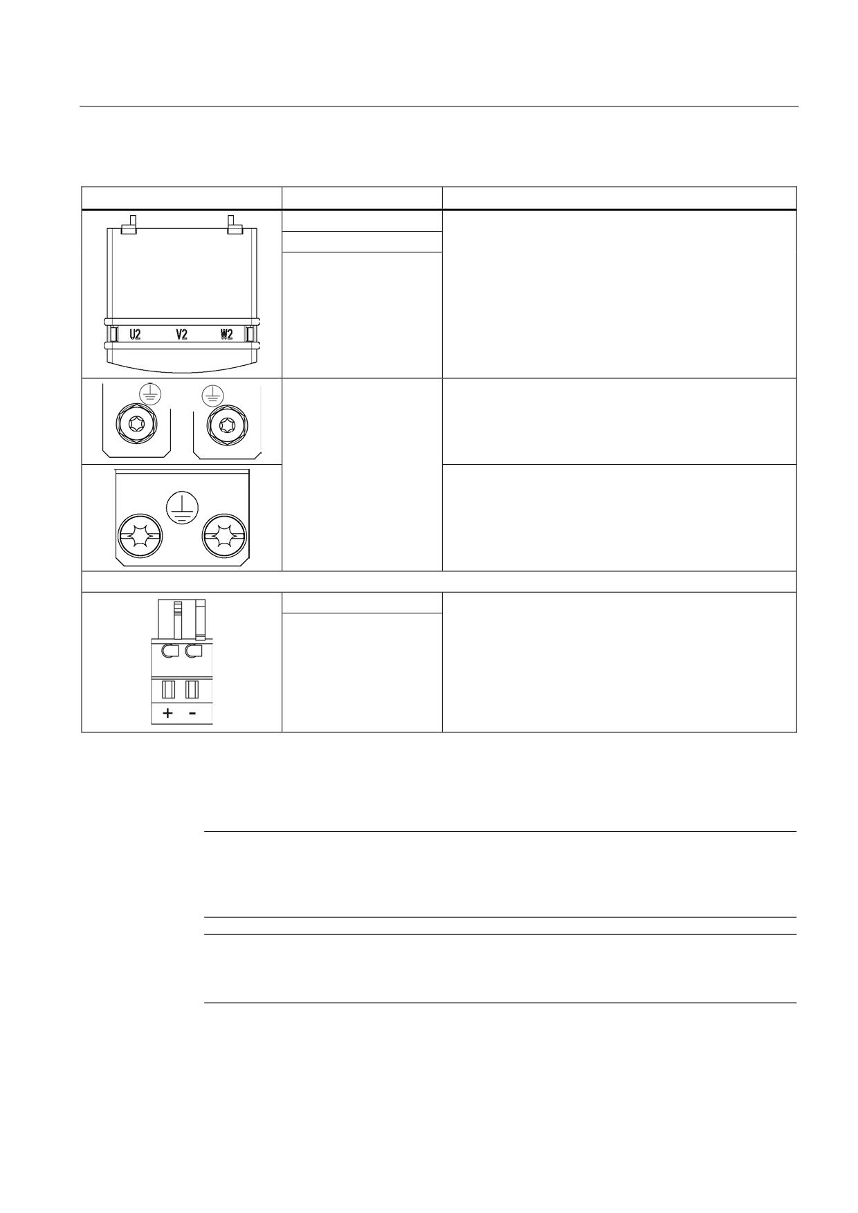
Table 8- 81 X1 motor connection and X11 brake connection for Single Motor Modules 45 A to 200 A
Terminal
Technical data
U2
45 A to 60 A:
Threaded bolts M6/6 Nm 1)
V2
85 A:
W2
Threaded bolts M8/13 Nm 1)
132 A to 200 A:
Threaded bolts M8/13 Nm 1)
PE connection
45 A to 60 A:
Threaded bolts for motor cables: M6/6 Nm 1)
Threaded hole for PE: M6 / 6 Nm 1)
85 A:
Threaded bolts for motor cables: M8/13 Nm 1)
Threaded hole for PE: M6 / 6 Nm 1)
132 A to 200 A:
Threaded bolts for motor cables: M8/13 Nm 1)
Threaded hole for PE: M8 / 13 Nm 1)
+ (BR+)
X11 brake connector 2):
- (BR-)
Voltage 24 VDC
Max. load current 2 A
Min. load current 0.1 A
Max. connectable cross-section 2.5 mm2
Type: Spring-loaded terminal 2
(see Appendix, Chapter "Spring-loaded terminals")
The brake connector is part of the prefabricated cable
1) For ring cable lugs in accordance with DIN 46234
2) The circuit for protecting the brake against overvoltage is integrated in the Motor Module and does not need to be
installed externally. The max. load current is 2 A, the min. load current 0.1 A.
Note
The total length of the power cables (motor supply cables and DC link cables) must not
exceed the values listed in the chapter titled "Possible line reactor and line filter
combinations (Page 158)".
Note
The motor brake must be connected via connector X11. Directly connecting the BR- cable to
the electronics ground M is not permitted.
Guidelines for machine configuration
System Manual, MA 01/2013, 6FC5397-6CP10-0BA2
349
Connection of the components in SINAMICS drive system
8.4 Connection of motor modules
WARNING
Safety extra-low voltages at connections and terminals
Only protective extra-low voltages (DVC A) that comply with EN 60204-1 may be connected
to all connections and terminals between 0 and 48 VDC.
The voltage tolerances of the motor holding brakes (24 V ±10%) must be taken into
account.
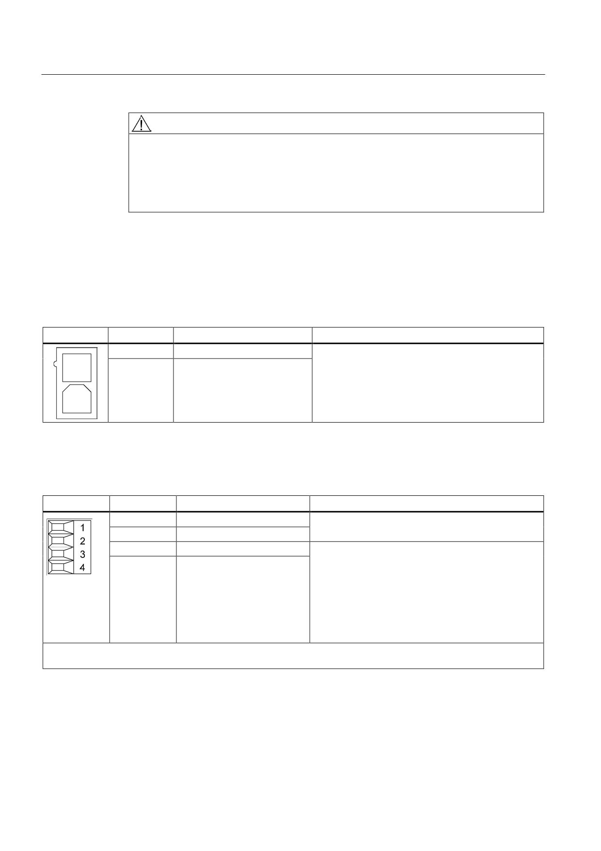
X12 fan connection
The Motor Modules 132 A and 200 A are equipped with an interface to connect a sub-
chassis fan. The interface is located on the underside of the Motor Module.
Table 8- 82 X12 fan connection
Terminal
Function
Technical specifications
1
Fan connection +
Voltage 48 V DC for the supplied fan
2
Fan connection -
X21/X22 EP terminals/temperature sensor
Table 8- 83 X21/X22 EP terminals/temperature sensor
Terminal
Function
Technical data
1
+ Temp
Temperature sensors: KTY84-1C130/PTC/bimetallic
switch with NC contact
2
- Temp
3
EP +24 V (Enable Pulses)
Supply voltage: 24 VDC (20.4 V - 28.8 V)
Current consumption: 10 mA
4
EP M1 (enable pulses)
Isolated input
Signal propagation times:
L → H: 100 μs
H → L: 1000 μs
The pulse inhibit function is only available when Safety
Integrated Basic Functions are enabled.
Max. connectable cross-section 1.5 mm2
Type: Screw terminal 1 (see Appendix A.1)
Guidelines for machine configuration
350
System Manual, MA 01/2013, 6FC5397-6CP10-0BA2
Connection of the components in SINAMICS drive system
8.4 Connection of motor modules
EP terminals
Parameters p9651 and p9851 are used to set the filter times to debounce terminals X21.3
and X21.4, as well as X22.3 and X22.4. Additional parameter settings are also required in
order to prevent discrepancy errors when performing bit pattern tests (light/dark tests). For
comprehensive information, see the SINAMICS S120 Safety Integrated Function Manual,
Chapter "Controlling the safety functions".
Note
Function of the EP terminals
The function of the EP terminals is only available when Safety Integrated Basic Functions
are enabled.
Temperature sensor connection
NOTICE
Risk of the motor overheating due to an incorrectly connected KTY temperature sensor
A KTY temperature sensor connected with incorrect polarity cannot detect if the motor
overheats.
• Always connect the KTY temperature sensor with the correct polarity.
Note
The temperature sensor input is not needed if the motors feature an integrated DRIVE-CLiQ
interface or if temperature values are detected by means of a different module (SMC, SME,
TM).
DANGER
Danger to life through electric shock
Only temperature sensors that meet the safety isolation specifications stipulated in
EN 61800-5-1 may be connected to terminals "+Temp" and "-Temp". If safe electrical
separation cannot be guaranteed (for linear motors or third-party motors, for example), a
Sensor Module External (SME120 or SME125) or Terminal Module TM120 must be used.
If these instructions are not complied with, there is danger to life!
Guidelines for machine configuration
System Manual, MA 01/2013, 6FC5397-6CP10-0BA2
351
Connection of the components in SINAMICS drive system
8.4 Connection of motor modules
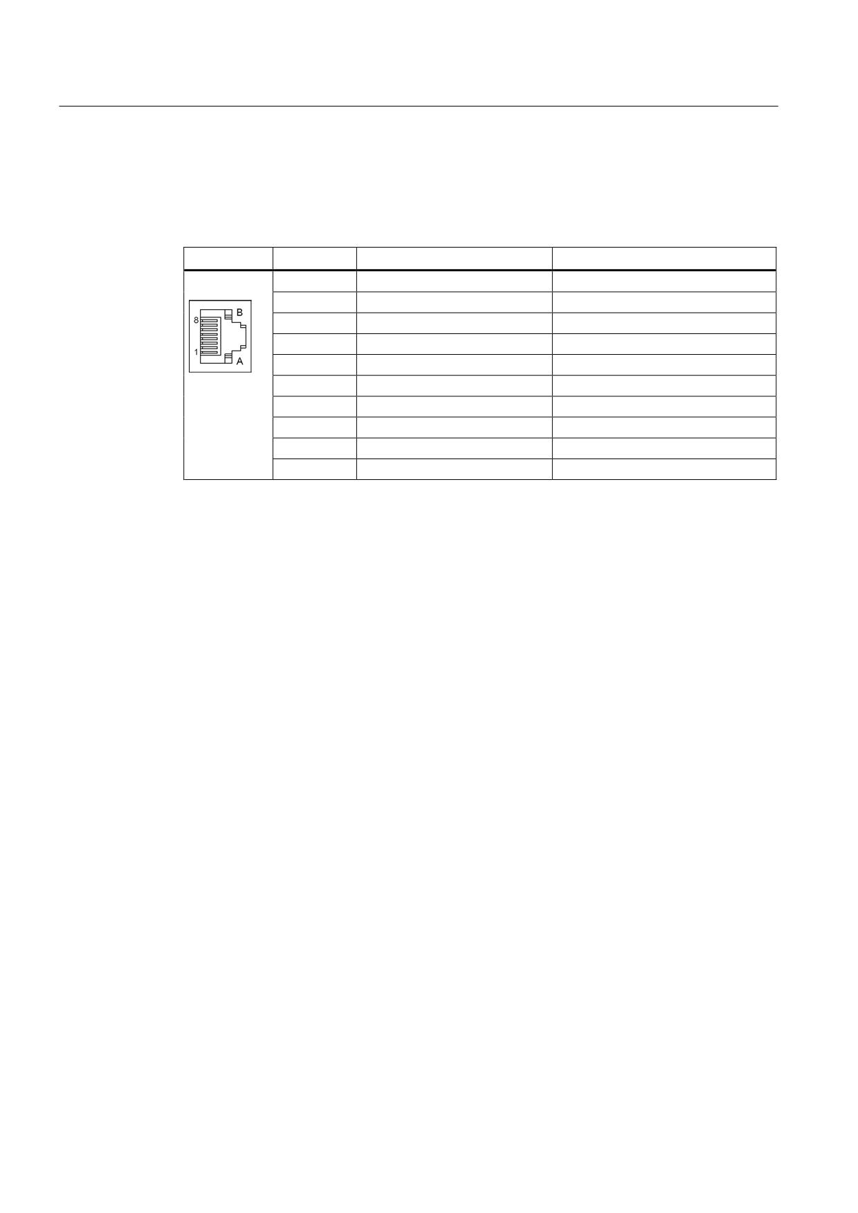
X200-X203 DRIVE-CLiQ interface
Table 8- 84 X200-X202: DRIVE-CLiQ interfaces for Single Motor Modules
X200-X203: DRIVE-CLiQ interfaces for Double Motor Modules
Pin
Name
Technical data
1
TXP
Transmit data +
2
TXN
Transmit data -
3
RXP
Receive data +
4
Reserved, do not use
5
Reserved, do not use
6
RXN
Receive data -
7
Reserved, do not use
8
Reserved, do not use
A
+ (24 V)
Power supply
B
M (0 V)
Electronics ground
The blanking covers for the DRIVE-CLiQ interfaces are included in the scope of delivery.
Blanking cover (50 pcs.) Order number: 6SL3066-4CA00-0AA0
Guidelines for machine configuration
352
System Manual, MA 01/2013, 6FC5397-6CP10-0BA2
Connection of the components in SINAMICS drive system
8.4 Connection of motor modules
8.4.2.3
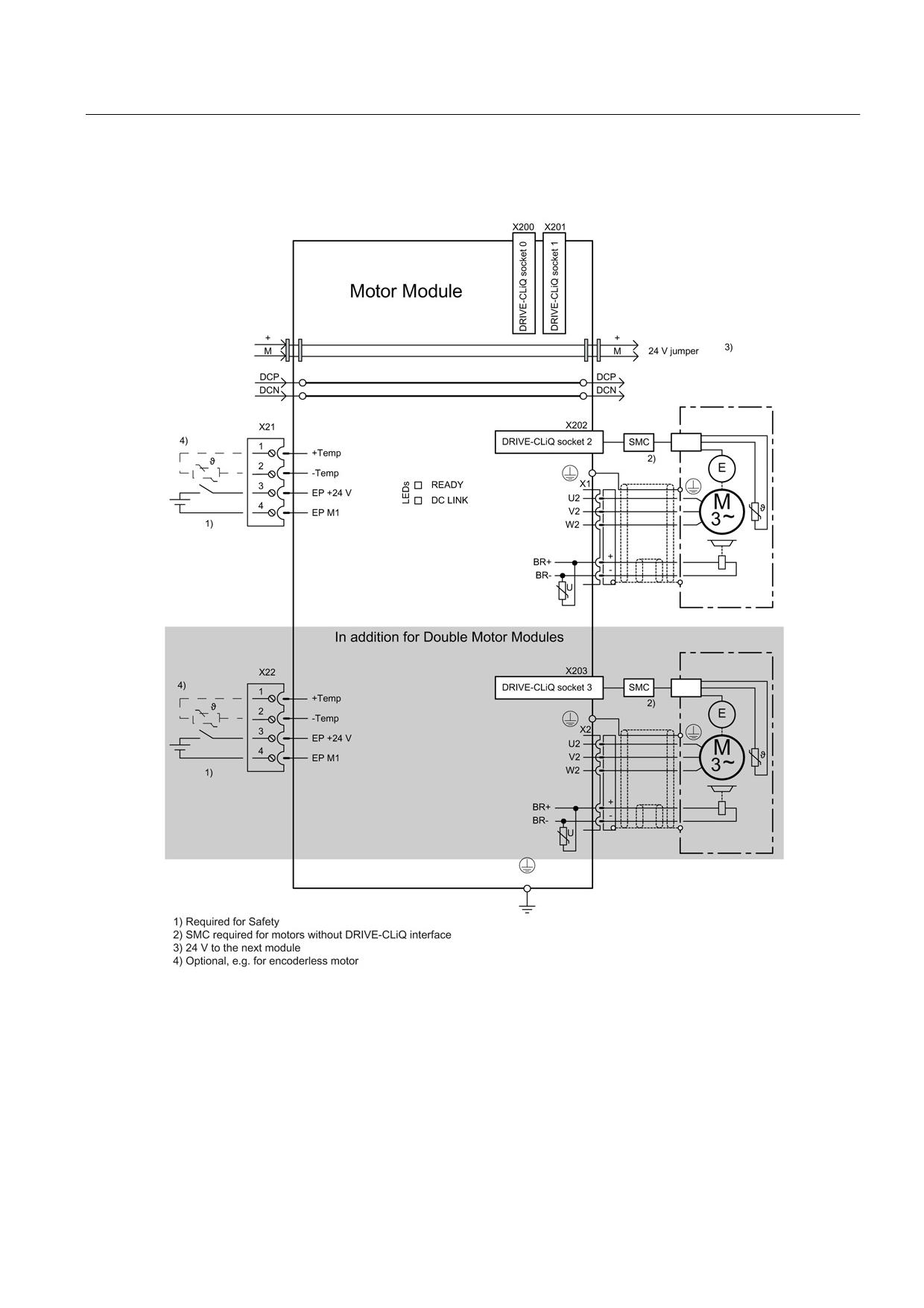
Connection examples
Figure 8-98 Connection example of Motor Modules 3 A to 30 A and Double Motor Modules 3 A to 18 A
Guidelines for machine configuration
System Manual, MA 01/2013, 6FC5397-6CP10-0BA2
353
Connection of the components in SINAMICS drive system
8.4 Connection of motor modules
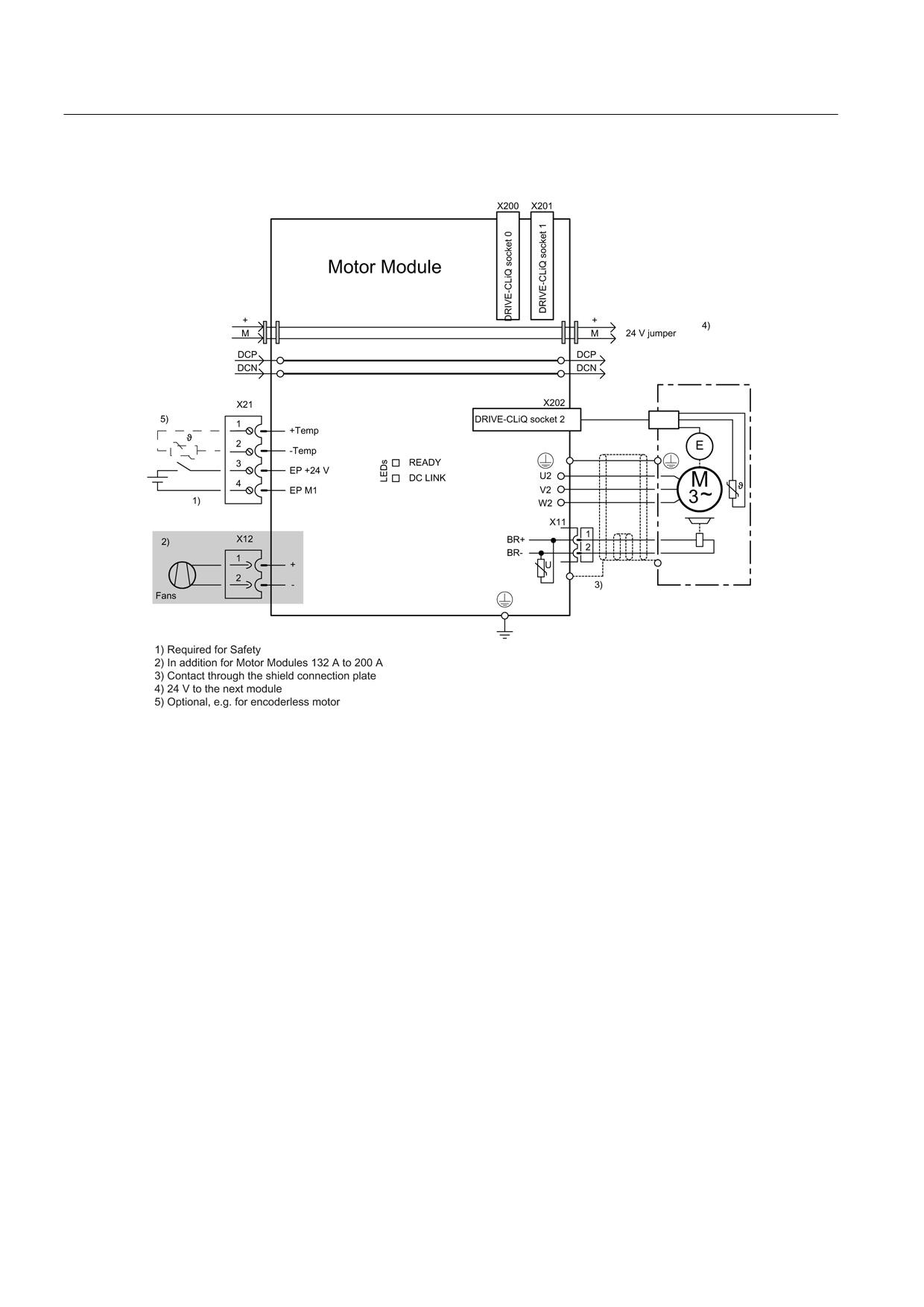
Figure 8-99 Example connection of Single Motor Modules 45 A to 200 A
Guidelines for machine configuration
354
System Manual, MA 01/2013, 6FC5397-6CP10-0BA2
Connection of the components in SINAMICS drive system
8.4 Connection of motor modules
8.4.2.4
Meaning of LEDs
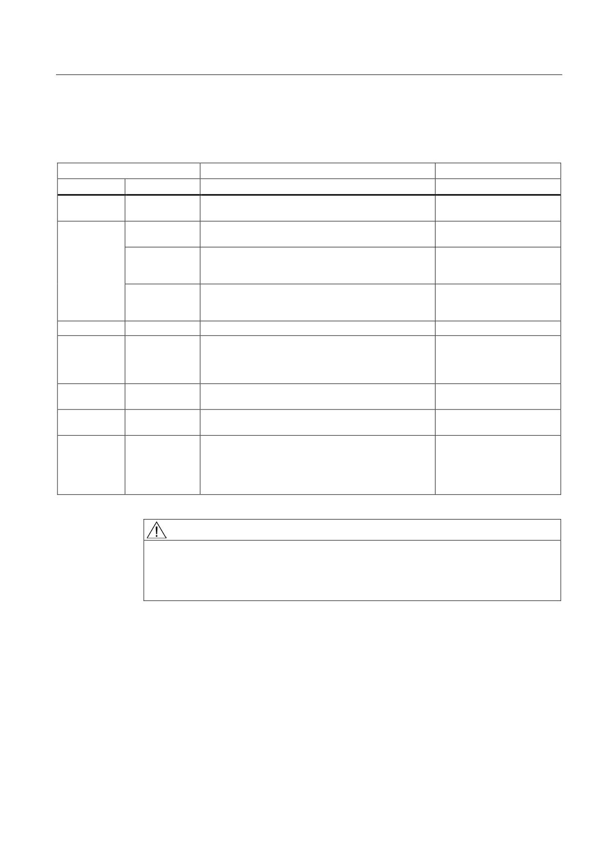
Table 8- 85 Meaning of the LEDs on the Motor Module
Status
Description, cause
Remedy
RDY
DC LINK
Off
Off
Electronics power supply is missing or outside
-
permissible tolerance range.
Green
--
The component is ready for operation and cyclic DRIVE-
-
CLiQ communication is taking place.
Orange
The component is ready for operation and cyclic DRIVE-
-
CLiQ communication is taking place.
The DC link voltage is present.
Red
The component is ready for operation and cyclic DRIVE-
Check line voltage
CLiQ communication is taking place.
The DC link voltage is too high.
Orange
Orange
DRIVE-CLiQ communication is being established.
-
Red
--
At least one fault is present in this component.
Remedy and acknowledge
Note:
fault
The LED is activated regardless of whether the
corresponding messages have been reconfigured.
Green/red
--
Firmware is being downloaded.
-
(0.5 Hz)
Green/red
--
Firmware download is complete. Wait for POWER ON.
Carry out a POWER ON
(2 Hz)
Green/orange
--
Detection of the components via LED is activated
-
or
(p0124).
Red/orange
Note:
Both options depend on the LED status in the case of
activation via p0124 = 1.
DANGER
Hazardous DC link voltage
Hazardous DC link voltages may be present at any time regardless of the status of the
"DC LINK" LED.
The warning information on the components must be carefully observed!
Guidelines for machine configuration
System Manual, MA 01/2013, 6FC5397-6CP10-0BA2
355
Connection of the components in SINAMICS drive system
8.4 Connection of motor modules
8.4.2.5
Dimension drawings
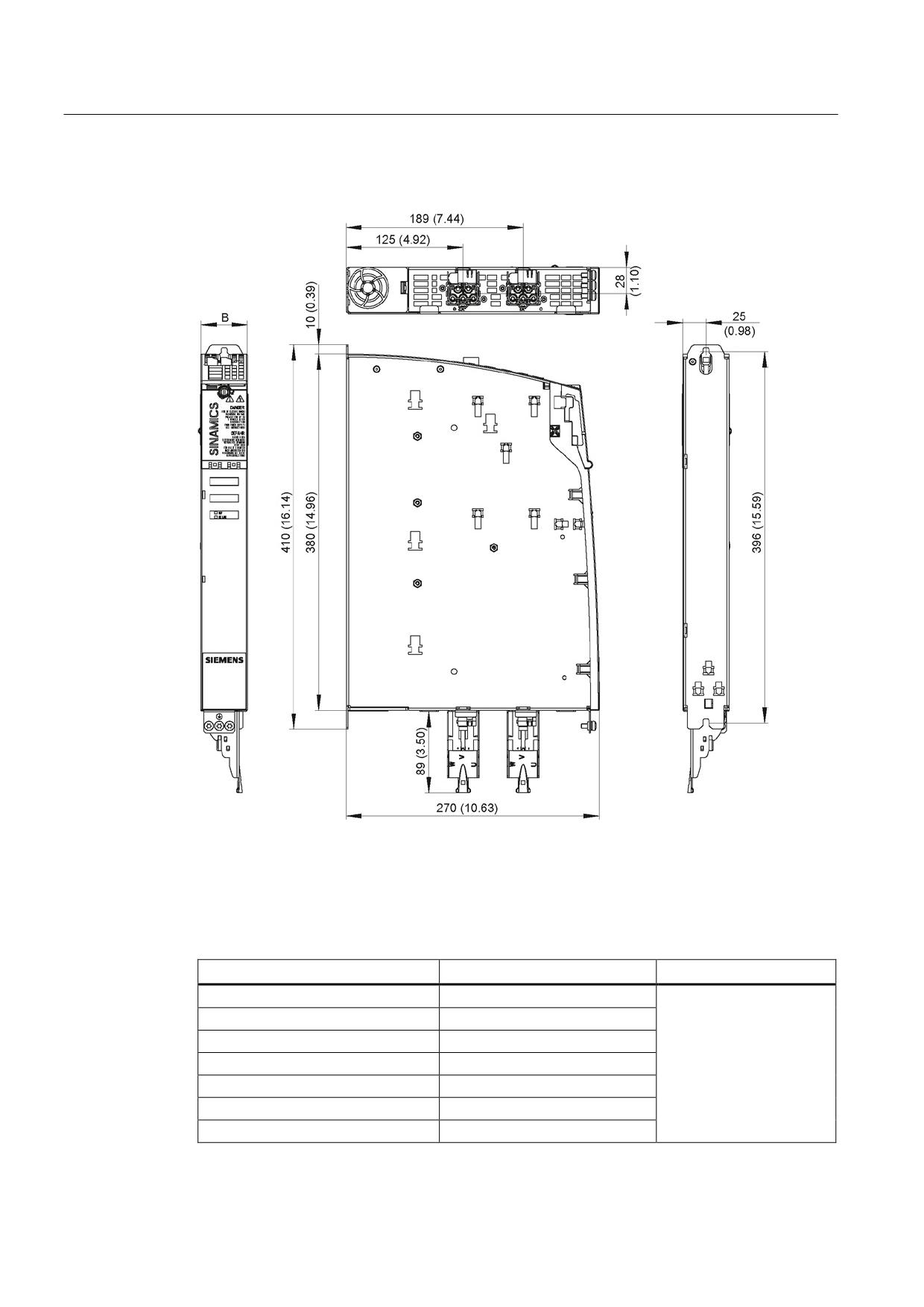
Figure 8-100 Dimension drawing of Motor Modules Booksize with internal air cooling 3 A to 18 A and
2 x 3 A to 2 x 9 A, all dimensions in mm and (inches); example: Double Motor Module
2 x 5 A
Table 8- 86 Dimensions of Motor Modules Booksize with internal air cooling 3 A to 18 A and 2 x 3 A
to 2 x 9 A
Motor Module
Order number
B [mm] (inches)
Single Motor Module 3 A
6SL3120-1TE13-0AAx
Single Motor Module 5 A
6SL3120-1TE15-0AAx
Single Motor Module 9 A
6SL3120-1TE21-0AAx
Single Motor Module 18 A
6SL3120-1TE21-8AAx
50 (1.97)
Double Motor Module 3 A
6SL3120-2TE13-0AAx
Double Motor Module 5 A
6SL3120-2TE15-0AAx
Double Motor Module 9 A
6SL3120-2TE21-0AAx
Guidelines for machine configuration
356
System Manual, MA 01/2013, 6FC5397-6CP10-0BA2
Connection of the components in SINAMICS drive system
8.4 Connection of motor modules
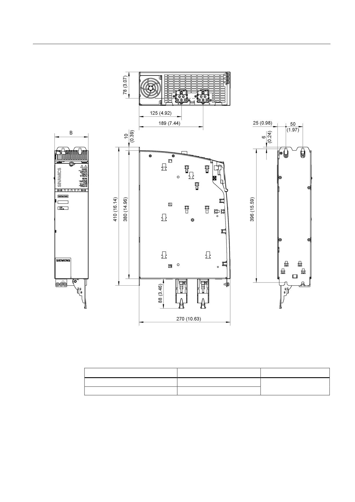
Figure 8-101 Dimension drawing of Motor Modules Booksize with internal air cooling 30 A and 2 x 18 A, all dimensions in
mm and (inches); example: Double Motor Module 2 x 18 A
Table 8- 87 Dimensions of Motor Modules Booksize with internal air cooling 30 A and 2 x 18 A
Motor Module
Order number
B [mm] (inches)
Single Motor Module 30 A
6SL3120-1TE23-0AAx
100 (3.94)
Double Motor Module 18 A
6SL3120-2TE21-8AAx
Guidelines for machine configuration
System Manual, MA 01/2013, 6FC5397-6CP10-0BA2
357
Connection of the components in SINAMICS drive system
8.4 Connection of motor modules
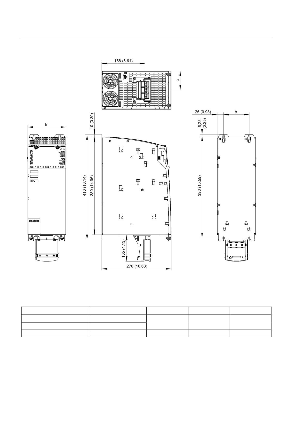
Figure 8-102 Dimension drawing of Motor Modules Booksize with internal air cooling 45 A to 85 A, all dimensions in mm
and (inches); example 45 A
Table 8- 88 Dimensions of Motor Modules Booksize with internal air cooling 45 A to 85 A
Motor Module
Order number
B [mm] (inches)
b [mm] (inches)
c [mm] (inches)
Single Motor Module 45 A
6SL3120-1TE24-5AAx
150 (5.91)
100 (3.94)
75 (2.95)
Single Motor Module 60 A
6SL3120-1TE26-0AAx
Single Motor Module 85 A
6SL3120-1TE28-5AAx
200 (7.87)
150 (5.91)
100 (3.94)
Guidelines for machine configuration
358
System Manual, MA 01/2013, 6FC5397-6CP10-0BA2
Connection of the components in SINAMICS drive system
8.4 Connection of motor modules
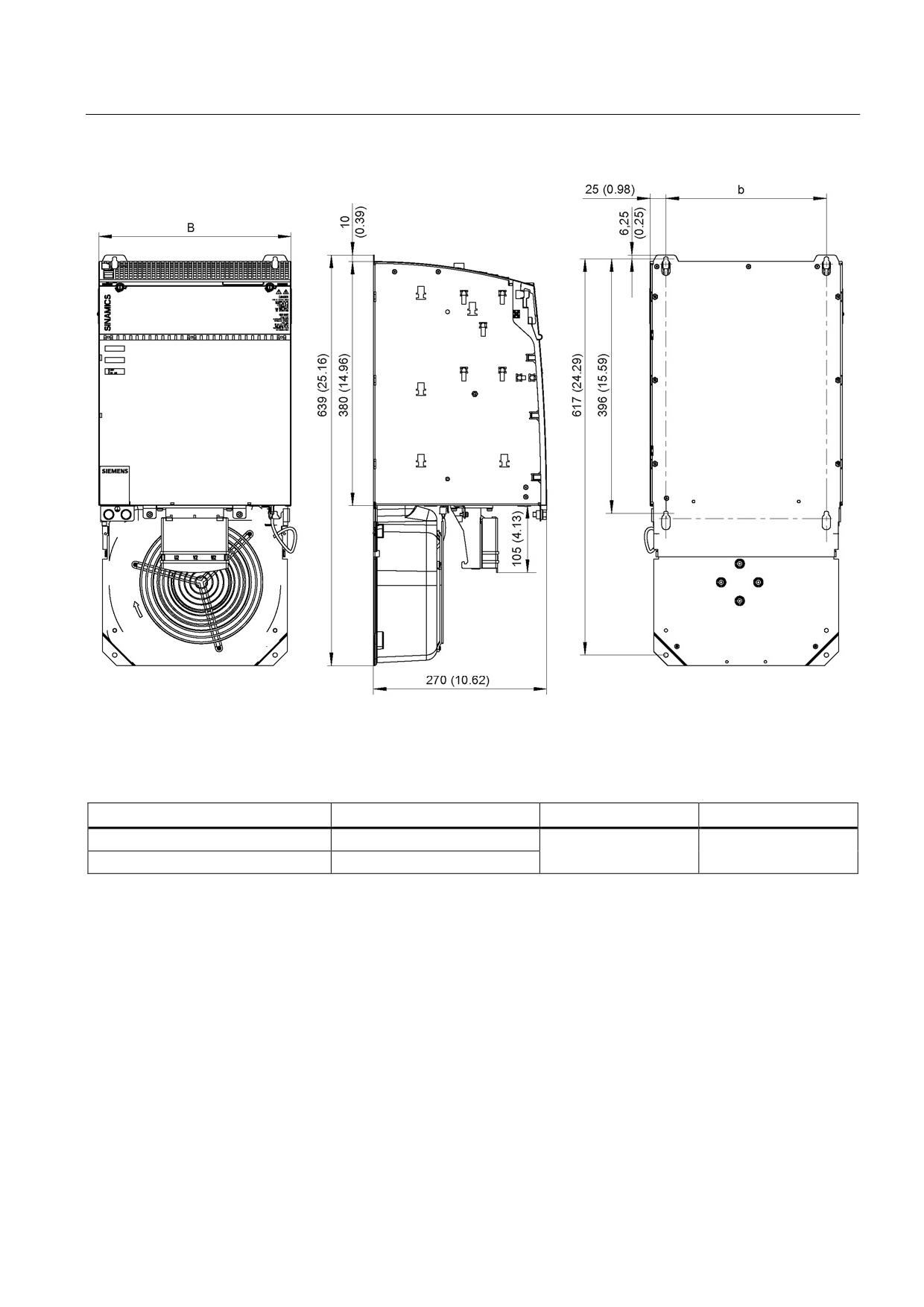
Figure 8-103 Dimension drawing of Motor Modules Booksize with internal air cooling 132 A and 200 A, all dimensions in
mm and (inches)
Table 8- 89 Dimensions of Motor Modules Booksize with internal air cooling 132 A and 200 A
Motor Module
Order number
B [mm] (inches)
b [mm] (inches)
Single Motor Module 132 A
6SL3120-1TE31-3AAx
300 (11.81)
250 (9.84)
Single Motor Module 200 A
6SL3120-1TE32-0AAx
Guidelines for machine configuration
System Manual, MA 01/2013, 6FC5397-6CP10-0BA2
359
Connection of the components in SINAMICS drive system
8.4 Connection of motor modules
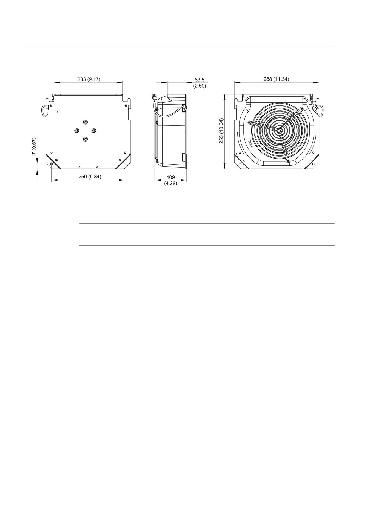
Figure 8-104 Dimension drawing of fans for Motor Modules 132 A and 200 A with internal air cooling, all dimensions in mm
and (inches)
Note
The fan for the Motor Modules 132 A and 200 A is included in the scope of supply.
Guidelines for machine configuration
360
System Manual, MA 01/2013, 6FC5397-6CP10-0BA2
Connection of the components in SINAMICS drive system
8.4 Connection of motor modules
8.4.2.6
Installation
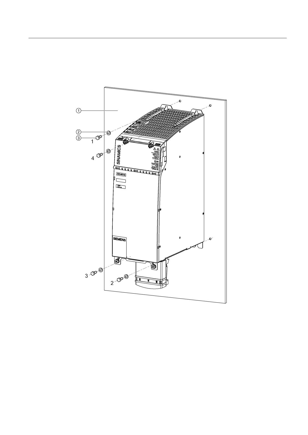
Motor Modules are designed for installation in the control cabinet. They are fixed to the
control cabinet panel or a mounting panel using M6 screws.
①
Control cabinet panel/mounting panel
②
Washer
③
M6 screw
Figure 8-105 Installation of a Motor Module with internal air cooling (example 45 A)
Tightening torques:
● Initially, tighten the nuts by hand (0.5 Nm)
● Then tighten with 6 Nm (in the specific sequence 1 to 4)
Guidelines for machine configuration
System Manual, MA 01/2013, 6FC5397-6CP10-0BA2
361
Connection of the components in SINAMICS drive system
8.4 Connection of motor modules
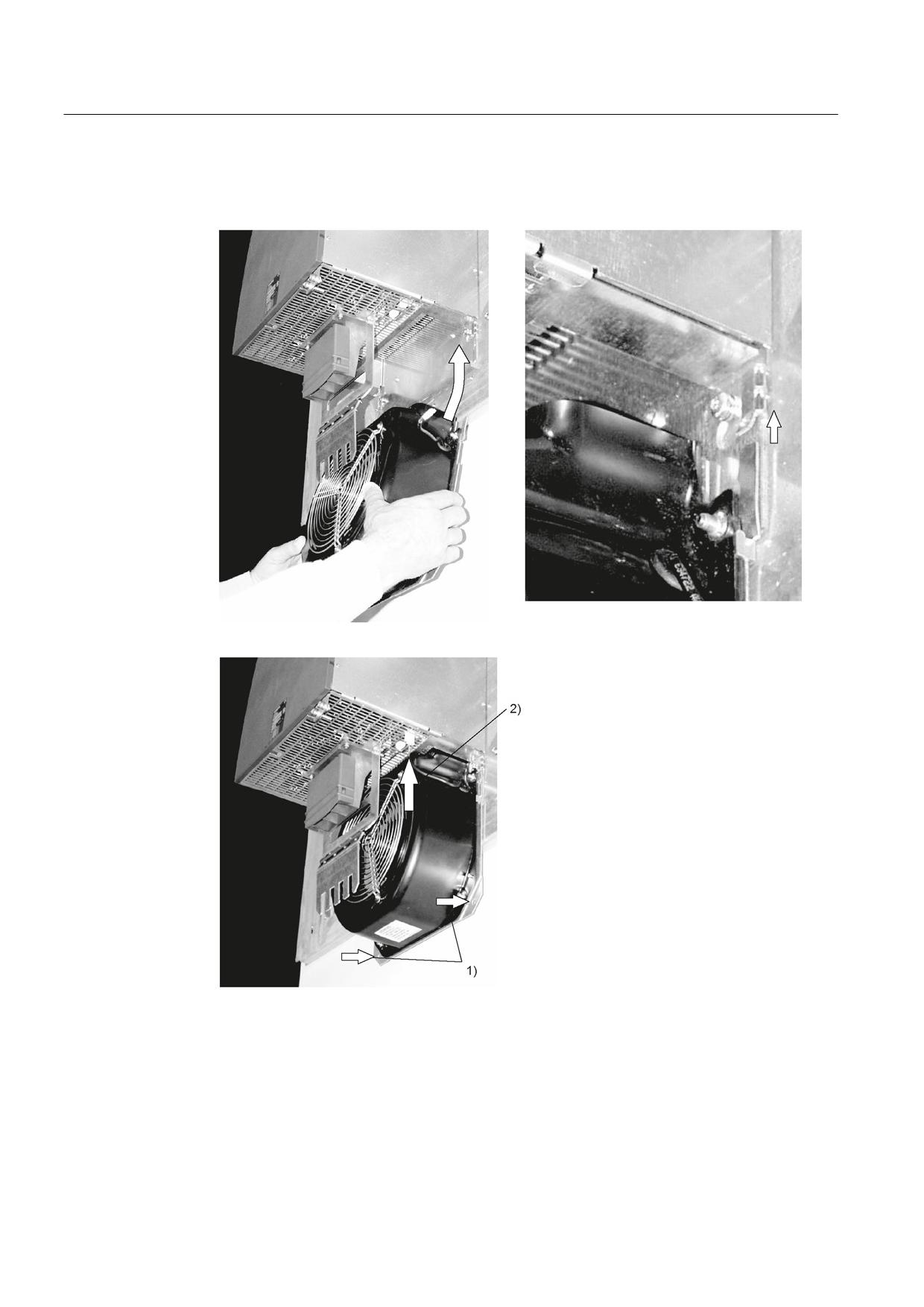
Installing the sub-chassis fan
Figure 8-106 Installing the fan for Motor Modules 132 A and 200 A
1. Attach the fan with M6 / 6 Nm screws
2. Connect the power supply for the fan
Guidelines for machine configuration
362
System Manual, MA 01/2013, 6FC5397-6CP10-0BA2
Connection of the components in SINAMICS drive system
8.4 Connection of motor modules
8.4.2.7
Technical specifications
Single Motor Modules
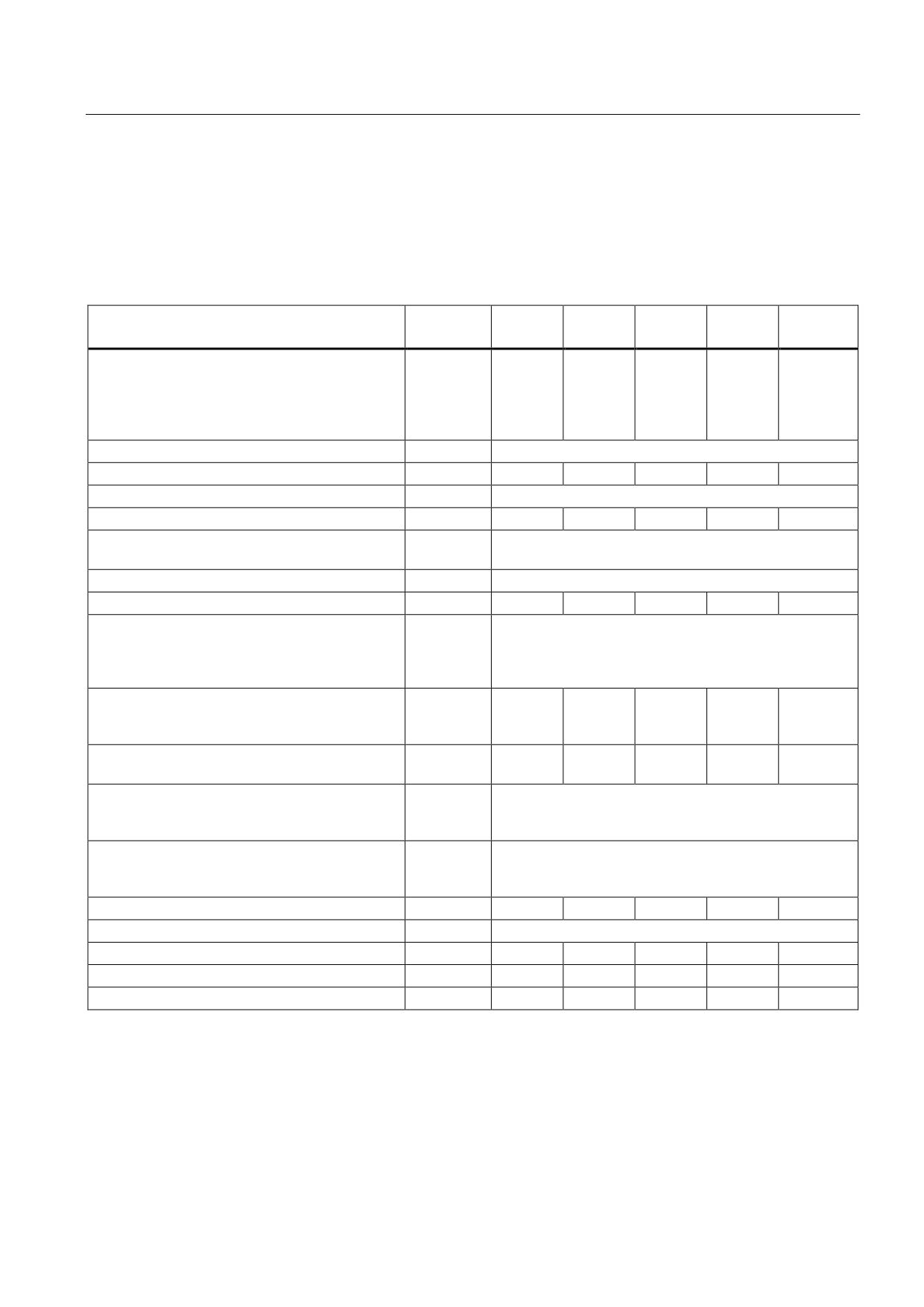
Table 8- 90 Technical data Single Motor Modules Booksize (3 to 30 A)
Internal air cooling
6SL3120-
1TE13-
1TE15-
1TE21-
1TE21-
1TE23-
0AAx
0AAx
0AAx
8AAx
0AAx
Output current
Rated current (ln)
AACrms
3
5
9
18
30
Base-load current (IH)
A
2.6
4.3
7.7
15.3
25.5
Intermittent duty current (Is6) 40%
AACrms
3.5
6
10
24
40
Peak current (lmax)
AACrms
6
10
18
36
56
Output voltage
VACrms
0 - 0.717 x DC link voltage
DC link current Id
ADC
3.6
6
11
22
36
DC link voltage (up to 2000 m above sea level)
VDC
510 - 720
DC link capacitance
μF
110
110
110
220
705
Overvoltage trip
VDC
820 ±2%
Undervoltage trip1)
VDC
380 ±2%
Electronics power supply
VDC
24 (20.4 - 28.8)
Electronics current consumption at 24 V DC
ADC
0.85
0.85
0.85
0.85
0.8
Current carrying capacity
DC link busbars
ADC
100
Reinforced DC link busbars
ADC
150
24 VDC busbars
ADC
20
Unit rating
Based on In (600 VDC; 4 kHz)
kW
1.6
2.7
4.8
9.7
16
Based on IH
kW
1.4
2.3
4.1
8.2
13.7
Total power loss
W
50.4
73.4
100.4
185.4
309.2
(including electronics losses)2)
Max. pulse frequency
without derating
kHz
4
with derating
kHz
16
Max. ambient temperature
without derating
°C
40
with derating
°C
55
Sound pressure level
dB(A)
<60
<60
<60
<60
<60
Cooling method
Internal fan
Cooling air requirement
m3/h
29.6
29.6
29.6
29.6
56
Max. permissible heat sink temperature
°C
75
75
79
82
85
Weight
kg
5
5
5
5
6.9
1)
Default for 400 V line systems; undervoltage trip threshold can be reduced by up to 80 V and is adjusted to the
parameterized rated voltage
2)
For an overview, see the power loss tables in the Appendix
Guidelines for machine configuration
System Manual, MA 01/2013, 6FC5397-6CP10-0BA2
363
Connection of the components in SINAMICS drive system
8.4 Connection of motor modules
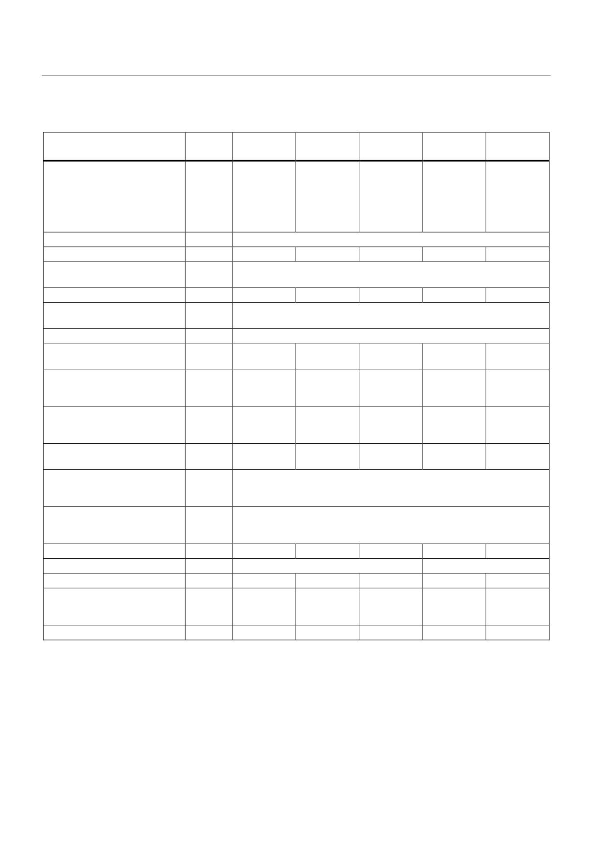
Table 8- 91 Technical data Single Motor Modules Booksize (45 to 200 A)
Internal air cooling
6SL3120
1TE24-5AAx
1TE26-0AAx
1TE28-5AAx
1TE31-3AAx
1TE32-0AAx
-
Output current
Rated current (ln)
AACrms
45
60
85
132
200
Base-load current (IH)
A
38
51
68
105
141
Intermittent duty current (Is6)
40%
AACrms
60
80
110
150
230
Peak current (lmax)
AACrms
85
113
141
210
282
Output voltage
VACrms
0 - 0.717 x DC link voltage
DC link current Id
ADC
54
72
102
158
200
DC link voltage
(up to 2000 m above sea level)
VDC
510 - 720
DC link capacitance
μF
1175
1410
1880
2820
3995
Overvoltage trip
VDC
820 ±2%
Undervoltage trip1)
VDC
380 ±2%
Electronics power supply
VDC
24 (20.4 - 28.8)
Electronics current consumption
at 24 V DC
ADC
1.05
1.05
1.5
0.85
0.85
Current carrying capacity
DC link busbars
ADC
200
200
200
200
200
24 VDC busbars
ADC
20
20
20
20
20
Unit rating
Based on In (600 VDC; 4 kHz)
kW
24
32
46
71
107
Based on IH
kW
21
28
37
57
76
Total power loss
(incl. electronics losses)2)
W
455.2
615.2
786
1270.4
2070.4
Max. pulse frequency
without derating
kHz
4
with derating
kHz
16
Max. ambient temperature
without derating
°C
40
with derating
°C
55
Sound pressure level
dB(A)
<65
<65
<60
<73
<73
Cooling method (with fan)
Internal fan
Mounted fan
Cooling air requirement
m3/h
112
112
160
520
520
Max. permissible heat sink
°C
85
90
83
70
80
temperature
(70%
derating)
Weight
kg
9
9
15
21
21
1)
Default for 400 V line systems; undervoltage trip threshold can be reduced by up to 80 V (exception: 132 A and 200 A
Motor Modules) and is adjusted to the parameterized rated voltage.
2)
For an overview, see the power loss tables in the Appendix
Guidelines for machine configuration
364
System Manual, MA 01/2013, 6FC5397-6CP10-0BA2
Connection of the components in SINAMICS drive system
8.4 Connection of motor modules
Double Motor Modules
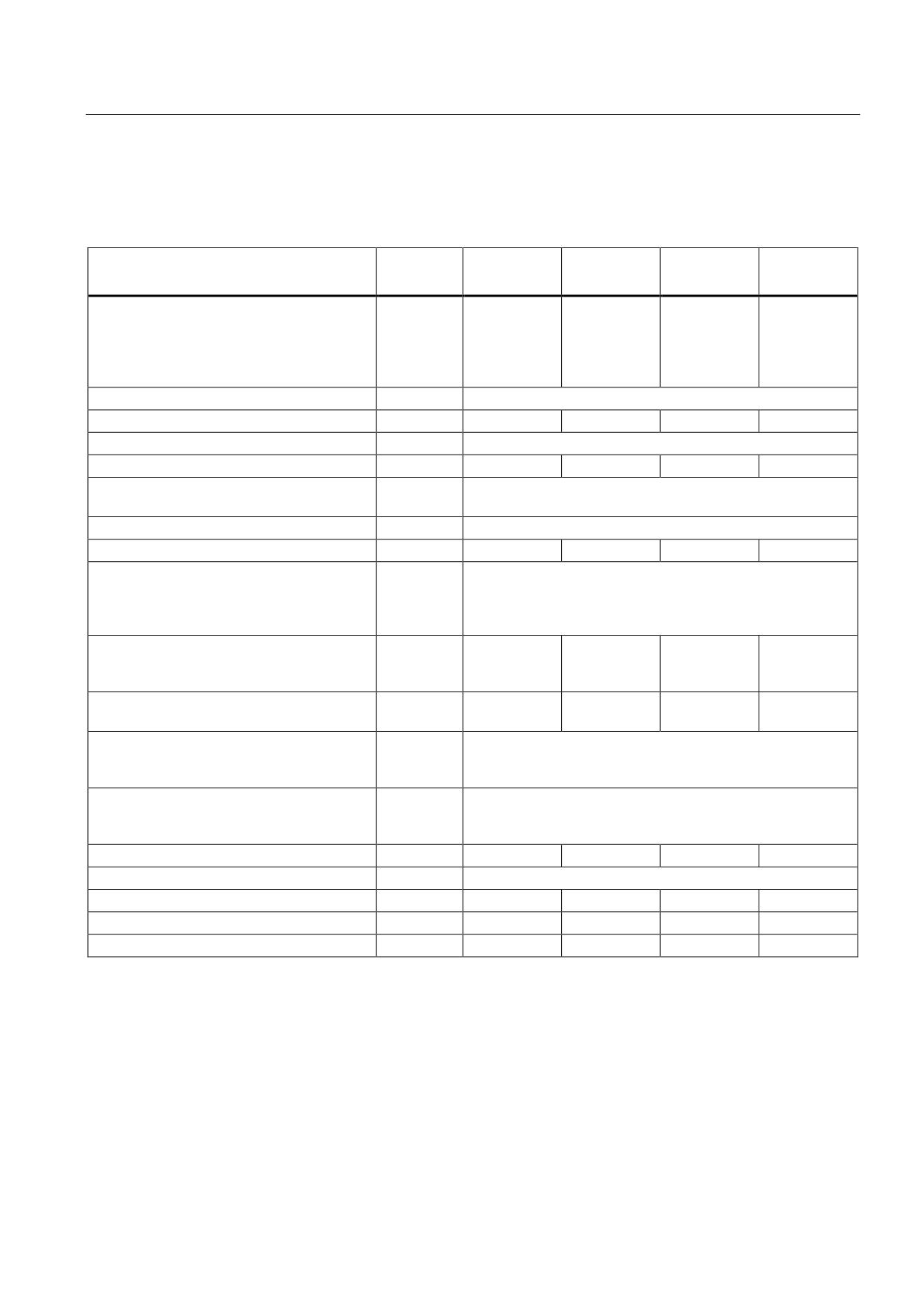
Table 8- 92 Technical data Double Motor Modules Booksize (3 to 18 A)
Internal air cooling
6SL3120-
2TE13-
2TE15-
2TE21-
2TE21-
0AAx
0AAx
0AAx
8AAx
Output current
Rated current (ln)
AACrms
2 x 3
2 x 5
2 x 9
2 x 18
Base-load current (IH)
A
2 x 2.6
2 x 4.3
2 x 7.7
2 x 15.3
Intermittent duty current (Is6) 40%
AACrms
2 x 3.5
2 x 6
2 x 10
2 x 24
Peak current (lmax)
AACrms
2 x 6
2 x 10
2 x 18
2 x 36
Output voltage
VACrms
0 - 0.717 x DC link voltage
DC link current Id
ADC
7.2
12
22
43
DC link voltage
VDC
510 - 720
DC link capacitance
μF
220
220
220
705
Overvoltage trip
VDC
820 ±2%
Undervoltage trip1)
VDC
380 ±2%
Electronics power supply
VDC
24 (20.4 - 28.8)
Electronics current consumption at 24 V DC
ADC
1.15
1.15
1.15
1.3
Current carrying capacity
DC link busbars
ADC
100
Reinforced DC link busbars
ADC
150
24 VDC busbars
A
20
Unit rating
Based on In (600 VDC, 4 kHz)
kW
2 x 1.6
2 x 2.7
2 x 4.8
2 x 9.7
Based on IH
kW
2 x 1.4
2 x 2.3
2 x 4.1
2 x 8.2
Total power loss
W
97.6
132.6
187.6
351.2
(including electronics losses)2)
Max. pulse frequency
without derating
kHz
4
with derating
kHz
16
Max. ambient temperature
without derating
°C
40
with derating
°C
55
Sound pressure level
dBA
<60
<60
<60
<60
Cooling method
Internal fan
Cooling air requirement
m3/h
29.6
29.6
29.6
56
Max. permissible heat sink temperature
°C
85
90
89
90
Weight
kg
5.3
5.3
5.5
6.8
1)
Default for 400 V line systems; undervoltage trip threshold can be reduced by up to 80 V and is adjusted to the
parameterized rated voltage
2)
For an overview, see the power loss tables in the Appendix
Guidelines for machine configuration
System Manual, MA 01/2013, 6FC5397-6CP10-0BA2
365
Connection of the components in SINAMICS drive system
8.4 Connection of motor modules
Characteristics
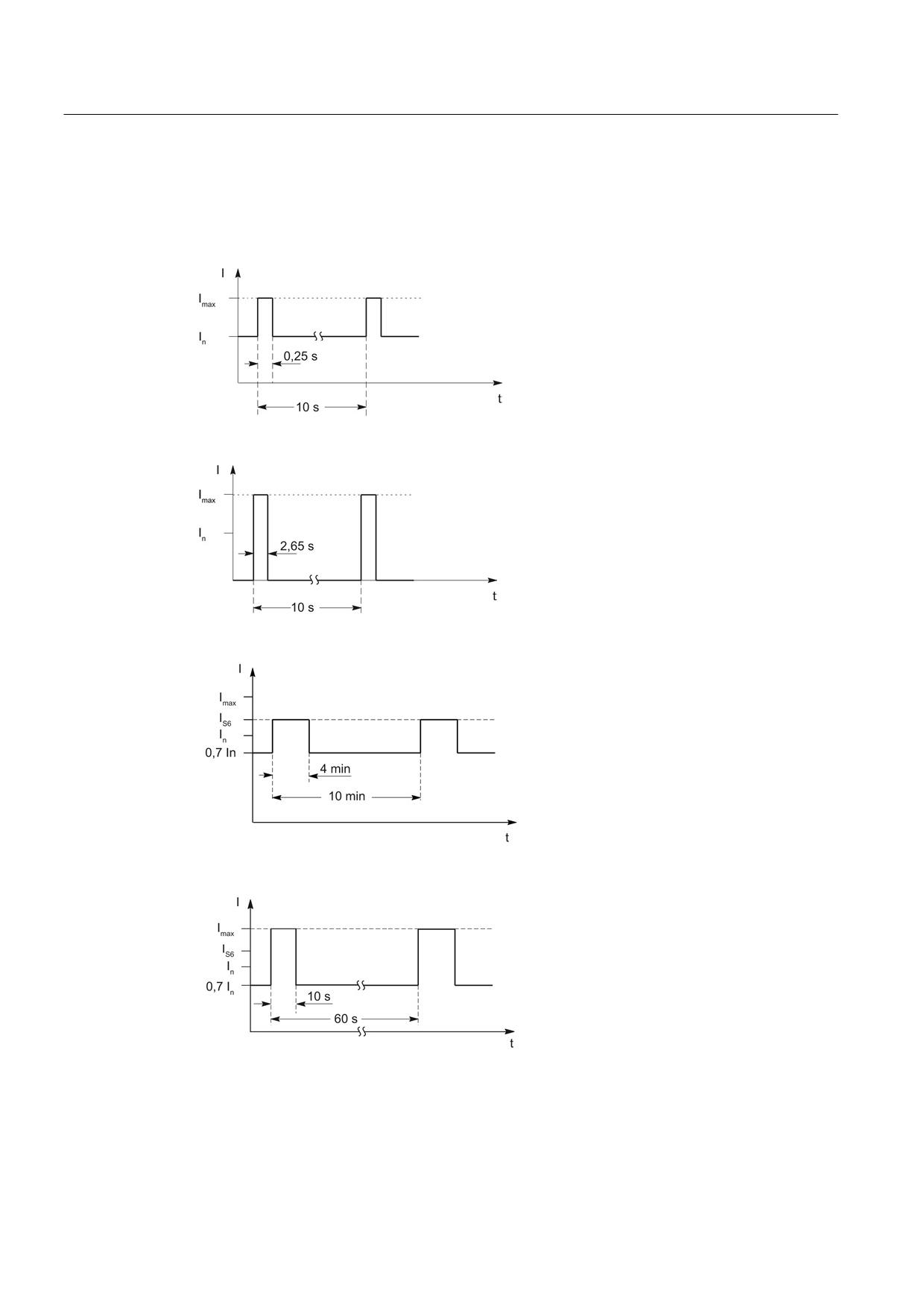
Rated duty cycles Motor Modules Booksize
Figure 8-107 Duty cycle with initial load (for servo drives)
Figure 8-108 Duty cycle without initial load (for servo drives)
Figure 8-109 S6 duty cycle with initial load with a duty cycle duration of 600 s (for servo drives)
Figure 8-110 S6 duty cycle with initial load with a duty cycle duration of 60 s (for servo drives)
Guidelines for machine configuration
366
System Manual, MA 01/2013, 6FC5397-6CP10-0BA2
Connection of the components in SINAMICS drive system
8.4 Connection of motor modules
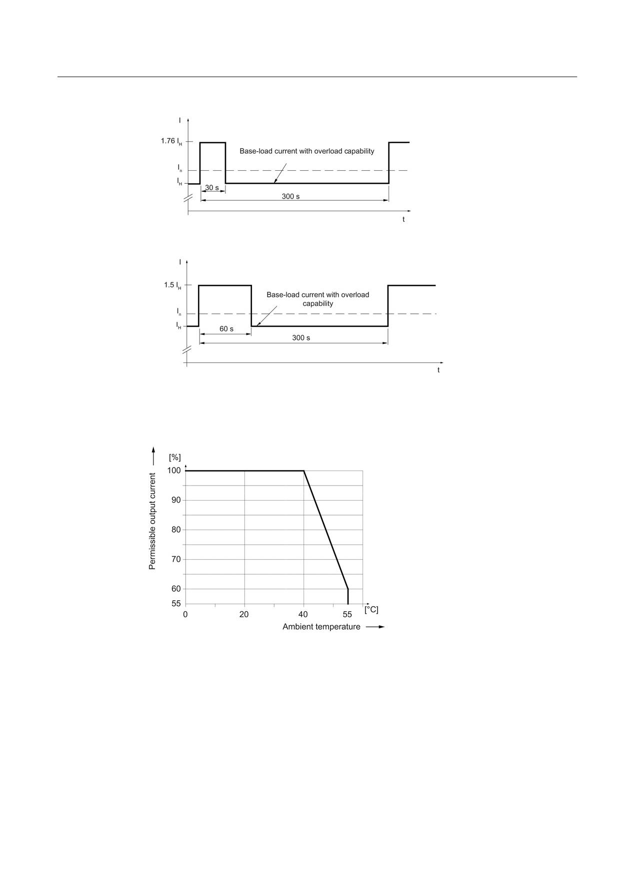
Figure 8-111 Duty cycle with 30 s overload for a duty cycle duration of 300 s
Figure 8-112 Duty cycle with 60 s overload for a duty cycle duration of 300 s
Derating characteristics for Motor Modules Booksize
Figure 8-113 Output current as a function of the ambient temperature
Guidelines for machine configuration
System Manual, MA 01/2013, 6FC5397-6CP10-0BA2
367
Connection of the components in SINAMICS drive system
8.4 Connection of motor modules
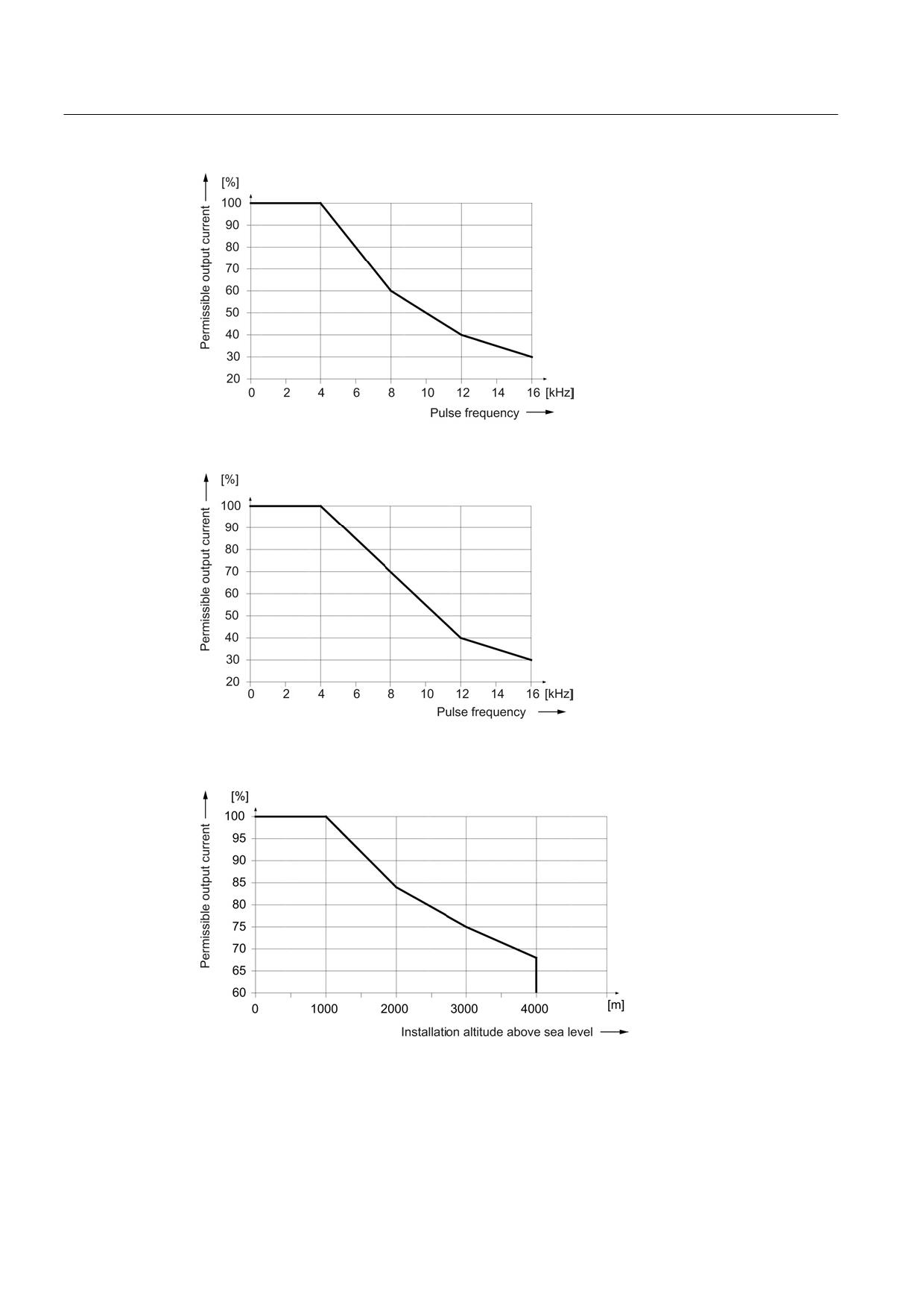
Figure 8-114 Output current as a function of the pulse frequency
Figure 8-115 Output current as a function of the pulse frequency for 200 A Motor Modules
(applies from order number 6SL312x-1TE32-0AA4)
Figure 8-116 Output current as a function of the installation altitude
Guidelines for machine configuration
368
System Manual, MA 01/2013, 6FC5397-6CP10-0BA2
Connection of the components in SINAMICS drive system
8.4 Connection of motor modules
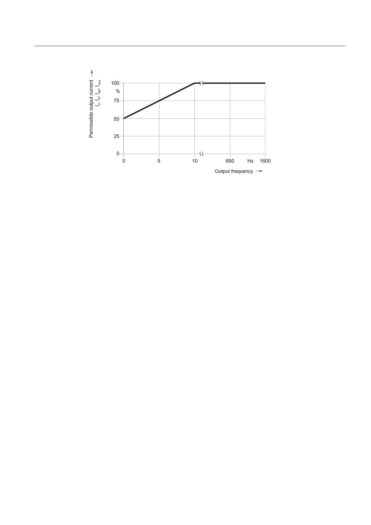
Figure 8-117 Output current as a function of the output frequency
At installation altitudes > 2000 m, an isolation transformer must be used (see the chapter
titled "System overview/Function of installation altitude and ambient temperature"
(Page 32)). The design of the secondary line system must be as follows:
● TN system with grounded neutral point (no grounded line conductor)
● IT system
A reduction of the line supply voltage phase-phase is not necessary.
8.4.3
Motor Module with external air cooling
8.4.3.1
Description
A Motor Module with external air cooling is a power unit (inverter) that provides the power
supply for the connected motor(s). Power is supplied by means of the DC link of the drive
unit. A Motor Module must be connected to a Control Unit via DRIVE-CLiQ. The open-loop
and closed-loop control functions for the Motor Module are stored in the Control Unit.
Motor Modules with external air cooling are offered as Single Motor Modules and Double
Motor Modules. One motor can be connected to Single Motor Modules and two motors can
be connected to Double Motor Modules.
External air cooling uses the "through-hole" method. The power unit and its heat sink can be
inserted in a rectangular knockout at the rear of the control cabinet and mounted with a seal.
The heat sink fins and the fan (included in the scope of delivery) project beyond the rear of
the control cabinet and the heat is dissipated outside the control cabinet or in a separate air
duct.
Guidelines for machine configuration
System Manual, MA 01/2013, 6FC5397-6CP10-0BA2
369
Connection of the components in SINAMICS drive system
8.4 Connection of motor modules
8.4.3.2
Interface description
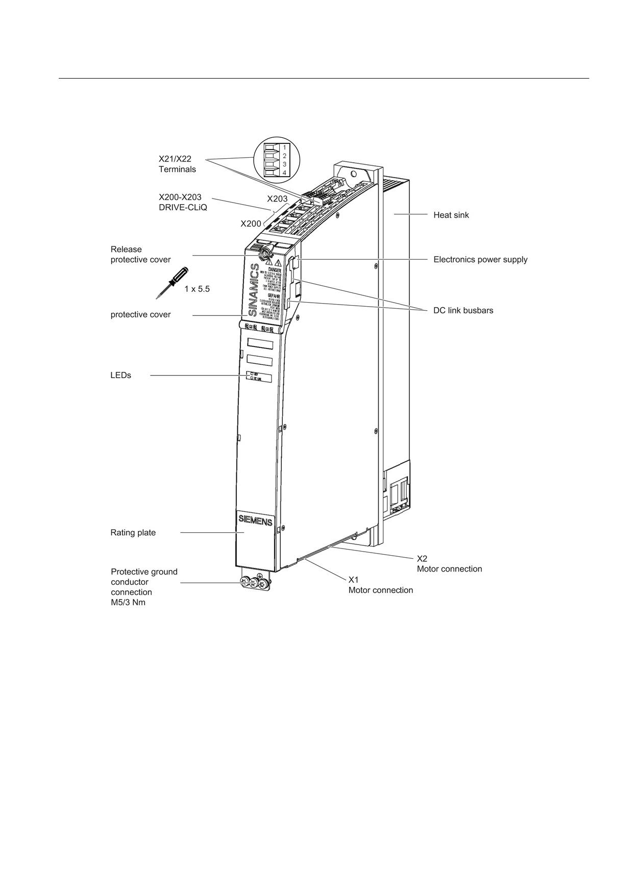
Overview
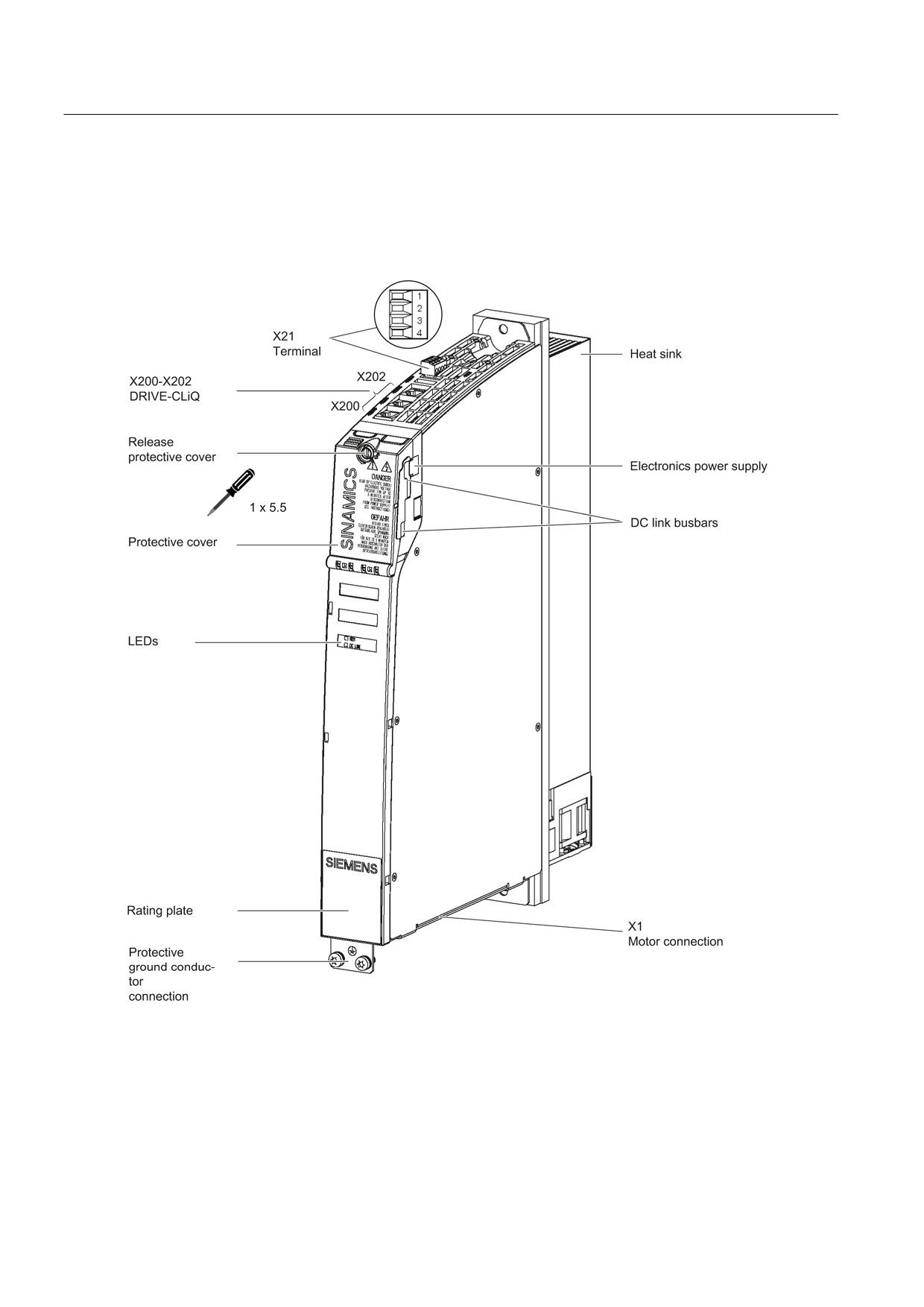
Figure 8-118 Interface overview, Single Motor Module Booksize with external air cooling (example: 5 A)
Guidelines for machine configuration
370
System Manual, MA 01/2013, 6FC5397-6CP10-0BA2
Connection of the components in SINAMICS drive system
8.4 Connection of motor modules
Figure 8-119 Interface overview, Double Motor Module Booksize with external air cooling (example: 2 x 5 A)
Guidelines for machine configuration
System Manual, MA 01/2013, 6FC5397-6CP10-0BA2
371
Connection of the components in SINAMICS drive system
8.4 Connection of motor modules
Motor and brake connection
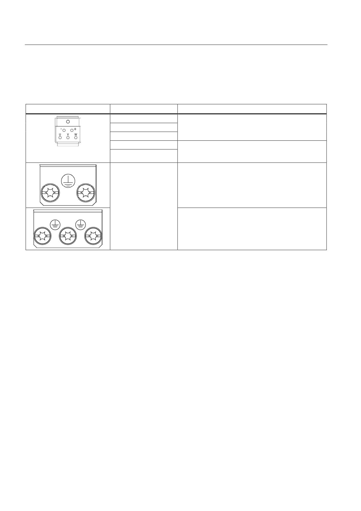
Table 8- 93 X1/X2 motor and brake connection for Single Motor Modules 3 A to 30 A and Double Motor Modules 3 A to
18 A
Terminal
Technical data
U (U2)
Motor connection
V (V2)
W (W2)
+ (BR+)
Brake connection
max. load current 2 A
- (BR-)
min. load current 0.1 A
PE connection
Single Motor Modules 3 A to 30 A:
Threaded hole M5/3 Nm 1)
Double Motor Modules 3 A to 18 A:
Threaded hole M5/3 Nm 1)
1) For ring cable lugs in accordance with DIN 46234
Guidelines for machine configuration
372
System Manual, MA 01/2013, 6FC5397-6CP10-0BA2
Connection of the components in SINAMICS drive system
8.4 Connection of motor modules
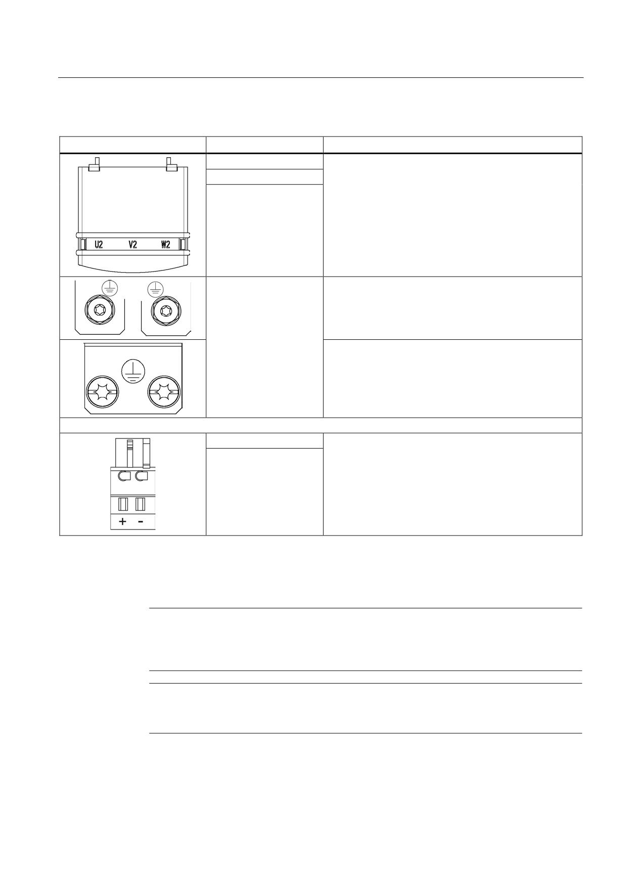
Table 8- 94 X1 motor connection and X11 brake connection for Single Motor Modules 45 A to 200 A
Terminal
Technical data
U2
45 A to 60 A:
Threaded bolts M6/6 Nm 1)
V2
85 A:
W2
Threaded bolts M8/13 Nm 1)
132 A to 200 A:
Threaded bolts M8/13 Nm 1)
PE connection
45 A to 60 A:
Threaded bolts for motor cables: M6/6 Nm 1)
Threaded hole for PE: M6 / 6 Nm 1)
85 A:
Threaded bolts for motor cables: M8/13 Nm 1)
Threaded hole for PE: M6 / 6 Nm 1)
132 A to 200 A:
Threaded bolts for motor cables: M8/13 Nm 1)
Threaded hole for PE: M8 / 13 Nm 1)
+ (BR+)
X11 brake connector 2):
- (BR-)
Voltage 24 VDC
Max. load current 2 A
Min. load current 0.1 A
Max. connectable cross-section 2.5 mm2
Type: Spring-loaded terminal 2
(see Appendix, Chapter "Spring-loaded terminals")
The brake connector is part of the prefabricated cable
1) For ring cable lugs in accordance with DIN 46234
2) The circuit for protecting the brake against overvoltage is integrated in the Motor Module and does not need to be
installed externally. The max. load current is 2 A, the min. load current 0.1 A.
Note
The total length of the power cables (motor supply cables and DC link cables) must not
exceed the values listed in the chapter titled "Possible line reactor and line filter
combinations (Page 158)".
Note
The motor brake must be connected via connector X11. Directly connecting the BR- cable to
the electronics ground M is not permitted.
Guidelines for machine configuration
System Manual, MA 01/2013, 6FC5397-6CP10-0BA2
373
Connection of the components in SINAMICS drive system
8.4 Connection of motor modules
WARNING
Safety extra-low voltages at connections and terminals
Only protective extra-low voltages (DVC A) that comply with EN 60204-1 may be connected
to all connections and terminals between 0 and 48 VDC.
The voltage tolerances of the motor holding brakes (24 V ±10 %) must be taken into
account.
X12 fan connection
The Motor Modules 132 A and 200 A are equipped with an interface to connect a sub-
chassis fan. The interface is located on the underside of the Motor Module.
Table 8- 95 X12 fan connection
Terminal
Function
Technical specifications
1
Fan connection +
Voltage 48 V DC for the supplied fan
2
Fan connection -
X21/X22 EP terminals/temperature sensor
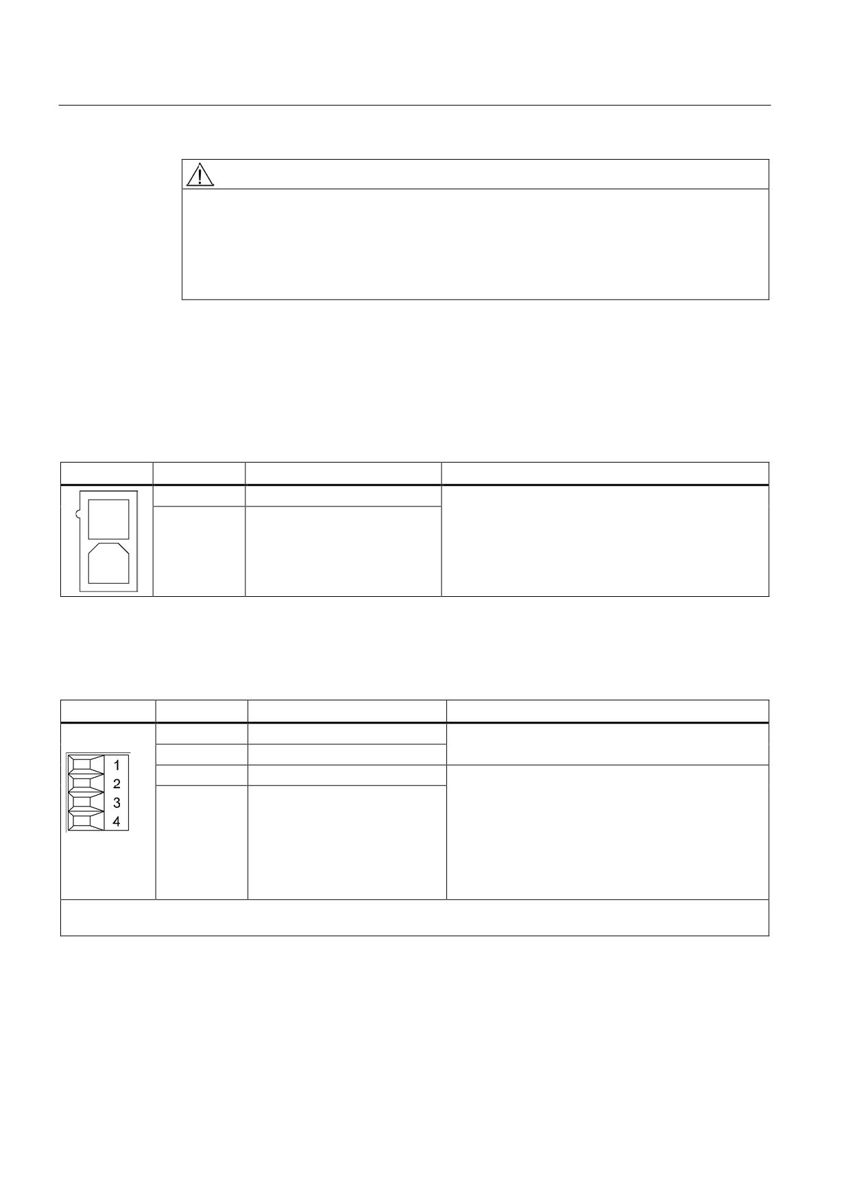
Table 8- 96 X21/X22 EP terminals/temperature sensor
Terminal
Function
Technical data
1
+ Temp
Temperature sensors: KTY84-1C130/PTC/bimetallic
switch with NC contact
2
- Temp
3
EP +24 V (Enable Pulses)
Supply voltage: 24 VDC (20.4 V - 28.8 V)
Current consumption: 10 mA
4
EP M1 (Enable Pulses)
Isolated input
Signal propagation times:
L → H: 100 μs
H → L: 1000 μs
The pulse inhibit function is only available when Safety
Integrated Basic Functions are enabled.
Max. connectable cross-section 1.5 mm2
Type: Screw terminal 1 (see Appendix A.1)
Guidelines for machine configuration
374
System Manual, MA 01/2013, 6FC5397-6CP10-0BA2
Connection of the components in SINAMICS drive system
8.4 Connection of motor modules
EP terminals
Parameters p9651 and p9851 are used to set the filter times to debounce terminals X21.3
and X21.4, as well as X22.3 and X22.4. Additional parameter settings are also required in
order to prevent discrepancy errors when performing bit pattern tests (light/dark tests). For
comprehensive information, see the SINAMICS S120 Safety Integrated Function Manual,
Chapter "Controlling the safety functions".
Note
Function of the EP terminals
The function of the EP terminals is only available when Safety Integrated Basic Functions
are enabled.
Temperature sensor connection
NOTICE
Risk of the motor overheating due to an incorrectly connected KTY temperature sensor
A KTY temperature sensor connected with incorrect polarity cannot detect if the motor
overheats.
• Always connect the KTY temperature sensor with the correct polarity.
Note
The temperature sensor input is not needed if the motors feature an integrated DRIVE-CLiQ
interface or if temperature values are detected by means of a different module (SMC, SME,
TM).
DANGER
Danger to life through electric shock
Only temperature sensors that meet the safety isolation specifications stipulated in
EN 61800-5-1 may be connected to terminals "+Temp" and "-Temp". If safe electrical
separation cannot be guaranteed (for linear motors or third-party motors, for example), a
Sensor Module External (SME120 or SME125) or Terminal Module TM120 must be used.
If these instructions are not complied with, there is danger to life!
Guidelines for machine configuration
System Manual, MA 01/2013, 6FC5397-6CP10-0BA2
375
Connection of the components in SINAMICS drive system
8.4 Connection of motor modules
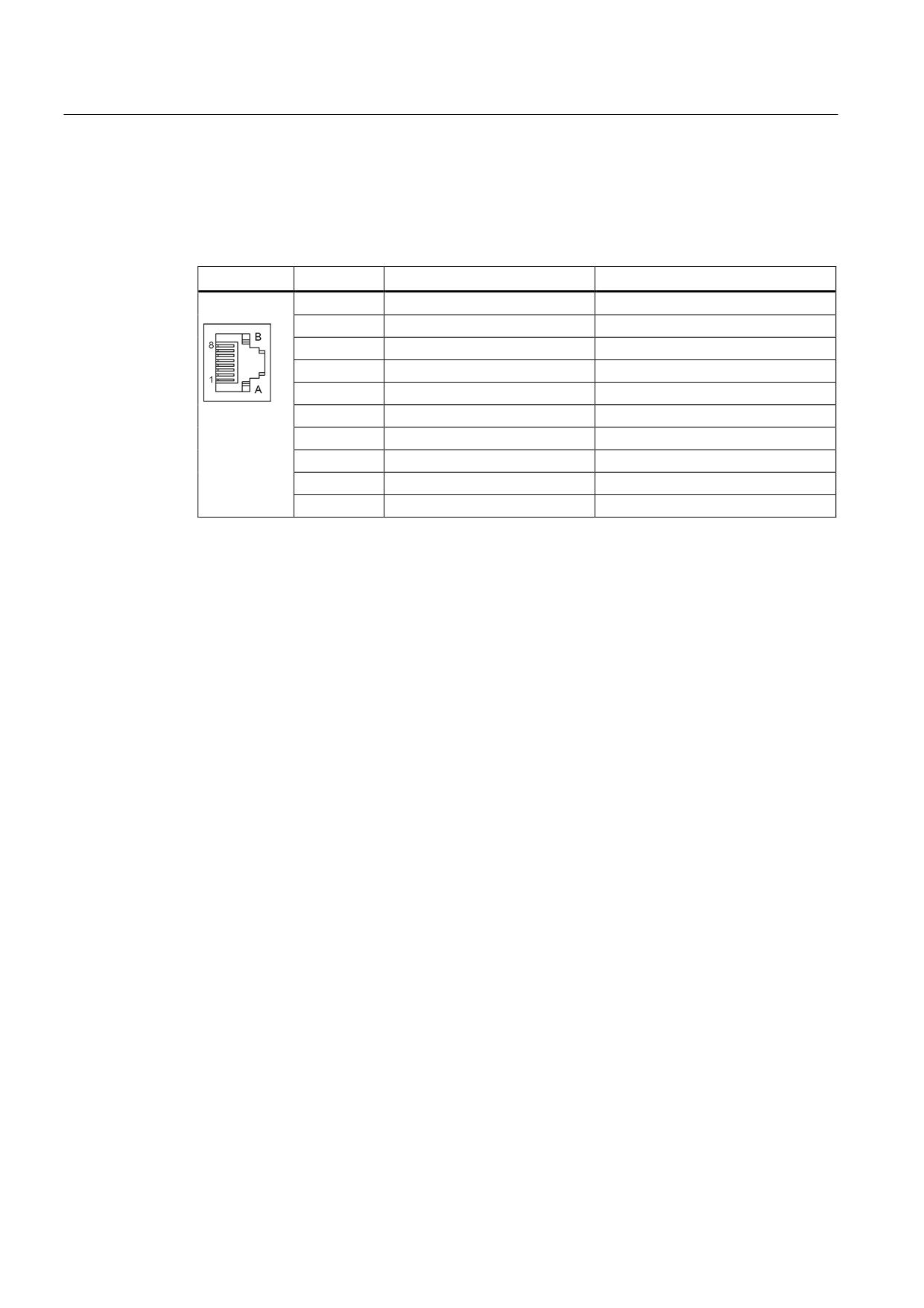
X200-X203 DRIVE-CLiQ interface
Table 8- 97 X200-X202: DRIVE-CLiQ interfaces for Single Motor Modules
X200-X203: DRIVE-CLiQ interfaces for Double Motor Modules
Pin
Name
Technical data
1
TXP
Transmit data +
2
TXN
Transmit data -
3
RXP
Receive data +
4
Reserved, do not use
5
Reserved, do not use
6
RXN
Receive data -
7
Reserved, do not use
8
Reserved, do not use
A
+ (24 V)
Power supply
B
M (0 V)
Electronics ground
The blanking covers for the DRIVE-CLiQ interfaces are included in the scope of delivery.
Blanking cover (50 pcs.) Order number: 6SL3066-4CA00-0AA0
Guidelines for machine configuration
376
System Manual, MA 01/2013, 6FC5397-6CP10-0BA2
Connection of the components in SINAMICS drive system
8.4 Connection of motor modules
8.4.3.3
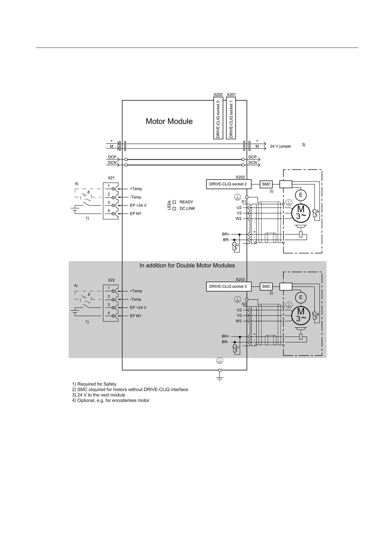
Connection examples
Figure 8-120 Connection example of Motor Modules 3 A to 30 A and Double Motor Modules 3 A to 18 A
Guidelines for machine configuration
System Manual, MA 01/2013, 6FC5397-6CP10-0BA2
377
Connection of the components in SINAMICS drive system
8.4 Connection of motor modules
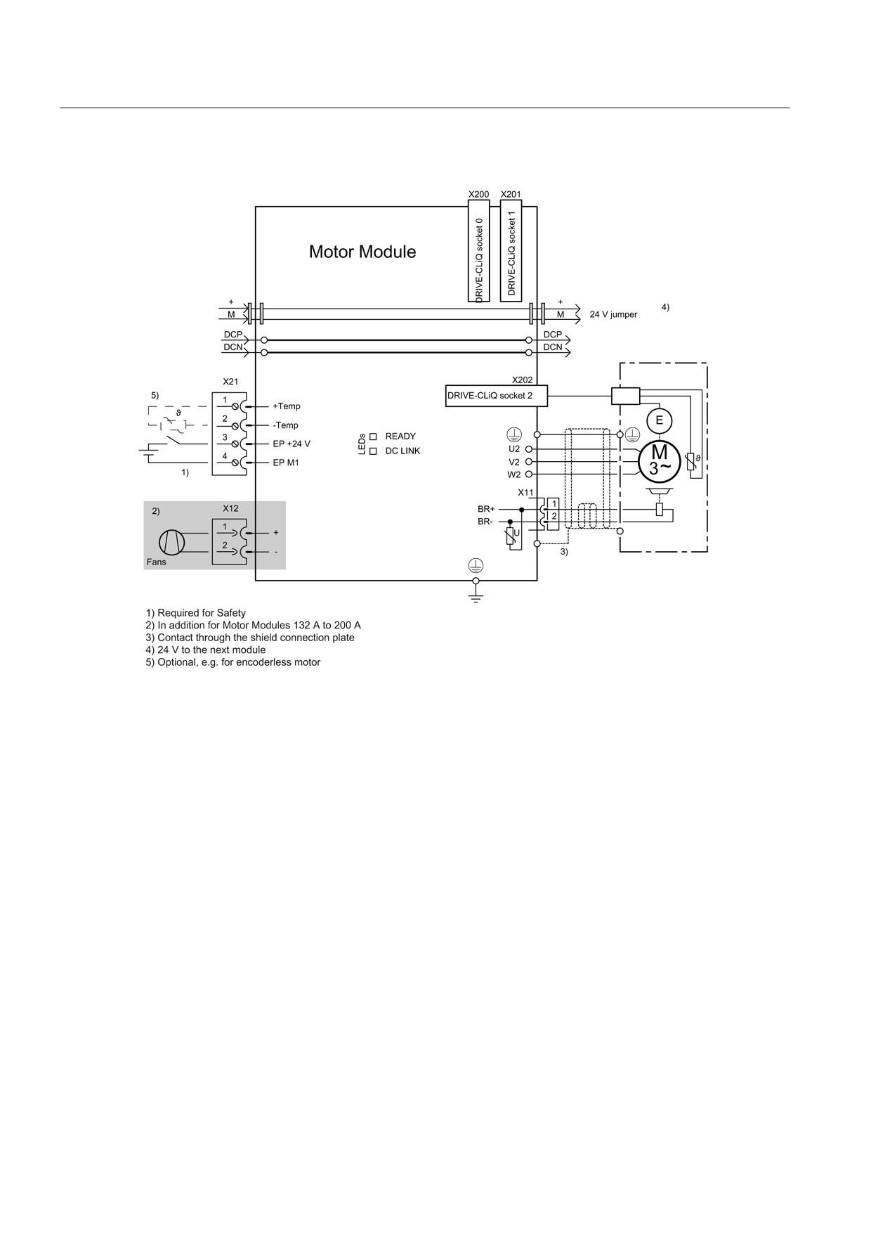
Figure 8-121 Example connection of Single Motor Modules 45 A to 200 A
Guidelines for machine configuration
378
System Manual, MA 01/2013, 6FC5397-6CP10-0BA2
Connection of the components in SINAMICS drive system
8.4 Connection of motor modules
8.4.3.4
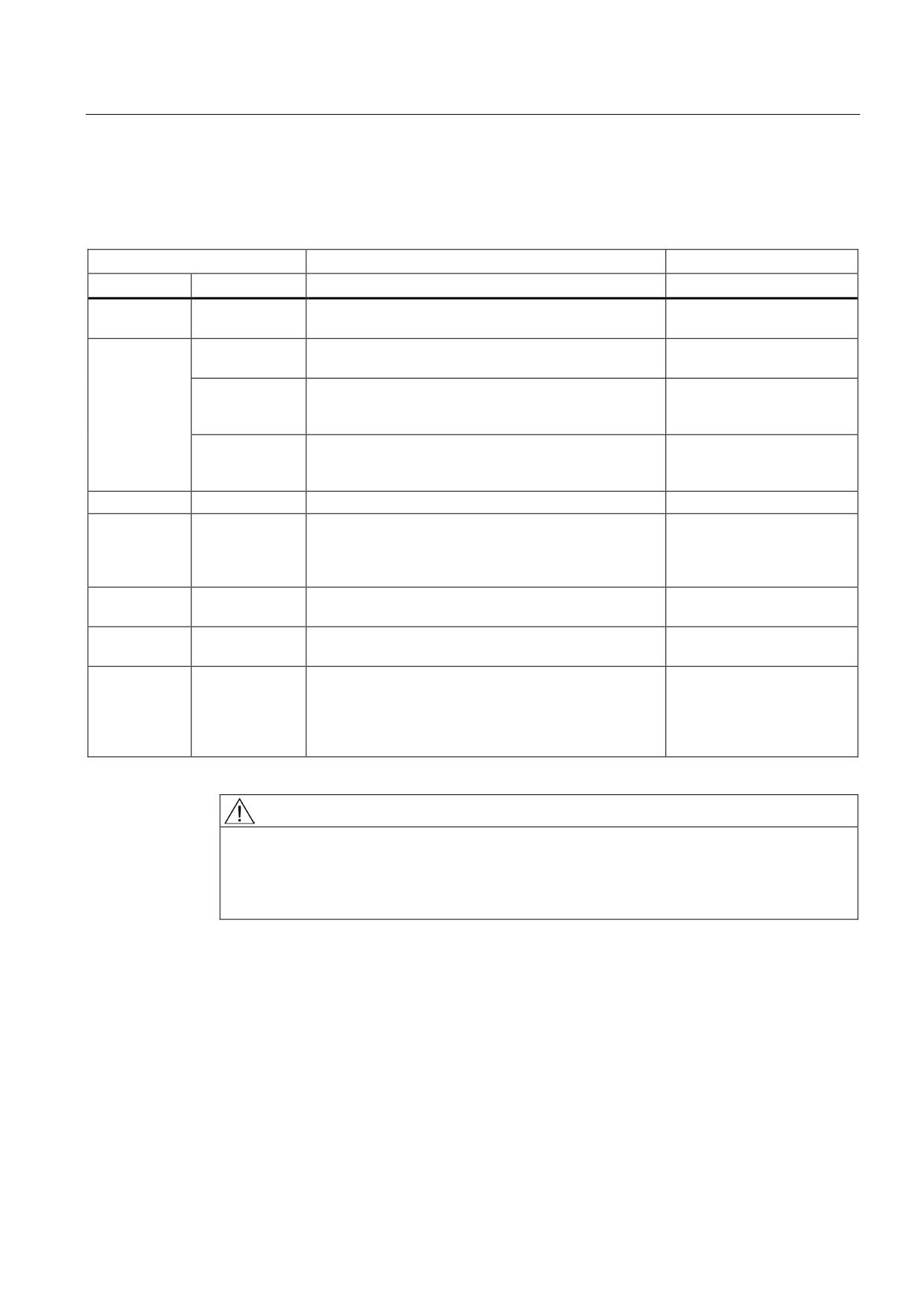
Meaning of LEDs
Table 8- 98 Meaning of the LEDs on the Motor Module
Status
Description, cause
Remedy
RDY
DC LINK
Off
Off
Electronics power supply is missing or outside
-
permissible tolerance range.
Green
--
The component is ready for operation and cyclic DRIVE-
-
CLiQ communication is taking place.
Orange
The component is ready for operation and cyclic DRIVE-
-
CLiQ communication is taking place.
The DC link voltage is present.
Red
The component is ready for operation and cyclic DRIVE-
Check line voltage
CLiQ communication is taking place.
The DC link voltage is too high.
Orange
Orange
DRIVE-CLiQ communication is being established.
-
Red
--
At least one fault is present in this component.
Remedy and acknowledge
Note:
fault
The LED is activated regardless of whether the
corresponding messages have been reconfigured.
Green/red
--
Firmware is being downloaded.
-
(0.5 Hz)
Green/red
--
Firmware download is complete. Wait for POWER ON.
Carry out a POWER ON
(2 Hz)
Green/orange
--
Detection of the components via LED is activated
-
or
(p0124).
Red/orange
Note:
Both options depend on the LED status in the case of
activation via p0124 = 1.
DANGER
Hazardous DC link voltage
Hazardous DC link voltages may be present at any time regardless of the status of the
"DC LINK" LED.
The warning information on the components must be carefully observed!
Guidelines for machine configuration
System Manual, MA 01/2013, 6FC5397-6CP10-0BA2
379
Connection of the components in SINAMICS drive system
8.4 Connection of motor modules
8.4.3.5
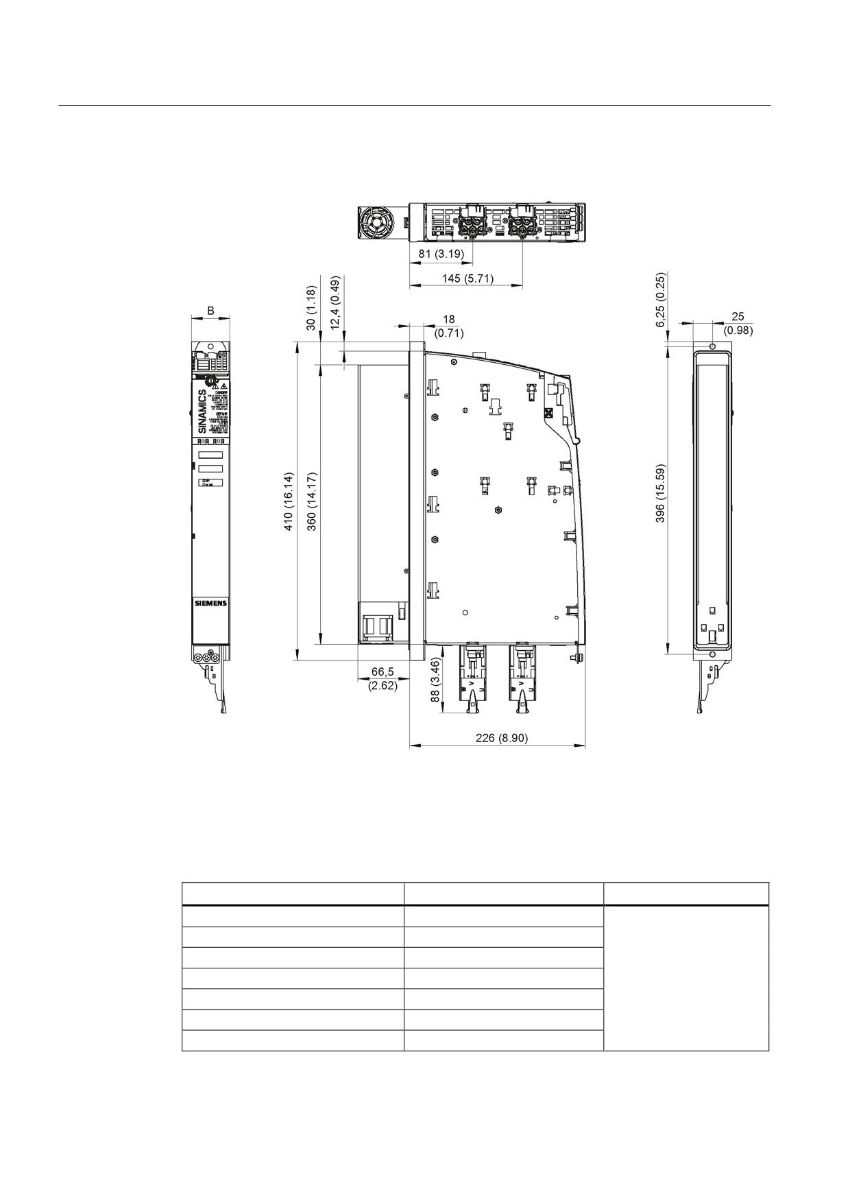
Dimension drawings
Figure 8-122 Dimension drawing of 3 A to 18 A and 2 x 3 A to 2 x 9 A Motor Modules Booksize with
external air cooling, all dimensions in mm and (inches); example: 2 x 5 A Double Motor
Module
Table 8- 99 Dimensions of 3 A to 18 A and 2 x 3 A to 2 x 9 A Motor Modules Booksize with external
air cooling
Motor Module
Order number
B [mm] (inches)
3 A Single Motor Module
6SL3121-1TE13-0AAx
5 A Single Motor Module
6SL3121-1TE15-0AAx
9 A Single Motor Module
6SL3121-1TE19-0AAx
18 A Single Motor Module
6SL3121-1TE21-8AAx
50 (1.97)
3 A Double Motor Module
6SL3121-2TE13-0AAx
5 A Double Motor Module
6SL3121-2TE15-0AAx
9 A Double Motor Module
6SL3121-2TE21-0AAx
Guidelines for machine configuration
380
System Manual, MA 01/2013, 6FC5397-6CP10-0BA2
Connection of the components in SINAMICS drive system
8.4 Connection of motor modules
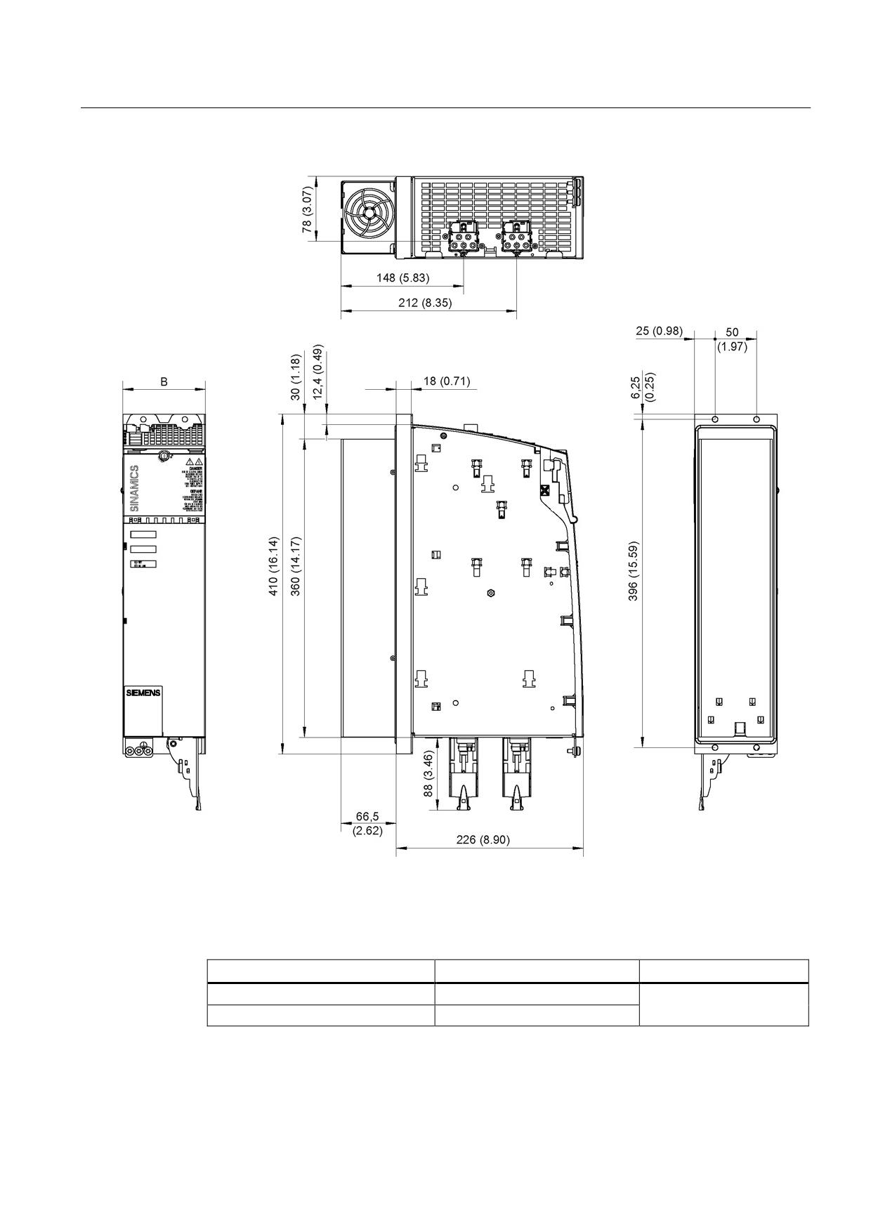
Figure 8-123 Dimension drawing of 30 A and 2 x 18 A Motor Modules Booksize with external air cooling, all dimensions in
mm and (inches); example: 2 x 18 A Double Motor Module
Table 8- 100 Dimensions of 30 A and 2 x 18 A Motor Modules Booksize with external air cooling
Motor Module
Order number
B [mm] (inches)
30 A Single Motor Module
6SL3121-1TE23-0AAx
100 (3.94)
18 A Double Motor Module
6SL3121-2TE21-8AAx
Guidelines for machine configuration
System Manual, MA 01/2013, 6FC5397-6CP10-0BA2
381
Connection of the components in SINAMICS drive system
8.4 Connection of motor modules
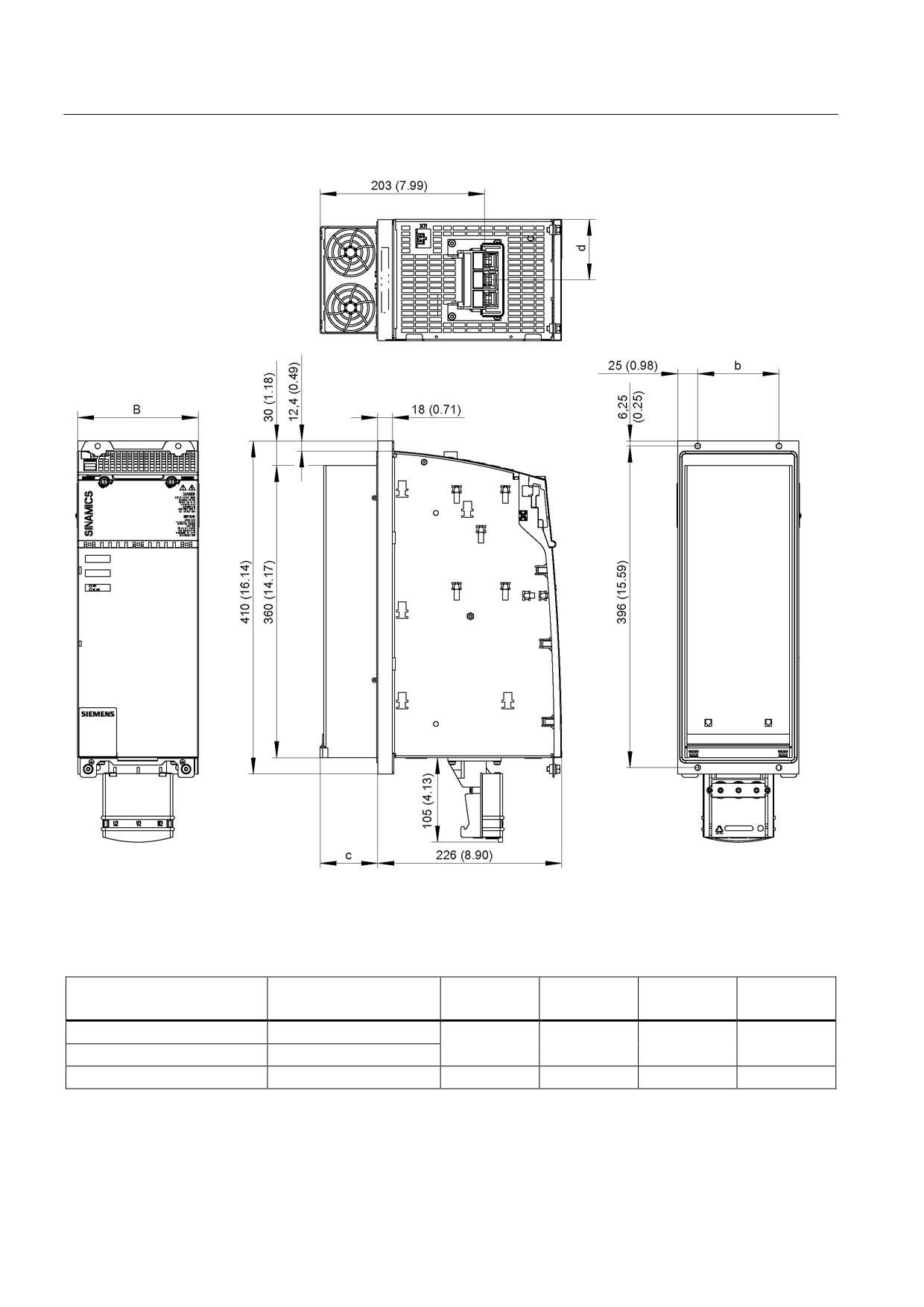
Figure 8-124 Dimension drawing of 45 A, 60 A, and 85 A Motor Modules Booksize with external air cooling, all dimensions
in mm and (inches); example 45 A
Table 8- 101 Dimensions of 45 A, 60 A, and 85 A Motor Modules Booksize with external air cooling
Motor Module
Order number
B [mm]
b [mm]
c [mm]
d [mm]
(inches)
(inches)
(inches)
(inches)
Single Motor Module 45 A
6SL3121-1TE24-5AAx
150 (5.91)
100 (3.94)
71 (2.80)
75 (2.95)
Single Motor Module 60 A
6SL3121-1TE26-0AAx
Single Motor Module 85 A
6SL3121-1TE28-5AAx
200 (7.87)
150 (5.91)
92 (3.62)
100 (3.94)
Guidelines for machine configuration
382
System Manual, MA 01/2013, 6FC5397-6CP10-0BA2
Connection of the components in SINAMICS drive system
8.4 Connection of motor modules
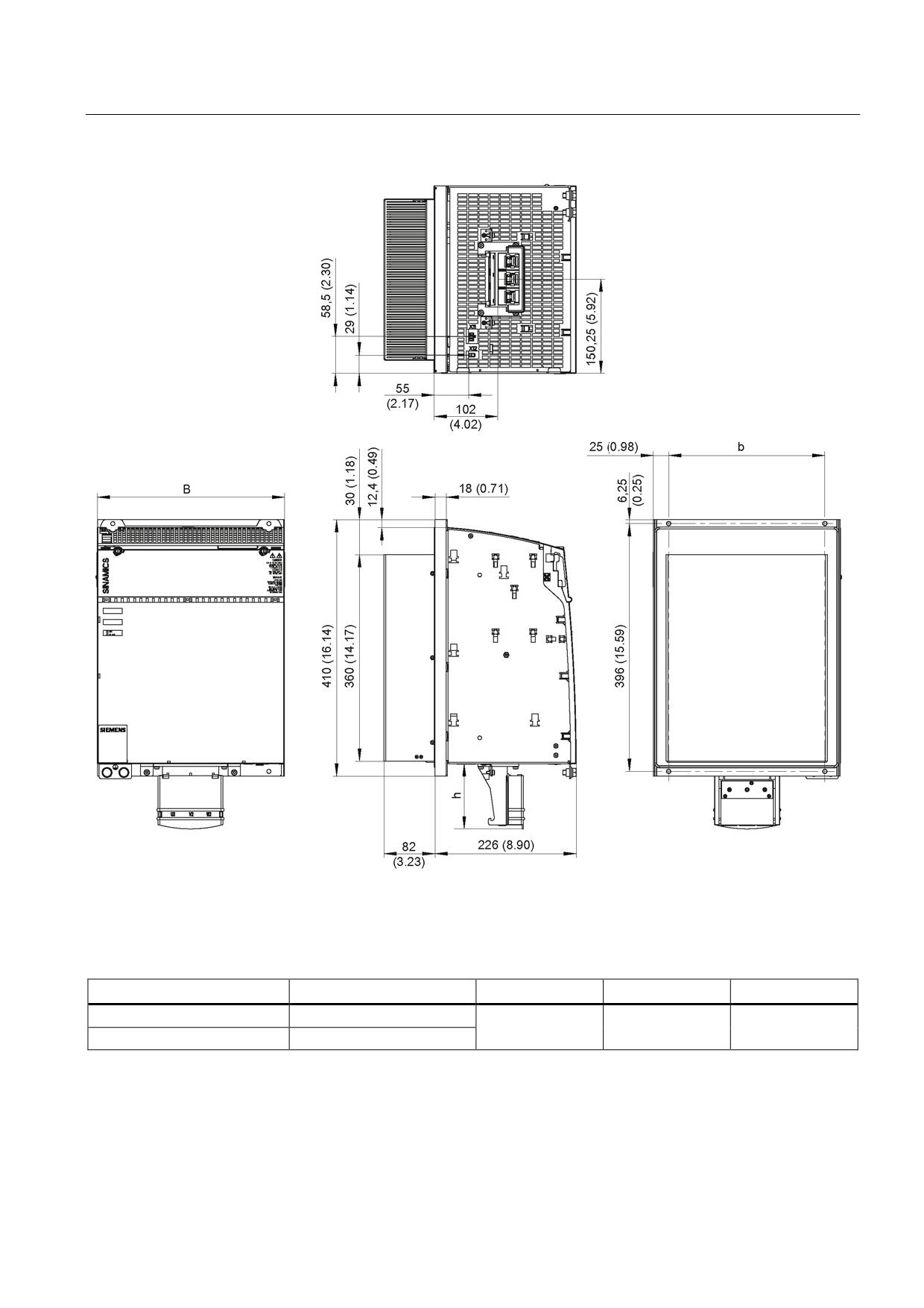
Figure 8-125 Dimension drawing of 132 A and 200 A Motor Modules Booksize, all dimensions in mm and (inches);
example: 200 A Single Motor Module
Table 8- 102 Dimensions of 132 A and 200 A Motor Modules Booksize with external air cooling
Motor Module
Order number
B [mm] (inches)
b [mm] (inches)
h [mm] (inches)
Single Motor Module 132 A
6SL3121-1TE31-3AAx
300 (11.81)
250 (9.84)
105 (4.13)
Single Motor Module 200 A
6SL3121-1TE32-0AAx
Guidelines for machine configuration
System Manual, MA 01/2013, 6FC5397-6CP10-0BA2
383
Connection of the components in SINAMICS drive system
8.4 Connection of motor modules
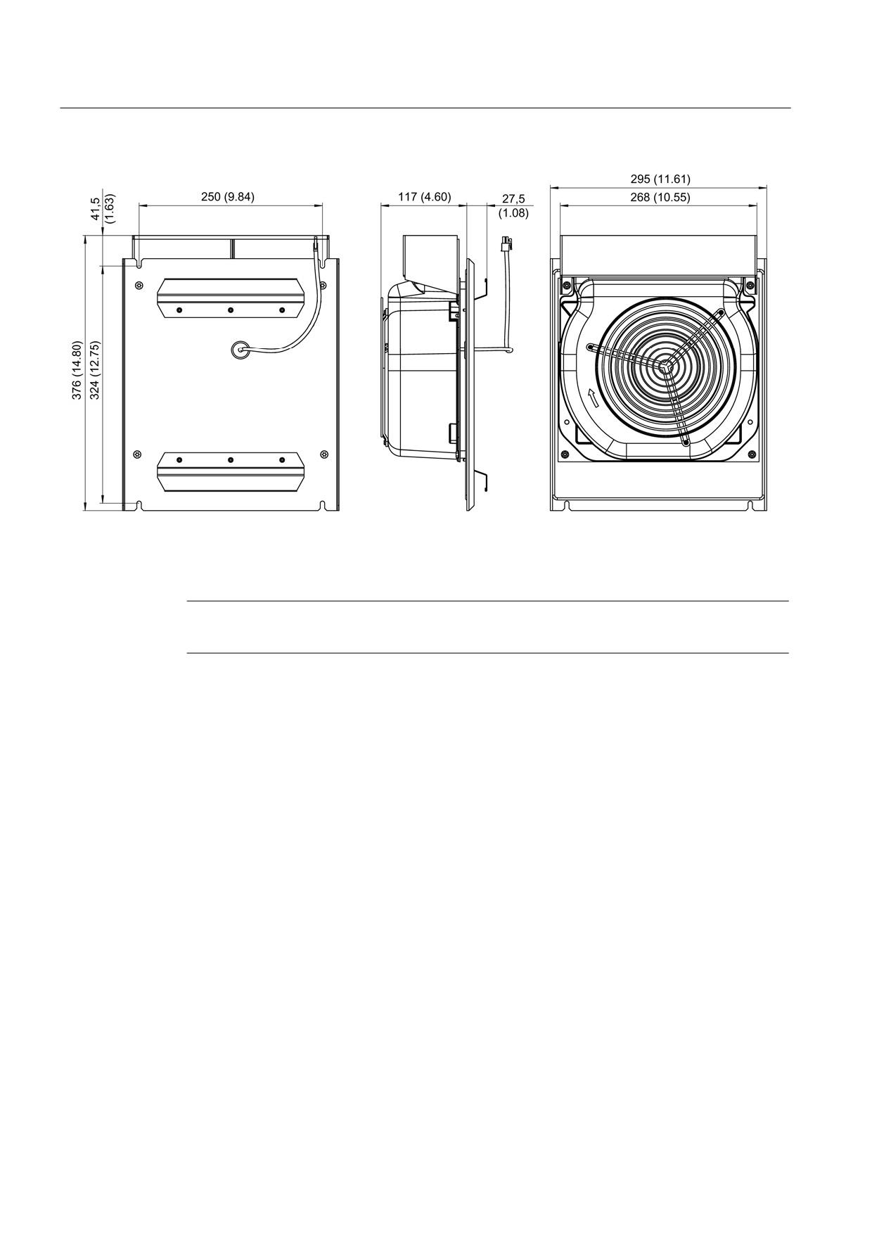
Figure 8-126 Dimension drawing of fan for 132 A and 200 A Motor Modules Booksize with external air cooling, all
dimensions in mm and (inches)
Note
The fans for the 132 kW and 200 kW Motor Modules are included in the scope of delivery.
Guidelines for machine configuration
384
System Manual, MA 01/2013, 6FC5397-6CP10-0BA2
Connection of the components in SINAMICS drive system
8.4 Connection of motor modules
8.4.3.6
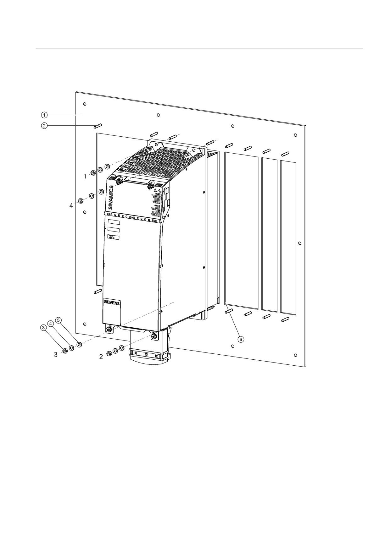
Mounting
①
Mounting plate with openings for mounting
②
M6 studs
③
M6 nut
④
Spring washer
⑤
Washer
⑥
Fan assembly
Figure 8-127 Mounting a Motor Module with external air cooling
Tightening torques:
● Initially, tighten the nuts by hand (0.5 Nm)
● Then tighten with 6 Nm (in the specific sequence 1 to 4)
Guidelines for machine configuration
System Manual, MA 01/2013, 6FC5397-6CP10-0BA2
385
Connection of the components in SINAMICS drive system
8.4 Connection of motor modules
Help with the mechanical control cabinet design is available from:
Siemens AG
Industry Sector, IA DT MC MF - WKC AS
TCCCC (Technical Competence Center Cabinets Chemnitz)
Postfach 1124
09070 Chemnitz, Germany
E-mail: cc.cabinetcooling.aud@siemens.com
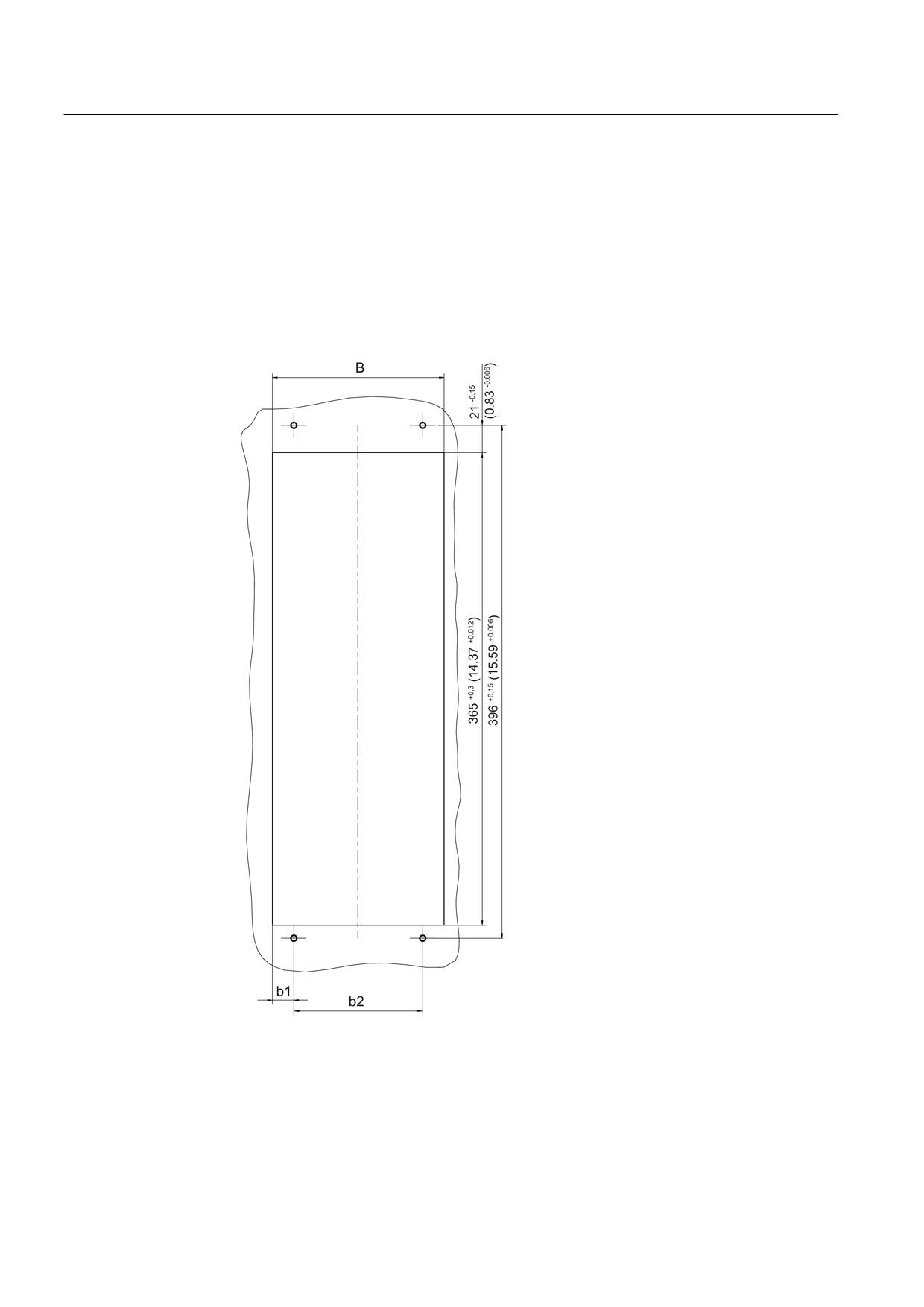
Figure 8-128 Opening to mount Motor Modules 50 mm to 200 mm with external air cooling, all data in
mm and (inches)
Guidelines for machine configuration
386
System Manual, MA 01/2013, 6FC5397-6CP10-0BA2
Connection of the components in SINAMICS drive system
8.4 Connection of motor modules
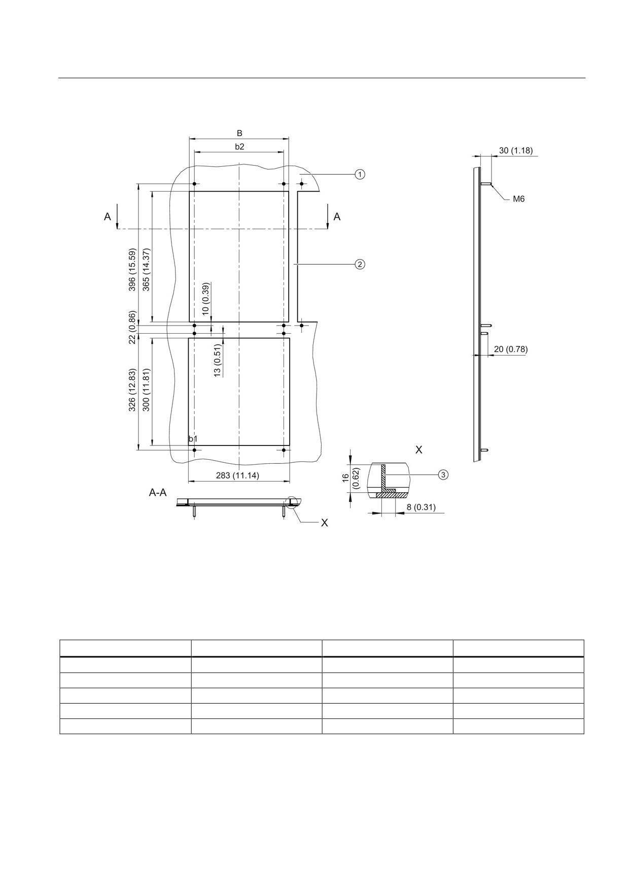
①
Insert plate or mounting plate
②
Cross-piece
③
Reinforcing bracket
Figure 8-129 Openings to mount a Motor Module 300 mm with external air cooling, all data in mm and (inches)
Table 8- 103 Dimensions of openings to mount Motor Modules with external air cooling
Component width
W [mm] (inches)
b1 [mm] (inch)
b2 [mm] (inch)
50 mm
41.5 +0.3 (1.63 +0.012)
20.75 +0.15 (0.82 +0.006)
0
100 mm
89,5 +0,3 (3.52 +0.012)
19,75 +0,15 (0.78 +0.006)
50 ±0,15 (1.97 ±0.006)
150 mm
133 +0,3 (5.24 +0.012)
16,5 +0,15 (0.65 +0.006)
100 ±0,15 (3.94 ±0.006)
200 mm
173 +0,3 (6.81 +0.012)
11,5 +0,15 (0.45 +0.006)
150 ±0,15 (5.91 ±0.006)
300 mm
278 +0,3 (10.94 +0.012)
14,0 ± 0,15 (0.55 ±0.006)
250 +0,15 (9.84 +0.006)
Guidelines for machine configuration
System Manual, MA 01/2013, 6FC5397-6CP10-0BA2
387
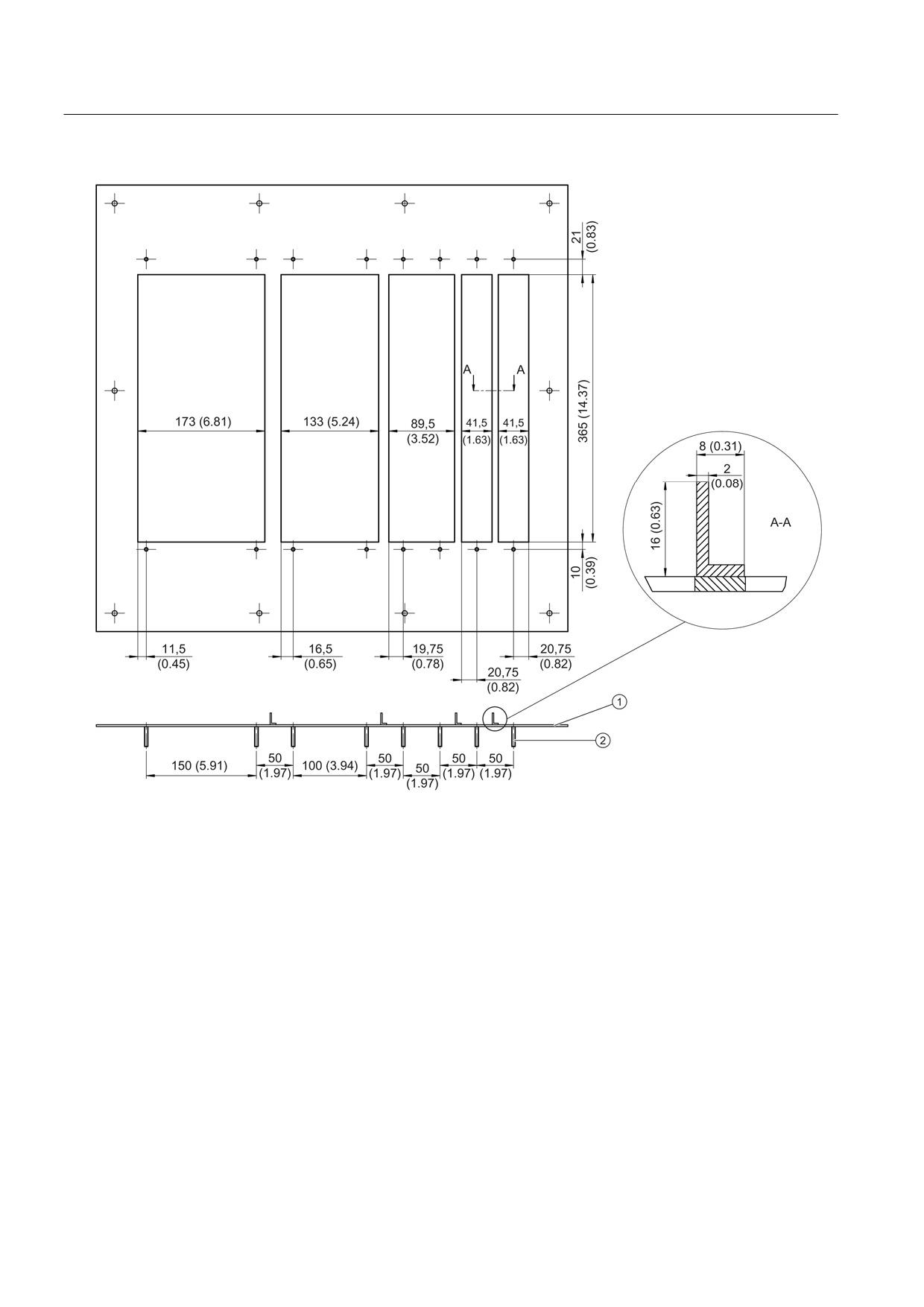
Connection of the components in SINAMICS drive system
8.4 Connection of motor modules
①
Insert plate or mounting plate
②
Threaded bolts M5 x 28
Figure 8-130 Example of a mounting plate for a drive line-up with external air cooling
When mounting it must be ensured that the component's seal is tight throughout. The cross-
pieces must have the appropriate stability. If necessary, the cross-pieces of the openings
must be reinforced.
In our example, the cross-pieces have been reinforced using brackets according to EN 755-
9. You are free to select the way that the bracket is attached to the insert.
Guidelines for machine configuration
388
System Manual, MA 01/2013, 6FC5397-6CP10-0BA2
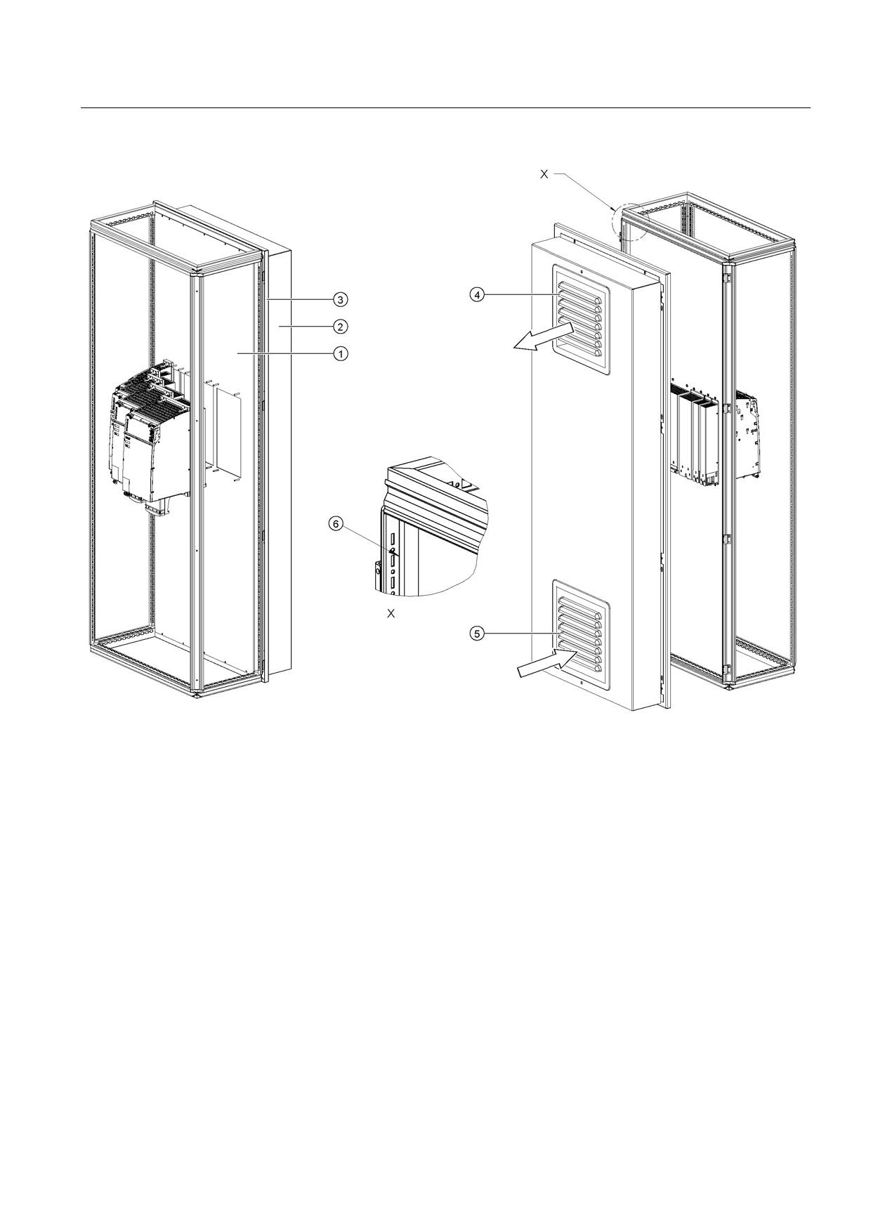
Connection of the components in SINAMICS drive system
8.4 Connection of motor modules
①
Mounting plate
②
Cover
③
Rear panel
④
Air discharge
⑤
Air inlet - filter with filter fan
⑥
To comply with degree of protection IP54, the surfaces ⑥ between the mounting plate and the cabinet strip must
be sealed all round. (for example, sealant Terostat-91 from the Teroson company)
Figure 8-131 Example 1: mounting in the cabinet with mounting plate
Guidelines for machine configuration
System Manual, MA 01/2013, 6FC5397-6CP10-0BA2
389
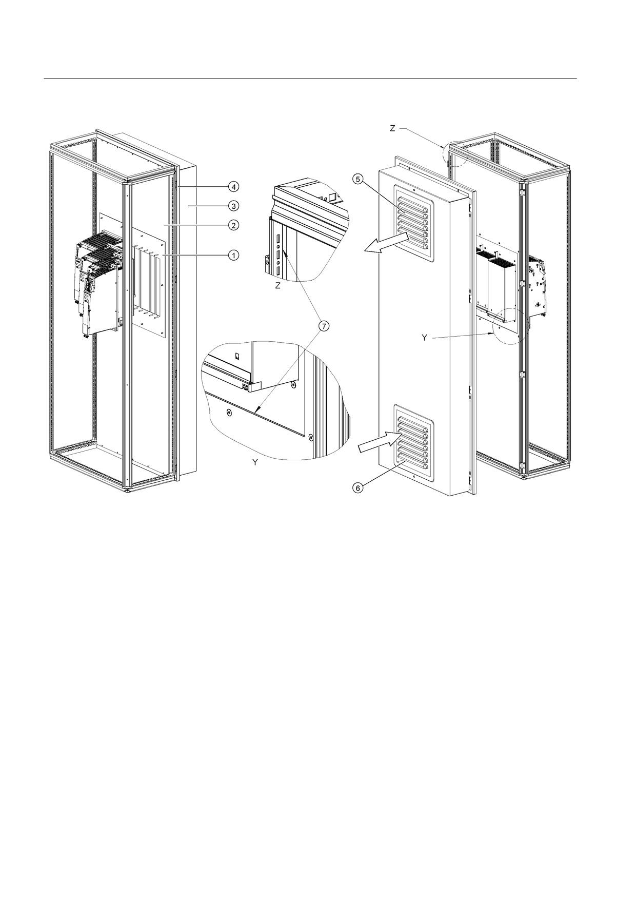
Connection of the components in SINAMICS drive system
8.4 Connection of motor modules
①
Insert plate
②
Mounting plate
③
Cover
④
Rear panel
⑤
Air discharge
⑥
Air inlet - filter with filter fan
⑦
To maintain the degree of protection IP54, the surfaces ⑦ between the mounting plate and the cabinet strip as
well as between the mounting plate and insert plate must be sealed all around. (for example, sealant Terostat-91
from the Teroson company)
Figure 8-132 Example 2: mounting in the cabinet with mounting plate
We recommend that you attach a cover and filter fan to the cabinet.
The filtered fan must be fitted in such a way that the cooling air required by the drive line-up
is not restricted. The overall cooling air requirement is obtained from the sum of the
individual components (see Section "Technical data").
Guidelines for machine configuration
390
System Manual, MA 01/2013, 6FC5397-6CP10-0BA2
Connection of the components in SINAMICS drive system
8.4 Connection of motor modules
Note
If the cooling air requirement is not covered by the filtered fan, the components cannot
output their specified power.
The filters with filter fan must be regularly checked for dirt and cleaned if necessary.
Guidelines for machine configuration
System Manual, MA 01/2013, 6FC5397-6CP10-0BA2
391
Connection of the components in SINAMICS drive system
8.4 Connection of motor modules
8.4.3.7
Technical data
Single Motor Modules
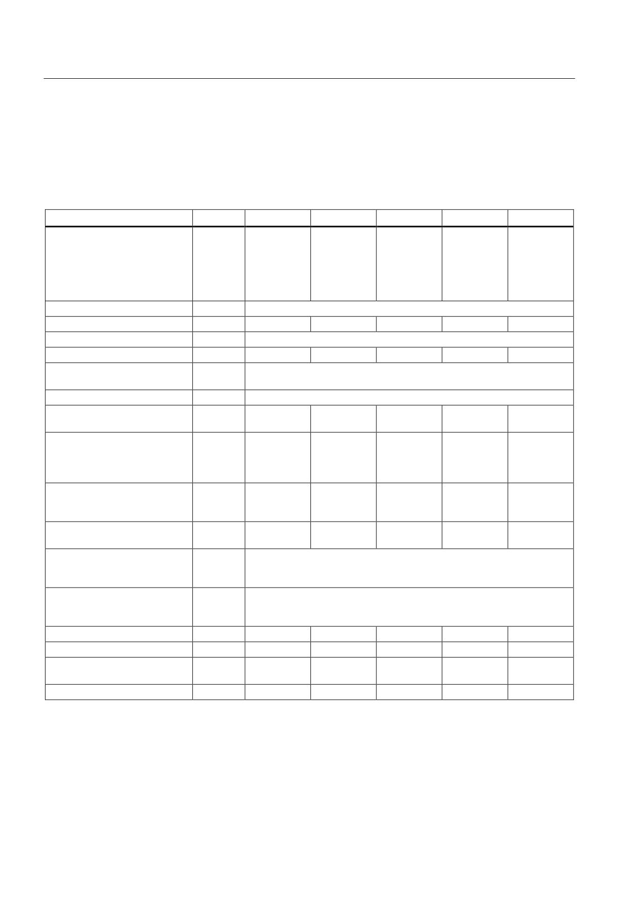
Table 8- 104 Technical data Single Motor Modules Booksize (3 to 30 A)
External air cooling
6SL3121-
1TE13-0AAx
1TE15-0AAx
1TE21-0AAx
1TE21-8AAx
1TE23-0AAx
Output current
Rated current (ln)
AACrms
3
5
9
18
30
Base-load current (IH)
A
2.6
4.3
7.7
15.3
25.5
Intermittent duty current (Is6)
40%
AACrms
3.5
6
10
24
40
Peak current (lmax)
AACrms
6
10
18
36
56
Output voltage
VACrms
0 - 0.717 x DC link voltage
DC link current Id
ADC
3.6
6
11
22
36
DC link voltage
VDC
510 - 720
DC link capacitance
μF
110
110
110
220
705
Overvoltage trip
VDC
820 ±2%
Undervoltage trip1)
VDC
380 ±2%
Electronics power supply
VDC
24 (20.4 - 28.8)
Electronics current consumption
ADC
0.85
0.85
0.85
0.85
0.8
at 24 V DC
Current carrying capacity
DC link busbars
ADC
100
100
100
100
100
Reinforced DC link busbars
ADC
150
150
150
150
150
24 VDC busbars
ADC
20
20
20
20
20
Unit rating
Based on In (600 VDC; 4 kHz)
kW
1.6
2.7
4.8
9.7
16
Based on IH
kW
1.4
2.3
4.1
8.2
13.7
Total power loss
W
50.4
73.4
100.4
185.4
309.2
(incl. electronics losses)2)
Max. pulse frequency
without derating
kHz
4
with derating
kHz
16
Max. ambient temperature
without derating
°C
40
with derating
°C
55
Sound pressure level
dB(A)
<60
<60
<60
<60
<60
Cooling air requirement
m3/h
29.6
29.6
29.6
29.6
56
Max. permissible heat sink
°C
70
70
73
82
85
temperature
Weight
kg
5.7
5.7
5.7
5.7
8.4
1)
Default for 400 V line systems; undervoltage trip threshold can be reduced by up to 80 V and is adjusted to the
parameterized rated voltage
2)
For an overview, see the power loss tables in the Appendix
Guidelines for machine configuration
392
System Manual, MA 01/2013, 6FC5397-6CP10-0BA2
Connection of the components in SINAMICS drive system
8.4 Connection of motor modules
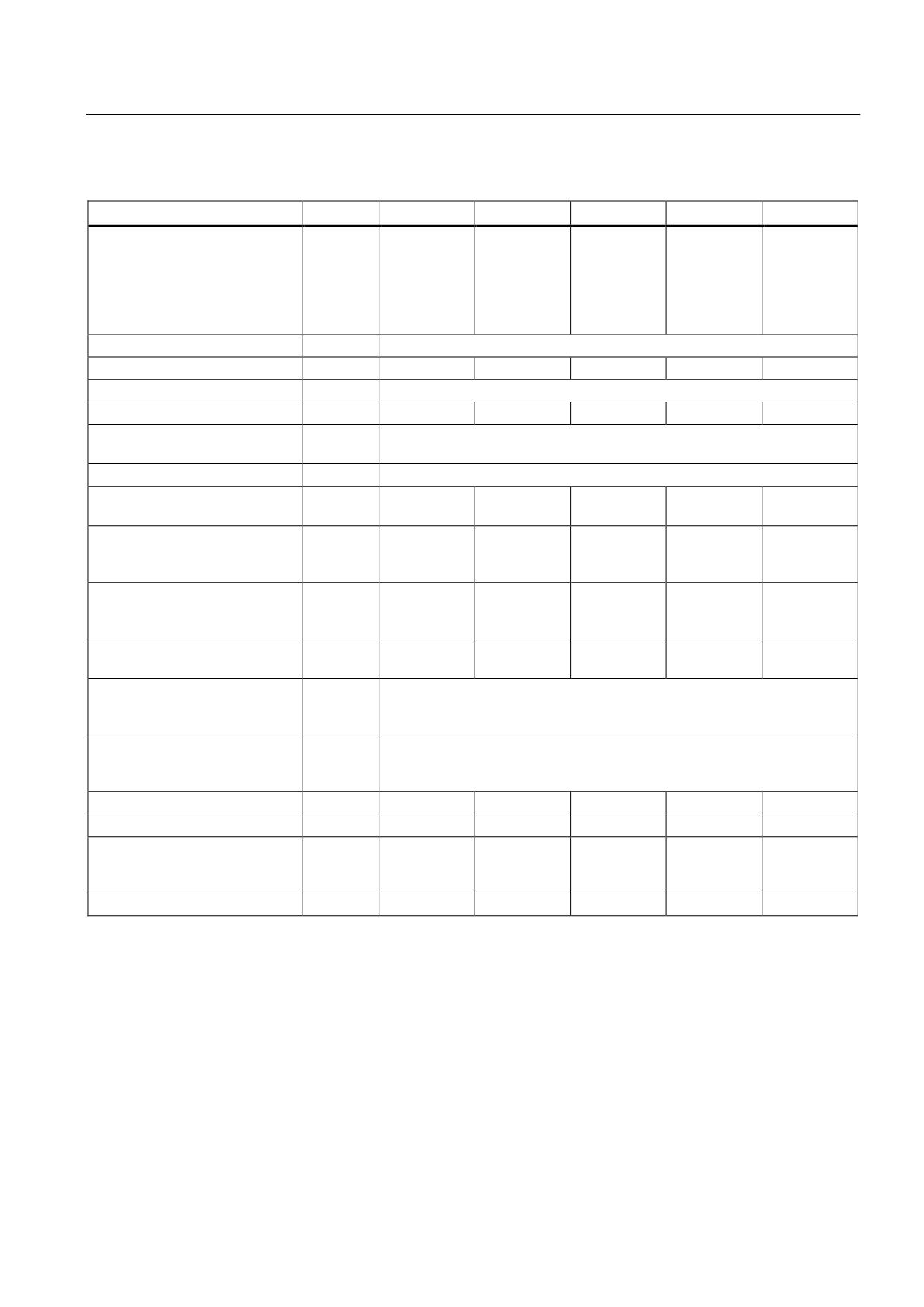
Table 8- 105 Technical data Single Motor Modules Booksize (45 to 200 A)
External air cooling
6SL3121-
1TE24-5AAx
1TE26-0AAx
1TE28-5AAx
1TE31-3AAx
1TE32-0AAx
Output current
Rated current (ln)
AACrms
45
60
85
132
200
Base-load current (IH)
A
38
51
68
105
141
Intermittent duty current (Is6)
40%
AACrms
60
80
110
150
230
Peak current (lmax)
AACrms
85
113
141
210
282
Output voltage
VACrms
0 - 0.717 x DC link voltage
DC link current Id
ADC
54
72
102
158
200
DC link voltage
VDC
510 - 720
DC link capacitance
μF
1175
1410
1880
2820
3995
Overvoltage trip
VDC
820 ±2%
Undervoltage trip1)
VDC
380 ±2%
Electronics power supply
VDC
24 (20.4 - 28.8)
Electronics current consumption
ADC
1.05
1.05
1.5
0.85
0.85
at 24 V DC
Current carrying capacity
DC link busbars
ADC
200
200
200
200
200
24 VDC busbars
ADC
20
20
20
20
20
Unit rating
Based on In (600 VDC; 4 kHz)
kW
24
32
46
71
107
Based on IH
kW
21
28
37
57
76
Total power loss
W
455.2
615.2
786
1270.4
2070.4
(incl. electronics losses)2)
Max. pulse frequency
without derating
kHz
4
with derating
kHz
16
Max. ambient temperature
without derating
°C
40
with derating
°C
55
Sound pressure level
dB(A)
< 65
< 65
< 60
< 73
< 73
Cooling air requirement
m3/h
112
112
160
520
520
Max. permissible heat sink
°C
85
90
88
73
80
temperature
(70%
derating)
Weight
kg
13.2
13.3
17.2
27.1
28
1)
Default for 400 V line systems; undervoltage trip threshold can be reduced by up to 80 V (exception: 132 A and 200 A
Motor Modules) and is adjusted to the parameterized rated voltage.
2)
For an overview, see the power loss tables in the Appendix
Guidelines for machine configuration
System Manual, MA 01/2013, 6FC5397-6CP10-0BA2
393
Connection of the components in SINAMICS drive system
8.4 Connection of motor modules
Double Motor Modules
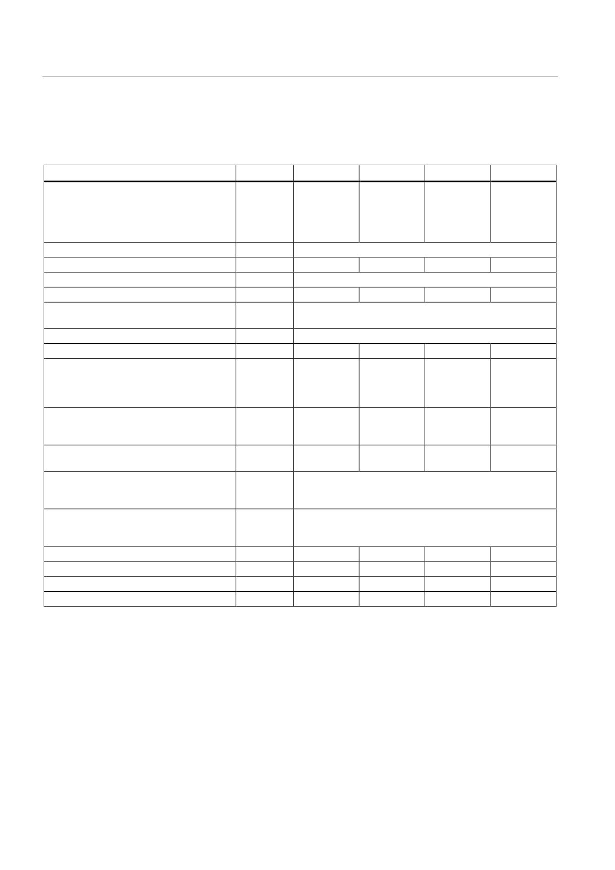
Table 8- 106 Technical data Double Motor Modules Booksize (3 to 18 A)
External air cooling
6SL3121-
2TE13-0AAx
2TE15-0AAx
2TE21-0AAx
2TE21-8AAx
Output current
Rated current (ln)
AACrms
2 x 3
2 x 5
2 x 9
2 x 18
Base-load current (IH)
A
2 x 2.6
2 x 4.3
2 x 7.7
2 x 15.3
Intermittent duty current (Is6) 40%
AACrms
2 x 3.5
2 x 6
2 x 10
2 x 24
Peak current (lmax)
AACrms
2 x 6
2 x 10
2 x 18
2 x 36
Output voltage
VACrms
0 -480
DC link current Id
ADC
7.2
12
22
43
DC link voltage
VDC
510 - 720
DC link capacitance
μF
110
220
220
705
Overvoltage trip
VDC
820 ±2%
Undervoltage trip1)
VDC
380 ±2%
Electronics power supply
VDC
24 (20.4 - 28.8)
Electronics current consumption at 24 V DC
ADC
1.15
1.15
1.15
1.3
Current carrying capacity
DC link busbars
ADC
100
100
100
100
Reinforced DC link busbars
ADC
150
150
150
150
24 VDC busbars
A
20
20
20
20
Unit rating
Based on In (600 VDC; 4 kHz)
kW
2 x 1.6
2 x 2.7
2 x 4.8
2 x 9.7
Based on IH
kW
2 x 1.4
2 x 2.3
2 x 4.4
2 x 8.2
Total power loss
W
97.6
132.6
187.6
351.2
(including electronics losses)2)
Max. pulse frequency
without derating
kHz
4
with derating
kHz
16
Max. ambient temperature
without derating
°C
40
with derating
°C
55
Sound pressure level
dBA
<60
<60
<60
<60
Cooling air requirement
m3/h
29.6
29.6
29.6
56
Max. permissible heat sink temperature
°C
80
85
89
90
Weight
kg
5.8
5.8
5.7
8.6
1)
Default for 400 V line systems; undervoltage trip threshold can be reduced by up to 80 V and is adjusted to the
parameterized rated voltage
2)
For an overview, see the power loss tables in the Appendix
Guidelines for machine configuration
394
System Manual, MA 01/2013, 6FC5397-6CP10-0BA2
Connection of the components in SINAMICS drive system
8.4 Connection of motor modules
Characteristics
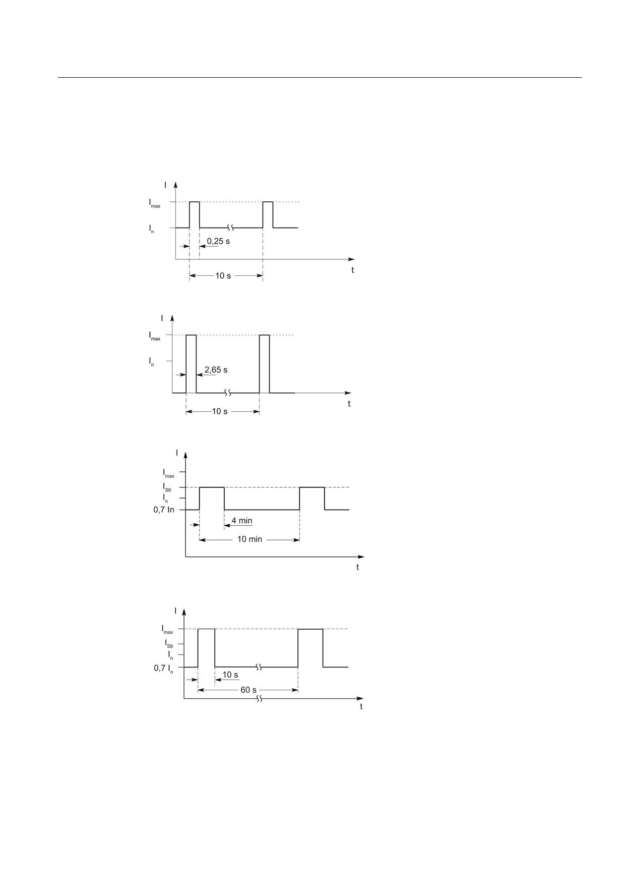
Rated duty cycles Motor Modules Booksize
Figure 8-133 Duty cycle with initial load (for servo drives)
Figure 8-134 Duty cycle without initial load (for servo drives)
Figure 8-135 S6 duty cycle with initial load with a duty cycle duration of 600 s (for servo drives)
Figure 8-136 S6 duty cycle with initial load with a duty cycle duration of 60 s (for servo drives)
Guidelines for machine configuration
System Manual, MA 01/2013, 6FC5397-6CP10-0BA2
395
Connection of the components in SINAMICS drive system
8.4 Connection of motor modules
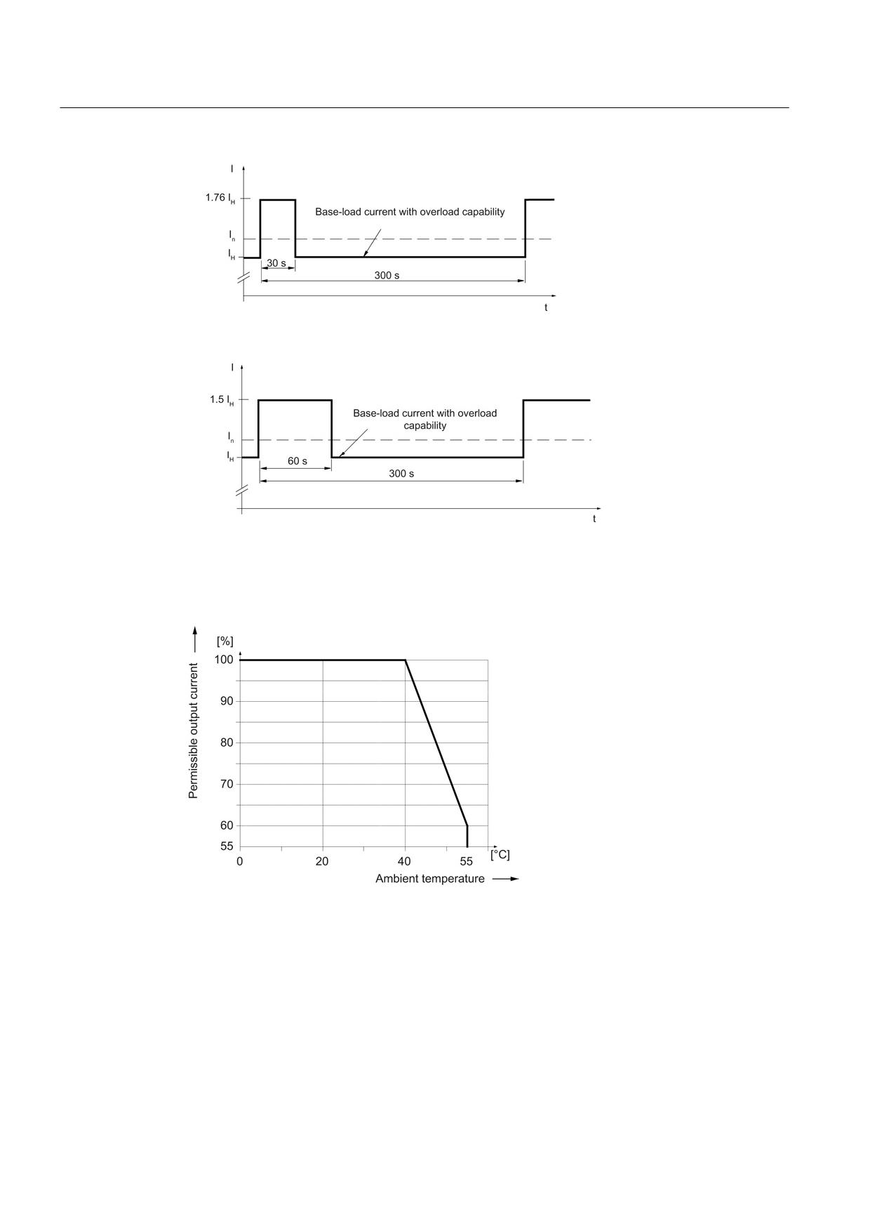
Figure 8-137 Duty cycle with 30 s overload for a duty cycle duration of 300 s
Figure 8-138 Duty cycle with 60 s overload for a duty cycle duration of 300 s
Derating characteristics for Motor Modules Booksize
Figure 8-139 Output current as a function of the ambient temperature
Guidelines for machine configuration
396
System Manual, MA 01/2013, 6FC5397-6CP10-0BA2
Connection of the components in SINAMICS drive system
8.4 Connection of motor modules
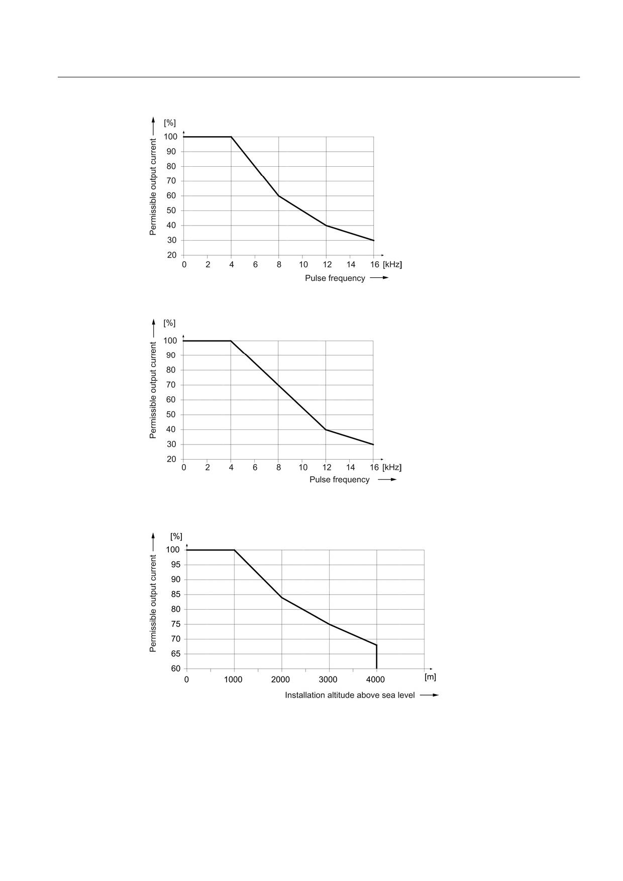
Figure 8-140 Output current as a function of the pulse frequency
Figure 8-141 Output current as a function of the pulse frequency for 200 A Motor Modules
(applies from order number 6SL312x-1TE32-0AA4)
Figure 8-142 Output current as a function of the installation altitude
Guidelines for machine configuration
System Manual, MA 01/2013, 6FC5397-6CP10-0BA2
397
Connection of the components in SINAMICS drive system
8.4 Connection of motor modules
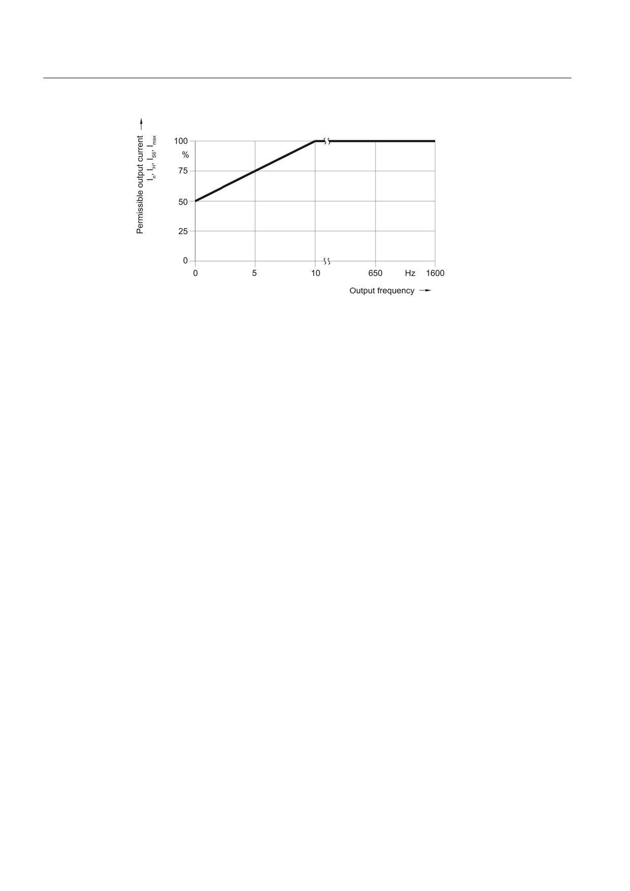
Figure 8-143 Output current as a function of the output frequency
At installation altitudes > 2000 m, an isolation transformer must be used (see the chapter
titled "System overview/Function of installation altitude and ambient temperature"
(Page 32)). The design of the secondary line system must be as follows:
● TN system with grounded neutral point (no grounded line conductor)
● IT system
A reduction of the line supply voltage phase-phase is not necessary.
8.4.4
Motor Modules with cold plate
8.4.4.1
Description
A Motor Module is a power unit (inverter) that provides the power supply for the connected
motor(s). Power is supplied by means of the DC link of the drive unit. A Motor Module must
be connected to a Control Unit via DRIVE-CLiQ. The open-loop and closed-loop control
functions for the Motor Module are stored in the Control Unit.
One motor can be connected to Single Motor Modules and two motors can be connected to
Double Motor Modules.
Guidelines for machine configuration
398
System Manual, MA 01/2013, 6FC5397-6CP10-0BA2
Connection of the components in SINAMICS drive system
8.4 Connection of motor modules
8.4.4.2
Interface description
Overview
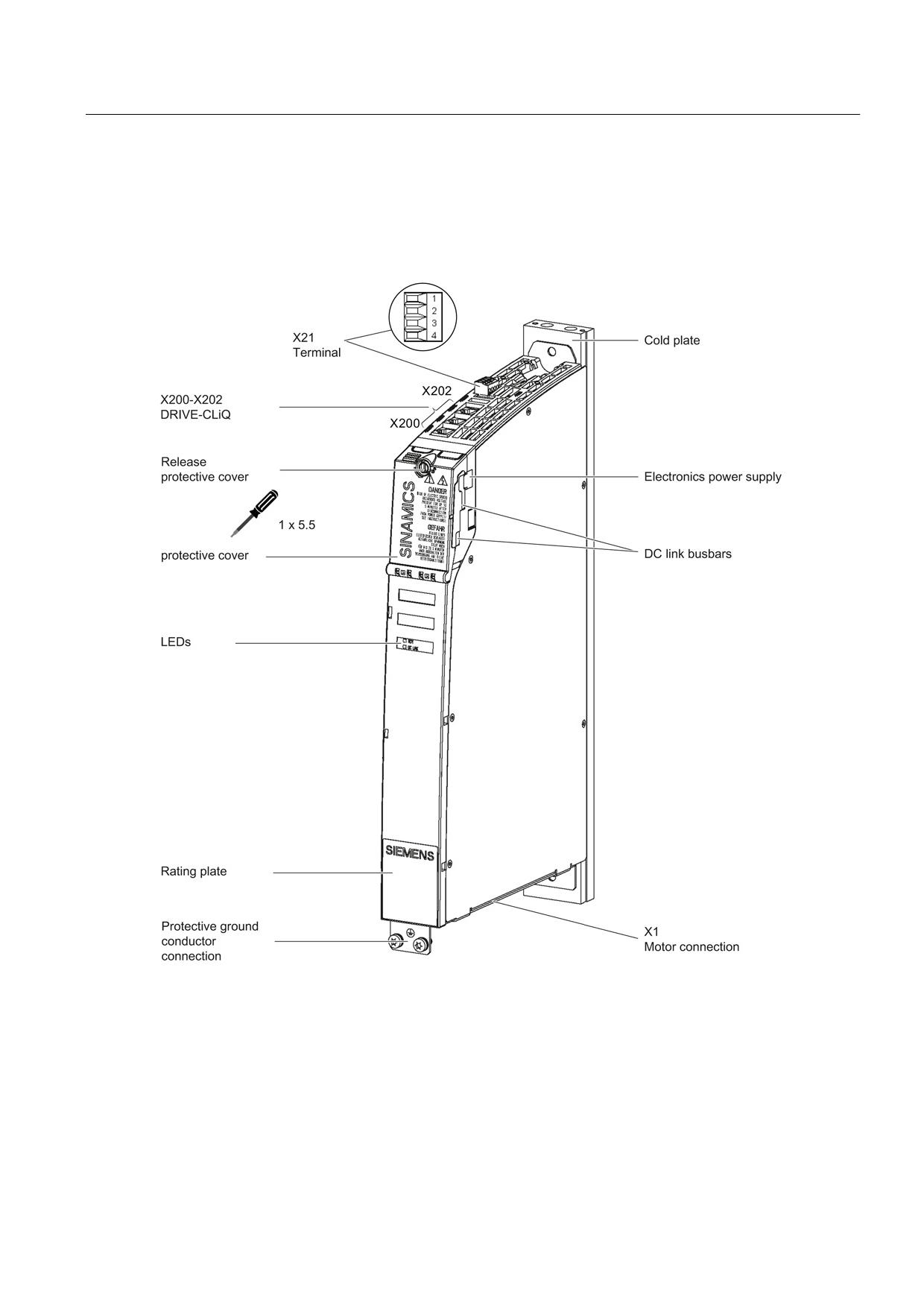
Figure 8-144 Interface overview, Single Motor Module Booksize with cold plate (example: 5 A)
Guidelines for machine configuration
System Manual, MA 01/2013, 6FC5397-6CP10-0BA2
399
Connection of the components in SINAMICS drive system
8.4 Connection of motor modules
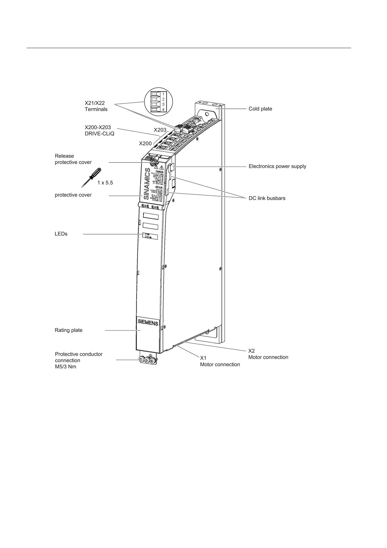
Figure 8-145 Interface overview, Double Motor Module Booksize with cold plate (example: 2 x 5 A)
Guidelines for machine configuration
400
System Manual, MA 01/2013, 6FC5397-6CP10-0BA2
Connection of the components in SINAMICS drive system
8.4 Connection of motor modules
Motor and brake connection
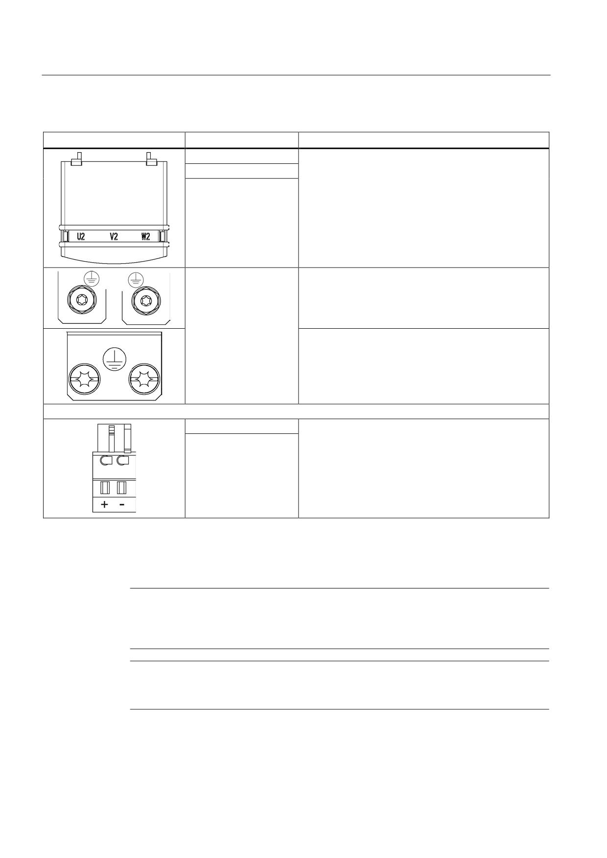
Table 8- 107 X1/X2 motor and brake connection for Single Motor Modules 3 A to 30 A and Double Motor Modules 3 A to
18 A
Terminal
Technical data
U (U2)
Motor connection
V (V2)
W (W2)
+ (BR+)
Brake connection
max. load current 2 A
- (BR-)
min. load current 0.1 A
PE connection
Single Motor Modules 3 A to 30 A:
Threaded hole M5/3 Nm 1)
Double Motor Modules 3 A to 18 A:
Threaded hole M5/3 Nm 1)
1) For ring cable lugs in accordance with DIN 46234
Guidelines for machine configuration
System Manual, MA 01/2013, 6FC5397-6CP10-0BA2
401
Connection of the components in SINAMICS drive system
8.4 Connection of motor modules
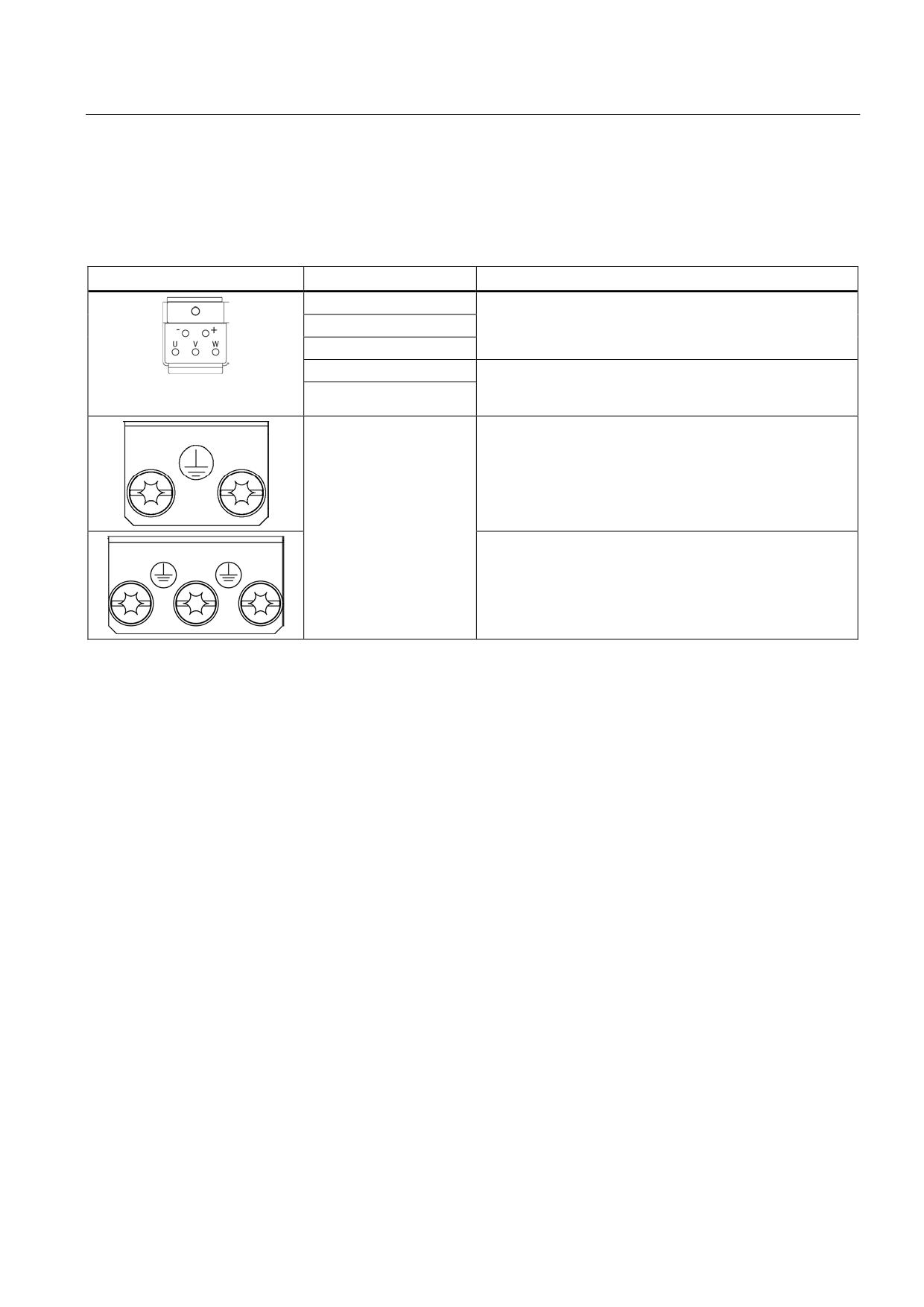
Table 8- 108 X1 motor connection and X11 brake connection for Single Motor Modules 45 A to 200 A
Terminal
Technical data
U2
45 A to 60 A:
Threaded bolts M6/6 Nm 1)
V2
85 A:
W2
Threaded bolts M8/13 Nm 1)
132 A to 200 A:
Threaded bolts M8/13 Nm 1)
PE connection
45 A to 60 A:
Threaded bolts for motor cables: M6/6 Nm 1)
Threaded hole for PE: M6 / 6 Nm 1)
85 A:
Threaded bolts for motor cables: M8/13 Nm 1)
Threaded hole for PE: M6 / 6 Nm 1)
132 A to 200 A:
Threaded bolts for motor cables: M8/13 Nm 1)
Threaded hole for PE: M8 / 13 Nm 1)
+ (BR+)
X11 brake connector 2):
- (BR-)
Voltage 24 VDC
Max. load current 2 A
Min. load current 0.1 A
Max. connectable cross-section 2.5 mm2
Type: Spring-loaded terminal 2
(see Appendix, Chapter "Spring-loaded terminals")
The brake connector is part of the prefabricated cable
1) For ring cable lugs in accordance with DIN 46234
2) The circuit for protecting the brake against overvoltage is integrated in the Motor Module and does not need to be
installed externally. The max. load current is 2 A, the min. load current 0.1 A.
Note
The total length of the power cables (motor supply cables and DC link cables) must not
exceed the values listed in the chapter titled "Possible line reactor and line filter
combinations".
Note
The motor brake must be connected via connector X11. Directly connecting the BR- cable to
the electronics ground M is not permitted.
Guidelines for machine configuration
402
System Manual, MA 01/2013, 6FC5397-6CP10-0BA2
Connection of the components in SINAMICS drive system
8.4 Connection of motor modules
WARNING
Safety extra-low voltages at connections and terminals
Only protective extra-low voltages (DVC A) that comply with EN 60204-1 may be connected
to all connections and terminals between 0 and 48 VDC.
The voltage tolerances of the motor holding brakes (24 V ±10 %) must be taken into
account.
X21/X22 EP terminals/temperature sensor
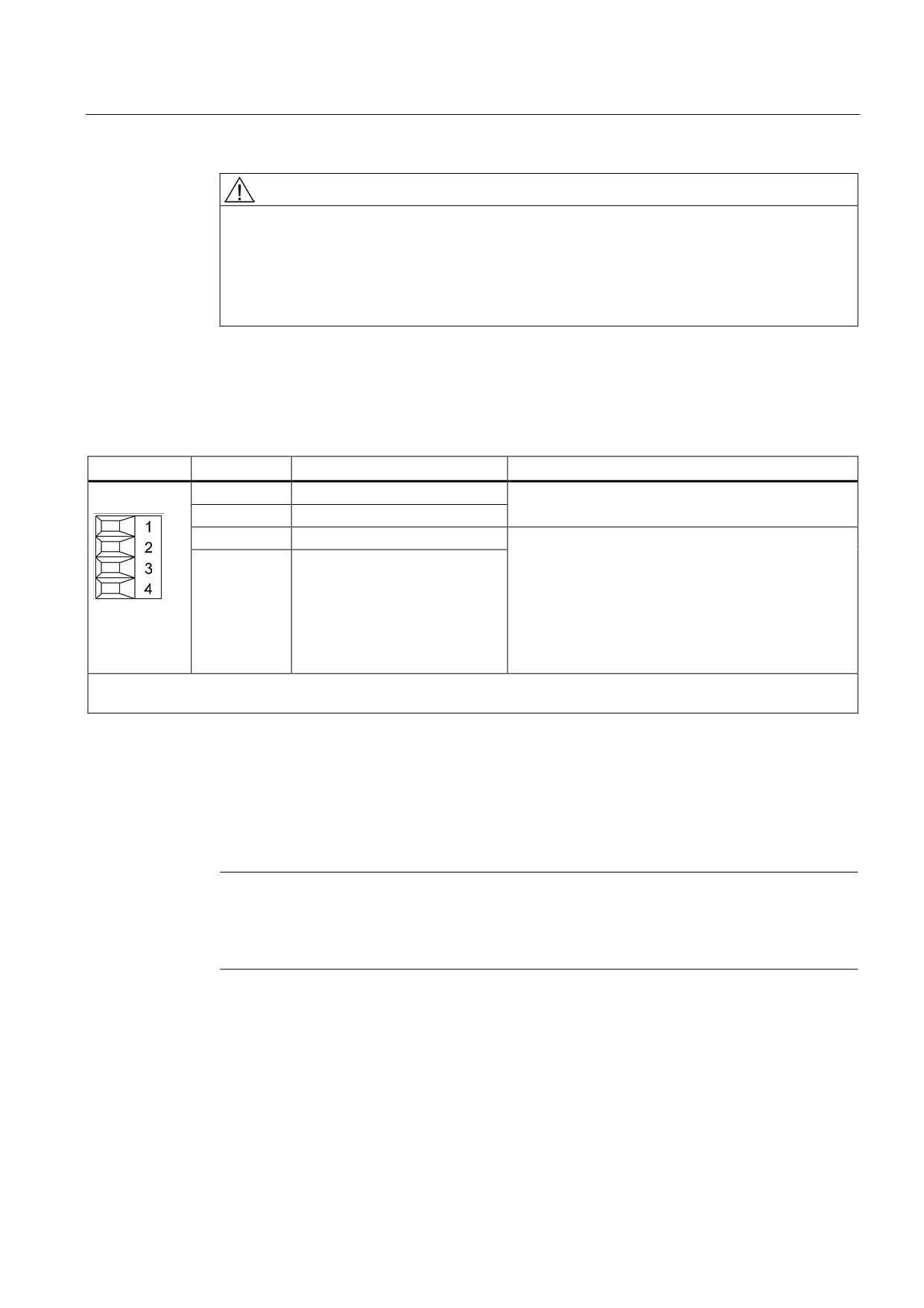
Table 8- 109 X21/X22 EP terminals/temperature sensor
Terminal
Function
Technical data
1
+ Temp
Temperature sensors: KTY84-1C130/PTC/bimetallic
switch with NC contact
2
- Temp
3
EP +24 V (Enable Pulses)
Supply voltage: 24 VDC (20.4 V - 28.8 V)
Current consumption: 10 mA
4
EP M1 (Enable Pulses)
Isolated input
Signal propagation times:
L → H: 100 μs
H → L: 1000 μs
The pulse inhibit function is only available when Safety
Integrated Basic Functions are enabled.
Max. connectable cross-section 1.5 mm2
Type: Screw terminal 1 (see Appendix A.1)
EP terminals
Parameters p9651 and p9851 are used to set the filter times to debounce terminals X21.3
and X21.4, as well as X22.3 and X22.4. Additional parameter settings are also required in
order to prevent discrepancy errors when performing bit pattern tests (light/dark tests). For
comprehensive information, see the SINAMICS S120 Safety Integrated Function Manual,
Chapter "Controlling the safety functions".
Note
Function of the EP terminals
The function of the EP terminals is only available when Safety Integrated Basic Functions
are enabled.
Guidelines for machine configuration
System Manual, MA 01/2013, 6FC5397-6CP10-0BA2
403
Connection of the components in SINAMICS drive system
8.4 Connection of motor modules
Temperature sensor connection
NOTICE
Risk of the motor overheating due to an incorrectly connected KTY temperature sensor
A KTY temperature sensor connected with incorrect polarity cannot detect if the motor
overheats.
• Always connect the KTY temperature sensor with the correct polarity.
Note
The temperature sensor input is not needed if the motors feature an integrated DRIVE-CLiQ
interface or if temperature values are detected by means of a different module (SMC, SME,
TM).
DANGER
Danger to life through electric shock
Only temperature sensors that meet the safety isolation specifications stipulated in
EN 61800-5-1 may be connected to terminals "+Temp" and "-Temp". If safe electrical
separation cannot be guaranteed (for linear motors or third-party motors, for example), a
Sensor Module External (SME120 or SME125) or Terminal Module TM120 must be used.
If these instructions are not complied with, there is danger to life!
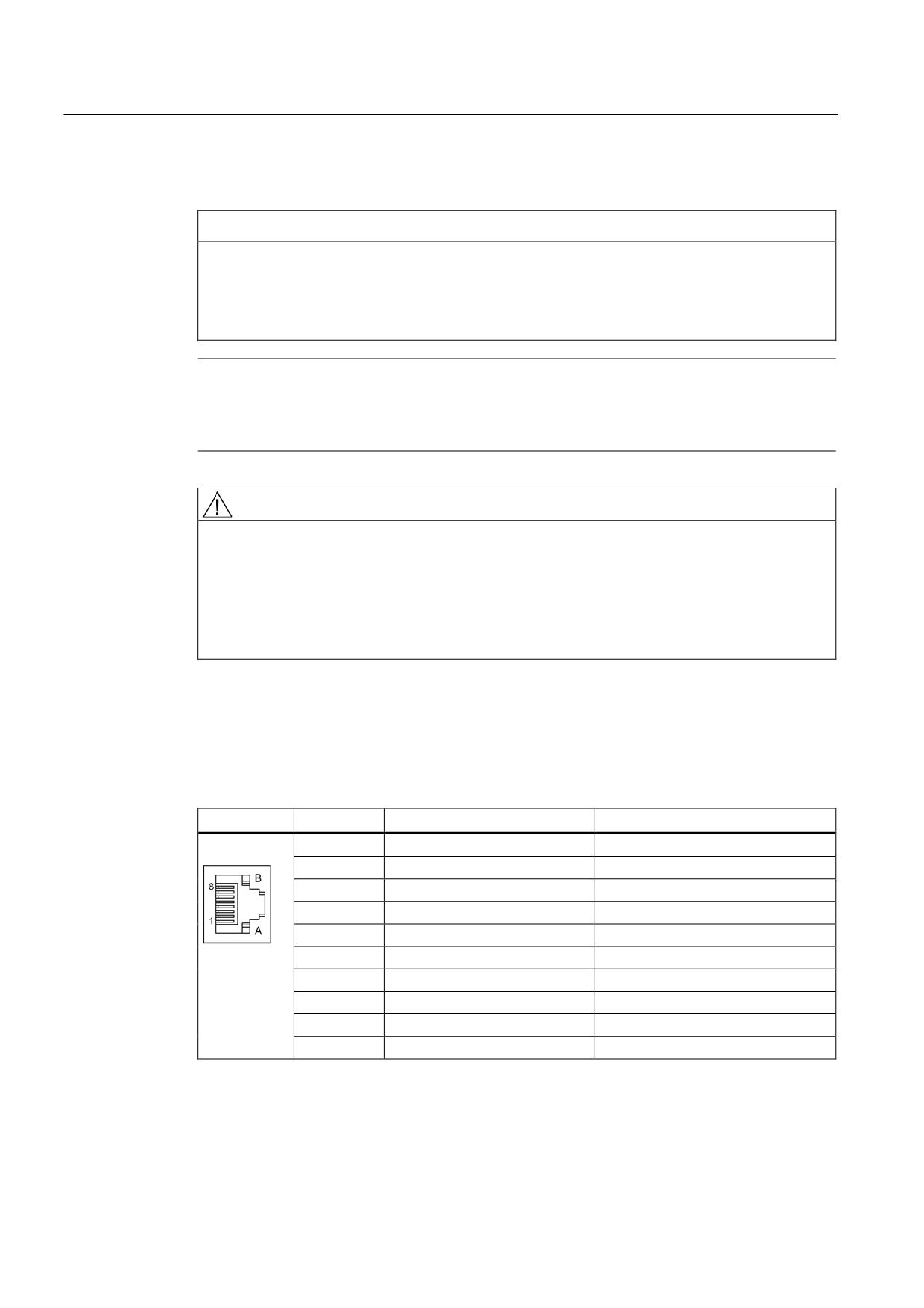
X200-X203 DRIVE-CLiQ interface
Table 8- 110 X200-X202: DRIVE-CLiQ interfaces for Single Motor Modules
X200-X203: DRIVE-CLiQ interfaces for Double Motor Modules
Pin
Name
Technical data
1
TXP
Transmit data +
2
TXN
Transmit data -
3
RXP
Receive data +
4
Reserved, do not use
5
Reserved, do not use
6
RXN
Receive data -
7
Reserved, do not use
8
Reserved, do not use
A
+ (24 V)
Power supply
B
M (0 V)
Electronics ground
The blanking covers for the DRIVE-CLiQ interfaces are included in the scope of delivery.
Blanking cover (50 pcs.) Order number: 6SL3066-4CA00-0AA0
Guidelines for machine configuration
404
System Manual, MA 01/2013, 6FC5397-6CP10-0BA2
Connection of the components in SINAMICS drive system
8.4 Connection of motor modules
8.4.4.3
Connection examples
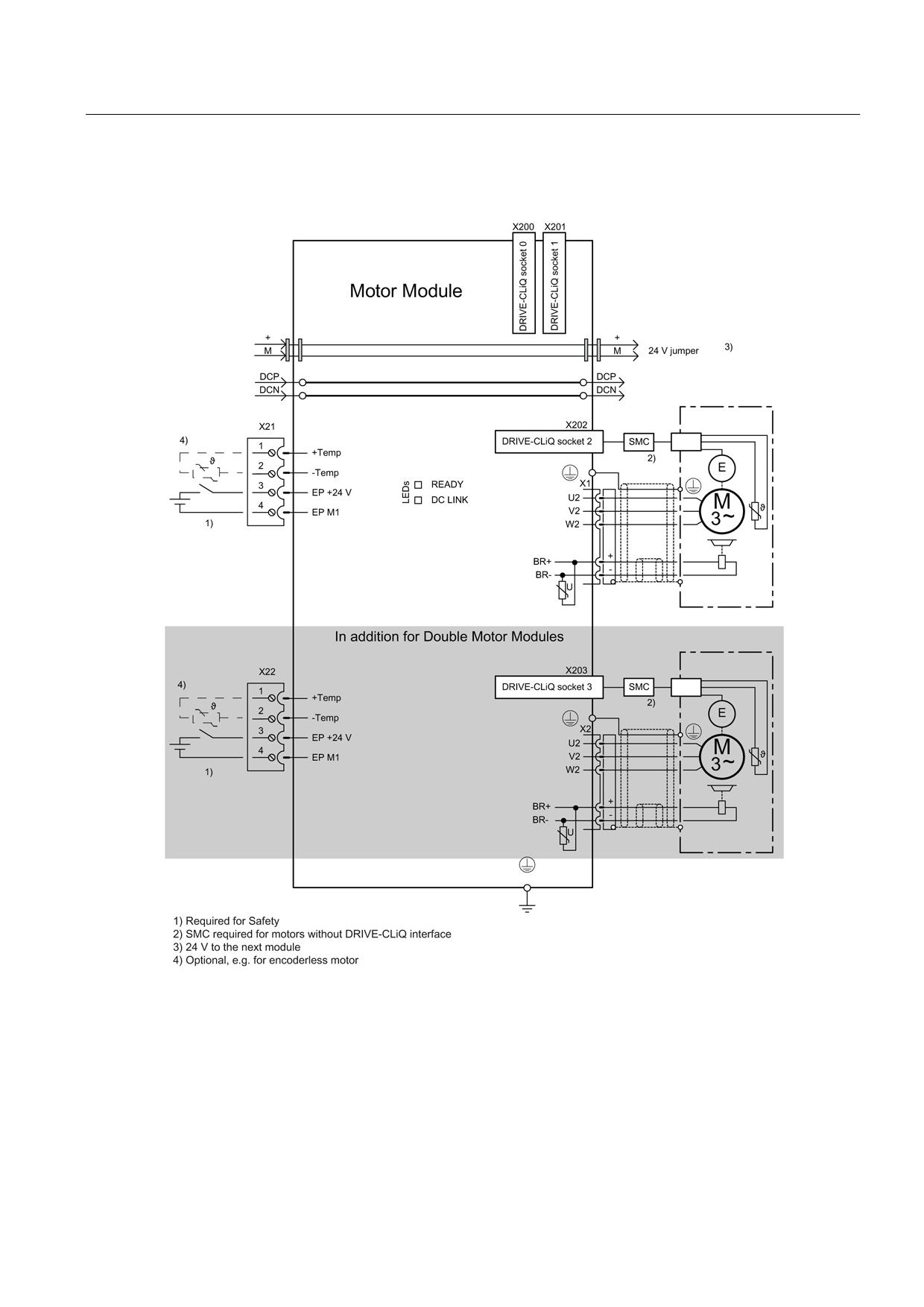
Figure 8-146 Connection example of Motor Modules 3 A to 30 A and Double Motor Modules 3 A to 18 A
Guidelines for machine configuration
System Manual, MA 01/2013, 6FC5397-6CP10-0BA2
405
Connection of the components in SINAMICS drive system
8.4 Connection of motor modules
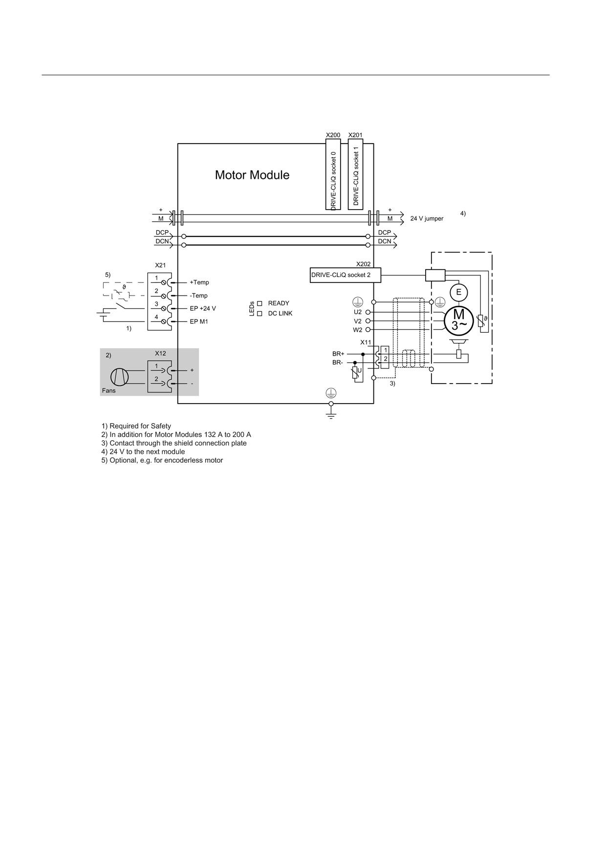
Figure 8-147 Example connection of Single Motor Modules 45 A to 200 A
Guidelines for machine configuration
406
System Manual, MA 01/2013, 6FC5397-6CP10-0BA2
Connection of the components in SINAMICS drive system
8.4 Connection of motor modules
8.4.4.4
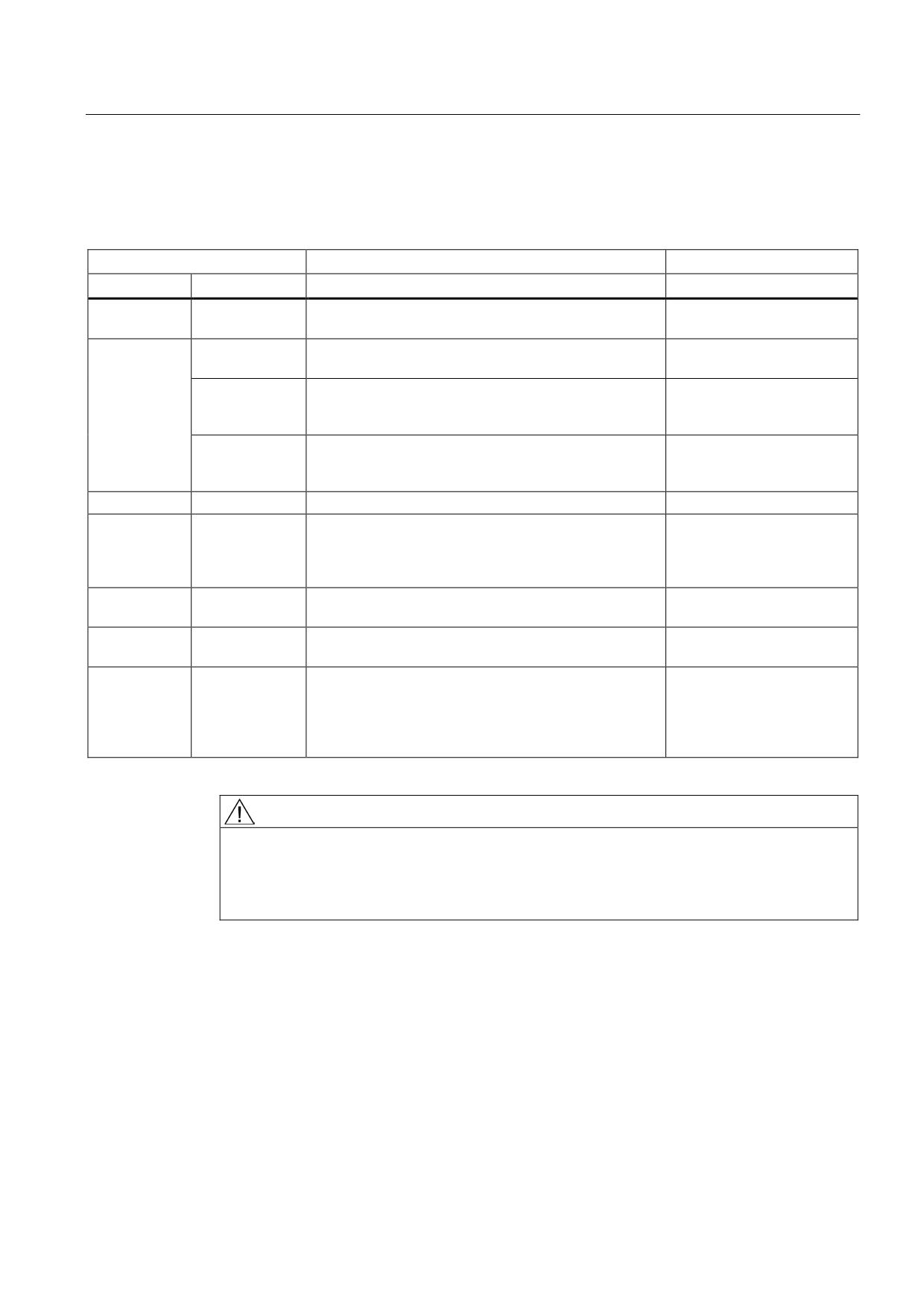
Meaning of LEDs
Table 8- 111 Meaning of the LEDs on the Motor Module
Status
Description, cause
Remedy
RDY
DC LINK
Off
Off
Electronics power supply is missing or outside
-
permissible tolerance range.
Green
--
The component is ready for operation and cyclic DRIVE-
-
CLiQ communication is taking place.
Orange
The component is ready for operation and cyclic DRIVE-
-
CLiQ communication is taking place.
The DC link voltage is present.
Red
The component is ready for operation and cyclic DRIVE-
Check line voltage
CLiQ communication is taking place.
The DC link voltage is too high.
Orange
Orange
DRIVE-CLiQ communication is being established.
-
Red
--
At least one fault is present in this component.
Remedy and acknowledge
Note:
fault
The LED is activated regardless of whether the
corresponding messages have been reconfigured.
Green/red
--
Firmware is being downloaded.
-
(0.5 Hz)
Green/red
--
Firmware download is complete. Wait for POWER ON.
Carry out a POWER ON
(2 Hz)
Green/orange
--
Detection of the components via LED is activated
-
or
(p0124).
Red/orange
Note:
Both options depend on the LED status in the case of
activation via p0124 = 1.
DANGER
Hazardous DC link voltage
Hazardous DC link voltages may be present at any time regardless of the status of the
"DC LINK" LED.
The warning information on the components must be carefully observed!
Guidelines for machine configuration
System Manual, MA 01/2013, 6FC5397-6CP10-0BA2
407
Connection of the components in SINAMICS drive system
8.4 Connection of motor modules
8.4.4.5
Dimension drawings
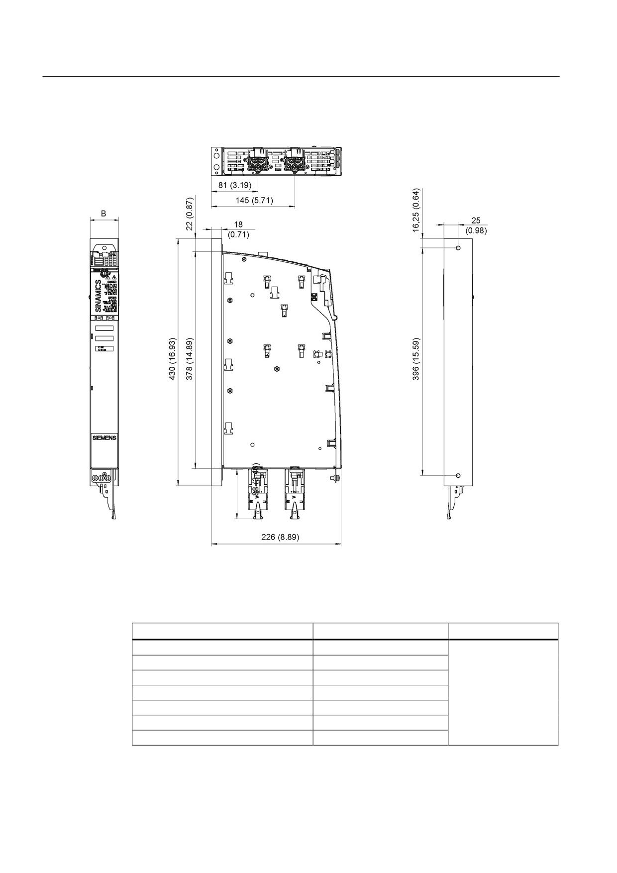
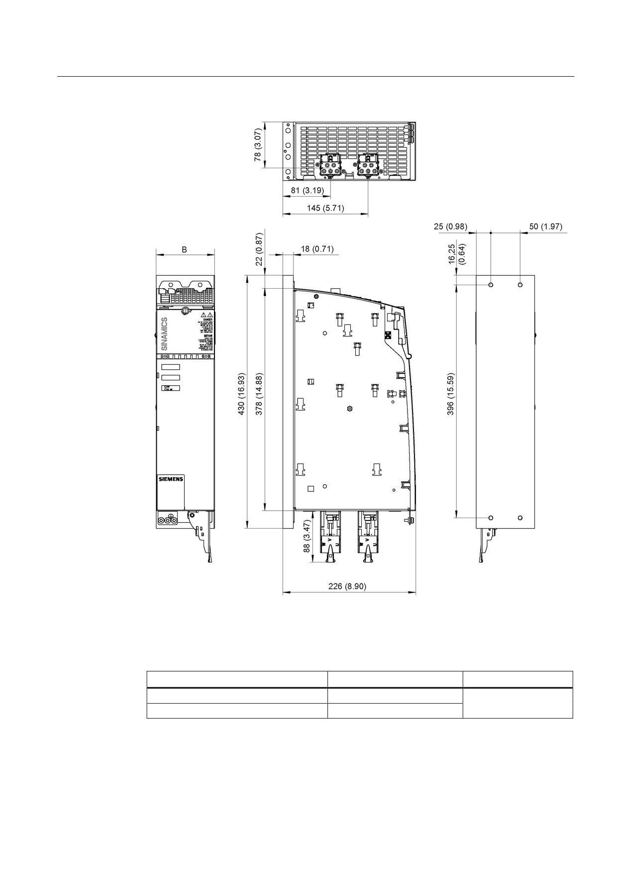
Figure 8-148 Dimension drawing of 3 A to 18 A and 2 x 3 A to 2 x 9 A Motor Modules Booksize with cold plate, all
dimensions in mm and (inches); example: 2 x 5 A Double Motor Module
Table 8- 112 Dimensions of 3 A to 18 A and 2 x 3 A to 2 x 9 A Motor Modules Booksize with cold plate
Motor Module
Order number
B [mm] (inches)
3 A Single Motor Module
6SL3126-1TE13-0AAx
5 A Single Motor Module
6SL3126-1TE15-0AAx
9 A Single Motor Module
6SL3126-1TE21-0AAx
18 A Single Motor Module
6SL3126-1TE21-8AAx
50 (1.97)
3 A Double Motor Module
6SL3126-2TE13-0AAx
5 A Double Motor Module
6SL3126-2TE15-0AAx
9 A Double Motor Module
6SL3126-2TE21-0AAx
Guidelines for machine configuration
408
System Manual, MA 01/2013, 6FC5397-6CP10-0BA2
Connection of the components in SINAMICS drive system
8.4 Connection of motor modules
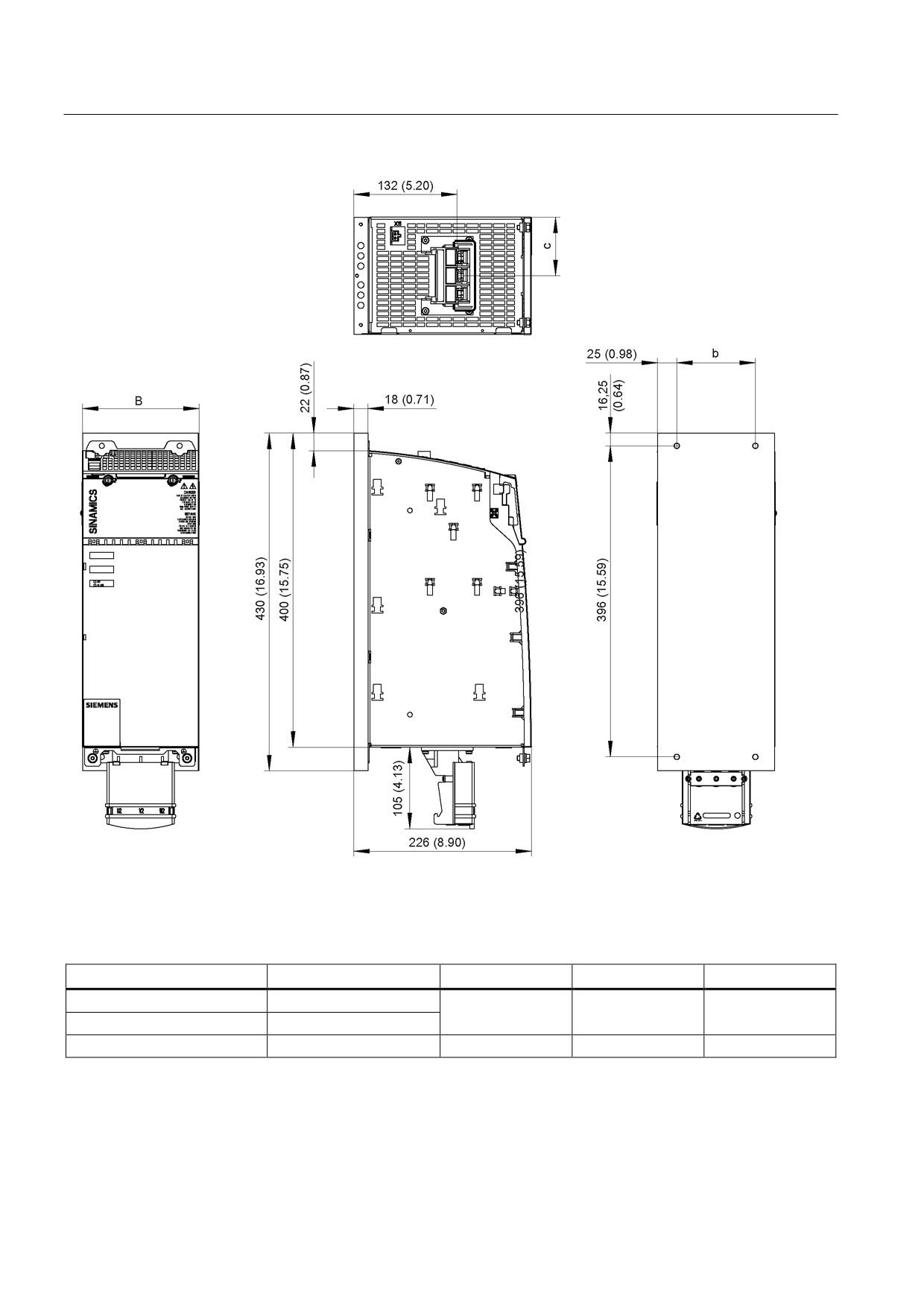
Figure 8-149 Dimension drawing of 30 A and 2 x 18 A Motor Modules Booksize with cold plate, all
dimensions in mm and (inches)
Table 8- 113 Dimensions of 30 A and 2 x 18 A Motor Modules Booksize with cold plate
Motor Module
Order number
B [mm] (inches)
30 A Single Motor Module
6SL3126-1TE23-0AAx
100 (3.94)
18 A Double Motor Module
6SL3126-2TE21-8AAx
Guidelines for machine configuration
System Manual, MA 01/2013, 6FC5397-6CP10-0BA2
409
Connection of the components in SINAMICS drive system
8.4 Connection of motor modules
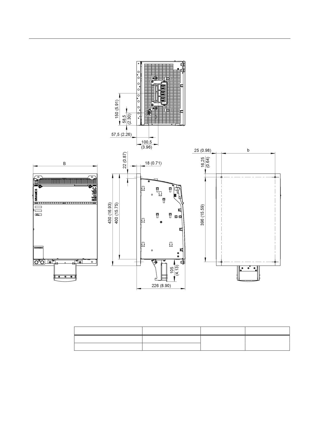
Figure 8-150 Dimension drawing of Motor Modules Booksize 45 A, 60 A, and 85 A with cold plate, all dimensions in mm and
(inches); example for Motor Module 45 A
Table 8- 114 Dimensions of 45 A, 60 A, and 85 A Motor Modules Booksize with cold plate
Motor Modules
Order number
B [mm] (inches)
b [mm] (inches)
c [mm] (inches)
Single Motor Module 45 A
6SL3126-1TE24-5AAx
150 (5.91)
100 (3.94)
75 (2.95)
Single Motor Module 60 A
6SL3126-1TE26-0AAx
Single Motor Module 85 A
6SL3126-1TE28-5AAx
200 (7.87)
150 (5.91)
100 (3.94)
Guidelines for machine configuration
410
System Manual, MA 01/2013, 6FC5397-6CP10-0BA2
Connection of the components in SINAMICS drive system
8.4 Connection of motor modules
Figure 8-151 Dimension drawing of Motor Modules Booksize 132 A and 200 A with cold plate, all dimensions in mm and
(inches); example for Motor Module 200 A
Table 8- 115 Dimensions of 132 A and 200 A Motor Modules Booksize with cold plate
Motor Module
Order number
B [mm] (inches)
b [mm] (inches)
Single Motor Module 132 A
6SL3126-1TE31-3AAx
300 (11.81)
250 (9.84)
Single Motor Module 200 A
6SL3126-1TE32-0AAx
Guidelines for machine configuration
System Manual, MA 01/2013, 6FC5397-6CP10-0BA2
411
Connection of the components in SINAMICS drive system
8.4 Connection of motor modules
8.4.4.6
Mounting
Please note the following before mounting a Motor Module with cold plate on a customer-
specific heat sink:
● Check the surface of the heat sink to ensure that it is not damaged.
● To improve heat transfer, a heat-conducting medium must be used. Special spherical-
indented heat-conducting foil must be used for this purpose. Every component with cold
plate is supplied with heat-conducting foil cut to the right size. Note the mounting position
of the heat-conducting foil (see diagram below).
Note
• Also replace the heat-conducting foil when replacing a component.
• Only use heat-conducting foil released or supplied by Siemens.
Table 8- 116 Overview of heat-conducting foils
Order number
Heat-conducting foil, 50 mm
6SL3162-6FB00-0AA0
Heat-conducting foil, 100 mm
6SL3162-6FD00-0AA0
Heat-conducting foil, 150 mm
6SL3162-6FF00-0AA0
Heat-conducting foil, 200 mm
6SL3162-6FH00-0AA0
Heat-conducting foil, 300 mm
6SL3162-6FM00-0AA0
Note
M6 studs and hexagon nuts or grub screws (ISO 7436-M6x40-14 H, property class 8.8) are
recommended for mounting the components.
Guidelines for machine configuration
412
System Manual, MA 01/2013, 6FC5397-6CP10-0BA2
Connection of the components in SINAMICS drive system
8.4 Connection of motor modules
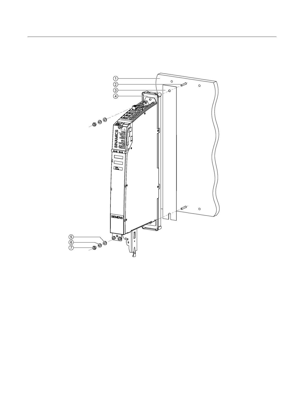
Mounting
①
External heat sink (air or liquid)
②
M6 studs
③
Heat-conducting foil
④
Cold plate
⑤
Washer
⑥
Spring washer
⑦
M6 nut
Figure 8-152 Mounting a Motor Module with cold plate on an external heat sink (example: 3 A Motor Module)
Tightening torques:
● Initially, tighten the nuts by hand (0.5 Nm)
● Then tighten with 10 Nm.
Guidelines for machine configuration
System Manual, MA 01/2013, 6FC5397-6CP10-0BA2
413
Connection of the components in SINAMICS drive system
8.4 Connection of motor modules
Note
• Where components have four fixing points, the nuts must be tightened evenly by
alternating diagonally between them.
Help with the mechanical control cabinet design is available from:
Siemens AG
Industry Sector, IA DT MC MF - WKC AS
TCCCC (Technical Competence Center Cabinets Chemnitz)
Postfach 1124
09070 Chemnitz, Germany
E-mail: cc.cabinetcooling.aud@siemens.com
Properties of the heat sink
We recommend using AlMgSi 0.5 as the heat sink material.
The roughness of the external heat sink surface should be at least Rz 16. The contact
surface between the heat sink and cold plate should have an evenness of 0.2 mm
(applicable to a height of 450 mm and a width of 300 mm).
Note
Machine manufacturers can adapt the heat sink version to their special requirements. The
specified rated data for the Motor Modules can only be achieved if the power losses can be
dissipated by the external heat sink under the specified general conditions.
NOTICE
Ensure that the threaded bolts do not damage the cold plate
• When mounting, ensure that the threaded bolts do not damage the cold plate.
Guidelines for machine configuration
414
System Manual, MA 01/2013, 6FC5397-6CP10-0BA2