SINUMERIK 840D sl. Service - Configuring Commissioning. Manual (2011-2020) - page 37
General settings
4.22 SINUMERIK Operate Display Manager
Property
Meaning
borderWidth2)
Width of the border of the menu item in pixels
Default: 1.
borderColor2)
Color of the border of the menu item
See paragraph "Color definitions".
Default: Qt::darkGray
textRect2)
Rectangle relative to the menu item (widget coordinate system, i.e. Top-
Left of the menu item is coordinate 0,0) in which the text is aligned.
The following should be specified:
x, y, width, height. For example, textRect:="0,10,40,30" or tex-
tRect:=0/10/40/30 or textRect:=0 10 40 30
Note the required quotes when commas are used as delimiters, because
commas are also the separator between the properties.
Default: The rectangle within the border; for borderWidth = 0 this is the
rectangle of the complete menu item.
imageRect2)
Rectangle relative to the menu item (widget coordinate system, i.e. Top-
Left of the menu item is coordinate 0,0) in which the icon is aligned.
The following should be specified:
x, y, width, height. For example, imageRect:="0,10,40,30" or image-
Rect:=0/10/40/30 or imageRect:=0 10 40 30
Note the required quotes when commas are used as delimiters, because
commas are also the separator between the properties.
Default: The rectangle within the border; for borderWidth = 0 this is the
rectangle of the complete menu item.
1) Only relevant for display buttons
2) Applies to menuItem and menuItemStyle
Example 1
[menuitems]
MENUITEM001= name:=menuitem1, onClicked:=showDisplay(display1),
text:="Display1"
MENUITEM002= name:=menuitem2, onClicked:=showDisplay(display2),
text:="Display2", accessLevel:=Customer, width:=100
MENUITEM003= name:=miPdf, menuItemStyle:=misMenu,
onClicked:="showApp(defaultFrame, appPdf)", image:=dm_pdf.png,
text:="PDF"
MENUITEM004= name:=miBrowser, menuItemStyle:=misMenu,
onClicked:="showApp(defaultFrame, appBrowser)",
image:=dm_browser.png, textID:=TEXT_ID_BROWSER
In the [menuitemstyles] section, styles can be defined for menu items in which all visual
properties of a menu item are defined. The individual properties can in turn be overwritten in the
menu item. The summary of all visual attributes saves typing work, because you usually have
many menu items that generally should all look the same. If a property should then be different
for a menu item, it can be overwritten individually.
Description of MenuItemStyle properties: See above.
SINUMERIK Operate
84
Commissioning Manual, 10/2020, 6FC5397-1DP40-6BA4
General settings
4.22 SINUMERIK Operate Display Manager
Example 2
[menuitemstyles]
MENUITEMSTYLE001= name:=misMenu, textSize:=10,
textAlignment:=bottom, imageAlignment:=top, color:=37/53/63,
textColor:=153/173/185, pressedColor:=52/87/140,
pressedTextColor:=White, borderColor:=37/53/63,
pressedBorderColor:=52/87/140, borderWidth:=5, height:=66, width:=66
For unspecified properties, the corresponding default values (see above) take effect.
In the [menus] section, one or more menuItems are combined into a menu. This is done using
the menuItems property, which contains a list of the menu items (buttons/buttons) to be
displayed in a certain menu. The available properties are listed in the following table:
Property
Meaning
menuItems
List of menu items.
Comma-separated list of menu item names
With the "grid" menu layout, the menu items are specified as follows to
determine their position within the menu:
menuItem(row, col, rowSpan=1, colSpan=1)
The indexes "row" and "col" start with the value 0.
Specifying "rowSpan" and "colSpan" is optional, default value is 1 (analo-
gous to QGridLayout::addWidget ())
With the "row" or "col" menu layout, you can also use the specification of
spacing (pixel) and stretch (factor = 0):
• Spacing inserts "int" pixels of additional spacing between the menu
items (analogous to QBoxLayout::addSpacing ())
• Stretch inserts a stretchable additional distance between the menu
items, an expansion factor can be optionally specified (analogous to
QBoxLayout::addStretch ())
defaultFrame
Name of the frame on which the menu items of the menu are to act and
that use the "defaultFrame" string as target specification in the showApp
statement. This allows menu items to be reused in multiple menus.
textContext
The context for the text ID of the menu items (see above).
itemAccessLevel /
Access level from which the menu items are displayed:
accessLevel
System, Manufacturer, Service, Customer, Key_3, Key_2, Key_1, Key_0 or
numerical equivalent (0-7)
Default: Key_0 (7)
menuStyle
Style of the menu.
Sets all visual properties
Note
All of the properties described below can be specified for configuring the
respective menus as well as for defining the MenuStyles. An entry in the
menu overwrites the corresponding entry in the MenuStyle.
layout1)
Alignment of menu items:
"row", "col" or "grid". With a "row" or "col" layout, the menu items are
aligned horizontally in a row or vertically in a column.
With a "grid" layout, the menu items are arranged in a grid.
Default: "row"
SINUMERIK Operate
Commissioning Manual, 10/2020, 6FC5397-1DP40-6BA4
85
General settings
4.22 SINUMERIK Operate Display Manager
Property
Meaning
margin1)
Margin between the menu items and the outer edge of the menu.
Value in pixels, (analogous to QBoxLayout::setMargin() or QGridLay-
out::setContentsMargin() (all 4 directions))
Default: 1.
spacing1)
Spacing between the menu items.
Value in pixels, (analogous to QBoxLayout::setSpacing() or QGridLay-
out::setSpacing())
Default: 1.
color/
Color (backg21round color) of the menu.
backg21roundColor1)
See paragraph "Color definitions".
Default: Qt::gray
1) Applies to menu and menuStyle
Example 3
[menus]
MENU001= name:=menu1, menuItems:="menuitem1, menuitem2, menuitem3"
MENU002= name:=menu2, orientation:=vertical, margin:=2, spacing:=2,
items:="menuitem4, menuitem5, spacing(50), menuitem6, menuitem7,
stretch()", itemHeight:=100
MENU003= name:=mMenuOben, menuStyle:=msMenu, defaultFrame:=fTop,
items:="miPdf, miBrowser, spacing(10), miOperate, stretch(),
miMaximize"
MENU004= name:=mGridMenu, menuStyle:=msGrid, defaultFrame:=fBottom,
items:="miMachine(0,0), miProgram(0,1), miProgramManager(0,2),
miDiagnosis(0,3), miPdf(1,0), miBrowser(1,1), mOperate(1,2,1,2),
miMirror(0,3,2,1)"
In the [menustyles] section, styles can be defined for menus in which all visual properties of
a menu are defined. The individual properties can in turn be overwritten during the
configuration of the respective menu.
Description of the menu style properties: See above.
Example 4
[menustyles]
MENUSTYLE001= name:=msVerticalMenu, color:=59/76/88, layout:=column,
margin:=0, spacing:=1
MENUSTYLE023= name:=msGrid, color:=59/76/88, layout:=grid,
margin:=10, spacing:=1
Finally, the menu still needs to be assigned to a frame. The "menu" frame property is used for this:
[frames]
FRAME003= name:=frame3, x:=0, y:=970, width:=460, height:=110,
menu:=menu2
SINUMERIK Operate
86
Commissioning Manual, 10/2020, 6FC5397-1DP40-6BA4
General settings
4.22 SINUMERIK Operate Display Manager
4.22.2.4
Menu actions
The actions to be performed when a menu item is pressed are defined in the onClicked property
of the menu items. This property can include one or more command statements (separated by
semicolons), which are executed one after the other.
The following commands are available:
Command
Meaning
showDisplay(displayname)
Switches to the display named displayname
The target display must be configured in the same dis-
play configuration file.
showApp(framename, appname)
Displays application appname in the framename frame
If the application is already visible in another frame of
the display, it is moved from there to the frame specified
here. If possible, the freed frame is filled with the appli-
cation displaced from framename. If this happens, it is
referred to as application swapping. Which applications
can be displayed in the released frame is specified in the
"runableApps" property of this frame.
You can prefix the frame name with a display name
(displayname.framename) and change the frame
assignment in hidden displays.
Instead of appname, you can also
specify framename.currentApp
or displayname.framename.currentApp.
showApp() then moves the displayed application in
the framename or displayname.framename frame
into the specified frame.
showPopup(framename, appname)
Displays application appname in the framename frame
as popup window.
It is not permissible that frame framename belongs to a
display, i.e. it is not specified in the Frames attribute for
an existing display. It is automatically displayed with
the showPopup() call and placed over the currently
active display.
The only applications allowed are the applications cre-
ated on the basis of the SlGfwSideScreenDialog
class. SINUMERIK Operate and OEM frame applications
cannot be displayed as popups. If you use an application
that was developed based on
the SlGfwSideScreenDialog class as a popup, you
need to declare its window as a TopLevel window, which
means the Qt::WindowStaysOnTopHint bit must be set in
the windowFlags().
Only one popup can be open at a time.
hidePopup(appname)
Hides an application displayed with showPopup()
or togglePopup()
togglePopup(framename, appname)
Displays application appname in the framename frame
as popup window. If the appname application is already
displayed as popup window, then it is hidden again.
showMenu(framename, menuname)
Shows the menuname menu in the framename frame.
SINUMERIK Operate
Commissioning Manual, 10/2020, 6FC5397-1DP40-6BA4
87
General settings
4.22 SINUMERIK Operate Display Manager
Command
Meaning
showPopupMenu(framename,
Shows the menu menuname in the framename frame as
menuname)
popup menu.
hidePopupMenu(menu name)
Hides a pop-up menu displayed
with showPopupMenu() or togglePopupMenu().
togglePopupMenu(framename,
Shows the menu menuname in the framename frame as
menuname)
popup menu. If menu menuname is already displayed as
popup menu in the framename frame, then it is hidden
again.
setMirrorMode(true|false)
Enables (true) or disables (false) mirror mode
When mirror mode is enabled, the frames of all displays
in which mirror mode has not been disabled
with enableMirrorMode(false) are mirrored hori-
zontally. In other words, frames that were previously
displayed on the left are now displayed on the right and
vice versa. The size of the frames does not change.
toggleMirrorMode()
Toggles the mirror mode
If it was previously enabled, it is now disabled and vice
versa.
sendCmd(appname, cmd1, ...)
Sends a command to the appname application. If the
target application is appname SINUMERIK Operate
(appname="OPERATE"), the operating area of SINU-
MERIK Operate can be selected in this way,
e.g. sendCmd(OPERATE, AreaMachine)
The identifier for the operating area (AreaMachine)
can be taken from the systemconfiguration.ini
file (see [areas] section). If the target application is an
application created on the basis of
the SlGfwSideScreenDialog class, this application
is given a command of the
type SL_GFW_MSG_DISPCONFIG_CMD in
its onMessage() implementation.
The commands cmd1,…, cmd10 are given as message
data in the form of a string in which the individual pa-
rameters (cmd1 … cmd10) are separated by the "|" sym-
bol.
Commands to Windows applications (.EXE) are not pos-
sible with sendCmd()!
Examples
[menuitems]
MENUITEM001= name:=item1, onClicked:=
"showApp(frame1,OPERATE);showApp(frame2,myDialog)", text:="HMI"
Displays SINUMERIK Operate in "frame1" and the "myDialog" application in "frame2" on the
current display.
MENUITEM003= name:=item3,
onClicked:="showApp(full.frame1,frame2.currentApp);showDisplay(full)
", text:="Full frame"
SINUMERIK Operate
88
Commissioning Manual, 10/2020, 6FC5397-1DP40-6BA4
General settings
4.22 SINUMERIK Operate Display Manager
Sets the currently displayed application (currentApp) from "frame2" to "frame1" in the "full"
display. Thereafter, the display is switched to "full".
MENUITEM004= name:=item4, onClicked:=
"sendCmd(OPERATE,'AreaMachine')", text:="Machine"
Selects the machine operating area in SINUMERIK Operate.
MENUITEM005= name:=item5,
onClicked:="sendCmd(myDialog,'doFun','42')", text:="Machine"
Sends message SL_GFW_MSG_DISPCONFIG_CMD with the data "doFun|42" to the "myDialog"
application (requires the use of CreateMyHMI/3GL).
4.22.2.5
Applications
The applications used in a display configuration must be specified in
the systemconfiguration.ini file.
There are two types of applications:
• Type A: Applications created on the basis of the SlGfwSideScreenDialog class
• Type B: Standard Windows applications (.EXE)
All applications are automatically started by the Display Manager at system start and closed
again when the system is shut down.
Type A applications are declared in the [dialogs] section of the
systemconfiguration.ini file in the number range 500 - 999 (OEM area).
Type B applications are handled like OEM frame applications and are therefore declared in the
[processes] section. In addition, the nPlacementMode parameter
must be set to 3 for the applications in the
C:\Program Files (x86)\Siemens\MotionControl\compat\user\OEMFRAME.INI file.
The following applications are included in the standard version:
• PDF viewer
• VNC viewer
• Virtual keyboard
• Virtual MCP
• Application for displaying widgets
• Camera display
• WEB Browser
• SINUMERIK Operate
PDF viewer
For the configuration in the standard version, the following is declared in
file systemconfiguration.ini:
[dialogs]
SINUMERIK Operate
Commissioning Manual, 10/2020, 6FC5397-1DP40-6BA4
89
General settings
4.22 SINUMERIK Operate Display Manager
DLG107= name:=SlPdfApp,
implementation:=sldmpdfviewerapp.SlDmPdfViewerApp,
process:=SlHmiHost1, preload:=false cmdline:="-pdfFile
gestenbedienung.pdf -matteColor #3b4c58"
The application name to be used for configuration within a display configuration:
SlPdfApp
The document to be displayed is specified in the "cmdline" parameter. The two parameters have
the following meaning:
• pdfFile: File to be displayed in the PDF Viewer. The file can be in the appl or hlp directories.
• matteColor: Background color of the PDF Viewer (color must be hex coded).
Additional instances of the PDF Viewer can be declared within a display configuration. The
"name" parameter obtains the name of the additional instance and the "cmdline" parameter
specifies the document to be displayed by this instance, for example:
DLGxxx= name:=anotherPdf,
implementation:=sldmpdfviewerapp.SlDmPdfViewerApp,
process:=SlHmiHost1, preload:=false cmdline:="-pdfFile
mydocument.pdf -matteColor #3b4c58"
The PDF viewer allows languages to be toggled.
You can find more information on how you integrate the PDF files for language identification
in Chapter "Language support for PDF files (Page 365)".
You can find more information on which functions are available in the PDF Viewer in the
Universal/Turning/Milling/Grinding Operating Manual.
VNC viewer
For the configuration in the standard version, the following is declared in
file systemconfiguration.ini:
[dialogs]
DLG108= name:=SlVncApp,
implementation:=sldmvncviewerapp.SlDmVncViewerApp,
process:=SlHmiHost1, preload:=false, cmdline:="-configuration MyPC"
The application name to be used for configuration within a display configuration:
SlVncApp
The VNC Viewer is configured in the slvncconfig.ini file. The name of the section
containing the configuration for a specific VNC Viewer instance is specified in the "cmdline"
parameter as the value of the "-configuration" argument - "MyPC" in the example above.
SINUMERIK Operate
90
Commissioning Manual, 10/2020, 6FC5397-1DP40-6BA4
General settings
4.22 SINUMERIK Operate Display Manager
The following parameters must be specified for each VNC Viewer instance:
• host: IP address or DNS name of the host on which the associated VNC server is running.
• port: TCP port that the server uses.
• Password (optional): Password for protected access to the VNC server.
Example
For configuration in the slvncconfig.ini file:
[MyPC]
host=172.218.152.43
port=5900
password=secret
Virtual keyboard
For the configuration in the standard version, the following is declared in
file systemconfiguration.ini:
[dialogs]
DLG111= name:=SlKeyboardApp,
implementation:=sldmvirtualkeyboardapp.SlDmVirtualKeyboardApp,
process:=SlHmiHost1, preload:=false, cmdline:="-settingsFile
sldm_keyboard.ini"
The application name to be used for configuration within a display configuration:
SlKeyboardApp
The application may only be used in one instance in a display configuration.
In the standard version, three sizes are pre-configured for the virtual keyboard (see file
sldm_keyboard.ini):
[760x505]
Num= KeyboardLayout:="numpadlayout", x:=430, y:=270
Alpha= KeyboardLayout:="nclayout", x:=92, y:=50
KeyHeight=47
[1024x242]
Num= KeyboardLayout:="numpadlayout", x:=784, y:=25
Alpha= KeyboardLayout:="nclayout", x:=206, y:=25
KeyHeight=47
[824x210]
Num= KeyboardLayout:="numpadlayout", x:=584, y:=22
Alpha= KeyboardLayout:="nclayout", x:=5, y:=22
KeyHeight=47
SINUMERIK Operate
Commissioning Manual, 10/2020, 6FC5397-1DP40-6BA4
91
General settings
4.22 SINUMERIK Operate Display Manager
The section name corresponds to the respective frame size (specification in pixels). The
attributes have the following meanings:
Property
Meaning
KeyboardLayout
Layout of the virtual keyboard. Two layouts are available:
• numpadlayout: Only has keys for inputting numbers
• nclayout: Complete NC keyboard
x, y
Position of the upper left corner of the virtual keyboard in relation to the
upper left corner of the frame in which the keyboard is displayed.
KeyHeight
Height (and width) of the keys on the virtual keyboard.
If further frames with other sizes are configured in a display configuration in which the virtual
keyboard is to be shown, the file sldm_keyboard.ini must be supplemented with the
corresponding sections and stored in the oem directory.
Virtual MCP
The MCP can be used in two different sizes in the Display Manager:
•
760x505
•
1024x242 - Hereinafter simply marked with the identifier "below"
If the Display Manager has four windows and the user interface is displayed at the top right, the
MCP is displayed once with the size [760x505] bottom left, and again with the size
[1024x242] below the user interface.
More information can be also be found in Chapter "Display Sidescreen machine control panel
(Page 71)".
Procedure
1. Copy the sample files sldm_1920x1080.ini, sldmmcppage1.ini,
sldmmcppagebelow1.ini, systemconfiguration.ini,
slsidescreenmcppageconfig.xml, slsidescreenmcppage_deu.ts and the
subdirectories ico640 and ico1920 from the directory:
/siemens/sinumerik/hmi/template/displaymanager/mcp/
2. Place the copies of sldm_1920x1080.ini, sldmmcppage1.ini,
sldmmcppagebelow1.ini and systemconfiguration.ini·into the directory:
/oem/sinumerik/hmi/cfg or
/user/sinumerik/hmi/cfg
3. Place the copy of slsidescreenmcppageconfig.xml into the directory:
/oem/sinumerik/hmi/proj or
/user/sinumerik/hmi/proj
4. Place the copy of slsidescreenmcppage_eng.ts in the directory:
/oem/sinumerik/hmi/lng or
/user/sinumerik/hmi/lng
Note
The TS file is automatically integrated by the system during startup.
SINUMERIK Operate
92
Commissioning Manual, 10/2020, 6FC5397-1DP40-6BA4
General settings
4.22 SINUMERIK Operate Display Manager
5. Save the directories ico640 and ico1920 using the following path:
/oem/sinumerik/hmi/ico or
/user/sinumerik/hmi/ico
6. The machine control panels can be selected following power up.
Additional machine control panel windows can be optionally activated (four more in this
example):
1. Perform the following adaptations in the file systemconfiguration.ini:
Remove the ";" in front of the keywords DLG501, DLG502, DLG503 and DLG504.
2. Perform the following adaptations in the file sldm_1920x1080.ini:
Remove the ";" in front of the keywords MENUITEM500, MENUITEM501, MENUITEM502,
MENUITEM503, MENUITEM550, MENU550 and FRAME500.
With the following keywords, insert a ";" in front of the first occurrence and remove the ";" in
the line directly below:
MENUITEM124, MENUITEM125, MENU022, MENU032, MENU033, FRAME022
and FRAME028.
3. Copy the sample files sldmmcppage2.ini, sldmmcppagebelow2.ini,
sldmmcppagebelow3.ini and sldmmcppagebelow4.ini into the directory:
/oem/sinumerik/hmi/cfg or
/user/sinumerik/hmi/cfg
Application for displaying widgets
For the configuration in the standard version, the following is declared in
file systemconfiguration.ini:
[dialogs]
DLG109= name:=SlWidgetsApp,
implementation:=sldmsidescreenapp.SlSideScreenDialog,
process:=SlHmiHost1, preload:=false, cmdline:="-sidescreen1
sldmwidgets1.ini -sidescreen2 sldmwidgets2.ini -spacing 3"
The application name to be used for configuration within a display configuration:
SlWidgetsApp
The application may only be used in one instance in a display configuration.
Camera display
The following keyword is used in files sldmwidgets1.ini and sldmwidgets2.ini for
configuring the application:
ELEMENT005
If cameras are set up with SINUMERIK Operate, up to two camera images can be displayed in the
Display Manager.
SINUMERIK Operate
Commissioning Manual, 10/2020, 6FC5397-1DP40-6BA4
93
General settings
4.22 SINUMERIK Operate Display Manager
WEB Browser
The following keyword is applied for the application configuration in the
file sldm_1920x1080.ini:
MENUITEM129
You will find more information on how to set up the WEB Browser in Chapter: "Setting the WEB
browser (Page 53)".
SINUMERIK Operate
The application name to be used for configuration within a display configuration:
OPERATE
Standard file sldm_1920x1080.ini:
FRAME040= name:=fMax, x:=66, y:=66, width:=1854, height:=1014,
app:=OPERATE
SINUMERIK Operate may only be used in one instance in a display configuration.
It should also be noted that SINUMERIK Operate can only be displayed/executed in certain sizes.
The currently supported sizes (in pixels) are:
•
640x480
•
760x505
•
800x480
•
800x600
•
1024x768
•
1024x1014
•
1080x810
•
1280x768
•
1280x800
•
1280x1024
•
1300x768
•
1366x768
•
1440x1080
•
1454x1080
•
1854x1014
•
1854x1080
•
1920x1080
SINUMERIK Operate
94
Commissioning Manual, 10/2020, 6FC5397-1DP40-6BA4
General settings
4.22 SINUMERIK Operate Display Manager
Example of Type B applications
Configuration in the systemconfiguration.ini file with the notepad.exe application as
an example:
[processes]
PROC500=process:=Notepad, image:=notepad, cmdline:="C:\Windows
\system32\notepad.exe", oemframe:=true, windowname:="Unknown -
Editor", classname:="Notepad", processaffinitymask:=0xFFFFFFFF,
deferred:=true
The application name to be used for configuration within a display configuration:
Notepad
The application may only be used in one instance in a display configuration.
Configuration in the oemframe.ini file with the notepad.exe application as an example:
[notepad]
nPlacementMode=3
WindowStyle_Off = 15597568
Type B applications may only be executed in one instance.
Note
Possible malfunction
Integrated OEM applications may be incompatible and cause malfunctions. Check the
configuration in the event of malfunctions. Insert the OEM application, e.g. using the
configuration option from Section "Link OEMFrame application (Page 551)".
4.22.2.6
Global settings
In addition to the configuration of the displays and their layouts, there is also
a [miscellaneous] section. Settings can be made there that apply to all displays of a display
configuration (configuration file).
Entry
Meaning
startupdisplay
Name of the display that is to be selected after starting the Display Man-
ager. If this information is omitted, the display configured first is used as
the startupdisplay.
hmihostofmenus
Specifies the host process in which the menus associated with a display
configuration are executed. Default is SlHmiHost1.
backg21roundcolor
Background color of the desktop, which can be visible in the gaps between
the frames depending on the configuration of the frames.
SINUMERIK Operate
Commissioning Manual, 10/2020, 6FC5397-1DP40-6BA4
95
General settings
4.22 SINUMERIK Operate Display Manager
Entry
Meaning
textfile
Language-dependent texts can be used in the same way as with SINU-
MERIK Operate. One or several text files can be specified.
slam must be specified as the 1st file. You can add your own text files
after a comma.
textcontext
In addition to specifying the text context for configuration of the menus
or the menu items, a global text context can be specified here, which then
applies to the language-dependent texts of all menu items.
Example
[miscellaneous]
backg21roundcolor=100/120/135
startupdisplay=d3
hmihostofmenus=SlHmiHost1
textfile=slam
textcontext=SlAmAreaMenu
Note
The designation slam must always remain. You can add your own language files after a comma,
e.g.:
textfile=slam, <anothertextfile>
Color information
Colors can be specified via decimal RGB values, for example in the form:
color:=255/255/255 or color:="255, 255, 255" or color:=255 255 255
Note
Note the required quotes when commas are used as delimiters, because commas are also the
separator between the property information.
Alternatively, the usual hexadecimal notation can be used with HTML, for example:
color:=#FFFFFF
SINUMERIK Operate
96
Commissioning Manual, 10/2020, 6FC5397-1DP40-6BA4
Licensing
5
Licenses are required for the activated options. When you purchase licenses you receive a
"license key" that contains all options requiring a license and which is only valid for your
CompactFlash card.
Requirement
If you wish to set or reset the options for a machine, you need at least access level 3 (user).
You can only license options for a machine from this access level and higher.
General information
Serial number of the Com- Permanently defined serial number of the CompactFlash card
pactFlash card
Hardware type
Data of the control
Machine name/No.
Displays the data saved in machine data
MD17400 $MN_OEM_GLOBAL_INFO.
Only with access level 1 (manufacturer) can a display field be edited.
License key
Information about options that require a license
Procedure
1.
Select the "Commissioning" operating area.
2.
Press the menu forward key.
3.
Press the "Licenses" softkey.
The "Licensing" window opens.
The general data for control and licenses is displayed.
License database
You purchase licenses via the Web License Manager in the Internet, administered by Siemens
Industry.
SINUMERIK Operate
Commissioning Manual, 10/2020, 6FC5397-1DP40-6BA4
97
Licensing
5.1 Determining the license requirement
Further information
A detailed description of the license management is provided in the
CNC Commissioning Manual: NCK, PLC, drive.
Deactivate options
When importing old archives from other HMI systems, it can occur that options are set which are
no longer required in the actual system - however, these are subject to the license check:
Order number
Option
6FC5800-0AP04-0YB0
Workstep programming
6FC5800-0AP11-0YB0
Manual machine
6FC5800-0AP15-0YB0
ShopTurn HMI/ShopMill HMI for SINUMERIK 840Di sl incl. HMI-Ad-
vanced
6FC5800-0AP20-0YB0
3D simulation of the finished part
6FC5800-0AP21-0YB0
Simulation milling (2D dynamic; 3D static)
6FC5800-0AP23-0YB0
Simultaneous recording ShopMill (real-time simu.)
6FC5800-0AP24-0YB0
Simultaneous recording ShopTurn (real-time simu.)
Further information: A summary of all options can be found in the SIEMENS Industry Service
& Support Portal (https://support.industry.siemens.com/cs/document/104466659/
sinumerik-840d-sl-glossary-functions-and-terms?dti=0&dl=en&lc=de-WW), for example.
5.1
Determining the license requirement
Procedure
1.
Press the "All options" softkey to list all the options that can be selected for
this controller.
- OR -
Press the "Missing lic./opt." softkey.
You receive an overview of all options that
• are not adequately licensed
• are licensed, but which have not been set
2.
Activate or deactivate the required options in the "Set" column:
• Activate the checkbox or
• Enter the number of options.
Options shown in red are activated, however, not yet licensed or not ad-
equately licensed.
- OR -
Press the "Set option acc. to license" softkey to activate all of the options
contained in the license key.
You obtain a confirmation prompt that you must confirm with "OK".
SINUMERIK Operate
98
Commissioning Manual, 10/2020, 6FC5397-1DP40-6BA4
Licensing
5.1 Determining the license requirement
3.
To activate new selected options, press the "Reset (po)" softkey. A safety
prompt appears.
For several options, you will have to also restart SINUMERIK Operate. Cor-
responding prompts will appear in the user response line.
4.
Press the "OK" softkey to trigger a warm restart.
- OR -
Press the "Cancel" softkey to cancel the process.
Note
If you activate the "Set option acc. to license" function, the sum of the axes that can be activated
may be exceeded. Therefore, reduce the number of actually used axes in the corresponding
options.
Searching for options
You have the possibility of finding options using the search function.
1.
The window "Licensing: All Options" or "Licensing: Non-licensed Options"
is open.
2.
Press the "Search" softkey and enter the required option in the search form.
The cursor is positioned on the first entry that corresponds to the search
term.
3.
Press the "Continue search" softkey if the term that was found is not the
option that you were looking for.
Additional search option
Press the "Go to beginning" softkey to start the search at the first option.
Press the "Go to end" softkey to start the search at the last option.
Note
Use of non-licensed options
Before licensing options, you can also activate them temporarily without the license keys and
use them for test purposes. In this case, the control displays alarm 8080/8081 periodically,
indicating that the option used has not yet been assigned the required license. Further, in this
state, the NC cannot be started.
SINUMERIK Operate
Commissioning Manual, 10/2020, 6FC5397-1DP40-6BA4
99
Licensing
5.2 Activating the test license
5.2
Activating the test license
If you wish to use options without any restrictions - and without purchasing a license - you can
activate these for a limited time using the test license. Six test license periods are available. The
first test license period has a longer operating time. The operating time depends on the NCU
being used. Generally, the additional test license periods are 150 operating hours of the control
system.
Note
A test license supports "short-term use" of the software in a non-productive context, e.g. use for
testing and evaluation purposes; it can be transitioned into another license.
Duration of the first test license period
NCU
Operating time duration
710.3
1000 h
720.3
2000 h
730.3
3000 h
Requirement
If you wish to activate the test license, you require access level 2 (service).
Procedure
1.
Press the "Activate test license" softkey.
A message informs you of the remaining number of test license
periods.
2.
Press the "OK" softkey.
The test license period is now active.
The active test license periods and the remaining operating time are
now displayed.
Note
In the message line, the control displays the operating time still available for the current test
license period every hour.
SINUMERIK Operate
100
Commissioning Manual, 10/2020, 6FC5397-1DP40-6BA4
Licensing
5.4 Reading in the license key
Note
Interruption of the test license
A test license period is interrupted in the following cases:
• If no axis is operated actively, e.g. during simulation mode.
• If a new valid license key is entered.
• If all non-licensed options are reset.
The test license continues when a non-licensed option is set again.
Note
End of the test license
A test license period ends when the time has expired.
No further test license can be activated on the NCU if all test license periods have expired.
5.3
Exporting license requirements
After you have determined the license requirement, you can export the data via the set-up
external storage locations.
Procedure
1.
Press the "Export license requirement" softkey.
A window opens listing the storage locations that have been set up.
2.
Select "USB" for example, if you export the licenses on a USB flash drive.
3.
Press the "OK" softkey.
The set options, the options which are not set but are licensed options, the
license requirement and the license key are stored in an Alm file.
In addition, an Internet connection is established for the Web License
Manager.
Further information
A detailed description of the license management is provided in the
CNC Commissioning Manual: NCK, PLC, drive.
5.4
Reading in the license key
You have the following options of communicating the license key to the control:
• Enter manually
• Read in electronically
SINUMERIK Operate
Commissioning Manual, 10/2020, 6FC5397-1DP40-6BA4
101
Licensing
5.5 Backing up the license of a new CompactFlash card.
Procedure
The "Licensing" window is open.
Enter license key manually
1.
If you obtained the license key via the Web License Manager, enter the
license key manually in the field "You can enter a new license key here".
2.
Press the <INPUT> key.
If the license key is valid, the message "License key set" is displayed.
Read in license key electronically
If you have an alm file with an appropriate license key, then press the "Read-
in license key" softkey.
Open the appropriate storage location (e.g. USB) with "OK".
The matching .alm file is detected automatically and the license key is read
in.
Note:
If several matching .alm files are in the directory, they will be offered to you
in a subsequent selection dialog box.
Select the desired file.
5.5
Backing up the license of a new CompactFlash card.
If, for example, you want to replace a defective card on the control and transfer an existing
archive to a new empty CompactFlash card, you must back up the license of the new CF card
before restoring. If you restore without backing up, the license key of the CompactFlash card will
be overwritten.
Requirement
To back up the license key, you require a multi-card reader with USB on a PG/PC.
Procedure
1. The CompactFlash card has been inserted into the multi-card reader, which is connected to
the PG/PC.
2. Open directory cards/keys/sinumerik/.
Here you will find the license key in the form of a txt file.
3. Copy the license key to your back-up directory.
4. Insert the CompactFlash Card into the control and perform the restore action.
5. Insert the CompactFlash card into the multi-card reader again.
SINUMERIK Operate
102
Commissioning Manual, 10/2020, 6FC5397-1DP40-6BA4
Licensing
5.5 Backing up the license of a new CompactFlash card.
6. Copy the license key, renamed keys.txt, back to directory cards/keys/sinumerik.
7. Insert the CompactFlash card into the control again.
After the control has been powered up again, the license key will be installed from the file
keys.txt onto the system and be activated. The system renames the txt file to the installation
date.
What to do if you lose the license key
To obtain a valid license key for the new, empty CompactFlash Card, please contact the
SINUMERIK hotline. They will then send you a new license key without delay.
SINUMERIK Operate
Commissioning Manual, 10/2020, 6FC5397-1DP40-6BA4
103
Licensing
5.5 Backing up the license of a new CompactFlash card.
SINUMERIK Operate
104
Commissioning Manual, 10/2020, 6FC5397-1DP40-6BA4
Creating drive connections
6
Up to 21 connections to so-called logical drives (data carriers) can be configured. These drives
can be accessed in the "Program Manager" and "Commissioning" operating areas.
The following logical drives can be set up:
• USB interface
• CompactFlash card of the NCU, only for SINUMERIK Operate in the NCU
• Network drives
• Local hard disk of the PCU, only for SINUMERIK Operate on the PCU
Software option
In order to use the CompactFlash Card as data carrier, you require the option "Additional
HMI user memory on CF card of NCU".
Note
The USB interfaces of the NCU are not available for SINUMERIK Operate and therefore cannot be
configured.
6.1
Setting up drives
The "Set Up Drives" window is available in the "Start-up" operating area for configuring the
softkeys in the Program Manager.
Additional information
Additional information on the procedure and configuration can be found in the
Operating Manual Universal/Turning/Milling/Grinding
File
The created configuration data is stored in the "logdrive.ini" file. This file is located in the /user/
sinumerik/hmi/cfg directory.
SINUMERIK Operate
Commissioning Manual, 10/2020, 6FC5397-1DP40-6BA4
105
Creating drive connections
6.2 Setting EXTCALL
General information
Note
We do not recommend that a USB front interface is permitted for part program execution using
EES if a system has several local USB front interfaces (several TCUs, an HT 8 is being used, etc.).
The connection to the USB FlashDrive can be interrupted as a result of the TCU switchover. This
setting should be made using the checkbox "Use this drive for program execution with EES".
Note
If a global USB front interface should be used via PCU, then the PCU must be configured as server
via the VNC connection, see Chapter "Configuring VNC connections (Page 245)".
6.2
Setting EXTCALL
Using the EXTCALL command, a program on an external program memory can be called from a
part program.
EXTCALL must be switched off, when in certain configurations two SINUMERIK Operate are
connected to one NCU.
Activating the function
Processing EXTCALL calls is switched-on or switched-off using the following display machine
data.
MD9106 $MM_SERVE_EXTCALL_PROGRAMS
= 0
HMI ignores EXTCALL instructions and selection via PLC
= 1
HMI processes EXTCALL instructions and selection via PLC (default value)
= 2
HMI processes EXTCALL instructions and ignores selection via PLC
= 3
HMI ignores EXTCALL instructions and processes selection via PLC
Note
A main program selected from an external program memory is selected again automatically
after a power-on if the same program memory is still available and execution of EXTCALL calls
has been activated in MD9106.
SINUMERIK Operate
106
Commissioning Manual, 10/2020, 6FC5397-1DP40-6BA4
Creating drive connections
6.3 Creating a global part program memory
6.3
Creating a global part program memory
With the global part program memory (GDIR), a structure is provided analog to the passive file
system of the NC. It is integrated in the search path of the NC for subprogram calls. If you create
a GDIR, all participants in the system have access to the same logical drive. The participants can
directly execute part programs from the common program memory. The GDIR so replaces or
extends the part program memory of the NC.
Note
The global part program memory plays a role only for the EES function. The creation of a GDIR
is, however, not essential for the EES operation.
Possible procedure
1. Declare the global part program memory in the "Creating drives" window
2. Shift the content of the local program memory with SPF, MPF and WCS directory to an
external drive, e.g. to a USB-FlashDrive.
3. Copy the directories, which have been backed up, to the global part program memory.
Additional information
Additional information about the program memory can be found in
Programming Manual NC Programming.
SINUMERIK Operate
Commissioning Manual, 10/2020, 6FC5397-1DP40-6BA4
107
Creating drive connections
6.3 Creating a global part program memory
SINUMERIK Operate
108
Commissioning Manual, 10/2020, 6FC5397-1DP40-6BA4
Channel menu
7
7.1
Configuring a channel menu
Q
The channel menu is activated for display via the channel switchover key.
&+$11(/
The channel menu is used to switchover the NC channel displayed in the SINUMERIK Operate or
more precisely at the operator station. If a channel menu has been configured, when the
channel switchover key is pressed, the channel menu for the channel switchover is displayed to
make the appropriate operator action. If there is no channel menu, then the channel switchover
key results in the HMI display advancing to the next NC channel.
Configuring
The configuration is made in the "netnames.ini" file for the operating software, as well as in the
particular "config.ini" files for the individual operator stations.
The "netnames.ini" file must be generated using an editor.
Storage
The "netnames.ini" file is stored for SINUMERIK Operate in the following directory:
/oem/sinumerik/hmi/cfg or /user/sinumerik/hmi/cfg
The "config.ini" file is located in the relevant directory:
• On the NCU:
/user/common/tcu/<TCU name>/common/tcu/config.ini
• On the PCU:
F:\user_base\common\tcu\<TCU name>\common/tcu/config.ini
For <TCU name>, the TCU name of the operator station should be used that was assigned at the
system when a TCU powered-up for the first time.
Using the channel menu
• For a system comprising several operator stations and several NCUs within the framework of
operator unit management, if the NC channels of several NCKs are operated from one
operator station.
• For a simple system with many NC channels, as an alternative to the standard mechanism,
the channel switchover can be made using the channel switchover key.
The basic philosophy of the channel menu is to provide - in a selection menu - the operator with
a view of the NC channels of all NCUs that are to be operated with the channel menu. In
conjunction with this, a logical grouping/structuring is introduced using the so-called channel
groups. The desired NC channel can be directly selected using the selection menu. Without a
SINUMERIK Operate
Commissioning Manual, 10/2020, 6FC5397-1DP40-6BA4
109
Channel menu
7.3 General structure of the channel menu
channel menu, when pressing the channel switchover key, the NC channels must be scrolled
through consecutively until the desired NC channel has been selected. An operator station can
only be switched over across NCUs using the channel menu.
7.2
Constraints
• Only one SINUMERIK Operate on a PCU/ PC may be permanently connected to one NCK. It is
not possible to switch over to another NCK.
• SINUMERIK Operate of an NCU can only operate with its own NCK and cannot be switched
over to another NCU.
7.3
General structure of the channel menu
Overview
For the channel menu, a logical view is defined across all of the channels of all NCKs involved;
this logical view is structured in channel groups and this in turn in specific NC channels.
A channel group list is defined for the channel menu in order to be able to switch over operation.
A channel group list comprises one or several channel groups. In turn, a channel group
comprises one or several NC channels.
In the channel menu, the channel groups can be selected using the horizontal softkeys.
The channels of a selected channel group can be selected with the vertical softkeys.
A certain NC channel of a specific NCU is always a switchover target that can be selected. A
switchover to another channel triggered via the channel menu can implicitly mean switchover
to another NCU.
&KDQQHO JURXS
OLVW
$VVLJQPHQW IRU KRUL]RQWDO
&KDQQHO JURXS
VRIWNH\V
$VVLJQPHQW IRU YHUWLFDO
1& FKDQQHO
VRIWNH\V
SINUMERIK Operate
110
Commissioning Manual, 10/2020, 6FC5397-1DP40-6BA4
Channel menu
7.4 Defining channel groups in the "netnames.ini" file
Note
In a system, for example, a channel group can correspond to a machining station, the channels
contained in it, machining units.
Up to 32 channel groups each with up to 8 channels can be configured in a channel menu.
Configuring the total structure
For a system, the total structure of the channel menu is configured in the "netnames.ini" file. The
configuring in the "netnames.ini" file includes all switchover targets that are used at the system.
This configuration must be saved or distributed in a standard form across all SINUMERIK Operate
systems that provide the channel menu.
An individual channel menu for the operating station is configured for each operating station in
the particular "config.ini" file.
Two-stage procedure
1. In the first stage, all channel groups that are used in the system are defined in the
"netnames.ini" file, irrespective of the actual operating stations.
2. In the second stage, the version of the channel menu for the specific operating station is
defined in the "config.ini" files belonging to the station.
7.4
Defining channel groups in the "netnames.ini" file
Defining channel groups
All channel groups that are used at the system are defined in the "netnames.ini" file. Independent
of the specific operator stations.
A separate section [CH_GRP_x] (1 <= x <= 32) should be created for every channel group.
The entries required for a channel group are as follows:
• The text to be displayed in the channel for the channel group at the corresponding horizontal
softkey.
• The list of jump destinations summarized in this channel group, i.e. NC channels. The jump
destinations are defined in a consecutively numbered list with the following entries:
- Membery.Target: Jump destination
- Membery.Text: Softkey text to be displayed in the channel menu (1 <= y <= 8).
SINUMERIK Operate
Commissioning Manual, 10/2020, 6FC5397-1DP40-6BA4
111
Channel menu
7.5 Configuring operating stations in the "config.ini" file
"netnames.ini" file
A channel group, e.g. channel group 1 is therefore specified as follows:
[CH_GRP_1]
;
Name of the channel group; the notation
;
must follow this scheme. The groups are
;
consecutively numbered at the last
;
position.
Text = Process1
;
Softkey text for the channel group for
;
display in the channel menu (horizontal
;
softkey) switchover designation 1 of the
;
channel group.
Member1.Target =
;
Computer name (host name) or the IP
[<HMI>.]<NC>.#<channel
;
address of the computer on which the HMI
number>
;
to be selected runs (NCU or PCU):
;
<HMI> = <IP address or name of the HMI
;
host (PC/PCU)>
;
<HMI> can be omitted if the HMI runs
;
locally on the NCU
;
<NC> = <IP address or name of the NC>
;
Alternatively, the machine name can also
;
be specified from the mmc.ini.
;
Using ".#Channel number", optionally the
;
NC channel can be specified that should
;
be taken when switching over.
;
Member<No>.Text = NCU730_K1
;
Softkey text for the display in the
;
channel menu (vertical softkey). If, for
;
"Target" a channel number is specified,
;
then instead of a text, using the fixed
;
value "$MC_CHAN_NAME", it can also be
;
defined that the text to be displayed
;
should be the channel name defined in the
;
NCK machine data.
;
Member2.Target =
Member2.Text
;
Same as for the vertical softkey 2
7.5
Configuring operating stations in the "config.ini" file
The version of the channel menu is individually defined for the operator stations in the
"config.ini" files belonging to the station. The data defined in the "netnames.ini" file is used. Here,
the channel groups are assigned a softkey in the channel menu.
SINUMERIK Operate
112
Commissioning Manual, 10/2020, 6FC5397-1DP40-6BA4
Channel menu
7.6 Example: Settings for 1:N
"config.ini" file
• The data is defined in section [T2M2N].
• The references CH_GRP_xx of the softkeys refer to the channel groups which are defined in
the "netnames.ini" file. This notation is binding.
• SKx in this case, designates the xth horizontal softkey in the channel menu.
Example
[T2M2N]
SK1=CH_GRP_1
SK2=CH_GRP_3
SK8=CH_GRP_15
7.6
Example: Settings for 1:N
1:N configuration
For a 1:N configuration the following requirements apply:
• A PCU with SINUMERIK Operate can be connected to a maximum of four NCUs.
• SINUMERIK Operate must be switched off on all NCUs.
• The following configuration files must be adapted:
siemens/sinumerik/hmi/template/cfg/netnames.ini
siemens/sinumerik/hmi/template/cfg/mmc.ini
This is illustrated in the following sections using an example with 1 PCU and 2 NCUs.
Example mmc.ini
[Global]
NcddeMachineNames=net, NCU840D_1, NCU840D_2
NcddeDefaultMachineName=NCU840D_1
[NCU840D_1]
ADDRESS0=192.168.214.1,LINE=14,NAME=/NC,SAP=040d,PROFILE=CLT1__CP_L4_INT
ADDRESS1=192.168.214.1,LINE=14,NAME=/PLC,SAP=0202,PROFILE=CLT1__CP_L4_INT
ADDRESS2=192.168.214.1,LINE=14,NAME=/CP,SAP=0502,PROFILE=CLT1__CP_L4_INT
ADDRESS10=192.168.214.1,LINE=14,NAME=/DRIVE_00_000,SAP=0201,
SUBNET=0046-00000000:000,PROFILE=CLT1__CP_L4_INT
ADDRESS11=192.168.214.1,LINE=14,NAME=/DRIVE_03_003,SAP=0900,
PROFILE=CLT1__CP_L4_INT
SINUMERIK Operate
Commissioning Manual, 10/2020, 6FC5397-1DP40-6BA4
113
Channel menu
7.6 Example: Settings for 1:N
[NCU840D_2]
ADDRESS0=192.168.214.2,LINE=14,NAME=/NC,SAP=040d,
PROFILE=CLT1__CP_L4_INT
ADDRESS1=192.168.214.2,LINE=14,NAME=/PLC,SAP=0202,
PROFILE=CLT1__CP_L4_INT
ADDRESS2=192.168.214.2,LINE=14,NAME=/CP,SAP=0502,
PROFILE=CLT1__CP_L4_INT
ADDRESS10=192.168.214.2,LINE=14,NAME=/DRIVE_00_000,SAP=0201,
SUBNET=0000-00000000:000,PROFILE=CLT1__CP_L4_INT
ADDRESS11=192.168.214.2,LINE=14,NAME=/DRIVE_03_003,SAP=0900,
PROFILE=CLT1__CP_L4_INT
Example netnames.ini
;******************************************************************
;
netnames.ini
- EXAMPLE -
;
; This is an example of a netnames.ini for 1:N NCU-switching in
; a configuration of 3 NCU and a PCU50.
;*******************************************************************
[own]
owner = HMI
;***************************
; ChanMenu
;***************************
[chan HMI]
ShowChanMenu = true
;*******************************************************************
;Channel-groups
;Correlation from channel-group to horizontal softkeys
; -> see config.ini of the TCU
;The section [T2M2N] can also be created in the netnames.ini file
;instead of config.ini file. This configuration applies to all TCU,
;which are not configured by their config.ini.
;*******************************************************************
[T2M2N]
SK1 = CH_GRP_1
SK2 = CH_GRP_2
[CH_GRP_1]
Text = 1. NCU
Member1.Target = 192.168.214.241.192.168.214.1.#1
Member1.Text = NCU1%nKanal 1
Member2.Target = 192.168.214.241.192.168.214.1.#2
Member2.Text = NCU1%nKanal 2
[CH_GRP_2]
SINUMERIK Operate
114
Commissioning Manual, 10/2020, 6FC5397-1DP40-6BA4
Channel menu
7.7 Distribution via job lists in the case of 1:N
Text = 2. NCU
Member1.Target = 192.168.214.241.192.168.214.2.#1
Member1.Text = NCU2%nKanal 1
Member2.Target = 192.168.214.241.192.168.214.2.#2
Member2.Text = NCU2%nKanal 2
Note
For switching over an MCP with the operating software, the PLC block FB9 must not be used (FB9
must not be active). If necessary, the MCP must be switched over in the PLC user program.
Solution
In the OB100 (call for FB1), set MCP1BusAdr to 255 and MCP1Stop to "true".
In the OB1, scan the "MMCBTSSready" (DB10.DBX108.3) signal. If this is set, write the MCP
address from DB19.DBB123 (MCP index) to the DB7.DBB27 before removing the MCP stop bit
DB7.DBX62.1. The MCP is now active.
If the "MMCBTSSready" (DB10.DBX108.3) is removed again (operating software switches to
another NCU), the MCP stop bit DB7.DBX62.1 will have to be reset.
7.7
Distribution via job lists in the case of 1:N
Simplified selection of programs
The function is only available in a group of several NCUs ands must be enabled in the
"systemconfiguration.ini " configuration file:
[miscellaneous]
distributeJoblist=true
The sources are located on the local drive of the PCU or the PC.
The distribution of the programs is done by selecting a job list which is located in a workpiece.
The job list may contain COPY and SELECT instructions:
; Copy A.MPF to NCU1:
COPY A.MPF NC=NCU1
; Copy B.MPF to NCU2:
COPY B.MPF NC=NCU2
; Copy all subprograms to all NCUs:
COPY *.SPF *
; Select A.MPF on NCU1 in channel 1.
SELECT A.MPF ch=NCU1,1
; Select B.MPF on NCU2 in channel 2.
SINUMERIK Operate
Commissioning Manual, 10/2020, 6FC5397-1DP40-6BA4
115

Channel menu
7.7 Distribution via job lists in the case of 1:N
SELECT B.MPF ch=NCU2,2
Sequence:
1. If a distributed job list is active during the selection, all distributed programs on the NCU are
deleted without confirmation. If the workpiece on the NCUs is empty, it will be deleted there.
2. The programs are copied to the corresponding workpieces of the relevant NCU.
3. Existing programs are overwritten without any message.
4. Following a change in a distributed program on the local drive, the modified programs using
the Editor are copied to the corresponding NCU.
Sample structure
/user/sinumerik/data/
NCU1
NCU2
prog/JOBA.WPD
JOBA.JOB
WKS.DIR
WKS.DIR
A.MPF
WKS.DIR/JOBA.WPD
WKS.DIR/JOBA.WPD
B.MPF
WKS.DIR/JOBA.WPD/B.MPF
WKS.DIR/JOBA.WPD/B.MPF
UP1.SPF
JOBA.WPD/UP1.SPF
JOBA.WPD/UP1.SPF
UP2.SPF
WKS.DIR/JOBA.WPD/UP2.SPF
WKS.DIR/JOBA.WPD/UP2.SPF
/user/sinumerik/data/
NCU1
NCU2
prog/wks.dir/JOBA.WPD
JOBA.JOB
WKS.DIR
WKS.DIR
A.MPF
WKS.DIR/JOBA.WPD
WKS.DIR/JOBA.WPD
B.MPF
WKS.DIR/JOBA.WPD/B.MPF
WKS.DIR/JOBA.WPD/B.MPF
UP1.SPF
JOBA.WPD/UP1.SPF
JOBA.WPD/UP1.SPF
UP2.SPF
WKS.DIR/JOBA.WPD/UP2.SPF
WKS.DIR/JOBA.WPD/UP2.SPF
Supplementary conditions
Special behavior:
• Distributed programs are retained during a restart of the operating software.
• On the local drive, distributed programs can neither be deleted nor renamed nor overwritten
using copy/move.
• Changes of distributed programs on the NCU are lost, if they are not manually saved.
• The program correction in the machine is not offered.
• When creating a commissioning archive, all data of the local drive is also automatically saved.
SINUMERIK Operate
116
Commissioning Manual, 10/2020, 6FC5397-1DP40-6BA4
Channel menu
7.7 Distribution via job lists in the case of 1:N
Restrictions:
• In the event of changes of distributed programs on the local drive using the Editor, it should
be noted that only the channel states are monitored on the NCU currently connected. If the
program is still interrupted or active on another NCU, it cannot be correctly distributed after
the change.
• The display of the active block, the marking of the block search as well as the read-only
handling of the program opened in the Editor are executed only for the active programs of
the currently connected NCU.
• In the Editor, programs are always opened in the context of the currently connected NCU.
This can lead to a faulty step recognition with distributed programs.
• In the current block display in the "Machine" operating area, you can display only the active/
distributed programs of the currently connected NCU.
• The simulation of job lists via several machines is not possible.
• If distributeJoblist=true is configured in the systemconfiguration.ini file, then part or
subprograms can no longer be selected via the "Program Manager" operating area.
SINUMERIK Operate
Commissioning Manual, 10/2020, 6FC5397-1DP40-6BA4
117
Channel menu
7.7 Distribution via job lists in the case of 1:N
SINUMERIK Operate
118
Commissioning Manual, 10/2020, 6FC5397-1DP40-6BA4

Machine and setting data
8
8.1
Machine and setting data
Overview
Prefix
Number rang-
Machine/setting data
Storage in range
es
(softkey)
$MM
9000 - 9999
Display machine data
Display MD
$MNS
51000 - 51299
General configuration machine data
General MD
51300 - 51999
General cycle machine data
$MCS
52000 - 52299
Channel-specific configuration machine data
Channel MD
52300 - 52999
Channel-specific cycle machine data
$MAS
53000 - 53299
Axis-specific configuration machine data
Axis MD
53300 - 53999
Axis-specific cycle machine data
$SNS
54000 - 54299
General configuration setting data
General SD
54300 - 54999
General cycle setting data
$SCS
55000 - 55299
Channel-specific configuration setting data
Channel SD
55300 - 55999
Channel-specific cycle setting data
$SAS
56000 - 56299
Axis-specific configuration setting data
Axis SD
56300 - 56999
Axis-specific cycle setting data
Further information
A detailed description of the machine and setting data can be found in the List Manual "Machine
Data and Parameters".
8.2
Displaying/editing machine data
You can access the following machine data in the "Start-up" operating area.
• General machine data ($MN) and general configuration machine data ($MNS)
• Channel-specific machine data ($MC) and channel-specific configuration machine data
($MCS)
• Axis-specific machine data ($MA) and axis-specific configuration machine data ($MAS)
• Drive-specific machine data ($M_)
• Machine data control unit: Drive parameters
• Machine data feed-in: Drive parameters
SINUMERIK Operate
Commissioning Manual, 10/2020, 6FC5397-1DP40-6BA4
119
Machine and setting data
8.2 Displaying/editing machine data
• I/O component parameters: Drive parameters
• Communication parameters (CULINK, DMC): Drive parameters
Note
The display of the machine data / drive parameters depends on the configuration of your
control.
Access authorization to the machine data operating area can be controlled by keyswitch
position or password.
Read-access to machine data is possible as of access level 4 (keyswitch 3).
Machine data can be changed with access level 1 (manufacturer).
WARNING
Incorrect parameterization
Changes in the machine data have a considerable influence on the machine. Incorrect
configuration of the parameters can endanger human life and cause damage to the
machine.
Information about machine data
The following information is displayed from left to right:
• Machine data number, with array index if applicable
• Machine data name
• Machine data value
• Machine data unit
• Effective
Note
If the machine data does not use units, the corresponding column is empty. If the data is not
available, the hash symbol "#" is displayed instead of the value. If the value ends in an "H", it is
a hexadecimal value.
The physical units of machine data are displayed on the right-hand side of the input field.
For each machine data item, an activation type can be read in the column on the right.
so
Immediately active: No action required
cf
Configuration: "Set MD to active (cf)" softkey
re
Reset: <Reset> key on the machine control panel
po
POWER ON: "Reset(po)" softkey
Additional Information
In the footer you are given a brief explanation of the selected machine or setting data item.
SINUMERIK Operate
120
Commissioning Manual, 10/2020, 6FC5397-1DP40-6BA4
Machine and setting data
8.2 Displaying/editing machine data
Procedure
1.
Select the "Start-up" operating area.
2.
Press the "Mach. data" softkey. Additional softkeys for the individual ma-
chine data areas are displayed.
3.
Press the "General MD", "Channel MD", or "Axis MD" softkey.
The window opens and the selected machine data is displayed.
4.
Place the cursor on a machine data item.
5.
Position the cursor on the entry to be modified and enter the required
value.
6.
Depending on the activation type, there are two ways of activating the
settings:
Press the "Activate MD (cf)" softkey. The value is applied.
- OR -
Press the "Reset (po)" softkey.
A safety prompt appears.
7.
Press the "OK" softkey to trigger a warm restart.
- OR -
Press the "Cancel" softkey if you do not want to apply the settings.
Axis selection
If several components are available for the area selected (e.g. "Axis MD"), you can choose from
the following options:
1.
Press the "Axis +" or "Axis -" softkey.
The values of the next (+) and the previous (-) axes are displayed.
- OR -
Press the "Direct selection..." softkey.
The "Axis Direct Selection" window opens.
2.
Select the required axis directly from those available in the drop-down list
box.
SINUMERIK Operate
Commissioning Manual, 10/2020, 6FC5397-1DP40-6BA4
121
Machine and setting data
8.4 Displaying/editing setting data
3.
Press the "OK" softkey to save the setting.
- OR -
Press the "Cancel" softkey to reject the settings.
8.3
Displaying/editing display machine data
You can access the display machine data via the user interface in the "Start-up" operating area.
Procedure
1.
Select the "Start-up" operating area.
2.
Press the "Mach. data" softkey.
3.
Press the menu forward key.
Further softkeys are displayed.
4.
Press the "Display MD" softkey.
The display machine data appears.
5.
Position the cursor on the entry to be modified and enter the required
value.
6.
Press the "Reset (po)" softkey.
A safety prompt appears.
7.
Press the "OK" softkey to trigger a warm restart.
- OR -
Press the "Cancel" softkey if you do not want to apply the settings.
8.4
Displaying/editing setting data
You can access the following setting data via the user interface in the "Startup" operating area.
• General setting data
• Channel-specific setting data
• Axis-specific setting data
SINUMERIK Operate
122
Commissioning Manual, 10/2020, 6FC5397-1DP40-6BA4
Machine and setting data
8.4 Displaying/editing setting data
Procedure
1.
Select the "Start-up" operating area.
2.
Press the "Mach. data" softkey.
3.
Press the menu forward key.
The softkeys "General SD", "Channel SD", and "Axis SD" are displayed.
4.
Press the relevant softkey to display a particular setting data area.
The window opens and the selected setting data is displayed.
5.
Place the cursor on the desired setting data and position the cursor on the
entry to be changed. Enter the desired value.
6.
Depending on the activation type, there are two ways of activating the
settings:
Press the "Activate MD (cf)" softkey.
- OR -
Press the "Reset (po)" softkey.
A safety prompt appears.
7.
Press the "OK" softkey to trigger a warm restart.
- OR -
Press the "Cancel" softkey if you do not want to apply the settings.
SINUMERIK Operate
Commissioning Manual, 10/2020, 6FC5397-1DP40-6BA4
123
Machine and setting data
8.5 Displaying/editing drive parameters
Axis/channel selection
If several components are available for the area selected (e.g. "Axis SD" or "Channel SD"), you can
choose from the following options:
1.
Press the "Axis +" or "Axis -" or "Channel +" or "Channel -" softkey.
The values of the next (+) and the previous axis/channel (-) are displayed.
- OR -
Press the "Direct selection..." softkey.
The "Direct Selection" window opens.
2.
Select the required axis directly from those available in the drop-down list
box.
3.
Press the "OK" softkey to save the setting.
- OR -
Press the "Cancel" softkey to reject the setting.
8.5
Displaying/editing drive parameters
The "Control Unit MD", "Infeed MD" and "Drive MD" softkeys as well as the "I/O comp. MD" and
"Comm. MD" softkeys on the menu forward key are available to display and edit drive
parameters.
A separate list display is provided for each of these areas in which you can view and edit drive
data.
Requirement
Settings for drive parameters are protected with access level 2 (service).
The lists of the drive parameters are visible with access level 4 (keyswitch 3).
Further information
Additional information on drive commissioning is provided in
CNC Commissioning Manual: NCK, PLC, drives.
SINUMERIK Operate
124
Commissioning Manual, 10/2020, 6FC5397-1DP40-6BA4
Machine and setting data
8.5 Displaying/editing drive parameters
Procedure
1.
Select the "Commissioning" operating area.
2.
Press the "Mach. data" softkey.
The "Control unit parameters", "Supply MD" and "Drive MD" softkeys are
displayed.
3.
Press the softkey of an area to show its parameters.
4.
Place the cursor on the desired parameter.
5.
Position the cursor on the entry to be modified and enter the required
value.
6.
In order to activate the settings, you have the option of saving or carrying
out a reset.
Press the "Save/reset" softkey.
7.
Press the "Save" softkey.
You are prompted "What do you wish to save?"
You can make the following selection per softkey:
• Actual drive object
• Drive unit
• Drive system
- OR -
Press the "Reset (po)" softkey.
You are prompted as to whether you wish to initiate a warm restart for the
NCK and the complete drive system.
Confirm the prompt with the "Yes" softkey.
Reject the warm restart with the "No" softkey.
Extended reset
If you wish to carry out a warm restart only for specific objects or specific areas, then additional
softkeys are available for this purpose.
Press the "Extended reset" softkey.
You are prompted to enter for which objects you wish to initiate a warm
restart.
You can make a selection with the following softkeys:
Only the NCK is restarted.
SINUMERIK Operate
Commissioning Manual, 10/2020, 6FC5397-1DP40-6BA4
125
Machine and setting data
8.6 Machine data display options
All of the control units and the NCK in the system are restarted. This soft-
key corresponds to the "Reset (po)" softkey if you confirm the prompt with
"Yes".
All of the control units and the NCK in the system as well as the operator
software are restarted.
Hiding the expanded softkey bar
The "Extended reset" softkey is defined in the "slsuconfig.ini" file. If the softkey is not to be
displayed, proceed as follows:
1. Copy the "slsuconfig.ini" file from the /siemens/sinumerik/hmi/template/cfg/ directory.
2. Insert the file into the following directory:
/user/sinumerik/hmi/cfg/
3. Open the file and in the section
[Softkeys] and enter
AdvancedReset = 0
8.6
Machine data display options
Through the use of the machine data display filter, it is possible to reduce the number of
displayed machine data relating to a certain area, e.g. general machine data, for special
purposes.
Machine data areas
Display filters are available for the following machine data areas:
• General machine data
• Channel-specific machine data
• Axis-specific machine data
• Drive machine data
• Display machine data
Filter options
It is possible to limit the machine data display using the following filtering methods:
• Only display axes that are used
• According to indices
• According to display groups
• Display expert parameters
SINUMERIK Operate
126
Commissioning Manual, 10/2020, 6FC5397-1DP40-6BA4
Machine and setting data
8.6 Machine data display options
Only display axes that are used
If this checkbox is activated, axes that are not used are hidden when scrolling.
Indices from ... to
The index filter refers to the machine data arrays. On the display, this machine data can be
identified by the field index attached to the machine data string.
Example: 10000[index]AXCONF_MACHAX_NAME_TAB
If the index filter is activated, machine data arrays are only displayed in the specified index area.
Display groups
A display group contains machine data within a machine data area that belongs to the same
topic.
Note
To find out which display group a machine data item belongs to, refer to the "Display filter"
parameter associated with the description of the machine data element in question.
Further information: List Manual Machine Data and Parameters
Select/deselect display groups to increase or decrease the number of machine data items
displayed for the current machine data area.
Display expert parameters
If the "Display expert parameters" filter is disabled, only the machine data in a machine data area
that is required for the basic functionality of the NC is displayed.
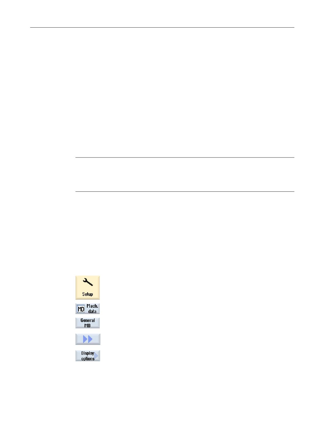
Procedure
1.
Select the "Commissioning" operating area.
2.
Press the "Mach. data" softkey.
3.
Press the softkey of a particular data area, e.g. "General MD".
The list of general machine data is displayed.
4.
Press the ">>" and "Display options" softkeys.
The "Display options: ..." window for the selected machine data opens.
5.
Select the required filter options (according to display groups, indices or
expert parameters) by activating the checkboxes.
SINUMERIK Operate
Commissioning Manual, 10/2020, 6FC5397-1DP40-6BA4
127
Machine and setting data
8.7 Editing machine data and drive parameters
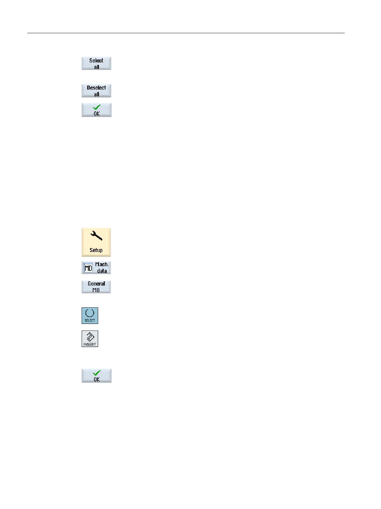
6.
Press the "Select all" softkey to activate all display groups.
- OR -
Press the "Deselect all" softkey.
All checkmarks are removed and you can select individual display groups.
Press the "OK" softkey to save the settings.
8.7
Editing machine data and drive parameters
8.7.1
Editing hexadecimal values
You can use a bit editor to enter the required values for machine data in hexadecimal format.
Procedure
1.
Select the "Start-up" operating area.
2.
Press the "Mach. data" softkey and select the required machine data area
(e.g. general machine data).
3.
Position the cursor on the entry to be edited.
4.
Press the <SELECT> or <INSERT> key.
The "Bit Editor" window opens.
All bits of the machine data item that have a description text are displayed.
5.
If you activate the "Display all bits" checkbox, all bits regardless of their
data type (8, 16 or 32 bits) are displayed. Activate the relevant bit.
6.
Press the "OK" softkey. The setting is checked and an error message may be
output.
The window closes and you return to the machine data overview.
The new value is displayed in hexadecimal format.
8.7.2
Editing BICO values
You can use the BICO editor to enter BICO values for drive parameters.
SINUMERIK Operate
128
Commissioning Manual, 10/2020, 6FC5397-1DP40-6BA4
Machine and setting data
8.7 Editing machine data and drive parameters
Note
BICO values can also be entered by copying and inserting or also directly entered the field.
Procedure
1.
Select the "Start-up" operating area.
2.
Press the "Mach. data" softkey.
3.
Press the "Control unit MD" softkey and select a BICO parameter, e.g.
"p738".
4.
Position the cursor on the entry to be changed, e.g. BICO 63.2091.0
5.
Press the <SELECT> or <INSERT> key.
The "BICO Editor" window opens.
6.
Complete the "Drive object number", "Parameter number", "Bit/Index" and
"Parameter value (hex)" fields.
Note
The BICO editor also opens if you enter a value other than 0 or 1 for the value to be changed.
8.7.3
Editing enum values
For drive parameters, you have the option of editing enum elements (e.g. r2, p3, p4, p97 etc.)
using a selection list.
Procedure
1.
Select the "Start-up" operating area.
2.
Press the "Mach. data" softkey.
3.
Select the desired drive parameter area, e.g. "Control unit MD".
SINUMERIK Operate
Commissioning Manual, 10/2020, 6FC5397-1DP40-6BA4
129
Machine and setting data
8.8 Searching for data
4.
Select the desired parameter, e.g. "p3" and position the cursor at the entry
to be changed, e.g. "[1] Display, Si...".
5.
Press the <SELECT> or <INSERT> key.
A window containing a list of all defined enum values and their descrip-
tions opens.
6.
You can select a value from the list.
- OR
You can also directly enter the value as decimal number into the brackets
[ ].
8.8
Searching for data
You can search for specific machine, setting and display machine data.
Search strategies
• When a digit or a digit with an index is entered, an exact search for this parameter is
performed.
Example: If "9" is entered > p9 will be found (but not p99)
• When text is entered, a full-text search is performed: i.e. the term is sought in the relevant
table and in the explanations in the footers.
Note
Search with place holders
When searching for machine data, you have the option of using place holders:
• "*": Replaces any character string
• "?": Replaces any character
Searched fields
A search is made in the following fields of the machine data for the character string that has been
entered if the "Additionally search in the explanation texts" option is not set:
• Machine data number
• Symbolic name
• Unit
The following fields are additionally searched if the "Additionally search in the explanation texts"
option is set:
• Descriptive text
• Bit texts
• Enum texts (only for drives)
SINUMERIK Operate
130
Commissioning Manual, 10/2020, 6FC5397-1DP40-6BA4
Machine and setting data
8.9 Data admin
Procedure
1.
Select the "Start-up" operating area.
2.
Press the "Mach. data" softkey.
3.
Select the required area by pressing the relevant softkey.
4.
Press the "Search..." softkey and enter the required text or digit in the
search screen.
5.
If you wish to restrict the search only to the texts in the tables that are
displayed, deactivate the "Search explanation texts too" checkbox.
6.
Select the search direction required (forwards, backwards) in the "Direc-
tion" field.
The cursor is positioned on the first entry that corresponds to the search
term.
7.
Press the "Continue search" softkey if this machine, setting or display
machine data item is not the one you are looking for.
Additional search option
Press the "Go to start" softkey to start the search at the first data.
Press the "Go to end" softkey to start the search at the last data.
8.9
Data admin
Overview
The "Data admin" function is used to simplify the commissioning and permits the transfer,
backup, loading and comparing of machine, setting, compensation and drive data at the file
level. The files are saved in the .tea ASCII format.
The "Data admin" softkey is visible as of access level "Service" (= 2).
SINUMERIK Operate
Commissioning Manual, 10/2020, 6FC5397-1DP40-6BA4
131
Machine and setting data
8.9 Data admin
The following option fields are available in the "Load machine data" window:
• Load data within the controller
Only those controller objects are listed that are currently available in the controller.
• Save data to a file
Additional files with the extensions .acx and .log are created for the SINAMICS parameters:
- Files with the extension .acx contain the parameter descriptions for the selected drive
object.
- The log file may also contain the warnings and errors that occurred during the conversion
from .acx to .tea.
• Load data from a file
Note
An NCK and drive reset is only triggered automatically for drive objects after loading. A reset
must be triggered manually for all other controller objects.
• Compare data
Several files (.tea) and/or controller objects (axis, channel, servo, infeed, etc.) can be
compared at the same time. An online comparison of constantly changing data is not
possible because the values are saved temporarily at the time of the comparison.
Up to eight elements can be taken into the list of the data to be compared.
• Export/import SINAMICS lists
If hydraulic components are used in the system, for example, you can export or import a valve
list (Hydraulic Drive).
Further information
Additional information on the application of valve lists is provided in
SINAMICS S120 System Manual Hydraulic Drive.
Procedure
1.
Select the "Commissioning" operating area.
2.
Press the "Mach. data" softkey.
The "Data admin" softkey is available in each machine data area, except in
"User views".
- OR -
Press the "System data" softkey and select the HMI data/Data backups/IB
data directory.
3.
Press the "Data admin" softkey.
The "Load machine data" window opens.
4.
Activate the required option filed and press "OK".
SINUMERIK Operate
132
Commissioning Manual, 10/2020, 6FC5397-1DP40-6BA4
Machine and setting data
8.9 Data admin
Load data within the controller
5.
Position the cursor on a controller object and confirm with "OK".
6.
In the window that opens, select the target controller object and confirm
with "OK".
Save data to a file
5.
Position the cursor on a controller object and confirm with "OK".
6.
The "Save Under: Select Archive" window opens and the appropriate stor-
age location is preselected.
If required, press the "New directory" softkey to generate a new subdir-
ectory. Enter the required name in the "New Directory" window and con-
firm with "OK".
7.
In the "New File" window, enter the required name for the file to be saved
and confirm with "OK".
The stored files can be found in the data tree of the "System data" in the
HMI data/Data backups/IB data directory.
Load data from a file
5.
The "Load Trace: Select file:" window opens.
Position the cursor on a .tea file that is located either in the IB data direc-
tory or on a USB flash drive and confirm with "OK".
Please note: If the source and target drive object numbers differ when
loading drive data, you must adapt individual parameters. To do this, press
the "Adapt" softkey and edit the parameter values in the window that
appears.
Compare data
5.
In the "Compare Data - Controller" window, select an element to be com-
pared from the tree structure of the control objects.
- OR -
Press the "File" softkey to select a .tea file to be compared from the tree
structure of the files.
6.
Press the "Add to list" softkey.
The list of the data to be compared is displayed in the lower part of the
window and the selected element is added.
7.
Press the "Delete from list" softkey to remove individual elements from the
comparison list.
- OR -
Deactivate the checkbox of the selected element in the list of the data to
be compared.
8.
When at least two elements are listed, the "Compare" softkey is enabled.
Press this softkey to perform the comparison.
SINUMERIK Operate
Commissioning Manual, 10/2020, 6FC5397-1DP40-6BA4
133
Machine and setting data
8.10 User views
8.10
User views
Use
In the "User Views" window you can create and adapt all machine data relevant to a particular
functionality. Machine data is individually collated to simplify the user's task.
You can include additional comments when creating and/or editing user views.
Note
Importing user views (compatibility)
If you have already created user views in HMI-Advanced, copy the *.klb files to /user/sinumerik/
hmi/template/user_views to use them in SINUMERIK Operate.
Display in the the "Parameter" operating area
Proceed as follows to show user views also in the "Parameters" operating area:
1. Select the "Start-up" operating area.
2. Press the "Machine data" softkey.
3. Press the "User views" softkey.
4. Press the "Manage view” softkey.
5. Press the "New view" softkey.
6. Activate the checkbox "Display parameter / use setting data", if you also wish to display the
new user view in the "Parameter" → "Setting data" → "Data lists".
7. Enter a name for the user view.
8. Confirm with "OK".
SINUMERIK Operate
134
Commissioning Manual, 10/2020, 6FC5397-1DP40-6BA4
Machine and setting data
8.10 User views
8.10.1
Creating a user view
Procedure
1.
Select the "Start-up" operating area and press the "Mach. data" softkey.
2.
Press the softkeys "User views",
"Manage view" and
"New view".
The "New View" window opens.
3.
Enter the desired view name.
Press the "OK" softkey.
If a user view already exists with the same name, you receive a safety
prompt as to whether the existing view should be overwritten.
4.
Press the "Enter data" softkey.
The "Insert data" selection box opens.
5.
Open the selection list with the <INSERT> key, select a machine data
area and press the <INPUT> key.
Select a machine data item with the cursor keys or using the "Find"
softkey.
6.
Press the "Insert before line" or "Insert after line" softkey to insert the
selected machine data at the required position in the user view.
Note:
You can navigate in the open user view with the mouse and select a line
without closing the list box.
SINUMERIK Operate
Commissioning Manual, 10/2020, 6FC5397-1DP40-6BA4
135
Machine and setting data
8.10 User views
7.
Press the "Back" softkey to close the list box and return to the user view
you want to edit.
Your entries are automatically stored.
8.
Press the "Insert text" softkey to insert any text in the open user view.
The "Insert Text" input window opens.
9.
Enter a text and explanatory description for the text and press the "Insert
before line" or "Insert after line" softkey to accept the text.
10.
Press the "Back" softkey to save your entries and return to the user view
you are editing.
Selecting a particular machine data item
You can use the Search dialog box to look for a particular data item.
8.10.2
Editing the user view
Depending on the row you have selected, you can use the "Properties" softkey to change
comments and, in the case of machine data, the data source (channel, axis, drive unit) and view
the description and, if required, change.
• Machine data
Depending on the data type you can select either a fixed or a variable data source for machine
data.
The entry "variable(*)" means that when you can select another data source (channel, axis,
drive unit) with vertical softkeys 1- 3 (+, - and direct selection) the value displayed changes
to refer to the data source currently selected.
Alternately, you can select a fixed data source so that the displayed value does not change
when you select a different data source.
• Comment texts
Text and description
Procedure
1.
Select the "Start-up" operating area and press the "Mach. data" softkey.
2.
Press the "User views" softkey.
The "User Views" window opens.
SINUMERIK Operate
136
Commissioning Manual, 10/2020, 6FC5397-1DP40-6BA4
Machine and setting data
8.10 User views
3.
Press the "Edit view” softkey. Additional softkeys to edit the user view are
listed.
4.
Press the "Insert data" softkey if you wish to enter another data item.
5.
Select a machine data item with the cursor keys.
6.
Press the "Up" or "Down" softkeys to move the selected row.
- OR -
Press the "Delete line" softkey to remove the selected line from the view.
The data item is removed without a prompt.
- OR -
Press the "Properties" softkey to view the texts for comments and, if re-
quired, change.
The "Properties" window is opened. For machine data, depending on the
setting, the description or the machine data is displayed in the lower left-
hand window.
7.
Press the "Back" softkey to save your changes.
Selecting a particular machine data item
You can use the Search dialog box to look for a particular data item.
Press the "Go to start" softkey to start the search at the first entry.
Press the "Go to end" softkey to start the search at the last entry.
Press the "Continue search" softkey if the data found during the search
does not match up with what you are looking for.
SINUMERIK Operate
Commissioning Manual, 10/2020, 6FC5397-1DP40-6BA4
137
Machine and setting data
8.11 Plain texts for machine and setting data
8.10.3
Deleting a user view
Procedure
1.
Select the "Start-up" operating area.
2.
press the "Machine data" softkey.
3.
Press the "User views" softkey.
4.
Press the "Manage view" softkey.
5.
Select the desired view from the selection list.
6.
Press the "Delete view" softkey.
With the final confirmation prompt you will be requested to confirm with
either "Yes" or cancel with "No".
or
The "User views" dialog is then redisplayed.
Just like before, as an alternative, it is possible to delete a user view under "System data" under
the following path: ../user/sinumerik/hmi/template/user_views
Note
User views that are part of the system cannot be deleted.
8.11
Plain texts for machine and setting data
Application-specific and language-dependent plain texts can be configured for machine and
setting data depending on the version [Index].
Displaying the plain texts
You set the display of the plain texts using the following display machine data:
MD9900 $MM_MD_TEXT_SWITCH
Plain texts instead of MD identifier
= 1
Plain text is displayed in the table
= 0
Plain text is displayed in the dialog line
SINUMERIK Operate
138
Commissioning Manual, 10/2020, 6FC5397-1DP40-6BA4
Machine and setting data
8.11 Plain texts for machine and setting data
Files
File
Machine/setting data
nctea_xxx.txt
General machine/setting data
chtea_xxx.txt
Channel-specific machine/setting data
axtea_xxx.txt
Axis-specific machine/setting data
hmitea_xxx.txt
Display machine data
For "xxx", the prescribed language code must be used, e.g. "deu" for German, "eng" for English,
etc..
Supported languages can be viewed in "Supported languages (Page 548)".
Ensure that the file names are written in lower case letters.
Procedure
1. Depending on the machine or setting data for which you wish to change the plain text, create
the corresponding file, e.g. "nctea_xxx.txt".
2. Save the file with the UTF-8 coding in order that umlauts and special characters are correctly
displayed in SINUMERIK Operate.
3. Place the file in SINUMERIK Operate in the following directory:
System CF card/user/sinumerik/hmi/Ing or
System CF card/oem/sinumerik/hmi/Ing or
System CF card/addon/sinumerik/hmi/Ing
Note
The files are searched through in the sequence of the directories "user", "oem" and "addon".
The first file that is found is evaluated. If, e.g. text files are available in the "user" and "oem"
directories, the files are evaluated in the "user" directory.
Note
If a machine data item has different indices and you do not specify an index for the plain text, the
same plain text appears for all the indices of the machine data item.
The parameters and indices must be sorted in an ascending order.
Example of a file with German texts
14510 My integer text for PLC_MD 14510
14510[1] My integer text for MD 14510[1]
14512[1] My text for HEX data 14512[1]
SINUMERIK Operate
Commissioning Manual, 10/2020, 6FC5397-1DP40-6BA4
139
Machine and setting data
8.11 Plain texts for machine and setting data
Result in the display
The plain text is displayed in the table or in the diagnostics line in the operating area "Startup",
"General MD".
Machine data
Text
14510
My integer text for PLC_MD 14510
14510[1]
My integer text for MD 14510[1]
14512[1]
My text in HEX data 14512[1]
SINUMERIK Operate
140
Commissioning Manual, 10/2020, 6FC5397-1DP40-6BA4
Customizing the "Machine" operating area
9
Automatic changeover
The circumstances under which an automatic changeover is made into the "Machine" operating
area are set in MD51040 $MNS_SWITCH_TO_MACHINE_MASK.
MD51040 $MNS_SWITCH_TO_MACHINE_MASK
0 (default setting)
Bit 0 = 1
For program selection in the Program Manager, an automatic change is not made into the
Machine operating area.
Bit 1 = 1
For program selection in the Program Manager, an automatic change is not made into the
Machine operating area.
When changing over the operating mode via the machine control panel, an automatic
change is not made into the Machine operating area.
Bit 2 = 1
For program selection in the Program operating area, an automatic change is not made into
the Machine operating area.
Bit 3 = 1
When selecting a program/executing a program in the Program operating area, the block
search is not automatically started.
9.1
Setting the font size of the actual value display
Setting font size
The actual values for the machine coordinate system or workpiece coordinate system can be
displayed in two different font sizes in the "Machine" operating area.
Using a channel machine data item, you can set how many axes should be displayed in a larger
font.
MD52010 $MCS_DISP_NUM_AXIS_BIG_FONT
Number of actual values with a large
font
= 3
Number of actual values with a larger font (default setting)
If the number of axes changes, e.g. as a result of transformations, then the following channel-
specific machine data is relevant for the representation pattern of the font sizes:
MD52011 $MCS_ADJUST_NUM_AXIS_BIG_FONT
The number of actual values with large
font is dynamically adapted to the num-
ber of geometry axes
= 0
Only MD52010 is valid. The number is therefore fixed.
= 1
Only the geometry axes are displayed using a large font. MD52010 is ignored.
= 2
The number of geometry axes and content MD52010 are displayed using a large font.
SINUMERIK Operate
Commissioning Manual, 10/2020, 6FC5397-1DP40-6BA4
141
Customizing the "Machine" operating area
9.2 Inserting a user-specific logo
9.2
Inserting a user-specific logo
For the traditional SINUMERIK Operate display, the Siemens logo is visible in the "Machine"
operating area in the header.
For the SINUMERIK Operate displays of the latest generation, the Siemens logo is permanently
displayed in the header.
You can replace the Siemens logo with your own logo.
OEM-specific logo in traditional display
Procedure:
1. Name your own logo "logo.png".
Note
The file name must not contain any lower case letters.
2. Save your own logo depending on the bitmap size in one of the directories: /oem/sinumerik/
hmi/ico or /user/sinumerik/hmi/ico
Directory
Bitmap size
/Ico640
122 x 19
/Ico800
160 x 24
/Ico1024
199 x 30
OEM-specific logo of displays Skin 1 and 2
Procedure:
1. Depending on the screen resolution, name your own logo
"company_label_XXXXxYYYY.png".
Placeholder XXXXxYYYY corresponds to the screen resolution, for example
"company_label_1024x768.png".
2. Save your own logo in one of the directories:
/oem/sinumerik/hmi/skins/skin1/ico/ico640
/user/sinumerik/hmi/skins/skin1/ico/ico640
or
/oem/sinumerik/hmi/skins/skin2/ico/ico640
/user/sinumerik/hmi/skins/skin2/ico/ico640
Note
Display error
Remove your own logo "logo.png" from the directories /oem or /user when the displays of the
latest generation are used.
Your own logo must not exceed the header height in relation to the screen resolution used.
SINUMERIK Operate
142
Commissioning Manual, 10/2020, 6FC5397-1DP40-6BA4
Customizing the "Machine" operating area
9.3 Configuring the display of the G-code groups
The following is allowed:
Screen resolution
Maximum bitmap height
640 x 480
32
760 x 505
32
800 x 480
32
800 x 600
40
1080 x 810
53
1024 x 768
51
1024 x 1014
51
1280 x 768
51
1280 x 800
51
1280 x 1024
53
1300 x 768
51
1366 x 768
51
1440 x 1080
72
1454 x 1080
70
1854 x 1014
51
1854 x 1080
70
1920 x 1080
70
9.3
Configuring the display of the G-code groups
The "G-functions" pane is visible in the "Machine" operating area.
Up to a maximum of 16 G-code groups are displayed in this pane. Configure the
"slmagcodeconfig.ini" file accordingly to determine which G-code groups should be displayed,
and where.
Configuring G-code groups
Section
Meaning
Selected G groups
This area is intended for operation of the controller in Siemens mode.
Selected G groups ISO
This area is intended for operation of the controller in ISO mode.
mode
Enter the G-code group and position as follows:
SelectedGGroupN = M
N
Position where G-code group M will be displayed.
If you want to leave a position empty, omit the number (M), e.g. "SelectedGGroup1 = "
M
The number of the G-code group to be displayed at position N
SINUMERIK Operate
Commissioning Manual, 10/2020, 6FC5397-1DP40-6BA4
143
Customizing the "Machine" operating area
9.3 Configuring the display of the G-code groups
Structure of the file
[Selected G-Groups]
SelectedGGroup1 = 1
SelectedGGroup2 = 2
SelectedGGroup3 = 3
SelectedGGroup4 = 4
SelectedGGroup5 = 5
SelectedGGroup6 = 6
SelectedGGroup7 = 7
SelectedGGroup8 = 8
SelectedGGroup9 = 9
SelectedGGroup10 = 11
SelectedGGroup12 = 12
SelectedGGroup13 = 13
SelectedGGroup14 = 14
SelectedGGroup15 = 15
SelectedGGroup16 = 16
[Selected G-Groups ISO-Mode]
... (as with section for Siemens)
Procedure
1. Copy the "slmagcodeconfig.ini" file from the folder
/siemens/sinumerik/hmi/template/cfg.
2. Place the file in the following directory: /oem/sinumerik/hmi/cfg or /user/sinumerik/hmi/cfg.
As soon as the file is located in the user-specific directory, the entries for this file take
precedence over the Siemens file. If an entry is missing in a user-specific file, the
corresponding entry from the Siemens file is used instead.
3. Open the file and enter the number of the G code in question at the required position
"SelectedGGroup1 = 5".
I.e. the 5th G code group will be displayed at the 1st position.
SINUMERIK Operate
144
Commissioning Manual, 10/2020, 6FC5397-1DP40-6BA4
Customizing the "Machine" operating area
9.4 Configuring the channel operational message
9.4
Configuring the channel operational message
Overview
The channel operational messages are displayed in the third line of the header in the "Machine"
operating area. There are two types of channel operational messages:
1. Channel operational messages that require an operator action to continue a program, e.g.
feed enable missing, M01 active.
The channel operational messages are identified by exclamation marks.
2. Channel operational messages that do not require an operator action to continue a program.
A stop condition is active for a length of time (>1 s) and is interrupted by the program
processing, e.g. dwell time active, waiting for tool change.
The channel operational message is identified by a clock icon and disappears after a certain
time.
File
The settings for this are specified in the "slmahdconfig.ini" file.
Configuring the channel operational message
Section
Meaning
CondStopIcons
Specification of an icon that is to be displayed with a certain channel operational
message.
If no icon is specified for a certain channel operational message, then the icon
specified for "DefaultIcon" is displayed.
CondDelayTime
Specification of how long (in milliseconds) a certain message must be present be-
fore it is displayed.
• If no time is specified for a certain channel operational message, then the time
specified at "DefaultDelayTime" is used.
• If the channel operational message is to be displayed immediately, "0" must be
specified as time.
Procedure
1. Save your own icon files under the following path in one of the intended subdirectories:
/oem/sinumerik/hmi/ico or
/user/sinumerik/hmi/ico
Depending on the screen resolution, there are the following subdirectories:
Directory
PNG image size (pixels)
/Ico640
16 x 16
/Ico800
17 x 17
/Ico1024
27 x 27
2. Copy the sample file "slmahdconfig.ini" from the directory
/siemens/sinumerik/hmi/template/cfg.
SINUMERIK Operate
Commissioning Manual, 10/2020, 6FC5397-1DP40-6BA4
145
Customizing the "Machine" operating area
9.4 Configuring the channel operational message
3. Place the file in the following directory:
/oem/sinumerik/hmi/cfg or
/user/sinumerik/hmi/cfg
4. Open the file and make the required settings:
- Specify an individual icon by changing the file name of the icon for channel operational
messages.
- Specify a different period by changing the time value for the channel operational
message.
5. Save the settings.
The configurations are activated after booting.
Example of file "slmahdconfig.ini"
Configuration
The following default messages are intended when technical faults occur:
[CondStopIcons]
DefaultIcon = condwait.png
1 = condstop.png
; No NC ready
2 = condstop.png
; No mode group ready
3 = condstop.png
; Emergency stop active
4 = condstop.png
; Alarm with stop active
26 = condwait.png
; Waiting for position control
30 = condwait.png
; Waiting for safe operation
31 = condwait.png
; No channel ready
46 = condwait.png
; Rapid retraction started
[CondDelayTime]
DefaultDelayTime=1000
1 = 0
; No NC ready
2 = 0
; No mode group ready
3 = 0
; Emergency stop active
4 = 0
; Alarm with stop active
SINUMERIK Operate
146
Commissioning Manual, 10/2020, 6FC5397-1DP40-6BA4
Customizing the "Machine" operating area
9.6 Display articulated joint position STAT and rotary axis position TU
9.5
Deactivating program test
There are several program test options to test and run-in a part program that are executed using
the "Program Test" function.
This function is active as standard. You can select the program test with the "PRT" check box in
the "Program control" window in the "Machine" operating area.
Deactivating the program test
You can deactivate the program test using the following configuration machine data. "PRT" is no
longer displayed in the status line.
MD51039 $MNS_PROGRAM_CONTROL_MODE_MASK
Options for machine - program
control
Bit 0 = 0
Function program test not available
Additional information
Additional information regarding test options is provided in the
Function Manual Basic Functions.
9.6
Display articulated joint position STAT and rotary axis position TU
Display STAT and TU in the "MCS" window
If you want to display the joint position of the machine with the value STAT and the position of
the rotary axes with the value TU in the "Machine" operating area for Cartesian point-to-point or
PTP traversing, set the following channel-specific configuration machine data ≠ 0:
MD52032 $MCS_STAT_DISPLAY_BASE
Number base for display of the joint position STAT
= 0
No display, value from MD51032 effective (default)
= 2
Display as binary value
= 10
Display as decimal value
= 16
Display as hexadecimal value
MD52033 $MCS_TU_DISPLAY_BASE
Number base, display of the rotary axes TU position
= 0
No display, value from MD51033 effective (default)
= 2
Display as binary value
= 10
Display as decimal value
= 16
Display as hexadecimal value
The settings in MD52032 and MD52033 also work for Teach In.
SINUMERIK Operate
Commissioning Manual, 10/2020, 6FC5397-1DP40-6BA4
147
Customizing the "Machine" operating area
9.7 Activating the "Teach In" function
Additional information
You can find additional information about STAT and TU in:
• Chapter "Activating the "Teach In" function (Page 148)"
• Function Manual Transformations
9.7
Activating the "Teach In" function
Activate Teach In
The Teach In function is activated in part via the general configuration machine data.
Settings
MD51034 $MNS_TEACH_MODE
Bit 0 = 1
The "Progr. teach in" softkey is displayed. The approached position is taken into the
program with the "Accept" softkey. (default)
Bit 1 = 1
The acceptance of the teach-in block can be blocked by the PLC.
DB19.DBX13.0 = 0 Block is accepted
DB19.DBX13.0 = 1 Block is not accepted
Access to the function still depends on access rights.
MD51045 $MNS_ACCESS_TEACH_IN
Protection level TEACH IN
= 7
The protection level for the execution of traversing movements to MDA buffer / part
program for TEACH IN is specified. (default)
MD51050 $MNS_ACCESS_WRITE_PROGRAM
Protection level write part program
= 7
The protection level for the writing of part programs is specified. (default)
Set the channel-specific machine data:
MD20700 $MC_REFP_NC_START_LOCK
NC-Start disable without reference point
= 0
MD52207 $MCS_AXIS_USAGE_ATTRIB
Attributes of the axes
[n] channel axis number
Bit 14
Activate spindle in axis mode for Teach In
= 1
A spindle in axis mode should also be teachable
Activating Teach In
1. Set the machine data and initiate a reset.
2. Now switch to the AUTO and MDA operating mode.
SINUMERIK Operate
148
Commissioning Manual, 10/2020, 6FC5397-1DP40-6BA4
Customizing the "Machine" operating area
9.8 Block search
3. Select the TEACH IN machine function.
4. Press the "Teach prog." softkey.
Teach In not active
If the "Prog. teach in" softkey is not active, the reasons can be as follows:
• The program is not in the stop, reset or interrupt state.
• Not all of the axes that require referencing are referenced.
Accept STAT and TU
If for the Cartesian point-to-point or PTP travel you want to import the joint position with the
value STAT of the machine and the position of the rotary axes with the value TU into the
traversing block for Teach In, click on the checkboxes STAT and TU in the "Settings" window under
"Prog. teach in".
The checkboxes are only displayed if the following general configuration machine data is set to
≠ 0:
MD52032 $MNS_STAT_DISPLAY_BASE
Number base for display of the joint position STAT
= 0
no display
= 2
Display as binary value (default)
= 10
Display as decimal value
= 16
Display as hexadecimal value
MD52033 $MNS_TU_DISPLAY_BASE
Number base, display of the rotary axes TU position
= 0
no display
= 2
Display as binary value (default)
= 10
Display as decimal value
= 16
Display as hexadecimal value
9.8
Block search
9.8.1
Activating block search mode
Block search mode settings
The following machine data can be used to set the possible variants for the block search with G-
code programming:
MD51028 $MNS_BLOCK_SEARCH_MODE_MASK
Bit mask for the available search modes
Bit 0 = 1
Block search with calculation, without approach
SINUMERIK Operate
Commissioning Manual, 10/2020, 6FC5397-1DP40-6BA4
149
Customizing the "Machine" operating area
9.8 Block search
Bit 1 = 1
Block search with calculation, with approach
Bit 4 = 1
Block search without calculation
Bit 5 = 1
Block search with test run
The following machine data can be used to set the possible variants for the block search in a
JobShop program (ShopMill, ShopTurn):
MD51024 $MNS_BLOCK_SEARCH_MODE_MASK_JS
Bit mask for the available search modes
(ShopMill, ShopTurn, single-channel)
Bit 0 = 1
Block search with calculation, without approach (default setting)
Bit 1 = 1
Block search with calculation, with approach
Notice:
In a ShopMill/ShopTurn program, the search is performed only on G code-blocks.
Bit 3 = 1
Skip EXTCALL programs
Bit 5 = 1
Block search with test run
MD52212 $MCS_FUNCTION_MASK_TECH
General function screen for all technolo-
gies
Bit 3
Block search cycle for ShopMill / ShopTurn
= 0
The E__ASUB or F_S_ASUB cycles are not called in the block search cycle PROG_EVENT.SPF
= 1
The E__ASUB (under ShopMill) or F_S_ASUB (under ShopTurn) cycles are called in the block
search cycle PROG_EVENT.SPF
Bit 5
Call block search function for SERUPRO
= 0
CYCLE207 is not called in the block search cycle PROG_EVENT.SPF.
= 1
In the block search cycle PROG_EVENT.SPF (for block search cycle with program test -
SERUPRO), the cycle for SERUPRO (CYCLE207) is called. After block search with program
test (SERUPRO), cycle CYCLE207 triggers the output of the collected machine commands.
Bit 15
Do not set $MC_TOOL_CARRIER_RESET_VALUE after block search
= 0
In the block search cycle Prog_Event.SPF, the current tool holder is written into the machine
data $MC_TOOL_CARRIER_RESET_VALUE.
= 1
In the block search cycle Prog_Event.SPF, the current tool holder is not written into the
machine data $MC_TOOL_CARRIER_RESET_VALUE.
Bit 16
Do not automatically execute swivel plane after block search
= 0
In the block search cycle PROG_EVENT.SPF, the section for standard cycles: Swivel plane is
executed
= 1
In the block search cycle PROG_EVENT.SPF, the section for standard cycles: Swivel plane is
not executed
Bit 17
Do not automatically align turning tool after block search
= 0
In the block search cycle PROG_EVENT.SPF, the section for aligning the turning tool is
executed.
= 1
In the block search cycle PROG_EVENT.SPF, the section for aligning the turning tool is not
executed.
SINUMERIK Operate
150
Commissioning Manual, 10/2020, 6FC5397-1DP40-6BA4
Customizing the "Machine" operating area
9.9 Multi-channel support
Note
The "Block search mode" softkey is only displayed, if, in the machine data MD51024 or
MD51028, more than one version for the block search has been defined; for example "Block
search with calculation without approach" and "Block search with calculation with approach".
When so doing, take into account that the search versions set active in the "Block search mode"
window are also referred to the program.
9.8.2
Accelerated block search for execution from external
The accelerated block search function allows you to run the part program forward until you
reach the block you require.
Settings
If you activate the "Skip EXCALL" function, then you must set the following general
configuration machine data:
MD51028 $MNS_BLOCK_SEARCH_MODE_MASK
Bit mask for the available search modes
Bit 3 = 1 (33H to 3BH)
For an external main program, a block search without calculation is always a fast block search.
Only the blocks from the search position are loaded.
9.9
Multi-channel support
In the "Machine" operating area, up to any four channels of a mode group can be displayed side
by side. The number of channels is dependent on the display size and resolution of the operator
panel used.
Using the multi-channel editor, for a multi-channel machine, you can open, change or generate
programs simultaneously that are independent of one another from a time perspective. In this
case, the programs involved are displayed next to one another in the editor.
Further, you have the option of simulating the programs before they are actually processed at
your control.
In addition, you can align the programs according to synchronization points.
SINUMERIK Operate
Commissioning Manual, 10/2020, 6FC5397-1DP40-6BA4
151
Customizing the "Machine" operating area
9.9 Multi-channel support
View options of the operator panel
The operator panel supports the following views:
Operator panel
Maximum number of channels
OP12
2 channels
OP15
3 channels
OP15 black
4 channels
OP19
4 channels
TOP 1500
4 channels
TOP 1900
4 channels
TOP 2200
4 channels
Precondition
• Multi-channel data only involve machines where the first technology is turning.
• For multi-channel machine, the following data must be the same for all channels:
- Measurement unit
- Zero offset (e.g. G54)
- Z value of the zero offset (optional)
- Blank
- Speed limitation
• Further, the following JobShop-specific data must be the same for all channels:
- Retraction plane (one each for the main and counterspindle)
- Tailstock (one each for the main and counterspindle)
- Tool change point (one each for the main and counterspindle)
- Safety clearance
- Climbing and conventional
Creating a multi-channel program
For multi-channel machining, you require a job list with the following data:
• Program names
• Program type
• G code
• ShopTurn program
• Channel assignment
Software option
You require the "ShopMill/ShopTurn" option to generate and edit ShopTurn/
ShopMill programs.
SINUMERIK Operate
152
Commissioning Manual, 10/2020, 6FC5397-1DP40-6BA4