SINUMERIK 840D sl Hardware. Manual (2011-2020) - page 25

Connecting
4.5 PN Basic connection module
X1, X2: Ethernet interfaces
The pin assignment of the Ethernet interfaces X1 and X2 can be found in the Chapter:
"Connecting", Section: "Pin assignment of the interfaces (Page 26)".
X3: Power supply
For the pin assignments of the power supply interface X3, refer to Chapter: "Connecting",
Section: "Pin assignment of the interfaces (Page 26)".
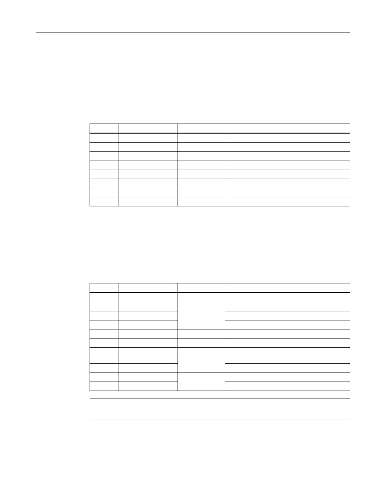
X7: Panel Present
Connector designa-
X7
tion:
Connector type:
6-pin Phoenix terminal
Table 4-3
Assignment of the interface Panel Present X7
Pin
Signal name
Signal type
Meaning
1
PRES
O
"High": Panel (HT 10) inserted
2
XCTL
O
"Low": EMER STOP button pressed 1)
3
XFAULT
O
"Low": Error in emergency stop electronics 1)
4
N.C.
-
Not connected
5
N.C.
-
Not connected
6
M
P
Ground
1)
Function not implemented in Basic PN variant, output is not switched to "High"
X8: Emergency Stop wiring terminal
Connector designa-
X8
tion:
Connector type:
4-pin Phoenix terminal
Table 4-4
Assignment of the emergency stop wiring terminal X8
Pin
Protective circuit
1
On-board jumper
between 1 and 2
2
3
On-board jumper
between 3 and 4
4
Note
Use this terminal for simple routing of the emergency stop cables, optional.
The connector is only used to assist looping through. The connected pins 1 and 2 as well as 3 and
4 have no additional function on the connection module.
Handheld Terminal HT 10
56
Equipment Manual, 09/2020, A5E47430965B AA
Connecting
4.5 PN Basic connection module
X20: Enabling buttons
Connector designa-
X20
tion:
Connector type:
8-pin Phoenix terminal
Table 4-5
Assignment of the interface enabling buttons X20
Pin
Signal name
Signal type
Meaning
1
ZUST1P
I
Enabling button 1 P
2
ZUST1M
O
Enabling button 1 M
3
ZUST2P
I
Enabling button 2 P
4
ZUST2M
O
Enabling button 2 M
5
N.C.
-
Not connected
6
N.C.
-
Not connected
7
N.C.
-
Not connected
8
N.C.
-
Not connected
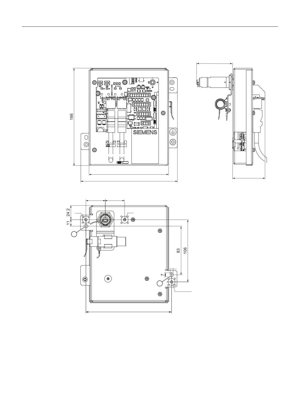
X21: Emergency Stop and key-operated switch
Connector designa-
X21
tion:
Connector type:
10-pin Phoenix terminal
Table 4-6
Assignment of the interface Emergency Stop and Module Supply Voltage
Pin
Signal name
Signal type
Meaning
1
STOP23
Emergency Stop circuit
2
STOP24
Emergency Stop circuit
B
3
STOP13
Emergency Stop circuit
4
STOP14
Emergency Stop circuit
5
M
P
Ground
6
N.C.
-
-
7
IN_E9
Connected P24 (jumpered to Pin8 during opera-
P
tion)
8
P24_FILT
Filtered 24 V module power supply
9
IN_E9_EXT
Feedback signal via connected P24
O
10
IN_E12_EXT
"High": Terminating connector plugged in
Note
Pins 7 and 8 must be jumpered in order to supply a handheld terminal with power.
Handheld Terminal HT 10
Equipment Manual, 09/2020, A5E47430965B AA
57
Connecting
4.5 PN Basic connection module
4.5.3
Dimension drawing
;
;
;
;
;
;
;
0
0
0
RSWLRQDO
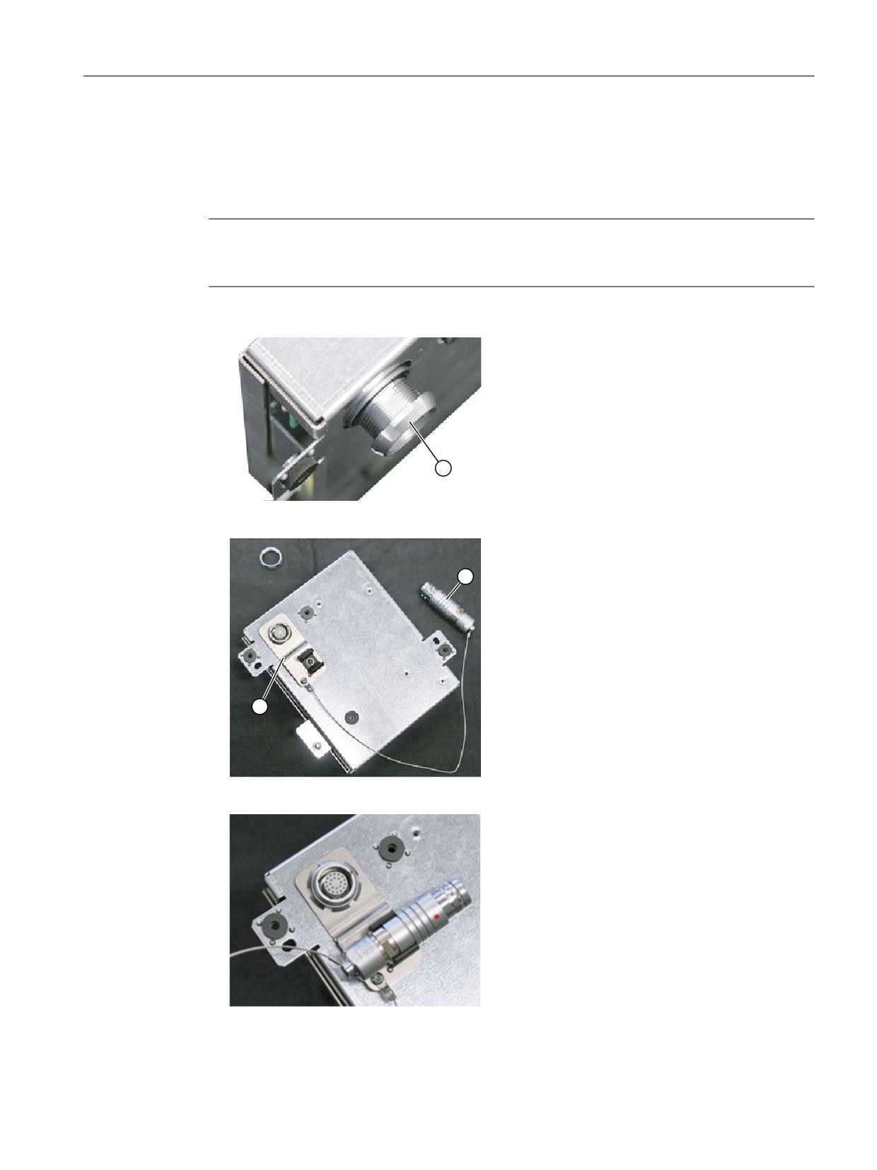
① Elongated holes - if the module is screwed to the inside of the control cabinet
Figure 4-11
Connection module Basic PN - dimension drawing for control cabinet installation
Handheld Terminal HT 10
58
Equipment Manual, 09/2020, A5E47430965B AA
Connecting
4.5 PN Basic connection module
4.5.4
Installing the terminating connector
Procedure
Note
If you never remove the HT 10 from the connection module, it is not necessary to attach the
terminating connector.
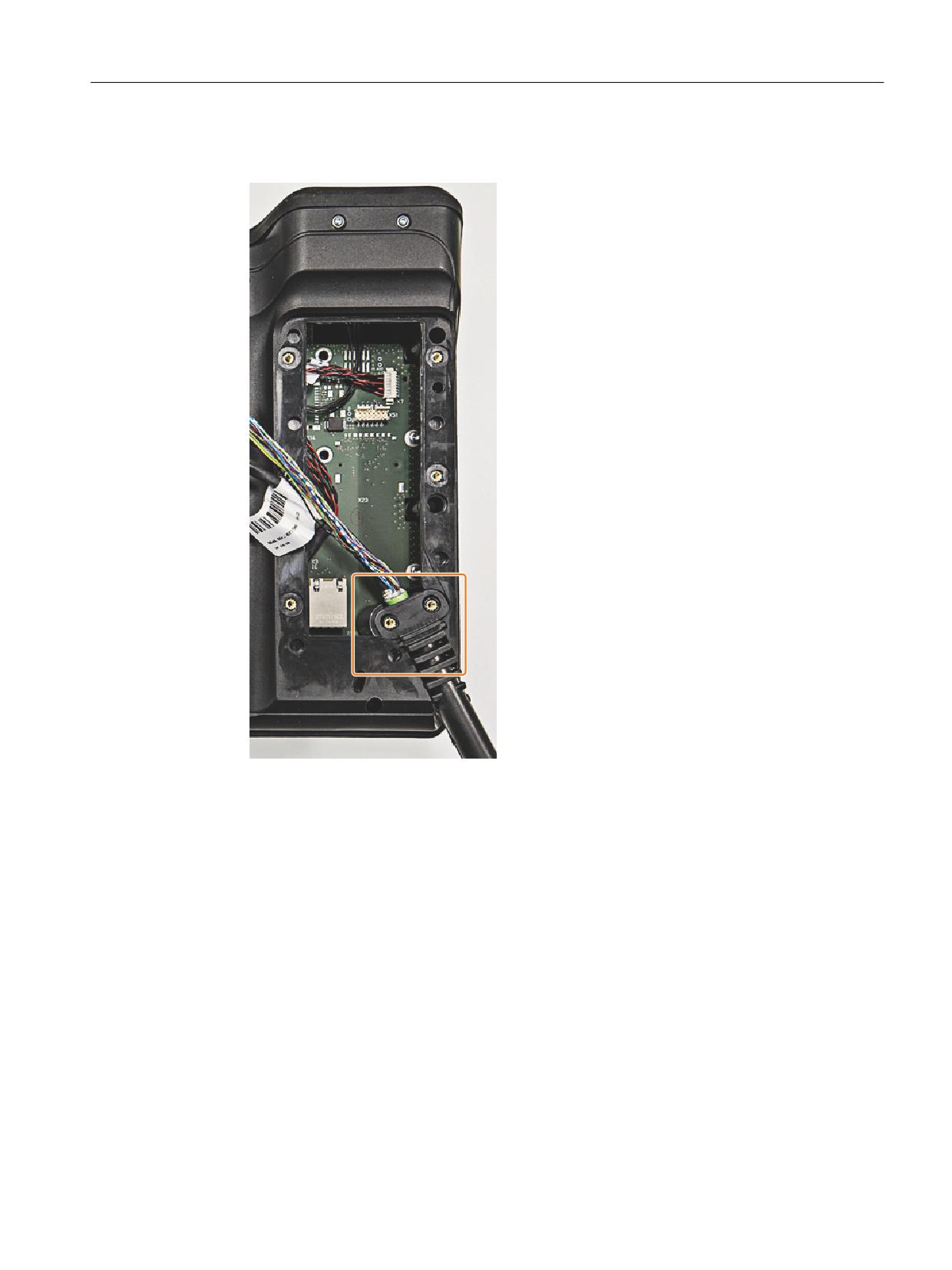
1. Unscrew the fastening nut ①.
2. Attach the bracket ① for the terminating connector ②.
3. Tighten the fastening nut and insert the terminating connector into the bracket.
Handheld Terminal HT 10
Equipment Manual, 09/2020, A5E47430965B AA
59

Connecting
4.6 Connecting cable
4.6
Connecting cable
The connecting cable is an industrial cable, can tolerate bending in-line with what is required in
practice - and is resistant to many solvents and lubricants.
The connecting cable is available in various lengths. More detailed information is provided in the
Chapter "Accessories (Page 93)".
① Metallic push-pull round connector (ODU connector)
② RJ45 plug to connect to the Ethernet
③ Plug connector for enabling button, Emergency Stop, 24 V and safety signals
④ Strain relief device and kink protection
Figure 4-12
Connecting cable for the HT 10
The connecting cable is connected to the HT 10 with the RJ45 connector ② and connector ③.
The ODU connector ① is used to connect the connecting cable to the connection box / module.
The tightening torque for the nut of the ODU socket is 6.5 Nm.
Routing the connecting cable
1. Grease the connecting cable at the entry point with Vaseline.
This ensures a better seal and makes it easier to insert the connecting cable.
2. Insert the connecting cable into the entry.
Note
Ensure correct orientation of the connecting cable. The convex side of the anti-kink
protection must face away from the device as otherwise the cover will not lie flush on the
housing when screwed on.
Handheld Terminal HT 10
60
Equipment Manual, 09/2020, A5E47430965B AA
Connecting
4.6 Connecting cable
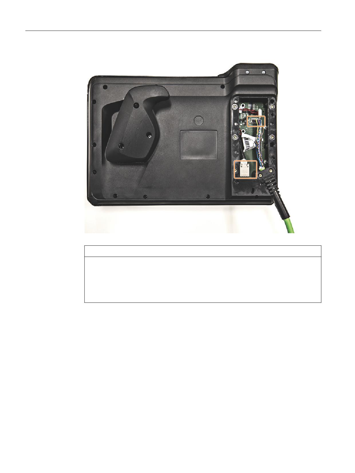
3. Press the cable lightly downwards until it rests completely on the fastening lugs and is flush
with the housing.
Handheld Terminal HT 10
Equipment Manual, 09/2020, A5E47430965B AA
61
Connecting
4.6 Connecting cable
4. Press the plug connector firmly into the power supply socket.
NOTICE
Improper installation of the cable can result in failure of the safety functions.
Please observe the following before you reattach the cover:
• Check to ensure that all of the conductors are aligned and straight and check the firm
seating of the plug connector.
• Make sure that the connecting cable sleeve is installed correctly.
Handheld Terminal HT 10
62
Equipment Manual, 09/2020, A5E47430965B AA
Connecting
4.6 Connecting cable
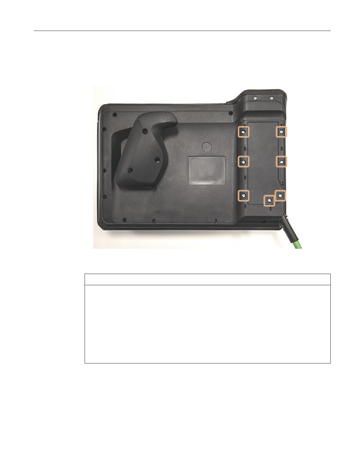
5. Connect the RJ-45 connector to the Ethernet socket.
6. Mount the cover by screwing in the seven PT screws (4 x 20 mm) for about 1 cm with a torque
of 0.3 Nm.
Use a 0.8 x 5.00 mm torx or cross-tip screwdriver for this.
NOTICE
Damage to the enclosure
The enclosure of the HT 10 is made of plastic. Therefore, the mounting hole threads cannot
handle the same amount of stress as a comparable metal enclosure. Therefore, do not exceed
the permissible torque of 0.3 Nm when tightening the screws (also to protect the connecting
cable).
If you use a power screwdriver, do not exceed the max. speed of 600 rpm (torque: 1 Nm).
The screws of the cover may only be loosened or tightened a maximum of 20 times. Otherwise,
there is the danger that the threads might become damaged and the seal of the enclosure
compromised, which could lead to failure of the device.
Handheld Terminal HT 10
Equipment Manual, 09/2020, A5E47430965B AA
63
Connecting
4.7 Unplugging/plugging during operation
4.7
Unplugging/plugging during operation
Detectability of an inserted HT 10 in the PLC
1. HW solution:
The X7 interface of the Basic PN connection module signals "HT 10 Present" at pin 1 for the
"active" connection module (see interfaces (Page 54)).
If the connection module is "inactive", this signal is not set.
This makes the "active" connection module detectable in the PLC by wiring pin 1 of all
connection modules with digital I/Os to PLC I/O modules in the PLC.
2. Permanently configured MCPs / HT 10s connected to one control:
If only permanently configured MCPs / HT 10s are present on a control, removing the MCPs
or HT 10s trips the PLC alarm "400260 Machine Control Panel failed".
Based on this an "active" or "inactive" MCP / HT 10 in the PLC can be detected.
The failure of an MCP / HT 10 is, however, only detected in the PLC if a max. of 2 MCPs / HT 10s
are permanently configured and there is no MCP switchover using FB9 (e.g. tripped when
operator focus is switched on the operator panel).
Note
Removing an HT 10 where the integrated machine control panel is active
Depending at which interface in the PLC (FB1: MCP1 or MCP2) the HT 10 is configured, the
transmission of machine control panel signals must be stopped before the HT 10 is removed.
This is possible as a direct access via data block DB7 (instance of the FB1).
To do this, set the corresponding interface signal to "true":
• 1st interface: DB7.DBX62.1 (MCP1Stop)
• 2nd interface: DB7.DBX62.2 (MCP2Stop)
If the machine control panel signals are not stopped, the message "400260 machine control
panel x failed" appears on the user interface:
Transmission of the machine control panel signals can be restarted after inserting the HT 10. To
do this, set e.g. the PLC interface signal DB7.DBX62.1 (MCP1Stop) to "false".
Handheld Terminal HT 10
64
Equipment Manual, 09/2020, A5E47430965B AA
Commissioning
5
5.1
Activating/deactivating the virtual keyboard
The virtual keyboard is configured in the file "slguiconfig.ini".
Procedure
1. Copy the "slguiconfig.ini" file from the folder
/siemens/sinumerik/hmi/template/cfg.
2. Insert the copy into the folder:
/oem/sinumerik/hmi/cfg or /user/sinumerik/hmi/cfg.
3. Open the file in the editor.
4. To activate or deactivate the keyboard, make the following settings:
- Activating the virtual keyboard:
In the section [TouchPanel], EnableTouch = true
In the section [Keyboard], EnableVirtualKeyBoard = true
- Deactivating the virtual keyboard:
In the section [TouchPanel], EnableTouch = true
In the section [Keyboard], EnableVirtualKeyBoard = false
5. Double click in the input field to display the keyboard.
5.2
Configuring user-specific key labeling
Labeling of the keys on the HT 10
The texts of the CPF menu (CPF: Control Panel Function) for the HT 10 can be labeled with your
own texts in the particular language of the country.
The texts are created in the "slck_xxx.ts" file.
"xxx" = language code for the corresponding language-specific labeling.
You can create and edit this file using the HMI or also externally on a PC.
Note
If you wish to create or edit the file on a PC, use an editor that supports UTF-8 coding.
Handheld Terminal HT 10
Equipment Manual, 09/2020, A5E47430965B AA
65

Commissioning
5.2 Configuring user-specific key labeling
Language code in file names "xxx"
Language
Language code
German
deu
English
eng
French
fra
Spanish
esp
Italian
ita
Chinese
chs
Creating key labeling
Tag
Meaning
source
Designation for the user softkey. "SK_USERKEY1" to "SK_USERKEY16" are possible,
whereby the names may not be changed.
comment
User-specific description of the key assignment.
translation
Text that should be shown on the key.
• A maximum of 10 characters are possible per line.
•
2-line labeling is possible, whereby the line break is set using "%n".
remark
Remark for key assignment.
chars
Number of characters. A maximum of 10 characters per line are possible.
lines
Number of lines. 2 lines are possible.
Procedure
1. You can copy the sample file "oem_slck_deu.ts" from the following folder: /siemens/
sinumerik/hmi/template/lng.
2. Store or create the file in the /oem/sinumerik/hmi/lng or
/user/sinumerik/hmi/lng directory.
3. Give the file a name, e.g. for German texts: "slck_deu.ts".
If you wish to create the key labeling for additional languages, then a separate file must be
created for each language. Save the file with the appropriate language code in the file name.
To do this, use the language codes specified above.
4. Open the file and in the <message> and </message> area, define the key labeling.
5. Restart the HMI.
In order that the key labeling is displayed during the program runtime, the file must be
converted into a binary format. This conversion is only executed when the HMI powers up.
Example of a key label
<!DOCTYPE TS><TS>
<context>
<name>SlCkDialog</name
<message>
Handheld Terminal HT 10
66
Equipment Manual, 09/2020, A5E47430965B AA

Commissioning
5.3 Configuring the function display at user-specific keys (U keys)
<source>SK_USERKEY1</source>
<comment></comment>
<translation>U1</translation>
<remark>User key 1</remark>
<chars>10</chars>
<lines>2</lines>
<languageIndependent>true</languageIndependent>
</message>
<message>
<source>SK_USERKEY2</source>
<comment></comment>
<translation>U2</translation>
<remark>User key 2</remark>
<chars>10</chars>
<lines>2</lines>
<languageIndependent>true</languageIndependent>
</message>
<message>
</message>
</context>
</TS>
5.3
Configuring the function display at user-specific keys (U keys)
Function
Active functions can be displayed at the configurable user keys via the PLC. For instance, small
LEDs can be emulated on the softkeys.
You configure the function in the "slckcpf.ini" file.
Interface signals
The PLC bits are in the output image of the PLC/HT 10 interface and are analogous to those in the
input image.
Signals to the MCP1 (or MCP2)
Interface PLC → HT 10
Byte
Bit 7
Bit 6
Bit 5
Bit 4
Bit 3
Bit 2
Bit 1
Bit 0
AB n + 1
U4
U3
U2
U1
AB n + 4
U9
U10
U11
U12
U13
U14
U15
U16
AB n + 5
U8
U7
U6
U5
Handheld Terminal HT 10
Equipment Manual, 09/2020, A5E47430965B AA
67
Commissioning
5.3 Configuring the function display at user-specific keys (U keys)
Adapt the display in the "slckcpf.ini" file
Section
Description
UserKeyLEDIcon
Name of the icon file.
Standard entry: led_green.png
OFF
Deactivates the icon display.
PRESSED
Displays the active functions by pressing
down the softkey.
UserKeyLEDIconAlignment
Specifies the position of the icon.
Standard position: AlignLeft | AlignTop
Horizontal and vertical alignments can be combined. The two
names are separated by the "|" character.
The following alignments are possible:
AlignLeft
Left
AlignRight
Right
AlignHCenter
Horizontal, center
AlignTop
Top
AlignBottom
Bottom
AlignVCenter
Vertical, center
UserKeyLEDMap
Specifies the start address of the output image.
Entries can be made in the following form: "DBx.DBBy", "ABx",
"MBx".
Default setting: The start address is determined using
DB7 MCP1Out (or MCP2Out).
U1LED ... U16LED
The status bit address can be defined - different from the output
VarIncLED
image - using these entries.
SBLLED
Note: The offsets from the HT 10 output image, for one or more
softkeys, are not taken into consideration.
WCSLED
showVarIncLED
true
When the increment mode is active, the icon is also
displayed on the "[VAR]" softkey.
false
The icon is not displayed.
showSBLLED
true
When the SingleBlock mode is active, then the icon is
also displayed on the "Single Block" softkey.
false
The icon is not displayed.
showWCSLED
true
When the SingleBlock mode is active, then the icon is
also displayed on the "Single Block" softkey.
false
The icon is not displayed.
1. You can copy the sample file "slckcpf.ini" from the following folder: /siemens/sinumerik/hmi/
template/cfg
2. Store the file in the /oem/sinumerik/hmi/cfg or /user/sinumerik/hmi/cfg directory.
3. If you have your own icon, place it, together with the corresponding resolution for HT 10 in
the folder: /oem/sinumerik/hmi/ico/ico800 or /user/sinumerik/hmi/ico/ico800.
4. Open the file and make the appropriate settings.
Handheld Terminal HT 10
68
Equipment Manual, 09/2020, A5E47430965B AA
Commissioning
5.3 Configuring the function display at user-specific keys (U keys)
Sample file "slckcpf.ini"
Template for the configuration of the
; HT 10 control panel function menu
;
; To activate the settings remove the
; commentary ';' at the beginning of the line
;; Display settings of the user key softkey leds
[UserKeyLED]
; Filename of the LED icon
;UserKeyLEDIcon = led_green.png
; Alignment of the LED icon
;UserKeyLEDIconAlignment= AlignLeft | AlignTop
; Use following led map start address instead of calculating
DB7.MCP1Out
;UserKeyLEDMap = AB0
; Use the following settings to use this status bits instead of the
led map for a specific sk
;U1LED=/channel/parameter/R[U1,1]
;
;U16LED=/channel/parameter/R[U1,16]
;VarIncLED = DB11.DBX8.5
;SBLLED = DB21.DBX0.4
;WCSLED = DB19.DBX0.7
; Show a LED for the var inc sk
;showVarIncLED = true
; Show a LED for the var single block sk
;showSBLLED = true
; Show a LED for the var wcs/mcs sk
;showWCSLED = true
Handheld Terminal HT 10
Equipment Manual, 09/2020, A5E47430965B AA
69
Commissioning
5.4 Dimming the display
5.4
Dimming the display
In the settings, you can configure the unmanned period after which the display is first slightly
dimmed, and strongly dimmed after another unmanned time period. Unmanned periods are
periods during which no operator actions are made on the device. Operator actions include, for
example, touching the display, making keyboard inputs or modifying the position of the device.
Handheld Terminal HT 10
70
Equipment Manual, 09/2020, A5E47430965B AA
Commissioning
5.4 Dimming the display
Setting unmanned period
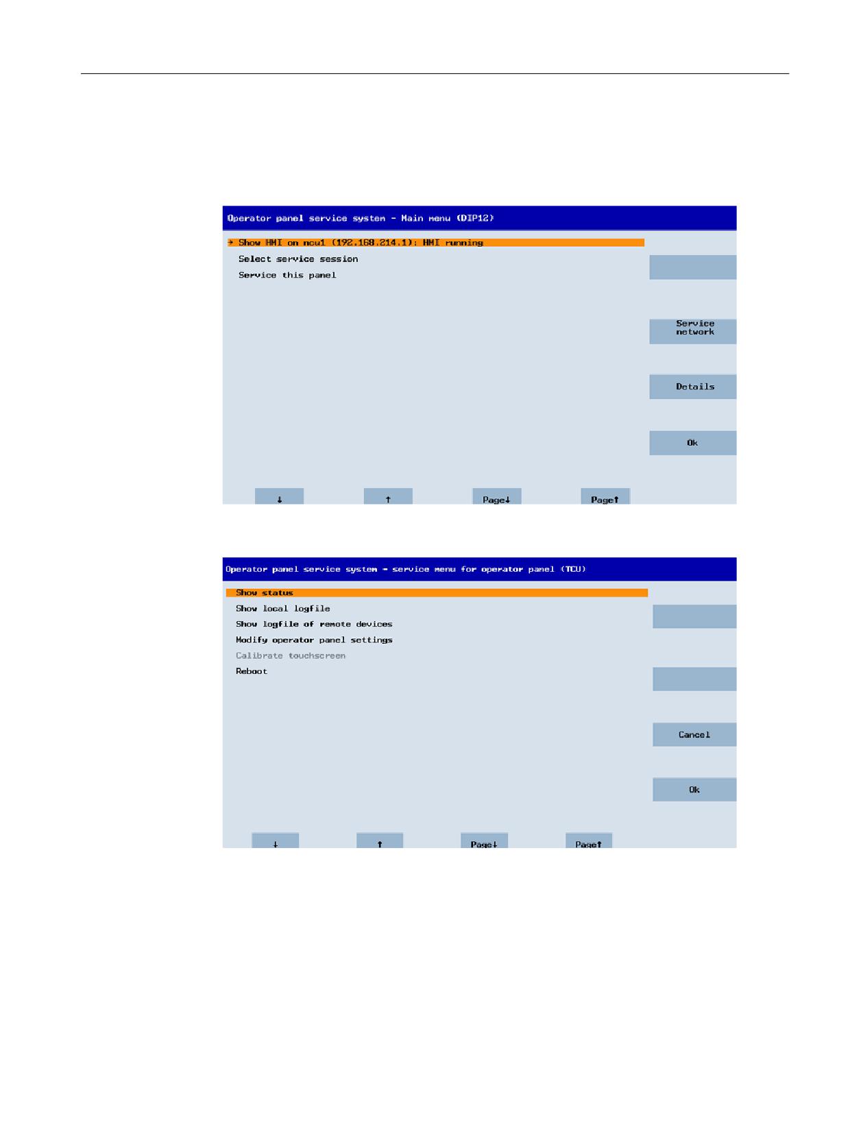
1. Open the TCU menu by simultaneously pressing the F9 and F10 keys, or touch the two lower
corners of the display .
The TCU menu "Main menu" opens.
2. Select the option ""Service this panel" and confirm your selection with "Ok".
The menu ""Service menu for operator panel (TCU)" opens.
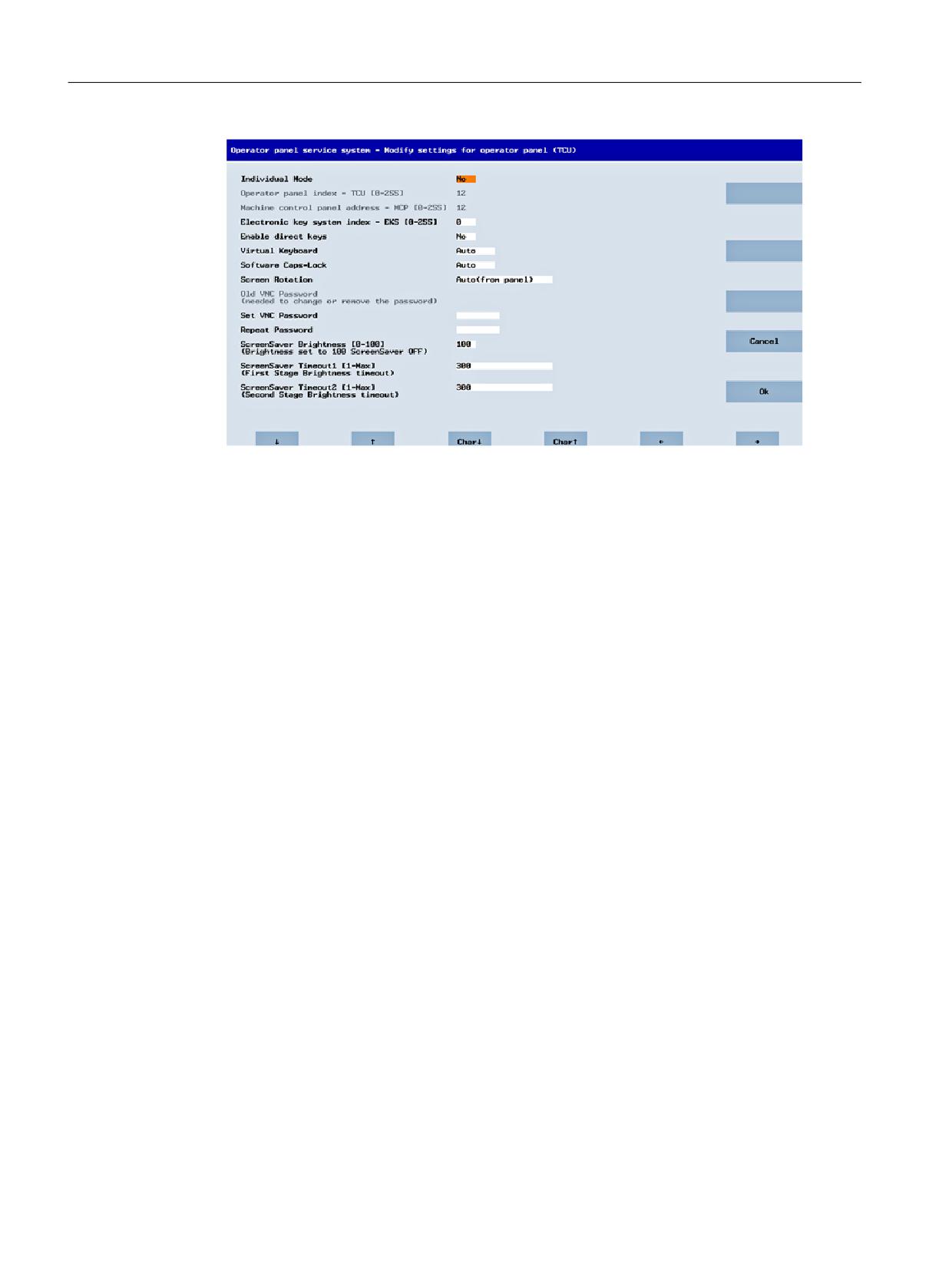
3. Select the option "Modify operator panel setting" and confirm your selection with "Ok".
The menu "Modify settings for operator panel (TCU)" opens.
Handheld Terminal HT 10
Equipment Manual, 09/2020, A5E47430965B AA
71
Commissioning
5.5 Troubleshooting
In the menu "Modify settings for operator panel (TCU)", you can configure the display dimming
options:
• ScreenSaver Timeout1 and ScreenSaver Timeout 2
This option allows you to configure the two-phase display dimming option.
ScreenSaver Timeout 1 is the unmanned time until the display is dimmed to the ScreenSaver
Brightness value set.
ScreenSaver Timeout 2 is the unmanned time starting at the end of ScreenSaver Timeout 1.
After the unmanned period of ScreenSaver Timout 2, the display is strongly dimmed.
By default, the value is set to "300".
• ScreenSaver Brightness
This option allows you to configure the display brightness which is set when the unmanned
time period set under ScreenSaver Timeout 1 has expired.
By default, this setting is "100". The value "100" means that the screen saver is deactivated.
Restoring the original display brightness
The following entries restore the original display brightness:
• Touching the display
• Movement of the mouse or a device (monitored using an acceleration sensor)
• Press of a button
5.5
Troubleshooting
If errors occur while booting, an appropriate message is displayed.
Handheld Terminal HT 10
72
Equipment Manual, 09/2020, A5E47430965B AA
Commissioning
5.5 Troubleshooting
5.5.1
Messages during booting
Messages when booting
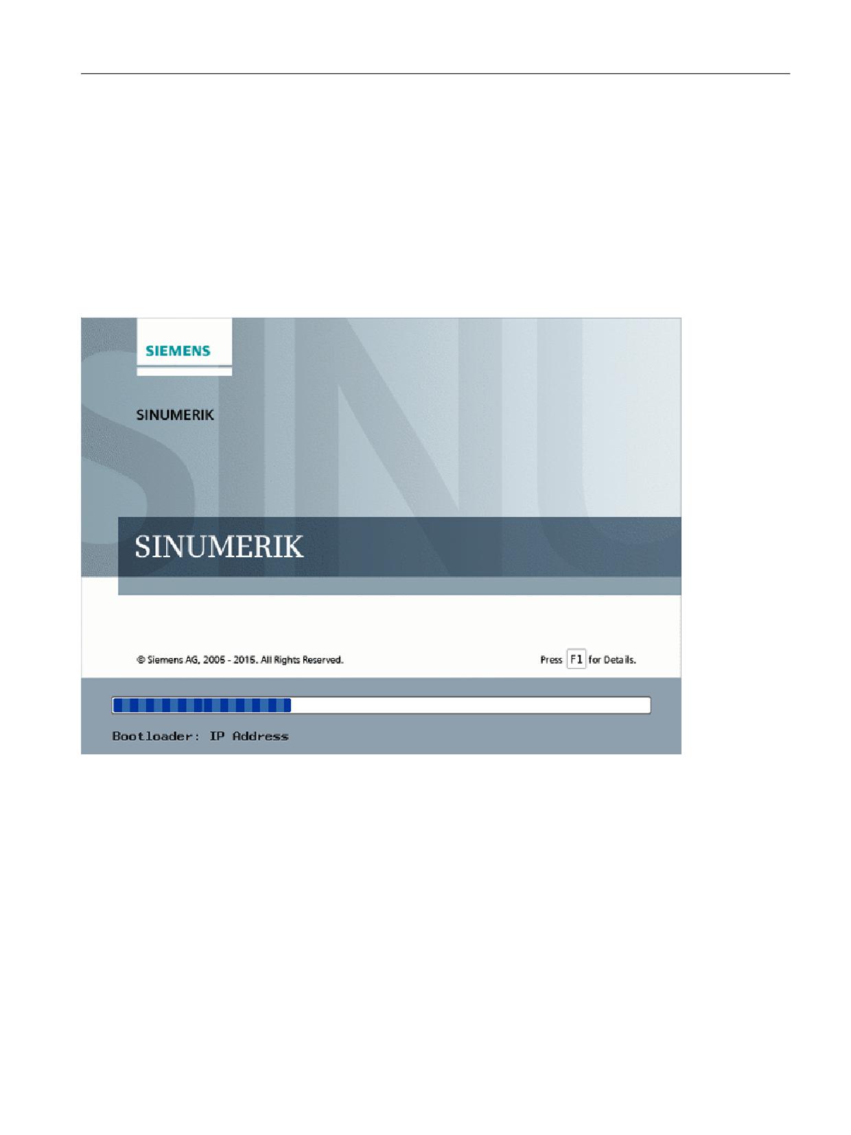
While the TCU boots, a progress indicator is displayed with messages showing the current status
after the BIOS has been loaded and before the operating system is started. While the IP address
is being determined via DHCP and the TFTP is being downloaded (boot image), a progress bar
indicates that booting of the TCU is not yet complete, or that a fault has occurred.
The figure below shows the structure of these messages:
You can see the current boot phase below the progress bar. If a fault occurs, you can call further
information by touching the "F1" field.
Handheld Terminal HT 10
Equipment Manual, 09/2020, A5E47430965B AA
73
Commissioning
5.5 Troubleshooting
5.5.2
Diagnostics options during booting
Diagnostics while booting supplementary conditions
In the following supplementary conditions, the diagnostics window is displayed and booting of
the TCU is interrupted:
• When the <1 / F1> function is selected during booting
• When a warning message is displayed
• When a fault occurs
You can select functions <1 / F1> to <8 / F8> mentioned below by tapping on the Panel.
Alternatively, you can do this via the corresponding function keys of a connected USB
keyboard.
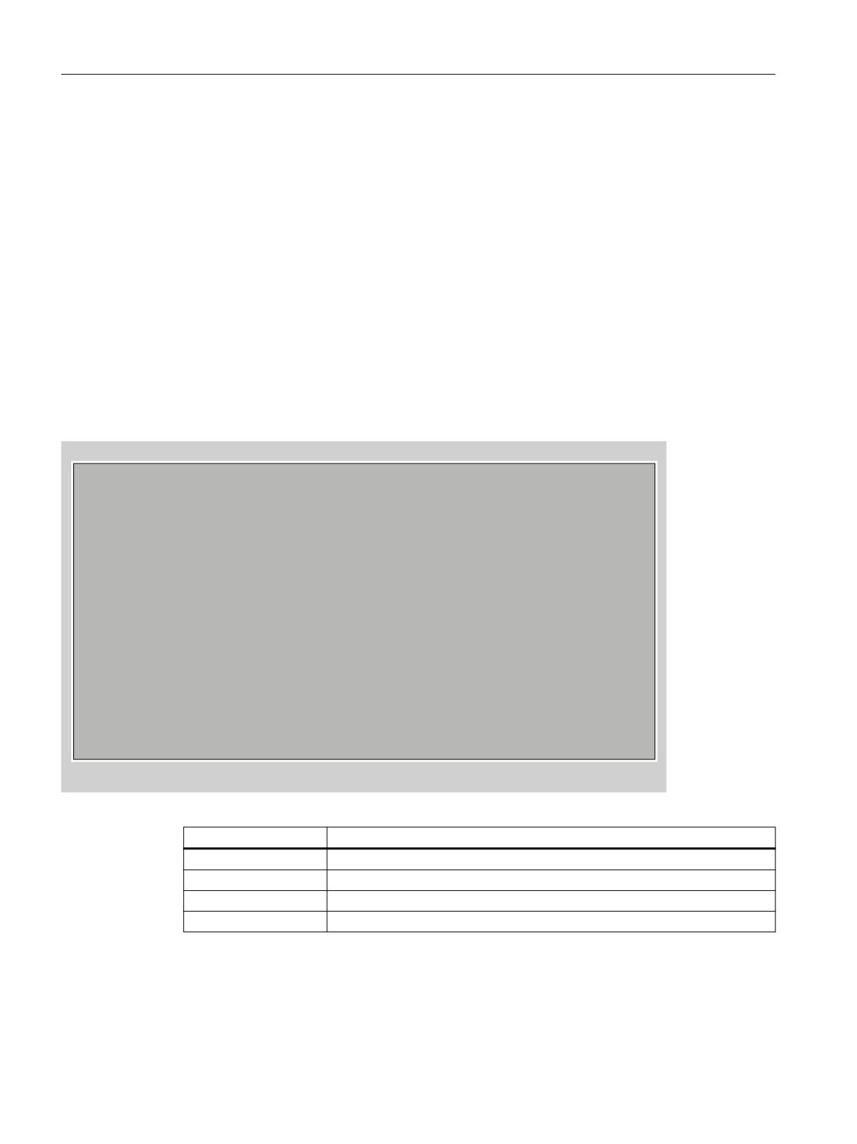
Using the <1 / F1> function
7hin Client Bootloader
V05.00.45.00
Boot Progress
BIOS Version
V15.00.00.00
MAC Address
08:06:00:F1:F7:F8
Hardware-ID
7.9.2.0
Network link
1000MB, full duplex
Boot from USB
no device found
IP Address
192.168.214.14
Netmask
255.255.255.0
DHCP Server
192.168.214.1
Boot Server
192.168.214.1
Image Metadata
71 bytes
Image Version
V05.00.46.00
Linux Image (linux.bin)
3295436 bytes
Image Kind
from boot server
Booting
ready
<1/F1> protocol <2/F2> Readme_OSS
<7/F7> continue <8/F8> reboot
Key / text
Meaning
F1 protocol
Display detailed information
F2 Readme_OSS
Details of the Open Source licenses
F7 continue
Continue booting of the TCU
F8 reboot
Restart the TCU
Handheld Terminal HT 10
74
Equipment Manual, 09/2020, A5E47430965B AA

Commissioning
5.5 Troubleshooting
Press <1 / F1> to continue
If you select function <F1> in the diagnostics window, the, detailed diagnostic information is
output.
Key / text
Meaning
F1 ... F6
Navigate within the window
(alternatively, the relevant keys on the OP can be used).
F7 -detail
Display less information
F8 +detail
Display more information
F9 back
Return to diagnostics window
Handheld Terminal HT 10
Equipment Manual, 09/2020, A5E47430965B AA
75
Maintenance and Service
6
Cleaning the device
Use a soft cloth moistened with either water or a mild cleaning agent to clean the enclosure,
display and operator control elements of the HT 10.
Checking the device
To prevent foreign bodies or liquids entering the HT 10, regularly check the device:
• that all the housing screws are in place and tight
• for damage to the housing
• for damage to the cable cover or cable entry
Protect the device from environmental effects
Protect the HT 10 against the following environmental effects:
• Direct solar radiation and heat sources
• Mechanical vibration and shock
• Dust
• Humidity
• Strong magnetic fields
Checking the emergency stop button and the enabling button
Check the emergency stop button regularly to ensure that it functions correctly.
Check the enabling button regularly to ensure that it functions correctly in the enable and panic
position.
Note
Check the functionality in the event of shock
Check the functioning of the emergency stop button and the enabling button immediately if the
device has been subject to severe shock (e.g. because it was dropped).
Handheld Terminal HT 10
Equipment Manual, 09/2020, A5E47430965B AA
77
Maintenance and Service
Handheld Terminal HT 10
78
Equipment Manual, 09/2020, A5E47430965B AA

Technical specifications
7
7.1
Handheld Terminal HT 10
Handheld Terminal HT 10
Safety
Safety class
III according to UL 61010-2-201
Degree of protection accord-
IP65
ing to DIN EN 60529
Approvals
CE/cULus/EAC/KC/RCM
Electrical data
Input voltage
24 V DC (20.4 V ... 28.8 V)
Input current
0.98 A
Current carrying capacity
Enabling button:
10 ... 250 mA / 1-channel, 3-stage
Emergency Stop button:
10 - 1000 mA / 2-channel
Max. current carrying capaci-
USB interface:
900 mA
ty
Mechanical data
Dimensions (W x H x D)
327 mm x 102 mm x 232 mm (enclosure dimensions only)
Weight
1.5 kg
Fall height, max.
1.20 m
Display
Size
10.1" TFT
Resolution
1280 x 800 pixels
Service life
At ambient temperatures of > 40º C and long periods of non-use, it is
advisable to activate the screen saver function.
Emergency Stop button
Rated voltage
24 V DC
Current rating, max.
1 A
Current rating, min.
18 mA
Switching capacity
DC 13 according to EN 60947-5-1
Conditional rated short-circuit current
10 A gL/gG according to EN 60947-5-1
B10d (if a connection box is not used)
250000
When using the connection box advanced:
PFHd
1.01 * 10-7
Service life
20 years
Forced dormant error detection interval (mechanical actua-
1 year
tion to the test the emergency stop)
Handheld Terminal HT 10
Equipment Manual, 09/2020, A5E47430965B AA
79
Technical specifications
7.2 Connection module Basic PN
Category
3
Performance Level
PL d
Note
The quantitative assessment of the emergency stop safety function must be based on the B10d
value corresponding to the used standards (e.g. ISO 13849-1) under consideration of the
respective application (frequency of the actuation, service life, diagnostics by the evaluation
unit, etc.). The B10d value only applies when the technical properties of the emergency stop
button are taken into account.
When using the connection box advanced, the specified failure probability (PFHd) must be taken
into account. This value only applies if the technical properties of the connection box advanced
and the quantitative conditions specified here (e.g. service life) are observed.
Enabling button
1-circuit, 3-stage
Supply voltage
24 V DC
Current rating, max.
250 mA
Current rating, min.
10 mA
Operating cycles
Switch position 2
105
Switch position 3
5 * 104
Actuation forces
From switch position 1 to 2, typically
3 N
From switch position 2 to 3, typically
17 N
Functional safety
EN ISO 13849-1:2008
Category
4
Performance Level (PL)
PL e
Proof test interval (operating duration)
20 years
EN 61508
Safety Integrity Level (SIL)
SIL 3
PFHd
5.07 * 10-9
Forced dormant error detection interval (mechanical actuation to the
1 year
test the enable and panic position)
Note
The PFHd value only applies when the technical properties of the enabling button and the
quantitative conditions specified here (e.g. service life) are observed.
The permissible number of switching cycles must also be observed in the application.
7.2
Connection module Basic PN
Safety
Safety class
III according to IEC 60536
Handheld Terminal HT 10
80
Equipment Manual, 09/2020, A5E47430965B AA
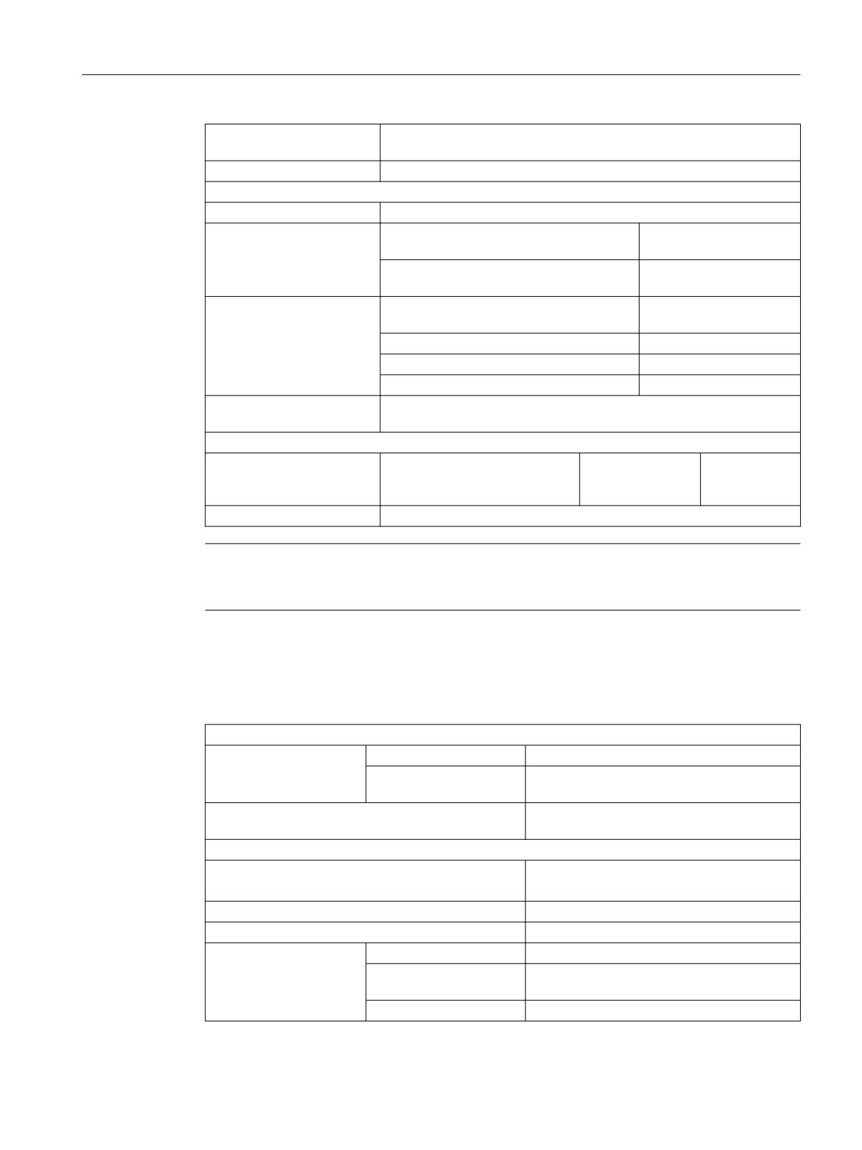
Technical specifications
7.3 Connection box
Degree of protection accord-
IP54
ing to EN 60529
Approvals
CE / cULus
Electrical data
Input voltage
24 VDC (via X3 connector)
Current carrying capacity
Enabling button contacts (X20 connector)
2-channel / 0.25 A max.
for each
Emergency stop button contacts (X21 con-
2-channel / 1.0 A max. for
nector)
each
Max. power consumption
Connection module without external load-
0.3 A
ing
Panel (HT 10)
0.7 A
5 status signals (X7 and X21)
2.5 A (0.5 A each)
Total:
4.4 A
Max. total
105.6 W
power consumption
Mechanical data
Dimensions
Height (without holder for termi-
Width:
Length:
nating connector):
165 mm
166 mm
66 mm
Weight
0.75 kg
Note
Further information about the ambient conditions can be found in the Chapter "Climatic and
mechanical ambient conditions" (Page 86).
7.3
Connection box
General data
Weight without packaging
Connection box compact
approx. 250 g
Connection box standard,
approx. 750 g
connection box advanced
Degree of protection according to EN 60529
IP65
(with HT 10 or dummy cap inserted)
Electrical data
Rated voltage
+24 V DC
Range, permissible
20.4 V to 28.8 V
Transients, maximum permissible
35 V (500 ms)
Time between two transients, minimum
≥50 s
Connection box standard
Typical
approx. 100 mA
and advanced without
Continuous current, maxi-
approx. 150 mA
HT 10
mum
Inrush current I2t
Approx. 0.5 A2s
Handheld Terminal HT 10
Equipment Manual, 09/2020, A5E47430965B AA
81

Technical specifications
7.4 Supplementary electrical conditions
Connection box standard and advanced with HT 10,
approx. 600 mA
typical
Fuse, internal
Electronic
Current load PLC-accompanying signals
Max. 100 mA
Note
Recovery time
After unplugging the connecting cable from the connection box wait for approximately one
second before reinserting it.
After power failures lasting less than one second the connecting cable has to be disconnected.
7.4
Supplementary electrical conditions
Ambient conditions
Remarks
Overvoltage category
OVC 2
EMC conducted / radiation
Class C2 according to EN 61800-3
Note
The user must consider radio interference for the complete system. Particular attention should
be paid to cabling. Please contact your sales representative for assistance and support.
Note
Disturbance of radio communication services due to radio (frequency) interferences in
residential environments
In a residential environment, this product can cause high-frequency interference, which may
make interference suppression measures necessary.
This device is not designed for unrestricted operation in the first environment (residential
environment), and may not be used in the first environment without suitable interference
suppression measures.
• Have the installation and commissioning with appropriate radio interference suppression
measures performed by qualified personnel.
Handheld Terminal HT 10
82
Equipment Manual, 09/2020, A5E47430965B AA

Technical specifications
7.4 Supplementary electrical conditions
7.4.1
Power supply
Requirements for DC power supplies
WARNING
Electric shock due to connection of an unsuitable power supply
If equipment is connected to an unsuitable power supply and/or insufficiently grounded or rear
cover, exposed components may carry a hazardous voltage that might result in serious injury
or death.
• Only use power supplies that provide SELV (Safety Extra Low Voltage) or PELV (Protective
Extra Low Voltage) output voltages acc. to UL 61010 for all connections and terminals of the
electronics modules.
WARNING
Inadequately fused supply cables can be life-threatening
If power supply cables are inadequately protected, then lightning strikes can result in a surge
voltage. This can result in death, serious injury and material damage.
In the case of supply lines > 10 m, protectors must be installed at the device input in order to
protect against lightning (surge).
The DC power supply must be connected to the ground/shield of the NC for EMC and/or
functional reasons. For EMC reasons, this connection should only be made at one point. As a
rule, the connection is provided as standard in the S7-300 I/Os. In exceptional circumstances
when this is not the case, the ground connection should be made on the grounding rail of the
NC cabinet (also refer to /EMC/EMC Installation Guide.)
WARNING
Electric shock in the event of an individual error if the rear cover is missing
If the rear cover is missing when mounting the device in an environment with a hazardous
voltage, a conductor with a hazardous voltage can come loose in the event of a normative
permissible individual error and touch parts of the printed-circuit board and cause electric
shocks. Due to its design, the printed-circuit board cannot trigger the overcurrent protection of
the circuit with hazardous voltage.
For this reason, protect areas of the printed-circuit board that are not adequately enclosed by
grounded sheet metal parts, or with a secure cover when installed in an environment with
hazardous voltages. If this cover is made of conductive material, it must be safely grounded.
See "Electric shock in the event of an individual error when grounding is insufficient".
To avoid electric shocks, mount a rear cover on the device when installing it in an environment
with a hazardous voltage.
Handheld Terminal HT 10
Equipment Manual, 09/2020, A5E47430965B AA
83

Technical specifications
7.4 Supplementary electrical conditions
Table 7-1
DC power supply requirements according to EN 61131-2
Rated voltage
According to EN 61131-2
24 VDC
Voltage range (mean value)
20.4 VDC to 28.8 VDC
Voltage ripple, peak/peak
5% (unsmoothed 6-pulse rectifi-
Ramp-up time when switched on
cation)
any
Non-periodic overvoltages
≤ 35 V
Period of overvoltage
≤ 500 ms
Recover time
≥ 50 s
Events per hour
≤ 10
Transient voltage interruptions
Downtime
≤ 3 ms
Recovery time
≥ 10 s
Events per hour
≤ 10
7.4.2
Grounding concept
Components
SINUMERIK ONE and SINUMERIK 840D sl systems consist of a number of individual components,
which have been designed so that, as a system, they comply with the relevant EMC and safety
standards. The individual system components are:
• Numerical Control Unit (NCU)
• Machine Control Panel (MCP), Machine Pushbutton Panel (MPP)
• Keyboard
• Operator panels (operator panel front + TCU/PCU)
• Distributor box and handheld unit
• S7-300 I/O with IM 153 interface module
Grounding measures
The individual modules are attached to a metal cabinet panel. Insulating paints on the mounting
points (e.g. tension jacks) must be removed.
It is permissible to cluster the operator control components regarding connection/potential
bonding.
Example: The control panel on the swivel arm.
It is sufficient in this instance to connect the ground connections of, for example, the PCU, TCU,
and operator panel front using a cable and to route a shared grounding conductor to the central
ground connection in the control cabinet.
Please note that interruption of the grounding during maintenance work is not permissible.
Note
The HT 10 is not affected by these grounding measures, which concern the connection box /
distribution box to which the HT 10 is connected.
Handheld Terminal HT 10
84
Equipment Manual, 09/2020, A5E47430965B AA
Technical specifications
7.4 Supplementary electrical conditions
Additional references
EMC Design Guidelines
7.4.3
RI suppression measures
In addition to the protective grounding of system components, special precautions must be
taken to ensure safe, fault-free operation of the system. These measures include shielded signal
lines, special equipotential bonding connections, and isolation and shielding measures.
Shielded signal cables
• Use the specified cables for safe and fault-free operation of the system.
• Connect the shield conductively at both ends to the housing for digital signal transmission.
Cable definition
Definition:
• Signal cables (example)
- Data cables (Ethernet, PROFIBUS, sensor cables, etc.)
- Digital I/Os
- Cables for safety functions (emergency stop, enabling)
• Power cables (example)
- Low-voltage supply lines (230 VAC, +24 VDC, etc.)
- Motor cables
Rules for routing cables
In order to achieve the greatest possible EMC compatibility for the complete system (control,
power unit, machine), the following EMC measures must be carefully observed:
• If necessary, signal and power cables may cross one another (if possible at an angle of 90°),
but must never be laid close or parallel to one another.
• Only use cables approved by SIEMENS for the signal lines from and to the Control Unit.
• Signal cables must not be routed close to strong external magnetic fields (e.g. motors and
transformers).
• If signal lines cannot be routed a sufficient distance away from other cables, they must be
installed in grounded cable ducts (metal).
• The operator panel fronts, MCPs, MPPs, and full keyboards must be installed in metallically
enclosed EMC-compatible housings.
Further information on RFI suppression measures and the connection of shielded cables can be
found in the EMC Installation Guidelines.
Handheld Terminal HT 10
Equipment Manual, 09/2020, A5E47430965B AA
85

Technical specifications
7.5 Climatic and mechanical ambient conditions
7.4.4
EMC limiting values in South Korea
EMC limit values in South Korea
The EMC limit values to be complied with for South Korea correspond to the limit values of the
EMC product standard for variable-speed electric drives EN 61800-3, Category C2, or limit value
class A, Group 1 according to EN 55011. By applying suitable supplementary measures, the limit
values according to Category C2 or according to limit value class A, Group 1, are maintained.
Further, additional measures may be required, for instance, using an additional radio
interference suppression filter (EMC filter).
The measures for EMC-compliant design of the system are described in detail in this manual
respectively in the Installation Guideline EMC.
Please note that the final statement on compliance with the standard is given by the respective
label attached to the individual unit.
7.4.5
EMF assessments for 24 V components
The 24 V components, e.g. control systems (NCU, MCU, PPU), PCUs/IPCs, operator panels,
handheld terminals and machine control panels do not generate any appreciable
electromagnetic fields.
No minimum clearance has to be maintained for 24 V components.
7.5
Climatic and mechanical ambient conditions
7.5.1
Shipping and storage conditions
In respect of shipping and storage conditions, the components surpass the requirements of
EN 61800-2.
The following data applies under the following conditions:
• Long-term storage in the transport and product packaging:
At weather-protected locations that have continuous contact with outside air through
openings.
• Transport in the transport packaging:
- In unventilated containers under conditions not protected from weather effects.
- In the “cold" in accordance with outside air.
- Air transport in the air-conditioned cargo hold.
Handheld Terminal HT 10
86
Equipment Manual, 09/2020, A5E47430965B AA

Technical specifications
7.5 Climatic and mechanical ambient conditions
Table 7-2
Ambient conditions during storage and transport
Type of condition
Permissible range/class
Classification
EN 60721-3-1
Climate class
1K4
Ambient temperature
From -20 °C to +55 °C
Biological environmental
1B1 1)
conditions
Chemically active environ-
1C2 2)
mental conditions
Maximum permissible tem-
30 K/h
perature change
Relative humidity
5 to 95%
Precipitation, rain
Not permitted
Water other than rain
Not permissible 3)
Condensation, splash water,
Not permissible 3)
icing, salt spray
1) Mold growth, slime, animal pests, rodents, termites and other animal vermin are not permissible.
2) In marine- and weather-resistant transport packaging (container).
3) For storage in the product packaging.
Note
Remove the transport protective foil and packaging material before installing the components.
Note
If you want to transport the HT10 as air freight in a completely assembled state including the
connecting cable, you should leave the USB opening free. This enables pressure compensation
to take place safely and prevents damage from occurring.
7.5.2
Operating conditions
The components are intended for use in a weatherproof, fixed location. The documented
environmental conditions apply to the climate in the immediate vicinity of the units and to the
entry of the cooling air. The following standards are complied with: EN 60204-1, EN 61800-2,
EN 61131-2 and IEC 62477-1.
Table 7-3
Ambient conditions for operation
Ambient conditions
Application areas
Remarks
Climatic environmental conditions
Climate class
Better than class
According to EN 60721-3-3
3K3
Limit temperatures at
0 °C ... 45 °C 1)
From an altitude of 2000 m, the max. ambient temper-
100% load
ature decreases by 7 °C for every 1000 m increase in
altitude - derating.
Handheld Terminal HT 10
Equipment Manual, 09/2020, A5E47430965B AA
87

Technical specifications
7.5 Climatic and mechanical ambient conditions
Ambient conditions
Application areas
Remarks
Relative humidity (with-
5% to 95% (60% when corrosive gases and/or dusts are present)
out condensation)
Condensation, icing,
Not permitted
drip, spray and splash
water
Max. installation alti-
Up to 4 000 m (13 123 ft) above sea level
tude
Air pressure
620 ... 1060 hPa
Biological, chemical and mechanical influences, pollutants
Biological environmental conditions
Class 3B1 according to EN 60 721-3-3:
Mold, mold growth, slime, rodents, termite and other
animal vermin are not permissible.
Mechanically active environmental conditions
Class 3S1 according to EN 60721-3-3:
Conductive dust not permitted.
Classification of the mechanical
3M3 for components on the machine
environment
3M1 / 3M2 for components in the control cabinet
Vibratory load
Frequency range: 10 ... 150 Hz
Deflection at 10 - 58 Hz: 0.075 mm
Acceleration at 58 ... 150 Hz: 1 g
Shock load with shock-sensitive components
Acceleration: 5 g
Shock duration: 30 ms
Load: 3 x in each direction
Pollution degree
2 (for indoor use only)
Type of enclosure
Type 1
Overvoltage category
OVC 2
EMC conducted / radiation
Class C2 according to EN 61800-3
1) At an ambient air temperature of 45 °C, exposed parts of the device may heat up to 65 °C.
Note
The user must consider radio interference for the complete system. Particular attention should
be paid to cabling. Please contact your sales representative for assistance and support.
Note
In a residential environment, this product can cause high-frequency interference, which may
make interference suppression measures necessary.
• Have the installation and commissioning with appropriate radio interference suppression
measures performed by qualified personnel.
Handheld Terminal HT 10
88
Equipment Manual, 09/2020, A5E47430965B AA
Technical specifications
7.7 Standards and approvals
7.6
Recycling and disposal
For environmentally friendly recycling and disposal of your old device, please contact a company
certified for the disposal of electrical and electronic waste and dispose of the device in
accordance with the regulations in your country.
7.7
Standards and approvals
Approvals
CE approval
Figure 7-1
CE marking
The operator panels and the safety-relevant accessories satisfy the requirements and protection
objectives of the following EC directives. The operator panels and the safety-relevant accessories
comply with the harmonized European standards (EN), promulgated in the Official Journals of
the European Community:
•
2004/108/EC "Electromagnetic Compatibility" (EMC directive)
• Directive 2006/42/EC of the European Parliament and Council of May 17, 2006, on
machinery, and Directive 95/16/EC (amendment)
China RoHS
The products comply with the China RoHS directive. Further information can be found in the
Internet at the following link: SIOS (https://support.industry.siemens.com/cs/document/
109738656/china-rohs-manufacturer?dti=0&lc=en-WW)
Risk assessment
The following standards must be used to perform the risk assessment:
• EN ISO 12100-1:2003 and EN ISO 12100-2:2003, General Design Guidelines for Machines
• EN ISO 14121-1:2007, Risk Assessment for Machinery
• EN ISO 13849-1:2008, Safety-related Parts of Machines
These considerations result in a category (B, 1, 2, 3, 4) and a performance level (PL a to e) in
accordance with EN ISO 13849-1:2008 that ultimately dictate how the safety-related parts of
the system to be monitored must be constructed.
The connection examples with different monitoring units in "Handheld units", Section: "HT 2",
Section: "Connections" → "Connection examples for acknowledgment button and Emergency
Stop button" can also be used for other operator panels and demonstrate how Category 3, PL d
according to EN ISO 13849-1:2008 can be attained with the safety-related parts of the operator
panels. Note that the overall concept of the installation must be designed with this in mind.
Handheld Terminal HT 10
Equipment Manual, 09/2020, A5E47430965B AA
89
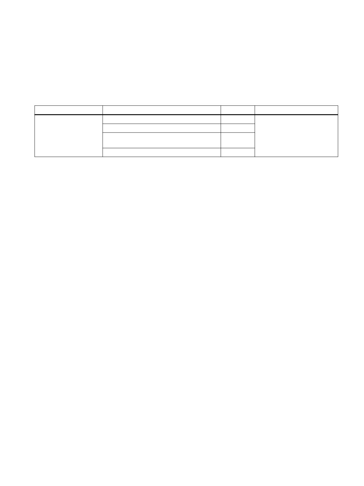
Spare parts
8
The following service set is available for SIMATIC connection boxes:
Designation
Remark
Qty.
Article number
Service set for Mobile Pan-
Dummy plugs for cable compartment
1
els
PG screw glands for connection box
2
6AV6574-1AA04-4AA0
Blanking cover for connecting a handheld ter-
1
minal
Terminal strips for connection box
3
Handheld Terminal HT 10
Equipment Manual, 09/2020, A5E47430965B AA
91
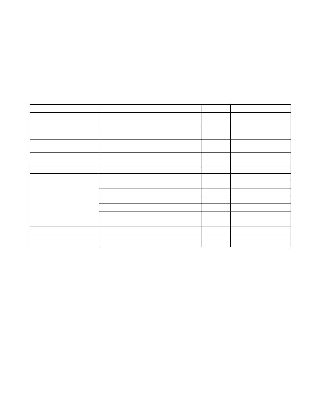
Accessories
9
9.1
Overview
The following accessories are available for the HT 10:
Designation
Remark
Quantity
Article number
Connection box advanced
With automatic emergency stop override for
1
6AV2125-2AE23-0AX0 *)
mounting in the system
Connection box standard
Without automatic emergency stop override for
1
6AV2125-2AE13-0AX0 *)
mounting in the system
PN Basic connection module
Without automatic emergency stop override for
1
6FC5303-0AA01-1AA0 *)
mounting in the control cabinet
HT10 wall holder
For safekeeping, also suitable for stationary op-
1
6FC5348-0AA20-0AA0
eration
Protective membrane
For 10.1" touch display, type 10
2
6AV6671-5BC00-0AX0
Length: 2 m
1
6XV1440-4BH20 *)
Length: 5 m
1
6XV1440-4BH50 *)
Length: 8 m
1
6XV1440-4BH80 *)
Straight connecting cable
Length: 10 m
1
6XV1440-4BN10 *)
Length: 15 m
1
6XV1440-4BN15 *)
Length: 20 m
1
6XV1440-4BN20 *)
Length: 25 m
1
6XV1440-4BN25 *)
Spiral connection cable
1.5 m long, can be extended to 3.5 m
1
6FC5348-0AA08-3AA0
Touch pen system
For capacitive or resistive touch screen pen incl.
1
6AV2181-8AV20-0AX0
holder, 22.5 mm
*) Safety related accessories
Handheld Terminal HT 10
Equipment Manual, 09/2020, A5E47430965B AA
93

Accessories
9.2 HT10 wall holder
9.2
HT10 wall holder
The HT 10 can be safely kept and operated in a stationary manner in the wall holder
Figure 9-1
HT 10 wall holder - view
Ensure that you position the wall holder in such a manner that
• When the HT 10 is hooked in, its display is not exposed to direct solar radiation.
• The HT 10 can be hooked-in in an ergonomic position. Therefore, choose a suitable mounting
height.
Handheld Terminal HT 10
94
Equipment Manual, 09/2020, A5E47430965B AA

Preface_______________
1
Safety Information______
2
System overview_______
SINUMERIK
3
Description__________
SINUMERIK 840D sl
4
NCU 7x0.2
Application Planning _____
5
Dimension drawings_____
Manual
6
Mounting___________
7
Connecting__________
8
Technical Data________
9
Connectable components
________________
10
Spare Parts/Accessories
________________
A
Appendix
Valid for
Control
SINUMERIK 840D sl / 840DE sl
Software
Version
CNC software
2.7
02/2011
6FC5397-0AP20-0BA0
Preface
SINUMERIK documentation
The SINUMERIK documentation is organized in the following categories:
● General documentation
● User documentation
● Manufacturer/service documentation
Additional information
You can find information on the following topics at
● Ordering documentation/overview of documentation
● Additional links to download documents
● Using documentation online (find and search in manuals/information)
Please send any questions about the technical documentation (e.g. suggestions for
improvement, corrections) to the following address:
mailto:docu.motioncontrol@siemens.com
My Documentation Manager (MDM)
Under the following link you will find information to individually compile OEM-specific
machine documentation based on the Siemens content:
Training
For information about the range of training courses, refer to:
SITRAIN - Siemens training for products, systems and solutions in automation technology
SinuTrain - training software for SINUMERIK
FAQs
You can find Frequently Asked Questions in the Service&Support pages under Product
Support.
NCU 7x0.2
Manual, 02/2011, 6FC5397-0AP20-0BA0
3
Preface
SINUMERIK
You can find information on SINUMERIK under the following link:
Target group
This documentation is intended for manufacturers of machine tools, particularly:
● Project engineers, electricians and installers
● Maintenance and service personnel
Benefits
The information in this manual facilitates installation and connection of the SINUMERIK
840D numerical control in the control cabinet.
Standard scope
This documentation only describes the functionality of the standard version. Extensions or
changes made by the machine tool manufacturer are documented by the machine tool
manufacturer.
Other functions not described in this documentation might be executable in the controller.
This does not, however, represent an obligation to supply such functions with a new
controller or when servicing.
Further, for the sake of simplicity, this documentation does not contain all detailed
information about all types of the product and cannot cover every conceivable case of
installation, operation or maintenance.
Technical Support
You will find telephone numbers for other countries for technical support in the Internet under
EC Declaration of Conformity
The EC Declaration of Conformity for the EMC Directive can be found on the Internet at:
Here, enter the number 15257461 as the search term or contact your local Siemens office.
NCU 7x0.2
4
Manual, 02/2011, 6FC5397-0AP20-0BA0
Table of contents
Preface
3
1
Safety Information
9
1.1
Danger notices
9
1.2
ESD notices
11
2
System overview
13
2.1
Application
13
2.2
System configuration
14
2.3
Variants
16
2.4
Ordering data
17
3
Description
19
3.1
Features
19
3.2
Illustration
20
3.3
Type plate
23
3.4
Operating and display elements
24
3.4.1
Overview of operating and display elements
24
3.4.2
LED displays
25
3.4.3
RESET button
26
3.4.4
7-segment display
26
3.4.5
Start-up and mode selector switch
27
4
Application Planning
29
4.1
Secondary electrical conditions
29
4.1.1
Grounding concept
29
4.1.2
RI suppression measures
30
4.2
Climatic and mechanical environmental conditions
31
4.2.1
Shipping and storage conditions
31
4.2.2
Operating conditions
33
4.3
Recycling and disposal
33
5
Dimension drawings
35
6
Mounting
37
6.1
Safety information
37
6.2
Installation types
38
6.3
Mounting the control unit on the rear wall of the control cabinet
40
6.3.1
Mounting control unit using spacers
40
NCU 7x0.2
Manual, 02/2011, 6FC5397-0AP20-0BA0
5
Table of contents
6.3.2
Mounting the Control Unit without spacers
40
6.3.3
Mounting the Control Unit for segregated heat removal
42
6.4
Lateral mounting of Control Unit on the SINAMICS drive line-up
43
7
Connecting
45
7.1
Overview
45
7.2
Safety information for wiring
47
7.3
Opening the front cover
48
7.4
Power supply
49
7.4.1
Application
49
7.4.2
Requirements for the power supply
50
7.4.3
Connecting the power supply
51
7.5
DRIVE CLiQ components
52
7.5.1
Application
52
7.5.2
Connectable DRIVE-CLiQ components
54
7.6
Use of Ethernet interfaces
55
7.7
PROFINET
58
7.7.1
Application
58
7.7.2
PROFINET cables
61
7.7.3
Preparing the twisted pair cables
62
7.7.4
Example PROFINET CBA configuration
64
7.8
PROFIBUS / MPI
65
7.8.1
Application
65
7.8.2
PROFIBUS cables and connectors
67
7.8.3
Connection components in PROFIBUS
68
7.8.4
Rules for the laying of PROFIBUS cables
68
7.8.5
Connecting PROFIBUS DP
69
7.8.6
Disconnecting stations from the PROFIBUS
70
7.8.7
Operating the X136 interface as MPI
70
7.9
Digital inputs/outputs
71
7.9.1
DIO application
71
7.9.2
Connecting digital inputs/outputs
75
7.9.3
Technical data
76
7.10
USB
78
7.11
Measuring sockets
79
8
Technical Data
81
9
Connectable components
83
9.1
NX10/15
83
9.1.1
Description
83
9.1.2
Dimension drawing
86
9.1.3
Mounting
87
9.1.4
Connection
90
9.1.5
Technical Data
95
NCU 7x0.2
6
Manual, 02/2011, 6FC5397-0AP20-0BA0
Table of contents
9.2
COM01.2 RS 232C (V.24) module
95
9.2.1
Description
95
9.2.2
Installation/Mounting
97
9.2.3
Connection
98
9.3
TM15 Terminal Module
99
9.4
DRIVE-CLiQ Hub Module DMC20
99
9.5
DME20 DRIVE-CLiQ Hub Module
100
10
Spare Parts/Accessories
101
10.1
Dual fan/ battery module
101
10.1.1
Application
101
10.1.2
Mounting
102
10.2
CompactFlash Card
104
10.2.1
Properties
104
10.2.2
Inserting the CompactFlash card
104
A
Appendix
107
A.1
Abbreviations
107
A.2
Overview
109
Index
111
NCU 7x0.2
Manual, 02/2011, 6FC5397-0AP20-0BA0
7

Safety Information
1
1.1
Danger notices
The following notices are intended firstly for your personal safety and secondly to prevent
damage occurring to the product described or any connected devices and machines. Non-
observance of the warnings can result in severe personal injury or property damage.
DANGER
Only appropriately qualified personnel may commission/start-up SINUMERIK equipment.
The personnel must take into account the information provided in the technical customer
documentation for the product, and be familiar with and observe the specified danger and
warning notices.
When electrical equipment and motors are operated, the electrical circuits automatically
conduct a dangerous voltage.
When the system is operating, dangerous axis movements may occur throughout the entire
work area.
A potential fire hazard exists due to the energy being transferred in the equipment and the
work materials used.
All work on the electrical system must be performed after the system has been switched off
and disconnected from the power supply.
DANGER
Proper transportation, expert storage, installation and mounting, as well as careful
operation and maintenance are essential for this SINUMERIK device to operate correctly
and reliably.
The details in the catalogs and proposals also apply to the design of special equipment
versions.
In addition to the danger and warning information provided in the technical customer
documentation, the applicable national, local, and system-specific regulations and
requirements must be taken into account.
Only protective extra-low voltages (PELVs) that comply with EN 61800-5-1 can be
connected to all connections and terminals between 0 and 48 V.
Should it be necessary to test or take measurements on live equipment, then the
specifications and procedural instructions defined in Accident Prevention Regulation BGV
A2 must be adhered to, in particular § 8 "Permissible deviations when working on live
components". Suitable electric tools should be used.
NCU 7x0.2
Manual, 02/2011, 6FC5397-0AP20-0BA0
9

Safety Information
1.1 Danger notices
WARNING
Power cables and signal lines should be installed in such a way that inductive and
capacitive interference does not in any way impair the automation and safety functions.
WARNING
Repairs to devices that have been supplied by our company may only be carried out by
Siemens customer service or by repair centers authorized by Siemens. When replacing
parts or components, only use those parts that are included in the spare parts list.
Before opening the device, always disconnect the power supply.
Emergency stop/off devices which comply with EN 60204 / IEC 60204 (VDE 0113-1) must
remain effective in all automation equipment operating modes. The act of releasing the
emergency stop/off device must not cause an uncontrolled or undefined hot restart.
Additional external measures must be taken, or devices must be created that enforce a
safe operational state even when there is a fault (e.g. using independent limit value
switches, mechanical locks, etc.) at any location in the automation equipment where faults
might cause major material damage or even physical injury, in other words, where faults
could be dangerous.
NCU 7x0.2
10
Manual, 02/2011, 6FC5397-0AP20-0BA0
Safety Information
1.2 ESD notices
1.2
ESD notices
CAUTION
The modules contain electrostatically sensitive devices. Discharge yourself of electrostatic
energy before touching the components. The easiest way to do this is to touch a
conductive, grounded object immediately beforehand (for example, bare metal parts of
control cabinet or the protective ground contact of a socket outlet).
NOTICE
Handling ESD-modules:
When handling electrostatically sensitive devices, make sure that operator, workplace
and packing material are properly grounded.
Generally, electronic modules must not be touched unless work has to be carried out on
them. When handling PCBs make absolutely sure that you do not touch component pins
or printed conductors.
Touch components only if:
- You are permanently grounded via an ESD armband
- You are wearing ESD shoes or ESD shoe-grounding-strips, if ESD flooring is
available
Modules may only be placed on electrically conductive surfaces (table with ESD top,
conductive ESD foam plastic, ESD packaging bags, ESD transport containers).
Keep modules away from visual display units, monitors or TV sets (minimum distance
from screen 10 cm).
Do not bring ESD-sensitive modules into contact with chargeable and highly-insulating
materials, such as plastic, insulating table tops or clothing made of synthetic materials.
Measurements on modules are allowed only if:
- The measuring instrument is properly earthed (e.g., protective conductor) or
- Before measuring with a floating measuring instrument, the probe is briefly
discharged (e.g., touch the bare metal parts of the control housing).
NCU 7x0.2
Manual, 02/2011, 6FC5397-0AP20-0BA0
11
System overview
2
2.1
Application
Features
SINUMERIK 840D sl offers modularity, openness, flexibility, and uniform structures for
operation, programming, and visualization. It provides a system platform with trend-setting
functions for almost all technologies.
Integrated into the SINAMICS S120 drive system and complemented by the SIMATIC S7-
300 automation system, the SINUMERIK 840D sl forms a complete digital system that is
best suited for the mid to upper performance range.
The SINUMERIK 840D sl is characterized by:
● A high degree of flexibility
● Excellent dynamic response and precision
● Optimum integration into networks
Integrated and certified SINUMERIK Safety Integrated safety functions are available with
SINUMERIK 840D sl. Consequently, highly effective protection for personnel and machines
is achieved in a simple, economical, and practical manner.
Operating and programming software such as ShopMill or ShopTurn, as well as Motion
Control Information System Products (MCIS-Products) can be used for the production
sector.
Fields of application
The SINUMERIK 840D sl can be used worldwide for turning, drilling, milling, grinding, laser
machining, nibbling, punching, in tool and mold making, for high-speed cutting applications,
for wood and glass processing, for handling operations, in transfer lines and rotary indexing
machines, for mass production and JobShop production.
The SINUMERIK 840DE sl is available as an export version for use in countries requiring an
export authorization.
NCU 7x0.2
Manual, 02/2011, 6FC5397-0AP20-0BA0
13

System overview
2.2 System configuration
2.2
System configuration
SINUMERIK 840D sl combines CNC, HMI, PLC, closed-loop control, and communication
tasks within a single NCU (Numerical Control Unit).
Components
For operation, programming, and visualization purposes, the corresponding operating
software is already integrated into the CNC software for the NCU and therefore runs on the
high-performance NCU multi-processor module. For increased operating performance, the
SINUMERIK PCU 50.3 industrial PC can be used.
Up to four distributed OPs can be operated on one NCU/PCU. The operator panel can be
installed as a Thin Client at a distance of up to 100 m.
6,180(5,.
6,180(5,. RSHUDWRU SDQHO IURQWV ZLWK 7&8
6,180(5,.
+7
3&8
,QGXVWULDO (WKHUQHW
352),1(7
352),%86
'5,9( &/L4
(7
SUR
6,1$0,&6 6
1;
ವವವ
3RZHU VXSSO\
ವವವ
6,180(5,.
' VO
ZLWK
6,1$0,&6 6
0DLQ VSLQGOH PRWRU
6HUYR PRWRUV
Figure 2-1
Typical topology of the SINUMERIK 840D sl complete system
The following components can be attached to the Control Unit:
● SINUMERIK operator panel front with TCU/PCU 50.3 and Machine Control
Panel/Machine Push Button Panel
● SIMATIC thin client (as of firmware V1.4)
● SIMATIC CE panel
● SINUMERIK handheld units
● Distributed PLC I/O via PROFIBUS DP or PROFINET I/O (only applies to NCU 720.2 PN
and NCU 730.2 PN)
NCU 7x0.2
14
Manual, 02/2011, 6FC5397-0AP20-0BA0
System overview
2.2 System configuration
● SINUMERIK PP 72/48 peripheral module
● SINUMERIK ADI 4 analog drive interface for four axes
● SINAMICS 120 drive system
● Feed and main spindle motors
- 1FT/1FK/1FN/1FW6/1FE1/2SP1 synchronous motors
- 1PH/1PM asynchronous motors
With the NCU 720.2 PN and NCU 730.2 PN, the SINUMERIK 840D sl is offering integrated
PROFINET functionality for the first time.
Supported:
● PROFINET CBA functionality
The CBA functionality integrated in the NCU allows users to modularize machinery and
systems: Rapid real-time communication (up to 10 ms) between the controllers means
that systems lend themselves better to standardization and can be reused or expanded
more easily. Response to customer demands is faster and more flexible and startup is
simplified and speeded up by pretesting at component level.
● PROFINET IO
As part of PROFINET, PROFINET IO is a communication concept that is used to
implement modular, distributed applications. PROFINET IO is based on Industrial
Ethernet and allows distributed field and I/O equipment to be connected to the central
processing unit.
128 PROFINET IO devices can be operated on the NCU as an IO controller.
NCU 7x0.2
Manual, 02/2011, 6FC5397-0AP20-0BA0
15

System overview
2.3 Variants
2.3
Variants
The scalability of the hardware and software - both from a CNC perspective and in terms of
operation - means the SINUMERIK 840D sl can be used in many sectors. The possibilities
range from simple positioning tasks up to complex multi-axis systems.
Application areas and performance
● As many as 6 axes can be implemented on an NCU 710. The NCU 710 can be expanded
by up to 2 NX modules. One possible benefit would be improved automatic speed control
performance.
● On the NCU 720/730, the number of axes and/or the performance of the drive controller
can be increased to 31 axes. This is achieved by using the NX10/15 module. The NCU
720/730 can be expanded by up to 5 NX10/15 modules in terms of drive controller
performance and the number of axes.
● Use of an NCU 730 is recommended for maximum dynamics and accuracy in mold
making or in the high speed cutting sector.
● Since it has the highest PLC capacity, the NCU 730.2 PN represents the most advanced
configuration within the SINUMERIK 840D sl range.
The following table shows the essential features of the various Control Units:
Table 2- 1
Versions
Property
NCU 710 .2
NCU 720.2
NCU 720.2 PN
NCU 730.2/.2 PN
Cooling fins
No
No
Yes
DRIVE-CLiQ ports
4
6
6
Axes
Up to 6
Up to 31
Up to 31
NX10/15
Up to 2
Up to 3/Up to 5
Up to 3/Up to 5
TCU
Up to 2
Up to 4
Up to 4
NCU 7x0.2
16
Manual, 02/2011, 6FC5397-0AP20-0BA0

System overview
2.4 Ordering data
2.4
Ordering data
Table 2- 2
Order data for system components
System components
Order numbers
NCU 710.2 with PLC 317-2DP
6FC5371-0AA10-0AA2
NCU 720.2 with PLC 317-2DP
6FC5372-0AA00-0AA2
NCU 720.2 PN with PLC 319-3PN/DP
6FC5372-0AA01-0AA2
NCU 730.2 with PLC 317-2DP
6FC5373-0AA00-0AA2
NCU 730.2 PN with PLC 319-3PN/DP
6FC5373-0AA01-0AA2
Numeric Control Extension NX15 (High Extension)
6SL3040-0NB00-0AA0
Numeric Control Extension NX10 (High Extension)
6SL3040-0NC00-0AA0
COM01.2 RS232C(V.24) module for NCU 7x0.2
6FC5312-0FA01-0AA0
TS Adapter IE ISDN with integrated ISDN terminal adapter
6ES7972-0ED00-0XA0
TS Adapter IE Modem with integrated analog modem
6ES7972-0EM00-0XA0
Table 2- 3
Ordering data for spare parts
Spare parts
Order numbers
Dual fan/battery module
6FC5348-0AA02-0AA0
Battery
6FC5247-0AA18-0AA0
Seal for segregated heat removal
6FC5348-0AA07-0AA0
Spacers for NCU 720.2 PN / 730.2 / 730.2 PN
6FC5348-0AA06-0AA0
Spacers for NCU 710.2/720.2
6SL3064-1BB00-0AA0
Front cover
6FC5348-0AA00-0AA0
Blanking plate
6SL3064-3BB00-0AA0
Cover for optional guide frame
6SL3064-3CB00-0AA0
DRIVE-CLiQ dust protection blanking plug (50 pieces)
6SL3066-4CA00-0AA0
PROFIBUS/MPI plug connector with terminating resistor
6ES7972-0BB41-0XA0
Terminal kit for NCU + NX, consisting of: 1 x 24 V connector,
6SL3064-8MA00-0AA0
2 x I/O connector, 5 x DRIVE-CLiQ dust protection blanking plugs
CompactFlash Card 1 GB empty
6FC5313-5AG00-0AA1
CompactFlash Card 8 GB empty
6FC5313-6AG00-0AA0
CNC user memory expansion 2 MB
6FC5800-0AD00-0YB0
PLC user memory expansion 128 KB
6FC5800-0AD10-0YB0
Ordering options
The products can also be ordered online:
NCU 7x0.2
Manual, 02/2011, 6FC5397-0AP20-0BA0
17
Description
3
3.1
Features
A Control Unit has the following elements:
● Battery-backed real-time clock
● Slot for a CompactFlash Card
● DRIVE-CLiQ interfaces for connecting to the drive
● Interfaces for operation behind a hinged front cover:
- Ethernet ports
- PROFINET interface for NCU 720.2 PN and NCU 730.2 PN
- PROFIBUS interfaces
- Digital inputs/outputs (6 of which can be parameterized as inputs for probe and
BERO)
● Commissioning interfaces behind a blanking cover
NCU 7x0.2
Manual, 02/2011, 6FC5397-0AP20-0BA0
19
Description
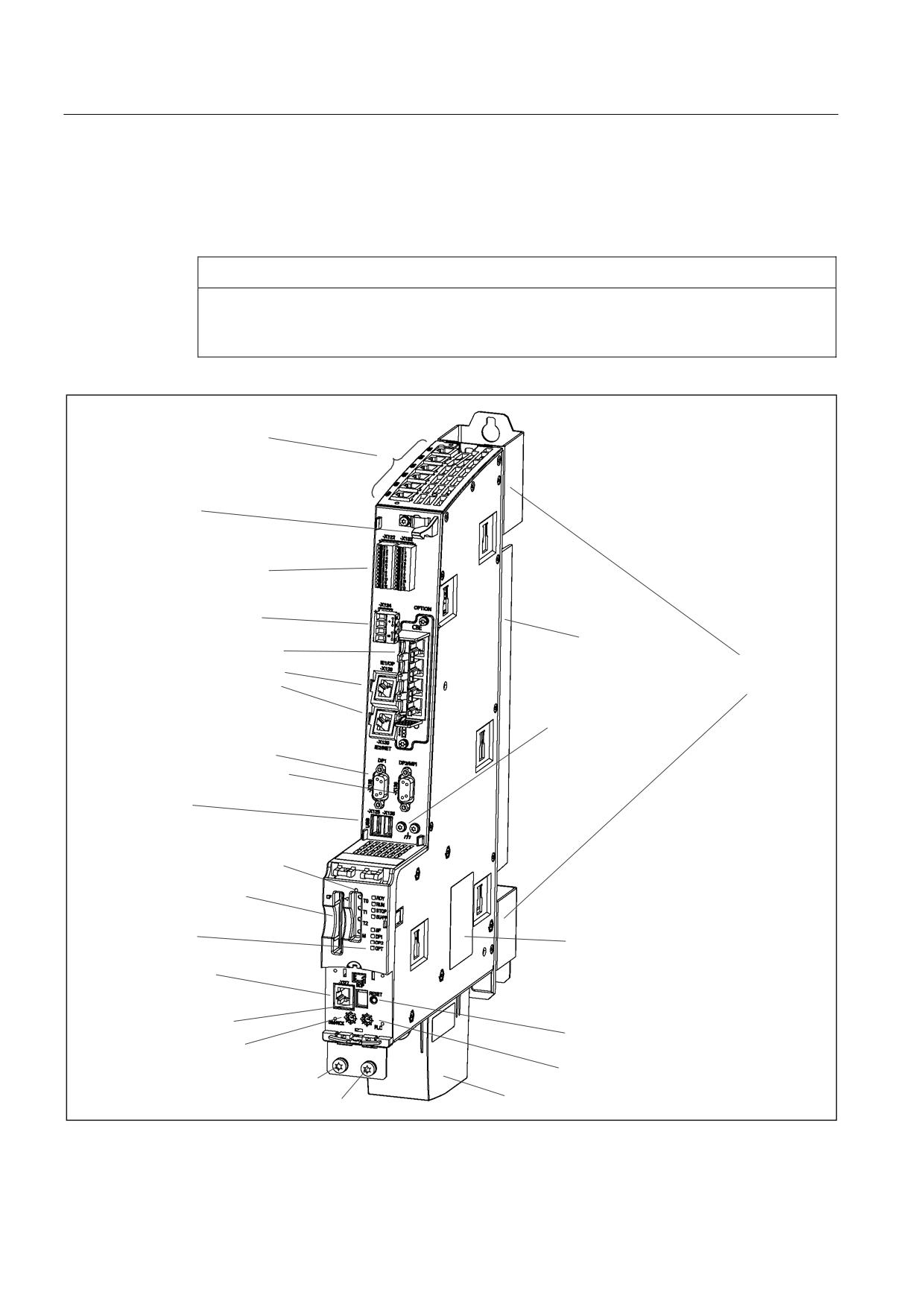
3.2 Illustration
3.2
Illustration
Control Units without PROFINET
The following figure shows an NCU 730.2 with its interfaces and control and display
elements (fault displays and status indicators). Please ensure that the structure of the NCUs
is virtually identical. There are only a few discrepancies, as follows:
● The NCU 710.2 has 4 rather than 6 DRIVE-CliQ interfaces.
● Deviations with NCU 710.2 and NCU 720.2:
- No cooling fins
- Layout of control and display elements behind the blanking plate (see Chapter
Position of operator control and display elements (Page 24))
NCU 7x0.2
20
Manual, 02/2011, 6FC5397-0AP20-0BA0
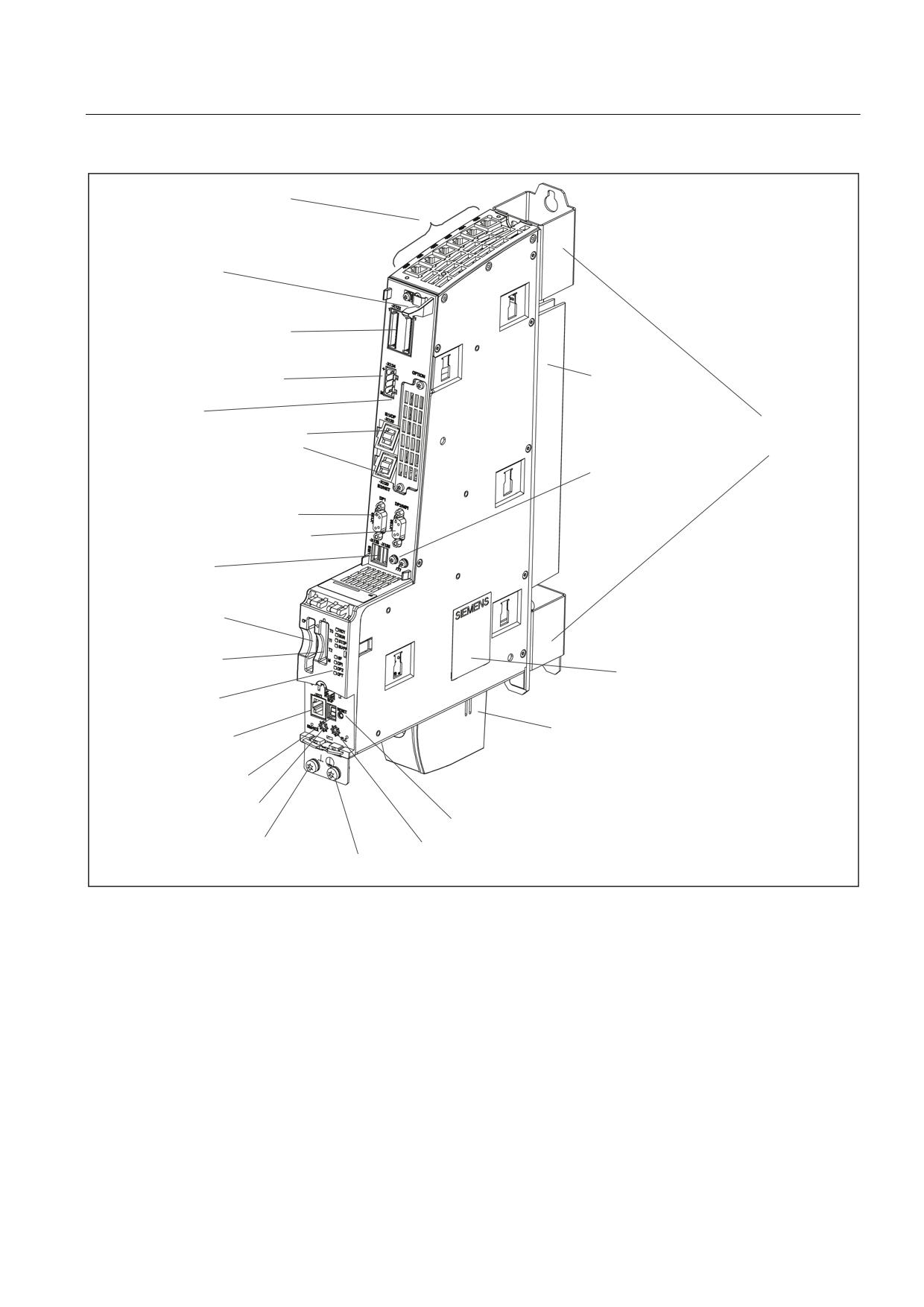
Description
3.2 Illustration
;
;
'5,9( &/L4 LQWHUIDFHV
6KLHOG VXSSRUW
'LJLWDO
;
LQSXWV RXWSXWV
;
(OHFWURQLF SRZHU
VXSSO\
;
&RROLQJ ILQV
2SWLRQ VORW
(WKHUQHW
;
6SDFHU
FRQQHFWLRQV
;
352),%86
(TXLSRWHQWLDO
ERQGLQJ
ZLUH FRQQHFWLRQV
352),%86 '3
;
352),%86 '3
03,
;
[ 86%
;
;
&RPSDFW)ODVK
VORW ;
0HDVXULQJ VRFNHWV
;
;
7\SH SODWH
/(' GLVSOD\
;
(WKHUQHW ;
'XDO IDQ EDWWHU\ PRGXOH
VHUYLFH VRFNHW
;
ORZHU VLGH
56
VHJPHQW GLVSOD\
QR IXQFWLRQ
1&. FRPPLVVLRQLQJ
5(6(7 EXWWRQ
VZLWFK
(TXLSRWHQWLDO ERQGLQJ FRQQHFWLRQ *
1P
3/& PRGH VZLWFK
3URWHFWLYH FRQGXFWRU FRQQHFWLRQ 0
1P
Figure 3-1
Representation of the NCU 730.2
NCU 7x0.2
Manual, 02/2011, 6FC5397-0AP20-0BA0
21
Description
3.2 Illustration
Control Units with PROFINET
The following figure shows an NCU 720.2 PN/730.2 PN with its interfaces and control and
display elements (fault LEDs and status indicators).
CAUTION
The PROFINET interfaces of the integrated PLC 319-3 PN/DP are permanently assigned to
the option slot on the "PN NCUs". Forceful removal of the interface module will cause
defects, which can only be repaired at the factory.
'5,9( &/L4
;
,QWHUIDFHV
;
6KLHOG VXSSRUW
'LJLWDO LQSXWV
;
RXWSXWV
;
(OHFWURQLF SRZHU
;
VXSSO\
&RROLQJ ILQV
352),1(7
3RUW
(WKHUQHW FRQQHF
;
6SDFHU
WLRQV
;
352),%86
(TXLSRWHQWLDO ERQGLQJ
ZLUH FRQQHFWLRQV
352),%86 '3
;
352),%86 '3
03,
;
b[b86%
;
;
0HDVXULQJ
;
;
VRFNHWV
&RPSDFW)ODVK
;
VORW
/(' GLVSOD\
7\SH SODWH
;
(WKHUQHW
;
ORZHU VLGH
56
VHUYLFH VRFNHW
QR IXQFWLRQ
VHJPHQW GLVSOD\
5(6(7 EXWWRQ
1&. VWDUW XS VZLWFK
3/& PRGH VZLWFK
(TXLSRWHQWLDO ERQGLQJ FRQQHFWLRQ *
1P
;
'XDO IDQ EDWWHU\ PRGXOH
3URWHFWLYH FRQGXFWRU FRQQHFWLRQ 0
1P
Figure 3-2
Representation of the NCU 720.2 PN/730.2 PN
NCU 7x0.2
22
Manual, 02/2011, 6FC5397-0AP20-0BA0
Description
3.3 Type plate
3.3
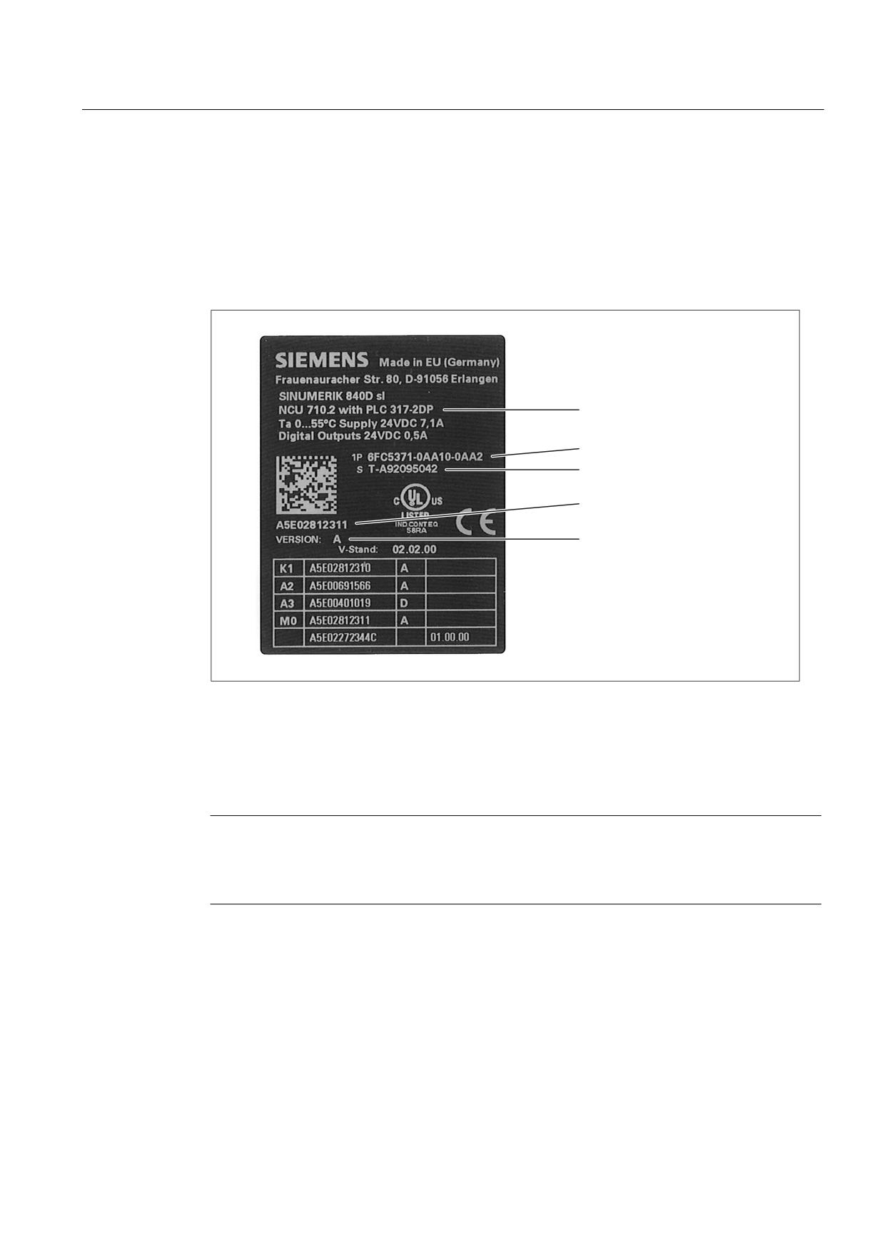
Type plate
Side-mounted type plate
The following figure shows you all the information included on the type plate located on the
side of the unit.
&RPSRQHQW QDPH
2UGHU QXPEHU
6HULDO QXPEHU
,' QXPEHU
+: YHUVLRQ
Figure 3-3
Type plate
You might need to access the information provided on the side-mounted type plate after the
equipment has been mounted. Since the type plate is located on the right-hand side of the
housing, which is the side typically used to connect to the SINAMICS S120 module, we
recommend that you make a note of the serial number of the control unit prior to assembly.
Note
The information contained in each field of the type plate on the current control unit may differ
from the information presented in this manual (for example, a later product version,
approvals and marks that have not yet been issued, etc., may be shown).
NCU 7x0.2
Manual, 02/2011, 6FC5397-0AP20-0BA0
23
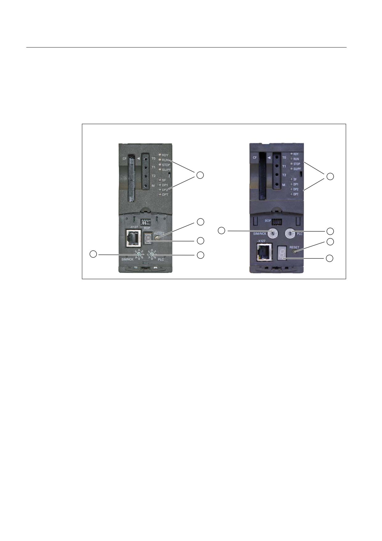
Description
3.4 Operating and display elements
3.4
Operating and display elements
3.4.1
Overview of operating and display elements
1&8
31
31
1&8
①
NCK start-up switch
②
PLC mode selector switch
③
7-segment display
④
Reset button
⑤
LED displays
Figure 3-4
Position of operator control and display elements
NCU 7x0.2
24
Manual, 02/2011, 6FC5397-0AP20-0BA0
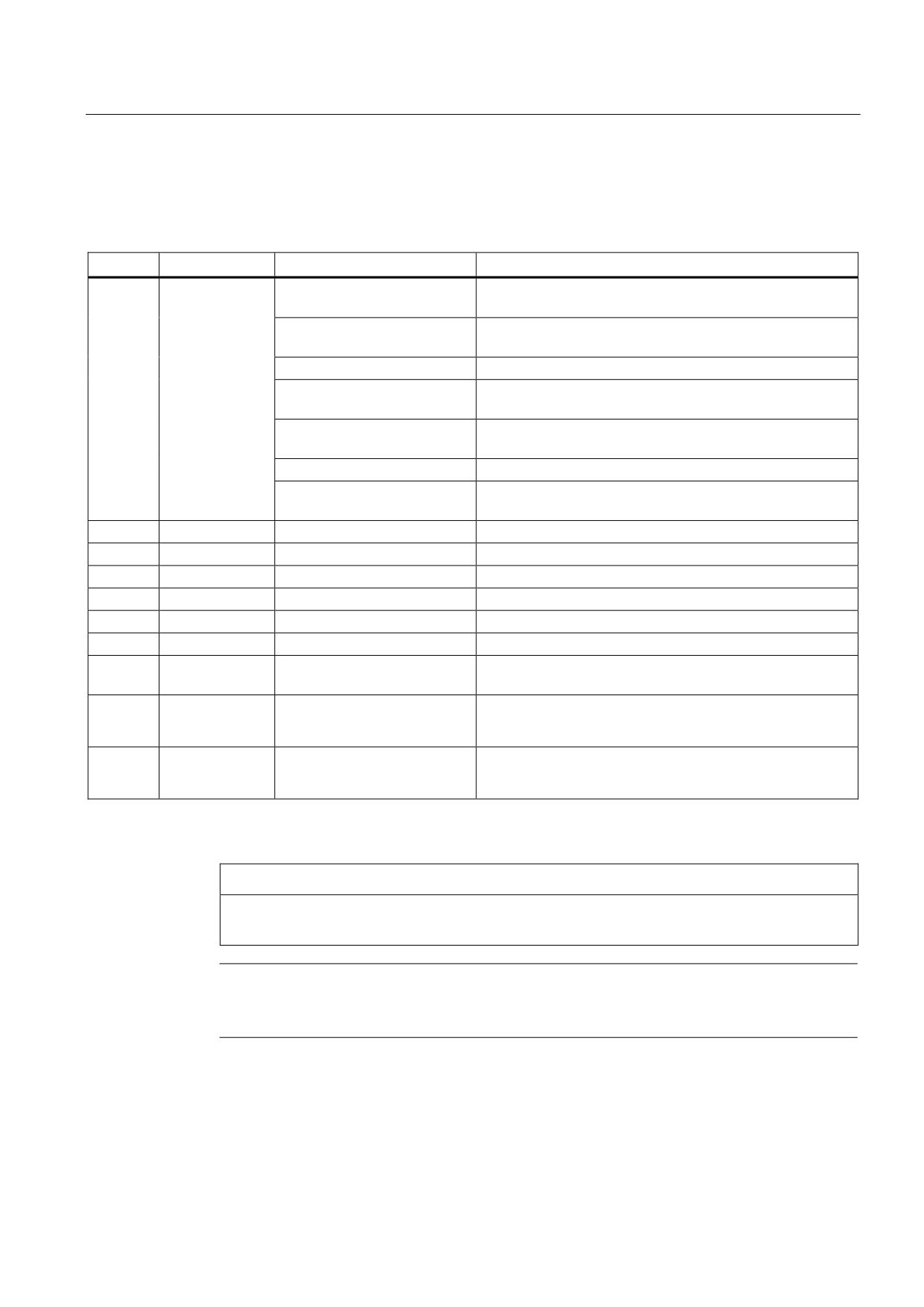
Description
3.4 Operating and display elements
3.4.2
LED displays
Table 3- 1
Meaning of LED states
Name
Function
Status
Meaning
RDY
Ready
Red
There is at least one fault (e.g. RESET, watchdog
monitoring etc. ) or the Control Unit is booting up.
Flashing red/orange
Error accessing CompactFlash Card
(0.5 Hz)
Orange
Accessing CompactFlash Card
Flashing orange (0.5 Hz)
Updating the firmware of the connected DRIVE-CLiQ
components
Flashing orange (2 Hz)
Firmware update is complete for components. Wait for
POWER ON for the components in question.
Green
NC powered up and everything in cyclic mode
Flashing green/orange or
LED-supported recognition of connected DRIVE-CLiQ
red/orange (1 Hz)
component is activated: (p0124[0] = 1).
RUN
PLC RUN
Green
PLC ready to operate
STOP
PLC STOP
Orange
PLC stopped
SU/PF
PLC FORCE
Red
FORCE activated
SF
PLC SF
Red
PLC group error
DP1
BUS1 F
Red
PROFIBUS-DP1 group error
DP2
BUS2 F
Red
PROFIBUS-DP2 group error
OPT *)
BUS3 F
Off
The PROFINET system runs correctly; data exchange to all
configured IO devices runs.
Red
Bus fault (no physical connection)
Incorrect transmission rate
Flashing red
Failure of a connected I/O device.
(2 Hz)
Incorrect or no configuration.
*) The "OPT" LED is only significant for "PN NCUs".
NOTICE
If all the LEDs are flashing, the PLC must be reset via the mode selector (move switch to
position "3" to reboot).
Note
While the Control Unit is powering up, all LEDs briefly light up orange. You can carry out a
detailed diagnosis using a PG/PC and the operating software.
NCU 7x0.2
Manual, 02/2011, 6FC5397-0AP20-0BA0
25
Description
3.4 Operating and display elements
Additional references
● You can find a detailed description of LED states during power-up in the "NCU Operating
System (IM7)" section of the Basesoftware and Operating Software Commissioning
Manual.
● For information on drive faults and alarms, see also:
SINAMICS S120/S150 List Manual (LH1)
3.4.3
RESET button
Arrangement
The RESET button is located behind the blanking cover.
Performing a reset operation
The reset operation resets the NCU and forces a new power-up. It is similar to a "Power On
Reset" except that the 24 V power supply does not have to be switched off.
3.4.4
7-segment display
Displaying messages
The 7-segment display is located behind the blanking plate of the Control Unit. It serves as a
status display during startup and performs the following tasks:
● Output of test and diagnostic messages.
● Output of status messages during booting
Critical messages
● During normal operation, "6" appears here and the dot flashes.
● An "8" indicates that the fan is defective or that the Control Unit is operating without a fan.
Additional references
Basic Software and Operating Software Commissioning Manual (IM7), Chapter "System
startup displays".
NCU 7x0.2
26
Manual, 02/2011, 6FC5397-0AP20-0BA0
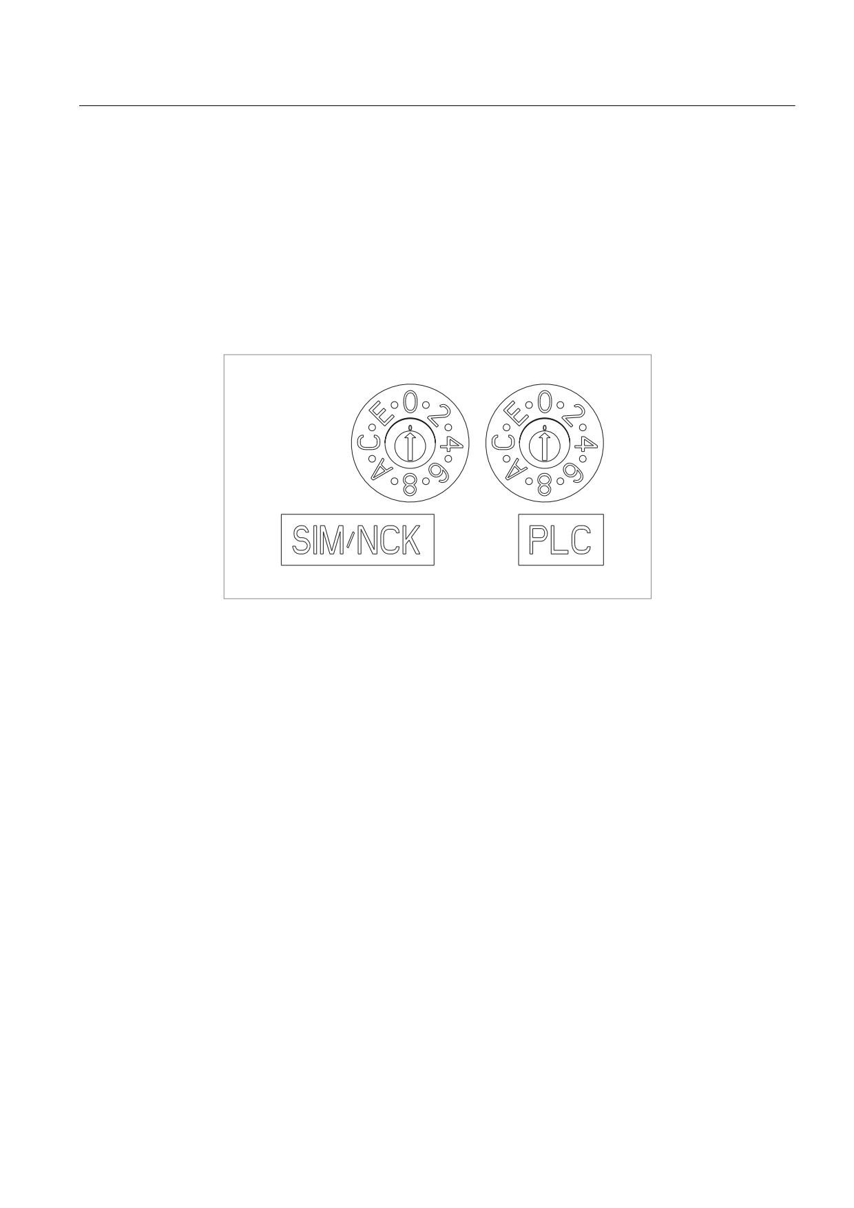
Description
3.4 Operating and display elements
3.4.5
Start-up and mode selector switch
Layout
The Control Unit has two coding switches in the lower section of the front panel.
● The left switch (labeled SIM/NCK) is the NCK startup switch.
Setting during normal operation: "0"
● The right switch (labeled PLC) is the PLC mode selector switch.
Setting during normal operation: "0"
Figure 3-5
Startup and mode selector switch
Additional references
CNC Commissioning Manual Part 1 (NCK, PLC, drive)
NCU 7x0.2
Manual, 02/2011, 6FC5397-0AP20-0BA0
27
Description
3.4 Operating and display elements
NCU 7x0.2
28
Manual, 02/2011, 6FC5397-0AP20-0BA0
Application Planning
4
4.1
Secondary electrical conditions
4.1.1
Grounding concept
Components
The SINUMERIK 840D sl system consists of a number of individual components which have
been designed so that the system complies with the appropriate EMC and safety standards.
The individual system components are:
● Numerical Control Unit (NCU):
● Machine Control Panel MCP, Machine Push Button Panel MPP
● Keyboard
● Operator panels (operator panel front + TCU/PCU)
● Distributor box and handheld unit
● S7-300 I/O with IM 153 interface module
Grounding measures
The individual modules are attached to a metal cabinet panel. Insulating paints on the
mounting points must be removed.
It is permissible to have a cluster of operator components for ground connection/PA.
Example: The control panel on the swivel arm.
It is sufficient in this instance to connect the ground connections of, for example, the PCU,
TCU, and operator panel front using a cable and to route a shared grounding conductor to
the central ground connection in the control cabinet.
Additional references
Configuration Manual, EMC Guidelines
NCU 7x0.2
Manual, 02/2011, 6FC5397-0AP20-0BA0
29
Application Planning
4.1 Secondary electrical conditions
4.1.2
RI suppression measures
In addition to the protective grounding of system components, special precautions must be
taken to ensure safe, fault-free operation of the system. These measures include shielded
signal lines, special equipotential bonding connections, and isolation and shielding
measures.
Shielded signal lines
● For safe and smooth operation of the system, the specified cables must be used. Please
refer to the chapter titled Connection.
● For digital signal transmission, the shield must have a conductive connection at both
sides of the housing.
Cable definitions
● Signal cables (example)
- Data cables (Ethernet, PROFIBUS, PROFINET, sensor cables, etc.)
- Digital inputs/outputs
- EMERGENCY OFF lines
● Power cables (example)
- Supply voltage 1 x 230 V AC or 3 x 400 V AC
- Motor cables
Rules for routing cables
In order to maximize noise immunity for the complete system (controller, power section,
machine) the following EMC measures must be observed:
● A minimum distance of 200 mm is to be observed between the signal lines and power
cables.
● If necessary, signal and load cables may cross one another (if possible, at an angle of
90°), but must never be laid close or parallel to one another.
● Only use cables approved by Siemens for the signal lines from and to the Control Unit.
NCU 7x0.2
30
Manual, 02/2011, 6FC5397-0AP20-0BA0

Application Planning
4.2 Climatic and mechanical environmental conditions
● Signal cables may not be routed close to strong external magnetic fields (e.g., motors
and transformers).
● If signal lines cannot be routed a sufficient distance away from other cables, they must be
installed in grounded cable ducts (metal).
Note
For more specifications regarding interference suppression measures and connection of
shielded cables, see
References
Configuration Manual, EMC Guidelines
4.2
Climatic and mechanical environmental conditions
4.2.1
Shipping and storage conditions
The components of the SINUMERIK 840D sl system exceed the requirements according to
EN 61131-2 with regard to shipping and storage conditions.
The following conditions apply to modules that are shipped and stored in the original
packaging.
Table 4- 1
Ambient conditions during storage and transport
Type of condition
Permissible range/class
Transport
Long-term storage
Climate class
2K4 acc. to EN 60721-3-2
1K4 acc. to EN 60721-3-1
Temperature
From -40° C to +70° C
From -25° C to +55° C
Relative humidity
From 5% to 95%
From 10% to 100%
Height
Max. 4,000 m above sea level
Air pressure
620 hPa to 1060 hPa (corresponding to 4000 m to 0 m above sea level)
Biological environmental
Class 2B1 acc. to EN 60721-3-2
Class 1B1 acc. to EN 60721-3-1
conditions
Chemically active
Class 2C2 acc. to EN 60721-3-2
Class 1C2 acc. to EN 60721-3-1
environmental conditions
NCU 7x0.2
Manual, 02/2011, 6FC5397-0AP20-0BA0
31

Application Planning
4.2 Climatic and mechanical environmental conditions
Shipping backup batteries
Backup batteries may only be shipped in the original packaging. No special authorization is
required to ship backup batteries. The lithium content is approximately 300 mg.
Note
The backup battery is classified as a hazardous substance, Class 9, in accordance with the
relevant air-freight transportation regulations.
Storage of backup batteries
Always store backup batteries in a cool and dry place. The batteries have a maximum shelf
life of 10 years.
Rules for handling backup batteries
WARNING
Incorrect handling of backup batteries can lead to a risk of ignition, explosion and
combustion. The stipulations of DIN EN 60086-4, in particular regarding avoidance of
mechanical or electrical tampering of any kind, must be complied with.
● Do not open a battery. Replace a faulty battery only with the same type.
● Obtain replacement batteries from Siemens alone (see Ordering data (Page 17)).
● Always try to return low batteries to the manufacturer or deliver these to a registered
recycling company.
NCU 7x0.2
32
Manual, 02/2011, 6FC5397-0AP20-0BA0

Application Planning
4.3 Recycling and disposal
4.2.2
Operating conditions
The components of the SINUMERIK 840D sl system are intended for a weatherproof, fixed
location. Operating conditions surpass EN 61131-2 requirements.
Table 4- 2
Ambient conditions for operation
Ambient conditions
Application areas
Remarks
Climatic environmental conditions
Climate class
3K3
According to EN 60721-3
Permissible ambient
From 0° C to +55° C,
As of an altitude of 2000 m, the max. ambient
temperature when
up to 2000 m above
temperature decreases by 7° C every 1000 m
installed vertically
sea level
increase in altitude.
Relative humidity
From 5% to 90 %
Condensation, icing,
Not allowed
drip, spray and splash
water
Installation altitude
Max. 4,000 m above sea level
Air pressure
620 hPa to 1060 hPa
Corresponding height 4000 m - 0 m above sea level
Biological, chemical and mechanical influences, pollutants
Biological environmental conditions
Class 3B1 according to EN 60 721-3-3;
Mold, mold growth, slime, rodents, termite and other
animal vermin are not permissible.
Chemically active environmental conditions
Class 3C1 according to EN 60721-3-3
Mechanically active environmental conditions
Class 3S1 according to EN 60721-3-3, conductive
dust not permitted
EMC conducted / radiation
Class C3 according to EN 61800-3
Note
The user must consider radio interference for the complete system. Particular attention
should be paid to cabling. Please contact your sales representative for assistance and
support.
If compliance with limit value class C2 is required, please contact your local Siemens sales
partner.
4.3
Recycling and disposal
Products should be disposed of corresponding to the relevant national regulations.
The products described in this manual can be mostly recycled due to the fact that they
contain very few damaging substances. To recycle and dispose of your old device in an
environmentally friendly way, please contact an appropriate disposal company.
NCU 7x0.2
Manual, 02/2011, 6FC5397-0AP20-0BA0
33
Application Planning
4.3 Recycling and disposal
NCU 7x0.2
34
Manual, 02/2011, 6FC5397-0AP20-0BA0
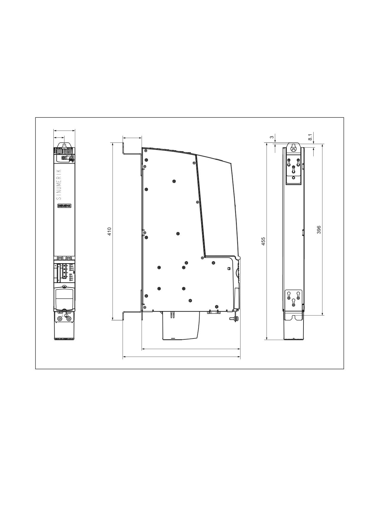
Dimension drawings
5
Figure 5-1
Dimension drawing for NCU 710.2 / 720.2 (dimensions in mm)
NCU 7x0.2
Manual, 02/2011, 6FC5397-0AP20-0BA0
35
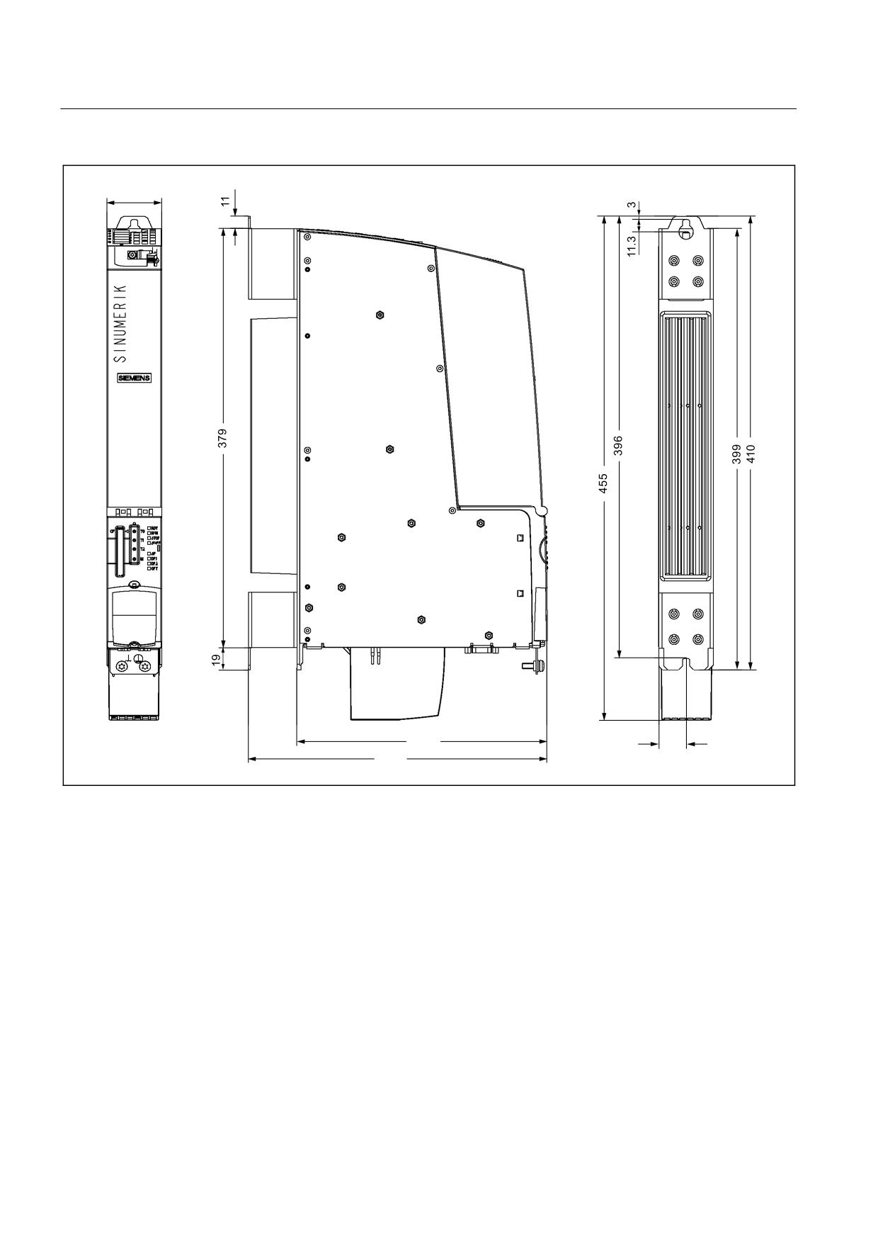
Dimension drawings
Figure 5-2
Dimension drawing for NCU 720.2 PN / 730.2 / 730.2 PN (dimensions in mm)
NCU 7x0.2
36
Manual, 02/2011, 6FC5397-0AP20-0BA0

Mounting
6
6.1
Safety information
NOTICE
The Control Unit is exclusively intended for installation in ESD-protected areas. The CE-
associated ESD interference immunity limit values can only be achieved via installation in
the control cabinet. Only make physical contact using appropriate ESD protective
measures.
Open equipment
These modules are open equipment. This means they may only be installed in housings,
cabinets or in electrical service rooms that can be entered or accessed exclusively by means
of a key or tool. Housings, cabinets, or electrical equipment rooms may only be accessed by
trained or authorized personnel. An external fire protection casing is required.
DANGER
The equipment must be deenergized when you mount the Control Unit.
Control cabinet installation
Please refer to the SINAMICS documentation for more details.
NOTICE
The 80 mm ventilation spaces above and below the Control Unit must be observed.
If you have any further questions or are looking for particular solutions, you can contact the
Systems Engineering Plant Chemnitz directly.
NCU 7x0.2
Manual, 02/2011, 6FC5397-0AP20-0BA0
37