SINUMERIK 840D sl Hardware. Manual (2011-2020) - page 23

Fundamental safety instructions
1.1 General safety instructions
WARNING
Electric shock due to equipment damage
Improper handling may cause damage to equipment. For damaged devices, hazardous
voltages can be present at the enclosure or at exposed components; if touched, this can result
in death or severe injury.
● Ensure compliance with the limit values specified in the technical data during transport,
storage and operation.
● Do not use any damaged devices.
WARNING
Electric shock due to unconnected cable shields
Hazardous touch voltages can occur through capacitive cross-coupling due to unconnected
cable shields.
● As a minimum, connect cable shields and the cores of cables that are not used at one end
at the grounded housing potential.
WARNING
Electric shock if there is no ground connection
For missing or incorrectly implemented protective conductor connection for devices with
protection class I, high voltages can be present at open, exposed parts, which when touched,
can result in death or severe injury.
● Ground the device in compliance with the applicable regulations.
WARNING
Spread of fire from built-in devices
In the event of fire outbreak, the enclosures of built-in devices cannot prevent the escape of
fire and smoke. This can result in serious personal injury or property damage.
● Install built-in units in a suitable metal cabinet in such a way that personnel are protected
against fire and smoke, or take other appropriate measures to protect personnel.
● Ensure that smoke can only escape via controlled and monitored paths.
Operator panel front: OP 012
6
Manual, 05/2019, A5E36371591B AB

Fundamental safety instructions
1.1 General safety instructions
WARNING
Unexpected movement of machines caused by radio devices or mobile phones
When radio devices or mobile phones with a transmission power > 1 W are used in the
immediate vicinity of components, they may cause the equipment to malfunction.
Malfunctions may impair the functional safety of machines and can therefore put people in
danger or lead to property damage.
● If you come closer than around 2 m to such components, switch off any radios or mobile
phones.
● Use the "SIEMENS Industry Online Support app" only on equipment that has already been
switched off.
WARNING
Fire due to inadequate ventilation clearances
Inadequate ventilation clearances can cause overheating of components with subsequent fire
and smoke. This can cause severe injury or even death. This can also result in increased
downtime and reduced service lives for devices/systems.
● Ensure compliance with the specified minimum clearance as ventilation clearance for the
respective component.
NOTICE
Overheating due to inadmissible mounting position
The device may overheat and therefore be damaged if mounted in an inadmissible position.
● Only operate the device in admissible mounting positions.
WARNING
Unexpected movement of machines caused by inactive safety functions
Inactive or non-adapted safety functions can trigger unexpected machine movements that
may result in serious injury or death.
● Observe the information in the appropriate product documentation before commissioning.
● Carry out a safety inspection for functions relevant to safety on the entire system, including
all safety-related components.
● Ensure that the safety functions used in your drives and automation tasks are adjusted and
activated through appropriate parameterizing.
● Perform a function test.
● Only put your plant into live operation once you have guaranteed that the functions relevant
to safety are running correctly.
Operator panel front: OP 012
Manual, 05/2019, A5E36371591B AB
7

Fundamental safety instructions
1.3 Warranty and liability for application examples
Note
Important safety notices for Safety Integrated functions
If you want to use Safety Integrated functions, you must observe the safety notices in the Safety
Integrated manuals.
1.2
Equipment damage due to electric fields or electrostatic discharge
Electrostatic sensitive devices (ESD) are individual components, integrated circuits, modules
or devices that may be damaged by either electric fields or electrostatic discharge.
NOTICE
Equipment damage due to electric fields or electrostatic discharge
Electric fields or electrostatic discharge can cause malfunctions through damaged individual
components, integrated circuits, modules or devices.
● Only pack, store, transport and send electronic components, modules or devices in their
original packaging or in other suitable materials, e.g conductive foam rubber of aluminum
foil.
● Only touch components, modules and devices when you are grounded by one of the
following methods:
- Wearing an ESD wrist strap
- Wearing ESD shoes or ESD grounding straps in ESD areas with conductive flooring
● Only place electronic components, modules or devices on conductive surfaces (table with
ESD surface, conductive ESD foam, ESD packaging, ESD transport container).
1.3
Warranty and liability for application examples
Application examples are not binding and do not claim to be complete regarding configuration,
equipment or any eventuality which may arise. Application examples do not represent specific
customer solutions, but are only intended to provide support for typical tasks.
As the user you yourself are responsible for ensuring that the products described are operated
correctly. Application examples do not relieve you of your responsibility for safe handling when
using, installing, operating and maintaining the equipment.
Operator panel front: OP 012
8
Manual, 05/2019, A5E36371591B AB
Fundamental safety instructions
1.4 Industrial security
1.4
Industrial security
Note
Industrial security
Siemens provides products and solutions with industrial security functions that support the
secure operation of plants, systems, machines and networks.
In order to protect plants, systems, machines and networks against cyber threats, it is
necessary to implement - and continuously maintain - a holistic, state-of-the-art industrial
security concept. Products and solutions from Siemens constitute one element of such a
concept.
Customers are responsible for preventing unauthorized access to their plants, systems,
machines and networks. Such systems, machines and components should only be connected
to an enterprise network or the Internet if and to the extent such a connection is necessary and
only when appropriate security measures (e.g. using firewalls and/or network segmentation)
are in place.
For additional information on industrial security measures that can be implemented, please
visit:
Siemens’ products and solutions undergo continuous development to make them more secure.
Siemens strongly recommends that product updates are applied as soon as they become
available, and that only the latest product versions are used. Use of product versions that are
no longer supported, and failure to apply the latest updates may increase customer’s exposure
to cyber threats.
To stay informed about product updates, subscribe to the Siemens Industrial Security RSS
Feed at:
Further information is provided on the Internet:
Industrial Security Configuration Manual (https://support.industry.siemens.com/cs/ww/en/
view/108862708)
Operator panel front: OP 012
Manual, 05/2019, A5E36371591B AB
9
Fundamental safety instructions
1.4 Industrial security
WARNING
Unsafe operating states resulting from software manipulation
Software manipulations, e.g. viruses, Trojans, or worms, can cause unsafe operating states
in your system that may lead to death, serious injury, and property damage.
● Keep the software up to date.
● Incorporate the automation and drive components into a holistic, state-of-the-art industrial
security concept for the installation or machine.
● Make sure that you include all installed products into the holistic industrial security concept.
● Protect files stored on exchangeable storage media from malicious software by with
suitable protection measures, e.g. virus scanners.
● On completion of commissioning, check all security-related settings.
● Protect the drive against unauthorized changes by activating the "Know-how protection"
converter function.
Operator panel front: OP 012
10
Manual, 05/2019, A5E36371591B AB
Fundamental safety instructions
1.5 Residual risks of power drive systems
1.5
Residual risks of power drive systems
When assessing the machine- or system-related risk in accordance with the respective local
regulations (e.g., EC Machinery Directive), the machine manufacturer or system installer must
take into account the following residual risks emanating from the control and drive components
of a drive system:
1.
Unintentional movements of driven machine or system components during commissioning,
operation, maintenance, and repairs caused by, for example,
- Hardware and/or software errors in the sensors, control system, actuators, and cables
and connections
- Response times of the control system and of the drive
- Operation and/or environmental conditions outside the specification
- Condensation/conductive contamination
- Parameterization, programming, cabling, and installation errors
- Use of wireless devices/mobile phones in the immediate vicinity of electronic
components
- External influences/damage
- X-ray, ionizing radiation and cosmic radiation
2.
Unusually high temperatures, including open flames, as well as emissions of light, noise,
particles, gases, etc., can occur inside and outside the components under fault conditions
caused by, for example:
- Component failure
- Software errors
- Operation and/or environmental conditions outside the specification
- External influences/damage
3.
Hazardous shock voltages caused by, for example:
- Component failure
- Influence during electrostatic charging
- Induction of voltages in moving motors
- Operation and/or environmental conditions outside the specification
- Condensation/conductive contamination
- External influences/damage
4.
Electrical, magnetic and electromagnetic fields generated in operation that can pose a risk
to people with a pacemaker, implants or metal replacement joints, etc., if they are too close
5.
Release of environmental pollutants or emissions as a result of improper operation of the
system and/or failure to dispose of components safely and correctly
6.
Influence of network-connected communication systems, e.g. ripple-control transmitters or
data communication via the network
For more information about the residual risks of the drive system components, see the relevant
sections in the technical user documentation.
Operator panel front: OP 012
Manual, 05/2019, A5E36371591B AB
11
Description
2
2.1
Overview
The SINUMERIK OP 012 operator panel front and 12.1" TFT color display with a resolution of
800 x 600 pixels (SVGA) features a 59-key membrane keyboard as well as 2 x (8 + 2) horizontal
and 2 x 8 vertical softkeys. The 2 x 8 vertical softkeys can be used as direct keys.
It is fixed from the rear using special clamps that are included in the delivery scope.
Validity
The description below applies to the OP 012 operator panel front.
Article number: 6FC5203-0AF02-0AA2
Features
●
19" mounting format, 7 HU (height units)
● Panel cutout (W x H): 450 x 290 mm
● Limited mounting depth
●
12.1" TFT flat screen (color) with SVGA resolution 800 x 600 pixels
● Membrane keyboard with alphabetic, numeric, cursor, and control keypad
● Softkeys / direct keys:
-
2 x 8 horizontal rows of keys with softkey function
–
2 x 8 vertical rows of keys with softkey and direct key functions
– Direct keys connectable via direct key / handwheel connection module or MCP interface
PN (optional), machine control panel, TCU or directly to the I/Os
● Shift key for switchover to the second key level (not for switching over the letters, since they
are uppercase only)
● Integrated touchpad mouse
● Front USB interface
● Degree of protection IP65
● Attachment: 12 tension jacks on the rear side
● Can be combined with PCU, TCU
Operator panel front: OP 012
Manual, 05/2019, A5E36371591B AB
13
Description
2.2 Operator control and display elements
2.2
Operator control and display elements
2.2.1
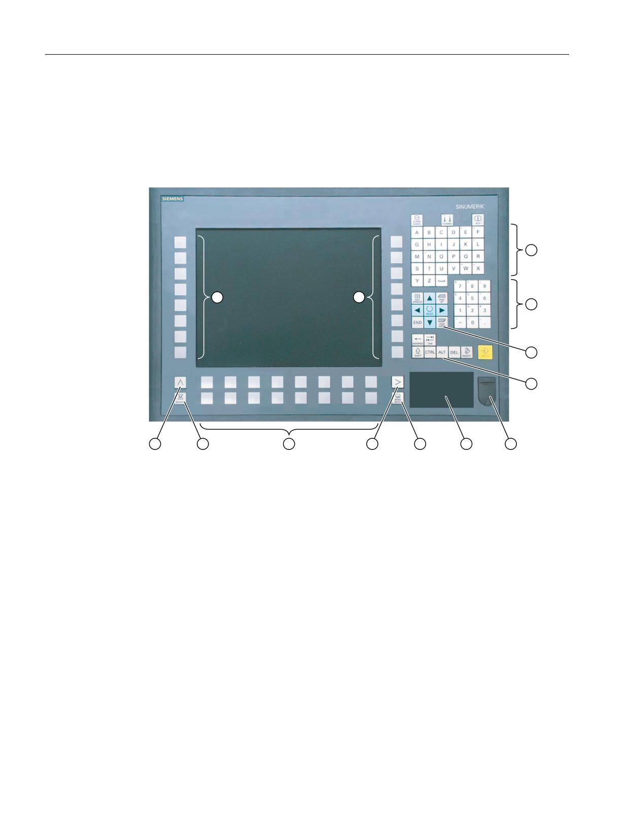
View
① Alphabetic key group
② Numeric key group
③ Cursor key group
④ Control key group
⑤ Front USB interface
⑥ Touchpad mouse
⑦ Menu select key
⑧ Menu forward key
⑨ Horizontal softkeys
⑩ Machine area button
⑪ Menu back key
⑫ Vertical softkeys (direct keys)
Figure 2-1
Front view of operator panel front OP 012
Operator panel front: OP 012
14
Manual, 05/2019, A5E36371591B AB
Description
2.2 Operator control and display elements
2.2.2
Keyboard
Keyboard
Several keys and keypads are installed on the operator panel front:
● The alphabetic block contains the letters A - Z and the space character.
● The numeric block contains the digits 0 - 9, and the characters "-", "/", "=", "+" and ".".
● The cursor key group is used to navigate on the screen.
● The control key group includes special functions.
● The mouse comprises a touchpad, for finger operation, as well as for cursor navigation and
also for the left and right mouse buttons.
● The softkeys call up functions that are available on the screen via a menu bar.
● The "Menu back" key switches back to the higher-level horizontal menu.
● The "Menu forward" key advances in the extended horizontal softkey bar.
● The "Menu select" key calls the main menu to select the operating area.
● The "Machine area" key selects the "Machine" operating area.
Switching between upper and lower case
To toggle between upper and lower case letters, press the key combination Ctrl + Shift
Upper case is always activated as standard.
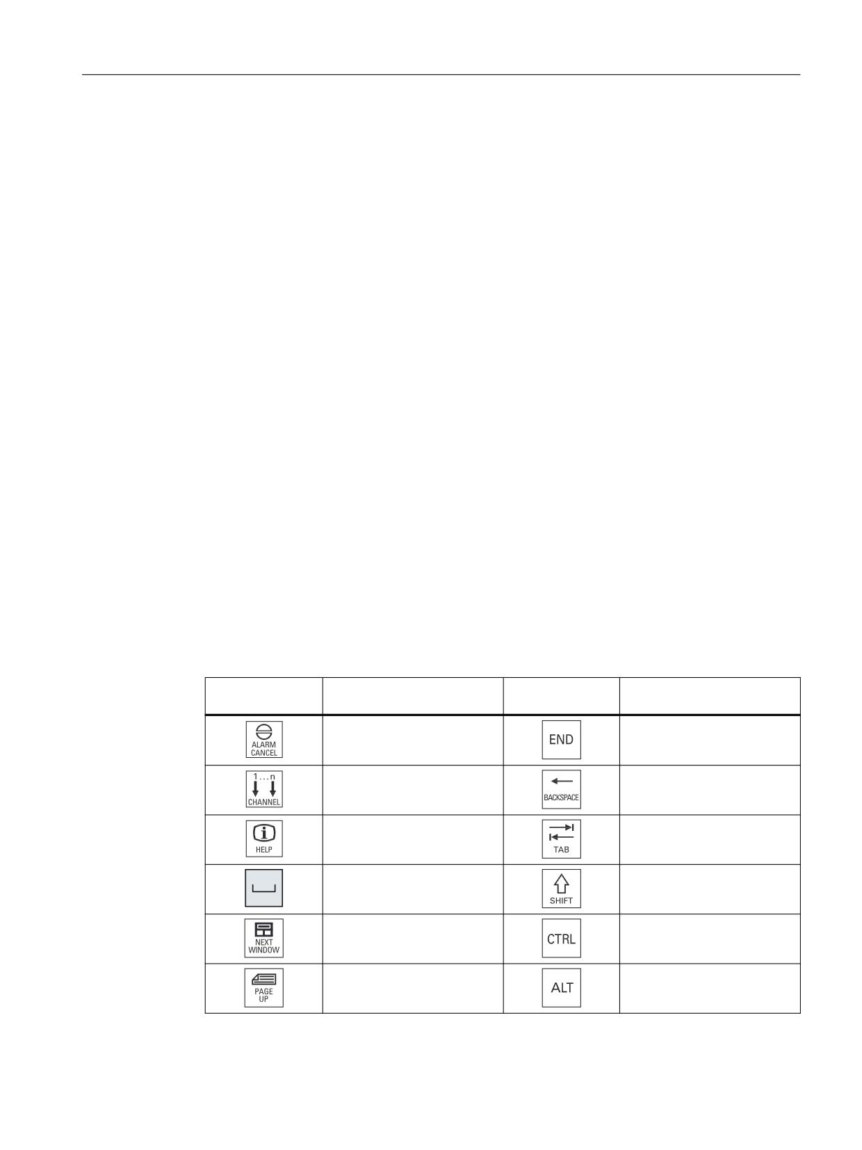
Overview of the key symbols
The key symbols used on the operator panel front are shown in the overview along with the
corresponding function keys on the PC keyboard.
Key
Function corresponds to the
Key
Function corresponds to the
PC key function
PC key function
Esc
End
F11
Backspace
F12
Tab
Space
(only intended for internal key-
board changeover)
Home
Ctrl key
Page up
Alt key
Operator panel front: OP 012
Manual, 05/2019, A5E36371591B AB
15
Description
2.2 Operator control and display elements
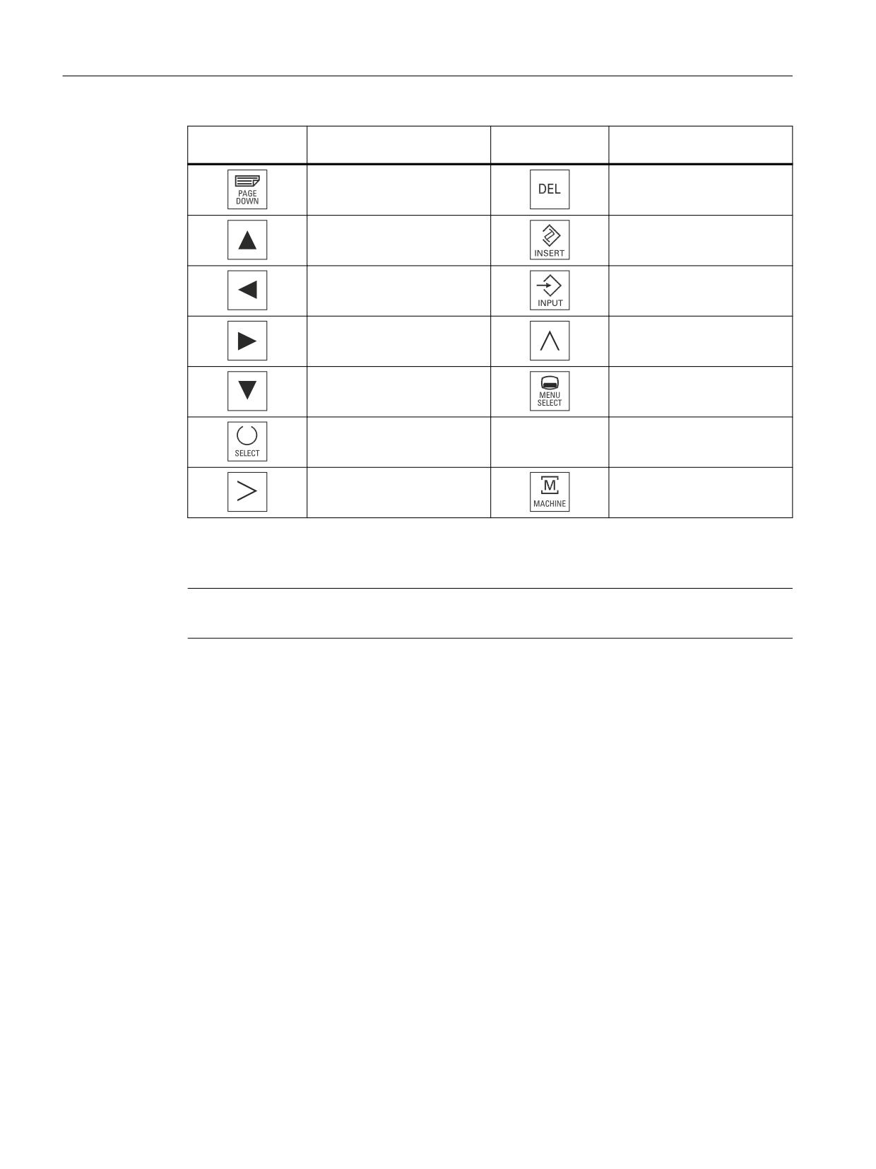
Key
Function corresponds to the
Key
Function corresponds to the
PC key function
PC key function
Page down
Delete
Cursor up
Insert
Cursor left
Enter
Cursor right
F9
Cursor down
F10
5 (in numeric key group)
A, ..., Z
<Shift> A, ..., Z
<Shift> F9
<Shift> F10
Display
Note
Pixel error according to DIN EN ISO 9241-307, Error class II.
2.2.3
Screen saver
If an image with high contrast is displayed without change for longer than one hour, then the
screen dark switching must be activated for energy efficiency reasons.
The time can be adapted individually. Further information can be found at:
Commissioning of Basic Software and Operating Software, SINUMERIK Operate (IM9)
Operator panel front: OP 012
16
Manual, 05/2019, A5E36371591B AB

Description
2.2 Operator control and display elements
2.2.4
Touchpad mouse
Operation
All of the mouse functions are based on 2-finger operation. The principle of operation of the OP
012 touchpad mouse is explained in the following table with reference to a classic 2-key mouse.
Action
Touch event
Corresponds to
Move the mouse pointer
Place your finger on the touchpad, keep it in
Move the mouse.
position and then move it.
Select
Touch the touchpad once with your finger.
Click with the left mouse button
Execute
Touch the touchpad twice with your finger.
Double-click with left mouse button.
Drag, mark, move window
Touch the touchpad twice in succession,
Click with the left mouse button and drag the
keep finger in position and then move.
mouse.
Open the context menu
Touch the touchpad with two fingers, keep
Click with the right mouse button.
briefly in place then lift one finger.
Note
The touchpad cannot be used in environments with spray water or water jets. Operating the
touchpad in environments with dripping water is only possible with some restrictions.
Deactivate touchpad mouse
If necessary, you can disable the touchpad mouse. Depending on whether the OP012 is
connected to a TCU or a PCU, proceed as follows:
● TCU:
- Open the TCU menu "Modify Settings".
- Select the "No" option under the parameter "Enable touch capability".
Note
A keyboard or mouse connected via USB is required to reactivate this option.
Further information on this can be found in the Section "Diagnostics and Service" of the
"TCU 30.3" equipment manual.
● PCU: Disable the Windows control panel in the device manager.
Further information on this can be found in the Section "Activating/deactivating mice and
pointers" of the IHsl basic software and operating software (IM10) commissioning manual.
Operator panel front: OP 012
Manual, 05/2019, A5E36371591B AB
17
Description
2.3 Interfaces
2.3
Interfaces
Front
USB 1.1 Full Speed (12 Mbps), high power (500 mA), Type A connector for connecting an
external keyboard, mouse and USB flash drive (see View (Page 14)).
Note
Note that the electromagnetic compatibility of commercially available peripheral devices
operated via the USB interface is usually rated for office use only.
For industrial use, components with a higher degree of certification are recommended.
Rear
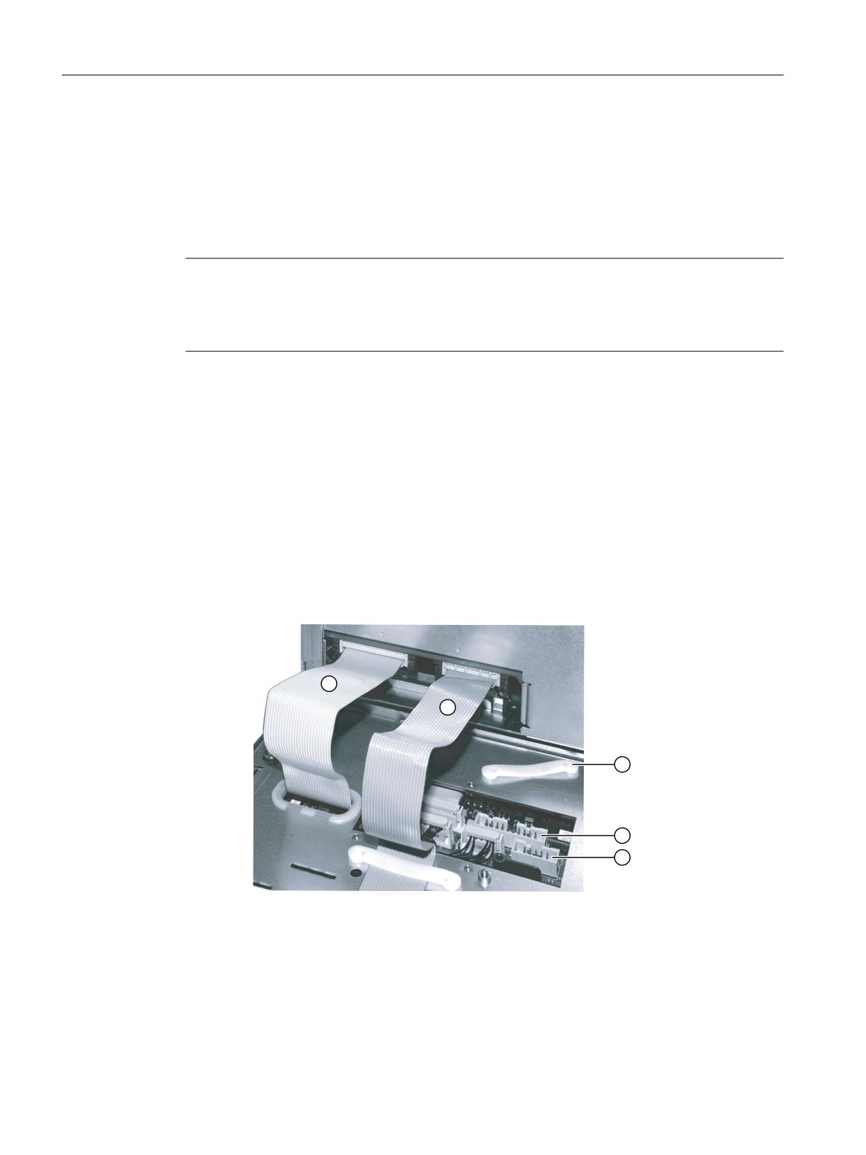
● Two flat ribbon cables for connecting the PCU:
- I/O USB cable K1 (ribbon cable): all signals that are used for the display interface and the
connection of operator panel fronts
(e.g. supply voltages).
- Display cable K2
● Direct key interface X11 (under the cover plate); signals from the 16 "vertical softkey" direct
keys
● Interface X12 - reserved (under the cover plate)
3&8
23
① I/O USB cable K1
② Display cable K2
③ Retainer for the connecting cable for the direct key module
④ Direct key interface X11
⑤ Interface X12 (reserved)
Figure 2-2
Connections on rear of housing: Connections to the PCU
Operator panel front: OP 012
18
Manual, 05/2019, A5E36371591B AB

Installation
3
3.1
Preparation for mounting
WARNING
Electric shock in the event of an individual error when grounding is insufficient
If the panel is installed with inadequate grounding in an environment with hazardous voltages,
this may cause an electric shock in the event of an individual error. This can result in death,
serious injury and material damage.
Adequately ground the conductive parts of the panel in accordance with the nationally
applicable regulations. When dimensioning the protective conductor connection, note the fuse
ratings of the electrical circuits with hazardous voltages, which would have an effect in
possible individual error scenarios.
WARNING
Parasitic voltage
If the device is installed with inadequate insulation in an environment with higher/more
hazardous voltages, parasitic voltages may occur. This can result in death, serious injury and
material damage.
Insulate the cables appropriately for the highest voltage coming into consideration.
The safety of a system with an integrated operator panel front is the responsibility of the system
installer.
The installation is performed in accordance with the installer's instructions.
Observe all the relevant information from this manual regarding installation.
Dimensions
Table 3-1
Dimensions of the mounting opening
Width (mm)
Height (mm)
450
290
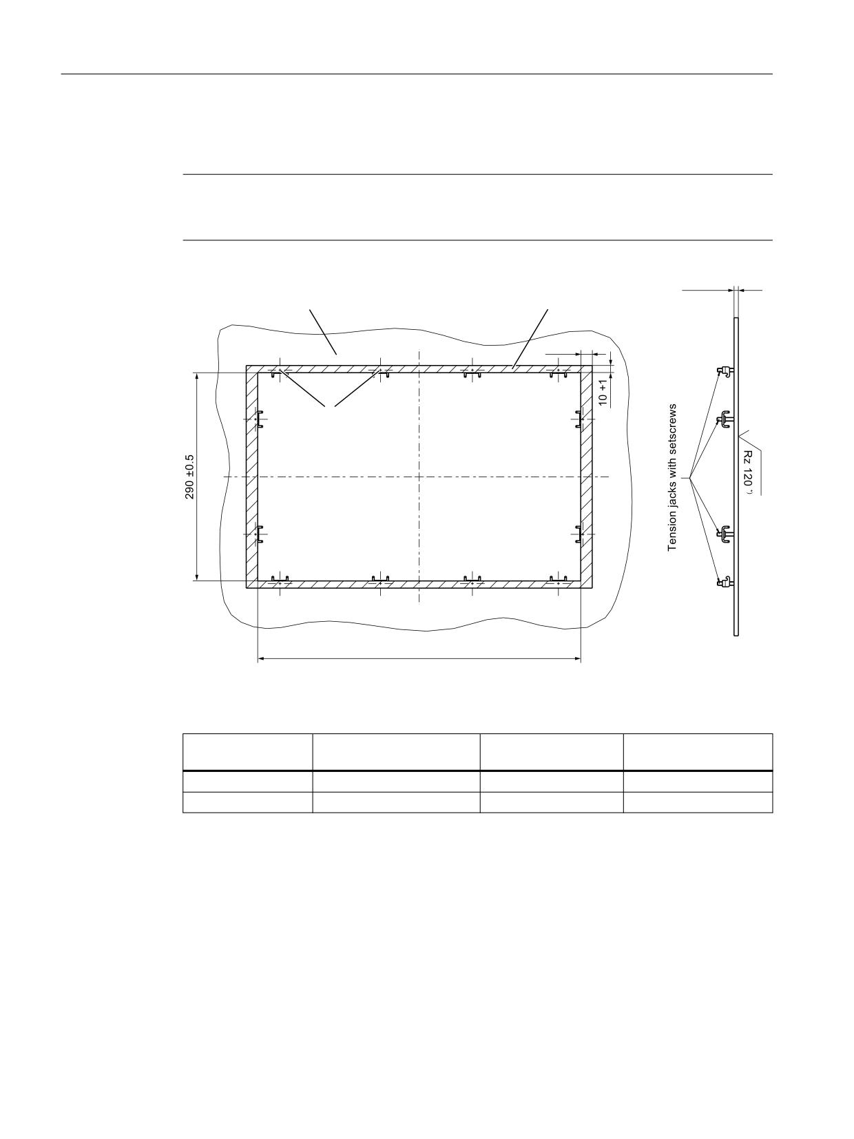
Thanks to the tension jacks on the OP 012, drill-holes or screw holes are not needed.
Operator panel front: OP 012
Manual, 05/2019, A5E36371591B AB
19
Installation
3.1 Preparation for mounting
This retaining method also enables the IP65 degree of protection (but only in conjunction with
a circumferential seal and when the protective USB cap is fitted).
Note
The OP 012 is supplied with 12 "small" tension jacks. If you have the "large" tension jacks
(6FC5248-0AF06-0AA0) in stock, then you can also use these.
0RXQWLQJ SDQHO
6HDOLQJ DUHD
3UHVVXUH SRLQWV
IRU WHQVLRQ MDFNV
s
,Q WKH VHDOLQJ DUHD
Figure 3-1
Dimension sheet for installing the OP 012 operator panel front
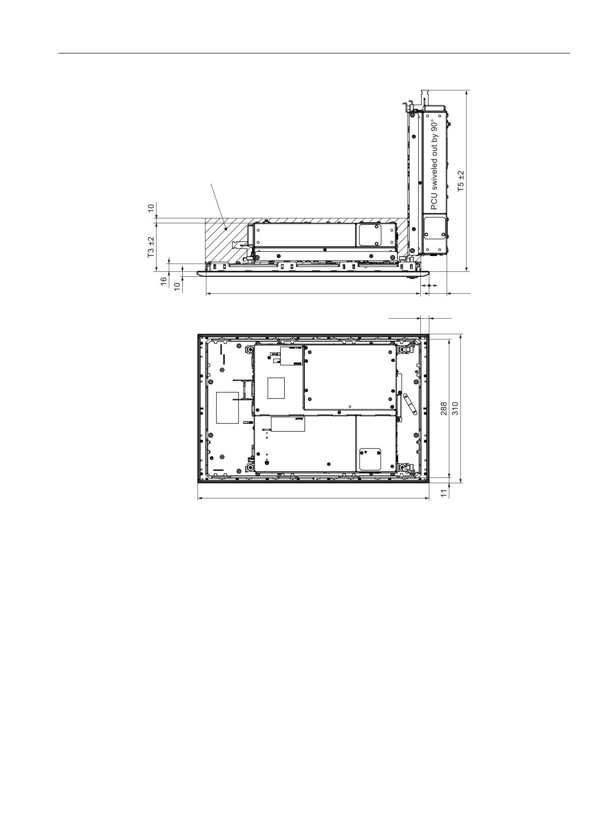
Table 3-2
Dimensions to be observed when installing
Mounting depth T3 + clear-
Opening depth T5
Protrusion P
ance (mm)
(mm)
(mm)
PCU 50.5
101 + 10
377
39
TCU 30.3
50 + 10
350
-12
Operator panel front: OP 012
20
Manual, 05/2019, A5E36371591B AB
Installation
3.2 Assembling an OP 012 and a PCU
&OHDUDQFH IRU FDEOHV DQG YHQWLODWLRQ
3&8 LQ WKH HQG SRVLWLRQ
s
s
s
Figure 3-2
Dimension sheet for attaching the PCU to the OP 012 operator panel front
3.2
Assembling an OP 012 and a PCU
When combining an OP 012 and PCU and possibly a direct key module, it is advisable to
assemble them prior to installation in an assembly panel.
Operator panel front: OP 012
Manual, 05/2019, A5E36371591B AB
21
Installation
3.2 Assembling an OP 012 and a PCU
Requirement
The PCU must now be bolted to the mounting brackets prior to assembly (if this has not already
been done). See Section in the “PCU 50.5” manual under “Assembly" → "Assembly of PCU and
operator panel front (standard mounting)"
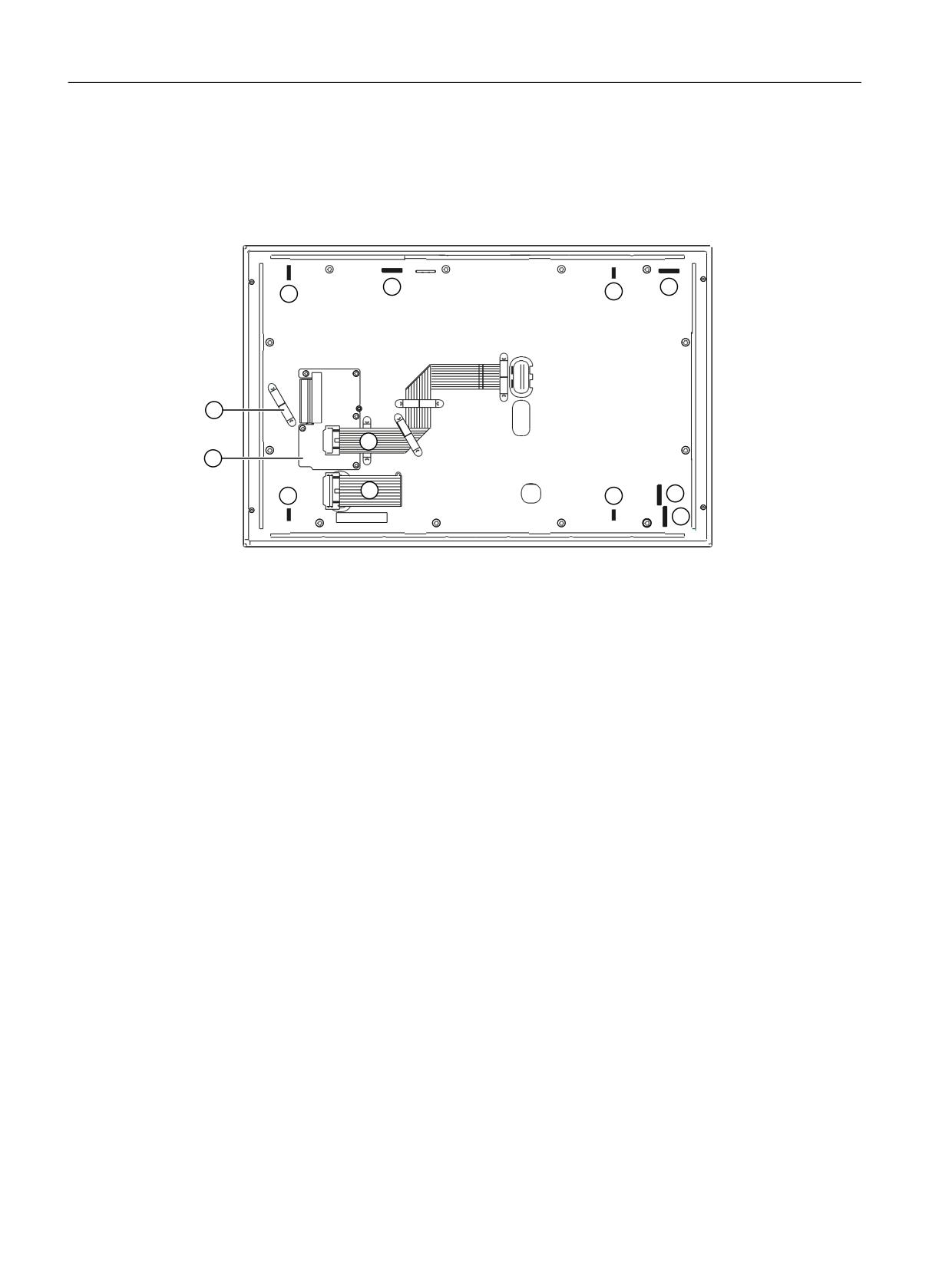
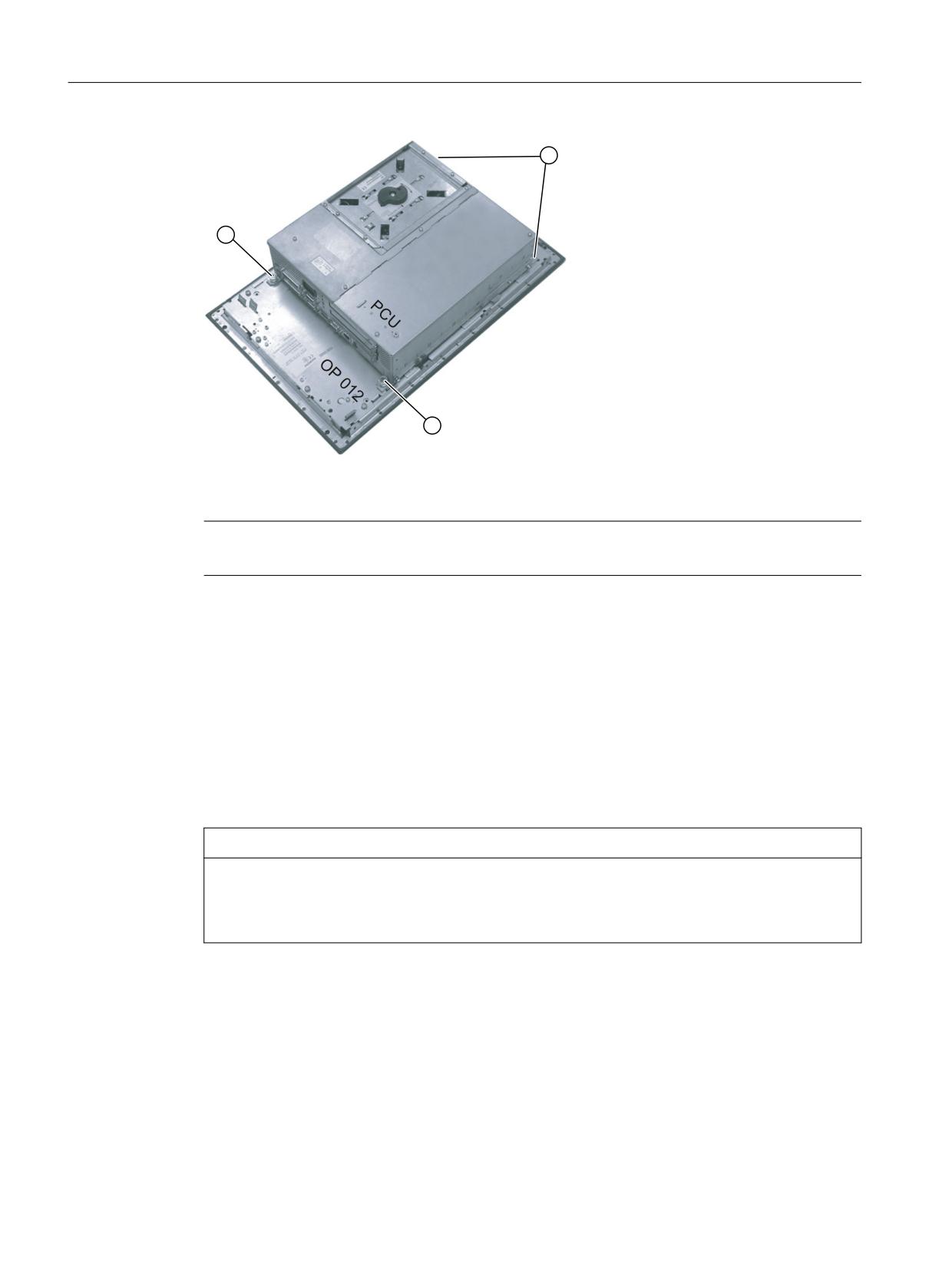
① Mounting slots for PCU lugs
② Slots for inserting softkey labeling strips
③ I/O USB cable K1
④ Display cable K2
⑤ Cover plate for keyboard controller connections
⑤ Retainers
Figure 3-3
Rear of the OP 012
Procedure
1. Place the OP 012 face down on a flat, soft (to avoid scratches) surface.
- Installation of the direct key module (see section in the “Direct key module" manual under
"installation" → “Combination with OP 012")
- Install or replace the softkey labeling strips (see Softkey labeling (Page 25))
2. Remove the PCU's interface cover.
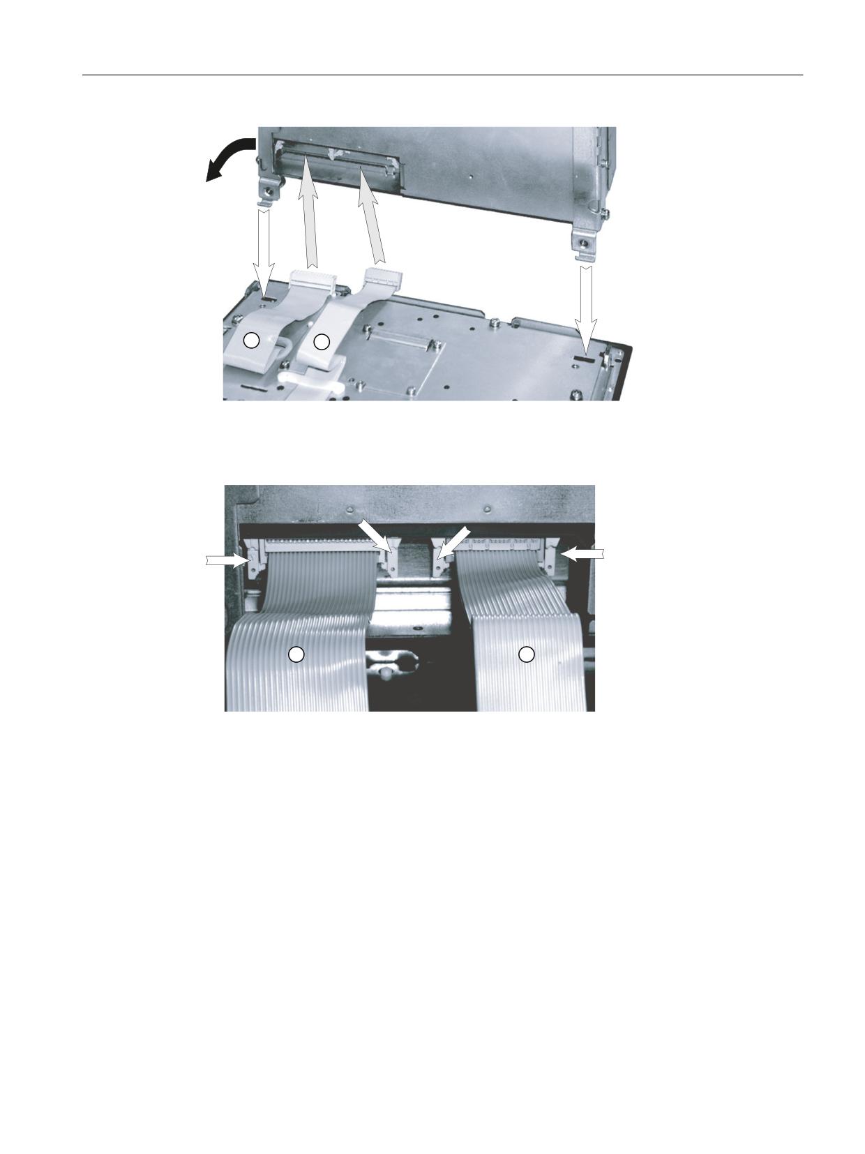
3. Place the PCU with the lugs of the bolted-on mounting brackets into the mounting slots on
the OP 012 as shown by the white arrows in diagram (A).
To make it easier to insert the lugs, it can be helpful to reduce the 90° angle between the
PCU and OP 012 by tilting the PCU as shown by the black arrow in the picture.
4. Insert cables K1 ① and K2 ② of the OP 012 in the connector strips of the PCU [see the gray
arrows in the diagram (A)]. Make sure that the connectors lock in audibly and that the locks
[see arrows in diagram: (B)] are closed.
5. Swivel the PCU into its final position and secure it with knurled screws, tightening torque of
1.8 Nm [see diagram: (C)].
Operator panel front: OP 012
22
Manual, 05/2019, A5E36371591B AB
Installation
3.2 Assembling an OP 012 and a PCU
3&8
23
① I/O USB cable K1
② Display cable K2
Figure 3-4
(A) Assembling PCU and OP 012
3&8
① I/O / USB cable K1
② Display cable K2
Figure 3-5
(B) Correct connection of I/O-USB and display cables to the PCU
Operator panel front: OP 012
Manual, 05/2019, A5E36371591B AB
23
Installation
3.3 Mounting on the mounting wall
① Knurled screw
Figure 3-6
(C) OP 012 and PCU after assembly
Note
The OP 012 and TCU assembly is similar to that for a PCU.
3.3
Mounting on the mounting wall
The clearance at the rear of the PCU/TCU must be at least 10 mm to ensure sufficient
ventilation (see Figure 3-2 Dimension sheet for attaching the PCU to the OP 012 operator panel
front (Page 21)).
For more detailed information, please refer to the relevant PCU sections and in "General
information and networking", Section: "Application planning", Section: "Climatic and
mechanical environmental conditions" → "Cooling".
NOTICE
Impermissible mounting positions can cause malfunctions
Observe the permissible mounting position: Deviating by up to 5º from the vertical.
This value can be further restricted by mounted components (e.g. PCU).
Procedure
1. Insert the assembled components (operator panel front and PCU) from the front into the
panel cutout (see Figure 3-1 Dimension sheet for installing the OP 012 operator panel front
(Page 20)).
2. Secure the operator panel front in the panel cutout from the rear using the tension jacks by
tightening the setscrews (torque 0.4 - 0.5 Nm).
Operator panel front: OP 012
24
Manual, 05/2019, A5E36371591B AB
Installation
3.4 Softkey labeling
See also
Preparation for mounting (Page 19)
3.4
Softkey labeling
User-specific functions can be assigned to the horizontal and vertical softkey bars. Printed
labeling strips can be used to label the softkeys.
Blank labels are already installed on delivery.
DIN A4 films are available for making the strips (for the article number, see Chapter Overview
(Page 89)).
Note
Use the "Arial" font to format text. This font is comparable to the "Univers S57" font, used by
Siemens for the key labeling.
Procedure
1. Letter the mat side of the film using a laser printer.
2. Cut the printed labels along the preprinted lines.
3. Remove the PCU retaining screws and swing out the PCU away from the operator panel
front.
4. Insert the strips into the slots provided on the rear of the operator panel front.
5. Swing the PCU back to the operator panel and secure by tightening the screws.
If the operator panel front and PCU are dismantled, omit steps 3 and 5.
Operator panel front: OP 012
Manual, 05/2019, A5E36371591B AB
25

Connecting
4
4.1
Pin assignment of the interfaces
The pins of the component interfaces are assigned as specified in the tables below. Any
deviations are indicated at the relevant point.
Signal type:
I
Input
O
Output
B
Bidirectional (inputs/outputs)
V
Power supply
-
Ground (reference potential) or N.C. (not connected)
Power supply X206
Connector designation:
X206
Connector type:
3-pin Combicon connector
Total cable length:
30 m
Pin
Name
Type
Meaning
1
P24 (+)
V/V/-
24 VDC potential (20.4 to 28.8 VDC)
2
M24 (-)
0 V
3
Functional earth
Connection for grounding the housing
X203, X204 and X213 USB interfaces
The USB interfaces are implemented as sockets and comply with the generally valid standard.
The version information (1.1, 2.0 etc.), the maximum velocity (low speed, full speed, etc.) and
the socket type (A or B) are documented in the individual sections for the associated devices.
Operator panel front: OP 012
Manual, 05/2019, A5E36371591B AB
27
Connecting
4.1 Pin assignment of the interfaces
In principle, USB interfaces have the following characteristics:
● Integrated power supply up to 500 mA for each socket.
● Maximum cable length 3 m (Length including the supply cable to the hub and the connected
terminal device; only 1 hub at maximum is permitted. It should be noted that some
keyboards already have a hub.)
NOTICE
Cables that are too long can cause the screen to freeze
Observe the following restrictions for the USB front interface for connecting operator
panels to the keyboard, mouse or USB FlashDrive:
● Maximum cable length: 1.8 m
● Extension cables are not permissible
● Hot-plugging-capable devices are connected during operation and are identified
automatically.
Note
Correct identification is only guaranteed for USB I/Os that comply to 100% with the USB
specification.
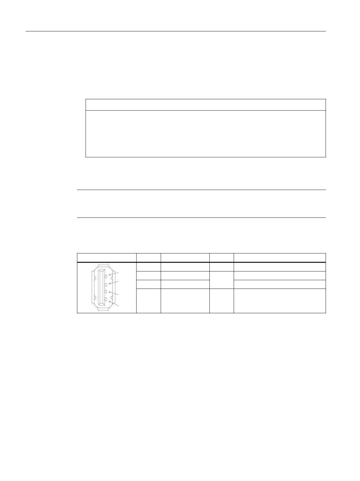
Table 4-1
Assignment of the USB interface
Type A socket
Pin
Name
Type
Remark
1
P5V_fused
V
+ 5 V (fused)
2
Data-
Data -
B
3
Data+
Data +
4
GND
V
Ground (reference potential)
USB sticks
If you want to connect a USB flash drive to the USB interface, you can use a USB flash drive
of any memory size. It must, however, meet the following minimum requirements:
● File system: FAT16 or FAT32
● Partitioning: only in PC partition format (MBR)
USB sticks that deviate from these requirements have not been tested and may not be
recognized by the NCU.
Operator panel front: OP 012
28
Manual, 05/2019, A5E36371591B AB
Connecting
4.1 Pin assignment of the interfaces
Ethernet RJ45 interface X202
Connector type:
Standard RJ45 socket
Max. data transmission rate:
10/100/1000 Mbit/s
Max. cable length:
100 m
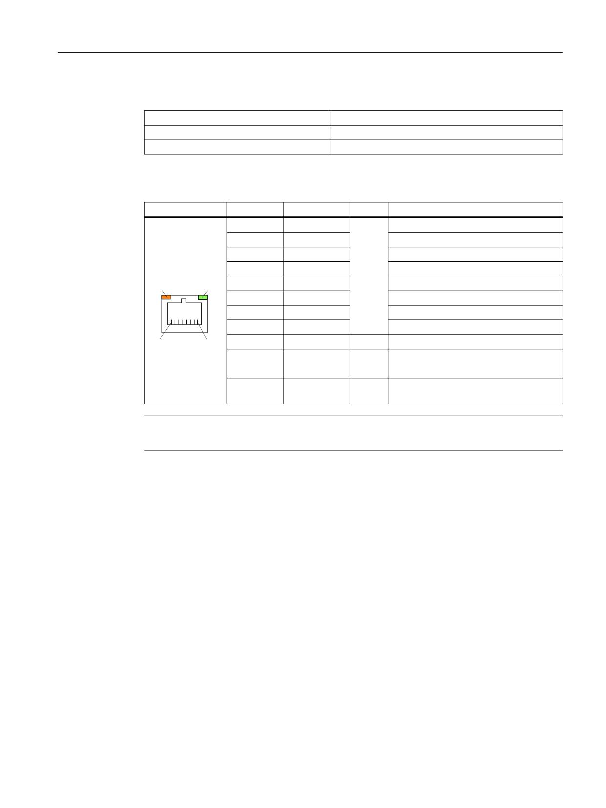
Table 4-2
Assignment of the Ethernet RJ45 interface 1000 Mbit/s
Connector
Pin
Name
Type
Remark
1
DA+
B
Bidirectional pair A+
2
DA-
Bidirectional pair A-
3
DB+
Bidirectional pair B+
4
DC+
Bidirectional pair C+
/('
/('
5
DC-
Bidirectional pair C-
6
DB-
Bidirectional pair B-
7
DD+
Bidirectional pair D+
8
DD-
Bidirectional pair D-
Shield
-
-
On connector housing
-
Green LED
-
Illuminated orange: 1000 Mbps
(right)
Off: No or faulty connection
-
Orange LED
-
Illuminated: Data exchange
(left)
Off: No data exchange
Note
Connection is only possible on an LAN, not on telecommunication networks.
I/O USB interface
All signals required for connecting operator panel fronts, with the exception of the display
interface, are assigned to this interface.
Associated interface cable:
K1
Connector type:
2 x 13-pin socket connector
Operator panel front: OP 012
Manual, 05/2019, A5E36371591B AB
29
Connecting
4.1 Pin assignment of the interfaces
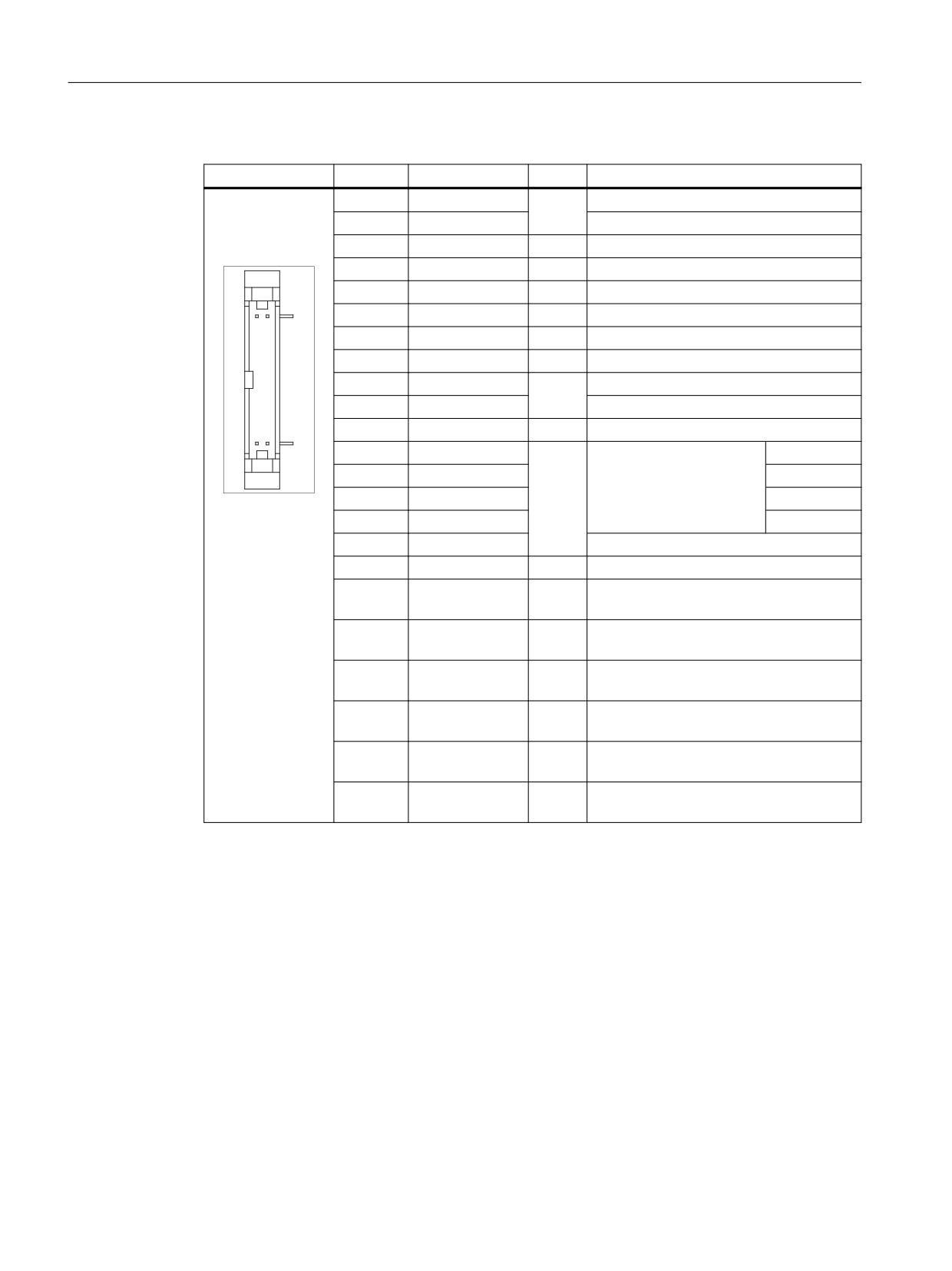
Table 4-3
Allocation of the I/O USB interface
Connector
Pin
Name
Type
Meaning
1
GND
Ground
VO
2
P12C
+power supply for backlight inverter
3
BL_ON
O
Backlight On
4
P5V_fused
VO
+5 V VCC (fused in PCU/TCU)
5
GND
VO
Ground
6
P3V3_fused
VO
+3.3 V VCC (fused in PCU/TCU)
7 - 10
N.C.
-
Not connected
11
P5V_fused
VO
+5 V VCC (fused in PCU/TCU)
12
USB_D1M
USB data- Channel 1
B
13
USB_D1P
USB data+ Channel 1
14
GND
VO
Ground
15
LCD_SEL0
1
16
LCD_SEL1
Display type select signal
2
17
LCD_SEL2
I
3
18
LCD_SEL3
4
19
RESET_N
Reset signal (low active)
20
reserved
-
Reserved
21
HD_LED
O
HD LED, anode with 1 kΩ in series on the
motherboard
22
DP_LED
O
MPI/DP LED, anode with 1 KΩ in series
on the motherboard
23
Ethernet_LED
O
Ethernet LED, anode with 1 kΩ in series
on the motherboard
24
TEMP_ERR
O
LED temperature sensor; anode with 1 kΩ
in series on the board
25
RUN_R *)
O
Watchdog error LED, anode with 1 kΩ in
series on the motherboard
26
RUN_G
O
Watchdog OK LED, anode with 1 kΩ in
series on the motherboard
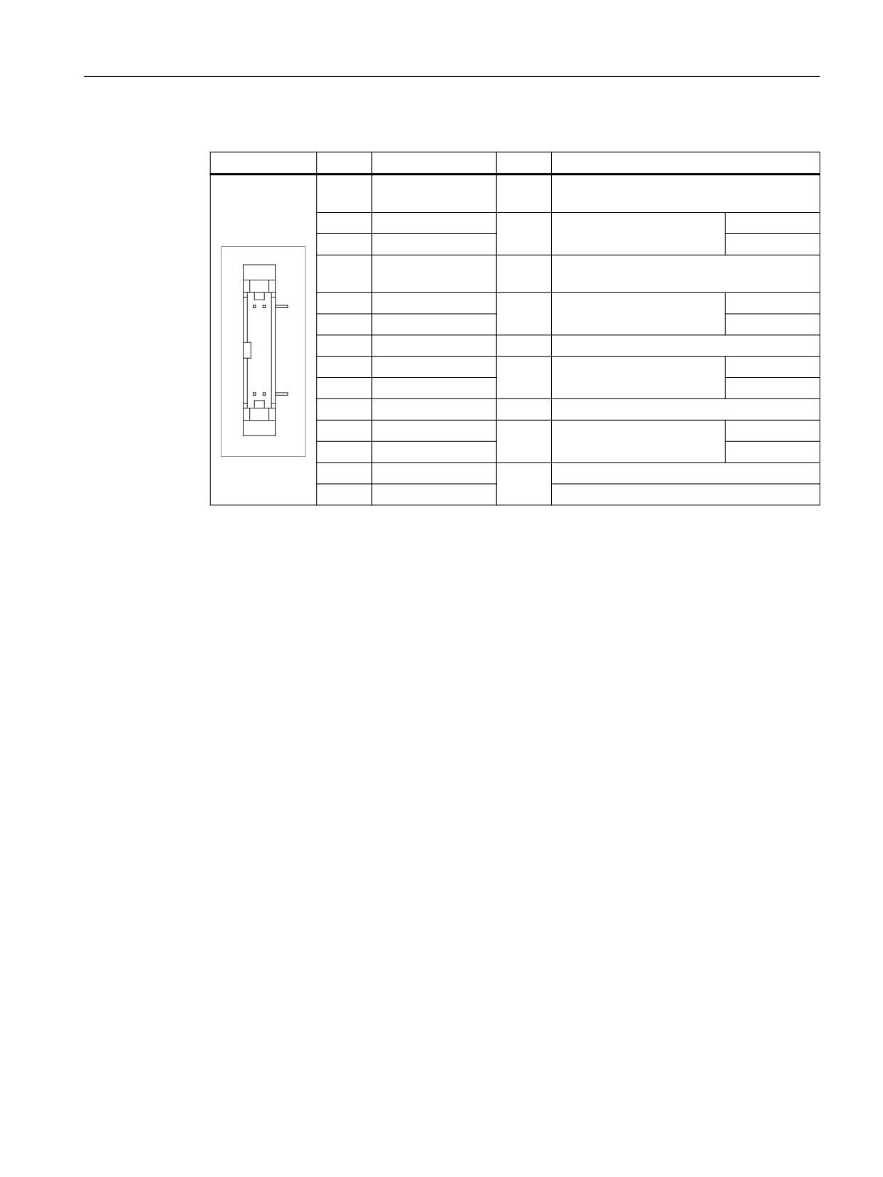
LVDS display interface channel 1
Used to connect operator panel fronts with TFT displays with 640 x 480 pixels (VGA), 800 x 600
pixels (SVGA) or 1024 x 768 pixels (XGA).
Associated interface cable:
K2, max. length: 0.5 m
Connector type:
2 x 10-pin socket connector
Operator panel front: OP 012
30
Manual, 05/2019, A5E36371591B AB
Connecting
4.1 Pin assignment of the interfaces
Table 4-4
Allocation of the LVDS display interface
Connector
Pin
Name
Type
Meaning
1/2
P5V_D_fused
VO
+5 V display supply voltage (fused in PCU/
TCU)
3
RXIN0-
Bit 0 (-)
I
LVDS input signal
4
RXIN0+
Bit 0 (+)
5/6
P3V3_D_fused
VO
+3.3 V display supply voltage (fused in PCU/
TCU)
7
RXIN1-
Bit 1 (-)
I
LVDS input signal
8
RXIN1+
Bit 1 (+)
9/10
GND
-
System ground (reference potential)
11
RXIN2-
Bit 2 (-)
I
LVDS input signal
12
RXIN2+
Bit 2 (+)
13/14
GND
-
System ground (reference potential)
15
RXCLKIN-
(-)
O
LVDS cycle clock signal
16
RXCLKIN+
(+)
17/18
GND
System ground (reference potential)
-
19/20
N.C.
Not connected
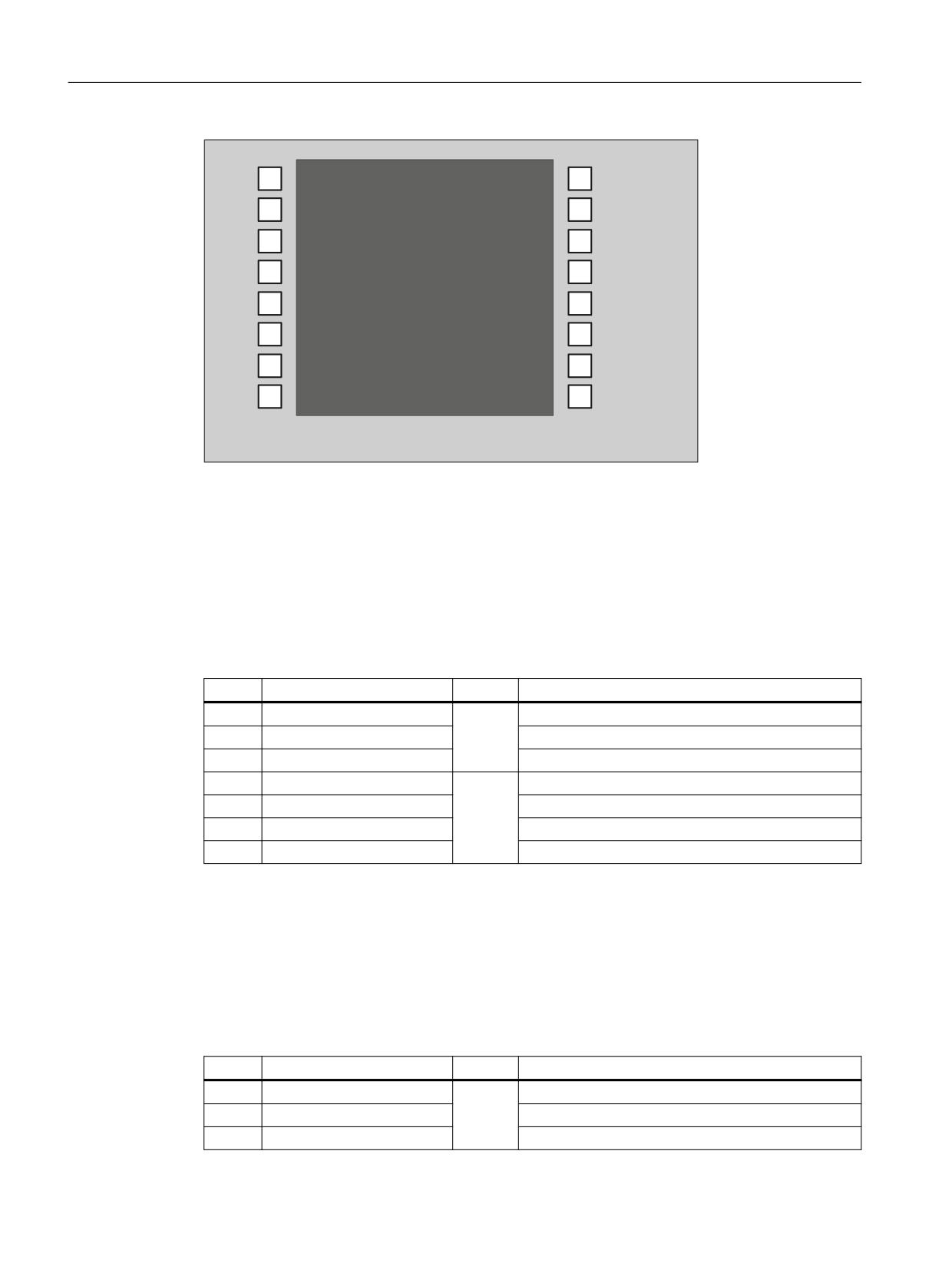
Interfaces for direct keys
X11 on the operator panel (OP) fronts can be used to fetch the state of the direct keys. The
connection of a 20-pin ribbon cable allows the direct keys to evaluate the following components:
● Direct key module (DTM)
● X70 in the machine control panels (MCP, MPP) and the handwheel connection module
(HAM)
● X205 on the Thin Client Unit (TCU)
The signals are then forwarded to the control over the various communications networks. Note
that DTM and HAM can be operated only with PROFIBUS DP.
Operator panel front: OP 012
Manual, 05/2019, A5E36371591B AB
31
Connecting
4.1 Pin assignment of the interfaces
'7
'7
'7
'7
'7
'7
'7
'7
'7
'7
'7
'7
'7
'7
'7
'7
Figure 4-1
Assignment of the direct keys to the vertical softkeys of an operator panel front
16 digital inputs (5 V) can be fetched via the X11 connector.
Connector designation:
X11
Connector type:
20-pin plug connector
Max. cable length:
0.85 m
Table 4-5
Assignment of connector X11
Pin
Name
Type
Meaning
1
DT1
Direct key 1
O
16
DT16
Direct key 16
17
P5V
+ 5 V (fused)
18
P5V
+ 5 V (fused)
V
19
GND
Ground
20
GND
Ground
16 digital inputs can be polled by the X70/X205/DTM connector.
Connector designation:
X70/X205/DTM
Connector type:
20-pin plug connector
Max. cable length:
0.85 m
Table 4-6
Assignment of connector X70 (MCP, MPP, HAM) / X205 (TCU) / DTM
Pin
Name
Type
Meaning
1
DT1
Direct key 1
I 1)
16
DT16
Direct key 16
Operator panel front: OP 012
32
Manual, 05/2019, A5E36371591B AB
Connecting
4.2 Handling membrane connectors
Pin
Name
Type
Meaning
17
P5V / CON1 2)
+ 5 V input voltage 3)
18
P5V / CON2 2)
+ 5 V input voltage 3)
V
19
GND
Ground
20
GND
Ground
1)
The inputs are electrically isolated for MCP / MPP / HAM and DTM.
2)
For the TCU, it is evaluated whether the direct keys have been connected.
3)
Power consumption: 100 mA for MCP / MPP / HAM; 500 mA for DTM
Table 4-7
Signal level
HIGH level:
5 V or open
Low level
<= 0.8 V
4.2
Handling membrane connectors
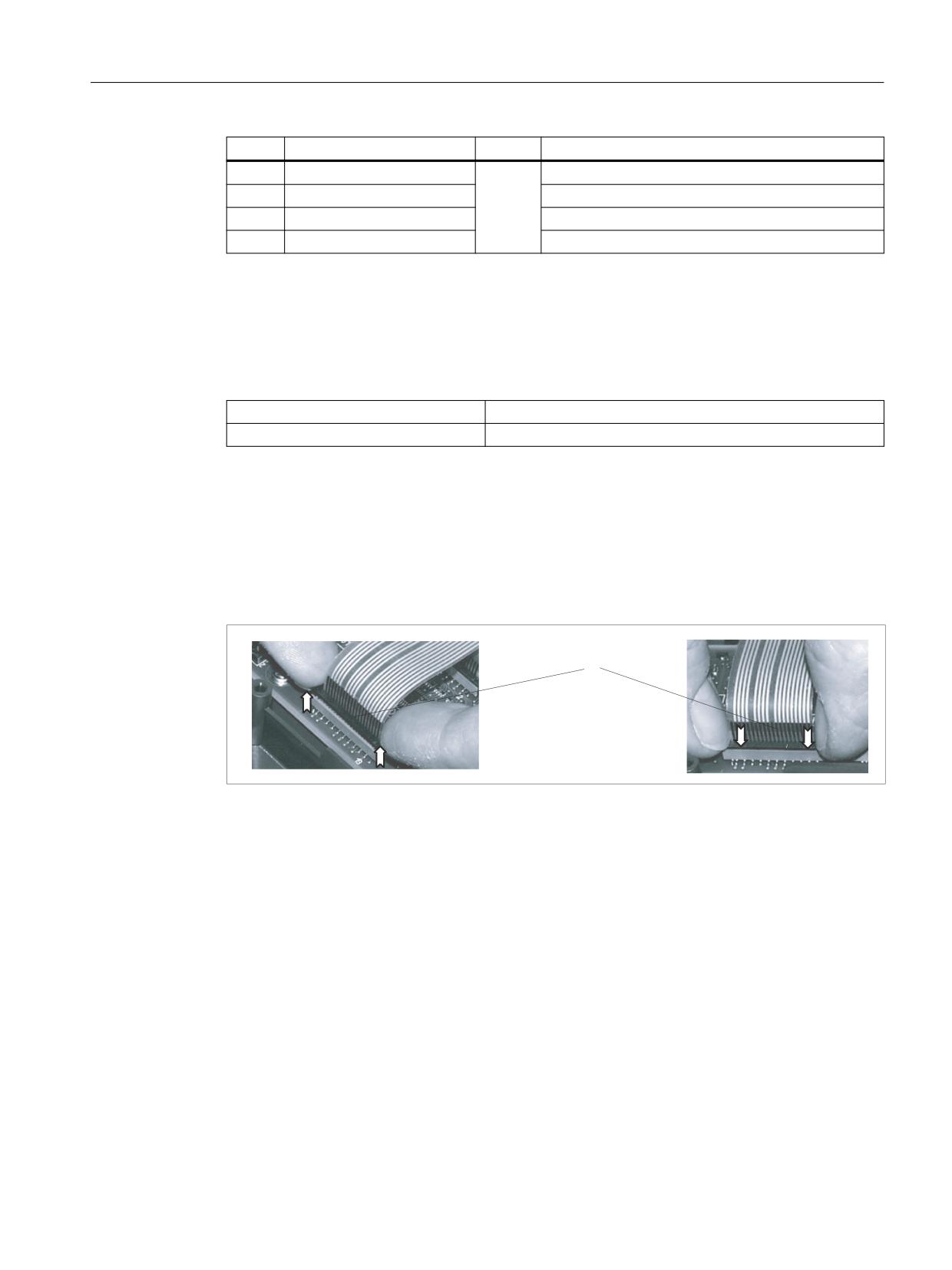
When replacing parts it can sometimes be necessary to disconnect membrane connectors
from the boards and reconnect them again.
This should be done as follows:
(1)
Clamping frame of socket
Figure 4-2
Removing (left) and attaching (right) a membrane connector
Unplugging the membrane connector
1. Loosen the dark clamping frame of the socket by pushing it up with your fingernails until it
engages in its upper, unlocked position (Fig. left).
2. Carefully pull off the membrane connector upward.
Plugging in the membrane connector
1. With the clamping frame in the upper position, carefully plug the membrane connector into
the socket.
2. Lock it in place by pushing down the clamping frame (Figure right).
Operator panel front: OP 012
Manual, 05/2019, A5E36371591B AB
33
Connecting
4.2 Handling membrane connectors
Operator panel front: OP 012
34
Manual, 05/2019, A5E36371591B AB
Networking
5
5.1
System settings
5.1.1
Thin Client Unit (TCU)
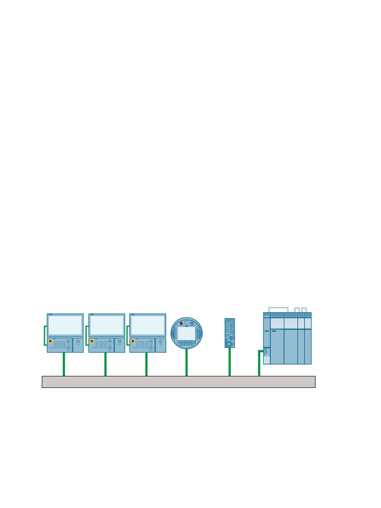
TCU overview
The Thin Client Unit (TCU) for the distributed configuration permits spatial separation of the
SINUMERIK operator panel front (OP/TP) and the SINUMERIK PCU/SIMATIC IPC or NCU.
With SINUMERIK solution line, the TCU is used to visualize the user interface of the PCU 50,
SIMATIC IPC for SINUMERIK with PCU basic software or NCU.
One TCU can be connected to multiple PCUs/IPCs/NCUs. All TCUs and PCUs/IPCs/NCUs
that are connected to one other via a Gigabit switch form the "system network". The user
interface of a PCU/IPC/NCU is copied to several OPs each with one TCU. This means that all
TCUs display the same screen. Operator actions can only be performed on one TCU at a time.
This TCU then has user authorization. The PCU can also have its own OP connected directly
to it.
The classic operator panel fronts can be used with an IPC 427E if a TCU is available.
The following diagram shows a configuration example for a distributed topology:
6,180(5,.
' VO
2SHUDWRU SDQHOV ZLWK 7&8V 0&3V DQG (0V
3&8
+7
6,0$7,& ,3&
*LJDELW VZLWFK
The mobile SINUMERIK HT 8 handheld terminal works on the thin client principle and
combines the functions of an operator panel with a machine control panel.
The configuration and cabling of the whole system based on a permissible configuration is
described in Section "Network configurations".
Operator panel front: OP 012
Manual, 05/2019, A5E36371591B AB
35
Networking
5.1 System settings
Supplementary conditions
The following supplementary conditions apply for the operation of a TCU:
● In the system network, the number of active thin clients is limited:
- A maximum of 2 TCUs: NCU 710.3 PN
- A maximum of 4 TCUs: NCU 720.3 PN or NCU 730.3 PN
- A maximum of 4 TCUs: PCU/IPC
Any number of TCUs can be operated in the system network.
● CompactFlash Cards cannot be used on the TCU.
● A 16 bit or 32 bit depth of color setting may be selected.
● If a PC keyboard is connected to the TCU, it is not possible to ensure that all special keys,
e.g. multi-media keys, will be transferred to the software of the NCU/PCU/IPC.
● Machine control panels connected via a PROFIBUS network are not supported for
switchover.
● Distributed memory media that are connected to the TCU via USB can be used.
● The TOP Panels must be networked on the basis of the Gigabit standard, e.g. Gigabit switch
or Ethernet cable according to CAT 6 or higher.
5.1.2
Settings for SINUMERIK solution line
Fundamentals
The system network for SINUMERIK solution line is structured as a star topology with a central
Ethernet switch, to which all Ethernet-based components of the system are connected.
For an NCU, the connection is via the X120 Ethernet socket, for an IPC/PCU, it is via the
"Ethernet 2" or "X2" or "X2 P1" connection. There is no default for all other components with two
Ethernet connections. These components have an internal 2-port switch and may be used to
connect an additional operator component. Thus, in this case, there can be deviations from the
strict star topology.
System network
In the system network, the IP address 192.168.214.xxx with subnet mask 255.255.255.0 is pre-
selected. Here there is precisely one DHCP server with DNS that can run on one NCU or one
PCU/IPC. The server ensures assignment of IP addresses to the Ethernet components in the
system network (DHCP clients) from a specified address band.
Operator panel front: OP 012
36
Manual, 05/2019, A5E36371591B AB
Networking
5.1 System settings
The following rules apply for assignment of IP addresses in the system network:
● For all NCUs and/or PCUs/IPCs, the commissioning engineer assigns fixed IP addresses in
the associated address bands, as well as appropriate computer names (host names). All
other operator components are automatically assigned an IP address by the DHCP server.
Its name is generated automatically (for MCP, MPP, HT 8), or is entered at commissioning
(TCU).
● If there are multiple NCUs, IPCs and/or PCUs in the system network, depending on the boot
sequence, the system automatically specifies the DHCP server and automatically ensures
synchronization of all necessary data, so that the next time the system boots any other NCU,
IPC, or PCU could take on the role of DHCP server. However it is better to specify a DHCP
master. This is an NCU, IPC, or PCU in the system network that is available on each system
boot and which regularly takes over the task of the DHCP server and DNS server.
Synchronization of data takes place in any event so that any other NCU, IPC, or PCU can
take over this task, unless you deactivate this option in the DHCP configuration. All non-
master NCUs/IPCs/PCUs wait while the system boots for a preset time for the master to
become available.
Note
In a system network or on a boot server, i.e. on the NCU, IPC, or PCU that accommodates
the active DHCP server, a maximum of 30 operator stations may be operated
simultaneously with the TCU.
A maximum of 10 operator stations with a TCU may connect up simultaneously with the
same HMI application when powering up.
Connection to a company network
Each NCU can be connected via X130, and each PCU/IPC can be connected via "Ethernet 1"
to a company network. The company network is used to exchange operating software with
servers or to execute part-programs directly from servers in the company network. Company
network and system network should always be logically and also physically separated.
Service interface X127
The service interface X127 of the NCU is used for direct connection of a PG/PC for service
purposes. Here, access with STEP 7 to the PLC, and with NCU 7x0.3 PN also to PROFINET
is possible.
With direct connection (peer-to-peer) of a PG/PC to X127 it is absolutely necessary that the PG
is operated as a DHCP client.
Operator panel front: OP 012
Manual, 05/2019, A5E36371591B AB
37
Networking
5.1 System settings
5.1.3
System boot with system network
System behavior at boot
The system boot behavior is based on the following principle:
● For the configuration of an NCU 7x0 with a PCU/IPC, the default for a network configuration
is as follows: The NCU keeps the default IP address 192.168.214.1 on X120, the PCU/IPC
keeps the default IP address 192.168.214.241 on Eth2.
● For a configuration of more than one NCU 7x0 without PCU/IPC, with one or morel PCUs/
IPCs, a distinction must be made between two cases:
- All address conflicts and DHCP conflicts are resolved automatically when booting and
the system is ready for operation. In this configuration there is no guarantee that all
NCUs and PCUs/IPCs will always receive the same IP address at each system boot.
- If the user requires all NCUs, and possibly also the PCU/IPC, to have a defined constant
IP address at each boot, for example, because the IP address is stated explicitly in the
PLC program, the user must configure a fixed IP address in the adapter settings in the
Windows Control Panel for each affected NCU 7x0/PCU/IPC.
● You can specify a DHCP master in the basesys.ini file.
● Assigning names:
- Assign meaningful names for all NCUs in the basesys.ini file otherwise the names will be
generated automatically.
- A PCU/IPC always has a computer name, which you can change if required.
● The IP addresses of the TCU, MCP/MPP, EKS, HT2, and HT8 are freely assigned within the
specified address range on each boot. MCP/MPP, HT2, and HT8 are identified in the PLC
via their DIP switch settings.
Using DNS name service
Availability of the DNS (Domain Name System) name service offers the following advantages
for system network administration:
● The name service enables easier configuration with names instead of IP addresses for
management of operating units: All components in the system network can be addressed
via a symbolic computer name. This name can to some extent be freely assigned, to some
extent it is derived automatically from a DIP switch setting (MCP, MPP, EKS, HT 8, HT 2).
● A computer node in the system network (NCU, PCU/IPC, TCU, MCP, HT 8, etc.) can be
addressed solely through assignment of the IP address, either via a freely selectable name
or via an internally generated name in the system network, and thus becomes independent
from its network address in the system network. Thus a change in the network address does
not necessarily necessitate a series of additional setting changes.
● In addition, the name service is used by the system for address resolution for MCP/MPP,
direct keys, and EKS when changing the user authorization.
Operator panel front: OP 012
38
Manual, 05/2019, A5E36371591B AB

Networking
5.1 System settings
5.1.4
Factory default settings
Meaning of the symbols:
○
Eth 1 as a DHCP client
●
Eth 2 as a DHCP server
■
Eth 2 with a fixed IP address
Preconfiguration of the TCU
The TCU is configured as a DHCP client and primarily accepts IP addresses from SINUMERIK
components, from the DHCP server of such components that are inherent to SINUMERIK, for
example, an NCU at X120 or a PCU/IPC on the system network or from a standard DHCP
server. The behavior of the TCU cannot be changed here.
A TCU is a SINUMERIK DHCP client.
The TCU has a single Ethernet connection.
7&8
A TCU executes a boot via the network. The boot server is the computer node from which the
TCU also obtains its IP address.
Pre-configuration of the PCU
A PCU has two Ethernet interfaces with default settings for use with SINUMERIK solution line:
Eth 1 is pre-selected as a default DHCP client for connection to a
company network.
3&8
Eth 2 is pre-selected as a SINUMERIK DHCP server for connec-
tion to a system network. On Eth 2 the fixed IP address
(WK
(WK
192.168.214.241 is pre-selected.
Preconfiguration of the IPC
An IPC has two Ethernet interfaces with default settings for use with SINUMERIK solution line:
X1 is preset as the standard DHCP client for connection to a com-
pany network.
,3&
X2 is preset as a SINUMERIK DHCP server for connection to a
system network. The fixed IP address 192.168.214.241 is preset
;
;
on X2.
Operator panel front: OP 012
Manual, 05/2019, A5E36371591B AB
39
Networking
5.1 System settings
Preconfiguration of the NCU
On the X120, the NCU is preconfigured for the SINUMERIK DHCP protocol. The NCU is pre-
selected here as a SINUMERIK DHCP server. On X120, the NCU occupies the fixed IP address
192.168.214.1 with the subnet mask 255.255.255.0 in its capacity as a DHCP server. The
DHCP server of the NCU assigns IP addresses from the range 192.168.214.10 -
192.168.214.239 to the DHCP clients.
It is also possible to make the NCU a DHCP client. The configured IP address in basesys.ini is
a "requested" IP address, which is rejected in the case of an address conflict and replaced by
a dynamic IP from the address range.
In large system networks, it makes sense to set an NCU/PCU/IPC as the DHCP master. If an
additional 2-3 hosts are used (NCU/PCU/IPC), the user sets the DHCP priority to "ON_HIGH".
For the other hosts, the user sets DHCP priority to "ON_CLIENT_SYNC" or
"ON_CLIENT_NO_SYNC".
Restricting the available address band that is managed by the DHCP server of the NCU frees
up IP addresses 192.168.214.2 to 192.168.214.9 as well as addresses 192.168.214.241 to
192.168.214.254 for network nodes with fixed IP addresses.
The NCU has three Ethernet connections:
;
;
● X120 to connect to the system network with an active DHCP
server (Eth 0)
1&8
● X130 to connect to the company network as the standard
;
DHCP client (Eth 1)
● X127 as a service connection with an active DHCP server (Ibn
0)
On X130, the NCU is set as a default DHCP client for the address reference from a company
network. The IP address received here is specified by the DHCP server from the company
network.
On X127, an NCU is a standard DHCP server in contrast to the SINUMERIK DHCP server. On
X127, the NCU has the fixed IP address 192.168.215.1 with the subnet mask 255.255.255.224
as Service input. The IP addresses 192.168.215.2 - 192.168.215.23 are dynamically assigned
to the DHCP clients. The range 192.168.215.24 - 192.168.215.30 is reserved, and can be used
by stations on the network with a fixed IP address, e.g. by a modem.
Operator panel front: OP 012
40
Manual, 05/2019, A5E36371591B AB
Networking
5.2 Commissioning TCU
IP address ranges reserved for NCU and PCU/IPC
The following defaults apply on delivery:
● Connection to the system network with subnet mask 255.255.255.0:
IP address
Network station
Remark
192.168.214.1
NCU on X120
Default
192.168.214.2 - 9
For additional NCUs with a fixed IP address on
Not assigned
the system network
192.168.214.10 - 239
For additional TCUs, later for additional PCUs,
DHCP clients
IPCs, NCUs, MCPs, MPPs
192.168.214.240
Reserved for EKS (Electronic Key System)
Default
192.168.214.241
Fixed IP address of PCU/IPC on Eth 2
Default
192.168.214.242 - 249
For additional PCUs/IPCs with a fixed IP ad-
Not assigned
dress
192.168.214.250 - 254
For PGs with a fixed IP address (Service con-
Not assigned
nection)
● Service connection with subnet mask 255.255.255.224:
IP address
Network station
Remark
192.168.215.1
NCU on X127
Default
192.168.215.2 - 23
For service purposes with PG, PC
DHCP clients
192.168.215.24 - 30
Fixed IP address, e.g. for a modem
Not assigned
5.2
Commissioning TCU
5.2.1
Key assignment
Key assignment
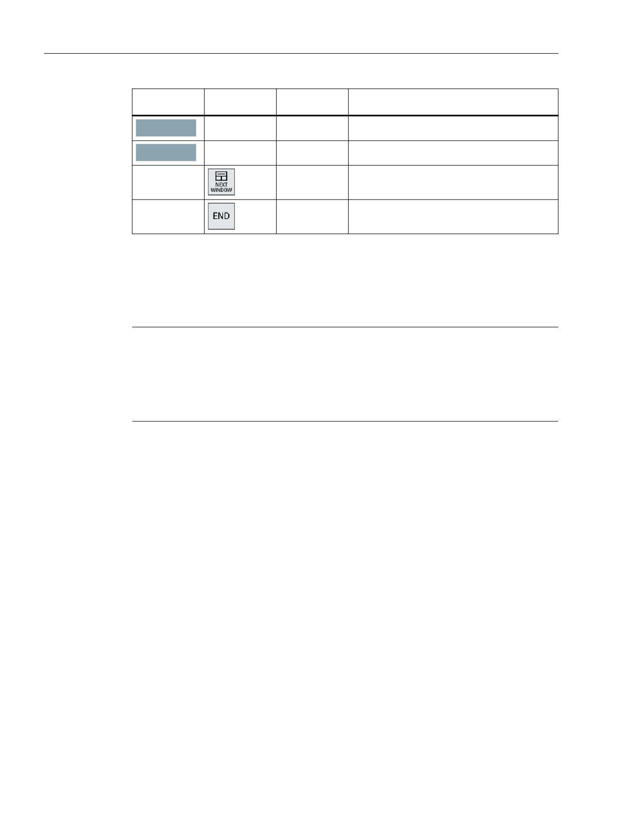
Functions of the keys and softkeys in the "Operator panel service system":
Softkey
Key on OP
External key-
Description
board
HSK1
<F1>
Moves the cursor down a row
HSK2
<F2>
Moves the cursor up a row
Page
HSK3
<F3>
Moves the cursor down a page
Page
HSK4
<F4>
Moves the cursor up a page
Char
HSK5
<F5>
Inserts text or digits
Char
HSK6
<F6>
Inserts text or digits
Operator panel front: OP 012
Manual, 05/2019, A5E36371591B AB
41
Networking
5.2 Commissioning TCU
Softkey
Key on OP
External key-
Description
board
VSK7
←
Cancel / Return
Cancel
VSK8
→
OK / Confirm
Ok
---
Pos1
Moves the cursor to the top row
---
End
Moves the cursor to the bottom row
Exceptions to the above are mainly the result of input fields. Where these are present, the left/
right cursor keys move the input cursor rather than performing an OK/cancel function. The
Return key takes you to the next field (like the "down" key) rather than closing the entire dialog
with OK. There are also Backspace (deletes character to the left) and Delete (deletes character
to the right) keys for editing text and numbers. The F5, F6, Backspace, Delete, and Select keys
(between the cursor keys) can be used to switch between Yes/No fields.
Note
Special function for Touch Panels without additional keys
Letters and numbers in input fields can be edited with HSK5/HSK6, which switch one character
forward or backward. With a touch screen, you can activate all the softkeys and even select
rows in a menu simply by touching them.
For operator panel fronts without keys, a virtual keyboard automatically appears.
5.2.2
Settings in the "TCU.ini" file
Directories
The tcu.ini file is created in the following directories:
NCU:
../siemens/system/etc/tcu.ini
../user/system/etc/tcu.ini
../oem/system/etc/tcu.ini
PCU/IPC (Windows 7 and Windows 10):
C:\ProgramData\Siemens\MotionControl\siemens\System\etc\tcu.ini
C:\ProgramData\Siemens\MotionControl\user\System\etc\tcu.ini
Operator panel front: OP 012
42
Manual, 05/2019, A5E36371591B AB
Networking
5.2 Commissioning TCU
C:\ProgramData\Siemens\MotionControl\oem\System\etc\tcu.ini
Note
The following entries are evaluated by SINUMERIK Operate:
● VNCServer/VetoMode
● VNCServer/AlarmBoxTimeOut
● VNCServer/FocusTimeout
● VNCServer/AdaptResolution
● VNCServer/MaxActiveTCUs
● VNCViewer/ExternalViewerSecurityPolicy
Restrictions
Restrictions for such external operator control units are:
● Neither MCP and direct keys nor an EKS system can be assigned. This also means that
these devices cannot be activated to be an operator control unit in the system.
● Direct keys cannot be triggered, i.e. the softkeys to the direct keys can be triggered in the
operating software. However, the keys do not appear in the direct key image to the PLC.
● There is no config.ini configuration file, as for a TCU, i.e. a configuration for a TCU is not
possible for such an operator control unit (power-up behavior, displacement, t:m:n);
however, the displacement mechanism on the external operator control units is effective.
● An external operator control unit is never signaled as active operator station in the PLC.
Configuring the external operator control units in the tcu.ini file in section:
[externalTcu]
# EXTERNAL TCU IP-ADDRESSES
# List of accepted TCUs in IP-V4-format (index 1 to maximal 16)
ExternalTcuIP_1=
You can also set the desired screen resolution in the tcu.ini file:
[VNCServer]
Resolution = ...
5.2.3
Displacement mechanism for TCUs
To operate a machine with more operating stations then the maximum number, the
displacement mechanism ensures that only the permitted number of TCUs are active in a
shadowing group. The remaining TCUs are switched to passive mode, which means they no
longer represent a load with regard to the resources. Thus the number of TCUs that can be
connected to one HMI application is practically no longer limited. The limitation is the number
of concurrently active TCUs.
Operator panel front: OP 012
Manual, 05/2019, A5E36371591B AB
43
Networking
5.2 Commissioning TCU
Supplementary conditions
The following supplementary conditions apply when operating the TCU:
2 active TCU connected in parallel to NCU 710.3 PN
4 active TCU connected in parallel to NCU 720.3 PN, NCU 730.3 PN
4 active TCUs connected in parallel to PCU/IPC
Displacement rules
You configure the displacement mechanism in SINUMERIK Operate in the "Setup" operating
area > menu forward key > "OPs" softkey for the respective operator panel.
The TCU can assume the following states:
● The TCU is active and has user authorization: This can be identified as the TCU shows the
screen of the operating software and the screen is bright.
● The TCU is active, is in the monitoring mode and has no user authorization: This can be
identified as the TCU shows the screen of the operating software, however, it is darkened
in comparison to the TCU with user authorization.
● The TCU is passive: The TCU shows the selection menu of the possible connections
instead of a screen of the operating software, and the softkey for selection of the last active
connection of the TCU is shown in color.
When powering up, the TCU always always attempts to establish the first connection. The
TCUs from a shadowing group establish their specified connection one after the other as long
as the maximum number of permissible active operator units is not exceeded.
If a TCU encounters the situation that this number is already reached in its power up, then it
attempts to obtain a connection via the displacement mechanism. If it can displace a formerly
active operator unit then it takes on the active status itself, otherwise it transitions to passive
status immediately after booting.
5.2.4
Disable switchover between TCU via PLC
Overview
The TCU switchover disable offers the option of dynamically disabling switchover from one
TCU to the next when the system is running via the PLC. For the duration of the disable, a user
authorization request to change user authorizations between TCUs will be ignored by the
system and rejected.
The rejected user authorization request causes a message to be output in the dialog line of the
HMI, in the form of a feedback message for the requester. The message disappears after five
seconds.
Operator panel front: OP 012
44
Manual, 05/2019, A5E36371591B AB
Networking
5.2 Commissioning TCU
HMI ↔ PLC data interface
The "switchover disable" function is always active and does not have to be switched on
explicitly. The function is controlled by a data bit in the PLC. The HMI transfers the active OP
to the PLC, thus forming the basis of the control function in the PLC.
The control bits and control information for this function are stored in the m:n data interface of
the PLC. In terms of m:n, this function can be operated separately for the currently overridden
HMIs in both m:n online interfaces (DB19.DBW120 ff for HMI1 and DB19.DBW130 ff for HMI2).
If a system is not running an m:n, only the first m:n online interface is used for this function.
Switchover disable is controlled by a TCU_SHIFT_LOCK bit, managed by the user, on each
HMI in the PLC. The bit address for the first HMI is DB19.DBB126.6 and DB19.DBB136.6 for
the second HMI.
The PLC m:n online interface is expanded so that byte DB19.DBB118 is also assigned to the
first interface and byte DB19.DBB119 to the second. These bytes acquire the index of the
active TCU/OP for the appropriate HMI. The byte is called TCU_INDEX. The appropriate HMI
uses the TCU index configured for the active TCU to describe the TCU_INDEX byte.
The TCU_SHIFT_LOCK bit is monitored by the appropriate HMI. A value = 1 triggers the
switchover disable. Switchover is enabled if the value returns to 0. The TCU_SHIFT_LOCK bit
can be set, for example, to the PLC by the user pressing a key or it can be managed by the PLC
user program according to its own logic. The TCU_SHIFT_LOCK bit is managed in the PLC
exclusively by the user; the HMI only accesses this bit in read-only mode.
The HMI assigns the TCU_INDEX field with the configured index to the TCU or PCU/IPC with
an OP that currently possesses user authorization in the shadow group. If no OP is active, a
value of 0 is entered in TCU_INDEX.
If no TCU index is configured for the active TCU/OP, the value 255 = undefined is transferred
as a TCU index. This means that the values 0 and 255 may not be configured as the TCU index.
Configuration
The TCU index is configured on the PCU/IPC in the same way as a machine control panel
address (MCP address). The TCU index is set in the "OP Properties" dialog of the "System
Network Center" program.
Operating principle
If the TCU_SHIFT_LOCK bit is set for switchover disable, a user authorization request is not
carried out independently of the mode set on the HMI for allocation of user authorizations (veto
mode), i.e. a change of user authorization is rejected.
This message appears on all OPs for approximately 5 seconds:
"No switchover: Switchover disable set in current PLC."
Operator panel front: OP 012
Manual, 05/2019, A5E36371591B AB
45
Networking
5.2 Commissioning TCU
While this message is displayed, operations on the OP with the user authorization can still be
carried out unaffected.
Note
Active switching of an OP to another PCU/IPC is possible
The switchover disable only relates to changing the user authorization on the OPs in a
shadowing group on a PCU/IPC.
This means that active switching away from one OP to another PCU/IPC is not prevented.
Special features
The following special cases should be noted:
● Even if switchover disable is set, the TCU_INDEX field value may change in the PLC. This
is the case under the following circumstances:
- If the OP in possession of the user authorization is actively switched to another PCU/IPC.
Depending on whether another TCU takes over the user authorization or whether no
TCU is currently active, the index of the TCU or the PCU/IPC itself (if its directly
connected OP becomes active) is entered, in exactly the same way as when there is a
switchover of user authorization.
This can also be the value 255, if no TCU index is available for the OP. 0 is entered if an
OP is no longer available in the shadow group.
- If an m:n switchover is in progress. The HMI program of the incoming PCU/IPC
deactivates the HMI program which is active on it. Therefore, an OP from the shadow
group of the new (incoming) PCU/IPC must receive the user authorization. The TCU
index of this OP is entered in the TCU_INDEX field.
- If a PCU/IPC is disconnected from an NCK/PLC in the context of m:n. No HMI program
and, therefore, no OP with user authorization is then available on the exited NCK/PLC.
This is signaled independently of a switchover disable by entering the value 0 into the
TCU_INDEX field.
● If a TCU is actively switched over to another PCU/IPC, it can be deactivated there, i.e. it
does not receive user authorization if a switchover disable is set for the destination PCU/IPC.
● With an m:n PCU/IPC switchover - the PCU/IPC is switched to another NCK and, therefore,
to another PLC - the PCU/IPC accepts the switchover disable settings of that PLC.
● The m:n interlock options on the PLC side have priority over the TCU switchover disable, so
that a set TCU switchover disable cannot prevent an m:n switchover. If necessary, the m:n
interference options should be synchronized here with those for the TCU in the PLC. It may,
for example, be practical to set or remove the m:n displacement disable simultaneously with
the TCU switchover disable.
Obtaining user authorization
At a TCU, which has no user authorization, press any key. The operating software does not
evaluate this key; this only serves to request user authorization.
Operator panel front: OP 012
46
Manual, 05/2019, A5E36371591B AB

Networking
5.2 Commissioning TCU
The settings for the right to veto are stored in file tcu.ini and are only effective if the operating
software is installed on the PCU/IPC. You can use the operating software on the OP or TCU in
the same way as on an OP connected directly to the PCU/IPC.
5.2.5
Example: How to select the behavior of the TCUs during boot up
Example: Distributing boot support across two PCUs/IPCs
Make the following settings to distribute the boot support across two PCUs/IPCs:
● On PCU_1/IPC_1, select "Boot support runtime and configuration only (TFTP/FTP)"
● On PCU_2/IPC_2, select "Boot support IP address only (DHCP)"
● On PCU_3/IPC_3, select the configuration "No boot support"
TCU_1
TCU_2
TCU_3
TCU_4
192.168.214.10
192.168.214.11
192.168.214.12
192.168.214.13
VNC connections:
VNC connections:
VNC connections:
VNC connections:
192.168.214.241
192.168.214.241
192.168.214.241
192.168.214.241
192.168.214.242
192.168.214.243
192.168.214.243
192.168.214.242
192.168.214.243
Switch to system network
PCU_1/IPC_1
PCU_2/IPC_2
PCU_3/IPC_3
192.168.214.241
192.168.214.242
192.168.214.243
Services:
Services:
Services:
X DHCP
✔ DHCP
X DHCP
✔ TFTP
X TFTP
X TFTP
✔ FTP
X FTP
X FTP
✔ VNC
✔ VNC
✔ VNC
Company network
In this case, PCU_2/IPC_2 serves as the DHCP server which provides the IP addresses for the
connected TCUs. PCU_3/IPC_3 is not involved in booting the TCUs, it is however displayed by
the TCUs using VNC.
Operator panel front: OP 012
Manual, 05/2019, A5E36371591B AB
47
Networking
5.3 Network configuration
5.3
Network configuration
5.3.1
Permissible network topologies
Ethernet connection
A SINUMERIK 840 D sl can only be operated as a network within which the individual
components communicate with one another via Ethernet connections. This network must be
set up.
The individual components are factory-set so that the most frequently occurring standard
configurations can be operated without changing the settings related to the network.
Division into system network and company network
On the SINUMERIK solution line, the components are generally split into a company network
on the one hand and a system network on the other.
The connection to the company network provides access to the network drives, for example.
On the system network, process data communication and image transmission runs from the
components with operator software to the display units of the respective TCU.
This separation is performed via the following specified use of the Ethernet interfaces on the
components:
● A TCU is connected exclusively to the system network.
● An NCU is always connected to the system network via X120.
● Ethernet interface Eth 2/X2 of the PCU/IPC is preconfigured for connection to the system
network; while Ethernet interface Eth 1/X1 is used for connection to the company network.
● An NCU is connected to the company network via X130.
Meaning of the connections:
○
Eth 1/X1 as DHCP client
●
Eth 2/X2 as DHCP server
■
Eth 2/X2 with fixed IP address
Green connection
Uncrossed Ethernet cable
Gray connection
Crossed Ethernet cable (crossover)
Operator panel front: OP 012
48
Manual, 05/2019, A5E36371591B AB
Networking
5.3 Network configuration
5.3.2
Networks without connection to the company network
5.3.2.1
Configuration 1: NCU and TCU
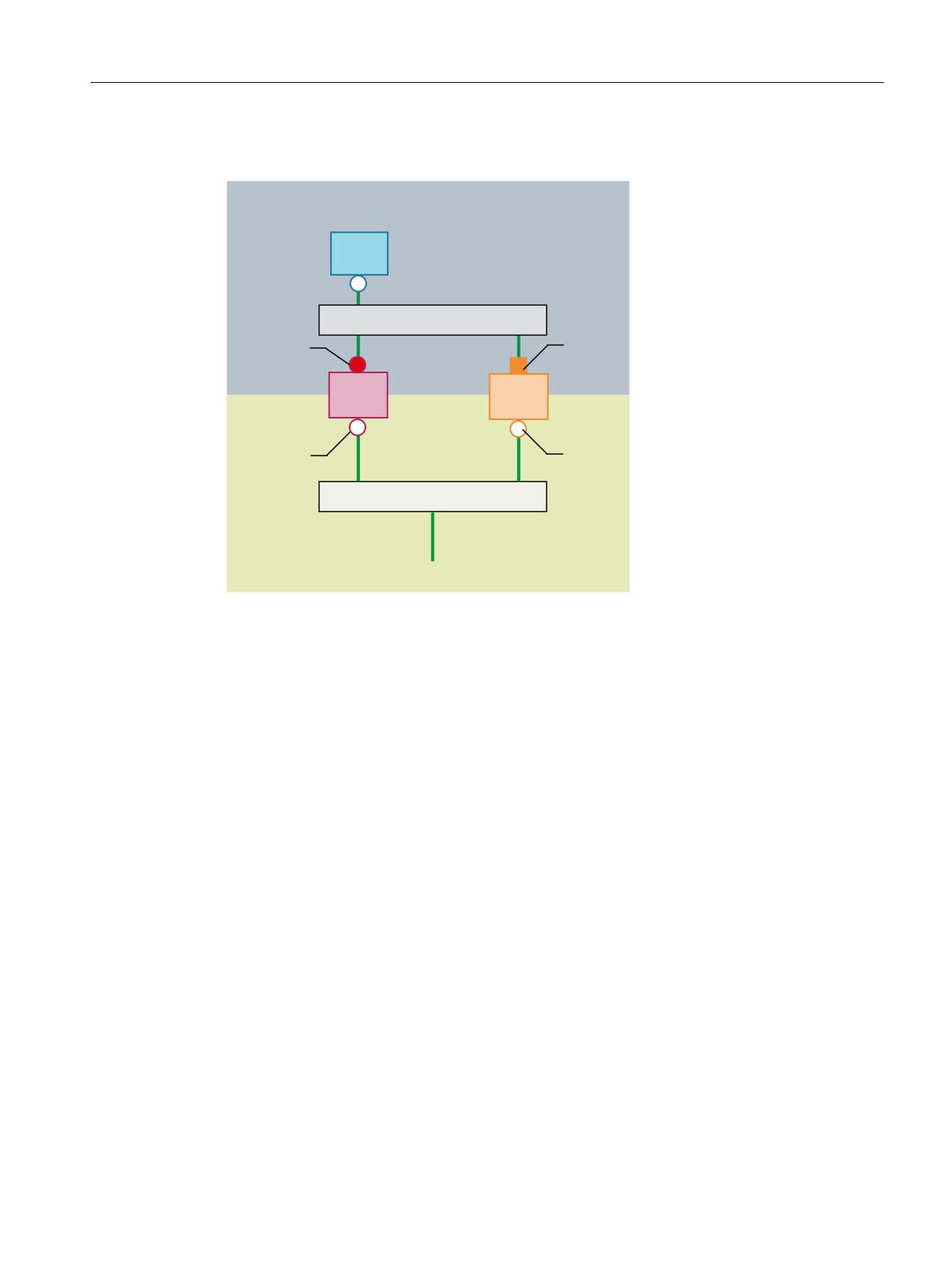
6\VWHP QHWZRUN
7&8
;
1&8
&RPSDQ\ QHWZRUN
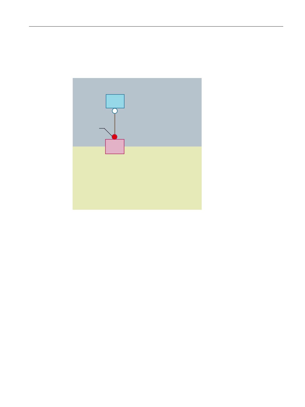
A direct Ethernet connection is used to connect a TCU to X120 of the NCU. NCU and TCU are
suitably preconfigured with IP addresses.
The IP addresses are not significant for further operation.
The TCU is connected to the NCU via a crossed Ethernet cable.
The direct connection of the NCU via X120 to the TCU automatically establishes a simple
system network consisting of two computer nodes.
Operator panel front: OP 012
Manual, 05/2019, A5E36371591B AB
49
Networking
5.3 Network configuration
5.3.3
Networks with NCU connection to the company network
5.3.3.1
Configuration 2: NCU and TCU
6\VWHP QHWZRUN
7&8
;
1&8
;
6ZLWFK
&RPSDQ\ QHWZRUN
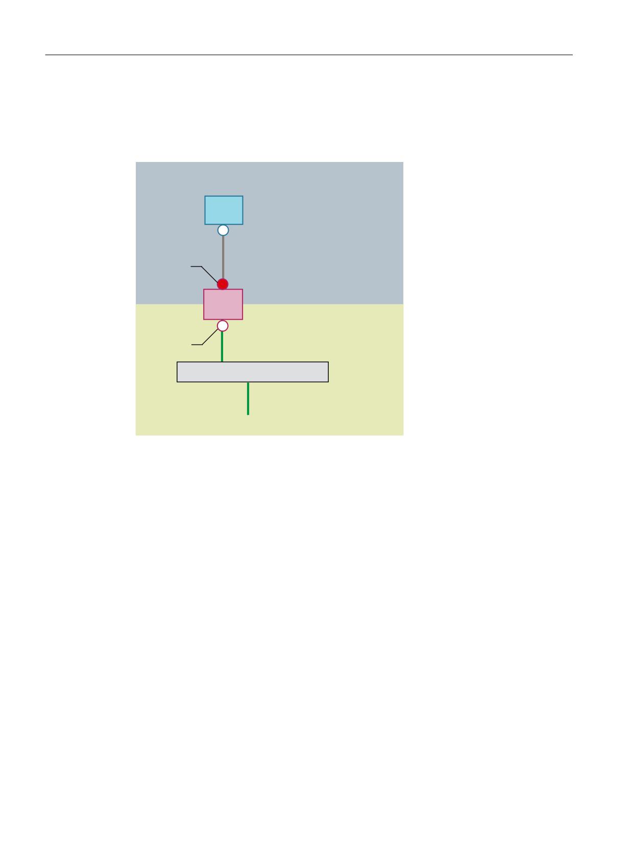
The TCU is directly connected to the NCU via a crossed Ethernet cable. On X130, the NCU is
connected to a switch to the company network with a straight cable.
As in configuration 1, there is a direct Ethernet connection between a TCU and X120 of the
NCU. NCU and TCU are suitably preconfigured with IP addresses. The IP addresses used here
are not significant for further operation.
IP configuration: DHCP server on the company network
On the X130, the NCU is set to the address reference via DHCP. If the company network has
a DHCP server that provides the NCU with an IP address/configuration, the NCU is integrated
in the company network.
Depending on the infrastructure available or the level of network administration of the company
network, the following network parameters must be set for the NCU on X130:
● Computer name on the company network
● The address of a DNS server
● The address of a gateway (default router)
The IP address of the NCU on this connection is also assigned via the network administration.
If the company network offers a low level of administration, in the worst case scenario the
network has only one DHCP server that assigns the addresses from a predefined address
range, the NCU receives an IP address that is initially unknown.
Operator panel front: OP 012
50
Manual, 05/2019, A5E36371591B AB
Networking
5.3 Network configuration
5.3.3.2
Configuration 3: PCU/IPC with TCU on NCU
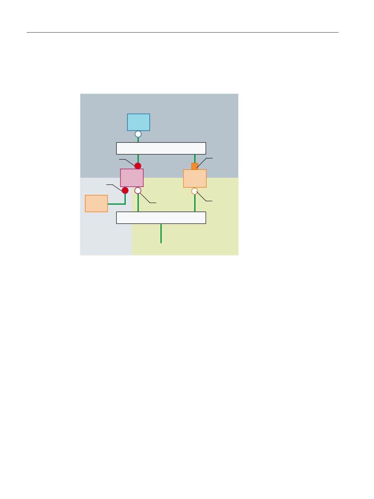
6\VWHP QHWZRUN
7&8
6ZLWFK
;
(WK
3&8
1&8
,3&
;
(WK
6ZLWFK
&RPSDQ\ QHWZRUN
In this configuration, a switch is also required for the system network. All components are
connected using straight Ethernet cables.
On X120, the NCU occupies the fixed IP address 192.168.214.1 in its capacity as a DHCP
server (not used in this configuration). For this configuration on Eth 2, the PCU/IPC is assigned
a static IP address in the range 192.168.214.241 - 192.168.214.249 with a subnet mask
255.255.255.0 . The DHCP server of the NCU supplies the TCU with an IP address and serves
as a boot server for the TCU.
The observations made for configuration 2 apply here with regard to the connection to the
company network. The connection to a switch on the company network is made via a patch
cable for Ethernet.
To connect one TCU to both HMI systems you must create an additional connection to the NCU
for the TCU.
Operator panel front: OP 012
Manual, 05/2019, A5E36371591B AB
51
Networking
5.3 Network configuration
5.3.3.3
Connecting the programming device (PG) to the NCU
Description
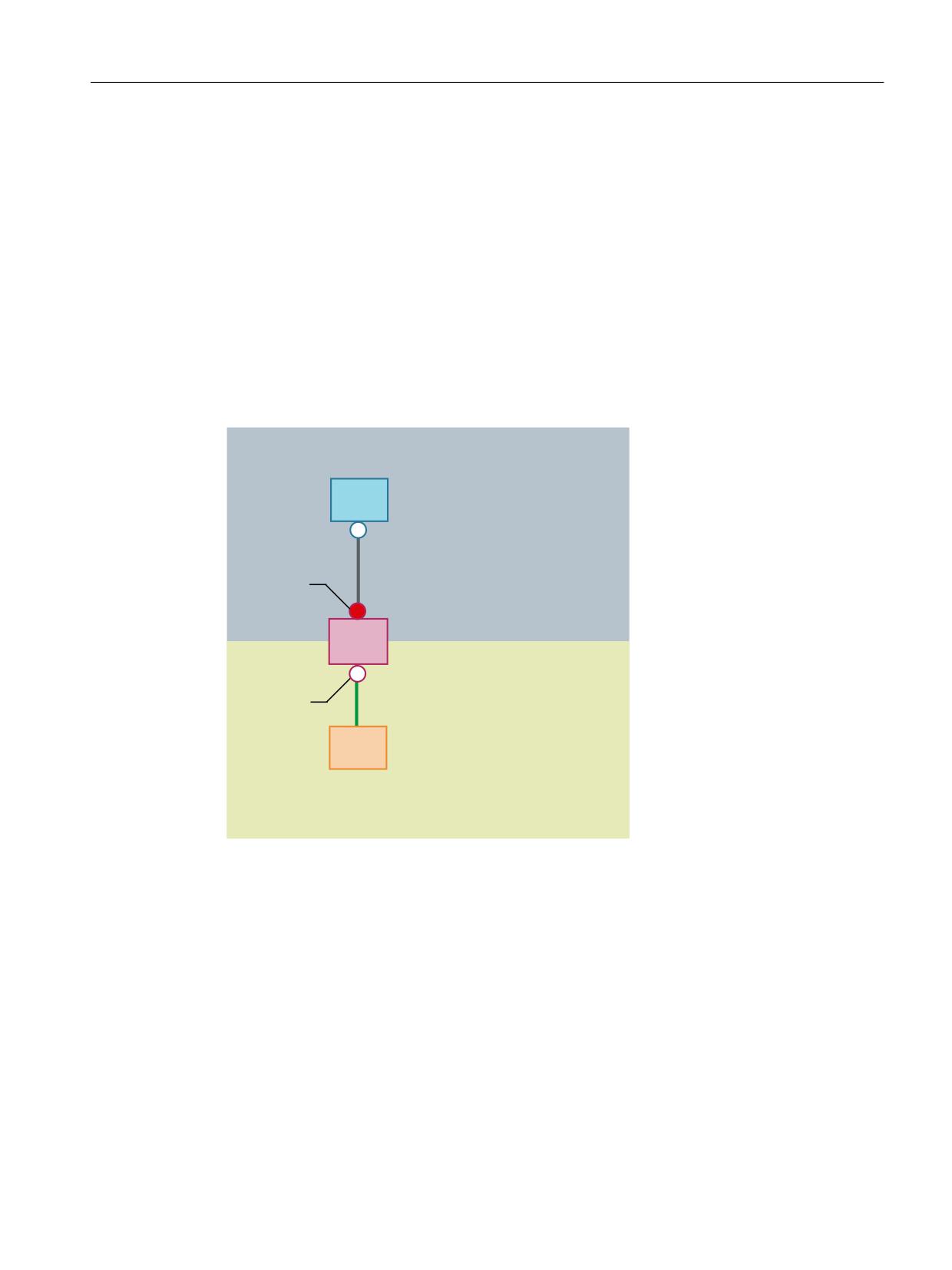
6\VWHP QHWZRUN
7&8
6ZLWFK
(WK
;
3&8
1&8
;
,3&
(WK
3* 3&
;
6ZLWFK
&RPSDQ\ QHWZRUN
For service purposes a programming device is connected to the NCU at X127 as a standard
DHCP client (automatically obtain an IP address). An NCU is a standard DHCP server on X127.
On X127, the NCU occupies the fixed IP address 192.168.215.1 with the subnet mask
255.255.255.224.
At X127, IP addresses from 192.168.215.2 onwards are assigned via DHCP; e.g. to connect a
programming device. This is the reason that a fixed IP address must not be set at the
programming device.
5.3.4
Example: Configuring a VNC connection to a PC
Requirements
In order to use a TCU to get visual access to a computer from a SINUMERIK system via VNC,
the following requirements apply:
● The VNC connections should be configured in the HMI.
● The boot server (active DHCP server) in the system network must be an NCU.
● This NCU must be integrated via X130 or X120, i.e. in the network that contains the
computer to be monitored.
Operator panel front: OP 012
52
Manual, 05/2019, A5E36371591B AB
Networking
5.3 Network configuration
● The computer to be monitored must be configured in the config.ini configuration file of the
TCU according to the general configuration for a TCU in a separate host section as a
switchover target for this TCU.
Where necessary, a password has to be specified in the configuration, if the VNC server
requires one on the target system (see below).
● To ensure that the TCU recognizes the new switchover target, the TCU requires a restart
and reboot.
● The screen resolution of the observed computer must be adjusted to the characteristics of
the TCU. Otherwise the TCU scales the image it receives to match the display area
available to the TCU, which impairs the quality of the display on the TCU.
Configuration
6\VWHP QHWZRUN
7&8
;
1&8
;
3* 3&
1HWZRUN
Figure 5-1
Configuration example
Configuration
The config.ini file is located in the following directory:
NCU:
/user/common/tcu/<TCU name>/common/tcu
PCU/IPC (Windows 7 and Windows 10):
C:\ProgramData\Siemens\MotionControl\user\common\tcu\<TCU name>
\common\tcu
The config.ini file must be stored on the boot server (active DHCP).
Operator panel front: OP 012
Manual, 05/2019, A5E36371591B AB
53
Networking
5.4 Service and diagnostics
Example:
[Station]
maxhostindex=2
/* Number of nodes that are defined under
[host_1] and [host_2].
mcpIndex=192
tcuIndex=1
eksIndex=0
[host_1]
Address=192.168.214.1
/* Address of the NCU to which the
connection is established during booting.
[host_2]
Address=157.163.230.202
/* Address of the PC
password=123456
/* Password of the VNC server on the PC
Switching over between the nodes
With the menu back key + MENU SELECT, the following actions are triggered:
● The TCU name is displayed in the header of the displayed window, e.g. TCU1.
● A selection list for connecting to the other nodes is displayed on the TCU.
5.4
Service and diagnostics
5.4.1
Using the TCU's main menu
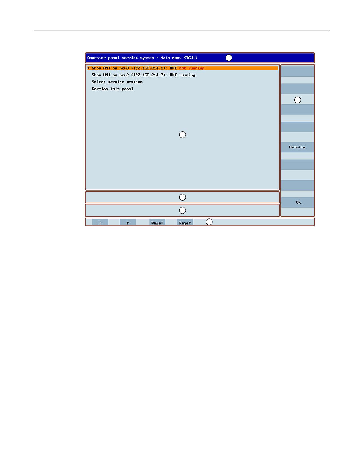
"Main menu"
The "Main menu (TCU1)" dialog is started with the menu back key and the <MENU SELECT>
key:
Operator panel front: OP 012
54
Manual, 05/2019, A5E36371591B AB
Networking
5.4 Service and diagnostics
① "Main menu" title followed by the TCU name in brackets
② Central area with the list of servers and two further permanent items, "Select service session"
and "Service this panel":
● "Select service session" triggers a server scan which detects all the VNC servers in the local
system network. These are then displayed in a session menu which largely reflects the main
menu.
● "Service this panel" opens the "Service menu for operator panel" submenu.
③ Eight vertical softkeys for use depending on the context
④ Four horizontal softkeys for navigating with the cursor
⑤ Message line whose content can be set via HWS commands from the servers
⑥ Error line in which error messages as well as transient status messages are output
Figure 5-2
TCU menu: Main menu
Operator panel front: OP 012
Manual, 05/2019, A5E36371591B AB
55
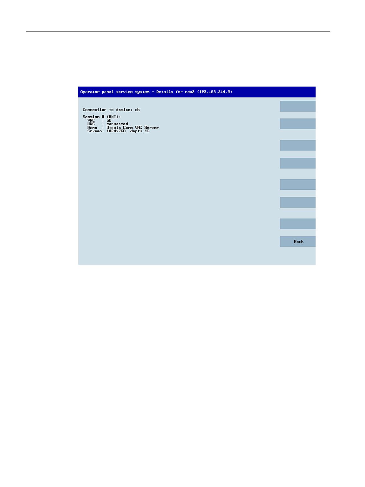
Networking
5.4 Service and diagnostics
"Details" softkey
The following connection data for the selected device appears when the "Details" softkey is
pressed:
Figure 5-3
TCU menu: Connection data
Operator panel front: OP 012
56
Manual, 05/2019, A5E36371591B AB
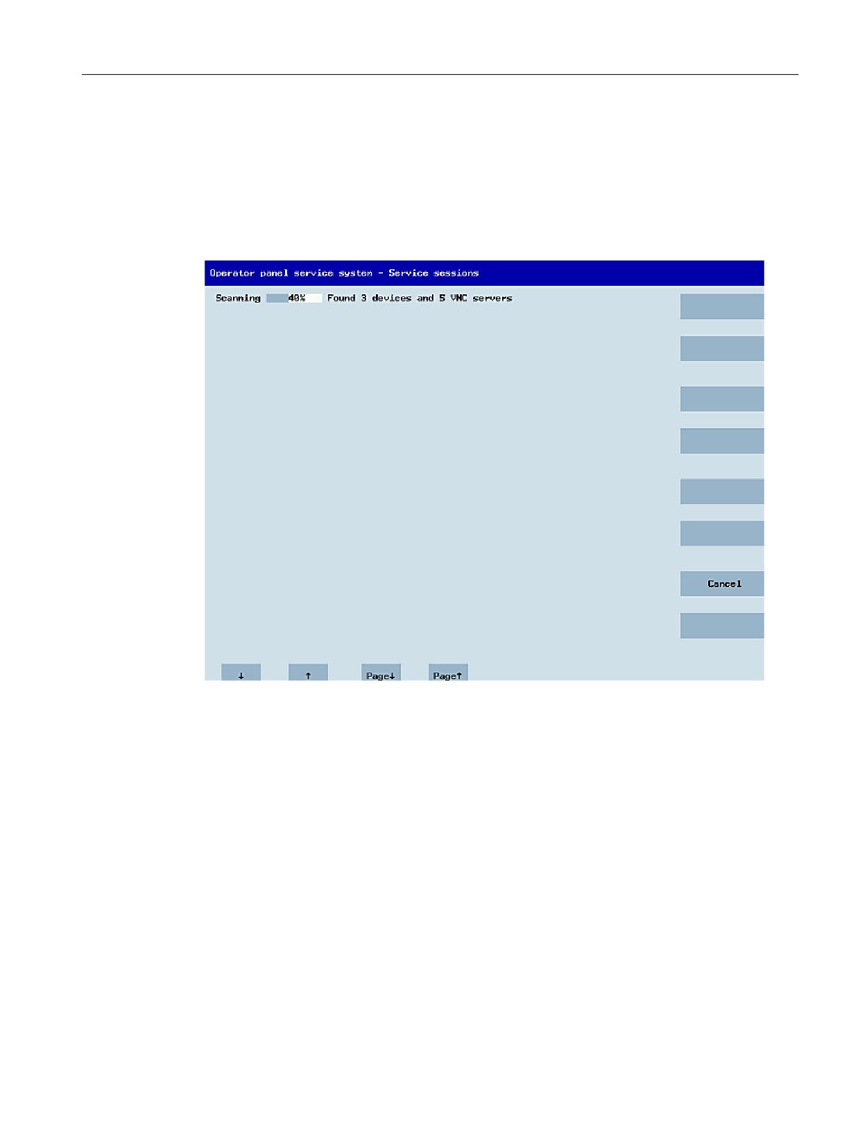
Networking
5.4 Service and diagnostics
5.4.2
Operating the TCU menu "Service sessions"
"Service sessions" dialog
When "Select service session" is selected from the main menu, the resulting process begins by
triggering a server scan:
Figure 5-4
TCU menu: Scanning
After this, the following dialog appears:
Operator panel front: OP 012
Manual, 05/2019, A5E36371591B AB
57
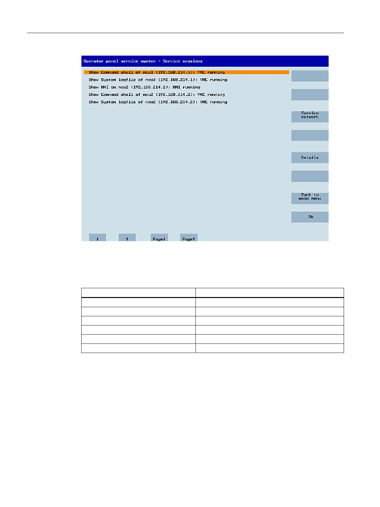
Networking
5.4 Service and diagnostics
Figure 5-5
TCU menu: Active sessions
Central area with the server list:
The individual server lines contain either "Show WHAT on NAME (IP)" or the IP address only
where the name is unknown.
Session number
VNC server
Session 0
HMI
Session 4
Command shell
Session 5
System logfile
Session 6
System Network Center (SNC)
Session <N>
Other servers
These details are followed by a status message regarding the accessibility of the VNC server.
● "Connection not ok" appears if it is already impossible to access the server from the IP side
(if switched off, for example).
● "HMI running/ not running", if an HMI VNC server is accessible.
The VSK8, Return or right cursor keys can be used to launch a VNC viewer for the selected
server.
Connection status:
Further details on the connection status can be called with the "Details" softkey. In the next
dialog, "not ok" or "not running" are accompanied by an additional error message with more
Operator panel front: OP 012
58
Manual, 05/2019, A5E36371591B AB
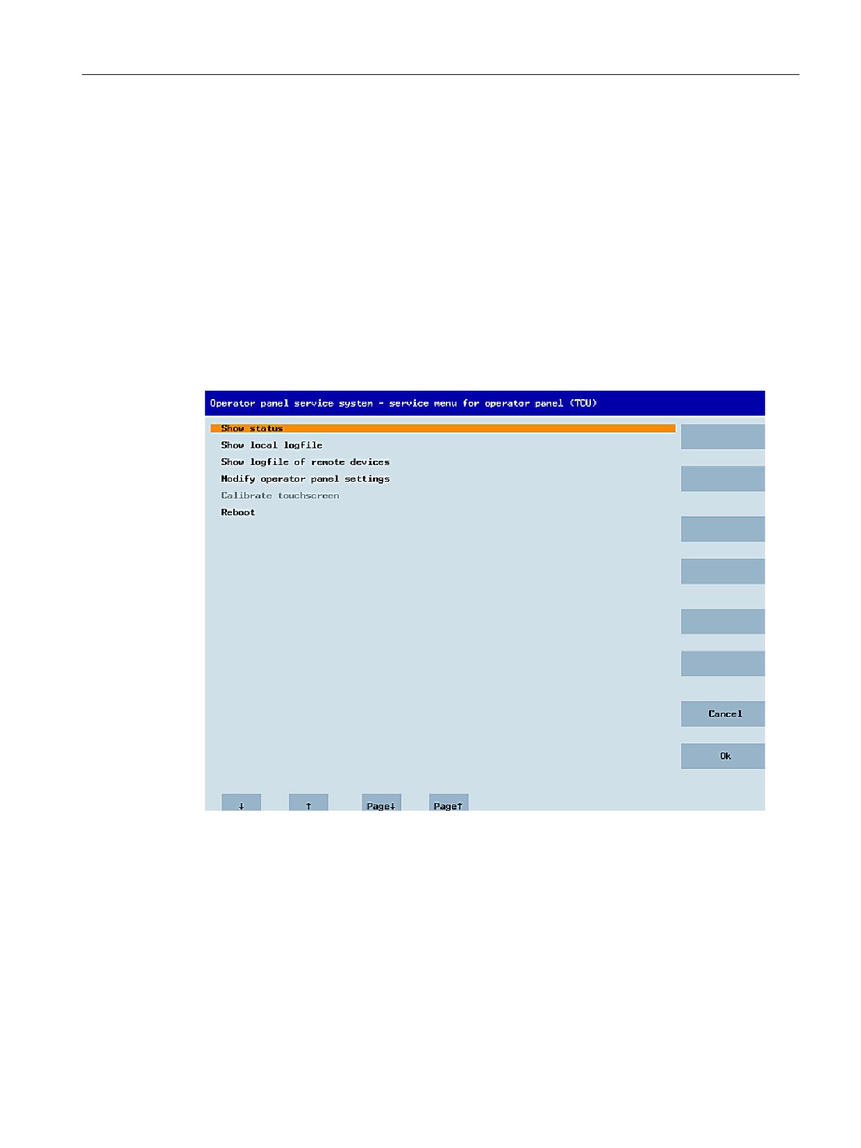
Networking
5.4 Service and diagnostics
precise details on the reason for the loss of function. With more favorable scenarios, the
session name for the VNC server will also be specified along with its resolution.
The connection and HMI status are monitored on a regular basis in the backg19round. This may
mean that these specifications change spontaneously if a change is made on the relevant
server, e.g. it may be switched off, the HMI may become available, etc.
5.4.3
Operating the TCU menu "Service menu"
"Service menu for operator panel (TCU)" dialog
The following dialog appears when "Service this panel" is selected from the main menu:
Figure 5-6
TCU menu: Service menu
Operator panel front: OP 012
Manual, 05/2019, A5E36371591B AB
59
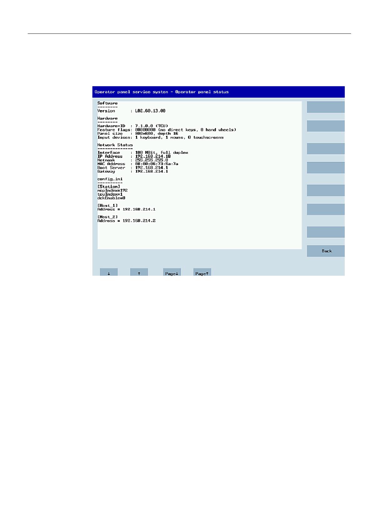
Networking
5.4 Service and diagnostics
The following menu items are available here:
● "Show status" shows status information, for example: Software version, hardware
information, TCU network data, and their configuration:
Figure 5-7
TCU menu: OP status
● "Show local logfile" shows a filtered version of the system log file in the /var/log/
messages directory, which contains only the messages of the local TCUs.
Syslog messages received via the network are not displayed.
Operator panel front: OP 012
60
Manual, 05/2019, A5E36371591B AB
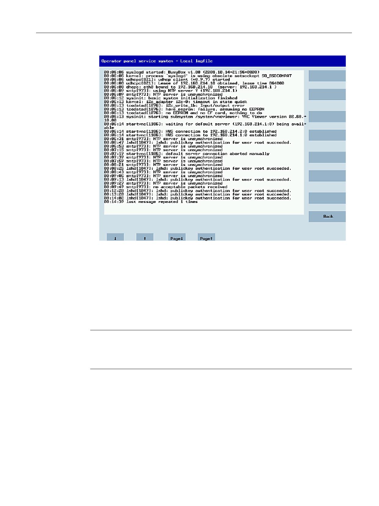
Networking
5.4 Service and diagnostics
Figure 5-8
TCU menu: Local log file
● "Show logfile of remote devices" shows the log file of the other devices in the network:
The syslog messages of devices in the system network which send syslog messages by
broadcast, such as NCU 7x0, ...
● "Modify operator panel settings" opens another submenu, see next section.
● Calibrate touch screen" is only active if there is a touch screen. This menu item recalibrates
an available touch screen.
● "Reboot" initiates a restart of the TCU.
Note
Long lines are broken and wrapped around.
Lines that are longer than the space available wrap round onto the next line so that you do not
have to scroll horizontally. When this occurs, the line has a right-facing arrow at its right edge.
Operator panel front: OP 012
Manual, 05/2019, A5E36371591B AB
61
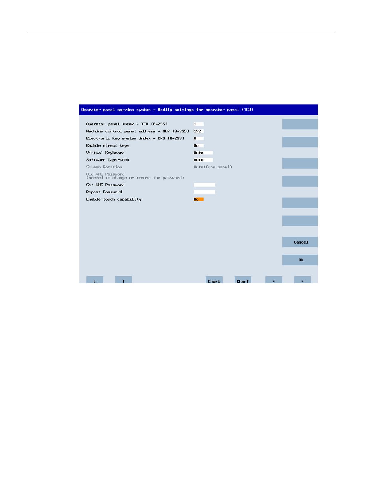
Networking
5.4 Service and diagnostics
5.4.4
Operating the TCU menu "Modify settings"
"Modify settings for operator panel (TCU)" dialog
The following dialog appears when "Modify settings" is selected from the main menu:
Figure 5-9
TCU menu: Settings
The following TCU parameters are set here during the first commissioning:
● "HT 8 individual mode" (yes/no)
This is only visible with HT 8, and is used to switch between Auto Mode and Individual Mode.
You do not have to make settings for an HT 8 in Auto Mode because the name is generated
automatically: ("DIP<n>") MCP address and TCU index are derived from the DIP setting
("DIP<n>").
● "Operator panel index - TCU" (0-255)
Defines the TCU index; see column "TCU" on the user interface.
● "Machine control panel address - MCP" (0-255)
Specifies the address of the associated MCP; see column "MCP" on the user interface.
● "Electronic key system index - EKS" (0-255)
Specifies the index of the associated EKS; see column "EKS" on the user interface.
● "Enable direct keys" (yes/no)
Specifies whether direct keys are registered with the PLC (yes) or are treated as ordinary
keys (no); see column "DCK" on the user interface.
Operator panel front: OP 012
62
Manual, 05/2019, A5E36371591B AB
Networking
5.4 Service and diagnostics
●
"Virtual Keyboard" (Auto/On/Off)
Specifies whether a virtual keyboard is shown on the screen for touch screens.
Depending on the panel features (Auto), the HMI decides whether a touch screen or
keyboard is available.
This parameter can also be set manually (On/Off).
●
"Software Caps-Lock" (Auto/On/Off)
The HMI can manage the Caps-Lock status of a keyboard in the software itself, when, for
example, the key is not available. This is normally (Auto) switched on via a display machine
data item. This machine data item can be overwritten individually for the TCU with the
setting (On/Off).
●
"Emulation Type" (TCU/TCU20.2/TCU30.3, only for modular TCU30.3)
Specifies which TCU type is to be emulated when the TCU30.3 is operated as replacement
device for an older TCU or as new device on a software version older than 4.7 SP2.
●
"Screen Rotation" (0°/90°/180°/-90°/Auto)
Specifies in which angle the screen is to be rotated in the software. This is useful when the
panel is to be rotated during installation.
For the "Auto" setting, the rotation of the display is taken from the panel.
●
"Old VNC Password"
If a password has already been set, it must be entered here so that it can be changed. If no
password has been set, this field is grayed-out. The existing password can also be deleted
if, after entering the old password, no new password is to be entered at "Set VNC Password"
and "Repeat Password".
●
"Set VNC Password"
Assign a password which is stored in the TCU and, if required, sent to the server when the
VNC connection is established.
●
"Repeat Password"
Repeat the password entered at "Set VNC Password".
●
"Enable touch capability" (yes/no)
Specifies whether the screen can be operated by touch. If you deactivate this option, you will
need a keyboard to reactivate it.
The values are applied and stored with "OK". You can also make any subsequent adaptations
or changes via the user interface in the "Setup" operating area > menu forward key > "OPs"
softkey.
5.4.5
Operating the menu for a new TCU or spare part TCU
Registering a new TCU
When an unknown TCU, i.e. not yet registered with the boot server, is started, a selection menu
containing both the "New" and "Replacement for existing panel" items is displayed. The
accessibility of all the registered TCUs is tested in the backg19round.
The status of this test is displayed in the message line: "(0/3 panels inactive)".
Operator panel front: OP 012
Manual, 05/2019, A5E36371591B AB
63
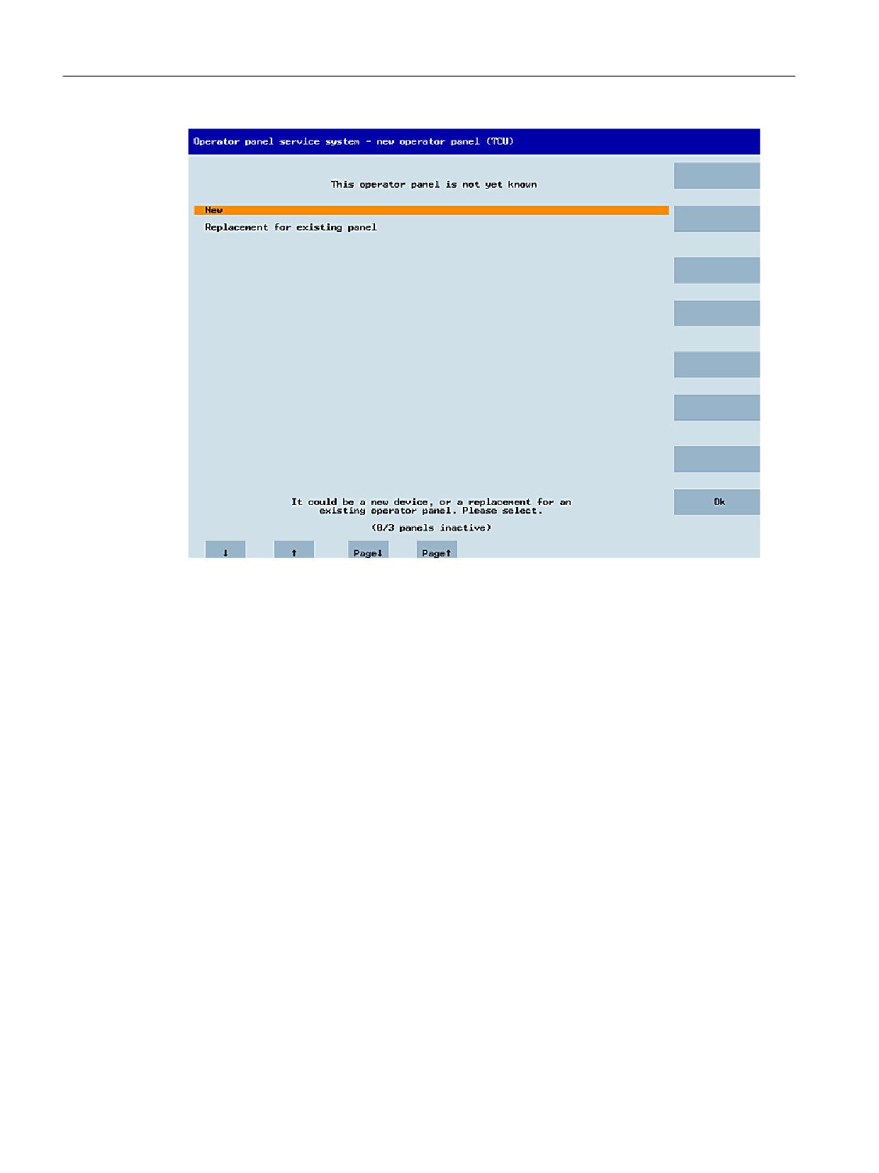
Networking
5.4 Service and diagnostics
Figure 5-10
TCU menu: New TCU
If all TCUs are active, the new TCU cannot be a spare part. The system will then automatically
switch to the name assignment phase after a set period of time has elapsed.
Operator panel front: OP 012
64
Manual, 05/2019, A5E36371591B AB
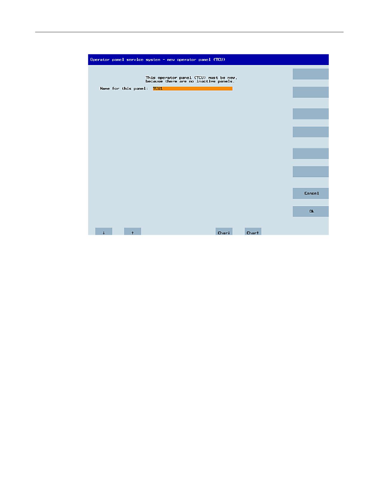
Networking
5.4 Service and diagnostics
Figure 5-11
TCU menu: Name of TCU
If a TCU30.3 is to be operated with a software version < 4.7 SP2, the TCU is operated in
compatibility mode. If required, you can view and change the emulation type in the settings.
Replacing a device
If "Replacement" is selected, all the registered TCUs will appear in a selection menu. Those
which are active in the network are grayed out. They are functioning and should not be replaced
by a spare part. The cursor automatically defaults to the first line for selection.
As the accessibility test is still running in the backg19round, the active status of the lines may
change if panels are switched on or off.
If a name is ultimately chosen, it will be applied to the new TCU along with the associated saved
settings.
Operator panel front: OP 012
Manual, 05/2019, A5E36371591B AB
65
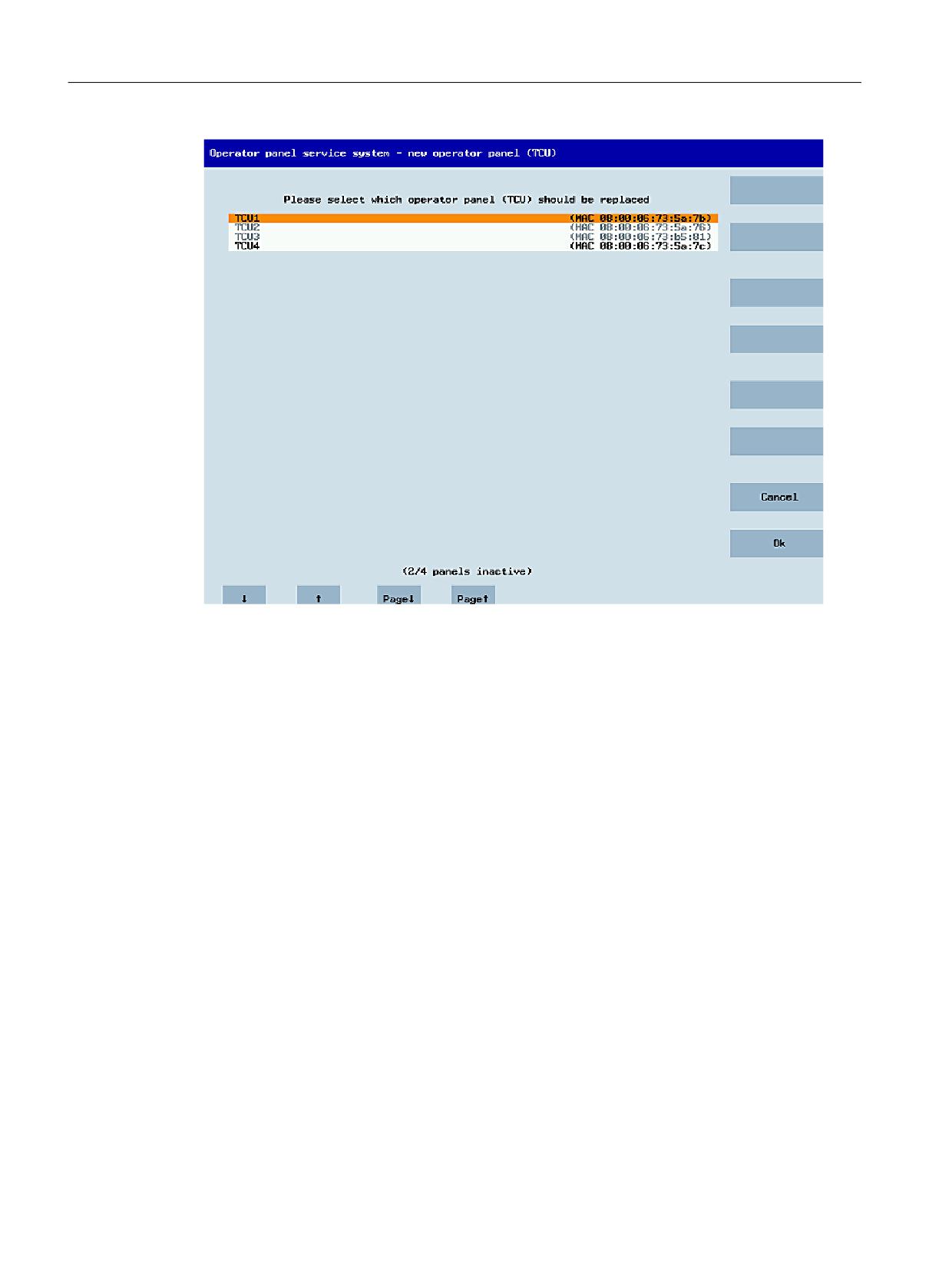
Networking
5.4 Service and diagnostics
Figure 5-12
TCU menu: Replacement TCU
With the TCU30.3, after selecting the TCU to be replaced, a further dialog to select the
emulation type can be displayed in compatibility mode:
Operator panel front: OP 012
66
Manual, 05/2019, A5E36371591B AB
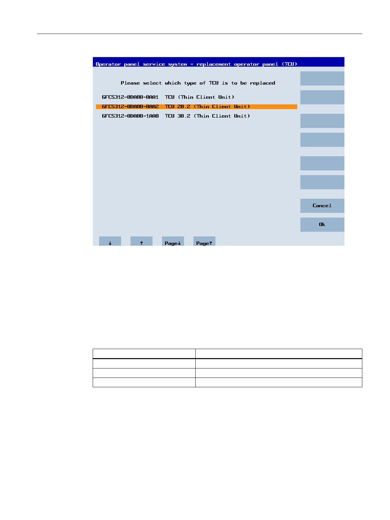
Networking
5.4 Service and diagnostics
If a static.ini of the TCU to be replaced (as of SW4.5) is found on the server, then the type of the
old TCU is preselected based on the HW ID found there. If this is not the case, the TCU20.2 type
is selected.
The following TCU types can be emulated:
● TCU
● TCU 20.2
● TCU 30.2
Note that if an older TCU is to be replaced by a TCU30.3, some interfaces cannot be used when
the HMI version is older than V4.7. The following interfaces are affected:
TCU to be replaced
Interfaces that cannot be used
TCU
X212, X213 (because they do not exist in the TCU)
TCU 20.2
X212 (because it does not exist in the TCU 20.2)
TCU 30.2
X211 (because it does not exist in the TCU 30.3)
Operator panel front: OP 012
Manual, 05/2019, A5E36371591B AB
67
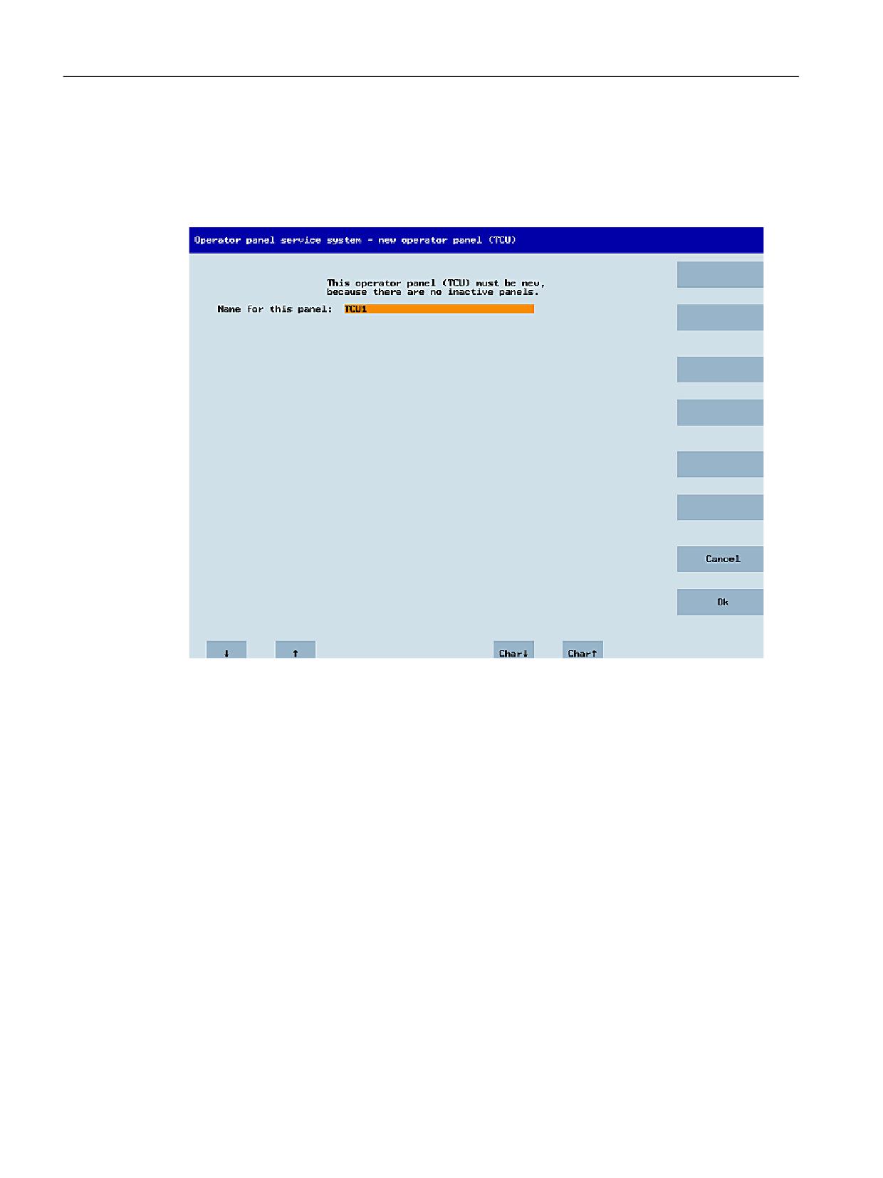
Networking
5.4 Service and diagnostics
Assigning a name
If, as described above, the system automatically follows the "New" path, an additional message
will appear: "This operator panel (TCU) must be new, because there are no inactive panels."
This message will not appear if "New" is selected manually.
Figure 5-13
TCU menu: Name of TCU
An available TCU name is suggested in the input field, although the user is able to change this.
The default name is "TCU<N>", where <N> is the lowest number yet to be used. If, however,
the name is already allocated after the OK softkey has been pressed, which may happen if a
number of TCUs log on at the same time, and the suggestion has not changed, a new and
unused name will be specified.
If the name selected was still available, this will now be allocated, and the TCU settings can still
be adapted if required. To enable any changes to be made, a new dialog appears in which all
the parameters have been pre-assigned their default values. You can make any changes you
like or just select "OK" to accept the existing values.
5.4.6
How to register a TCU on the system network
Requirement
The boot server (NCU or PCU 50/IPC) defined in the system network as a DHCP master must
be switched on and available in the network.
Operator panel front: OP 012
68
Manual, 05/2019, A5E36371591B AB
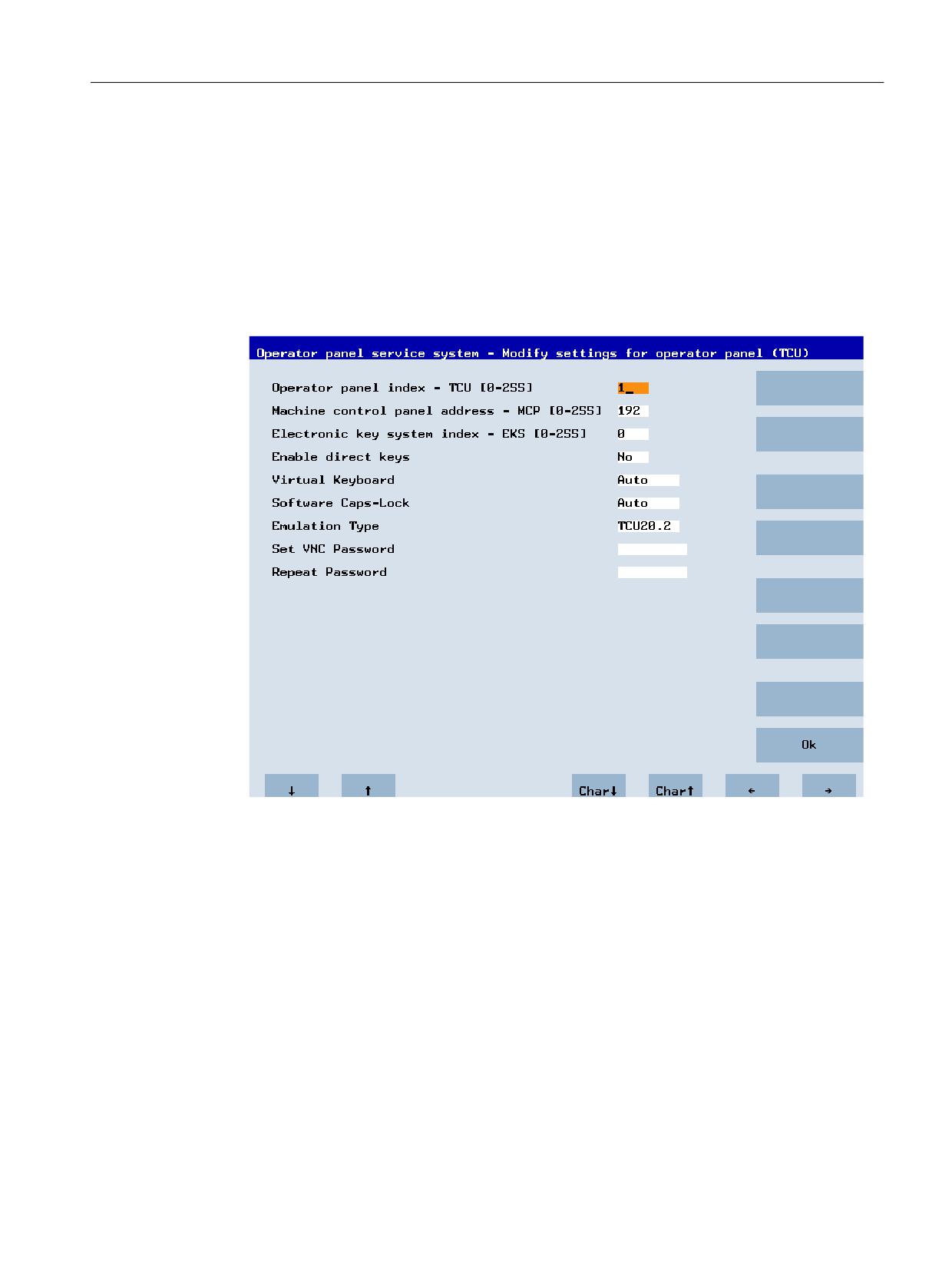
Networking
5.4 Service and diagnostics
Using the TCU
Procedure:
1. Connect the TCU.
This opens the "New operator panel (TCU)" dialog.
2. Select "New" to connect a new TCU and "OK" to confirm.
3. In the next dialog, accept the name suggested by the system or enter a name and confirm
this with "OK".
The following parameters are preselected for the TCU:
4. Restart the TCU to apply the new settings.
5. If you want to change the parameters, select "Main menu" > "Service this panel" > "Modify
operator panel settings".
Operator panel front: OP 012
Manual, 05/2019, A5E36371591B AB
69
Networking
5.4 Service and diagnostics
Procedure for the HT 8
1. Connect the HT 8 to a connection module and calibrate the touch screen.
Additional softkeys are available for convenient touch panel operation:
- "OK" has the same function as the <INPUT> key
- Select "DEF" to save the "Default" settings.
- "Edit" has the same effect as the <F10> or <MENU SELECT> key.
2. Select HT 8 Individual Mode:
According to the default setting for an HT 8, "HT 8 Individual Mode" is deselected with "No".
This means "Auto" mode is activated for automatic detection in the system network. The HT
8 is automatically detected based on its name "DIP_". If "HT 8 Individual Mode" is activated
with "Yes", the HT 8 is identified by its MAC address on the system network.
3. For an HT 8, confirm the "DIP..." name proposed by the system or adapt the name. You can
select any other characters.
Press the <INPUT> key to apply the following values as default settings for the HT 8:
HT8 Individual Mode
No
Operator panel index - TCU [0-255]
10
Machine control panel address - MCP [0-255]
10
Electronic key system index - EKS [0-255]
0
Enable direct keys
No
The following message will then appear: "New TCU 'DIP10' registered."
Note
TCU index for the HT 8
The TCU index is used to evaluate the direct keys. Direct keys can only be activated by
appropriate devices. For an HT 8 the TCU index cannot be set, but is assigned by the
system.
Activate direct keys
The signals from pressing the direct keys are sent directly to the PLC. In the PLC, the keys
appear as 16 digital inputs.
Additional information on programming the PLC is provided in:
SINUMERIK Basic Functions Function Manual, Basic PLC Program (P3)
Definition: Operator panel
The term operator station designates a unit that consists of an OP/TP, a TCU or PCU/IPC and
a machine control panel (MCP), which are connected to each other via Ethernet.
All TCUs, PCU 50s and IPCs can be used along with the OP/TP with "integrated TCU", e.g.
OP 08T, OP 015T, TP 015AT.
Operator panel front: OP 012
70
Manual, 05/2019, A5E36371591B AB
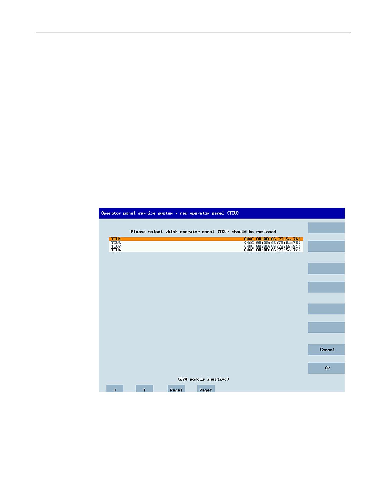
Networking
5.4 Service and diagnostics
Specifying settings without machine control panel
If a PCU, IPC or TCU does not have a machine control panel (MCP), one of the two following
options must be set:
● MCP address = 0 or no entry
After the change of user authorization, there is no switchover of the machine control panel;
the previously active MCP remains active.
● MCP address = 255
If the user authorization is transferred to this PCU, IPC or TCU, the previous machine control
panel is deactivated, and there is no active machine control panel as from this point.
5.4.7
This is how you register a spare part TCU
To connect the spare part TCU, proceed as follows:
1. Connect the new TCU.
The "New operator panel (TCU)" dialog opens.
This dialog lists the TCUs on the system network along with their "active" or "inactive" status:
2. Select the name previously assigned to the defective TCU. As a result, the new TCU is
recognized on the network and acquires all of the configuration settings from the TCU that
has been replaced.
Operator panel front: OP 012
Manual, 05/2019, A5E36371591B AB
71
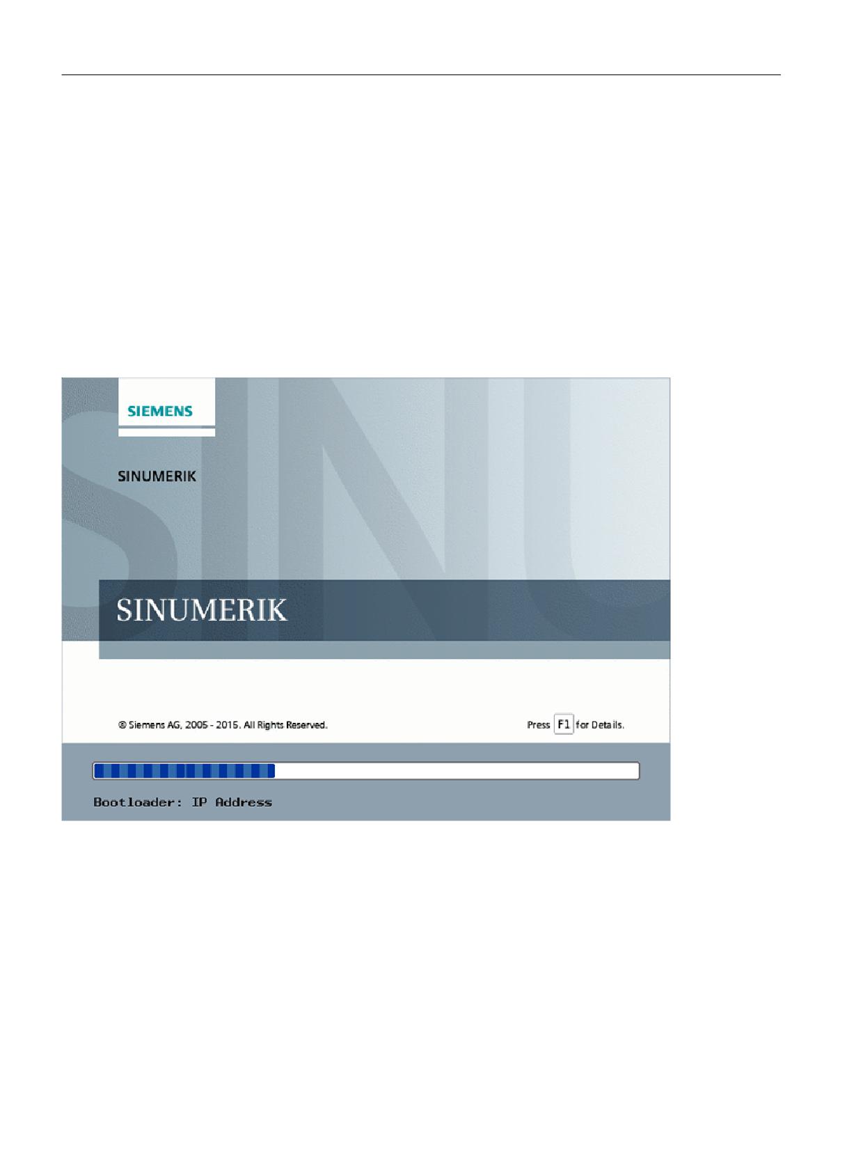
Networking
5.4 Service and diagnostics
5.4.8
Booting of the TCU
5.4.8.1
Messages during booting
Messages when booting
While the TCU boots, a progress indicator is displayed with messages showing the current
status after the BIOS has been loaded and before the operating system is started. While the IP
address is being determined via DHCP and the TFTP is being downloaded (boot image), a
progress bar indicates that booting of the TCU is not yet complete, or that a fault has occurred.
The figure below shows the structure of these messages:
You can see the current boot phase below the progress bar. If a fault occurs, you can call further
information by touching the "F1" field.
Operator panel front: OP 012
72
Manual, 05/2019, A5E36371591B AB
Networking
5.4 Service and diagnostics
5.4.8.2
Diagnostics options during booting
Diagnostics while booting supplementary conditions
In the following supplementary conditions, the diagnostics window is displayed and booting of
the TCU is interrupted:
● When the <1 / F1> function is selected during booting
● When a warning message is displayed
● When a fault occurs
You can select functions <1 / F1> to <8 / F8> mentioned below by tapping on the Panel.
Alternatively, you can do this via the corresponding function keys of a connected USB
keyboard.
Using the <1 / F1> function
7hin Client Bootloader
V05.00.45.00
Boot Progress
BIOS Version
V15.00.00.00
MAC Address
08:06:00:F1:F7:F8
Hardware-ID
7.9.2.0
Network link
1000MB, full duplex
Boot from USB
no device found
IP Address
192.168.214.14
Netmask
255.255.255.0
DHCP Server
192.168.214.1
Boot Server
192.168.214.1
Image Metadata
71 bytes
Image Version
V05.00.46.00
Linux Image (linux.bin)
3295436 bytes
Image Kind
from boot server
Booting
ready
<1/F1> protocol <2/F2> Readme_OSS
<7/F7> continue <8/F8> reboot
Key / text
Meaning
F1 protocol
Display detailed information
F2 Readme_OSS
Details of the Open Source licenses
F7 continue
Continue booting of the TCU
F8 reboot
Restart the TCU
Operator panel front: OP 012
Manual, 05/2019, A5E36371591B AB
73

Networking
5.4 Service and diagnostics
Press <1 / F1> to continue
If you select function <F1> in the diagnostics window, the, detailed diagnostic information is
output.
Key / text
Meaning
F1 ... F6
Navigate within the window
(alternatively, the relevant keys on the OP can be used).
F7 -detail
Display less information
F8 +detail
Display more information
F9 back
Return to diagnostics window
Operator panel front: OP 012
74
Manual, 05/2019, A5E36371591B AB
Service and maintenance
6
Cleaning the device
The operator panel front is designed for low-maintenance operation. Nevertheless, you must
regularly clean the display.
Note
Switch the device off for cleaning
Clean the device only when it is switched off. This way, you ensure that you cannot
unintentionally trigger any functions by touching the touch-sensitive glass surface.
For cleaning, use a soft cloth moistened either with water or a mild cleaning agent. Only use
dish soap or foaming screen detergent as cleaning agents.
Procedure
Spray the cleaning agent on to a cleaning cloth. Never use caustic solvents or abrasive
cleaners.
Note
Avoid damage
Do not clean the device using compressed air or steam jets because they can damage it.
Checking the device
In order to prevent foreign bodies or liquids entering the device, regularly check the device for
the following:
● Ensure that all the housing screws are in place and tight
● For damage to the housing
● For damage to the cable cover or cable entry
Protect the device from environmental effects
Protect the device against the following environmental factors:
● Direct sunshine and heat sources
● Mechanical vibration and shock
● Dust
● Humidity
● Strong magnetic fields
Operator panel front: OP 012
Manual, 05/2019, A5E36371591B AB
75
Service and maintenance
Spare parts
There are no parts of this device that can be replaced by the user.
Suspected malfunction
If you suspect a malfunction due to unusual product reactions, isolate the device from power.
Immediately inform qualified personnel to check the function and ensure that the product
functions correctly.
The following signs can indicate a malfunction:
● Unusual or no functioning
● Unusual heat generation
● Smoke development
Repair
Send the device back to the manufacturer for repair. The device must only be repaired there.
Operator panel front: OP 012
76
Manual, 05/2019, A5E36371591B AB