SINUMERIK 840D sl Hardware. Manual (2011-2020) - page 24

Technical specifications
7
7.1
Technical data
Safety
Safety class
III; PELV according to EN 50178
Degree of protection accord-
Front side IP65
ing to EN 60529
Rear side IP00
Approvals
CE/cULus/EAC/KC/RCM
Electrical data
Power consumption
typically approx. 5 W
(without load at USB interface,
maximum approx. 6 W
without direct key module)
Mechanical data
Dimensions
Width: 483 mm
Height: 310 mm
Depth: 30 mm
Weight
Approx. 5 kg
Tightening torques, max.
Tension jack screws:
M3 screws:
M4 screws:
0.5 Nm
0.8 Nm
1.8 Nm
Display
Size / resolution
12.1" TFT / 800 x 600 pixels
Backlight-service life
typ. 50,000 h at 25º C (dependent on the temperature)
Note
Information about the climatic and mechanical environmental conditions is contained in the
associated section under:
"General notes and interconnection" → "Operational planning".
Operator panel front: OP 012
Manual, 05/2019, A5E36371591B AB
77
Technical specifications
7.2 Secondary electrical conditions
7.2
Secondary electrical conditions
7.2.1
Power supply
Requirements for DC power supplies
WARNING
Electric shock due to connection of an unsuitable power supply
When equipment is connected to an unsuitable power supply and/or insufficiently grounded or
rear cover (Page 19), exposed components may carry a hazardous voltage that might result
in serious injury or death.
● Only use power supplies that provide SELV (Safety Extra Low Voltage) or PELV
(Protective Extra Low Voltage) output voltages acc. to UL 61010 for all connections and
terminals of the electronics modules.
WARNING
Inadequately fused supply cables can be life-threatening
In the case of supply lines >30 m, protectors must be installed at the device input to protect
against lightning (surge).
The DC power supply must be connected to the ground/shield of the NC for EMC and/or
functional reasons. For EMC reasons, this connection should only be made at one point. As
a rule, the connection is provided as standard in the S7-300 I/Os. In exceptional
circumstances when this is not the case, the ground connection should be made on the
grounding rail of the NC cabinet (also refer to /EMC/EMC Installation Guide.)
Table 7-1
Requirements of the DC power supply
Rated voltage
According to EN 61131-2
24 VDC
Voltage range (mean value)
20.4 VDC to 28.8 VDC
Voltage ripple, peak/peak
5% (unsmoothed 6-pulse recti-
Ramp-up time when switched on
fication)
any
Non-periodic overvoltages
≤ 35 V
Period of overvoltage
≤ 500 ms
Recover time
≥ 50 s
Events per hour
≤ 10
Transient voltage interruptions
Downtime
≤ 3 ms
Recovery time
≥ 10 s
Events per hour
≤ 10
Operator panel front: OP 012
78
Manual, 05/2019, A5E36371591B AB
Technical specifications
7.2 Secondary electrical conditions
7.2.2
Grounding concept
Components
The SINUMERIK 840D sl system consists of a number of individual components which have
been designed so that the system complies with the appropriate EMC and safety standards.
The individual system components are:
● Numerical Control Unit (NCU)
● Machine Control Panel (MCP), Machine Pushbutton Panel (MPP)
● Keyboard
● Operator panels (operator panel front + TCU/PCU)
● Distributor box and handheld unit
● S7-300 I/O with IM 153 interface module
Grounding measures
The individual modules are attached to a metal cabinet panel. Insulating paints on the mounting
points (e.g. tension jacks) must be removed.
It is permissible to cluster the operator control components regarding connection/potential
bonding.
Example: The control panel on the swivel arm.
It is sufficient in this instance to connect the ground connections of, for example, the PCU, TCU,
and operator panel front using a cable and to route a shared grounding conductor to the central
ground connection in the control cabinet.
Additional references
EMC Design Guidelines
7.2.3
EMC compatibility
In addition to the protective grounding of system components, special precautions must be
taken to guarantee safe, trouble-free operation of the system. These measures include
shielded signal lines, special equipotential bonding connections, and isolation and shielding
measures.
Shielded signal cables
● For safe and fault-free operation of the system, the specified cables must be used.
● For digital signal transmission, the shield must have a conductive connection at both sides
of the housing.
Operator panel front: OP 012
Manual, 05/2019, A5E36371591B AB
79
Technical specifications
7.2 Secondary electrical conditions
Cable definition
Definition:
● Signal cables (example)
- Data cables (Ethernet, PROFIBUS, sensor cables, etc.)
- Digital I/Os
- Cables for safety functions (emergency stop, enabling)
● Power cables (example)
- Low-voltage supply lines (230 VAC, +24 VDC, etc.)
- Motor cables
Rules for routing cables
In order to achieve the greatest possible EMC compatibility for the complete system (control,
power unit, machine), the following EMC measures must be carefully observed:
● If necessary, signal and power cables may cross one another (if possible at an angle of 90°),
but must never be laid close or parallel to one another.
● Only use cables approved by SIEMENS for the signal lines from and to the Control Unit.
● Signal cables must not be routed close to strong external magnetic fields (e.g. motors and
transformers).
● If signal lines cannot be routed a sufficient distance away from other cables, they must be
installed in grounded cable ducts (metal).
● The operator panel fronts, MCPs, MPPs, and full keyboards must be installed in metallically
enclosed EMC-compatible housings.
Note
For further information on interference suppression measures and the connection of
shielded cables, please refer to the EMC Installation Guide.
7.2.4
EMC limit values in South Korea
The EMC limit values to be observed for Korea correspond to the limit values of the EMC
product standard for variable-speed electric drives EN 61800-3 of category C2 or the limit value
class A, Group 1 according to EN 55011. By implementing appropriate additional measures,
the limit values according to category C2 or limit value class A, Group 1, are observed. Further,
additional measures may be required, for instance, using an additional radio interference
suppression filter (EMC filter).
Operator panel front: OP 012
80
Manual, 05/2019, A5E36371591B AB

Technical specifications
7.3 Ambient climatic and mechanical conditions
The measures for EMC-compliant design of the system are described in detail in this manual
respectively in the Installation Guideline EMC.
Please note that the final statement on compliance with the standard is given by the respective
label attached to the individual unit.
7.3
Ambient climatic and mechanical conditions
7.3.1
Transport and storage conditions
The components of the SINUMERIK 840D sl system exceed the requirements according to
EN 61800-2 with regard to shipping and storage conditions.
The following data applies under the following conditions:
● Long-term storage in the transport and product packaging:
At weather-protected locations that have continuous contact with outside air through
openings.
● Transport in the transport packaging:
- In unventilated containers under conditions not protected from weather effects.
- In the "cold" in accordance with outside air.
- Air transport in the air-conditioned cargo hold.
Table 7-2
Ambient conditions during storage and transport
Type of condition
Permissible range/class
Transport
Storage
Classification
EN 60721-3-2
EN 60721-3-1
Climate class
2K4
1K4
Ambient temperature 1)
-40° C ... +70° C
-25° C ... +55° C
Biological environmental condi-
2B1 2)
1B1 2)
tions
Chemically active environmental
2C2 3)
1C2 3)
conditions
Mechanical environmental condi-
Class 2M3 according to EN
Class 1M2 according to EN
tions
60721-3-2, in transport pack-
60721-3-1, in product packag-
aging 4)
ing 5)
Maximum permissible tempera-
Direct interaction in air/air:
30 k/h
ture change
-40°/+30° C at 95% relative
humidity
Relative humidity (without conden-
5 to 95%
sation)
Precipitation, rain
6 mm/min 2)
Not permissible
Water other than rain
1 m/s and wet loading surfa-
Not permis-
1 m/s and wet
ces 6)
sible 7)
loading surfaces 6)
Operator panel front: OP 012
Manual, 05/2019, A5E36371591B AB
81
Technical specifications
7.3 Ambient climatic and mechanical conditions
Type of condition
Permissible range/class
Height
Max. 4,000 m above sea level
Condensation, splash water,
Permissible
Not permis-
Permissible 6)
icing, salt spray
sible 7)
1)
Transport and storage of operator panel fronts and diskette drives: -20° C to +55° C.
2)
Mold growth, slime, rodents, termites and other animal vermin are not permissible.
3)
In marine- and weather-resistant transport packaging (container).
4)
Transport packaging is either packaging that is directly suitable for transport or secondary packaging,
which together with the product packaging, satisfies the requirements for transport.
5)
Product packaging (storage packaging) is an individual packaging for storage and does not satisfy the
requirements for transport. As a consequence, product packaging is therefore not suitable for
shipping.
6)
For storage in the transport packaging.
7)
For storage in the product packaging.
Note
Remove the transport protective foil and packaging material before installing the components.
7.3.2
Operating conditions
The components of the SINUMERIK 840D sl system are intended for a weatherproof, fixed
location. The documented
environmental conditions apply to the climate in the immediate vicinity of the units and to the
entry of the cooling air. They exceed the requirements according to EN 60204-1, EN 61800-2,
EN 61131-2 and IEC 62477-1.
NOTICE
Damage to components by coolants and lubricants
The SINUMERIK operator components have been designed for industrial use, particularly on
machine tools and production machines. This also takes into account the use of commercially
available coolants and lubricants. The use of aggressive compounds and additives can
damage components and result in their failure.
Contact between the operator components and coolants and lubricants should be avoided as
far as possible, as resistance to all coolants and lubricants cannot be guaranteed.
Ambient climatic conditions
Climate class according to EN
Better than class 3K3
60721-3-3
Temperature
0 ... 55° C (without derating)
Installation altitude
Up to 1000 m without derating
From 1000 m to 3000 m with linear ambient temperature de-
rating, -0.5 K per 100 m
Operator panel front: OP 012
82
Manual, 05/2019, A5E36371591B AB

Technical specifications
7.3 Ambient climatic and mechanical conditions
Ambient climatic conditions
Relative humidity
5 ... 95% (no condensation)
Oil mist, salt mist, ice formation, con-
Not permitted
densation, dripping water, spraying
water, splashing water and water jets
Biological, chemical, electrical and mechanical influences, pollutants
Biological environmental conditions
Class 3B1 according to EN 60 721-3-3:
Mold, mold growth, slime, rodents, termites and other animal
vermin are not permissible.
Chemically active environmental con-
Class 3C1 according to EN 60721-3-3
ditions
Mechanically active environmental
Class 3M1 according to EN 60721-3-3:
conditions
Conductive dust not permissible.
Classification of the mechanical
3M3 for components on the machine
environment
3M1/3M2 for components in the control cabinet
Vibration test in operation
According to IEC 60068-2-6 test Fc (sinusoidal)
●
10…57 Hz: 0.075 mm deflection amplitude
●
57…150 Hz: 1 g acceleration amplitude
●
10 frequency cycles per axis
Shock test in operation
According to IEC 60068-2-27 test Ea (half-sine)
●
5 g peak acceleration
●
30 ms duration
●
3 shocks in all three axes in both directions
Degree of contamination
2 (only use indoors)
EMC conducted / radiation
Class C2 according to EN 61800-3
Note
The user must consider radio interference for the complete system. Particular attention should
be paid to cabling. Please contact your sales representative for assistance and support.
Note
In a residential environment, this product can cause high-frequency interference, which may
make interference suppression measures necessary.
Have the installation and commissioning with appropriate radio interference suppression
measures performed by qualified personnel.
7.3.3
Cooling
To calculate the heat dissipation, the total power loss PVtotal of all heat-generating components
in a housing must be taken into account.
Total power loss PVtotal = PV1 + PV2 + PV3 +... [W]
Operator panel front: OP 012
Manual, 05/2019, A5E36371591B AB
83
Technical specifications
7.3 Ambient climatic and mechanical conditions
Convection surface area A [m2]:
The surface areas of the front and bottom sides are not included in the convection surface area
calculation.
Note
A recommended value for the power loss of the operator control components is contained in the
"Technical data" section of the associated component (see "Power consumption").
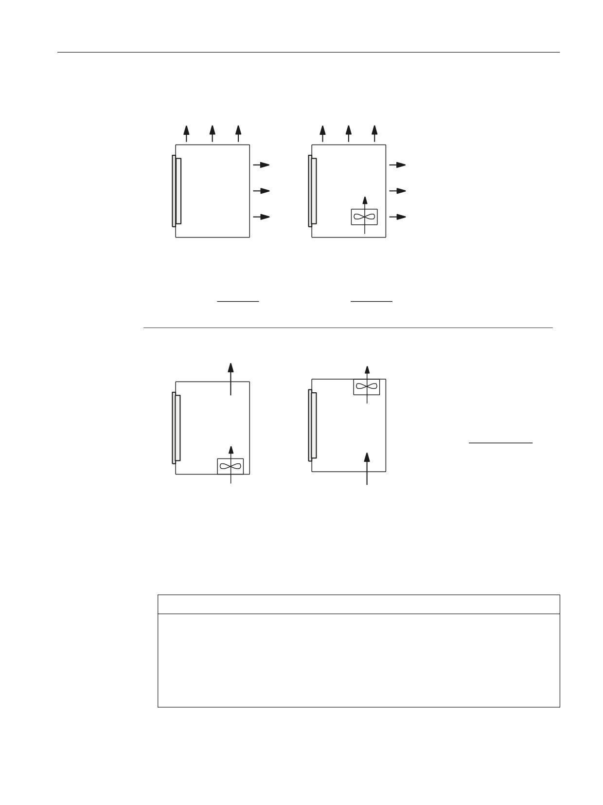
Means of heat dissipation
Heat dissipation can take place as follows:
● Heat dissipation by natural convection
● Heat dissipation by natural convection and internal air turbulence
● Heat dissipation by open-circuit cooling
● Heat dissipation by open-circuit ventilation
Operator panel front: OP 012
84
Manual, 05/2019, A5E36371591B AB
Technical specifications
7.3 Ambient climatic and mechanical conditions
+HDW GLVVLSDWLRQ
+HDW GLVVLSDWLRQ
XVLQJ QDWXUDO FRQYHFWLRQ
XVLQJ QDWXUDO FRQYHQWLRQ DQG
LQWHUQDO WXUEXOHQFH
2SHUDWRU
2SHUDWRU
YROXPHWULF IORZ RI WKH IDQ
SDQHO IURQW
SDQHO IURQW
P K
7
7
7
7
7KH UHTXLUHG IUHH FRQYHFWLRQ VXUIDFH $>P @ RI WKH
URRP WR EH FRQYHUWHG VWHHO RU DOXPLQXP VKHHWLQJ
PP WKLFNQHVV LV FDOFXODWHG EDVHG RQ
D WHPSHUDWXUH GLIIHUHQFH 7
7
ෙ7 ุ
. DSSUR[LPDWHG IURP
39
>:@
39JHV>:@
$ >P @
JHV
$ >P @
˂7 >.@
˂7 >.@
+HDW GLVVLSDWLRQ
+HDW GLVVLSDWLRQ
XVLQJ RSHQ FLUFXLW YHQWLODWLRQ
XVLQJ RSHQ FLUFXLW YHQWLODWLRQ
7KH UHTXLUHG YROXPHWULF
IORZ IRU GLVVLSDWLQJ WKH KHDW
ORVV LV FDOFXODWHG XVLQJ
DSSUR[LPDWLRQV IURP
2SHUDWRU
2SHUDWRU
SDQHO IURQW
SDQHO IURQW
39JHV >:@
9 >P K@
7
7
7
7
˂7 >.@
Figure 7-1
Means of heat dissipation
Fan design
● The fan must be positioned to produce an optimum heat dissipation. A clearance of 10 mm
must be maintained in front of the fan.
● The inlet and outlet slots must remain free for the open-circuit ventilation.
● Air filters must be provided to maintain the permitted environmental conditions.
NOTICE
Damage to the operating components caused by temperatures that are too high or too low
Contaminated air filters impair the desired heat dissipation. For handling the air filters, pay
attention to:
● Proper handling
● Regular replacement
● Correct disposal
Operator panel front: OP 012
Manual, 05/2019, A5E36371591B AB
85
Technical specifications
7.4 Standards and approvals
Guidelines
If the convection area A [m2] does not suffice for the "heat dissipation using natural convection",
then use:
● "Heat dissipation using natural convection and internal turbulence" for hot spots and heat
concentrations in housings subject to space constraints. The total power loss PLtot for
thermally critical applications can be determined as follows:
- Current measurement for a 24 V supply voltage
- Power loss PLtot [W] = U (24 V) * |measured value in ampères|
● Heat dissipation using open-circuit ventilation
Calculation of the volumetric flow
The power loss (thermal) dissipated by the components in an operator unit is to be dissipated
using open-circuit ventilation. The volumetric flow V required for this should be calculated at a
difference in temperature of T2 - T1 = ΔT ≥ 10K.
([DPSOH IRU KHDW GLVVLSDWLRQ ZLWK RSHQ FLUFXLW YHQWLODWLRQ
3&8
ZLWK 23
3&8
&DOFXODWLRQ RI WKH SRZHU ORVV
LQFOXGLQJ LQWHUQDO SRZHU VXSSO\ XQLW
23
:
3&8
:
39JHV
:
PD[
:
7
7
39JHV
>:@
9
>P K@
˂7 >.@
23
([WHUQDO WHPSHUDWXUH
7
r&
ය ˂7
,QWHUQDO WHPSHUDWXUH
7
r&
Figure 7-2
Calculating heat dissipation for PCU 50.5 with OP 019
7.4
Standards and approvals
Approvals
CE approval
Figure 7-3
CE marking
Operator panel front: OP 012
86
Manual, 05/2019, A5E36371591B AB
Technical specifications
7.5 Recycling and disposal
The operator panels and the safety-relevant accessories satisfy the requirements and
protection objectives of the following EC directives. The operator panels and the safety-
relevant accessories comply with the harmonized European standards (EN), promulgated in
the Official Journals of the European Community:
●
2004/108/EC "Electromagnetic Compatibility" (EMC directive)
● Directive 2006/42/EC of the European Parliament and Council of May 17, 2006, on
machinery, and Directive 95/16/EC (amendment)
China RoHS
The products comply with the China RoHS directive Further information on this can be found
on the Internet at the following link: SIOS (https://support.industry.siemens.com/cs/document/
109738656/china-rohs-manufacturer?dti=0&lc=en-WW)
Risk assessment
The following standards must be used to perform the risk assessment:
● EN ISO 12100-1:2003 and EN ISO 12100-2:2003, General Design Guidelines for Machines
● EN ISO 14121-1:2007, Risk Assessment for Machinery
● EN ISO 13849-1:2008, Safety-related Parts of Machines
These considerations result in a category (B, 1, 2, 3, 4) and a performance level (PL a to e) in
accordance with EN ISO 13849-1:2008 that ultimately dictate how the safety-related parts of
the system to be monitored must be constructed.
The connection examples with different monitoring units in "Handheld units", Section: "HT 2",
Section: "Connections" → "Connection examples for acknowledgment button and Emergency
Stop button" can also be used for other operator panels and demonstrate how Category 3, PL
d according to EN ISO 13849-1:2008 can be attained with the safety-related parts of the
operator panels. Note that the overall concept of the installation must be designed with this in
mind.
7.5
Recycling and disposal
For environmentally friendly recycling and disposal of your old device, please contact a
company certified for the disposal of electrical and electronic waste and dispose of the device
in accordance with the regulations in your country.
Operator panel front: OP 012
Manual, 05/2019, A5E36371591B AB
87
Technical specifications
7.5 Recycling and disposal
Operator panel front: OP 012
88
Manual, 05/2019, A5E36371591B AB
Spare parts
8
8.1
Overview
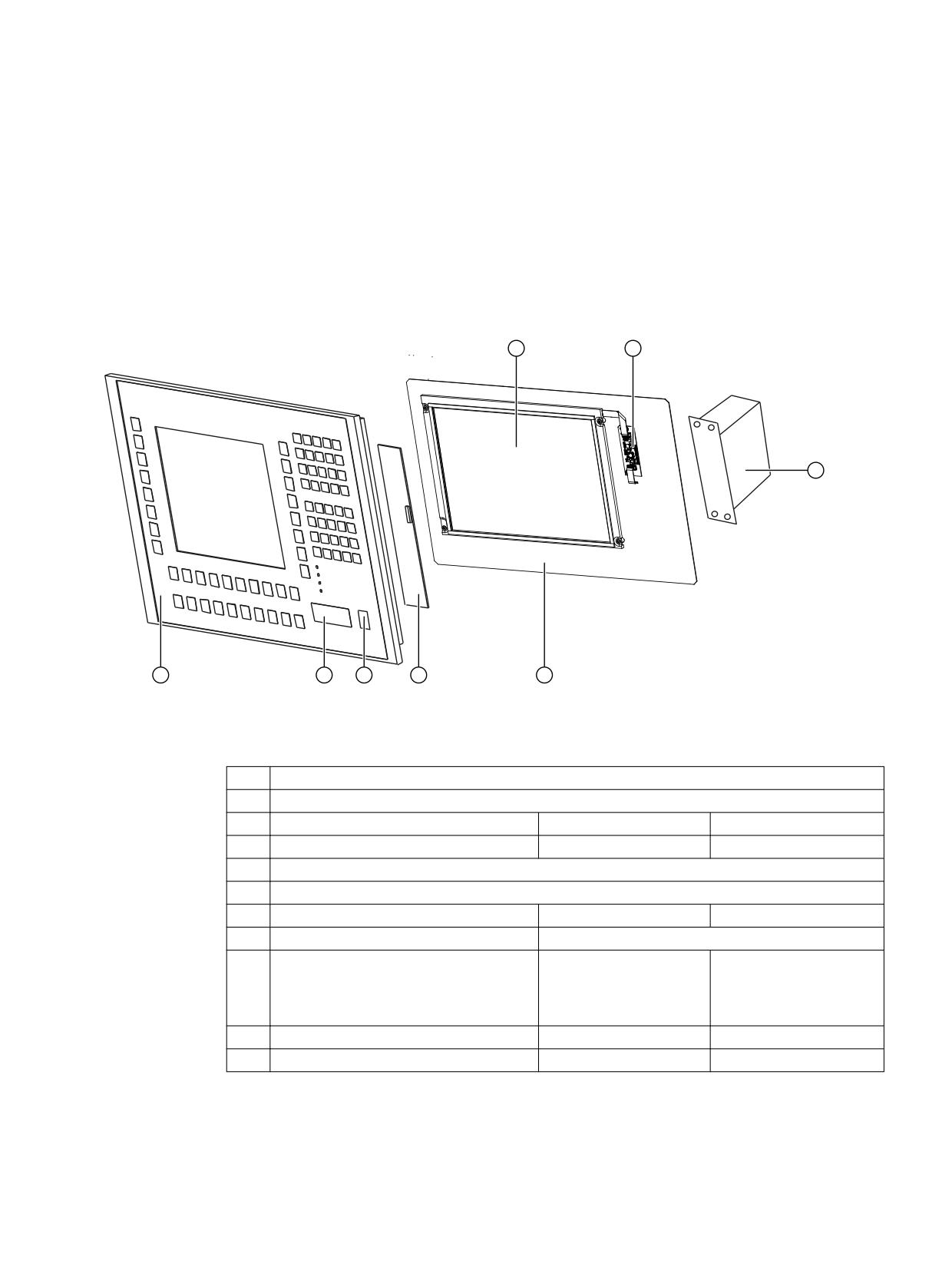
The diagram shows the OP 012 operator panel front dismantled into its individual parts.
Figure 8-1
Individual parts for the OP 012 operator panel front
The components listed in the following table with an article number are available as spare parts.
①
Display
②
LED backlight driver
Spare part
Article number
Remark
③
Direct key module
6FC5247-0AF11-0AA0
④
Display support
⑤
Keyboard controller
⑥
Caps for the USB port
6FC5248-0AF05-0AA0
Set of 10
⑦
Touchpad mouse
⑧
Operator panel front
6FC5248-0AF02-0AA2
with touchpad mouse,
without display, without
keyboard controller, with-
out direct key module
Slide-in strips that can be labeled
6FC5248-0AF08-0AA0
Set with 3 foils, DIN A4
Tension jacks
6FC5248-0AF14-0AA0
Set of 9
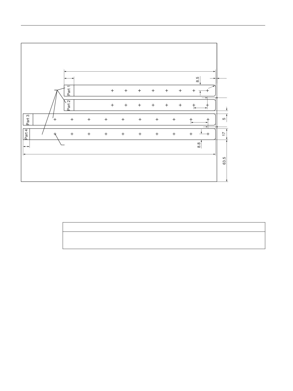
The dimensions for creating slide-in labels from the foil for labeling the vertical softkeys can be
seen in the following diagram.
Operator panel front: OP 012
Manual, 05/2019, A5E36371591B AB
89
Spare parts
8.2 Replacement
5
6OLGH LQ ODEHOV
&HQWHU RI WKH NH\
Figure 8-2
Dimensions for slide-in labels
8.2
Replacement
NOTICE
Risk of damage to sensitive components due to static electricity
Spare parts must always be replaced by properly trained personnel!
USB cap / tension jack
The replacement of the USB sealing cap and tension jacks will not be described since it is
simple and self-explanatory.
Film labels
The procedure for replacement is as described in the section "Softkey labeling":
Operator panel front: OP 012
90
Manual, 05/2019, A5E36371591B AB
Spare parts
8.2 Replacement
Operator panel front
When replacing the operator panel front, the previous USB interface, display and keyboard
controller can continue to be used. They are therefore disassembled and reassembled after the
appropriate component has been replaced.
Note
We recommend reusing the keypad controller to prevent any loss of the control parameters that
have been programmed in.
Procedure
1. Put the OP 012 face down on a flat, soft surface and loosen the 12 housing screws (see
figure: "Rear of the OP 012 (Page 22)").
2. Remove the softkey labeling strips and the cover plate.
3. Remove connector X14 for the backlight ⑧ and the IO-USB cable K1 ④ from the keyboard
controller ③.
4. Remove connector X4 for the touchpad mouse ⑨.
5. Lift off the display support with the display.
The rear of the front USB interface ② becomes visible near the keyboard controller ③.
6. After bending back the two lugs, withdraw the front USB interface ②.
7. Disconnect the two membrane connectors ⑥ of the operator panel front keyboard from
sockets X7 and X8 (procedure: see note).
8. Remove the fixing screws from the keyboard controller ③.
9. Lift the front USB interface ② and keyboard controller ③ off the front plate. The
interconnections may remain plugged.
10.Install the components into the new operator front panel in reverse order (procedure: see
note).
Note
Descriptions of how to disconnect and connect the membrane connector can be found in
"General information and networking", Chapter: "Connecting", Section: "Handling
membrane connectors".
When tightening the screws, observe the torques (refer to Section: "Technical data").
Operator panel front: OP 012
Manual, 05/2019, A5E36371591B AB
91
Spare parts
8.2 Replacement
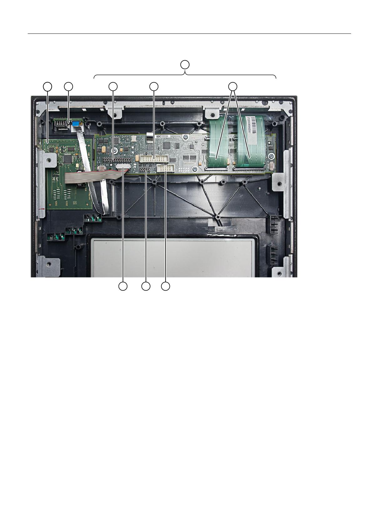
①
Touchpad mouse
②
Front USB interface
③
Keyboard controller
④
Connection X1 for IO-USB cable K1
⑤
Direct key connection X11
⑥
Membrane connectors X7 and X8 for connecting the operator panel front keyboard.
⑦
Connection X12 (reserved)
⑧
Connection X14 for backlight
⑨
Connection X4 for touchpad mouse
Figure 8-3
Replacement of operator panel front OP 012
See also
Assembling an OP 012 and a PCU (Page 21)
Operator panel front: OP 012
92
Manual, 05/2019, A5E36371591B AB

Fundamental safety
1
instructions
2
Description
3
Dimension drawings
SINUMERIK
4
Connecting
SINUMERIK ONE / SINUMERIK 840D
sl
5
Commissioning
Handheld Terminal HT 10
6
Maintenance and Service
Equipment Manual
7
Technical specifications
8
Spare parts
9
Accessories
Valid for:
Control
SINUMERIK ONE
SINUMERIK 840D sl / 840DE sl
09/2020
A5E47430965B AA
Table of contents
1
Fundamental safety instructions
5
1.1
General safety instructions
5
1.2
Equipment damage due to electric fields or electrostatic discharge
8
1.3
Warranty and liability for application examples
9
1.4
Security information
9
1.5
Residual risks of power drive systems
10
2
Description
13
2.1
Characteristics
13
2.2
Representation
15
2.3
Type plate
17
2.4
Operator control and display elements
17
2.5
Touch operation
20
2.6
Interfaces
22
2.7
Screen brightness control
22
3
Dimension drawings
23
4
Connecting
25
4.1
Overview
25
4.2
Pin assignment of the interfaces
26
4.2.1
Power supply
26
4.2.2
USB interfaces
27
4.2.3
Ethernet RJ45 interface
28
4.3
Power supply
29
4.4
SIMATIC connection box
30
4.4.1
Description
30
4.4.2
Connection box standard
32
4.4.3
Connection box advanced
34
4.4.4
Interface assignment
36
4.4.5
Connecting a connection box
42
4.4.5.1
Connection information
42
4.4.5.2
Opening and closing connection box standard and connection box advanced
42
4.4.5.3
Equipotential bonding of connection boxes
45
4.4.5.4
Connecting the functional grounding and power supply to the connection box
47
4.4.5.5
Connecting cables for a hardwired F-system
48
4.4.5.6
Connecting Ethernet to the connection box
50
4.4.5.7
Setting the box ID of the connection box
51
4.4.5.8
Secure cables and seal screw glands
53
Handheld Terminal HT 10
Equipment Manual, 09/2020, A5E47430965B AA
3
Table of contents
4.5
PN Basic connection module
54
4.5.1
Description
54
4.5.2
interfaces
54
4.5.3
Dimension drawing
58
4.5.4
Installing the terminating connector
59
4.6
Connecting cable
60
4.7
Unplugging/plugging during operation
64
5
Commissioning
65
5.1
Activating/deactivating the virtual keyboard
65
5.2
Configuring user-specific key labeling
65
5.3
Configuring the function display at user-specific keys (U keys)
67
5.4
Dimming the display
70
5.5
Troubleshooting
72
5.5.1
Messages during booting
73
5.5.2
Diagnostics options during booting
74
6
Maintenance and Service
77
7
Technical specifications
79
7.1
Handheld Terminal HT 10
79
7.2
Connection module Basic PN
80
7.3
Connection box
81
7.4
Supplementary electrical conditions
82
7.4.1
Power supply
83
7.4.2
Grounding concept
84
7.4.3
RI suppression measures
85
7.4.4
EMC limiting values in South Korea
86
7.4.5
EMF assessments for 24 V components
86
7.5
Climatic and mechanical ambient conditions
86
7.5.1
Shipping and storage conditions
86
7.5.2
Operating conditions
87
7.6
Recycling and disposal
89
7.7
Standards and approvals
89
8
Spare parts
91
9
Accessories
93
9.1
Overview
93
9.2
HT10 wall holder
94
Index
95
Handheld Terminal HT 10
4
Equipment Manual, 09/2020, A5E47430965B AA

Fundamental safety instructions
1
1.1
General safety instructions
WARNING
Electric shock and danger to life due to other energy sources
Touching live components can result in death or severe injury.
• Only work on electrical devices when you are qualified for this job.
• Always observe the country-specific safety rules.
Generally, the following steps apply when establishing safety:
1. Prepare for disconnection. Notify all those who will be affected by the procedure.
2. Isolate the drive system from the power supply and take measures to prevent it being
switched back on again.
3. Wait until the discharge time specified on the warning labels has elapsed.
4. Check that there is no voltage between any of the power connections, and between any of
the power connections and the protective conductor connection.
5. Check whether the existing auxiliary supply circuits are de-energized.
6. Ensure that the motors cannot move.
7. Identify all other dangerous energy sources, e.g. compressed air, hydraulic systems, or
water. Switch the energy sources to a safe state.
8. Check that the correct drive system is completely locked.
After you have completed the work, restore the operational readiness in the inverse sequence.
WARNING
Electric shock due to connection to an unsuitable power supply
When equipment is connected to an unsuitable power supply, exposed components may carry
a hazardous voltage. Contact with hazardous voltage can result in severe injury or death.
• Only use power supplies that provide SELV (Safety Extra Low Voltage) or PELV- (Protective
Extra Low Voltage) output voltages for all connections and terminals of the electronics
modules.
Handheld Terminal HT 10
Equipment Manual, 09/2020, A5E47430965B AA
5

Fundamental safety instructions
1.1 General safety instructions
WARNING
Electric shock due to equipment damage
Improper handling may cause damage to equipment. For damaged devices, hazardous
voltages can be present at the enclosure or at exposed components; if touched, this can result
in death or severe injury.
• Ensure compliance with the limit values specified in the technical data during transport,
storage and operation.
• Do not use any damaged devices.
WARNING
Electric shock due to unconnected cable shields
Hazardous touch voltages can occur through capacitive cross-coupling due to unconnected
cable shields.
• As a minimum, connect cable shields and the cores of cables that are not used at one end
at the grounded housing potential.
WARNING
Electric shock if there is no ground connection
For missing or incorrectly implemented protective conductor connection for devices with
protection class I, high voltages can be present at open, exposed parts, which when touched,
can result in death or severe injury.
• Ground the device in compliance with the applicable regulations.
NOTICE
Damage to equipment due to unsuitable tightening tools.
Unsuitable tightening tools or fastening methods can damage the screws of the equipment.
• Be sure to only use screwdrivers which exactly match the heads of the screws.
• Tighten the screws with the torque specified in the technical documentation.
• Use a torque wrench or a mechanical precision nut runner with a dynamic torque sensor and
speed limitation system.
Handheld Terminal HT 10
6
Equipment Manual, 09/2020, A5E47430965B AA

Fundamental safety instructions
1.1 General safety instructions
WARNING
Spread of fire from built-in devices
In the event of fire outbreak, the enclosures of built-in devices cannot prevent the escape of
fire and smoke. This can result in serious personal injury or property damage.
• Install built-in units in a suitable metal cabinet in such a way that personnel are protected
against fire and smoke, or take other appropriate measures to protect personnel.
• Ensure that smoke can only escape via controlled and monitored paths.
WARNING
Unexpected movement of machines caused by radio devices or mobile phones
Using radio devices or mobile telephones in the immediate vicinity of the components can
result in equipment malfunction. Malfunctions may impair the functional safety of machines
and can therefore put people in danger or lead to property damage.
• Therefore, if you move closer than 20 cm to the components, be sure to switch off radio
devices or mobile telephones.
• Use the "SIEMENS Industry Online Support app" only on equipment that has already been
switched off.
WARNING
Fire due to inadequate ventilation clearances
Inadequate ventilation clearances can cause overheating of components with subsequent fire
and smoke. This can cause severe injury or even death. This can also result in increased
downtime and reduced service lives for devices/systems.
• Ensure compliance with the specified minimum clearance as ventilation clearance for the
respective component.
NOTICE
Overheating due to inadmissible mounting position
The device may overheat and therefore be damaged if mounted in an inadmissible position.
• Only operate the device in admissible mounting positions.
Handheld Terminal HT 10
Equipment Manual, 09/2020, A5E47430965B AA
7

Fundamental safety instructions
1.2 Equipment damage due to electric fields or electrostatic discharge
WARNING
Unexpected movement of machines caused by inactive safety functions
Inactive or non-adapted safety functions can trigger unexpected machine movements that
may result in serious injury or death.
• Observe the information in the appropriate product documentation before commissioning.
• Carry out a safety inspection for functions relevant to safety on the entire system, including
all safety-related components.
• Ensure that the safety functions used in your drives and automation tasks are adjusted and
activated through appropriate parameterizing.
• Perform a function test.
• Only put your plant into live operation once you have guaranteed that the functions
relevant to safety are running correctly.
Note
Important safety notices for Safety Integrated functions
If you want to use Safety Integrated functions, you must observe the safety notices in the Safety
Integrated manuals.
1.2
Equipment damage due to electric fields or electrostatic discharge
Electrostatic sensitive devices (ESD) are individual components, integrated circuits, modules or
devices that may be damaged by either electric fields or electrostatic discharge.
NOTICE
Equipment damage due to electric fields or electrostatic discharge
Electric fields or electrostatic discharge can cause malfunctions through damaged individual
components, integrated circuits, modules or devices.
• Only pack, store, transport and send electronic components, modules or devices in their
original packaging or in other suitable materials, e.g conductive foam rubber of aluminum
foil.
• Only touch components, modules and devices when you are grounded by one of the
following methods:
- Wearing an ESD wrist strap
- Wearing ESD shoes or ESD grounding straps in ESD areas with conductive flooring
• Only place electronic components, modules or devices on conductive surfaces (table with
ESD surface, conductive ESD foam, ESD packaging, ESD transport container).
Handheld Terminal HT 10
8
Equipment Manual, 09/2020, A5E47430965B AA
Fundamental safety instructions
1.4 Security information
1.3
Warranty and liability for application examples
Application examples are not binding and do not claim to be complete regarding configuration,
equipment or any eventuality which may arise. Application examples do not represent specific
customer solutions, but are only intended to provide support for typical tasks.
As the user you yourself are responsible for ensuring that the products described are operated
correctly. Application examples do not relieve you of your responsibility for safe handling when
using, installing, operating and maintaining the equipment.
1.4
Security information
Siemens provides products and solutions with industrial security functions that support the
secure operation of plants, systems, machines and networks.
In order to protect plants, systems, machines and networks against cyber threats, it is necessary
to implement - and continuously maintain - a holistic, state-of-the-art industrial security
concept. Siemens’ products and solutions constitute one element of such a concept.
Customers are responsible for preventing unauthorized access to their plants, systems,
machines and networks. Such systems, machines and components should only be connected to
an enterprise network or the internet if and to the extent such a connection is necessary and only
when appropriate security measures (e.g. firewalls and/or network segmentation) are in place.
For additional information on industrial security measures that may be implemented, please
visit
Siemens’ products and solutions undergo continuous development to make them more secure.
Siemens strongly recommends that product updates are applied as soon as they are available
and that the latest product versions are used. Use of product versions that are no longer
supported, and failure to apply the latest updates may increase customer’s exposure to cyber
threats.
To stay informed about product updates, subscribe to the Siemens Industrial Security RSS Feed
under
services/cert.html#Subscriptions).
Further information is provided on the Internet:
Handheld Terminal HT 10
Equipment Manual, 09/2020, A5E47430965B AA
9
Fundamental safety instructions
1.5 Residual risks of power drive systems
Industrial Security Configuration Manual (https://support.industry.siemens.com/cs/ww/en/
view/108862708)
WARNING
Unsafe operating states resulting from software manipulation
Software manipulations, e.g. viruses, Trojans, or worms, can cause unsafe operating states in
your system that may lead to death, serious injury, and property damage.
• Keep the software up to date.
• Incorporate the automation and drive components into a holistic, state-of-the-art industrial
security concept for the installation or machine.
• Make sure that you include all installed products into the holistic industrial security concept.
• Protect files stored on exchangeable storage media from malicious software by with suitable
protection measures, e.g. virus scanners.
• On completion of commissioning, check all security-related settings.
1.5
Residual risks of power drive systems
When assessing the machine- or system-related risk in accordance with the respective local
regulations (e.g., EC Machinery Directive), the machine manufacturer or system installer must
take into account the following residual risks emanating from the control and drive components
of a drive system:
1. Unintentional movements of driven machine or system components during commissioning,
operation, maintenance, and repairs caused by, for example,
- Hardware and/or software errors in the sensors, control system, actuators, and cables and
connections
- Response times of the control system and of the drive
- Operation and/or environmental conditions outside the specification
- Condensation/conductive contamination
- Parameterization, programming, cabling, and installation errors
- Use of wireless devices/mobile phones in the immediate vicinity of electronic components
- External influences/damage
- X-ray, ionizing radiation and cosmic radiation
2. Unusually high temperatures, including open flames, as well as emissions of light, noise,
particles, gases, etc., can occur inside and outside the components under fault conditions
caused by, for example:
- Component failure
- Software errors
- Operation and/or environmental conditions outside the specification
- External influences/damage
Handheld Terminal HT 10
10
Equipment Manual, 09/2020, A5E47430965B AA
Fundamental safety instructions
1.5 Residual risks of power drive systems
3. Hazardous shock voltages caused by, for example:
- Component failure
- Influence during electrostatic charging
- Induction of voltages in moving motors
- Operation and/or environmental conditions outside the specification
- Condensation/conductive contamination
- External influences/damage
4. Electrical, magnetic and electromagnetic fields generated in operation that can pose a risk to
people with a pacemaker, implants or metal replacement joints, etc., if they are too close
5. Release of environmental pollutants or emissions as a result of improper operation of the
system and/or failure to dispose of components safely and correctly
6. Influence of network-connected communication systems, e.g. ripple-control transmitters or
data communication via the network
For more information about the residual risks of the drive system components, see the relevant
sections in the technical user documentation.
Handheld Terminal HT 10
Equipment Manual, 09/2020, A5E47430965B AA
11

Description
2
2.1
Characteristics
The HT 10 mobile handheld terminal combines the functions of an operator panel and a
machine control panel in one device, permitting complete operator control and monitoring of
machines. It can be used according to the principle of a Thin Client (see also the Equipment
Manual: "TCU 30.3") as a supplementary main operator panel or as a secondary control panel.
Note
Siemens AG declares that this device complies with the requirements and other regulations of
the directives 2006/42/EC (Machinery Directive) and 2004/108/EC (EMC Directive).
You can find all HT 10 declarations in the Siemens Industry Online Support at: (https://
support.industry.siemens.com/cs/products?mfn=ps&lc=en-WW)
Enter the MLFB in the search field.
Handheld Terminal HT 10
Equipment Manual, 09/2020, A5E47430965B AA
13

Description
2.1 Characteristics
Validity
The following description applies to the following components:
Designation
Features
Article number
HT 10
Enabling button, emergency stop button, override
6FC5403-0AA21-0AA1
rotary switch
HT 10H
Enabling button, emergency stop button, override
6FC5403-0AA21-1AA1
rotary switch, handwheel
Characteristics
Device front:
• Pixel-graphics 10.1" TFT color display
-
1280 x 800 (WXGA) color TFT
– LED backlight
• Multi-touch operation and gesture control via touch screen, can also be actuated when
operators are wearing gloves.
• Touch keys: Keys on predefined, reserved area of the screen
• Unlit emergency stop button (2-channel)
•
7 mechanical function keys with colored replaceable caps, tactile feedback and LED
checkback signal above each key
• Easy hot swapping during operation (hot plug and play) possible without tripping the
emergency stop in combination with the "SIMATIC PN advanced" connection box and
without an additional, manual actuating element / keyswitch
• Rotary override switch (19 positions)
• Handwheel (only with 6FC5403-0AA21-1AA1)
Device rear:
• Power supply (+24 V)
•
1 enabling button (2-channel, 3-stage)
• Cover with option of installing a connecting cable (can be ordered separately) to the
connection box/connection module (24 V)
• Customer interfaces:
- HT 10 connecting cable to connection box / connection module
- USB interface 3.0 (with dummy plug)
Optional:
Wall holder (accessory): The HT 10 can be kept safely and operated in a stationary manner in the
wall holder.
Handheld Terminal HT 10
14
Equipment Manual, 09/2020, A5E47430965B AA
Description
2.2 Representation
2.2
Representation
Front
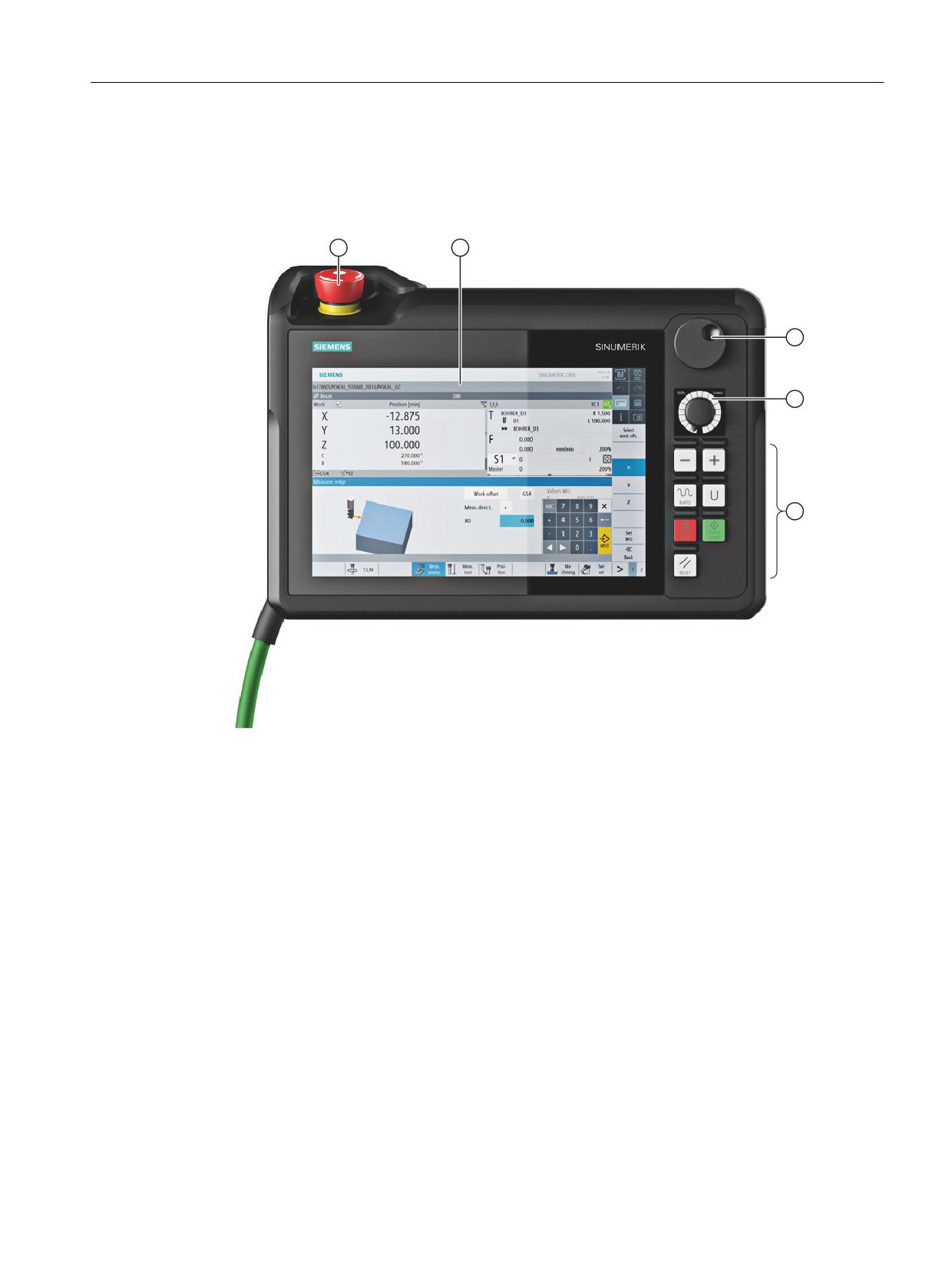
① Emergency Stop button
② Display / touch screen
③ Handwheel (optional)
④ Rot. over. switch
⑤ LED function keys
Figure 2-1
HT 10 with handwheel and wall holder
Handheld Terminal HT 10
Equipment Manual, 09/2020, A5E47430965B AA
15
Description
2.2 Representation
Rear
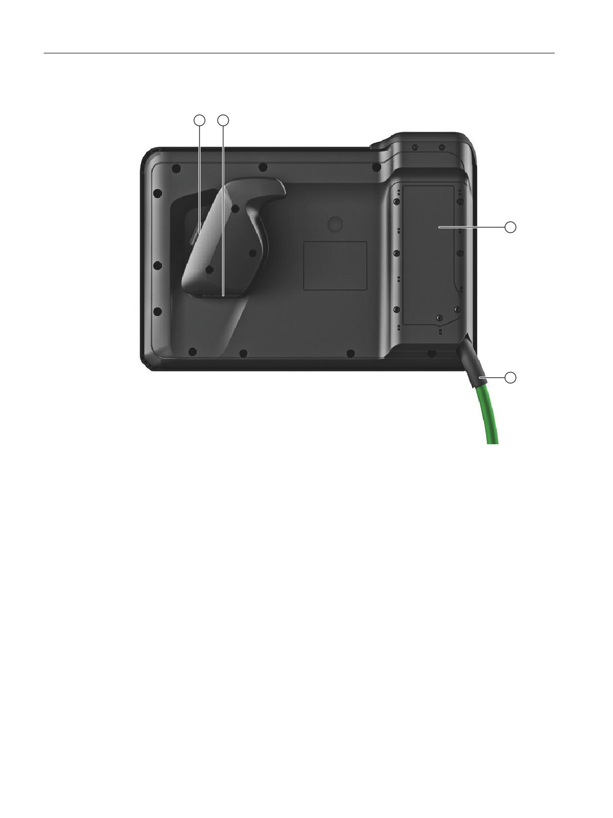
① Enabling button
② USB interface with protective cover
③ Cover
④ Connection cable (order separately)
Figure 2-2
Rear of the HT 10
Handheld Terminal HT 10
16
Equipment Manual, 09/2020, A5E47430965B AA
Description
2.4 Operator control and display elements
2.3
Type plate
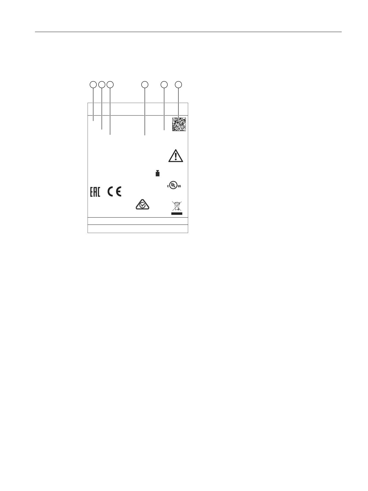
The following diagram shows you all the information provided on the nameplate.
s
6
,180(5
,. +$1'+(/' 7(50,1$/
+7
+Z
LWK KDQGZKHHO
3
)&
$$
$$
)6
$ (
6 /%/
2SHUDWLQJ
7D r& WR
r&
1RQ 2SHUDWLQJ
7D
r& WR
r&
,QSXW
9
$ PD[
(QFORVXUH 7\SH
3URWHFWLRQ
,3
UHIHU WR XVHU PDQXDO
NJ
LISTED
PROG. CNTLR
E164110
KWWS VXSSRUW DXWRPDWLRQ VLHPHQV FRP
6LHPHQV $* )UDXHQDXUDFKHU 6WU
'(
(UODQJHQ
0DGH LQ *HUPDQ\
① Component name
② Article number
③ Material number
④ Serial number
⑤ Version (functional state)
⑥ Product code
2.4
Operator control and display elements
Display / touch screen
The industrial display has LED backlighting.
All application-specific functions are displayed on the touch-sensitive display (projected
capacitive). A particular function is initiated by touching the appropriate location in the display
with the finger. The front glass is toughened and bonded to the touch sensor and display by
optical bonding to form one unit.
Advantages of optical bonding:
• Improved view of the displayed contents without parallax
• Larger viewing angle
• Good transparency
Handheld Terminal HT 10
Equipment Manual, 09/2020, A5E47430965B AA
17

Description
2.4 Operator control and display elements
• Low reflection
• Increased contrast
• Particles cannot penetrate between display and touch sensor
NOTICE
Damage to the display by pointed or hard objects
Touch the display only with the fingers or gloves, and not with pointed or hard objects as this
can damage it, sometimes beyond repair.
Mechanical keys
There are 7 keys on the front of the HT 10:
•
-
•
+
• RAPID
• U (User button)
• CYCLE STOP
• CYCLE START
• RESET
Further information can be found at Figure 2-1 HT 10 with handwheel and wall holder (Page 15).
Emergency Stop button
The red emergency stop mushroom pushbutton has a yellow ring.
Directly under the mushroom pushbutton, there is also a black ring, which identifies the position
status of the emergency stop button.
State
Ring (black)
Visible
Not visible
Emergency Stop button
Not pressed
Pressed
The pushbutton latches in when an emergency stop is tripped. To unlock the pushbutton, turn
it to the right.
Press the red button in emergencies when:
• people are at risk.
• there is the danger of machines or the workpiece being damaged.
As a rule, when operating the Emergency Stop button, all drives are brought to a standstill with
max. braking torque.
Handheld Terminal HT 10
18
Equipment Manual, 09/2020, A5E47430965B AA
Description
2.4 Operator control and display elements
The signals are sent via the connecting cable to the connection box or connection module, and
are available for further wiring.
Note
Lock away the HT 10 after removing it.
Emergency stop buttons that are inactive must not be identified as such or must be inaccessible.
This is to prevent an emergency stop button from being used inadvertently.
Rotary override switch
The rotary override switch of the HT 10 has 19 positions.
The evaluation scale (0 to max.) is specified by the machine's manufacturer in the form of
machine data.
Enabling button
The HT 10 has an enabling button.
The enabling button is designed as a 3-positon switch for the following pushbutton positions:
• Released (no activation)
• Enable (center position)
• Panic (completely pushed in - without enabling on release)
Note
Monitoring the enabling function
To avoid permanent override of the acknowledgment button, the enabling duration must be
monitored externally. After a maximum of 30 minutes of continuous enabling, enabling should
be cancelled (configure system accordingly).
The signals are sent via the connecting cable to the connection box or the connection module,
and are available there for further wiring.
Connection examples of the enabling and emergency stop button can be found in the Chapter
"Connection examples of the enabling and emergency stop button" in the "Handheld Terminal
HT 2" Equipment Manual.
Handwheel
The HT 10 is available with a handwheel.
The handwheel operates with 50 pulses/revolution.
Handheld Terminal HT 10
Equipment Manual, 09/2020, A5E47430965B AA
19

Description
2.5 Touch operation
HT 10 operated with a handwheel
An HT 10 with a handwheel behaves in the same way as an MCP 483C PN (in Ethernet mode)
with a handwheel. The handwheel pulses are transmitted via Ethernet to the NCK in the HT 10
MCP process image.
NOTICE
Lack of care for traversing can cause damage to the tool/workpiece
A handwheel on a mobile HT 10 has 50 increments per revolution. There are 100 increments/
revolution on a stationary device. This difference results in traverse paths of differing lengths.
See also
Representation (Page 15)
2.5
Touch operation
The HT 10 is operated by touching the touch-sensitive glass surface with fingers or gloves
(projected capacitive) or with a touch pen for capacitive user interfaces:
• Depending on the application-specific functions shown in the display area, for example, by:
- pressing a softkey or a displayed button
- Gestures with up to 5 fingers
WARNING
Unexpected machine movements caused by incorrect operation
Incorrect operation of devices with a touch screen can lead to unexpected machine
movements. This can result in death, serious injury and material damage.
• Prevent unintentional incorrect operation by appropriate configuration of the user
interface, e.g. by placing the buttons for starting and stopping machine components far
enough apart.
• Configure the machine so that safety-related functions are not operated with the touch
screen.
Handheld Terminal HT 10
20
Equipment Manual, 09/2020, A5E47430965B AA
Description
2.5 Touch operation
Note
Notes on operation of the touch-sensitive glass surface with multi-finger operation
function using gestures
Observe the following notes in order to avoid incorrect operation of the touch-sensitive glass
surface with multi-finger operation function. Otherwise, entries made at the device will either
be incorrectly identified/implemented - or not at all.
• Safety-related functions must not be implemented in the touch-sensitive glass user interface.
• The touch-sensitive glass surface reacts to contact with its surface, not to pressure.
Therefore, do not subsequently attach a protective film to the touch-sensitive glass surface.
Also remove all protective and packaging films, as these have a negative impact/prevent data
from being entered and initiate incorrect operator entries.
• Only operate the touch-sensitive glass user interface with your finger tips.
• Touch the touch-sensitive glass surface either perpendicularly or at a maximum angle of 45°
to the surface.
• Avoid unintentional multiple touches, e.g. with the knuckles or by leaning on or against the
display.
• Make sure that the surface of the touch-sensitive glass screen is free of dirt.
Always check whether the executed operator actions have been recognized by the device.
Note
Note the valid C standards for the particular machine type (e.g. for turning machines: EN ISO
23125-2010, pages 36 and 49). This states that a button that initiates motion with the
protective door open must be implemented using an additional acknowledgment device; this is
because for single-channel keyboards generally no PL (performance level) level "d" can be
achieved.
Displaying the TCU menu
To display the TCU menu, simultaneously touch the left-hand and right-hand lower corner of the
active display area in order to display the TCU menu.
Gloves
You can wear thin gloves made of cotton or gloves for touch-sensitive glass user interfaces with
capacitive contact function when operating the touch-sensitive glass user interface.
You can wear the following gloves for operating the touch-sensitive glass user interface of the
operator panel front:
• Dermatril L
• Camatril Velours Art. 730
• Uvex Profas Profi ENB 20A
• Comasec PU 900 (4342)
• Camapur Comfort Antistatic type 619
• KCL Men at Work Art. 301
Handheld Terminal HT 10
Equipment Manual, 09/2020, A5E47430965B AA
21

Description
2.7 Screen brightness control
• Carex Art. 1505/k (leather)
• Reusable gloves, medium, white, cotton: BM Polyco
Note
The gloves listed above are recommendations only. The type designations can change.
Information about third-party software used
This product contains open source software. License information can be obtained via the
shortcut "License files" on your SINUMERIK PCU desktop, or navigate to the SINUMERIK Operate
Readme OSS path "Setup/system data: System CF card/siemens/oss-license" on your SINUMERIK
NCU and read the appropriate OSS file for this device.
2.6
Interfaces
Interface
Interface designation
X51
24 V power supply and control signals
X23
(Reserved for the SD card)
X3
Ethernet (IE / PN (optional))
X5
USB 3.0 SuperSpeed (for service purposes only)
2.7
Screen brightness control
If a screen with high contrast is displayed unchanged for longer than 1 hour, the screen
brightness control must be activated (screen switched dark) in order to protect the TFT display
against a phenomenon known as "burn-in" of the last displayed screen.
The activated screen brightness control switches the backlight off if it is inactive for a lengthy
period. Switching off the backlight prevents excessive heating of the device and lengthens the
service life of the backlight.
For more information see:
• IM9 Commissioning Manual SINUMERIK Operate
• IM4 HMI-Advanced Commissioning Manual
Handheld Terminal HT 10
22
Equipment Manual, 09/2020, A5E47430965B AA
Dimension drawings
3
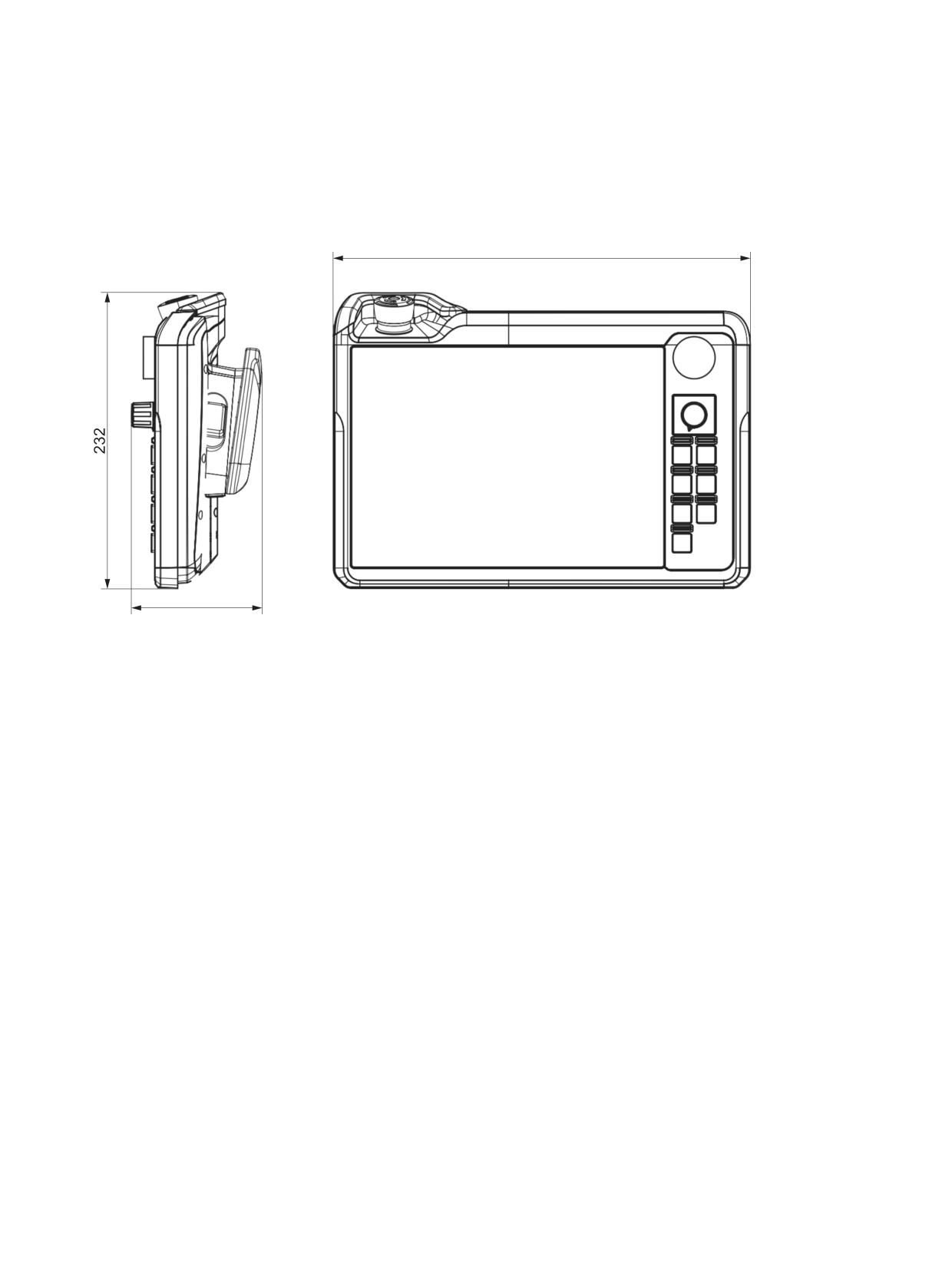
Figure 3-1
Front and side view of HT 10 (all dimensions in mm)
Handheld Terminal HT 10
Equipment Manual, 09/2020, A5E47430965B AA
23
Connecting
4
4.1
Overview
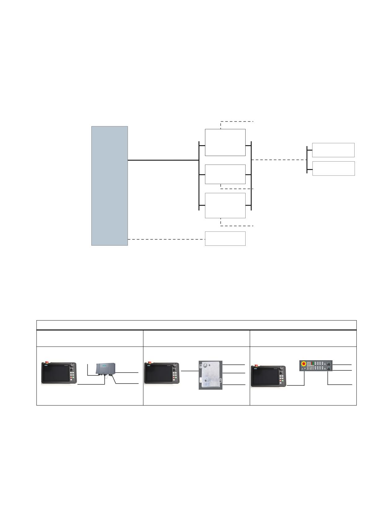
Emergency stop / enabling circuit
SINUMERIK
SIMATIC HMI
Handheld
Terminal
connection box
standard /
HT 10
SIMATIC IPC for
advanced
SINUMERIK
Ethernet cable
or
SINUMERIK
Connection
NCU
module
Basic PN
or
Emergency stop / enabling circuit
SINUMERIK
MPP 310 IEH/
MPP 483 IEH/
MPP 483 HTC
Emergency stop / enabling circuit
USB
interface
Figure 4-1
Connection overview of the HT 10
The HT 10 is designed for communication in an Ethernet network. The following connection
options are available:
• SIMATIC HMI connection box standard/connection box advanced
• PN Basic connection module (for control cabinet installation) or
• MPP 310 IEH / MPP 483 IEH / MPP 483 HTC
HT 10 with
SIMATIC HMI connection boxes standard
PN Basic connection module
MPP 483 HTC
and advanced
(WKHUQHW
(WKHUQHW
(WKHUQHW
(WKHUQHW
(WKHUQHW
(WKHUQHW
(WKHUQHW
6DIHW\
6DIHW\
6DIHW\
VLJQDOV
VLJQDOV
VLJQDOV
(WKHUQHW
(WKHUQHW
Handheld Terminal HT 10
Equipment Manual, 09/2020, A5E47430965B AA
25

Connecting
4.2 Pin assignment of the interfaces
Connection via the SIMATIC HMI connection box advanced allows quick connection and
disconnection during machine operation without tripping an emergency stop.
NOTICE
Damage through regenerative feedback
Regenerative feedback of voltage to ground by a connected or installed component can
damage the device.
Connected or built-in I/Os, for example a USB drive, are not permitted to supply any voltage to
the device. Regenerative feedback is generally not permitted.
4.2
Pin assignment of the interfaces
I
Signal input
O
Signal output
B
Bi-directional signal
V
Supply voltage
K
Contact
VI
Voltage input
VO
Voltage output
See also
Pin assignment of the interfaces (Page 26)
4.2.1
Power supply
Connector designation:
X 51
Connector type:
12-pole connector plug with coding and locking
Pin
Signal name
Signal type
Signal
type
1
nc
2
nc
3
ENABLE 2+
(Enabling button channel 2, digital)
I
4
ENABLE 2-
(Enabling button channel 2, digital)
O
5
ENABLE 1+
Enabling button channel 1, digital
I
6
ENABLE 1-
Enabling button channel 1, digital
O
7
STOP -13
EMERGENCY STOP circuit 2
K
8
STOP -14
EMERGENCY STOP circuit 2
K
Handheld Terminal HT 10
26
Equipment Manual, 09/2020, A5E47430965B AA
Connecting
4.2 Pin assignment of the interfaces
Pin
Signal name
Signal type
Signal
type
9
STOP -23
EMERGENCY STOP circuit 1
K
10
STOP -24
EMERGENCY STOP circuit 1
K
11
P24
+24 V power supply
VI
12
M24
External ground
VI
4.2.2
USB interfaces
X5: USB interface
The USB interface conforms to the specification for USB 3.0 Hi-Speed type A.
Connector designation:
X5
Connector type:
Type A socket
Current carrying capaci-
0.9 A
ty
Max. cable length
5 m
Pin
Signal name
Signal type
Signal
type
1
Shield
Shield
2
+5 V
Power supply for external devices
VO
3
USB-DN
USB data - channel 1
B
4
USB-DP
USB data + channel 1
B
5
0 V
Ground
VO
6
Shield
Shield
NOTICE
Damage to the connector caused by missing protective cap
Replace the USB connector if its protective cap is torn, because the connector is no longer
protected against dirt.
NOTICE
Damage to the inserted USB FlashDrive should the HT 10 fall to the ground
An inserted USB FlashDrive can be damaged or broken off if the device falls.
Handheld Terminal HT 10
Equipment Manual, 09/2020, A5E47430965B AA
27
Connecting
4.2 Pin assignment of the interfaces
Hot-plugging-capable devices are connected during operation and are identified automatically.
Note
Correct identification is only guaranteed for USB I/Os that comply to 100% with the USB
specification.
USB sticks
If you want to connect a USB stick to the USB interface, preferably use the tested SIMATIC USB
stick 16 GB for this purpose (Article No.: 6ES7648-0DC60-0AA0). Alternatively, you can use a
USB stick with any memory size. It must, however, meet the following minimum requirements:
• File system: FAT16 or FAT32
• Partitioning: only in PC partition format (MBR)
USB sticks that deviate from these requirements have not been tested and may not be
recognized.
4.2.3
Ethernet RJ45 interface
Connector type:
Standard RJ45 socket
Max. data transmission rate:
10/100 Mbps
Max. cable length:
100 m
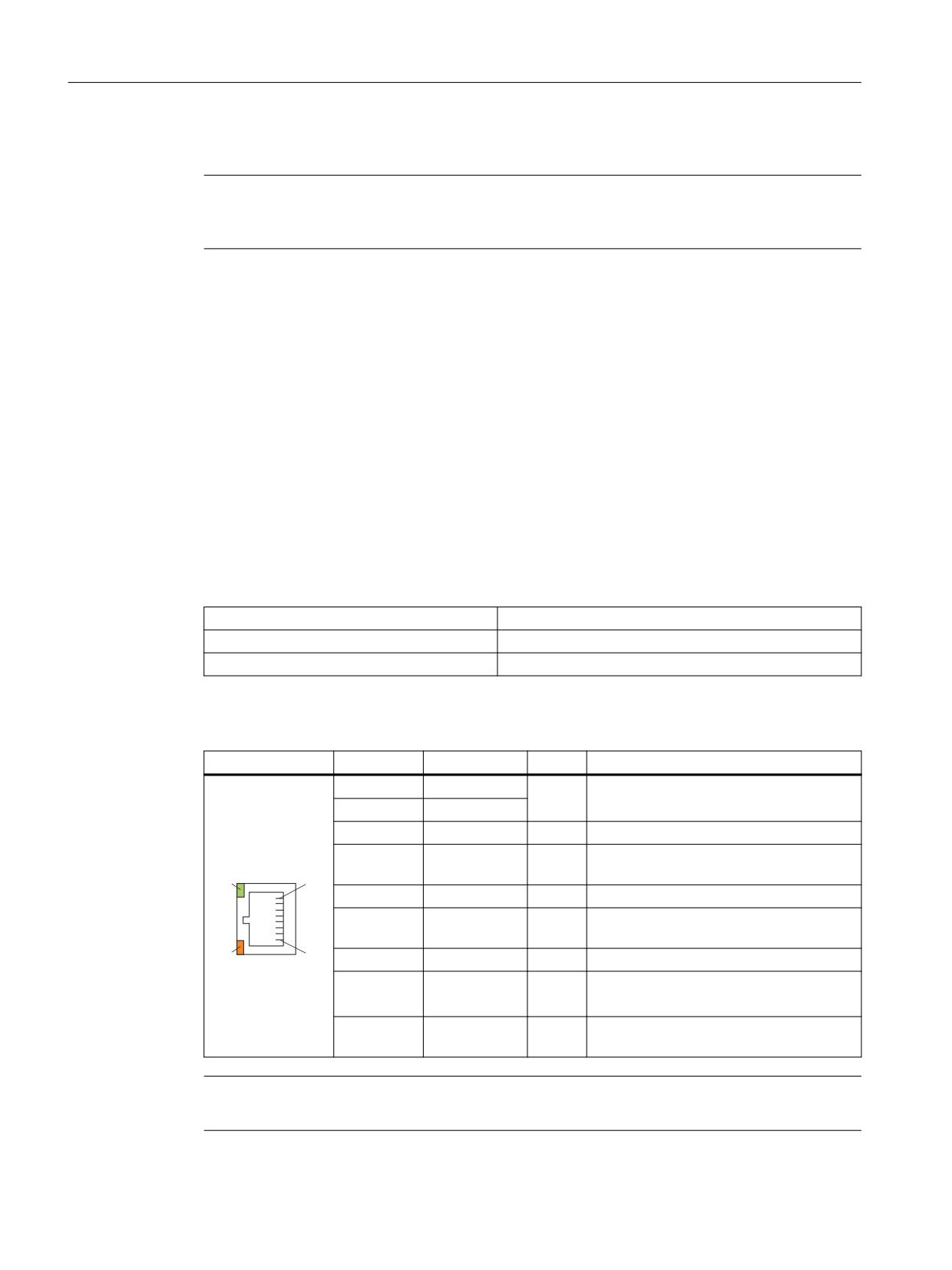
Table 4-1
Assignment of the Ethernet RJ45 interface 10/100 Mbit/s
Connector
Pin
Name
Type
Remark
1
TxD+
O
Transmit data
2
TxD-
3
RxD+
I
Receive data
4/5
GND
-
(terminated internally with 75 Ω; not re-
quired for data transmission)
/('
6
RD-
I
Receive data
7/8
GND
-
(terminated internally with 75 Ω; not re-
quired for data transmission)
/('
Shield
-
-
On connector housing
-
Green LED
-
Illuminated: 10 or 100 Mbit/s
(right)
Off: No or faulty connection
-
Orange LED
-
Illuminated: Data exchange
(left)
Off: No data exchange
Note
Connection only on LAN, not on telecommunication networks!
Handheld Terminal HT 10
28
Equipment Manual, 09/2020, A5E47430965B AA

Connecting
4.3 Power supply
4.3
Power supply
Power is supplied to the HT 10 from a connection box through the connecting cable. The
following power consumption values for an HT 10 provide a configuration basis for calculating
the 24 V DC power supply supply.
Table 4-2
Input voltage specification
Typ. power consumption
Max. power consumption
0.6 A
3 A (short-time)
Note
When using external power supplies (e.g. SITOP), the ground potential of the power supply must
be connected to the protective conductor connection of the system (SELV/PELV).
Note
Ground potential and enclosure (PE) are connected internally to one another with low
impedance.
Interface characteristics
The following special requirements apply to the connecting cables:
• The 24 V DC cable must be approved for temperatures up to 70 °C.
• Observe the permissible bending radius of the cables.
• Route all the cables so that they cannot be crushed or pinched.
• Route all the cables so that they cannot come into contact with chafing edges.
Les câbles de raccordement doivent répondre aux conditions suivantes :
• Le câble 24 V CC doit être autorisé pour des températures jusqu'à 70 °C.
• Tenir compte du rayon de courbure admissible des câbles.
• Pose les câbles de manière à ce qu’ils ne pincent pas les câbles.
• Pose les câbles en évitant tout contact avec des arrêtes abrasives.
Handheld Terminal HT 10
Equipment Manual, 09/2020, A5E47430965B AA
29

Connecting
4.4 SIMATIC connection box
WARNING
Warning for areas subject to NEC or CEC:
Safety notice for connectors with Ethernet marking:
A Ethernet or Ethernet segment, with all its associated interconnected equipment, shall be
entirely contained within a single low-voltage power distribution and within a single building.
The Ethernet is considered to be in an "environment A" according IEEE802.3 or "environment
0" according IEC TR 62102, respectively.
Never make direct electrical connection to TNV-circuits (Telephone Network) or WAN (Wide
Area Network).
Note
When connecting an external 24 V DC power supply to the interfaces, it must meet the
requirements of a protective extra low voltage (SELV/PELV) according to UL 61010. A series fuse
must also be used, which reliably trips within 120 seconds when a short-circuit occurs at an
ambient temperature of 0 °C.
For a primary supply of the power supply used from OVC III circuits up to 600 V AC (line to neutral
voltage), it must be ensured that the contact gap of the fuse - or the individual fault-proof circuit
- is 3.0 mm according to UL 61010.
When using an external power supply, ensure that the fuse used has a trip rating that
corresponds to the maximum possible short-term short-circuit current of the power supply unit
being used.
4.4
SIMATIC connection box
4.4.1
Description
Two versions of the SIMATIC connection box are available.
• Connection box standard
The connection box standard is intended for use outside the control cabinet.
The connection box standard can be used if hot plugging is not required. The Emergency Stop
circuit can be overridden here by external mechanisms.
• Connection box advanced
The connection box advanced is intended for use outside the control cabinet.
The connection box advanced can be hot plugged. This means that it is possible to connect
and disconnect during operation without any disruption.
The emergency stop circuit is automatically maintained during the switching of connectors.
The connection box advanced also has:
- Real-time Ethernet
- F signal override
Handheld Terminal HT 10
30
Equipment Manual, 09/2020, A5E47430965B AA
Connecting
4.4 SIMATIC connection box
The connection boxes have two rotary coding switches (S1 and S2) for setting a unique ID for
station identification. See Chapter interfaces (Page 54).
NOTICE
Versions of the connection box
If you install connection boxes with and without an emergency stop override in your fail-safe
automation system, there is a risk of inadvertently tripping a disconnection when switching the
connectors an HMI device.
Therefore use only the "standard" or "advanced" versions of the connection box in a fail-safe
automation system.
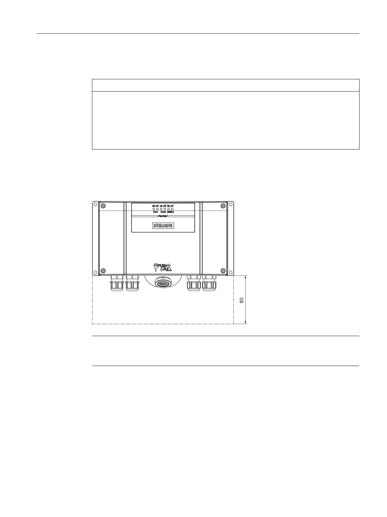
Clearance
The connection boxes standard and advanced require the following clearances:
Note
Degree of protection IP65 is ensured on the connection box if an HT 10 or a dummy cap is
inserted.
Additional references
You can find a detailed description in the Operating Instructions for the "SIMATIC HMI Mobile
Panels 2nd Generation":
Handheld Terminal HT 10
Equipment Manual, 09/2020, A5E47430965B AA
31
Connecting
4.4 SIMATIC connection box
4.4.2
Connection box standard
In contrast to the connection box advanced, the "Stop loop through" function is not
implemented in the connection box standard. Relays are so not required.
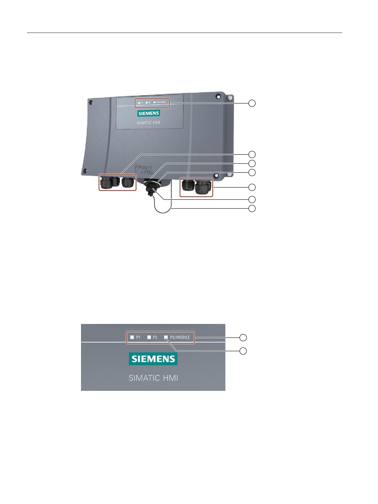
① LED display
② Screw glands for the data cables
③ Position mark
There is also a red position mark on the connecting cable. Align this with the position mark on the
connection box when connecting.
④ Connection socket for the connecting cable
⑤ Screw glands for the power supply cables and F signal cables
⑥ Sealing cap of the connection socket
⑦ Safety strap
Figure 4-2
Connection box standard
On the front of the connection box, there are 3 LEDs which indicate the state of communication.
① LED display of the three Ethernet ports:
• P1: Fast Connector X1
• P2: Fast Connector X2
• P3: Connection socket for the HT 10
② LED
Handheld Terminal HT 10
32
Equipment Manual, 09/2020, A5E47430965B AA

Connecting
4.4 SIMATIC connection box
Basic functions of the LEDs:
• LED lights up green: Link present, no data transmission
• LED flashes yellow green or lights up yellow: Link present, transmitting data
Further information about the possible states of the LEDs can be found in the following
document:
"SCALANCE X-200" Operating Instructions (https://support.industry.siemens.com/cs/document/
102051962/simatic-net%3A-industrial-ethernet-switches-scalance-x-200?dti=0&lc=en-WW)
Switching states of the emergency stop circuit
HT 10
Emergency
Switching status, emergency stop circuit
Stop button
Connected
Not pressed
Emergency stop circuit in the connection box remains
closed.
Connected
Pressed
The emergency stop circuit in the connection box is open.
The monitored system is stopped.
Not connected
-
The emergency stop circuit in the connection box is open.
The monitored system is stopped.
Note
The emergency stop circuit is controlled via the emergency stop button when the HT 10 is
inserted. If the connecting cable of the HT 10 is unplugged from the connection box standard,
the emergency stop circuit is interrupted. This leads to a safe machine stop or an Emergency Stop
of the monitored system.
WARNING
Danger of death resulting from the premature emergency stop unlocking
Premature unlocking of the emergency stop can lead to death, serious injury and/or machine
damage.
If you have shut down the monitored system, you can only release the emergency stop button
or put the monitored system back into operation if the conditions that tripped the emergency
stop have been eliminated and a safe restart is ensured.
Handheld Terminal HT 10
Equipment Manual, 09/2020, A5E47430965B AA
33
Connecting
4.4 SIMATIC connection box
4.4.3
Connection box advanced
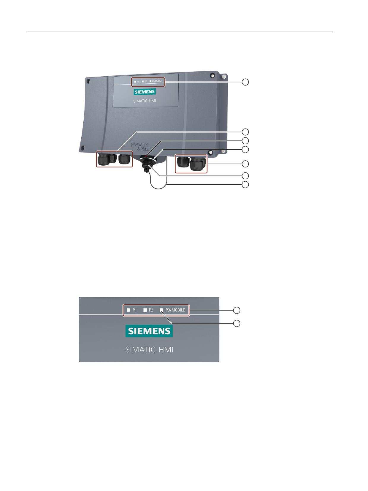
① LED display
② Screw glands for the data cables
③ Position mark
There is also a red position mark on the connecting cable. Align this with the position mark on the
connection box when connecting.
④ Connection socket for the connecting cable
⑤ Screw glands for the power supply cables and F signal cables
⑥ Sealing cap of the connection socket
⑦ Safety strap
Figure 4-3
Connection box advanced
On the front of the connection box, there are 3 LEDs which indicate the state of communication.
① LED display of the three Ethernet ports:
• P1: Fast Connector X1
• P2: Fast Connector X2
• P3: Connection socket for the HT 10
② LED
Basic functions of the LEDs:
• LED lights up green: Link present, no data transmission
• LED flashes yellow green or lights up yellow: Link present, transmitting data
Handheld Terminal HT 10
34
Equipment Manual, 09/2020, A5E47430965B AA

Connecting
4.4 SIMATIC connection box
Further information about the possible states of the LEDs can be found in the following
document:
"SCALANCE X-200" Operating Instructions (https://support.industry.siemens.com/cs/ww/en/
view/102051962)
NOTICE
Removing the HT 10 from the connection box advanced
Removing the HT 10 from the connection box advanced closes the emergency stop circuit and
cancels the stop state of the monitored system, irrespective of whether the emergency stop
button on the HT 10 had been pressed.
Switching states of the emergency stop circuit
HT 10
Emergency
Switching status, emergency stop circuit
Stop button
Connected
Not pressed
Emergency stop circuit in the connection box remains
closed.
Connected
Pressed
The emergency stop circuit in the connection box is open.
The monitored system is stopped.
Not connected
-
Emergency stop circuit in the connection box is closed.
The monitored system continues to run.
WARNING
Danger of death resulting from the premature emergency stop unlocking
Premature unlocking of the emergency stop can lead to death, serious injury and/or machine
damage.
If you have shut down the monitored system, you can only release the emergency stop button
or put the monitored system back into operation if the conditions that tripped the emergency
stop have been eliminated and a safe restart is ensured.
Handheld Terminal HT 10
Equipment Manual, 09/2020, A5E47430965B AA
35
Connecting
4.4 SIMATIC connection box
4.4.4
Interface assignment
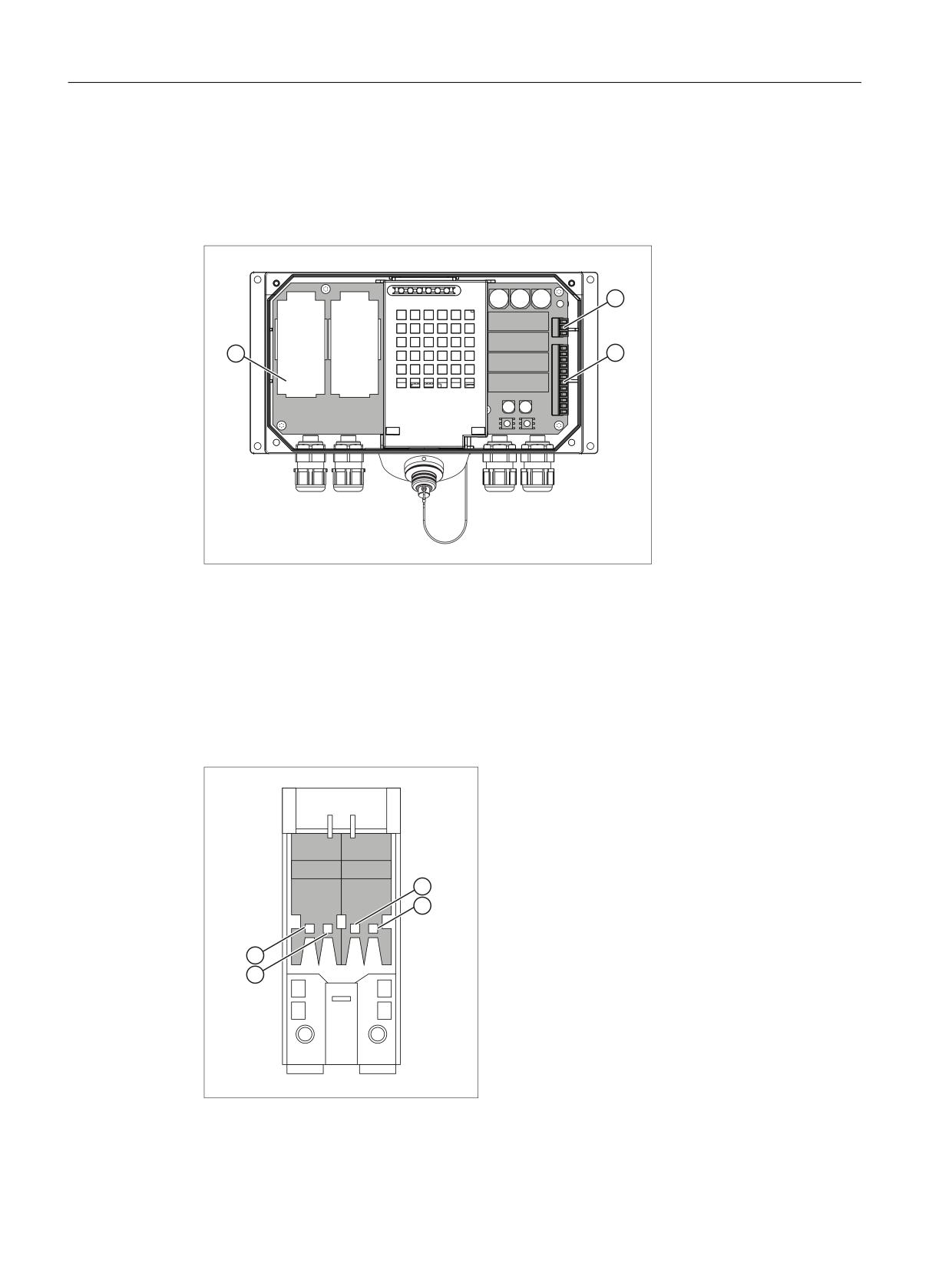
Location of the interfaces
① Fast connector
② Terminal strip 1
③ Terminal strip 2
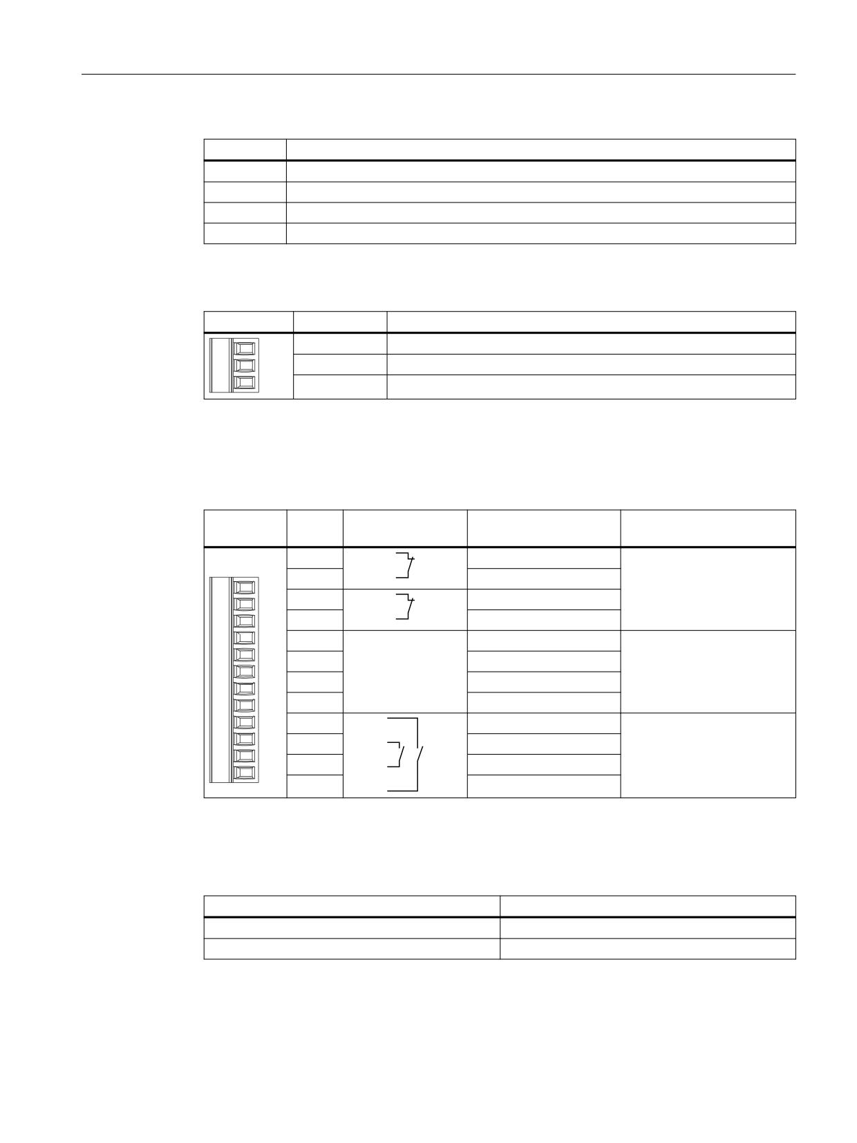
Fast Connector, 4-pin
The connection box contains two fast connectors for connecting the PROFINET data cables. The
figure below illustrates the assignment of the fast connector:
Handheld Terminal HT 10
36
Equipment Manual, 09/2020, A5E47430965B AA
Connecting
4.4 SIMATIC connection box
Pin
Signal name
1
RD+
2
TD+
3
RD-
4
TD-
Terminal strip 1, for power supply, 3-pin
Pin
Signal name
1
PE
2
M24
3
P24
Terminal strip 2, 12-pin
The safety and additional functions are connected to this terminal strip. The terminal strip is
mechanically coded to prevent it from being confused with terminal strip 1.
Pin
Internal intercon-
Signal name
Circuit
nection
1
STOP13
Emergency Stop button
2
STOP14
3
STOP23
4
STOP24
5
+24 V 1)
Accompanying control sig-
nals
6
CTRL32 1) 2)
7
PRESENT31 3)
8
+24 V 1)
9
ENABLE2+
Enabling button
10
ENABLE1-
11
ENABLE1+
12
ENABLE2-
1)
Applies only to the connection box advanced
2)
Active, if the Emergency Stop pushbutton is pressed
3)
Active if HT 10 is inserted
HT 10 on the connection box
Signal at digital input of the control
Not connected
"0"
Connected
"1"
Handheld Terminal HT 10
Equipment Manual, 09/2020, A5E47430965B AA
37
Connecting
4.4 SIMATIC connection box
Note
The "Emergency Stop button pressed" signal has no error detection facility and must, therefore,
not be used for safety-critical applications.
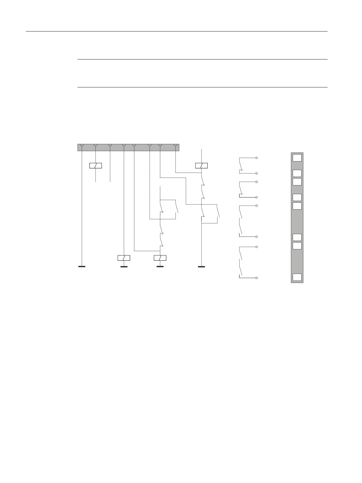
Circuit examples of the connection box advanced
9
7HUPLQDO VWULS
SLQ
6723
6723
6723
9
9
9
6723
9
&75/
35(6(17
9
Figure 4-4
Circuit example 1: HT 10 not inserted and power supply switched on
Handheld Terminal HT 10
38
Equipment Manual, 09/2020, A5E47430965B AA
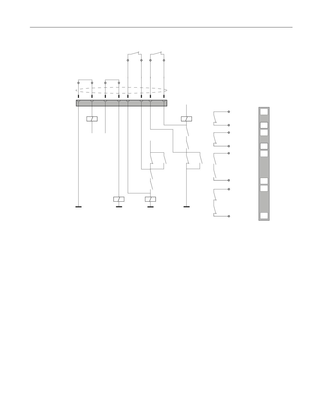
Connecting
4.4 SIMATIC connection box
6723
6723
+7
35(6(17
35(6(17
&RQQHFWLQJ FDEOH
9
7HUPLQDO VWULS
SLQ
6723
6723
6723
9
9
9
6723
9
&75/
35(6(17
9
Figure 4-5
Circuit example 2: HT 10 inserted, power supply switched on and emergency stop inactive
Handheld Terminal HT 10
Equipment Manual, 09/2020, A5E47430965B AA
39
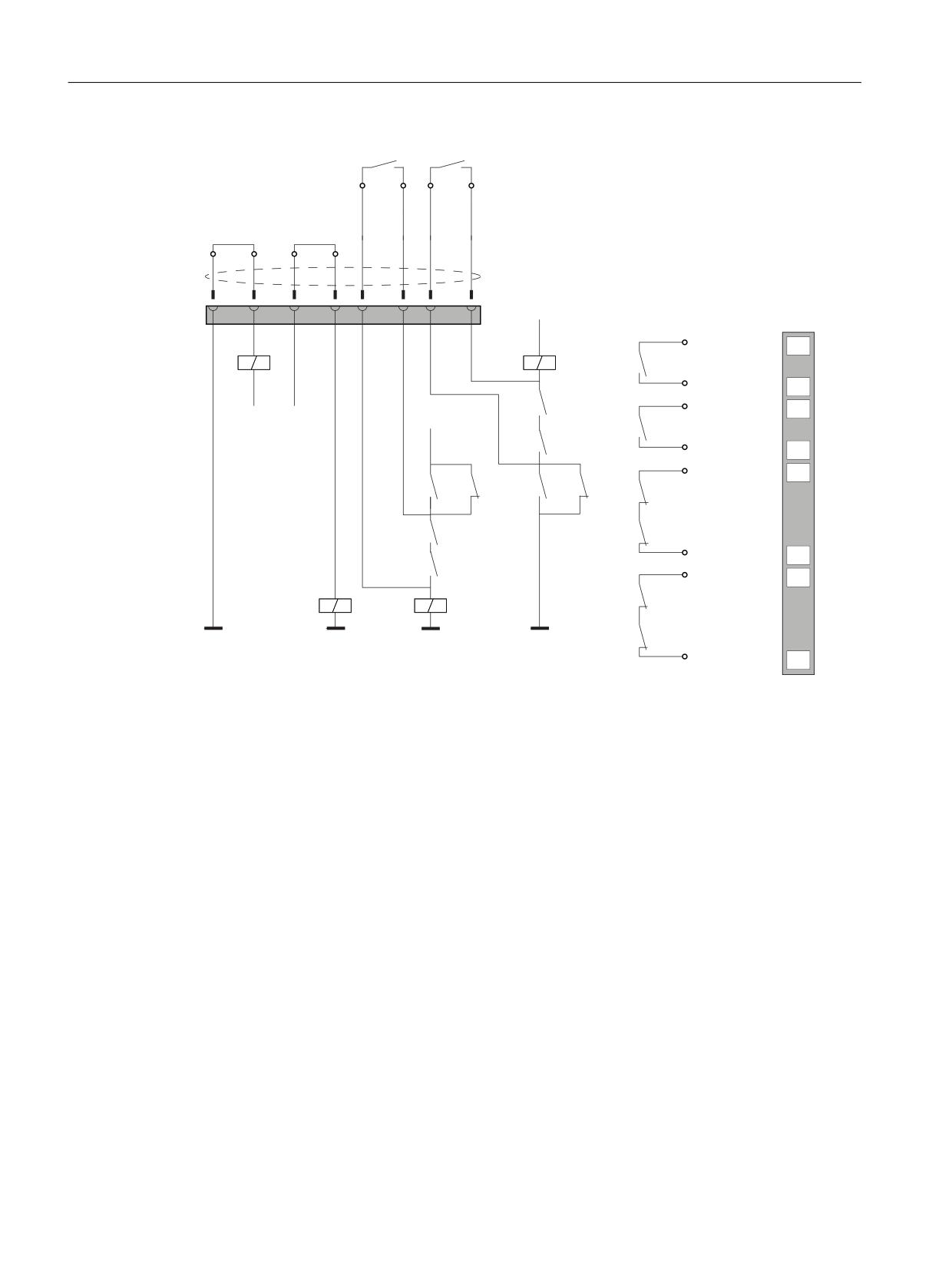
Connecting
4.4 SIMATIC connection box
6723
6723
+7
35(6(17
35(6(17
&RQQHFWLQJ FDEOH
9
7HUPLQDO VWULS
SLQ
6723
6723
6723
9
9
9
6723
9
&75/
35(6(17
9
Figure 4-6
Circuit example 3: HT 10 inserted, power supply switched on and emergency stop active
Handheld Terminal HT 10
40
Equipment Manual, 09/2020, A5E47430965B AA
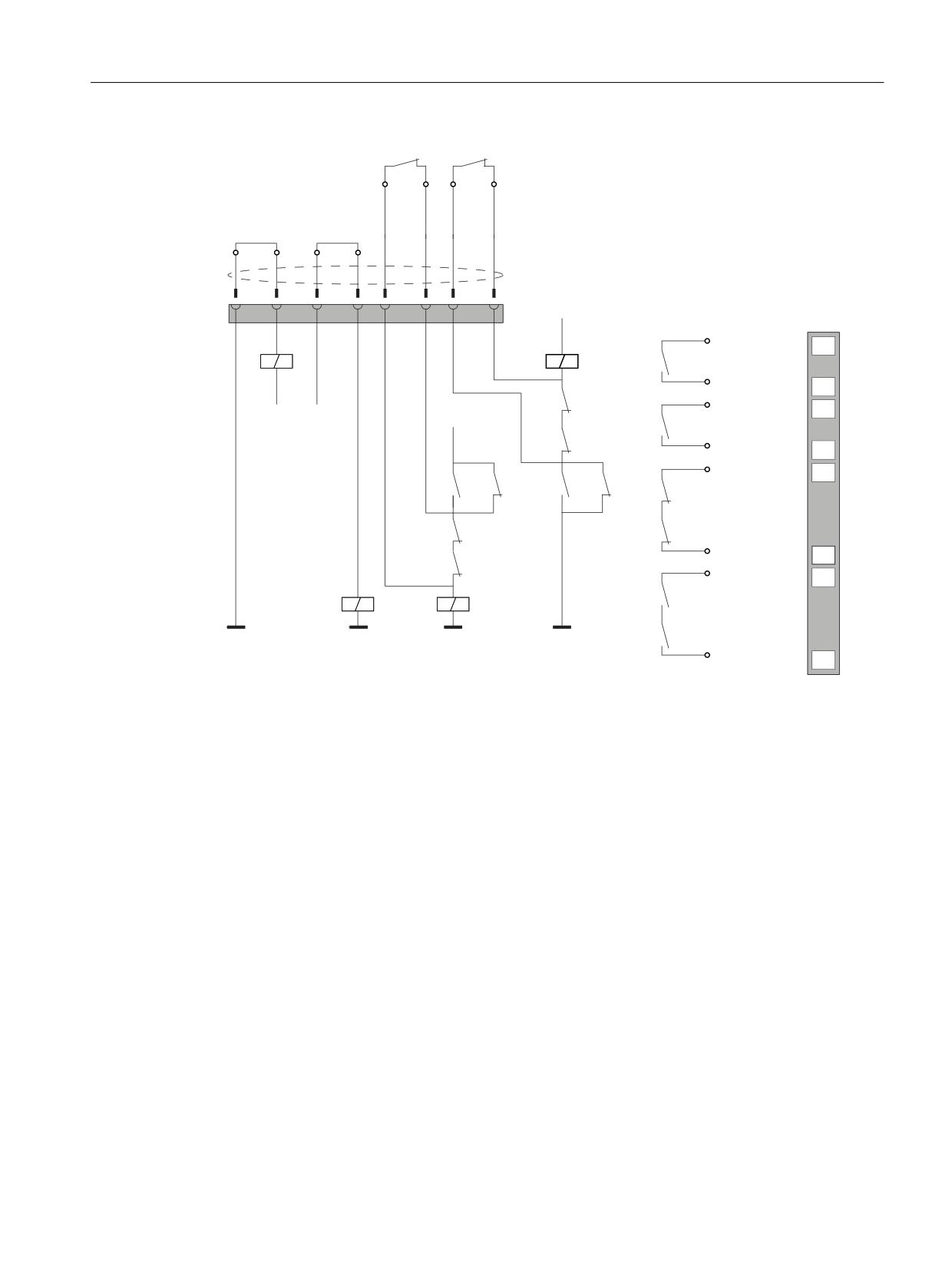
Connecting
4.4 SIMATIC connection box
6723
6723
+7
35(6(17
35(6(17
&RQQHFWLQJ FDEOH
9
7HUPLQDO VWULS
SLQ
6723
6723
6723
9
9
9
6723
9
&75/
35(6(17
9
Figure 4-7
Circuit example 4: Power supply switched off
The "CTRL32 / STOP button pressed" signal is not available with the connection box standard. The
signal has no error detection facility and must, therefore, not be used for safety-critical
applications.
Observe the following when connecting the signal "Present31 HT 10 inserted":
• Connect Pin 7 of the connection box to the digital input of the control
• Connection box standard: Pin 8 of the connection box remains not assigned
• Connection box advanced: +24 V must be supplied at Pin 8
Handheld Terminal HT 10
Equipment Manual, 09/2020, A5E47430965B AA
41

Connecting
4.4 SIMATIC connection box
4.4.5
Connecting a connection box
4.4.5.1
Connection information
NOTICE
Foreign objects or liquids
Foreign objects or liquids can cause a short-circuit inside the connection box and damage the
connection box or HMI device accordingly.
Pay attention to cleanliness. Keep foreign objects and liquids away while working on the
connection box.
Take care when working on the connection box that conducting materials, such as bare cable
leads, do not come into contact with the electrical circuits.
NOTICE
Observe local installation regulations
Observe the local installation regulations and the local installation conditions, such as
protective wiring for power supply cables, when connecting the cables.
Short-circuit and overload protection
Different measures for short-circuit and overload protection are required when setting up an
entire plant. The type of components and the level of obligation for the protective measures
depends on the regulation that applies to your plant configuration.
Connection sequence
NOTICE
Potential damage to property with incorrect connection sequence
Failure to adhere to the connection sequence can damage the connection box.
Connect the connection box in the following sequence:
1. Functional grounding
2. Power supply
3. Control via PROFINET (LAN)
4. Other Ethernet devices, such as an additional connection box
4.4.5.2
Opening and closing connection box standard and connection box advanced
The connection boxes standard and advanced must be opened for connecting and setting the
box ID.
Handheld Terminal HT 10
42
Equipment Manual, 09/2020, A5E47430965B AA
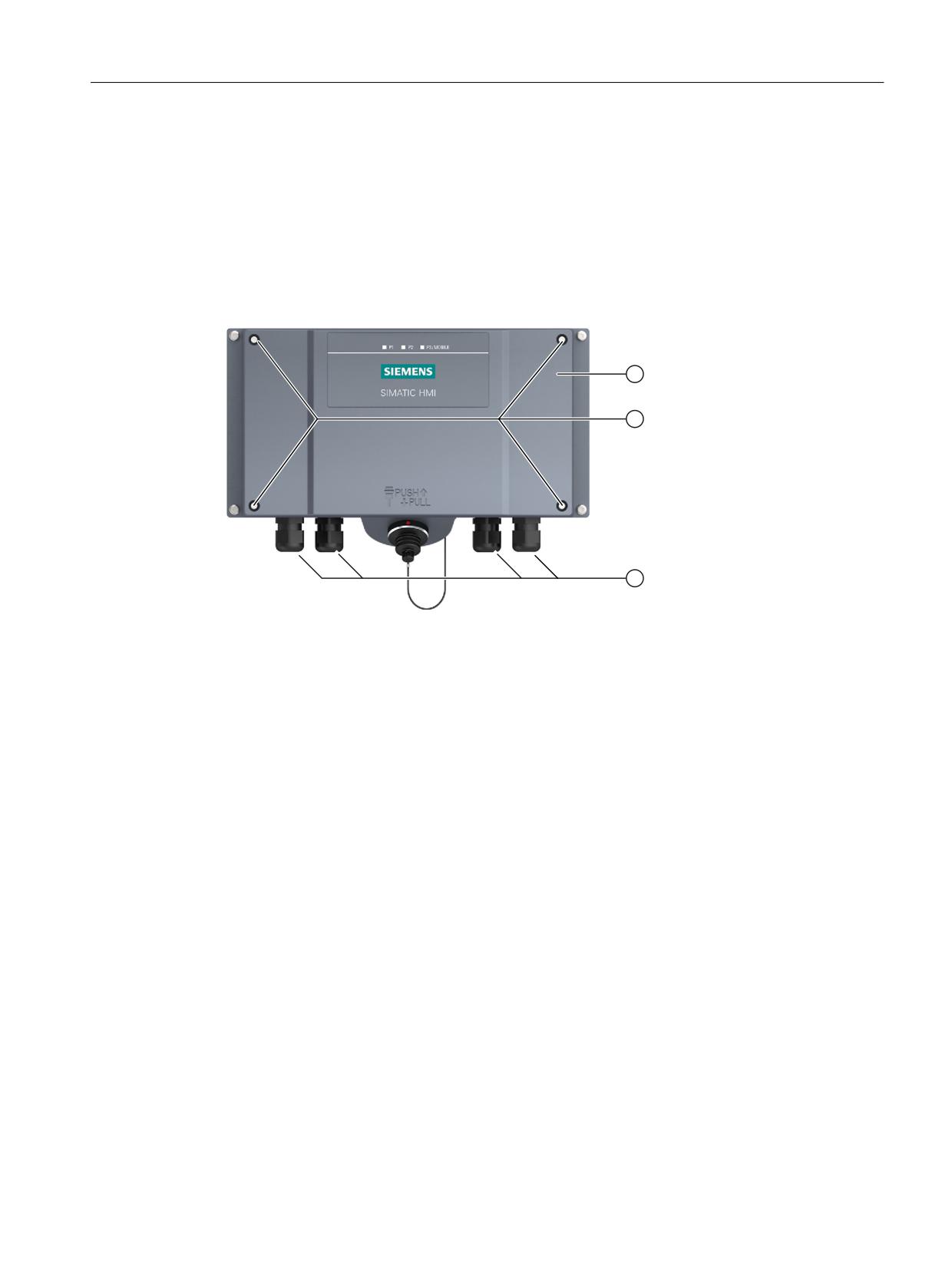
Connecting
4.4 SIMATIC connection box
Requirement
• The connection box is de-energized.
• Torque screwdriver with T10 insert
Procedure
Open
① Cover
② Screws
③ Screw glands M16x1.5 for cable diameters 5 to 10 mm
Handheld Terminal HT 10
Equipment Manual, 09/2020, A5E47430965B AA
43
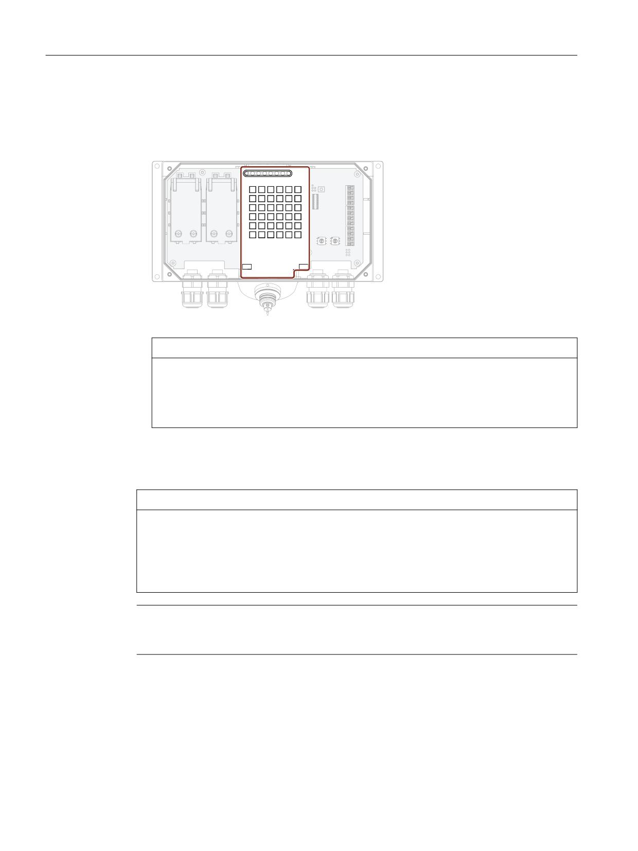
Connecting
4.4 SIMATIC connection box
1. Loosen the 4 screws
②.
2. Lift the cover ① carefully, because the seal may stick to the lid and can be pulled out.
3. Remove the screws and the cover.
The following protective cover is visible:
NOTICE
Damage to the connection box
Without a protective cover, there is a risk that the electronics of the connection box are
damaged or destroyed.
Do not remove the protective cover.
Close
Follow the steps for opening in reverse order.
NOTICE
Permissible torque
The connection box enclosure is made of plastic. Therefore, the mounting hole threads cannot
handle the same amount of stress as a comparable metallic enclosure. If the screws are
tightened with too great a torque or more than 20 times, there is risk of damage to the thread.
Do not exceed 0.4 to 0.5 Nm of torque when tightening the screws.
Note
During assembly, make sure that the seal for the cover is inserted and not damaged. Otherwise
the specified degrees of protection cannot be guaranteed.
Handheld Terminal HT 10
44
Equipment Manual, 09/2020, A5E47430965B AA
Connecting
4.4 SIMATIC connection box
4.4.5.3
Equipotential bonding of connection boxes
Potential differences
Differences in potential between separated plant components can lead to high equalizing
currents over the data cables, destroying the circuits. This situation may arise if the cable
shielding is terminated at both ends and grounded at different system parts.
Differences in potential can also be caused by different mains supplies.
General requirements for equipotential bonding
Differences in potential must be reduced far enough with equipotential bonding conductors to
ensure error-free operation of the relevant electronic components. The following information
must therefore be observed when installing the equipotential bonding:
• The effectiveness of equipotential bonding increases as the impedance of the equipotential
bonding conductor decreases or as its cross-section increases.
• If two plant sections are interconnected by means of shielded data cables and their shielding
is connected at both ends to the grounding/protective conductor, the impedance of the
additionally installed equipotential bonding conductor must not exceed 10% of the shielding
impedance.
• The cross-section of a selected equipotential bonding conductor must be capable of handling
the maximum equalizing current.
Equipotential bonding cables are required between two control cabinets with a minimum
conductor cross-section of 16 mm².
• Use equipotential bonding conductors made of copper or galvanized steel. Connect the
equipotential bonding conductors to the ground / protective conductor over a wide area.
Protect the equipotential bonding conductors against corrosion.
• Clamp the shielding of the data cable on the HMI device flush and near the equipotential
busbar using suitable cable clamps.
• Route the equipotential bonding conductor and data cables in parallel with minimum
clearance between them.
Note
Cable shielding is not suitable for equipotential bonding. Always use the prescribed
equipotential bonding conductors. When installing PROFINET networks, always use cables
with a sufficient cross-section. Otherwise, there is a risk that interface components will be
damaged or destroyed.
Connection graphic
The figure below shows how to connect the equipotential bonding of the connection boxes to
the equipotential busbars.
Handheld Terminal HT 10
Equipment Manual, 09/2020, A5E47430965B AA
45
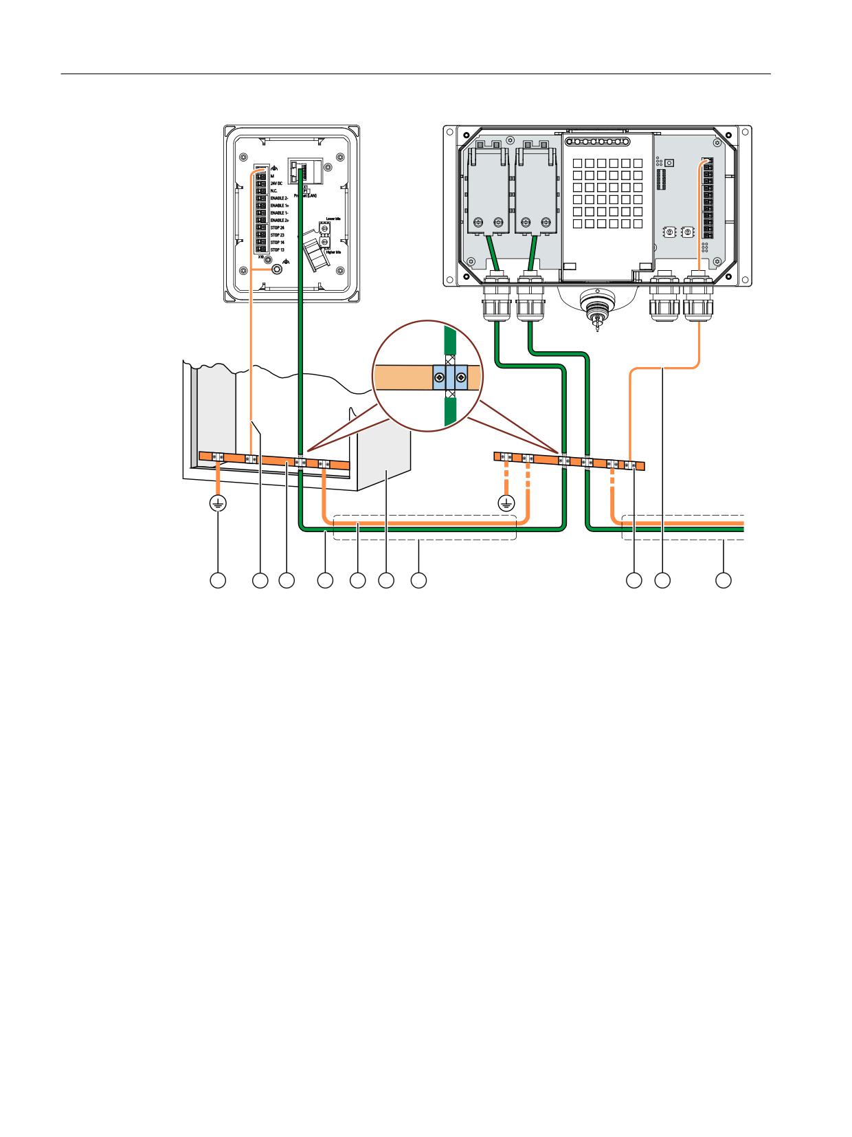
Connecting
4.4 SIMATIC connection box
① Ground connection
② Equipotential bonding conductor, cross-section 1.5 mm2
③ Equipotential busbar for equipotential bonding cables, grounding connection and shield support
of the data cables
④ Ethernet cable
⑤ Equipotential bonding conductor, cross-section ≥ 16 mm2
⑥ Parallel routing of the equipotential bonding conductor and data cable
⑦ Cable clip
⑧ Control cabinet
Handheld Terminal HT 10
46
Equipment Manual, 09/2020, A5E47430965B AA
Connecting
4.4 SIMATIC connection box
4.4.5.4
Connecting the functional grounding and power supply to the connection box
The power supply for the HMI device is connected to a terminal strip in the connection box. The
connection box has reverse polarity protection.
WARNING
24 V DC power supply
If the supply voltage is outside the specified range, it may cause the HMI device to malfunction.
This can result in personal injury or material damage.
Use a 24 V DC power supply with the following properties for the connection box:
• Safe electrical isolation according to IEC 60364-4-41 or HD 384.04.41 (VDE 0100, Part 410).
• The power supply provides safety extra-low voltage according to SELV/PELV up to a
maximum of 36 V DC and also does not exceed Um = 36 V DC in case of fault. Refer to the
information in the data sheet for overvoltage protection in the event of an internal error or
take appropriate voltage-limiting measures, such as the use of a surge protection device.
Requirement
• The power supply meets the requirements set out in "Power supply (Page 29)".
• The connection box standard or advanced is open.
• Power supply cables and equipotential bonding conductor
• The wires of the power supply cable have been stripped by 8 mm.
• Matching ferrules when using flexible cables
Procedure
1. For connection box standard and connection box advanced: Thread the cables through the
corresponding screw glands.
2. When you use flexible cables, place a wire end ferrule on each wire to be connected.
Handheld Terminal HT 10
Equipment Manual, 09/2020, A5E47430965B AA
47
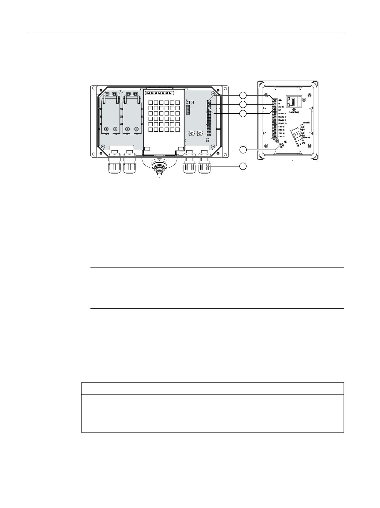
Connecting
4.4 SIMATIC connection box
3. Insert the wire ends into the associated spring-loaded terminal as shown in the figures below.
The figure below shows the contacts to be connected to the X10 terminal of the connection
box and the cable glands for cable entry.
① Connection for functional ground
② M24
③ P24
④ Screw gland
4. Connect the equipotential bonding conductor to the equipotential busbar.
5. Connect the equipotential bonding conductor to the terminal for the functional ground of
the connection box.
Connect the equipotential bonding conductor of the connection box as described in the
section "Equipotential bonding of connection boxes (Page 45)".
Note
Applies to floating system design:
Connect the terminal for GND 24 V from the 24 V power supply output to equipotential
bonding for uniform reference potential.
6. For connection box standard and connection box advanced:
When all the required work has been completed in the connection box, close it.
4.4.5.5
Connecting cables for a hardwired F-system
The signals for the emergency stop / stop button and the enabling button must be wired for a
hardwired F-system.
NOTICE
Length of the data cables to the connection box
If the permissible length of the data cables and signal cables between a connection box and the
plant is exceeded, malfunctions may occur. Keep the permissible length of ≤ 30 m for cables
between the connection box and the evaluation unit.
Handheld Terminal HT 10
48
Equipment Manual, 09/2020, A5E47430965B AA
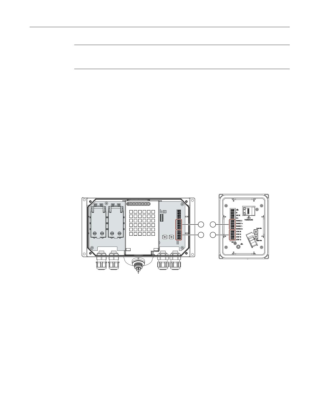
Connecting
4.4 SIMATIC connection box
Note
If a connection box is to be operated in "E-stop button evaluated by PROFIsafe" mode, the
connection box cannot be wired according to a hardwired F-system.
Requirement
• The connection box standard or advanced is open.
• Required number of connecting cables
• The wires of the connection cables have been stripped by 8 mm.
• Matching ferrules when using flexible cables
Procedure
1. Connection boxes standard and advanced:
Thread the cables through the corresponding screw glands.
2. When you use flexible cables, place a wire end ferrule on each wire to be connected.
3. Insert the wire ends into the associated spring-loaded terminal as shown in the figures below.
The figure below shows the terminals to be connected to the connection box.
① Terminal for the emergency stop / stop button
② Terminal for the enabling button
4. Connect the cables.
5. For connection box standard and connection box advanced:
When all the required work has been completed in the connection box, close it.
Handheld Terminal HT 10
Equipment Manual, 09/2020, A5E47430965B AA
49

Connecting
4.4 SIMATIC connection box
4.4.5.6
Connecting Ethernet to the connection box
Note
Using an Ethernet data transmission rate of 100 Mbps
The Ethernet data transmission rate of 10 Mbps is not supported by 2nd generation Mobile
Panels.
Use a data transmission rate of 100 Mbps for communication with the Mobile Panel.
Maximum cable lengths
Ethernet cable
Connection box used
Maximum cable length in-
cluding connecting cable
Between Mobile Panel and con-
• Connection box standard
25 m
nection box
• Connection box advanced
Between Mobile Panel and PRO-
• Connection box standard
125 m
FINET/PROFIsafe station
• Connection box advanced
Requirement
• The connection box is mounted.
• The connection box is open.
•
1 Ethernet cable (not preassembled)
•
1 screwdriver, PZ 2
•
1 stripping tool
Handheld Terminal HT 10
50
Equipment Manual, 09/2020, A5E47430965B AA
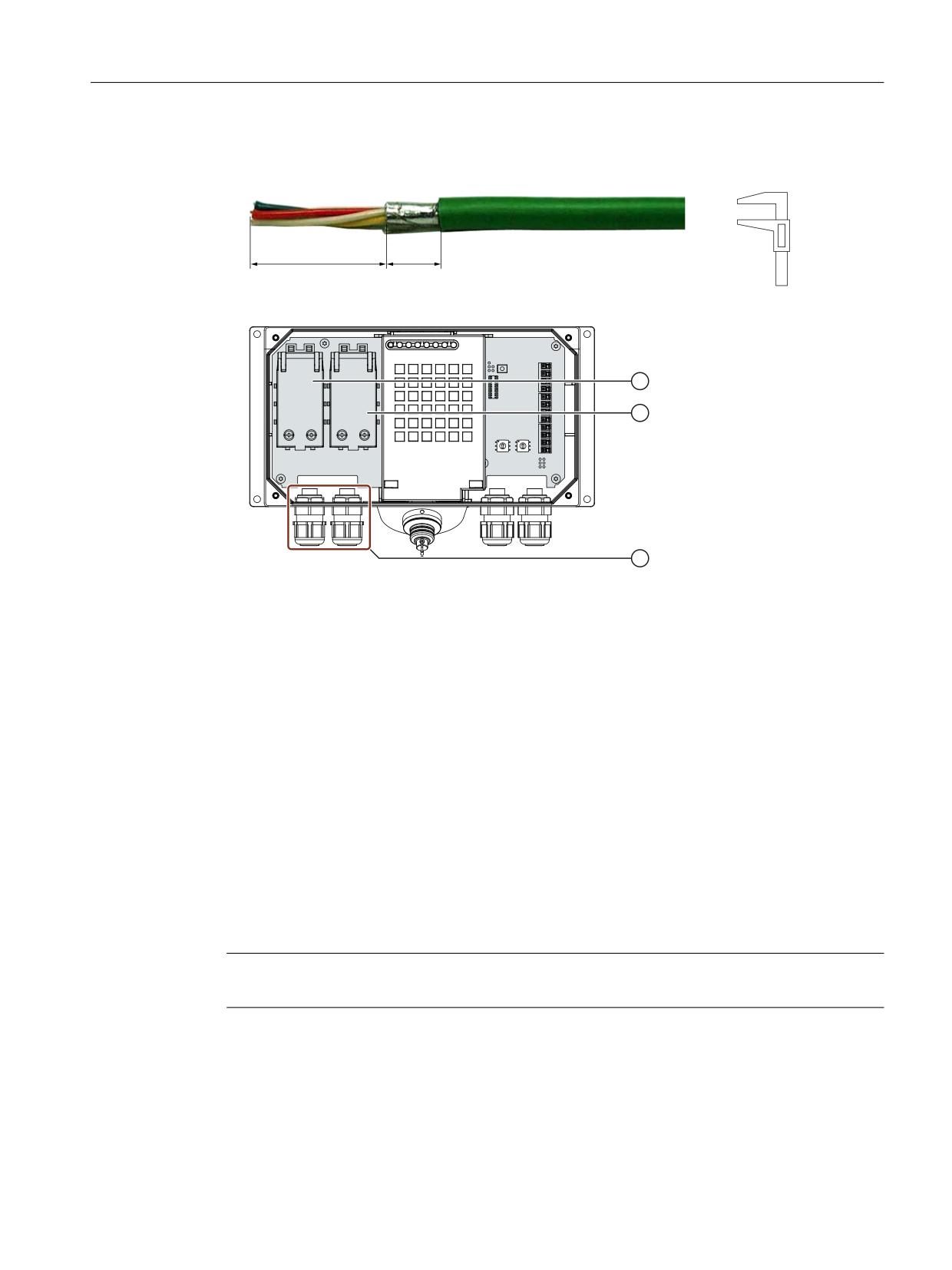
Connecting
4.4 SIMATIC connection box
Procedure
1. Strip the insulation on the Ethernet cable as shown in the figure below.
PP
2. Open fast connector 1.
① Fast connector 1
② Fast connector 2
③ Screw gland
3. Push the Ethernet cable through the screw gland and connect the wires.
4. Close the fast connector.
Closing the fast connector establishes the contact to the wires in the Ethernet cable.
5. Tighten the screw cap on the screw gland.
The specified degrees of protection are only met when the screw cap has been tightened.
6. Once all the required work in the connection box has been completed, close it.
4.4.5.7
Setting the box ID of the connection box
You need to set a box ID for each connection box. If configured, the box ID can be read by the HMI
device and transmitted to the PLC.
The box ID allows connection point detection.
Note
You need to set a box ID for each connection box. Do not assign the same box ID twice.
Handheld Terminal HT 10
Equipment Manual, 09/2020, A5E47430965B AA
51
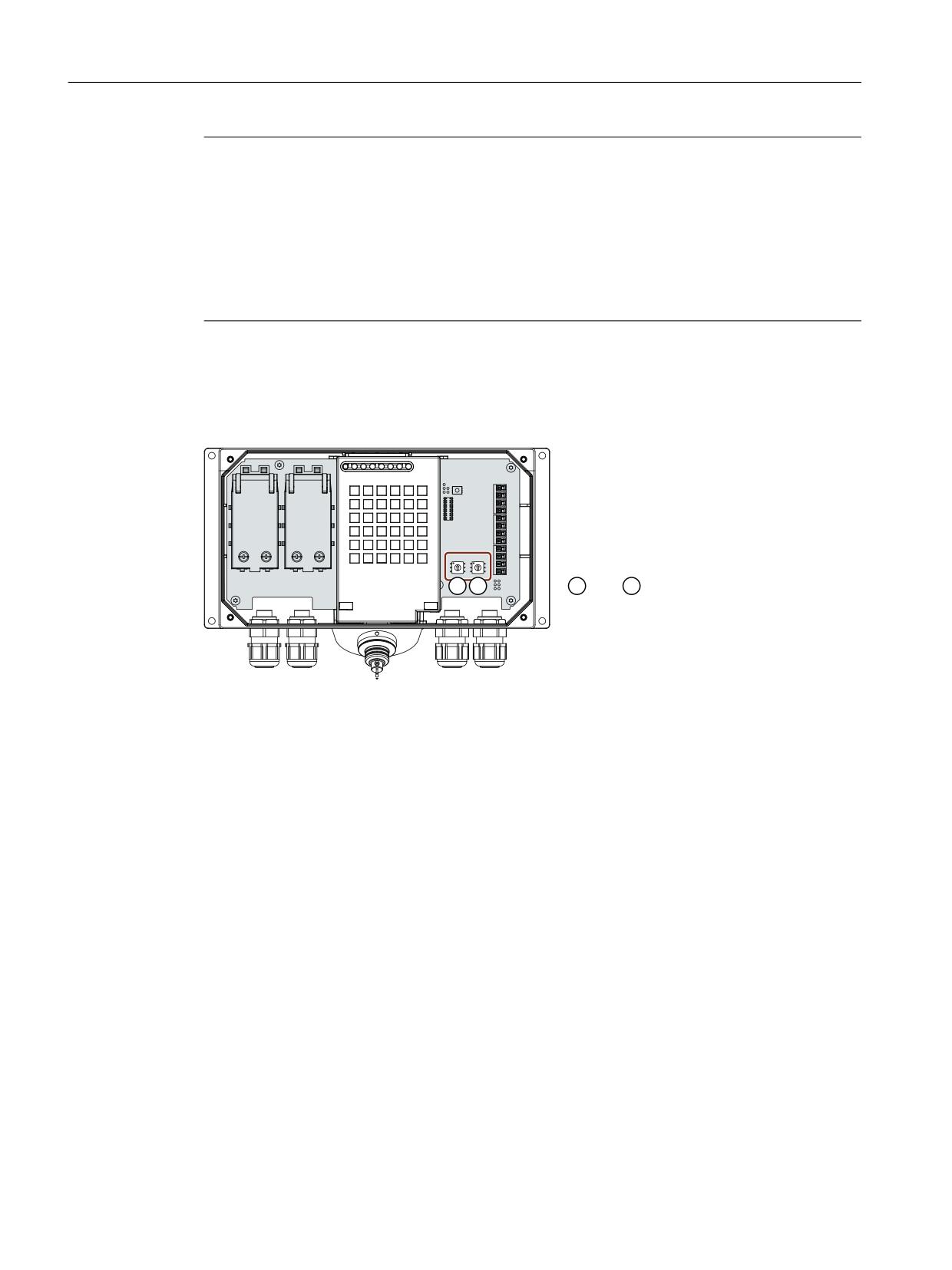
Connecting
4.4 SIMATIC connection box
Note
Changing the box ID of a connection box
Observe the following information when changing the box ID of a connection box:
• If you want to change the box ID of a connection box, remove the connection box from its
power supply before you set the box ID with the rotary coding switch.
• After you have confirmed the changed box ID in the dialog "Safety operation", unplug the
HMI-device connecting cable from the connection box and then plug it into the connection
box again.
Rotary encoder switch
Position of the rotary coding switch in the connection box standard and advanced:
+LJKHU /RZHU
ELWV
ELWV
Requirement
• The connection box is open.
• The connection box is disconnected from its power supply.
• A suitable tool made of plastic
Handheld Terminal HT 10
52
Equipment Manual, 09/2020, A5E47430965B AA
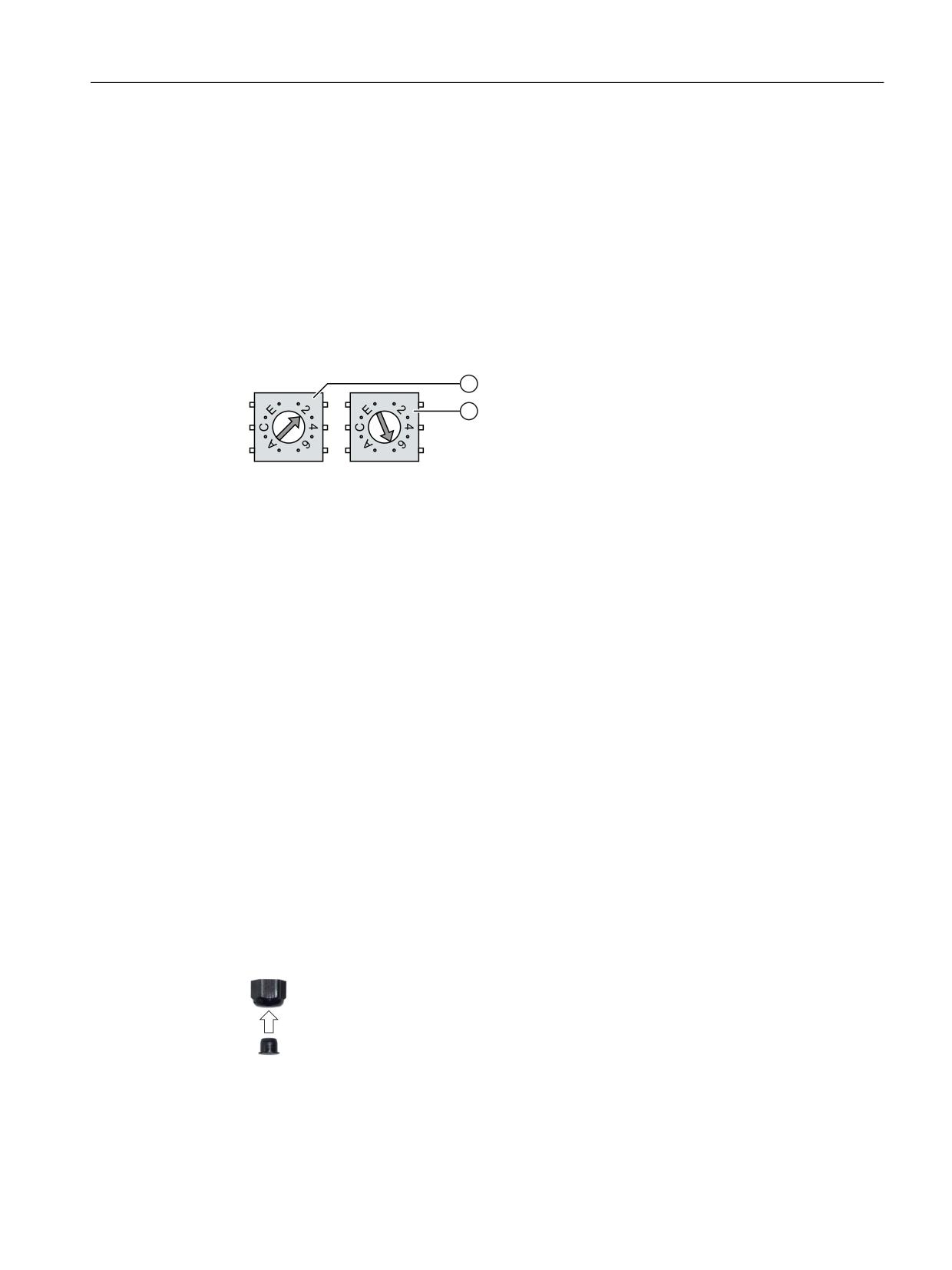
Connecting
4.4 SIMATIC connection box
Procedure
1. Rotate the arrows of the rotary coding switch to the required hexadecimal value using a
suitable tool.
Values from "00" to "FF" (0 to 255 in decimal form) can be set with the rotary coding switches.
When setting the box ID:
- Use the value "00" only for the "Stop button evaluated by safety relay" operating mode.
- The value "FF" (255) is reserved and may not be used.
Example:
The figure below shows an example of the rotary coding switch for a connection box
standard. "27H" (39 in decimal form) is set for the box ID as an example.
① Rotary encoding switch for more significant bits
In the connection boxes standard and advanced, it is the left rotary coding switch.
② Rotary encoding switch for less significant bits
2. Once all the required work in the connection box has been completed, close it.
4.4.5.8
Secure cables and seal screw glands
After you have connected all cables to the connection box, close and secure the screw glands.
Requirement
For the connection box compact:
•
1 cable tie
•
1 diagonal cutter
• The connection box is closed.
Procedure
1. Check whether the cover is located in the cable glands that are not in use.
2. If a cover is missing, replace it.
3. Tighten the screw cap.
This will ensure IP65 degree of protection for the connection box standard or the connection box
advanced.
Handheld Terminal HT 10
Equipment Manual, 09/2020, A5E47430965B AA
53
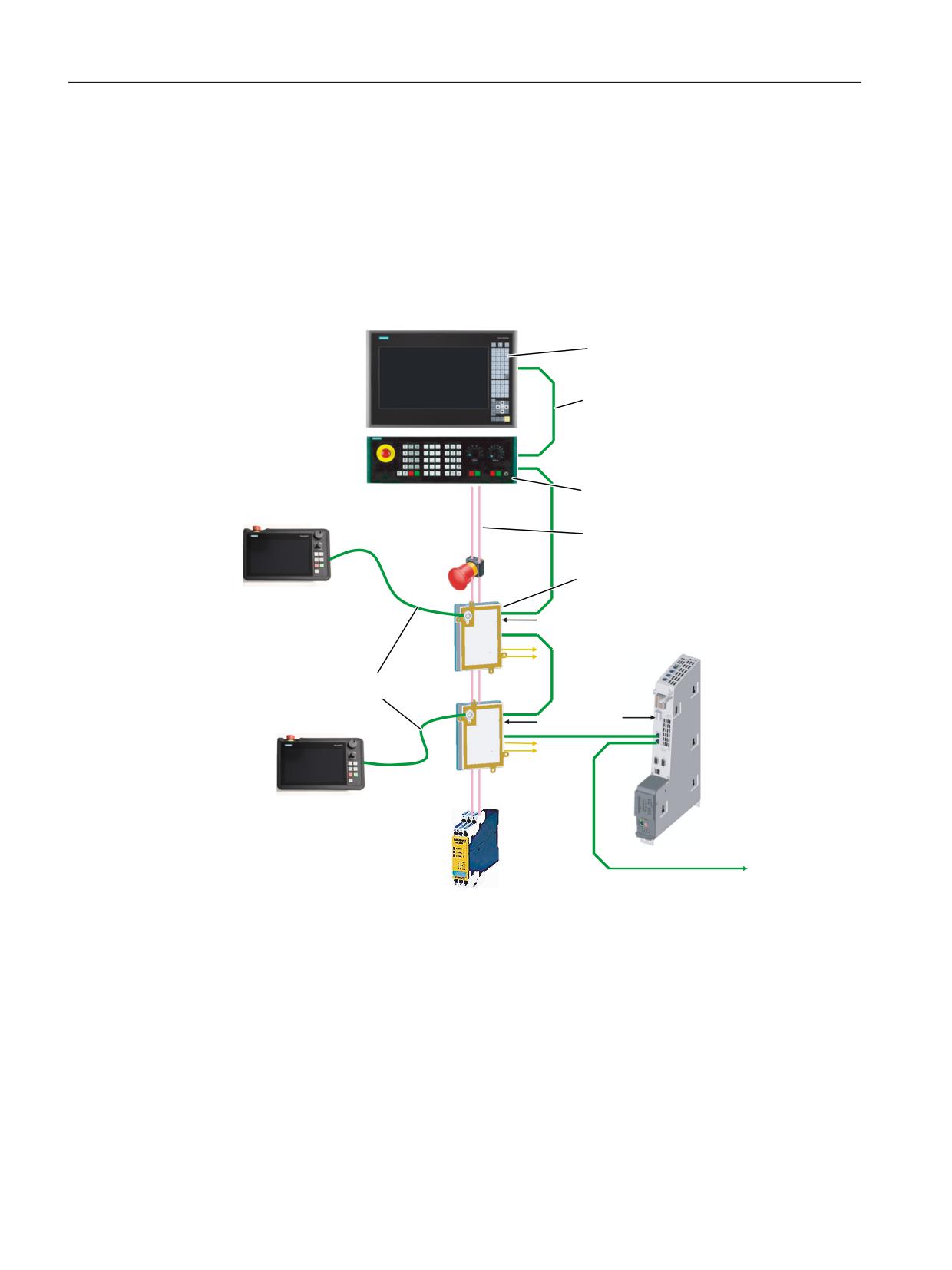
Connecting
4.5 PN Basic connection module
4.5
PN Basic connection module
4.5.1
Description
The connection module Basic PN was specially developed for installation in the control cabinet.
The terminating connector protrudes through the panel of the control cabinet so that the HT 10
can be connected from the outside.
2SHUDWRU SDQHO
6\VWHP QHWZRUN
0DFKLQH FRQWURO SDQHO
+7
(PHUJ VWRS FLUFXLWV
31 %DVLF FRQQHFWLRQ PRGXOH
3
&RQQHFWLQJ FDEOH
3
3
+7
&RQWUROV
6WDWXV VLJQDOV
1&8
(PHUJHQF\
1&8
6WRS
1&8
3DQHO SUHVHQW
6DIHW\
FRPELQDWLRQ
7.
)DFWRU\ QHWZRUN
Figure 4-8
System configuration (example)
The connection module Basic PN is not hot plug-capable.
The HT 10 can be connected either directly to the NCU or to the PCU as a Thin Client.
4.5.2
interfaces
The connector for the HT 10 is located on the front of the Basic PN connection module.
The other interfaces of the connection module are located at the rear:
Handheld Terminal HT 10
54
Equipment Manual, 09/2020, A5E47430965B AA
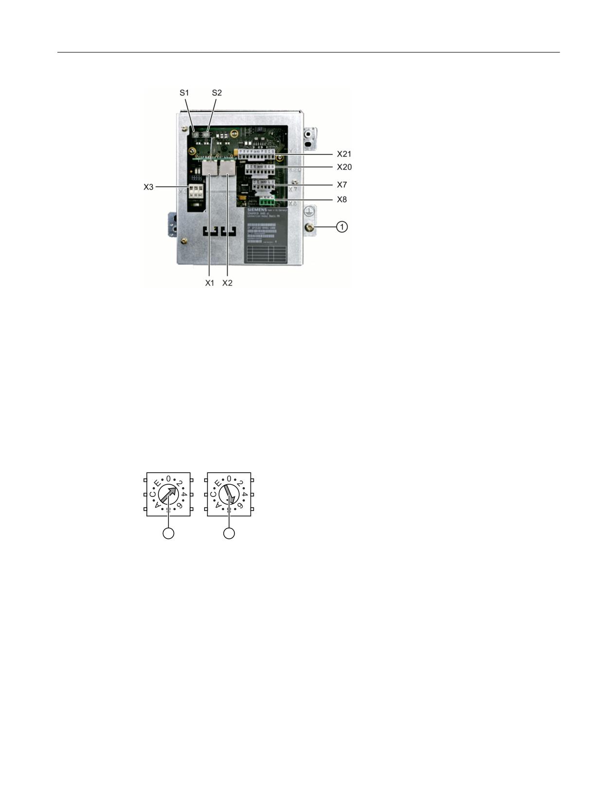
Connecting
4.5 PN Basic connection module
① Grounding screw M5 for potential equalization connection
Figure 4-9
Rear of the Basic PN connection module
Setting the box ID
You can use rotary coding switches S1 and S2 to set a unique ID on any connection module for
station identification purposes.
Use a screwdriver to set the IDs.
The setting is entered in hexadecimal format. Values in the decimal format between 0 and 255
can be entered.
By way of an example, the figure below illustrates address 27H, which corresponds to decimal
address 39.
① Rotary coding switch for higher-order bits (S1)
② Rotary coding switch for lower-order bits (S2)
Figure 4-10
Example for address "27H"
Connector pin assignments
Signal type:
I
Input
O
Output
B
Bi-directional signals
P
Potential
Handheld Terminal HT 10
Equipment Manual, 09/2020, A5E47430965B AA
55