SINUMERIK 840D sl Hardware. Manual (2011-2020) - page 21

Hardware
4.7 Technical data
4.7
Technical data
Table 4- 16 Technical data of the ADI4 module
Safety
Degree of protection
IP20
Protection class
Protection class I in accordance with VDE 0106 Part 1: 1982
(IEC 536);
Protection against ingress of foreign bodies and water in
accordance with IEC 529
Approvals
UL/CSA, CE
Power consumption
Nominal load
12 W
Maximum
30.2 W
Mechanical specifications
Dimensions WxHxD [mm]
154.4 x 325 x 48.5
Weight
Approximately 1.5 kg
Climatic ambient conditions
Heat dissipation
Open-circuit-ventilated
Operation
Storage/transport
Temperature limits
0 … +55° C
-20 to 55 °C/-40 to 70 °C
Relative humidity limits
5 to 95 %
5 to 95 %
without condensation
without condensation
Condensation
Not permitted
Atmospheric pressure
700 to 1060 hPa
700 to 1060 hPa
Transportation altitude
-
-1000 to 3000 m
Shock stress during transportation
Free fall in transport packaging
≤ 1000 mm
ADI4 - Analog drive interface for 4 axes
Manual, 03/2010, 6FC5297-0BA01-0BP5
39
Hardware
4.7 Technical data
ADI4 - Analog drive interface for 4 axes
40
Manual, 03/2010, 6FC5297-0BA01-0BP5
Parameter assignment
5
5.1
Boundary conditions of ADI4 DP slave
NOTICE
The following boundary conditions must be taken into account for the operation of an ADI4
DP slave on the PROFIBUS DP:
• An ADI4 DP slave is not a certified DP standard slave as defined by the PROFIDrive
profile. For example, an ADI4 DP slave does not enable acyclic communication.
Therefore, an ADI4 DP slave can only be operated on a DP master specially released
for this purpose.
• An ADI4 DP slave can only be operated on an equidistant PROFIBUS DP. The
minimum DP cycle is 1 ms.
5.2
Preconditions, SINUMERIK 802D sl
The following components are required for assigning parameters for an ADI4 DP slave:
● SINUMERIK 802D sl system software: from version 01.04.xx
5.3
Preconditions, SINUMERIK 840Di sl
Required components
The following components are required to assign the parameters of SINUMERIK 840Di sl
NC and the DP slave ADI4 in SIMATIC STEP7 HW Config:
● References: /HBIsl/ SINUMERIK 840Di sl Manual
● SIMATIC STEP 7, Version 5.3, Service Pack 2 and higher
● SlaveOM (Slave Object Manager) for SINUMERIK 840Di sl
ADI4 - Analog drive interface for 4 axes
Manual, 03/2010, 6FC5297-0BA01-0BP5
41

Parameter assignment
5.4 Preconditions, SINUMERIK 840D sl
SlaveOM
The SlaveOM for SINUMERIK 840Di sl allows dialog-based parameter assignment of the DP
slave:
● DP slave SINAMICS S120
● ADI4 DP slave
Within the scope of generating the configuration with SIMATIC STEP 7 HW Config.
The SlaveOM for SINUMERIK 840Di sl is part of the SINUMERIK 840Di sl toolbox.
Note
When using the SlaveOM for SINUMERIK 840Di sl in connection with other CPUs, a
consistency error is reported during the configuration compilation and no system data blocks
are generated.
5.4
Preconditions, SINUMERIK 840D sl
Required components
The following components are required to assign the parameters of SINUMERIK 840D sl NC
and the DP slave ADI4 in SIMATIC STEP7 HW Config:
● References: Commissioning Manual IBN CNC: NCK, PLC, drive
● SIMATIC STEP7, Version 5.3, Service Pack 3 and higher
● SlaveOM (Slave Object Manager) for SINUMERIK 840D sl
SlaveOM
The SlaveOM for SINUMERIK 840D sl allows dialog-based parameter assignment of the DP
slave:
● DP slave SINAMICS S120
● ADI4 DP slave
Within the scope of generating the configuration with SIMATIC STEP 7 HW Config.
The SlaveOM for SINUMERIK 840D sl is part of the SINUMERIK 840D sl toolbox.
Note
When using the SlaveOM for SINUMERIK 840D sl in connection with other CPUs, a
consistency error is reported during the configuration compilation and no system data blocks
are generated.
ADI4 - Analog drive interface for 4 axes
42
Manual, 03/2010, 6FC5297-0BA01-0BP5
Parameter assignment
5.5 PROFIBUS DP parameter assignment
5.5
PROFIBUS DP parameter assignment
5.5.1
Parameter assignment sequence
Parameter assignment sequence
The PROFIBUS DP parameter assignment for the ADI4 DP slave can be generally divided
into the following steps:
1. Step
After inserting the ADI4 DP slave in the configuration, the following parameters are
assigned on a slave-specific basis:
- PROFIBUS parameters (see Chapter "PROFIBUS parameters (Page 45)")
- Function parameters (see Chapter "Function parameters (Page 52)")
Step 1 should be carried out first for all ADI4 DP slaves needed in the configuration.
2. Step
Parameter assignment of the DP communication (refer to Chapter "Parameterization of
the DP communication (Page 62))
Step 2 can be performed last on any ADI4 DP slave. These settings can be transferred to
all other ADI4 DP slaves using the alignment function.
ADI4 - Analog drive interface for 4 axes
Manual, 03/2010, 6FC5297-0BA01-0BP5
43

Parameter assignment
5.6 PROFIBUS parameters for SINUMERIK 802D sl
5.5.2
Inserting an ADI4 DP slave in the configuration
Procedure
1. To insert an ADI4 DP slave in the configuration, open the hardware catalog using the
View > Catalog menu command.
The ADI4 DP slave can be found at:
- Profile: Standard
PROFIBUS DP > SINUMERIK > ADI4
SIMATIC Technology CPU
If S7-Technology was installed for the Technology CPU, the ADI4 DP slave is located
under:
- Profile: SIMATIC Technology CPU
PROFIBUS DP (DRIVE) > Other FIELD DEVICES > SINUMERIK > ADI4
2. Using a drag-and-drop operation, select the ADI4 DP slave and move it onto to the DP
master system in the station window.
The DP master system is displayed in the station window with the following symbol:
When you release the left mouse button, the DP slave ADI4 is inserted into the configuration.
Note
As you drag the DP slave, the cursor appears as a circle with a slash through it. When the
cursor is positioned exactly over the DP master system, it changes to a plus sign, and the
DP slave can be added to the configuration.
5.6
PROFIBUS parameters for SINUMERIK 802D sl
The PROFIBUS parameters are set for SINUMERIK 802D sl by activating one of the defined
configurations supplied. The PROFIBUS parameter values of the various configurations as
well as the activation of a configuration are described in:
References
SINUMERIK 802D sl Toolbox > Readme: ADI4_SDB.PDF
ADI4 - Analog drive interface for 4 axes
44
Manual, 03/2010, 6FC5297-0BA01-0BP5
Parameter assignment
5.7 PROFIBUS parameters
5.7
PROFIBUS parameters
5.7.1
Parameter components
Configuring the PROFIBUS parameters
The PROFIBUS parameters are a result of the following:
● PROFIBUS address
● Number of axes and encoders (message frame type)
● I/O addresses
5.7.2
PROFIBUS address
Procedure
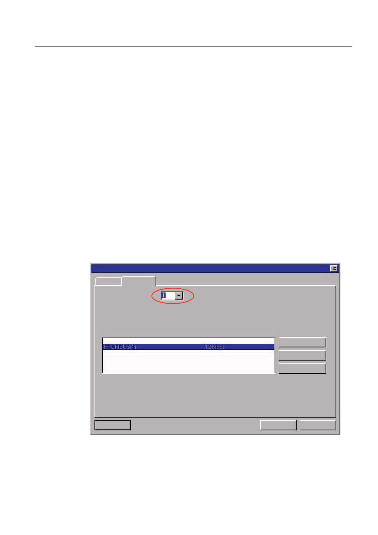
Inserting an ADI4 DP slave into the configuration will open the "Properties - PROFIBUS
Interface ADI4" dialog, "Parameters" tab:
3URSHUWLHV
352),%86 LQWHUIDFH $',
*HQHUDO
3DUDPHWHUV
$GGUHVV
7UDQVPLVVLRQ UDWH
0ELWV V
6XEQHW
QRW QHWZRUNHG
1HZ
3URSHUWLHV
'HOHWH
2.
&DQFHO
+HOS
Figure 5-1
PROFIBUS address
ADI4 - Analog drive interface for 4 axes
Manual, 03/2010, 6FC5297-0BA01-0BP5
45

Parameter assignment
5.7 PROFIBUS parameters
The displayed address value was automatically set by HW Config to the next available
PROFIBUS address within the configuration.
NOTICE
The PROFIBUS address of the ADI4 DP slave can be set to any value, in principle.
However, it must be ensured that the PROFIBUS address setting in HW Config matches
the DIP switch setting on the ADI4 DP slave:
There is no automatic adjustment!
The following data must agree:
• SIMATIC S7 configuration ADI4 DP slave
PROFIBUS address
• ADI4 module DIP switch S2
PROFIBUS address
Note
PROFIBUS address 127
If PROFIBUS address is set to 127, when the module powers up, the firmware release is
displayed on the internal module LEDs using a flashing code. It is not recommended to use
PROFIBUS address 127 as this lengthens the time that the module requires to power up.
After the dialog is confirmed with "OK", the "DP Slave Properties" dialog box is opened.
Continue with the parameter assignment for the message frame type.
5.7.3
Message frame type
Message frame type
The ADI4 DP slave is operated with a specific message frame type:
4 axes, each with one encoder (standard message frame 3) and I/O data
ADI4 - Analog drive interface for 4 axes
46
Manual, 03/2010, 6FC5297-0BA01-0BP5
Parameter assignment
5.7 PROFIBUS parameters
'3 VODYH SURSHUWLHV
*HQHUDO
&RQILJXUDWLRQ
,VRFKURQRXV RSHUDWLRQ
(QFRGHU
1RQH
1RQH
6ORW
D[HV HDFK ZLWK RQH HQFRGHU VWDQGDUG PHVVDJH IUDPH
,2 3='
2,
7\SH
$GGUHVV
7\SH
35
, 2 DGGUHVV
3UR
/¦
1R 3.:
$GG VORW
'HOHWH VORW
0DVWHU VODYH FRQILJXUDWLRQ
0DVWHU
'3 '5,9(
6WDWLRQ
6,0$7,&
&RPPHQW
2.
&DQFHO
+HOS
Figure 5-2
Message frame type
Setting the message frame type
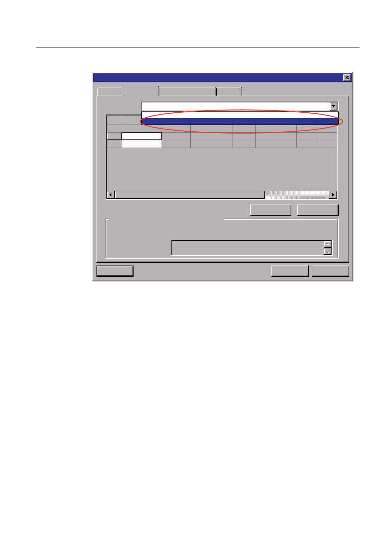
By default, no message frame type is selected. The ADI4-specific message frame type must
be explicitly selected in the "Configuration" tab.
1. In the "DP Slave Properties" dialog box, select the "Configuration" tab.
2. In the "Default" list, select the entry "4 axes, each with one encoder, Standard message
frame 3 + IO, PZD-5/9 O/I 1/1".
3. Click "OK".
ADI4 - Analog drive interface for 4 axes
Manual, 03/2010, 6FC5297-0BA01-0BP5
47
Parameter assignment
5.7 PROFIBUS parameters
Message frame structure
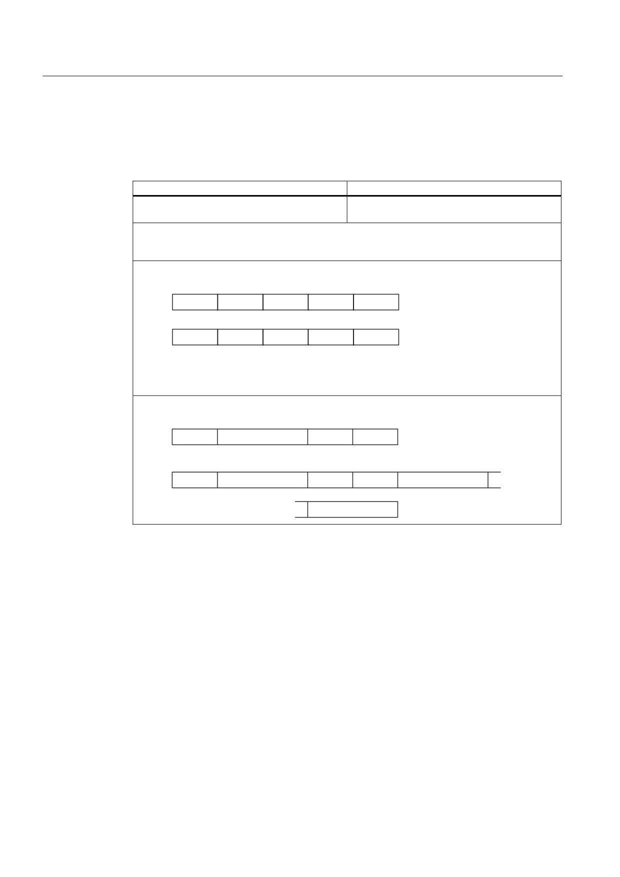
The message frame is structured as follows:
Table 5- 1
Message frame structure
Message frame type
Description
4 axes, each with one encoder, Standard
4 x Standard message frame 3 and 1 PZD word
message frame 3 + IO, PZD-5/9 O/I 1/1
each for digital I/O data
PZD x/y Number of process data words, x: Setpoint, y: Actual value, e.g. PZD-5/9:
5 process data words for setpoints
9 process data words for actual values
$', PHVVDJH IUDPH VWUXFWXUH
$[LV
$[LV
$[LV
$[LV
,2
67'
67'
67'
67'
2 ZRUG
6HWSRLQWV PDVWHU ! VODYH
/RZ
+LJK
$[LV
$[LV
$[LV
$[LV
,2
67'
67'
67'
67'
2 ZRUG
$FWXDO YDOXHV VODYH ! PDVWHU
67'
VWDQGDUG PHVVDJH IUDPH SHU 352),'ULYH 6SHFLILFDWLRQ 9
4 ZRUG GLJLWDO RXWSXW GDWD
ELWV
, ZRUG GLJLWDO LQSXW GDWD
ELWV
6WDQGDUG PHVVDJH IUDPH
VSHHG VHWSRLQW LQWHUIDFH
ELWV ZLWK HQFRGHU
3='
3='
3='
3='
3='
67:
16(7B%
67:
* B67:
6HWSRLQW PDVWHU ! VODYH
/RZ
+LJK
3='
3='
3='
3='
3='
3='
3='
=6:
1$&7B%
=6:
* B=6:
* B;,67
3='
3='
* B;,67
$FWXDO YDOXH VODYH ! PDVWHU
ADI4 - Analog drive interface for 4 axes
48
Manual, 03/2010, 6FC5297-0BA01-0BP5
Parameter assignment
5.7 PROFIBUS parameters
Message frame type
Description
2 ZRUG GLJ RXWSXW GDWD
ELWV
+LJK %\WH
/RZ %\WH
'LJ RXWSXWV ದ
! ; ದ 3LQ ದ
'LJ RXWSXW ದ
GLUHFWLRQ VLJQDO ದ IRU
XQLSRODU VSLQGOH ! ; ದ 3LQ ದ
8 FRQIRUPDQW PRGH
6HOHFW +RPLQJ XVLQJ H[WHUQDO ]HUR PDUN
VLJQDOV WR
1RW XVHG
2 ZRUG GLJ RXWSXW GDWD
ELWV
+LJK %\WH
/RZ %\WH
'LJ LQSXWV ದ
H[W ]HUR PDUNV ದ ದ!
; ದ 3LQ ದ
'LJ LQSXW ದ
0HDVXULQJ LQSXW ದ
ದ! ; ದ 3LQ ದ
'LJ LQSXW ದ
'UYB5G\ ದ ದ!
; ದ 3LQ ದ
'LJ LQSXW ದ
'UYB5G\ ದ ದ!
; ದ 3LQ ದ
1RW XVHG
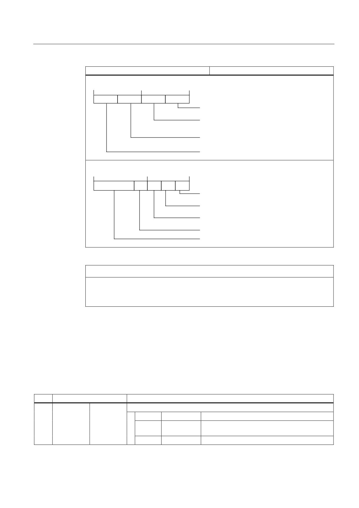
NOTICE
The message frame type setting for the ADI4 DP slave in HW Config must agree with the
message frame type setting in the controller.
There is no automatic adjustment.
Encoder control word Gx_STW
Description of the encoder control word (extract) for:
● Find reference mark
● On-the-fly measurement
● Encoder error
Table 5- 2
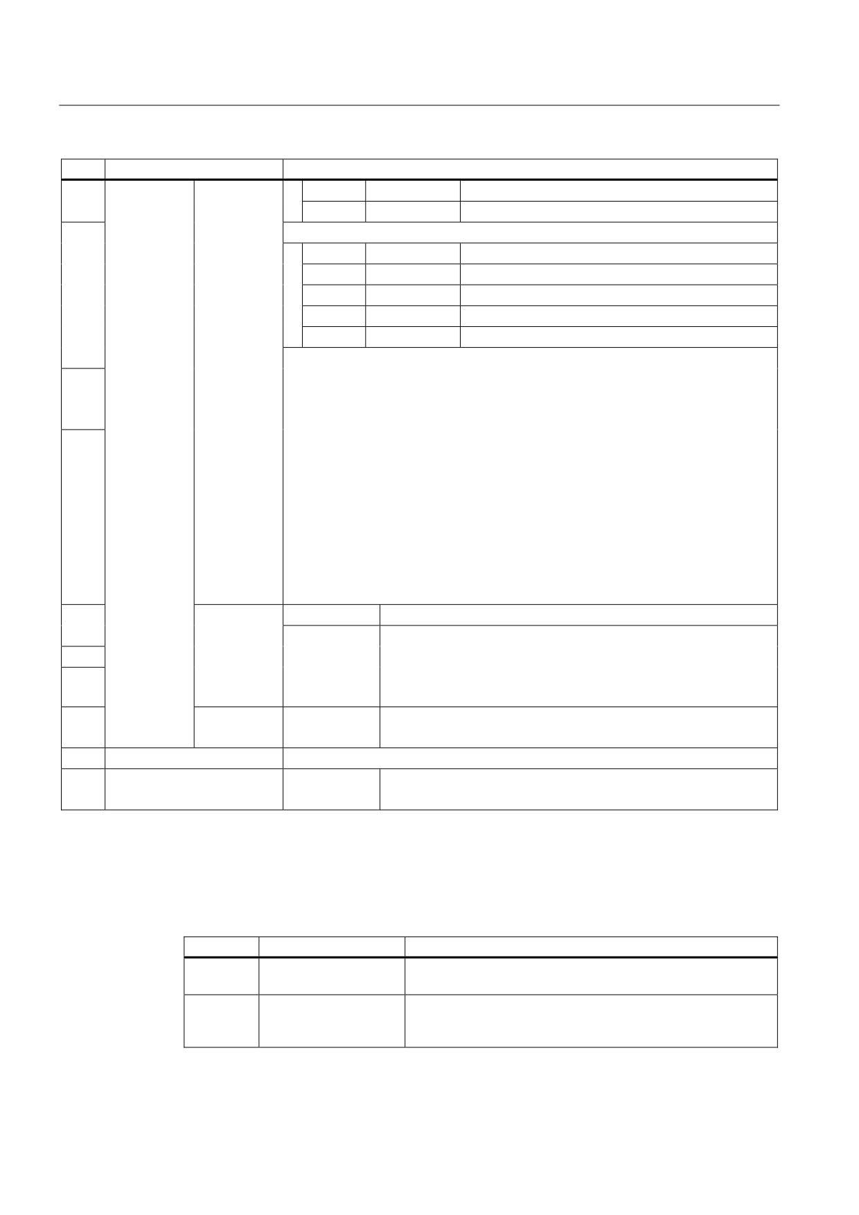
Encoder control word Gx_STW (extract)
Bit
Name
Signal status, description
Find reference mark: Bit 7 = 0
Bit
Meaning
Homing using:
0
Function 1:
Encoder zero mark (except in "611U conformant
mode")
1
Function 2:
Rising edge of external zero mark
ADI4 - Analog drive interface for 4 axes
Manual, 03/2010, 6FC5297-0BA01-0BP5
49
Parameter assignment
5.7 PROFIBUS parameters
Bit
Name
Signal status, description
0
2
Function 3:
Falling edge of external zero mark
3
Function 4:
Not used
On-the-fly measurement: Bit 7 = 1
Bit
Meaning
Measuring using:
Find
0
Function 1:
Measuring Input 1 rising edge
reference
1
1
Function 2:
Measuring Input 1 falling edge
mark
2
Function 3:
Measuring Input 2 rising edge
or
Functions
3
Function 4:
Measuring Input 2 falling edge
On-the-fly
measure-
Note
ment
• Bit 0 to 3
Bit x = 1 Function requested
Bit x = 0 Function not requested
2
• If more than one function is enabled, the values for all functions cannot be read
until all functions have ended and this has been signaled via the relevant status
bit (G1_ZSW, Bit 0 - Bit 3 = 0).
• On-the-fly measurement
3
The rising and falling edges of the measuring input can be enabled
simultaneously. The measuring input signal is detected according to the
direction of the signal change. The measured values are read out consecutively.
Notice
ADI4 only supports measurement on a rising or falling edge.
• Find reference mark and on-the-fly measurement
Only one of the two functions can be active at a time.
4
Bit 6, 5, 4
Meaning
000
- -
5
Command
001
Activate function x
6
010
Read value x
011
Cancel function x
7
Mode
0
Find reference mark
1
On-the-fly measurement
:
:
15
Encoder error
0
No error
1
Encoder error pending; error code in Gx_XIST2
Additional encoder actual value Gx_XIST2
Error codes in Gx_XIST2 where G1_ZSW, Bit 15 = 1
Table 5- 3
Error codes in Gx_XIST2
G1_XIST2
Meaning
Possible causes/description
1Hex
Encoder sum error
The encoder signal levels are too low, faulty (inadequate
shielding) or cable breakage monitoring has been tripped.
2Hex
Zero mark monitoring
A fluctuation in the measured rotor position has arisen
between two encoder zero marks (encoder pulses may be
lost).
ADI4 - Analog drive interface for 4 axes
50
Manual, 03/2010, 6FC5297-0BA01-0BP5
Parameter assignment
5.7 PROFIBUS parameters
5.7.4
I/O addresses
Requirements
For communication between the controller and the individual axes of an ADI4 DP slave, it is
necessary that the setpoint and the actual value of an axis have the same I/O address.
HW Config takes this requirement into account automatically when an ADI4 DP slave is
inserted in the configuration.
Inserting I/O addresses
1. In the "DP Slave Properties" dialog box, select the "Configuration" tab.
2. Under PROFIBUS partner, I/O addr., enter: <I/O address>.
3. Click "OK".
NOTICE
The setpoint and actual value of an axis must have the same I/O address.
I address (actual value) = O address (setpoint)
If an ADI4 DP slave is inserted into an S7 project through a copy operation, e.g., from
another S7 project, the I/O addresses are assigned directly by HW Config. This may
have the consequence that an axis is assigned different I/O addresses for setpoint and
actual values. The I/O addresses must be manually corrected in this case.
To avoid access conflicts between the PROFIBUS DP drives and the I/O modules,
values ≥ 272 must be used for I/O addresses for the ADI4 DP slave.
5.7.5
Consistency
Consistency setting
The default setting for I/O data consistency is "Total length".
The "Total length" consistency setting means that direct access from the PLC user program
(e.g. byte, word, or double word) to this address area of the PLC operating system is not
permitted.
ADI4 - Analog drive interface for 4 axes
Manual, 03/2010, 6FC5297-0BA01-0BP5
51
Parameter assignment
5.8 Function parameters for SINUMERIK 802D sl
5.8
Function parameters for SINUMERIK 802D sl
Parameter values
The function parameters are permanently specified in the preset configuration and cannot be
changed.
The following parameter values are set:
● Sensor type: TTL 1)
● Unipolar spindle: "Inactive"
● Shutdown ramp: 0
● Shutdown delay time: 0
● Tolerable sign-of-life failures: 0
● Reserved bits for fine resolution: 11
●
611U conformant mode: "Active"
1) Incremental encoder (TTL) with differential transmission of 5 V square wave signals
(RS 422 Standard).
5.9
Function parameters
Parameters
The function-specific parameters of the ADI4 DP slave are entered under the "Encoder" tab:
● Encoder type
● Unipolar spindle (or unipolar motor)
● Shutdown ramp
● Shutdown delay
● Tolerable sign-of-life failures
● Reserved bits for fine resolution
●
611U conformant mode
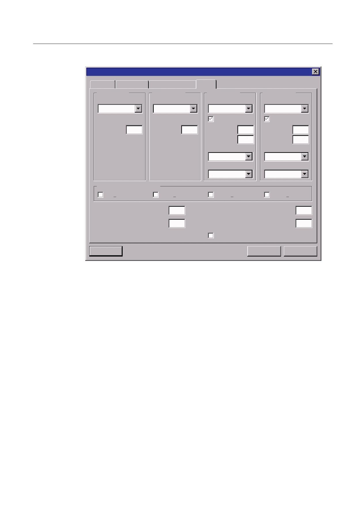
The figure below shows the corresponding dialog box with sample values for the various
encoder types and parameters.
ADI4 - Analog drive interface for 4 axes
52
Manual, 03/2010, 6FC5297-0BA01-0BP5
Parameter assignment
5.9 Function parameters
'3 VODYH SURSHUWLHV
*HQHUDO
&RQILJXUDWLRQ ,VRFKURQRXV RSHUDWLRQ
(QFRGHU
(QFRGHUB
(QFRGHUB
(QFRGHUB
(QFRGHUB
(QFRGHU W\SH
(QFRGHU W\SH
(QFRGHU W\SH
(QFRGHU W\SH
77/
77/
66,
66,
3DULW\
3DULW\
5HVROXWLRQ
5HVROXWLRQ
5HVROXWLRQ
5HVROXWLRQ
0VJ/HQJWK
0VJ/HQJWK
(QFRGLQJ
(QFRGLQJ
%LQDU\*UD\
%DXG UDWH
%DXG UDWH
N%LW V
N%LW V
8QLSRODU VSLQGOH
VW $[LV
QG $[LV
UG $[LV
WK $[LV
6KXWGRZQ UDPS >PV@
7ROHUDEOH VLJQ RI OLIH HUURUV
6KXWGRZQ GHOD\ >V@
5HVHUYHG ELWV IRU ILQH UHVROXWLRQ
8 FRQIRUPDQW PRGH
2.
&DQFHO
+HOS
Figure 5-3
"DP Slave Properties" dialog box, "Encoder" tab
5.9.1
Encoder type
Encoder type "not available"
An encoder type setting of "not available" for encoder x means that axis x does not exist, or
that it is not to be operated. Net data transmitted for this axis in the PROFIBUS message
frame are empty.
Encoder type TTL
Encoder parameter:
● Resolution
Encoder resolution in encoder pulses per encoder revolution
ADI4 - Analog drive interface for 4 axes
Manual, 03/2010, 6FC5297-0BA01-0BP5
53
Parameter assignment
5.9 Function parameters
Note
In the case of spindles with a low-resolution encoder, the actual-value characteristic
(incrementing) may be displayed in a non-linear fashion. The grid that is visible on the
actual-value display is the result of the speed resolution (RR), where:
RR = 60000 / ( Tdp * ER * PM )
• RR (speed resolution): [(revolutions/min) / encoder pulse]
• Tdp (position control cycle clock = PROFIBUS cycle clock): [ms]
• ER (encoder resolution): [Encoder pulse / revolution]
• PM (pulse multiplication)
Example:
Tdp (position control cycle clock = PROFIBUS cycle clock): 2 ms
ER (encoder resolution): 2500 pulses/revolution
PM (pulse multiplication): 4
RR = 60000 / (2 * 2500 * 4) = 3 (revolutions/min) / encoder pulse
(SINUMERIK 840Di sl, SINUMERIK 840D sl)
Smoothing of the actual value for low-resolution encoders via machine data:
MD34990 $MA_ENC_ACTVAL_SMOOTH_TIME (smoothing time constant)
Encoder type SSI
Encoder parameters:
● Parity
Select this check box if the encoder data are to be transmitted from the encoder to the
ADI4 with a parity bit.
● Resolution
Encoder resolution in encoder pulses per encoder revolution
● MsgLength
Number of net data bits transmitted from the encoder
ADI4 - Analog drive interface for 4 axes
54
Manual, 03/2010, 6FC5297-0BA01-0BP5

Parameter assignment
5.9 Function parameters
● Encoding
The following encoder codes are supported:
- Binary
- Gray
● Baud rate
The following baud rates are supported:
-
187.5 kbit/s
–
375 kbit/s
–
750 kbit/s
NOTICE
Regarding SSI encoders (absolute encoders), the following limitations should be
observed:
• The baud rate setting must be identical for all SSI encoders. If baud rate settings
are different, the baud rate of the SSI encoder with the highest encoder number is
used.
• In conjunction with ADI4, only SSI encoders with "Christmas tree" data output
format (TSSI) can be operated.
5.9.2
Unipolar spindle or unipolar motor
Introduction
The drive can be moved in two directions. Selecting the "Unipolar spindle" option switches
over the voltage range of the analog output voltage.
Unipolar spindle not selected
If the "Unipolar spindle" option button is not selected, an analog voltage in the range of -10 V
to +10 V is output as the setpoint.
Unipolar spindle selected
If the "Unipolar spindle" option button is selected, an analog voltage in the range of 0 V to
+10 V is output as the setpoint. Depending on the actual speed setpoint, the direction of
rotation is then output via a digital output of the ADI4:
● Direction of rotation signal for axis 1 -> digital output X6-1, pin 6
● Direction of rotation signal for axis 2 -> digital output X6-1, pin 7
● Direction of rotation signal for axis 3 -> digital output X6-1, pin 8
● Direction of rotation signal for axis 4 -> digital output X6-1, pin 9
ADI4 - Analog drive interface for 4 axes
Manual, 03/2010, 6FC5297-0BA01-0BP5
55

Parameter assignment
5.9 Function parameters
Direction of rotation signal
The following voltage level is available at the digital outputs X6-1, pins 6 - 9 depending on
the direction of rotation:
● M3 (spindle CW)= 24 V
● M4 (spindle CCW) = 0 V
● M5 (spindle stop) = 24 V
5.9.3
Shutdown ramp
Shutdown ramp
The "Shutdown ramp" parameter specifies a function that is linear with respect to time. If an
error is detected in the ADI4, all ADI4 drives are slowed down to Setpoint "0" in accordance
with this function.
A parameter value of "0" brings the drives to an immediate stop (braking at the current limit).
● Unit: [ms]
W >PV@
Figure 5-4
Parameter: Shutdown ramp
①
Maximum setpoint
②
Current setpoint
③
Parameter value: Shutdown ramp
5.9.4
Shutdown delay
Shutdown delay parameter
The "Shutdown delay" parameter can be used to specify a time after which all ADI4 drives
are slowed down to the setpoint "0" following a temperature alarm in the ADI4.
After the "Shutdown delay" has elapsed, the "Shutdown ramp" is taken into account.
● Unit: [s]
ADI4 - Analog drive interface for 4 axes
56
Manual, 03/2010, 6FC5297-0BA01-0BP5

Parameter assignment
5.9 Function parameters
5.9.5
Tolerable sign-of-life failures
"Tolerable sign-of-life failures" parameter
The "Tolerable sign-of-life failures" parameter specifies the number of sign-of-life failures
tolerated for the DP master. If the assigned number is exceeded, the setpoint interfaces of
the drives are ramped down to the value "0" using the "Shutdown ramp".
NOTICE
Presently, the "Tolerable sign-of-life failures" parameter may only be used on values in the
range of 0 to 13.
5.9.6
Reserved bits for fine resolution
"Additional substitute bits for fine resolution" parameter
The "Additional substitute bits for fine resolution" parameter specifies the desired pulse
multiplication of the encoder increments transmitted in actual encoder values G1_XIST1 and
G1_XIST2.
Presently, the number of additional substitute bits for fine resolution must be set permanently
to 11. This corresponds to a pulse multiplication of: 211 = 2048.
NOTICE
The "Reserved bits for fine resolution" parameter must always be set to 11.
7UDQVPLWWHG DFWXDO HQFRGHU YDOXH * B;,67 RU * B;,67
2YHUIORZV
&XUUHQW HQFRGHU LQFUHPHQWV
5HVHUYHG ELWV IRU ILQH UHVROXWLRQ
(SINUMERIK 840Di sl, SINUMERIK 840D sl)
NOTICE
Corresponding to the "Additional substitute bits for fine resolution" parameter, the following
must be entered in the axis-specific machine data:
MD30260 $MA_ABS_INC_RATIO (ratio of the absolute resolution to the incremental
resolution)
the value 2"Additional fine bits for fine resolution" = 211 = 2048.
ADI4 - Analog drive interface for 4 axes
Manual, 03/2010, 6FC5297-0BA01-0BP5
57

Parameter assignment
5.9 Function parameters
5.9.7
611U conformant mode
Setting options
In 611U conformant mode, the signal source for homing of axes is no longer specified using
the PROFIDrive standard message frame (STD3, encoder control word G1_STW), but rather
using the additional digital output word in the PROFIBUS message frame of the ADI4 (see
table "Message frame structure" in the "Message frame type" section).
611U conformant mode:
● Not selected
The signal source for homing is specified via the encoder control word Gx_STW in the
PROFIDrive standard message frame.
● Selected
The signal source for homing is specified via the additional digital output word in the
PROFIBUS message frame.
Digital output word
The signal sources for the homing are selected on an axis-specific basis via the following
bits of the output word (see also output word in the table "Message frame structure" in the
"Message frame type" section)
Table 5- 4
Output word: Signal sources for homing
Bit
Value
Signal source for homing
8
0
Axis 1: Zero mark of encoder 1 (X4-1)
1
Axis 1: Rising edge of external zero mark 1 (X6-2, pin 2)
9
0
Axis 2: Zero mark of encoder 2 (X4-2)
1
Axis 2: Rising edge of external zero mark 2 (X6-2, pin 3)
10
0
Axis 3: Zero mark of encoder 3 (X4-3)
1
Axis 3: Rising edge of external zero mark 3 (X6-2, pin 4)
11
0
Axis 4: Zero mark of encoder 4 (X4-4)
1
Axis 4: Rising edge of external zero mark 4 (X6-2, pin 5)
If the 611U conformant mode has been parameterized for an axis to be homed, the axis-
specific signal for selection of the signal source must be set in the digital output word of the
ADI4 from the PLC user program, before the "Reference mark search" function is requested
in the encoder control word.
The following sections show the basic system structure and the respective boundary
conditions of the individual homing methods.
Exiting the dialog box
If the "DP Slave Properties" dialog box is exited with "OK", the data are accepted and the
dialog box is closed.
ADI4 - Analog drive interface for 4 axes
58
Manual, 03/2010, 6FC5297-0BA01-0BP5
Parameter assignment
5.9 Function parameters
Step1: End
Step 1 of the ADI4 DP slave parameterization is now complete.
See also
Message frame type (Page 46)
Boundary conditions (Page 61)
5.9.8
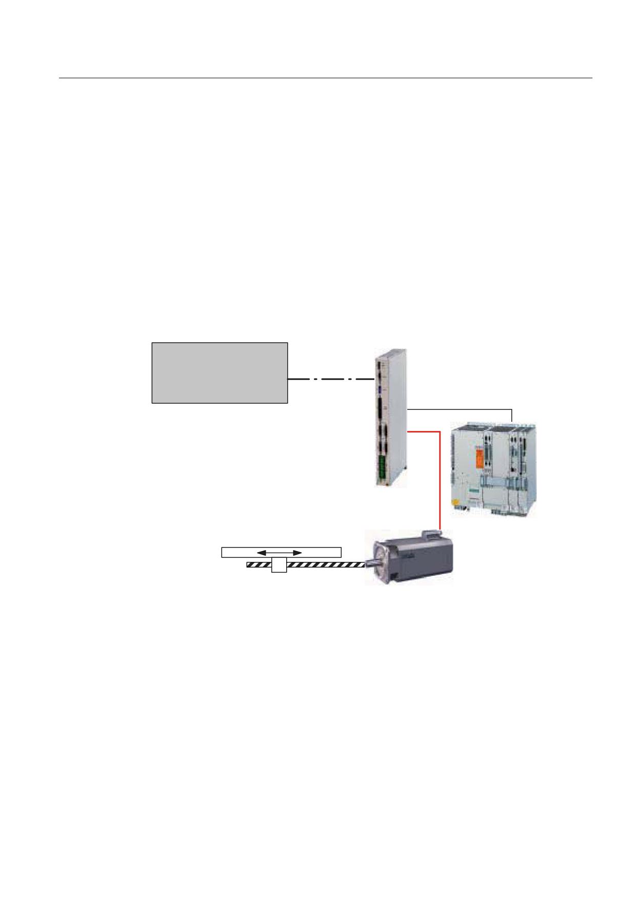
Homing using encoder zero mark
System setup
$',
,QYHUWHU V\VWHP H J
&RQWUROOHU H J
6,02'5,9(
ZLWK FRQWURO
ದ 6,180(5,.
'
352),%86 '3
XQLW ZLWK DQDORJ VHWSRLQW
ದ 6,180(5,.
'L
LQWHUIDFH
ದ 6,027,21
ದ 6,0$7,&
7HFKQRORJ\ &38
$QDORJ VHWSRLQW
(QFRGHU DFWXDO
YDOXH HQFRGHU ]HUR PDUN
0RWRU H J
)7
$[LV H J PDFKLQLQJ WDEOH
Figure 5-5
Basic system structure: Homing using encoder zero mark
Function
Once the controller requests homing, the ADI4 transmits the actual encoder value to the
controller as the home position the next time it detects an encoder zero mark.
Without 611U conformant mode
No further measures are required.
ADI4 - Analog drive interface for 4 axes
Manual, 03/2010, 6FC5297-0BA01-0BP5
59
Parameter assignment
5.9 Function parameters
With 611U conformant mode
The relevant signal for the axis to be homed (e.g. axis 1) must be set in the digital output
word:
● Digital output word:
Bit 8: = 0 => "Axis 1: Zero mark of encoder 1 (X4-1)"
5.9.9
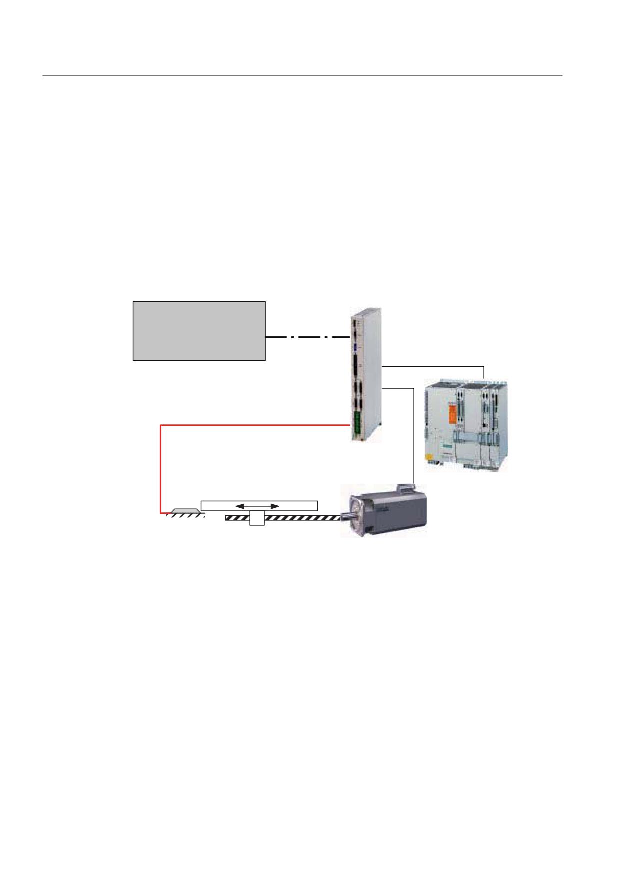
Homing using external zero mark
System setup
$',
,QYHUWHU V\VWHP H J
&RQWUROOHU H J
6,02'5,9(
ZLWK FRQWURO
ದ 6,180(5,.
'
352),%86 '3
XQLW ZLWK DQDORJ VHWSRLQW
ದ 6,180(5,.
'L
LQWHUIDFH
ದ 6,027,21
ದ 6,0$7,&
7HFKQRORJ\ &38
$QDORJ VHWSRLQW
'LJLWDO LQSXWV H J $[LV
; ದ 3LQ
$FWXDO HQFRGHU YDOXH
([WHUQDO ]HUR PDUN
VLJQDO
0RWRU H J
)7
$[LV H J PDFKLQLQJ WDEOH
([WHUQDO ]HUR
PDUN
Figure 5-6
Basic system structure: Homing using external zero mark
Function
Once the controller requests homing, the ADI4 transmits the actual encoder value to the
controller as the home position the next time it detects an external zero mark signal.
Without 611U conformant mode
The controller must define the relevant function via encoder control word G1_STW:
● Function 2 (homing via rising edge of external zero mark)
● Function 3 (homing via falling edge of external zero mark)
ADI4 - Analog drive interface for 4 axes
60
Manual, 03/2010, 6FC5297-0BA01-0BP5
Parameter assignment
5.9 Function parameters
With 611U conformant mode
The relevant signal for the axis to be homed (e.g. axis 1) must be set in the digital output
word:
● Digital output word:
Bit 8: = 1 => "Axis 1: Rising edge of external zero mark 1 (X6-2, pin 2)"
Note
Homing using an external zero mark requires 611U conformant mode to be selected.
5.9.10
Boundary conditions
Probe or on-the-fly measurement
ADI4 supports only measurement using a rising or falling edge of the probe. It is not possible
to parameterize simultaneous measurement on a rising edge and a negative edge.
Speed actual value
The actual speed value (PZD2/3: NACT_B) contained in standard message frame 3 (see
table "Message frame structure" in the "Message frame type" section) is not supported by
the ADI4. The ADI4 always sends a value of 0 as the actual speed value.
External encoder interface (encoders without an axis)
If only encoders are connected to the ADI4 without at least one axis being parameterized,
i.e. the ADI4 uses the encoder as an external encoder interface only, a "Ready" signal
(interface X6-1, pin 10/11) is not output. For information on the "Ready" signal, refer to
section "Interface (X6-1): Digital outputs".
See also
Interface (X6-1): Digital outputs (Page 28)
ADI4 - Analog drive interface for 4 axes
Manual, 03/2010, 6FC5297-0BA01-0BP5
61
Parameter assignment
5.10 Parameterization of the DP communication
5.10
Parameterization of the DP communication
5.10.1
Parameter assignment of the equidistant cyclic DP communication
Action steps
Once all the DP slaves have been inserted in the configuration and their function parameters
have been assigned as described (Step 1), the parameters for the equidistant cyclic DP
communication must then be assigned (Step 2).
Parameters are assigned to the equidistant cyclic DP communication in two steps, as well:
Step 1
● Activation of the equidistant DP cycle
● Equidistant master cyclic component TDX
Step 2
● Equidistant DP cycle TDP
● Master application cycle TMAPC
● Actual value acquisition Ti
● Setpoint acceptance To
NOTICE
When assigning parameters for DP communication, you must observe the boundary
conditions applicable to the individual parameters.
See also
Boundary conditions (Page 78)
ADI4 - Analog drive interface for 4 axes
62
Manual, 03/2010, 6FC5297-0BA01-0BP5
Parameter assignment
5.10 Parameterization of the DP communication
5.10.2
Activation of the equidistant DP cycle
Procedure
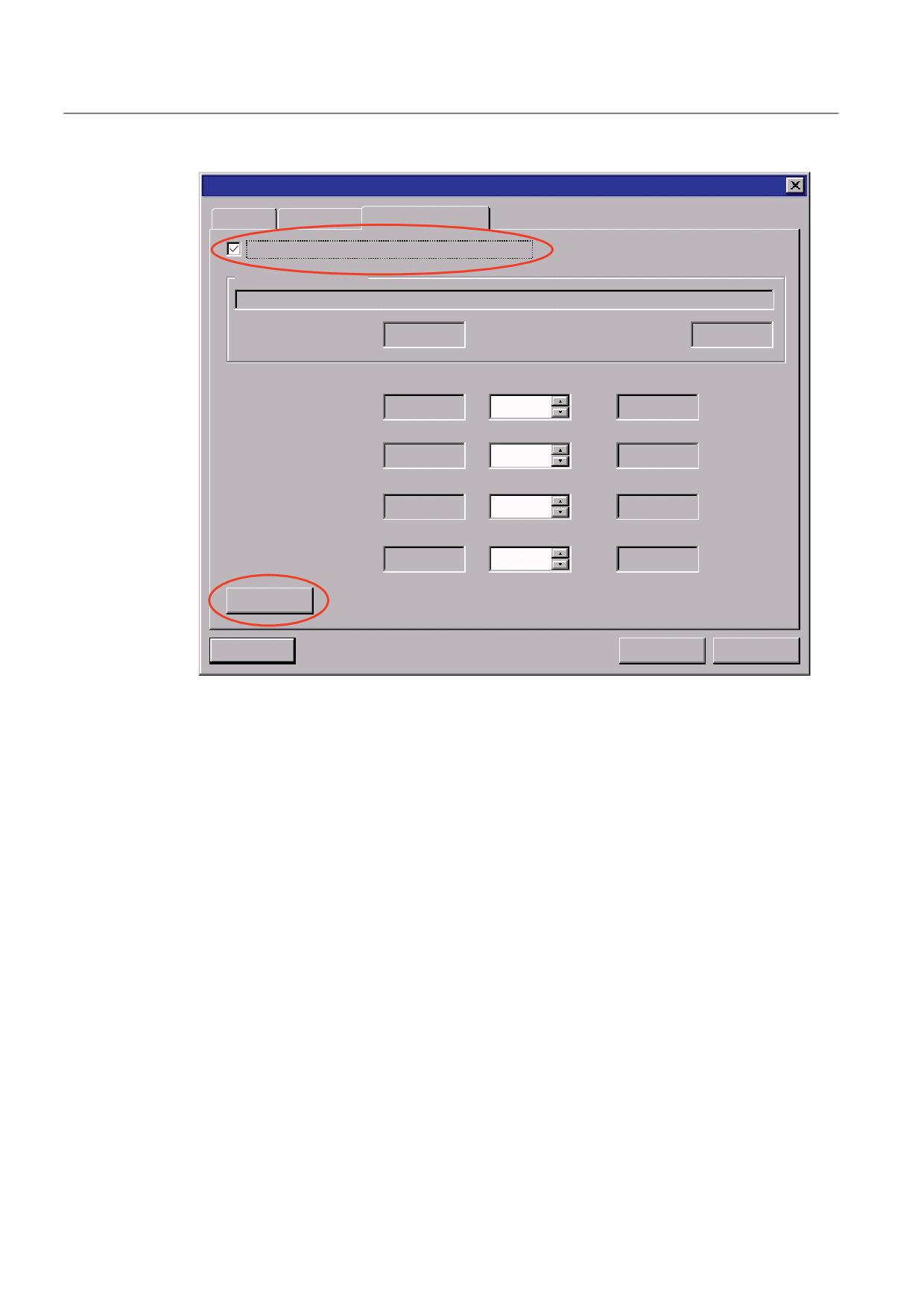
Double-click an ADI4 DP slave. In the station window of HW Config, the dialog box: "DP
Slave Properties" opens.
Note
It is recommended that the equidistant DP cycle be enabled for all ADI4 DP slaves by
enabling the equidistant DP cycle within the selected ADI4 DP slave, and then performing an
alignment:
During an alignment, all values displayed in the "DP Slave Properties" dialog box,
"Isochronous mode" tab are transferred to all DP slaves of the same type, ADI4 DP slave
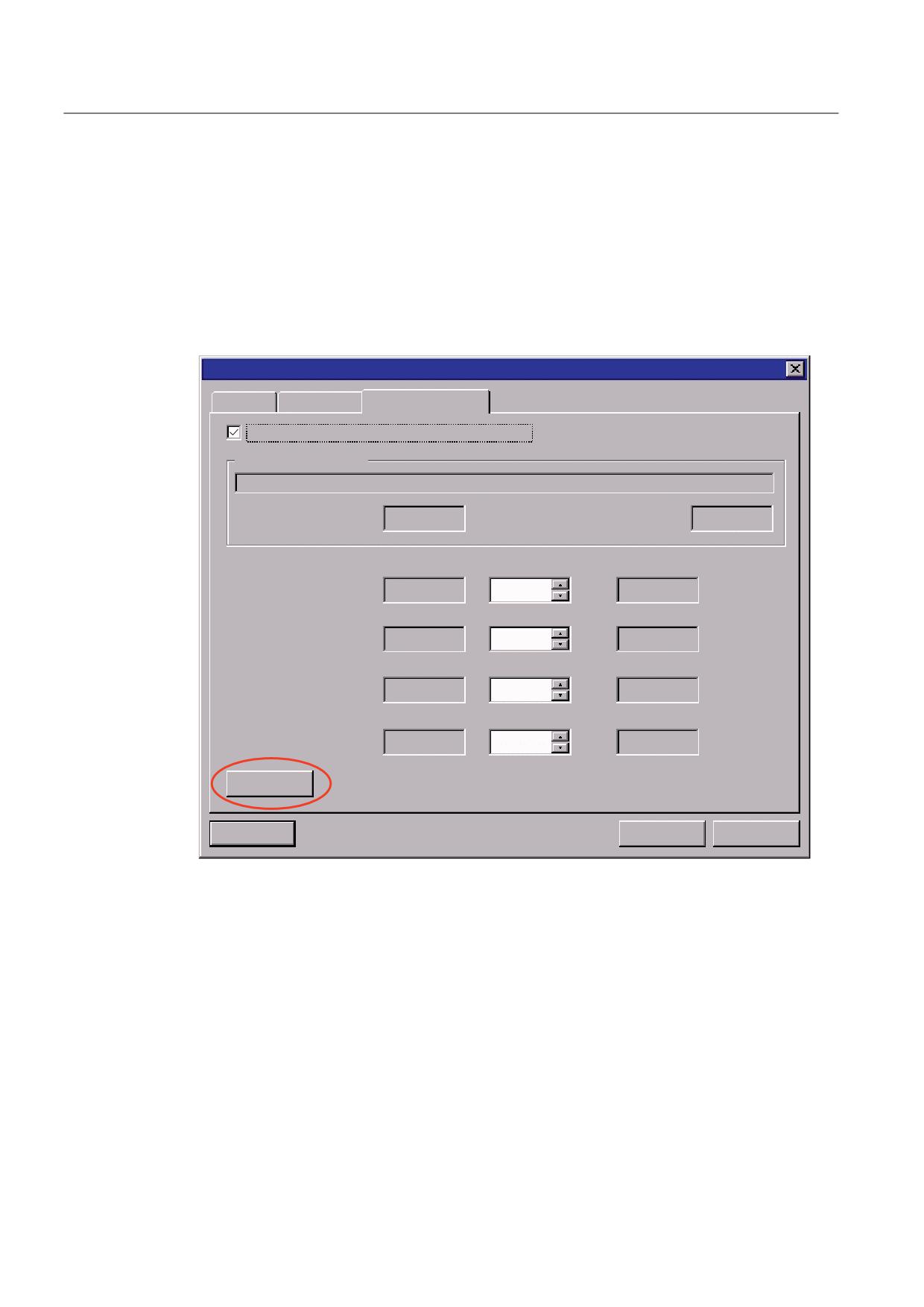
here, of the configuration.
Dialog: Start
Dialog: DP slave properties
Tab: Isochronous operation
Radio button: Synchronize drive to equidistant DP cycle ☑
Button: Alignment
ADI4 - Analog drive interface for 4 axes
Manual, 03/2010, 6FC5297-0BA01-0BP5
63
Parameter assignment
5.10 Parameterization of the DP communication
'3 VODYH SURSHUWLHV
*HQHUDO &RQILJXUDWLRQ ,VRFKURQRXV RSHUDWLRQ
6\QFKURQL]H GULYH WR HTXLGLVWDQW '3 F\FOH
1HWZRUN VHWWLQJV LQ PV
(TXLGLVWDQW EXV F\FOH DFWLYDWHG
(TXLGLVWDQW '3 F\FOH
(TXLGLVWDQW PDVWHU F\FOLF FRPSRQHQW
)DFWRU
%DVH WLPH >PV@
0DVWHU DSSOLFDWLRQ F\FOH
[
>PV@
)DFWRU
%DVH WLPH >PV@
'3 F\FOH >PV@
[
7LPH 7L >PV@
)DFWRU
%DVH WLPH >PV@
$FWXDO YDOXH DFTXLVLWLRQ
[
7LPH 7R >PV@
)DFWRU
%DVH WLPH >PV@
6HWSRLQW DFFHSWDQFH
[
$OLJQPHQW
2.
&DQFHO
+HOS
Figure 5-7
"DP Slave Properties" dialog box
5.10.3
Equidistant master cyclic component TDX
Procedure
Once synchronization to the equidistant DP cycle has been enabled for all DP slaves, the
time required for the cyclic component of the DP communication must be recalculated.
The calculation is performed automatically by the DP master each time the equidistant bus
cycle is enabled. This is performed in the following dialog box by selecting/clearing the
"Activate equidistant bus cycle" check box.
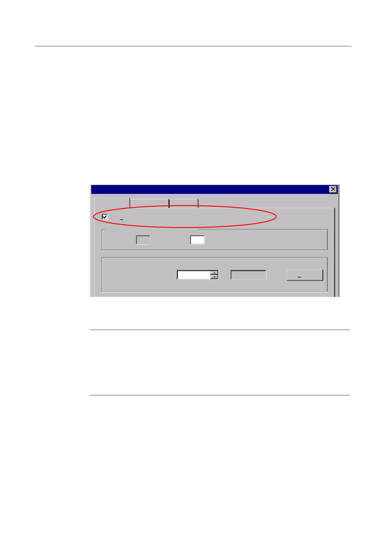
Dialog: Continuation
Dialog box: DP slave properties
Tab: General
Group: Node/Master System
Button: PROFIBUS...
ADI4 - Analog drive interface for 4 axes
64
Manual, 03/2010, 6FC5297-0BA01-0BP5
Parameter assignment
5.10 Parameterization of the DP communication
Dialog box: Properties - PROFIBUS interface ADI4 ...
Tab: Parameters
Button: Properties...
Dialog box: PROFIBUS properties
Tab: Network settings
Button: Options...
Dialog box: Options
Tab: Equidistance
1. Radio button: Activate equidistant bus cycle ☐ (deselect)
2. Radio button: Activate equidistant bus cycle ☑ (select)
2SWLRQV
(TXLGLVWDQFH 1HWZRUN VWDWLRQ
&DEOHV
$FWLYDWH HTXLGLVWDQW EXV F\FOH UHFDOFXODWH HTXLGLVWDQW WLPH
1XPEHU RI 3*V 23V 7'V RQ 352),%86
*ULG
(TXLGLVWDQW '3 F\FOH
PV
PV
'HWDLOV ಹ
PLQLPXP
PV
Figure 5-8
"Options" dialog box (excerpt)
Note
If there are different equidistant DP slave types (for example, different SIMODRIVE drives,
ADI4, etc.) in an S7 project, you must first perform the following two steps for each DP slave
type:
1. Synchronize drive to equidistant DP cycle
2. Perform alignment
You can then continue to set the other parameters.
ADI4 - Analog drive interface for 4 axes
Manual, 03/2010, 6FC5297-0BA01-0BP5
65
Parameter assignment
5.10 Parameterization of the DP communication
5.10.4
Equidistant DP cycle TDP
Procedure
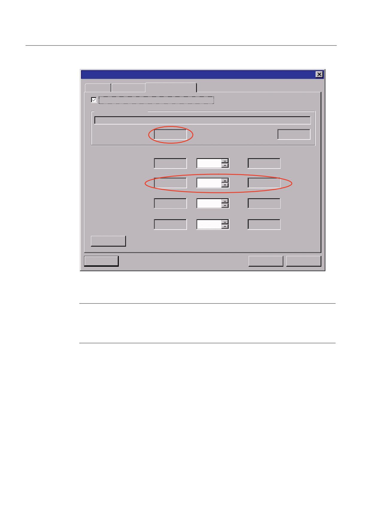
When the cyclic component of the DP communication is calculated, the DP master
automatically changes the value for the equidistant DP cycle to the minimum required time.
This change must be undone by re-entering the intended value for the equidistant DP cycle.
(SINUMERIK 840D sl)
Equidistant DP cycle
For SINUMERIK 840D sl, an ADI4 module is connected via an external PROFIBUS
(connection: DP1, X126 or DP2/MPI, X136). The DP cycle - with constant bus cycle time - of
the external PROFIBUS must then be set the same as the position controller clock cycle
parameterized in the NC or the equidistant DP cycle of the internal PROFIBUS.
Note
The DP cycle of the external PROFIBUS must be the same as that of the internal
PROFIBUS:
Equidistant DP cycle (external PROFIBUS) = position controller cycle = equidistant DP cycle
(internal PROFIBUS)
Connection to "NCU7x0.2 PN"
If an ADI4 module is connected to NCU module "NCU7x0.2 PN" then a module with the
following version and higher must be used: MLFB …-0AA2
Dialog: Continuation
Dialog box: Options
Tab: Equidistance
Entry field: Equidistant DP cycle = 2.000 ms (example value)
OK (close dialog box: Options)
OK (close dialog box: PROFIBUS properties)
OK (close dialog box: Properties - PROFIBUS interface ADI4 ...)
ADI4 - Analog drive interface for 4 axes
66
Manual, 03/2010, 6FC5297-0BA01-0BP5
Parameter assignment
5.10 Parameterization of the DP communication
2SWLRQV
(TXLGLVWDQFH 1HWZRUN VWDWLRQ
&DEOHV
$FWLYDWH HTXLGLVWDQW EXV F\FOH UHFDOFXODWH HTXLGLVWDQFH WLPH
1XPEHU RI 3*V 23V 7'V RQ WKH 352),%86
5HVROXWLRQ
(TXLGLVWDQW '3 F\FOH
PV
PV
'HWDLOV ಹ
PLQLPXP
PV
6\QFKURQL]DWLRQ RI WKH VODYHV
7LPHV 7L DQG 7R DUH WKH VDPH IRU DOO VODYHV
LI QRW 6HW LQ 3URSHUWLHV ದ VODYHV
7LPH 7L UHDG LQ SURFHVV YDOXHV
PV
7LPH 7R RXWSXW SURFHVV YDOXHV
PV
2.
&DQFHO
+HOS
Figure 5-9
"Options" dialog box
5.10.5
DP cycle TDP
Procedure
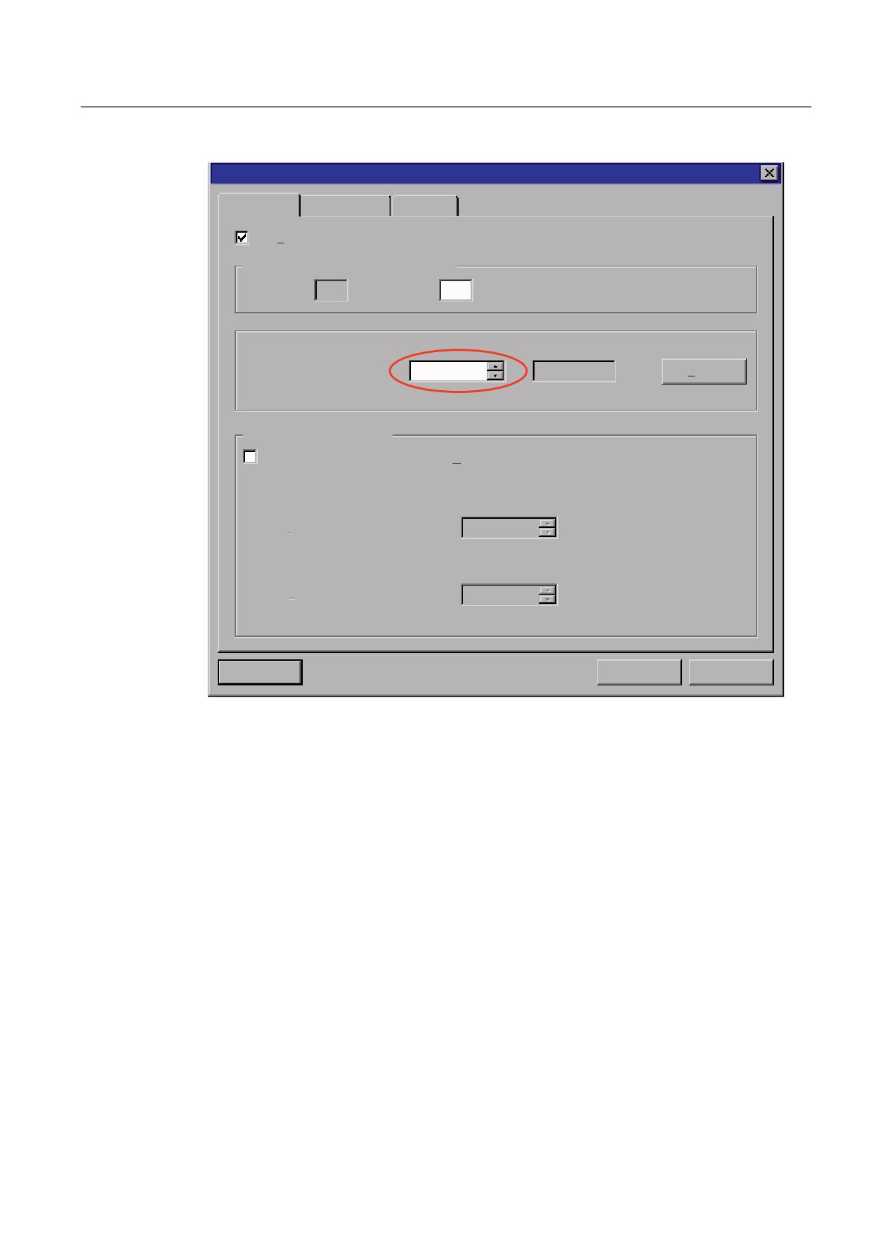
In the "Factor" entry field of the "DP cycle (ms)", enter a value such that the resulting DP
cycle is equal to the equidistant DP cycle.
Dialog: Start
Dialog: DP slave properties
Tab: Isochronous operation
Entry field: Factor = 16 (example value)
ADI4 - Analog drive interface for 4 axes
Manual, 03/2010, 6FC5297-0BA01-0BP5
67
Parameter assignment
5.10 Parameterization of the DP communication
'3 VODYH SURSHUWLHV
*HQHUDO &RQILJXUDWLRQ ,VRFKURQRXV RSHUDWLRQ
6\QFKURQL]H GULYH WR HTXLGLVWDQW '3 F\FOH
1HWZRUN VHWWLQJV LQ PV
(TXLGLVWDQW EXV F\FOH DFWLYDWHG
(TXLGLVWDQW '3 F\FOH
(TXLGLVWDQW PDVWHU F\FOLF FRPSRQHQW
)DFWRU
%DVH WLPH >PV@
0DVWHU DSSOLFDWLRQ F\FOH
[
>PV@
)DFWRU
%DVH WLPH >PV@
'3 F\FOH >PV@
[
7LPH 7L >PV@
)DFWRU
%DVH WLPH >PV@
$FWXDO YDOXH DFTXLVLWLRQ
[
7LPH 7R >PV@
)DFWRU
%DVH WLPH >PV@
6HWSRLQW DFFHSWDQFH
[
$OLJQPHQW
2.
&DQFHO
+HOS
Figure 5-10 "DP Slave Properties" dialog box
Note
The DP cycle time ("DP cycle" parameter) of the ADI4 DP slave must be set to the same
value as the DP cycle time setting for the DP master ("Equidistant DP cycle" parameter):
DP cycle = equidistant DP cycle
See also
Boundary conditions (Page 78)
ADI4 - Analog drive interface for 4 axes
68
Manual, 03/2010, 6FC5297-0BA01-0BP5
Parameter assignment
5.10 Parameterization of the DP communication
5.10.6
Master application cycle TMAPC
Introduction
The "Master application cycle TMAPC" parameter specifies the integer ratio between the cycle
time of the master application (position controller) and the equidistant DP cycle.
Using ratios other then 1:1, the dead times of the position controller can be reduced if control
hardware with a lower performance is being used.
Note
(SINUMERIK 840Di sl, SINUMERIK 840D sl)
The ratio between master application cycle TMAC and DP cycle time TDP must be 1:1.
(SINUMERIK 802D sl)
The ratio between master application cycle TMAC and DP cycle time TDP can be set to a ratio
other than 1:1.
Procedure
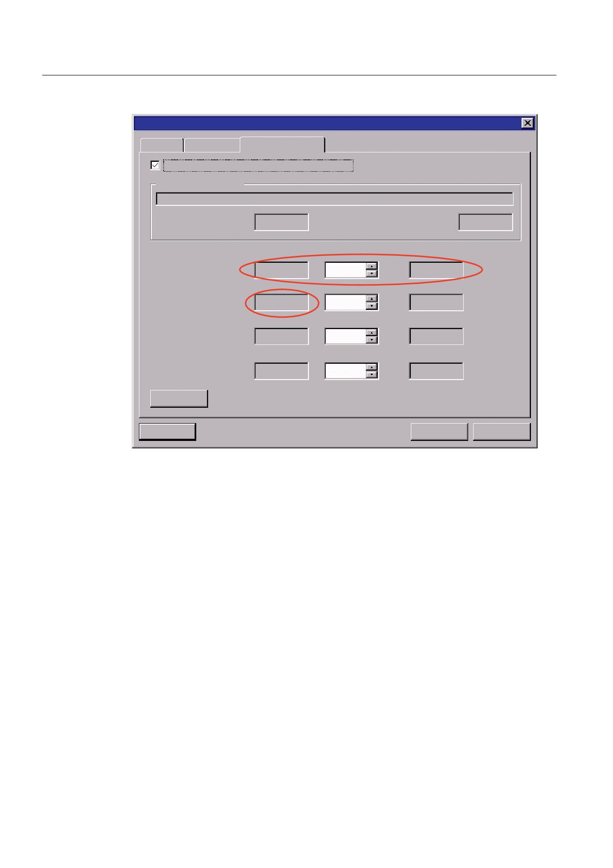
In the entry field for the factor of the "Master application cycle [ms], enter a value such that
the required time ratio is achieved.
Dialog: Continuation
Dialog: DP slave properties
Tab: Isochronous mode
Entry field: Factor = 1 (example value)
ADI4 - Analog drive interface for 4 axes
Manual, 03/2010, 6FC5297-0BA01-0BP5
69
Parameter assignment
5.10 Parameterization of the DP communication
'3 VODYH SURSHUWLHV
*HQHUDO &RQILJXUDWLRQ ,VRFKURQRXV RSHUDWLRQ
6\QFKURQL]H GULYH WR HTXLGLVWDQW '3 F\FOH
1HWZRUN VHWWLQJV LQ PV
(TXLGLVWDQW EXV F\FOH DFWLYDWHG
(TXLGLVWDQW '3 F\FOH
(TXLGLVWDQW PDVWHU F\FOLF FRPSRQHQW
)DFWRU
%DVH WLPH >PV@
0DVWHU DSSOLFDWLRQ
[
F\FOH >PV@
)DFWRU
%DVH WLPH >PV@
'3 F\FOH >PV@
[
7LPH 7L >PV@
)DFWRU
%DVH WLPH >PV@
$FWXDO YDOXH DFTXLVLWLRQ
[
7LPH 7R >PV@
)DFWRU
%DVH WLPH >PV@
6HWSRLQW DFFHSWDQFH
[
$OLJQPHQW
2.
&DQFHO
+HOS
Figure 5-11 Dialog: DP slave properties
ADI4 - Analog drive interface for 4 axes
70
Manual, 03/2010, 6FC5297-0BA01-0BP5
Parameter assignment
5.10 Parameterization of the DP communication
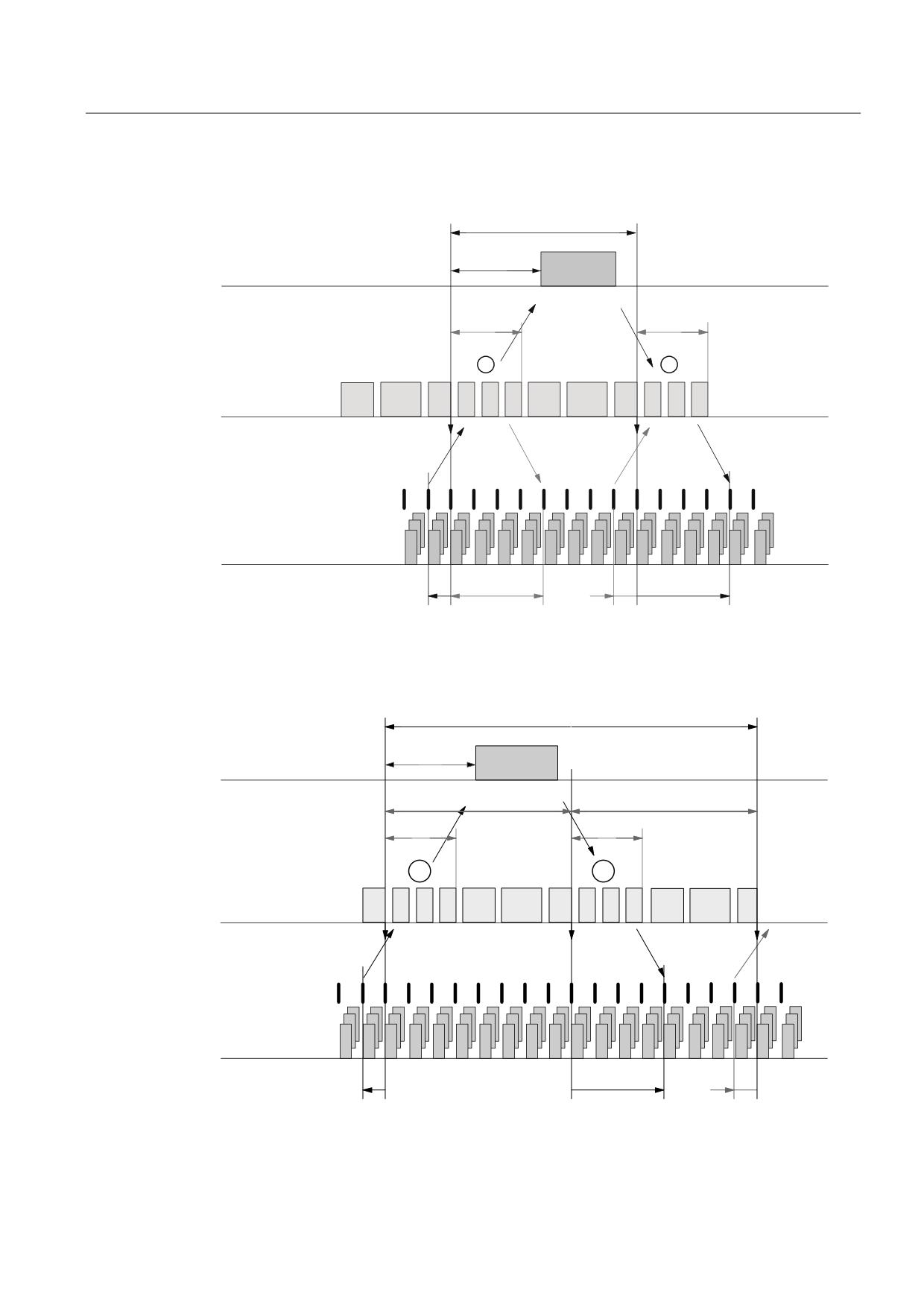
Sequence, TMAPC : TDP = 1 : 1
70$3& 7'3
1&
70
0DVWHU RU SRVLWLRQ
5
FRQWUROOHU
7';
7';
352),%86 '3
'39
*75
*&
'[
'[
'[
'39
*75
*&
'[
'[
'[
FRPPXQLFDWLRQ
6SHHG
FRQWUROOHU
F\FOH FORFN
'ULYHV
5
5
5
5
5
5
5
5
5
5
5
5
5
5
5
5
'3 VODYH
WR
72
7,
7,
72
Figure 5-12 Example: optimized DP cycle with TMAPC: TDP = 1:1
Sequence, TMAPC : TDP = 2 : 1
70$3&
7'3
1&
0DVWHU RU SRVLWLRQ
70
5
FRQWUROOHU
7'3
7'3
7';
7';
352),%86 '3
*&
'[
'[
'[
'39
*75
*&
'[
'[
'[
'39
*75
*&
FRPPXQLFDWLRQ
6SHHG
FRQWUROOHU
F\FOH
'ULYHV
5
5
5
5
5
5
5
5
5
5
5
5
5
5
5
5
5
5
5
5
'3 VODYHV
WR
7,
7,
72
Figure 5-13 Example: optimized DP cycle with TMAPC: TDP = 2:1
ADI4 - Analog drive interface for 4 axes
Manual, 03/2010, 6FC5297-0BA01-0BP5
71
Parameter assignment
5.10 Parameterization of the DP communication
TMAPC
Master application cycle: Position controller clock cycle
TDP
DP cycle time: DP cycle time
TDX
Data exchange time: Total transfer time for all DP slaves
TM
Master time: Offset of the start time for NC position control
TI
Input time: Time of the actual value acquisition. The actual values are
transferred to the DP master in the next DP cycle.
TO
Output time: Time of the setpoint acceptance. The setpoints were generated by
the DP master application in the previous DP cycle.
GC
Global control telegram (broadcast telegram) for cyclic synchronization of the
equidistance between the DP master and DP slaves
R
Computation time for speed or position controller
Dx
Net data exchange between the DP master and DP slaves
DPV1
After cyclic communication, an acyclic service is sent, if the token holding time
TTH has not yet been exceeded. TTH is calculated by the engineering system.
GTR
GAP, TOKEN, RESERVE:
GAP: An attempt is made during GAP to accept new active stations.
TOKEN: The token passing is either to itself or other masters.
RESERVE: The reserve is used as an "active pause" for the station to send the
token to itself until the equidistant cycle expires.
①
The actual values for the actual DP cycle / position controller cycle are
transferred from the DP slave drives to the NC position controller.
②
The setpoints computed by the NC position controller are transferred to the DP
slave drives.
See also
Boundary conditions (Page 78)
5.10.7
Actual value acquisition Ti
Introduction
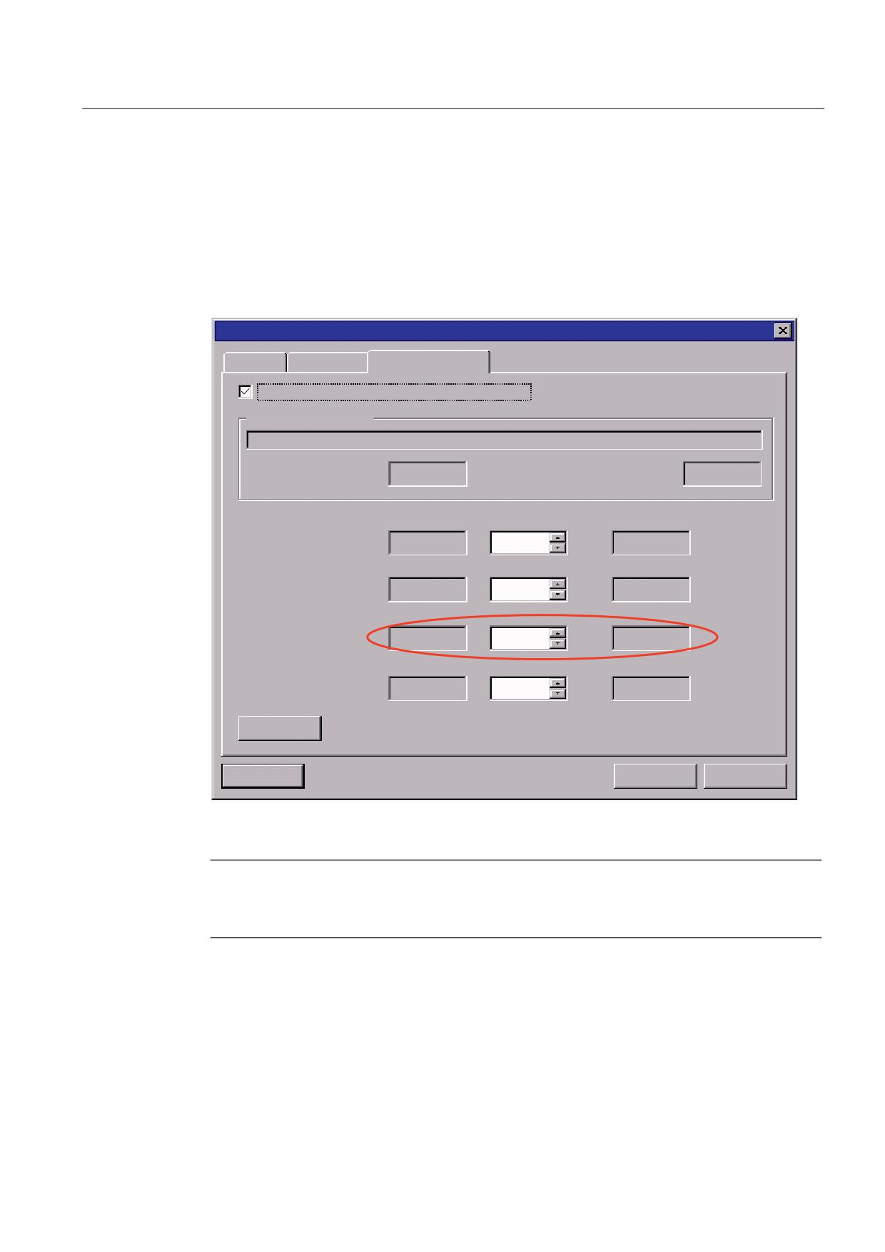
The "Actual value acquisition Ti" parameter specifies the time when an ADI4 DP slave reads
in the actual values (actual position value).
It is recommended to specify the same time for the actual value acquisition Ti for all ADI4 DP
slaves. Special attention must be paid to this if axes of different ADI4 DP slaves move
according to interpolation on a common path.
Procedure
Enter the required value in the entry field for the factor of the actual value acquisition.
ADI4 - Analog drive interface for 4 axes
72
Manual, 03/2010, 6FC5297-0BA01-0BP5
Parameter assignment
5.10 Parameterization of the DP communication
Dialog: Start
Dialog: DP slave properties
Tab: Isochronous operation
Entry field: Factor = 2 (example value)
'3 VODYH SURSHUWLHV
*HQHUDO &RQILJXUDWLRQ ,VRFKURQRXV RSHUDWLRQ
6\QFKURQL]H GULYH WR HTXLGLVWDQW '3 F\FOH
1HWZRUN VHWWLQJV LQ PV
(TXLGLVWDQW EXV F\FOH DFWLYDWHG
(TXLGLVWDQW '3 F\FOH
(TXLGLVWDQW PDVWHU F\FOLF FRPSRQHQW
)DFWRU
%DVH WLPH >PV@
0DVWHU DSSOLFDWLRQ
[
F\FOH >PV@
)DFWRU
%DVH WLPH >PV@
'3 F\FOH >PV@
[
7LPH 7L >PV@
)DFWRU
%DVH WLPH >PV@
$FWXDO YDOXH DFTXLVLWLRQ
[
7LPH 7R >PV@
)DFWRU
%DVH WLPH >PV@
6HWSRLQW DFFHSWDQFH
[
$OLJQPHQW
2.
&DQFHO
+HOS
Figure 5-14 "DP Slave Properties" dialog box
Note
The following condition must be observed for the time of actual value acquisition Ti:
Base time ≤ actual value acquisition ≤ DP cycle
See also
Boundary conditions (Page 78)
ADI4 - Analog drive interface for 4 axes
Manual, 03/2010, 6FC5297-0BA01-0BP5
73
Parameter assignment
5.10 Parameterization of the DP communication
5.10.8
Setpoint acceptance To
Introduction
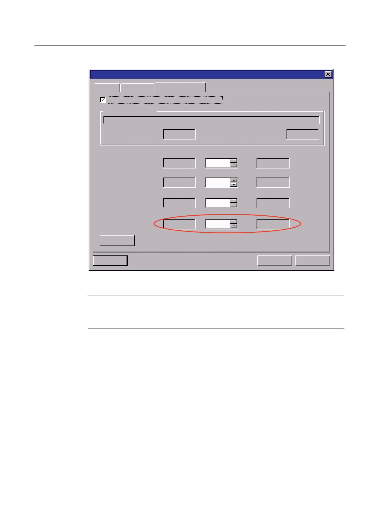
The "Setpoint acceptance To" parameter specifies the time when the ADI4 DP slave receives
the speed setpoint from the position controller.
It is recommended that setpoint acceptance time To be the same for all ADI4 DP slaves,
particularly if axes are interpolated together.
Procedure
Enter the required value in the entry field for the factor of the setpoint acceptance.
Dialog: Start
Dialog: DP slave properties
Tab: Isochronous operation
Entry field: Factor = 8 (example value)
ADI4 - Analog drive interface for 4 axes
74
Manual, 03/2010, 6FC5297-0BA01-0BP5
Parameter assignment
5.10 Parameterization of the DP communication
'3 VODYH SURSHUWLHV
*HQHUDO &RQILJXUDWLRQ ,VRFKURQRXV RSHUDWLRQ
6\QFKURQL]H GULYH WR HTXLGLVWDQW '3 F\FOH
1HWZRUN VHWWLQJV LQ PV
(TXLGLVWDQW EXV F\FOH DFWLYDWHG
(TXLGLVWDQW '3 F\FOH
(TXLGLVWDQW PDVWHU F\FOLF FRPSRQHQW
)DFWRU
%DVH WLPH >PV@
0DVWHU DSSOLFDWLRQ
[
F\FOH >PV@
)DFWRU
%DVH WLPH >PV@
'3 F\FOH >PV@
[
7LPH 7L >PV@
)DFWRU
%DVH WLPH >PV@
$FWXDO YDOXH DFTXLVLWLRQ
[
7LPH 7R >PV@
)DFWRU
%DVH WLPH >PV@
6HWSRLQW DFFHSWDQFH
[
$OLJQPHQW
2.
&DQFHO
+HOS
Figure 5-15 "DP Slave Properties" dialog box
Note
The following condition must be observed for the time of setpoint acceptance To:
Equidistant master cyclic component + base time ≤ setpoint acceptance ≤ DP cycle
See also
Boundary conditions (Page 78)
5.10.9
Alignment
Procedure
The alignment is used to transfer the values of the current ADI4 DP slave displayed in the
"Isochronous operation" tab to all the other ADI4 DP slaves of the configuration.
ADI4 - Analog drive interface for 4 axes
Manual, 03/2010, 6FC5297-0BA01-0BP5
75
Parameter assignment
5.10 Parameterization of the DP communication
Dialog: End
Dialog: DP slave properties
Tab: Isochronous operation
Button: Alignment
OK
'3 VODYH SURSHUWLHV
*HQHUDO &RQILJXUDWLRQ ,VRFKURQRXV RSHUDWLRQ
6\QFKURQL]H GULYH WR HTXLGLVWDQW '3 F\FOH
1HWZRUN VHWWLQJV LQ PV
(TXLGLVWDQW EXV F\FOH DFWLYDWHG
(TXLGLVWDQW '3 F\FOH
(TXLGLVWDQW PDVWHU F\FOLF FRPSRQHQW
)DFWRU
%DVH WLPH >PV@
0DVWHU DSSOLFDWLRQ F\FOH
[
>PV@
)DFWRU
%DVH WLPH >PV@
'3 F\FOH >PV@
[
7LPH 7L >PV@
)DFWRU
%DVH WLPH >PV@
[
$FWXDO YDOXH DFTXLVLWLRQ
7LPH 7R >PV@
)DFWRU
%DVH WLPH >PV@
6HWSRLQW DFFHSWDQFH
[
$OLJQPHQW
2.
&DQFHO
+HOS
Figure 5-16 "DP Slave Properties" dialog box
ADI4 - Analog drive interface for 4 axes
76
Manual, 03/2010, 6FC5297-0BA01-0BP5
Parameter assignment
5.10 Parameterization of the DP communication
Note
If an S7 project includes different equidistant DP slave types, such as different SIMODRIVE
drives, ADI4, etc., the following parameter settings must be made for each DP slave type as
described above, and an alignment must be performed:
• Equidistant DP cycle TDP
• Master application cycle TMAPC
• Actual value acquisition Ti
• Setpoint acceptance To
The alignment only transfers the values displayed in the "Isochronous operation" tab to the
DP slaves of the same type.
The alignment concludes the parameter assignment of all ADI4 DP slaves with respect to the
DP communication.
ADI4 - Analog drive interface for 4 axes
Manual, 03/2010, 6FC5297-0BA01-0BP5
77
Parameter assignment
5.10 Parameterization of the DP communication
5.10.10
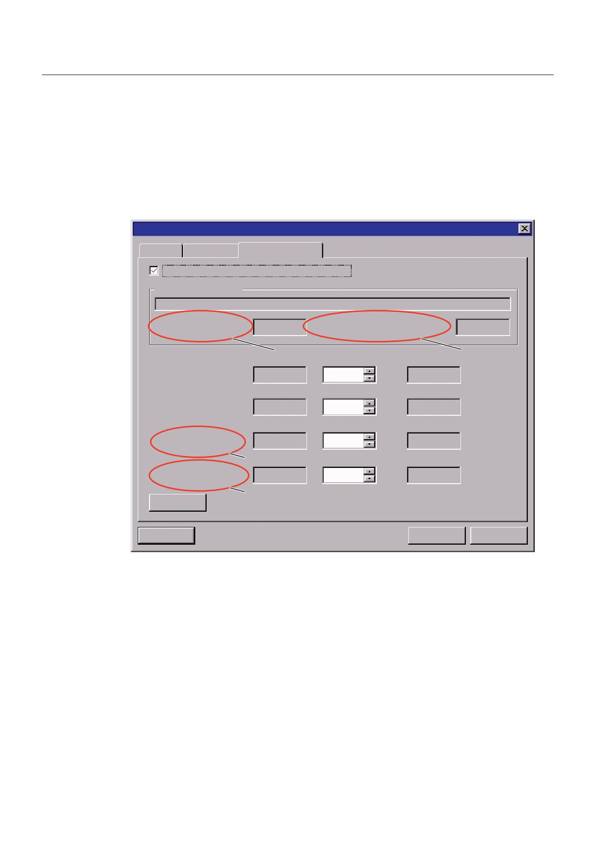
Boundary conditions
ADI4 from MLFB: 6FC5 211-0BA01-0AA1
The following boundary conditions must be observed when making the final parameter
assignment of the equidistant DP cycle in conjunction with ADI4 from the following MLFB
onwards: 6FC5 211-0BA01-0AA1:
'3 VODYH SURSHUWLHV
*HQHUDO &RQILJXUDWLRQ ,VRFKURQRXV RSHUDWLRQ
6\QFKURQL]H GULYH WR HTXLGLVWDQW '3 F\FOH
1HWZRUN VHWWLQJV LQ PV
(TXLGLVWDQW EXV F\FOH DFWLYDWHG
(TXLGLVWDQW '3 F\FOH
(TXLGLVWDQW PDVWHU F\FOLF FRPSRQHQW
7'3
7';
)DFWRU
%DVH WLPH >PV@
0DVWHU DSSOLFDWLRQ F\FOH
[
>PV@
)DFWRU
%DVH WLPH >PV@
'3 F\FOH >PV@
[
)DFWRU
%DVH WLPH >PV@
$FWXDO YDOXH DFTXLVLWLRQ
[
>PV@
7,
)DFWRU
%DVH WLPH >PV@
6HWSRLQW DFFHSWDQFH >PV@
[
72
$OLJQPHQW
2.
&DQFHO
+HOS
Figure 5-17 Section of the "DP Slave Properties" dialog box
1. Equidistant DP cycle (TDP)
TDP = 2* n * 125 us;
with n ≧ 4 ( => minimum TDP = 1 ms)
2. Setpoint acceptance (To)
(TDX + 125 us) ≤TO < TDP;
with rounded variable TDX = TDX, rounded to an integer
multiple of 125 us
3. Actual value acquisition (Ti)
250 us ≤ TI ≤ 625 us
4. TI and TO cannot be in the same 125 us cycle clock
ΔT ≠ 0; with ΔT = TDP - TI - TO
ADI4 - Analog drive interface for 4 axes
78
Manual, 03/2010, 6FC5297-0BA01-0BP5
Parameter assignment
5.10 Parameterization of the DP communication
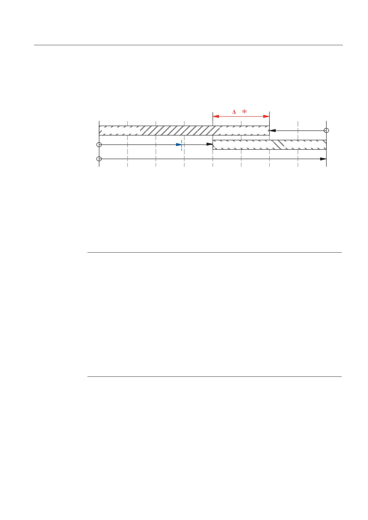
5. If TO == (TDP - 125 us)
Then for TI, the following must apply: TI > 3 * 125 us
6. If TO == (TDX + 125 us)
Then for (TI + TO), the following must apply: (TI + TO) ≠(TDP + 125 us)
7
7,
7, ದ
0D[
7'3
7, ದ
0LQ
XV
7
2
72 ದ
0LQ
7';
XV
72 ದ
0D[
7'3
7';
7'
3
XV
XV
XV
XV
XV
XV
XV
XV
Figure 5-18 Graphic illustration of the boundary conditions
Typical parameter values
Equidistant DP cycle (TDP)
2.000 ms
Actual value acquisition (Ti)
0.250 ms
Setpoint acceptance (To)
1.000 ms
Note
The ADI4 DP slaves
• Order number (MLFB): 6FC5 211-0BA01-0AA0
• Order number (MLFB): 6FC5 211-0BA01-0AA1 or
0AA2
manifest a different behavior for a parameter assignment deviating from the boundary
conditions indicated above for actual value acquisition (Ti) and setpoint acceptance (To).
• ADI4 DP slave with MLFB ...-0AA0
If parameters are assigned that deviate from the boundary conditions indicated above,
they are ignored by this ADI4 DP slave, as parameters are fixed internally. The ADI4 DP
slave establishes cyclic communication with the DP master using values that differ from
the parameterized preset values without an error message.
• ADI4 DP slave with MLFB ...0AA1 or ...0AA2
If parameters are assigned that deviate from the boundary conditions indicated above
and these parameters are downloaded to the ADI4 DP slave, the ADI4 DP slave does not
establish cyclic communication with the DP master.
ADI4 - Analog drive interface for 4 axes
Manual, 03/2010, 6FC5297-0BA01-0BP5
79
Parameter assignment
5.10 Parameterization of the DP communication
ADI4 - Analog drive interface for 4 axes
80
Manual, 03/2010, 6FC5297-0BA01-0BP5
Further information
6
6.1
Wiring of drive ready signals
In order that a drive connected to the ADI4 can be switched-on via the S7 function block
FB 401 (MC_POWER), the ready signal of the drive must be connected to one of the digital
inputs, "Drive Ready" signal, axis x (DRVx_RDY), interface (X6-2) of the ADI4.
The ready signal must still be available at the ADI4 input even after the drive has been
switched on.
Note
Drives without ready signal
If a ready signal is not available for a drive, then 24 V can be statically assigned to the
corresponding digital ready signal input "Drive Ready" axis x (DRVx_RDY) of the ADI4.
However, this approach has the disadvantage that when a drive fails, this is no longer
detected by the S7 function block FB 401 (MC_POWER). FB 401 returns the status "TRUE"
at its output even after a drive failure.
6.2
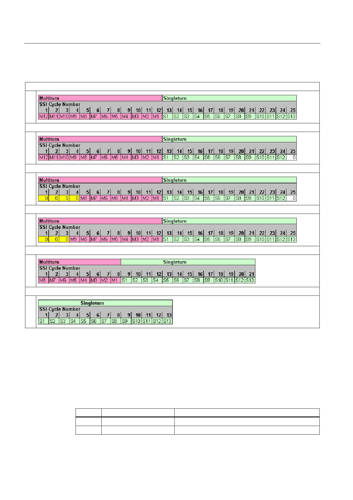
Supported SSI encoder formats
SSI encoders with the following formats are supported:
1. "Christmas tree" formats whose net data length (MsgLength, see Chapter "Encoder type
(Page 53)") is the same as the number of significant data bits:
-
25 bit with 12-bit multiturn and 13-bit singleturn information (MsgLength = 25)
–
21 bit with 8-bit multiturn and 13-bit singleturn information (MsgLength = 21)
–
13 bit with 13-bit singleturn information (MsgLength = 13)
2. Left-justified "Christmas tree" formats whose net data length (MsgLength) is not equal to
the number of significant data bits:
-
25 bit with 12-bit multiturn and 12-bit singleturn information (MsgLength = 24)
–
21 bit with 8-bit multiturn and 12-bit singleturn information (MsgLength = 20)
–
13 bit with 12-bit singleturn information (MsgLength = 12)
Note
SSI encoders with net data lengths not equal to the number of significant data bits can
only be used if the complete net data length does not have to be read!
3. All right-justified "Christmas tree" formats, which fulfill the condition under 1.
ADI4 - Analog drive interface for 4 axes
Manual, 03/2010, 6FC5297-0BA01-0BP5
81
Further information
6.3 Linear encoder with distance-coded zero marks / reference marks
Examples for Christmas tree formats that are supported
25-bit multiturn encoder, Christmas tree format, multiturn: 12-bit, singleturn: 13 bit ⇒ resolution: 213 = 8192
25-bit multiturn encoder, Christmas tree format (multiturn: 12-bit, singleturn: 12 bit ⇒ resolution: 213 = 8192
25-bit multiturn encoder, Christmas tree format (multiturn: 8-bit, singleturn: 12 bit ⇒ resolution: 213 = 8192
25-bit multiturn encoder, Christmas tree format (multiturn: 9-bit, singleturn: 13 bit ⇒ resolution: 213 = 8192
21-bit multiturn encoder, Christmas tree format (multiturn: 8-bit, singleturn: 13 bit ⇒ resolution: 213 = 8192
13-bit singleturn encoder (left aligned) ⇒ resolution: 213 = 8192
6.3
Linear encoder with distance-coded zero marks / reference marks
Machine data
The following machine data must be set for the commissioning of the measuring system of a
machine axis with linear encoder and distance-coded zero marks / reference marks:
Number
Identifier: $MA_
Meaning
30240
ENC_TYPE
Encoder type (data transmission)
31000
ENC_IS_LINEAR
Encoder type (type of construction) Linear encoders
ADI4 - Analog drive interface for 4 axes
82
Manual, 03/2010, 6FC5297-0BA01-0BP5
Further information
6.3 Linear encoder with distance-coded zero marks / reference marks
Number
Identifier: $MA_
Meaning
31010
ENC_GRID_POINT_DIST
Signal period or scale division / EXE factor
31040
ENC_IS_DIRECT
Encoder mounting method: Direct measuring system
32100
AX_MOTION_DIR
Traversing direction (does not affect the control sense)
32110
ENC_FEEDBACK_POL
Encoder value polarity (affects the control sense)
34090
REFP_MOVE_DIST_CORR
Zero point/reference point offset
The offset between the machine zero point and the first
reference mark.
34200
ENC_REFP_MODE
Homing mode
34300
ENC_REFP_MARKER_DIST
Reference mark distance (basic distance)
34310
ENC_MARKER_INC
Interval between two reference marks
Note
Heidenhain: For all linear encoders with distance-coded
zero marks / reference marks 20 µm
34320
ENC_INVERS
Orientation of the measuring system in relation to axis
motion
Example
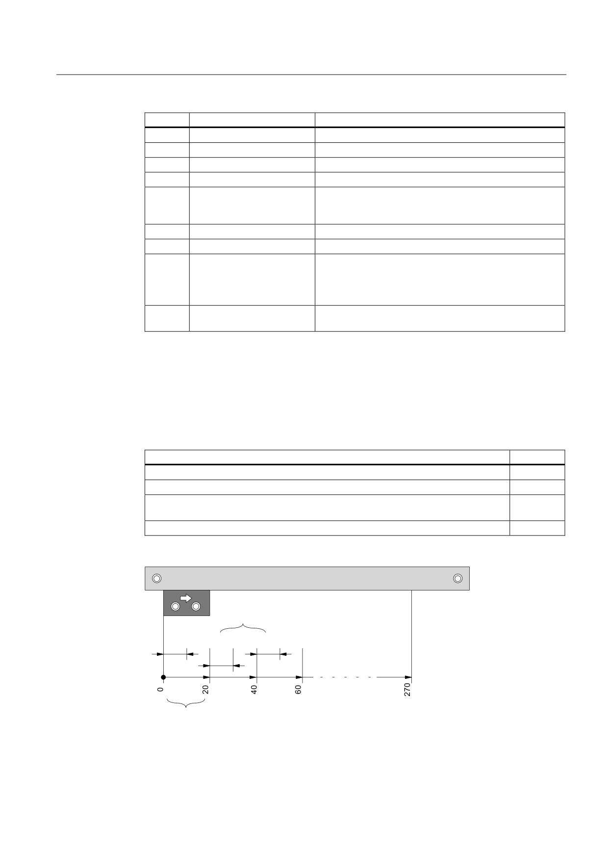
The following example illustrates how the mounting conditions of the machine axis and linear
encoder have to be taken into account in the machine data for the machine axis concerned.
Type of linear encoder with distance-coded zero marks / reference marks used:
Heidenhain: LS 476 C
Technical characteristics (extract)
Value
Measuring length
270 mm
Reference mark distance
20 mm
Signal period of the incremental signals with scale division of 0.02 and integrated
0.004 mm
interpolation: 5x
Distance between two reference marks (specific to Heidenhain)
0.02 mm
/6
& 0HDVXULQJ OHQJWK 0/
PP
,QWHUYDO EHWZHHQ WZR UHIHUHQFH PDUNV
ದ
5HIHUHQFH PDUN GLVWDQFH
Figure 6-1
Linear encoder: LS 476 C
ADI4 - Analog drive interface for 4 axes
Manual, 03/2010, 6FC5297-0BA01-0BP5
83
Further information
6.3 Linear encoder with distance-coded zero marks / reference marks
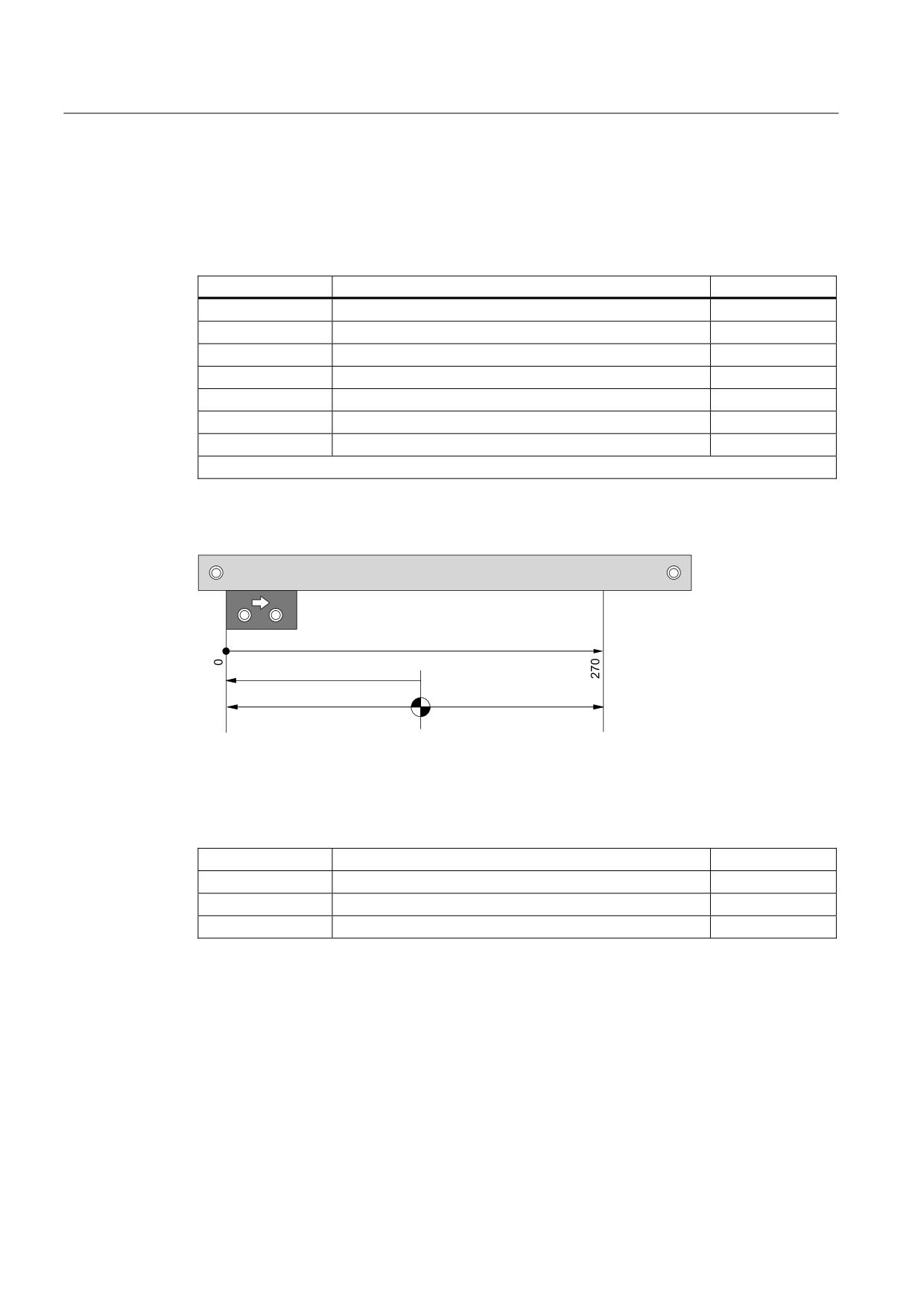
Because of the various possibilities regarding the orientation of the machine axis and linear
encoder (same sense / opposite sense), it is necessary to distinguish between two
scenarios.
Machine data remains the same in both cases:
Number
Identifier: $MA_
Value
30240
ENC_TYPE
2
31000
ENC_IS_LINEAR
1
31010 *
ENC_GRID_POINT_DIST
0.004
31040
ENC_IS_DIRECT
1
34200
ENC_REFP_MODE
3
34300 *
ENC_REFP_MARKER_DIST
20
34310 *
ENC_MARKER_INC
0.02
*) Technical characteristics of the encoder
Scenario 1: Equidirectional orientation
/6
& 0HDVXULQJ OHQJWK 0/
PP
5HIHUHQFH SRLQW RIIVHW 52
ದ
7UDYHUVLQJ UDQJH RI WKH PDFKLQH D[LV
Figure 6-2
Machine axis with linear encoder: Equidirectional orientation
Orientation-dependent machine data
32100
AX_MOTION_DIR
1
32110
ENC_FEEDBACK_POL
1
34090
REFP_MOVE_DIST_CORR
RO
34320
ENC_INVERS
0
ADI4 - Analog drive interface for 4 axes
84
Manual, 03/2010, 6FC5297-0BA01-0BP5
Further information
6.3 Linear encoder with distance-coded zero marks / reference marks
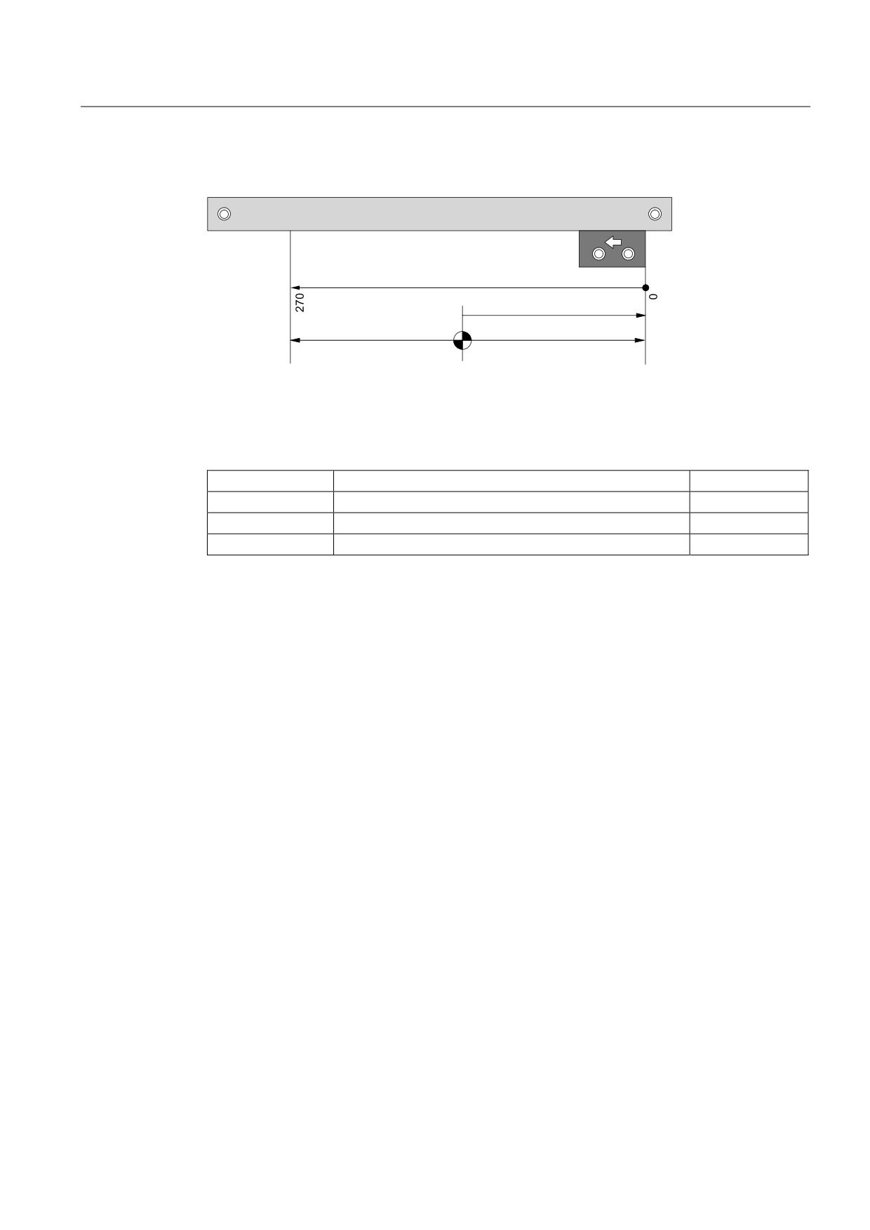
Scenario 2: Inverse orientation
/6
& 0HDVXULQJ OHQJWK 0/
PP
5HIHUHQFH SRLQW RIIVHW 52
ದ
7UDYHUVLQJ UDQJH RI WKH PDFKLQH D[LV
Figure 6-3
Machine axis with linear encoder: Inverse orientation
Orientation-dependent machine data
32100
AX_MOTION_DIR
1
32110
ENC_FEEDBACK_POL
-1
34090
REFP_MOVE_DIST_CORR
RO
34320
ENC_INVERS
1
ADI4 - Analog drive interface for 4 axes
Manual, 03/2010, 6FC5297-0BA01-0BP5
85
Fundamental safety
1
instructions
2
Description
3
Mounting
SINUMERIK
Connecting
4
SINUMERIK 840D sl
Operator panel front: OP 015 black
5
Networking
Service and maintenance
6
Manual
7
Technical data
Spare parts/accessories
8
Valid for: SINUMERIK 840D sl / 840DE sl control
05/2019
A5E35227814B AB
Table of contents
1
Fundamental safety instructions
5
1.1
General safety instructions
5
1.2
Equipment damage due to electric fields or electrostatic discharge
8
1.3
Warranty and liability for application examples
8
1.4
Industrial security
9
1.5
Residual risks of power drive systems
11
2
Description
13
2.1
Overview
13
2.2
Operator controls and displays
14
2.2.1
View
14
2.2.2
Operation
15
2.2.3
Keyboard
17
2.2.4
Screen saver
18
2.3
Interfaces
19
3
Mounting
21
4
Connecting
27
4.1
Pin assignment of the interfaces
27
4.2
Handling membrane connectors
33
5
Networking
35
5.1
System settings
35
5.1.1
Thin Client Unit (TCU)
35
5.1.2
Settings for SINUMERIK solution line
36
5.1.3
System boot with system network
38
5.1.4
Factory default settings
39
5.2
Commissioning TCU
41
5.2.1
Key assignment
41
5.2.2
Settings in the "TCU.ini" file
42
5.2.3
Displacement mechanism for TCUs
43
5.2.4
Disable switchover between TCU via PLC
44
5.2.5
Example: How to select the behavior of the TCUs during boot up
47
5.3
Network configuration
48
5.3.1
Permissible network topologies
48
5.3.2
Networks without connection to the company network
49
5.3.2.1
Configuration 1: NCU and TCU
49
5.3.3
Networks with NCU connection to the company network
50
5.3.3.1
Configuration 2: NCU and TCU
50
5.3.3.2
Configuration 3: PCU/IPC with TCU on NCU
51
5.3.3.3
Connecting the programming device (PG) to the NCU
52
Operator panel front: OP 015 black
Manual, 05/2019, A5E35227814B AB
3
Table of contents
5.3.4
Example: Configuring a VNC connection to a PC
52
5.4
Service and diagnostics
54
5.4.1
Using the TCU's main menu
54
5.4.2
Operating the TCU menu "Service sessions"
57
5.4.3
Operating the TCU menu "Service menu"
59
5.4.4
Operating the TCU menu "Modify settings"
62
5.4.5
Operating the menu for a new TCU or spare part TCU
63
5.4.6
How to register a TCU on the system network
68
5.4.7
This is how you register a spare part TCU
71
5.4.8
Booting of the TCU
72
5.4.8.1
Messages during booting
72
5.4.8.2
Diagnostics options during booting
73
6
Service and maintenance
75
7
Technical data
77
7.1
Secondary electrical conditions
78
7.1.1
Power supply
78
7.1.2
Grounding concept
79
7.1.3
EMC compatibility
80
7.1.4
EMC limit values in South Korea
81
7.2
Ambient climatic and mechanical conditions
81
7.2.1
Transport and storage conditions
81
7.2.2
Operating conditions
83
7.2.3
Cooling
84
7.3
Standards and approvals
86
7.4
Recycling and disposal
87
8
Spare parts/accessories
89
Index
91
Operator panel front: OP 015 black
4
Manual, 05/2019, A5E35227814B AB

Fundamental safety instructions
1
1.1
General safety instructions
WARNING
Electric shock and danger to life due to other energy sources
Touching live components can result in death or severe injury.
● Only work on electrical devices when you are qualified for this job.
● Always observe the country-specific safety rules.
Generally, the following six steps apply when establishing safety:
1. Prepare for disconnection. Notify all those who will be affected by the procedure.
2. Isolate the drive system from the power supply and take measures to prevent it being
switched back on again.
3. Wait until the discharge time specified on the warning labels has elapsed.
4. Check that there is no voltage between any of the power connections, and between any of
the power connections and the protective conductor connection.
5. Check whether the existing auxiliary supply circuits are de-energized.
6. Ensure that the motors cannot move.
7. Identify all other dangerous energy sources, e.g. compressed air, hydraulic systems, or
water. Switch the energy sources to a safe state.
8. Check that the correct drive system is completely locked.
After you have completed the work, restore the operational readiness in the inverse sequence.
WARNING
Electric shock due to connection to an unsuitable power supply
When equipment is connected to an unsuitable power supply, exposed components may
carry a hazardous voltage. Contact with hazardous voltage can result in severe injury or death.
● Only use power supplies that provide SELV (Safety Extra Low Voltage) or PELV-
(Protective Extra Low Voltage) output voltages for all connections and terminals of the
electronics modules.
Operator panel front: OP 015 black
Manual, 05/2019, A5E35227814B AB
5

Fundamental safety instructions
1.1 General safety instructions
WARNING
Electric shock due to equipment damage
Improper handling may cause damage to equipment. For damaged devices, hazardous
voltages can be present at the enclosure or at exposed components; if touched, this can result
in death or severe injury.
● Ensure compliance with the limit values specified in the technical data during transport,
storage and operation.
● Do not use any damaged devices.
WARNING
Electric shock due to unconnected cable shields
Hazardous touch voltages can occur through capacitive cross-coupling due to unconnected
cable shields.
● As a minimum, connect cable shields and the cores of cables that are not used at one end
at the grounded housing potential.
WARNING
Electric shock if there is no ground connection
For missing or incorrectly implemented protective conductor connection for devices with
protection class I, high voltages can be present at open, exposed parts, which when touched,
can result in death or severe injury.
● Ground the device in compliance with the applicable regulations.
WARNING
Spread of fire from built-in devices
In the event of fire outbreak, the enclosures of built-in devices cannot prevent the escape of
fire and smoke. This can result in serious personal injury or property damage.
● Install built-in units in a suitable metal cabinet in such a way that personnel are protected
against fire and smoke, or take other appropriate measures to protect personnel.
● Ensure that smoke can only escape via controlled and monitored paths.
Operator panel front: OP 015 black
6
Manual, 05/2019, A5E35227814B AB

Fundamental safety instructions
1.1 General safety instructions
WARNING
Unexpected movement of machines caused by radio devices or mobile phones
When radio devices or mobile phones with a transmission power > 1 W are used in the
immediate vicinity of components, they may cause the equipment to malfunction.
Malfunctions may impair the functional safety of machines and can therefore put people in
danger or lead to property damage.
● If you come closer than around 2 m to such components, switch off any radios or mobile
phones.
● Use the "SIEMENS Industry Online Support app" only on equipment that has already been
switched off.
WARNING
Fire due to inadequate ventilation clearances
Inadequate ventilation clearances can cause overheating of components with subsequent fire
and smoke. This can cause severe injury or even death. This can also result in increased
downtime and reduced service lives for devices/systems.
● Ensure compliance with the specified minimum clearance as ventilation clearance for the
respective component.
NOTICE
Overheating due to inadmissible mounting position
The device may overheat and therefore be damaged if mounted in an inadmissible position.
● Only operate the device in admissible mounting positions.
WARNING
Unexpected movement of machines caused by inactive safety functions
Inactive or non-adapted safety functions can trigger unexpected machine movements that
may result in serious injury or death.
● Observe the information in the appropriate product documentation before commissioning.
● Carry out a safety inspection for functions relevant to safety on the entire system, including
all safety-related components.
● Ensure that the safety functions used in your drives and automation tasks are adjusted and
activated through appropriate parameterizing.
● Perform a function test.
● Only put your plant into live operation once you have guaranteed that the functions relevant
to safety are running correctly.
Operator panel front: OP 015 black
Manual, 05/2019, A5E35227814B AB
7

Fundamental safety instructions
1.3 Warranty and liability for application examples
Note
Important safety notices for Safety Integrated functions
If you want to use Safety Integrated functions, you must observe the safety notices in the Safety
Integrated manuals.
1.2
Equipment damage due to electric fields or electrostatic discharge
Electrostatic sensitive devices (ESD) are individual components, integrated circuits, modules
or devices that may be damaged by either electric fields or electrostatic discharge.
NOTICE
Equipment damage due to electric fields or electrostatic discharge
Electric fields or electrostatic discharge can cause malfunctions through damaged individual
components, integrated circuits, modules or devices.
● Only pack, store, transport and send electronic components, modules or devices in their
original packaging or in other suitable materials, e.g conductive foam rubber of aluminum
foil.
● Only touch components, modules and devices when you are grounded by one of the
following methods:
- Wearing an ESD wrist strap
- Wearing ESD shoes or ESD grounding straps in ESD areas with conductive flooring
● Only place electronic components, modules or devices on conductive surfaces (table with
ESD surface, conductive ESD foam, ESD packaging, ESD transport container).
1.3
Warranty and liability for application examples
Application examples are not binding and do not claim to be complete regarding configuration,
equipment or any eventuality which may arise. Application examples do not represent specific
customer solutions, but are only intended to provide support for typical tasks.
As the user you yourself are responsible for ensuring that the products described are operated
correctly. Application examples do not relieve you of your responsibility for safe handling when
using, installing, operating and maintaining the equipment.
Operator panel front: OP 015 black
8
Manual, 05/2019, A5E35227814B AB
Fundamental safety instructions
1.4 Industrial security
1.4
Industrial security
Note
Industrial security
Siemens provides products and solutions with industrial security functions that support the
secure operation of plants, systems, machines and networks.
In order to protect plants, systems, machines and networks against cyber threats, it is
necessary to implement - and continuously maintain - a holistic, state-of-the-art industrial
security concept. Products and solutions from Siemens constitute one element of such a
concept.
Customers are responsible for preventing unauthorized access to their plants, systems,
machines and networks. Such systems, machines and components should only be connected
to an enterprise network or the Internet if and to the extent such a connection is necessary and
only when appropriate security measures (e.g. using firewalls and/or network segmentation)
are in place.
For additional information on industrial security measures that can be implemented, please
visit:
Siemens’ products and solutions undergo continuous development to make them more secure.
Siemens strongly recommends that product updates are applied as soon as they become
available, and that only the latest product versions are used. Use of product versions that are
no longer supported, and failure to apply the latest updates may increase customer’s exposure
to cyber threats.
To stay informed about product updates, subscribe to the Siemens Industrial Security RSS
Feed at:
Further information is provided on the Internet:
Industrial Security Configuration Manual (https://support.industry.siemens.com/cs/ww/en/
view/108862708)
Operator panel front: OP 015 black
Manual, 05/2019, A5E35227814B AB
9
Fundamental safety instructions
1.4 Industrial security
WARNING
Unsafe operating states resulting from software manipulation
Software manipulations, e.g. viruses, Trojans, or worms, can cause unsafe operating states
in your system that may lead to death, serious injury, and property damage.
● Keep the software up to date.
● Incorporate the automation and drive components into a holistic, state-of-the-art industrial
security concept for the installation or machine.
● Make sure that you include all installed products into the holistic industrial security concept.
● Protect files stored on exchangeable storage media from malicious software by with
suitable protection measures, e.g. virus scanners.
● On completion of commissioning, check all security-related settings.
● Protect the drive against unauthorized changes by activating the "Know-how protection"
converter function.
Operator panel front: OP 015 black
10
Manual, 05/2019, A5E35227814B AB
Fundamental safety instructions
1.5 Residual risks of power drive systems
1.5
Residual risks of power drive systems
When assessing the machine- or system-related risk in accordance with the respective local
regulations (e.g., EC Machinery Directive), the machine manufacturer or system installer must
take into account the following residual risks emanating from the control and drive components
of a drive system:
1.
Unintentional movements of driven machine or system components during commissioning,
operation, maintenance, and repairs caused by, for example,
- Hardware and/or software errors in the sensors, control system, actuators, and cables
and connections
- Response times of the control system and of the drive
- Operation and/or environmental conditions outside the specification
- Condensation/conductive contamination
- Parameterization, programming, cabling, and installation errors
- Use of wireless devices/mobile phones in the immediate vicinity of electronic
components
- External influences/damage
- X-ray, ionizing radiation and cosmic radiation
2.
Unusually high temperatures, including open flames, as well as emissions of light, noise,
particles, gases, etc., can occur inside and outside the components under fault conditions
caused by, for example:
- Component failure
- Software errors
- Operation and/or environmental conditions outside the specification
- External influences/damage
3.
Hazardous shock voltages caused by, for example:
- Component failure
- Influence during electrostatic charging
- Induction of voltages in moving motors
- Operation and/or environmental conditions outside the specification
- Condensation/conductive contamination
- External influences/damage
4.
Electrical, magnetic and electromagnetic fields generated in operation that can pose a risk
to people with a pacemaker, implants or metal replacement joints, etc., if they are too close
5.
Release of environmental pollutants or emissions as a result of improper operation of the
system and/or failure to dispose of components safely and correctly
6.
Influence of network-connected communication systems, e.g. ripple-control transmitters or
data communication via the network
For more information about the residual risks of the drive system components, see the relevant
sections in the technical user documentation.
Operator panel front: OP 015 black
Manual, 05/2019, A5E35227814B AB
11
Description
2
2.1
Overview
The SINUMERIK OP 015 black operator panel front has a touch-sensitive glass surface with
multiple finger operator control. The integrated TCU enables the operator panel front and
control to be installed separately.
The OP 015 black operator panel front is linked to the PCU/NCU via Ethernet as thin client in
a dedicated subnet (via DHCP server on the PCU/NCU). The distance to the operator panel
fronts is determined by the maximum distance between two network nodes / access points (100
m). Mixed operation with several TCUs and one operator panel front directly on the PCU is
possible.
The operator panel front is secured from the rear using special clamps supplied with the panel.
Validity
This description applies to:
Type
Description
Article number
OP 015 black
Operator panel front as thin client with touch screen
6FC5303-0AF14-0AA0
Features
● Ethernet 10/100/1000 Mbit/s
●
3 x USB (max. high speed) on the rear
●
15" LCD flat screen (color) in widescreen format
● Multiple finger operation in the screen area
● Printed keyboard with alphabetic, numeric, cursor and control keypad
● Status LEDs for power supply, key feedback and keylock / Caps lock key
● Panel cutout (W x H): 450 x 290 mm
● Can be installed by one person (see Section "Mounting (Page 21)")
● Degree of protection: IP65 / IP66
● Attachment: Tension jacks at the rear
- Min./max. thickness of the wall 1.5 to 6 mm
Operator panel front: OP 015 black
Manual, 05/2019, A5E35227814B AB
13
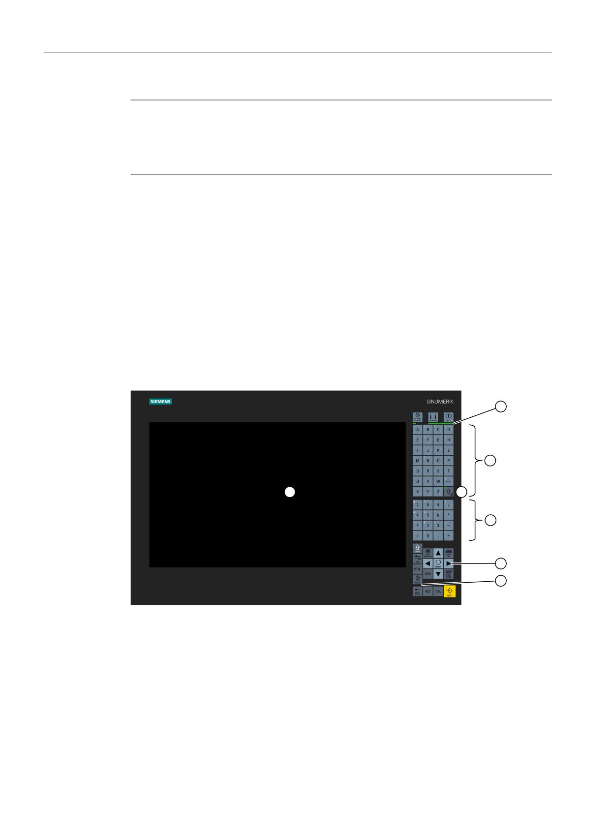
Description
2.2 Operator controls and displays
Note
Connecting USB devices
The OP 015 black does not have any USB interfaces on the front. If required, the rear USB
interfaces can be routed to the front via a USB extension (see Section "Keyboards and
additional components").
Naming convention
The following generic term is used in this documentation:
● PCU: Describes the SINUMERIK PCU 50 or the SIMATIC IPC 427E, in each case including
PCU basic software.
2.2
Operator controls and displays
2.2.1
View
① Multiple finger operating area for operating software (softkeys) in the display area
② Green LED bars for POWER OK (left) and key feedback (right)
③ Alphabetic key group
④ Caps lock key incl.keylock - green LED (displays keylock active or Caps lock key)
⑤ Numeric key group
⑥ Cursor key group
⑦ Control key group
Figure 2-1
Front view of the OP 015 black operator panel front
Operator panel front: OP 015 black
14
Manual, 05/2019, A5E35227814B AB
Description
2.2 Operator controls and displays
2.2.2
Operation
The operator panel front is operated through finger contact with the touch-sensitive glass
surface:
● Depending on the application-specific functions shown in the display area, for example, by:
- pressing a softkey or a displayed button
- gestures with up to eight fingers
● Depending on the displayed keys. Two keys (plus modifier keys) can be pressed
simultaneously.
- Modifier: CTRL, ALT, SHIFT
WARNING
Unexpected machine movements caused by incorrect operation
Incorrect operation of devices with a touch screen can lead to unexpected machine
movements. This can result in death, serious injury and material damage.
● Prevent unintentional incorrect operation by appropriate configuration of the user
interface, e.g. by placing the buttons for starting and stopping machine components far
enough apart.
● Configure the machine so that safety-related functions are not operated with the touch
screen.
Operator panel front: OP 015 black
Manual, 05/2019, A5E35227814B AB
15
Description
2.2 Operator controls and displays
Note
Notes on operation of the touch-sensitive glass surface with multi-finger operation function
using gestures
Observe the following notes in order to avoid incorrect operation of the touch-sensitive glass
surface with multi-finger operation function. Otherwise, entries made at the device will either be
incorrectly identified/implemented - or not at all.
● The OP 015 black does not support safety-relevant functions and these may also not be
implemented in the touch-sensitive glass surface.
● The touch-sensitive glass surface reacts to contact with its surface, not to pressure.
Therefore, do not subsequently attach a protective film to the touch-sensitive glass surface.
Also remove all protective and packaging films, as these have a negative impact/prevent
data from being entered and initiate incorrect operator entries.
● Only operate the touch-sensitive glass surface with your finger tips, not with your fingernails.
● Touch the touch-sensitive glass surface either perpendicularly or at a maximum angle of 45°
to the surface.
● Avoid unintentional multiple touches, e.g. with the knuckles or by leaning on or against the
display.
● Make sure that the surface of the touch-sensitive glass screen does not get dirty. Cleaning
information can be found on the Internet in the following article in the Service & Support
portal of Siemens Industry:
Always check whether the executed operator actions have been recognized by the device.
Note
Please observe the valid C standards for the particular machine type (e.g. for turning machines:
EN ISO 23125-2010, pages 36 and 49). These state that a button that initiates motion with the
protective door open must be implemented using an additional acknowledgment device; this is
because for single-channel keyboards - such as the OP 015 black - generally no PL
(performance level) "d" can be achieved.
Displaying the TCU menu
To display the TCU menu, simultaneously touch the left-hand and right-hand lower corner of
the active display area in order to display the TCU menu.
If you have connected a USB PC keyboard to the OP 015 black, you can also display the TCU
menu by simultaneously pressing keys F9 and F10.
Gloves
Do not wear thick gloves, such as work gloves, when operating the touch-sensitive glass
surface. You can wear thin gloves made of cotton or gloves for touch-sensitive glass surfaces
with capacitive touch function.
You can wear the following gloves for operating the touch-sensitive glass user interface of the
operator panel:
● Dermatril L
● Camatril Velours Art. 730
Operator panel front: OP 015 black
16
Manual, 05/2019, A5E35227814B AB
Description
2.2 Operator controls and displays
● Uvex Profas Profi ENB 20A
● Comasec PU 900 (4342)
● Camapur Comfort Art. 619
● KCL Men at Work Art. 301
● Carex Art. 1505/k (leather)
● Cotton Cat. 1
Note
The gloves listed here are recommendations only. The type designations can change.
Keylock
E.g. it is advisable to use the keylock when cleaning the device:
● Activate the keylock by pressing the Caps lock key for at least five seconds, the LED flashes.
● Deactivate the keylock by pressing the Caps lock key again for at least five seconds.
The keylock can also be triggered by the software.
Note
The keylock only applies to the keys next to the display and not for the display touch.
2.2.3
Keyboard
Keyboard
Several keys and keypads are installed on the operator panel front:
● The alphabetic block contains the letters A - Z, the space character and the Caps lock key
with keylock.
● The numeric block contains the digits 0 - 9, and the characters "/", "*", "-", "+", "=" and ".".
● The cursor key group is used to navigate on the screen.
● The control key group includes special functions.
Switching between upper and lower case
Upper case is always activated as standard. To toggle between upper and lower case letters,
press the Caps lock key.
Operator panel front: OP 015 black
Manual, 05/2019, A5E35227814B AB
17
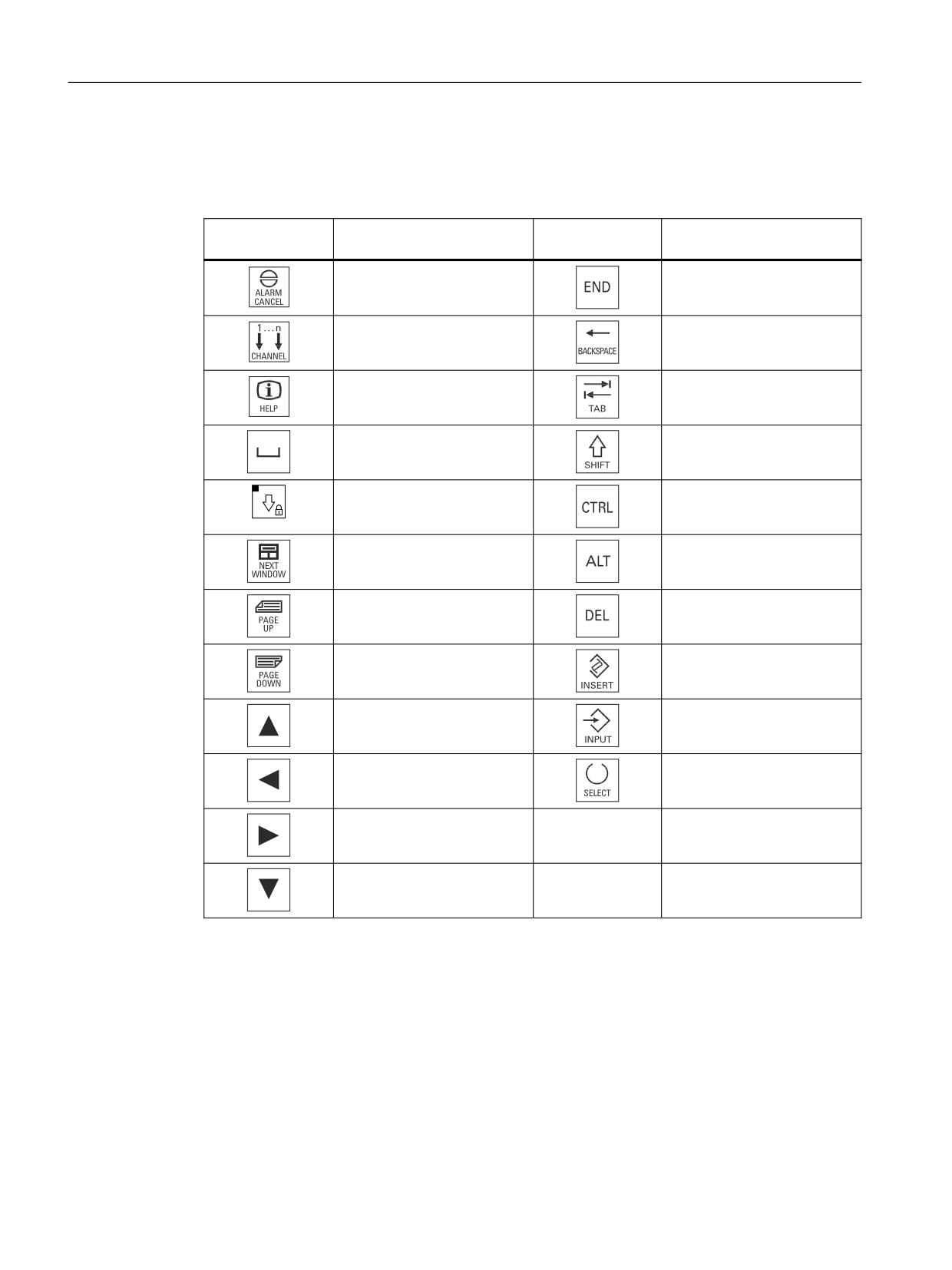
Description
2.2 Operator controls and displays
Overview of the key symbols
The key symbols used on the operator panel front are shown below along with the
corresponding function keys on the PC keyboard.
Key
Function corresponds to the
Key
Function corresponds to the
PC key function
PC key function
Esc
End
F11
Backspace
F12
Tab
Space
(only intended for internal key-
board changeover)
Caps lock
Ctrl key
Home
Alt key
Page up
Delete
Page down
Insert
Cursor up
Enter
Cursor left
5 (in numeric key group)
Cursor right
A, ..., Z
<Shift> A, ..., Z
Cursor down
Display
Pixel error according to DIN EN ISO 9241-307, Error class II.
2.2.4
Screen saver
If an image with high contrast is displayed without change for longer than one hour, the dark-ON
function must be activated for energy efficiency reasons.
Operator panel front: OP 015 black
18
Manual, 05/2019, A5E35227814B AB
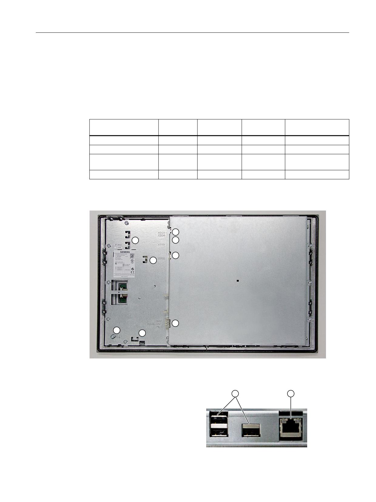
Description
2.3 Interfaces
The time can be adapted individually. Further information can be found at:
Commissioning of Basic Software and Operating Software, SINUMERIK Operate (IM9)
2.3
Interfaces
The OP 015 black operator panel front has the following interfaces:
Interface name
Connector
Speed
Permissible to-
Connector type
name
tal length
Ethernet interface
X202
1000 Mbps
Max. 100 m
8-pin RJ45 socket
Double USB interface 1
X203, X204
480 Mbps each
Max. 1.8 m
Double USB socket
24 V power supply
X206
-
max. 30 m
3-pin Combicon con-
nector
USB interface 2
X213
480 Mbps
Max. 1.8 m
Single USB socket
Rear
① X206
Power supply (with connector that can be screwed in place)
② -
Strain relief for connecting cables
③ -
M5 grounding screw (for screw connection with cable lug)
④ X203 / X 204 / USB interfaces
X213
⑤ X202
Ethernet interface
Operator panel front: OP 015 black
Manual, 05/2019, A5E35227814B AB
19
Description
2.3 Interfaces
Figure 2-2
OP 015 black - rear with interfaces
Pin assignment
The pin assignments of the interfaces can be found in the Section "Connecting".
Operator panel front: OP 015 black
20
Manual, 05/2019, A5E35227814B AB

Mounting
3
WARNING
Electric shock in the event of an individual error when grounding is insufficient
If the panel is installed with inadequate grounding in an environment with hazardous voltages,
this may cause an electric shock in the event of an individual error. This can result in death,
serious injury and material damage.
Adequately ground the conductive parts of the panel in accordance with the nationally
applicable regulations. When dimensioning the protective conductor connection, note the fuse
ratings of the electrical circuits with hazardous voltages, which would have an effect in
possible individual error scenarios.
WARNING
Unexpected machine movements caused by defective grounding
A defective or non-existent ground connection can lead to malfunction of the touch screen.
The malfunction can trigger an unexpected machine movement, or a machine movement can
no longer be stopped.
Ground the touch screen with the shortest possible cable with a minimum conductor cross-
section of 2.5 mm².
WARNING
Parasitic voltage
If the device is installed with inadequate insulation in an environment with higher/more
hazardous voltages, parasitic voltages may occur. This can result in death, serious injury and
material damage.
Insulate the cables appropriately for the highest voltage coming into consideration.
The safety of a system with an integrated operator panel front is the responsibility of the system
installer.
The installation is performed in accordance with the installer's instructions.
Observe all the relevant information from this manual regarding installation.
Operator panel front: OP 015 black
Manual, 05/2019, A5E35227814B AB
21
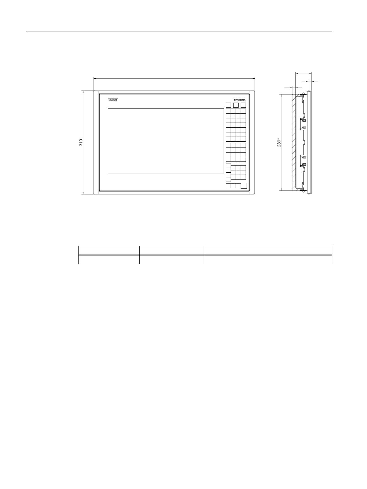
Mounting
Dimensions
37
483
11
10*
OP 015 black with TCU (integrated)
* Clearance for cable and ventilation
Table 3-1
Dimensions of the mounting opening
Width (mm)
Height (mm)
Mounting depth + clearance (mm)
450
290
37 + 10
The OP 015 black is mounted using the tension jacks provided (2.5 mm profile; 20 mm long).
When using the tension jacks, holes or threaded holes are not required.
This mounting method also enables the IP65/IP66 degree of protection if the mounting panel
corresponds to the requirements specified in the dimension drawing. The seal (PU foam seal)
to the mounting panel is already provided on the OP 015 black.
Operator panel front: OP 015 black
22
Manual, 05/2019, A5E35227814B AB
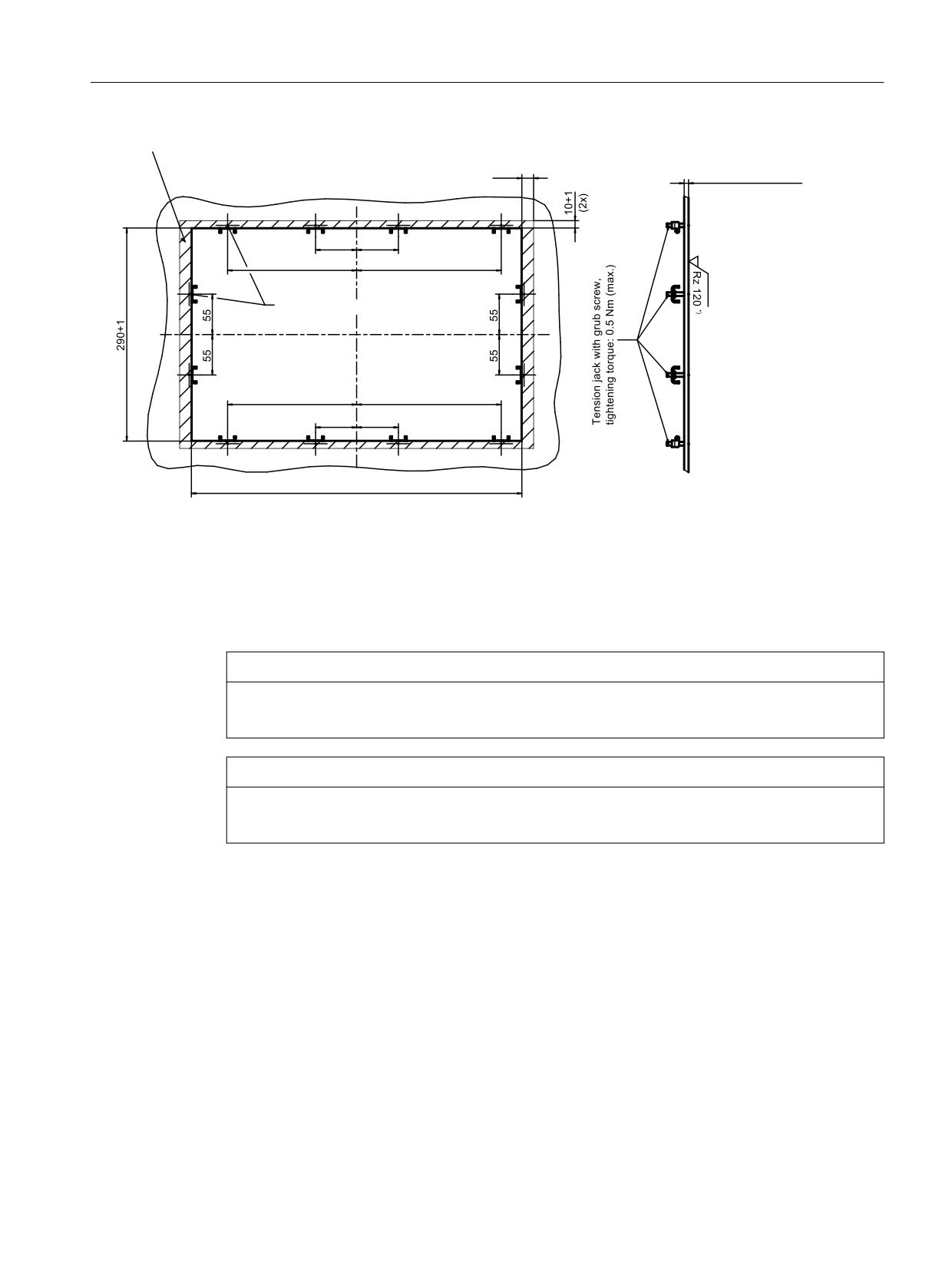
Mounting
6HDO DUHD
)RU ,3
PLQ
PD[
[
)RU ,3
PLQ
PD[
3UHVVXUH SRLQWV IRU WHQVLRQ MDFNV
,Q WKH VHDOLQJ DUHD
Figure 3-1
Dimension drawing for installing the OP 015 black operator panel front
One person installation
You should also observe the data provided in Section "General information and networking" →
"Application planning" → "Climatic and mechanical environmental conditions" → "Cooling".
NOTICE
Impermissible mounting positions can cause malfunctions
Observe the permissible mounting position: Deviating by up to 45º from the vertical.
NOTICE
Damage to the glass front
Do not use suction grippers to lift the glass front.
Operator panel front: OP 015 black
Manual, 05/2019, A5E35227814B AB
23
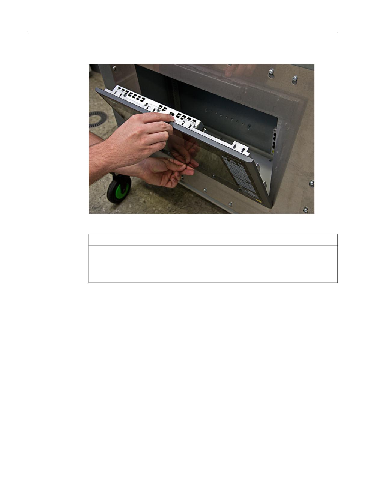
Mounting
1. Insert the operator panel front in the panel cutout from the front.
Figure 3-2
Inserting the operator panel
NOTICE
Damage to the sealing
The seal must not be damaged when installing the device so that the maximum achievable
degree of protection can be fulfilled. Therefore, insert the OP 015 black centered in the
panel cutout.
2. Tilt and press the operator panel front into the panel cutout. The catches must be pressed
down.
Operator panel front: OP 015 black
24
Manual, 05/2019, A5E35227814B AB